JP6901002B2 - Communication control method, communication control device and communication control program - Google Patents
Communication control method, communication control device and communication control program Download PDFInfo
- Publication number
- JP6901002B2 JP6901002B2 JP2019543438A JP2019543438A JP6901002B2 JP 6901002 B2 JP6901002 B2 JP 6901002B2 JP 2019543438 A JP2019543438 A JP 2019543438A JP 2019543438 A JP2019543438 A JP 2019543438A JP 6901002 B2 JP6901002 B2 JP 6901002B2
- Authority
- JP
- Japan
- Prior art keywords
- communication
- terminal
- communication process
- signal
- executed
- Prior art date
- Legal status (The legal status is an assumption and is not a legal conclusion. Google has not performed a legal analysis and makes no representation as to the accuracy of the status listed.)
- Active
Links
- 230000006854 communication Effects 0.000 title claims description 468
- 238000004891 communication Methods 0.000 title claims description 369
- 238000000034 method Methods 0.000 title claims description 50
- 230000005540 biological transmission Effects 0.000 claims description 168
- 238000012545 processing Methods 0.000 claims description 29
- 238000010586 diagram Methods 0.000 description 12
- 230000008054 signal transmission Effects 0.000 description 8
- 230000000694 effects Effects 0.000 description 5
- 238000005516 engineering process Methods 0.000 description 5
- 238000012546 transfer Methods 0.000 description 4
- 230000002452 interceptive effect Effects 0.000 description 3
- 239000004302 potassium sorbate Substances 0.000 description 3
- QVFWZNCVPCJQOP-UHFFFAOYSA-N chloralodol Chemical compound CC(O)(C)CC(C)OC(O)C(Cl)(Cl)Cl QVFWZNCVPCJQOP-UHFFFAOYSA-N 0.000 description 1
- 238000009432 framing Methods 0.000 description 1
- 230000010354 integration Effects 0.000 description 1
- 238000004519 manufacturing process Methods 0.000 description 1
- 238000012986 modification Methods 0.000 description 1
- 230000004048 modification Effects 0.000 description 1
- 230000035945 sensitivity Effects 0.000 description 1
- 239000007787 solid Substances 0.000 description 1
Images


Classifications
-
- H—ELECTRICITY
- H04—ELECTRIC COMMUNICATION TECHNIQUE
- H04W—WIRELESS COMMUNICATION NETWORKS
- H04W52/00—Power management, e.g. Transmission Power Control [TPC] or power classes
- H04W52/04—Transmission power control [TPC]
- H04W52/18—TPC being performed according to specific parameters
- H04W52/24—TPC being performed according to specific parameters using SIR [Signal to Interference Ratio] or other wireless path parameters
- H04W52/243—TPC being performed according to specific parameters using SIR [Signal to Interference Ratio] or other wireless path parameters taking into account interferences
-
- H—ELECTRICITY
- H04—ELECTRIC COMMUNICATION TECHNIQUE
- H04W—WIRELESS COMMUNICATION NETWORKS
- H04W40/00—Communication routing or communication path finding
- H04W40/02—Communication route or path selection, e.g. power-based or shortest path routing
- H04W40/04—Communication route or path selection, e.g. power-based or shortest path routing based on wireless node resources
- H04W40/08—Communication route or path selection, e.g. power-based or shortest path routing based on wireless node resources based on transmission power
-
- H—ELECTRICITY
- H04—ELECTRIC COMMUNICATION TECHNIQUE
- H04W—WIRELESS COMMUNICATION NETWORKS
- H04W52/00—Power management, e.g. Transmission Power Control [TPC] or power classes
- H04W52/04—Transmission power control [TPC]
- H04W52/06—TPC algorithms
- H04W52/14—Separate analysis of uplink or downlink
- H04W52/146—Uplink power control
-
- H—ELECTRICITY
- H04—ELECTRIC COMMUNICATION TECHNIQUE
- H04W—WIRELESS COMMUNICATION NETWORKS
- H04W52/00—Power management, e.g. Transmission Power Control [TPC] or power classes
- H04W52/04—Transmission power control [TPC]
- H04W52/06—TPC algorithms
- H04W52/16—Deriving transmission power values from another channel
-
- H—ELECTRICITY
- H04—ELECTRIC COMMUNICATION TECHNIQUE
- H04W—WIRELESS COMMUNICATION NETWORKS
- H04W52/00—Power management, e.g. Transmission Power Control [TPC] or power classes
- H04W52/04—Transmission power control [TPC]
- H04W52/18—TPC being performed according to specific parameters
- H04W52/24—TPC being performed according to specific parameters using SIR [Signal to Interference Ratio] or other wireless path parameters
- H04W52/245—TPC being performed according to specific parameters using SIR [Signal to Interference Ratio] or other wireless path parameters taking into account received signal strength
-
- H—ELECTRICITY
- H04—ELECTRIC COMMUNICATION TECHNIQUE
- H04W—WIRELESS COMMUNICATION NETWORKS
- H04W52/00—Power management, e.g. Transmission Power Control [TPC] or power classes
- H04W52/04—Transmission power control [TPC]
- H04W52/18—TPC being performed according to specific parameters
- H04W52/24—TPC being performed according to specific parameters using SIR [Signal to Interference Ratio] or other wireless path parameters
- H04W52/247—TPC being performed according to specific parameters using SIR [Signal to Interference Ratio] or other wireless path parameters where the output power of a terminal is based on a path parameter sent by another terminal
-
- H—ELECTRICITY
- H04—ELECTRIC COMMUNICATION TECHNIQUE
- H04W—WIRELESS COMMUNICATION NETWORKS
- H04W52/00—Power management, e.g. Transmission Power Control [TPC] or power classes
- H04W52/04—Transmission power control [TPC]
- H04W52/30—Transmission power control [TPC] using constraints in the total amount of available transmission power
- H04W52/36—Transmission power control [TPC] using constraints in the total amount of available transmission power with a discrete range or set of values, e.g. step size, ramping or offsets
- H04W52/367—Power values between minimum and maximum limits, e.g. dynamic range
-
- H—ELECTRICITY
- H04—ELECTRIC COMMUNICATION TECHNIQUE
- H04W—WIRELESS COMMUNICATION NETWORKS
- H04W52/00—Power management, e.g. Transmission Power Control [TPC] or power classes
- H04W52/04—Transmission power control [TPC]
- H04W52/18—TPC being performed according to specific parameters
- H04W52/28—TPC being performed according to specific parameters using user profile, e.g. mobile speed, priority or network state, e.g. standby, idle or non-transmission
- H04W52/283—Power depending on the position of the mobile
Landscapes
- Engineering & Computer Science (AREA)
- Computer Networks & Wireless Communication (AREA)
- Signal Processing (AREA)
- Mobile Radio Communication Systems (AREA)
Description
本発明は、通信制御方法、通信制御装置および通信制御プログラムに関し、特に無線通信における送信電力を調整できる通信制御方法、通信制御装置および通信制御プログラムに関する。 The present invention relates to a communication control method, a communication control device and a communication control program, and more particularly to a communication control method, a communication control device and a communication control program capable of adjusting transmission power in wireless communication.
各種産業におけるデジタル技術の普及と共に、振動、温度、湿度等の各種のセンサ情報を収集して産業における生産性を向上させる取り組みが増加している。特に、製造工場等では高機能な通信機器等の一部の機器の情報が収集されることによって運用管理の効率化が行われている。デジタル技術の普及に伴い、より多くの機器の情報が収集される運用管理が行われることが検討されている。 With the spread of digital technology in various industries, efforts to improve productivity in industry by collecting various sensor information such as vibration, temperature, and humidity are increasing. In particular, in manufacturing factories and the like, the efficiency of operation management is improved by collecting information on some devices such as high-performance communication devices. With the spread of digital technology, it is being considered to carry out operation management in which information on more devices is collected.
また、各種産業において無線通信の利用も普及している。特に、Wi-Fi(登録商標) 規格(IEEE(登録商標)802.11)の無線通信は、使用にあたって免許が不要であるため、多くの産業で利用されている。 The use of wireless communication is also widespread in various industries. In particular, Wi-Fi (registered trademark) standard (IEEE (registered trademark) 802.11) wireless communication is used in many industries because it does not require a license to use it.
なお、Wi-Fi 規格の無線通信に対して、LoRa( 登録商標) 、SIGFOX( 登録商標) 、Wi-SUN( 登録商標) 等の、通信距離が長いLPWA(Low Power Wide Area) の通信規格が採用された無線通信の利用も今後普及することが考えられる。 For Wi-Fi standard wireless communication, LPWA (Low Power Wide Area) communication standards with long communication distances such as LoRa (registered trademark), SIGFOX (registered trademark), and Wi-SUN (registered trademark) are available. It is expected that the use of adopted wireless communication will become widespread in the future.
無線通信の資源が多数のセンサに共有されて使用されている場合、多数のセンサが同時に無線通信を実行すると無線通信の信号同士が衝突する可能性がある。無線通信の信号同士の衝突が発生すると、通信効率が低くなるという課題がある。上記の課題は、Hidden node problem 、およびExposed node problemとして知られている。 When wireless communication resources are shared and used by a large number of sensors, if a large number of sensors execute wireless communication at the same time, wireless communication signals may collide with each other. When a collision between wireless communication signals occurs, there is a problem that the communication efficiency is lowered. The above problems are known as Hidden node problem and Exposed node problem.
また、センサは、センサ情報が記載された短いデータまたはフレームを送信する場合が多い。すなわち、センサ情報の送信が頻繁に行われるため、DCF(Distributed Coodination Function) 方式等の通信の実行に多くの手順を要する方式が採用された無線通信をセンサが実行する場合、通信効率が低くなるという課題がある。 In addition, the sensor often transmits short data or frames in which the sensor information is described. That is, since sensor information is frequently transmitted, the communication efficiency is low when the sensor executes wireless communication in which a method such as the DCF (Distributed Coodination Function) method, which requires many steps to execute communication, is adopted. There is a problem.
一般的なDCF 方式が採用された無線通信では、通信端末(以下、単に端末ともいう。)が通信エリア内の他の全ての端末と通信可能であることが、通信が実行される前提条件である。少なくともアクセスポイントは、通信エリア内の他の全ての端末と通信できる。 In wireless communication using the general DCF method, it is a prerequisite for communication to be performed that the communication terminal (hereinafter, also simply referred to as a terminal) can communicate with all other terminals in the communication area. is there. At least the access point can communicate with all other terminals in the communication area.
例えば、Wi-Fi 規格の無線通信では、アクセスポイントが、CTS(Clear to Send)信号(以下、単にCTS という。)を使用して、次にアクセスポイントに信号を送信する端末を通信エリア内に広告する。なお、広告は、ブロードキャスト通信に相当する処理である。 For example, in Wi-Fi standard wireless communication, an access point uses a CTS (Clear to Send) signal (hereinafter simply referred to as CTS), and then a terminal that transmits a signal to the access point is placed in the communication area. advertise. The advertisement is a process corresponding to broadcast communication.
CTS が使用された広告が行われることによって、通信エリア内では、1つの端末のみがアクセスポイントに信号を送信する。すなわち、通信エリア内で有効な通信を実行できる端末は、1つだけである。 Due to the advertisement using CTS, only one terminal sends a signal to the access point in the communication area. That is, only one terminal can execute effective communication in the communication area.
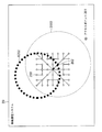
図11は、一般的なDCF 方式が採用された無線通信における信号の到達範囲の例を示す説明図である。図11に示す二重円は、アクセスポイント902を表す。また、図11に示す白色の円は、アクセスポイント902と通信可能な端末を表す。また、図11に示す黒色の円は、現在アクセスポイント902と通信中の端末を表す。すなわち図11は、所定の通信エリア内に複数の端末が存在していることを示す。 FIG. 11 is an explanatory diagram showing an example of a signal reach range in wireless communication in which a general DCF method is adopted. The double circle shown in FIG. 11 represents the access point 902. The white circle shown in FIG. 11 represents a terminal capable of communicating with the access point 902. The black circle shown in FIG. 11 represents a terminal currently communicating with the access point 902. That is, FIG. 11 shows that a plurality of terminals exist in a predetermined communication area.
また、図11に示す各端末とアクセスポイント902を結ぶ線は、通信エリア内の各端末からアクセスポイント902に向けた通信(より具体的には、通信の際に信号が送信される様子)を表す。すなわち、アクセスポイント902には、多くの通信信号が集中する。また、図11に示す端末901からアクセスポイント902へ向かう矢印は、端末901からアクセスポイント902への通信信号を表す。
Further, the line connecting each terminal and the access point 902 shown in FIG. 11 indicates communication from each terminal in the communication area to the access point 902 (more specifically, a signal is transmitted during communication). Represent. That is, many communication signals are concentrated on the access point 902. Further, the arrow from the
図11に示す2つの破線の円は、複数の端末のうちの1つの端末である端末901の送信信号の到達範囲9001および到達範囲9002をそれぞれ表す。到達範囲9001および到達範囲9002は、端末901が通信可能な通信エリアである。
The two dashed circles shown in FIG. 11 represent the
到達範囲9001および到達範囲9002は、端末901がアクセスポイント902に信号を送信する際の送信信号の到達範囲の例である。なお、図11に示す各表記の意味は、他の図においても同様である。
The
到達範囲9001は、アクセスポイント902と通信可能な通信エリア内の全ての端末に到達可能な送信電力で端末901が信号を送信した場合の到達範囲である。端末901が上記の送信電力で信号を送信する場合、通信エリア内の全ての端末は、キャリアセンスする(チャンネルが空いているか否かを調べる)ことによって端末901が信号を送信していることを検出できる。このため、他の端末は、端末901による送信処理が実行されている間、信号の送信を避けることによって、送信信号同士の衝突の発生を防ぐことができる。
The
また、到達範囲9002は、アクセスポイント902に到達可能な最小の送信電力で端末901が信号を送信した場合の到達範囲である。すなわち、端末901の送信信号の到達範囲は、到達範囲9002よりも大きく、到達範囲9001よりも小さい。
Further, the
端末901が上記の送信電力で信号を送信する場合、端末901の送信信号の到達範囲9002に含まれない端末が、通信エリア内に存在する。到達範囲9002に含まれない端末は、端末901が信号を送信していることを検出できない。
When the
すなわち、到達範囲9002に含まれない端末は、端末901による送信処理が実行されている間、アクセスポイント902に信号を送信する可能性がある。信号が送信されると、送信信号同士の衝突が発生してしまう恐れがある。
That is, a terminal not included in the
端末が送信電力を調整しない場合であっても、DCF 方式では、アクセスポイント902が、自身の通信エリア内のいずれかの端末が信号を送信することを示すCTS を通信エリア内の全ての端末に送信する。上述したように、例えば端末901が信号を送信することが記載されたCTS が送信されると、通信エリア内の端末901以外の端末による送信処理は抑制される。
In the DCF method, the access point 902 provides all terminals in the communication area with a CTS indicating that any terminal in its communication area transmits a signal, even if the terminal does not adjust the transmission power. Send. As described above, for example, when the CTS described that the
そこで、通信が排他的に制御されるDCF 方式が採用された無線通信を多くの無線通信装置が効率よく実行するために、隣接する複数のアクセスポイント間の影響を軽減することが検討されている。 Therefore, in order for many wireless communication devices to efficiently execute wireless communication using the DCF method in which communication is exclusively controlled, it is being studied to reduce the influence between a plurality of adjacent access points. ..
例えば、非特許文献1に記載されているシスコシステムズ社が開発したCisco(登録商標) Wireless LAN Controller には、アクセスポイント間の電波干渉を考慮して、各アクセスポイントの出力を調整する方式が採用されている。 For example, the Cisco® Wireless LAN Controller developed by Cisco Systems, Inc. described in Non-Patent Document 1 employs a method of adjusting the output of each access point in consideration of radio wave interference between access points. Has been done.
また、無線通信を多くの無線通信装置が効率よく実行するために、無線アドホック通信や、無線メッシュネットワーク等が研究されている。無線アドホック通信や無線メッシュネットワークは、主に信号強度が十分に得られる通信経路の中から最短経路を選択する通信技術である。 Further, in order for many wireless communication devices to efficiently execute wireless communication, wireless ad hoc communication, wireless mesh networks, and the like are being studied. Wireless ad hoc communication and wireless mesh networks are communication technologies that mainly select the shortest path from communication paths that provide sufficient signal strength.
しかし、上記の通信技術は、無線通信装置の信号の送信タイミングを制御する機能を提供しない。また、上記の通信技術が使用されて通信経路が選択される場合、選択された通信経路が全ての無線通信装置に共有される。無線通信装置の位置が変化しない限り、無線通信装置に共有される通信経路は、固定される。 However, the above-mentioned communication technology does not provide a function of controlling the signal transmission timing of the wireless communication device. Further, when the communication path is selected by using the above communication technique, the selected communication path is shared by all the wireless communication devices. As long as the position of the wireless communication device does not change, the communication path shared by the wireless communication device is fixed.
DCF 方式が採用された無線通信における第1の問題点は、無線通信エリア内で1組の端末しか無線通信を実行できないように規定されているため、無線電波の利用効率が低くなることである。 The first problem in wireless communication in which the DCF method is adopted is that the utilization efficiency of wireless radio waves is low because it is stipulated that only one set of terminals can execute wireless communication in the wireless communication area. ..
仮に2組以上の端末が無線通信を実行できるように規定されたとしても、各端末は、無線通信エリア内で既に実行中の無線通信に対する影響が十分に小さくなる無線通信における送信電力および宛先を把握していない。このため、DCF 方式等、一定の品質が保たれた通信が実行されている通信エリアと重複するエリア内で、他の端末は、並列に無線通信を実行できない。 Even if it is specified that two or more sets of terminals can execute wireless communication, each terminal sets the transmission power and destination in wireless communication so that the influence on the wireless communication already being executed in the wireless communication area is sufficiently small. I don't know. Therefore, other terminals cannot execute wireless communication in parallel in an area that overlaps with a communication area where communication with a certain quality is executed, such as the DCF method.
仮に無線通信に対する影響が十分に小さくなる無線通信における送信電力および宛先を把握したとしても、各端末は、無線通信エリア内で既に実行中の無線通信における受信側が信号を受信した時の信号強度を把握していない。このため、既に実行中の無線通信における受信側に対する影響が十分に小さくなる無線通信における送信電力および宛先を決定できないため、他の端末は、並列に無線通信を実行できない。 Even if the transmission power and destination in wireless communication, which have a sufficiently small effect on wireless communication, are grasped, each terminal determines the signal strength when the receiving side in wireless communication already being executed in the wireless communication area receives the signal. I don't know. Therefore, since the transmission power and the destination in the wireless communication in which the influence on the receiving side in the wireless communication already being executed is sufficiently small cannot be determined, other terminals cannot execute the wireless communication in parallel.
非特許文献1に記載されている製品や、無線アドホック通信等の通信技術は、効率的な無線通信の実行を目的とする。しかし、無線通信を並列に実行することや、無線通信が実行される空間における通信量の総和を最大化することは、想定されていない。 The products described in Non-Patent Document 1 and communication technologies such as wireless ad hoc communication aim at efficient wireless communication execution. However, it is not assumed that wireless communication is executed in parallel or that the total amount of communication in the space where wireless communication is executed is maximized.
[発明の目的]
そこで、本発明は、上述した課題を解決する、既に実行中の無線通信の無線通信エリア内で実行中の無線通信に支障を来すことなく無線通信を並列に実行できる通信制御方法、通信制御装置および通信制御プログラムを提供することを目的とする。[Purpose of Invention]
Therefore, the present invention solves the above-mentioned problems, and is a communication control method and communication control capable of executing wireless communication in parallel without interfering with the wireless communication being executed in the wireless communication area of the wireless communication already being executed. It is an object of the present invention to provide a device and a communication control program.
本発明による通信制御方法は、送信端末と受信端末の間で実行されている通信処理である第1通信処理と並列に実行可能な通信処理である第2通信処理を決定する通信制御装置において実行される通信制御方法であって、第2通信処理で送信される信号が受信端末に受信されても第1通信処理に支障が生じないような信号の送信電力の条件を決定し、決定された条件を満たす送信電力で送信される信号が到達可能な端末の中から第2通信処理の宛先を決定し、第1通信処理の終了予定時刻を推定し、推定された終了予定時刻までに第2通信処理が終了するように第2通信処理を実行することを特徴とする。 The communication control method according to the present invention is executed in a communication control device that determines a second communication process, which is a communication process that can be executed in parallel with a first communication process, which is a communication process executed between a transmitting terminal and a receiving terminal. It is a communication control method to be performed, and the condition of the transmission power of the signal is determined so that the signal transmitted in the second communication process is received by the receiving terminal but does not interfere with the first communication process. The destination of the second communication process is determined from the terminals to which the signal transmitted with the transmission power satisfying the conditions can be reached , the scheduled end time of the first communication process is estimated, and the second scheduled end time is reached by the estimated end time. It is characterized in that the second communication process is executed so that the communication process is completed.
本発明による通信制御装置は、送信端末と受信端末の間で実行されている通信処理である第1通信処理と並列に実行可能な通信処理である第2通信処理を決定する通信制御装置であって、第2通信処理で送信される信号が受信端末に受信されても第1通信処理に支障が生じないような信号の送信電力の条件を決定する送信電力決定部と、決定された条件を満たす送信電力で送信される信号が到達可能な端末の中から第2通信処理の宛先を決定する宛先決定部と、第1通信処理の終了予定時刻を推定し、推定された終了予定時刻までに第2通信処理が終了するように第2通信処理を実行する制御部とを備えることを特徴とする。 The communication control device according to the present invention is a communication control device that determines a second communication process, which is a communication process that can be executed in parallel with a first communication process, which is a communication process executed between a transmitting terminal and a receiving terminal. Then, the transmission power determination unit that determines the condition of the signal transmission power so that the signal transmitted in the second communication processing is received by the receiving terminal but does not interfere with the first communication processing, and the determined condition are determined. The destination determination unit that determines the destination of the second communication process and the scheduled end time of the first communication process are estimated from the terminals that can reach the signal transmitted with the satisfied transmission power, and by the estimated end time. It is characterized by including a control unit that executes the second communication process so that the second communication process is completed.
本発明による通信制御プログラムは、送信端末と受信端末の間で実行されている通信処理である第1通信処理と並列に実行可能な通信処理である第2通信処理を決定するコンピュータで実行される通信制御プログラムであって、コンピュータに、第2通信処理で送信される信号が受信端末に受信されても第1通信処理に支障が生じないような信号の送信電力の条件を決定する条件決定処理、決定された条件を満たす送信電力で送信される信号が到達可能な端末の中から第2通信処理の宛先を決定する宛先決定処理、第1通信処理の終了予定時刻を推定する推定処理、および推定された終了予定時刻までに第2通信処理が終了するように第2通信処理を実行する実行処理を実行させることを特徴とする。 The communication control program according to the present invention is executed by a computer that determines a second communication process, which is a communication process that can be executed in parallel with a first communication process, which is a communication process executed between a transmitting terminal and a receiving terminal. A condition determination process that is a communication control program that determines the conditions for the transmission power of a signal so that the computer does not interfere with the first communication process even if the signal transmitted in the second communication process is received by the receiving terminal. , The destination determination process for determining the destination of the second communication process from the terminals to which the signal transmitted with the transmission power satisfying the determined condition can be reached, the estimation process for estimating the scheduled end time of the first communication process, and the estimation process. It is characterized in that an execution process for executing the second communication process is executed so that the second communication process is completed by the estimated end time.
本発明によれば、既に実行中の無線通信の無線通信エリア内で実行中の無線通信に支障を来すことなく無線通信を並列に実行できる。 According to the present invention, wireless communication can be executed in parallel without interfering with the wireless communication being executed within the wireless communication area of the wireless communication already being executed.
実施形態1.
[構成の説明]
以下、本発明の実施形態を、図面を参照して説明する。図1は、本発明による通信システムの第1の実施形態の構成例を示す説明図である。Embodiment 1.
[Description of configuration]
Hereinafter, embodiments of the present invention will be described with reference to the drawings. FIG. 1 is an explanatory diagram showing a configuration example of a first embodiment of the communication system according to the present invention.
本実施形態の無線通信システム10に含まれる各端末は、自律分散的に送信電力を決定する。また、本実施形態の無線通信システム10では、電波が到達する空間が分割されて扱われ、分割された空間毎に並列に無線通信が実行される。すなわち、無線通信システム10に含まれる各端末は、通信処理を協調して制御できる。
Each terminal included in the
図1に示すように、本実施形態の無線通信システム10は、端末Aと、端末Bと、端末Cと、端末Xとを含む。図1に示す例では、所定の空間において無線通信システム10に含まれる端末A、端末B、端末C、端末Xがそれぞれ無線通信を実行する。なお、端末Cが本実施形態の端末である。また、端末A、端末B、端末Xは、それぞれ一般的な無線通信装置である。なお、端末A、端末B、端末Xが、本実施形態の端末でもよい。
As shown in FIG. 1, the
端末Aは、例えばセンサデバイスである。端末Bは、例えばゲートウェイである。また、端末Bは、アクセスポイントとしての機能を有する。また、端末Cおよび端末Xは、例えばノートPC(パーソナルコンピュータ)やスマートフォンである。本実施形態では、アクセスポイントも無線通信の信号の宛先とされる端末の1つとして扱われる。 The terminal A is, for example, a sensor device. The terminal B is, for example, a gateway. Further, the terminal B has a function as an access point. Further, the terminal C and the terminal X are, for example, a notebook PC (personal computer) or a smartphone. In the present embodiment, the access point is also treated as one of the terminals to be the destination of the wireless communication signal.
図1に示す例では、端末Aがアクセスポイントを介して、すなわち端末Bを介して無線通信を実行する。なお、端末Cおよび端末Xも、アクセスポイントを介して無線通信を実行してもよい。 In the example shown in FIG. 1, the terminal A executes wireless communication via the access point, that is, via the terminal B. The terminal C and the terminal X may also execute wireless communication via the access point.
また、図1の右に示す破線の楕円1001は、端末Aの送信信号の到達範囲(以下、到達範囲1001という。)を表す。到達範囲1001は、端末Aが他の端末に信号を送信した時に、他の端末が受信信号を基に受信データを復元可能な範囲でもある。
The
同様に、図1の左に示す破線の楕円1002は、端末Cの送信信号の到達範囲(以下、到達範囲1002という。)を表す。また、図1に示す実線の楕円1003は、アクセスポイントである端末Bの送信信号の到達範囲(以下、到達範囲1003という。)を表す。
Similarly, the
端末は、DCF 方式に従って、ランダムに算出されたバックオフ時間の経過中に他の端末が通信を実行していることを検出しなかった場合にデータを送信する。なお、バックオフは、複数の無線通信装置が同時に送信を開始することによってフレーム同士が衝突することを回避するための送信待機処理である。バックオフアルゴリズムでは、複数の無線通信装置に平等に通信の機会が与えられるように乱数が使用される。 According to the DCF method, the terminal transmits data when it does not detect that another terminal is performing communication during the elapse of the randomly calculated backoff time. The backoff is a transmission standby process for preventing frames from colliding with each other when a plurality of wireless communication devices start transmission at the same time. In the backoff algorithm, random numbers are used so that multiple wireless communication devices are given equal communication opportunities.
本実施形態では、端末Aとアクセスポイント(端末B)の間で通信が実行されている間に、端末Bの通信エリア内において端末Cと端末Xの間で並列に通信を実行することを考える。 In the present embodiment, it is considered that communication is executed in parallel between the terminal C and the terminal X in the communication area of the terminal B while the communication is being executed between the terminal A and the access point (terminal B). ..
図2は、第1の実施形態の通信端末の構成例を示すブロック図である。図2に示すように、通信端末100は、アプリケーション処理部(以下、アプリ処理部という。)110と、送受信制御部120と、同時送信宛先決定部130と、受信信号リスト記憶部140と、電波干渉管理部150と、無線通信制御部160とを有する。
FIG. 2 is a block diagram showing a configuration example of the communication terminal of the first embodiment. As shown in FIG. 2, the
上述したように、図1に示す端末Cの構成は、図2に示す通信端末100の構成と同様である。また、図1に示す端末A、端末B、端末Xの各構成も、図2に示す通信端末100の構成と同様でもよい。
As described above, the configuration of the terminal C shown in FIG. 1 is the same as the configuration of the
アプリ処理部110は、送信対象のデータ、受信対象のデータ、または転送対象のデータを決定する機能を有する。また、送受信制御部120は、同時送信宛先決定部130から指定された宛先と送信電力に基づいて送信処理を実行する機能を有する。
The
なお、本実施形態の送信処理は、「送信」に特化して説明する時の通信処理の別称である。以下、別の通信処理が実行されている間に実行される送信処理を、第2通信処理ともいう。また、第2通信処理に対して、既に実行されている別の通信処理を第1通信処理ともいう。 The transmission process of the present embodiment is another name for the communication process when the description is specific to "transmission". Hereinafter, the transmission process executed while another communication process is being executed is also referred to as a second communication process. Further, another communication process that has already been executed with respect to the second communication process is also referred to as a first communication process.
送受信制御部120は、アプリ処理部110から入力された送信対象のデータを、フレーム化した上で送信する。送受信制御部120は、送信待ちデータの宛先リストの中から、所定の通信時間内に指定された送信電力で指定された宛先へ送信可能なデータを選択する。送受信制御部120は、選択されたデータを宛先に送信する。
The transmission /
同時送信宛先決定部130は、受信信号リスト記憶部140に記憶されている情報に基づいて、実行されても現在実行中の通信に対する影響が小さい通信の宛先と送信電力を決定する機能を有する。
The simultaneous transmission
具体的には、同時送信宛先決定部130は、実行されても現在実行中の通信に支障が生じないような通信の宛先と送信電力を決定する。なお、同時送信宛先決定部130は、送信電力の条件を決定してもよい。
Specifically, the simultaneous transmission
例えば、同時送信宛先決定部130は、現在実行中の通信の通信時間、アクセスポイントが信号を受信した時の信号強度、およびSN比を推定する。同時送信宛先決定部130は、推定された結果と、送信対象の他の端末との距離とに基づいて通信端末100が現在実行中の通信と並列に信号を送信してもアクセスポイントに影響がない送信電力と宛先を決定する。
For example, the simultaneous transmission
受信信号リスト記憶部140は、通信端末100が受信した受信信号の信号強度を、信号を送信した送信元毎に記憶する機能を有する。受信信号リスト記憶部140は、例えば受信信号の信号強度の最大値、平均値、分散を記憶する。なお、受信信号リスト記憶部140は、信号強度と共にSN比を記憶してもよい。
The reception signal
電波干渉管理部150は、通信端末100が受信した受信信号の信号強度を送信元毎に計測する機能を有する。電波干渉管理部150は、計測された信号強度の値を受信信号リスト記憶部140に格納する。
The radio wave
無線通信制御部160は、無線通信を実行する機能を有する。例えば、無線通信制御部160は、送受信制御部120から入力されたフレームを無線通信において転送する。また、無線通信制御部160は、端末間で実行されている通信を検出する機能も有する。
The wireless
本実施形態の端末Cの同時送信宛先決定部130は、例えば以下のように、端末Aと端末Bの間で実行される通信への影響が小さく、かつ端末Aと端末Bの間で実行される通信からの影響も小さいような信号が送信される宛先Xを決定する。
The simultaneous transmission
C transmits to a node ∃X with power P s.t. P(C, X, B) < P(A, B, B), P(C, X, X) > P(A, B, X) ・・・式(1)C transmits to a node ∃ X with power P st P (C, X, B) <P (A, B, B), P (C, X, X)> P (A, B, X) ・ ・ ・ Expression (1)
なお、例えば信号強度P(N, M, L)は、端末Nから端末Mに送信された信号の端末Lで受信された時の信号強度を表す。信号強度P(N, M, L)は、例えば距離に対する電波減衰のモデルを用いて、以下の式で求められる。 For example, the signal strength P (N, M, L) represents the signal strength when the signal transmitted from the terminal N to the terminal M is received by the terminal L. The signal strength P (N, M, L) is calculated by the following equation, for example, using a model of radio wave attenuation with respect to distance.
P(N, M, L) = RSSI(d) = A − 10Blog10(d) ・・・式(2)P (N, M, L) = RSSI (d) = A − 10Blog 10 (d) ・ ・ ・ Equation (2)
なお、式(2)におけるdは、端末Nと端末Lの間の距離である。また、Aは、端末Nから1m離れた場所で受信された信号の信号強度である。また、Bは、定数である。なお、遮蔽物や反射物が多い場所で送信される信号の信号強度の推定には、他の信号強度モデルが用いられてもよい。 Note that d in the equation (2) is the distance between the terminal N and the terminal L. Further, A is the signal strength of the signal received at a place 1 m away from the terminal N. Further, B is a constant. In addition, another signal strength model may be used for estimating the signal strength of the signal transmitted in a place where there are many shields and reflectors.
なお、端末Cの同時送信宛先決定部130は、端末Bが端末Aから信号を受信した時の信号強度の履歴に基づいて端末Bが端末Aから信号を受信する時の信号強度の範囲を推定してもよい。また、同時送信宛先決定部130は、推定された信号強度の範囲よりも十分に信号強度が小さくなる送信電力で送信される信号が到達可能な端末を送信処理の宛先に決定してもよい。
The simultaneous transmission
また、端末Cの無線通信制御部160は、端末Aからのフレームを端末Bが受信した時の信号強度、SN比、および通信時間を示す情報が格納されたデータを、通信エリア内の他の端末に広告してもよい。
Further, the wireless
[動作の説明]
以下、本実施形態の端末Cが通信を実行する動作を図3を参照して説明する。図3は、第1の実施形態の端末Cによる通信処理の動作を示すフローチャートである。図3は、通信が開始されてから通信が終了するまでの端末Cの動作を示す。[Explanation of operation]
Hereinafter, the operation of the terminal C of the present embodiment to execute communication will be described with reference to FIG. FIG. 3 is a flowchart showing the operation of the communication process by the terminal C of the first embodiment. FIG. 3 shows the operation of the terminal C from the start of communication to the end of communication.
なお、本例における端末A、端末B、端末C、および端末Xの各構成は、図2に示す通信端末100の構成である。
Each configuration of the terminal A, the terminal B, the terminal C, and the terminal X in this example is the configuration of the
図3に示す通信処理が実行される前の無線通信システム10の状況は、端末Aと端末Cが含まれるいくつかの端末が送信待ちのデータを保有しており、かつキャリアセンスを実行しているという状況である。
In the situation of the
図3に示す通信処理は、端末Cが端末Aから端末Bへの通信を検出し、検出された通信に影響を与えずに並列にデータを送信する処理の例である。また、図3に示す通信処理は、各端末の送信電力と位置が既知の情報である場合の処理の例である。すなわち、本例では、端末Cは、任意の送信側の端末が任意の受信側の端末に信号を送信した際の受信側の受信信号の信号強度を算出できる。 The communication process shown in FIG. 3 is an example of a process in which the terminal C detects the communication from the terminal A to the terminal B and transmits data in parallel without affecting the detected communication. Further, the communication process shown in FIG. 3 is an example of the process when the transmission power and the position of each terminal are known information. That is, in this example, the terminal C can calculate the signal strength of the received signal on the receiving side when the terminal on the arbitrary transmitting side transmits the signal to the terminal on the arbitrary receiving side.
端末Cの無線通信制御部160は、キャリアセンスしながら送信処理の実行を待機する(ステップS101)。具体的には、無線通信制御部160は、通信電波を観察することによって、他の端末が信号を送信しているか否かを確認する。
The wireless
端末Aがバックオフ時間を終え、端末Bに向けた信号の送信を開始する。すなわち、端末Aと端末Bの間で通信が開始される(ステップS102)。なお、端末Aは、送信電力が記載されたRTS(Request to Send)信号(以下、単にRTS という。)を端末Bに送信してもよい。 The terminal A finishes the backoff time and starts transmitting a signal to the terminal B. That is, communication is started between the terminal A and the terminal B (step S102). The terminal A may transmit an RTS (Request to Send) signal (hereinafter, simply referred to as RTS) in which the transmission power is described to the terminal B.
一般的なDCF 方式が採用された無線通信において、端末Cは、端末Aが通信を開始した時点でバックオフを中止し、端末Aが通信を終えた時である次の送信機会を待つ。しかし、本実施形態の端末Cは、端末Aが通信を開始してもバックオフを継続して実行する。 In wireless communication in which the general DCF method is adopted, the terminal C stops the backoff when the terminal A starts the communication, and waits for the next transmission opportunity when the terminal A finishes the communication. However, the terminal C of the present embodiment continues to back off even if the terminal A starts communication.
次いで、端末Bの無線通信制御部160が、CTS を広告する。CTS には、端末Aからの送信信号が受信された時の信号強度P(A, B, B)が電波干渉管理部150により記載されている。
Next, the wireless
CTS を受信することによって、端末Cの同時送信宛先決定部130は、端末Aからの信号を端末Bが受信した時の信号強度P(A, B, B)を把握する(ステップS103)。なお、同時送信宛先決定部130は、CTS に依らずに信号強度P(A, B, B)を自ら推定してもよい。例えば、各端末の位置を把握している場合、同時送信宛先決定部130は、端末間の距離に基づいて信号強度P(A, B, B)を推定できる。
By receiving the CTS, the simultaneous transmission
次いで、端末Cの同時送信宛先決定部130は、端末Cから端末Xに送信された信号が端末Bで受信された時の信号強度P(C, X, B)が、信号強度P(A, B, B)よりも十分小さくなるような宛先Xを決定する(ステップS104)。
Next, in the simultaneous transmission
宛先Xを決定するために、端末Cの同時送信宛先決定部130は、例えば信号が宛先に到達するために求められる送信電力を考慮することによって、送信待ちのデータの宛先の集合の中から条件を満たす宛先を探す。例えば、同時送信宛先決定部130は、送信待ちのデータの宛先が優先度順に格納されている送信待ちキューの先頭の宛先から順に、条件を満たす宛先を探す。
In order to determine the destination X, the simultaneous transmission
決定された宛先Xは、端末Aと端末Bの間で実行される通信(第1通信処理)と並列に実行可能な送信処理(第2通信処理)の宛先である。なお、同時送信宛先決定部130は、データの最終宛先を決定する代わりに、経由されるノードの候補の中から送信先を決定してもよい。
The determined destination X is the destination of the transmission process (second communication process) that can be executed in parallel with the communication (first communication process) executed between the terminal A and the terminal B. Note that the simultaneous transmission
次いで、端末Cの無線通信制御部160は、バックオフ時間が経過しても端末Aと端末Bの間で実行される通信以外の通信を検出しなかった場合、端末Xに到達可能であり、かつ端末Aからの通信に対する影響が端末B側で十分に小さくなる送信電力で、端末Xに信号を送信する(ステップS105)。
Next, the wireless
すなわち、無線通信制御部160は、端末Bでの信号強度が信号強度P(C, X, B)になるような送信電力で端末Xに信号を送信する。信号を送信した後、端末Cは、図3に示す通信処理を終了する。信号を受信した端末Xは、端末Aと端末Bの間で実行される通信に対する影響が十分に小さくなる送信電力でCTS を送信する。
That is, the wireless
図4は、無線通信システム10で実行される通信の時間関係の例を示す説明図である。図4に示す「A→B」と記載された矩形は、端末Aと端末Bの間で実行される通信を表す。また、図4に示す「C→X」と記載された矩形は、端末Cと端末Xの間で実行される通信を表す。
FIG. 4 is an explanatory diagram showing an example of the time relationship of communication executed by the
ステップS102におけるバックオフ時間は、図4に示すDIFS(DCF Inter Frame Space) とCW(Contention Windows)の合計時間に相当する。上述したように、端末Aと端末Bの間で実行される通信は、「DIFS+CW 」のバックオフ時間が経過した後に開始される。 The backoff time in step S102 corresponds to the total time of DIFS (DCF Inter Frame Space) and CW (Contention Windows) shown in FIG. As described above, the communication executed between the terminal A and the terminal B is started after the backoff time of "DIFS + CW" has elapsed.
また、上記の通信が開始されても、端末Cは、図4に示すようにバックオフを継続して実行する。図4に示すvCW は、本実施形態で使用される仮想的なコンテンションウィンドウである。 Further, even if the above communication is started, the terminal C continuously executes the backoff as shown in FIG. The vCW shown in FIG. 4 is a virtual contention window used in this embodiment.
また、図4に示すxDA は、宛先アドレスの探索処理を表す。また、vPは、信号を送信するための送信電力の決定処理を表す。「DIFS+vCW」のバックオフ時間中に、端末Cは、xDA およびvPを終える(ステップS104)。 Further, xDA shown in FIG. 4 represents a search process for a destination address. Further, vP represents a process of determining transmission power for transmitting a signal. During the "DIFS + vCW" backoff time, terminal C finishes xDA and vP (step S104).
次いで、端末Cと端末Xの間で実行される通信は、「DIFS+vCW」のバックオフ時間が経過した後に開始される(ステップS105)。通信が開始されると、端末Cは、端末Xにフレームを転送する。 Next, the communication executed between the terminal C and the terminal X is started after the backoff time of "DIFS + vCW" has elapsed (step S105). When the communication is started, the terminal C transfers the frame to the terminal X.
なお、端末Cが、端末Aと端末Bの間で実行される通信の先頭フレームを受信し、受信された先頭フレームに基づいて通信の終了予定時刻を推定することもできる。また、端末Cは、RTS またはCTS に記載されているフレームのフレーム長に基づいて通信の終了予定時刻を推定してもよい。 It should be noted that the terminal C can also receive the first frame of the communication executed between the terminal A and the terminal B and estimate the scheduled end time of the communication based on the received first frame. Further, the terminal C may estimate the scheduled end time of communication based on the frame length of the frame described in RTS or CTS.
終了予定時刻を推定することによって、端末Cは、端末Cと端末Xの間で実行される通信を、端末Aと端末Bの間で実行される通信の推定された終了予定時刻までに終えることができる。端末Cが通信を推定された終了予定時刻までに終える場合、一般的なDCF 方式が採用された無線通信と、本実施形態の無線通信との外部から観察された違いが小さくなる。 By estimating the scheduled end time, the terminal C finishes the communication executed between the terminal C and the terminal X by the estimated end time of the communication executed between the terminal A and the terminal B. Can be done. When the terminal C finishes the communication by the estimated end time, the difference observed from the outside between the wireless communication adopting the general DCF method and the wireless communication of the present embodiment becomes small.
以下、端末Cが推定された終了予定時刻までに通信を終える利点を説明する。図5は、無線通信システム10で実行される通信の時間関係の他の例を示す説明図である。
Hereinafter, the advantage that the terminal C finishes the communication by the estimated end time will be described. FIG. 5 is an explanatory diagram showing another example of the time relationship of communication executed by the
図5に示す例では、図4に示す例と異なり、端末Cと端末Xの間で実行される通信が、端末Aと端末Bの間で実行される通信が終了した後も実行されている。また、端末Cと端末Xの間で通信が実行されている段階で、端末Aと端末Bの間で実行される通信の終了を待機している、送信待ち状態の端末Yが存在する。 In the example shown in FIG. 5, unlike the example shown in FIG. 4, the communication executed between the terminal C and the terminal X is executed even after the communication executed between the terminal A and the terminal B is completed. .. Further, there is a terminal Y in a transmission waiting state, which is waiting for the end of the communication executed between the terminal A and the terminal B at the stage where the communication between the terminal C and the terminal X is being executed.
端末Yは、端末Aからの送信信号を受信でき、かつ端末Cからの送信信号を受信できない端末である。よって、端末Yは、端末Aと端末Bの間で実行される通信が終了してから開始されるバックオフ時間が経過した後に、端末Cと端末Xの間で実行される通信の終了を待たずに信号の送信を開始する。 The terminal Y is a terminal that can receive the transmission signal from the terminal A and cannot receive the transmission signal from the terminal C. Therefore, the terminal Y waits for the end of the communication executed between the terminal C and the terminal X after the backoff time started after the communication executed between the terminal A and the terminal B ends has elapsed. Start transmitting the signal without.
端末Yが端末Zに送信する信号を端末Xが受信すると、信号同士の衝突の発生等、端末Cと端末Xの間で実行される通信に影響が及ぶ可能性がある。図5に示す斜線の領域は、影響が及ぶ可能性がある通信の部分を表す。 When the terminal X receives the signal transmitted by the terminal Y to the terminal Z, the communication executed between the terminal C and the terminal X may be affected, such as the occurrence of collision between the signals. The shaded area shown in FIG. 5 represents the portion of communication that may be affected.
しかし、端末Cが通信を推定された終了予定時刻までに終えれば、上記の問題は発生しない可能性が高い。端末Aと端末Bの間で実行される通信の終了予定時刻を推定するために、端末Cは、例えば端末Aと端末Bの間で実行される通信で転送されるフレームのフレーム長を参照する。 However, if the terminal C finishes the communication by the estimated end time, it is highly possible that the above problem does not occur. In order to estimate the scheduled end time of the communication executed between the terminal A and the terminal B, the terminal C refers to, for example, the frame length of the frame transferred in the communication executed between the terminal A and the terminal B. ..
参照されたフレーム長を用いて、端末Cは、例えば端末Aと端末Bの間で実行される通信の通信時間を「通信時間=(フレーム長/通信速度)」と算出する。 Using the referenced frame length, the terminal C calculates, for example, the communication time of the communication executed between the terminal A and the terminal B as "communication time = (frame length / communication speed)".
算出された通信時間を用いて、端末Cは、例えば端末Aと端末Bの間で実行される通信の終了予定時刻を「終了予定時刻=(端末Aと端末Bの間で実行される通信の通信開始時刻+算出された通信時間)」と算出する。 Using the calculated communication time, the terminal C sets, for example, the scheduled end time of the communication executed between the terminal A and the terminal B as "scheduled end time = (the communication executed between the terminal A and the terminal B). Communication start time + calculated communication time) "is calculated.
なお、端末Aは、端末Aと端末Bの間で実行される通信の通信時間を、RTS 、CTS 、またはフレームに記載してもよい。端末Cは、受信された情報に記載されている通信時間に基づいて、端末Cと端末Xの間で実行される通信を、上記のように算出された端末Aと端末Bの間で実行される通信の終了予定時刻までに終えてもよい。 Note that the terminal A may describe the communication time of the communication executed between the terminal A and the terminal B in the RTS, CTS, or frame. The terminal C executes the communication executed between the terminal C and the terminal X based on the communication time described in the received information between the terminal A and the terminal B calculated as described above. It may be completed by the scheduled end time of the communication.
本実施形態の無線通信システム10では、端末A以外で通信が開始された場合であっても、ステップS103〜ステップS105の処理が繰り返し実行されることによって、より多くの通信が並列に実行される。
In the
図3に示す例であれば、CTS を受信した他の端末は、既に受信された他のCTS を累積的に考慮することによって、既存の通信の受信側端末である端末Bおよび端末Xへの影響が小さくなる送信電力で信号を送信できる。 In the example shown in FIG. 3, the other terminals that have received the CTS can reach the terminals B and X, which are the receiving terminals of the existing communication, by cumulatively considering the other CTSs that have already been received. The signal can be transmitted with transmission power that has less effect.
以下、本実施形態の無線通信システムにおける通信の他の例を示す。図6は、無線通信システム20で実行される通信の例を示す説明図である。
Hereinafter, other examples of communication in the wireless communication system of the present embodiment will be shown. FIG. 6 is an explanatory diagram showing an example of communication executed by the
図6に示すように、無線通信システム20は、通信エリアの中心にアクセスポイント201を含む。また、上述したように、図6に示す各端末が中心である破線の円は、無線通信で送信される電波の到達範囲を表す。
As shown in FIG. 6, the
例えば、到達範囲2001は、アクセスポイント201が送信する電波の到達範囲である。また、到達範囲2002は、端末202が送信する電波の到達範囲である。
For example, the
本例では、アクセスポイント201に対して端末202が信号を送信した場合、端末202の送信処理に続いて端末203、端末204、端末205が順に送信処理を実行する。なお、各送信処理は、並列に実行される。 In this example, when the terminal 202 transmits a signal to the access point 201, the terminal 203, the terminal 204, and the terminal 205 execute the transmission process in order following the transmission process of the terminal 202. Note that each transmission process is executed in parallel.
図6に示す例では、以下のように送信処理が実行される。バックオフを終了した端末202が、RTS をアクセスポイント201に送信する。RTS を受信したアクセスポイント201は、通信エリアにおける到達範囲2001内の全ての端末にCTS を送信する。
In the example shown in FIG. 6, the transmission process is executed as follows. The terminal 202 that has completed the backoff transmits the RTS to the access point 201. Upon receiving the RTS, the access point 201 transmits the CTS to all terminals within the
なお、アクセスポイント201が送信したCTS には、端末202からの信号を受信した時の信号強度と、信号の送信元が端末202であることを示す情報が格納されている。なお、アクセスポイント201は、CTS 以外のフレームに上記の情報を格納してもよい。 The CTS transmitted by the access point 201 stores the signal strength when the signal from the terminal 202 is received and the information indicating that the source of the signal is the terminal 202. The access point 201 may store the above information in a frame other than the CTS.
端末202は、受信されたCTS が示す信号強度を参照して、端末202の送信電力との差分に基づいて信号の減衰量を推定する。次いで、端末202は、アクセスポイント201に到達した信号の信号強度がアクセスポイント201の最低受信感度よりも高くなるような送信電力を算出する。 The terminal 202 refers to the signal strength indicated by the received CTS, and estimates the amount of signal attenuation based on the difference from the transmission power of the terminal 202. Next, the terminal 202 calculates the transmission power so that the signal strength of the signal reaching the access point 201 becomes higher than the minimum reception sensitivity of the access point 201.
次いで、端末202は、算出された送信電力でアクセスポイント201に信号を送信する。なお、端末202は、算出されたアクセスポイント201用の送信電力を記憶する。また、端末202は、事前に全ての端末用の送信電力を算出し、算出された送信電力を記憶してもよい。 Next, the terminal 202 transmits a signal to the access point 201 with the calculated transmission power. The terminal 202 stores the calculated transmission power for the access point 201. Further, the terminal 202 may calculate the transmission power for all terminals in advance and store the calculated transmission power.
端末202以外のCTS を受信した通信エリアにおける到達範囲2001内の各端末は、バックオフを継続して実行する。バックオフを継続して実行している各端末は、過去のCTS の授受で得られた、アクセスポイント201と、他のいくつかの端末に信号が到達可能な送信電力を記憶している。
Each terminal within the
記憶されている送信電力に基づいて、各端末は、送信キューに格納されている各フレームの宛先のうち、アクセスポイント201用の送信電力よりも十分に送信電力が小さい宛先を選択する。例えば、端末203は、アクセスポイント201用の送信電力よりも20dB低い送信電力で信号が送信される宛先である端末213を選択する。
Based on the stored transmission power, each terminal selects, among the destinations of each frame stored in the transmission queue, a destination whose transmission power is sufficiently smaller than the transmission power for the access point 201. For example, the terminal 203 selects the terminal 213 which is the destination to which the signal is transmitted with the
具体的には、各端末は、アクセスポイント201に受信された時の信号強度がCTS が示す信号強度よりも小さくなるような送信電力を選択する。また、各端末は、選択された送信電力で信号が到達可能な宛先を選択する。 Specifically, each terminal selects a transmission power such that the signal strength when received by the access point 201 is smaller than the signal strength indicated by the CTS. In addition, each terminal selects a destination to which the signal can reach with the selected transmission power.
バックオフを終了した端末は、選択された宛先に選択された送信電力で信号を送信する。端末203の受信側になる端末213は、既に検出された実行中の送信処理の対象であるアクセスポイント201に影響を与えない送信電力でCTS を送信する。上記の処理が繰り返し実行されることによって、再帰的に複数の送信処理が実行される。 The terminal that has completed the backoff transmits a signal to the selected destination with the selected transmission power. The terminal 213, which is the receiving side of the terminal 203, transmits the CTS with a transmission power that does not affect the access point 201, which is the target of the already detected and executing transmission process. By repeatedly executing the above processes, a plurality of transmission processes are recursively executed.
図7は、無線通信システム20で実行される通信の他の例を示す説明図である。図7は、端末202が通信エリア内の全ての端末に到達可能な送信電力で信号を送信する場合の例を示す。図6に示す到達範囲2002よりも、図7に示す到達範囲2002の方が大きい。
FIG. 7 is an explanatory diagram showing another example of communication executed by the
なお、図7に示す端末202は、図2に示すような構成の通信端末でなくてもよい。例えば、端末202は、DCF 方式が採用された一般的な通信端末でもよい。すなわち、図7に示す例は、本実施形態の通信端末100と、通信エリアを網羅する一般的な通信端末とが組み合わせられて使用される例である。
The terminal 202 shown in FIG. 7 does not have to be a communication terminal having a configuration as shown in FIG. For example, the terminal 202 may be a general communication terminal adopting the DCF method. That is, the example shown in FIG. 7 is an example in which the
図7に示す例では、以下のように送信処理が実行される。バックオフを終了した端末202が、送信処理を開始する。本実施形態の端末203は、端末202による送信処理の宛先と送信電力を検出する。
In the example shown in FIG. 7, the transmission process is executed as follows. The terminal 202 that has completed the backoff starts the transmission process. The
次いで、端末203は、アクセスポイント201が端末202からの信号を受信した時の信号強度を推定する。端末202の送信電力の範囲が把握できれば、端末203は、端末202が所在する位置を大まかに推定できる。 Next, the terminal 203 estimates the signal strength when the access point 201 receives the signal from the terminal 202. If the range of the transmission power of the terminal 202 can be grasped, the terminal 203 can roughly estimate the position where the terminal 202 is located.
図8は、端末203による送信端末の位置の推定の例を示す説明図である。例えば、図8には、端末203が推定した端末202が所在する可能性の高い範囲E202が太い破線の円で示されている。
FIG. 8 is an explanatory diagram showing an example of estimating the position of the transmitting terminal by the
E202を推定することによって、端末203は、端末202からアクセスポイント201までの距離、信号の減衰量、およびアクセスポイント201が信号を受信した時の信号強度の範囲も併せて推定できる。 By estimating E202, the terminal 203 can also estimate the distance from the terminal 202 to the access point 201, the amount of signal attenuation, and the range of signal strength when the access point 201 receives the signal.
上記の方法で、端末202からのRTS 、または任意の送信信号を受信した各端末は、アクセスポイント201が信号を受信した時の信号強度を推定する。次いで、各端末は、アクセスポイント201に受信された時の信号強度が推定された信号強度よりも小さく、かつ宛先の端末に信号が到達可能な送信電力で信号を送信する。 By the above method, each terminal that has received the RTS from the terminal 202 or an arbitrary transmission signal estimates the signal strength when the access point 201 receives the signal. Next, each terminal transmits a signal with a transmission power that the signal strength when received by the access point 201 is smaller than the estimated signal strength and the signal can reach the destination terminal.
なお、端末202の大よその位置を事前に計測することによって、端末203は、アクセスポイント201が信号を受信した時の信号強度の推定範囲をより狭くできる。すなわち、信号強度の推定精度が高められる。 By measuring the approximate position of the terminal 202 in advance, the terminal 203 can narrow the estimation range of the signal strength when the access point 201 receives the signal. That is, the estimation accuracy of the signal strength is improved.
また、E202のような、端末202が所在する可能性の高い範囲が2つ推定されると、端末202は、2つの範囲が重複する箇所に所在すると推測される。また、端末202が所在する可能性の高い範囲が3つ推定されると、端末202が所在する箇所は、1点に絞られる。本例では、CTS が用いられなくても、並列に通信が実行される。 Further, if it is estimated that there are two ranges in which the terminal 202 is likely to be located, such as E202, it is presumed that the terminal 202 is located in a location where the two ranges overlap. Further, if three ranges in which the terminal 202 is likely to be located are estimated, the location where the terminal 202 is located is narrowed down to one point. In this example, communication is executed in parallel even if CTS is not used.
図9は、無線通信システム20で実行される通信の他の例を示す説明図である。図9は、端末202が通信エリア内の一部の端末に到達不可能な送信電力で信号を送信する場合の例を示す。図7に示す到達範囲2002よりも、図9に示す到達範囲2002の方が小さい。
FIG. 9 is an explanatory diagram showing another example of communication executed by the
図9は、衝突する通信信号が存在する場合にも並列に実行される通信の例を示す。図9に示す到達範囲2003は、端末203が送信する電波の到達範囲である。
FIG. 9 shows an example of communication executed in parallel even when there are conflicting communication signals. The
図9に示す例では、CTS が使用されないと端末202による信号送信を検出できない端末が存在する。例えば、到達範囲2002に含まれない端末203は、送信信号を端末202からの送信信号と衝突させてしまう可能性がある。
In the example shown in FIG. 9, there is a terminal in which signal transmission by the terminal 202 cannot be detected unless CTS is used. For example, the terminal 203 not included in the
ただし、CTS が使用されない場合であっても、通信エリア内の一部の領域では並列に通信が実行される。例えば、端末202による信号送信を検出した端末204および端末205は、アクセスポイント201における信号強度に影響を与えない送信電力で信号を送信できる。また、端末203による信号送信を検出した端末206は、アクセスポイント201における信号強度に影響を与えない送信電力で信号を送信できる。 However, even if CTS is not used, communication is executed in parallel in some areas within the communication area. For example, the terminal 204 and the terminal 205 that have detected the signal transmission by the terminal 202 can transmit the signal with the transmission power that does not affect the signal strength at the access point 201. Further, the terminal 206 that has detected the signal transmission by the terminal 203 can transmit the signal with the transmission power that does not affect the signal strength at the access point 201.
すなわち、端末202による信号送信を検出した端末204および端末205と、端末203による信号送信を検出した端末206は、並列にデータ転送を実行できる。本例では、端末202からの送信信号と端末203からの送信信号が衝突する可能性があるが、無線通信システム20に含まれる他の複数の組の端末は、並列に通信を実行できる。
That is, the terminal 204 and the terminal 205 that have detected the signal transmission by the terminal 202 and the terminal 206 that has detected the signal transmission by the terminal 203 can execute data transfer in parallel. In this example, the transmission signal from the terminal 202 and the transmission signal from the terminal 203 may collide, but the other plurality of sets of terminals included in the
[効果の説明]
本実施形態の通信端末100は、無線通信において他の端末への影響が考慮された通信方法を提供する。本実施形態の通信端末100では、同時送信宛先決定部130が既に実行中の通信と並列に信号が送信される宛先の通信装置を決定し、無線通信制御部160が送信タイミングを調整しつつ信号を送信する。よって、本実施形態の通信端末100は、通信エリア内で自律分散的な並列通信を実現できる。すなわち、空間あたりの通信容量が増加する。[Explanation of effect]
The
本実施形態の通信端末100は、他の端末が通信を実行している間、通信への電波干渉の影響が十分に小さくなる送信電力と送信信号の宛先を自律分散的に決定する。各通信端末は、決定された送信電力で、決定された宛先への送信処理を並列に実行する。
The
また、本実施形態の通信端末100は、既に実行中の通信に対する影響が十分に小さくなる送信電力を決定し、送信信号の宛先を無線通信エリア内の端末から選択する。よって、通信端末100は、既に実行中の通信に対する影響が十分に小さくなる送信電力と無線通信エリア内の送信信号の宛先を把握できる。
Further, the
本実施形態の通信端末100が使用されると、無線通信エリア内で複数の組の端末が並列に通信を実行できる。無線通信エリア内で複数の組の端末が並列に通信を実行できるため、空間あたりの無線電波の利用効率が高められる。すなわち、空間あたりの通信容量が増加する。特に、DCF 方式が採用された通信端末と本実施形態の通信端末100とが組み合わせられて使用される場合、空間あたりの通信容量が増加する。
When the
また、本実施形態の通信端末100は、通信相手になる予定の端末からの信号を受信した時の信号強度を無線通信エリア内の他の端末に広告する。信号強度が広告されると、無線通信エリア内の他の端末は、既に実行中の通信の信号を受信した受信側における信号強度を把握できる。
Further, the
無線通信エリア内の他の端末は、把握された信号強度に基づいて、既に実行中の通信に対する影響が十分に小さくなる送信電力と送信信号の宛先を決定できる。すなわち、無線通信エリア内で複数の組の端末が並列に通信を実行できる。 Other terminals in the wireless communication area can determine the transmission power and the destination of the transmission signal, which have a sufficiently small effect on the communication already being executed, based on the grasped signal strength. That is, a plurality of sets of terminals can execute communication in parallel within the wireless communication area.
本実施形態の無線通信システムには、各端末が周囲の通信状況を観察し、通信が実行されていない場合に自端末が信号を送信する分散的なキャリアセンス通信方式(DCF 通信方式)が適用される。また、本実施形態の無線通信システムでは、無線メッシュネットワークにおけるデータ転送も実現される。 A decentralized carrier sense communication method (DCF communication method) is applied to the wireless communication system of the present embodiment, in which each terminal observes the surrounding communication status and the own terminal transmits a signal when communication is not executed. Will be done. Further, in the wireless communication system of the present embodiment, data transfer in a wireless mesh network is also realized.
なお、本実施形態の通信端末100は、例えば、非一時的な記憶媒体に格納されているプログラムに従って処理を実行する中央処理装置(CPU(Central Processing Unit))等のプロセッサによって実現されてもよい。すなわち、アプリ処理部110、送受信制御部120、同時送信宛先決定部130、電波干渉管理部150、および無線通信制御部160は、例えば、プログラム制御に従って処理を実行するCPU によって実現されてもよい。
The
また、受信信号リスト記憶部140は、例えばRAM(Random Access Memory) で実現されてもよい。
Further, the received signal
また、本実施形態の通信端末100における各部は、ハードウェア回路によって実現されてもよい。一例として、アプリ処理部110、送受信制御部120、同時送信宛先決定部130、受信信号リスト記憶部140、電波干渉管理部150、および無線通信制御部160が、それぞれLSI(Large Scale Integration)で実現される。また、それらが1つのLSI で実現されていてもよい。
Further, each part of the
次に、本発明の概要を説明する。図10は、本発明による通信制御装置の概要を示すブロック図である。本発明による通信制御装置30は、送信端末と受信端末の間で実行されている通信処理である第1通信処理と並列に実行可能な通信処理である第2通信処理を決定する通信制御装置であって、第2通信処理で送信される信号が受信端末に受信されても第1通信処理に支障が生じないような信号の送信電力の条件を決定する送信電力決定部31(例えば、同時送信宛先決定部130)と、決定された条件を満たす送信電力で送信される信号が到達可能な端末の中から第2通信処理の宛先を決定する宛先決定部32(例えば、同時送信宛先決定部130)とを備える。
Next, the outline of the present invention will be described. FIG. 10 is a block diagram showing an outline of the communication control device according to the present invention. The
そのような構成により、通信制御装置は、既に実行中の無線通信の無線通信エリア内で実行中の無線通信に支障を来すことなく無線通信を並列に実行できる。 With such a configuration, the communication control device can execute wireless communication in parallel without interfering with the wireless communication being executed in the wireless communication area of the wireless communication already being executed.
また、送信電力の条件は、第2通信処理で送信される信号の第1通信処理の受信端末での信号強度が、第1通信処理で送信された信号の受信端末での信号強度よりも所定の割合以上小さいことでもよい。 Further, the condition of the transmission power is that the signal strength of the signal transmitted in the second communication processing at the receiving terminal of the first communication processing is more predetermined than the signal strength of the signal transmitted in the first communication processing at the receiving terminal. It may be smaller than the ratio of.
そのような構成により、通信制御装置は、受信端末に受信された時の信号強度が十分に小さくなるような送信電力で信号を送信できる。 With such a configuration, the communication control device can transmit a signal with a transmission power such that the signal strength when received by the receiving terminal is sufficiently reduced.
また、送信電力決定部31は、第1通信処理の受信端末から転送される、第1通信処理で送信された信号の受信端末での信号強度を示すデータを用いて送信電力の条件を決定してもよい。
Further, the transmission
そのような構成により、通信制御装置は、アクセスポイントが広告したCTS を用いて送信電力を決定できる。 With such a configuration, the communication controller can determine the transmission power using the CTS advertised by the access point.
また、送信電力決定部31は、第1通信処理の送信端末が第1通信処理で送信した信号を用いて送信電力の条件を決定してもよい。
Further, the transmission
そのような構成により、通信制御装置は、CTS を用いずに送信電力を決定できる。 With such a configuration, the communication controller can determine the transmission power without using CTS.
また、通信制御装置30は、第2通信処理を制御する制御部(例えば、送受信制御部120)を備え、制御部は、第1通信処理の終了予定時刻を推定し、推定された終了予定時刻までに第2通信処理が終了するように第2通信処理を実行してもよい。
Further, the
そのような構成により、通信制御装置は、DCF 方式が採用された無線通信と外部から観察された時の差異がないような無線通信を実行できる。 With such a configuration, the communication control device can perform wireless communication in which there is no difference when observed from the outside with wireless communication in which the DCF method is adopted.
また、制御部は、第1通信処理の受信端末から転送される、第1通信処理の実行予定時間を示すデータを用いて第1通信処理の終了予定時刻を推定してもよい。 Further, the control unit may estimate the scheduled end time of the first communication process by using the data indicating the scheduled execution time of the first communication process transferred from the receiving terminal of the first communication process.
そのような構成により、通信制御装置は、第1通信処理の終了予定時刻の推定にかかる時間を短縮できる。 With such a configuration, the communication control device can shorten the time required for estimating the scheduled end time of the first communication process.
また、第1通信処理の送信端末は、信号を送信した時の送信電力を通信フレームに格納してもよい。通信フレームを受信した第1通信処理の受信端末は、通信エリアにおける電波減衰量を推定してもよい。 Further, the transmission terminal of the first communication process may store the transmission power at the time of transmitting the signal in the communication frame. The receiving terminal of the first communication process that has received the communication frame may estimate the amount of radio wave attenuation in the communication area.
以上、実施形態および実施例を参照して本願発明を説明したが、本願発明は上記実施形態および実施例に限定されるものではない。本願発明の構成及び詳細には、本願発明のスコープ内で当業者が理解し得る様々な変更をすることができる。 Although the present invention has been described above with reference to the embodiments and examples, the present invention is not limited to the above embodiments and examples. Various modifications that can be understood by those skilled in the art can be made within the scope of the present invention in the configuration and details of the present invention.
この出願は、2017年9月21日に出願された日本特許出願2017−180925を基礎とする優先権を主張し、その開示の全てをここに取り込む。 This application claims priority on the basis of Japanese Patent Application 2017-180925 filed on September 21, 2017, and incorporates all of its disclosures herein.
10、20 無線通信システム
30 通信制御装置
31 送信電力決定部
32 宛先決定部
A、B、C、X、Y、Z、100、202、203、204、205、206、213、901 通信端末
110 アプリケーション処理部
120 送受信制御部
130 同時送信宛先決定部
140 受信信号リスト記憶部
150 電波干渉管理部
160 無線通信制御部
201、902 アクセスポイント
1001、1002、1003、2001、2002、2003、9001、9002 到達範囲10, 20
Claims (9)
前記第2通信処理で送信される信号が前記受信端末に受信されても前記第1通信処理に支障が生じないような前記信号の送信電力の条件を決定し、
決定された条件を満たす送信電力で送信される信号が到達可能な端末の中から前記第2通信処理の宛先を決定し、
前記第1通信処理の終了予定時刻を推定し、
推定された終了予定時刻までに前記第2通信処理が終了するように前記第2通信処理を実行する
ことを特徴とする通信制御方法。 A communication control method executed in a communication control device that determines a second communication process, which is a communication process that can be executed in parallel with a first communication process, which is a communication process executed between a transmitting terminal and a receiving terminal. ,
Even if the signal transmitted in the second communication process is received by the receiving terminal, the condition of the transmission power of the signal is determined so that the first communication process is not hindered.
The destination of the second communication process is determined from the terminals that can reach the signal transmitted with the transmission power satisfying the determined condition .
Estimate the scheduled end time of the first communication process,
A communication control method characterized in that the second communication process is executed so that the second communication process is completed by the estimated end time.
請求項1記載の通信制御方法。 The condition of the transmission power is that the signal strength of the signal transmitted in the second communication process at the receiving terminal of the first communication processing is more predetermined than the signal strength of the signal transmitted in the first communication processing at the receiving terminal. The communication control method according to claim 1, wherein the communication control method is smaller than the ratio of.
請求項1または請求項2記載の通信制御方法。 Claim 1 or claim 2 in which the condition of the transmission power is determined by using the data indicating the signal strength of the signal transmitted in the first communication process transferred from the receiving terminal of the first communication process at the receiving terminal. The described communication control method.
請求項1または請求項2記載の通信制御方法。 The communication control method according to claim 1 or 2, wherein the transmitting terminal of the first communication process determines the condition of the transmission power using the signal transmitted in the first communication process.
請求項1記載の通信制御方法。 Is transferred from the receiving terminal of the first communication processing, the first communication control method according to claim 1, wherein using the data indicating the scheduled execution time of the communication processing for estimating the expected ending time of the first communication processing.
前記第2通信処理で送信される信号が前記受信端末に受信されても前記第1通信処理に支障が生じないような前記信号の送信電力の条件を決定する送信電力決定部と、
決定された条件を満たす送信電力で送信される信号が到達可能な端末の中から前記第2通信処理の宛先を決定する宛先決定部と、
前記第1通信処理の終了予定時刻を推定し、推定された終了予定時刻までに前記第2通信処理が終了するように前記第2通信処理を実行する制御部とを備える
ことを特徴とする通信制御装置。 A communication control device that determines a second communication process, which is a communication process that can be executed in parallel with a first communication process, which is a communication process executed between a transmitting terminal and a receiving terminal.
A transmission power determination unit that determines conditions for transmission power of the signal so that the signal transmitted in the second communication process is received by the receiving terminal so as not to interfere with the first communication process.
A destination determination unit that determines the destination of the second communication process from among terminals that can reach a signal transmitted with transmission power that satisfies the determined conditions .
A communication including a control unit that estimates the scheduled end time of the first communication process and executes the second communication process so that the second communication process is completed by the estimated scheduled end time. Control device.
請求項6記載の通信制御装置。 The condition of the transmission power is that the signal strength of the signal transmitted in the second communication process at the receiving terminal of the first communication processing is more predetermined than the signal strength of the signal transmitted in the first communication processing at the receiving terminal. The communication control device according to claim 6, which is smaller than the ratio of.
前記コンピュータに、
前記第2通信処理で送信される信号が前記受信端末に受信されても前記第1通信処理に支障が生じないような前記信号の送信電力の条件を決定する条件決定処理、
決定された条件を満たす送信電力で送信される信号が到達可能な端末の中から前記第2通信処理の宛先を決定する宛先決定処理、
前記第1通信処理の終了予定時刻を推定する推定処理、および
推定された終了予定時刻までに前記第2通信処理が終了するように前記第2通信処理を実行する実行処理
を実行させるための通信制御プログラム。 A communication control program executed by a computer that determines a second communication process, which is a communication process that can be executed in parallel with a first communication process, which is a communication process executed between a transmitting terminal and a receiving terminal.
On the computer
A condition determination process for determining the condition of the transmission power of the signal so that the signal transmitted in the second communication process is received by the receiving terminal so as not to interfere with the first communication process .
A destination determination process for determining the destination of the second communication process from among terminals to which a signal transmitted with transmission power satisfying the determined condition can be reached .
Estimating processing for estimating the scheduled end time of the first communication processing, and
A communication control program for executing an execution process for executing the second communication process so that the second communication process is completed by the estimated end time.
請求項8記載の通信制御プログラム。 The condition of the transmission power is that the signal strength of the signal transmitted in the second communication process at the receiving terminal of the first communication processing is more predetermined than the signal strength of the signal transmitted in the first communication processing at the receiving terminal. 8. The communication control program according to claim 8, which is smaller than the ratio of.
Applications Claiming Priority (3)
| Application Number | Priority Date | Filing Date | Title |
|---|---|---|---|
| JP2017180925 | 2017-09-21 | ||
| JP2017180925 | 2017-09-21 | ||
| PCT/JP2018/026155 WO2019058715A1 (en) | 2017-09-21 | 2018-07-11 | Communication control method, communication control device, and communication control program |
Publications (2)
| Publication Number | Publication Date |
|---|---|
| JPWO2019058715A1 JPWO2019058715A1 (en) | 2020-10-15 |
| JP6901002B2 true JP6901002B2 (en) | 2021-07-14 |
Family
ID=65810240
Family Applications (1)
| Application Number | Title | Priority Date | Filing Date |
|---|---|---|---|
| JP2019543438A Active JP6901002B2 (en) | 2017-09-21 | 2018-07-11 | Communication control method, communication control device and communication control program |
Country Status (3)
| Country | Link |
|---|---|
| US (1) | US11057843B2 (en) |
| JP (1) | JP6901002B2 (en) |
| WO (1) | WO2019058715A1 (en) |
Families Citing this family (1)
| Publication number | Priority date | Publication date | Assignee | Title |
|---|---|---|---|---|
| US11057843B2 (en) * | 2017-09-21 | 2021-07-06 | Nec Corporation | Communication control method, communication control device, and communication control program |
Family Cites Families (25)
| Publication number | Priority date | Publication date | Assignee | Title |
|---|---|---|---|---|
| EP1530316A1 (en) * | 2003-11-10 | 2005-05-11 | Go Networks | Improving the performance of a wireless packet data communication system |
| US7535839B2 (en) * | 2005-06-30 | 2009-05-19 | Alcatel-Lucent Usa Inc. | Method and apparatus for quality-of-service based admission control using prediction of scheduling gain |
| CN101395854B (en) * | 2006-03-02 | 2012-09-26 | 松下电器产业株式会社 | Transmission device, wireless communication system and transmission method |
| JP4805756B2 (en) * | 2006-08-31 | 2011-11-02 | 株式会社エヌ・ティ・ティ・ドコモ | Communication control device and communication control method |
| US8041375B2 (en) * | 2007-10-31 | 2011-10-18 | Qualcomm Incorporated | Methods and apparatus for use in peer to peer communications devices and/or systems relating to rate scheduling, traffic scheduling, rate control, and/or power control |
| JP2009231912A (en) * | 2008-03-19 | 2009-10-08 | Oki Electric Ind Co Ltd | Radio communication system and transmission power control method |
| CN101635932B (en) * | 2008-07-21 | 2012-08-29 | 华为技术有限公司 | Method and system for channel detection and report, terminal and management center |
| US9072055B2 (en) * | 2011-06-21 | 2015-06-30 | Telefonaktiebolaget L M Ericsson (Publ) | Systems and methods for controlling the power at which a communication device transmits an uplink signal |
| WO2012177218A2 (en) * | 2011-06-21 | 2012-12-27 | Telefonaktiebolaget L M Ericsson (Publ) | Selecting uplink multi-antenna transmission to enhance coverage |
| JP5814041B2 (en) * | 2011-08-12 | 2015-11-17 | 株式会社Nttドコモ | Radio communication system, radio base station apparatus, user terminal, and radio communication method |
| JP2014216796A (en) * | 2013-04-24 | 2014-11-17 | 株式会社東芝 | Radio communication device and method, and program |
| JP6142921B2 (en) * | 2013-05-22 | 2017-06-07 | 富士通株式会社 | Communication node, system, communication method, and communication program |
| JP6223224B2 (en) * | 2014-02-21 | 2017-11-01 | ルネサスエレクトロニクス株式会社 | Image processing apparatus and control method thereof |
| US9622189B2 (en) * | 2014-03-28 | 2017-04-11 | Zte Corporation | Techniques for fast delivery of radio information |
| US20160157182A1 (en) * | 2014-11-28 | 2016-06-02 | Fujitsu Limited | Base station, communication system, and communication control method |
| EP3228133A1 (en) * | 2014-12-02 | 2017-10-11 | Telefonaktiebolaget LM Ericsson (publ) | Combined power control for d2d wireless communication |
| JP6004021B2 (en) * | 2015-01-27 | 2016-10-05 | 沖電気工業株式会社 | Wireless communication apparatus and wireless communication program |
| JP6554798B2 (en) * | 2015-01-28 | 2019-08-07 | 富士通株式会社 | Wireless communication system |
| WO2016158801A1 (en) * | 2015-03-31 | 2016-10-06 | 三菱重工業株式会社 | Work planning system, work planning method, decision-making support system, computer program, and storage medium |
| US10027385B2 (en) * | 2015-12-23 | 2018-07-17 | Intel IP Corporation | Methods and apparatus for multi-destination wireless transmissions |
| US11233586B2 (en) * | 2016-03-18 | 2022-01-25 | Kyocera Corporation | Providing user equipment feedback via signal forwarding device |
| US10804999B2 (en) * | 2016-08-01 | 2020-10-13 | Kyocera Corporation | Robust relay retransmissions with dual-coding |
| WO2019024925A1 (en) * | 2017-08-03 | 2019-02-07 | Mediatek Inc. | Methods and apparatus for channel access in mobile communications |
| US10931426B2 (en) * | 2017-08-10 | 2021-02-23 | Futurewei Technologies, Inc. | System and method for sidelink feedback |
| US11057843B2 (en) * | 2017-09-21 | 2021-07-06 | Nec Corporation | Communication control method, communication control device, and communication control program |
-
2018
- 2018-07-11 US US16/648,339 patent/US11057843B2/en active Active
- 2018-07-11 WO PCT/JP2018/026155 patent/WO2019058715A1/en not_active Ceased
- 2018-07-11 JP JP2019543438A patent/JP6901002B2/en active Active
Also Published As
| Publication number | Publication date |
|---|---|
| WO2019058715A1 (en) | 2019-03-28 |
| US11057843B2 (en) | 2021-07-06 |
| US20200221389A1 (en) | 2020-07-09 |
| JPWO2019058715A1 (en) | 2020-10-15 |
Similar Documents
| Publication | Publication Date | Title |
|---|---|---|
| US8218493B2 (en) | System and method for interference mitigation in wireless networks | |
| JP5531338B2 (en) | Interference detection device, interference avoidance device, wireless communication device, wireless network system, interference detection method, interference avoidance method, and program | |
| US20150078351A1 (en) | Fast wireless local area network communication method and apparatus using multiple transfer rate partitioning and cooperative transmission | |
| KR20130022038A (en) | Method for collision avoidance in wireless netowkrs and apparatus for the same | |
| EP3247157B1 (en) | Method for managing wireless resources, and access point using same | |
| CN105992307B (en) | Wireless sensor network and association request sending method | |
| JP6747571B2 (en) | Communication terminal, communication method, and communication program in wireless ad hoc network | |
| US11419149B2 (en) | Systems and methods for latency reduction in backhaul | |
| JP6901002B2 (en) | Communication control method, communication control device and communication control program | |
| JP5751150B2 (en) | Wireless communication apparatus and wireless communication method | |
| Gao et al. | Contention and Queue-aware routing protocol for mobile ad hoc networks | |
| JP2011035600A (en) | Wireless communication system | |
| TWI745495B (en) | Wireless communication device and recording medium for recording program | |
| US9860851B2 (en) | Managing access to transmission medium in a wireless environment | |
| US8923193B2 (en) | Low power radio device and radio resource sharing method for low power radio device | |
| JP4881194B2 (en) | Wireless communication system, wireless communication apparatus, and wireless communication method | |
| JP6288268B2 (en) | Wireless communication device, wireless communication method, and computer program | |
| JP7299590B2 (en) | Communication system, relay device and relay method | |
| JP6236616B2 (en) | Communication device having radio wave interference prevention function and control method thereof | |
| Kim et al. | Distributed channel assignment algorithm based on traffic awareness in wireless mesh networks | |
| JP6236617B2 (en) | Communication device having radio wave interference prevention function and control method thereof | |
| US11627483B2 (en) | Communication device, communication method, and computer program product for measuring quality of link | |
| JP4784747B2 (en) | Radio interference avoidance method, radio terminal, radio interference avoidance program, and radio communication system | |
| JP4563210B2 (en) | Communication control method, communication node, and communication system | |
| CN101095367B (en) | Processing of a radio-communication frame in a system comprising at least three radio transmitter/receiver devices |
Legal Events
| Date | Code | Title | Description |
|---|---|---|---|
| A521 | Request for written amendment filed |
Free format text: JAPANESE INTERMEDIATE CODE: A523 Effective date: 20200313 |
|
| A621 | Written request for application examination |
Free format text: JAPANESE INTERMEDIATE CODE: A621 Effective date: 20200313 |
|
| A131 | Notification of reasons for refusal |
Free format text: JAPANESE INTERMEDIATE CODE: A131 Effective date: 20210224 |
|
| A521 | Request for written amendment filed |
Free format text: JAPANESE INTERMEDIATE CODE: A523 Effective date: 20210422 |
|
| TRDD | Decision of grant or rejection written | ||
| A01 | Written decision to grant a patent or to grant a registration (utility model) |
Free format text: JAPANESE INTERMEDIATE CODE: A01 Effective date: 20210518 |
|
| A61 | First payment of annual fees (during grant procedure) |
Free format text: JAPANESE INTERMEDIATE CODE: A61 Effective date: 20210531 |
|
| R150 | Certificate of patent or registration of utility model |
Ref document number: 6901002 Country of ref document: JP Free format text: JAPANESE INTERMEDIATE CODE: R150 |