[1.パチンコ機の全体構造]
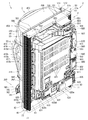
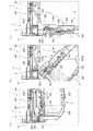
本発明の一実施形態であるパチンコ機1について、図面を参照して詳細に説明する。まず、図1乃至図12を参照して本実施形態のパチンコ機1の全体構成について説明する。図1は本発明の一実施形態であるパチンコ機の正面図である。図2はパチンコ機の右側面図であり、図3はパチンコ機の左側面図であり、図4はパチンコ機の背面図である。図5はパチンコ機を右前から見た斜視図であり、図6はパチンコ機を左前から見た斜視図であり、図7はパチンコ機を後ろから見た斜視図である。図8は演出操作ユニットの押圧操作部が上昇位置の時のパチンコ機の正面図であり、図9は演出操作ユニットの押圧操作部が上昇位置の時のパチンコ機を右前から見た斜視図である。また、図10A、図10Bは、本体枠から扉枠を開放させると共に、外枠から本体枠を開放させた状態で前から見たパチンコ機の斜視図である。図11はパチンコ機を扉枠、遊技盤、本体枠、及び外枠に分解して前から見た分解斜視図であり、図12はパチンコ機を扉枠、遊技盤、本体枠、及び外枠に分解して後ろから見た分解斜視図である。
[1. Overall structure of pachinko machine]
The pachinko machine 1 according to the embodiment of the present invention will be described in detail with reference to the drawings. First, the overall configuration of the pachinko machine 1 of the present embodiment will be described with reference to FIGS. 1 to 12. FIG. 1 is a front view of a pachinko machine according to an embodiment of the present invention. FIG. 2 is a right side view of the pachinko machine, FIG. 3 is a left side view of the pachinko machine, and FIG. 4 is a rear view of the pachinko machine. FIG. 5 is a perspective view of the pachinko machine viewed from the front right, FIG. 6 is a perspective view of the pachinko machine viewed from the front left, and FIG. 7 is a perspective view of the pachinko machine viewed from the back. FIG. 8 is a front view of the pachinko machine when the pressing operation unit of the effect operating unit is in the raised position, and FIG. 9 is a perspective view of the pachinko machine when the pressing operation unit of the effect operating unit is in the raised position. is there. Further, FIGS. 10A and 10B are perspective views of the pachinko machine viewed from the front with the door frame opened from the main body frame and the main body frame opened from the outer frame. FIG. 11 is an exploded perspective view of the pachinko machine disassembled into a door frame, a game board, a main body frame, and an outer frame, and FIG. 12 is an exploded perspective view of the pachinko machine as a door frame, a game board, a main body frame, and an outer frame. It is an exploded perspective view seen from the back by disassembling into.
本実施形態のパチンコ機1は、遊技ホールの島設備(図示しない)に設置される枠状の外枠2と、外枠2の前面を開閉可能に閉鎖する扉枠3と、扉枠3を開閉可能に支持していると共に外枠2に開閉可能に取付けられている本体枠4と、本体枠4に前側から着脱可能に取付けられると共に扉枠3を通して遊技者側から視認可能とされ遊技者によって遊技球B(図90を参照)が打込まれる遊技領域5aを有した遊技盤5と、を備えている。
The pachinko machine 1 of the present embodiment includes a frame-shaped outer frame 2 installed in an island facility (not shown) of a game hall, a door frame 3 for opening and closing the front surface of the outer frame 2, and a door frame 3. The main body frame 4 which is supported so as to be openable and closable and is attached to the outer frame 2 so as to be openable and closable, and the main body frame 4 which is detachably attached from the front side and is visible from the player side through the door frame 3. It includes a game board 5 having a game area 5a into which a game ball B (see FIG. 90) is hit.
外枠2は、正面視の形状が上下に延びた四角形の枠に形成されている。外枠2は、左右に離間しており上下に延びている外枠左組立体10及び外枠右組立体20と、外枠左組立体10及び外枠右組立体20の上端同士を連結している外枠上部材30と、外枠左組立体10及び外枠右組立体20の下端同士を連結している外枠下組立体40と、外枠上部材30の上面左端に取付けられている外枠上ヒンジ組立体50と、外枠左組立体10の右側面下部と外枠下組立体40の上面左端に取付けられている外枠下ヒンジ部材60と、を備えている。
The outer frame 2 is formed in a quadrangular frame whose front view shape extends vertically. The outer frame 2 connects the outer frame left assembly 10 and the outer frame right assembly 20 which are separated from each other to the left and right and extend vertically, and the upper ends of the outer frame left assembly 10 and the outer frame right assembly 20. The outer frame upper member 30 is attached to the outer frame lower assembly 40 connecting the lower ends of the outer frame left assembly 10 and the outer frame right assembly 20, and the upper left end of the outer frame upper member 30. The outer frame upper hinge assembly 50 and the outer frame lower hinge member 60 attached to the lower right surface of the outer frame left assembly 10 and the upper left end of the outer frame lower assembly 40 are provided.
外枠2は、パチンコ機1が設置される遊技ホールの島設備に取付けられ、外枠上ヒンジ組立体50と外枠下ヒンジ部材60とによって、本体枠4の本体枠上ヒンジ部材510と本体枠下ヒンジ組立体520とを同軸上で回転可能に支持して、本体枠4を正面視左側を中心にして前方へ開閉可能に取付けるためのものである。
The outer frame 2 is attached to the island equipment of the game hall where the pachinko machine 1 is installed, and the outer frame upper hinge assembly 50 and the outer frame lower hinge member 60 make up the main body frame upper hinge member 510 and the main body of the main body frame 4. The hinge assembly 520 under the frame is rotatably supported on the same axis, and the main body frame 4 is attached so as to be openable and closable forward centering on the left side in the front view.
また、扉枠3は、本体枠4を閉じた時に、外枠下組立体40が、本体枠4における基板ユニット620のスピーカユニット620aと協働して、本体枠スピーカ622のエンクロージャ624の一部を形成し、本体枠スピーカ622の後方へ出力されたサウンドを、位相反転させて前方へ放射することで、より重低音のサウンドを遊技者に聴かせることができるものである。
Further, in the door frame 3, when the main body frame 4 is closed, the outer frame lower assembly 40 cooperates with the speaker unit 620a of the board unit 620 in the main body frame 4 to form a part of the enclosure 624 of the main body frame speaker 622. Is formed, and the sound output to the rear of the main body frame speaker 622 is phase-inverted and radiated forward, so that the player can hear a deeper bass sound.
扉枠3は、遊技球Bが打込まれる遊技盤5の遊技領域5aを前側から視認可能に閉鎖し、遊技領域5a内に打込むための遊技球Bを貯留すると共に、貯留している遊技球Bを遊技領域5a内へ打込むために遊技者が操作するハンドル182を備えているものである。また、扉枠3は、パチンコ機1の前面全体を装飾するものである。
The door frame 3 visibly closes the game area 5a of the game board 5 into which the game ball B is driven, stores the game ball B for driving into the game area 5a, and stores the stored game. It is provided with a handle 182 operated by a player to drive the ball B into the game area 5a. Further, the door frame 3 decorates the entire front surface of the pachinko machine 1.
また、扉枠3は、ハンドル182とは別に遊技者が操作可能な演出操作部301を備えており、遊技者参加型演出が実行された際に、遊技者が演出操作部301を操作することで遊技者が演出に参加できるようになり、遊技球Bによる遊技に加えて、演出操作部301の操作によっても遊技者を楽しませることができるようにしている。
Further, the door frame 3 is provided with an effect operation unit 301 that can be operated by the player separately from the handle 182, and the player operates the effect operation unit 301 when the player participation type effect is executed. The player can participate in the production, and the player can be entertained by operating the production operation unit 301 in addition to the game by the game ball B.
本体枠4は、後部が外枠2の枠内に挿入可能とされると共に遊技盤5の外周を支持可能とされた枠状の本体枠ベースユニット500と、本体枠4を外枠2に対して開閉可能に取付けると共に扉枠3を開閉可能に取付けるための本体枠上ヒンジ部材510及び本体枠下ヒンジ組立体520と、本体枠ベースユニット500を補強している本体枠補強フレーム530と、遊技盤5の遊技領域5a内に遊技球Bを打込むための球発射装置540と、遊技ホールの島設備から供給される遊技球Bを受取る払出ベースユニット550と、払出ベースユニット550で受取った遊技球Bを遊技者側へ払出すための払出ユニット560と、電源基板630や払出制御基板633を有している基板ユニット620と、本体枠ベース501に取付けられた遊技盤5の後側を覆う裏カバー640と、外枠2と本体枠4、及び扉枠3と本体枠4の間を施錠する施錠ユニット650と、を備えている。
The main body frame 4 has a frame-shaped main body frame base unit 500 whose rear portion can be inserted into the frame of the outer frame 2 and which can support the outer circumference of the game board 5, and the main body frame 4 with respect to the outer frame 2. The hinge member 510 on the main body frame and the hinge assembly 520 on the lower side of the main body frame for attaching the door frame 3 so as to be openable and closable, and the main body frame reinforcement frame 530 for reinforcing the main body frame base unit 500. A ball launching device 540 for driving a game ball B into the game area 5a of the board 5, a payout base unit 550 for receiving the game ball B supplied from the island equipment of the game hall, and a game received by the payout base unit 550. Covers the payout unit 560 for paying out the ball B to the player side, the board unit 620 having the power supply board 630 and the payout control board 633, and the rear side of the game board 5 attached to the main body frame base 501. It includes a back cover 640, an outer frame 2 and a main body frame 4, and a locking unit 650 that locks between the door frame 3 and the main body frame 4.
本体枠4は、遊技球Bを打込むことで遊技が行われる遊技領域5aを有した遊技盤5を保持すると共に、遊技球Bを遊技者側へ払出したり、遊技に使用された遊技球Bをパチンコ機1の後方(遊技ホールの島設備側)へ排出したり、するためのものである。本体枠4は、前方が開放された箱状に形成されており、内部に前方から遊技盤5が着脱可能に収容される。また、本体枠4は、正面左辺側前端の上下において、遊技ホールの島設備に取付けられる枠状の外枠2に開閉可能に取付けられると共に、開放された前面側が閉鎖されるように扉枠3が開閉可能に取付けられる。
The main body frame 4 holds the game board 5 having the game area 5a in which the game is played by hitting the game ball B, and pays out the game ball B to the player side, or the game ball B used for the game. Is for discharging to the rear of the pachinko machine 1 (on the island equipment side of the game hall). The main body frame 4 is formed in a box shape with an open front, and the game board 5 is detachably housed inside from the front. Further, the main body frame 4 is attached to the frame-shaped outer frame 2 attached to the island equipment of the game hall above and below the front end on the left side of the front side so as to be openable and closable, and the door frame 3 is closed so that the opened front side is closed. Can be installed so that it can be opened and closed.
遊技盤5は、遊技者の操作によって遊技球Bが行われる遊技領域5aと、遊技領域5aの外周を区画し外形が正面視略四角形状とされた前構成部材1000と、前構成部材1000の後側に取付けられており遊技領域5aの後端を区画する板状の遊技パネル1100と、遊技パネル1100の後側下部に取付けられている基板ホルダ1200と、基板ホルダ1200の後面に取付けられており主制御基板1310を有している主制御ユニット1300と、主制御基板1310からの制御信号に基づいて遊技状況を表示する機能表示ユニット1400と、遊技パネル1100の後側に配置されている周辺制御ユニット1500と、正面視において遊技領域5aの中央に配置されており所定の演出画像を表示可能な演出表示装置1600と、遊技パネル1100の前面に取付けられる表ユニット2000と、遊技パネル1100の後面に取付けられる裏ユニット3000と、を備えている。裏ユニット3000には、遊技状態に応じて可動演出や発光演出を行うことが可能な裏演出ユニット3100を備えている。
The game board 5 includes a game area 5a in which a game ball B is played by a player's operation, a front component 1000 that divides the outer periphery of the game area 5a and has a substantially square outer shape in front view, and a front component 1000. A plate-shaped game panel 1100 attached to the rear side and partitioning the rear end of the game area 5a, a board holder 1200 attached to the lower part of the rear side of the game panel 1100, and a board holder 1200 attached to the rear surface of the board holder 1200. The main control unit 1300 having the main control board 1310, the function display unit 1400 that displays the game status based on the control signal from the main control board 1310, and the periphery arranged behind the game panel 1100. The control unit 1500, the effect display device 1600 arranged in the center of the game area 5a in front view and capable of displaying a predetermined effect image, the front unit 2000 attached to the front surface of the game panel 1100, and the rear surface of the game panel 1100. It is equipped with a back unit 3000 that can be attached to. The back unit 3000 is provided with a back effect unit 3100 capable of performing a movable effect or a light emitting effect according to the game state.
遊技盤5の遊技領域5a内には、遊技球Bと当接し所定のゲージ配列で植設されている複数の障害釘と、遊技球Bの受入れ又は通過により遊技者に対して所定の特典(例えば、所定数の遊技球Bの払出し)を付与する一般入賞口2001、第一始動口2002、ゲート部2003、第二始動口2004、及び大入賞口2005と、を備えている。障害釘は、遊技パネル1100の前面に植設されている。一般入賞口2001、第一始動口2002、ゲート部2003、第二始動口2004、及び大入賞口2005は、表ユニット2000に備えられている。
In the game area 5a of the game board 5, a plurality of obstacle nails that are in contact with the game ball B and are planted in a predetermined gauge arrangement, and a predetermined privilege for the player by accepting or passing the game ball B ( For example, it is provided with a general winning opening 2001, a first starting opening 2002, a gate portion 2003, a second starting opening 2004, and a large winning opening 2005 for granting a predetermined number of game balls B). Obstacle nails are planted in front of the game panel 1100. The general winning opening 2001, the first starting opening 2002, the gate portion 2003, the second starting opening 2004, and the large winning opening 2005 are provided in the table unit 2000.
遊技盤5の遊技領域5a内には、遊技者がハンドルユニット180のハンドル182を操作することで、遊技球Bを打込むことができる。これにより、遊技球Bが、遊技領域5a内の一般入賞口2001、第一始動口2002、ゲート部2003、第二始動口2004、及び大入賞口2005等に、受入れられたり通過したりするように、遊技者に対してハンドル182の打込操作を楽しませることができる。
The game ball B can be driven into the game area 5a of the game board 5 by the player operating the handle 182 of the handle unit 180. As a result, the game ball B is accepted or passed through the general winning opening 2001, the first starting opening 2002, the gate portion 2003, the second starting opening 2004, the large winning opening 2005, etc. in the game area 5a. In addition, the player can enjoy the driving operation of the handle 182.
また、遊技盤5は、遊技領域5a内に遊技球Bを打込むことで変化する遊技状態に応じて、演出表示装置1600に所定の演出画像を表示させたり、裏演出ユニット3100により可動演出や発光演出を行わせたりして、遊技者を楽しませることができる。
Further, the game board 5 displays a predetermined effect image on the effect display device 1600 according to the game state that changes by hitting the game ball B into the game area 5a, or a movable effect is performed by the back effect unit 3100. It is possible to entertain the player by performing a light emitting effect.
本実施形態のパチンコ機1は、後述する上皿201に遊技球を貯留した状態で遊技者がハンドル182を回転操作すると、球発射装置540によってハンドル182の回転角度に応じた強さで打ち出される遊技球が、発射レール544と外レール1001と内レール1002とによる発射通路部1012で形成された発射球通路を通って遊技盤5の遊技領域5a内へ案内される。そして、遊技領域5a内に打込まれた遊技球が、前記一般入賞口2001等に受入れられると、受入れられた入賞口に応じて、所定数の遊技球が後述する払出装置580によって球用開口から上皿201に払出される。
In the pachinko machine 1 of the present embodiment, when the player rotates the handle 182 while the game balls are stored in the upper plate 201, which will be described later, the pachinko machine 1 is launched by the ball launcher 540 with a strength corresponding to the rotation angle of the handle 182. The game ball is guided into the game area 5a of the game board 5 through the launch ball passage formed by the launch passage portion 1012 formed by the launch rail 544, the outer rail 1001 and the inner rail 1002. Then, when the game balls driven into the game area 5a are received by the general winning opening 2001 or the like, a predetermined number of game balls are opened for balls by the payout device 580 described later according to the received winning openings. Is paid out to the upper plate 201.
なお、遊技球の打込強さ等の関係で、遊技領域5aに到達不能な強さ、つまり弱い発射力で発射された遊技球が遊技領域5a内に到達しなかった場合は、図10A、図37Aに示したように、発射レール544の端部(終端部)と外レール1001の端部(始端部)との間に開設されたファール球落下口1013に落下し、それが後述する返却通路部1014を構成するファールカバーユニット150のファール球受部150cに受けられ、ファールカバーユニット150内を通って球用開口たる下皿球供給口211cから下皿202に排出される。
If the strength of the game ball that cannot reach the game area 5a due to the driving strength of the game ball, that is, the game ball launched with a weak firing force does not reach the game area 5a, FIG. 10A, FIG. As shown in FIG. 37A, the ball falls into the foul ball drop port 1013 provided between the end (end) of the launch rail 544 and the end (start) of the outer rail 1001, which is returned later. It is received by the foul ball receiving portion 150c of the foul cover unit 150 constituting the passage portion 1014, passes through the foul cover unit 150, and is discharged to the lower plate 202 from the lower plate ball supply port 211c which is an opening for the ball.
[2.外枠の全体構成]
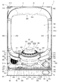
パチンコ機1の外枠2について、図13乃至図18を参照して説明する。図13はパチンコ機における外枠の正面図であり、図14は外枠の背面図であり、図15は外枠の右側面図である。また、図16は外枠を前から見た斜視図であり、図17は外枠を後ろから見た斜視図である。図18は、外枠を主な部材毎に分解して前から見た分解斜視図である。外枠2は、遊技ホール等のパチンコ機1が設置される島設備(図示は省略)に取付けられるものである。外枠2は、正面視の形状が上下に延びた四角形の枠に形成されている。
[2. Overall composition of the outer frame]
The outer frame 2 of the pachinko machine 1 will be described with reference to FIGS. 13 to 18. FIG. 13 is a front view of the outer frame of the pachinko machine, FIG. 14 is a rear view of the outer frame, and FIG. 15 is a right side view of the outer frame. Further, FIG. 16 is a perspective view of the outer frame viewed from the front, and FIG. 17 is a perspective view of the outer frame viewed from the back. FIG. 18 is an exploded perspective view of the outer frame disassembled for each main member and viewed from the front. The outer frame 2 is attached to an island facility (not shown) in which a pachinko machine 1 is installed, such as a game hall. The outer frame 2 is formed in a quadrangular frame whose front view shape extends vertically.
外枠2は、図示するように、左右に離間しており上下に延びている外枠左組立体10及び外枠右組立体20と、外枠左組立体10及び外枠右組立体20の上端同士を連結している外枠上部材30と、外枠左組立体10及び外枠右組立体20の下端同士を連結している外枠下組立体40と、外枠上部材30の上面左端に取付けられている外枠上ヒンジ組立体50と、外枠左組立体10の右側面下部と外枠下組立体40の上面左端に取付けられている外枠下ヒンジ部材60と、を備えている。
As shown in the figure, the outer frame 2 includes an outer frame left assembly 10 and an outer frame right assembly 20 which are separated from each other to the left and right and extend vertically, and an outer frame left assembly 10 and an outer frame right assembly 20. The outer frame upper member 30 connecting the upper ends, the outer frame lower assembly 40 connecting the lower ends of the outer frame left assembly 10 and the outer frame right assembly 20, and the upper surface of the outer frame upper member 30. The outer frame upper hinge assembly 50 attached to the left end, and the outer frame lower hinge member 60 attached to the lower right side of the outer frame left assembly 10 and the upper left end of the outer frame lower assembly 40 are provided. ing.
外枠2は、本体枠4を閉じた時に、外枠下組立体40が、本体枠4における基板ユニット620のスピーカユニット620aと協働して、本体枠スピーカ622のエンクロージャ624の一部を形成していると共に、本体枠スピーカ622の後方へ出力されたサウンドを、位相反転させて前方へ放射することができるものである。
In the outer frame 2, when the main body frame 4 is closed, the outer frame lower assembly 40 cooperates with the speaker unit 620a of the board unit 620 in the main body frame 4 to form a part of the enclosure 624 of the main body frame speaker 622. At the same time, the sound output to the rear of the main body frame speaker 622 can be phase-inverted and radiated forward.
外枠2は、外枠上ヒンジ組立体50が、本体枠4の本体枠上ヒンジ部材510を着脱可能に支持することができる。外枠2は、外枠上ヒンジ組立体50と外枠下ヒンジ部材60とによって、本体枠4の本体枠上ヒンジ部材510と本体枠下ヒンジ組立体520とを同軸上で回転可能に支持することができ、本体枠4を正面視左側を中心にして前方へ開閉可能に取付けることができる。
In the outer frame 2, the outer frame upper hinge assembly 50 can detachably support the main body frame upper hinge member 510 of the main body frame 4. The outer frame 2 coaxially and rotatably supports the main body frame upper hinge member 510 and the main body frame lower hinge assembly 520 of the main body frame 4 by the outer frame upper hinge assembly 50 and the outer frame lower hinge member 60. The main body frame 4 can be attached so as to be openable and closable forward centering on the left side in the front view.
[2−1.外枠左組立体及び外枠右組立体]
外枠2の外枠左組立体10及び外枠右組立体20について、主に図19を参照して詳細に説明する。図19は、外枠の外枠左組立体及び外枠右組立体を夫々分解して前から見た分解斜視図である。外枠2の外枠左組立体10及び外枠右組立体20は、夫々が上下に延びており、互いに左右に離間して配置されている。外枠左組立体10及び外枠右組立体20は、本体枠4の本体枠上ヒンジ部材510及び本体枠下ヒンジ組立体520を同軸上で回転可能に支持して、外枠2に対して本体枠4を開閉可能に取付けるためのものである。
[2-1. Outer frame left assembly and outer frame right assembly]
The outer frame left assembly 10 and the outer frame right assembly 20 of the outer frame 2 will be described in detail mainly with reference to FIG. FIG. 19 is an exploded perspective view of the outer frame left assembly and the outer frame right assembly of the outer frame, which are disassembled and viewed from the front. The outer frame left assembly 10 and the outer frame right assembly 20 of the outer frame 2 extend vertically, respectively, and are arranged so as to be separated from each other on the left and right. The outer frame left assembly 10 and the outer frame right assembly 20 coaxially and rotatably support the main body frame upper hinge member 510 and the main body frame lower hinge assembly 520 of the main body frame 4 with respect to the outer frame 2. This is for attaching the main body frame 4 so that it can be opened and closed.
まず、外枠左組立体10は、前後方向が一定の幅(奥行)で上下に延びている外枠左部材11と、外枠左部材11の右側面上端に取付けられている左上連結部材12と、外枠左部材11の右側面下端に取付けられている左下連結部材13と、を備えている。
First, in the outer frame left assembly 10, the outer frame left member 11 extending vertically with a constant width (depth) in the front-rear direction and the upper left connecting member 12 attached to the upper end of the right side surface of the outer frame left member 11 And a lower left connecting member 13 attached to the lower end of the right side surface of the outer frame left member 11.
外枠左部材11は、一定の断面形状で上下に延びており、アルミ合金の押出型材によって形成されている。外枠左部材11は、左側面における前後方向を三等分したうちの後側の部位において平坦状に右方へ窪んでいる凹部11aと、右側面における凹部11aとは反対側の部位から右方へ膨出している膨出部11bと、膨出部11bを上下に貫通している空洞部11cと、を備えている。外枠左部材11は、凹部11aや膨出部11bによって、強度・剛性が高められていると共に、空洞部11cによって、重量が軽減されている。
The outer frame left member 11 extends vertically with a constant cross-sectional shape, and is formed of an extruded aluminum alloy mold material. The outer frame left member 11 has a recess 11a that is flatly recessed to the right in the rear portion of the left side surface divided into three equal parts in the front-rear direction, and a portion on the right side surface that is opposite to the recess 11a to the right. It includes a bulging portion 11b that bulges toward the direction and a hollow portion 11c that vertically penetrates the bulging portion 11b. The strength and rigidity of the outer frame left member 11 are increased by the recess 11a and the bulging portion 11b, and the weight is reduced by the cavity 11c.
また、外枠左部材11は、左右両側面において、上下に延びた複数の溝が形成されている。左側面の複数の溝は、V字状に形成されており、右側面の複数の溝は、半円形状に形成されている。外枠左部材11は、後述する外枠右組立体20の外枠右部材21と左右対称形状に形成されている。
Further, the outer frame left member 11 is formed with a plurality of grooves extending vertically on both the left and right side surfaces. The plurality of grooves on the left side surface are formed in a V shape, and the plurality of grooves on the right side surface are formed in a semicircular shape. The outer frame left member 11 is formed in a symmetrical shape with the outer frame right member 21 of the outer frame right assembly 20, which will be described later.
左上連結部材12は、外枠左部材11の上端と外枠上部材30の左端とを連結するためのものである。左上連結部材12は、水平に延びた平板状の水平固定部12aと、水平固定部12aの左辺における前後方向の中間から上方へ延出している平板状の上横固定部12bと、水平固定部12aの左辺における上横固定部12bの前後両側から下方へ延出している平板状の一対の下横固定部12cと、を備えている。左上連結部材12は、平板状の金属板を屈曲させて形成されている。
The upper left connecting member 12 is for connecting the upper end of the outer frame left member 11 and the left end of the outer frame upper member 30. The upper left connecting member 12 includes a horizontally extending flat plate-shaped horizontal fixing portion 12a, a flat plate-shaped upper and horizontal fixing portion 12b extending upward from the middle in the front-rear direction on the left side of the horizontal fixing portion 12a, and a horizontal fixing portion. A pair of flat plate-shaped lower horizontal fixing portions 12c extending downward from both front and rear sides of the upper horizontal fixing portion 12b on the left side of 12a are provided. The upper left connecting member 12 is formed by bending a flat metal plate.
左上連結部材12は、後側の下横固定部12cを外枠左部材11の空洞部11c内に挿入させると共に、水平固定部12aを外枠左部材11の上端に当接させ、更に、前側及び後側の下横固定部12cを外枠左部材11の右側面に当接させた状態で、外枠左部材11の左側面の外側から下横固定部12cにビスを捩じ込むことで、外枠左部材11に取付けられる。また、左上連結部材12は、水平固定部12aを外枠上部材30の左端側の下面に当接させると共に、上横固定部12bを外枠上部材30の左側面の切欠部30a内に挿入させた状態で、水平固定部12a及び上横固定部12bを通して外枠上部材30にビスを捩じ込むことで、外枠上部材30に取付けられる。
In the upper left connecting member 12, the lower horizontal fixing portion 12c on the rear side is inserted into the cavity portion 11c of the outer frame left member 11, the horizontal fixing portion 12a is brought into contact with the upper end of the outer frame left member 11, and further, the front side. In a state where the lower horizontal fixing portion 12c on the rear side is in contact with the right side surface of the outer frame left member 11, a screw is screwed into the lower horizontal fixing portion 12c from the outside of the left side surface of the outer frame left member 11. , Attached to the outer frame left member 11. Further, in the upper left connecting member 12, the horizontal fixing portion 12a is brought into contact with the lower surface on the left end side of the outer frame upper member 30, and the upper horizontal fixing portion 12b is inserted into the notch 30a on the left side surface of the outer frame upper member 30. In this state, it is attached to the outer frame upper member 30 by screwing a screw into the outer frame upper member 30 through the horizontal fixing portion 12a and the upper horizontal fixing portion 12b.
左下連結部材13は、外枠左部材11の下端と外枠下組立体40(外枠下部材41)の左端とを連結するためのものである。左下連結部材13は、水平に延びた平板状の水平固定部13aと、水平固定部13aの左辺から上方へ延出していると共に水平固定部13aよりも後方へ延出している平板状の上横固定部13bと、上横固定部13bの下辺における水平固定部よりも後側の部位から下方へ延出している平板状の下横固定部13cと、上横固定部13bの後辺から右方へ短く延出している平板状の当接部13dと、を備えている。左下連結部材13は、平板状の金属板を屈曲させて形成されている。
The lower left connecting member 13 is for connecting the lower end of the outer frame left member 11 and the left end of the outer frame lower assembly 40 (outer frame lower member 41). The lower left connecting member 13 has a horizontally extending flat plate-shaped horizontal fixing portion 13a and a flat plate-shaped upper side extending upward from the left side of the horizontal fixing portion 13a and extending rearward from the horizontal fixing portion 13a. The fixed portion 13b, the flat plate-shaped lower lateral fixing portion 13c extending downward from the portion posterior to the horizontal fixing portion on the lower side of the upper lateral fixing portion 13b, and the upper lateral fixing portion 13b to the right from the rear side. It is provided with a flat plate-shaped contact portion 13d extending shortly to. The lower left connecting member 13 is formed by bending a flat metal plate.
左下連結部材13は、当接部13dの後面を外枠左部材11の膨出部11bの前面に当接させると共に、上横固定部13bの左側面を外枠左部材11の右側面に当接させ、水平固定部13aの下面を外枠左部材11の下端と一致させた状態で、外枠左部材11の左側面の外側から上横固定部13bにビスを捩じ込むことで、外枠左部材11に取付けられる。また、左下連結部材13は、水平固定部13aを外枠下部材41の左端側の上面に当接させると共に、下横固定部13cを外枠下部材41の左側面の切欠部41aに挿入させた状態で、水平固定部13a及び下横固定部13cを通して外枠下部材にビスを捩じ込むことで、外枠下部材41に取付けられる。
In the lower left connecting member 13, the rear surface of the contact portion 13d is brought into contact with the front surface of the bulging portion 11b of the outer frame left member 11, and the left surface of the upper horizontal fixing portion 13b is in contact with the right surface of the outer frame left member 11. With the lower surface of the horizontal fixing portion 13a in contact with the lower end of the outer frame left member 11, a screw is screwed into the upper horizontal fixing portion 13b from the outside of the left side surface of the outer frame left member 11 to remove the outer frame. It is attached to the frame left member 11. Further, in the lower left connecting member 13, the horizontal fixing portion 13a is brought into contact with the upper surface on the left end side of the outer frame lower member 41, and the lower horizontal fixing portion 13c is inserted into the cutout portion 41a on the left side surface of the outer frame lower member 41. In this state, it is attached to the outer frame lower member 41 by screwing a screw into the outer frame lower member through the horizontal fixing portion 13a and the lower horizontal fixing portion 13c.
次に、外枠右組立体20は、前後方向が一定の幅(奥行)で上下に延びている外枠右部材21と、外枠右部材21の左側面上端に取付けられている右上連結部材22と、外枠右部材21の左側面下端に取付けられている右下連結部材23と、外枠右部材21の左側面上部に取付けられている上鉤掛部材24と、外枠右部材21の左側面下部に取付けられている下鉤掛部材25と、を備えている。
Next, the outer frame right assembly 20 has an outer frame right member 21 extending vertically with a constant width (depth) in the front-rear direction and an upper right connecting member attached to the upper end of the left side surface of the outer frame right member 21. 22, the lower right connecting member 23 attached to the lower end of the left side surface of the outer frame right member 21, the upper hook member 24 attached to the upper part of the left side surface of the outer frame right member 21, and the outer frame right member 21. It includes a lower hook member 25 attached to the lower part of the left side surface.
外枠右部材21は、一定の断面形状で上下に延びており、アルミ合金の押出型材によって形成されている。外枠右部材21は、右側面における前後方向を三等分したうちの後側の部位において平坦状に左方へ窪んでいる凹部21aと、左側面における凹部21aとは反対側の部位から左方へ膨出している膨出部21bと、膨出部21bを上下に貫通している空洞部21cと、を備えている。外枠右部材21は、凹部21aや膨出部21bによって、強度・剛性が高められていると共に、空洞部21cによって、重量が軽減されている。
The outer frame right member 21 extends vertically with a constant cross-sectional shape, and is formed of an extruded aluminum alloy mold material. The outer frame right member 21 has a recess 21a that is flatly recessed to the left in the rear portion of the right side surface divided into three equal parts in the front-rear direction, and a recess 21a on the left side surface that is opposite to the recess 21a to the left. It includes a bulging portion 21b that bulges toward the direction and a hollow portion 21c that vertically penetrates the bulging portion 21b. The strength and rigidity of the outer frame right member 21 are increased by the concave portion 21a and the bulging portion 21b, and the weight is reduced by the hollow portion 21c.
また、外枠右部材21は、左右両側面において、上下に延びた複数の溝が形成されている。右側面の複数の溝は、V字状に形成されており、左側面の複数の溝は、半円形状に形成されている。外枠右部材21は、外枠左組立体10の外枠左部材11と左右対称形状に形成されている。
Further, the outer frame right member 21 is formed with a plurality of grooves extending vertically on both the left and right side surfaces. The plurality of grooves on the right side surface are formed in a V shape, and the plurality of grooves on the left side surface are formed in a semicircular shape. The outer frame right member 21 is formed symmetrically with the outer frame left member 11 of the outer frame left assembly 10.
右上連結部材22は、外枠右部材21の上端と外枠上部材30の右端とを連結するためのものである。右上連結部材22は、水平に延びた平板状の水平固定部22aと、水平固定部22aの右辺における前後方向の中間から上方へ延出している平板状の上横固定部22bと、水平固定部22aの右辺における上横固定部22bの前後両側から下方へ延出している平板状の一対の下横固定部22cと、を備えている。右上連結部材22は、平板状の金属板を屈曲させて形成されている。
The upper right connecting member 22 is for connecting the upper end of the outer frame right member 21 and the right end of the outer frame upper member 30. The upper right connecting member 22 includes a horizontally extending flat plate-shaped horizontal fixing portion 22a, a flat plate-shaped upper and horizontal fixing portion 22b extending upward from the middle in the front-rear direction on the right side of the horizontal fixing portion 22a, and a horizontal fixing portion. A pair of flat plate-shaped lower horizontal fixing portions 22c extending downward from both front and rear sides of the upper horizontal fixing portion 22b on the right side of 22a are provided. The upper right connecting member 22 is formed by bending a flat metal plate.
右上連結部材22は、後側の下横固定部22cを外枠右部材21の空洞部21c内に挿入させると共に、水平固定部22aを外枠右部材21の上端に当接させ、更に、前側及び後側の下横固定部22cを外枠右部材21の左側面に当接させた状態で、外枠右部材21の右側面の外側から下横固定部22cにビスを捩じ込むことで、外枠右部材21に取付けられる。また、右上連結部材22は、水平固定部22aを外枠上部材30の右端側の下面に当接させると共に、上横固定部22bを外枠上部材30の右側面の切欠部30a内に挿入させた状態で、水平固定部22a及び上横固定部22bを通して外枠上部材30にビスを捩じ込むことで、外枠上部材30に取付けられる。
In the upper right connecting member 22, the lower horizontal fixing portion 22c on the rear side is inserted into the hollow portion 21c of the outer frame right member 21, the horizontal fixing portion 22a is brought into contact with the upper end of the outer frame right member 21, and further, the front side. In a state where the lower horizontal fixing portion 22c on the rear side is in contact with the left side surface of the outer frame right member 21, a screw is screwed into the lower horizontal fixing portion 22c from the outside of the right side surface of the outer frame right member 21. , Attached to the outer frame right member 21. Further, in the upper right connecting member 22, the horizontal fixing portion 22a is brought into contact with the lower surface on the right end side of the outer frame upper member 30, and the upper horizontal fixing portion 22b is inserted into the notch 30a on the right side surface of the outer frame upper member 30. In this state, it is attached to the outer frame upper member 30 by screwing a screw into the outer frame upper member 30 through the horizontal fixing portion 22a and the upper horizontal fixing portion 22b.
右下連結部材23は、外枠右部材21の下端と外枠下組立体40(外枠下部材41)の右端とを連結するためのものである。右下連結部材23は、水平に延びた平板状の水平固定部23aと、水平固定部23aの右辺から上方へ延出していると共に水平固定部23aよりも後方へ延出している平板状の上横固定部23bと、上横固定部23bの下辺における水平固定部よりも後側の部位から下方へ延出している平板状の下横固定部23cと、上横固定部23bの後辺から左方へ短く延出している平板状の当接部23dと、を備えている。右下連結部材23は、平板状の金属板を屈曲させて形成されている。
The lower right connecting member 23 is for connecting the lower end of the outer frame right member 21 and the right end of the outer frame lower assembly 40 (outer frame lower member 41). The lower right connecting member 23 has a horizontally extending flat plate-shaped horizontal fixing portion 23a and a flat plate-shaped upper portion extending upward from the right side of the horizontal fixing portion 23a and extending rearward from the horizontal fixing portion 23a. The horizontal fixing portion 23b, the flat plate-shaped lower horizontal fixing portion 23c extending downward from the portion posterior to the horizontal fixing portion on the lower side of the upper horizontal fixing portion 23b, and the upper horizontal fixing portion 23b from the rear side to the left. It is provided with a flat plate-shaped contact portion 23d that extends shortly toward the direction. The lower right connecting member 23 is formed by bending a flat metal plate.
右下連結部材23は、当接部23dの後面を外枠右部材21の膨出部21bの前面に当接させると共に、上横固定部23bの右側面を外枠右部材21の左側面に当接させ、水平固定部23aの下面を外枠右部材21の下端と一致させた状態で、外枠右部材21の右側面の外側から上横固定部23bにビスを捩じ込むことで、外枠右部材21に取付けられる。また、右下連結部材23は、水平固定部23aを外枠下部材41の右端側の上面に当接させると共に、下横固定部23cを外枠下部材41の右側面の切欠部41aに挿入させた状態で、水平固定部23a及び下横固定部23cを通して外枠下部材にビスを捩じ込むことで、外枠下部材41に取付けられる。
In the lower right connecting member 23, the rear surface of the contact portion 23d is brought into contact with the front surface of the bulging portion 21b of the outer frame right member 21, and the right surface of the upper horizontal fixing portion 23b is brought into contact with the left surface of the outer frame right member 21. By abutting and aligning the lower surface of the horizontal fixing portion 23a with the lower end of the outer frame right member 21, a screw is screwed into the upper horizontal fixing portion 23b from the outside of the right side surface of the outer frame right member 21. It is attached to the outer frame right member 21. Further, in the lower right connecting member 23, the horizontal fixing portion 23a is brought into contact with the upper surface on the right end side of the outer frame lower member 41, and the lower horizontal fixing portion 23c is inserted into the cutout portion 41a on the right side surface of the outer frame lower member 41. In this state, it is attached to the outer frame lower member 41 by screwing a screw into the outer frame lower member through the horizontal fixing portion 23a and the lower horizontal fixing portion 23c.
上鉤掛部材24及び下鉤掛部材25は、後述する本体枠4における施錠ユニット650の外枠用鉤653が掛止されるものである。上鉤掛部材24は、前後方向に一定の幅で上下に延びており外枠右部材21の左側面に取付けられる平板状の取付部24aと、取付部24aの前辺から左方へ延出しており上側の外枠用鉤653が掛止される平板状の掛止片部24bと、を備えている。
The upper hook member 24 and the lower hook member 25 are for hooking the outer frame hook 653 of the locking unit 650 in the main body frame 4, which will be described later. The upper hook member 24 extends vertically with a constant width in the front-rear direction, and extends to the left from the front side of the flat plate-shaped mounting portion 24a to be mounted on the left side surface of the outer frame right member 21 and the mounting portion 24a. It is provided with a flat plate-shaped hooking piece portion 24b on which the hook 653 for the outer frame on the upper side of the cage is hooked.
下鉤掛部材25は、前後方向に一定の幅で上下に延びており外枠右部材21の左側面に取付けられる平板状の取付部25aと、取付部25aの前辺から左方へ延出しており下側の外枠用鉤653が掛止される平板状の掛止片部25bと、掛止片部25bを前後に貫通しており下側の外枠用鉤653が挿通可能な挿通口25cと、を備えている。
The lower hook member 25 extends vertically with a constant width in the front-rear direction, and has a flat plate-shaped mounting portion 25a attached to the left side surface of the outer frame right member 21 and extending from the front side of the mounting portion 25a to the left. Insertion that allows the lower outer frame hook 653 to be inserted through the flat plate-shaped hook piece portion 25b on which the lower outer frame hook 653 is hooked and the hook piece portion 25b. It has a mouth 25c and.
[2−2.外枠上部材]
外枠2の外枠上部材30について、主に図18を参照して詳細に説明する。外枠上部材30は、左右に離間している外枠左組立体10及び外枠右組立体20の上端同士を連結するためのものである。外枠上部材30は、前後方向の幅が、外枠左部材11及び外枠右部材21の前後方向と略同じ幅で、上下方向の厚さが一定で、左右方向に延びており、木材によって形成されている。外枠上部材30は、左右方向の長さが、後述する外枠下組立体40の外枠下部材41の左右方向の長さと同じに形成されている。
[2-2. Outer frame upper member]
The outer frame upper member 30 of the outer frame 2 will be described in detail mainly with reference to FIG. The outer frame upper member 30 is for connecting the upper ends of the outer frame left assembly 10 and the outer frame right assembly 20 that are separated from each other to the left and right. The width of the outer frame upper member 30 in the front-rear direction is substantially the same as the width in the front-rear direction of the outer frame left member 11 and the outer frame right member 21, the thickness in the vertical direction is constant, and the width extends in the left-right direction. Is formed by. The outer frame upper member 30 is formed so that the length in the left-right direction is the same as the length in the left-right direction of the outer frame lower member 41 of the outer frame lower assembly 40 described later.
外枠上部材30は、左右両側面における前後方向の中央において、上下に貫通した状態で左右方向中央側へ夫々窪んでいる切欠部30aを備えている。これら左右両端の切欠部30aには、左上連結部材12の上横固定部12b及び右上連結部材22の上横固定部22bが夫々挿入された状態で取付けられる。
The outer frame upper member 30 is provided with a notch 30a that is recessed toward the center side in the left-right direction in a state of penetrating vertically at the center in the front-rear direction on both left and right side surfaces. The upper lateral fixing portion 12b of the upper left connecting member 12 and the upper lateral fixing portion 22b of the upper right connecting member 22 are attached to the cutout portions 30a at both left and right ends in a state of being inserted respectively.
また、外枠上部材30は、左側端部において、上面と前面が一般面よりも窪んだ取付段部30bを備えている。この取付段部30bには、後述する外枠上ヒンジ組立体50が取付けられる。
Further, the outer frame upper member 30 includes a mounting step portion 30b whose upper surface and front surface are recessed from the general surface at the left end portion. A hinge assembly 50 on an outer frame, which will be described later, is attached to the attachment step portion 30b.
[2−3.外枠下組立体]
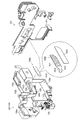
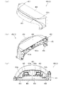
外枠2の外枠下組立体40について、主に図20を参照して詳細に説明する。図20は、外枠の外枠下組立体を分解して前から見た分解斜視図である。外枠下組立体40は、左右に離間している外枠左組立体10及び外枠右組立体20の下端同士を連結すると共に、パチンコ機1において扉枠3よりも下側を閉鎖して装飾するためのものである。
[2-3. Assembly under the outer frame]
The outer frame lower assembly 40 of the outer frame 2 will be described in detail mainly with reference to FIG. FIG. 20 is an exploded perspective view of the lower assembly of the outer frame as viewed from the front by disassembling the assembly. The outer frame lower assembly 40 connects the lower ends of the outer frame left assembly 10 and the outer frame right assembly 20 that are separated to the left and right, and closes the lower side of the pachinko machine 1 below the door frame 3. It is for decoration.
外枠下組立体40は、左右に離間している外枠左組立体10及び外枠右組立体20の下端同士を連結しており左右に延びている外枠下部材41と、外枠下部材41の前方に配置されており外枠下部材41に沿って左右に延びていると共に後方が開放されている箱状の幕板前部材42と、幕板前部材42の後側に取付けられていると共に外枠下部材41の上面に取付けられており前方が開放されている左右に延びた箱状の幕板後部材43と、幕板後部材43の上面における左端に形成されている球噛防止機構44と、を備えている。
The outer frame lower assembly 40 includes an outer frame lower member 41 that connects the lower ends of the outer frame left assembly 10 and the outer frame right assembly 20 that are separated to the left and right and extends to the left and right, and the outer frame lower assembly 40. A box-shaped front curtain plate member 42 that is arranged in front of the member 41 and extends to the left and right along the lower member 41 of the outer frame and is open at the rear, and is attached to the rear side of the front curtain plate member 42. A box-shaped rear curtain plate member 43 that is attached to the upper surface of the outer frame lower member 41 and has an open front, and a ball bite prevention formed at the left end on the upper surface of the rear curtain plate member 43. It includes a mechanism 44 and.
外枠下部材41は、前後方向の幅が、外枠左部材11及び外枠右部材21の前後方向と略同じ幅で、上下方向の厚さが一定で、左右方向に延びており、木材によって形成されている。外枠下部材41は、左右方向の長さが、外枠上部材30の左右方向の長さと同じに形成されている。
The width of the outer frame lower member 41 in the front-rear direction is substantially the same as the width in the front-rear direction of the outer frame left member 11 and the outer frame right member 21, the thickness in the vertical direction is constant, and the width extends in the left-right direction. Is formed by. The outer frame lower member 41 is formed so that the length in the left-right direction is the same as the length in the left-right direction of the outer frame upper member 30.
外枠下部材41は、左右両側面における前後方向の中央において、上下に貫通した状態で左右方向中央側へ夫々窪んでいる切欠部41aを備えている。これら左右両端の切欠部41aには、左下連結部材13の下横固定部13c及び右下連結部材23の下横固定部23cが夫々挿入された状態で取付けられる。これにより、外枠左部材11及び外枠右部材21の下端同士を連結することができる。
The outer frame lower member 41 includes a notch 41a that is recessed toward the center side in the left-right direction in a state of penetrating vertically at the center in the front-rear direction on both the left and right side surfaces. The lower lateral fixing portion 13c of the lower left connecting member 13 and the lower lateral fixing portion 23c of the lower right connecting member 23 are attached to the cutout portions 41a at both left and right ends in a state of being inserted respectively. As a result, the lower ends of the outer frame left member 11 and the outer frame right member 21 can be connected to each other.
また、外枠下部材41は、上面から凹んでおり、幕板後部材43の下部が挿入される凹部41bを備えている。凹部41bは、左右に延びていると共に、前後方向中央の後ろ寄りの位置から前端側へ抜けている。この凹部41bにより、幕板前部材42及び幕板後部材43により形成される幕板内部空間40aの容積を可及的に広くしている。
Further, the outer frame lower member 41 is recessed from the upper surface, and includes a recess 41b into which the lower portion of the curtain plate rear member 43 is inserted. The recess 41b extends to the left and right, and is pulled out from a position closer to the rear in the center in the front-rear direction toward the front end side. The recess 41b makes the volume of the curtain plate internal space 40a formed by the curtain plate front member 42 and the curtain plate rear member 43 as large as possible.
幕板前部材42は、左右方向の長さが外枠下部材41と同じ長さに延びており、高さに対して前後方向の奥行が短い横長の直方体状の箱状に形成されており、後側の全面が開放されている。幕板前部材42は、開放されている後側を、幕板後部材43によって閉鎖することで、幕板後部材43と協働して本体枠スピーカ622のエンクロージャ624の一部となる幕板内部空間40aを形成する。幕板前部材42は、右端付近の前面において、前後に貫通していると共に左右に延びている長孔状の開口部42aを備えている。
The curtain plate front member 42 is formed in a horizontally long rectangular parallelepiped shape in which the length in the left-right direction extends to the same length as the outer frame lower member 41 and the depth in the front-rear direction is short with respect to the height. The entire rear side is open. The curtain plate front member 42 is closed on the open rear side by the curtain plate rear member 43, so that the curtain plate front member 42 becomes a part of the enclosure 624 of the main body frame speaker 622 in cooperation with the curtain plate rear member 43. The space 40a is formed. The curtain plate front member 42 includes an elongated hole-shaped opening 42a that penetrates the front and rear and extends to the left and right on the front surface near the right end.
幕板後部材43は、左右方向の長さが外枠下部材41よりも若干短く延びており、前方が開放された箱状に形成されている。幕板後部材43は、前面に幕板前部材42を取付けることで、幕板前部材42と協働して本体枠スピーカ622のエンクロージャ624の一部となる幕板内部空間40aを形成する。幕板後部材43は、上面における左右方向中央部において、左右に延びていると共に上方へ突出しており幕板内部空間40aと連通している筒状の接続筒部43aを有している。接続筒部43aは、上端が、幕板後部材43の一般的な上面と一致している前端側から後方へ向かうほど上方へ位置するように傾斜している。本実施形態では、接続筒部43aの上端は、45度の角度で傾斜している。
The curtain plate rear member 43 has a length in the left-right direction slightly shorter than that of the outer frame lower member 41, and is formed in a box shape with an open front. By attaching the curtain plate front member 42 to the front surface of the curtain plate rear member 43, the curtain plate front member 42 cooperates with the curtain plate front member 42 to form a curtain plate internal space 40a that becomes a part of the enclosure 624 of the main body frame speaker 622. The curtain plate rear member 43 has a tubular connecting cylinder portion 43a that extends left and right and projects upward at the central portion in the left-right direction on the upper surface and communicates with the curtain plate internal space 40a. The upper end of the connecting cylinder portion 43a is inclined so as to be positioned upward from the front end side, which coincides with the general upper surface of the curtain plate rear member 43, toward the rear. In the present embodiment, the upper end of the connecting cylinder portion 43a is inclined at an angle of 45 degrees.
この接続筒部43aは、左右方向の長さが、幕板後部材43全体の約1/3の長さに形成されていると共に、前後方向の奥行が、幕板後部材43全体の奥行よりも若干短く形成されている。接続筒部43a内には、前端側と後端側とを結ぶ複数のリブ43bが備えられている。この接続筒部43aの上端には、外枠2に対して本体枠4を閉じた時に、本体枠4における基板ユニット620のスピーカユニット620aにおけるスピーカカバー621の接続部621cが接続されて、スピーカユニット620aの内部空間と連通した状態となり、エンクロージャ624を形成する。
The length of the connecting cylinder portion 43a in the left-right direction is formed to be about 1/3 of the length of the entire curtain plate rear member 43, and the depth in the front-rear direction is greater than the depth of the entire curtain plate rear member 43. Is also formed slightly shorter. A plurality of ribs 43b connecting the front end side and the rear end side are provided in the connecting cylinder portion 43a. When the main body frame 4 is closed with respect to the outer frame 2, the connection portion 621c of the speaker cover 621 in the speaker unit 620a of the board unit 620 in the main body frame 4 is connected to the upper end of the connection cylinder portion 43a to connect the speaker unit. It communicates with the internal space of the 620a and forms the enclosure 624.
球噛防止機構44は、幕板後部材43の上面における左端において、外枠下ヒンジ部材60の部位に遊技球Bが滞留することで、外枠2と本体枠4との間に遊技球Bが挟まれるのを防止するためのものである。
In the ball biting prevention mechanism 44, the game ball B stays at the portion of the outer frame lower hinge member 60 at the left end on the upper surface of the curtain plate rear member 43, so that the game ball B is between the outer frame 2 and the main body frame 4. Is to prevent being pinched.
球噛防止機構44は、幕板後部材43の上面における左端に形成されており、後述する外枠下ヒンジ部材60が際されるように平坦に形成された載置部44aと、載置部44aの左端において上方へ向かって開口している第一排出口44bと、載置部44aにおける第一排出口44bよりも右方で上方へ向かって開口している第二排出口44cと、載置部44aの後辺及び右辺から上方へ延出している立壁部44dと、立壁部44dの上端から前方へ突出していると共に上面が後方へ向かうに従って上方に位置するように傾斜している上端突出部44eと、を備えている。
The ball biting prevention mechanism 44 is formed at the left end on the upper surface of the curtain plate rear member 43, and is a mounting portion 44a formed flat so that the hinge member 60 under the outer frame, which will be described later, is highlighted, and a mounting portion. The first discharge port 44b that opens upward at the left end of 44a and the second discharge port 44c that opens upward to the right of the first discharge port 44b in the mounting portion 44a are mounted. A vertical wall portion 44d extending upward from the rear side and the right side of the placement portion 44a, and an upper end protrusion protruding forward from the upper end of the vertical wall portion 44d and being inclined so that the upper surface is positioned upward as the upper surface is directed backward. A part 44e and a part 44e are provided.
第一排出口44bは、後述する外枠下ヒンジ部材60の排出孔60dと一致する位置に形成されている。第一排出口44b及び第二排出口44cは、遊技球Bが通過可能な大きさに形成されている。第一排出口44b及び第二排出口44cは、幕板内部空間40aとは連通しておらず、幕板後部材43の後面に開口している。従って、第一排出口44b及び第二排出口44cに進入した遊技球Bを、幕板後部材43の後方へ排出することができる。
The first discharge port 44b is formed at a position corresponding to the discharge hole 60d of the outer frame lower hinge member 60, which will be described later. The first discharge port 44b and the second discharge port 44c are formed in a size that allows the game ball B to pass through. The first discharge port 44b and the second discharge port 44c do not communicate with the curtain plate internal space 40a and are open to the rear surface of the curtain plate rear member 43. Therefore, the game ball B that has entered the first discharge port 44b and the second discharge port 44c can be discharged to the rear of the curtain plate rear member 43.
この球噛防止機構44は、球噛防止機構44は、外枠下ヒンジ部材60と後述する本体枠下ヒンジ組立体520との間の隙間を通して、ピアノ線等の不正な工具が挿入された場合、載置部44aの後端から立上っている立壁部44dにより、不正な工具の侵入を阻止することができる。仮に、不正な工具の先端が立壁部44dに当接することで、上方へ曲がったとしても、立壁部44dの上端に備えられている前方へ突出した上端突出部44eに当接し、これ以上の侵入を阻止することができる。従って、外枠下ヒンジ部材60の部位を介して、不正行為が行われるのを防止することができる。
The ball biting prevention mechanism 44 is a case where an illegal tool such as a piano wire is inserted through the gap between the outer frame lower hinge member 60 and the main body frame lower hinge assembly 520 described later. The standing wall portion 44d rising from the rear end of the mounting portion 44a can prevent an unauthorized tool from entering. Even if the tip of an illegal tool abuts on the standing wall portion 44d and bends upward, it abuts on the upper end protruding portion 44e provided at the upper end of the standing wall portion 44d and further invades. Can be blocked. Therefore, it is possible to prevent fraudulent acts from being performed through the portion of the hinge member 60 under the outer frame.
ところで、載置部44aの後端に立壁部44dを備えた場合、外枠2に対して本体枠4を開けた時に、何らかの理由により載置部44a上に落下した遊技球Bが、立壁部44dによって外枠2の後方への移動が阻止されるため、載置部44a上に遊技球Bが滞留し易くなる。そして、載置部44a上に遊技球Bが滞留していると、外枠2に対して本体枠4を閉じる際に、外枠2と本体枠4との間に遊技球Bが挟み込まれてしまい、本体枠4を閉じることができなくなる問題が発生する。
By the way, when the standing wall portion 44d is provided at the rear end of the mounting portion 44a, when the main body frame 4 is opened with respect to the outer frame 2, the game ball B that has fallen on the mounting portion 44a for some reason is the standing wall portion. Since the movement of the outer frame 2 to the rear is prevented by the 44d, the game ball B is likely to stay on the mounting portion 44a. If the game ball B stays on the mounting portion 44a, the game ball B is sandwiched between the outer frame 2 and the main body frame 4 when the main body frame 4 is closed with respect to the outer frame 2. This causes a problem that the main body frame 4 cannot be closed.
これに対して、本実施形態の球噛防止機構44では、外枠下ヒンジ部材60上や載置部44a上に落下した遊技球Bを、外枠下ヒンジ部材60の排出孔60dと第一排出口44bを通して、又は、第二排出口44cを通して、遊技球Bを幕板後部材43の後方(外枠2の後方)へ排出することができ、外枠2と本体枠4との間に遊技球Bが挟まれるのを防止することができる。
On the other hand, in the ball biting prevention mechanism 44 of the present embodiment, the game ball B that has fallen on the outer frame lower hinge member 60 or the mounting portion 44a is first referred to as the discharge hole 60d of the outer frame lower hinge member 60. The game ball B can be discharged to the rear of the curtain plate rear member 43 (behind the outer frame 2) through the discharge port 44b or the second discharge port 44c, and is between the outer frame 2 and the main body frame 4. It is possible to prevent the game ball B from being pinched.
外枠下組立体40は、幕板前部材42及び幕板後部材43の上面に左右に離間して配置されている一対の案内部材45と、幕板前部材42の開口部42aを後側から閉鎖している平板状のグリル部材46と、グリル部材46を挟んで開口部42aを閉鎖するように幕板前部材42の内部に取付けられており前後に延びた二つの円筒を有したポート部材47と、幕板後部材43の接続筒部43aの上端に配置される枠状のシール部材48と、を備えている。
The outer frame lower assembly 40 closes a pair of guide members 45 arranged apart from each other on the upper surfaces of the curtain plate front member 42 and the curtain plate rear member 43, and the opening 42a of the curtain plate front member 42 from the rear side. A flat plate-shaped grill member 46 and a port member 47 having two cylinders extending back and forth, which are attached to the inside of the curtain plate front member 42 so as to close the opening 42a with the grill member 46 sandwiched between them. A frame-shaped seal member 48 arranged at the upper end of the connecting cylinder portion 43a of the curtain plate rear member 43 is provided.
一対の案内部材45は、外枠2に対して本体枠4を閉じた時に、扉枠3の下端が当接するものである。案内部材45は、摩擦抵抗の低い低摩擦材料によって形成されており、本体枠4の下端を滑り易くして、開閉を容易にしている。
The pair of guide members 45 are such that the lower end of the door frame 3 comes into contact with the outer frame 2 when the main body frame 4 is closed. The guide member 45 is made of a low friction material having low frictional resistance, and makes the lower end of the main body frame 4 slippery to facilitate opening and closing.
グリル部材46は、無数の小穴を有したパンチングメタルにより形成されている。ポート部材47は、二つの円筒により、グリル部材46を介して幕板内部空間40a(エンクロージャ624)と外枠2の前方とを連通させている。ポート部材47は、二つの円筒が、所定の内径で所定の長さに形成されており、ヘルムホルツ共鳴の原理により本体枠スピーカ622から後方(エンクロージャ624内)へ発せられた低音を共振・増幅させて、豊かな低音を外枠2の前方(遊技者側)へ放射することができる。つまり、本実施形態では、本体枠スピーカ622のエンクロージャ624がバスレフ型とされており、遊技者に対して重低音を聞かせることができる。
The grill member 46 is formed of a punching metal having innumerable small holes. The port member 47 communicates the curtain plate internal space 40a (enclosure 624) with the front of the outer frame 2 via the grill member 46 by two cylinders. The port member 47 has two cylinders formed with a predetermined inner diameter and a predetermined length, and resonates and amplifies the bass emitted from the main body frame speaker 622 to the rear (inside the enclosure 624) by the principle of Helmholtz resonance. Therefore, rich bass can be radiated to the front (player side) of the outer frame 2. That is, in the present embodiment, the enclosure 624 of the main body frame speaker 622 is a bass reflex type, and the player can hear the deep bass.
シール部材48は、外枠2に対して本体枠4を閉じた時に、接続筒部43aの上端と本体枠4におけるスピーカカバー621の接続部621cの下端との間に挟まれて圧縮されるものであり、接続筒部43aと接続部621cとの間からスピーカのエンクロージャ内の音が漏れるのを防止するものである。
The seal member 48 is sandwiched and compressed between the upper end of the connection cylinder portion 43a and the lower end of the connection portion 621c of the speaker cover 621 in the main body frame 4 when the main body frame 4 is closed with respect to the outer frame 2. This is to prevent the sound in the speaker enclosure from leaking from between the connection cylinder portion 43a and the connection portion 621c.
[2−4.外枠上ヒンジ組立体]
外枠2の外枠上ヒンジ組立体50について、主に図21を参照して詳細に説明する。図21(a)は外枠2の外枠上ヒンジ組立体を分解して前上から見た分解斜視図であり、(b)は(a)を前下から見た分解斜視図である。外枠上ヒンジ組立体50は、外枠左組立体10の上端と外枠上部材30の左端に取付けられるものであり、外枠2に対して本体枠4をヒンジ回転可能に取付けるためのものである。外枠上ヒンジ組立体50は、外枠左部材11の凹部11aの上端と外枠上部材30の取付段部30bとに取付けられる外枠上ヒンジ部材51と、外枠上ヒンジ部材51に取付けられているロック部材52と、ロック部材52を外枠上ヒンジ部材51に取付けている取付ビス53と、を備えている。
[2-4. Hinge assembly on outer frame]
The hinge assembly 50 on the outer frame of the outer frame 2 will be described in detail mainly with reference to FIG. 21 (a) is an exploded perspective view of the outer frame upper hinge assembly of the outer frame 2 disassembled and viewed from the front upper side, and FIG. 21 (b) is an exploded perspective view of (a) viewed from the front lower surface. The outer frame upper hinge assembly 50 is attached to the upper end of the outer frame left assembly 10 and the left end of the outer frame upper member 30, and is for attaching the main body frame 4 to the outer frame 2 so that the hinge can be rotated. Is. The outer frame upper hinge assembly 50 is attached to the outer frame upper hinge member 51 attached to the upper end of the recess 11a of the outer frame left member 11 and the mounting step portion 30b of the outer frame upper member 30, and to the outer frame upper hinge member 51. The lock member 52 is provided, and a mounting screw 53 for attaching the lock member 52 to the hinge member 51 on the outer frame is provided.
外枠上ヒンジ部材51は、水平に延びた平板状で外枠上部材30の取付段部30bの上面に取付けられる上固定部51aと、上固定部51aの前辺から前方へ延出している平板状の前方延出部51bと、前方延出部51bの右辺の途中から前方へ向かうに従って前方延出部51bの左右中央へ延びており上下に貫通している軸受溝51cと、上固定部51aの左辺から下方へ延びている平板状の横固定部51dと、前方延出部51bの左辺から前辺を周って軸受溝51cが開口している部位までの端縁から下方へ延びており横固定部51dと連続している平板状の端縁壁部51eと、を備えている。外枠上ヒンジ部材51は、金属板をプレス成型により打抜き・屈曲させて形成されている。外枠上ヒンジ部材51は、軸受溝51c内において、本体枠上ヒンジ部材510の後述する本体枠上ヒンジピン512を回転可能に支持することができる。
The outer frame upper hinge member 51 has an upper fixing portion 51a which is horizontally extended and is attached to the upper surface of the mounting step portion 30b of the outer frame upper member 30, and extends forward from the front side of the upper fixing portion 51a. A flat plate-shaped front extending portion 51b, a bearing groove 51c extending from the middle of the right side of the front extending portion 51b to the left and right center of the front extending portion 51b and penetrating vertically, and an upper fixing portion. The flat plate-shaped horizontal fixing portion 51d extending downward from the left side of the 51a and the end edge extending downward from the left side of the front extending portion 51b to the portion where the bearing groove 51c is opened around the front side. It is provided with a flat plate-shaped edge wall portion 51e that is continuous with the cage horizontal fixing portion 51d. The hinge member 51 on the outer frame is formed by punching and bending a metal plate by press molding. The outer frame upper hinge member 51 can rotatably support the main body frame upper hinge pin 512, which will be described later, of the main body frame upper hinge member 510 in the bearing groove 51c.
ロック部材52は、前後に延びている帯板状のロック本体52aと、ロック本体52aの後端から右方へ突出している操作片52bと、ロック本体52aの後端から左方へ延びた後に斜め左前方へ延びている弾性変形可能な棒状の弾性部52cと、ロック本体52aの後端付近で上下に貫通している取付孔52dと、を備えている。ロック部材52は、合成樹脂によって形成されている。ロック部材52は、取付ビス53によって、外枠上ヒンジ部材51における前方延出部51bの下面で、軸受溝51cよりも後側の部位に回動可能に取付けられる。
The lock member 52 includes a strip-shaped lock body 52a extending back and forth, an operation piece 52b protruding to the right from the rear end of the lock body 52a, and after extending to the left from the rear end of the lock body 52a. It is provided with an elastically deformable rod-shaped elastic portion 52c extending diagonally to the left front and a mounting hole 52d penetrating vertically near the rear end of the lock body 52a. The lock member 52 is made of synthetic resin. The lock member 52 is rotatably attached to a portion rearward of the bearing groove 51c on the lower surface of the front extending portion 51b of the hinge member 51 on the outer frame by the attachment screw 53.
ロック部材52は、外枠上ヒンジ部材51に取付けた状態で、ロック本体52aが、平面視で軸受溝51cを遮ることができると共に、前端付近の右側面が、外枠上ヒンジ部材51の端縁壁部51eにおける軸受溝51cの開口まで延びている部位と当接可能となるように前方へ延びている。また、ロック本体52aの後端から左方へ延びている弾性部52cの先端は、外枠上ヒンジ部材51における端縁壁部51eの内周面に当接している。このロック部材52は、弾性部52cの付勢力によって取付孔52dを中心に、前端が左方へ回動する方向に付勢されている。従って、通常の状態では、ロック部材52のロック本体52aの前端付近の右側面が、端縁壁部51eに当接している。この状態では、軸受溝51cにおけるロック本体52aよりも前側の部位に、本体枠上ヒンジ部材510の本体枠上ヒンジピン512を収容可能な空間が形成される。
When the lock member 52 is attached to the hinge member 51 on the outer frame, the lock body 52a can block the bearing groove 51c in a plan view, and the right surface near the front end is the end of the hinge member 51 on the outer frame. It extends forward so that it can come into contact with a portion of the edge wall portion 51e that extends to the opening of the bearing groove 51c. Further, the tip of the elastic portion 52c extending to the left from the rear end of the lock body 52a is in contact with the inner peripheral surface of the end edge wall portion 51e of the hinge member 51 on the outer frame. The lock member 52 is urged by the urging force of the elastic portion 52c in a direction in which the front end rotates to the left around the mounting hole 52d. Therefore, in a normal state, the right side surface of the lock member 52 near the front end of the lock body 52a is in contact with the edge wall portion 51e. In this state, a space is formed in the bearing groove 51c on the front side of the lock main body 52a so that the hinge pin 512 on the main body frame of the hinge member 510 on the main body frame can be accommodated.
このロック部材52は、操作片52bを操作することで、弾性部52cの付勢力に抗してロック本体52aを回動させることができる。そして、操作片52bの操作によって、ロック本体52aを、その前端が左方へ移動する方向へ回動させることで、平面視において軸受溝51cからロック本体52aを後退させることができ、軸受溝51cが全通している状態とすることができる。これにより、軸受溝51c内に本体枠上ヒンジピン512を挿入したり、軸受溝51c内から本体枠上ヒンジピン512を外したりすることができる。
By operating the operation piece 52b, the lock member 52 can rotate the lock body 52a against the urging force of the elastic portion 52c. Then, by operating the operation piece 52b, the lock body 52a is rotated in the direction in which the front end thereof moves to the left, so that the lock body 52a can be retracted from the bearing groove 51c in a plan view, and the bearing groove 51c can be retracted. Can be in a state of being fully passed. As a result, the hinge pin 512 on the main body frame can be inserted into the bearing groove 51c, and the hinge pin 512 on the main body frame can be removed from the bearing groove 51c.
[2−5.外枠下ヒンジ部材]
外枠2の外枠下ヒンジ部材60について、主に図18を参照して詳細に説明する。外枠下ヒンジ部材60は、水平に延びた平板状の水平部60aと、水平部60aの左辺において前後方向中央よりも後側の部位から上方へ立上っている平板状の立上部60bと、水平部60aの前端付近から上方へ突出している外枠下ヒンジピン60cと、水平部60aを上下に貫通しており遊技球Bが一つのみ通過可能な大きさの排出孔60dと、を備えている。この外枠下ヒンジ部材60は、金属板をプレス成型により打抜き・屈曲させて形成されている。
[2-5. Hinge member under the outer frame]
The hinge member 60 below the outer frame of the outer frame 2 will be described in detail mainly with reference to FIG. The outer frame lower hinge member 60 includes a horizontally extending flat plate-shaped horizontal portion 60a and a flat plate-shaped rising portion 60b rising upward from a portion rearward of the center in the front-rear direction on the left side of the horizontal portion 60a. A hinge pin 60c under the outer frame that protrudes upward from the vicinity of the front end of the horizontal portion 60a, and a discharge hole 60d that penetrates the horizontal portion 60a up and down and allows only one game ball B to pass through. ing. The outer frame lower hinge member 60 is formed by punching and bending a metal plate by press molding.
外枠下ヒンジ部材60の水平部60aは、平面視において、左辺を底辺とした台形に形成されている。外枠下ヒンジピン60cは、円柱状で、上下方向中央よりも上部が、上端が窄まった円錐台状に形成されている。この外枠下ヒンジピン60cは、水平部60aの前端付近における左寄りの位置に取付けられている。排出孔60dは、水平部60aにおいて、立上部60bの前後方向中央の部位と接し、水平部60aの左辺から右方へ逆U字状に延びるように形成されている。この排出孔60dは、外枠下組立体40における球噛防止機構44の第一排出口44bと、略同じ大きさに形成されている。
The horizontal portion 60a of the outer frame lower hinge member 60 is formed in a trapezoidal shape with the left side as the base in a plan view. The lower hinge pin 60c of the outer frame has a columnar shape, and is formed in a truncated cone shape in which the upper end is narrowed above the center in the vertical direction. The lower hinge pin 60c of the outer frame is attached to a position on the left side near the front end of the horizontal portion 60a. The discharge hole 60d is formed in the horizontal portion 60a so as to be in contact with the central portion of the rising portion 60b in the front-rear direction and extend from the left side of the horizontal portion 60a to the right in an inverted U shape. The discharge hole 60d is formed to have substantially the same size as the first discharge port 44b of the ball biting prevention mechanism 44 in the outer frame lower assembly 40.
外枠下ヒンジ部材60は、外枠2に組立てた状態で、水平部60aの後部が、外枠下組立体40における幕板後部材43の載置部44a上に載置され、図示しないビスによって幕板後部材43に固定されている。また、立上部60bが、外枠左部材11の右側面における膨出部11bよりも前側の部位に、図示しないビスによって取付けられている。この外枠下ヒンジ部材60は、外枠下ヒンジピン60cを、本体枠4の本体枠下ヒンジ組立体520における外枠用下ヒンジ孔521aに挿通させることで、外枠上ヒンジ部材51と協働して本体枠4を開閉可能に取付けることができる。
In the state where the outer frame lower hinge member 60 is assembled on the outer frame 2, the rear portion of the horizontal portion 60a is mounted on the mounting portion 44a of the curtain plate rear member 43 in the outer frame lower assembly 40, and a screw (not shown) is provided. It is fixed to the rear member 43 of the curtain plate. Further, the rising portion 60b is attached to a portion on the right side surface of the outer frame left member 11 on the front side of the bulging portion 11b by a screw (not shown). The outer frame lower hinge member 60 cooperates with the outer frame upper hinge member 51 by inserting the outer frame lower hinge pin 60c into the outer frame lower hinge hole 521a in the main body frame lower hinge assembly 520 of the main body frame 4. Then, the main body frame 4 can be attached so as to be openable and closable.
また、外枠2を組立てた状態では、排出孔60dが、外枠下組立体40における球噛防止機構44の第一排出口44bと一致している。これにより、水平部60a上の遊技球Bを、排出孔60d及び第一排出口44bを通して、外枠2の後方へ落下(排出)させることができる。詳述すると、外枠2に対して本体枠4を閉じる時に、外枠2と本体枠4との間に落下した遊技球Bが、本体枠4が閉じられるのに従って、外枠2と本体枠4との間が徐々に狭くなることから、間隔が広い後方側へ転動とすることとなり、排出孔60dから排出させることができる。この際に、排出孔60dが、パチンコ機1に組立てた状態で、外枠2に対して本体枠4を閉じた時に、本体枠4の後端と略同じとなる位置に形成されているため、外枠2と本体枠4との間に落下した遊技球Bを、排出孔60dから排出させることで本体枠4よりも後側へ転動するのを阻止し易くすることができ、外枠下ヒンジ部材60の部位に遊技球Bが留まり難くすることができる。
Further, in the state where the outer frame 2 is assembled, the discharge hole 60d coincides with the first discharge port 44b of the ball biting prevention mechanism 44 in the outer frame lower assembly 40. As a result, the game ball B on the horizontal portion 60a can be dropped (discharged) to the rear of the outer frame 2 through the discharge hole 60d and the first discharge port 44b. More specifically, when the main body frame 4 is closed with respect to the outer frame 2, the game ball B that has fallen between the outer frame 2 and the main body frame 4 is moved between the outer frame 2 and the main body frame as the main body frame 4 is closed. Since the distance from 4 is gradually narrowed, the ball is rolled to the rear side where the interval is wide, and the ball can be discharged from the discharge hole 60d. At this time, since the discharge hole 60d is formed at a position substantially the same as the rear end of the main body frame 4 when the main body frame 4 is closed with respect to the outer frame 2 in the state of being assembled in the pachinko machine 1. By discharging the game ball B that has fallen between the outer frame 2 and the main body frame 4 from the discharge hole 60d, it is possible to easily prevent the game ball B from rolling to the rear side of the main body frame 4, and the outer frame can be easily prevented from rolling. The game ball B can be made difficult to stay at the portion of the lower hinge member 60.
[3.扉枠の全体構成]
パチンコ機1の扉枠3について、主に図22乃至図30を参照して詳細に説明する。図22はパチンコ機における扉枠の表面図であり、図23は扉枠の背面図であり、図24は扉枠の左側面図であり、図25は扉枠の右側面図である。図26は扉枠を右前から見た斜視図であり、図27は扉枠を左前から見た斜視図であり、図28は扉枠を後ろから見た斜視図である。図29は扉枠を主な部材毎に分解して前から見た分解斜視図であり、図30は扉枠を主な部材毎に分解して後ろから見た分解斜視図である。
[3. Overall configuration of door frame]
The door frame 3 of the pachinko machine 1 will be described in detail mainly with reference to FIGS. 22 to 30. 22 is a front view of the door frame in the pachinko machine, FIG. 23 is a rear view of the door frame, FIG. 24 is a left side view of the door frame, and FIG. 25 is a right side view of the door frame. FIG. 26 is a perspective view of the door frame viewed from the front right, FIG. 27 is a perspective view of the door frame viewed from the front left, and FIG. 28 is a perspective view of the door frame viewed from the back. FIG. 29 is an exploded perspective view of the door frame disassembled for each main member and viewed from the front, and FIG. 30 is an exploded perspective view of the door frame disassembled for each main member and viewed from the rear.
扉枠3は、外枠2の枠内と略同じ大きさで正面視において上下に延びた四角形に形成されており、本体枠4を介して外枠2の枠内を前側から開閉可能に取付けられている。扉枠3は、遊技球Bが打込まれる遊技盤5の遊技領域5aを前側から視認可能に閉鎖し、遊技領域5a内に打込むための遊技球Bを貯留すると共に、貯留している遊技球Bを遊技領域5a内へ打込むために遊技者が操作するハンドル182を備えているものである。また、扉枠3は、パチンコ機1の前面全体を装飾するものである。
The door frame 3 has substantially the same size as the inside of the outer frame 2 and is formed in a quadrangle extending vertically in front view, and the inside of the outer frame 2 can be opened and closed from the front side via the main body frame 4. Has been done. The door frame 3 visibly closes the game area 5a of the game board 5 into which the game ball B is driven, stores the game ball B for driving into the game area 5a, and stores the stored game. It is provided with a handle 182 operated by a player to drive the ball B into the game area 5a. Further, the door frame 3 decorates the entire front surface of the pachinko machine 1.
扉枠3は、正面視の外形が上下に延びた四角形で枠状の扉枠ベースユニット100と、扉枠ベースユニット100に着脱可能に取付けられており本体枠4に取付けられた遊技盤5の遊技領域5aを前方から視認可能に閉鎖しているガラスユニット160と、ガラスユニット160の下部を後側から覆うように扉枠ベースユニット100に取付けらている防犯カバー170と、扉枠ベースユニット100の前面右下隅に取付けられているハンドルユニット180と、扉枠ベースユニット100の前面下部に取付けられている皿ユニット200と、皿ユニット200の上側で扉枠ベースユニット100の前面左部に取付けられている扉枠左サイドユニット400と、皿ユニットの上側で扉枠ベースユニット100の前面右部に取付けられている扉枠右サイドユニット410と、扉枠左サイドユニット400及び扉枠右サイドユニット410の上側で扉枠ベースユニット100の前面上部に取付けられている扉枠トップユニット450と、を備えている。
The door frame 3 is a square and frame-shaped door frame base unit 100 whose outer shape extends vertically when viewed from the front, and a game board 5 which is detachably attached to the door frame base unit 100 and is attached to the main body frame 4. A glass unit 160 that visibly closes the game area 5a from the front, a security cover 170 that is attached to the door frame base unit 100 so as to cover the lower part of the glass unit 160 from the rear side, and a door frame base unit 100. The handle unit 180 attached to the lower right corner of the front surface of the door frame, the dish unit 200 attached to the lower part of the front surface of the door frame base unit 100, and the upper side of the dish unit 200 attached to the front left portion of the door frame base unit 100. The door frame left side unit 400, the door frame right side unit 410 attached to the front right part of the door frame base unit 100 on the upper side of the dish unit, the door frame left side unit 400, and the door frame right side unit 410. The door frame top unit 450, which is attached to the upper part of the front surface of the door frame base unit 100 on the upper side of the door frame, is provided.
扉枠ベースユニット100は、正面視の外形が上下に延びた四角形(長方形)に形成されており前後に貫通している扉窓101aを有した扉枠ベース101と、扉枠ベース101の前面右下に取付けられているハンドル取付部材102と、扉枠ベース101の後側で背面視右下隅に取付けられているスピーカダクト103と、扉枠ベース101の後側の下部における背面視右端付近に取付けられている扉枠主中継基板104と、扉枠主中継基板104の背面視左方に取付けられている扉枠副中継基板105と、扉枠副中継基板105の背面視左方に取付けられているハンドル後中継基板106と、扉枠主中継基板104と扉枠副中継基板105の一部とを後側から被覆する扉枠中継基板カバー107と、ハンドル後中継基板106を後側から被覆するハンドル後中継基板カバー108と、配線ケーブルを被覆するケーブルカバー109と、を備えている。
The door frame base unit 100 includes a door frame base 101 having a door window 101a which is formed in a square shape (rectangular shape) whose outer shape extends vertically and penetrates in the front-rear direction, and a front right side of the door frame base 101. The handle mounting member 102 mounted below, the speaker duct 103 mounted in the lower right corner of the rear view on the rear side of the door frame base 101, and the speaker duct 103 mounted in the lower part of the rear side of the door frame base 101 near the right end of the rear view. The door frame main relay board 104, the door frame sub-relay board 105 attached to the left side of the door frame main relay board 104, and the door frame sub-relay board 105 attached to the left side of the rear view. Covers the rear relay board 106 after the handle, the door frame relay board cover 107 that covers the door frame main relay board 104 and a part of the door frame sub relay board 105 from the rear side, and the door frame rear relay board 106 from the rear side. It includes a relay board cover 108 after the handle and a cable cover 109 that covers the wiring cable.
また、扉枠ベースユニット100は、扉枠ベース101の後側に取付けられている枠状の扉枠補強ユニット110と、扉枠補強ユニット110に取付けられている扉枠上ヒンジ組立体120及び扉枠下ヒンジ部材125と、扉枠補強ユニット110に取付けられている開閉用のシリンダ錠130と、扉枠ベース101の後側でハンドル後中継基板106の上方に取付けられている球送給ユニット140と、扉枠ベース101の後側の下部における背面視右側に取付けられているファールカバーユニット150と、を備えている。
Further, the door frame base unit 100 includes a frame-shaped door frame reinforcing unit 110 attached to the rear side of the door frame base 101, a hinge assembly 120 on the door frame attached to the door frame reinforcing unit 110, and a door. The hinge member 125 under the frame, the cylinder lock 130 for opening and closing attached to the door frame reinforcing unit 110, and the ball feeding unit 140 attached to the rear side of the door frame base 101 and above the relay board 106 after the handle. And a foul cover unit 150 attached to the right side of the rear view at the lower part of the rear side of the door frame base 101.
扉枠補強ユニット110は、扉枠ベース101の後側に取付けられることで、扉枠ベース101を補強して剛性を付与するものである。扉枠上ヒンジ組立体120及び扉枠下ヒンジ部材125は、扉枠3を本体枠4に対して開閉可能に取付けるためのものである。シリンダ錠130は、本体枠4の施錠ユニット650と協働して、扉枠3と本体枠4との開閉、及び、外枠2と本体枠4との開閉施錠に使用されるものである。
The door frame reinforcing unit 110 is attached to the rear side of the door frame base 101 to reinforce the door frame base 101 and impart rigidity. The door frame upper hinge assembly 120 and the door frame lower hinge member 125 are for attaching the door frame 3 to the main body frame 4 so as to be openable and closable. The cylinder lock 130 is used in cooperation with the locking unit 650 of the main body frame 4 to open and close the door frame 3 and the main body frame 4, and to open and close the outer frame 2 and the main body frame 4.
また、球送給ユニット140は、上皿201内の遊技球Bを一つずつ本体枠4の球発射装置540へ供給するためのものである。
また、ファールカバーユニット150は、球発射装置540により弱い発射力で発射されて遊技盤5の遊技領域5a内に到達しなかった遊技球B(ファール球)を、下皿202に誘導すると共に、払出装置580から払出された遊技球Bを、上皿201又は下皿202に誘導するためのものである。
Further, the ball feeding unit 140 is for supplying the game balls B in the upper plate 201 one by one to the ball launching device 540 of the main body frame 4.
Further, the foul cover unit 150 guides the game ball B (foul ball), which is launched by the ball launcher 540 with a weak firing force and does not reach the game area 5a of the game board 5, to the lower plate 202, and at the same time. This is for guiding the game ball B paid out from the payout device 580 to the upper plate 201 or the lower plate 202.
ガラスユニット160は、透明なガラス板162を有しており扉枠ベース101の扉窓101aを閉鎖している。防犯カバー170は、ガラスユニット160の下部を後方から覆うように扉枠ベース101に取付けられている。ハンドルユニット180は、遊技者が回転操作可能なハンドル182を備えており、ハンドル182を操作することで、上皿201内の遊技球Bを、球発射装置540によって遊技盤5の遊技領域5a内に打込む遊技を行うためのものである。
The glass unit 160 has a transparent glass plate 162 and closes the door window 101a of the door frame base 101. The security cover 170 is attached to the door frame base 101 so as to cover the lower portion of the glass unit 160 from the rear. The handle unit 180 includes a handle 182 that can be rotated by the player, and by operating the handle 182, the game ball B in the upper plate 201 is moved into the game area 5a of the game board 5 by the ball launcher 540. It is for playing a game of driving into.
[3−1.扉枠ベースユニットの全体構成]
扉枠3の扉枠ベースユニット100について、主に図31乃至図33を参照して詳細に説明する。図31(a)は扉枠の扉枠ベースユニットを前から見た斜視図であり、(b)は扉枠ベースユニットを後ろから見た斜視図である。図32は扉枠ベースユニットを主な部材毎に分解して前から見た分解斜視図であり、図33は扉枠ベースユニットを主な部材毎に分解して後ろから見た分解斜視図である。
[3-1. Overall configuration of door frame base unit]
The door frame base unit 100 of the door frame 3 will be described in detail mainly with reference to FIGS. 31 to 33. FIG. 31 (a) is a perspective view of the door frame base unit of the door frame as viewed from the front, and FIG. 31 (b) is a perspective view of the door frame base unit as viewed from the rear. FIG. 32 is an exploded perspective view of the door frame base unit disassembled for each main member and viewed from the front, and FIG. 33 is an exploded perspective view of the door frame base unit disassembled for each main member and viewed from the rear. is there.
扉枠ベースユニット100は、正面視左辺側が本体枠4に対してヒンジ回転可能に取付けられ、本体枠4の前面を開閉可能に閉鎖していると共に、本体枠4に取付けられている遊技盤の遊技領域を前方から視認可能としている。扉枠ベースユニット100は、外形が上下に延びた四角形で平板状の扉枠ベース101と、扉枠ベース101の前面右下に取付けられておりハンドルユニット180を取付けるためのハンドル取付部材102と、扉枠ベース101の後側で背面視右下隅に取付けられているスピーカダクト103と、を備えている。
The door frame base unit 100 is attached so that the left side of the front view can be hinged with respect to the main body frame 4, and the front surface of the main body frame 4 is closed so as to be openable and closable. The game area is visible from the front. The door frame base unit 100 includes a quadrangular and flat door frame base 101 whose outer shape extends vertically, a handle mounting member 102 mounted on the lower right front of the door frame base 101 for mounting the handle unit 180, and the like. It is provided with a speaker duct 103 attached to the lower right corner of the rear view on the rear side of the door frame base 101.
また、扉枠ベースユニット100は、扉枠ベース101の後側の下部における背面視右端付近に取付けられている扉枠主中継基板104と、扉枠ベース101の後側の下部における扉枠主中継基板104の背面視左方に取付けられている扉枠副中継基板105と、扉枠ベース101の後側の下部における扉枠副中継基板105の背面視左方に取付けられているハンドル後中継基板106と、扉枠ベース101の後側に取付けられており扉枠主中継基板104と扉枠副中継基板105の一部とを後側から被覆する扉枠中継基板カバー107と、扉枠ベース101の後側に取付けられておりハンドル後中継基板106を後側から被覆するハンドル後中継基板カバー108と、扉枠ベース101の後側に取付けられており配線ケーブルを被覆するケーブルカバー109と、を備えている。
Further, the door frame base unit 100 includes a door frame main relay board 104 attached near the right end of the rear view at the lower rear side of the door frame base 101, and a door frame main relay at the lower rear side of the door frame base 101. The door frame sub-relay board 105 attached to the left side of the board 104 in the rear view, and the rear handle relay board attached to the left side of the door frame sub-relay board 105 in the lower part of the rear side of the door frame base 101. The door frame relay board cover 107, which is attached to the rear side of the door frame base 101 and covers a part of the door frame main relay board 104 and the door frame sub relay board 105 from the rear side, and the door frame base 101. The rear relay board cover 108, which is attached to the rear side and covers the rear relay board 106 from the rear side, and the cable cover 109, which is attached to the rear side of the door frame base 101 and covers the wiring cable, are attached. I have.
更に、扉枠ベースユニット100は、扉枠ベース101の後側に取付けられている枠状の扉枠補強ユニット110と、扉枠補強ユニット110に取付けられている扉枠上ヒンジ組立体120及び扉枠下ヒンジ部材125と、扉枠補強ユニット110に取付けられている開閉用のシリンダ錠130と、扉枠ベース101の後側でハンドル後中継基板106の上方に取付けられている球送給ユニット140と、扉枠ベース101の後側の下部における背面視右側に取付けられているファールカバーユニット150と、を備えている。
Further, the door frame base unit 100 includes a frame-shaped door frame reinforcing unit 110 attached to the rear side of the door frame base 101, a hinge assembly 120 on the door frame attached to the door frame reinforcing unit 110, and a door. The hinge member 125 under the frame, the cylinder lock 130 for opening and closing attached to the door frame reinforcing unit 110, and the ball feeding unit 140 attached to the rear side of the door frame base 101 and above the relay board 106 after the handle. And a foul cover unit 150 attached to the right side of the rear view at the lower part of the rear side of the door frame base 101.
この扉枠ベースユニット100には、前面下隅にハンドルユニット180が、扉窓101aの下側前面に皿ユニット200が、扉窓101aの左外側前面に扉枠左サイドユニット400が、扉窓101aの右外側前面に扉枠右サイドユニット410が、扉窓101aの上外側前面に扉枠トップユニット450が、夫々取付けられるものである。
The door frame base unit 100 has a handle unit 180 in the lower front corner, a dish unit 200 in the lower front surface of the door window 101a, a door frame left side unit 400 in the left outer front surface of the door window 101a, and a door window 101a. The door frame right side unit 410 is attached to the right outer front surface, and the door frame top unit 450 is attached to the upper outer front surface of the door window 101a.
また、扉枠ベースユニット100には、扉窓101aを後方から閉鎖するようにガラスユニット160が取付けられると共に、ガラスユニット160の下部を後方から覆うように透明な防犯カバー170が取付けられるものである。
Further, a glass unit 160 is attached to the door frame base unit 100 so as to close the door window 101a from the rear, and a transparent security cover 170 is attached so as to cover the lower portion of the glass unit 160 from the rear. ..
[3−1a.扉枠ベース]
扉枠3における扉枠ベースユニット100の扉枠ベース101について、主に図31乃至図33を参照して詳細に説明する。扉枠ベース101は、正面視の外形が上下に延びた四角形(長方形)に形成されている。扉枠ベース101は、前後に貫通しており、正面視における内周形状が上下に延びた略四角形に形成された扉窓101aを備えている。扉窓101aは、内周を形成している上辺及び左右両辺が、扉枠ベース101の外周辺に夫々接近しており、内周を形成している下辺が、扉枠ベース101の下端から上下方向の約1/3の高さに位置している。このように、扉枠ベース101は、前後に貫通している扉窓101aにより全体が枠状に形成されている。この扉枠ベース101は、合成樹脂により一体成形されている。
[3-1a. Door frame base]
The door frame base 101 of the door frame base unit 100 in the door frame 3 will be described in detail mainly with reference to FIGS. 31 to 33. The door frame base 101 is formed in a quadrangle (rectangle) whose outer shape in front view extends vertically. The door frame base 101 penetrates back and forth, and includes a door window 101a formed in a substantially quadrangular shape having an inner peripheral shape extending vertically in a front view. In the door window 101a, the upper side and the left and right sides forming the inner circumference are close to the outer periphery of the door frame base 101, respectively, and the lower side forming the inner circumference is up and down from the lower end of the door frame base 101. It is located at a height of about 1/3 in the direction. As described above, the door frame base 101 is entirely formed in a frame shape by the door windows 101a penetrating the front and rear. The door frame base 101 is integrally molded with a synthetic resin.
扉枠ベース101は、前面における正面視右下隅に形成されており左端側が右端側よりも前方へやや突出するように傾斜しているハンドル取付座面101bと、ハンドル取付座面101bと扉窓101aとの間で正面視右端付近に後面から前方へ向かって窪み、扉枠補強ユニット110のシリンダ取付フレーム115が挿入される挿入凹部101cと、挿入凹部101cにおいて前後に貫通しておりシリンダ錠130のシリンダ本体131が挿通されるシリンダ挿通孔101dと、シリンダ挿通孔101d及びハンドル取付座面101bの正面視左側で前後に貫通しており球送給ユニット140の進入口141a及び球抜口141bを前方に臨ませるための球送給開口101eと、を備えている。
The door frame base 101 is formed in the lower right corner of the front view and is inclined so that the left end side slightly protrudes forward from the right end side, the handle mounting seat surface 101b, the handle mounting seat surface 101b, and the door window 101a. The insertion recess 101c, in which the cylinder mounting frame 115 of the door frame reinforcing unit 110 is inserted, and the insertion recess 101c, which are recessed from the rear surface to the front near the right end of the front view, penetrate the front and rear of the cylinder lock 130. The cylinder insertion hole 101d through which the cylinder body 131 is inserted, the cylinder insertion hole 101d, and the handle mounting seat surface 101b penetrate the front and rear on the left side of the front view, and the entry entrance 141a and the ball outlet 141b of the ball feeding unit 140 are forward. It is equipped with a ball feeding opening 101e for facing the cylinder.
また、扉枠ベース101は、左右方向中央より左寄りで且つハンドル取付座面101bと略同じ高さで前後に貫通しておりファールカバーユニット150の球放出口150dを前方に臨ませる下皿用球通過口101fと、正面視左端付近で扉窓101aの下辺に隣接するように前後に貫通しておりファールカバーユニット150の貫通球通路150aを前方に臨ませる上皿用球通過口101gと、扉窓101aの内周に沿って後面から前方へ向かって窪み、ガラスユニット160のガラス枠161が挿入されるガラスユニット取付部101hと、を備えている。
Further, the door frame base 101 is to the left of the center in the left-right direction and penetrates back and forth at substantially the same height as the handle mounting seat surface 101b, so that the ball discharge port 150d of the foul cover unit 150 faces forward. The passage port 101f, the upper plate ball passage port 101g that penetrates the front and rear so as to be adjacent to the lower side of the door window 101a near the left end of the front view and faces the through ball passage 150a of the foul cover unit 150 to the front, and the door. It is provided with a glass unit mounting portion 101h that is recessed from the rear surface to the front along the inner circumference of the window 101a and into which the glass frame 161 of the glass unit 160 is inserted.
また、扉枠ベース101は、正面視左下隅(上皿用球通過口101gの下方)に形成されており前後に貫通した縦長の複数のスリット101iを、備えている。複数のスリット101iの後側にスピーカダクト103が取付けられる。また、複数のスリット101iは、パチンコ機1を組立てた状態で、前方に皿ユニット200における皿ユニットベース211のスピーカ口211bが位置していると共に、後方に本体枠4のスピーカユニット620aにおける本体枠スピーカ622が位置しており、本体枠スピーカ622からの音を前方へ放射することができる。
Further, the door frame base 101 is formed in the lower left corner of the front view (below the upper plate ball passage port 101 g), and is provided with a plurality of vertically long slits 101i penetrating the front and rear. A speaker duct 103 is attached to the rear side of the plurality of slits 101i. Further, in the plurality of slits 101i, in the state where the pachinko machine 1 is assembled, the speaker port 211b of the dish unit base 211 in the dish unit 200 is located in front, and the main body frame in the speaker unit 620a of the main body frame 4 is located in the rear. The speaker 622 is located, and the sound from the main body frame speaker 622 can be radiated forward.
更に、扉枠ベース101は、扉窓101aの下方でハンドル取付座面101bの上方において、前後に貫通している貫通孔101jを備えている。この貫通孔101jは、扉枠ベースユニット100側と皿ユニット200側とを接続する配線ケーブル(図示は省略)が挿通されるものであり、後述する扉枠補強ユニット110における中間補強フレーム114の貫通部114bと一致するように形成されている。
Further, the door frame base 101 is provided with a through hole 101j penetrating back and forth below the door window 101a and above the handle mounting seat surface 101b. A wiring cable (not shown) connecting the door frame base unit 100 side and the dish unit 200 side is inserted through the through hole 101j, and the intermediate reinforcing frame 114 in the door frame reinforcing unit 110 described later is penetrated. It is formed so as to coincide with the portion 114b.
[3−1b.ハンドル取付部材]
扉枠ベースユニット100のハンドル取付部材102について、主に図31乃至図33を参照して詳細に説明する。ハンドル取付部材102は、扉枠ベース101の前面にハンドルユニットを取付けるためのものであり、扉枠ベース101の前面のハンドル取付座面101bに取付けられる。
[3-1b. Handle mounting member]
The handle mounting member 102 of the door frame base unit 100 will be described in detail mainly with reference to FIGS. 31 to 33. The handle mounting member 102 is for mounting the handle unit on the front surface of the door frame base 101, and is mounted on the handle mounting seat surface 101b on the front surface of the door frame base 101.
ハンドル取付部材102は、前後方向へ延びた円筒状の筒部102aと、筒部102aの後端から筒部102aの軸に対して直角方向外方へ延びた円環状のフランジ部102bと、筒部102a内に突出していると共に筒部102aの軸方向全長に亘って延びており筒部102aの周方向に対して不等間隔に配置された複数(本例では三つ)の突条102cと、筒部102aの外周面とフランジ部102bの前面とを繋ぎ、筒部102aの周方向に対して複数配置された補強リブ102dと、を備えている。
The handle mounting member 102 includes a cylindrical tubular portion 102a extending in the front-rear direction, an annular flange portion 102b extending outward in a direction perpendicular to the axis of the tubular portion 102a from the rear end of the tubular portion 102a, and a cylinder. With a plurality of (three in this example) ridges 102c that protrude into the portion 102a and extend over the entire length of the tubular portion 102a in the axial direction and are arranged at unequal intervals in the circumferential direction of the tubular portion 102a. The outer peripheral surface of the tubular portion 102a and the front surface of the flange portion 102b are connected to each other, and a plurality of reinforcing ribs 102d arranged in the circumferential direction of the tubular portion 102a are provided.
ハンドル取付部材102は、フランジ部102bの後面を、扉枠ベース101におけるハンドル取付座面101bの前面に当接させた状態で、ビスによってハンドル取付座面101bに取付けられる。
The handle mounting member 102 is mounted on the handle mounting seat surface 101b with screws in a state where the rear surface of the flange portion 102b is in contact with the front surface of the handle mounting seat surface 101b of the door frame base 101.
筒部102aは、内径がハンドルユニット180におけるハンドルベース181の基部181aの外径よりも若干大きく形成されている。三つの突条102cは、一つが筒部102aの上部に備えられており、残り二つが筒部102aの下部に備えられている。これら三つの突条102cは、ハンドルベース181における三つの溝部181cと対応する位置に形成されている。従って、ハンドル取付部材102は、三つの突条102cと、ハンドルベース181の三つの溝部181cとを一致させた状態でのみ、筒部102a内にハンドルベース181の基部181aを挿入させることができ、扉枠ベース101に対してハンドルベース181(ハンドルユニット180)の回転位置を規制することができる。
The inner diameter of the tubular portion 102a is formed to be slightly larger than the outer diameter of the base portion 181a of the handle base 181 in the handle unit 180. One of the three ridges 102c is provided on the upper portion of the tubular portion 102a, and the other two are provided on the lower portion of the tubular portion 102a. These three ridges 102c are formed at positions corresponding to the three groove portions 181c in the handle base 181. Therefore, the handle mounting member 102 can insert the base portion 181a of the handle base 181 into the tubular portion 102a only when the three ridges 102c and the three groove portions 181c of the handle base 181 are aligned with each other. The rotation position of the handle base 181 (handle unit 180) can be regulated with respect to the door frame base 101.
なお、ハンドル取付部材102は、フランジ部102bの後面に対して、筒部102aの軸線が垂直に延びていることから、扉枠ベース101の傾斜しているハンドル取付座面101bに取付けることで、筒部102aの軸線が右前方へ延びるように傾いた状態となり、ハンドルユニット180を同様に傾いた状態で扉枠ベース101に取付けることができる。
Since the axis of the tubular portion 102a extends perpendicularly to the rear surface of the flange portion 102b, the handle mounting member 102 can be attached to the inclined handle mounting seat surface 101b of the door frame base 101. The axis of the tubular portion 102a is tilted so as to extend to the front right, and the handle unit 180 can be attached to the door frame base 101 in the same tilted state.
[3−1c.スピーカダクト]
扉枠ベースユニット100のスピーカダクト103について、主に図31乃至図33を参照して詳細に説明する。このスピーカダクト103は、筒状に形成されており、扉枠ベース101の後側において複数のスリット101iが形成されている部位に取付けられる。スピーカダクト103は、パチンコ機1を組立てた状態で、筒状の部位の後端が、本体枠4の本体枠スピーカ622の前方に位置している。これにより、本体枠4の本体枠スピーカ622から放射(出力)された音(サウンド)を、拡散させることなく前方へ誘導することができ、扉枠ベース101の複数のスリット101i及び皿ユニット200の皿ユニットベース211におけるスピーカ口211bを通して、パチンコ機1の前方(遊技者側)へ良好に誘導することができる。
[3-1c. Speaker duct]
The speaker duct 103 of the door frame base unit 100 will be described in detail mainly with reference to FIGS. 31 to 33. The speaker duct 103 is formed in a tubular shape, and is attached to a portion where a plurality of slits 101i are formed on the rear side of the door frame base 101. In the speaker duct 103, when the pachinko machine 1 is assembled, the rear end of the tubular portion is located in front of the main body frame speaker 622 of the main body frame 4. As a result, the sound (sound) radiated (output) from the main body frame speaker 622 of the main body frame 4 can be guided forward without being diffused, and the plurality of slits 101i of the door frame base 101 and the dish unit 200 can be guided. Through the speaker port 211b in the dish unit base 211, the pachinko machine 1 can be satisfactorily guided to the front (player side).
また、スピーカダクト103は、筒状の部位の下方の後面に、接続ケーブル503を保持するケーブルホルダ103aを備えている。ケーブルホルダ103aは、扉枠中継基板カバー107よりも正面視左方に配置されており、扉枠主中継基板104及び扉枠副中継基板105に接続されている接続ケーブル503を、扉枠3の左端側へ延びるように保持している。
Further, the speaker duct 103 is provided with a cable holder 103a for holding the connection cable 503 on the lower rear surface of the tubular portion. The cable holder 103a is arranged on the left side of the door frame relay board cover 107 when viewed from the front, and the connection cable 503 connected to the door frame main relay board 104 and the door frame sub-relay board 105 is connected to the door frame 3. It is held so as to extend to the left end side.
[3−1d.扉枠主中継基板・扉枠副中継基板・ハンドル後中継基板]
扉枠ベースユニット100の扉枠主中継基板104、扉枠副中継基板105、ハンドル後中継基板106について、主に図32及び図33等を参照して説明する。扉枠主中継基板104は、外形が上下に延びた四角形に形成されており、扉枠ベース101の後側の下部における背面視右下隅に取付けられる。扉枠主中継基板104は、ハンドル後中継基板106と本体枠4の基板ユニット620におけるインターフェース基板635との接続を中継するためのものであり、本体枠4から延びている接続ケーブル503(図83及び図84を参照)の一部が接続される。
[3-1d. Door frame main relay board, door frame sub relay board, rear relay board after handle]
The door frame main relay board 104, the door frame sub-relay board 105, and the rear-handle relay board 106 of the door frame base unit 100 will be described mainly with reference to FIGS. 32 and 33. The door frame main relay board 104 is formed in a quadrangle whose outer shape extends vertically, and is attached to the lower right corner of the rear side of the door frame base 101 when viewed from the rear. The door frame main relay board 104 is for relaying the connection between the relay board 106 after the handle and the interface board 635 in the board unit 620 of the main body frame 4, and the connection cable 503 extending from the main body frame 4 (FIG. 83). And a part of (see FIG. 84) are connected.
扉枠副中継基板105は、外形が、上下に延びた四角形の上部の正面視右側に左右に延びた四角形が組み合された逆L字状に形成されており、上下に延びているが扉枠主中継基板104の背面視左方に隣接するように、扉枠ベース101の後側に取付けられている。
扉枠副中継基板105は、ハンドルユニット180のハンドル装飾基板184、皿ユニット200の皿ユニット中継基板214、扉枠左サイドユニット400の扉枠左サイド装飾基板402、扉枠右サイドユニット410のサイド窓内装飾部装飾基板413及び扉枠右サイド装飾基板418、扉枠トップユニット450の扉枠トップ中継基板467等と、本体枠4のインターフェース基板635との接続を中継するためのものであり、本体枠4から延びている接続ケーブル503の残りが接続される。
The door frame sub-relay board 105 is formed in an inverted L shape in which the quadrangles extending to the left and right are combined on the right side of the front view of the upper part of the quadrangles extending vertically, and the door frame is formed in an inverted L shape. It is attached to the rear side of the door frame base 101 so as to be adjacent to the left side of the frame main relay board 104 when viewed from the rear.
The door frame sub-relay board 105 is a handle decorative board 184 of the handle unit 180, a dish unit relay board 214 of the dish unit 200, a door frame left side decorative board 402 of the door frame left side unit 400, and a side of the door frame right side unit 410. The purpose is to relay the connection between the decorative substrate 413 of the window decoration, the decorative substrate 418 on the right side of the door frame, the door frame top relay substrate 467 of the door frame top unit 450, and the interface substrate 635 of the main body frame 4. The rest of the connection cable 503 extending from the main body frame 4 is connected.
扉枠主中継基板104及び扉枠副中継基板105は、接続端子が後方へ向かって突出するように、扉枠ベース101に取付けられる。扉枠主中継基板104及び扉枠副中継基板105は、扉枠ベースユニット100を組立てた状態で、扉枠主中継基板104と扉枠副中継基板105の上下に延びている部位とが、扉枠中継基板カバー107によって後側が被覆された状態となり、扉枠副中継基板105の残りの部位が、ファールカバーユニット150によって後側が被覆された状態となる。
The door frame main relay board 104 and the door frame sub-relay board 105 are attached to the door frame base 101 so that the connection terminals project rearward. In the door frame main relay board 104 and the door frame sub-relay board 105, when the door frame base unit 100 is assembled, the door frame main relay board 104 and the parts extending vertically of the door frame sub-relay board 105 are doors. The rear side is covered by the frame relay board cover 107, and the remaining portion of the door frame sub-relay board 105 is covered by the foul cover unit 150.
ハンドル後中継基板106は、外形が左右に延びた四角形に形成されており、扉枠ベース101の後側における球送給開口101eの下方でハンドル取付座面101bの後側に取付けられる。ハンドル後中継基板106は、扉枠主中継基板104とハンドルユニット180のハンドル回転検知センサ189、ハンドルタッチセンサ192、単発ボタン操作センサ194、及び球送給ユニット140の球送給ソレノイド145との接続を中継するためのものである。ハンドル後中継基板106は、扉枠ベースユニット100を組立てた状態で、ハンドル後中継基板カバー108によって後側が被覆された状態となる。
The rear handle relay board 106 is formed in a quadrangle whose outer shape extends to the left and right, and is mounted on the rear side of the handle mounting seat surface 101b below the ball feeding opening 101e on the rear side of the door frame base 101. The rear-handle relay board 106 is connected to the door frame main relay board 104, the handle rotation detection sensor 189 of the handle unit 180, the handle touch sensor 192, the single-shot button operation sensor 194, and the ball feed solenoid 145 of the ball feed unit 140. Is for relaying. The rear side of the rear-handle relay board 106 is covered with the rear-handle relay board cover 108 in a state where the door frame base unit 100 is assembled.
[3−1e.扉枠中継基板カバー・ハンドル後中継基板カバー・ケーブルカバー]
扉枠ベースユニット100の扉枠中継基板カバー107、ハンドル後中継基板カバー108、及びケーブルカバー109について、主に図31乃至図33を参照して説明する。扉枠中継基板カバー107は、扉枠ベース101の後側に取付けることで、扉枠主中継基板104と扉枠副中継基板の一部(逆L字状の上下に延びている部位)の後側を被覆するものである。扉枠中継基板カバー107は、前方及び正面視左方が開放された箱状に形成されている。扉枠ベースユニット100に組立てた状態では、後側を被覆している扉枠主中継基板104及び扉枠副中継基板105の接続端子が扉枠中継基板カバー107の内部に露出しており、開放されている左側から接続ケーブル503を内部に挿入して、それら端子に接続することができる。
[3-1e. Door frame relay board cover / rear relay board cover / cable cover]
The door frame relay board cover 107, the rear relay board cover 108 after the handle, and the cable cover 109 of the door frame base unit 100 will be described mainly with reference to FIGS. 31 to 33. By attaching the door frame relay board cover 107 to the rear side of the door frame base 101, it is behind a part of the door frame main relay board 104 and the door frame sub relay board (a portion extending vertically in an inverted L shape). It covers the side. The door frame relay board cover 107 is formed in a box shape with the front side and the left side when viewed from the front open. In the state of being assembled to the door frame base unit 100, the connection terminals of the door frame main relay board 104 and the door frame sub-relay board 105 covering the rear side are exposed inside the door frame relay board cover 107 and are open. The connection cable 503 can be inserted into the inside from the left side and connected to those terminals.
ハンドル後中継基板カバー108は、ハンドル後中継基板106の後側を被覆するように扉枠ベース101の後側に取付けられるものである。ケーブルカバー109は、扉枠補強ユニット110における中間補強フレーム114の後側に取付けられ、扉枠主中継基板104と皿ユニット200の球貸操作ユニット220とを接続する配線ケーブル(図示は省略)を被覆するためのものである。ケーブルカバー109は、左右に延びた箱状に形成されており、前面の左端付近と下面の左右方向中央に、配線ケーブルを通すための開口が形成されている。
The rear-handle relay board cover 108 is attached to the rear side of the door frame base 101 so as to cover the rear side of the rear-handle relay board 106. The cable cover 109 is attached to the rear side of the intermediate reinforcing frame 114 in the door frame reinforcing unit 110, and provides a wiring cable (not shown) that connects the door frame main relay board 104 and the ball rental operation unit 220 of the dish unit 200. It is for covering. The cable cover 109 is formed in a box shape extending to the left and right, and openings for passing wiring cables are formed in the vicinity of the left end of the front surface and in the center of the lower surface in the left-right direction.
[3−1f.扉枠補強ユニット]
扉枠ベースユニット100の扉枠補強ユニット110について、主に図31乃至図33を参照して詳細に説明する。扉枠補強ユニット110は、扉枠ベース101の後側に取付けられることで、平板状の扉枠ベース101を補強して、扉枠ベースユニット100に剛性を付与している。扉枠補強ユニット110は、左右に離間して配置されている上下に延びた左補強フレーム111及び右補強フレーム112と、左補強フレーム111及び右補強フレーム112の上端同士を連結している左右に延びた上補強フレーム113と、左補強フレーム111の下端から上寄りの位置に左端側が取付けられており右補強フレーム112付近まで右方へ延びた中間補強フレーム114と、中間補強フレーム114の右端と右補強フレーム112とを連結しているシリンダ取付フレーム115と、右補強フレーム112の後側に上下に離間して複数取付けられており本体枠4の施錠ユニット650の扉枠用鉤652が掛止される鉤掛部材116と、を備えている。
[3-1f. Door frame reinforcement unit]
The door frame reinforcing unit 110 of the door frame base unit 100 will be described in detail mainly with reference to FIGS. 31 to 33. The door frame reinforcing unit 110 is attached to the rear side of the door frame base 101 to reinforce the flat plate-shaped door frame base 101 and impart rigidity to the door frame base unit 100. The door frame reinforcing unit 110 is provided on the left and right sides connecting the left and right reinforcing frames 111 and the right reinforcing frame 112, which are arranged apart from each other on the left and right, and the upper ends of the left reinforcing frame 111 and the right reinforcing frame 112. The extended upper reinforcing frame 113, the intermediate reinforcing frame 114 having the left end side attached at a position upward from the lower end of the left reinforcing frame 111 and extending to the right to the vicinity of the right reinforcing frame 112, and the right end of the intermediate reinforcing frame 114. A cylinder mounting frame 115 connecting the right reinforcing frame 112 and a plurality of mounted cylinder mounting frames 115 vertically separated from each other on the rear side of the right reinforcing frame 112, and a hook 652 for the door frame of the locking unit 650 of the main body frame 4 is hooked. The hook member 116 is provided.
左補強フレーム111及び右補強フレーム112は、左右方向が一定の幅で、扉枠ベース101の上下の高さと略同じ長さで上下に延びている。右補強フレーム112には、上下方向に離間しており、前後方向に貫通している複数の挿通孔が形成されている。これら挿通孔は、本体枠4に対して扉枠3を閉めた時に、施錠ユニット650の扉枠用鉤652の先端が挿通される。上補強フレーム113は、上下方向が一定の幅で、扉枠ベース101の左右の幅と略同じ長さで左右に延びている。
The left reinforcing frame 111 and the right reinforcing frame 112 have a constant width in the left-right direction, and extend vertically at substantially the same length as the vertical height of the door frame base 101. The right reinforcing frame 112 is formed with a plurality of insertion holes that are separated in the vertical direction and penetrate in the front-rear direction. When the door frame 3 is closed with respect to the main body frame 4, the tip of the door frame hook 652 of the locking unit 650 is inserted into these insertion holes. The upper reinforcing frame 113 has a constant width in the vertical direction, and extends to the left and right with substantially the same length as the left and right width of the door frame base 101.
中間補強フレーム114は、上下方向が上補強フレーム113の上下の幅よりも広い幅で左右に延びている。中間補強フレーム114は、左端付近において上端から下方へ四角く切欠かれた切欠部114aと、右端付近において前後に貫通している貫通部114bと、を有している。切欠部114aは、扉枠ベース101の上皿用球通過口101gと、貫通部114bは、扉枠ベース101の貫通孔101jと、夫々一致する位置に形成されている。
The intermediate reinforcing frame 114 extends horizontally in the vertical direction with a width wider than the vertical width of the upper reinforcing frame 113. The intermediate reinforcing frame 114 has a notch 114a that is squarely cut downward from the upper end near the left end, and a penetrating portion 114b that penetrates back and forth near the right end. The cutout portion 114a is formed at a position corresponding to the upper plate ball passage port 101g of the door frame base 101, and the penetrating portion 114b is formed at a position corresponding to the through hole 101j of the door frame base 101.
シリンダ取付フレーム115は、左右に離間して配置されており正面視において上下に延びた四角形の平板状に形成されている一対の後片部と、一対の後片部の対面している夫々の辺から前方へ平板状に延出している一対の側片部と、一対の前方延出部の前端の辺同士を連結している平板状の前片部と、を備えている。このシリンダ取付フレーム115は、平面視の形状が前方へ突出した凸形状に形成されている。シリンダ取付フレーム115は、左側の後片部が中間補強フレーム114の右端に取付けられ、右側の後片部が右補強フレーム112に取付けられる。このシリンダ取付フレーム115は、前片部にシリンダ錠130が取付けられる。
The cylinder mounting frame 115 is arranged so as to be separated from each other on the left and right sides, and has a pair of rear piece portions formed in a quadrangular flat plate shape extending vertically in a front view, and a pair of rear piece portions facing each other. It includes a pair of side pieces extending in a flat plate shape from the side to the front, and a flat plate-shaped front piece portion connecting the front end sides of the pair of front extending portions. The cylinder mounting frame 115 is formed in a convex shape in which the shape in a plan view protrudes forward. The left rear piece of the cylinder mounting frame 115 is attached to the right end of the intermediate reinforcing frame 114, and the right rear piece is attached to the right reinforcing frame 112. A cylinder lock 130 is attached to the front piece of the cylinder attachment frame 115.
鉤掛部材116は、右補強フレーム112の後側において、前後に貫通している挿通孔の部位に取付けられている。これら鉤掛部材116は、施錠ユニット650の扉枠用鉤652が掛止される。
The hook member 116 is attached to the rear side of the right reinforcing frame 112 at a portion of an insertion hole penetrating the front and rear. The hook 652 for the door frame of the locking unit 650 is hooked on these hook members 116.
扉枠補強ユニット110を構成している左補強フレーム111、右補強フレーム112、上補強フレーム113、中間補強フレーム114、シリンダ取付フレーム115、及び鉤掛部材116は、金属板をプレス成型によって打抜き・屈曲することで形成されている。これらは、リベットによって組立てられている。
The left reinforcing frame 111, the right reinforcing frame 112, the upper reinforcing frame 113, the intermediate reinforcing frame 114, the cylinder mounting frame 115, and the hooking member 116 constituting the door frame reinforcing unit 110 are punched metal plates by press molding. It is formed by bending. These are assembled by rivets.
扉枠補強ユニット110は、左補強フレーム111、右補強フレーム112、及び上補強フレーム113が、扉枠ベース101の左辺、右辺、及び上辺に沿うように組立てられていると共に、中間補強フレーム114が、扉枠ベース101の扉窓101aの下方に位置するように組立てられている。
In the door frame reinforcing unit 110, the left reinforcing frame 111, the right reinforcing frame 112, and the upper reinforcing frame 113 are assembled along the left side, the right side, and the upper side of the door frame base 101, and the intermediate reinforcing frame 114 is assembled. , It is assembled so as to be located below the door window 101a of the door frame base 101.
扉枠補強ユニット110は、図示しない複数のビスにより扉枠ベース101の後側に取付けられる。この扉枠補強ユニット110は、扉枠ベース101に取付けた状態で、中間補強フレーム114の切欠部114a及び貫通部114bが、扉枠ベース101の上皿用球通過口101g及び貫通孔101jと一致した状態となると共に、シリンダ取付フレーム115が、扉枠ベース101の挿入凹部101c内に挿入された状態となる。
The door frame reinforcing unit 110 is attached to the rear side of the door frame base 101 by a plurality of screws (not shown). In the state where the door frame reinforcing unit 110 is attached to the door frame base 101, the cutout portion 114a and the penetrating portion 114b of the intermediate reinforcing frame 114 coincide with the upper plate ball passage port 101g and the through hole 101j of the door frame base 101. The cylinder mounting frame 115 is inserted into the insertion recess 101c of the door frame base 101.
[3−1g.扉枠上ヒンジ組立体]
扉枠ベースユニット100の扉枠上ヒンジ組立体120について、主に図31乃至図33を参照して説明する。扉枠上ヒンジ組立体120は、扉枠補強ユニット110の正面視左上隅に取付けられる。扉枠上ヒンジ組立体120は、扉枠3を、扉枠下ヒンジ部材125と協働して本体枠4に対してヒンジ回転可能に取付けるためのものである。扉枠上ヒンジ組立体120は、扉枠補強ユニット110に取付けられるヒンジブラケット121と、ヒンジブラケット121に上下方向へ移動可能に取付けられる扉枠上ヒンジピン122と、扉枠上ヒンジピン122に取付けられる鍔部材123と、扉枠上ヒンジピン122を上方へ移動するように付勢しているロックバネ124と、を備えている。
[3-1 g. Door frame hinge assembly]
The hinge assembly 120 on the door frame of the door frame base unit 100 will be described mainly with reference to FIGS. 31 to 33. The door frame upper hinge assembly 120 is attached to the front upper left corner of the door frame reinforcing unit 110. The door frame upper hinge assembly 120 is for attaching the door frame 3 to the main body frame 4 in cooperation with the door frame lower hinge member 125 so that the hinge can be rotated. The door frame upper hinge assembly 120 includes a hinge bracket 121 attached to the door frame reinforcing unit 110, a door frame upper hinge pin 122 attached to the hinge bracket 121 so as to be movable in the vertical direction, and a flange attached to the door frame upper hinge pin 122. It includes a member 123 and a lock spring 124 that urges the hinge pin 122 on the door frame to move upward.
ヒンジブラケット121は、正面視四角形の平板状の取付片121aと、取付片121aの上辺及び下辺から前方へ延出している平板状の突出片121bと、を備えている。ヒンジブラケット121は、取付片121aが扉枠補強ユニット110に取付けられる。ヒンジブラケット121は、金属板を屈曲させて形成されている。
The hinge bracket 121 includes a flat plate-shaped mounting piece 121a having a quadrangular front view, and a flat plate-shaped protruding piece 121b extending forward from the upper and lower sides of the mounting piece 121a. In the hinge bracket 121, the mounting piece 121a is mounted on the door frame reinforcing unit 110. The hinge bracket 121 is formed by bending a metal plate.
扉枠上ヒンジピン122は、円柱状の金属棒をL字状に屈曲させたものである。扉枠上ヒンジピン122は、扉枠上ヒンジ組立体120に組立てた状態で、上下に延びている部位が、ヒンジブラケット121における一対の突出片121bの前端付近において下方から貫通し、上端が上側の突出片121bよりも上方へ延び出していると共に、水平に延びている部位が下側の突出片121bの下面に当接している。扉枠上ヒンジピン122は、上端が本体枠4の本体枠上ヒンジ部材510における上ヒンジ本体511の扉枠用上ヒンジ孔511aに回転可能に挿通される。
The hinge pin 122 on the door frame is a columnar metal rod bent into an L shape. When the door frame upper hinge pin 122 is assembled to the door frame upper hinge assembly 120, a portion extending vertically penetrates from below near the front end of a pair of projecting pieces 121b in the hinge bracket 121, and the upper end is on the upper side. A portion extending upward from the protruding piece 121b and extending horizontally is in contact with the lower surface of the lower protruding piece 121b. The upper end of the door frame upper hinge pin 122 is rotatably inserted into the door frame upper hinge hole 511a of the upper hinge main body 511 in the main body frame upper hinge member 510 of the main body frame 4.
鍔部材123は、Eリングとされており、扉枠上ヒンジピン122における一対の突出片121bの間となる部位に取付けられている。ロックバネ124は、コイル状に形成されており、鍔部材123とヒンジブラケット121における下側の突出片121bとの間において扉枠上ヒンジピン122の上下に延びている部位の周りに被せられている。このロックバネ124により、鍔部材123を介して扉枠上ヒンジピン122が上方へ付勢されている。
The collar member 123 is an E-ring, and is attached to a portion of the hinge pin 122 on the door frame between the pair of projecting pieces 121b. The lock spring 124 is formed in a coil shape, and is placed around a portion extending vertically on the hinge pin 122 on the door frame between the flange member 123 and the lower protruding piece 121b of the hinge bracket 121. The lock spring 124 urges the hinge pin 122 on the door frame upward via the collar member 123.
扉枠上ヒンジ組立体120は、扉枠上ヒンジピン122がロックバネ124により上方へ付勢された状態となっており、扉枠上ヒンジピン122における下端の水平に延びている部位が下側の突出片121bの下面に当接することで、これ以上の上方への移動が規制されている。この状態では、扉枠上ヒンジピン122の上端が、上側の突出片121bの上面よりも所定量上方に突出している。
In the door frame upper hinge assembly 120, the door frame upper hinge pin 122 is in a state of being urged upward by the lock spring 124, and the horizontally extending portion of the lower end of the door frame upper hinge pin 122 is a lower protruding piece. Further upward movement is restricted by abutting on the lower surface of 121b. In this state, the upper end of the hinge pin 122 on the door frame protrudes a predetermined amount above the upper surface of the upper protruding piece 121b.
扉枠上ヒンジ組立体120は、扉枠上ヒンジピン122における下端の水平に延びている部位を、ロックバネ124の付勢力に抗してその部位を下方へ移動させると、扉枠上ヒンジピン122を全体的に下方へ移動させることができ、扉枠上ヒンジピン122の上端を、上側の突出片121bの上面よりも下方へ没入させることができる。従って、扉枠上ヒンジ組立体120は、扉枠上ヒンジピン122の上端を、本体枠上ヒンジ部材510の扉枠用上ヒンジ孔511aに対して下方から挿入させたり、下方へ抜いたりすることができる。これにより、扉枠上ヒンジピン122の上端を、本体枠上ヒンジ部材510の扉枠用上ヒンジ孔511aに挿入させることで、扉枠3の正面視上部左端を、本体枠4に対してヒンジ回転可能に支持させることができる。
When the horizontally extending portion of the lower end of the door frame upper hinge pin 122 is moved downward against the urging force of the lock spring 124, the door frame upper hinge assembly 120 moves the door frame upper hinge pin 122 as a whole. The upper end of the hinge pin 122 on the door frame can be immersed below the upper surface of the upper protruding piece 121b. Therefore, in the door frame upper hinge assembly 120, the upper end of the door frame upper hinge pin 122 may be inserted from below into the door frame upper hinge hole 511a of the main body frame upper hinge member 510, or may be pulled out downward. it can. As a result, the upper end of the door frame upper hinge pin 122 is inserted into the door frame upper hinge hole 511a of the main body frame upper hinge member 510, so that the upper left end of the door frame 3 in front view is hinged with respect to the main body frame 4. It can be supported as much as possible.
また、扉枠上ヒンジ組立体120は、扉枠上ヒンジピン122における上下に延びている部位が、後述する扉枠下ヒンジ部材125の扉枠下ヒンジピン126と同軸上に位置している。これにより、扉枠上ヒンジピン122と扉枠下ヒンジピン126とによって、扉枠3を本体枠4に対して良好な状態でヒンジ回転させることができる。
Further, in the door frame upper hinge assembly 120, a portion of the door frame upper hinge pin 122 extending vertically is located coaxially with the door frame lower hinge pin 126 of the door frame lower hinge member 125 described later. As a result, the door frame 3 can be hinged with respect to the main body frame 4 by the door frame upper hinge pin 122 and the door frame lower hinge pin 126.
[3−1h.扉枠下ヒンジ部材]
扉枠ベースユニット100の扉枠下ヒンジ部材125について、主に図31乃至図33を参照して説明する。扉枠下ヒンジ部材125は、扉枠補強ユニット110の正面視左下隅に取付けられる。扉枠下ヒンジ部材125は、扉枠3を、扉枠上ヒンジ組立体120と協働して本体枠4に対してヒンジ回転可能に取付けるためのものである。
[3-1h. Hinge member under the door frame]
The hinge member 125 under the door frame of the door frame base unit 100 will be described mainly with reference to FIGS. 31 to 33. The door frame lower hinge member 125 is attached to the front left lower corner of the door frame reinforcing unit 110. The door frame lower hinge member 125 is for attaching the door frame 3 to the main body frame 4 in cooperation with the door frame upper hinge assembly 120 so that the hinge can be rotated.
扉枠下ヒンジ部材125は、扉枠補強ユニット110に取付けられ正面視四角形で平板状の取付片125aと、取付片125aの下辺から前方へ延出している平板状の突出片125bと、突出片125bの前端付近の下面から下方へ突出している扉枠下ヒンジピン126(図22等を参照)と、を備えている。
The door frame lower hinge member 125 is attached to the door frame reinforcing unit 110 and has a quadrangular front view flat plate-shaped mounting piece 125a, a flat plate-shaped projecting piece 125b extending forward from the lower side of the mounting piece 125a, and a projecting piece. The door frame lower hinge pin 126 (see FIG. 22 and the like) projecting downward from the lower surface near the front end of 125b is provided.
扉枠下ヒンジ部材125の取付片125a及び突出片125bは、金属板を屈曲させて形成されている。扉枠下ヒンジピン126は、円柱状の金属棒で、下端部の外周にテーパ状の面取りが施されている。この扉枠下ヒンジピン126は、扉枠ベースユニット100に組立てた状態で、突出片125bにおける扉枠上ヒンジ組立体120の扉枠上ヒンジピン122の上下に延びている部位と同軸上となる部位に取付けられている。
The mounting piece 125a and the protruding piece 125b of the hinge member 125 under the door frame are formed by bending a metal plate. The hinge pin 126 under the door frame is a columnar metal rod having a tapered chamfer on the outer periphery of the lower end portion. When the door frame lower hinge pin 126 is assembled to the door frame base unit 100, the hinge pin 126 is located on the protruding piece 125b so as to be coaxial with the portion extending vertically of the door frame upper hinge pin 122 of the door frame upper hinge assembly 120. It is installed.
この扉枠下ヒンジ部材125は、扉枠下ヒンジピン126を本体枠側下ヒンジ部材の扉枠用ヒンジ孔に挿入することで、扉枠3を本体枠4に対してヒンジ回転可能に支持することができる。
The door frame lower hinge member 125 supports the door frame 3 with respect to the main body frame 4 so as to be rotatable by inserting the door frame lower hinge pin 126 into the door frame hinge hole of the main body frame side lower hinge member. Can be done.
[3−1i.シリンダ錠]
扉枠ベースユニット100のシリンダ錠130について、主に図31乃至図33を参照して詳細に説明する。シリンダ錠130は、扉枠補強ユニット110のシリンダ取付フレーム115に取付けられ、後述する施錠ユニット650と協働して、扉枠3と本体枠4との開閉、及び、外枠2と本体枠4との開閉施錠に使用されるものである。シリンダ錠130は、前後に延びた円柱状のシリンダ本体131と、シリンダ本体131の前端面に形成されている鍵穴132と、シリンダ本体131の後側に取付けられており鍵穴132に挿入され正規の鍵を回転させると一緒に回転する回転伝達部材133と、を備えている。
[3-1i. Cylinder lock]
The cylinder lock 130 of the door frame base unit 100 will be described in detail mainly with reference to FIGS. 31 to 33. The cylinder lock 130 is attached to the cylinder mounting frame 115 of the door frame reinforcing unit 110, and cooperates with the locking unit 650 described later to open and close the door frame 3 and the main body frame 4, and the outer frame 2 and the main body frame 4. It is used for opening and closing locks. The cylinder lock 130 is a regular cylinder lock 130 that is attached to the rear side of a cylindrical cylinder body 131 extending forward and backward, a keyhole 132 formed on the front end surface of the cylinder body 131, and a keyhole 132 that is inserted into the keyhole 132. It includes a rotation transmission member 133 that rotates with the rotation of the key.
シリンダ錠130のシリンダ本体131は、シリンダ取付フレーム115の前片部を後方から貫通して後端が前片部に取付けられている。回転伝達部材133は、後方が開放された円筒状(詳しくは、後方へ向かうに従って直径が大きくなる円錐筒状)に形成されており、中心軸を挟んで対向した位置に後端から前方へ向かって切欠かれた一対の切欠部を有している。回転伝達部材133は、本体枠4における施錠ユニット650の伝達シリンダ654が後方から挿入されるように形成されており、伝達シリンダ654の一対の突起が一対の切欠部内に挿入されることで、回転伝達部材133(鍵穴132に挿入された鍵)の回転を、伝達シリンダ654に伝達させて回転させることができる。
The cylinder body 131 of the cylinder lock 130 penetrates the front piece portion of the cylinder mounting frame 115 from the rear, and the rear end is attached to the front piece portion. The rotation transmission member 133 is formed in a cylindrical shape with an open rear (specifically, a conical cylinder whose diameter increases toward the rear), and faces forward from the rear end to positions facing each other across the central axis. It has a pair of notches that are notched. The rotation transmission member 133 is formed so that the transmission cylinder 654 of the locking unit 650 in the main body frame 4 is inserted from the rear, and the rotation is rotated by inserting the pair of protrusions of the transmission cylinder 654 into the pair of notches. The rotation of the transmission member 133 (the key inserted in the keyhole 132) can be transmitted to the transmission cylinder 654 to rotate.
シリンダ錠130は、扉枠3に組立てた状態で、シリンダ本体131の前端が皿ユニット200における皿ユニット本体252のシリンダ挿通口252hの前端と略一致した状態となる(図22等を参照)。
When the cylinder lock 130 is assembled to the door frame 3, the front end of the cylinder body 131 is in a state of substantially coincident with the front end of the cylinder insertion port 252h of the dish unit main body 252 in the dish unit 200 (see FIG. 22 and the like).
[3−1j.球送給ユニット]
扉枠ベースユニット100の球送給ユニット140について、主に図34及び図35を参照して詳細に説明する。図34(a)は扉枠ベースユニットの球送給ユニットを前から見た斜視図であり、(b)は球送給ユニットを後ろから見た斜視図である。図35(a)は球送給ユニットを分解して前から見た分解斜視図であり、(b)は球送給ユニットの後ケースと不正防止部材を外して後から見た分解斜視図である。球送給ユニット140は、皿ユニット200の上皿201から供給される遊技球Bを一つずつ本体枠4の球発射装置540へ供給することができると共に、上皿201内に貯留された遊技球Bを、上皿球抜ボタン222の操作によって下皿202へ抜くことができるものである。
[3-1j. Ball feeding unit]
The ball feeding unit 140 of the door frame base unit 100 will be described in detail mainly with reference to FIGS. 34 and 35. FIG. 34 (a) is a perspective view of the ball feeding unit of the door frame base unit as viewed from the front, and FIG. 34 (b) is a perspective view of the ball feeding unit as viewed from the rear. FIG. 35 (a) is an exploded perspective view of the ball feeding unit disassembled and viewed from the front, and FIG. 35 (b) is an exploded perspective view of the ball feeding unit after removing the rear case and the fraud prevention member. is there. The ball feeding unit 140 can supply the game balls B supplied from the upper plate 201 of the plate unit 200 one by one to the ball launching device 540 of the main body frame 4, and the game stored in the upper plate 201. The ball B can be pulled out to the lower plate 202 by operating the upper plate ball removal button 222.
球送給ユニット140は、皿ユニット200の上皿201から遊技球Bが供給され前後方向に貫通している進入口141a、及び進入口141aの下側に開口する球抜口141bを有し後方が開放された箱状の前カバー141と、前カバー141の後端を閉鎖すると共に前方が開放された箱状で、前後方向に貫通している前カバー141の進入口141aから進入した遊技球Bを球発射装置540へ供給するための打球供給口142aを有した後カバー142と、後カバー142及び前カバー141の間で前後方向へ延びた軸周りに回動可能に軸支され前カバー141の後側で進入口141aと球抜口141bとの間を仕切る仕切部143aを有した球抜部材143と、球抜部材143の仕切部143a上の遊技球Bを一つずつ後カバー142の打球供給口142aへ送り、前カバー141と後カバー142との間で上下方向へ延びた軸周りに回動可能に支持された球送給部材144と、球送給部材144を回動させる球送給ソレノイド145と、を備えている。
The ball feeding unit 140 has an entrance 141a through which the game ball B is supplied from the upper plate 201 of the plate unit 200 and penetrates in the front-rear direction, and a ball outlet 141b that opens below the entrance 141a. A box-shaped front cover 141 with an open front cover and a box-shaped front cover with the rear end of the front cover 141 closed and the front open, and a game ball entered from the entrance 141a of the front cover 141 penetrating in the front-rear direction. The front cover is rotatably supported around an axis extending in the front-rear direction between the rear cover 142 having a ball hitting supply port 142a for supplying B to the ball launcher 540, the rear cover 142, and the front cover 141. A ball pulling member 143 having a partition portion 143a for partitioning between the entrance 141a and the ball pulling port 141b on the rear side of 141, and a game ball B on the partition portion 143a of the ball pulling member 143 are covered one by one. The ball feeding member 144, which is rotatably supported around the axis extending in the vertical direction between the front cover 141 and the rear cover 142, and the ball feeding member 144 are rotated. It is provided with a ball feeding solenoid 145.
この球送給ユニット140は、図示するように、正面視で、球送給部材144が進入口141aの右側に配置されており、球送給部材144の左側に球抜部材143が、球送給部材144の右側に球送給ソレノイド145が夫々配置されている。
As shown in the figure, in the ball feeding unit 140, the ball feeding member 144 is arranged on the right side of the entrance 141a in the front view, and the ball feeding member 143 is ball feeding on the left side of the ball feeding member 144. Ball feeding solenoids 145 are arranged on the right side of the feeding member 144, respectively.
球送給ユニット140の前カバー141は、正面視で球抜口141bの左側に、球抜部材143の回転中心に対して同心円状に形成された円弧状のスリット141cを備えており、このスリット141cから後述する球抜部材143の作動棹143cが前方へ延びだすようになっている。また、前カバー141は、進入口141aの上縁から上側が上方へ延びだしており、扉枠3を組立てた際に、上皿球抜後ユニット240における後ベース241の球送給誘導路241b及び球抜誘導路241cの上流端側の後方へ開放されている部位を後側から閉鎖するように形成されている。
The front cover 141 of the ball feeding unit 140 is provided with an arc-shaped slit 141c formed concentrically with respect to the rotation center of the ball pulling member 143 on the left side of the ball pulling port 141b when viewed from the front. From 141c, the operating rod 143c of the ball pulling member 143, which will be described later, extends forward. Further, the front cover 141 extends upward from the upper edge of the entrance 141a, and when the door frame 3 is assembled, the ball feeding guide path 241b of the rear base 241 in the upper plate ball removing unit 240 The portion of the ball-extracting guide path 241c that is open to the rear on the upstream end side is closed from the rear side.
球抜部材143は、進入口141aよりも下側で進入口141aと球抜口141bとの間を仕切り上面が球送給部材144の方向へ向かって低くなる仕切部143aと、仕切部143aの球送給部材144とは反対側の端部から下方へ延出すると共に上下方向の中間付近から球抜口141bの下側中央へ向かってく字状に屈曲し下端が前後方向へ延びた軸周りに回動可能に支持される回動棹部143bと、回動棹部143bの上端から前方へ向かって突出する棒状の作動棹143cと、作動棹143cよりも下側で回動棹部143bの側面から仕切部143aとは反対側へ突出した錘部143dと、を備えている。球抜部材143の作動棹143cは、前カバー141に形成された円弧状のスリット141cを通して前方へ突出するように形成されている(図34(a)を参照)。作動棹143cは、扉枠ベース101の球送給開口101eを介して皿ユニット200の上皿球抜ボタン222の押圧操作によって下方へ移動する上皿球抜スライダ242の作動伝達部242bの上端(上面)と当接する。
The ball pulling member 143 has a partition portion 143a and a partition portion 143a whose upper surface is lowered toward the ball feeding member 144 as a partition between the entrance entrance 141a and the ball ejection port 141b below the entrance 141a. Around the axis that extends downward from the end opposite to the ball feeding member 144 and bends in a dogleg shape from the vicinity of the middle in the vertical direction toward the lower center of the ball outlet 141b, and the lower end extends in the front-rear direction. A rotating paddle portion 143b that is rotatably supported, a rod-shaped operating rod 143c that protrudes forward from the upper end of the rotating rod portion 143b, and a rotating rod portion 143b that is below the operating rod 143c. It is provided with a weight portion 143d projecting from the side surface to the side opposite to the partition portion 143a. The working paddle 143c of the ball pulling member 143 is formed so as to project forward through the arcuate slit 141c formed in the front cover 141 (see FIG. 34 (a)). The operation paddle 143c is the upper end of the operation transmission portion 242b of the upper plate ball removal slider 242 that moves downward by the pressing operation of the upper plate ball removal button 222 of the plate unit 200 through the ball feeding opening 101e of the door frame base 101. Contact with the upper surface).
球送給部材144は、進入口141a及び球抜部材143の仕切部143aの方を向き上下方向へ延びた回転軸芯を中心とした平面視が扇状の遮断部144aと、遮断部144aの後端から回転軸芯側へ円弧状に窪んだ球保持部144bと、球保持部144bの後端から下方へ延出する棒状の棹部144cと、を備えている。球送給部材144における遮断部144aと球保持部144bは、夫々回転軸芯を中心とした約180゜の角度範囲内に隣接して形成されている。また、球送給部材144の球保持部144bは、一つの遊技球Bを保持可能な大きさとされている。球送給部材144は、球送給ソレノイド145の駆動によって回転軸芯と偏芯した位置に配置された棹部144cが左右方向へ移動させられることで、回転軸芯周りに回動する。
The ball feeding member 144 is after the blocking portion 144a and the blocking portion 144a having a fan-shaped plan view centered on the rotation axis extending in the vertical direction toward the partition portion 143a of the entrance / exit 141a and the ball pulling member 143. It is provided with a ball holding portion 144b recessed in an arc shape from the end toward the center of rotation axis, and a rod-shaped paddle portion 144c extending downward from the rear end of the ball holding portion 144b. The blocking portion 144a and the ball holding portion 144b of the ball feeding member 144 are formed adjacent to each other within an angle range of about 180 ° about the center of rotation axis. Further, the ball holding portion 144b of the ball feeding member 144 has a size capable of holding one game ball B. The ball feeding member 144 rotates around the rotating shaft core by moving the paddle portion 144c arranged at a position eccentric to the rotating shaft core in the left-right direction by driving the ball feeding solenoid 145.
この球送給部材144は、遮断部144aが仕切部143aの方向を向くと同時に球保持部144bが打球供給口142aと連通した方向を向いた供給位置と、球保持部144bが仕切部143aの方向へ向いた保持位置との間で回動するようになっている。球送給部材144が供給位置の時には、球保持部144bに保持された遊技球Bが、打球供給口142aから球発射装置540へ供給されると共に、進入口141aから仕切部143a上に進入した遊技球Bが、遮断部144aによって球保持部144b(打球供給口142a)側への移動が遮断されて仕切部143a上に留まった状態(待機位置に留まった状態)となる。一方、球送給部材144が保持位置へ回動すると、球保持部144bが仕切部143aの方向を向くと共に、球保持部144bの棹部144c側の端部が打球供給口142aを閉鎖した状態となり、待機位置である仕切部143a上の遊技球Bが一つだけ球保持部144b内に保持される。
The ball feeding member 144 has a supply position in which the blocking portion 144a faces the direction of the partition portion 143a and at the same time the ball holding portion 144b faces the direction in which the ball holding portion 144b communicates with the hit ball supply port 142a, and the ball holding portion 144b faces the partition portion 143a. It is designed to rotate with and from the holding position facing in the direction. When the ball feeding member 144 is in the supply position, the game ball B held by the ball holding portion 144b is supplied to the ball launching device 540 from the hit ball supply port 142a and enters the partition portion 143a from the entrance 141a. The game ball B is blocked from moving toward the ball holding portion 144b (ball hitting supply port 142a) by the blocking portion 144a, and stays on the partition portion 143a (a state of staying in the standby position). On the other hand, when the ball feeding member 144 rotates to the holding position, the ball holding portion 144b faces the direction of the partition portion 143a, and the end of the ball holding portion 144b on the paddle portion 144c side closes the ball hitting supply port 142a. Therefore, only one game ball B on the partition portion 143a, which is the standby position, is held in the ball holding portion 144b.
また、球送給ユニット140は、球送給ソレノイド145の駆動(通電)によって先端が上下方向へ揺動する球送給作動桿146と、球送給作動桿146における上下方向へ揺動する先端の動きによって前後方向へ延びた軸周りに回動すると共に、球送給部材144を上下方向へ延びた軸周りに回動させる球送給クランク147と、を備えている。
Further, the ball feeding unit 140 has a ball feeding operating rod 146 whose tip swings in the vertical direction by driving (energizing) the ball feeding solenoid 145 and a tip of the ball feeding operating rod 146 that swings in the vertical direction. It is provided with a ball feeding crank 147 that rotates around an axis extending in the front-rear direction and rotates a ball feeding member 144 around an axis extending in the vertical direction.
球送給作動棹146は、球送給ソレノイド145の下方の部位に鉄板146aを備えている。球送給作動棹146は、左右に延びており、球送給クランク147とは反対側の端部(右端部)が前後に延びた軸周りに回転可能に前カバー141及び後カバー142に取付けられている。球送給作動棹146は、球送給ソレノイド145が駆動されると、発生する磁力によって鉄板146aが球送給ソレノイド145の方(上方)へ引寄せられ、右端部を中心にして球送給クランク147に近い左端部側が上方へ移動するように回動する。その後、球送給ソレノイド145の駆動が解除されると、磁力が消滅することによって鉄板146aの自重が作用して、右端部を中心にして球送給クランク147に近い左端部側が下方へ移動するように回動して初めの状態に復帰する。これにより、球送給作動棹146は、球送給ソレノイド145によって、球送給クランク147に近い左端部(先端)が上下方向に揺動することとなる。
The ball feeding operation paddle 146 is provided with an iron plate 146a at a portion below the ball feeding solenoid 145. The ball feeding operation paddle 146 extends to the left and right, and is attached to the front cover 141 and the rear cover 142 so that the end (right end) opposite to the ball feeding crank 147 can rotate around the axis extending back and forth. Has been done. In the ball feeding operation paddle 146, when the ball feeding solenoid 145 is driven, the iron plate 146a is attracted toward the ball feeding solenoid 145 (upward) by the generated magnetic force, and the ball feeding is centered on the right end portion. The left end side near the crank 147 rotates so as to move upward. After that, when the drive of the ball feeding solenoid 145 is released, the magnetic force disappears and the weight of the iron plate 146a acts, and the left end side close to the ball feeding crank 147 moves downward around the right end. It rotates in this way and returns to the initial state. As a result, in the ball feeding operation paddle 146, the left end portion (tip) near the ball feeding crank 147 swings in the vertical direction by the ball feeding solenoid 145.
球送給クランク147は、球送給作動桿146の上下動する先端と係合可能とされ左右方向へ延びた係合部147aと、係合部147aの球送給作動桿146と係合する側とは反対側に配置され前カバー141と後カバー142との間で前後方向へ延びた軸周りに回動可能に軸支される軸部147bと、軸部147bから上方へ延出しており、球送給部材144における回動中心に対して偏芯した位置から下方へ突出する棒状の棹部144c(図35(b)を参照)と係合する伝達部147cと、を備えている。
The ball feeding crank 147 engages with the engaging portion 147a extending in the left-right direction so as to be able to engage with the vertically moving tip of the ball feeding operating rod 146 and the ball feeding operating rod 146 of the engaging portion 147a. A shaft portion 147b that is arranged on the opposite side to the side and is rotatably supported around an axis extending in the front-rear direction between the front cover 141 and the rear cover 142, and extends upward from the shaft portion 147b. The ball feeding member 144 includes a transmission portion 147c that engages with a rod-shaped rod portion 144c (see FIG. 35B) that protrudes downward from a position eccentric with respect to the center of rotation.
この球送給ユニット140は、球送給ソレノイド145の駆動により球送給作動棹146の先端(左端)を上方へ移動させることで、球送給作動棹146を介して球送給クランク147を前後に延びた軸周りに回動させることができる。
The ball feeding unit 140 moves the tip (left end) of the ball feeding operation paddle 146 upward by driving the ball feeding solenoid 145, thereby moving the ball feeding crank 147 via the ball feeding operating paddle 146. It can be rotated around an axis that extends back and forth.
球送給ユニット140は、球送給ソレノイド145の非駆動時(通常時)では、球送給作動桿146が球送給ソレノイド145の下端から離れて先端が下方へ位置した状態となり、この状態では球送給部材144が供給位置に位置した状態となる。また、球送給ソレノイド145の駆動時では、球送給作動桿146が球送給ソレノイド145の下端に吸引されて先端(左端)が上方へ位置した状態となり、球送給部材144が保持位置へ回動する。つまり、球送給ソレノイド145が駆動される(ONの状態)と、球送給部材144が待機位置にある遊技球Bを一つ受入れ、球送給ソレノイド145の駆動が解除される(OFFの状態)と、球送給部材144が受入れた遊技球Bを球発射装置540側へ送る(供給する)ことができる。この球送給ユニット140における球送給ソレノイド145の駆動は、払出制御基板633の発射制御部633b(図102を参照)により発射ソレノイド542の駆動制御と同期して制御される。
When the ball feeding solenoid 145 is not driven (normal time), the ball feeding unit 140 is in a state where the ball feeding operating rod 146 is separated from the lower end of the ball feeding solenoid 145 and the tip is positioned downward. Then, the ball feeding member 144 is in a state of being positioned at the feeding position. Further, when the ball feeding solenoid 145 is driven, the ball feeding operating rod 146 is attracted to the lower end of the ball feeding solenoid 145 so that the tip (left end) is positioned upward, and the ball feeding member 144 is in the holding position. Rotate to. That is, when the ball feeding solenoid 145 is driven (ON state), the ball feeding member 144 receives one game ball B in the standby position, and the driving of the ball feeding solenoid 145 is released (OFF). The state) and the game ball B received by the ball feeding member 144 can be sent (supplied) to the ball launching device 540 side. The drive of the ball feed solenoid 145 in the ball feed unit 140 is controlled by the launch control unit 633b (see FIG. 102) of the payout control board 633 in synchronization with the drive control of the launch solenoid 542.
また、球送給ユニット140は、回動可能に軸支されている球抜部材143か、錘部143dによって正面視反時計周りの方向へ回転するようなモーメントがかかるようになっている。しかしながら、球抜部材143の前方へ突出している作動棹143cが、皿ユニット200の上皿球抜ボタン222の押圧操作によって動作する上皿球抜スライダ242の作動伝達部242bの上端と当接することで、その回動が規制されているため、通常の状態では、球抜部材143の仕切部143aが進入口141aと球抜口141bとの間に位置して仕切っており、球抜口141b側へ遊技球Bが侵入することはない。
Further, the ball feeding unit 140 is adapted to apply a moment that rotates in a counterclockwise direction when viewed from the front by a ball pulling member 143 that is rotatably supported by the ball or a weight portion 143d. However, the operating rod 143c projecting forward of the ball removing member 143 comes into contact with the upper end of the operation transmitting portion 242b of the upper plate ball removing slider 242 that operates by pressing the upper plate ball removing button 222 of the plate unit 200. Since the rotation is restricted, the partition portion 143a of the ball pulling member 143 is located between the entrance 141a and the ball pulling port 141b to partition the ball pulling member 143, and the ball pulling port 141b side. The game ball B does not invade.
そして、遊技者が、皿ユニットの上皿球抜ボタンを下方へ押圧操作すると、上皿球抜スライダが作動伝達部と共に下方へスライドし、作動伝達部の下方への移動に伴って作動棹143cも相対的に下方へ移動することとなる。作動伝達部と共に作動棹143cが下方へ移動すると、球抜部材143が正面視反時計周りの方向へ回動し、仕切部143aが進入口141aと球抜口141bとの間から移動して仕切りが解除される。これにより、進入口141aから進入した遊技球Bが、球抜口141b側へ落下し、球抜口141bから皿ユニット200における上皿球抜後ユニット240の球抜誘導路241cへと排出され、下皿球供給口211cを介して下皿202へ排出(供給)させることができる。
Then, when the player presses the upper plate ball removal button of the plate unit downward, the upper plate ball removal slider slides downward together with the operation transmission unit, and the operation paddle 143c slides downward as the operation transmission unit moves downward. Will move relatively downward. When the operating rod 143c moves downward together with the operation transmitting portion, the ball pulling member 143 rotates in the counterclockwise direction when viewed from the front, and the partition portion 143a moves from between the entrance 141a and the ball pulling port 141b to partition. Is released. As a result, the game ball B that has entered from the entrance 141a falls to the ball extraction port 141b side, and is discharged from the ball extraction port 141b to the ball extraction guide path 241c of the upper plate ball extraction unit 240 in the plate unit 200. It can be discharged (supplied) to the lower plate 202 via the lower plate ball supply port 211c.
なお、球抜部材143の作動棹143cが当接する作動伝達部242bが形成されている上皿球抜スライダ242は、バネ243によって上方へ付勢されているので、仕切部143a上に遊技球Bが勢い良く供給されても、その衝撃を、作動棹143cを介してバネ243によって吸収させることができ、球抜部材143等が破損するのを防止することができると共に、遊技球Bが仕切部143aで跳ね返るのを防止することができる。
Since the upper plate ball pulling slider 242 in which the working transmission portion 242b with which the working paddle 143c of the ball pulling member 143 abuts is formed is urged upward by the spring 243, the game ball B is placed on the partition portion 143a. Even if the ball is supplied vigorously, the impact can be absorbed by the spring 243 via the operating rod 143c, the ball pulling member 143 and the like can be prevented from being damaged, and the game ball B is a partition portion. It is possible to prevent the bounce at 143a.
また、球送給ユニット140は、後カバー142における打球供給口142aの背面視で右上に前方へ窪んだ矩形状の取付凹部142b(図35(b)等を参照)が形成されていると共に、その取付凹部142b内に第1の不正防止手段たる操作線無効化部材700が収容されるように取付けられている。球送給ユニット140の操作線無効化部材700は、工具鋼やステンレス等の硬質の金属板により形成されており、後カバー142の取付凹部142b内に対して後側から脱着可能に取付けられている。なお、ここで、操作線の無効化とは、操作線を切断又は挟止(挟んで止める)又は絡める(巻き取る)又はホットメルト等で接着する等して不正球の操作が正常に行えない状態にすることをいう。
Further, the ball feeding unit 140 is formed with a rectangular mounting recess 142b (see FIG. 35B and the like) recessed forward in the upper right corner when viewed from the rear of the ball hitting port 142a in the rear cover 142. The operation line invalidating member 700, which is the first fraud prevention means, is mounted in the mounting recess 142b. The operation line invalidating member 700 of the ball feeding unit 140 is formed of a hard metal plate such as tool steel or stainless steel, and is detachably attached to the inside of the mounting recess 142b of the rear cover 142 from the rear side. There is. Here, disabling the operation line means that the operation line cannot be normally operated by cutting or pinching (pinching and stopping), entwining (winding), or adhering with hot melt or the like. It means to put it in a state.
操作線無効化部材700は、正面視の外形が左右に延びた長方形状に形成されており、右辺から左方へ所定距離の間において、上下方向略中央で上下に分離している第一片部701及び第二片部702と、第一片部701及び第二片部702の互いに対向している辺の先端側(正面視右端側)でC面取り状に夫々形成されている傾斜部703と、を備えている。操作線無効化部材700の第一片部701は、操作線無効化部材700の平板面に対して、図35(a)において正面視右端が後方へ突出するように屈曲させられている。一方、第二片部702は、操作線無効化部材700の平板面と同一面上に延びている。これにより、平面視において、第一片部701と第二片部702とによって、右方に向かうに従ってV字状に広がる剪断部700vを形成している。
The operation line invalidation member 700 is formed in a rectangular shape with the outer shape of the front view extending to the left and right, and is separated vertically at a substantially center in the vertical direction within a predetermined distance from the right side to the left. Inclined portions 703 formed in a C chamfer shape on the tip side (right end side in front view) of the portions 701 and the second piece portion 702 and the sides of the first piece portion 701 and the second piece portion 702 facing each other. And have. The first piece 701 of the operation line invalidation member 700 is bent so that the right end in the front view protrudes rearward with respect to the flat plate surface of the operation line invalidation member 700 in FIG. 35 (a). On the other hand, the second piece 702 extends on the same surface as the flat plate surface of the operation line invalidation member 700. As a result, in a plan view, the first piece portion 701 and the second piece portion 702 form a shearing portion 700v that spreads in a V shape toward the right.
操作線無効化部材700は、後カバー142の取付凹部142bに取付けられることで、第一片部701と第二片部702とで形成されるV字状の剪断部700vが打球供給口142a内と連通した状態となる。
When the operation line invalidation member 700 is attached to the mounting recess 142b of the rear cover 142, a V-shaped shearing portion 700v formed by the first piece portion 701 and the second piece portion 702 is formed in the ball striking supply port 142a. It will be in a state of communication with.
この操作線無効化部材700によれば、柔軟な紐状の操作線(糸、ピアノ線、ワイヤーあるいはカテーテル等の線状部材)を取付けた不正球(遊技球か又はそれとほぼ同径の金属球又はそれとほぼ同径の合成樹脂球)を、上皿201から球送給ユニット140を介して球発射装置540により遊技領域5a内に打込み、不正球に取付けられた上皿201側に出ている操作線を操作して、不正球を用いて不正な球流路を形成したり、不正球を第一始動口2002等に出し入れさせるような不正行為が行われる際に、球発射装置540により遊技領域5aに到達可能な強さで発射(打球)された不正球の勢いによって、不正球に取付けられた操作線を、第一片部701と第二片部702との間に挿入させた上で、第一片部701と第二片部702とによって形成された剪断部700vの狭くなった部位によりハサミのごとくに切断させることができ、そうして操作線を無効化して不正球を用いた不正行為が行われるのを抑止することができる。
なお、球送給ユニット140に設けられる第1の不正防止手段としては、上記した形態のものに限らず、他の形態であってもよい。例えば、不正球に取付けられた操作線を切断或は狭止して、不正行為を抑止する構成であれば、金属板を上述と異なる形態に屈曲させたり、折り曲げた操作線無効化部材700を設ける構成としてもよいし、不正球に取付けられた操作線を切断或は狭止し得る形状を有した樹脂成型部材を、金属板に代えて設ける構成としてもよい。
また、不正球がアクリル等の合成樹脂製である場合には、球送給ユニット140の前記待機位置(前記仕切部143a上)にある金属製の遊技球を非接触タイプ(例えば近接スイッチ)のセンサーで検知し、その検知信号を電動送給手段たる球送給ソレノイド145の駆動条件に加えることで不正球の発射自体を防止することができる。非接触タイプのセンサーでは合成樹脂製の不正球が検知されず、球送給ソレノイド145が球送給用の駆動を行わないためである。
According to the operation line invalidation member 700, an illegal ball (game ball or a metal ball having almost the same diameter as the game ball) to which a flexible string-shaped operation line (a linear member such as a thread, a piano wire, a wire or a catheter) is attached. Or a synthetic resin ball having almost the same diameter as that) is driven into the game area 5a from the upper plate 201 via the ball feeding unit 140 by the ball launching device 540, and is projected to the upper plate 201 side attached to the illegal ball. When the operation line is operated to form an illegal ball flow path using an illegal ball, or when an illegal act such as causing an illegal ball to be taken in and out of the first starting port 2002 or the like is performed, the ball launching device 540 plays a game. The operation line attached to the fraudulent ball is inserted between the first piece 701 and the second piece 702 by the momentum of the fraudulent ball launched (struck) with a strength that can reach the region 5a. Then, it can be cut like scissors by the narrowed part of the shearing part 700v formed by the first piece part 701 and the second piece part 702, and thus the operation line is invalidated and the illegal ball is used. It is possible to deter the fraudulent activity that was being carried out.
The first fraud prevention means provided in the ball feeding unit 140 is not limited to the above-described form, but may be another form. For example, if the operation line attached to the fraudulent ball is cut or narrowed to prevent fraudulent activity, the metal plate may be bent into a form different from the above, or the bent operation line nullifying member 700 may be formed. It may be provided, or a resin molded member having a shape capable of cutting or narrowing the operation line attached to the illegal ball may be provided in place of the metal plate.
When the illegal ball is made of a synthetic resin such as acrylic, the metal game ball at the standby position (on the partition portion 143a) of the ball feeding unit 140 is of a non-contact type (for example, a proximity switch). By detecting with a sensor and adding the detection signal to the driving condition of the ball feeding solenoid 145 as the electric feeding means, it is possible to prevent the firing of an illegal ball itself. This is because the non-contact type sensor does not detect an illegal ball made of synthetic resin, and the ball feeding solenoid 145 does not drive the ball feeding.
[3−1k.ファールカバーユニット]
扉枠ベースユニット100のファールカバーユニット150について、主に図36A及び図36Bを参照して詳細に説明する。図36A(a)は扉枠ベースユニットのファールカバーユニットを前から見た斜視図であり、(b)はファールカバーユニットを後ろから見た斜視図である。また、図36B(a)はファールカバーユニットを蓋部材を外して前から見た分解斜視図であり、(b)はファールカバーユニットを蓋部材を外して後ろから見た分解斜視図である。
[3-1k. Foul cover unit]
The foul cover unit 150 of the door frame base unit 100 will be described in detail mainly with reference to FIGS. 36A and 36B. 36A (a) is a perspective view of the foul cover unit of the door frame base unit as viewed from the front, and FIG. 36A (b) is a perspective view of the foul cover unit as viewed from the rear. Further, FIG. 36B (a) is an exploded perspective view of the foul cover unit viewed from the front with the lid member removed, and FIG. 36B (b) is an exploded perspective view of the foul cover unit viewed from the rear with the lid member removed.
ファールカバーユニット150は、扉枠ベース101の後側の下部における背面視右側に取付けられている。ファールカバーユニット150は、球発射装置540により所定の力(遊技領域5aに到達可能な発射力)より弱い力(遊技領域5aに到達不能な発射力)で発射されて遊技盤5の遊技領域5a内に到達しなかった遊技球B(ファール球)を、下皿202に誘導すると共に、払出装置580から払出された遊技球Bを、上皿201又は下皿202に誘導するためのものである。
ファールカバーユニット150は、図示するように、扉枠ベース101の後側に取付けられ前側が開放された浅い箱状のユニット本体151と、ユニット本体151の前面に取付けられている平板状の蓋部材152と、を備えている。
ファールカバーユニット150は、正面視左上隅において前後に貫通しており本体枠4の下部満タン球経路ユニット610の下部通常払出通路610aと皿ユニット200の球用開口である上皿球供給口211aとを連通させる貫通球通路150aと、貫通球通路150aの正面視右下側で後方へ向かって開口しており本体枠4の下部満タン球経路ユニット610の下部満タン払出通路610bと連通可能な満タン球受口150bと、を備えている。
The foul cover unit 150 is attached to the right side in the rear view at the lower part of the rear side of the door frame base 101. The foul cover unit 150 is launched by the ball launching device 540 with a force weaker than a predetermined force (launching force that can reach the game area 5a) (launching force that cannot reach the game area 5a), and the game area 5a of the game board 5 is launched. The purpose is to guide the game ball B (foul ball) that has not reached the inside to the lower plate 202, and to guide the game ball B paid out from the payout device 580 to the upper plate 201 or the lower plate 202. ..
As shown in the figure, the foul cover unit 150 includes a shallow box-shaped unit main body 151 attached to the rear side of the door frame base 101 and an open front side, and a flat plate-shaped lid member attached to the front surface of the unit main body 151. It is equipped with 152.
The foul cover unit 150 penetrates back and forth in the upper left corner of the front view, and is the lower normal payout passage 610a of the lower full tank path unit 610 of the main body frame 4 and the upper dish ball supply port 211a which is an opening for the ball of the dish unit 200. It is possible to communicate with the penetrating ball passage 150a that communicates with the penetrating ball passage 150a and the lower full tank payout passage 610b of the lower full ball path unit 610 of the main body frame 4 that opens rearward on the lower right side of the penetrating ball passage 150a in the front view. It is equipped with a full tank ball receiving port 150b.
また、ファールカバーユニット150は、満タン球受口150bの正面視右側で上方へ向かって開口しており本体枠4の球発射装置540で発射レール544から発射されたにも関わらず勢い不足で遊技領域5a内へ到達することなく該発射レール544と外レール1001の間に形成されたファール球落下口1013に落下した遊技球B(ファール球)を受けるファール球受部150cと、正面視右下隅付近で前方へ向かって開口しており満タン球受口150b及びファール球受部150cに受入れられた遊技球Bを前方へ放出すると共に皿ユニット200の球用開口たる下皿球供給口211cと連通する球放出口150dと、該球放出口150d(厳密には後述する貯留通路150e)と前記ファール球受部150cとをつなぐ連絡通路150hと、を備えている。この連絡通路150hは、ファール球受部150cの底壁150gの下側に該底壁150gとは逆の勾配にして配設された上部通路壁150iと、該上部通路壁150iから遊技球ほぼ1個分の間隔を離して平行に配設された下部通路壁150jとからなり、始端部がファール球受部150cの底壁150gの下傾端部に上向きに開口し、終端部が貯留通路150eに対して下向きに開口する。
なお、発射レール544と外レール1001の間に開設されたファール球落下口1013からファール球受部150cと連絡通路150hと貯留通路150eを通って球放出口150dに至る一連の通路がファール球返却通路であり、これら一連の要素によって返却通路部1014が形成される。
Further, the foul cover unit 150 is open upward on the right side of the front view of the full tank ball receiving port 150b, and although it is launched from the launch rail 544 by the ball launching device 540 of the main body frame 4, the momentum is insufficient. A foul ball receiving portion 150c that receives a foul ball B (foul ball) that has fallen into a foul ball drop port 1013 formed between the launch rail 544 and the outer rail 1001 without reaching the game area 5a, and a front view right. The game ball B, which is open forward near the lower corner and is received by the full tank ball receiving port 150b and the foul ball receiving portion 150c, is discharged forward and the lower dish ball supply port 211c, which is an opening for the ball of the dish unit 200. It is provided with a ball discharge port 150d communicating with the ball discharge port 150d, and a communication passage 150h connecting the ball discharge port 150d (strictly speaking, a storage passage 150e described later) and the foul ball receiving portion 150c. The connecting passage 150h includes an upper passage wall 150i arranged below the bottom wall 150g of the foul ball receiving portion 150c with a slope opposite to that of the bottom wall 150g, and approximately 1 game ball from the upper passage wall 150i. It consists of a lower passage wall 150j arranged in parallel at intervals of one piece, the starting end opens upward to the downwardly inclined end portion of the bottom wall 150g of the foul ball receiving portion 150c, and the ending portion is a storage passage 150e. It opens downward with respect to.
A series of passages from the foul ball drop port 1013 established between the launch rail 544 and the outer rail 1001 to the ball discharge port 150d through the foul ball receiving portion 150c, the connecting passage 150h and the storage passage 150e are returned. It is a passage, and the return passage portion 1014 is formed by these series of elements.
更に、ファールカバーユニット150は、ユニット本体151及び蓋部材152によって、満タン球受口150b及びファール球受部150cと球放出口150dとの間に形成されており所定量の遊技球Bを貯留可能な広さを有している貯留通路150eを、備えている。
Further, the foul cover unit 150 is formed by the unit body 151 and the lid member 152 between the full tank ball receiving port 150b, the foul ball receiving portion 150c, and the ball discharging port 150d, and stores a predetermined amount of the game ball B. It is provided with a storage passage 150e having a possible size.
貫通球通路150aは、ユニット本体151と蓋部材152の両方に跨って形成されている。満タン球受口150b及びファール球受部150cは、ユニット本体151に形成されている。球放出口150dは、蓋部材152に形成されている。貯留通路150eは、ユニット本体151と蓋部材152とで形成されている。
The penetrating ball passage 150a is formed so as to straddle both the unit main body 151 and the lid member 152. The full tank ball receiving port 150b and the foul ball receiving portion 150c are formed in the unit main body 151. The ball discharge port 150d is formed on the lid member 152. The storage passage 150e is formed by the unit main body 151 and the lid member 152.
また、ファールカバーユニット150は、貯留通路150eの内壁の一部を構成しており下端が回動可能にユニット本体151及び蓋部材152に取付けられている平板状の可動片153と、可動片153の貯留通路150eから遠ざかる方向への回動を検知する満タン検知センサ154と、可動片153を貯留通路150e側へ付勢しているバネ155と、を備えている。
Further, the foul cover unit 150 constitutes a part of the inner wall of the storage passage 150e, and has a flat plate-shaped movable piece 153 and a movable piece 153 whose lower end is rotatably attached to the unit main body 151 and the lid member 152. It is provided with a full tank detection sensor 154 that detects rotation in a direction away from the storage passage 150e, and a spring 155 that urges the movable piece 153 toward the storage passage 150e.
このファールカバーユニット150は、皿ユニット200の下皿202内が遊技球Bで一杯になって、球放出口150dから遊技球Bが下皿202側へ放出されなくなると、貯留通路150e内にある程度の数の遊技球Bを貯留することができる。そして、貯留通路150e内にある程度の数の遊技球Bが貯留されると、遊技球Bの重さによって可動片153の上端がバネ155の付勢力に抗して貯留通路150eから遠ざかる方向へ移動するように可動片153が回動し、その回動が満タン検知センサ154によって検知される。これにより、下皿202が遊技球Bで満タンになっていると判断することができるため、満タン検知センサ154により満タンが検知されると、これ以上の遊技球Bの払出しを停止させると共に、その旨を遊技者や遊技ホールの係員等に報知して、下皿202の満タンを解消させるように促すことができる。
In this foul cover unit 150, when the lower plate 202 of the plate unit 200 is filled with the game ball B and the game ball B is not discharged from the ball discharge port 150d to the lower plate 202 side, the storage passage 150e is filled to some extent. The number of game balls B can be stored. Then, when a certain number of game balls B are stored in the storage passage 150e, the upper end of the movable piece 153 moves in a direction away from the storage passage 150e against the urging force of the spring 155 due to the weight of the game balls B. The movable piece 153 rotates so as to do so, and the rotation is detected by the full tank detection sensor 154. As a result, it can be determined that the lower plate 202 is full with the game ball B. Therefore, when the full tank detection sensor 154 detects that the lower plate 202 is full, the payout of the game ball B is stopped. At the same time, it is possible to notify the player, the staff of the game hall, and the like to that effect, and urge the player to eliminate the fullness of the lower plate 202.
また、ファールカバーユニット150は、ユニット本体151の後側で貫通球通路150aの下側に取付けられており、本体枠4の後述する払出ユニット560における下部満タン球経路ユニット610の払出通路開閉扉613の作動突部613aが当接可能な扉開閉当接部150fを備えている(図91を参照)。扉開閉当接部150fは、後面が下方へ向かうに従って前方へ移動するように傾斜している。この扉開閉当接部150fに払出通路開閉扉613の作動突部613aが当接することで、払出通路開閉扉613を回動させて下部通常払出通路610a及び下部満タン払出通路610bの下流端(前側開口)を開放させることができる。
Further, the foul cover unit 150 is attached to the lower side of the penetrating ball passage 150a on the rear side of the unit main body 151, and the payout passage opening / closing door of the lower full tank path unit 610 in the payout unit 560 described later in the main body frame 4. The door opening / closing contact portion 150f to which the actuating protrusion 613a of the 613 can come into contact is provided (see FIG. 91). The door opening / closing contact portion 150f is inclined so as to move forward as the rear surface moves downward. When the operating protrusion 613a of the payout passage opening / closing door 613 comes into contact with the door opening / closing contact portion 150f, the payout passage opening / closing door 613 is rotated to rotate the lower end of the lower normal payout passage 610a and the lower full tank payout passage 610b. The front opening) can be opened.
また、ファールカバーユニット150には、前記操作線Lを取付けた不正球Qによる不正を抑止するための第2の不正防止手段たる操作線無効化部材7000が設けられ、同じく前記発射レール544と外レール1001の間に開設されたファール球落下口1013には第3の不正防止手段たる操作線無効化部材7000H,7000Sが設けられている。
Further, the foul cover unit 150 is provided with an operation line invalidating member 7000 as a second fraud prevention means for suppressing fraud caused by the fraudulent ball Q to which the operation line L is attached, and is also provided with the launch rail 544 and the outside. The foul ball drop port 1013 established between the rails 1001 is provided with operation line invalidating members 7000H and 7000S as a third fraud prevention means.
ファールカバーユニット150に設けられた第2の操作線無効化部材7000は、連絡通路150hの上部通路壁150iとファール球受部150cの底壁150gとの間の内部空間であって、図37B拡大図に示したようにユニット本体151の取付孔151h及び蓋部材152の取付孔152hに両横の凸部7001が嵌合支持され且つ上部通路壁150iの上面に固着(接着)して取り付けられ、さらに、安全上の配慮から従業員や遊技機組立作業員等の手が接触困難なように、ユニット本体151及び蓋部材152によって外部からカバーして収容されている。
具体的な操作線無効化部材7000は、前記球送給ユニット140に設けられた前記操作線無効化部材700と同等の構成要素を備えており、図35の屈曲した第一片部701に相当する第一片部7010と、真っ直ぐな第二片部702に相当する前記凸部7001から延設された第二片部7020とによって、連絡通路150hの球の流下方向と対向する向きに開口するV字状の剪断部7000vが形成されている。
なお、実施形態のファールカバーユニット150は、図37B拡大図に示したように、操作線無効化部材7000の前記V字状の剪断部7000vの中心が、ファールカバーユニット150を構成する蓋部材152の内面とほぼ面一になるように配設されると共にファール球受部150cの底壁150gと連絡通路150hの上部通路壁150iとの折り返し部分に操作線無効化部材7000の剪断部7000vに向けて操作線Lを誘導し得るテーパ状の誘導部150kが設けられている。具体的にはファール球受部150cの底壁150gは、その上面を遊技球が流下するに必要な面幅を有しつつ、上部通路壁150iとの折り返し部分に、蓋部材152側に向けて操作線無効化部材7000側に下る第一の傾斜部150kaと、その第一の傾斜部150kaに連続するように蓋部材152沿いに操作線無効化部材7000の剪断部7000vに向かって幅が狭くなる先窄み形状(操作線Lを捕獲し得る形状)の第二の傾斜部150kbと、からなるテーパ状の誘導部150kを有している。そして、この誘導部150kに不正球Qの転がりや外部からの引張りで張力を受けた操作線Lが巻回状に摺接すると、操作線Lに加わる張力によって前記第一の傾斜部150kaから第二の傾斜部150kbを滑るようにして該操作線Lが操作線無効化部材7000に誘導される。これにより、操作線Lを操作線無効化部材7000で確実に捉えることができる。このようにして正常なファール球の円滑な流下と、不正球Qに取り付けられた操作線Lの誘導を担っている。なお、操作線Lをより捕獲しやすくするために、誘導部150kの第一の傾斜部150kaと第二の傾斜部150kbの角部を湾曲状に形成しておくようにしてもよい。
The second operation line nullifying member 7000 provided on the foul cover unit 150 is an internal space between the upper passage wall 150i of the connecting passage 150h and the bottom wall 150g of the foul ball receiving portion 150c, which is enlarged in FIG. 37B. As shown in the figure, the convex portions 7001 on both sides are fitted and supported in the mounting holes 151h of the unit main body 151 and the mounting holes 152h of the lid member 152, and are fixed (adhered) to the upper surface of the upper passage wall 150i. Further, for safety reasons, the unit body 151 and the lid member 152 cover and accommodate the unit body 151 and the lid member 152 so that the hands of employees, game machine assembly workers, and the like are difficult to contact.
The specific operation line invalidation member 7000 includes the same components as the operation line invalidation member 700 provided in the ball feeding unit 140, and corresponds to the bent first piece portion 701 of FIG. 35. The first piece 7010 and the second piece 7020 extending from the convex portion 7001 corresponding to the straight second piece 702 open in the direction facing the flow direction of the ball in the connecting passage 150h. A V-shaped sheared portion 7000v is formed.
In the foul cover unit 150 of the embodiment, as shown in the enlarged view of FIG. 37B, the center of the V-shaped shearing portion 7000v of the operation line invalidation member 7000 constitutes the foul cover unit 150. It is arranged so as to be substantially flush with the inner surface of the foul ball receiving portion 150c, and is directed toward the sheared portion 7000v of the operation line invalidating member 7000 at the folded portion between the bottom wall 150g of the foul ball receiving portion 150c and the upper passage wall 150i of the connecting passage 150h. A tapered guide portion 150k capable of guiding the operation line L is provided. Specifically, the bottom wall 150g of the foul ball receiving portion 150c has a surface width required for the game ball to flow down the upper surface thereof, and is directed toward the lid member 152 side at the folded portion with the upper passage wall 150i. The width narrows toward the sheared portion 7000v of the operation line invalidating member 7000 along the lid member 152 so as to be continuous with the first inclined portion 150ka descending to the operation line invalidating member 7000 side and the first inclined portion 150ka. It has a second inclined portion 150 kb having a narrowed tip shape (a shape capable of capturing the operation line L) and a tapered guide portion 150 kb. Then, when the operation line L, which is tensioned by the rolling of the illegal ball Q or the tension from the outside, slides into the guide portion 150k in a winding shape, the tension applied to the operation line L causes the first inclined portion 150ka to become the first. The operation line L is guided to the operation line invalidation member 7000 by sliding the second inclined portion 150 kb. As a result, the operation line L can be reliably captured by the operation line invalidation member 7000. In this way, it is responsible for the smooth flow of the normal foul ball and the guidance of the operation line L attached to the illegal ball Q. In addition, in order to make it easier to capture the operation line L, the corner portions of the first inclined portion 150 ka and the second inclined portion 150 kb of the guide portion 150 k may be formed in a curved shape.
ファールカバーユニット150に設けられた第2の操作線無効化部材7000は以上のように構成されているため、下皿球供給口211cから遊技領域5aに連通する空間を用いて、操作線Lを取付けた不正球Qを遊技領域5aに侵入させるとともに、下皿球供給口211c側に出ている操作線Lを操作して、不正球Qを用いて不正な球流路を形成したり、不正球Qを第一始動口等に出し入れさせるような不正行為を抑止することができる。
例えば、下皿球供給口211cからセル板等の専用工具を使って不正球Qを返却通路部1014に押し込んで逆流させて球発射装置540の発射位置に送り込むような不正行為(以下「不正行為A」という。)が行われた場合、不正球Qが連絡通路150hの上部通路壁150iとファール球受部150cの底壁150gとの折り返し部分を越えて発射レール544の発射位置に向かうと、それに引っ張られて(張力が負荷されて)操作線Lが同折り返し部分に沿ってUターン状に回り込む。そうすると操作線Lが、誘導部150kのテーパに沿って操作線無効化部材7000に案内され、第一片部7010と第二片部7020によるV字状の剪断部7000vに入り込んで最終的に切断され、結果的に操作線Lが操作できなくなるから不正球Qを用いた不正行為を抑止することが可能となる。
また、操作線Lに複数の不正球Qをつなげてそのうちの1つを打球供給口142aから発射位置に送り込み、それを意図的にファール球にして、球用開口である下皿球供給口211cからファール球となった不正球に繋げられた操作線Lを掴んで後続の不正球Qを遊技領域5aに発射する不正行為(以下「不正行為B」という。)が行われた場合にも、連絡通路150hの上部通路壁150iとファール球受部150cの底壁150gとの折り返し部分に存在する操作線Lが、後続の不正球Qの発射により引っ張られて(張力が負荷されて)操作線Lが同折り返し部分に押し付けられ、上記と同様に操作線Lが剪断部7000vに入り込んで切断され、結果的に操作線Lが操作できなくなるから不正球Qを用いた不正行為を抑止することが可能となる。なお、図37A、図37Bは、不正行為Bが行われた場合を想定した説明図である。また、上記した不正行為Bに対しては、第1の不正防止手段たる操作線無効化部材700等がファール球となる不正球Qに十分に効果を発揮できない可能性(例えば、ファール球となる程度の強さで不正球Qが発射されても操作線Lが第1の不正防止手段で無効化されない可能性)もあるため、本実施形態は、第1の不正防止手段による不正対策を補強する効果も有している。このため、不正行為Bを対象にする場合には、第1、第2の不正防止手段たる操作線無効化部材700,7000、さらには後述する第3の不正防止手段たる操作線無効化部材7000H,7000Sを適宜併用することが好ましく、第1の操作線無効化部材700と、それとは別の第2の操作線無効化部材7000或は第3の操作線無効化部材7000H,7000Sを一台のパチンコ機1に一緒に設けるとよい。この場合、第1の操作線無効化部材700と第2の操作線無効化部材7000は、扉枠3側に一緒に且つ外部に露出しない状態に設けられているため目立ちにくく、従って球詰まり等のトラブルで扉枠3を開いても不正対策情報が漏れにくい。また、操作線無効化部材700,7000は、切れ味の低下等が防犯性能を左右するため、扉枠3と一緒に交換されるようにすれば防犯性能を維持することが容易である。
Since the second operation line invalidating member 7000 provided on the foul cover unit 150 is configured as described above, the operation line L is provided by using the space communicating from the lower plate ball supply port 211c to the game area 5a. The attached illegal ball Q is allowed to enter the game area 5a, and the operation line L protruding from the lower plate ball supply port 211c is operated to form an illegal ball flow path using the illegal ball Q, or to be illegal. It is possible to prevent fraudulent acts such as moving the ball Q in and out of the first starting port or the like.
For example, a fraudulent act such as pushing the fraudulent ball Q into the return passage portion 1014 from the lower plate ball supply port 211c using a special tool such as a cell plate, causing it to flow backward, and sending it to the launch position of the ball launcher 540 (hereinafter, “illegal act”). When "A") is performed, when the illegal ball Q goes over the folded portion between the upper passage wall 150i of the connecting passage 150h and the bottom wall 150g of the foul ball receiving portion 150c and heads for the launch position of the launch rail 544, Pulled by it (tension is applied), the operation line L wraps around in a U-turn along the folded portion. Then, the operation line L is guided to the operation line invalidation member 7000 along the taper of the guide portion 150k, enters the V-shaped shearing portion 7000v by the first piece portion 7010 and the second piece portion 7020, and finally cuts. As a result, the operation line L cannot be operated, so that it is possible to deter fraudulent acts using the fraudulent ball Q.
Further, a plurality of illegal balls Q are connected to the operation line L, one of them is sent from the hit ball supply port 142a to the launch position, and the foul ball is intentionally made into a foul ball to be a foul ball, and the lower plate ball supply port 211c which is an opening for a ball. Even when a fraudulent act (hereinafter referred to as "cheating act B") is performed in which the operation line L connected to the fraudulent ball that has become a foul ball is grabbed and the subsequent fraudulent ball Q is launched into the game area 5a. The operation line L existing at the folded portion between the upper passage wall 150i of the connecting passage 150h and the bottom wall 150g of the foul ball receiving portion 150c is pulled (tension is applied) by the subsequent firing of the illegal ball Q and is operated. L is pressed against the folded-back portion, and the operation line L enters the shearing portion 7000v and is cut in the same manner as described above, and as a result, the operation line L cannot be operated. It will be possible. It should be noted that FIGS. 37A and 37B are explanatory views assuming a case where a fraudulent act B is performed. Further, with respect to the above-mentioned fraudulent act B, there is a possibility that the operation line invalidating member 700 or the like, which is the first fraud prevention means, cannot sufficiently exert an effect on the fraudulent ball Q which becomes a foul ball (for example, it becomes a foul ball). Even if the fraud ball Q is fired with a certain degree of strength, the operation line L may not be invalidated by the first fraud prevention means), so this embodiment reinforces the fraud countermeasure by the first fraud prevention means. It also has the effect of Therefore, when targeting fraudulent activity B, the operation line invalidating member 700, 7000, which is the first and second fraud prevention means, and the operation line invalidating member 7000H, which is the third fraud prevention means described later. , 7000S is preferably used in combination as appropriate, and one unit of the first operation line invalidation member 700 and another second operation line invalidation member 7000 or the third operation line invalidation member 7000H, 7000S. It is recommended to install it together with the pachinko machine 1. In this case, the first operation line invalidation member 700 and the second operation line invalidation member 7000 are provided together on the door frame 3 side and in a state where they are not exposed to the outside, so that they are inconspicuous, and therefore ball clogging or the like. Even if the door frame 3 is opened due to the trouble of, it is difficult for fraud countermeasure information to be leaked. Further, since the operation line invalidation members 700 and 7000 have a decrease in sharpness and the like affect the crime prevention performance, it is easy to maintain the crime prevention performance if they are replaced together with the door frame 3.
ところで上記した第1、第2の不正防止手段たる操作線無効化部材700,7000は、剪断部700v,7000vによって操作線Lを切断して無効化するものであるが、操作線Lを挟止させる、すなわち操作線Lを例えば二枚の金属板7011,7022間に挟み込んで柔軟な操作線Lを押し引き不能又は押し引き困難な状態にして操作線Lに繋がる不正球Qを容易に操作できないように無効化するようにしてもよい。
By the way, the operation line invalidating members 700 and 7000, which are the first and second fraud prevention means described above, cut the operation line L by the shearing portions 700v and 7000v to invalidate the operation line L, but sandwich the operation line L. That is, the operation line L is sandwiched between, for example, two metal plates 7011 and 7022, and the flexible operation line L cannot be pushed or pulled or is difficult to push or pull, and the illegal ball Q connected to the operation line L cannot be easily operated. It may be invalidated as follows.
具体的には、例えば図37C、図37Dに示したように操作線無効化部材7000を図37C拡大図の斜線部で接合した二枚の金属板7011,7022で形成し、該金属板7011,7022の先端の非接合部前半をV字状に拡開させて導入案内部7033とし、非接合部後半を挟止部7044とする。このような操作線無効化部材7000は、蓋部材152の内面に固着して取り付けられ、さらに、安全上の配慮から従業員や遊技機組立者等の手に接触困難なように、ユニット本体151及び蓋部材152によって外部からカバーして収容されている。
かかる操作線無効化部材7000によれば、図37D拡大図に示したように操作線Lが、不正球Qに引っ張られて連絡通路150hの上部通路壁150iとファール球受部150cの底壁150gとの折り返し部分をUターン状に回り込むとき、同折り返し部分の誘導部150kのテーパに沿って操作線無効化部材7000に案内され、金属板7011と金属板7022の非接合部後半の挟止部7044によってピンセットのごとくに挟まれて挟止される。
これにより、前述した不正行為Aにより下皿球供給口211cから逆流した不正球Qが発射レール544の発射位置に到達すること、或は、不正行為Bにより意図的にファール球にした不正球Qが球用開口である下皿球供給口211cに到達することを抑制することが可能になると共に、仮にそこまで到達したとしても、操作線Lが操作線無効化部材7000に挟まれた状態にあるため、下皿球供給口211cから柔軟な操作線Lをいくら押し入れようとしてもそこで弛むのみであって結果的に操作線Lの繰り出し量が調整できない(遊技領域5aにぶら下がった不正球Qの高さが調整できない)ようになるから不正球Qを用いた不正行為を抑止することが可能となる。
なお、上述した実施形態では、二枚の金属板7011,7022の先端の非接合部前半をV字状に拡開させて導入案内部7033とし、非接合部後半を挟止部7044とする構成としたが、これに代えて、一枚の金属板を板面を重ねるように折り曲げて、折り曲がった一方の板面の先端部分をV字状に拡開させて導入案内部7033(誘導部)とし、両板面の挟幅部分を挟止部7044とする構成としてもよい。これにより、上述の不正抑止効果と同様の効果を奏しつつ、金属板の部品点数を減らすことによる組付作業効率を向上させることができる。
Specifically, for example, as shown in FIGS. 37C and 37D, the operation line nullification member 7000 is formed of two metal plates 7011 and 7022 joined by the shaded portions in the enlarged view of FIG. 37C, and the metal plates 7011, The first half of the non-joining portion at the tip of 7022 is expanded in a V shape to form an introduction guide portion 7033, and the latter half of the non-joining portion is used as a holding portion 7044. Such an operation line invalidation member 7000 is fixedly attached to the inner surface of the lid member 152, and further, for safety reasons, the unit body 151 is made so that it is difficult to contact the hands of employees, game machine assemblers, and the like. And it is covered and accommodated from the outside by the lid member 152.
According to the operation line invalidation member 7000, as shown in the enlarged view of FIG. 37D, the operation line L is pulled by the illegal ball Q and the upper passage wall 150i of the connecting passage 150h and the bottom wall 150g of the foul ball receiving portion 150c. When wrapping around the folded-back portion in a U-turn shape, the metal plate 7011 and the metal plate 7022 are guided by the operation line invalidating member 7000 along the taper of the guide portion 150k of the folded-back portion, and the holding portion in the latter half of the non-joint portion of the metal plate 7011 and the metal plate 7022 It is pinched and pinched by 7044 like tweezers.
As a result, the fraudulent ball Q that has flowed back from the lower plate ball supply port 211c due to the above-mentioned fraudulent act A reaches the launch position of the launch rail 544, or the fraudulent ball Q that is intentionally made into a foul ball by the fraudulent act B. It becomes possible to suppress the arrival of the lower plate ball supply port 211c, which is the opening for the ball, and even if it reaches there, the operation line L is sandwiched between the operation line invalidation member 7000. Therefore, no matter how much the flexible operation line L is pushed in from the lower plate ball supply port 211c, it only loosens there, and as a result, the amount of extension of the operation line L cannot be adjusted (the illegal ball Q hanging in the game area 5a). Since the height cannot be adjusted), it is possible to deter fraudulent acts using the fraudulent ball Q.
In the above-described embodiment, the first half of the non-joining portion at the tips of the two metal plates 7011 and 7022 is expanded in a V shape to form the introduction guide portion 7033, and the latter half of the non-joining portion is used as the sandwiching portion 7044. However, instead of this, one metal plate is bent so as to overlap the plate surfaces, and the tip portion of one of the bent plate surfaces is expanded in a V shape to introduce the introduction guide portion 7033 (guidance portion). ), And the sandwiching width portion of both plate surfaces may be the sandwiching portion 7044. As a result, it is possible to improve the assembling work efficiency by reducing the number of parts of the metal plate while achieving the same effect as the above-mentioned fraud deterrent effect.
また、操作線Lを挟止させる操作線無効化部材7000は、図示しないが図37Dの第二の傾斜部150kbの隙間に両面テープを設置するか或は硬化しない性質の粘着剤を充填するなどして粘着部を形成し、そうして第二の傾斜部150kbに誘導された操作線Lが該粘着部に接着されて動けなくなるようにしてもよい。
Further, although not shown, the operation line invalidation member 7000 that sandwiches the operation line L is provided with a double-sided tape in the gap of the second inclined portion 150 kb in FIG. 37D, or is filled with an adhesive having a property of not curing. Then, the adhesive portion may be formed, and the operation line L guided to the second inclined portion 150 kb may be adhered to the adhesive portion so as not to move.
また、操作線Lを挟止させる操作線無効化部材7000は、二枚の金属板7011,7022からなる上記のものを、図37Eに示したようにコイルスプリングに変更し、このコイルスプリングを、前記誘導部150kの第二の傾斜部150kbの誘導方向と自己の中心軸線とが略直交するように設置して形成してもよい。かかるコイルスプリングの隣合うコイル同士の間に第二の傾斜部150kbで案内された操作線Lが嵌り込んで挟止される。
なお、コイルスプリングは、引張りコイルスプリングや捩りコイルスプリングのような無荷重時に隣合うコイル同士が当接している構造のものが、圧縮コイルスプリングのように圧縮状態にして設置する必要があるものに比べて設置作業上有利である。
また、コイルスプリングは、無荷重時の真っ直ぐな状態で設置してももちろんよいが、図37Eに示したように操作線Lの進入側のコイル同士が若干拡開する向きに湾曲させて設置する方が、操作線Lの進入が円滑になるため好ましい。
このように操作線無効化部材7000をコイルスプリングで形成した場合には、安価に製造できるため低コストにすることができる。
Further, the operation line invalidation member 7000 for sandwiching the operation line L is changed from the above-mentioned one composed of two metal plates 7011 and 7022 to a coil spring as shown in FIG. 37E, and this coil spring is replaced with a coil spring. It may be installed and formed so that the guiding direction of the second inclined portion 150kb of the guiding portion 150k and its own central axis are substantially orthogonal to each other. The operation line L guided by the second inclined portion 150 kb is fitted between the adjacent coils of the coil spring and is sandwiched.
Note that coil springs that have a structure in which adjacent coils are in contact with each other when no load is applied, such as tension coil springs and torsion coil springs, need to be installed in a compressed state, such as compression coil springs. Compared to this, it is advantageous in terms of installation work.
Further, the coil spring may be installed in a straight state when no load is applied, but as shown in FIG. 37E, the coil spring is installed by being curved in a direction in which the coils on the approach side of the operation line L are slightly expanded. This is preferable because the operation line L can enter smoothly.
When the operation line nullification member 7000 is formed of the coil spring in this way, it can be manufactured at low cost, so that the cost can be reduced.
また、上記の操作線無効化部材7000に対し、球用開口(下皿球供給口211c)からセル板等の異物を差し込んで該セル板で操作線無効化部材7000への誘導部150kを塞ごうとするさらなる不正工作が考えられるが、これに対応すべく上述した実施形態では、ファール球の返却通路部1014の進路変更部分(本実施形態では下皿球供給口211c直上に対応する部分)に、かかるセル板(異物)が入り込むスリット1015を形成している(図37A参照)。これにより、球用開口(下皿球供給口211c)から異物を差し込んで誘導部150kを塞ごうとするさらなる不正工作も抑止することができる。なお、球用開口(下皿球供給口211c)からセル板等の異物を差し込んで誘導部150kを塞ごうとする不正工作の対応としては、上述のスリット1015のようにセル板等の異物を取り込む取り込み口を形成するものに限らず、図37Aに二点鎖線で示したように、セル板等の異物を衝突させて誘導部150kまでの到達を阻害する突起状の障害部1016を設ける構成として、さらに高度な不正防止が達成できるようにしてもよい。
Further, a foreign substance such as a cell plate is inserted into the operation line invalidation member 7000 from the ball opening (lower plate ball supply port 211c), and the cell plate closes the guide portion 150k to the operation line invalidation member 7000. Further fraudulent work is conceivable, but in order to deal with this, in the above-described embodiment, the course change portion of the return passage portion 1014 of the foul ball (in this embodiment, the portion corresponding to directly above the lower plate ball supply port 211c). A slit 1015 is formed in the cell plate (foreign matter) into which the cell plate (foreign matter) enters (see FIG. 37A). As a result, it is possible to prevent further illicit work in which a foreign object is inserted through the ball opening (lower plate ball supply port 211c) to close the guide portion 150k. As a countermeasure against illegal work in which a foreign substance such as a cell plate is inserted through the ball opening (lower plate ball supply port 211c) to close the guide portion 150k, a foreign substance such as a cell plate is inserted as in the slit 1015 described above. Not limited to the one that forms the intake port, as shown by the alternate long and short dash line in FIG. 37A, a configuration in which a protruding obstacle portion 1016 is provided to prevent foreign matter such as a cell plate from colliding with the guide portion 150k. As a result, a higher degree of fraud prevention may be achieved.
また、これまで説明した第1、第2の操作線無効化部材700,7000は、操作線Lの進入を待って無効化する静的構造になっているが、図37K、図37L、図37M、図37N、図37Pに示したように、不正球Qの存在によって操作線Lを積極的に無効化する動的な操作線無効化部材7000Dにしてもよい。
Further, the first and second operation line invalidating members 700 and 7000 described so far have a static structure that waits for the entry of the operation line L and invalidates the members. As shown in FIGS. 37N and 37P, a dynamic operation line invalidation member 7000D that positively invalidates the operation line L due to the presence of the illegal ball Q may be used.
図37K、図37L、図37Mは、動的な操作線無効化部材7000Dの一つの具体例を示したものであり、その操作線無効化部材7000Dは、ファール球返却通路(返却通路部1014)の進路変更部(下皿球供給口211c直上に対応する角部)に揺動可能に軸着されている。
37K, 37L, and 37M show one specific example of the dynamic operation line invalidation member 7000D, and the operation line invalidation member 7000D is a foul ball return passage (return passage portion 1014). It is swingably attached to the course change portion (corner portion corresponding to directly above the lower plate ball supply port 211c).
すなわち、操作線無効化部材7000Dは、図37Kにおいて、水平な板状の球受部2645と、該球受部2645の右端に垂直に突設した板状の無効化部2646と、球受部2645と無効化部2646が交わる角部に形成した軸孔2647と、無効化部2646の上縁から右側に突設された前記軸孔2647を中心とする弧状の球止部2648と、を有し、前記軸孔2647にファールカバーユニット150に植設された支持軸2649が回転自在に挿通されていて、図37L(a)の球受け姿勢から反時計回りに約90゜回転した図37L(b)のリリース姿勢に揺動し得る。また、操作線無効化部材7000Dには、前記球受部2645と無効化部2646の軸孔2647を挟んだ反対側にバランスウェイト2650が設けられており、該バランスウェイト2650の付勢によって球受部2645に外力(具体的には遊技球1個分の荷重)が作用しない状態で図37L(a)の球受け姿勢が保たれ、一方、球受部2645に遊技球1個分の荷重が作用したとき図37L(b)のリリース姿勢に揺動するようになっている。
また、操作線無効化部材7000Dの無効化部2646の端縁は、軸孔2647を中心に旋回してファール球返却通路(返却通路部1014)を横切る交差辺部2651になっており、操作線無効化部材7000Dが図37L(b)のリリース姿勢に揺動したとき該交差辺部2651がファール球返却通路の受部2652に嵌まるようになっている。
That is, in FIG. 37K, the operation line invalidation member 7000D has a horizontal plate-shaped ball receiving portion 2645, a plate-shaped invalidating portion 2646 projecting vertically to the right end of the ball receiving portion 2645, and a ball receiving portion. It has a shaft hole 2647 formed at a corner where the 2645 and the invalidation portion 2646 intersect, and an arc-shaped ball stop portion 2648 centered on the shaft hole 2647 projecting to the right from the upper edge of the invalidation portion 2646. The support shaft 2649 planted in the foul cover unit 150 is rotatably inserted into the shaft hole 2647, and is rotated by about 90 ° counterclockwise from the ball receiving posture of FIG. 37L (a). It can swing to the release posture of b). Further, the operation line invalidation member 7000D is provided with a balance weight 2650 on the opposite side of the ball receiving portion 2645 and the invalidating portion 2646 with the shaft hole 2647 sandwiched between them, and the ball receiving portion is urged by the balance weight 2650. The ball receiving posture shown in FIG. 37L (a) is maintained in a state where no external force (specifically, the load of one game ball) acts on the ball receiving portion 2645, while the load of one game ball is applied to the ball receiving portion 2645. When acted, it swings to the release posture shown in FIG. 37L (b).
Further, the end edge of the invalidation portion 2646 of the operation line invalidation member 7000D is an intersection side portion 2651 that turns around the shaft hole 2647 and crosses the foul ball return passage (return passage portion 1014), and is an operation line. When the invalidating member 7000D swings to the release posture shown in FIG. 37L (b), the intersection side portion 2651 is fitted into the receiving portion 2652 of the foul ball return passage.
以上の動的な操作線無効化部材7000Dを備えたファールカバーユニット150に通常のファール球が流入した場合は、該ファール球が図37L(a)のようにファール球返却通路の連絡通路150hを流下し、進路変更部で下向きに進路を変えた直後に球受け姿勢にある操作線無効化部材7000Dの球受部2645に載る。このファール球の荷重により操作線無効化部材7000Dが支持軸2649を中心に反時計回りに回動して図37L(b)のリリース姿勢に変わる。そうすると操作線無効化部材7000Dの球受部2645に載っていたファール球が下流の貯留通路150eに放出されるため、該ファール球から解放された操作線無効化部材7000Dがバランスウェイト2650の付勢により元の球受け姿勢に復動する。
なお、まれに複数のファール球が一度に発生する場合があるが、そうした場合でも先のファール球が操作線無効化部材7000Dで処理される間、後のファール球が図37L(b)のように弧状の球止部2648で止められ、操作線無効化部材7000Dが復動してから続けて処理される。したがってファール球が複数個同時に発生しても、一個ずつ順番に支障なく処理することができる。
When a normal foul ball flows into the foul cover unit 150 provided with the above dynamic operation line nullification member 7000D, the foul ball passes through the connecting passage 150h of the foul ball return passage as shown in FIG. 37L (a). Immediately after flowing down and changing the course downward at the course changing section, the ball is placed on the ball receiving section 2645 of the operation line invalidating member 7000D in the ball receiving posture. Due to the load of the foul ball, the operation line nullification member 7000D rotates counterclockwise around the support shaft 2649 and changes to the release posture shown in FIG. 37L (b). Then, the foul ball resting on the ball receiving portion 2645 of the operation line invalidation member 7000D is released to the downstream storage passage 150e, so that the operation line invalidation member 7000D released from the foul ball urges the balance weight 2650. It returns to the original ball receiving posture.
In rare cases, a plurality of foul balls may be generated at one time, but even in such a case, while the previous foul ball is processed by the operation line invalidation member 7000D, the later foul ball is as shown in FIG. 37L (b). It is stopped by the arc-shaped ball stop portion 2648, and the operation line invalidation member 7000D is reactivated before being continuously processed. Therefore, even if a plurality of foul balls are generated at the same time, they can be processed one by one without any problem.
次に、動的な操作線無効化部材7000Dを備えたファールカバーユニット150に上記した不正行為B(操作線Lに複数の不正球Qをつなげてそのうちの1つを打球供給口142aから発射位置に送り込み、その不正球を意図的に弱く発射することによりファール球にして球用開口である下皿球供給口211cから取り出し、さらにその不正球に繋げられた操作線Lを掴んで後続の不正球Qを遊技領域5aに発射する不正行為)による不正球Qが流入した場合は、該不正球Qが図37M(a)のように連絡通路150hを流下し、進路変更部で下向きに進路を変えた直後に球受け姿勢にある操作線無効化部材7000Dの球受部2645に載る。そしてこの不正球Qの荷重により操作線無効化部材7000Dが支持軸2649を中心に反時計回りに回動して図37M(b)のリリース姿勢に変わる。このとき操作線無効化部材7000Dの無効化部2646も回動し、その端縁の交差辺部2651がファール球返却通路を横切って通路側の受部2652に嵌まるが、交差辺部2651がファール球返却通路を横切る際、そこを通る操作線Lも当然に横切るため、該操作線Lが図37M(b)のように交差辺部2651と受部2652の間に挟まって動けない状態(挟止)になる。そうすると操作線Lに繋がっている不正球Qが落下不能になるため、操作線無効化部材7000Dの球受部2645が不正球Qから解放されずにリリース姿勢を継続することになる。もちろん操作線無効化部材7000Dは、球用開口たる下皿球供給口211cから手を入れても届かない位置にあるため、この位置に止まる不正球Qが外部から取り出されるおそれはない。
なお、交差辺部2651と受部2652の間で操作線Lを蛇行させるなどして操作線Lの逆進が困難になるようにしておけば、操作線無効化部材7000Dに捕捉された状態の不正球Qを打球供給口142a側に引き戻すことも困難になる。これにより操作線無効化部材7000Dに残った不正球Qを証拠球として保存・回収することができる。
Next, the foul cover unit 150 provided with the dynamic operation line invalidation member 7000D is connected to the above-mentioned fraudulent act B (a plurality of fraudulent balls Q are connected to the operation line L, and one of them is launched from the ball hitting supply port 142a. By intentionally firing the illegal ball weakly, it is made into a foul ball and taken out from the lower plate ball supply port 211c which is an opening for the ball, and further, the operation line L connected to the illegal ball is grasped and the subsequent illegal ball is performed. When the fraudulent ball Q (a fraudulent act of firing the ball Q into the game area 5a) flows in, the fraudulent ball Q flows down the connecting passage 150h as shown in FIG. 37M (a), and the course is changed downward at the course change section. Immediately after the change, the ball is placed on the ball receiving portion 2645 of the operation line invalidating member 7000D in the ball receiving posture. Then, due to the load of the illegal ball Q, the operation line nullification member 7000D rotates counterclockwise around the support shaft 2649 and changes to the release posture shown in FIG. 37M (b). At this time, the invalidation portion 2646 of the operation line invalidation member 7000D also rotates, and the intersection side portion 2651 of the end edge crosses the foul ball return passage and fits into the receiving portion 2652 on the passage side, but the intersection side portion 2651 When crossing the foul ball return passage, the operation line L passing through the passage naturally also crosses, so that the operation line L is sandwiched between the intersection side portion 2651 and the receiving portion 2652 as shown in FIG. 37M (b) and cannot move. (Pinch). Then, since the illegal ball Q connected to the operation line L cannot fall, the ball receiving portion 2645 of the operation line invalidation member 7000D is not released from the illegal ball Q and continues the release posture. Of course, since the operation line invalidation member 7000D is in a position that cannot be reached even if a hand is put in from the lower plate ball supply port 211c, which is an opening for the ball, there is no possibility that the illegal ball Q that stops at this position is taken out from the outside.
If the operation line L is meandered between the intersection side portion 2651 and the receiving portion 2652 to make it difficult for the operation line L to reverse, it is in a state of being captured by the operation line invalidation member 7000D. It is also difficult to pull the illegal ball Q back to the hit ball supply port 142a side. As a result, the illegal ball Q remaining on the operation line invalidation member 7000D can be stored and recovered as a evidence ball.
以上の動的な操作線無効化部材7000Dは、不正球Qの自重を利用したものであるが、該操作線無効化部材7000Dを図37Nに示したように電動駆動手段で作動させるようにしてもよい。
すなわち図37Nの操作線無効化部材7000Dは、前記のバランスウェイト2650を設けた部分に電動駆動手段たるソレノイド2653のプランジャ2654を連結すると共に操作線無効化部材7000Dの無効化部2646に球検出器2655を設けてなり、球受部2645に遊技球が載ってそれが球検出器2655によって検出されるとソレノイド2653のプランジャ2654が上昇して操作線無効化部材7000Dが球受け姿勢からリリース姿勢に変化し、また、球受部2645から遊技球が放出されてそれが球検出器2655によって検出(遊技球有りから無しへの信号の変化)されるとソレノイド2653のプランジャ2654が下降して操作線無効化部材7000Dがリリース姿勢から球受け姿勢に復動するようになっている。
斯かる操作線無効化部材7000Dの球受部2645に正常なファール球が載った場合は、ファール球の発生と放出が球検出器2655の信号の変化によって検出され、それを受けてソレノイド2653が適宜作動するため、自重利用の操作線無効化部材7000Dと同様にファール球が一個ずつ処理される。
一方、操作線無効化部材7000Dの球受部2645に不正球Qが載った場合は、不正球Qが球検出器2655で検出されるため、ソレノイド2653のプランジャ2654が上昇して操作線無効化部材7000Dが不正球Qを伴ってリリース姿勢に変化するものの、上記のように操作線Lが無効化部2646の交差辺部2651と受部2652に挟止されて不正球Qが落下せず、球検出器2655から放出の信号が発せられないため、ソレノイド2653のプランジャ2654が上昇位置に止まる。よって不正球Qが狙った球用開口から取り出せないため、不正を未然に防止することができる。
The above-mentioned dynamic operation line invalidation member 7000D utilizes the own weight of the illegal ball Q, but the operation line invalidation member 7000D is operated by an electric drive means as shown in FIG. 37N. May be good.
That is, in the operation line invalidation member 7000D of FIG. 37N, the plunger 2654 of the solenoid 2653, which is an electric drive means, is connected to the portion provided with the balance weight 2650, and the ball detector is connected to the invalidation unit 2646 of the operation line invalidation member 7000D. 2655 is provided, and when a game ball is placed on the ball receiving portion 2645 and it is detected by the ball detector 2655, the plunger 2654 of the solenoid 2653 rises and the operation line invalidating member 7000D changes from the ball receiving posture to the release posture. When the game ball is released from the ball receiving unit 2645 and detected by the ball detector 2655 (the signal changes from the presence of the game ball to the absence of the game ball), the plunger 2654 of the solenoid 2653 descends to operate the operation line. The invalidation member 7000D is adapted to return from the release position to the ball receiving position.
When a normal foul ball is placed on the ball receiving portion 2645 of the operation line invalidating member 7000D, the generation and release of the foul ball is detected by the change of the signal of the ball detector 2655, and the solenoid 2653 receives the change. In order to operate appropriately, foul balls are processed one by one in the same manner as the operation line nullification member 7000D using its own weight.
On the other hand, when the illegal ball Q is placed on the ball receiving portion 2645 of the operation line invalidation member 7000D, the illegal ball Q is detected by the ball detector 2655, so that the plunger 2654 of the solenoid 2653 rises to invalidate the operation line. Although the member 7000D changes to the release posture with the illegal ball Q, the operation line L is sandwiched between the intersecting side portion 2651 and the receiving portion 2652 of the invalidation portion 2646 as described above, and the illegal ball Q does not fall. Since the emission signal is not emitted from the ball detector 2655, the plunger 2654 of the solenoid 2653 stops at the ascending position. Therefore, since the fraudulent ball Q cannot be taken out from the target ball opening, fraudulent ball Q can be prevented.
なお、上記した動的な操作線無効化部材7000Dは、無効化部2646の交差辺部2651及び/又は受部2652に切断刃を設けておくことにより、操作線Lを切断して無効化することができる。また、実施形態の操作線無効化部材7000Dは、球受部2645が返却通路部104を塞いだ状態で球用開口側からの不正球Qの侵入を阻止する機能を有するため、後述する不正球逆進防止手段として利用することもできる。よって、より高い不正防止機能を発揮する。
また、動的な操作線無効化部材7000Dは、上記の構成以外にも、例えば無効化部を、直線的に進退して連絡通路150hを開閉するシャッター板構造に形成すると共にそのシャッター板の先端をファール球返却通路を横切る交差辺部となし、また、連絡通路150hの流路の途中であって前記交差辺部の可動領域より下流に球検出器を設置すると共に交差辺部の可動領域を通過した後の不正球Qを該球検出器で検出して無効化部を作動させるようになし、そうして連絡通路150hを横切った交差辺部で操作線Lを挟止又は切断させるようにしてもよい。
また、上記した動的な操作線無効化部材7000Dは、球送給ユニット140の第1の操作線無効化部材700に適用することもできる。具体的には、球送給ユニット140に設けられている球送給ソレノイド145を操作線無効化部材7000Dのソレノイド2653に置き換え、球送給部材144を操作線無効化部材7000Dに置き換える。この場合、不正球Qが球送給ユニット140内に止まって球発射装置540へ供給されなくなるため、不正抑止効果を確実に高めることができる。
The dynamic operation line invalidation member 7000D described above cuts and invalidates the operation line L by providing a cutting blade at the intersecting side portion 2651 and / or the receiving portion 2652 of the invalidation portion 2646. be able to. Further, since the operation line invalidation member 7000D of the embodiment has a function of preventing the illegal ball Q from entering from the opening side of the ball while the ball receiving portion 2645 is blocking the return passage portion 104, the illegal ball described later will be described. It can also be used as a measure to prevent reverse movement. Therefore, it exhibits a higher fraud prevention function.
In addition to the above configuration, the dynamic operation line invalidation member 7000D is formed with, for example, a shutter plate structure in which the invalidation portion linearly advances and retreats to open and close the connecting passage 150h, and the tip of the shutter plate is formed. Is a crossing side that crosses the foul ball return passage, and a ball detector is installed in the middle of the flow path of the connecting passage 150h and downstream of the movable area of the crossing side, and the movable area of the crossing side is set. The illegal ball Q after passing is detected by the ball detector to activate the invalidation unit, and the operation line L is pinched or cut at the intersection crossing the connecting passage 150h. You may.
Further, the dynamic operation line invalidation member 7000D described above can also be applied to the first operation line invalidation member 700 of the ball feeding unit 140. Specifically, the ball feeding solenoid 145 provided in the ball feeding unit 140 is replaced with the solenoid 2653 of the operation line nullifying member 7000D, and the ball feeding member 144 is replaced with the operating line nullifying member 7000D. In this case, since the illegal ball Q stops in the ball feeding unit 140 and is not supplied to the ball launching device 540, the illegal deterrent effect can be surely enhanced.
また、図37Pは、動的な操作線無効化部材7000Dであって、操作線Lを巻き取って無効化するものである。
すなわち、この操作線無効化部材7000Dは、ファールカバーユニット150の連絡通路150h内に該通路と直交する向きの回転軸2656を中心に回転し得るように取り付けられた角リング状の無効化部2646と、該無効化部2646を回転させる電動駆動手段たるモーター2657と、該無効化部2646の連絡通路150hを横切る横棒を交差辺部2651として該交差辺部2651の可動(回転)領域より下流に設けられた球検出器2655と、からなり、該球検出器2655でファール球が検出される度に無効化部2646を1回転させるようにしたものである。
斯かる操作線無効化部材7000Dを備えたファールカバーユニット150に通常のファール球が流入した場合は、該ファール球が連絡通路150hに入って無効化部2646を潜り抜け、そのファール球が球検出器2655で検出されることで無効化部2646が1回空回りするが、ファール球はそのまま流下して球用開口から外部に放出される。
一方、この操作線無効化部材7000Dを備えたファールカバーユニット150に上記した不正行為Bによる不正球Qが流入した場合は、不正球Qが無効化部2646を潜った時点で操作線Lも無効化部2646を通るため、不正球Qが球検出器2655で検出されて無効化部2646が1回転すると操作線Lが無効化部2646に巻き付く。したがって不正球Qが連絡通路150h内に止まるため、不正者の手に渡るおそれがない。
なお、不正球Qを検出する球検出器2655は、不正球Qに付された操作線Lの張力を受けて変位するものでもよく、そうした場合は、不正球Qを確実に検出することができるため、前記した操作線Lを巻き取る操作線無効化部材7000Dの無駄な空回しをなくすることができる。
Further, FIG. 37P is a dynamic operation line invalidation member 7000D, which winds up and invalidates the operation line L.
That is, the operation line invalidation member 7000D is a square ring-shaped invalidation portion 2646 mounted in the connecting passage 150h of the foul cover unit 150 so as to be able to rotate about a rotation shaft 2656 in a direction orthogonal to the passage. The motor 2657, which is an electric drive means for rotating the invalidation portion 2646, and the horizontal bar crossing the connecting passage 150h of the invalidation portion 2646 are used as the intersection side portion 2651, and are downstream from the movable (rotation) region of the intersection side portion 2651. The ball detector 2655 is provided in the above, and the invalidation unit 2646 is rotated once each time a foul ball is detected by the ball detector 2655.
When a normal foul ball flows into the foul cover unit 150 provided with the operation line nullification member 7000D, the foul ball enters the connecting passage 150h and passes through the nullification section 2646, and the foul ball detects the ball. When detected by the vessel 2655, the invalidation unit 2646 spins once, but the foul ball flows down as it is and is discharged to the outside through the ball opening.
On the other hand, when the fraudulent ball Q due to the above-mentioned fraudulent act B flows into the foul cover unit 150 provided with the operation line invalidation member 7000D, the operation line L is also invalidated when the fraudulent ball Q goes under the invalidation unit 2646. In order to pass through the conversion unit 2646, when the illegal ball Q is detected by the ball detector 2655 and the invalidation unit 2646 makes one rotation, the operation line L winds around the invalidation unit 2646. Therefore, since the fraudulent ball Q stops within the connecting passage 150h, there is no risk of it falling into the hands of a fraudulent person.
The ball detector 2655 that detects the illegal ball Q may be displaced by receiving the tension of the operation line L attached to the illegal ball Q, and in such a case, the illegal ball Q can be reliably detected. Therefore, it is possible to eliminate unnecessary idle rotation of the operation line invalidation member 7000D that winds up the operation line L described above.
以上、動的な操作線無効化部材に関する実施形態の説明には、次のような技術的思想が含まれる。
「遊技球で遊技を行う遊技領域と、
遊技球を発射する球発射装置と、
前記球発射装置の発射位置から前記遊技領域に連通する発射球通路を形成する発射通路部と、
前記発射球通路の途中に開設されたファール球落下口と機前の外部に遊技球を放出する球用開口とを結ぶファール球返却通路を形成する返却通路部と、
不正球に付された操作線の機前からの操作を防止し得る不正防止手段と、を備え、
前記不正防止手段は、前記操作線を挟止又は切断又は巻き取って無効化する操作線無効化部材であり、
該操作線無効化部材は、遊技球の前記ファール球返却通路を横切る交差辺部を備えると共に前記不正球が該交差辺部の可動領域を通過した後に該交差辺部を作動させて前記ファール球返却通路を横切らせるようになし、そうして前記交差辺部で前記ファール球返却通路を通る前記操作線を挟止又は切断又は巻き取って無効化するものであることを特徴とする遊技機。」
As described above, the description of the embodiment relating to the dynamic operation line nullification member includes the following technical ideas.
"A game area where you play with a game ball, and
A ball launcher that launches a game ball,
A launch passage portion that forms a launch ball passage that communicates with the game area from the launch position of the ball launcher.
A return passage portion forming a foul ball return passage connecting a foul ball drop opening opened in the middle of the launch ball passage and a ball opening for discharging a game ball to the outside in front of the machine.
Equipped with fraud prevention means that can prevent the operation of the operation line attached to the fraudulent ball from the front of the machine.
The fraud prevention means is an operation line invalidating member that clamps, cuts, or winds the operation line to invalidate it.
The operation line nullification member includes an intersection side portion of the game ball that crosses the foul ball return passage, and operates the intersection side portion after the illegal ball has passed through the movable area of the intersection side portion to operate the foul ball. A gaming machine characterized in that it is designed to cross a return passage, and thus the operation line passing through the foul ball return passage is pinched, cut, or wound up at the intersection to invalidate the operation line. "
次に、前記したファール球落下口1013に設けられた第3の不正防止手段は、図10A、図10B、図37A、図37I、図37Jに示したように、発射レール544の端部(終端部)に設けられた操作線無効化部材7000Hと外レール1001の端部(具体的には樹脂製のレール基台1001x)に設けられた操作線無効化部材7000Sとからなる。
Next, as shown in FIGS. 10A, 10B, 37A, 37I, and 37J, the third fraud prevention means provided at the foul ball drop port 1013 is the end (termination) of the launch rail 544. The operation line invalidation member 7000H provided on the part) and the operation line invalidation member 7000S provided on the end portion (specifically, the resin rail base 1001x) of the outer rail 1001.
発射レール544の飛び出し側の端部に設けられた操作線無効化部材7000Hは、鋭利な切断刃であり、その刃先に作業者の手が直接触れないように金属製の三角プレートを櫛歯状に並べた安全カバー部1017でカバーしてなる。なお、切断刃は、この安全カバー部1017によって支持されている。
したがって、前記のように、下皿球供給口211cからセル板等の専用工具を使って不正球Qを返却通路部1014に押し込んで逆流させ、球発射装置540の発射位置に送り込むような不正行為Aが行われた場合、不正球Qが発射レール544の端部に載って傾斜により転がって発射位置に向かうと、それに引っ張られて(張力が負荷されて)操作線Lが操作線無効化部材7000Hの切断刃に触れて切断される。よって操作線Lが操作できなくなる。
また、操作線Lに複数の不正球Qをつなげてそのうちの1つを打球供給口142aから発射位置に送り込み、それを意図的にファール球にして球用開口である下皿球供給口211cから不正球Qに繋げられた操作線Lを掴んで後続の不正球Qを遊技領域5aに発射する不正行為Bが行われた場合にも、不正球Qがファール球となって返却通路部1014を落下する過程で操作線Lが操作線無効化部材7000Hの切断刃に触れるため、その段階で切断される。よって操作線Lが操作できなくなる。
The operation line nullification member 7000H provided at the protruding end of the launch rail 544 is a sharp cutting blade, and a metal triangular plate is combed so that the operator's hand does not directly touch the cutting edge. It is covered with the safety cover part 1017 arranged in. The cutting blade is supported by the safety cover portion 1017.
Therefore, as described above, an illegal act such as pushing the illegal ball Q from the lower plate ball supply port 211c into the return passage portion 1014 using a special tool such as a cell plate to cause the illegal ball Q to flow backward and send it to the launch position of the ball launcher 540. When A is performed, when the illegal ball Q is placed on the end of the launch rail 544 and rolls due to the inclination toward the launch position, it is pulled by it (tension is applied) and the operation line L becomes the operation line invalidation member. It is cut by touching the cutting blade of 7000H. Therefore, the operation line L cannot be operated.
Further, a plurality of illegal balls Q are connected to the operation line L, one of them is sent from the hit ball supply port 142a to the launch position, and the foul ball is intentionally made into a foul ball from the lower plate ball supply port 211c which is an opening for the ball. Even when a fraudulent act B is performed in which the operation line L connected to the fraudulent ball Q is grasped and the subsequent fraudulent ball Q is launched into the game area 5a, the fraudulent ball Q becomes a foul ball and the return passage portion 1014 is used. Since the operation line L touches the cutting blade of the operation line invalidation member 7000H in the process of falling, it is cut at that stage. Therefore, the operation line L cannot be operated.
一方、外レール1001を構成する樹脂製のレール基台1001xに設けられた操作線無効化部材7000Sは、図10A、図37A及び図37Iに示したように硬質樹脂製の線材をブラシ状に多数突設してなる。
かかる操作線無効化部材7000Sによれば、仮に不正球Qが遊技領域5aに到達して操作線Lにつながった状態でぶら下がり、その操作線Lの端を球用開口である下皿球供給口211cを介して不正者が掴んでいるとしても、遊技領域5aの不正球Qを上昇させるべく操作線Lを外部から引っ張ったとき、その張力により操作線Lが操作線無効化部材7000Sの線材同士の間に入り込むため、その後、不正球Qを下降させるべく操作線Lを操る手の力を緩めても、操作線Lが操作線無効化部材7000Sの線材群から受ける抵抗で滑りにくくなっているから緩めた手の動きが不正球Qに伝わらない。つまり遊技領域5aにある不正球Qが下げられないため、結果的に不正球Qを用いた不正行為を抑止することができる。
On the other hand, the operation line invalidating member 7000S provided on the resin rail base 1001x constituting the outer rail 1001 has a large number of hard resin wire rods in a brush shape as shown in FIGS. 10A, 37A and 37I. It's a rush.
According to the operation line invalidation member 7000S, the illegal ball Q tentatively hangs in a state where it reaches the game area 5a and is connected to the operation line L, and the end of the operation line L is a lower plate ball supply port which is an opening for a ball. Even if an illegal person is grasping through 211c, when the operation line L is pulled from the outside in order to raise the illegal ball Q in the game area 5a, the operation line L becomes the wire rods of the operation line invalidation member 7000S due to the tension. After that, even if the force of the hand operating the operation line L is loosened in order to lower the illegal ball Q, the operation line L is hard to slip due to the resistance received from the wire group of the operation line invalidation member 7000S. The movement of the loosened hand is not transmitted to the illegal ball Q. That is, since the fraudulent ball Q in the game area 5a cannot be lowered, as a result, fraudulent acts using the fraudulent ball Q can be suppressed.
このように第3の不正防止手段は、不正行為A、Bの初期段階で発射レール544側の操作線無効化部材7000Hが効果を発揮し、また、仮にそれが破られたとしても外レール1001側の操作線無効化部材7000Sが効果を発揮するため、より高度な不正防止効果が得られる。
なお、操作線無効化部材7000H,7000Sの何れか一方を単独で使用することももちろん可能であり、また、操作線無効化部材7000Hと操作線無効化部材7000Sの具体的な無効化部材も実施形態同士で入れ替えたり、同じ無効化部材を採用してもよい。
また、操作線無効化部材7000H,7000Sを実施形態のように別部品化して発射レール544や外レール1001に取り付ける場合の他、例えば発射レール544を構成する金属板を適宜加工して操作線無効化部材7000Hを一体に形成したり、或は外レール1001を構成する樹脂製のレール基台1001xに線材を一体成形するか、または該レール基台1001xの角部に図10BのようにV溝状の挟止部7000Svを刻設し該挟止部7000Svの溝奥に操作線Lを誘引して挟止するようにしてもよい。
さらにまた、外レール1001の操作線無効化部材7000Sを、図37Jに示したように第2の操作線無効化部材7000と同じ構成、例えば図37C、図37Dで説明した二枚の金属板7011,7022で形成し、外レール1001のレール基台1001xに第一の傾斜部150kaと第二の傾斜部150kbとからなる誘導部150kを設ける構成にしてもよい。
As described above, as the third fraud prevention means, the operation line invalidation member 7000H on the launch rail 544 side is effective at the initial stage of the fraudulent acts A and B, and even if it is broken, the outer rail 1001 Since the operation line nullification member 7000S on the side exerts its effect, a higher fraud prevention effect can be obtained.
Of course, it is also possible to use either one of the operation line invalidation member 7000H and 7000S alone, and a specific invalidation member of the operation line invalidation member 7000H and the operation line invalidation member 7000S is also implemented. The forms may be exchanged with each other, or the same invalidating member may be adopted.
Further, in addition to the case where the operation line invalidation members 7000H and 7000S are made into separate parts and attached to the launch rail 544 and the outer rail 1001 as in the embodiment, for example, the metal plate constituting the launch rail 544 is appropriately processed to invalidate the operation line. The chemical member 7000H is integrally formed, or the wire rod is integrally formed on the resin rail base 1001x constituting the outer rail 1001, or the V groove is formed on the corner of the rail base 1001x as shown in FIG. 10B. The shape of the pinching portion 7000Sv may be engraved and the operation line L may be attracted to the depth of the groove of the pinching portion 7000Sv to be pinched.
Furthermore, the operation line invalidation member 7000S of the outer rail 1001 has the same configuration as the second operation line invalidation member 7000 as shown in FIG. 37J, for example, the two metal plates 7011 described with reference to FIGS. 37C and 37D. , 7022, and the rail base 1001x of the outer rail 1001 may be provided with a guide portion 150k including a first inclined portion 150 ka and a second inclined portion 150 kb.
以上、不正球Qに取り付けられた操作線Lを無効化する第2の操作線無効化部材7000を返却通路部1014に設ける実施形態について、また、同じく第3の操作線無効化部材7000をファール球落下口1013に設ける実施形態について説明したが、もちろん本発明は上記実施形態に限定されるものではない。
例えば、上記実施形態では操作線無効化部材7000をファール球受部150cの底壁150gと連絡通路150hの上部通路壁150iとの折り返し部分、つまり連絡通路150hの入口部分に設けたが、当該操作線無効化部材7000を連絡通路150hの出口部分(図37A矢示z参照)に設けたり、図36B(a)の球放出口150dの後面側に設けたり、ファール球落下口1013を構成する外レール1001の始端部と発射レール544の終端部のそれぞれに設ける等、操作線Lが返却通路部1014の一部に当接して屈曲する部位であって操作線Lが不正球Qの重量等と不正者による引張り力とによる張力を受けて真っ直ぐ張ろうとした場合に押圧力を受ける部位であることを条件として、返却通路部1014内のどの位置に設けるようにしてもよい。なお、実施形態の操作線無効化部材7000の設置位置は、球用開口から遊技者が指先を挿入しても触れることができない位置としており、この位置が、遊技者の安全面及び操作線無効化部材7000自体に対する不正工作が困難になる防犯面を考慮すると好ましい。
As described above, with respect to the embodiment in which the second operation line invalidating member 7000 for invalidating the operation line L attached to the illegal ball Q is provided in the return passage portion 1014, and also the third operation line invalidating member 7000 is fouled. Although the embodiment provided in the ball drop port 1013 has been described, the present invention is not limited to the above embodiment, of course.
For example, in the above embodiment, the operation line invalidating member 7000 is provided at the folded portion between the bottom wall 150g of the foul ball receiving portion 150c and the upper passage wall 150i of the connecting passage 150h, that is, at the entrance portion of the connecting passage 150h. The line nullification member 7000 is provided at the exit portion of the connecting passage 150h (see arrow z in FIG. 37A), is provided on the rear surface side of the ball discharge port 150d in FIG. 36B (a), or outside the foul ball drop port 1013. The operation line L is a portion where the operation line L abuts on a part of the return passage portion 1014 and bends, such as being provided at the start end of the rail 1001 and the end of the launch rail 544, and the operation line L is the weight of the illegal ball Q or the like. It may be provided at any position in the return passage portion 1014, provided that it is a portion that receives a pressing force when it tries to be stretched straight by receiving a tension due to a pulling force by an illegal person. In addition, the installation position of the operation line invalidation member 7000 of the embodiment is a position where the player cannot touch even if the player inserts the fingertip through the opening for the ball, and this position is the safety aspect of the player and the operation line invalidation. It is preferable in consideration of the crime prevention aspect that makes it difficult to illegally work on the chemical member 7000 itself.
また、実施形態では操作線無効化部材7000を連絡通路150hの一方に片寄せて設けるようにしたが、図37F(a),(b)のように通路幅一杯に操作線無効化部材7000として切断刃を配置するようにしてもよい。なお、図37F(a),(b)では、ファール球受部150cの底壁150gの終端部分と連絡通路150hの始端部分を櫛歯状の安全カバー部1017にして切断刃の刃先が作業者に触れないようになっている。この場合の操作線無効化部材7000の切断刃は、周知の折れ刃構造又はチップ構造のものを使用し、これを上部通路壁150iの上面の鞘状ホルダー部1018に設置すると共にユニット本体151と蓋部材152の夫々に装填口1019と排出口1020を設け、そうして切断刃をところてん式に押し出して新旧交換し得るようにすれば、常にシャープな切れ味を持続させることができる。
その他、図37F(a),(b)において符合1021は、前記安全カバー部1017の谷部に切り込んだ操作線L用の挟止割線部であり、該挟止割線部1021に操作線Lが食い込み得るようになっている。したがって、もし仮に切断刃の操作線無効化部材7000が操作線Lの切断に失敗したとしても、底壁150g等の前記挟止割線部1021に操作線Lが食い込み得るため、不正防止の確実性が向上する。
Further, in the embodiment, the operation line invalidation member 7000 is provided so as to be offset to one side of the connecting passage 150h, but as shown in FIGS. 37F (a) and 37F, the operation line invalidation member 7000 is provided to fill the passage width. The cutting blade may be arranged. In FIGS. 37F (a) and 37F, the end portion of the bottom wall 150g of the foul ball receiving portion 150c and the starting end portion of the connecting passage 150h are made into a comb-shaped safety cover portion 1017, and the cutting edge of the cutting blade is an operator. It is designed not to touch. In this case, the cutting blade of the operation line invalidation member 7000 uses a well-known folding blade structure or a chip structure, which is installed in the sheath-shaped holder portion 1018 on the upper surface of the upper passage wall 150i and with the unit main body 151. If the loading port 1019 and the discharging port 1020 are provided in each of the lid members 152, and the cutting blade is extruded in an elaborate manner so that the old and new can be exchanged, sharp sharpness can always be maintained.
In addition, in FIGS. 37F (a) and 37F, reference numeral 1021 is a pinching secant line portion for the operation line L cut into the valley portion of the safety cover portion 1017, and the operation line L is provided on the pinching secant line portion 1021. It is designed to bite into it. Therefore, even if the operation line invalidating member 7000 of the cutting blade fails to cut the operation line L, the operation line L can bite into the pinching secant line portion 1021 such as the bottom wall 150 g, so that the certainty of fraud prevention is ensured. Is improved.
また、上述の実施形態ではファール球が下皿に返却される例を示したが、ファール球が上皿(下皿がない場合を含む)に返却される構造の遊技機もあり、こうした遊技機の場合、上皿球供給口(球用開口)から遊技領域5aに連通する空間を用いて、操作線Lを取付けた不正球Qを遊技領域5aに侵入させる不正行為(上述した不正行為A、Bに類似する不正行為)が行われる虞がある。こうした遊技機の場合には、上皿球供給口から遊技領域5aに連通する空間に位置するファール返却通路の所定部位に、上述した実施例と同様に第2の不正防止手段を設けることが例示できる。
Further, in the above-described embodiment, an example in which the foul ball is returned to the lower plate is shown, but there is also a gaming machine having a structure in which the foul ball is returned to the upper plate (including the case where there is no lower plate). In the case of, the fraudulent act of invading the fraudulent ball Q to which the operation line L is attached into the game area 5a by using the space communicating from the upper plate ball supply port (opening for the ball) to the game area 5a (the fraudulent act A, described above There is a risk of fraudulent activity similar to B). In the case of such a gaming machine, it is exemplified that a second fraud prevention means is provided at a predetermined portion of the foul return passage located in the space communicating from the upper plate ball supply port to the gaming area 5a, as in the above-described embodiment. it can.
また、上述の実施形態では、返却通路部1014を構成するファールカバーユニット150を扉枠3側に設けたが、該ファールカバーユニット150は本体枠4側に設けてもよい。
Further, in the above-described embodiment, the foul cover unit 150 constituting the return passage portion 1014 is provided on the door frame 3 side, but the foul cover unit 150 may be provided on the main body frame 4 side.
また、上述の実施形態では、返却通路部1014を構成するファールカバーユニット150に第2の不正防止手段を一つ設けるようにしたが、複数設けるようにしてもよい。例えば、返却通路部1014に上述した実施形態の折り返し部分のような屈曲部が複数形成される通路構成の場合、屈曲部の各々に(折り返し部分の各々に)、上述した実施形態のような第2の不正防止手段を設けるようにしてもよい。これにより、不正球Qを用いた不正行為の抑止効果を一層高めることが可能となる。
Further, in the above-described embodiment, the foul cover unit 150 constituting the return passage portion 1014 is provided with one second fraud prevention means, but a plurality of second fraud prevention means may be provided. For example, in the case of a passage configuration in which a plurality of bent portions such as the folded portion of the above-described embodiment are formed in the return passage portion 1014, each of the bent portions (each of the folded portions) has a second such as the above-described embodiment. The fraud prevention means of 2 may be provided. This makes it possible to further enhance the deterrent effect of fraudulent activity using the fraudulent ball Q.
また、上述の実施形態では、返却通路部1014を構成するファールカバーユニット150に第2の不正防止手段として金属板を設けるようにしたが、金属板でなく同様の構成の樹脂成型物を設けるものとしたり、あるいは、ファールカバーユニット150の成型そのものを特殊な形状として第2の不正防止手段として機能し得るようにしてもよい。例えば、前述した実施形態における第2の不正防止手段である金属板を設けず、代わりに、ファール球受部150cの底壁150gと連絡通路150hの上部通路壁150iとの折り返し部分に設けられるテーパ状の誘導部150kの最も幅が狭い部分(最狭部分)で操作線Lを捕獲し得るように、返却通路部1014を構成する樹脂成型部品にスリット状の捕獲部を形成するようにしておき、この誘導部150kの最狭部分である捕獲部で不正球Qに取り付けられた操作線Lが挟止される構成としてもよい。このような構成でも、上述した実施形態と同等の不正抑止効果を奏することができる。
Further, in the above-described embodiment, the foul cover unit 150 constituting the return passage portion 1014 is provided with a metal plate as a second fraud prevention means, but a resin molded product having the same configuration is provided instead of the metal plate. Alternatively, the molding itself of the foul cover unit 150 may have a special shape so as to function as a second fraud prevention means. For example, the metal plate which is the second fraud prevention means in the above-described embodiment is not provided, and instead, a taper provided at the folded portion between the bottom wall 150 g of the foul ball receiving portion 150c and the upper passage wall 150i of the connecting passage 150h. A slit-shaped catching portion is formed in the resin molded part constituting the return passage portion 1014 so that the operation line L can be captured in the narrowest portion (narrowest portion) of the shaped guide portion 150k. The operation line L attached to the fraudulent ball Q may be sandwiched by the catching portion which is the narrowest portion of the guiding portion 150k. Even with such a configuration, the same fraud deterrent effect as that of the above-described embodiment can be obtained.
また、上述の実施形態では不正球Qに取り付けられた操作線Lを操作線無効化部材7000によって切断又は挟止するようにしたが、上述した不正行為Aの対策に特化したものとして、図37G,図37H,図37Kでは、正常なファール球の流下に影響を与えることなく、球用開口からの不正球Qの侵入を阻止する(不正球Qの逆進・逆流を阻止する)不正球逆進防止手段を設けることによって、不正球Qによる不正を防止するようにしている。
具体的には、図37Gのように、返却通路部1014の進路変更部(下皿球供給口211c直上に対応する部分)に、例えば不正球Qを押し込むセル板(異物)のような専用工具だけでなく、不正球Qそのものを別通路に誘引して動きを封じるための誘引部1022を設けることが例示できる(第1の不正球逆進防止手段)。これにより、正常なファール球の流下に影響を与えることなく、上述した不正行為Aのような不正球Qを逆流させる不正行為を抑止できる。加えて、誘引部1022の入口部分に、逆流した不正球Qの該誘引部1022への侵入方向にのみ揺動可能な捕獲弁(誘引部1022への侵入を許容し、且つ、誘引部1022からの離脱を不能とする片開き式の弁、図示省略)を設けるようにしてもよく、これにより不正球Qを使用した痕跡、不正行為を行った証拠を残すことができる。
また、図37Hのように、返却通路部1014の所定部位に遊技球の流下方向にのみ揺動可能な逆止弁1023を設けて、不正球Qの逆進(逆流)を阻止することが例示できる(第2の不正球逆進防止手段)。このような構成によっても、正常なファール球の流下に影響を与えることなく、上述した不正行為Aのような不正球Qを逆流させる不正行為を抑止できる。なお、図37Kの操作線無効化部材7000Dも一種の逆止弁であり、前記逆止弁1023と同様な効果を発揮する。
また、上記した静的な操作線無効化部材と動的な操作線無効化部材は、両方を兼ね備えるようにしてももちろんよい。
Further, in the above-described embodiment, the operation line L attached to the fraudulent ball Q is cut or pinched by the operation line invalidation member 7000. In 37G, 37H, and 37K, an illegal ball that prevents the intrusion of the illegal ball Q from the ball opening (prevents the reverse / reverse flow of the illegal ball Q) without affecting the flow of the normal foul ball. By providing a reverse movement prevention means, fraud due to the fraudulent ball Q is prevented.
Specifically, as shown in FIG. 37G, a special tool such as a cell plate (foreign matter) for pushing an illegal ball Q into the course change part (the part directly above the lower plate ball supply port 211c) of the return passage part 1014. Not only that, it can be exemplified that the attracting portion 1022 for attracting the fraudulent ball Q itself to another passage and blocking the movement is provided (first fraudulent ball reversal prevention means). As a result, it is possible to suppress a fraudulent act such as the above-mentioned fraudulent act A in which the fraudulent ball Q is regurgitated without affecting the flow of a normal foul ball. In addition, a capture valve that can swing only in the direction in which the backflowing illegal ball Q enters the attracting portion 1022 at the inlet portion of the attracting portion 1022 (allowing the invasion into the attracting portion 1022 and from the attracting portion 1022 A one-sided valve that makes it impossible to leave the ball (not shown) may be provided, whereby a trace of using the fraudulent ball Q and evidence of cheating can be left.
Further, as shown in FIG. 37H, it is exemplified that a check valve 1023 that can swing only in the flow direction of the game ball is provided at a predetermined portion of the return passage portion 1014 to prevent the backflow (backflow) of the illegal ball Q. Yes (second illegal ball reverse prevention means). Even with such a configuration, it is possible to suppress the fraudulent act of regurgitating the fraudulent ball Q such as the above-mentioned fraudulent act A without affecting the flow of the normal foul ball. The operation line nullification member 7000D shown in FIG. 37K is also a kind of check valve, and exhibits the same effect as the check valve 1023.
Further, of course, the static operation line invalidation member and the dynamic operation line invalidation member described above may have both of them.
また、上記の実施形態では第1の操作線無効化部材700とは別の操作線無効化部材を返却通路部1014に設けるようにしたが、かかる操作線無効化部材を例えばファール球落下口1013と発射位置との間或はファール球落下口1013と内レール1002の上端との間に設けるようにしてもよい。
Further, in the above embodiment, an operation line invalidation member different from the first operation line invalidation member 700 is provided in the return passage portion 1014, but such an operation line invalidation member is provided, for example, a foul ball drop port 1013. It may be provided between the launch position and the launch position, or between the foul ball drop port 1013 and the upper end of the inner rail 1002.
また、上述の実施形態では遊技機としてパチンコ機1に適用したものを示したが、これに限定するものではなく、パチスロ機や、パチンコ機とパチスロ機とを融合させてなる遊技機に、適用しても良く、この場合でも、上記と同様の作用効果を奏することができる。
Further, in the above-described embodiment, the one applied to the pachinko machine 1 as a gaming machine is shown, but the present invention is not limited to this, and is applied to a pachislot machine or a gaming machine obtained by fusing a pachinko machine and a pachislot machine. In this case as well, the same effects as described above can be obtained.
[3−2.ガラスユニット]
扉枠3におけるガラスユニット160について、主に図29及び図30等を参照して詳細に説明する。ガラスユニット160は、扉枠ベースユニット100における扉枠ベース101の扉窓101aを閉鎖するように、後方からガラスユニット取付部101h内に挿入されて着脱可能に取付けられている。このガラスユニット160は、扉枠3を本体枠4に対して閉めた時に、本体枠4に取付けられている遊技盤5の遊技領域5aを遊技者側(前方)から視認可能とすると共に、遊技領域5aの前方を閉鎖するものである。
[3-2. Glass unit]
The glass unit 160 in the door frame 3 will be described in detail mainly with reference to FIGS. 29 and 30 and the like. The glass unit 160 is inserted into the glass unit mounting portion 101h from the rear and is detachably attached so as to close the door window 101a of the door frame base 101 in the door frame base unit 100. When the door frame 3 is closed with respect to the main body frame 4, the glass unit 160 makes the game area 5a of the game board 5 attached to the main body frame 4 visible from the player side (front), and also makes the game visible. It closes the front of the region 5a.
ガラスユニット160は、扉枠ベース101の扉窓101aの内周形状よりも大きくガラスユニット取付部101hに取付可能な枠状のガラス枠161と、ガラス枠161の枠内を閉鎖し外周がガラス枠161に取付けられている透明な二つのガラス板162と、扉枠ベースユニット100における扉枠ベース101の後側に回転可能に取付けられガラス枠161を扉枠ベース101に取付けるための一対のガラスユニット取付部材163と、を備えている。
The glass unit 160 has a frame-shaped glass frame 161 that is larger than the inner peripheral shape of the door window 101a of the door frame base 101 and can be attached to the glass unit mounting portion 101h, and the glass frame 161 is closed and the outer periphery is a glass frame. Two transparent glass plates 162 attached to 161 and a pair of glass units rotatably attached to the rear side of the door frame base 101 in the door frame base unit 100 to attach the glass frame 161 to the door frame base 101. It includes a mounting member 163.
ガラス枠161は、正面視左右上隅よりも下側の位置から外方へ平板状に延出している一対の取付片161aと、下端から下方へ突出していると共に下辺に沿って延びている帯板状の係止片161bと、を有している。ガラス枠161の取付片161aは、ガラスユニット取付部材163の突出部163bと当接可能とされている。係止片161bは、扉枠ベース101と扉枠補強ユニット110の中間補強フレーム114との間の空間内に挿入可能とされている(図97を参照)。二つのガラス板162は、ガラス枠161の前端側と後端側とに夫々取付けられており、互いの間に空間が形成されるように前後に離間している(図97を参照)。
The glass frame 161 includes a pair of mounting pieces 161a extending outward in a flat plate shape from a position below the upper left and right corners in the front view, and a band extending downward from the lower end and extending along the lower side. It has a plate-shaped locking piece 161b and. The mounting piece 161a of the glass frame 161 can be brought into contact with the protruding portion 163b of the glass unit mounting member 163. The locking piece 161b can be inserted into the space between the door frame base 101 and the intermediate reinforcing frame 114 of the door frame reinforcing unit 110 (see FIG. 97). The two glass plates 162 are attached to the front end side and the rear end side of the glass frame 161, respectively, and are separated from each other in the front-rear direction so as to form a space between them (see FIG. 97).
ガラスユニット取付部材163は、扉枠ベース101の後側で前後に延びた軸線周りに対して回転可能に取付けられる円盤状の基部163aと、基部163aから回転軸線に対して直角方向へ棒状に突出している突出部163bと、を有している。ガラスユニット取付部材163は、扉枠ベース101の後面における扉窓101aの四隅のうち上側の二つの隅の外側に、夫々回転可能に取付けられる。
The glass unit mounting member 163 has a disk-shaped base 163a that is rotatably mounted around an axis extending back and forth on the rear side of the door frame base 101, and a rod-shaped protrusion from the base 163a in a direction perpendicular to the rotation axis. It has a protruding portion 163b and a protruding portion 163b. The glass unit mounting member 163 is rotatably mounted on the outer side of the upper two corners of the four corners of the door window 101a on the rear surface of the door frame base 101.
ガラスユニット160を扉枠ベース101に取付けるには、まず、扉枠ベース101に取付けられているガラスユニット取付部材163を、突出部163bが基部163aよりも上方に位置するように回転させた状態とする。そして、扉枠ベース101の後側から、ガラスユニット160のガラス枠161の係止片161bを、扉枠ベース101と扉枠補強ユニット110の中間補強フレーム114との間の隙間に上方から挿入した上で、ガラス枠161の前端を扉枠ベース101のガラスユニット取付部101hの後面に当接させる。その後、ガラスユニット取付部材163を、突出部163bが基部163aよりも下方に位置するように回転させて、突出部163bをガラス枠161の取付片161aの後面と当接させる。これにより、ガラスユニット160が扉枠ベース101に取付けられる。
To attach the glass unit 160 to the door frame base 101, first, the glass unit attachment member 163 attached to the door frame base 101 is rotated so that the protruding portion 163b is located above the base portion 163a. To do. Then, from the rear side of the door frame base 101, the locking piece 161b of the glass frame 161 of the glass unit 160 was inserted from above into the gap between the door frame base 101 and the intermediate reinforcing frame 114 of the door frame reinforcing unit 110. Above, the front end of the glass frame 161 is brought into contact with the rear surface of the glass unit mounting portion 101h of the door frame base 101. After that, the glass unit mounting member 163 is rotated so that the protruding portion 163b is located below the base portion 163a, and the protruding portion 163b is brought into contact with the rear surface of the mounting piece 161a of the glass frame 161. As a result, the glass unit 160 is attached to the door frame base 101.
ガラスユニット160を扉枠ベース101から取外す場合は、上記と逆の手順により、取外すことができる。これにより、ガラスユニット160は、扉枠ベース101(扉枠ベースユニット100)に対して着脱可能となっている。
When the glass unit 160 is removed from the door frame base 101, it can be removed by the reverse procedure of the above. As a result, the glass unit 160 can be attached to and detached from the door frame base 101 (door frame base unit 100).
なお、ガラスユニット160では、ガラスユニット取付部材163の突出部163bが、基部163aよりも下方に位置している回転位置の時に、突出部163bによりガラス枠161の後方への移動を規制しているため、ガラスユニット取付部材163に振動等が作用しても、突出部163bが基部163aよりも上方となるように位置へ回転することはない。従って、ガラス枠161の後方への移動の規制が自然に解除されることはなく、ガラスユニット160が扉枠ベース101から自然に外れることはない。
In the glass unit 160, when the protruding portion 163b of the glass unit mounting member 163 is in the rotational position located below the base portion 163a, the protruding portion 163b restricts the movement of the glass frame 161 to the rear. Therefore, even if vibration or the like acts on the glass unit mounting member 163, the protruding portion 163b does not rotate to a position above the base portion 163a. Therefore, the restriction on the rearward movement of the glass frame 161 is not naturally lifted, and the glass unit 160 is not naturally disengaged from the door frame base 101.
[3−3.防犯カバー]
扉枠3における防犯カバー170について、主に図29及び図30等を参照して詳細に説明する。防犯カバー170は、ガラスユニット160の後面下部を覆うように扉枠ベースユニット100の後側に取付けられ、透明な合成樹脂により形成されている。防犯カバー170は、外周が所定形状に形成された平板状の本体部171と、本体部171の外周縁に沿って後方へ短く突出した平板状の後方突片172と、左右に離間して配置され本体部171よりも前方に突出し、扉枠ベース101の後側に係止可能とされている一対の係止片173と、を備えている。
[3-3. Security cover]
The security cover 170 in the door frame 3 will be described in detail mainly with reference to FIGS. 29 and 30 and the like. The security cover 170 is attached to the rear side of the door frame base unit 100 so as to cover the lower part of the rear surface of the glass unit 160, and is made of a transparent synthetic resin. The security cover 170 is arranged separately from the left and right sides of a flat plate-shaped main body 171 having a predetermined outer circumference and a flat plate-shaped rear projecting piece 172 projecting rearward along the outer peripheral edge of the main body 171. It is provided with a pair of locking pieces 173 that project forward from the main body 171 and are lockable on the rear side of the door frame base 101.
防犯カバー170の本体部171は、扉枠ベースユニット100に取付けた状態で下端がガラスユニット160の下端よりも下方へ突出するように形成されている。また、本体部171は、上端が、パチンコ機1に組立てた状態で、遊技盤5における遊技領域5aの下端に沿った形状に形成されている。詳述すると、本体部171の上端は、後述する前構成部材1000の内レール1002の一部、アウト誘導部1003、右下レール1004の一部、及び右レール1005に沿った形状に形成されており、パチンコ機1に組立てた状態で遊技領域5a内に突出しないように形成されている。
The main body 171 of the security cover 170 is formed so that the lower end thereof protrudes downward from the lower end of the glass unit 160 when attached to the door frame base unit 100. Further, the upper end of the main body 171 is formed in a shape along the lower end of the game area 5a in the game board 5 in a state where the upper end is assembled to the pachinko machine 1. More specifically, the upper end of the main body 171 is formed in a shape along a part of the inner rail 1002 of the front component 1000 described later, an out guide part 1003, a part of the lower right rail 1004, and the right rail 1005. The rails are formed so as not to protrude into the game area 5a when assembled in the pachinko machine 1.
後方突片172は、本体部171の外周縁の略全周に亘って形成されている。従って、防犯カバー170は、本体部171と後方突片172とによって、後方へ開放された浅い箱状に形成されており、強度・剛性が高くなっている。また、後方突片172は、本体部171の外周縁とは異なる本体部171の後面の一部からも後方に突出している。この本体部171の後面の一部から後方に突出している後方突片172は、パチンコ機1に組立てた状態で遊技盤5の前構成部材1000における外レール1001の一部と沿うように形成されている。
The rear projecting piece 172 is formed over substantially the entire circumference of the outer peripheral edge of the main body portion 171. Therefore, the security cover 170 is formed in a shallow box shape that is opened rearward by the main body portion 171 and the rear projecting piece 172, and has high strength and rigidity. Further, the rear projecting piece 172 also protrudes rearward from a part of the rear surface of the main body portion 171 which is different from the outer peripheral edge of the main body portion 171. The rear projecting piece 172 projecting rearward from a part of the rear surface of the main body 171 is formed along a part of the outer rail 1001 in the front component 1000 of the game board 5 in a state of being assembled in the pachinko machine 1. ing.
なお、後方突片172は、パチンコ機1に組立てた状態で、遊技盤5における外レール1001と内レール1002との間に位置する部位には形成されていない。これにより、外レール1001と内レール1002との間を通る遊技球B(球発射装置540により発射された遊技球B)が、防犯カバー170の後方突片172に当接することはなく、遊技領域5a内への遊技球Bの打込みを阻害することはない。
The rear projecting piece 172 is not formed at a portion of the game board 5 located between the outer rail 1001 and the inner rail 1002 in a state of being assembled on the pachinko machine 1. As a result, the game ball B (the game ball B launched by the ball launching device 540) passing between the outer rail 1001 and the inner rail 1002 does not come into contact with the rear projecting piece 172 of the security cover 170, and the game area. It does not hinder the driving of the game ball B into 5a.
一対の係止片173は、扉枠ベースユニット100(スピーカダクト103及びケーブルカバー109)の後側に弾性係止される。これにより、防犯カバー170は、扉枠ベースユニット100に対して容易に着脱することができる。
The pair of locking pieces 173 are elastically locked to the rear side of the door frame base unit 100 (speaker duct 103 and cable cover 109). As a result, the security cover 170 can be easily attached to and detached from the door frame base unit 100.
防犯カバー170は、パチンコ機1に組立てた状態で、本体部171の前面がガラスユニット160の後面(ガラス枠161の後端)と当接し、本体部171の下辺から後方へ突出している部位を除いた後方突片172が、前構成部材1000の防犯凹部1009内に挿入された状態となる。また、防犯カバー170は、本体部171の下辺から後方に突出している後方突片172が、前構成部材1000の下面と接するように前構成部材1000の前面よりも後方へ突出している状態となる。これにより、防犯カバー170と遊技盤5(前構成部材1000)との間が、防犯カバー170の後方突片172と前構成部材1000の防犯凹部1009とによって複雑に屈曲した状態となるため、遊技盤5の前面下方より防犯カバー170と前構成部材1000との間を通してピアノ線等の不正な工具を遊技領域5a内に侵入させようとしても、後方突片172や防犯凹部1009に阻まれることとなり、遊技領域5a内への不正な工具の侵入を阻止することができる。
When the security cover 170 is assembled in the pachinko machine 1, the front surface of the main body 171 is in contact with the rear surface of the glass unit 160 (the rear end of the glass frame 161), and the portion protruding rearward from the lower side of the main body 171 is formed. The removed rear projecting piece 172 is in a state of being inserted into the security recess 1009 of the front component 1000. Further, the security cover 170 is in a state in which the rear projecting piece 172 projecting rearward from the lower side of the main body 171 projects rearward from the front surface of the front component 1000 so as to come into contact with the lower surface of the front component 1000. .. As a result, the space between the security cover 170 and the game board 5 (front component 1000) is complicatedly bent by the rear projecting piece 172 of the security cover 170 and the security recess 1009 of the front component 1000. Even if an illegal tool such as a piano wire is allowed to enter the game area 5a from below the front surface of the board 5 through between the security cover 170 and the front component 1000, it will be blocked by the rear projecting piece 172 and the security recess 1009. , It is possible to prevent an unauthorized tool from entering the game area 5a.
[3−4.ハンドルユニット]
扉枠3におけるハンドルユニット180について、主に図38等を参照して詳細に説明する。図38(a)は扉枠におけるハンドルユニットを分解して前から見た分解斜視図であり、(b)はハンドルユニットを分解して後ろから見た分解斜視図である。ハンドルユニット180は、扉枠ベースユニット100のハンドル取付部材102に取付けられ、遊技者が操作することで、上皿201内の遊技球Bを遊技盤5の遊技領域5a内に打込むことができるものである。
[3-4. Handle unit]
The handle unit 180 in the door frame 3 will be described in detail mainly with reference to FIG. 38 and the like. FIG. 38 (a) is an exploded perspective view of the handle unit in the door frame disassembled and viewed from the front, and FIG. 38 (b) is an exploded perspective view of the handle unit disassembled and viewed from the rear. The handle unit 180 is attached to the handle mounting member 102 of the door frame base unit 100, and by being operated by the player, the game ball B in the upper plate 201 can be driven into the game area 5a of the game board 5. It is a thing.
ハンドルユニット180は、扉枠ベースユニット100におけるハンドル取付部材102の筒部102aに取付けられるハンドルベース181と、ハンドルベース181の前端に回転可能に取付けられるハンドル182と、ハンドル182の前端側を覆うようにハンドルベース181に取付けられる円盤状のカバー台座183と、カバー台座183の前側に取付けられており前面に複数のLEDが実装されているハンドル装飾基板184と、ハンドル装飾基板184の前側を覆うようにカバー台座183に取付けられているハンドルカバー185と、を備えている。
The handle unit 180 covers the handle base 181 attached to the tubular portion 102a of the handle mounting member 102 in the door frame base unit 100, the handle 182 rotatably attached to the front end of the handle base 181 and the front end side of the handle 182. Covers the disk-shaped cover pedestal 183 attached to the handle base 181 and the handle decorative substrate 184 attached to the front side of the cover pedestal 183 and having a plurality of LEDs mounted on the front side, and the front side of the handle decorative substrate 184. It is provided with a handle cover 185 attached to a cover pedestal 183.
また、ハンドルユニット180は、ハンドル182の後側でハンドルベース181の前面に取付けられるインナーベース186と、前端にハンドル182が取付けられると共にインナーベース186とハンドルベース181とによって回転可能に取付けられ外周に駆動ギア部187aを有している軸部材187と、軸部材187の駆動ギア部187aと噛合している伝達ギア188と、伝達ギア188と一体回転する検知軸189aを有しハンドルベース181とインナーベース186との間に挟持されているハンドル回転検知センサ189と、を備えている。
Further, the handle unit 180 has an inner base 186 attached to the front side of the handle base 181 on the rear side of the handle 182, and a handle 182 attached to the front end thereof, and is rotatably attached to the outer periphery by the inner base 186 and the handle base 181. The handle base 181 and the inner have a shaft member 187 having a drive gear portion 187a, a transmission gear 188 meshing with the drive gear portion 187a of the shaft member 187, and a detection shaft 189a that rotates integrally with the transmission gear 188. It includes a handle rotation detection sensor 189 sandwiched between the base 186 and the base 186.
更に、ハンドルユニット180は、一端側がハンドルベース181に取付けられると共に他端側がハンドル182に取付けられハンドル182を初期回転位置(正面視で反時計周りの方向への回転端)へ復帰させるように付勢しているハンドル復帰バネ190と、一端側がインナーベース186に取付けられると共に他端側が伝達ギア188に取付けられ伝達ギア188を介してハンドル回転検知センサ189の検知軸189aを正面視で時計回りの方向へ付勢している補助バネ191と、を備えている。
Further, the handle unit 180 is attached so that one end side is attached to the handle base 181 and the other end side is attached to the handle 182 so that the handle 182 returns to the initial rotation position (rotation end in the counterclockwise direction when viewed from the front). The steering wheel return spring 190 and the other end side are attached to the inner base 186 and the other end side is attached to the transmission gear 188, and the detection shaft 189a of the handle rotation detection sensor 189 is clockwise in front view via the transmission gear 188. It is equipped with an auxiliary spring 191 that is urged in the direction.
また、ハンドルユニット180は、インナーベース186の後方でハンドルベース181に取付けられているハンドルタッチセンサ192と、先端側がハンドルベース181の前端外周面の正面視おける左側から外方に突出していると共に基端側がインナーベース186の後方でハンドルベース181に前後に延びた軸周りに回転可能に取付けられている単発ボタン193と、単発ボタン193の押圧操作を検知しハンドルベース181に取付けられている単発ボタン操作センサ194と、を備えている。
Further, the handle unit 180 includes a handle touch sensor 192 attached to the handle base 181 behind the inner base 186, and a tip side protruding outward from the left side of the outer peripheral surface of the front end of the handle base 181 when viewed from the front. A single-shot button 193 whose end side is rotatably attached to the handle base 181 behind the inner base 186 around an axis extending back and forth, and a single-shot button that detects the pressing operation of the single-shot button 193 and is attached to the handle base 181. It is equipped with an operation sensor 194.
ハンドルユニット180のハンドルベース181は、前後に延びた円筒状の基部181aと、基部181aの前端から半径方向へ突出している円盤状の前端部181bと、円筒状の基部181aの外周面から窪んでいると共に軸方向に延びており周方向へ不等間隔で三つ形成されている溝部181cと、を備えている。ハンドルベース181の基部181aは、外径がハンドル取付部材102の筒部102aの内径よりも若干小さく形成されている。また、三つの溝部181cは、ハンドル取付部材102における筒部102aの三つの突条102cと対応した位置に形成されている。従って、三つの溝部181cを三つの突条102cと一致させた状態で、基部181aをハンドル取付部材102の筒部102a内に挿入させることができると共に、三つの溝部181c内に夫々突条102cが挿入されることで、ハンドルベース181がハンドル取付部材102に対して相対回転不能な状態となる。
The handle base 181 of the handle unit 180 is recessed from the outer peripheral surface of the cylindrical base 181a extending in the front-rear direction, the disk-shaped front end 181b protruding radially from the front end of the base 181a, and the cylindrical base 181a. It also has three groove portions 181c that extend in the axial direction and are formed at irregular intervals in the circumferential direction. The base portion 181a of the handle base 181 is formed so that the outer diameter is slightly smaller than the inner diameter of the tubular portion 102a of the handle mounting member 102. Further, the three groove portions 181c are formed at positions corresponding to the three ridges 102c of the tubular portion 102a of the handle mounting member 102. Therefore, with the three groove portions 181c aligned with the three ridges 102c, the base portion 181a can be inserted into the tubular portion 102a of the handle mounting member 102, and the ridges 102c are formed in the three groove portions 181c, respectively. When inserted, the handle base 181 becomes unable to rotate relative to the handle mounting member 102.
ハンドル182は、外周面から周方向に離れて外方へ突出している四つの第一突起182a、第二突起182b、第三突起182c、及び第四突起182dと、回転軸(軸部材187)を中心として円弧状に延びていると共に前後方向に貫通している二つのスリット182eと、スリット182eよりも回転中心に対して内側の位置から後方に突出しておりハンドル復帰バネ190の他端側が係止される係止突部182fと、を備えている。
The handle 182 has four first protrusions 182a, a second protrusion 182b, a third protrusion 182c, and a fourth protrusion 182d protruding outward from the outer peripheral surface in the circumferential direction, and a rotation shaft (shaft member 187). Two slits 182e extending in an arc shape as the center and penetrating in the front-rear direction, and protruding rearward from a position inside the rotation center with respect to the slit 182e, the other end side of the handle return spring 190 is locked. It is provided with a locking protrusion 182f to be formed.
四つの第一突起182a、第二突起182b、第三突起182c、及び第四突起182dは、正面視において時計回りの方向に順番に備えられている。詳述すると、第一突起182aは、ハンドル182の一般外周面から最も突出した部位の正面視時計回りの方向の側面が、外側へ膨らむように膨出しており、反対側である反都決周りの方向の側面が、内側へ湾曲するように凹んでいる(抉れている)。第二突起182bは、ハンドル182の一般外周面から最も突出した部位が、第一突起182aの最も突出した部位から時計回りの方向へ約85度の回転角度で離れており、第一突起182aよりはやや低く突出している。この第二突起182bは、最も突出した部位の正面視時計回りの方向の側面が、外側へ膨らむように膨出しており、反対側である反時計周りの方向の側面が、内側へ湾曲するように凹んでおり、第一突起182aと相似した形状に形成されている。
The four first protrusions 182a, the second protrusions 182b, the third protrusions 182c, and the fourth protrusions 182d are provided in order in the clockwise direction in the front view. More specifically, the first protrusion 182a bulges outward so that the side surface in the front-view clockwise direction of the portion most protruding from the general outer peripheral surface of the handle 182 bulges outward, and is the opposite side around the anti-city decision. The side surface in the direction of is dented (cut) so as to curve inward. In the second protrusion 182b, the most protruding portion from the general outer peripheral surface of the handle 182 is separated from the most protruding portion of the first protrusion 182a in the clockwise direction at a rotation angle of about 85 degrees, and the second protrusion 182b is separated from the first protrusion 182a. It protrudes slightly low. The second protrusion 182b bulges so that the side surface in the front-view clockwise direction of the most protruding portion bulges outward, and the side surface in the counterclockwise direction on the opposite side curves inward. It is recessed in the shape and is formed in a shape similar to the first protrusion 182a.
第三突起182cは、ハンドル182の一般外周面から最も突出した部位が、第二突起182bの最も突出した部位から時計回りの方向へ約70度の回転角度で離れており、第一突起182aの約半分の高さで突出している。この第三突起182cは、両側の側面が略直線状に傾斜しており、時計回りの方向の側面が反対側である反時計回りの方向の側面よりもなだらかに傾斜している。第四突起182dは、ハンドル182の一般外周面から最も突出した部位が、第三突起182cの最も突出した部位から時計回りの方向へ約55度の回転角度で離れており、第一突起182aよりもやや高く突出している。この第四突起182dは、両側の側面が略直線状に傾斜しており、略二等辺三角形に形成されている。
In the third protrusion 182c, the most protruding portion from the general outer peripheral surface of the handle 182 is separated from the most protruding portion of the second protrusion 182b in the clockwise direction at a rotation angle of about 70 degrees, and the third protrusion 182a has a rotation angle of about 70 degrees. It protrudes at about half the height. The side surfaces of the third protrusion 182c are inclined substantially linearly on both sides, and the side surface in the clockwise direction is inclined more gently than the side surface in the counterclockwise direction on the opposite side. In the fourth protrusion 182d, the most protruding portion from the general outer peripheral surface of the handle 182 is separated from the most protruding portion of the third protrusion 182c in the clockwise direction at a rotation angle of about 55 degrees, and the fourth protrusion 182d is separated from the first protrusion 182a. It protrudes slightly higher. The fourth protrusion 182d has side surfaces on both sides that are inclined in a substantially straight line, and is formed in a substantially isosceles triangle.
カバー台座183は、円盤状に形成されており、後面から後方へ突出している三つの取付ボス183aを備えている。三つの取付ボス183aは、ハンドル182のスリット182eを前方から貫通してハンドルベース181の前面に取付けられる。ハンドルカバー185の取付ボス183aが、ハンドル182のスリット182eを貫通していることから、取付ボス183aがスリット182eの周方向端部に当接することとなり、ハンドル182の回転角度を規制している。本例では、ハンドル182を、約120度の回転角度の範囲内で回転させることができる。
The cover pedestal 183 is formed in a disk shape and includes three mounting bosses 183a projecting rearward from the rear surface. The three mounting bosses 183a penetrate the slit 182e of the handle 182 from the front and are mounted on the front surface of the handle base 181. Since the mounting boss 183a of the handle cover 185 penetrates the slit 182e of the handle 182, the mounting boss 183a comes into contact with the circumferential end of the slit 182e, which regulates the rotation angle of the handle 182. In this example, the handle 182 can be rotated within a rotation angle of about 120 degrees.
ハンドルカバー185は、前面が前方へ丸く膨出しており、透光性を有している。ハンドルカバー185は、内部に、透明な部材で立体的に形成されたレンズ部材が備えられている。このハンドルカバー185は、ハンドル装飾基板184の前面のLEDを適宜発光させることで、発光装飾させられる。
The front surface of the handle cover 185 is bulged forward and has translucency. The handle cover 185 is provided with a lens member three-dimensionally formed of a transparent member inside. The handle cover 185 can be decorated by emitting light by appropriately emitting an LED on the front surface of the handle decoration substrate 184.
このハンドルユニット180は、扉枠ベース101のハンドル取付座面101bに対して、ハンドル取付部材102を介して取付けられる。この扉枠ベース101のハンドル取付座面101bは、平面視において、右端側が左端側よりも後方に位置するように傾斜しており、外側(開放側)を向いているため、ハンドル取付部材102を介して取付けられるハンドルユニット180も平面視で外側に傾斜(換言すると、パチンコ機1の前面に直交する線に対してその先端部がパチンコ機1の外側に向かうように傾斜している。)して扉枠3に取付固定される。これにより、遊技者がハンドルユニット180のハンドル182が握り易く、違和感がなく回動操作を行わせることができる。
The handle unit 180 is attached to the handle mounting seat surface 101b of the door frame base 101 via the handle mounting member 102. The handle mounting seat surface 101b of the door frame base 101 is inclined so that the right end side is located behind the left end side in a plan view and faces the outside (open side). The handle unit 180 attached via the slingshot unit 180 is also tilted outward in a plan view (in other words, its tip is tilted toward the outside of the pachinko machine 1 with respect to a line orthogonal to the front surface of the pachinko machine 1). It is attached and fixed to the door frame 3. As a result, the player can easily grip the handle 182 of the handle unit 180 and perform the rotation operation without a sense of discomfort.
ハンドルユニット180のハンドル回転検知センサ189は、可変抵抗器とされており、ハンドル182を回転させると、軸部材187及び伝達ギア188を介してハンドル回転検知センサ189の検知軸189aが回転する。この検知軸189aの回転角度に応じてハンドル回転検知センサ189の内部抵抗が変化し、ハンドル回転検知センサ189の内部抵抗に応じて後述する球発射装置540における発射ソレノイド542の駆動力が変化して、ハンドル182の回転角度に応じた強さで遊技球Bが遊技領域5a内へ打込まれる。
The handle rotation detection sensor 189 of the handle unit 180 is a variable resistor, and when the handle 182 is rotated, the detection shaft 189a of the handle rotation detection sensor 189 rotates via the shaft member 187 and the transmission gear 188. The internal resistance of the handle rotation detection sensor 189 changes according to the rotation angle of the detection shaft 189a, and the driving force of the launch solenoid 542 in the ball launcher 540 described later changes according to the internal resistance of the handle rotation detection sensor 189. , The game ball B is driven into the game area 5a with a strength corresponding to the rotation angle of the handle 182.
ハンドルタッチセンサ192は、ハンドルユニット180に作用する静電気を検知するものであり、遊技者がハンドル182等に接触することで、遊技者から作用する静電気を検知し、遊技者のハンドル182等への接触を検出する。そして、ハンドルタッチセンサ192が遊技者の接触を検出している時に、ハンドル182を回動させると、ハンドル回転検知センサ189の検知が受付けられ、ハンドル182の回転角度に応じた強さで発射ソレノイド542の駆動が制御されて、遊技球Bを打込むことができる。つまり、遊技者がハンドル182に触れずに、何らかの方法でハンドル182を回転させて遊技球Bを遊技領域5a内に打込もうとしても、ハンドルタッチセンサ192が遊技者の接触を検知していないことから、発射ソレノイド542は駆動されず、遊技球Bを打込むことができないようになっている。これにより、遊技者が本来とは異なる方法でハンドル182を回転させて遊技が行われるのを防止することができ、パチンコ機1を設置する遊技ホールに係る負荷(負担)を軽減させることができる。
The handle touch sensor 192 detects static electricity acting on the handle unit 180, and when the player comes into contact with the handle 182 or the like, it detects static electricity acting on the handle 182 or the like of the player and applies the static electricity to the handle 182 or the like of the player. Detect contact. Then, when the handle 182 is rotated while the handle touch sensor 192 is detecting the contact of the player, the detection of the handle rotation detection sensor 189 is received, and the firing solenoid has a strength corresponding to the rotation angle of the handle 182. The drive of 542 is controlled, and the game ball B can be driven. That is, even if the player tries to drive the game ball B into the game area 5a by rotating the handle 182 in some way without touching the handle 182, the handle touch sensor 192 does not detect the player's contact. Therefore, the firing solenoid 542 is not driven, and the game ball B cannot be driven. As a result, it is possible to prevent the player from rotating the handle 182 by a method different from the original one to play the game, and it is possible to reduce the load (burden) on the game hall in which the pachinko machine 1 is installed. ..
また、ハンドルユニット180は、遊技者がハンドル182を回転操作中に、単発ボタン193を押圧すると、単発ボタン操作センサ194が単発ボタン193の操作を検知し、払出制御基板633の発射制御部633bによって発射ソレノイド542の駆動が停止させられる。これにより、ハンドル182の回転操作を戻さなくても、遊技球Bの発射を一時的に停止させることができると共に、単発ボタン193の押圧操作を解除することで、単発ボタン193を操作する前の打込み強さで再び遊技球Bを遊技領域5a内に打込むことができる。
Further, in the handle unit 180, when the player presses the single-shot button 193 while the player is rotating the handle 182, the single-shot button operation sensor 194 detects the operation of the single-shot button 193, and the firing control unit 633b of the payout control board 633 detects the operation of the single-shot button 193. The drive of the firing solenoid 542 is stopped. As a result, the firing of the game ball B can be temporarily stopped without returning the rotation operation of the handle 182, and by releasing the pressing operation of the single-shot button 193, before operating the single-shot button 193. The game ball B can be driven into the game area 5a again with the driving strength.
更に、ハンドルユニット180は、ハンドル182に、四つの第一突起182a、第二突起182b、第三突起182c、及び第四突起182dを備えており、ハンドル182を正面視時計回りの方向へ最も回転させて、遊技球Bを最も強く遊技領域5a内に打込むようにした(所謂、「右打ち」した)時に、第四突起182dが、ハンドル182を回転させていない時の第一突起182aの位置と、略同じ位置となるため、第四突起182dを第一突起182aとしてハンドル182を持ち替えることで、遊技者が楽な状態で「右打ち」の位置でハンドル182を維持させることができ、遊技者の疲労感を軽減させて遊技に対する興趣の低下を抑制させることができる。
Further, the handle unit 180 includes four first protrusions 182a, second protrusions 182b, third protrusions 182c, and fourth protrusions 182d on the handle 182, and rotates the handle 182 most in the front-view clockwise direction. When the game ball B is driven into the game area 5a most strongly (so-called "right-handed"), the fourth protrusion 182d of the first protrusion 182a when the handle 182 is not rotated. Since the position is substantially the same as the position, by changing the handle 182 with the fourth protrusion 182d as the first protrusion 182a, the player can maintain the handle 182 in the "right-handed" position in a comfortable state. It is possible to reduce the player's feeling of fatigue and suppress the decline in interest in the game.
[3−5.皿ユニットの全体構成]
扉枠3における皿ユニット200について、主に図39乃至図42を参照して詳細に説明する。図39は扉枠の皿ユニットを見た斜視図であり、図40は皿ユニットを後ろから見た斜視図である。図41は皿ユニットを主な部材毎に分解して前から見た分解斜視図であり、図42は皿ユニットを主な部材毎に分解して後ろから見た分解斜視図である。皿ユニット200は、扉枠ベースユニット100の扉枠ベース101の前面における扉窓101aよりも下側の部位に取付けられる。皿ユニット200は、遊技領域5a内に打込むための遊技球Bを貯留する上皿201と、上皿201の下側に配置されており上皿201やファールカバーユニット150から供給される遊技球Bを貯留可能な下皿202と、を備えている。
[3-5. Overall configuration of the dish unit]
The dish unit 200 in the door frame 3 will be described in detail mainly with reference to FIGS. 39 to 42. FIG. 39 is a perspective view of the plate unit of the door frame, and FIG. 40 is a perspective view of the plate unit as viewed from behind. FIG. 41 is an exploded perspective view of the dish unit disassembled for each main member and viewed from the front, and FIG. 42 is an exploded perspective view of the dish unit disassembled for each main member and viewed from the rear. The dish unit 200 is attached to a portion of the door frame base unit 100 on the front surface of the door frame base 101 below the door window 101a. The plate unit 200 has an upper plate 201 for storing a game ball B for driving into the game area 5a, and a game ball arranged below the upper plate 201 and supplied from the upper plate 201 and the foul cover unit 150. It is provided with a lower plate 202 capable of storing B.
皿ユニット200は、上皿201を有しており扉枠ベースユニット100の扉枠ベース101の前面に取付けられている皿ベースユニット210と、皿ベースユニット210の前面に取付けられており下皿202を有している皿装飾ユニット250と、皿装飾ユニット250及び皿ベースユニット210の前面に取付けられており遊技者が操作可能な演出操作ユニット300と、を備えている。
The plate unit 200 has an upper plate 201 and is attached to the front surface of the door frame base 101 of the door frame base unit 100, and the lower plate 202 is attached to the front surface of the plate base unit 210. It is provided with a plate decoration unit 250 having a plate decoration unit 250, and a production operation unit 300 attached to the front surface of the plate decoration unit 250 and the plate base unit 210 and operated by a player.
皿ベースユニット210は、左右に延びた平板状の皿ユニットベース211と、皿ユニットベース211の前面上部に取付けられ上皿201を有している上皿本体212と、上皿本体212の右方に取付けられており前方へ突出している取付ベース213と、取付ベース213の右方に取付けられている皿ユニット中継基板214と、取付ベース213の上面に取付けられている球貸操作ユニット220と、取付ベース213の下方に取付けられている上皿球抜前ユニット230と、上皿球抜前ユニット230の後方に取付けられている上皿球抜後ユニット240と、を備えている。
The plate base unit 210 includes a flat plate-shaped plate unit base 211 extending to the left and right, an upper plate main body 212 attached to the upper front surface of the plate unit base 211 and having an upper plate 201, and the right side of the upper plate main body 212. The mounting base 213 mounted on the mounting base 213 and protruding forward, the dish unit relay board 214 mounted on the right side of the mounting base 213, and the ball lending operation unit 220 mounted on the upper surface of the mounting base 213. The upper plate ball removal unit 230 mounted below the mounting base 213 and the upper plate ball removal unit 240 mounted behind the upper plate ball removal unit 230 are provided.
皿装飾ユニット250は、皿ユニットベース211の前面下部に取付けられており下皿202を有している下皿本体251と、下皿本体251の外周を覆うように皿ユニットベース211の前面に取付けられる皿ユニット本体252と、下皿本体251の下面に取付けられている下皿球抜ユニット260と、皿ユニット本体252の前面上部に左右に離間して夫々取付けられている皿左上装飾ユニット270及び皿右上装飾ユニット275と、皿左上装飾ユニット270及び皿右上装飾ユニット275の夫々の下方に取付けられている皿左下装飾ユニット280及び皿右下装飾ユニット285と、を備えている。
The plate decoration unit 250 is attached to the lower part of the front surface of the plate unit base 211 and is attached to the front surface of the plate unit base 211 so as to cover the lower plate body 251 having the lower plate 202 and the outer periphery of the lower plate body 251. The dish unit main body 252, the lower dish ball pulling unit 260 attached to the lower surface of the lower dish main body 251 and the dish upper left decorative unit 270 attached to the upper part of the front surface of the dish unit main body 252, respectively. It includes a plate upper right decoration unit 275, a plate upper left decoration unit 270, and a plate upper left decoration unit 280 and a plate lower right decoration unit 285 attached below each of the plate upper right decoration unit 275.
演出操作ユニット300は、遊技者が操作可能な演出操作部301として、遊技者が回転操作可能な回転操作部302と、遊技者が押圧操作可能な押圧操作部303と、を備えている。演出操作ユニット300は、皿装飾ユニット250の前面に取付けられる演出操作部カバーユニット310と、演出操作部カバーユニット310に内に収容される操作部ベース320と、操作部ベース320の上面に取付けられており回転操作部302を有している円環状の演出操作リング330と、回転操作部302を回転させる回転駆動ユニット340と、回転駆動ユニット340の回転を回転操作部302に伝達させる操作リング用伝達ギア350と、操作リング用伝達ギア350を回転可能に取付けているギア取付部材351と、を備えている。
The effect operation unit 300 includes a rotation operation unit 302 that can be rotated by the player and a pressing operation unit 303 that can be pressed by the player as the effect operation unit 301 that can be operated by the player. The effect operation unit 300 is attached to the upper surface of the effect operation unit cover unit 310 mounted on the front surface of the dish decoration unit 250, the operation unit base 320 housed in the effect operation unit cover unit 310, and the operation unit base 320. For an annular effect operation ring 330 having a rotation operation unit 302, a rotation drive unit 340 for rotating the rotation operation unit 302, and an operation ring for transmitting the rotation of the rotation drive unit 340 to the rotation operation unit 302. It includes a transmission gear 350 and a gear mounting member 351 that rotatably mounts the transmission gear 350 for an operation ring.
また、演出操作ユニット300は、演出操作リング330を発光装飾させる演出操作リング装飾基板352と、演出操作リング装飾基板352の上側を覆う装飾基板カバー353と、操作部ベース320の下面に取付けられている振動スピーカ354と、演出操作リング330の環内に臨むように操作部ベース320に取付けられている演出操作ボタンユニット360と、操作部ベース320の後面に取付けられている操作部中継基板ユニット390と、を備えている。
Further, the effect operation unit 300 is attached to the effect operation ring decorative substrate 352 that emits and decorates the effect operation ring 330, the decorative substrate cover 353 that covers the upper side of the effect operation ring decorative substrate 352, and the lower surface of the operation unit base 320. The vibrating speaker 354, the effect operation button unit 360 attached to the operation unit base 320 so as to face the inside of the ring of the effect operation ring 330, and the operation unit relay board unit 390 attached to the rear surface of the operation unit base 320. And have.
皿ユニット200は、全体が前方へ膨出しており、左右方向中央において演出操作部301の上面が斜め上前方を向くように演出操作ユニット300が配置されており、上面における演出操作ユニット300の左側に上皿201が演出操作ユニット300の右側に球貸操作ユニット220が配置されていると共に、上皿201の下側で演出操作ユニット300の左側に下皿202が配置されている。
The plate unit 200 bulges forward as a whole, and the effect operation unit 300 is arranged so that the upper surface of the effect operation unit 301 faces diagonally upward and forward at the center in the left-right direction, and the left side of the effect operation unit 300 on the upper surface. The upper plate 201 is arranged on the right side of the effect operation unit 300, and the ball lending operation unit 220 is arranged on the right side, and the lower plate 202 is arranged on the lower side of the upper plate 201 and on the left side of the effect operation unit 300.
[3−5a.上皿]
皿ユニット200の上皿201について、主に図39乃至図42等を参照して詳細に説明する。上皿201は、皿ユニットベース211と上皿本体212とによって形成されており、正面視左右の中央より左側の方が大きく前方へ膨出し、上方へ開放された容器状に形成されている。上皿201(上皿本体212)は、扉枠3の左右方向の幅に対して左端から右方へ約1/3の部位が最も前方に膨出している。上皿201は、最も膨出した部位から正面視右方へ向かうに従って、前端が後方へ後退しており、前後方向の奥行が遊技球Bの外径よりも若干大きい誘導通路部201a(図46を参照)を有している。上皿201は、誘導通路部201aを含む底面の全体が、右端側が低くなるように傾斜しており、誘導通路部201aの正面視右端側が、球貸操作ユニット220の下方へ潜り込んでいる。
[3-5a. Upper plate]
The upper plate 201 of the plate unit 200 will be described in detail mainly with reference to FIGS. 39 to 42 and the like. The upper plate 201 is formed by the plate unit base 211 and the upper plate main body 212, and is formed in a container shape in which the left side side bulges forward more than the center of the left and right sides of the front view and is opened upward. In the upper plate 201 (upper plate main body 212), a portion of about 1/3 from the left end to the right with respect to the width of the door frame 3 in the left-right direction bulges most forward. The front end of the upper plate 201 recedes backward from the most bulging portion toward the right in the front view, and the depth in the front-rear direction is slightly larger than the outer diameter of the game ball B. See). The entire bottom surface of the upper plate 201 including the guide passage portion 201a is inclined so that the right end side is lowered, and the front view right end side of the guide passage portion 201a is recessed below the ball lending operation unit 220.
上皿201は、皿ユニット200に組立てた状態で、その底面が、皿ユニットベース211の上皿球供給口211aよりも下側の位置から上皿球送給口211eの上端に対して遊技球Bの外径よりも若干下側の位置へ向かって低くなるように傾斜している。これにより、上皿球供給口211aから前方へ放出された遊技球Bが、上皿201内に受けられて貯留させることができると共に、受けられた遊技球Bを誘導通路部201aの右端側から上皿球送給口211eを通って球送給ユニット140側へ供給させることができる。
When the upper plate 201 is assembled in the plate unit 200, the bottom surface of the upper plate 201 is a game ball from a position lower than the upper plate ball supply port 211a of the plate unit base 211 with respect to the upper end of the upper plate ball supply port 211e. It is inclined so as to be slightly lower than the outer diameter of B. As a result, the game ball B discharged forward from the upper plate ball supply port 211a can be received and stored in the upper plate 201, and the received game ball B can be received from the right end side of the guide passage portion 201a. It can be supplied to the ball feeding unit 140 side through the upper plate ball feeding port 211e.
なお、誘導通路部201aには、パチンコ機1において電気的に接地(アース)されている金属製のアース金具201bが備えられており、遊技球Bが接触(転動)することで、遊技球Bに帯電した静電気を除去させることができる。
The guide passage portion 201a is provided with a metal ground fitting 201b that is electrically grounded in the pachinko machine 1, and the game ball B comes into contact with (rolls) the game ball. The static electricity charged in B can be removed.
[3−5b.下皿]
皿ユニット200の下皿202について、主に図39乃至図42等を参照して詳細に説明する。下皿202は、上皿201の下方で、正面視おいて皿ユニット200(扉枠3)の左右方向中央よりも左側に配置されている。下皿202は、下皿本体251と皿ユニットベース211とで形成されている。下皿202は、遊技球Bを貯留可能な容器状に形成されており、底壁に上下に貫通し遊技球Bを排出可能とされた下皿球抜孔202aを備えている。下皿202の下皿球抜孔202aは、下皿球抜ユニット260によって開閉可能に閉鎖されている。
[3-5b. Lower plate]
The lower plate 202 of the plate unit 200 will be described in detail mainly with reference to FIGS. 39 to 42 and the like. The lower plate 202 is arranged below the upper plate 201 and on the left side of the center of the plate unit 200 (door frame 3) in the left-right direction when viewed from the front. The lower plate 202 is formed of a lower plate main body 251 and a plate unit base 211. The lower plate 202 is formed in a container shape capable of storing the game ball B, and is provided with a lower plate ball extraction hole 202a that penetrates the bottom wall up and down so that the game ball B can be discharged. The lower plate ball extraction hole 202a of the lower plate 202 is closed by the lower plate ball extraction unit 260 so as to be openable and closable.
下皿202は、平面視の形状が左右に延びた略四角形に形成されており、左右方向中央より左側の前端が右側よりも前方へ突出している。下皿202は、上下に貫通している下皿球抜孔202aが、右端付近の前端付近に配置されている。この下皿202は、底面が下皿球抜孔202aへ向かって低くなるように傾斜している。下皿202の下皿球抜孔202aは、皿ユニット200に組立てた状態で、下皿球供給口211cの前方で演出操作ユニット300の下方に位置している。
The lower plate 202 is formed in a substantially quadrangle shape in a plan view extending to the left and right, and the front end on the left side of the center in the left-right direction protrudes forward from the right side. In the lower plate 202, a lower plate ball extraction hole 202a penetrating vertically is arranged near the front end near the right end. The bottom surface of the lower plate 202 is inclined so as to be lowered toward the lower plate ball extraction hole 202a. The lower plate ball extraction hole 202a of the lower plate 202 is located in front of the lower plate ball supply port 211c and below the effect operation unit 300 in a state of being assembled in the plate unit 200.
下皿202は、下皿球抜孔202aを閉鎖している状態で、下皿球供給口211cから前方へ放出された遊技球Bを貯留することができると共に、下皿球抜孔202aを開放することで貯留されている遊技球Bを皿ユニット200の下方(例えば、ドル箱)へ排出させることができる。また、下皿202の下皿球抜孔202aが開放されている状態では、下皿球抜孔202aが下皿球供給口211cの前方に配置されていることから、下皿球供給口211cから前方へ放出された遊技球Bを、最短距離の移動で速やかに下皿球抜孔202aから下方へ排出させることができる。
The lower plate 202 can store the game ball B discharged forward from the lower plate ball supply port 211c in a state where the lower plate ball extraction hole 202a is closed, and at the same time, the lower plate ball extraction hole 202a is opened. The game ball B stored in the plate unit 200 can be discharged below the plate unit 200 (for example, a dollar box). Further, in the state where the lower plate ball extraction hole 202a of the lower plate 202 is open, since the lower plate ball extraction hole 202a is arranged in front of the lower plate ball supply port 211c, the lower plate ball supply port 211c is forward. The released game ball B can be quickly discharged downward from the lower plate ball extraction hole 202a by moving the shortest distance.
[3−5c.皿ベースユニット]
皿ユニット200における皿ベースユニット210について、主に図43乃至図46を参照して詳細に説明する。図43は皿ユニットにおける皿ベースユニットを前から見た斜視図であり、図44は皿ユニットにおける皿ベースユニットを後ろから見た斜視図である。また、図45は皿ベースユニットを主な部材毎に分解して前から見た分解斜視図であり、図46は皿ベースユニットを主な部材毎に分解して後ろから見た分解斜視図である。皿ベースユニット210は、扉枠ベースユニット100の扉枠ベース101の前面における扉窓101aの下方に取付けられると共に、前面に、皿装飾ユニット250及び演出操作ユニット300が取付けられるものである。
[3-5c. Plate base unit]
The dish base unit 210 in the dish unit 200 will be described in detail mainly with reference to FIGS. 43 to 46. FIG. 43 is a perspective view of the plate base unit of the plate unit as viewed from the front, and FIG. 44 is a perspective view of the plate base unit of the plate unit as viewed from the rear. Further, FIG. 45 is an exploded perspective view of the dish base unit disassembled for each main member and viewed from the front, and FIG. 46 is an exploded perspective view of the dish base unit disassembled for each main member and viewed from the rear. is there. The plate base unit 210 is attached below the door window 101a on the front surface of the door frame base 101 of the door frame base unit 100, and the plate decoration unit 250 and the effect operation unit 300 are attached to the front surface.
皿ベースユニット210は、扉枠ベースユニット100の前面下部に取付けられ左右に延びた平板状の皿ユニットベース211と、皿ユニットベース211の前面上部に取付けられ上皿201を有している上皿本体212と、皿ユニットベース211の前面上部における上皿本体212の右方に取付けられており前方へ突出している取付ベース213と、皿ユニットベース211の前面で取付ベース213の右方に取付けられている皿ユニット中継基板214と、を備えている。
The plate base unit 210 has a flat plate-shaped plate unit base 211 attached to the lower part of the front surface of the door frame base unit 100 and extending to the left and right, and an upper plate attached to the upper part of the front surface of the plate unit base 211 and having an upper plate 201. The main body 212, the mounting base 213 which is mounted on the right side of the upper dish main body 212 on the upper front surface of the dish unit base 211 and protrudes forward, and the mounting base 213 which is mounted on the front surface of the dish unit base 211 on the right side of the mounting base 213. The dish unit relay board 214 is provided.
また、皿ベースユニット210は、取付ベース213の上面に取付けられている球貸操作ユニット220と、取付ベース213の下方で皿ユニットベース211の前面に取付けられている上皿球抜前ユニット230と、上皿球抜前ユニット230の後方で皿ユニットベース211の後側に取付けられている上皿球抜後ユニット240と、を備えている。
Further, the dish base unit 210 includes a ball lending operation unit 220 mounted on the upper surface of the mounting base 213 and an upper dish ball pulling-out unit 230 mounted on the front surface of the dish unit base 211 below the mounting base 213. A unit 240 after removing the upper plate ball, which is attached to the rear side of the plate unit base 211 behind the unit 230 before removing the upper plate ball.
[3−5c−1.皿ユニットベース]
皿ベースユニット210の皿ユニットベース211について、主に図45及び図46を参照して詳細に説明する。皿ユニットベース211は、扉枠ベースユニット100の扉枠ベース101の前面における扉窓101aの下方に取付けられ、扉枠ベース101の全幅に亘って左右に延びた平板状(後方が開放された浅い箱状)に形成されている。
[3-5c-1. Dish unit base]
The dish unit base 211 of the dish base unit 210 will be described in detail mainly with reference to FIGS. 45 and 46. The dish unit base 211 is attached below the door window 101a on the front surface of the door frame base 101 of the door frame base unit 100, and has a flat plate shape (shallow with the rear open) extending to the left and right over the entire width of the door frame base 101. It is formed in a box shape).
皿ユニットベース211は、正面視左上隅付近で前後に貫通していると共に後方へ筒状に延びている上皿球供給口211aと、上皿球供給口211aの下方で前後に貫通しており前側にパンチングメタルが取付けられているスピーカ口211bと、正面視左右中央に対して左寄りの下部において前後に貫通していると共に後方へ筒状に延びている下皿球供給口211cと、下皿球供給口211cの後方へ筒状に延びている部位の右側壁において遊技球Bが通過可能な大きさに切欠かれている切欠部211dと、下皿球供給口211cの正面視右上側で前後に貫通していると共に上下に延びており上部が上皿本体212の右端に位置する上皿球送給口211eと、を備えている。
The plate unit base 211 penetrates back and forth near the upper left corner of the front view and also penetrates back and forth below the upper plate ball supply port 211a and the upper plate ball supply port 211a extending rearward in a tubular shape. A speaker port 211b with a punching metal attached to the front side, a lower plate ball supply port 211c that penetrates back and forth at the lower part on the left side of the center of the left and right sides of the front view, and extends rearward in a tubular shape, and a lower plate. A notch 211d that is cut out to a size that allows the game ball B to pass through the right wall of a portion that extends cylindrically to the rear of the ball supply port 211c, and front and rear on the upper right side of the front view of the lower plate ball supply port 211c. It is provided with an upper plate ball feeding port 211e whose upper portion is located at the right end of the upper plate main body 212.
また、皿ユニットベース211は、上皿球送給口211eの右方で前方へ突出しており取付ベースが載置される載置突部211fと、上皿球送給口211eの左方で上皿本体の下方において前後に貫通しており上皿球抜後ユニット240における上皿球抜スライダ242の作動伝達部242bが挿通されるスライダ挿通口211gと、正面視右下隅で前後に貫通しており扉枠ベースユニット100のハンドル取付部材102の筒部102aが挿通されるハンドル挿通口211hと、正面視右隅付近で前後に貫通しておりシリンダ錠130のシリンダ本体131が挿通されるシリンダ挿通口211iと、を備えている。
Further, the plate unit base 211 protrudes forward on the right side of the upper plate ball feeding port 211e, and is upper on the left side of the mounting protrusion 211f on which the mounting base is placed and the upper plate ball feeding port 211e. It penetrates back and forth below the plate body and penetrates back and forth at the lower right corner of the front view with the slider insertion port 211g through which the operation transmission portion 242b of the upper plate ball removal slider 242 in the upper plate ball removal slider 242 is inserted. The handle insertion port 211h through which the tubular portion 102a of the handle mounting member 102 of the cage door frame base unit 100 is inserted, and the cylinder insertion through which the cylinder body 131 of the cylinder lock 130 is inserted through the front and rear near the right corner of the front view. It is equipped with a mouth 211i.
皿ユニットベース211の上皿球供給口211aは、扉枠3に組立てた状態で、前端が上皿201の後壁に開口し、筒状の後端が扉枠ベース101の上皿用球通過口101gを前側から貫通してファールカバーユニット150の貫通球通路150aの前端と接続している。これにより、払出ユニット560の払出装置580から払出された遊技球Bが、上皿球供給口211aを通って上皿201内に供給(払出)される。
The upper plate ball supply port 211a of the plate unit base 211 is assembled in the door frame 3, the front end opens to the rear wall of the upper plate 201, and the tubular rear end passes through the upper plate ball of the door frame base 101. The mouth 101g is penetrated from the front side and connected to the front end of the penetrating ball passage 150a of the foul cover unit 150. As a result, the game ball B paid out from the payout device 580 of the payout unit 560 is supplied (paid out) into the upper plate 201 through the upper plate ball supply port 211a.
下皿球供給口211cは、扉枠3に組立てた状態で、前端が下皿202の後壁に開口し、筒状の後端が扉枠ベース101の下皿用球通過口101fを前側から貫通してファールカバーユニット150の球放出口150dの前端と接続している。これにより、ファールカバーユニット150の貯留通路150e内を流通する遊技球Bが、下皿球供給口211cを通って下皿202内に供給される。また、下皿球供給口211cの筒状に延びている部位に形成されている切欠部211dには、上皿球抜後ユニット240の後ベース241における球抜誘導路241cの下流端が接続されている。これにより、上皿201に貯留されている遊技球Bが、上皿球抜ボタン222の操作により、上皿球送給口211e、球送給ユニット140の進入口141a及び球抜口141b、上皿球抜後ユニット240の球送給誘導路241b及び球抜誘導路241c、及び切欠部211dを介して、下皿球供給口211cから下皿202内に排出される。
The lower plate ball supply port 211c has a front end opening to the rear wall of the lower plate 202 and a tubular rear end having a lower plate ball passage port 101f of the door frame base 101 from the front side in a state of being assembled to the door frame 3. It penetrates and is connected to the front end of the ball discharge port 150d of the foul cover unit 150. As a result, the game ball B circulating in the storage passage 150e of the foul cover unit 150 is supplied into the lower plate 202 through the lower plate ball supply port 211c. Further, the downstream end of the ball extraction guide path 241c in the rear base 241 of the upper plate ball extraction unit 240 is connected to the notch portion 211d formed in the tubular portion of the lower plate ball supply port 211c. ing. As a result, the game ball B stored in the upper plate 201 can be moved to the upper plate ball feeding port 211e, the entrance / entrance 141a and the ball removing port 141b of the ball feeding unit 140 by operating the upper plate ball removing button 222. After the plate ball is removed, the unit 240 is discharged from the lower plate ball supply port 211c into the lower plate 202 via the ball feeding guide path 241b, the ball removal guide path 241c, and the notch 211d.
上皿球送給口211eは、皿ベースユニット210に組立てた状態で、上皿球抜後ユニット240における後ベース241の球受口241aの前方に位置しており、上皿201内の遊技球Bが、上皿球抜後ユニット240の球受口241aから球送給誘導路241bへ供給される。
The upper plate ball feeding port 211e is located in front of the ball receiving port 241a of the rear base 241 in the unit 240 after removing the upper plate ball in a state of being assembled to the plate base unit 210, and is a game ball in the upper plate 201. B is supplied from the ball receiving port 241a of the unit 240 to the ball feeding guide path 241b after the upper plate ball is pulled out.
[3−5c−2.上皿本体]
皿ベースユニット210の上皿本体212について、主に図45及び図46等を参照して詳細に説明する。上皿本体212は、皿ユニットベース211の前面に取付けられ、皿ユニットベース211と協働して上皿201を形成するものである。上皿本体212は、上方及び後方が開放された容器状(皿状)に形成されている。上皿本体212は、左右に延びており、正面視左右の中央より左側の方が大きく前方へ膨出している。上皿本体212は、最も前方へ膨出した部位から正面視右方へ向かうに従って、前端が後方へ後退しており、前後方向の奥行が遊技球Bの外径よりも若干大きい幅に形成されている。上皿本体212の底面は、右端が最も低くなるように傾斜している。上皿本体212は、右端付近の上方が閉鎖されている。
[3-5c-2. Upper plate body]
The upper plate main body 212 of the plate base unit 210 will be described in detail mainly with reference to FIGS. 45 and 46 and the like. The upper plate main body 212 is attached to the front surface of the plate unit base 211 and cooperates with the plate unit base 211 to form the upper plate 201. The upper plate main body 212 is formed in a container shape (dish shape) with the upper and rear sides open. The upper plate main body 212 extends to the left and right, and the left side is larger and bulges forward than the center of the left and right in the front view. The front end of the upper plate main body 212 recedes rearward from the most forward bulging portion toward the right side of the front view, and the depth in the front-rear direction is formed to have a width slightly larger than the outer diameter of the game ball B. ing. The bottom surface of the upper plate body 212 is inclined so that the right end is the lowest. The upper plate main body 212 is closed above the right end.
上皿本体212は、皿ユニット200に組立てた状態で、右端付近の上方が閉鎖されている部位が、球貸操作ユニット220の下方に潜り込むように取付けられている。また、上皿本体212は、上部における左右方向の中間部に、演出操作ユニット取付部212aが形成されており、この演出操作ユニット取付部212aに演出操作ユニット300の一部が取付けられる。
In the state of being assembled to the plate unit 200, the upper plate main body 212 is attached so that the portion where the upper part is closed near the right end is recessed below the ball lending operation unit 220. Further, in the upper plate main body 212, an effect operation unit mounting portion 212a is formed in an intermediate portion in the left-right direction at the upper portion, and a part of the effect operation unit 300 is attached to the effect operation unit mounting portion 212a.
[3−5c−3.取付ベース]
皿ベースユニット210の取付ベース213について、主に図45及び図46を参照して詳細に説明する。取付ベース213は、皿ユニットベース211の載置突部211fの上面に載置された状態で皿ユニットベース211の前面に取付けられると共に、上側に球貸操作ユニット220が取付けられるものである。取付ベース213は、上方が開放された浅い箱状に形成されている。取付ベース213は、左端付近において上下に貫通している挿通口213aと、後端右隅において上下に貫通している貫通口213bと、を備えている。
[3-5c-3. Mounting base]
The mounting base 213 of the dish base unit 210 will be described in detail mainly with reference to FIGS. 45 and 46. The mounting base 213 is mounted on the front surface of the dish unit base 211 in a state of being mounted on the upper surface of the mounting protrusion 211f of the dish unit base 211, and the ball lending operation unit 220 is mounted on the upper side. The mounting base 213 is formed in a shallow box shape with an open upper part. The mounting base 213 includes an insertion port 213a that penetrates vertically near the left end and a through opening 213b that penetrates vertically at the right corner of the rear end.
取付ベース213の挿通口213aは、上皿球抜前ユニット230の前スライダ232が挿通されるものである。また、貫通口213bは、球貸操作ユニット220と扉枠主中継基板104とを接続するための配線ケーブルが挿通されるものである。
The front slider 232 of the upper plate ball pulling-out unit 230 is inserted into the insertion port 213a of the mounting base 213. Further, a wiring cable for connecting the ball lending operation unit 220 and the door frame main relay board 104 is inserted through the through port 213b.
[3−5c−4.皿ユニット中継基板]
皿ベースユニット210の皿ユニット中継基板214は、扉枠ベースユニット100における扉枠副中継基板105と、皿左上装飾基板273、皿右上装飾基板278、皿左下装飾基板283、皿右下装飾基板288、及び操作部中継基板392との接続を中継するためのものである。皿ユニット中継基板214は、皿ユニットベース211の前面における載置突部211fより右側に取付けられる。この皿ユニット中継基板214は、皿ユニットベース211に取付けた状態では、後面が皿ユニットベース211の後側に臨んでいる。
[3-5c-4. Dish unit relay board]
The dish unit relay board 214 of the dish base unit 210 includes a door frame sub-relay board 105 in the door frame base unit 100, a dish upper left decorative board 273, a dish upper right decorative board 278, a dish lower left decorative board 283, and a dish lower right decorative board 288. , And for relaying the connection with the operation unit relay board 392. The dish unit relay board 214 is attached to the right side of the mounting protrusion 211f on the front surface of the dish unit base 211. When the dish unit relay board 214 is attached to the dish unit base 211, its rear surface faces the rear side of the dish unit base 211.
[3−5c−5.球貸操作ユニット]
皿ベースユニット210の球貸操作ユニット220について、主に図39乃至図46等を参照して詳細に説明する。球貸操作ユニット220は、取付ベース213を介して皿ユニットベース211の前面に取付けられている。この球貸操作ユニット220は、上皿201に貯留されている遊技球Bを下皿202へ排出したり、パチンコ機1に隣接して設けられた球貸機(図示は省略)に対して現金やプリペイドカードを投入した上で、所定数の遊技球Bを皿ユニット200の上皿201内へ貸出したり、球貸機に投入された現金やプリペイドカードの残量を表示したり、球貸機に投入された現金やプリペイドカードを貸出された遊技球Bの分を差し引いて返却したり、するためのものである。
[3-5c-5. Ball rental operation unit]
The ball lending operation unit 220 of the plate base unit 210 will be described in detail mainly with reference to FIGS. 39 to 46 and the like. The ball lending operation unit 220 is attached to the front surface of the dish unit base 211 via the attachment base 213. The ball lending operation unit 220 discharges the game ball B stored in the upper plate 201 to the lower plate 202, or cashes the ball lending machine (not shown) provided adjacent to the pachinko machine 1. After inserting a prepaid card or a prepaid card, a predetermined number of game balls B can be lent into the upper plate 201 of the plate unit 200, the remaining amount of cash or prepaid card inserted in the ball lending machine can be displayed, or the ball lending machine can be used. The purpose is to deduct the amount of the loaned game ball B and return the cash or prepaid card inserted in the machine.
球貸操作ユニット220は、取付ベース213の上側に取付けられるベース部221と、ベース部221の上面の左端付近に配置されている上皿球抜ボタン222と、ベース部221の上面における上皿球抜ボタン222の右方に配置されており透光性を有した円盤状の球貸操作ベース223と、球貸操作ベース223の前部左側に配置されている球貸ボタン224と、球貸操作ベース223の前部右側に配置されている返却ボタン225と、球貸操作ベース223の後部下方に配置されている球貸表示部226と、を備えている。
The ball lending operation unit 220 includes a base portion 221 mounted on the upper side of the mounting base 213, an upper plate ball removal button 222 arranged near the left end of the upper surface of the base portion 221 and an upper plate ball on the upper surface of the base portion 221. A disk-shaped ball lending operation base 223 that is arranged on the right side of the pull-out button 222 and has translucency, a ball lending button 224 that is arranged on the front left side of the ball lending operation base 223, and a ball lending operation. It includes a return button 225 arranged on the right side of the front part of the base 223, and a ball lending display unit 226 arranged below the rear part of the ball lending operation base 223.
上皿球抜ボタン222は、ベース部221の上面から円柱状に上方へ突出しており、遊技者が押圧操作することで下方へ移動することができる。球貸ボタン224は、円形状に形成されている。返却ボタン225は、三角形状に形成されている。球貸表示部226は、三つの7セグメントLEDにより構成されており、発光している状態で透明な球貸操作ベース223を通して視認することができる。
The upper plate ball pulling button 222 projects upward in a columnar shape from the upper surface of the base portion 221 and can be moved downward by a pressing operation by the player. The ball lending button 224 is formed in a circular shape. The return button 225 is formed in a triangular shape. The ball lending display unit 226 is composed of three 7-segment LEDs, and can be visually recognized through the transparent ball lending operation base 223 in a light emitting state.
球貸操作ユニット220は、上皿球抜ボタン222を押圧操作することで、上皿201に貯留されている遊技球Bを下皿へ排出することができる。また、球貸機に現金や残金のあるプリペイドカードを投入した上で、球貸ボタン224を押圧操作すると、所定数の遊技球Bが上皿201に供給される。返却ボタン225を押圧操作すると、球貸機に投入されている現金やプリペイドカードに対して、貸出された遊技球Bの分を差し引いて返却する。球貸表示部226には、球貸機に投入されている現金やプリペイドカードの残量が表示される。また、球貸表示部226には、球貸機が故障した時にエラーコードが表示される。
The ball lending operation unit 220 can discharge the game ball B stored in the upper plate 201 to the lower plate by pressing the upper plate ball removal button 222. Further, when a prepaid card having cash or a balance is inserted into the ball lending machine and then the ball lending button 224 is pressed, a predetermined number of game balls B are supplied to the upper plate 201. When the return button 225 is pressed, the rented game ball B is deducted from the cash or prepaid card inserted in the ball lending machine and returned. The ball lending display unit 226 displays the remaining amount of cash and prepaid cards inserted in the ball lending machine. In addition, an error code is displayed on the ball lending display unit 226 when the ball lending machine breaks down.
[3−5c−6.上皿球抜前ユニット及び上皿球抜後ユニット]
皿ベースユニット210における上皿球抜前ユニット230及び上皿球抜後ユニット240について、主に図45及び図46等を参照して詳細に説明する。上皿球抜前ユニット230及び上皿球抜後ユニット240は、球貸操作ユニット220の上皿球抜ボタン222が押圧操作された時に、球送給ユニット140と協働して、上皿201内に貯留されている遊技球Bを下皿202へ排出させるためのものである。
[3-5c-6. Unit before removing the upper plate ball and unit after removing the upper plate ball]
The unit 230 before removing the upper plate ball and the unit 240 after removing the upper plate ball in the plate base unit 210 will be described in detail mainly with reference to FIGS. 45 and 46 and the like. The upper plate ball removal unit 230 and the upper plate ball removal unit 240 cooperate with the ball feeding unit 140 when the upper plate ball removal button 222 of the ball lending operation unit 220 is pressed, and the upper plate 201 This is for discharging the game ball B stored in the lower plate 202 to the lower plate 202.
上皿球抜前ユニット230は、皿ユニットベース211の前面における載置突部211fの左方で球貸操作ユニット220の下方に取付けられる。上皿球抜後ユニット240は、皿ユニットベース211の後面における上皿球抜前ユニット230の後方となる部位に取付けられる。
The upper plate ball extraction unit 230 is attached below the ball lending operation unit 220 on the left side of the mounting protrusion 211f on the front surface of the plate unit base 211. The upper plate ball removal unit 240 is attached to a portion on the rear surface of the plate unit base 211 behind the upper plate ball removal unit 230.
上皿球抜前ユニット230は、皿ユニットベース211の前面に取付けられており上下に延びた筒状の前ベース231と、前ベース231の筒内に上下方向へ移動可能に挿入されている前スライダ232と、を備えている。前ベース231は、皿ユニットベース211の前面における上皿球送給口211e及びスライダ挿通口211gの前方付近に取付けられている。前スライダ232は、上下に延びており、上端が上皿球抜ボタン222の下端と当接していると共に、下端が上皿球抜後ユニット240の上皿球抜スライダ242の作動受部242aの上面と当接している。
The upper plate ball extraction front unit 230 is attached to the front surface of the plate unit base 211 and has a tubular front base 231 extending vertically and a front base 231 that is movably inserted into the cylinder of the front base 231. It includes a slider 232 and. The front base 231 is attached to the front surface of the dish unit base 211 near the front of the upper dish ball feeding port 211e and the slider insertion port 211g. The front slider 232 extends vertically, and the upper end is in contact with the lower end of the upper plate ball removing button 222, and the lower end is the operation receiving portion 242a of the upper plate ball removing slider 242 of the upper plate ball removing slider 242 after removing the upper plate ball. It is in contact with the upper surface.
上皿球抜後ユニット240は、上皿球送給口211e及びスライダ挿通口211gを後方から閉鎖するように皿ユニットベース211の後面に取付けられる後ベース241と、後ベース241の前面に上下方向へスライド可能に取付けられている上皿球抜スライダ242と、上皿球抜スライダ242を上方へ付勢しているバネ243と、後ベース241の後側に取付けられている後カバー244と、を備えている。
The unit 240 after removing the upper plate ball has a rear base 241 attached to the rear surface of the plate unit base 211 so as to close the upper plate ball feeding port 211e and the slider insertion port 211g from the rear, and the rear base 241 in the vertical direction on the front surface of the rear base 241. An upper plate ball pulling slider 242 attached so as to be slidable to, a spring 243 for urging the upper plate ball pulling slider 242 upward, and a rear cover 244 attached to the rear side of the rear base 241. It has.
後ベース241は、上皿球抜スライダ242をスライド可能に取付ける部位から上方へ突出していると共に前方へ向かって開口しており遊技球Bが通過可能な球受口241aと、球受口241aに受入れられた遊技球Bを後ベース241の後面において下方へ誘導した後に後方へ誘導する球送給誘導路241bと、後ベース241の後面において球送給誘導路241bよりも下側の位置から遊技球Bを下方へ誘導した後に背面視右方へ誘導する球抜誘導路241cと、を備えている。
The rear base 241 projects upward from the portion where the upper plate ball pulling slider 242 is slidably attached and is open forward so that the game ball B can pass through the ball receiving port 241a and the ball receiving port 241a. A game from a position below the ball feeding guide path 241b on the rear surface of the rear base 241 and a ball feeding guide path 241b that guides the received game ball B downward on the rear surface of the rear base 241 and then guides it backward. It is provided with a taxiing guide path 241c that guides the ball B downward and then to the right in the rear view.
球受口241aは、皿ベースユニット210に組立てた状態で、上皿201の誘導通路部201a下流端(正面視右端)において、皿ユニットベース211の上皿球送給口211eを通して前方へ向かって開口する位置に形成されている。球送給誘導路241bは、扉枠3に組立てた状態で、下部の後方に球送給ユニット140の進入口141aが位置するように形成されている。これにより、上皿201に供給された遊技球Bが、球受口241a及び球送給誘導路241bを通って球送給ユニット140の進入口141aに進入するようになっている。
The ball receiving port 241a is assembled in the plate base unit 210, and at the downstream end (right end in the front view) of the guide passage portion 201a of the upper plate 201, the ball receiving port 241a is directed forward through the upper plate ball feeding port 211e of the plate unit base 211. It is formed at the opening position. The ball feeding guide path 241b is formed so that the entrance / exit 141a of the ball feeding unit 140 is located behind the lower part in a state of being assembled to the door frame 3. As a result, the game ball B supplied to the upper plate 201 enters the entrance 141a of the ball feeding unit 140 through the ball receiving port 241a and the ball feeding guide path 241b.
球抜誘導路241cの左右に延びている部位は、上皿球抜スライダ242をスライド可能に取付けている部位よりも背面視右方へ突出していると共に、背面視右端側が低くなるように傾斜しており、背面視右側面に開口している。球抜誘導路241cの左右に延びている部位は、後側が後カバー244によって閉鎖される。球抜誘導路241cは、扉枠3に組立てた状態で、球送給誘導路241bの下方で上下に延びている部位の上部が、球送給ユニット140の球抜口141bの前方に位置すると共に、左右に延びている部位の背面視右端が皿ユニットベース211における下皿球供給口211cの切欠部211dに接続されるように形成されている。これにより、球送給ユニット140の球抜口141bから排出された遊技球Bは、球抜誘導路241c及び切欠部211dを介して下皿球供給口211cから下皿202内へ放出される。
The portion extending to the left and right of the taxiing guide path 241c protrudes to the right in the rear view from the portion in which the upper plate ball removal slider 242 is slidably attached, and is inclined so that the right end side in the rear view is lower. It is open on the right side of the rear view. The rear side of the portion extending to the left and right of the taxiing guide path 241c is closed by the rear cover 244. In the state where the ball feeding guide path 241c is assembled to the door frame 3, the upper part of the portion extending vertically below the ball feeding guiding path 241b is located in front of the ball feeding port 141b of the ball feeding unit 140. At the same time, the right end of the portion extending to the left and right in the rear view is formed so as to be connected to the notch 211d of the lower plate ball supply port 211c in the plate unit base 211. As a result, the game ball B discharged from the ball ejection port 141b of the ball feeding unit 140 is discharged into the lower plate 202 from the lower plate ball supply port 211c via the ball extraction guide path 241c and the notch 211d.
上皿球抜スライダ242は、正面視の形状が四角形に形成されており、左上隅から前方へ突出している作動受部242aと、作動受部242aの後側となる後面から後方へ突出している作動伝達部242bと、を備えている。作動受部242aは、上面が平坦に形成されている。また、作動伝達部242bは、上面が後方へ向かうに従って下方へ位置するように傾斜しており、上面の後端と繋がるように下面が水平に延びている。
The upper plate ball pulling slider 242 has a quadrangular shape in front view, and has an actuating receiving portion 242a projecting forward from the upper left corner and an actuating receiving portion 242a projecting rearward from a rear surface on the rear side of the actuating receiving portion 242a. It is provided with an operation transmission unit 242b. The upper surface of the actuating receiving portion 242a is formed to be flat. Further, the operation transmitting portion 242b is inclined so that the upper surface is positioned downward toward the rear, and the lower surface thereof extends horizontally so as to be connected to the rear end of the upper surface.
上皿球抜スライダ242は、扉枠3に組立てた状態で、作動受部242aが、皿ユニットベース211のスライダ挿通口211gを後側から貫通して前方へ突出していると共に、作動受部242aの上面に上皿球抜前ユニット230の前スライダ232の下端が当接している。また、上皿球抜スライダ242は、扉枠3に組立てた状態で、作動伝達部242bが、後ベース241の後方に突出していると共に、上面に球送給ユニット140の球抜部材143における作動棹143cが当接している。
In the state where the upper plate ball pulling slider 242 is assembled to the door frame 3, the operation receiving portion 242a penetrates the slider insertion port 211g of the plate unit base 211 from the rear side and protrudes forward, and the actuating receiving portion 242a. The lower end of the front slider 232 of the upper plate ball extraction unit 230 is in contact with the upper surface of the above. Further, in the state where the upper plate ball pulling slider 242 is assembled on the door frame 3, the operation transmitting portion 242b projects rearward of the rear base 241 and the ball feeding unit 140 operates on the ball pulling member 143 on the upper surface. The paddle 143c is in contact.
バネ243は、上端が後ベース241に取付けられていると共に、下端が上皿球抜スライダ242に取付けられており、上皿球抜スライダ242を上方へ付勢している。従って、上皿球抜スライダ242は、バネ243の付勢力により上方への移動端に位置しており、バネ243の付勢力に抗することで下方へ移動することができる。
The upper end of the spring 243 is attached to the rear base 241 and the lower end is attached to the upper plate ball removal slider 242, and the upper plate ball removal slider 242 is urged upward. Therefore, the upper plate ball pulling slider 242 is located at the upward moving end by the urging force of the spring 243, and can move downward by resisting the urging force of the spring 243.
上皿球抜前ユニット230及び上皿球抜後ユニット240は、バネ243の付勢力により、上皿球抜スライダ242が上方への移動端に位置させていると共に、上皿球抜スライダ242の作動受部242aの上面に当接している前スライダ232を介して上皿球抜ボタン222を上方へ移動端に位置させている。また、バネ243の付勢力により、上皿球抜スライダ242が上方への移動端に位置させていることから、作動伝達部242bの上面に当接している作動棹143cの下方への移動を阻止しており、球抜部材143の仕切部143aを進入口141aと球抜口141bとの間に位置させて、両者の間を仕切っている。
In the upper plate ball removal unit 230 and the upper plate ball removal unit 240, the upper plate ball removal slider 242 is positioned at the upward moving end by the urging force of the spring 243, and the upper plate ball removal slider 242 The upper plate ball pulling button 222 is positioned at the moving end upward via the front slider 232 that is in contact with the upper surface of the operation receiving portion 242a. Further, since the upper plate ball pulling slider 242 is positioned at the upward moving end by the urging force of the spring 243, the downward movement of the working paddle 143c which is in contact with the upper surface of the working transmission portion 242b is prevented. The partition portion 143a of the ball pulling member 143 is positioned between the entrance 141a and the ball pulling port 141b to partition the two.
従って、上皿球抜ボタン222を押圧していない状態では、球送給ユニット140において進入口141aと球抜口141bとの間が仕切られており、上皿201から球受口241aへ送られた遊技球Bを、進入口141a及び球送給部材144を介して打球供給口142aから球発射装置540側へ送ることができる。
Therefore, when the upper plate ball removal button 222 is not pressed, the ball feeding unit 140 is partitioned between the entrance 141a and the ball extraction port 141b, and is sent from the upper plate 201 to the ball receiving port 241a. The game ball B can be sent from the hit ball supply port 142a to the ball launcher 540 side via the entrance 141a and the ball feeding member 144.
一方、上皿球抜ボタン222を、バネ243の付勢力に抗して下方へ押圧すると、前スライダ232を介して上皿球抜スライダ242が下方へ移動し、上皿球抜スライダ242の作動伝達部242bの上面に当接している球抜部材143の作動棹143cが下方へ移動できるようになり、球抜部材143の錘部143dの荷重により球抜部材143が回動して仕切部143aが進入口141aと球抜口141bとの間から後退する。これにより、上皿201から球受口241a及び球送給誘導路241bを通って進入口141aに進入した遊技球Bが、進入口141aの下方に開口している球抜口141bから前方へ排出されることとなる。そして、球抜口141bから前方へ排出された遊技球Bは、球抜誘導路241cを通って切欠部211dから下皿球供給口211c内へ誘導された後に、下皿球供給口211cから下皿202内へ放出され、上皿201内の遊技球Bが下皿202内へ排出されることとなる。
On the other hand, when the upper plate ball removal button 222 is pressed downward against the urging force of the spring 243, the upper plate ball removal slider 242 moves downward via the front slider 232, and the upper plate ball removal slider 242 operates. The operating rod 143c of the ball pulling member 143 that is in contact with the upper surface of the transmission portion 242b can move downward, and the ball pulling member 143 rotates due to the load of the weight portion 143d of the ball pulling member 143 to rotate the partition portion 143a. Retreats from between the entrance 141a and the ball outlet 141b. As a result, the game ball B that has entered the entrance 141a from the upper plate 201 through the ball receiving port 241a and the ball feeding guide path 241b is discharged forward from the ball outlet 141b that opens below the entrance 141a. Will be done. Then, the game ball B discharged forward from the ball extraction port 141b is guided from the notch portion 211d into the lower plate ball supply port 211c through the ball extraction guide path 241c, and then lower from the lower plate ball supply port 211c. It is discharged into the plate 202, and the game ball B in the upper plate 201 is discharged into the lower plate 202.
上皿球抜ボタン222の下方への押圧を解除すると、バネ243の付勢力により上皿球抜スライダ242が上方へ移動し、作動受部242aと当接している前スライダ232を介して上皿球抜ボタン222が上昇すると共に、作動伝達部242bと当接している作動棹143cにより球抜部材143が回動して進入口141aと球抜口141bとの間に仕切部143aが位置して元の状態に復帰することとなる。
When the downward pressure of the upper plate ball removal button 222 is released, the upper plate ball removal slider 242 moves upward due to the urging force of the spring 243, and the upper plate is passed through the front slider 232 that is in contact with the actuating receiving portion 242a. As the ball pulling button 222 rises, the ball pulling member 143 rotates due to the operating rod 143c in contact with the operation transmitting portion 242b, and the partition portion 143a is positioned between the entrance 141a and the ball pulling port 141b. It will return to the original state.
このように、上皿球抜前ユニット230及び上皿球抜後ユニット240によって、上皿201内の遊技球Bを、球送給ユニット140を介して球発射装置540側へ送給したり、下皿202側へ排出したりすることができる。
In this way, the game ball B in the upper plate 201 can be fed to the ball launching device 540 side via the ball feeding unit 140 by the upper plate ball extraction unit 230 and the upper plate ball extraction unit 240. It can be discharged to the lower plate 202 side.
[3−5d.皿装飾ユニット]
皿ユニット200における皿装飾ユニット250について、主に図47乃至図50等を参照して詳細に説明する。図47は皿ユニットにおける皿装飾ユニットを前から見た斜視図であり、図48は皿装飾ユニットを後ろから見た斜視図である。また、図49は皿装飾ユニットを主な部材毎に分解して前から見た分解斜視図であり、図50は皿装飾ユニットを主な部材毎に分解して後ろから見た分解斜視図である。皿装飾ユニット250は、下皿202を有しており皿ベースユニット210の前面に取付けられると共に、左右方向中央に前方から演出操作ユニット300が取付けられるものである。皿装飾ユニット250は、皿ユニット200の略全体を装飾している。
[3-5d. Plate decoration unit]
The dish decoration unit 250 in the dish unit 200 will be described in detail mainly with reference to FIGS. 47 to 50 and the like. FIG. 47 is a perspective view of the plate decoration unit in the plate unit as viewed from the front, and FIG. 48 is a perspective view of the plate decoration unit as viewed from the back. Further, FIG. 49 is an exploded perspective view of the dish decoration unit disassembled for each main member and viewed from the front, and FIG. 50 is an exploded perspective view of the dish decoration unit disassembled for each main member and viewed from the rear. is there. The plate decoration unit 250 has a lower plate 202 and is attached to the front surface of the plate base unit 210, and the effect operation unit 300 is attached to the center in the left-right direction from the front. The dish decoration unit 250 decorates substantially the entire dish unit 200.
皿装飾ユニット250は、皿ユニットベース211の前面下部に取付けられ皿ユニットベース211と協働して下皿202を形成する下皿本体251と、下皿本体251の外周を覆うように皿ユニットベース211の前面に取付けられる皿ユニット本体252と、下皿本体251の下面に取付けられている下皿球抜ユニット260と、皿ユニット本体252の前面上部に左右に離間して夫々取付けられている皿左上装飾ユニット270及び皿右上装飾ユニット275と、皿ユニット本体252の全面で皿左上装飾ユニット270及び皿右上装飾ユニット275の夫々の下方に取付けられている皿左下装飾ユニット280及び皿右下装飾ユニット285と、を備えている。
The plate decoration unit 250 is attached to the lower part of the front surface of the plate unit base 211 to form the lower plate 202 in cooperation with the plate unit base 211, and the plate unit base so as to cover the outer periphery of the lower plate body 251. The plate unit main body 252 attached to the front surface of 211, the lower plate ball removal unit 260 attached to the lower surface of the lower plate main body 251 and the plates attached to the upper front surface of the plate unit main body 252, respectively. The upper left decoration unit 270 and the upper right decoration unit 275 of the plate, and the lower left decoration unit 280 and the lower right decoration unit of the plate attached below the upper left decoration unit 270 and the upper right decoration unit 275 of the plate on the entire surface of the plate unit main body 252. 285 and.
[3−5d−1.下皿本体]
皿装飾ユニット250における下皿本体251について、主に図47乃至図50等を参照して詳細に説明する。下皿本体251は、皿ベースユニット210の皿ユニットベース211と協働して下皿202を形成するものである。下皿本体251は、左右に延びていると共に、上方及び後方が開放された容器状(皿状)に形成されている。この下皿本体251は、皿ユニットベース211の前面下部における左右方向中央より左側の部位に、開放されている後方が閉鎖されるように取付けられる。
[3-5d-1. Lower plate body]
The lower plate main body 251 in the plate decoration unit 250 will be described in detail mainly with reference to FIGS. 47 to 50 and the like. The lower plate main body 251 forms the lower plate 202 in cooperation with the plate unit base 211 of the plate base unit 210. The lower plate body 251 extends to the left and right, and is formed in a container shape (dish shape) with the upper and rear sides open. The lower plate main body 251 is attached to a portion of the lower part of the front surface of the plate unit base 211 on the left side of the center in the left-right direction so that the open rear portion is closed.
下皿本体251は、平面視の形状が左右に延びた略四角形に形成されており、左右方向中央より左側の前端が右側よりも前方へ突出している。下皿本体251には、平面視において、右端の前端付近において、上下に貫通している下皿球抜孔202aが形成されている。下皿本体251は、底面が、下皿球抜孔202aへ向かって低くなるように傾斜している。下皿球抜孔202aは、下皿球抜ユニット260の下皿球抜蓋265によって開閉可能に閉鎖される。
The lower plate main body 251 is formed in a substantially quadrangular shape in a plan view extending to the left and right, and the front end on the left side from the center in the left-right direction protrudes forward from the right side. The lower plate main body 251 is formed with a lower plate ball extraction hole 202a that penetrates vertically in the vicinity of the front end at the right end in a plan view. The bottom surface of the lower plate main body 251 is inclined so as to be lowered toward the lower plate ball extraction hole 202a. The lower plate ball extraction hole 202a is closed by the lower plate ball extraction lid 265 of the lower plate ball extraction unit 260 so as to be openable and closable.
下皿本体251は、皿装飾ユニット250に組立てた状態で、外周と下面の一部とが皿ユニット本体252に覆われた状態となる。また、下皿本体は、皿ユニット200に組立てた状態で、底面が皿ユニットベース211の下皿球供給口211cよりも下方に位置していると共に、下皿球抜孔202aが下皿球供給口211cの前方に位置している。これにより、下皿球供給口211cから前方へ放出された遊技球Bを、貯留することができる。
The lower plate main body 251 is in a state of being assembled to the plate decoration unit 250, and the outer periphery and a part of the lower surface are covered with the plate unit main body 252. Further, in the state where the lower plate body is assembled in the plate unit 200, the bottom surface is located below the lower plate ball supply port 211c of the plate unit base 211, and the lower plate ball extraction hole 202a is the lower plate ball supply port. It is located in front of 211c. As a result, the game ball B discharged forward from the lower plate ball supply port 211c can be stored.
[3−5d−2.皿ユニット本体]
皿装飾ユニット250における皿ユニット本体252について、主に図47乃至図50等を参照して詳細に説明する。皿ユニット本体252は、皿ベースユニット210における皿ユニットベース211の前面に取付けられ、皿ユニット200の前面を装飾するものである。皿ユニット本体252は、上部側では左右方向の中央が前方へ突出するように膨出しており、下部側では左右方向の左側が前方へ突出するように膨出している。また、皿ユニット本体252は、上面が、左右方向の中央が最も低くなるように湾曲している。皿ユニット本体252は、後方へ開放された箱状に形成されている。
[3-5d-2. Dish unit body]
The plate unit main body 252 of the plate decoration unit 250 will be described in detail with reference to FIGS. 47 to 50 and the like. The plate unit main body 252 is attached to the front surface of the plate unit base 211 in the plate base unit 210 to decorate the front surface of the plate unit 200. The dish unit main body 252 bulges so that the center in the left-right direction protrudes forward on the upper side, and the left side in the left-right direction protrudes forward on the lower side. Further, the upper surface of the dish unit main body 252 is curved so that the center in the left-right direction is the lowest. The dish unit main body 252 is formed in a box shape that is open to the rear.
皿ユニット本体252は、上部において左右両端から左右方向中央へ向かうに従って前方へ膨出していると共に下方へ延びており左右に離間している上部サイド膨出部252aと、下部において左右方向中央より左側が下皿本体251の外周を被覆するように前方へ膨出している下部前面装飾部252bと、下部前面装飾部252bの下端から後方へ平板状に延びている底板部252cと、を備えている。
The dish unit main body 252 has an upper side bulging portion 252a that bulges forward from both left and right ends toward the center in the left-right direction and extends downward and is separated from each other to the left and right, and a left side from the center in the left-right direction at the lower part. Includes a lower front decorative portion 252b that bulges forward so as to cover the outer periphery of the lower plate main body 251 and a bottom plate portion 252c that extends rearward from the lower end of the lower front decorative portion 252b in a flat plate shape. ..
左右の上部サイド膨出部252aは、後方が開放された箱状に形成されており、夫々の前面に皿左上装飾ユニット270及び皿左下装飾ユニット280と皿右上装飾ユニット275及び皿右下装飾ユニット285が取付けられる。左側の上部サイド膨出部252aは、下面の右端が下部前面装飾部252bと接続されている。また、右側の上部サイド膨出部252aは、下端が下部前面装飾部252bと接続されている。
The left and right upper side bulging portions 252a are formed in a box shape with the rear open, and the upper left decorative unit 270 and the lower left decorative unit 280 of the plate, the upper right decorative unit 275 of the plate, and the lower right decorative unit of the plate are formed on the front of each. 285 is attached. The right end of the lower surface of the upper side bulging portion 252a on the left side is connected to the lower front decorative portion 252b. Further, the lower end of the upper side bulging portion 252a on the right side is connected to the lower front decorative portion 252b.
皿ユニット本体252は、左側の上部サイド膨出部252aと下部前面装飾部252bとの間で前後に貫通している下皿開口部252dが形成されている。下皿開口部252dは、遊技者の手指が挿入可能な大きさで、左方へ向かうに従って上下が広くなるように形成されている。下皿開口部252dは、下皿本体251と左側の上部サイド膨出部252aの下面とによって、前後に延びた筒状に形成されている。
The plate unit main body 252 is formed with a lower plate opening 252d that penetrates back and forth between the upper side bulging portion 252a on the left side and the lower front decorative portion 252b. The lower plate opening 252d has a size that allows the player's fingers to be inserted, and is formed so that the upper and lower sides become wider toward the left. The lower plate opening 252d is formed in a tubular shape extending back and forth by the lower plate main body 251 and the lower surface of the upper side bulging portion 252a on the left side.
また、皿ユニット本体252は、下部前面装飾部252bにおける下皿本体251の外周を被覆している部位の前面下端から上方へ切欠かれている前面切欠部252eと、底板部252cにおける下皿本体251の下方となる部位において切欠かれている底面切欠部252fと、を備えている。前面切欠部252e及び底面切欠部252fには、下皿球抜ユニット260が挿入される。
Further, the plate unit main body 252 includes a front notch portion 252e cut out upward from the lower front end of a portion covering the outer circumference of the lower plate main body 251 in the lower front decorative portion 252b, and a lower plate main body 251 in the bottom plate portion 252c. It is provided with a bottom surface notch 252f, which is notched at a portion below the above. The lower plate ball removing unit 260 is inserted into the front notch 252e and the bottom notch 252f.
更に、皿ユニット本体252は、下部前面装飾部252bの右下隅において前後に貫通しておりハンドル取付部材102の筒部102aが挿通されるハンドル挿通口252gと、ハンドル挿通口252gの上方で下部前面装飾部252bを前後に貫通しておりシリンダ錠130のシリンダ本体131が挿通されるシリンダ挿通口252hと、左右方向中央となる一対の上部サイド膨出部252aの間に形成されており演出操作ユニット300が取付けられる演出操作ユニット取付部252iと、を備えている。演出操作ユニット取付部252iは、皿ユニット本体252の左右方向の幅の約1/3の幅に形成されている。
Further, the dish unit main body 252 penetrates back and forth in the lower right corner of the lower front decorative portion 252b, and has a handle insertion port 252 g through which the cylinder portion 102a of the handle mounting member 102 is inserted, and a lower front surface above the handle insertion port 252 g. A production operation unit formed between a cylinder insertion port 252h that penetrates the decorative portion 252b in the front-rear direction and into which the cylinder body 131 of the cylinder lock 130 is inserted and a pair of upper side bulging portions 252a that are centered in the left-right direction. It is provided with an effect operation unit mounting portion 252i to which the 300 is mounted. The effect operation unit mounting portion 252i is formed to have a width of about 1/3 of the width in the left-right direction of the dish unit main body 252.
皿ユニット本体252は、皿ユニット200に組立てた状態で、皿ベースユニット210の前面を全体的に覆うように形成されており、下皿開口部252dを通してスピーカ口211bが前方へ臨んだ状態となる。また、皿装飾ユニット250に組立てた状態では、前面切欠部252eから下皿球抜ユニット260の下皿球抜ボタン263が前方へ臨むと共に、下皿球抜ユニット260の下皿球抜ベース261が底面切欠部252fを閉鎖して下面同士が同一面上の状態となる。
The plate unit main body 252 is formed so as to cover the entire front surface of the plate base unit 210 in a state of being assembled to the plate unit 200, and the speaker port 211b faces forward through the lower plate opening 252d. .. Further, in the state of being assembled to the plate decoration unit 250, the lower plate ball removal button 263 of the lower plate ball removal unit 260 faces forward from the front notch 252e, and the lower plate ball removal base 261 of the lower plate ball removal unit 260 faces forward. The bottom surface notch 252f is closed so that the bottom surfaces are on the same surface.
[3−5d−3.下皿球抜ユニット]
皿装飾ユニット250における下皿球抜ユニット260について、主に図47乃至図50等を参照して詳細に説明する。下皿球抜ユニット260は、下皿本体251の下面に取付けられ、下皿球抜孔202aを開閉させることで、下皿202に遊技球Bを貯留させたり、下皿202から遊技球Bを排出させたりするためのものである。
[3-5d-3. Lower plate ball removal unit]
The lower plate ball removing unit 260 in the plate decoration unit 250 will be described in detail mainly with reference to FIGS. 47 to 50 and the like. The lower plate ball removing unit 260 is attached to the lower surface of the lower plate main body 251 and opens and closes the lower plate ball removing hole 202a to store the game ball B in the lower plate 202 and discharge the game ball B from the lower plate 202. It is for letting you do it.
下皿球抜ユニット260は、下皿本体251の下面に取付けられており平面視右前隅に上下に貫通している貫通孔を有した平板状の下皿球抜ベース261と、下皿球抜ベース261の上面側において前後へスライド可能に取付けられているスライダ262と、スライダ262の前端に取付けられている下皿球抜ボタン263と、スライダ262を前方へ付勢しているバネ264と、スライダ262の前後方向への移動によって貫通孔を開閉する下皿球抜蓋265と、スライダ262を介して下皿球抜蓋265を開状態に保持する保持機構266と、を備えている。
The lower plate ball removal unit 260 is attached to the lower surface of the lower plate main body 251 and has a flat plate-shaped lower plate ball removal base 261 having a through hole penetrating up and down in the right front corner in a plan view, and a lower plate ball removal unit 260. A slider 262 that is slidably attached back and forth on the upper surface side of the base 261, a lower plate ball removal button 263 that is attached to the front end of the slider 262, and a spring 264 that urges the slider 262 forward. It includes a lower plate ball removing lid 265 that opens and closes a through hole by moving the slider 262 in the front-rear direction, and a holding mechanism 266 that holds the lower plate ball removing lid 265 in an open state via the slider 262.
下皿球抜ベース261は、皿ユニット本体252の底面切欠部252fを閉鎖する大きさに形成されており、下皿202(下皿本体251)の下皿球抜孔202aと一致する位置に上下に貫通している貫通孔が形成されている。下皿球抜ベース261の貫通孔は、下皿球抜孔202aと同じ大きさに形成されている。スライダ262は、前後に延びた平板状に形成されており、下皿球抜ベース261における左右方向中央から左寄りの部位に、前後へスライド可能に取付けられている。スライダ262は、上方へ円柱状に突出している突ピンを備えている。
The lower plate ball removal base 261 is formed in a size that closes the bottom notch 252f of the plate unit main body 252, and is vertically positioned at a position corresponding to the lower plate ball extraction hole 202a of the lower plate 202 (lower plate main body 251). A through hole that penetrates is formed. The through hole of the lower plate ball extraction base 261 is formed to have the same size as the lower plate ball extraction hole 202a. The slider 262 is formed in a flat plate shape extending in the front-rear direction, and is slidably attached to a portion of the lower plate ball removal base 261 to the left from the center in the left-right direction. The slider 262 includes a protruding pin that projects upward in a columnar shape.
下皿球抜蓋265は、左端側が、スライダ262よりも左方の位置で、上下に延びた軸周りに対して回転可能に下皿球抜ベース261に取付けられており、右端側が、スライダ262を越えて右方へ延出しており右端側が貫通孔を閉鎖可能に形成されている。下皿球抜蓋265には、スライダ262の突ピンが摺動可能に挿入される左右に延びたスリットが形成されている。
The lower plate ball removal lid 265 is attached to the lower plate ball removal base 261 so that the left end side can rotate around the axis extending vertically at a position to the left of the slider 262, and the right end side is the slider 262. It extends to the right beyond the above, and the right end side is formed so that the through hole can be closed. The lower plate ball removing lid 265 is formed with slits extending to the left and right into which the protrusion pin of the slider 262 is slidably inserted.
下皿球抜ユニット260は、皿装飾ユニット250に組立てた状態で、下皿球抜ベース261が皿ユニット本体252の底面切欠部252fを閉鎖していると共に、下皿球抜ベース261の下面が底板部252cの下面と同一面上に位置している。また、下皿球抜ボタン263が、皿ユニット本体252の前面切欠部252eから前方に臨んでいる。下皿球抜ユニット260は、通常の状態では、スライダ262がバネ264の付勢力により前方側の移動端に位置していると共に、下皿球抜蓋265の右端側が貫通孔の直上に位置しており、貫通孔(下皿球抜孔202a)を閉鎖している。
In the state where the lower plate ball removal unit 260 is assembled to the plate decoration unit 250, the lower plate ball removal base 261 closes the bottom notch 252f of the plate unit main body 252, and the lower surface of the lower plate ball removal base 261 It is located on the same surface as the lower surface of the bottom plate portion 252c. Further, the lower plate ball removal button 263 faces forward from the front notch 252e of the plate unit main body 252. In the lower plate ball removing unit 260, under normal conditions, the slider 262 is located at the moving end on the front side due to the urging force of the spring 264, and the right end side of the lower plate ball removing lid 265 is located directly above the through hole. The through hole (lower plate ball extraction hole 202a) is closed.
この通常の状態では、下皿球抜孔202aが下皿球抜蓋265によって閉鎖されており、下皿202に遊技球Bを貯留させることができる。また、通常の状態では、下皿球抜ボタン263の前面が、下部前面装飾部252bの前面における前面切欠部252eの周囲の前面と略一致している。
In this normal state, the lower plate ball extraction hole 202a is closed by the lower plate ball extraction lid 265, and the game ball B can be stored in the lower plate 202. Further, in a normal state, the front surface of the lower plate ball pulling button 263 substantially coincides with the front surface around the front surface notch portion 252e on the front surface of the lower front surface decorative portion 252b.
通常の状態において、下皿球抜ボタン263を後方へ押圧して、バネ264の付勢力に抗して後方へ移動させると、下皿球抜ボタン263と伴にスライダ262が後方へ移動することとなる。このスライダ262が後方へ移動することで、スライダ262の突ピンがスリットを介して下皿球抜蓋265を後方へ押圧し、下皿球抜蓋265が左端側を中心にして右端側が後方へ移動する方向へ回動することとなる。そして、貫通孔の直上に位置していた下皿球抜蓋265の右端側が、貫通孔の位置から後方へ移動することで、貫通孔が開放されて下皿球抜孔202aが開いた状態となり、下皿球抜孔202aを通して下皿202内の遊技球Bを皿ユニット200の下方へ排出させることができる。
In a normal state, when the lower plate ball removal button 263 is pressed backward and moved backward against the urging force of the spring 264, the slider 262 moves backward together with the lower plate ball removal button 263. It becomes. When the slider 262 moves backward, the protruding pin of the slider 262 pushes the lower plate ball removal lid 265 rearward through the slit, and the lower plate ball removal lid 265 is centered on the left end side and the right end side is rearward. It will rotate in the direction of movement. Then, the right end side of the lower plate ball removal lid 265, which was located directly above the through hole, moves rearward from the position of the through hole, so that the through hole is opened and the lower plate ball removal hole 202a is opened. The game ball B in the lower plate 202 can be discharged below the plate unit 200 through the lower plate ball extraction hole 202a.
なお、下皿球抜ボタン263の押圧によりスライダ262を後方へ移動させると、スライダ262の後端が保持機構266によって保持されるようになっており、下皿球抜ボタン263の押圧を解除しても、スライダ262がバネ264の付勢力によって前方へ移動することはない。これにより、下皿球抜蓋265の右端側が後方へ回動したままの状態となり、下皿球抜孔202aが開放されたままの状態で維持され、下皿202内の遊技球Bを連続して下方へ排出させることができる。
When the slider 262 is moved backward by pressing the lower plate ball pulling button 263, the rear end of the slider 262 is held by the holding mechanism 266, and the pressing of the lower plate ball pulling button 263 is released. However, the slider 262 does not move forward due to the urging force of the spring 264. As a result, the right end side of the lower plate ball removal lid 265 remains rotated backward, the lower plate ball extraction hole 202a is maintained in an open state, and the game balls B in the lower plate 202 are continuously played. It can be discharged downward.
この状態から下皿球抜孔202aを閉鎖するには、下部前面装飾部252bの前面よりも後退している下皿球抜ボタン263を後方へ押圧すると、保持機構266によるスライダ262の保持が解除される。そして、下皿球抜ボタン263の押圧を放すと、スライダ262がバネ264の付勢力により前方へ移動し、下皿球抜ボタン263の前面が下部前面装飾部252bの前面と一致した状態に復帰すると共に、下皿球抜蓋265が回動して右端側が貫通孔の直上に位置し、下皿球抜孔202aが下皿球抜蓋265により閉鎖された状態となる。これにより、下皿202内に遊技球Bを貯留させることができる。
To close the lower plate ball extraction hole 202a from this state, press the lower plate ball extraction button 263, which is recessed from the front surface of the lower front decorative portion 252b, backward, and the holding of the slider 262 by the holding mechanism 266 is released. To. Then, when the pressure of the lower plate ball removal button 263 is released, the slider 262 moves forward by the urging force of the spring 264, and the front surface of the lower plate ball removal button 263 returns to the state where it coincides with the front surface of the lower front decorative portion 252b. At the same time, the lower plate ball removal lid 265 rotates so that the right end side is located directly above the through hole, and the lower plate ball removal hole 202a is closed by the lower plate ball removal lid 265. As a result, the game ball B can be stored in the lower plate 202.
[3−5d−4.皿左上装飾ユニット及び皿右上装飾ユニット]
皿装飾ユニット250における皿左上装飾ユニット270及び皿右上装飾ユニット275について、主に図47乃至図50等を参照して詳細に説明する。皿左上装飾ユニット270及び皿右上装飾ユニット275は、皿ユニット本体252の上部サイド膨出部252aにおける前面の上部に取付けられる。皿左上装飾ユニット270及び皿右上装飾ユニット275は、皿ユニット200の上部で演出操作ユニット300の左右両側を装飾するものである。
[3-5d-4. Plate upper left decoration unit and plate upper right decoration unit]
The plate upper left decoration unit 270 and the plate upper right decoration unit 275 in the plate decoration unit 250 will be described in detail mainly with reference to FIGS. 47 to 50 and the like. The dish upper left decorative unit 270 and the dish upper right decorative unit 275 are attached to the upper part of the front surface of the upper side bulging portion 252a of the dish unit main body 252. The plate upper left decoration unit 270 and the plate upper right decoration unit 275 decorate both the left and right sides of the effect operation unit 300 at the upper part of the plate unit 200.
皿左上装飾ユニット270は、半円筒状で左右に延びており透光性を有している皿左上装飾体271と、皿左上装飾体271の後側に取付けられている皿左上リフレクタ272と、皿左上リフレクタ272の後側に取付けられており前面に複数のLEDが実装されている皿左上装飾基板273と、を備えている。
The dish upper left decorative unit 270 includes a dish upper left decorative body 271 that is semi-cylindrical and extends to the left and right and has translucency, and a dish upper left reflector 272 that is attached to the rear side of the dish upper left decorative body 271. It is provided with a dish upper left decorative substrate 273 which is attached to the rear side of the dish upper left reflector 272 and has a plurality of LEDs mounted on the front surface.
皿左上装飾体271は、左端から右端へ向かうに従って、前方へ移動すると共に下方へ移動するように曲線状に延びており、左側の上部サイド膨出部252aの上部に取付けられる。皿左上装飾体271は、前方へ膨出した半円弧が、左端では中心軸が斜め左上に延びていると共に、右端では中心軸が左右に延びており、半円筒が捩れているような形状に形成されている。この皿左上装飾体271は、乳白色に形成されている。
The dish upper left decorative body 271 extends in a curved shape so as to move forward and downward from the left end to the right end, and is attached to the upper part of the left upper side bulging portion 252a. The upper left decorative body 271 of the plate has a semi-circular shape that bulges forward, and the central axis extends diagonally to the upper left at the left end, and the central axis extends to the left and right at the right end, giving the shape that the semi-cylinder is twisted. It is formed. The upper left decorative body 271 of the plate is formed in a milky white color.
皿左上リフレクタ272は、皿左上装飾体271の内部に後方から挿入されており、皿左上装飾基板273のLEDと対応している部位に貫通孔が形成されている。皿左上装飾基板273に実装されている複数のLEDは、フルカラーLEDとされており、発光させることで、皿左上装飾体271を発光装飾させることができる。
The dish upper left reflector 272 is inserted into the dish upper left decorative body 271 from the rear, and a through hole is formed in a portion of the dish upper left decorative substrate 273 corresponding to the LED. The plurality of LEDs mounted on the plate upper left decorative substrate 273 are full-color LEDs, and by emitting light, the plate upper left decorative body 271 can be light-emittingly decorated.
皿左上装飾ユニット270は、扉枠3に組立てた状態で、左端が扉枠左サイドユニット400の下端と連続し、右端が演出操作ユニット300におけるユニット前カバー312の皿中央上装飾体312aの左端と連続している。皿左上装飾ユニット270は、皿左上装飾体271において長手方向の途中にリブを有していないことから、皿左上装飾基板273の複数のLEDを発光させると、皿左上装飾体271の前面全体を略均一に発光装飾させることができ、蛍光灯が埋め込まれているように見せることができる。
When the plate upper left decorative unit 270 is assembled to the door frame 3, the left end is continuous with the lower end of the door frame left side unit 400, and the right end is the left end of the plate center upper decorative body 312a of the unit front cover 312 in the effect operation unit 300. Is continuous. Since the dish upper left decorative unit 270 does not have a rib in the middle of the dish upper left decorative body 271 in the longitudinal direction, when a plurality of LEDs of the dish upper left decorative substrate 273 are made to emit light, the entire front surface of the dish upper left decorative body 271 is emitted. The light emitting decoration can be made almost uniformly, and it can be made to appear as if a fluorescent lamp is embedded.
皿右上装飾ユニット275は、半円筒状で左右に延びており透光性を有している皿右上装飾体276と、皿右上装飾体276の後側に取付けられている皿右上リフレクタ277と、皿右上リフレクタ277の後側に取付けられており前面に複数のLEDが実装されている皿右上装飾基板278と、を備えている。
The dish upper right decoration unit 275 has a semi-cylindrical shape that extends to the left and right and has translucency, a dish upper right decorative body 276, and a dish upper right reflector 277 attached to the rear side of the dish upper right decorative body 276. It is equipped with a dish upper right decorative substrate 278, which is attached to the rear side of the dish upper right reflector 277 and has a plurality of LEDs mounted on the front surface.
皿右上装飾体276は、右端から左端へ向かうに従って、前方へ移動すると共に下方へ移動するように曲線状に延びており、右側の上部サイド膨出部252aの上部に取付けられる。皿右上装飾体276は、前方へ膨出した半円弧が、右端では中心軸が斜め右上に延びていると共に、左端では中心軸が左右に延びており、半円筒が捩れているような形状に形成されている。この皿右上装飾体276は、乳白色に形成されている。
The dish upper right decorative body 276 extends in a curved shape so as to move forward and downward from the right end to the left end, and is attached to the upper part of the upper right side bulge 252a. The dish upper right decorative body 276 has a semi-circular shape that bulges forward, and the central axis extends diagonally to the upper right at the right end, and the central axis extends to the left and right at the left end, giving the shape of a twisted semi-cylinder. It is formed. The upper right decorative body 276 of the plate is formed in a milky white color.
皿右上リフレクタ277は、皿右上装飾体276の内部に後方から挿入されており、皿右上装飾基板278のLEDと対応している部位に貫通孔が形成されている。皿右上装飾基板278に実装されている複数のLEDは、フルカラーLEDとされており、発光させることで、皿右上装飾体276を発光装飾させることができる。
The dish upper right reflector 277 is inserted into the dish upper right decorative body 276 from the rear, and a through hole is formed in a portion corresponding to the LED of the dish upper right decorative substrate 278. The plurality of LEDs mounted on the plate upper right decorative substrate 278 are full-color LEDs, and by emitting light, the plate upper right decorative body 276 can be light-emittingly decorated.
皿右上装飾ユニット275は、扉枠3に組立てた状態で、右端が扉枠右サイドユニット410の下端と連続し、左端が演出操作ユニット300におけるユニット前カバー312の皿中央上装飾体312aの右端と連続している。皿右上装飾ユニット275は、皿右上装飾体276において長手方向の途中にリブを有していないことから、皿右上装飾基板278の複数のLEDを発光させると、皿右上装飾体276の前面全体を略均一に発光装飾させることができ、蛍光灯が埋め込まれているように見せることができる。
In the state where the plate upper right decorative unit 275 is assembled to the door frame 3, the right end is continuous with the lower end of the door frame right side unit 410, and the left end is the right end of the plate center upper decorative body 312a of the unit front cover 312 in the effect operation unit 300. Is continuous. Since the dish upper right decorative unit 275 does not have a rib in the middle of the dish upper right decorative body 276 in the longitudinal direction, when a plurality of LEDs of the dish upper right decorative board 278 are made to emit light, the entire front surface of the dish upper right decorative body 276 is emitted. The light emitting decoration can be made almost uniformly, and it can be made to appear as if a fluorescent lamp is embedded.
[3−5d−5.皿左下装飾ユニット及び皿右下装飾ユニット]
皿装飾ユニット250における皿左下装飾ユニット280及び皿右下装飾ユニット285について、主に図47乃至図50等を参照して詳細に説明する。皿左下装飾ユニット280及び皿右下装飾ユニット285は、皿左上装飾ユニット270及び皿右上装飾ユニット275に夫々沿って延びるように、皿ユニット本体252の上部サイド膨出部252aにおける前面の下部に取付けられる。皿左下装飾ユニット280及び皿右下装飾ユニット285は、皿左上装飾ユニット270及び皿右上装飾ユニット275と協働して、皿ユニット200の前面と演出操作ユニット300の左右両側を装飾するものである。
[3-5d-5. Lower left decoration unit of the plate and lower right decoration unit of the plate]
The lower left decorative unit 280 and the lower right decorative unit 285 of the dish decoration unit 250 will be described in detail with reference to FIGS. 47 to 50 and the like. The lower left decorative unit 280 and the lower right dish 285 are attached to the lower part of the front surface of the upper side bulge 252a of the dish unit body 252 so as to extend along the upper left decorative unit 270 and the upper right dish 275, respectively. Be done. The lower left decorative unit 280 and the lower right decorative unit 285 of the plate cooperate with the upper left decorative unit 270 of the plate and the upper right decorative unit 275 to decorate the front surface of the plate unit 200 and the left and right sides of the effect operation unit 300. ..
皿左下装飾ユニット280は、半円筒状で左右に延びており透光性を有している皿左下装飾体281と、皿左下装飾体281の後側に取付けられている皿左下リフレクタ282と、皿左下リフレクタ282の後側に取付けられており前面に複数のLEDが実装されている皿左下装飾基板283と、を備えている。
The lower left dish decorative unit 280 has a semi-cylindrical shape extending to the left and right to have translucency, a lower left dish decorative body 281, and a lower left dish reflector 282 attached to the rear side of the lower left dish decorative body 281. It is provided with a dish lower left decorative substrate 283, which is attached to the rear side of the dish lower left reflector 282 and has a plurality of LEDs mounted on the front surface.
皿左下装飾体281は、左端から右端へ向かうに従って、前方へ移動すると共に下方へ移動するように曲線状に延びていると共に、平面視において後方に中心を有した円弧状に延びており、左側の上部サイド膨出部252aの下部に取付けられる。皿左下装飾体281は、皿左上装飾体271及び皿右上装飾体276よりも小さい半径で前方へ膨出した半円弧が、左端では中心軸がやや斜め左上後方に延びていると共に、右端では中心軸が左右に延びており、半円筒が曲げられているような形状に形成されている。皿左下装飾体281は、左端が球面状に形成されている。皿左下装飾体281は、左端側へ向かうに従って細くなるように半円弧の曲率が変化している。この皿左下装飾体281は、乳白色に形成されている。
The lower left decorative body 281 of the plate extends in a curved shape so as to move forward and downward from the left end to the right end, and extends in an arc shape having a center in the rear in a plan view. It is attached to the lower part of the upper side bulging portion 252a of the above. The lower left decorative body 281 of the plate has a semicircular arc that bulges forward with a radius smaller than that of the upper left decorative body 271 of the plate and the upper right decorative body 276 of the plate. The shaft extends to the left and right, and is formed in a shape in which a semi-cylinder is bent. The left end of the lower left decorative body 281 of the plate is formed in a spherical shape. The curvature of the semicircular arc of the lower left decorative body 281 of the plate changes so as to become thinner toward the left end side. The lower left decorative body 281 of the plate is formed in a milky white color.
皿左下リフレクタ282は、皿左下装飾体281の内部に後方から挿入されており、皿左下装飾基板283のLEDと対応している部位に貫通孔が形成されている。皿左下装飾基板283に実装されている複数のLEDは、フルカラーLEDとされており、発光させることで、皿左下装飾体281を発光装飾させることができる。
The lower left dish reflector 282 is inserted into the lower left dish decorative body 281 from the rear, and a through hole is formed in a portion of the lower left dish decorative substrate 283 corresponding to the LED. The plurality of LEDs mounted on the lower left decorative substrate 283 of the plate are full-color LEDs, and by emitting light, the lower left decorative body 281 of the plate can be light-emittingly decorated.
皿左下装飾ユニット280は、扉枠3に組立てた状態で、左端が皿左上装飾ユニット270の左端の下方に位置し、右端が演出操作ユニット300におけるユニット前カバー312の皿中央下装飾体312bの左端と連続している。皿左下装飾ユニット280は、皿左下装飾体281の左端が球面状に形成されていることから、左端が扉枠3内へ潜り込んでいるように見える。皿左下装飾ユニット280は、皿左下装飾体281において長手方向の途中にリブを有していないことから、皿左下装飾基板283の複数のLEDを発光させると、皿左下装飾体281の前面全体を略均一に発光装飾させることができ、蛍光灯が埋め込まれているように見せることができる。
The lower left decorative unit 280 of the plate is assembled on the door frame 3, the left end is located below the left end of the upper left decorative unit 270 of the plate, and the right end is the lower left decorative unit 312b of the unit front cover 312 of the effect operation unit 300. It is continuous with the left end. Since the left end of the lower left decorative body 281 of the plate is formed in a spherical shape, the lower left decorative unit 280 of the plate seems to have the left end sunk into the door frame 3. Since the lower left decorative unit 280 of the dish does not have a rib in the middle of the lower left decorative body 281 in the longitudinal direction, when a plurality of LEDs of the lower left decorative substrate 283 of the dish are made to emit light, the entire front surface of the lower left decorative body 281 of the dish is emitted. The light emitting decoration can be made almost uniformly, and it can be made to appear as if a fluorescent lamp is embedded.
皿右下装飾ユニット285は、半円筒状で左右に延びており透光性を有している皿右下装飾体286と、皿右下装飾体286の後側に取付けられている皿右下リフレクタ287と、皿右下リフレクタ287の後側に取付けられており前面に複数のLEDが実装されている皿右下装飾基板288と、を備えている。
The lower right decorative unit 285 of the plate has a semi-cylindrical shape extending to the left and right and has translucency, and the lower right decorative unit 286 of the plate and the lower right of the plate attached to the rear side of the lower right decorative body 286. It includes a reflector 287 and a dish lower right decorative substrate 288 that is attached to the rear side of the dish lower right reflector 287 and has a plurality of LEDs mounted on the front surface.
皿右下装飾体286は、右端から左端へ向かうに従って、前方へ移動すると共に下方へ移動するように曲線状に延びていると共に、平面視において後方に中心を有した円弧状に延びており、右側の上部サイド膨出部252aの下部に取付けられる。皿右下装飾体286は、皿左上装飾体271及び皿右上装飾体276よりも小さい半径で前方へ膨出した半円弧が、右端では中心軸がやや斜め右上後方に延びていると共に、左端では中心軸が左右に延びており、半円筒が曲げられているような形状に形成されている。皿右下装飾体286は、右端が球面状に形成されている。皿右下装飾体286は、右端側へ向かうに従って細くなるように半円弧の曲率が変化している。この皿右下装飾体286は、乳白色に形成されている。
The lower right decorative body 286 of the plate extends in a curved shape so as to move forward and downward from the right end to the left end, and also extends in an arc shape having a center at the rear in a plan view. It is attached to the lower part of the upper side bulge 252a on the right side. The lower right decorative body 286 of the plate has a semicircular arc that bulges forward with a radius smaller than that of the upper left decorative body 271 of the plate and the upper right decorative body 276 of the plate, and the central axis extends slightly diagonally to the upper right and rear at the right end, and at the left end. The central axis extends to the left and right, and the shape is such that the semi-cylinder is bent. The right end of the lower right decorative body 286 of the plate is formed in a spherical shape. The curvature of the semicircular arc of the lower right decorative body 286 of the plate changes so as to become thinner toward the right end side. The lower right decorative body 286 of the plate is formed in a milky white color.
皿右下リフレクタ287は、皿右下装飾体286の内部に後方から挿入されており、皿右下装飾基板288のLEDと対応している部位に貫通孔が形成されている。皿右下装飾基板288に実装されている複数のLEDは、フルカラーLEDとされており、発光させることで、皿右下装飾体286を発光装飾させることができる。
The dish lower right reflector 287 is inserted into the dish lower right decorative body 286 from the rear, and a through hole is formed in a portion of the dish lower right decorative substrate 288 corresponding to the LED. The plurality of LEDs mounted on the lower right decorative substrate 288 of the plate are full-color LEDs, and by emitting light, the lower right decorative body 286 of the plate can be light-emittingly decorated.
皿右下装飾ユニット285は、扉枠3に組立てた状態で、右端が皿右上装飾ユニット275の右端の下方に位置し、左端が演出操作ユニット300におけるユニット前カバー312の皿中央下装飾体312bの右端と連続している。皿右下装飾ユニット285は、皿右下装飾体286の右端が球面状に形成されていることから、右端が扉枠3内へ潜り込んでいるように見える。皿右下装飾ユニット285は、皿右下装飾体286において長手方向の途中にリブを有していないことから、皿右下装飾基板288の複数のLEDを発光させると、皿右下装飾体286の前面全体を略均一に発光装飾させることができ、蛍光灯が埋め込まれているように見せることができる。
The lower right decorative unit 285 of the plate is assembled on the door frame 3, the right end is located below the right end of the upper right decorative unit 275 of the plate, and the left end is the lower right decorative unit 312b of the unit front cover 312 of the effect operation unit 300. It is continuous with the right end of. Since the right end of the lower right decorative body 286 of the plate is formed in a spherical shape, the lower right decorative unit 285 of the plate seems to have the right end sunk into the door frame 3. Since the lower right decorative unit 285 of the plate does not have a rib in the middle of the lower right decorative body 286 in the longitudinal direction, when a plurality of LEDs of the lower right decorative substrate 288 of the plate are made to emit light, the lower right decorative unit 286 of the plate emits light. The entire front surface of the plate can be luminescent and decorated almost uniformly, and it can be made to appear as if a fluorescent lamp is embedded.
[3−5e.演出操作ユニットの全体構成]
皿ユニット200における演出操作ユニット300の全体構成について、主に図51乃至図54等を参照して詳細に説明する。図51は、皿ユニットにおける演出操作ユニットを演出操作ボタンの進退方向から見た平面図である。図52(a)は演出操作ユニットを前から見た斜視図であり、(b)は演出操作ユニットを後ろから見た斜視図である。図53は演出操作ユニットを主な部材毎に分解して前から見た分解斜視図であり、図54は演出操作ユニットを主な部材毎に分解して後ろから見た分解斜視図である。演出操作ユニット300は、皿ユニット200における左右方向中央に備えられており、皿ユニット200を装飾していると共に、遊技者参加型演出が実行された際に遊技者が操作して演出に参加することができるものである。演出操作ユニット300は、皿ベースユニット210と皿装飾ユニット250とに取付けられている。
[3-5e. Overall configuration of the production operation unit]
The overall configuration of the effect operation unit 300 in the plate unit 200 will be described in detail with reference to FIGS. 51 to 54 and the like. FIG. 51 is a plan view of the effect operation unit in the plate unit as viewed from the advancing / retreating direction of the effect operation button. FIG. 52A is a perspective view of the effect operation unit viewed from the front, and FIG. 52B is a perspective view of the effect operation unit viewed from the back. FIG. 53 is an exploded perspective view of the effect operation unit disassembled for each main member and viewed from the front, and FIG. 54 is an exploded perspective view of the effect operation unit disassembled for each main member and viewed from the rear. The effect operation unit 300 is provided in the center of the plate unit 200 in the left-right direction, decorates the plate unit 200, and is operated by the player to participate in the effect when the player participation type effect is executed. It is something that can be done. The effect operation unit 300 is attached to the plate base unit 210 and the plate decoration unit 250.
演出操作ユニット300は、遊技者が操作可能な演出操作部301を備えている。演出操作部301は、遊技者が回転操作可能な回転操作部302と、遊技者が押圧操作可能な押圧操作部303と、から構成されている。演出操作部301は、回転操作部302が、外径に対して約3/5の大きさの内径を有した円環状に形成されており、その環内に押圧操作部303が配置されている。押圧操作部303は、回転操作部302の中心に配置され、回転操作部302の内径の半分よりも若干大きい直径の中央押圧操作部303aと、中央押圧操作部303aの外周と回転操作部302の内周との間に配置されている円環状の外周押圧操作部303bとで構成されている。
The effect operation unit 300 includes an effect operation unit 301 that can be operated by the player. The effect operation unit 301 is composed of a rotation operation unit 302 that can be rotated by the player and a pressing operation unit 303 that can be pressed by the player. In the effect operation unit 301, the rotation operation unit 302 is formed in an annular shape having an inner diameter of about 3/5 of the outer diameter, and the pressing operation unit 303 is arranged in the ring. .. The pressing operation unit 303 is arranged at the center of the rotation operation unit 302, and has a central pressing operation unit 303a having a diameter slightly larger than half the inner diameter of the rotation operation unit 302, and an outer circumference of the central pressing operation unit 303a and the rotation operation unit 302. It is composed of an annular outer peripheral pressing operation unit 303b arranged between the inner circumference and the outer circumference.
演出操作ユニット300は、皿装飾ユニット250の前面に取付けられる演出操作部カバーユニット310と、演出操作部カバーユニット310に内に収容される操作部ベース320と、操作部ベース320の上面に取付けられており回転操作部302を有している円環状の演出操作リング330と、演出操作リング330の回転操作部302を回転させる回転駆動ユニット340と、回転駆動ユニット340と演出操作リング330の回転操作部302との間で回転を伝達させる操作リング用伝達ギア350と、操作リング用伝達ギア350を回転可能に操作部ベース320に取付けているギア取付部材351と、を備えている。
The effect operation unit 300 is attached to the upper surface of the effect operation unit cover unit 310 mounted on the front surface of the dish decoration unit 250, the operation unit base 320 housed in the effect operation unit cover unit 310, and the operation unit base 320. An annular effect operation ring 330 having a rotation operation unit 302, a rotation drive unit 340 for rotating the rotation operation unit 302 of the effect operation ring 330, and a rotation operation of the rotation drive unit 340 and the effect operation ring 330. It includes a transmission gear 350 for an operation ring that transmits rotation to and from the unit 302, and a gear mounting member 351 that rotatably attaches the transmission gear 350 for the operation ring to the operation unit base 320.
また、演出操作ユニット300は、演出操作リング330の下方で操作部ベース320の上面に取付けられており上面に複数のLEDが実装されている演出操作リング装飾基板352と、演出操作リング装飾基板352の上側を覆うように操作部ベース320に取付けられている装飾基板カバー353と、操作部ベース320の下面に取付けられている振動スピーカ354と、演出操作リング330の環内に臨むように操作部ベース320に取付けられている演出操作ボタンユニット360と、操作部ベース320の後面に取付けられている操作部中継基板ユニット390と、を備えている。
Further, the effect operation unit 300 is attached to the upper surface of the operation unit base 320 below the effect operation ring 330, and the effect operation ring decorative board 352 and the effect operation ring decorative board 352 on which a plurality of LEDs are mounted on the upper surface. The decorative board cover 353 attached to the operation unit base 320 so as to cover the upper side of the operation unit base 320, the vibration speaker 354 attached to the lower surface of the operation unit base 320, and the operation unit so as to face the inside of the ring of the effect operation ring 330. It includes an effect operation button unit 360 attached to the base 320, and an operation unit relay board unit 390 attached to the rear surface of the operation unit base 320.
[3−5e−1.演出操作部カバーユニット]
演出操作ユニット300の演出操作部カバーユニット310について、主に図53及び図54等を参照して詳細に説明する。演出操作部カバーユニット310は、皿装飾ユニット250の皿ユニット本体252の演出操作ユニット取付部252iに取付けられ、皿ユニット200の左右方向中央で演出操作ユニット300の前面を装飾するものである。演出操作部カバーユニット310は、上方及び後方が開放された容器状に形成されている。
[3-5e-1. Production operation unit cover unit]
The effect operation unit cover unit 310 of the effect operation unit 300 will be described in detail mainly with reference to FIGS. 53 and 54. The effect operation unit cover unit 310 is attached to the effect operation unit mounting portion 252i of the plate unit main body 252 of the plate decoration unit 250, and decorates the front surface of the effect operation unit 300 at the center in the left-right direction of the plate unit 200. The effect operation unit cover unit 310 is formed in a container shape with the upper and rear sides open.
演出操作部カバーユニット310は、下方へ窪んだ半球状のユニット下カバー311と、ユニット下カバー311の前側上端に取付けられており前方へ膨出した半円環状のユニット前カバー312と、ユニット前カバー312の皿中央上装飾体312a内に後方から取付けられている皿中央上リフレクタ313と、皿中央上リフレクタ313に取付けられており前方へ向かって光を照射可能な複数のLEDが実装されている皿中央上装飾基板314と、ユニット前カバー312の皿中央下装飾体312b内に後方から取付けられている皿中央下リフレクタ315と、皿中央下リフレクタ315に取付けられており前方へ向かって光を照射可能な複数のLEDが実装されている皿中央下装飾基板316と、を備えている。
The effect operation unit cover unit 310 includes a hemispherical unit lower cover 311 that is recessed downward, a semi-annular unit front cover 312 that is attached to the front upper end of the unit lower cover 311 and bulges forward, and the front of the unit. A dish center upper reflector 313 mounted from the rear inside the dish center upper decorative body 312a of the cover 312, and a plurality of LEDs mounted on the dish center upper reflector 313 and capable of irradiating light toward the front are mounted. The dish center upper decorative substrate 314, the dish center lower reflector 315 attached to the dish center lower decorative body 312b of the unit front cover 312 from the rear, and the dish center lower reflector 315 attached to the dish center lower reflector 315, and light toward the front. It is provided with a dish center lower decorative substrate 316 on which a plurality of LEDs capable of illuminating the light are mounted.
ユニット下カバー311は、ユニット下カバー311は、前後方向中央後寄りから前側が、下方へ膨出した半球面状に形成されており、これより後側が、皿ユニット本体252の演出操作ユニット取付部252iに、上方から載置されるように取付けられる。ユニット下カバー311は、前部の半円弧状に延びている上端縁に形成される仮想の平面に垂直な軸線が、上方へ向かうに従って前方へ位置するように、傾斜した状態で取付けられる。本実施形態では、鉛直線に対して約18度(18.65度)の角度で傾斜している。ユニット下カバー311は、皿ユニット200に組立てた時に、最も低くなる部位に複数の排水孔311aが形成されている。
The unit lower cover 311 is formed in a hemispherical shape in which the front side of the unit lower cover 311 bulges downward from the rear side in the center in the front-rear direction, and the rear side of the unit lower cover 311 is the effect operation unit mounting portion of the dish unit main body 252. It is attached to the 252i so as to be mounted from above. The unit lower cover 311 is attached in an inclined state so that the axis perpendicular to the virtual plane formed on the upper end edge extending in a semicircular shape at the front is positioned forward as it goes upward. In this embodiment, it is tilted at an angle of about 18 degrees (18.65 degrees) with respect to the vertical line. When the unit lower cover 311 is assembled into the dish unit 200, a plurality of drain holes 311a are formed at the lowest portion.
演出操作ユニット300には、中央押圧操作部303aと外周押圧操作部303bとの隙間や、外周押圧操作部303bと回転操作部302との隙間が存在するため、演出操作ユニット300に対して上方から、異物としてコーヒーやジュースなどの液体や煙草の灰や塵埃などの粉末状の物体が進入する可能性がある。この場合、演出操作ユニット300に設けられる各種のセンサやモータが不具合を起こしたり、中央押圧操作部303aと外周押圧操作部303bとの隙間や、外周押圧操作部303bと回転操作部302との隙間に異物が挟まることで、中央押圧操作部303a、外周押圧操作部303b、回転操作部302などがスムーズに移動しなくなったりするなどの不具合を起こす可能性がある。そのため、これらの異物をパチンコ機1から外部に排出する機構として、ユニット下カバー311に排水孔311aが形成されている。
Since the effect operation unit 300 has a gap between the central pressing operation unit 303a and the outer peripheral pressing operation unit 303b and a gap between the outer peripheral pressing operation unit 303b and the rotation operation unit 302, the effect operation unit 300 is viewed from above. , Liquids such as coffee and juice and powdery objects such as cigarette ash and dust may enter as foreign substances. In this case, various sensors and motors provided in the effect operation unit 300 may malfunction, a gap between the central pressing operation unit 303a and the outer peripheral pressing operation unit 303b, or a gap between the outer peripheral pressing operation unit 303b and the rotation operation unit 302. If a foreign object is caught in the center pressing operation unit 303a, the outer peripheral pressing operation unit 303b, the rotation operation unit 302, or the like may not move smoothly. Therefore, a drain hole 311a is formed in the unit lower cover 311 as a mechanism for discharging these foreign substances from the pachinko machine 1 to the outside.
排水孔311aは複数設けられているが、一部の排水孔311aの真下には、下皿202などのパチンコ機1を構成する部材は設けられておらず、これらの排水孔311aから異物が排出された場合は、パチンコ機1が載置される島設備の載置面上に直接落下する。このような構成とすることで、排水孔311aから排出された異物をパチンコ機1から離間した状態におくことができ、排出された異物によってパチンコ機1が汚されることを抑止することが可能となる。
Although a plurality of drain holes 311a are provided, members constituting the pachinko machine 1 such as the lower plate 202 are not provided directly under some of the drain holes 311a, and foreign matter is discharged from these drain holes 311a. If so, it will fall directly onto the mounting surface of the island equipment on which the pachinko machine 1 is mounted. With such a configuration, the foreign matter discharged from the drain hole 311a can be kept away from the pachinko machine 1, and it is possible to prevent the pachinko machine 1 from being polluted by the discharged foreign matter. Become.
本実施形態において、一部の排水孔311aの真下には、下皿202などのパチンコ機1を構成する部材は設けられていないが、排水孔311aの真下に下皿202が位置するようにしてもよい。このような構成とすることで、液体が下皿202において滞留するため、パチンコ機1が載置される島設備の載置面が汚されることを抑止することが可能となる。
In the present embodiment, the lower plate 202 and other members constituting the pachinko machine 1 are not provided directly under the drain hole 311a, but the lower plate 202 is located directly under the drain hole 311a. May be good. With such a configuration, since the liquid stays in the lower plate 202, it is possible to prevent the mounting surface of the island equipment on which the pachinko machine 1 is mounted from being soiled.
ユニット下カバー311は、厚さ2mm程度の不透明なポリカーボネート樹脂により形成されている。このような構成とすることで、排水孔311aによって排出しきれなかった異物が、ユニット下カバー311の内側における排水孔311a周辺に残留したとしても、外観からはその存在が確認できないため、美観が低下することを抑止することが可能となる。
The unit lower cover 311 is made of an opaque polycarbonate resin having a thickness of about 2 mm. With such a configuration, even if the foreign matter that could not be discharged by the drain hole 311a remains around the drain hole 311a inside the unit lower cover 311, its existence cannot be confirmed from the appearance, so that the appearance is aesthetically pleasing. It is possible to prevent the decline.
一方、ユニット下カバー311を透明な樹脂で形成し、内部が視認できるようにしてもよい。このような構成とすることで、演出操作ユニット300に上方から異物が進入し、ユニット下カバー311に異物が流下してきた場合に、扉枠3を開放し、扉枠3から皿ユニット200を取外して、さらに皿ユニット200から演出操作ユニット300を取外して、演出操作ユニット300の内部の状況を確認するといった手間を要することなく、外部からの観察によって、演出操作ユニット300に異物が進入したことや、排水孔311aによる異物の排出状況、ユニット下カバー311内における異物の滞留状況が確認でき、演出操作ユニット300への異物の進入状況に応じて、パチンコ機1を用いた営業の中止、パチンコ機1の清掃、部品交換といった処置を適切に行うことが可能となる。
On the other hand, the unit lower cover 311 may be formed of a transparent resin so that the inside can be visually recognized. With such a configuration, when foreign matter enters the effect operation unit 300 from above and foreign matter flows down to the unit lower cover 311, the door frame 3 is opened and the dish unit 200 is removed from the door frame 3. Further, it is possible that a foreign substance has entered the effect operation unit 300 by observing from the outside without the trouble of removing the effect operation unit 300 from the plate unit 200 and checking the internal condition of the effect operation unit 300. , The discharge status of foreign matter through the drain hole 311a and the retention status of foreign matter in the unit lower cover 311 can be confirmed. It is possible to appropriately perform measures such as cleaning and parts replacement in 1.
ユニット下カバー311に排水孔311aが設けられている実施形態を示したが、排水孔311aを設けないようにしてもよい。このような構成とした場合でも、ユニット下カバー311を不透明な樹脂により形成した場合、あるいは透明な樹脂により形成した場合の双方において上述したような効果を奏するものとなる。また、排水孔311aを設けないようにすることで、排水孔311aに対して下方から針金やピアノ線等の金属製細線を挿入するといった遊技者による悪戯、嫌がらせ行為が行われることを防止することが可能となる。
Although the embodiment in which the drain hole 311a is provided in the unit lower cover 311 is shown, the drain hole 311a may not be provided. Even with such a configuration, the above-mentioned effects can be obtained both when the unit lower cover 311 is formed of an opaque resin or when it is formed of a transparent resin. In addition, by not providing the drainage hole 311a, it is possible to prevent the player from performing mischief or harassment by inserting a thin metal wire such as a wire or a piano wire into the drainage hole 311a from below. Is possible.
排水孔311aは、ユニット下カバー311を円柱状にくり抜いたような形状で、形成されている。このような構成とすることで、演出操作ユニット300に上方から異物として液体が進入し、ユニット下カバー311に流下してきた場合に、排水孔311aを通過する液体の抵抗を減らし、パチンコ機1の外への排出を速やかに行うことが可能となる。また、演出操作ユニット300に上方から異物として煙草の灰等の固体が進入し、ユニット下カバー311に流下してきた場合に、排水孔311aを通過する固体が排水孔311a内で滞留することを防止でき、パチンコ機1の外への排出を速やかに行うことが可能となる。
The drain hole 311a is formed in a shape as if the lower cover 311 of the unit is hollowed out in a columnar shape. With such a configuration, when a liquid enters the effect operation unit 300 as a foreign substance from above and flows down to the unit lower cover 311, the resistance of the liquid passing through the drain hole 311a is reduced, and the pachinko machine 1 It is possible to quickly discharge to the outside. Further, when a solid such as cigarette ash enters the effect operation unit 300 as a foreign substance from above and flows down to the unit lower cover 311, the solid passing through the drain hole 311a is prevented from staying in the drain hole 311a. This makes it possible to quickly discharge the pachinko machine 1 to the outside.
排水孔311aが、ユニット下カバー311を円柱状にくり抜いたような形状で直線的に形成されている実施形態を示したが、排水孔311aをこのような直線的でない形状としてもよい。例えば、排水孔の形状が円弧状やS字状に曲がっていたりするようにしてもよい。このような構成とすることで、排水孔311aに対して下方から針金やピアノ線等の金属製細線を挿入するといった遊技者による悪戯、嫌がらせ行為から、演出操作ユニット300内に設けられる部材である振動スピーカ354、操作ボタン昇降駆動モータ367、操作部中継基板ユニット390等を保護することが可能となる。
Although the embodiment is shown in which the drainage hole 311a is linearly formed in a shape such that the unit lower cover 311 is hollowed out in a columnar shape, the drainage hole 311a may be formed in such a non-linear shape. For example, the shape of the drain hole may be curved in an arc shape or an S shape. With such a configuration, it is a member provided in the production operation unit 300 from mischief and harassment by the player such as inserting a thin metal wire such as a wire or a piano wire into the drain hole 311a from below. It is possible to protect the vibration speaker 354, the operation button elevating drive motor 367, the operation unit relay board unit 390, and the like.
排水孔311aは、ユニット下カバー311を円柱状にくり抜いたような形状で、形成されているが、その直径は約2mmとなっている。排水孔311aは、演出操作ユニット300内に進入した異物を排出するために設けられているが、排水孔311aに異物を挿入するといった遊技者による悪戯、嫌がらせ行為が行われることを念頭に置く必要がある。挿入される異物としては、遊技者自身の指(直径15−20mm程度)、遊技球(直径11mm程度)、煙草(直径8mm程度)、針金・ピアノ線等の金属製細線(直径0.2−2mm程度)が想定される。これらの異物の挿入を防ぐには、排水孔311aの直径をこれらの異物の直径よりも小さくすることが望ましい。一方、排水孔311aの直径を小さくした場合に、ユニット下カバー311内に流下してきた液体の表面張力の影響が無視できない大きさとなり、排水孔311aからの液体の排出効率が低下する可能性がある。したがって、本実施形態においては、排水孔311aの直径を約2mmとしている。
The drain hole 311a is formed in a shape as if the lower cover 311 of the unit is hollowed out in a columnar shape, but the diameter thereof is about 2 mm. The drainage hole 311a is provided to discharge the foreign matter that has entered the effect operation unit 300, but it is necessary to keep in mind that mischief and harassment by the player such as inserting the foreign matter into the drainage hole 311a are performed. There is. The foreign matter to be inserted includes the player's own finger (about 15-20 mm in diameter), a game ball (about 11 mm in diameter), a cigarette (about 8 mm in diameter), and a thin metal wire (diameter 0.2-) such as a wire or piano wire. (About 2 mm) is assumed. In order to prevent the insertion of these foreign substances, it is desirable that the diameter of the drain hole 311a is smaller than the diameter of these foreign substances. On the other hand, when the diameter of the drain hole 311a is reduced, the influence of the surface tension of the liquid flowing down into the unit lower cover 311 becomes a size that cannot be ignored, and the efficiency of discharging the liquid from the drain hole 311a may decrease. is there. Therefore, in the present embodiment, the diameter of the drain hole 311a is set to about 2 mm.
上記した挿入が想定される異物のうち、遊技者の指、遊技球、煙草については、事前の準備を要することなく衝動的に排水孔311aに対して挿入することが可能なものである。一方、針金・ピアノ線等の金属製細線については、遊技者が通常持ち歩いているものではなく、計画的にホールに所持してきたりすることがなければ、排水孔311aに対して挿入することができないものであり、そのような事態が発生する可能性と比べると、遊技者の指、遊技球、煙草が挿入される事態が発生する可能性の方が相対的に高いものと考えられる。そこで、遊技者の指、遊技球、煙草が発作的に挿入されるような事態に対する対策としては、排水孔311aの直径を8mm未満としておけばよい。このような構成とすることで、排水孔311aに対して下方から遊技者の指、遊技球、煙草を挿入するといった悪戯、嫌がらせ行為から、演出操作ユニット300内に設けられる部材である振動スピーカ354、操作ボタン昇降駆動モータ367、操作部中継基板ユニット390等を保護することが可能となる。
Among the above-mentioned foreign substances that are expected to be inserted, the player's finger, the game ball, and the cigarette can be impulsively inserted into the drain hole 311a without requiring prior preparation. On the other hand, thin metal wires such as wires and piano wires cannot be inserted into the drain hole 311a unless the player normally carries them around and brings them to the hall in a planned manner. It is considered that the possibility that the player's finger, the game ball, and the cigarette are inserted is relatively higher than the possibility that such a situation occurs. Therefore, as a countermeasure against a situation in which a player's finger, a game ball, or a cigarette is inserted accidentally, the diameter of the drain hole 311a may be set to less than 8 mm. With such a configuration, the vibration speaker 354, which is a member provided in the production operation unit 300, is prevented from mischief and harassment such as inserting a player's finger, a game ball, and a cigarette into the drain hole 311a from below. , The operation button elevating drive motor 367, the operation unit relay board unit 390, and the like can be protected.
排水孔311aの形状が円柱状の例を示したが、排水孔311aの形状は円柱状に限定されるものではなく、スリット状、テーパ状、正方形・長方形等の四角形等の形状をしていてもよい。これらの形状とした場合も、排水孔311aの最も狭い部分の幅を8mm未満とすることで、排水孔311aに対し、遊技者の指、遊技球、煙草を挿入するといった悪戯、嫌がらせ行為から、演出操作ユニット300内に設けられる部材である振動スピーカ354、操作ボタン昇降駆動モータ367、操作部中継基板ユニット390等を保護することが可能となる。
An example in which the shape of the drainage hole 311a is columnar is shown, but the shape of the drainage hole 311a is not limited to the columnar shape, and has a shape such as a slit shape, a taper shape, or a quadrangle such as a square or a rectangle. May be good. Even with these shapes, by making the width of the narrowest part of the drainage hole 311a less than 8 mm, mischief and harassment such as inserting a player's finger, a game ball, and a cigarette into the drainage hole 311a can be prevented. It is possible to protect the vibration speaker 354, the operation button elevating drive motor 367, the operation unit relay board unit 390, etc., which are members provided in the effect operation unit 300.
排水孔311aは、ユニット下カバー311を円柱状にくり抜いたような形状で、形成されているが、ユニット下カバー311を備える演出操作ユニット300がパチンコ機1に取り付けられた状態では、排水孔311aの下方へ向かうに従って後方へ位置するように傾斜した状態となっている。本実施形態では、鉛直線に対して約18度(18.65度)の角度で後方に向かってのみ傾斜している。排水孔311aから異物として液体が排出される場合、後方に向かって勢いがついた状態で液体が排出される。このような構成とすることで、椅子に座って遊技をしている遊技者の着衣等に液体が飛散することを抑止することが可能となる。また、遊技者が遊技をしていない場合には、椅子の着座部に液体が飛散することを抑止することが可能となる。また、演出操作ユニット300に多量の液体が進入し、ユニット下カバー311の内側に液体が多く滞留している場合には、排水孔311aにかかる水圧が強くなり、後方側に向けて勢いよく液体が排出されることとなり、遊技者の着衣等に液体が飛散することを抑止するといった効果をより高めることが可能となる。
The drainage hole 311a is formed in a shape as if the lower cover 311 of the unit is hollowed out in a columnar shape. However, when the effect operation unit 300 including the lower cover 311 of the unit is attached to the pachinko machine 1, the drainage hole 311a is formed. It is in a state of being inclined so that it is located backward as it goes downward. In this embodiment, it is inclined only backward at an angle of about 18 degrees (18.65 degrees) with respect to the vertical line. When the liquid is discharged as a foreign substance from the drain hole 311a, the liquid is discharged with momentum toward the rear. With such a configuration, it is possible to prevent the liquid from splashing on the clothes of the player who is sitting on the chair and playing the game. Further, when the player is not playing the game, it is possible to prevent the liquid from splashing on the seating portion of the chair. Further, when a large amount of liquid enters the effect operation unit 300 and a large amount of liquid stays inside the unit lower cover 311, the water pressure applied to the drain hole 311a becomes stronger, and the liquid vigorously toward the rear side. Will be discharged, and it will be possible to further enhance the effect of suppressing the liquid from splashing on the clothes of the player.
排水孔311aが下方へ向かうに従って後方へ位置するように傾斜した状態となっている実施形態を示したが、傾斜を設けないように排水孔311aを形成するようにしてもよい。このような構成とすることで、排水孔311aから排出された液体の落下位置が排水孔311aの真下に限定されることとなるため、パチンコ機1が載置される島設備の載置面上における液体の落下位置を容易に予測することができ、液体の落下に対する対策をとりやすくすることが可能となる。
Although the embodiment is shown in which the drainage hole 311a is inclined so as to be positioned rearward as it goes downward, the drainage hole 311a may be formed so as not to provide the inclination. With such a configuration, the drop position of the liquid discharged from the drain hole 311a is limited to just below the drain hole 311a, so that the pachinko machine 1 is mounted on the mounting surface of the island facility. It is possible to easily predict the drop position of the liquid in the above, and it is possible to easily take measures against the drop of the liquid.
排水孔311aが下方へ向かうに従って後方へ位置するように傾斜した状態となっている実施形態を示したが、下方へ向かうに従って前方へ位置するように傾斜した状態にしてもよい。この場合、排水孔311aから異物として液体が排出される場合、前方に向かって勢いがついた状態で液体が排出される。このような構成とすることで、パチンコ機1の手前側に載置されるドル箱や各台計数システムにおける球受け皿の中に液体が落下することを抑止することが可能となる。
Although the embodiment is shown in which the drainage hole 311a is tilted so as to be positioned rearward as the drainage hole 311a is directed downward, the drainage hole 311a may be tilted so as to be positioned forward as the drainage hole 311a is directed downward. In this case, when the liquid is discharged as a foreign substance from the drain hole 311a, the liquid is discharged with momentum toward the front. With such a configuration, it is possible to prevent the liquid from falling into the dollar box placed on the front side of the pachinko machine 1 or the ball tray in each machine counting system.
排水孔311aが下方へ向かうに従って後方へ位置するように傾斜した状態となっている実施形態を示したが、下方へ向かうに従って左方へ位置するように傾斜した状態にしてもよい。この場合、排水孔311aから異物として液体が排出される場合、左方に向かって勢いがついた状態で液体が排出される。このような構成とすることで、パチンコ機1の手前側に載置されるドル箱、各台計数システムにおける球受け皿、ハンドル182を操作する遊技者の手に対して液体が落下することを抑止することが可能となる。
Although the embodiment is shown in which the drainage hole 311a is tilted so as to be positioned rearward as the drainage hole 311a is directed downward, the drainage hole 311a may be tilted so as to be located rearward as the drainage hole 311a is directed downward. In this case, when the liquid is discharged as a foreign substance from the drain hole 311a, the liquid is discharged with momentum toward the left. With such a configuration, it is possible to prevent the liquid from falling onto the hands of the player who operates the dollar box placed on the front side of the pachinko machine 1, the ball tray in each machine counting system, and the handle 182. It becomes possible to do.
排水孔311aが下方へ向かうに従って後方へ位置するように傾斜した状態となっている実施形態を示したが、下方へ向かうに従って右方へ位置するように傾斜した状態にしてもよい。この場合、排水孔311aから異物として液体が排出される場合、右方に向かって勢いがついた状態で液体が排出される。このような構成とすることで、パチンコ機1の手前側に載置されるドル箱、各台計数システムにおける球受け皿、一般にパチンコ機1の左側に設置される台間機、各台計数システムにおける球受け皿と台間機とを繋ぐ流路に対して液体が落下することを抑止することが可能となる。
Although the embodiment is shown in which the drainage hole 311a is tilted so as to be positioned rearward as the drainage hole 311a is directed downward, the drainage hole 311a may be tilted so as to be located rearward as the drainage hole 311a is directed downward. In this case, when the liquid is discharged as a foreign substance from the drain hole 311a, the liquid is discharged with momentum toward the right. With such a configuration, a dollar box placed on the front side of the pachinko machine 1, a ball tray in each machine counting system, a machine machine generally installed on the left side of the pachinko machine 1, and each machine counting system. It is possible to prevent the liquid from falling into the flow path connecting the ball tray and the pachinko machine.
排水孔311aが下方へ向かうに従って後方へ位置するように傾斜した状態となっている実施形態及び、排水孔311aが下方へ向かうに従って前方、左方、右方へ位置するように傾斜した状態となっている変形例を示したが、前後方向、左右方向を組み合わせた方向に排水孔311aを傾斜させた状態としてもよい。このような構成とすることで、遊技者や遊技場施設等に対して液体が落下することを抑止することが可能となる。例えば、排水孔311aが下方へ向かうに従って左前方へ位置するように傾斜した状態とした場合には、ハンドル182を操作する遊技者の右手、ドル箱、各台計数システムにおける球受け皿、台間機、各台計数システムにおける球受け皿と台間機とを繋ぐ流路に対して液体が落下することを抑止することが可能となる。
An embodiment in which the drainage hole 311a is inclined so as to be positioned rearward as the drainage hole 311a is directed downward, and a state in which the drainage hole 311a is inclined so as to be located forward, left, and right as the drainage hole 311a is directed downward. Although the modified example is shown, the drainage hole 311a may be tilted in a direction in which the front-rear direction and the left-right direction are combined. With such a configuration, it is possible to prevent the liquid from falling to the player, the amusement park facility, or the like. For example, when the drain hole 311a is tilted so as to be positioned forward to the left as it goes downward, the player's right hand operating the handle 182, the dollar box, the ball tray in each machine counting system, and the machine between the machines. , It is possible to prevent the liquid from falling into the flow path connecting the ball tray and the inter-table machine in each unit counting system.
本実施形態において、排水孔311aは、ユニット下カバー311の下方に複数個(具体的には8個)設けられている。このような構成とすることで、排水孔311aの一部において、流下してきた異物が詰まったり、遊技者により外側からガムでふさがれたりといった事態が発生した場合でも、排水孔311aの排出機能を確保することが可能となる。
In the present embodiment, a plurality (specifically, eight) of drain holes 311a are provided below the unit lower cover 311. With such a configuration, even if a part of the drainage hole 311a is clogged with foreign matter that has flowed down or is blocked by a player from the outside with gum, the drainage hole 311a can be discharged. It becomes possible to secure it.
排水孔311aがユニット下カバー311の下方に複数個(具体的には8個)設けられている実施形態を示したが、排水孔311aを1つのみ設けるようにしてもよい。このような構成とすることで、排水孔311aを複数設ける場合と比べ、液体の落下位置が限定されるため、液体の落下により汚れる遊技場施設の面積を軽減することが可能となる。
Although a plurality (specifically, eight) drain holes 311a are provided below the unit lower cover 311, only one drain hole 311a may be provided. With such a configuration, since the drop position of the liquid is limited as compared with the case where a plurality of drain holes 311a are provided, it is possible to reduce the area of the amusement park facility that becomes dirty due to the drop of the liquid.
本実施形態において、排水孔311aは、下方に凸となる球面状のユニット下カバー311の下方に複数個(具体的には8個)設けられているが、最下端に4つ、中間の高さに2つ、さらに上方に2つといったように高さを変えて設けられている。このような構成とすることで、ユニット下カバー311の内側に流入した液体の量が少ない場合には、最下端の4つの排水孔311aのみから液体が排出される。最下端の4つの排水孔311aは近接しており、液体の落下位置が限定されるため、液体の落下により遊技場施設が汚れることを抑止することが可能となる。一方、流入した液体の量が多く、ユニット下カバー311の内側に多くの液体が溜まってきた場合には、中間の高さに設けられた2つの排水孔311a、さらには上方に設けられた2つの排水孔311aからも液体の排出が行われる。この場合には、最下端の4つの排水孔311aを用いて液体を排出する場合と比べ、単位時間当たりの液体の排出量を増やすことが可能となる。
In the present embodiment, a plurality (specifically, eight) of drainage holes 311a are provided below the spherical unit lower cover 311 which is convex downward, but four at the lowermost end and an intermediate height. There are two different heights, two above, and so on. With such a configuration, when the amount of liquid flowing into the inside of the unit lower cover 311 is small, the liquid is discharged only from the four drain holes 311a at the lowermost end. Since the four drain holes 311a at the lowermost end are close to each other and the drop position of the liquid is limited, it is possible to prevent the amusement park facility from becoming dirty due to the drop of the liquid. On the other hand, when the amount of liquid that has flowed in is large and a large amount of liquid has accumulated inside the unit lower cover 311, two drain holes 311a provided at an intermediate height and further provided above 2 The liquid is also discharged from the two drain holes 311a. In this case, it is possible to increase the amount of liquid discharged per unit time as compared with the case where the liquid is discharged using the four drain holes 311a at the lowermost end.
ユニット前カバー312は、ユニット前カバー312は、平面視の形状がユニット下カバー311の前端に沿うように前方へ膨出した半円弧状に形成されており、ユニット下カバー311の前部上端に取付けられている。ユニット前カバー312は、前方へ膨出した半円弧がユニット下カバー311の前端に沿うように半円弧状に延びている皿中央上装飾体312aと、皿中央上装飾体312aの下方で前方へ膨出した半円弧がユニット下カバー311の前端に沿うように半円弧状に延びている皿中央下装飾体312bと、を備えている。ユニット前カバー312は、皿中央下装飾体312bの下端がユニット下カバー311に取付けられている。
The unit front cover 312 is formed in a semicircular shape in which the plan view shape is bulged forward along the front end of the unit lower cover 311 and is formed on the upper end of the front portion of the unit lower cover 311. It is installed. The unit front cover 312 has a semicircular arc extending forward along the front end of the unit lower cover 311 in a semicircular shape, and a dish center upper decorative body 312a and a dish center upper decorative body 312a below the dish center upper decorative body 312a. It is provided with a dish center lower decorative body 312b in which a bulging semicircle extends in a semicircular shape along the front end of the unit lower cover 311. In the unit front cover 312, the lower end of the dish center lower decorative body 312b is attached to the unit lower cover 311.
ユニット前カバー312の皿中央上装飾体312aと皿中央下装飾体312bは、略同じ太さ(半径)の円筒を、半割にした上で割面を中心側へ向けて半円弧状に延びるように屈曲させた形状に形成されている。皿中央上装飾体312aに対して皿中央下装飾体312bは、大きい曲率で半円弧状に延びていると共に、皿中央上装飾体312aに対して皿中央下装飾体312bは、若干細い太さの半円筒状に形成されている。ユニット前カバー312は、皿ユニット200に組立てた状態で、皿中央上装飾体312aの前端が、皿中央下装飾体312bの前端よりも前方へ突出している。また、皿ユニット200に組立てた状態では、皿中央上装飾体312aの左右両端が、皿左上装飾ユニット270の右端及び皿右上装飾ユニット275の左端と夫々連続していると共に、皿中央下装飾体312bの左右両端が、皿左下装飾ユニット280の右端及び皿右下装飾ユニット285の左端と夫々連続している。ユニット前カバー312は、透光性を有し、乳白色に形成されている。
The dish center upper decoration body 312a and the dish center lower decoration body 312b of the unit front cover 312 are formed by halving a cylinder having substantially the same thickness (radius) and extending the split surface toward the center in a semicircular shape. It is formed in such a bent shape. The dish center lower decoration 312b extends in a semicircular shape with a large curvature with respect to the dish center upper decoration 312a, and the dish center lower decoration 312b has a slightly thinner thickness than the dish center upper decoration 312a. It is formed in a semi-cylindrical shape. When the unit front cover 312 is assembled in the dish unit 200, the front end of the dish center upper decorative body 312a protrudes forward from the front end of the dish center lower decorative body 312b. Further, in the state of being assembled in the plate unit 200, the left and right ends of the plate center upper decoration unit 312a are continuous with the right end of the plate upper left decoration unit 270 and the left end of the plate upper right decoration unit 275, respectively, and the plate center lower decoration body. The left and right ends of the 312b are continuous with the right end of the lower left decorative unit 280 of the plate and the left end of the lower right decorative unit 285 of the plate, respectively. The unit front cover 312 is translucent and is formed in a milky white color.
また、ユニット前カバー312は、扉枠3に組立てた状態で、その前端が扉枠3の前端となっており、扉枠ベース101の前面からユニット前カバー312の前端までの距離が、扉枠ベース101の左右方向の全幅の約1/2の距離となっている。
Further, the unit front cover 312 is assembled to the door frame 3, and the front end thereof is the front end of the door frame 3, and the distance from the front surface of the door frame base 101 to the front end of the unit front cover 312 is the door frame. The distance is about 1/2 of the total width of the base 101 in the left-right direction.
皿中央上リフレクタ313は、前方へ膨出した半円弧状に形成されており、ユニット前カバー312の皿中央上装飾体312a内に後方から挿入されて取付けられる。皿中央上リフレクタ313は、皿中央上装飾基板314に実装されているLEDからの光が、後方(内側)へ漏れるのを遮断している。皿中央上装飾基板314は、皿中央上装飾体312aに沿うように半円弧状に形成されており、上面に前方(外側)へ向かって光を照射可能な複数のLEDが実装されている。皿中央上装飾基板314の複数のLEDは、フルカラーLEDとされており、発光させることで皿中央上装飾体312aを発光装飾させることができる。
The dish center upper reflector 313 is formed in a semicircular shape that bulges forward, and is inserted and attached from the rear into the dish center upper decorative body 312a of the unit front cover 312. The dish center upper reflector 313 blocks the light from the LED mounted on the dish center upper decorative substrate 314 from leaking to the rear (inside). The decorative substrate 314 on the center of the plate is formed in a semicircular shape along the decorative body 312a on the center of the plate, and a plurality of LEDs capable of irradiating light forward (outside) are mounted on the upper surface. The plurality of LEDs of the decorative substrate 314 on the center of the plate are full-color LEDs, and the decorative body 312a on the center of the plate can be light-emittingly decorated by emitting light.
皿中央下リフレクタ315は、前方へ膨出した半円弧状に形成されており、ユニット前カバー312の皿中央下装飾体312b内に後方から挿入されて取付けられる。皿中央下リフレクタ315は、皿中央下装飾基板316に実装されているLEDからの光が、後方(内側)へ漏れるのを遮断している。皿中央下装飾基板316は、皿中央下装飾体312bに沿うように半円弧状に形成されており、上面に前方(外側)へ向かって光を照射可能な複数のLEDが実装されている。皿中央下装飾基板316の複数のLEDは、フルカラーLEDとされており、発光させることで皿中央下装飾体312bを発光装飾させることができる。
The dish center lower reflector 315 is formed in a semicircular shape that bulges forward, and is inserted and attached from the rear into the dish center lower decorative body 312b of the unit front cover 312. The dish center lower reflector 315 blocks the light from the LED mounted on the dish center lower decorative substrate 316 from leaking to the rear (inside). The dish center lower decorative substrate 316 is formed in a semicircular shape along the dish center lower decorative body 312b, and a plurality of LEDs capable of irradiating light forward (outside) are mounted on the upper surface thereof. The plurality of LEDs of the dish center lower decoration substrate 316 are full-color LEDs, and the dish center lower decoration body 312b can be light-emittingly decorated by emitting light.
演出操作部カバーユニット310は、ユニット前カバー312の皿中央上装飾体312a及び皿中央下装飾体312bにおいて、半円弧状に延びている途中に補強用のリブを有していないことから、皿中央上装飾基板314のLED及び皿中央下装飾基板316のLEDを発光させると、夫々の全体を略均一に発光装飾させることができ、蛍光灯が埋め込まれているように見せることができる。
Since the effect operation unit cover unit 310 does not have a rib for reinforcement in the middle of the dish center upper decorative body 312a and the dish center lower decorative body 312b of the unit front cover 312 extending in a semi-arc shape, the dish When the LED of the decorative substrate 314 on the upper center and the LED of the decorative substrate 316 below the center of the plate are made to emit light, the whole of each can be light-emitting and decorated substantially uniformly, and it can be made to appear as if a fluorescent lamp is embedded.
演出操作部カバーユニット310は、皿ユニット200に組立てた状態で、前端が、上皿201や下皿202よりも前方へ大きく突出している。また、演出操作部カバーユニット310は、皿中央上装飾体312aが皿左上装飾体271及び皿右上装飾体276と連続していると共に、皿中央下装飾体312bが皿左下装飾体281及び皿右下装飾体286と連続している。これにより、演出操作ユニット300を目立たせていると共に、一体的な装飾により見栄えを良くしている。
The front end of the effect operation unit cover unit 310 is greatly projected forward from the upper plate 201 and the lower plate 202 in a state of being assembled to the plate unit 200. Further, in the effect operation unit cover unit 310, the upper left decorative body 312a of the plate is continuous with the upper left decorative body 271 of the plate and the upper right decorative body 276 of the plate, and the lower upper decorative body 312b of the plate is the lower left decorative body 281 of the plate and the right of the plate. It is continuous with the lower decoration body 286. As a result, the production operation unit 300 is made to stand out, and the appearance is improved by the integrated decoration.
[3−5e−2.操作部ベース]
演出操作ユニット300の操作部ベース320について、主に図53及び図54等を参照して詳細に説明する。操作部ベース320は、演出操作部カバーユニット310内に上方から挿入され、下端が演出操作部カバーユニット310に取付けられると共に、上部後端が皿ベースユニット210における上皿本体212の演出操作ユニット取付部212aに取付けられる。操作部ベース320は、上方が開放された容器状に形成されている。
[3-5e-2. Operation unit base]
The operation unit base 320 of the effect operation unit 300 will be described in detail mainly with reference to FIGS. 53 and 54. The operation unit base 320 is inserted into the effect operation unit cover unit 310 from above, the lower end is attached to the effect operation unit cover unit 310, and the upper rear end is the effect operation unit attachment of the upper plate body 212 on the plate base unit 210. It is attached to the portion 212a. The operation unit base 320 is formed in the shape of a container with an open upper part.
操作部ベース320は、外形が略立方体の箱状に形成されており上方が開放されている本体部321と、本体部321の上端から外方へ延出しており外周が円形状に形成されているフランジ部322と、本体部321の底面から下方へ突出している複数(ここでは四つ)の脚部323と、フランジ部322の後端に形成されており皿ベースユニット210に取付けられる上部取付部324と、本体部321の左外側でフランジ部322を貫通して上方に開口しており操作リング用伝達ギア350を回転可能に支持するためのギア軸受部325と、を備えている。
The operation unit base 320 has a main body portion 321 whose outer shape is formed in a substantially cubic box shape and whose upper part is open, and a main body portion 321 which extends outward from the upper end of the main body portion 321 and has a circular outer circumference. The flange portion 322, the plurality of (four in this case) leg portions 323 protruding downward from the bottom surface of the main body portion 321, and the upper mounting formed at the rear end of the flange portion 322 and attached to the dish base unit 210. A portion 324 and a gear bearing portion 325 that rotatably supports the operation ring transmission gear 350 that penetrates the flange portion 322 and opens upward on the left outer side of the main body portion 321 are provided.
操作部ベース320は、本体部321が、内部に演出操作ボタンユニット360を収容可能な大きさに形成されている。本体部321は、底壁に下側から振動スピーカ354が取付けられると共に、下面における振動スピーカ354が取付けられる部位が平坦面に形成されている。本体部321の底壁は、振動スピーカ354からの振動に対して共振し易く形成されており、振動を増幅させることができる。
The operation unit base 320 is formed in such a size that the main body unit 321 can accommodate the effect operation button unit 360 inside. The vibration speaker 354 is attached to the bottom wall of the main body 321 from below, and the portion of the lower surface to which the vibration speaker 354 is attached is formed on a flat surface. The bottom wall of the main body 321 is formed so as to easily resonate with the vibration from the vibration speaker 354, and the vibration can be amplified.
本体部321の底壁の上面には、演出操作ボタンユニット360におけるボタンユニットベース361の脚部361bが取付けられる。また、本体部321は、底壁の外周縁において、本体部321内に侵入した液体を排出させる貫通孔が形成されている。本体部321は、左側壁外側に回転駆動ユニット340が取付けられると共に、後側壁外側に操作部中継基板ユニット390が取付けられる。
The leg portion 361b of the button unit base 361 of the effect operation button unit 360 is attached to the upper surface of the bottom wall of the main body portion 321. Further, the main body portion 321 is formed with a through hole on the outer peripheral edge of the bottom wall for discharging the liquid that has entered the main body portion 321. The rotation drive unit 340 is attached to the outside of the left side wall of the main body 321 and the operation unit relay board unit 390 is attached to the outside of the rear side wall.
本体部321はその上部が前方に傾くように取り付けられるため、底壁321aに流入した液体は底壁321a上を流下し前方に移動するようになっている。前記した貫通孔321bは、底壁321aの前方側端部に複数個(具体的には3個)設けられており、前方に移動してきた液体は、貫通孔321bから排出され、ユニット下カバー311に向けて落下する。このような構成とすることで、底壁321aの下面に取付けられた振動スピーカ354に液体が進入し、振動スピーカ354が故障するといった事態が発生することを抑止することが可能となる。
Since the main body portion 321 is attached so that its upper portion is inclined forward, the liquid flowing into the bottom wall 321a flows down on the bottom wall 321a and moves forward. A plurality (specifically, three) of the through holes 321b are provided at the front end of the bottom wall 321a, and the liquid that has moved forward is discharged from the through holes 321b, and the unit lower cover 311 Fall towards. With such a configuration, it is possible to prevent a situation in which a liquid enters the vibrating speaker 354 attached to the lower surface of the bottom wall 321a and the vibrating speaker 354 breaks down.
底壁321aの下面に振動スピーカ354が取付けられている実施形態を示したが、振動スピーカ354に代えて駆動用・振動発生用のモータや、LEDが実装された装飾基板、皿ユニット中継基板214から演出操作ユニット300へ送られる信号を中継する操作部中継基板392が収納された基板ボックス391などを底壁321aの下面に取り付けるようにしてもよい。このような構成とすることで、これらの物品に液体が進入し、これらの物品が故障するといった事態が発生することを抑止することが可能となる。
Although the embodiment in which the vibration speaker 354 is attached to the lower surface of the bottom wall 321a is shown, a motor for driving / vibration generation, a decorative board on which an LED is mounted, and a dish unit relay board 214 are shown instead of the vibration speaker 354. A board box 391 or the like in which the operation unit relay board 392 for relaying the signal sent from the effect operation unit 300 to the effect operation unit 300 may be mounted on the lower surface of the bottom wall 321a. With such a configuration, it is possible to prevent a situation in which a liquid enters these articles and the articles break down.
本実施形態において、振動スピーカ354は、底壁321aの下面の略中央に取付けられているが、振動スピーカ354を取付ける位置を底壁321aの下面における後方側の領域としてもよい。このような構成とすることで、振動スピーカ354の取付け位置が高くなり、演出操作ユニット300に多量の液体が進入し、ユニット下カバー311の内側に多量の液体が滞留したとしても、底壁321aの下面に取付けられた振動スピーカ354に液体が進入し、振動スピーカ354が故障するといった事態が発生することを抑止することが可能となる。
In the present embodiment, the vibration speaker 354 is attached substantially in the center of the lower surface of the bottom wall 321a, but the position where the vibration speaker 354 is attached may be a region on the rear side of the lower surface of the bottom wall 321a. With such a configuration, even if the mounting position of the vibration speaker 354 is raised, a large amount of liquid enters the effect operation unit 300, and a large amount of liquid stays inside the unit lower cover 311, the bottom wall 321a It is possible to prevent a situation in which a liquid enters the vibration speaker 354 attached to the lower surface of the vibration speaker 354 and the vibration speaker 354 breaks down.
本実施形態において、振動スピーカ354は、底壁321aの下面に取付けられているが、底壁321aの下面に、底壁321aに対して垂直方向に立直する立壁を設けて振動スピーカ354の全周を覆うようにしてもよい。このような構成とすることで、底壁321aの下面を液体が流下して、底壁321aの下面に取付けられた振動スピーカ354に液体が進入し、振動スピーカ354が故障するといった事態が発生することを抑止することが可能となる。
In the present embodiment, the vibration speaker 354 is attached to the lower surface of the bottom wall 321a, but the entire circumference of the vibration speaker 354 is provided on the lower surface of the bottom wall 321a with a vertical wall that stands upright with respect to the bottom wall 321a. May be covered. With such a configuration, a situation occurs in which the liquid flows down the lower surface of the bottom wall 321a, the liquid enters the vibration speaker 354 attached to the lower surface of the bottom wall 321a, and the vibration speaker 354 breaks down. It becomes possible to deter that.
振動スピーカ354の全周を覆うように立壁を設ける例を示したが、立壁によって振動スピーカ354の周囲の一部を覆うようにしてもよい。例えば、立壁によって振動スピーカ354の少なくとも後方側を覆うようにしてもよい。また、立壁によって振動スピーカ354の外周と底壁321aの周縁とが最も近づく位置の近傍を少なくとも覆うようにしてもよい。また、振動スピーカ354の配線が設けられている部位については対応する部位に立壁を設けないようにしてもよい。このような構成とすることで、底壁321aの下面を液体が流下して、底壁321aの下面に取付けられた振動スピーカ354に液体が進入し、振動スピーカ354が故障するといった事態が発生することを抑止することが可能となる。さらに、振動スピーカ354の全周を覆うように立壁を設ける場合と比べ、振動スピーカ354の放熱性を高めることが可能となる。
Although an example is shown in which a standing wall is provided so as to cover the entire circumference of the vibrating speaker 354, the standing wall may cover a part of the periphery of the vibrating speaker 354. For example, a standing wall may cover at least the rear side of the vibration speaker 354. Further, the vertical wall may at least cover the vicinity of the position where the outer periphery of the vibration speaker 354 and the peripheral edge of the bottom wall 321a are closest to each other. Further, with respect to the portion where the wiring of the vibration speaker 354 is provided, a standing wall may not be provided at the corresponding portion. With such a configuration, a situation occurs in which the liquid flows down the lower surface of the bottom wall 321a, the liquid enters the vibration speaker 354 attached to the lower surface of the bottom wall 321a, and the vibration speaker 354 breaks down. It becomes possible to deter that. Further, the heat dissipation of the vibrating speaker 354 can be improved as compared with the case where a vertical wall is provided so as to cover the entire circumference of the vibrating speaker 354.
底壁321aの上面には、底壁321aの強度を高めるためのリブが前後方向及び左右方向に向けてそれぞれ複数本設けられている。また、左右方向のリブの高さ(約0.5mm)は前後方向のリブの高さ(約2mm)よりも低くなっている。このような構成とすることで、底壁321aの強度を保ちつつ操作部ベース320に流入した液体をよどみなく貫通孔321bに誘導することが可能となる。
On the upper surface of the bottom wall 321a, a plurality of ribs for increasing the strength of the bottom wall 321a are provided in the front-rear direction and the left-right direction, respectively. Further, the height of the ribs in the left-right direction (about 0.5 mm) is lower than the height of the ribs in the front-rear direction (about 2 mm). With such a configuration, it is possible to guide the liquid flowing into the operation unit base 320 to the through hole 321b without stagnation while maintaining the strength of the bottom wall 321a.
フランジ部322は、外周がユニット前カバー312の皿中央上装飾体312aの内周と略一致する直径に形成されている。フランジ部322の上面には、演出操作リング装飾基板352及び装飾基板カバー353が取付けられると共に、演出操作リング330のリング取付ベース331が取付けられる。複数の脚部323は、下端が演出操作部カバーユニット310におけるユニット下カバー311の上面に取付けられる。
The outer circumference of the flange portion 322 is formed to have a diameter substantially matching the inner circumference of the decorative body 312a on the center of the dish of the unit front cover 312. The effect operation ring decorative substrate 352 and the decorative substrate cover 353 are attached to the upper surface of the flange portion 322, and the ring attachment base 331 of the effect operation ring 330 is attached. The lower ends of the plurality of legs 323 are attached to the upper surface of the unit lower cover 311 in the effect operation unit cover unit 310.
ギア軸受部325は、ギア取付部材と協働して操作リング用伝達ギアを、左右に延びた軸周りに対して回転可能に取付けることができる。ギア軸受部325に操作リング用伝達ギア350を取付けた状態では、操作リング用伝達ギア350の上部が上方へ突出した状態となると共に、操作リング用伝達ギア350の駆動側ギア部350bがフランジ部322の下方において外側に露出した状態となる。
The gear bearing portion 325 can rotatably mount the transmission gear for the operation ring around the axis extending to the left and right in cooperation with the gear mounting member. When the operation ring transmission gear 350 is attached to the gear bearing portion 325, the upper portion of the operation ring transmission gear 350 protrudes upward, and the drive side gear portion 350b of the operation ring transmission gear 350 is a flange portion. Below 322, it is exposed to the outside.
操作部ベース320は、演出操作ユニット300に組立てた状態で、フランジ部322の上面が、ユニット前カバー312の皿中央上装飾体312aの上面よりも若干下方に位置している。また、演出操作ユニット300に組立てた状態では、本体部321の下面に振動スピーカ354が接した状態で取付けられている。
When the operation unit base 320 is assembled to the effect operation unit 300, the upper surface of the flange portion 322 is located slightly below the upper surface of the dish center upper decorative body 312a of the unit front cover 312. Further, in the state of being assembled to the effect operation unit 300, the vibration speaker 354 is attached to the lower surface of the main body 321 in a state of being in contact with the lower surface.
[3−5e−3.演出操作リング]
演出操作ユニット300の演出操作リング330について、主に図55及び図56等を参照して詳細に説明する。図55(a)は演出操作ユニットの演出操作リングを上前から見た斜視図であり、(b)は演出操作リングを下前から見た斜視図である。図56(a)は演出操作リングを分解して上前から見た分解斜視図であり、(b)は演出操作リングを分解して下前から見た分解斜視図である。演出操作リング330は、操作部ベース320におけるフランジ部322の上面に取付けられ、遊技者が回転操作可能な回転操作部302を有している。演出操作リング330(回転操作部302)は、直径(外径)が上皿201の前後方向の寸法の約2倍の大きさとされており、内径が外径の約3/5の大きさの円環状に形成されている。本実施形態では、演出操作リング330の外径が約13cmとされている。
[3-5e-3. Production operation ring]
The effect operation ring 330 of the effect operation unit 300 will be described in detail mainly with reference to FIGS. 55 and 56. FIG. 55 (a) is a perspective view of the effect operation ring of the effect operation unit viewed from the top front, and FIG. 55 (b) is a perspective view of the effect operation ring viewed from the bottom front. FIG. 56A is an exploded perspective view of the effect operating ring disassembled and viewed from the upper front, and FIG. 56B is an exploded perspective view of the effect operation ring disassembled and viewed from the lower front. The effect operation ring 330 is attached to the upper surface of the flange portion 322 of the operation unit base 320, and has a rotation operation unit 302 that can be rotated by the player. The diameter (outer diameter) of the effect operation ring 330 (rotation operation unit 302) is about twice the size of the upper plate 201 in the front-rear direction, and the inner diameter is about 3/5 of the outer diameter. It is formed in an annular shape. In the present embodiment, the outer diameter of the effect operation ring 330 is about 13 cm.
演出操作リング330は、操作部ベース320のフランジ部322の上面に取付けられる円環状のリング取付ベース331と、リング取付ベース331に回転可能に載置される円環状の回転ベース332と、回転ベース332の外周面と当接しリング取付ベース331に上下に延びた軸周りに回転可能に取付けられている複数のブッシュ333と、リング取付ベース331に取付けられており回転ベース332の上方への移動を規制しているリング抜止部材334と、を備えている。
The effect operation ring 330 includes an annular ring mounting base 331 mounted on the upper surface of the flange portion 322 of the operating portion base 320, an annular rotation base 332 rotatably mounted on the ring mounting base 331, and a rotation base. A plurality of bushes 333 that are rotatably mounted around an axis extending vertically and vertically on the ring mounting base 331 that abuts on the outer peripheral surface of the 332, and that is mounted on the ring mounting base 331 and moves upward of the rotating base 332. It is provided with a regulated ring retaining member 334.
また、演出操作リング330は、回転ベース332の上面に取付けられており回転操作部302の一部を構成しているリング外上カバー335と、リング外上カバー335の下側に取付けられており回転操作部302の一部を構成しているリング外下カバー336と、リング外上カバー335の内周側で回転ベース332の上面に取付けられており回転操作部302の一部を構成しているリング内カバー337と、を備えている。リング外上カバー335、リング外下カバー336、及びリング内カバー337は、夫々透光性を有した円環状に形成されている。
Further, the effect operation ring 330 is attached to the upper surface of the rotation base 332 and is attached to the lower side of the ring outer upper cover 335 and the ring outer upper cover 335 which form a part of the rotation operation unit 302. The ring outer lower cover 336, which forms a part of the rotation operation unit 302, and the ring outer upper cover 335, which are attached to the upper surface of the rotation base 332 on the inner peripheral side, form a part of the rotation operation unit 302. It is provided with a ring inner cover 337. The ring outer upper cover 335, the ring outer lower cover 336, and the ring inner cover 337 are each formed in an annular shape having translucency.
リング取付ベース331は、外径が操作部ベース320のフランジ部322の外径よりも若干大きく、内径がフランジ部322の内径と略同じ大きさに形成されている。リング取付ベース331は、内周縁に沿った上面側に回転ベース332が周方向へ摺動可能に載置される載置部331aと、上面における載置部331aよりも外側で周方向へ離間して複数(ここでは四つ)の部位から上方へ円筒状に突出しておりブッシュ333を回転可能に取付けるためのボス部331bと、上面における載置部331aよりも外側で周方向へ間隔をあけて複数の部位において上下に貫通している貫通口331cと、を備えている。複数の貫通口331cは、演出操作リング装飾基板352のLEDと対応する位置に形成されている。
The outer diameter of the ring mounting base 331 is slightly larger than the outer diameter of the flange portion 322 of the operation portion base 320, and the inner diameter is formed to be substantially the same as the inner diameter of the flange portion 322. The ring mounting base 331 is separated from the mounting portion 331a on which the rotary base 332 is slidably mounted on the upper surface side along the inner peripheral edge in the circumferential direction on the outer side of the mounting portion 331a on the upper surface. The boss portion 331b, which protrudes upward in a cylindrical shape from a plurality of (here, four) parts and for rotatably mounting the bush 333, and the mounting portion 331a on the upper surface are spaced apart from each other in the circumferential direction. It is provided with a through-hole 331c that penetrates up and down at a plurality of parts. The plurality of through holes 331c are formed at positions corresponding to the LEDs of the effect operation ring decorative substrate 352.
回転ベース332は、外径がリング取付ベース331の載置部331aの直径(外径)よりも若干小さく、内径がリング取付ベース331の内径よりも小さく形成されている。回転ベース332は、下面から下方へ突出していると共に周方向へ延びているリングギア332aを備えている。リングギア332aは、回転ベース332の中心側へ向かうに従って下方へ突出するように傘歯車に形成されている。リングギア332aは、リング取付ベース331の内径よりも外径が小さく形成されており、演出操作リング330に組立てた状態では、リング取付ベース331の内周側から下方へ臨んだ状態となる。このリングギア332aは、演出操作ユニット300に組立てた状態で、操作リング用伝達ギア350のリング側ギア部350aと噛合する。
The outer diameter of the rotary base 332 is slightly smaller than the diameter (outer diameter) of the mounting portion 331a of the ring mounting base 331, and the inner diameter is smaller than the inner diameter of the ring mounting base 331. The rotary base 332 includes a ring gear 332a that projects downward from the lower surface and extends in the circumferential direction. The ring gear 332a is formed on the bevel gear so as to project downward toward the center side of the rotation base 332. The ring gear 332a is formed to have an outer diameter smaller than the inner diameter of the ring mounting base 331, and when assembled to the effect operation ring 330, the ring gear 332a faces downward from the inner peripheral side of the ring mounting base 331. The ring gear 332a meshes with the ring-side gear portion 350a of the operation ring transmission gear 350 in a state of being assembled to the effect operation unit 300.
リング外上カバー335は、円形における外部且つ上部を構成している円弧が円環状に延びている外上表面部335aと、外上表面部335aに立体的に形成されており周方向へ複数配置されている装飾部335bと、外上表面部335aの内周端から下方へ延出した後に中心側へ延出しており周方向へ複数配置されている外上カバー取付部335cと、を備えている。リング外上カバー335の外上表面部335aは、円の1/4の範囲の円弧が円環状に延びた形状に形成されている。装飾部335bは、外形が六角形に形成されている。外上カバー取付部335cは、外上表面部335aの下端よりも若干下方へ延出しており、回転ベース332の上面に取付けられるものである。
The ring outer upper cover 335 is three-dimensionally formed on the outer upper surface portion 335a and the outer upper surface portion 335a in which the arcs forming the outer and upper parts of the ring extend in an annular shape, and a plurality of ring outer upper covers 335 are arranged in the circumferential direction. The decorative portion 335b is provided, and the outer upper cover mounting portion 335c that extends downward from the inner peripheral end of the outer upper surface portion 335a and then extends toward the center side and is arranged in a plurality of circumferential directions. There is. The outer upper surface portion 335a of the ring outer upper cover 335 is formed in a shape in which an arc in a range of 1/4 of a circle extends in an annular shape. The decorative portion 335b has a hexagonal outer shape. The outer upper cover mounting portion 335c extends slightly downward from the lower end of the outer upper surface portion 335a, and is mounted on the upper surface of the rotation base 332.
リング外下カバー336は、円形における外部且つ下部を構成している円弧が円環状に延びている外下表面部336aと、外下表面部336aの内側から上方且つ中心側へ突出しており周方向へ複数配置されている外下カバー取付部336bと、を備えている。リング外下カバー336の外下表面部336aは、円の1/8の範囲の円弧が円環状に延びた形状に形成されている。外下カバー取付部336bは、リング外上カバー335に取付けられるものである。
The outer lower cover 336 of the ring has an outer lower surface portion 336a in which an arc constituting the outer and lower parts in a circle extends in an annular shape, and the outer lower surface portion 336a projecting upward and toward the center from the inside in the circumferential direction. A plurality of outer and lower cover mounting portions 336b, which are arranged in a plurality of units, are provided. The outer lower surface portion 336a of the ring outer lower cover 336 is formed in a shape in which an arc in a range of 1/8 of a circle extends in an annular shape. The outer lower cover attachment portion 336b is attached to the ring outer upper cover 335.
リング内カバー337は、円形における内部且つ上部を構成している円弧が円環状に延びている内表面部337aと、内表面部337aの内側端部から中心軸に平行に下方へ延びている筒状の筒表面部337bと、筒表面部337bの外周に形成されており周方向へ複数配置されている内カバー取付部337cと、を備えている。リング内カバー337の内表面部337aは、円の1/8の範囲の円弧が円環状に延びた形状に形成されている。筒表面部337bは、円筒状の内径が回転ベース332の内径と同じ大きさである。内カバー取付部337cは、回転ベース332の上面に取付けられるものである。
The ring inner cover 337 is a cylinder having an inner surface portion 337a in which an arc forming an inner and upper portion in a circle extends in an annular shape and a cylinder extending downward in parallel with the central axis from the inner end portion of the inner surface portion 337a. It is provided with a tubular surface portion 337b and an inner cover mounting portion 337c formed on the outer periphery of the tubular surface portion 337b and arranged in a plurality in the circumferential direction. The inner surface portion 337a of the ring inner cover 337 is formed in a shape in which an arc in a range of 1/8 of a circle extends in an annular shape. The cylindrical inner diameter of the cylinder surface portion 337b is the same as the inner diameter of the rotary base 332. The inner cover mounting portion 337c is mounted on the upper surface of the rotation base 332.
リング外上カバー335、リング外下カバー336、及びリング内カバー337は、演出操作リング330に組立てた状態で、外上表面部335a、外下表面部336a、及び内表面部337aが、連続するように形成されており、外上表面部335a、外下表面部336a、及び内表面部337aによって、円の1/2以上の範囲の部位を構成し、全体がドーナツ状となる。演出操作リング330は、演出操作リング装飾基板352によって発光装飾可能とされている。
When the ring outer upper cover 335, the ring outer lower cover 336, and the ring inner cover 337 are assembled to the effect operation ring 330, the outer upper surface portion 335a, the outer lower surface portion 336a, and the inner surface portion 337a are continuous. The outer upper surface portion 335a, the outer lower surface portion 336a, and the inner surface portion 337a form a portion in a range of 1/2 or more of the circle, and the whole is donut-shaped. The effect operation ring 330 can be light-emitting decorated by the effect operation ring decorative substrate 352.
[3−5e−4.回転駆動ユニット]
演出操作ユニット300における回転駆動ユニット340について、主に図57乃至図59等を参照して詳細に説明する。図57(a)は演出操作ユニットの回転駆動ユニットを前から見た斜視図であり、(b)は回転駆動ユニットを後ろから見た斜視図である。図58は回転駆動ユニットを分解して右前から見た分解斜視図であり、図59は回転駆動ユニットを分解して左前から見た分解斜視図である。回転駆動ユニット340は、演出操作リング330の回転操作部302を回転駆動させたり、回転操作部302の回転操作を検知したりするためのものである。回転駆動ユニット340は、操作部ベース320の本体部321における左側面の外側に取付けられる。
[3-5e-4. Rotation drive unit]
The rotation drive unit 340 in the effect operation unit 300 will be described in detail mainly with reference to FIGS. 57 to 59 and the like. FIG. 57A is a perspective view of the rotation drive unit of the effect operation unit as viewed from the front, and FIG. 57B is a perspective view of the rotation drive unit as viewed from the rear. FIG. 58 is an exploded perspective view of the rotary drive unit disassembled and viewed from the front right, and FIG. 59 is an exploded perspective view of the rotary drive unit disassembled and viewed from the front left. The rotation drive unit 340 is for rotating the rotation operation unit 302 of the effect operation ring 330 and detecting the rotation operation of the rotation operation unit 302. The rotation drive unit 340 is attached to the outside of the left side surface of the main body 321 of the operation unit base 320.
回転駆動ユニット340は、操作部ベース320の本体部321に取付けられる回転駆動ベース341と、回転駆動ベース341の右側面後部に回転軸が左方へ突出するように取付けられる操作リング駆動モータ342と、操作リング駆動モータ342の回転軸に取付けられる駆動ギア343と、駆動ギア343により回転させられる変速ギア344と、変速ギア344により回転させられると共に操作リング用伝達ギア350を回転させる伝達検知ギア部材345と、変速ギア344及び伝達検知ギア部材345を回転駆動ベースを協働して回転可能に取付けていると共に駆動ギア343、変速ギア344及び伝達検知ギア部材345左方から被覆しているギアカバー346と、を備えている。
The rotation drive unit 340 includes a rotation drive base 341 attached to the main body 321 of the operation unit base 320, and an operation ring drive motor 342 attached to the rear portion of the right side surface of the rotation drive base 341 so that the rotation shaft projects to the left. , A drive gear 343 attached to the rotating shaft of the operation ring drive motor 342, a transmission gear 344 rotated by the drive gear 343, and a transmission detection gear member rotated by the transmission gear 344 and rotating the operation ring transmission gear 350. A gear cover that rotatably attaches the 345, the transmission gear 344, and the transmission detection gear member 345 to the rotary drive base, and covers the drive gear 343, the transmission gear 344, and the transmission detection gear member 345 from the left side. It is equipped with 346 and.
また、回転駆動ユニット340は、ギアカバー346に取付けられており伝達検知ギア部材345の回転位置を検知している第一回転検知センサ347及び第二回転検知センサ348と、第一回転検知センサ347及び第二回転検知センサ348を左方から覆うようにギアカバー346に取付けられているセンサカバー349と、を備えている。
Further, the rotation drive unit 340 includes a first rotation detection sensor 347 and a second rotation detection sensor 348, which are attached to the gear cover 346 and detect the rotation position of the transmission detection gear member 345, and a first rotation detection sensor 347. And a sensor cover 349 attached to the gear cover 346 so as to cover the second rotation detection sensor 348 from the left side.
回転駆動ベース341は、左右方向が短く前後方向へ長く延びており左方へ開放されている浅い箱状に形成されている。操作リング駆動モータ342は、ステッピングモータとされている。駆動ギア343は、平歯車とされている。変速ギア344は、駆動ギアと噛合する平歯車状の第一ギア344aと、第一ギア344aと一体回転すると共に大径に形成されている平歯車状の第二ギア344bと、から構成されている。変速ギア344の第二ギア344bは、伝達検知ギア部材345のギア部345aと噛合する。
The rotary drive base 341 is formed in a shallow box shape that is short in the left-right direction and long in the front-rear direction and is open to the left. The operation ring drive motor 342 is a stepping motor. The drive gear 343 is a spur gear. The transmission gear 344 is composed of a spur gear-shaped first gear 344a that meshes with the drive gear, and a spur gear-shaped second gear 344b that rotates integrally with the first gear 344a and is formed to have a large diameter. There is. The second gear 344b of the transmission gear 344 meshes with the gear portion 345a of the transmission detection gear member 345.
伝達検知ギア部材345は、変速ギア344よりも大径(第二ギア344bの直径の2倍の大きさ)のギア部345aと、ギア部345aの左側面から左方へ突出しており周方向に一定の間隔で列設されている複数の検知片345bと、を備えている。ギア部345aは、変速ギア344の第二ギア344bと噛合すると共に、操作リング用伝達ギア350の駆動側ギア部350bと噛合する。複数の検知片345bは、周方向の長さが周方向へ離間している間隔と同じ長さとされている。本実施形態では、検知片345bは、45度の回転角度の間隔で、周方向に八つ配置されている。これら検知片345bは、第一回転検知センサ347及び第二回転検知センサ348によって検知される。
The transmission detection gear member 345 has a gear portion 345a having a diameter larger than that of the transmission gear 344 (twice the diameter of the second gear 344b) and a gear portion 345a projecting to the left from the left side surface of the gear portion 345a in the circumferential direction. A plurality of detection pieces 345b, which are arranged in a row at regular intervals, are provided. The gear portion 345a meshes with the second gear 344b of the transmission gear 344 and also meshes with the drive side gear portion 350b of the operation ring transmission gear 350. The plurality of detection pieces 345b have the same length as the interval in which the length in the circumferential direction is separated in the circumferential direction. In the present embodiment, eight detection pieces 345b are arranged in the circumferential direction at intervals of a rotation angle of 45 degrees. These detection pieces 345b are detected by the first rotation detection sensor 347 and the second rotation detection sensor 348.
第一回転検知センサ347及び第二回転検知センサ348は、伝達検知ギア部材345の検知片345bを検知するものである。第一回転検知センサ347及び第二回転検知センサ348は、周方向へ列設されている検知片345bの間隔に対して、整数倍とは異なる間隔で周方向へ離間して配置されている。本実施形態では、第一回転検知センサ347及び第二回転検知センサ348は、101.25度の回転角度で離間している。これにより、伝達検知ギア部材345が回転した時に、第一回転検知センサ347及び第二回転検知センサ348が同じタイミングで検知片345bを検知することはなく、一方が先に検知片345bを検知するようになっている。これにより、伝達検知ギア部材345を介して演出操作リング330における回転操作部302の回転方向や回転速度を検知することができる。
The first rotation detection sensor 347 and the second rotation detection sensor 348 detect the detection piece 345b of the transmission detection gear member 345. The first rotation detection sensor 347 and the second rotation detection sensor 348 are arranged so as to be spaced apart from each other in the circumferential direction at intervals different from an integral multiple with respect to the interval of the detection pieces 345b arranged in the circumferential direction. In this embodiment, the first rotation detection sensor 347 and the second rotation detection sensor 348 are separated by a rotation angle of 101.25 degrees. As a result, when the transmission detection gear member 345 rotates, the first rotation detection sensor 347 and the second rotation detection sensor 348 do not detect the detection piece 345b at the same timing, and one of them first detects the detection piece 345b. It has become like. Thereby, the rotation direction and the rotation speed of the rotation operation unit 302 in the effect operation ring 330 can be detected via the transmission detection gear member 345.
回転駆動ユニット340は、組立てた状態で、伝達検知ギア部材345のギア部345aの上部が上方へ露出しており、ギア部345aの露出した部位が操作リング用伝達ギア350の駆動側ギア部350bと噛合する。また、回転駆動ユニット340は、演出操作ユニット300に組立てた状態で、全体が演出操作部カバーユニット310内に位置している。
In the assembled state of the rotary drive unit 340, the upper portion of the gear portion 345a of the transmission detection gear member 345 is exposed upward, and the exposed portion of the gear portion 345a is the drive side gear portion 350b of the transmission gear 350 for the operation ring. To mesh with. Further, the rotation drive unit 340 is entirely located in the effect operation unit cover unit 310 in a state of being assembled to the effect operation unit 300.
回転駆動ユニット340は、操作リング駆動モータ342の駆動により、駆動ギア343、変速ギア344、伝達検知ギア部材345、及び操作リング用伝達ギアを介して、演出操作リング330の回転操作部302を任意の方向へ回転させることができる。また、回転駆動ユニット340は、操作リング駆動モータ342により駆動ギア343を、所定の回転角度の範囲で正転・逆転を繰返させることで、回転操作部302を往復回動させて振動させることができる。
The rotation drive unit 340 arbitrarily drives the rotation operation unit 302 of the effect operation ring 330 via the drive gear 343, the transmission gear 344, the transmission detection gear member 345, and the operation ring transmission gear by driving the operation ring drive motor 342. Can be rotated in the direction of. Further, the rotation drive unit 340 can reciprocate and vibrate the rotation operation unit 302 by repeating forward rotation and reverse rotation of the drive gear 343 by the operation ring drive motor 342 within a range of a predetermined rotation angle. it can.
また、回転駆動ユニット340は、遊技者により演出操作リング330の回転操作部302が回転させられると、操作リング用伝達ギア350を介して伝達検知ギア部材345が回転し、伝達検知ギア部材345の検知片345bが第一回転検知センサ347及び第二回転検知センサ348によって検知され、回転操作部302の回転操作を検知することができる。従って、回転操作部302の回転方向に応じて遊技者参加型演出の内容を変化させることができる。
Further, in the rotation drive unit 340, when the rotation operation unit 302 of the effect operation ring 330 is rotated by the player, the transmission detection gear member 345 rotates via the operation ring transmission gear 350, and the transmission detection gear member 345 The detection piece 345b is detected by the first rotation detection sensor 347 and the second rotation detection sensor 348, and can detect the rotation operation of the rotation operation unit 302. Therefore, the content of the player participation type effect can be changed according to the rotation direction of the rotation operation unit 302.
また、回転駆動ユニット340では、第一回転検知センサ347及び第二回転検知センサ348によって回転操作部302の回転操作を検知することができるため、回転操作された回転方向と同じ方向へ操作リング駆動モータ342を駆動させることで、遊技者の回転操作をアシストすることができる。或いは、回転操作部302の回転方向とは反対の方向へ操作リング駆動モータ342を駆動させることで、遊技者の回転操作に負荷を与えることができる。従って、これらを適宜組合せることで、回転操作部302に、遊技者参加型演出の内容に応じた操作感を付与したり、クリック感を付与したりすることができる。
Further, in the rotation drive unit 340, since the rotation operation of the rotation operation unit 302 can be detected by the first rotation detection sensor 347 and the second rotation detection sensor 348, the operation ring is driven in the same direction as the rotation operation. By driving the motor 342, it is possible to assist the player in the rotation operation. Alternatively, by driving the operation ring drive motor 342 in the direction opposite to the rotation direction of the rotation operation unit 302, a load can be applied to the rotation operation of the player. Therefore, by appropriately combining these, it is possible to give the rotation operation unit 302 an operation feeling or a click feeling according to the content of the player participation type production.
[3−5e−5.操作リング用伝達ギア]
演出操作ユニット300の操作リング用伝達ギア350について、主に図53及び図54等を参照して詳細に説明する。操作リング用伝達ギア350は、回転駆動ユニット340の伝達検知ギア部材345と演出操作リング330の回転操作部302の回転ベース332との間で回転を伝達させるものであり、操作部ベース320のギア軸受部325に回転可能に取付けられるものである。
[3-5e-5. Transmission gear for operation ring]
The operation ring transmission gear 350 of the effect operation unit 300 will be described in detail mainly with reference to FIGS. 53 and 54. The operation ring transmission gear 350 transmits rotation between the transmission detection gear member 345 of the rotation drive unit 340 and the rotation base 332 of the rotation operation unit 302 of the effect operation ring 330, and is a gear of the operation unit base 320. It is rotatably attached to the bearing portion 325.
操作リング用伝達ギア350は、演出操作リング330の回転ベース332におけるリングギア332aと噛合する傘歯車状のリング側ギア部350aと、リング側ギア部350aと一体回転し回転駆動ユニット340の伝達検知ギア部材345におけるギア部345aと噛合する平歯車状の駆動側ギア部350bと、を備えている。リング側ギア部350aと駆動側ギア部350bは、ピッチ円が同じ直径に形成されている。傘歯車状のリング側ギア部350aは、回転ベース332の回転軸の方向へ窄まっている。
The transmission gear 350 for the operation ring rotates integrally with the ring-side gear portion 350a in the shape of a bevel gear that meshes with the ring gear 332a in the rotation base 332 of the effect operation ring 330 and the ring-side gear portion 350a to detect transmission of the rotation drive unit 340. A spur gear-shaped drive-side gear portion 350b that meshes with the gear portion 345a of the gear member 345 is provided. The ring-side gear portion 350a and the drive-side gear portion 350b have pitch circles having the same diameter. The bevel gear-shaped ring-side gear portion 350a is narrowed in the direction of the rotation axis of the rotation base 332.
操作リング用伝達ギア350は、回転軸が左右方向へ延びていると共に、演出操作リング330の回転ベース332の回転軸と交わるように、操作部ベース320に取付けられる。操作リング用伝達ギア350は、操作部ベース320のギア軸受部325に上方から挿入された上で、ギア取付部材351が操作部ベース320に取付けられることで、操作部ベース320に回転可能に取付けられる。
The operation ring transmission gear 350 is attached to the operation unit base 320 so that the rotation axis extends in the left-right direction and intersects the rotation axis of the rotation base 332 of the effect operation ring 330. The transmission gear 350 for the operation ring is rotatably attached to the operation unit base 320 by being inserted into the gear bearing portion 325 of the operation unit base 320 from above and then the gear attachment member 351 is attached to the operation unit base 320. Be done.
操作リング用伝達ギア350は、演出操作ユニット300に組立てられた状態で、リング側ギア部350aが演出操作リング330における回転ベース332のリングギア332aと噛合していると共に、駆動側ギア部350bが回転駆動ユニット340における伝達検知ギア部材345のギア部345aと噛合している。従って、操作リング用伝達ギア350は、演出操作リング330の回転操作部302の回転操作を回転駆動ユニット340側へ伝達させることができると共に、回転駆動ユニット340の操作リング駆動モータ342の回転駆動を演出操作リング330の回転操作部302に伝達させて回転させることができる。
In the state where the operation ring transmission gear 350 is assembled to the effect operation unit 300, the ring side gear portion 350a meshes with the ring gear 332a of the rotation base 332 in the effect operation ring 330, and the drive side gear portion 350b It meshes with the gear portion 345a of the transmission detection gear member 345 in the rotation drive unit 340. Therefore, the operation ring transmission gear 350 can transmit the rotation operation of the rotation operation unit 302 of the effect operation ring 330 to the rotation drive unit 340 side, and can also transmit the rotation drive of the operation ring drive motor 342 of the rotation drive unit 340. It can be transmitted to the rotation operation unit 302 of the effect operation ring 330 and rotated.
[3−5e−6.演出操作リング装飾基板]
演出操作ユニット300における演出操作リング装飾基板352について、主に図53及び図54等を参照して説明する。演出操作リング装飾基板352は、操作部ベース320におけるフランジ部322の上面に取付けられ、上面に複数のLEDが実装されている。演出操作リング装飾基板352は、演出操作リング330の下方に取付けられており、複数のLEDを適宜発光させることで演出操作リング330(回転操作部302)を発光装飾させることができる。
[3-5e-6. Production operation ring decorative board]
The effect operation ring decorative substrate 352 in the effect operation unit 300 will be described mainly with reference to FIGS. 53 and 54. The effect operation ring decorative substrate 352 is attached to the upper surface of the flange portion 322 of the operation portion base 320, and a plurality of LEDs are mounted on the upper surface. The effect operation ring decoration substrate 352 is attached below the effect operation ring 330, and the effect operation ring 330 (rotation operation unit 302) can be light-emitting and decorated by appropriately emitting light from a plurality of LEDs.
演出操作リング装飾基板352は、円環を前後に分割したような形態に形成されており、前側の前装飾基板352aと、後側の後装飾基板352bとで構成されている。前装飾基板352a及び後装飾基板352bの上面の夫々に、複数のLEDが外周に沿って列設されている。演出操作リング装飾基板352の複数のLEDは、フルカラーLEDとされている。
The effect operation ring decorative substrate 352 is formed in a form in which an annulus is divided into front and rear parts, and is composed of a front decorative substrate 352a on the front side and a rear decorative substrate 352b on the rear side. A plurality of LEDs are arranged in rows along the outer periphery on each of the upper surfaces of the front decorative substrate 352a and the rear decorative substrate 352b. The plurality of LEDs of the effect operation ring decorative substrate 352 are full-color LEDs.
演出操作リング装飾基板352は、演出操作ユニット300に組立てた状態で、演出操作リング330のリング取付ベース331の下方に位置している。演出操作リング装飾基板352は、上側が透明な装飾基板カバー353によって被覆されている。装飾基板カバー353は、演出操作リング装飾基板352と同様に、前後に分割された形態に形成されており、前装飾基板352aを上側から覆い操作部ベース320のフランジ部322に取付けられる前基板カバー353aと、後装飾基板352bを上側から覆い操作部ベース320のフランジ部322に取付けられる後基板カバー353bと、で構成されている。
The effect operation ring decorative substrate 352 is located below the ring mounting base 331 of the effect operation ring 330 in a state of being assembled to the effect operation unit 300. The effect operation ring decorative substrate 352 is covered with a decorative substrate cover 353 whose upper side is transparent. The decorative substrate cover 353 is formed in a front and rear divided form like the effect operation ring decorative substrate 352, and covers the front decorative substrate 352a from above and is attached to the flange portion 322 of the operation portion base 320. It is composed of 353a and a rear substrate cover 353b that covers the rear decorative substrate 352b from above and is attached to the flange portion 322 of the operation unit base 320.
演出操作リング装飾基板352は、上面に実装されている複数のLEDを発光させることで、装飾基板カバー353及びリング取付ベース331の貫通口331cを通して、回転操作部302を構成しているリング外上カバー335、リング外下カバー336、及びリング内カバー337を、内部から発光装飾させることができる。従って、回転操作部302内にLEDが備えられているような発光装飾を遊技者に見せることができる。
The effect operation ring decorative substrate 352 emits light from a plurality of LEDs mounted on the upper surface, thereby passing through the decorative substrate cover 353 and the through port 331c of the ring mounting base 331, and above the ring forming the rotation operation unit 302. The cover 335, the ring outer and lower covers 336, and the ring inner cover 337 can be light-emitting decorated from the inside. Therefore, it is possible to show the player a light emitting decoration as if an LED is provided in the rotation operation unit 302.
[3−5e−7.振動スピーカ]
演出操作ユニット300における振動スピーカ354について、主に図53及び図54等を参照して詳細に説明する。振動スピーカ354は、操作部ベース320における本体部321の下面に出力方向を上方へ向けて取付けられている。
[3-5e-7. Vibration speaker]
The vibration speaker 354 in the effect operation unit 300 will be described in detail mainly with reference to FIGS. 53 and 54. The vibration speaker 354 is attached to the lower surface of the main body 321 of the operation unit base 320 with the output direction facing upward.
ここで、振動スピーカ354の原理について簡単に説明すると、振動スピーカ354は一般的なダイナミック型スピーカと同様に、ボイスコイル、マグネット、ヨーク、ダイアフラムなどを備えている。また、振動スピーカ354内には前記マグネットを備える磁気回路部が弾性的に支持されている。音源ICから、ボイスコイルに対して予め定められた所定の周波数の正弦波を入力すると、ボイスコイルが励磁され、弾性的に支持された磁気回路部が共振することにより振動が発生し、振動スピーカ354の外部に対して振動を伝達する仕組みとなっている。
一方、従来の振動を発生させる方式としては、円筒型のコアレスモータの出力軸に偏心した分銅を取りつけたモータ(いわゆる「偏心モータ」)を回転させることで振動を発生させる方式が知られている。
この方式と比較すると、振動スピーカ354を用いた方式には、薄型でスペースを取らない、同サイズの偏心モータを利用した方式と比べ強い振動を得ることができる、振動の指向性が高いといった利点がある。また、偏心モータを用いた方式は出力軸に大きな負荷がかかり壊れやすいのに対し、振動スピーカ354は耐久性が高いといった利点がある。
Here, the principle of the vibrating speaker 354 will be briefly described. The vibrating speaker 354 includes a voice coil, a magnet, a yoke, a diaphragm, and the like, like a general dynamic speaker. Further, a magnetic circuit portion including the magnet is elastically supported in the vibration speaker 354. When a sine wave of a predetermined frequency is input to the voice coil from the sound source IC, the voice coil is excited and the elastically supported magnetic circuit portion resonates to generate vibration, resulting in a vibration speaker. It is a mechanism to transmit vibration to the outside of 354.
On the other hand, as a conventional method of generating vibration, a method of generating vibration by rotating a motor (so-called "eccentric motor") in which an eccentric weight is attached to the output shaft of a cylindrical coreless motor is known. ..
Compared to this method, the method using the vibration speaker 354 has the advantages of being thin and taking up less space, being able to obtain stronger vibration than the method using an eccentric motor of the same size, and having high vibration directivity. There is. Further, the method using the eccentric motor has an advantage that the output shaft is heavily loaded and fragile, whereas the vibration speaker 354 has high durability.
本体部321にはボタンユニットベース361の脚部361bを介して演出操作ボタンユニット360が取り付けられており、振動スピーカ354により生成された上下方向の振動が、本体部321の底壁からボタンユニットベース361の脚部361bを介して演出操作ボタンユニット360へと伝わるように構成されている。
また、本体部321にはフランジ部322を介して演出操作リング330が取り付けられており、振動スピーカ354により生成された上下方向の振動が本体部321の底壁からフランジ部322を介して演出操作リング330へと伝わるように構成されている。
また、本体部321は本体部321の底面から下方へ突出している複数の脚部323を介して、ユニット下カバー311に取り付けられており、振動スピーカ354により生成された上下方向の振動が本体部321の底壁から本体部321の底面から下方へ突出している複数の脚部323を介してユニット下カバー311へと伝わるように構成されている。
さらに、ユニット下カバー311やフランジ部322からの振動がユニット前カバー312へ伝わるように構成されている。
The effect operation button unit 360 is attached to the main body 321 via the legs 361b of the button unit base 361, and the vertical vibration generated by the vibration speaker 354 is transmitted from the bottom wall of the main body 321 to the button unit base. It is configured to be transmitted to the effect operation button unit 360 via the leg portion 361b of 361.
Further, the effect operation ring 330 is attached to the main body portion 321 via the flange portion 322, and the vertical vibration generated by the vibration speaker 354 is produced from the bottom wall of the main body portion 321 via the flange portion 322. It is configured to reach the ring 330.
Further, the main body portion 321 is attached to the unit lower cover 311 via a plurality of leg portions 323 protruding downward from the bottom surface of the main body portion 321, and the vertical vibration generated by the vibration speaker 354 is the main body portion. It is configured to be transmitted to the unit lower cover 311 via a plurality of leg portions 323 protruding downward from the bottom surface of the main body portion 321 from the bottom wall of the 321.
Further, the vibration from the unit lower cover 311 and the flange portion 322 is transmitted to the unit front cover 312.
このように、振動スピーカ354は操作部ベース320の底壁を振動させ、この振動が操作部ベース320を介して伝達することにより、演出操作ユニット300全体を振動させることができる。
In this way, the vibration speaker 354 vibrates the bottom wall of the operation unit base 320, and the vibration is transmitted via the operation unit base 320, so that the entire effect operation unit 300 can be vibrated.
また、振動スピーカ354の中心を垂直に通る軸と、押圧操作部303の表面をなす面を垂直に通る軸が同一のものとなっている。振動スピーカ354は振動スピーカ354の中心を垂直に通る軸の軸方向に対して振動を発生させるため、振動スピーカ354の中心を垂直に通る軸と、押圧操作部303の表面をなす面を垂直に通る軸とを同一のものとすることにより、振動スピーカ354から出力される振動を、押圧操作部303に対して好適に伝達することができる。
Further, the axis that vertically passes through the center of the vibration speaker 354 and the axis that vertically passes through the surface forming the surface of the pressing operation unit 303 are the same. Since the vibration speaker 354 generates vibration in the axial direction of the axis that vertically passes through the center of the vibration speaker 354, the axis that vertically passes through the center of the vibration speaker 354 and the surface forming the surface of the pressing operation unit 303 are perpendicular to each other. By making the passing shaft the same, the vibration output from the vibration speaker 354 can be suitably transmitted to the pressing operation unit 303.
また、振動スピーカ354の中心を垂直に通る軸と、押圧操作部303の表面をなす面の中心を垂直に通る軸が同一のものとなっている。振動スピーカ354は振動スピーカ354の中心を垂直に通る軸の軸方向に対して振動を発生させるため、振動スピーカ354の中心を垂直に通る軸と、押圧操作部303の表面をなす面の中心を垂直に通る軸とを同一のものとすることにより、振動スピーカ354から出力される振動を、押圧操作部303に対して好適に伝達することができる。
Further, the axis that vertically passes through the center of the vibration speaker 354 and the axis that vertically passes through the center of the surface forming the surface of the pressing operation unit 303 are the same. Since the vibration speaker 354 generates vibration in the axial direction of the axis vertically passing through the center of the vibration speaker 354, the axis vertically passing through the center of the vibration speaker 354 and the center of the surface forming the surface of the pressing operation unit 303 are set. By making the axis passing vertically the same, the vibration output from the vibration speaker 354 can be suitably transmitted to the pressing operation unit 303.
また、振動スピーカ354から出力される振動の振動方向と押圧操作部303の操作方向とが平行になるように構成されている。この場合、遊技者による押圧操作部303の操作に対して、振動スピーカ354から出力される振動を遊技者に対してダイレクトに伝えることが可能となる。
Further, the vibration direction of the vibration output from the vibration speaker 354 is configured to be parallel to the operation direction of the pressing operation unit 303. In this case, it is possible to directly transmit the vibration output from the vibration speaker 354 to the player in response to the operation of the pressing operation unit 303 by the player.
また、振動スピーカ354は、押圧操作部303のように遊技者による押圧操作によって移動する部材の中に取り付けられるのではなく、遊技者による押圧操作によって直接移動することがない本体部321の底壁に対して、押圧操作部303から離間するように取り付けられている。これにより、遊技者が押圧操作部303を強く操作し、演出操作部301に強い衝撃が伝達された場合であっても、振動スピーカ354を押圧操作部303のように遊技者による押圧操作によって移動する部材の中に取り付ける場合と比較して、振動スピーカ354が内部に備えるボイスコイルやダイアフラムなどの可動体に与える衝撃を抑えることができ、それらが破損することを防止できることが可能となる。
Further, the vibration speaker 354 is not mounted in the member that moves by the pressing operation by the player like the pressing operation unit 303, but does not move directly by the pressing operation by the player, but does not move directly on the bottom wall of the main body unit 321. However, it is attached so as to be separated from the pressing operation unit 303. As a result, even when the player strongly operates the pressing operation unit 303 and a strong impact is transmitted to the effect operating unit 301, the vibration speaker 354 is moved by the pressing operation by the player like the pressing operation unit 303. Compared with the case where the vibration speaker 354 is mounted inside the member, the impact given to the movable body such as the voice coil and the diaphragm provided inside the vibration speaker 354 can be suppressed, and it is possible to prevent them from being damaged.
なお、振動を発生する手段は振動スピーカ354に限定されるわけではなく、例えば、振動を発生する手段として偏心モータを採用した場合であっても、偏心モータを遊技者による押圧操作によっても移動することがない部位に取り付けることで、偏心モータの出力軸などの破損を防止することが可能となる。
The means for generating vibration is not limited to the vibration speaker 354. For example, even when an eccentric motor is adopted as the means for generating vibration, the eccentric motor is also moved by a pressing operation by the player. By attaching it to a part where it does not occur, it is possible to prevent damage to the output shaft of the eccentric motor.
なお、振動スピーカ354は、発生した振動を操作部ベース320の底壁に伝達させることで、操作部ベース320を介して演出操作ユニット300全体を振動させることができるが、これに加え、演出操作ユニット300が取り付けられる皿ユニット200に振動を伝達することで、皿ユニット200を構成する皿装飾ユニット250が有する下皿202や、同じく皿ユニット200を構成する皿ベースユニット210が有する上皿201を振動させてもよい。
The vibration speaker 354 can vibrate the entire effect operation unit 300 via the operation unit base 320 by transmitting the generated vibration to the bottom wall of the operation unit base 320. In addition to this, the effect operation By transmitting vibration to the plate unit 200 to which the unit 300 is attached, the lower plate 202 of the plate decoration unit 250 constituting the plate unit 200 and the upper plate 201 of the plate base unit 210 also forming the plate unit 200 can be obtained. It may be vibrated.
この場合、遊技機における演出として演出操作ユニット300を振動させた際に、演出操作ユニット300に手を触れず、上皿201に手をかけている遊技者に対しても演出として振動が発生したことを認知させることができるため、興趣の低下を抑えることが可能となる。
In this case, when the effect operation unit 300 is vibrated as an effect in the gaming machine, the vibration is generated as an effect even for the player who is touching the upper plate 201 without touching the effect operation unit 300. Since it is possible to make people aware of this, it is possible to suppress the decline in interest.
また、上皿201を振動させることにより、上皿201に滞留する遊技球Bをスムーズに球発射装置540に対して供給することが可能となる。
Further, by vibrating the upper plate 201, the game ball B staying in the upper plate 201 can be smoothly supplied to the ball launching device 540.
また、下皿202を振動させることにより、下皿202に滞留する遊技球Bを、皿ユニット200の下方へスムーズに排出させることが可能となる。
Further, by vibrating the lower plate 202, the game ball B staying in the lower plate 202 can be smoothly discharged below the plate unit 200.
振動スピーカ354からの振動が演出操作ユニット300全体を振動させ、さらに、演出操作ユニット300が取り付けられる皿ユニット200に振動を伝達する例を示したが、ハンドルユニット180に対しては振動を伝達させないようにすることが望ましい。これは、ハンドルユニット180が振動することで、遊技者によるハンドル182の操作が妨害されるおそれがあるためである。
ハンドルユニット180に対して振動を伝達させないようにするには、振動を吸収する部材をハンドル挿通口252gの内側に設けたり、振動スピーカ354の発生する振動の大きさを調整したりするとよい。
An example is shown in which the vibration from the vibration speaker 354 vibrates the entire effect operation unit 300 and further transmits the vibration to the dish unit 200 to which the effect operation unit 300 is attached, but the vibration is not transmitted to the handle unit 180. It is desirable to do so. This is because the vibration of the handle unit 180 may interfere with the operation of the handle 182 by the player.
In order to prevent the vibration from being transmitted to the handle unit 180, a member that absorbs the vibration may be provided inside the handle insertion port 252 g, or the magnitude of the vibration generated by the vibration speaker 354 may be adjusted.
また、演出操作ユニット300は、中央押圧操作部303aと外周押圧操作部303bとの隙間や、外周押圧操作部303bと回転操作部302との隙間が存在するため、演出操作ユニット300に対して上方から、異物としてコーヒーやジュースなどの液体や煙草の灰や塵埃などの粉末状の物体が進入する可能性がある。この場合、演出操作ユニット300に設けられる各種のセンサやモータが不具合を起こしたり、中央押圧操作部303aと外周押圧操作部303bとの隙間や、外周押圧操作部303bと回転操作部302との隙間に異物が挟まることで、中央押圧操作部303a、外周押圧操作部303b、回転操作部302などがスムーズに移動しなくなったりするなどの不具合を起こす可能性があるため、これらの異物を適切に排出する機構を設けることが望ましい。
Further, since the effect operation unit 300 has a gap between the central pressing operation unit 303a and the outer peripheral pressing operation unit 303b and a gap between the outer peripheral pressing operation unit 303b and the rotation operation unit 302, the effect operation unit 300 is upward with respect to the effect operation unit 300. Therefore, liquids such as coffee and juice and powdery objects such as cigarette ash and dust may enter as foreign substances. In this case, various sensors and motors provided in the effect operation unit 300 may malfunction, a gap between the central pressing operation unit 303a and the outer peripheral pressing operation unit 303b, or a gap between the outer peripheral pressing operation unit 303b and the rotation operation unit 302. If foreign matter is caught in the vehicle, problems such as the central pressing operation unit 303a, the outer peripheral pressing operation unit 303b, and the rotation operation unit 302 not moving smoothly may occur. Therefore, these foreign substances are properly discharged. It is desirable to provide a mechanism for this.
そこで、振動スピーカ354が、遊技機における演出として振動を発生させ、演出操作ユニット300全体が振動した場合に、これらの異物が演出操作ユニット300内で下方に落下し、ユニット下カバー311の上面に集まり、最終的には排水孔311aから外部に排出できるように構成されている。また、振動スピーカ354は演出操作ユニット300の下方に設置されているため、同じく演出操作ユニット300の下方に設置されているユニット下カバー311に対して、振動を効率的に伝えることが可能となる。
Therefore, when the vibration speaker 354 generates vibration as an effect in the gaming machine and the entire effect operation unit 300 vibrates, these foreign substances fall downward in the effect operation unit 300 and fall on the upper surface of the unit lower cover 311. It is configured so that it can be gathered and finally discharged to the outside through the drain hole 311a. Further, since the vibration speaker 354 is installed below the effect operation unit 300, it is possible to efficiently transmit the vibration to the unit lower cover 311 which is also installed below the effect operation unit 300. ..
振動スピーカ354による振動の発生は、遊技機における演出として用いられるが、この際、異物の排出も同時に行うことができるため、遊技を中断することなく、異物の進入への対処をすることが可能となる。また、遊技機における演出として、振動スピーカ354による振動の発生が所定の確率で発生することによって、定期的に異物の排出が行われるため、長期間に渡って演出操作ユニット300を正常に動作させることが可能となる。
The generation of vibration by the vibration speaker 354 is used as an effect in the gaming machine, but at this time, foreign matter can be discharged at the same time, so that it is possible to deal with the invasion of foreign matter without interrupting the game. It becomes. Further, as an effect in the gaming machine, the vibration speaker 354 generates vibration with a predetermined probability, so that foreign matter is periodically discharged, so that the effect operation unit 300 is operated normally for a long period of time. It becomes possible.
遊技機による演出として、振動スピーカ354により振動を発生させる例を示したが、店員あるいは異物を侵入させてしまった遊技者自身が、演出操作部301を操作することによって、任意に振動スピーカ354により振動を発生させることができるようにしてもよい。
この場合、図柄が変動していない非遊技時や電源投入時に演出操作部301を操作することにより、振動スピーカ354により振動を発生させることができるようにするとよい。これにより、演出操作ユニット300に進入した異物の量が多く、遊技機における演出として振動スピーカ354による振動が偶然発生するのを待つ場合と比較し、排水孔311aからの異物の排出を速やかに行うことが可能となる。
また、演出操作部301を操作することにより、任意に振動スピーカ354の振動を発生させる場合には、振動スピーカ354による振動を遊技機における演出に用いる場合と比べ、異なる継続時間や異なる強さで振動を発生させてもよい。
As an effect by the gaming machine, an example in which vibration is generated by the vibration speaker 354 is shown, but the clerk or the player himself who has invaded a foreign substance can arbitrarily operate the effect operation unit 301 by the vibration speaker 354. Vibration may be generated.
In this case, it is preferable that the vibration speaker 354 can generate vibration by operating the effect operation unit 301 during non-game or when the power is turned on when the symbol does not change. As a result, the amount of foreign matter that has entered the effect operation unit 300 is large, and compared to the case of waiting for the vibration speaker 354 to accidentally generate vibration as an effect in the gaming machine, the foreign matter is quickly discharged from the drain hole 311a. It becomes possible.
Further, when the vibration of the vibration speaker 354 is arbitrarily generated by operating the effect operation unit 301, the duration and the strength of the vibration speaker 354 are different from those of the case where the vibration of the vibration speaker 354 is used for the production in the gaming machine. Vibration may be generated.
一方、遊技機における演出として、押圧操作部303が上昇あるいは下降したり、回転操作部302が回転したりした場合にも、振動スピーカ354により振動を発生させる場合と同様に進入した異物の排出を促すことができる。
また、振動スピーカ354により振動を発生させる場合と同様に、店員あるいは異物を侵入させてしまった遊技者自身が、演出操作部301を操作することによって、任意に押圧操作部303を上昇あるいは下降させたり、回転操作部302を回転させたりすることができるようにしてもよい。
この場合、図柄が変動していない非遊技時や電源投入時に演出操作部301を操作することにより、押圧操作部303の上昇や下降、回転操作部302の回転を発生させることができるようにするとよい。これにより、演出操作ユニット300に進入した異物の量が多く、遊技機における演出として、押圧操作部303の上昇や下降、あるいは、回転操作部302の回転が偶然発生するのを待つ場合と比較し、排水孔311aからの異物の排出を速やかに行うことが可能となる。
また、演出操作部301を操作することにより、任意に押圧操作部303の上昇や下降、回転操作部302の回転を発生させる場合には、押圧操作部303の上昇や下降、演出操作リング330の回転を遊技機における演出に用いる場合と比べ、異なる継続時間や異なる速度で昇降や回転を発生させてもよい。
On the other hand, as an effect in the gaming machine, even when the pressing operation unit 303 rises or falls or the rotation operation unit 302 rotates, the foreign matter that has entered is discharged in the same manner as when the vibration speaker 354 generates vibration. Can be prompted.
Further, as in the case of generating vibration by the vibration speaker 354, the store clerk or the player himself who has invaded the foreign matter can arbitrarily raise or lower the pressing operation unit 303 by operating the effect operation unit 301. Alternatively, the rotation operation unit 302 may be able to be rotated.
In this case, by operating the effect operation unit 301 during non-game or when the power is turned on when the symbol does not change, the pressing operation unit 303 can be raised or lowered, and the rotation operation unit 302 can be rotated. Good. As a result, the amount of foreign matter that has entered the effect operation unit 300 is large, and compared to the case where the effect in the gaming machine is to wait for the pressing operation unit 303 to rise or fall, or for the rotation operation unit 302 to rotate by chance. , Foreign matter can be quickly discharged from the drain hole 311a.
Further, when the pressing operation unit 303 is arbitrarily raised or lowered and the rotation operation unit 302 is rotated by operating the effect operation unit 301, the pressing operation unit 303 is raised or lowered, and the effect operation ring 330 is operated. As compared with the case where the rotation is used for the production in the gaming machine, the ascending / descending / rotating may be generated at a different duration and a different speed.
なお、本実施例において、振動スピーカ354が振動を発生させる際に、40Hz±2Hz程度の周波数の音波を出力しているが、この周波数は人の可聴域の下限に近いものであり、遊技機が設置されるパチンコホール等の環境音や遊技機自身が備える他のスピーカ(例えば本体枠スピーカ622)から出力される可聴音によるマスキング効果を考慮すると実質的に人の聴覚によって認識できるものではない。
In this embodiment, when the vibration speaker 354 generates vibration, it outputs a sound wave having a frequency of about 40 Hz ± 2 Hz, but this frequency is close to the lower limit of the human audible range and is a game machine. Considering the masking effect of the environmental sound of the pachinko hall where the device is installed and the audible sound output from other speakers (for example, the main body frame speaker 622) of the game machine itself, it is not practically recognizable by human hearing. ..
一方、音源ICから振動スピーカ354に対して、振動を発生させる場合と比べて周波数の高い音波を出力する信号を与えることにより、通常のスピーカのように可聴音を発するように振動スピーカ354を制御することも可能である。
On the other hand, by giving a signal from the sound source IC to the vibration speaker 354 to output a sound wave having a higher frequency than in the case of generating vibration, the vibration speaker 354 is controlled so as to emit an audible sound like a normal speaker. It is also possible to do.
このように演出操作ユニット300に設けられる振動スピーカ354は、音源ICから与えられる信号に応じて、振動と可聴音の双方を出力することができるものとなっている。
In this way, the vibration speaker 354 provided in the effect operation unit 300 can output both vibration and audible sound according to the signal given from the sound source IC.
また、音源ICから振動スピーカ354に対して供給する信号の振幅を変更することにより、振動スピーカ354が発生する振動の強さを変更することができる。
Further, by changing the amplitude of the signal supplied from the sound source IC to the vibration speaker 354, the strength of the vibration generated by the vibration speaker 354 can be changed.
また、音源ICから振動スピーカ354に対して供給する信号は、連続的に供給してもよいし、間欠的に供給するようにしてもよい。例えば、あらかじめ定められた期間(例えば5秒間)、連続的に信号を供給することで連続的な振動を発生させたり、所定期間(例えば1秒)毎に信号の供給を開始及び停止するようにすることで間欠的な振動を発生させたりするようにしてもよい。これにより興趣を向上させることが可能となる。
Further, the signal supplied from the sound source IC to the vibration speaker 354 may be continuously supplied or may be supplied intermittently. For example, continuous vibration may be generated by continuously supplying a signal for a predetermined period (for example, 5 seconds), or signal supply may be started and stopped at predetermined periods (for example, 1 second). By doing so, intermittent vibration may be generated. This makes it possible to improve the interest.
また、操作リング駆動モータ342はステッピングモータとされ、操作リング駆動モータ342の駆動により回転操作部302を回転させているが、このとき、振動スピーカ354により振動を発生させると、操作部ベース320を介して、操作リング駆動モータ342に強い振動が伝達され、操作リング駆動モータ342に脱調が発生するおそれがある。そこで、操作リング駆動モータ342の駆動と振動スピーカ354による振動の発生は排他的に行われることが望ましい。例えば、操作リング駆動モータ342の駆動により回転操作部302を回転させ、その後回転を停止させたのちに、振動スピーカ354により振動を発生させたり、振動スピーカ354により振動を発生させ、その後振動の発生を停止させたのちに、操作リング駆動モータ342の駆動により回転操作部302を回転させたりするとよい。これにより、操作リング駆動モータ342に脱調が発生することを防止することができ、回転操作部302の回転制御の精度を高めることが可能となる。
Further, the operation ring drive motor 342 is a stepping motor, and the rotation operation unit 302 is rotated by driving the operation ring drive motor 342. At this time, when vibration is generated by the vibration speaker 354, the operation unit base 320 is moved. Strong vibration may be transmitted to the operation ring drive motor 342 via the operation ring drive motor 342, and step-out may occur in the operation ring drive motor 342. Therefore, it is desirable that the operation ring drive motor 342 is driven and the vibration speaker 354 generates vibration exclusively. For example, after rotating the rotation operation unit 302 by driving the operation ring drive motor 342 and then stopping the rotation, vibration is generated by the vibration speaker 354 or vibration is generated by the vibration speaker 354, and then vibration is generated. After stopping, the rotation operation unit 302 may be rotated by driving the operation ring drive motor 342. As a result, it is possible to prevent step-out from occurring in the operation ring drive motor 342, and it is possible to improve the accuracy of rotation control of the rotation operation unit 302.
また、操作ボタン昇降駆動モータ367を駆動することにより、押圧操作部303が上昇あるいは下降することとなるが、操作ボタン昇降駆動モータ367として、ステッピングモータを採用した場合も、操作リング駆動モータ342の場合と同様に、操作ボタン昇降駆動モータ367の駆動と振動スピーカ354による振動の発生は排他的に行われることが望ましい。これにより、操作ボタン昇降駆動モータ367に脱調が発生することを防止することができ、押圧操作部303を上昇あるいは下降させる制御の精度を高めることが可能となる。
Further, by driving the operation button elevating drive motor 367, the pressing operation unit 303 is raised or lowered. However, even when a stepping motor is adopted as the operation button elevating drive motor 367, the operation ring drive motor 342 As in the case, it is desirable that the operation button elevating drive motor 367 and the vibration speaker 354 generate vibration exclusively. As a result, it is possible to prevent step-out from occurring in the operation button elevating drive motor 367, and it is possible to improve the accuracy of control for raising or lowering the pressing operation unit 303.
また、図柄が変動していない非遊技時や電源投入時に演出操作部301を操作することにより、振動スピーカ354により遊技領域5aにまで伝達する振動を発生させることができるようにするとよい。これにより、扉枠3を開くことなく、障害釘と障害釘の間や、障害釘と種々の役物の間に遊技球Bが詰まる球詰まり状態(いわゆる「ブドウ」と称する状態)や、可動入賞装置により球が挟まれた状態(いわゆる「球噛み」状態)の解消を図ることが可能となる。
Further, it is preferable to operate the effect operation unit 301 when the symbol is not changed during non-game or when the power is turned on so that the vibration speaker 354 can generate the vibration transmitted to the game area 5a. As a result, the game ball B is clogged between the obstacle nail and the obstacle nail, or between the obstacle nail and various accessories without opening the door frame 3 (a state called "grape") or movable. It is possible to eliminate the state in which the ball is pinched by the winning device (so-called "ball biting" state).
[3−5e−8.演出操作ボタンユニット]
演出操作ユニット300における演出操作ボタンユニット360について、主に図60乃至図62等を参照して詳細に説明する。図60は演出操作ユニットの演出操作ボタンユニットを分解して前上から見た分解斜視図であり、図61は演出操作ボタンユニットを分解して前下から見た分解斜視図である。図62(a)は押圧操作部が下降位置の時の演出操作ボタンユニットの断面図であり、(b)押圧操作部が上昇位置の時の演出操作ボタンユニットの断面図である。演出操作ボタンユニット360は、演出操作リング330の環内に臨むように操作部ベース320に取付けられており、遊技者が押圧操作可能な押圧操作部303を有している。演出操作ボタンユニット360の押圧操作部303は、円柱状の中央押圧操作部303aと、中央押圧操作部303aの外周を覆うように形成されている円筒状の外周押圧操作部303bと、で構成されている。
[3-5e-8. Production operation button unit]
The effect operation button unit 360 in the effect operation unit 300 will be described in detail with reference to FIGS. 60 to 62 and the like. FIG. 60 is an exploded perspective view of the effect operation button unit of the effect operation unit disassembled and viewed from the front upper side, and FIG. 61 is an exploded perspective view of the effect operation button unit disassembled and viewed from the front lower side. FIG. 62 (a) is a cross-sectional view of the effect operation button unit when the pressing operation unit is in the descending position, and FIG. 62 (b) is a cross-sectional view of the effect operation button unit when the pressing operation unit is in the ascending position. The effect operation button unit 360 is attached to the operation unit base 320 so as to face the inside of the ring of the effect operation ring 330, and has a pressing operation unit 303 that can be pressed by the player. The pressing operation unit 303 of the effect operation button unit 360 is composed of a cylindrical central pressing operation unit 303a and a cylindrical outer peripheral pressing operation unit 303b formed so as to cover the outer circumference of the central pressing operation unit 303a. ing.
演出操作ボタンユニット360は、外周が略円形状に形成されており操作部ベース320の本体部321内に取付けられるボタンユニットベース361と、ボタンユニットベース361の中心軸を境にして対象に配置されており上方へ円柱状に延出している一対のガイドシャフト362と、一対のガイドシャフト362の上端同士を連結しており外周がボタンユニットベース361よりも小さい円形状に形成されている円盤状の上部ベース363と、上部ベース363とボタンユニットベース361との間において一対のガイドシャフト362によって上下方向へ移動可能に取付けられており外周がボタンユニットベース361と略同じ大きさの円形状に形成されている円盤状の昇降ベース364と、一対のガイドシャフト362が夫々挿通されており昇降ベース364を上方へ付勢している一対の昇降バネ365と、を備えている。
The effect operation button unit 360 has a substantially circular outer circumference, and is arranged on a target with the button unit base 361 mounted in the main body 321 of the operation unit base 320 and the central axis of the button unit base 361 as a boundary. A disk-shaped guide shaft 362 that extends upward in a columnar shape and the upper ends of the pair of guide shafts 362 are connected to each other and the outer circumference is formed in a circular shape smaller than the button unit base 361. It is attached to the upper base 363, the upper base 363, and the button unit base 361 so as to be movable in the vertical direction by a pair of guide shafts 362, and the outer circumference is formed in a circular shape having substantially the same size as the button unit base 361. It is provided with a disk-shaped elevating base 364 and a pair of elevating springs 365 through which a pair of guide shafts 362 are inserted and urging the elevating base 364 upward.
また、演出操作ボタンユニット360は、ボタンユニットベース361の中心から上方へ円柱状に延出しており上端が上部ベース363に取付けられている中央シャフト366と、ボタンユニットベース361の下面に回転軸が上方へ突出するように取付けられている操作ボタン昇降駆動モータ367と、操作ボタン昇降駆動モータ367の回転軸に取付けられている平歯車状の昇降駆動ギア368と、昇降駆動ギア368と噛合しておりボタンユニットベース361の上側に回転可能に取付けられている平歯車状の従動ギア369と、従動ギア369により回転させられ中央シャフト366が挿通されて回転可能に取付けられている昇降カム駆動ギア部材370と、昇降カム駆動ギア部材370と下端が連結されていると共に中央シャフト366が挿通されて回転可能に取付けられており回転することで昇降ベース364を昇降させる昇降カム部材371と、昇降駆動ギア368、従動ギア369、及び昇降カム駆動ギア部材370を上方から覆うようにボタンユニットベース361の上側に取付けられている円盤状のギアカバー372と、を備えている。
Further, the effect operation button unit 360 has a central shaft 366 that extends upward from the center of the button unit base 361 in a columnar shape and whose upper end is attached to the upper base 363, and a rotation shaft on the lower surface of the button unit base 361. The operation button elevating drive motor 367 attached so as to project upward, the spur gear-shaped elevating drive gear 368 attached to the rotating shaft of the operation button elevating drive motor 367, and the elevating drive gear 368 mesh with each other. A spur gear-shaped driven gear 369 rotatably attached to the upper side of the cage button unit base 361, and an elevating cam drive gear member rotatably attached by inserting a central shaft 366 rotated by the driven gear 369. The 370, the elevating cam drive gear member 370 and the lower end are connected, and the central shaft 366 is inserted and rotatably attached, and the elevating cam member 371 that elevates and elevates the elevating base 364 by rotating, and the elevating drive gear. It includes a 368, a driven gear 369, and a disk-shaped gear cover 372 attached to the upper side of the button unit base 361 so as to cover the elevating cam drive gear member 370 from above.
更に、演出操作ボタンユニット360は、内径が上部ベースよりも大径で上下に延びた有底筒状に形成されており昇降ベース364より上側で一対のガイドシャフト362によって上下方向へ移動可能に取付けられている中央ボタン本体373と、中央ボタン本体373と昇降ベース364との間に配置されており中央ボタン本体373を上方へ付勢している一対のボタンバネ374と、中央ボタン本体373と略同じ径で上端側が閉鎖された有底筒状に形成されており上部ベース363の上方を覆うように中央ボタン本体373の上端に取付けられている中央ボタンカバー375と、上部ベース363の上面に取付けられており上方へ光を照射可能な複数のLEDが実装されている中央ボタン装飾基板376と、を備えている。演出操作ボタンユニット360は、中央ボタン本体373と中央ボタンカバー375とで中央押圧操作部303aを構成している。
Further, the effect operation button unit 360 is formed in a bottomed tubular shape having an inner diameter larger than that of the upper base and extending vertically, and is mounted on the upper side of the elevating base 364 so as to be movable in the vertical direction by a pair of guide shafts 362. The center button body 373, the pair of button springs 374 that are arranged between the center button body 373 and the elevating base 364 and urging the center button body 373 upward, and the center button body 373 are substantially the same. The central button cover 375, which is formed in a bottomed tubular shape with the upper end side closed by diameter and is attached to the upper end of the central button body 373 so as to cover the upper part of the upper base 363, and is attached to the upper surface of the upper base 363. It is provided with a central button decorative substrate 376 on which a plurality of LEDs capable of irradiating light upward are mounted. In the effect operation button unit 360, the central button main body 373 and the central button cover 375 form a central pressing operation unit 303a.
また、演出操作ボタンユニット360は、昇降ベース364の上面における中央ボタン本体373よりも外側の部位に取付けられており上面に複数のLEDが実装されている円環状の外周ボタン装飾基板377と、外周ボタン装飾基板377の上側を覆うと共に中央ボタン本体373の外周を覆うように昇降ベース364に取付けられている外周基板カバー378と、外周基板カバー378における中央ボタン本体373の外周を覆っている部位の外周側で外周ボタン装飾基板377の上方に配置されており立体的な装飾が施された透光性を有する円筒状の外周装飾レンズ379と、外周装飾レンズ379の外周及び上面を覆うように昇降ベース364に取付けられており中央において中央ボタンカバー375が上方へ臨む透明な外周ボタンカバー380と、を備えている。演出操作ボタンユニット360は、外周基板カバー378と外周装飾レンズ379と外周ボタンカバー380とで、外周押圧操作部303bを構成している。
Further, the effect operation button unit 360 is attached to a portion of the upper surface of the elevating base 364 outside the central button body 373, and has an annular outer peripheral button decorative substrate 377 on which a plurality of LEDs are mounted on the upper surface, and an outer circumference. The outer peripheral board cover 378 attached to the elevating base 364 so as to cover the upper side of the button decorative board 377 and the outer circumference of the central button main body 373, and the portion of the outer peripheral board cover 378 that covers the outer circumference of the central button main body 373. A cylindrical outer peripheral decorative lens 379 that is arranged above the outer peripheral button decorative substrate 377 on the outer peripheral side and has a three-dimensional decoration and has translucency, and moves up and down so as to cover the outer circumference and the upper surface of the outer peripheral decorative lens 379. It is attached to the base 364 and has a transparent outer peripheral button cover 380 in which the central button cover 375 faces upward in the center. The effect operation button unit 360 includes an outer peripheral substrate cover 378, an outer peripheral decorative lens 379, and an outer peripheral button cover 380, and constitutes an outer peripheral pressing operation unit 303b.
また、演出操作ボタンユニット360は、ボタンユニットベース361に取付けられており押圧操作部303の押圧操作を検知する押圧検知センサ381と、ボタンユニットベース361に取付けられており昇降カム駆動ギア部材370の回転位置を検知することで昇降ベース364の昇降を検知する昇降検知センサ382と、を備えている。
Further, the effect operation button unit 360 is attached to the button unit base 361 and is attached to the pressure detection sensor 381 that detects the pressing operation of the pressing operation unit 303, and is attached to the button unit base 361 and is attached to the elevating cam drive gear member 370. It is provided with an elevating detection sensor 382 that detects the elevating of the elevating base 364 by detecting the rotation position.
ボタンユニットベース361は、円盤状に形成されているベース本体361aと、ベース本体361aから下方へ突出している複数の脚部361bと、を備えている。ボタンユニットベース361のベース本体361aは、外径が、操作部ベース320における本体部321の内周径よりも若干小さい大きさに形成されている。このベース本体361aは、上面に、一対のガイドシャフト362、中央シャフト366、従動ギア369、昇降カム駆動ギア部材370、及びギアカバー372が取付けられ、下面に、押圧検知センサ381及び昇降検知センサ382が取付けられる。ボタンユニットベース361は、脚部361bの下端が操作部ベース320における本体部321の底壁に取付けられる。
The button unit base 361 includes a base body 361a formed in a disk shape, and a plurality of leg portions 361b protruding downward from the base body 361a. The outer diameter of the base main body 361a of the button unit base 361 is formed to be slightly smaller than the inner peripheral diameter of the main body 321 of the operation unit base 320. A pair of guide shafts 362, a central shaft 366, a driven gear 369, an elevating cam drive gear member 370, and a gear cover 372 are attached to the upper surface of the base body 361a, and a pressure detection sensor 381 and an elevating detection sensor 382 are attached to the lower surface. Is installed. The lower end of the leg portion 361b of the button unit base 361 is attached to the bottom wall of the main body portion 321 of the operation portion base 320.
一対のガイドシャフト362は、ボタンユニットベース361のベース本体361aの上面において、中心から前方及び後方へ、ベース本体361aの直径の半分の距離の位置に夫々取付けられている。一対のガイドシャフト362及び中央シャフト366は、金属棒によって形成されている。一対のガイドシャフト362は、中央シャフト366よりも太く形成されている。
The pair of guide shafts 362 are attached to the upper surface of the base body 361a of the button unit base 361 from the center to the front and the rear at a distance of half the diameter of the base body 361a, respectively. The pair of guide shafts 362 and the central shaft 366 are formed of metal rods. The pair of guide shafts 362 are formed thicker than the central shaft 366.
上部ベース363は、外径がボタンユニットベース361のベース本体361aの外径の約1/2の大きさに形成されている。一対の昇降バネ365は、コイルスプリングとされており、下端がボタンユニットベース361のベース本体361aに当接していると共に、上端が昇降ベース364に当接している。昇降バネ365は、ボタンバネ374よりも付勢力の強いバネとされている。
The outer diameter of the upper base 363 is formed to be about ½ of the outer diameter of the base body 361a of the button unit base 361. The pair of elevating springs 365 are coil springs, the lower end of which is in contact with the base body 361a of the button unit base 361, and the upper end of which is in contact with the elevating base 364. The elevating spring 365 is a spring having a stronger urging force than the button spring 374.
昇降ベース364は、外径がボタンユニットベース361のベース本体361aの外径と略同じ大きさに形成されている。昇降ベース364は、一対のガイドシャフト362が夫々摺動可能に挿入される一対のガイド孔364aと、中央において昇降カム部材371が通過可能な大きさで上下に貫通している中央孔364bと、中央孔364bの周縁から上方へ円筒状に突出している立壁部364cと、立壁部364cの下端付近において中央孔364bの内へ互いに対向するように突出している一対の案内ピン364dと、を備えている。一対の案内ピン364dは、同一軸芯上で互いに対向していると共に、軸芯周りに回転可能に取付けられている。
The elevating base 364 is formed so that the outer diameter is substantially the same as the outer diameter of the base body 361a of the button unit base 361. The elevating base 364 includes a pair of guide holes 364a into which a pair of guide shafts 362 are slidably inserted, and a central hole 364b in which the elevating cam member 371 penetrates vertically in a size that allows the elevating cam member 371 to pass therethrough. A vertical wall portion 364c protruding upward from the peripheral edge of the central hole 364b in a cylindrical shape, and a pair of guide pins 364d protruding upward from the peripheral edge of the central hole 364b so as to face each other in the central hole 364b near the lower end of the vertical wall portion 364c. There is. The pair of guide pins 364d face each other on the same shaft core and are rotatably attached around the shaft core.
昇降ベース364は、一対のガイド孔364aに一対のガイドシャフト362が挿通されることで、上下方向へ昇降可能に案内される。昇降ベース364は、立壁部364cの上端が上部ベース363に当接することで、上方への移動が規制されると共に、上部ベース363との間に中央ボタン本体373の底部373bが移動可能な空間を形成している。また、昇降ベース364は、一対の案内ピン364dが、昇降カム部材371のカム部371aに案内されることで、上下方向へ移動させられる。
The elevating base 364 is guided so as to be able to move up and down in the vertical direction by inserting a pair of guide shafts 362 into the pair of guide holes 364a. The elevating base 364 is restricted from moving upward by the upper end of the vertical wall portion 364c coming into contact with the upper base 363, and at the same time, a space where the bottom 373b of the central button body 373 can move is provided between the elevating base 364 and the upper base 363. Is forming. Further, the elevating base 364 is moved in the vertical direction by a pair of guide pins 364d being guided by the cam portion 371a of the elevating cam member 371.
昇降カム駆動ギア部材370は、従動ギア369と噛合する平歯車状のギア部370aと、ギア部370aから上方へ突出しており昇降カム部材371の下端が連結される連結部370bと、ギア部370aから下方へ筒状に突出していると共に対向している二箇所が切欠かれており昇降検知センサ382により検知される昇降検知片370cと、を備えている。昇降カム駆動ギア部材370は、ギア部370aの中心に中央シャフト366が挿入されることで、回転可能に取付けられる。
The elevating cam drive gear member 370 includes a spur gear-shaped gear portion 370a that meshes with the driven gear 369, a connecting portion 370b that protrudes upward from the gear portion 370a and connects the lower end of the elevating cam member 371, and a gear portion 370a. It is provided with an elevating detection piece 370c, which protrudes downward from the top in a tubular shape and has two notches facing each other and is detected by the elevating detection sensor 382. The elevating cam drive gear member 370 is rotatably attached by inserting the central shaft 366 into the center of the gear portion 370a.
昇降カム部材371は、中心に中央シャフト366が挿通されることで、回転可能に取付けられる。昇降カム部材371は、円柱状の外周面において周方向へ180度離間しており、外方へ突出している一対のカム部371aを備えている。一対のカム部371aは、昇降ベース364の案内ピン364dを案内するものである。
The elevating cam member 371 is rotatably attached by inserting the central shaft 366 in the center. The elevating cam member 371 includes a pair of cam portions 371a that are separated by 180 degrees in the circumferential direction on the outer peripheral surface of the columnar column and protrude outward. The pair of cam portions 371a guide the guide pin 364d of the elevating base 364.
カム部371aは、下端付近において軸芯に対して直角方向へ延びている第一カム371bと、第一カム371bの中間で上方へ窪んでいる係止部371cと、第一カム371bの一方の端部から軸芯と平行に上方へ延びている第二カム371dと、第一カム371bの第二カム371dとは反対側の端部から螺旋状に上方へ延びている第三カム371eと、を備えている(図62を参照)。第二カム371dと第三カム371eは、同じ高さまで上方へ延びており、隣接するカム部371a同士の間では、昇降ベース364の案内ピン364dの直径よりも小さい距離で離間している。
The cam portion 371a is one of a first cam 371b extending in a direction perpendicular to the axis near the lower end, a locking portion 371c recessed upward in the middle of the first cam 371b, and one of the first cam 371b. A second cam 371d extending upward from the end in parallel with the shaft core, and a third cam 371e spirally extending upward from the end of the first cam 371b opposite to the second cam 371d. (See FIG. 62). The second cam 371d and the third cam 371e extend upward to the same height, and are separated from each other by a distance smaller than the diameter of the guide pin 364d of the elevating base 364 between the adjacent cam portions 371a.
また、昇降カム部材371は、下端に昇降カム駆動ギア部材370の連結部370bと連結する被連結部371fを備えている。
Further, the elevating cam member 371 is provided with a connected portion 371f connected to the connecting portion 370b of the elevating cam drive gear member 370 at the lower end.
昇降カム部材371は、カム部371aにおいて、第二カム371dが、昇降カム部材371を平面視において反時計回りの方向へ回転させた時に、第一カム371bの後端側から上方へ延出するように形成されている。昇降カム部材371は、回転することで、カム部371aにより昇降ベース364の案内ピン364dを案内して昇降ベース364を昇降させることができる。
The elevating cam member 371 extends upward from the rear end side of the first cam 371b in the cam portion 371a when the second cam 371d rotates the elevating cam member 371 in the counterclockwise direction in a plan view. It is formed like this. By rotating the elevating cam member 371, the elevating base 364 can be moved up and down by guiding the guide pin 364d of the elevating base 364 by the cam portion 371a.
中央ボタン本体373は、中央ボタン本体373は、上下に延びた円筒状の筒部373aと、筒部373aの下端側を閉鎖している底部373bと、底部373bを貫通しており一対のガイドシャフト362が摺動可能に挿入される一対のガイド孔373cと、底部373bの中央において昇降ベース364の立壁部364cの外径よりも大きい径で貫通している中央口373dと、底部373bから下方へ突出しており押圧検知センサ381により検知される押圧検知片373eと、底部373bから後方へ円柱状に突出しておりボタンバネ374に挿通される一対のガイドボス373fと、を備えている。
The center button body 373 is a pair of guide shafts that penetrate the cylindrical cylinder portion 373a extending vertically, the bottom portion 373b that closes the lower end side of the cylinder portion 373a, and the bottom portion 373b. A pair of guide holes 373c into which the 362 is slidably inserted, a central opening 373d penetrating at the center of the bottom 373b with a diameter larger than the outer diameter of the vertical wall portion 364c of the elevating base 364, and downward from the bottom 373b. It includes a pressure detection piece 373e that protrudes and is detected by the pressure detection sensor 381, and a pair of guide bosses 373f that protrude rearward from the bottom 373b and are inserted into the button spring 374.
中央ボタン本体373は、筒部373aと底部373bとによって、有底筒状に形成されている。中央ボタン本体373は、底部373bが上部ベース363と昇降ベース364との間に配置されると共に、筒部373aの上端が上部ベース363よりも上方へ突出するように形成されている。中央口373dは、下方へ短く延びた円筒状に形成されており、下端が昇降ベース364の上面に当接することで、中央ボタン本体373の下方への移動が規制される。中央ボタン本体373の中央口373dを通って、昇降ベース364の立壁部364cの上端が上部ベース363に当接する。
The central button main body 373 is formed in a bottomed tubular shape by a tubular portion 373a and a bottom portion 373b. The central button body 373 is formed so that the bottom portion 373b is arranged between the upper base 363 and the elevating base 364, and the upper end of the tubular portion 373a projects upward from the upper base 363. The central opening 373d is formed in a cylindrical shape extending downward shortly, and the lower end abuts on the upper surface of the elevating base 364 to restrict the downward movement of the central button main body 373. The upper end of the vertical wall portion 364c of the elevating base 364 comes into contact with the upper base 363 through the central opening 373d of the central button main body 373.
中央ボタン本体373は、一対のガイドボス373fが挿通されている一対のボタンバネ374によって上方へ付勢されている。一対のガイドボス373fは、下端が昇降ベース364を貫通して下方へ延出するように形成されており、下端にワッシャが挿通されたビスが取付けられる。ガイドボス373fの下端に取付けられたワッシャが昇降ベース364の下面に当接することで、中央ボタン本体373の上方への移動が規制される。
The central button body 373 is urged upward by a pair of button springs 374 through which a pair of guide bosses 373f are inserted. The pair of guide bosses 373f are formed so that the lower end penetrates the elevating base 364 and extends downward, and a screw having a washer inserted is attached to the lower end. The washer attached to the lower end of the guide boss 373f comes into contact with the lower surface of the elevating base 364, thereby restricting the upward movement of the center button body 373.
中央ボタン本体373の押圧検知片373eは、一対のボタンバネ374の付勢力に抗して中央ボタン本体373の底部373b(中央口373dの下端)が昇降ベース364の上面に当接した時に、昇降ベース364を貫通して下方へ突出するように形成されている。この中央ボタン本体373は、不透明に形成されている。一対のボタンバネ374は、昇降バネ365よりも付勢力の弱いコイルバネとされている。
The pressure detection piece 373e of the central button body 373 is a lifting base when the bottom portion 373b (lower end of the central port 373d) of the center button body 373 abuts on the upper surface of the lifting base 364 against the urging force of the pair of button springs 374. It is formed so as to penetrate 364 and project downward. The central button body 373 is opaquely formed. The pair of button springs 374 are coil springs having a weaker urging force than the elevating spring 365.
中央ボタンカバー375は、中央ボタン本体373の筒部373aと略同じ直径の円盤状の天板部375aと、天板部375aの外周から下方へ延出している筒状の周壁部375bと、を備えており、透光性を有するように形成されている。中央ボタンカバー375は、天板部375aと周壁部375bとによって有底筒状に形成されている。この中央ボタンカバー375は、周壁部375bの下端が中央ボタン本体373における筒部373aの上端に取付けられる。
The central button cover 375 includes a disk-shaped top plate portion 375a having substantially the same diameter as the tubular portion 373a of the central button main body 373, and a tubular peripheral wall portion 375b extending downward from the outer periphery of the top plate portion 375a. It is provided and is formed to have translucency. The central button cover 375 is formed in a bottomed tubular shape by the top plate portion 375a and the peripheral wall portion 375b. The lower end of the peripheral wall portion 375b of the central button cover 375 is attached to the upper end of the tubular portion 373a of the central button main body 373.
中央ボタン装飾基板376は、上面に実装されている複数のLEDがフルカラーLEDとされている。中央ボタン装飾基板376は、複数のLEDを適宜発光させることで、中央ボタンカバー375を発光装飾させることができる。外周ボタン装飾基板377は、上面に実装されている複数のLEDがフルカラーLEDとされている。外周ボタン装飾基板377は、複数のLEDを適宜発光させることで、外周装飾レンズ379及び外周ボタンカバー380を発光装飾させることができる。
In the central button decorative board 376, a plurality of LEDs mounted on the upper surface are full-color LEDs. The central button decoration substrate 376 can make the central button cover 375 emit light by appropriately emitting light from a plurality of LEDs. In the outer peripheral button decorative substrate 377, a plurality of LEDs mounted on the upper surface are full-color LEDs. The outer peripheral button decoration substrate 377 can illuminate and decorate the outer peripheral decorative lens 379 and the outer peripheral button cover 380 by appropriately emitting light from a plurality of LEDs.
外周基板カバー378は、外周ボタン装飾基板377の上側を覆い昇降ベース364に取付けられる円環状の基板部378aと、基板部378aの内周から上方へ筒状に延出しており中央ボタン本体373の外周を覆う円筒部378bと、を備えている。外周基板カバー378は、透明に形成されている。
The outer peripheral board cover 378 covers the upper side of the outer peripheral button decorative board 377 and has an annular board portion 378a attached to the elevating base 364 and a cylindrical board portion 378a extending upward from the inner circumference of the central button body 373. It is provided with a cylindrical portion 378b that covers the outer periphery. The outer peripheral substrate cover 378 is formed transparently.
外周装飾レンズ379は、上方へ向かうに従って周方向へ移動するように延びている捩れた部位が、周方向に一定の間隔で列設されている。外周装飾レンズ379は、外周基板カバー378における基板部378aの上側に取付けられている。外周ボタンカバー380は、外周装飾レンズ379の外周を覆う円筒状の筒状部380aと、筒状部380aの上端から中心側へ延出している円環状の環状部380bと、を備えている。外周ボタンカバー380は、筒状部380aの下端が昇降ベース364に取付けられる。環状部380bは、内径が外周基板カバー378の円筒部378bと略同じ大きさに形成されている。
In the outer peripheral decorative lens 379, twisted portions extending so as to move in the circumferential direction toward the upward direction are arranged in a row at regular intervals in the circumferential direction. The outer peripheral decorative lens 379 is attached to the upper side of the substrate portion 378a of the outer peripheral substrate cover 378. The outer peripheral button cover 380 includes a cylindrical tubular portion 380a that covers the outer periphery of the outer peripheral decorative lens 379, and an annular annular portion 380b that extends from the upper end of the tubular portion 380a toward the center. The lower end of the tubular portion 380a of the outer peripheral button cover 380 is attached to the elevating base 364. The inner diameter of the annular portion 380b is formed to be substantially the same as that of the cylindrical portion 378b of the outer peripheral substrate cover 378.
演出操作ボタンユニット360は、組立てた状態では、図62(a)に示すように、昇降ベース364が一対の昇降バネ365によって上方へ付勢された状態で、昇降ベース364の案内ピン364dが、昇降カム部材371のカム部371aにおける係止部371cに下方から挿入されている。この状態では、昇降ベース364が下方へ移動した下降位置の状態となっており、一対の昇降バネ365が圧縮されている。また、この状態では、中央ボタン本体373がボタンバネ374の付勢力により上方側への移動端に位置しており、中央ボタンカバー375の上面が、外周ボタンカバー380の上面よりも上方へ突出した状態となっている。
In the assembled state of the effect operation button unit 360, as shown in FIG. 62A, the elevating base 364 is urged upward by the pair of elevating springs 365, and the guide pin 364d of the elevating base 364 It is inserted from below into the locking portion 371c of the cam portion 371a of the elevating cam member 371. In this state, the elevating base 364 is in the descending position where the elevating base 364 is moved downward, and the pair of elevating springs 365 are compressed. Further, in this state, the central button body 373 is located at the upward moving end due to the urging force of the button spring 374, and the upper surface of the central button cover 375 projects upward from the upper surface of the outer peripheral button cover 380. It has become.
従って、演出操作ユニット300に組立てた状態では、外周ボタンカバー380の上面が演出操作リング330の上面よりも僅かに上方へ突出していると共に、中央ボタンカバー375の上面が外周ボタンカバー380の上面よりも上方へ突出している(図63等を参照)。
Therefore, in the state of being assembled to the effect operation unit 300, the upper surface of the outer peripheral button cover 380 protrudes slightly upward from the upper surface of the effect operation ring 330, and the upper surface of the central button cover 375 protrudes from the upper surface of the outer peripheral button cover 380. Also protrudes upward (see FIG. 63 and the like).
この状態(図62(a)の状態)で、中央ボタンカバー375(中央押圧操作部303a)を下方へ押圧して、ボタンバネ374の付勢力に抗して下方へ移動させると、中央ボタン本体373の押圧検知片373eが押圧検知センサ381により検知され、中央押圧操作部303aの押圧操作が検知される。中央押圧操作部303aを押圧操作した状態では、中央ボタンカバー375の上面が、外周ボタンカバー380の上面と略一致した高さとなっている(図65(c)を参照)。
In this state (state of FIG. 62A), when the central button cover 375 (center pressing operation unit 303a) is pressed downward and moved downward against the urging force of the button spring 374, the central button main body 373 The pressing detection piece 373e is detected by the pressing detection sensor 381, and the pressing operation of the central pressing operation unit 303a is detected. When the central pressing operation unit 303a is pressed, the upper surface of the central button cover 375 has a height that substantially coincides with the upper surface of the outer peripheral button cover 380 (see FIG. 65 (c)).
また、この状態で、外周ボタンカバー380(外周押圧操作部303b)を下方へ押圧操作しても、外周ボタンカバー380は下方へ移動することはなく、中央ボタン本体373の押圧検知片373eが押圧検知センサ381に検知されることもない。つまり、押圧操作部303の押圧操作が検知されない。
Further, in this state, even if the outer peripheral button cover 380 (outer peripheral pressing operation unit 303b) is pressed downward, the outer peripheral button cover 380 does not move downward, and the pressing detection piece 373e of the central button main body 373 presses. It is not detected by the detection sensor 381. That is, the pressing operation of the pressing operation unit 303 is not detected.
この下降位置の状態で、操作ボタン昇降駆動モータ367により昇降駆動ギア368を平面視において反時計回りの方向へ回転させると、昇降駆動ギア368と噛合している従動ギア369を介して昇降カム駆動ギア部材370が平面視反時計回りの方向へ回転し、昇降カム駆動ギア部材370と連結されている昇降カム部材371も同じ方向へ回転することとなる。この昇降カム部材371が反時計回りの方向へ回転すると、図62において正面に見えているカム部371aが右方へ移動することとなり、昇降ベース364の案内ピン364dが、係止部371cから第一カム371bにおける係止部371cの左方の部位へ転動すると共に、案内ピン364dを介して昇降ベース364が昇降バネ365の付勢力に抗して下方へ移動する。
In this lowered position, when the lift drive gear 368 is rotated in the counterclockwise direction in the plan view by the operation button lift drive motor 367, the lift cam is driven via the driven gear 369 meshing with the lift drive gear 368. The gear member 370 rotates in the counterclockwise direction in a plan view, and the elevating cam member 371 connected to the elevating cam drive gear member 370 also rotates in the same direction. When the elevating cam member 371 rotates in the counterclockwise direction, the cam portion 371a seen in the front in FIG. 62 moves to the right, and the guide pin 364d of the elevating base 364 moves from the locking portion 371c to the third. The cam 371b rolls to the left side of the locking portion 371c, and the elevating base 364 moves downward against the urging force of the elevating spring 365 via the guide pin 364d.
そして、昇降カム部材371の回転に伴って、第一カム371bに沿って相対的に左方へ転動する案内ピン364dが、第一カム371bの左端から第二カム371d側へ位置すると、第二カム371dが第一カム371bに対して垂直に上方へ延びていることから、昇降バネ365の付勢力により案内ピン364dが第二カム371dに沿って上方へ移動することとなり、案内ピン364dと一緒に昇降ベース364が上昇して上昇位置の状態となる。
Then, when the guide pin 364d that rolls relatively to the left along the first cam 371b with the rotation of the elevating cam member 371 is located from the left end of the first cam 371b to the second cam 371d side, the second cam Since the second cam 371d extends vertically upward with respect to the first cam 371b, the guide pin 364d moves upward along the second cam 371d due to the urging force of the elevating spring 365, and the guide pin 364d and the guide pin 364d At the same time, the elevating base 364 rises and is in the ascending position.
上昇位置の状態では、図62(b)に示すように、昇降ベース364の案内ピン364dが、一方のカム部371aの第二カム371dと残りのカム部371aの第三カム371eとに接した状態となっている。この状態で、操作ボタン昇降駆動モータ367の駆動が一旦停止される。
In the raised position, as shown in FIG. 62B, the guide pin 364d of the elevating base 364 is in contact with the second cam 371d of one cam portion 371a and the third cam 371e of the remaining cam portion 371a. It is in a state. In this state, the drive of the operation button elevating drive motor 367 is temporarily stopped.
上昇位置の状態では、昇降ベース364の立壁部364cの上端が上部ベース363の下面に当接しており、昇降ベース364のこれ以上の上方への移動が規制されている。また、上昇位置の状態では、下降位置の時の中央ボタンカバー375(中央押圧操作部303a)と外周ボタンカバー380(外周押圧操作部303b)との位置関係が保持されており、中央ボタンカバー375及び外周ボタンカバー380を含む押圧操作部303全体が上方へ移動していると共に、中央ボタンカバー375の上面が外周ボタンカバー380の上面よりも上方へ突出している。
In the raised position, the upper end of the vertical wall portion 364c of the elevating base 364 is in contact with the lower surface of the upper base 363, and the elevating base 364 is restricted from moving further upward. Further, in the raised position, the positional relationship between the central button cover 375 (center pressing operation unit 303a) and the outer peripheral button cover 380 (outer peripheral pressing operation unit 303b) in the lowered position is maintained, and the central button cover 375 is maintained. The entire pressing operation unit 303 including the outer peripheral button cover 380 and the outer peripheral button cover 380 are moved upward, and the upper surface of the central button cover 375 projects upward from the upper surface of the outer peripheral button cover 380.
演出操作ユニット300に組立てた状態で、上昇位置へ移動させると、中央ボタンカバー375及び外周ボタンカバー380が、演出操作リング330の上面よりも大きく突出した状態となる(図65(b)等を参照)。
When the central button cover 375 and the outer peripheral button cover 380 are moved to the ascending position in the state of being assembled to the effect operation unit 300, the central button cover 375 and the outer peripheral button cover 380 are in a state of protruding more than the upper surface of the effect operation ring 330 (FIG. 65 (b) and the like). reference).
この上昇位置の状態で、中央ボタンカバー375(中央押圧操作部303a)を、ボタンバネ374の付勢力よりも強い力で下方へ押圧した場合、中央ボタンカバー375及び中央ボタン本体373がボタンバネ374の付勢力に抗して下方へ移動し、中央ボタン本体373が昇降ベース364に当接することとなる。中央ボタン本体373が昇降ベース364に当接している状態では、中央ボタン本体373の押圧検知片373eが昇降ベース364よりも下方へ突出した状態となっているが、昇降ベース364がボタンユニットベース361から離れているため、押圧検知片373eが押圧検知センサ381によって検知されることはない。
When the center button cover 375 (center pressing operation unit 303a) is pressed downward with a force stronger than the urging force of the button spring 374 in this raised position, the center button cover 375 and the center button body 373 are attached with the button spring 374. It moves downward against the force, and the central button body 373 comes into contact with the elevating base 364. In the state where the center button main body 373 is in contact with the elevating base 364, the pressure detection piece 373e of the central button main body 373 is in a state of protruding downward from the elevating base 364, but the elevating base 364 is the button unit base 361. Since the pressure detection piece 373e is separated from the pressure detection sensor 381, the pressure detection piece 373e is not detected by the pressure detection sensor 381.
中央ボタンカバー375(中央押圧操作部303a)を、昇降バネ365の付勢力よりも強い力で下方へ押圧した場合、中央ボタンカバー375及び中央ボタン本体373がボタンバネ374の付勢力に抗して、中央ボタン本体373が昇降ベース364に当接した上で、昇降ベース364が、昇降バネ365の付勢力に抗して下方へ移動し、昇降ベース364の下端がボタンユニットベース361に当接することとなる。昇降ベース364がボタンユニットベース361に当接することで、昇降ベース364が下降位置の状態となり、昇降ベース364と共に外周ボタンカバー380(外周押圧操作部303b)も下降位置の状態となる。
When the central button cover 375 (center pressing operation unit 303a) is pressed downward with a force stronger than the urging force of the elevating spring 365, the center button cover 375 and the center button body 373 resist the urging force of the button spring 374. After the central button body 373 comes into contact with the elevating base 364, the elevating base 364 moves downward against the urging force of the elevating spring 365, and the lower end of the elevating base 364 comes into contact with the button unit base 361. Become. When the elevating base 364 comes into contact with the button unit base 361, the elevating base 364 is in the lowered position, and the outer peripheral button cover 380 (outer peripheral pressing operation unit 303b) is also in the lowered position together with the elevating base 364.
このように、中央ボタン本体373が昇降ベース364に当接した状態で、昇降ベース364がボタンユニットベース361に当接すると、昇降ベース364から下方へ突出している中央ボタン本体373の押圧検知片373eが、押圧検知センサ381に検知された状態となり、中央ボタンカバー375(中央押圧操作部303a)の押圧が検知される。
In this way, when the elevating base 364 comes into contact with the button unit base 361 while the central button body 373 is in contact with the elevating base 364, the pressure detection piece 373e of the central button body 373 protruding downward from the elevating base 364e. Is detected by the press detection sensor 381, and the press of the center button cover 375 (center press operation unit 303a) is detected.
一方、上昇位置の状態で、外周ボタンカバー380(外周押圧操作部303b)を、昇降バネ365の付勢力よりも力で下方へ押圧した場合、外周ボタンカバー380を介して昇降ベース364が昇降バネ365の付勢力に抗して下方へ移動し、昇降ベース364の下端がボタンユニットベース361に当接することとなる。この状態では、昇降ベース364と共に外周ボタンカバー380が下降位置の状態となるが、中央ボタンカバー375(中央押圧操作部303a)がボタンバネ374の付勢力により上方へ突出していることから、中央ボタン本体373の押圧検知片373eが昇降ベース364から下方へ突出しておらず、押圧検知片373eが押圧検知センサ381により検知されない。
On the other hand, when the outer peripheral button cover 380 (outer peripheral pressing operation unit 303b) is pressed downward by a force lower than the urging force of the elevating spring 365 in the raised position, the elevating base 364 is moved to the elevating spring via the outer peripheral button cover 380. It moves downward against the urging force of 365, and the lower end of the elevating base 364 comes into contact with the button unit base 361. In this state, the outer peripheral button cover 380 is in the lowered position together with the elevating base 364, but since the central button cover 375 (center pressing operation unit 303a) protrudes upward due to the urging force of the button spring 374, the center button main body The press detection piece 373e of 373 does not protrude downward from the elevating base 364, and the press detection piece 373e is not detected by the press detection sensor 381.
中央ボタンカバー375及び外周ボタンカバー380を(押圧操作部303を)、上昇位置から下降位置へ戻すには、操作ボタン昇降駆動モータ367により、昇降カム部材371を平面視反時計回りの方向へ回転させると、図62(b)において、昇降ベース364の案内ピン364dの左上と当接している第三カム371eが、右方(案内ピン364dの方向)へ移動することとなるため、第三カム371eによって案内ピン364dが下方へ押圧され、案内ピン364dを介して昇降ベース364が昇降バネ365の付勢力に抗して下方へ移動することとなる。
To return the central button cover 375 and the outer peripheral button cover 380 (pressing operation unit 303) from the ascending position to the descending position, the elevating cam member 371 is rotated counterclockwise in a plan view by the operation button elevating drive motor 367. Then, in FIG. 62B, the third cam 371e, which is in contact with the upper left of the guide pin 364d of the elevating base 364, moves to the right (in the direction of the guide pin 364d), so that the third cam The guide pin 364d is pressed downward by the 371e, and the elevating base 364 moves downward against the urging force of the elevating spring 365 via the guide pin 364d.
そして、昇降カム部材371の回転に伴って案内ピン364dが第三カム371eの下端から第一カム371b側へ移動すると、昇降ベース364の下方への移動が停止し、案内ピン364dが第一カム371bに沿って転動する。その後、案内ピン364dが第一カム371bの途中の係止部371cの位置に到達すると、昇降バネ365の付勢力により案内ピン364dが上方へ窪んだ係止部371c内に挿入されると共に、操作ボタン昇降駆動モータ367による昇降カム部材371の回転を停止させることで、元の下降位置の状態となる。
Then, when the guide pin 364d moves from the lower end of the third cam 371e to the first cam 371b side with the rotation of the elevating cam member 371, the downward movement of the elevating base 364 stops and the guide pin 364d moves to the first cam. It rolls along 371b. After that, when the guide pin 364d reaches the position of the locking portion 371c in the middle of the first cam 371b, the guide pin 364d is inserted into the locking portion 371c recessed upward by the urging force of the elevating spring 365, and the operation is performed. By stopping the rotation of the elevating cam member 371 by the button elevating drive motor 367, the original descending position is restored.
また、演出操作ボタンユニット360は、その上部が前方に傾いた状態で操作部ベース320内に載置されており、演出操作ボタンユニット360の一部である、ボタンユニットベース361、ボタンユニットベース361の上側に取付けられている円盤状のギアカバー372も同様に傾いた状態で操作部ベース320内に載置された状態となっている。このような構成とすることで、中央押圧操作部303aと外周押圧操作部303bとの隙間から液体が進入してきたとしても、進入してきた液体はギアカバー372の上面を前面側に流下して、操作部ベース320内に流下することとなる。
Further, the effect operation button unit 360 is placed in the operation unit base 320 with its upper portion tilted forward, and is a part of the effect operation button unit 360, the button unit base 361 and the button unit base 361. The disk-shaped gear cover 372 attached to the upper side of the above is also placed in the operation unit base 320 in a tilted state. With such a configuration, even if the liquid enters through the gap between the central pressing operation unit 303a and the outer peripheral pressing operation unit 303b, the invading liquid flows down the upper surface of the gear cover 372 toward the front side. It will flow down into the operation unit base 320.
また、ボタンユニットベース361の下面における後方側の領域に操作ボタン昇降駆動モータ367が取り付けられている。このような構成とすることで、中央押圧操作部303aと外周押圧操作部303bとの隙間から液体が進入してきたとしても、操作ボタン昇降駆動モータ367へ液体が流下することを抑止することが可能となる。
Further, an operation button elevating drive motor 367 is attached to a region on the rear side of the lower surface of the button unit base 361. With such a configuration, even if the liquid enters through the gap between the central pressing operation unit 303a and the outer peripheral pressing operation unit 303b, it is possible to prevent the liquid from flowing down to the operation button elevating drive motor 367. It becomes.
また、操作ボタン昇降駆動モータ367は、電源供給や制御を行うための操作ボタン昇降駆動モータ端子367aをその側面に備えているが、操作ボタン昇降駆動モータ端子367aがボタンユニットベース361の中央側を向くように、ボタンユニットベース361に取り付けられている。このような構成とすることで、ギアカバー372の周縁から操作部ベース320に向けて液体が流下してきたとしても、操作ボタン昇降駆動モータ端子367aに液体が接触し短絡などの電気的な不具合が発生するといった事態の発生を抑止することが可能となる。
Further, the operation button elevating drive motor 367 is provided with an operation button elevating drive motor terminal 367a for power supply and control on its side surface, and the operation button elevating drive motor terminal 367a is located on the center side of the button unit base 361. It is attached to the button unit base 361 so that it faces. With such a configuration, even if the liquid flows down from the peripheral edge of the gear cover 372 toward the operation unit base 320, the liquid comes into contact with the operation button elevating drive motor terminal 367a and causes an electrical problem such as a short circuit. It is possible to suppress the occurrence of a situation such as the occurrence.
本実施形態において、操作ボタン昇降駆動モータ367は、ボタンユニットベース361の下面に取付けられているが、ボタンユニットベース361の下面に、ボタンユニットベース361に対して垂直方向に立直する立壁を設けて操作ボタン昇降駆動モータ367の全周を覆うようにしてもよい。このような構成とすることで、ボタンユニットベース361の下面を液体が流下して、ボタンユニットベース361の下面に取付けられた操作ボタン昇降駆動モータ367に液体が進入し、操作ボタン昇降駆動モータ367が故障するといった事態が発生することを抑止することが可能となる。
In the present embodiment, the operation button elevating drive motor 367 is attached to the lower surface of the button unit base 361, but the lower surface of the button unit base 361 is provided with a vertical wall that stands upright with respect to the button unit base 361. The entire circumference of the operation button elevating drive motor 367 may be covered. With such a configuration, the liquid flows down the lower surface of the button unit base 361, and the liquid enters the operation button elevating drive motor 367 attached to the lower surface of the button unit base 361, and the operation button elevating drive motor 367 It is possible to prevent the occurrence of a situation such as a failure of the motor.
操作ボタン昇降駆動モータ367の全周を覆うように立壁を設ける例を示したが、立壁によって操作ボタン昇降駆動モータ367の周囲の一部を覆うようにしてもよい。例えば、立壁によって操作ボタン昇降駆動モータ367の少なくとも後方側を覆うようにしてもよい。また、立壁によって操作ボタン昇降駆動モータ367の外周とボタンユニットベース361の周縁とが最も近づく位置の近傍を少なくとも覆うようにしてもよい。また、操作ボタン昇降駆動モータ端子367aが設けられている部位については、少なくとも操作ボタン昇降駆動モータ端子367aに対応する部位がカバーされるように立壁を設けるようにしてもよい。一方、操作ボタン昇降駆動モータ端子367aがボタンユニットベース361の中央側を向くように、ボタンユニットベース361に取り付けられている場合には、操作ボタン昇降駆動モータ端子367aに対応する部位の立壁を設けないようにしてもよい。このような構成とすることで、ボタンユニットベース361の下面を液体が流下して、ボタンユニットベース361の下面に取付けられた操作ボタン昇降駆動モータ367に液体が進入し、操作ボタン昇降駆動モータ367が故障するといった事態が発生することを抑止することが可能となる。さらに、操作ボタン昇降駆動モータ367の全周を覆うように立壁を設ける場合と比べ、操作ボタン昇降駆動モータ367の放熱性を高めることが可能となる。
Although an example in which a standing wall is provided so as to cover the entire circumference of the operation button elevating drive motor 367 is shown, a part of the periphery of the operation button elevating drive motor 367 may be covered by the standing wall. For example, a standing wall may cover at least the rear side of the operation button elevating drive motor 367. Further, the vertical wall may cover at least the vicinity of the position where the outer circumference of the operation button elevating drive motor 367 and the outer circumference of the button unit base 361 are closest to each other. Further, for the portion where the operation button elevating drive motor terminal 367a is provided, a standing wall may be provided so as to cover at least the portion corresponding to the operation button elevating drive motor terminal 367a. On the other hand, when the operation button elevating drive motor terminal 367a is attached to the button unit base 361 so that the operation button elevating drive motor terminal 367a faces the center side of the button unit base 361, a standing wall of a portion corresponding to the operation button elevating drive motor terminal 367a is provided. It may not be. With such a configuration, the liquid flows down the lower surface of the button unit base 361, and the liquid enters the operation button elevating drive motor 367 attached to the lower surface of the button unit base 361, and the operation button elevating drive motor 367 It is possible to prevent the occurrence of a situation such as a failure of the motor. Further, the heat dissipation of the operation button elevating drive motor 367 can be improved as compared with the case where a standing wall is provided so as to cover the entire circumference of the operation button elevating drive motor 367.
[3−5e−9.操作部中継基板ユニット]
演出操作ユニット300における操作部中継基板ユニット390について、主に図53及び図54等を参照して詳細に説明する。操作部中継基板ユニット390は、操作部ベース320の後面に取付けられている。操作部中継基板ユニット390は、操作部ベース320における本体部321の後面に取付けられる箱状の基板ボックス391と、基板ボックス391内に取付けられている操作部中継基板392と、を備えている。
[3-5e-9. Operation unit relay board unit]
The operation unit relay board unit 390 in the effect operation unit 300 will be described in detail mainly with reference to FIGS. 53 and 54. The operation unit relay board unit 390 is attached to the rear surface of the operation unit base 320. The operation unit relay board unit 390 includes a box-shaped substrate box 391 attached to the rear surface of the main body 321 of the operation unit base 320, and an operation unit relay board 392 installed in the substrate box 391.
基板ボックス391は、演出操作ユニット300に組立てた時に、回転駆動ユニット340の操作リング駆動モータ342を後側から覆うモータカバー部391aを有している。操作部中継基板392は、皿中央上装飾基板314、皿中央下装飾基板316、操作リング駆動モータ342、第一回転検知センサ347、第二回転検知センサ348、演出操作リング装飾基板352、振動スピーカ354、操作ボタン昇降駆動モータ367、中央ボタン装飾基板376、外周ボタン装飾基板377、押圧検知センサ381、及び昇降検知センサ382と、皿ベースユニット210の皿ユニット中継基板214との接続を中継している。
The board box 391 has a motor cover portion 391a that covers the operation ring drive motor 342 of the rotation drive unit 340 from the rear side when assembled into the effect operation unit 300. The operation unit relay board 392 includes a decorative substrate 314 on the center of the plate, a decorative substrate 316 below the center of the plate, an operation ring drive motor 342, a first rotation detection sensor 347, a second rotation detection sensor 348, an effect operation ring decorative substrate 352, and a vibration speaker. 354, operation button elevating drive motor 367, center button decorative board 376, outer peripheral button decorative board 377, pressure detection sensor 381, elevating detection sensor 382, and relaying the connection between the dish unit relay board 214 of the dish base unit 210 There is.
基板ボックス391は、その外観が長方形状に形成されており、長辺が左右方向を向くように操作部ベース320の後面に取付けられている。また、基板ボックス391は内部が視認可能なように透明な合成樹脂により形成されている。
The board box 391 is formed in a rectangular shape in appearance, and is attached to the rear surface of the operation unit base 320 so that the long side faces the left-right direction. Further, the substrate box 391 is made of a transparent synthetic resin so that the inside can be visually recognized.
操作部中継基板392の後方側の面には、演出操作ユニット300に設けられている各種の基板、モータ、センサ等との接続及び皿ベースユニット210の皿ユニット中継基板214との接続を行うための操作部中継基板コネクタ部392aが複数設けられている。基板ボックス391には、操作部中継基板コネクタ部392aに対応する位置において、基板ボックス391の後方側を形成する平面をくり抜いたような形状で基板ボックス開口部391bが設けられている。基板ボックス開口部391bの形状は、操作部中継基板コネクタ部392aの形状に合わせた形状となっており、具体的には、正方形または長方形状となっている。また、基板ボックス開口部391bを通して、演出操作ユニット300内に設けられている各種の基板、モータ、センサ等及び皿ベースユニット210の皿ユニット中継基板214からの配線の端部に設けられたコネクタが操作部中継基板コネクタ部392aに接続されている。
On the rear surface of the operation unit relay board 392, various boards, motors, sensors, etc. provided in the effect operation unit 300 are connected, and the dish base unit 210 is connected to the dish unit relay board 214. A plurality of operation unit relay board connector units 392a are provided. The board box 391 is provided with a board box opening 391b at a position corresponding to the operation section relay board connector section 392a in a shape such that a flat surface forming the rear side of the board box 391 is hollowed out. The shape of the board box opening 391b matches the shape of the operation unit relay board connector portion 392a, and specifically, it has a square or rectangular shape. Further, through the board box opening 391b, various boards, motors, sensors, etc. provided in the effect operation unit 300 and connectors provided at the end of the wiring from the dish unit relay board 214 of the dish base unit 210 are provided. It is connected to the operation unit relay board connector unit 392a.
本実施形態において、基板ボックス391の後方側を形成する平面をくり抜くような形状で基板ボックス開口部391bが設けられているが、基板ボックス開口部391bの全周縁から後方に向けて立壁状に立直する防水壁391cを設けるようにしてもよい。このような構成とすることで、基板ボックス391の後方側を形成する平面の面上を液体が流下してきたとしても、防水壁391cにより基板ボックス391内へ液体が流下する事態が発生することを抑止することが可能となる。
In the present embodiment, the substrate box opening 391b is provided in a shape such that the plane forming the rear side of the substrate box 391 is hollowed out, but the substrate box opening 391b stands upright from the entire peripheral edge toward the rear. A waterproof wall 391c may be provided. With such a configuration, even if the liquid flows down on the plane surface forming the rear side of the substrate box 391, the waterproof wall 391c may cause the liquid to flow down into the substrate box 391. It becomes possible to deter.
基板ボックス391の後方側を形成する面に設けられている基板ボックス開口部391bの全周縁から後方に向けて防水壁391cを設ける変形例を示したが、防水壁391cを設ける部位を基板ボックス開口部391bの全周縁とするのではなく、周縁の一部のみとしてもよい。例えば、基板ボックス開口部391bの上半分の領域に対応する周縁に少なくとも防水壁391cを設けるようにしてもよいし、正方形又は長方形状の形状となっている基板ボックス開口部391bの上辺に対応する周縁に少なくとも防水壁391cを設けるようにしてもよいし、正方形又は長方形状の形状となっている基板ボックス開口部391bの下辺に対応する周縁に少なくとも防水壁391cを設けないようにしてもよい。このような構成とすることで、基板ボックス391内へ液体が流下する事態が発生することを抑止することが可能となる。また、基板ボックス開口部391bにおけるコネクタの着脱を容易に行うことが可能となる。
A modified example is shown in which the waterproof wall 391c is provided from the entire peripheral edge of the substrate box opening 391b provided on the surface forming the rear side of the substrate box 391 toward the rear, but the portion where the waterproof wall 391c is provided is the substrate box opening. Instead of the entire peripheral edge of the portion 391b, only a part of the peripheral edge may be used. For example, at least a waterproof wall 391c may be provided on the peripheral edge corresponding to the upper half region of the substrate box opening 391b, or may correspond to the upper side of the substrate box opening 391b having a square or rectangular shape. At least the waterproof wall 391c may be provided on the peripheral edge, or at least the waterproof wall 391c may not be provided on the peripheral edge corresponding to the lower side of the substrate box opening 391b having a square or rectangular shape. With such a configuration, it is possible to prevent a situation in which the liquid flows down into the substrate box 391. In addition, the connector at the substrate box opening 391b can be easily attached and detached.
基板ボックス391の後方側を形成する面に設けられている基板ボックス開口部391bの周縁から後方に向けて防水壁391cを設ける変形例を示したが、防水壁391cを設ける部位を基板ボックス開口部391bの周縁以外の部位としてもよい。例えば、基板ボックス開口部391bから離間した位置において、防水壁391cを設けてもよい。また、複数の基板ボックス開口部391bへの液体の流入を抑止するように1の防水壁391cを設けるようにしてもよい。このような構成とすることで、基板ボックス391の後方側を形成する平面の面上を液体が流下してきたとしても、防水壁391cにより基板ボックス391内へ液体が流下する事態が発生することを抑止することが可能となる。また、基板ボックス開口部391bにおけるコネクタの着脱を容易に行うことが可能となる。
A modified example is shown in which the waterproof wall 391c is provided from the peripheral edge of the substrate box opening 391b provided on the surface forming the rear side of the substrate box 391 toward the rear, but the portion where the waterproof wall 391c is provided is the substrate box opening. It may be a part other than the peripheral edge of 391b. For example, the waterproof wall 391c may be provided at a position away from the substrate box opening 391b. Further, the waterproof wall 391c of 1 may be provided so as to prevent the inflow of the liquid into the plurality of substrate box openings 391b. With such a configuration, even if the liquid flows down on the plane surface forming the rear side of the substrate box 391, the waterproof wall 391c may cause the liquid to flow down into the substrate box 391. It becomes possible to deter. In addition, the connector at the substrate box opening 391b can be easily attached and detached.
さらに、防水壁391cを直線状とし、防水壁391cが右方向あるいは左方向に行くに従って下方に行くように形成してもよい。このような構成とすることで、基板ボックス391の後方側を形成する平面の面上を液体が流下してきたとしても、防水壁391cにより基板ボックス391内へ液体が流下する事態が発生することを抑止することが可能となる。さらに、防水壁391cに傾きが設けられていることで、流下してきた液体を右方向あるいは左方向へ誘導することができ、防水壁391cより下方にある他の物品から流下してきた液体を遠ざけることが可能となる。
Further, the waterproof wall 391c may be formed in a straight line so that the waterproof wall 391c goes downward as it goes to the right or left. With such a configuration, even if the liquid flows down on the plane surface forming the rear side of the substrate box 391, the waterproof wall 391c may cause the liquid to flow down into the substrate box 391. It becomes possible to deter. Further, since the waterproof wall 391c is provided with an inclination, the liquid that has flowed down can be guided to the right or left, and the liquid that has flowed down from other articles below the waterproof wall 391c can be kept away. Is possible.
操作部中継基板392は、前後方向において、演出操作ユニット300に設けられている各種の基板、モータ、センサ等と、皿ベースユニット210の皿ユニット中継基板214との間の位置に取り付けられている。このような構成とすることで、演出操作ユニット300に設けられている各種の基板、モータ、センサ等と操作部中継基板392とを接続する配線の長さと、操作部中継基板392と皿ユニット中継基板214とを接続する配線の長さとの総延長を短くすることが可能となる。
The operation unit relay board 392 is attached at a position between various boards, motors, sensors, etc. provided in the effect operation unit 300 and the dish unit relay board 214 of the dish base unit 210 in the front-rear direction. .. With such a configuration, the length of the wiring for connecting the various boards, motors, sensors, etc. provided in the effect operation unit 300 to the operation unit relay board 392, and the operation unit relay board 392 and the dish unit relay. It is possible to shorten the total length with the length of the wiring connecting the substrate 214.
基板ボックス391は、演出操作ユニット300における、中央押圧操作部303aと外周押圧操作部303bとの隙間や、外周押圧操作部303bと回転操作部302との隙間から前後方向に距離を置くように取付けられている。また、基板ボックス391は操作部ベース320の後面に取付けられている。このような構成とすることで、演出操作ユニット300における、中央押圧操作部303aと外周押圧操作部303bとの隙間や、外周押圧操作部303bと回転操作部302との隙間に液体が進入した場合でも、操作部ベース320の後面が壁となり、基板ボックス391に液体が流下するという事態が発生することを抑止することが可能となる。
The board box 391 is attached so as to keep a distance in the front-rear direction from the gap between the central pressing operation unit 303a and the outer peripheral pressing operation unit 303b and the gap between the outer peripheral pressing operation unit 303b and the rotation operation unit 302 in the effect operation unit 300. Has been done. Further, the board box 391 is attached to the rear surface of the operation unit base 320. With such a configuration, when the liquid enters the gap between the central pressing operation unit 303a and the outer peripheral pressing operation unit 303b or the gap between the outer peripheral pressing operation unit 303b and the rotation operating unit 302 in the effect operation unit 300. However, the rear surface of the operation unit base 320 serves as a wall, and it is possible to prevent a situation in which the liquid flows down into the substrate box 391.
また、基板ボックス391は、操作部ベース320における本体部321の後面において、その上部が前方に傾くように取付けられている。このような構成とすることで、基板ボックス391を水平面に対して平行になるように取付けた場合と比べて、平面視における基板ボックス391の面積を小さくすることができ、上方から流下してくる液体による影響を少なくすることが可能となる。
Further, the substrate box 391 is attached to the rear surface of the main body portion 321 of the operation portion base 320 so that the upper portion thereof is inclined forward. With such a configuration, the area of the board box 391 in the plan view can be reduced as compared with the case where the board box 391 is mounted so as to be parallel to the horizontal plane, and the board box 391 flows down from above. It is possible to reduce the influence of the liquid.
本実施形態において、基板ボックス391は、操作部ベース320における本体部321の後面において、その上部が前方に傾くように取り付けられているが、基板ボックス391が水平面に対して垂直になるように、取付けるようにしてもよい。このような構成とすることで、基板ボックス391を水平面に対して平行になるように取付けた場合や、基板ボックス391の上部が前方に傾くように取付ける場合と比べて、平面視における基板ボックス391の面積を小さくすることができ、上方から流下してくる液体による影響を少なくすることが可能となる。
In the present embodiment, the board box 391 is attached to the rear surface of the main body 321 of the operation unit base 320 so that the upper portion thereof is tilted forward, but the board box 391 is perpendicular to the horizontal plane. It may be attached. With such a configuration, the board box 391 in a plan view is compared with the case where the board box 391 is mounted so as to be parallel to the horizontal plane or the upper portion of the board box 391 is mounted so as to be tilted forward. The area of the can be reduced, and the influence of the liquid flowing down from above can be reduced.
基板ボックス391が、操作部ベース320における本体部321の後面において、水平面に対して垂直になるように取り付ける例を示したが、基板ボックス391の長辺が上下方向を向くように、取付けるようにしてもよい。このような構成とすることで、平面視における基板ボックス391の面積をさらに小さくすることができ、上方から流下してくる液体による影響を少なくすることが可能となる。
An example is shown in which the board box 391 is mounted so as to be perpendicular to the horizontal plane on the rear surface of the main body portion 321 of the operation unit base 320, but the board box 391 is mounted so that the long side of the board box 391 faces in the vertical direction. You may. With such a configuration, the area of the substrate box 391 in a plan view can be further reduced, and the influence of the liquid flowing down from above can be reduced.
本実施形態において、基板ボックス391の後方側を形成する平面をくり抜くような形状で基板ボックス開口部391bが設けられており、基板ボックス開口部391bを通して、演出操作ユニット300内に設けられている各種の基板、モータ、センサ等及び皿ベースユニット210の皿ユニット中継基板214からの配線の端部に設けられたコネクタが操作部中継基板コネクタ部392aに接続されているが、基板ボックス391をカバーする基板ボックスカバー393を、基板ボックス391の少なくとも一部を覆うように基板ボックス391の後方から取付けるようにしてもよい。基板ボックスカバー393は、基板ボックス391の後方側を形成する平面に対して平行となるような平面状に形成することが望ましい。また、基板ボックスカバー393は、基板ボックス391の後方側を形成する平面と、基板ボックスカバー393の一部を構成する平面状の部分とは一定の間隔を設けることが望ましい。また、基板ボックスカバー393を後方に凸状の形状とし、基板ボックス391の上端、左右端及び下端の少なくとも一部を覆う形状としてもよい。このような構成とすることで、操作部中継基板コネクタ部392aに液体が進入するといった事態が発生することを抑止することが可能となる。
In the present embodiment, the substrate box opening 391b is provided in a shape such that the plane forming the rear side of the substrate box 391 is hollowed out, and various types provided in the effect operation unit 300 through the substrate box opening 391b. The board, motor, sensor, etc. of the above and the connector provided at the end of the wiring from the dish unit relay board 214 of the dish base unit 210 are connected to the operation part relay board connector part 392a, but cover the board box 391. The board box cover 393 may be attached from the rear of the board box 391 so as to cover at least a part of the board box 391. It is desirable that the substrate box cover 393 is formed in a planar shape so as to be parallel to the plane forming the rear side of the substrate box 391. Further, it is desirable that the substrate box cover 393 is provided with a certain distance between the plane forming the rear side of the substrate box 391 and the planar portion forming a part of the substrate box cover 393. Further, the substrate box cover 393 may have a shape that is convex rearward, and may have a shape that covers at least a part of the upper end, the left and right ends, and the lower end of the substrate box 391. With such a configuration, it is possible to prevent a situation in which a liquid enters the operation unit relay board connector unit 392a from occurring.
基板ボックス391をカバーする基板ボックスカバー393を、基板ボックス391の後方から取付ける変形例を示したが、基板ボックス391と基板ボックスカバー393との間に形成される隙間に、操作部中継基板コネクタ部392aに接続される配線の余剰部分を収納するようにしてもよい。このような構成とすることで、流下してきた液体によって演出操作ユニット300内における各種の配線が汚れるという事態が発生することを抑止することが可能となる。
A modified example is shown in which the board box cover 393 that covers the board box 391 is attached from the rear of the board box 391, but the operation unit relay board connector portion is formed in the gap formed between the board box 391 and the board box cover 393. The surplus portion of the wiring connected to the 392a may be accommodated. With such a configuration, it is possible to prevent a situation in which various wirings in the effect operation unit 300 are contaminated by the flowing liquid.
基板ボックス391をカバーする基板ボックスカバー393を、基板ボックス391の後方から取付ける変形例を示したが、基板ボックスカバー393の後面に流下してきた液体を左右方向に誘導する突状の基板ボックスカバー液体誘導部393aを基板ボックスカバー393の後面に立直するようにして設けるようにしてもよい。具体的には、基板ボックスカバー393の後面において、基板ボックスカバー液体誘導部393aを直線状とし、基板ボックスカバー液体誘導部393aが右方向あるいは左方向に行くに従って下方に行くように形成するとよい。また、基板ボックスカバー393背面において、直線状の2本の基板ボックスカバー液体誘導部393aを、上が凸の山型の形状で設けるようにし、右方向及び左方向に流下してきた液体を振り分けるようにしてもよい。基板ボックスカバー液体誘導部393aが右方向や左方向に傾いている例を示したが、左右方向に平行に基板ボックスカバー液体誘導部393aを設けるようにしてもよい。このような構成とすることで、基板ボックスカバー393に流下してきた液体を遊技機1内における液体を流下させたくない部位から遠ざけることが可能となる。
A modified example is shown in which the board box cover 393 that covers the board box 391 is attached from the rear of the board box 391, but the protruding board box cover liquid that guides the liquid that has flowed down to the rear surface of the board box cover 393 in the left-right direction is shown. The guide portion 393a may be provided so as to stand upright on the rear surface of the substrate box cover 393. Specifically, on the rear surface of the substrate box cover 393, the substrate box cover liquid guiding portion 393a may be formed in a straight line, and the substrate box cover liquid guiding portion 393a may be formed so as to go downward as it goes to the right or left. Further, on the back surface of the substrate box cover 393, two linear substrate box cover liquid guide portions 393a are provided in a mountain-shaped shape with a convex top so as to distribute the liquid flowing down to the right and left directions. It may be. Although the example in which the substrate box cover liquid guiding portion 393a is tilted to the right or left is shown, the substrate box cover liquid guiding portion 393a may be provided parallel to the left-right direction. With such a configuration, the liquid that has flowed down to the substrate box cover 393 can be kept away from the portion of the gaming machine 1 that the liquid does not want to flow down.
基板ボックスカバー液体誘導部393aを、基板ボックスカバー393の後面に立直するようにして設ける例を示したが、上述のような基板ボックスカバー液体誘導部393aに代えて、あるいは加えて基板ボックスカバー393自体が段差部を備えるようにし、段差部によって液体を誘導するようにしてもよい。
An example has been shown in which the substrate box cover liquid guide portion 393a is provided so as to stand upright on the rear surface of the substrate box cover 393, but the substrate box cover 393 is replaced with or in addition to the substrate box cover liquid guide portion 393a as described above. It may be provided with a stepped portion itself, and the liquid may be guided by the stepped portion.
[3−5e−10.演出操作ユニットの作用]
次に、演出操作ユニット300の作用について、主に図63乃至図65等を参照して詳細に説明する。図63は、演出操作ユニットの左側面図において演出操作リングと回転駆動ユニットとの関係を示す説明図である。図64は、演出操作ユニットを押圧操作部の押圧方向から見た平面図において演出操作リングと演出操作リング装飾基板との関係を示す説明図である。図65(a)は通常の状態で示す皿ユニットの正面図であり、(b)は押圧操作部が上昇位置の時の皿ユニットの正面図であり、(c)は押圧操作部の中央押圧操作部を押圧した時の皿ユニットの正面図である。
[3-5e-10. Action of production operation unit]
Next, the operation of the effect operation unit 300 will be described in detail with reference to FIGS. 63 to 65 and the like. FIG. 63 is an explanatory view showing the relationship between the effect operation ring and the rotation drive unit in the left side view of the effect operation unit. FIG. 64 is an explanatory view showing the relationship between the effect operation ring and the effect operation ring decorative substrate in a plan view of the effect operation unit viewed from the pressing direction of the pressing operation unit. FIG. 65A is a front view of the plate unit shown in a normal state, FIG. 65B is a front view of the plate unit when the pressing operation unit is in the raised position, and FIG. 65C is a central pressing of the pressing operation unit. It is a front view of the dish unit when the operation part is pressed.
演出操作ユニット300は、上面に遊技者が操作可能な演出操作部301を備えている。演出操作部301は、大きな円環状の回転操作部302と、回転操作部302の環内に配置されている押圧操作部303とで構成されている。押圧操作部303は、回転操作部302の中心に位置する円柱状の中央押圧操作部303aと、中央押圧操作部303aと回転操作部302との間に配置されている円環状の外周押圧操作部303bとで構成されている。
The effect operation unit 300 is provided with an effect operation unit 301 that can be operated by the player on the upper surface. The effect operation unit 301 is composed of a large annular rotation operation unit 302 and a pressing operation unit 303 arranged in the ring of the rotation operation unit 302. The pressing operation unit 303 is an annular outer peripheral pressing operation unit arranged between the columnar central pressing operation unit 303a located at the center of the rotation operation unit 302 and the central pressing operation unit 303a and the rotation operation unit 302. It is composed of 303b.
回転操作部302は、演出操作リング330のリング外上カバー335、リング外下カバー336、及びリング内カバー337によって形成されている。中央押圧操作部303aは、演出操作ボタンユニット360の中央ボタンカバー375及び中央ボタン本体373によって形成されており、外周押圧操作部303bは、外周ボタンカバー380及び外周基板カバー378によって形成されている。
The rotation operation unit 302 is formed by a ring outer upper cover 335, a ring outer lower cover 336, and a ring inner cover 337 of the effect operation ring 330. The central pressing operation unit 303a is formed by the central button cover 375 and the central button main body 373 of the effect operation button unit 360, and the outer peripheral pressing operation unit 303b is formed by the outer peripheral button cover 380 and the outer peripheral substrate cover 378.
演出操作ユニット300は、円環状の回転操作部302(演出操作リング330)の上面によって形成される仮想の平面の前方側が低くなるように傾斜した状態で皿ユニット200に組立てられる。従って、回転操作部302の環内に配置されている押圧操作部303の押圧方向が、下方へ向かうに従って後方へ移動する(換言すると、上方へ向かうに従って前方へ移動する)ように傾斜している。
The effect operation unit 300 is assembled to the dish unit 200 in a state of being inclined so that the front side of the virtual plane formed by the upper surface of the annular rotation operation unit 302 (effect operation ring 330) is lowered. Therefore, the pressing direction of the pressing operation unit 303 arranged in the ring of the rotation operating unit 302 is inclined so as to move backward as it goes downward (in other words, it moves forward as it goes upward). ..
演出操作ユニット300は、通常の状態では、回転操作部302の上面よりも押圧操作部303が僅かに上方へ突出した状態となっている。詳しくは、演出操作リング330の上面よりも外周ボタンカバー380の上面が僅かに上方へ突出していると共に、外周ボタンカバー380の上面よりも中央ボタンカバー375の上面が上方へ突出した状態となっている(図63等を参照)。
In the normal state, the effect operation unit 300 is in a state in which the pressing operation unit 303 slightly protrudes upward from the upper surface of the rotation operation unit 302. Specifically, the upper surface of the outer peripheral button cover 380 slightly protrudes upward from the upper surface of the effect operation ring 330, and the upper surface of the central button cover 375 protrudes upward from the upper surface of the outer peripheral button cover 380. (See Fig. 63, etc.).
この通常の状態で、回転駆動ユニット340の操作リング駆動モータ342により、伝達検知ギア部材345を左側面視で時計回りの方向へ回転させると、操作リング用伝達ギア350を介して演出操作リング330の回転操作部302が、平面視において時計周りの方向へ回転する。一方、操作リング駆動モータ342により、伝達検知ギア部材345を左側面視で反時計周りの方向へ回転させると、演出操作リング330の回転操作部302が平面視において反時計回りの方向へ回転する。
In this normal state, when the transmission detection gear member 345 is rotated clockwise by the operation ring drive motor 342 of the rotation drive unit 340 in the left side view, the effect operation ring 330 is passed through the operation ring transmission gear 350. The rotation operation unit 302 of the above rotates in the clockwise direction in a plan view. On the other hand, when the transmission detection gear member 345 is rotated in the counterclockwise direction in the left side view by the operation ring drive motor 342, the rotation operation unit 302 of the effect operation ring 330 rotates in the counterclockwise direction in the plan view. ..
操作リング駆動モータ342は、ステッピングモータとされており、所定の回転角度の範囲で正転・逆転を繰返させることで、回転操作部302を往復回動させて振動させることができる。この振動は、振動スピーカ354による振動とは異なり、回転操作部302のみが振動する。
The operation ring drive motor 342 is a stepping motor, and the rotation operation unit 302 can be reciprocally rotated to vibrate by repeating forward rotation and reverse rotation within a predetermined rotation angle range. This vibration is different from the vibration caused by the vibration speaker 354, and only the rotation operation unit 302 vibrates.
演出操作リング330の回転操作部302は、操作リング駆動モータ342により回転させられるだけでなく、遊技者によっても回転させることができる。回転操作部302を平面視において時計回りの方向へ回転させると、操作リング用伝達ギア350を介して回転駆動ユニット340の伝達検知ギア部材345が左側面視において時計回りの方向へ回転し、回転操作部302を平面視において反時計回りの方向へ回転させると、伝達検知ギア部材345が左側面視において反時計回りの方向へ回転する。この伝達検知ギア部材345は、第一回転検知センサ347と第二回転検知センサ348の二つのセンサによって回転を検知している。
The rotation operation unit 302 of the effect operation ring 330 can be rotated not only by the operation ring drive motor 342 but also by the player. When the rotation operation unit 302 is rotated in the clockwise direction in the plan view, the transmission detection gear member 345 of the rotation drive unit 340 is rotated in the clockwise direction in the left side view via the transmission gear 350 for the operation ring and rotates. When the operation unit 302 is rotated in the counterclockwise direction in the plan view, the transmission detection gear member 345 is rotated in the counterclockwise direction in the left side view. The transmission detection gear member 345 detects rotation by two sensors, a first rotation detection sensor 347 and a second rotation detection sensor 348.
伝達検知ギア部材345の回転は、複数の検知片345bを第一回転検知センサ347及び第二回転検知センサ348によって検知することで、回転を検知している。詳述すると、周方向に等間隔で列設されている複数の検知片345bの間隔に対して、周方向に離間している第一回転検知センサ347と第二回転検知センサ348との間隔が、整数倍とならない間隔とされている。これにより、第一回転検知センサ347と第二回転検知センサ348とが、同じタイミングで検知片345bを検知しないように構成されている。
The rotation of the transmission detection gear member 345 is detected by detecting a plurality of detection pieces 345b by the first rotation detection sensor 347 and the second rotation detection sensor 348. More specifically, the distance between the first rotation detection sensor 347 and the second rotation detection sensor 348, which are separated in the circumferential direction, is equal to the distance between the plurality of detection pieces 345b arranged at equal intervals in the circumferential direction. , The interval is not an integral multiple. As a result, the first rotation detection sensor 347 and the second rotation detection sensor 348 are configured so as not to detect the detection piece 345b at the same timing.
本実施形態では、伝達検知ギア部材345が左側面視において時計回りの方向へ回転すると、第二回転検知センサ348が検知片345bを検知してから第一回転検知センサ347が検知片345bを検知する。これに対して、伝達検知ギア部材345が左側面視において反時計回りの方向へ回転すると、第一回転検知センサ347が検知片345bを検知してから第二回転検知センサ348が検知片345bを検知する。従って、第一回転検知センサ347と第二回転検知センサ348とが、検知片345bを検知する順番によって、伝達検知ギア部材345(回転操作部302)の回転方向を検知することができる。また、第一回転検知センサ347及び第二回転検知センサ348における検知片345bの検知時間によって、伝達検知ギア部材345(回転操作部302)の回転速度を検知することができる。
In the present embodiment, when the transmission detection gear member 345 rotates in the clockwise direction in the left side view, the second rotation detection sensor 348 detects the detection piece 345b, and then the first rotation detection sensor 347 detects the detection piece 345b. To do. On the other hand, when the transmission detection gear member 345 rotates in the counterclockwise direction in the left side view, the first rotation detection sensor 347 detects the detection piece 345b, and then the second rotation detection sensor 348 detects the detection piece 345b. Detect. Therefore, the first rotation detection sensor 347 and the second rotation detection sensor 348 can detect the rotation direction of the transmission detection gear member 345 (rotation operation unit 302) in the order of detecting the detection piece 345b. Further, the rotation speed of the transmission detection gear member 345 (rotation operation unit 302) can be detected by the detection time of the detection piece 345b in the first rotation detection sensor 347 and the second rotation detection sensor 348.
このように、回転操作部302の回転操作を検知することができるため、回転操作部302の回転方向に応じて遊技者参加型演出の内容を変化させることができる。また、回転操作部302の回転操作を検知した時に、操作リング駆動モータ342により、回転操作部302を回転操作方向と同じ方向へ回転駆動させることで、回転操作を軽くしてアシストすることができる。或いは、操作リング駆動モータ342により、回転操作部302を回転操作方向と反対方向へ回転駆動させることで、回転操作を重くしたり、クリック感を付与したりすることができる。
In this way, since the rotation operation of the rotation operation unit 302 can be detected, the content of the player participation type effect can be changed according to the rotation direction of the rotation operation unit 302. Further, when the rotation operation of the rotation operation unit 302 is detected, the operation ring drive motor 342 drives the rotation operation unit 302 to rotate in the same direction as the rotation operation direction, so that the rotation operation can be lightened and assisted. .. Alternatively, the rotation operation unit 302 can be rotationally driven in the direction opposite to the rotation operation direction by the operation ring drive motor 342 to make the rotation operation heavier or give a click feeling.
演出操作リング330の回転操作部302は、リング外上カバー335、リング外下カバー336、及びリング内カバー337によって形成されており、円の半分以上の円弧が環状に延びている形状に形成されている。換言すると、回転操作部302がドーナツ状に形成されている。そして、回転操作部302は、図示するように、外周面、上面、及び内周面の一部、が露出した状態で取付けられているため、遊技者の手で掴み易い形状に形成されている。
The rotation operation unit 302 of the effect operation ring 330 is formed by a ring outer upper cover 335, a ring outer lower cover 336, and a ring inner cover 337, and is formed in a shape in which an arc of more than half of a circle extends in an annular shape. ing. In other words, the rotation operation unit 302 is formed in a donut shape. As shown in the figure, the rotation operation unit 302 is attached in a state where the outer peripheral surface, the upper surface, and a part of the inner peripheral surface are exposed, so that the rotation operation unit 302 is formed in a shape that can be easily grasped by the player's hand. ..
これにより、回転操作部302に対して遊技者が様々な方向から触れることができるため、遊技者のやり易い思い思いの仕方で回転操作部302を回転操作させることができ、回転操作部302の操作性が高められている。また、回転操作部302は、押圧操作部303が下降位置又は上昇位置の何れの状態の時でも、回転操作することができる。なお、回転操作部302は、下面側が操作部ベース320に取付けられているため、自動車のハンドルのように握ることはできない。
As a result, the player can touch the rotation operation unit 302 from various directions, so that the rotation operation unit 302 can be rotated in a way that is easy for the player to do, and the rotation operation unit 302 can be operated. The sex is enhanced. Further, the rotation operation unit 302 can be rotated when the pressing operation unit 303 is in either the lower position or the ascending position. Since the lower surface side of the rotation operation unit 302 is attached to the operation unit base 320, the rotation operation unit 302 cannot be gripped like the steering wheel of an automobile.
演出操作ユニット300は、図64に示すように、演出操作リング330の下方に、複数のLEDが円環状に列設されている演出操作リング装飾基板352を備えている。これにより、演出操作リング装飾基板352のLEDを発光させることで、演出操作リング330の回転操作部302を発光装飾させることができる。また、演出操作リング装飾基板352では、複数のLEDを回転操作部302に沿って環状に列設しているため、回転操作部302の回転に合わせて、列設されている複数のLEDを順次発光させることで、回転している回転操作部302の特定の部位のみを発光装飾させることができる。これにより、回転する回転操作部302内に、LED(装飾基板)が備えられているように遊技者を錯覚させることができる。
As shown in FIG. 64, the effect operation unit 300 includes an effect operation ring decorative substrate 352 in which a plurality of LEDs are arranged in an annular shape below the effect operation ring 330. As a result, the rotation operation unit 302 of the effect operation ring 330 can be light-emitting and decorated by emitting the LED of the effect operation ring decoration substrate 352. Further, in the effect operation ring decorative substrate 352, since a plurality of LEDs are arranged in a ring along the rotation operation unit 302, the plurality of LEDs arranged in a row are sequentially arranged according to the rotation of the rotation operation unit 302. By emitting light, it is possible to illuminate and decorate only a specific portion of the rotating rotation operation unit 302. This makes it possible for the player to have the illusion that an LED (decorative substrate) is provided in the rotating rotation operation unit 302.
演出操作ユニット300は、通常の状態では、図65(a)に示すように、回転操作部302の環内に配置されている押圧操作部303が、その上面が回転操作部302の上面よりも僅かに上方に突出した下降位置の状態となっている。この状態では、回転操作部302を回転させることができると共に、押圧操作部303における中央押圧操作部303aを押圧操作することができる。中央押圧操作部303aを下方へ押圧操作すると、中央押圧操作部303a(中央ボタンカバー375)の上面が、外周押圧操作部303b(外周ボタンカバー380)の上面と略同じ高さまで下降し、押圧検知センサ381により押圧が検知される。
In the normal state of the effect operation unit 300, as shown in FIG. 65 (a), the pressing operation unit 303 arranged in the ring of the rotation operation unit 302 has an upper surface thereof more than the upper surface of the rotation operation unit 302. It is in a descending position that protrudes slightly upward. In this state, the rotation operation unit 302 can be rotated, and the central pressing operation unit 303a in the pressing operation unit 303 can be pressed. When the central pressing operation unit 303a is pressed downward, the upper surface of the central pressing operation unit 303a (center button cover 375) is lowered to substantially the same height as the upper surface of the outer peripheral pressing operation unit 303b (outer peripheral button cover 380), and the pressure is detected. Pressing is detected by the sensor 381.
この通常(下降位置)の状態では、押圧操作部303における外周押圧操作部303bを下方へ押圧しても、外周押圧操作部303b(外周ボタンカバー380)が下方へ移動することはなく、押圧検知センサ381により押圧が検知されることはない。
In this normal (lowering position) state, even if the outer peripheral pressing operation unit 303b in the pressing operation unit 303 is pressed downward, the outer peripheral pressing operation unit 303b (outer peripheral button cover 380) does not move downward, and the pressure is detected. The pressure is not detected by the sensor 381.
通常の状態で、操作ボタン昇降駆動モータ367により、昇降カム部材371を平面視において反時計回りの方向へ回転させると、昇降ベース364の案内ピン364dがカム部371a(第一カム371b)から外れて、一対の昇降バネ365の付勢力により、昇降ベース364と共に押圧操作部303が勢いよく上方へ突出して上昇位置の状態となる(図65(b)を参照)。この上昇位置の状態では、押圧操作部303の上面が回転操作部302の上面よりも大きく上方に位置している。換言すると、中央ボタンカバー375及び外周ボタンカバー380が、演出操作リング330の上面よりも大きく上方へ突出している。
In a normal state, when the elevating cam member 371 is rotated in the counterclockwise direction in a plan view by the operation button elevating drive motor 367, the guide pin 364d of the elevating base 364 is disengaged from the cam portion 371a (first cam 371b). Then, due to the urging force of the pair of elevating springs 365, the pressing operation unit 303 vigorously protrudes upward together with the elevating base 364 to be in the ascending position (see FIG. 65 (b)). In this raised position, the upper surface of the pressing operation unit 303 is located above the upper surface of the rotation operating unit 302. In other words, the central button cover 375 and the outer peripheral button cover 380 project significantly upward from the upper surface of the effect operation ring 330.
押圧操作部303が上昇位置の状態で、中央押圧操作部303aを下方へ押圧すると、まず、ボタンバネ374の付勢力に抗して中央押圧操作部303aが下方へ移動し、中央押圧操作部303aの上面と外周押圧操作部303bの上面とが略同じ高さの状態となる。この状態では、押圧検知センサ381が押圧を検知しない。更に、昇降バネ365の付勢力に抗して中央押圧操作部303aが外周押圧操作部303bと一緒に下方へ移動し、中央押圧操作部303a及び外周押圧操作部303bの上面が回転操作部302の上面と略同じ高さの状態となる(図65(c)を参照)。この状態では、押圧検知センサ381が押圧を検知する。
When the central pressing operation unit 303a is pressed downward while the pressing operation unit 303 is in the raised position, the central pressing operation unit 303a first moves downward against the urging force of the button spring 374, and the central pressing operation unit 303a The upper surface and the upper surface of the outer peripheral pressing operation unit 303b are in a state of substantially the same height. In this state, the pressure detection sensor 381 does not detect the pressure. Further, the central pressing operation unit 303a moves downward together with the outer peripheral pressing operation unit 303b against the urging force of the elevating spring 365, and the upper surfaces of the central pressing operation unit 303a and the outer peripheral pressing operation unit 303b are the rotation operation unit 302. It is in a state of substantially the same height as the upper surface (see FIG. 65 (c)). In this state, the pressure detection sensor 381 detects the pressure.
また、押圧操作部303が上昇位置の状態で、外周押圧操作部303bを下方へ押圧すると、中央押圧操作部303aの上面が外周押圧操作部303bの上面よりも上方へ突出している状態のまま、外周押圧操作部303bと中央押圧操作部303aとが下方へ移動し、外周押圧操作部303bの上面が回転操作部302の上面と略同じ高さの状態となる(図65(a)を参照)。この状態では、押圧検知センサ381が押圧を検知しない。
Further, when the outer peripheral pressing operation unit 303b is pressed downward while the pressing operation unit 303 is in the raised position, the upper surface of the central pressing operation unit 303a remains projected upward from the upper surface of the outer peripheral pressing operation unit 303b. The outer peripheral pressing operation unit 303b and the central pressing operation unit 303a move downward, and the upper surface of the outer peripheral pressing operation unit 303b is in a state of substantially the same height as the upper surface of the rotation operation unit 302 (see FIG. 65 (a)). .. In this state, the pressure detection sensor 381 does not detect the pressure.
このように、本実施形態の押圧操作部303は、下降位置或いは上昇位置に関わらず、中央押圧操作部303aを、下方への移動端まで押圧しないと、押圧検知センサ381により検知されないようになっている。従って、遊技者に対して、中央押圧操作部303aをしっかりと押圧操作させることを促すことが可能となるため、遊技者参加型演出において演出操作部301の操作に注意を引付けさせることができ、遊技者参加型演出をより楽しませることができる。
As described above, the pressing operation unit 303 of the present embodiment is not detected by the pressing detection sensor 381 unless the central pressing operation unit 303a is pressed to the downward moving end regardless of the descending position or the ascending position. ing. Therefore, since it is possible to urge the player to firmly press the central pressing operation unit 303a, it is possible to draw attention to the operation of the effect operation unit 301 in the player participation type production. , Player participation type production can be more enjoyed.
なお、押圧操作部303が上昇位置の状態でも、回転操作部302を回転させることができる。従って、押圧操作部303を上昇位置の状態とした時では、遊技者によっては、押圧操作部303を手がかりにして回転操作が楽になったり、押圧操作部303が邪魔になって回転操作がし難くなったりすることから、回転操作部302の操作性を変化させることができ、より多彩な操作を楽しませることができる。
The rotation operation unit 302 can be rotated even when the pressing operation unit 303 is in the raised position. Therefore, when the pressing operation unit 303 is in the raised position, depending on the player, the rotation operation becomes easier by using the pressing operation unit 303 as a clue, or the pressing operation unit 303 becomes an obstacle and the rotation operation becomes difficult. Therefore, the operability of the rotation operation unit 302 can be changed, and a wider variety of operations can be enjoyed.
[3−6.扉枠左サイドユニット]
扉枠3における扉枠左サイドユニット400について、主に図66乃至図68を参照して詳細に説明する。図66(a)は扉枠の扉枠左サイドユニットを前から見た斜視図であり、(b)は扉枠左サイドユニットを後ろから見た斜視図である。図67は扉枠左サイドユニットを分解して前から見た分解斜視図であり、図68は扉枠左サイドユニットを分解して後ろから見た分解斜視図である。扉枠左サイドユニット400は、皿ユニット200の上側で扉枠ベースユニット100の前面左部に取付けられており、正面視において遊技領域5aの左外側を装飾するものである。
[3-6. Door frame left side unit]
The door frame left side unit 400 in the door frame 3 will be described in detail mainly with reference to FIGS. 66 to 68. FIG. 66A is a perspective view of the door frame left side unit of the door frame as viewed from the front, and FIG. 66B is a perspective view of the door frame left side unit as viewed from the rear. FIG. 67 is an exploded perspective view of the door frame left side unit disassembled and viewed from the front, and FIG. 68 is an exploded perspective view of the door frame left side unit disassembled and viewed from the rear. The door frame left side unit 400 is attached to the front left portion of the door frame base unit 100 on the upper side of the plate unit 200, and decorates the left outer side of the game area 5a in the front view.
扉枠左サイドユニット400は、扉枠ベースユニット100の扉枠ベース101の前面における扉窓101aの左外側に取付けられる扉枠左サイドベース401と、扉枠左サイドベース401の前面に取付けられており前面に複数のLEDが実装されている扉枠左サイド装飾基板402と、扉枠左サイド装飾基板402の前側を覆うように扉枠左サイドベース401に取付けられている左サイドリフレクタ403と、左サイドリフレクタ403の前側を覆うように扉枠左サイドベース401に取付けられている扉枠左サイド装飾体404と、を備えている。
The door frame left side unit 400 is attached to the front surface of the door frame left side base 401 and the door frame left side base 401 attached to the left outer side of the door window 101a on the front surface of the door frame base 101 of the door frame base unit 100. A door frame left side decorative board 402 on which a plurality of LEDs are mounted on the front surface of the cage, and a left side reflector 403 attached to the door frame left side base 401 so as to cover the front side of the door frame left side decorative board 402. A door frame left side decorative body 404 attached to the door frame left side base 401 so as to cover the front side of the left side reflector 403 is provided.
扉枠左サイドベース401は、上下に延びており前方へ開放された箱状に形成されている。扉枠左サイド装飾基板402は、上下に延びた帯板状に形成されており、左サイド上装飾基板402aと左サイド下装飾基板402bとで構成されている。扉枠左サイド装飾基板402は、前面に実装されている複数のLEDが、フルカラーLEDとされている。扉枠左サイド装飾基板402は、複数のLEDを適宜発光させることで、扉枠左サイド装飾体404を発光装飾させることができる。
The door frame left side base 401 extends vertically and is formed in a box shape that is open forward. The door frame left side decorative substrate 402 is formed in the shape of a strip extending vertically, and is composed of a left side upper decorative substrate 402a and a left side lower decorative substrate 402b. In the door frame left side decorative board 402, a plurality of LEDs mounted on the front surface are full-color LEDs. The door frame left side decorative substrate 402 can illuminate and decorate the door frame left side decorative body 404 by appropriately emitting light from a plurality of LEDs.
左サイドリフレクタ403は、扉枠左サイド装飾基板402に実装されているLEDと対応する位置に前後に貫通している貫通孔403aが形成されている。扉枠左サイド装飾体404は、透光性を有した乳白色に形成されている。扉枠左サイド装飾体404は、前方へ膨出した半円弧が上下に延びた形態に形成されている。これにより、扉枠左サイド装飾体404は、後方へ開放された半チューブ状に形成されている。
The left side reflector 403 has a through hole 403a formed in the front and rear at a position corresponding to the LED mounted on the door frame left side decorative substrate 402. The door frame left side decorative body 404 is formed in a milky white color having translucency. The door frame left side decorative body 404 is formed in a form in which a semicircle bulging forward extends vertically. As a result, the door frame left side decorative body 404 is formed in a semi-tube shape that is open to the rear.
扉枠左サイドユニット400は、下端が皿ユニット200における皿左上装飾ユニット270の皿左上装飾体271の左端と連続するように形成されており、上端が扉枠トップユニット450扉枠トップ装飾体453の左側下端と連続するように形成されている。
The lower end of the door frame left side unit 400 is formed so as to be continuous with the left end of the dish upper left decorative unit 271 of the dish upper left decorative unit 270 in the dish unit 200, and the upper end is formed so as to be continuous with the left end of the dish upper left decorative unit 270 and the upper end of the door frame top unit 450 door frame top decorative body 453. It is formed so as to be continuous with the lower left end of the door.
扉枠左サイドユニット400は、左右方向の幅と前後方向の奥行が、略同じ距離に形成されている。扉枠左サイドユニット400は、扉枠3に組立てた状態で、扉枠ベース101の扉窓101aの左外側を装飾しており、円柱状の蛍光灯が埋め込まれているように見せている。
The door frame left side unit 400 is formed so that the width in the left-right direction and the depth in the front-rear direction are substantially the same distance. The door frame left side unit 400 is assembled on the door frame 3 and decorates the left outer side of the door window 101a of the door frame base 101, so that it looks as if a columnar fluorescent lamp is embedded in the door frame left side unit 400.
[3−7.扉枠右サイドユニット]
扉枠3における扉枠右サイドユニット410について、主に図69乃至図71を参照して詳細に説明する。図69(a)は扉枠の扉枠右サイドユニットを前から見た斜視図であり、(b)は扉枠右サイドユニットを後ろから見た斜視図である。図70は扉枠右サイドユニットを分解して前から見た分解斜視図であり、図71は扉枠右サイドユニットを分解して後ろから見た分解斜視図である。扉枠右サイドユニット410は、皿ユニット200の上側で扉枠ベースユニット100の前面右部に取付けられており、正面視において遊技領域5aの右外側を装飾するものである。
[3-7. Door frame right side unit]
The door frame right side unit 410 in the door frame 3 will be described in detail mainly with reference to FIGS. 69 to 71. FIG. 69A is a perspective view of the door frame right side unit of the door frame viewed from the front, and FIG. 69B is a perspective view of the door frame right side unit viewed from the rear. FIG. 70 is an exploded perspective view of the door frame right side unit disassembled and viewed from the front, and FIG. 71 is an exploded perspective view of the door frame right side unit disassembled and viewed from the rear. The door frame right side unit 410 is attached to the front right portion of the door frame base unit 100 on the upper side of the plate unit 200, and decorates the right outer side of the game area 5a in the front view.
扉枠右サイドユニット410は、扉枠3の右辺から皿ユニット200の上皿201や下皿202と略同じ位置まで前方へ平板状に延出しており、左右方向へ貫通しているサイド窓410aと、サイド窓410a内に複数配置されている発光可能なサイド窓内装飾部410bと、を備えている。この扉枠右サイドユニット410は、パチンコ機1が設置された遊技ホール等において、右側に配置されているパチンコ機の遊技領域内を見え難くしたり、右側のパチンコ機で遊技している遊技者から本パチンコ機1の遊技領域5a内を見え難くしたりすることができ、遊技のプライバシーを保護するような遊技者のパーソナル空間を形成することができる。
The door frame right side unit 410 extends forward in a flat plate shape from the right side of the door frame 3 to substantially the same position as the upper plate 201 and the lower plate 202 of the plate unit 200, and the side window 410a penetrates in the left-right direction. And, a plurality of light emitting side window interior decoration portions 410b arranged in the side window 410a are provided. The door frame right side unit 410 makes it difficult to see the inside of the game area of the pachinko machine arranged on the right side in a game hall or the like where the pachinko machine 1 is installed, or a player playing a game with the pachinko machine on the right side. Therefore, it is possible to make it difficult to see the inside of the game area 5a of the pachinko machine 1, and it is possible to form a personal space for the player that protects the privacy of the game.
扉枠右サイドユニット410は、扉枠ベースユニット100の扉枠ベース101の前面における扉窓101aの右外側に取付けられ上下に延びている扉枠右サイドベース411と、扉枠右サイドベース411の前面に取付けられており前方へ円筒状に延出し上下に列設されている複数のサイド窓内装飾部410bを有するサイド窓内装飾部材412と、前面におけるサイド窓内装飾部材412の複数のサイド窓内装飾部410bと対応する部位に複数のLEDが実装されており扉枠右サイドベース411の前側に取付けられているサイド窓内装飾部装飾基板413と、サイド窓内装飾部材412の複数のサイド窓内装飾部410bの内部に夫々挿入されている内部リフレクタ414と、を備えている。
The door frame right side unit 410 is a door frame right side base 411 attached to the right outside of the door window 101a on the front surface of the door frame base 101 of the door frame base unit 100 and extending vertically, and a door frame right side base 411. A side window interior decoration member 412 having a plurality of side window interior decoration members 410b mounted on the front surface and extending forward in a cylindrical shape and arranged vertically, and a plurality of sides of the side window interior decoration member 412 on the front surface. A plurality of LEDs are mounted on the portion corresponding to the window interior decoration portion 410b, and the side window interior decoration portion decoration substrate 413 attached to the front side of the door frame right side base 411 and a plurality of side window interior decoration members 412. It is provided with an internal reflector 414, which is inserted into each of the side window interior decoration portions 410b.
また、扉枠右サイドユニット410は、サイド窓内装飾部材412の前端よりも前方に配置されており上下に延びている右サイドリフレクタ415と、扉枠右サイドベース411に取付けられており扉枠右サイドベース411と右サイドリフレクタ415の右側面を被覆するように上下方向及び前後方向へ平板状に延びていると共に左右方向へ貫通しサイド窓410aを構成する貫通口416aが形成されている扉枠右サイド外パネル416と、扉枠右サイドベース411及び右サイドリフレクタ415に取付けられており扉枠右サイドベース411と右サイドリフレクタ415の左側面を被覆するように上下方向及び前後方向へ平板状に延びていると共に左右方向へ貫通しサイド窓410aを構成する貫通口417aが形成されている扉枠右サイド内パネルと417と、を備えている。
Further, the door frame right side unit 410 is attached to the right side reflector 415, which is arranged in front of the front end of the side window interior decorative member 412 and extends vertically, and the door frame right side base 411, and is attached to the door frame. A door that extends in a flat plate shape in the vertical and front-rear directions so as to cover the right side surface of the right side base 411 and the right side reflector 415, and also has a through opening 416a that penetrates in the left-right direction and constitutes a side window 410a. It is attached to the frame right side outer panel 416, the door frame right side base 411 and the right side reflector 415, and is flattened in the vertical and front-rear directions so as to cover the left side surfaces of the door frame right side base 411 and the right side reflector 415. It is provided with an inner panel on the right side of the door frame and 417, which extend in a shape and penetrate in the left-right direction to form a through opening 417a forming a side window 410a.
更に、扉枠右サイドユニット410は、右サイドリフレクタ415の後面に取付けられており前面に複数のLEDが実装されている扉枠右サイド装飾基板418と、右サイドリフレクタ415の前側を覆うように右サイドリフレクタ415に取付けられている扉枠右サイド装飾体419と、を備えている。
Further, the door frame right side unit 410 is attached to the rear surface of the right side reflector 415 so as to cover the door frame right side decorative board 418 on which a plurality of LEDs are mounted on the front surface and the front side of the right side reflector 415. It includes a door frame right side decorative body 419 attached to the right side reflector 415.
扉枠右サイドベース411は、上下に延びており後方へ開放された箱状に形成されている。サイド窓内装飾部材412は、上下方向に列設されている複数(ここでは三つ)のサイド窓内装飾部410bの下端同士を連結している平板状の連結ベース412aを有している。サイド窓内装飾部材412のサイド窓内装飾部410bは、前端側が後端側よりも外径がやや小さくなった円錐台状の円筒に形成されていると共に、円筒の前端が半球状に形成されている。サイド窓内装飾部材412は、サイド窓内装飾部410bの前端が扉枠右サイド外パネル416に取付けられる。サイド窓内装飾部材412は、扉枠右サイドベース411の前面において、上下方向中央に対して下寄りの位置から上側の部位に取付けられる。サイド窓内装飾部材412は、透光性を有した乳白色に形成されている。
The door frame right side base 411 extends vertically and is formed in a box shape that is open to the rear. The side window interior decoration member 412 has a flat plate-shaped connecting base 412a that connects the lower ends of a plurality of (here, three) side window interior decoration portions 410b arranged in a vertical direction. The side window interior decoration portion 410b of the side window interior decoration member 412 is formed into a truncated cone-shaped cylinder whose outer diameter is slightly smaller than that of the rear end side on the front end side, and the front end of the cylinder is formed in a hemispherical shape. ing. In the side window interior decoration member 412, the front end of the side window interior decoration portion 410b is attached to the door frame right side outer panel 416. The side window interior decorative member 412 is attached to a portion on the front surface of the door frame right side base 411 from a position lower to the center in the vertical direction to an upper portion. The decorative member 412 in the side window is formed in a milky white color having translucency.
サイド窓内装飾部装飾基板413は、扉枠右サイドベース411の前面において、サイド窓内装飾部材412の連結ベース412aの後方となる部位に取付けられる。サイド窓内装飾部装飾基板413に備えられている複数のLEDは、フルカラーLEDとされている。サイド窓内装飾部装飾基板413は、複数のサイド窓内装飾部410bの夫々の後方となる部位に、四つのLEDがサイド窓内装飾部410bの軸芯を中心として上下左右の十字状に配置されている。
The decorative substrate 413 for the decorative portion in the side window is attached to a portion on the front surface of the right side base 411 of the door frame, which is behind the connecting base 412a of the decorative member 412 in the side window. The plurality of LEDs provided on the decorative substrate 413 of the decorative portion in the side window are full-color LEDs. In the side window interior decoration portion decorative substrate 413, four LEDs are arranged in a cross shape up, down, left and right around the axis of the side window interior decoration portion 410b at a portion behind each of the plurality of side window interior decoration portions 410b. Has been done.
内部リフレクタ414は、正面視の形状がX状に形成されており、挿入されるサイド窓内装飾部410bの内面に沿うように前後方向に延びている。内部リフレクタ414は、サイド窓内装飾部410bの内部を、上下左右の四つに仕切っている。
The internal reflector 414 has an X-shaped front view, and extends in the front-rear direction along the inner surface of the side window interior decoration portion 410b to be inserted. The internal reflector 414 divides the inside of the side window interior decoration portion 410b into four parts, top, bottom, left, and right.
右サイドリフレクタ415は、扉枠右サイドベース411と同じ高さで上下に延びており、前後方向の形状が、上端から下端へ向かうに従って、前方へ移動した後に後方へ移動するような波状に形成されている。右サイドリフレクタ415は、前後に貫通し、扉枠右サイド装飾基板418のLEDが前方へ臨む複数の貫通孔415aが形成されている。
The right side reflector 415 extends vertically at the same height as the door frame right side base 411, and the shape in the front-rear direction is formed in a wavy shape that moves forward and then backward as it goes from the upper end to the lower end. Has been done. The right side reflector 415 penetrates back and forth, and a plurality of through holes 415a are formed so that the LED of the door frame right side decorative substrate 418 faces forward.
扉枠右サイド外パネル416は、平板状で上下及び前後に延びており、後辺が鉛直に直線状に延びていると共に、前辺が右サイドリフレクタ415に沿って波状に延びている。扉枠右サイド外パネル416は、左右方向へ貫通している貫通口416aが、上下に延びた変楕円形状に形成されていると共に、サイド窓内装飾部材412の連結ベース412aの前側と扉枠右サイド装飾基板418(右サイドリフレクタ415)の後側とを被覆可能に形成されている。扉枠右サイド外パネル416は、不透光性に形成されている。
The door frame right side outer panel 416 is flat and extends vertically and front and back, and the rear side extends vertically and linearly, and the front side extends in a wavy shape along the right side reflector 415. The door frame right side outer panel 416 has a through hole 416a penetrating in the left-right direction formed in a deformed elliptical shape extending vertically, and the front side of the connecting base 412a of the side window interior decorative member 412 and the door frame. It is formed so as to be able to cover the rear side of the right side decorative substrate 418 (right side reflector 415). The outer panel 416 on the right side of the door frame is formed to be translucent.
扉枠右サイド内パネル417は、平板状で上下及び前後に延びており、後辺が鉛直に直線状に延びていると共に、前辺が右サイドリフレクタ415に沿って波状に延びている。扉枠右サイド内パネル417は、左右方向へ貫通している貫通口417aが、上下に延びた変楕円形状に形成されていると共に、サイド窓内装飾部材412の連結ベース412aの前側と扉枠右サイド装飾基板418(右サイドリフレクタ415)の後側とを被覆可能に形成されている。扉枠右サイド内パネル417は、不透光性に形成されている。
The inner panel 417 on the right side of the door frame is flat and extends vertically and front and back, and the rear side extends vertically and linearly, and the front side extends in a wavy shape along the right side reflector 415. In the door frame right side inner panel 417, the through hole 417a penetrating in the left-right direction is formed in a deformed elliptical shape extending vertically, and the front side of the connecting base 412a of the side window interior decorative member 412 and the door frame. It is formed so as to be able to cover the rear side of the right side decorative substrate 418 (right side reflector 415). The inner panel 417 on the right side of the door frame is formed to be translucent.
扉枠右サイド装飾基板418は、上下に延びた帯板状に形成されており、右サイド上装飾基板418aと、右サイド下装飾基板418bとで構成されている。扉枠右サイド装飾基板418は、前面に実装されている複数のLEDが、フルカラーLEDとされている。扉枠右サイド装飾基板418は、複数のLEDを適宜発光させることで、扉枠右サイド装飾体419を発光装飾させることができる。
The door frame right side decorative substrate 418 is formed in the shape of a strip extending vertically, and is composed of a right side upper decorative substrate 418a and a right side lower decorative substrate 418b. In the door frame right side decorative board 418, a plurality of LEDs mounted on the front surface are full-color LEDs. The door frame right side decorative substrate 418 can illuminate and decorate the door frame right side decorative body 419 by appropriately emitting light from a plurality of LEDs.
扉枠右サイド装飾体419は、透光性を有した乳白色に形成されている。扉枠右サイド装飾体419は、前方へ膨出した半円弧が、右サイドリフレクタ415に沿うように波状に上下に延びた形態に形成されている。これにより、扉枠右サイド装飾体419は、後方へ開放された半チューブ状に形成されている。
The door frame right side decorative body 419 is formed in a milky white color having translucency. The door frame right side decorative body 419 is formed in a form in which a semicircle bulging forward extends vertically in a wavy shape along the right side reflector 415. As a result, the door frame right side decorative body 419 is formed in a semi-tube shape that is open to the rear.
扉枠右サイドユニット410は、下端が皿ユニット200における皿右上装飾ユニット275の皿右上装飾体276の右端と連続するように形成されていると共に、上端が扉枠トップユニット450の扉枠トップ装飾体453の右側下端と連続するように形成されている。
The lower end of the door frame right side unit 410 is formed so as to be continuous with the right end of the dish upper right decorative body 276 of the dish upper right decorative unit 275 in the dish unit 200, and the upper end is the door frame top decoration of the door frame top unit 450. It is formed so as to be continuous with the lower right end of the body 453.
扉枠右サイドユニット410は、扉枠3に組立てた状態で、扉枠ベース101の扉窓101aの右外側を装飾しており、扉枠右サイド装飾体419の部位が円柱状の蛍光灯が埋め込まれているように見える。扉枠右サイドユニット410は、上から1/4の部位が最も前方へ突出するように前端(前辺)が波状に前方へ延びており、衝立状に形成されている。扉枠右サイドユニット410は、左右方向へ貫通しているサイド窓410aを有しており、サイド窓410aを通して反対側を視認することができる。
The door frame right side unit 410 decorates the right outside of the door window 101a of the door frame base 101 in a state of being assembled to the door frame 3, and the part of the door frame right side decorative body 419 is a cylindrical fluorescent lamp. Looks like it's embedded. The front end (front side) of the door frame right side unit 410 extends forward in a wavy shape so that a quarter portion from the top protrudes most forward, and is formed in a tsuitate shape. The door frame right side unit 410 has a side window 410a penetrating in the left-right direction, and the opposite side can be visually recognized through the side window 410a.
扉枠右サイドユニット410は、サイド窓410a内に、前後に延びた円筒状(円柱状)のサイド窓内装飾部410bを備えており、サイド窓内装飾部装飾基板413のLEDを発光させることで、サイド窓内装飾部410bを発光装飾させることができる。そして、サイド窓内装飾部410bを発光装飾させることで、サイド窓410a内を眩しくすることができ、サイド窓410aを通して反対側を見え難くすることができる。
The door frame right side unit 410 includes a cylindrical (cylindrical) side window interior decoration portion 410b extending in the front-rear direction in the side window 410a, and causes the LED of the side window interior decoration portion decoration substrate 413 to emit light. Therefore, the decoration portion 410b in the side window can be light-emittingly decorated. Then, by illuminating the decoration portion 410b in the side window, the inside of the side window 410a can be dazzled, and the opposite side can be made difficult to see through the side window 410a.
本実施形態の扉枠右サイドユニット410によれば、通常の状態では、複数のサイド窓内装飾部410bを発光装飾させるサイド窓内装飾部装飾基板413のLEDが消灯しているため、サイド窓410aにおける三つのサイド窓内装飾部410bの間を通して、本パチンコ機1の横(島設備の端)から遊技領域5a内を視認することができる。従って、遊技をするパチンコ機として本パチンコ機1(本遊技盤5)を探している遊技者が、島設備に沿って本パチンコ機1の前方まで移動しなくても、本パチンコ機1を簡単に見つけることができ、本パチンコ機1での遊技に対する期待感を高めさせて興趣の低下を抑制させることができる。
According to the door frame right side unit 410 of the present embodiment, in a normal state, the LED of the side window interior decoration portion decoration substrate 413 that emits and decorates the plurality of side window interior decoration portions 410b is turned off, so that the side window The inside of the game area 5a can be visually recognized from the side (edge of the island equipment) of the pachinko machine 1 through between the three side window interior decoration portions 410b in the 410a. Therefore, a player who is looking for the pachinko machine 1 (the game board 5) as a pachinko machine to play a game can easily use the pachinko machine 1 without having to move to the front of the pachinko machine 1 along the island equipment. It can be found in, and it is possible to raise the expectation for the game with this pachinko machine 1 and suppress the decline in interest.
また、扉枠右サイドユニット410にサイド窓410aが貫通していてもサイド窓内装飾部410bを含むその他の部位によって、近隣に位置している遊技者の視線を遮ることができるため、他の遊技者から遊技領域5aの全体を見え辛くすることができ、他の遊技者から見られているような感じを受け難くすることで他の遊技者に気兼ねすることなく遊技を行わせることができる。
Further, even if the side window 410a penetrates the door frame right side unit 410, the line of sight of a player located in the vicinity can be blocked by other parts including the side window interior decoration portion 410b. It is possible to make it difficult for the player to see the entire game area 5a, and to make it difficult for the player to feel as if it is being seen by another player, so that the other player can play the game without hesitation. ..
更に、サイド窓内装飾部装飾基板413のLEDにより三つのサイド窓内装飾部410bを発光させると、その光によりサイド窓410a内を眩しくすることができ、サイド窓410aを通した視認性を変化させる。この際に、三つのサイド窓内装飾部410bを、円柱状としていることから、光が帯状且つ放射状に放射されることとなるため、サイド窓内装飾部410bを眩しくさせて間から反対側を視認し難くすることができ、隣等の他の遊技者から遊技領域5a内を覗かれ難くすることができる。このように、遊技領域5a内を覗かれ難くすることができることから、他の遊技者が本パチンコ機1に注目するのを回避させることができるため、注目されることで他の遊技者が気になって遊技に専念できないことから不快感を覚えたり、ミスが誘発されることで損した気分になったりするのを防止することができ、遊技者を遊技に専念させることで遊技をより楽しませて興趣の低下を抑制させることができる。
Further, when the three side window interior decoration portions 410b are made to emit light by the LED of the side window interior decoration portion decoration substrate 413, the inside of the side window 410a can be dazzled by the light, and the visibility through the side window 410a is changed. Let me. At this time, since the three side window interior decoration portions 410b are columnar, the light is radiated in a band-like and radial manner. Therefore, the side window interior decoration portions 410b are dazzled and the opposite side is radiated. It is possible to make it difficult to see, and it is possible to make it difficult for other players such as those next to each other to look into the game area 5a. In this way, since it is possible to make it difficult for the inside of the game area 5a to be seen, it is possible to prevent other players from paying attention to the pachinko machine 1. It is possible to prevent the player from feeling uncomfortable because he / she cannot concentrate on the game, or feeling lost due to the induction of mistakes, and by devoting the player to the game, he / she can enjoy the game more. However, it is possible to suppress the decline in interest.
[3−8.扉枠トップユニット]
扉枠3における扉枠トップユニット450について、主に図72乃至図74等を参照して詳細に説明する。図72(a)は扉枠における扉枠トップユニットを前から見た斜視図であり、(b)は扉枠トップユニットを後ろから見た斜視図であり、(c)はトップ下カバーを外した状態で示す扉枠トップユニットの底面図である。図73は扉枠トップユニットを分解して前上から見た分解斜視図であり、図74は扉枠トップユニットを分解して前下から見た分解斜視図である。扉枠トップユニット450は、扉枠左サイドユニット400及び扉枠右サイドユニット410の上側で扉枠ベースユニット100の前面上部に取付けられるものである。
[3-8. Door frame top unit]
The door frame top unit 450 in the door frame 3 will be described in detail with reference to FIGS. 72 to 74 and the like. 72 (a) is a perspective view of the door frame top unit in the door frame as viewed from the front, (b) is a perspective view of the door frame top unit as viewed from the back, and (c) is the top bottom cover removed. It is the bottom view of the door frame top unit shown in this state. FIG. 73 is an exploded perspective view of the door frame top unit disassembled and viewed from the front upper side, and FIG. 74 is an exploded perspective view of the door frame top unit disassembled and viewed from the front lower side. The door frame top unit 450 is attached to the upper front surface of the door frame base unit 100 above the door frame left side unit 400 and the door frame right side unit 410.
扉枠トップユニット450は、扉枠ベースユニット100の扉枠ベース101の前面における扉窓101aよりも上側に取付けられる扉枠トップベース451と、扉枠トップベース451の左右両側と前面上部を覆うように扉枠トップベース451に取付けられているトップ上カバー452と、トップ上カバー452の前端に取付けられている扉枠トップ装飾体453と、扉枠トップ装飾体453の下端と扉枠トップベース451の下端とを連結している扉枠トップ底板454と、を添えている。
The door frame top unit 450 covers the door frame top base 451 mounted on the front surface of the door frame base 101 of the door frame base unit 100 above the door window 101a, the left and right sides of the door frame top base 451 and the upper front surface. The top top cover 452 attached to the door frame top base 451, the door frame top decorative body 453 attached to the front end of the top top cover 452, the lower end of the door frame top decorative body 453, and the door frame top base 451. The door frame top bottom plate 454, which is connected to the lower end of the door frame, is attached.
また、扉枠トップユニット450は、扉枠トップ装飾体453の後方でトップ上カバー452の前面中央に取付けられており前面に複数のLEDが実装されている扉枠トップ中央装飾基板455と、扉枠トップ装飾体453の後方でトップ上カバー452の前面における扉枠トップ中央装飾基板455の左方に取付けられており前面に複数のLEDが実装されている扉枠トップ左装飾基板456と、扉枠トップ装飾体453の後方でトップ上カバー452の前面における扉枠トップ中央装飾基板455の右方に取付けられており前面に複数のLEDが実装されている扉枠トップ右装飾基板457と、を備えている。
Further, the door frame top unit 450 is attached to the center of the front surface of the top top cover 452 behind the door frame top decorative body 453, and has a door frame top central decorative board 455 on which a plurality of LEDs are mounted on the front surface and a door. Door frame top left decorative board 456 mounted on the left side of the door frame top center decorative board 455 on the front side of the top top cover 452 behind the frame top decorative body 453 and having a plurality of LEDs mounted on the front, and a door The door frame top right decorative board 457, which is attached to the right side of the door frame top center decorative board 455 on the front side of the top top cover 452 behind the frame top decorative body 453 and has a plurality of LEDs mounted on the front surface. I have.
また、扉枠トップユニット450は、扉枠トップ装飾体453と扉枠トップ中央装飾基板455との間に配置されトップ上カバー452の前面に取付けられているトップ中央リフレクタ458と、扉枠トップ装飾体453と扉枠トップ左装飾基板456との間に配置されトップ上カバー452の前面に取付けられているトップ左リフレクタ459と、扉枠トップ装飾体453と扉枠トップ右装飾基板457との間に配置されトップ上カバー452の前面に取付けられているトップ右リフレクタ460と、を備えている。
Further, the door frame top unit 450 includes a top center reflector 458 arranged between the door frame top decorative body 453 and the door frame top central decorative substrate 455 and attached to the front surface of the top top cover 452, and the door frame top decoration. Between the top left reflector 459, which is arranged between the body 453 and the door frame top left decorative board 456 and attached to the front surface of the top top cover 452, and between the door frame top decorative body 453 and the door frame top right decorative board 457. It is provided with a top right reflector 460, which is arranged in and attached to the front surface of the top top cover 452.
更に、扉枠トップユニット450は、扉枠トップ底板454の上面中央に取付けられている中央スピーカボックス461と、中央スピーカボックス461に下方へ向けて取付けられている一対のトップ中央スピーカ462と、扉枠トップベース451の前面左右両端付近に取付けられている一対のスピーカブラケット463と、一対のスピーカブラケット463に夫々取付けられている一対のトップサイドスピーカ464と、扉枠トップ底板454を下方から覆うように扉枠トップ底板454に取付けられているトップ下カバー465と、トップ下カバー465の外周縁を下方から押圧するように扉枠トップ底板454に取付けられている下カバー枠466と、扉枠トップベース451の上部右端付近に取付けられている扉枠トップ中継基板467と、扉枠トップベース451の上方を覆うようにトップ上カバー452に取付けられている扉枠トップ天板468と、を備えている。
Further, the door frame top unit 450 includes a central speaker box 461 attached to the center of the upper surface of the door frame top bottom plate 454, a pair of top central speakers 462 attached downward to the central speaker box 461, and a door. Cover the pair of speaker brackets 463 attached to the front left and right ends of the frame top base 451, the pair of top side speakers 464 attached to the pair of speaker brackets 463, and the door frame top bottom plate 454 from below. The top lower cover 465 attached to the door frame top bottom plate 454, the lower cover frame 466 attached to the door frame top bottom plate 454 so as to press the outer peripheral edge of the top lower cover 465 from below, and the door frame top. The door frame top relay board 467 attached near the upper right end of the base 451 and the door frame top top plate 468 attached to the top top cover 452 so as to cover the upper part of the door frame top base 451 are provided. There is.
扉枠トップベース451は、扉枠ベースユニット100の扉枠ベース101の左右方向の幅と同じ長さで左右に延びている平板状の本体部451aと、本体部451aの前面における左右両端付近から前方へ突出している前方突出部451bと、を備えている。本体部451aは、下辺が、扉枠ベース101における扉窓101aの上縁と沿うように、左右方向の中央が上方へ位置するような湾曲状に形成されている。左右の前方突出部451bは、前端が下方へ向かうに従って後方へ移動するように傾斜しており、後方へ開放された箱状に形成されている。正面視右側の前方突出部451bは、上方にも開放されている。
The door frame top base 451 has a flat plate-shaped main body portion 451a extending to the left and right with the same length as the width in the left-right direction of the door frame base 101 of the door frame base unit 100, and from the vicinity of both left and right ends on the front surface of the main body portion 451a. It includes a front protruding portion 451b that protrudes forward. The main body portion 451a is formed in a curved shape so that the lower side thereof is aligned with the upper edge of the door window 101a in the door frame base 101 and the center in the left-right direction is positioned upward. The left and right front projecting portions 451b are inclined so as to move rearward as the front end moves downward, and are formed in a box shape open to the rear. The front protrusion 451b on the right side of the front view is also open upward.
トップ上カバー452は、正面視の形状が、扉枠トップベース451と略同じ形状に形成されている。トップ上カバー452は、扉枠トップベース451の左右の前方突出部451bの夫々の外側を覆うと共に、左右の前方突出部451bの前端上部の間を結ぶような形状に形成されている。トップ上カバー452の前端は、左右方向中央が前方へ最も突出しており、左右方向中央から左右方向両端へ向かうに従って、下方及び後方へ移動するように湾曲状に延びている。また、トップ上カバー452は、上面に後端から前方へ向かって大きく切欠かれた開口部452aを有している。この開口部452aは、扉枠トップ天板468によって閉鎖される。
The top top cover 452 is formed so that the front view shape is substantially the same as that of the door frame top base 451. The top top cover 452 is formed so as to cover the outside of each of the left and right front protrusions 451b of the door frame top base 451 and to connect the upper front ends of the left and right front protrusions 451b. The front end of the top top cover 452 projects most forward in the center in the left-right direction, and extends in a curved shape so as to move downward and rearward from the center in the left-right direction toward both ends in the left-right direction. Further, the top top cover 452 has an opening 452a on the upper surface, which is largely notched from the rear end to the front. The opening 452a is closed by the door frame top top plate 468.
扉枠トップ装飾体453は、透光性を有した乳白色に形成されている。扉枠トップ装飾体453は、前方へ膨出した半円弧が、左右両端から左右方向中央へ向かうに従って曲率が小さくなると共に、トップ上カバー452の前端に沿うように、左右方向へ延びた形態に形成されている。これにより、扉枠トップ装飾体453は、後方へ開放された半チューブ状に形成されている。扉枠トップ装飾体453は、左右方向の両端が下方へ延びるように向いており、扉枠左サイド装飾体404及び扉枠右サイド装飾体419の上端と夫々連続するように形成されている。
The door frame top decorative body 453 is formed in a milky white color having translucency. The door frame top decorative body 453 has a shape in which a semicircular arc that bulges forward decreases in curvature toward the center in the left-right direction from both left and right ends, and extends in the left-right direction along the front end of the top top cover 452. It is formed. As a result, the door frame top decorative body 453 is formed in a semi-tube shape that is open to the rear. The door frame top decorative body 453 is oriented so that both ends in the left-right direction extend downward, and is formed so as to be continuous with the upper ends of the door frame left side decorative body 404 and the door frame right side decorative body 419, respectively.
扉枠トップ底板454は、扉枠トップ装飾体453の下端と扉枠トップベース451の本体部451aの下端同士を連結するように前後方向へ延びていると共に、左右方向中央が上方へ膨出するように左右方向へ延びている。扉枠トップ底板454は、前後方向の中央が下方へ突出するように折れ曲がった形態に形成されている。扉枠トップ底板454は、左右方向へ離間しており前端と後端とを結ぶと共に上方へ平板状に延びている一対の補強リブ454aと、一対の補強リブ454aの間において上下に貫通しておりトップ中央スピーカ462が臨む一対の中央スピーカ口454bと、一対の補強リブ454aの夫々の左右方向外側において上下に貫通しておりトップサイドスピーカ464が臨む一対のサイドスピーカ口454cと、を有している。扉枠トップ底板454の上面における一対の補強リブ454aの間に中央スピーカボックス461が取付けられる。
The door frame top bottom plate 454 extends in the front-rear direction so as to connect the lower end of the door frame top decorative body 453 and the lower end of the main body portion 451a of the door frame top base 451, and the center in the left-right direction bulges upward. It extends in the left-right direction. The door frame top bottom plate 454 is formed in a bent form so that the center in the front-rear direction protrudes downward. The door frame top bottom plate 454 penetrates vertically between the pair of reinforcing ribs 454a, which are separated in the left-right direction, connect the front end and the rear end, and extend upward in a flat plate shape, and the pair of reinforcing ribs 454a. It has a pair of central speaker ports 454b facing the top center speaker 462 and a pair of side speaker ports 454c penetrating vertically on the outside of each pair of reinforcing ribs 454a in the left-right direction and facing the top side speaker 464. ing. The central speaker box 461 is mounted between the pair of reinforcing ribs 454a on the upper surface of the door frame top bottom plate 454.
扉枠トップ中央装飾基板455は、左右に延びた帯板状に形成されている。扉枠トップ中央装飾基板455は、前面に実装されている複数のLEDが、フルカラーLEDとされている。この扉枠トップ中央装飾基板455は、複数のLEDを適宜発光させることで、扉枠トップ装飾体453の中央部分を発光装飾させることができる。
The door frame top central decorative substrate 455 is formed in the shape of a strip extending to the left and right. A plurality of LEDs mounted on the front surface of the door frame top central decorative substrate 455 are full-color LEDs. The door frame top central decorative substrate 455 can illuminate and decorate the central portion of the door frame top decorative body 453 by appropriately emitting light from a plurality of LEDs.
扉枠トップ左装飾基板456は、左右に延びた帯板状に形成されている。扉枠トップ左装飾基板456は、前面に実装されている複数のLEDが、フルカラーLEDとされている。この扉枠トップ左装飾基板456は、複数のLEDを適宜発光させることで、扉枠トップ装飾体453の左部分を発光装飾させることができる。
The door frame top left decorative substrate 456 is formed in a strip shape extending to the left and right. In the door frame top left decorative board 456, a plurality of LEDs mounted on the front surface are full-color LEDs. The door frame top left decorative substrate 456 can illuminate and decorate the left portion of the door frame top decorative body 453 by appropriately emitting a plurality of LEDs.
扉枠トップ右装飾基板457は、左右に延びた帯板状に形成されている。扉枠トップ右装飾基板457は、前面に実装されている複数のLEDが、フルカラーLEDとされている。この扉枠トップ右装飾基板457は、複数のLEDを適宜発光させることで、扉枠トップ装飾体453の右部分を発光装飾させることができる。
The door frame top right decorative substrate 457 is formed in the shape of a strip extending to the left and right. In the door frame top right decorative board 457, a plurality of LEDs mounted on the front surface are full-color LEDs. The door frame top right decorative substrate 457 can illuminate and decorate the right portion of the door frame top decorative body 453 by appropriately emitting light from a plurality of LEDs.
トップ中央リフレクタ458、トップ左リフレクタ459、及びトップ右リフレクタ460は、夫々左右方向に延びており、扉枠トップ中央装飾基板455、扉枠トップ左装飾基板456、及び扉枠トップ右装飾基板457に夫々実装されているLEDと対応する位置に前後に貫通している貫通孔が形成されている。
The top center reflector 458, the top left reflector 459, and the top right reflector 460 extend in the left-right direction, respectively, to the door frame top center decorative substrate 455, the door frame top left decorative substrate 456, and the door frame top right decorative substrate 457. Through holes penetrating back and forth are formed at positions corresponding to the mounted LEDs, respectively.
中央スピーカボックス461は、左右に延びた箱状に形成され、一対のトップ中央スピーカ462が下前を向くように取付けられる。この中央スピーカボックス461は、扉枠トップ底板454の上面における一対の補強リブ454aの間に取付けられる。トップ中央スピーカ462は、フルレンジスピーカとされており、広い周波数帯域で音声や音楽等のサウンドを出力するものである。
The central speaker box 461 is formed in a box shape extending to the left and right, and a pair of top central speakers 462 are attached so as to face downward and forward. The central speaker box 461 is mounted between a pair of reinforcing ribs 454a on the upper surface of the door frame top bottom plate 454. The top center speaker 462 is a full-range speaker, and outputs sounds such as voice and music in a wide frequency band.
スピーカブラケット463は、扉枠トップベース451における左右の前方突出部451bの下面に取付けられる。トップサイドスピーカ464は、ツイータとされており、音声や音楽等のサウンドの高音域を出力するものである。
The speaker bracket 463 is attached to the lower surface of the left and right front protrusions 451b of the door frame top base 451. The top-side speaker 464 is a tweeter and outputs a high frequency range of sounds such as voice and music.
トップ下カバー465は、無数の貫通孔を有した金属板からなるパンチングメタルによって形成されている。トップ下カバー465を通して、トップ中央スピーカ462やトップサイドスピーカ464から出力されたサウンドが、前方且つ下方へ向けて放射される。
The top lower cover 465 is formed of a punching metal made of a metal plate having innumerable through holes. Through the top lower cover 465, the sound output from the top center speaker 462 and the top side speaker 464 is radiated forward and downward.
扉枠トップ中継基板467は、扉枠トップ中央装飾基板455、扉枠トップ左装飾基板456、扉枠トップ右装飾基板457、トップ中央スピーカ462、及びトップサイドスピーカ464と、扉枠ベースユニット100の扉枠副中継基板105との接続を中継するためのものである。
The door frame top relay board 467 includes a door frame top central decorative board 455, a door frame top left decorative board 456, a door frame top right decorative board 457, a top center speaker 462, a top side speaker 464, and a door frame base unit 100. This is for relaying the connection with the door frame sub-relay board 105.
扉枠トップ天板468は、トップ上カバー452の開口部452aを閉鎖するものであり、前端がトップ上カバー452に係止されると共に、後端が扉枠ベースユニット100に取付けられる。
The door frame top top plate 468 closes the opening 452a of the top top cover 452, the front end is locked to the top top cover 452, and the rear end is attached to the door frame base unit 100.
扉枠トップユニット450は、扉枠3に組立てた状態で、扉枠ベース101の扉窓101aの上外側を装飾している。扉枠トップユニット450は、扉枠トップ装飾体453の左右両端が、扉枠左サイド装飾体404及び扉枠右サイド装飾体419の上端と夫々連続しており、一体的な装飾を形成している。また、扉枠トップユニット450は、一対のトップ中央スピーカ462及び一対のトップサイドスピーカ464によって、音声や音楽等のサウンドを遊技者側へ出力することができる。
The door frame top unit 450 is assembled on the door frame 3 and decorates the upper and outer sides of the door window 101a of the door frame base 101. In the door frame top unit 450, the left and right ends of the door frame top decorative body 453 are continuous with the upper ends of the door frame left side decorative body 404 and the door frame right side decorative body 419, respectively, forming an integrated decoration. There is. Further, the door frame top unit 450 can output sounds such as voice and music to the player side by the pair of top center speakers 462 and the pair of top side speakers 464.
[3−9.扉枠の装飾]
扉枠3における装飾について、主に図75等を参照して詳細に説明する。図75は、各装飾基板と共に示す扉枠の正面図である。扉枠3は、図示するように、正面視中央に、ガラスユニット160の透明なガラス板162によって閉鎖されている上下に延びた略四角形の扉窓101aを有している。扉枠3は、皿ユニット200の皿左上装飾体271、皿右上装飾体276、演出操作ユニット300の皿中央上装飾体312a、扉枠左サイドユニット400の扉枠左サイド装飾体404、扉枠右サイドユニット410の扉枠右サイド装飾体419、及び扉枠トップユニット450の扉枠トップ装飾体453によって、扉窓101aの外周が全周に亘って囲まれている。
[3-9. Door frame decoration]
The decoration of the door frame 3 will be described in detail mainly with reference to FIG. 75 and the like. FIG. 75 is a front view of the door frame shown together with each decorative substrate. As shown in the figure, the door frame 3 has a substantially quadrangular door window 101a extending vertically and closed by a transparent glass plate 162 of the glass unit 160 in the center of the front view. The door frame 3 includes a plate upper left decorative body 271 of the plate unit 200, a plate upper right decorative body 276, a plate center upper decorative body 312a of the production operation unit 300, a door frame left side decorative body 404 of the door frame left side unit 400, and a door frame. The outer periphery of the door window 101a is surrounded by the door frame right side decorative body 419 of the right side unit 410 and the door frame top decorative body 453 of the door frame top unit 450 over the entire circumference.
扉窓101aの外周を囲っている皿左上装飾体271、皿右上装飾体276、皿中央上装飾体312a、扉枠左サイド装飾体404、扉枠右サイド装飾体419、及び扉枠トップ装飾体453は、半チューブ状に形成されているため、扉窓101aの全周が蛍光灯で囲まれているような装飾を遊技者に見せることができる。
Plate upper left decorative body 271, dish upper right decorative body 276, dish center upper decorative body 312a, door frame left side decorative body 404, door frame right side decorative body 419, and door frame top decorative body surrounding the outer periphery of the door window 101a. Since the 453 is formed in a semi-tube shape, it is possible to show the player a decoration in which the entire circumference of the door window 101a is surrounded by a fluorescent lamp.
扉枠3では、扉窓101aの外周を囲っている皿左上装飾体271、皿右上装飾体276、皿中央上装飾体312a、扉枠左サイド装飾体404、扉枠右サイド装飾体419、及び扉枠トップ装飾体453の後方に、皿左上装飾基板273、皿右上装飾基板278、皿中央上装飾基板314、扉枠左サイド装飾基板402、扉枠右サイド装飾基板418、扉枠トップ中央装飾基板455、扉枠トップ左装飾基板456、及び扉枠トップ右装飾基板457が配置されているため、それら装飾基板のLEDを適宜発光させることで、扉窓101aの外周全体を発光装飾させたり、扉窓101aの外周に沿って光が移動するように発光演出を遊技者に見せたり、することができる。
In the door frame 3, the upper left decorative body 271 of the plate, the upper right decorative body 276 of the plate, the upper upper decorative body 312a of the plate, the left side decorative body 404 of the door frame, the right side decorative body 419 of the door frame, and the right side decorative body 419, which surround the outer periphery of the door window 101a, and Behind the door frame top decorative body 453, the dish upper left decorative board 273, the dish upper right decorative board 278, the dish center upper decorative board 314, the door frame left side decorative board 402, the door frame right side decorative board 418, the door frame top center decoration Since the substrate 455, the door frame top left decorative substrate 456, and the door frame top right decorative substrate 457 are arranged, the entire outer periphery of the door window 101a can be illuminated and decorated by appropriately emitting the LEDs of the decorative substrate. It is possible to show the player a light emitting effect so that the light moves along the outer periphery of the door window 101a.
扉枠3の皿ユニット200では、上面に、上皿201の前後方向の距離よりも直径が大きい円環状でドーナツ形状の回転操作部302と、回転操作部302の環内に同軸状に配置された円筒状の外周押圧操作部303bと円柱状の中央押圧操作部303aとからなる押圧操作部303とが取付けられていると共に、回転操作部302の下方に回転操作部302と同じような半円弧のドーナツ形状(半円筒状、若しくは、半チューブ状)で直径の大きな二つの皿中央上装飾体312a及び皿中央下装飾体312bが上下に二つ離間して取付けられていると共に、皿中央上装飾体312a及び皿中央下装飾体312bの両端と連続するように同じような形状の扉枠左サイドユニット400の扉枠左サイド装飾体404、扉枠右サイドユニット410の扉枠右サイド装飾体419、及び扉枠トップユニット450の扉枠トップ装飾体453が遊技領域5aの外周を囲むように扉枠ベース101の扉窓101aの外側に取付けられている。
In the plate unit 200 of the door frame 3, an annular and donut-shaped rotation operation unit 302 having a diameter larger than the distance in the front-rear direction of the upper plate 201 is arranged coaxially in the ring of the rotation operation unit 302 on the upper surface. A pressing operation unit 303 including a cylindrical outer peripheral pressing operation unit 303b and a cylindrical central pressing operation unit 303a is attached, and a semicircular arc similar to the rotation operation unit 302 is attached below the rotation operation unit 302. Two donut-shaped (semi-cylindrical or semi-tube-shaped) large diameter upper decorative bodies 312a and lower center of the dish 312b are attached vertically apart from each other, and above the center of the dish. The door frame left side decoration 404 of the door frame left side unit 400 and the door frame right side decoration of the door frame right side unit 410 having the same shape so as to be continuous with both ends of the decoration 312a and the lower center decoration 312b of the plate. The 419 and the door frame top decorative body 453 of the door frame top unit 450 are attached to the outside of the door window 101a of the door frame base 101 so as to surround the outer periphery of the game area 5a.
これにより、皿ユニット200において、回転操作部302と二つの皿中央上装飾体312a及び皿中央下装飾体312bとで三つのドーナツ形状の部材が上下に並んでいると共に、回転操作部302、外周押圧操作部303b、及び中央押圧操作部303aが同心円状に並んでいるため、見た目のインパクトを高めることができ、回転操作部302や押圧操作部303を目立たせることができる。
As a result, in the plate unit 200, the rotation operation unit 302, the two plate center upper decorative bodies 312a, and the plate center lower decorative body 312b are arranged vertically with three donut-shaped members, and the rotation operation unit 302 and the outer circumference are arranged. Since the pressing operation unit 303b and the central pressing operation unit 303a are arranged concentrically, the impact of appearance can be enhanced, and the rotation operation unit 302 and the pressing operation unit 303 can be made conspicuous.
また、皿左上装飾体271、皿右上装飾体276、及び皿中央上装飾体312aの下方に配置されている皿左下装飾体281、皿右下装飾体286及び皿中央下装飾体312bを、半チューブ状のチューブの太さを若干細くしていると共に、皿中央下装飾体312bの下方に半球面状のユニット下カバー311を備えている。これにより、演出操作ユニット300では下端から上方へ向かうほど大きくなっているため、上下方向に対する遠近感を強調することが可能となり、上側に配置されている遊技者が操作可能な回転操作部302や押圧操作部303を大きく見せることができ、遊技者の関心を皿ユニット200の上面の演出操作ユニット300における回転操作部302や押圧操作部303へ強く引付けさせて興趣の低下を抑制させることができる。
Further, the dish upper left decorative body 271, the dish upper right decorative body 276, and the dish lower left decorative body 281, the dish lower right decorative body 286, and the dish center lower decorative body 312b arranged below the dish central upper decorative body 312a are half. The thickness of the tubular tube is slightly reduced, and a hemispherical unit lower cover 311 is provided below the dish center lower decorative body 312b. As a result, since the effect operation unit 300 becomes larger from the lower end toward the upper side, it is possible to emphasize the perspective in the vertical direction, and the rotation operation unit 302 arranged on the upper side can be operated by the player. The pressing operation unit 303 can be made to look large, and the player's interest can be strongly attracted to the rotation operation unit 302 and the pressing operation unit 303 in the effect operation unit 300 on the upper surface of the plate unit 200, and the deterioration of the interest can be suppressed. it can.
更に、皿ユニット200の上面に、ドーナツ形状の回転操作部302を上方へ向かうに従って前方へ位置するように延びている軸周りに回転可能に取付けており、回転操作部302の上面が、前端側が低くなるように傾斜した状態となるため、回転操作部302や押圧操作部303の上面が本パチンコ機1の前方に着座した遊技者の頭(顔)の方向を向くこととなり、遊技者から回転操作部302や押圧操作部303の全容を見え易くすることができ、回転操作部302や押圧操作部303を大きく見せることができる。また、上述したように、回転操作部302や押圧操作部303の全容が判り易くなるため、遊技者に対して回転操作部302がドーナツ形状であることを認識させ易くすることができる。従って、遊技者に対して、ドーナツ形状の回転操作部302が回転操作するものであることを即座に認識させることができるため、遊技者参加型演出が実行された時に、即座に遊技者が回転操作部302を回転操作することができ、回転操作部302の操作により遊技者参加型演出を楽しませて興趣の低下を抑制させることができる。
Further, a donut-shaped rotation operation unit 302 is rotatably attached to the upper surface of the dish unit 200 around an axis extending so as to be positioned forward as it goes upward, and the upper surface of the rotation operation unit 302 has a front end side. Since the rotation operation unit 302 and the pressing operation unit 303 are tilted so as to be lowered, the upper surfaces of the rotation operation unit 302 and the pressing operation unit 303 face the direction of the player's head (face) seated in front of the pachinko machine 1, and the rotation operation unit 302 rotates from the player. The entire operation unit 302 and the pressing operation unit 303 can be easily seen, and the rotation operation unit 302 and the pressing operation unit 303 can be made to look larger. Further, as described above, since the entire rotation operation unit 302 and the pressing operation unit 303 can be easily understood, it is possible to make it easier for the player to recognize that the rotation operation unit 302 has a donut shape. Therefore, since the player can be made to immediately recognize that the donut-shaped rotation operation unit 302 is to be rotated, the player is immediately rotated when the player participation type production is executed. The operation unit 302 can be rotated, and the rotation operation unit 302 can be used to entertain the player-participatory production and suppress the decline in interest.
また、回転操作部302の直径を上皿201の前後方向の距離よりも大きくしていると共に、皿中央上装飾体312a及び皿中央下装飾体312bの直径を回転操作部302よりも大きくしており、パチンコ機1の皿ユニット200において、回転操作部302や皿中央上装飾体312a及び皿中央下装飾体312bの前端側が上皿201よりも前方へ大きく突出した状態となると共に、皿中央上装飾体312a及び皿中央下装飾体312bが回転操作部302の外周を装飾している状態となるため、回転操作部302や皿中央上装飾体312a及び皿中央下装飾体312bを大きく目立たせることができると同時に、皿中央上装飾体312a及び皿中央下装飾体312bによって回転操作部302周りの見栄えを良くすることができる。従って、遊技者に対して、一見して他のパチンコ機とは異なるパチンコ機1であることを認識させることができ、遊技者の関心を強く引付けさせることができると共に、遊技者に対する訴求力を高めることができ、遊技するパチンコ機として本パチンコ機1を選択させ易くすることができる。
Further, the diameter of the rotation operation unit 302 is made larger than the distance in the front-rear direction of the upper plate 201, and the diameters of the upper plate center upper decoration body 312a and the plate center lower decoration body 312b are made larger than the rotation operation unit 302. In the plate unit 200 of the pachinko machine 1, the front end side of the rotation operation unit 302, the plate center upper decorative body 312a, and the plate center lower decorative body 312b is in a state of protruding more forward than the upper plate 201, and is on the plate center. Since the decorative body 312a and the plate center lower decoration body 312b are in a state of decorating the outer periphery of the rotation operation unit 302, the rotation operation unit 302, the plate center upper decoration body 312a, and the plate center lower decoration body 312b should be greatly conspicuous. At the same time, the appearance around the rotation operation unit 302 can be improved by the decorative body 312a on the center of the plate and the decorative body 312b on the lower center of the plate. Therefore, it is possible to make the player recognize that the pachinko machine 1 is different from other pachinko machines at first glance, and it is possible to strongly attract the interest of the player and appeal to the player. This makes it easier to select the pachinko machine 1 as a pachinko machine to play.
[4.本体枠の全体構成]
パチンコ機1における本体枠4の全体構成について、主に図76乃至図82を参照して詳細に説明する。図76はパチンコ機における本体枠の正面図であり、図77はパチンコ機における本体枠の背面図である。図78は本体枠を右前から見た斜視図であり、図79は本体枠を左前から見た斜視図であり、図80は本体枠を後ろから見た斜視図である。図81は本体枠を主な部材毎に分解して前から見た分解斜視図であり、図82は本体枠を主な部材毎に分解して後ろから見た分解斜視図である。
[4. Overall configuration of the main body frame]
The overall configuration of the main body frame 4 in the pachinko machine 1 will be described in detail mainly with reference to FIGS. 76 to 82. FIG. 76 is a front view of the main body frame of the pachinko machine, and FIG. 77 is a rear view of the main body frame of the pachinko machine. FIG. 78 is a perspective view of the main body frame viewed from the front right, FIG. 79 is a perspective view of the main body frame viewed from the front left, and FIG. 80 is a perspective view of the main body frame viewed from the back. FIG. 81 is an exploded perspective view of the main body frame disassembled for each main member and viewed from the front, and FIG. 82 is an exploded perspective view of the main body frame disassembled for each main member and viewed from the rear.
本体枠4は、遊技球Bを打込むことで遊技が行われる遊技領域5aを有した遊技盤5を保持すると共に、遊技球Bを遊技者側へ払出したり、遊技に使用された遊技球Bをパチンコ機1の後方(遊技ホールの島設備側)へ排出したり、するためのものである。本体枠4は、図示するように、前方が開放された箱状に形成されており、内部に前方から遊技盤5が着脱可能に収容される。本体枠4は、正面左辺側前端の上下において、遊技ホールの島設備に取付けられる枠状の外枠2に開閉可能に取付けられると共に、開放された前面側が閉鎖されるように扉枠3が開閉可能に取付けられる。
The main body frame 4 holds the game board 5 having the game area 5a in which the game is played by hitting the game ball B, and pays out the game ball B to the player side, or the game ball B used for the game. Is for discharging to the rear of the pachinko machine 1 (on the island equipment side of the game hall). As shown in the figure, the main body frame 4 is formed in a box shape with an open front, and the game board 5 is detachably housed inside from the front. The main body frame 4 is vertically attached to the frame-shaped outer frame 2 attached to the island equipment of the game hall above and below the front end on the left side of the front, and the door frame 3 is opened and closed so that the opened front side is closed. Can be installed.
本体枠4は、後部が外枠2の枠内に挿入可能とされると共に遊技盤5の外周を支持可能とされた枠状の本体枠ベースユニット500と、本体枠ベースユニット500の正面視左側の上端に取付けられ外枠2の外枠上ヒンジ組立体50に回転可能に取付けられると共に扉枠3の扉枠上ヒンジ組立体120が回転可能に取付けられる本体枠上ヒンジ部材510と、本体枠ベースユニット500の正面視左側の下端に取付けられ外枠2の外枠下ヒンジ部材60に回転可能に取付けられると共に扉枠3の扉枠下ヒンジ部材125が回転可能に取付けられる本体枠下ヒンジ組立体520と、を備えている。
The main body frame 4 has a frame-shaped main body frame base unit 500 whose rear portion can be inserted into the frame of the outer frame 2 and which can support the outer periphery of the game board 5, and the left side of the main body frame base unit 500 when viewed from the front. The hinge member 510 on the main body frame and the hinge member 510 on the main body frame, which are attached to the upper end of the outer frame 2 and rotatably attached to the hinge assembly 50 on the outer frame of the outer frame 2 and rotatably attached to the hinge assembly 120 on the door frame of the door frame 3, and the main body frame. Main body frame lower hinge assembly that is attached to the lower end on the left side of the front view of the base unit 500 and is rotatably attached to the outer frame lower hinge member 60 of the outer frame 2 and the door frame lower hinge member 125 of the door frame 3 is rotatably attached. It has a three-dimensional 520 and.
また、本体枠4は、本体枠ベースユニット500の正面視左側面に取付けられる本体枠補強フレーム530と、本体枠ベースユニット500の前面下部に取付けられており遊技盤5の遊技領域5a内に遊技球Bを打込むための球発射装置540と、本体枠ベースユニット500の後側における正面視上辺及び左辺に沿って取付けられている逆L字状の払出ベースユニット550と、払出ベースユニット550の後側に取付けられており遊技者側へ遊技球Bを払出すための払出ユニット560と、本体枠ベースユニット500の後面下部に取付けられている基板ユニット620と、本体枠ベースユニット500の後側に開閉可能に取付けられ本体枠ベース501に取付けられた遊技盤5の後側を覆う裏カバー640と、本体枠ベースユニット500の正面視右側面に取付けられており外枠2と本体枠4、及び扉枠3と本体枠4の間を施錠する施錠ユニット650と、を備えている。
Further, the main body frame 4 is attached to the main body frame reinforcing frame 530 attached to the left side surface of the main body frame base unit 500 when viewed from the front, and is attached to the lower front portion of the main body frame base unit 500, and the game is played in the game area 5a of the game board 5. A ball launcher 540 for driving the ball B, an inverted L-shaped payout base unit 550 attached along the front side and the left side on the rear side of the main body frame base unit 500, and a payout base unit 550. A payout unit 560 attached to the rear side for paying out the game ball B to the player side, a board unit 620 attached to the lower part of the rear surface of the main body frame base unit 500, and the rear side of the main body frame base unit 500. The back cover 640 that covers the rear side of the game board 5 that is openable and closable and is attached to the main body frame base 501, and the outer frame 2 and the main body frame 4 that are attached to the right side surface of the main body frame base unit 500 when viewed from the front. It also includes a locking unit 650 that locks between the door frame 3 and the main body frame 4.
本体枠ベースユニット500は、正面視の形状が上下に延びた長方形の枠状に形成されている本体枠ベース501と、扉枠3側と接続するための接続ケーブル503を案内する接続ケーブル案内部材502と、遊技盤5を着脱可能に保持するための遊技盤ロック部材505と、を備えている。
The main body frame base unit 500 is a connection cable guide member that guides the main body frame base 501, which is formed in a rectangular frame shape whose front view shape extends vertically, and the connection cable 503 for connecting to the door frame 3 side. It includes a 502 and a game board lock member 505 for holding the game board 5 detachably.
払出ベースユニット550は、本体枠ベースユニット500の本体枠ベース501の後側に取付けられる払出ベース551と、払出ベース551に取付けられており左右に延びた箱状で上方へ開放されている球タンク552と、球タンク552の左側に取付けられており上方へ開放された溝状に左方へ延びているタンクレール553と、タンクレール553の上端に取付けられている第一レールカバー554と、第一レールカバー554から正面視左方に離間してタンクレール553の上端に取付けられている第二レールカバー555と、第一レールカバー554と第二レールカバー555の間の位置でタンクレール553の上端に取付けられている球整流部材556と、タンクレール553の下流側端に取付けられている球止部材557と、を備えている。
The payout base unit 550 includes a payout base 551 attached to the rear side of the main body frame base 501 of the main body frame base unit 500, and a ball tank attached to the payout base 551 and open upward in a box shape extending to the left and right. The 552, the tank rail 553 attached to the left side of the ball tank 552 and extending to the left in a groove shape open upward, the first rail cover 554 attached to the upper end of the tank rail 553, and the first rail cover 554. The second rail cover 555 attached to the upper end of the tank rail 555 separated from the first rail cover 554 to the left in the front view, and the tank rail 555 at a position between the first rail cover 554 and the second rail cover 555. It includes a ball rectifying member 556 attached to the upper end and a ball stopping member 557 attached to the downstream end of the tank rail 553.
払出ユニット560は、タンクレール553からの遊技球Bを蛇行状に下方へ誘導する球誘導ユニット570と、球誘導ユニット570により誘導された遊技球Bを払出制御基板633からの指示に基づいて一つずつ払出す払出装置580と、払出装置580を通った遊技球Bを下方へ誘導する上部満タン球経路ユニット600と、上部満タン球経路ユニット600を通った遊技球Bを扉枠3側又は基板ユニット620側へ誘導する下部満タン球経路ユニット610と、を備えている。
The payout unit 560 includes a ball guide unit 570 that guides the game ball B from the tank rail 553 downward in a meandering manner, and a game ball B guided by the ball guide unit 570 based on an instruction from the payout control board 633. The payout device 580 to be paid out one by one, the upper full tank path unit 600 for guiding the game ball B passing through the payout device 580 downward, and the game ball B passing through the upper full tank path unit 600 are placed on the door frame 3 side. Alternatively, it is provided with a lower full tank path unit 610 that guides the substrate unit to the 620 side.
基板ユニット620は、本体枠ベースユニット500の本体枠ベース501に取付けられるスピーカユニット620aと、本体枠ベース501の後面に取付けられるベースユニット620bと、ベースユニット620bの後側に取付けられている電源ユニット620cと、電源ユニット620cの後側に取付けられている払出制御ユニット620dと、スピーカユニット620aの後面に取付けられているインターフェースユニット620eと、を備えている。
The board unit 620 includes a speaker unit 620a attached to the main body frame base 501 of the main body frame base unit 500, a base unit 620b attached to the rear surface of the main body frame base 501, and a power supply unit attached to the rear side of the base unit 620b. It includes a 620c, a payout control unit 620d attached to the rear side of the power supply unit 620c, and an interface unit 620e attached to the rear surface of the speaker unit 620a.
施錠ユニット650は、本体枠ベース501に取付けられるユニットベース651と、ユニットベース651から前方へ突出しており扉枠3と係止可能な複数の扉枠用鉤652と、ユニットベース651から後方へ突出しており外枠2と係止可能な複数の外枠用鉤653と、扉枠用鉤652又は外枠用鉤653を上下方向へ移動させる伝達シリンダ654と、扉枠用鉤652を下方へ付勢していると共に外枠用鉤653を上方へ付勢している錠バネ655と、外枠用鉤653を下方へ移動させる外枠用開錠レバー656と、を備えている。
The locking unit 650 includes a unit base 651 attached to the main body frame base 501, a plurality of door frame hooks 652 that project forward from the unit base 651 and can be locked to the door frame 3, and project rearward from the unit base 651. A plurality of outer frame hooks 653 that can be locked with the outer frame 2, a transmission cylinder 654 that moves the door frame hook 652 or the outer frame hook 653 in the vertical direction, and a door frame hook 652 are attached downward. It is provided with a lock spring 655 that is urging and urging the outer frame hook 653 upward, and an outer frame unlocking lever 656 that moves the outer frame hook 653 downward.
[4−1.本体枠ベースユニット]
本体枠4における本体枠ベースユニット500について、主に図76乃至図84等を参照して詳細に説明する。図83(a)は本体枠における正面左下隅を示す拡大斜視図であり、(b)は本体枠に対して扉枠を開いた時の本体枠の正面左下隅を示す拡大斜視図である。図84は、本体枠に対する扉枠の開閉時における本体枠の接続ケーブル案内部材の動作を示す説明図である。本体枠ベースユニット500は、前方から後部が外枠2の枠内に挿入されると共に、前方から挿入された遊技盤5の外周を保持するものである。
[4-1. Body frame base unit]
The main body frame base unit 500 in the main body frame 4 will be described in detail mainly with reference to FIGS. 76 to 84 and the like. FIG. 83A is an enlarged perspective view showing a front left lower corner of the main body frame, and FIG. 83B is an enlarged perspective view showing a front left lower corner of the main body frame when the door frame is opened with respect to the main body frame. FIG. 84 is an explanatory diagram showing the operation of the connection cable guide member of the main body frame when the door frame is opened and closed with respect to the main body frame. The main body frame base unit 500 has a rear portion inserted into the frame of the outer frame 2 from the front, and holds the outer circumference of the game board 5 inserted from the front.
本体枠ベースユニット500は、正面視の形状が上下に延びた長方形の枠状に形成されている本体枠ベース501と、本体枠ベース501の前面における左下隅に取付けられており接続ケーブル503を案内する接続ケーブル案内部材502と、本体枠ベース501の前面下部に前後に延びた軸周りに回転可能に取付けられており遊技盤5を着脱可能に保持するための遊技盤ロック部材505と、を備えている。
The main body frame base unit 500 is attached to the main body frame base 501, which is formed in a rectangular frame shape in which the front view extends vertically, and the lower left corner on the front surface of the main body frame base 501, and guides the connection cable 503. A connection cable guide member 502 to be connected, and a game board lock member 505 rotatably attached to the lower part of the front surface of the main body frame base 501 around an axis extending back and forth to hold the game board 5 detachably. ing.
本体枠ベースユニット500の本体枠ベース501は、正面視の形状が上下に延びた長方形に形成されているベース本体501aと、ベース本体501aの上端よりやや下側の位置から全高の約3/4の高さの範囲で前後に貫通しており遊技盤5が前側から挿入される遊技盤挿入口501bと、遊技盤挿入口501bの下辺を形成しており遊技盤5が載置される遊技盤載置部501cと、遊技盤載置部501cの左右方向中央から上方へ突出しており遊技盤5の下端の左右及び後方への移動を規制する遊技盤規制部501dと、を備えている。
The main body frame base 501 of the main body frame base unit 500 has a base main body 501a whose front view shape is formed in a rectangular shape extending vertically and about 3/4 of the total height from a position slightly lower than the upper end of the base main body 501a. A game board that penetrates back and forth within the height range of the game board 5 and forms the lower side of the game board insertion port 501b into which the game board 5 is inserted from the front side and the game board insertion port 501b on which the game board 5 is placed. It includes a mounting portion 501c and a game board restricting section 501d that projects upward from the center of the game board mounting section 501c in the left-right direction and regulates the movement of the lower end of the game board 5 to the left and right and to the rear.
また、本体枠ベース501は、ベース本体501aの前面における遊技盤載置部501cの正面視右下側で後方へ窪んでおり球発射装置540を取付けるための発射装置取付部501eと、発射装置取付部501eの正面視右側で前後に貫通しており施錠ユニット650の伝達シリンダ654が挿通されるシリンダ挿通口501fと、遊技盤載置部501cの正面視左下側で前後に貫通しており基板ユニット620におけるスピーカユニット620aの本体枠スピーカ622を前方へ臨ませる円形状のスピーカ用開口部501gと、本体枠ベース501は、スピーカ用開口部501gの下方で後方へ窪んでいると共に左右に延びており接続ケーブル案内部材502が取付けられるケーブル取付凹部501hと、ケーブル取付凹部501hの正面視右端上部において前後に貫通しているケーブル挿通口501iと、を備えている。
Further, the main body frame base 501 is recessed rearward on the lower right side of the front view of the game board mounting portion 501c on the front surface of the base main body 501a, and the launcher mounting portion 501e for mounting the ball launcher 540 and the launcher mounting portion 501e are mounted. The board unit penetrates back and forth on the right side of the front view of the unit 501e and penetrates back and forth on the lower left side of the front view of the cylinder insertion port 501f through which the transmission cylinder 654 of the locking unit 650 is inserted and the game board mounting portion 501c. The circular speaker opening 501 g for the main body frame speaker 622 of the speaker unit 620a in the 620 and the main body frame base 501 are recessed rearward and extend to the left and right below the speaker opening 501 g. It is provided with a cable mounting recess 501h to which the connection cable guide member 502 is mounted, and a cable insertion port 501i penetrating back and forth at the upper right end of the cable mounting recess 501h in the front view.
更に、本体枠ベース501は、ベース本体501aにおける遊技盤挿入口501bの正面視右辺から後方へ板状に延出しており、右側面に施錠ユニット650が取付けられると共に、後端に裏カバー640が回動可能に取付けられる後方延出部501jと、ベース本体501aの後面における正面視左端の上下両端部付近に形成されており、本体枠上ヒンジ部材510及び本体枠下ヒンジ組立体520を取付けるための上ヒンジ取付部501k及び下ヒンジ取付部501lと、を備えている。
Further, the main body frame base 501 extends in a plate shape from the right side of the game board insertion port 501b in the base main body 501a to the rear in a plate shape, the locking unit 650 is attached to the right side surface, and the back cover 640 is attached to the rear end. A rear extending portion 501j that can be rotatably attached and a rear extending portion 501j are formed near both upper and lower ends of the left end of the front view on the rear surface of the base main body 501a to attach the hinge member 510 on the main body frame and the hinge assembly 520 below the main body frame. It includes an upper hinge mounting portion 501k and a lower hinge mounting portion 501l.
本体枠ベース501には、前面における遊技盤載置部501cの下方でスピーカ用開口部501gの右方の位置に、遊技盤ロック部材505が前後に延びた軸周りに回転可能に取付けられる。遊技盤ロック部材505は、遊技盤挿入口501bに挿通された遊技盤5の前方への移動を規制可能とすることで、遊技盤挿入口501bに挿入された遊技盤5を着脱可能としている。
The game board lock member 505 is rotatably attached to the main body frame base 501 at a position on the right side of the speaker opening 501 g below the game board mounting portion 501c on the front surface and around an axis extending back and forth. The game board lock member 505 makes it possible to restrict the forward movement of the game board 5 inserted through the game board insertion port 501b, so that the game board 5 inserted into the game board insertion port 501b can be attached and detached.
本体枠ベース501のケーブル取付凹部501hは、下ヒンジ取付部501lの右端側からスピーカ用開口部501gよりも右方で遊技盤ロック部材505が取付けられ部位の下方の位置まで左右方向に延びている。ケーブル取付凹部501hは、接続ケーブル案内部材502を収容可能な大きさに形成されており、接続ケーブル案内部材502の右端側を上下に延びた軸周りに回転可能に取付けることができる。
The cable mounting recess 501h of the main body frame base 501 extends in the left-right direction from the right end side of the lower hinge mounting portion 501l to the position below the portion where the game board lock member 505 is mounted on the right side of the speaker opening 501g. .. The cable mounting recess 501h is formed in a size capable of accommodating the connecting cable guide member 502, and the right end side of the connecting cable guide member 502 can be rotatably mounted around an vertically extending axis.
本体枠ベースユニット500の接続ケーブル案内部材502は、左右に延びた平板状の案内本体502aと、案内本体502aの上下両辺において夫々前方へ突出していると共に案内本体502aの右端よりも右方へ延出している帯板状の一対の枠片502bと、一対の枠片502bの右端同士を連結している円柱状の取付軸502cと、案内本体502aの上下両端において前後に貫通していると共に左右方向へ列設されている複数の貫通孔502dと、を備えている。
The connection cable guide member 502 of the main body frame base unit 500 protrudes forward on both the upper and lower sides of the flat guide main body 502a extending to the left and right and the guide main body 502a, and extends to the right of the right end of the guide main body 502a. A pair of strip-shaped frame pieces 502b that are exposed, a columnar mounting shaft 502c that connects the right ends of the pair of frame pieces 502b, and the upper and lower ends of the guide body 502a that penetrate back and forth and are left and right. It is provided with a plurality of through holes 502d arranged in a row in the direction.
接続ケーブル案内部材502は、左右方向の長さが、本体枠ベース501のケーブル取付凹部501hの左右方向の長さよりも若干短い長さとされており、ケーブル取付凹部501h内に収容可能な大きさに形成されている。接続ケーブル案内部材502は、取付軸502cが、ケーブル取付凹部501h内における右端付近において上下に延びた軸周りに回転可能に取付けられる。これにより、接続ケーブル案内部材502は、左端側が前方へ突出するように回動(ヒンジ回転)することができる。
The length of the connection cable guide member 502 in the left-right direction is slightly shorter than the length in the left-right direction of the cable mounting recess 501h of the main body frame base 501, and has a size that can be accommodated in the cable mounting recess 501h. It is formed. The connection cable guide member 502 is rotatably mounted around a shaft whose mounting shaft 502c extends vertically near the right end in the cable mounting recess 501h. As a result, the connection cable guide member 502 can be rotated (hinge rotation) so that the left end side protrudes forward.
この接続ケーブル案内部材502は、接続ケーブル503を案内するためのものである。接続ケーブル503は、複数の配線コードからなり、一方の端部が基板ユニット620のインターフェース基板635に接続されると共に、反対側の端部が扉枠3の扉枠主中継基板104及び扉枠副中継基板105に接続される。
The connection cable guide member 502 is for guiding the connection cable 503. The connection cable 503 is composed of a plurality of wiring cords, one end of which is connected to the interface board 635 of the board unit 620, and the other end of the door frame 3 is the door frame main relay board 104 and the door frame sub. It is connected to the relay board 105.
続いて、接続ケーブル案内部材502による作用効果について説明する。接続ケーブル案内部材502は、図84等に示すように、本体枠ベース501に対して、左右方向における扉枠3をヒンジ回転可能に取付ける側(左側)とは反対側の端部(右側端部)が、扉枠3のヒンジ軸と平行に延びた軸周りに回転可能に取付けられる。
Subsequently, the action and effect of the connection cable guide member 502 will be described. As shown in FIG. 84 and the like, the connection cable guide member 502 has an end portion (right end portion) opposite to the side (left side) on which the door frame 3 is hinge-rotatably attached in the left-right direction with respect to the main body frame base 501. ) Is rotatably attached around an axis extending parallel to the hinge axis of the door frame 3.
そして、本体枠4のインターフェース基板635と扉枠3の扉枠主中継基板104及び扉枠副中継基板105とを接続する接続ケーブル503は、インターフェース基板635に接続されている側が、接続ケーブル案内部材502の案内本体502aの右方から左方へ延びるように案内本体502aの前面に当接させた状態で、案内本体502aの上下両端側に形成されている複数の貫通孔502dのうち左右方向が同じ位置の一組の貫通孔502dに挿通した結束バンド504により、案内本体502aと一緒に締付けられることで、案内本体502aに取付けられる。
The connection cable 503 that connects the interface board 635 of the main body frame 4 to the door frame main relay board 104 and the door frame sub relay board 105 of the door frame 3 has a connection cable guide member on the side connected to the interface board 635. The left and right directions of the plurality of through holes 502d formed on both the upper and lower ends of the guide body 502a are in contact with the front surface of the guide body 502a so as to extend from the right side to the left side of the guide body 502a. It is attached to the guide main body 502a by being tightened together with the guide main body 502a by a binding band 504 inserted through a set of through holes 502d at the same position.
本体枠4の接続ケーブル案内部材502は、パチンコ機1に組立て扉枠3を本体枠4に対して閉じた状態で、扉枠3の扉枠主中継基板104及び扉枠副中継基板105の後方に位置している(図84(a)を参照)。この状態では、接続ケーブル503が、接続ケーブル案内部材502から左方へ延び出した後、下ヒンジ取付部501lの前方で曲げ返されて扉枠3のケーブルホルダ103aを通って扉枠中継基板カバー107内へ延出している。扉枠3のケーブルホルダ103aは、接続ケーブル案内部材502の左端よりも左方に配置されている。
The connection cable guide member 502 of the main body frame 4 is assembled in the pachinko machine 1 and the door frame 3 is closed with respect to the main body frame 4. Behind the door frame main relay board 104 and the door frame sub-relay board 105 of the door frame 3. (See FIG. 84 (a)). In this state, the connection cable 503 extends to the left from the connection cable guide member 502, is then bent back in front of the lower hinge mounting portion 501l, passes through the cable holder 103a of the door frame 3, and covers the door frame relay board. It extends into 107. The cable holder 103a of the door frame 3 is arranged to the left of the left end of the connection cable guide member 502.
この状態で、扉枠3を本体枠4に対して開くようにヒンジ回転させると、接続ケーブル案内部材502の左端側が、接続ケーブル503における扉枠3に取付けられている側によって前方へ引っ張られ、接続ケーブル案内部材502が右端の取付軸502cを中心にして回動することとなる。この際に、本実施形態では、扉枠3の開角度αと、接続ケーブル案内部材502の開角度βとの関係が、 α/2≧β (望ましくは、α/3≧β) を満たすように形成されている(図84(b)を参照)。
In this state, when the door frame 3 is hinged to open with respect to the main body frame 4, the left end side of the connection cable guide member 502 is pulled forward by the side of the connection cable 503 attached to the door frame 3. The connection cable guide member 502 rotates about the rightmost mounting shaft 502c. At this time, in the present embodiment, the relationship between the opening angle α of the door frame 3 and the opening angle β of the connecting cable guide member 502 satisfies α / 2 ≧ β (preferably α / 3 ≧ β). (See FIG. 84 (b)).
接続ケーブル案内部材502の開角度βは、扉枠3が閉じている状態(扉枠3の開角度αが0度の状態)では、0度となっている。接続ケーブル案内部材502の開角度βは、扉枠3を開いて開角度αが大きくなるに従って、大きくなるが、開角度αがある程度(例えば、約90度)よりも大きくなると、増加が停止するように推移する。本実施形態では、開角度βの最大角度が、45度未満とされている。
The opening angle β of the connecting cable guide member 502 is 0 degrees when the door frame 3 is closed (when the opening angle α of the door frame 3 is 0 degrees). The opening angle β of the connecting cable guide member 502 increases as the opening angle α increases when the door frame 3 is opened, but the increase stops when the opening angle α becomes larger than a certain level (for example, about 90 degrees). It changes like this. In the present embodiment, the maximum opening angle β is set to be less than 45 degrees.
このように、扉枠3を開けた時に、接続ケーブル案内部材502の左端側が、本体枠ベース501よりも前方へ移動するように接続ケーブル案内部材502が回動するため、接続ケーブル案内部材502に接続ケーブル503が案内されることで、扉枠3と本体枠4との間で接続ケーブル503が垂れ下がってしまうのを防止することができる。
In this way, when the door frame 3 is opened, the connection cable guide member 502 rotates so that the left end side of the connection cable guide member 502 moves forward of the main body frame base 501, so that the connection cable guide member 502 By guiding the connection cable 503, it is possible to prevent the connection cable 503 from hanging between the door frame 3 and the main body frame 4.
開いた扉枠3を閉める時には、接続ケーブル503における扉枠3に取付けられている部位が相対的に後方へ移動することとなるため、接続ケーブル503によって接続ケーブル案内部材502の左端側が後方へ押圧され、接続ケーブル案内部材502が取付軸502cを中心にして左端側が後方へ移動するように回動することとなる。この際に、接続ケーブル案内部材502が、45度未満の開角度βで開いているため、接続ケーブル案内部材502が扉枠3の閉じる方向への移動を阻害することはなく、扉枠3をスムーズに閉めることができる。また、接続ケーブル503が接続ケーブル案内部材502に案内されているため、扉枠3を閉める際に、接続ケーブル503が扉枠3と本体枠4との間に挟まれることはなく、接続ケーブル503に異常が生じるのを防止することができる。
When the open door frame 3 is closed, the portion of the connection cable 503 attached to the door frame 3 moves relatively rearward, so that the connection cable 503 presses the left end side of the connection cable guide member 502 rearward. Then, the connection cable guide member 502 rotates about the mounting shaft 502c so that the left end side moves rearward. At this time, since the connecting cable guide member 502 is opened at an opening angle β of less than 45 degrees, the connecting cable guide member 502 does not hinder the movement of the door frame 3 in the closing direction, and the door frame 3 is opened. It can be closed smoothly. Further, since the connection cable 503 is guided by the connection cable guide member 502, the connection cable 503 is not sandwiched between the door frame 3 and the main body frame 4 when the door frame 3 is closed, and the connection cable 503 is not sandwiched between the door frame 3 and the main body frame 4. It is possible to prevent an abnormality from occurring in the door.
また、本体枠4に対して扉枠3を閉じた時に、接続ケーブル案内部材502に案内されている接続ケーブル503を、180度折返していることから、接続ケーブル503の折返している部位に、折り癖を付けることができる。これにより、扉枠3を開くことで、接続ケーブル503の180度折返されている部位が開くように変化した時に、折り癖により接続ケーブル503に対して閉じようとする力が作用することとなるため、扉枠3を閉じる際に、その折り癖により接続ケーブル503(接続ケーブル案内部材502)が開く方向へ移動するのを阻止することができると共に、接続ケーブル503(接続ケーブル案内部材502)を閉じる方向へ誘導させることができ、扉枠3を円滑に閉じさせることができる。
Further, when the door frame 3 is closed with respect to the main body frame 4, the connection cable 503 guided by the connection cable guide member 502 is folded 180 degrees, so that the connection cable 503 is folded at the folded portion. You can make a habit. As a result, when the door frame 3 is opened and the portion of the connecting cable 503 that is folded 180 degrees is changed to open, a force that tries to close the connecting cable 503 due to the folding habit acts. Therefore, when the door frame 3 is closed, it is possible to prevent the connection cable 503 (connection cable guide member 502) from moving in the opening direction due to the bending habit, and the connection cable 503 (connection cable guide member 502) is closed. It can be guided in the closing direction, and the door frame 3 can be closed smoothly.
更に、扉枠3側において、折返されている接続ケーブル503を接続ケーブル案内部材502の先端よりも扉枠上ヒンジピン122及び扉枠下ヒンジピン126の中心軸(軸芯)に近い位置でケーブルホルダ103aによって保持していることから、本体枠4に対して扉枠3を閉じる際に、ケーブルホルダ103aによって保持されている接続ケーブル503により、接続ケーブル案内部材502の先端側を扉枠上ヒンジピン122及び扉枠下ヒンジピン126の中心軸(軸芯)側へ引寄せることができる。
Further, on the door frame 3 side, the folded connection cable 503 is placed closer to the central axis (axis core) of the hinge pin 122 above the door frame and the hinge pin 126 below the door frame than the tip of the connection cable guide member 502. When the door frame 3 is closed with respect to the main body frame 4, the connection cable 503 held by the cable holder 103a causes the tip end side of the connection cable guide member 502 to be held by the hinge pin 122 on the door frame and the hinge pin 122 on the door frame. It can be pulled toward the central axis (axis core) side of the hinge pin 126 under the door frame.
また、本実施形態では、接続ケーブル案内部材502の回転中心を通り、扉枠上ヒンジピン122及び扉枠下ヒンジピン126の中心軸(軸芯)を中心として、スピーカダクト103におけるケーブルホルダ103aよりも扉枠上ヒンジピン122及び扉枠下ヒンジピン126の中心軸(軸芯)側で後方へ突出している部位(押圧部)を通る円に接する接線と、本体枠4の前面と交差する角度が、45度以下となるように構成している。これにより、これにより、本体枠4に対して扉枠3を閉じる時に、押圧部が接続ケーブル503に当接することにより、接続ケーブル503を介して開いている接続ケーブル案内部材502の先端側を閉じる方向へ押圧することができるため、扉枠3の閉方向への移動に伴って接続ケーブル案内部材502をスムーズに閉じさせることができ、扉枠3を確実に閉じることができる。また、扉枠3の開閉に伴って回転(開閉)する接続ケーブル案内部材502の最大開角度βを、45度以下とすることができるため、扉枠3を閉じる際に、接続ケーブル案内部材502を閉じる方向へ確実に回転させることができ、上述と同様の作用効果を奏することができる。
Further, in the present embodiment, the door passes through the rotation center of the connection cable guide member 502, is centered on the central axis (axis core) of the hinge pin 122 above the door frame and the hinge pin 126 below the door frame, and is more door than the cable holder 103a in the speaker duct 103. The angle at which the tangent line tangent to the circle passing through the portion (pressing portion) protruding rearward on the central axis (axis core) side of the upper hinge pin 122 and the lower hinge pin 126 of the door frame intersects with the front surface of the main body frame 4 is 45 degrees. It is configured as follows. As a result, when the door frame 3 is closed with respect to the main body frame 4, the pressing portion abuts on the connection cable 503, thereby closing the tip end side of the connection cable guide member 502 that is open via the connection cable 503. Since it can be pressed in the direction, the connection cable guide member 502 can be smoothly closed as the door frame 3 moves in the closing direction, and the door frame 3 can be reliably closed. Further, since the maximum opening angle β of the connection cable guide member 502 that rotates (opens and closes) with the opening and closing of the door frame 3 can be set to 45 degrees or less, the connection cable guide member 502 is used when the door frame 3 is closed. Can be reliably rotated in the closing direction, and the same effect as described above can be obtained.
[4−2.本体枠上ヒンジ部材]
本体枠4における本体枠上ヒンジ部材510について、主に図81及び図82等を参照して詳細に説明する。本体枠上ヒンジ部材510は、本体枠ベースユニット500の本体枠ベース501における上ヒンジ取付部501kに取付けられ、外枠2の外枠上ヒンジ組立体50に回転可能に取付けられると共に、扉枠3の扉枠上ヒンジ組立体120を回転可能に取付けるものである。
[4-2. Hinge member on the main body frame]
The hinge member 510 on the main body frame in the main body frame 4 will be described in detail mainly with reference to FIGS. 81 and 82 and the like. The main body frame upper hinge member 510 is attached to the upper hinge mounting portion 501k of the main body frame base 501 of the main body frame base unit 500, and is rotatably attached to the outer frame upper hinge assembly 50 of the outer frame 2, and the door frame 3 The hinge assembly 120 on the door frame is rotatably attached.
本体枠上ヒンジ部材510は、水平に延びた平板状の板材の後部が下方へL字状に折り曲げられている上ヒンジ本体511と、上ヒンジ本体511の前端から上方へ円柱状に突出しており外枠上ヒンジ組立体50に軸支される本体枠上ヒンジピン512と、を備えている。上ヒンジ本体511は、水平に延びた部位における本体枠上ヒンジピン512の正面視左側で上下方向に貫通しており扉枠上ヒンジ組立体120を軸支するための扉枠用上ヒンジ孔511aを備えている。
The hinge member 510 on the main body frame has an upper hinge main body 511 in which the rear portion of a horizontally extending flat plate is bent downward in an L shape, and the upper hinge main body 511 projects upward in a columnar shape from the front end. The hinge pin 512 on the main body frame, which is pivotally supported by the hinge assembly 50 on the outer frame, is provided. The upper hinge main body 511 penetrates in the vertical direction on the left side of the front view of the main body frame upper hinge pin 512 in a horizontally extended portion, and provides a door frame upper hinge hole 511a for axially supporting the door frame upper hinge assembly 120. I have.
本体枠上ヒンジ部材510は、上ヒンジ本体511における下方へ折り曲げられて上下に延びている部位が、本体枠ベースユニット500の本体枠ベース501における上ヒンジ取付部501kに取付けられる。本体枠上ヒンジ部材510は、本体枠上ヒンジピン512が、外枠上ヒンジ組立体50における外枠上ヒンジ部材51の軸受溝51c内に挿入されて軸支される。上ヒンジ本体511の扉枠用上ヒンジ孔511aには、扉枠3の扉枠上ヒンジ組立体120における扉枠上ヒンジピン122が下方から回転可能に挿入される。
In the main body frame upper hinge member 510, a portion of the upper hinge main body 511 that is bent downward and extends vertically is attached to the upper hinge mounting portion 501k of the main body frame base 501 of the main body frame base unit 500. The main body frame upper hinge member 510 is pivotally supported by the main body frame upper hinge pin 512 being inserted into the bearing groove 51c of the outer frame upper hinge member 51 in the outer frame upper hinge assembly 50. The hinge pin 122 on the door frame of the door frame upper hinge assembly 120 of the door frame 3 is rotatably inserted into the door frame upper hinge hole 511a of the upper hinge main body 511 from below.
この本体枠上ヒンジ部材510は、本体枠下ヒンジ組立体520と協働して、本体枠4を外枠2に対してヒンジ回転可能に取付けることができると共に、本体枠4に対して扉枠3をヒンジ回転可能に取付けることができる。
The main body frame upper hinge member 510 can cooperate with the main body frame lower hinge assembly 520 to attach the main body frame 4 to the outer frame 2 so that the hinge can be rotated, and the door frame to the main body frame 4. 3 can be attached so that the hinge can be rotated.
[4−3.本体枠下ヒンジ組立体]
本体枠4における本体枠下ヒンジ組立体520について、主に図81及び図82等を参照して詳細に説明する。本体枠下ヒンジ組立体520は、本体枠ベースユニット500の本体枠ベース501における下ヒンジ取付部501lに取付けられ、外枠2の外枠下ヒンジ部材60に回転可能に取付けられると共に、扉枠3の扉枠下ヒンジ部材125が回転可能に取付けられる。
[4-3. Hinge assembly under the main body frame]
The hinge assembly 520 under the main body frame in the main body frame 4 will be described in detail with reference to FIGS. 81 and 82 and the like. The main body frame lower hinge assembly 520 is attached to the lower hinge mounting portion 501l of the main body frame base 501 of the main body frame base unit 500, and is rotatably attached to the outer frame lower hinge member 60 of the outer frame 2, and the door frame 3 The hinge member 125 under the door frame is rotatably attached.
本体枠下ヒンジ組立体520は、水平に延びた平板状の板材の後部が上方へL字状に折り曲げられている下ヒンジ第一本体521と、下ヒンジ第一本体521の上側に配置されており水平に延びた平板状の板材の後部が上方へL字状に折り曲げられている下ヒンジ第二本体522と、を備えている。本体枠下ヒンジ組立体520は、下ヒンジ第一本体521の水平に延びている部位から上方へ間隔をあけて下ヒンジ第二本体522の水平に延びている部位が配置されていると共に、下ヒンジ第一本体521の垂直に延びている部位の前面に、下ヒンジ第二本体522の垂直に延びている部位が当接している。
The lower hinge assembly 520 of the main body frame is arranged above the lower hinge first main body 521 and the lower hinge first main body 521 in which the rear portion of the horizontally extending flat plate material is bent upward in an L shape. It is provided with a lower hinge second main body 522 in which the rear portion of a flat plate-like plate extending horizontally is bent upward in an L shape. In the lower hinge assembly 520 of the main body frame, a horizontally extending portion of the lower hinge second main body 522 is arranged at an upward interval from a horizontally extending portion of the lower hinge first main body 521, and a lower portion is arranged. The vertically extending portion of the lower hinge second main body 522 is in contact with the front surface of the vertically extending portion of the hinge first main body 521.
下ヒンジ第一本体521は、水平に延びている部位の前端付近で上下に貫通しており外枠2の外枠下ヒンジ部材60における外枠下ヒンジピン60cが下方から挿入される外枠用下ヒンジ孔521aを有している。外枠用下ヒンジ孔521aは、本体枠上ヒンジ部材510の本体枠上ヒンジピン512と同軸上に形成されている。
The lower hinge first main body 521 penetrates up and down near the front end of the horizontally extending portion, and the lower hinge pin 60c of the outer frame lower hinge member 60 of the outer frame 2 is inserted from below. It has a hinge hole 521a. The lower hinge hole 521a for the outer frame is formed coaxially with the hinge pin 512 on the main body frame of the hinge member 510 on the main body frame.
下ヒンジ第二本体522は、水平に延びている部位の前端付近で上下に貫通しており扉枠3の扉枠下ヒンジ部材125の扉枠下ヒンジピン126が上方から挿入される扉枠用下ヒンジ孔522aと、水平に延びている部位の左辺における扉枠用下ヒンジ孔522aよりも後側の位置から上方へ延出しており扉枠3の回動範囲を規制するための規制片522bと、を備えている。扉枠用下ヒンジ孔522aは、本体枠上ヒンジ部材510の上ヒンジ本体511における扉枠用上ヒンジ孔511aと同軸上に形成されている。
The lower hinge second main body 522 penetrates up and down near the front end of the horizontally extending portion, and the lower hinge pin 126 of the door frame lower hinge member 125 of the door frame 3 is inserted from above. A hinge hole 522a and a restricting piece 522b extending upward from a position rearward from the lower hinge hole 522a for the door frame on the left side of the horizontally extending portion to regulate the rotation range of the door frame 3. , Is equipped. The lower hinge hole 522a for the door frame is formed coaxially with the upper hinge hole 511a for the door frame in the upper hinge main body 511 of the main body frame upper hinge member 510.
本体枠下ヒンジ組立体520は、下ヒンジ第一本体521と下ヒンジ第二本体522とにおける垂直に延びている部位が、本体枠ベースユニット500の本体枠ベース501における下ヒンジ取付部501lに取付けられる。本体枠下ヒンジ組立体520は、本体枠上ヒンジ部材510と協働して、本体枠4を外枠2に対してヒンジ回転可能に取付けることができると共に、本体枠4に対して扉枠3をヒンジ回転可能に取付けることができる。
In the main body frame lower hinge assembly 520, the vertically extending portions of the lower hinge first main body 521 and the lower hinge second main body 522 are attached to the lower hinge mounting portion 501l of the main body frame base 501 of the main body frame base unit 500. Be done. The main body frame lower hinge assembly 520 can attach the main body frame 4 to the outer frame 2 so that the hinge can be rotated in cooperation with the main body frame upper hinge member 510, and the door frame 3 to the main body frame 4. Can be mounted so that the hinge can be rotated.
[4−4.本体枠補強フレーム]
本体枠4における本体枠補強フレーム530について、主に図81及び図82等を参照して詳細に説明する。本体枠補強フレーム530は、本体枠ベースユニット500における本体枠ベース501の左側面に取付けられる。本体枠補強フレーム530は、平面視の断面形状が、右側が開放されたコ字状に形成されており、一定の断面形状で上下に延びている。本実施形態では、本体枠補強フレーム530が、金属の押出型材によって形成されている。
[4-4. Body frame reinforcement frame]
The main body frame reinforcing frame 530 in the main body frame 4 will be described in detail mainly with reference to FIGS. 81 and 82 and the like. The main body frame reinforcing frame 530 is attached to the left side surface of the main body frame base 501 of the main body frame base unit 500. The main body frame reinforcing frame 530 has a cross-sectional shape in a plan view formed in a U-shape with the right side open, and extends vertically with a constant cross-sectional shape. In the present embodiment, the main body frame reinforcing frame 530 is formed of an extruded metal material.
本体枠補強フレーム530には、前端から右方へ延びている部位の後側に、本体枠ベース501の遊技盤挿入口501bに挿入された遊技盤5が前方及び上下に移動するのを規制する左位置規制部材531が、上下に離間して二つ取付けられている。
The main body frame reinforcing frame 530 regulates the movement of the game board 5 inserted into the game board insertion port 501b of the main body frame base 501 forward and up and down on the rear side of the portion extending from the front end to the right. Two left position regulating members 531 are attached vertically separated from each other.
本体枠補強フレーム530は、本体枠ベースユニット500の本体枠ベース501の左側(ヒンジ側)を補強していると共に、外枠2と本体枠4の間を通した左側からの本体枠4内(遊技盤5)への不正な工具の差し込みを防止している。
The main body frame reinforcing frame 530 reinforces the left side (hinge side) of the main body frame base 501 of the main body frame base unit 500, and the inside of the main body frame 4 from the left side passing between the outer frame 2 and the main body frame 4 ( It prevents unauthorized insertion of tools into the game board 5).
[4−5.球発射装置]
本体枠4における球発射装置540について、主に図85等を参照して詳細に説明する。図85(a)は本体枠における球発射装置を前から見た斜視図であり、(b)は球発射装置を後ろから見た斜視図である。球発射装置540は、本体枠ベースユニット500の前面下部に取付けられており、扉枠3における皿ユニット200の上皿201に貯留されている遊技球Bを、本体枠4に取付けられた遊技盤5の遊技領域5a内に打込むためのものである。球発射装置540は、扉枠3の前面右下隅のハンドルユニット180のハンドル182の回動角度に応じた強さで遊技球Bを打込むことができる。
[4-5. Ball launcher]
The ball launching device 540 in the main body frame 4 will be described in detail mainly with reference to FIG. 85 and the like. FIG. 85A is a perspective view of the ball launching device in the main body frame as viewed from the front, and FIG. 85B is a perspective view of the ball launching device as viewed from the rear. The ball launcher 540 is attached to the lower part of the front surface of the main body frame base unit 500, and the game ball B stored in the upper plate 201 of the plate unit 200 in the door frame 3 is attached to the main body frame 4. This is for driving into the game area 5a of 5. The ball launcher 540 can drive the game ball B with a strength corresponding to the rotation angle of the handle 182 of the handle unit 180 in the lower right corner of the front surface of the door frame 3.
球発射装置540は、本体枠ベースユニット500における本体枠ベース501の発射装置取付部501eに取付けられる平板状の発射ベース541と、発射ベース541の正面視右部の後面に取付けられており回動軸が発射ベース541を貫通して前方へ延出しているロータリーソレノイドからなる発射ソレノイド542と、発射ソレノイド542の回転軸に基端が取付けられている打球槌543と、打球槌543の先端付近から左斜め上方へ延出するように発射ベース541の前面に取付けられており遊技球Bが転動可能な発射レール544と、を備えている。
The ball launching device 540 is attached to a flat launching base 541 attached to the launching device mounting portion 501e of the main body frame base 501 of the main body frame base unit 500, and is attached to the rear surface of the right portion of the launching base 541 in front view and rotates. From the launch solenoid 542, which consists of a rotary solenoid whose shaft extends forward through the launch base 541, the ball hammer 543 whose base end is attached to the rotation shaft of the launch solenoid 542, and the vicinity of the tip of the ball mallet 543. It is equipped with a launch rail 544 that is attached to the front surface of the launch base 541 so as to extend diagonally upward to the left and on which the game ball B can roll.
球発射装置540は、扉枠3の球送給ユニット140から遊技球Bが発射レール544の上面右端の発射位置に供給されるようになっており、発射レール544の発射位置に遊技球Bが供給されている状態で、ハンドル182を回動操作すると、その回動操作角度に応じた強さで発射ソレノイド542が駆動して、打球槌543により遊技球Bを打球する。そして、打球槌543により打たれた遊技球Bは、発射レール544と遊技盤5の外レール1001及び内レール1002よりなる発射通路部1012の発射球通路(図37A参照)を通って遊技領域5a内に打込まれる。
In the ball launcher 540, the game ball B is supplied from the ball feeding unit 140 of the door frame 3 to the launch position at the right end of the upper surface of the launch rail 544, and the game ball B is supplied to the launch position of the launch rail 544. When the handle 182 is rotated while being supplied, the firing solenoid 542 is driven with a strength corresponding to the rotation operation angle, and the game ball B is hit by the hitting mallet 543. Then, the game ball B struck by the ball hammer 543 passes through the launch ball passage (see FIG. 37A) of the launch passage portion 1012 composed of the launch rail 544, the outer rail 1001 and the inner rail 1002 of the game board 5, and the game area 5a. Driven in.
なお、遊技球Bの打込強さ等の関係で、発射した遊技球Bが遊技領域5a内に到達しなかった場合は、図37Aに示したように、発射レール544と外レール1001の間に開設されたファール球落下口1013から返却通路部1014を構成するファールカバーユニット150のファール球受部150cへ落下し、ファールカバーユニット150内を通って球用開口たる下皿球供給口211cから下皿202に排出される。
If the launched game ball B does not reach the game area 5a due to the driving strength of the game ball B or the like, as shown in FIG. 37A, between the launch rail 544 and the outer rail 1001. It falls from the foul ball drop port 1013 opened in the above to the foul ball receiving portion 150c of the foul cover unit 150 constituting the return passage portion 1014, passes through the foul cover unit 150, and passes from the lower plate ball supply port 211c which is an opening for the ball. It is discharged to the lower plate 202.
[4−6.払出ベースユニット]
本体枠4における払出ベースユニット550について、主に図86等を参照して詳細に説明する。図86(a)は本体枠の払出ベースユニットを前から見た斜視図であり、(b)は払出ベースユニットを後ろから見た斜視図である。払出ベースユニット550は、逆L字状に形成されており、本体枠ベースユニット500の後側に取付けられる。
[4-6. Payout base unit]
The payout base unit 550 in the main body frame 4 will be described in detail mainly with reference to FIG. 86 and the like. FIG. 86A is a perspective view of the payout base unit of the main body frame as viewed from the front, and FIG. 86B is a perspective view of the payout base unit as viewed from the back. The payout base unit 550 is formed in an inverted L shape and is attached to the rear side of the main body frame base unit 500.
払出ベースユニット550は、本体枠ベースユニット500における本体枠ベース501の後側に取付けられる払出ベース551を備えている。払出ベース551は、前後方向が略一定の幅で左右に延びている天板部551aと、天板部551aの正面視左辺から前後方向の幅が天板部と略同じ幅で下方へ長く延びている左側板部551bと、天板部551aの正面視右辺から前後方向の幅が天板部551aと略同じ幅で下方へ短く延びている右側板部551cと、天板部551aの後辺から右側板部551cの下辺と同じ位置まで下方へ延びている背板上部551dと、左側板部551bの後辺よりも前方寄りの位置から右方へ略一定の幅で下端付近まで延びている背板左部551eと、背板左部551eの右辺から後方へ左側板部551bの後辺と同じ位置まで延びている内側板部551fと、左側板部551bの下辺の前部から右方へ背板左部551eの右辺と略同じ位置まで延びている底板部551gと、底板部551gの右辺と内側板部551fの下辺とを連結している連結板部551hと、を備えている。払出ベース551は、正面視において逆L字状に形成されており、前方とL字の内方へ開放された箱状に形成されている。
The payout base unit 550 includes a payout base 551 attached to the rear side of the main body frame base 501 in the main body frame base unit 500. The payout base 551 has a top plate portion 551a extending to the left and right with a substantially constant width in the front-rear direction, and a width in the front-rear direction extending downward from the left side of the top plate portion 551a in the front-rear direction with substantially the same width as the top plate portion. The left side plate portion 551b, the right side plate portion 551c whose width in the front-rear direction from the right side of the top plate portion 551a in the front-rear direction is substantially the same as that of the top plate portion 551a, and the rear side of the top plate portion 551a. The upper part of the back plate 551d extending downward to the same position as the lower side of the right side plate portion 551c and the position closer to the front than the rear side of the left side plate portion 551b extend to the right with a substantially constant width to the vicinity of the lower end. The left side of the back plate 551e, the inner plate 551f extending rearward from the right side of the left side of the back plate 551e to the same position as the rear side of the left side plate 551b, and the lower side of the left side plate 551b from the front to the right. It includes a bottom plate portion 551g extending to substantially the same position as the right side of the back plate left portion 551e, and a connecting plate portion 551h connecting the right side of the bottom plate portion 551g and the lower side of the inner plate portion 551f. The payout base 551 is formed in an inverted L shape in front view, and is formed in a box shape open to the front and inward of the L shape.
払出ベース551は、天板部551aが本体枠ベース501の遊技盤挿入口501bの左右方向の幅と略同じ長さで左右に延びていると共に、左側板部551bが遊技盤挿入口501bの上下方向の高さと略同じ長さで上下に延びている。払出ベース551は、天板部551a、左側板部551b、及び右側板部551cの前端が本体枠ベース501の後側に取付けられる。
In the payout base 551, the top plate portion 551a extends to the left and right with substantially the same length as the width in the left-right direction of the game board insertion port 501b of the main body frame base 501, and the left plate portion 551b extends above and below the game board insertion port 501b. It extends up and down with approximately the same length as the height in the direction. In the payout base 551, the front ends of the top plate portion 551a, the left side plate portion 551b, and the right side plate portion 551c are attached to the rear side of the main body frame base 501.
また、払出ベース551は、左側板部551b、背板左部551e、及び内側板部551fによって、後方へ開放されており上下に延びている浅い凹部状の部位を備えており、その部位に払出ユニット560が取付けられる。また、払出ベース551は、内側板部551fの正面視右側面の上部において右方へ突出しており、裏カバー640が取付けられる裏カバー取付部551iを有している。
Further, the payout base 551 is provided with a shallow concave portion that is open rearward and extends vertically by the left plate portion 551b, the back plate left portion 551e, and the inner plate portion 551f, and the payout base 551 is provided in the portion. The unit 560 is mounted. Further, the payout base 551 projects to the right at the upper part of the right side surface of the inner plate portion 551f in the front view, and has a back cover mounting portion 551i to which the back cover 640 is mounted.
払出ベースユニット550は、払出ベース551の天板部551aの上面に取付けられており左右に延びた箱状で上方へ開放されている球タンク552と、払出ベース551の左右に延びている部位の上側における球タンク552の左側に取付けられており上方へ開放された溝状に左方へ延びているタンクレール553と、を備えている。
The payout base unit 550 is a box-shaped ball tank 552 attached to the upper surface of the top plate portion 551a of the payout base 551 and extending upward to the left and right, and a portion extending to the left and right of the payout base 551. It is provided with a tank rail 553 that is attached to the left side of the ball tank 552 on the upper side and extends to the left in a groove shape that is open upward.
[静電ノイズ対策]
ところで、パチンコ機等の遊技機では、主制御基板1310をはじめとした複数の制御基板が搭載され、主制御基板1310から出力されたコマンドを介したそれら制御基板の連携によって遊技制御、演出制御、払出制御等の各種制御が行われている。これら制御基板上には、電磁波ノイズの影響を受けやすいCPU等の電子部品が多数実装されているため、誤動作のない安定的な遊技動作を保証するためには電磁波ノイズの影響を如何に排除するかが非常に重要である。
[Countermeasures against electrostatic noise]
By the way, in a game machine such as a pachinko machine, a plurality of control boards including a main control board 1310 are mounted, and game control and effect control are performed by linking the control boards via commands output from the main control board 1310. Various controls such as payout control are performed. Since many electronic components such as CPUs that are easily affected by electromagnetic noise are mounted on these control boards, how to eliminate the influence of electromagnetic noise in order to guarantee stable gaming operation without malfunction. Is very important.
この電磁波ノイズの発生源は種々考えられるが、弾球遊技機等、遊技媒体として遊技球を使用する遊技機に特有でしかも最も影響が大きいノイズ発生源が遊技球である。即ち、遊技球は遊技島設備によって各遊技機の上方から球タンク552に供給され、遊技機内で遊技に供された後、再び遊技島に回収されるようになっているが、その移動過程で遊技球同士の摩擦、遊技球と通路壁との摩擦等によって静電気が発生する。そして、帯電した遊技球からの放電によって電磁波ノイズが発生し、CPU等の電子部品に悪影響を与えてしまう。
There are various possible sources of this electromagnetic noise, but a game ball is a noise source that is peculiar to a game machine that uses a game ball as a game medium, such as a ball game machine, and has the greatest influence. That is, the game balls are supplied to the ball tank 552 from above each game machine by the game island equipment, are used for the game in the game machine, and then are collected again on the game island. Static electricity is generated by friction between the game balls and friction between the game balls and the passage wall. Then, electromagnetic noise is generated by the discharge from the charged game ball, which adversely affects the electronic components such as the CPU.
上記したように、ノイズ発生源となる遊技球が最も多数供給されて集中する箇所は球タンク552である。その次は、球タンク552から遊技球を払出装置580へと誘導するタンクレール553となる。即ち、球タンク552に蓄積される静電気の量が最も大きいと考えられる。そこで、球タンク552の直近にて静電気を除電することが得策であると考えられる。また、より安定的な遊技動作を実現するためには、このような静電気の瞬間的な放電による電磁波ノイズの発生自体を抑制する対策以外にも、電磁波ノイズが発生してもそれによる電子部品への悪影響を排除できるような対策も望まれる。
As described above, the ball tank 552 is the place where the largest number of game balls, which are noise sources, are supplied and concentrated. Next is the tank rail 553 that guides the game ball from the ball tank 552 to the payout device 580. That is, it is considered that the amount of static electricity accumulated in the ball tank 552 is the largest. Therefore, it is considered to be a good idea to eliminate static electricity in the immediate vicinity of the ball tank 552. In addition, in order to realize more stable game operation, in addition to measures to suppress the generation of electromagnetic noise due to such momentary discharge of static electricity, even if electromagnetic noise is generated, it is necessary to use electronic components. Measures that can eliminate the adverse effects of
従来の遊技機では、例えば、特開2012−120593号公報(段落[0335]、図68、図69)に開示されているように、球タンク552へ投入される遊技球の除電については、「タンクレール731の内壁に配置されたアース板736は、詳細な図示は省略するが、アース金具782を介して電源基板851のアース用コネクタを経由して外部に接地されるようになっており、タンクレール731内で遊技球がアース板736と接触することで、帯電した静電気を除去することができるようになっている。」との記載のように、CRユニット6との間で通信される通信用の電源である電源AC24Vを供給し易いように遊技機の本体枠4の下部のCRユニット6側に配置された電源基板630(図95参照)に各アースを一旦集約し、電源基板630を介して島設備のアース6000に接続して接地していた。
In the conventional gaming machine, for example, as disclosed in Japanese Patent Application Laid-Open No. 2012-120595 (paragraph [0335], FIG. 68, FIG. 69), the static electricity elimination of the gaming ball put into the ball tank 552 is described as " The ground plate 736 arranged on the inner wall of the tank rail 731 is grounded to the outside via the grounding connector of the power supply board 851 via the grounding metal fitting 782, although detailed illustration is omitted. By contacting the game ball with the ground plate 736 in the tank rail 731, the charged static electricity can be removed. " Each ground is once integrated on the power supply board 630 (see FIG. 95) arranged on the CR unit 6 side at the bottom of the main body frame 4 of the gaming machine so as to easily supply the power supply AC24V which is the power supply for communication, and the power supply board 630 It was connected to the ground 6000 of the island facility via the ground.
図202(a)はこの態様を示した従来の遊技機のアース系統を示すブロック図である。図202(a)に示すように、従来は、球タンク552や、主制御基板1310に代表されるような各種制御基板、CRユニット6とをインターフェースするインターフェース基板635等の各所で発生する静電気をいったん電源基板630において集約し、電源基板630を通じて島設備のアース6000に接続して接地していた。
FIG. 202A is a block diagram showing a ground system of a conventional gaming machine showing this aspect. As shown in FIG. 202A, conventionally, static electricity generated in various places such as a ball tank 552, various control boards represented by the main control board 1310, and an interface board 635 that interfaces with the CR unit 6 is generated. Once integrated on the power supply board 630, it was connected to the ground 6000 of the island facility through the power supply board 630 and grounded.
電源基板630は一般的に重量があるため、遊技機において下方に配置されることが多い。そのため、アース電源基板630において集約するためには、遊技機の上部の球タンク552や払出装置580等からアース線を下方の電源基板630に向けて引き回す必要がある。このようにアース線を引き回すことによって、途中に存在する各種制御基板に電磁波ノイズが伝達して予期せぬ影響を及ぼす虞があった。また、電源基板630にアース線を集約しているため、電源基板630に何らかの問題が発生するとアースに影響が出たり、逆にアース線に電流が流れることによって、電源基板630の動作に影響を与える虞があった。さらに、島設備のアースを取る箇所が遊技機の上方にある場合などは、電源基板630で集約したアース線を再度下方から上方に引き回して接続する必要があるため煩雑となることがあった。
Since the power supply board 630 is generally heavy, it is often arranged downward in a gaming machine. Therefore, in order to consolidate on the ground power supply board 630, it is necessary to route the ground wire from the ball tank 552 at the upper part of the gaming machine, the payout device 580, or the like toward the lower power supply board 630. By routing the ground wire in this way, electromagnetic noise may be transmitted to various control boards existing in the middle, which may have an unexpected effect. Further, since the ground wire is integrated on the power supply board 630, if any problem occurs on the power supply board 630, the ground is affected, or conversely, a current flows through the ground wire, which affects the operation of the power supply board 630. There was a risk of giving. Further, when the grounding point of the island equipment is above the gaming machine, it may be complicated because it is necessary to route the grounding wire collected by the power supply board 630 from the lower side to the upper side again.
そこで、本実施形態の遊技機では、遊技球が最も多数供給されて、発生する静電気が最も多い球タンク552について、電源基板630を介することなく接地する構成とした。また、いち早く除電するため、球タンク552を導電性樹脂(例えば、ABS樹脂への導電性フィラを混ぜる含有量を増やす等して得られた樹脂)で構成し、従来は球タンク552で発生した静電気を、タンクレール等を通じてアースに接続していたところを、球タンク552から直接アースに接続するようにしている。そして、静電気が最も溜りやすい球タンク552の直近に除電作用を発揮するアース回路基板559を電源基板630とは別に独立させて配置し、球タンク552とアース回路基板559とをアース線で接続し、さらに、アース回路基板559を島設備のアース6000に接続するようにした。
Therefore, in the gaming machine of the present embodiment, the ball tank 552 to which the largest number of gaming balls are supplied and the largest amount of static electricity is generated is grounded without going through the power supply board 630. Further, in order to quickly eliminate static electricity, the ball tank 552 is made of a conductive resin (for example, a resin obtained by increasing the content of the conductive filler mixed with the ABS resin), and conventionally, it was generated in the ball tank 552. The place where static electricity was connected to the ground through a tank rail or the like is connected directly to the ground from the ball tank 552. Then, the ground circuit board 559 that exerts a static electricity eliminating action is arranged in the immediate vicinity of the ball tank 552 where static electricity is most likely to accumulate, separately from the power supply board 630, and the ball tank 552 and the ground circuit board 559 are connected by a ground wire. Further, the ground circuit board 559 is connected to the ground 6000 of the island facility.
図202(b)は本実施形態の遊技機のアース系統を示すブロック図である。図202(b)に示すように、球タンク552だけではなく、CRユニット6とをインターフェースするインターフェース基板635、電源基板630等、各所で発生する静電気をいったんアース回路基板559において集約し、アース回路基板559を通じて島設備のアース6000に接続して接地した。このように、各所で発生する静電気をいったん集約する役目をアース回基板559が果たしている。本実施形態においては、球タンク552、インターフェース基板635、電源基板630等と、アース回路基板559とは直接接続される構成とされている。なお、遊技球を誘導するタンクレール553は、透明な非導電性樹脂で構成されているが、導電性を備えて球タンク552と一体として導電性を有するようにしてもよい。この場合、従来から行われているように、内部に金属板を備えることによって導電性を持たせるようにすることもできる。また、球誘導ユニット570からもアースを取るようにすることもできるが、そのように構成すると、球タンク552からのアース経路と、球タンク552と接続している球誘導ユニット570の複数の経路が形成されるため、両者の間で干渉が発生するおそれもあることから、適切な箇所から一点で接地することが望ましい。
FIG. 202 (b) is a block diagram showing a ground system of the gaming machine of the present embodiment. As shown in FIG. 202 (b), static electricity generated in various places such as the interface board 635 and the power supply board 630 that interface with the CR unit 6 as well as the ball tank 552 is once collected on the ground circuit board 559, and the ground circuit is used. It was connected to the ground 6000 of the island facility through the board 559 and grounded. In this way, the grounding substrate 559 plays a role of once collecting static electricity generated in various places. In the present embodiment, the ball tank 552, the interface board 635, the power supply board 630, and the like are directly connected to the ground circuit board 559. Although the tank rail 553 that guides the game ball is made of a transparent non-conductive resin, it may have conductivity and be integrated with the ball tank 552 to have conductivity. In this case, it is also possible to provide conductivity by providing a metal plate inside, as has been conventionally performed. Further, it is possible to take the ground from the ball guidance unit 570, but if it is configured in this way, the ground path from the ball tank 552 and the plurality of paths of the ball guidance unit 570 connected to the ball tank 552 are configured. Is formed, and interference may occur between the two. Therefore, it is desirable to ground at one point from an appropriate place.
そして、球タンク552の側面或いは後面といった複数の箇所にアース金具を接続可能としている。なんとなれば、遊技場側に設置されている島設備の違いによって遊技球の球タンク552への供給(落下)位置がまちまちであるので、電気的に接続するためのアース線を接続するための位置をそれに合わせてより近傍に変更することを可能とするのである。アース金具の取付位置は球タンク552において適宜選択して任意に取り付ける。そして、静電気が最も溜りやすい球タンク552の直近に除電作用を発揮するアース回路基板559を配置するようにした。
Then, the ground fitting can be connected to a plurality of places such as the side surface or the rear surface of the ball tank 552. The reason is that the supply (fall) position of the game ball to the ball tank 552 varies depending on the island equipment installed on the game hall side, so to connect the ground wire for electrical connection. It makes it possible to change the position closer to it. The mounting position of the ground fitting is appropriately selected in the ball tank 552 and mounted arbitrarily. Then, the ground circuit board 559 that exerts the static electricity eliminating action is arranged in the immediate vicinity of the ball tank 552 where static electricity is most likely to accumulate.
図203は、除電を行うためのアース回路基板559を備えた払出ベースユニット550を本体枠4の斜め後方から見た斜視図である。また、図204はアース回路基板559を収納した収納ケース部551jを上方から透視して示した裏面図であり、また、図205はアース回路基板559の回路図である。さらに、図206は図203における主として球タンク552並びにタンクレール553を示す要部拡大図である。
FIG. 203 is a perspective view of the payout base unit 550 provided with the ground circuit board 559 for static elimination as viewed from diagonally rearward of the main body frame 4. Further, FIG. 204 is a back view showing the storage case portion 551j containing the ground circuit board 559 as seen through from above, and FIG. 205 is a circuit diagram of the ground circuit board 559. Further, FIG. 206 is an enlarged view of a main part showing mainly the ball tank 552 and the tank rail 553 in FIG. 203.
図203に示すように、払出ベース551を透過性を有するものとすると共に、払出ベースユニット550は、払出ベース551の左右に延びている部位の上面における球タンク552の右側方であってタンクレール553の上方には、外部から視認可能な透明な樹脂ケースで構成された外部端子板558の回路部分が集約されたケース部558aが配置されており、外部端子板558の回路部分(例えば、端子板裏面)と外部端子板558の外部との接続部分の両者が外部から視認可能となっている。なお、本例では外部端子板558は横長な矩形のものでその長辺が本体枠4の左右方向に沿って配置されている。また、本例では、外部端子板558の短辺は本体枠4の上下方向に沿って配置されているが、これに限らず、外部端子板558の短辺は本体枠4の上下方向に対して傾いて配置されていてもよい。また、ケース部558aの後面に外部端子板558(接続部)が配設されている。
As shown in FIG. 203, the payout base 551 is made transparent, and the payout base unit 550 is on the right side of the ball tank 552 on the upper surface of the portion extending to the left and right of the payout base 551 and is a tank rail. Above the 553, a case portion 558a in which the circuit portions of the external terminal plate 558 composed of a transparent resin case that can be visually recognized from the outside are integrated is arranged, and the circuit portion of the external terminal plate 558 (for example, a terminal) is arranged. Both the back surface of the plate and the connection portion between the external terminal plate 558 and the outside can be visually recognized from the outside. In this example, the external terminal plate 558 is a horizontally long rectangular one, and its long side is arranged along the left-right direction of the main body frame 4. Further, in this example, the short side of the external terminal plate 558 is arranged along the vertical direction of the main body frame 4, but the short side of the external terminal plate 558 is not limited to this, with respect to the vertical direction of the main body frame 4. It may be tilted and arranged. Further, an external terminal plate 558 (connection portion) is arranged on the rear surface of the case portion 558a.
また、外部端子板558のケース部558aの内部の上方には、内部が視認可能である透明樹脂製で薄型箱状の収納ケース部551jが配置され、収納ケース部551jの内部には除電を行うためのアース回路基板559が裏面(半田面)を上方に向けて収納されている。このため、外部端子板558の接続部分はもとより、外部端子板558の端子板裏面並びにアース回路基板559の裏面と後述のコネクタ部分との両方が外部から容易に視認可能に設けられている。なお、本例では、透明な樹脂製のケースにより外部から視認可能としているが、これに限らず、透明とは限られないケース部に開口する孔部(例えば、スリットや溝孔等でもよい)を設け、前記孔部から外部端子板558の接続部分はもとより、外部端子板558の端子板裏面並びにアース回路基板559の裏面と後述のコネクタ部分との両方が外部から容易に視認可能な構成としてもよい。
また、払出ベース551も透明樹脂で形成すれば、遊技盤を外せば内側より外部端子板558の裏面(半田面)を視認することができる。なお、収納ケース部551jは払出ベース551に対して別体でも一体に形成してもよい。
Further, above the inside of the case portion 558a of the external terminal plate 558, a thin box-shaped storage case portion 551j made of transparent resin whose inside is visible is arranged, and static elimination is performed inside the storage case portion 551j. The ground circuit board 559 for this purpose is housed with the back surface (solder surface) facing upward. Therefore, not only the connection portion of the external terminal board 558, but also the back surface of the terminal plate of the external terminal board 558, the back surface of the ground circuit board 559, and the connector portion described later are both easily visible from the outside. In this example, a transparent resin case makes it visible from the outside, but the present invention is not limited to this, and a hole (for example, a slit or a groove) that opens in the case that is not always transparent may be used. As a configuration in which not only the connection portion of the external terminal board 558 but also the back surface of the terminal plate of the external terminal board 558 and the back surface of the ground circuit board 559 and the connector portion described later can be easily seen from the outside. May be good.
Further, if the payout base 551 is also made of transparent resin, the back surface (solder surface) of the external terminal plate 558 can be visually recognized from the inside by removing the game board. The storage case portion 551j may be formed separately or integrally with the payout base 551.
このような位置にアース回路基板559が設けられているため、遊技機を本体枠4の前方から見る場合には、遊技盤を外すだけで、払出ベースユニット550や、そこに含まれている外部端子板558、アース回路基板559を視認することができる。その際、外部端子板558やアース回路基板559は、本体枠4の前方から見る場合には、左上付近に位置することになるため、不正行為を行おうとしたときに扉を大きく開ける必要があり、アース回路基板559等に不正な電気的素子を取り付けにくくなり、仮に行ったとしても、外部から不正行為が行われていることを発見しやすくなる。
Since the ground circuit board 559 is provided at such a position, when the gaming machine is viewed from the front of the main body frame 4, the payout base unit 550 and the external components included therein can be simply removed by simply removing the gaming board. The terminal plate 558 and the ground circuit board 559 can be visually recognized. At that time, since the external terminal board 558 and the ground circuit board 559 are located near the upper left when viewed from the front of the main body frame 4, it is necessary to open the door wide when trying to cheat. , It becomes difficult to attach an illegal electric element to the ground circuit board 559 or the like, and even if it is done, it becomes easy to detect that an illegal act is performed from the outside.
[球タンク552の固定態様]
本例における球タンク552の固定態様について図206に基づいて説明する。球タンク552は透過性を有する払出ベース551の上部裏面の背面視左側にビス止めにより取り付けられる。本例では、払出ベース551への取付面に当接する球タンク552の前部の上部の左右両側に、側方の突出した取付部552a、552bが形成されている。そして、本体枠4の後方から取付部552a、552bに対してそれぞれ払出ベース551にビス止めされている。
[Fixing mode of ball tank 552]
The fixing mode of the ball tank 552 in this example will be described with reference to FIG. 206. The ball tank 552 is attached to the left side of the upper back surface of the transparent payout base 551 by screwing. In this example, laterally protruding mounting portions 552a and 552b are formed on both left and right sides of the upper part of the front portion of the ball tank 552 that abuts on the mounting surface to the payout base 551. Then, from the rear of the main body frame 4, the mounting portions 552a and 552b are screwed to the payout base 551, respectively.
また、球タンク552は、球タンク552の外面略中央に突設形成されたボス部による取付部552cと、球タンク552の背面視で右側部後部に前後方向に並んで突出形成されたボス部によるタンクレール553の取付部552dと、アース金具の取付部552eとを備えている。
Further, the ball tank 552 has a mounting portion 552c formed by a boss portion projecting from substantially the center of the outer surface of the ball tank 552, and a boss portion formed so as to project in the rear portion of the right side portion in the rear view of the ball tank 552 in the front-rear direction. It is provided with a mounting portion 552d of the tank rail 553 and a mounting portion 552e of the ground fitting.
タンクレール553は、球タンク552の取付部552cと552dに対して下方からビス止めされることで取り付けられている。また、本例では球タンクの取付部552eに対して、アース線5591(図204参照)の一端に接続されたアース金具が金属製のビス(図示せず)によって下方からビス止めされている。
The tank rail 553 is attached by being screwed from below to the attachment portions 552c and 552d of the ball tank 552. Further, in this example, the ground fitting connected to one end of the ground wire 5591 (see FIG. 204) is screwed from below to the mounting portion 552e of the ball tank by a metal screw (not shown).
[球タンク552におけるアース金具の取り付け態様]
なお、本例では球タンク552のアース金具の取付部552eは他の取付部に対して独立して専用に設けられているが、必ずしも独立的に設けるというものに限定されるものではなく、他の取付部と共用することも可能である。以下にその各例を挙げる。
[Attachment of ground fitting in ball tank 552]
In this example, the mounting portion 552e of the ground fitting of the ball tank 552 is provided independently and exclusively for the other mounting portions, but it is not necessarily limited to being provided independently. It is also possible to share it with the mounting part of. Each example is given below.
例えば、遊技場側に設置されている島設備からの遊技球の供給箇所が、図206の遊技機1の裏面側から示す斜視図で球タンク552の内部の左側部に集中するような場合では、遊技球の侵入箇所近傍の球タンク552の左側部に静電気が最も溜りやすい。このような場合、取付部552aに金属製のビスでアース金具を払出ベース551に対して共締めするようにしてもよい。
For example, in the case where the supply points of the game balls from the island equipment installed on the game hall side are concentrated on the left side inside the ball tank 552 in the perspective view shown from the back side of the game machine 1 in FIG. 206. , Static electricity is most likely to accumulate on the left side of the ball tank 552 near the entry point of the game ball. In such a case, the ground fitting may be fastened to the mounting portion 552a with a metal screw together with the payout base 551.
また、例えば、遊技場側に設置されている島設備からの遊技球の供給箇所が、図206の遊技機1の裏面側から示す斜視図で球タンク552の内部の中央部に集中するような場合では、遊技球の侵入箇所近傍の球タンク552の中央部に静電気が最も溜りやすい。このような場合、取付部552cに金属製のビスで下方からアース金具をタンクレール553と共に共締めするようにしてもよい。
Further, for example, the supply points of the game balls from the island equipment installed on the game hall side are concentrated in the central portion inside the ball tank 552 in the perspective view shown from the back surface side of the game machine 1 in FIG. 206. In this case, static electricity is most likely to accumulate in the central portion of the ball tank 552 near the entry point of the game ball. In such a case, the ground fitting may be fastened together with the tank rail 553 from below with a metal screw to the mounting portion 552c.
さらに、例えば、遊技場側に設置されている島設備からの遊技球の供給箇所が、図206の遊技機1の裏面側から示す斜視図で球タンク552の右側部に集中するような場合では、遊技球の侵入箇所近傍の球タンク552の右側部に静電気が最も溜りやすい。また、遊技球の侵入箇所とは別に、球タンク552の右側部は、静電気を帯びた遊技球が多数集合してくることによって、静電気が溜まりやすくなることもある。さらに、タンクレール553は遊技球を上下に重ならないように一列に整列させる球整流部材556を有していることにより、遊技球が停留しやすい。このような場合、取付部552dに金属製のビスでアース金具をタンクレール553と共に下方から共締めするようにしてもよい。
Further, for example, in the case where the supply points of the game balls from the island equipment installed on the game hall side are concentrated on the right side of the ball tank 552 in the perspective view shown from the back side of the game machine 1 in FIG. 206. , Static electricity is most likely to accumulate on the right side of the ball tank 552 near the entry point of the game ball. Further, apart from the entry point of the game ball, static electricity may easily accumulate on the right side portion of the ball tank 552 due to the accumulation of a large number of static electricity-bearing game balls. Further, since the tank rail 553 has a ball rectifying member 556 that aligns the game balls in a line so as not to overlap each other, the game balls are likely to stay. In such a case, the ground fitting may be fastened to the mounting portion 552d together with the tank rail 553 from below with a metal screw.
図204は、除電を行うためのアース回路基板559を備えた払出ベースユニット550の収納ケース部551jを上方から眺めて見た透視図である。図204に示すように、アース回路基板559は5つのコネクタCN11〜CN15を備えている。詳述すると、一端が導電性樹脂により構成された球タンク552に接続された除電用のアース線5591の他端がコネクタCN13に接続されている。なお、球タンク552の外周面にアース接続用のボス部を複数箇所設けて、球タンク552の下部に配設された各主演出装置の増大化による配置構成の変化に対応できるようにしてもよく、静電気の発生要因に対応するためには、それぞれのアース接続用のボス部は、互いに離間した状態で設けておくことが望ましい。
FIG. 204 is a perspective view of the storage case portion 551j of the payout base unit 550 provided with the ground circuit board 559 for static elimination as viewed from above. As shown in FIG. 204, the ground circuit board 559 includes five connectors CN11 to CN15. More specifically, the other end of the static elimination ground wire 5591 connected to the ball tank 552, one end of which is made of a conductive resin, is connected to the connector CN13. It should be noted that even if a plurality of boss portions for ground connection are provided on the outer peripheral surface of the ball tank 552 so as to be able to respond to changes in the arrangement configuration due to an increase in each main effect device arranged in the lower part of the ball tank 552. Often, in order to deal with the factors that generate static electricity, it is desirable that the boss portions for ground connection are provided in a state of being separated from each other.
また、一端が本体枠4に設けられた本体枠金属部材に接続された除電用のアース線5592の他端がコネクタCN14に接続されている。なお、球誘導ユニット570の誘導通路570aにアースのためのアース金具で接続し、アース回路基板に別途コネクタCN16(図示せず)を設けてアース接続端子を設けてもよい。この場合、後述の図205の回路図に示されているように、CN13やCN14に対して並列に接続してもよい。
Further, the other end of the static elimination ground wire 5592 whose one end is connected to the main body frame metal member provided in the main body frame 4 is connected to the connector CN14. In addition, you may connect to the guidance passage 570a of the ball guidance unit 570 with a grounding metal fitting for grounding, and provide a separate connector CN16 (not shown) on the grounding circuit board to provide a grounding connection terminal. In this case, as shown in the circuit diagram of FIG. 205 described later, it may be connected in parallel to CN13 and CN14.
また、電源基板630のアース線5593の一端がコネクタCN15に接続されている。さらに、一端がインターフェース基板635のフレームグランドに接続されたアース線5595の他端がコネクタCN11に接続されている。なお、インターフェース基板635のフレームグランドは、CRユニット6が収納される筐体(フレーム)と所定の配線を介して電気的に接続されており、CRユニット6が収納される筐体からのノイズ電流が、インターフェース基板635のフレームグランド、アース線5595を介して、アース回路基板559に接続されるようになっている。コネクタCN12には、アース線5594の一端が接続されている。そして、アース線5594の他端を当該遊技機1が設置される島設備(遊技機設備)に用意されたアースに接続することで、遊技機全体が接地されるようになっている。
Further, one end of the ground wire 5593 of the power supply board 630 is connected to the connector CN15. Further, the other end of the ground wire 5595, one end of which is connected to the frame ground of the interface board 635, is connected to the connector CN11. The frame ground of the interface board 635 is electrically connected to the housing (frame) in which the CR unit 6 is housed via a predetermined wiring, and the noise current from the housing in which the CR unit 6 is housed. Is connected to the ground circuit board 559 via the frame ground of the interface board 635 and the ground wire 5595. One end of the ground wire 5594 is connected to the connector CN12. Then, by connecting the other end of the ground wire 5594 to the ground prepared in the island equipment (game machine equipment) in which the game machine 1 is installed, the entire game machine is grounded.
図205はアース回路基板559の回路図である。球タンク552と接続されたアース線5591が接続されたコネクタCN13からの接続線の一端にはアース抵抗ER1の一端が接続されている。また、本体枠4に設けられた本体枠金属部材と接続されたアース線5592が接続されたコネクタCN14からの接続線の一端にもアース抵抗ER2の一端が接続されている。すなわち、静電気が溜る部分にアース抵抗ER1(本例では一例として抵抗値510Ω)を介して電気的に接続し、少しずつ静電気を遊技機設備のグランドに導くことで除き、徐々に放電させることで静電気の瞬間的な放電を抑止している。
FIG. 205 is a circuit diagram of the ground circuit board 559. One end of the ground resistor ER1 is connected to one end of the connection wire from the connector CN13 to which the ground wire 5591 connected to the ball tank 552 is connected. Further, one end of the ground resistance ER2 is also connected to one end of the connection wire from the connector CN14 to which the ground wire 5592 connected to the main body frame metal member provided in the main body frame 4 is connected. That is, by electrically connecting to the part where static electricity is accumulated via the earth resistor ER1 (resistance value 510Ω as an example in this example), removing the static electricity by gradually guiding it to the ground of the amusement machine equipment, and gradually discharging it. It suppresses the momentary discharge of static electricity.
また、アース抵抗ER1の他端とアース抵抗ER2の他端とが接続されると共に、アース抵抗ER1側の接続点の後段は二股に分岐され、分岐された一方はコネクタCN15(電源基板)に接続され、分岐された他方がコネクタCN12(島設備)と接続される。アース抵抗ER2側の接続点の後段はコネクタCN11(インターフェース基板)に接続されている。
Further, the other end of the ground resistor ER1 and the other end of the ground resistor ER2 are connected, and the rear stage of the connection point on the ground resistance ER1 side is bifurcated, and one of the branches is connected to the connector CN15 (power supply board). The other branch is connected to the connector CN12 (island equipment). The latter stage of the connection point on the ground resistance ER2 side is connected to the connector CN11 (interface board).
なお、CRユニット6から、CRユニット6が収納された筐体を介して、インターフェース基板635に流れるノイズ電流は小さいので、アース線5595は他のアース線5591〜5594に比べ細いアース線を用いており、アース線5595を接続するコネクタCN11も他のコネクタに比べて小型なものを用いている(図204参照)。
Since the noise current flowing from the CR unit 6 to the interface board 635 via the housing in which the CR unit 6 is housed is small, the ground wire 5595 uses a thinner ground wire than the other ground wires 5591 to 5594. The connector CN11 for connecting the ground wire 5595 is also smaller than the other connectors (see FIG. 204).
このように、収納ケース部551jの内部にはアース抵抗ER1及びER2を備えたアース回路基板559が設けられ、アース回路基板559に設けられたアース抵抗ER1の一端に球タンク552に接続されたアース線が接続され、アース抵抗ER1を介して電磁波ノイズの原因となる高電圧の瞬時的な放電を抑止するようにしている。また、アース抵抗ER2の一端に本体枠4の本体枠金属部材に接続されたアース線が接続され、アース抵抗ER2を介して電磁波ノイズの原因となる高電圧の瞬時的な放電を抑止するようにしている。
As described above, the ground circuit board 559 provided with the ground resistors ER1 and ER2 is provided inside the storage case portion 551j, and the ground connected to the ball tank 552 at one end of the ground resistor ER1 provided on the ground circuit board 559. A wire is connected, and the instantaneous discharge of a high voltage that causes electromagnetic noise is suppressed via the ground resistor ER1. Further, a ground wire connected to a metal member of the main body frame of the main body frame 4 is connected to one end of the ground resistance ER2 so as to suppress an instantaneous discharge of a high voltage that causes electromagnetic noise through the ground resistance ER2. ing.
また、図205に示されているように、各所における静電気は一点においてコネクタCN12(島設備)と一点で接続して、一系統で静電気を逃がすようにしている。例えば、球タンク552からアース線を取りつつ、球タンク552と接続している球誘導ユニット570からも同時にアース線を取るといった構成も可能であるが、その場合には、球タンク552で発生した静電気が、直接コネクタCN12(島設備)に接続される系統と、球誘導ユニット570を経由して接続される系統の2系統となるため、それぞれの経路による除電が互いに干渉してうまくアースができなくなるおそれがある。
Further, as shown in FIG. 205, the static electricity in each place is connected to the connector CN12 (island equipment) at one point so that the static electricity can be released by one system. For example, it is possible to take the ground wire from the ball tank 552 and at the same time take the ground wire from the ball guidance unit 570 connected to the ball tank 552, but in that case, it occurred in the ball tank 552. Since static electricity is divided into two systems, one that is directly connected to the connector CN12 (island equipment) and the other that is connected via the ball induction unit 570, static electricity removal by each route interferes with each other and grounding can be performed well. It may disappear.
また、本体枠4の裏面上部に配置したアース回路基板559に各所で発生する静電気を一旦集約するようにしたので、従来のように本体枠4の裏面下部に配置した電源基板630に静電気を一旦集約するものに比して、アース配線の引き回しが簡単となる。
Further, since the static electricity generated in various places is temporarily collected on the ground circuit board 559 arranged on the upper part of the back surface of the main body frame 4, the static electricity is once applied to the power supply board 630 arranged on the lower part of the back surface of the main body frame 4 as in the conventional case. It is easier to route the ground wiring than the one to be aggregated.
アース回路基板559と外部端子板558とを近接させ、両者を本体枠4において、裏面から見て上部の右側に配置したので、アース回路基板559からのアース線5594の島設備のアース6000との接続と、外部端子板558からの出力配線の島設備との接続との作業を同時に行うといったことがしやすくなり、作業性が向上する。
Since the ground circuit board 559 and the external terminal board 558 were placed close to each other and placed on the upper right side of the main body frame 4 when viewed from the back surface, the ground wire 5594 from the ground circuit board 559 was connected to the ground 6000 of the island equipment. It becomes easy to perform the work of connecting and connecting the output wiring from the external terminal board 558 to the island equipment at the same time, and the workability is improved.
そうして、アース抵抗ER1及びアース抵抗ER2の他端に遊技機設備に向けてアース線5594(図204参照)が接続されていて、収納ケース部551jの後面から外部にさらにアース線5594が引き出され、引き出されたアース線5594が遊技場設備に用意されたグランドに接続されることで、遊技機全体が接地されるようになっている。このように、静電気が溜りやすい球タンク552と除電作用を発揮するアース回路基板559とを接続するアース線5591の長さを他のアース線よりも最短となるように構成してある。
Then, the ground wire 5594 (see FIG. 204) is connected to the other ends of the ground resistance ER1 and the ground resistance ER2 toward the gaming machine equipment, and the ground wire 5594 is further pulled out from the rear surface of the storage case portion 551j to the outside. By connecting the drawn ground wire 5594 to the ground prepared in the amusement park equipment, the entire gaming machine is grounded. In this way, the length of the ground wire 5591 connecting the ball tank 552, which tends to accumulate static electricity, and the ground circuit board 559, which exerts a static electricity elimination action, is configured to be the shortest than the other ground wires.
また、アース回路基板559に各アース線を集約し、アース回路基板559のコネクタCN12(島設備)から引き出されるアース線5594が直接島設備のアース6000に接続されていることにより、電源基板630を通さないで接地できる。このため、電源基板630に何らかの問題が発生してもアースに影響が出ることを低減することができる。また逆に、従来は電源基板630を介してアースを行っていたため、アース線に多くの電流が流れた場合などに電源基板630の動作に影響を及ぼすおそれがあったが、本実施形態のように電源基板630を介さないで接地したことによって、そのようなおそれも回避できる。
Further, each ground wire is integrated on the ground circuit board 559, and the ground wire 5594 drawn from the connector CN12 (island equipment) of the ground circuit board 559 is directly connected to the ground 6000 of the island equipment to connect the power supply board 630. Can be grounded without passing through. Therefore, even if some problem occurs in the power supply board 630, it is possible to reduce the influence on the ground. On the contrary, since the ground is conventionally performed via the power supply board 630, there is a possibility that the operation of the power supply board 630 may be affected when a large amount of current flows through the ground wire. By grounding without passing through the power supply board 630, such a possibility can be avoided.
なお、実施形態ではアース回路基板559のコネクタCN13(球タンク)とコネクタCN12(島設備)との間、コネクタCN14(本体枠金属部材)とコネクタCN12(島設備)との間に、それぞれアース抵抗ER1、ER2が設けられているが、アース抵抗を必ずしも設ける必要はない。アース抵抗はアースの際に電流が急激に流れることを防ぐために設けられているため、予測される発生電圧に応じて設ければよく、必要に応じてコネクタCN11(インターフェース基板)、コネクタCN12(島設備)、コネクタCN15(電源基板)においても適宜の抵抗値を有する抵抗を設けるようにすることもできる。また、コネクタCN12(島設備)の手前に適当な大きさのアース抵抗を設けるようにして、各部で発生した静電気をアースする際の共通の抵抗とすることもできるし、例えば球タンクの導電率を調整することによって、アース抵抗を設けずに適宜の大きさの電流量でアースを行うようにすることも可能である。
In the embodiment, ground resistance is provided between the connector CN13 (ball tank) and the connector CN12 (island equipment) of the earth circuit board 559, and between the connector CN14 (main body frame metal member) and the connector CN12 (island equipment). Although ER1 and ER2 are provided, it is not always necessary to provide a ground resistor. Since the ground resistance is provided to prevent a sudden current from flowing during grounding, it may be provided according to the expected generated voltage, and if necessary, the connector CN11 (interface board) and the connector CN12 (island). Equipment) and the connector CN15 (power supply board) may also be provided with a resistance having an appropriate resistance value. Further, a grounding resistor having an appropriate size may be provided in front of the connector CN12 (island facility) so that the static electricity generated in each part can be used as a common resistance for grounding. For example, the conductivity of the ball tank. It is also possible to perform grounding with an appropriate amount of current without providing a grounding resistor by adjusting.
なお、アース回路基板559は基板裏面(半田面)を上にして収納ケース部551jの内部に収められており、払出ユニットベース550の外部から視認可能に配置されている。このため、アース回路基板559に不正な電気的素子が取り付けられたとしても、即座に目視により発見することができる。また、下側となる基板表面には、アース回路基板559のコネクタCN13(球タンク)とコネクタCN12(島設備)との間、コネクタCN14(本体枠金属部材)とコネクタCN12(島設備)との間をそれぞれ接続する間に、アース抵抗ER1、ER2が設けられており、こちらについても外部から視認可能な状態で取り付けられている。また、コネクタの緩み等の不測の事態に備えるため、払出ユニットベース550から収納ケース部551jを取り外し可能とすると共に、アース回路基板559を収納ケース部551jから取り外し可能に構成してもよい。
The ground circuit board 559 is housed inside the storage case portion 551j with the back surface (solder side) of the board facing up, and is arranged so as to be visible from the outside of the payout unit base 550. Therefore, even if an illegal electric element is attached to the ground circuit board 559, it can be immediately and visually detected. Further, on the lower substrate surface, between the connector CN13 (ball tank) and the connector CN12 (island equipment) of the ground circuit board 559, the connector CN14 (main body frame metal member) and the connector CN12 (island equipment) are provided. Earth resistors ER1 and ER2 are provided between the connectors, and they are also attached so that they can be seen from the outside. Further, in order to prepare for an unexpected situation such as loosening of the connector, the storage case portion 551j may be removable from the payout unit base 550, and the ground circuit board 559 may be removable from the storage case portion 551j.
また、外部端子板558のケース部558aの外面にアース線を引っ掛ける掛止部(例えば、鉤状)を複数箇所に設け、これらの掛止部にアース線を引っ掛けた後、アース回路基板559にアース線をコネクタ接続する構成としてもよい。このようにすれば、アース線の重みによるアース線自体のふらつきや、アース線が他の部材に接触したときのふらつきに起因するコネクタへの影響を抑止でき、接続を安定させることができる。
Further, hooking portions (for example, hook-shaped) for hooking the ground wire are provided on the outer surface of the case portion 558a of the external terminal plate 558 at a plurality of places, and after hooking the ground wire on these hooking portions, the ground circuit board 559 is used. The ground wire may be connected to the connector. In this way, it is possible to suppress the wobbling of the ground wire itself due to the weight of the ground wire and the influence on the connector due to the wobbling when the ground wire comes into contact with other members, and it is possible to stabilize the connection.
なお、球タンク552は樹脂で形成されているため、図77並びに図80に示されるように、球タンク552に遊技球が貯留されたり、上部から球が衝突することで、球タンク552の底部が撓んで下方の部材に接触するとアースされてしまう虞があるため、球タンク552の底部が撓んでも、球タンク552が払出ベース551の天板部551aに接触しないことを考慮して接触を避ける程度に隙間が形成されているものである。さらに、前記隙間を設けることで、球タンク552に遊技球が島設備から投入された時の衝撃がその下の部材に伝わることがない。
さらに、球タンク552において、左側に設けられている取付部552aからアースを取ってアース回路基板559と接続する場合などは、取付部552aとアース回路基板559とを接続するアース線を、この隙間を使って通すように構成するとよい。
Since the ball tank 552 is made of resin, as shown in FIGS. 77 and 80, the ball tank 552 stores game balls or the balls collide with each other from the upper part, so that the bottom portion of the ball tank 552 is formed. If the ball tank 552 bends and comes into contact with the lower member, it may be grounded. Therefore, even if the bottom of the ball tank 552 bends, the ball tank 552 does not come into contact with the top plate portion 551a of the payout base 551. A gap is formed to the extent that it is avoided. Further, by providing the gap, the impact when the game ball is thrown into the ball tank 552 from the island equipment is not transmitted to the member below it.
Further, in the ball tank 552, when grounding is taken from the mounting portion 552a provided on the left side and connected to the ground circuit board 559, the ground wire connecting the mounting portion 552a and the ground circuit board 559 is connected to this gap. It is recommended to configure it so that it can be passed through using.
また、図12の斜視図に示すように、本体枠4に遊技盤5を嵌め込んで装着した状態では、球タンク552の下方に周辺制御ユニット1500が位置することとなる。なお、周辺制御ユニット1500は、演出表示装置1600やその他の演出用の可動役物を駆動させるための電気的駆動源を抱えているので、発熱しやすいものとなっている。そこで、周辺制御ユニット1500の中の、周辺制御基板1510が収納された周辺制御基板ボックス1520には難燃性のポリカーボネート樹脂(透明もしくは黒色)が使われている。周辺制御基板ボックス1520を樹脂製とすることで、周辺制御基板ボックス1520を金属で構成したものに比べて重量を軽量化することができる効果がある。
Further, as shown in the perspective view of FIG. 12, when the game board 5 is fitted and mounted on the main body frame 4, the peripheral control unit 1500 is located below the ball tank 552. Since the peripheral control unit 1500 has an electric drive source for driving the effect display device 1600 and other movable accessories for effect, it tends to generate heat. Therefore, a flame-retardant polycarbonate resin (transparent or black) is used for the peripheral control board box 1520 in which the peripheral control board 1510 is housed in the peripheral control unit 1500. By making the peripheral control board box 1520 made of resin, there is an effect that the weight can be reduced as compared with the case where the peripheral control board box 1520 is made of metal.
周辺制御ユニット1500の周辺制御基板ボックス1520は、球タンク552を構成しているABS樹脂よりは電気的抵抗が低い導電性樹脂であるポリカーボネート(導電性のフィラの含有量を高く調整されることで実現でき、例えば含有される炭素の量を多くする)で構成されている。すなわち、導電率は周辺制御ユニット1500の周辺制御基板ボックス1520のほうが球タンク552よりも高い。なお、周辺制御基板ボックス1520は金属で構成されていてもよい。なぜなら、静電気による電磁波ノイズの影響を受けやすい周辺制御基板1510が内部に収納されていることによるものである。
The peripheral control board box 1520 of the peripheral control unit 1500 is made of polycarbonate, which is a conductive resin having a lower electrical resistance than the ABS resin constituting the ball tank 552 (by adjusting the content of the conductive filler to be high). It can be realized, for example, by increasing the amount of carbon contained). That is, the conductivity of the peripheral control board box 1520 of the peripheral control unit 1500 is higher than that of the ball tank 552. The peripheral control board box 1520 may be made of metal. This is because the peripheral control board 1510, which is easily affected by electromagnetic noise due to static electricity, is housed inside.
なお、周辺制御基板ボックス1520もアース回路基板559にアース金具(図示せず)を介してアース線で本体枠金属部材に接続され、最終的にはアース線5592により、アース回路基板559に接続されている。このため、周辺制御基板1510は、静電気の放電によって発生する電磁波ノイズを抑止するようにされ、電磁波ノイズの影響を受け難くするように、早急に静電気を除去するようにされている。また、これにより、ポリカーボネートは高熱に強いため、ポリカーボネートが有する自己消火性(高温に強い)によって、その下方に配置される主制御ユニット1300へ熱伝達の影響が及ぶことを抑止することができる。
The peripheral control board box 1520 is also connected to the ground circuit board 559 via a ground metal fitting (not shown) to the main body frame metal member by a ground wire, and finally to the ground circuit board 559 by a ground wire 5592. ing. Therefore, the peripheral control board 1510 is designed to suppress the electromagnetic wave noise generated by the discharge of static electricity, and to remove the static electricity as soon as possible so as to be less susceptible to the electromagnetic wave noise. Further, since the polycarbonate is resistant to high heat, it is possible to prevent the influence of heat transfer on the main control unit 1300 arranged below the polycarbonate due to its self-extinguishing property (resistant to high temperature).
なお、本体枠4を外枠2に対して閉じたときに、島設備側の遊技球を球タンク552に供給する方向に開く方向に動作させる球供給レバーに当接して押圧させる当接押圧部が球タンク552の周壁に形成されている。本例では、球タンク552の周壁を形成している周壁部の上縁に外方に突出する突部が設けられている(図80に示されている球タンク552の側部及び後部を参照)。このため、球タンク552が前記球供給レバーに当った時の衝撃をある程度吸収できるようになっている。
When the main body frame 4 is closed with respect to the outer frame 2, a contact pressing portion that abuts and presses the ball supply lever that operates in the direction of opening the game ball on the island equipment side in the direction of supplying the ball tank 552. Is formed on the peripheral wall of the ball tank 552. In this example, a protrusion protruding outward is provided on the upper edge of the peripheral wall portion forming the peripheral wall of the ball tank 552 (see the side portion and the rear portion of the ball tank 552 shown in FIG. 80). ). Therefore, the impact when the ball tank 552 hits the ball supply lever can be absorbed to some extent.
また、払出ベースユニット550は、タンクレール553の上端における左右方向の途中に取付けられている第一レールカバー554と、第一レールカバー554から正面視左方に離間してタンクレール553の上端に取付けられておりタンクレール553の左端まで延びている第二レールカバー555と、第一レールカバー554と第二レールカバー555の間の位置でタンクレール553の上端に取付けられている球整流部材556と、タンクレール553の下端における正面視左端付近に取付けられている球止部材557と、を備えている。
Further, the payout base unit 550 is separated from the first rail cover 554 attached in the middle of the upper end of the tank rail 535 in the left-right direction and the first rail cover 554 to the left in the front view, and is attached to the upper end of the tank rail 535. A ball rectifying member 556 that is attached and is attached to the upper end of the tank rail 555 at a position between the second rail cover 555 that extends to the left end of the tank rail 555 and the first rail cover 554 and the second rail cover 555. And a ball stop member 557 attached near the left end of the front view at the lower end of the tank rail 553.
球タンク552は、左右方向が払出ベース551の天板部551aの左右方向の幅の約半分の長さに形成されていると共に、前後方向が天板部551aの前後方向の奥行よりも短い長さに形成されている。球タンク552は、天板部551aの上面において、左右方向の右寄りの位置に取付けられている。球タンク552の底面は、左端側が低くなるように傾斜している。球タンク552は、左端側がタンクレール553と連通している。
The ball tank 552 is formed so that the left-right direction is about half the width of the top plate portion 551a of the payout base 551 in the left-right direction, and the front-rear direction is shorter than the depth of the top plate portion 551a in the front-rear direction. It is formed in the direction. The ball tank 552 is attached to the upper surface of the top plate portion 551a at a position to the right in the left-right direction. The bottom surface of the ball tank 552 is inclined so that the left end side is low. The left end side of the ball tank 552 communicates with the tank rail 553.
タンクレール553は、払出ベース551の天板部551aの上面における左右方向中央より左側の後端付近に取付けられている。タンクレール553は、平面視の形状が、球タンク552と連通している右端から左方且つ後方へ斜めで前後方向の奥行が遊技球Bの外径の数倍の奥行から略一つ分の奥行になるように延びた後に、前後方向の奥行が遊技球Bの外径よりも若干大きい奥行で左方へ真直ぐに延びた形状に形成されている。タンクレール553は、左端側が低くなるように底面が傾斜しており、底面の左端が遊技球Bの外径よりも若干大きい大きさで下方へ向かって開口している。タンクレール553の底面の左端の開口が、払出ユニット560の球誘導ユニット570における誘導通路570aの上端開口と連通している。
The tank rail 553 is attached near the rear end on the left side of the center in the left-right direction on the upper surface of the top plate portion 551a of the payout base 551. The shape of the tank rail 553 in a plan view is diagonally to the left and rearward from the right end communicating with the ball tank 552, and the depth in the front-rear direction is about one from the depth of several times the outer diameter of the game ball B. After extending to the depth, the depth in the front-rear direction is formed in a shape that extends straight to the left with a depth slightly larger than the outer diameter of the game ball B. The bottom surface of the tank rail 553 is inclined so that the left end side is lowered, and the left end of the bottom surface is slightly larger than the outer diameter of the game ball B and opens downward. The opening at the left end of the bottom surface of the tank rail 553 communicates with the upper end opening of the guidance passage 570a in the ball guidance unit 570 of the payout unit 560.
また、タンクレール553は、左方へ真直ぐに延びている部位の上端が、左端側の高さが遊技球Bの外径よりも若干大きい高さとなるように、底面よりも水平に対して急な角度で左端側が低くなるように傾斜している。タンクレール553は、左方へ真直ぐに延びている部位の後端が、天板部551aの後辺と略一致するように天板部551aの上面に取付けられる。また、タンクレール553は、左方へ真直ぐ延びている部位の上端に、第一レールカバー554、第二レールカバー555、球整流部材556、及び球止部材557が取付けられる。
Further, the tank rail 553 is steeper than the bottom surface so that the upper end of the portion extending straight to the left has a height slightly larger than the outer diameter of the game ball B on the left end side. It is tilted so that the left end side is low at an angle. The tank rail 553 is attached to the upper surface of the top plate portion 551a so that the rear end of the portion extending straight to the left substantially coincides with the rear side of the top plate portion 551a. Further, in the tank rail 553, the first rail cover 554, the second rail cover 555, the ball rectifying member 556, and the ball stopping member 557 are attached to the upper end of the portion extending straight to the left.
第一レールカバー554及び第二レールカバー555は、タンクレール553における左方へ真直ぐに延びている部位の上端に取付けられる。第一レールカバー554及び第二レールカバー555は、タンクレール553の上端の前後方向の奥行が、タンクレール553内の遊技球Bの圧力によって、広がったり、狭くなったりするのを防止するためのものである。
The first rail cover 554 and the second rail cover 555 are attached to the upper end of the portion of the tank rail 553 that extends straight to the left. The first rail cover 554 and the second rail cover 555 are for preventing the depth of the upper end of the tank rail 555 in the front-rear direction from expanding or narrowing due to the pressure of the game ball B in the tank rail 553. It is a thing.
球整流部材556は、タンクレール553の上端における第一レールカバー554と第二レールカバー555との間に部位において、第一レールカバー554側の端部が前後方向に延びた軸周りに対して回転可能に取付けられている。球整流部材556は、タンクレール553内へ突出し左右方向に延びている整流片556aを備えている(図92を参照)。この整流片556aによって上下二段になって流通している遊技球Bの上段側の遊技球Bの流れを遅らせて、下流側では一段となって流れるように整流することで、タンクレール553内の高さが低くなっても球詰りしないようにしている。
The ball rectifying member 556 is provided at a portion between the first rail cover 554 and the second rail cover 555 at the upper end of the tank rail 555 with respect to the axis around which the end on the first rail cover 554 side extends in the front-rear direction. It is mounted rotatably. The ball rectifying member 556 includes a rectifying piece 556a that protrudes into the tank rail 553 and extends in the left-right direction (see FIG. 92). The rectifying piece 556a delays the flow of the game ball B on the upper side of the game ball B, which is distributed in two upper and lower stages, and rectifies the game ball B so that it flows in one stage on the downstream side. I try not to clog the ball even if the height becomes low.
球止部材557は、タンクレール553の下面における正面視左端付近において、左右方向へスライド可能に取付けられており、左方へスライドさせることで、タンクレール553の底面左端の開口を閉鎖して、タンクレール553から下流の払出ユニット側へ遊技球Bが流通しないようにすることができる。なお、球止部材557は払出ベース551に形成された凹部(図示せず)の内方に配置されており、図80に示すように後方に突出していない。このため、不測に球止部材557に接触して引っ掛けてしまうことを防止できる。
The ball stop member 557 is slidably attached in the left-right direction near the left end of the front view on the lower surface of the tank rail 553, and by sliding it to the left, the opening at the left end of the bottom surface of the tank rail 553 is closed. It is possible to prevent the game ball B from flowing from the tank rail 553 to the payout unit side downstream. The ball stop member 557 is arranged inside a recess (not shown) formed in the payout base 551, and does not project rearward as shown in FIG. 80. Therefore, it is possible to prevent the ball stop member 557 from being unexpectedly contacted and caught.
先にも説明したが、払出ベースユニット550は、払出ベース551の左右に延びている部位の上面における球タンク552の正面視左方に取付けられている外部端子板558を、更に備えている。外部端子板558は、パチンコ機1とパチンコ機1が設置される遊技ホールの島設備との間で電気的な接続を行うためのものである。外部端子板558は、図示は省略するが、本体枠ベース501の遊技盤挿入口501b側へ臨んだアース接続部を備えている。アース接続部には、遊技盤5側から延びたアース線が接続される。
As described above, the payout base unit 550 further includes an external terminal plate 558 attached to the left side of the ball tank 552 when viewed from the front on the upper surface of a portion extending to the left and right of the payout base 551. The external terminal plate 558 is for making an electrical connection between the pachinko machine 1 and the island equipment of the game hall where the pachinko machine 1 is installed. Although not shown, the external terminal plate 558 includes a ground connection portion facing the game board insertion port 501b side of the main body frame base 501. A ground wire extending from the game board 5 side is connected to the ground connection portion.
[4−7.払出ユニットの全体構成]
本体枠4における払出ユニット560の全体構成について、主に図87及び図88等を参照して詳細に説明する。図87(a)は本体枠における払出ユニットを前から見た斜視図であり、(b)は払出ユニットを後ろから見た斜視図である。図88(a)は払出ユニットを主な構成毎に分解して前から見た分解斜視図であり、(b)は払出ユニットを主な構成毎に分解して後ろから見た分解斜視図である。払出ユニット560は、払出ベースユニット550の払出ベース551の背板左部551eの後面に取付けられるものである。
[4-7. Overall configuration of payout unit]
The overall configuration of the payout unit 560 in the main body frame 4 will be described in detail with reference to FIGS. 87 and 88 and the like. FIG. 87 (a) is a perspective view of the payout unit in the main body frame as viewed from the front, and FIG. 87 (b) is a perspective view of the payout unit as viewed from the back. FIG. 88 (a) is an exploded perspective view of the payout unit disassembled for each main configuration and viewed from the front, and FIG. 88 (b) is an exploded perspective view of the payout unit disassembled for each main configuration and viewed from behind. is there. The payout unit 560 is attached to the rear surface of the back plate left portion 551e of the payout base 551 of the payout base unit 550.
払出ユニット560は、タンクレール553からの遊技球Bを蛇行状に下方へ誘導する球誘導ユニット570と、球誘導ユニット570の下側に配置されており球誘導ユニット570により誘導された遊技球Bを払出制御基板633からの指示に基づいて一つずつ払出す払出装置580と、払出装置580を通った遊技球Bを下方へ誘導する上部満タン球経路ユニット600と、上部満タン球経路ユニット600を通った遊技球Bを扉枠3側又は基板ユニット620側へ誘導する下部満タン球経路ユニット610と、を備えている。
The payout unit 560 is a ball guidance unit 570 that guides the game ball B from the tank rail 553 downward in a meandering manner, and a game ball B that is arranged below the ball guidance unit 570 and is guided by the ball guidance unit 570. A payout device 580 that pays out one by one based on an instruction from the payout control board 633, an upper full tank path unit 600 that guides the game ball B passing through the payout device 580 downward, and an upper full tank path unit. It includes a lower full tank path unit 610 that guides the game ball B that has passed through 600 to the door frame 3 side or the substrate unit 620 side.
球誘導ユニット570は、タンクレール553により一列に整列された遊技球Bを、払出装置580へ供給する。払出装置580は、球誘導ユニット570から供給された遊技球Bが流通可能な払出通路580aと、払出通路580aの途中から分岐している球抜通路580bとを有しており、通常の状態では、払出制御基板633からの指示に基づいて払出通路580aから上部満タン球経路ユニット600側へ遊技球Bを放出し、球抜レバー593が操作される球抜通路580bから上部満タン球経路ユニット600側へ遊技球Bを放出するものである。
The ball guidance unit 570 supplies the game balls B arranged in a row by the tank rail 553 to the payout device 580. The payout device 580 has a payout passage 580a through which the game ball B supplied from the ball guidance unit 570 can be distributed, and a ball removal passage 580b branching from the middle of the payout passage 580a. , The game ball B is discharged from the payout passage 580a to the upper full tank path unit 600 side based on the instruction from the payout control board 633, and the ball pulling lever 593 is operated from the ball pulling passage 580b to the upper full tank path unit. The game ball B is released to the 600 side.
上部満タン球経路ユニット600は、払出装置580の払出通路580aから放出された遊技球Bと、球抜通路580bから放出された遊技球Bとを、分けて下方へ誘導するものである。下部満タン球経路ユニット610は、上部満タン球経路ユニット600を介して、払出装置580の払出通路580aから放出された遊技球Bを扉枠3側へ誘導し、球抜通路580bから放出された遊技球Bを基板ユニット620側へ誘導するものである。
The upper full tank path unit 600 separately guides the game ball B discharged from the payout passage 580a of the payout device 580 and the game ball B discharged from the ball removal passage 580b downward. The lower full tank path unit 610 guides the game ball B released from the payout passage 580a of the payout device 580 to the door frame 3 side via the upper full tank path unit 600, and is discharged from the ball removal passage 580b. The game ball B is guided to the substrate unit 620 side.
[4−7a.球誘導ユニット]
払出ユニット560における球誘導ユニット570について、主に図87及び図88等を参照して詳細に説明する。球誘導ユニット570は、払出ベースユニット550における払出ベース551の背板左部551eの後面上部に後方から取付けられ、タンクレール553からの遊技球Bを受取って払出装置580側へ遊技球Bを誘導するためのものである。
[4-7a. Ball guidance unit]
The ball guidance unit 570 in the payout unit 560 will be described in detail mainly with reference to FIGS. 87 and 88 and the like. The ball guidance unit 570 is attached from the rear to the upper part of the rear surface of the left portion 551e of the back plate of the payout base 551 in the payout base unit 550, receives the game ball B from the tank rail 553, and guides the game ball B to the payout device 580 side. It is for doing.
球誘導ユニット570は、遊技球Bが流通可能な蛇行状に延びた誘導通路570aを有しており前方へ開放されている箱状の誘導ユニットベース571と、誘導ユニットベース571の前側を閉鎖している平板状の誘導通路前蓋572と、誘導通路570a内を流通する遊技球Bにより可動する可動片部材573と、可動片部材573の可動を検知することで誘導通路570a内の遊技球Bの有無を検知する球切検知センサ574と、を備えている(図92を参照)。
The ball guidance unit 570 has a box-shaped guidance unit base 571 that has a meandering guidance passage 570a through which the game ball B can flow and is open forward, and closes the front side of the guidance unit base 571. The movable piece member 573 that is movable by the flat plate-shaped guide passage front lid 572 and the game ball B that circulates in the guide passage 570a, and the game ball B in the guide passage 570a by detecting the movement of the movable piece member 573. It is provided with a ball cutting detection sensor 574 that detects the presence or absence of the (see FIG. 92).
球誘導ユニット570は、誘導ユニットベース571及び誘導通路前蓋572の正面視の形状が、上下に延びた四角形に形成されている。誘導通路570aは、誘導ユニットベース571の上面の左端付近において上方へ開口しており、上端から誘導ユニットベース571の高さ方向中央付近まで垂直に下方へ延びた後に、右方へ屈曲し、誘導ユニットベース571の左右方向の幅の間で折返しを繰返しながら蛇行状に下方へ延びて、誘導ユニットベース571の下面の左端付近において下方へ開口している。
The ball guidance unit 570 has a front view shape of the guidance unit base 571 and the guidance passage front lid 572 formed in a quadrangle extending vertically. The guidance passage 570a opens upward near the left end of the upper surface of the guidance unit base 571, extends vertically downward from the upper end to the vicinity of the center in the height direction of the guidance unit base 571, and then bends to the right to guide. It extends downward in a meandering manner while repeatedly folding back between the widths of the unit base 571 in the left-right direction, and opens downward near the left end of the lower surface of the induction unit base 571.
誘導通路570aは、遊技球Bが流通する流通方向に対して、前後右方の奥行と、左右方向の幅とが、遊技球Bの外径よりも若干大きく形成されており、遊技球Bを一列で誘導することができる。
In the guidance passage 570a, the depth on the front-back right side and the width in the left-right direction are formed to be slightly larger than the outer diameter of the game ball B with respect to the distribution direction in which the game ball B is distributed. It can be guided in a row.
球誘導ユニット570は、上部付近において、可動片部材573が誘導通路570a内へ進退可能に取付けられている。詳しくは、可動片部材573は、上部が誘導通路570aの正面視右外側の部位で前後に延びた軸周りに回転可能に取付けられており、自重により下端の一部が誘導通路570a内へ突出するように形成されている。この可動片部材573は、誘導通路570a内へ突出している部位に遊技球Bが当接することで、突出している部位が遊技球Bに押されて誘導通路570a内から後退して突出していない状態となる。
In the ball guidance unit 570, a movable piece member 573 is attached in the vicinity of the upper portion so as to be able to move forward and backward into the guidance passage 570a. Specifically, the movable piece member 573 is rotatably attached around an axis whose upper portion extends forward and backward at a portion on the right outer side of the guide passage 570a when viewed from the front, and a part of its lower end protrudes into the guide passage 570a due to its own weight. It is formed to do. The movable piece member 573 is in a state in which the game ball B comes into contact with the portion protruding into the guidance passage 570a, so that the protruding portion is pushed by the game ball B and retracts from the guidance passage 570a and does not protrude. It becomes.
球切検知センサ574は、可動片部材573の一部が誘導通路570a内へ突出している時には、可動片部材573を検知せず、可動片部材573の一部が誘導通路570a内から後退して突出していない時には、可動片部材573を検知する。従って、球切検知センサ574は、誘導通路570a内に遊技球Bが存在している時には検知の状態となり、誘導通路570a内に遊技球Bが存在していない時には非検知の状態となる。
When a part of the movable piece member 573 protrudes into the guide passage 570a, the ball cutting detection sensor 574 does not detect the movable piece member 573, and a part of the movable piece member 573 retracts from the inside of the guide passage 570a. When it is not protruding, the movable piece member 573 is detected. Therefore, the ball cutting detection sensor 574 is in the detection state when the game ball B is present in the guidance passage 570a, and is in the non-detection state when the game ball B is not present in the guidance passage 570a.
球誘導ユニット570は、本体枠4に組立てた状態で、誘導通路570aの上流端が、タンクレール553の下流端と連通していると共に、誘導通路570aの下流端が、払出装置580の払出通路580aの上流端と連通している。球誘導ユニット570は、遊技球Bを誘導する誘導通路570aが蛇行状に延びていることから、球誘導ユニット570の全高によりも誘導通路570aが長く延びており、誘導通路570a内に多くの遊技球Bを貯留することができる。また、球誘導ユニット570は、球切検知センサ574によって誘導通路570a内の遊技球Bの有無を検知することができるため、誘導通路570aを介して球タンク552内の遊技球Bの有無を検知することができる。
In the state where the ball guidance unit 570 is assembled in the main body frame 4, the upstream end of the guidance passage 570a communicates with the downstream end of the tank rail 553, and the downstream end of the guidance passage 570a is the payout passage of the payout device 580. It communicates with the upstream end of 580a. In the ball guidance unit 570, since the guidance passage 570a for guiding the game ball B extends in a meandering shape, the guidance passage 570a extends longer than the total height of the ball guidance unit 570, and many games are played in the guidance passage 570a. The sphere B can be stored. Further, since the ball guidance unit 570 can detect the presence or absence of the game ball B in the guidance passage 570a by the ball cutting detection sensor 574, the presence or absence of the game ball B in the ball tank 552 is detected via the guidance passage 570a. can do.
[4−7b.払出装置]
払出ユニット560における払出装置580について、主に図87乃至図90等を参照して詳細に説明する。図89は、払出ユニットの払出装置を払出羽根の前後方向中央で切断した背面断面図である。図90(a)は球抜可動片が開状態の時に払出装置を払出羽根の前後方向中央で切断した背面断面図であり、(b)は(a)におけるA−A線で切断した断面図である。払出装置580は、払出ベースユニット550の払出ベース551における背板左部551eの後面の球誘導ユニット570の下側に後方から着脱可能に取付けられる。
[4-7b. Payout device]
The payout device 580 in the payout unit 560 will be described in detail mainly with reference to FIGS. 87 to 90 and the like. FIG. 89 is a rear sectional view of the payout device of the payout unit cut at the center in the front-rear direction of the payout blade. FIG. 90 (a) is a rear sectional view of the payout device cut at the center of the payout blade in the front-rear direction when the ball-extracting movable piece is in the open state, and FIG. Is. The payout device 580 is detachably attached to the lower side of the ball guidance unit 570 on the rear surface of the back plate left portion 551e of the payout base 551 of the payout base unit 550 from the rear.
払出装置580は、後方へ開放された箱状で遊技球Bが流通可能な払出通路580a及び払出通路580aの途中から分岐している球抜通路580bを有している払出装置本体581と、払出装置本体581を後側から閉鎖している平板状の払出装置後蓋582と、払出装置本体581の前側に取付けられており後方へ開放された浅い箱状の払出装置前蓋583と、を備えている。
The payout device 580 includes a payout device main body 581 having a box-shaped payout passage 580a open to the rear and a ball ejection passage 580b branching from the middle of the payout passage 580a through which the game ball B can flow, and a payout device main body 581. It is provided with a flat plate-shaped payout device rear lid 582 that closes the device main body 581 from the rear side, and a shallow box-shaped payout device front lid 583 that is attached to the front side of the payout device main body 581 and is open to the rear. ing.
また、払出装置580は、払出装置本体581の後面に取付けられており回転軸が払出装置本体581と払出装置前蓋583との間に突出している払出モータ584と、払出モータ584の回転軸に取付けられている平歯車状の駆動ギア585と、駆動ギア585と噛合しており払出装置本体581と払出装置前蓋583とによって回転可能に取付けられている平歯車状の第一伝達ギア586と、第一伝達ギア586と噛合しており払出装置本体581と払出装置前蓋583とによって回転可能に取付けられている平歯車状の第二伝達ギア587と、第二伝達ギア587と噛合している平歯車状の払出ギア588a及び払出ギア588aよりも外方へ延出している複数の検知片588bを有し払出装置本体581と払出装置前蓋583との間で回転可能に取付けられている払出ギア部材588と、払出装置本体581と払出装置後蓋582との間で払出ギア部材588と一体回転し払出通路580a内に突出している複数の羽根片589aを有した払出羽根589と、払出装置本体581の後側に取付けられており払出ギア部材588の検知片588bを検知する羽根回転検知センサ590と、を備えている。
Further, the payout device 580 is attached to the rear surface of the payout device main body 581, and the rotary shaft is projected on the payout motor 584 between the payout device main body 581 and the payout device front lid 583, and the rotary shaft of the payout motor 584. A spur gear-shaped drive gear 585 that is attached, and a spur gear-shaped first transmission gear 586 that meshes with the drive gear 585 and is rotatably attached by a payout device main body 581 and a payout device front lid 583. , The spur gear-shaped second transmission gear 587, which is meshed with the first transmission gear 586 and is rotatably attached by the payout device main body 581 and the payout device front lid 583, is meshed with the second transmission gear 587. It has a spur gear-shaped payout gear 588a and a plurality of detection pieces 588b extending outward from the payout gear 588a, and is rotatably attached between the payout device main body 581 and the payout device front lid 583. The payout gear member 588, the payout blade 589 having a plurality of blade pieces 589a that rotate integrally with the payout gear member 588 between the payout device main body 581 and the payout device rear lid 582 and project into the payout passage 580a, and the payout blade 589. It is equipped with a blade rotation detection sensor 590 which is attached to the rear side of the apparatus main body 581 and detects the detection piece 588b of the payout gear member 588.
更に、払出装置580は、払出通路580aの下流端において払出装置本体581と払出装置後蓋582とによって取付けられており遊技球Bを検知する払出検知センサ591と、払出装置本体581と払出装置後蓋582とによって払出通路580aから分岐する部位で球抜通路580bを開閉可能に取付けられている球抜可動片592と、球抜可動片592が球抜通路580bを閉鎖している位置で保持可能とされており払出装置本体581と払出装置後蓋582とによって上下方向へスライド可能に取付けられている球抜レバー593と、を備えている。
Further, the payout device 580 is attached by a payout device main body 581 and a payout device rear lid 582 at the downstream end of the payout passage 580a, and a payout detection sensor 591 for detecting the game ball B, and a payout device main body 581 and after the payout device. A ball-extracting movable piece 592 attached so that the ball-extracting passage 580b can be opened and closed at a portion branched from the payout passage 580a by the lid 582, and a ball-extracting movable piece 592 can be held at a position where the ball-extracting passage 580b is closed. It is provided with a ball pulling lever 593 that is slidably attached in the vertical direction by the payout device main body 581 and the payout device rear lid 582.
払出装置580は、平面視の形状が上下に延びた四角形に形成されている。払出装置580は、左右方向の幅が、球誘導ユニット570の左右方向の幅よりも正面視右方へ大きく形成されている。
The payout device 580 is formed in a quadrangle whose plan view shape extends vertically. The width of the payout device 580 in the left-right direction is formed to be larger to the right in the front view than the width in the left-right direction of the ball guidance unit 570.
払出装置580の払出通路580aは、図89に示すように、背面視において、上流端が左右方向の中央から左寄りの位置で上方へ開口しており、下流端が左右方向の右端付近の位置で下方へ開口している。払出通路580aは、上流端から下方へ向かうに従って少しずつ左方へ移動するように上から全高の約1/3の高さほど下方へ斜めに延び、そこから右方やや斜め下へ折れ曲がった後に、左右の幅の約1/3のところで折れ曲がって払出羽根589の中心(回転軸)へ向かうように下方へ略垂直に延びている。そして、払出羽根589の中心よりも上側において、遊技球Bの外径よりも若干大きい幅で背面視右方へ折れ曲がった後に、払出羽根589の外周との間に遊技球Bよりも若干大きい隙間が形成されるように払出羽根589と同心円の円弧状に下方へ延びた上で、払出羽根589の中心よりも背面視右方の位置で下流端まで下方へ垂直に延びている。
As shown in FIG. 89, the payout passage 580a of the payout device 580 has an upstream end opening upward from the center in the left-right direction to the left and a downstream end near the right end in the left-right direction. It opens downward. The payout passage 580a extends diagonally downward from the top to a height of about 1/3 of the total height so as to gradually move to the left from the upstream end, and then bends slightly diagonally downward to the right. It bends at about 1/3 of the left and right width and extends substantially vertically downward toward the center (rotation axis) of the payout blade 589. Then, above the center of the payout blade 589, after bending to the right in the rear view with a width slightly larger than the outer diameter of the game ball B, a gap slightly larger than the game ball B is provided between the payout blade 589 and the outer circumference. It extends downward in an arc shape concentric with the payout blade 589 so as to form, and then extends vertically downward to the downstream end at a position on the right side of the rear view from the center of the payout blade 589.
払出通路580a内において、払出羽根589よりも下方で下流端の直上に払出検知センサ591が配置されている。
In the payout passage 580a, the payout detection sensor 591 is arranged below the payout blade 589 and directly above the downstream end.
球抜通路580bは、払出通路580a内における上流端から斜め下方へ延びて右方へ折れ曲がっている部位で分岐して、背面視左辺に沿って下端まで垂直に延びており、底面の背面視における左端付近で下方へ開口している。
The ball-extracting passage 580b branches at a portion of the payout passage 580a that extends diagonally downward from the upstream end and bends to the right, and extends vertically to the lower end along the left side of the rear view. It opens downward near the left end.
払出装置本体581及び払出装置後蓋582は、払出通路580aと球抜通路580bとが分岐している部位における球抜可動片592が取付けられている側において、互いに対向し遊技球Bの外径よりも狭い隙間を形成するように夫々から後方及び前方へ突出していると共に、夫々が払出通路580aと球抜通路580bの背面視における左側壁と連続するように形成されている本体側ガイド壁581a及び後蓋側ガイド壁582aを備えている。本体側ガイド壁581a及び後蓋側ガイド壁582aは、払出通路580aにおける球抜通路580bと分岐して上から約1/3の高さの位置で背面視右方へ延びている部位の背面視左方の位置に形成されている。本体側ガイド壁581a及び後蓋側ガイド壁582aは、背面視において左斜め上へ窪むように湾曲しており、主に球抜通路580bの側壁を構成するように形成されている。本体側ガイド壁581aと後蓋側ガイド壁582aとの間を通って球抜可動片592が回動する。
The payout device main body 581 and the payout device rear lid 582 face each other on the side where the ball pulling movable piece 592 is attached at the portion where the payout passage 580a and the ball pulling passage 580b are branched, and the outer diameter of the game ball B is opposed to each other. The main body side guide wall 581a is formed so as to project rearward and forward from each so as to form a narrower gap, and to be continuous with the left side wall in the rear view of the payout passage 580a and the ball ejection passage 580b, respectively. And a rear lid side guide wall 582a is provided. The main body side guide wall 581a and the rear lid side guide wall 582a are rear view of the portion extending to the right side of the rear view at a height of about 1/3 from the top branching from the ball ejection passage 580b in the payout passage 580a. It is formed in the left position. The main body side guide wall 581a and the rear lid side guide wall 582a are curved so as to be recessed diagonally upward to the left in the rear view, and are mainly formed to form a side wall of the ball pulling passage 580b. The ball pulling movable piece 592 rotates between the main body side guide wall 581a and the rear lid side guide wall 582a.
払出モータ584は、払出装置本体581における払出通路580aが上流端から斜め下方へ延びている部位の背面視右方に取付けられている。駆動ギア585、第一伝達ギア586、第二伝達ギア587、及び払出ギア部材588は、払出装置本体581の前方に配置されており、前側が払出装置前蓋583によって被覆されている。払出ギア部材588は、外方へ延出している平板状の検知片588bが、周方向へ120度の角度の間隔で三つ備えられている。
The payout motor 584 is attached to the right side of the rear view of the portion of the payout device main body 581 where the payout passage 580a extends diagonally downward from the upstream end. The drive gear 585, the first transmission gear 586, the second transmission gear 587, and the payout gear member 588 are arranged in front of the payout device main body 581, and the front side is covered with the payout device front lid 583. The payout gear member 588 is provided with three flat plate-shaped detection pieces 588b extending outward at intervals of 120 degrees in the circumferential direction.
払出羽根589は、払出装置本体581と払出装置後蓋582との間に配置されている。払出羽根589は、外方へ平板状に延出している複数の羽根片589aが、周方向へ120度の角度の間隔で三つ備えられている。羽根片589aは、払出通路580a内における上方から回転軸に向かって延びた後に背面視右方へ延びている部位において、払出通路の側壁との間が遊技球Bの外径よりも狭くなるように、払出通路580a内へ突出している。払出羽根589は、三つの羽根片589aの間に、中心側へ遊技球Bの半径よりも若大きい半径の円弧で窪んだ球収容部589bを備えている。この球収容部589bには、遊技球Bを一つのみ収容可能とされている。これにより、払出羽根589は、羽根片589aによって払出通路580a内の遊技球Bが、払出羽根589よりも下流側へ移動するのを規制することができると共に、背面視時計回りの方向へ回転することで球収容部589bに収容された遊技球Bを下流側へ移動させることができる。
The payout blade 589 is arranged between the payout device main body 581 and the payout device rear lid 582. The payout blade 589 is provided with a plurality of blade pieces 589a extending outward in a flat plate shape at intervals of 120 degrees in the circumferential direction. The blade piece 589a extends from above toward the rotation axis in the payout passage 580a and then extends to the right in the rear view so that the distance between the blade piece 589a and the side wall of the payout passage becomes narrower than the outer diameter of the game ball B. In addition, it protrudes into the payout passage 580a. The payout blade 589 includes a ball accommodating portion 589b recessed between the three blade pieces 589a by an arc having a radius younger than the radius of the game ball B toward the center. Only one game ball B can be accommodated in the ball accommodating portion 589b. As a result, the payout blade 589 can be restricted from moving the game ball B in the payout passage 580a to the downstream side of the payout blade 589 by the blade piece 589a, and is rotated in the clockwise direction in the rear view. As a result, the game ball B accommodated in the ball accommodating portion 589b can be moved to the downstream side.
払出ギア部材588と払出羽根589は、払出装置後蓋582と払出装置前蓋583とによって同軸上で一体回転可能に取付けられている。羽根回転検知センサ590は、背面視において、払出ギア部材588の回転軸の背面視左方に配置されている。羽根回転検知センサ590は、払出羽根589と一体回転する払出ギア部材588の検知片588bを検知することで、払出羽根589の回転を検知するためのものである。
The payout gear member 588 and the payout blade 589 are coaxially and integrally rotatably attached by the payout device rear lid 582 and the payout device front lid 583. The blade rotation detection sensor 590 is arranged on the left side of the rotation shaft of the payout gear member 588 in the rear view. The blade rotation detection sensor 590 is for detecting the rotation of the payout blade 589 by detecting the detection piece 588b of the payout gear member 588 that rotates integrally with the payout blade 589.
球抜可動片592は、上端が、本体側ガイド壁581a及び後蓋側ガイド壁582aの上端において前後に延びた軸周りに回転可能に取付けられている。球抜可動片592は、く字状に屈曲しており、窪んでいる側が払出通路580a内を向くように取付けられている。球抜可動片592は、前後方向の奥行が、本体側ガイド壁581aと後蓋側ガイド壁582aとの間の隙間よりも小さく形成されており、本体側ガイド壁581a及び後蓋側ガイド壁582aの間の隙間を通って、球抜通路580b内へ突出したり球抜通路580b外へ後退したりすることができる。
The ball pulling movable piece 592 is rotatably attached around an axis extending back and forth at the upper ends of the main body side guide wall 581a and the rear lid side guide wall 582a. The ball-extracting movable piece 592 is bent in a dogleg shape, and is attached so that the recessed side faces the inside of the payout passage 580a. The ball-extracting movable piece 592 is formed so that the depth in the front-rear direction is smaller than the gap between the main body side guide wall 581a and the rear lid side guide wall 582a, and the main body side guide wall 581a and the rear lid side guide wall 582a. Through the gap between them, it is possible to project into the ball-extracting passage 580b or retreat to the outside of the ball-extracting passage 580b.
球抜レバー593は、球抜可動片592の上端付近の背面視左方において上下方向へスライド可能に、払出装置本体581及び払出装置後蓋582に取付けられている。球抜レバー593は、一部が払出装置後蓋582を貫通して後方へ突出しており、その突出している部位を操作することで、スライドさせることができる。球抜レバー593は、下降端に位置させることで、下部が球抜可動片592と当接可能となり、球抜可動片592の背面視時計回りの方向への回動を規制することができ、球抜可動片592によって球抜通路580bを閉鎖させることができる。また、球抜レバー593は、上昇端に位置させることで、球抜可動片592を球抜通路580bの外側へ回動できるようにすることができ、球抜通路580bを開くことができる(図90を参照)。
The ball pulling lever 593 is attached to the payout device main body 581 and the payout device rear lid 582 so as to be slidable in the vertical direction on the left side of the rear view near the upper end of the ball pulling movable piece 592. A part of the ball pulling lever 593 penetrates the rear lid 582 of the payout device and protrudes rearward, and can be slid by operating the protruding portion. By locating the ball pulling lever 593 at the descending end, the lower part can come into contact with the ball pulling movable piece 592, and the rotation of the ball pulling movable piece 592 in the clockwise direction in the rear view can be restricted. The ball pulling passage 580b can be closed by the ball pulling movable piece 592. Further, by locating the ball pulling lever 593 at the rising end, the ball pulling movable piece 592 can be rotated to the outside of the ball pulling passage 580b, and the ball pulling passage 580b can be opened (FIG. FIG. 90).
球抜レバー593を上昇させて球抜可動片592を回動可能な状態とすると、球抜可動片592の上流側で数珠繋ぎのような状態となっていた遊技球Bが、球抜可動片592を越えて球抜通路580b側へ流下することとなる。この際に、球抜通路580bが払出通路580aの上流側から真直ぐに直線状に延びているため、払出通路580aの上流から流下してきた遊技球Bが、真直ぐに球抜通路580b側へ流下すると共に、球抜通路580bの下流側が島設備側に連通していることから、払出羽根589のように遊技球Bの流れを抑制するようなものがないため、遊技球Bが払出通路580a側よりも早く流下することとなる。
When the ball pulling lever 593 is raised to make the ball pulling movable piece 592 rotatable, the game ball B, which has been in a state like a string of beads on the upstream side of the ball pulling movable piece 592, becomes a ball pulling movable piece 592. It will flow down to the ball pulling passage 580b side beyond the above. At this time, since the ball ejection passage 580b extends straight from the upstream side of the payout passage 580a, the game ball B flowing down from the upstream side of the payout passage 580a flows straight down to the ball ejection passage 580b side. At the same time, since the downstream side of the ball removal passage 580b communicates with the island equipment side, there is no such thing as a payout blade 589 that suppresses the flow of the game ball B, so that the game ball B is from the payout passage 580a side. Will flow down soon.
このように、球抜可動片592を回動可能としている状態では、球抜通路580b内を遊技球Bが早い速度で流下することから、球抜通路580b内に突出している球抜可動片592の下端側に遊技球Bが勢い良く当接することとなるが、球抜可動片592が払出装置本体581の本体側ガイド壁581aと払出装置後蓋582の後蓋側ガイド壁582aとの間を通して球抜通路580bの内面よりも外側へ移動することができることから、その当接の力によって球抜可動片592が球抜通路580bの外側へ移動することとなるため、球抜可動片592が球抜通路580bの壁面と遊技球Bとの間に挟まれることはなく、遊技球Bにより球抜可動片592に強い力が作用しないようにすることができ、遊技球Bの衝突による球抜可動片592の耐久性の低下や破損を抑制させることができる。
In this way, in the state where the ball pulling movable piece 592 is rotatable, the game ball B flows down in the ball pulling passage 580b at a high speed, so that the ball pulling movable piece 592 projecting into the ball pulling passage 580b. The game ball B vigorously abuts on the lower end side of the ball, but the ball pulling movable piece 592 passes between the main body side guide wall 581a of the payout device main body 581 and the rear lid side guide wall 582a of the payout device rear lid 582. Since the ball pulling passage 580b can be moved to the outside of the inner surface, the ball pulling movable piece 592 moves to the outside of the ball pulling passage 580b due to the contact force, so that the ball pulling movable piece 592 is a ball. It is not sandwiched between the wall surface of the drawing passage 580b and the game ball B, and the game ball B can prevent a strong force from acting on the ball pulling movable piece 592, and the ball can be pulled out by the collision of the game ball B. It is possible to suppress a decrease in durability and damage of the piece 592.
このようなことから、球抜可動片592を破損し難くすることができることから、球抜通路580bの下流側の島設備側へより多くの遊技球Bをより早く排出させることができるため、パチンコ機1の交換やメンテナンス等にかかる時間の増加を抑制させることができ、遊技ホール側の負担を軽減させることができる。
Because of this, the movable ball-extracting piece 592 can be made less likely to be damaged, and more game balls B can be discharged to the island equipment side on the downstream side of the ball-extracting passage 580b more quickly. It is possible to suppress an increase in the time required for replacement and maintenance of the machine 1, and it is possible to reduce the burden on the game hall side.
また、球抜可動片592が回動可能な状態の時に、球抜可動片592が遊技球Bよりも狭い間隔の本体側ガイド壁581aと後蓋側ガイド壁582aとの間を通して球抜通路580bの外側へ移動するため、球抜通路580b内に突出している球抜可動片592に遊技球Bが当接することで球抜可動片592が本体側ガイド壁581aと後蓋側ガイド壁582aとの間を通して外側へ移動する際に、球抜可動片592と一緒に遊技球Bが本体側ガイド壁581aと後蓋側ガイド壁582aとの間側へ移動しても、遊技球Bよりも間隔の狭い本体側ガイド壁581aと後蓋側ガイド壁582aとの間により、遊技球Bのみが外側への移動を阻止することができる。
Further, when the ball pulling movable piece 592 is in a rotatable state, the ball pulling movable piece 592 passes between the main body side guide wall 581a and the rear lid side guide wall 582a at a narrower interval than the game ball B, and the ball pulling passage 580b. In order to move to the outside of the ball pulling passage 580b, the game ball B comes into contact with the ball pulling movable piece 592 protruding into the ball pulling passage 580b, so that the ball pulling movable piece 592 comes into contact with the main body side guide wall 581a and the rear lid side guide wall 582a. Even if the game ball B moves to the side between the main body side guide wall 581a and the rear lid side guide wall 582a together with the ball pulling movable piece 592 when moving outward through the space, the space is larger than that of the game ball B. Only the game ball B can be prevented from moving outward due to the narrow space between the main body side guide wall 581a and the rear lid side guide wall 582a.
そして、本体側ガイド壁581aと後蓋側ガイド壁582aとの間によって遊技球Bの外側への移動が阻止されることで、球抜可動片592から遊技球Bが離れることとなり、その後の球抜可動片592の移動が慣性力によることとなるため、球抜可動片592に対して強い力が作用することはなく、球抜可動片592を破損し難くすることができると共に、本体側ガイド壁581aと後蓋側ガイド壁582aとの間から遊技球Bが球抜通路580bの外側へ飛び出すことはなく、遊技球Bを球抜通路580bの下流側へ確実に流通させることができる。
Then, the movement of the game ball B to the outside is blocked by the space between the main body side guide wall 581a and the rear lid side guide wall 582a, so that the game ball B is separated from the ball pulling movable piece 592, and the subsequent ball. Since the movement of the movable ball-pulling piece 592 is due to the inertial force, a strong force does not act on the movable ball-pulling piece 592, the movable ball-pulling piece 592 can be made hard to be damaged, and the guide on the main body side. The game ball B does not jump out from between the wall 581a and the rear lid side guide wall 582a to the outside of the ball pulling passage 580b, and the game ball B can be reliably distributed to the downstream side of the ball pulling passage 580b.
[4−7c.上部満タン球経路ユニット]
払出ユニット560における上部満タン球経路ユニット600について、主に図87及び図88等を参照して詳細に説明する。上部満タン球経路ユニット600は、払出ベースユニット550における払出ベース551の背板左部551eの後面下部で払出装置580の下側に後方から取付けられる。上部満タン球経路ユニット600は、払出装置580から下方へ放出され遊技球Bを、下部満タン球経路ユニット610へ誘導するためのものである。上部満タン球経路ユニット600は、正面視の形状が上下に延びた四角形に形成されている。
[4-7c. Upper full tank path unit]
The upper full tank path unit 600 in the payout unit 560 will be described in detail mainly with reference to FIGS. 87 and 88 and the like. The upper full tank path unit 600 is attached from the rear to the lower side of the payout device 580 at the lower part of the rear surface of the back plate left portion 551e of the payout base 551 in the payout base unit 550. The upper full tank path unit 600 is for guiding the game ball B downward from the payout device 580 to the lower full tank path unit 610. The upper full tank path unit 600 is formed in a quadrangle whose front view shape extends vertically.
上部満タン球経路ユニット600は、払出ベース551に取付けられ後側が開放された箱状の上部満タンベース601と、上部満タンベース601の後側に取付けられており前側が開放された箱状の上部満タンカバー602と、上部満タンカバー602の上端付近に回転可能に取付けられており払出装置580を上方へ押圧可能な払出装置押圧部材603と、を備えている。上部満タンベース601は、正面視右辺から右方へ突出しており、裏カバーを取付けるための裏カバー取付部601aを備えている。
The upper full tank path unit 600 has a box-shaped upper full tank base 601 attached to the payout base 551 and the rear side is open, and a box shape attached to the rear side of the upper full tank base 601 and the front side is open. The upper full tank cover 602 and the payout device pressing member 603 rotatably attached near the upper end of the upper full tank cover 602 and capable of pressing the payout device 580 upward are provided. The upper full tank base 601 projects from the right side in the front view to the right, and includes a back cover mounting portion 601a for mounting the back cover.
また、上部満タン球経路ユニット600は、上面における正面視左端付近において上方へ開口しており下から全高の約2/3の高さの位置まで左辺に沿って下方へ延出している上部払出球受通路600aと、上部払出球受通路600aと連通しており正面視右方へ全幅の約3/4ほど延びていると共に下から全高の約1/6の高さまで下方へ延出している上部球貯留通路600bと、上部球貯留通路600bの左右方向中央より正面視左側から下方へ延びており下面において下方へ開口している上部通常払出通路600cと、上部通常払出通路600cと隣接し上部球貯留通路600bの左右方向中央より正面視右側から下方へ延びており下面において下方へ開口している上部満タン払出通路600dと、上面における正面視右端付近において上方へ開口して下方へ略垂直に延びた後に下面の右端付近において下方へ開口している上部球抜通路600eと、を備えている(図92を参照)。
Further, the upper full tank path unit 600 is open upward near the left end of the front view on the upper surface, and extends downward along the left side from the bottom to a position at a height of about 2/3 of the total height. It communicates with the ball receiving passage 600a and the upper payout ball receiving passage 600a, and extends to the right of the front view by about 3/4 of the total width and extends downward from the bottom to a height of about 1/6 of the total height. The upper sphere storage passage 600b, the upper normal payout passage 600c extending downward from the left side in the front view from the center of the upper sphere storage passage 600b in the left-right direction and opening downward on the lower surface, and the upper normal payout passage 600c adjacent to the upper normal payout passage 600c. The upper full tank discharge passage 600d extending downward from the right side of the front view and opening downward on the lower surface of the ball storage passage 600b from the center in the left-right direction, and the upper full tank discharge passage 600d opening upward near the right end of the front view on the upper surface and substantially vertical downward. It is provided with an upper ball-extracting passage 600e which is opened downward near the right end of the lower surface after extending to (see FIG. 92).
上部満タン球経路ユニット600は、下面において、正面視左側から、上部通常払出通路600c、上部満タン払出通路600d、及び上部球抜通路600eが、順に並んで下方へ開口している。上部満タン球経路ユニット600は、払出ユニット560に組立てた状態で、上部払出球受通路600aの上流端が、払出装置580における払出通路580aの下流端の直下で開口しており、上部球抜通路600eの上流端が、払出装置580における球抜通路580bの下流端の直下で開口している。これにより、払出装置580の払出通路580aから放出(払出)された遊技球Bは、上部払出球受通路600a及び上部球貯留通路600bを通って、上部通常払出通路600c又は上部満タン払出通路600dの何れかから下方へ放出される。また、払出装置580の球抜通路580bから下方へ放出された遊技球Bは、上部球抜通路600eを通って下方へ放出される。
On the lower surface of the upper full tank path unit 600, the upper normal payout passage 600c, the upper full tank payout passage 600d, and the upper ball removal passage 600e are opened downward in order from the left side in the front view. In the state where the upper full tank path unit 600 is assembled in the payout unit 560, the upstream end of the upper payout ball receiving passage 600a is opened just below the downstream end of the payout passage 580a in the payout device 580, and the upper ball is pulled out. The upstream end of the passage 600e opens just below the downstream end of the ball ejection passage 580b in the payout device 580. As a result, the game ball B released (paid out) from the payout passage 580a of the payout device 580 passes through the upper payout ball receiving passage 600a and the upper ball storage passage 600b, and passes through the upper normal payout passage 600c or the upper full tank payout passage 600d. It is emitted downward from any of the above. Further, the game ball B discharged downward from the ball pulling passage 580b of the payout device 580 is discharged downward through the upper ball pulling passage 600e.
[4−7d.下部満タン球経路ユニット]
払出ユニット560における下部満タン球経路ユニット610について、主に図87及び図88等を参照して詳細に説明する。下部満タン球経路ユニット610は、払出ベースユニット550における払出ベース551の底板部551gに載置されると共に、上部満タン球経路ユニット600の下部に取付けられる。下部満タン球経路ユニット610は、上部満タン球経路ユニット600から下方へ放出された遊技球Bを、扉枠3側へ誘導したり、基板ユニット620側へ誘導したりするものである。下部満タン球経路ユニット610は、前端側が低くなるように前後方向に延びていると共に、後端が上方へ延びている。
[4-7d. Lower full tank path unit]
The lower full tank path unit 610 in the payout unit 560 will be described in detail mainly with reference to FIGS. 87 and 88 and the like. The lower full tank path unit 610 is placed on the bottom plate portion 551 g of the payout base 551 in the payout base unit 550, and is attached to the lower part of the upper full tank path unit 600. The lower full tank path unit 610 guides the game ball B discharged downward from the upper full tank path unit 600 to the door frame 3 side or to the substrate unit 620 side. The lower full tank path unit 610 extends in the front-rear direction so that the front end side is lowered, and the rear end extends upward.
下部満タン球経路ユニット610は、下部通常払出通路610a、下部満タン払出通路610b、及び下部球抜通路610cを有しており前後方向に延びていると共に上方へ開放されている下部満タンベース611と、下部満タンベース611の上側に取付けられている下部満タンカバー612と、下部満タンベース611の前端に前後に延びた軸周りに回動可能に取付けられており下部通常払出通路610a及び下部満タン払出通路610bの下流端開口を開閉可能としている払出通路開閉扉613と、下部通常払出通路610a及び下部満タン払出通路610bの下流端開口を閉鎖する方向へ払出通路開閉扉613を付勢している閉鎖バネ614と、を備えている。
The lower full tank path unit 610 has a lower normal payout passage 610a, a lower full tank payout passage 610b, and a lower ball removal passage 610c, and is a lower full tank base that extends in the front-rear direction and is open upward. 611, the lower full tank cover 612 attached to the upper side of the lower full tank base 611, and the lower normal payout passage 610a and the lower normal payout passage 610a which are rotatably attached to the front end of the lower full tank base 611 around an axis extending back and forth. A payout passage opening / closing door 613 that can open and close the downstream end opening of the lower full tank payout passage 610b, and a payout passage opening / closing door 613 in the direction of closing the downstream end opening of the lower normal payout passage 610a and the lower full tank payout passage 610b are attached. It is equipped with a rushing closing spring 614.
下部満タン球経路ユニット610は、後端の上方へ延びている部位の上面に、正面視左から順に、下部通常払出通路610a、下部満タン払出通路610b、及び下部球抜通路610cが並んだ状態で、夫々の上流端が上方へ向かって開口している。下部通常払出通路610a及び下部満タン払出通路610bは、左右に並んだ状態で前方へ延びた上で、下部満タン球経路ユニット610の前端において前方へ向かって開口している。下部満タン払出通路610bは、下部通常払出通路610aよりも若干低い状態で前方へ延びている。下部球抜通路610cは、下部満タン払出通路610bの正面視右側面に沿って前方へ延びており、前後方向の途中において右方へ向かって開口している。
In the lower full tank path unit 610, the lower normal payout passage 610a, the lower full tank payout passage 610b, and the lower ball removal passage 610c are arranged in this order from the left in the front view on the upper surface of the portion extending upward at the rear end. In the state, each upstream end opens upward. The lower normal payout passage 610a and the lower full tank payout passage 610b extend forward in a state of being arranged side by side, and then open forward at the front end of the lower full tank ball path unit 610. The lower full tank payout passage 610b extends forward in a state slightly lower than the lower normal payout passage 610a. The lower ball pulling passage 610c extends forward along the front right side surface of the lower full tank payout passage 610b, and opens to the right in the middle of the front-rear direction.
払出通路開閉扉613は、下部通常払出通路610aと下部満タン払出通路610bとの夫々の前端開口の間の位置で回動可能に取付けられている。この払出通路開閉扉613は、閉鎖バネ614によって正面視時計回りの方向へ付勢されており、通常の状態では、下部通常払出通路610a及び下部満タン払出通路610bの夫々の前端開口(下流端開口)を閉鎖している。払出通路開閉扉613は、前方へ突出している作動突部613aを備えている。作動突部613aは、正面視の形状が、払出通路開閉扉613の回動中心を中心とした短い円弧状に形成されており、前端面が、反時計回りの方向の端部側へ近付くに従って前方へ突出するように傾斜している。この作動突部613aは、本体枠4に対して扉枠3を閉めた時に、扉枠3におけるファールカバーユニット150の扉開閉当接部150fと当接するように形成されている。
The payout passage opening / closing door 613 is rotatably attached at a position between the front end openings of the lower normal payout passage 610a and the lower full tank payout passage 610b. The payout passage opening / closing door 613 is urged in the clockwise direction when viewed from the front by a closing spring 614. Under normal conditions, the front end openings (downstream ends) of the lower normal payout passage 610a and the lower full tank payout passage 610b are provided. The opening) is closed. The payout passage opening / closing door 613 is provided with an actuating protrusion 613a projecting forward. The actuating protrusion 613a is formed in a front view shape in a short arc shape centered on the rotation center of the payout passage opening / closing door 613, and as the front end surface approaches the end side in the counterclockwise direction. It is tilted so that it protrudes forward. The actuating protrusion 613a is formed so as to come into contact with the door opening / closing contact portion 150f of the foul cover unit 150 in the door frame 3 when the door frame 3 is closed with respect to the main body frame 4.
下部満タン球経路ユニット610は、払出ユニット560に組立てた状態で、後部上端において上方へ開口している下部通常払出通路610a、下部満タン払出通路610b、下部球抜通路610cが、夫々上部満タン球経路ユニット600の上部通常払出通路600c、上部満タン払出通路600d、及び上部球抜通路600eの下流端の直下に位置している。これにより、上部通常払出通路600cから下方へ放出された遊技球Bは、下部通常払出通路610aを流通し、上部満タン払出通路600dから下方へ放出された遊技球Bは下部満タン払出通路610bを流通し、上部球抜通路600eから下方へ放出された遊技球Bは下部球抜通路610cを流通することとなる。
When the lower full tank path unit 610 is assembled to the payout unit 560, the lower normal payout passage 610a, the lower full tank payout passage 610b, and the lower ball removal passage 610c, which are open upward at the upper end of the rear portion, are each upper full. It is located directly below the downstream end of the upper normal payout passage 600c, the upper full tank payout passage 600d, and the upper ball removal passage 600e of the tongue ball path unit 600. As a result, the game ball B discharged downward from the upper normal payout passage 600c circulates in the lower normal payout passage 610a, and the game ball B discharged downward from the upper full tank payout passage 600d circulates in the lower full tank payout passage 610b. The game ball B discharged downward from the upper ball pulling passage 600e will circulate in the lower ball pulling passage 610c.
また、下部満タン球経路ユニット610は、パチンコ機1に組立てた状態で、下部通常払出通路610a及び下部満タン払出通路610bの前端(下流端)が、扉枠3におけるファールカバーユニット150の貫通球通路150a及び満タン球受口150bの直後で開口している。また、下部球抜通路610cの下流端は、基板ユニット620のベースユニット620bにおける左方へ開口した球抜誘導部627と対向するように開口している。
Further, in the state where the lower full tank path unit 610 is assembled in the pachinko machine 1, the front end (downstream end) of the lower normal payout passage 610a and the lower full tank payout passage 610b penetrates the foul cover unit 150 in the door frame 3. It opens immediately after the ball passage 150a and the full ball receiving port 150b. Further, the downstream end of the lower ball pulling passage 610c is opened so as to face the ball pulling guide portion 627 which is opened to the left in the base unit 620b of the substrate unit 620.
下部満タン球経路ユニット610は、通常の状態(本体枠4に対して扉枠3を閉じている状態)では、払出通路開閉扉613の作動突部613aがファールカバーユニット150の扉開閉当接部150fと当接することで、閉鎖バネ614の付勢力に抗して正面視反時計回りの方向へ回動している。これにより、下部通常払出通路610a及び下部満タン払出通路610bの夫々の下流端の開口が開いた状態となっており、ファールカバーユニット150の貫通球通路150a及び満タン球受口150bと連通した状態となっている。
In the normal state (the state in which the door frame 3 is closed with respect to the main body frame 4), the lower full tank path unit 610 has the operating protrusion 613a of the payout passage opening / closing door 613 in contact with the door opening / closing contact of the foul cover unit 150. By abutting against the portion 150f, it rotates in the counterclockwise direction when viewed from the front against the urging force of the closing spring 614. As a result, the openings at the downstream ends of the lower normal payout passage 610a and the lower full tank payout passage 610b are open, and communicate with the penetrating ball passage 150a and the full tank receiver 150b of the foul cover unit 150. It is in a state.
一方、本体枠4に対して扉枠3を開いた状態とすると、払出通路開閉扉613の作動突部613aがファールカバーユニット150の扉開閉当接部150fから離れることとなり、払出通路開閉扉613が閉鎖バネ614の付勢力によって正面視時計回りの方向へ回動し、下部通常払出通路610a及び下部満タン払出通路610bの夫々の下流端の開口が閉じられた状態となる。この状態では、下部通常払出通路610a及び下部満タン払出通路610b内の遊技球Bが、夫々の前端開口から前方へ移動することができなくなる。これにより、本体枠4に対して扉枠3を開けても、下部通常払出通路610a及び下部満タン払出通路610bから遊技球Bがこぼれることはない。
On the other hand, when the door frame 3 is opened with respect to the main body frame 4, the operating protrusion 613a of the payout passage opening / closing door 613 is separated from the door opening / closing contact portion 150f of the foul cover unit 150, and the payout passage opening / closing door 613 Is rotated in the clockwise direction in the front view by the urging force of the closing spring 614, and the openings at the downstream ends of the lower normal payout passage 610a and the lower full tank payout passage 610b are closed. In this state, the game balls B in the lower normal payout passage 610a and the lower full tank payout passage 610b cannot move forward from their respective front end openings. As a result, even if the door frame 3 is opened with respect to the main body frame 4, the game ball B does not spill from the lower normal payout passage 610a and the lower full tank payout passage 610b.
[4−7e.払出ユニットにおける遊技球の流れ]
続いて、払出ユニット560における遊技球Bの流れについて、主に図92を参照して詳細に説明する。払出ユニット560は、本体枠4に組立てた状態では、払出ベース551の後面に取付けられている。通常の状態では、払出装置580の球抜レバー593が下降端に位置しており、払出通路580aから分岐している球抜通路580bを分岐部分において閉鎖している。また、下部満タン球経路ユニット610では、払出通路開閉扉613が開状態となっている。
[4-7e. Flow of game balls in the payout unit]
Subsequently, the flow of the game ball B in the payout unit 560 will be described in detail mainly with reference to FIG. 92. The payout unit 560 is attached to the rear surface of the payout base 551 when assembled on the main body frame 4. In a normal state, the ball pulling lever 593 of the payout device 580 is located at the descending end, and the ball pulling passage 580b branching from the payout passage 580a is closed at the branch portion. Further, in the lower full tank path unit 610, the payout passage opening / closing door 613 is in the open state.
上方へ開放されている球タンク552には、パチンコ機1を設置している遊技ホール島設備から、例えば、球誘導ユニット570の球切検知センサ574による球切れの検知に基づいて、所定数の遊技球Bが供給される。球タンク552に供給・貯留された遊技球Bは、タンクレール553によって一列に整列された状態で、球誘導ユニット570の誘導通路570aを通って払出装置580の払出通路580a内へと送られる。払出モータ584が回転していない状態では、遊技球Bが払出羽根589よりも下流側へ移動(流下)することができず、払出羽根589よりも上流側に複数の遊技球Bが滞留した状態となる。
In the ball tank 552 opened upward, a predetermined number is set based on the detection of the ball out by the ball out of ball detection sensor 574 of the ball guidance unit 570, for example, from the game hall island facility in which the pachinko machine 1 is installed. The game ball B is supplied. The game balls B supplied and stored in the ball tank 552 are sent into the payout passage 580a of the payout device 580 through the guide passage 570a of the ball guide unit 570 in a state of being arranged in a row by the tank rail 553. When the payout motor 584 is not rotating, the game ball B cannot move (flow down) to the downstream side of the payout blade 589, and a plurality of game balls B stay on the upstream side of the payout blade 589. It becomes.
そして、球誘導ユニット570の誘導通路570a内の遊技球Bが可動片部材573を押圧し、球切検知センサ574が可動片部材573を検知することなる。これにより、少なくとも可動片部材573から払出羽根589までの間の通路内に遊技球Bが貯留されていることが判る。
Then, the game ball B in the guidance passage 570a of the ball guidance unit 570 presses the movable piece member 573, and the ball cutting detection sensor 574 detects the movable piece member 573. From this, it can be seen that the game ball B is stored in the passage between at least the movable piece member 573 and the payout blade 589.
この状態で、払出モータ584により払出羽根589が背面視時計周りの方向へ回転すると、球収容部589bに収容された遊技球Bが背面視時計回りの方向へ移動し、払出通路580aにおける払出羽根589よりも下流側へ放出される。そして、払出羽根589(球収容部589b)から放出された遊技球Bは、払出検知センサ591に検知された後に、上部満タン球経路ユニット600の上部払出球受通路600aへと送られる。
In this state, when the payout blade 589 is rotated in the rear view clockwise direction by the payout motor 584, the game ball B housed in the ball accommodating portion 589b moves in the rear view clockwise direction, and the payout blade 580a in the payout passage 580a is moved. It is released to the downstream side of 589. Then, the game ball B released from the payout blade 589 (ball accommodating portion 589b) is sent to the upper payout ball receiving passage 600a of the upper full tank ball path unit 600 after being detected by the payout detection sensor 591.
上部満タン球経路ユニット600の上部払出球受通路600aへ送られた遊技球Bは、通常の状態では、上部球貯留通路600bを通って、上部払出球受通路600aの直下に配置されている上部通常払出通路600cへと流下する。そして、上部通常払出通路600cへと流下した遊技球Bは、下部満タン球経路ユニット610の下部通常払出通路610a、扉枠3のファールカバーユニット150の貫通球通路150aを通って、皿ユニット200における皿ユニットベース211の上皿球供給口211aから上皿201内へ放出される。
The game ball B sent to the upper payout ball receiving passage 600a of the upper full tank path unit 600 is arranged directly under the upper payout ball receiving passage 600a through the upper ball storage passage 600b in a normal state. It flows down to the upper normal payout passage 600c. Then, the game ball B that has flowed down into the upper normal payout passage 600c passes through the lower normal payout passage 610a of the lower full tank path unit 610 and the through ball passage 150a of the foul cover unit 150 of the door frame 3, and the plate unit 200. Is discharged into the upper plate 201 from the upper plate ball supply port 211a of the plate unit base 211 in the above.
払出装置580から多くの遊技球Bが払出されて、上皿201内が遊技球Bで一杯になると、上皿球供給口211aから前方へ遊技球Bを放出することができなくなるため、払出装置580から払出された遊技球Bが、下部満タン球経路ユニット610の下部通常払出通路610a内に滞留するようになり、更に遊技球Bが払出されると、下部通常払出通路610aと上流側で連通している上部満タン球経路ユニット600の上部通常払出通路600c内にも滞留することとなる。そして、上部通常払出通路600c内が遊技球Bで一杯になった状態で、更に遊技球Bが払出されると、上部通常払出通路600cの上流側で連通している上部球貯留通路600b内に遊技球Bが滞留し始める共に、遊技球Bが上部通常払出通路600cと隣接している上部満タン払出通路600d側へ流下し初める。
When a large number of game balls B are paid out from the payout device 580 and the inside of the upper plate 201 is filled with the game balls B, the game balls B cannot be discharged forward from the upper plate ball supply port 211a, so that the payout device The game ball B paid out from the 580 stays in the lower normal payout passage 610a of the lower full tank path unit 610, and when the game ball B is further paid out, the lower normal payout passage 610a and the upstream side It will also stay in the upper normal payout passage 600c of the upper full tank path unit 600 that communicates. Then, when the upper normal payout passage 600c is filled with the game ball B and the game ball B is further paid out, the upper normal payout passage 600c is communicated with the upper ball storage passage 600b on the upstream side. As the game ball B begins to stay, the game ball B begins to flow down to the upper full tank payout passage 600d adjacent to the upper normal payout passage 600c.
そして、上部満タン払出通路600d側へ流下した遊技球Bは、下部満タン球経路ユニット610の下部満タン払出通路610bを通って、扉枠3のファールカバーユニット150における満タン球受口150bに受けられる。その後、満タン球受口150bに受けられた遊技球Bは、貯留通路150e、球放出口150d、及び皿ユニットベース211の下皿球供給口211cを通って下皿202内へ放出される。これにより、上皿201が遊技球Bで満タンになった状態で、更に遊技球Bが払出された場合、遊技球Bを自動的に下皿202へ払出させることができる。
Then, the game ball B that has flowed down to the upper full tank payout passage 600d passes through the lower full tank payout passage 610b of the lower full tank path unit 610, and the full tank receiver 150b in the foul cover unit 150 of the door frame 3 Can be received by. After that, the game ball B received by the full tank ball receiving port 150b is discharged into the lower plate 202 through the storage passage 150e, the ball discharge port 150d, and the lower plate ball supply port 211c of the plate unit base 211. As a result, when the upper plate 201 is filled with the game ball B and the game ball B is further paid out, the game ball B can be automatically paid out to the lower plate 202.
なお、下皿202が遊技球Bで一杯になって、下皿球供給口211cから前方へ遊技球Bを放出することができなくなった状態で、更に遊技球Bが払出されると、下皿球供給口211cの上流側のファールカバーユニット150の貯留通路150e内に遊技球Bが滞留して貯留されることとなる。そして、貯留通路150e内にある程度の数の遊技球Bが貯留されると、可動片153が可動して満タン検知センサ154に検知され、上皿201及び下皿202が遊技球Bで満杯(満タン)になっていることを遊技者に案内すると共に、払出装置580の払出モータ584を、満タン検知センサ154が非検知の状態となるまで一時的に停止させる。
When the lower plate 202 is filled with the game ball B and the game ball B cannot be discharged forward from the lower plate ball supply port 211c, the lower plate B is further paid out. The game ball B is retained and stored in the storage passage 150e of the foul cover unit 150 on the upstream side of the ball supply port 211c. When a certain number of game balls B are stored in the storage passage 150e, the movable piece 153 moves and is detected by the full tank detection sensor 154, and the upper plate 201 and the lower plate 202 are filled with the game balls B ( The player is informed that the tank is full), and the payout motor 584 of the payout device 580 is temporarily stopped until the full tank detection sensor 154 is in a non-detection state.
パチンコ機1のメンテナンスや交換等の際に、球タンク552内に貯留されている遊技球Bをパチンコ機1から排出する場合は、払出装置580の球抜レバー593を下降端の位置から上方へスライドさせて上昇端の位置の状態とする。その後、球抜可動片592の下端側が遊技球Bに押されて、背面視時計回りの方向へ回動することとなり、球抜可動片592が本体側ガイド壁581aと後蓋側ガイド壁582aとの間を通って、球抜通路580bの外側へ押し出された状態となる。これにより、払出通路580aから分岐している球抜通路580bへ遊技球Bが進入可能となり、上流側の遊技球Bが球抜通路580bを通って下方へ放出される。
When the game ball B stored in the ball tank 552 is discharged from the pachinko machine 1 during maintenance or replacement of the pachinko machine 1, the ball pulling lever 593 of the payout device 580 is moved upward from the position of the descending end. Slide it to the position of the rising end. After that, the lower end side of the ball-extracting movable piece 592 is pushed by the game ball B and rotates in the clockwise direction in the rear view, and the ball-extracting movable piece 592 becomes the main body side guide wall 581a and the rear lid side guide wall 582a. It is in a state of being pushed out to the outside of the ball pulling passage 580b through the space. As a result, the game ball B can enter the ball pulling passage 580b branching from the payout passage 580a, and the game ball B on the upstream side is discharged downward through the ball pulling passage 580b.
この際に、球抜可動片592の部位では、流下する遊技球Bが、球抜可動片592よりも本体側ガイド壁581a及び後蓋側ガイド壁582aに強く当接するため、球抜可動片592が破損し難くなっている。
At this time, at the portion of the ball pulling movable piece 592, the flowing game ball B comes into contact with the main body side guide wall 581a and the rear lid side guide wall 582a more strongly than the ball pulling movable piece 592, so that the ball pulling movable piece 592 Is hard to break.
そして、払出装置580の球抜通路580bから下方へ放出された遊技球Bは、上部満タン球経路ユニット600の上部球抜通路600e、及び下部満タン球経路ユニット610の下部球抜通路610cを通って、下部球抜通路610cの下流端開口から基板ユニット620の球抜誘導部627へ放出された後に、排出球受部628及び球排出口629を通ってパチンコ機1の後方外部(遊技ホールの島設備側)に排出される。
Then, the game ball B discharged downward from the ball pulling passage 580b of the payout device 580 passes through the upper ball pulling passage 600e of the upper full tank path unit 600 and the lower ball pulling passage 610c of the lower full ball path unit 610. After being discharged from the downstream end opening of the lower ball ejection passage 610c to the ball ejection guiding portion 627 of the substrate unit 620, it passes through the ejection ball receiving portion 628 and the ball ejection port 629 to the rear outside of the pachinko machine 1 (game hole). It is discharged to the island facility side).
[4−8.基板ユニット]
本体枠4における基板ユニット620について、主に図93乃至図97等を参照して詳細に説明する。図93(a)は本体枠の基板ユニットを前から見た斜視図であり、(b)は基板ユニットを後ろから見た斜視図である。図94は、基板ユニットを後ろ下から見た斜視図である。図95は基板ユニットを主な構成毎に分解して前から見た分解斜視図であり、図96は基板ユニットを主な構成毎に分解して後ろから見た分解斜視図である。図97は、左右方向中央で切断したパチンコ機の下部を示す拡大側面断面図である。基板ユニット620は、本体枠ベースユニット500の後面下部に取付けられている。
[4-8. Board unit]
The substrate unit 620 in the main body frame 4 will be described in detail with reference to FIGS. 93 to 97 and the like. FIG. 93 (a) is a perspective view of the substrate unit of the main body frame as viewed from the front, and FIG. 93 (b) is a perspective view of the substrate unit as viewed from the rear. FIG. 94 is a perspective view of the substrate unit as viewed from below. FIG. 95 is an exploded perspective view of the substrate unit disassembled for each main configuration and viewed from the front, and FIG. 96 is an exploded perspective view of the substrate unit disassembled for each main configuration and viewed from the rear. FIG. 97 is an enlarged side sectional view showing the lower part of the pachinko machine cut at the center in the left-right direction. The board unit 620 is attached to the lower part of the rear surface of the main body frame base unit 500.
基板ユニット620は、本体枠ベースユニット500における本体枠ベース501の後面における遊技盤載置部501cよりも下側に取付けられるスピーカユニット620aと、スピーカユニット620aの一部を後方から覆うように本体枠ベース501の後面に取付けられるベースユニット620bと、ベースユニット620bの後側に取付けられている電源ユニット620cと、電源ユニット620cの後側に取付けられている払出制御ユニット620dと、払出制御ユニット620dの一部を後方から覆うようにスピーカユニット620aの後面に取付けられているインターフェースユニット620eと、を備えている。
The board unit 620 includes a speaker unit 620a mounted below the game board mounting portion 501c on the rear surface of the main body frame base 501 of the main body frame base unit 500, and a main body frame so as to cover a part of the speaker unit 620a from the rear. A base unit 620b mounted on the rear surface of the base 501, a power supply unit 620c mounted on the rear side of the base unit 620b, a payout control unit 620d mounted on the rear side of the power supply unit 620c, and a payout control unit 620d. It includes an interface unit 620e attached to the rear surface of the speaker unit 620a so as to partially cover the speaker unit 620a from the rear.
スピーカユニット620aは、本体枠ベースユニット500における本体枠ベース501の後面における遊技盤載置部501cよりも下側に取付けられるスピーカカバー621と、スピーカカバー621の後面における正面視左端付近において前方へ向けて取付けられている本体枠スピーカ622と、本体枠スピーカ622の後側を覆うようにスピーカカバー621の後側に取付けられており前方へ開放された容器状のスピーカボックス623と、を備えている。
The speaker unit 620a has a speaker cover 621 mounted below the game board mounting portion 501c on the rear surface of the main body frame base 501 of the main body frame base unit 500, and the speaker unit 621 faces forward near the left end of the front view on the rear surface of the speaker cover 621. It is provided with a main body frame speaker 622 attached to the main body frame speaker 622, and a container-shaped speaker box 623 attached to the rear side of the speaker cover 621 so as to cover the rear side of the main body frame speaker 622 and opened forward. ..
スピーカカバー621は、左右方向へ延びており、正面視左端付近において前後に貫通しており上下に延びた複数のスリットにより構成されている円形状のスピーカ取付部621aと、スピーカ取付部621aの正面視右方側で後方から前方へ膨出するように窪んでいる空間用前凹部621bと、空間用前凹部621bの下面から下方へ突出していると共に左右方向へ延びており斜め下後へ向けて開口している接続部621cと、を備えている。
The speaker cover 621 extends in the left-right direction, penetrates back and forth near the left end of the front view, and has a circular speaker mounting portion 621a formed by a plurality of slits extending vertically, and the front surface of the speaker mounting portion 621a. The space front recess 621b, which is recessed so as to bulge from the rear to the front on the right side of the view, and the space front recess 621b, which protrudes downward from the lower surface and extends in the left-right direction, diagonally downward and backward. It is provided with an open connection portion 621c.
スピーカカバー621のスピーカ取付部621aに、後側から本体枠スピーカ622が前方へ向けて取付けられる。また、スピーカカバー621の接続部621cは、下端が外枠2の外枠下組立体40における幕板後部材43の接続筒部43aの上端と一致するように45度の角度で傾斜している。本体枠スピーカ622は、主に低音を出力するコーン型スピーカとされている
The main body frame speaker 622 is attached to the speaker mounting portion 621a of the speaker cover 621 from the rear side toward the front. Further, the connection portion 621c of the speaker cover 621 is inclined at an angle of 45 degrees so that the lower end coincides with the upper end of the connection cylinder portion 43a of the curtain plate rear member 43 in the outer frame lower assembly 40 of the outer frame 2. .. The main body frame speaker 622 is a cone-type speaker that mainly outputs bass.
スピーカボックス623は、前方へ開放された容器状に形成されており、本体枠スピーカ622の後側となる部位が後方へ最も大きく突出しており、正面視右方へ向かうに従って、階段状に後方への突出が小さくなるように形成されている。これにより、スピーカボックス623の正面視中央より右側の後方の空間を十分に確保することができ、ベースユニット620bや電源ユニット620c等が配置できるようにしている。スピーカボックス623は、スピーカカバー621の接続部621cを除いた後面の全体を被覆する(閉じる)ように形成されている。
The speaker box 623 is formed in a container shape that is open to the front, and the portion on the rear side of the main body frame speaker 622 protrudes most rearward. It is formed so that the protrusion of the speaker is small. As a result, a sufficient space behind the center of the front view of the speaker box 623 can be secured, and the base unit 620b, the power supply unit 620c, and the like can be arranged. The speaker box 623 is formed so as to cover (close) the entire rear surface of the speaker cover 621 except for the connecting portion 621c.
スピーカユニット620aは、スピーカカバー621とスピーカボックス623とで本体枠スピーカ622から後方へ出力されるサウンドを封じ込めるエンクロージャ624の一部を形成している。このエンクロージャ624は、スピーカカバー621においてスピーカ取付部621aの正面視右方に前方へ膨出した空間用前凹部621bが形成されていることから、スピーカボックス623が右方へ向かうに従って後方への突出量が小さくなるように階段状に形成されていても、本体枠スピーカ622よりも右方の空間を充分に広く確保されている。
The speaker unit 620a is formed by a speaker cover 621 and a speaker box 623 as a part of an enclosure 624 for containing the sound output rearward from the main body frame speaker 622. Since the enclosure 624 has a front recess 621b for space that bulges forward to the right of the front view of the speaker mounting portion 621a in the speaker cover 621, the speaker box 623 projects rearward as it moves to the right. Even if the speaker is formed in a stepped shape so that the amount is small, the space to the right of the main body frame speaker 622 is sufficiently widened.
スピーカユニット620aは、外枠2に対して本体枠4を閉じた状態とすると、スピーカカバー621の接続部621cがシール部材48を挟むように接続筒部43aに接続され、本体枠スピーカ622の後方の空間と、外枠2の幕板内部空間40aとが連通した状態となる。従って、本体枠スピーカ622の後側に、スピーカカバー621、スピーカボックス623、幕板前部材42、及び幕板後部材43によって、広い空間のエンクロージャ624を形成することができ、本体枠スピーカ622の後方へ出力されたサウンドを幕板前部材42の開口部42aから前方へ出力(放射)させることができる。
When the main body frame 4 of the speaker unit 620a is closed with respect to the outer frame 2, the connection portion 621c of the speaker cover 621 is connected to the connection cylinder portion 43a so as to sandwich the seal member 48, and is behind the main body frame speaker 622. And the space 40a inside the curtain plate of the outer frame 2 are in communication with each other. Therefore, an enclosure 624 in a wide space can be formed on the rear side of the main body frame speaker 622 by the speaker cover 621, the speaker box 623, the curtain plate front member 42, and the curtain plate rear member 43, and behind the main body frame speaker 622. The sound output to can be output (radiated) forward from the opening 42a of the curtain plate front member 42.
詳述すると、上述したように、スピーカユニット620aでは、本体枠スピーカ622の後方の空間(エンクロージャ624の一部)を、比較的広い奥行で正面視右方まで延出させて、接続部621c及び接続筒部43aを介して外枠下組立体40側へ連通させていることから、本体枠スピーカ622から後方へ出力されたサウンドにおいて、特に低音域を減衰させることなく、外枠下組立体40側へ伝達させることができると共に、伝達された低音域を二つのポート部材47を通すことで共振・増幅させて幕板前部材42の開口部42aから前方へ放射することができる。
More specifically, as described above, in the speaker unit 620a, the space behind the main body frame speaker 622 (a part of the enclosure 624) is extended to the right side of the front view with a relatively wide depth, and the connection portion 621c and the connection portion 621c and Since the sound is communicated to the outer frame lower assembly 40 side via the connection cylinder portion 43a, the outer frame lower assembly 40 does not particularly attenuate the bass range in the sound output rearward from the main body frame speaker 622. It can be transmitted to the side, and the transmitted bass range can be resonated and amplified by passing through the two port members 47 and radiated forward from the opening 42a of the curtain plate front member 42.
この際に、幕板前部材42の開口部42aから前方へ放射されるサウンドは、位相が反転された状態で、放射されるようにしているため、本体枠スピーカ622の前面から出力されて皿ユニット200のスピーカ口211bから放射されたサウンドに対して、増幅させるように共振することとなり、本体枠スピーカ622の口径が小さくても重低音が響く大きなサウンドを出力することができる。
At this time, since the sound radiated forward from the opening 42a of the curtain plate front member 42 is radiated in a state where the phase is inverted, it is output from the front surface of the main body frame speaker 622 and is a dish unit. The sound radiated from the speaker port 211b of 200 is resonated so as to be amplified, and even if the diameter of the main body frame speaker 622 is small, it is possible to output a large sound in which deep bass sounds.
つまり、本実施形態では、本体枠スピーカ622のエンクロージャ624がバスレフ型とされており、遊技者に対して重低音を聞かせることができる。これにより、本体枠スピーカ622の前面から出力されて皿ユニット200のスピーカ口211bから放射されるサウンドと、本体枠スピーカ622の後面から出力されて外枠2のグリル部材46から放射されるサウンドとによって、豊かな低音を有したサウンドを遊技者に聴かせることができる。
That is, in the present embodiment, the enclosure 624 of the main body frame speaker 622 is a bass reflex type, and the player can hear the deep bass. As a result, the sound output from the front surface of the main body frame speaker 622 and radiated from the speaker port 211b of the dish unit 200 and the sound output from the rear surface of the main body frame speaker 622 and radiated from the grill member 46 of the outer frame 2 This makes it possible for the player to hear a sound having rich bass.
また、スピーカユニット620aは、スピーカカバー621に、スピーカ取付部621aの下部と空間用前凹部621bとの間の位置で前後方向に貫通している貫通口621dが形成されていると共に、スピーカボックス623に、貫通口621dと連通して筒状に延びており前後に貫通している貫通筒623aが形成されている。スピーカユニット620aに組立てた状態では、貫通口621dと貫通筒623aが互いに連通し、エンクロージャ624とは独立した状態となる。これら貫通口621d及び貫通筒623aには、接続ケーブル503が挿通される。
Further, in the speaker unit 620a, the speaker cover 621 is formed with a through hole 621d penetrating in the front-rear direction at a position between the lower portion of the speaker mounting portion 621a and the front recess 621b for space, and the speaker box 623. In addition, a through cylinder 623a that communicates with the through port 621d and extends in a tubular shape and penetrates back and forth is formed. In the state of being assembled to the speaker unit 620a, the through port 621d and the through cylinder 623a communicate with each other and become independent from the enclosure 624. A connection cable 503 is inserted through the through port 621d and the through cylinder 623a.
基板ユニット620のベースユニット620bは、スピーカボックス623の一部を後方から覆うように本体枠ベース501の後面に取付けられる前ベース625と、前ベース625の後側に取付けられており後面に電源ユニット620cが取付けられる後ベース626と、を備えている。
The base unit 620b of the board unit 620 has a front base 625 attached to the rear surface of the main body frame base 501 so as to cover a part of the speaker box 623 from the rear, and a power supply unit attached to the rear side of the front base 625. It is equipped with a rear base 626 to which the 620c is mounted.
また、ベースユニット620bは、前ベース625と後ベース626とで協働して形成しており、下部満タン球経路ユニット610の下部球抜通路610cから放出された遊技球Bを受取って正面視右方へ誘導する球抜誘導部627と、球抜誘導部627の下流側で正面視右方において上方へ開口しており遊技盤5から下方に排出された遊技球Bを受ける排出球受部628と、球抜誘導部627及び排出球受部628を通った遊技球Bを下方へ排出する球排出口629と、を備えている。
Further, the base unit 620b is formed by the front base 625 and the rear base 626 in cooperation with each other, and receives the game ball B released from the lower ball removal passage 610c of the lower full tank path unit 610 and is viewed from the front. A ball ejection guidance unit 627 that guides to the right, and a discharge ball receiving portion that is open upward on the right side of the front view on the downstream side of the ball extraction guidance unit 627 and receives the game ball B discharged downward from the game board 5. It includes a 628, a ball discharge port 629 that discharges the game ball B that has passed through the ball pulling guidance unit 627 and the discharge ball receiving unit 628 downward.
球抜誘導部627は、上流端が正面視において左側面の上部に左方へ向けて開口しており、下流端が排出球受部628の左端側に開口している。球抜誘導部627は、本体枠4に組立てた状態で、上流端の開口が、下部満タン球経路ユニット610の下部球抜通路610cの下流端開口と一致するように対向しており、下部球抜通路610cから放出された遊技球Bを受取って、排出球受部628へ誘導することができる。
The ball pulling guide portion 627 has an upstream end opening to the upper part of the left side surface toward the left in front view, and a downstream end opening to the left end side of the discharge ball receiving portion 628. In the state of being assembled to the main body frame 4, the ball pulling guide portion 627 faces the opening at the upstream end so as to coincide with the opening at the downstream end of the lower ball pulling passage 610c of the lower full tank path unit 610. The game ball B released from the ball removal passage 610c can be received and guided to the discharge ball receiving portion 628.
排出球受部628は、上方へ開放されていると共に、左右に長く延びている。排出球受部628の底面は、正面視左端が球抜誘導部627の底面と連続しており、右方へ向かうに従って低くなるように傾斜している。
The discharge ball receiving portion 628 is open upward and extends long to the left and right. The bottom surface of the discharge ball receiving portion 628 is inclined so that the left end of the front view is continuous with the bottom surface of the ball ejection guiding portion 627 and becomes lower toward the right.
ベースユニット620bは、球タンク552から抜かれた遊技球Bや、遊技盤5から排出された遊技球Bを、球抜誘導部627や排出球受部628によって正面視右方へ誘導した後に、球排出口629から下方へ排出するようにしているため、正面視において左右方向中央より左側の空間を広く確保し易くすることができる。これにより、スピーカユニット620aのエンクロージャ624の空間を広くすることができ、従来のパチンコ機よりも豊かな低音を有したサウンドを遊技者に聴かせることができる。
The base unit 620b guides the game ball B pulled out from the ball tank 552 and the game ball B discharged from the game board 5 to the right in the front view by the ball pulling guide unit 627 and the discharge ball receiving unit 628, and then the ball. Since the space is discharged downward from the discharge port 629, it is possible to easily secure a large space on the left side of the center in the left-right direction in the front view. As a result, the space of the enclosure 624 of the speaker unit 620a can be widened, and the player can hear the sound having richer bass than the conventional pachinko machine.
基板ユニット620の電源ユニット620cは、ベースユニット620bの後ベース626の後側に取付けられている電源基板630と、電源基板630の後側を覆うように後ベース626に取付けられている電源基板カバー631と、を備えている。
The power supply unit 620c of the board unit 620 is a power supply board 630 attached to the rear side of the rear base 626 of the base unit 620b and a power supply board cover attached to the rear base 626 so as to cover the rear side of the power supply board 630. It is equipped with 631 and.
払出制御ユニット620dは、電源ユニット620cにおける電源基板カバー631の後側に着脱可能に取付けられる箱状の払出制御基板ボックス632と、払出制御基板ボックス632内に収容されている払出制御基板633(図97を参照)と、を備えている。払出制御基板633は、皿ユニット200における球貸操作ユニット220の球貸ボタン224の押圧操作や、遊技盤5の主制御基板等からの払出コマンドに応じて、払出装置580の払出モータ584を制御して、指示された数の遊技球Bを遊技者側(上皿201又は下皿202)に払出すためのものである。払出制御基板ボックス632は、開閉の痕跡が残るように形成されている。これにより、払出制御基板633に対する不正な改造を察知することができ、不正行為に対する抑止力を高めている。
The payout control unit 620d includes a box-shaped payout control board box 632 that is detachably attached to the rear side of the power supply board cover 631 in the power supply unit 620c, and a payout control board 633 housed in the payout control board box 632 (FIG. 97) and. The payout control board 633 controls the payout motor 584 of the payout device 580 in response to a pressing operation of the ball lending button 224 of the ball lending operation unit 220 in the dish unit 200 and a payout command from the main control board of the game board 5. Then, the instructed number of game balls B are paid out to the player side (upper plate 201 or lower plate 202). The payout control board box 632 is formed so as to leave a trace of opening and closing. As a result, it is possible to detect unauthorized modification of the payout control board 633, and enhance the deterrent against fraudulent activities.
インターフェースユニット620eは、スピーカユニット620aにおけるスピーカボックス623の後側に取付けられている基板ベース634と、基板ベース634の後面に取付けられているインターフェース基板635と、インターフェース基板635の後側を覆うように基板ベース634に取付けられているインターフェース基板カバー636と、を備えている。
The interface unit 620e covers the substrate base 634 attached to the rear side of the speaker box 623 in the speaker unit 620a, the interface substrate 635 attached to the rear surface of the substrate base 634, and the rear side of the interface substrate 635. It includes an interface board cover 636 attached to the board base 634.
基板ベース634は、スピーカボックス623の後面における本体枠スピーカ622の後方となる後方へ最も突出している部位に取付けられている。インターフェース基板635は、接続ケーブル503の一方(本体枠4側)の端部が接続されている。インターフェース基板635は、電源基板630、払出制御基板633、主制御基板、周辺制御基板、等が接続されると共に、パチンコ機1の外部に設置されているCRユニットと接続される。インターフェース基板カバー636は、払出制御ユニット620dの一部を覆うように基板ベース634(インターフェース基板635)よりも正面視右方へ延出している。
The board base 634 is attached to a portion on the rear surface of the speaker box 623 that protrudes most rearward, which is behind the main body frame speaker 622. One end (main body frame 4 side) of the connection cable 503 is connected to the interface board 635. The interface board 635 is connected to the power supply board 630, the payout control board 633, the main control board, the peripheral control board, and the like, and is also connected to the CR unit installed outside the pachinko machine 1. The interface board cover 636 extends to the right in the front view from the board base 634 (interface board 635) so as to cover a part of the payout control unit 620d.
[4−9.裏カバー]
本体枠4における裏カバー640について、主に図76乃至図82を参照して詳細に説明する。裏カバー640は、本体枠ベースユニット500の本体枠ベース501の遊技盤挿入口501b内に前方から挿入されて取付けられた遊技盤5の後側を覆うものである。裏カバー640は、正面視における右辺が、本体枠ベース501の後方延出部501jの上下に延びている後端に、上下に延びた軸周りに回転可能に取付けられ、左辺が、払出ベース551の裏カバー取付部551iと上部満タン球経路ユニット600の裏カバー取付部601aとに取付けられる。
[4-9. Back cover]
The back cover 640 in the main body frame 4 will be described in detail mainly with reference to FIGS. 76 to 82. The back cover 640 covers the rear side of the game board 5 inserted and attached from the front into the game board insertion port 501b of the main body frame base 501 of the main body frame base unit 500. The back cover 640 is rotatably attached to the rear end where the right side in front view extends vertically of the rear extending portion 501j of the main body frame base 501, and the left side is the payout base 551. It is attached to the back cover mounting portion 551i of the above and the back cover mounting portion 601a of the upper full tank path unit 600.
裏カバー640は、上下左右に延びた平板の正面視右辺側が前方へ折り曲げられたような形状に形成されており、本体枠4に組立てた状態で、後面が払出ベース551の背板上部551dの後面と略同一面上に位置するように形成されている。裏カバー640は、前後に貫通し上下に延びている複数のスリット641が形成されている。本実施形態では、裏カバー640は、透明な合成樹脂によって形成されており、パチンコ機1の後側から本体枠4内を視認することができる。
The back cover 640 is formed in a shape in which the right side of the flat plate extending vertically and horizontally is bent forward, and the rear surface of the back plate upper portion 551d of the payout base 551 is formed in a state of being assembled to the main body frame 4. It is formed so as to be located on substantially the same surface as the rear surface. The back cover 640 is formed with a plurality of slits 641 that penetrate the front and rear and extend vertically. In the present embodiment, the back cover 640 is made of a transparent synthetic resin, and the inside of the main body frame 4 can be visually recognized from the rear side of the pachinko machine 1.
[4−10.施錠ユニット]
本体枠4における施錠ユニット650について、主に図98を参照して詳細に説明する。図98(a)は本体枠の施錠ユニットを前から見た斜視図であり、(b)は施錠ユニットを後ろから見た斜視図である。施錠ユニット650は、本体枠4の本体枠ベース501に取付けられ、本体枠4と扉枠3、本体枠4と外枠2、との間を施錠するものである。
[4-10. Locking unit]
The locking unit 650 in the main body frame 4 will be described in detail mainly with reference to FIG. 98. FIG. 98 (a) is a perspective view of the locking unit of the main body frame as viewed from the front, and FIG. 98 (b) is a perspective view of the locking unit as viewed from the rear. The locking unit 650 is attached to the main body frame base 501 of the main body frame 4 and locks between the main body frame 4 and the door frame 3 and between the main body frame 4 and the outer frame 2.
施錠ユニット650は、本体枠ベース501の後方延出部501jの右側面に取付けられ上下に延びているユニットベース651と、ユニットベース651から前方へ突出しており扉枠3と係止可能な複数の扉枠用鉤652と、ユニットベース651から後方へ突出しており外枠2と係止可能な複数の外枠用鉤653と、ユニットベース651の前端下部から前方へ突出しており回転方向によって扉枠用鉤652又は外枠用鉤653を上下方向へ移動させる伝達シリンダ654と、を備えている。
The locking unit 650 includes a unit base 651 that is attached to the right side surface of the rear extending portion 501j of the main body frame base 501 and extends vertically, and a plurality of units that project forward from the unit base 651 and can be locked to the door frame 3. Door frame hook 652, multiple outer frame hooks 653 protruding rearward from the unit base 651 and lockable to the outer frame 2, and door frame protruding forward from the lower front end of the unit base 651 depending on the direction of rotation. It is provided with a transmission cylinder 654 for moving the hook 652 or the hook 653 for the outer frame in the vertical direction.
また、施錠ユニット650は、扉枠用鉤652を下方へ付勢していると共に外枠用鉤653を上方へ付勢している錠バネ655と、ユニットベース651の前端における伝達シリンダ654よりも上方の位置から前方へ突出しており下方へスライドさせることで、外枠用鉤653を下方へ移動させる外枠用開錠レバー656と、を備えている。
Further, the locking unit 650 is more than a lock spring 655 that urges the door frame hook 652 downward and an outer frame hook 653 upward, and a transmission cylinder 654 at the front end of the unit base 651. It is provided with an outer frame unlocking lever 656 that projects forward from an upper position and slides downward to move the outer frame hook 653 downward.
施錠ユニット650は、本体枠4に組立てた状態で、複数(三つ)の扉枠用鉤652、伝達シリンダ654、及び外枠用開錠レバー656が、本体枠ベース501の前面よりも前方へ突出している。伝達シリンダ654は、本体枠ベース501のシリンダ挿通口501fを通って前方へ突出し、本体枠4に対して扉枠3を閉じた状態とすることで、前端が扉枠3のシリンダ錠130の回転伝達部材133と係合し、鍵穴132に挿入された鍵の回転が伝達されて回転する。
When the locking unit 650 is assembled on the main body frame 4, a plurality of (three) door frame hooks 652, a transmission cylinder 654, and an outer frame unlocking lever 656 are moved forward from the front surface of the main body frame base 501. It is protruding. The transmission cylinder 654 protrudes forward through the cylinder insertion port 501f of the main body frame base 501, and the door frame 3 is closed with respect to the main body frame 4, so that the front end of the cylinder lock 130 of the door frame 3 rotates. It engages with the transmission member 133, and the rotation of the key inserted in the keyhole 132 is transmitted and rotates.
施錠ユニット650は、複数(三つ)の扉枠用鉤652が、扉枠3の扉枠ベースユニット100における扉枠補強ユニット110の鉤掛部材116に係止され、複数(二つ)の外枠用鉤653が、外枠2における外枠右組立体20の上鉤掛部材24と下鉤掛部材25とに係止される。
In the locking unit 650, a plurality of (three) door frame hooks 652 are locked to the hook member 116 of the door frame reinforcing unit 110 in the door frame base unit 100 of the door frame 3, and the outside of the plurality (two). The frame hook 653 is locked to the upper hook member 24 and the lower hook member 25 of the outer frame right assembly 20 in the outer frame 2.
施錠ユニット650は、パチンコ機1に組立てた状態で、シリンダ錠130の鍵穴132に対応している鍵を差し込んで、正面視反時計回りの方向へ回転させると、伝達シリンダ654を介して複数の扉枠用鉤652が上方へ移動し、本体枠4に対して扉枠3が開錠される。一方、鍵を正面視時計回りの方向へ回転させると、伝達シリンダ654を介して複数の外枠用鉤653が下方へ移動し、外枠2に対して本体枠4が開錠される。本体枠4に対して扉枠3を開いた状態では、外枠用開錠レバー656を下方へスライドさせると、複数の外枠用鉤653が下方へ移動し、外枠2に対して本体枠4が開錠される。このようにして、本体枠4と扉枠3との間や、本体枠4と外枠2との間の施錠を、開錠することができる。
When the lock unit 650 is assembled in the pachinko machine 1 and the key corresponding to the keyhole 132 of the cylinder lock 130 is inserted and rotated in the counterclockwise direction when viewed from the front, a plurality of lock units 650 are inserted via the transmission cylinder 654. The door frame hook 652 moves upward, and the door frame 3 is unlocked with respect to the main body frame 4. On the other hand, when the key is rotated in the clockwise direction in the front view, a plurality of outer frame hooks 653 move downward via the transmission cylinder 654, and the main body frame 4 is unlocked with respect to the outer frame 2. When the door frame 3 is opened with respect to the main body frame 4, when the outer frame unlocking lever 656 is slid downward, a plurality of outer frame hooks 653 move downward, and the main body frame with respect to the outer frame 2 is moved downward. 4 is unlocked. In this way, the lock between the main body frame 4 and the door frame 3 and between the main body frame 4 and the outer frame 2 can be unlocked.
本体枠4と扉枠3との間や、本体枠4と外枠2との間を施錠する場合は、扉枠用鉤652及び外枠用鉤653の先端側が細くなるように傾斜しているため、本体枠4に対して扉枠3を閉じたり、外枠2に対して本体枠4を閉じたりすると、扉枠用鉤652や外枠用鉤653が、鉤掛部材116や上鉤掛部材24及び下鉤掛部材25を乗り越えるように下方や上方へ移動した後に、錠バネ655の付勢力によって施錠状態となる。
When locking between the main body frame 4 and the door frame 3 or between the main body frame 4 and the outer frame 2, the tip side of the door frame hook 652 and the outer frame hook 653 is inclined so as to be thin. Therefore, when the door frame 3 is closed with respect to the main body frame 4 or the main body frame 4 is closed with respect to the outer frame 2, the door frame hook 652 and the outer frame hook 653 are replaced with the hook member 116 and the upper hook member. After moving downward or upward so as to get over the 24 and the lower hook member 25, the door is locked by the urging force of the lock spring 655.
[5.遊技盤の全体構成]
パチンコ機1における遊技盤5の全体構成について、主に図99乃至図101を参照して詳細に説明する。図99はパチンコ機における遊技盤の正面図である。図100は遊技盤を主な構成毎に分解して前から見た分解斜視図であり、図101は遊技盤を主な構成毎に分解して後ろから見た分解斜視図である。パチンコ機1の遊技盤5は、遊技者がハンドルユニット180のハンドル182を操作することで遊技球Bが打込まれる遊技領域5aを有している。遊技領域5aには、遊技球Bの受入れ又は通過により遊技者に対して所定の特典(例えば、所定数の遊技球Bの払出し)を付与する一般入賞口2001、第一始動口2002、ゲート部2003、第二始動口2004、及び大入賞口2005が備えられている。従って、遊技盤5は、遊技球Bが、遊技領域5a内の一般入賞口2001、第一始動口2002、ゲート部2003、第二始動口2004、及び大入賞口2005等に、受入れられたり通過したりするように、ハンドル182の打込操作と遊技領域5a内での遊技球Bの流通とを楽しませる遊技を行うためのものである。
[5. Overall configuration of the game board]
The overall configuration of the game board 5 in the pachinko machine 1 will be described in detail with reference to FIGS. 99 to 101. FIG. 99 is a front view of the game board in the pachinko machine. FIG. 100 is an exploded perspective view of the game board disassembled for each main configuration and viewed from the front, and FIG. 101 is an exploded perspective view of the game board disassembled for each main configuration and viewed from the rear. The game board 5 of the pachinko machine 1 has a game area 5a in which the game ball B is hit by the player operating the handle 182 of the handle unit 180. In the game area 5a, a general winning opening 2001, a first starting port 2002, and a gate portion that give a predetermined privilege (for example, payout of a predetermined number of game balls B) to a player by accepting or passing the game ball B. It is provided with 2003, a second starting port 2004, and a large winning opening 2005. Therefore, in the game board 5, the game ball B is accepted or passed through the general winning opening 2001, the first starting port 2002, the gate portion 2003, the second starting port 2004, the large winning opening 2005, etc. in the game area 5a. This is for performing a game that enjoys the driving operation of the handle 182 and the distribution of the game ball B in the game area 5a.
遊技盤5は、遊技領域5aの外周を区画し外形が正面視略四角形状とされた前構成部材1000と、前構成部材1000の後側に取付けられており遊技領域5aの後端を区画する板状の遊技パネル1100と、を備えている。遊技パネル1100の前面における遊技領域5a内となる部位には、遊技球Bと当接する複数の障害釘が所定のゲージ配列で植設されている(図示は省略)。また、遊技盤5は、遊技パネル1100の後側下部に取付けられている基板ホルダ1200と、基板ホルダ1200の後面に取付けられており遊技球Bを遊技領域5a内へ打込むことで行われる遊技内容を制御する主制御基板1310(図102を参照)を有している主制御ユニット1300と、を備えている。
The game board 5 is attached to the rear side of the front component 1000, which divides the outer periphery of the game area 5a and has a substantially square outer shape in front view, and the rear end of the game area 5a. It is provided with a plate-shaped game panel 1100. A plurality of obstacle nails that come into contact with the game ball B are planted in a predetermined gauge arrangement in a portion within the game area 5a on the front surface of the game panel 1100 (not shown). Further, the game board 5 is a game played by driving the game ball B into the game area 5a, which is attached to the rear surface of the board holder 1200 attached to the lower rear side of the game panel 1100 and the board holder 1200. It includes a main control unit 1300 having a main control board 1310 (see FIG. 102) that controls the contents.
また、遊技盤5は、主制御基板1310からの制御信号に基づいて遊技状況を表示し前構成部材1000の左下隅に遊技者側へ視認可能に取付けられている機能表示ユニット1400と、遊技パネル1100の後側に配置されている周辺制御ユニット1500と、正面視において遊技領域5aの中央に配置されており所定の演出画像を表示可能な演出表示装置1600と、遊技パネル1100の前面に取付けられる表ユニット2000と、遊技パネル1100の後面に取付けられる裏ユニット3000と、を更に備えている。裏ユニット3000の後面に演出表示装置1600が取付けられていると共に、演出表示装置1600の後面に周辺制御ユニット1500が取付けられている。
Further, the game board 5 displays a game status based on a control signal from the main control board 1310, and has a function display unit 1400 and a game panel visibly attached to the player side in the lower left corner of the front component 1000. It is attached to the peripheral control unit 1500 arranged on the rear side of the 1100, the effect display device 1600 arranged in the center of the game area 5a in front view and capable of displaying a predetermined effect image, and the front surface of the game panel 1100. It further includes a front unit 2000 and a back unit 3000 attached to the rear surface of the game panel 1100. The effect display device 1600 is attached to the rear surface of the back unit 3000, and the peripheral control unit 1500 is attached to the rear surface of the effect display device 1600.
遊技パネル1100は、外周が枠状の前構成部材1000の内周よりもやや大きく形成されていると共に透明な平板状のパネル板1110と、パネル板1110の外周を保持しており前構成部材1000の後側に取付けられると共に後面に裏ユニット3000が取付けられる枠状のパネルホルダ1120と、を備えている。
The game panel 1100 holds the transparent flat plate-shaped panel plate 1110 and the outer circumference of the panel plate 1110, which are formed to be slightly larger than the inner circumference of the frame-shaped front component 1000, and the front component 1000. It is provided with a frame-shaped panel holder 1120 that is attached to the rear side and to which the back unit 3000 is attached to the rear surface.
表ユニット2000は、遊技領域5a内に打込まれた遊技球Bを受入可能に常時開口している複数(ここでは四つ)の一般入賞口2001と、複数の一般入賞口2001とは遊技領域5a内の異なる位置で遊技球Bを受入可能に常時開口している第一始動口2002と、遊技領域5a内の所定位置に取付けられており遊技球Bの通過を検知するゲート部2003と、遊技球Bがゲート部2003を通過することにより抽選される普通抽選結果に応じて遊技球Bの受入れが可能となる第二始動口2004と、第一始動口2002又は第二始動口2004への遊技球Bの受入れにより抽選される第一特別抽選結果又は第二特別抽選結果に応じて何れかにおいて遊技球Bの受入れが可能となる大入賞口2005と、を備えている。
The table unit 2000 has a plurality of (here, four) general winning openings 2001 that are always open so that the game ball B driven into the game area 5a can be received, and the plurality of general winning openings 2001 are game areas. The first start port 2002, which is always open so that the game ball B can be received at different positions in 5a, and the gate portion 2003, which is attached to a predetermined position in the game area 5a and detects the passage of the game ball B, To the second starting port 2004 and the first starting port 2002 or the second starting port 2004, in which the game ball B can be accepted according to the result of the ordinary lottery drawn by passing the game ball B through the gate portion 2003. It is provided with a large winning opening 2005 in which the game ball B can be accepted at either the first special lottery result or the second special lottery result drawn by the acceptance of the game ball B.
また、表ユニット2000は、遊技領域5a内の左右方向中央で遊技領域5aの下端の直上に取付けられており第一始動口2002と一つの一般入賞口2001を有している始動口ユニット2100と、始動口ユニット2100の正面視左方で内レール1002に沿うように取付けられており二つの一般入賞口2001を有しているサイドユニット2200と、遊技領域5a内の正面視右下隅となる始動口ユニット2100の正面視右方に取付けられており一つの一般入賞口2001、ゲート部2003、第二始動口2004、及び大入賞口2005を有しているアタッカユニット2400と、始動口ユニット2100及びサイドユニット2200よりも上方で、遊技領域5a内の正面視略中央やや上寄りに取付けられている枠状のセンター役物2500と、を備えている。
Further, the table unit 2000 is attached to the center of the game area 5a in the left-right direction and directly above the lower end of the game area 5a, and has a first start port 2002 and a start port unit 2100 having one general winning port 2001. , The side unit 2200, which is mounted along the inner rail 1002 on the left side of the start port unit 2100 and has two general winning openings 2001, and the start which is the lower right corner of the front view in the game area 5a. The attacker unit 2400, which is attached to the right side of the front view of the mouth unit 2100 and has one general winning opening 2001, a gate portion 2003, a second starting opening 2004, and a large winning opening 2005, and a starting port unit 2100 and It is provided with a frame-shaped center accessory 2500 that is attached above the side unit 2200 and slightly above the center of the front view in the game area 5a.
裏ユニット3000は、パネルホルダ1120の後面に取付けられ前方が開放されている箱状で後壁に四角い開口部3010aを有している裏箱3010と、裏箱3010の後面に取付けられており演出表示装置1600を着脱可能に取付けるためのロック機構3020と、裏箱3010の後面における開口部3010aよりも下側で背面視左端に取付けられているパネル中継基板3031と、裏箱3010内に取付けられている複数の裏演出ユニット3100と、を備えている。
The back unit 3000 is attached to the rear surface of the panel holder 1120 and is attached to the back surface of the back box 3010 which is box-shaped and has a square opening 3010a on the rear wall and is attached to the rear surface of the back box 3010. A lock mechanism 3020 for detachably mounting the display device 1600, a panel relay board 3031 mounted on the left end of the rear view below the opening 3010a on the rear surface of the back box 3010, and mounted in the back box 3010. It is equipped with a plurality of back effect units 3100.
[5−1.前構成部材]
遊技盤5における前構成部材1000について、主に図99乃至図101を参照して詳細に説明する。前構成部材1000は、正面視の外形が略正方形とされ、内形が略円形状に前後方向へ貫通しており、内形の内周によって遊技領域5aの外周を区画している。この前構成部材1000は、正面視で左右方向中央から左寄りの下端から時計回りの周方向へ沿って円弧状に延び正面視左右方向中央上端を通り過ぎて右斜め上部まで延びた外レール1001と、外レール1001に略沿って前構成部材1000の内側に配置され正面視左右方向中央下部から正面視左斜め上部まで円弧状に延びた内レール1002と、内レール1002の下端の正面視右側で遊技領域5aの最も低くなった位置に形成されており後方へ向かって低くなるように傾斜しているアウト誘導部1003と、を備えている。
[5-1. Front component]
The front component 1000 in the game board 5 will be described in detail mainly with reference to FIGS. 99 to 101. The front component 1000 has a substantially square outer shape in front view, and has a substantially circular inner shape penetrating in the front-rear direction, and the inner circumference of the inner shape divides the outer periphery of the game area 5a. The front component 1000 includes an outer rail 1001 that extends in an arc shape from the lower end to the left from the center in the left-right direction in the front view in an arc shape along the clockwise circumferential direction, passes through the upper end in the center in the left-right direction in the front view, and extends diagonally to the upper right. The game is played on the inner rail 1002, which is arranged inside the front component 1000 substantially along the outer rail 1001 and extends in an arc shape from the lower center in the left-right direction in the front view to the diagonally upper left side in the front view, and the right side in the front view of the lower end of the inner rail 1002. It includes an out-guide portion 1003, which is formed at the lowest position of the region 5a and is inclined so as to be lowered toward the rear.
また、前構成部材1000は、アウト誘導部1003の正面視右端から前構成部材1000の右辺付近まで右端側が僅かに高くなるように直線状に傾斜している右下レール1004と、右下レール1004の右端から前構成部材1000の右辺に沿って外レール1001の上端の下側まで延びており上部が前構成部材1000の内側へ湾曲している右レール1005と、右レール1005の上端と外レール1001の上端とを繋いでおり外レール1001に沿って転動して来た遊技球Bが当接する衝止部1006と、を備えている。
Further, the front component 1000 has a lower right rail 1004 and a lower right rail 1004 that are linearly inclined so that the right end side is slightly higher from the right end of the out guide portion 1003 in the front view to the vicinity of the right side of the front component 1000. Right rail 1005 extending from the right end of the front component 1000 to the lower side of the upper end of the outer rail 1001 along the right side of the front component 1000, and the upper end curved inward of the front component 1000, and the upper end and outer rail of the right rail 1005. It is provided with an abutting portion 1006 that is connected to the upper end of the 1001 and is in contact with the game ball B that has rolled along the outer rail 1001.
また、前構成部材1000は、内レール1002の上端に回動可能に軸支され、外レール1001との間を閉鎖するように内レール1002の上端から上方へ延出した閉鎖位置と正面視時計回りの方向へ回動して外レール1001との間を開放した開放位置との間でのみ回動可能とされると共に閉鎖位置側へ復帰するように図示しないバネによって付勢された逆流防止部材1007を、備えている。
Further, the front component 1000 is rotatably supported by the upper end of the inner rail 1002, and extends upward from the upper end of the inner rail 1002 so as to close between the front component 1000 and the front view clock. A backflow prevention member urged by a spring (not shown) so that it can rotate only with the open position that rotates in the circumferential direction and opens between the outer rail 1001 and returns to the closed position side. It is equipped with 1007.
更に、前構成部材1000は、枠内における正面視左右方向中央下部で、アウト誘導部1003の後端において前後に貫通しているアウト口1008を備えている。アウト誘導部1003によって後方へ誘導された遊技球Bは、アウト口1008を通って前構成部材1000(遊技パネル1100)の後方へ排出される。
Further, the front component 1000 includes an out port 1008 that penetrates back and forth at the rear end of the out guide portion 1003 at the lower center in the left-right direction in the front view in the frame. The game ball B guided rearward by the out guide unit 1003 is discharged to the rear of the front component 1000 (game panel 1100) through the out port 1008.
また、前構成部材1000は、外レール1001及び内レール1002における下端から略垂直に延びた付近の部位の外側、アウト誘導部1003及び右下レール1004の下側、及び右レール1005の外側、の夫々の部位において、前端から後方へ窪んだ防犯凹部1009を備えている。この防犯凹部1009は、遊技盤5を本体枠4に取付けて、本体枠4に対して扉枠3を閉じた状態とすると、扉枠3における防犯カバー170の後方へ突出した後方突片172が挿入された状態となる。これにより、防犯カバー170と遊技盤5(前構成部材1000)との間が、防犯カバー170の後方突片172と前構成部材1000の防犯凹部1009とによって複雑に屈曲した状態となるため、遊技盤5の前面下方より防犯カバー170と前構成部材1000との間を通してピアノ線等の不正な工具を遊技領域5a内に侵入させようとしても、後方突片172や防犯凹部1009に阻まれることとなり、遊技領域5a内への不正な工具の侵入を阻止することができる。
Further, the front component 1000 is formed on the outside of the portion of the outer rail 1001 and the inner rail 1002 that extends substantially vertically from the lower end, the lower side of the out guide portion 1003 and the lower right rail 1004, and the outer side of the right rail 1005. Each portion is provided with a security recess 1009 recessed from the front end to the rear. When the game board 5 is attached to the main body frame 4 and the door frame 3 is closed with respect to the main body frame 4, the security recess 1009 has a rear projecting piece 172 protruding rearward of the security cover 170 in the door frame 3. It will be in the inserted state. As a result, the space between the security cover 170 and the game board 5 (front component 1000) is complicatedly bent by the rear projecting piece 172 of the security cover 170 and the security recess 1009 of the front component 1000. Even if an illegal tool such as a piano wire is allowed to enter the game area 5a from below the front surface of the board 5 through between the security cover 170 and the front component 1000, it will be blocked by the rear projecting piece 172 and the security recess 1009. , It is possible to prevent an unauthorized tool from entering the game area 5a.
また、前構成部材1000は、正面視左下隅において下端から上方へ切欠かれている切欠部1010を備えている。この切欠部1010は、遊技パネル1100におけるパネルホルダ1120の切欠部1122と一致しており、遊技盤5を本体枠4に取付けた時に、切欠部1010及び切欠部1122を貫通して下部満タン球経路ユニット610の下部通常払出通路610a及び下部満タン払出通路610bの前端開口が前方へ臨むようになっている。
Further, the front component 1000 includes a notch portion 1010 notched upward from the lower end in the lower left corner of the front view. This notch 1010 coincides with the notch 1122 of the panel holder 1120 in the game panel 1100, and when the game board 5 is attached to the main body frame 4, the lower full ball penetrates the notch 1010 and the notch 1122. The front end openings of the lower normal payout passage 610a and the lower full tank payout passage 610b of the route unit 610 face forward.
[5−2.遊技パネル]
遊技盤5における遊技パネル1100について、主に図99乃至図101を参照して詳細に説明する。遊技パネル1100は、前構成部材1000の後面に取付けられており、表ユニット2000及び裏ユニット3000が取付けられるものである。遊技パネル1100は、外周が枠状の前構成部材1000の内周よりもやや大きく形成されていると共に透明な合成樹脂で形成されている平板状のパネル板1110と、パネル板1110の外周を保持しており前構成部材1000の後側に取付けられると共に後面に裏ユニット3000が取付けられる枠状のパネルホルダ1120と、を備えている。
[5-2. Game panel]
The game panel 1100 in the game board 5 will be described in detail mainly with reference to FIGS. 99 to 101. The game panel 1100 is attached to the rear surface of the front component 1000, to which the front unit 2000 and the back unit 3000 are attached. The game panel 1100 holds a flat plate-shaped panel plate 1110 whose outer circumference is slightly larger than the inner circumference of the frame-shaped front component 1000 and is made of a transparent synthetic resin, and the outer circumference of the panel plate 1110. It is provided with a frame-shaped panel holder 1120 which is attached to the rear side of the front component 1000 and to which the back unit 3000 is attached to the rear surface.
遊技パネル1100のパネル板1110は、アクリル樹脂、ポリカーボネート樹脂、ポリアリレート樹脂、メタクリル樹脂等の合成樹脂板や、ガラスや金属等の無機質板により形成されている。このパネル板1110の板厚は、パネルホルダ1120よりも薄く、障害釘を前面に植設したり表ユニット2000を取付けたりしても十分に保持可能な必要最低限の厚さ(8〜10mm)とされている。なお、本実施形態では、透明な合成樹脂板によってパネル板1110が形成されている。
The panel plate 1110 of the game panel 1100 is formed of a synthetic resin plate such as an acrylic resin, a polycarbonate resin, a polyarylate resin, or a methacrylic resin, or an inorganic plate such as glass or metal. The plate thickness of this panel plate 1110 is thinner than that of the panel holder 1120, and is the minimum necessary thickness (8 to 10 mm) that can be sufficiently held even if an obstacle nail is planted on the front surface or the front unit 2000 is attached. It is said that. In this embodiment, the panel plate 1110 is formed of a transparent synthetic resin plate.
パネル板1110は、遊技領域5a内において最も低い位置となり前構成部材1000のアウト口1008と対応した位置に下端から上方へ窪んだアウト凹部1111が形成されている。また、パネル板1110には、前後に貫通しており表ユニット2000を取付けるための開口部1112が複数形成されている。
The panel plate 1110 is at the lowest position in the game area 5a, and an out recess 1111 recessed upward from the lower end is formed at a position corresponding to the out port 1008 of the front component 1000. Further, the panel plate 1110 is formed with a plurality of openings 1112 that penetrate the panel plate 1110 in the front-rear direction and for mounting the table unit 2000.
遊技パネル1100のパネルホルダ1120は、パネル板1110を包含する大きさで外形が略四角形状とされ、パネル板1110よりも厚く(本例では、約20mm)形成されている。パネルホルダ1120は、合成樹脂(例えば、熱可塑性合成樹脂)により形成されている。このパネルホルダ1120は、パネル板1110を着脱可能に保持し前面側から後方側に向かって凹んだ上で、内側が略遊技領域5aと同等の大きさで前後方向に貫通している貫通口1121を備えている。
The panel holder 1120 of the game panel 1100 has a size including the panel plate 1110 and has a substantially quadrangular outer shape, and is formed to be thicker than the panel plate 1110 (about 20 mm in this example). The panel holder 1120 is made of a synthetic resin (for example, a thermoplastic synthetic resin). The panel holder 1120 holds the panel plate 1110 detachably and is recessed from the front side to the rear side, and the inside is substantially the same size as the game area 5a and penetrates in the front-rear direction 1121. It has.
また、パネルホルダ1120は、正面視左下隅において下端から上方へ切欠かれている切欠部1122を備えている。この切欠部1122は、前構成部材1000の切欠部1010と一致するように形成されており、遊技盤5を本体枠4に取付けた時に、切欠部1010及び切欠部1122を貫通して貫通して下部満タン球経路ユニット610の下部通常払出通路610a及び下部満タン払出通路610bの前端開口が前方へ臨むようになっている。
Further, the panel holder 1120 includes a notch 1122 that is notched upward from the lower end in the lower left corner of the front view. The notch 1122 is formed so as to coincide with the notch 1010 of the front component 1000, and when the game board 5 is attached to the main body frame 4, it penetrates through the notch 1010 and the notch 1122. The front end openings of the lower normal payout passage 610a and the lower full tank payout passage 610b of the lower full tank path unit 610 face forward.
[5−3.基板ホルダ]
遊技盤5における基板ホルダ1200について、主に図100及び図101を参照して詳細に説明する。基板ホルダ1200は、上方及び前方が開放された横長の箱状に形成されており、底面が左右方向中央へ向かって低くなるように傾斜している。基板ホルダ1200は、底面における左右方向中央において、前端から後方へ向かって切欠かれている排出部1201を有している。この基板ホルダ1200は、遊技盤5に組立てた状態で、遊技パネル1100の後側に取付けられている裏ユニット3000の下部を下側及び後側から覆っていると共に、後面に主制御ユニット1300の主制御基板ボックス1320が取付けられている。
[5-3. Board holder]
The substrate holder 1200 in the game board 5 will be described in detail mainly with reference to FIGS. 100 and 101. The substrate holder 1200 is formed in a horizontally long box shape with the upper side and the front side open, and the bottom surface is inclined so as to be lowered toward the center in the left-right direction. The substrate holder 1200 has a discharge portion 1201 notched from the front end to the rear at the center in the left-right direction on the bottom surface. The board holder 1200 covers the lower part of the back unit 3000 attached to the rear side of the game panel 1100 from the lower side and the rear side in a state of being assembled on the game board 5, and the main control unit 1300 is on the rear surface. The main control board box 1320 is attached.
基板ホルダ1200は、パチンコ機1に組立てた状態で、排出部1201が、本体枠4の基板ユニット620におけるベースユニット620bの排出球受部628の直上に位置している。これにより、アウト口1008を通って遊技パネル1100の後側へ排出された遊技球B、及び、表ユニット2000及び裏ユニット3000から下方へ排出された遊技球B、を全て受けることができ、底面に形成された排出部1201から下方の排出球受部628へ排出させることができる。
When the board holder 1200 is assembled in the pachinko machine 1, the discharge unit 1201 is located directly above the discharge ball receiving portion 628 of the base unit 620b in the board unit 620 of the main body frame 4. As a result, the game ball B discharged to the rear side of the game panel 1100 through the out port 1008 and the game ball B discharged downward from the front unit 2000 and the back unit 3000 can all be received, and the bottom surface can be received. It can be discharged from the discharge unit 1201 formed in the above to the discharge ball receiving unit 628 below.
[5−4.主制御基板ユニット]
遊技盤5における主制御ユニット1300について、主に図100及び図101を参照して詳細に説明する。主制御ユニット1300は、基板ホルダ1200の後面に着脱可能に取付けられている。主制御ユニット1300は、遊技内容及び遊技球Bの払出し等を制御する主制御基板1310(図102を参照)と、主制御基板1310を収容しており基板ホルダ1200に取付けられる主制御基板ボックス1320と、を備えている。
[5-4. Main control board unit]
The main control unit 1300 in the game board 5 will be described in detail mainly with reference to FIGS. 100 and 101. The main control unit 1300 is detachably attached to the rear surface of the board holder 1200. The main control unit 1300 houses the main control board 1310 (see FIG. 102) that controls the game content and the payout of the game ball B, and the main control board 1310, and is attached to the board holder 1200. And have.
主制御基板ボックス1320は、複数の封印機構を備えており、一つの封印機構を用いて主制御基板ボックス1320を閉じると、次に、主制御基板ボックス1320を開けるためにはその封印機構を破壊する必要があり、主制御基板ボックス1320の開閉の痕跡を残すことができる。従って、開閉の痕跡を見ることで、主制御基板ボックス1320の不正な開閉を発見することができ、主制御基板1310への不正行為に対する抑止力が高められている。
The main control board box 1320 is provided with a plurality of sealing mechanisms, and when the main control board box 1320 is closed by using one sealing mechanism, the sealing mechanism is destroyed in order to open the main control board box 1320. It is necessary to leave a trace of opening and closing of the main control board box 1320. Therefore, by looking at the traces of opening and closing, it is possible to detect unauthorized opening and closing of the main control board box 1320, and the deterrent force against illegal acts on the main control board 1310 is enhanced.
主制御ユニット1300の主制御基板1310は、インターフェース基板635、及び周辺制御基板1510と、接続されている。また、主制御基板1310は、パネル中継基板3031を介して、機能表示ユニット1400、ゲートセンサ2401、第二始動口センサ2402、大入賞口センサ2403、始動口ソレノイド2404、アタッカソレノイド2405、一般入賞口センサ3001、第一始動口センサ3002、磁気センサ3003、と接続されている。
The main control board 1310 of the main control unit 1300 is connected to the interface board 635 and the peripheral control board 1510. Further, the main control board 1310 has a function display unit 1400, a gate sensor 2401, a second start port sensor 2402, a large winning opening sensor 2403, a starting opening solenoid 2404, an attacker solenoid 2405, and a general winning opening via the panel relay board 3031. It is connected to the sensor 3001, the first starting port sensor 3002, and the magnetic sensor 3003.
[5−5.機能表示ユニット]
遊技盤5における機能表示ユニット1400について、主に図99を参照して詳細に説明する。機能表示ユニット1400は、遊技領域5aの外側で前構成部材1000の左下隅に取付けられている。機能表示ユニット1400は、パチンコ機1に組立てた状態で、扉枠3の扉窓101aを通して前方(遊技者側)から視認することができる。この機能表示ユニット1400は、主制御基板1310からの制御信号に基づき複数のLEDを用いて、遊技状態(遊技状況)や、普通抽選結果や特別抽選結果等を表示するものである。
[5-5. Function display unit]
The function display unit 1400 in the game board 5 will be described in detail mainly with reference to FIG. 99. The function display unit 1400 is attached to the lower left corner of the front component 1000 on the outside of the game area 5a. The function display unit 1400 can be visually recognized from the front (player side) through the door window 101a of the door frame 3 in a state of being assembled in the pachinko machine 1. The function display unit 1400 uses a plurality of LEDs based on control signals from the main control board 1310 to display a game state (game status), a normal lottery result, a special lottery result, and the like.
機能表示ユニット1400は、図99において拡大して示すように、遊技状態を表示する三つのLEDからなる状態表示器1401と、ゲート部2003に対する遊技球Bの通過により抽選される普通抽選結果を表示する二つのLEDからなる普通図柄表示器1402と、ゲート部2003に対する遊技球Bの通過に係る保留数を表示する二つのLEDからなる普通保留表示器1403と、を備えている。
As shown in an enlarged manner in FIG. 99, the function display unit 1400 displays a status indicator 1401 composed of three LEDs for displaying the game status and a normal lottery result drawn by passing the game ball B to the gate portion 2003. It is provided with a normal symbol display 1402 composed of two LEDs and a normal hold display 1403 composed of two LEDs for displaying the number of holds related to the passage of the game ball B with respect to the gate portion 2003.
また、機能表示ユニット1400は、第一始動口2002への遊技球Bの受入れにより抽選された第一特別抽選結果を表示する八つのLEDからなる第一特別図柄表示器1404と、第一始動口2002への遊技球Bの受入れに係る保留数を表示する二つのLEDからなる第一特別保留数表示器1405と、第二始動口2004への遊技球Bの受入れにより抽選された第二特別抽選結果を表示する八つのLEDからなる第二特別図柄表示器1406と、第二始動口2004への遊技球Bの受入れに係る保留数を表示する二つのLEDからなる第二特別保留数表示器1407と、を備えている。
Further, the function display unit 1400 includes a first special symbol display 1404 composed of eight LEDs for displaying the result of the first special lottery drawn by accepting the game ball B to the first starting port 2002, and the first starting port. The first special hold number indicator 1405 consisting of two LEDs indicating the number of holds related to the acceptance of the game ball B to 2002, and the second special lottery drawn by accepting the game ball B to the second start port 2004. The second special symbol display 1406 consisting of eight LEDs displaying the result and the second special holding number indicator 1407 consisting of two LEDs displaying the number of holdings related to the acceptance of the game ball B to the second starting port 2004. And have.
更に、機能表示ユニット1400は、第一特別抽選結果又は第二特別抽選結果が「大当り」等の時に、大入賞口2005の開閉パターンの繰返し回数(ラウンド数)を表示する五つのLEDからなるラウンド表示器1408、を備えている。
Further, the function display unit 1400 is a round composed of five LEDs that displays the number of repetitions (number of rounds) of the opening / closing pattern of the big winning opening 2005 when the first special lottery result or the second special lottery result is "big hit" or the like. It is equipped with a display 1408.
この機能表示ユニット1400では、備えられているLEDを、適宜、点灯、消灯、及び、点滅、等させることにより、保留数や図柄等を表示することができる。
In this function display unit 1400, the number of holds, symbols, and the like can be displayed by appropriately turning on, turning off, blinking, and the like the LEDs provided.
[5−6.周辺制御ユニット]
遊技盤5における周辺制御ユニット1500について、主に図101を参照して説明する。周辺制御ユニット1500は、裏ユニット3000の裏箱3010の後面に取付けられている演出表示装置1600の後側に取付けられている。周辺制御ユニット1500は、主制御基板1310からの制御信号に基づいて遊技者に提示する演出を制御する周辺制御基板1510(図102を参照)と、周辺制御基板1510を収容している周辺制御基板ボックス1520と、を備えている。周辺制御基板1510は、図示は省略するが、発光演出、サウンド演出、及び可動演出、等を制御するための周辺制御部1511と、演出画像を制御するための演出表示制御部1512と、を備えている。
[5-6. Peripheral control unit]
The peripheral control unit 1500 in the game board 5 will be described mainly with reference to FIG. 101. The peripheral control unit 1500 is attached to the rear side of the effect display device 1600 attached to the rear surface of the back box 3010 of the back unit 3000. The peripheral control unit 1500 includes a peripheral control board 1510 (see FIG. 102) that controls an effect presented to the player based on a control signal from the main control board 1310, and a peripheral control board that houses the peripheral control board 1510. It is equipped with a box 1520. Although not shown, the peripheral control board 1510 includes a peripheral control unit 1511 for controlling light emission effect, sound effect, movable effect, and the like, and an effect display control unit 1512 for controlling an effect image. ing.
周辺制御ユニット1500の周辺制御基板1510は、主制御基板1310、演出操作ユニット300、扉枠3側の各種装飾基板、演出表示装置1600、等と接続されている。
The peripheral control board 1510 of the peripheral control unit 1500 is connected to the main control board 1310, the effect operation unit 300, various decorative boards on the door frame 3 side, the effect display device 1600, and the like.
[5−7.演出表示装置]
遊技盤5における演出表示装置1600について、主に図99乃至図101を参照して説明する。演出表示装置1600は、正面視において遊技領域5aの中央に配置されており、遊技パネル1100の後側に、裏ユニット3000の裏箱3010を介して取付けられている。演出表示装置1600は、裏箱の後壁の略中央の後面に対して、着脱可能に取付けられている。演出表示装置1600は、遊技盤5を組立てた状態で、枠状のセンター役物2500の枠内を通して、前側(遊技者側)から視認することができる。演出表示装置1600は、白色LEDをバックライトとした12inchのフルカラーの液晶表示装置である。演出表示装置は、周辺制御基板1510に接続されており、所定の静止画像や動画を表示することができる。
[5-7. Production display device]
The effect display device 1600 on the game board 5 will be described mainly with reference to FIGS. 99 to 101. The effect display device 1600 is arranged in the center of the game area 5a in the front view, and is attached to the rear side of the game panel 1100 via the back box 3010 of the back unit 3000. The effect display device 1600 is detachably attached to the rear surface at the substantially center of the rear wall of the back box. The effect display device 1600 can be visually recognized from the front side (player side) through the frame of the frame-shaped center accessory 2500 in a state where the game board 5 is assembled. The effect display device 1600 is a 12-inch full-color liquid crystal display device backed by a white LED. The effect display device is connected to the peripheral control board 1510, and can display a predetermined still image or moving image.
演出表示装置1600は、正面視左側面から外方へ突出している二つの左固定片1601と、正面視右側面から外方へ突出している右固定片1602と、を備えている。この演出表示装置1600は、液晶画面を前方へ向けた状態で、後述する裏箱3010の枠状の液晶取付部3010b内の正面視左内周面に開口している二つの固定溝3010cに、裏箱3010の斜め後方から二つの左固定片1601を挿入した上で、右固定片1602側を前方へ移動させて、右固定片1602をロック機構3020の開口部内に挿入し、ロック機構3020を下方へスライドさせることにより、裏箱3010に取付けられる。
The effect display device 1600 includes two left fixing pieces 1601 protruding outward from the left side surface in front view, and a right fixing piece 1602 protruding outward from the right side surface in front view. The effect display device 1600 has two fixing grooves 3010c opened on the left inner peripheral surface of the front view in the frame-shaped liquid crystal mounting portion 3010b of the back box 3010, which will be described later, with the liquid crystal screen facing forward. After inserting the two left fixing pieces 1601 diagonally from the rear of the back box 3010, move the right fixing piece 1602 side forward, insert the right fixing piece 1602 into the opening of the lock mechanism 3020, and insert the lock mechanism 3020. It is attached to the back box 3010 by sliding it downward.
[5−8.表ユニット]
遊技盤5における表ユニット2000について、主に図99乃至図101を参照して詳細に説明する。表ユニット2000は、遊技パネル1100のパネル板1110に、前方から取付けられており、前端がパネル板1110の前面よりも前方へ突出していると共に、後端の一部が開口部1112を貫通してパネル板1110の後面よりも後方へ突出している。
[5-8. Table unit]
The table unit 2000 in the game board 5 will be described in detail mainly with reference to FIGS. 99 to 101. The front unit 2000 is attached to the panel plate 1110 of the game panel 1100 from the front, the front end protrudes forward from the front surface of the panel plate 1110, and a part of the rear end penetrates the opening 1112. It protrudes rearward from the rear surface of the panel plate 1110.
表ユニット2000は、遊技領域5a内に打込まれた遊技球Bを受入可能としており常時開口している複数(ここでは四つ)の一般入賞口2001と、複数の一般入賞口2001とは遊技領域5a内の異なる位置で遊技球Bを受入可能に常時開口している第一始動口2002と、遊技領域5a内の所定位置に取付けられており遊技球Bの通過を検知するゲート部2003と、遊技球Bがゲート部2003を通過することにより抽選される普通抽選結果に応じて遊技球Bの受入れが可能となる第二始動口2004と、第一始動口2002又は第二始動口2004への遊技球Bの受入れにより抽選される第一特別抽選結果又は第二特別抽選結果に応じて何れかにおいて遊技球Bの受入れが可能となる大入賞口2005と、を備えている。
The table unit 2000 is capable of accepting the game ball B driven into the game area 5a, and the plurality of (four in this case) general winning openings 2001 that are always open, and the plurality of general winning openings 2001 are games. A first start port 2002 that is always open so that the game ball B can be received at different positions in the game area 5a, and a gate portion 2003 that is attached to a predetermined position in the game area 5a and detects the passage of the game ball B. , To the second starting port 2004 and the first starting port 2002 or the second starting port 2004 where the game ball B can be accepted according to the result of the ordinary lottery drawn by passing the game ball B through the gate portion 2003. It is provided with a large winning opening 2005 in which the game ball B can be accepted at either the first special lottery result or the second special lottery result drawn by the acceptance of the game ball B.
複数(ここでは四つ)の一般入賞口2001は、遊技領域5a内の下部に配置されおり、左右方向中央に対して左側に三つ、右側に一つ夫々配置されている。第一始動口2002は、遊技領域5a内の左右方向中央で最下端にあるアウト口1008の直上に配置されている。ゲート部2003は、遊技領域5a内における正面視右端付近で上下方向中央の下寄りに配置されている。第二始動口2004は、ゲート部2003の直下に配置されている。大入賞口2005は、左右方向中央より右側の一般入賞口2001の右上方で第一始動口2002と第二始動口2004との間の高さに配置されている。
A plurality of (here, four) general winning openings 2001 are arranged at the lower part in the game area 5a, three on the left side and one on the right side with respect to the center in the left-right direction. The first starting port 2002 is arranged directly above the out port 1008 at the lowermost end in the center in the left-right direction in the game area 5a. The gate portion 2003 is arranged below the center in the vertical direction near the right end of the front view in the game area 5a. The second starting port 2004 is arranged directly below the gate portion 2003. The large winning opening 2005 is arranged at a height between the first starting opening 2002 and the second starting opening 2004 on the upper right side of the general winning opening 2001 on the right side of the center in the left-right direction.
表ユニット2000は、遊技領域5a内の左右方向中央でアウト口1008の直上に取付けられており一つの一般入賞口2001と第一始動口2002とを有している始動口ユニット2100と、始動口ユニット2100の正面視左方で内レール1002に沿うように取付けられており二つの一般入賞口2001を有しているサイドユニット2200と、始動口ユニット2100の正面視右方に取付けられており一つの一般入賞口2001、ゲート部2003、第二始動口2004、及び大入賞口2005を有しているアタッカユニット2400と、遊技領域5a内の略中央に取付けられている枠状のセンター役物2500と、センター役物2500に取付けられている表演出ユニット2600と、を備えている。
The table unit 2000 is a start port unit 2100 which is mounted directly above the out port 1008 in the center of the game area 5a in the left-right direction and has one general winning opening 2001 and a first start port 2002, and a start port. The side unit 2200, which is mounted along the inner rail 1002 on the left side of the front view of the unit 2100 and has two general winning openings 2001, and the side unit 2200, which is mounted on the right side of the front view of the starting port unit 2100, are installed. An attacker unit 2400 having two general winning openings 2001, a gate portion 2003, a second starting opening 2004, and a large winning opening 2005, and a frame-shaped center accessory 2500 attached substantially in the center of the game area 5a. And a front effect unit 2600 attached to the center accessory 2500.
表ユニット2000のアタッカユニット2400は、ゲート部2003を通過した遊技球Bを検知するゲートセンサ2401と、第二始動口2004に受入れられた遊技球Bを検知する第二始動口センサ2402と、大入賞口2005に受入れられた遊技球Bを検知する大入賞口センサ2403(カウントセンサとも称する)と、を備えている(図102を参照)。また、アタッカユニット2400は、ゲート部2003の遊技球Bの通過により抽選される普通抽選結果に応じて第二始動口2004を開閉させる始動口ソレノイド2404と、第一始動口2002又は第二始動口2004への遊技球Bの受入れにより抽選される第一特別抽選結果又は第二特別抽選結果に応じて大入賞口2005を開閉させるアタッカソレノイド2405と、を備えている。
The attacker unit 2400 of the table unit 2000 has a large gate sensor 2401 that detects the game ball B that has passed through the gate unit 2003, and a second start port sensor 2402 that detects the game ball B that has been received by the second start port 2004. It is equipped with a large winning opening sensor 2403 (also referred to as a count sensor) that detects the game ball B received in the winning opening 2005 (see FIG. 102). Further, the attacker unit 2400 has a start port solenoid 2404 that opens and closes the second start port 2004 according to the result of a normal lottery drawn by passing the game ball B of the gate portion 2003, and the first start port 2002 or the second start port. It is provided with an attacker solenoid 2405 that opens and closes the large winning opening 2005 according to the result of the first special lottery or the result of the second special lottery drawn by accepting the game ball B into 2004.
表ユニット2000のセンター役物2500は、遊技領域5a内において、始動口ユニット2100、及びサイドユニット2200よりも上方で、正面視略中央やや上寄りに配置されており、遊技パネル1100のパネル板1110の前面に取付けられている。センター役物2500は、枠状に形成されており、枠内を通して遊技パネル1100の後方に配置された演出表示装置1600や裏ユニット3000に備えられている各種演出ユニット等を前方から視認することができる。
The center accessory 2500 of the front unit 2000 is arranged in the game area 5a above the start port unit 2100 and the side unit 2200, slightly above the center of the front view, and the panel plate 1110 of the game panel 1100. It is attached to the front of the. The center accessory 2500 is formed in a frame shape, and various effect units and the like provided in the effect display device 1600 and the back unit 3000 arranged behind the game panel 1100 can be visually recognized from the front through the frame. it can.
枠状のセンター役物2500は、下辺を除いた全周が、遊技パネル1100のパネル板1110の前面よりも前方へ突出しており、遊技領域5a内に打込まれた遊技球Bが、枠内に侵入できないようになっている。
The entire circumference of the frame-shaped center accessory 2500 except for the lower side protrudes forward from the front surface of the panel plate 1110 of the game panel 1100, and the game ball B driven into the game area 5a is inside the frame. It is not possible to invade.
センター役物2500は、正面視左側の外周面に、遊技領域5a内の遊技球Bが進入可能に開口しているワープ入口2501と、ワープ入口2501に進入した遊技球Bを放出可能とされ枠内に開口しているワープ出口2502と、ワープ出口2502から放出された遊技球Bを左右方向に転動させた後に遊技領域5a内へ放出可能なステージ2503と、を備えている。
The center accessory 2500 has a frame on the outer peripheral surface on the left side of the front view so that the warp entrance 2501 in which the game ball B in the game area 5a can enter and the game ball B that has entered the warp entrance 2501 can be released. It includes a warp outlet 2502 that is open inside, and a stage 2503 that can roll the game ball B discharged from the warp outlet 2502 in the left-right direction and then discharge it into the game area 5a.
センター役物2500のステージ2503は、左右方向の中央側が窪んだ湾曲状で、始動口ユニット2100の第一始動口2002の直上と対応した位置、つまり、センター役物2500を遊技パネル1100(パネル板1110)に取付けた状態で左右方向の略中央の位置が、その左右両側よりも若干高くなるような波状に形成されている。このステージ2503は、左右方向中央の左右両側よりも若干高くなっている部位(頂部)と、その左右両側の最も低くなっている部位(谷部)とが、前方へ向かって低くなるように傾斜しており、それらの部位から遊技球Bを遊技領域5a内へ放出させることができる。
The stage 2503 of the center accessory 2500 has a curved shape with a concave center side in the left-right direction, and the position corresponding to directly above the first start port 2002 of the start port unit 2100, that is, the center accessory 2500 is placed on the game panel 1100 (panel plate). When attached to 1110), the position at the substantially center in the left-right direction is formed in a wavy shape so as to be slightly higher than both the left and right sides. The stage 2503 is inclined so that the portion (top) slightly higher than the left and right sides in the center of the left-right direction and the lowest portion (valley) on both the left and right sides are lowered toward the front. Therefore, the game ball B can be released into the game area 5a from those parts.
センター役物2500は、遊技盤5に組立てた状態で、ステージ2503の左右方向中央の高くなっている部位(頂部)が、始動口ユニット2100の第一始動口2002の直上に位置している。これにより、ステージ2503の中央から遊技球Bが放出されると、極めて高い確率で第一始動口2002に受入れられる。
When the center accessory 2500 is assembled on the game board 5, the raised portion (top) at the center of the stage 2503 in the left-right direction is located directly above the first start port 2002 of the start port unit 2100. As a result, when the game ball B is released from the center of the stage 2503, it is received by the first starting port 2002 with an extremely high probability.
センター役物2500は、遊技盤5に組立てた状態で、正面視において上面の左右方向中央より右側と、右側面の上部とが、遊技領域5aの外周(外レール1001及び右レール1005)との間で遊技球Bの外径よりも若干大きい隙間が形成されるように取付けられている。そして、センター役物2500の右側面上部の下方にアタッカユニット2400が取付けられている。従って、遊技球Bがセンター役物2500の右側を流通するように遊技領域5a内に打込む(所謂、右打ちする)と、高い確率でゲート部2003に対して遊技球Bを通過させることができると共に、高い確率で開放されている(開いている)大入賞口2005に対して遊技球Bを受入させることができる。
When the center accessory 2500 is assembled on the game board 5, the right side of the upper surface in the left-right direction and the upper part of the right side of the upper surface are the outer circumferences (outer rail 1001 and right rail 1005) of the game area 5a in the front view. It is attached so that a gap slightly larger than the outer diameter of the game ball B is formed between them. Then, the attacker unit 2400 is attached below the upper part of the right side surface of the center accessory 2500. Therefore, when the game ball B is driven into the game area 5a (so-called right-handed) so as to circulate on the right side of the center accessory 2500, the game ball B can be passed through the gate portion 2003 with high probability. At the same time, it is possible to accept the game ball B for the large winning opening 2005 that is open (open) with a high probability.
表演出ユニット2600は、詳細に図示は省略するが、第一始動口2002や第二始動口2004への遊技球Bの受入れにより抽選された第一特別抽選結果や第二特別抽選結果に応じて、可動したり発光したりする複数の演出装飾体を備えており、可動演出や発光演出を行うことができるものである。表演出ユニット2600は、複数の演出装飾体を適宜用いて、発光演出や可動演出等を行うことが可能であり、それらを適宜組合せることで多彩なパターンの演出を遊技者に提示することができ、遊技者を飽きさせ難くすることができると共に、各種の演出によって遊技者を楽しませることができ、遊技者の遊技に対する興趣が低下するのを抑制することができる。
Although not shown in detail, the front effect unit 2600 depends on the result of the first special lottery and the result of the second special lottery drawn by accepting the game ball B into the first start port 2002 and the second start port 2004. , It is equipped with a plurality of effect decorative bodies that can move and emit light, and can perform movable effects and light emission effects. The front effect unit 2600 can perform light emission effect, movable effect, etc. by appropriately using a plurality of effect decorative bodies, and by appropriately combining them, it is possible to present various patterns of effect to the player. It is possible to make the player less likely to get bored, and it is possible to entertain the player by various effects, and it is possible to suppress a decrease in the player's interest in the game.
表ユニット2000において、一般入賞口2001に受入れられた遊技球Bは、遊技パネル1100の後側の裏ユニット3000へ送られて一般入賞口センサ3001により検知された上で、下方の基板ホルダ1200へ排出される。また、第一始動口2002に受入れられた遊技球Bは、遊技パネル1100の後側の裏ユニット3000へ送られて第一始動口センサ3002により検知された上で、下方の基板ホルダ1200へ排出される。
In the front unit 2000, the game ball B received in the general winning opening 2001 is sent to the back unit 3000 on the rear side of the game panel 1100, detected by the general winning opening sensor 3001, and then sent to the lower board holder 1200. It is discharged. Further, the game ball B received in the first start port 2002 is sent to the back unit 3000 on the rear side of the game panel 1100, detected by the first start port sensor 3002, and then discharged to the lower substrate holder 1200. Will be done.
また、第二始動口2004に受入れられた遊技球Bは、第二始動口センサ2402に検知された後に、遊技パネル1100の後側へ送られて、下方の基板ホルダ1200へ排出される。大入賞口2005に受入れられた遊技球Bは、大入賞口センサ2403に検知された後に、遊技パネル1100の後側へ送られて、下方の基板ホルダ1200へ排出される。
Further, the game ball B received in the second start port 2004 is sent to the rear side of the game panel 1100 after being detected by the second start port sensor 2402, and is discharged to the lower substrate holder 1200. The game ball B received in the large winning opening 2005 is sent to the rear side of the game panel 1100 after being detected by the large winning opening sensor 2403, and is discharged to the lower substrate holder 1200.
[5−9.裏ユニット]
遊技盤5における裏ユニット3000について、主に図99乃至図101を参照して説明する。裏ユニット3000は、遊技パネル1100におけるパネルホルダ1120の後面に取付けられており、後側に演出表示装置1600及び周辺制御ユニット1500が取付けられている。裏ユニット3000は、表ユニット2000の一般入賞口2001に受入れられた遊技球Bを検知する一般入賞口センサ3001と、第一始動口2002に受入れられた遊技球Bを検知する第一始動口センサ3002と、第一始動口2002付近に作用する磁気を検知する磁気センサ3003と、を備えている(図102を参照)。
[5-9. Back unit]
The back unit 3000 in the game board 5 will be described mainly with reference to FIGS. 99 to 101. The back unit 3000 is attached to the rear surface of the panel holder 1120 in the game panel 1100, and the effect display device 1600 and the peripheral control unit 1500 are attached to the rear side. The back unit 3000 includes a general winning opening sensor 3001 that detects the game ball B received in the general winning opening 2001 of the front unit 2000, and a first starting port sensor that detects the game ball B received in the first starting port 2002. It includes 3002 and a magnetic sensor 3003 that detects magnetism acting in the vicinity of the first starting port 2002 (see FIG. 102).
裏ユニット3000は、パネルホルダ1120の後面に取付けられ前方が開放されている箱状で後壁に四角い開口部3010aを有している裏箱3010と、裏箱3010の後面に取付けられており演出表示装置1600を着脱可能に取付けるためのロック機構3020と、裏箱3010の後面における開口部3010aよりも下側で背面視左端に取付けられているパネル中継基板3031と、裏箱3010内に取付けられている裏演出ユニット3100と、を備えている。
The back unit 3000 is attached to the rear surface of the panel holder 1120 and is attached to the back surface of the back box 3010 which is box-shaped and has a square opening 3010a on the rear wall and is attached to the rear surface of the back box 3010. A lock mechanism 3020 for detachably mounting the display device 1600, a panel relay board 3031 mounted on the left end of the rear view below the opening 3010a on the rear surface of the back box 3010, and mounted in the back box 3010. It is equipped with a back effect unit 3100.
裏ユニット3000の裏箱3010は、前方が開放されている箱状で後壁に四角く貫通している開口部3010aと、開口部3010aの周縁から間隔を開けて後方へ突出している平板枠状の液晶取付部3010bと、液晶取付部3010bにおける背面視右辺において枠内の内側から外方へ向かって窪んでおり演出表示装置1600の左固定片1601が挿入される二つの固定溝3010cと、液晶取付部3010bの背面視左辺の上下方向中央において後端から裏箱3010の後壁まで切欠かれロック機構3020が取付けられる切欠部3010dと、を備えている。
The back box 3010 of the back unit 3000 has a box-shaped opening 3010a having an open front and a square penetrating rear wall, and a flat plate frame-shaped opening protruding rearward at a distance from the peripheral edge of the opening 3010a. The liquid crystal mounting portion 3010b, the two fixing grooves 3010c that are recessed from the inside to the outside in the frame on the right side of the rear view of the liquid crystal mounting portion 3010b into which the left fixing piece 1601 of the effect display device 1600 is inserted, and the liquid crystal mounting portion 3010c. A notch 3010d is provided at the center of the left side of the rear view of the portion 3010b in the vertical direction from the rear end to the rear wall of the back box 3010 and to which the lock mechanism 3020 is attached.
裏箱3010の開口部3010aは、演出表示装置1600の表示画面と略同じ大きさに形成されている。また、液晶取付部3010bは、枠内に演出表示装置1600を嵌め込むことが可能な大きさに形成されている。裏箱3010は、後面における切欠部3010dの背面視左側にロック機構3020が上下にスライド可能に取付けられる。
The opening 3010a of the back box 3010 is formed to have substantially the same size as the display screen of the effect display device 1600. Further, the liquid crystal mounting portion 3010b is formed in a size capable of fitting the effect display device 1600 into the frame. The lock mechanism 3020 is slidably attached to the back box 3010 on the left side of the notch 3010d on the rear surface when viewed from the rear.
また、裏箱3010は、前端から外方へ延出している平板状の固定片部3010eを備えている。この固定片部3010eは、前面が遊技パネル1100のパネルホルダ1120の後面に当接した状態で、パネルホルダ1120に取付けられる。裏箱3010は、裏演出ユニット3100等を取付けるためのボスや取付孔等が適宜位置に形成されている。
Further, the back box 3010 includes a flat plate-shaped fixed piece portion 3010e extending outward from the front end. The fixed piece portion 3010e is attached to the panel holder 1120 with the front surface in contact with the rear surface of the panel holder 1120 of the game panel 1100. The back box 3010 is formed with bosses, mounting holes, and the like for mounting the back effect unit 3100 and the like at appropriate positions.
パネル中継基板3031は、主制御基板1310と、機能表示ユニット1400、ゲートセンサ2401、第二始動口センサ2402、大入賞口センサ2403、始動口ソレノイド2404、アタッカソレノイド2405、一般入賞口センサ3001、第一始動口センサ3002、及び磁気センサ3003との接続を中継するためのものである。
The panel relay board 3031 includes a main control board 1310, a function display unit 1400, a gate sensor 2401, a second start port sensor 2402, a large winning opening sensor 2403, a starting opening solenoid 2404, an attacker solenoid 2405, a general winning opening sensor 3001, and a first. (1) The purpose is to relay the connection with the start port sensor 3002 and the magnetic sensor 3003.
裏演出ユニット3100は、詳細に図示は省略するが、第一始動口2002や第二始動口2004への遊技球Bの受入れにより抽選された第一特別抽選結果や第二特別抽選結果に応じて、可動したり発光したりする複数の演出装飾体を備えており、可動演出や発光演出を行うことができるものである。裏演出ユニット3100は、複数の演出装飾体を適宜用いて、発光演出や可動演出等を行うことが可能であり、それらを適宜組合せることで多彩なパターンの演出を遊技者に提示することができ、遊技者を飽きさせ難くすることができると共に、各種の演出によって遊技者を楽しませることができ、遊技者の遊技に対する興趣が低下するのを抑制することができる。
Although not shown in detail, the back effect unit 3100 depends on the result of the first special lottery and the result of the second special lottery drawn by accepting the game ball B into the first start port 2002 and the second start port 2004. , It is equipped with a plurality of effect decorative bodies that can move and emit light, and can perform movable effects and light emission effects. The back effect unit 3100 can perform light emission effect, movable effect, etc. by appropriately using a plurality of effect decorative bodies, and by appropriately combining them, it is possible to present various patterns of effect to the player. It is possible to make the player less likely to get bored, and it is possible to entertain the player by various effects, and it is possible to suppress a decrease in the player's interest in the game.
[6.制御構成]
次に、パチンコ機1の各種制御を行う制御構成について、図102を参照して説明する。図102は、パチンコ機の制御構成を概略で示すブロック図である。パチンコ機1の主な制御構成は、図示するように、遊技盤5に取付けられる主制御基板1310及び周辺制御基板1510と、本体枠4に取付けられる払出制御基板633と、から構成されており、夫々の制御が分担されている。主制御基板1310は、遊技動作(遊技の進行)を制御する。周辺制御基板1510は、主制御基板1310からのコマンドに基づいて遊技中の各種演出を制御する周辺制御部1511と、周辺制御部1511からのコマンドに基づいて演出表示装置1600での演出画像の表示を制御する演出表示制御部1512と、を備えている。払出制御基板633は、遊技球Bの払出し等を制御する払出制御部633aと、ハンドル182の回転操作による遊技球Bの発射を制御する発射制御部633bと、を備えている。
[6. Control configuration]
Next, a control configuration for performing various controls of the pachinko machine 1 will be described with reference to FIG. 102. FIG. 102 is a block diagram schematically showing a control configuration of a pachinko machine. As shown in the figure, the main control configuration of the pachinko machine 1 is composed of a main control board 1310 and a peripheral control board 1510 attached to the game board 5, and a payout control board 633 attached to the main body frame 4. Each control is shared. The main control board 1310 controls the game operation (progress of the game). The peripheral control board 1510 displays the effect image on the effect display device 1600 based on the command from the peripheral control unit 1511 and the peripheral control unit 1511 that controls various effects during the game based on the command from the main control board 1310. It is provided with an effect display control unit 1512 for controlling the above. The payout control board 633 includes a payout control unit 633a that controls the payout of the game ball B and the like, and a launch control unit 633b that controls the launch of the game ball B by rotating the handle 182.
[6−1.主制御基板]
遊技の進行を制御する主制御基板1310は、図102では詳細な図示は省略するが、図154に示すように、第一始動口センサ3002及び第二始動口センサ2402を直接主制御基板1310に接続し、磁気センサ3003、大入賞口センサ2403、一般入賞口センサ3001、ゲートセンサ2401、始動口ソレノイド2404、アタッカソレノイド2405は、パネル中継基板3031を介して主制御基板1310に接続するようにしてもよい。なお、制御構成についての詳細な説明は、図103乃至図153を用いて後述する。
[6-1. Main control board]
The main control board 1310 that controls the progress of the game is not shown in detail in FIG. 102, but as shown in FIG. 154, the first start port sensor 3002 and the second start port sensor 2402 are directly attached to the main control board 1310. The magnetic sensor 3003, the large winning opening sensor 2403, the general winning opening sensor 3001, the gate sensor 2401, the starting port solenoid 2404, and the attacker solenoid 2405 are connected to the main control board 1310 via the panel relay board 3031. May be good. A detailed description of the control configuration will be described later with reference to FIGS. 103 to 153.
主制御基板1310は、各種処理プログラムや各種コマンドを記憶するROMや一時的にデータを記憶するRAM等が内蔵されるマイクロプロセッサである主制御MPU1310aと、入出力デバイス(I/Oデバイス)としての主制御I/Oポートと、各種検出スイッチからの検出信号が入力される主制御入力回路1310bと、各種ソレノイドを駆動するための主制御ソレノイド駆動回路1310dと、主制御MPUに内蔵されているRAMに記憶された情報を完全に消去するためのRAMクリアスイッチと、停電監視回路1310eと、を備えている。主制御MPUは、その内蔵されたROMやRAMのほかに、その動作(システム)を監視するウォッチドックタイマや不正を防止するための機能等も内蔵されている。
The main control board 1310 is a main control MPU 1310a which is a microprocessor having a built-in ROM for storing various processing programs and various commands, a RAM for temporarily storing data, and the like, and an input / output device (I / O device). The main control I / O port, the main control input circuit 1310b to which the detection signals from various detection switches are input, the main control solenoid drive circuit 1310d for driving various solenoids, and the RAM built in the main control MPU. It is provided with a RAM clear switch for completely erasing the information stored in the power failure monitoring circuit 1310e. In addition to the built-in ROM and RAM, the main control MPU also has a built-in watchdog timer for monitoring its operation (system) and a function for preventing fraud.
主制御基板1310の主制御MPUは、第一始動口2002に受入れられた遊技球Bを検出する第一始動口センサ3002、第二始動口2004に受入れられた遊技球Bを検出する第二始動口センサ2402、一般入賞口2001に受入れられた遊技球Bを検出する一般入賞口センサ3001、ゲート部2003を通過した遊技球Bを検知するゲートセンサ2401、大入賞口2005に受入れられた遊技球Bを検知する大入賞口センサ2403、及び遊技領域5a内における不正な磁気を検知する磁気センサ3003(なお、後述では磁気検出センサ4024として記している)、等からの検出信号が夫々主制御I/Oポートを介して入力される。
The main control MPU of the main control board 1310 has a first start port sensor 3002 for detecting the game ball B received in the first start port 2002, and a second start for detecting the game ball B received in the second start port 2004. The mouth sensor 2402, the general winning opening sensor 3001 that detects the game ball B received in the general winning opening 2001, the gate sensor 2401 that detects the game ball B that has passed through the gate portion 2003, and the game ball received in the large winning opening 2005. The detection signals from the large winning opening sensor 2403 that detects B, the magnetic sensor 3003 that detects illegal magnetism in the game area 5a (described later as the magnetic detection sensor 4024), and the like are the main controls I, respectively. Input via the / O port.
主制御MPUは、これらの検出信号に基づいて、主制御I/Oポートから主制御ソレノイド駆動回路に制御信号を出力することにより、始動口ソレノイド2404、及びアタッカソレノイド2405に駆動信号を出力したり、主制御I/Oポートから機能表示ユニット1400の状態表示器1401、普通図柄表示器1402、普通保留表示器1403、第一特別図柄表示器1404、第一特別保留数表示器1405、第二特別図柄表示器1406、第二特別保留数表示器1407、ラウンド表示器1408、等に駆動信号を出力したりする。
Based on these detection signals, the main control MPU outputs a control signal from the main control I / O port to the main control solenoid drive circuit, thereby outputting a drive signal to the start port solenoid 2404 and the attacker solenoid 2405. , Status display 1401, normal symbol display 1402, normal hold display 1403, first special symbol display 1404, first special hold number display 1405, second special of the function display unit 1400 from the main control I / O port. A drive signal is output to the symbol display 1406, the second special hold number display 1407, the round display 1408, and the like.
なお、本実施形態おいて、第一始動口センサ3002、第二始動口センサ2402、ゲートセンサ2401、及び大入賞口センサ2403には、非接触タイプの電磁式の近接スイッチを用いているのに対して、一般入賞口センサ3001には、接触タイプのON/OFF動作式のメカニカルスイッチを用いている。これは、遊技球Bが、第一始動口2002や第二始動口2004に頻繁に入球すると共に、ゲート部2003を頻繁に通過するため、第一始動口センサ3002、第二始動口センサ2402、及びゲートセンサ2401による遊技球Bの検出も頻繁に発生する。このため、第一始動口センサ3002、第二始動口センサ2402、及びゲートセンサ2401には、耐久性が高く寿命の長い近接スイッチを用いている。
In the present embodiment, the first start port sensor 3002, the second start port sensor 2402, the gate sensor 2401, and the grand prize opening sensor 2403 use a non-contact type electromagnetic proximity switch. On the other hand, the general winning opening sensor 3001 uses a contact type ON / OFF operation type mechanical switch. This is because the game ball B frequently enters the first start port 2002 and the second start port 2004 and frequently passes through the gate portion 2003, so that the first start port sensor 3002 and the second start port sensor 2402 , And the detection of the game ball B by the gate sensor 2401 also frequently occurs. Therefore, the proximity switch having high durability and long life is used for the first start port sensor 3002, the second start port sensor 2402, and the gate sensor 2401.
また、遊技者にとって有利となる有利遊技状態(「大当り」遊技、等)が発生すると、大入賞口2005が開放されて遊技球Bが頻繁に入球するため、大入賞口センサ2403による遊技球Bの検出も頻繁に発生する。このため、大入賞口センサ2403にも、耐久性が高く寿命の長い近接スイッチを用いている。これに対して、遊技球Bが頻繁に入球しない一般入賞口2001には、一般入賞口センサ3001による検出も頻繁に発生しない。このため、一般入賞口センサ3001には、近接スイッチより寿命が短いメカニカルスイッチを用いている。
In addition, when an advantageous gaming state (“big hit” game, etc.) that is advantageous to the player occurs, the big winning opening 2005 is opened and the game ball B frequently enters, so that the game ball by the big winning opening sensor 2403 B detection also occurs frequently. For this reason, the large winning opening sensor 2403 also uses a proximity switch with high durability and long life. On the other hand, in the general winning opening 2001 in which the game ball B does not enter frequently, the detection by the general winning opening sensor 3001 does not occur frequently. Therefore, the general winning opening sensor 3001 uses a mechanical switch having a shorter life than the proximity switch.
また、主制御MPUは、遊技に関する各種情報(遊技情報)及び払出しに関する各種コマンド等を払出制御基板633に送信したり、この払出制御基板633からのパチンコ機1の状態に関する各種コマンド等を受信したりする。更に、主制御MPUは、遊技演出の制御に関する各種コマンド及びパチンコ機1の状態に関する各種コマンドを、主制御I/Oポートを介して周辺制御基板1510の周辺制御部1511に送信したりする。なお、主制御MPUは、その詳細な説明は後述するが、払出制御基板633からパチンコ機1の状態に関する各種コマンドを受信すると、これらの各種コマンドを整形して周辺制御部1511に送信する。
Further, the main control MPU transmits various information related to the game (game information) and various commands related to payout to the payout control board 633, and receives various commands related to the state of the pachinko machine 1 from the payout control board 633. Or Further, the main control MPU transmits various commands related to the control of the game effect and various commands related to the state of the pachinko machine 1 to the peripheral control unit 1511 of the peripheral control board 1510 via the main control I / O port. Although the details of the main control MPU will be described later, when the main control MPU receives various commands related to the state of the pachinko machine 1 from the payout control board 633, these various commands are shaped and transmitted to the peripheral control unit 1511.
主制御基板1310には、詳細な説明は後述するが、基板ユニット620の電源基板630から各種電圧が供給されている。この主制御基板1310に各種電圧を供給する電源基板630は、電源遮断時にでも所定時間、主制御基板1310に電力を供給するためのバックアップ電源としての電気二重層キャパシタ(以下、単に「キャパシタ」と記載する。)を備えている。このキャパシタにより主制御MPUは、電源遮断時にでも電源断時処理において各種情報をRAMに記憶することができる。この記憶した各種情報は、電源投入時に主制御基板1310のRAMクリアスイッチが操作されると、RAMから完全に消去(クリア)される。このRAMクリアスイッチの操作信号(検出信号)は、払出制御基板633にも出力される。
Although detailed description will be described later, various voltages are supplied to the main control board 1310 from the power supply board 630 of the board unit 620. The power supply board 630 that supplies various voltages to the main control board 1310 is an electric double layer capacitor (hereinafter, simply referred to as "capacitor") as a backup power source for supplying power to the main control board 1310 for a predetermined time even when the power supply is cut off. It is equipped with. With this capacitor, the main control MPU can store various information in the RAM in the power off processing even when the power is cut off. When the RAM clear switch of the main control board 1310 is operated when the power is turned on, the various stored information is completely erased (cleared) from the RAM. The operation signal (detection signal) of the RAM clear switch is also output to the payout control board 633.
また、主制御基板1310には、停電監視回路が設けられている。この停電監視回路は、電源基板630から供給される各種電圧の低下を監視しており、それらの電圧が停電予告電圧以下となると、停電予告として停電予告信号を出力する。この停電予告信号は、主制御I/Oポートを介して主制御MPUに入力される他に、払出制御基板633等にも出力されている。
Further, the main control board 1310 is provided with a power failure monitoring circuit. This power failure monitoring circuit monitors a decrease in various voltages supplied from the power supply board 630, and outputs a power failure warning signal as a power failure warning when those voltages are equal to or lower than the power failure warning voltage. This power failure warning signal is input to the main control MPU via the main control I / O port, and is also output to the payout control board 633 and the like.
[6−2.払出制御基板]
遊技球Bの払出し等を制御する払出制御基板633は、払出しに関する各種制御を行う払出制御部633aと、発射ソレノイド542による発射制御を行うとともに、球送給ソレノイド145による球送給制御を行う発射制御部633bと、パチンコ機1の状態を表示するエラーLED表示器と、エラーLED表示器に表示されているエラーを解除するためのエラー解除スイッチと、メンテナンスの際に、球タンク552、タンクレール553、球誘導ユニット570、及び払出装置580内の遊技球Bを、パチンコ機1の外部(上皿201)へ排出して球抜き動作を開始するための球抜スイッチと、を備えている。
[6-2. Payout control board]
The payout control board 633, which controls the payout of the game ball B, performs launch control by the payout control unit 633a that performs various controls related to payout and the launch solenoid 542, and launches by ball feed control by the ball feed solenoid 145. The control unit 633b, the error LED display that displays the status of the pachinko machine 1, the error release switch for canceling the error displayed on the error LED display, the ball tank 552, and the tank rail during maintenance. It is provided with a ball pulling switch for ejecting the game ball B in the 553, the ball guiding unit 570, and the payout device 580 to the outside (upper plate 201) of the pachinko machine 1 and starting the ball pulling operation.
[6−2a.払出制御部]
払出制御基板633における払出しに関する各種制御を行う払出制御部633aは、詳細な図示は省略するが、各種処理プログラムや各種コマンドを記憶するROMや一時的にデータを記憶するRAM等が内蔵されるマイクロプロセッサである払出制御MPUと、I/Oデバイスとしての払出制御I/Oポートと、払出制御MPUが正常に動作しているか否かを監視するための外部WDT(外部ウォッチドックタイマ)と、払出装置580の払出モータ584に駆動信号を出力するための払出モータ駆動回路と、払出しに関する各種検出スイッチからの検出信号が入力される払出制御入力回路と、を備えている。払出制御MPUには、その内蔵されたROMやRAMのほかに、不正を防止するため機能等も内蔵されている。
[6-2a. Payout control unit]
Although detailed illustration is omitted, the payout control unit 633a that performs various controls related to payout on the payout control board 633 is a micro that has a built-in ROM for storing various processing programs and various commands, a RAM for temporarily storing data, and the like. A payout control MPU that is a processor, a payout control I / O port as an I / O device, an external WDT (external watchdog timer) for monitoring whether or not the payout control MPU is operating normally, and a payout. It includes a payout motor drive circuit for outputting a drive signal to the payout motor 584 of the device 580, and a payout control input circuit for inputting detection signals from various detection switches related to payout. In addition to the built-in ROM and RAM, the payout control MPU also has a built-in function to prevent fraud.
払出制御部633aの払出制御MPUは、主制御基板1310からの遊技に関する各種情報(遊技情報)及び払い出しに関する各種コマンドを払出制御I/Oポートを介してシリアル方式で受信したり、主制御基板1310からのRAMクリアスイッチの操作信号(検出信号)が払出制御I/Oポートを介して入力されたりする他に、満タン検知センサ154からの検出信号が入力されたり、球切検知センサ574、払出検知センサ591、及び羽根回転検知センサ590からの検出信号が入力される。
The payout control MPU of the payout control unit 633a receives various information (game information) related to the game from the main control board 1310 and various commands related to the payout in a serial manner via the payout control I / O port, or the main control board 1310. The operation signal (detection signal) of the RAM clear switch from is input via the payout control I / O port, the detection signal from the full tank detection sensor 154 is input, and the ball cut detection sensor 574 is paid out. The detection signals from the detection sensor 591 and the blade rotation detection sensor 590 are input.
球誘導ユニット570の球切検知センサ574、払出装置580の払出検知センサ591及び羽根回転検知センサ590からの検出信号は、払出制御入力回路に入力され、払出制御I/Oポートを介して払出制御MPUに入力される。
The detection signals from the ball cut detection sensor 574 of the ball guidance unit 570, the payout detection sensor 591 of the payout device 580, and the blade rotation detection sensor 590 are input to the payout control input circuit and payout control is performed via the payout control I / O port. Input to MPU.
また、本体枠4に対する扉枠3の開放を検出する扉枠開放スイッチ、及び外枠2に対する本体枠4の開放を検出する本体枠開放スイッチからの検出信号は、払出制御入力回路に入力され、払出制御I/Oポートを介して払出制御MPUに入力される。
Further, the detection signals from the door frame opening switch for detecting the opening of the door frame 3 with respect to the main body frame 4 and the main body frame opening switch for detecting the opening of the main body frame 4 with respect to the outer frame 2 are input to the payout control input circuit. It is input to the payout control MPU via the payout control I / O port.
また、ファールカバーユニット150の満タン検知センサ154からの検出信号は、払出制御入力回路に入力され、払出制御I/Oポートを介して払出制御MPUに入力される。
Further, the detection signal from the full tank detection sensor 154 of the foul cover unit 150 is input to the payout control input circuit, and is input to the payout control MPU via the payout control I / O port.
払出制御MPUは、払出モータ584を駆動するための駆動信号を、払出制御I/Oを介して払出モータ584に出力したり、パチンコ機1の状態をエラーLED表示器に表示するための信号を、払出制御I/Oポートを介してエラーLED表示器に出力したり、パチンコ機1の状態を示すためのコマンドを、払出制御I/Oポートを介して主制御基板1310にシリアル方式で送信したり、実際に払出した遊技球Bの球数を払出制御I/Oポートを介して外部端子板558に出力したりする。この外部端子板558は、遊技ホール側に設置されたホールコンピュータに接続されている。このホールコンピュータは、パチンコ機1が払出した遊技球Bの球数やパチンコ機1の遊技情報等を把握することにより遊技者の遊技を監視している。
The payout control MPU outputs a drive signal for driving the payout motor 584 to the payout motor 584 via the payout control I / O, and outputs a signal for displaying the status of the pachinko machine 1 on the error LED display. , Output to the error LED display via the payout control I / O port, or send a command to indicate the status of the pachinko machine 1 to the main control board 1310 via the payout control I / O port in a serial manner. Alternatively, the number of balls of the game ball B actually paid out is output to the external terminal board 558 via the payout control I / O port. The external terminal plate 558 is connected to a hall computer installed on the game hall side. This hall computer monitors the player's game by grasping the number of balls of the game ball B paid out by the pachinko machine 1 and the game information of the pachinko machine 1.
エラーLED表示器(図示は省略)は、セグメント表示器であり、英数字や図形等を表示してパチンコ機1の状態を表示している。エラーLED表示器が表示して報知する内容としては、次のようなものがある。例えば、図形「−」が表示されているときには「正常」である旨を報知し、数字「0」が表示されているときには「接続異常」である旨(具体的には、主制御基板1310と払出制御基板633との基板間の電気的な接続に異常が生じている旨)を報知し、数字「1」が表示されているときには「球切れ」である旨(具体的には、球切検知センサ574からの検出信号に基づいて払出装置580内に遊技球Bがない旨)を報知し、数字「2」が表示されているときには「球がみ」である旨(具体的には、羽根回転検知センサ590からの検出信号に基づいて払出装置580の払出通路580aと払出羽根589との間に遊技球Bがかみ込んで払出羽根589が回転困難となっている旨)を報知し、数字「3」が表示されているときには「計数スイッチエラー」である旨(具体的には、払出検知センサ591からの検出信号に基づいて払出検知センサ591に異常が生じている旨)を報知し、数字「5」が表示されているときには「リトライエラー」である旨(具体的には、払出し動作のリトライ回数が予め設定された上限値に達した旨)を報知し、数字「6」が表示されているときには「満タン」である旨(具体的には、満タン検知センサ154からの検出信号に基づいてファールカバーユニット150内に貯留された遊技球Bで満タンである旨)を報知し、数字「7」が表示されているときには「CR未接続」である旨(払出制御基板633からCRユニットまでに亘るいずれかにおいて電気的な接続が切断されている旨)を報知し、数字「9」が表示されているときには「ストック中」である旨(具体的には、まだ払出していない遊技球Bの球数が予め定めた球数に達している旨)を報知している。
The error LED display (not shown) is a segment display, which displays alphanumeric characters, figures, and the like to indicate the status of the pachinko machine 1. The contents displayed and notified by the error LED display are as follows. For example, when the figure "-" is displayed, it is notified that it is "normal", and when the number "0" is displayed, it means that it is "connection abnormality" (specifically, with the main control board 1310). Notifies that there is an abnormality in the electrical connection between the payout control board 633 and the board, and when the number "1" is displayed, it means that the ball is out (specifically, the ball is out). Based on the detection signal from the detection sensor 574, it notifies that there is no game ball B in the payout device 580), and when the number "2" is displayed, it means that it is a "ball" (specifically, it is a ball. Based on the detection signal from the blade rotation detection sensor 590, the game ball B is caught between the payout passage 580a of the payout device 580 and the payout blade 589, and the payout blade 589 is difficult to rotate). When the number "3" is displayed, a "count switch error" is notified (specifically, an abnormality has occurred in the payout detection sensor 591 based on the detection signal from the payout detection sensor 591). , When the number "5" is displayed, a "retry error" is notified (specifically, the number of retries of the payout operation has reached a preset upper limit), and the number "6" is displayed. When it is displayed, it indicates that it is "full" (specifically, it means that the game ball B stored in the foul cover unit 150 is full based on the detection signal from the full tank detection sensor 154). When the number "7" is displayed, it is notified that "CR is not connected" (the electrical connection is disconnected in any of the payout control board 633 to the CR unit). When the number "9" is displayed, it is informed that it is "in stock" (specifically, the number of balls of the game ball B that has not been paid out has reached a predetermined number). ..
球貸ボタン224からの遊技球Bの球貸要求信号、及び返却ボタン225からのプリペイドカードの返却要求信号は、CRユニットに入力される。CRユニットは、球貸要求信号に従って貸し出す遊技球Bの球数を指定した信号を、払出制御基板633にシリアル方式で送信し、この信号が払出制御I/Oポートで受信されて払出制御MPUに入力される。またCRユニットは、貸出した遊技球Bの球数に応じて挿入されたプリペイドカードの残度を更新するとともに、その残度の表示信号を球貸操作ユニット220へ出力し、この信号が球貸操作ユニット220の球貸表示部226に入力されて表示される。
The ball lending request signal of the game ball B from the ball lending button 224 and the return request signal of the prepaid card from the return button 225 are input to the CR unit. The CR unit serially transmits a signal specifying the number of balls of the game ball B to be rented according to the ball lending request signal to the payout control board 633, and this signal is received by the payout control I / O port to the payout control MPU. Entered. Further, the CR unit updates the remaining amount of the inserted prepaid card according to the number of balls of the rented game ball B, and outputs a display signal of the remaining amount to the ball lending operation unit 220, and this signal is used for ball lending. It is input to and displayed on the ball rental display unit 226 of the operation unit 220.
[6−2b.発射制御部]
発射制御部633bは、発射ソレノイド542による発射制御と、球送給ソレノイド145による球送給制御と、を行う。発射制御部633bは、詳細に図示は省略するが、発射に関する各種検出スイッチからの検出信号が入力される発射制御入力回路と、定時間毎にクロック信号を出力する発振回路と、このクロック信号に基づいて遊技球Bを遊技領域5aに向かって打ち出すための発射基準パルスを出力する発射タイミング制御回路と、この発射基準パルスに基づいて発射ソレノイド542に駆動信号を出力する発射ソレノイド駆動回路と、発射基準パルスに基づいて球送給ソレノイド145に駆動信号を出力する球送給ソレノイド駆動回路と、を備えている。発射タイミング制御回路は、発振回路からのクロック信号に基づいて、1分当たり100個の遊技球Bが遊技領域5aに向かって打ち出されるよう発射基準パルスを生成して発射ソレノイド駆動回路に出力するとともに、発射基準パルスを所定数倍した球送基準パルスを生成して球送給ソレノイド駆動回路に出力する。
[6-2b. Launch control unit]
The launch control unit 633b performs launch control by the launch solenoid 542 and ball feed control by the ball feed solenoid 145. Although not shown in detail, the launch control unit 633b has a launch control input circuit for inputting detection signals from various detection switches related to launch, an oscillation circuit for outputting a clock signal at regular time intervals, and the clock signal. Based on this, a launch timing control circuit that outputs a launch reference pulse for launching the game ball B toward the game area 5a, a launch solenoid drive circuit that outputs a drive signal to the launch solenoid 542 based on this launch reference pulse, and launch. It is provided with a ball feed solenoid drive circuit that outputs a drive signal to the ball feed solenoid 145 based on a reference pulse. The launch timing control circuit generates a launch reference pulse so that 100 game balls B are launched toward the game region 5a per minute based on the clock signal from the oscillation circuit, and outputs the launch reference pulse to the launch solenoid drive circuit. , Generates a ball feed reference pulse obtained by multiplying the launch reference pulse by a predetermined number and outputs it to the ball feed solenoid drive circuit.
ハンドルユニット180の関係では、ハンドル182に手のひらや指が触れているか否かを検出するハンドルタッチセンサ192、及び遊技者の意志によって遊技球Bの打ち出しを強制的に停止するか否かを検出する単発ボタン操作センサ194からの検出信号は、発射制御入力回路に入力された後に、発射タイミング制御回路に入力される。またCRユニットとCRユニット接続端子板とが電気的に接続されると、CR接続信号として発射制御入力回路に入力され、発射タイミング制御回路に入力される。ハンドル182の回転位置に応じて遊技球Bを遊技領域5aに向かって打ち出す強度を電気的に調節するハンドル回転検知センサ189からの信号は、発射ソレノイド駆動回路に入力され。
In relation to the handle unit 180, the handle touch sensor 192 that detects whether or not the palm or finger is touching the handle 182, and whether or not the launch of the game ball B is forcibly stopped by the player's will is detected. The detection signal from the single-shot button operation sensor 194 is input to the firing control input circuit and then input to the firing timing control circuit. When the CR unit and the CR unit connection terminal plate are electrically connected, they are input to the launch control input circuit as a CR connection signal and input to the launch timing control circuit. A signal from the handle rotation detection sensor 189 that electrically adjusts the strength of launching the game ball B toward the game area 5a according to the rotation position of the handle 182 is input to the firing solenoid drive circuit.
この発射ソレノイド駆動回路は、ハンドル回転検知センサ189からの信号に基づいて、ハンドル182の回転位置に見合う打ち出し強度で遊技球Bを遊技領域5aに向かって打ち出すための駆動電流を、発射基準パルスが入力されたことを契機として、発射ソレノイド542に出力する。一方、球送給ソレノイド駆動回路は、球送基準パルスが入力されたことを契機として、球送給ソレノイド145に一定電流を出力することにより、皿ユニット200の上皿201に貯留された遊技球Bを球送給ユニット140内に1球受入れ、その球送基準パルスの入力が終了したことを契機として、その一定電流の出力を停止することにより受入れた遊技球Bを球発射装置540側へ送る。このように、発射ソレノイド駆動回路から発射ソレノイド542に出力される駆動電流は可変に制御されるのに対して、球送給ソレノイド駆動回路から球送給ソレノイド145に出力される駆動電流は一定に制御されている。
In this launch solenoid drive circuit, based on the signal from the handle rotation detection sensor 189, the launch reference pulse generates a drive current for launching the game ball B toward the game region 5a with a launch strength commensurate with the rotation position of the handle 182. When it is input, it is output to the firing solenoid 542. On the other hand, the ball feeding solenoid drive circuit outputs a constant current to the ball feeding solenoid 145 when the ball feeding reference pulse is input, so that the game ball stored in the upper dish 201 of the dish unit 200 One ball B is received in the ball feeding unit 140, and when the input of the ball feeding reference pulse is completed, the output of the constant current is stopped to move the received game ball B to the ball launching device 540 side. send. In this way, the drive current output from the launch solenoid drive circuit to the launch solenoid 542 is variably controlled, whereas the drive current output from the ball feed solenoid drive circuit to the ball feed solenoid 145 is constant. It is controlled.
なお、払出制御基板633に各種電圧を供給する電源基板630は、電源遮断時にでも所定時間、主制御基板1310に電力を供給するためのバックアップ電源としてのキャパシタを備えている。このキャパシタにより払出制御MPUは、電源遮断時にでも電源断時処理において各種情報を払出制御基板633のRAMに記憶することができる。この記憶した各種情報は、電源投入時に主制御基板1310のRAMクリアスイッチが操作されると、払出制御基板633のRAMから完全に消去(クリア)される。
The power supply board 630 that supplies various voltages to the payout control board 633 includes a capacitor as a backup power source for supplying power to the main control board 1310 for a predetermined time even when the power supply is cut off. With this capacitor, the payout control MPU can store various information in the RAM of the payout control board 633 in the power off processing even when the power is cut off. When the RAM clear switch of the main control board 1310 is operated when the power is turned on, the various stored information is completely erased (cleared) from the RAM of the payout control board 633.
[6−3.周辺制御基板]
周辺制御基板1510は、図102に示すように、主制御基板1310からのコマンドに基づいて演出制御を行う周辺制御部1511と、この周辺制御部1511からの制御データに基づいて、演出表示装置1600の描画制御を行う演出表示制御部1512と、を備えている。
[6-3. Peripheral control board]
As shown in FIG. 102, the peripheral control board 1510 has a peripheral control unit 1511 that performs effect control based on a command from the main control board 1310, and an effect display device 1600 based on control data from the peripheral control unit 1511. It is provided with an effect display control unit 1512 that controls drawing of the above.
[6−3a.周辺制御部]
周辺制御基板1510における演出制御を行う周辺制御部1511は、詳細な図示は省略するが、マイクロプロセッサとしての周辺制御MPUと、各種処理プログラムや各種コマンドを記憶する周辺制御ROMと、高音質の演奏を行う音源ICと、この音源ICが参照する音楽、音声、及び効果音等の音情報が記憶されている音ROMと、を備えている。
[6-3a. Peripheral control unit]
Although detailed illustration is omitted, the peripheral control unit 1511 that performs the effect control on the peripheral control board 1510 has a peripheral control MPU as a microprocessor, a peripheral control ROM that stores various processing programs and various commands, and high-quality sound performance. It is provided with a sound source IC for performing the above, and a sound ROM in which sound information such as music, sound, and sound effects referred to by the sound source IC is stored.
周辺制御MPUは、パラレルI/Oポート、シリアルI/Oポート等を複数内蔵しており、主制御基板1310から各種コマンドを受信すると、この各種コマンドに基づいて、遊技盤5の各装飾基板に設けられたカラーLED等への点灯信号、点滅信号又は階調点灯信号を出力するための遊技盤側発光データをランプ駆動基板用シリアルI/Oポートから遊技盤5の各装飾基板に送信したり、遊技盤5に設けられた各種演出ユニットを作動させる駆動モータへの駆動信号を出力するための遊技盤側駆動データを遊技盤装飾駆動基板用シリアルI/Oポートから遊技盤5の駆動モータ或いは駆動ソレノイドに送信したり、扉枠3に設けられた操作リング駆動モータ342、及び操作ボタン昇降駆動モータ367等への駆動信号を出力するための扉側駆動データと、扉枠3の各装飾基板に設けられたカラーLED等への点灯信号、点滅信号又は階調点灯信号を出力するための扉側発光データと、から構成される扉側駆動発光データを枠装飾駆動基板用シリアルI/Oポートから扉枠3側に送信したり、演出表示装置1600に表示させる画面を示す制御データ(表示コマンド)を表示制御部用シリアルI/Oポートから演出表示制御部1512に送信したり、するほかに、音ROMから音情報を抽出するための制御信号(音コマンド)を音源ICに出力したりする。
The peripheral control MPU has a plurality of parallel I / O ports, serial I / O ports, etc. built-in, and when various commands are received from the main control board 1310, each decorative board of the game board 5 is based on these various commands. The game board side light emission data for outputting a lighting signal, blinking signal, or gradation lighting signal to the provided color LED or the like is transmitted from the serial I / O port for the lamp drive board to each decorative board of the game board 5. , The drive motor of the game board 5 or the drive motor of the game board 5 from the serial I / O port for the game board decorative drive board to output the drive data on the game board side for outputting the drive signal to the drive motor for operating various production units provided on the game board 5. Door-side drive data for transmitting to the drive solenoid and outputting drive signals to the operation ring drive motor 342 provided on the door frame 3, the operation button elevating drive motor 367, and the like, and each decorative substrate of the door frame 3. Door-side drive light emission data for outputting a lighting signal, blinking signal, or gradation lighting signal to a color LED or the like provided in the frame decoration drive board serial I / O port In addition to transmitting from to the door frame 3 side, or transmitting control data (display command) indicating a screen to be displayed on the effect display device 1600 from the serial I / O port for the display control unit to the effect display control unit 1512. , A control signal (sound command) for extracting sound information from the sound ROM is output to the sound source IC.
遊技盤5に設けられた表演出ユニット2600や裏演出ユニット3100の位置を検出するための各種検知センサからの検知信号は、周辺制御MPUに入力されている。また、扉枠3に設けられた演出操作ユニット300の押圧検知センサ381、第一回転検知センサ347及び第二回転検知センサ348からの検知信号は、周辺制御MPUに入力されている。
Detection signals from various detection sensors for detecting the positions of the front effect unit 2600 and the back effect unit 3100 provided on the game board 5 are input to the peripheral control MPU. Further, the detection signals from the pressure detection sensor 381, the first rotation detection sensor 347, and the second rotation detection sensor 348 of the effect operation unit 300 provided on the door frame 3 are input to the peripheral control MPU.
また周辺制御MPUは、演出表示制御部1512が正常に動作している旨を伝える信号(動作信号)が演出表示制御部1512から入力されており、この動作信号に基づいて演出表示制御部1512の動作を監視している。
Further, in the peripheral control MPU, a signal (operation signal) indicating that the effect display control unit 1512 is operating normally is input from the effect display control unit 1512, and the effect display control unit 1512 is based on this operation signal. The operation is being monitored.
音源ICは、周辺制御MPUからの制御データ(音コマンド)に基づいて音ROMから音情報を抽出し、トップ中央スピーカ462、トップサイドスピーカ464や、本体枠4の本体枠スピーカ622等から各種演出に合せた音楽及び効果音等のサウンドが流れるように制御を行う。なお、周辺制御基板1510が収容された周辺制御基板ボックス1520から後方へ突出しているボリュームを回転操作することで、音量を調整することができるようになっている。本実施形態では、扉枠3側のトップ中央スピーカ462、トップサイドスピーカ464と、本体枠4の低音用の本体枠スピーカ622とに、音情報としての音響信号(例えば、2chステレオ信号、4chステレオ信号、2.1chサラウンド信号、或いは、4.1chサラウンド信号、等)を送ることで、従来よりも臨場感のある音響効果(音響演出)を提示することができる。
The sound source IC extracts sound information from the sound ROM based on the control data (sound command) from the peripheral control MPU, and produces various effects from the top center speaker 462, the top side speaker 464, the main body frame speaker 622 of the main body frame 4, and the like. Control is performed so that sounds such as music and sound effects that match the above flow. The volume can be adjusted by rotating the volume protruding rearward from the peripheral control board box 1520 in which the peripheral control board 1510 is housed. In the present embodiment, the top center speaker 462 and the top side speaker 464 on the door frame 3 side and the main body frame speaker 622 for bass of the main body frame 4 have acoustic signals (for example, 2ch stereo signal, 4ch stereo) as sound information. By sending a signal, a 2.1ch surround signal, a 4.1ch surround signal, etc.), it is possible to present a more realistic sound effect (sound effect) than before.
また、振動スピーカ354においても、他のスピーカと同様に、音源ICを用いて、周辺制御MPUからの制御データに基づいて音ROMから振動に変わる音情報を抽出し、押しボタン演出と合わせて使用される。例えば、演出表示装置1600に表示された「ボタンを押せ!!」、もしくは、こちらは音声を発生させるスピーカから発音される「ボタンを押せ!!」の音声を契機に遊技者が演出操作部301を押すこととなるが、このとき振動スピーカに振動に変わる音情報を利用して、操作部ベース320の底壁を振動板にみたてて振動スピーカの振動を演出操作部301へと伝える。このとき遊技者は、あたかも演出操作部301が震えたかのような感触を得ることになる。
Further, in the vibration speaker 354 as well as other speakers, sound information that changes to vibration is extracted from the sound ROM based on the control data from the peripheral control MPU using the sound source IC, and is used together with the push button effect. Will be done. For example, the player can use the effect operation unit 301 as a trigger of the sound of "press the button !!" displayed on the effect display device 1600 or "press the button !!" sounded from the speaker that generates the sound. At this time, the vibration speaker uses sound information that changes to vibration, and the bottom wall of the operation unit base 320 is viewed as a diaphragm, and the vibration of the vibration speaker is transmitted to the effect operation unit 301. At this time, the player feels as if the production operation unit 301 trembled.
ここで、振動スピーカ354は音情報を与えて、演出操作部301を振動させることを目的としており、共振により振動が得られるように音情報を与えることとなる。ここで、共振させるにあたっては、遊技機に取り付けられる振動スピーカ354の特性、振動スピーカを取り付ける部材の材質、硬さ、取り付け方法に左右されるため、特定の周波数のみの音情報を入力するようにした場合には、特性のばらつきによって共振せずに振動が得られない場合がある。本実施例では、これらの特性のばらつきを吸収すべく、入力する音情報の周波数を単一の周波数とはせずに、幅を持たせた周波数として入力している。本実施の遊技機では、40Hz±2Hzの正弦波、38Hzから42Hzを1Hz単位で各1周期、およそ1秒間に8回変化(スイープ)させている。これを断続的に、1秒スイープ入力しては、1秒後再び入力することを繰り返し行っている。
Here, the vibration speaker 354 is intended to give sound information to vibrate the effect operation unit 301, and gives sound information so that vibration can be obtained by resonance. Here, in resonating, since it depends on the characteristics of the vibration speaker 354 attached to the game machine, the material and hardness of the member to which the vibration speaker is attached, and the attachment method, sound information of only a specific frequency should be input. In this case, vibration may not be obtained without resonance due to variations in characteristics. In this embodiment, in order to absorb the variation in these characteristics, the frequency of the sound information to be input is not a single frequency but is input as a frequency having a width. In the gaming machine of the present implementation, a sine wave of 40 Hz ± 2 Hz and 38 Hz to 42 Hz are changed (sweep) in 1 Hz units for each cycle of about 8 times per second. This is intermittently input by sweeping for 1 second, and then input again after 1 second.
なお、出荷時における振動スピーカーの検査(動作確認)については、図125のフローチャートのステップS16〜S36に示されているような、RAMクリア処理における一連の処理を利用したり、RAMクリア処理を契機として行うようにしている。
本実施例に記載の遊技機では、電源遮断時には主制御基板1310が記憶する情報、及び、払出制御基板633が記憶する情報は同様な方法で記憶保持している。
具体的には、CPUが内蔵するRAMに対する電源供給端子に、通電中に電荷を蓄えるコンデンサを接続し、電源が遮断したときにコンデンサに蓄えられた電荷によって、電源供給するようにしている。
Regarding the inspection (operation check) of the vibration speaker at the time of shipment, a series of processes in the RAM clear process as shown in steps S16 to S36 of the flowchart of FIG. 125 may be used, or the RAM clear process may be used as an opportunity. I try to do it as.
In the gaming machine described in this embodiment, the information stored in the main control board 1310 and the information stored in the payout control board 633 when the power is cut off are stored and held in the same manner.
Specifically, a capacitor that stores electric charge during energization is connected to the power supply terminal for the RAM built in the CPU, and power is supplied by the electric charge stored in the capacitor when the power is cut off.
ここで、遊技機の出荷時には、十分な通電がされておらず、コンデンサには電荷が蓄えられておらず、RAMは不定な状態となる場合がある。そうすると、コンデンサに電荷が蓄えられていない状態で電源が供給された場合においては、電源遮断時に記録する、チェックサム値およびバックアップフラグの値が正常な値としては存在しないため、RAMが異常であると判定される。その場合は、CPUはRAMの全領域をクリアするとともに、電源投入時の状態に関するコマンドとして、RAMクリア報知コマンドをサブ制御基板に送信する。サブ制御基板は、RAMクリア報知音コマンドを受信すると、所定期間、例えば90秒間RAMクリアに関する報知を繰り返す。
Here, at the time of shipment of the gaming machine, sufficient energization is not performed, electric charges are not stored in the capacitor, and the RAM may be in an indefinite state. Then, when power is supplied with no charge stored in the capacitor, the checksum value and backup flag value recorded when the power is cut off do not exist as normal values, and the RAM is abnormal. Is determined. In that case, the CPU clears the entire area of the RAM and sends a RAM clear notification command to the sub-control board as a command related to the state when the power is turned on. Upon receiving the RAM clear notification sound command, the sub-control board repeats the notification regarding RAM clear for a predetermined period, for example, 90 seconds.
本実施形態においては、このRAMクリア報知期間を利用して、振動スピーカの動作確認を行う。
サブ制御基板のCPUは、自己の状態がRAMクリア報知状態にあるときに押しボタンが操作された場合、前述したように、40Hz±2Hzの正弦波信号(38Hzから42Hzを1Hz単位で各1周期として、およそ1秒間に8回変化(スイープ))させる。これを断続的に、1秒スイープ入力しては、1秒後再び入力することを繰り返し行って、所定期間振動スピーカーに入力するよう制御する。
In the present embodiment, the operation of the vibrating speaker is confirmed by using this RAM clear notification period.
When the push button is operated while the CPU of the sub-control board is in the RAM clear notification state, as described above, the CPU of the sub-control board has a sine wave signal of 40 Hz ± 2 Hz (38 Hz to 42 Hz in 1 Hz units, one cycle each). As a result, it is changed (sweep) about 8 times per second. This is intermittently input for 1 second, and after 1 second, the input is repeated repeatedly to control the input to the vibration speaker for a predetermined period.
そもそもRAMには、例えば、大当たり中や確率変動中といった、遊技者が有利な状態にあるとき、一時的に停電が発生した場合の担保として情報を記憶しておく。逆に、閉店間際に確率変動状態になった場合や、遊技者の都合により確率変動状態で遊技をやめざるをえない状況が発生したときに遊技者間の公平を保つために、遊技機の状態を初期状態にすべく機能としてRAMクリア機能は備えられている。そして、電源が供給されるときにRAMクリアボタンを押しておくことで、押されていると判断したときにも、前記したRAMクリアにおける一連の処理を実行するものである。したがって、RAMクリア報知期間に振動スピーカの動作確認を行うようにしても、通常の営業中は意識的にRAMクリアしないかぎりは、突然、サブ制御基板の状態が振動スピーカの動作確認状態に移行することはない。
In the first place, information is stored in the RAM as collateral in the event of a temporary power failure when the player is in an advantageous state, such as during a big hit or during a probability fluctuation. On the contrary, in order to maintain fairness among the players, in order to maintain fairness among the players, when the probability fluctuates just before the store closes or when the player has to stop playing the game in the probability fluctuating state due to the convenience of the player. The RAM clear function is provided as a function to return the state to the initial state. Then, by pressing the RAM clear button when the power is supplied, the series of processes in the RAM clear described above are executed even when it is determined that the button is pressed. Therefore, even if the operation of the vibrating speaker is checked during the RAM clear notification period, the state of the sub-control board suddenly shifts to the operation check state of the vibrating speaker unless the RAM is consciously cleared during normal business hours. There is no such thing.
なお、本実施例に記載の遊技機の音源IC(又は内蔵IC)は、スピーカが接続可能な音声出力端子を6つ持ち、各チャンネルに設定された音声が内蔵ミキサーでミックスされて、各スピーカが接続された音声出力端子を介して出力される。
ここで、音声出力端子は、選択的に設定することが可能になっており、振動スピーカについては、複数備えられている音声出力端子のうち、1つを振動スピーカ専用の音声出力端子として設定している。
The sound source IC (or built-in IC) of the gaming machine described in this embodiment has six audio output terminals to which speakers can be connected, and the audio set for each channel is mixed by the built-in mixer to be mixed with each speaker. Is output via the connected audio output terminal.
Here, the audio output terminal can be selectively set, and for the vibrating speaker, one of the plurality of provided audio output terminals is set as the audio output terminal dedicated to the vibrating speaker. ing.
また、通常のスピーカにおける音声信号と、振動スピーカにおける振動のための信号は、いずれも同様の形態であるため、信号の生成については共通の音源ICを利用することができる。ただ、それぞれの機能や目的は異なるため、両者の混同を避けるべく、音声用として利用する音声出力端子と、振動発生源として利用する音声出力端子とを分けるようにすることが好ましい。このように設定しておくと、例えば、一斉に音量を均一に絞りたいときには、音量の調整を後述するメインボリューム等を用いて一括管理することが可能となるが、このような場合においても、同じようなタイミングで発生した振動スピーカによる演出が併せて絞り込まれることなく制御を行うことが可能となるように、音声と振動とを分けて制御することが可能となる。
Further, since the audio signal in the normal speaker and the signal for vibration in the vibration speaker both have the same form, a common sound source IC can be used for signal generation. However, since each function and purpose are different, it is preferable to separate the audio output terminal used for audio and the audio output terminal used as a vibration source in order to avoid confusion between the two. With this setting, for example, when it is desired to uniformly reduce the volume all at once, it is possible to collectively manage the volume adjustment using the main volume or the like, which will be described later. It is possible to control the sound and the vibration separately so that the production by the vibration speaker generated at the same timing can be controlled without being narrowed down at the same time.
なお、周辺制御部1511は、周辺制御MPUに内蔵された内蔵WDT(ウォッチドックタイマ)のほかに、図示しない、外部WDT(ウォッチドックタイマ)も備えており、周辺制御MPUは、内蔵WDTと外部WDTとを併用して自身のシステムが暴走しているか否かを診断している。
In addition to the built-in WDT (watchdog timer) built into the peripheral control MPU, the peripheral control unit 1511 also includes an external WDT (watchdog timer) (not shown), and the peripheral control MPU has the built-in WDT and an external device. In combination with WDT, he diagnoses whether his system is out of control.
この周辺制御MPUから演出表示制御部1512に出力される表示コマンドはシリアル入出力ポートにより行われ、本実施形態では、ビットレート(単位時間あたりに送信できるデータの大きさ)として19.2キロ(k)ビーピーエス(bits per second、以下、「bps」と記載する)が設定されている。一方、周辺制御MPUから遊技盤5の演出駆動基板に出力される、初期データ、扉枠側点灯点滅コマンド、遊技盤側点灯点滅コマンド、可動体駆動コマンド等は、表示コマンドと異なる複数のシリアル入出力ポートにより行われ、本実施形態では、ビットレートとして250kbpsが設定されている。
The display command output from the peripheral control MPU to the effect display control unit 1512 is performed by the serial input / output port, and in the present embodiment, the bit rate (the size of data that can be transmitted per unit time) is 19.2 km (19.2 km). k) BPS (bits per second, hereinafter referred to as "bps") is set. On the other hand, the initial data, the door frame side lighting / blinking command, the game board side lighting / blinking command, the movable body drive command, etc. output from the peripheral control MPU to the effect drive board of the game board 5 are input with a plurality of serials different from the display commands. It is performed by the output port, and in this embodiment, 250 kbps is set as the bit rate.
演出駆動基板は、受信した扉枠側点灯点滅コマンドに基づいた点灯信号又は点滅信号を、扉枠3に備えられた各装飾基板のLEDに出力したり、受信した遊技盤側点灯点滅コマンドに基づいた点灯信号又は点滅信号を遊技盤5に備えられた各装飾基板のLEDに出力したりする。
The effect drive board outputs a lighting signal or a blinking signal based on the received door frame side lighting / blinking command to the LED of each decorative board provided in the door frame 3, or is based on the received game board side lighting / blinking command. The lighting signal or blinking signal is output to the LED of each decorative board provided on the game board 5.
また、演出駆動基板は、受信した駆動コマンドに基づいた駆動信号を、扉枠3に備えられた操作リング駆動モータ342及び操作ボタン昇降駆動モータ367や、遊技盤5に備えられた各駆動モータ等に出力したりする。
Further, the effect drive board transmits a drive signal based on the received drive command to the operation ring drive motor 342 and the operation button elevating drive motor 367 provided on the door frame 3, each drive motor provided on the game board 5, and the like. Output to.
[6−3b.演出表示制御部]
演出表示制御部1512は、演出表示装置1600の描画制御を行うものである。演出表示制御部1512は、詳細な図示は省略するが、マイクロプロセッサとしての表示制御MPUと、各種処理プログラム、各種コマンド及び各種データを記憶する表示制御ROMと、演出表示装置1600を表示制御するVDP(Video Display Processorの略)と、演出表示装置1600に表示される画面の各種データを記憶する画像ROMと、この画像ROMに記憶されている各種データが転送されてコピーされる画像RAMと、を備えている。
[6-3b. Production display control unit]
The effect display control unit 1512 controls the drawing of the effect display device 1600. Although detailed illustration is omitted, the effect display control unit 1512 displays and controls a display control MPU as a microprocessor, a display control ROM that stores various processing programs, various commands, and various data, and a VDP that displays and controls the effect display device 1600. (Abbreviation for Video Display Processor), an image ROM that stores various data of the screen displayed on the effect display device 1600, and an image RAM in which various data stored in the image ROM are transferred and copied. I have.
この表示制御MPUは、パラレルI/Oポート、シリアルI/Oポート等を内蔵しており、周辺制御部1511からの制御データ(表示コマンド)に基づいてVDPを制御して演出表示装置1600の描画制御を行っている。なお、表示制御MPUは、正常に動作していると、その旨を伝える動作信号を周辺制御部1511に出力する。また表示制御MPUは、VDPから実行中信号が入力されており、この実行中信号の出力が16msごとに停止されたことを契機として、割り込み処理を行っている。
This display control MPU has a built-in parallel I / O port, serial I / O port, etc., and controls VDP based on control data (display command) from the peripheral control unit 1511 to draw the effect display device 1600. It is in control. When the display control MPU is operating normally, the display control MPU outputs an operation signal to that effect to the peripheral control unit 1511. Further, the display control MPU performs interrupt processing when an execution signal is input from the VDP and the output of the execution signal is stopped every 16 ms.
表示制御ROMは、演出表示装置1600に描画する画面を生成するための各種プログラムのほかに、周辺制御部1511からの制御データ(表示コマンド)と対応するスケジュールデータ、その制御データ(表示コマンド)と対応する非常駐領域転送スケジュールデータ等を複数記憶している。スケジュールデータは、画面の構成を規定する画面データが時系列に配列されて構成されており、演出表示装置1600に描画する画面の順序が規定されている。非常駐領域転送スケジュールデータは、画像ROMに記憶されている各種データを画像RAMの非常駐領域に転送する際に、その順序を規定する非常駐領域転送データが時系列に配列されて構成されている。この非常駐領域転送データは、スケジュールデータの進行に従って演出表示装置1600に描画される画面データを、前もって、画像ROMから画像RAMの非常駐領域に各種データを転送する順序が規定されている。
The display control ROM includes various programs for generating a screen to be drawn on the effect display device 1600, control data (display command) from the peripheral control unit 1511, corresponding schedule data, and the control data (display command). A plurality of corresponding non-resident area transfer schedule data and the like are stored. The schedule data is configured by arranging screen data that defines the screen configuration in chronological order, and defines the order of the screens to be drawn on the effect display device 1600. The non-resident area transfer schedule data is configured by arranging the non-resident area transfer data that defines the order of various data stored in the image ROM to the non-resident area of the image RAM in chronological order. As the non-resident area transfer data, the order in which the screen data drawn on the effect display device 1600 according to the progress of the schedule data is transferred in advance from the image ROM to the non-resident area of the image RAM is defined.
表示制御MPUは、周辺制御部1511からの制御データ(表示コマンド)と対応するスケジュールデータの先頭の画面データを表示制御ROMから抽出してVDPに出力した後に、先頭の画面データに続く画面データを表示制御ROMから抽出してVDPに出力する。このように、表示制御MPUは、スケジュールデータに時系列に配列された画面データを、先頭の画面データから1つずつ表示制御ROMから抽出してVDPに出力する。
The display control MPU extracts the first screen data of the schedule data corresponding to the control data (display command) from the peripheral control unit 1511 from the display control ROM, outputs it to the VDP, and then outputs the screen data following the first screen data. Extract from the display control ROM and output to VDP. In this way, the display control MPU extracts the screen data arranged in time series in the schedule data from the display control ROM one by one from the first screen data and outputs the screen data to the VDP.
VDPは、表示制御MPUから出力された画面データが入力されると、この入力された画面データに基づいて画像RAMからスプライトデータを抽出して演出表示装置1600に表示する描画データを生成し、この生成した描画データを、演出表示装置1600に出力する。またVDPは、演出表示装置1600が、表示制御MPUからの画面データを受入れないときに、その旨を伝える実行中信号を表示制御MPUに出力する。なお、VDPは、ラインバッファ方式が採用されている。この「ラインバッファ方式」とは、演出表示装置1600の左右方向を描画する1ライン分の描画データをラインバッファに保持し、このラインバッファに保持した1ライン分の描画データを、演出表示装置1600に出力する方式である。
When the screen data output from the display control MPU is input, the VDP extracts sprite data from the image RAM based on the input screen data and generates drawing data to be displayed on the effect display device 1600. The generated drawing data is output to the effect display device 1600. Further, when the effect display device 1600 does not accept the screen data from the display control MPU, the VDP outputs an executing signal to that effect to the display control MPU. The line buffer method is adopted for VDP. This "line buffer method" means that the drawing data for one line that draws the left-right direction of the effect display device 1600 is held in the line buffer, and the drawing data for one line held in the line buffer is stored in the effect display device 1600. It is a method to output to.
画像ROMには、極めて多くのスプライトデータが記憶されており、その容量が大きくなっている。画像ROMの容量が大きくなると、つまり、演出表示装置1600に描画するスプライトの数が多くなると、画像ROMのアクセス速度が無視できなくなり、演出表示装置1600に描画する速度に影響することとなる。そこで、本実施形態では、アクセス速度の速い画像RAMに、画像ROMに記憶されているスプライトデータを転送してコピーし、この画像RAMからスプライトデータを抽出している。なお、スプライトデータは、スプライトをビットマップ形式に展開する前のデータである基データであり、圧縮された状態で画像ROMに記憶されている。
An extremely large amount of sprite data is stored in the image ROM, and its capacity is large. When the capacity of the image ROM becomes large, that is, when the number of sprites drawn on the effect display device 1600 increases, the access speed of the image ROM cannot be ignored, which affects the speed of drawing on the effect display device 1600. Therefore, in the present embodiment, the sprite data stored in the image ROM is transferred and copied to the image RAM having a high access speed, and the sprite data is extracted from the image RAM. The sprite data is basic data that is data before the sprite is expanded in the bitmap format, and is stored in the image ROM in a compressed state.
ここで、「スプライト」について説明すると、「スプライト」とは、演出表示装置1600に、纏まった単位として表示されるイメージである。例えば、演出表示装置1600に、種々の人物(キャラクタ)を表示させる場合には、夫々の人物を描くためのデータを「スプライト」と呼ぶ。これにより、演出表示装置1600に複数人の人物を表示させる場合には、複数のスプライトを用いることとなる。また人物のほかに、背景を構成する家、山、道路等もスプライトであり、背景全体を1つのスプライトとすることもできる。これらのスプライトは、画面に配置される位置やスプライト同士が重なる場合の上下関係(以下、「スプライトの重ね合わせの順序」と記載する。)が設定されて演出表示装置1600に描画される。
Here, the "sprite" will be described. The "sprite" is an image displayed on the effect display device 1600 as a unit. For example, when displaying various characters on the effect display device 1600, the data for drawing each person is called a "sprite". As a result, when displaying a plurality of people on the effect display device 1600, a plurality of sprites are used. In addition to people, houses, mountains, roads, etc. that make up the background are also sprites, and the entire background can be a single sprite. These sprites are drawn on the effect display device 1600 by setting the positions arranged on the screen and the vertical relationship when the sprites overlap each other (hereinafter, referred to as "the order of superimposing the sprites").
なお、スプライトは縦横それぞれ64画素の矩形領域を複数張り合わせて構成されている。この矩形領域を描くためのデータを「スプライトキャラクタ」と呼ぶ。小さなスプライトの場合には1つのスプライトキャラクタを用いて表現することができるし、人物など比較的大きいスプライトの場合には、例えば横2×縦3などで配置した合計6個のスプライトキャラクタを用いて表現することができる。背景のように更に大きいスプライトの場合には更に多数のスプライトキャラクタを用いて表現することができる。このように、スプライトキャラクタの数及び配置は、スプライトごとに任意に指定することができるようになっている。
The sprite is composed of a plurality of rectangular areas having 64 pixels in each of the vertical and horizontal directions. The data for drawing this rectangular area is called a "sprite character". In the case of a small sprite, it can be expressed using one sprite character, and in the case of a relatively large sprite such as a person, for example, a total of 6 sprite characters arranged in a width of 2 x a height of 3 can be used. Can be expressed. In the case of a larger sprite such as a background, it can be expressed by using a larger number of sprite characters. In this way, the number and arrangement of sprite characters can be arbitrarily specified for each sprite.
演出表示装置1600は、その正面から見て左から右に向かって順次、画素に沿った一方向に画素ごとの表示状態を設定する主走査と、その一方向と交差する方向に主走査を繰り返し行う副走査と、によって駆動される。演出表示装置1600は、演出表示制御部1512から出力された1ライン分の描画データが入力されると、主走査として演出表示装置1600の正面から見て左から右に向かって順次、1ライン分の画素にそれぞれ出力する。そして1ライン分の出力が完了すると、演出表示装置1600は、副走査として直下のラインに移行し、同様に次ライン分の描画データが入力されると、この次ライン分の描画データに基づいて主走査として演出表示装置1600の正面から見て左から右に向かって順次、1ライン分の画素にそれぞれ出力する。
The effect display device 1600 repeats a main scan for setting a display state for each pixel in one direction along the pixels and a main scan in a direction intersecting the one direction, sequentially from left to right when viewed from the front. Driven by sub-scanning performed. When the drawing data for one line output from the effect display control unit 1512 is input, the effect display device 1600 sequentially performs one line from the left to the right when viewed from the front of the effect display device 1600 as the main scan. Output to each pixel. Then, when the output for one line is completed, the effect display device 1600 shifts to the line immediately below as a sub-scan, and similarly, when the drawing data for the next line is input, it is based on the drawing data for the next line. As the main scan, the output is sequentially output to one line of pixels from left to right when viewed from the front of the effect display device 1600.
[7.遊技内容]
本実施形態のパチンコ機1による遊技内容について、図99を参照して説明する。本実施形態のパチンコ機1は、扉枠3の前面右下隅に配置されたハンドルユニット180のハンドル182を遊技者が回転操作することで、皿ユニット200の上皿201に貯留された遊技球Bが、発射レール544と遊技盤5における外レール1001と内レール1002とによる発射通路部1012を通って遊技領域5a内の上部へと打ち込まれて、遊技球Bによる遊技が開始される。遊技領域5a内の上部へ打ち込まれた遊技球Bは、その打込強さによってセンター役物2500の左側、或いは、右側の何れかを流下する。なお、遊技球Bの打込み強さは、ハンドル182の回転量によって調整することができ、時計回りの方向へ回転させるほど強く打込むことができ、連続で一分間に最大100個の遊技球B、つまり、0.6秒間隔で遊技球Bを打込むことができる。
[7. Game content]
The content of the game played by the pachinko machine 1 of the present embodiment will be described with reference to FIG. 99. In the pachinko machine 1 of the present embodiment, the game ball B stored in the upper plate 201 of the plate unit 200 is operated by the player by rotating the handle 182 of the handle unit 180 arranged in the lower right corner of the front surface of the door frame 3. Is driven into the upper part of the game area 5a through the launch passage portion 1012 by the outer rail 1001 and the inner rail 1002 on the launch rail 544 and the game board 5, and the game by the game ball B is started. The game ball B driven into the upper part of the game area 5a flows down either the left side or the right side of the center accessory 2500 depending on the driving strength. The striking strength of the game ball B can be adjusted by the amount of rotation of the handle 182, and the more the handle 182 is rotated, the stronger the striking force can be. That is, the game ball B can be hit at intervals of 0.6 seconds.
また、遊技領域5a内には、適宜位置に所定のゲージ配列で複数の障害釘(図示は省略)が遊技パネル1100(パネル板1110)の前面に植設されており、遊技球Bが障害釘に当接することで、遊技球Bの流下速度が抑制されると共に、遊技球Bに様々な動きが付与されて、その動きを楽しませられるようになっている。また、遊技領域5a内には、障害釘の他に、遊技球Bの当接により回転する風車(図示は省略)が適宜位置に備えられている。
Further, in the game area 5a, a plurality of obstacle nails (not shown) are planted in front of the game panel 1100 (panel plate 1110) in a predetermined gauge arrangement at appropriate positions, and the game ball B is an obstacle nail. By abutting against the game ball B, the flow speed of the game ball B is suppressed, and various movements are given to the game ball B so that the movement can be enjoyed. Further, in the game area 5a, in addition to the obstacle nail, a windmill (not shown) that rotates due to the contact of the game ball B is provided at an appropriate position.
センター役物2500の上部へ打込まれた遊技球Bは、センター役物2500の外周面のうち、最も高くなった部位よりも正面視左側へ進入すると、図示しない複数の障害釘に当接しながら、センター役物2500よりも左側の領域を流下することとなる。そして、センター役物2500の左側の領域を流下する遊技球Bが、センター役物2500の外周面に開口しているワープ入口2501に進入すると、ワープ出口2502からステージ2503に供給される。
When the game ball B driven into the upper part of the center accessory 2500 enters the left side of the front view from the highest portion of the outer peripheral surface of the center accessory 2500, it comes into contact with a plurality of obstacle nails (not shown). , The area on the left side of the center accessory 2500 will flow down. Then, when the game ball B flowing down the area on the left side of the center accessory 2500 enters the warp inlet 2501 opened on the outer peripheral surface of the center accessory 2500, it is supplied to the stage 2503 from the warp outlet 2502.
ステージ2503に供給された遊技球Bは、ステージ2503上を転動して左右に行ったり来たりして、左右方向中央の頂部、又は、頂部の左右両側の谷部、の何れかから前方へ放出される。ステージ2503の中央の頂部から遊技球Bが遊技領域5a内に放出されると、その頂部が第一始動口2002の直上に位置していることから、高い確率で第一始動口2002に受入れられる。この第一始動口2002に遊技球Bが受入れられると、主制御基板1310及び払出制御基板633を介して払出装置580から所定数(例えば、3個)の遊技球Bが、上皿201に払出される。
The game ball B supplied to the stage 2503 rolls on the stage 2503 and moves back and forth from side to side, and moves forward from either the top in the center in the left-right direction or the valleys on both the left and right sides of the top. Be released. When the game ball B is released into the game area 5a from the central top of the stage 2503, it is received by the first start port 2002 with a high probability because the top is located directly above the first start port 2002. .. When the game balls B are received in the first starting port 2002, a predetermined number (for example, three) of game balls B are paid out to the upper plate 201 from the payout device 580 via the main control board 1310 and the payout control board 633. Will be done.
ステージ2503を転動している遊技球Bが、頂部の左右両側の谷部から遊技領域5a内に放出されと、始動口ユニット2100へ向かって流下する。センター役物2500のステージ2503から遊技領域5a内に放出された遊技球Bは、始動口ユニット2100の第一始動口2002、始動口ユニット2100やサイドユニット2200の一般入賞口2001、及びアタッカユニット2400の一般入賞口2001等、に受入れられる可能性がある。
When the game ball B rolling on the stage 2503 is released into the game area 5a from the valleys on both the left and right sides of the top, it flows down toward the start port unit 2100. The game ball B released from the stage 2503 of the center accessory 2500 into the game area 5a is the first start port 2002 of the start port unit 2100, the general winning opening 2001 of the start port unit 2100 and the side unit 2200, and the attacker unit 2400. There is a possibility that it will be accepted in the general winning opening 2001 etc.
ところで、センター役物2500の左側へ流下した遊技球Bが、ワープ入口2501に進入しなかった場合、サイドユニット2200により左右方向中央側へ寄せられ、サイドユニット2200の一般入賞口2001、或いは、始動口ユニット2100の第一始動口2002や一般入賞口2001等、に受入れられる可能性がある。そして、一般入賞口2001に遊技球Bが受入れられると、主制御基板1310及び払出制御基板633を介して払出装置580から所定数(例えば、10個)の遊技球Bが、上皿201に払出される。
By the way, when the game ball B that has flowed down to the left side of the center accessory 2500 does not enter the warp entrance 2501, it is moved to the center side in the left-right direction by the side unit 2200, and is moved to the general winning opening 2001 of the side unit 2200 or started. There is a possibility that it will be accepted by the first starting port 2002 of the mouth unit 2100, the general winning port 2001, and the like. Then, when the game balls B are received in the general winning opening 2001, a predetermined number (for example, 10) of the game balls B are paid out to the upper plate 201 from the payout device 580 via the main control board 1310 and the payout control board 633. Will be done.
一方、遊技領域5a内においてセンター役物2500の上部に打込まれた遊技球Bが、センター役物2500の外周面の最も高くなった部位よりも右側に進入する(所謂、右打ちする)と、センター役物2500の右側を通ってアタッカユニット2400の上部へ放出される。この部位には、アタッカユニット2400におけるゲート部2003と第二始動口2004とが備えられており、ある程度の確率でゲート部2003を通過する。
On the other hand, when the game ball B driven into the upper part of the center accessory 2500 in the game area 5a enters the right side of the highest portion of the outer peripheral surface of the center accessory 2500 (so-called right-handed strike). , It is discharged to the upper part of the attacker unit 2400 through the right side of the center accessory 2500. This portion is provided with a gate portion 2003 and a second starting port 2004 in the attacker unit 2400, and passes through the gate portion 2003 with a certain probability.
そして、右打した遊技球Bが、ゲート部2003を通過すると、主制御基板1310において普通抽選が行われ、抽選された普通抽選結果が「普通当り」の場合、閉鎖されている第二始動口2004が所定時間(例えば、0.3〜10秒)の間、開状態となり、第二始動口2004への遊技球Bの受入れが可能となる。そして、第二始動口2004に遊技球Bが受入れられると、主制御基板1310及び払出制御基板633を介して払出装置580から所定数(例えば、4個)の遊技球Bが、上皿201に払出される。
Then, when the right-handed game ball B passes through the gate portion 2003, a normal lottery is performed on the main control board 1310, and when the lottery normal lottery result is "normal hit", the second starting port is closed. 2004 is opened for a predetermined time (for example, 0.3 to 10 seconds), and the game ball B can be accepted into the second starting port 2004. Then, when the game balls B are received in the second starting port 2004, a predetermined number (for example, four) of the game balls B are transferred from the payout device 580 to the upper plate 201 via the main control board 1310 and the payout control board 633. It will be paid out.
本実施形態では、ゲート部2003を遊技球Bが通過することで行われる普通抽選において、普通抽選を開始してから普通抽選結果を示唆するまでにある程度の時間を設定している(例えば、0.01〜60秒、普通変動時間とも称す)。この普通抽選結果の示唆は、遊技盤5の機能表示ユニット1400に表示される。第二始動口2004では、普通変動時間の経過後に開状態となる。この普通変動時間が短いほど、ゲート部2003において「普通当り」を抽選した遊技球Bが、第二始動口2004に受入れられるようになる。
In the present embodiment, in the ordinary lottery performed by passing the game ball B through the gate portion 2003, a certain amount of time is set from the start of the ordinary lottery to suggesting the result of the ordinary lottery (for example, 0). 0.01 to 60 seconds, also referred to as normal fluctuation time). The suggestion of the normal lottery result is displayed on the function display unit 1400 of the game board 5. The second starting port 2004 is normally opened after the lapse of the fluctuation time. The shorter the normal fluctuation time, the more the game ball B in which the "normal hit" is drawn at the gate portion 2003 will be accepted by the second starting port 2004.
なお、遊技球Bがゲート部2003を通過してから普通抽選結果が示唆されるまでの間に、遊技球Bがゲート部2003を通過すると、普通抽選結果の示唆を開始することができないため、普通抽選結果の示唆の開始を、先の普通抽選結果の示唆が終了するまで保留するようにしている。また、普通抽選結果の保留数は、4つまでを上限とし、それ以上については、ゲート部2003を遊技球Bが通過しても、保留せずに破棄している。これにより、保留が貯まることで遊技ホール側の負担の増加を抑制している。
If the game ball B passes through the gate portion 2003 between the time when the game ball B passes through the gate portion 2003 and the time when the normal lottery result is suggested, the suggestion of the normal lottery result cannot be started. The start of the suggestion of the ordinary lottery result is suspended until the suggestion of the previous ordinary lottery result is completed. In addition, the maximum number of pending lottery results is four, and more than that, even if the game ball B passes through the gate portion 2003, it is discarded without being reserved. As a result, the increase in the burden on the game hall side is suppressed by accumulating the hold.
本実施形態のパチンコ機1は、第一始動口2002及び第二始動口2004に遊技球Bが受入れられると、主制御基板1310において、遊技者に有利な有利遊技状態(例えば、「大当り」、「中当り」、「小当り」、「確率変動(確変)当り」、「時間短縮(時短)当り」、を発生させる特別抽選結果の抽選が行われる。そして、抽選された特別抽選結果を、所定時間(例えば、0.1〜360秒、特別変動時間とも称す)かけて遊技者に示唆する。なお、第一始動口2002及び第二始動口2004に遊技球Bが受入れられることで抽選される特別抽選結果には、「ハズレ」、「小当り」、「2R大当り」、「5R大当り」、「15R大当り」、「確変(確率変更)当り」、「時短(時間短縮)当り」、「確変時短当り」、「確変時短無し当り」、等がある。
In the pachinko machine 1 of the present embodiment, when the game ball B is received in the first start port 2002 and the second start port 2004, the main control board 1310 has an advantageous gaming state (for example, "big hit", which is advantageous to the player. A lottery of special lottery results that generate "medium hit", "small hit", "probability fluctuation (probability change) hit", and "time reduction (time reduction) hit" is performed. It is suggested to the player over a predetermined time (for example, 0.1 to 360 seconds, also referred to as a special fluctuation time). In addition, a lottery is drawn when the game ball B is accepted at the first starting port 2002 and the second starting port 2004. The special lottery results include "miss", "small hit", "2R big hit", "5R big hit", "15R big hit", "probability change (probability change)", "time reduction (time reduction)", " There are "probability change time reduction hit", "probability change time reduction no hit", etc.
第一始動口2002及び第二始動口2004への遊技球Bの受入れにより抽選された特別抽選結果(第一特別抽選結果及び第二特別抽選結果)が、有利遊技状態を発生させる特別抽選結果の場合、特別変動時間の経過後に、大入賞口2005が所定の開閉パターンで遊技球Bの受入れが可能な状態となる。大入賞口2005が開状態の時に、大入賞口2005に遊技球Bが受入れられると、主制御基板1310及び払出制御基板633によって払出装置580から所定数(例えば、10個、又は、13個)の遊技球Bが、上皿201に払出される。従って、大入賞口2005が遊技球Bを受入可能としている時に、大入賞口2005に遊技球Bを受入れさせることで、多くの遊技球Bを払出させることができ、遊技者を楽しませることができる。
The special lottery result (first special lottery result and second special lottery result) drawn by accepting the game ball B to the first start port 2002 and the second start port 2004 is the result of the special lottery that causes an advantageous gaming state. In this case, after the special fluctuation time has elapsed, the large winning opening 2005 is in a state where the game ball B can be accepted in a predetermined opening / closing pattern. When the game ball B is received in the large winning opening 2005 when the large winning opening 2005 is open, a predetermined number (for example, 10 or 13) is received from the payout device 580 by the main control board 1310 and the payout control board 633. Game ball B is paid out to the upper plate 201. Therefore, when the large winning opening 2005 allows the game ball B to be accepted, by allowing the large winning opening 2005 to accept the game ball B, a large number of game balls B can be paid out, and the player can be entertained. it can.
特別抽選結果が「小当り」の場合、大入賞口2005が、所定短時間(例えば、0.2秒〜0.6秒の間)の間、遊技球Bを受入可能な開状態となってから閉鎖する開閉パターンを複数回(例えば、2回)繰返す。一方、特別抽選結果が「大当り」の場合、大入賞口2005が、遊技球Bを受入可能な開状態となった後に、所定時間(例えば、約30秒)経過、或いは、大入賞口2005への所定個数(例えば、10個)の遊技球Bの受入れ、の何れかの条件が充足すると、遊技球Bを受入不能な閉状態とする開閉パターン(一回の開閉パターンを1ラウンドと称す)を、所定回数(所定ラウンド数)繰返す。例えば、「2R大当り」であれば2ラウンド、「5R大当り」であれば5ラウンド、「15R大当り」であれば15ラウンド、夫々繰返して、遊技者に有利な有利遊技状態を発生させる。
When the special lottery result is "small hit", the big winning opening 2005 is in an open state where the game ball B can be accepted for a predetermined short time (for example, between 0.2 seconds and 0.6 seconds). The opening / closing pattern that closes from is repeated a plurality of times (for example, twice). On the other hand, when the special lottery result is "big hit", a predetermined time (for example, about 30 seconds) elapses after the big winning opening 2005 is in an open state where the game ball B can be accepted, or the big winning opening 2005 is reached. When any of the conditions of accepting a predetermined number (for example, 10) of game balls B is satisfied, an opening / closing pattern that makes the game balls B unacceptable in a closed state (one opening / closing pattern is referred to as one round). Is repeated a predetermined number of times (a predetermined number of rounds). For example, "2R jackpot" is repeated for 2 rounds, "5R jackpot" is for 5 rounds, and "15R jackpot" is for 15 rounds, respectively, to generate an advantageous gaming state advantageous to the player.
なお、「大当り」では、大当り遊技の終了後に、「大当り」等の特別抽選結果が抽選される確率を変更(「確変当り」)したり、特別抽選結果を示唆する演出画像の表示時間を変更(「時短当り」)したりする「当り」がある。
In "big hit", after the big hit game is over, the probability that a special lottery result such as "big hit" will be drawn is changed ("probability change hit"), or the display time of the production image suggesting the special lottery result is changed. ("Time saving hit") There is a "hit".
本実施形態では、第一始動口2002及び第二始動口2004への遊技球Bの受入れにより特別抽選の開始から抽選された特別抽選結果が示唆されるまでの間に、第一始動口2002及び第二始動口2004に遊技球Bが受入れられると、特別抽選結果の示唆を開始することができないため、先に抽選された特別抽選結果の示唆が完了するまで、特別抽選結果の示唆の開始が保留される。この保留される特別抽選結果の保留数は、第一始動口2002及び第二始動口2004に対して、夫々4つまでを上限とし、それ以上については、第一始動口2002及び第二始動口2004に遊技球Bが受入れられても特別抽選結果を保留せずに、破棄している。これにより、保留が貯まることで遊技ホール側の負担の増加を抑制している。
In the present embodiment, from the start of the special lottery to the suggestion of the result of the special lottery due to the acceptance of the game ball B into the first start port 2002 and the second start port 2004, the first start port 2002 and When the game ball B is accepted in the second starting port 2004, the suggestion of the special lottery result cannot be started. Therefore, the suggestion of the special lottery result is started until the suggestion of the special lottery result previously drawn is completed. It is put on hold. The number of reserved special lottery results is limited to four for each of the first starting port 2002 and the second starting port 2004, and for more than that, the first starting port 2002 and the second starting port 2004. Even if the game ball B is accepted in 2004, the special lottery result is not reserved and is discarded. As a result, the increase in the burden on the game hall side is suppressed by accumulating the hold.
この特別抽選結果の示唆は、機能表示ユニット1400と演出表示装置1600とで行われる。機能表示ユニット1400では、主制御基板1310によって直接制御されて特別抽選結果の示唆が行われる。機能表示ユニット1400での特別抽選結果の示唆は、複数のLEDを、点灯・消灯を繰返して所定時間点滅させ、その後に、点灯しているLEDの組合せによって特別抽選結果を示唆する。
The suggestion of the special lottery result is performed by the function display unit 1400 and the effect display device 1600. In the function display unit 1400, the special lottery result is suggested by being directly controlled by the main control board 1310. The suggestion of the special lottery result in the function display unit 1400 suggests the special lottery result by repeatedly turning on and off the plurality of LEDs to blink for a predetermined time and then by combining the lit LEDs.
一方、演出表示装置1600では、主制御基板1310からの制御信号に基づいて、周辺制御基板1510によって間接的に制御され演出画像として特別抽選結果の示唆が行われる。演出表示装置1600での特別抽選結果を示唆する演出画像は、複数の絵柄からなる絵柄列を、左右方向へ三つ並べて表示した状態で、各絵柄列を変動させ、変動表示されている絵柄列を順次停止表示させ、停止表示される三つの絵柄列の絵柄が、特別抽選結果と対応した組合せとなるように夫々の絵柄列が停止表示される。特別抽選結果が「ハズレ」以外の場合は、三つの絵柄列が停止して各絵柄が停止表示された後に、特別抽選結果を示唆する確定画像が演出表示装置1600に表示されて、抽選された特別抽選結果に応じた有利遊技状態(例えば、小当り遊技、大当り遊技、等)が発生する。
On the other hand, in the effect display device 1600, based on the control signal from the main control board 1310, the peripheral control board 1510 indirectly controls and suggests the special lottery result as the effect image. The effect image suggesting the result of the special lottery on the effect display device 1600 is a pattern sequence in which three pattern rows consisting of a plurality of patterns are displayed side by side in the left-right direction, and each pattern sequence is changed to display the pattern sequence in a variable manner. Are stopped and displayed in sequence, and each of the three picture rows is stopped and displayed so that the patterns of the three picture rows that are stopped and displayed are in a combination corresponding to the special lottery result. When the special lottery result is other than "missing", after the three pattern rows are stopped and each pattern is stopped and displayed, a definite image suggesting the special lottery result is displayed on the effect display device 1600 and the lottery is performed. An advantageous gaming state (for example, a small hit game, a big hit game, etc.) occurs according to the result of the special lottery.
なお、機能表示ユニット1400での特別抽選結果を示唆する時間(LEDの点滅時間(変動時間))と、演出表示装置1600での特別抽選結果を示唆する時間(絵柄列が変動して確定画像が表示されるまでの時間)とは、異なっており、機能表示ユニット1400の方が長い時間に設定されている。
In addition, the time suggesting the special lottery result in the function display unit 1400 (LED blinking time (variable time)) and the time suggesting the special lottery result in the effect display device 1600 (the pattern sequence fluctuates and the confirmed image is displayed. It is different from the time until it is displayed), and the function display unit 1400 is set to a longer time.
また、周辺制御基板1510では、演出表示装置1600による特別抽選結果を示唆するための演出画像の表示の他に、抽選された特別抽選結果に応じて、扉枠3における演出操作ユニット300における演出操作部301の回転操作部302や押圧操作部303を操作させる遊技者参加型演出を行うことができる。遊技者参加型演出では、操作リング駆動モータ342により回転操作部302を回転させたり、振動させたり、回転操作をアシストしたり、回転操作を阻害したりすることができると共に、操作ボタン昇降駆動モータ367により押圧操作部303を上昇させて目立たせることができ、演出操作部301の操作により遊技者参加型演出を楽しませることができる。
Further, in the peripheral control board 1510, in addition to displaying the effect image for suggesting the special lottery result by the effect display device 1600, the effect operation in the effect operation unit 300 in the door frame 3 is performed according to the lottery special lottery result. It is possible to perform a player participation type production in which the rotation operation unit 302 and the pressing operation unit 303 of the unit 301 are operated. In the player participation type production, the rotation operation unit 302 can be rotated or vibrated by the operation ring drive motor 342, the rotation operation can be assisted, the rotation operation can be hindered, and the operation button elevating drive motor can be used. The pressing operation unit 303 can be raised by 367 to make it stand out, and the player participation type production can be enjoyed by operating the effect operation unit 301.
また、周辺制御基板1510では、扉枠3に備えられている各装飾基板や、遊技盤5に備えられている各装飾基板及び表演出ユニット2600や裏演出ユニット3100等を適宜用いて、発光演出や可動演出等を行うことが可能であり、各種の演出によっても遊技者を楽しませることができ、遊技者の遊技に対する興趣が低下するのを抑制することができる。
Further, in the peripheral control board 1510, each decorative board provided on the door frame 3, each decorative board provided on the game board 5, front effect unit 2600, back effect unit 3100, and the like are appropriately used to produce light emission. It is possible to perform a movable effect, etc., and it is possible to entertain the player by various effects, and it is possible to suppress a decrease in the player's interest in the game.
更に、周辺制御基板1510では、回転操作部302や押圧操作部303を操作する遊技者参加型演出において、遊技者が操作すべき操作を間違えたり、行わなかったりした時に、正しい操作を行わせるように遊技者にその旨を告知する。具体的には、例えば、中央押圧操作部303aの押圧操作が要求されている時に、外周押圧操作部303bを押圧操作したり、回転操作部302を回転操作した場合、振動スピーカ354により振動させたり演出表示装置1600にその旨を表示させたりする。
Further, in the peripheral control board 1510, in the player participation type production in which the rotation operation unit 302 and the pressing operation unit 303 are operated, when the player makes a mistake or does not perform the operation to be operated, the correct operation is performed. Notify the player to that effect. Specifically, for example, when the pressing operation of the central pressing operation unit 303a is required, the outer peripheral pressing operation unit 303b is pressed, or when the rotation operation unit 302 is rotated, the vibration speaker 354 vibrates. The effect display device 1600 is displayed to that effect.
[8.本実施形態と本発明の関係]
本実施形態における扉枠3の皿ユニット200は本発明の膨出部に、本実施形態における上皿201及び下皿202は本発明の貯留皿に、本実施形態の演出操作ユニット300における演出操作部カバーユニット310のユニット下カバー311及びユニット前カバー312は本発明の装飾体に、本実施形態におけるユニット前カバー312の皿中央上装飾体312aは本発明の第一装飾部に、本実施形態におけるユニット前カバー312の皿中央下装飾体312bは本発明の第二装飾部に、本実施形態における皿中央上装飾基板314及び皿中央下装飾基板316は本発明の装飾体発光手段に、本実施形態における演出操作リング装飾基板352、中央ボタン装飾基板376及び外周ボタン装飾基板377は本発明の操作部発光手段に、夫々相当している。
[8. Relationship between the present embodiment and the present invention]
The plate unit 200 of the door frame 3 in the present embodiment is in the bulging portion of the present invention, the upper plate 201 and the lower plate 202 in the present embodiment are in the storage plate of the present invention, and the effect operation in the effect operation unit 300 of the present embodiment. The unit lower cover 311 and the unit front cover 312 of the unit cover unit 310 are in the decorative body of the present invention, and the dish center upper decorative body 312a of the unit front cover 312 in the present embodiment is in the first decorative part of the present invention. The dish center lower decorative body 312b of the unit front cover 312 in the unit front cover 312 is used as the second decorative part of the present invention, and the dish center upper decorative substrate 314 and the dish center lower decorative substrate 316 in the present embodiment are used as the decorative body light emitting means of the present invention. The effect operation ring decorative substrate 352, the central button decorative substrate 376, and the outer peripheral button decorative substrate 377 in the embodiment correspond to the operation unit light emitting means of the present invention, respectively.
[9.本実施形態の特徴的な作用効果]
このように、本実施形態のパチンコ機1によると、本体枠4を開閉可能に閉鎖している扉枠3における扉枠ベース101の前面における扉窓101aよりも下側の部位に、遊技球Bを貯留可能な上皿201及び下皿202を備えている皿ユニット200が前方へ膨出していると共に、皿ユニット200に、扉枠ベース101の全幅に対して約1/2の長さで前端が扉枠ベース101の前面から前方へ突出している演出操作部カバーユニット310を備えていると共に、演出操作部カバーユニット310の上面に同心円状に配置されている中央押圧操作部303a、外周押圧操作部303b、及び回転操作部302を備えている。これにより、本パチンコ機1を遊技ホールの島設備に取付けると、遊技領域5a内を視認可能な扉窓101aの下方において、上面に演出操作部301が取付けられている演出操作部カバーユニット310が前方へ大きく突出しているため、他のパチンコ機1よりも皿ユニット200(演出操作部カバーユニット310)を目立たせることができ、遊技者の関心を強く引付けることができると共に、遊技者に対する訴求力を高めることができ、遊技するパチンコ機として本パチンコ機1を選択させ易くすることができる。また、扉枠3の下方において、演出操作部カバーユニット310(ユニット前カバー312)の前端を前方へ大きく突出させているため、上皿201の前端から演出操作部カバーユニット310を前方へ遠ざけることができると共に、演出操作部カバーユニット310の左右方向の長さを従来よりも長くすることができる。従って、遊技者が皿ユニット200の上面に手を置いたり上皿201に手を掛けたりしても、演出操作部カバーユニット310の全体に対して、遊技者の手によって隠される部位を少なくすることができるため、皿中央上装飾基板314及び皿中央下装飾基板316により演出操作部カバーユニット310(ユニット前カバー312)を発光装飾させた時に、遊技者に対してユニット前カバー312の発光装飾に気付かせ易くすることができ、遊技者が損した気分になるのを回避させて遊技に対する興趣の低下を抑制させることができる。
[9. Characteristic effects of this embodiment]
As described above, according to the pachinko machine 1 of the present embodiment, the game ball B is located at a portion below the door window 101a on the front surface of the door frame base 101 in the door frame 3 in which the main body frame 4 is openably closed. The plate unit 200 having the upper plate 201 and the lower plate 202 capable of storing the door frame 202 bulges forward, and the plate unit 200 has a front end having a length of about 1/2 of the total width of the door frame base 101. Is provided with an effect operating unit cover unit 310 projecting forward from the front surface of the door frame base 101, and a central pressing operation unit 303a arranged concentrically on the upper surface of the effect operating unit cover unit 310, and an outer peripheral pressing operation. A unit 303b and a rotation operation unit 302 are provided. As a result, when the pachinko machine 1 is attached to the island equipment of the game hall, the effect operation unit cover unit 310 to which the effect operation unit 301 is attached to the upper surface is below the door window 101a that allows the inside of the game area 5a to be visually recognized. Since it protrudes greatly forward, the plate unit 200 (directing operation unit cover unit 310) can be made more prominent than the other pachinko machines 1, and the player's interest can be strongly attracted and the player can be appealed. The power can be increased, and the pachinko machine 1 can be easily selected as the pachinko machine to be played. Further, since the front end of the effect operation unit cover unit 310 (unit front cover 312) is greatly projected forward below the door frame 3, the effect operation unit cover unit 310 should be moved forward from the front end of the upper plate 201. At the same time, the length of the effect operation unit cover unit 310 in the left-right direction can be made longer than before. Therefore, even if the player puts his / her hand on the upper surface of the plate unit 200 or puts his / her hand on the upper plate 201, the portion hidden by the player's hand is reduced with respect to the entire effect operation unit cover unit 310. Therefore, when the effect operation unit cover unit 310 (unit front cover 312) is light-emittingly decorated by the plate center upper decorative board 314 and the dish center lower decorative board 316, the player is given a light-emitting decoration of the unit front cover 312. It is possible to make it easier for the player to notice, and it is possible to prevent the player from feeling lost and suppress the decline in the interest in the game.
また、扉窓101aの下方において、演出操作部カバーユニット310を前方へ大きく突出させていることから、遊技者が本パチンコ機1の前方に着座すると、演出操作部カバーユニット310におけるユニット前カバー312の前端が遊技者に対して可及的に接近した状態となるため、遊技状態に応じて皿中央上装飾基板314及び皿中央下装飾基板316によりユニット前カバー312を発光装飾させたり、演出操作リング装飾基板352、中央ボタン装飾基板376及び外周ボタン装飾基板377により演出操作部301を発光装飾させたりすると、その光が下方から遊技者を照射することとなり、ユニット前カバー312や演出操作部301の発光装飾によって遊技者の視線を下方のユニット前カバー312や演出操作部301へ向けさせることができると共に、遊技者の視線を下方に向けさせることで、前方に備えられている遊技領域5a内を遊技者の視界から遠ざけて、遊技領域5a内を視認させ難くすることができる。従って、遊技領域5a内において、例えば、演出表示装置1600による演出画像の場面が変化する時、可動体が可動する時、第二始動口2004や大入賞口2005が開閉動作する時、等の際に、ユニット前カバー312や演出操作部301を発光装飾させることで、遊技者を遊技領域5aの下方に向けさせ、その後、遊技者が視線を遊技領域5a内に戻した時に、演出画像や可動体等が変化していることで、遊技者を驚かせて強いインパクトを与えることができ、遊技者を楽しませることができると共に、遊技者に対して何か良いことがあるのではないかと思わせることができ、遊技に対する期待感を高めさせて興趣の低下を抑制させることができる。
Further, since the effect operation unit cover unit 310 is greatly projected forward below the door window 101a, when the player sits in front of the pachinko machine 1, the unit front cover 312 of the effect operation unit cover unit 310 Since the front end of the machine is as close as possible to the player, the unit front cover 312 is light-emitting and decorated by the plate center upper decorative substrate 314 and the plate center lower decorative substrate 316 according to the game state. When the effect operation unit 301 is light-emitting and decorated by the ring decorative substrate 352, the center button decorative substrate 376, and the outer peripheral button decorative substrate 377, the light illuminates the player from below, and the unit front cover 312 and the effect operation unit 301. The light emitting decoration of the player can direct the player's line of sight to the lower unit front cover 312 and the effect operation unit 301, and by directing the player's line of sight downward, the inside of the game area 5a provided in front. Can be kept away from the player's view to make it difficult to see the inside of the game area 5a. Therefore, in the game area 5a, for example, when the scene of the effect image by the effect display device 1600 changes, when the movable body moves, when the second start port 2004 or the grand prize opening 2005 opens and closes, etc. In addition, the unit front cover 312 and the effect operation unit 301 are light-emittingly decorated to direct the player to the lower side of the game area 5a, and then when the player returns his / her line of sight to the game area 5a, the effect image or movable By changing the body etc., it is possible to surprise the player and give a strong impact, entertain the player, and make the player think that there is something good for the player. It is possible to raise the expectation for the game and suppress the decline in the interest.
更に、上述したように、遊技状態に応じてユニット前カバー312を発光装飾させることで注目させて、その隙に遊技領域5a内での演出を変化させることにより遊技者を驚かせることができるため、ユニット前カバー312の発光装飾によって遊技者にチャンスの到来(例えば、遊技者が有利となる有利遊技状態(「大当り遊技」)の発生)を示唆することができる。これにより、ユニット前カバー312の発光装飾に対してプレミアム感を付与することができるため、ユニット前カバー312が発光装飾するか否かによって遊技者をワクワク・ドキドキさせることができ、遊技者を楽しませて興趣の低下を抑制させることができる。
Further, as described above, the unit front cover 312 is light-emittingly decorated according to the game state to attract attention, and the player can be surprised by changing the effect in the game area 5a in the gap. , The light emitting decoration of the unit front cover 312 can indicate the arrival of a chance to the player (for example, the occurrence of an advantageous gaming state (“big hit game”) in which the player is advantageous). As a result, it is possible to give a premium feeling to the light emitting decoration of the unit front cover 312, so that the player can be excited and excited depending on whether or not the unit front cover 312 is light emitting decoration, and the player can be enjoyed. However, it is possible to suppress the decline in interest.
また、ユニット前カバー312を前方へ大きく突出させていることから、遊技者がユニット前カバー312の全体を見ようとすると、パチンコ機1から遠ざかって見ることとなるため、遊技領域を含む遊技機全体が見易くなる。これにより、遊技者に対してワンテンポ置いたような気分にさせることができ、遊技者をリラックスさせて興趣の低下を抑制させることができる。
Further, since the unit front cover 312 is greatly projected forward, when the player tries to see the entire unit front cover 312, he / she looks away from the pachinko machine 1, so that the entire gaming machine including the gaming area is viewed. Is easier to see. As a result, the player can be made to feel as if he / she is at one tempo, and the player can be relaxed and the deterioration of the interest can be suppressed.
また、皿ユニット200の左右方向中央に前方へ大きく突出した演出操作部カバーユニット310を取付けているため、演出操作部カバーユニット310の存在感を際立たせて遊技者の関心を強く引付けさせることができ、遊技者に対する訴求力を高めて遊技するパチンコ機として本パチンコ機1を選択させ易くすることができる。また、前方へ突出している演出操作部カバーユニット310を左右方向中央に取付けていることから、遊技者の両手を前方へ伸ばし易くすることができるため、遊技領域5a内へ遊技球Bを打込むためのハンドル182の操作や、上皿201内に貯留されている遊技球Bの取扱い等を行い易くすることができ、遊技者にストレスを与え難くして興趣の低下を抑制させることができる。
Further, since the effect operation unit cover unit 310 that protrudes greatly forward is attached to the center of the plate unit 200 in the left-right direction, the presence of the effect operation unit cover unit 310 is emphasized and the player's interest is strongly attracted. This makes it easier to select the pachinko machine 1 as a pachinko machine that enhances the appeal to the player and plays the game. Further, since the effect operation unit cover unit 310 projecting forward is attached to the center in the left-right direction, it is possible to easily extend both hands of the player forward, so that the game ball B is driven into the game area 5a. It is possible to facilitate the operation of the handle 182 for the purpose, the handling of the game ball B stored in the upper plate 201, and the like, making it difficult for the player to be stressed and suppressing the deterioration of the interest.
更に、演出操作部カバーユニット310のユニット前カバー312の上下に配置されている皿中央上装飾体312a及び皿中央下装飾体312bを、半円弧形状の断面が、外方へ膨出するように半円環状に延びるようにしていることから、円筒チューブ状のドーナツの半分が前方へ突出しているような形態としているため、遊技者に対して滑らかで柔らかな印象を与えることが可能となり、遊技者に対して落ち着いた気分で遊技を行わせることができ、遊技者を遊技に専念させて興趣の低下を抑制させることができると共に、遊技者が一見しただけで接触しても怪我のし難い安全なものであることを認識させることができ、遊技者を安心させることで遊技に対する興趣の低下を抑制させることができる。
Further, the dish center upper decorative body 312a and the dish center lower decorative body 312b arranged above and below the unit front cover 312 of the effect operation unit cover unit 310 are arranged so that the semicircular arc-shaped cross section bulges outward. Since it extends in a semicircular ring shape, half of the cylindrical tube-shaped donut protrudes forward, which makes it possible to give the player a smooth and soft impression. It is possible to make the player play the game in a calm mood, to concentrate the player on the game and suppress the deterioration of the interest, and it is difficult for the player to get injured even if he / she makes contact at first glance. It is possible to recognize that the game is safe, and by reassuring the player, it is possible to suppress a decline in the interest in the game.
また、演出操作部カバーユニット310と、演出操作部カバーユニット310の上面から突出している演出操作部301とを同時に発光装飾させることで、扉窓101aの下方の前方へ膨出している皿ユニット200の全体を発光装飾させることができるため、皿ユニット200を目立たせて遊技者の関心を強く引付けさせることができ、全体の発光装飾により遊技者に対して何か良いことがあるのではないかと思わせることができると共に、遊技者の関心を演出操作部301に向けさせて操作を促すことができ、遊技者に演出操作部301を操作させることで遊技者参加型演出を楽しませて興趣の低下を抑制させることができる。
Further, by simultaneously emitting and decorating the effect operation unit cover unit 310 and the effect operation unit 301 protruding from the upper surface of the effect operation unit cover unit 310, the dish unit 200 bulging forward below the door window 101a. Since the entire light-emitting decoration can be made to stand out, the dish unit 200 can be made to stand out and attract the player's attention strongly, and there is nothing good for the player due to the light-emitting decoration of the whole. At the same time, it is possible to direct the player's attention to the production operation unit 301 to encourage the operation, and by having the player operate the production operation unit 301, the player participation type production can be enjoyed and enjoyed. Can be suppressed.
また、上述したように、皿中央上装飾体312a及び皿中央下装飾体312bを半ドーナツ状としているため、遊技状態に応じて皿中央上装飾基板314及び皿中央下装飾基板316により皿中央上装飾体312a及び皿中央下装飾体312bの全体を発光装飾させると、円環状の蛍光灯のような発光装飾を遊技者に見せることができ、遊技者の関心を強く引付けさせることができる。発光装飾させる際に、例えば、一方から光が流れるように発光装飾させると、ドーナツの内部を光が移動して回転しているような発光演出を遊技者に見せることができるため、遊技者を驚かせて何か良いことがあるのではないかと思わせることができると共に、演出操作部カバーユニット310の上面に取付けられている回転操作部302を、皿中央上装飾体312a及び皿中央下装飾体312bの光が回転している方向へと同じ方向へ回転操作させるように遊技者を促すことができる。或いは、上下に配置されている皿中央上装飾体312aと皿中央下装飾体312bとを交互に発光装飾させることで、光が上下に移動するような発光演出を、遊技者に見せることができると共に、上下に移動する光により遊技者に対して外周押圧操作部303bや中央押圧操作部303aの押圧操作を促すことができる。従って、皿中央上装飾体312a及び皿中央下装飾体312bを適宜発光装飾させることにより遊技者に対して回転操作部302の回転操作を促したり、押圧操作部303の押圧操作を促したりすることができるため、遊技者に対して回転操作部302又は押圧操作部303を的確に操作させることができ、遊技者参加型演出を楽しませて興趣の低下を抑制させることができる。
Further, as described above, since the dish center upper decorative body 312a and the dish center lower decorative body 312b are in the shape of a semi-doughnut, the dish center upper decorative substrate 314 and the dish center lower decorative substrate 316 are used to upper the dish center depending on the playing state. When the entire decorative body 312a and the lower center decorative body 312b of the plate are luminescently decorated, the luminescent decoration such as an annular fluorescent lamp can be shown to the player, and the player's interest can be strongly attracted. When the light emission decoration is performed, for example, if the light emission decoration is made so that the light flows from one side, the player can be shown a light emission effect in which the light moves and rotates inside the donut. It is possible to surprise and make people think that there is something good, and at the same time, the rotation operation unit 302 attached to the upper surface of the effect operation unit cover unit 310 is mounted on the plate center upper decoration body 312a and the plate center lower decoration body. The player can be urged to rotate the light of 312b in the same direction as the light is rotating. Alternatively, by alternately illuminating the upper plate decorative body 312a and the plate center lower decorative body 312b arranged vertically, it is possible to show the player a light emitting effect in which the light moves up and down. At the same time, the light moving up and down can urge the player to press the outer peripheral pressing operation unit 303b and the central pressing operation unit 303a. Therefore, by appropriately illuminating the upper center decorative body 312a and the lower center decorative body 312b of the plate, the player is urged to rotate the rotation operation unit 302 or to press the pressing operation unit 303. Therefore, the player can accurately operate the rotation operation unit 302 or the pressing operation unit 303, and the player participation type production can be enjoyed and the deterioration of the interest can be suppressed.
更に、本実施形態のパチンコ機1によると、本パチンコ機1を遊技ホールの島設備に設置すると、扉枠3における扉枠ベース101の扉窓101aの横(右側辺の外側)から前方へ延出している平板状の扉枠右サイドユニット410に、サイド窓内装飾部材412の前後方向へ円柱状に延びた三つのサイド窓内装飾部410bが上下方向へ間隔をあけて配置されているサイド窓410aが形成されており、通常の状態では、複数のサイド窓内装飾部410bを発光装飾させるサイド窓内装飾部装飾基板413のLEDが消灯しているため、サイド窓410aにおける三つのサイド窓内装飾部410bの間を通して、本パチンコ機1の横(島設備の端)から遊技領域5a内を視認することができる。従って、遊技をするパチンコ機として本パチンコ機1(本遊技盤5)を探している遊技者が、島設備に沿って本パチンコ機1の前方まで移動しなくても、本パチンコ機1を簡単に見つけることができ、本パチンコ機1での遊技に対する期待感を高めさせて興趣の低下を抑制させることができる。その後、遊技者が本パチンコ機1の前方に着座すると、扉枠3の扉窓101aを通して遊技盤5の遊技領域5a内や機能表示ユニット1400及び演出表示装置1600を良好に視認することができるため、遊技領域5a内で遊技を行うことができ、遊技者に対して遊技を楽しませることができると共に、現在の遊技状態を機能表示ユニット1400及び演出表示装置1600によって知ることができる。
Further, according to the pachinko machine 1 of the present embodiment, when the pachinko machine 1 is installed in the island facility of the game hall, it extends forward from the side (outside of the right side) of the door window 101a of the door frame base 101 in the door frame 3. On the right side unit 410 of the flat door frame, three side window interior decoration portions 410b extending in a columnar shape in the front-rear direction of the side window interior decoration member 412 are arranged at intervals in the vertical direction. Since the window 410a is formed and the LED of the side window decoration portion decoration substrate 413 that emits and decorates the plurality of side window interior decoration portions 410b is turned off in a normal state, the three side windows in the side window 410a are turned off. The inside of the game area 5a can be visually recognized from the side (the end of the island facility) of the pachinko machine 1 through the space between the interior decoration portions 410b. Therefore, a player who is looking for the pachinko machine 1 (the game board 5) as a pachinko machine to play a game can easily use the pachinko machine 1 without having to move to the front of the pachinko machine 1 along the island equipment. It can be found in, and it is possible to raise the expectation for the game with this pachinko machine 1 and suppress the decline in interest. After that, when the player sits in front of the pachinko machine 1, the inside of the game area 5a of the game board 5 and the function display unit 1400 and the effect display device 1600 can be satisfactorily visually recognized through the door window 101a of the door frame 3. , The game can be played in the game area 5a, the player can enjoy the game, and the current game state can be known by the function display unit 1400 and the effect display device 1600.
この際に、本体枠4に対して左側の側辺が扉枠上ヒンジピン122及び扉枠下ヒンジピン126によりヒンジ回転可能に取付けられている扉枠3において、扉窓101aの左右方向両外側のうちヒンジの軸芯から遠い右外側から扉枠右サイドユニット410が前方へ延出していることから、扉枠右サイドユニット410にサイド窓410aが貫通していてもサイド窓内装飾部410bを含むその他の部位によって、近隣に位置している遊技者の視線を遮ることができるため、他の遊技者から遊技領域5aの全体を見え辛くすることができ、他の遊技者から見られているような感じを受け難くすることで他の遊技者に気兼ねすることなく遊技を行わせることができる。そして、遊技領域5a内において遊技が進行することで所定の遊技状態に変化すると、サイド窓内装飾部装飾基板413のLEDにより三つのサイド窓内装飾部410bを発光させて、その光によりサイド窓410a内を眩しくすることでサイド窓410aを通した視認性を変化させる。この際に、三つのサイド窓内装飾部410bを、円柱状としているため、光を帯状且つ放射状に放射させることができ、サイド窓内装飾部410bを眩しくさせて間から反対側を視認し難くすることができると共に、サイド窓内装飾部410bの発光によって遊技者の視線をサイド窓内装飾部410bに向けさせることが可能となり、サイド窓410aを通した反対側に対する関心を薄れさせてサイド窓410aを通した視認性を低下させることができ、隣等の他の遊技者から遊技領域5a内や機能表示ユニット1400及び演出表示装置1600を覗かれ難くすることができる。
At this time, in the door frame 3 in which the left side side with respect to the main body frame 4 is rotatably attached by the hinge pin 122 on the door frame and the hinge pin 126 below the door frame, of the two outer sides in the left-right direction of the door window 101a. Since the door frame right side unit 410 extends forward from the right outside far from the axis of the hinge, even if the side window 410a penetrates the door frame right side unit 410, the side window interior decoration portion 410b is included. Since the line of sight of a player located in the vicinity can be blocked by the part of the door, it is possible to make it difficult for other players to see the entire game area 5a, as if it were seen by another player. By making it hard to feel, it is possible to let other players play the game without hesitation. Then, when the game progresses in the game area 5a and the game changes to a predetermined game state, the LED of the side window decoration portion decoration substrate 413 causes the three side window interior decoration portions 410b to emit light, and the light causes the side window to emit light. By dazzling the inside of 410a, the visibility through the side window 410a is changed. At this time, since the three side window interior decoration portions 410b are columnar, light can be radiated in a band-like and radial manner, and the side window interior decoration portions 410b are dazzled so that the opposite side cannot be visually recognized from between. In addition, the light emission of the side window interior decoration portion 410b makes it possible to direct the player's line of sight to the side window interior decoration portion 410b, which diminishes the interest in the opposite side through the side window 410a and the side window. The visibility through the 410a can be reduced, and it is possible to make it difficult for other players such as the neighbors to look into the game area 5a, the function display unit 1400, and the effect display device 1600.
詳述すると、遊技状態として、例えば、遊技者が有利となるチャンスの到来を示唆するような遊技状態(場面)の時に、三つのサイド窓内装飾部410bを発光させて、その眩しさによりサイド窓410aを通した視認性を低下させる。これにより、隣等の他の遊技者が、サイド窓410aを通して本パチンコ機1においてチャンスが到来していることを認識させ難くすることができることから、他の遊技者が本パチンコ機1に注目するのを回避させることができるため、注目されることで他の遊技者が気になって遊技に専念できないことから不快感を覚えたり、ミスが誘発されることで損した気分になったりするのを防止することができ、遊技を楽しませて興趣の低下を抑制させることができる。従って、チャンスの到来等の遊技状態の時に、サイド窓410aを通して他の遊技者から遊技領域5a内を覗かれるのを防止することができるため、遊技者を遊技に専念させることができ、遊技をより楽しませて興趣の低下を抑制させることができる。
More specifically, as a gaming state, for example, in a gaming state (scene) that suggests the arrival of a chance for the player to have an advantage, the three side window decorative portions 410b are made to emit light, and the side is caused by the glare. Visibility through the window 410a is reduced. As a result, it is possible to make it difficult for another player such as the neighbor to recognize that a chance has arrived in the pachinko machine 1 through the side window 410a, so that the other player pays attention to the pachinko machine 1. Because it is possible to avoid the problem, it makes me feel uncomfortable because other players are worried about it and cannot concentrate on the game, or I feel lost because of the induction of mistakes. Can be prevented, the game can be enjoyed, and the decline in interest can be suppressed. Therefore, when a game state such as the arrival of a chance, it is possible to prevent another player from looking into the game area 5a through the side window 410a, so that the player can concentrate on the game and play the game. It can be more entertaining and suppress the decline in interest.
また、サイド窓410a内において、前後方向に延びている三つのサイド窓内装飾部410bを、上下方向へ間隔をあけて配置していることから、サイド窓410aを横から見る角度が変化しても、三つのサイド窓内装飾部410bが重なって見えることはないため、サイド窓内装飾部410bを発光させていない時には、サイド窓410a内における三つのサイド窓内装飾部410bの間を通して反対側(遊技領域5a内)を視認することができ、遊技をするパチンコ機として本パチンコ機1(本遊技盤5)を探している遊技者が、島設備に沿って本パチンコ機1の前方まで移動しなくても、本パチンコ機1を簡単に見つけることができる。
Further, in the side window 410a, since the three side window interior decoration portions 410b extending in the front-rear direction are arranged at intervals in the vertical direction, the angle at which the side window 410a is viewed from the side changes. However, since the three side window interior decoration portions 410b do not appear to overlap each other, when the side window interior decoration portion 410b is not emitting light, the opposite side is passed between the three side window interior decoration portions 410b in the side window 410a. A player who can visually recognize (inside the game area 5a) and is looking for the pachinko machine 1 (the game board 5) as a pachinko machine to play a game moves to the front of the pachinko machine 1 along the island equipment. This pachinko machine 1 can be easily found without doing so.
また、三つのサイド窓内装飾部410bを上下方向へ間隔をあけて配置していることから、ある高さのサイド窓内装飾部410bを発光させると、遊技領域5a内における同じ高さの部位を、サイド窓410aを通して他の遊技者から視認し難くすることができるため、遊技状態に応じて三つのサイド窓内装飾部410bのうちの特定のサイド窓内装飾部410bを発光させることで、遊技領域5a内の高さ方向において特定の領域(部位)を視認し難くすることができ、チャンスの到来等を他の遊技者に知られ難くすることができる。従って、チャンスの到来等の遊技状態の時に、サイド窓410aを通して他の遊技者から遊技領域5a内を覗かれるのを防止することができるため、遊技者を遊技に専念させることができ、遊技をより楽しませて興趣の低下を抑制させることができる。
Further, since the three side window interior decoration portions 410b are arranged at intervals in the vertical direction, when the side window interior decoration portions 410b having a certain height emit light, the portions having the same height in the game area 5a Can be made difficult for other players to see through the side window 410a. Therefore, by making a specific side window interior decoration portion 410b out of the three side window interior decoration portions 410b emit light according to the game state, It is possible to make it difficult to visually recognize a specific area (part) in the height direction within the game area 5a, and it is possible to make it difficult for other players to know the arrival of a chance or the like. Therefore, when a game state such as the arrival of a chance, it is possible to prevent another player from looking into the game area 5a through the side window 410a, so that the player can concentrate on the game and play the game. It can be more entertaining and suppress the decline in interest.
更に、前方へ長く延出している扉枠右サイドユニット410に、左右に貫通しているサイド窓410aを備えていることから、三つのサイド窓内装飾部410bを消灯させて、サイド窓410aを通した視認性を確保している状態では、サイド窓410aを通して本パチンコ機1の横から遊技領域5a内を視認することができるため、本パチンコ機1の前方まで移動しなくても、島設備の端から遊技領域5a内に対して不正行為が行われているのを発見し易くすることができ、遊技ホール側の負担を軽減させることができる。
Further, since the door frame right side unit 410 extending forward long is provided with side windows 410a penetrating to the left and right, the three side window interior decoration portions 410b are turned off to turn off the side windows 410a. In the state where the visibility through the pachinko machine is secured, the inside of the game area 5a can be visually recognized from the side of the pachinko machine 1 through the side window 410a, so that the island equipment does not have to move to the front of the pachinko machine 1. It is possible to easily detect that a fraudulent act is being performed in the game area 5a from the end of the window, and it is possible to reduce the burden on the game hall side.
また、扉枠3の扉窓101aの左右両外側のうち、本体枠4にヒンジ回転可能に取付けられている左側辺側より遠ざかった右外側から扉枠右サイドユニット410を前方へ延出させているため、本体枠4に対して扉枠3を90度以上開くことができる。従って、扉枠3を開いてメンテナンスや遊技盤5の交換等の作業を行う際に、扉枠3を大きく開けることで扉枠3を邪魔になり難くすることができ、作業性の悪化を防止することができる。
Further, of the left and right outer sides of the door window 101a of the door frame 3, the door frame right side unit 410 is extended forward from the right outer side away from the left side side which is hinge-rotatably attached to the main body frame 4. Therefore, the door frame 3 can be opened 90 degrees or more with respect to the main body frame 4. Therefore, when the door frame 3 is opened for maintenance or work such as replacement of the game board 5, the door frame 3 can be made less likely to get in the way by opening the door frame 3 widely, and deterioration of workability can be prevented. can do.
また、遊技状態に応じて三つのサイド窓内装飾部410bを発光させるようにしていることから、遊技者が有利となる有利遊技状態(例えば、「大当り」遊技)の発生する可能性(所謂、期待値)に応じて、サイド窓内装飾部410bを発光させたり消灯させたりしても良い。詳述すると、例えば、リーチ演出やリーチ発展演出等の実行中において、期待値が低い時にサイド窓内装飾部410bを発光させて他の遊技者から覗かれ難くすることで、有利遊技状態が発生しなかった時(「ハズレ」の時)に、他の遊技者との間で気まずい雰囲気となるのを回避させることができ、遊技者の遊技に対する興趣の低下を抑制させることができ。或いは、期待値が高い時には、サイド窓内装飾部410bを発光させなかったり消灯させたりすることで、他の遊技者から覗かれ易い状態としても、有利遊技状態が発生する(「大当り」となる)ことで、気まずい雰囲気となることはなく興趣の低下を抑制させることができると共に、他の遊技者が応援しているような雰囲気にすることができ、遊技者の遊技に対する興趣を高めさせて遊技をより楽しませることができる。
In addition, since the three side window decorative portions 410b are made to emit light according to the game state, there is a possibility that an advantageous game state (for example, a "big hit" game) that is advantageous to the player may occur (so-called "big hit" game). Depending on the expected value), the decorative portion 410b in the side window may be turned on or off. More specifically, for example, during execution of a reach effect, a reach development effect, etc., when the expected value is low, the decorative portion 410b in the side window is made to emit light to make it difficult for other players to see, thereby generating an advantageous gaming state. When it is not done (when it is "lost"), it is possible to avoid an awkward atmosphere with other players, and it is possible to suppress a decrease in the player's interest in the game. Alternatively, when the expected value is high, the decorative portion 410b in the side window is not emitted or turned off, so that an advantageous gaming state occurs even if it is easily seen by other players (a "big hit"). ) By doing so, it is possible to suppress the decline in the interest of the player without creating an awkward atmosphere, and at the same time, it is possible to create an atmosphere in which other players are cheering, which enhances the interest of the player in the game. You can enjoy the game more.
更に、三つのサイド窓内装飾部410bを上下方向へ間隔をあけて配置していることから、遊技者が有利となる有利遊技状態(例えば、「大当り」遊技)の発生する可能性(所謂、期待値)に応じて、三つのサイド窓内装飾部410bを順番(例えば、下から上、上から下、中央から上下両側、等)に発光させたり、三つのサイド窓内装飾部410bのうちの特定のサイド窓内装飾部410bを発光させたりしても良い。詳述すると、例えば、リーチ演出やリーチ発展演出等の実行中において、期待値が高くなるほど、三つのサイド窓内装飾部410bを、下から順に、或いは、上から順に、発光させることで、他の遊技者から覗かれ難くすると共に、期待値を示唆することができ、遊技者の遊技に対する期待感を高めさせて興趣の低下を抑制させることができる。
Further, since the three side window decorative portions 410b are arranged at intervals in the vertical direction, there is a possibility that an advantageous gaming state (for example, a "big hit" gaming) that is advantageous to the player may occur (so-called "big hit" game). Depending on the expected value), the three side window interior decoration portions 410b may be made to emit light in order (for example, from bottom to top, top to bottom, center to top and bottom sides, etc.), or among the three side window interior decoration portions 410b. The decoration portion 410b in the specific side window of the above may be made to emit light. More specifically, for example, during the execution of the reach effect, the reach development effect, etc., the higher the expected value, the more the three side window decoration portions 410b are made to emit light in order from the bottom or from the top. It is possible to make it difficult for the player to look into the game, and to suggest the expected value, so that the player's sense of expectation for the game can be increased and the decline in interest can be suppressed.
上記のような三つのサイド窓内装飾部410bの発光の態様は、発光(点灯)・消灯の他に、点滅パターンや発光色の違い、発光色の変化(例えば、冷めた感じの青色から熱い感じの赤色への変化、交通信号を模したような青黄赤の変化、等)、或いは、明るさ(輝度)の変化、等としても良く、上記と同様の作用効果を奏することができると共に、三つのサイド窓内装飾部410bにより扉枠3の装飾性をより高めることができ、遊技者の関心を強く引付けられる訴求力の高いパチンコ機1とすることができる。
In addition to light emission (lighting) and extinguishing, the three side window decorations 410b as described above have different blinking patterns, different emission colors, and changes in emission color (for example, from cold blue to hot). It may be a change to red in feeling, a change in blue-yellow-red that imitates a traffic signal, etc.), or a change in brightness (luminance), etc. The decorativeness of the door frame 3 can be further enhanced by the three side window interior decoration portions 410b, and the pachinko machine 1 having a high appealing power that strongly attracts the attention of the player can be obtained.
このようなことから、逆に、リーチ演出やリーチ発展演出等の実行中において、三つのサイド窓内装飾部410bの発光の有無や発光パターン等の発光態様により、遊技者に対して有利遊技状態の発生する可能性の度合い(期待値)を示唆することができるため、当該演出の実行中に三つのサイド窓内装飾部410bがどのような発光態様で発光するか否かによって遊技者をワクワク・ドキドキさせることができ、遊技者の期待感を高めさせて興趣の低下を抑制させることができる。
Therefore, on the contrary, during the execution of the reach effect, the reach development effect, etc., the gaming state is advantageous to the player depending on the presence / absence of light emission of the three side window interior decoration portions 410b and the light emission mode such as the light emission pattern. Since it is possible to suggest the degree of possibility (expected value) of occurrence of the above, the player is excited by how the three side window decoration portions 410b emit light during the execution of the effect. -It can be throbbing, raising the player's expectation and suppressing the decline in interest.
また、扉枠3に設けられている演出操作ユニット300の演出操作部301の操作により、三つのサイド窓内装飾部410bを、任意に発光させたり消灯させたりすることができるようにしても良い。これにより、例えば、リーチ演出やリーチ発展演出等の際に、遊技者が有利となる有利遊技状態(例えば、「大当り」遊技)の発生する可能性(所謂、期待値)が低い時に、演出操作部301を操作してサイド窓内装飾部410bを発光させることで、他の遊技者から覗かれるのを防止することができるため、有利遊技状態が発生しなかった時(「ハズレ」の時)に、他の遊技者に見られていることで気まずい雰囲気になるのを回避させることができ、遊技者の遊技に対する興趣の低下を抑制させることができる。或いは、有利遊技状態の発生する可能性(期待値)が高い時(又は、熱い演出が実行されている時)に、演出操作部301を操作してサイド窓内装飾部410bを発光させないようにする(或いは、サイド窓内装飾部410bを消灯させるようにする)ことで、他の遊技者から覗かれても、有利遊技状態が発生することで、気まずい雰囲気となることはなく興趣の低下を抑制させることができると共に、他の遊技者が応援しているような雰囲気にすることができ、遊技者の遊技に対する興趣を高めさせて遊技をより楽しませることができる。
Further, by operating the effect operation unit 301 of the effect operation unit 300 provided on the door frame 3, the three side window interior decoration units 410b may be arbitrarily made to emit light or turn off. .. As a result, for example, when there is a low possibility (so-called expected value) of an advantageous gaming state (for example, a "big hit" game) in which the player has an advantage during a reach effect or a reach development effect, the effect operation is performed. By operating the unit 301 to make the decoration unit 410b in the side window emit light, it is possible to prevent other players from looking into it, so that when an advantageous gaming state does not occur (at the time of "loss"). In addition, it is possible to prevent an awkward atmosphere from being seen by other players, and it is possible to suppress a decrease in the player's interest in the game. Alternatively, when there is a high possibility (expected value) that an advantageous gaming state will occur (or when a hot effect is being executed), the effect operation unit 301 is operated so that the side window interior decoration unit 410b does not emit light. By doing so (or turning off the decoration part 410b in the side window), even if another player looks into it, an advantageous gaming state will occur, and the atmosphere will not be awkward and the interest will be reduced. In addition to being able to suppress it, it is possible to create an atmosphere in which other players are cheering, and it is possible to enhance the interest of the player in the game and make the game more enjoyable.
また、演出操作部301の操作により、三つのサイド窓内装飾部410bが発光するタイミングや発光態様等を設定できるようにしても良い。これにより、予め設定されているデフォルトの状態では、他の遊技者から覗かれたくない遊技者特有のタイミングが設定されていないことで、遊技者によっては覗かれることで不快に感じて遊技に対する興趣を低下させてしまう虞があるが、演出操作部301の操作により遊技者の好みに応じてカスタマイズすることができるため、上述した作用効果を確実に奏することができ、遊技者の遊技に対する興趣の低下を抑制させることができる。
Further, by operating the effect operation unit 301, it is possible to set the timing and mode of light emission of the three side window interior decoration units 410b. As a result, in the preset default state, the timing peculiar to the player who does not want to be peeped by other players is not set, so that some players feel uncomfortable to be peeped and enjoy the game. However, since it can be customized according to the player's preference by operating the effect operation unit 301, the above-mentioned action and effect can be surely achieved, and the player's interest in the game can be achieved. The decrease can be suppressed.
更に、本実施形態のパチンコ機1によると、本体枠4における払出ユニット560の払出装置580において、球抜レバー593を下降(ロック)させて球抜可動片592を回動不能とすると共に球抜通路580bを閉鎖している状態(第一状態)とすると、上流から払出通路580aを流下してきた遊技球Bが、球抜可動片592によって球抜通路580bへの流通が不能とされているため、引続き払出通路580aの下流側へと流通することとなり、払出通路580aを介して払出羽根589へ送ることができる。一方、球抜レバー593を上昇(ロックを解除)させて球抜可動片592を回動可能な状態(第二状態)とすると、上流から払出通路580aを流下してきた遊技球Bが、払出通路580aの下流側へ流通することなく、球抜可動片592を越えて球抜通路580bへ流通することとなり、球抜通路580bを介して島設備側となるパチンコ機1の外部へ排出することができる。そして、払出通路580aの下流側に払出羽根589を備えていることから、通常の状態では、球抜レバー593によって球抜可動片592が回動不能な状態(第一状態)となっていると共に、払出羽根589より上流側では、遊技球Bが数珠繋ぎのように連続した状態で停留している。
Further, according to the pachinko machine 1 of the present embodiment, in the payout device 580 of the payout unit 560 in the main body frame 4, the ball pulling lever 593 is lowered (locked) to make the ball pulling movable piece 592 non-rotatable and the ball is pulled out. Assuming that the passage 580b is closed (first state), the game ball B that has flowed down the payout passage 580a from the upstream cannot be distributed to the ball removal passage 580b by the ball removal movable piece 592. , It will continue to circulate to the downstream side of the payout passage 580a, and can be sent to the payout blade 589 via the payout passage 580a. On the other hand, when the ball pulling lever 593 is raised (locked) to make the ball pulling movable piece 592 rotatable (second state), the game ball B flowing down the payout passage 580a from the upstream moves into the payout passage. Instead of circulating to the downstream side of 580a, it will be distributed to the ball pulling passage 580b beyond the ball pulling movable piece 592, and may be discharged to the outside of the pachinko machine 1 on the island equipment side via the ball pulling passage 580b. it can. Since the payout blade 589 is provided on the downstream side of the payout passage 580a, in the normal state, the ball pulling lever 593 makes the ball pulling movable piece 592 non-rotatable (first state). On the upstream side of the payout blade 589, the game balls B are stopped in a continuous state like a string of beads.
この通常の状態で払出羽根589が回転駆動されると、払出羽根589より上流側の遊技球Bが下流側へ流れることとなり、球抜可動片592によって払出羽根589側へ遊技球Bが誘導されて払出羽根589へ送られると共に、払出羽根589では遊技球Bを一つずつ払出すことから、払出羽根589より上流側の遊技球Bの流れる速度が比較的遅くなるため、遊技球Bの当接により球抜可動片592に作用する力が比較的弱いと共に、球抜可動片592における遊技球Bと当接する部位の反対側が球抜通路580bの中央付近であることから、球抜可動片592が球抜通路580bの壁面と遊技球Bとの間に挟まれることはなく、球抜可動片592が破損することはない。このことから、遊技中の球抜可動片592の破損を低減させることができるため、球抜可動片592の破損により遊技が中断して遊技者に不快感を与えてしまうのを回避させることができ、遊技者の遊技に対する興趣の低下を抑制させることができる。
When the payout blade 589 is rotationally driven in this normal state, the game ball B on the upstream side of the payout blade 589 flows to the downstream side, and the game ball B is guided to the payout blade 589 side by the ball pulling movable piece 592. The game balls B are paid out one by one at the payout blades 589, and the speed at which the game balls B on the upstream side of the payout blades 589 flow is relatively slow. Since the force acting on the ball-extracting movable piece 592 due to contact is relatively weak and the opposite side of the portion of the ball-extracting movable piece 592 that comes into contact with the game ball B is near the center of the ball-extracting passage 580b, the ball-extracting movable piece 592 Is not sandwiched between the wall surface of the ball pulling passage 580b and the game ball B, and the ball pulling movable piece 592 is not damaged. From this, since it is possible to reduce the damage of the ball-extracting movable piece 592 during the game, it is possible to prevent the game from being interrupted due to the damage of the ball-extracting movable piece 592 and causing discomfort to the player. It is possible to suppress a decrease in the interest of the player in the game.
一方、パチンコ機1(或いは遊技盤5)の交換やメンテナンス等の際に、払出通路580aから遊技球Bを排出させる時には、球抜レバー593を上昇させて球抜可動片592を回動可能な状態(第二状態)とすると、球抜可動片592の上流側で数珠繋ぎのような状態となっていた遊技球Bが、球抜可動片592を越えて球抜通路580b側へ流下することとなる。この際に、球抜通路580bが払出通路580aの上流側から真直ぐに直線状に延びているため、払出通路580aの上流から流下してきた遊技球Bが、真直ぐに球抜通路580b側へ流下すると共に、球抜通路580bの下流側が島設備側に連通していることから、払出羽根589のように遊技球Bの流れを抑制するようなものがないため、遊技球Bが払出通路580a側よりも早く流下することとなる。このように、球抜可動片592を回動可能としている状態では、球抜通路580b内を遊技球Bが早い速度で流下することから、球抜通路580b内に突出している球抜可動片592の下端側に遊技球Bが勢い良く当接することとなるが、球抜可動片592が払出装置本体581の本体側ガイド壁581aと払出装置後蓋582の後蓋側ガイド壁582aとの間を通して球抜通路580bの内面よりも外側へ移動することができることから、その当接の力によって球抜可動片592が球抜通路580bの外側へ移動することとなるため、球抜可動片592が球抜通路580bの壁面と遊技球Bとの間に挟まれることはなく、遊技球Bにより球抜可動片592に強い力が作用しないようにすることができ、遊技球Bの衝突による球抜可動片592の耐久性の低下や破損を抑制させることができる。このようなことから、球抜可動片592を破損し難くすることができることから、球抜通路580bの下流側の島設備側へより多くの遊技球Bをより早く排出させることができるため、パチンコ機1の交換やメンテナンス等にかかる時間の増加を抑制させることができ、遊技ホール側の負担を軽減させることができる。
On the other hand, when the game ball B is discharged from the payout passage 580a when the pachinko machine 1 (or the game board 5) is replaced or maintained, the ball pulling lever 593 can be raised to rotate the ball pulling movable piece 592. In the state (second state), the game ball B, which was in a state like a string of beads on the upstream side of the ball pulling movable piece 592, flows down to the ball pulling passage 580b side beyond the ball pulling movable piece 592. Become. At this time, since the ball ejection passage 580b extends straight from the upstream side of the payout passage 580a, the game ball B flowing down from the upstream side of the payout passage 580a flows straight down to the ball ejection passage 580b side. At the same time, since the downstream side of the ball removal passage 580b communicates with the island equipment side, there is no such thing as a payout blade 589 that suppresses the flow of the game ball B, so that the game ball B is from the payout passage 580a side. Will flow down soon. In this way, in the state where the ball pulling movable piece 592 is rotatable, the game ball B flows down in the ball pulling passage 580b at a high speed, so that the ball pulling movable piece 592 projecting into the ball pulling passage 580b. The game ball B vigorously abuts on the lower end side of the ball, but the ball pulling movable piece 592 passes between the main body side guide wall 581a of the payout device main body 581 and the rear lid side guide wall 582a of the payout device rear lid 582. Since the ball pulling passage 580b can be moved to the outside of the inner surface, the ball pulling movable piece 592 moves to the outside of the ball pulling passage 580b due to the contact force, so that the ball pulling movable piece 592 is a ball. It is not sandwiched between the wall surface of the drawing passage 580b and the game ball B, and the game ball B can prevent a strong force from acting on the ball pulling movable piece 592, and the ball can be pulled out by the collision of the game ball B. It is possible to suppress a decrease in durability and damage of the piece 592. Because of this, the movable ball-extracting piece 592 can be made less likely to be damaged, and more game balls B can be discharged to the island equipment side on the downstream side of the ball-extracting passage 580b more quickly. It is possible to suppress an increase in the time required for replacement and maintenance of the machine 1, and it is possible to reduce the burden on the game hall side.
また、球抜可動片592が回動可能な状態の時に、球抜可動片592が遊技球Bよりも狭い間隔の本体側ガイド壁581aと後蓋側ガイド壁582aとの間を通して球抜通路580bの外側へ移動するため、球抜通路580b内に突出している球抜可動片592に遊技球Bが当接することで球抜可動片592が本体側ガイド壁581aと後蓋側ガイド壁582aとの間を通して外側へ移動する際に、球抜可動片592と一緒に遊技球Bが本体側ガイド壁581aと後蓋側ガイド壁582aとの間側へ移動しても、遊技球Bよりも間隔の狭い本体側ガイド壁581aと後蓋側ガイド壁582aとの間により、遊技球Bのみが外側への移動を阻止することができる。そして、本体側ガイド壁581aと後蓋側ガイド壁582aとの間によって遊技球Bの外側への移動が阻止されることで、球抜可動片592から遊技球Bが離れることとなり、その後の球抜可動片592の移動が慣性力によることとなるため、球抜可動片592に対して強い力が作用することはなく、球抜可動片592を破損し難くすることができると共に、本体側ガイド壁581aと後蓋側ガイド壁582aとの間から遊技球Bが球抜通路580bの外側へ飛び出すことはなく、遊技球Bを球抜通路580bの下流側へ確実に流通させることができる。
Further, when the ball pulling movable piece 592 is in a rotatable state, the ball pulling movable piece 592 passes between the main body side guide wall 581a and the rear lid side guide wall 582a at a narrower interval than the game ball B, and the ball pulling passage 580b. In order to move to the outside of the ball pulling passage 580b, the game ball B comes into contact with the ball pulling movable piece 592 protruding into the ball pulling passage 580b, so that the ball pulling movable piece 592 comes into contact with the main body side guide wall 581a and the rear lid side guide wall 582a. Even if the game ball B moves to the side between the main body side guide wall 581a and the rear lid side guide wall 582a together with the ball pulling movable piece 592 when moving outward through the space, the space is larger than that of the game ball B. Only the game ball B can be prevented from moving outward due to the narrow space between the main body side guide wall 581a and the rear lid side guide wall 582a. Then, the movement of the game ball B to the outside is blocked by the space between the main body side guide wall 581a and the rear lid side guide wall 582a, so that the game ball B is separated from the ball pulling movable piece 592, and the subsequent ball. Since the movement of the movable ball-pulling piece 592 is due to the inertial force, a strong force does not act on the movable ball-pulling piece 592, the movable ball-pulling piece 592 can be made hard to be damaged, and the guide on the main body side. The game ball B does not jump out from between the wall 581a and the rear lid side guide wall 582a to the outside of the ball pulling passage 580b, and the game ball B can be reliably distributed to the downstream side of the ball pulling passage 580b.
更に、本実施形態のパチンコ機1によると、パチンコ機1を設置する遊技ホールの島設備に取付けられている枠状の外枠2に対して、左辺側において上下に延びている軸周りに開閉可能に取付けられている本体枠4が、外枠2の枠内を閉鎖するように閉じていると共に、本体枠4に対して左辺側の扉枠上ヒンジピン122及び扉枠下ヒンジピン126(軸芯)を中心として開閉可能(ヒンジ回転可能)に取付けられている扉枠3を閉じている状態では、本体枠4の前面と扉枠3の後面とが互いに対面して平行に延びていると共に、本体枠4側の払出制御基板633、主制御基板1310、及び周辺制御基板1510等と、扉枠3側の球送給ユニット140、ハンドルユニット180、及び演出操作ユニット300等とを接続している接続ケーブル503が、本体枠4における本体枠ベース501の前面において後方へ窪んでいるケーブル取付凹部501hにおける軸芯より遠ざかった部位から軸芯側へ延びて、ケーブル取付凹部501h内に取付けられ本体枠4の前面及び扉枠3の後面と平行に延びている接続ケーブル案内部材502の案内本体502aに保持された上で更に軸芯付近まで延びた後に、折返して軸芯より遠ざかる方向へ延びて、扉枠3における接続ケーブル案内部材502の先端よりも軸芯に近い位置でスピーカダクト103のケーブルホルダ103aによって保持された上で扉枠3側の扉枠主中継基板104及び扉枠副中継基板105に接続されている。
Further, according to the pachinko machine 1 of the present embodiment, the frame-shaped outer frame 2 attached to the island facility of the game hall in which the pachinko machine 1 is installed is opened and closed around an axis extending vertically on the left side. The possibly attached main body frame 4 is closed so as to close the inside of the outer frame 2, and the hinge pin 122 on the door frame on the left side side with respect to the main body frame 4 and the hinge pin 126 below the door frame (axis core). ) Is closed, the front surface of the main body frame 4 and the rear surface of the door frame 3 extend in parallel facing each other and extend in parallel when the door frame 3 attached so as to be openable / closable (rotatable hinge) is closed. The payout control board 633, the main control board 1310, the peripheral control board 1510, etc. on the main body frame 4 side are connected to the ball feeding unit 140, the handle unit 180, the effect operation unit 300, etc. on the door frame 3 side. The connection cable 503 extends toward the shaft core from a portion of the cable mounting recess 501h that is recessed rearward on the front surface of the main body frame base 501 in the main body frame 4 and is mounted in the cable mounting recess 501h. After being held by the guide body 502a of the connecting cable guide member 502 extending parallel to the front surface of the door frame 3 and the rear surface of the door frame 3, the door frame 3 is further extended to the vicinity of the shaft core, then folded back and extended in a direction away from the shaft core. The door frame main relay board 104 and the door frame sub relay board 105 on the door frame 3 side are held by the cable holder 103a of the speaker duct 103 at a position closer to the shaft core than the tip of the connection cable guide member 502 in the door frame 3. It is connected to the.
そして、本体枠4の前面側を閉鎖している(閉じている)扉枠3を、本体枠4から開くように左辺側の軸芯を中心としてヒンジ回転させると、扉枠3の後面が本体枠4の前面から遠ざかることから、接続ケーブル503における扉枠3から延び出している部位が本体枠4から離れるように前方へ移動するため、折返されている接続ケーブル503が開くように変形し、接続ケーブル503の変形に伴って接続ケーブル案内部材502が本体枠4の前面に対して傾くように、軸芯から遠ざかった取付軸502cを中心にして回転(回動)する。このように、本体枠4に対して扉枠3を開くと、本体枠4と扉枠3との間の空間へ、接続ケーブル案内部材502における軸芯に近い先端側が突出するため、接続ケーブル案内部材502に案内されている接続ケーブル503が軸芯の近くを通ることとなり、接続ケーブル案内部材502や接続ケーブル503が邪魔になり難い状態となっている。
Then, when the door frame 3 whose front side of the main body frame 4 is closed (closed) is hinged around the axis on the left side so as to open from the main body frame 4, the rear surface of the door frame 3 becomes the main body. Since it moves away from the front surface of the frame 4, the portion of the connection cable 503 extending from the door frame 3 moves forward so as to move away from the main body frame 4, so that the folded connection cable 503 is deformed to open. The connection cable guide member 502 rotates (rotates) around the mounting shaft 502c away from the shaft core so that the connection cable guide member 502 tilts with respect to the front surface of the main body frame 4 as the connection cable 503 is deformed. When the door frame 3 is opened with respect to the main body frame 4 in this way, the tip side of the connection cable guide member 502 near the axis protrudes into the space between the main body frame 4 and the door frame 3, so that the connection cable guide The connection cable 503 guided by the member 502 passes near the axis, so that the connection cable guide member 502 and the connection cable 503 are less likely to get in the way.
換言すると、接続ケーブル案内部材502が、回転可能に取付けられている取付軸502cから軸芯側へ先端部を延出させているため、従来のパチンコ機のように、案内部材の基端部を軸芯から遠ざかる方向へ延出させた場合と比較して、接続ケーブル案内部材502に案内されている接続ケーブル503の折返している部位が、扉枠3の開閉の扉枠上ヒンジピン122及び扉枠下ヒンジピン126に近い位置となり、接続ケーブル503の折返している部位を邪魔になり難い位置とすることができる。
In other words, since the connection cable guide member 502 extends the tip portion from the rotatably mounted mounting shaft 502c toward the shaft core side, the base end portion of the guide member can be extended like a conventional pachinko machine. Compared to the case where the connection cable 503 is extended away from the shaft core, the folded portion of the connection cable 503 guided by the connection cable guide member 502 is the hinge pin 122 on the door frame for opening and closing the door frame 3 and the door frame. The position is close to the lower hinge pin 126, and the folded portion of the connection cable 503 can be positioned so as not to be in the way.
一方、本体枠4に対して開いている扉枠3を閉じる時には、本体枠4の前面に対して扉枠3の後面が接近するように移動するため、接続ケーブル案内部材502と接続ケーブル503とが上記とは逆の動きをすると共に、接続ケーブル503が接続ケーブル案内部材502に保持(案内)されていることで、本体枠4と扉枠3との間に挟まれることなく扉枠3を閉じることができる。従って、扉枠3を開閉させるようなメンテナンスの際に、接続ケーブル案内部材502や接続ケーブル503がメンテナンスの邪魔になることはなく、メンテナンスを円滑に行わせることができると共に、メンテナンスのために中断している遊技の中断時間の増加を低減させることができ、遊技者の遊技に対する興趣の低下を抑制させることができる。
On the other hand, when the door frame 3 which is open to the main body frame 4 is closed, the rear surface of the door frame 3 moves so as to approach the front surface of the main body frame 4, so that the connection cable guide member 502 and the connection cable 503 Is moved in the opposite direction to the above, and the connection cable 503 is held (guided) by the connection cable guide member 502, so that the door frame 3 is held without being sandwiched between the main body frame 4 and the door frame 3. Can be closed. Therefore, during maintenance such as opening and closing the door frame 3, the connection cable guide member 502 and the connection cable 503 do not interfere with the maintenance, the maintenance can be smoothly performed, and the maintenance is interrupted. It is possible to reduce the increase in the interruption time of the game being played, and it is possible to suppress the decrease in the interest of the player in the game.
また、接続ケーブル案内部材502の先端から軸芯側へ延び出した後に折返されて軸芯より遠ざかる方向へ延びている接続ケーブル503を、接続ケーブル案内部材502の先端よりも軸芯に近い位置でケーブルホルダ103aによって扉枠3側に保持していることから、本体枠4(ケーブル取付凹部501h)の前面に対する接続ケーブル案内部材502の回転角度が、軸芯を中心としてケーブルホルダ103aを通る円に接し、接続ケーブル案内部材502の取付軸502cの中心を通る接線が、扉枠3の後面と交差する角度以下となるため、接続ケーブル案内部材502の延びている長手方向の軸線が、扉枠3の後面に対して、直角に近い角度とならないようにすることができる。また、扉枠3側において、折返されている接続ケーブル503を接続ケーブル案内部材502の先端よりも軸芯に近い位置でケーブルホルダ103aによって保持していることから、本体枠4に対して扉枠3を閉じる際に、ケーブルホルダ103aによって保持されている接続ケーブル503により、接続ケーブル案内部材502の先端側を軸芯側へ引寄せることができる。
Further, the connection cable 503 that extends from the tip of the connection cable guide member 502 toward the shaft core side and then is folded back and extends in a direction away from the shaft core is placed at a position closer to the shaft core than the tip of the connection cable guide member 502. Since it is held on the door frame 3 side by the cable holder 103a, the rotation angle of the connecting cable guide member 502 with respect to the front surface of the main body frame 4 (cable mounting recess 501h) is a circle passing through the cable holder 103a around the axis. Since the tangent line that is in contact and passes through the center of the mounting shaft 502c of the connecting cable guide member 502 is at an angle or less that intersects the rear surface of the door frame 3, the axial axis in the longitudinal direction of the connecting cable guide member 502 is the door frame 3. It is possible to prevent the angle from being close to a right angle with respect to the rear surface. Further, on the door frame 3 side, since the folded connection cable 503 is held by the cable holder 103a at a position closer to the axis than the tip of the connection cable guide member 502, the door frame is held with respect to the main body frame 4. When closing 3, the connection cable 503 held by the cable holder 103a can pull the tip end side of the connection cable guide member 502 toward the axis side.
これらのことから、本体枠4に対して扉枠3を閉じる際に、接続ケーブル案内部材502を基の状態へ復帰するように回転させることができ、扉枠3が閉まらなくなったり、接続ケーブル案内部材502の先端が扉枠3に当接して接続ケーブル503が断線してしまったりするような異常の発生を防止することができる。従って、遊技中に、扉枠3を開閉させてメンテナンスを行わなければならないような異常が発生した際に、接続ケーブル案内部材502や接続ケーブル503がメンテナンスの作業を阻害することはなく、メンテナンスを円滑に行わせることができ、遊技の中断時間の増加を低減させて、遊技者の遊技に対する興趣の低下を抑制させることができる。
From these facts, when the door frame 3 is closed with respect to the main body frame 4, the connection cable guide member 502 can be rotated so as to return to the original state, and the door frame 3 does not close or the connection cable guide is provided. It is possible to prevent the occurrence of an abnormality such that the tip of the member 502 abuts on the door frame 3 and the connection cable 503 is broken. Therefore, when an abnormality occurs during the game in which the door frame 3 must be opened and closed for maintenance, the connection cable guide member 502 and the connection cable 503 do not interfere with the maintenance work, and maintenance is performed. It can be smoothly performed, the increase in the interruption time of the game can be reduced, and the decrease in the interest of the player in the game can be suppressed.
また、本体枠4に対して扉枠3を閉じた時に、接続ケーブル案内部材502に案内されている接続ケーブル503を、180度折返していることから、接続ケーブル503の折返している部位に、折り癖を付けることができる。これにより、扉枠3を開くことで、接続ケーブル503の180度折返されている部位が開くように変化した時に、折り癖により接続ケーブル503に対して閉じようとする力が作用することとなるため、扉枠3を閉じる際に、その折り癖により接続ケーブル503(接続ケーブル案内部材502)が開く方向へ移動するのを阻止することができると共に、接続ケーブル503(接続ケーブル案内部材502)を閉じる方向へ誘導させることができ、扉枠3を円滑に閉じさせることができる。
Further, when the door frame 3 is closed with respect to the main body frame 4, the connection cable 503 guided by the connection cable guide member 502 is folded 180 degrees, so that the connection cable 503 is folded at the folded portion. You can make a habit. As a result, when the door frame 3 is opened and the portion of the connecting cable 503 that is folded 180 degrees is changed to open, a force that tries to close the connecting cable 503 due to the folding habit acts. Therefore, when the door frame 3 is closed, it is possible to prevent the connection cable 503 (connection cable guide member 502) from moving in the opening direction due to the bending habit, and the connection cable 503 (connection cable guide member 502) is closed. It can be guided in the closing direction, and the door frame 3 can be closed smoothly.
また、接続ケーブル案内部材502が取付けられている本体枠4とは反対側の扉枠3において、閉じた時に接続ケーブル案内部材502の先端よりも軸芯に近い位置(ケーブルホルダ103aよりも軸芯に近い位置)に備えられており、当接することで接続ケーブル503を接続ケーブル案内部材502が取付けられている本体枠4側へ押圧可能な押圧部(スピーカダクト103におけるケーブルホルダ103aよりも軸芯側で後方へ突出している部位)を、備える。これにより、本体枠4に対して扉枠3を閉じる時に、押圧部が接続ケーブル503に当接することにより、接続ケーブル503を介して開いている接続ケーブル案内部材502の先端側を閉じる方向へ押圧することができるため、扉枠3の閉方向への移動に伴って接続ケーブル案内部材502をスムーズに閉じさせることができ、扉枠3を確実に閉じることができる。また、接続ケーブル案内部材502の回転中心を通り、扉枠上ヒンジピン122及び扉枠下ヒンジピン126の中心軸(軸芯)を中心として押圧部を通る円に接する接線と、本体枠4の前面と交差する角度が、45度以下となるように構成している。これにより、扉枠3の開閉に伴って回転(開閉)する接続ケーブル案内部材502の最大開角度βを、45度以下とすることができるため、扉枠3を閉じる際に、接続ケーブル案内部材502を閉じる方向へ確実に回転させることができ、上述と同様の作用効果を奏することができる。
Further, in the door frame 3 on the side opposite to the main body frame 4 to which the connection cable guide member 502 is attached, a position closer to the shaft core than the tip of the connection cable guide member 502 when closed (the shaft core rather than the cable holder 103a). A pressing portion (a position closer to) that can press the connection cable 503 toward the main body frame 4 side to which the connection cable guide member 502 is attached by contacting the cable holder (axis core rather than the cable holder 103a in the speaker duct 103). A part that protrudes rearward on the side) is provided. As a result, when the door frame 3 is closed with respect to the main body frame 4, the pressing portion abuts on the connection cable 503, thereby pressing the tip side of the connection cable guide member 502 that is open via the connection cable 503 in the closing direction. Therefore, the connection cable guide member 502 can be smoothly closed as the door frame 3 moves in the closing direction, and the door frame 3 can be reliably closed. Further, a tangent line passing through the center of rotation of the connection cable guide member 502 and tangent to a circle passing through the pressing portion centering on the central axis (axis core) of the hinge pin 122 above the door frame and the hinge pin 126 below the door frame, and the front surface of the main body frame 4. The intersecting angle is configured to be 45 degrees or less. As a result, the maximum opening angle β of the connection cable guide member 502 that rotates (opens and closes) as the door frame 3 opens and closes can be set to 45 degrees or less. Therefore, when the door frame 3 is closed, the connection cable guide member The 502 can be reliably rotated in the closing direction, and the same effects as described above can be obtained.
更に、接続ケーブル案内部材502における案内本体502aの二つの長辺側に夫々枠片502bを備えていることから、平板状の案内本体502aの剛性が高まって曲がり難くなるため、接続ケーブル503をしっかりと保持することができると共に、一対の枠片502bによって接続ケーブル503を長手方向へ案内させることができ、上述したような作用効果を奏するパチンコ機1を確実に具現化することができる。
Further, since the frame pieces 502b are provided on each of the two long sides of the guide body 502a of the connection cable guide member 502, the rigidity of the flat plate guide body 502a increases and it becomes difficult to bend, so that the connection cable 503 is firmly connected. The connection cable 503 can be guided in the longitudinal direction by the pair of frame pieces 502b, and the pachinko machine 1 having the above-mentioned effects can be surely realized.
また、上述したように、接続ケーブル案内部材502の剛性が高められていることから、接続ケーブル503として、多くの電線からなる重い接続ケーブル503とした場合でも、接続ケーブル案内部材502が曲がって歪むことはないため、取付軸502cを中心にして接続ケーブル案内部材502が確実に回転することができ、良好な状態で接続ケーブル503を案内させることができると共に、より多くの電線を案内させることが可能となるため、本体枠4と扉枠3との間の電気的な接続を、一か所に集約させることができ、パチンコ機1にかかる構成を簡略化させることができる。
Further, as described above, since the rigidity of the connection cable guide member 502 is increased, the connection cable guide member 502 is bent and distorted even when the connection cable 503 is a heavy connection cable 503 composed of many electric wires. Therefore, the connection cable guide member 502 can be reliably rotated around the mounting shaft 502c, and the connection cable 503 can be guided in a good condition, and more electric wires can be guided. Since this is possible, the electrical connections between the main body frame 4 and the door frame 3 can be integrated in one place, and the configuration of the pachinko machine 1 can be simplified.
また、接続ケーブル案内部材502の案内本体502aにおける一対の枠片502bの間に接続ケーブル503を添わせた状態で、接続ケーブル503の両側の貫通孔502dに結束バンド504を通して、接続ケーブル503と接続ケーブル案内部材502とを結束バンド504で一緒に巻き付けることにより、接続ケーブル503を接続ケーブル案内部材502に保持させることができるため、接続ケーブル503を接続ケーブル案内部材502に保持させる作業を簡単に行うことができる。また、接続ケーブル案内部材502の貫通孔502dを通した結束バンド504により接続ケーブル503を保持させることで、結束バンド504が案内部材502から外れないようにすることができ、接続ケーブル案内部材502に接続ケーブル503を確実に保持させることができると共に、接続ケーブル案内部材502から接続ケーブル503が外れることにより扉枠3を閉める際に接続ケーブル503が本体枠4と扉枠3との間に挟まれてしまうのを回避させることができ、上述した作用効果を確実に奏することができる。
Further, with the connection cable 503 attached between the pair of frame pieces 502b in the guide body 502a of the connection cable guide member 502, the connection cable 503 is connected to the connection cable 503 through the through holes 502d on both sides of the connection cable 503. Since the connection cable 503 can be held by the connection cable guide member 502 by winding the cable guide member 502 together with the binding band 504, the work of holding the connection cable 503 by the connection cable guide member 502 can be easily performed. be able to. Further, by holding the connection cable 503 by the binding band 504 through the through hole 502d of the connecting cable guide member 502, the binding band 504 can be prevented from coming off from the guide member 502, and the connecting cable guide member 502 The connection cable 503 can be reliably held, and the connection cable 503 is sandwiched between the main body frame 4 and the door frame 3 when the door frame 3 is closed by disconnecting the connection cable 503 from the connection cable guide member 502. It is possible to avoid the above-mentioned action and effect.
更に、本体枠4に取付けられているスピーカユニット620aの本体枠スピーカ622の後側の空間を、接続部621c及び接続筒部43aを介して、外枠2の下辺を構成している外枠下組立体40におけるポート部材47と接続筒部43aとの間の空間(幕板内部空間40a)と連通させていることから、スピーカユニット620a内の空間と外枠2側の空間とにより本体枠スピーカ622のエンクロージャ624の容積を充分に確保することができるため、本体枠スピーカ622から重低音を出力させることができ、重低音のサウンドにより遊技者を楽しませて遊技に対する興趣の低下を抑制させることができる。従って、本体枠4に接続ケーブル案内部材502を取付けるためのケーブル取付凹部501hを備えることで、スピーカユニット620a内の容積が減少しても、本体枠スピーカ622から重低音のサウンドを出力させることができることから、本体枠4において本体枠スピーカ622の下方に後方へ窪んだケーブル取付凹部501hを備えることができ、本体枠4側に上述した作用効果を奏する接続ケーブル案内部材502を取付けることができる。また、接続ケーブル503の一部を保持している接続ケーブル案内部材502を、本体枠4における後方へ窪んだケーブル取付凹部501hの内部に取付けているため、本体枠4に対して扉枠3を閉じた時に、接続ケーブル案内部材502がケーブル取付凹部501h内に収容された状態となり、本体枠4の前面からの突出を可及的に抑制することができ、扉枠3の後面との干渉を回避させて扉枠3を確実に閉じられるようにすることができる。
Further, the space behind the main body frame speaker 622 of the speaker unit 620a attached to the main body frame 4 is under the outer frame constituting the lower side of the outer frame 2 via the connection portion 621c and the connection cylinder portion 43a. Since it communicates with the space (internal space 40a of the curtain plate) between the port member 47 and the connecting cylinder portion 43a in the assembly 40, the space inside the speaker unit 620a and the space on the outer frame 2 side provide the main body frame speaker. Since the volume of the enclosure 624 of the 622 can be sufficiently secured, the deep bass can be output from the main body frame speaker 622, and the deep bass sound can entertain the player and suppress the deterioration of the interest in the game. Can be done. Therefore, by providing the cable mounting recess 501h for mounting the connection cable guide member 502 on the main body frame 4, even if the volume inside the speaker unit 620a is reduced, the deep bass sound can be output from the main body frame speaker 622. Therefore, the main body frame 4 can be provided with a cable mounting recess 501h recessed rearward below the main body frame speaker 622, and a connection cable guide member 502 that exerts the above-described effects can be attached to the main body frame 4 side. Further, since the connection cable guide member 502 holding a part of the connection cable 503 is mounted inside the cable mounting recess 501h recessed rearward in the main body frame 4, the door frame 3 is attached to the main body frame 4. When closed, the connection cable guide member 502 is housed in the cable mounting recess 501h, and the protrusion from the front surface of the main body frame 4 can be suppressed as much as possible, and interference with the rear surface of the door frame 3 can be prevented. It can be avoided and the door frame 3 can be surely closed.
更に、本実施形態のパチンコ機1によると、外枠2に対して本体枠4及び扉枠3を閉じている状態では、扉枠3における扉枠ベース101の扉窓101aを通して本体枠4における本体枠ベース501の遊技盤挿入口501bに保持されている遊技盤5の遊技領域5aを前方(遊技者側)から視認することができ、その扉窓101aの下方では、外枠2の下辺を構成している外枠下組立体40の幕板前部材42の前面においてその長手方向(左右方向)の右端部付近にポート部材47の前端が開口していると共に、扉枠3の前面の下部においてポート部材47とは左右方向の反対側となる左端部付近に皿ベースユニット210のスピーカ口211bが開口している。そして、スピーカ口211bが本体枠4の遊技盤挿入口501bの下方に取付けられている本体枠スピーカ622の前面側と連通していると共に、本体枠スピーカ622の後側を覆っているスピーカユニット620a(スピーカカバー621及びスピーカボックス623)の内部空間が、スピーカカバー621の接続部621c及び幕板後部材43の接続筒部43aを介してポート部材47の内部と連通している。この状態で、スピーカユニット620aに取付けられている本体枠スピーカ622を駆動させると、本体枠スピーカ622から前方へ出力された音声、音楽、及び効果音等のサウンドは、スピーカカバー621のスピーカ取付部621a及び扉枠3のスピーカ口211bを通して遊技者側へ放射される。一方、本体枠スピーカ622から後方へ出力されたサウンドは、接続部621c及び接続筒部43aを通って幕板前部材42と幕板後部材43とで構成されている幕板内部空間40aの内部へと伝達され、ポート部材47から前方の遊技者側へ放射される。この際に、本体枠スピーカ622の後側の空間(エンクロージャ624)を、スピーカユニット620aの内部空間と、外枠下組立体40の幕板内部空間40aとで構成しているため、エンクロージャ624の容積を可及的に大きくすることができ、本体枠スピーカ622から前方へ低音域において伸びのあるサウンドを出力させることができる。また、外枠2における幕板後部材43の接続筒部43aを、枠内の中心側(上方)へ向かって開口させていることから、エンクロージャ624において外枠2と本体枠4(スピーカユニット620a)との接続部分における奥行方向(前後方向)の幅を、従来よりも大きくすることができるため、接続筒部43a及び接続部621cの前後方向の幅を大きくしており、スピーカユニット620aの内部空間から外枠2の幕板内部空間40a側へのサウンドの減衰を可及的に低減させることができる。更に、外枠2側では、ポート部材47を筒状としていることから、ポート部材47においてヘルムホルツ共振が発生するため、低音域を増幅させることができると共に、位相を反転させることができ、ポート部材47から低音が増幅されたサウンドを出力させることができる。そして、本体枠スピーカ622から前方へ出力されたサウンドと、ポート部材47から前方へ出力されたサウンドとが、パチンコ機1の前方において互いに干渉して合成されることで、音量がより大きくなるため、遊技者に対してより豊かな低音のサウンドを聴かせることができ、遊技者に音声、音楽、及び効果音等のサウンドを楽しませて興趣の低下を抑制させることができる。
Further, according to the pachinko machine 1 of the present embodiment, when the main body frame 4 and the door frame 3 are closed with respect to the outer frame 2, the main body in the main body frame 4 is passed through the door window 101a of the door frame base 101 in the door frame 3. The game area 5a of the game board 5 held in the game board insertion port 501b of the frame base 501 can be visually recognized from the front (player side), and below the door window 101a, the lower side of the outer frame 2 is formed. The front end of the port member 47 is open near the right end in the longitudinal direction (left-right direction) on the front surface of the curtain plate front member 42 of the outer frame lower assembly 40, and the port is opened in the lower part of the front surface of the door frame 3. The speaker port 211b of the dish base unit 210 is opened near the left end portion on the opposite side in the left-right direction from the member 47. Then, the speaker port 211b communicates with the front side of the main body frame speaker 622 attached below the game board insertion port 501b of the main body frame 4, and the speaker unit 620a covers the rear side of the main body frame speaker 622. The internal space of (speaker cover 621 and speaker box 623) communicates with the inside of the port member 47 via the connection portion 621c of the speaker cover 621 and the connection cylinder portion 43a of the curtain plate rear member 43. In this state, when the main body frame speaker 622 mounted on the speaker unit 620a is driven, the sound such as the sound, music, and sound effect output forward from the main body frame speaker 622 is generated by the speaker mounting portion of the speaker cover 621. It is radiated to the player side through the speaker ports 211b of the door frame 3 and 621a. On the other hand, the sound output rearward from the main body frame speaker 622 passes through the connecting portion 621c and the connecting cylinder portion 43a to the inside of the curtain plate internal space 40a composed of the curtain plate front member 42 and the curtain plate rear member 43. Is transmitted and radiated from the port member 47 to the player side in front. At this time, since the space behind the main body frame speaker 622 (enclosure 624) is composed of the internal space of the speaker unit 620a and the curtain plate internal space 40a of the outer frame lower assembly 40, the enclosure 624 The volume can be increased as much as possible, and the sound extending in the low frequency range can be output forward from the main body frame speaker 622. Further, since the connecting cylinder portion 43a of the curtain plate rear member 43 in the outer frame 2 is opened toward the center side (upward) in the frame, the outer frame 2 and the main body frame 4 (speaker unit 620a) in the enclosure 624 are opened. ), The width of the connection portion in the depth direction (front-back direction) can be made larger than before, so that the width of the connection cylinder portion 43a and the connection portion 621c in the front-rear direction is increased, and the inside of the speaker unit 620a. It is possible to reduce the attenuation of the sound from the space to the inner space 40a side of the curtain plate of the outer frame 2 as much as possible. Further, since the port member 47 has a tubular shape on the outer frame 2 side, Helmholtz resonance occurs in the port member 47, so that the bass range can be amplified and the phase can be inverted, and the port member can be inverted. It is possible to output a sound in which the bass is amplified from 47. Then, the sound output forward from the main body frame speaker 622 and the sound output forward from the port member 47 interfere with each other in front of the pachinko machine 1 and are combined, so that the volume becomes louder. , It is possible to make the player hear a richer bass sound, and it is possible to entertain the player with sounds such as voice, music, and sound effects, and suppress the deterioration of the interest.
また、上述したように、ポート部材47において本体枠スピーカ622から後方へ出力されたサウンドの位相を反転させて前方へ放射している(所謂、バスレフ型スピーカを構成している)ことから、本体枠スピーカ622から前方へ出力されたサウンドと、ポート部材47から前方へ出力されたサウンドとが重なると、互いの位相が同じであるため、音波の振幅が大きくなりサウンドの音量が大きくなり、従来のパッシブラジエータを用いた場合と比較して、簡単な構成でサウンドの出力を高めることができる。
Further, as described above, since the port member 47 inverts the phase of the sound output rearward from the main body frame speaker 622 and radiates it forward (constituting a so-called bass reflex type speaker), the main body. When the sound output forward from the frame speaker 622 and the sound output forward from the port member 47 overlap, the phases of the sound are the same as each other, so that the amplitude of the sound wave becomes large and the volume of the sound becomes loud. Compared to the case of using the passive radiator of, the sound output can be enhanced with a simple configuration.
更に、遊技盤5が保持される遊技盤挿入口501bよりも下方にスピーカユニット620aや外枠下組立体40を配置しているため、それらの上下寸法を大きくすることができ、本体枠スピーカ622のエンクロージャ624の容積を大きくすることができる。詳述すると、一般的には、パチンコ機1の前方に遊技者が着座した時に、遊技者の目の位置(高さ)を、パチンコ機1の上下方向中央よりも上側に位置させるようにしているため、遊技が行われる遊技領域5aの中心を、パチンコ機1の中心よりも上側に位置させている。このことから、パチンコ機1の下部ではスペースを比較的確保し易くなることから、外枠2の下辺を構成している外枠下組立体40や本体枠4における遊技盤挿入口501bよりも下側の上下寸法を比較的大きくすることが可能となるため、外枠下組立体40やスピーカユニット620aの上下寸法を大きくすることで、本体枠スピーカ622のエンクロージャ624の容積を大きくすることができ、低音がより豊かなサウンドを出力させることができると共に、遊技者にサウンドを楽しませることができ、遊技に対する興趣の低下を抑制させることができる。
Further, since the speaker unit 620a and the outer frame lower assembly 40 are arranged below the game board insertion port 501b in which the game board 5 is held, the vertical dimensions thereof can be increased, and the main body frame speaker 622 can be increased. The volume of the enclosure 624 can be increased. More specifically, in general, when the player sits in front of the pachinko machine 1, the position (height) of the player's eyes is positioned above the center of the pachinko machine 1 in the vertical direction. Therefore, the center of the game area 5a where the game is played is positioned above the center of the pachinko machine 1. From this, since it is relatively easy to secure a space in the lower part of the pachinko machine 1, it is lower than the outer frame lower assembly 40 forming the lower side of the outer frame 2 and the game board insertion port 501b in the main body frame 4. Since it is possible to make the vertical dimension of the side relatively large, the volume of the enclosure 624 of the main body frame speaker 622 can be increased by increasing the vertical dimension of the outer frame lower assembly 40 and the speaker unit 620a. , It is possible to output a sound with richer bass, and it is possible to entertain the sound to the player, and it is possible to suppress a decrease in the interest in the game.
また、接続筒部43aと接続部621cとを前後方向に対して傾斜させているため、外枠2に対して本体枠4を閉じるだけで、接続筒部43aに接続部621cが当接して互いに接続させることができ、上述と同様の作用効果を奏することができると共に、接続筒部43aと接続部621cとの間で摺動抵抗が発生しないことから本体枠4の開閉動作が重くなることはなく、メンテナンス等の際の作業性の低下を抑制させることができる。
Further, since the connection cylinder portion 43a and the connection portion 621c are inclined in the front-rear direction, the connection portion 621c abuts on the connection cylinder portion 43a and abuts each other only by closing the main body frame 4 with respect to the outer frame 2. It can be connected, the same effect as described above can be obtained, and since no sliding resistance is generated between the connection cylinder portion 43a and the connection portion 621c, the opening / closing operation of the main body frame 4 becomes heavy. Therefore, it is possible to suppress a decrease in workability during maintenance and the like.
更に、シール部材48によって接続筒部43aと接続部621cとの間を密閉しているため、接続筒部43aと接続部621cとの間においてエンクロージャ624内のサウンドの漏れを防止することができ、上述した作用効果を確実に奏するパチンコ機1とすることができる。
Further, since the sealing member 48 seals between the connecting cylinder portion 43a and the connecting portion 621c, it is possible to prevent sound leakage in the enclosure 624 between the connecting cylinder portion 43a and the connecting portion 621c. The pachinko machine 1 can be used to reliably achieve the above-mentioned effects.
また、本体枠スピーカ622のエンクロージャ624の容積の一部を、外枠2の外枠下組立体40において確保することができることから、スピーカユニット620aを小さくすることができるため、相対的に遊技盤挿入口501bを大きくしてより遊技領域5aの広い遊技盤5を備えることができ、広い遊技領域5aによって遊技者をより楽しませることができると共に、扉枠3の扉窓101aを通して広い遊技領域5aが見えることで本パチンコ機1を目立たせることができ、遊技者に対する訴求力の高いパチンコ機1とすることができる。
Further, since a part of the volume of the enclosure 624 of the main body frame speaker 622 can be secured in the outer frame lower assembly 40 of the outer frame 2, the speaker unit 620a can be made smaller, so that the game board can be relatively reduced. The insertion port 501b can be enlarged to provide a game board 5 having a wider game area 5a, and the wider game area 5a can make the player more entertaining, and the wide game area 5a can be provided through the door window 101a of the door frame 3. This pachinko machine 1 can be made to stand out by seeing, and the pachinko machine 1 can be made to have a high appeal to the player.
更に、パチンコ機1の下部において、左右方向の右端部付近にポート部材47を配置していると共に、反対側の左端部付近にスピーカユニット620aのスピーカ取付部621aつまり本体枠スピーカ622を配置しているため、本体枠スピーカ622とポート部材47とが左右方向に離れていることで、本体枠スピーカ622から前方へ出力されたサウンドと、ポート部材47から前方へ出力されたサウンドとが、外枠2(パチンコ機1)から前方へある程度離れた位置において互いに干渉することとなり、パチンコ機1の前方に着座している遊技者付近でサウンドを増幅させることができ、上述したように、遊技者に対して豊かな低音のサウンドを聴かせることができる。
Further, in the lower part of the pachinko machine 1, the port member 47 is arranged near the right end portion in the left-right direction, and the speaker mounting portion 621a of the speaker unit 620a, that is, the main body frame speaker 622 is arranged near the left end portion on the opposite side. Therefore, since the main body frame speaker 622 and the port member 47 are separated from each other in the left-right direction, the sound output forward from the main body frame speaker 622 and the sound output forward from the port member 47 are separated from each other in the outer frame. 2 (Pachinko machine 1) will interfere with each other at a position some distance forward, and the sound can be amplified in the vicinity of the player sitting in front of the pachinko machine 1, and as described above, the player can hear the sound. On the other hand, you can hear rich bass sound.
また、上述したように、本体枠スピーカ622とポート部材47とから前方へ出力されたサウンドを、遊技者付近で干渉させて増幅させるようにしているため、本パチンコ機1から離れている他の遊技者には増幅されていないサウンドが届くこととなる。これにより、チャンスの到来を示唆するようなサウンドが出力された時に、本パチンコ機1で遊技している遊技者には、音量が大きく低音が豊かなサウンドが聞えることで遊技に対する期待感を高めさせることができる。一方、他のパチンコ機で遊技している遊技者に対しては、本パチンコ機1からのサウンドが聞え難くなるため、本パチンコ機1においてチャンスの到来等が示唆されていることを認識させ難くすることが可能となり、他の遊技者が本パチンコ機1をのぞき込むのを低減させることができ、のぞき込みにより本パチンコ機1で遊技している遊技者に不快感を与えて興趣を低下させてしまうのを抑制させることができる。
Further, as described above, since the sound output forward from the main body frame speaker 622 and the port member 47 is made to interfere with each other in the vicinity of the player and amplified, other pachinko machines 1 are separated from the pachinko machine 1. The player will receive the unamplified sound. As a result, when a sound that suggests the arrival of a chance is output, the player playing with this pachinko machine 1 can hear a sound with a loud volume and rich bass, which raises expectations for the game. Can be made to. On the other hand, it is difficult for a player playing with another pachinko machine to hear the sound from the pachinko machine 1, so that it is difficult for the pachinko machine 1 to recognize that an opportunity has arrived. It is possible to reduce the number of other players looking into the pachinko machine 1, and the peep causes discomfort to the player playing with the pachinko machine 1 and reduces the interest of the player. Can be suppressed.
また、外枠2の接続筒部43aの位置を、外枠下組立体40の長手方向(左右方向)の中央としていることから、接続筒部43aに接続される本体枠4側のスピーカユニット620aの接続部621cの位置が、左右方向の中央となるため、左右方向に対するスピーカユニット620aの長さを、スピーカ取付部621aが形成されている左端部付近から中央までとすることができ、本体枠4において中央を間にしてスピーカユニット620aとは反対側にスペースを確保することができる。従って、本体枠4において、左右方向の中央を間にしてスピーカユニット620aとは反対側に確保されたスペースに他の部材を配置したり、当該スペースに広がるように他の部材を大きくしたりすることができるため、他の部材によって他のパチンコ機との差別化を図ることができ、遊技者の関心を強く引付けられるパチンコ機1とすることができる。
Further, since the position of the connection cylinder portion 43a of the outer frame 2 is set to the center in the longitudinal direction (left-right direction) of the outer frame lower assembly 40, the speaker unit 620a on the main body frame 4 side connected to the connection cylinder portion 43a. Since the position of the connecting portion 621c of the above is the center in the left-right direction, the length of the speaker unit 620a with respect to the left-right direction can be set from the vicinity of the left end portion where the speaker mounting portion 621a is formed to the center, and the main body frame. In No. 4, a space can be secured on the side opposite to the speaker unit 620a with the center in between. Therefore, in the main body frame 4, other members are arranged in a space secured on the opposite side of the speaker unit 620a with the center in the left-right direction in between, or the other members are enlarged so as to spread in the space. Therefore, it is possible to differentiate the pachinko machine from other pachinko machines by other members, and it is possible to make the pachinko machine 1 that strongly attracts the interest of the player.
また、上述したように、外枠2の下辺の左右方向の中央を間にしてスピーカユニット620aとは反対側にスペースを確保することができるため、そのスペースに、遊技球Bを外部へ排出するための球抜誘導部627や排出球受部628等を備えたベースユニット620b、本体枠4に取付けられている遊技盤5の遊技領域5a内へ遊技球Bを打込むための球発射装置540、パチンコ機1での電源を制御する電源基板630、及び遊技媒球の払出しを制御する払出制御基板633、等を配置することができ、それらを確実に備えたパチンコ機1とすることができる。
Further, as described above, since a space can be secured on the side opposite to the speaker unit 620a with the center of the lower side of the outer frame 2 in the left-right direction in between, the game ball B is discharged to the outside in that space. Base unit 620b provided with a ball pulling-out guide unit 627, a discharge ball receiving unit 628, etc., and a ball launching device 540 for driving a game ball B into the game area 5a of the game board 5 attached to the main body frame 4. , A power supply board 630 that controls the power supply in the pachinko machine 1, a payout control board 633 that controls the payout of the game medium ball, and the like can be arranged, and the pachinko machine 1 can be surely provided with them. ..
更に、本実施形態のパチンコ機1によると、遊技が行われる遊技盤5の遊技領域5aの前方且つ下方において前方へ膨出している皿ユニット200に、上面から上方へ突出している中央押圧操作部303aと、中央押圧操作部303aの外周を囲み上皿201の前後方向の距離よりも大きい直径の環状の外周押圧操作部303bと、外周押圧操作部303bの外周を囲んでいる円環状の回転操作部302とが、上面の前端側が低くなるように傾斜している状態で配置されているため、それら回転操作部302及び押圧操作部303の上面が本パチンコ機1の前方に着座した遊技者の頭(顔)がある方向を向くこととなり、中央押圧操作部303a、外周押圧操作部303b、回転操作部302の全容を見え易くして、同心円状に配置されている三つの大きな操作部(押圧操作部303及び回転操作部302)を遊技者に見せることができ、遊技者に対して強いインパクトを与えることができると共に、従来のパチンコ機に備えられている操作部とは明らかに異なる形態の操作部が備えられていることを一見して認識させることができ、他のパチンコ機に対して本パチンコ機1を差別化して遊技者の関心を強く引付けさせることができる。また、中央押圧操作部303a、外周押圧操作部303b、及び回転操作部302が目立つことから、遊技者に対して中央押圧操作部303a、外周押圧操作部303b、及び回転操作部302を操作する遊技者参加型演出に対する期待感を高めさせることができ、遊技者参加型演出が実行される遊技状態となるように遊技を進めさせる(ここでは、遊技領域5a内へ遊技球Bを多く打込ませる)ことができると共に、遊技者参加型演出が実行された時に当該演出に参加させ易くすることができ、遊技者参加型演出を楽しませて興趣の低下を抑制させることができる。
Further, according to the pachinko machine 1 of the present embodiment, the central pressing operation unit protruding upward from the upper surface of the dish unit 200 protruding forward and downward in the game area 5a of the game board 5 on which the game is played. An annular rotation operation that surrounds the outer periphery of the central pressing operation unit 303a and the outer peripheral pressing operation unit 303b having a diameter larger than the distance in the front-rear direction of the upper plate 201 and the outer peripheral pressing operation unit 303b. Since the portions 302 are arranged so as to be inclined so that the front end side of the upper surface is lowered, the upper surfaces of the rotation operation unit 302 and the pressing operation unit 303 are seated in front of the pachinko machine 1. The head (face) faces a certain direction, and the central pressing operation unit 303a, the outer peripheral pressing operation unit 303b, and the rotation operation unit 302 can be easily seen, and three large operation units (pressing) arranged concentrically. The operation unit 303 and the rotation operation unit 302) can be shown to the player, can give a strong impact to the player, and have a form clearly different from the operation unit provided in the conventional pachinko machine. It is possible to recognize at a glance that the operation unit is provided, and it is possible to differentiate the pachinko machine 1 from other pachinko machines and strongly attract the interest of the player. Further, since the central pressing operation unit 303a, the outer peripheral pressing operation unit 303b, and the rotation operating unit 302 are conspicuous, a game in which the central pressing operation unit 303a, the outer peripheral pressing operation unit 303b, and the rotation operating unit 302 are operated by the player. It is possible to raise the expectation for the player-participation-type production, and the game is advanced so that the player-participation-type production is executed (here, a large number of game balls B are driven into the game area 5a). ), And when the player participation type production is executed, it is possible to easily participate in the production, and it is possible to entertain the player participation type production and suppress the deterioration of the interest.
また、遊技状態に応じて操作ボタン昇降駆動モータ367等からなる昇降機構により中央押圧操作部303a及び外周押圧操作部303bを、回転操作部302の上面よりも僅かに突出している後退位置(下降位置)と、後退位置よりも上方へ突出している突出位置(上昇位置)との間で移動させることができると共に、後退位置の時には昇降カム部材371の係止部371cによって外周押圧操作部303bを押圧不能な状態としており、中央押圧操作部303a及び外周押圧操作部303bが後退位置にあることで、遊技者に対して外周押圧操作部303bの押圧操作が受付けられないことを明確に認識させることができるため、中央押圧操作部303aを確実に押圧操作させることができ、遊技者参加型演出を楽しませて興趣の低下を抑制させることができる。
Further, the center pressing operation unit 303a and the outer peripheral pressing operation unit 303b are slightly projected from the upper surface of the rotation operation unit 302 by the elevating mechanism including the operation button elevating drive motor 367 or the like according to the game state (lowering position). ) And the protruding position (rising position) protruding upward from the retracted position, and at the retracted position, the outer peripheral pressing operation portion 303b is pressed by the locking portion 371c of the elevating cam member 371. Since the central pressing operation unit 303a and the outer peripheral pressing operation unit 303b are in the retracted position, it is possible to make the player clearly recognize that the pressing operation of the outer peripheral pressing operation unit 303b cannot be accepted. Therefore, the central pressing operation unit 303a can be reliably pressed, and the player participation type production can be enjoyed and the deterioration of the interest can be suppressed.
更に、後退位置の状態では、外周押圧操作部303bが押圧不能な状態となっていることから、中央押圧操作部303aと回転操作部302の間に動かない外周押圧操作部303bが存在することとなるため、回転操作部302を回転操作したはずみに中央押圧操作部303aを押圧してしまったり、中央押圧操作部303aを押圧操作したはずみに回転操作部302を回転させてしまったりするような誤操作を発生し難くすることができ、遊技者参加型演出を確実に楽しませて興趣の低下を抑制させることができる。
Further, since the outer peripheral pressing operation unit 303b cannot be pressed in the retracted position, there is an outer peripheral pressing operation unit 303b that does not move between the central pressing operation unit 303a and the rotation operation unit 302. Therefore, an erroneous operation such as pressing the central pressing operation unit 303a with the momentum of rotating the rotation operation unit 302 or rotating the rotation operation unit 302 with the momentum of pressing the central pressing operation unit 303a. Can be made less likely to occur, and the player-participatory production can be surely enjoyed and the deterioration of the interest can be suppressed.
そして、突出位置へ移動させることで、皿ユニット200の上面において、中央押圧操作部303aと外周押圧操作部303bとが上方へ大きく突出した状態となるため、中央押圧操作部303a及び外周押圧操作部303bを目立たせることができ、遊技者に強いインパクトを与えることができると共に、中央押圧操作部303aや外周押圧操作部303bの押圧操作に対するプレミアム感を付与することができ、何か良いことがあるのではないかと思わせて遊技に対する期待感を高めさせることができる。従って、外周押圧操作部303bや中央押圧操作部303aを押圧操作する遊技者参加型演出に参加させ易くすることができ、遊技者参加型演出を楽しませて興趣の低下を抑制させることができる。
Then, by moving to the protruding position, the central pressing operation unit 303a and the outer peripheral pressing operation unit 303b are in a state of being greatly projected upward on the upper surface of the dish unit 200, so that the central pressing operation unit 303a and the outer peripheral pressing operation unit 303a The 303b can be made to stand out, a strong impact can be given to the player, and a premium feeling can be given to the pressing operation of the central pressing operation unit 303a and the outer peripheral pressing operation unit 303b, and there is something good. It is possible to raise expectations for the game by making people think that it is. Therefore, it is possible to easily participate in the player participation type production in which the outer peripheral pressing operation unit 303b and the center pressing operation unit 303a are pressed, and the player participation type production can be enjoyed and the deterioration of the interest can be suppressed.
この突出位置の状態では、外周押圧操作部303bが新たに押圧操作可能となると共に、中央押圧操作部303a、外周押圧操作部303b、及び回転操作部302を同心円状に配置しているため、例えば、中央押圧操作部303aを押圧操作しなければならない時に、外周押圧操作部303bを押圧操作してしまったり、中央押圧操作部303aと外周押圧操作部303bの両方を押圧操作してしまったり、或いは、外周押圧操作部303bを押圧操作しなければならない時に、中央押圧操作部303aを押圧操作してしまったり、中央押圧操作部303aと外周押圧操作部303bの両方を押圧操作してしまったり、回転操作部302を回転させてしまったり、更には、回転操作部302を回転操作しなければならない時に、外周押圧操作部303bを押圧してしまったり、外周押圧操作部303bと中央押圧操作部303aとを押圧してしまったりすることを誘発させることができる。これにより、遊技者に対して、押圧操作や回転操作する際に、押圧操作すべき押圧操作部303や回転操作すべき回転操作部302に留意させながら押圧操作や回転操作をさせることができるため、押圧操作や回転操作に対して緊張感を付与することができ、遊技者を飽きさせ難くすることができると共に、押圧操作や回転操作をおこなう遊技者参加型演出を楽しませることができ、遊技者の遊技に対する興趣の低下を抑制させることができる。
In this protruding position, the outer peripheral pressing operation unit 303b can be newly pressed, and the central pressing operation unit 303a, the outer peripheral pressing operation unit 303b, and the rotation operation unit 302 are arranged concentrically, for example. , When the central pressing operation unit 303a must be pressed, the outer peripheral pressing operation unit 303b may be pressed, or both the central pressing operation unit 303a and the outer peripheral pressing operation unit 303b may be pressed. When the outer peripheral pressing operation unit 303b must be pressed, the central pressing operation unit 303a may be pressed, or both the central pressing operation unit 303a and the outer peripheral pressing operation unit 303b may be pressed or rotated. When the operation unit 302 is rotated, or when the rotation operation unit 302 must be rotated, the outer peripheral pressing operation unit 303b is pressed, or the outer peripheral pressing operation unit 303b and the central pressing operation unit 303a It can be induced to press. As a result, the player can perform the pressing operation and the rotation operation while paying attention to the pressing operation unit 303 to be pressed and the rotation operation unit 302 to be rotated when performing the pressing operation and the rotation operation. , It is possible to give a feeling of tension to the pressing operation and the rotation operation, it is possible to make it difficult for the player to get bored, and it is possible to entertain the player participation type production in which the pressing operation and the rotation operation are performed. It is possible to suppress a decline in the interest of a person's game.
また、振動スピーカ354や演出表示装置1600等の告知手段を備えており、遊技者参加型演出において、外周押圧操作部303bの押圧操作が可能となる突出位置の状態で、遊技者が中央押圧操作部303aを押圧操作すべき時に、間違えて外周押圧操作部303bのみを押圧操作すると、告知手段によって中央押圧操作部303aを押圧操作する旨を告知することで、押圧操作をやり直させて押圧操作すべき中央押圧操作部303aを確実に押圧操作させることができ、遊技者に遊技者参加型演出を楽しませることができると共に、押圧操作の間違いが修正されるため、間違えることで遊技者が損した気分になるのを回避させることができ、遊技者参加型演出を楽しませて興趣の低下を抑制させることができる。
Further, it is equipped with a notification means such as a vibration speaker 354 and an effect display device 1600, and in a player participation type effect, the player performs a central pressing operation in a protruding position where the outer peripheral pressing operation unit 303b can be pressed. If the outer peripheral pressing operation unit 303b is mistakenly pressed when the unit 303a should be pressed, the center pressing operation unit 303a is notified by the notification means that the central pressing operation unit 303a is pressed, so that the pressing operation is redone and the pressing operation is performed. The central pressing operation unit 303a to be pressed can be reliably pressed, the player can enjoy the player participation type production, and the mistake in the pressing operation is corrected, so that the player loses by making a mistake. It is possible to avoid feeling uncomfortable, to entertain the player-participatory production, and to suppress the decline in interest.
また、遊技者が正しく中央押圧操作部303aの押圧操作をしていると思い込んでいる場合、中央押圧操作部303aを押圧操作しているのにも関わらず遊技者参加型演出の反応(変化)が所望と異なることとなり、中央押圧操作部303aが故障していると遊技者が錯覚して興趣を低下させてしまう虞がある。これに対して、上記のように、告知手段によって押圧操作の間違えを告知しているため、遊技者の思い込みを修正させることができ、正しく中央押圧操作部303aを押圧操作させて、遊技者参加型演出を楽しませることができる。
Further, when the player thinks that the central pressing operation unit 303a is being pressed correctly, the reaction (change) of the player participation type production despite the pressing operation of the central pressing operation unit 303a. However, if the central pressing operation unit 303a is out of order, the player may have an illusion and the interest may be reduced. On the other hand, as described above, since the notification means notifies the mistake of the pressing operation, the player's belief can be corrected, and the central pressing operation unit 303a is correctly pressed to participate in the player. You can entertain the pattern production.
更に、本実施形態のパチンコ機1によると、遊技が行われる遊技盤5の遊技領域5aの前方且つ下方において、前方へ膨出し遊技を行うための遊技球Bを貯留する上皿201及び下皿202を備えている皿ユニット200に、外周側面、上面、及び内周側面が外部に露出し上下に延びた軸周りに回転可能な円環状の回転操作部302と、回転操作部302の環内に中央押圧操作部303aと外周押圧操作部303bとからなる押圧操作部303とが配置されていると共に、遊技領域5a内において遊技が行われることで変化する遊技状態に応じて、回転操作部302を回転操作したり押圧操作部303を押圧操作したりする遊技者参加型演出が周辺制御基板1510によって実行される。そして、遊技者参加型演出が実行された時に、遊技者が回転操作部302を適宜方向へ回転操作したり押圧操作部303を押圧操作したりすることで、その回転操作や押圧操作に応じて当該演出が変化することとなるため、遊技者が演出に参加することができ、遊技者を楽しませて興趣の低下を抑制させることができる。この回転操作部302を回転操作する際に、遊技者が外部に露出している外周側面、上面、及び内周側面の何れかに触れて操作することとなり、回転操作部302の回転中心から最も遠い位置に触れて回転操作することが可能となるため、回転操作部302を相対的に小さい力で回転させることができ、回転操作部302の回転操作を行い易いものとすることができる。また、回転操作部302の外周側面に触れて回転操作する場合、遊技者の手によって外周側面を一方向へ擦るように操作することで、回転操作部302を簡単に早い速度で回転させることができる。従って、回転操作部302に対して高速回転を要求するような遊技者参加型演出が実行された場合でも、上述したように、回転操作部302を早い速度で回転させることができるため、遊技者に対して当該演出を楽しませることができ、遊技者の遊技に対する興趣の低下を抑制させることができる。
Further, according to the pachinko machine 1 of the present embodiment, the upper plate 201 and the lower plate for storing the game ball B for bulging forward and playing a game in front of and below the game area 5a of the game board 5 where the game is played. In the dish unit 200 provided with 202, an annular rotation operation unit 302 whose outer peripheral side surface, upper surface, and inner peripheral side surface are exposed to the outside and can rotate around an axis extending vertically, and inside the ring of the rotation operation unit 302. A pressing operation unit 303 including a central pressing operation unit 303a and an outer peripheral pressing operation unit 303b is arranged therein, and a rotation operation unit 302 is arranged according to a game state that changes as a game is performed in the game area 5a. The peripheral control board 1510 executes a player-participation-type effect such as rotating the machine or pressing the pressing operation unit 303. Then, when the player participation type effect is executed, the player rotates the rotation operation unit 302 in an appropriate direction or presses the pressing operation unit 303, so that the rotation operation or the pressing operation can be performed. Since the effect is changed, the player can participate in the effect, entertain the player, and suppress the deterioration of the interest. When the rotation operation unit 302 is rotated, the player touches any of the outer peripheral side surface, the upper surface surface, and the inner peripheral side surface exposed to the outside to operate the rotation operation unit 302, and the most from the rotation center of the rotation operation unit 302. Since the rotation operation can be performed by touching a distant position, the rotation operation unit 302 can be rotated with a relatively small force, and the rotation operation of the rotation operation unit 302 can be easily performed. Further, when the rotation operation is performed by touching the outer peripheral side surface of the rotation operation unit 302, the rotation operation unit 302 can be easily rotated at a high speed by operating the outer peripheral side surface by rubbing it in one direction by the player's hand. it can. Therefore, even when the player participation type effect that requires the rotation operation unit 302 to rotate at high speed is executed, the rotation operation unit 302 can be rotated at a high speed as described above, so that the player can rotate the rotation operation unit 302 at a high speed. However, it is possible to entertain the production, and it is possible to suppress a decrease in the player's interest in the game.
また、回転操作部302を比較的小さい(軽い)力で回転させることができるため、回転操作部302を頻繁に回転操作しても、遊技者を早期に疲労させ難くすることが可能となり、回転操作部302を回転操作する遊技者参加型演出を継続して楽しませることができ、遊技者の遊技に対する興趣の低下を抑制させることができる。また、上述したように、回転操作部302を早く回転させたり、軽い力で回転させたりすることができるため、遊技者参加型演出において、遊技者に対して多様な回転操作を要求したり、夫々において異なる回転操作を要求したりすることが可能となり、より多種・多様な遊技者参加型演出を遊技者に提示することができ、遊技者を飽きさせ難くして興趣の低下を抑制させることができる。
Further, since the rotation operation unit 302 can be rotated with a relatively small (light) force, even if the rotation operation unit 302 is frequently rotated, it is possible to prevent the player from getting tired at an early stage, and the rotation operation unit 302 can be rotated. It is possible to continuously entertain the player-participatory production in which the operation unit 302 is rotated and operated, and it is possible to suppress a decrease in the interest of the player in the game. Further, as described above, since the rotation operation unit 302 can be rotated quickly or with a light force, in the player participation type production, the player is required to perform various rotation operations. It is possible to request different rotation operations for each, and it is possible to present a wider variety of player participation type productions to the player, making it difficult for the player to get bored and suppressing the decline in interest. Can be done.
更に、遊技者が触れて回転操作する操作カバー(リング外上カバー335、リング外下カバー336、及びリング内カバー337によって構成されている)の外周側面が、皿ユニット200に回転可能に取付けられている回転ベース332よりも外方(回転中心とは反対側の方向)へ円弧状に突出しているため、外周側面を擦るように回転操作しても、皿ユニット200が邪魔になることはなく、回転操作部302を容易に回転させることができると共に、回転操作部302の外周側面が丸くなっていることから、回転操作部302の真横(回転軸に対して直角方向)以外の方向からでも外周側面に触れ易くなるため、回転操作部302を回転操作する際に、遊技者が回転操作部302の外周側面の位置や向きを気にすることなく操作することができ、回転操作部302の操作性を高めることができる。従って、回転操作部302(操作カバー)の外周側面を擦るようにして回転操作部302を回転させることができるため、遊技者参加型演出において回転操作部302をより早い速度で回転させることができ、遊技者を楽しませて興趣の低下を抑制させることができる。
Further, the outer peripheral side surface of the operation cover (composed of the ring outer upper cover 335, the ring outer lower cover 336, and the ring inner cover 337) that the player touches and rotates is rotatably attached to the dish unit 200. Since it protrudes outward (in the direction opposite to the center of rotation) in an arc shape from the rotating base 332, the dish unit 200 does not get in the way even if the rotation operation is performed by rubbing the outer peripheral side surface. Since the rotation operation unit 302 can be easily rotated and the outer peripheral side surface of the rotation operation unit 302 is rounded, the rotation operation unit 302 can be rotated even from a direction other than the side (direction perpendicular to the rotation axis) of the rotation operation unit 302. Since it is easy to touch the outer peripheral side surface, when the rotation operation unit 302 is rotated, the player can operate the rotation operation unit 302 without worrying about the position and orientation of the outer peripheral side surface of the rotation operation unit 302. Operability can be improved. Therefore, since the rotation operation unit 302 can be rotated by rubbing the outer peripheral side surface of the rotation operation unit 302 (operation cover), the rotation operation unit 302 can be rotated at a higher speed in the player participation type production. , It is possible to entertain the player and suppress the deterioration of the interest.
また、回転操作部302の直径を大きくしていることから、従来のパチンコ機のような直径の小さい回転操作部と比較して、微小な回転角度での回転操作をし易くしたり、回転操作の際の遊技者の動作を大きくしたりすることができるため、遊技者に対して回転操作部302を回転操作していることをより実感させることができ、遊技者参加型演出において回転操作部302の回転操作を楽しませて興趣の低下を抑制させることができる。
Further, since the rotation operation unit 302 has a large diameter, it is easier to perform a rotation operation at a minute rotation angle and a rotation operation as compared with a rotation operation unit having a small diameter such as a conventional pachinko machine. Since the movement of the player at the time of the above can be increased, the player can be made to feel that the rotation operation unit 302 is being rotated, and the rotation operation unit can be used in the player participation type production. It is possible to entertain the rotation operation of the 302 and suppress the deterioration of the interest.
更に、回転操作部302を円環状として、外周側面、上面、及び内周側面を外部に露出させていることから、遊技者が回転操作部302を回転操作する際に、外周側面以外に、上面や内周側面等の遊技者の好みや状況に応じた部位に触れて回転操作することができるため、回転操作部302の操作性をより高めることができ、回転操作部302を回転操作する遊技者参加型演出をより楽しませて興趣の低下を抑制させることができる。
Further, since the rotation operation unit 302 is formed in an annular shape and the outer peripheral side surface, the upper surface, and the inner peripheral side surface are exposed to the outside, when the player rotates the rotation operation unit 302, the upper surface other than the outer peripheral side surface is exposed. Since the rotation operation can be performed by touching a part according to the player's preference or situation such as the inner peripheral side surface, the operability of the rotation operation unit 302 can be further improved, and the game of rotating the rotation operation unit 302. It is possible to make the participatory production more enjoyable and suppress the decline in interest.
また、回転操作部302の外周側面、上面、及び内周側面を外部に露出させて遊技者が回転操作可能としているため、回転操作部302の環内に押圧操作部303を備えても、押圧操作部303が回転操作部302の回転操作を阻害することはなく、回転操作部302を快適に回転操作させることができ、回転操作と押圧操作の両方を充分に楽しませて興趣の低下を抑制させることができる。
Further, since the outer peripheral side surface, the upper surface, and the inner peripheral side surface of the rotation operation unit 302 are exposed to the outside so that the player can perform the rotation operation, even if the pressing operation unit 303 is provided in the ring of the rotation operation unit 302, the pressing operation unit 302 is pressed. The operation unit 303 does not hinder the rotation operation of the rotation operation unit 302, the rotation operation unit 302 can be comfortably rotated, and both the rotation operation and the pressing operation are fully enjoyed to suppress the deterioration of interest. Can be made to.
更に、回転操作部302の外周側面、上面、及び内周側面を外部に露出させて遊技者が回転操作可能としており、回転操作部302を遊技者が握ることができない形態としているため、回転操作部302の外観を、自動車のステアリングホイールや飛行機の操縦桿、等とは全く異なる外観とすることできる。これにより、例えば、回転操作部を自動車のステアリングホイールのような形態とした場合、遊技者が回転操作部を見た瞬間に、回転操作部を握って操作するものであると思い込んでしまい、自動車のハンドルさばきのような操作しかできなくなるため、多彩な回転操作を要求する遊技者参加型演出が実行された時に、ハンドルさばきとは異なる回転操作を行うことができず、遊技者参加型演出を楽しめなくなって、遊技に対する興趣を低下させてしまう虞がある。しかしながら、本実施形態では、回転操作部302の外観を、自動車のステアリングホイールや飛行機の操縦桿、等とは全く異なる外観としているため、遊技者に対して回転操作部302の操作の仕方に対する先入観を払拭することが可能となり、回転操作部302を遊技者の思い思いに操作させることができ、遊技者参加型演出を楽しませて興趣の低下を抑制させることができる。
Further, the outer peripheral side surface, the upper surface, and the inner peripheral side surface of the rotation operation unit 302 are exposed to the outside so that the player can perform the rotation operation, and the rotation operation unit 302 cannot be grasped by the player. The appearance of the part 302 can be completely different from that of the steering wheel of an automobile, the control stick of an airplane, and the like. As a result, for example, when the rotation operation unit is shaped like the steering wheel of an automobile, the player thinks that the rotation operation unit is gripped and operated at the moment when the player sees the rotation operation unit. When a player-participation-type production that requires a variety of rotation operations is executed, it is not possible to perform a rotation operation different from that of the steering wheel-handling, and the player-participation-type production is performed. There is a risk that it will not be enjoyable and the interest in the game will be reduced. However, in the present embodiment, since the appearance of the rotation operation unit 302 is completely different from that of the steering wheel of an automobile, the control stick of an airplane, etc., the player is prejudiced about how to operate the rotation operation unit 302. It becomes possible to dispel the above, the rotation operation unit 302 can be operated as desired by the player, and the player participation type production can be enjoyed and the deterioration of the interest can be suppressed.
また、押圧操作部303を突出位置へ移動させた状態でも、回転操作部302の外周側面や上面等が外部に露出しているため、回転操作部302の外周側面や上面等を回転操作することで、突出している押圧操作部303が邪魔になることはなく、回転操作部302を快適に回転操作することができ、回転操作部302の回転操作を楽しませて興趣の低下を抑制させることができる。
Further, even when the pressing operation unit 303 is moved to the protruding position, the outer peripheral side surface and the upper surface of the rotation operation unit 302 are exposed to the outside, so that the outer peripheral side surface and the upper surface of the rotation operation unit 302 can be rotated. Therefore, the protruding pressing operation unit 303 does not get in the way, and the rotation operation unit 302 can be comfortably rotated, and the rotation operation of the rotation operation unit 302 can be enjoyed and the deterioration of interest can be suppressed. it can.
更に、本実施形態のパチンコ機1によると、遊技盤5において遊技が行われる遊技領域5aの前方且つ下方において、前方へ膨出し遊技を行うための遊技球Bを貯留する上皿201や下皿202を備えている皿ユニット200の上面に、回転軸が上下に延びている円環状の回転操作部302と、回転操作部302の環内に中央押圧操作部303aと外周押圧操作部303bとからなる押圧操作部303とが配置されており、回転操作部302を遊技者が回転させると、回転操作部302の回転ベース332のリングギア332aを介して、回転操作部302の回転軸とは直交する軸周りに回転駆動ユニット340の伝達検知ギア部材345が回転すると共に、第一回転検知センサ347及び第二回転検知センサ348が伝達検知ギア部材345の検知片345bを検知して回転を検知するため、伝達検知ギア部材345を介して回転操作部302の回転操作を検知することができる。従って、従来の回転操作部のように、下側に回転を検知するための検知片を全周に亘って備える必要がない。また、回転操作部302の回転を、リングギア332aを介して伝達検知ギア部材345へ伝達させているため、リングギア332aから伝達検知ギア部材345へ回転を伝達させる部位(操作リング用伝達ギア350と噛合している部位)が、回転操作部302の全周の一部で済む。従って、回転操作部302の下方に容易にスペースを確保することができ、回転操作部302と伝達検知ギア部材345との間の高さに十分な数のLEDが円環状に列設された演出操作リング装飾基板352を配置することができる。そして、遊技領域5a内において遊技が行われることで変化する遊技状態と、第一回転検知センサ347及び第二回転検知センサ348による回転操作部302の回転検知とに応じて、演出操作リング装飾基板352の複数のLEDを適宜発光させることで、回転操作部302を構成しているリング外上カバー335、リング外下カバー336、及びリング内カバー337の全体を充分(均一)に発光装飾させることができ、回転操作部302を目立たせて遊技者の関心を強く引付けさせることができる。
Further, according to the pachinko machine 1 of the present embodiment, the upper plate 201 and the lower plate for storing the game ball B for bulging forward and performing the game in front of and below the game area 5a in which the game is played on the game board 5. From the annular rotation operation unit 302 whose rotation axis extends vertically on the upper surface of the dish unit 200 provided with 202, the central pressing operation unit 303a and the outer circumference pressing operation unit 303b in the ring of the rotation operation unit 302. When the player rotates the rotation operation unit 302, the rotation operation unit 302 is orthogonal to the rotation axis of the rotation operation unit 302 via the ring gear 332a of the rotation base 332 of the rotation operation unit 302. The transmission detection gear member 345 of the rotation drive unit 340 rotates around the axis, and the first rotation detection sensor 347 and the second rotation detection sensor 348 detect the detection piece 345b of the transmission detection gear member 345 to detect the rotation. Therefore, the rotation operation of the rotation operation unit 302 can be detected via the transmission detection gear member 345. Therefore, unlike the conventional rotation operation unit, it is not necessary to provide a detection piece for detecting rotation on the lower side over the entire circumference. Further, since the rotation of the rotation operation unit 302 is transmitted to the transmission detection gear member 345 via the ring gear 332a, a portion for transmitting the rotation from the ring gear 332a to the transmission detection gear member 345 (operation ring transmission gear 350). The part that meshes with) is only a part of the entire circumference of the rotation operation unit 302. Therefore, a space can be easily secured below the rotation operation unit 302, and a sufficient number of LEDs are arranged in an annular shape at a height between the rotation operation unit 302 and the transmission detection gear member 345. The operation ring decorative substrate 352 can be arranged. Then, according to the game state that changes as the game is performed in the game area 5a and the rotation detection of the rotation operation unit 302 by the first rotation detection sensor 347 and the second rotation detection sensor 348, the effect operation ring decorative substrate By appropriately emitting light from a plurality of LEDs of 352, the entire ring outer upper cover 335, ring outer lower cover 336, and ring inner cover 337 constituting the rotation operation unit 302 are sufficiently (uniformly) luminescent and decorated. The rotation operation unit 302 can be made to stand out and the player's interest can be strongly attracted.
また、第一回転検知センサ347及び第二回転検知センサ348により伝達検知ギア部材345を介して回転操作部302の回転方向や回転速度を検知することができるため、回転操作部302の回転方向と同じ方向と同じ速度で、演出操作リング装飾基板352の円環状に列設されている複数のLEDを順次発光(点灯・消灯)させることができる。これにより、リング外上カバー335、リング外下カバー336、及びリング内カバー337の特定の部位が発光装飾された状態で、回転操作部302が回転することとなるため、遊技者に対して、恰も回転操作部302の内部にLEDが備えられているように錯覚させることができ、回転操作部302の回転(回転操作)を楽しませて興趣の低下を抑制させることができる。或いは、遊技状態に応じて、回転操作部302の回転操作を要求する遊技者参加型演出を実行した際に、演出操作リング装飾基板352の円環状に列設されている複数のLEDを、回転操作させたい方向へ順次発光させることで、遊技者に対して回転操作部302の回転操作を促すことができ、遊技者参加型演出を楽しませて興趣の低下を抑制させることができる。
Further, since the rotation direction and the rotation speed of the rotation operation unit 302 can be detected by the first rotation detection sensor 347 and the second rotation detection sensor 348 via the transmission detection gear member 345, the rotation direction of the rotation operation unit 302 and the rotation direction of the rotation operation unit 302 can be detected. A plurality of LEDs arranged in an annular shape of the effect operation ring decorative substrate 352 can be sequentially emitted (turned on / off) in the same direction and at the same speed. As a result, the rotation operation unit 302 rotates while the specific parts of the ring outer upper cover 335, the ring outer lower cover 336, and the ring inner cover 337 are light-emittingly decorated. It is possible to make the illusion that the LED is provided inside the rotation operation unit 302, and it is possible to enjoy the rotation (rotation operation) of the rotation operation unit 302 and suppress the deterioration of the interest. Alternatively, when a player participation type effect requesting the rotation operation of the rotation operation unit 302 is executed according to the game state, a plurality of LEDs arranged in an annular shape of the effect operation ring decorative substrate 352 are rotated. By sequentially emitting light in the direction to be operated, it is possible to urge the player to rotate the rotation operation unit 302, to entertain the player-participatory production, and to suppress the deterioration of the interest.
また、第一回転検知センサ347及び第二回転検知センサ348により回転操作部302の回転方向及び回転速度(rpm)を検知しており、演出操作リング装飾基板352において円環状に列設されている複数のLEDを、回転操作部302と同じ回転速度となるように順番に点灯させることができる。これにより、遊技者が回転操作部302を回転操作しているのにも関わらず、回転操作部302のとある部位が発光している状態で回転操作部302と一緒に回転することとなるため、遊技者に対して強いインパクトを与えることができ、回転操作部302の回転と発光装飾とでプレミアム感を付与することができると共に、遊技者に対して何か良いことがあるのではないかと思わせて遊技に対する期待感を高めさせることができ、遊技者の遊技に対する興趣の低下を抑制させることができる。
Further, the rotation direction and the rotation speed (rpm) of the rotation operation unit 302 are detected by the first rotation detection sensor 347 and the second rotation detection sensor 348, and are arranged in an annular shape on the effect operation ring decorative substrate 352. A plurality of LEDs can be turned on in order so as to have the same rotation speed as the rotation operation unit 302. As a result, even though the player is rotating the rotation operation unit 302, the rotation operation unit 302 is rotated together with the rotation operation unit 302 in a state where a certain part of the rotation operation unit 302 is emitting light. , It can give a strong impact to the player, it can give a premium feeling by the rotation of the rotation operation unit 302 and the light emitting decoration, and there may be something good for the player. It is possible to raise the expectation for the game by reminiscent of it, and it is possible to suppress a decrease in the player's interest in the game.
更に、演出操作リング装飾基板352の円環状に列設されている複数のLEDを順次発光させて、回転操作部302において光が回転する発光装飾を遊技者に見せることができるため、遊技者に対して円環状の回転操作部302が回転操作するためのものであることを即座位に認識させることができ、遊技者参加型演出が実行された時に遊技者を当該演出に参加させ易くすることができると共に、遊技者参加型演出の実行に対して期待感を高めさせることができ、遊技者の興趣の低下を抑制させることができる。
Further, a plurality of LEDs arranged in an annular shape on the effect operation ring decoration substrate 352 can be sequentially emitted to emit light, and the rotation operation unit 302 can show the player the light emitting decoration in which the light rotates. On the other hand, it is possible to immediately recognize that the annular rotation operation unit 302 is for the rotation operation, and it is easy for the player to participate in the effect when the player participation type effect is executed. At the same time, it is possible to raise the expectation for the execution of the player participation type production, and it is possible to suppress the deterioration of the player's interest.
また、伝達検知ギア部材345を、回転操作部302の回転軸に対して直交する軸周りへ回転可能に取付けており、回転操作部302の回転面に対して垂直方向から見た時に、回転操作部302の投影範囲に可及的に近い位置、に伝達検知ギア部材345を配置しており、皿ユニット200において、回転操作部302に係る構成(演出操作ユニット300、或いは、回転駆動ユニット340)をコンパクトにまとめることができるため、相対的に回転操作部302の直径を大きくすることができ、回転操作部302を目立たせて遊技者の関心を強く引付けさせることができる。
Further, the transmission detection gear member 345 is rotatably attached around an axis orthogonal to the rotation axis of the rotation operation unit 302, and the rotation operation is performed when viewed from a direction perpendicular to the rotation surface of the rotation operation unit 302. The transmission detection gear member 345 is arranged at a position as close as possible to the projection range of the unit 302, and the plate unit 200 has a configuration related to the rotation operation unit 302 (effect operation unit 300 or rotation drive unit 340). Since the above can be compactly put together, the diameter of the rotation operation unit 302 can be relatively increased, and the rotation operation unit 302 can be made to stand out and the player's interest can be strongly attracted.
更に、遊技状態に応じて伝達検知ギア部材345を介して回転操作部302を回転駆動させる操作リング駆動モータ342を備えており、上述したように、演出操作リング装飾基板352によって発光装飾可能な回転操作部302を、遊技者の回転操作に加えて、操作リング駆動モータ342によっても回転させることができるため、遊技状態に応じて皿ユニット200の上面の回転操作部302をぐるぐる回転させと共に、発光装飾させることで、遊技領域5aの下方且つ前方において回転操作部302を目立たせることができ、遊技者の関心を回転操作部302へ強く引付けさせることができる。
Further, the operation ring drive motor 342 for rotationally driving the rotation operation unit 302 via the transmission detection gear member 345 according to the game state is provided, and as described above, the rotation that can be light-emitting and decorated by the effect operation ring decoration substrate 352. Since the operation unit 302 can be rotated by the operation ring drive motor 342 in addition to the rotation operation of the player, the rotation operation unit 302 on the upper surface of the plate unit 200 is rotated around and emits light according to the game state. By decorating, the rotation operation unit 302 can be made to stand out below and in front of the game area 5a, and the player's interest can be strongly attracted to the rotation operation unit 302.
また、回転操作部302の回転を伝達検知ギア部材345、第一回転検知センサ347及び第二回転検知センサ348によって検知することができるため、遊技者が回転操作部302を回転操作した時に、回転操作部302と同じ方向へ操作リング駆動モータ342により回転操作部302を回転させることで、回転操作部302の回転操作をアシストすることができ、回転操作部302の操作感を軽くすることができる。或いは、遊技者による回転操作とは逆方向へ操作リング駆動モータ342により回転操作部302を回転させることで、回転操作部302の回転操作に負荷を与えることができ、回転操作部302の操作感を重くすることができる。更に、遊技者による回転操作に対して、所定の回転角度毎に、操作リング駆動モータ342により回転が停止する方向へ回転操作部302に回転力を与えることで、回転操作部302の回転操作にクリック感を付与することができる。また、回転操作部302を、操作リング駆動モータ342により所定の角度範囲内で往復回動させることで、回転操作部302を振動させることができる。このように、操作リング駆動モータ342により回転操作部302に対して様々な操作感を付与することができることから、より多彩な遊技者参加型演出に対応することができるため、多彩な演出によって遊技者を飽きさせ難くすることができ、遊技者の遊技に対する興趣の低下を抑制させることができる。
Further, since the rotation of the rotation operation unit 302 can be detected by the transmission detection gear member 345, the first rotation detection sensor 347, and the second rotation detection sensor 348, when the player rotates the rotation operation unit 302, the rotation operation unit 302 rotates. By rotating the rotation operation unit 302 with the operation ring drive motor 342 in the same direction as the operation unit 302, the rotation operation of the rotation operation unit 302 can be assisted, and the operation feeling of the rotation operation unit 302 can be lightened. .. Alternatively, by rotating the rotation operation unit 302 with the operation ring drive motor 342 in the direction opposite to the rotation operation by the player, a load can be applied to the rotation operation of the rotation operation unit 302, and the operation feeling of the rotation operation unit 302 can be applied. Can be made heavier. Further, in response to the rotation operation by the player, the rotation operation unit 302 can be rotated by applying a rotational force to the rotation operation unit 302 in the direction in which the operation ring drive motor 342 stops the rotation at each predetermined rotation angle. A click feeling can be given. Further, the rotation operation unit 302 can be vibrated by reciprocating the rotation operation unit 302 within a predetermined angle range by the operation ring drive motor 342. In this way, since the operation ring drive motor 342 can give various operation feelings to the rotation operation unit 302, it is possible to support a wider variety of player-participation-type productions. It is possible to make it difficult for a person to get bored, and it is possible to suppress a decrease in the player's interest in playing a game.
更に、演出操作リング装飾基板352を備えていることから、操作リング駆動モータ342による回転操作部302の操作感を付与させる際に、演出操作リング装飾基板352の複数のLEDを、回転操作と同じ方向へ順次発光させたり、回転操作と逆方向へ順次発光させたりすることで、光によって操作感を支援することができるため、遊技者に対して回転操作部302の回転操作を楽しませることができ、遊技に対する興趣の低下を抑制させることができる。
Further, since the effect operation ring decorative board 352 is provided, when giving the operation feeling of the rotation operation unit 302 by the operation ring drive motor 342, the plurality of LEDs of the effect operation ring decorative board 352 are the same as the rotation operation. Since the operation feeling can be supported by the light by sequentially emitting light in the direction or sequentially emitting light in the direction opposite to the rotation operation, it is possible to entertain the player with the rotation operation of the rotation operation unit 302. It is possible to suppress the decline in the interest in the game.
また、回転操作部302の直径を上皿201の前後方向の距離よりも大きくしていることから、回転操作部302の下方のスペースが確保し易くなり、より多くの数のLEDが実装された演出操作リング装飾基板352を配置することができるため、回転操作部302をより均一且つ明るく発光装飾させることができ、遊技者の関心を強く引付けることができる。
Further, since the diameter of the rotation operation unit 302 is made larger than the distance in the front-rear direction of the upper plate 201, it becomes easier to secure a space below the rotation operation unit 302, and a larger number of LEDs are mounted. Since the effect operation ring decorative substrate 352 can be arranged, the rotation operation unit 302 can be decorated with light emission more uniformly and brightly, and the interest of the player can be strongly attracted.
更に、演出操作リング装飾基板352、外周ボタン装飾基板377、及び中央ボタン装飾基板376によって、回転操作部302、外周押圧操作部303b、及び中央押圧操作部303aを、夫々良好な状態に発光装飾させることができるため、それらを適宜発光させることで、回転操作部302のみを発光装飾させたり、押圧操作部303のみを発光装飾させたり、中央押圧操作部303aのみを発光装飾させたり、外周押圧操作部303bのみを発光装飾させたりすることができ、遊技者に対して操作させたい操作部を認識させ易くして遊技者参加型演出を楽しませることができる。
Further, the effect operation ring decorative substrate 352, the outer peripheral button decorative substrate 377, and the central button decorative substrate 376 are used to illuminate and decorate the rotation operation unit 302, the outer peripheral pressing operation unit 303b, and the central pressing operation unit 303a in good condition. Therefore, by appropriately emitting light from them, only the rotation operation unit 302 is light-emitting and decorated, only the pressing operation unit 303 is light-emitting and decorated, only the central pressing operation unit 303a is light-emitting and decorated, and the outer peripheral pressing operation is performed. Only the unit 303b can be light-emitting and decorated, so that the player can easily recognize the operation unit to be operated, and the player participation type production can be enjoyed.
また、外周ボタン装飾基板377において複数のLEDを円環状に列設していることから、それらを順次発光させることで、光が回るような発光演出を行うことができるため、回転操作部302における演出操作リング装飾基板352による演出と、外周押圧操作部303bにおける外周ボタン装飾基板377による演出とを関連付けた演出を行うことができる。具体的には、例えば、遊技者に対して、回転操作部302の回転操作を促す際に、演出操作リング装飾基板352のLEDと外周ボタン装飾基板377のLEDの両方を夫々順次発光させることで、二列になって光が回転する発光装飾を行う。或いは、遊技者が回転操作部302を回転操作している時に、外周ボタン装飾基板377のLED(外周押圧操作部303b)でも回転操作部302の回転に合わせて光を回転させたり、遊技者に対して回転操作部302の回転方向を逆方向へ促したい時に、外周ボタン装飾基板377のLEDにより逆方向へ光を回転させたりする発光装飾を行う。このように、多彩な発光による演出を遊技者に見せることができるため、遊技者を楽しませることができ、遊技に対する興趣の低下を抑制させることができる。
Further, since a plurality of LEDs are arranged in an annular shape on the outer peripheral button decorative substrate 377, it is possible to produce a light emitting effect such that the light turns by sequentially emitting light, so that the rotation operation unit 302 Effect operation It is possible to perform an effect in which the effect of the ring decorative substrate 352 and the effect of the outer peripheral button decorative substrate 377 on the outer peripheral pressing operation unit 303b are associated with each other. Specifically, for example, when urging the player to rotate the rotation operation unit 302, both the LED of the effect operation ring decorative substrate 352 and the LED of the outer peripheral button decorative substrate 377 are sequentially emitted. , The light emitting decoration that the light rotates in two rows. Alternatively, when the player is rotating the rotation operation unit 302, the LED (outer circumference pressing operation unit 303b) of the outer peripheral button decorative substrate 377 also rotates the light according to the rotation of the rotation operation unit 302, or the player can use it. On the other hand, when it is desired to urge the rotation direction of the rotation operation unit 302 in the opposite direction, the LED of the outer peripheral button decoration substrate 377 performs light emitting decoration such as rotating the light in the opposite direction. In this way, since it is possible to show the player the effect of various light emission, it is possible to entertain the player and suppress the decline in the interest in the game.
更に、同心円状に並んでいる回転操作部302、外周押圧操作部303b、及び中央押圧操作部303aを夫々発光装飾させる演出操作リング装飾基板352、外周ボタン装飾基板377、及び中央ボタン装飾基板376を備えているため、例えば、演出操作リング装飾基板352、外周ボタン装飾基板377、及び中央ボタン装飾基板376の順に夫々のLEDを発光させたり、逆の順に発光させたりすることで、回転操作部302から中央押圧操作部303aへ集中するような光の演出や、中央押圧操作部303aから回転操作部302へ拡散するような光の演出を見せることができる。これにより、より多彩な発光装飾を遊技者に見せることができ、遊技者を楽しませることができると共に、遊技者の関心を中央押圧操作部303aへ向けさせたり、回転操作部302へ向けさせたりすることができ、中央押圧操作部303aや回転操作部302の操作を促して遊技者参加型演出を楽しませることができる。
Further, the effect operation ring decorative substrate 352, the outer peripheral button decorative substrate 377, and the central button decorative substrate 376 that illuminate the rotation operation unit 302, the outer peripheral pressing operation unit 303b, and the central pressing operation unit 303a, which are arranged concentrically, respectively. Therefore, for example, by causing the LEDs of the effect operation ring decorative substrate 352, the outer peripheral button decorative substrate 377, and the center button decorative substrate 376 to emit light in this order, or in the reverse order, the rotation operation unit 302 is provided. It is possible to show an effect of light that concentrates on the central pressing operation unit 303a and an effect of light that diffuses from the central pressing operation unit 303a to the rotation operation unit 302. As a result, a wider variety of light emitting decorations can be shown to the player, the player can be entertained, and the player's interest can be directed to the central pressing operation unit 303a or the rotation operation unit 302. It is possible to promote the operation of the central pressing operation unit 303a and the rotation operation unit 302 to enjoy the player participation type production.
更に、本実施形態のパチンコ機1によると、遊技が行われる遊技領域5aを備えた遊技盤5を、本体枠4に対して前方から着脱可能に取付けていると共に、本体枠4の前面を開閉可能に閉鎖している扉枠3の扉枠ベース101に、遊技領域5aを前方から視認可能な扉窓101aを形成すると共に、透明平板状のガラス板162を備えたガラスユニット160を、扉窓101aを閉鎖するように扉枠3(扉枠ベース101)に取付け、扉枠ベース101の前面における扉窓101aの下方に、遊技を行うための遊技球Bを貯留する上皿201及び下皿202を備えた皿ユニット200を取付けている。
Further, according to the pachinko machine 1 of the present embodiment, the game board 5 provided with the game area 5a in which the game is played is detachably attached to the main body frame 4 from the front, and the front surface of the main body frame 4 is opened and closed. A door window 101a in which the game area 5a can be visually recognized from the front is formed on the door frame base 101 of the door frame 3 which is possibly closed, and a glass unit 160 provided with a transparent flat glass plate 162 is attached to the door window. The upper plate 201 and the lower plate 202 are attached to the door frame 3 (door frame base 101) so as to close the 101a, and store the game balls B for playing the game below the door window 101a on the front surface of the door frame base 101. The dish unit 200 provided with the above is attached.
そして、皿ユニット200の上面に、上皿201の前後方向の距離よりも直径が大きい円環状でドーナツ形状の回転操作部302と、回転操作部302の環内に同軸状に配置された円筒状の外周押圧操作部303bと円柱状の中央押圧操作部303aとからなる押圧操作部303とが取付けられていると共に、回転操作部302の下方に回転操作部302と同じような半円弧のドーナツ形状で直径の大きな二つの皿中央上装飾体312a及び皿中央下装飾体312bが上下に二つ離間して取付けられていると共に、皿中央上装飾体312a及び皿中央下装飾体312bの両端と連続するように同じような形状の扉枠左サイドユニット400の扉枠左サイド装飾体404、扉枠右サイドユニット410の扉枠右サイド装飾体419、及び扉枠トップユニット450の扉枠トップ装飾体453が遊技領域5aの外周を囲むように扉枠ベース101の扉窓101aの外側に取付けられている。
Then, on the upper surface of the plate unit 200, an annular and donut-shaped rotation operation unit 302 having a diameter larger than the distance in the front-rear direction of the upper plate 201 and a cylindrical shape coaxially arranged in the ring of the rotation operation unit 302. A pressing operation unit 303 including an outer peripheral pressing operation unit 303b and a cylindrical central pressing operation unit 303a is attached, and a semi-circular donut shape similar to the rotation operation unit 302 is attached below the rotation operation unit 302. Two large-diameter upper plate center decorations 312a and plate center lower decorations 312b are attached vertically apart from each other, and are continuous with both ends of the plate center upper decorations 312a and the plate center lower decorations 312b. The door frame left side decorative body 404 of the door frame left side unit 400, the door frame right side decorative body 419 of the door frame right side unit 410, and the door frame top decorative body of the door frame top unit 450 having the same shape. The 453 is attached to the outside of the door window 101a of the door frame base 101 so as to surround the outer circumference of the game area 5a.
従って、皿ユニット200において、回転操作部302と二つの皿中央上装飾体312a及び皿中央下装飾体312bとで三つのドーナツ形状の部材が上下に並んでいると共に、回転操作部302、外周押圧操作部303b、及び中央押圧操作部303aが同心円状に並んでいるため、見た目のインパクトを高めることができ、回転操作部302や押圧操作部303を目立たせることができると共に、遊技者が操作可能な回転操作部302や押圧操作部303を大きく見せることができ、遊技者の関心を皿ユニット200の上面の演出操作ユニット300における回転操作部302や押圧操作部303へ強く引付けさせて興趣の低下を抑制させることができる。
Therefore, in the plate unit 200, the rotation operation unit 302, the two plate center upper decorative bodies 312a, and the plate center lower decorative body 312b are arranged vertically with three donut-shaped members, and the rotation operation unit 302 and the outer peripheral pressing are performed. Since the operation unit 303b and the central pressing operation unit 303a are arranged concentrically, the impact of appearance can be enhanced, the rotation operation unit 302 and the pressing operation unit 303 can be made to stand out, and the player can operate them. The rotation operation unit 302 and the pressing operation unit 303 can be made to look larger, and the player's interest is strongly attracted to the rotation operation unit 302 and the pressing operation unit 303 in the production operation unit 300 on the upper surface of the plate unit 200. The decrease can be suppressed.
また、回転操作部302と皿中央上装飾体312a及び皿中央下装飾体312bとを同じような円柱形状(チューブ)を環状にしたようなドーナツ形状としていると共に、回転操作部302の下方に備えられている皿中央上装飾体312aと連続するように半円柱形状の扉枠左サイド装飾体404、扉枠右サイド装飾体419、及び扉枠トップ装飾体453が遊技領域5aの外周を囲んでいるため、遊技領域5aの外周を円柱形状のチューブで囲んだような装飾を遊技者に見せることができ、パチンコ機1前面の装飾に対して統一感を付与することができ、パチンコ機1の見栄えを良くすることができると共に、遊技者の関心を円柱形状のチューブで囲まれている内側(遊技領域5a及び回転操作部302や押圧操作部303)へ向けさせて訴求力を高めることができ、本パチンコ機1での遊技に対する期待感を高めさせて遊技するパチンコ機として本パチンコ機1を選択させ易くすることができる。
Further, the rotation operation unit 302, the plate center upper decoration body 312a, and the plate center lower decoration body 312b have a donut shape as if a similar cylindrical shape (tube) is circular, and are provided below the rotation operation unit 302. A semi-cylindrical door frame left side decorative body 404, a door frame right side decorative body 419, and a door frame top decorative body 453 surround the outer periphery of the game area 5a so as to be continuous with the decorative body 312a on the center of the plate. Therefore, it is possible to show the player a decoration in which the outer circumference of the game area 5a is surrounded by a cylindrical tube, and it is possible to give a sense of unity to the decoration on the front surface of the pachinko machine 1. The appearance can be improved, and the appealing power can be enhanced by directing the player's attention to the inside (the game area 5a, the rotation operation unit 302, and the pressing operation unit 303) surrounded by the cylindrical tube. , The pachinko machine 1 can be easily selected as the pachinko machine for playing by increasing the expectation for the game with the pachinko machine 1.
また、皿ユニット200の上面に、ドーナツ形状の回転操作部302を上方へ向かうに従って前方へ位置するように延びている軸周りに回転可能に取付けており、回転操作部302の上面が、前端側が低くなるように傾斜した状態となるため、回転操作部302や押圧操作部303の上面が本パチンコ機1の前方に着座した遊技者の頭(顔)の方向を向くこととなり、遊技者から回転操作部302や押圧操作部303の全容を見え易くすることができ、回転操作部302や押圧操作部303を大きく見せることができる。また、上述したように、回転操作部302や押圧操作部303の全容が判り易くなるため、遊技者に対して回転操作部302がドーナツ形状であることを認識させ易くすることができる。従って、遊技者に対して、ドーナツ形状の回転操作部302が回転操作するものであることを即座に認識させることができるため、遊技者参加型演出が実行された時に、即座に遊技者が回転操作部302を回転操作することができ、回転操作部302の操作により遊技者参加型演出を楽しませて興趣の低下を抑制させることができる。
Further, a donut-shaped rotation operation unit 302 is rotatably attached to the upper surface of the dish unit 200 around an axis extending so as to be positioned forward as it goes upward, and the upper surface of the rotation operation unit 302 has a front end side. Since the rotation operation unit 302 and the pressing operation unit 303 are tilted so as to be lowered, the upper surfaces of the rotation operation unit 302 and the pressing operation unit 303 face the direction of the player's head (face) seated in front of the pachinko machine 1, and the rotation operation unit 302 rotates from the player. The entire operation unit 302 and the pressing operation unit 303 can be easily seen, and the rotation operation unit 302 and the pressing operation unit 303 can be made to look larger. Further, as described above, since the entire rotation operation unit 302 and the pressing operation unit 303 can be easily understood, it is possible to make it easier for the player to recognize that the rotation operation unit 302 has a donut shape. Therefore, since the player can be made to immediately recognize that the donut-shaped rotation operation unit 302 is to be rotated, the player is immediately rotated when the player participation type production is executed. The operation unit 302 can be rotated, and the rotation operation unit 302 can be used to entertain the player-participatory production and suppress the decline in interest.
また、回転操作部302の直径を上皿201の前後方向の距離よりも大きくしていると共に、皿中央上装飾体312a及び皿中央下装飾体312bの直径を回転操作部302よりも大きくしており、パチンコ機1の皿ユニット200において、回転操作部302や皿中央上装飾体312a及び皿中央下装飾体312bの前端側が上皿201よりも前方へ大きく突出した状態となると共に、皿中央上装飾体312a及び皿中央下装飾体312bが回転操作部302の外周を装飾している状態となるため、回転操作部302や皿中央上装飾体312a及び皿中央下装飾体312bを大きく目立たせることができると同時に、皿中央上装飾体312a及び皿中央下装飾体312bによって回転操作部302周りの見栄えを良くすることができる。従って、遊技者に対して、一見して他のパチンコ機とは異なるパチンコ機1であることを認識させることができ、遊技者の関心を強く引付けさせることができると共に、遊技者に対する訴求力を高めることができ、遊技するパチンコ機として本パチンコ機1を選択させ易くすることができる。
Further, the diameter of the rotation operation unit 302 is made larger than the distance in the front-rear direction of the upper plate 201, and the diameters of the upper plate center upper decoration body 312a and the plate center lower decoration body 312b are made larger than the rotation operation unit 302. In the plate unit 200 of the pachinko machine 1, the front end side of the rotation operation unit 302, the plate center upper decorative body 312a, and the plate center lower decorative body 312b is in a state of protruding more forward than the upper plate 201, and is on the plate center. Since the decorative body 312a and the plate center lower decoration body 312b are in a state of decorating the outer periphery of the rotation operation unit 302, the rotation operation unit 302, the plate center upper decoration body 312a, and the plate center lower decoration body 312b should be greatly conspicuous. At the same time, the appearance around the rotation operation unit 302 can be improved by the decorative body 312a on the center of the plate and the decorative body 312b on the lower center of the plate. Therefore, it is possible to make the player recognize that the pachinko machine 1 is different from other pachinko machines at first glance, and it is possible to strongly attract the interest of the player and appeal to the player. This makes it easier to select the pachinko machine 1 as a pachinko machine to play.
更に、回転操作部302を、円柱形状を環状にしたようなドーナツ形状としていることから、平らな円盤形状とした場合と比較して、回転操作部302の上面、外側側面、内側側面、等に手指がかかり易くなるため、遊技者が好きなように回転操作部302を回転操作することができる。また、皿中央上装飾体312a及び皿中央下装飾体312bを回転操作部302よりも大きく形成していることから、皿中央上装飾体312a及び皿中央下装飾体312bが回転操作部302よりも外側へ突出することとなるため、皿中央上装飾体312a及び皿中央下装飾体312bに腕を置いたり手指をかけたりすることができ、遊技者が楽な姿勢で回転操作部302を操作することができると共に、回転操作部302よりも前方へ突出している皿中央上装飾体312a及び皿中央下装飾体312bの存在によって、遊技者が回転操作部302に近付きすぎないようにすることが可能となり、回転操作部302の周りに遊技者が操作するための腕や手指が移動する空間を確保し易くすることができ、回転操作部302の操作性を高めることができる。このように、回転操作部302の回転操作が行い易いため、遊技者参加型演出が実行された時に、遊技者が回転操作部302の操作を思うようにすることができ、遊技者に遊技者参加型演出を楽しませて興趣の低下を抑制させることができる。
Further, since the rotation operation unit 302 has a donut shape such that the cylindrical shape is an annular shape, the upper surface, the outer side surface, the inner side surface, etc. of the rotation operation unit 302 can be compared with the case where the rotation operation unit 302 has a flat disk shape. Since it is easy for the fingers to be applied, the rotation operation unit 302 can be rotated as desired by the player. Further, since the plate center upper decoration body 312a and the plate center lower decoration body 312b are formed larger than the rotation operation unit 302, the plate center upper decoration body 312a and the plate center lower decoration body 312b are larger than the rotation operation unit 302. Since it protrudes outward, the player can put his / her arm or finger on the upper center decorative body 312a and the lower center decorative body 312b of the plate, and the player operates the rotation operation unit 302 in a comfortable posture. In addition, the presence of the dish center upper decorative body 312a and the dish center lower decorative body 312b projecting forward from the rotation operation unit 302 makes it possible to prevent the player from getting too close to the rotation operation unit 302. Therefore, it is possible to easily secure a space around the rotation operation unit 302 for the arm or finger to move for the player to operate, and the operability of the rotation operation unit 302 can be improved. In this way, since the rotation operation of the rotation operation unit 302 can be easily performed, the player can be made to think about the operation of the rotation operation unit 302 when the player participation type production is executed, and the player can be made to think about the operation of the rotation operation unit 302. Participatory production can be enjoyed and the decline in interest can be suppressed.
また、回転操作部302の内側の外周押圧操作部303b及び中央押圧操作部303aからなる押圧操作部303を、後退位置(下降位置)と突出位置(上昇位置)との間で移動可能としていることから、押圧操作部303を上昇位置へ移動させると、押圧操作部303が回転操作部302よりも上方へ大きく突出した状態となるため、回転操作部302や押圧操作部303をより大きく見せることができ、遊技者に強いインパクトを与えることができると共に、遊技者の関心を強く引付けさせることができ、回転操作部302や押圧操作部303の操作に対する期待感を高めさせて興趣の低下を抑制させることができる。
Further, the pressing operation unit 303 including the outer peripheral pressing operation unit 303b and the central pressing operation unit 303a inside the rotation operation unit 302 can be moved between the retracted position (lowering position) and the protruding position (rising position). Therefore, when the pressing operation unit 303 is moved to the ascending position, the pressing operation unit 303 is in a state of protruding greatly upward from the rotation operation unit 302, so that the rotation operation unit 302 and the pressing operation unit 303 can be made to look larger. It is possible to give a strong impact to the player, and it is possible to strongly attract the interest of the player, raise the expectation for the operation of the rotation operation unit 302 and the pressing operation unit 303, and suppress the deterioration of the interest. Can be made to.
また、押圧操作部303が下降位置の時には、押圧操作部303よりもドーナツ形状の回転操作部302の方が相対的に目立ち易くなることから、遊技者の関心を回転操作部302へ向けさせることができる一方、押圧操作部303が上昇位置の時には、突出した押圧操作部303が回転操作部302よりも目立ち易くなることから、遊技者の関心を押圧操作部303へ向けさせることができる。従って、実行される遊技者参加型演出の内容に応じて、押圧操作部303を下降位置と上昇位置との間で移動させることで、遊技者に対して操作させたい演出操作部301を促すことができ、遊技者に対して回転操作部302や押圧操作部303を的確に操作させて遊技者参加型演出を楽しませることができる。
Further, when the pressing operation unit 303 is in the lowered position, the donut-shaped rotation operation unit 302 is relatively more conspicuous than the pressing operation unit 303, so that the player's attention is directed to the rotation operation unit 302. On the other hand, when the pressing operation unit 303 is in the raised position, the protruding pressing operation unit 303 becomes more conspicuous than the rotation operation unit 302, so that the player's attention can be directed to the pressing operation unit 303. Therefore, the pressing operation unit 303 is moved between the descending position and the ascending position according to the content of the player participation type effect to be executed, thereby prompting the player to operate the effect operating unit 301. It is possible to allow the player to accurately operate the rotation operation unit 302 and the pressing operation unit 303 to enjoy the player participation type production.
更に、回転操作部302の内側にある押圧操作部303を下降位置とした時には、回転操作部302、外周押圧操作部303b、及び中央押圧操作部303aが互いに同じような高さとなると共に、回転操作部302及び中央押圧操作部303aが操作可能となり、押圧操作部303を下降位置から上昇位置へ移動させた時には、外周押圧操作部303bと中央押圧操作部303aが回転操作部302よりも上方へ突出した状態となると共に、回転操作部302、外周押圧操作部303b、及び中央押圧操作部303aが操作可能となる。従って、遊技者参加型演出の内容に応じて、遊技者が操作可能な演出操作部301を適宜使い分けることができ、より多彩な演出に対応させることができると共に、遊技者に多様な操作を楽しませることができ、遊技者を飽きさせ難くして興趣の低下を抑制させることができる。
Further, when the pressing operation unit 303 inside the rotation operation unit 302 is set to the lowered position, the rotation operation unit 302, the outer peripheral pressing operation unit 303b, and the central pressing operation unit 303a have the same height as each other, and the rotation operation is performed. The outer peripheral pressing operation unit 303b and the central pressing operation unit 303a protrude upward from the rotation operation unit 302 when the pressing operation unit 303 becomes operable and the pressing operation unit 303 is moved from the lowering position to the ascending position. The rotation operation unit 302, the outer peripheral pressing operation unit 303b, and the central pressing operation unit 303a can be operated. Therefore, depending on the content of the player participation type production, the production operation unit 301 that can be operated by the player can be appropriately used, and it is possible to correspond to a wider variety of productions, and the player can enjoy various operations. It is possible to prevent the player from getting bored and to suppress the decline in interest.
また、演出操作リング装飾基板352、皿中央上装飾基板314及び皿中央下装飾基板316、扉枠左サイドユニット400の扉枠左サイド装飾基板402、扉枠右サイドユニット410の扉枠右サイド装飾基板418、扉枠トップユニット450の扉枠トップ中央装飾基板455、扉枠トップ左装飾基板456、及び扉枠トップ右装飾基板457を備えているため、回転操作部302、皿中央上装飾体312a及び皿中央下装飾体312b、及び、扉枠左サイド装飾体404、扉枠右サイド装飾体419、及び扉枠トップ装飾体453を、発光装飾させることで、パチンコ機1全体の見栄えを良くすることができ、遊技者の関心を強く引付けさせて訴求力の高いパチンコ機1とすることができる。また、回転操作部302、皿中央上装飾体312a及び皿中央下装飾体312b、及び、扉枠左サイド装飾体404、扉枠右サイド装飾体419、及び扉枠トップ装飾体453を、適宜発光装飾させることで、遊技者の視線を遊技領域5a内から演出操作部301(回転操作部302)へ誘導したり、演出操作部301から遊技領域5a内へ誘導したりすることができるため、遊技状態に応じて遊技者に演出操作部301を操作させたり、遊技領域5a内での遊技を行わせたりすることができ、遊技者を飽きさせ難くして興趣の低下を抑制させることができる。
Further, the effect operation ring decorative board 352, the dish center upper decorative board 314 and the dish center lower decorative board 316, the door frame left side decorative board 402 of the door frame left side unit 400, and the door frame right side decoration of the door frame right side unit 410. Since the board 418, the door frame top central decorative board 455 of the door frame top unit 450, the door frame top left decorative board 456, and the door frame top right decorative board 457 are provided, the rotation operation unit 302 and the decorative body 312a on the center of the plate are provided. And the door frame left side decoration body 404, the door frame right side decoration body 419, and the door frame top decoration body 453 are luminescently decorated to improve the appearance of the entire pachinko machine 1. It is possible to make the pachinko machine 1 having a high appealing power by strongly attracting the interest of the player. Further, the rotation operation unit 302, the plate center upper decoration body 312a and the plate center lower decoration body 312b, the door frame left side decoration body 404, the door frame right side decoration body 419, and the door frame top decoration body 453 are appropriately emitted with light. By decorating, the player's line of sight can be guided from the game area 5a to the effect operation unit 301 (rotation operation unit 302), or can be guided from the effect operation unit 301 into the game area 5a. Depending on the state, the player can be made to operate the effect operation unit 301 or play the game in the game area 5a, so that the player is less likely to get bored and the deterioration of the interest can be suppressed.
以上、本発明について好適な実施形態を挙げて説明したが、本発明はこれらの実施形態に限定されるものではなく、以下に示すように、本発明の要旨を逸脱しない範囲において、種々の改良及び設計の変更が可能である。
Although the present invention has been described above with reference to preferred embodiments, the present invention is not limited to these embodiments, and as shown below, various improvements are made without departing from the gist of the present invention. And the design can be changed.
すなわち、上記の実施形態では、遊技機としてパチンコ機1に適用したものを示したが、これに限定するものではなく、パチスロ機や、パチンコ機とパチスロ機とを融合させてなる遊技機に、適用しても良く、この場合でも、上記と同様の作用効果を奏することができる。
That is, in the above embodiment, the one applied to the pachinko machine 1 as a gaming machine is shown, but the present invention is not limited to this, and the pachinko machine or a gaming machine obtained by fusing a pachinko machine and a pachislot machine can be used. It may be applied, and even in this case, the same action and effect as described above can be obtained.
また、上記の実施形態では、押圧操作部303を上昇位置へ移動させた状態で、外周押圧操作部303b(外周ボタンカバー380)を下降端まで押圧しても、外周押圧操作部303bの押圧が検知されないものを示したが、これに限定するものではなく、外周押圧操作部303bの押圧を検知できるようにしても良い。これにより、同じ押圧操作でも、中央押圧操作部303aと外周押圧操作部303bとで異なる演出態様に変化させたり、外周押圧操作部303bが押圧操作された時には中央押圧操作部303aの押圧操作を促したりすることが可能となり、より多彩な遊技者参加型演出を行うことができ、遊技者を楽しませて興趣の低下を抑制させることができる。
Further, in the above embodiment, even if the outer peripheral pressing operation unit 303b (outer peripheral button cover 380) is pressed to the lower end while the pressing operation unit 303 is moved to the ascending position, the outer peripheral pressing operation unit 303b is pressed. Although not detected is shown, the present invention is not limited to this, and the pressing of the outer peripheral pressing operation unit 303b may be detected. As a result, even with the same pressing operation, the central pressing operation unit 303a and the outer peripheral pressing operation unit 303b are changed to different production modes, and when the outer peripheral pressing operation unit 303b is pressed, the pressing operation of the central pressing operation unit 303a is promoted. It is possible to perform a wider variety of player-participation-type productions, entertain the players, and suppress the decline in interest.
また、上記の実施形態では、押圧操作部303(中央押圧操作部303a及び外周押圧操作部303b)を上昇位置へ移動させた状態では、押圧操作部303を押圧すると、下降位置まで移動するものを示したが、これに限定するものではなく、上昇位置の状態で押圧操作部303を押圧すると、上昇位置から僅かに下方へ移動した後に下方への移動が規制されるようにしても良い。
Further, in the above embodiment, in a state where the pressing operation unit 303 (center pressing operation unit 303a and outer peripheral pressing operation unit 303b) is moved to the ascending position, when the pressing operation unit 303 is pressed, the one that moves to the descending position is used. Although shown, the present invention is not limited to this, and when the pressing operation unit 303 is pressed in the ascending position, the downward movement may be restricted after the pressing operation unit 303 moves slightly downward from the ascending position.
更に、上記の実施形態では、前方へ膨出している皿ユニット200の上面に回転操作部302を備えたものを示したが、これに限定するものではなく、皿ユニットの内部に回転操作部を配置すると共に、皿ユニットの前面において回転操作部の外周側面を外部に露出させるようにしても良い。これによっても、上述と同様に回転操作部の回転操作を遊技者に楽しませることができ、遊技に対する興趣の低下を抑制させることができる。
Further, in the above embodiment, the dish unit 200 having the rotation operation unit 302 provided on the upper surface of the dish unit 200 protruding forward is not limited to this, and the rotation operation unit is provided inside the dish unit. In addition to the arrangement, the outer peripheral side surface of the rotation operation unit may be exposed to the outside on the front surface of the dish unit. This also makes it possible for the player to entertain the rotation operation of the rotation operation unit in the same manner as described above, and it is possible to suppress a decrease in interest in the game.
また、上記の実施形態では、接続筒部43aを介して幕板内部空間40a(ポート部材47)と連通されるスピーカユニット620aを、本体枠4に備えものを示したが、これに限定するものではなく、扉枠3(皿ユニット200)に内部がポート部材47と連通するスピーカユニットを備えるようにしても良く、上述と同様の作用効果を奏することができる。
Further, in the above embodiment, the speaker unit 620a that communicates with the curtain plate internal space 40a (port member 47) via the connecting cylinder portion 43a is provided in the main body frame 4, but the present invention is limited to this. Instead, the door frame 3 (dish unit 200) may be provided with a speaker unit whose inside communicates with the port member 47, and the same effect as described above can be obtained.
[主制御基板、払出制御基板及び周辺制御基板]
次に、パチンコ機1の各種制御を行う制御基板について、図102、図154、図103〜図120を参照して説明する。図102及び図154は主制御基板、払出制御基板及び周辺制御基板のブロック図である。また、図103は図102のつづきを示すブロック図であり、図104は主基板を構成する払出制御基板とCRユニット及び度数表示板との電気的な接続を中継する遊技球等貸出装置接続端子板に入出力される各種検出信号の概略図であり、図105は図154のつづきを示すブロック図であり、図106は周辺制御MPUの概略を示すブロック図であり、図107は液晶表示制御部における音源内蔵VDP周辺のブロック図である。
[Main control board, payout control board and peripheral control board]
Next, the control board that performs various controls of the pachinko machine 1 will be described with reference to FIGS. 102, 154, and 103 to 120. 102 and 154 are block diagrams of a main control board, a payout control board, and a peripheral control board. Further, FIG. 103 is a block diagram showing a continuation of FIG. 102, and FIG. 104 is a connection terminal for a game ball or the like lending device that relays an electrical connection between a payout control board constituting the main board, a CR unit, and a frequency display board. It is a schematic diagram of various detection signals input / output to and from the board, FIG. 105 is a block diagram showing the continuation of FIG. 154, FIG. It is a block diagram around a VDP with a built-in sound source in a section.
なお、上述の実施形態では扉枠3には演出表示に関わる演出表示装置は設けられていないものであった。しかしながら、以下の説明においては、遊技盤5に設けられた演出表示装置1600とは別に、扉枠3にも演出表示に関わる扉枠側演出表示装置460(図107参照)を設けることのできるように、制御構成するものとして説明する。
In the above-described embodiment, the door frame 3 is not provided with the effect display device related to the effect display. However, in the following description, apart from the effect display device 1600 provided on the game board 5, the door frame side effect display device 460 (see FIG. 107) related to the effect display can also be provided on the door frame 3. Will be described as a control configuration.
パチンコ機1の制御構成は、図102に示すように、主制御基板1310、払出制御基板633及び周辺制御基板1510から主として構成されており、各種制御が分担されている。まず、主制御基板1310について説明し、続いて払出制御基板633、電源基板630、そして周辺制御基板1510について説明する。
As shown in FIG. 102, the control configuration of the pachinko machine 1 is mainly composed of the main control board 1310, the payout control board 633, and the peripheral control board 1510, and various controls are shared. First, the main control board 1310 will be described, and then the payout control board 633, the power supply board 630, and the peripheral control board 1510 will be described.
[7−1.主制御基板]
遊技の進行を制御する主制御基板1310は、図154に示すように、電源投入時に実行される電源投入時処理を制御するとともに電源投入時から所定時間が経過した後に実行されるとともに遊技動作を制御するメイン制御プログラムなどの各種制御プログラムや各種コマンドを記憶するROMや一時的にデータを記憶するRAM等が内蔵されるマイクロプロセッサである主制御MPU1310aと、各種検出スイッチからの検出信号が入力される主制御入力回路1310bと、各種信号を外部の基板等へ出力するための主制御出力回路1310cと、各種ソレノイドを駆動するための主制御ソレノイド駆動回路1310dと、予め定めた電圧の停電又は瞬停の兆候を監視する停電監視回路1310eと、を主として備えている。
[7-1. Main control board]
As shown in FIG. 154, the main control board 1310 that controls the progress of the game controls the power-on processing executed at the time of power-on, and is executed after a predetermined time has elapsed from the time of power-on, and also performs the game operation. The detection signals from the main control MPU1310a, which is a microprocessor with a built-in various control programs such as the main control program to be controlled, a ROM for storing various commands, and a RAM for temporarily storing data, and various detection switches are input. Main control input circuit 1310b, main control output circuit 1310c for outputting various signals to an external board, main control solenoid drive circuit 1310d for driving various solenoids, and a power failure or momentary voltage of a predetermined voltage. It is mainly equipped with a power failure monitoring circuit 1310e for monitoring signs of stoppage.
主制御MPU1310aには、その内蔵されているRAM(以下、「主制御内蔵RAM」と記載する。)や、その内蔵されているROM(以下、「主制御内蔵ROM」と記載する。)のほかに、その動作(システム)を監視するウォッチドックタイマ1310af(以下、「主制御内蔵WDT1310af」と記載する。)や不正を防止するための機能等も内蔵されている。
In addition to the built-in RAM (hereinafter, referred to as "main control built-in RAM") and the built-in ROM (hereinafter, referred to as "main control built-in ROM") of the main control MPU 1310a. It also has a built-in watchdog timer 1310af (hereinafter referred to as "main control built-in WDT 1310af") for monitoring its operation (system) and a function for preventing fraud.
また、主制御MPU1310aは、不揮発性のRAMが内蔵されている。この不揮発性のRAMには、主制御MPU1310aを製造したメーカによって個体を識別するためのユニークな符号(世界で1つしか存在しない符号)が付された固有のIDコードが予め記憶されている。この一度付されたIDコードは、不揮発性のRAMに記憶されるため、外部装置を用いても書き換えることができない。主制御MPU1310aは、不揮発性のRAMからIDコードを取り出して参照することができるようになっている。
Further, the main control MPU 1310a has a built-in non-volatile RAM. In this non-volatile RAM, a unique ID code with a unique code (a code that exists only once in the world) for identifying an individual by the manufacturer of the main control MPU 1310a is stored in advance. Since the ID code once attached is stored in the non-volatile RAM, it cannot be rewritten even by using an external device. The main control MPU 1310a can take out an ID code from the non-volatile RAM and refer to it.
また、主制御MPU1310aは、遊技に関する各種乱数のうち、大当り遊技状態を発生させるか否かの決定に用いるための大当り判定用乱数をハードウェアにより更新するハード乱数回路1310an(以下、「主制御内蔵ハード乱数回路1310an」と記載する。)が内蔵されている。この主制御内蔵ハード乱数回路1310anは、予め定めた数値範囲(本実施形態では、最小値として値0〜最大値として値32767という数値範囲が予め設定されている。)内において乱数を生成し、初期値として予め定めた値が固定されておらず(つまり、初期値が固定されておらず)、主制御MPU1310aがリセットされるごとに異なる値がセットされるように回路構成されている。具体的には、主制御内蔵ハード乱数回路1310anは、主制御MPU1310aがリセットされると、まず、予め定めた数値範囲内における一の値を初期値として、主制御MPU1310aに入力されるクロック信号(後述する主制御水晶発振器から出力されるクロック信号)に基づいて高速に予め定めた数値範囲内における他の値を重複することなく次々に抽出し、予め定めた数値範囲内におけるすべての値を抽出し終えると、再び、予め定めた数値範囲内における一の値を抽出して、主制御MPU1310aに入力されるクロック信号に基づいて高速に予め定めた数値範囲内における他の値を重複することなく次々に抽出する。このような高速な抽選を主制御内蔵ハード乱数回路1310anが繰り返し行い、主制御MPU1310aは、主制御内蔵ハード乱数回路1310anから値を取得する時点における主制御内蔵ハード乱数回路1310anが抽出した値を大当り判定用乱数としてセットするようになっている。
Further, the main control MPU 1310a is a hard random number circuit 1310an (hereinafter, "built-in main control") that updates a big hit determination random number to be used for determining whether or not to generate a big hit game state among various random numbers related to the game by hardware. It is described as "hard random number circuit 1310an"). The main control built-in hard random number circuit 1310an generates a random number within a predetermined numerical range (in the present embodiment, a numerical range of a value 0 to a maximum value of 32767 is preset). The circuit is configured so that a predetermined value is not fixed as the initial value (that is, the initial value is not fixed), and a different value is set each time the main control MPU 1310a is reset. Specifically, when the main control MPU 1310a is reset, the main control built-in hard random number circuit 1310an first sets a clock signal (1 value within a predetermined numerical range) as an initial value and is input to the main control MPU 1310a. Based on the clock signal output from the main control crystal oscillator, which will be described later, other values within the predetermined numerical range are extracted one after another at high speed without duplication, and all the values within the predetermined numerical range are extracted. When this is completed, one value within the predetermined numerical range is extracted again, and the other values within the predetermined numerical range are extracted at high speed based on the clock signal input to the main control MPU 1310a without duplication. Extract one after another. The main control built-in hard random number circuit 1310an repeatedly performs such a high-speed lottery, and the main control MPU 1310a hits the value extracted by the main control built-in hard random number circuit 1310an at the time of acquiring the value from the main control built-in hard random number circuit 1310an. It is designed to be set as a random number for judgment.
主制御入力回路1310bは、その各種入力端子に各種検出スイッチからの検出信号がそれぞれ入力された情報を強制的にリセットするためのリセット端子が設けられず、リセット機能を有していない。このため、主制御入力回路1310bは、後述する主制御システムリセットからのシステムリセット信号が入力されない回路として構成されている。つまり、主制御入力回路1310bは、その各種入力端子に入力されている各種検出スイッチからの検出信号に基づく情報が後述する主制御システムリセットによりリセットされないことによって、その情報に基づく各種信号がその各種出力端子から出力される回路として構成されている。
The main control input circuit 1310b is not provided with a reset terminal for forcibly resetting the information in which the detection signals from the various detection switches are input to the various input terminals, and does not have a reset function. Therefore, the main control input circuit 1310b is configured as a circuit in which the system reset signal from the main control system reset described later is not input. That is, in the main control input circuit 1310b, the information based on the detection signals from the various detection switches input to the various input terminals is not reset by the main control system reset described later, so that the various signals based on the information are various. It is configured as a circuit that is output from the output terminal.
主制御出力回路1310cは、エミッタ端子がグランド(GND)と接地されたオープンコレクタ出力タイプとして回路構成されており、その各種入力端子に各種信号を外部の基板等へ出力するための各種信号が入力された情報を強制的にリセットするためのリセット端子が設けられるリセット機能を有するリセット機能付き主制御出力回路1310caと、リセット端子が設けられていないリセット機能を有しないリセット機能なし主制御出力回路1310cbと、から構成されている。リセット機能付き主制御出力回路1310caは、後述する主制御システムリセットからのシステムリセット信号が入力される回路として構成されている。つまり、リセット機能付き主制御出力回路1310caは、その各種入力端子に入力されている各種信号を外部の基板等へ出力するための情報が後述する主制御システムリセットによりリセットされることによって、その情報に基づく信号がその各種出力端子から全く出力されない回路として構成されている。これに対して、リセット機能なし主制御出力回路1310cbは、後述する主制御システムリセットからのシステムリセット信号が入力されない回路として構成されている。つまり、リセット機能なし主制御出力回路1310cbは、その各種入力端子に入力されている各種信号を外部の基板等へ出力するための情報が後述する主制御システムリセットによりリセットされないことによって、その情報に基づく信号がその各種出力端子から出力される回路として構成されている。
The main control output circuit 1310c is configured as an open collector output type in which the emitter terminal is grounded to the ground (GND), and various signals for outputting various signals to an external board or the like are input to the various input terminals. The main control output circuit 1310ca with a reset function having a reset function provided with a reset terminal for forcibly resetting the input information, and the main control output circuit 1310cc without a reset function having no reset function without a reset terminal. It is composed of and. The main control output circuit 1310ca with a reset function is configured as a circuit to which a system reset signal from the main control system reset described later is input. That is, the main control output circuit 1310ca with a reset function has the information for outputting various signals input to the various input terminals to an external board or the like by being reset by the main control system reset described later. It is configured as a circuit in which signals based on the above are not output at all from the various output terminals. On the other hand, the main control output circuit 1310cc without a reset function is configured as a circuit in which a system reset signal from a main control system reset, which will be described later, is not input. That is, the main control output circuit 1310cc without a reset function is converted to the information because the information for outputting various signals input to the various input terminals to an external board or the like is not reset by the main control system reset described later. It is configured as a circuit in which the based signal is output from its various output terminals.
図99に示した、第一始動口2002に入球した遊技球を検出する第一始動口センサ3002、第二始動口2004に入球した遊技球を検出する第二始動口センサ2402、及び一般入賞口2001に入球した遊技球を検出する一般入賞口センサ3001からの検出信号や停電監視回路1310eからの信号は、主制御入力回路1310bを介して主制御MPU1310aの所定の入力ポートの入力端子に入力されている。また、図99に示した、ゲート部2003を通過した遊技球を検出するゲートセンサ2401、大入賞口2005に入球した遊技球を検出する大入賞口センサ2403、及び図100示した裏ユニット3000に取り付けられて磁石を用いた不正行為を検出する磁気センサ3003からの検出信号は、遊技盤5に取り付けられたパネル中継基板3031、そして主制御入力回路1310bを介して主制御MPU1310aの所定の入力ポートの入力端子に入力されている。
The first start port sensor 3002 for detecting the game ball that has entered the first start port 2002, the second start port sensor 2402 for detecting the game ball that has entered the second start port 2004, and the general, as shown in FIG. The detection signal from the general winning opening sensor 3001 that detects the game ball that has entered the winning opening 2001 and the signal from the power failure monitoring circuit 1310e are input terminals of the predetermined input port of the main control MPU 1310a via the main control input circuit 1310b. Is entered in. Further, the gate sensor 2401 for detecting the game ball that has passed through the gate unit 2003 shown in FIG. 99, the large winning opening sensor 2403 for detecting the game ball that has entered the large winning opening 2005, and the back unit 3000 shown in FIG. 100 The detection signal from the magnetic sensor 3003 attached to the game board 5 to detect fraudulent activity using a magnet is a predetermined input of the main control MPU 1310a via the panel relay board 3031 attached to the game board 5 and the main control input circuit 1310b. It is input to the input terminal of the port.
主制御MPU1310aは、これらの各スイッチからの検出信号に基づいて、その所定の出力ポートの出力端子からリセット機能付き主制御出力回路1310caに駆動信号を出力することにより、リセット機能付き主制御出力回路1310caから主制御ソレノイド駆動回路1310dに制御信号を出力し、主制御ソレノイド駆動回路1310dからパネル中継基板3031を介して始動口ソレノイド2404及びアタッカソレノイド2405に駆動信号を出力したり、その所定の出力ポートの出力端子からリセット機能付き主制御出力回路1310caに駆動信号を出力することにより、リセット機能付き主制御出力回路1310caからパネル中継基板3031、そして機能表示ユニット1400を介して第一特別図柄表示器1404、第二特別図柄表示器1406、第一特別保留数表示器1405、第二特別保留数表示器1407、普通図柄表示器1402、状態表示器1401、及びラウンド表示器1408に駆動信号を出力したりする。
The main control MPU 1310a is a main control output circuit with a reset function by outputting a drive signal from the output terminal of the predetermined output port to the main control output circuit 1310ca with a reset function based on the detection signals from each of these switches. A control signal is output from 1310ca to the main control solenoid drive circuit 1310d, and a drive signal is output from the main control solenoid drive circuit 1310d to the start port solenoid 2404 and the attacker solenoid 2405 via the panel relay board 3031, or a predetermined output port thereof. By outputting a drive signal from the output terminal of the main control output circuit 1310ca with a reset function to the main control output circuit 1310ca with a reset function, the first special symbol display 1404 via the panel relay board 3031 and the function display unit 1400. , 2nd special symbol indicator 1406, 1st special hold number indicator 1405, 2nd special hold number indicator 1407, normal symbol indicator 1402, status indicator 1401, and round indicator 1408 to output drive signals. To do.
また、主制御MPU1310aは、その所定の出力ポートの出力端子からリセット機能付き主制御出力回路1310caに遊技に関する各種情報(遊技情報)を出力することにより、リセット機能付き主制御出力回路1310caから払出制御基板633に遊技に関する各種情報(遊技情報)を出力したり、その所定の出力ポートの出力端子からリセット機能付き主制御出力回路1310caに信号(停電クリア信号)を出力することにより、リセット機能付き主制御出力回路1310caから停電監視回路1310eに信号(停電クリア信号)を出力したりする。
Further, the main control MPU 1310a outputs various information (game information) related to the game from the output terminal of the predetermined output port to the main control output circuit 1310ca with a reset function, thereby controlling the payout from the main control output circuit 1310ca with a reset function. By outputting various information (game information) related to the game to the board 633 and outputting a signal (power failure clear signal) to the main control output circuit 1310ca with a reset function from the output terminal of the predetermined output port, the main with a reset function. A signal (power failure clear signal) is output from the control output circuit 1310ca to the power failure monitoring circuit 1310e.
なお、本実施形態おいて、第一始動口センサ3002、第二始動口センサ2402、ゲートセンサ2401、及び大入賞口センサ2403には、非接触タイプの電磁式の近接スイッチを用いているのに対して、一般入賞口センサ3001には、接触タイプのON/OFF動作式のメカニカルスイッチを用いている。これは、遊技球が第一始動口2002や第二始動口2004に頻繁に入球するし、ゲート部2003を頻繁に通過するため、第一始動口センサ3002、第二始動口センサ2402、及びゲートセンサ2401による遊技球の検出も頻繁に発生する。このため、第一始動口センサ3002、第二始動口センサ2402、及びゲートセンサ2401には、寿命の長い近接スイッチを用いている。また、遊技者にとって有利となる大当り遊技状態が発生すると、大入賞口2005が開放されて遊技球が頻繁に入球するため、大入賞口センサ2403による遊技球の検出も頻繁に発生する。このため、大入賞口センサ2403にも、寿命の長い近接スイッチを用いている。これに対して、遊技球が頻繁に入球しない一般入賞口2001,2201には、一般入賞口センサ3001,4020による検出も頻繁に発生しない。このため、一般入賞口センサ3001,4020には、近接スイッチより寿命が短いメカニカルスイッチを用いている。
In the present embodiment, the first start port sensor 3002, the second start port sensor 2402, the gate sensor 2401, and the grand prize opening sensor 2403 use a non-contact type electromagnetic proximity switch. On the other hand, the general winning opening sensor 3001 uses a contact type ON / OFF operation type mechanical switch. This is because the game ball frequently enters the first start port 2002 and the second start port 2004 and frequently passes through the gate portion 2003, so that the first start port sensor 3002, the second start port sensor 2402, and the second start port sensor 2402, and The detection of the game ball by the gate sensor 2401 also frequently occurs. Therefore, a proximity switch having a long life is used for the first start port sensor 3002, the second start port sensor 2402, and the gate sensor 2401. Further, when a big hit game state that is advantageous for the player occurs, the big winning opening 2005 is opened and the game ball frequently enters, so that the big winning opening sensor 2403 also frequently detects the game ball. For this reason, a proximity switch having a long life is also used for the large winning opening sensor 2403. On the other hand, in the general winning opening 2001,2201 where the game ball does not enter frequently, the detection by the general winning opening sensor 3001, 4020 does not occur frequently. Therefore, the general winning opening sensors 3001 and 4020 use a mechanical switch having a shorter life than the proximity switch.
また、主制御MPU1310aは、その所定のシリアル出力ポートの出力端子からリセット機能なし主制御出力回路1310cbに払い出しに関する各種コマンドをシリアルデータとして送信することにより、リセット機能なし主制御出力回路1310cbから払出制御基板633に各種コマンドをシリアルデータとして送信する。払出制御基板633は、主制御基板1310からの各種コマンドをシリアルデータとして正常受信完了すると、その旨を伝える信号(払主ACK信号)を主制御基板1310に出力する。この信号(払主ACK信号)が主制御入力回路1310bを介して主制御MPU1310aの所定の入力ポートの入力端子に入力されるようになっている。
Further, the main control MPU 1310a sends various commands related to payout as serial data from the output terminal of the predetermined serial output port to the main control output circuit 1310 cab without a reset function, thereby controlling the payout from the main control output circuit 1310 cc without a reset function. Various commands are transmitted as serial data to the board 633. When the payout control board 633 normally completes receiving various commands from the main control board 1310 as serial data, the payout control board 633 outputs a signal (payer ACK signal) to that effect to the main control board 1310. This signal (payer ACK signal) is input to the input terminal of a predetermined input port of the main control MPU 1310a via the main control input circuit 1310b.
また、主制御MPU1310aは、払出制御基板633からのパチンコ機1の状態に関する各種コマンドをシリアルデータとして主制御入力回路1310bで受信することにより、主制御入力回路1310bからその所定のシリアル入力ポートの入力端子で各種コマンドをシリアルデータとして受信する。主制御MPU1310aは、払出制御基板633からの各種コマンドをシリアルデータとして正常受信完了すると、その旨を伝える信号(主払ACK信号)を、その所定の出力ポートの出力端子からリセット機能付き主制御出力回路1310caに出力し、リセット機能付き主制御出力回路1310caから払出制御基板633に信号(主払ACK信号)を出力する。
Further, the main control MPU 1310a receives various commands related to the state of the pachinko machine 1 from the payout control board 633 as serial data in the main control input circuit 1310b, so that the main control input circuit 1310b inputs the predetermined serial input port. Receive various commands as serial data at the terminal. When the main control MPU 1310a normally receives various commands from the payout control board 633 as serial data, the main control MPU 1310a outputs a signal (main payment ACK signal) to that effect from the output terminal of the predetermined output port with a reset function. It is output to the circuit 1310ca, and a signal (main payment ACK signal) is output from the main control output circuit 1310ca with a reset function to the payout control board 633.
また、主制御MPU1310aは、その所定のシリアル出力ポートの出力端子からリセット機能なし主制御出力回路1310cbに遊技演出の制御に関する各種コマンド及びパチンコ機1の状態に関する各種コマンドをシリアルデータとして送信することにより、リセット機能なし主制御出力回路1310cbから周辺制御基板1510に各種コマンドをシリアルデータとして送信する。
Further, the main control MPU 1310a transmits various commands related to the control of the game effect and various commands related to the state of the pachinko machine 1 as serial data from the output terminal of the predetermined serial output port to the main control output circuit 1310 bb without the reset function. , No reset function Various commands are transmitted as serial data from the main control output circuit 1310cc to the peripheral control board 1510.
ここで、周辺制御基板1510へ各種コマンドをシリアルデータとして送信する主周シリアル送信ポートについて簡単に説明する。主制御MPU1310aは、主制御CPUコア1310aaを中心として構成されており、主制御内蔵RAMのほかに、主制御各種シリアルI/Oポートの1つである主周シリアル送信ポート1310ae等がバス1310ahを介して回路接続されている(図112を参照)。主周シリアル送信ポート1310aeは、周辺制御基板1510へ各種コマンドを主周シリアルデータとして送信するものであり、送信シフトレジスタ1310aea、送信バッファレジスタ1310aeb、シリアル管理部1310aec等を主として構成されている(図112を参照)。主制御CPUコア1310aaは、コマンドを送信バッファレジスタ1310aebにセットして送信開始信号をシリアル管理部1310aecに出力すると、このシリアル管理部1310aecが送信バッファレジスタ1310aebにセットされたコマンドを送信バッファレジスタ1310aebから送信シフトレジスタ1310aeaに転送して主周シリアルデータとして周辺制御基板1510に送信開始する。本実施形態では、送信バッファレジスタ1310aebの記憶容量として32バイトを有している。主制御CPUコア1310aaは、送信バッファレジスタ1310aebに複数のコマンドをセットした後にシリアル管理部1310aecに送信開始信号を出力することによって複数のコマンドを連続的に周辺制御基板1510に送信している。
Here, the main peripheral serial transmission port that transmits various commands as serial data to the peripheral control board 1510 will be briefly described. The main control MPU 1310a is configured around the main control CPU core 1310aa, and in addition to the main control built-in RAM, the main peripheral serial transmission port 1310ae, which is one of the main control various serial I / O ports, provides the bus 1310ah. The circuit is connected via (see FIG. 112). The main peripheral serial transmission port 1310ae transmits various commands to the peripheral control board 1510 as main peripheral serial data, and is mainly composed of a transmission shift register 1310aea, a transmission buffer register 1310aeb, a serial management unit 1310aec, and the like (FIG. FIG. See 112). When the main control CPU core 1310aa sets a command in the transmission buffer register 1310aeb and outputs a transmission start signal to the serial management unit 1310aec, the serial management unit 1310aec outputs a command set in the transmission buffer register 1310aeb from the transmission buffer register 1310aeb. The data is transferred to the transmission shift register 1310aea and transmitted to the peripheral control board 1510 as main peripheral serial data. In the present embodiment, the transmission buffer register 1310aeb has 32 bytes as a storage capacity. The main control CPU core 1310aa continuously transmits a plurality of commands to the peripheral control board 1510 by outputting a transmission start signal to the serial management unit 1310aec after setting a plurality of commands in the transmission buffer register 1310aeb.
なお、主制御基板1310に各種電圧を供給する電源基板630は、電源遮断時にでも所定時間、主制御基板1310に電力を供給するためのバックアップ電源としての電気二重層キャパシタ(以下、単に「キャパシタ」と記載する。)BC0(図108を参照)を備えている。このキャパシタBC0により主制御MPU1310aは、電源遮断時にでも電源断時処理において各種情報を主制御内蔵RAMに記憶することができるようになっている。主制御内蔵RAMに記憶される各種情報は、電源投入時から予め定めた期間内に後述する払出制御基板633の操作スイッチ954が操作されると、操作スイッチ954からの操作信号(RAMクリア信号)が払出制御基板633から出力され、主制御入力回路1310bを介して、主制御MPU1310aの所定の入力ポートの入力端子に入力され、これを契機として、主制御MPU1310aによって主制御内蔵RAMから完全に消去(クリア)されるようになっている。
The power supply board 630 that supplies various voltages to the main control board 1310 is an electric double layer capacitor (hereinafter, simply "capacitor") as a backup power source for supplying power to the main control board 1310 for a predetermined time even when the power supply is cut off. BC0 (see FIG. 108) is provided. The capacitor BC0 allows the main control MPU 1310a to store various information in the main control built-in RAM in the power off processing even when the power is cut off. Various information stored in the main control built-in RAM is an operation signal (RAM clear signal) from the operation switch 954 when the operation switch 954 of the payout control board 633 described later is operated within a predetermined period from the time when the power is turned on. Is output from the payout control board 633 and is input to the input terminal of the predetermined input port of the main control MPU 1310a via the main control input circuit 1310b. It is supposed to be (cleared).
[7−2.払出制御基板]
遊技球の払い出し等を制御する払出制御基板633は、図103に示すように、払い出しに関する各種制御を行う払出制御部633aと、各種機能を兼用する操作スイッチ954と、パチンコ機1の状態を表示するエラーLED表示器860bと、を備えている。また、RAMクリアスイッチとしての機能を兼ね備える操作スイッチ954は、操作されることによって出力された検出信号に基づいて、主制御MPU1310aに内蔵されているRAM(以下、「主制御内蔵RAM」と記載する。)に記憶された情報を完全に消去するためのRAMクリア信号を出力する。
[7-2. Payout control board]
As shown in FIG. 103, the payout control board 633 that controls the payout of the game ball displays the state of the payout control unit 633a that performs various controls related to the payout, the operation switch 954 that also has various functions, and the pachinko machine 1. The error LED display 860b and the like are provided. Further, the operation switch 954 having a function as a RAM clear switch is described as a RAM built in the main control MPU 1310a (hereinafter, referred to as "main control built-in RAM") based on a detection signal output by the operation. .) Outputs a RAM clear signal for completely erasing the information stored in.
[7−2−1.払出制御部]
払い出しに関する各種制御を行う払出制御部633aは、図103に示すように、電源投入時に実行される電源投入時処理を制御するとともに電源投入時から所定時間が経過した後に実行される遊技媒体の払出動作を制御する払出制御プログラムを含む各種制御プログラムや各種コマンドを記憶するROMや一時的にデータを記憶するRAM等が内蔵されるマイクロプロセッサである払出制御MPU952aと、払い出しに関する各種検出スイッチからの検出信号が入力される払出制御入力回路952bと、各種信号を外部の基板等へ出力するための払出制御出力回路952cと、図89に示した払出装置580の払出モータ584に駆動信号を出力するための払出モータ駆動回路952dと、CRユニット6との各種信号をやり取りするためのCRユニット入出力回路952eと、を備えている。払出制御MPU952aには、その内蔵されているRAM(以下、「払出制御内蔵RAM」と記載する。)や、その内蔵されているROM(以下、「払出制御内蔵ROM」と記載する。)のほかに、その動作(システム)を監視するウォッチドックタイマや不正を防止するための機能等も内蔵されている。
[7-2-1. Payout control unit]
As shown in FIG. 103, the payout control unit 633a, which performs various controls related to payout, controls the power-on processing executed when the power is turned on, and pays out the game medium executed after a predetermined time has elapsed from the time when the power is turned on. Detection from the payout control MPU952a, which is a microprocessor with a built-in ROM that stores various control programs including payout control programs that control operations, a ROM that stores various commands, and a RAM that temporarily stores data, and various detection switches related to payout. To output drive signals to the payout control input circuit 952b to which signals are input, the payout control output circuit 952c to output various signals to an external board, and the payout motor 584 of the payout device 580 shown in FIG. 89. The payout motor drive circuit 952d and the CR unit input / output circuit 952e for exchanging various signals with the CR unit 6 are provided. The payout control MPU952a includes a built-in RAM (hereinafter, referred to as "payout control built-in RAM"), a built-in ROM thereof (hereinafter, referred to as "payout control built-in ROM"), and the like. It also has a built-in watchdog timer that monitors its operation (system) and a function to prevent fraud.
払出制御プログラムは、払出制御MPU952aの制御によって、主制御基板1310からの遊技に関する各種情報(遊技情報)及び払い出しに関する各種コマンドをそれぞれ払出制御入力回路952bを介して主払シリアルデータ受信信号としてシリアル方式でシリアルデータを受信する。また、払出制御プログラムは、遊技球の払出動作にエラーが発生したことを契機として枠状態1コマンド(第1のエラー発生コマンドに相当)を生成したり、エラー解除部としての操作スイッチ954の操作信号(検出信号)に基づいて16ビット(2バイト)のエラー解除ナビコマンド(第1のエラー解除コマンドに相当)を作成し、これらエラー発生コマンド及びエラー解除ナビコマンドをそれぞれ、払主シリアルデータ送信信号としてシリアル方式のシリアルデータとして、払出制御I/Oポート952bを介して主制御基板1310の受信ポートに対して出力する(コマンド送信手段)。また、この払出制御プログラムは、電源投入時から所定時間が経過した後、即ち、払出制御部メイン処理が実行されたり払出制御部タイマ割り込み処理が実行されて払出制御が開始された後に、その払出動作に関してエラーが発生した場合、操作スイッチ954の操作に伴って発生した検出信号に基づいて当該エラーを解除するとともに当該エラーに応じた警告情報の出力などを停止させる(エラー解除制御手段)。
Under the control of the payout control MPU952a, the payout control program serializes various information (game information) related to the game from the main control board 1310 and various commands related to the payout as main payout serial data reception signals via the payout control input circuit 952b. Receive serial data with. Further, the payout control program generates a frame state 1 command (corresponding to the first error occurrence command) when an error occurs in the payout operation of the game ball, or operates the operation switch 954 as an error canceling unit. A 16-bit (2-byte) error release navigation command (corresponding to the first error release command) is created based on the signal (detection signal), and these error occurrence commands and error release navigation commands are transmitted to the payer serial data, respectively. As a signal, serial data is output to the receiving port of the main control board 1310 via the payout control I / O port 952b (command transmission means). Further, this payout control program pays out after a predetermined time has elapsed from the time when the power is turned on, that is, after the payout control unit main process is executed or the payout control unit timer interrupt process is executed and the payout control is started. When an error occurs in operation, the error is canceled based on the detection signal generated by the operation of the operation switch 954, and the output of warning information corresponding to the error is stopped (error cancellation control means).
また、この払出制御プログラムは、扉枠開放スイッチ618からその開放操作に伴う検出信号(扉枠開放検出信号)が入力されると扉枠開放コマンドの(第1の扉開放コマンド)を出力するともに、本体枠開放スイッチ619からその開放操作に伴う検出信号(本体枠開放検出信号)が入力されると本体枠開放コマンド(第1の本体枠開放コマンド)を出力する。一方、また、この払出制御プログラムは、扉枠開放スイッチ618からその閉鎖操作に伴う検出信号(扉枠閉鎖検出信号)が入力されると扉枠閉鎖コマンド(第1の扉枠閉鎖コマンド)のを出力するともに、本体枠開放スイッチ619からその閉鎖操作に伴う検出信号(本体枠閉鎖検出信号)が入力されると本体枠閉鎖コマンド(第1の本体枠閉鎖コマンド)を出力する。
Further, this payout control program outputs a door frame opening command (first door opening command) when a detection signal (door frame opening detection signal) accompanying the opening operation is input from the door frame opening switch 618. When a detection signal (main body frame opening detection signal) accompanying the opening operation is input from the main body frame opening switch 619, a main body frame opening command (first main body frame opening command) is output. On the other hand, this payout control program also issues a door frame closing command (first door frame closing command) when a detection signal (door frame closing detection signal) accompanying the closing operation is input from the door frame opening switch 618. At the same time, when the detection signal (main body frame closing detection signal) accompanying the closing operation is input from the main body frame opening switch 619, the main body frame closing command (first main body frame closing command) is output.
払出制御入力回路952bは、その各種入力端子に各種検出スイッチからの検出信号がそれぞれ入力された情報を強制的にリセットするためのリセット端子が設けられず、リセット機能を有していない。このため、払出制御入力回路952bは、後述する払出制御システムリセットからのシステムリセット信号が入力されない回路として構成されている。つまり、払出制御入力回路952bは、その各種入力端子に入力されている各種検出スイッチからの検出信号に基づく情報が後述する払出制御システムリセットによりリセットされないことによって、その情報に基づく各種信号がその各種出力端子から出力される回路として構成されている。
The payout control input circuit 952b is not provided with a reset terminal for forcibly resetting the information in which the detection signals from the various detection switches are input to the various input terminals, and does not have a reset function. Therefore, the payout control input circuit 952b is configured as a circuit in which the system reset signal from the payout control system reset described later is not input. That is, in the payout control input circuit 952b, the information based on the detection signals from the various detection switches input to the various input terminals is not reset by the payout control system reset described later, so that the various signals based on the information are various. It is configured as a circuit that is output from the output terminal.
払出制御出力回路952cは、エミッタ端子がグランド(GND)と接地されたオープンコレクタ出力タイプとして回路構成されており、その各種入力端子に各種信号を外部の基板等へ出力するための各種信号が入力された情報を強制的にリセットするためのリセット端子が設けられるリセット機能を有するリセット機能付き払出制御出力回路952caと、リセット端子が設けられていないリセット機能を有しないリセット機能なし払出制御出力回路952cbと、から構成されている。リセット機能付き払出制御出力回路952caは、後述する払出制御システムリセットからのシステムリセット信号が入力される回路として構成されている。つまり、リセット機能付き払出制御出力回路952caは、その各種入力端子に入力されている各種信号を外部の基板等へ出力するための情報が後述する払出制御システムリセットによりリセットされることによって、その情報に基づく信号がその各種出力端子から全く出力されない回路として構成されている。これに対して、リセット機能なし払出制御出力回路952cbは、後述する払出制御システムリセットからのシステムリセット信号が入力されない回路として構成されている。つまり、リセット機能なし払出制御出力回路952cbは、その各種入力端子に入力されている各種信号を外部の基板等へ出力するための情報が後述する払出制御システムリセットによりリセットされないことによって、その情報に基づく信号がその各種出力端子から出力される回路として構成されている。
The payout control output circuit 952c is configured as an open collector output type in which the emitter terminal is grounded to ground (GND), and various signals for outputting various signals to an external board or the like are input to the various input terminals. A payout control output circuit 952ca with a reset function having a reset function provided with a reset terminal for forcibly resetting the input information, and a payout control output circuit 952cc without a reset function having no reset function without a reset terminal. It is composed of and. The payout control output circuit 952ca with a reset function is configured as a circuit to which a system reset signal from the payout control system reset described later is input. That is, the payout control output circuit 952ca with a reset function is reset by the payout control system reset described later, so that the information for outputting various signals input to the various input terminals to an external board or the like is reset. It is configured as a circuit in which signals based on the above are not output at all from the various output terminals. On the other hand, the payout control output circuit 952 kb without the reset function is configured as a circuit in which the system reset signal from the payout control system reset described later is not input. That is, the payout control output circuit 952 kb without the reset function is converted to the information because the information for outputting the various signals input to the various input terminals to the external board or the like is not reset by the payout control system reset described later. It is configured as a circuit in which the based signal is output from its various output terminals.
払出ユニット560の球誘導ユニット570の供給通路内の遊技球の球切れを検知する球切検知センサ574、及び払出装置580の払出出口831b,832bから放出される遊技球を検知する払出検知センサ591、払出羽根839の回転を検知する羽根回転検知センサ590からの検出信号は、払出制御入力回路952bを介して払出制御MPU952aの所定の入力ポートの入力端子に入力されている。なお、後述の説明上、羽根回転検知センサ590を、この明細書において単に回転検知センサ840ということにする。
The ball cut detection sensor 574 that detects the ball out of the game ball in the supply passage of the ball guidance unit 570 of the payout unit 560, and the payout detection sensor 591 that detects the game ball discharged from the payout ports 831b and 832b of the payout device 580. The detection signal from the blade rotation detection sensor 590 that detects the rotation of the payout blade 839 is input to the input terminal of the predetermined input port of the payout control MPU952a via the payout control input circuit 952b. In the description described later, the blade rotation detection sensor 590 will be simply referred to as the rotation detection sensor 840 in this specification.
また、本体枠4に対する扉枠3の開放を検出する扉枠開放スイッチ618、及び外枠2に対する本体枠4の開放を検出する本体枠開放スイッチ619からの検出信号は、払出制御入力回路952bを介して払出制御MPU952aの所定の入力ポートの入力端子に入力されている。
Further, the detection signals from the door frame opening switch 618 for detecting the opening of the door frame 3 with respect to the main body frame 4 and the main body frame opening switch 619 for detecting the opening of the main body frame 4 with respect to the outer frame 2 are the payout control input circuit 952b. It is input to the input terminal of a predetermined input port of the payout control MPU952a via the payout control MPU952a.
また、図1に示したファールカバーユニット270の収容空間が貯留された遊技球で満タンであるか否かを検出する満タン検知センサ154からの検出信号は、まずハンドル中継端子板315、電源基板630、そして払出制御入力回路952bを介して払出制御MPU952aの所定の入力ポートの入力端子に入力されている。
Further, the detection signal from the full tank detection sensor 154 that detects whether or not the game ball in which the accommodation space of the foul cover unit 270 shown in FIG. 1 is stored is full is first the handle relay terminal board 315 and the power supply. It is input to the input terminal of a predetermined input port of the payout control MPU952a via the board 630 and the payout control input circuit 952b.
払出制御MPU952aは、主制御基板1310からの払い出しに関する各種コマンドを、払出制御入力回路952bを介して、そのシリアル入力ポートの入力端子でシリアルデータ方式で受信したり、操作スイッチ954の操作信号(検出信号)を払出制御入力回路952bを介して主制御基板1310に対して出力する。払出制御MPU952aは、主制御基板1310からの各種コマンドをシリアルデータとして正常受信完了すると、その旨を伝える信号(払主ACK信号)を、その所定の出力ポートの出力端子からリセット機能付き払出制御出力回路952caに出力することにより、リセット機能付き払出制御出力回路952caから主制御基板1310に信号(払主ACK信号)を出力する。
The payout control MPU952a receives various commands related to payout from the main control board 1310 via the payout control input circuit 952b at the input terminal of the serial input port in a serial data manner, or receives an operation signal (detection) of the operation switch 954. The signal) is output to the main control board 1310 via the payout control input circuit 952b. When the payout control MPU952a normally receives various commands from the main control board 1310 as serial data, the payout control MPU952a outputs a signal (payer ACK signal) to that effect from the output terminal of the predetermined output port with a reset function. By outputting to the circuit 952ca, a signal (payer ACK signal) is output from the payout control output circuit 952ca with a reset function to the main control board 1310.
また、払出制御MPU952aは、そのシリアル出力ポートの出力端子から、パチンコ機1の状態を示すための各種コマンドをシリアルデータとしてリセット機能なし払出制御出力回路952cbに送信することにより、リセット機能なし払出制御出力回路952cbから主制御基板1310に各種コマンドをシリアルデータとして送信する。
Further, the payout control MPU952a transmits various commands for indicating the state of the pachinko machine 1 as serial data from the output terminal of the serial output port to the payout control output circuit 952 kb without a reset function, thereby performing payout control without a reset function. Various commands are transmitted as serial data from the output circuit 952 kb to the main control board 1310.
主制御基板1310は、払出制御基板633からの各種コマンドをシリアルデータとして正常受信完了すると、その旨を伝える信号(主払ACK信号)を払出制御基板633に出力する。この信号(主払ACK信号)が払出制御入力回路952bを介して払出制御MPU952aの所定の入力ポートの入力端子に入力されるようになっている。
When the main control board 1310 normally completes receiving various commands from the payout control board 633 as serial data, the main control board 1310 outputs a signal (main payout ACK signal) to that effect to the payout control board 633. This signal (main payment ACK signal) is input to the input terminal of a predetermined input port of the payout control MPU952a via the payout control input circuit 952b.
また、払出制御MPU952aは、その所定の出力ポートの出力端子から、払出モータ584を駆動するための駆動信号をリセット機能付き払出制御出力回路952caに出力することにより、リセット機能付き払出制御出力回路952caから駆動信号を払出モータ駆動回路952dに出力し、払出モータ駆動回路952dから駆動信号を払出モータ584に出力したり、その所定の出力ポートの出力端子から、パチンコ機1の状態をエラーLED表示器860bに表示するための駆動信号をリセット機能付き払出制御出力回路952caに出力することにより、リセット機能付き払出制御出力回路952caから駆動信号をエラーLED表示器860bに出力したりする。
Further, the payout control MPU952a outputs a drive signal for driving the payout motor 584 from the output terminal of the predetermined output port to the payout control output circuit 952ca with a reset function, whereby the payout control output circuit 952ca with a reset function is output. Outputs the drive signal from the payout motor drive circuit 952d to the payout motor drive circuit 952d, outputs the drive signal from the payout motor drive circuit 952d to the payout motor 584, and outputs the status of the pachinko machine 1 to the payout motor 584 from the output terminal of the predetermined output port. By outputting the drive signal to be displayed on the 860b to the payout control output circuit 952ca with the reset function, the drive signal is output from the payout control output circuit 952ca with the reset function to the error LED display 860b.
エラーLED表示器860bは、セグメント表示器であり、英数字や図形等を表示してパチンコ機1の状態を表示している。エラーLED表示器860bが表示して報知する内容としては、次のようなものがある。例えば、図形「−」が表示されているときには「正常」である旨を報知し、数字「0」が表示されているときには「接続異常」である旨(具体的には、主制御基板1310と払出制御基板633との基板間において電気的な接続に異常が生じている旨)を報知し、数字「1」が表示されているときには「球切れ」である旨(具体的には、球切検知センサ574からの検出信号に基づいて払出装置580の供給通路内に遊技球がない旨)を報知し、数字「2」が表示されているときには「球がみ」である旨(具体的には、回転検知センサ840からの検出信号に基づいて払出装置580の供給通路と連通する振分空間の入り口において払出回転体と遊技球とがその入り口近傍でかみ合って払出回転体が回転困難となっている旨)を報知し、数字「3」が表示されているときには「払出検知センサエラー」である旨(具体的には、払出検知センサ591からの検出信号に基づいて払出検知センサ591に異常が生じている旨)を報知し、数字「5」が表示されているときには「リトライエラー」である旨(具体的には、払い出し動作のリトライ回数が予め設定された上限値に達した旨)を報知し、数字「6」が表示されているときには「満タン」である旨(具体的には、満タン検知センサ154からの検出信号に基づいてファールカバーユニット270の収容空間が貯留された遊技球で満タンである旨)を報知し、数字「7」が表示されているときには「CR未接続」である旨(払出制御基板633からCRユニット6までに亘るいずれかにおいて電気的な接続が切断されている旨)を報知し、数字「9」が表示されているときには「ストック中(賞球ストック(未払出)あり)」である旨(具体的には、まだ払い出していない遊技球の球数が予め定めた球数に達している旨)を報知している。
The error LED display 860b is a segment display, and displays alphanumeric characters, figures, and the like to display the status of the pachinko machine 1. The contents displayed and notified by the error LED display 860b are as follows. For example, when the figure "-" is displayed, it is notified that it is "normal", and when the number "0" is displayed, it means that it is "connection abnormality" (specifically, with the main control board 1310). Notifies that there is an abnormality in the electrical connection between the payout control board 633 and the board, and when the number "1" is displayed, it means that the ball is out (specifically, the ball is out). Based on the detection signal from the detection sensor 574, it notifies that there is no game ball in the supply passage of the payout device 580), and when the number "2" is displayed, it means that it is a "ball" (specifically). At the entrance of the distribution space communicating with the supply passage of the payout device 580 based on the detection signal from the rotation detection sensor 840, the payout rotating body and the game ball mesh with each other in the vicinity of the entrance, and the payout rotating body becomes difficult to rotate. When the number "3" is displayed, it means that there is a "payout detection sensor error" (specifically, the payout detection sensor 591 is abnormal based on the detection signal from the payout detection sensor 591). Is occurring), and when the number "5" is displayed, it means that there is a "retry error" (specifically, the number of retries for the payout operation has reached a preset upper limit). When the number "6" is displayed, it means that the tank is "full" (specifically, the accommodation space of the foul cover unit 270 is stored based on the detection signal from the full tank detection sensor 154. Notifies that the game ball is full), and when the number "7" is displayed, it means that "CR is not connected" (electrical connection in any of the payout control board 633 to the CR unit 6). Is disconnected), and when the number "9" is displayed, it means "in stock (there is a prize ball stock (unpaid))" (specifically, a game ball that has not been paid out yet). The number of balls has reached a predetermined number).
また、払出制御MPU952aは、その所定の出力ポートの出力端子から、実際に払い出した遊技球の球数等をリセット機能付き払出制御出力回路952caに出力することにより、リセット機能付き払出制御出力回路952caから図示しない抵抗を介して外部端子板784に実際に払い出した遊技球の球数等を出力したりする。
Further, the payout control MPU952a outputs the number of balls of the game ball actually paid out from the output terminal of the predetermined output port to the payout control output circuit 952ca with a reset function, whereby the payout control output circuit 952ca with a reset function The number of game balls actually paid out is output to the external terminal plate 784 via a resistor (not shown).
また、払出制御基板633は、主制御基板1310からの遊技に関する各種情報(遊技情報)を図示しない抵抗を介して外部端子板784に出力している。外部端子板784は、図示しない複数のフォトカプラ(赤外LEDとフォトICとが内蔵されて構成されている。)が設けられており、これらの複数のフォトカプラを介して、遊技場(ホール)に設置されたホールコンピュータに遊技球の球数等及び各種情報(遊技情報、遊技球の払出動作に関するエラー内容或いはエラーがあった旨)をそれぞれ伝えるようになっている。
外部端子板784とホールコンピュータとは、複数のフォトカプラにより電気的に絶縁された状態となっており、パチンコ機1の外部端子板784を経由してホールコンピュータへ異常な電圧が印加されてホールコンピュータが誤動作したり故障したりしないようになっているし、ホールコンピュータからパチンコ機1の外部端子板784を経由して遊技を進行する主制御基板1310や払出等を制御する払出制御基板633に異常な電圧が印加されて誤動作したり故障したりしなしようになっている。ホールコンピュータは、パチンコ機1が払い出した遊技球の球数等やパチンコ機1の遊技情報を把握することにより遊技者の遊技を監視している。
Further, the payout control board 633 outputs various information (game information) related to the game from the main control board 1310 to the external terminal board 784 via a resistor (not shown). The external terminal plate 784 is provided with a plurality of photocouplers (which are configured by incorporating an infrared LED and a photo IC) (not shown), and the playground (hall) is provided through the plurality of photocouplers. ), The number of game balls and various other information (game information, error details related to the payout operation of the game balls, or the fact that there was an error) are transmitted to the hall computer installed in).
The external terminal plate 784 and the hall computer are electrically insulated by a plurality of photocouplers, and an abnormal voltage is applied to the hall computer via the external terminal plate 784 of the pachinko machine 1 to perform a hole. The computer does not malfunction or break down, and the main control board 1310 that advances the game from the hall computer via the external terminal plate 784 of the pachinko machine 1 and the payout control board 633 that controls the payout, etc. An abnormal voltage is applied to prevent malfunction or failure. The hall computer monitors the player's game by grasping the number of game balls paid out by the pachinko machine 1 and the game information of the pachinko machine 1.
球貸ボタン328からの遊技球の球貸要求信号、及び返却ボタン329からのプリペイドカードの返却要求信号は、まず度数表示板365、主扉中継端子板880、そして遊技球等貸出装置接続端子板869を介してCRユニット6に入力されるようになっている。CRユニット6は、球貸要求信号に従って貸し出す遊技球の球数を指定した信号を、遊技球等貸出装置接続端子板869を介して払出制御基板633にシリアル方式で送信し、この信号がCRユニット入出力回路952eを介して払出制御MPU952aの所定の入力ポートの入力端子に入力されるようになっている。また、CRユニット6は、貸し出した遊技球の球数に応じて挿入されたプリペイドカードの残度を更新するとともに、その残度を球貸返却表示部に表示するための信号を、遊技球等貸出装置接続端子板869、主扉中継端子板880、そして度数表示板365に出力し、この信号が球貸返却表示部に入力されるようになっている。また、球貸返却表示部に隣接するCRユニットランプ365dは、CRユニット6からの供給電圧が遊技球等貸出装置接続端子板869そして主扉中継端子板880を介して入力されるようになっている。
The ball lending request signal for the game ball from the ball lending button 328 and the return request signal for the prepaid card from the return button 329 are, first, the frequency display board 365, the main door relay terminal board 880, and the game ball lending device connection terminal board. It is designed to be input to the CR unit 6 via 869. The CR unit 6 serially transmits a signal specifying the number of game balls to be rented according to the ball lending request signal to the payout control board 633 via the game ball lending device connection terminal plate 869, and this signal is the CR unit. It is input to the input terminal of a predetermined input port of the payout control MPU952a via the input / output circuit 952e. Further, the CR unit 6 updates the remaining amount of the inserted prepaid card according to the number of rented game balls, and sends a signal for displaying the remaining amount on the ball lending display unit, such as a game ball. It is output to the rental device connection terminal board 869, the main door relay terminal board 880, and the frequency display board 365, and this signal is input to the ball rental display unit. Further, in the CR unit lamp 365d adjacent to the ball rental display unit, the supply voltage from the CR unit 6 is input via the game ball rental device connection terminal plate 869 and the main door relay terminal plate 880. There is.
なお、払出制御基板633に各種電圧を供給する電源基板630は、電源遮断時にでも所定時間、払出制御基板633に電力を供給するためのバックアップ電源としてのキャパシタBC1(図108を参照)を備えている。このキャパシタBC1により払出制御MPU952aは、電源遮断時にでも電源断時処理において各種情報を払出制御内蔵RAM(払出記憶部)に記憶することができるようになっている。払出制御内蔵RAMに記憶される各種情報は、電源投入時から予め定めた期間内に操作スイッチ954が操作されると、その操作信号が払出制御入力回路952bを介して、払出制御MPU952aの所定の入力ポートの入力端子に入力され、払出制御MPU952aは払出制御内蔵RAMに記憶された情報を完全に消去するためのRAMクリア信号として判断し、これを契機として、払出制御MPU952aによって払出制御内蔵RAMから完全に消去(クリア)されるようになっている。この操作信号(RAMクリア信号)は、リセット機能なし払出制御出力回路952cbに出力され、リセット機能なし払出制御出力回路952cbから主制御基板1310に出力されるようにもなっている。
The power supply board 630 that supplies various voltages to the payout control board 633 is provided with a capacitor BC1 (see FIG. 108) as a backup power source for supplying power to the payout control board 633 for a predetermined time even when the power supply is cut off. There is. With the capacitor BC1, the payout control MPU952a can store various information in the payout control built-in RAM (payout storage unit) in the power off processing even when the power is cut off. When the operation switch 954 is operated within a predetermined period from the time when the power is turned on, the various information stored in the payout control built-in RAM is sent to the predetermined payout control MPU952a via the payout control input circuit 952b. The payout control MPU952a, which is input to the input terminal of the input port, determines as a RAM clear signal for completely erasing the information stored in the payout control built-in RAM, and with this as an opportunity, the payout control MPU952a uses the payout control built-in RAM. It is designed to be completely erased (cleared). This operation signal (RAM clear signal) is also output to the payout control output circuit 952 kb without the reset function, and is also output to the main control board 1310 from the payout control output circuit 952 cc without the reset function.
[7−2−2.遊技球等貸出装置接続端子板との各種信号のやり取り]
ここで、払出制御部633aとCRユニット6とにおける各種信号のやり取り、及びCRユニット6と度数表示板365とにおける各種信号のやり取りについて、図125に基づいて説明する。遊技球等貸出装置接続端子板869は、図125に示すように、CRユニット6と払出制御基板633との基板間の電気的な接続を中継するほかに、CRユニット6と度数表示板365との基板間の電気的な接続も中継している(正確には、遊技球等貸出装置接続端子板869は、主扉中継端子板880を介して度数表示板365と電気的に接続されており、CRユニット6と遊技球等貸出装置接続端子板869とが電気的に接続され、遊技球等貸出装置接続端子板869と主扉中継端子板880とが電気的に接続され、そして主扉中継端子板880と度数表示板365とが電気的に接続されている)。CRユニット6と遊技球等貸出装置接続端子板869との基板間、遊技球等貸出装置接続端子板869と払出制御基板633との基板間、遊技球等貸出装置接続端子板869と主扉中継端子板880との基板間、及び遊技球等貸出装置接続端子板869と度数表示板365との基板間は、各配線(ハーネス)によって電気的にそれぞれ接続されている。また、電源基板630からの後述するAC24Vが遊技球等貸出装置接続端子板869を介してCRユニット6に供給されている。CRユニット6は、この供給されたAC24Vから所定電圧VL(本実施形態では、直流+12V(DC+12V、以下「+12V」記載する。))を、内蔵する図示しない電圧作成回路により作成してグランドLGとともに、遊技球等貸出装置接続端子板869を介して払出制御基板633に供給する一方、遊技球等貸出装置接続端子板869そして主扉中継端子板880を介して度数表示板365に供給している。
[7-2-2. Exchange of various signals with the terminal board for renting game balls, etc.]
Here, the exchange of various signals between the payout control unit 633a and the CR unit 6 and the exchange of various signals between the CR unit 6 and the frequency display board 365 will be described with reference to FIG. 125. As shown in FIG. 125, the game ball rental device connection terminal board 869 relays the electrical connection between the CR unit 6 and the payout control board 633, and also includes the CR unit 6 and the frequency display board 365. (To be exact, the game ball rental device connection terminal board 869 is electrically connected to the frequency display board 365 via the main door relay terminal board 880. , The CR unit 6 and the game ball rental device connection terminal board 869 are electrically connected, the game ball rental device connection terminal board 869 and the main door relay terminal board 880 are electrically connected, and the main door relay. The terminal board 880 and the frequency display board 365 are electrically connected). Between the boards of the CR unit 6 and the game ball rental device connection terminal board 869, between the boards of the game ball rental device connection terminal board 869 and the payout control board 633, the game ball rental device connection terminal board 869 and the main door relay The boards of the terminal board 880 and the boards of the game ball rental device connection terminal board 869 and the frequency display board 365 are electrically connected by each wiring (harness). Further, AC24V, which will be described later, from the power supply board 630 is supplied to the CR unit 6 via a game ball or the like rental device connection terminal plate 869. The CR unit 6 creates a predetermined voltage VL (in this embodiment, DC + 12V (hereinafter referred to as “+ 12V”)) from the supplied AC24V by a built-in voltage creation circuit (not shown) together with the ground LG. , The game ball rental device connection terminal board 869 is supplied to the payout control board 633, while the game ball rental device connection terminal board 869 and the main door relay terminal board 880 are supplied to the frequency display board 365. ..
度数表示板365は、その部品面に、の球貸ボタン328と対応する位置に押ボタンスイッチである球貸ボタン328が実装され、貸球ユニット360の返却ボタン329と対応する位置に押ボタンスイッチである返却ボタン329が実装され、貸球ユニット360の貸出残表示部363と対応する位置にセグメント表示器である球貸返却表示部が実装されている。
The frequency display board 365 has a push button switch 328 mounted on the component surface at a position corresponding to the ball lending button 328, and a push button switch at a position corresponding to the return button 329 of the ball lending unit 360. The return button 329 is mounted, and the ball rental display unit, which is a segment display, is mounted at a position corresponding to the rental balance display unit 363 of the ball rental unit 360.
球貸ボタン328及び返却ボタン329は、CRユニット6からのグランドLGが遊技球等貸出装置接続端子板869そして主扉中継端子板880を介して電気的に接続されている。球貸ボタン328は、球貸ボタン328が押圧操作されると、球貸ボタン328のスイッチが入り(ONし)、球貸ボタン328からの球貸操作信号TDSが主扉中継端子板880そして遊技球等貸出装置接続端子板869を介してCRユニット6に入力されるようになっている。返却ボタン329は、返却ボタン329が押圧操作されると、返却ボタン329のスイッチが入り(ONし)、返却ボタン329からの返却操作信号RESが主扉中継端子板880そして遊技球等貸出装置接続端子板869を介してCRユニット6に入力されるようになっている。
In the ball lending button 328 and the return button 329, the ground LG from the CR unit 6 is electrically connected via the game ball lending device connection terminal plate 869 and the main door relay terminal plate 880. When the ball lending button 328 is pressed, the ball lending button 328 is switched on (ON), and the ball lending operation signal TDS from the ball lending button 328 is the main door relay terminal board 880 and the game. It is designed to be input to the CR unit 6 via the ball rental device connection terminal plate 869. When the return button 329 is pressed, the return button 329 is switched on (ON), and the return operation signal RES from the return button 329 is connected to the main door relay terminal board 880 and the game ball rental device. It is designed to be input to the CR unit 6 via the terminal plate 869.
球貸返却表示部は、セグメント表示器が3個一列に並設されたものであり、これら3桁のセグメント表示器のうち1桁のセグメント表示器ずつ順次駆動する、いわゆるダイナミック点灯方式によって3桁のセグメント表示器が点灯制御されるようになっている。このような点灯制御によって、球貸返却表示部は、CRユニット6に挿入されたプリペイドカードの残額を表示したり、CRユニット6のエラーを表示したりする。球貸返却表示部は、3桁のセグメント表示器のうち1桁のセグメント表示器を指定するためのデジット信号DG0〜DG2(計3本の信号)と、この指定した1桁のセグメント表示器を点灯させて表示させる内容を指定するためのセグメント駆動信号SEG−A〜SEG−G(計7本の信号)と、がCRユニット6から遊技球等貸出装置接続端子板869そして主扉中継端子板880を介して入力されると、この入力された、デジット信号DG0〜DG2及びセグメント駆動信号SEG−A〜SEG−Gに従って1桁のセグメント表示器が順次発光され、これらの3桁のセグメント表示器の発光による内容が貸出残表示部363を通して視認することができるようになっている。
In the ball return display unit, three segment indicators are arranged side by side in a row, and one digit of these three digit segment indicators is sequentially driven one by one, which is a so-called dynamic lighting method. The segment display of is controlled to be lit. By such lighting control, the ball lending / returning display unit displays the remaining amount of the prepaid card inserted in the CR unit 6 or displays the error of the CR unit 6. The ball return display unit uses digit signals DG0 to DG2 (three signals in total) for designating one digit segment display among the three digit segment display, and the designated one digit segment display. Segment drive signals SEG-A to SEG-G (7 signals in total) for designating the contents to be lit and displayed are from the CR unit 6 to the game ball rental device connection terminal board 869 and the main door relay terminal board. When input via 880, the 1-digit segment display is sequentially emitted according to the input digit signals DG0 to DG2 and the segment drive signals SEG-A to SEG-G, and these 3-digit segment indicators are emitted in sequence. The contents of the light emission can be visually recognized through the loan balance display unit 363.
なお、球貸返却表示部に隣接してCRユニットランプ365dが度数表示板365に実装されている。このCRユニットランプ365dは、CRユニット6からの所定電圧VLが遊技球等貸出装置接続端子板869そして主扉中継端子板880を介して入力されている。所定電圧VLは、CRユニットランプ365dを介して遊技球等貸出装置接続端子板869に実装された電流制限抵抗を通って球貸可能信号TDLとしてCRユニット6に入力されている。CRユニット6は、内蔵する電圧作成回路で電源基板630から供給されたAC24Vから所定電圧VLを作成しており、球貸ボタン328及び返却ボタン329が有効である球貸可能な状態である場合には球貸可能信号TDLの論理を制御してCRユニットランプ365dを発光させ、この発光が貸出残表示部363を通して視認することができるようになっている。また、セグメント駆動信号SEG−A〜SEG−Gは、遊技球等貸出装置接続端子板869に実装された電流制限抵抗を通って球貸返却表示部に入力されている。
A CR unit lamp 365d is mounted on the frequency display board 365 adjacent to the ball rental display unit. In this CR unit lamp 365d, a predetermined voltage VL from the CR unit 6 is input via the game ball rental device connection terminal plate 869 and the main door relay terminal plate 880. The predetermined voltage VL is input to the CR unit 6 as a ball lending signal TDL through a current limiting resistor mounted on the game ball lending device connection terminal plate 869 via the CR unit lamp 365d. The CR unit 6 creates a predetermined voltage VL from AC24V supplied from the power supply board 630 by the built-in voltage creation circuit, and the ball lending button 328 and the return button 329 are in a valid ball lending state. Controls the logic of the ball lending signal TDL to make the CR unit lamp 365d emit light, and this light emission can be visually recognized through the loan remaining display unit 363. Further, the segment drive signals SEG-A to SEG-G are input to the ball rental display unit through the current limiting resistor mounted on the game ball rental device connection terminal plate 869.
CRユニット6は、球貸ボタン328が押圧操作されて球貸ボタン328からの球貸操作信号TDSが度数表示板365から主扉中継端子板880そして遊技球等貸出装置接続端子板869を介して入力されると、貸球要求信号であるBRDYを、遊技球等貸出装置接続端子板869を介して、払出制御基板633(払出制御MPU952a)に出力するようになっている。そしてCRユニット6は、1回の払出動作で所定の貸球数(本実施形態では、25球であり、金額として100円に相当する。)を払い出すための1回の払出動作開始要求信号であるBRQを、遊技球等貸出装置接続端子板869を介して、払出制御基板633(払出制御MPU952a)に出力するようになっている。BRDY及びBRQが入力される払出制御基板633(払出制御MPU952a)は、1回の払出動作を開始した旨又は終了した旨を伝えるための信号であるEXSを、遊技球等貸出装置接続端子板869を介して、CRユニット6に出力したり、貸球を払い出すための払出動作が可能である旨又は不可能である旨を伝えるための信号であるPRDYを、遊技球等貸出装置接続端子板869を介して、CRユニット6に出力したりする。なお、例えば、球貸ボタン328が押圧操作されると、200円分の遊技球が払い出されるように、ホールの店員等がCRユニット6に予め設定している場合には、1回の払出動作が連続して2回行われるようになっており、100円分の25球が払い出されると、続けて100円分の25球が払い出され、計200円分の50球が払い出されることとなる。
In the CR unit 6, the ball lending button 328 is pressed and the ball lending operation signal TDS from the ball lending button 328 is transmitted from the frequency display board 365 via the main door relay terminal board 880 and the game ball lending device connection terminal board 869. When input, BRDY, which is a ball lending request signal, is output to the payout control board 633 (payout control MPU952a) via the game ball or the like lending device connection terminal board 869. Then, the CR unit 6 is a one-time payout operation start request signal for paying out a predetermined number of loaned balls (in this embodiment, 25 balls, which corresponds to an amount of 100 yen) in one payout operation. The BRQ is output to the payout control board 633 (payout control MPU952a) via the game ball or the like rental device connection terminal board 869. The payout control board 633 (payout control MPU952a) into which BRDY and BRQ are input sends EXS, which is a signal for notifying that one payout operation has started or ended, to a game ball or the like rental device connection terminal board 869. PRDY, which is a signal for outputting to the CR unit 6 or for notifying that the payout operation for paying out the ball rental is possible or impossible, is transmitted to the game ball rental device connection terminal board. It is output to the CR unit 6 via 869. For example, if the hall clerk or the like presets the CR unit 6 so that 200 yen worth of game balls are paid out when the ball lending button 328 is pressed, one payout operation is performed. Is to be performed twice in a row, and if 25 balls for 100 yen are paid out, 25 balls for 100 yen will be paid out in succession, and 50 balls for a total of 200 yen will be paid out. Become.
CRユニット6は、返却ボタン329が押圧操作されて返却ボタン329からの返却操作信号RESが度数表示板365から主扉中継端子板880そして遊技球等貸出装置接続端子板869を介して入力されると、プリペイドカードを図示しない挿入口から排出して返却するようになっている。この返却されたプリペイドカードは、球貸ボタン328が押圧操作された結果、払い出された遊技球の球数に相当する金額が減算された残額が記憶されている。
In the CR unit 6, the return button 329 is pressed and the return operation signal RES from the return button 329 is input from the frequency display board 365 via the main door relay terminal board 880 and the game ball rental device connection terminal board 869. The prepaid card is ejected from an insertion slot (not shown) and returned. The returned prepaid card stores the remaining amount obtained by subtracting the amount corresponding to the number of balls of the game ball paid out as a result of pressing the ball lending button 328.
[7−3.電源基板630]
次に、電源基板630について簡単に説明する。電源基板630は、パチンコ島設備から供給され交流24ボルト(AC24V)を電気的に接続したり、電気的に遮断したりすることができる電源スイッチ934と、各種電源を生成する電源制御部935と、図5に示した打球発射装置650の発射ソレノイド542による発射制御及び図1に示した球送りユニット250の球送給ソレノイド255による球送制御を行う発射制御部633bと、を備えている。
[7-3. Power supply board 630]
Next, the power supply board 630 will be briefly described. The power supply board 630 includes a power supply switch 934 supplied from the pachinko island equipment and capable of electrically connecting or electrically shutting off AC 24 volts (AC24V), and a power supply control unit 935 that generates various power sources. A launch control unit 633b that controls launch by the launch solenoid 542 of the ball launching device 650 shown in FIG. 5 and ball feed control by the ball feed solenoid 255 of the ball feed unit 250 shown in FIG. 1 is provided.
[7−3−1.電源制御部]
電源制御部935は、電源スイッチ934が操作されてパチンコ島設備から供給される交流24ボルト(AC24V)を整流する同期整流回路935aと、同期整流回路935aで整流された電力の力率を改善する力率改善回路935bと、力率改善回路935bで力率が改善された電力を平滑化する平滑化回路935cと、平滑化回路935cで平滑化された電力から各種基板に供給するための各種直流電源を作成する電源作成回路935dと、を備えている。
[7-3-1. Power control unit]
The power supply control unit 935 improves the power factor of the power rectified by the synchronous rectifier circuit 935a and the synchronous rectifier circuit 935a in which the power switch 934 is operated to rectify the AC 24 volt (AC24V) supplied from the Pachinko Island facility. The power factor improvement circuit 935b, the smoothing circuit 935c for smoothing the power with the power factor improved by the power factor improvement circuit 935b, and various alternating currents for supplying the power smoothed by the smoothing circuit 935c to various substrates. It includes a power supply creation circuit 935d for creating a power source.
[7−3−2.発射制御部]
発射ソレノイド542による発射制御と、球送給ソレノイド145による球送制御と、を行う発射制御部633bは、発射制御回路953aを主として構成されている。発射制御回路953aは、ハンドル182の回転位置に応じて遊技球を遊技領域5aに向かって打ち出す強度(発射強度)を電気的に調節するハンドル回転検知センサ189からの操作信号と、ハンドル182に手のひらや指が触れているか否かを検出するハンドルタッチセンサ192からの検出信号と、遊技者の意志によって遊技球の打ち出し(発射)を強制的に停止するか否かを検出する単発ボタン操作センサ194からの検出信号と、がハンドル中継端子板315を介して、入力されている。また、発射制御回路953aは、CRユニット6と遊技球等貸出装置接続端子板869とが電気的に接続されると、その旨を伝えるCR接続信号が払出制御基板633を介して入力されている。
[7-3-2. Launch control unit]
The launch control unit 633b, which performs launch control by the launch solenoid 542 and ball feed control by the ball feed solenoid 145, mainly includes a launch control circuit 953a. The launch control circuit 953a includes an operation signal from the handle rotation detection sensor 189 that electrically adjusts the strength (launch intensity) of launching the game ball toward the game area 5a according to the rotation position of the handle 182, and a palm on the handle 182. A detection signal from the handle touch sensor 192 that detects whether or not the player is touching or a finger, and a single-shot button operation sensor 194 that detects whether or not the launch (launch) of the game ball is forcibly stopped by the player's will. Is input via the handle relay terminal plate 315. Further, in the launch control circuit 953a, when the CR unit 6 and the game ball rental device connection terminal plate 869 are electrically connected, a CR connection signal to that effect is input via the payout control board 633. ..
発射制御回路953aは、ハンドル回転検知センサ189からの操作信号に基づいて遊技球を遊技領域5aに向かって打ち出す(発射する)ための駆動電流を調整して発射ソレノイド542に出力する制御を行っている一方、ハンドル中継端子板315を介して球送給ソレノイド145に一定電流を出力することにより球送りユニット250の球送部材が皿ユニット320の上皿321に貯留された遊技球を1球受け入れ、球送部材が受け入れた遊技球を打球発射装置650側へ送る制御を行っている。
The launch control circuit 953a adjusts the drive current for launching (launching) the game ball toward the game area 5a based on the operation signal from the handle rotation detection sensor 189, and controls the output to the launch solenoid 542. On the other hand, by outputting a constant current to the ball feeding solenoid 145 via the handle relay terminal plate 315, the ball feeding member of the ball feeding unit 250 receives one game ball stored in the upper dish 321 of the dish unit 320. , The game ball received by the ball feeding member is controlled to be sent to the hitting ball launching device 650 side.
[7−4.周辺制御基板]
周辺制御基板1510は、図105に示すように、主制御基板1310からの各種コマンドに基づいて演出制御を行い、かつ、図19に示す扉枠側演出表示装置460の表示領域の描画を行う演出表示駆動基板4450と制御コマンドや各種情報(各種データ)をやり取りする周辺制御部1511と、遊技盤側演出表示装置1600及び扉枠側演出表示装置460の描画制御を行う一方、スピーカ921及び上部スピーカ573から流れる音楽や効果音等の音制御を行う液晶表示制御部1512と、年月日を特定するカレンダー情報と時分秒を特定する時刻情報とを保持するリアルタイムクロック(以下、「RTC」と記載する。)制御部4165と、スピーカ921及び上部スピーカ573から流れる音楽や効果音等の音量をつまみ部を回動操作することにより調節する音量調整ボリューム1510aと、を備えている。
[7-4. Peripheral control board]
As shown in FIG. 105, the peripheral control board 1510 performs effect control based on various commands from the main control board 1310, and draws a display area of the door frame side effect display device 460 shown in FIG. While performing drawing control of the peripheral control unit 1511 that exchanges control commands and various information (various data) with the display drive board 4450, the game board side effect display device 1600, and the door frame side effect display device 460, the speaker 921 and the upper speaker A real-time clock (hereinafter referred to as "RTC") that holds a liquid crystal display control unit 1512 that controls sounds such as music and sound effects flowing from 573, calendar information that specifies the date, and time information that specifies the hour, minute, and second. A control unit 4165 and a volume adjusting volume 1510a for adjusting the volume of music, sound effects, etc. flowing from the speaker 921 and the upper speaker 573 by rotating the knob unit are provided.
[7−4−1.周辺制御部]
演出制御を行う周辺制御部1511は、図105に示すように、マイクロプロセッサとしての周辺制御MPU1511aと、電源投入時に実行される電源投入時処理を制御するとともに電源投入時から所定時間が経過した後に実行されるとともに演出動作を制御するサブ制御プログラムなどの各種制御プログラム、各種データ、各種制御データ及び各種スケジュールデータを記憶する周辺制御ROM1511bと、後述する液晶表示制御部1512の音源内蔵VDP1512aからのVブランク信号が入力されるごとに実行される周辺制御部定常処理をまたいで継続される各種情報(例えば、遊技盤側演出表示装置1600に描画する画面を規定するスケジュールデータや各種LED等の発光態様を規定するスケジュールデータなどを管理するための情報など)を記憶する周辺制御RAM1511cと、日をまたいで継続される各種情報(例えば、大当り遊技状態が発生した履歴を管理するための情報や特別な演出フラグの管理するための情報など)を記憶する周辺制御SRAM1511dと、周辺制御MPU1511aが正常に動作しているか否かを監視するための周辺制御外部ウォッチドックタイマ1511e(以下、「周辺制御外部WDT1511e」と記載する。)と、を備えている。
[7-4-1. Peripheral control unit]
As shown in FIG. 105, the peripheral control unit 1511 that performs the effect control controls the peripheral control MPU 1511a as a microprocessor and the power-on processing executed at the time of power-on, and after a predetermined time has elapsed from the time of power-on. Peripheral control ROM 1511b that stores various control programs such as sub-control programs that are executed and controls the production operation, various data, various control data, and various schedule data, and V from the sound source built-in VDP 1512a of the liquid crystal display control unit 1512 described later. Various information (for example, schedule data that defines a screen to be drawn on the game board side effect display device 1600, various LEDs, and other light emitting modes) that are continued across the peripheral control unit steady processing that is executed each time a blank signal is input. Peripheral control RAM 1511c that stores information for managing schedule data, etc. that defines the above, and various information that continues over days (for example, information for managing the history of jackpot game states and special information). Peripheral control SRAM 1511d that stores information for managing production flags, and peripheral control external watch dock timer 1511e (hereinafter, "peripheral control external WDT1511e") for monitoring whether peripheral control MPU1511a is operating normally. ”) And.
周辺制御RAM1511cは、瞬停が発生して電力がすぐ復帰する程度の時間しか記憶された内容を保持することができず、電力が長時間遮断された状態(長時間の電断が発生した場合)ではその内容を失うのに対して、周辺制御SRAM1511dは、電源基板630に設けられた図示しない大容量の電解コンデンサ(以下、「SRAM用電解コンデンサ」と記載する。)によりバックアップ電源が供給されることにより、記憶された内容を50時間程度、保持することができるようになっている。電源基板630にSRAM用電解コンデンサが設けられることにより、遊技盤5をパチンコ機1から取り外した場合には、周辺制御SRAM1511dにバックアップ電源が供給されなくなるため、周辺制御SRAM1511dは、記憶された内容を保持することができなくなってその内容を失う。
The peripheral control RAM 1511c can hold the stored contents only for a time when a momentary power failure occurs and the power is immediately restored, and the power is cut off for a long time (when a long-time power failure occurs). ), The peripheral control SRAM 1511d is supplied with backup power by a large-capacity electrolytic capacitor (hereinafter, referred to as "electrolytic capacitor for SRAM") provided on the power supply board 630. As a result, the stored contents can be retained for about 50 hours. Since the power supply board 630 is provided with the electrolytic capacitor for SRAM, when the game board 5 is removed from the pachinko machine 1, backup power is not supplied to the peripheral control SRAM 1511d. Therefore, the peripheral control SRAM 1511d stores the stored contents. You can no longer hold it and lose its contents.
周辺制御外部WDT1511eは、周辺制御MPU1511aのシステムが暴走していないかを監視するためのタイマであり、このタイマがタイマアップすると、ハードウェア的にリセットをかけるようになっている。つまり、周辺制御MPU1511aは、一定期間内(タイマがタイマアップするまで)に周辺制御外部WDT1511eのタイマをクリアするクリア信号を周辺制御外部WDT1511eに出力しないときには、リセットがかかることとなる。周辺制御MPU1511aは、一定期間内にクリア信号を周辺制御外部WDT1511eに出力するときには、周辺制御外部WDT1511eのタイマカウントを再スタートさせることができるため、リセットがかからない。
The peripheral control external WDT1511e is a timer for monitoring whether the system of the peripheral control MPU1511a is out of control, and when the timer is up, it is reset by hardware. That is, if the peripheral control MPU1511a does not output a clear signal for clearing the timer of the peripheral control external WDT1511e to the peripheral control external WDT1511e within a certain period of time (until the timer starts up), the peripheral control MPU1511a is reset. When the peripheral control MPU1511a outputs a clear signal to the peripheral control external WDT1511e within a certain period of time, the timer count of the peripheral control external WDT1511e can be restarted, so that the reset is not applied.
周辺制御MPU1511aは、パラレルI/Oポート、シリアルI/Oポート等を複数内蔵しており、主制御基板1310からの各種コマンドを受信すると、この各種コマンドに基づいて、遊技盤5の各装飾基板に設けた複数のLED等への点灯信号、点滅信号又は階調点灯信号を出力するための遊技盤側発光データをランプ駆動基板用シリアルI/Oポートから図示しない周辺制御出力回路を介してランプ駆動基板4170に送信したり、遊技盤5に設けた各種可動体を作動させるモータやソレノイド等の電気的駆動源への駆動信号を出力するための遊技盤側モータ駆動データをモータ駆動基板用シリアルI/Oポートから周辺制御出力回路を介してモータ駆動基板4180に送信したり、扉枠3に設けたダイヤル駆動モータ414等の電気的駆動源への駆動信号を出力するための扉側モータ駆動データを枠装飾駆動アンプ基板モータ用シリアルI/Oポートから周辺制御出力回路、枠周辺中継端子板868、そして周辺扉中継端子板882を介して枠装飾駆動アンプ基板194に送信したり、扉枠3の各装飾基板に設けた複数のLED等への点灯信号、点滅信号又は階調点灯信号を出力するための扉側発光データを枠装飾駆動アンプ基板LED用シリアルI/Oポートから周辺制御出力回路、枠周辺中継端子板868、そして周辺扉中継端子板882を介して枠装飾駆動アンプ基板194に送信したりする。
The peripheral control MPU 1511a has a plurality of parallel I / O ports, serial I / O ports, etc. built-in, and when various commands from the main control board 1310 are received, each decorative board of the game board 5 is based on these various commands. The game board side light emission data for outputting the lighting signal, blinking signal, or gradation lighting signal to a plurality of LEDs provided in the lamp drive board is transmitted from the serial I / O port for the lamp drive board via a peripheral control output circuit (not shown). Serial for motor drive board to transmit game board side motor drive data for transmission to drive board 4170 and output drive signals to electrical drive sources such as motors and solenoids that operate various movable bodies provided on game board 5. Door-side motor drive for transmitting data from the I / O port to the motor drive board 4180 via the peripheral control output circuit, or outputting a drive signal to an electrical drive source such as the dial drive motor 414 provided on the door frame 3. Data can be transmitted from the serial I / O port for the frame decoration drive amplifier board motor to the frame decoration drive amplifier board 194 via the peripheral control output circuit, the frame peripheral relay terminal board 868, and the peripheral door relay terminal board 882, or the door frame. Peripheral control output of door-side light emission data for outputting lighting signals, blinking signals, or gradation lighting signals to a plurality of LEDs provided on each decorative board of 3 from the serial I / O port for frame decoration drive amplifier board LED. It is transmitted to the frame decoration drive amplifier board 194 via the circuit, the frame peripheral relay terminal plate 868, and the peripheral door relay terminal plate 882.
主制御基板1310からの各種コマンドは、図示しない周辺制御入力回路を介して、周辺制御MPU1511aの主制御基板用シリアルI/Oポートに入力されている。また、演出操作ユニット400に設けられた、ダイヤル操作部401の回転(回転方向)を検出するための回転検出スイッチからの検出信号、及び押圧操作部405の操作を検出するための押圧検出スイッチからの検出信号は、枠装飾駆動アンプ基板194に設けた図示しない扉側シリアル送信回路でシリアル化され、このシリアル化された演出操作ユニット検出データが扉側シリアル送信回路から、周辺扉中継端子板882、枠周辺中継端子板868、そして周辺制御入力回路を介して、周辺制御MPU1511aの演出操作ユニット検出用シリアルI/Oポートに入力されている。
Various commands from the main control board 1310 are input to the main control board serial I / O port of the peripheral control MPU 1511a via a peripheral control input circuit (not shown). Further, from the detection signal from the rotation detection switch for detecting the rotation (rotation direction) of the dial operation unit 401 and the press detection switch for detecting the operation of the press operation unit 405 provided in the effect operation unit 400. The detection signal is serialized by a door-side serial transmission circuit (not shown) provided on the frame decoration drive amplifier board 194, and the serialized effect operation unit detection data is transmitted from the door-side serial transmission circuit to the peripheral door relay terminal board 882. , The frame peripheral relay terminal plate 868, and the peripheral control MPU 1511a are input to the serial I / O port for detecting the effect operation unit via the peripheral control input circuit.
遊技盤5に設けた各種可動体の原位置や可動位置等を検出するための各種検出スイッチ(例えば、フォトセンサなど。)からの検出信号は、モータ駆動基板4180に設けた図示しない遊技盤側シリアル送信回路でシリアル化され、このシリアル化された可動体検出データが遊技盤側シリアル送信回路から周辺制御入力回路を介して、周辺制御MPU1511aのモータ駆動基板用シリアルI/Oポートに入力されている。周辺制御MPU1511aは、モータ駆動基板用シリアルI/Oポートの入出力を切り替えることにより周辺制御基板1510とモータ駆動基板4180との基板間における各種データのやり取りを行うようになっている。
Detection signals from various detection switches (for example, a photo sensor) for detecting the original position, movable position, etc. of various movable bodies provided on the game board 5 are on the game board side (not shown) provided on the motor drive board 4180. It is serialized by the serial transmission circuit, and this serialized movable body detection data is input from the game board side serial transmission circuit to the serial I / O port for the motor drive board of the peripheral control MPU1511a via the peripheral control input circuit. There is. The peripheral control MPU 1511a exchanges various data between the peripheral control board 1510 and the motor drive board 4180 by switching the input / output of the serial I / O port for the motor drive board.
なお、周辺制御MPU1511aは、ウォッチドックタイマを内蔵(以下、「周辺制御内蔵WDT」と記載する。)しており、周辺制御内蔵WDTと周辺制御外部WDT1511eとを併用して自身のシステムが暴走しているか否かを診断している。
The peripheral control MPU1511a has a built-in watchdog timer (hereinafter referred to as "peripheral control built-in WDT"), and its own system goes out of control by using the peripheral control built-in WDT and the peripheral control external WDT1511e together. I am diagnosing whether or not it is.
[7−4−1a.周辺制御MPU]
次に、マイクロコンピュータである周辺制御MPU1511aについて説明する。周辺制御MPU1511aは、図106に示すように、周辺制御CPUコア1511aaを中心として、周辺制御内蔵RAM1511ab、周辺制御DMA(Direct Memory Accessの略)コントローラ1511ac、周辺制御バスコントローラ1511ad、周辺制御各種シリアルI/Oポート1511ae、周辺制御内蔵WDT1511af、周辺制御各種パラレルI/Oポート1511ag、及び周辺制御アナログ/デジタルコンバータ(以下、周辺制御A/Dコンバータと記載する)1511ak等から構成されている。
[7-4-1a. Peripheral control MPU]
Next, the peripheral control MPU1511a, which is a microcomputer, will be described. As shown in FIG. 106, the peripheral control MPU 1511a is centered on the peripheral control CPU core 1511aa, and has a peripheral control built-in RAM 1511ab, a peripheral control DMA (abbreviation of Direct Memory Access) controller 1511ac, a peripheral control bus controller 1511ad, and various peripheral control serials I. It is composed of a / O port 1511ae, a WDT1511af with built-in peripheral control, various parallel I / O ports for peripheral control 1511ag, a peripheral control analog / digital converter (hereinafter, referred to as a peripheral control A / D converter) 1511ak, and the like.
周辺制御CPUコア1511aaは、周辺制御内蔵RAM1511ab、周辺制御DMAコントローラ1511acに対して、内部バス1511ahを介して、各種データを読み書きする一方、周辺制御各種シリアルI/Oポート1511ae、周辺制御内蔵WDT1511af、周辺制御各種パラレルI/Oポート1511ag、及び周辺制御A/Dコンバータ1511akに対して、内部バス1511ah、周辺制御バスコントローラ1511ad、そして周辺バス1511aiを介して、各種データを読み書きする。
Peripheral control CPU core 1511aa reads and writes various data to peripheral control built-in RAM 1511ab and peripheral control DMA controller 1511ac via the internal bus 1511ah, while peripheral control various serial I / O ports 1511ae, peripheral control built-in WDT1511af, Peripheral control Various data are read and written to the various parallel I / O ports 1511ag and the peripheral control A / D converter 1511ak via the internal bus 1511ah, the peripheral control bus controller 1511ad, and the peripheral bus 1511ai.
また、周辺制御CPUコア1511aaは、周辺制御ROM1511bに対して、内部バス1511ah、周辺制御バスコントローラ1511ad、そして外部バス1511hを介して、各種データを読み込む一方、周辺制御RAM1511c、及び周辺制御SRAM1511dに対して、内部バス1511ah、周辺制御バスコントローラ1511ad、そして外部バス1511hを介して、各種データを読み書きする。
Further, the peripheral control CPU core 1511aa reads various data to the peripheral control ROM 1511b via the internal bus 1511ah, the peripheral control bus controller 1511ad, and the external bus 1511h, while reading the peripheral control RAM 1511c and the peripheral control SRAM 1511d. Then, various data are read and written via the internal bus 1511ah, the peripheral control bus controller 1511ad, and the external bus 1511h.
周辺制御DMAコントローラ1511acは、周辺制御内蔵RAM1511ab、周辺制御ROM1511b、周辺制御RAM1511c、及び周辺制御SRAM1511d等の記憶装置と、周辺制御各種シリアルI/Oポート1511ae、周辺制御内蔵WDT1511af、周辺制御各種パラレルI/Oポート1511ag、及び周辺制御A/Dコンバータ1511ak等の入出力装置と、の装置間において、周辺制御CPUコア1511aaを介すことなく、独立してデータ転送を行う専用のコントローラであり、DMA0〜DMA3という4つのチャンネルを有している。
The peripheral control DMA controller 1511ac includes storage devices such as peripheral control built-in RAM 1511ab, peripheral control ROM 1511b, peripheral control RAM 1511c, and peripheral control SRAM 1511d, peripheral control various serial I / O ports 1511ae, peripheral control built-in WDT1511af, and peripheral control parallel I. It is a dedicated controller that independently transfers data between the / O port 1511ag and the input / output devices such as the peripheral control A / D converter 1511ak without going through the peripheral control CPU core 1511aa, and is DMA0. It has four channels, ~ DMA3.
具体的には、周辺制御DMAコントローラ1511acは、周辺制御MPU1511aに内蔵される周辺制御内蔵RAM1511abの記憶装置と、周辺制御MPU1511aに内蔵される、周辺制御各種シリアルI/Oポート1511ae、周辺制御内蔵WDT1511af、周辺制御各種パラレルI/Oポート1511ag、及び周辺制御A/Dコンバータ1511ak等の入出力装置と、の装置間において、周辺制御CPUコア1511aaを介すことなく、独立してデータ転送を行うために、周辺制御内蔵RAM1511abの記憶装置に対して、内部バス1511ahを介して、読み書きする一方、周辺制御各種シリアルI/Oポート1511ae、周辺制御内蔵WDT1511af、周辺制御各種パラレルI/Oポート1511ag、及び周辺制御A/Dコンバータ1511ak等の入出力装置に対して、周辺制御バスコントローラ1511ad及び周辺バス1511aiを介して、読み書きする。
Specifically, the peripheral control DMA controller 1511ac includes a storage device of the peripheral control built-in RAM 1511ab built in the peripheral control MPU 1511a, various peripheral control serial I / O ports 1511ae built in the peripheral control MPU 1511a, and a peripheral control built-in WDT1511af. , Peripheral control Various parallel I / O ports 1511ag, and input / output devices such as peripheral control A / D converter 1511ak, to perform data transfer independently without going through the peripheral control CPU core 1511aa. In addition, while reading and writing to the storage device of the RAM 1511ab with built-in peripheral control via the internal bus 1511ah, various serial I / O ports 1511ae for peripheral control, WDT1511af with built-in peripheral control, parallel I / O ports 1511ag for peripheral control, and Reads and outputs to / from an input / output device such as a peripheral control A / D converter 1511ak via the peripheral control bus controller 1511ad and the peripheral bus 1511ai.
また、周辺制御DMAコントローラ1511acは、周辺制御MPU1511aに外付けされる、周辺制御ROM1511b、周辺制御RAM1511c、及び周辺制御SRAM1511d等の記憶装置と、周辺制御MPU1511aに内蔵される、周辺制御各種シリアルI/Oポート1511ae、周辺制御内蔵WDT1511af、周辺制御各種パラレルI/Oポート1511ag、及び周辺制御A/Dコンバータ1511ak等の入出力装置と、の装置間において、周辺制御CPUコア1511aaを介すことなく、独立してデータ転送を行うために、周辺制御ROM1511b、周辺制御RAM1511c、及び周辺制御SRAM1511d等の記憶装置に対して、周辺制御バスコントローラ1511ad及び外部バス1511hを介して、読み書きする一方、周辺制御各種シリアルI/Oポート1511ae、周辺制御内蔵WDT1511af、周辺制御各種パラレルI/Oポート1511ag、及び周辺制御A/Dコンバータ1511ak等の入出力装置に対して、周辺制御バスコントローラ1511ad及び周辺バス1511aiを介して、読み書きする。
Further, the peripheral control DMA controller 1511ac includes a storage device such as a peripheral control ROM 1511b, a peripheral control RAM 1511c, and a peripheral control SRAM 1511d externally attached to the peripheral control MPU 1511a, and various peripheral control serial I / Os built in the peripheral control MPU 1511a. Between the O port 1511ae, the WDT1511af with built-in peripheral control, the various parallel I / O ports 1511ag for peripheral control, and the input / output devices such as the peripheral control A / D converter 1511ak, without going through the peripheral control CPU core 1511aa. In order to perform data transfer independently, while reading and outputting to storage devices such as the peripheral control ROM 1511b, the peripheral control RAM 1511c, and the peripheral control SRAM 1511d via the peripheral control bus controller 1511ad and the external bus 1511h, various peripheral controls are performed. For input / output devices such as serial I / O port 1511ae, WDT1511af with built-in peripheral control, various parallel I / O ports 1511ag for peripheral control, and peripheral control A / D converter 1511ak, via peripheral control bus controller 1511ad and peripheral bus 1511ai. Read and write.
周辺制御バスコントローラ1511adは、内部バス1511ah、周辺バス1511ai、及び外部バス1511hをコントロールして周辺制御MPUコア1511aaの中央処理装置と、周辺制御内蔵RAM1511ab、周辺制御ROM1511b、周辺制御RAM1511c、及び周辺制御SRAM1511d等の記憶装置と、周辺制御各種シリアルI/Oポート1511ae、周辺制御内蔵WDT1511af、周辺制御各種パラレルI/Oポート1511ag、及び周辺制御A/Dコンバータ1511ak等の入出力装置と、の各種装置間において、各種データのやり取りを行う専用のコントローラである。
The peripheral control bus controller 1511ad controls the internal bus 1511ah, the peripheral bus 1511ai, and the external bus 1511h to control the central processing unit of the peripheral control MPU core 1511aa, the peripheral control built-in RAM 1511ab, the peripheral control ROM 1511b, the peripheral control RAM 1511c, and the peripheral control. Various devices such as a storage device such as SRAM 1511d, various peripheral control serial I / O ports 1511ae, WDT1511af with built-in peripheral control, various parallel I / O ports 1511ag for peripheral control, and input / output devices such as peripheral control A / D converter 1511ak. It is a dedicated controller that exchanges various data between them.
周辺制御各種シリアルI/Oポート1511aeは、ランプ駆動基板用シリアルI/Oポート、モータ駆動基板用シリアルI/Oポート、枠装飾駆動アンプ基板モータ用シリアルI/Oポート、枠装飾駆動アンプ基板LED用シリアルI/Oポート、枠装飾駆動アンプ基板モータ用シリアルI/Oポート、主制御基板用シリアルI/Oポート、演出操作ユニット情報取得用シリアルI/Oポートを有している。
Peripheral control Various serial I / O ports 1511ae are a serial I / O port for a lamp drive board, a serial I / O port for a motor drive board, a serial I / O port for a frame decoration drive amplifier board motor, and a frame decoration drive amplifier board LED. It has a serial I / O port for, a serial I / O port for a frame decoration drive amplifier board motor, a serial I / O port for a main control board, and a serial I / O port for acquiring information on an effect operation unit.
周辺制御内蔵ウォッチドックタイマ(周辺制御内蔵WDT)1511afは、周辺制御MPU1511aのシステムが暴走していないかを監視するためのタイマであり、このタイマがタイマアップすると、ハードウェア的にリセットをかけるようになっている。つまり、周辺制御CPUコア1511aaは、ウォッチドックタイマをスタートさせた場合には、一定期間内(タイマがタイマアップするまで)にそのタイマをクリアするクリア信号を周辺制御内蔵WDT1511afに出力しないときには、リセットがかかることとなる。周辺制御CPUコア1511aaは、ウォッチドックタイマをスタートさせて一定期間内にクリア信号を周辺制御内蔵WDT1511afに出力するときには、タイマカウントを再スタートさせることができるため、リセットがかからない。
The peripheral control built-in watchdog timer (WDT with built-in peripheral control) 1511af is a timer for monitoring whether the system of the peripheral control MPU 1511a is out of control. It has become. That is, the peripheral control CPU core 1511aa resets when the watchdog timer is started and does not output a clear signal for clearing the timer within a certain period of time (until the timer is up) to the peripheral control built-in WDT1511af. Will be required. When the peripheral control CPU core 1511aa starts the watchdog timer and outputs a clear signal to the peripheral control built-in WDT1511af within a certain period of time, the timer count can be restarted, so that the reset is not applied.
周辺制御各種パラレルI/Oポート1511agは、遊技盤側モータ駆動ラッチ信号、扉側モータ駆動発光ラッチ信号等の各種ラッチ信号を出力するほかに、周辺制御外部WDT1511eにクリア信号を出力したり、遊技盤5に設けた各種可動体の原位置や可動位置等を検出するための各種検出スイッチからの検出信号をモータ駆動基板4180に設けた図示しない遊技盤側シリアル送信回路でシリアル化して、このシリアル化された可動体検出データを遊技盤側シリアル送信回路から周辺制御MPU1511aのモータ駆動基板用シリアルI/Oポートで受信するための可動体情報取得ラッチ信号を出力したりする。このLEDは、高輝度の白色LEDであり、大当り遊技状態の発生が確定している旨を伝えるための確定告知ランプとなっている。本実施形態では、LEDと周辺制御各種パラレルI/Oポート1511agとが電気的に直接接続された構成を採用することにより、LEDと周辺制御各種パラレルI/Oポート1511agとの経路を短くすることで遊技上重量な意味を持つLEDの点灯制御についてノイズ対策を講ずることができる。なお、LEDの点灯制御については、後述する周辺制御部1msタイマ割り込み処理において実行されるようになっており、このLEDを除く他のLED等は、後述する周辺制御部定常処理において実行されるようになっている。
Peripheral control Various parallel I / O ports 1511ag output various latch signals such as game board side motor drive latch signal and door side motor drive light emission latch signal, as well as output clear signal to peripheral control external WDT1511e, and play games. Detection signals from various detection switches for detecting the original position, movable position, etc. of various movable bodies provided on the board 5 are serialized by a game board side serial transmission circuit provided on the motor drive board 4180, and this serialization is performed. A movable body information acquisition latch signal for receiving the converted movable body detection data from the game board side serial transmission circuit at the serial I / O port for the motor drive board of the peripheral control MPU1511a is output. This LED is a high-brightness white LED, and is a confirmation lamp for notifying that the occurrence of the big hit game state is confirmed. In the present embodiment, the path between the LED and the peripheral control parallel I / O ports 1511ag is shortened by adopting a configuration in which the LED and the peripheral control various parallel I / O ports 1511ag are directly connected electrically. It is possible to take noise countermeasures for LED lighting control, which has a heavy meaning in terms of games. The LED lighting control is executed in the peripheral control unit 1 ms timer interrupt process described later, and other LEDs and the like other than this LED are executed in the peripheral control unit steady process described later. It has become.
周辺制御A/Dコンバータ1511akは、音量調整ボリューム1510aと電気的に接続されており、音量調整ボリューム1510aのつまみ部が回動操作されることにより抵抗値が可変し、つまみ部の回転位置における抵抗値により分圧された電圧を、アナログ値からデジタル値に変換して、値0〜値1023までの1024段階の値に変換している。本実施形態では、1024段階の値を7つに分割して基板ボリューム0〜6として管理している。基板ボリューム0では消音、基板ボリューム6では最大音量に設定されており、基板ボリューム0から基板ボリューム6に向かって音量が大きくなるようにそれぞれ設定されている。基板ボリューム0〜6に設定された音量となるように液晶表示制御部1512(後述する音源内蔵VDP1512a)を制御してスピーカ921及び上部スピーカ573から音楽や効果音が流れるようになっている。このように、つまみ部の回動操作に基づく音量調整によりスピーカ921及び上部スピーカ573から音楽や効果音が流れるようになっている。
The peripheral control A / D converter 1511ak is electrically connected to the volume adjustment volume 1510a, and the resistance value is changed by rotating the knob portion of the volume adjustment volume 1510a, and the resistance at the rotation position of the knob portion is changed. The voltage divided by the value is converted from an analog value to a digital value and converted into a value in 1024 steps from a value to a value of 1023. In the present embodiment, the value of 1024 steps is divided into seven and managed as the substrate volumes 0 to 6. The board volume 0 is set to mute, the board volume 6 is set to the maximum volume, and the volume is set to increase from the board volume 0 to the board volume 6. The liquid crystal display control unit 1512 (VDP1512a with a built-in sound source, which will be described later) is controlled so that the volume is set to the board volumes 0 to 6, and music and sound effects are played from the speaker 921 and the upper speaker 573. In this way, music and sound effects are played from the speaker 921 and the upper speaker 573 by adjusting the volume based on the rotation operation of the knob portion.
なお、本実施形態では、音楽や効果音のほかに、パチンコ機1の異常の発生やパチンコ機1に対する不正行為をホールの店員等に報知するための報知音や、遊技演出に関する内容等を告知する(例えば、遊技盤側演出表示装置1600に繰り広げられている画面をより迫力あるものとして演出したり、遊技者にとって有利な遊技状態に移行する可能性が高いこと告知したりする等。)ための告知音もスピーカ921及び上部スピーカ573から流れるが、報知音や告知音は、つまみ部の回動操作に基づく音量調整に全く依存されずに流れる仕組みとなっており、消音から最大音量までの音量をプログラムにより液晶表示制御部1512(後述する音源内蔵VDP1512a)を制御して調整することができるようになっている。このプログラムにより調整される音量は、上述した7段階に分けられた基板ボリュームと異なり、消音から最大音量までを滑らかに変化させることができるようになっている。
これにより、例えば、ホールの店員等が音量調整ボリューム1510aのつまみ部を回動操作して音量を小さく設定した場合であっても、スピーカ921及び上部スピーカ573から流れる音楽や効果音等の演出音が小さくなるものの、パチンコ機1に異常が発生しているときや遊技者が不正行為を行っているときには大音量(本実施形態では、最大音量)に設定した報知音を流すことができる。したがって、演出音の音量を小さくしても、報知音によりホールの店員等が異常の発生や遊技者の不正行為を気付き難くなることを防止することができる。また、つまみ部の回動操作に基づく音量調整により設定されている現在の基板ボリュームに基づいて、広告音を流す音量を小さくして音楽や効果音の妨げとならないようにしたりする一方、広告音を流す音量を大きくして音楽や効果音に加えて遊技盤側演出表示装置1600で繰り広げられている画面をより迫力あるものとして演出したり、遊技者にとって有利な遊技状態に移行する可能性が高いこと告知したりすることもできる。
In the present embodiment, in addition to music and sound effects, a notification sound for notifying the clerk of the hall of an abnormality in the pachinko machine 1 or an illegal act against the pachinko machine 1 and contents related to the game production are announced. (For example, the screen unfolded on the game board side effect display device 1600 is produced as more powerful, or it is announced that there is a high possibility that the game state will be favorable to the player). The notification sound also flows from the speaker 921 and the upper speaker 573, but the notification sound and the notification sound flow without depending on the volume adjustment based on the rotation operation of the knob part, from mute to the maximum volume. The volume can be adjusted by controlling the liquid crystal display control unit 1512 (VDP1512a with a built-in sound source, which will be described later) by a program. The volume adjusted by this program is different from the substrate volume divided into the above-mentioned seven stages, and can smoothly change from mute to maximum volume.
As a result, for example, even when a hall clerk or the like rotates the knob portion of the volume adjustment volume 1510a to set the volume to a low level, the production sound such as music or sound effect flowing from the speaker 921 and the upper speaker 573 is produced. However, when an abnormality has occurred in the pachinko machine 1 or when the player is cheating, a notification sound set to a loud volume (maximum volume in the present embodiment) can be played. Therefore, even if the volume of the effect sound is reduced, it is possible to prevent the hall clerk and the like from becoming less likely to notice the occurrence of an abnormality or the cheating of the player due to the notification sound. In addition, based on the current board volume set by adjusting the volume based on the rotation operation of the knob, the volume at which the advertisement sound is played is reduced so as not to interfere with music and sound effects, while the advertisement sound is played. In addition to music and sound effects, there is a possibility that the screen unfolded by the game board side effect display device 1600 will be produced as more powerful by increasing the volume of the sound, or the game will shift to a game state that is advantageous to the player. You can also announce that it is expensive.
[7−4−1b.周辺制御ROM]
周辺制御ROM1511bは、周辺制御部1511、液晶表示制御部1512、RTC制御部4165等を制御する各種制御プログラム、各種データ、各種制御データ、及び各種スケジュールデータを予め記憶されている。各種スケジュールデータには、遊技盤側演出表示装置1600及び扉枠側演出表示装置460に描画する画面を生成する画面生成用スケジュールデータ、各種LEDの発光態様を生成する発光態様生成用スケジュールデータ、音楽や効果音等を生成する音生成用スケジュールデータ、及びモータやソレノイド等の電気的駆動源の駆動態様を生成する電気的駆動源スケジュールデータ等がある。画面生成用スケジュールデータは、画面の構成を規定する画面データが時系列に配列されて構成されており、遊技盤側演出表示装置1600及び扉枠側演出表示装置460に描画する画面の順序が規定されている。発光態様生成用スケジュールデータは、各種LEDの発光態様を規定する発光データが時系列に配列されて構成されている。音生成用スケジュールデータは、音指令データが時系列に配列されて構成されており、音楽や効果音が流れる順番が規定されている。この音指令データには、後述する液晶表示制御部1512の音源内蔵VDP1512aの内蔵音源における複数の出力チャンネルのうち、どの出力チャンネルを使用するのかを指示するための出力チャンネル番号と、音源内蔵VDP1512aの内蔵音源における複数のトラックのうち、どのトラックに音楽及び効果音等の音データを組み込むのかを指示するためのトラック番号と、が規定されている。電気的駆動源スケジュールデータは、モータやソレノイド等の電気的駆動源の駆動データが時系列に配列されて構成されており、モータやソレノイド等の電気的駆動源の動作が規定されている。
[7-4-1b. Peripheral control ROM]
The peripheral control ROM 1511b stores in advance various control programs, various data, various control data, and various schedule data for controlling the peripheral control unit 1511, the liquid crystal display control unit 1512, the RTC control unit 4165, and the like. The various schedule data include screen generation schedule data for generating screens to be drawn on the game board side effect display device 1600 and door frame side effect display device 460, light emission mode generation schedule data for generating light emission modes of various LEDs, and music. There are sound generation schedule data for generating sound effects and sound effects, and electrical drive source schedule data for generating drive modes of electric drive sources such as motors and solenoids. The screen generation schedule data is configured by arranging screen data that defines the screen configuration in chronological order, and defines the order of screens to be drawn on the game board side effect display device 1600 and the door frame side effect display device 460. Has been done. The light emission mode generation schedule data is configured by arranging light emission data defining the light emission modes of various LEDs in a time series. The sound generation schedule data is composed of sound command data arranged in chronological order, and the order in which music and sound effects are played is defined. The sound command data includes an output channel number for instructing which output channel to use among a plurality of output channels in the built-in sound source of the sound source built-in VDP1512a of the liquid crystal display control unit 1512, which will be described later, and the sound source built-in VDP1512a. Of the plurality of tracks in the built-in sound source, a track number for instructing which track to incorporate sound data such as music and sound effects is specified. The electric drive source schedule data is composed of drive data of electric drive sources such as motors and solenoids arranged in chronological order, and the operation of electric drive sources such as motors and solenoids is specified.
なお、周辺制御ROM1511bに記憶されている各種制御プログラムは、周辺制御ROM1511bから直接読み出されて実行されるものもあれば、後述する周辺制御RAM1511cの各種制御プログラムコピーエリアに電源投入時等においてコピーされたものが読み出されて実行されるものもある。また周辺制御ROM1511bに記憶されている、各種データ、各種制御データ及び各種スケジュールデータも、周辺制御ROM1511bから直接読み出されるものもあれば、後述する周辺制御RAM1511cの各種制御データコピーエリアに電源投入時等においてコピーされたものが読み出されるものもある。
Some of the control programs stored in the peripheral control ROM 1511b are directly read from the peripheral control ROM 1511b and executed, and some are copied to the various control program copy areas of the peripheral control RAM 1511c, which will be described later, when the power is turned on. Some of them are read out and executed. Further, various data, various control data, and various schedule data stored in the peripheral control ROM 1511b may be directly read from the peripheral control ROM 1511b, or when the power is turned on in the various control data copy areas of the peripheral control RAM 1511c described later. In some cases, the copy is read out.
また、周辺制御ROM1511bには、RTC制御部4165を制御する各種制御プログラムの1つとして、遊技盤側演出表示装置1600の使用時間に応じて遊技盤側演出表示装置1600の輝度を補正するための輝度補正プログラムが含まれている。この輝度補正プログラムは、遊技盤側演出表示装置1600のバックライトがLEDタイプのものが装着されている場合には、遊技盤側演出表示装置1600の経年変化にともなう輝度低下を補正するものであり、後述するRTC制御部4165の内蔵RAMから遊技盤側演出表示装置1600を最初に電源投入した日時、現在の日時、輝度設定情報等を取得して、この取得した輝度設定情報を補正情報に基づいて補正する。この補正情報は、周辺制御ROM1511bに予め記憶されている。輝度設定情報は、後述するように、遊技盤側演出表示装置1600のバックライトであるLEDの輝度が100%〜70%までに亘る範囲を5%刻みで調節するための輝度調節情報と、現在設定されている遊技盤側演出表示装置1600のバックライトであるLEDの輝度と、が含まれているものであり、例えば、遊技盤側演出表示装置1600を最初に電源投入した日時と現在の日時とから、遊技盤側演出表示装置1600を最初に電源投入した日時からすでに6月を経過している場合には、周辺制御ROM1511bから対応する補正情報(例えば、5%)を取得するとともに、輝度設定情報に含まれるLEDの輝度が75%で遊技盤側演出表示装置1600のバックライトを点灯するときには、この75%に対して取得した補正情報である5%だけさらに上乗せした80%の輝度となるように、輝度設定情報に含まれる輝度調節情報に基づいて遊技盤側演出表示装置1600のバックライトの輝度を調節して点灯し、遊技盤側演出表示装置1600を最初に電源投入した日時からすでに12月を経過している場合には、周辺制御ROM1511bから対応する補正情報(例えば、10%)を取得するとともに、輝度設定情報に含まれるLEDの輝度が75%で遊技盤側演出表示装置1600のバックライトを点灯するときには、この75%に対して取得した補正情報である10%だけさらに上乗せした85%の輝度となるように、輝度設定情報に含まれる輝度調節情報に基づいて遊技盤側演出表示装置1600のバックライトの輝度を調節して点灯する。
Further, the peripheral control ROM 1511b is used as one of various control programs for controlling the RTC control unit 4165 to correct the brightness of the game board side effect display device 1600 according to the usage time of the game board side effect display device 1600. A brightness correction program is included. This brightness correction program corrects the decrease in brightness due to aging of the game board side effect display device 1600 when the backlight of the game board side effect display device 1600 is equipped with an LED type. , The date and time when the game board side effect display device 1600 was first turned on, the current date and time, the brightness setting information, etc. are acquired from the built-in RAM of the RTC control unit 4165, which will be described later, and the acquired brightness setting information is based on the correction information. To correct. This correction information is stored in advance in the peripheral control ROM 1511b. As will be described later, the brightness setting information includes brightness adjustment information for adjusting the brightness of the LED, which is the backlight of the game board side effect display device 1600, in 5% increments, and the current brightness setting information. The brightness of the LED that is the backlight of the game board side effect display device 1600 that has been set is included. For example, the date and time when the game board side effect display device 1600 is first turned on and the current date and time. Therefore, if six months have already passed since the date and time when the game board side effect display device 1600 was first turned on, the corresponding correction information (for example, 5%) is acquired from the peripheral control ROM 1511b and the brightness is increased. When the brightness of the LED included in the setting information is 75% and the backlight of the game board side effect display device 1600 is turned on, the brightness is 80%, which is an additional 5% of the correction information acquired for this 75%. The brightness of the backlight of the game board side effect display device 1600 is adjusted and turned on based on the brightness adjustment information included in the brightness setting information, and the power is turned on from the date and time when the game board side effect display device 1600 is first turned on. If December has already passed, the corresponding correction information (for example, 10%) is acquired from the peripheral control ROM 1511b, and the brightness of the LED included in the brightness setting information is 75%, which is the effect display device on the game board side. When the 1600 backlight is turned on, the game board is based on the brightness adjustment information included in the brightness setting information so that the brightness is 85%, which is an additional 10% of the correction information acquired for this 75%. The brightness of the backlight of the side effect display device 1600 is adjusted and turned on.
[7−4−1c.周辺制御RAM]
周辺制御MPU1511aに外付けされる周辺制御RAM1511cは、図106に示すように、各種制御プログラムが実行されることにより更新される各種情報のうち、バックアップ対象となっているものを専用に記憶するバックアップ管理対象ワークエリア1511caと、このバックアップ管理対象ワークエリア1511caに記憶されている各種情報がコピーされたものを専用に記憶するバックアップ第1エリア1511cb及びバックアップ第2エリア1511ccと、周辺制御ROM1511bに記憶されている各種制御プログラムがコピーされたものを専用に記憶する各種制御プログラムコピーエリア1511cdと、周辺制御ROM1511bに記憶されている、各種データ、各種制御データ、及び各種スケジュールデータ等がコピーされたものを専用に記憶する各種制御データコピーエリア1511ceと、各種制御プログラムが実行されることにより更新される各種情報のうち、バックアップ対象となっていないものを専用に記憶するバックアップ非管理対象ワークエリア1511cfと、が設けられている。
[7-4-1c. Peripheral control RAM]
As shown in FIG. 106, the peripheral control RAM 1511c externally attached to the peripheral control MPU 1511a is a backup that exclusively stores various information that is updated by executing various control programs and is to be backed up. It is stored in the management target work area 1511ca, the backup first area 1511cc and the backup second area 1511cc, and the peripheral control ROM 1511b, which exclusively store a copy of various information stored in the backup management target work area 1511ca. Various control program copy areas 1511cd that exclusively store copies of various control programs, and various data, various control data, various schedule data, etc. stored in the peripheral control ROM 1511b are copied. Various control data copy areas 1511ce that are exclusively stored, and backup unmanaged work area 1511cf that exclusively stores information that is not backed up among various information that is updated when various control programs are executed. Is provided.
なお、パチンコ機1の電源投入時(瞬停や停電による復電時も含む。)には、バックアップ非管理対象ワークエリア1511cfに対して値0が強制的に書き込まれてゼロクリアされる一方、バックアップ管理対象ワークエリア1511ca、バックアップ第1エリア1511cb、及びバックアップ第2エリア1511ccについては、パチンコ機1の電源投入時に主制御基板1310からの電源投入時状態コマンド(図143を参照)がRAMクリア演出開始及び遊技状態を指示するものである(例えば、電源投入時から予め定めた期間内に図123に示した操作スイッチ954が操作された時における演出の開始を指示したりするものである)であるときにはゼロクリアされる。
When the power of the pachinko machine 1 is turned on (including when the power is restored due to a momentary power failure or a power failure), a value 0 is forcibly written to the backup unmanaged work area 1511cf and cleared to zero, while backup is performed. For the managed work area 1511ca, the backup first area 1511cc, and the backup second area 1511cc, the power-on state command (see FIG. 143) from the main control board 1310 starts the RAM clear effect when the pachinko machine 1 is powered on. (For example, it instructs the start of the effect when the operation switch 954 shown in FIG. 123 is operated within a predetermined period from the time when the power is turned on). Sometimes it is cleared to zero.
バックアップ管理対象ワークエリア1511caは、後述する液晶表示制御部1512の音源内蔵VDP1512aからのVブランク信号が入力されるごとに実行される周辺制御部定常処理において更新される各種情報である演出情報(1fr)をバックアップ対象として専用に記憶するBank0(1fr)と、後述する1msタイマ割り込みが発生するごとに実行される周辺制御部1msタイマ割り込み処理において更新される各種情報である演出情報(1ms)をバックアップ対象として専用に記憶するBank0(1ms)と、から構成されている。ここで、Bank0(1fr)及びBank0(1ms)の名称について簡単に説明すると、「Bank」とは、各種情報を記憶するための記憶領域の大きさを表す最小管理単位であり、「Bank」に続く「0」は、各種制御プログラムが実行されることにより更新される各種情報を記憶するための通常使用する記憶領域であることを意味している。つまり「Bank0」とは、通常使用する記憶領域の大きさを最小管理単位としているという意味である。そして、後述するバックアップ第1エリア1511cbからバックアップ第2エリア1511ccに亘るエリアに設けられる、「Bank1」、「Bank2」、「Bank3」、及び「Bank4」とは、「Bank0」と同一の記憶領域の大きさを有していることを意味している。「(1fr)」は、後述するように、音源内蔵VDP1512aが1画面分(1フレーム分)の描画データを遊技盤側演出表示装置1600及び扉枠側演出表示装置460に出力すると、周辺制御MPU1511aからの画面データを受け入れることができる状態である旨を伝えるVブランク信号を周辺制御MPU1511aに出力するようになっているため、Vブランク信号が入力されるごとに、換言すると、1フレーム(1frame)ごとに周辺制御部定常処理が実行されるところから、「Bank0」、「Bank1」、「Bank2」、「Bank3」、及び「Bank4」にそれぞれ付記されている(演出情報(1fr)や後述する演出バックアップ情報(1fr)についても、同一の意味で用いる)。「(1ms)」は、後述するように、1msタイマ割り込みが発生するごとに周辺制御部1msタイマ割り込み処理が実行されるところから、「Bank0」、「Bank1」、「Bank2」、「Bank3」、及び「Bank4」にそれぞれ付記されている(演出情報(1ms)や後述する演出バックアップ情報(1ms)についても、同一の意味で用いる)。
The backup management target work area 1511ca is a production information (1fr) which is various information updated in the peripheral control unit steady processing executed every time a V blank signal is input from the sound source built-in VDP 1512a of the liquid crystal display control unit 1512, which will be described later. ) Is backed up as Bank0 (1fr), which is exclusively stored as a backup target, and production information (1ms), which is various information updated in the peripheral control unit 1ms timer interrupt processing that is executed every time a 1ms timer interrupt, which will be described later, occurs. It is composed of Bank0 (1 ms), which is exclusively stored as an object. Here, to briefly explain the names of Bank0 (1fr) and Bank0 (1ms), "Bank" is a minimum management unit representing the size of a storage area for storing various information, and is referred to as "Bank". The following "0" means that it is a normally used storage area for storing various information updated by executing various control programs. That is, "Bank 0" means that the size of the storage area normally used is set as the minimum management unit. The "Bank1", "Bank2", "Bank3", and "Bank4" provided in the area extending from the backup first area 1511cc to the backup second area 1511cc, which will be described later, are the same storage areas as the "Bank0". It means that it has a size. As will be described later, when the sound source built-in VDP1512a outputs the drawing data for one screen (one frame) to the game board side effect display device 1600 and the door frame side effect display device 460, the peripheral control MPU1511a Since the V-blank signal indicating that the screen data from the above can be accepted is output to the peripheral control MPU1511a, in other words, one frame (1 frame) each time the V-blank signal is input. Since the peripheral control unit routine processing is executed for each, it is added to "Bank0", "Bank1", "Bank2", "Bank3", and "Bank4", respectively (effect information (1fr) and effects described later). Backup information (1fr) is also used with the same meaning). As described later, "(1ms)" is defined as "Bank0", "Bank1", "Bank2", "Bank3", since the peripheral control unit 1ms timer interrupt processing is executed every time a 1ms timer interrupt is generated. And "Bank 4", respectively (the effect information (1 ms) and the effect backup information (1 ms) described later are also used with the same meaning).
Bank0(1fr)には、ランプ駆動基板側送信データ記憶領域1511caa、枠装飾駆動アンプ基板側LED用送信データ記憶領域1511cab、受信コマンド記憶領域1511cac、RTC情報取得記憶領域1511cad、及びスケジュールデータ記憶領域1511cae等が設けられている。ランプ駆動基板側送信データ記憶領域1511caaには、遊技盤5の各装飾基板に設けた複数のLEDへの点灯信号、点滅信号又は階調点灯信号を出力するための遊技盤側発光データSL−DATがセットされる記憶領域であり、枠装飾駆動アンプ基板側LED用送信データ記憶領域1511cabには、扉枠3の各装飾基板に設けた複数のLED等への点灯信号、点滅信号又は階調点灯信号を出力するための扉側発光データSTL−DATがセットされる記憶領域であり、受信コマンド記憶領域1511cacには、主制御基板1310から送信される各種コマンドを受信してその受信した各種コマンドがセットされる記憶領域であり、RTC情報取得記憶領域1511cadには、RTC制御部4165(後述するRTC4165aのRTC内蔵RAM4165aa)から取得した各種情報がセットされる記憶領域であり、スケジュールデータ記憶領域1511caeには、主制御基板1310(主制御MPU1310a)から受信したコマンドに基づいて、この受信したコマンドと対応する各種スケジュールデータがセットされる記憶領域である。スケジュールデータ記憶領域1511caeには、周辺制御ROM1511bから各種制御データコピーエリア1511ceにコピーされた各種スケジュールデータが読み出されてセットされるものもあれば、周辺制御ROM1511bから各種スケジュールデータが直接読み出されてセットされるものもある。
Bank0 (1fr) includes a lamp drive board side transmission data storage area 1511caa, a frame decoration drive amplifier board side LED transmission data storage area 1511cab, a reception command storage area 1511cac, an RTC information acquisition storage area 1511cad, and a schedule data storage area 1511cae. Etc. are provided. In the lamp drive board side transmission data storage area 1511caa, the game board side light emission data SL-DAT for outputting a lighting signal, a blinking signal, or a gradation lighting signal to a plurality of LEDs provided on each decorative board of the game board 5. Is a storage area in which is set, and in the transmission data storage area 1511cab for the LED on the frame decoration drive amplifier board side, a lighting signal, a blinking signal, or a gradation lighting for a plurality of LEDs provided on each decoration board of the door frame 3 is lit. It is a storage area in which the door-side light emission data STL-DAT for outputting a signal is set, and in the reception command storage area 1511cc, various commands transmitted from the main control board 1310 are received and the received various commands are stored. It is a storage area to be set, and the RTC information acquisition storage area 1511cad is a storage area in which various information acquired from the RTC control unit 4165 (RTC built-in RAM4165aa of RTC4165a described later) is set, and is stored in the schedule data storage area 1511cae. Is a storage area in which various schedule data corresponding to the received command are set based on the command received from the main control board 1310 (main control MPU 1310a). In the schedule data storage area 1511cae, various schedule data copied from the peripheral control ROM 1511b to the various control data copy areas 1511ce are read and set, and various schedule data are directly read from the peripheral control ROM 1511b. Some are set.
Bank0(1ms)には、枠装飾駆動アンプ基板側モータ用送信データ記憶領域1511caf、モータ駆動基板側送信データ記憶領域1511cag、可動体情報取得記憶領域1511cah、及び演出操作ユニット情報取得記憶領域1511cai、及び描画状態情報取得記憶領域1511cak等が設けられている。枠装飾駆動アンプ基板側モータ用送信データ記憶領域1511cafには、扉枠3に設けたダイヤル駆動モータ414等の電気的駆動源への駆動信号を出力するための扉側モータ駆動データSTM−DATがセットされる記憶領域であり、モータ駆動基板側送信データ記憶領域1511cagには、遊技盤5に設けた各種可動体を作動させるモータやソレノイド等の電気的駆動源への駆動信号を出力するための遊技盤側モータ駆動データSM−DATがセットされる記憶領域であり、可動体情報取得記憶領域1511cahには、遊技盤5に設けた各種検出スイッチからの検出信号に基づいて遊技盤5に設けた各種可動体の原位置や可動位置等を取得した各種情報がセットされる記憶領域であり、演出操作ユニット情報取得記憶領域1511caiには、演出操作ユニット400に設けられた各種検出スイッチからの検出信号に基づいてダイヤル操作部401の回転(回転方向)及び押圧操作部405の操作等を取得した各種情報(例えば、演出操作ユニット400に設けられた各種検出スイッチからの検出信号に基づいて作成するダイヤル操作部401の回転(回転方向)履歴情報、及び押圧操作部405の操作履歴情報など。)がセットされる記憶領域であり、描画状態情報取得記憶領域1511cakには、演出表示駆動基板4450が周辺制御基板1510の音源内蔵VDP1512aからの描画データを受信し、この受信した描画データが異常なデータであると判断すると、その旨を伝えるために出力する後述するLOCKN信号に基づいて周辺制御基板1510と演出表示駆動基板4450との接続間における異常の頻度や異常の発生状態を取得した各種情報がセットされる記憶領域である。
Bank0 (1 ms) includes a frame decoration drive amplifier board side motor transmission data storage area 1511 caf, a motor drive board side transmission data storage area 1511 cag, a movable body information acquisition storage area 1511 cah, and an effect operation unit information acquisition storage area 1511 cai. A drawing state information acquisition storage area 1511 cap and the like are provided. In the transmission data storage area 1511 caf for the frame decoration drive amplifier board side motor, the door side motor drive data STM-DAT for outputting a drive signal to an electric drive source such as the dial drive motor 414 provided in the door frame 3 is provided. It is a storage area to be set, and is for outputting a drive signal to an electric drive source such as a motor or a solenoid for operating various movable bodies provided on the game board 5 in the transmission data storage area 1511bag on the motor drive board side. It is a storage area in which the motor drive data SM-DAT on the game board side is set, and the movable body information acquisition storage area 1511cah is provided in the game board 5 based on the detection signals from various detection switches provided in the game board 5. It is a storage area in which various information acquired such as the original position and the movable position of various movable bodies is set. In the effect operation unit information acquisition storage area 1511 kai, detection signals from various detection switches provided in the effect operation unit 400 are set. Dial created based on various information acquired from the rotation (rotation direction) of the dial operation unit 401, the operation of the pressing operation unit 405, etc. (for example, detection signals from various detection switches provided in the effect operation unit 400). A storage area in which rotation (rotation direction) history information of the operation unit 401, operation history information of the pressing operation unit 405, etc.) is set. When drawing data from the sound source built-in VDP1512a of the control board 1510 is received and it is determined that the received drawing data is abnormal data, the peripheral control board 1510 and the peripheral control board 1510 are output based on the LOCKN signal to be output to convey that fact. This is a storage area in which various information obtained by acquiring the frequency of abnormalities and the state of occurrence of abnormalities between the connections with the effect display drive board 4450 is set.
なお、Bank0(1fr)のランプ駆動基板側送信データ記憶領域1511caa及び枠装飾駆動アンプ基板側LED用送信データ記憶領域1511cabと、Bank0(1ms)の枠装飾駆動アンプ基板側モータ用送信データ記憶領域1511caf及びモータ駆動基板側送信データ記憶領域1511cagとは、第1領域及び第2領域という2つの領域にそれぞれ分割されている。
The lamp drive board side transmission data storage area 1511ca of Bank0 (1fr), the frame decoration drive amplifier board side LED transmission data storage area 1511cab, and the Bank0 (1ms) frame decoration drive amplifier board side motor transmission data storage area 1511caf. The transmission data storage area 1511bag on the motor drive board side is divided into two areas, a first area and a second area, respectively.
ランプ駆動基板側送信データ記憶領域1511caaは、後述する周辺制御部定常処理が実行されると、ランプ駆動基板側送信データ記憶領域1511caaの第1領域に、遊技盤側発光データSL−DATがセットされ、次の周辺制御部定常処理が実行されると、ランプ駆動基板側送信データ記憶領域1511caaの第2領域に遊技盤側発光データSL−DATがセットされるようになっており、周辺制御部定常処理が実行されるごとに、ランプ駆動基板側送信データ記憶領域1511caaの第1領域、第2領域に遊技盤側発光データSL−DATが交互にセットされる。周辺制御部定常処理が実行され、例えば、今回の周辺制御部定常処理においてランプ駆動基板側送信データ記憶領域1511caaの第2領域に遊技盤側発光データSL−DATがセットされるときには、前回の周辺制御部定常処理が実行された際に、ランプ駆動基板側送信データ記憶領域1511caaの第1領域にセットした遊技盤側発光データSL−DATに基づいて処理を進行するようになっている。
In the lamp drive board side transmission data storage area 1511caa, when the peripheral control unit steady processing described later is executed, the game board side light emission data SL-DAT is set in the first area of the lamp drive board side transmission data storage area 1511caa. When the next peripheral control unit steady processing is executed, the game board side light emission data SL-DAT is set in the second area of the lamp drive board side transmission data storage area 1511caa, and the peripheral control unit steady processing. Each time the process is executed, the game board side light emitting data SL-DAT is alternately set in the first area and the second area of the lamp drive board side transmission data storage area 1511caa. Peripheral control unit steady-state processing is executed. For example, when the game board side light emission data SL-DAT is set in the second area of the lamp drive board side transmission data storage area 1511caa in the current peripheral control unit steady-state processing, the peripheral area of the previous time is executed. When the control unit steady-state processing is executed, the processing proceeds based on the game board side light emission data SL-DAT set in the first area of the lamp drive board side transmission data storage area 1511caa.
枠装飾駆動アンプ基板側LED用送信データ記憶領域1511cabは、周辺制御部定常処理が実行されると、枠装飾駆動アンプ基板側LED用送信データ記憶領域1511cabの第1領域に、扉側発光データSTL−DATがセットされ、次の周辺制御部定常処理が実行されると、枠装飾駆動アンプ基板側LED用送信データ記憶領域1511cabの第2領域に扉側発光データSTL−DATがセットされるようになっており、周辺制御部定常処理が実行されるごとに、枠装飾駆動アンプ基板側LED用送信データ記憶領域1511cabの第1領域、第2領域に扉側発光データSTL−DATが交互にセットされる。周辺制御部定常処理が実行され、例えば、今回の周辺制御部定常処理において枠装飾駆動アンプ基板側LED用送信データ記憶領域1511cabの第2領域に扉側発光データSTL−DATがセットされるときには、前回の周辺制御部定常処理が実行された際に、枠装飾駆動アンプ基板側LED用送信データ記憶領域1511cabの第1領域にセットした扉側発光データSTL−DATに基づいて処理を進行するようになっている。
When the peripheral control unit steady processing is executed, the frame decoration drive amplifier board side LED transmission data storage area 1511cab is stored in the first area of the frame decoration drive amplifier board side LED transmission data storage area 1511cab. When -DAT is set and the next peripheral control unit steady processing is executed, the door side light emission data STL-DAT is set in the second area of the transmission data storage area 1511cab for the frame decoration drive amplifier board side LED. The door side emission data STL-DAT is alternately set in the first area and the second area of the frame decoration drive amplifier board side LED transmission data storage area 1511cab every time the peripheral control unit steady processing is executed. LED. Peripheral control unit steady processing is executed, for example, when the door side light emission data STL-DAT is set in the second area of the frame decoration drive amplifier board side LED transmission data storage area 1511cab in the peripheral control unit steady processing this time. When the previous peripheral control unit steady processing is executed, the processing proceeds based on the door side emission data STL-DAT set in the first area of the transmission data storage area 1511cab for the frame decoration drive amplifier board side LED. It has become.
枠装飾駆動アンプ基板側モータ用送信データ記憶領域1511cafは、後述する周辺制御部1msタイマ割り込み処理が実行されると、枠装飾駆動アンプ基板側モータ用送信データ記憶領域1511cafの第1領域に、扉側モータ駆動データSTM−DATがセットされ、次の周辺制御部1msタイマ割り込み処理が実行されると、枠装飾駆動アンプ基板側モータ用送信データ記憶領域1511cafの第2領域に扉側モータ駆動データSTM−DATがセットされるようになっており、周辺制御部1msタイマ割り込み処理が実行されるごとに、枠装飾駆動アンプ基板側モータ用送信データ記憶領域1511cafの第1領域、第2領域に扉側モータ駆動データSTM−DATが交互にセットされる。周辺制御部1msタイマ割り込み処理が実行され、例えば、今回の周辺制御部1msタイマ割り込み処理において枠装飾駆動アンプ基板側モータ用送信データ記憶領域1511cafの第2領域に扉側モータ駆動データSTM−DATがセットされるときには、前回の周辺制御部1msタイマ割り込み処理が実行された際に、枠装飾駆動アンプ基板側モータ用送信データ記憶領域1511cafの第1領域にセットした扉側モータ駆動データSTM−DATに基づいて処理を進行するようになっている。
The frame decoration drive amplifier board side motor transmission data storage area 1511caf is opened to the first area of the frame decoration drive amplifier board side motor transmission data storage area 1511caf when the peripheral control unit 1ms timer interrupt process described later is executed. When the side motor drive data STM-DAT is set and the next peripheral control unit 1 ms timer interrupt process is executed, the door side motor drive data STM is stored in the second area of the frame decoration drive amplifier board side motor transmission data storage area 1511 caf. -DAT is set, and each time the peripheral control unit 1ms timer interrupt processing is executed, the door side is in the first and second areas of the transmission data storage area 1511caf for the frame decoration drive amplifier board side motor. Motor drive data STM-DAT are set alternately. Peripheral control unit 1ms timer interrupt processing is executed. For example, in the peripheral control unit 1ms timer interrupt processing this time, the door side motor drive data STM-DAT is stored in the second area of the frame decoration drive amplifier board side motor transmission data storage area 1511 caf. When set, the door side motor drive data STM-DAT set in the first area of the frame decoration drive amplifier board side motor transmission data storage area 1511 caf when the previous peripheral control unit 1 ms timer interrupt process was executed. The process is to proceed based on this.
モータ駆動基板側送信データ記憶領域1511cagは、周辺制御部1msタイマ割り込み処理が実行されると、モータ駆動基板側送信データ記憶領域1511cagの第1領域に、遊技盤側モータ駆動データSM−DATがセットされ、次の周辺制御部1msタイマ割り込み処理が実行されると、モータ駆動基板側送信データ記憶領域1511cagの第2領域に遊技盤側モータ駆動データSM−DATがセットされるようになっており、周辺制御部1msタイマ割り込み処理が実行されるごとに、モータ駆動基板側送信データ記憶領域1511cagの第1領域、第2領域に遊技盤側モータ駆動データSM−DATが交互にセットされる。周辺制御部1msタイマ割り込み処理が実行され、例えば、今回の周辺制御部1msタイマ割り込み処理においてモータ駆動基板側送信データ記憶領域1511cagの第2領域に遊技盤側モータ駆動データSM−DATがセットされるときには、前回の周辺制御部1msタイマ割り込み処理が実行された際に、モータ駆動基板側送信データ記憶領域1511cagの第1領域にセットした遊技盤側モータ駆動データSM−DATに基づいて処理を進行するようになっている。
When the peripheral control unit 1ms timer interrupt process is executed, the motor drive board side transmission data storage area 1511 cag sets the game board side motor drive data SM-DAT in the first area of the motor drive board side transmission data storage area 1511 cag. Then, when the next peripheral control unit 1 ms timer interrupt process is executed, the game board side motor drive data SM-DAT is set in the second area of the motor drive board side transmission data storage area 1511 cag. Every time the peripheral control unit 1ms timer interrupt process is executed, the game board side motor drive data SM-DAT is alternately set in the first area and the second area of the motor drive board side transmission data storage area 1511 cag. Peripheral control unit 1ms timer interrupt processing is executed. For example, in the peripheral control unit 1ms timer interrupt processing this time, the game board side motor drive data SM-DAT is set in the second area of the motor drive board side transmission data storage area 1511 cag. Occasionally, when the previous peripheral control unit 1 ms timer interrupt process is executed, the process proceeds based on the game board side motor drive data SM-DAT set in the first area of the motor drive board side transmission data storage area 1511 cag. It has become like.
次に、バックアップ管理対象ワークエリア1511caに記憶されている各種情報である演出情報がコピーされたものを専用に記憶するバックアップ第1エリア1511cb及びバックアップ第2エリア1511ccについて説明する。バックアップ第1エリア1511cb及びバックアップ第2エリア1511ccは、2つのバンクを1ペアとする2ペアが1ページとして管理されている。通常使用する記憶領域であるBank0(1fr)に記憶される内容である演出情報(1fr)は、演出バックアップ情報(1fr)として、1フレーム(1frame)ごとに周辺制御部定常処理が実行されるごとに、バックアップ第1エリア1511cb及びバックアップ第2エリア1511ccに周辺制御DMAコントローラ1511acにより高速にコピーされるとともに、通常使用する記憶領域であるBank0(1ms)に記憶される内容である演出情報(1ms)は、演出バックアップ情報(1ms)として、1msタイマ割り込みが発生するごとに周辺制御部1msタイマ割り込み処理が実行されるごとに、バックアップ第1エリア1511cb及びバックアップ第2エリア1511ccに周辺制御DMAコントローラ1511acにより高速にコピーされる。1ページの整合性は、そのページを構成する2つのバンクの内容が一致しているか否かにより行う。
Next, the backup first area 1511cc and the backup second area 1511cc, which exclusively store the copy of the effect information which is various information stored in the backup management target work area 1511ca, will be described. In the backup first area 1511cc and the backup second area 1511cc, two pairs with two banks as one pair are managed as one page. The effect information (1fr), which is the content stored in Bank0 (1fr), which is a normally used storage area, is used as the effect backup information (1fr) every time the peripheral control unit steady processing is executed for each frame (1frame). The effect information (1 ms) is copied to the backup first area 1511 cc and the backup second area 1511 cc by the peripheral control DMA controller 1511ac at high speed and is stored in the normally used storage area Bank0 (1 ms). Is used as the effect backup information (1 ms) by the peripheral control DMA controller 1511ac in the backup first area 1511 cc and the backup second area 1511 cc each time the peripheral control unit 1 ms timer interrupt process is executed every time a 1 ms timer interrupt is generated. It is copied at high speed. Consistency of one page is determined by whether or not the contents of the two banks constituting the page match.
具体的には、バックアップ第1エリア1511cbは、Bank1(1fr)及びBank2(1fr)を1ペアとし、Bank1(1ms)及びBank2(1ms)を1ペアとする、計2ペアが1ページとして管理されている。通常使用する記憶領域であるBank0(1fr)に記憶される内容は、1フレーム(1frame)ごとに周辺制御部定常処理が実行されるごとに、Bank1(1fr)及びBank2(1fr)に周辺制御DMAコントローラ1511acにより高速にコピーされるとともに、通常使用する記憶領域であるBank0(1ms)に記憶される記憶は、1msタイマ割り込みが発生するごとに周辺制御部1msタイマ割り込み処理が実行されるごとに、Bank1(1ms)及びBank2(1ms)に周辺制御DMAコントローラ1511acにより高速にコピーされ、このページの整合性は、Bank1(1fr)及びBank2(1fr)の内容が一致しているか否かにより行うとともに、Bank1(1ms)及びBank2(1ms)の内容が一致しているか否かにより行う。
Specifically, in the backup first area 1511cc, Bank1 (1fr) and Bank2 (1fr) are set as one pair, and Bank1 (1ms) and Bank2 (1ms) are set as one pair, for a total of two pairs managed as one page. ing. The contents stored in Bank0 (1fr), which is a normally used storage area, are stored in Bank1 (1fr) and Bank2 (1fr) every time the peripheral control unit routine processing is executed for each frame (1frame). The memory that is copied at high speed by the controller 1511ac and stored in Bank0 (1ms), which is a normally used storage area, is stored every time a 1ms timer interrupt is generated and every time the peripheral control unit 1ms timer interrupt processing is executed. It is copied to Bank1 (1ms) and Bank2 (1ms) at high speed by the peripheral control DMA controller 1511ac, and the consistency of this page is determined by whether or not the contents of Bank1 (1fr) and Bank2 (1fr) match. This is performed depending on whether or not the contents of Bank 1 (1 ms) and Bank 2 (1 ms) match.
また、バックアップ第2エリア1511ccは、Bank3(1fr)及びBank4(1fr)を1ペアとし、Bank3(1ms)及びBank4(1ms)を1ペアとする、計2ペアが1ページとして管理されている。通常使用する記憶領域であるBank0(1fr)に記憶される内容は、1フレーム(1frame)ごとに周辺制御部定常処理が実行されるごとに、Bank3(1fr)及びBank4(1fr)に周辺制御DMAコントローラ1511acにより高速にコピーされるとともに、通常使用する記憶領域であるBank0(1ms)に記憶される記憶は、1msタイマ割り込みが発生するごとに周辺制御部1msタイマ割り込み処理が実行されるごとに、Bank3(1ms)及びBank4(1ms)に周辺制御DMAコントローラ1511acにより高速にコピーされ、このページの整合性は、Bank3(1fr)及びBank4(1fr)の内容が一致しているか否かにより行うとともに、Bank3(1ms)及びBank4(1ms)の内容が一致しているか否かにより行う。
Further, in the backup second area 1511cc, Bank3 (1fr) and Bank4 (1fr) are set as one pair, and Bank3 (1ms) and Bank4 (1ms) are set as one pair, so that a total of two pairs are managed as one page. The content stored in Bank0 (1fr), which is a normally used storage area, is stored in Bank3 (1fr) and Bank4 (1fr) every time the peripheral control unit routine processing is executed for each frame (1frame). The memory that is copied at high speed by the controller 1511ac and stored in Bank0 (1ms), which is a normally used storage area, is stored every time a 1ms timer interrupt is generated and every time the peripheral control unit 1ms timer interrupt processing is executed. It is copied to Bank3 (1ms) and Bank4 (1ms) at high speed by the peripheral control DMA controller 1511ac, and the consistency of this page is determined by whether or not the contents of Bank3 (1fr) and Bank4 (1fr) match. This is performed depending on whether or not the contents of Bank 3 (1 ms) and Bank 4 (1 ms) match.
このように、本実施形態では、バックアップ第1エリア1511cbは、Bank1(1fr)及びBank2(1fr)を1ペアとし、Bank1(1ms)及びBank2(1ms)を1ペアとする、計2ペアを1ページとして管理するためのエリアであり、バックアップ第2エリア1511ccは、Bank3(1fr)及びBank4(1fr)を1ペアとし、Bank3(1ms)及びBank4(1ms)を1ペアとする、計2ペアを1ページとして管理するためのエリアである。各ページの先頭と終端とには、つまりバックアップ第1エリア1511cb及びバックアップ第2エリア1511ccの先頭と終端とには、それぞれ異なるIDコートが記憶されるようになっている。
As described above, in the present embodiment, the backup first area 1511 kb has Bank 1 (1 fr) and Bank 2 (1 fr) as one pair, and Bank 1 (1 ms) and Bank 2 (1 ms) as one pair, for a total of two pairs. This is an area for managing as a page, and the backup second area 1511cc has a total of two pairs, with Bank3 (1fr) and Bank4 (1fr) as one pair, and Bank3 (1ms) and Bank4 (1ms) as one pair. This is an area for managing as one page. Different ID coats are stored at the beginning and end of each page, that is, at the beginning and end of the backup first area 1511cc and the backup second area 1511cc.
また、本実施形態では、通常使用する記憶領域であるBank0(1fr)に記憶される内容である演出情報(1fr)は、演出バックアップ情報(1fr)として、1フレーム(1frame)ごとに周辺制御部定常処理が実行されるごとに、バックアップ第1エリア1511cb及びバックアップ第2エリア1511ccに周辺制御DMAコントローラ1511acにより高速にコピーされるとともに、通常使用する記憶領域であるBank0(1ms)に記憶される内容である演出情報(1ms)は、演出バックアップ情報(1ms)として、1msタイマ割り込みが発生するごとに周辺制御部1msタイマ割り込み処理が実行されるごとに、バックアップ第1エリア1511cb及びバックアップ第2エリア1511ccに周辺制御DMAコントローラ1511acにより高速にコピーされるようになっているが、これらの周辺制御DMAコントローラ1511acによる高速コピーを実行するプログラムは共通化されている。つまり本実施形態では、演出情報(1fr)、演出情報(1ms)を、共通の管理手法(共通のプログラムの実行)で情報を管理している。
Further, in the present embodiment, the effect information (1fr), which is the content stored in Bank0 (1fr), which is a normally used storage area, is used as the effect backup information (1fr) in the peripheral control unit for each frame (1frame). Every time the steady processing is executed, the contents are copied to the backup first area 1511cc and the backup second area 1511cc by the peripheral control DMA controller 1511ac at high speed, and are stored in Bank0 (1ms), which is a normally used storage area. The effect information (1 ms) is the effect backup information (1 ms), and each time a 1 ms timer interrupt is generated and each time the peripheral control unit 1 ms timer interrupt process is executed, the backup first area 1511 cc and the backup second area 1511 cc The peripheral control DMA controller 1511ac makes a high-speed copy, but the programs that execute the high-speed copy by these peripheral control DMA controllers 1511ac are standardized. That is, in the present embodiment, the effect information (1fr) and the effect information (1 ms) are managed by a common management method (execution of a common program).
[7−4−1d.周辺制御SRAM]
周辺制御MPU1511aに外付けされる周辺制御SRAM1511dは、各種制御プログラムが実行されることにより更新される各種情報のうち、バックアップ対象となっているものを専用に記憶するバックアップ管理対象ワークエリア1511daと、このバックアップ管理対象ワークエリア1511daに記憶されている各種情報がコピーされたものを専用に記憶するバックアップ第1エリア1511db及びバックアップ第2エリア1511dcと、が設けられている。なお、周辺制御SRAM1511dに記憶された内容は、パチンコ機1の電源投入時(瞬停や停電による復電時も含む。)に主制御基板1310からの電源投入時状態コマンド(図122を参照)がRAMクリア演出開始及び遊技状態を指示するものである(例えば、電源投入時から予め定めた期間内に図103に示した操作スイッチ954が操作された時における演出の開始を指示したりするものである)ときにおいても、ゼロクリアされない。この点については、上述した周辺制御RAM1511cのバックアップ管理対象ワークエリア1511ca、バックアップ第1エリア1511cb、及びバックアップ第2エリア1511ccがゼロクリアされる点と、全く異なる。また、パチンコ機1の電源投入後、所定時間内において、演出操作ユニット400のダイヤル操作部401や押圧操作部405を操作すると、設定モードを行うための画面が遊技盤側演出表示装置1600に表示されるようになっている。この設定モードの画面に従って演出操作ユニット400のダイヤル操作部401や押圧操作部405を操作することで、周辺制御SRAM1511dに記憶されている内容(項目)ごとに(例えば、大当り遊技状態が発生した履歴など。)クリアすることができる一方、周辺制御RAM1511cに記憶されている内容(項目)については、全く表示されず、設定モードにおいてクリアすることができないようになっている。この点についても、周辺制御RAM1511cと周辺制御SRAM1511dとで全く異なる。
[7-4-1d. Peripheral control SRAM]
The peripheral control SRAM 1511d externally attached to the peripheral control MPU 1511a includes a backup management target work area 1511da that exclusively stores the information to be backed up among various information updated by executing various control programs. A backup first area 1511db and a backup second area 1511dc are provided for exclusively storing a copy of various information stored in the backup management target work area 1511da. The contents stored in the peripheral control SRAM 1511d are commanded when the power of the pachinko machine 1 is turned on (including when the power is restored due to a momentary power failure or a power failure) when the power is turned on from the main control board 1310 (see FIG. 122). Indicates the start of the RAM clear effect and the gaming state (for example, the start of the effect when the operation switch 954 shown in FIG. 103 is operated within a predetermined period from the time when the power is turned on. Even at that time, it is not cleared to zero. This point is completely different from the above-mentioned point that the backup management target work area 1511ca, the backup first area 1511cc, and the backup second area 1511cc of the peripheral control RAM 1511c are cleared to zero. Further, when the dial operation unit 401 or the pressing operation unit 405 of the effect operation unit 400 is operated within a predetermined time after the power of the pachinko machine 1 is turned on, a screen for performing the setting mode is displayed on the game board side effect display device 1600. It is supposed to be done. By operating the dial operation unit 401 and the pressing operation unit 405 of the effect operation unit 400 according to the screen of this setting mode, the history of occurrence of the jackpot game state for each content (item) stored in the peripheral control SRAM 1511d (for example, the history of the occurrence of the jackpot game state). Etc.) On the other hand, the contents (items) stored in the peripheral control RAM 1511c are not displayed at all and cannot be cleared in the setting mode. This point is also completely different between the peripheral control RAM 1511c and the peripheral control SRAM 1511d.
バックアップ管理対象ワークエリア1511daは、日をまたいで継続される各種情報である演出情報(SRAM)(例えば、大当り遊技状態が発生した履歴を管理するための情報や特別な演出フラグの管理するための情報など)をバックアップ対象として専用に記憶するBank0(SRAM)から構成されている。ここで、Bank0(SRAM)の名称について簡単に説明すると、「Bank」とは、上述したように、各種情報を記憶するための記憶領域の大きさを表す最小管理単位であり、「Bank」に続く「0」は、各種制御プログラムが実行されることにより更新される各種情報を記憶するための通常使用する記憶領域であることを意味している。つまり「Bank0」とは、通常使用する記憶領域の大きさを最小管理単位としているという意味である。そして、後述するバックアップ第1エリア1511dbからバックアップ第2エリア1511dcに亘るエリアに設けられる、「Bank1」、「Bank2」、「Bank3」、及び「Bank4」とは、「Bank0」と同一の記憶領域の大きさを有していることを意味している。「(SRAM)」は、周辺制御MPU1511aに外付けされる周辺制御SRAM1511dに記憶されている各種情報がバックアップ対象となっていることから、「Bank0」、「Bank1」、「Bank2」、「Bank3」、及び「Bank4」にそれぞれ付記されている(演出情報(SRAM)や後述する演出バックアップ情報(SRAM)についても、同一の意味で用いる)。
The backup management target work area 1511da is used to manage various information such as effect information (SRAM) (for example, information for managing the history of occurrence of a jackpot game state and a special effect flag), which is various information that is continued over days. It is composed of Bank0 (SRAM) that exclusively stores information) as a backup target. Here, briefly explaining the name of Bank0 (SRAM), as described above, "Bank" is a minimum management unit representing the size of a storage area for storing various information, and is referred to as "Bank". The following "0" means that it is a normally used storage area for storing various information updated by executing various control programs. That is, "Bank 0" means that the size of the storage area normally used is set as the minimum management unit. The "Bank1", "Bank2", "Bank3", and "Bank4" provided in the area extending from the backup first area 1511db to the backup second area 1511dc, which will be described later, are the same storage areas as the "Bank0". It means that it has a size. Since various information stored in the peripheral control SRAM 1511d externally attached to the peripheral control SRAM 1511a is backed up in "(RAM)", "Bank0", "Bank1", "Bank2", and "Bank3" , And "Bank 4", respectively (the effect information (SRAM) and the effect backup information (SRAM) described later are also used with the same meaning).
次に、バックアップ管理対象ワークエリア1511daに記憶されている各種情報である演出情報(SRAM)がコピーされたものを専用に記憶するバックアップ第1エリア1511db及びバックアップ第2エリア1511dcについて説明する。バックアップ第1エリア1511db及びバックアップ第2エリア1511dcは、2つのバンクを1ペアとする、この1ペアを1ページとして管理されている。通常使用する記憶領域であるBank0(SRAM)に記憶される内容である演出情報(SRAM)は、演出バックアップ情報(SRAM)として、1フレーム(1frame)ごとに周辺制御部定常処理が実行されるごとに、バックアップ第1エリア1511db及びバックアップ第2エリア1511dcに周辺制御DMAコントローラ1511acにより高速にコピーされる。1ページの整合性は、そのページを構成する2つのバンクの内容が一致しているか否かにより行う。
Next, the backup first area 1511db and the backup second area 1511dc, which exclusively store the copy of the effect information (SRAM) which is various information stored in the backup management target work area 1511da, will be described. The backup first area 1511db and the backup second area 1511dc have two banks as one pair, and this one pair is managed as one page. The effect information (SRAM), which is the content stored in Bank0 (SRAM), which is a normally used storage area, is used as the effect backup information (SRAM) every time the peripheral control unit steady processing is executed for each frame (1 frame). In addition, it is copied to the backup first area 1511db and the backup second area 1511dc at high speed by the peripheral control DMA controller 1511ac. Consistency of one page is determined by whether or not the contents of the two banks constituting the page match.
具体的には、バックアップ第1エリア1511dbは、Bank1(SRAM)及びBank2(SRAM)を1ペアとする、この1ペアが1ページとして管理されている。通常使用する記憶領域であるBank0(SRAM)に記憶される内容は、1フレーム(1frame)ごとに周辺制御部定常処理が実行されるごとに、Bank1(SRAM)及びBank2(SRAM)に周辺制御DMAコントローラ1511acにより高速にコピーされ、このページの整合性は、Bank1(SRAM)及びBank2(SRAM)の内容が一致しているか否かにより行う。
Specifically, the backup first area 1511db has Bank1 (SRAM) and Bank2 (SRAM) as one pair, and this one pair is managed as one page. The contents stored in Bank0 (SRAM), which is a normally used storage area, are stored in Bank1 (SRAM) and Bank2 (SRAM) every time the peripheral control unit routine processing is executed for each frame (1 frame). It is copied at high speed by the controller 1511ac, and the consistency of this page is determined by whether or not the contents of Bank1 (SRAM) and Bank2 (SRAM) match.
また、バックアップ第2エリア1511dcは、Bank3(SRAM)及びBank4(SRAM)を1ペアとする、この1ペアが1ページとして管理されている。通常使用する記憶領域であるBank0(SRAM)に記憶される内容は、1フレーム(1frame)ごとに周辺制御部定常処理が実行されるごとに、Bank3(SRAM)及びBank4(SRAM)に周辺制御DMAコントローラ1511acにより高速にコピーされ、このページの整合性は、Bank3(SRAM)及びBank4(SRAM)の内容が一致しているか否かにより行う。
Further, in the backup second area 1511dc, Bank3 (SRAM) and Bank4 (SRAM) are set as one pair, and this one pair is managed as one page. The contents stored in Bank0 (SRAM), which is a normally used storage area, are stored in Bank3 (SRAM) and Bank4 (SRAM) every time the peripheral control unit routine processing is executed for each frame (1 frame). It is copied at high speed by the controller 1511ac, and the consistency of this page is determined by whether or not the contents of Bank3 (SRAM) and Bank4 (SRAM) match.
このように、本実施形態では、バックアップ第1エリア1511dbは、Bank1(SRAM)及びBank2(SRAM)を1ペアとする、この1ペアを1ページとして管理するためのエリアであり、バックアップ第2エリア1511dcは、Bank3(SRAM)及びBank4(SRAM)を1ペアとする、この1ペアを1ページとして管理するためのエリアである。各ページの先頭と終端とには、つまりバックアップ第1エリア1511db及びバックアップ第2エリア1511dcの先頭と終端とには、それぞれ異なるIDコートが記憶されるようになっている。
As described above, in the present embodiment, the backup first area 1511db is an area for managing Bank1 (SRAM) and Bank2 (SRAM) as one pair, and managing this one pair as one page, and the backup second area. 1511dc is an area for managing Bank3 (SRAM) and Bank4 (SRAM) as one pair, and managing this one pair as one page. Different ID coats are stored at the beginning and end of each page, that is, at the beginning and end of the backup first area 1511db and the backup second area 1511dc.
[7−4−2.液晶表示制御部]
遊技盤側演出表示装置1600及び扉枠側演出表示装置460の描画制御とスピーカ921及び上部スピーカ573から流れる音楽や効果音等の音制御とを行う液晶表示制御部1512は、図105に示すように、音楽や効果音等の音制御を行うための音源が内蔵(以下、「内蔵音源」と記載する。)されるとともに遊技盤側演出表示装置1600及び扉枠側演出表示装置460の描画制御を行う音源内蔵VDP(Video Display Processorの略)1512aと、遊技盤側演出表示装置1600及び扉枠側演出表示装置460に表示される画面の各種キャラクタデータに加えて音楽や効果音等の各種音データを記憶する液晶及び音制御ROM1512bと、シリアル化された音楽や効果音等をオーディオデータとして枠装飾駆動アンプ基板194に向かって送信するオーディオデータ送信IC1512cと、扉枠側演出表示装置460へシリアル化された描画データを扉枠3の皿ユニット320の右側に取り付けられている扉枠側演出表示装置460の下方近傍に配置されて皿ユニット320内に収納される演出表示駆動基板4450へ向かって送信する扉枠側演出用トランスミッタIC1512dと、周辺制御部1511の周辺制御MPU1511aから出力されるシリアルデータであるLOCKN信号出力要求データをプラス信号とマイナス信号とに差動化する差動化回路1512eと、扉枠側演出用トランスミッタIC1512dから出力される信号のほかに、差動化回路1512eからの信号が入力されるとともに、差動化回路1512eからの信号が入力されているときには、この信号を伝送するように回路接続する一方、差動化回路1512eからの信号が入力されていないときには、扉枠側演出用トランスミッタIC1512dから出力される信号を伝送するように回路接続する強制切替回路1512fと、を備えている。この液晶及び音制御ROM1512bには、後述する画面や画像の表示に用いるスプライトデータとして、例えばリング状表示物(環状の表示物)の表示に用いる環状画像データ、後述する操作メニュー背景画像の表示に用いる操作メニュー背景画像データ、後述する少なくとも1つの選択表示物の表示に用いる選択表示物画像データ、後述するボリュームスケールを含む音量調整画面の表示に用いる音調調整背景画像データ、後述する音量調整アイコンの表示に用いる音量設定アイコン画像データ等の他、遊技者から見て本体枠4の背面における各部位の位置が視認可能な本体枠背面画像の表示に用いる本体枠背面画像データ、サービスモード画面の表示に用いるサービスモード画面画像データ、休憩タイマー設定画面の表示に用いる休憩タイマー設定画面画像データ、及び、休憩中画面の表示に用いる休憩中画面画像データが格納されている。なお、液晶及び音制御ROM1512bは、演出操作ユニット400の押圧操作部405(操作部)を操作すべき旨を促すための示唆表示物の表示に用いる示唆表示物画像データをも格納している。
[7-4-2. Liquid crystal display control unit]
As shown in FIG. 105, the liquid crystal display control unit 1512 that controls the drawing of the game board side effect display device 1600 and the door frame side effect display device 460 and controls the sounds such as music and sound effects flowing from the speaker 921 and the upper speaker 573 is shown in FIG. In addition, a sound source for controlling sounds such as music and sound effects is built-in (hereinafter, referred to as "built-in sound source"), and drawing control of the game board side effect display device 1600 and the door frame side effect display device 460. VDP (abbreviation of Video Display Processor) 1512a with built-in sound source, various sound such as music and sound effects in addition to various character data of the screen displayed on the game board side effect display device 1600 and the door frame side effect display device 460. Serial to the liquid crystal and sound control ROM 1512b for storing data, the audio data transmission IC 1512c for transmitting serialized music, sound effects, etc. as audio data toward the frame decoration drive amplifier board 194, and the door frame side effect display device 460. The converted drawing data is arranged near the lower side of the door frame side effect display device 460 attached to the right side of the plate unit 320 of the door frame 3 toward the effect display drive board 4450 stored in the plate unit 320. A speaker IC 1512d for directing the door frame side to transmit, and a differential circuit 1512e that differentiates the LOCKN signal output request data, which is serial data output from the peripheral control MPU 1511a of the peripheral control unit 1511, into a positive signal and a negative signal. In addition to the signal output from the door frame side effect transmitter IC 1512d, the signal from the differential circuit 1512e is input, and when the signal from the differential circuit 1512e is input, this signal is transmitted. On the other hand, when the signal from the differential circuit 1512e is not input, the forced switching circuit 1512f is connected so as to transmit the signal output from the door frame side effect transmitter IC 1512d. I have. In the liquid crystal and sound control ROM 1512b, as sprite data used for displaying a screen or an image described later, for example, ring-shaped image data used for displaying a ring-shaped display object (annular display object), and an operation menu background image described later can be displayed. Operation menu to be used Background image data, selected display image data used to display at least one selected display object described later, tone adjustment background image data used to display a volume adjustment screen including a volume scale described later, volume adjustment icon described later. In addition to the volume setting icon image data used for display, the rear image data of the main frame used for displaying the rear image of the main frame, which allows the position of each part on the back of the main frame 4 to be visually recognized by the player, and the display of the service mode screen. The service mode screen image data used for the above, the break timer setting screen image data used for displaying the break timer setting screen, and the break screen image data used for displaying the break screen are stored. The liquid crystal and the sound control ROM 1512b also store the suggestion display object image data used for displaying the suggestion display object for prompting that the pressing operation unit 405 (operation unit) of the effect operation unit 400 should be operated.
周辺制御部1511の周辺制御MPU1511aは、主制御基板1310からのコマンドと対応する画面生成用スケジュールデータを、周辺制御部1511の周辺制御ROM1511b又は周辺制御RAM1511cの各種制御データコピーエリア1511ceから抽出して周辺制御RAM1511cのスケジュールデータ記憶領域に1511caeにセットし、このスケジュールデータ記憶領域1511caeにセットされた画面生成用スケジュールデータの先頭の画面データを、周辺制御部1511の周辺制御ROM1511b又は周辺制御RAM1511cの各種制御データコピーエリア1511ceから抽出して音源内蔵VDP1512aに出力した後に、後述するVブランク信号が入力されたことを契機として、スケジュールデータ記憶領域1511caeにセットされた画面生成用スケジュールデータに従って先頭の画面データに続く次の画面データを、周辺制御部1511の周辺制御ROM1511b又は周辺制御RAM1511cの各種制御データコピーエリア1511ceから抽出して音源内蔵VDP1512aに出力する。このように、周辺制御MPU1511aは、スケジュールデータ記憶領域1511caeにセットされた画面生成用スケジュールデータに従って、この画面生成用スケジュールデータに時系列に配列された画面データを、Vブランク信号が入力されるごとに、先頭の画面データから1つずつ音源内蔵VDP1512aに出力する。
The peripheral control MPU 1511a of the peripheral control unit 1511 extracts the screen generation schedule data corresponding to the command from the main control board 1310 from the peripheral control ROM 1511b of the peripheral control unit 1511 or various control data copy areas 1511ce of the peripheral control RAM 1511c. The schedule data storage area of the peripheral control RAM 1511c is set to 1511cae, and the screen data at the beginning of the screen generation schedule data set in the schedule data storage area 1511cae is set to the peripheral control ROM 1511b of the peripheral control unit 1511 or various types of the peripheral control RAM 1511c. After extracting from the control data copy area 1511ce and outputting it to the sound source built-in VDP1512a, the first screen data according to the screen generation schedule data set in the schedule data storage area 1511cae triggered by the input of the V blank signal described later. The next screen data following is extracted from the peripheral control ROM 1511b of the peripheral control unit 1511 or various control data copy areas 1511ce of the peripheral control RAM 1511c and output to the sound source built-in VDP1512a. In this way, the peripheral control MPU 1511a displays the screen data arranged in time series in the screen generation schedule data according to the screen generation schedule data set in the schedule data storage area 1511 cage, each time a V blank signal is input. The first screen data is output to the built-in sound source VDP1512a one by one.
また、周辺制御MPU1511aは、主制御基板1310からのコマンドと対応する音生成用スケジュールデータの先頭の音指令データを、周辺制御部1511の周辺制御ROM1511b又は周辺制御RAM1511cの各種制御データコピーエリア1511ceから抽出して周辺制御RAM1511cのスケジュールデータ記憶領域に1511caeにセットし、このスケジュールデータ記憶領域1511caeにセットされた音生成用スケジュールデータの先頭の音指令データを、周辺制御部1511の周辺制御ROM1511b又は周辺制御RAM1511cの各種制御データコピーエリア1511ceから抽出して音源内蔵VDP1512aに出力した後に、Vブランク信号が入力されたことを契機として、スケジュールデータ記憶領域1511caeにセットされた音生成用スケジュールデータに従って先頭の音指令データに続く次の音指令データを、周辺制御部1511の周辺制御ROM1511b又は周辺制御RAM1511cの各種制御データコピーエリア1511ceから抽出して音源内蔵VDP1512aに出力する。このように、周辺制御MPU1511aは、スケジュールデータ記憶領域1511caeにセットされた音生成用スケジュールデータに従って、この音生成用スケジュールデータに時系列に配列された音指令データを、Vブランク信号が入力されるごとに、先頭の音指令データから1つずつ音源内蔵VDP1512aに出力する。
Further, the peripheral control MPU 1511a transfers the sound command data at the head of the sound generation schedule data corresponding to the command from the main control board 1310 from the peripheral control ROM 1511b of the peripheral control unit 1511 or various control data copy areas 1511ce of the peripheral control RAM 1511c. Extracted and set in the schedule data storage area of the peripheral control RAM 1511c to 1511cae, and set the sound command data at the beginning of the sound generation schedule data set in the schedule data storage area 1511cae to the peripheral control ROM 1511b or the periphery of the peripheral control unit 1511. After extracting from various control data copy areas 1511ce of the control RAM 1511c and outputting to the sound source built-in VDP1512a, when a V blank signal is input, the head is headed according to the sound generation schedule data set in the schedule data storage area 1511cae. The next sound command data following the sound command data is extracted from the peripheral control ROM 1511b of the peripheral control unit 1511 or various control data copy areas 1511ce of the peripheral control RAM 1511c and output to the sound source built-in VDP 1512a. In this way, the peripheral control MPU 1511a inputs the sound command data arranged in time series into the sound generation schedule data according to the sound generation schedule data set in the schedule data storage area 1511cae, and the V blank signal is input. Each time, the first sound command data is output to the built-in sound source VDP1512a one by one.
[7−4−2a.音源内蔵VDP]
音源内蔵VDP1512aは、上述した内蔵音源のほかに、周辺制御MPU1511aから画面データが入力されると、この入力された画面データに基づいて、図107に示すように、液晶及び音制御ROM1512bから遊技盤側キャラクタデータ及び上皿側キャラクタデータを抽出してスプライトデータを作成して遊技盤側演出表示装置1600及び扉枠側演出表示装置460に表示する1画面分(1フレーム分)の描画データを生成するためのVRAMも内蔵(以下、「内蔵VRAM」と記載する。)している。音源内蔵VDP1512aは、内蔵VRAM上に生成した描画データのうち、遊技盤側演出表示装置1600に対する描画データをチャンネルCH1から遊技盤側演出表示装置1600に出力するとともに、扉枠側演出表示装置460に対する描画データをチャンネルCH2から、図示しない周辺制御出力回路、枠周辺中継端子板868、周辺扉中継端子板882、そして扉枠3の皿ユニット320内に収納される演出表示駆動基板4450を介して、扉枠側演出表示装置460に出力(送信)することで、遊技盤側演出表示装置1600と扉枠側演出表示装置460との同期化を図っている。
[7-4-2a. VDP with built-in sound source]
When screen data is input from the peripheral control MPU1511a in addition to the above-mentioned built-in sound source, the sound source built-in VDP1512a is a game board from the liquid crystal and the sound control ROM 1512b as shown in FIG. 107 based on the input screen data. The side character data and the upper plate side character data are extracted to create sprite data, and drawing data for one screen (one frame) to be displayed on the game board side effect display device 1600 and the door frame side effect display device 460 is generated. It also has a built-in VRAM (hereinafter referred to as "built-in VRAM"). The sound source built-in VDP1512a outputs the drawing data for the game board side effect display device 1600 from the channel CH1 to the game board side effect display device 1600 among the drawing data generated on the built-in VRAM, and also for the door frame side effect display device 460. Drawing data is transmitted from channel CH2 via a peripheral control output circuit (not shown), a frame peripheral relay terminal plate 868, a peripheral door relay terminal plate 882, and an effect display drive board 4450 housed in the plate unit 320 of the door frame 3. By outputting (transmitting) to the door frame side effect display device 460, the game board side effect display device 1600 and the door frame side effect display device 460 are synchronized.
チャンネルCH1から出力される描画データは、周辺制御基板1510から遊技盤側演出表示装置1600に出力されるのに対して、チャンネルCH2から出力される描画データは、周辺制御基板1510から、枠周辺中継端子板868、周辺扉中継端子板882、そして扉枠3の皿ユニット320の右側に取り付けられている扉枠側演出表示装置460の下方近傍に配置されて皿ユニット320内に収納される演出表示駆動基板4450を介して扉枠側演出表示装置460に出力(送信)される。このように、チャンネルCH1から出力される描画データは、上述したように、周辺制御基板1510から遊技盤側演出表示装置1600に出力されるため、周辺制御基板1510及び遊技盤側演出表示装置1600は遊技盤5にそれぞれ取り付けられていることによりチャンネルCH1から遊技盤側演出表示装置1600までの経路に要する配線の長さが短いものの、チャンネルCH2から出力される描画データは、上述したように、周辺制御基板1510から扉枠3の皿ユニット320内に収納される演出表示駆動基板4450を介して扉枠側演出表示装置460に出力されるため、周辺制御基板1510は遊技盤5に取り付けられているのに対して、演出表示駆動基板4450は扉枠3の皿ユニット320内に収納されていることによりチャンネルCH2から枠周辺中継端子板868、周辺扉中継端子板882、そして演出表示駆動基板4450までの経路に要する配線の長さがチャンネルCH1と比べて極めて長くなることでノイズの影響を極めて受けやすくなる。このため、描画データを送るための配線の長さがチャンネルCH1と比べて極めて長くなるというチャンネルCH2に対しては、扉枠側演出用トランスミッタIC1512dにおいてザインエレクトロニクス株式会社の「V−by−One(登録商標)」というディファレンシャル方式の通信を採用することにより、ノイズの影響を受け難い仕組みとなっている。
The drawing data output from the channel CH1 is output from the peripheral control board 1510 to the game board side effect display device 1600, whereas the drawing data output from the channel CH2 is relayed from the peripheral control board 1510 to the periphery of the frame. The effect display arranged in the terminal plate 868, the peripheral door relay terminal plate 882, and the lower side of the door frame side effect display device 460 attached to the right side of the plate unit 320 of the door frame 3 and stored in the plate unit 320. It is output (transmitted) to the door frame side effect display device 460 via the drive board 4450. As described above, the drawing data output from the channel CH1 is output from the peripheral control board 1510 to the game board side effect display device 1600, so that the peripheral control board 1510 and the game board side effect display device 1600 Although the length of the wiring required for the route from the channel CH1 to the game board side effect display device 1600 is short because they are attached to the game board 5, the drawing data output from the channel CH2 is peripheral as described above. Since the control board 1510 outputs the output to the door frame side effect display device 460 via the effect display drive board 4450 housed in the dish unit 320 of the door frame 3, the peripheral control board 1510 is attached to the game board 5. On the other hand, since the effect display drive board 4450 is housed in the dish unit 320 of the door frame 3, from the channel CH2 to the frame peripheral relay terminal board 868, the peripheral door relay terminal board 882, and the effect display drive board 4450. Since the length of the wiring required for the path is extremely longer than that of the channel CH1, it becomes extremely susceptible to noise. For this reason, for channel CH2 in which the length of the wiring for sending drawing data is extremely longer than that of channel CH1, the door frame side effect transmitter IC1512d is used by THine Electronics Inc.'s "V-by-One ( By adopting a differential communication system called "registered trademark)", the system is less susceptible to noise.
チャンネルCH1は、LVDS(Low Voltage Differential
Signaling)というシリアル方式による差動インターフェースを使用しているのに対して、チャンネルCH2は、パラレル方式によるインターフェースを使用している。チャンネルCH2から出力される描画データは、赤色映像信号、緑色映像信号、及び青色映像信号という3つの映像信号と、水平同期信号、垂直同期信号、及びクロック信号という3つの同期信号と、から構成されており、扉枠側演出用トランスミッタIC4610dでシリアル化されて、図示しない周辺制御出力回路、枠周辺中継端子板868、周辺扉中継端子板882、そして扉枠3の皿ユニット320内に収納される演出表示駆動基板4450に送信される。そして、このシリアル化された各種信号は、演出表示駆動基板4450においてパラレル信号に復元されて扉枠側演出表示装置460に出力されるようになっている。
Channel CH1 is LVDS (Low Voltage Differential).
While a differential interface based on a serial system called Signaling) is used, the channel CH2 uses an interface based on a parallel system. The drawing data output from the channel CH2 is composed of three video signals, a red video signal, a green video signal, and a blue video signal, and three sync signals, a horizontal sync signal, a vertical sync signal, and a clock signal. It is serialized by the door frame side directing transmitter IC4610d, and is housed in a peripheral control output circuit (not shown), a frame peripheral relay terminal board 868, a peripheral door relay terminal board 882, and a dish unit 320 of the door frame 3. It is transmitted to the effect display drive board 4450. Then, the various serialized signals are restored to parallel signals on the effect display drive board 4450 and output to the door frame side effect display device 460.
このように、周辺制御MPU1511aが遊技盤側演出表示装置1600及び扉枠側演出表示装置460に表示する1画面分(1フレーム分)の画面データを音源内蔵VDP1512aに出力すると、音源内蔵VDP1512aは、この入力された画面データに基づいて液晶及び音制御ROM1512bからキャラクタデータを抽出してスプライトデータを作成して遊技盤側演出表示装置1600及び扉枠側演出表示装置460に表示する1画面分(1フレーム分)の描画データを内蔵VRAM上で生成し、この生成した描画データうち、遊技盤側演出表示装置1600に対する画像データをチャンネルCH1から遊技盤側演出表示装置1600に出力するとともに、扉枠側演出表示装置460に対する画像データをチャンネルCH2から図示しない周辺制御出力回路、枠周辺中継端子板868、周辺扉中継端子板882、そして扉枠3の皿ユニット320内に収納される演出表示駆動基板4450を介して扉枠側演出表示装置460に出力(送信)する。つまり、「1画面分(1フレーム分)の画面データ」とは、遊技盤側演出表示装置1600及び扉枠側演出表示装置460に表示する1画面分(1フレーム分)の描画データを内蔵VRAM上で生成するためのデータのことである。
In this way, when the peripheral control MPU1511a outputs the screen data for one screen (one frame) displayed on the game board side effect display device 1600 and the door frame side effect display device 460 to the sound source built-in VDP1512a, the sound source built-in VDP1512a becomes Character data is extracted from the liquid crystal and sound control ROM 1512b based on the input screen data, sprite data is created, and one screen is displayed on the game board side effect display device 1600 and the door frame side effect display device 460 (1). The drawing data for the frame) is generated on the built-in VRAM, and among the generated drawing data, the image data for the game board side effect display device 1600 is output from the channel CH1 to the game board side effect display device 1600, and the door frame side. Peripheral control output circuit (not shown), frame peripheral relay terminal board 868, peripheral door relay terminal board 882, and effect display drive board 4450 housed in the dish unit 320 of the door frame 3 to display image data for the effect display device 460 from channel CH2. Is output (transmitted) to the door frame side effect display device 460 via. That is, the "screen data for one screen (one frame)" is the built-in VRAM containing the drawing data for one screen (one frame) to be displayed on the game board side effect display device 1600 and the door frame side effect display device 460. It is the data to be generated above.
また、音源内蔵VDP1512aは、1画面分(1フレーム分)の描画データを、チャンネルCH1から遊技盤側演出表示装置1600に出力するとともに、扉枠側演出表示装置460に対する画像データをチャンネルCH2から図示しない周辺制御出力回路、枠周辺中継端子板868、周辺扉中継端子板882、そして扉枠3の皿ユニット320内に収納される演出表示駆動基板4450を介して扉枠側演出表示装置460に出力(送信)すると、周辺制御MPU1511aからの画面データを受け入れることができる状態である旨を伝えるVブランク信号を周辺制御MPU1511aに出力する。本実施形態では、遊技盤側演出表示装置1600及び扉枠側演出表示装置460のフレーム周波数(1秒間あたりの画面更新回数)として概ね秒間30fpsに設定しているため、Vブランク信号が出力される間隔は、約33.3ms(=1000ms÷30fps)となっている。周辺制御MPU1511aは、このVブランク信号が入力されたことを契機として、後述する周辺制御部Vブランク信号割り込み処理を実行するようになっている。ここで、Vブランク信号が出力される間隔は、遊技盤側演出表示装置1600及び扉枠側演出表示装置460の液晶サイズによって多少変化する。また、周辺制御MPU1511aと音源内蔵VDP1512aとが実装された周辺制御基板1510の製造ロットにおいてもVブランク信号が出力される間隔が多少変化する場合がある。
Further, the VDP1512a with a built-in sound source outputs drawing data for one screen (one frame) from the channel CH1 to the game board side effect display device 1600, and displays image data for the door frame side effect display device 460 from the channel CH2. Output to the door frame side effect display device 460 via the peripheral control output circuit, the frame peripheral relay terminal plate 868, the peripheral door relay terminal plate 882, and the effect display drive board 4450 housed in the plate unit 320 of the door frame 3. When (transmitted), a V blank signal indicating that the screen data from the peripheral control MPU1511a can be accepted is output to the peripheral control MPU1511a. In the present embodiment, since the frame frequency (the number of screen updates per second) of the game board side effect display device 1600 and the door frame side effect display device 460 is set to approximately 30 fps per second, a V blank signal is output. The interval is about 33.3 ms (= 1000 ms ÷ 30 fps). Peripheral control MPU1511a executes peripheral control unit V blank signal interrupt processing, which will be described later, when the V blank signal is input. Here, the interval at which the V blank signal is output varies slightly depending on the liquid crystal size of the game board side effect display device 1600 and the door frame side effect display device 460. Further, even in the manufacturing lot of the peripheral control board 1510 on which the peripheral control MPU 1511a and the sound source built-in VDP1512a are mounted, the interval at which the V blank signal is output may change slightly.
なお、音源内蔵VDP1512aは、フレームバッファ方式が採用されている。この「フレームバッファ方式」とは、遊技盤側演出表示装置1600及び扉枠側演出表示装置460の画面に描画する1画面分(1フレーム分)の描画データをフレームバッファ(内蔵VRAM)に保持し、このフレームバッファ(内蔵VRAM)に保持した1画面分(1フレーム分)の描画データを、遊技盤側演出表示装置1600及び扉枠側演出表示装置460に出力する方式である。
The sound source built-in VDP1512a employs a frame buffer method. This "frame buffer method" means that the drawing data for one screen (one frame) to be drawn on the screens of the game board side effect display device 1600 and the door frame side effect display device 460 is held in the frame buffer (built-in VRAM). This is a method of outputting the drawing data for one screen (one frame) held in the frame buffer (built-in VRAM) to the game board side effect display device 1600 and the door frame side effect display device 460.
また、音源内蔵VDP1512aは、主制御基板1310からのコマンドに基づいて周辺制御MPU1511aから上述した音指令データが入力されると、図107に示すように、液晶及び音制御ROM1512bに記憶されている音楽や効果音等の音データを抽出して内蔵音源を制御することにより、音指令データに規定された、トラック番号に従って音楽及び効果音等の音データをトラックに組み込むとともに、出力チャンネル番号に従って使用する出力チャンネルを設定してスピーカ921及び上部スピーカ573から流れる音楽や効果音等をシリアル化してオーディオデータとしてオーディオデータ送信IC1512cに出力する。
Further, in the sound effect built-in VDP1512a, when the above-mentioned sound command data is input from the peripheral control MPU1511a based on the command from the main control board 1310, as shown in FIG. 107, the music stored in the liquid crystal and the sound control ROM 1512b. By extracting sound data such as sound effects and sound effects and controlling the built-in sound source, sound data such as music and sound effects are incorporated into the track according to the track number specified in the sound command data, and used according to the output channel number. The output channel is set, and the music, sound effects, etc. flowing from the speaker 921 and the upper speaker 573 are serialized and output as audio data to the audio data transmission IC 1512c.
なお、音指令データには、音データを組み込むトラックの音量を調節するためのサブボリューム値も含まれており、音源内蔵VDP1512aの内蔵音源における複数のトラックには、音楽や効果音等の演出音の音データとその音量を調節するサブボリューム値のほかに、パチンコ機1の異常の発生やパチンコ機1に対する不正行為をホールの店員等に報知するための報知音の音データとその音量を調節するサブボリューム値が組み込まれる。具体的には、演出音に対しては、上述した、音量調整ボリューム1510aのつまみ部が回動操作されて調節された基板ボリュームがサブボリューム値として設定され、報知音に対しては、音量調整ボリューム1510aのつまみ部の回動操作に基づく音量調整に全く依存されず最大音量がサブボリューム値として設定されるようになっている。
演出音のサブボリューム値は、演出操作ユニット400のダイヤル操作部401や押圧操作部405を操作することで後述する設定モードへ移行して調節することができるようになっている。
The sound command data also includes a sub-volume value for adjusting the volume of the track that incorporates the sound data, and multiple tracks in the built-in sound source of the built-in sound source VDP1512a include directing sounds such as music and sound effects. In addition to the sound data of the sound data and the sub-volume value that adjusts the volume, the sound data of the notification sound and its volume for notifying the clerk of the hall of the occurrence of an abnormality in the pachinko machine 1 or an illegal act against the pachinko machine 1 are adjusted. Subvolume value to be included. Specifically, for the production sound, the substrate volume adjusted by rotating the knob portion of the volume adjustment volume 1510a described above is set as the sub-volume value, and for the notification sound, the volume is adjusted. The maximum volume is set as the sub-volume value without being completely dependent on the volume adjustment based on the rotation operation of the knob portion of the volume 1510a.
The sub-volume value of the effect sound can be adjusted by operating the dial operation unit 401 or the press operation unit 405 of the effect operation unit 400 to shift to the setting mode described later.
また、音指定データには、出力するチャンネルの音量を調節するためのマスターボリューム値も含まれており、音源内蔵VDP1512aの内蔵音源における複数の出力チャンネルには、音源内蔵VDP1512aの内蔵音源における複数のトラックうち、使用するトラックに組み込まれた演出音の音データと、使用するトラックに組み込まれた演出音の音量を調節するサブボリューム値と、を合成して、この合成した演出音の音量を、実際に、スピーカ921及び上部スピーカ573から流れる音量となるマスターボリューム値まで増幅し、この増幅した演出音をシリアル化してオーディオデータとしてオーディオデータ送信IC1512cに出力するようになっている。
The sound designation data also includes a master volume value for adjusting the volume of the output channel, and the plurality of output channels in the built-in sound source of the built-in sound source VDP1512a include a plurality of multiple output channels in the built-in sound source of the built-in sound source VDP1512a. Of the tracks, the sound data of the production sound incorporated in the track to be used and the sub-volume value for adjusting the volume of the production sound incorporated in the track to be used are combined to obtain the volume of the combined production sound. Actually, it is amplified to the master volume value which is the volume flowing from the speaker 921 and the upper speaker 573, and the amplified production sound is serialized and output as audio data to the audio data transmission IC 1512c.
本実施形態では、マスターボリューム値は一定値に設定されており、合成した演出音の音量が最大音量であるときに、マスターボリューム値まで増幅されることにより、スピーカ921及び上部スピーカ573から流れる音量が許容最大音量となるように設定されている。具体的には、演出音に対しては、複数のトラックのうち、使用するトラックに組み込まれた演出音の音データと、使用するトラックに組み込まれた演出音の音量を調節するサブボリューム値として設定された音量調整ボリューム1510aのつまみ部が回動操作されて調節された基板ボリュームと、を合成して、この合成した演出音の音量を、実際に、スピーカ921及び上部スピーカ573から流れる音量となるマスターボリューム値まで増幅し、この増幅した演出音をシリアル化してオーディオデータとしてオーディオデータ送信IC1512cに出力し、報知音に対しては、使用するトラックに組み込まれた報知音の音データと、使用するトラックに組み込まれた報知音の音量を調節するサブボリューム値として設定された音量調整ボリューム1510aのつまみ部の回動操作に基づく音量調整に全く依存されず最大音量と、を合成して、この合成した報知音の音量を、実際に、スピーカ921及び上部スピーカ573から流れる音量となるマスターボリューム値まで増幅し、この増幅した報知音をシリアル化してオーディオデータとしてオーディオデータ送信IC1512cに出力する。
In the present embodiment, the master volume value is set to a constant value, and when the volume of the combined effect sound is the maximum volume, the volume flows from the speaker 921 and the upper speaker 573 by being amplified to the master volume value. Is set to the maximum allowable volume. Specifically, for the effect sound, as a sub-volume value for adjusting the volume of the effect sound incorporated in the track to be used and the volume of the effect sound incorporated in the track to be used among a plurality of tracks. The knob portion of the set volume adjustment volume 1510a is rotated to adjust the substrate volume, and the combined production sound volume is actually combined with the volume actually flowing from the speaker 921 and the upper speaker 573. The amplified master volume value is amplified, and this amplified production sound is serialized and output as audio data to the audio data transmission IC1512c. For the notification sound, the sound data of the notification sound incorporated in the track to be used and the sound data used are used. The maximum volume, which is completely independent of the volume adjustment based on the rotation operation of the knob of the volume adjustment volume 1510a set as the sub-volume value for adjusting the volume of the notification sound incorporated in the track to be used, is combined and this is combined. The volume of the synthesized notification sound is actually amplified to the master volume value which is the volume flowing from the speaker 921 and the upper speaker 573, and the amplified notification sound is serialized and output to the audio data transmission IC 1512c as audio data.
ここで、演出音がスピーカ921及び上部スピーカ573から流れている場合に、パチンコ機1の異常の発生やパチンコ機1に対する不正行為をホールの店員等に報知するため報知音を流す制御について簡単に説明すると、まず演出音が組み込まれているトラックのサブボリューム値を強制的に消音に設定し、この演出音が組み込まれたトラックの音データと、その消音に設定したサブボリューム値と、報知音が組み込まれたトラックの音データと、報知音の音量が最大音量に設定されたサブボリューム値と、を合成し、この合成した演出音の音量と報知音の音量とを、実際に、スピーカ921及び上部スピーカ573から流れる音量となるマスターボリューム値まで増幅し、この増幅した演出音及び報知音をシリアル化してオーディオデータとしてオーディオデータ送信IC1512cに出力する。
Here, when the production sound is flowing from the speaker 921 and the upper speaker 573, the control of playing the notification sound in order to notify the clerk of the hall of the occurrence of the abnormality of the pachinko machine 1 or the fraudulent act against the pachinko machine 1 is briefly described. To explain, first, the sub-volume value of the track in which the effect sound is incorporated is forcibly set to mute, the sound data of the track in which this effect sound is incorporated, the sub-volume value set for the mute, and the notification sound. The sound data of the track in which is incorporated and the sub-volume value in which the volume of the notification sound is set to the maximum volume are combined, and the volume of the combined production sound and the volume of the notification sound are actually combined with the speaker 921. And the master volume value which is the volume flowing from the upper speaker 573 is amplified, and the amplified production sound and the notification sound are serialized and output to the audio data transmission IC 1512c as audio data.
つまり、実際に、スピーカ921及び上部スピーカ573から流れる音は、最大音量の報知音だけが流れることとなる。このとき、演出音は消音となっているため、スピーカ921及び上部スピーカ573から流れないものの、演出音は、上述した音生成用スケジュールデータに従って進行している。本実施形態では、報知音は所定期間(例えば、90秒)だけスピーカ921及び上部スピーカ573から流れるようになっており、この所定期間経過すると、これまで消音に強制的に設定された音生成用スケジュールデータに従って進行している演出音の音量が、音量調整ボリューム1510aのつまみ部が回動操作されて調節された基板ボリュームがサブボリューム値として再び設定され(このとき、演出操作ユニット400のダイヤル操作部401や押圧操作部405を操作することで設定モードへ移行して調節されている場合には、その調節された演出音のサブボリューム値に設定され)、スピーカ921及び上部スピーカ573から流れるようになっている。
That is, as for the sound actually flowing from the speaker 921 and the upper speaker 573, only the maximum volume notification sound is played. At this time, since the effect sound is muted, the effect sound does not flow from the speaker 921 and the upper speaker 573, but the effect sound proceeds according to the above-mentioned sound generation schedule data. In the present embodiment, the notification sound flows from the speaker 921 and the upper speaker 573 for a predetermined period (for example, 90 seconds), and after the predetermined period elapses, the sound is forcibly set to mute. The volume of the effect sound progressing according to the schedule data is set again as the sub-volume value of the board volume adjusted by rotating the knob portion of the volume adjustment volume 1510a (at this time, the dial operation of the effect operation unit 400 is performed. If the mode is adjusted by operating the unit 401 or the pressing operation unit 405, the sub-volume value of the adjusted production sound is set), and the sound flows from the speaker 921 and the upper speaker 573. It has become.
このように、演出音がスピーカ921及び上部スピーカ573から流れている場合に、パチンコ機1の異常の発生やパチンコ機1に対する不正行為をホールの店員等に報知するため報知音が流れるときには、演出音の音量が消音になって報知音がスピーカ921及び上部スピーカ573から流れるものの、この消音となった演出音は、音生成用スケジュールデータに従って進行しているため、報知音が所定期間経過してスピーカ921及び上部スピーカ573から流れなくなると、演出音は、報知音が流れ始めたところから再び流れ始めるのではなく、報知音が流れ始めて所定期間経過した時点まで音生成用スケジュールデータに従って進行したところから再び流れ始めるようになっている。
In this way, when the production sound is flowing from the speaker 921 and the upper speaker 573, and the notification sound is played to notify the clerk of the hall of the occurrence of an abnormality in the pachinko machine 1 or an illegal act against the pachinko machine 1, the production is produced. Although the volume of the sound is muted and the notification sound flows from the speaker 921 and the upper speaker 573, the muted production sound is proceeding according to the sound generation schedule data, so that the notification sound has elapsed for a predetermined period of time. When the sound stops flowing from the speaker 921 and the upper speaker 573, the production sound does not start to flow again from the place where the notification sound starts to flow, but progresses according to the sound generation schedule data until the time when the notification sound starts to flow and a predetermined period elapses. It has come to start flowing again from.
[7−4−2b.液晶及び音制御ROM]
液晶及び音制御ROM1512bは、図107に示すように、遊技盤側演出表示装置1600の表示領域に描画するための遊技盤側キャラクタデータと、扉枠側演出表示装置460の表示領域に描画するための上皿側キャラクタデータと、が予め記憶されるとともに、音楽、効果音、報知音、及び告知音等の各種の音データも予め記憶されている。
[7-4-2b. LCD and sound control ROM]
As shown in FIG. 107, the liquid crystal and the sound control ROM 1512b are for drawing on the game board side character data for drawing in the display area of the game board side effect display device 1600 and in the display area of the door frame side effect display device 460. The upper plate side character data is stored in advance, and various sound data such as music, sound effects, notification sounds, and notification sounds are also stored in advance.
[7−4−2c.オーディオデータ送信IC]
オーディオデータ送信IC1512cは、音源内蔵VDP1512aからのシリアル化したオーディオデータが入力されると、右側オーディオデータをプラス信号、マイナス信号とする差分方式のシリアルデータとして、図示しない周辺制御出力回路、枠周辺中継端子板868、そして周辺扉中継端子板882を介して、枠装飾駆動アンプ基板194に送信するとともに、左側オーディオデータをプラス信号、マイナス信号とする差分方式のシリアルデータとして、図示しない周辺制御出力回路、枠周辺中継端子板868、そして周辺扉中継端子板882を介して、枠装飾駆動アンプ基板194に送信する。これにより、スピーカ921及び上部スピーカ573から各種演出に合わせた音楽や効果音等がステレオ再生されるようになっている。
[7-4-2c. Audio data transmission IC]
When the serialized audio data from the VDP1512a with a built-in sound source is input, the audio data transmission IC 1512c uses the right side audio data as a positive signal and a negative signal as differential serial data, which is not shown in the peripheral control output circuit and the frame peripheral relay. Peripheral control output circuit (not shown) that is transmitted to the frame decoration drive amplifier board 194 via the terminal plate 868 and the peripheral door relay terminal plate 882, and the left side audio data is used as a positive signal and a negative signal as differential serial data. , The frame peripheral relay terminal plate 868, and the peripheral door relay terminal plate 882 are transmitted to the frame decoration drive amplifier board 194. As a result, music, sound effects, and the like that match various effects are reproduced in stereo from the speaker 921 and the upper speaker 573.
なお、オーディオデータ送信IC1512cは、周辺制御基板1510から枠装飾駆動アンプ基板194に亘る基板間を、左右それぞれ差分方式のシリアルデータとしてオーディオデータを出力することにより、例えば、左側オーディオデータのプラス信号、マイナス信号にノイズの影響を受けても、プラス信号に乗ったノイズ成分と、マイナス信号に乗ったノイズ成分と、を枠装飾駆動アンプ基板194で合成して1つの左側オーディオデータにする際に、互いにキャンセルし合ってノイズ成分が除去されるようになっているため、ノイズ対策を講じることができる。
The audio data transmission IC 1512c outputs audio data as serial data of the difference method between the left and right sides of the board extending from the peripheral control board 1510 to the frame decoration drive amplifier board 194, for example, a positive signal of the left side audio data. Even if the negative signal is affected by noise, when combining the noise component on the positive signal and the noise component on the negative signal on the frame decoration drive amplifier board 194 to make one left side audio data, Since the noise components are removed by canceling each other, noise countermeasures can be taken.
[7−4−2d.扉枠側演出用トランスミッタIC]
扉枠側演出用トランスミッタIC1512dは、図107に示すように、音源内蔵VDP1512aのチャンネルCH2から出力される描画データが入力されている。チャンネルCH2は、上述したように、パラレル方式によるインターフェースが使用されている。描画データは、赤色映像信号、緑色映像信号、及び青色映像信号という3つの映像信号と、水平同期信号、垂直同期信号、及びクロック信号という3つの同期信号と、から構成されており、赤色映像信号、緑色映像信号、及び青色映像信号がそれぞれ8ビット、計24ビットで構成されている。本実施形態では、扉枠側演出用トランスミッタIC1512dに入力可能な赤色映像信号、緑色映像信号、及び青色映像信号がそれぞれ6ビット、計18ビットであるため、各映像信号における上位6ビットが扉枠側演出用トランスミッタIC1512dに入力されている。下位2ビットは、人間の目にとって判別困難な極めて微弱な色情報であるため、音源内蔵VDP1512aから出力されているものの、微弱な色情報を含む下位2ビットを無効化している。
[7-4-2d. Door frame side production transmitter IC]
As shown in FIG. 107, drawing data output from channel CH2 of the sound source built-in VDP1512a is input to the door frame side effect transmitter IC1512d. As described above, the channel CH2 uses a parallel interface. The drawing data is composed of three video signals, a red video signal, a green video signal, and a blue video signal, and three sync signals, a horizontal sync signal, a vertical sync signal, and a clock signal, and is a red video signal. , The green video signal, and the blue video signal are each composed of 8 bits, for a total of 24 bits. In the present embodiment, the red video signal, the green video signal, and the blue video signal that can be input to the door frame side effect transmitter IC1512d are each 6 bits, for a total of 18 bits, so that the upper 6 bits of each video signal are the door frame. It is input to the side effect transmitter IC1512d. Since the lower 2 bits are extremely weak color information that is difficult for the human eye to distinguish, the lower 2 bits including the weak color information are invalidated although they are output from the sound source built-in VDP1512a.
音源内蔵VDP1512aのチャンネルCH2から出力される描画データである、赤色映像信号、緑色映像信号、及び青色映像信号という3つの映像信号と、水平同期信号、垂直同期信号、及びクロック信号という3つの同期信号と、が扉枠側演出用トランスミッタIC1512dに入力されると、扉枠側演出用トランスミッタIC1512dは、赤色映像信号、緑色映像信号、及び青色映像信号という3つの映像信号と、水平同期信号、垂直同期信号、及びクロック信号という3つの同期信号と、がザインエレクトロニクス株式会社の「V−by−One(登録商標)」というディファレンシャル方式のシリアル信号(シリアルデータ)にシリアル化して差動1ペアケーブルのみでこれらの各種信号を、周辺制御基板1510から枠周辺中継端子板868、周辺扉中継端子板882、そして扉枠3の皿ユニット320内に収納される演出表示駆動基板4450に送信する。
Three video signals, red video signal, green video signal, and blue video signal, which are drawing data output from channel CH2 of VDP1512a with built-in sound source, and three sync signals, horizontal sync signal, vertical sync signal, and clock signal. When is input to the door frame side effect transmitter IC1512d, the door frame side effect transmitter IC1512d has three image signals, a red image signal, a green image signal, and a blue image signal, and a horizontal synchronization signal and a vertical synchronization signal. Three synchronous signals, a signal and a clock signal, are serialized into a differential serial signal (serial data) called "V-by-One (registered trademark)" of Zain Electronics Co., Ltd. with only a differential 1-pair cable. These various signals are transmitted from the peripheral control board 1510 to the frame peripheral relay terminal board 868, the peripheral door relay terminal board 882, and the effect display drive board 4450 housed in the dish unit 320 of the door frame 3.
上述したように、音源内蔵VDP1512aのチャンネルCH1から出力される描画データは、周辺制御基板1510から遊技盤側演出表示装置1600に出力されるため、チャンネルCH1から遊技盤側演出表示装置1600までの経路(第1経路)に要する配線の長さが短いものの、音源内蔵VDP1512aのチャンネルCH2から出力される描画データは、周辺制御基板1510から枠周辺中継端子板868、周辺扉中継端子板882、そして扉枠3の皿ユニット320内に収納される演出表示駆動基板4450を介して扉枠側演出表示装置460に出力(送信)されるため、チャンネルCH2から扉枠側演出表示装置460までの経路(第2経路)に要する配線の長さが第1経路に要する配線の長さより極めて長くなることによりノイズの影響を極めて受けやすくなる。
As described above, since the drawing data output from the channel CH1 of the sound source built-in VDP1512a is output from the peripheral control board 1510 to the game board side effect display device 1600, the route from the channel CH1 to the game board side effect display device 1600. Although the wiring length required for (first path) is short, the drawing data output from the channel CH2 of the VDP1512a with a built-in sound source is obtained from the peripheral control board 1510, the frame peripheral relay terminal board 868, the peripheral door relay terminal board 882, and the door. Since it is output (transmitted) to the door frame side effect display device 460 via the effect display drive board 4450 housed in the plate unit 320 of the frame 3, the route from channel CH2 to the door frame side effect display device 460 (No. 1). Since the length of the wiring required for the second path) is extremely longer than the length of the wiring required for the first path, it becomes extremely susceptible to noise.
具体的には、図1に示した本体枠4に対して開閉自在に扉枠3が軸支されているため、本体枠4の開放側辺に沿って図5に示した施錠ユニット700の反対側である閉塞側に、例えば本体枠4に装着される遊技盤5に備える周辺制御基板1510から扉枠3に備える皿ユニット320に収納される演出表示駆動基板4450などの、本体枠4側に備える各種基板と扉枠3側に備える各種基板とを電気的に接続する各種配線を通す必要がある。ところが、本体枠4の閉塞側には、払出装置580のほかに、この払出装置580によって払出された遊技球を、皿ユニット320の上皿321へ誘導することができると共に上皿321が遊技球で満タンになると払出された遊技球を下皿322側へ分岐誘導することができる満タン分岐ユニット770が配置されている。
Specifically, since the door frame 3 is pivotally supported with respect to the main body frame 4 shown in FIG. 1, the opposite of the locking unit 700 shown in FIG. 5 along the open side of the main body frame 4. On the closed side, which is the side, for example, from the peripheral control board 1510 provided on the game board 5 mounted on the main body frame 4 to the effect display drive board 4450 housed in the dish unit 320 provided on the door frame 3, the main body frame 4 side. It is necessary to pass various wirings that electrically connect the various substrates provided and the various substrates provided on the door frame 3 side. However, on the closed side of the main body frame 4, in addition to the payout device 580, the game ball paid out by the payout device 580 can be guided to the upper plate 321 of the plate unit 320, and the upper plate 321 is the game ball. A full tank branching unit 770 that can branch and guide the paid-out game ball to the lower plate 322 side when the tank is full is arranged.
また、本体枠4の下側には、パチンコ島設備から電源が供給される図6に示した電源基板630等を一纏めにしてユニット化した図5に示した払出ユニット560が配置されている。このように、本体枠4側に備える各種基板と扉枠3側に備える各種基板とを電気的に接続する各種配線は、払出装置580、満タン分岐ユニット770、電源基板630等の近傍に引き回されることとなり、払出装置580に備える払出モータ584が駆動されることによるノイズのほかに、遊技球による静電放電によるノイズやパチンコ機1が設置されるパチンコ島設備から供給される電源ラインに侵入したノイズ等を受ける環境下にある。
Further, on the lower side of the main body frame 4, the payout unit 560 shown in FIG. 5 is arranged as a unit in which the power supply board 630 and the like shown in FIG. 6 to which power is supplied from the pachinko island facility are integrated. In this way, the various wirings that electrically connect the various boards provided on the main body frame 4 side and the various boards provided on the door frame 3 side are drawn in the vicinity of the payout device 580, the full tank branch unit 770, the power supply board 630, and the like. In addition to the noise caused by driving the payout motor 584 provided in the payout device 580, the noise caused by electrostatic discharge from the game ball and the power supply line supplied from the pachinko island facility where the pachinko machine 1 is installed. The environment is such that it receives noise that has invaded the machine.
このため、描画データを送るための配線の長さがチャンネルCH1と比べて極めて長くなるというチャンネルCH2に対しては、周辺制御基板1510に備える扉枠側演出用トランスミッタIC1512dにおいてザインエレクトロニクス株式会社の「V−by−One(登録商標)」というディファレンシャル方式の通信を採用することにより、ノイズの影響を受け難い仕組みとなっている。本実施形態では、周辺制御基板1510に備える扉枠側演出用トランスミッタIC1512dと、扉枠3の皿ユニット320内に収納される演出表示駆動基板4450に備える後述する扉枠側演出用レシーバICSDIC0と、の接続間、つまりトランスミッタとレシーバとの間を電気的に接続するための配線として、上述したように、差動1ペアケーブルを用いているが、この差動1ペアケーブルは、2本の配線が単に平行に設けられる平行線ではなく、ツイストペアケーブルである。このツイストペアケーブルは、2本の配線を撚り合わせたケーブルであって、撚り対線とも呼ばれるものである。
For this reason, for channel CH2 in which the length of the wiring for sending drawing data is extremely longer than that of channel CH1, the door frame side directing transmitter IC1512d provided in the peripheral control board 1510 is described by THine Electronics Inc. By adopting a differential type communication called "V-by-One (registered trademark)", the mechanism is less susceptible to noise. In the present embodiment, the door frame side effect transmitter IC1512d provided in the peripheral control board 1510, and the door frame side effect receiver ICSDIC0 described later in the effect display drive board 4450 housed in the dish unit 320 of the door frame 3 are used. As described above, a differential 1-pair cable is used as wiring for electrically connecting between the connections of the above, that is, between the transmitter and the receiver. However, this differential 1-pair cable has two wirings. Is not just a parallel wire provided in parallel, but a twisted pair cable. This twisted pair cable is a cable in which two wires are twisted together, and is also called a twisted pair wire.
ここで、トランスミッタとレシーバとの間を電気的に接続する差動1ペアケーブルとして平行線を採用した場合について簡単に説明する。描画データを送るための配線の長さが音源内蔵VDP1512aのチャンネルCH1と比べて極めて長くなるという音源内蔵VDP1512aのチャンネルCH2に対して、周辺制御基板1510に備える扉枠側演出用トランスミッタIC1512dにおいてザインエレクトロニクス株式会社の「V−by−One(登録商標)」というディファレンシャル方式の通信を採用してノイズの影響を受け難い仕組みとしても、このようなハードウェアによる構成だけでは、遊技球の静電放電によるノイズ、パチンコ機1が設置されるパチンコ島設備から供給される電源ラインに侵入したノイズ等により、平行線におけるシリアルデータが影響を受けると、扉枠3の皿ユニット320内に収納される演出表示駆動基板4450に備える扉枠側演出用レシーバICSDIC0で受信する際にそのノイズがキャンセル(除去)されないため、シリアルデータが影響を受けた状態のまま扉枠側演出用レシーバICSDIC0で受信されることとなり、音源内蔵VDP1512aのチャンネルCH2から出力される描画データが正規なものと異なる乱れたものとして扉枠側演出用レシーバICSDIC0で受信され、扉枠側演出表示装置460の表示領域では、いわゆる砂嵐のような画像が表示されて何の画像であるのかを全く認識することができなくなるという問題がある。
Here, a case where a parallel wire is adopted as a differential paired cable that electrically connects the transmitter and the receiver will be briefly described. In contrast to channel CH2 of VDP1512a with built-in sound source, where the length of the wiring for sending drawing data is extremely longer than channel CH1 of VDP1512a with built-in sound source, THine Electronics in the door frame side directing transmitter IC1512d provided on the peripheral control board 1510. Even if it adopts a differential communication method called "V-by-One (registered trademark)" of THine Electronics Inc. and is less susceptible to noise, the configuration with such hardware alone will result in electrostatic discharge of the game ball. When the serial data on the parallel lines is affected by noise, noise that has entered the power supply line supplied from the Pachinko Island facility where the pachinko machine 1 is installed, etc., the effect display is stored in the dish unit 320 of the door frame 3. Since the noise is not canceled (removed) when the noise is received by the door frame side effect receiver ICSDIC0 provided in the drive board 4450, the serial data is received by the door frame side effect receiver ICSDIC0 while being affected. , The drawing data output from the channel CH2 of the VDP1512a with built-in sound source is received by the door frame side effect receiver ICSDIC0 as a disordered one different from the normal one, and in the display area of the door frame side effect display device 460, it looks like a so-called sandstorm. There is a problem that various images are displayed and it becomes impossible to recognize what kind of image it is.
そこで、本実施形態では、描画データを送るための配線の長さが音源内蔵VDP1512aのチャンネルCH1と比べて極めて長くなるという音源内蔵VDP1512aのチャンネルCH2に対して、周辺制御基板1510に備える扉枠側演出用トランスミッタIC1512dにおいてザインエレクトロニクス株式会社の「V−by−One(登録商標)」というディファレンシャル方式の通信を採用してノイズの影響を受け難い仕組みとするとともに、このようなハードウェアによる構成に加えて、ディファレンシャル方式によるシリアルデータが配線に侵入したノイズの影響を受けたとしても受信側においてそのノイズをキャンセル(除去)することができるツイストペアケーブルを、トランスミッタとレシーバとの間を電気的に接続する差動1ペアケーブルとして採用した。これにより、遊技球の静電放電によるノイズ、パチンコ機1が設置されるパチンコ島設備から供給される電源ラインに侵入したノイズ等により、ツイストペアケーブルにおいてシリアルデータが影響を受けたとしても、扉枠3の皿ユニット320内に収納される演出表示駆動基板4450に備える扉枠側演出用レシーバICSDIC0で受信する際にそのノイズがキャンセル(除去)されるようになっているため、音源内蔵VDP1512aのチャンネルCH2から出力される描画データは、扉枠3の皿ユニット320内に収納される演出表示駆動基板4450に備える扉枠側演出用レシーバICSDIC0で確実に受信されて扉枠側演出表示装置460に出力されることにより、扉枠側演出表示装置460において、液晶表示制御部1512の音源内蔵VDP1512aが生成した画像を確実に表示することができる。ノイズをキャンセル(除去)することにより、砂嵐のような何の画像であるのかを全く認識することができなくなるような画像が扉枠側演出表示装置460で表示されることを防止することができるため、遊技者の遊技意欲の低下を抑制することができる。したがって、ノイズの影響による遊技者の遊技意欲の低下を抑制することができる。
Therefore, in the present embodiment, the door frame side provided in the peripheral control board 1510 is provided with respect to the channel CH2 of the sound source built-in VDP1512a in which the length of the wiring for sending the drawing data is extremely longer than the channel CH1 of the sound source built-in VDP1512a. The production transmitter IC1512d adopts a differential type communication called "V-by-One (registered trademark)" of Zain Electronics Co., Ltd. to make it less susceptible to noise, and in addition to such a hardware configuration. Therefore, even if the serial data by the differential method is affected by the noise that has entered the wiring, a twisted pair cable that can cancel (remove) the noise on the receiving side is electrically connected between the transmitter and the receiver. It was adopted as a differential 1-pair cable. As a result, even if the serial data in the twist pair cable is affected by noise due to electrostatic discharge of the game ball, noise invading the power supply line supplied from the pachinko island facility where the pachinko machine 1 is installed, etc., the door frame Since the noise is canceled (removed) when the noise is received by the door frame side effect receiver ICSDIC0 provided in the effect display drive board 4450 housed in the plate unit 320 of 3, the channel of the sound source built-in VDP1512a The drawing data output from CH2 is reliably received by the door frame side effect receiver ICSDIC0 provided in the effect display drive board 4450 stored in the dish unit 320 of the door frame 3, and is output to the door frame side effect display device 460. By doing so, the door frame side effect display device 460 can reliably display the image generated by the sound source built-in VDP1512a of the liquid crystal display control unit 1512. By canceling (removing) the noise, it is possible to prevent an image such as a sandstorm that cannot be recognized at all from being displayed on the door frame side effect display device 460. Therefore, it is possible to suppress a decrease in the player's motivation to play. Therefore, it is possible to suppress a decrease in the player's willingness to play due to the influence of noise.
なお、本実施形態では、周辺制御基板1510に備える扉枠側演出用トランスミッタIC1512dと、扉枠3の皿ユニット320内に収納される演出表示駆動基板4450に備える後述する扉枠側演出用レシーバICSDIC0と、の接続間、つまりトランスミッタとレシーバとの間においては、枠周辺中継端子板868、そして周辺扉中継端子板882が介在している。これは、本体枠4と扉枠3とが一体的に構成されるものではなく、別々に組み立てられたものを、本体枠4に扉枠3を取り付けるという構造を採用しているため、本体枠4に扉枠3を取り付ける作業のあとに、扉枠3側に備える各種基板からのハーネスやツイストケーブルなどの各種配線を本体枠4側に備える周辺扉中継端子板882に電気的に接続することによって、本体枠4側に備える各種基板と、扉枠3側に備える各種基板と、を電気的に接続することができるようになっている。このような構成により、本体枠4から扉枠3を開放して各種配線を取り外す作業を行ったあとに、本体枠4から扉枠3を取り外すことで、本体枠4や扉枠3のメンテナンスを行うことができるし、扉枠3に生じた異常が解消することができない場合には、この異常のある扉枠3に替えて他の扉枠3’を本体枠4に取り付けて、扉枠3’側に備える各種基板からの各種配線を本体枠4側に備える周辺扉中継端子板882に電気的に接続することによって、本体枠4側に備える各種基板と、扉枠3’側に備える各種基板と、を電気的に接続することができる。
In the present embodiment, the door frame side effect transmitter IC1512d provided in the peripheral control board 1510 and the door frame side effect receiver ICSDIC0 provided in the effect display drive board 4450 housed in the dish unit 320 of the door frame 3 will be described later. And, that is, between the transmitter and the receiver, the frame peripheral relay terminal plate 868 and the peripheral door relay terminal plate 882 are interposed. This is because the main body frame 4 and the door frame 3 are not integrally configured, but a structure in which the door frame 3 is attached to the main body frame 4 after being assembled separately is adopted. After the work of attaching the door frame 3 to the door frame 3, various wirings such as harnesses and twist cables from various boards provided on the door frame 3 side are electrically connected to the peripheral door relay terminal plate 882 provided on the main body frame 4 side. As a result, various substrates provided on the main body frame 4 side and various substrates provided on the door frame 3 side can be electrically connected. With such a configuration, the door frame 3 is opened from the main body frame 4 to remove various wirings, and then the door frame 3 is removed from the main body frame 4, so that the main body frame 4 and the door frame 3 can be maintained. If the abnormality that has occurred in the door frame 3 cannot be resolved, another door frame 3'is attached to the main body frame 4 in place of the door frame 3 having the abnormality, and the door frame 3 is attached. By electrically connecting various wirings from various boards provided on the'side to the peripheral door relay terminal plate 882 provided on the main body frame 4 side, various boards provided on the main body frame 4 side and various types provided on the door frame 3'side. It can be electrically connected to the substrate.
また、本実施形態では、上述したように、周辺制御基板1510に備える扉枠側演出用トランスミッタIC1512dにおいてザインエレクトロニクス株式会社の「V−by−One(登録商標)」というディファレンシャル方式の通信を採用してノイズの影響を受け難い仕組みとするとともに、このようなハードウェアによる構成に加えて、ディファレンシャル方式によるシリアルデータが配線に侵入したノイズの影響を受けたとしても受信側においてそのノイズをキャンセル(除去)することができるツイストペアケーブルを、トランスミッタとレシーバとの間を電気的に接続する差動1ペアケーブルとして採用した。具体的には、周辺制御基板1510と枠周辺中継端子板868との基板間、枠周辺中継端子板868と周辺扉中継端子板882との基板間、そして周辺扉中継端子板882と演出表示駆動基板4450との基板間においては、それぞれツイストペアケーブルにより電気的に接続されているのに対して、電源配線やその他の各種信号を伝える配線においては、それぞれハーネスにより電気的に接続されている。これにより、枠周辺中継端子板868と周辺扉中継端子板882とには、扉枠側演出用トランスミッタIC1512dにより送信されるディファレンシャル方式によるシリアルデータを伝送するための映像伝送用配線パターンのほかに、電源用配線パターンやその他の各種信号を伝送するための各種信号用配線パターンと、が混在している。このため、枠周辺中継端子板868、及び周辺扉中継端子板882には、電源用配線パターンや各種信号用配線パターンから所定寸法だけ離して上述した映像伝送用配線パターンがそれぞれ形成されている。トランスミッタからレシーバまでの経路には、枠周辺中継端子板868、及び周辺扉中継端子板882という複数の中継端子板をまたぐこととなるため、これらの複数の中継端子板に形成される映像伝送用配線パターンの入出力間において、扉枠側演出用トランスミッタIC1512dにより送信されるディファレンシャル方式によるシリアルデータを伝送する信号の一部が反射されてノイズとなったり、その信号の出力レベルが低下するという問題が生ずる。そこで、本実施形態では、これらの複数の中継端子板に形成される映像伝送用配線パターンには、インピーダンス整合が施されている。
Further, in the present embodiment, as described above, the door frame side directing transmitter IC1512d provided in the peripheral control board 1510 employs differential communication called "V-by-One (registered trademark)" of Zain Electronics Co., Ltd. In addition to the hardware configuration, even if the serial data by the differential method is affected by the noise that has entered the wiring, the noise is canceled (removed) on the receiving side. A twisted pair cable that can be used is used as a differential 1-pair cable that electrically connects the transmitter and receiver. Specifically, between the boards of the peripheral control board 1510 and the frame peripheral relay terminal board 868, between the boards of the frame peripheral relay terminal board 868 and the peripheral door relay terminal board 882, and between the peripheral door relay terminal board 882 and the effect display drive. The boards with the board 4450 are electrically connected by twisted pair cables, whereas the power supply wiring and other wirings for transmitting various signals are electrically connected by harnesses. As a result, in addition to the video transmission wiring pattern for transmitting the serial data by the differential method transmitted by the door frame side production transmitter IC1512d, the frame peripheral relay terminal plate 868 and the peripheral door relay terminal plate 882 are Wiring patterns for power supplies and other wiring patterns for various signals for transmitting various signals are mixed. Therefore, the above-mentioned video transmission wiring pattern is formed on the frame peripheral relay terminal plate 868 and the peripheral door relay terminal plate 882, respectively, separated from the power supply wiring pattern and various signal wiring patterns by a predetermined dimension. Since the path from the transmitter to the receiver straddles a plurality of relay terminal plates such as a frame peripheral relay terminal plate 868 and a peripheral door relay terminal plate 882, it is used for video transmission formed on these plurality of relay terminal plates. Between the input and output of the wiring pattern, there is a problem that a part of the signal for transmitting the serial data by the differential method transmitted by the door frame side effect transmitter IC1512d is reflected and becomes noise, or the output level of the signal is lowered. Occurs. Therefore, in the present embodiment, impedance matching is applied to the video transmission wiring patterns formed on these plurality of relay terminal plates.
また、本実施形態では、上述したように、周辺制御基板1510と枠周辺中継端子板868との基板間、枠周辺中継端子板868と周辺扉中継端子板882との基板間、そして周辺扉中継端子板882と演出表示駆動基板4450との基板間においては、それぞれツイストペアケーブルにより電気的に接続されているのに対して、電源配線やその他の各種信号を伝える配線においては、それぞれハーネスにより電気的に接続されているが、ツイストペアケーブルのうち、一方の配線を赤色とし、他方の配線を灰色とするとともに、ハーネスのうち、電源を供給する配線を赤色とし、他の複数の配線を灰色としている。なお、電源を供給する配線を赤色とせず、黄色としてもよい。
Further, in the present embodiment, as described above, between the boards of the peripheral control board 1510 and the frame peripheral relay terminal board 868, between the boards of the frame peripheral relay terminal board 868 and the peripheral door relay terminal board 882, and the peripheral door relay. The terminals 882 and the effect display drive board 4450 are electrically connected by twisted pair cables, whereas the power supply wiring and other wiring that transmits various signals are electrically connected by harnesses. One of the twisted pair cables is red and the other is gray, and the harness that supplies power is red and the other wires are gray. .. The wiring for supplying power may be yellow instead of red.
[7−4−2e.強制切替回路、差動化回路]
扉枠側演出用トランスミッタIC1512dから出力される信号は、強制切替回路1512f、図示しない周辺制御出力回路、枠周辺中継端子板868、周辺扉中継端子板882、そして扉枠3の皿ユニット320内に収納される演出表示駆動基板4450に送信されるようになっている。この強制切替回路1512fには、扉枠側演出用トランスミッタIC1512dから出力される信号のほかに、周辺制御基板1510の周辺制御部1511の周辺制御MPU1511aから出力されるシリアルデータであるLOCKN信号出力要求データが差動化回路1512eにおいてプラス信号とマイナス信号とに差動化されて入力されている。この差動化回路1512eでは、LOCKN信号出力要求データをディファレンシャル方式のシリアル信号(シリアルデータ)にシリアル化している。このLOCKN信号出力要求データは、パチンコ機1の電源投入時における起動画面を遊技盤側演出表示装置1600に表示している期間や、客待ち状態となって遊技盤側演出表示装置1600によるデモンストレーションを行っている期間において、周辺制御基板1510に備える扉枠側演出用トランスミッタIC1512dと、扉枠3の皿ユニット320内に収納される演出表示駆動基板4450に備える後述する扉枠側演出用レシーバICSDIC0と、の接続間、つまりトランスミッタとレシーバとの間の接続に異常が発生しているか否かを確認するために、扉枠側演出表示装置460の動作確認要求として送信されるものである。強制切替回路1512fは、差動化回路1512eにおいてプラス信号とマイナス信号とに差動化された2つの信号が入力されているときには、この2つの信号を伝送するように回路接続する一方、差動化回路1512eにおいてプラス信号とマイナス信号とに差動化された2つの信号が入力されていないときには、扉枠側演出用トランスミッタIC1512dから出力される信号を伝送するように回路接続するように回路構成されている。これにより、差動化回路1512eにおいてプラス信号とマイナス信号とに差動化された2つの信号が入力されているときには、その2つの信号を伝送するように回路接続するため、その2つの信号が、周辺制御基板1510から枠周辺中継端子板868、周辺扉中継端子板882、そして扉枠3の皿ユニット320内に収納される演出表示駆動基板4450に送信される一方、差動化回路1512eにおいてプラス信号とマイナス信号とに差動化された2つの信号が入力されていないときには、扉枠側演出用トランスミッタIC1512dから出力される信号を伝送するように回路接続するため、扉枠側演出用トランスミッタIC1512dから出力される信号が、周辺制御基板1510から枠周辺中継端子板868、周辺扉中継端子板882、そして扉枠3の皿ユニット320内に収納される演出表示駆動基板4450に送信される。周辺制御MPU1511aは、パチンコ機1の電源投入時における起動画面を遊技盤側演出表示装置1600に表示している期間や、客待ち状態となって遊技盤側演出表示装置1600によるデモンストレーションを行っている期間において、LOCKN信号出力要求データを、扉枠3の皿ユニット320内に収納される演出表示駆動基板4450(実際には、周辺制御基板1510に備える差動化回路1512e)に向かって送信する。
[7-4-2e. Forced switching circuit, differential circuit]
The signal output from the door frame side effect transmitter IC 1512d is in the forced switching circuit 1512f, the peripheral control output circuit (not shown), the frame peripheral relay terminal plate 868, the peripheral door relay terminal plate 882, and the dish unit 320 of the door frame 3. It is designed to be transmitted to the effect display drive board 4450 to be housed. In this forced switching circuit 1512f, in addition to the signal output from the door frame side effect transmitter IC 1512d, the LOCKN signal output request data which is serial data output from the peripheral control MPU 1511a of the peripheral control unit 1511 of the peripheral control board 1510. Is input as a positive signal and a negative signal in the differential circuit 1512e. In this differential circuit 1512e, the LOCKN signal output request data is serialized into a differential type serial signal (serial data). This LOCKN signal output request data is used for a period during which the startup screen when the power of the pachinko machine 1 is turned on is displayed on the game board side effect display device 1600, and a demonstration by the game board side effect display device 1600 in a customer waiting state. During this period, the door frame side effect transmitter IC1512d provided on the peripheral control board 1510 and the door frame side effect receiver ICSDIC0 provided on the effect display drive board 4450 housed in the dish unit 320 of the door frame 3 , That is, it is transmitted as an operation confirmation request of the door frame side effect display device 460 in order to confirm whether or not an abnormality has occurred in the connection between the transmitter and the receiver. When two signals differentiated into a plus signal and a minus signal are input in the differential circuit 1512e, the forced switching circuit 1512f is circuit-connected so as to transmit these two signals, while being differential. When two signals differentiated into a plus signal and a minus signal are not input in the conversion circuit 1512e, the circuit is configured so as to transmit the signal output from the door frame side effect transmitter IC 1512d. Has been done. As a result, when two signals differentiated into a plus signal and a minus signal are input in the differential circuit 1512e, the two signals are connected in a circuit so as to transmit the two signals, so that the two signals are connected. , It is transmitted from the peripheral control board 1510 to the frame peripheral relay terminal board 868, the peripheral door relay terminal board 882, and the effect display drive board 4450 housed in the dish unit 320 of the door frame 3, while in the differential circuit 1512e. When two differential signals, a positive signal and a negative signal, are not input, a circuit connection is made so as to transmit the signal output from the door frame side effect transmitter IC1512d, so that the door frame side effect transmitter is transmitted. The signal output from the IC 1512d is transmitted from the peripheral control board 1510 to the frame peripheral relay terminal board 868, the peripheral door relay terminal board 882, and the effect display drive board 4450 housed in the dish unit 320 of the door frame 3. Peripheral control MPU1511a is demonstrating by the game board side effect display device 1600 during the period when the start screen when the pachinko machine 1 is turned on is displayed on the game board side effect display device 1600 and in the customer waiting state. During the period, the LOCKN signal output request data is transmitted toward the effect display drive board 4450 (actually, the differential circuit 1512e provided in the peripheral control board 1510) housed in the dish unit 320 of the door frame 3.
扉枠3の皿ユニット320内に収納される演出表示駆動基板4450は、周辺制御基板1510からのシリアル信号(シリアルデータ)を後述する扉枠側演出用レシーバICSDIC0で受信すると、シリアル化された各種信号をパラレル信号に復元して扉枠側演出表示装置460に出力する液晶モジュール回路4450Vと、から主として構成されている。
When the effect display drive board 4450 housed in the dish unit 320 of the door frame 3 receives the serial signal (serial data) from the peripheral control board 1510 by the door frame side effect receiver ICSDIC0 described later, various serialized effects are generated. It is mainly composed of a liquid crystal module circuit 4450V that restores a signal to a parallel signal and outputs it to a door frame side effect display device 460.
扉枠側演出用レシーバICSDIC0は、音源内蔵VDP1512aからの描画データを受信し、この受信した描画データが異常なデータであると判断すると、その旨を伝える後述するLOCKN信号を周辺扉中継端子板882、そして枠周辺中継端子板868を介して、周辺制御基板1510に出力する。このLOCKN信号は、周辺制御基板1510の図示しない周辺制御入力回路を介して、周辺制御基板1510の周辺制御部1511の周辺制御MPU1511aに入力される。周辺制御MPU1511aは、入力されるLOCKN信号に基づいて、所定の条件が成立すると、その旨を伝えるための画像を音源内蔵VDP1512aを制御して生成して遊技盤側演出表示装置1600に出力することにより遊技盤側演出表示装置1600の表示領域に表示して報知する。
The door frame side production receiver ICSDIC0 receives drawing data from the VDP1512a with a built-in sound source, and if it determines that the received drawing data is abnormal data, it transmits a LOCKN signal to that effect, which will be described later, to the peripheral door relay terminal board 882. , And output to the peripheral control board 1510 via the frame peripheral relay terminal plate 868. This LOCKN signal is input to the peripheral control MPU 1511a of the peripheral control unit 1511 of the peripheral control board 1510 via a peripheral control input circuit (not shown) of the peripheral control board 1510. Based on the input LOCKN signal, the peripheral control MPU1511a controls the sound source built-in VDP1512a to generate an image for notifying that when a predetermined condition is satisfied, and outputs the image to the game board side effect display device 1600. It is displayed in the display area of the game board side effect display device 1600 and notified.
また、扉枠側演出用レシーバICSDIC0は、受信したその2つの信号がLOCKN信号出力要求データであると判断したときには、後述するLOCKN信号を周辺扉中継端子板882、そして枠周辺中継端子板868を介して、周辺制御基板1510に出力する。このLOCKN信号は、周辺制御基板1510の図示しない周辺制御入力回路を介して、周辺制御基板1510の周辺制御部1511の周辺制御MPU1511aに入力される。これにより、周辺制御MPU1511aは、LOCKN信号出力要求データの送信に対する応答信号として、LOCKN信号が入力されているときにはトランスミッタとレシーバとの間の接続に異常が発生していないとして扉枠3の皿ユニット320内に収納される演出表示駆動基板4450に異常が発生していないと判断することができる一方、LOCKN信号が入力されていないときにはトランスミッタとレシーバとの間の接続に異常が発生しているとして扉枠3の皿ユニット320内に収納される演出表示駆動基板4450に異常が発生していると判断して、その旨を伝える報知画像(例えば、「上皿側液晶表示装置に異常が発生しました。店員をお呼びください。」)を、音源内蔵VDP1512aを制御して遊技盤側演出表示装置1600に出力するとともに、その旨を伝える報知音(例えば、「上皿側液晶表示装置に異常が発生しています。」)を、音源内蔵VDP1512aを制御してオーディオデータ送信IC1512cに出力することにより扉枠3に設けたスピーカから報知音が流れる。これにより、遊技盤側演出表示装置1600の表示領域に表示される報知画像と、扉枠3に設けたスピーカ等から繰り返し流れる報知音と、により報知を行うことができるようになっている。このとき、扉枠3に備える発光装飾用のLEDや遊技盤5に備える各種装飾基板に実装される各種LEDをすべて点灯してもよい。
Further, when the door frame side effect receiver ICSDIC0 determines that the two received signals are the LOCKN signal output request data, the LOCKN signal described later is transmitted to the peripheral door relay terminal plate 882 and the frame peripheral relay terminal plate 868. It is output to the peripheral control board 1510 via. This LOCKN signal is input to the peripheral control MPU 1511a of the peripheral control unit 1511 of the peripheral control board 1510 via a peripheral control input circuit (not shown) of the peripheral control board 1510. As a result, the peripheral control MPU1511a determines that no abnormality has occurred in the connection between the transmitter and the receiver when the LOCKN signal is input as a response signal to the transmission of the LOCKN signal output request data, and the dish unit of the door frame 3 While it can be determined that no abnormality has occurred in the effect display drive board 4450 housed in the 320, it is assumed that an abnormality has occurred in the connection between the transmitter and the receiver when the LOCKN signal is not input. It is determined that an abnormality has occurred in the effect display drive board 4450 housed in the plate unit 320 of the door frame 3, and a notification image (for example, "an abnormality has occurred in the upper plate side liquid crystal display device") is transmitted to that effect. (Please call a clerk. ”) Is output to the game board side production display device 1600 by controlling the VDP1512a with a built-in sound source, and a notification sound to that effect (for example,“ an abnormality has occurred in the upper plate side liquid crystal display device. ” By controlling the VDP1512a with a built-in sound source and outputting it to the audio data transmission IC1512c, a notification sound flows from the speaker provided in the door frame 3. As a result, the notification image displayed in the display area of the game board side effect display device 1600 and the notification sound repeatedly flowing from the speaker or the like provided on the door frame 3 can be used for notification. At this time, all the LEDs for light emitting decoration provided in the door frame 3 and the various LEDs mounted on the various decorative substrates provided in the game board 5 may be turned on.
[7−4−3.RTC制御部]
年月日を特定するカレンダー情報と時分秒を特定する時刻情報とを保持するRTC制御部4165は、図105に示すように、RTC4165aを中心として構成されている。このRTC4165aには、カレンダー情報と時刻情報とが保持されるRAM4165aaが内蔵(以下、「RTC内蔵RAM4165aa」と記載する。)されている。RTC4165aは、駆動用電源及びRTC内蔵RAM4165aaのバックアップ用電源として電池4165b(本実施形態では、ボタン電池を採用している。)から電力が供給されるようになっている。つまりRTC4165aは、周辺制御基板1510(パチンコ機1)からの電力が全く供給されずに、周辺制御基板1510(パチンコ機1)と独立して電池4165bから電力が供給されている。これにより、RTC4165aは、パチンコ機1の電力が遮断されても、電池4165bからの電力供給により、カレンダー情報や時刻情報を更新保持することができるようになっている。
[7-4-3. RTC control unit]
As shown in FIG. 105, the RTC control unit 4165 that holds the calendar information that specifies the date and the time information that specifies the hour, minute, and second is configured around the RTC4165a. The RTC4165a has a built-in RAM4165aa that holds calendar information and time information (hereinafter, referred to as "RTC built-in RAM4165aa"). The RTC4165a is supplied with power from a battery 4165b (a button battery is adopted in this embodiment) as a drive power source and a backup power source for the RTC built-in RAM4165aa. That is, the RTC4165a is not supplied with power from the peripheral control board 1510 (pachinko machine 1) at all, but is supplied with power from the battery 4165b independently of the peripheral control board 1510 (pachinko machine 1). As a result, even if the power of the pachinko machine 1 is cut off, the RTC4165a can update and hold the calendar information and the time information by the power supply from the battery 4165b.
周辺制御部1511の周辺制御MPU1511aは、RTC4165aのRTC内蔵RAM4165aaからカレンダー情報や時刻情報を取得して上述した周辺制御RAM1511cのRTC情報取得記憶領域1511cadにセットし、この取得したカレンダー情報や時刻情報に基づく演出を遊技盤側演出表示装置1600及び扉枠側演出表示装置460で繰り広げることができるようになっている。このような演出としては、例えば、12月25日であればクリスマスツリーやトナカイの画面が遊技盤側演出表示装置1600及び扉枠側演出表示装置460で繰り広げられたり、大晦日であれば新年カウントダウンを実行する画面が遊技盤側演出表示装置1600及び扉枠側演出表示装置460で繰り広げられたりする等を挙げることができる。カレンダー情報や時刻情報は、工場出荷時に設定される。
The peripheral control MPU 1511a of the peripheral control unit 1511 acquires calendar information and time information from the RTC built-in RAM4165aa of the RTC4165a, sets them in the RTC information acquisition storage area 1511cad of the peripheral control RAM 1511c described above, and uses the acquired calendar information and time information as the peripheral control MPU1511a. Based on the effect, the game board side effect display device 1600 and the door frame side effect display device 460 can be used to develop the effect. As such an effect, for example, on December 25, the screen of the Christmas tree or reindeer is unfolded by the game board side effect display device 1600 and the door frame side effect display device 460, or on New Year's Eve, the New Year countdown is performed. It can be mentioned that the screen to be executed is unfolded by the game board side effect display device 1600 and the door frame side effect display device 460. Calendar information and time information are set at the time of shipment from the factory.
なお、RTC内蔵RAM4165aaには、カレンダー情報や時刻情報のほかに、遊技盤側演出表示装置1600のバックライトがLEDタイプのものが装着されている場合にはLEDの輝度設定情報が記憶保持されている。周辺制御MPU1511aは、遊技盤側演出表示装置1600のバックライトがLEDタイプのものが装着されている場合には、RTC内蔵RAM4165aaから輝度設定情報を取得してバックライトの輝度調整をPWM制御により行う。輝度設定情報は、遊技盤側演出表示装置1600のバックライトであるLEDの輝度が100%〜70%までに亘る範囲を5%刻みで調節するための輝度調節情報と、現在設定されている遊技盤側演出表示装置1600及び扉枠側演出表示装置460のバックライトであるLEDの輝度と、が含まれている。
In addition to the calendar information and the time information, the RTC built-in RAM4165aa stores and holds the LED brightness setting information when the backlight of the game board side effect display device 1600 is an LED type. There is. When the backlight of the game board side effect display device 1600 is an LED type, the peripheral control MPU1511a acquires the brightness setting information from the RTC built-in RAM4165aa and adjusts the brightness of the backlight by PWM control. .. The brightness setting information includes brightness adjustment information for adjusting the brightness of the LED, which is the backlight of the game board side effect display device 1600, in 5% increments in a range of 100% to 70%, and the game currently set. The brightness of the LED, which is the backlight of the panel-side effect display device 1600 and the door frame-side effect display device 460, is included.
また、RTC内蔵RAM4165aaには、カレンダー情報、時刻情報や輝度設定情報のほかに、カレンダー情報、時刻情報、及び輝度設定情報をRTC内蔵RAM4165aaに最初に記憶した年月日及び時分秒の情報として入力日時情報も記憶されている。
Further, in addition to the calendar information, the time information and the brightness setting information, the RTC built-in RAM4165aa also stores the calendar information, the time information and the brightness setting information as the date and hour, minute and second information first stored in the RTC built-in RAM4165aa. The input date and time information is also stored.
周辺制御MPU1511aは、遊技盤側演出表示装置1600及び扉枠側演出表示装置460のバックライトが冷陰極管タイプのものが装着されている場合には、バックライトのON/OFF制御もしくはONのみとするようになっている。
When the backlight of the game board side effect display device 1600 and the door frame side effect display device 460 is a cold cathode tube type, the peripheral control MPU1511a can be turned on / off or only turned on. It is designed to do.
RTC内蔵RAM4165aaに記憶される、カレンダー情報、時刻情報、輝度設定情報、及び入力日時情報等の各種情報は、遊技機メーカの製造ラインにおいて設定される。製造ラインにおいては、例えば遊技盤側演出表示装置1600の表示テスト等の各種テストを行うため、遊技盤側演出表示装置1600を最初に電源投入した日時として入力日時情報が製造ラインで入力された年月日及び時分秒である製造日時に設定される。
Various information such as calendar information, time information, luminance setting information, and input date / time information stored in the RTC built-in RAM4165aa are set in the manufacturing line of the game machine manufacturer. In the production line, for example, in order to perform various tests such as a display test of the game board side effect display device 1600, the year when the input date and time information was input on the production line as the date and time when the game board side effect display device 1600 was first turned on. It is set to the manufacturing date and time, which is the month, day, hour, minute, and second.
このように、RTC内蔵RAM4165aaには、カレンダー情報や時刻情報のほかに、遊技盤側演出表示装置1600のバックライトがLEDタイプのものが装着されている場合における輝度設定情報、及び入力日時情報等、パチンコ機1の機種情報(例えば、低確率や高確率における大当り遊技状態が発生する確率など)とは独立して維持が必要な情報を記憶保持することができるようになっている。
As described above, in addition to the calendar information and the time information, the RTC built-in RAM4165aa has the brightness setting information when the backlight of the game board side effect display device 1600 is of the LED type, the input date and time information, and the like. , Information that needs to be maintained can be stored and retained independently of the model information of the pachinko machine 1 (for example, the probability that a big hit game state occurs at a low probability or a high probability).
また、RTC内蔵RAM4165aaに記憶保持される輝度設定情報等は、パチンコ機1が設置されるホールの環境によっては製造日時に設定された遊技盤側演出表示装置1600のバックライトの輝度では明るすぎたり、暗すぎたりする場合もある。そこで、演出操作ユニット400のダイヤル操作部401や押圧操作部405を操作することで設定モードへ移行してバックライトの輝度を所定の輝度に調節することができるようになっている。パチンコ機1の電源投入後、所定時間内において、演出操作ユニット400のダイヤル操作部401や押圧操作部405を操作すると、設定モードを行うための画面が遊技盤側演出表示装置1600に表示されるほかに、客待ち状態となって遊技盤側演出表示装置1600によるデモンストレーションが行われている期間内において、演出操作ユニット400のダイヤル操作部401や押圧操作部405を操作すると、設定モードを行うための画面が遊技盤側演出表示装置1600に表示されるようになっている。この設定モードの画面に従って演出操作ユニット400のダイヤル操作部401や押圧操作部405を操作することでカレンダー情報、時刻情報を再設定したり、遊技盤側演出表示装置1600のバックライトの輝度を所望の輝度に調節したりすることができる。この調節された遊技盤側演出表示装置1600のバックライトの所望の輝度は、輝度設定情報に記憶されるLEDの輝度としてそれぞれ上書き(更新記憶)されるようになっている。
Further, the brightness setting information and the like stored and stored in the RTC built-in RAM4165aa may be too bright with the brightness of the backlight of the game board side effect display device 1600 set at the manufacturing date and time depending on the environment of the hall where the pachinko machine 1 is installed. , It may be too dark. Therefore, by operating the dial operation unit 401 and the pressing operation unit 405 of the effect operation unit 400, it is possible to shift to the setting mode and adjust the brightness of the backlight to a predetermined brightness. When the dial operation unit 401 or the pressing operation unit 405 of the effect operation unit 400 is operated within a predetermined time after the power of the pachinko machine 1 is turned on, the screen for performing the setting mode is displayed on the game board side effect display device 1600. In addition, if the dial operation unit 401 or the pressing operation unit 405 of the effect operation unit 400 is operated during the period during which the pachinko / pachislot machine side effect display device 1600 is performing the demonstration while waiting for customers, the setting mode is performed. Screen is displayed on the game board side effect display device 1600. By operating the dial operation unit 401 and the pressing operation unit 405 of the effect operation unit 400 according to the screen of this setting mode, the calendar information and the time information can be reset, and the brightness of the backlight of the game board side effect display device 1600 is desired. It can be adjusted to the brightness of. The desired brightness of the backlight of the adjusted game board side effect display device 1600 is overwritten (updated and stored) as the brightness of the LED stored in the brightness setting information.
なお、設定モードでは、周辺制御MPU1511aは、上述した輝度補正プログラムを実行することにより、遊技盤側演出表示装置1600のバックライトがLEDタイプのものが装着されている場合には、遊技盤側演出表示装置1600の経年変化にともなう輝度低下を補正する。周辺制御MPU1511aは、RTC制御部4165のRTC内蔵RAM4165aaから、入力日時情報を取得して遊技盤側演出表示装置1600を最初に電源投入した日時を特定し、年月日を特定するカレンダー情報と時分秒を特定する時刻情報とを取得して現在の日時を特定し、遊技盤側演出表示装置1600のバックライトであるLEDの輝度が100%〜70%までに亘る範囲を5%刻みで調節するための輝度調節情報と現在設定されている遊技盤側演出表示装置1600のバックライトであるLEDの輝度とを有する輝度設定情報を取得する。この取得した輝度設定情報を周辺制御ROM1511bに予め記憶されている補正情報に基づいて補正する。
In the setting mode, the peripheral control MPU1511a executes the above-mentioned luminance correction program to produce the game board side effect when the backlight of the game board side effect display device 1600 is an LED type. The decrease in brightness due to the aging of the display device 1600 is corrected. The peripheral control MPU1511a acquires input date and time information from the RTC built-in RAM4165aa of the RTC control unit 4165, specifies the date and time when the game board side effect display device 1600 is first turned on, and specifies the date and time as calendar information and time. The current date and time is specified by acquiring the time information that specifies the minutes and seconds, and the brightness of the LED, which is the backlight of the game board side effect display device 1600, is adjusted in 5% increments from 100% to 70%. The brightness setting information having the brightness adjustment information for the purpose and the brightness of the LED which is the backlight of the game board side effect display device 1600 which is currently set is acquired. The acquired luminance setting information is corrected based on the correction information stored in advance in the peripheral control ROM 1511b.
例えば、遊技盤側演出表示装置1600を最初に電源投入した日時と現在の日時とから、遊技盤側演出表示装置1600を最初に電源投入した日時からすでに6月を経過している場合には、周辺制御ROM1511bから対応する補正情報(例えば、5%)を取得するとともに、輝度設定情報に含まれるLEDの輝度が75%で遊技盤側演出表示装置1600のバックライトを点灯するときには、この75%に対して取得した補正情報である5%だけさらに上乗せした80%の輝度となるように、輝度設定情報に含まれる輝度調節情報に基づいて遊技盤側演出表示装置1600のバックライトの輝度を調節して点灯し、遊技盤側演出表示装置1600を最初に電源投入した日時からすでに12月を経過している場合には、周辺制御ROM1511bから対応する補正情報(例えば、10%)を取得するとともに、輝度設定情報に含まれるLEDの輝度が75%で遊技盤側演出表示装置1600のバックライトを点灯するときには、この75%に対して取得した補正情報である10%だけさらに上乗せした85%の輝度となるように、輝度設定情報に含まれる輝度調節情報に基づいて遊技盤側演出表示装置1600のバックライトの輝度を調節して点灯する。
For example, if six months have already passed from the date and time when the game board side effect display device 1600 was first turned on and the current date and time, and from the date and time when the game board side effect display device 1600 was first turned on. When the corresponding correction information (for example, 5%) is acquired from the peripheral control ROM 1511b and the brightness of the LED included in the brightness setting information is 75% and the backlight of the game board side effect display device 1600 is turned on, this 75%. The brightness of the backlight of the game board side effect display device 1600 is adjusted based on the brightness adjustment information included in the brightness setting information so that the brightness is 80%, which is an additional 5% of the correction information acquired for the above. When 12 months have already passed since the date and time when the power of the game board side effect display device 1600 was first turned on, the corresponding correction information (for example, 10%) is acquired from the peripheral control ROM 1511b. When the brightness of the LED included in the brightness setting information is 75% and the backlight of the game board side effect display device 1600 is turned on, the correction information acquired for this 75% is added by 10% to 85%. The brightness of the backlight of the game board side effect display device 1600 is adjusted and turned on based on the brightness adjustment information included in the brightness setting information so as to be the brightness.
なお、RTC制御部4165のRTC内蔵RAM4165aaから、直接、年月日を特定するカレンダー情報と時分秒を特定する時刻情報とを取得して現在の日時を特定してもいいし、後述する周辺制御部電源投入時処理におけるステップS1002の現在時刻情報取得処理において周辺制御RAM1511cのRTC情報取得記憶領域1511cadにおける、カレンダー情報記憶部にセットされて周辺制御基板1510のシステムにより更新される現在のカレンダー情報と、時刻情報記憶部にセットされて周辺制御基板1510のシステムにより更新される現在の時刻情報と、を取得して現在の日時を特定してもいい。
The current date and time may be specified by directly acquiring the calendar information for specifying the date and the time information for specifying the hour, minute, and second from the RTC built-in RAM4165aa of the RTC control unit 4165. Current calendar information set in the calendar information storage unit and updated by the system of the peripheral control board 1510 in the RTC information acquisition storage area 1511cad of the peripheral control RAM 1511c in the current time information acquisition process of step S1002 in the control unit power-on processing. The current time information set in the time information storage unit and updated by the system of the peripheral control board 1510 may be acquired to specify the current date and time.
[834.音量調整ボリューム]
音量調整ボリューム1510aは、上述したように、スピーカ921及び上部スピーカ573から流れる音楽や効果音等の音量をつまみ部を回動操作することにより調節することができるようになっている。音量調整ボリューム1510aは、上述したように、そのつまみ部が回動操作されることにより抵抗値が可変するようになっており、電気的に接続された周辺制御A/Dコンバータ1511akがつまみ部の回転位置における抵抗値により分圧された電圧を、アナログ値からデジタル値に変換して、値0〜値1023までの1024段階の値に変換している。本実施形態では、上述したように、1024段階の値を7つに分割して基板ボリューム0〜6として管理している。基板ボリューム0では消音、基板ボリューム6では最大音量に設定されており、基板ボリューム0から基板ボリューム6に向かって音量が大きくなるようにそれぞれ設定されている。基板ボリューム0〜6に設定された音量となるように液晶表示制御部1512(音源内蔵VDP1512a)を制御してスピーカ921及び上部スピーカ573から音楽や効果音が流れるようになっている。
[834. Volume adjustment volume]
As described above, the volume adjusting volume 1510a can adjust the volume of music, sound effects, etc. flowing from the speaker 921 and the upper speaker 573 by rotating the knob portion. As described above, the volume adjustment volume 1510a has a variable resistance value when the knob portion is rotated, and an electrically connected peripheral control A / D converter 1511ak is used as the knob portion. The voltage divided by the resistance value at the rotation position is converted from an analog value to a digital value and converted into a value in 1024 steps from a value to a value of 1023. In the present embodiment, as described above, the value of 1024 steps is divided into seven and managed as the substrate volumes 0 to 6. The board volume 0 is set to mute, the board volume 6 is set to the maximum volume, and the volume is set to increase from the board volume 0 to the board volume 6. The liquid crystal display control unit 1512 (VDP1512a with a built-in sound source) is controlled so that the volume is set to the board volumes 0 to 6, and music and sound effects are played from the speaker 921 and the upper speaker 573.
このように、つまみ部の回動操作に基づく音量調整によりスピーカ921及び上部スピーカ573から音楽や効果音が流れるようになっている。また、本実施形態では、上述したように、音楽や効果音のほかに、パチンコ機1の異常の発生やパチンコ機1に対する不正行為をホールの店員等に報知するための報知音や、遊技演出に関する内容等を告知する(例えば、遊技盤側演出表示装置1600に繰り広げられている画面をより迫力あるものとして演出したり、遊技者にとって有利な遊技状態に移行する可能性が高いこと告知したり等。)ための告知音もスピーカ921及び上部スピーカ573から流れるが、報知音や告知音は、つまみ部の回動操作に基づく音量調整に全く依存されずに流れる仕組みとなっており、消音から最大音量までの音量をプログラムにより液晶表示制御部1512(音源内蔵VDP1512a)を制御して調整することができるようになっている。
In this way, music and sound effects are played from the speaker 921 and the upper speaker 573 by adjusting the volume based on the rotation operation of the knob portion. Further, in the present embodiment, as described above, in addition to the music and sound effects, a notification sound for notifying the clerk of the hall of the occurrence of an abnormality in the pachinko machine 1 or an illegal act against the pachinko machine 1 and a game production. (For example, the screen unfolded on the game board side effect display device 1600 is produced as more powerful, or there is a high possibility that the game state will be favorable to the player. Etc.), but the notification sound and the notification sound also flow from the speaker 921 and the upper speaker 573, but the notification sound and the notification sound flow without depending on the volume adjustment based on the rotation operation of the knob part, and from the mute. The volume up to the maximum volume can be adjusted by controlling the liquid crystal display control unit 1512 (VDP1512a with built-in sound source) by a program.
このプログラムにより調整される音量は、上述した7段階に分けられた基板ボリュームと異なり、消音から最大音量までを滑らかに変化させることができるようになっている。これにより、例えば、ホールの店員等が音量調整ボリューム1510aのつまみ部を回動操作して音量を小さく設定した場合であっても、スピーカ921及び上部スピーカ573から流れる音楽や効果音等の演出音が小さくなるものの、パチンコ機1に異常が発生しているときや遊技者が不正行為を行っているときには大音量(本実施形態では、最大音量)に設定した報知音を流すことができる。したがって、演出音の音量を小さくしても、報知音によりホールの店員等が異常の発生や遊技者の不正行為を気付き難くなることを防止することができる。
The volume adjusted by this program is different from the substrate volume divided into the above-mentioned seven stages, and can smoothly change from mute to maximum volume. As a result, for example, even when a hall clerk or the like rotates the knob portion of the volume adjustment volume 1510a to set the volume low, the production sound such as music or sound effect flowing from the speaker 921 and the upper speaker 573. However, when an abnormality has occurred in the pachinko machine 1 or when the player is cheating, a notification sound set to a loud volume (maximum volume in the present embodiment) can be played. Therefore, even if the volume of the effect sound is reduced, it is possible to prevent the hall clerk and the like from becoming less likely to notice the occurrence of an abnormality or the cheating of the player due to the notification sound.
また、つまみ部の回動操作に基づく音量調整により設定されている現在の基板ボリュームに基づいて、広告音を流す音量を小さくして音楽や効果音の妨げとならないようにしたりする一方、広告音を流す音量を大きくして音楽や効果音に加えて遊技盤側演出表示装置1600及び扉枠側演出表示装置460で繰り広げられている画面をより迫力あるものとして演出したり、遊技者にとって有利な遊技状態に移行する可能性が高いこと告知したりすることもできる。
In addition, based on the current board volume set by adjusting the volume based on the rotation operation of the knob, the volume at which the advertisement sound is played is reduced so as not to interfere with music and sound effects, while the advertisement sound is played. In addition to music and sound effects, the screen unfolded by the game board side effect display device 1600 and the door frame side effect display device 460 can be produced as more powerful, which is advantageous for the player. It is also possible to announce that there is a high possibility of shifting to the gaming state.
なお、本実施形態では、音量調整ボリューム1510aのつまみ部を回動操作することにより音楽や効果音の音量を調節するようになっていることに加えて、演出操作ユニット400のダイヤル操作部401や押圧操作部405を操作することで設定モードへ移行して音楽や効果音の音量を調節することができるようになっている。パチンコ機1の電源投入後、所定時間内において、演出操作ユニット400のダイヤル操作部401や押圧操作部405を操作すると、設定モードを行うための画面が遊技盤側演出表示装置1600に表示されるほかに、客待ち状態となって遊技盤側演出表示装置1600によるデモンストレーションが行われている期間内において、演出操作ユニット400のダイヤル操作部401や押圧操作部405を操作すると、設定モードを行うための画面が遊技盤側演出表示装置1600に表示されるようになっている。この設定モードの画面に従って演出操作ユニット400のダイヤル操作部401や押圧操作部405を操作することで音楽や効果音の音量を所望の音量に調節することができる。具体的には、音量調整ボリューム1510aのつまみ部の回転位置における抵抗値により分圧された電圧を、周辺制御A/Dコンバータ1511akがアナログ値からデジタル値に変換して、この変換した値に対して、演出操作ユニット400のダイヤル操作部401や押圧操作部405の操作に応じて所定値を加算又は減算することによって、基板ボリュームの値を増やしたり、又は減らしたりすることができるようになっている。この調節された音量は、音源内蔵VDP1512aの内蔵音源における複数のトラックのうち、音楽や効果音等の演出音の音データが組み込まれたトラックに対して、サブボリューム値として設定更新されて演出音の音量の調節に反映されるものの、上述した報知音や告知音の音量に調節に反映されないようになっている。
In the present embodiment, in addition to adjusting the volume of music and sound effects by rotating the knob portion of the volume adjustment volume 1510a, the dial operation portion 401 of the production operation unit 400 and the dial operation unit 401 By operating the pressing operation unit 405, it is possible to shift to the setting mode and adjust the volume of music and sound effects. When the dial operation unit 401 or the pressing operation unit 405 of the effect operation unit 400 is operated within a predetermined time after the power of the pachinko machine 1 is turned on, the screen for performing the setting mode is displayed on the game board side effect display device 1600. In addition, if the dial operation unit 401 or the pressing operation unit 405 of the effect operation unit 400 is operated during the period during which the pachinko / pachislot machine side effect display device 1600 is performing the demonstration while waiting for customers, the setting mode is performed. Screen is displayed on the game board side effect display device 1600. The volume of music and sound effects can be adjusted to a desired volume by operating the dial operation unit 401 and the pressing operation unit 405 of the effect operation unit 400 according to the screen of this setting mode. Specifically, the peripheral control A / D converter 1511ak converts the voltage divided by the resistance value at the rotation position of the knob portion of the volume adjustment volume 1510a from an analog value to a digital value, and the converted value is obtained. Therefore, the value of the board volume can be increased or decreased by adding or subtracting a predetermined value according to the operation of the dial operation unit 401 or the pressing operation unit 405 of the effect operation unit 400. There is. This adjusted volume is set and updated as a sub-volume value for the track in which the sound data of the production sound such as music or sound effect is incorporated among the plurality of tracks in the built-in sound source of the built-in sound source VDP1512a. Although it is reflected in the adjustment of the volume of the above-mentioned notification sound and the notification sound, it is not reflected in the adjustment.
このように、本実施形態では、音量調整ボリューム1510aのつまみ部を直接回動操作することにより音楽や効果音の音量を調節する場合と、演出操作ユニット400のダイヤル操作部401や押圧操作部405の操作に応じて所定値を加算又は減算することによって、基板ボリュームの値を増やしたり、又は減らしたりすることにより音楽や効果音の音量を調節する場合と、の2つの方法がある。音量調整ボリューム1510aは、周辺制御基板1510に実装されているため、本体枠4を外枠2から必ず開放した状態にする必要がある。そうすると、音量調整ボリューム1510aのつまみ部を回動操作することができるのは、ホールの店員となる。ところが、ホールの店員が調節した音量では、遊技者にとって小さく感じて音楽や効果音を聞き取り難い場合もあるし、遊技者にとって大きく感じて音楽や効果音をうるさく感じる場合もある。そこで、パチンコ機1の電源投入後、所定時間内において、演出操作ユニット400のダイヤル操作部401や押圧操作部405を操作したり、客待ち状態となって遊技盤側演出表示装置1600によるデモンストレーションが行われている期間内において、演出操作ユニット400のダイヤル操作部401や押圧操作部405を操作したりした場合には、設定モードを行うための画面が遊技盤側演出表示装置1600に表示され、この設定モードの画面に従って演出操作ユニット400のダイヤル操作部401や押圧操作部405を操作することで音楽や効果音の音量を所望の音量に調節することができるようになっている。これにより、遊技者は所望の音量に音楽や効果音の音量を調節することができるため、ホールの店員が調節した音量を小さく感じて音楽や効果音を聞き取り難い場合には、演出操作ユニット400のダイヤル操作部401や押圧操作部405を操作して所望の音量まで大きくすることができるし、ホールの店員が調節した音量を大きく感じて音楽や効果音をうるさく感じる場合には、演出操作ユニット400のダイヤル操作部401や押圧操作部405を操作して所望の音量まで小さくすることができる。
As described above, in the present embodiment, there are cases where the volume of music and sound effects is adjusted by directly rotating the knob portion of the volume adjusting volume 1510a, and cases where the dial operation unit 401 and the pressing operation unit 405 of the effect operation unit 400 are operated. There are two methods, one is to adjust the volume of music and sound effects by increasing or decreasing the value of the substrate volume by adding or subtracting a predetermined value according to the operation of. Since the volume adjusting volume 1510a is mounted on the peripheral control board 1510, it is necessary to make sure that the main body frame 4 is opened from the outer frame 2. Then, it is the clerk in the hall who can rotate the knob portion of the volume adjustment volume 1510a. However, at the volume adjusted by the clerk in the hall, the player may feel small and it may be difficult to hear the music or sound effect, or the player may feel loud and the music or sound effect may be noisy. Therefore, after the power of the pachinko machine 1 is turned on, within a predetermined time, the dial operation unit 401 and the pressing operation unit 405 of the effect operation unit 400 are operated, or the pachinko machine 1 is in a waiting state and a demonstration is performed by the game board side effect display device 1600. When the dial operation unit 401 or the pressing operation unit 405 of the effect operation unit 400 is operated within the period during which the effect is being performed, a screen for performing the setting mode is displayed on the game board side effect display device 1600. By operating the dial operation unit 401 and the pressing operation unit 405 of the effect operation unit 400 according to the screen of this setting mode, the volume of music and sound effects can be adjusted to a desired volume. As a result, the player can adjust the volume of the music or sound effect to a desired volume. Therefore, if the volume adjusted by the hall clerk feels low and it is difficult to hear the music or sound effect, the production operation unit 400 You can operate the dial operation unit 401 and the pressing operation unit 405 to increase the volume to the desired level, and if you feel the volume adjusted by the hall clerk is loud and the music or sound effects are noisy, the production operation unit The dial operation unit 401 and the pressing operation unit 405 of the 400 can be operated to reduce the volume to a desired level.
また、本実施形態では、パチンコ機1において遊技が行われていない状態が所定時間継続され、客待ち状態となって遊技盤側演出表示装置1600によるデモンストレーションが繰り返し行われると(例えば、10回)、前回、パチンコ機1の前面に着座して遊技を行っていた遊技者が調節した音量がキャンセルされて、音量が初期化されるようになっている。この音量の初期化では、ホールの店員が調節した音量、つまりホールの店員が音量調整ボリューム1510aのつまみ部を直接回動操作して調節した音量となるようになっている。これにより、前回、パチンコ機1の前面に着座して遊技を行っていた遊技者が調節した音量を小さく感じて音楽や効果音を聞き取り難い場合には、今回、パチンコ機1の前面に着座して遊技を行う遊技者が演出操作ユニット400のダイヤル操作部401や押圧操作部405を操作して所望の音量まで大きくすることができるし、前回、パチンコ機1の前面に着座して遊技を行っていた遊技者が調節した音量を大きく感じて音楽や効果音をうるさく感じる場合には、今回、パチンコ機1の前面に着座して遊技を行う遊技者が演出操作ユニット400のダイヤル操作部401や押圧操作部405を操作して所望の音量まで小さくすることができる。
Further, in the present embodiment, when the state in which the pachinko machine 1 is not playing is continued for a predetermined time, the pachinko machine 1 is in the waiting state for customers, and the demonstration by the game board side effect display device 1600 is repeatedly performed (for example, 10 times). , The volume adjusted by the player who was sitting in front of the pachinko machine 1 and playing the game last time is canceled and the volume is initialized. In this volume initialization, the volume is adjusted by the hall clerk, that is, the volume adjusted by the hall clerk by directly rotating the knob portion of the volume adjusting volume 1510a. As a result, if the player who was sitting in front of the pachinko machine 1 last time feels that the volume adjusted is low and it is difficult to hear music or sound effects, he / she will be seated in the front of the pachinko machine 1 this time. The player who plays the game can operate the dial operation unit 401 and the pressing operation unit 405 of the effect operation unit 400 to increase the volume to a desired level, and last time, the player sits on the front of the pachinko machine 1 and plays the game. If the player who was playing the game feels the volume adjusted loudly and the music or sound effects are noisy, this time, the player who sits in front of the pachinko machine 1 and plays the game can use the dial operation unit 401 of the production operation unit 400 or The pressing operation unit 405 can be operated to reduce the volume to a desired level.
[8.電源システム]
次に、パチンコ機1の電源システムについて、図108及び図109を参照して説明する。図108はパチンコ機の電源システムを示すブロック図であり、図109は図108のつづきを示すブロック図である。まず、電源基板630について説明し、続いて各制御基板等に供給される電源について説明する。なお、各種基板のグランド(GND)や各種端子板のグランド(GND)は、電源基板630のグランド(GND)と電気的に接続されており、同一グランド(GND)となっている。
[8. Power system]
Next, the power supply system of the pachinko machine 1 will be described with reference to FIGS. 108 and 109. FIG. 108 is a block diagram showing a power supply system of a pachinko machine, and FIG. 109 is a block diagram showing a continuation of FIG. 108. First, the power supply board 630 will be described, and then the power supply supplied to each control board and the like will be described. The grounds (GNDs) of the various substrates and the grounds (GNDs) of the various terminal boards are electrically connected to the grounds (GNDs) of the power supply substrate 630 and are the same grounds (GNDs).
[8−1.電源基板630]
電源基板630は、電源コードと電気的に接続されており、この電源コードのプラグがパチンコ島設備の電源コンセントに差し込まれている。電源スイッチ934を操作すると、パチンコ島設備から供給されている電力が電源基板630に供給され、パチンコ機1の電源投入を行うことができる。
[8-1. Power supply board 630]
The power supply board 630 is electrically connected to the power supply cord, and the plug of the power supply cord is plugged into the power outlet of the pachinko island equipment. When the power switch 934 is operated, the electric power supplied from the pachinko island equipment is supplied to the power supply board 630, and the pachinko machine 1 can be turned on.
電源基板630は、図108に示すように、電源制御部935、発射制御部633bを備えている。電源制御部935は、パチンコ島設備から供給される交流24ボルト(AC24V)から各種直流電圧を作成したり、主制御基板1310や払出制御基板633へのバックアップ電源を供給する回路であり、発射制御部633bは、図5に示した打球発射装置650の発射ソレノイド542や図1に示した球送りユニット250の球送給ソレノイド145を駆動制御する回路である。
As shown in FIG. 108, the power supply board 630 includes a power supply control unit 935 and a launch control unit 633b. The power supply control unit 935 is a circuit that creates various DC voltages from AC 24 volts (AC24V) supplied from the Pachinko Island facility and supplies backup power to the main control board 1310 and the payout control board 633, and is a emission control. Section 633b is a circuit that drives and controls the firing solenoid 542 of the ball striking device 650 shown in FIG. 5 and the ball feeding solenoid 145 of the ball feeding unit 250 shown in FIG.
電源制御部935は、同期整流回路935a、力率改善回路935b、平滑化回路935c、電源作成回路935d、キャパシタBC0,BC1を備えている。パチンコ島設備から供給されているAC24Vは、電源基板630を介して遊技球等貸出装置接続端子板869に供給されるとともに、同期整流回路935aに供給されている。この同期整流回路935aは、パチンコ島設備から供給され交流24ボルト(AC24V)を整流して力率改善回路935bに供給している。この力率改善回路935bは、整流された電力の力率を改善して直流+37V(DC+37V、以下、「+37V」と記載する。)を作成して平滑化回路935cに供給している。この平滑化回路935cは、供給される+37Vのリップルを除去して+37Vを平滑化させて発射制御部633bの発射制御回路953a及び電源作成回路935dにそれぞれ供給している。
The power supply control unit 935 includes a synchronous rectifier circuit 935a, a power factor improvement circuit 935b, a smoothing circuit 935c, a power supply creation circuit 935d, and capacitors BC0 and BC1. The AC24V supplied from the pachinko island facility is supplied to the game ball rental device connection terminal plate 869 via the power supply board 630, and is also supplied to the synchronous rectifier circuit 935a. The synchronous commutator circuit 935a is supplied from the pachinko island facility, rectifies AC 24 volts (AC24V), and supplies the power factor improvement circuit 935b. The power factor improving circuit 935b improves the power factor of the rectified electric power to create DC + 37V (DC + 37V, hereinafter referred to as “+ 37V”) and supplies it to the smoothing circuit 935c. The smoothing circuit 935c removes the supplied + 37V ripple, smoothes the + 37V, and supplies the + 37V to the launch control circuit 953a and the power supply creation circuit 935d of the launch control unit 633b, respectively.
キャパシタBC0は、主制御基板1310の主制御MPU1310aに内蔵されたRAM(主制御内蔵RAM)へのバックアップ電源を供給し、キャパシタBC1は、払出制御基板633における払出制御部633aの払出制御MPU952aに内蔵されたRAM(払出制御内蔵RAM)へのバックアップ電源を供給している。
The capacitor BC0 supplies backup power to the RAM (main control built-in RAM) built in the main control MPU 1310a of the main control board 1310, and the capacitor BC1 is built in the payout control MPU952a of the payout control unit 633a in the payout control board 633. It supplies backup power to the RAM (RAM with built-in payout control).
発射制御部633bの発射制御回路953aは、平滑化回路935cから供給される+37Vを駆動電源として、ハンドル182の回転位置に見合う打ち出し強度(発射強度)で遊技球を図1に示した遊技領域5aに向かって打ち出す(発射する)ための駆動電流を調整して発射ソレノイド542に出力する制御を行う一方、球送りユニット250の球送給ソレノイド145に一定電流を出力することにより球送りユニット250の球送部材が皿ユニット320の上皿321に貯留された遊技球を1球受け入れ、球送部材が受け入れた遊技球を打球発射装置650側へ送る制御を行う。
The launch control circuit 953a of the launch control unit 633b uses + 37V supplied from the smoothing circuit 935c as a drive power source, and has a launch strength (launch strength) commensurate with the rotation position of the handle 182. While controlling the drive current for launching (launching) toward the ball feed unit 250 and outputting it to the launch solenoid 542, the ball feed unit 250 outputs a constant current to the ball feed solenoid 145 of the ball feed unit 250. The ball feeding member receives one game ball stored in the upper plate 321 of the plate unit 320, and controls to send the game ball received by the ball feeding member to the hitting ball launching device 650 side.
電源作成回路935dは、平滑化回路935cから供給される+37Vから直流+5V(DC+5V、以下、「+5V」と記載する。)、直流+12V(DC+12V、以下、「+12V」と記載する。)、及び直流+24V(DC+24V、以下、「+24V」と記載する。)をそれぞれ作成して払出制御基板633及び枠周辺中継端子板868にそれぞれ供給している。+5Vが印加されて供給される電源系統が+5V電源ライン、+12Vが印加されて供給される電源系統が+12V電源ライン、そして+24Vが印加されて供給される電源系統が+24V電源ラインとなる。
The power supply creation circuit 935d is supplied from the smoothing circuit 935c from + 37V to DC + 5V (DC + 5V, hereinafter referred to as “+ 5V”), DC + 12V (DC + 12V, hereinafter referred to as “+ 12V”), and DC. + 24V (DC + 24V, hereinafter referred to as “+ 24V”) is created and supplied to the payout control board 633 and the frame peripheral relay terminal board 868, respectively. The power supply system to which + 5V is applied and supplied is the + 5V power supply line, the power supply system to which + 12V is applied and supplied is the + 12V power supply line, and the power supply system to which + 24V is applied and supplied is the + 24V power supply line.
電源作成回路935dで作成される+5Vは、後述するように、払出制御基板633に供給されている。払出制御基板633に供給される+5Vは、払出制御フィルタ回路951aを介して払出制御MPU952aの電源端子に印加されるとともに、ダイオードPD0を介して払出制御内蔵RAMの電源端子に印加されるようになっている。電源作成回路935dで作成される+12Vは、払出制御基板633を介して主制御基板1310の+5V作成回路1310gに供給されている。この+5V作成回路1310gは、払出制御基板633からの+12Vから主制御MPU1310aの制御基準電圧である+5Vを作成している。+5V作成回路1310gで作成される+5Vは、主制御フィルタ回路1310hを介して主制御MPU1310aの電源端子に供給されるとともに、ダイオードMD0を介して主制御内蔵RAMの電源端子に供給されるようになっている。
The + 5V created by the power supply creation circuit 935d is supplied to the payout control board 633 as described later. The + 5V supplied to the payout control board 633 is applied to the power supply terminal of the payout control MPU952a via the payout control filter circuit 951a, and is also applied to the power supply terminal of the payout control built-in RAM via the diode PD0. ing. The + 12V created by the power supply creation circuit 935d is supplied to the + 5V creation circuit 1310g of the main control board 1310 via the payout control board 633. The + 5V creation circuit 1310g creates + 5V, which is the control reference voltage of the main control MPU 1310a, from + 12V from the payout control board 633. The + 5V created by the + 5V creation circuit 1310g is supplied to the power supply terminal of the main control MPU 1310a via the main control filter circuit 1310h, and is also supplied to the power supply terminal of the main control built-in RAM via the diode MD0. ing.
電源基板630のキャパシタBC1のマイナス端子は、グランド(GND)と接地される一方、キャパシタBC1のプラス端子は、払出制御基板633の払出制御内蔵RAMの電源端子と電気的に接続されるとともに、払出制御基板633のダイオードPD0のカソード端子とも電気的に接続されている。つまり、電源基板630の電源作成回路935dで作成される+5Vは、払出制御MPU952aの電源端子に向かって電流が流れるとともに、ダイオードPD0により順方向である払出制御内蔵RAMの電源端子と、キャパシタBC1のプラス端子と、に向かって電流が流れるようになっている。このように、キャパシタBC1は、電源基板630の電源作成回路935dで作成される+5Vが払出制御基板633、そして再び払出制御基板633から電源基板630に戻ってくるという電気的な接続方法により、+5Vが供給されて充電することができるようになっている。これにより、電源作成回路935dで作成される+5Vが払出制御基板633に供給されなくなった場合には、キャパシタBC1に充電された電荷が払VBBとして払出制御基板633に供給されるようになっているため、払出制御MPU952aの電源端子にはダイオードPD0により電流が妨げられて流れず払出制御MPU952aが作動しないものの、払出制御内蔵RAMの電源端子には払VBBが供給されることにより記憶内容が保持されるようになっている。
The negative terminal of the capacitor BC1 of the power supply board 630 is grounded to the ground (GND), while the positive terminal of the capacitor BC1 is electrically connected to the power supply terminal of the payout control built-in RAM of the payout control board 633 and is paid out. It is also electrically connected to the cathode terminal of the diode PD0 of the control board 633. That is, the + 5V created by the power supply creation circuit 935d of the power supply board 630 causes a current to flow toward the power supply terminal of the payout control MPU952a, and the power supply terminal of the payout control built-in RAM and the capacitor BC1 which are in the forward direction by the diode PD0. A current flows toward the positive terminal. In this way, the capacitor BC1 is + 5V by the electrical connection method in which + 5V created by the power supply creation circuit 935d of the power supply board 630 is returned from the payout control board 633 and the power supply board 630 again. Is supplied and can be charged. As a result, when the + 5V created by the power supply creation circuit 935d is no longer supplied to the payout control board 633, the electric charge charged in the capacitor BC1 is supplied to the payout control board 633 as the payout VBB. Therefore, although the current is blocked by the diode PD0 and does not flow to the power supply terminal of the payout control MPU952a and the payout control MPU952a does not operate, the stored contents are retained by supplying the payout VBB to the power supply terminal of the payout control built-in RAM. It has become so.
電源基板630のキャパシタBC0のマイナス端子は、グランド(GND)と接地される一方、キャパシタBC0のプラス端子は、払出制御基板633を介して主制御基板1310の主制御内蔵RAMの電源端子と電気的に接続されるとともに、主制御基板1310のダイオードMD0のカソード端子とも電気的に接続されている。つまり、+5V作成回路1310gで作成される+5Vは、主制御MPU1310aの電源端子に向かって電流が流れるとともに、ダイオードMD0により順方向である主制御内蔵RAMの電源端子と、キャパシタBC0のプラス端子と、に向かって電流が流れるようになっている。このように、キャパシタBC0は、+5V作成回路1310gで作成される+5Vが主制御基板1310、そして払出制御基板633から電源基板630に供給されるという電気的な接続方法により、+5Vが供給されて充電することができるようになっている。これにより、電源基板630の電源作成回路935dで作成される+12Vが払出制御基板633を介して主制御基板1310の+5V作成回路1310gに供給されなくなって+5V作成回路1310gが+5Vを作成することができなくなった場合には、キャパシタBC0に充電された電荷が主VBBとして、払出制御基板633を介して、主制御基板1310に供給されるようになっているため、主制御MPU1310aの電源端子にはダイオードMD0により電流が妨げられて流れず主制御MPU1310aが作動しないものの、主制御内蔵RAMの電源端子には主VBBが供給されることにより記憶内容が保持されるようになっている。
The negative terminal of the capacitor BC0 of the power supply board 630 is grounded to the ground (GND), while the positive terminal of the capacitor BC0 is electrically connected to the power supply terminal of the main control built-in RAM of the main control board 1310 via the payout control board 633. It is also electrically connected to the cathode terminal of the diode MD0 of the main control board 1310. That is, in the + 5V created by the + 5V creation circuit 1310g, a current flows toward the power supply terminal of the main control MPU 1310a, and the power supply terminal of the main control built-in RAM in the forward direction by the diode MD0, the positive terminal of the capacitor BC0, and the positive terminal of the capacitor BC0. The current is flowing toward. In this way, the capacitor BC0 is charged with + 5V supplied by the electrical connection method in which + 5V created by the + 5V creation circuit 1310g is supplied from the main control board 1310 and the payout control board 633 to the power supply board 630. You can do it. As a result, + 12V created by the power supply creation circuit 935d of the power supply board 630 is not supplied to the + 5V creation circuit 1310g of the main control board 1310 via the payout control board 633, and the + 5V creation circuit 1310g can create + 5V. When it disappears, the charge charged in the capacitor BC0 is supplied to the main control board 1310 as the main VBB via the payout control board 633. Therefore, a diode is connected to the power supply terminal of the main control MPU 1310a. Although the main control MPU1310a does not operate because the current is obstructed by MD0 and does not flow, the stored contents are retained by supplying the main VBB to the power supply terminal of the main control built-in RAM.
[8−2.各制御基板等に供給される電圧]
次に、各制御基板等に供給される電圧についての概要を説明し、続いて、主として払出制御基板に供給される電圧、そして主制御基板に供給される電圧について説明する。
[8-2. Voltage supplied to each control board, etc.]
Next, the outline of the voltage supplied to each control board and the like will be described, and then the voltage mainly supplied to the payout control board and the voltage supplied to the main control board will be described.
電源基板630の電源作成回路935dで作成された+5V、+12V、及び+24Vという3種類の電圧は、図108に示すように、払出制御基板633に供給され、これら3種類の電圧のうち、+12V及び+24Vという2種類の電圧は、払出制御基板633を介して主制御基板1310に供給されている。また電源基板630の電源作成回路935dで作成された+5V、+12V、及び+24Vという3種類の電圧は、枠周辺中継端子板868に供給されるとともに、この枠周辺中継端子板868を介して、周辺制御基板1510及び周辺扉中継端子板882にそれぞれ供給されている。
As shown in FIG. 108, three types of voltages of + 5V, + 12V, and + 24V created by the power supply creation circuit 935d of the power supply board 630 are supplied to the payout control board 633, and of these three types of voltages, + 12V and Two types of voltages of + 24V are supplied to the main control board 1310 via the payout control board 633. In addition, three types of voltages, + 5V, + 12V, and + 24V, created by the power supply creation circuit 935d of the power supply board 630, are supplied to the frame peripheral relay terminal plate 868, and are peripheral through the frame peripheral relay terminal plate 868. It is supplied to the control board 1510 and the peripheral door relay terminal board 882, respectively.
周辺制御基板1510に供給される+5V、+12V、及び+24Vという3種類の電圧は、図109(a)に示すように、ランプ駆動基板4170のランプ駆動回路4170a及びモータ駆動基板4180の駆動源駆動回路4180aにそれぞれ供給されている。ランプ駆動基板4170のランプ駆動回路4170aは、遊技盤5の各種装飾基板に点灯信号、点滅信号や階調点灯信号等の各種信号を出力し、モータ駆動基板4180の駆動源駆動回路4180aは、遊技盤5のモータやソレノイド等の電気的駆動源に駆動信号を出力する。
As shown in FIG. 109A, the three types of voltages of + 5V, + 12V, and + 24V supplied to the peripheral control board 1510 are the lamp drive circuit 4170a of the lamp drive board 4170 and the drive source drive circuit of the motor drive board 4180. It is supplied to each of the 4180a. The lamp drive circuit 4170a of the lamp drive board 4170 outputs various signals such as a lighting signal, a blinking signal, and a gradation lighting signal to various decorative boards of the game board 5, and the drive source drive circuit 4180a of the motor drive board 4180 is a game. A drive signal is output to an electric drive source such as a motor or a solenoid of the board 5.
周辺制御基板1510は、枠周辺中継端子板868から供給される+5Vから直流3.3V(DC+3.3V、以下、「+3.3V」と記載する。)を作成する+3.3V作成回路1510bを備えている。+3.3V作成回路1510bが作成する+3.3Vは、遊技盤側演出表示装置1600の液晶モジュール1600aに供給されている。また、周辺制御基板1510に供給される+12Vは、遊技盤側演出表示装置1600のバックライト電源1600bに供給されている。
The peripheral control board 1510 includes a + 3.3V creation circuit 1510b that creates DC 3.3V (DC + 3.3V, hereinafter referred to as “+ 3.3V”) from + 5V supplied from the frame peripheral relay terminal board 868. ing. The + 3.3V created by the + 3.3V creation circuit 1510b is supplied to the liquid crystal module 1600a of the game board side effect display device 1600. Further, + 12V supplied to the peripheral control board 1510 is supplied to the backlight power supply 1600b of the game board side effect display device 1600.
これに対して、周辺扉中継端子板882に供給される+5V、+12V、及び+24Vという3種類の電圧は、図109(b)に示すように、枠装飾駆動アンプ基板194に供給されている。枠装飾駆動アンプ基板194は、周辺扉中継端子板882から供給される+12Vから直流+9V(DC+9V、以下、「+9V」と記載する。)を作成する+9V作成回路194aを備えている。+9V作成回路194aが作成する+9Vとともに、周辺扉中継端子板882から供給される+5V、+12V、及び+24Vという計4種類の電圧が扉枠3の各種装飾基板等に供給されている。
On the other hand, three types of voltages, + 5V, + 12V, and + 24V, which are supplied to the peripheral door relay terminal board 882, are supplied to the frame decoration drive amplifier board 194 as shown in FIG. 109 (b). The frame decoration drive amplifier board 194 includes a + 9V creation circuit 194a that creates a direct current + 9V (DC + 9V, hereinafter referred to as “+ 9V”) from + 12V supplied from the peripheral door relay terminal board 882. Along with + 9V created by the + 9V creation circuit 194a, a total of four types of voltages of + 5V, + 12V, and + 24V supplied from the peripheral door relay terminal plate 882 are supplied to various decorative substrates of the door frame 3.
また、周辺扉中継端子板882に供給される+12Vは、上皿側液晶モジュール電源回路4450xに供給されている。上皿側液晶モジュール電源回路4450xは、+12Vから+3.3Vを作成している。上皿側液晶モジュール電源回路4450xが作成した+3.3Vは、図107に示した液晶モジュール回路4450Vを構成する各種電子部品にそれぞれ供給されているほかに、上皿側液晶モジュールバックライト電源回路4450yや扉枠側演出表示装置460にそれぞれ供給されている。上皿側液晶モジュールバックライト電源回路4450yが作成した電圧は、扉枠側演出表示装置460に供給されている。
Further, + 12V supplied to the peripheral door relay terminal plate 882 is supplied to the upper plate side liquid crystal module power supply circuit 4450x. The upper plate side liquid crystal module power supply circuit 4450x creates + 13.V from + 12V. The + 3.3V created by the upper plate side liquid crystal module power supply circuit 4450x is supplied to each of the various electronic components constituting the liquid crystal module circuit 4450V shown in FIG. 107, and the upper plate side liquid crystal module backlight power supply circuit 4450y. And the door frame side effect display device 460, respectively. The voltage created by the upper plate side liquid crystal module backlight power supply circuit 4450y is supplied to the door frame side effect display device 460.
[8−2−1.払出制御基板に供給される電圧]
払出制御基板633は、図108に示すように、払出制御MPU952a等のほかに、払出制御フィルタ回路951a等を備えている。この払出制御フィルタ回路951aは、電源基板630からの+5Vが供給されており、この+5Vからノイズを除去している。この+5Vは、ダイオードPD0を介して電源基板630のキャパシタBC1に供給されるほかに、例えば、払出制御部633aの払出制御MPU952a等に供給されている。電源基板630からの+12Vは、例えば、払出制御部633aの払出制御入力回路952b等に供給されるとともに、払出制御基板633を介して、外部端子板784の外部通信回路784aに供給されている。この外部端子板784の外部通信回路784aは、パチンコ機1が払い出した遊技球の球数やパチンコ機1の遊技情報等を伝える信号を遊技場(ホール)に設置されたホールコンピュータへ出力する回路である。ホールコンピュータは、外部通信回路784aから出力される信号から、パチンコ機1が払い出した遊技球の球数やパチンコ機1の遊技情報等を把握することにより遊技者の遊技を監視している。なお、電源基板630からの+24は、払出制御基板633において何ら使用されずに、払出制御基板633を介して、主制御基板1310に供給されている。
[8-2-1. Voltage supplied to the payout control board]
As shown in FIG. 108, the payout control board 633 includes a payout control filter circuit 951a and the like in addition to the payout control MPU952a and the like. The payout control filter circuit 951a is supplied with + 5V from the power supply board 630, and noise is removed from this + 5V. This + 5V is supplied to the capacitor BC1 of the power supply board 630 via the diode PD0, and is also supplied to, for example, the payout control MPU952a of the payout control unit 633a. The + 12V from the power supply board 630 is supplied to, for example, the payout control input circuit 952b of the payout control unit 633a, and is also supplied to the external communication circuit 784a of the external terminal board 784 via the payout control board 633. The external communication circuit 784a of the external terminal plate 784 is a circuit that outputs a signal for transmitting the number of game balls paid out by the pachinko machine 1 and the game information of the pachinko machine 1 to a hall computer installed in the game hall. Is. The hall computer monitors the player's game by grasping the number of game balls paid out by the pachinko machine 1 and the game information of the pachinko machine 1 from the signal output from the external communication circuit 784a. The +24 from the power supply board 630 is supplied to the main control board 1310 via the payout control board 633 without being used in the payout control board 633.
[8−2−2.主制御基板に供給される電圧]
主制御基板1310は、図108に示すように、主制御MPU1310a等のほかに、+5V作成回路1310g、主制御フィルタ回路1310h、停電監視回路1310e等を備えている。+5V作成回路1310gは、電源基板630からの+12Vが払出制御基板633を介して供給され、この+12Vから主制御MPU1310aの制御基準電圧である+5Vを作成している。主制御基板1310において、+5V作成回路1310gが作成する+5Vが印加されて供給される電源系統が+5V電源ラインとなる。本実施形態では、電源基板630の電源作成回路935dで作成される+5V電源ラインと、主制御基板1310の+5V作成回路1310gで作成される+5V電源ラインと、が電気的に接続されることがないように回路構成されているため、電源基板630の電源作成回路935dで作成される+5V電源ラインが主制御基板1310の各種電子部品と電気的に接続されることがないし、主制御基板1310の+5V作成回路1310gで作成される+5V電源ラインが主制御基板1310を除く他の基板等の各種電子部品と電気的に接続されることもない。
[8-2-2. Voltage supplied to the main control board]
As shown in FIG. 108, the main control board 1310 includes a + 5V creation circuit 1310g, a main control filter circuit 1310h, a power failure monitoring circuit 1310e, and the like, in addition to the main control MPU 1310a and the like. In the + 5V creation circuit 1310g, + 12V from the power supply board 630 is supplied via the payout control board 633, and + 5V, which is the control reference voltage of the main control MPU 1310a, is created from this + 12V. In the main control board 1310, the power supply system to which + 5V created by the + 5V creation circuit 1310g is applied and supplied becomes the + 5V power supply line. In the present embodiment, the + 5V power supply line created by the power supply creation circuit 935d of the power supply board 630 and the + 5V power supply line created by the + 5V creation circuit 1310g of the main control board 1310 are not electrically connected. Since the circuit is configured as described above, the + 5V power supply line created by the power supply creation circuit 935d of the power supply board 630 is not electrically connected to various electronic components of the main control board 1310, and + 5V of the main control board 1310. The + 5V power supply line created by the creation circuit 1310g is not electrically connected to various electronic components such as other boards other than the main control board 1310.
主制御フィルタ回路1310hは、+5V作成回路1310gで作成される+5Vが供給されており、この+5Vからノイズを除去している。この+5Vは、ダイオードMD0を介して電源基板630のキャパシタBC0に供給されるほかに、例えば、主制御MPU1310a等に供給されている。払出制御基板633からの+12Vは、例えば、主制御入力回路1310b等に供給され、払出制御基板633からの+24Vは、例えば、主制御ソレノイド駆動回路1310d等に供給されている。
The main control filter circuit 1310h is supplied with + 5V created by the + 5V creation circuit 1310g, and noise is removed from this + 5V. This + 5V is supplied to the capacitor BC0 of the power supply board 630 via the diode MD0, and is also supplied to, for example, the main control MPU1310a. The + 12V from the payout control board 633 is supplied to, for example, the main control input circuit 1310b, and the + 24V from the payout control board 633 is supplied to, for example, the main control solenoid drive circuit 1310d.
停電監視回路1310eは、電源基板630からの+12V及び+24Vが払出制御基板633を介して供給されており、これら+12V及び+24Vの停電又は瞬停の兆候を監視している。停電監視回路1310eは、+12V及び+24Vの停電又は瞬停の兆候を検出すると、停電予告として停電予告信号を主制御MPU1310aに出力する。停電予告信号は、主制御基板1310、そして払出制御基板633の払出制御入力回路952bを介して払出制御MPU952aに入力される。また、停電予告信号は、主制御基板1310を介して周辺制御基板1510に入力される。また、停電予告信号は、周辺制御基板1510、枠周辺中継端子板868、そして周辺扉中継端子板882を介して、図109(b)に示すように、枠装飾駆動アンプ基板194に入力されるとともに、この枠装飾駆動アンプ基板194を介して、扉枠の装飾基板等にそれぞれ入力されるようになっている。
The power failure monitoring circuit 1310e supplies + 12V and + 24V from the power supply board 630 via the payout control board 633, and monitors signs of a power failure or momentary power failure of these + 12V and + 24V. When the power failure monitoring circuit 1310e detects a sign of a power failure or momentary power failure of + 12V and + 24V, it outputs a power failure warning signal to the main control MPU 1310a as a power failure warning. The power failure warning signal is input to the payout control MPU952a via the payout control input circuit 952b of the main control board 1310 and the payout control board 633. Further, the power failure warning signal is input to the peripheral control board 1510 via the main control board 1310. Further, the power failure warning signal is input to the frame decoration drive amplifier board 194 as shown in FIG. 109 (b) via the peripheral control board 1510, the frame peripheral relay terminal board 868, and the peripheral door relay terminal board 882. At the same time, the input is input to the decorative substrate of the door frame or the like via the frame decorative drive amplifier substrate 194.
本実施形態では、停電監視回路1310eは、+12V電源ラインと+24V電源ラインとの2つの電源ラインに印加される電圧をそれぞれ監視することによって、+12V電源ライン又は+24V電源ラインの一方の電源ラインに印加される電圧を監視する場合と比べて、停電又は瞬停等の電源断の兆候をより正確に把握することができる。
In the present embodiment, the power failure monitoring circuit 1310e applies to one of the + 12V power supply line or the + 24V power supply line by monitoring the voltage applied to each of the two power supply lines, the + 12V power supply line and the + 24V power supply line. Compared with the case of monitoring the voltage to be output, it is possible to more accurately grasp the signs of power failure such as power failure or momentary power failure.
[9.主制御基板の回路]
次に、図154に示した主制御基板1310の回路等について、図110〜図112を参照して説明する。図110は主制御基板の回路を示す回路図であり、図111は停電監視回路を示す回路図であり、図112は主制御基板と周辺制御基板との基板間の通信用インターフェース回路を示す回路図である。まず、図108に示した主制御フィルタ回路1310hについて説明し、続いて主制御基板1310で作成された電源、主制御システムリセット、主制御水晶発振器、主制御入力回路、停電監視回路、主制御MPUへの各種入出力信号、そして主制御基板1310と周辺制御基板1510との基板間の通信用インターフェース回路について説明する。
[9. Main control board circuit]
Next, the circuit and the like of the main control board 1310 shown in FIG. 154 will be described with reference to FIGS. 110 to 112. FIG. 110 is a circuit diagram showing a circuit of the main control board, FIG. 111 is a circuit diagram showing a power failure monitoring circuit, and FIG. 112 is a circuit showing a communication interface circuit between the main control board and the peripheral control board. It is a figure. First, the main control filter circuit 1310h shown in FIG. 108 will be described, and then the power supply, main control system reset, main control crystal oscillator, main control input circuit, power failure monitoring circuit, and main control MPU created by the main control board 1310 will be described. Various input / output signals to and from the main control board 1310 and a communication interface circuit between the main control board 1310 and the peripheral control board 1510 will be described.
主制御基板1310は、図154及び図110に示した、主制御MPU1310a、主制御入力回路1310b、主制御出力回路1310c、主制御ソレノイド駆動回路1310d、停電監視回路1310e、+5V作成回路1310g、及び主制御フィルタ回路1310hのほかに、周辺回路として、図110に示すように、リセット信号を出力する主制御システムリセットMIC1、クロック信号を出力する主制御水晶発振器MX0(本実施形態では、24メガヘルツ(MHz))を主として構成されている。
The main control board 1310 includes the main control MPU 1310a, the main control input circuit 1310b, the main control output circuit 1310c, the main control solenoid drive circuit 1310d, the power failure monitoring circuit 1310e, the + 5V creation circuit 1310g, and the main control board 1310g shown in FIGS. 154 and 110. In addition to the control filter circuit 1310h, as peripheral circuits, as shown in FIG. 110, a main control system reset MIC1 that outputs a reset signal and a main control crystal oscillator MX0 that outputs a clock signal (in this embodiment, 24 megahertz (MHz)). )) Is mainly composed.
[9−1.主制御フィルタ回路]
主制御フィルタ回路1310hは、図110に示すように、主制御3端子フィルタMIC0を主として構成されている。この主制御3端子フィルタMIC0は、T型フィルタ回路であり、フェライトで磁気シールドした減衰特性の優れたものである。主制御3端子フィルタMIC0は、その1番端子に、+5V作成回路1310gで作成される+5Vが印加され、その2番端子がグランド(GND)と接地され、その3番端子からノイズ成分を除去した+5Vが出力されている。1番端子に印加される+5Vは、一端がグランド(GND)と接地されるコンデンサMC0の他端と電気的に接続されることにより、まずリップル(電圧に畳重された交流成分)が除去されて平滑化されている。
[9-1. Main control filter circuit]
As shown in FIG. 110, the main control filter circuit 1310h mainly comprises the main control 3-terminal filter MIC0. This main control 3-terminal filter MIC0 is a T-type filter circuit, which is magnetically shielded with ferrite and has excellent attenuation characteristics. In the main control 3-terminal filter MIC0, + 5V created by the + 5V creation circuit 1310g was applied to the 1st terminal, the 2nd terminal was grounded to the ground (GND), and the noise component was removed from the 3rd terminal. + 5V is output. The + 5V applied to the 1st terminal is first electrically removed from the ripple (AC component folded by the voltage) by being electrically connected to the other end of the capacitor MC0 whose one end is grounded to ground (GND). Is smoothed.
3番端子から出力される+5Vは、一端がグランド(GND)と接地される、コンデンサMC1及び電解コンデンサMC2(本実施形態では、静電容量:470マイクロファラッド(μF))の他端とそれぞれ電気的に接続されることにより、さらにリップルが除去されて平滑化されている。この平滑化された+5Vは、主制御システムリセットMIC1の電源端子、主制御水晶発振器MX0の電源端子であるVDD端子、主制御MPU1310aの電源端子であるVDD端子等にそれぞれ印加されている。なお、主制御MPU1310aの電源端子であるVDD端子には、停電又は瞬停が発生してパチンコ島設備からの電源が遮断された場合に、電解コンデンサMC2に充電された電荷が停電又は瞬停が発生してから約7ミリ秒(ms)という期間に亘って+5Vとして印加されるようになっている。
The + 5V output from the 3rd terminal is electrically connected to the other end of the capacitor MC1 and the electrolytic capacitor MC2 (capacitance: 470 microfarad (μF) in this embodiment), one end of which is grounded to ground (GND). By connecting to, the ripple is further removed and smoothed. This smoothed + 5V is applied to the power supply terminal of the main control system reset MIC1, the VDD terminal which is the power supply terminal of the main control crystal oscillator MX0, the VDD terminal which is the power supply terminal of the main control MPU 1310a, and the like. When a power failure or momentary power failure occurs at the VDD terminal, which is the power supply terminal of the main control MPU 1310a, and the power supply from the pachinko island equipment is cut off, the electric charge charged in the electrolytic capacitor MC2 is power failure or momentary power failure. It is applied as + 5V over a period of about 7 milliseconds (ms) after it is generated.
主制御MPU1310aのVDD端子は一端がグランド(GND)と接地されるコンデンサMC3の他端と電気的に接続され、VDD端子に印加される+5Vはさらにリップルが除去されて平滑化されている。主制御MPU1310aの接地端子であるVSS端子はグランド(GND)と接地されている。
The VDD terminal of the main control MPU 1310a is electrically connected to the other end of the capacitor MC3 whose one end is grounded to ground (GND), and the + 5V applied to the VDD terminal is further stripped of ripples and smoothed. The VSS terminal, which is the ground terminal of the main control MPU 1310a, is grounded to the ground (GND).
また、主制御MPU1310aのVDD端子は、コンデンサMC3と電気的に接続されるほかに、ダイオードMD0のアノード端子と電気的に接続されている。ダイオードMD0のカソード端子は、主制御MPU1310aに内蔵されているRAM(主制御内蔵RAM)の電源端子であるVBB端子と電気的に接続されるとともに、一端がグランド(GND)と接地されるコンデンサMC4の他端と電気的に接続されている。この主制御内蔵RAMのVBB端子は、ダイオードMD0のカソード端子及びコンデンサMC4の他端と電気的に接続されるほかに、抵抗MR0を介して、図108に示した電源基板630のキャパシタBC0のプラス端子と電気的に接続されている。つまり、主制御フィルタ回路1310hによりノイズ成分が除去されて平滑化された+5Vは、主制御MPU1310aのVDD端子に印加されるとともに、ダイオードMD0を介して、主制御内蔵RAMのVBB端子と、キャパシタBC0のプラス端子と、に印加されるようになっている。これにより、上述したように、図108に示した電源基板630の電源作成回路935dで作成される+12Vが払出制御基板633を介して主制御基板1310の+5V作成回路1310gに供給されなくなって+5V作成回路1310gが+5Vを作成することができなくなった場合には、キャパシタBC0に充電された電荷が主VBBとして主制御基板1310に供給されるようになっているため、主制御MPU1310aのVDD端子にはダイオードMD0により電流が妨げられて流れず主制御MPU1310aが作動しないものの、主制御内蔵RAMのVBB端子には主VBBが印加されることにより記憶内容が保持されるようになっている。
Further, the VDD terminal of the main control MPU 1310a is electrically connected to the anode terminal of the diode MD0 in addition to being electrically connected to the capacitor MC3. The cathode terminal of the diode MD0 is electrically connected to the VBB terminal, which is the power supply terminal of the RAM (main control built-in RAM) built in the main control MPU1310a, and one end of the capacitor MC4 is grounded to ground (GND). It is electrically connected to the other end of the. The VBB terminal of the main control built-in RAM is electrically connected to the cathode terminal of the diode MD0 and the other end of the capacitor MC4, and is also the plus of the capacitor BC0 of the power supply board 630 shown in FIG. 108 via the resistor MR0. It is electrically connected to the terminal. That is, + 5V smoothed by removing the noise component by the main control filter circuit 1310h is applied to the VDD terminal of the main control MPU 1310a, and is applied to the VBB terminal of the main control built-in RAM and the capacitor BC0 via the diode MD0. It is designed to be applied to the positive terminal of. As a result, as described above, + 12V created by the power supply creation circuit 935d of the power supply board 630 shown in FIG. 108 is not supplied to the + 5V creation circuit 1310g of the main control board 1310 via the payout control board 633, and + 5V is created. When the circuit 1310g cannot create + 5V, the charge charged in the capacitor BC0 is supplied to the main control board 1310 as the main VBB, so that the VDD terminal of the main control MPU 1310a Although the main control MPU1310a does not operate because the current is obstructed by the diode MD0 and does not flow, the stored contents are retained by applying the main VBB to the VBB terminal of the main control built-in RAM.
[9−2.主制御システムリセット]
主制御フィルタ回路1310hによりノイズ成分が除去されて平滑化された+5Vは、図110に示すように、主制御システムリセットMIC1の電源端子に印加されている。主制御システムリセットMIC1は、主制御MPU1310a及びリセット機能付き主制御出力回路1310caにそれぞれリセットをかけるものであり、遅延回路が内蔵されている。主制御システムリセットMIC1の遅延容量端子には、一端がグランド(GND)と接地されるコンデンサMC5の他端と電気的に接続されており、このコンデンサMC5の容量によって遅延回路による遅延時間を設定することができるようになっている。具体的には、主制御システムリセットMIC1は、電源端子に入力された+5Vがしきい値(例えば、4.25V)に達すると、遅延時間経過後に出力端子からシステムリセット信号を出力する。
[9-2. Main control system reset]
As shown in FIG. 110, + 5V smoothed by removing the noise component by the main control filter circuit 1310h is applied to the power supply terminal of the main control system reset MIC1. The main control system reset MIC1 resets the main control MPU 1310a and the main control output circuit 1310ca with a reset function, respectively, and has a built-in delay circuit. One end of the delay capacitance terminal of the main control system reset MIC1 is electrically connected to the other end of the capacitor MC5 which is grounded to ground (GND), and the delay time by the delay circuit is set by the capacitance of this capacitor MC5. You can do it. Specifically, when the + 5V input to the power supply terminal reaches the threshold value (for example, 4.25V), the main control system reset MIC1 outputs a system reset signal from the output terminal after the delay time elapses.
主制御システムリセットMIC1の出力端子は、主制御MPU1310aのリセット端子であるSRST端子及びリセット機能付き主制御出力回路1310caのリセット端子とそれぞれ電気的に接続されている。出力端子は、オープンコレクタ出力タイプであり、一端が+5V電源ラインと電気的に接続されるプルアップ抵抗MR1の他端と電気的に接続されるとともに、一端がグランド(GND)と接地されるコンデンサMC6の他端と電気的に接続されている。このコンデンサMC6によりリップルが除去されて平滑化されている。出力端子は、電源端子に入力される電圧がしきい値より大きいときにはプルアップ抵抗MR1により+5V側に引き上げられて論理がHIとなり、この論理が主制御MPU1310aのSRST端子及びリセット機能付き主制御出力回路1310caのリセット端子にそれぞれ入力される一方、電源端子に入力される電圧がしきい値より小さいときには論理がLOWとなり、この論理が主制御MPU1310aのSRST端子及びリセット機能付き主制御出力回路1310caのリセット端子にそれぞれ入力される。主制御MPU1310aのSRST端子及びリセット機能付き主制御出力回路1310caのリセット端子はそれぞれ負論理入力であるため、電源端子に入力される電圧がしきい値より小さい状態となると、主制御MPU1310a及びリセット機能付き主制御出力回路1310caにリセットがかかる。なお、電源端子は一端がグランド(GND)と接地されるコンデンサMC7の他端と電気的に接続されており、電源端子に入力される+5Vはリップルが除去されて平滑化されている。また、接地端子はグラント(GND)と接地されており、NC端子は外部と電気的に未接続の状態となっている。
The output terminal of the main control system reset MIC1 is electrically connected to the SRST terminal which is the reset terminal of the main control MPU 1310a and the reset terminal of the main control output circuit 1310ca with a reset function. The output terminal is an open collector output type, and is a capacitor whose one end is electrically connected to the other end of the pull-up resistor MR1 which is electrically connected to the + 5V power supply line and one end is grounded to ground (GND). It is electrically connected to the other end of the MC6. Ripple is removed and smoothed by this capacitor MC6. When the voltage input to the power supply terminal is larger than the threshold value, the output terminal is pulled up to the + 5V side by the pull-up resistor MR1 and the logic becomes HI, and this logic becomes the SRST terminal of the main control MPU1310a and the main control output with a reset function. While each is input to the reset terminal of the circuit 1310ca, when the voltage input to the power supply terminal is smaller than the threshold value, the logic becomes LOW, and this logic becomes the SRST terminal of the main control MPU 1310a and the main control output circuit 1310ca with a reset function. It is input to each reset terminal. Since the SRST terminal of the main control MPU 1310a and the reset terminal of the main control output circuit 1310ca with a reset function are negative logic inputs, respectively, when the voltage input to the power supply terminal becomes smaller than the threshold value, the main control MPU 1310a and the reset function The main control output circuit 1310ca is reset. The power supply terminal is electrically connected to the other end of the capacitor MC7 whose one end is grounded to ground (GND), and the + 5V input to the power supply terminal is smoothed by removing ripples. Further, the ground terminal is grounded to the grant (GND), and the NC terminal is in a state of being electrically unconnected to the outside.
[9−3.主制御水晶発振器]
主制御フィルタ回路1310hによりノイズ成分が除去されて平滑化された+5Vは、図110に示すように、主制御水晶発振器MX0の電源端子であるVDD端子に印加されている。このVDD端子は、一端がグランド(GND)と接地されるコンデンサMC8の他端と電気的に接続されており、VDD端子に入力される+5Vは、さらにリップルが除去されて平滑化されている。また、この平滑化された+5Vは、VDD端子のほかに、出力周波数選択端子であるA端子、B端子、C端子及びST端子にもそれぞれ印加されている。主制御水晶発振器MX0は、これらのA端子、B端子、C端子及びST端子に+5Vがそれぞれ印加されることにより、24MHzのクロック信号を出力端子であるF端子から出力する。
[9-3. Main control crystal oscillator]
As shown in FIG. 110, + 5V smoothed by removing the noise component by the main control filter circuit 1310h is applied to the VDD terminal which is the power supply terminal of the main control crystal oscillator MX0. This VDD terminal is electrically connected to the other end of the capacitor MC8 whose one end is grounded to ground (GND), and the + 5V input to the VDD terminal is further stripped of ripples and smoothed. Further, this smoothed + 5V is applied not only to the VDD terminal but also to the A terminal, the B terminal, the C terminal, and the ST terminal, which are output frequency selection terminals, respectively. The main control crystal oscillator MX0 outputs a 24 MHz clock signal from the F terminal, which is an output terminal, by applying + 5 V to these A terminal, B terminal, C terminal, and ST terminal, respectively.
主制御水晶発振器MX0のF端子は、主制御MPU1310aのクロック端子であるCLK端子と電気的に接続されており、24MHzのクロック信号が入力されている。なお、主制御水晶発振器MX0の接地端子であるGND端子はグランド(GND)と接地されており、主制御水晶発振器MX0のF端子の分周波を出力するD端子は外部と電気的に未接続の状態となっている。
The F terminal of the main control crystal oscillator MX0 is electrically connected to the CLK terminal, which is the clock terminal of the main control MPU 1310a, and a 24 MHz clock signal is input. The GND terminal, which is the ground terminal of the main control crystal oscillator MX0, is grounded to ground (GND), and the D terminal, which outputs the frequency division of the F terminal of the main control crystal oscillator MX0, is not electrically connected to the outside. It is in a state.
[9−4.主制御入力回路]
主制御入力回路1310bは、図102に示した、一般入賞口センサ3001,4020、第一始動口センサ3002、第二始動口センサ2402、磁気検出センサ4024、大入賞口センサ2403、ゲートセンサ2401からの検出信号のほかに、図103に示した払出制御基板633に備える操作スイッチ954からの操作信号(RAMクリア信号)等が入力される回路である。各スイッチからの検出信号が入力される回路構成は、同一であるため、ここでは、操作スイッチ954からの操作信号(RAMクリア信号)が入力される回路について説明する。
[9-4. Main control input circuit]
The main control input circuit 1310b is from the general winning opening sensor 3001, 4020, the first starting opening sensor 3002, the second starting opening sensor 2402, the magnetic detection sensor 4024, the large winning opening sensor 2403, and the gate sensor 2401 shown in FIG. In addition to the detection signal of the above, the circuit is such that an operation signal (RAM clear signal) or the like from the operation switch 954 provided in the payout control board 633 shown in FIG. 103 is input. Since the circuit configuration in which the detection signal from each switch is input is the same, a circuit in which the operation signal (RAM clear signal) from the operation switch 954 is input will be described here.
[9−4−1.操作スイッチからの操作信号(RAMクリア信号)が入力される回路]
まず、操作スイッチ954は、上述したように、電源投入時から予め定めた期間内において払出制御基板633の払出制御MPU952aに内蔵されるRAM(払出制御内蔵RAM)、及び主制御基板1310の主制御MPU1310aに内蔵されるRAM(主制御内蔵RAM)をクリアする場合に操作されたり、電源投入後においてエラー報知されている際に、そのエラーを解除するために操作されたりするようになっており、電源投入時から予め定めた期間内におけるRAMクリアを行う機能と、電源投入後(RAMクリアとして機能を奏する期間を経過した後、つまり電源投入時から予め定めた期間が経過した後)におけるエラー解除を行う機能と、を有している。主制御基板1310には、払出制御基板633が有するエラー解除を行う機能を有していないため、電源投入時から予め定めた期間内に操作スイッチ954からの操作信号が入力されると、主制御内蔵RAMをクリアするためのRAMクリア信号として判断して主制御内蔵RAMをクリアする処理を行う。
[9-4-1. Circuit to which the operation signal (RAM clear signal) from the operation switch is input]
First, as described above, the operation switch 954 is the RAM (RAM with built-in payout control) built into the payout control MPU952a of the payout control board 633 and the main control of the main control board 1310 within a predetermined period from the time when the power is turned on. It is operated when clearing the RAM (main control built-in RAM) built in the MPU 1310a, or when an error is notified after the power is turned on, it is operated to clear the error. A function to clear the RAM within a predetermined period from the time the power is turned on, and an error cancellation after the power is turned on (after the period during which the function as RAM clear is performed, that is, after the predetermined period has passed from the time the power is turned on). It has a function to perform. Since the main control board 1310 does not have the function of canceling the error of the payout control board 633, the main control is performed when the operation signal from the operation switch 954 is input within a predetermined period from the time when the power is turned on. It is determined as a RAM clear signal for clearing the built-in RAM, and the main control built-in RAM is cleared.
主制御基板1310には、操作スイッチ954が操作されていないときには払出制御基板633から論理がLOWとなった操作信号が入力される一方、操作スイッチ954が操作されているときには払出制御基板633から論理がHIとなった操作信号が払出制御基板633から入力されるようになっている(この点の詳細な説明について後述する)。
When the operation switch 954 is not operated, the operation signal whose logic is LOW is input to the main control board 1310, while when the operation switch 954 is operated, the logic is input from the payout control board 633. The operation signal in which is HI is input from the payout control board 633 (a detailed description of this point will be described later).
電源投入時から予め定めた期間内において払出制御基板633に備える操作スイッチ954からの操作信号を伝える伝送ラインは、図110に示すように、一端が+12V電源ラインと電気的に接続されるプルアップ抵抗MR2の他端と電気的に接続されるとともに抵抗MR3を介してトランジスタMTR0のベース端子と電気的に接続されている。トランジスタMTR0のベース端子は、抵抗MR3と電気的に接続されるほかに、一端がグランド(GND)と接地される抵抗MR4の他端と電気的に接続されている。トランジスタMTR0のエミッタ端子は、グランド(GND)と接地され、トランジスタMTR0のコレクタ端子は、一端が+5V電源ラインと電気的に接続される抵抗MR5の他端と電気的に接続されるとともに非反転バッファICMIC10(非反転バッファICMIC10は、8つの非反転バッファ回路を備えており、その1つ(MIC10A)に入力された信号波形の論理を反転させることなく整形して出力する。)を介して主制御MPU1310aの入力ポートPAの入力端子PA0と電気的に接続されている。
As shown in FIG. 110, the transmission line for transmitting the operation signal from the operation switch 954 provided on the payout control board 633 within a predetermined period from the time when the power is turned on is a pull-up in which one end is electrically connected to the + 12V power supply line. It is electrically connected to the other end of the resistor MR2 and is also electrically connected to the base terminal of the transistor MTR0 via the resistor MR3. In addition to being electrically connected to the resistor MR3, the base terminal of the transistor MTR0 is electrically connected to the other end of the resistor MR4 whose one end is grounded to ground (GND). The emitter terminal of the transistor MTR0 is grounded to ground (GND), and the collector terminal of the transistor MTR0 is electrically connected to the other end of the resistor MR5, one end of which is electrically connected to the + 5V power supply line, and a non-inverting buffer. Main control via ICMIC10 (non-inverting buffer ICMIC10 includes eight non-inverting buffer circuits, and formats and outputs the logic of the signal waveform input to one of them (MIC10A) without inverting it). It is electrically connected to the input terminal PA0 of the input port PA of the MPU 1310a.
払出制御基板633における操作スイッチ954からの操作信号を出力する回路は、エミッタ端子がグランド(GND)と接地されるオープンコレクタ出力タイプとして回路構成されており、操作スイッチ954からの操作信号を伝える伝送ラインがプルアップ抵抗MR2により+12V側に引き上げられている。主制御基板1310は、操作スイッチ954が操作されていないときには払出制御基板633からの操作信号がグランド(GND)側に引き下げられて論理がLOWとなって入力される一方、操作スイッチ954が操作されているときには払出制御基板633からの操作信号がプルアップ抵抗MR2により+12V側に引き上げられて論理がHIとなって入力される。
The circuit that outputs the operation signal from the operation switch 954 on the payout control board 633 is configured as an open collector output type in which the emitter terminal is grounded to ground (GND), and the transmission that transmits the operation signal from the operation switch 954. The line is pulled up to the + 12V side by the pull-up resistor MR2. In the main control board 1310, when the operation switch 954 is not operated, the operation signal from the payout control board 633 is pulled down to the ground (GND) side and the logic is input as LOW, while the operation switch 954 is operated. At this time, the operation signal from the payout control board 633 is pulled up to the + 12V side by the pull-up resistor MR2, and the logic is input as HI.
抵抗MR3,MR4、及びトランジスタMTR0から構成される回路は、操作スイッチ954からの操作信号によりON/OFFするスイッチ回路である。
The circuit composed of the resistors MR3 and MR4 and the transistor MTR0 is a switch circuit that is turned ON / OFF by an operation signal from the operation switch 954.
操作スイッチ954が操作されていないときには、論理がLOWとなった操作信号がトランジスタMTR0のベース端子に入力されることでトランジスタMTR0がOFFし、スイッチ回路もOFFすることとなる。これにより、トランジスタMTR0のコレクタ端子に印加される電圧が抵抗MR5により+5V側に引き上げられて論理がHIとなった操作スイッチ954からの操作信号が主制御MPU1310aの入力ポートPAの入力端子PA0に入力される。主制御MPU1310aは、入力端子PA0に入力される操作スイッチ954からの操作信号の論理値がHIであるときには主制御内蔵RAMに記憶される情報を消去するRAMクリアを行うことを指示するものでないと判断する。
When the operation switch 954 is not operated, the operation signal whose logic is LOW is input to the base terminal of the transistor MTR0, so that the transistor MTR0 is turned off and the switch circuit is also turned off. As a result, the voltage applied to the collector terminal of the transistor MTR0 is pulled up to the + 5V side by the resistor MR5, and the operation signal from the operation switch 954 whose logic becomes HI is input to the input terminal PA0 of the input port PA of the main control MPU1310a. Will be done. The main control MPU 1310a must instruct to clear the RAM that erases the information stored in the main control built-in RAM when the logical value of the operation signal from the operation switch 954 input to the input terminal PA0 is HI. to decide.
一方、操作スイッチ954が操作されているときには、プルアップ抵抗MR2により+12V側に引き上げられて論理がHIとなった操作信号がトランジスタMTR0のベース端子に入力されることでトランジスタMTR0がONし、スイッチ回路もONすることとなる。これにより、トランジスタMTR0のコレクタ端子に印加される電圧がグランド(GND)側に引き下げられて論理がLOWとなった操作スイッチ954からの操作信号が主制御MPU1310aの入力ポートPAの入力端子PA0に入力される。主制御MPU1310aは、入力端子PA0に入力される操作スイッチ954からの操作信号の論理値がLOWであるときには主制御内蔵RAMに記憶される情報を消去するRAMクリアを行うことを指示するものであると判断する。
On the other hand, when the operation switch 954 is operated, the transistor MTR0 is turned on by inputting the operation signal whose logic is HI by being pulled up to the + 12V side by the pull-up resistor MR2 to the base terminal of the transistor MTR0, and the switch is switched. The circuit will also be turned on. As a result, the voltage applied to the collector terminal of the transistor MTR0 is lowered to the ground (GND) side, and the operation signal from the operation switch 954 whose logic is LOW is input to the input terminal PA0 of the input port PA of the main control MPU1310a. Will be done. The main control MPU 1310a instructs to clear the RAM that erases the information stored in the main control built-in RAM when the logical value of the operation signal from the operation switch 954 input to the input terminal PA0 is LOW. Judge.
なお、操作スイッチ954からの操作信号は、プルアップ抵抗MR2により+12V側に引き上げられている。これは、操作スイッチ954からの操作信号が払出制御基板633を介して入力されているためである。つまり、主制御基板1310と払出制御基板633との基板間においては、基板間を電気的に接続する配線(ハーネス)に侵入するノイズの影響を抑えるために、制御基準電圧である+5Vよりも高い電圧である+12Vを用いて信号の信頼性を高めている。そこで、本実施形態では、主制御基板1310に直接入力される、一般入賞口センサ3001、第一始動口センサ3002、及び第二始動口センサ2402からの検出信号は、プルアップ抵抗により+5V側に引き上げられる一方、図123に示したパネル中継基板3031を介して入力される、磁気検出センサ4024、大入賞口センサ2403、一般入賞口センサ3001、及びゲートセンサ2401からの検出信号は、主制御基板1310に直接入力されないため、操作スイッチ954からの操作信号と同様に、プルアップ抵抗により+12V側に引き上げられている。
The operation signal from the operation switch 954 is pulled up to the + 12V side by the pull-up resistor MR2. This is because the operation signal from the operation switch 954 is input via the payout control board 633. That is, the voltage between the main control board 1310 and the payout control board 633 is higher than the control reference voltage of + 5V in order to suppress the influence of noise invading the wiring (harness) that electrically connects the boards. The reliability of the signal is enhanced by using + 12V, which is a voltage. Therefore, in the present embodiment, the detection signals from the general winning port sensor 3001, the first starting port sensor 3002, and the second starting port sensor 2402, which are directly input to the main control board 1310, are moved to the + 5V side by the pull-up resistance. While being pulled up, the detection signals from the magnetic detection sensor 4024, the large winning opening sensor 2403, the general winning opening sensor 3001, and the gate sensor 2401 input via the panel relay board 3031 shown in FIG. 123 are the main control board. Since it is not directly input to 1310, it is pulled up to the + 12V side by the pull-up resistance like the operation signal from the operation switch 954.
[9−5.停電監視回路]
主制御基板1310は、図108に示したように、電源基板630から+12V及び+24Vという2種類の電圧が払出制御基板633を介して供給されており、+12V及び+24Vが停電監視回路1310eに入力されている。停電監視回路1310eは、+12V及び+24Vの停電又は瞬停の兆候を監視しており、停電又は瞬停の兆候を検出すると、停電予告として停電予告信号を、主制御MPU1310aのほかに、払出制御基板633の払出制御MPU952aや周辺制御基板1510に出力する。ここでは、まず停電監視回路の構成について説明し、続いて+24Vの停電又は瞬停の監視、+12Vの停電又は瞬停の監視、そして停電予告信号の出力について説明する。
[9-5. Power failure monitoring circuit]
As shown in FIG. 108, the main control board 1310 is supplied with two types of voltages, + 12V and + 24V, from the power supply board 630 via the payout control board 633, and + 12V and + 24V are input to the power failure monitoring circuit 1310e. ing. The power failure monitoring circuit 1310e monitors signs of a power failure or momentary power failure of + 12V and + 24V, and when it detects a sign of power failure or momentary power failure, it sends a power failure warning signal as a power failure warning, in addition to the main control MPU 1310a, a payout control board. It is output to the payout control MPU952a of 633 and the peripheral control board 1510. Here, the configuration of the power failure monitoring circuit will be described first, followed by the monitoring of + 24V power failure or momentary power failure, the monitoring of + 12V power failure or momentary power failure, and the output of the power failure warning signal.
[9−5−1.停電監視回路の構成]
停電監視回路1310eは、図111に示すように、シャント式安定化電源回路MIC20、オープンコレクタ出力タイプのコンパレータMIC21、DタイプフリップフロップMIC22、トランジスタMTR20〜MTR23を主として構成されている。
[9-5-1. Power failure monitoring circuit configuration]
As shown in FIG. 111, the power failure monitoring circuit 1310e mainly includes a shunt type stabilized power supply circuit MIC20, an open collector output type comparator MIC21, a D type flip-flop MIC22, and transistors MTR20 to MTR23.
シャント式安定化電源回路MIC20の基準電圧入力端子であるREF端子、及びカソード端子であるK端子は、一端が+5V電源ラインと電気的に接続される抵抗MR20の他端と電気的に接続されて+5Vが印加されており、REF端子に入力される電流が抵抗MR20により制限されている。K端子は、コンパレータMIC21の比較基準電圧となるリファレンス電圧Vref(本実施形態では、2.495Vが設定されている。)を出力する。K端子は、一端がグランド(GND)と接地されるコンデンサMC20の他端と電気的に接続されており、K端子から出力されるリファレンス電圧Vrefは、コンデンサMC20によりリップル(電圧に畳重された交流成分)が除去されて平滑化されている。なお、シャント式安定化電源回路MIC20のアノード端子であるA端子はグランド(GND)と接地されている。
The REF terminal, which is the reference voltage input terminal of the shunt-type regulated power supply circuit MIC20, and the K terminal, which is the cathode terminal, are electrically connected to the other end of the resistor MR20, one end of which is electrically connected to the + 5V power supply line. + 5V is applied, and the current input to the REF terminal is limited by the resistor MR20. The K terminal outputs a reference voltage Vref (2.495V is set in this embodiment) which is a comparison reference voltage of the comparator MIC21. The K terminal is electrically connected to the other end of the capacitor MC20 whose one end is grounded to ground (GND), and the reference voltage Vref output from the K terminal is rippled (folded by the voltage) by the capacitor MC20. The AC component) has been removed and smoothed. The A terminal, which is the anode terminal of the shunt-type regulated power supply circuit MIC20, is grounded to ground (GND).
コンパレータMIC21は、2つの電圧比較回路を備えており、その1つ(MIC21A)を、+24Vの監視電圧V1とリファレンス電圧Vrefとを比較するために用いているとともに、残りの1つ(MIC21B)を、+12Vの監視電圧V2とリファレンス電圧Vrefとを比較するために用いている。MIC21Aのプラス端子である3番端子は、+24Vの監視電圧V1が印加され、MIC21Aのマイナス端子である2番端子は、リファレンス電圧Vrefが印加されている。MIC21Bのプラス端子である5番端子は、+12Vの監視電圧V2が印加され、MIC21Bのマイナス端子である6番端子は、リファレンス電圧Vrefが印加されている。これらの比較結果は、DタイプフリップフロップMIC22に入力されている。このDタイプフリップフロップMIC22は、2つのDタイプフリップフロップ回路を備えており、その1つ(MIC22A)を本実施形態に用いている。コンパレータMIC21の電源端子であるVcc端子は、一端がグランド(GND)と接地されるコンデンサMC21の他端と電気的に接続されており、コンパレータMIC21の電源端子であるVcc端子に印加される+5Vは、コンデンサMC21によりリップルが除去されて平滑化され、コンパレータMIC21のグランド端子であるGND端子は、グランド(GND)と接地されている。
The comparator MIC21 includes two voltage comparison circuits, one of which (MIC21A) is used to compare the + 24V monitoring voltage V1 with the reference voltage Vref, and the remaining one (MIC21B). , + 12V monitoring voltage V2 and reference voltage Vref are used for comparison. A monitoring voltage V1 of + 24V is applied to the positive terminal 3 of the MIC 21A, and a reference voltage Vref is applied to the negative terminal 2 of the MIC 21A. A monitoring voltage V2 of + 12V is applied to the 5th terminal which is a positive terminal of the MIC21B, and a reference voltage Vref is applied to the 6th terminal which is a negative terminal of the MIC21B. The results of these comparisons are input to the D-type flip-flop MIC22. This D-type flip-flop MIC 22 includes two D-type flip-flop circuits, one of which (MIC 22A) is used in the present embodiment. The Vcc terminal, which is the power supply terminal of the comparator MIC21, is electrically connected to the other end of the capacitor MC21 whose one end is grounded to ground (GND), and + 5V applied to the Vcc terminal which is the power supply terminal of the comparator MIC21 is Ripple is removed and smoothed by the capacitor MC21, and the GND terminal, which is the ground terminal of the comparator MIC21, is grounded to the ground (GND).
[9−5−2.+24Vの停電又は瞬停の監視]
+24Vの停電又は瞬停の監視は、上述したように、コンパレータMIC21のMIC21Aが+24Vの監視電圧V1とリファレンス電圧Vrefとを比較することにより行われている。+24Vの監視電圧V1が印加されるコンパレータMIC21のMIC21Aのプラス端子である3番端子は、図111に示すように、一端が+24V電源ラインと電気的に接続される抵抗MR21の他端と、一端がグランド(GND)に接地される抵抗MR22の他端と、が電気的に接続されるとともに抵抗MR21,MR22の他端と、一端がグランド(GND)と接地されるコンデンサMC23の他端と、が電気的に接続されている。コンパレータMIC21のMIC21Aのプラス端子である3番端子に印加される+24Vの監視電圧V1は、抵抗MR21,MR22による抵抗比によって+24Vが分圧され、コンデンサMC23によりリップルが除去されて平滑化されている。抵抗MR21,MR22の値は、+24Vが停電又は瞬停した際に、その電圧が+24Vから落ち始めて予め設定した停電検知電圧V1pf(本実施形態では、21.40Vに設定されている。)となったときに、+24Vの監視電圧V1がリファレンス電圧Vrefと同値になるように設定されている。
[9-5-2. + 24V power outage or momentary power failure monitoring]
As described above, the monitoring of the + 24V power failure or momentary power failure is performed by comparing the monitoring voltage V1 of + 24V with the reference voltage Vref by the MIC21A of the comparator MIC21. As shown in FIG. 111, the third terminal, which is the positive terminal of the MIC21A of the comparator MIC21 to which the monitoring voltage V1 of + 24V is applied, has the other end and one end of the resistor MR21 whose one end is electrically connected to the + 24V power supply line. Is electrically connected to the other end of the resistor MR22 which is grounded to the ground (GND), the other end of the resistors MR21 and MR22, and the other end of the capacitor MC23 whose one end is grounded to the ground (GND). Are electrically connected. The + 24V monitoring voltage V1 applied to the 3rd terminal, which is the positive terminal of the MIC21A of the comparator MIC21, is divided by + 24V by the resistance ratio of the resistors MR21 and MR22, and the ripple is removed by the capacitor MC23 and smoothed. .. The values of the resistors MR21 and MR22 are the power failure detection voltage V1pf (set to 21.40V in this embodiment) set in advance when the voltage starts to drop from + 24V when + 24V has a power failure or momentary power failure. At that time, the monitoring voltage V1 of + 24V is set to be the same value as the reference voltage Vref.
コンパレータMIC21のMIC21Aの出力端子である1番端子は、オープンコレクタ出力となっており、一端が+5V電源ラインと電気的に接続されるプルアップ抵抗MR23の他端と電気的に接続されるとともに、一端がグランド(GND)と接地されるコンデンサMC24の他端と電気的に接続されてDタイプフリップフロップMIC22のプリセット端子であるPR端子と電気的に接続されている。コンデンサMC24は、ローパスフィルタとしての役割を担っている。
The first terminal, which is the output terminal of the MIC21A of the comparator MIC21, has an open collector output, and one end is electrically connected to the other end of the pull-up resistor MR23 which is electrically connected to the + 5V power supply line. One end is electrically connected to the other end of the capacitor MC24 which is grounded to the ground (GND), and is electrically connected to the PR terminal which is a preset terminal of the D type flip flop MIC22. The capacitor MC24 plays a role as a low-pass filter.
+24Vの電圧が停電検知電圧V1pfより大きいときには、+24Vの監視電圧V1がリファレンス電圧Vrefより大きくなり、コンパレータMIC21のMIC21Aの出力端子である1番端子に印加される電圧は、プルアップ抵抗MR23により+5V側に引き上げられ、論理がHIとなった信号がDタイプフリップフロップMIC22のプリセット端子であるPR端子に入力される。
When the + 24V voltage is larger than the power failure detection voltage V1pf, the + 24V monitoring voltage V1 becomes larger than the reference voltage Vref, and the voltage applied to the first terminal, which is the output terminal of the MIC21A of the comparator MIC21, is + 5V due to the pull-up resistor MR23. The signal pulled up to the side and the logic becomes HI is input to the PR terminal which is the preset terminal of the D type flip-flop MIC22.
一方、+24Vの電圧が停電検知電圧V1pfより小さいときには、+24Vの監視電圧V1がリファレンス電圧Vrefより小さくなり、コンパレータMIC21のMIC21Aの出力端子である1番端子に印加される電圧は、グランド(GND)側に引き下げられ、論理がLOWとなった信号がDタイプフリップフロップMIC22のプリセット端子であるPR端子に入力される。
On the other hand, when the voltage of + 24V is smaller than the power failure detection voltage V1pf, the monitoring voltage V1 of + 24V becomes smaller than the reference voltage Vref, and the voltage applied to the first terminal which is the output terminal of the MIC21A of the comparator MIC21 is ground (GND). The signal pulled down to the side and the logic becomes LOW is input to the PR terminal which is the preset terminal of the D type flip-flop MIC22.
[9−5−3.+12Vの停電又は瞬停の監視]
+12Vの停電又は瞬停の監視は、上述したように、コンパレータMIC21のMIC21Bが+12Vの監視電圧V2とリファレンス電圧Vrefとを比較することにより行われている。+12Vの監視電圧V2が印加されるコンパレータMIC21のMIC21Bのプラス端子である5番端子は、図111に示すように、一端が+12V電源ラインと電気的に接続される抵抗MR24の他端と、一端がグランド(GND)に接地される抵抗MR25の他端と、が電気的に接続されるとともに抵抗MR24,MR25の他端と、一端がグランド(GND)と接地されるコンデンサMC25の他端と、が電気的に接続されている。コンパレータMIC21のMIC21Bのプラス端子である5番端子に印加される+12Vの監視電圧V2は、抵抗MR24,MR25による抵抗比によって+12Vが分圧され、コンデンサMC25によりリップルが除去されて平滑化されている。抵抗MR24,MR25の値は、+12Vが停電又は瞬停した際に、その電圧が+12Vから落ち始めて予め設定した停電検知電圧V2pf(本実施形態では、10.47Vに設定されている。)となったときに、+12Vの監視電圧V2がリファレンス電圧Vrefと同値になるように設定されている。
[9-5-3. + 12V power outage or momentary power failure monitoring]
Monitoring of a + 12V power failure or momentary power failure is performed by comparing the monitoring voltage V2 of + 12V with the reference voltage Vref by the MIC21B of the comparator MIC21, as described above. As shown in FIG. 111, the 5th terminal, which is the positive terminal of the MIC21B of the comparator MIC21 to which the monitoring voltage V2 of + 12V is applied, has the other end and one end of the resistor MR24 whose one end is electrically connected to the + 12V power supply line. Is electrically connected to the other end of the resistor MR25 which is grounded to the ground (GND), the other end of the resistors MR24 and MR25, and the other end of the capacitor MC25 whose one end is grounded to the ground (GND). Are electrically connected. The + 12V monitoring voltage V2 applied to the 5th terminal, which is the positive terminal of the MIC21B of the comparator MIC21, is divided by the resistance ratio of the resistors MR24 and MR25 to + 12V, and the ripple is removed by the capacitor MC25 and smoothed. .. The values of the resistors MR24 and MR25 become the power failure detection voltage V2pf (set to 10.47V in this embodiment) set in advance when the voltage starts to drop from + 12V when + 12V has a power failure or momentary power failure. At that time, the monitoring voltage V2 of + 12V is set to be the same value as the reference voltage Vref.
コンパレータMIC21のMIC21Bの出力端子である7番端子は、オープンコレクタ出力となっており、上述したMIC21Aの出力端子である1番端子と電気的に接続されているため、一端が+5V電源ラインと電気的に接続されるプルアップ抵抗MR23の他端と電気的に接続されるとともに、一端がグランド(GND)と接地されるコンデンサMC24の他端と電気的に接続されてDタイプフリップフロップMIC22のプリセット端子であるPR端子と電気的に接続されている。コンデンサMC24は、上述したように、ローパスフィルタとしての役割を担っている。
The 7th terminal, which is the output terminal of the MIC21B of the comparator MIC21, has an open collector output and is electrically connected to the 1st terminal, which is the output terminal of the MIC21A described above. The preset of the D type flip flop MIC22 is electrically connected to the other end of the pull-up resistor MR23 and is electrically connected to the other end of the capacitor MC24 whose one end is grounded to the ground (GND). It is electrically connected to the PR terminal, which is a terminal. As described above, the capacitor MC24 plays a role as a low-pass filter.
+12Vの電圧が停電検知電圧V2pfより大きいときには、+12Vの監視電圧V2がリファレンス電圧Vrefより大きくなり、コンパレータMIC21のMIC21Bの出力端子である7番端子に印加される電圧は、プルアップ抵抗MR23により+5V側に引き上げられ、論理がHIとなった信号がDタイプフリップフロップMIC22のプリセット端子であるPR端子に入力される。
When the + 12V voltage is larger than the power failure detection voltage V2pf, the + 12V monitoring voltage V2 becomes larger than the reference voltage Vref, and the voltage applied to the 7th terminal, which is the output terminal of the MIC21B of the comparator MIC21, is + 5V due to the pull-up resistor MR23. The signal pulled up to the side and the logic becomes HI is input to the PR terminal which is the preset terminal of the D type flip-flop MIC22.
一方、+12Vの電圧が停電検知電圧V2pfより小さいときには、+12Vの監視電圧V2がリファレンス電圧Vrefより小さくなり、コンパレータMIC21のMIC21Bの出力端子である7番端子に印加される電圧は、グランド(GND)側に引き下げられ、論理がLOWとなった信号がDタイプフリップフロップMIC22のプリセット端子であるPR端子に入力される。
On the other hand, when the + 12V voltage is smaller than the power failure detection voltage V2pf, the + 12V monitoring voltage V2 becomes smaller than the reference voltage Vref, and the voltage applied to the 7th terminal which is the output terminal of the MIC21B of the comparator MIC21 is ground (GND). The signal pulled down to the side and the logic becomes LOW is input to the PR terminal which is the preset terminal of the D type flip-flop MIC22.
[9−5−4.停電予告信号の出力]
DタイプフリップフロップMIC22は、クロック入力端子である1CK端子に入力されるクロック信号のエッジの変化により、D入力端子である1D端子に入力される信号の値(論理)を記憶し、この記憶値(論理)を、出力端子である1Q端子から出力するとともに、その記憶値(論理)を反転させた値を、出力端子である負論理1Q端子から出力する。また、DタイプフリップフロップMIC22は、クリア端子であるCLR端子に論理がLOWとなった信号が入力されると、ラッチ状態を解除してプリセット端子であるPR端子に入力されている信号の論理を反転させた信号を出力端子である1Q端子から出力する(このとき、1Qから出力される信号の論理を反転させた信号、つまりプリセット端子であるPR端子に入力されている信号の論理と同一の論理となった信号を負論理1Q端子から出力する)一方、クリア端子であるCLR端子に論理がHIとなった信号が入力されると、ラッチ状態をセットする。また、DタイプフリップフロップMIC22は、クリア端子であるCLR端子に論理がHIとなった信号が入力されてラッチ状態をセットするようになっている際に、プリセット端子であるPR端子に論理がLOWとなった信号が入力されると、論理をHIとする信号を出力端子である1Q端子から出力する状態を維持する(このとき、1Qから出力される信号の論理を反転させた信号を負論理1Q端子から出力する状態を維持する)。
[9-5-4. Output of power failure warning signal]
The D-type flip-flop MIC22 stores the value (logic) of the signal input to the 1D terminal, which is the D input terminal, due to the change in the edge of the clock signal input to the 1CK terminal, which is the clock input terminal, and this stored value. (Logic) is output from the 1Q terminal which is an output terminal, and the value obtained by inverting the stored value (logic) is output from the negative logic 1Q terminal which is an output terminal. Further, when a signal whose logic is LOW is input to the CLR terminal which is a clear terminal, the D type flip-flop MIC 22 releases the latch state and transfers the logic of the signal input to the PR terminal which is a preset terminal. The inverted signal is output from the 1Q terminal which is the output terminal (at this time, the logic of the signal output from 1Q is inverted, that is, the same as the logic of the signal input to the PR terminal which is the preset terminal. (The logical signal is output from the negative logic 1Q terminal) On the other hand, when the signal whose logic is HI is input to the CLR terminal which is the clear terminal, the latch state is set. Further, in the D type flip-flop MIC22, when a signal whose logic is HI is input to the CLR terminal which is a clear terminal and the latch state is set, the logic is LOW to the PR terminal which is a preset terminal. When the signal becomes, the state of outputting the signal whose logic is HI from the 1Q terminal which is the output terminal is maintained (at this time, the signal obtained by inverting the logic of the signal output from 1Q is negative logic. Maintain the state of output from the 1Q terminal).
DタイプフリップフロップMIC22は、本実施形態において、D入力端子である1D端子、及びクロック入力端子である1CK端子は、グランド(GND)とそれぞれ接地されているため、クロック入力端子である1CK端子に入力されるクロック信号のエッジの変化がなく、D入力端子である1D端子に入力される信号の値(論理)を記憶して出力端子である1Q端子から出力することがないように回路構成されている。DタイプフリップフロップMIC22は、プリセット端子であるPR端子に、上述したように、+24Vの停電又は瞬停の監視を行うコンパレータMIC21のMIC21Aの出力端子である1番端子からの信号と、+12Vの停電又は瞬停の監視を行うコンパレータMIC21のMIC21Bの出力端子である7番端子からの信号と、が入力され、これらの信号に基づいて、出力端子である1Q端子から信号を出力する。なお、電源端子であるVcc端子は、一端がグランド(GND)と接地されるコンデンサMC22の他端と電気的に接続されており、DタイプフリップフロップMIC22の電源端子であるVcc端子に印加される+5Vは、コンデンサMC22によりリップルが除去されて平滑化され、接地端子であるGND端子は、グランド(GND)と接地され、出力端子である1Q端子の論理を反転する負論理1Q端子は外部と電気的に未接続の状態となっている。
In the D-type flip-flop MIC22, in the present embodiment, the 1D terminal which is the D input terminal and the 1CK terminal which is the clock input terminal are grounded to the ground (GND), respectively, so that the 1CK terminal which is the clock input terminal can be used. The circuit is configured so that the edge of the input clock signal does not change, and the value (logic) of the signal input to the 1D terminal, which is the D input terminal, is not stored and output from the 1Q terminal, which is the output terminal. ing. As described above, the D-type flip-flop MIC22 has a signal from the output terminal 1 of the MIC21A of the comparator MIC21 that monitors a + 24V power failure or a momentary power failure and a + 12V power failure at the PR terminal which is a preset terminal. Alternatively, signals from the 7th terminal, which is the output terminal of the MIC21B of the comparator MIC21 that monitors the momentary power failure, are input, and based on these signals, a signal is output from the 1Q terminal, which is the output terminal. The Vcc terminal, which is a power supply terminal, is electrically connected to the other end of the capacitor MC22 whose one end is grounded to ground (GND), and is applied to the Vcc terminal which is the power supply terminal of the D type flip flop MIC22. + 5V is smoothed by removing ripples by the capacitor MC22, the GND terminal, which is the ground terminal, is grounded to ground (GND), and the negative logic 1Q terminal, which inverts the logic of the 1Q terminal, which is the output terminal, is electrical to the outside. It is in an unconnected state.
DタイプフリップフロップMIC22は、本実施形態において、クリア端子であるCLR端子に主制御MPU1310aからの停電クリア信号がリセット機能付き主制御出力回路1310caを介して入力されている。この停電クリア信号は、主制御MPU1310aが行う後述する主制御側電源投入時処理において、出力開始されて所定時間経過後に停止されるようになっている。CLR端子は負論理入力であるため、主制御MPU1310aからの停電クリア信号は、リセット機能付き主制御出力回路1310caを介してその論理がLOWとなってCLR端子に入力される。DタイプフリップフロップMIC22は、CLR端子に停電クリア信号が入力されると、ラッチ状態を解除するようになっており、このとき、プリセット端子であるPR端子に入力された論理を反転して出力端子である1Q端子から出力する。
In the D-type flip-flop MIC22, in the present embodiment, a power failure clear signal from the main control MPU 1310a is input to the CLR terminal, which is a clear terminal, via the main control output circuit 1310ca with a reset function. This power failure clear signal is output started and stopped after a predetermined time has elapsed in the main control side power-on processing described later performed by the main control MPU 1310a. Since the CLR terminal is a negative logic input, the power failure clear signal from the main control MPU 1310a is input to the CLR terminal with its logic set to LOW via the main control output circuit 1310ca with a reset function. The D-type flip-flop MIC22 is designed to release the latch state when a power failure clear signal is input to the CLR terminal. At this time, the logic input to the PR terminal, which is a preset terminal, is inverted and the output terminal is output. Output from the 1Q terminal.
一方、主制御MPU1310aからの停電クリア信号の出力が停止されると、リセット機能付き主制御出力回路1310caを介してその論理がHIとなってCLR端子に入力される。DタイプフリップフロップMIC22は、CLR端子に停電クリア信号が入力されないときには、ラッチ状態をセットするようになっており、PR端子に論理がLOWとなって入力された状態をラッチする。
On the other hand, when the output of the power failure clear signal from the main control MPU 1310a is stopped, the logic becomes HI and is input to the CLR terminal via the main control output circuit 1310ca with a reset function. The D-type flip-flop MIC 22 is designed to set a latch state when a power failure clear signal is not input to the CLR terminal, and latches the state in which the logic is LOW and is input to the PR terminal.
DタイプフリップフロップMIC22の出力端子である1Q端子は、主制御入力回路1310bを介して主制御MPU1310aの入力ポートPAの入力端子PA1と電気的に接続され、DタイプフリップフロップMIC22の出力端子である1Q端子から出力される信号が停電予告信号として主制御MPU1310aの入力ポートPAの入力端子PA1に入力されるようになっている。また、DタイプフリップフロップMIC22の出力端子である1Q端子は、リセット機能なし主制御出力回路1310cbと電気的に接続され、DタイプフリップフロップMIC22の出力端子である1Q端子から出力される信号をリセット機能なし主制御出力回路1310cbから払出制御基板633に払出停電予告信号として出力するとともに、周辺制御基板1510に周辺停電予告信号として出力する。
The 1Q terminal, which is the output terminal of the D-type flip flop MIC 22, is electrically connected to the input terminal PA1 of the input port PA of the main control MPU 1310a via the main control input circuit 1310b, and is an output terminal of the D-type flip flop MIC 22. The signal output from the 1Q terminal is input to the input terminal PA1 of the input port PA of the main control MPU 1310a as a power failure warning signal. Further, the 1Q terminal, which is the output terminal of the D-type flip-flop MIC22, is electrically connected to the main control output circuit 1310cc without a reset function, and resets the signal output from the 1Q terminal, which is the output terminal of the D-type flip-flop MIC22. No function The main control output circuit 1310cc outputs the payout control board 633 as a payout power failure warning signal, and outputs the peripheral control board 1510 as a peripheral power failure warning signal.
DタイプフリップフロップMIC22の出力端子である1Q端子と、主制御MPU1310aの入力ポートPAの入力端子PA1と、を電気的に接続する主制御入力回路1310bは、図111に示すように、DタイプフリップフロップMIC22の出力端子である1Q端子が、一端が+5V電源ラインと電気的に接続される抵抗MR26の他端と電気的に接続されるとともに抵抗MR27を介してトランジスタMTR20のベース端子と電気的に接続されている。トランジスタMTR20のベース端子は、抵抗MR27と電気的に接続されるほかに、一端がグランド(GND)と接地される抵抗MR28の他端と電気的に接続されている。トランジスタMTR20のエミッタ端子は、グランド(GND)と接地され、トランジスタMTR20のコレクタ端子は、一端が+5V電源ラインと電気的に接続される抵抗MR29の他端と電気的に接続されるとともに非反転バッファICMIC23(非反転バッファICMIC23は、8つの非反転バッファ回路を備えており、その1つ(MIC23A)に入力された信号波形の論理を反転させることなく整形して出力する。)を介して主制御MPU1310aの入力ポートPAの入力端子PA1と電気的に接続されている。
As shown in FIG. 111, the main control input circuit 1310b that electrically connects the 1Q terminal, which is the output terminal of the D type flip flop MIC22, and the input terminal PA1 of the input port PA of the main control MPU 1310a The 1Q terminal, which is the output terminal of the MIC22, is electrically connected to the other end of the resistor MR26, one end of which is electrically connected to the + 5V power supply line, and electrically to the base terminal of the transistor MTR20 via the resistor MR27. It is connected. In addition to being electrically connected to the resistor MR27, the base terminal of the transistor MTR20 is electrically connected to the other end of the resistor MR28, one end of which is grounded to ground (GND). The emitter terminal of the transistor MTR20 is grounded to ground (GND), and the collector terminal of the transistor MTR20 is electrically connected to the other end of the resistor MR29, one end of which is electrically connected to the + 5V power supply line, and a non-inverting buffer. Main control via ICMIC23 (non-inverting buffer ICMIC23 includes eight non-inverting buffer circuits, and formats and outputs the logic of the signal waveform input to one of them (MIC23A) without inverting it). It is electrically connected to the input terminal PA1 of the input port PA of the MPU 1310a.
抵抗MR27,MR28、及びトランジスタMTR20から構成される回路は、DタイプフリップフロップMIC22の出力端子である1Q端子から出力される信号によりON/OFFするスイッチ回路である。
The circuit composed of the resistors MR27, MR28, and the transistor MTR20 is a switch circuit that turns ON / OFF by a signal output from the 1Q terminal which is the output terminal of the D type flip-flop MIC22.
DタイプフリップフロップMIC22の出力端子である1Q端子から出力される信号の論理がLOWであるときには、トランジスタMTR20のベース端子に印加される電圧がグランド(GND)側に引き下げられてトランジスタMTR20がOFFし、スイッチ回路もOFFすることとなる。一方、DタイプフリップフロップMIC22の出力端子である1Q端子から出力される信号の論理がHIであるときには、トランジスタMTR20のベース端子に印加される電圧が+5V側に引き上げられてトランジスタMTR20がONし、スイッチ回路もONすることとなる。
When the logic of the signal output from the 1Q terminal, which is the output terminal of the D-type flip-flop MIC22, is LOW, the voltage applied to the base terminal of the transistor MTR20 is lowered to the ground (GND) side, and the transistor MTR20 is turned off. , The switch circuit will also be turned off. On the other hand, when the logic of the signal output from the 1Q terminal, which is the output terminal of the D type flip-flop MIC22, is HI, the voltage applied to the base terminal of the transistor MTR20 is raised to the + 5V side, and the transistor MTR20 is turned on. The switch circuit will also be turned on.
+24Vの電圧が停電検知電圧V1pfより大きいという条件、及び+12Vの電圧が停電検知電圧V2pfより大きいという条件の両方の条件が成立したときには、論理がHIとなった信号がDタイプフリップフロップMIC22のプリセット端子であるPR端子に入力されるため、DタイプフリップフロップMIC22の出力端子である1Q端子から出力される信号がその論理がLOWとなってトランジスタMTR20のベース端子に入力されることでトランジスタMTR20がOFFする。これにより、トランジスタMTR20のコレクタ端子に印加される電圧が抵抗MR29により+5V側に引き上げられて非反転バッファICMIC23を介して論理がHIとなった停電予告信号が主制御MPU1310aの入力ポートPAの入力端子PA1に入力される。
When both the condition that the voltage of + 24V is larger than the power failure detection voltage V1pf and the condition that the voltage of + 12V is larger than the power failure detection voltage V2pf are satisfied, the signal whose logic is HI is the preset of the D type flip-flop MIC22. Since it is input to the PR terminal, which is a terminal, the signal output from the 1Q terminal, which is the output terminal of the D-type flip-flop MIC22, has its logic as LOW and is input to the base terminal of the transistor MTR20, so that the transistor MTR20 is Turn off. As a result, the voltage applied to the collector terminal of the transistor MTR20 is pulled up to the + 5V side by the resistor MR29, and the power failure warning signal whose logic becomes HI via the non-inverting buffer ICMIC23 is the input terminal of the input port PA of the main control MPU1310a. It is input to PA1.
一方、+24Vの電圧が停電検知電圧V1pfより小さいという条件、及び+12Vの電圧が停電検知電圧V2pfより小さいという条件のうち、いずれか一方の条件が成立したときには、論理がLOWとなった信号がDタイプフリップフロップMIC22のプリセット端子であるPR端子に入力されるため、DタイプフリップフロップMIC22の出力端子である1Q端子から出力される信号がその論理がHIとなってトランジスタMTR20のベース端子に入力されることでトランジスタMTR20がONする。これにより、トランジスタMTR20のコレクタ端子に印加される電圧がグランド(GND)側に引き下げられて非反転バッファICMIC23を介して論理がLOWとなった停電予告信号が主制御MPU1310aの入力ポートPAの入力端子PA1に入力される。
On the other hand, when either of the condition that the voltage of + 24V is smaller than the power failure detection voltage V1pf and the condition that the voltage of + 12V is smaller than the power failure detection voltage V2pf is satisfied, the signal whose logic is LOW is D. Since it is input to the PR terminal which is the preset terminal of the type flip-flop MIC22, the signal output from the 1Q terminal which is the output terminal of the D type flip-flop MIC22 becomes HI and is input to the base terminal of the transistor MTR20. As a result, the transistor MTR20 is turned on. As a result, the voltage applied to the collector terminal of the transistor MTR20 is lowered to the ground (GND) side, and the power failure warning signal whose logic becomes LOW via the non-inverting buffer ICMIC23 is the input terminal of the input port PA of the main control MPU1310a. It is input to PA1.
また、DタイプフリップフロップMIC22の出力端子である1Q端子から出力される信号を払出制御基板633に払出停電予告信号として出力するリセット機能なし主制御出力回路1310cbは、図111に示すように、オープンコレクタ出力タイプとして回路構成されており、DタイプフリップフロップMIC22の出力端子である1Q端子が上述した主制御入力回路1310bの抵抗MR26と電気的に接続されて抵抗MR30を介して前段のトランジスタMTR21のベース端子と電気的に接続されている。前段のトランジスタMTR21のベース端子は、抵抗MR30と電気的に接続されるほかに、一端がグランド(GND)と接地される抵抗MR31の他端と電気的に接続されている。前段のトランジスタMTR21のエミッタ端子は、グランド(GND)と接地され、前段のトランジスタMTR21のコレクタ端子は、一端が+5V電源ラインと電気的に接続される抵抗MR32の他端と電気的に接続されるとともに抵抗MR33を介して後段のトランジスタMTR22のベース端子と電気的に接続されている。後段のトランジスタMTR22のベース端子は、抵抗MR33と電気的に接続されるほかに、一端がグランド(GND)と接地される抵抗MR34の他端と電気的に接続されている。後段のトランジスタMTR22のエミッタ端子は、グランド(GND)と接地され、後段のトランジスタMTR22のコレクタ端子は、一端がグランド(GND)と接地されるコンデンサMC26の他端と電気的に接続され、そして配線(ハーネス)を介して払出制御基板633と電気的に接続されている。なお、後段のトランジスタMTR22のコレクタ端子は、配線(ハーネス)を介して、払出制御基板633と電気的に接続されると、払出制御基板633における図113に示した払出制御部633aの払出制御入力回路952bにおいて、一端が+12V電源ラインと電気的に接続される図示しないプルアップ抵抗の他端と電気的に接続されるとともに図113に示した払出制御MPU952aの所定の入力ポートの入力端子と電気的に接続される。
Further, the main control output circuit 1310cc without a reset function that outputs a signal output from the 1Q terminal, which is an output terminal of the D-type flip-flop MIC22, to the payout control board 633 as a payout failure warning signal is open as shown in FIG. 111. The circuit is configured as a collector output type, and the 1Q terminal, which is the output terminal of the D type flip-flop MIC22, is electrically connected to the resistor MR26 of the main control input circuit 1310b described above, and the transistor MTR21 in the previous stage is connected via the resistor MR30. It is electrically connected to the base terminal. The base terminal of the transistor MTR21 in the previous stage is electrically connected to the resistor MR30, and is also electrically connected to the other end of the resistor MR31 whose one end is grounded to ground (GND). The emitter terminal of the transistor MTR21 in the previous stage is grounded to ground (GND), and the collector terminal of the transistor MTR21 in the previous stage is electrically connected to the other end of the resistor MR32 whose one end is electrically connected to the + 5V power supply line. It is electrically connected to the base terminal of the transistor MTR22 in the subsequent stage via the resistor MR33. The base terminal of the transistor MTR22 in the subsequent stage is electrically connected to the resistor MR33, and is also electrically connected to the other end of the resistor MR34 whose one end is grounded to ground (GND). The emitter terminal of the latter transistor MTR22 is grounded to ground (GND), and the collector terminal of the latter transistor MTR22 is electrically connected to the other end of the capacitor MC26, one end of which is grounded to ground (GND), and wiring. It is electrically connected to the payout control board 633 via (harness). When the collector terminal of the transistor MTR22 in the subsequent stage is electrically connected to the payout control board 633 via wiring (harness), the payout control input of the payout control unit 633a shown in FIG. 113 on the payout control board 633. In circuit 952b, one end is electrically connected to the other end of a pull-up resistor (not shown) that is electrically connected to the + 12V power supply line, and the input terminal and electricity of a predetermined input port of the payout control MPU952a shown in FIG. Is connected.
抵抗MR30,MR31、及び前段のトランジスタMTR21から構成される回路は前段のスイッチ回路であり、抵抗MR33,MR34、及び後段のトランジスタMTR22から構成される回路は後段のスイッチ回路であり、DタイプフリップフロップMIC22の出力端子である1Q端子から出力される信号によりON/OFFするものである。
The circuit composed of the resistors MR30, MR31, and the transistor MTR21 in the front stage is the switch circuit in the front stage, and the circuit composed of the resistors MR33, MR34, and the transistor MTR22 in the rear stage is the switch circuit in the rear stage, and is a D type flip-flop. It is turned ON / OFF by the signal output from the 1Q terminal which is the output terminal of the MIC 22.
DタイプフリップフロップMIC22の出力端子である1Q端子から出力される信号の論理がLOWであるときには、前段のトランジスタMTR21のベース端子に印加される電圧がグランド(GND)側に引き下げられて前段のトランジスタMTR21がOFFし、前段のスイッチ回路もOFFすることとなり、後段のトランジスタMTR22のベース端子に印加される電圧である、前段のトランジスタMTR21のコレクタ端子に印加される電圧が抵抗MR32により+5V側に引き上げられることで後段のトランジスタMTR22がONし、後段のスイッチ回路もONすることとなる。一方、DタイプフリップフロップMIC22の出力端子である1Q端子から出力される信号の論理がHIであるときには、トランジスタMTR21のベース端子に印加される電圧が+5V側に引き上げられてトランジスタMTR21がONし、前段のスイッチ回路もONすることとなり、後段のトランジスタMTR22のベース端子に印加される電圧である、前段のトランジスタMTR21のコレクタ端子に印加される電圧がグランド(GND)側に引き下げられることで後段のトランジスタMTR22がOFFし、後段のスイッチ回路もOFFすることとなる。
When the logic of the signal output from the 1Q terminal, which is the output terminal of the D type flip flop MIC22, is LOW, the voltage applied to the base terminal of the transistor MTR21 in the previous stage is lowered to the ground (GND) side, and the transistor in the previous stage The MTR21 is turned off, the switch circuit in the front stage is also turned off, and the voltage applied to the collector terminal of the transistor MTR21 in the front stage, which is the voltage applied to the base terminal of the transistor MTR22 in the rear stage, is raised to the + 5V side by the resistor MR32. As a result, the transistor MTR22 in the subsequent stage is turned on, and the switch circuit in the subsequent stage is also turned on. On the other hand, when the logic of the signal output from the 1Q terminal, which is the output terminal of the D type flip flop MIC22, is HI, the voltage applied to the base terminal of the transistor MTR21 is raised to the + 5V side, and the transistor MTR21 is turned on. The switch circuit in the front stage is also turned on, and the voltage applied to the collector terminal of the transistor MTR21 in the front stage, which is the voltage applied to the base terminal of the transistor MTR22 in the rear stage, is lowered to the ground (GND) side, so that the switch circuit in the rear stage is turned on. The transistor MTR22 is turned off, and the switch circuit in the subsequent stage is also turned off.
+24Vの電圧が停電検知電圧V1pfより大きいという条件、及び+12Vの電圧が停電検知電圧V2pfより大きいという条件の両方の条件が成立したときには、論理がHIとなった信号がDタイプフリップフロップMIC22のプリセット端子であるPR端子に入力されるため、DタイプフリップフロップMIC22の出力端子である1Q端子から出力される信号がその論理がLOWとなって前段のトランジスタMTR21のベース端子に入力されることで前段のトランジスタMTR21がOFFする。これにより、前段のトランジスタMTR21のコレクタ端子に印加される電圧が抵抗MR32により+5V側に引き上げられて後段のトランジスタMTR22のベース端子に印加されることで後段のトランジスタMTR22がONする。これにより、後段のトランジスタMTR22のコレクタ端子に印加される電圧が配線(ハーネス)を介して払出制御基板633においてグランド(GND)側に引き下げられることで論理がLOWとなった払出停電予告信号が払出制御基板633に入力される。
When both the condition that the voltage of + 24V is larger than the power failure detection voltage V1pf and the condition that the voltage of + 12V is larger than the power failure detection voltage V2pf are satisfied, the signal whose logic is HI is the preset of the D type flip-flop MIC22. Since it is input to the PR terminal, which is a terminal, the signal output from the 1Q terminal, which is the output terminal of the D-type flip-flop MIC22, has its logic set to LOW and is input to the base terminal of the transistor MTR21 in the previous stage. Transistor MTR21 is turned off. As a result, the voltage applied to the collector terminal of the transistor MTR21 in the front stage is pulled up to the + 5V side by the resistor MR32 and applied to the base terminal of the transistor MTR22 in the rear stage, so that the transistor MTR22 in the rear stage is turned on. As a result, the voltage applied to the collector terminal of the transistor MTR22 in the subsequent stage is lowered to the ground (GND) side in the payout control board 633 via the wiring (harness), so that the payout power failure warning signal whose logic is LOW is paid out. It is input to the control board 633.
一方、+24Vの電圧が停電検知電圧V1pfより小さいという条件、及び+12Vの電圧が停電検知電圧V2pfより小さいという条件のうち、いずれか一方の条件が成立したときには、論理がLOWとなった信号がDタイプフリップフロップMIC22のプリセット端子であるPR端子に入力されるため、DタイプフリップフロップMIC22の出力端子である1Q端子から出力される信号がその論理がHIとなって前段のトランジスタMTR21のベース端子に入力されることで前段のトランジスタMTR21がONする。これにより、前段のトランジスタMTR21のコレクタ端子に印加される電圧がグランド(GND)に引き下げられて後段のトランジスタMTR22のベース端子に印加されることで後段のトランジスタMTR22がOFFする。これにより、後段のトランジスタMTR22のコレクタ端子に印加される電圧が配線(ハーネス)を介して払出制御基板633における払出制御部633aの払出制御入力回路952bにおいてプルアップ抵抗により+12V側に引き上げられることで論理がHIとなった払出停電予告信号が払出制御基板633に入力される。
On the other hand, when either of the condition that the voltage of + 24V is smaller than the power failure detection voltage V1pf and the condition that the voltage of + 12V is smaller than the power failure detection voltage V2pf is satisfied, the signal whose logic is LOW is D. Since it is input to the PR terminal, which is the preset terminal of the type flip-flop MIC22, the signal output from the 1Q terminal, which is the output terminal of the D-type flip-flop MIC22, has its logic as HI and becomes the base terminal of the transistor MTR21 in the previous stage. Upon input, the transistor MTR21 in the previous stage is turned on. As a result, the voltage applied to the collector terminal of the transistor MTR 21 in the previous stage is lowered to ground (GND) and applied to the base terminal of the transistor MTR 22 in the subsequent stage, so that the transistor MTR 22 in the subsequent stage is turned off. As a result, the voltage applied to the collector terminal of the transistor MTR22 in the subsequent stage is pulled up to the + 12V side by the pull-up resistor in the payout control input circuit 952b of the payout control unit 633a in the payout control board 633 via the wiring (harness). A payout power failure warning signal whose logic is HI is input to the payout control board 633.
また、DタイプフリップフロップMIC22の出力端子である1Q端子から出力される信号を周辺制御基板1510に周辺停電予告信号として出力するリセット機能なし主制御出力回路1310cbは、図111に示すように、オープンコレクタ出力タイプとして回路構成されており、DタイプフリップフロップMIC22の出力端子である1Q端子が上述した主制御入力回路1310bの抵抗MR26と電気的に接続されて抵抗MR35を介してトランジスタMTR23のベース端子と電気的に接続されている。トランジスタMTR23のベース端子は、抵抗MR35と電気的に接続されるほかに、一端がグランド(GND)と接地される抵抗MR36の他端と電気的に接続されている。トランジスタMTR23のエミッタ端子は、グランド(GND)と接地され、トランジスタMTR23のコレクタ端子は、配線(ハーネス)を介して周辺制御基板1510と電気的に接続されている。
なお、トランジスタMTR23のコレクタ端子は、配線(ハーネス)を介して周辺制御基板1510と電気的に接続されると、図105に示した周辺制御基板1510における周辺制御部1511の図示しない周辺制御入力回路において、一端が+12V電源ラインと電気的に接続される図示しないプルアップ抵抗の他端と電気的に接続されるとともに図105に示した周辺制御MPU1511aの所定の入力ポートの入力端子と電気的に接続される。
Further, the main control output circuit 1310cc without a reset function that outputs the signal output from the 1Q terminal, which is the output terminal of the D-type flip-flop MIC22, to the peripheral control board 1510 as a peripheral power failure warning signal is open as shown in FIG. 111. The circuit is configured as a collector output type, and the 1Q terminal, which is the output terminal of the D type flip-flop MIC22, is electrically connected to the resistor MR26 of the main control input circuit 1310b described above, and is the base terminal of the transistor MTR23 via the resistor MR35. Is electrically connected to. In addition to being electrically connected to the resistor MR35, the base terminal of the transistor MTR23 is electrically connected to the other end of the resistor MR36 whose one end is grounded to ground (GND). The emitter terminal of the transistor MTR23 is grounded to ground (GND), and the collector terminal of the transistor MTR23 is electrically connected to the peripheral control board 1510 via wiring (harness).
When the collector terminal of the transistor MTR23 is electrically connected to the peripheral control board 1510 via wiring (harness), a peripheral control input circuit (not shown) of the peripheral control unit 1511 in the peripheral control board 1510 shown in FIG. 105. In the above, one end is electrically connected to the other end of a pull-up resistor (not shown) which is electrically connected to the + 12V power supply line, and is electrically connected to the input terminal of the predetermined input port of the peripheral control MPU 1511a shown in FIG. 105. Be connected.
抵抗MR35,MR36、及びトランジスタMTR23から構成される回路は、DタイプフリップフロップMIC22の出力端子である1Q端子から出力される信号によりON/OFFするスイッチ回路である。
The circuit composed of the resistors MR35, MR36, and the transistor MTR23 is a switch circuit that turns ON / OFF by a signal output from the 1Q terminal which is the output terminal of the D type flip-flop MIC22.
DタイプフリップフロップMIC22の出力端子である1Q端子から出力される信号の論理がLOWであるときには、トランジスタMTR23のベース端子に印加される電圧がグランド(GND)側に引き下げられてトランジスタMTR23がOFFし、スイッチ回路もOFFすることとなる。一方、DタイプフリップフロップMIC22の出力端子である1Q端子から出力される信号の論理がHIであるときには、トランジスタMTR23のベース端子に印加される電圧が+5V側に引き上げられてトランジスタMTR23がONし、スイッチ回路もONすることとなる。
When the logic of the signal output from the 1Q terminal, which is the output terminal of the D-type flip-flop MIC22, is LOW, the voltage applied to the base terminal of the transistor MTR23 is lowered to the ground (GND) side, and the transistor MTR23 is turned off. , The switch circuit will also be turned off. On the other hand, when the logic of the signal output from the 1Q terminal, which is the output terminal of the D type flip-flop MIC22, is HI, the voltage applied to the base terminal of the transistor MTR23 is raised to the + 5V side, and the transistor MTR23 is turned on. The switch circuit will also be turned on.
+24Vの電圧が停電検知電圧V1pfより大きいという条件、及び+12Vの電圧が停電検知電圧V2pfより大きいという条件の両方の条件が成立したときには、論理がHIとなった信号がDタイプフリップフロップMIC22のプリセット端子であるPR端子に入力されるため、DタイプフリップフロップMIC22の出力端子である1Q端子から出力される信号がその論理がLOWとなってトランジスタMTR23のベース端子に入力されることでトランジスタMTR23がOFFする。これにより、トランジスタMTR23のコレクタ端子に印加される電圧が配線(ハーネス)を介して周辺制御基板1510における周辺制御部1511の払出制御入力回路においてプルアップ抵抗により+12V側に引き上げられることで論理がHIとなった周辺停電予告信号が周辺制御基板1510に入力される。
When both the condition that the voltage of + 24V is larger than the power failure detection voltage V1pf and the condition that the voltage of + 12V is larger than the power failure detection voltage V2pf are satisfied, the signal whose logic is HI is the preset of the D type flip-flop MIC22. Since it is input to the PR terminal, which is a terminal, the signal output from the 1Q terminal, which is the output terminal of the D-type flip-flop MIC22, has its logic as LOW and is input to the base terminal of the transistor MTR23, so that the transistor MTR23 becomes Turn off. As a result, the voltage applied to the collector terminal of the transistor MTR23 is pulled up to the + 12V side by the pull-up resistor in the payout control input circuit of the peripheral control unit 1511 on the peripheral control board 1510 via the wiring (harness), so that the logic is HI. The peripheral power failure warning signal is input to the peripheral control board 1510.
一方、+24Vの電圧が停電検知電圧V1pfより小さいという条件、及び+12Vの電圧が停電検知電圧V2pfより小さいという条件のうち、いずれか一方の条件が成立したときには、論理がLOWとなった信号がDタイプフリップフロップMIC22のプリセット端子であるPR端子に入力されるため、DタイプフリップフロップMIC22の出力端子である1Q端子から出力される信号がその論理がHIとなってトランジスタMTR23のベース端子に入力されることでトランジスタMTR23がONする。これにより、トランジスタMTR23のコレクタ端子に印加される電圧が配線(ハーネス)を介して周辺制御基板1510においてグランド(GND)側に引き下げられることで論理がLOWとなった周辺停電予告信号が周辺制御基板1510に入力される。
On the other hand, when either of the condition that the voltage of + 24V is smaller than the power failure detection voltage V1pf and the condition that the voltage of + 12V is smaller than the power failure detection voltage V2pf is satisfied, the signal whose logic is LOW is D. Since it is input to the PR terminal which is the preset terminal of the type flip-flop MIC22, the signal output from the 1Q terminal which is the output terminal of the D type flip-flop MIC22 becomes HI and is input to the base terminal of the transistor MTR23. As a result, the transistor MTR23 is turned on. As a result, the voltage applied to the collector terminal of the transistor MTR23 is lowered to the ground (GND) side in the peripheral control board 1510 via the wiring (harness), so that the peripheral power failure warning signal whose logic is LOW is sent to the peripheral control board. It is input to 1510.
このように、DタイプフリップフロップMIC22の出力端子である1Q端子から出力される信号を主制御MPU1310aに停電予告信号として伝える主制御入力回路1310bと、DタイプフリップフロップMIC22の出力端子である1Q端子から出力される信号を周辺制御基板1510に周辺停電予告信号として出力するリセット機能なし主制御出力回路1310cbと、にはトランジスタがそれぞれ1つであり、主制御MPU1310aに入力される停電予告信号と周辺制御基板1510に入力される周辺停電予告信号との論理が同一論理となっているのに対して、DタイプフリップフロップMIC22の出力端子である1Q端子から出力される信号を払出制御基板633に払出停電予告信号として出力するリセット機能なし主制御出力回路1310cbにはトランジスタが前段と後段との2つであり、払出停電予告信号の論理は、主制御MPU1310aに入力される停電予告信号の論理と周辺制御基板1510に入力される周辺停電予告信号の論理とを反転させた論理となっており、停電予告信号の論理及び周辺停電予告信号の論理と異なっている。
In this way, the main control input circuit 1310b that transmits the signal output from the 1Q terminal, which is the output terminal of the D type flip flop MIC22, to the main control MPU 1310a as a power failure warning signal, and the 1Q terminal, which is the output terminal of the D type flip flop MIC22. There is no reset function that outputs the signal output from the peripheral control board 1510 as a peripheral power failure warning signal. The main control output circuit 1310cc has one transistor each, and the power failure warning signal and the peripherals input to the main control MPU 1310a. While the logic is the same as the peripheral power failure warning signal input to the control board 1510, the signal output from the 1Q terminal, which is the output terminal of the D type flip flop MIC 22, is delivered to the payout control board 633. There is no reset function to output as a power failure warning signal. The main control output circuit 1310cc has two transistors, the front stage and the rear stage, and the logic of the payout power failure warning signal is the logic of the power failure warning signal input to the main control MPU 1310a and its surroundings. The logic is the reverse of the logic of the peripheral power failure warning signal input to the control board 1510, which is different from the logic of the power failure warning signal and the logic of the peripheral power failure warning signal.
また、主制御入力回路1310bのトランジスタMTR20のコレクタ端子は、一端が+5V電源ラインと電気的に接続される抵抗MR29の他端と電気的に接続されるとともに非反転バッファICMIC23を介して主制御MPU1310aの入力ポートPAの入力端子PA1と電気的に接続されているのに対して、リセット機能なし主制御出力回路1310cbの後段のトランジスタMTR22のコレクタ端子は、配線(ハーネス)を介して、払出制御基板633における払出制御部633aの払出制御入力回路952bにおいて、一端が+12V電源ラインと電気的に接続されるプルアップ抵抗の他端と電気的に接続されているとともに、リセット機能なし主制御出力回路1310cbのトランジスタMTR23のコレクタ端子は、配線(ハーネス)を介して、周辺制御基板1510における周辺制御部1511の払出制御入力回路において、一端が+12V電源ラインと電気的に接続されるプルアップ抵抗と電気的に接続されている。これは、主制御入力回路1310bのトランジスタMTR20のコレクタ端子と主制御MPU1310aの入力ポートPAの入力端子PA1との端子間においては、主制御入力回路1310bのトランジスタMTR20と主制御MPU1310aとが主制御基板1310に実装されているため、主制御MPU1310aの制御基準電圧である+5Vを用いた停電予告信号の論理(ON/OFF信号)によって停電予告を行うのに対して、主制御基板1310と払出制御基板633との基板間、及び主制御基板1310と周辺制御基板1510との基板間においては、基板間を電気的に接続する配線(ハーネス)に侵入するノイズの影響を抑えるために、主制御MPU1310a、払出制御MPU952a、及び周辺制御MPU1511aの制御基準電圧である+5Vよりも高い電圧である+12Vを用いた停電予告信号の論理(ON/OFF信号)によって停電予告を行っている。
Further, the collector terminal of the transistor MTR20 of the main control input circuit 1310b is electrically connected to the other end of the resistor MR29 whose one end is electrically connected to the + 5V power supply line, and the main control MPU 1310a is electrically connected via the non-inverting buffer ICMIC23. The collector terminal of the transistor MTR22 in the subsequent stage of the main control output circuit 1310cc without the reset function is electrically connected to the input terminal PA1 of the input port PA of the above, and is connected to the payout control board via the wiring (harness). In the payout control input circuit 952b of the payout control unit 633a in 633, one end is electrically connected to the other end of the pull-up resistor electrically connected to the + 12V power supply line, and the main control output circuit 1310cc without a reset function. The collector terminal of the transistor MTR23 is a pull-up resistor and an electrical one end of which is electrically connected to a + 12V power supply line in the payout control input circuit of the peripheral control unit 1511 on the peripheral control board 1510 via a wiring (harness). It is connected to the. This is because the transistor MTR20 of the main control input circuit 1310b and the main control MPU 1310a are the main control boards between the collector terminal of the transistor MTR20 of the main control input circuit 1310b and the input terminal PA1 of the input port PA of the main control MPU 1310a. Since it is mounted on the 1310, the power failure warning is given by the logic (ON / OFF signal) of the power failure warning signal using + 5V, which is the control reference voltage of the main control MPU 1310a, whereas the main control board 1310 and the payout control board are used. In order to suppress the influence of noise invading the wiring (harness) that electrically connects the boards between the boards of the 633 and the boards of the main control board 1310 and the peripheral control board 1510, the main control MPU 1310a, The power failure warning is given by the logic (ON / OFF signal) of the power failure warning signal using + 12V, which is a voltage higher than the control reference voltage of + 5V, which is the control reference voltage of the payout control MPU952a and the peripheral control MPU1511a.
[9−6.主制御MPUへの各種入出力信号]
次に、主制御MPU1310aへの各種入出力信号について、図110を参照して説明する。主制御MPU1310aのシリアル入力ポートのシリアルデータ入力端子であるRXA端子は、図110に示した払出制御基板633からのシリアルデータが主制御入力回路1310bを介して払主シリアルデータ受信信号として受信される。一方、主制御MPU1310aのシリアル出力ポートのシリアルデータ出力端子であるTXA端子及びTXB端子は、TXA端子から、払出制御基板633に送信するシリアルデータを主払シリアルデータ送信信号としてリセット機能なし主制御出力回路1310cbに送信してリセット機能なし主制御出力回路1310cbから払出制御基板633に主払シリアルデータ送信信号を送信し、TXB端子から、図110に示した周辺制御基板1510に送信するシリアルデータを主周シリアルデータ送信信号としてリセット機能なし主制御出力回路1310cbに送信してリセット機能なし主制御出力回路1310cbから周辺制御基板1510に主周シリアルデータ送信信号を送信する。
[9-6. Various input / output signals to the main control MPU]
Next, various input / output signals to the main control MPU 1310a will be described with reference to FIG. 110. The RXA terminal, which is the serial data input terminal of the serial input port of the main control MPU 1310a, receives the serial data from the payout control board 633 shown in FIG. 110 as the payer serial data reception signal via the main control input circuit 1310b. .. On the other hand, the TXA terminal and the TXB terminal, which are the serial data output terminals of the serial output port of the main control MPU 1310a, use the serial data transmitted from the TXA terminal to the payout control board 633 as the main pay serial data transmission signal without the reset function. No reset function by transmitting to circuit 1310cc The main control output circuit 1310cc transmits the main payment serial data transmission signal to the payout control board 633, and the TXB terminal mainly transmits the serial data to be transmitted to the peripheral control board 1510 shown in FIG. As a peripheral serial data transmission signal, it is transmitted to the main control output circuit 1310cc without a reset function, and a main control output circuit 1310cc without a reset function transmits a main peripheral serial data transmission signal to the peripheral control board 1510.
主制御MPU1310aの所定の入力ポートの各入力端子には、上述した操作信号(RAMクリア信号)が入力されるほかに、例えば、上述した主払シリアルデータ受信信号の正常受信完了の旨を伝える払出制御基板633からの払主ACK信号が主制御入力回路1310bを介して入力されたり、図110に示した第一始動口センサ3002等の各種スイッチからの検出信号が主制御入力回路1310bを介してそれぞれ入力されたり等する。
In addition to the above-mentioned operation signal (RAM clear signal) being input to each input terminal of the predetermined input port of the main control MPU 1310a, for example, payout notifying that the above-mentioned main payment serial data reception signal has been normally received. The payer ACK signal from the control board 633 is input via the main control input circuit 1310b, and the detection signals from various switches such as the first start port sensor 3002 shown in FIG. 110 are input via the main control input circuit 1310b. Each is entered, etc.
一方、主制御MPU1310aの所定の出力ポートの各出力端子からは、例えば、上述した払主シリアルデータ受信信号の正常受信完了の旨を伝える主払ACK信号をリセット機能付き主制御出力回路1310caに出力してリセット機能付き主制御出力回路1310caから主払ACK信号を払出制御基板633に出力したり、図123に示した、始動口ソレノイド2404に対して、リセット機能付き主制御出力回路1310caに駆動信号を出力してリセット機能付き主制御出力回路1310caから主制御ソレノイド駆動回路1310dを介して始動口ソレノイド2404に駆動信号を出力したり、図123に示した第一特別図柄表示器1404等の各種表示器に対して、リセット機能付き主制御出力回路1310caにそれぞれ駆動信号を出力してリセット機能付き主制御出力回路1310caから各種表示器に駆動信号をそれぞれ出力したり、遊技に関する各種情報(遊技情報)をリセット機能付き主制御出力回路1310caに出力してリセット機能付き主制御出力回路1310caから遊技に関する各種情報(遊技情報)を払出制御基板633に出力したり等する。
On the other hand, from each output terminal of the predetermined output port of the main control MPU 1310a, for example, the main payment ACK signal for notifying the completion of normal reception of the above-mentioned payer serial data reception signal is output to the main control output circuit 1310ca with a reset function. Then, the main control output circuit 1310ca with a reset function outputs a main payment ACK signal to the payout control board 633, or the drive signal is sent to the main control output circuit 1310ca with a reset function with respect to the start port solenoid 2404 shown in FIG. 123. Is output and a drive signal is output from the main control output circuit 1310ca with a reset function to the start port solenoid 2404 via the main control solenoid drive circuit 1310d, and various displays such as the first special symbol display 1404 shown in FIG. 123 are displayed. Drive signals are output to the main control output circuit 1310ca with a reset function, and drive signals are output from the main control output circuit 1310ca with a reset function to various indicators, and various information related to the game (game information). Is output to the main control output circuit 1310ca with a reset function, and various information (game information) related to the game is output from the main control output circuit 1310ca with a reset function to the payout control board 633.
[9−7.主制御基板と周辺制御基板との基板間の通信用インターフェース回路]
次に、主制御基板1310と周辺制御基板1510との基板間の通信用インターフェース回路について、図112を参照して説明する。主制御基板1310は、図108に示した電源基板630からの+12Vが払出制御基板633を介して供給され、+5V作成回路1310gは、この+12Vから主制御MPU1310aの制御基準電圧である+5Vを作成している。主制御基板1310から周辺制御基板1510へ送信される主周シリアルデータ送信信号は、主制御基板1310と周辺制御基板1510との基板間を電気的に接続する配線(ハーネス)に侵入するノイズの影響を抑えるために、主制御MPU1310aの制御基準電圧である+5Vよりも高い電圧である+12Vを用いて送信されることによってその信頼性が高められている。
[9-7. Interface circuit for communication between the main control board and the peripheral control board]
Next, the communication interface circuit between the main control board 1310 and the peripheral control board 1510 will be described with reference to FIG. 112. In the main control board 1310, + 12V from the power supply board 630 shown in FIG. 108 is supplied via the payout control board 633, and the + 5V creation circuit 1310g creates + 5V, which is the control reference voltage of the main control MPU 1310a, from this + 12V. ing. The main peripheral serial data transmission signal transmitted from the main control board 1310 to the peripheral control board 1510 is affected by noise that invades the wiring (harness) that electrically connects the main control board 1310 and the peripheral control board 1510. The reliability is enhanced by transmitting using + 12V, which is a voltage higher than + 5V, which is the control reference voltage of the main control MPU 1310a, in order to suppress the above.
具体的には、主制御基板1310は、リセット機能なし主制御出力回路1310cbを通信用インターフェース回路として機能させており、通信用インターフェース回路は、抵抗MR50、抵抗MR51,MR52、及びトランジスタMTR50を主として構成されている。これに対して、周辺制御基板1510には、通信用インターフェース回路として、ダイオードAD10、電解コンデンサAC10(本実施形態では、静電容量:47μF)、フォトカプラAIC10(赤外LEDとフォトICとが内蔵されて構成されている。)を主として構成されている。
Specifically, the main control board 1310 makes the main control output circuit 1310cc without a reset function function as a communication interface circuit, and the communication interface circuit mainly comprises resistors MR50, resistors MR51, MR52, and a transistor MTR50. Has been done. On the other hand, the peripheral control board 1510 includes a diode AD10, an electrolytic capacitor AC10 (capacitance: 47 μF in this embodiment), and a photocoupler AIC10 (infrared LED and photoIC) as communication interface circuits. It is mainly composed of.).
主制御基板1310のダイオードMD50のアノード端子には、電源基板630から供給される+12Vが払出制御基板633を介して印加され、ダイオードMD50のカソード端子には、マイナス端子がグランド(GND)と接地される電解コンデンサMC50(本実施形態では、静電容量:220マイクロファラッド(μF))のプラス端子と電気的に接続されている。ダイオードMD50のカソード端子は、電解コンデンサMC50のプラス端子と電気的に接続されるほかに、配線(ハーネス)を介して、周辺制御基板1510のフォトカプラAIC10のアノード端子(1番端子)と電気的に接続されている。
これにより、例えば停電又は瞬停が発生することにより、電源基板630からの電力が払出制御基板633を介して主制御基板1310に供給されなくなった場合には、電解コンデンサMC50に充電された電荷が+12Vとして主制御基板1310から周辺制御基板1510のフォトカプラAIC10のアノード端子に印加し続けることができるようになっている。
+ 12V supplied from the power supply board 630 is applied to the anode terminal of the diode MD50 of the main control board 1310 via the payout control board 633, and the negative terminal is grounded to the ground (GND) to the cathode terminal of the diode MD50. It is electrically connected to the positive terminal of the electrolytic capacitor MC50 (capacitance: 220 microfarad (μF) in this embodiment). The cathode terminal of the diode MD50 is electrically connected to the positive terminal of the electrolytic capacitor MC50, and is also electrically connected to the anode terminal (terminal 1) of the photocoupler AIC10 of the peripheral control board 1510 via wiring (harness). It is connected to the.
As a result, when the power from the power supply board 630 is not supplied to the main control board 1310 via the payout control board 633 due to, for example, a power failure or a momentary power failure, the charge charged in the electrolytic capacitor MC50 is charged. As + 12V, it can be continuously applied from the main control board 1310 to the anode terminal of the photocoupler AIC10 of the peripheral control board 1510.
このように、主制御MPU1310aの電源端子であるVDD端子には、停電又は瞬停が発生した場合に、図110に示した電解コンデンサMC2(本実施形態では、静電容量:470μF)に充電された電荷が+5Vとして印加されるようになっているため、主制御MPU1310aに内蔵される主周シリアル送信ポート1310aeは、少なくとも、その送信バッファレジスタ1310aebに主制御CPUコア1310aaがセットしたコマンドをシリアル管理部1310aecにより送信シフトレジスタ41aeaに転送して送信シフトレジスタ1310aeaから主周シリアルデータとして送信完了することができる。
As described above, the VDD terminal, which is the power supply terminal of the main control MPU 1310a, is charged to the electrolytic capacitor MC2 (capacity: 470 μF in this embodiment) shown in FIG. 110 when a power failure or a momentary power failure occurs. Since the charged charge is applied as + 5V, the main peripheral serial transmission port 1310ae built in the main control MPU 1310a serially manages at least the command set by the main control CPU core 1310aa in the transmission buffer register 1310aeb. The unit 1310aec can transfer the data to the transmission shift register 41aea and complete the transmission as main peripheral serial data from the transmission shift register 1310aea.
主制御基板1310から周辺制御基板1510へ送信される主周シリアルデータ送信信号は、上述したように、主制御基板1310と周辺制御基板1510との基板間を電気的に接続する配線(ハーネス)に侵入するノイズの影響を抑えるために、主制御MPU1310aの制御基準電圧である+5Vよりも高い電圧である+12Vを用いて送信されることによってその信頼性が高められている。
As described above, the main peripheral serial data transmission signal transmitted from the main control board 1310 to the peripheral control board 1510 is connected to the wiring (harness) that electrically connects the boards between the main control board 1310 and the peripheral control board 1510. In order to suppress the influence of invading noise, the reliability is enhanced by transmitting using + 12V, which is a voltage higher than the control reference voltage of the main control MPU 1310a, which is + 5V.
そこで、本実施形態では、停電又は瞬停が発生した場合に、電解コンデンサMC50に充電された電荷が+12Vとして主制御基板1310から周辺制御基板1510のフォトカプラAIC10のアノード端子に印加されるようになっているため、主制御MPU1310aに内蔵される主周シリアル送信ポート1310aeは、その送信バッファレジスタ1310aebに主制御CPUコア1310aaがセットしたコマンドをシリアル管理部1310aecにより送信シフトレジスタ41aeaに転送して送信シフトレジスタ1310aeaから主周シリアルデータとして送信すると、トランジスタMTR50のコレクタ端子から+12Vにより論理をHIとする主周シリアルデータ送信信号を送信することができるようになっている。
Therefore, in the present embodiment, when a power failure or a momentary power failure occurs, the charge charged in the electrolytic capacitor MC50 is applied as + 12V from the main control board 1310 to the anode terminal of the photocoupler AIC10 of the peripheral control board 1510. Therefore, the main peripheral serial transmission port 1310ae built in the main control MPU 1310a transfers the command set by the main control CPU core 1310aa to the transmission buffer register 1310aeb to the transmission shift register 41aea by the serial management unit 1310aec and transmits the command. When transmitted as main-circle serial data from the shift register 1310aea, a main-circle serial data transmission signal whose logic is HI can be transmitted from the collector terminal of the transistor MTR50 by + 12V.
なお、本実施形態では、主制御MPU1310aに内蔵される主周シリアル送信ポート1310aeの送信バッファレジスタ1310aebの記憶容量が32バイトを有しており、また1パケットが3バイトのデータから構成されているため、送信バッファレジスタ1310aebに最大で10パケット分のデータが記憶されるようになっている。また、本実施形態では、主制御MPU1310aから送信される主周シリアルデータの転送ビットレートが19200bpsに設定されている。
In the present embodiment, the storage capacity of the transmission buffer register 1310aeb of the main peripheral serial transmission port 1310ae built in the main control MPU 1310a has 32 bytes, and one packet is composed of 3 bytes of data. Therefore, a maximum of 10 packets of data are stored in the transmission buffer register 1310aeb. Further, in the present embodiment, the transfer bit rate of the main peripheral serial data transmitted from the main control MPU 1310a is set to 19200 bps.
フォトカプラAIC10のカソード端子(3番端子)は、抵抗AR10、そしてその配線(ハーネス)を介して、主制御基板1310のトランジスタMTR50のコレクタ端子と電気的に接続されている。周辺制御基板1510の抵抗AR10は、フォトカプラAIC10の内蔵赤外LEDに流れる電流を制限するための制限抵抗である。
The cathode terminal (terminal No. 3) of the photocoupler AIC10 is electrically connected to the collector terminal of the transistor MTR50 of the main control board 1310 via the resistor AR10 and its wiring (harness). The resistor AR10 of the peripheral control board 1510 is a limiting resistor for limiting the current flowing through the built-in infrared LED of the photocoupler AIC10.
図110に示した主制御MPU1310aから主周シリアルデータ送信信号を出力するTXB端子は、一端が+5V電源ラインと電気的に接続される抵抗MR50の他端と電気的に接続されるとともに抵抗MR51を介してトランジスタMTR50のベース端子と電気的に接続されている。トランジスタMTR50のベース端子は、抵抗MR51と電気的に接続されるほかに、一端がグランド(GND)と接地される抵抗MR52の他端と電気的に接続されている。トランジスタMTR50のエミッタ端子は、グランド(GND)と接地されている。
The TXB terminal that outputs the main peripheral serial data transmission signal from the main control MPU 1310a shown in FIG. 110 is electrically connected to the other end of the resistor MR50, one end of which is electrically connected to the + 5V power supply line, and the resistor MR51. It is electrically connected to the base terminal of the transistor MTR50 via. In addition to being electrically connected to the resistor MR51, the base terminal of the transistor MTR50 is electrically connected to the other end of the resistor MR52 whose one end is grounded to ground (GND). The emitter terminal of the transistor MTR50 is grounded to ground (GND).
抵抗MR51,MR52、及びトランジスタMTR50から構成される回路はスイッチ回路であり、主周シリアルデータ送信信号の論理がHIであるときには、トランジスタMTR50のベース端子に印加される電圧がグランド(GND)側に引き下げられてトランジスタMTR50がOFFし、スイッチ回路もOFFすることとなる。これにより、周辺制御基板1510のフォトカプラAIC10の内蔵赤外LEDに順方向の電流が流れないため、フォトカプラAIC10がOFFする。一方、主周シリアルデータ送信信号の論理がLOWであるときには、トランジスタMTR50のベース端子に印加される電圧が抵抗MR50により+5V側に引き上げられてトランジスタMTR50がONし、スイッチ回路もONすることとなる。これにより、周辺制御基板1510のフォトカプラAIC10の内蔵赤外LEDに順方向の電流が流れるため、フォトカプラAIC10がONする。
The circuit composed of the resistors MR51, MR52, and the transistor MTR50 is a switch circuit, and when the logic of the main peripheral serial data transmission signal is HI, the voltage applied to the base terminal of the transistor MTR50 is on the ground (GND) side. When it is pulled down, the transistor MTR50 is turned off, and the switch circuit is also turned off. As a result, no forward current flows through the built-in infrared LED of the photocoupler AIC10 of the peripheral control board 1510, so that the photocoupler AIC10 is turned off. On the other hand, when the logic of the main peripheral serial data transmission signal is LOW, the voltage applied to the base terminal of the transistor MTR50 is pulled up to the + 5V side by the resistor MR50, the transistor MTR50 is turned on, and the switch circuit is also turned on. .. As a result, a forward current flows through the built-in infrared LED of the photocoupler AIC10 of the peripheral control board 1510, so that the photocoupler AIC10 is turned on.
周辺制御基板1510のダイオードAD10のアノード端子には、電源基板630から供給される+5Vが枠周辺中継端子板868を介して印加されて、ダイオードAD10のカソード端子が、マイナス端子がグランド(GND)と接地される電解コンデンサAC10のプラス端子と電気的に接続されている。ダイオードAD10のカソード端子は、電解コンデンサAC10のプラス端子と電気的に接続されるほかに、フォトカプラAIC10の電源端子であるVcc端子(6番端子)と電気的に接続されている。フォトカプラAIC10のエミッタ端子(4番端子)は、グランド(GND)と接地され、フォトカプラAIC10のコレクタ端子(5番端子)は、電解コンデンサAC10のプラス端子と電気的に接続されるプルアップ抵抗AR11により+5V側に引き上げられて周辺制御MPU1511aの主制御基板用シリアルI/Oポートの入力端子と電気的に接続されている。フォトカプラAIC10がON/OFFすることによりフォトカプラAIC10のコレクタ端子から出力される信号の論理が変化し、その信号が主周シリアルデータ送信信号として周辺制御MPU1511aの主制御基板用シリアルI/Oポートの入力端子に入力される。
+ 5V supplied from the power supply board 630 is applied to the anode terminal of the diode AD10 of the peripheral control board 1510 via the frame peripheral relay terminal plate 868, and the cathode terminal of the diode AD10 and the negative terminal are grounded (GND). It is electrically connected to the positive terminal of the grounded electrolytic capacitor AC10. The cathode terminal of the diode AD10 is electrically connected to the positive terminal of the electrolytic capacitor AC10, and is also electrically connected to the Vcc terminal (terminal 6) which is the power supply terminal of the photocoupler AIC10. The emitter terminal (terminal 4) of the photocoupler AIC10 is grounded to ground (GND), and the collector terminal (terminal 5) of the photocoupler AIC10 is a pull-up resistor that is electrically connected to the positive terminal of the electrolytic capacitor AC10. It is pulled up to the + 5V side by AR11 and is electrically connected to the input terminal of the serial I / O port for the main control board of the peripheral control MPU1511a. When the photocoupler AIC10 is turned ON / OFF, the logic of the signal output from the collector terminal of the photocoupler AIC10 changes, and the signal is used as the main peripheral serial data transmission signal for the serial I / O port for the main control board of the peripheral control MPU1511a. It is input to the input terminal of.
これにより、上述したように、例えば停電又は瞬停が発生することにより、電源基板630から供給される+5Vが枠周辺中継端子板868を介して周辺制御基板1510に供給されなくなった場合には、電解コンデンサAC10に充電された電荷が+5VとしてフォトカプラAIC10のVcc端子に印加し続けることができるようになっている。電又は瞬停が発生した際に、電解コンデンサAC10からの+5Vが印加されることにより、主制御MPU1310aのTXB端子から周辺制御基板1510へ送信される主周シリアルデータ送信信号は、主制御MPU1310aに内蔵される主周シリアル送信ポート1310aeの送信バッファレジスタ1310aebにセットされたデータが送信完了することができるようになっており、送信途中の主周シリアルデータ送信信号、つまり主周シリアルデータが寸断されることなく、また欠落されることなく周辺制御基板1510で確実に受信されるようになっている。
As a result, as described above, when + 5V supplied from the power supply board 630 is not supplied to the peripheral control board 1510 via the frame peripheral relay terminal board 868 due to, for example, a power failure or a momentary power failure. The electric charge charged in the electrolytic capacitor AC10 can be continuously applied to the Vcc terminal of the photocoupler AIC10 as + 5V. When + 5V is applied from the electrolytic capacitor AC10 when electricity or momentary power failure occurs, the main control serial data transmission signal transmitted from the TXB terminal of the main control MPU 1310a to the peripheral control board 1510 is sent to the main control MPU 1310a. The data set in the transmission buffer register 1310aeb of the built-in main-circle serial transmission port 1310ae can be completed, and the main-circle serial data transmission signal during transmission, that is, the main-circle serial data is cut off. The peripheral control board 1510 ensures that the data is received without any omission or omission.
主制御MPU1310aのTXB端子から周辺制御基板1510へ送信される主周シリアルデータ送信信号の論理がHIであるときには、トランジスタMTR50のベース端子に印加される電圧がグランド(GND)側に引き下げられてトランジスタMTR50がOFFすることでフォトカプラAIC10がOFFするようになっているため、フォトカプラAIC10のコレクタ端子に印加される電圧がプルアップ抵抗AR11により+5V側に引き上げられて論理がHIとなった主周シリアルデータ送信信号が周辺制御MPU1511aの主制御基板用シリアルI/Oポートの入力端子に入力される一方、主制御MPU1310aのTXB端子から周辺制御基板1510へ送信される主周シリアルデータ送信信号の論理がLOWであるときには、トランジスタMTR50のベース端子に印加される電圧が抵抗MR50により+5V側に引き上げられてトランジスタMTR50がONすることでフォトカプラAIC10がONするようになっているため、フォトカプラAIC10のコレクタ端子に印加される電圧がグランド(GND)側に引き下げられて論理がLOWとなった主周シリアルデータ送信信号が周辺制御MPU1511aの主制御基板用シリアルI/Oポートの入力端子に入力される。このように、フォトカプラAIC10のコレクタ端子から出力される主周シリアルデータ送信信号の論理は、主制御MPU1310aのTXB端子から周辺制御基板1510へ送信される主周シリアルデータ送信信号の論理と、同一の論理となっている。
When the logic of the main peripheral serial data transmission signal transmitted from the TXB terminal of the main control MPU 1310a to the peripheral control board 1510 is HI, the voltage applied to the base terminal of the transistor MTR50 is lowered to the ground (GND) side and the transistor. Since the photocoupler AIC10 is turned off when the MTR50 is turned off, the voltage applied to the collector terminal of the photocoupler AIC10 is pulled up to the + 5V side by the pull-up resistor AR11, and the logic becomes HI. The logic of the main peripheral serial data transmission signal transmitted from the TXB terminal of the main control MPU 1310a to the peripheral control board 1510 while the serial data transmission signal is input to the input terminal of the serial I / O port for the main control board of the peripheral control MPU 1511a. When is LOW, the voltage applied to the base terminal of the transistor MTR50 is pulled up to the + 5V side by the resistor MR50, and when the transistor MTR50 is turned on, the photocoupler AIC10 is turned on, so that the photocoupler AIC10 is turned on. The voltage applied to the collector terminal is lowered to the ground (GND) side, and the main peripheral serial data transmission signal whose logic is LOW is input to the input terminal of the serial I / O port for the main control board of the peripheral control MPU1511a. .. As described above, the logic of the main peripheral serial data transmission signal output from the collector terminal of the photocoupler AIC10 is the same as the logic of the main peripheral serial data transmission signal transmitted from the TXB terminal of the main control MPU 1310a to the peripheral control board 1510. It is the logic of.
このように、本実施形態では、主制御MPU1310aの制御基準電圧である+5Vが印加される+5V電源ラインと、ダイオードMD50を介して印加される通信用電圧である+12Vが印加される+12V電源ラインと、が停電又は瞬停が発生して制御基準電圧及び通信用電圧が低下した際の対策が施されている。つまり、主制御MPU1310aに内蔵される主周シリアル送信ポート1310aeに対しては、+5V電源ラインと、主制御フィルタ回路1310hの電解コンデンサMC2を第1の補助電源とする電解コンデンサMC2のプラス端子と、が電気的に並列接続されることにより、停電又は瞬停が発生して+5V電源ラインから印加される制御基準電圧が低下しても、第1の補助電源である主制御フィルタ回路1310hの電解コンデンサMC2のプラス端子からの制御基準電圧が印加されることによって、制御基準電圧が印加された状態を維持することができるようになっているし、抵抗MR50、抵抗MR51,MR52、及びトランジスタMTR50から構成されて通信用インターフェース回路として機能させるリセット機能なし主制御出力回路1310cbに対しては、+12V電源ラインに印加される+12Vが通信用電圧としてダイオードMD50のアノード端子に印加され、このダイオードMD50のカソード端子と、第2の補助電源である電解コンデンサMC50のプラス端子と、が電気的に並列接続されることにより、停電又は瞬停が発生して+12V電源ラインからダイオードMD50を介して印加される通信用電圧が低下しても、第2の補助電源である電解コンデンサMC50のプラス端子からの通信用電圧が印加されることによって、通信用電圧が印加された状態を維持することができるようになっている。これにより、主制御基板1310から周辺制御基板1510へ送信中のコマンドの寸断を防止することができ、また欠落を防止することができるため、周辺制御基板1510は、送信中のコマンドを確実に受信することができる。したがって、停電の発生直後や瞬停時におけるコマンドの取りこぼしを解消することができる。
As described above, in the present embodiment, the + 5V power supply line to which the control reference voltage of the main control MPU 1310a is applied and the + 12V power supply line to which the communication voltage of + 12V applied via the diode MD50 is applied. However, measures are taken when a power failure or momentary power failure occurs and the control reference voltage and communication voltage drop. That is, for the main peripheral serial transmission port 1310ae built in the main control MPU 1310a, a + 5V power supply line, a positive terminal of the electrolytic capacitor MC2 using the electrolytic capacitor MC2 of the main control filter circuit 1310h as the first auxiliary power supply, and Even if the control reference voltage applied from the + 5V power supply line drops due to a power failure or momentary power failure due to the electrical parallel connection, the electrolytic capacitor of the main control filter circuit 1310h, which is the first auxiliary power supply. By applying the control reference voltage from the positive terminal of the MC2, the state in which the control reference voltage is applied can be maintained, and it is composed of the resistors MR50, the resistors MR51, MR52, and the transistor MTR50. No reset function to function as a communication interface circuit For the main control output circuit 1310cc, + 12V applied to the + 12V power supply line is applied to the anode terminal of the diode MD50 as a communication voltage, and the cathode terminal of this diode MD50. And the positive terminal of the electrolytic capacitor MC50, which is the second auxiliary power supply, are electrically connected in parallel, so that a power failure or momentary power failure occurs and the power is applied from the + 12V power supply line via the diode MD50. Even if the voltage drops, the communication voltage from the positive terminal of the electrolytic capacitor MC50, which is the second auxiliary power source, is applied, so that the state in which the communication voltage is applied can be maintained. There is. As a result, it is possible to prevent the command being transmitted from the main control board 1310 to the peripheral control board 1510 to be interrupted, and it is possible to prevent the command from being missing. Therefore, the peripheral control board 1510 reliably receives the command being transmitted. can do. Therefore, it is possible to eliminate missing commands immediately after a power failure occurs or during a momentary power failure.
また、主制御MPU1310aに内蔵される主周シリアル送信ポート1310aeの送信バッファレジスタ1310aebにセットされた複数のコマンドを主周シリアルデータとしてすべて、抵抗MR50、抵抗MR51,MR52、及びトランジスタMTR50から構成されて通信用インターフェース回路として機能させるリセット機能なし主制御出力回路1310cbを介して、周辺制御基板1510へ送信完了することができるように、主制御フィルタ回路1310hの電解コンデンサMC2の静電容量として470μFが設定され、電解コンデンサMC50の静電容量として220μFが設定されている。これにより、主制御基板1310から周辺制御基板1510へ送信中に停電又は瞬停が発生しても、送信バッファレジスタ1310aebにセットされた複数のコマンドを主周シリアルデータとしてすべてインターフェース回路として機能させるリセット機能なし主制御出力回路1310cbを介して周辺制御基板1510へ送信完了することができるため、周辺制御基板1510は、送信バッファレジスタ1310aebにセットされた複数のコマンドを寸断することなく、また欠落することなく確実に受信することができる。
Further, a plurality of commands set in the transmission buffer register 1310aeb of the main peripheral serial transmission port 1310ae built in the main control MPU 1310a are all composed of resistors MR50, resistors MR51, MR52, and a transistor MTR50 as main peripheral serial data. No reset function to function as a communication interface circuit 470 μF is set as the capacitance of the electrolytic capacitor MC2 of the main control filter circuit 1310h so that transmission to the peripheral control board 1510 can be completed via the main control output circuit 1310 cc. Therefore, 220 μF is set as the capacitance of the electrolytic capacitor MC50. As a result, even if a power failure or a momentary power failure occurs during transmission from the main control board 1310 to the peripheral control board 1510, all the commands set in the transmission buffer register 1310aeb are reset to function as an interface circuit as main peripheral serial data. Since transmission to the peripheral control board 1510 can be completed via the main control output circuit 1310 cc without a function, the peripheral control board 1510 does not interrupt a plurality of commands set in the transmission buffer register 1310aeb and is missing. It can be received reliably without any problems.
[10.払出制御基板の回路]
次に、図103に示した払出制御基板633の回路等について、図113〜図118を参照して説明する。図113は払出制御部の回路等を示す回路図であり、図114は払出制御入力回路を示す回路図であり、図115は図114の続きを示す回路図であり、図116は払出モータ駆動回路を示す回路図であり、図117はCRユニット入出力回路を示す回路図であり、図118は主制御基板との各種入出力信号、及び外部端子板への各種出力信号を示す入出力図である。まず、払出制御フィルタ回路について説明し、続いて払出制御部の回路、そして主制御基板との各種入出力信号及び外部端子板への各種出力信号について説明する。
[10. Payout control board circuit]
Next, the circuit and the like of the payout control board 633 shown in FIG. 103 will be described with reference to FIGS. 113 to 118. FIG. 113 is a circuit diagram showing a circuit of the payout control unit and the like, FIG. 114 is a circuit diagram showing a payout control input circuit, FIG. 115 is a circuit diagram showing a continuation of FIG. 114, and FIG. 116 is a payout motor drive. FIG. 117 is a circuit diagram showing a circuit, FIG. 117 is a circuit diagram showing a CR unit input / output circuit, and FIG. 118 is an input / output diagram showing various input / output signals to and from the main control board and various output signals to an external terminal board. Is. First, the payout control filter circuit will be described, and then the payout control unit circuit, various input / output signals with the main control board, and various output signals to the external terminal board will be described.
[10−1.払出制御フィルタ回路]
払出制御フィルタ回路951aは、図113に示すように、払出制御3端子フィルタPIC0を主として構成されている。この払出制御3端子フィルタPIC0は、T型フィルタ回路であり、フェライトで磁気シールドした減衰特性の優れたものである。払出制御3端子フィルタPIC0の1番端子は、図108に示した電源基板630からの+5Vが印加されるとともに、一端がグランド(GND)と接地されるコンデンサPC0の他端と電気的に接続されており、電源基板630からの+5VがコンデンサPC0により、まずリップル(電圧に畳重された交流成分)が除去されて平滑化されている。払出制御3端子フィルタPIC0の2番端子は、グランド(GND)と接地され、払出制御3端子フィルタPIC0の3番端子は、ノイズ成分を除去した+5Vを出力している。
[10-1. Payout control filter circuit]
As shown in FIG. 113, the payout control filter circuit 951a mainly includes the payout control 3-terminal filter PIC0. The payout control 3-terminal filter PIC0 is a T-type filter circuit, which is magnetically shielded with ferrite and has excellent attenuation characteristics. + 5V from the power supply board 630 shown in FIG. 108 is applied to the 1st terminal of the payout control 3-terminal filter PIC0, and one end is electrically connected to the other end of the capacitor PC0 grounded to the ground (GND). + 5V from the power supply board 630 is first smoothed by removing ripples (AC components folded by the voltage) by the capacitor PC0. The 2nd terminal of the payout control 3 terminal filter PIC0 is grounded to ground (GND), and the 3rd terminal of the payout control 3 terminal filter PIC0 outputs + 5V from which the noise component is removed.
払出制御3端子フィルタPIC0の3番端子は、一端がグランド(GND)と接地される、コンデンサPC1、及び電解コンデンサPC2(本実施形態では、静電容量:180マイクロファラッド(μF))の他端とそれぞれ電気的に接続されることにより、払出制御3端子フィルタPIC0の3番端子から出力される+5Vからさらにリップルが除去されて平滑化されている。この平滑化された+5Vは、後述する、払出制御システムリセットPIC1の電源端子、払出制御水晶発振器PX0の電源端子であるVCC端子、払出制御MPU952aの電源端子であるVDD端子等にそれぞれ印加されている。なお、払出制御MPU952aの電源端子であるVDD端子には、停電又は瞬停が発生してパチンコ島設備からの電源が遮断された場合に、電解コンデンサPC2に充電された電荷が停電又は瞬停が発生してから約7ミリ秒(ms)という期間に亘って+5Vとして印加されるようになっている。
The third terminal of the payout control three-terminal filter PIC0 is the other end of the capacitor PC1 and the electrolytic capacitor PC2 (capacitance: 180 microfarad (μF) in this embodiment) whose one end is grounded to ground (GND). By being electrically connected to each other, ripples are further removed from + 5V output from the 3rd terminal of the payout control 3-terminal filter PIC0 to smooth the filter. This smoothed + 5V is applied to the power supply terminal of the payout control system reset PIC1, the VCS terminal which is the power supply terminal of the payout control crystal oscillator PX0, the VDD terminal which is the power supply terminal of the payout control MPU952a, and the like, which will be described later. .. If a power failure or momentary power failure occurs at the VDD terminal, which is the power supply terminal of the payout control MPU952a, and the power supply from the pachinko island facility is cut off, the electric charge charged in the electrolytic capacitor PC2 will cause a power failure or momentary power failure. It is applied as + 5V over a period of about 7 milliseconds (ms) after it is generated.
払出制御MPU952aのVDD端子は、一端がグランド(GND)と接地されるコンデンサPC3の他端と電気的に接続され、VDD端子に印加される+5VはコンデンサPC3によりさらにリップルが除去されて平滑化されている。払出制御MPU952aの接地端子であるVSS端子はグランド(GND)と接地されている。
The VDD terminal of the payout control MPU952a is electrically connected to the other end of the capacitor PC3 whose one end is grounded to ground (GND), and the + 5V applied to the VDD terminal is further stripped of ripples by the capacitor PC3 and smoothed. ing. The VSS terminal, which is the ground terminal of the payout control MPU952a, is grounded to ground (GND).
また、払出制御MPU952aのVDD端子は、コンデンサPC3と電気的に接続されるほかに、ダイオードPD0のアノード端子と電気的に接続されている。ダイオードPD0のカソード端子は、払出制御MPU952aに内蔵されているRAM(払出制御内蔵RAM)の電源端子であるVBB端子と電気的に接続されるとともに、一端がグランド(GND)と接地されるコンデンサPC4の他端と電気的に接続されている。この払出制御内蔵RAMのVBB端子は、ダイオードPD0のカソード端子及びコンデンサPC4の他端と電気的に接続されるほかに、抵抗PR0を介して、図108に示した電源基板630のキャパシタBC1のプラス端子と電気的に接続されている。つまり、払出制御フィルタ回路951aによりノイズ成分が除去されて平滑化された+5Vは、払出制御MPU952aのVDD端子に印加されるとともに、ダイオードPD0を介して、払出制御内蔵RAMのVBB端子と、キャパシタBC1のプラス端子と、に印加されるようになっている。これにより、上述したように、図108に示した電源基板630の電源作成回路935dで作成される+5Vが払出制御基板633に供給されなくなった場合には、キャパシタBC1に充電された電荷が払VBBとして払出制御基板633に供給されるようになっているため、払出制御MPU952aのVDD端子にはダイオードPD0により電流が妨げられて流れず払出制御MPU952aが作動しないものの、払出制御内蔵RAMのVBB端子には払VBBが印加されることにより記憶内容が保持されるようになっている。
Further, the VDD terminal of the payout control MPU952a is electrically connected to the anode terminal of the diode PD0 in addition to being electrically connected to the capacitor PC3. The cathode terminal of the diode PD0 is electrically connected to the VBB terminal, which is the power supply terminal of the RAM (RAM with built-in payout control) built in the payout control MPU952a, and one end of the capacitor PC4 is grounded to ground (GND). It is electrically connected to the other end of the. The VBB terminal of the RAM with built-in payout control is electrically connected to the cathode terminal of the diode PD0 and the other end of the capacitor PC4, and is also connected to the plus of the capacitor BC1 of the power supply board 630 shown in FIG. 108 via the resistor PR0. It is electrically connected to the terminal. That is, + 5V smoothed by removing the noise component by the payout control filter circuit 951a is applied to the VDD terminal of the payout control MPU952a, and is applied to the VBB terminal of the payout control built-in RAM and the capacitor BC1 via the diode PD0. It is designed to be applied to the positive terminal of. As a result, as described above, when the + 5V created by the power supply creation circuit 935d of the power supply board 630 shown in FIG. 108 is no longer supplied to the payout control board 633, the electric charge charged in the capacitor BC1 is paid VBB. Since the electric charge is supplied to the payout control board 633, the current is blocked by the diode PD0 and does not flow to the VDD terminal of the payout control MPU952a, and the payout control MPU952a does not operate. The stored contents are retained by applying the pay VBB.
[10−2.払出制御部の回路]
払出制御部633aは、払出制御MPU952a、払出制御入力回路952b、払出制御出力回路952c、払出モータ駆動回路952d、CRユニット入出力回路952eのほかに、周辺回路として、図113に示すように、リセット信号を出力する払出制御システムリセットPIC1、クロック信号を出力する払出制御水晶発振器PX0(本実施形態では、8メガヘルツ(MHz))を主として構成されている。ここでは、まず払出制御システムリセットについて説明し、続いて払出制御水晶発振器、払出制御入力回路、払出モータ駆動回路、CRユニット入出力回路、そして払出制御MPUへの各種入出力信号について説明する。
[10-2. Payout control unit circuit]
In addition to the payout control MPU952a, the payout control input circuit 952b, the payout control output circuit 952c, the payout motor drive circuit 952d, and the CR unit input / output circuit 952e, the payout control unit 633a resets as peripheral circuits as shown in FIG. It mainly consists of a payout control system reset PIC1 that outputs a signal and a payout control crystal oscillator PX0 (8 megahertz (MHz) in this embodiment) that outputs a clock signal. Here, the payout control system reset will be described first, and then the payout control crystal oscillator, the payout control input circuit, the payout motor drive circuit, the CR unit input / output circuit, and various input / output signals to the payout control MPU will be described.
[10−2−1.払出制御システムリセット]
払出制御フィルタ回路951aによりノイズ成分が除去されて平滑化された+5Vは、図113に示すように、払出制御システムリセットPIC1の電源端子に印加されている。払出制御システムリセットPIC1は、払出制御MPU952a及びリセット機能付き払出制御出力回路952caにそれぞれリセットをかけるものであり、遅延回路が内蔵されている。払出制御システムリセットPIC1の遅延容量端子には、一端がグランド(GND)と接地されるコンデンサPC5の他端と電気的に接続されており、このコンデンサPC5の容量によって遅延回路による遅延時間を設定することができるようになっている。具体的には、払出制御システムリセットPIC1は、電源端子に入力された+5Vがしきい値(例えば、4.25V)に達すると、遅延時間経過後に出力端子からシステムリセット信号を出力する。
[10-2-1. Payout control system reset]
As shown in FIG. 113, + 5V smoothed by removing the noise component by the payout control filter circuit 951a is applied to the power supply terminal of the payout control system reset PIC1. The payout control system reset PIC1 resets the payout control MPU952a and the payout control output circuit 952ca with a reset function, respectively, and has a built-in delay circuit. The delay capacitance terminal of the payout control system reset PIC1 is electrically connected to the other end of the capacitor PC5 whose one end is grounded to ground (GND), and the delay time by the delay circuit is set by the capacitance of this capacitor PC5. You can do it. Specifically, the payout control system reset PIC1 outputs a system reset signal from the output terminal after the delay time elapses when the + 5V input to the power supply terminal reaches a threshold value (for example, 4.25V).
払出制御システムリセットPIC1の出力端子は、払出制御MPU952aのリセット端子であるSRT0端子及びリセット機能付き払出制御出力回路952caのリセット端子とそれぞれ電気的に接続されている。出力端子は、オープンコレクタ出力タイプであり、一端が+5V電源ラインと電気的に接続されるプルアップ抵抗PR1の他端と電気的に接続されるとともに、一端がグランド(GND)と接地されるコンデンサPC6の他端と電気的に接続されている。このコンデンサPC6は、ローパスフィルタとしての役割を担っている。出力端子は、電源端子に入力される電圧がしきい値より大きいときにはプルアップ抵抗PR1により+5V側に引き上げられて論理がHIとなり、この論理が払出制御MPU952aのSRT0端子及びリセット機能付き払出制御出力回路952caのリセット端子にそれぞれ入力される一方、電源端子に入力される電圧がしきい値より小さいときには論理がLOWとなり、この論理が払出制御MPU952aのSRT0端子及びリセット機能付き払出制御出力回路952caのリセット端子にそれぞれ入力される。払出制御MPU952aのSRT0端子及びリセット機能付き払出制御出力回路952caのリセット端子はそれぞれ負論理入力であるため、電源端子に入力される電圧がしきい値より小さい状態となると、払出制御MPU952a及びリセット機能付き払出制御出力回路952caにリセットがかかる。なお、電源端子は一端がグランド(GND)と接地されるコンデンサPC7の他端と電気的に接続されており、電源端子に入力される+5Vはリップルが除去されて平滑化されている。また、接地端子はグラント(GND)と接地されており、NC端子は外部と電気的に未接続の状態となっている。
The output terminal of the payout control system reset PIC1 is electrically connected to the SRT0 terminal, which is the reset terminal of the payout control MPU952a, and the reset terminal of the payout control output circuit 952ca with a reset function. The output terminal is an open collector output type, and is a capacitor whose one end is electrically connected to the other end of the pull-up resistor PR1 which is electrically connected to the + 5V power supply line, and one end is grounded to ground (GND). It is electrically connected to the other end of the PC 6. This capacitor PC6 plays a role as a low-pass filter. When the voltage input to the power supply terminal is larger than the threshold value, the output terminal is pulled up to the + 5V side by the pull-up resistor PR1 and the logic becomes HI, and this logic becomes the SRT0 terminal of the payout control MPU952a and the payout control output with a reset function. While each is input to the reset terminal of the circuit 952ca, when the voltage input to the power supply terminal is smaller than the threshold value, the logic becomes LOW, and this logic is the SRT0 terminal of the payout control MPU952a and the payout control output circuit 952ca with a reset function. It is input to each reset terminal. Since the SRT0 terminal of the payout control MPU952a and the reset terminal of the payout control output circuit 952ca with a reset function are negative logic inputs, respectively, when the voltage input to the power supply terminal becomes smaller than the threshold value, the payout control MPU952a and the reset function The payout control output circuit 952ca is reset. The power supply terminal is electrically connected to the other end of the capacitor PC7 whose one end is grounded to ground (GND), and the + 5V input to the power supply terminal is smoothed by removing ripples. Further, the ground terminal is grounded to the grant (GND), and the NC terminal is in a state of being electrically unconnected to the outside.
[10−2−2.払出制御水晶発振器]
払出制御フィルタ回路951aによりノイズ成分が除去されて平滑化された+5Vは、図113に示すように、払出制御水晶発振器PX0の電源端子であるVCC端子に入力されている。このVCC端子は、一端がグランド(GND)と接地されるコンデンサPC8の他端と電気的に接続されており、VCC端子に入力される+5Vはさらにリップルが除去されて平滑化されている。また、この平滑化された+5Vは、VCC端子のほかに、払出制御水晶発振器PX0の出力許可(Output Enable)端子であるOE端子にも印加されている。払出制御水晶発振器PX0は、そのOE端子に+5Vが印加されることにより、8MHzのクロック信号を出力端子であるOUT端子から出力する。
[10-2-2. Payout control crystal oscillator]
As shown in FIG. 113, + 5V smoothed by removing the noise component by the payout control filter circuit 951a is input to the VCS terminal which is the power supply terminal of the payout control crystal oscillator PX0. This VCS terminal is electrically connected to the other end of the capacitor PC8 whose one end is grounded to ground (GND), and the + 5V input to the VCS terminal is further stripped of ripples and smoothed. Further, this smoothed + 5V is applied not only to the VCS terminal but also to the OE terminal which is the output enable terminal of the payout control crystal oscillator PX0. The payout control crystal oscillator PX0 outputs an 8 MHz clock signal from the OUT terminal, which is an output terminal, by applying + 5 V to its OE terminal.
払出制御水晶発振器PX0のOUT端子は、払出制御MPU952aのクロック端子であるMCLK端子と電気的に接続されており、8MHzのクロック信号が払出制御MPU952aに入力されている。なお、払出制御水晶発振器PX0の接地端子であるGND端子はグラント(GND)と接地されている。
The OUT terminal of the payout control crystal oscillator PX0 is electrically connected to the MCLK terminal, which is the clock terminal of the payout control MPU952a, and an 8 MHz clock signal is input to the payout control MPU952a. The GND terminal, which is the ground terminal of the payout control crystal oscillator PX0, is grounded to the grant (GND).
[10−2−3.払出制御入力回路]
払出制御入力回路952bは、図114に示した、扉枠開放スイッチ618、本体枠開放スイッチ619、図108に示した主制御基板1310に備える停電監視回路1310eからの払出停電予告信号が入力される回路、図124に示したハンドル中継端子板315、そして電源基板630を介して満タン検知センサ154からの検出信号が入力される回路、操作スイッチ954からの操作信号が入力される回路等である。まず、扉枠開放スイッチからの検出信号が入力される回路について説明し、続いて本体枠開放スイッチからの検出信号が入力される回路、停電監視回路からの払出停電予告信号が入力される回路、満タン検知センサからの検出信号が入力される回路、そして操作スイッチからの操作信号が入力される回路について説明する。なお、満タン検知センサ154や、図124に示した、球切検知センサ574、払出検知センサ591、回転検知センサ840等の各種検出スイッチは、出力端子がオープンコレクタ出力タイプであるため、各種検出スイッチからの検出信号が入力される回路構成はほぼ同一であるため、ここでは、満タン検知センサからの検出信号が入力される回路について説明する。
[10-2-3. Payout control input circuit]
The payout control input circuit 952b receives a payout power failure warning signal from the power failure monitoring circuit 1310e provided in the door frame opening switch 618, the main body frame opening switch 619, and the main control board 1310 shown in FIG. 108. The circuit, the handle relay terminal plate 315 shown in FIG. 124, the circuit in which the detection signal from the full tank detection sensor 154 is input via the power supply board 630, the circuit in which the operation signal from the operation switch 954 is input, and the like. .. First, the circuit in which the detection signal from the door frame opening switch is input will be described, followed by the circuit in which the detection signal from the main body frame opening switch is input, the circuit in which the payout power failure warning signal from the power failure monitoring circuit is input, and the circuit in which the payout power failure warning signal from the power failure monitoring circuit is input. A circuit in which a detection signal from a full tank detection sensor is input and a circuit in which an operation signal from an operation switch is input will be described. Since the output terminals of various detection switches such as the full tank detection sensor 154, the ball cut detection sensor 574, the payout detection sensor 591, and the rotation detection sensor 840 shown in FIG. 124 are open collector output types, various detections are made. Since the circuit configuration in which the detection signal from the switch is input is almost the same, a circuit in which the detection signal from the full tank detection sensor is input will be described here.
[10−2−3(a).扉枠開放スイッチからの検出信号が入力される回路]
扉枠開放スイッチ618は、常閉形(ノーマルクローズ(NC))を用いており、図1に示した、扉枠3が本体枠4から開放された状態でスイッチがON(導通)し、扉枠3が本体枠4に閉鎖された状態でスイッチがOFF(切断)するようになっている。扉枠開放スイッチ618の2番端子は、グランド(GND)に接地される一方、扉枠開放スイッチ618の1番端子は、一端が+5V電源ラインと電気的に接続されるプルアップ抵抗PR20の他端と電気的に接続されるとともに抵抗PR21を介してトランジスタPTR20のベース端子と電気的に接続されている。トランジスタPTR20のベース端子は抵抗PR21と電気的に接続されるほかに、一端がグランド(GND)と接地される抵抗PR22の他端と電気的に接続されている。また、扉枠開放スイッチ618の1番端子は、プルアップ抵抗PR20と電気的に接続されるほかに、一端がグランド(GND)と接地されるコンデンサPC20の他端と電気的に接続されている。トランジスタPTR20のエミッタ端子は、グランド(GND)と接地され、トランジスタPTR20のコレクタ端子は、一端が+5V電源ラインと電気的に接続される抵抗PR23の他端と電気的に接続されるとともに非反転バッファICPIC20(非反転バッファICPIC20は、8つの非反転バッファ回路を備えており、その1つ(PIC20A)に入力された信号波形の論理を反転させることなく整形して出力する。)を介して払出制御MPU952aの入力ポートPAの入力端子PA0と電気的に接続されている。トランジスタPTR20がON/OFFすることによりトランジスタPTR20のコレクタ端子から出力される信号の論理が変化し、その信号が扉開放信号として払出制御MPU952aの入力ポートPAの入力端子PA0に入力される。
[10-2-3 (a). Circuit where the detection signal from the door frame open switch is input]
The door frame opening switch 618 uses a normally closed type (normally closed (NC)), and the switch is turned on (conducting) in a state where the door frame 3 is opened from the main body frame 4 as shown in FIG. 1, and the door frame is turned on. The switch is turned off (disconnected) when 3 is closed to the main body frame 4. The second terminal of the door frame opening switch 618 is grounded to the ground (GND), while the first terminal of the door frame opening switch 618 has a pull-up resistor PR20 whose one end is electrically connected to the + 5V power supply line. It is electrically connected to the end and is also electrically connected to the base terminal of the transistor PTR20 via a resistor PR21. In addition to being electrically connected to the resistor PR21, the base terminal of the transistor PTR20 is electrically connected to the other end of the resistor PR22 whose one end is grounded to ground (GND). Further, the first terminal of the door frame opening switch 618 is electrically connected to the pull-up resistor PR20, and is also electrically connected to the other end of the capacitor PC20 whose one end is grounded to the ground (GND). .. The emitter terminal of the transistor PTR20 is grounded to ground (GND), and the collector terminal of the transistor PTR20 is electrically connected to the other end of the resistor PR23, one end of which is electrically connected to the + 5V power supply line, and a non-inverting buffer. Payout control via ICPIC20 (non-inverting buffer ICPIC20 includes eight non-inverting buffer circuits, and formats and outputs the logic of the signal waveform input to one of them (PIC20A) without inverting it). It is electrically connected to the input terminal PA0 of the input port PA of the MPU952a. When the transistor PTR 20 is turned ON / OFF, the logic of the signal output from the collector terminal of the transistor PTR 20 changes, and the signal is input to the input terminal PA0 of the input port PA of the payout control MPU952a as a door opening signal.
また、扉枠開放スイッチ618の1番端子は、プルアップ抵抗PR20により+5V側に引き上げられて抵抗PR21を介してトランジスタPTR20のベース端子と電気的に接続されるほか、プルアップ抵抗PR20により+5V側に引き上げられて抵抗PR24を介してトランジスタPTR21のベース端子と電気的に接続されている。トランジスタPTR21のベース端子は抵抗PR24と電気的に接続されるほかに、一端がグランド(GND)と接地される抵抗PR25の他端と電気的に接続されている。トランジスタPTR21のエミッタ端子は、グランド(GND)と接地され、トランジスタPTR21のコレクタ端子は、配線(ハーネス)を介して外部端子板784と電気的に接続されている。なお、トランジスタPTR21のコレクタ端子は、配線(ハーネス)を介して外部端子板784と電気的に接続されると、外部端子板784において、一端が+12V電源ラインと電気的に接続される図示しないプルアップ抵抗の他端と電気的に接続される。トランジスタPTR21がON/OFFすることによりトランジスタPTR21のコレクタ端子から出力される信号の論理が変化し、その信号が外端枠扉開放情報出力信号として外部端子板784に入力される。
Further, the first terminal of the door frame opening switch 618 is pulled up to the + 5V side by the pull-up resistor PR20 and electrically connected to the base terminal of the transistor PTR20 via the resistor PR21, and is also electrically connected to the + 5V side by the pull-up resistor PR20. It is pulled up to and electrically connected to the base terminal of the transistor PTR21 via a resistor PR24. In addition to being electrically connected to the resistor PR24, the base terminal of the transistor PTR21 is electrically connected to the other end of the resistor PR25, one end of which is grounded to ground (GND). The emitter terminal of the transistor PTR21 is grounded to ground (GND), and the collector terminal of the transistor PTR21 is electrically connected to the external terminal plate 784 via wiring (harness). When the collector terminal of the transistor PTR21 is electrically connected to the external terminal plate 784 via wiring (harness), one end of the external terminal plate 784 is electrically connected to the + 12V power supply line, which is not shown. It is electrically connected to the other end of the up resistor. When the transistor PTR21 is turned ON / OFF, the logic of the signal output from the collector terminal of the transistor PTR21 is changed, and the signal is input to the external terminal plate 784 as the outer end frame door opening information output signal.
更に、扉枠開放スイッチ618の1番端子は、プルアップ抵抗PR20により+5V側に引き上げられて抵抗PR21を介してトランジスタPTR20のベース端子と電気的に接続されるとともに、プルアップ抵抗PR20により+5V側に引き上げられて抵抗PR24を介してトランジスタPTR21のベース端子と電気的に接続されるほか、プルアップ抵抗PR20により+5V側に引き上げられて抵抗PR26を介してトランジスタPTR22のベース端子と電気的に接続されている。トランジスタPTR22のベース端子は抵抗PR26と電気的に接続されるほかに、一端がグランド(GND)と接地される抵抗PR27の他端と電気的に接続されている。トランジスタPTR22のエミッタ端子は、グランド(GND)と接地され、トランジスタPTR22のコレクタ端子は、配線(ハーネス)を介して図123に示した主制御基板1310と電気的に接続されている。なお、トランジスタPTR22のコレクタ端子は、配線(ハーネス)を介して主制御基板1310と電気的に接続されると、図123に示した主制御基板1310の主制御入力回路1310bにおいて、一端が+12V電源ラインと電気的に接続される図示しないプルアップ抵抗の他端と電気的に接続される。トランジスタPTR22がON/OFFすることによりトランジスタPTR22のコレクタ端子から出力される信号の論理が変化し、その信号が主枠扉開放信号として主制御基板1310に入力される。
Further, the first terminal of the door frame opening switch 618 is pulled up to the + 5V side by the pull-up resistor PR20 and electrically connected to the base terminal of the transistor PTR20 via the resistor PR21, and is also electrically connected to the + 5V side by the pull-up resistor PR20. In addition to being pulled up to the base terminal of the transistor PTR21 via the resistor PR24, it is pulled up to the + 5V side by the pull-up resistor PR20 and electrically connected to the base terminal of the transistor PTR22 via the resistor PR26. ing. In addition to being electrically connected to the resistor PR26, the base terminal of the transistor PTR22 is electrically connected to the other end of the resistor PR27, one end of which is grounded to ground (GND). The emitter terminal of the transistor PTR22 is grounded to ground (GND), and the collector terminal of the transistor PTR22 is electrically connected to the main control board 1310 shown in FIG. 123 via wiring (harness). When the collector terminal of the transistor PTR22 is electrically connected to the main control board 1310 via wiring (harness), one end of the main control input circuit 1310b of the main control board 1310 shown in FIG. 123 is a + 12V power supply. It is electrically connected to the other end of a pull-up resistor (not shown) that is electrically connected to the line. When the transistor PTR22 is turned ON / OFF, the logic of the signal output from the collector terminal of the transistor PTR22 changes, and the signal is input to the main control board 1310 as a main frame door opening signal.
プルアップ抵抗PR20及びコンデンサPC20から構成される回路は、スイッチ信号発生回路であり、扉枠3が本体枠4から開放される際に、又は扉枠3が本体枠4に閉鎖される際に、扉枠開放スイッチ618を構成する接点が短時間ON/OFFを繰り返すバタつき現象による扉枠開放スイッチ618からの電圧の変動を吸収する機能も有する回路として構成されている。
The circuit composed of the pull-up resistor PR20 and the capacitor PC20 is a switch signal generation circuit, and when the door frame 3 is opened from the main body frame 4 or when the door frame 3 is closed by the main body frame 4. It is configured as a circuit having a function of absorbing voltage fluctuations from the door frame opening switch 618 due to a fluttering phenomenon in which the contacts constituting the door frame opening switch 618 are repeatedly turned on and off for a short time.
抵抗PR21,PR22、及びトランジスタPTR20から構成される回路と、抵抗PR24,PR25、及びトランジスタPTR21から構成される回路と、抵抗PR26,PR27、及びトランジスタPTR22から構成される回路と、は扉枠開放スイッチ618からの検出信号によりON/OFFするスイッチ回路である。
The circuit composed of the resistors PR21, PR22 and the transistor PTR20, the circuit composed of the resistors PR24, PR25 and the transistor PTR21, and the circuit composed of the resistors PR26, PR27 and the transistor PTR22 are door frame opening switches. It is a switch circuit that turns ON / OFF according to the detection signal from 618.
扉枠3が本体枠4から開放された状態では、扉枠開放スイッチ618がONしているため、トランジスタPTR20のベース端子に印加される電圧がグランド(GND)側に引き下げられることでトランジスタPTR20がOFFし、スイッチ回路もOFFすることとなる。これにより、トランジスタPTR20のコレクタ端子に印加される電圧がプルアップ抵抗PR23により+5V側に引き上げられて論理がHIとなった扉枠開放信号が払出制御MPU952aの入力ポートPAの入力端子PA0に入力される。また、扉枠3が本体枠4から開放された状態では、扉枠開放スイッチ618がONしているため、トランジスタPTR21のベース端子に印加される電圧がグランド(GND)側に引き下げられることでトランジスタPTR21がOFFし、スイッチ回路もOFFすることとなる。
これにより、トランジスタPTR21のコレクタ端子に印加される電圧が配線(ハーネス)を介して外部端子板784のプルアップ抵抗により+12V側に引き上げられて論理がHIとなった外端枠扉開放情報出力信号が外部端子板784に入力される。また、扉枠3が本体枠4から開放された状態では、扉枠開放スイッチ618がONしているため、トランジスタPTR22のベース端子に印加される電圧がグランド(GND)側に引き下げられることでトランジスタPTR22がOFFし、スイッチ回路もOFFすることとなる。これにより、トランジスタPTR22のコレクタ端子に印加される電圧が配線(ハーネス)を介して主制御基板1310の主制御入力回路1310bのプルアップ抵抗により+12V側に引き上げられて論理がHIとなった主枠扉開放信号が主制御基板1310に入力される。
When the door frame 3 is opened from the main body frame 4, the door frame opening switch 618 is ON, so that the voltage applied to the base terminal of the transistor PTR 20 is lowered to the ground (GND) side, so that the transistor PTR 20 is opened. It turns off, and the switch circuit also turns off. As a result, the voltage applied to the collector terminal of the transistor PTR20 is pulled up to the + 5V side by the pull-up resistor PR23, and the door frame opening signal whose logic is HI is input to the input terminal PA0 of the input port PA of the payout control MPU952a. To. Further, in the state where the door frame 3 is opened from the main body frame 4, since the door frame opening switch 618 is ON, the voltage applied to the base terminal of the transistor PTR21 is lowered to the ground (GND) side, so that the transistor The PTR21 is turned off, and the switch circuit is also turned off.
As a result, the voltage applied to the collector terminal of the transistor PTR21 is pulled up to the + 12V side by the pull-up resistor of the external terminal plate 784 via the wiring (harness), and the logic becomes HI. Is input to the external terminal board 784. Further, in the state where the door frame 3 is opened from the main body frame 4, since the door frame opening switch 618 is ON, the voltage applied to the base terminal of the transistor PTR22 is lowered to the ground (GND) side, so that the transistor The PTR 22 is turned off, and the switch circuit is also turned off. As a result, the voltage applied to the collector terminal of the transistor PTR22 is pulled up to the + 12V side by the pull-up resistance of the main control input circuit 1310b of the main control board 1310 via the wiring (harness), and the logic becomes HI. The door opening signal is input to the main control board 1310.
一方、扉枠3が本体枠4から閉鎖された状態では、扉枠開放スイッチ618がOFFしているため、トランジスタPTR20のベース端子に印加される電圧がプルアップ抵抗PR20により+5V側に引き上げられることでトランジスタPTR20がONし、スイッチ回路もONすることとなる。これにより、トランジスタPTR20のコレクタ端子に印加される電圧がグランド(GND)側に引き下げられて論理がLOWとなった扉枠開放信号が払出制御MPU952aの入力ポートPAの入力端子PA0に入力される。また、扉枠3が本体枠4から閉鎖された状態では、扉枠開放スイッチ618がOFFしているため、トランジスタPTR21のベース端子に印加される電圧が+5V側に引き上げられることでトランジスタPTR21がONし、スイッチ回路もONすることとなる。これにより、トランジスタPTR21のコレクタ端子に印加される電圧がグランド(GND)側に引き下げられて論理がLOWとなった外端枠扉開放情報出力信号が外部端子板784に入力される。また、扉枠3が本体枠4から閉鎖された状態では、扉枠開放スイッチ618がOFFしているため、トランジスタPTR22のベース端子に印加される電圧が+5V側に引き上げられることでトランジスタPTR22がONし、スイッチ回路もONすることとなる。これにより、トランジスタPTR22のコレクタ端子に印加される電圧がグランド(GND)側に引き下げられて論理がLOWとなった主枠扉開放信号が主制御基板1310に入力される。
On the other hand, when the door frame 3 is closed from the main body frame 4, the door frame opening switch 618 is turned off, so that the voltage applied to the base terminal of the transistor PTR 20 is pulled up to the + 5V side by the pull-up resistor PR20. Then, the transistor PTR20 is turned on, and the switch circuit is also turned on. As a result, the voltage applied to the collector terminal of the transistor PTR20 is lowered to the ground (GND) side, and the door frame opening signal whose logic is LOW is input to the input terminal PA0 of the input port PA of the payout control MPU952a. Further, when the door frame 3 is closed from the main body frame 4, the door frame opening switch 618 is turned off, so that the voltage applied to the base terminal of the transistor PTR 21 is raised to the + 5 V side, so that the transistor PTR 21 is turned on. However, the switch circuit will also be turned on. As a result, the voltage applied to the collector terminal of the transistor PTR21 is lowered to the ground (GND) side, and the outer end frame door opening information output signal whose logic is LOW is input to the external terminal plate 784. Further, when the door frame 3 is closed from the main body frame 4, the door frame opening switch 618 is turned off, so that the voltage applied to the base terminal of the transistor PTR 22 is raised to the + 5 V side, so that the transistor PTR 22 is turned on. However, the switch circuit will also be turned on. As a result, the voltage applied to the collector terminal of the transistor PTR22 is lowered to the ground (GND) side, and the main frame door opening signal whose logic is LOW is input to the main control board 1310.
このように、扉枠3が本体枠4から開放された状態では、扉枠開放スイッチ618がONすることにより、論理がHIとなった扉枠開放信号が払出制御MPU952aの入力ポートPAの入力端子PA0に入力され、論理がHIとなった外端枠扉開放情報出力信号が外部端子板784に入力され、論理がHIとなった主枠扉開放信号が主制御基板1310に入力される一方、扉枠3が本体枠4に閉鎖された状態では、扉枠開放スイッチ618がOFFすることにより、論理がLOWとなった扉枠開放信号が払出制御MPU952aの入力ポートPAの入力端子PA0に入力され、論理がLOWとなった外端枠扉開放情報出力信号が外部端子板784に入力され、論理がLOWとなった主枠扉開放信号が主制御基板1310に入力される。
In this way, when the door frame 3 is opened from the main body frame 4, when the door frame opening switch 618 is turned on, the door frame opening signal whose logic is HI is the input terminal of the input port PA of the payout control MPU952a. The outer end frame door opening information output signal input to PA0 and whose logic is HI is input to the external terminal board 784, and the main frame door opening signal whose logic is HI is input to the main control board 1310. When the door frame 3 is closed to the main body frame 4, the door frame opening switch 618 is turned off, so that the door frame opening signal whose logic is LOW is input to the input terminal PA0 of the input port PA of the payout control MPU952a. , The outer end frame door opening information output signal whose logic is LOW is input to the external terminal board 784, and the main frame door opening signal whose logic is LOW is input to the main control board 1310.
[10−2−3(b).本体枠開放スイッチからの検出信号が入力される回路]
本体枠開放スイッチ619は、常閉形(ノーマルクローズ(NC))を用いており、図1に示した、本体枠4が外枠2から開放された状態でスイッチがON(導通)し、本体枠4が外枠2に閉鎖された状態でスイッチがOFF(切断)するようになっている。本体枠開放スイッチ619の2番端子は、グランド(GND)に接地される一方、本体枠開放スイッチ619の1番端子は、一端が+5V電源ラインと電気的に接続されるプルアップ抵抗PR28の他端と電気的に接続されるとともに抵抗PR29を介してトランジスタPTR23のベース端子と電気的に接続されている。トランジスタPTR23のベース端子は抵抗PR29と電気的に接続されるほかに、一端がグランド(GND)と接地される抵抗PR30の他端と電気的に接続されている。また、本体枠開放スイッチ619の1番端子は、プルアップ抵抗PR28と電気的に接続されるほかに、一端がグランド(GND)と接地されるコンデンサPC21の他端と電気的に接続されている。トランジスタPTR23のエミッタ端子は、グランド(GND)と接地され、トランジスタPTR23のコレクタ端子は、上述したトランジスタPTR21のコレクタ端子と電気的に接続されるとともに、配線(ハーネス)を介して外部端子板784と電気的に接続されている。なお、トランジスタPTR23のコレクタ端子は、配線(ハーネス)を介して外部端子板784と電気的に接続されると、外部端子板784において、一端が+12V電源ラインと電気的に接続される図示しないプルアップ抵抗の他端と電気的に接続される。トランジスタPTR23がON/OFFすることによりトランジスタPTR23のコレクタ端子から出力される信号の論理が変化し、その信号が外端枠扉開放情報出力信号として外部端子板784に入力される。
[10-2-3 (b). Circuit to which the detection signal from the main body frame release switch is input]
The main body frame release switch 619 uses a normally closed type (normally closed (NC)), and the switch is turned on (conducting) with the main body frame 4 released from the outer frame 2 as shown in FIG. 1, and the main body frame is turned on. The switch is turned off (disconnected) when 4 is closed to the outer frame 2. The 2nd terminal of the main body frame opening switch 619 is grounded to the ground (GND), while the 1st terminal of the main body frame opening switch 619 has a pull-up resistor PR28 whose one end is electrically connected to the + 5V power supply line. It is electrically connected to the end and is also electrically connected to the base terminal of the transistor PTR23 via a resistor PR29. The base terminal of the transistor PTR23 is electrically connected to the resistor PR29, and is also electrically connected to the other end of the resistor PR30 whose one end is grounded to ground (GND). In addition to being electrically connected to the pull-up resistor PR28, the first terminal of the main body frame release switch 619 is electrically connected to the other end of the capacitor PC21 whose one end is grounded to ground (GND). .. The emitter terminal of the transistor PTR23 is grounded to ground (GND), and the collector terminal of the transistor PTR23 is electrically connected to the collector terminal of the transistor PTR21 described above, and is connected to the external terminal plate 784 via wiring (harness). It is electrically connected. When the collector terminal of the transistor PTR23 is electrically connected to the external terminal plate 784 via wiring (harness), one end of the external terminal plate 784 is electrically connected to the + 12V power supply line, which is not shown. It is electrically connected to the other end of the up resistor. When the transistor PTR23 is turned ON / OFF, the logic of the signal output from the collector terminal of the transistor PTR23 is changed, and the signal is input to the external terminal plate 784 as the outer end frame door opening information output signal.
また、本体枠開放スイッチ619の1番端子は、プルアップ抵抗PR28により+5V側に引き上げられて抵抗PR29を介してトランジスタPTR23のベース端子と電気的に接続されるほか、プルアップ抵抗PR28により+5V側に引き上げられて抵抗PR31を介してトランジスタPTR24のベース端子と電気的に接続されている。トランジスタPTR24のベース端子は抵抗PR31と電気的に接続されるほかに、一端がグランド(GND)と接地される抵抗PR32の他端と電気的に接続されている。トランジスタPTR24のエミッタ端子は、グランド(GND)と接地され、トランジスタPTR24のコレクタ端子は、上述したトランジスタPTR22のコレクタ端子と電気的に接続されるとともに、配線(ハーネス)を介して図123に示した主制御基板1310と電気的に接続されている。なお、トランジスタPTR24のコレクタ端子は、配線(ハーネス)を介して主制御基板1310と電気的に接続されると、図123に示した主制御基板1310の主制御入力回路1310bにおいて、一端が+12V電源ラインと電気的に接続される図示しないプルアップ抵抗の他端と電気的に接続される。トランジスタPTR24がON/OFFすることによりトランジスタPTR24のコレクタ端子から出力される信号の論理が変化し、その信号が主枠扉開放信号として主制御基板1310に入力される。
Further, the first terminal of the main body frame opening switch 619 is pulled up to the + 5V side by the pull-up resistor PR28 and electrically connected to the base terminal of the transistor PTR23 via the resistor PR29, and is also connected to the base terminal of the transistor PTR23 by the pull-up resistor PR28 on the + 5V side. It is pulled up to and electrically connected to the base terminal of the transistor PTR24 via a resistor PR31. In addition to being electrically connected to the resistor PR31, the base terminal of the transistor PTR24 is electrically connected to the other end of the resistor PR32, one end of which is grounded to ground (GND). The emitter terminal of the transistor PTR24 is grounded to ground (GND), and the collector terminal of the transistor PTR24 is electrically connected to the collector terminal of the transistor PTR22 described above, and is shown in FIG. 123 via wiring (harness). It is electrically connected to the main control board 1310. When the collector terminal of the transistor PTR24 is electrically connected to the main control board 1310 via wiring (harness), one end of the main control input circuit 1310b of the main control board 1310 shown in FIG. 123 is a + 12V power supply. It is electrically connected to the other end of a pull-up resistor (not shown) that is electrically connected to the line. When the transistor PTR24 is turned ON / OFF, the logic of the signal output from the collector terminal of the transistor PTR24 changes, and the signal is input to the main control board 1310 as a main frame door opening signal.
プルアップ抵抗PR28及びコンデンサPC21から構成される回路は、スイッチ信号発生回路であり、本体枠4が外枠2から開放される際に、又は本体枠4が外枠2に閉鎖される際に、本体枠開放スイッチ619を構成する接点が短時間ON/OFFを繰り返すバタつき現象による本体枠開放スイッチ619からの電圧の変動を吸収する機能も有する回路として構成されている。
The circuit composed of the pull-up resistor PR28 and the capacitor PC21 is a switch signal generation circuit, and when the main body frame 4 is released from the outer frame 2 or when the main body frame 4 is closed by the outer frame 2. It is configured as a circuit having a function of absorbing voltage fluctuations from the main body frame opening switch 619 due to a fluttering phenomenon in which the contacts constituting the main body frame opening switch 619 are repeatedly turned on and off for a short time.
抵抗PR29,PR30、及びトランジスタPTR23から構成される回路と、抵抗PR31,PR32、及びトランジスタPTR24から構成される回路と、は本体枠開放スイッチ619からの検出信号によりON/OFFするスイッチ回路である。
The circuit composed of the resistors PR29 and PR30 and the transistor PTR23 and the circuit composed of the resistors PR31, PR32 and the transistor PTR24 are switch circuits that are turned ON / OFF by a detection signal from the main body frame opening switch 619.
本体枠4が外枠2から開放された状態では、本体枠開放スイッチ619がONしているため、トランジスタPTR23のベース端子に印加される電圧がグランド(GND)側に引き下げられることでトランジスタPTR23がOFFし、スイッチ回路もOFFすることとなる。これにより、トランジスタPTR23のコレクタ端子に印加される電圧が配線(ハーネス)を介して外部端子板784のプルアップ抵抗により+12V側に引き上げられて論理がHIとなった外端枠扉開放情報出力信号が外部端子板784に入力される。また、本体枠4が外枠2から開放された状態では、本体枠開放スイッチ619がONしているため、トランジスタPTR24のベース端子に印加される電圧がグランド(GND)側に引き下げられることでトランジスタPTR24がOFFし、スイッチ回路もOFFすることとなる。これにより、トランジスタPTR24のコレクタ端子に印加される電圧が配線(ハーネス)を介して主制御基板1310の主制御入力回路1310bのプルアップ抵抗により+12V側に引き上げられて論理がHIとなった主枠扉開放信号が主制御基板1310に入力される。
When the main body frame 4 is released from the outer frame 2, the main body frame release switch 619 is ON, so that the voltage applied to the base terminal of the transistor PTR23 is lowered to the ground (GND) side, so that the transistor PTR23 is opened. It turns off, and the switch circuit also turns off. As a result, the voltage applied to the collector terminal of the transistor PTR23 is pulled up to the + 12V side by the pull-up resistor of the external terminal plate 784 via the wiring (harness), and the logic becomes HI. Is input to the external terminal board 784. Further, in the state where the main body frame 4 is opened from the outer frame 2, since the main body frame opening switch 619 is ON, the voltage applied to the base terminal of the transistor PTR24 is lowered to the ground (GND) side, so that the transistor The PTR24 is turned off, and the switch circuit is also turned off. As a result, the voltage applied to the collector terminal of the transistor PTR24 is pulled up to the + 12V side by the pull-up resistance of the main control input circuit 1310b of the main control board 1310 via the wiring (harness), and the logic becomes HI. The door opening signal is input to the main control board 1310.
一方、本体枠4が外枠2に閉鎖された状態では、本体枠開放スイッチ619がOFFしているため、トランジスタPTR23のベース端子に印加される電圧がプルアップ抵抗PR28により+5V側に引き上げられることでトランジスタPTR23がONし、スイッチ回路もONすることとなる。これにより、トランジスタPTR23のコレクタ端子に印加される電圧が配線(ハーネス)を介して外部端子板784においてグランド(GND)側に引き下げられて論理がLOWとなった外端枠扉開放情報出力信号が外部端子板784に入力される。また、本体枠4が外枠2に閉鎖された状態では、本体枠開放スイッチ619がOFFしているため、トランジスタPTR24のベース端子に印加される電圧がプルアップ抵抗PR28により+5V側に引き上げられることでトランジスタPTR24がONし、スイッチ回路もONすることとなる。これにより、トランジスタPTR24のコレクタ端子に印加される電圧が配線(ハーネス)を介して主制御基板1310においてグランド(GND)側に引き下げられて論理がLOWとなった主枠扉開放信号が主制御基板1310に入力される。
On the other hand, when the main body frame 4 is closed to the outer frame 2, since the main body frame opening switch 619 is OFF, the voltage applied to the base terminal of the transistor PTR23 is pulled up to the + 5V side by the pull-up resistor PR28. Then, the transistor PTR23 is turned on, and the switch circuit is also turned on. As a result, the voltage applied to the collector terminal of the transistor PTR23 is lowered to the ground (GND) side in the external terminal plate 784 via the wiring (harness), and the logic becomes LOW. It is input to the external terminal board 784. Further, in the state where the main body frame 4 is closed to the outer frame 2, since the main body frame opening switch 619 is OFF, the voltage applied to the base terminal of the transistor PTR24 is pulled up to the + 5V side by the pull-up resistor PR28. Then, the transistor PTR24 is turned on, and the switch circuit is also turned on. As a result, the voltage applied to the collector terminal of the transistor PTR24 is lowered to the ground (GND) side in the main control board 1310 via the wiring (harness), and the main frame door opening signal whose logic becomes LOW is the main control board. It is input to 1310.
このように、本体枠4が外枠2から開放された状態では、本体枠開放スイッチ619がONすることにより、論理がHIとなった外端枠扉開放情報出力信号が外部端子板784に入力され、論理がHIとなった主枠扉開放信号が主制御基板1310に入力される一方、本体枠4が外枠2に閉鎖された状態では、本体枠開放スイッチ619がOFFすることにより、論理がLOWとなった外端枠扉開放情報出力信号が外部端子板784に入力され、論理がLOWとなった主枠扉開放信号が主制御基板1310に入力される。
In this way, when the main body frame 4 is released from the outer frame 2, the main body frame opening switch 619 is turned on, so that the outer end frame door opening information output signal whose logic is HI is input to the external terminal board 784. The main frame door opening signal whose logic is HI is input to the main control board 1310, while when the main body frame 4 is closed to the outer frame 2, the main frame opening switch 619 is turned off to perform logic. The outer end frame door opening information output signal whose logic is LOW is input to the external terminal board 784, and the main frame door opening signal whose logic is LOW is input to the main control board 1310.
本実施形態では、上述したように、扉枠3が本体枠4に閉鎖された状態と、本体枠4が外枠2から開放された状態と、のうち、いずれか一方の状態又は両方の状態となった場合でも、主制御基板1310に対しては主枠扉開放信号が入力されるようになっているため、図154に示した主制御基板1310の主制御MPU1310aは、主枠扉開放信号に基づいて、扉枠3が本体枠4から開放された状態であるか、それとも本体枠4が外枠2から開放された状態であるかを判別することができないものの、扉枠3及び/又は本体枠4が開放されているという遊技者が通常遊技中に生じない状態が発生していることを判断することができるし、外部端子板784に対しては外端枠扉開放情報出力信号が入力されるようになっているため、この外端枠扉開放情報出力信号が外部端子板784を介してホールコンピュータに伝わり、ホールコンピュータは、外端枠扉開放情報出力信号に基づいて、扉枠3が本体枠4から開放された状態であるか、それとも本体枠4が外枠2から開放された状態であるかを判別することができないものの、扉枠3及び/又は本体枠4が開放されているという遊技者が通常遊技中に生じない状態が発生していることを判断することができる。
In the present embodiment, as described above, one or both of the state in which the door frame 3 is closed to the main body frame 4 and the state in which the main body frame 4 is opened from the outer frame 2 are in the present embodiment. Even in the case of, since the main frame door opening signal is input to the main control board 1310, the main control MPU 1310a of the main control board 1310 shown in FIG. 154 is the main frame door opening signal. Although it is not possible to determine whether the door frame 3 is open from the main body frame 4 or the main body frame 4 is open from the outer frame 2, the door frame 3 and / or The player can determine that the main body frame 4 is open, which does not occur during the normal game, and the outer end frame door opening information output signal is sent to the external terminal plate 784. Since it is input, this outer end frame door opening information output signal is transmitted to the hall computer via the external terminal plate 784, and the hall computer uses the outer end frame door opening information output signal to transmit the door frame. Although it is not possible to determine whether 3 is in the state of being released from the main body frame 4 or the main body frame 4 is in the state of being released from the outer frame 2, the door frame 3 and / or the main body frame 4 is opened. It is possible to determine that the player who says that the door is in a state that does not occur during the normal game.
また、本実施形態では、上述したように、扉枠開放スイッチ618、本体枠開放スイッチ619をノーマルクローズのスイッチを採用したことにより、何らかの原因により扉枠開放スイッチ618が短絡してスイッチがON(導通)する状態となっても、扉枠3が本体枠4から開放された状態となり、何らかの原因により本体枠開放スイッチ619が短絡してスイッチがON(導通)する状態となっても、本体枠4が外枠2から開放された状態となる。このように、扉枠開放スイッチ618及び本体枠開放スイッチ619をノーマルクローズのスイッチを採用することにより、短絡時にでも、主枠扉開放信号を主制御基板1310に出力することができるとともに、外端枠扉開放情報出力信号を外部端子板784を介してホールコンピュータに伝えることができる。
Further, in the present embodiment, as described above, by adopting the normally closed switch for the door frame opening switch 618 and the main body frame opening switch 619, the door frame opening switch 618 is short-circuited for some reason and the switch is turned on ( Even if the door frame 3 is released from the main body frame 4 and the main body frame opening switch 619 is short-circuited for some reason and the switch is turned on (conducting), the main body frame is turned on. 4 is released from the outer frame 2. In this way, by adopting the normally closed switch for the door frame opening switch 618 and the main body frame opening switch 619, the main frame door opening signal can be output to the main control board 1310 even at the time of a short circuit, and the outer end can be output. The frame door opening information output signal can be transmitted to the hall computer via the external terminal board 784.
なお、扉枠開放スイッチ618及び本体枠開放スイッチ619をノーマルクローズのスイッチから、常開形(ノーマルオープン(NO))のスイッチ(扉枠開放スイッチ618’及び本体枠開放スイッチ619’)に替えると、扉枠開放スイッチ618’は、扉枠3が本体枠4から閉鎖された状態でスイッチがON(導通)し、扉枠3が本体枠4に開放された状態でスイッチがOFF(切断)する。本体枠開放スイッチ619’は、本体枠4が外枠2から閉鎖された状態でスイッチがON(導通)し、本体枠4が外枠2に開放された状態でスイッチがOFF(切断)する。そうすると、何らかの原因により扉枠開放スイッチ618’が断線してスイッチがOFF(切断)する状態となっても、扉枠3が本体枠4から開放された状態となるし、また、何らかの原因により本体枠開放スイッチ619’が断線してスイッチがOFF(切断)する状態となっても、本体枠4が外枠2から開放された状態となる。このように、扉枠開放スイッチ618’及び本体枠開放スイッチ619’をノーマルオープンのスイッチを採用しても、断線時にでも、主枠扉開放信号を主制御基板1310に出力することができるとともに、外端枠扉開放情報出力信号を外部端子板784を介してホールコンピュータに伝えることができる。
If the door frame opening switch 618 and the main body frame opening switch 619 are changed from the normally closed switch to the normally open type (normally open (NO)) switch (door frame opening switch 618'and main body frame opening switch 619'), , The door frame opening switch 618'turns on (conducts) when the door frame 3 is closed from the main body frame 4, and turns off (disconnects) when the door frame 3 is opened to the main body frame 4. .. The main body frame opening switch 619'turns on (conducts) when the main body frame 4 is closed from the outer frame 2, and turns off (disconnects) when the main body frame 4 is opened to the outer frame 2. Then, even if the door frame opening switch 618'is disconnected for some reason and the switch is turned off (disconnected), the door frame 3 is released from the main body frame 4, and the main body is released for some reason. Even if the frame opening switch 619'is disconnected and the switch is turned off (disconnected), the main body frame 4 is released from the outer frame 2. In this way, even if the door frame opening switch 618'and the main body frame opening switch 619'are adopted as normally open switches, the main frame door opening signal can be output to the main control board 1310 even when the wire is broken. The outer end frame door opening information output signal can be transmitted to the hall computer via the external terminal plate 784.
[10−2−3(c).停電監視回路からの払出停電予告信号が入力される回路]
主制御基板1310に備える停電監視回路1310eからの払出停電予告信号を伝える伝送ラインは、一端が+12V電源ラインと電気的に接続されるプルアップ抵抗PR40の他端と電気的に接続されるとともに抵抗PR41を介してトランジスタPTR40のベース端子と電気的に接続されている。トランジスタPTR40のベース端子は抵抗PR41と電気的に接続されるほかに、一端がグランド(GND)と接地される抵抗PR42の他端と電気的に接続されている。トランジスタPTR40のエミッタ端子は、グランド(GND)と接地され、トランジスタPTR40のコレクタ端子は、一端が+5V電源ラインと電気的に接続される抵抗PR43の他端と電気的に接続されるとともに非反転バッファICPIC40(非反転バッファICPIC40は、8つの非反転バッファ回路を備えており、その1つ(PIC40A)に入力された信号波形の論理を反転させることなく整形して出力する。)を介して払出制御MPU952aの入力ポートPAの入力端子PA1と電気的に接続されている。トランジスタPTR40がON/OFFすることによりトランジスタPTR40のコレクタ端子から出力される信号の論理が変化し、その信号が払出停電予告信号として払出制御MPU952aの入力ポートPAの入力端子PA1に入力される。
[10-2-3 (c). A circuit to which a power outage warning signal is input from the power outage monitoring circuit]
The transmission line for transmitting the payout power failure warning signal from the power failure monitoring circuit 1310e provided in the main control board 1310 is electrically connected to and resists the other end of the pull-up resistor PR40 whose one end is electrically connected to the + 12V power supply line. It is electrically connected to the base terminal of the transistor PTR40 via PR41. In addition to being electrically connected to the resistor PR41, the base terminal of the transistor PTR40 is electrically connected to the other end of the resistor PR42, one end of which is grounded to ground (GND). The emitter terminal of the transistor PTR40 is grounded to ground (GND), and the collector terminal of the transistor PTR40 is electrically connected to the other end of the resistor PR43, one end of which is electrically connected to the + 5V power supply line, and a non-inverting buffer. Payout control via ICPIC40 (non-inverting buffer ICPIC40 includes eight non-inverting buffer circuits, and formats and outputs the logic of the signal waveform input to one of them (PIC40A) without inverting it). It is electrically connected to the input terminal PA1 of the input port PA of the MPU952a. When the transistor PTR40 is turned ON / OFF, the logic of the signal output from the collector terminal of the transistor PTR40 changes, and the signal is input to the input terminal PA1 of the input port PA of the payout control MPU952a as a payout power failure warning signal.
抵抗PR41,PR42、及びトランジスタPTR40から構成される回路は、主制御基板1310に備える停電監視回路1310eからの払出停電予告信号によりON/OFFするスイッチ回路である。
The circuit composed of the resistors PR41, PR42, and the transistor PTR40 is a switch circuit that is turned ON / OFF by a payout power failure warning signal from the power failure monitoring circuit 1310e provided in the main control board 1310.
停電監視回路1310eは、上述したように、電源基板630からの+12V及び+24Vという2種類の電圧の停電又は瞬停の兆候を監視しており、停電又は瞬停の兆候を検出すると、リセット機能なし主制御出力回路1310cbを介して停電予告として払出停電予告信号を払出制御基板633に出力する。停電監視回路1310eは、+12V及び+24Vの電圧の停電又は瞬停の兆候を監視し、上述したように、+24Vの電圧が停電検知電圧V1pfより大きいという条件、及び+12Vの電圧が停電検知電圧V2pfより大きいという条件の両方の条件が成立したときには、後段のトランジスタMTR22のコレクタ端子に印加される電圧が配線(ハーネス)を介して払出制御基板633においてグランド(GND)側に引き下げられて論理がLOWとなった払出停電予告信号が払出制御基板633に入力される一方、+24Vの電圧が停電検知電圧V1pfより小さいという条件、及び+12Vの電圧が停電検知電圧V2pfより小さいという条件のうち、いずれか一方の条件が成立したときには、後段のトランジスタMTR22のコレクタ端子に印加される電圧が配線(ハーネス)を介して上述したプルアップ抵抗PR40により+12V側に引き上げられることで論理がHIとなった払出停電予告信号が払出制御基板633に入力される。
As described above, the power failure monitoring circuit 1310e monitors the signs of power failure or momentary power failure of two types of voltages, + 12V and + 24V, from the power supply board 630, and when the power failure or momentary power failure sign is detected, there is no reset function. A payout power failure warning signal is output to the payout control board 633 as a power failure notice via the main control output circuit 1310 cc. The power failure monitoring circuit 1310e monitors signs of power failure or momentary power failure of + 12V and + 24V voltages, and as described above, the condition that the voltage of + 24V is larger than the power failure detection voltage V1pf, and the voltage of + 12V is higher than the power failure detection voltage V2pf. When both of the conditions of being large are satisfied, the voltage applied to the collector terminal of the transistor MTR22 in the subsequent stage is lowered to the ground (GND) side in the payout control board 633 via the wiring (harness), and the logic becomes LOW. While the payout power failure warning signal is input to the payout control board 633, one of the conditions that the + 24V voltage is smaller than the power failure detection voltage V1pf and the + 12V voltage is smaller than the power failure detection voltage V2pf. When the condition is satisfied, the voltage applied to the collector terminal of the transistor MTR22 in the subsequent stage is pulled up to the + 12V side by the pull-up resistor PR40 described above via the wiring (harness), and the logic becomes HI. Is input to the payout control board 633.
+24Vの電圧が停電検知電圧V1pfより大きいという条件、及び+12Vの電圧が停電検知電圧V2pfより大きいという条件の両方の条件が成立したときには、つまり+12V及び+24Vの電圧の停電又は瞬停の兆候がないときには、論理がLOWとなった払出停電予告信号が払出制御基板633に入力されるため、トランジスタPTR40のベース端子に印加される電圧がグランド(GND)側に引き下げられることでトランジスタPTR40がOFFし、トランジスタPTR40のコレクタ端子に印加される電圧が抵抗PR43により+5V側に引き上げられる。これにより、トランジスタPTR40のコレクタ端子から論理がHIとなった払出停電予告信号が払出制御MPU952aの入力ポートPAの入力端子PA1に入力される。
When both the condition that the voltage of + 24V is larger than the power failure detection voltage V1pf and the condition that the voltage of + 12V is larger than the power failure detection voltage V2pf are satisfied, that is, there is no sign of power failure or momentary power failure of the + 12V and + 24V voltages. Occasionally, a payout power failure warning signal whose logic is LOW is input to the payout control board 633, so that the voltage applied to the base terminal of the transistor PTR40 is lowered to the ground (GND) side, so that the transistor PTR40 is turned off. The voltage applied to the collector terminal of the transistor PTR40 is raised to the + 5V side by the resistor PR43. As a result, the payout power failure warning signal whose logic is HI is input from the collector terminal of the transistor PTR40 to the input terminal PA1 of the input port PA of the payout control MPU952a.
一方、+24Vの電圧が停電検知電圧V1pfより小さいという条件、及び+12Vの電圧が停電検知電圧V2pfより小さいという条件のうち、いずれか一方の条件が成立したときには、つまり+12V及び/又は+24Vの電圧の停電又は瞬停の兆候があるときには、論理がHIとなった払出停電予告信号が払出制御基板633に入力されるため、停電監視回路1310eからの払出停電予告信号によりトランジスタPTR40のベース端子に印加される電圧がプルアップ抵抗PR40により+12V側に引き上げられることでトランジスタPTR40がONし、トランジスタPTR40のコレクタ端子に印加される電圧がグランド(GND)側に引き下げられる。これにより、トランジスタPTR40のコレクタ端子の論理がLOWとなった払出停電予告信号が払出制御MPU952aの入力ポートPAの入力端子PA1に入力される。
On the other hand, when either of the condition that the voltage of + 24V is smaller than the power failure detection voltage V1pf and the condition that the voltage of + 12V is smaller than the power failure detection voltage V2pf is satisfied, that is, the voltage of + 12V and / or + 24V When there is a sign of power failure or momentary power failure, the payout power failure warning signal whose logic is HI is input to the payout control board 633, so that the payout power failure warning signal from the power failure monitoring circuit 1310e is applied to the base terminal of the transistor PTR40. When the voltage is pulled up to the + 12V side by the pull-up resistor PR40, the transistor PTR40 is turned on, and the voltage applied to the collector terminal of the transistor PTR40 is lowered to the ground (GND) side. As a result, the payout power failure warning signal in which the logic of the collector terminal of the transistor PTR40 is LOW is input to the input terminal PA1 of the input port PA of the payout control MPU952a.
このように、+12V及び/又は+24Vの電圧の停電又は瞬停の兆候があるときには、論理がHIとなった払出停電予告信号が払出制御MPU952aの入力ポートPAの入力端子PA1に入力される一方、+12V及び+24Vの電圧の停電又は瞬停の兆候がないときには、論理がLOWとなった払出停電予告信号が払出制御MPU952aの入力ポートPAの入力端子PA1に入力されるようになっている。これは、上述したように、+12V及び/又は+24Vの電圧の停電又は瞬停の兆候があるときには、論理がHIとなった停電予告信号が主制御MPU1310aの入力ポートPAの入力端子PA1に入力される一方、+12V及び+24Vの電圧の停電又は瞬停の兆候がないときには、停電予告信号が主制御MPU1310aの入力ポートPAの入力端子PA1に入力されるようになっているため、停電監視回路1310eからの停電予告による、払出制御MPU952aに入力される払出停電予告信号の論理と、主制御MPU1310aに入力される停電予告信号の論理と、が同一論理となっている。
In this way, when there is a sign of power failure or momentary power failure of + 12V and / or + 24V voltage, the payout power failure warning signal whose logic is HI is input to the input terminal PA1 of the input port PA of the payout control MPU952a, while When there is no sign of a power failure or momentary power failure of the + 12V and + 24V voltages, the payout power failure warning signal whose logic is LOW is input to the input terminal PA1 of the input port PA of the payout control MPU952a. As described above, when there is a sign of a power failure or momentary power failure of + 12V and / or + 24V, a power failure warning signal whose logic is HI is input to the input terminal PA1 of the input port PA of the main control MPU 1310a. On the other hand, when there is no sign of power failure or momentary power failure of + 12V and + 24V voltage, the power failure warning signal is input to the input terminal PA1 of the input port PA of the main control MPU 1310a, so that the power failure monitoring circuit 1310e The logic of the payout power failure warning signal input to the payout control MPU952a and the logic of the power failure warning signal input to the main control MPU1310a are the same logic.
[10−2−3(d).満タン検知センサからの検出信号が入力される回路]
図1に示したファールカバーユニット270に備える満タン検知センサ154からの検出信号は、図1に示したハンドル中継端子板315、そして図6に示した電源基板630を介して、払出制御基板633に入力されている。この満タン検知センサ154の出力端子は、エミッタ端子がグランド(GND)と接地されるオープンコレクタ出力タイプとして回路構成されており、払出制御基板633において、一端が+12V電源ラインと電気的に接続されるプルアップ抵抗PR44aの他端と電気的に接続されるとともに満タン検知センサ用3端子フィルタPIC50の1番端子と電気的に接続されている。この満タン検知センサ用3端子フィルタPIC50は、T型フィルタ回路であり、フェライトで磁気シールドした減衰特性の優れたものである。
[10-2-3 (d). Circuit to which the detection signal from the full tank detection sensor is input]
The detection signal from the full tank detection sensor 154 provided in the foul cover unit 270 shown in FIG. 1 is transmitted through the handle relay terminal plate 315 shown in FIG. 1 and the power supply board 630 shown in FIG. Is entered in. The output terminal of the full tank detection sensor 154 is configured as an open collector output type in which the emitter terminal is grounded to ground (GND), and one end of the payout control board 633 is electrically connected to the + 12V power supply line. It is electrically connected to the other end of the pull-up resistor PR44a and is also electrically connected to the first terminal of the 3-terminal filter PIC50 for a full tank detection sensor. The 3-terminal filter PIC50 for a full tank detection sensor is a T-type filter circuit, which is magnetically shielded with ferrite and has excellent attenuation characteristics.
満タン検知センサ用3端子フィルタPIC50の2番端子は、グランド(GND)と接地され、満タン検知センサ用3端子フィルタPIC50の3番端子は、抵抗PR44bを介して、満タン検知センサ用3端子フィルタPIC50の1番端子と電気的に接続されるとともに、抵抗PR45を介してトランジスタPTR41のベース端子と電気的に接続されている。これにより、満タン検知センサ154の検出信号は、満タン検知センサ用3端子フィルタPIC50において、ノイズ成分が除去されてトランジスタPTR41のベース端子に入力される。トランジスタPTR41のベース端子は、抵抗PR45が電気的に接続されるほかに、一端がグランド(GND)に接地される抵抗PR46の他端と電気的に接続されるとともに、一端がグランド(GND)と電気的に接続されるコンデンサPC40の他端と電気的に接続されている。コンデンサPC40は、ローパスフィルタとしての役割を担っている。トランジスタPTR41のエミッタ端子は、グランド(GND)に接地され、トランジスタPTR41のコレクタ端子は、一端が+5V電源ラインと電気的に接続される抵抗PR47の他端と電気的に接続されるとともに非反転バッファICPIC40(非反転バッファICPIC40は、8つの非反転バッファ回路を備えており、その1つ(PIC40B)に入力された信号波形の論理を反転させることなく整形して出力する。)を介して払出制御MPU952aの入力ポートPAの入力端子PA2と電気的に接続されている。トランジスタPTR41がON/OFFすることによりトランジスタPTR41のコレクタ端子から出力される信号の論理が変化し、その信号が満タン信号として払出制御MPU952aの入力ポートPAの入力端子PA2に入力される。
The 2nd terminal of the 3-terminal filter PIC50 for the full tank detection sensor is grounded to the ground (GND), and the 3rd terminal of the 3-terminal filter PIC50 for the full tank detection sensor is 3 for the full tank detection sensor via the resistor PR44b. It is electrically connected to the first terminal of the terminal filter PIC50 and is also electrically connected to the base terminal of the transistor PTR41 via the resistor PR45. As a result, the detection signal of the full tank detection sensor 154 is input to the base terminal of the transistor PTR 41 after the noise component is removed by the 3-terminal filter PIC50 for the full tank detection sensor. In addition to being electrically connected to the resistor PR45, the base terminal of the transistor PTR41 is electrically connected to the other end of the resistor PR46, one end of which is grounded to ground (GND), and one end to ground (GND). It is electrically connected to the other end of the electrically connected capacitor PC40. The capacitor PC 40 plays a role as a low-pass filter. The emitter terminal of the transistor PTR41 is grounded to ground (GND), and the collector terminal of the transistor PTR41 is electrically connected to the other end of the resistor PR47, one end of which is electrically connected to the + 5V power supply line, and a non-inverting buffer. Payout control via ICPIC40 (non-inverting buffer ICPIC40 includes eight non-inverting buffer circuits, and formats and outputs the logic of the signal waveform input to one of them (PIC40B) without inverting it). It is electrically connected to the input terminal PA2 of the input port PA of the MPU952a. When the transistor PTR41 is turned ON / OFF, the logic of the signal output from the collector terminal of the transistor PTR41 changes, and the signal is input to the input terminal PA2 of the input port PA of the payout control MPU952a as a full tank signal.
抵抗PR45,PR46、及びトランジスタPTR41から構成される回路は、満タン検知センサ154からの検出信号によりON/OFFするスイッチ回路である。
The circuit composed of the resistors PR45 and PR46 and the transistor PTR41 is a switch circuit that is turned ON / OFF by a detection signal from the full tank detection sensor 154.
満タン検知センサ154は、上述したように、ファールカバーユニット270の第二球通路における収容空間が貯留された遊技球で満タンとなっているか否かを検出するものである。本実施形態では、収容空間が貯留された遊技球で満タンとなっていないときには、満タン検知センサ154の出力端子に印加される電圧がハンドル中継端子板315、そして電源基板630を介して、払出制御基板633においてプルアップ抵抗44aにより+12V側に引き上げられて論理がHIとなった信号が払出制御基板633に入力される一方、収容空間が貯留された遊技球で満タンとなっているときには、満タン検知センサ154の出力端子に印加される電圧がハンドル中継端子板315、そして電源基板630を介して、払出制御基板633においてグランド(GND)側に引き下げられて論理がLOWとなった信号が払出制御基板633に入力される。
As described above, the full tank detection sensor 154 detects whether or not the game ball in which the accommodation space in the second ball passage of the foul cover unit 270 is full is full. In the present embodiment, when the accommodation space is not full in the stored game ball, the voltage applied to the output terminal of the full tank detection sensor 154 is applied to the output terminal of the full tank detection sensor 154 via the handle relay terminal plate 315 and the power supply board 630. When the signal that the pull-up resistor 44a pulls up to the + 12V side in the payout control board 633 and the logic becomes HI is input to the payout control board 633, while the accommodation space is filled with the stored game balls. , A signal in which the voltage applied to the output terminal of the full tank detection sensor 154 is lowered to the ground (GND) side on the payout control board 633 via the handle relay terminal board 315 and the power supply board 630, and the logic becomes LOW. Is input to the payout control board 633.
収容空間が貯留された遊技球で満タンとなっていないときには、満タン検知センサ154の出力端子に印加される電圧がハンドル中継端子板315、そして電源基板630を介して、払出制御基板633においてプルアップ抵抗44aにより+12V側に引き上げられて論理がHIとなった信号が上述したトランジスタPTR41のベース端子に入力されることでトランジスタPTR41がONし、スイッチ回路もONすることとなる。これにより、トランジスタPTR41のコレクタ端子に印加される電圧がグランド(GND)側に引き下げられて論理がLOWとなった満タン信号が払出制御MPU952aの入力ポートPAの入力端子PA2に入力される。
When the accommodation space is not full in the stored game ball, the voltage applied to the output terminal of the full tank detection sensor 154 is applied to the payout control board 633 via the handle relay terminal board 315 and the power supply board 630. When the signal pulled up to the + 12V side by the pull-up resistor 44a and the logic becomes HI is input to the base terminal of the transistor PTR41 described above, the transistor PTR41 is turned on and the switch circuit is also turned on. As a result, the voltage applied to the collector terminal of the transistor PTR41 is lowered to the ground (GND) side, and the full tank signal whose logic is LOW is input to the input terminal PA2 of the input port PA of the payout control MPU952a.
一方、収容空間が貯留された遊技球で満タンとなっているときには、満タン検知センサ154の出力端子に印加される電圧がハンドル中継端子板315、そして電源基板630を介して、払出制御基板633においてグランド(GND)側に引き下げられて論理がLOWとなった信号が上述したトランジスタPTR41のベース端子に入力されることでトランジスタPTR41がOFFし、スイッチ回路もOFFすることとなる。これにより、トランジスタPTR41のコレクタ端子に印加される電圧が抵抗PR47により+5V側に引き上げられて論理がHIとなった満タン信号が払出制御MPU952aの入力ポートPAの入力端子PA2に入力される。
On the other hand, when the game ball in which the accommodation space is stored is full, the voltage applied to the output terminal of the full tank detection sensor 154 is passed through the handle relay terminal plate 315 and the power supply board 630 to the payout control board. At 633, when the signal pulled down to the ground (GND) side and the logic becomes LOW is input to the base terminal of the transistor PTR41 described above, the transistor PTR41 is turned off and the switch circuit is also turned off. As a result, the voltage applied to the collector terminal of the transistor PTR41 is pulled up to the + 5V side by the resistor PR47, and the full tank signal whose logic is HI is input to the input terminal PA2 of the input port PA of the payout control MPU952a.
なお、本実施形態では、満タン検知センサ154からの検出信号は、満タン検知センサ用3端子フィルタPIC50を介して、抵抗PR45、抵抗PR46、及びトランジスタPTR41から構成されるスイッチ回路に入力される回路構成としていたが、図124に示した、球切検知センサ574、払出検知センサ591等の各種検出スイッチからの検出信号は、満タン検知センサ用3端子フィルタPIC50のようなT型フィルタ回路を介さずに各スイッチ回路に直接入力される回路構成となっている。満タン検知センサ154は、扉枠3に取り付けられるファールカバーユニット270に設けられているため、本体枠4に取り付けられる払出装置580に設けられる球切検知センサ574、払出検知センサ591等と比べると、検出信号を伝送する経路が極めて長くなり、ノイズの影響を極めて受けやすい。
In the present embodiment, the detection signal from the full tank detection sensor 154 is input to the switch circuit composed of the resistor PR45, the resistor PR46, and the transistor PTR41 via the 3-terminal filter PIC50 for the full tank detection sensor. Although the circuit configuration was used, the detection signals from various detection switches such as the ball cut detection sensor 574 and the payout detection sensor 591 shown in FIG. 124 are T-type filter circuits such as the 3-terminal filter PIC50 for the full tank detection sensor. The circuit configuration is such that it is directly input to each switch circuit without going through it. Since the full tank detection sensor 154 is provided in the foul cover unit 270 attached to the door frame 3, it is compared with the ball cut detection sensor 574 and the payout detection sensor 591 provided in the payout device 580 attached to the main body frame 4. , The path for transmitting the detection signal becomes extremely long, and it is extremely susceptible to noise.
満タン検知センサ154は、ファールカバーユニット270の第二球通路における収容空間が貯留された遊技球で満タンとなっているか否かを検出するものであり、払出制御MPU952aは、満タン検知センサ154からの検出信号に基づいて、収容空間が貯留された遊技球で満タンであると判断すると、払出モータ584の駆動制御を強制的に停止して払出回転体による遊技球の払い出しを停止する制御を行うようになっている。つまり、満タン検知センサ154からの検出信号を伝える伝送経路(伝送ライン)にノイズが侵入すると、払出制御MPU952aは、収容空間が貯留された遊技球で満タンでもないのに、払出モータ584の駆動制御を強制的に停止して払出回転体による遊技球の払い出しを停止するという場合もあるし、収容空間が貯留された遊技球で満タンであるにもかからず、払出モータ584を駆動制御して払出回転体を回転させて遊技球の払い出しを継続することにより上述した賞球通路の上流側まで遊技球で満たされると、払出回転体そのものが回転することができなくなって払出モータ584に負荷が異常にかかり、払出モータ584が過負荷となって異常発熱して故障したり、払出モータ584の回転軸を払出回転体の回転運動に伝達する機構等が故障したりするという場合もある。そこで、本実施形態では、このような問題が発生しないように、満タン検知センサ154からの検出信号を、まず満タン検知センサ用3端子フィルタPIC50において、ノイズ成分が除去するように回路構成を採用した。
The full tank detection sensor 154 detects whether or not the game ball in which the accommodation space in the second ball passage of the foul cover unit 270 is stored is full, and the payout control MPU952a is a full tank detection sensor. When it is determined that the game ball in which the accommodation space is stored is full based on the detection signal from 154, the drive control of the payout motor 584 is forcibly stopped to stop the payout of the game ball by the payout rotating body. It is designed to control. That is, when noise enters the transmission path (transmission line) that transmits the detection signal from the full tank detection sensor 154, the payout control MPU952a is a game ball in which the accommodation space is stored and is not full, but the payout motor 584 In some cases, the drive control is forcibly stopped to stop the payout of the game ball by the payout rotating body, and even though the game ball in which the accommodation space is stored is full, the payout motor 584 is driven. When the game ball is filled up to the upstream side of the prize ball passage described above by controlling and rotating the payout rotating body to continue paying out the game ball, the payout rotating body itself cannot rotate and the payout motor 584 In some cases, the load is abnormally applied to the payout motor 584, causing abnormal heat generation and failure, or the mechanism for transmitting the rotating shaft of the payout motor 584 to the rotational movement of the payout rotating body breaks down. is there. Therefore, in the present embodiment, in order to prevent such a problem from occurring, the circuit configuration is configured so that the detection signal from the full tank detection sensor 154 is first removed by the noise component in the 3-terminal filter PIC50 for the full tank detection sensor. Adopted.
[10−2−3(e).操作スイッチからの操作信号が入力される回路]
操作スイッチ954の出力端子である1番端子及び2番端子は、グランド(GND)に接地され、操作スイッチ954の出力端子である3番端子及び4番端子は、プルアップ抵抗PR48により+5V側に引き上げられて抵抗PR49を介して前段のトランジスタPTR42のベース端子と電気に接続されている。前段のトランジスタPTR42のベース端子は、抵抗PR49と電気的に接続されるほかに、一端がグランド(GND)と接地される抵抗PR50の他端と電気的に接続されている。また、操作スイッチ954の出力端子である4番端子は、プルアップ抵抗PR48と電気的に接続されるほかに、一端がグランド(GND)と接地されるコンデンサPC41の他端と電気的に接続されている。前段のトランジスタPTR42のエミッタ端子は、グランド(GND)と接地され、前段のトランジスタPTR42のコレクタ端子は、一端が+5V電源ラインと電気的に接続される抵抗PR51の他端と電気的に接続されるとともに抵抗PR52を介して後段のトランジスタPTR43のベース端子と電気的に接続されている。後段のトランジスタPTR43のベース端子は、抵抗PR52と電気的に接続されるほかに、一端がグランド(GND)と接地される抵抗PR53の他端と電気的に接続されている。後段のトランジスタPTR43のエミッタ端子は、グランド(GND)と接地され、後段のトランジスタPTR43のコレクタ端子は、一端が+5V電源ラインと電気的に接続される抵抗PR54の他端と電気的に接続されるとともに非反転バッファICPIC40(非反転バッファICPIC40は、8つの非反転バッファ回路を備えており、その1つ(PIC40C)に入力された信号波形の論理を反転させることなく整形して出力する。)を介して払出制御MPU952aの入力ポートPAの入力端子PA3と電気的に接続されている。前段及び後段のトランジスタPTR42,PTR43がON/OFFすることにより後段のトランジスタPTR43のコレクタ端子から出力される信号の論理が変化し、その信号がRWMCLR信号として払出制御MPU952aの入力ポートPAの入力端子PA3に入力される。
[10-2-3 (e). Circuit to which the operation signal from the operation switch is input]
The 1st and 2nd terminals, which are the output terminals of the operation switch 954, are grounded to the ground (GND), and the 3rd and 4th terminals, which are the output terminals of the operation switch 954, are moved to the + 5V side by the pull-up resistor PR48. It is pulled up and connected to the base terminal of the transistor PTR42 in the previous stage via a resistor PR49 and electrically. In addition to being electrically connected to the resistor PR49, the base terminal of the transistor PTR42 in the previous stage is electrically connected to the other end of the resistor PR50 whose one end is grounded to ground (GND). In addition to being electrically connected to the pull-up resistor PR48, the fourth terminal, which is the output terminal of the operation switch 954, is electrically connected to the other end of the capacitor PC41 whose one end is grounded to ground (GND). ing. The emitter terminal of the transistor PTR42 in the previous stage is grounded to ground (GND), and the collector terminal of the transistor PTR42 in the previous stage is electrically connected to the other end of the resistor PR51 whose one end is electrically connected to the + 5V power supply line. At the same time, it is electrically connected to the base terminal of the transistor PTR43 in the subsequent stage via the resistor PR52. The base terminal of the transistor PTR43 in the subsequent stage is electrically connected to the resistor PR52, and is also electrically connected to the other end of the resistor PR53 whose one end is grounded to ground (GND). The emitter terminal of the latter transistor PTR43 is grounded to ground (GND), and the collector terminal of the latter transistor PTR43 is electrically connected to the other end of the resistor PR54, one end of which is electrically connected to the + 5V power supply line. The non-inverting buffer ICPIC40 (the non-inverting buffer ICPIC40 includes eight non-inverting buffer circuits, and formats and outputs the logic of the signal waveform input to one of them (PIC40C) without inverting it). It is electrically connected to the input terminal PA3 of the input port PA of the payout control MPU952a via. When the first-stage and second-stage transistors PTR42 and PTR43 are turned ON / OFF, the logic of the signal output from the collector terminal of the second-stage transistor PTR43 changes, and the signal becomes the RWMCLR signal as the input terminal PA3 of the input port PA of the payout control MPU952a. Is entered in.
また、操作スイッチ954の出力端子である3番端子及び4番端子は、プルアップ抵抗PR48により+5V側に引き上げられて抵抗PR49を介して前段のトランジスタPTR42のベース端子と電気に接続されるほか、プルアップ抵抗PR48により+5V側に引き上げられて抵抗PR55を介してトランジスタPTR44のベース端子と電気に接続されている。トランジスタPTR44のベース端子は、抵抗PR55と電気的に接続されるほかに、一端がグランド(GND)と接地される抵抗PR56の他端と電気的に接続されている。トランジスタPTR44のエミッタ端子は、グランド(GND)と接地され、トランジスタPTR44のコレクタ端子は、配線(ハーネス)を介して主制御基板1310と電気的に接続されている。なお、トランジスタPTR44のコレクタ端子は、配線(ハーネス)を介して主制御基板1310と電気的に接続されると、図110に示した、主制御基板1310の主制御入力回路1310bにおいて、一端が+12V電源ラインと電気的に接続されるプルアップ抵抗MR2の他端と電気的に接続される。トランジスタPTR44がON/OFFすることによりトランジスタPTR44のコレクタ端子から出力される信号の論理が変化し、その信号がRAMクリア信号として主制御MPU1310aの入力ポートPAの入力端子PA0に入力される。
In addition, the 3rd and 4th terminals, which are the output terminals of the operation switch 954, are pulled up to the + 5V side by the pull-up resistor PR48 and are electrically connected to the base terminal of the transistor PTR42 in the previous stage via the resistor PR49. It is pulled up to the + 5V side by the pull-up resistor PR48 and is electrically connected to the base terminal of the transistor PTR44 via the resistor PR55. In addition to being electrically connected to the resistor PR55, the base terminal of the transistor PTR44 is electrically connected to the other end of the resistor PR56, one end of which is grounded to ground (GND). The emitter terminal of the transistor PTR44 is grounded to ground (GND), and the collector terminal of the transistor PTR44 is electrically connected to the main control board 1310 via wiring (harness). When the collector terminal of the transistor PTR44 is electrically connected to the main control board 1310 via wiring (harness), one end of the main control input circuit 1310b of the main control board 1310 shown in FIG. 110 is + 12V. It is electrically connected to the other end of the pull-up resistor MR2 that is electrically connected to the power supply line. When the transistor PTR44 is turned ON / OFF, the logic of the signal output from the collector terminal of the transistor PTR44 changes, and the signal is input to the input terminal PA0 of the input port PA of the main control MPU1310a as a RAM clear signal.
プルアップ抵抗PR48及びコンデンサPC41から構成される回路は、スイッチ信号発生回路であり、操作スイッチ954が押圧操作される際に、操作スイッチ954を構成する接点が短時間ON/OFFを繰り返すバタつき現象による操作スイッチ954からの電圧の変動を吸収する機能も有する回路として構成されている。
The circuit composed of the pull-up resistor PR48 and the capacitor PC41 is a switch signal generation circuit, and when the operation switch 954 is pressed, the contacts constituting the operation switch 954 repeatedly turn on and off for a short time. It is configured as a circuit having a function of absorbing the fluctuation of the voltage from the operation switch 954 by the above.
抵抗PR49,PR50、及びトランジスタPTR42から構成される回路は前段のスイッチ回路であり、抵抗PR52,PR53、及びトランジスタPTR43から構成される回路は後段のスイッチ回路であり、抵抗PR55,PR56、及びトランジスタPTR44から構成される回路はスイッチ回路であり、操作スイッチ954からの操作信号によりON/OFFするものである。
The circuit composed of the resistors PR49, PR50, and the transistor PTR42 is the switch circuit in the front stage, and the circuit composed of the resistors PR52, PR53, and the transistor PTR43 is the switch circuit in the rear stage, and the resistors PR55, PR56, and the transistor PTR44. The circuit composed of is a switch circuit, which is turned on / off by an operation signal from the operation switch 954.
操作スイッチ954は、上述したように、電源投入時から予め定めた期間内において払出制御基板633の払出制御MPU952aに内蔵されるRAM(払出制御内蔵RAM)、及び主制御基板1310の主制御MPU1310aに内蔵されるRAM(主制御内蔵RAM)をクリアする場合に操作されたり、電源投入後においてエラー報知されている際に、そのエラーを解除するために操作されたりするようになっており、電源投入時から予め定めた期間内におけるRAMクリアを行う機能と、電源投入後(RAMクリアとして機能を奏する期間を経過した後、つまり電源投入時から予め定めた期間が経過した後)におけるエラー解除を行う機能と、を有している。操作スイッチ954からの操作信号は、電源投入時から予め定めた期間内におけるRAMクリアを行う機能においては、RAMクリア信号となる一方、電源投入後(電源投入時から予め定めた期間が経過した後)におけるエラー解除を行う機能においては、エラー解除信号となる。
As described above, the operation switch 954 is used in the RAM (RAM with built-in payout control) built in the payout control MPU 952a of the payout control board 633 and the main control MPU 1310a of the main control board 1310 within a predetermined period from the time when the power is turned on. It is operated to clear the built-in RAM (main control built-in RAM), or when an error is notified after the power is turned on, it is operated to clear the error, and the power is turned on. The function to clear the RAM within a predetermined period from time and the error cancellation after the power is turned on (after the period during which the function as RAM clear is performed, that is, after the predetermined period has elapsed from the time when the power is turned on) It has a function. The operation signal from the operation switch 954 is a RAM clear signal in the function of clearing the RAM within a predetermined period from the time when the power is turned on, while after the power is turned on (after a predetermined period has elapsed from the time when the power is turned on). ) Is an error release signal.
操作スイッチ954が操作されていないときには、操作スイッチ954の出力端子である3番端子及び4番端子がプルアップ抵抗PR48により+5V側に引き上げられることで論理がHIとなった操作信号が前段のトランジスタPTR42のベース端子に入力されて前段のトランジスタPTR42がONし、前段のスイッチ回路もONすることとなり、後段のトランジスタPTR43のベースに印加される電圧である、前段のトランジスタPTR43のコレクタ端子に印加される電圧がグランド(GND)側に引き下げられることで後段のトランジスタPTR43がOFFし、後段のスイッチ回路もOFFすることとなる。これにより、後段のトランジスタPTR43のコレクタ端子に印加される電圧が抵抗PR54により+5V側に引き上げられて論理がHIとなったRWMCLR信号が払出制御MPU952aの入力ポートPAの入力端子PA3に入力される。払出制御MPU952aは、電源投入時から予め定めた期間内において、入力端子PA3に入力されるRWMCLR信号の論理がHIであるときには払出制御内蔵RAMに記憶される情報を消去するRAMクリアを行うことを指示するものではないと判断し、電源投入後(電源投入時から予め定めた期間が経過した後)において、入力端子PA3に入力されるRWMCLR信号の論理がHIであるときにはエラー解除を行うことを指示するものではないと判断する。
When the operation switch 954 is not operated, the operation signal whose logic is HI is the transistor in the previous stage because the 3rd and 4th terminals, which are the output terminals of the operation switch 954, are pulled up to the + 5V side by the pull-up resistor PR48. It is input to the base terminal of the PTR42, the transistor PTR42 in the previous stage is turned on, the switch circuit in the previous stage is also turned on, and it is applied to the collector terminal of the transistor PTR43 in the previous stage, which is the voltage applied to the base of the transistor PTR43 in the subsequent stage. When the voltage is lowered to the ground (GND) side, the transistor PTR43 in the subsequent stage is turned off, and the switch circuit in the subsequent stage is also turned off. As a result, the voltage applied to the collector terminal of the transistor PTR43 in the subsequent stage is pulled up to the + 5V side by the resistor PR54, and the RWMCLR signal whose logic is HI is input to the input terminal PA3 of the input port PA of the payout control MPU952a. The payout control MPU952a performs RAM clearing that erases the information stored in the payout control built-in RAM when the logic of the RWMCLR signal input to the input terminal PA3 is HI within a predetermined period from the time when the power is turned on. It is judged that it is not an instruction, and after the power is turned on (after a predetermined period has passed since the power was turned on), if the logic of the RWMCLR signal input to the input terminal PA3 is HI, the error is cleared. Judge that it is not an instruction.
また、操作スイッチ954が操作されていないときには、操作スイッチ954の出力端子である3番端子及び4番端子がプルアップ抵抗PR48により+5V側に引き上げられて論理がHIとなった操作信号がトランジスタPTR44のベース端子に入力されてトランジスタPTR44がONし、スイッチ回路もONすることとなる。これにより、トランジスタPTR44のコレクタ端子に印加される電圧が配線(ハーネス)を介して主制御基板1310においてグランド(GND)側に引き下げられて論理がLOWとなったRAMクリア信号が主制御基板1310に入力される。主制御基板1310の主制御MPU1310aは、電源投入時から予め定めた期間内に論理がLOWであるRAMクリア信号が入力されているときには、上述したように、図110に示した、この論理がLOWであるRAMクリア信号がトランジスタMTR0のベース端子に入力されることでトランジスタMTR0がOFFし、スイッチ回路もOFFすることとなる。これにより、トランジスタMTR0のコレクタ端子に印加される電圧が抵抗MR5により+5V側に引き上げられて論理がHIとなったRAMクリア信号が主制御MPU1310aの入力ポートPAの入力端子PA0に入力される。主制御MPU1310aは、入力端子PA0に入力されるRAMクリア信号の論理がHIであるときには主制御内蔵RAMに記憶される情報を消去するRAMクリアを行うことを指示するものではないと判断する。
When the operation switch 954 is not operated, the operation signal whose logic is HI is the transistor PTR44 when the output terminals of the operation switch 954, the 3rd terminal and the 4th terminal, are pulled up to the + 5V side by the pull-up resistor PR48. The transistor PTR44 is turned on by being input to the base terminal of the above, and the switch circuit is also turned on. As a result, the voltage applied to the collector terminal of the transistor PTR44 is lowered to the ground (GND) side in the main control board 1310 via the wiring (harness), and the RAM clear signal whose logic is LOW is sent to the main control board 1310. Entered. When the RAM clear signal whose logic is LOW is input to the main control MPU 1310a of the main control board 1310 within a predetermined period from the time when the power is turned on, as described above, this logic is LOW. When the RAM clear signal is input to the base terminal of the transistor MTR0, the transistor MTR0 is turned off and the switch circuit is also turned off. As a result, the voltage applied to the collector terminal of the transistor MTR0 is pulled up to the + 5V side by the resistor MR5, and the RAM clear signal whose logic is HI is input to the input terminal PA0 of the input port PA of the main control MPU1310a. The main control MPU 1310a determines that when the logic of the RAM clear signal input to the input terminal PA0 is HI, it does not instruct to perform RAM clear for erasing the information stored in the main control built-in RAM.
一方、操作スイッチ954が操作されているときには、操作スイッチ954の出力端子である3番端子及び4番端子がグランド(GND)側に引き下げられることで論理がLOWとなった操作信号が前段のトランジスタPTR42のベース端子に入力されて前段のトランジスタPTR42がOFFし、前段のスイッチ回路もOFFすることとなり、後段のトランジスタPTR43のベースに印加される電圧である、前段のトランジスタPTR42のコレクタ端子に印加される電圧が抵抗PR51により+5V側に引き上げられることで後段のトランジスタPTR43がONし、後段のスイッチ回路もONすることとなる。これにより、後段のトランジスタPTR43のコレクタ端子に印加される電圧がグランド(GND)側に引き下げられて論理がLOWとなったRWMCLR信号が払出制御MPU952aの入力ポートPAの入力端子PA3に入力される。払出制御MPU952aは、電源投入時から予め定めた期間内において、入力端子PA3に入力されるRWMCLR信号の論理がLOWであるときには払出制御内蔵RAMに記憶される情報を消去するRAMクリアを行うことを指示するものであると判断し、電源投入後(電源投入時から予め定めた期間が経過した後)において、入力端子PA3に入力されるRWMCLR信号の論理がLOWであるときにはエラー解除を行うことを指示するものであると判断する。
On the other hand, when the operation switch 954 is being operated, the operation signal whose logic is LOW is the transistor in the previous stage because the 3rd and 4th terminals, which are the output terminals of the operation switch 954, are pulled down to the ground (GND) side. It is input to the base terminal of the PTR 42, the transistor PTR 42 in the previous stage is turned off, the switch circuit in the previous stage is also turned off, and it is applied to the collector terminal of the transistor PTR 42 in the previous stage, which is the voltage applied to the base of the transistor PTR 43 in the rear stage. When the voltage is raised to the + 5V side by the resistor PR51, the transistor PTR43 in the subsequent stage is turned on, and the switch circuit in the subsequent stage is also turned on. As a result, the voltage applied to the collector terminal of the transistor PTR43 in the subsequent stage is lowered to the ground (GND) side, and the RWMCLR signal whose logic is LOW is input to the input terminal PA3 of the input port PA of the payout control MPU952a. The payout control MPU952a performs RAM clearing that erases the information stored in the payout control built-in RAM when the logic of the RWMCLR signal input to the input terminal PA3 is LOW within a predetermined period from the time when the power is turned on. It is determined that the signal is to be instructed, and after the power is turned on (after a predetermined period has elapsed since the power was turned on), if the logic of the RWMCLR signal input to the input terminal PA3 is LOW, the error is cleared. Judge that it is an instruction.
また、操作スイッチ954が操作されているときには、操作スイッチ954の出力端子である3番端子及び4番端子がプルアップ抵抗PR48によりグランド(GND)側に引き下げられることで論理がLOWとなった操作信号がトランジスタPTR44のベース端子に入力されてトランジスタPTR44がOFFし、スイッチ回路もOFFすることとなる。これにより、トランジスタPTR44のコレクタ端子に印加される電圧が配線(ハーネス)を介して主制御基板1310の主制御入力回路1310bのプルアップ抵抗MR2により+12V側に引き上げられて論理がHIとなったRAMクリア信号が主制御基板1310に入力される。主制御基板1310の主制御MPU1310aは、電源投入時から予め定めた期間内に論理がHIであるRAMクリア信号が入力されているときには、上述したように、図110に示した、この論理がHIであるRAMクリア信号がトランジスタMTR0のベース端子に入力されることでトランジスタMTR0がONし、スイッチ回路もONすることとなる。これにより、トランジスタMTR0のコレクタ端子に印加される電圧がグランド(GND)側に引き下げられて論理がLOWとなったRAMクリア信号が主制御MPU1310aの入力ポートPAの入力端子PA0に入力される。主制御MPU1310aは、入力端子PA0に入力されるRAMクリア信号の論理がLOWであるときには主制御内蔵RAMに記憶される情報を消去するRAMクリアを行うことを指示するものであると判断する。
Further, when the operation switch 954 is being operated, the operation switch 954's output terminals, the 3rd terminal and the 4th terminal, are pulled down to the ground (GND) side by the pull-up resistor PR48, so that the logic becomes LOW. A signal is input to the base terminal of the transistor PTR44, the transistor PTR44 is turned off, and the switch circuit is also turned off. As a result, the voltage applied to the collector terminal of the transistor PTR44 is pulled up to the + 12V side by the pull-up resistor MR2 of the main control input circuit 1310b of the main control board 1310 via the wiring (harness), and the logic becomes HI. The clear signal is input to the main control board 1310. When the RAM clear signal whose logic is HI is input to the main control MPU 1310a of the main control board 1310 within a predetermined period from the time when the power is turned on, as described above, this logic is HI. When the RAM clear signal is input to the base terminal of the transistor MTR0, the transistor MTR0 is turned on and the switch circuit is also turned on. As a result, the voltage applied to the collector terminal of the transistor MTR0 is lowered to the ground (GND) side, and the RAM clear signal whose logic is LOW is input to the input terminal PA0 of the input port PA of the main control MPU1310a. The main control MPU 1310a determines that when the logic of the RAM clear signal input to the input terminal PA0 is LOW, it is instructed to perform RAM clear that erases the information stored in the main control built-in RAM.
[10−2−4.払出モータ駆動回路]
次に、図116に示した払出装置580の払出モータ584に駆動信号を出力するための払出モータ駆動回路952dについて説明する。払出モータ駆動回路952dは、図116に示すように、電圧切替回路952da、ドライブICPIC60を主として構成されている。電圧切替回路952daの電源入力端子1,2は、+12V電源ライン及び+5V電源ラインとそれぞれ電気的に接続されて+12及び+5Vがそれぞれ印加され、電圧切替回路952daの接地端子は、グランド(GND)と接地されている。電圧切替回路952daの電源切替入力端子は、電圧切替信号が入力される。この電圧切替信号は、払出制御MPU952aの所定の出力ポートの出力端子からリセット機能付き払出制御出力回路952caに出力され、リセット機能付き払出制御出力回路952caから電圧切替回路952daの電源切替入力端子に出力されるようになっている。電圧切替回路952daの電源出力端子は、ツェナーダイオードPZD60を介して、ドライブICPIC60のカソード端子である3番端子及び10番端子とそれぞれ電気的に接続されるとともに、払出モータ584の電源端子と電気的に接続され、電圧切替回路952daの電圧切替入端子に入力される電圧切替信号に基づいて、+12V又は+5Vを、モータ駆動電圧として、ツェナーダイオードPZD60を介して、ドライブICPIC60のカソード端子である3番端子及び10番端子にそれぞれ供給するとともに、払出モータ584に供給する。
[10-2-4. Payout motor drive circuit]
Next, a payout motor drive circuit 952d for outputting a drive signal to the payout motor 584 of the payout device 580 shown in FIG. 116 will be described. As shown in FIG. 116, the payout motor drive circuit 952d mainly includes a voltage switching circuit 952da and a drive ICPIC60. The power input terminals 1 and 2 of the voltage switching circuit 952da are electrically connected to the + 12V power supply line and the + 5V power supply line, respectively, and +12 and + 5V are applied, respectively. It is grounded. A voltage switching signal is input to the power switching input terminal of the voltage switching circuit 952da. This voltage switching signal is output from the output terminal of the predetermined output port of the payout control MPU952a to the payout control output circuit 952ca with a reset function, and is output from the payout control output circuit 952ca with a reset function to the power supply switching input terminal of the voltage switching circuit 952da. It is supposed to be done. The power output terminal of the voltage switching circuit 952da is electrically connected to the cathode terminals 3 and 10 of the drive ICPIC60 via the Zener diode PZD60, respectively, and is also electrically connected to the power supply terminal of the payout motor 584. Based on the voltage switching signal connected to the voltage switching circuit 952da and input to the voltage switching input terminal, + 12V or + 5V is used as the motor drive voltage via the Zener diode PZD60, and is the cathode terminal of the drive ICPIC60. It is supplied to the terminal and the 10th terminal, respectively, and is also supplied to the payout motor 584.
ドライブICPIC60は、4つのダーリントンパワートランジスタを備えており、本実施形態では、ドライブICPIC60のエミッタ端子である6番端子及び7番端子は、それぞれグランド(GND)と接地され、ドライブICPIC60のベース端子である1番端子、5番端子、8番端子、そして12番端子は、払出モータ駆動信号が抵抗PR60〜PR63を介してそれぞれ入力される。ドライブICPIC60のコレクタ端子である2番端子、4番端子、9番端子、そして11番端子は、ドライブICPIC60のベース端子である1番端子、5番端子、8番端子、そして12番端子とそれぞれ対応しており、ドライブICPIC60のベース端子である1番端子、5番端子、8番端子、そして12番端子に払出モータ駆動信号が抵抗PR60〜PR63を介してそれぞれ入力されると、励磁信号である駆動パルスを払出モータ584と対応する各相(/B相、B相、A相、/A相)にそれぞれ出力する。この払出モータ駆動信号は、払出制御MPU952aの所定の出力ポートの出力端子からリセット機能付き払出制御出力回路952caに出力され、リセット機能付き払出制御出力回路952caから抵抗PR60〜PR63を介してドライブICPIC60のベース端子である1番端子、5番端子、8番端子、そして12番端子にそれぞれ出力されるようになっている。これらの駆動パルスは、払出モータ584の各相(/B相、B相、A相、/A相)に流す励磁電流のスイッチングにより行われ、払出モータ584を回転させる。なお、このスイッチングにより各相(/B相、B相、A相、/A相)の駆動パルス(励磁信号)を遮断したときには逆起電力が発生する。この逆起電力がドライブICPIC60の耐圧を超えると、ドライブICPIC60が破損するため、保護として、ドライブICPIC60のカソード端子である3番端子及び10番端子の前段に上述したツェナーダイオードPZD0を電気的に接続する回路構成を採用した。
The drive ICPIC60 includes four Darlington power transistors. In this embodiment, the emitter terminals 6 and 7 of the drive ICPIC60 are grounded to ground (GND), respectively, and are the base terminals of the drive ICPIC60. At the 1st terminal, the 5th terminal, the 8th terminal, and the 12th terminal, the payout motor drive signal is input via the resistors PR60 to PR63, respectively. The 2nd terminal, 4th terminal, 9th terminal, and 11th terminal, which are the collector terminals of the drive ICPIC60, are the 1st terminal, the 5th terminal, the 8th terminal, and the 12th terminal, which are the base terminals of the drive ICPIC60, respectively. When the payout motor drive signal is input to the 1st terminal, 5th terminal, 8th terminal, and 12th terminal, which are the base terminals of the drive ICPIC60, via the resistors PR60 to PR63, it is an excitation signal. A certain drive pulse is output to each phase (/ B phase, B phase, A phase, / A phase) corresponding to the payout motor 584. This payout motor drive signal is output from the output terminal of the predetermined output port of the payout control MPU952a to the payout control output circuit 952ca with a reset function, and from the payout control output circuit 952ca with a reset function to the drive ICPIC60 via resistors PR60 to PR63. It is designed to be output to the base terminals 1, 1, 5, and 8 and 12 respectively. These drive pulses are performed by switching the exciting current flowing through each phase (/ B phase, B phase, A phase, / A phase) of the payout motor 584, and rotate the payout motor 584. When the drive pulse (excitation signal) of each phase (/ B phase, B phase, A phase, / A phase) is cut off by this switching, a counter electromotive force is generated. If this counter electromotive force exceeds the withstand voltage of the drive ICPIC60, the drive ICPIC60 will be damaged. Therefore, as protection, the Zener diode PZD0 described above is electrically connected to the front stages of the 3rd and 10th terminals which are the cathode terminals of the drive ICPIC60. The circuit configuration is adopted.
[10−2−5.CRユニット入出力回路]
次に、図117に示したCRユニット6との各種信号を入出力するためのCRユニット入出力回路952eについて説明する。払出制御基板633は、CRユニット6から、上述したように、遊技球等貸出装置接続端子板869を介して、貸球要求信号であるBRDYと、1回の払出動作開始要求信号であるBRQと、が入力され、また図125に示した電源基板630から供給されるAC24Vから作成した、所定電圧VL(+12V)及びグランドLGが供給される一方、払出制御基板633から、遊技球等貸出装置接続端子板869を介して、1回の払出動作を開始した旨又は終了した旨を伝えるEXS信号と、貸球を払い出すための払出動作が可能である旨又は不可能である旨を伝えるPRDY信号と、を出力する。これらの各種信号等を入出力する入出力回路は、図117に示すように、フォトカプラPIC70〜PIC74(赤外LEDとフォトトランジスタとが内蔵されている。)を主として構成されている。
[10-2-5. CR unit input / output circuit]
Next, the CR unit input / output circuit 952e for inputting / outputting various signals with the CR unit 6 shown in FIG. 117 will be described. As described above, the payout control board 633 includes the BRDY, which is a ball lending request signal, and the BRQ, which is a single payout operation start request signal, via the game ball lending device connection terminal plate 869. , And the predetermined voltage VL (+ 12V) and ground LG created from AC24V supplied from the power supply board 630 shown in FIG. 125 are supplied, while the payout control board 633 connects the rental device such as a game ball. An XS signal indicating that one payout operation has started or ended, and a PRDY signal indicating that the payout operation for paying out the ball is possible or impossible, via the terminal board 869. And output. As shown in FIG. 117, the input / output circuits for inputting / outputting these various signals and the like are mainly composed of photocouplers PIC70 to PIC74 (infrared LED and phototransistor are built-in).
CRユニット6からの所定電圧VLは、抵抗PR70を介して、フォトカプラPIC70のアノード端子に印加されている。フォトカプラPIC70のカソード端子は、CRユニット6からのグランドLGと電気的に接続されている。抵抗PR60は、フォトカプラPIC70の内蔵赤外LEDに流れる電流を制限するための制限抵抗である。フォトカプラPIC70のアノード端子にCRユニット6からの所定電圧VLが印加されているときには、フォトカプラPIC70がONする一方、フォトカプラPIC70のアノード端子にCRユニット6からの所定電圧VLが印加されていないときには、フォトカプラPIC70がOFFするようになっている。フォトカプラPIC70のエミッタ端子は、グランド(GND)と接地され、フォトカプラPIC70のコレクタ端子は、抵抗PR71を介してトランジスタPTR70のベース端子と電気的に接続されるほかに、抵抗PR72を介してトランジスタPTR71のベース端子と電気的に接続されている。フォトカプラPIC70のコレクタ端子は、抵抗PR71と電気的に接続されるほかに、一端が+5V電源ラインと電気的に接続されるプルアップ抵抗PR73の他端と電気的に接続されている。
The predetermined voltage VL from the CR unit 6 is applied to the anode terminal of the photocoupler PIC70 via the resistor PR70. The cathode terminal of the photocoupler PIC70 is electrically connected to the ground LG from the CR unit 6. The resistor PR60 is a limiting resistor for limiting the current flowing through the built-in infrared LED of the photocoupler PIC70. When the predetermined voltage VL from the CR unit 6 is applied to the anode terminal of the photocoupler PIC70, the photocoupler PIC70 is turned on, while the predetermined voltage VL from the CR unit 6 is not applied to the anode terminal of the photocoupler PIC70. Occasionally, the photocoupler PIC 70 is turned off. The emitter terminal of the photocoupler PIC70 is grounded to ground (GND), and the collector terminal of the photocoupler PIC70 is electrically connected to the base terminal of the transistor PTR70 via the resistor PR71, and is also connected to the transistor via the resistor PR72. It is electrically connected to the base terminal of the PTR71. In addition to being electrically connected to the resistor PR71, the collector terminal of the photocoupler PIC70 is electrically connected to the other end of the pull-up resistor PR73, one end of which is electrically connected to the + 5V power supply line.
トランジスタPTR70のベース端子は、抵抗PR71と電気的に接続されるほかに、一端がグランド(GND)と接地される抵抗PR74の他端と電気的に接続されている。トランジスタPTR70のエミッタ端子は、グランド(GND)に接地され、トランジスタPTR70のコレクタ端子は、一端が+5V電源ラインと電気的に接続される抵抗PR75の他端と電気的に接続されるとともに非反転バッファICPIC80(非反転バッファICPIC80は、8つの非反転バッファ回路を備えており、その1つ(PIC80A)に入力された信号波形の論理を反転させることなく整形して出力する。)を介して図113に示した払出制御MPU952aの所定の入力ポートの入力端子と電気的に接続されている。トランジスタPTR70がON/OFFすることによりトランジスタPTR70のコレクタ端子から出力される信号の論理が変化し、その信号がCR接続信号1として払出制御MPU952aの所定の入力ポートの入力端子に入力される。
In addition to being electrically connected to the resistor PR71, the base terminal of the transistor PTR70 is electrically connected to the other end of the resistor PR74, one end of which is grounded to ground (GND). The emitter terminal of the transistor PTR70 is grounded to ground (GND), and the collector terminal of the transistor PTR70 is electrically connected to the other end of the resistor PR75, one end of which is electrically connected to the + 5V power supply line, and a non-inverting buffer. FIG. 113 via ICPIC80 (the non-inverting buffer ICPIC80 includes eight non-inverting buffer circuits, and shapes and outputs the logic of the signal waveform input to one of them (PIC80A) without inverting it). It is electrically connected to the input terminal of the predetermined input port of the payout control MPU952a shown in 1. When the transistor PTR 70 is turned ON / OFF, the logic of the signal output from the collector terminal of the transistor PTR 70 is changed, and the signal is input to the input terminal of the predetermined input port of the payout control MPU952a as the CR connection signal 1.
一方、トランジスタPTR71のベース端子は、抵抗PR72と電気的に接続されるほかに、一端がグランド(GND)と接地される抵抗PR76の他端と電気的に接続されている。トランジスタPTR71のエミッタ端子は、グランド(GND)に接地され、トランジスタPTR71のコレクタ端子は、配線(ハーネス)を介して電源基板630と電気的に接続されている。なお、トランジスタPTR71のコレクタ端子は、配線(ハーネス)を介して電源基板630と電気的に接続されると、電源基板630において、一端が+12V電源ラインと電気的に接続される図示しないプルアップ抵抗の他端と電気的に接続される。トランジスタPTR71がON/OFFすることによりトランジスタPTR71のコレクタ端子から出力される信号の論理が変化し、その信号がCR接続信号として電源基板630に入力される。
On the other hand, the base terminal of the transistor PTR71 is electrically connected to the resistor PR72 and also electrically connected to the other end of the resistor PR76 whose one end is grounded to ground (GND). The emitter terminal of the transistor PTR71 is grounded to ground (GND), and the collector terminal of the transistor PTR71 is electrically connected to the power supply board 630 via wiring (harness). When the collector terminal of the transistor PTR71 is electrically connected to the power supply board 630 via wiring (harness), one end of the power supply board 630 is electrically connected to the + 12V power supply line, which is a pull-up resistor (not shown). It is electrically connected to the other end of the. When the transistor PTR71 is turned ON / OFF, the logic of the signal output from the collector terminal of the transistor PTR71 changes, and the signal is input to the power supply board 630 as a CR connection signal.
抵抗PR71,PR74、及びトランジスタPTR70から構成される回路は、フォトカプラPIC70のON/OFFによりON/OFFするスイッチ回路である。
The circuit composed of the resistors PR71 and PR74 and the transistor PTR70 is a switch circuit that is turned ON / OFF by ON / OFF of the photocoupler PIC70.
CRユニット6からの所定電圧VLがフォトカプラPIC70のアノード端子に印加されていないときには、フォトカプラPIC70がOFFし、プルアップ抵抗PR73により+5V側に引き上げられることでトランジスタPTR70がONし、スイッチ回路もONすることとなる。これにより、トランジスタPTR70のコレクタ端子に印加される電圧がグランド(GND)側に引き下げられて論理がLOWとなったCR接続信号1が払出制御MPU952aの所定の入力ポートの入力端子に入力される。
When the predetermined voltage VL from the CR unit 6 is not applied to the anode terminal of the photocoupler PIC70, the photocoupler PIC70 is turned off, and the transistor PTR70 is turned on by being pulled up to the + 5V side by the pull-up resistor PR73, and the switch circuit is also turned on. It will be turned on. As a result, the voltage applied to the collector terminal of the transistor PTR70 is lowered to the ground (GND) side, and the CR connection signal 1 whose logic is LOW is input to the input terminal of the predetermined input port of the payout control MPU952a.
一方、CRユニット6からの所定電圧VLがフォトカプラPIC70のアノード端子に印加されているときには、フォトカプラPIC70がONし、トランジスタPTR70のベース端子に印加される電圧がグランド(GND)側に引き下げられることでトランジスタPTR70がOFFし、スイッチ回路もOFFすることとなる。これにより、トランジスタPTR70のコレクタ端子に印加される電圧がプルアップ抵抗PTR75により+5V側に引き上げられて論理がHIとなったCR接続信号1が払出制御MPU952aの所定の入力ポートの入力端子に入力される。
On the other hand, when the predetermined voltage VL from the CR unit 6 is applied to the anode terminal of the photocoupler PIC70, the photocoupler PIC70 is turned on and the voltage applied to the base terminal of the transistor PTR70 is lowered to the ground (GND) side. As a result, the transistor PTR70 is turned off, and the switch circuit is also turned off. As a result, the voltage applied to the collector terminal of the transistor PTR70 is pulled up to the + 5V side by the pull-up resistor PTR75, and the CR connection signal 1 whose logic is HI is input to the input terminal of the predetermined input port of the payout control MPU952a. To.
抵抗PR72,PR76、及びトランジスタPTR71から構成される回路も、フォトカプラPIC70のON/OFFによりON/OFFするスイッチ回路である。
The circuit composed of the resistors PR72 and PR76 and the transistor PTR71 is also a switch circuit that is turned ON / OFF by ON / OFF of the photocoupler PIC70.
CRユニット6からの所定電圧VLがフォトカプラPIC70のアノード端子に印加されていないときには、フォトカプラPIC70がOFFし、プルアップ抵抗PR73により+5V側に引き上げられることでトランジスタPTR71がONし、スイッチ回路もONすることとなる。これにより、トランジスタPTR71のコレクタ端子に印加される電圧が配線(ハーネス)を介して電源基板630においてグランド(GND)側に引き下げられて論理がLOWとなったCR接続信号が電源基板630に入力される。
When the predetermined voltage VL from the CR unit 6 is not applied to the anode terminal of the photocoupler PIC70, the photocoupler PIC70 is turned off, and the transistor PTR71 is turned on by being pulled up to the + 5V side by the pull-up resistor PR73, and the switch circuit is also turned on. It will be turned on. As a result, the voltage applied to the collector terminal of the transistor PTR71 is lowered to the ground (GND) side of the power supply board 630 via the wiring (harness), and the CR connection signal whose logic is LOW is input to the power supply board 630. To.
一方、CRユニット6からの所定電圧VLがフォトカプラPIC70のアノード端子に印加されているときには、フォトカプラPIC70がONし、トランジスタPTR71のベース端子に印加される電圧がグランド(GND)側に引き下げられることでトランジスタPTR71がOFFし、スイッチ回路もOFFすることとなる。これにより、トランジスタPTR71のコレクタ端子に印加される電圧が配線(ハーネス)を介して電源基板630のプルアップ抵抗により+12V側に引き上げられて論理がHIとなったCR接続信号が電源基板630に入力される。
On the other hand, when the predetermined voltage VL from the CR unit 6 is applied to the anode terminal of the photocoupler PIC70, the photocoupler PIC70 is turned on and the voltage applied to the base terminal of the transistor PTR71 is lowered to the ground (GND) side. As a result, the transistor PTR71 is turned off, and the switch circuit is also turned off. As a result, the voltage applied to the collector terminal of the transistor PTR71 is pulled up to the + 12V side by the pull-up resistor of the power supply board 630 via the wiring (harness), and the CR connection signal whose logic is HI is input to the power supply board 630. Will be done.
CRユニット6からの所定電圧VLは、フォトカプラPIC70のアノード端子のほかに、抵抗PR77を介して、フォトカプラPIC71のアノード端子にも印加されている。フォトカプラPIC71のカソード端子は、CRユニット6からのBRDYが入力されている。抵抗PR77は、フォトカプラPIC71の内蔵赤外LEDに流がれる電流を制限するための制限抵抗である。フォトカプラPIC71のアノード端子にCRユニット6からの所定電圧VLが印加されているときであって、CRユニット6からのBRDYの論理がLOWとなっているときには、フォトカプラPIC71がONする一方、フォトカプラPIC71のアノード端子にCRユニット6からの所定電圧VLが印加されているときであって、CRユニット6からのBRDYの論理がHIとなっているときには、フォトカプラPIC71がOFFするようになっている。フォトカプラPIC71のエミッタ端子は、グランド(GND)と接地され、フォトカプラPIC71のコレクタ端子は、一端が+5V電源ラインと電気的に接続されるプルアップ抵抗PR78の他端と電気的に接続されるとともに非反転バッファICPIC80(非反転バッファICPIC80は、8つの非反転バッファ回路を備えており、その1つ(PIC80B)に入力された信号波形の論理を反転させることなく整形して出力する。)を介して払出制御MPU952aの所定の入力ポートの入力端子と電気的に接続されている。フォトカプラPIC71がON/OFFすることによりフォトカプラPIC71のコレクタ端子から出力される信号の論理が変化し、その信号がBRDY信号として払出制御MPU952aの所定の入力ポートの入力端子に入力される。
The predetermined voltage VL from the CR unit 6 is applied not only to the anode terminal of the photocoupler PIC70 but also to the anode terminal of the photocoupler PIC71 via the resistor PR77. BRDY from the CR unit 6 is input to the cathode terminal of the photocoupler PIC71. The resistor PR77 is a limiting resistor for limiting the current flowing through the built-in infrared LED of the photocoupler PIC71. When the predetermined voltage VL from the CR unit 6 is applied to the anode terminal of the photocoupler PIC71 and the logic of BRDY from the CR unit 6 is LOW, the photocoupler PIC71 is turned on while the photo When the predetermined voltage VL from the CR unit 6 is applied to the anode terminal of the coupler PIC71 and the logic of BRDY from the CR unit 6 is HI, the photocoupler PIC71 is turned off. There is. The emitter terminal of the photocoupler PIC71 is grounded to ground (GND), and the collector terminal of the photocoupler PIC71 is electrically connected to the other end of the pull-up resistor PR78, one end of which is electrically connected to the + 5V power supply line. The non-inverting buffer ICPIC80 (the non-inverting buffer ICPIC80 includes eight non-inverting buffer circuits, and the logic of the signal waveform input to one of them (PIC80B) is formatted and output without being inverted). It is electrically connected to the input terminal of a predetermined input port of the payout control MPU952a via. When the photocoupler PIC71 is turned ON / OFF, the logic of the signal output from the collector terminal of the photocoupler PIC71 is changed, and the signal is input as a BRDY signal to the input terminal of the predetermined input port of the payout control MPU952a.
フォトカプラPIC71のアノード端子にCRユニット6からの所定電圧VLが印加されているときであって、CRユニット6からのBRDYの論理がLOWとなっているときには、フォトカプラPIC71がONするため、フォトカプラPIC71のコレクタ端子に印加される電圧がグランド(GND)側に引き下げられて論理がLOWとなったBRDY信号が払出制御MPU952aの所定の入力ポートの入力端子に入力される。一方、フォトカプラPIC71のアノード端子にCRユニット6からの所定電圧VLが印加されているときであって、CRユニット6からのBRDYの論理がHIとなっているときには、フォトカプラPIC71がOFFするため、フォトカプラPIC71のコレクタ端子に印加される電圧がプルアップ抵抗PR78により+5V側に引き上げられて論理がHIとなったBRDY信号が払出制御MPU952aの所定の入力ポートの入力端子に入力される。このように、フォトカプラPIC71のコレクタ端子から出力されるBRDY信号の論理は、CRユニット6からのBRDYの論理と同一の論理となっている。
When a predetermined voltage VL from the CR unit 6 is applied to the anode terminal of the photocoupler PIC71 and the logic of BRDY from the CR unit 6 is LOW, the photocoupler PIC71 is turned on and therefore the photo The voltage applied to the collector terminal of the coupler PIC71 is lowered to the ground (GND) side, and the BRDY signal whose logic is LOW is input to the input terminal of the predetermined input port of the payout control MPU952a. On the other hand, when a predetermined voltage VL from the CR unit 6 is applied to the anode terminal of the photocoupler PIC71 and the logic of BRDY from the CR unit 6 is HI, the photocoupler PIC71 is turned off. , The voltage applied to the collector terminal of the photocoupler PIC71 is pulled up to the + 5V side by the pull-up resistor PR78, and the BRDY signal whose logic is HI is input to the input terminal of the predetermined input port of the payout control MPU952a. As described above, the logic of the BRDY signal output from the collector terminal of the photocoupler PIC71 is the same as the logic of the BRDY from the CR unit 6.
CRユニット6からの所定電圧VLは、フォトカプラPIC70のアノード端子、及びフォトカプラPIC71のアノード端子のほかに、抵抗PR79を介して、フォトカプラPIC72のアノード端子にも印加されている。フォトカプラPIC72のカソード端子は、CRユニット6からのBRQが入力されている。抵抗PR79は、フォトカプラPIC72の内蔵赤外LEDに流がれる電流を制限するための制限抵抗である。フォトカプラPIC72のアノード端子にCRユニット6からの所定電圧VLが印加されているときであって、CRユニット6からのBRQの論理がLOWとなっているときには、フォトカプラPIC72がONする一方、フォトカプラPIC72のアノード端子にCRユニット6からの所定電圧VLが印加されているときであって、CRユニット6からのBRQの論理がHIとなっているときには、フォトカプラPIC72がOFFするようになっている。フォトカプラPIC72のエミッタ端子は、グランド(GND)と接地され、フォトカプラPIC72のコレクタ端子は、一端が+5V電源ラインと電気的に接続されるプルアップ抵抗PR80の他端と電気的に接続されるとともに非反転バッファICPIC80(非反転バッファICPIC80は、8つの非反転バッファ回路を備えており、その1つ(PIC80C)に入力された信号波形の論理を反転させることなく整形して出力する。)を介して払出制御MPU952aの所定の入力ポートの入力端子と電気的に接続されている。フォトカプラPIC72がON/OFFすることによりフォトカプラPIC72のコレクタ端子から出力される信号の論理が変化し、その信号がBRQ信号として払出制御MPU952aの所定の入力ポートの入力端子に入力される。
The predetermined voltage VL from the CR unit 6 is applied not only to the anode terminal of the photocoupler PIC70 and the anode terminal of the photocoupler PIC71, but also to the anode terminal of the photocoupler PIC72 via the resistor PR79. The BRQ from the CR unit 6 is input to the cathode terminal of the photocoupler PIC72. The resistor PR79 is a limiting resistor for limiting the current flowing through the built-in infrared LED of the photocoupler PIC72. When the predetermined voltage VL from the CR unit 6 is applied to the anode terminal of the photocoupler PIC72 and the logic of the BRQ from the CR unit 6 is LOW, the photocoupler PIC72 is turned on while the photo is taken. When the predetermined voltage VL from the CR unit 6 is applied to the anode terminal of the coupler PIC72 and the logic of the BRQ from the CR unit 6 is HI, the photocoupler PIC72 is turned off. There is. The emitter terminal of the optocoupler PIC72 is grounded to ground (GND), and the collector terminal of the optocoupler PIC72 is electrically connected to the other end of the pull-up resistor PR80, one end of which is electrically connected to the + 5V power supply line. The non-inverting buffer ICPIC80 (the non-inverting buffer ICPIC80 includes eight non-inverting buffer circuits, and the logic of the signal waveform input to one of them (PIC80C) is formatted and output without being inverted). It is electrically connected to the input terminal of a predetermined input port of the payout control MPU952a via. When the photocoupler PIC72 is turned ON / OFF, the logic of the signal output from the collector terminal of the photocoupler PIC72 is changed, and the signal is input as a BRQ signal to the input terminal of the predetermined input port of the payout control MPU952a.
フォトカプラPIC72のアノード端子にCRユニット6からの所定電圧VLが印加されているときであって、CRユニット6からのBRQの論理がLOWとなっているときには、フォトカプラPIC72がONするため、フォトカプラPIC72のコレクタ端子に印加される電圧がグランド(GND)側に引き下げられて論理がLOWとなったBRQ信号が払出制御MPU952aの所定の入力ポートの入力端子に入力される。一方、フォトカプラPIC72のアノード端子にCRユニット6からの所定電圧VLが印加されているときであって、CRユニット6からのBRQの論理がHIとなっているときには、フォトカプラPIC72がOFFするため、フォトカプラPIC72のコレクタ端子に印加される電圧がプルアップ抵抗PR80により+5V側に引き上げられて論理がHIとなったBRQ信号が払出制御MPU952aの所定の入力ポートの入力端子に入力される。このように、フォトカプラPIC72のコレクタ端子から出力されるBRQ信号の論理は、CRユニット6からのBRQの論理と同一の論理となっている。
When a predetermined voltage VL from the CR unit 6 is applied to the anode terminal of the photocoupler PIC72 and the logic of the BRQ from the CR unit 6 is LOW, the photocoupler PIC72 is turned on, so that the photocoupler PIC72 is turned on. The voltage applied to the collector terminal of the coupler PIC72 is lowered to the ground (GND) side, and the BRQ signal whose logic is LOW is input to the input terminal of the predetermined input port of the payout control MPU952a. On the other hand, when a predetermined voltage VL from the CR unit 6 is applied to the anode terminal of the photocoupler PIC72 and the logic of the BRQ from the CR unit 6 is HI, the photocoupler PIC72 is turned off. The voltage applied to the collector terminal of the photocoupler PIC72 is pulled up to the + 5V side by the pull-up resistor PR80, and the BRQ signal whose logic is HI is input to the input terminal of the predetermined input port of the payout control MPU952a. As described above, the logic of the BRQ signal output from the collector terminal of the photocoupler PIC72 is the same as the logic of the BRQ from the CR unit 6.
払出制御MPU952aの所定の出力ポートの出力端子から1回の払出動作を開始した旨又は終了した旨を伝えるEXS信号は、リセット機能なし払出制御出力回路952cbに出力され、リセット機能なし払出制御出力回路952cbから抵抗PR81を介してフォトカプラPIC73のカソード端子に入力されている。フォトカプラPIC73のアノード端子は、一端が+12V電源ラインと電気的に接続される抵抗PR82の他端と電気的に接続されている。抵抗PR82は、フォトカプラPIC73の内蔵赤外LEDに流がれる電流を制限するための制限抵抗である。フォトカプラPIC73のアノード端子に抵抗PR82を介して+12Vが印加されているときであって、払出制御MPU952aの所定の出力ポートの出力端子からリセット機能なし払出制御出力回路952cbを介して出力されるEXS信号の論理がLOWとなっているときには、フォトカプラPIC73がONする一方、フォトカプラPIC73のアノード端子に抵抗PR82を介して+12Vが印加されているときであって、払出制御MPU952aの所定の出力ポートの出力端子からリセット機能なし払出制御出力回路952cbを介して出力されるEXS信号の論理がHIとなっているときには、フォトカプラPIC73がOFFするようになっている。フォトカプラPIC73のエミッタ端子は、CRユニット6からのグランドLGと接地され、フォトカプラPIC73のコレクタ端子は、プルアップ抵抗PR83により、遊技球等貸出装置接続端子板869を介して、CRユニット6内において所定電圧VLに引き上げられてその内蔵制御装置と電気的に接続されている。フォトカプラPIC73がON/OFFすることによりフォトカプラPIC73のコレクタ端子から出力される信号の論理が変化し、その信号がEXSとしてCRユニット6の内蔵制御装置に入力される。
The EXE signal indicating that one payout operation has started or ended from the output terminal of the predetermined output port of the payout control MPU952a is output to the payout control output circuit 952 kb without the reset function, and the payout control output circuit without the reset function. It is input from 952 bc to the cathode terminal of the photocoupler PIC73 via the resistor PR81. The anode terminal of the photocoupler PIC73 is electrically connected to the other end of the resistor PR82, one end of which is electrically connected to the + 12V power supply line. The resistor PR82 is a limiting resistor for limiting the current flowing through the built-in infrared LED of the photocoupler PIC73. When + 12V is applied to the anode terminal of the photocoupler PIC73 via the resistor PR82, the EXS is output from the output terminal of the predetermined output port of the payout control MPU952a via the payout control output circuit 952cc without a reset function. When the signal logic is LOW, the photocoupler PIC73 is turned on, while + 12V is applied to the anode terminal of the photocoupler PIC73 via the resistor PR82, and the predetermined output port of the payout control MPU952a. When the logic of the EXS signal output from the output terminal of the output terminal without the reset function via the payout control output circuit 952 cc is HI, the photocoupler PIC73 is turned off. The emitter terminal of the photocoupler PIC73 is grounded to the ground LG from the CR unit 6, and the collector terminal of the photocoupler PIC73 is inside the CR unit 6 via a pull-up resistor PR83 via a game ball rental device connection terminal plate 869. The voltage is raised to a predetermined voltage VL and is electrically connected to the built-in control device. When the photocoupler PIC73 is turned ON / OFF, the logic of the signal output from the collector terminal of the photocoupler PIC73 is changed, and the signal is input to the built-in control device of the CR unit 6 as EXS.
フォトカプラPIC73のアノード端子に抵抗PR82を介して+12Vが印加されているときであって、払出制御MPU952aの所定の出力ポートの出力端子からリセット機能なし払出制御出力回路952cbを介して出力されるEXS信号の論理がLOWとなっているときには、フォトカプラPIC73がONするため、フォトカプラPIC73のコレクタ端子に印加される電圧がグランド(GND)側に引き下げられて論理がLOWとなったEXSがCRユニット6の内蔵制御装置に入力される。一方、フォトカプラPIC73のアノード端子に抵抗PR82を介して+12Vが印加されているときであって、払出制御MPU952aの所定の出力ポートの出力端子からリセット機能なし払出制御出力回路952cbを介して出力されるEXS信号の論理がHIとなっているときには、フォトカプラPIC73がOFFするため、フォトカプラPIC73のコレクタ端子に印加される電圧がプルアップ抵抗PR83により所定電圧VLに引き上げられて論理がHIとなったEXSがCRユニット6の内蔵制御装置に入力される。このように、フォトカプラPIC73のコレクタ端子から出力されるEXSの論理は、払出制御MPU952aの所定の出力ポートの出力端子からリセット機能なし払出制御出力回路952cbを介して出力されるEXS信号の論理と同一の論理となっている。
When + 12V is applied to the anode terminal of the photocoupler PIC73 via the resistor PR82, the EXS is output from the output terminal of the predetermined output port of the payout control MPU952a via the payout control output circuit 952cc without a reset function. When the signal logic is LOW, the photocoupler PIC73 is turned on, so the voltage applied to the collector terminal of the photocoupler PIC73 is lowered to the ground (GND) side, and the EXS whose logic is LOW is the CR unit. It is input to the built-in control device of 6. On the other hand, when + 12V is applied to the anode terminal of the photocoupler PIC73 via the resistor PR82, it is output from the output terminal of the predetermined output port of the payout control MPU952a via the payout control output circuit 952cc without a reset function. When the logic of the EXS signal is HI, the photocoupler PIC73 is turned off, so that the voltage applied to the collector terminal of the photocoupler PIC73 is raised to a predetermined voltage VL by the pull-up resistor PR83, and the logic becomes HI. The EXS is input to the built-in control device of the CR unit 6. As described above, the logic of the EXE output from the collector terminal of the photocoupler PIC73 is the logic of the EXS signal output from the output terminal of the predetermined output port of the payout control MPU952a via the payout control output circuit 952cc without the reset function. It has the same logic.
払出制御MPU952aの所定の出力ポートの出力端子から貸球を払い出すための払出動作が可能である旨又は不可能である旨を伝えるPRDY信号は、抵抗PR84を介して、フォトカプラPIC74のカソード端子に入力されている。フォトカプラPIC74のアノード端子は、一端が+12V電源ラインと電気的に接続される抵抗PR85の他端と電気的に接続されている。抵抗PR85は、フォトカプラPIC74の内蔵赤外LEDに流がれる電流を制限するための制限抵抗である。フォトカプラPIC74のアノード端子に抵抗PR85を介して+12Vが印加されているときであって、払出制御MPU952aの所定の出力ポートの出力端子からリセット機能なし払出制御出力回路952cbを介して出力されるPRDY信号の論理がLOWとなっているときには、フォトカプラPIC74がONする一方、フォトカプラPIC74のアノード端子に抵抗PR85を介して+12Vが印加されているときであって、払出制御MPU952aの所定の出力ポートの出力端子からリセット機能なし払出制御出力回路952cbを介して出力されるPRDY信号の論理がHIとなっているときには、フォトカプラPIC74がOFFするようになっている。フォトカプラPIC74のエミッタ端子は、CRユニット6からのグランドLGと接地され、フォトカプラPIC74のコレクタ端子は、プルアップ抵抗PR86により、遊技球等貸出装置接続端子板869を介して、CRユニット6内において所定電圧VLに引き上げられてその内蔵制御装置と電気的に接続されている。フォトカプラPIC74がON/OFFすることによりフォトカプラPIC74のコレクタ端子から出力される信号の論理が変化し、その信号がPRDYとしてCRユニット6の内蔵制御装置に入力される。
The PRDY signal for notifying that the payout operation for paying out the rental ball is possible or not possible from the output terminal of the predetermined output port of the payout control MPU952a is the cathode terminal of the photocoupler PIC74 via the resistor PR84. Is entered in. The anode terminal of the photocoupler PIC74 is electrically connected to the other end of the resistor PR85, one end of which is electrically connected to the + 12V power supply line. The resistor PR85 is a limiting resistor for limiting the current flowing through the built-in infrared LED of the photocoupler PIC74. When + 12V is applied to the anode terminal of the photocoupler PIC74 via the resistor PR85, the PRDY is output from the output terminal of the predetermined output port of the payout control MPU952a via the payout control output circuit 952cc without a reset function. When the signal logic is LOW, the photocoupler PIC74 is turned on, while + 12V is applied to the anode terminal of the photocoupler PIC74 via the resistor PR85, and the predetermined output port of the payout control MPU952a. When the logic of the PRDY signal output from the output terminal of the output terminal without the reset function via the payout control output circuit 952 cc is HI, the photocoupler PIC74 is turned off. The emitter terminal of the photocoupler PIC74 is grounded to the ground LG from the CR unit 6, and the collector terminal of the photocoupler PIC74 is inside the CR unit 6 via a pull-up resistor PR86 via a game ball rental device connection terminal plate 869. The voltage is raised to a predetermined voltage VL and is electrically connected to the built-in control device. When the photocoupler PIC74 is turned ON / OFF, the logic of the signal output from the collector terminal of the photocoupler PIC74 changes, and the signal is input to the built-in control device of the CR unit 6 as a PRDY.
フォトカプラPIC74のアノード端子に抵抗PR85を介して+12Vが印加されているときであって、払出制御MPU952aの所定の出力ポートの出力端子からリセット機能なし払出制御出力回路952cbを介して出力されるPRDY信号の論理がLOWとなっているときには、フォトカプラPIC74がONするため、フォトカプラPIC74のコレクタ端子に印加される電圧がグランド(GND)側に引き下げられて論理がLOWとなったPRDYがCRユニット6の内蔵制御装置に入力される。一方、フォトカプラPIC74のアノード端子に抵抗PR85を介して+12Vが印加されているときであって、払出制御MPU952aの所定の出力ポートの出力端子からリセット機能なし払出制御出力回路952cbを介して出力されるPRDY信号の論理がHIとなっているときには、フォトカプラPIC74がOFFするため、フォトカプラPIC74のコレクタ端子に印加される電圧がプルアップ抵抗PR86により所定電圧VLに引き上げられて論理がHIとなったPRDYがCRユニット6の内蔵制御装置に入力される。このように、フォトカプラPIC74のコレクタ端子から出力されるPRDYの論理は、払出制御MPU952aの所定の出力ポートの出力端子からリセット機能なし払出制御出力回路952cbを介して出力されるPRDY信号の論理と同一の論理となっている。
When + 12V is applied to the anode terminal of the photocoupler PIC74 via the resistor PR85, the PRDY is output from the output terminal of the predetermined output port of the payout control MPU952a via the payout control output circuit 952cc without a reset function. When the signal logic is LOW, the photocoupler PIC74 is turned on, so the voltage applied to the collector terminal of the photocoupler PIC74 is lowered to the ground (GND) side, and the PRDY whose logic is LOW is the CR unit. It is input to the built-in control device of 6. On the other hand, when + 12V is applied to the anode terminal of the photocoupler PIC74 via the resistor PR85, it is output from the output terminal of the predetermined output port of the payout control MPU952a via the payout control output circuit 952cc without a reset function. When the logic of the PRDY signal is HI, the photocoupler PIC74 is turned off, so that the voltage applied to the collector terminal of the photocoupler PIC74 is raised to a predetermined voltage VL by the pull-up resistor PR86, and the logic becomes HI. The PRDY is input to the built-in control device of the CR unit 6. As described above, the logic of the PRDY output from the collector terminal of the photocoupler PIC74 is the logic of the PRDY signal output from the output terminal of the predetermined output port of the payout control MPU952a via the payout control output circuit 952cc without the reset function. It has the same logic.
[10−2−6.払出制御MPUへの各種入出力信号]
次に、払出制御MPU952aの各種入出力ポートの入出力端子から入出力される各種入出力信号について説明する。
[10-2-6. Various input / output signals to the payout control MPU]
Next, various input / output signals input / output from the input / output terminals of the various input / output ports of the payout control MPU952a will be described.
払出制御MPU952aのシリアル入力ポートのシリアルデータ入力端子であるRXD端子は、図113に示すように、主制御基板1310からのシリアルデータが払出制御入力回路952bを介して主払シリアルデータ受信信号として受信される。一方、払出制御MPU952aのシリアル出力ポートのシリアルデータ出力端子であるTXD端子からは、主制御基板1310に送信するシリアルデータを払主シリアルデータ送信信号としてリセット機能なし払出制御出力回路952cbに送信してリセット機能なし払出制御出力回路952cbから主制御基板1310に払主シリアルデータ送信信号を送信する。
As shown in FIG. 113, the RXD terminal, which is the serial data input terminal of the serial input port of the payout control MPU952a, receives the serial data from the main control board 1310 as the main payout serial data reception signal via the payout control input circuit 952b. Will be done. On the other hand, from the TXD terminal, which is the serial data output terminal of the serial output port of the payout control MPU952a, the serial data to be transmitted to the main control board 1310 is transmitted as the payer serial data transmission signal to the payout control output circuit 952 kb without a reset function. No reset function The payer serial data transmission signal is transmitted from the payout control output circuit 952 kb to the main control board 1310.
払出制御MPU952aの所定の入力ポートの各入力端子には、上述した、RWMCLR信号、払出停電予告信号、扉開放信号、満タン信号、CRユニット6からの各種信号(BRQ信号、BRDY信号、CR接続信号1等)等がそれぞれ入力されるほかに、例えば、上述した払主シリアルデータ受信信号の正常受信完了の旨を伝える主制御基板1310からの主払ACK信号が払出制御入力回路952bを介して入力されたり、図124に示した、球切検知センサ574、払出検知センサ591、回転検知センサ840等からの検出信号が払出制御入力回路952bを介してそれぞれ入力されたり等する。
Each input terminal of the predetermined input port of the payout control MPU952a has the above-mentioned RWMCLR signal, payout power failure warning signal, door open signal, full tank signal, and various signals from the CR unit 6 (BRQ signal, BRDY signal, CR connection). In addition to the signals 1 and the like being input, for example, the main payment ACK signal from the main control board 1310 that conveys the completion of normal reception of the above-mentioned payer serial data reception signal is transmitted via the payout control input circuit 952b. It may be input, or the detection signals from the ball cut detection sensor 574, the payout detection sensor 591, the rotation detection sensor 840, and the like shown in FIG. 124 may be input via the payout control input circuit 952b.
一方、払出制御MPU952aの所定の出力ポートの各出力端子からは、上述したEXS信号及びPRDY信号をリセット機能なし払出制御出力回路952cbにそれぞれ出力してリセット機能なし払出制御出力回路952cbからEXS信号及びPRDY信号をCRユニット入出力回路952eに出力したり、上述した電圧切替信号をリセット機能付き払出制御出力回路952caに出力してリセット機能付き払出制御出力回路952caから電圧切替信号を電圧切替回路952daに出力したり、払出モータ駆動信号をリセット機能付き払出制御出力回路952caに出力してリセット機能付き払出制御出力回路952caから払出モータ駆動信号を払出モータ駆動回路952dを介して払出モータ584に出力したりするほかに、例えば、上述した主払シリアルデータ受信信号の正常受信完了の旨を伝える払主ACK信号をリセット機能付き払出制御出力回路952caに出力してリセット機能付き払出制御出力回路952caから払主ACK信号を主制御基板1310に出力したり、図124に示したエラーLED表示器860bの駆動信号をリセット機能付き払出制御出力回路952caに出力してリセット機能付き払出制御出力回路952caから駆動信号をエラーLED表示器860bに出力したり等する。
On the other hand, from each output terminal of the predetermined output port of the payout control MPU952a, the above-mentioned EXS signal and PRDY signal are output to the payout control output circuit 952 kb without the reset function, respectively, and the EXS signal and the EXS signal from the payout control output circuit 952 cc without the reset function. The PRDY signal is output to the CR unit input / output circuit 952e, or the above-mentioned voltage switching signal is output to the payout control output circuit 952ca with a reset function, and the voltage switching signal is output from the payout control output circuit 952ca with a reset function to the voltage switching circuit 952da. Output or output the payout motor drive signal to the payout control output circuit 952ca with a reset function and output the payout motor drive signal from the payout control output circuit 952ca with the reset function to the payout motor 584 via the payout motor drive circuit 952d. In addition, for example, the payer ACK signal for notifying the completion of normal reception of the above-mentioned main pay serial data reception signal is output to the payout control output circuit 952ca with a reset function, and the payer is output from the payout control output circuit 952ca with a reset function. The ACK signal is output to the main control board 1310, or the drive signal of the error LED display 860b shown in FIG. 124 is output to the payout control output circuit 952ca with a reset function, and the drive signal is output from the payout control output circuit 952ca with a reset function. Output to the error LED display 860b, etc.
[10−3.主制御基板との各種入出力信号及び外部端子板への各種出力信号]
次に、払出制御基板633と主制御基板1310との各種入出力信号と、払出制御基板633から外部端子板784への各種出力信号について、図118を参照して説明する。
[10-3. Various input / output signals with the main control board and various output signals to the external terminal board]
Next, various input / output signals between the payout control board 633 and the main control board 1310 and various output signals from the payout control board 633 to the external terminal board 784 will be described with reference to FIG. 118.
[10−3−1.主制御基板との各種入出力信号]
払出制御基板633は、主制御基板1310と各種入出力信号のやり取りを行う。具体的には、図118(a)に示すように、払出制御基板633は、上述した、払主シリアルデータ送信信号、払主ACK信号、操作信号(RAMクリア信号)、主枠扉開放信号等を、主制御基板1310に出力する。これらの出力される信号は、主制御基板1310の主制御入力回路1310bのプルアップ抵抗により+12V側に引き上げられている。
[10-3-1. Various input / output signals with the main control board]
The payout control board 633 exchanges various input / output signals with the main control board 1310. Specifically, as shown in FIG. 118 (a), the payout control board 633 has the payer serial data transmission signal, payer ACK signal, operation signal (RAM clear signal), main frame door open signal, and the like described above. Is output to the main control board 1310. These output signals are pulled up to the + 12V side by the pull-up resistor of the main control input circuit 1310b of the main control board 1310.
一方、払出制御基板633は、上述した、主払シリアルデータ受信信号、主払ACK信号、及び操作信号(RAMクリア信号)のほかに、メイン賞球数情報出力信号、15ラウンド大当り情報出力信号、及び2ラウンド大当り情報出力信号等の大当り情報出力信号、確率変動中情報出力信号、特別図柄表示情報出力信号、普通図柄表示情報出力信号、時短中情報出力信号、始動口入賞情報出力信号等の遊技に関する遊技情報信号や払出停電予告信号等が主制御基板1310から入力される。これらの入力される信号は、払出制御基板633の払出制御部633aの払出制御入力回路952bのプルアップ抵抗により+12V側に引き上げられている。
On the other hand, the payout control board 633 has a main prize ball number information output signal, a 15-round jackpot information output signal, in addition to the main pay serial data reception signal, main pay ACK signal, and operation signal (RAM clear signal) described above. And 2 rounds big hit information output signal such as big hit information output signal, probability fluctuation information output signal, special symbol display information output signal, normal symbol display information output signal, time saving medium information output signal, start opening winning information output signal, etc. A game information signal, a payout power failure warning signal, and the like are input from the main control board 1310. These input signals are pulled up to the + 12V side by the pull-up resistance of the payout control input circuit 952b of the payout control unit 633a of the payout control board 633.
[10−3−2.外部端子板への各種出力信号]
払出制御基板633は、外部端子板784に各種信号を出力する。具体的には、図118(b)に示すように、上述した外端枠扉開放情報出力信号のほかに、払出モータ584が賞球として実際に払い出した遊技球の球数が10球に達するごとに出力される賞球数情報出力信号、主制御基板1310から払出制御基板633を介して、メイン賞球数情報出力信号、15ラウンド大当り情報出力信号と2ラウンド大当り情報出力信号との大当り情報出力信号、確率変動中情報出力信号、特別図柄表示情報出力信号、普通図柄表示情報出力信号、時短中情報出力信号、及び始動口入賞情報出力信号等の遊技情報信号を、外部端子板784に出力する。これらの出力される信号は、外部端子板784のプルアップ抵抗により+12V側に引き上げられている。つまり外部端子板784には、払出制御基板633側からの外端枠扉開放情報出力信号、及び賞球数情報出力信号という2つの信号が出力され、主制御基板1310側からのメイン賞球数情報出力信号、15ラウンド大当り情報出力信号、2ラウンド大当り情報出力信号、確率変動中情報出力信号、特別図柄表示情報出力信号、普通図柄表示情報出力信号、時短中情報出力信号、及び始動口入賞情報出力信号という8つの信号が払出制御基板633を介して(通過して)出力されるようになっている。
[10-3-2. Various output signals to the external terminal board]
The payout control board 633 outputs various signals to the external terminal board 784. Specifically, as shown in FIG. 118 (b), in addition to the above-mentioned outer end frame door opening information output signal, the number of game balls actually paid out by the payout motor 584 as prize balls reaches 10 balls. The prize ball number information output signal output for each, the main prize ball number information output signal from the main control board 1310 via the payout control board 633, the big hit information of the 15 round big hit information output signal and the 2 round big hit information output signal. A game information signal such as an output signal, a probability fluctuation information output signal, a special symbol display information output signal, a normal symbol display information output signal, a time saving medium information output signal, and a start opening winning information output signal is output to the external terminal board 784. To do. These output signals are pulled up to the + 12V side by the pull-up resistor of the external terminal plate 784. That is, two signals, an outer end frame door opening information output signal from the payout control board 633 side and a prize ball number information output signal, are output to the external terminal board 784, and the number of main prize balls from the main control board 1310 side. Information output signal, 15 round jackpot information output signal, 2 round jackpot information output signal, probability fluctuation information output signal, special symbol display information output signal, normal symbol display information output signal, time saving medium information output signal, and start opening winning information Eight signals called output signals are output via (passing through) the payout control board 633.
外部端子板784から出力される信号は、図示しない遊技場(ホール)に設置されたホールコンピュータに伝わるようになっており、ホールコンピュータは、遊技者の遊技等を監視している。なお、15ラウンド大当り情報出力信号又は2ラウンド大当り情報出力信号を1つの大当り情報出力信号としてホールコンピュータに出力する場合には、ホールコンピュータは、ラウンドが2回となった大当りの回数(2ラウンド大当りの発生回数)と、ラウンドが15回となった大当りの回数(15ラウンド大当りの発生回数)と、が合算されたものがパチンコ機1の大当りの回数となる。このため、ホールコンピュータは、その合算された大当り回数から、2ラウンド大当りの発生回数や15ランド大当りの発生回数を把握することができないので、実際にパチンコ機1で発生した大当り回数が多いのが、2ラウンド大当りであるのか、それとも15ラウンド大当りであるのかを、把握することができない。またパチンコ機1の上方に図示しないデータカウンタが配置されており、遊技者の中には、このデータカウンタに表示された大当り遊技状態の発生回数等を参考にして遊技を行うか否かを選択する者もいる。
The signal output from the external terminal board 784 is transmitted to a hall computer installed in a game hall (hall) (not shown), and the hall computer monitors the player's game or the like. When the 15-round jackpot information output signal or the 2-round jackpot information output signal is output to the hall computer as one jackpot information output signal, the hall computer has the number of jackpots in which the round is 2 times (2 round jackpot). The number of big hits in the pachinko machine 1 is the sum of the number of big hits in which the number of rounds is 15 (the number of big hits in 15 rounds) and the number of big hits in the pachinko machine 1. For this reason, the hall computer cannot grasp the number of occurrences of 2-round jackpots and the number of occurrences of 15-land jackpots from the total number of jackpots, so the number of jackpots actually generated by the pachinko machine 1 is large. It is not possible to know whether it is a 2-round jackpot or a 15-round jackpot. In addition, a data counter (not shown) is arranged above the pachinko machine 1, and some players select whether or not to play the game by referring to the number of occurrences of the jackpot game state displayed on the data counter. Some people do.
ところが、データカウンタに表示された大当り遊技状態の発生回数は、実際には2ラウンド大当りの発生回数に偏っている場合もあるので、遊技者が遊技を開始しても、2ラウンド大当りばかり発生して15ラウンド大当りがなかなか発生しないこともある。このように、データカウンタに表示された大当り遊技状態の発生回数は、遊技者に期待感を与えることはできるものの、必要以上に遊技者の射幸心をあおりかねない。
However, the number of occurrences of the jackpot game state displayed on the data counter may actually be biased to the number of occurrences of the two-round jackpot, so even if the player starts the game, only two rounds of jackpots occur. In some cases, the 15-round jackpot does not occur easily. In this way, the number of occurrences of the jackpot gaming state displayed on the data counter can give the player a sense of expectation, but may unnecessarily arouse the player's gambling spirit.
そこで、本実施形態では、大当り情報出力信号として、15ラウンド大当り情報出力信号と2ラウンド大当り情報出力信号とを別々にホールコンピュータに出力することにより、ホールコンピュータは、2ラウンド大当りの発生回数と、15ラウンド大当り発生回数と、を正確に把握することができるようになっている。したがって、ホールコンピュータは、実際にパチンコ機1で発生した大当り回数の多いのが、2ラウンド大当りであるのか、それとも15ラウンド大当りであるのかを、把握することができるし、データカウンタには15ラウンド大当りの発生回数と2ラウンド大当りの発生回数とを別々に又は15ラウンド大当りの発生回数のみを大当り遊技状態の発生回数として表示することができるので、必要以上に遊技者の射幸心をあおることもない。
Therefore, in the present embodiment, as the jackpot information output signal, the 15-round jackpot information output signal and the 2-round jackpot information output signal are separately output to the hall computer, so that the hall computer can determine the number of occurrences of the 2-round jackpot and the number of occurrences of the 2-round jackpot. It is possible to accurately grasp the number of big hits in 15 rounds. Therefore, the hall computer can grasp whether the number of big hits actually generated in the pachinko machine 1 is 2 rounds or 15 rounds, and the data counter has 15 rounds. Since the number of big hits and the number of 2 round big hits can be displayed separately or only the number of 15 round big hits can be displayed as the number of big hit gaming states, it is possible to arouse the player's gambling spirit more than necessary. Absent.
なお、本実施形態では、2ラウンド大当り情報出力信号は2ラウンド大当りが発生して終了するまでの期間においてホールコンピュータに出力された状態となっており、15ラウンド大当り情報出力信号も15ラウンド大当りが発生して終了するまでの期間においてホールコンピュータに出力された状態となっている。本実施形態のように、2ラウンド大当り情報出力信号及び15ラウンド大当り情報出力信号をホールコンピュータに出力する方法のほかに、例えば、2ラウンド大当りが発生すると、2ラウンド大当り情報出力信号が所定期間だけホールコンピュータに出力される状態とし、15ラウンド大当りが発生すると、15ラウンド大当り情報出力信号が所定期間だけホールコンピュータに出力される状態とする、このような2ラウンド大当り情報出力信号及び15ラウンド大当り情報出力信号を同一の所定期間だけホールコンピュータに出力する方法も挙げることができる。
In the present embodiment, the 2-round jackpot information output signal is in a state of being output to the hall computer during the period from the occurrence of the 2-round jackpot to the end, and the 15-round jackpot information output signal is also the 15-round jackpot. It is in the state of being output to the hall computer during the period from the occurrence to the end. In addition to the method of outputting the 2-round jackpot information output signal and the 15-round jackpot information output signal to the hall computer as in the present embodiment, for example, when a 2-round jackpot occurs, the 2-round jackpot information output signal is output only for a predetermined period. Such a 2-round jackpot information output signal and 15-round jackpot information are output to the hall computer, and when a 15-round jackpot occurs, the 15-round jackpot information output signal is output to the hall computer for a predetermined period. A method of outputting the output signal to the hall computer for the same predetermined period can also be mentioned.
[11.外部端子板の出力端子の配列]
次に、遊技場(ホール)に設置されたホールコンピュータへ各種信号を出力する外部端子板784の出力端子の配列について、図119を参照して説明する。外部端子板784は、、本体枠ベース600の後面に取り付けられる賞球ベースの後面に取り付けられるとともに、その後側が外部端子板カバー786により覆われている。図119は外部端子板の出力端子の配列を示す図である。
[11. Arrangement of output terminals on the external terminal board]
Next, the arrangement of the output terminals of the external terminal board 784 that outputs various signals to the hall computer installed in the amusement park (hall) will be described with reference to FIG. 119. The external terminal plate 784 is attached to the rear surface of the prize ball base attached to the rear surface of the main body frame base 600, and the rear side thereof is covered with the external terminal plate cover 786. FIG. 119 is a diagram showing an arrangement of output terminals of the external terminal plate.
外部端子板784は、上述したように、外端枠扉開放情報出力信号、賞球数情報出力信号、メイン賞球数情報出力信号、15ラウンド大当り情報出力信号と2ラウンド大当り情報出力信号との大当り情報出力信号、確率変動中情報出力信号、特別図柄表示情報出力信号、普通図柄表示情報出力信号、時短中情報出力信号、及び始動口入賞情報出力信号を払出制御基板633から入力されると、パチンコ機1の外部へ出力するものである。
As described above, the external terminal plate 784 comprises an outer end frame door opening information output signal, a prize ball number information output signal, a main prize ball number information output signal, a 15-round jackpot information output signal, and a 2-round jackpot information output signal. When the jackpot information output signal, the information output signal during probability fluctuation, the special symbol display information output signal, the normal symbol display information output signal, the time saving medium information output signal, and the start opening winning information output signal are input from the payout control board 633, It outputs to the outside of the pachinko machine 1.
これらの各種信号について、簡単に説明すると、外端枠扉開放情報出力信号は、図1に示した扉枠3及び/又は本体枠4が開放されているという遊技者が通常遊技中に生じない状態が発生していることを伝える信号であり、賞球数情報出力信号は、図5に示した払出モータ584が賞球として実際に払い出した遊技球の球数が10球に達するごとにその旨を伝える信号であり、メイン賞球数情報出力信号は、図8に示した第一始動口2002、第二始動口2004、一般入賞口2001,2201、及び大入賞口2005等の各種入賞口に入球した遊技球に基づいて賞球として払い出す予定の遊技球の球数が10球に達するごとにその旨を伝える信号であり、15ラウンド大当り情報出力信号は、15ラウンド大当りが発生している状態である旨を伝える信号であり、2ラウンド大当り情報出力信号は、2ラウンド大当りが発生している状態である旨を伝える信号であり、確率変動中情報出力信号は、確率変動が発生している状態である旨を伝える信号であり、特別図柄表示情報出力信号は、図10に示した機能表示ユニット1400の第一特別図柄表示器1404や第二特別図柄表示器1406で特別図柄の変動表示を終了(停止)した状態である旨を伝える信号であり、普通図柄表示情報出力信号は、図10に示した機能表示ユニット1400の普通図柄表示器1402で普通図柄の変動表示を終了(停止)した状態である旨を伝える信号であり、時短中情報出力信号は、時短状態が発生している旨を伝える信号であり、始動口入賞情報出力信号は、図8に示した第一始動口2002又は第二始動口2004に遊技球が入球するごとにその旨を伝える信号である。
Briefly explaining these various signals, the outer end frame door opening information output signal does not occur during a normal game by a player in which the door frame 3 and / or the main body frame 4 shown in FIG. 1 is open. It is a signal that conveys that a state has occurred, and the prize ball number information output signal is obtained every time the number of game balls actually paid out as prize balls by the payout motor 584 shown in FIG. 5 reaches 10. The main prize ball number information output signal is a signal to that effect, and the main prize ball number information output signals are various winning ports such as the first starting port 2002, the second starting port 2004, the general winning ports 2001 and 2,201, and the large winning opening 2005. It is a signal to notify each time the number of game balls to be paid out as a prize ball reaches 10 based on the game ball entered in, and the 15-round jackpot information output signal generates a 15-round jackpot. The 2-round jackpot information output signal is a signal that conveys that a 2-round jackpot has occurred, and the information output signal during probability fluctuation has a probability fluctuation. The special symbol display information output signal is a signal indicating that the signal is being displayed, and the special symbol display information output signal is a special symbol on the first special symbol display 1404 or the second special symbol display 1406 of the function display unit 1400 shown in FIG. It is a signal indicating that the variation display has been completed (stopped), and the normal symbol display information output signal ends the variation display of the normal symbol on the normal symbol display 1402 of the function display unit 1400 shown in FIG. The signal indicating that the time saving state has occurred, the time saving medium information output signal is a signal indicating that the time saving state has occurred, and the starting opening winning information output signal is the first start shown in FIG. This is a signal for notifying each time a game ball enters the port 2002 or the second starting port 2004.
外部端子板784には、図119に示すように、出力端子PT1〜PT10が一列に水平に並んで配置されている。出力端子PT1は、白色に施されて賞球数情報出力信号が出力されるものである。賞球数情報出力信号は、上述したように、図5に示した払出モータ584が賞球として実際に払い出した遊技球の球数が10球に達するごとにその旨を伝える信号であり、本実施形態では、出力端子PT1から0.105秒間、出力されるようになっている。外部端子板784からの賞球数情報出力信号がホールコンピュータへ入力されると、ホールコンピュータは、賞球数情報出力信号が入力されるごとに、パチンコ機1の払出モータ584が賞球として10球の遊技球を賞球として払い出したことを把握することができるとともに、その払い出した遊技球の球数をカウントしてパチンコ機1が払い出した遊技球の総球数を把握することができる。
As shown in FIG. 119, the output terminals PT1 to PT10 are arranged horizontally in a row on the external terminal plate 784. The output terminal PT1 is white and outputs a prize ball number information output signal. As described above, the prize ball number information output signal is a signal for notifying each time the number of game balls actually paid out as prize balls by the payout motor 584 shown in FIG. 5 reaches 10. In the embodiment, the output is output from the output terminal PT1 for 0.105 seconds. When the prize ball number information output signal from the external terminal board 784 is input to the hall computer, the hall computer uses the payout motor 584 of the pachinko machine 1 as a prize ball 10 each time the prize ball number information output signal is input. It is possible to grasp that the game balls of the balls have been paid out as prize balls, and it is possible to count the number of the paid out game balls and grasp the total number of the game balls paid out by the pachinko machine 1.
出力端子PT2は、緑色に施されて外端枠扉開放情報出力信号が出力されるものである。外端枠扉開放情報出力信号は、上述したように、図1に示した扉枠3及び/又は本体枠4が開放されているという遊技者が通常遊技中に生じない状態が発生していることを伝える信号であり、本実施形態では、出力端子PT2から扉枠3及び/又は本体枠4が開放されている間、出力されるようになっている。外部端子板784からの外端枠扉開放情報出力信号がホールコンピュータへ入力されると、ホールコンピュータは、外端枠扉開放情報出力信号が入力されている間、パチンコ機1の扉枠3及び/又は本体枠4が開放されていることを把握することができる。
The output terminal PT2 is provided in green to output an outer end frame door opening information output signal. As described above, the outer end frame door opening information output signal is in a state in which the player that the door frame 3 and / or the main body frame 4 shown in FIG. 1 is open does not occur during the normal game. This is a signal to convey that, and in the present embodiment, it is output from the output terminal PT2 while the door frame 3 and / or the main body frame 4 is open. When the outer end frame door opening information output signal from the external terminal plate 784 is input to the hall computer, the hall computer performs the door frame 3 of the pachinko machine 1 and the door frame 3 while the outer end frame door opening information output signal is input. / Or it can be grasped that the main body frame 4 is open.
出力端子PT3は、灰色に施されて特別図柄表示情報出力信号が出力されるものである。特別図柄表示情報出力信号は、上述したように、図10に示した機能表示ユニット1400の第一特別図柄表示器1404や第二特別図柄表示器1406で特別図柄の変動表示を終了(停止)した状態である旨を伝える信号であり、本実施形態では、出力端子PT3から機能表示ユニット1400の第一特別図柄表示器1404や第二特別図柄表示器1406における特別図柄の変動表示の終了(停止)時に0.128秒間、出力されるようになっている。外部端子板784からの特別図柄表示情報出力信号がホールコンピュータへ入力されると、ホールコンピュータは、特別図柄表示情報出力信号が入力されると、パチンコ機1の機能表示ユニット1400の第一特別図柄表示器1404や第二特別図柄表示器1406において特別図柄の変動表示が終了(停止)したことを把握することができるとともに、その回数をカウントしてパチンコ機1の機能表示ユニット1400の第一特別図柄表示器1404や第二特別図柄表示器1406において特別図柄を変動表示した総回数を把握することができる。
The output terminal PT3 is grayed out to output a special symbol display information output signal. As described above, the special symbol display information output signal ends (stops) the variable display of the special symbol on the first special symbol display 1404 and the second special symbol display 1406 of the function display unit 1400 shown in FIG. It is a signal to convey that it is in a state, and in this embodiment, the end (stop) of the variation display of the special symbol in the first special symbol display 1404 and the second special symbol display 1406 of the function display unit 1400 from the output terminal PT3. It is designed to be output for 0.128 seconds at times. When the special symbol display information output signal from the external terminal board 784 is input to the hall computer, the hall computer receives the special symbol display information output signal and receives the first special symbol of the function display unit 1400 of the pachinko machine 1. It is possible to grasp that the variable display of the special symbol has ended (stopped) on the display 1404 and the second special symbol display 1406, and the number of times is counted to count the number of times, and the first special of the function display unit 1400 of the pachinko machine 1 It is possible to grasp the total number of times that the special symbol is variablely displayed on the symbol display 1404 or the second special symbol display 1406.
出力端子PT4は、黄色に施されて始動口入賞情報出力信号が出力されるものである。始動口入賞情報出力信号は、上述したように、図8に示した第一始動口2002又は第二始動口2004に遊技球が入球するごとにその旨を伝える信号であり、本実施形態では、出力端子PT4から第一始動口2002又は第二始動口2004に遊技球が入球するごとに0.128秒間、出力されるようになっている。外部端子板784からの始動口入賞情報出力信号がホールコンピュータへ入力されると、ホールコンピュータは、始動口入賞情報出力信号が入力されるごとに、パチンコ機1の第一始動口2002又は第二始動口2004に遊技球が入球したことを把握することができるとともに、始動口入賞情報出力信号が入力された回数をカウントしてパチンコ機1の第一始動口2002又は第二始動口2004に入球した遊技球の総球数を把握することができる。
The output terminal PT4 is provided in yellow and outputs a start opening winning information output signal. As described above, the start port winning information output signal is a signal for notifying each time a game ball enters the first start port 2002 or the second start port 2004 shown in FIG. 8, and in the present embodiment, it is a signal to that effect. , Every time a game ball enters the first start port 2002 or the second start port 2004 from the output terminal PT4, it is output for 0.128 seconds. When the starting port winning information output signal from the external terminal plate 784 is input to the hall computer, the hall computer performs the first starting port 2002 or the second starting port 2002 of the pachinko machine 1 each time the starting port winning information output signal is input. It is possible to grasp that the game ball has entered the start port 2004, and count the number of times the start port winning information output signal is input to the first start port 2002 or the second start port 2004 of the pachinko machine 1. It is possible to grasp the total number of game balls that have entered.
出力端子PT5は、黒色に施されて15ラウンド大当り情報出力信号が出力されるものである。15ラウンド大当り情報出力信号は、上述したように、15ラウンド大当りが発生している状態である旨を伝える信号であり、本実施形態では、出力端子PT5から15ラウンド大当りが発生している間、出力されるようになっている。外部端子板784からの15ラウンド大当り情報出力信号がホールコンピュータへ入力されると、ホールコンピュータは、15ラウンド大当り情報出力信号が入力されている間、パチンコ機1に15ラウンド大当りが発生している状態であることを把握することができるとともに、15ラウンド大当り情報出力信号が入力された回数をカウントしてパチンコ機1に15ラウンド大当りが発生した総回数を把握することができる。
The output terminal PT5 is black and outputs a 15-round jackpot information output signal. As described above, the 15-round jackpot information output signal is a signal indicating that a 15-round jackpot has occurred, and in the present embodiment, while the 15-round jackpot is occurring from the output terminal PT5, It is designed to be output. When the 15-round jackpot information output signal from the external terminal board 784 is input to the hall computer, the hall computer generates a 15-round jackpot in the pachinko machine 1 while the 15-round jackpot information output signal is input. It is possible to grasp the state, and it is possible to count the number of times the 15-round jackpot information output signal is input to grasp the total number of times the 15-round jackpot has occurred in the pachinko machine 1.
出力端子PT6は、桃色に施されて2ラウンド大当り情報出力信号が出力されるものである。2ラウンド大当り情報出力信号は、上述したように、2ラウンド大当りが発生している状態である旨を伝える信号であり、本実施形態では、出力端子PT6から2ラウンド大当りが発生している間、出力されるようになっている。外部端子板784からの2ラウンド大当り情報出力信号がホールコンピュータへ入力されると、ホールコンピュータは、2ラウンド大当り情報出力信号が入力されている間、パチンコ機1に2ラウンド大当りが発生している状態であることを把握することができるとともに、2ラウンド大当り情報出力信号が入力された回数をカウントしてパチンコ機1に2ラウンド大当りが発生した総回数を把握することができる。
The output terminal PT6 is colored pink and outputs a 2-round jackpot information output signal. As described above, the two-round jackpot information output signal is a signal indicating that a two-round jackpot is occurring, and in the present embodiment, while the two-round jackpot is occurring from the output terminal PT6, It is designed to be output. When the 2-round jackpot information output signal from the external terminal board 784 is input to the hall computer, the hall computer generates a 2-round jackpot in the pachinko machine 1 while the 2-round jackpot information output signal is input. It is possible to grasp the state, and it is possible to count the number of times the two-round jackpot information output signal is input to grasp the total number of times the two-round jackpot has occurred in the pachinko machine 1.
出力端子PT7は、青色に施されて普通図柄表示情報出力信号が出力されるものである。普通図柄表示情報出力信号は、上述したように、図10に示した機能表示ユニット1400の普通図柄表示器1402で普通図柄の変動表示を終了(停止)した状態である旨を伝える信号であり、本実施形態では、出力端子PT7から機能表示ユニット1400の普通図柄表示器1402における普通図柄の変動表示の終了(停止)時に0.128秒間、出力されるようになっている。外部端子板784からの普通図柄表示情報出力信号がホールコンピュータへ入力されると、ホールコンピュータは、普通図柄表示情報出力信号が入力されると、パチンコ機1の機能表示ユニット1400の普通図柄表示器1402において普通図柄の変動表示が終了(停止)したことを把握することができるとともに、その回数をカウントしてパチンコ機1の機能表示ユニット1400の普通図柄表示器1402において普通図柄を変動表示した総回数を把握することができる。
The output terminal PT7 is provided in blue to output a normal symbol display information output signal. As described above, the normal symbol display information output signal is a signal indicating that the normal symbol display 1402 of the function display unit 1400 shown in FIG. 10 has finished (stopped) the variation display of the normal symbol. In the present embodiment, the output is output from the output terminal PT7 for 0.128 seconds at the end (stop) of the variation display of the normal symbol on the normal symbol display 1402 of the function display unit 1400. When the normal symbol display information output signal from the external terminal board 784 is input to the hall computer, the hall computer receives the normal symbol display information output signal, and when the normal symbol display information output signal is input, the hall computer is the normal symbol display of the function display unit 1400 of the pachinko machine 1. It is possible to grasp that the variation display of the normal symbol has ended (stopped) in 1402, and the number of times is counted to display the variation of the normal symbol on the normal symbol display 1402 of the function display unit 1400 of the pachinko machine 1. You can know the number of times.
出力端子PT8は、赤色に施されて時短中情報出力信号が出力されるものである。時短中情報出力信号は、上述したように、時短状態が発生している旨を伝える信号であり、本実施形態では、出力端子PT8から時短状態が発生している間、出力されるようになっている。外部端子板784からの時短中情報出力信号がホールコンピュータへ入力されると、ホールコンピュータは、時短中情報出力信号が入力されると、パチンコ機1に時短状態が発生していることを把握することができるとともに、時短中情報出力信号が入力された回数をカウントしてパチンコ機1に時短状態が発生した総回数を把握することができる。
The output terminal PT8 is colored in red to output a time-saving and medium-time information output signal. As described above, the time saving medium information output signal is a signal indicating that the time saving state is occurring, and in the present embodiment, it is output from the output terminal PT8 while the time saving state is occurring. ing. When the time saving / medium information output signal from the external terminal board 784 is input to the hall computer, the hall computer grasps that the pachinko machine 1 is in the time saving state when the time saving / medium information output signal is input. In addition to being able to count the number of times the information output signal is input during the time saving, it is possible to grasp the total number of times the time saving state has occurred in the pachinko machine 1.
出力端子PT9は、橙色に施されて確率変動中情報出力信号が出力されるものである。確率変動中情報出力信号は、上述したように、確率変動が発生している状態である旨を伝える信号であり、本実施形態では、出力端子PT9から確率変動が発生している間、出力されるようになっている。外部端子板784からの確率変動中情報出力信号がホールコンピュータへ入力されると、ホールコンピュータは、確率変動中情報出力信号が入力されると、パチンコ機1に確率変動が発生している状態であることを把握することができるとともに、確率変動中情報出力信号が入力された回数をカウントしてパチンコ機1に確率変動が発生した総回数を把握することができる。
The output terminal PT9 is colored orange and outputs an information output signal during probability fluctuation. As described above, the information output signal during the probability fluctuation is a signal indicating that the probability fluctuation is occurring, and is output from the output terminal PT9 while the probability fluctuation is occurring in the present embodiment. It has become so. When the information output signal during probability fluctuation from the external terminal board 784 is input to the hall computer, the hall computer is in a state where the probability fluctuation occurs in the pachinko machine 1 when the information output signal during probability fluctuation is input. In addition to being able to grasp that there is, it is possible to count the number of times the information output signal is input during the probability fluctuation and to grasp the total number of times the probability fluctuation has occurred in the pachinko machine 1.
出力端子PT10は、水色に施されてメイン賞球数情報出力信号が出力されるものである。メイン賞球数情報出力信号は、上述したように、図8に示した第一始動口2002、第二始動口2004、一般入賞口2001,2201、及び大入賞口2005等の各種入賞口に入球した遊技球に基づいて賞球として払い出される予定の遊技球の球数が10球に達するごとにその旨を伝える信号であり、本実施形態では、出力端子PT10から0.128秒間、出力されるようになっている。外部端子板784からのメイン賞球数情報出力信号がホールコンピュータへ入力されると、ホールコンピュータは、メイン賞球数情報出力信号が入力されるごとに、パチンコ機1が賞球として10球の遊技球を賞球として払い出す予定であることを把握することができるとともに、その払い出す予定の遊技球の球数をカウントしてパチンコ機1が払い出す予定の遊技球の総球数を把握することができる。なお、例えば第一始動口2002、第二始動口2004、一般入賞口2001,2201、及び大入賞口2005等の各種入賞口に入球した遊技球に基づいて賞球として払い出す予定の遊技球の球数が20球以上に達してメイン賞球数情報出力信号を複数回出力するとき場合には、メイン賞球数情報出力信号が0.256(=0.128秒間×2回)秒間、1つの連続した信号とならにように、0.128秒間という間隔をあけて出力するようになっている。
The output terminal PT10 is light blue and outputs a main prize ball number information output signal. As described above, the main prize ball number information output signal enters various winning openings such as the first starting opening 2002, the second starting opening 2004, the general winning openings 2001 and 2,201, and the large winning opening 2005 shown in FIG. It is a signal to notify each time the number of game balls to be paid out as a prize ball based on the ball has reached 10, and is output from the output terminal PT10 for 0.128 seconds in the present embodiment. It has become so. When the main prize ball number information output signal from the external terminal board 784 is input to the hall computer, the hall computer receives 10 balls as prize balls from the pachinko machine 1 each time the main prize ball number information output signal is input. It is possible to grasp that the game balls are to be paid out as prize balls, and to count the number of game balls to be paid out to grasp the total number of game balls to be paid out by the pachinko machine 1. can do. It should be noted that, for example, a game ball scheduled to be paid out as a prize ball based on a game ball entered in various winning ports such as the first starting port 2002, the second starting port 2004, the general winning opening 2001, 2,201, and the large winning opening 2005. When the number of balls reaches 20 or more and the main prize ball number information output signal is output multiple times, the main prize ball number information output signal is 0.256 (= 0.128 seconds x 2 times) seconds. It is designed to be output at intervals of 0.128 seconds, as if it were one continuous signal.
外部端子板784の出力端子PT1〜PT10のうち、出力端子PT1,PT2は、払出制御基板633側において出力される各種信号が出力されるのに対して、出力端子PT3〜PT10は、主制御基板1310側において出力される各種信号が払出制御基板633を介して(通過して)出力されるように配置されている。出力端子PT1〜PT10は、それぞれ色が施され、これらの色と同一色に施されたコネクタを有する配線を出力端子PT1〜PT10にそれぞれ電気的に接続することにより、他の配線を誤って電気的に接続することを防止することができるようになっている。そして、払出制御基板633側において出力される各種信号と、主制御基板1310側において出力される各種信号と、を混在しないように、払出制御基板633側において出力される各種信号をホールコンピュータへ伝えるための出力端子PT1,PT2を外部端子板784の左側に一列に配置するとともに、主制御基板1310側において出力される各種信号をホールコンピュータへ伝えるための出力端子PT3〜PT10を外部端子板784の中央左寄りから右側に向かって一列に配置することにより、この点においても、払出制御基板633側において出力される各種信号をホールコンピュータへ伝えるための配線と、主制御基板1310側において出力される各種信号をホールコンピュータへ伝えるための配線と、を誤って電気的に接続することを防止することができるようになっている。
Of the output terminals PT1 to PT10 of the external terminal board 784, the output terminals PT1 and PT2 output various signals output on the payout control board 633 side, whereas the output terminals PT3 to PT10 are the main control boards. Various signals output on the 1310 side are arranged so as to be output via (passing through) the payout control board 633. The output terminals PT1 to PT10 are each colored, and by electrically connecting the wiring having a connector that is colored in the same color to the output terminals PT1 to PT10, the other wiring is erroneously electrically connected. It is possible to prevent the connection from being targeted. Then, the various signals output on the payout control board 633 side are transmitted to the hall computer so as not to mix the various signals output on the payout control board 633 side and the various signals output on the main control board 1310 side. The output terminals PT1 and PT2 for this purpose are arranged in a row on the left side of the external terminal board 784, and the output terminals PT3 to PT10 for transmitting various signals output on the main control board 1310 side to the hall computer are provided on the external terminal board 784. By arranging them in a row from the left side of the center to the right side, in this respect as well, the wiring for transmitting various signals output on the payout control board 633 side to the hall computer and various outputs on the main control board 1310 side. It is possible to prevent accidental electrical connection with the wiring for transmitting signals to the hall computer.
なお、本実施形態では、払出制御基板633側において出力される賞球数情報出力信号と、主制御基板1310側において出力されるメイン賞球数情報出力信号と、がそれぞれ外部端子板784からホールコンピュータへ伝えるように構成されている。これは、例えば、パチンコ島設備に何らかのトラブルにより図1に示した賞球タンク720にパチンコ島設備側からの遊技球が供給されなくなっている状態において、賞球タンク720に貯留されている遊技球が残り少なくなった時点において、たまたまパチンコ機1に15ラウンド大当りが発生すると、遊技球を賞球として払い出すための賞球タンク720に貯留されている遊技球の球数が不足するため、払い出すことができなくなる(また、例えば払出装置580内において球詰まりや球がみが発生すると、これを解消することができないと、遊技球を払い出すことができない)。そうすると、払出制御基板633側において出力される賞球数情報出力信号は、上述したように、図5に示した払出モータ584が賞球として実際に払い出した遊技球の球数が10球に達するごとにその旨を伝える信号であるため、遊技球を払い出すことができなくなることにより払出制御基板633は賞球数情報出力信号を出力して外部端子板784を介してホールコンピュータへ伝えることができなくなる。遊技球が払い出されない状態となると、遊技者がホールの店員等を呼び出す。ホールの店員などは、例えば、パチンコ島設備から賞球タンク720へ遊技球を供給するためのホース状の補給ノズル等をチェックして球詰まりの位置を特定(また、例えば払出装置580内において発生した、球詰まりの位置や球がみの位置を特定)して解消することにより、遊技球が払い出される状態に復帰することとなる。
In the present embodiment, the prize ball number information output signal output on the payout control board 633 side and the main prize ball number information output signal output on the main control board 1310 side are holed from the external terminal board 784, respectively. It is configured to tell the computer. This is because, for example, the game balls stored in the prize ball tank 720 are stored in the prize ball tank 720 in a state where the game balls from the pachinko island equipment side are not supplied to the prize ball tank 720 shown in FIG. 1 due to some trouble in the pachinko island equipment. If a 15-round jackpot happens to occur in the pachinko machine 1 when the remaining number is low, the number of game balls stored in the prize ball tank 720 for paying out the game balls as prize balls will be insufficient. (Also, if ball clogging or ball clogging occurs in the payout device 580, the game ball cannot be paid out unless this can be resolved). Then, in the prize ball number information output signal output on the payout control board 633 side, as described above, the number of game balls actually paid out by the payout motor 584 shown in FIG. 5 reaches 10 balls. Since it is a signal to convey that fact for each, the payout control board 633 can output a prize ball number information output signal and transmit it to the hall computer via the external terminal board 784 because the game ball cannot be paid out. become unable. When the game ball is not paid out, the player calls a clerk in the hall. The clerk in the hall, for example, checks the hose-shaped replenishment nozzle for supplying the game ball from the pachinko island facility to the prize ball tank 720 and identifies the position of the ball clogging (also occurs in the payout device 580, for example). By identifying the position of the ball jam and the position of the ball hose) and eliminating the problem, the game ball will be returned to the state of being paid out.
しかし、ホールの店員等が作業をすすめている状況であっても、主制御基板1310による遊技は進行しているため、15ラウンド大当り終了したのちに、ホールの店員等の作業により遊技球が払い出される状態に復帰すると、払出制御基板633は未払い出しの遊技球を次々と払い出すこととなり、15ラウンド大当り終了して15ラウンド大当りが発生していない時期であるにもかかわらず、払出制御基板633は、払出モータ584が賞球として実際に払い出した遊技球の球数が10球に達するごとにその旨を伝える賞球数情報出力信号を出力して外部端子板784を介してホールコンピュータへ伝えることとなる。そうすると、15ラウンド大当りが発生していない時期であるにもかかわらず、極めて多くの遊技球を払い出すこととなるため、パチンコ機1の遊技状態と、パチンコ機1が払い出した遊技球の球数と、の関係をホールコンピュータが正確に把握することができないという問題が生ずる。
However, even if the clerk in the hall is working, the game by the main control board 1310 is in progress, so after the 15 rounds of big hits are completed, the game ball is paid out by the clerk in the hall. When the game returns to the above state, the payout control board 633 pays out the unpaid game balls one after another, and the payout control board 633 is in the period when the 15-round big hit is completed and the 15-round big hit is not generated. Outputs a prize ball number information output signal to notify each time the number of game balls actually paid out by the payout motor 584 as prize balls reaches 10, and transmits the signal to the hall computer via the external terminal plate 784. It will be. Then, even though the 15-round jackpot has not occurred, an extremely large number of game balls will be paid out. Therefore, the gaming state of the pachinko machine 1 and the number of game balls paid out by the pachinko machine 1 The problem arises that the hall computer cannot accurately grasp the relationship between.
そこで、本実施形態では、払出制御基板633により払出モータ584が駆動制御されて賞球として実際に払い出したか否かに関係なく、つまり払出制御基板633が出力する賞球数情報出力信号とは別の信号として、主制御基板1310は、図8に示した第一始動口2002、第二始動口2004、一般入賞口2001,2201、及び大入賞口2005等の各種入賞口に入球した遊技球に基づいて賞球として払い出す予定の遊技球の球数が10球に達するごとにその旨を伝える信号としてメイン賞球数情報出力信号を出力して払出制御基板633、そして外部端子板784を介して、ホールコンピュータへ伝えるという仕組みを採用した。これにより、仮に、上述したトラブル(補給ノズル等における球詰まり、払出装置580内における球詰まりや球がみ等のトラブル)が発生したとしても、パチンコ機1の遊技状態と、この遊技状態における払い出す予定の遊技球の球数と、の関係を正確にホールコンピュータへ伝えることができる。したがって、パチンコ機1の遊技状態と、遊技状態における払い出される遊技球の球数と、の関係をホールコンピュータが正確に把握することができる。
Therefore, in the present embodiment, regardless of whether or not the payout motor 584 is driven and controlled by the payout control board 633 and actually paid out as a prize ball, that is, it is different from the prize ball number information output signal output by the payout control board 633. As a signal of, the main control board 1310 is a game ball that has entered various winning openings such as the first starting opening 2002, the second starting opening 2004, the general winning openings 2001 and 2,201, and the large winning opening 2005 shown in FIG. When the number of game balls to be paid out as prize balls reaches 10 based on the above, the main prize ball number information output signal is output as a signal to that effect, and the payout control board 633 and the external terminal board 784 are displayed. Through this, we adopted a mechanism to convey information to the hall computer. As a result, even if the above-mentioned troubles (trouble such as ball clogging in the replenishment nozzle or the like, ball clogging in the payout device 580, ball clogging, etc.) occur, the gaming state of the pachinko machine 1 and the payment in this gaming state. It is possible to accurately convey the relationship between the number of game balls to be released and the number of balls to be released to the hall computer. Therefore, the hall computer can accurately grasp the relationship between the gaming state of the pachinko machine 1 and the number of gaming balls paid out in the gaming state.
[12.演出表示駆動基板の回路]
次に、扉枠側演出表示装置460の表示領域の描画を行う演出表示駆動基板4450の回路について、図120を参照して説明する。演出表示駆動基板4450は、上述したように、扉枠3の皿ユニット320の右側に取り付けられている扉枠側演出表示装置460の下方近傍に配置されて皿ユニット320内に収納されており、扉枠側演出表示装置460の表示領域の描画を行う液晶モジュール回路450Vを主として構成されている。図120は上皿側液晶表示装置の表示領域の描画を行う液晶モジュール回路を示す回路図である。
[12. Production display drive board circuit]
Next, the circuit of the effect display drive board 4450 that draws the display area of the door frame side effect display device 460 will be described with reference to FIG. 120. As described above, the effect display drive board 4450 is arranged near the lower side of the door frame side effect display device 460 attached to the right side of the plate unit 320 of the door frame 3 and is housed in the plate unit 320. The liquid crystal module circuit 450V that draws the display area of the door frame side effect display device 460 is mainly configured. FIG. 120 is a circuit diagram showing a liquid crystal module circuit that draws a display area of the upper plate side liquid crystal display device.
[12−1.液晶モジュール回路]
演出表示駆動基板4450の液晶モジュール回路450Vは、図120に示すように、扉枠側演出用レシーバICSDIC0を主として構成されている。
[12-1. Liquid crystal module circuit]
As shown in FIG. 120, the liquid crystal module circuit 450V of the effect display drive board 4450 mainly comprises the door frame side effect receiver ICSDIC0.
液晶モジュール回路450Vは、図107に示した周辺制御基板1510の扉枠側演出用トランスミッタIC1512dからザインエレクトロニクス株式会社の「V−by−One(登録商標)」というディファレンシャル方式によるシリアル信号(シリアルデータ)がプラス信号とマイナス信号として送信されると、枠周辺中継端子板868、そして周辺扉中継端子板882を介して、コモンモードチョークコイルSDL0にそれぞれ入力され、このコモンモードチョークコイルSDL0によりプラス信号とマイナス信号とからノイズをそれぞれ分離することができるようになっている。ノイズが分離されたプラス信号とマイナス信号とは、扉枠側演出用レシーバICSDIC0のRXIN+端子とRXIN−端子とにそれぞれ入力されている。RXIN+端子とRXIN−端子との間には抵抗SDR0が電気的に接続されている。この抵抗SDR0は、終端抵抗(ターミネータ)であり、プラス信号とマイナス信号とがRXIN+端子とRXIN−端子とにおいてそれぞれ反射するのを防ぎ、シリアル信号の乱れを防止している。
The liquid crystal module circuit 450V is a serial signal (serial data) from the door frame side directing transmitter IC1512d of the peripheral control board 1510 shown in FIG. 107 by a differential method called "V-by-One (registered trademark)" of Zain Electronics Co., Ltd. Is transmitted as a positive signal and a negative signal, and is input to the common mode choke coil SDL0 via the frame peripheral relay terminal plate 868 and the peripheral door relay terminal plate 882, respectively. Noise can be separated from the negative signal. The positive signal and the negative signal from which noise is separated are input to the RXIN + terminal and the RXIN− terminal of the door frame side effect receiver ICSDIC0, respectively. A resistor SDR0 is electrically connected between the RXIN + terminal and the RXIN− terminal. This resistor SDR0 is a terminating resistor (terminator), and prevents the plus signal and the minus signal from being reflected at the RXIN + terminal and the RXIN− terminal, respectively, and prevents the serial signal from being disturbed.
扉枠側演出用レシーバICSDIC0は、RXIN+端子とRXIN−端子とにおいてそれぞれ入力されたシリアル信号(シリアルデータ)に基づいて、赤色映像信号、緑色映像信号、及び青色映像信号という3つの映像信号と、水平同期信号、垂直同期信号、及びクロック信号という3つの同期信号と、に復元する(つまり、シリアル化される前のパラレル信号に復元する)。なお、赤色映像信号、緑色映像信号、及び青色映像信号は、上述したように、音源内蔵VDP1512aのチャンネルCH2から出力される赤色映像信号、緑色映像信号、及び青色映像信号がそれぞれ8ビットであるものの、扉枠側演出用トランスミッタIC1512dに入力可能な赤色映像信号、緑色映像信号、及び青色映像信号がそれぞれ6ビット、計18ビットであるため、各映像信号における上位6ビットの信号となっている。
The door frame side effect receiver ICSDIC0 has three video signals, a red video signal, a green video signal, and a blue video signal, based on the serial signals (serial data) input at the RXIN + terminal and the RXIN- terminal, respectively. It is restored to three synchronization signals, a horizontal synchronization signal, a vertical synchronization signal, and a clock signal (that is, it is restored to a parallel signal before being serialized). As for the red video signal, the green video signal, and the blue video signal, as described above, the red video signal, the green video signal, and the blue video signal output from the channel CH2 of the sound source built-in VDP1512a are 8 bits each. Since the red video signal, the green video signal, and the blue video signal that can be input to the door frame side effect transmitter IC1512d are each 6 bits, a total of 18 bits, they are the upper 6 bits of each video signal.
液晶モジュール回路450Vは、周辺制御基板1510の扉枠側演出用トランスミッタIC1512dからの信号のほかに、上述したように、周辺制御基板1510の周辺制御部1511の周辺制御MPU1511aから出力されるシリアルデータであるLOCKN信号出力要求データが周辺制御基板1510の差動化回路1512eにおいてプラス信号とマイナス信号とに差動化された2つの信号も入力されるようになっている。周辺制御基板1510の強制切替回路1512fは、上述したように、差動化回路1512eにおいてプラス信号とマイナス信号とに差動化された2つの信号が入力されているときには、この2つの信号を伝送するように回路接続する一方、差動化回路1512eにおいてプラス信号とマイナス信号とに差動化された2つの信号が入力されていないときには、扉枠側演出用トランスミッタIC1512dから出力される信号を伝送するように回路接続するように回路構成されている。これにより、差動化回路1512eにおいてプラス信号とマイナス信号とに差動化された2つの信号が入力されているときには、その2つの信号を伝送するように回路接続するため、その2つの信号が、周辺制御基板1510から枠周辺中継端子板868、周辺扉中継端子板882、そして扉枠3の皿ユニット320内に収納される演出表示駆動基板4450の液晶モジュール回路450Vに送信される一方、差動化回路1512eにおいてプラス信号とマイナス信号とに差動化された2つの信号が入力されていないときには、扉枠側演出用トランスミッタIC1512dから出力される信号を伝送するように回路接続するため、扉枠側演出用トランスミッタIC1512dから出力される信号が、周辺制御基板1510から枠周辺中継端子板868、周辺扉中継端子板882、そして扉枠3の皿ユニット320内に収納される演出表示駆動基板4450の液晶モジュール回路450Vに送信される。
The liquid crystal module circuit 450V is the serial data output from the peripheral control MPU 1511a of the peripheral control unit 1511 of the peripheral control board 1510 as described above, in addition to the signal from the door frame side effect transmitter IC 1512d of the peripheral control board 1510. Two signals in which a certain LOCKN signal output request data is differentiated into a positive signal and a negative signal are also input in the differential circuit 1512e of the peripheral control board 1510. As described above, the forced switching circuit 1512f of the peripheral control board 1510 transmits these two signals when the two signals differentiated into the plus signal and the minus signal are input in the differential circuit 1512e. On the other hand, when the two differential signals, the positive signal and the negative signal, are not input in the differential circuit 1512e, the signal output from the door frame side effect transmitter IC 1512d is transmitted. The circuit is configured to connect the circuit so that it does. As a result, when two signals differentiated into a plus signal and a minus signal are input in the differential circuit 1512e, the two signals are connected in a circuit so as to transmit the two signals, so that the two signals are connected. , The peripheral control board 1510 transmits to the frame peripheral relay terminal board 868, the peripheral door relay terminal board 882, and the liquid crystal module circuit 450V of the effect display drive board 4450 housed in the dish unit 320 of the door frame 3, while the difference. When the two signals differentiated into the plus signal and the minus signal are not input in the activation circuit 1512e, the circuit is connected so as to transmit the signal output from the door frame side effect transmitter IC 1512d. The signal output from the frame-side effect transmitter IC 1512d is stored in the peripheral control board 1510, the frame peripheral relay terminal plate 868, the peripheral door relay terminal plate 882, and the plate unit 320 of the door frame 3, and the effect display drive board 4450. It is transmitted to the liquid crystal module circuit 450V of.
強制切替回路1512fは、差動化回路1512eにおいてプラス信号とマイナス信号とに差動化された2つの信号が入力されていないときには、扉枠側演出用トランスミッタIC1512dから出力される信号、つまり扉枠側演出用トランスミッタIC1512dからザインエレクトロニクス株式会社の「V−by−One(登録商標)」というディファレンシャル方式によるシリアル信号(シリアルデータ)がプラス信号とマイナス信号として、周辺制御基板1510から枠周辺中継端子板868、そして周辺扉中継端子板882を介して、コモンモードチョークコイルSDL0に入力され、そして扉枠側演出用レシーバICSDIC0のRXIN+端子とRXIN−端子とにそれぞれ入力される一方、差動化回路1512eにおいてプラス信号とマイナス信号とに差動化された2つの信号が周辺制御基板1510から枠周辺中継端子板868、そして周辺扉中継端子板882を介して入力されているときには、この2つの信号がコモンモードチョークコイルSDL0に入力され、そして扉枠側演出用レシーバICSDIC0のRXIN+端子とRXIN−端子とにそれぞれ入力される。扉枠側演出用レシーバICSDIC0は、差動化回路1512eにおいてプラス信号とマイナス信号とに差動化された2つの信号が入力されているときには、LOCKN信号の出力要求であることを判断して、後述するLOCKN端子からLOCKN信号を周辺扉中継端子板882、そして枠周辺中継端子板868を介して、周辺制御基板1510に出力する。このLOCKN信号は、周辺制御基板1510の図示しない周辺制御入力回路を介して、周辺制御基板1510の周辺制御部1511の周辺制御MPU1511aに入力される。
The forced switching circuit 1512f is a signal output from the door frame side effect transmitter IC 1512d, that is, a door frame when two signals differentiated into a plus signal and a minus signal are not input in the differential circuit 1512e. From the side effect transmitter IC1512d, the serial signal (serial data) by the differential method called "V-by-One (registered trademark)" of Zain Electronics Co., Ltd. is used as a plus signal and a minus signal from the peripheral control board 1510 to the frame peripheral relay terminal board. It is input to the common mode choke coil SDL0 via the 868 and the peripheral door relay terminal plate 882, and is input to the RXIN + terminal and the RXIN- terminal of the door frame side effect receiver ICSDIC0, respectively, while the differential circuit 1512e. When two signals differentiated into a positive signal and a negative signal are input from the peripheral control board 1510 via the frame peripheral relay terminal plate 868 and the peripheral door relay terminal plate 882, these two signals are input. It is input to the common mode choke coil SDL0, and is input to the RXIN + terminal and the RXIN- terminal of the door frame side effect receiver ICSDIC0, respectively. The door frame side effect receiver ICSDIC0 determines that it is a LOCKN signal output request when two signals differentiated into a plus signal and a minus signal are input in the differential circuit 1512e. A LOCKN signal is output from the LOCKN terminal, which will be described later, to the peripheral control board 1510 via the peripheral door relay terminal plate 882 and the frame peripheral relay terminal plate 868. This LOCKN signal is input to the peripheral control MPU 1511a of the peripheral control unit 1511 of the peripheral control board 1510 via a peripheral control input circuit (not shown) of the peripheral control board 1510.
なお、周辺制御基板1510の周辺制御部1511の周辺制御MPU1511aから出力されるシリアルデータであるLOCKN信号出力要求データは、上述したように、パチンコ機1の電源投入時における起動画面を遊技盤側演出表示装置1600に表示している期間や、客待ち状態となって遊技盤側演出表示装置1600によるデモンストレーションを行っている期間において、周辺制御基板1510に備える扉枠側演出用トランスミッタIC1512dと、演出表示駆動基板4450に備える扉枠側演出用レシーバICSDIC0と、の接続間、つまりトランスミッタとレシーバとの間の接続に異常が発生しているか否かを確認するために、扉枠側演出表示装置460の動作確認要求として送信されるものである。本実施形態におけるLOCKN信号出力要求データは、差動化回路1512eにおいてプラス信号とマイナス信号とに差動化されるものの、扉枠側演出用トランスミッタIC1512dから出力される信号、つまり上述したザインエレクトロニクス株式会社の「V−by−One(登録商標)」というディファレンシャル方式のシリアル信号(シリアルデータ)とデータ形式が全く異なる構造としている。このため、LOCKN信号出力要求データが扉枠側演出用レシーバICSDIC0で受信されると、扉枠側演出用レシーバICSDIC0が扉枠側演出用トランスミッタIC1512dから出力される信号でないものと判断し、異常なデータであるとして、後述するLOCKN端子からLOCKN信号を出力することとなる。換言すると、本実施形態では、受信したデータが異常なデータであると判断したときにLOCKN信号を出力するという扉枠側演出用レシーバICSDIC0の機能を利用して、後述するLOCKN端子からLOCKN信号を強制的に出力させるために、わざわざ、扉枠側演出用トランスミッタIC1512dから出力される信号とデータ形式が異なる構造のLOCKN信号出力要求データを、周辺制御基板1510の周辺制御部1511の周辺制御MPU1511aから出力することにより、扉枠側演出用レシーバICSDIC0というデバイスが正常に動作しているか否かを確認することができるようになっている。これにより、トランスミッタとレシーバとの間の接続に異常が発生しているか否かを確認することができる。
As described above, the LOCKN signal output request data, which is the serial data output from the peripheral control MPU 1511a of the peripheral control unit 1511 of the peripheral control board 1510, displays the startup screen when the power of the pachinko machine 1 is turned on on the game board side. During the period of display on the display device 1600 and the period of demonstrating by the game board side effect display device 1600 while waiting for customers, the door frame side effect transmitter IC1512d provided on the peripheral control board 1510 and the effect display. In order to confirm whether or not an abnormality has occurred between the connection between the door frame side effect receiver ICSDIC0 provided on the drive board 4450, that is, the connection between the transmitter and the receiver, the door frame side effect display device 460 It is sent as an operation check request. Although the LOCKN signal output request data in the present embodiment is differentiated into a positive signal and a negative signal in the differential circuit 1512e, the signal output from the door frame side effect transmitter IC 1512d, that is, the above-mentioned Zain Electronics stock. The data format is completely different from that of the company's "V-by-One (registered trademark)" differential serial signal (serial data). Therefore, when the LOCKN signal output request data is received by the door frame side effect receiver ICSDIC0, it is determined that the door frame side effect receiver ICSDIC0 is not a signal output from the door frame side effect transmitter IC1512d, which is abnormal. Assuming that the data is used, the LOCKN signal is output from the LOCKN terminal described later. In other words, in the present embodiment, the LOCKN signal is output from the LOCKN terminal described later by utilizing the function of the door frame side effect receiver ICSDIC0 that outputs the LOCKN signal when it is determined that the received data is abnormal data. In order to forcibly output the LOCKN signal output request data having a structure different from the signal output from the door frame side effect transmitter IC1512d, from the peripheral control MPU1511a of the peripheral control unit 1511 of the peripheral control board 1510. By outputting the data, it is possible to confirm whether or not the device called the door frame side effect receiver ICSDIC0 is operating normally. This makes it possible to confirm whether or not an abnormality has occurred in the connection between the transmitter and the receiver.
扉枠側演出用レシーバICSDIC0のVDD端子、VDDO端子、LVDSVDD端子、PLLVDD端子、及びPDWN端子は、図109に示した上皿側液晶モジュール電源回路4450xが作成した+3.3Vがそれぞれ供給され、扉枠側演出用レシーバICSDIC0のGND端子、GNDO端子、LVDSGND願紙、PLLGND端子、EDGE端子、OE端子、MODE0、及びMODE1端子がそれぞれグランドに接地されている。
The VDD terminal, VDDO terminal, LVDS VDD terminal, PLL VDD terminal, and PDWN terminal of the door frame side effect receiver ICSDIC0 are supplied with + 3.3V created by the upper plate side liquid crystal module power supply circuit 4450x shown in FIG. The GND terminal, GNDO terminal, LVDSGND application sheet, PLLGND terminal, EDGE terminal, OE terminal, MODE0, and MODE1 terminal of the frame-side effect receiver ICSDIC0 are grounded to the ground, respectively.
VDD端子は、デジタル回路用の電源端子であり、このデジタル回路用のグランドとなるGND端子との端子間にコンデンサSDC0が電気的に接続されており、VDD端子に供給される+3.3Vの電源ラインから高周波ノイズを除去している。
The VDD terminal is a power supply terminal for a digital circuit, and a capacitor SDC0 is electrically connected between the terminal and the GND terminal which is the ground for the digital circuit, and a + 3.3V power supply supplied to the VDD terminal. High frequency noise is removed from the line.
VDDO端子は、TTL(Transistor−Transistor Logic)出力用の電源端子であり、このTTL出力用のグランドとなるGNDO端子との端子間にコンデンサSDC1が電気的に接続されており、VDDO端子に供給される+3.3Vの電源ラインから高周波ノイズを除去している。
The VDDO terminal is a power supply terminal for TTL (Transistor-Transistor Logical) output, and a capacitor SDC1 is electrically connected between the terminal and the GNDO terminal which is the ground for this TTL output, and is supplied to the VDDO terminal. High frequency noise is removed from the + 3.3V power supply line.
LVDSVDD端子は、LVDS(Low Voltage Differential Signaling)入力用の電源端子であり、このLVDS入力用のグランドとなるLVDSGND端子との端子間にコンデンサSDC2が電気的に接続されており、LVDSVDD端子に供給される+3.3Vの電源ラインから高周波ノイズを除去している。
The LVDS VDD terminal is a power supply terminal for LVDS (Low Voltage Differential Signaling) input, and a capacitor SDC2 is electrically connected between the terminal and the LVDSGND terminal which is the ground for this LVDS input, and is supplied to the LVDS VDD terminal. High frequency noise is removed from the + 3.3V power supply line.
PLLVDD端子は、PLL(Phase Locked Loop)回路用の電源端子であり、このPLL回路用のグランドとなるPLLGND端子との端子間にコンデンサSDC3が電気的に接続されており、PLLVDD端子に供給される+3.3Vの電源ラインから高周波ノイズを除去している。
The PLL VDD terminal is a power supply terminal for a PLL (Phase Locked Loop) circuit, and a capacitor SDC3 is electrically connected between the terminal and the PLLGND terminal that serves as a ground for the PLL circuit, and is supplied to the PLL VDD terminal. High frequency noise is removed from the + 3.3V power line.
PDWN端子は、+3.3Vが供給(印加)されることにより論理がHIとなって通常動作する旨を伝える一方、+3.3の供給が停止されて論理がLOWとなってパワーダウンする旨を伝える端子である。PDWN端子は、+3.3Vが抵抗SDR1を介して供給されるとともに、一端がグランドに接地されたバリスタSDZ0の他端と電気的に接続されている。このバリスタSDZ0は、抵抗SDR1を介して供給される+3.3Vの電電ラインのノイズや過電圧を抑えている。
The PDWN terminal tells that when + 3.3V is supplied (applied), the logic becomes HI and operates normally, while the supply of +3.3 is stopped and the logic becomes LOW and powers down. It is a terminal to transmit. The PDWN terminal is supplied with +3.3 V via the resistor SDR1 and is electrically connected to the other end of the varistor SDZ0 whose one end is grounded to the ground. This varistor SDZ0 suppresses noise and overvoltage of the + 3.3 V electric line supplied via the resistor SDR1.
EDGE端子は、後述する、CLKOUT端子から出力されるクロック信号DCLKに基づく各種出力端子(DE端子、SYNC0端子〜SYNC2端子、及びD0端子〜D17端子)から出力される各種信号の伝送を、立ち上がりエッジとする(論理がLOWからHIへ遷移する)場合、又は立ち下がりエッジとする(論理がHIからLOWへ遷移する)場合のいずれかを指定するための端子であり、本実施形態では、上述したように、EDGE端子をグランドに接地することにより立ち下がりエッジを指定している。因みに、EDGE端子を+3.3Vに接続すると、立ち上がりエッジを指定することができる。
The EDGE terminal transmits various signals output from various output terminals (DE terminal, SYNC0 terminal to SYNC2 terminal, and D0 terminal to D17 terminal) based on the clock signal DCLK output from the CLKOUT terminal, which will be described later, at the rising edge. It is a terminal for designating either (the logic transitions from LOW to HI) or the falling edge (the logic transitions from HI to LOW), and is described above in the present embodiment. As described above, the falling edge is specified by grounding the EDGE terminal to the ground. By the way, if the EDGE terminal is connected to + 3.3V, the rising edge can be specified.
OE端子は、後述する各種出力端子(DE端子、SYNC0端子〜SYNC2端子、D0端子〜D17端子、及びCLKOUT端子)の出力を許可するか否かを指示するものであり、本実施形態では、上述したように、OE端子をグランドに接地することにより、常に、出力可能状態としている。因みに、OE端子を+3.3Vに接続すると、出力することができない状態となる。
The OE terminal indicates whether or not to allow output of various output terminals (DE terminal, SYNC0 terminal to SYNC2 terminal, D0 terminal to D17 terminal, and CLKOUT terminal) described later. As described above, by grounding the OE terminal to the ground, the output is always possible. By the way, if the OE terminal is connected to + 3.3V, it will not be possible to output.
MODE0端子、及びMODE1端子は、動作モードを選択する端子であり、ともにグランドに接地することで動作モードを選択することができる。動作モードには、ノーマルモードとシェイクハンドモードとがある。ノーマルモードでは、RXIN+端子とRXIN−端子とにおいてそれぞれ入力されたシリアル信号(シリアルデータ)に基づいて、赤色映像信号、緑色映像信号、及び青色映像信号という3つの映像信号(18ビットの映像信号)と、水平同期信号、垂直同期信号、及びクロック信号という3つの同期信号(3ビットの同期信号)と、から構成されるパラレル信号に扉枠側演出用レシーバICSDIC0が復元するという通常動作するモードである。シェイクハンドモードでは、周辺制御基板1510に備える扉枠側演出用トランスミッタIC1512dと、演出表示駆動基板4450に備える扉枠側演出用レシーバICSDIC0と、の接続間、つまりトランスミッタとレシーバとの間の接続を確認(回復)するための所定のデータパターン(SYNCパターン)を送信要求する旨をLOCKN端子からLOCKN信号を出力するモードである。このシェイクハンドモードは、自動的に切り替わるようになっている。
The MODE0 terminal and the MODE1 terminal are terminals for selecting an operation mode, and the operation mode can be selected by grounding both of them to the ground. The operation mode includes a normal mode and a shake hand mode. In the normal mode, three video signals (18-bit video signal), a red video signal, a green video signal, and a blue video signal, are based on the serial signals (serial data) input at the RXIN + terminal and the RXIN- terminal, respectively. In the normal operation mode in which the door frame side effect receiver ICSDIC0 is restored to a parallel signal composed of three synchronization signals (3-bit synchronization signal), a horizontal synchronization signal, a vertical synchronization signal, and a clock signal. is there. In the shake hand mode, the connection between the door frame side effect transmitter IC1512d provided on the peripheral control board 1510 and the door frame side effect receiver ICSDIC0 provided on the effect display drive board 4450, that is, the connection between the transmitter and the receiver is established. This mode outputs a LOCKN signal from the LOCKN terminal to the effect that a predetermined data pattern (SYNC pattern) for confirmation (recovery) is requested to be transmitted. This shake hand mode is designed to switch automatically.
例えば、RXIN+端子とRXIN−端子とにおいてそれぞれ入力されたシリアル信号(シリアルデータ)に基づいて、赤色映像信号、緑色映像信号、及び青色映像信号という3つの映像信号(18ビットの映像信号)と、水平同期信号、垂直同期信号、及びクロック信号という3つの同期信号(3ビットの同期信号)と、から構成されるパラレル信号に扉枠側演出用レシーバICSDIC0が復元したものが、何らかの理由により、異常なデータで扉枠側演出表示装置460に描画することが困難である場合には、ノーマルモードからシェイクハンドモードに自動的に切り替わってLOCKN端子からLOCKN信号を出力する。このLOCKN信号は、ダンピング抵抗である抵抗SDR2、周辺扉中継端子板882、そして枠周辺中継端子板868を介して、周辺制御基板1510に入力され、周辺制御基板1510の図示しない周辺制御入力回路を介して、周辺制御基板1510の周辺制御部1511の周辺制御MPU1511aに入力される。周辺制御MPU1511aは、入力されるLOCKN信号に基づいて、所定の条件が成立すると、その旨を扉枠側演出用トランスミッタIC1512dに伝えるために、扉枠側演出用トランスミッタIC1512dのINIT端子に接続確認信号を出力する。この接続確認信号がINIT端子に入力されると、扉枠側演出用トランスミッタIC1512dは、演出表示駆動基板4450に備える扉枠側演出用レシーバICSDIC0との接続間、つまりトランスミッタとレシーバとの間の接続を回復するための所定のデータパターン(SYNCパターン)を、周辺制御基板1510から枠周辺中継端子板868、そして周辺扉中継端子板882を介して、演出表示駆動基板4450に備える扉枠側演出用レシーバICSDIC0に送信する。このような所定のデータパターン(SYNCパターン)が扉枠側演出用レシーバICSDIC0で受信されることにより、トランスミッタとレシーバとの間の接続を容易に回復することができるようになっている。所定のデータパターン(SYNCパターン)は、扉枠側演出用トランスミッタIC1512dに予め記憶されている。なお、周辺制御基板1510に備える扉枠側演出用トランスミッタIC1512dのINIT端子と、演出表示駆動基板4450に備える扉枠側演出用レシーバICSDIC0のLOCKN端子と、を枠周辺中継端子板868、そして周辺扉中継端子板882を介して電気的に直接接続してもよい。
For example, based on the serial signals (serial data) input at the RXIN + terminal and the RXIN- terminal, three video signals (18-bit video signals), a red video signal, a green video signal, and a blue video signal, The door frame side production receiver ICSDIC0 restored to a parallel signal composed of three synchronization signals (3-bit synchronization signal), a horizontal synchronization signal, a vertical synchronization signal, and a clock signal, but for some reason, it is abnormal. When it is difficult to draw on the door frame side effect display device 460 with such data, the normal mode is automatically switched to the shake hand mode and the LOCKN signal is output from the LOCKN terminal. This LOCKN signal is input to the peripheral control board 1510 via the resistor SDR2 which is a damping resistor, the peripheral door relay terminal plate 882, and the frame peripheral relay terminal plate 868, and the peripheral control input circuit (not shown) of the peripheral control board 1510 is used. It is input to the peripheral control MPU 1511a of the peripheral control unit 1511 of the peripheral control board 1510 via the peripheral control board 1510. Peripheral control MPU1511a is a connection confirmation signal to the INIT terminal of the door frame side effect transmitter IC1512d in order to notify the door frame side effect transmitter IC1512d that a predetermined condition is satisfied based on the input LOCKN signal. Is output. When this connection confirmation signal is input to the INIT terminal, the door frame side effect transmitter IC1512d is connected between the door frame side effect receiver ICSDIC0 provided on the effect display drive board 4450, that is, the connection between the transmitter and the receiver. For the door frame side effect provided on the effect display drive board 4450 via the peripheral control board 1510, the frame peripheral relay terminal plate 868, and the peripheral door relay terminal plate 882, a predetermined data pattern (SYNC pattern) for recovering the It is transmitted to the receiver ICSDIC0. By receiving such a predetermined data pattern (SYNC pattern) by the door frame side effect receiver ICSDIC0, the connection between the transmitter and the receiver can be easily restored. The predetermined data pattern (SYNC pattern) is stored in advance in the door frame side effect transmitter IC1512d. The INIT terminal of the door frame side effect transmitter IC1512d provided on the peripheral control board 1510 and the LOCKN terminal of the door frame side effect receiver ICSDIC0 provided on the effect display drive board 4450 are connected to the frame peripheral relay terminal plate 868 and the peripheral door. It may be directly connected electrically via the relay terminal plate 882.
LOCKN端子は、上述したように、周辺制御基板1510に備える扉枠側演出用トランスミッタIC1512dと、演出表示駆動基板4450に備える扉枠側演出用レシーバICSDIC0と、の接続間、つまりトランスミッタとレシーバとの間の接続を確認(回復)するための所定のデータパターン(SYNCパターン)を送信要求する旨を出力する端子である。LOCKN端子から出力されるLOCKN信号は、演出表示駆動基板4450のダンピング抵抗である抵抗SDR2、周辺扉中継端子板882、そして枠周辺中継端子板868を介して、周辺制御基板1510に入力され、周辺制御基板1510の図示しない周辺制御入力回路を介して、周辺制御基板1510の周辺制御部1511の周辺制御MPU1511aに入力される。
As described above, the LOCKN terminal is connected between the door frame side effect transmitter IC1512d provided on the peripheral control board 1510 and the door frame side effect receiver ICSDIC0 provided on the effect display drive board 4450, that is, between the transmitter and the receiver. It is a terminal that outputs a request for transmission of a predetermined data pattern (SYNC pattern) for confirming (recovering) the connection between the doors. The LOCKN signal output from the LOCKN terminal is input to the peripheral control board 1510 via the resistor SDR2 which is the damping resistance of the effect display drive board 4450, the peripheral door relay terminal board 882, and the frame peripheral relay terminal board 868, and is input to the peripheral control board 1510. It is input to the peripheral control MPU 1511a of the peripheral control unit 1511 of the peripheral control board 1510 via a peripheral control input circuit (not shown) of the control board 1510.
SYNC0端子〜SYNC2端子は、RXIN+端子とRXIN−端子とにおいてそれぞれ入力されたシリアル信号(シリアルデータ)に基づいて復元された水平同期信号、垂直同期信号、及びクロック信号という3つの同期信号を出力する端子である。本実施形態では、復元された、水平同期信号、垂直同期信号、及びクロック信号という3つの同期信号を使用しないため、SYNC0端子〜SYNC2端子が未接続端子となっている。
The SYNC0 terminal to the SYNC2 terminal output three synchronization signals, a horizontal synchronization signal, a vertical synchronization signal, and a clock signal, which are restored based on the serial signals (serial data) input at the RXIN + terminal and the RXIN- terminal, respectively. It is a terminal. In this embodiment, since the restored horizontal synchronization signal, vertical synchronization signal, and clock signal are not used, the SYNC0 terminal to the SYNC2 terminal are unconnected terminals.
DE端子は、後述する、CLKOUT端子から出力されるクロック信号、データ出力端子であるD0端子〜D17端子から出力されるデータが有効又は無効であることを伝えるDE信号を出力する端子である。DE端子から出力されるDE信号は、ダンピング抵抗である抵抗SDR3を介して扉枠側演出表示装置460に入力される。
The DE terminal is a terminal that outputs a clock signal output from the CLKOUT terminal and a DE signal that conveys that the data output from the D0 terminals to the D17 terminals, which are data output terminals, is valid or invalid, which will be described later. The DE signal output from the DE terminal is input to the door frame side effect display device 460 via the resistor SDR3 which is a damping resistor.
CLKOUT端子は、扉枠側演出用レシーバICSDIC0に内蔵されるPLL回路により生成されるクロック信号DCLKを出力する端子である。CLKOUT端子から出力されるクロック信号DCLKは、ダンピング抵抗である抵抗SDR4を介して扉枠側演出表示装置460に入力される。
The CLKOUT terminal is a terminal that outputs the clock signal DCLK generated by the PLL circuit built in the door frame side effect receiver ICSDIC0. The clock signal DCLK output from the CLKOUT terminal is input to the door frame side effect display device 460 via the resistor SDR4 which is a damping resistor.
D0端子〜D17端子は、RXIN+端子とRXIN−端子とにおいてそれぞれ入力されたシリアル信号(シリアルデータ)に基づいて復元された赤色映像信号、緑色映像信号、及び青色映像信号という3つの映像信号(18ビットの映像信号)を出力するデータ出力端子である。D0端子〜D5端子という6ビットのデータ出力端子から青色映像信号B0〜B5(6ビット)をクロック信号DCLKと同期して出力し、この青色映像信号B0〜B5の各信号線がダンピング抵抗であるラダー抵抗SDRA0を介して扉枠側演出表示装置460にそれぞれ入力される。D6端子〜D11端子という6ビットのデータ出力端子から緑色映像信号G0〜G5(6ビット)をクロック信号DCLKと同期して出力し、この緑色映像信号G0〜G5の各信号線がダンピング抵抗であるラダー抵抗SDRA1を介して扉枠側演出表示装置460にそれぞれ入力される。D12端子〜D17端子という6ビットのデータ出力端子から赤色映像信号R0〜R5(6ビット)をクロック信号DCLKと同期して出力し、この赤色映像信号R0〜R5の各信号線がダンピング抵抗であるラダー抵抗SDRA2を介して扉枠側演出表示装置460にそれぞれ入力される。
The D0 terminal to D17 terminal are three video signals (18), which are a red video signal, a green video signal, and a blue video signal restored based on the serial signals (serial data) input at the RXIN + terminal and the RXIN- terminal, respectively. It is a data output terminal that outputs a bit video signal). Blue video signals B0 to B5 (6 bits) are output in synchronization with the clock signal DCLK from the 6-bit data output terminals D0 terminal to D5 terminal, and each signal line of the blue video signals B0 to B5 is a damping resistor. It is input to the door frame side effect display device 460 via the ladder resistor SDRA0. The green video signals G0 to G5 (6 bits) are output in synchronization with the clock signal DCLK from the 6-bit data output terminals D6 terminal to D11 terminal, and each signal line of the green video signals G0 to G5 is a damping resistor. It is input to the door frame side effect display device 460 via the ladder resistor SDRA1. The red video signals R0 to R5 (6 bits) are output in synchronization with the clock signal DCLK from the 6-bit data output terminals D12 terminal to D17 terminal, and each signal line of the red video signals R0 to R5 is a damping resistor. It is input to the door frame side effect display device 460 via the ladder resistor SDRA2.
なお、周辺制御基板1510、枠周辺中継端子板868、周辺扉中継端子板882、演出表示駆動基板4450、及び扉枠側演出表示装置460のグランドは、電気的に接続されており、同一グランドとなっている。
The grounds of the peripheral control board 1510, the frame peripheral relay terminal board 868, the peripheral door relay terminal board 882, the effect display drive board 4450, and the door frame side effect display device 460 are electrically connected to each other and are the same ground. It has become.
[13.主制御基板の送受信に関する各種コマンド]
次に、主制御基板1310から払出制御基板633へ送信される各種コマンドと、主制御基板1310から周辺制御基板1510へ送信される各種コマンドについて、図121〜図122を参照して説明する。図121は主制御基板から払出制御基板へ送信される各種コマンドの一例を示すテーブルであり、図122は主制御基板から周辺制御基板へ送信される各種コマンドの一例を示すテーブルであり、図123は図122の主制御基板から周辺制御基板へ送信される各種コマンドのつづきを示すテーブルであり、図124は主制御基板が受信する払出制御基板からの各種コマンドの一例を示すテーブルである。まず、主制御基板から払出制御基板へ送信される払い出しに関するコマンドである賞球コマンドについて説明し、続いて主制御基板から周辺制御基板へ送信される各種コマンドについて説明し、主制御基板が受信する払出制御基板からの各種コマンドについて説明する。
[13. Various commands related to transmission and reception of the main control board]
Next, various commands transmitted from the main control board 1310 to the payout control board 633 and various commands transmitted from the main control board 1310 to the peripheral control board 1510 will be described with reference to FIGS. 121 to 122. FIG. 121 is a table showing an example of various commands transmitted from the main control board to the payout control board, and FIG. 122 is a table showing an example of various commands transmitted from the main control board to the peripheral control board. FIG. 123 Is a table showing the continuation of various commands transmitted from the main control board to the peripheral control board of FIG. 122, and FIG. 124 is a table showing an example of various commands received from the payout control board received by the main control board. First, the prize ball command, which is a command related to payout transmitted from the main control board to the payout control board, is described, then various commands transmitted from the main control board to the peripheral control board are described, and the main control board receives the command. Various commands from the payout control board will be described.
[13−1.主制御基板から払出制御基板へ送信される各種コマンド]
主制御基板1310の主制御MPU1310aは、図123に示した、一般入賞口センサ3001、第一始動口センサ3002、第二始動口センサ2402、及び大入賞口センサ2403等の各種入賞スイッチからの検出信号が入力されると、これらの検出信号に基づいて、予め定めた球数の遊技球を賞球として払い出すための賞球コマンドを払出制御基板へ送信する。この賞球コマンドは、1バイト(8ビット)の記憶容量を有するコマンドである。本実施形態では、パチンコ機1とCRユニット6(パチンコ機1と通信して、パチンコ機1(払出装置580)の払出モータ584を駆動して貯留皿である、上皿321や下皿322に貸球として遊技球を払い出す装置)とが電気的に接続されている場合には(このようなパチンコ機を「CR機」という。)、図121(a)に示すように、主制御基板1310から払出制御基板633に送信する賞球コマンドには、コマンド10H〜コマンド1EH(「H」は16進数を表す。)が用意されており、コマンド10Hでは賞球1個が指定され、コマンド11Hでは賞球2個が指定され、・・・、コマンド1EHでは賞球15個が指定されている。この指定された賞球数だけ、払出制御基板633は、払出モータ584を駆動して遊技球を払い出す制御を行う。
[13-1. Various commands sent from the main control board to the payout control board]
The main control MPU 1310a of the main control board 1310 is detected from various winning switches such as the general winning opening sensor 3001, the first starting opening sensor 3002, the second starting opening sensor 2402, and the large winning opening sensor 2403 shown in FIG. 123. When the signal is input, a prize ball command for paying out a predetermined number of game balls as a prize ball is transmitted to the payout control board based on these detection signals. This prize ball command is a command having a storage capacity of 1 byte (8 bits). In the present embodiment, the pachinko machine 1 and the CR unit 6 (communicate with the pachinko machine 1 and drive the payout motor 584 of the pachinko machine 1 (payout device 580) to the upper plate 321 and the lower plate 322 which are storage plates. When a device that pays out game balls as a rental ball) is electrically connected (such a pachinko machine is referred to as a "CR machine"), as shown in FIG. 121 (a), a main control board. Commands 10H to 1EH (“H” represents a hexadecimal number) are prepared as prize ball commands transmitted from 1310 to the payout control board 633, and one prize ball is specified in command 10H, and command 11H. In, two prize balls are specified, ..., In command 1EH, 15 prize balls are specified. The payout control board 633 controls the payout motor 584 to pay out the game balls by the designated number of prize balls.
また、パチンコ機1と球貸し機(遊技球を貯留皿である、上皿321や下皿322に貸球として直接払い出す装置)とが遊技場(ホール)に隣接して設置され、パチンコ機1と球貸し機が電気的に接続されている場合には(このようなパチンコ機を「一般機」という。)、図121(b)に示すように、主制御基板1310から払出制御基板633に送信する賞球コマンドには、コマンド20H〜コマンド2EHが用意されており、コマンド20Hでは賞球1個が指定され、コマンド21Hでは賞球2個が指定され、・・・、コマンド2EHでは賞球15個が指定されている。この指定された賞球数だけ、払出制御基板633は、払出モータ584を駆動して遊技球を払い出す制御を行う。
In addition, a pachinko machine 1 and a ball lending machine (a device that directly pays out game balls to the upper plate 321 and the lower plate 322 as storage plates) are installed adjacent to the game hall (hall), and the pachinko machines are installed. When 1 and the ball lending machine are electrically connected (such a pachinko machine is referred to as a "general machine"), as shown in FIG. 121 (b), the payout control board 633 is connected to the main control board 1310. Command 20H to command 2EH are prepared for the prize ball command to be sent to, command 20H specifies one prize ball, command 21H specifies two prize balls, ..., Command 2EH gives a prize. Fifteen spheres are designated. The payout control board 633 controls the payout motor 584 to pay out the game balls by the designated number of prize balls.
なお、CR機及び一般機の共通のコマンドとして、図121(c)に示すように、コマンド30Hが用意されており、このコマンド30Hではセルフチェックが指定されている。送信側は、コマンド送信後、所定期間、受信側からコマンドの受け取り確認として出力するACK信号が入力されない場合に、コマンド30Hを送信して、ACK信号が入力されるか否かをチェックすることで接続状態を確認する。本実施形態におけるCR機の場合では、払出制御基板633がCRユニット6との接続状態を確認する。
As shown in FIG. 121 (c), a command 30H is prepared as a common command for the CR machine and the general machine, and a self-check is specified in this command 30H. After the command is transmitted, the transmitting side transmits the command 30H and checks whether or not the ACK signal is input when the ACK signal to be output as confirmation of receipt of the command is not input from the receiving side for a predetermined period. Check the connection status. In the case of the CR machine in the present embodiment, the payout control board 633 confirms the connection state with the CR unit 6.
[13−2.主制御基板から周辺制御基板へ送信される各種コマンド]
次に、主制御基板1310から周辺制御基板1510へ送信される各種コマンドについて説明する。主制御基板1310の主制御MPU1310aは、遊技の進行に基づいて周辺制御基板1510に各種コマンドを送信する。これらの各種コマンドは、2バイト(16ビット)の記憶容量を有するコマンドであり、図122及び図123に示すように、1バイト(8ビット)の記憶容量を有するコマンドの種類を示すステータスと、1バイト(8ビット)の記憶容量を有する演出のバリエーションを示すモードと、から構成されている。
[13-2. Various commands sent from the main control board to the peripheral control board]
Next, various commands transmitted from the main control board 1310 to the peripheral control board 1510 will be described. The main control MPU 1310a of the main control board 1310 transmits various commands to the peripheral control board 1510 based on the progress of the game. These various commands are commands having a storage capacity of 2 bytes (16 bits), and as shown in FIGS. 122 and 123, status indicating the type of the command having a storage capacity of 1 byte (8 bits) and a status indicating the type of the command have a storage capacity of 1 byte (8 bits). It is composed of a mode showing a variation of an effect having a storage capacity of 1 byte (8 bits).
各種コマンドは、図122及び図123に示すように、特図1同調演出関連、特図2同調演出関連、大当り関連、電源投入、普図同調演出関連、普通電役演出関連、報知表示、状態表示、及びその他に区分されている。
As shown in FIGS. 122 and 123, the various commands are related to the special figure 1 synchronization effect, the special figure 2 synchronization effect, the jackpot, the power on, the normal electric role effect, the notification display, and the state. It is divided into display and others.
[13−2−1.特図1同調演出関連]
特図1同調演出関連は、図123に示した第一始動口センサ3002からの検出信号に基づくものであり、その区分には、図122に示すように、図99に示した機能表示ユニット1400の第一特別図柄表示器1404に関する、特図1同調演出開始、特別図柄1指定、特図1同調演出終了、及び変動時状態指定という名称のコマンドから構成されている。これらの各種コマンドには、ステータスとして「A*H」、モードとして「**H」(「H」は16進数を表す。)が割り振られている(「*」は、特定の16進数であることを示し、パチンコ機1の仕様内容によって予め定められたものである)。
[13-2-1. Special figure 1 Synchronized production related]
The special figure 1 tuning effect-related is based on the detection signal from the first start port sensor 3002 shown in FIG. 123, and the classification is divided into the function display unit 1400 shown in FIG. 99 as shown in FIG. 122. It is composed of commands named special figure 1 synchronization effect start, special symbol 1 designation, special figure 1 synchronization effect end, and change state designation regarding the first special symbol display 1404. These various commands are assigned "A * H" as the status and "** H" as the mode ("H" represents a hexadecimal number) ("*" is a specific hexadecimal number. This is indicated in advance according to the specifications of the pachinko machine 1).
特図1同調演出開始コマンドは、モードで指定された演出パターンで特図同調演出開始を指示するものであり、特別図柄1指定コマンドは、はずれ、特定大当り、非特定大当りを指定するものであり、特図1同調演出終了コマンドは、特図1同調演出終了を指示するものであり、変動時状態指定コマンドは、確率及び時短状態を指示するものである。なお、確率及び時短状態には、低確率状態であって時短状態であることを指示する低確率時短状態と、高確率状態であって時短状態であるを指示する高確率時短状態と、低確率状態であって時短状態でないことを指示する低確率非時短状態と、高確率状態であって時短状態でないことを指示する高確率非時短状態と、から構成されている(通常遊技状態としては、低確率非時短状態が設定されている)。ここで、高確率状態は、大当りする確率が低確率状態(通常遊技状態)と比べて高く設定されるという状態であり、時短状態は、例えば、図99に示した普通図柄表示器1402による普通図柄を変動表示する時間を、非時短状態(通常遊技状態)と比べて、短くして普通抽選結果に対応した発光パターンで停止表示することにより、所定時間における後述する普通抽選による普通抽選結果の停止表示回数を非時短状態と比べて多くするとともに、さらに、第二始動口2004への遊技球の受入率(入球率)を高めることにより持ち球を減らさず特別図柄の抽選機会を得ることができるという状態(換言すると、非時短状態と比べて、一対の可動片を開閉動作させるか否かの決定を多くするとともに、一対の可動片を開閉動作させる場合には一対の可動片の開閉動作の期間を長くすることにより、第二始動口2004への遊技球の受入率(入球率)を高めるという状態)である。
The special figure 1 synchronization effect start command instructs the start of the special figure synchronization effect with the effect pattern specified in the mode, and the special symbol 1 designation command specifies the loss, the specific jackpot, and the non-specific jackpot. The special figure 1 synchronization effect end command instructs the end of the special figure 1 synchronization effect, and the variable time state designation command indicates the probability and the time saving state. The probabilities and time-saving states include a low-probability time-saving state that indicates a low-probability state and a time-saving state, a high-probability time-saving state that indicates a high-probability state and a time-saving state, and a low-probability state. It is composed of a low-probability non-time-saving state that indicates that it is a state and not a time-saving state, and a high-probability non-time-saving state that indicates that it is a high-probability state and not a time-saving state. Low probability non-time saving state is set). Here, the high probability state is a state in which the probability of a big hit is set higher than that in the low probability state (normal game state), and the time saving state is, for example, the normal symbol display 1402 shown in FIG. 99. By shortening the time for variable display of the symbol compared to the non-time saving state (normal game state) and stopping and displaying the light emission pattern corresponding to the normal lottery result, the normal lottery result by the normal lottery described later at a predetermined time can be displayed. In addition to increasing the number of stops displayed compared to the non-time saving state, by increasing the acceptance rate (entry rate) of game balls to the second starting port 2004, it is possible to obtain a lottery opportunity for special symbols without reducing the number of balls held. (In other words, compared to the non-time saving state, more decisions are made as to whether or not to open / close the pair of movable pieces, and when the pair of movable pieces are opened / closed, the pair of movable pieces is opened / closed. By lengthening the operation period, the acceptance rate (entry rate) of the game ball to the second starting port 2004 is increased).
これらの各種コマンドの送信タイミングとして、特図1同調演出開始コマンドは、特別図柄1変動開始時に送信され、特別図柄1指定コマンドは、特図1同調演出開始の直後に送信され、特図1同調演出終了コマンドは、特別図柄1変動時間経過時(特別図柄1確定時)に送信され、変動時状態指定コマンドは、特図当落情報指定の直後に送信される。なお、これらの各種コマンドは、実際には後述する主制御側タイマ割り込み処理におけるステップS120の周辺制御基板コマンド送信処理で送信される。
As the transmission timing of these various commands, the special symbol 1 synchronization effect start command is transmitted at the start of the special symbol 1 fluctuation, and the special symbol 1 designation command is transmitted immediately after the start of the special diagram 1 synchronization effect. The effect end command is transmitted when the special symbol 1 variation time elapses (when the special symbol 1 is confirmed), and the variation state specification command is transmitted immediately after the special symbol winning information is specified. It should be noted that these various commands are actually transmitted in the peripheral control board command transmission process in step S120 in the main control side timer interrupt process described later.
[13−2−2.特図2同調演出関連]
特図2同調演出関連は、図102に示した第二始動口センサ2402からの検出信号に基づくものであり、その区分には、図122に示すように、図123に示した機能表示ユニット1400の第二特別図柄表示器1406に関する、特図2同調演出開始、特別図柄2指定、及び特図2同調演出終了という名称のコマンドから構成されている。これらの各種コマンドには、ステータスとして「B*H」、モードとして「**H」(「H」は16進数を表す。)が割り振られている(「*」は、特定の16進数であることを示し、パチンコ機1の仕様内容によって予め定められたものである)。
[13-2-2. Special Figure 2 Synchronized production related]
The special figure 2 tuning effect-related is based on the detection signal from the second start port sensor 2402 shown in FIG. 102, and the classification is divided into the function display unit 1400 shown in FIG. 123 as shown in FIG. 122. It is composed of commands named Special Figure 2 Synchronized Effect Start, Special Symbol 2 Designation, and Special Figure 2 Synchronized Effect End for the second special symbol display 1406. These various commands are assigned "B * H" as the status and "** H" as the mode ("H" represents a hexadecimal number) ("*" is a specific hexadecimal number. This is indicated in advance according to the specifications of the pachinko machine 1).
特図2同調演出開始コマンドは、モードで指定された演出パターンで特図同調演出開始を指示するものであり、特別図柄2指定コマンドは、はずれ、特定大当り、非特定大当りを指定するものであり、特図2同調演出終了は、特図2同調演出終了を指示するものである。
The special figure 2 synchronization effect start command instructs the start of the special figure synchronization effect with the effect pattern specified in the mode, and the special symbol 2 designation command specifies the loss, the specific jackpot, and the non-specific jackpot. , The end of the special figure 2 synchronization effect indicates the end of the special figure 2 synchronization effect.
これらの各種コマンドの送信タイミングとして、特図2同調演出開始コマンドは、特別図柄2変動開始時に送信され、特別図柄2指定コマンドは、特図2同調演出開始の直後に送信され、特図2同調演出終了コマンドは、特別図柄2変動時間経過時(特別図柄2確定時)に送信される。なお、これらの各種コマンドは、実際には主制御側タイマ割り込み処理におけるステップS120の周辺制御基板コマンド送信処理で送信される。
As the transmission timing of these various commands, the special symbol 2 synchronization effect start command is transmitted at the start of the special symbol 2 fluctuation, and the special symbol 2 designation command is transmitted immediately after the start of the special diagram 2 synchronization effect. The effect end command is transmitted when the special symbol 2 variation time elapses (when the special symbol 2 is confirmed). It should be noted that these various commands are actually transmitted in the peripheral control board command transmission process in step S120 in the main control side timer interrupt process.
[13−2−3.大当り関連]
大当り関連という区分には、図122に示すように、大当りオープニング、大入賞口1開放N回目表示、大入賞口1閉鎖表示、大入賞口1カウント表示、大当りエンディング、大当り図柄表示、小当りオープニング、小当り開放表示、小当りカウント表示、及び小当りエンディングという名称のコマンドから構成されている。これらの各種コマンドには、ステータスとして「C*H」、モードとして「**H」(「H」は16進数を表す。)が割り振られている(「*」は、特定の16進数であることを示し、パチンコ機1の仕様内容によって予め定められたものである)。
[13-2-3. Big hit related]
As shown in FIG. 122, the big hit related category includes the big hit opening, the big winning opening 1 open Nth display, the big winning opening 1 closed display, the big winning opening 1 count display, the big hit ending, the big hit symbol display, and the small hit opening. , Small hit open display, small hit count display, and small hit ending commands. These various commands are assigned "C * H" as the status and "** H" as the mode ("H" represents a hexadecimal number) ("*" is a specific hexadecimal number. This is indicated in advance according to the specifications of the pachinko machine 1).
大当りオープニングコマンドは、大当りオープニング開始を指示するものであり、大入賞口1開放N回目表示コマンドは、1〜16ラウンド目の大入賞口1開放中開始(図99に示した、始動口ユニット2100の大入賞口2005のN回目のラウンドの開放中又は開放開始)を指示するものであり、大入賞口1閉鎖表示コマンドは、ラウンド間の大入賞口1閉鎖中開始(始動口ユニット2100の大入賞口2005のラウンド間の閉鎖中又は閉鎖開始)を指示するものであり、大入賞口1カウント表示コマンドは、カウント0〜10個の遊技球の球数をカウントした旨(図123に示した大入賞口センサ2403によって検出された、大入賞口2005に入球した遊技球の球数)を伝えるものであり、大当りエンディングコマンドは、大当りエンディング開始を指示するものであり、大当り図柄表示コマンドは、大当り図柄情報表示を指示するものである。
The jackpot opening command indicates the start of the jackpot opening, and the Nth display command for opening the jackpot 1 is the start during the opening of the jackpot 1 in the 1st to 16th rounds (starting port unit 2100 shown in FIG. 99). (Opening or opening start of the Nth round of the large winning opening 2005) is instructed, and the large winning opening 1 closing display command during the round starts while the large winning opening 1 is closed (large starting port unit 2100). It indicates that the winning opening 2005 is being closed or the closing is started), and the large winning opening 1 count display command counts the number of game balls with a count of 0 to 10 (shown in FIG. 123). The number of game balls that have entered the big winning opening 2005 detected by the big winning opening sensor 2403) is transmitted, the big hit ending command indicates the start of the big hit ending, and the big hit symbol display command is , The jackpot symbol information display is instructed.
また、小当りオープニングコマンドは、小当りオープニング開始を指示するものであり、小当り開放表示コマンドは、小当り開放中開始(小当り時における、始動口ユニット2100の大入賞口2005の開放中又は開放開始)を指示するものであり、小当りカウント表示コマンドは、小当り中大入賞口入賞演出(小当り中における、大入賞口2005に入球した遊技球が大入賞口センサ2403によって検出された場合における演出)を指示するものであり、小当りエンディングコマンドは、小当りエンディング開始を指示するものである。
Further, the small hit opening command indicates the start of the small hit opening, and the small hit open display command starts during the small hit opening (during the opening of the large winning opening 2005 of the starting port unit 2100 at the time of the small hit, or The small hit count display command indicates (opening start), and the small hit medium / large winning opening winning effect (the game ball that entered the large winning opening 2005 during the small hit is detected by the large winning opening sensor 2403). The small hit ending command is instructed to start the small hit ending.
これらの各種コマンドの送信タイミングとして、大当りオープニングコマンドは、大当りオープニング開始時に送信され、大入賞口1開放N回目表示コマンドは、1〜16ラウンド目の大入賞口1開放時(始動口ユニット2100の大入賞口2005のN回目のラウンドの開放時)に送信され、大入賞口1閉鎖表示コマンドは、大入賞口1閉鎖時(始動口ユニット2100の大入賞口2005の閉鎖開始)に送信され、大入賞口1カウント表示コマンドは、大入賞口1開放時及び大入賞口1へのカウント変化時(始動口ユニット2100の大入賞口2005の開放時、及び大入賞口2005に入球した遊技球が大入賞口センサ2403によって検出された時)に送信され、大当りエンディングコマンドは、大当りエンディング開始時に送信され、大当り図柄表示コマンドは、大入賞口開放時(始動口ユニット2100の大入賞口2005の開放時)に送信される。
As the transmission timing of these various commands, the jackpot opening command is transmitted at the start of the jackpot opening, and the Nth display command for opening the jackpot 1 is when the jackpot 1 is opened in the 1st to 16th rounds (starting port unit 2100). It is transmitted at the time of opening the Nth round of the grand prize opening 2005), and the command for displaying the closing of the large winning opening 1 is transmitted at the time of closing the large winning opening 1 (starting closing of the large winning opening 2005 of the starting port unit 2100). The large winning opening 1 count display command is used when the large winning opening 1 is opened and when the count changes to the large winning opening 1 (when the large winning opening 2005 of the starting port unit 2100 is opened, and the game ball entered in the large winning opening 2005. Is transmitted by the big winning opening sensor 2403), the big hit ending command is sent at the start of the big hit ending, and the big hit symbol display command is sent when the big winning opening is opened (the big winning opening 2005 of the starting opening unit 2100). It is sent at the time of opening).
また、小当りオープニングコマンドは、小当りオープニング開始時に送信され、小当り開放表示コマンドは、小当り開放時(小当り時における、始動口ユニット2100の大入賞口2005の開放時)に送信され、小当りカウント表示コマンドは、小当り中大入賞口入賞時(小当り中における、大入賞口2005に入球した遊技球が大入賞口センサ2403によって検出された時)に送信され、小当りエンディングコマンドは、小当りエンディング開始時に送信される。なお、これらの各種コマンドは、実際には主制御側タイマ割り込み処理におけるステップS120の周辺制御基板コマンド送信処理で送信される。
Further, the small hit opening command is transmitted at the start of the small hit opening, and the small hit open display command is transmitted at the time of opening the small hit (at the time of opening the large winning opening 2005 of the starting port unit 2100 at the time of the small hit). The small hit count display command is transmitted at the time of winning the small hit medium large winning opening (when the game ball entered in the large winning opening 2005 is detected by the large winning opening sensor 2403 during the small hit), and the small hit ending The command is sent at the start of the small hit ending. It should be noted that these various commands are actually transmitted in the peripheral control board command transmission process in step S120 in the main control side timer interrupt process.
[13−2−4.電源投入]
電源投入という区分には、図122に示すように、電源投入時状態、及び電源投入時主制御復帰先という名称のコマンドから構成されている。これらの各種コマンドには、ステータスとして「D*H」、モードとして「**H」(「H」は16進数を表す。)が割り振られている(「*」は、特定の16進数であることを示し、パチンコ機1の仕様内容によって予め定められたものである)。
[13-2-4. Power on]
As shown in FIG. 122, the power-on category includes commands named power-on state and power-on main control return destination. These various commands are assigned "D * H" as the status and "** H" as the mode ("H" represents a hexadecimal number) ("*" is a specific hexadecimal number. This is indicated in advance according to the specifications of the pachinko machine 1).
電源投入時状態コマンドは、RAMクリア演出開始及び遊技状態を指示するものである。電源投入時状態コマンドは、電源投入時(電源投入する場合のほかに、停電や瞬停が発生して電力が回復する復電時も含む。)に、図124に示した払出制御基板633の操作スイッチ954が操作されてRAMクリアを行う場合にその旨を指示する情報と、電源投入時(電源投入する場合のほかに、停電や瞬停が発生して電力が回復する復電時も含む。)に、上述した、低確率時短状態、高確率時短状態、低確率非時短状態、及び高確率非時短状態のうち、いずれの状態(確率及び時短状態)で復帰するかを指示する情報と、パチンコ機の機種コードを示す情報と、から構成されている。このパチンコ機の機種コードは、例えば、いわゆる、マックスタイプ、ミドルタイプ、甘デジタイプをそれぞれ作成するときに、どの作品の版権に対するものであるのか、どのような遊技仕様(例えば、確率変動が生ずると、次回大当り遊技状態が発生するまでその状態が継続されるという遊技仕様のほかに、特別図柄の変動回数が限定(例えば、30回や70回)された状態で確率変動が生ずるという遊技仕様(いわゆる、ST機)など)であるのか、を特定するものである。つまり、パチンコ機の機種コードの情報は、機種タイプを示すマックスタイプ、ミドルタイプ、及び甘デジタイプのうち、いずれのタイプであるかを特定するためのシリーズコードと、作品の版権を特定するための版権コードと、遊技仕様(例えば、確率変動が生ずると、次回大当り遊技状態が発生するまでその状態が継続されるという遊技仕様のほかに、特別図柄の変動回数が限定された状態で確率変動が生ずるという遊技仕様(ST機)など)を特定するための遊技仕様コードと、から主として構成されている。
The power-on state command indicates the start of the RAM clear effect and the game state. The power-on state command is used for the payout control board 633 shown in FIG. 124 when the power is turned on (including not only when the power is turned on but also when the power is restored due to a power failure or a momentary power failure). Includes information instructing that when the operation switch 954 is operated to clear the RAM, and when the power is turned on (in addition to when the power is turned on, when the power is restored due to a power failure or momentary power failure. ) With information indicating which of the above-mentioned low-probability time-saving state, high-probability time-saving state, low-probability non-time-saving state, and high-probability non-time-saving state (probability and time-saving state) is to be restored. , Information indicating the model code of the pachinko machine, and. When creating so-called max type, middle type, and Amadeji type, for example, the model code of this pachinko machine is for the copyright of which work, and what kind of game specifications (for example, probability fluctuations occur). In addition to the game specification that the state is continued until the next big hit game state occurs, the game specification that the probability fluctuation occurs when the number of fluctuations of the special symbol is limited (for example, 30 times or 70 times). (So-called ST machine), etc.). In other words, the information on the model code of the pachinko machine is to specify the series code to identify which type is the max type, middle type, or Amadeji type indicating the model type, and to specify the copyright of the work. In addition to the copyright code of the game specification and the game specification (for example, when a probability change occurs, the state is continued until the next big hit game state occurs, the probability change in a state where the number of changes of the special symbol is limited. It is mainly composed of a game specification code for specifying a game specification (ST machine, etc.) in which
電源投入時主制御復帰先コマンドは、主制御基板1310自体の復帰先を指示するものである。電源投入時主制御復帰先コマンドは、図123に示した始動口ソレノイド2404の駆動状態を指示する情報と、図122に示した大入賞口センサ2405の駆動状態を指示する情報と、を主としてから構成されている。
The main control return destination command at power-on indicates the return destination of the main control board 1310 itself. The main control return destination command at power-on mainly consists of information indicating the driving state of the starting port solenoid 2404 shown in FIG. 123 and information indicating the driving state of the large winning opening sensor 2405 shown in FIG. 122. It is configured.
電源投入時状態コマンドと電源投入時主制御復帰先コマンドとの送信タイミングとして、主制御基板電源投入時(電源投入する場合のほかに、停電や瞬停が発生して電力が回復する復電時も含む。)に送信される。具体的には、パチンコ機1の電源投入時、停電又は瞬停から復帰するときに、後述する主制御側電源投入時処理が実行されて主制御側タイマ割り込み処理におけるステップS120の周辺制御基板コマンド送信処理で電源投入時状態コマンドと電源投入時主制御復帰先コマンドとが送信される。
The transmission timing of the power-on status command and the power-on main control return destination command is when the main control board is powered on (in addition to when the power is turned on, when power is restored due to a power failure or momentary power failure. Is also sent to.). Specifically, when the power of the pachinko machine 1 is turned on, or when the pachinko machine 1 recovers from a power failure or momentary power failure, the main control side power on time process described later is executed, and the peripheral control board command in step S120 in the main control side timer interrupt process is executed. In the transmission process, the power-on status command and the power-on main control return destination command are transmitted.
[13−2−5.普図同調演出関連]
普図同調演出関連は、図123に示したゲートセンサ2401からの検出信号に基づくものであり、その区分には、図123示すように、図123に示した機能表示ユニット1400の普通図柄表示器1402に関する、普図同調演出開始、普図柄指定、普図同調演出終了、及び変動時状態指定という名称のコマンドから構成されている。これらの各種コマンドには、ステータスとして「E*H」、モードとして「**H」(「H」は16進数を表す。)が割り振られている(「*」は、特定の16進数であることを示し、パチンコ機1の仕様内容によって予め定められたものである)。
[13-2-5. Fuzu-tuned production-related]
The normal symbol tuning effect-related is based on the detection signal from the gate sensor 2401 shown in FIG. 123, and the classification is divided into the normal symbol display of the function display unit 1400 shown in FIG. 123 as shown in FIG. 123. It is composed of commands related to 1402, which are named as the start of the normal figure synchronization effect, the designation of the normal symbol, the end of the normal figure synchronization effect, and the specification of the state at the time of fluctuation. These various commands are assigned "E * H" as the status and "** H" as the mode ("H" represents a hexadecimal number) ("*" is a specific hexadecimal number. This is indicated in advance according to the specifications of the pachinko machine 1).
普図同調演出開始コマンドは、モードで指定された演出パターンで普図同調演出開始を指示するものであり、普図柄指定コマンドは、はずれ、特定大当り、非特定大当りを指定するものであり、普図同調演出終了コマンドは、普図同調演出終了を指示するものであり、変動時状態指定コマンドは、確率及び時短状態を指示するものである。なお、確率及び時短状態には、上述したように、低確率状態であって時短状態であることを指示する低確率時短状態と、高確率状態であって時短状態であるを指示する高確率時短状態と、低確率状態であって時短状態でないことを指示する低確率非時短状態と、高確率状態であって時短状態でないことを指示する高確率非時短状態と、から構成されている(通常遊技状態としては、低確率非時短状態が設定されている)。
The normal figure synchronization effect start command is for instructing the start of the normal figure synchronization effect with the effect pattern specified in the mode, and the normal symbol designation command is for designating the miss, the specific jackpot, and the non-specific jackpot. The figure synchronization effect end command instructs the end of the normal figure synchronization effect, and the variable time state designation command indicates the probability and the time saving state. As described above, the probability and time saving states include a low probability time saving state indicating that the time saving state is a low probability state and a high probability time saving state indicating that the time saving state is a high probability state. It is composed of a state, a low-probability non-time-saving state indicating that it is a low-probability state and not a time-saving state, and a high-probability non-time-saving state indicating that it is a high-probability state and not a time-saving state (usually). As the game state, a low probability non-time saving state is set).
これらの各種コマンドの送信タイミングとして、普図同調演出開始コマンドは、普通図柄1変動開始時に送信され、普図柄指定コマンドは、普図同調演出開始の直後に送信され、普図同調演出終了コマンドは、普通図柄変動時間経過時(普通図柄確定時)に送信され、変動時状態指定コマンドは、普図当落情報指定の直後に送信される。なお、これらの各種コマンドは、実際には主制御側タイマ割り込み処理におけるステップS120の周辺制御基板コマンド送信処理で送信される。
As the transmission timing of these various commands, the normal symbol synchronization effect start command is transmitted at the start of the normal symbol 1 fluctuation, the normal symbol designation command is transmitted immediately after the start of the normal symbol synchronization effect, and the normal symbol synchronization effect end command is transmitted. , Ordinary symbol is transmitted when the fluctuation time elapses (when the normal symbol is confirmed), and the change state specification command is transmitted immediately after the normal symbol winning information is specified. It should be noted that these various commands are actually transmitted in the peripheral control board command transmission process in step S120 in the main control side timer interrupt process.
[13−2−6.普通電役演出関連]
普通電役演出関連は、図99に示した始動口ソレノイド2404の駆動により開閉れる図8に示した一対の可動片に関するものであり、その区分には、図122に示すように、普図当りオープニング、普電開放表示、及び普図当りエンディングという名称のコマンドから構成されている。これらの各種コマンドには、ステータスとして「F*H」、モードとして「**H」(「H」は16進数を表す。)が割り振られている(「*」は、特定の16進数であることを示し、パチンコ機1の仕様内容によって予め定められたものである)。
[13-2-6. Ordinary electric role production related]
The normal electric service production-related is related to the pair of movable pieces shown in FIG. 8 which can be opened and closed by driving the start port solenoid 2404 shown in FIG. It consists of commands named opening, solenoid open display, and ending per solenoid. These various commands are assigned "F * H" as the status and "** H" as the mode ("H" represents a hexadecimal number) ("*" is a specific hexadecimal number. This is indicated in advance according to the specifications of the pachinko machine 1).
普図当りオープニングコマンドは、普図当りオープニング開始を指示するものであり、普電開放表示コマンドは、普電開放中開始(一対の可動片が始動口ソレノイド2404の駆動により左右方向へ拡開した状態、又は拡開する時)を指示するものであり、普図当りエンディングコマンドは、普図当りエンディング開始を指示するものである。
The opening command per normal figure indicates the start of the opening per normal figure, and the open normal power display command starts while the normal power is open (a pair of movable pieces are expanded in the left-right direction by driving the starting port solenoid 2404). The state or the time of expansion) is instructed, and the ending command per normal figure indicates the start of the ending per normal figure.
これらの各種コマンドの送信タイミングとして、普図当りオープニングコマンドは、普図当りオープニング開始時に送信され、普電開放表示コマンドは、普電開放時(一対の可動片が始動口ソレノイド2404の駆動により左右方向へ拡開する時)に送信され、普図当りエンディングコマンドは、普図当りエンディング開始時に送信される。なお、これらの各種コマンドは、実際には主制御側タイマ割り込み処理におけるステップS120の周辺制御基板コマンド送信処理で送信される。
As the transmission timing of these various commands, the opening command per normal figure is transmitted at the start of the opening per normal figure, and the open power display command is left and right when the normal power is opened (a pair of movable pieces are driven by the start port solenoid 2404). It is transmitted at the time of expanding in the direction), and the ending command per normal figure is transmitted at the start of the ending per normal figure. It should be noted that these various commands are actually transmitted in the peripheral control board command transmission process in step S120 in the main control side timer interrupt process.
[13−2−7.報知表示]
報知表示の区分には、図124に示すように、入賞異常表示、接続異常表示、断線・短絡異常表示、磁気検出スイッチ異常表示、扉開放、及び扉閉鎖という名称のコマンドから構成されている。これらの各種コマンドには、ステータスとして「6*H」、モードとして「**H」(「H」は16進数を表す。)が割り振られている(「*」は、特定の16進数であることを示し、パチンコ機1の仕様内容によって予め定められたものである)。
[13-2-7. Notification display]
As shown in FIG. 124, the notification display category is composed of commands named winning abnormality display, connection abnormality display, disconnection / short circuit abnormality display, magnetic detection switch abnormality display, door opening, and door closing. These various commands are assigned a status of "6 * H" and a mode of "** H"("H" represents a hexadecimal number) ("*" is a specific hexadecimal number). This is indicated in advance according to the specifications of the pachinko machine 1).
入賞異常表示コマンドは、大当り中(条件装置作動中)以外に大入賞口に入賞した時(大当り中でもないのに、始動口ユニット2100の大入賞口2005に遊技球が入球してその遊技球を大入賞口センサ2403が検出した時)に入賞異常報知の開始を指示するものであり、接続異常表示コマンドは、例えば、主制御基板1310と払出制御基板633との基板間に亘る経路において電気的な接続異常がある場合に接続異常報知の開始を指示するものであり、断線・短絡異常表示コマンドは、例えば、主制御基板1310と、第一始動口センサ3002、第二始動口センサ2402、大入賞口センサ2403等との電気的な接続の断線・短絡が生じた場合に断線・短絡異常表示の開始を指示するものであり、磁気検出スイッチ異常表示コマンドは、図123に示した磁気検出センサ4024に異常が生じた場合に磁気検出スイッチ異常報知の開始を指示するものである。
The winning abnormality display command is used when a game ball enters the big winning opening 2005 other than during the big hit (when the condition device is operating) (even though it is not a big hit, the game ball enters the big winning opening 2005 of the starting port unit 2100). (When the large winning opening sensor 2403 detects), the start of the winning abnormality notification is instructed, and the connection abnormality display command is, for example, electric in the path between the main control board 1310 and the payout control board 633. When there is a connection abnormality, the connection abnormality notification is instructed to start, and the disconnection / short-circuit abnormality display command is, for example, the main control board 1310, the first start port sensor 3002, the second start port sensor 2402, and the like. When the electrical connection with the grand prize opening sensor 2403 or the like is broken or short-circuited, the start of the disconnection / short-circuit abnormality display is instructed, and the magnetic detection switch abnormality display command is the magnetic detection shown in FIG. 123. When an abnormality occurs in the sensor 4024, the magnetic detection switch abnormality notification is instructed to start.
また、扉開放コマンドは、図124に示した、払出制御基板633を介して入力される扉枠開放スイッチ618からの検出信号(開放信号)に基づいて、扉枠3が本体枠4に対して開放された状態である場合に、扉開放報知を指示するものであり、扉枠閉鎖コマンドは、その扉枠開放スイッチ618からの検出信号に基づいて、扉枠3が本体枠4に対して閉鎖された状態である場合に扉開放報知終了を指示するものである。一方、本体枠開放コマンドは、図124に示した、払出制御基板633を介して入力される本体枠開放スイッチ619からの検出信号(開放信号)に基づいて、本体枠4が外枠2に対して開放された状態である場合に、本体枠開放報知を指示するものであり、本体枠閉鎖コマンドは、その本体枠開放スイッチ619からの検出信号に基づいて、本体枠4が外枠2に対して閉鎖された状態である場合に本体枠開放報知終了を指示するものである。
Further, in the door opening command, the door frame 3 is directed to the main body frame 4 based on the detection signal (opening signal) from the door frame opening switch 618 input via the payout control board 633 shown in FIG. 124. When the door is in the opened state, the door opening notification is instructed, and the door frame closing command closes the door frame 3 with respect to the main body frame 4 based on the detection signal from the door frame opening switch 618. This is to instruct the end of the door opening notification when the state is set. On the other hand, in the main body frame opening command, the main body frame 4 refers to the outer frame 2 based on the detection signal (opening signal) from the main body frame opening switch 619 input via the payout control board 633 shown in FIG. In the open state, the main body frame opening notification is instructed, and the main body frame closing command is issued to the main body frame 4 with respect to the outer frame 2 based on the detection signal from the main body frame opening switch 619. When it is in the closed state, it instructs the end of the main body frame opening notification.
これらの各種コマンドの送信タイミングとして、入賞異常表示コマンドは、大当り中(条件装置作動中)以外に大入賞口に入賞した時に送信され、接続異常表示コマンドは、主制御基板1310から払出制御基板633へのコマンド送信時に払出制御基板633からのACK返信(ACK信号)がなかった時に送信され、断線・短絡異常表示コマンドは、第一始動口センサ3002、第二始動口センサ2402、大入賞口センサ2403等のうち、いずれが断線または短絡状態となった時に送信され、磁気検出スイッチ異常表示コマンドは、磁気検出センサ4024の異常を検知した時に送信される。また、扉開放コマンドは、扉開放を検知した時(扉枠開放スイッチ618からの検出信号に基づいて、扉枠3が本体枠4に対して開放された状態である場合)に送信され、扉枠閉鎖コマンドは、扉閉鎖を検知した時(扉枠開放スイッチ618からの検出信号に基づいて、扉枠3が本体枠4に対して閉鎖された状態である場合)に送信される。本体枠開放コマンドは、本体枠開放を検知した時(本体枠開放スイッチ619からの検出信号に基づいて、本体枠4が外枠2に対して開放された状態である場合)に送信され、本体枠閉鎖コマンドは、本体枠閉鎖を検知した時(本体枠開放スイッチ619からの検出信号に基づいて、本体枠4が外枠2に対して閉鎖された状態である場合)に送信される。なお、これらの各種コマンドは、実際には主制御側タイマ割り込み処理におけるステップS120の周辺制御基板コマンド送信処理で送信される。
As the transmission timing of these various commands, the winning abnormality display command is transmitted when a prize is won in the big winning opening other than during the big hit (condition device is operating), and the connection abnormality display command is sent from the main control board 1310 to the payout control board 633. It is transmitted when there is no ACK reply (ACK signal) from the payout control board 633 when the command is transmitted to, and the disconnection / short circuit abnormality display command is the first start port sensor 3002, the second start port sensor 2402, and the large winning port sensor. It is transmitted when any of 2403 and the like is disconnected or short-circuited, and the magnetic detection switch abnormality display command is transmitted when an abnormality of the magnetic detection sensor 4024 is detected. Further, the door opening command is transmitted when the door opening is detected (when the door frame 3 is in the open state with respect to the main body frame 4 based on the detection signal from the door frame opening switch 618), and the door is opened. The frame closing command is transmitted when the door closing is detected (when the door frame 3 is closed with respect to the main body frame 4 based on the detection signal from the door frame opening switch 618). The main body frame open command is transmitted when the main body frame open is detected (when the main body frame 4 is open to the outer frame 2 based on the detection signal from the main body frame open switch 619), and the main body is sent. The frame closing command is transmitted when the main body frame closing is detected (when the main body frame 4 is closed with respect to the outer frame 2 based on the detection signal from the main body frame opening switch 619). It should be noted that these various commands are actually transmitted in the peripheral control board command transmission process in step S120 in the main control side timer interrupt process.
[13−2−8.状態表示]
状態表示の区分には、図124に示すように、枠状態1コマンド(エラー発生コマンドに相当)、エラー解除ナビコマンド(エラー解除コマンドに相当)及び枠状態2コマンドという名称のコマンドから構成されている。これらの各種コマンドには、ステータスとして「7*H」、モードとして「**H」(「H」は16進数を表す。)が割り振られている(「*」は、特定の16進数であることを示し、パチンコ機1の仕様内容によって予め定められたものである)。
[13-2-8. Status display]
As shown in FIG. 124, the status display division is composed of commands named frame status 1 command (corresponding to an error occurrence command), error canceling navigation command (corresponding to an error canceling command), and frame status 2 command. There is. These various commands are assigned a status of "7 * H" and a mode of "** H"("H" represents a hexadecimal number) ("*" is a specific hexadecimal number). This is indicated in advance according to the specifications of the pachinko machine 1).
枠状態1コマンド、エラー解除ナビコマンド及び枠状態2コマンドは、それぞれ、払出制御基板633から送信された1バイト(8ビット)の記憶容量を有するコマンドであり、これらの詳細な説明は、後述する。なお、主制御基板1310の主制御MPU1310aは、払出制御基板633からの枠状態1コマンド、エラー解除ナビコマンド、及び枠状態2コマンドを受信すると、図124に示すように、「7*H」をステータスとして設定するとともに、その受信したコマンドをそのままモードとして設定する。つまり、主制御MPU1310aは、払出制御基板633からの枠状態1コマンド、エラー解除ナビコマンド、及び枠状態2コマンドを受信すると、これら受信したコマンドに付加情報である「7*H」を付加することにより、2バイト(16ビット)の記憶容量を有するコマンドに整形する。
The frame state 1 command, the error release navigation command, and the frame state 2 command are commands having a storage capacity of 1 byte (8 bits) transmitted from the payout control board 633, respectively, and detailed description thereof will be described later. .. When the main control MPU 1310a of the main control board 1310 receives the frame state 1 command, the error release navigation command, and the frame state 2 command from the payout control board 633, it outputs "7 * H" as shown in FIG. 124. Along with setting it as a status, the received command is set as it is as a mode. That is, when the main control MPU 1310a receives the frame state 1 command, the error release navigation command, and the frame state 2 command from the payout control board 633, the main control MPU 1310a adds "7 * H" which is additional information to these received commands. Formats the command into a command having a storage capacity of 2 bytes (16 bits).
整形された、枠状態1コマンドは、電源復旧時、枠状態の変化時、及びエラー解除ナビ時に送信され、エラー解除ナビコマンドは、エラー解除ナビ時に送信され、枠状態2コマンドは、電源復旧時、及び枠状態の変化時に送信される。なお、これら整形された、枠状態1コマンド、エラー解除ナビコマンド、及び枠状態2コマンドは、実際には主制御側タイマ割り込み処理におけるステップS120の周辺制御基板コマンド送信処理で送信される。
The formatted frame state 1 command is sent when the power is restored, when the frame state changes, and when the error release navigation is performed, the error release navigation command is sent when the error release navigation is performed, and the frame state 2 command is sent when the power is restored. , And when the frame state changes. The shaped frame state 1 command, error release navigation command, and frame state 2 command are actually transmitted in the peripheral control board command transmission process in step S120 in the main control side timer interrupt process.
[13−2−9.テスト関連]
テスト関連の区分には、図123に示すように、テストという名称の各種コマンドから構成されている。このテストコマンドには、ステータスとして「8*H」、モードとして「**H」(「H」は16進数を表す。)が割り振られている(「*」は、特定の16進数であることを示し、パチンコ機1の仕様内容によって予め定められたものである)。
[13-2-9. Test related]
As shown in FIG. 123, the test-related division is composed of various commands named tests. This test command is assigned a status of "8 * H" and a mode of "** H"("H" represents a hexadecimal number) ("*" is a specific hexadecimal number). Is determined in advance according to the specifications of the pachinko machine 1).
テストコマンドは、周辺制御基板1510の各種検査を指示するものである(例えば、図105に示した、周辺制御部1511、液晶表示制御部1512、ランプ駆動基板4170、モータ駆動基板4180、及び枠装飾駆動アンプ基板194等の各種基板の検査を行うものである)。
The test command instructs various inspections of the peripheral control board 1510 (for example, the peripheral control unit 1511, the liquid crystal display control unit 1512, the lamp drive board 4170, the motor drive board 4180, and the frame decoration shown in FIG. 105. It inspects various boards such as the drive amplifier board 194).
テストコマンドの送信タイミングとして、主制御基板電源投入時RAMクリア及びRAMクリア以外の時に送信される。具体的には、パチンコ機1の電源投入時、停電又は瞬停から復帰するときであって、払出制御基板633の操作スイッチ954が操作されたときに、後述する主制御側電源投入時処理が実行されて主制御側タイマ割り込み処理におけるステップS120の周辺制御基板コマンド送信処理でテストコマンドが送信される。
As the transmission timing of the test command, it is transmitted at a time other than RAM clear and RAM clear when the main control board is turned on. Specifically, when the power of the pachinko machine 1 is turned on, when the power is restored from a power failure or a momentary power failure, and when the operation switch 954 of the payout control board 633 is operated, the main control side power-on processing described later is performed. It is executed and a test command is transmitted in the peripheral control board command transmission process in step S120 in the main control side timer interrupt process.
[13−2−10.その他]
その他の区分には、図123に示すように、始動口入賞、変動短縮作動終了指定、高確率終了指定、特別図柄1記憶、特別図柄2記憶、普通図柄記憶、特別図柄1記憶先読み演出、及び特別図柄2記憶先読み演出という名称のコマンドから構成されている。これらの各種コマンドには、ステータスとして「9*H」、モードとして「**H」(「H」は16進数を表す。)が割り振られている(「*」は、特定の16進数であることを示し、パチンコ機1の仕様内容によって予め定められたものである)。
[13-2-10. Others]
In other categories, as shown in FIG. 123, start opening winning, fluctuation shortening operation end designation, high probability end designation, special symbol 1 memory, special symbol 2 memory, normal symbol memory, special symbol 1 memory look-ahead effect, and Special symbol 2 Consists of a command named memory look-ahead effect. These various commands are assigned a status of "9 * H" and a mode of "** H"("H" represents a hexadecimal number) ("*" is a specific hexadecimal number). This is indicated in advance according to the specifications of the pachinko machine 1).
始動口入賞コマンドは、始動口入賞演出開始を指示するものであって、第一始動口センサ3002からの検出信号に基づいて第一始動口2002に遊技球が入球した場合における演出の開始と、第二始動口センサ2402からの検出信号に基づいて第二始動口2004に遊技球が入球した場合における演出の開始と、をそれぞれ指示するものであり、変動短縮作動終了指定コマンドは、変動短縮作動状態から変動短縮非作動状態への状態移行を指示するものであり、高確率終了指定コマンドは、高確率状態から低確率状態への状態移行を指示するものであり、特別図柄1記憶コマンドは、特別図柄1保留0〜4個(図8に示した第一始動口2002に遊技球が入球して機能表示ユニット1400の第一特別図柄表示器1404で特別図柄の変動表示に未だ使用されていない球数(保留数))を伝えるものであり、特別図柄2記憶コマンドは、特別図柄2保留0〜4個(図8に示した第二始動口2004に遊技球が入球して機能表示ユニット1400の第二特別図柄表示器1406で特別図柄の変動表示に未だ使用されていない球数(保留数))を伝えるものであり、普通図柄記憶コマンドは、普通図柄1保留0〜4個(図8に示したゲート部2003を遊技球が通過して機能表示ユニット1400の普通図柄表示器1402で普通図柄の変動表示に未だ使用されていない球数(保留数))を伝えるものであり、特別図柄1記憶先読み演出コマンドは、特別図柄1保留が機能表示ユニット1400の第一特別図柄表示器1404で特別図柄の変動表示に使用される前に、先読みしてその特別図柄1保留に基づく第一特別図柄表示器1404による表示結果の予告を報知する先読み演出開始を指示するものであり、特別図柄2記憶先読み演出コマンドは、特別図柄2保留が機能表示ユニット1400の第二特別図柄表示器1406で特別図柄の変動表示に使用される前に、先読みしてその特別図柄2保留に基づく第二特別図柄表示器1406による表示結果の予告を報知する先読み演出開始を指示するものである。
The start opening winning command instructs the start of the starting opening winning effect, and is the start of the effect when the game ball enters the first starting port 2002 based on the detection signal from the first starting port sensor 3002. , The start of the effect when the game ball enters the second start port 2004 based on the detection signal from the second start port sensor 2402, respectively. The state transition from the shortened operating state to the variable shortened non-operating state is instructed, and the high-probability end designation command is instructed to shift the state from the high-probability state to the low-probability state. Is still used for the variable display of the special symbol on the first special symbol display 1404 of the function display unit 1400 when the game ball enters the first starting port 2002 shown in FIG. The number of balls that have not been held (number of holds) is transmitted, and the special symbol 2 storage command is to hold 0 to 4 special symbols 2 (the game ball enters the second starting port 2004 shown in FIG. 8). The second special symbol display 1406 of the function display unit 1400 conveys the number of balls (holding number) that have not yet been used for the variable display of the special symbol. The number of balls (the number of balls (holding number) that the game ball has passed through the gate portion 2003 shown in FIG. 8 and has not yet been used for the variable display of the normal symbol on the normal symbol display 1402 of the function display unit 1400) is transmitted. Yes, the special symbol 1 storage look-ahead effect command pre-reads the special symbol 1 hold before the special symbol 1 hold is used for the variable display of the special symbol on the first special symbol display 1404 of the function display unit 1400. Based on this, the first special symbol display 1404 instructs the start of the look-ahead effect for notifying the notice of the display result, and the special symbol 2 storage look-ahead effect command has the function of holding the special symbol 2 to display the second special symbol of the display unit 1400. Before it is used for the variable display of the special symbol in the device 1406, it is instructed to start the look-ahead effect of pre-reading and notifying the notice of the display result by the second special symbol display 1406 based on the special symbol 2 hold.
これらの各種コマンドの送信タイミングとして、始動口入賞コマンドは、始動口入賞時(第一始動口センサ3002からの検出信号に基づいて第一始動口2002に遊技球が入球した時や、第二始動口センサ2402からの検出信号に基づいて第二始動口2004に遊技球が入球した時)に、図72に示したスピーカ622及び図72に示した上部スピーカ464から主に音声でその旨を報知するために送信され、変動短縮作動終了指定コマンドは、規定回数の変動短縮を消化した変動確定後の停止期間終了時(はずれ停止期間経過後)に送信され、高確率終了指定コマンドは、「高確率N回」の場合の高確率回数を消化した変動確定後の停止期間終了時(はずれ停止期間経過後)に送信され、特別図柄1記憶コマンドは、特別図柄1作動保留球数変化時(第一始動口2002に遊技球が入球して機能表示ユニット1400の第一特別図柄表示器1404で特別図柄の変動表示に未だ使用されていない保留数がある状態において、さらに第一始動口2002に遊技球が入球して保留数が増加した時や、その保留数から第一特別図柄表示器1404で特別図柄の変動表示に使用してその保留数が減少した時)に送信され、特別図柄2記憶コマンドは、特別図柄2作動保留球数変化時(第二始動口2004に遊技球が入球して機能表示ユニット1400の第二特別図柄表示器1406で特別図柄の変動表示に未だ使用されていない保留数がある状態において、さらに第二始動口2004に遊技球が入球して保留数が増加した時や、その保留数から第二特別図柄表示器1406で特別図柄の変動表示に使用してその保留数が減少した時)に送信され、普通図柄記憶コマンドは、普通図柄1作動保留球数変化時(ゲート部2003を遊技球が通過して機能表示ユニット1400の普通図柄表示器1402で普通図柄の変動表示に未だ使用されていない保留数がある状態において、さらにゲート部2003を遊技球が通過して保留数が増加した時や、その保留数から普通図柄表示器1402で普通図柄の変動表示に使用してその保留数が減少した時)に送信され、特別図柄1記憶先読み演出コマンドは、特別図柄1作動保留球数増加時(第一始動口2002に遊技球が入球して保留数が増加した時)に送信され、特別図柄2記憶先読み演出コマンドは、特別図柄2作動保留球数増加時(第二始動口2004に遊技球が入球して保留数が増加した時)に送信される。なお、これらの各種コマンドは、実際には主制御側タイマ割り込み処理におけるステップS120の周辺制御基板コマンド送信処理で送信される。
As the transmission timing of these various commands, the start port winning command is used at the time of starting port winning (when the game ball enters the first starting port 2002 based on the detection signal from the first starting port sensor 3002, or the second. When the game ball enters the second starting port 2004 based on the detection signal from the starting port sensor 2402), the speaker 622 shown in FIG. 72 and the upper speaker 464 shown in FIG. The fluctuation shortening operation end specification command is sent at the end of the stop period after the fluctuation is confirmed after the specified number of fluctuation reductions have been completed (after the out-of-order stop period has elapsed), and the high-probability end specification command is It is sent at the end of the stop period (after the out-of-order stop period has elapsed) after the fluctuation is confirmed after the high probability number of times in the case of "high probability N times" is exhausted, and the special symbol 1 storage command is sent when the number of special symbol 1 operation pending balls changes. (When a game ball enters the first start port 2002 and there is a hold number that has not yet been used for the variable display of the special symbol on the first special symbol display 1404 of the function display unit 1400, the first start port is further set. It is transmitted when a game ball enters in 2002 and the number of holdings increases, or when the number of holdings is used for variable display of a special symbol on the first special symbol display 1404 and the number of holdings decreases). The special symbol 2 storage command is still displayed when the number of balls on hold for operation of special symbol 2 changes (a game ball enters the second starting port 2004 and the second special symbol display 1406 of the function display unit 1400 displays the fluctuation of the special symbol. When there is an unused number of holds, when a game ball enters the second start port 2004 and the number of holds increases, or when the number of holds increases, the second special symbol display 1406 displays fluctuations in the special symbol. When the number of reserved balls is reduced, the normal symbol memory command is sent when the number of reserved balls for normal symbol 1 is changed (when the game ball passes through the gate 2003 and the number of reserved balls is reduced), the normal symbol display of the function display unit 1400 is displayed. When there is a hold number that has not yet been used for the variable display of the normal symbol in the device 1402, and when the game ball passes through the gate portion 2003 and the hold number increases, or from the hold number, the normal symbol display 1402 It is sent when the number of reserved balls is reduced by using it to display the fluctuation of the normal symbol), and the special symbol 1 memory look-ahead effect command is sent when the number of reserved balls for special symbol 1 operation is increased (the game ball enters the first starting port 2002). The special symbol 2 memory look-ahead effect command is sent when the number of reserved balls is increased (when the number of reserved balls is increased), and the number of reserved balls is increased when the number of reserved balls for special symbol 2 operation is increased (when the game ball enters the second starting port 2004). When it increases), it will be sent. It should be noted that these various commands are actually transmitted in the peripheral control board command transmission process in step S120 in the main control side timer interrupt process.
ところで、始動口入賞コマンドは、上述したように、始動口入賞時(第一始動口センサ3002からの検出信号に基づいて第一始動口2002に遊技球が入球した時や、第二始動口センサ2402からの検出信号に基づいて第二始動口2004に遊技球が入球した時)に、スピーカ921及び上部スピーカ573から主に音声でその旨を報知するために送信されるが、図105に示した周辺制御基板1510が始動口入賞コマンドをどのように利用するかについては、パチンコ機の仕様によって異なる場合もある。例えば、本実施形態におけるパチンコ機1では、スピーカ921及び上部スピーカ573から音声で報知するほかに、不正行為の有無を監視するためにも利用するという仕様のものである。これに対して、他のパチンコ機では、周辺制御基板1510が始動口入賞コマンドを単に受信するだけで、スピーカ921及び上部スピーカ573から音声で報知しない仕様のものもある。
By the way, as described above, the start opening winning command is used when the starting opening is won (when a game ball enters the first starting opening 2002 based on the detection signal from the first starting opening sensor 3002, or when the game ball enters the first starting opening 2002, or when the second starting opening is entered. When the game ball enters the second starting port 2004 based on the detection signal from the sensor 2402), it is transmitted from the speaker 921 and the upper speaker 573 mainly to notify the fact by voice. How the peripheral control board 1510 shown in the above uses the start opening winning command may differ depending on the specifications of the pachinko machine. For example, the pachinko machine 1 in the present embodiment is designed to be used not only for voice notification from the speaker 921 and the upper speaker 573 but also for monitoring the presence or absence of fraudulent activity. On the other hand, in other pachinko machines, the peripheral control board 1510 simply receives the start opening winning command, and the speaker 921 and the upper speaker 573 do not notify by voice.
[13−3.主制御基板が受信する払出制御基板からの各種コマンド]
次に、主制御基板1310が受信する払出制御基板633からの各種コマンドについて説明する。
[13-3. Various commands from the payout control board received by the main control board]
Next, various commands from the payout control board 633 received by the main control board 1310 will be described.
払出制御基板633からの各種コマンドの区分には、図124に示すように、枠状態1、エラー解除ナビ及び枠状態2という名称のコマンドから構成されており、枠状態1、エラー解除ナビ、そして枠状態2の順で優先順位が設定されている。
As shown in FIG. 124, the classification of various commands from the payout control board 633 is composed of commands named frame state 1, error release navigation, and frame state 2, frame state 1, error release navigation, and The order of priority is set in the order of frame state 2.
枠状態1コマンド(エラー発生コマンドに相当)には、球切れ、満タン、50個以上のストック中、接続異常及びCR未接続が用意されており、球切れではビット0(B0、「B」はビットを表す。)に値1がセットされ、満タンではビット1(B1)に値1がセットされ、50個以上のストック中ではビット2(B2)に値1がセットされ、接続異常ではビット3(B3)に値1がセットされ、CR未接続ではビット4(B4)に値1がセットされる。枠状態1コマンドのビット5(B5)〜ビット7(B7)には、B5に値1、B6に値0、そしてB7に値0がセットされている。
The frame state 1 command (corresponding to the error occurrence command) includes out-of-ball, full tank, stock of 50 or more, connection abnormality and CR not connected, and bit 0 (B0, "B") when the ball is out. Represents a bit.) Is set to a value 1, bit 1 (B1) is set to a value 1 when the tank is full, bit 2 (B2) is set to a value 1 when 50 or more stocks are in stock, and a connection error occurs. The value 1 is set in the bit 3 (B3), and the value 1 is set in the bit 4 (B4) when the CR is not connected. Bits 5 (B5) to 7 (B7) of the frame state 1 command are set to have a value of 1 in B5, a value of 0 in B6, and a value of 0 in B7.
エラー解除ナビコマンド(エラー解除コマンドに相当)には、球がみ、払出検知センサエラー及びリトライエラーが用意されており、球がみではビット2(B2)に値1がセットされ、払出検知センサエラーではビット3(B3)に値1がセットされ、リトライエラーではビット4(B4)に値1がセットされる。ここで、「払出検知センサエラー」とは、図124に示した払出検知センサ591の異常が生じているか否かを示すものである。「リトライエラー」とは、リトライ動作によるつじつまの合わない遊技球の払い出しが繰り返し行われたことを示すものである。エラー解除ナビコマンドのビット(B0)、ビット(B1)、及びビット5(B5)〜ビット7(B7)には、B0に値0、B1に値0、B5に値0、B6に値1、そしてB7に値0がセットされている。
The error release navigation command (corresponding to the error release command) includes a ball-shaped, payout detection sensor error, and a retry error. In the ball-shaped ball, bit 2 (B2) is set to a value of 1, and the payout detection sensor. In the case of an error, the value 1 is set in the bit 3 (B3), and in the retry error, the value 1 is set in the bit 4 (B4). Here, the “payout detection sensor error” indicates whether or not an abnormality has occurred in the payout detection sensor 591 shown in FIG. 124. The "retry error" indicates that the inconsistent game ball is repeatedly paid out by the retry operation. Bits (B0), bits (B1), and bits 5 (B5) to 7 (B7) of the error release navigation command have a value of 0 for B0, a value of 0 for B1, a value of 0 for B5, and a value of 1 for B6. And the value 0 is set in B7.
枠状態2コマンドには、球抜き中が用意されており、球抜き中ではビット0(B0)に値1がセットされる。枠状態2コマンドのビット1(B1)〜ビット7(B7)には、B1に値0、B2に値0、B3に値0、B4に値0、B5に値1、B6に値1、そしてB7に値0がセットされている。
The frame state 2 command is prepared during ball removal, and the value 1 is set to bit 0 (B0) during ball removal. Bits 1 (B1) to 7 (B7) of the frame state 2 command have a value of 0 for B1, a value of 0 for B2, a value of 0 for B3, a value of 0 for B4, a value of 1 for B5, a value of 1 for B6, and so on. The value 0 is set in B7.
これらの各種コマンドの送信タイミングとして、枠状態1コマンドは、電源復旧時、枠状態の変化時、及びエラー解除ナビ時に送信され、エラー解除ナビコマンドは、エラー解除ナビ時に送信され、枠状態2コマンドは、電源復旧時、及び枠状態の変化時に送信される。なお、これらの各種コマンドは、実際には後述する払出制御部電源投入時処理の払出制御部メイン処理におけるステップS558のコマンド送信処理で送信される。
As the transmission timing of these various commands, the frame state 1 command is transmitted at the time of power restoration, the frame state change, and the error release navigation, and the error release navigation command is transmitted at the time of error release navigation, and the frame state 2 command is transmitted. Is transmitted when the power is restored and when the frame state changes. It should be noted that these various commands are actually transmitted in the command transmission process of step S558 in the payout control unit main process of the payout control unit power-on processing described later.
[14.主制御基板の各種制御処理]
次に、パチンコ機1の遊技の進行に応じて、図125した主制御基板1310が行う各種制御処理について、図125〜図127を参照して説明する。図125は主制御側電源投入時処理の一例を示すフローチャートであり、図126は図125の主制御側電源投入時処理のつづきを示すフローチャートであり、図127は主制御側タイマ割り込み処理の一例を示すフローチャートである。まず、遊技制御に用いられる各種乱数について説明し、続いて初期値更新型のカウンタの動き、主制御側電源投入時処理、主制御側タイマ割り込み処理について説明する。
[14. Various control processes on the main control board]
Next, various control processes performed by the main control board 1310 shown in FIG. 125 according to the progress of the game of the pachinko machine 1 will be described with reference to FIGS. 125 to 127. FIG. 125 is a flowchart showing an example of the main control side power-on processing, FIG. 126 is a flowchart showing the continuation of the main control-side power-on processing of FIG. 125, and FIG. 127 is an example of the main control side timer interrupt processing. It is a flowchart which shows. First, various random numbers used for game control will be described, and then the operation of the initial value update type counter, the main control side power-on processing, and the main control side timer interrupt processing will be described.
[14−1.各種乱数]
遊技制御に用いられる各種乱数として、大当り遊技状態を発生させるか否かの決定に用いるための大当り判定用乱数と、大当り遊技状態を発生させないときにリーチ(リーチはずれ)を発生させるか否かの決定に用いるためのリーチ判定用乱数と、図102に示した、第一特別図柄表示器1404及び第二特別図柄表示器1406で変動表示される特別図柄の変動表示パターンの決定に用いるための変動表示パターン用乱数と、大当り遊技状態を発生させるときに第一特別図柄表示器1404及び第二特別図柄表示器1406で導出表示される大当り図柄の決定に用いるための大当り図柄用乱数と、この大当り図柄用乱数の初期値の決定に用いるための大当り図柄用初期値決定用乱数、小当り遊技状態を発生させるときに第一特別図柄表示器1404及び第二特別図柄表示器1406で導出表示される小当り図柄の決定に用いるための小当り図柄用乱数、この小当り図柄用乱数の初期値の決定に用いるための小当り図柄用初期値決定用乱数等が用意されている。またこれらの乱数に加えて、図8に示した可動片を開閉動作させるか否かの決定に用いるための普通図柄当り判定用乱数と、この普通図柄当り判定用乱数の初期値の決定に用いるための普通図柄当り判定用初期値決定用乱数と、図102に示した普通図柄表示器1402で変動表示される普通図柄の変動表示パターンの決定に用いるための普通図柄変動表示パターン用乱数等が用意されている。
[14-1. Various random numbers]
As various random numbers used for game control, a random number for determining a big hit to be used for determining whether or not to generate a big hit game state, and whether or not to generate a reach (out of reach) when the big hit game state is not generated. Random number for reach determination to be used for determination, and variation for use in determining the variation display pattern of the special symbol shown in FIG. 102, which is variablely displayed by the first special symbol display 1404 and the second special symbol display 1406. A random number for the display pattern, a random number for the jackpot symbol to be used for determining the jackpot symbol derived and displayed by the first special symbol display 1404 and the second special symbol display 1406 when the jackpot game state is generated, and this jackpot. A random number for determining the initial value for a big hit symbol to be used for determining the initial value of a random number for a symbol, and a random number for determining a small hit game state, which is derived and displayed by the first special symbol display 1404 and the second special symbol display 1406 when a small hit game state is generated. A random number for a small hit symbol to be used for determining a small hit symbol, a random number for determining an initial value for a small hit symbol to be used for determining an initial value of the random number for the small hit symbol, and the like are prepared. Further, in addition to these random numbers, a random number for determining whether or not to open and close the movable piece shown in FIG. 8 and a random number for determining normal symbol hit are used for determining the initial value of the random number for determining whether or not to open and close the movable piece. The random number for determining the initial value for determining the hit of the ordinary symbol, and the random number for the ordinary symbol variation display pattern used for determining the variation display pattern of the ordinary symbol that is variablely displayed on the ordinary symbol display 1402 shown in FIG. 102. It is prepared.
このような遊技制御に用いられる各種乱数のうち、大当り判定用乱数はハードウェアにより更新されるものに対して、他の各種乱数はソフトウェアにより更新されるようになっている。
Of the various random numbers used for such game control, the big hit determination random numbers are updated by the hardware, while the other various random numbers are updated by the software.
例えば、大当り判定用乱数は、図102に示した主制御MPU1310aに内蔵される主制御内蔵ハード乱数回路1310anによりハードウェアにより直接更新されるようになっている。この主制御内蔵ハード乱数回路1310anは、上述したように、主制御MPU1310aがリセットされると、まず、予め定めた数値範囲内における一の値を初期値として、主制御MPU1310aに入力されるクロック信号(図110に示した主制御水晶発振器MX0から出力されるクロック信号)に基づいて高速に予め定めた数値範囲内における他の値を次々に抽出し、予め定めた数値範囲内におけるすべての値を抽出し終えると、再び、予め定めた数値範囲内における一の値を抽出して、主制御MPU1310aに入力されるクロック信号に基づいて高速に予め定めた数値範囲内における他の値を次々に抽出する。このような高速な抽選を主制御内蔵ハード乱数回路1310anが繰り返し行い、主制御MPU1310aは、主制御内蔵ハード乱数回路1310anから値を取得する時点における主制御内蔵ハード乱数回路1310anが抽出した値を大当り判定用乱数としてセットするようになっている。
For example, the big hit determination random number is directly updated by the hardware by the main control built-in hard random number circuit 1310an built in the main control MPU 1310a shown in FIG. 102. As described above, in the main control built-in hard random number circuit 1310an, when the main control MPU 1310a is reset, first, the clock signal input to the main control MPU 1310a is set to one value within a predetermined numerical range as an initial value. Based on (the clock signal output from the main control crystal oscillator MX0 shown in FIG. 110), other values within the predetermined numerical range are extracted one after another at high speed, and all the values within the predetermined numerical range are extracted. When the extraction is completed, one value within the predetermined numerical range is extracted again, and other values within the predetermined numerical range are extracted one after another at high speed based on the clock signal input to the main control MPU1310a. To do. The main control built-in hard random number circuit 1310an repeatedly performs such a high-speed lottery, and the main control MPU 1310a hits the value extracted by the main control built-in hard random number circuit 1310an at the time of acquiring the value from the main control built-in hard random number circuit 1310an. It is designed to be set as a random number for judgment.
これに対して、普通図柄当り判定用乱数を更新するカウンタは、最小値から最大値までに亘る予め定めた固定数値範囲内において更新され、この最小値から最大値までに亘る範囲を、後述する主制御側タイマ割り込み処理が行われるごとに値1ずつ加算されることでカウントアップする。このカウンタは、普通図柄当り判定用初期値決定用乱数から最大値に向かってカウントアップし、続いて最小値から普通図柄当り判定用初期値決定用乱数に向かってカウントアップする。普通図柄当り判定用乱数の最小値から最大値までに亘る範囲をカウンタがカウントアップし終えると、普通図柄当り判定用初期値決定用乱数は更新される。このようなカウンタの更新方法を「初期値更新型のカウンタ」という。普通図柄当り判定用初期値決定用乱数は、普通図柄当り判定用乱数を更新するカウンタの固定数値範囲から一の値を抽選する初期値抽選処理を実行して得ることができるようになっている。
On the other hand, the counter that updates the random number for normal symbol hit determination is updated within a predetermined fixed numerical value range from the minimum value to the maximum value, and the range from the minimum value to the maximum value will be described later. Each time the main control side timer interrupt process is performed, the value is incremented by 1 to count up. This counter counts up from the random number for determining the initial value for determining the normal symbol hit to the maximum value, and then counts up from the minimum value toward the random number for determining the initial value for determining the normal symbol hit. When the counter finishes counting up the range from the minimum value to the maximum value of the normal symbol hit judgment random number, the normal symbol hit judgment initial value determination random number is updated. Such a counter update method is called an "initial value update type counter". The initial value determination random number for normal symbol hit judgment can be obtained by executing the initial value lottery process in which one value is drawn from the fixed numerical range of the counter that updates the normal symbol hit judgment random number. ..
なお、本実施形態では、図103に示した払出制御基板633の操作スイッチ954が電源投入時に操作された場合や、後述する、主制御側電源投入時処理において図154に示した主制御MPU1310aの主制御内蔵RAMに記憶されている遊技情報を数値とみなしてその合計を算出して得たチェックサムの値(サム値)が主制御側電源断時処理(電源断時)において記憶されているチェックサムの値(サム値)と一致していない場合など、主制御内蔵RAMの全領域をクリアする場合には、普通図柄当り判定用初期値決定用乱数は、図154に示した主制御MPU1310aがその内蔵する不揮発性のRAMからIDコードを取り出し、この取り出したIDコードに基づいて普通図柄当り判定用乱数を更新するカウンタの固定数値範囲から常に同一の固定値を導出する初期値導出処理を実行し、この導出した固定値がセットされる仕組みとなっている。つまり、普通図柄当り判定用初期値決定用乱数は、初期値導出処理の実行によりIDコードに基づいて導出された同一の固定値が常に上書き更新されるようになっている。このように、普通図柄当り判定用初期値決定用乱数にセットされる値は、IDコードを利用して導出されており、主制御MPU1310aを製造したメーカによって主制御MPU1310aに内蔵する不揮発性のRAMにIDコードを記憶させるとIDコードが外部装置を用いても書き換えられないという第1のセキュリティー対策と、主制御内蔵RAMの全領域をクリアする場合に初期値導出処理を実行することによってIDコードに基づいて同一の固定値を導出するという第2のセキュリティー対策と、による2段階のセキュリティー対策が講じられることよって解析されるのを防止している。
In the present embodiment, when the operation switch 954 of the payout control board 633 shown in FIG. 103 is operated at the time of turning on the power, or in the processing at the time of turning on the power on the main control side, which will be described later, the main control MPU 1310a shown in FIG. The checksum value (sum value) obtained by calculating the total of the game information stored in the main control built-in RAM as a numerical value is stored in the main control side power off processing (power off). When clearing the entire area of the main control built-in RAM, such as when the checksum value (sum value) does not match, the random number for determining the initial value for normal symbol hit determination is the main control MPU1310a shown in FIG. 154. Extracts the ID code from the built-in non-volatile RAM, and based on the extracted ID code, performs the initial value derivation process that always derives the same fixed value from the fixed numerical range of the counter that updates the normal symbol hit judgment random number. It is a mechanism to execute and set this derived fixed value. That is, the random number for determining the initial value for determining the normal symbol hit is constantly overwritten and updated with the same fixed value derived based on the ID code by executing the initial value derivation process. In this way, the value set in the random number for determining the initial value for normal symbol hit determination is derived using the ID code, and the non-volatile RAM built in the main control MPU 1310a by the manufacturer of the main control MPU 1310a. The ID code is stored by storing the ID code in the first security measure that the ID code cannot be rewritten even if an external device is used, and by executing the initial value derivation process when clearing the entire area of the main control built-in RAM. It is prevented from being analyzed by taking a second security measure of deriving the same fixed value based on the above and a two-step security measure by.
ここで、主制御MPU1310aに内蔵する不揮発性のRAMからIDコードを取り出し、この取り出したIDコードを普通図柄当り判定用初期値決定用乱数として用いる利点について説明する。例えば、賞球として払い出される遊技球を不正に獲得しようとする者が何らかの方法で遊技盤5を入手して分解し、主制御MPU1310aに内蔵する不揮発性のRAMに予め記憶されているIDコードを不正に取得し、普通図柄当り判定用乱数を更新するカウンタの値と普通図柄当り判定値とが一致するタイミングを把握することができたとしても、そのIDコードが個体を識別するためのユニークな符号が付されたものであるため、他の遊技盤5’に備える主制御MPU1310a’に内蔵する不揮発性のRAMに予め記憶されているIDコードとまったく異なるものとなる。つまり他の遊技盤5’においては、普通図柄当り判定用乱数を更新するカウンタの値と普通図柄当り判定値とが一致するタイミングも、入手した遊技盤5のものとまったく異なる。換言すると、入手した遊技盤5を分解して解析して得たIDコードは、他の遊技盤5’、つまり他のパチンコ機1’において、まったく役に立たないものであるため、分解して解析した得た所定間隔ごとに瞬停を発生させ、その所定間隔ごとに、図99示したゲート部2003に遊技球を通過させたとしても、図99示した可動片を開閉動作させて第二始動口2004へ遊技球が受入可能となる遊技状態を発生させることができない。
Here, an advantage of extracting an ID code from the non-volatile RAM built in the main control MPU 1310a and using the extracted ID code as a random number for determining an initial value for determining a normal symbol hit will be described. For example, a person who illegally obtains a game ball to be paid out as a prize ball obtains the game board 5 by some method, disassembles it, and inputs an ID code stored in advance in the non-volatile RAM built in the main control MPU 1310a. Even if it is possible to grasp the timing when the value of the counter that illegally acquires and updates the random value for normal symbol hit judgment and the normal symbol hit judgment value match, the ID code is unique for identifying the individual. Since the code is attached, the ID code is completely different from the ID code stored in advance in the non-volatile RAM built in the main control MPU 1310a'provided in the other game board 5'. That is, in the other game board 5', the timing at which the value of the counter for updating the random number for the normal symbol hit determination and the normal symbol hit determination value match is also completely different from that of the obtained game board 5. In other words, the ID code obtained by disassembling and analyzing the obtained game board 5 is completely useless in another game board 5', that is, another pachinko machine 1', so it was disassembled and analyzed. Even if a momentary power failure is generated at each predetermined interval obtained and the game ball is passed through the gate portion 2003 shown in FIG. 99 at each predetermined interval, the movable piece shown in FIG. 99 is opened and closed to open and close the second starting port. It is not possible to generate a gaming state in which the gaming ball can be accepted into 2004.
[14−2.主制御側電源投入時処理]
まず、パチンコ機1に電源が投入されると、デフォルトとして予め定めたアドレスにスタックポインタが設定されるように主制御MPU1310aが回路構成されている。このスタックポインタは、例えば、使用中の記憶素子(レジスタ)の内容を一時記憶するためにスタックに積んだアドレスを示したり、サブルーチンを終了して本ルーチンに復帰するときの本ルーチンの復帰アドレスを一時記憶するためにスタックに積んだアドレスを示したりするものであり、スタックが積まれるごとにスタックポインタが進む。
[14-2. Main control side power-on processing]
First, when the power is turned on to the pachinko machine 1, the main control MPU 1310a is configured so that the stack pointer is set at a predetermined address as a default. This stack pointer indicates, for example, the address loaded on the stack for temporarily storing the contents of the storage element (register) in use, or the return address of this routine when the subroutine is terminated and returned to this routine. It indicates the address stacked on the stack for temporary storage, and the stack pointer advances each time the stack is stacked.
そして上述したメイン制御プログラムが、主制御基板1310の主制御MPU1310aによる制御の下、図125及び図126に示すように、主制御側電源投入時処理を行う。この主制御側電源投入時処理が開始されると、メイン制御プログラムは、主制御MPU1310aの制御の下、RAMアクセス許可の設定を行う(ステップS10)。このRAMアクセス許可の設定により主制御内蔵RAM(遊技記憶部)に対する更新を行うことができる。
Then, the above-mentioned main control program performs the main control side power-on processing as shown in FIGS. 125 and 126 under the control of the main control MPU 1310a of the main control board 1310. When the main control side power-on processing is started, the main control program sets the RAM access permission under the control of the main control MPU 1310a (step S10). By setting this RAM access permission, the main control built-in RAM (game storage unit) can be updated.
ステップS10に続いて、メイン制御プログラムは、図154に示した主制御内蔵WDT1310afの初期値設定及び起動設定を行う(ステップS12)。ここでは、主制御MPU1310aの動作(システム)が正常動作しているか否かを監視する主制御内蔵WDT1310afに初期値を設定するために主制御MPU1310aに内蔵されるウオッチドックタイマコントロールレジスタ(以下、「WDTコントロールレジスタ」と記載する。)にタイマ設定値を設定して主制御内蔵WDT1310afを起動させて主制御MPU1310aをリセットするまでの計時を開始する。主制御内蔵WDT1310afが起動すると、主制御内蔵WDT1310afによる計時が開始され、この計時された時間がタイマ設定値で設定された時間に達するまでに、主制御MPU1310aに内蔵されるウオッチドックタイマクリアレジスタ(以下、「WDTクリアレジスタ」と記載する。)にタイマクリア設定値をセットしないと、主制御内蔵WDT1310afにより主制御MPU1310aが強制的にリセットされるようになっている。これに対して、主制御内蔵WDT1310afが起動して計時が開始されると、この計時された時間がタイマ設定値で設定された時間に達するまでにWDTクリアレジスタにタイマクリア設定値をセットすると、主制御内蔵WDT1310afによる計時がクリアされて、再び計時が開始されるようになっている。このように、主制御内蔵WDT1310afによる計時をタイマ設定値で設定された時間に達するまでにクリアして再び計時を開始するという処理を繰り返し行うことにより主制御MPU1310aの動作(システム)が正常動作しているか否かを監視することができる。
Following step S10, the main control program sets the initial value and the start setting of the main control built-in WDT1310af shown in FIG. 154 (step S12). Here, the watchdog timer control register built in the main control MPU 1310a for setting the initial value in the main control built-in WDT1310af that monitors whether or not the operation (system) of the main control MPU 1310a is operating normally (hereinafter, "" The timer setting value is set in the WDT control register), the main control built-in WDT1310af is started, and the time counting until the main control MPU1310a is reset is started. When the main control built-in WDT1310af is started, the time counting by the main control built-in WDT1310af is started, and the watchdog timer clear register built in the main control MPU 1310a is reached by the time when the timed time reaches the time set by the timer set value. Hereinafter, if the timer clear setting value is not set in the “WDT clear register”), the main control MPU 1310a is forcibly reset by the main control built-in WDT1310af. On the other hand, when the main control built-in WDT1310af is activated and the time is started, if the timer clear setting value is set in the WDT clear register before the time is reached by the time set by the timer setting value, the timer clear setting value is set. The time counting by the main control built-in WDT1310af is cleared, and the timekeeping is started again. In this way, the operation (system) of the main control MPU 1310a operates normally by repeating the process of clearing the time measurement by the main control built-in WDT1310af until the time set by the timer set value is reached and restarting the time measurement. It is possible to monitor whether or not it is.
ステップS12に続いて、メイン制御プログラムは、停電クリア処理を行う(ステップS14)。この停電クリア処理では、まず、図111に示した停電監視回路1310eに停電クリア信号の出力を開始する。この停電監視回路1310eは、電圧比較回路であるコンパレータMIC21と、DタイプフリップフロップMIC22と、から構成されている。電圧比較回路であるコンパレータMIC21は、+24Vとリファレンス電圧との電圧を比較したり、+12Vとリファレンス電圧との電圧を比較したりすることで、その比較結果を出力する。この比較結果は、停電又は瞬停が発生していない場合ではその論理がHIとなってDタイプフリップフロップMIC22のプリセット端子であるPR端子に入力される一方、停電又は瞬停が発生した場合ではその論理がLOWとなってDタイプフリップフロップMIC22のプリセット端子であるPR端子に入力されるようになっている。
Following step S12, the main control program performs a power failure clearing process (step S14). In this power failure clearing process, first, the power failure clear signal is started to be output to the power failure monitoring circuit 1310e shown in FIG. 111. The power failure monitoring circuit 1310e is composed of a comparator MIC21 which is a voltage comparison circuit and a D type flip-flop MIC22. The comparator MIC21, which is a voltage comparison circuit, outputs the comparison result by comparing the voltage between + 24V and the reference voltage or comparing the voltage between + 12V and the reference voltage. This comparison result becomes HI when no power failure or momentary power failure occurs and is input to the PR terminal which is a preset terminal of the D type flip-flop MIC22, while when a power failure or momentary power failure occurs. The logic becomes LOW and is input to the PR terminal which is a preset terminal of the D type flip-flop MIC22.
停電クリア処理では、まず停電監視回路1310eに停電クリア信号の出力を開始することにより、このDタイプフリップフロップMIC22のクリア端子であるCLR端子に停電クリア信号の出力を開始する。この停電クリア信号は、主制御MPU1310aの所定の出力ポートの出力端子からその論理をLOWとして、リセット機能付き主制御出力回路1310caを介して、DタイプフリップフロップICのクリア端子であるCLR端子に入力される。これにより、主制御MPU1310aは、DタイプフリップフロップMIC22のラッチ状態を解除することができ、ラッチ状態をセットするまでの間、DタイプフリップフロップMIC22のプリセット端子であるPR端子に入力された論理を反転して出力端子である1Q端子から出力する状態とすることができ、その1Q端子からの信号を監視することができる。
In the power failure clear process, the power failure clear signal is first output to the power failure monitoring circuit 1310e to start the output of the power failure clear signal to the CLR terminal which is the clear terminal of the D type flip-flop MIC22. This power failure clear signal is input from the output terminal of the predetermined output port of the main control MPU 1310a to the CLR terminal which is the clear terminal of the D type flip-flop IC via the main control output circuit 1310ca with a reset function with its logic as LOW. Will be done. As a result, the main control MPU 1310a can release the latch state of the D-type flip-flop MIC22, and until the latch state is set, the logic input to the PR terminal which is the preset terminal of the D-type flip-flop MIC22 is input. It can be inverted and output from the 1Q terminal, which is an output terminal, and the signal from the 1Q terminal can be monitored.
続いて、停電クリア処理では、ウェイトタイマ処理を行い、停電予告信号が入力されているか否かを判定する。電源投入時から所定電圧となるまでの間では電圧がすぐに上がらない。一方、停電又は瞬停(電力の供給が一時停止する現象)となるときでは電圧が下がり、停電予告電圧より小さくなると、停電監視回路1310eから停電予告として停電予告信号が入力される。電源投入時から所定電圧に上がるまでの間では同様に電圧が停電予告電圧より小さくなると、停電監視回路1310eから停電予告信号が入力される。そこで、ウェイトタイマ処理では、電源投入後、電圧が停電予告電圧より大きくなって安定するまで待つための処理であり、本実施形態では、待ち時間(ウェイトタイマ)として200ミリ秒(ms)が設定されている。停電予告信号が入力されているか否かの判定では、停電予告信号として、上述したDタイプフリップフロップMIC22の出力端子である1Q端子から出力されている信号に基づいて行う。
Subsequently, in the power failure clearing process, a wait timer process is performed to determine whether or not a power failure warning signal has been input. The voltage does not rise immediately from the time the power is turned on until the specified voltage is reached. On the other hand, in the event of a power failure or momentary power failure (a phenomenon in which the power supply is temporarily stopped), the voltage drops, and when the voltage becomes smaller than the power failure warning voltage, a power failure warning signal is input from the power failure monitoring circuit 1310e as a power failure warning. Similarly, when the voltage becomes smaller than the power failure warning voltage between the time when the power is turned on and the voltage rises to a predetermined voltage, a power failure warning signal is input from the power failure monitoring circuit 1310e. Therefore, the wait timer process is a process for waiting until the voltage becomes higher than the power failure warning voltage and stabilizes after the power is turned on. In the present embodiment, 200 milliseconds (ms) is set as the waiting time (wait timer). Has been done. The determination of whether or not the power failure warning signal is input is performed based on the signal output from the 1Q terminal, which is the output terminal of the above-mentioned D type flip-flop MIC 22, as the power failure warning signal.
電源投入後に電圧が停電予告電圧より大きくなって安定するまで待っても停電予告信号の入力がなかったときには、メイン制御プログラムは、DタイプフリップフロップMIC22のクリア端子であるCLR端子に停電クリア信号の出力を停止する。ここでは、停電クリア信号は、主制御MPU1310aの所定の出力ポートの出力端子からその論理をHIとして、リセット機能付き主制御出力回路1310caを介して、DタイプフリップフロップICのクリア端子であるCLR端子に入力される。これにより、主制御MPU1310aは、DタイプフリップフロップMIC22をラッチ状態にセットすることができる。DタイプフリップフロップMIC22は、そのプリセット端子であるPR端子に論理がLOWとなって入力された状態をラッチすると、出力端子である1Q端子から停電予告信号を出力する。
If there is no power failure warning signal input even after waiting until the voltage becomes higher than the power failure warning voltage and stabilizes after the power is turned on, the main control program sends a power failure clear signal to the CLR terminal, which is the clear terminal of the D-type flip-flop MIC22. Stop the output. Here, the power failure clear signal is a CLR terminal which is a clear terminal of the D type flip-flop IC via the main control output circuit 1310ca with a reset function from the output terminal of the predetermined output port of the main control MPU 1310a with its logic as HI. Is entered in. Thereby, the main control MPU 1310a can set the D type flip-flop MIC 22 in the latch state. When the D-type flip-flop MIC 22 latches the state in which the logic is LOW and is input to the PR terminal which is the preset terminal, the power failure warning signal is output from the 1Q terminal which is the output terminal.
ステップS14に続いて、メイン制御プログラムは、電源投入時から所定時間に亘って主制御内蔵RAM(遊技記憶部)の初期化を行うRAMクリア処理を実行可能な状態とする(遊技側電源投入時操作制御手段)。具体的には、メイン制御プログラムは、まず、図124に示した払出制御基板633の操作スイッチ954が操作されているか否かを判定する(ステップS16)。この判定では、メイン制御プログラムが、払出制御基板633の操作スイッチ954が操作されたことに伴う操作信号(検出信号)に基づくエラー解除ナビコマンド(第1のエラー解除コマンド)が主制御MPU1310aに入力されているか否かにより行う。メイン制御プログラムは、その操作信号の論理値に基づいて、操作スイッチ954からの操作信号の論理値がHIであるときにはRAMクリアを行うことを指示するものではないと判断して操作スイッチ954が操作されていないと判定する一方、操作スイッチ954からの操作信号の論理値がLOWであるときにはRAMクリアを行うことを指示するものであると判断して操作スイッチ954が操作されていると判定する。
Following step S14, the main control program is in a state in which the RAM clear process for initializing the main control built-in RAM (game storage unit) can be executed for a predetermined time from the time when the power is turned on (when the power is turned on on the game side). Operation control means). Specifically, the main control program first determines whether or not the operation switch 954 of the payout control board 633 shown in FIG. 124 is operated (step S16). In this determination, the main control program inputs an error release navigation command (first error release command) based on the operation signal (detection signal) associated with the operation of the operation switch 954 of the payout control board 633 to the main control MPU 1310a. It depends on whether or not it is done. Based on the logical value of the operation signal, the main control program determines that the operation switch 954 does not instruct to clear the RAM when the logical value of the operation signal from the operation switch 954 is HI, and the operation switch 954 operates. On the other hand, when the logical value of the operation signal from the operation switch 954 is LOW, it is determined that the operation switch 954 is operated by determining that the RAM is cleared.
ステップS16において、メイン制御プログラムは、上記操作スイッチ954が操作されているときには、RAMクリア報知フラグRCL−FLGに値1をセットする(ステップS18)。一方、メイン制御プログラムは、ステップS16で操作スイッチ954が操作されていないときには、RAMクリア報知フラグRCL−FLGに値0をセットする(ステップS20)。即ち、メイン制御プログラムは、電源投入時から所定時間に亘って、主制御MPU1310aに内蔵されたRAM(つまり、主制御内蔵RAM(遊技記憶部))の初期化を行うRAMクリア処理を実行可能な状態とする(遊技制御側電源投入時操作制御手段)。上述したRAMクリア報知フラグRCL−FLGは、主制御MPU1310aの主制御内蔵RAM(遊技記憶部)に記憶されている、確率変動、未払い出し賞球等の遊技に関する遊技情報を消去するか否かを示すフラグであり、遊技情報を消去するとき値1、遊技情報を消去しないとき値0にそれぞれ設定される。なお、ステップS18及びステップS20でセットされたRAMクリア報知フラグRCL−FLGの値は、主制御MPU1310aの汎用記憶素子(汎用レジスタ)に記憶される。
In step S16, the main control program sets the value 1 in the RAM clear notification flag RCL-FLG when the operation switch 954 is being operated (step S18). On the other hand, when the operation switch 954 is not operated in step S16, the main control program sets the value 0 in the RAM clear notification flag RCL-FLG (step S20). That is, the main control program can execute the RAM clear process that initializes the RAM (that is, the main control built-in RAM (game storage unit)) built in the main control MPU 1310a for a predetermined time from the time when the power is turned on. Set to the state (operation control means when the power is turned on on the game control side). The above-mentioned RAM clear notification flag RCL-FLG determines whether or not to erase the game information related to the game such as the probability fluctuation and the unpaid prize ball stored in the main control built-in RAM (game storage unit) of the main control MPU 1310a. This flag is set to a value of 1 when the game information is deleted and a value of 0 when the game information is not deleted. The value of the RAM clear notification flag RCL-FLG set in steps S18 and S20 is stored in the general-purpose storage element (general-purpose register) of the main control MPU 1310a.
ステップS18又はステップS20に続いて、メイン制御プログラムは、ウェイト時間待機処理を行う(ステップS22)。このウェイト時間待機処理では、図126に示した、周辺制御基板1510の液晶表示制御部1512による演出表示装置1600及びの描画制御を行うシステムが起動する(ブートする)まで待っている。本実施形態では、ブートするまでの待機時間(ブートタイマ)として2.5秒(s)が設定されている。
Following step S18 or step S20, the main control program performs a wait time wait process (step S22). In this wait time standby process, the system that controls the drawing of the effect display device 1600 by the liquid crystal display control unit 1512 of the peripheral control board 1510 shown in FIG. 126 is waiting until it starts (boots). In the present embodiment, 2.5 seconds (s) is set as a waiting time (boot timer) until booting.
ステップS22に続いて、メイン制御プログラムは、停電予告信号が入力されているか否かを判定する(ステップS24)。上述したように、パチンコ機1の電源を遮断したり、停電又は瞬停したりするときには、電圧が停電予告電圧以下となると、停電予告として停電予告信号が停電監視回路1310eから入力される。ステップS24の判定は、この停電予告信号に基づいて行う。ステップS24の判定で停電予告信号の入力があるときには、メイン制御プログラムは、ステップS24の判定に再び戻り、停電予告信号の入力があり続ける限り、ステップS24の判定を繰り返し行う。これにより、ステップS12において起動した主制御内蔵WDT1310afに対して主制御MPU1310aに内蔵されるWDTクリアレジスタにタイマクリア設定値をセットし、主制御内蔵WDT1310afによる計時をクリアして再び計時を開始させることができなくなることによって、主制御内蔵WDT1310afにより主制御MPU1310aが強制的にリセットされることとなる。その後メイン制御プログラムが、主制御基板1310の主制御MPU1310aによる制御の下、この主制御側電源投入時処理を再び行う。なお、ステップS24の判定がステップS22のウェイト時間待機処理に続いて行われる点についての詳細な説明を後述する。
Following step S22, the main control program determines whether or not a power failure warning signal has been input (step S24). As described above, when the power supply of the pachinko machine 1 is cut off, a power failure or a momentary power failure occurs, when the voltage becomes equal to or lower than the power failure warning voltage, a power failure warning signal is input from the power failure monitoring circuit 1310e as a power failure warning. The determination in step S24 is performed based on this power failure warning signal. When the power failure warning signal is input in the determination in step S24, the main control program returns to the determination in step S24 again, and repeats the determination in step S24 as long as the power failure warning signal is continuously input. As a result, the timer clear setting value is set in the WDT clear register built in the main control MPU 1310a for the main control built-in WDT1310af started in step S12, the time counting by the main control built-in WDT1310af is cleared, and the time counting is started again. The main control MPU 1310a is forcibly reset by the main control built-in WDT1310af. After that, the main control program again performs this main control side power-on processing under the control of the main control MPU 1310a of the main control board 1310. A detailed description of the point that the determination in step S24 is performed following the wait time waiting process in step S22 will be described later.
ステップS24の判定で停電予告信号の入力がないときには、メイン制御プログラムは、RAMクリア報知フラグRCL−FLGが値0である否かを判定する(ステップS26)。上述したように、RAMクリア報知フラグRCL−FLGは、遊技情報を消去するとき値1、遊技情報を消去しないとき値0にそれぞれ設定される。ステップS26でRAMクリア報知フラグRCL−FLGが値0であるとき、つまり遊技情報を消去しないときには、チェックサムの算出を行う(ステップS28)。このチェックサムは、主制御内蔵RAMに記憶されている遊技情報を数値とみなしてその合計を算出するものである。
When the power failure warning signal is not input in the determination in step S24, the main control program determines whether or not the RAM clear notification flag RCL-FLG has a value of 0 (step S26). As described above, the RAM clear notification flag RCL-FLG is set to a value of 1 when the game information is erased and a value of 0 when the game information is not erased. When the RAM clear notification flag RCL-FLG has a value of 0 in step S26, that is, when the game information is not erased, the checksum is calculated (step S28). This checksum regards the game information stored in the main control built-in RAM as a numerical value and calculates the total.
ステップS28に続いて、メイン制御プログラムは、算出したチェックサムの値(サム値)が後述する主制御側電源断時処理(電源断時)において記憶されているチェックサムの値(サム値)と一致しているか否かを判定する(ステップS30)。一致しているときには、このメイン制御プログラムは、バックアップフラグBK−FLGが値1であるか否かを判定する(ステップS32)。このバックアップフラグBK−FLGは、遊技情報、チェックサムの値(サム値)及びバックアップフラグBK−FLGの値等の遊技バックアップ情報を後述する主制御側電源断時処理において主制御内蔵RAMに記憶保持したか否かを示すフラグであり、主制御側電源断時処理を正常に終了したとき値1、主制御側電源断時処理を正常に終了していないとき値0にそれぞれ設定される。なお、主制御基板1310の製造ラインの検査工程において、検査のために製造してから最初に主制御基板1310が電源投入される際における、ステップS28のチェックサムの算出と、ステップS30の判定と、についての詳細な説明を後述する。
Following step S28, the main control program sets the calculated checksum value (sum value) as the checksum value (sum value) stored in the main control side power off processing (power off) described later. It is determined whether or not they match (step S30). When they match, the main control program determines whether or not the backup flag BK-FLG has a value of 1 (step S32). The backup flag BK-FLG stores the game backup information such as the game information, the checksum value (sum value), and the backup flag BK-FLG value in the main control built-in RAM in the main control side power off processing described later. This flag indicates whether or not the operation has been performed, and is set to a value of 1 when the main control side power off processing is normally completed, and a value of 0 when the main control side power off processing is not normally completed. In the inspection process of the production line of the main control board 1310, the checksum of step S28 is calculated and the determination of step S30 is performed when the main control board 1310 is first turned on after being manufactured for inspection. , Will be described in detail later.
ステップS32でバックアップフラグBK−FLGが値1であるとき、つまり主制御側電源断時処理を正常に終了したときには、メイン制御プログラムは、復電時として主制御内蔵RAMの作業領域を設定する(ステップS34)。この設定は、主制御MPU1310aに内蔵されたROM(つまり、主制御内蔵ROM)から復電時情報を読み出し、この復電時情報を主制御内蔵RAMの作業領域にセットする。これにより、遊技バックアップ情報から遊技情報を読み出してこの遊技情報に応じた各種コマンドを主制御内蔵RAMの所定記憶領域に記憶する。なお、「復電」とは、電源を遮断した状態から電源を投入した状態のほかに、停電又は瞬停からその後の電力の復旧した状態、不正手段(例えば、不正行為者が腕の裾に隠した高周波出力装置)からの高周波が主制御基板1310に照射されて主制御MPU1310a自体がリセットし、その後に復帰した状態も含める。
When the backup flag BK-FLG has a value of 1 in step S32, that is, when the main control side power off processing is normally completed, the main control program sets the work area of the main control built-in RAM as the time of power recovery ( Step S34). In this setting, the power recovery information is read from the ROM (that is, the main control built-in ROM) built in the main control MPU 1310a, and the power recovery information is set in the work area of the main control built-in RAM. As a result, the game information is read from the game backup information, and various commands corresponding to the game information are stored in a predetermined storage area of the main control built-in RAM. In addition to the state where the power is turned on from the state where the power is cut off, the "reset" is the state where the power is restored after the power failure or momentary power failure, and the fraudulent means (for example, the cheating person is on the hem of the arm). The state in which the main control board 1310 is irradiated with the high frequency from the hidden high frequency output device), the main control MPU 1310a itself is reset, and then returned is also included.
ステップS34に続いて、メイン制御プログラムは、バックアップフラグBK−FLGに値0をセットする(ステップS36)。これにより、これ以後の各種処理が行われることにより遊技情報、チェックサムの値(サム値)等が変更されるため、後述する主制御側電源断時処理を正常に終了してバックアップフラグBK−FLGに値1がセットされないと、後述するように、主制御内蔵RAMの全領域がクリアされることとなる。
Following step S34, the main control program sets the backup flag BK-FLG to a value of 0 (step S36). As a result, the game information, checksum value (sum value), etc. are changed as various processes are performed thereafter. Therefore, the main control side power off processing described later is normally completed and the backup flag BK- If the value 1 is not set in FLG, the entire area of the main control built-in RAM will be cleared, as will be described later.
一方、ステップS26でRAMクリア報知フラグRCL−FLGが値0でない(値1である)とき、つまり遊技情報を消去するときには、或いはステップS30でチェックサムの値(サム値)が一致していないときには、又はステップS32でバックアップフラグBK−FLGが値1でない(値0である)とき、つまり主制御側電源断時処理を正常に終了していないときには、メイン制御プログラムは、主制御内蔵RAMの全領域をクリアする(ステップS38)。即ち、メイン制御プログラムは、上述した操作スイッチ954の操作に伴う検出信号の入力を契機として遊技制御側RAMクリア処理を実行している(払出制御側電源投入時操作制御手段)。具体的には、メイン制御プログラムは、値0を主制御内蔵RAMに書き込むことよって行う。なお、その代わりに、メイン制御プログラムは、初期値として主制御内蔵ROMから所定値を読み出して、セットしてもよい。また、主制御MPU1310aは、操作スイッチ954からの操作信号の論理値がRAMクリアを指示するもので遊技情報を消去するとき、サム値が一致していないとき、又は主制御側電源断時処理を正常に終了していないときには、主制御MPU1310aの不揮発性のRAMに予め記憶された固有のIDコードを取り出し、この取り出したIDコードに基づいて普通図柄当り判定用乱数を更新するカウンタの固定数値範囲から常に同一の固定値を導出する初期値導出処理を行い、この固定値を、上述した普通図柄当り判定用乱数の初期値の決定に用いるための普通図柄当り判定用初期値決定用乱数にセットする。
On the other hand, when the RAM clear notification flag RCL-FLG is not a value 0 (value 1) in step S26, that is, when the game information is erased, or when the checksum values (sum values) do not match in step S30. Or, when the backup flag BK-FLG is not a value 1 (value 0) in step S32, that is, when the main control side power off processing is not normally completed, the main control program is used for all of the main control internal RAM. Clear the area (step S38). That is, the main control program executes the game control side RAM clear process triggered by the input of the detection signal accompanying the operation of the operation switch 954 described above (the payout control side power-on operation control means). Specifically, the main control program performs by writing the value 0 to the main control built-in RAM. Instead, the main control program may read a predetermined value from the main control built-in ROM as an initial value and set it. Further, the main control MPU 1310a performs processing when the logical value of the operation signal from the operation switch 954 indicates RAM clear and the game information is erased, when the sum values do not match, or when the main control side power is turned off. When it is not completed normally, the unique ID code stored in advance in the non-volatile RAM of the main control MPU1310a is taken out, and the fixed numerical range of the counter that updates the random number for normal symbol hit judgment based on the taken-out ID code. The initial value derivation process that always derives the same fixed value from is performed, and this fixed value is set to the random number for determining the initial value for determining the normal symbol hit to be used for determining the initial value of the above-mentioned random number for determining the normal symbol hit. To do.
ステップS38に続いて、メイン制御プログラムは、初期設定として主制御内蔵RAMの作業領域を設定する(ステップS40)。この設定は、主制御内蔵ROMから初期情報を読み出してこの初期情報を主制御内蔵RAMの作業領域にセットされることにより実施される。
Following step S38, the main control program sets the work area of the main control built-in RAM as an initial setting (step S40). This setting is performed by reading the initial information from the main control built-in ROM and setting this initial information in the work area of the main control built-in RAM.
ステップS36又はステップS40に続いて、メイン制御プログラムは、割り込み初期設定を行う(ステップS42)。この設定は、後述する主制御側タイマ割り込み処理が行われるときの割り込み周期を設定するものである。本実施形態では、4ミリ秒(ms)に設定されている。
Following step S36 or step S40, the main control program performs interrupt initial setting (step S42). This setting sets the interrupt cycle when the main control side timer interrupt process, which will be described later, is performed. In this embodiment, it is set to 4 milliseconds (ms).
ステップS42に続いて、メイン制御プログラムは、シリアル通信初期設定を行う(ステップS44)。ここでは、主制御MPU1310aに内蔵される各種シリアル入出力ポート(例えば、払出制御基板633に対するシリアル入出力ポート(受信チャンネル及び送信チャンネル)、周辺制御基板1510に対するシリアル入出力ポート(受信チャンネル及び送信チャンネル)に対応する、送信シリアルポートプリスケーラに通信速度の設定やパリティ有無の設定等を行うとともに、送信シリアルポートコントロールレジスタに送信回路の初期化の設定や送信許可の設定等を行う。
Following step S42, the main control program performs serial communication initial setting (step S44). Here, various serial input / output ports built in the main control MPU 1310a (for example, serial input / output ports (reception channel and transmission channel) for the payout control board 633, serial input / output ports (reception channel and transmission channel) for the peripheral control board 1510). ), The communication speed is set and the presence / absence of parity is set in the transmission serial port prescaler, and the initialization of the transmission circuit and the transmission permission are set in the transmission serial port control register.
ステップS44に続いて、メイン制御プログラムは、試験信号出力ポート初期化設定を行う(ステップS46)。ここでは、遊技機の試験機関において、各種検査情報を出力するための図示しない試験信号出力ポートを、電源投入時に初期化設定(OFFデータ出力に設定)等を行う。
Following step S44, the main control program sets the test signal output port initialization (step S46). Here, in a gaming machine testing institution, a test signal output port (not shown) for outputting various inspection information is initialized (set to OFF data output) when the power is turned on.
ステップS46に続いて、メイン制御プログラムは、図154に示した主制御内蔵ハード乱数回路1310anの起動設定を行う(ステップS48)。ここでは、遊技に関する各種乱数のうち、大当り遊技状態を発生させるか否かの決定に用いるための大当り判定用乱数を、ハードウェアにより更新するために主制御MPU1310aに内蔵される、ハード乱数コントロールレジスタに乱数をラッチして取得するという設定等を行うとともに、ハード乱数設定レジスタに主制御内蔵ハード乱数回路1310anの起動等を設定する。これらの設定により主制御内蔵ハード乱数回路1310anが起動すると、主制御MPU1310aに入力されるクロック信号(図131に示した主制御水晶発振器MX0から出力されるクロック信号)に基づいて高速に予め定めた数値範囲内における他の値を重複することなく次々に抽出し、予め定めた数値範囲内におけるすべての値を抽出し終えると、再び、予め定めた数値範囲内における一の値を抽出して、主制御MPU1310aに入力されるクロック信号に基づいて高速に予め定めた数値範囲内における他の値を重複することなく次々に抽出する。なお、主制御MPU1310aは、主制御内蔵ハード乱数回路1310anから乱数(乱数値)を取得するときには、主制御内蔵ハード乱数回路1310anにラッチ信号を出力し、このラッチ信号が入力された際における主制御内蔵ハード乱数回路1310anが抽出した乱数(乱数値)を、主制御内蔵主制御MPU1310aに内蔵されるハード乱数ラッチレジスタから取得するようになっている。主制御MPU1310aは、この取得した乱数値を大当り判定用乱数としてセットする。
Following step S46, the main control program sets the activation of the main control built-in hard random number circuit 1310an shown in FIG. 154 (step S48). Here, among various random numbers related to the game, a hard random number control register built in the main control MPU1310a to update the big hit determination random number used for determining whether or not to generate the big hit game state by hardware. In addition to making settings such as latching and acquiring random numbers, the hardware random number setting register is set to start the main control built-in hard random number circuit 1310an. When the main control built-in hard random number circuit 1310an is activated by these settings, it is determined in advance at high speed based on the clock signal input to the main control MPU 1310a (the clock signal output from the main control crystal oscillator MX0 shown in FIG. 131). Other values in the numerical range are extracted one after another without duplication, and when all the values in the predetermined numerical range have been extracted, one value in the predetermined numerical range is extracted again. Based on the clock signal input to the main control MPU 1310a, other values within a predetermined numerical range are extracted one after another at high speed without duplication. When the main control MPU 1310a acquires a random number (random number value) from the main control built-in hard random number circuit 1310an, the main control MPU 1310a outputs a latch signal to the main control built-in hard random number circuit 1310an, and the main control when this latch signal is input. The random number (random number value) extracted by the built-in hard random number circuit 1310an is acquired from the hard random number latch register built in the main control built-in main control MPU 1310a. The main control MPU 1310a sets the acquired random number value as a random number for jackpot determination.
ステップS48に続いて、メイン制御プログラムは、電源投入時に送信するコマンドの予約設定を行う(ステップS50)。ここでは、ステップS34の主制御内蔵RAMの作業領域の設定において主制御内蔵RAMの作業領域にセットされた復電時情報に基づいて、電源投入(復電)した旨を伝えるために、図122に示した電源投入に区分される電源投入時状態コマンドと電源投入時主制御復帰先コマンドとを作成して送信情報として主制御内蔵RAMの送信情報記憶領域に記憶する。主制御内蔵RAMの送信情報記憶領域には、ステップS34の主制御内蔵RAMの作業領域の設定において、遊技バックアップ情報から遊技情報を読み出してこの遊技情報に応じた各種コマンドが記憶されている場合もある。このような場合には、まず遊技情報に応じた各種コマンドの送信完了後に、続いて電源投入時状態コマンドと電源投入時主制御復帰先コマンドとが送信されることとなる。これらのコマンドは、後述する主制御側タイマ割り込み処理において送信されるようになっている。なお、ステップS50において電源投入時に送信するコマンドの予約設定が行われる点についての詳細な説明を後述する。
Following step S48, the main control program makes reservation settings for commands to be transmitted when the power is turned on (step S50). Here, in order to convey that the power has been turned on (recovered) based on the power recovery information set in the work area of the main control built-in RAM in the setting of the work area of the main control built-in RAM in step S34, FIG. 122 The power-on state command and the power-on main control return destination command, which are classified as power-on, are created and stored in the transmission information storage area of the main control built-in RAM as transmission information. In the transmission information storage area of the main control built-in RAM, in the setting of the work area of the main control built-in RAM in step S34, the game information may be read from the game backup information and various commands corresponding to the game information may be stored. is there. In such a case, first, after the transmission of various commands according to the game information is completed, the power-on state command and the power-on main control return destination command are transmitted. These commands are transmitted in the timer interrupt processing on the main control side, which will be described later. A detailed description of the fact that the reservation setting of the command to be transmitted when the power is turned on is set in step S50 will be described later.
ステップS50に続いて、メイン制御プログラムは、割り込み許可設定を行う(ステップS52)。この設定によりステップS42で設定した割り込み周期、つまり4msごとに後述する主制御側タイマ割り込み処理が繰り返し行われる。
Following step S50, the main control program sets interrupt enable setting (step S52). With this setting, the interrupt cycle set in step S42, that is, the main control side timer interrupt process described later is repeatedly performed every 4 ms.
ステップS52に続いて、メイン制御プログラムは、電源投入時から所定時間を経過すると、つまり、主制御側メイン処理が開始されると、操作スイッチ954(操作スイッチ)の操作に伴うエラー解除ナビコマンドの受け取りを契機とした遊技制御側RAMクリア処理の実行を規制することとなる(通常時操作制御手段)。以上のように、メイン制御プログラムは、操作スイッチ954の操作に伴って入力される検出信号を、タイムシェアリングの概念により、上述のように電源投入時から所定時間に亘ってエラー解除ナビコマンドの入力を契機としてRAMクリア処理を実行させたり(遊技制御側電源投入時操作制御手段)、当該所定時間の経過後は当該エラー解除ナビコマンドの入力があってもRAMクリア処理の実行を規制し(遊技制御側通常時操作制御手段)、発生したエラーに伴うエラー報知を解除するための解除スイッチとして取り扱っている。つまり、本来、払出動作に関して発生したエラーを解除するために使用されるはずであった操作スイッチ954(エラー解除部)を、電源投入時から所定時間に亘って、その代わりに、遊技記憶部としての主制御内蔵RAM(及び後述する払出記憶部としての払出制御内蔵RAM)の初期化を開始させるためのRAMクリア処理を実行するための操作部として機能させたり、当該所定時間の経過後に、遊技球の払出動作に関して発生したエラーを解除するための操作部として機能させることができるようになっている。
Following step S52, the main control program receives an error release navigation command associated with the operation of the operation switch 954 (operation switch) when a predetermined time elapses from the power-on, that is, when the main control side main process is started. The execution of the game control side RAM clear process triggered by the receipt is restricted (normal operation control means). As described above, the main control program uses the concept of time sharing to send the detection signal input in connection with the operation of the operation switch 954 to the error release navigation command for a predetermined time from the time when the power is turned on as described above. The RAM clear process is executed with the input as an opportunity (operation control means when the power is turned on on the game control side), and the execution of the RAM clear process is restricted even if the error release navigation command is input after the predetermined time has elapsed (the execution of the RAM clear process is restricted). Game control side normal operation control means), it is treated as a release switch for canceling the error notification associated with the generated error. That is, the operation switch 954 (error release unit), which was originally supposed to be used to release the error that occurred in the payout operation, is used as a game storage unit instead of the operation switch 954 (error release unit) for a predetermined time from the time when the power is turned on. It functions as an operation unit for executing RAM clear processing for starting initialization of the main control built-in RAM (and the payout control built-in RAM as a payout storage unit described later), or after the lapse of the predetermined time, a game It can function as an operation unit for canceling an error that occurs in the ball payout operation.
次にメイン制御プログラムは、停電予告信号が入力されているか否かを判定する(ステップS54)。上述したように、パチンコ機1の電源を遮断したり、停電又は瞬停したりするときには、電圧が停電予告電圧以下となると、停電予告として停電予告信号が停電監視回路1310eから入力される。ステップS54の判定は、この停電予告信号に基づいて行う。
Next, the main control program determines whether or not a power failure warning signal has been input (step S54). As described above, when the power supply of the pachinko machine 1 is cut off, a power failure or a momentary power failure occurs, when the voltage becomes equal to or lower than the power failure warning voltage, a power failure warning signal is input from the power failure monitoring circuit 1310e as a power failure warning. The determination in step S54 is performed based on this power failure warning signal.
ステップS54で停電予告信号の入力がないときには、メイン制御プログラムは非当落乱数更新処理を行う(ステップS56)。この非当落乱数更新処理では、上述した、リーチ判定用乱数、変動表示パターン用乱数、大当り図柄用初期値決定用乱数、及び小当り図柄用初期値決定用乱数等を更新する。このように、非当落乱数更新処理では、当落判定(大当り判定)にかかわらない乱数をソフトウェアにより更新する。なお、上述した、普通図柄当り判定用乱数、普通図柄当り判定用初期値決定用乱数及び普通図柄変動表示パターン用乱数等もこの非当落乱数更新処理により更新される。
When there is no input of the power failure warning signal in step S54, the main control program performs the non-winning random number update process (step S56). In this non-winning random number update process, the above-mentioned random number for reach determination, random number for variable display pattern, random number for determining initial value for big hit symbol, random number for determining initial value for small hit symbol, and the like are updated. In this way, in the non-winning random number update process, the random numbers that are not related to the winning determination (big hit determination) are updated by software. It should be noted that the above-mentioned random number for determining the normal symbol hit, the random number for determining the initial value for determining the normal symbol hit, the random number for the normal symbol variation display pattern, and the like are also updated by this non-winning random number update process.
ステップS56に続いて、再びステップS54に戻り、メイン制御プログラムは、停電予告信号の入力があるか否かを判定し、この停電予告信号の入力がなければ、ステップS56で非当落乱数更新処理を行い、ステップS54〜ステップS56を繰り返し行う。なお、このステップS54〜ステップS56の処理を「主制御側メイン処理」という。
Following step S56, the process returns to step S54 again, the main control program determines whether or not there is a power failure warning signal input, and if there is no power failure warning signal input, the non-winning random number update process is performed in step S56. Then, steps S54 to S56 are repeated. The processes of steps S54 to S56 are referred to as "main control side main process".
一方、ステップS54で停電予告信号の入力があったときには、メイン制御プログラムは、割り込み禁止設定を行う(ステップS58)。この設定により後述する主制御側タイマ割り込み処理が行われなくなり、主制御内蔵RAMへの書き込みを防ぎ、遊技情報の書き換えを保護している。
On the other hand, when the power failure warning signal is input in step S54, the main control program sets interrupt prohibition (step S58). With this setting, the timer interrupt process on the main control side, which will be described later, is not performed, writing to the main control built-in RAM is prevented, and rewriting of game information is protected.
ステップS58に続いて、メイン制御プログラムは、停電クリア信号を出力開始する(ステップS60)。ここでは、ステップS14の停電クリア処理において停電クリア信号を出力開始した処理と同一の処理を行う。これにより、メイン制御プログラムは、主制御MPU1310aの制御の下、DタイプフリップフロップMIC22のラッチ状態を解除することができる。
Following step S58, the main control program starts outputting a power failure clear signal (step S60). Here, the same process as the process of starting the output of the power failure clear signal in the power failure clear process of step S14 is performed. As a result, the main control program can release the latch state of the D-type flip-flop MIC 22 under the control of the main control MPU 1310a.
ステップS60に続いて、メイン制御プログラムは、図102に示した、始動口ソレノイド2404、大入賞口センサ2405、第一特別図柄表示器1404、第二特別図柄表示器1406、第一特別保留数表示器1405、第二特別保留数表示器1407、普通図柄表示器1402、普通図柄記憶表示器1188、状態表示器1401、ラウンド表示器1408等に出力している駆動信号を停止する(ステップS62)。
Following step S60, the main control program includes the start port solenoid 2404, the large winning opening sensor 2405, the first special symbol display 1404, the second special symbol display 1406, and the first special hold number display shown in FIG. 102. The drive signal output to the device 1405, the second special hold number display 1407, the normal symbol display 1402, the normal symbol storage display 1188, the status display 1401, the round display 1408, etc. is stopped (step S62).
ステップS62に続いて、メイン制御プログラムは、チェックサムの算出を行ってこの算出した値を記憶する(ステップS64)。このチェックサムは、上述したチェックサムの値(サム値)及びバックアップフラグBK−FLGの値の記憶領域を除く、主制御内蔵RAMの作業領域の遊技情報を数値とみなしてその合計を算出する。
Following step S62, the main control program calculates the checksum and stores the calculated value (step S64). This checksum calculates the total of the game information of the work area of the main control built-in RAM, excluding the storage area of the checksum value (sum value) and the backup flag BK-FLG value described above, as numerical values.
ステップS64に続いて、メイン制御プログラムは、バックアップフラグBK−FLGに値1をセットする(ステップS66)。これにより、遊技バックアップ情報の記憶が完了する。
Following step S64, the main control program sets the backup flag BK-FLG to a value of 1 (step S66). As a result, the storage of the game backup information is completed.
ステップS66に続いて、メイン制御プログラムは、RAMアクセス禁止の設定を行う(ステップS68)。このRAMアクセス禁止の設定により主制御内蔵RAM(遊技記憶部)に対するアクセスが行うことができなくなることよって主制御内蔵RAM(遊技記憶部)の内容の更新を防止することができる。
Following step S66, the main control program sets RAM access prohibition (step S68). This RAM access prohibition setting makes it impossible to access the main control built-in RAM (game storage unit), so that it is possible to prevent the contents of the main control built-in RAM (game storage unit) from being updated.
ステップS68に続いて、無限ループに入る。この無限ループでは、ステップS12において起動した主制御内蔵WDT1310afに対して主制御MPU1310aに内蔵されるWDTクリアレジスタにタイマクリア設定値をセットし、主制御内蔵WDT1310afによる計時をクリアして再び計時を開始させることができなくなることによって、主制御内蔵WDT1310afにより主制御MPU1310aが強制的にリセットされることとなる。その後メイン制御プログラムが、主制御基板1310の主制御MPU1310aによる制御の下、この主制御側電源投入時処理を再び行う。なお、ステップS58〜ステップS68の処理及び無限ループを「主制御側電源断時処理」という。
Following step S68, an infinite loop is entered. In this infinite loop, the timer clear setting value is set in the WDT clear register built in the main control MPU 1310a for the main control built-in WDT1310af started in step S12, the time counting by the main control built-in WDT1310af is cleared, and the timekeeping is started again. The main control MPU 1310a is forcibly reset by the main control built-in WDT1310af. After that, the main control program again performs this main control side power-on processing under the control of the main control MPU 1310a of the main control board 1310. The processing of steps S58 to S68 and the infinite loop are referred to as "main control side power off processing".
パチンコ機1(主制御MPU1310a)は、停電したとき又は瞬停したときにはリセットがかかり、その後の電力の復旧により主制御側電源投入時処理を行う。
The pachinko machine 1 (main control MPU 1310a) is reset when there is a power failure or when there is a momentary power failure, and when the power is restored thereafter, the main control side power-on processing is performed.
なお、ステップS30では主制御内蔵RAMに記憶されている遊技バックアップ情報が正常なものであるか否かを検査し、続いてステップS32では主制御側電源断時処理が正常に終了された否かを検査している。このように、主制御内蔵RAMに記憶されている遊技バックアップ情報を2重にチェックすることにより遊技バックアップ情報が不正行為により記憶されたものであるか否かを検査している。
In step S30, it is inspected whether or not the game backup information stored in the main control built-in RAM is normal, and then in step S32, whether or not the main control side power off processing is normally completed. Is inspecting. In this way, by double-checking the game backup information stored in the main control built-in RAM, it is inspected whether or not the game backup information is stored by fraudulent activity.
ここで、ステップS24の停電予告信号の有無の判定をステップS22のウェイト時間待機処理に続いて行う点について説明する。まず、ステップS24の停電予告信号の有無の判定がない場合における問題点について、つまりステップS22のウェイト時間待機処理に続いてステップS26のRAMクリアフラグの値の判定を行ってその後の処理をすすめる場合における問題点について説明する。
Here, a point will be described in which the presence / absence of the power failure warning signal in step S24 is determined following the wait time standby process in step S22. First, regarding the problem in the case where the presence / absence of the power failure warning signal in step S24 is not determined, that is, the case where the value of the RAM clear flag in step S26 is determined following the wait time standby process in step S22 and the subsequent processing is proceeded. The problem in is explained.
主制御MPU1310aの電源端子であるVDD端子には、上述したように、停電又は瞬停が発生してパチンコ島設備からの電源が遮断された場合に、図110に示した電解コンデンサMC2に充電された電荷が停電又は瞬停が発生してから約7ミリ秒(ms)という期間に亘って+5Vとして印加されるようになっている。つまり、瞬停や停電によりパチンコ島設備からの電源が遮断された状態であっても、電解コンデンサMC2というハードウェアに充電された電荷が+5Vとして印加されることにより、パチンコ島設備からの電源が遮断されてから約7msという時間が経過するまでの期間内に、主制御側電源断時処理を完了することができるようになっている。これは、遊技者が遊技を行っている際に、つまり、主制御側メイン処理又は後述する主制御側タイマ割り込み処理を行っている際に、停電又は瞬停が発生してパチンコ島設備からの電源が遮断された場合において、主制御側電源断時処理を確実に完了することができるようになっている。
As described above, the VDD terminal, which is the power supply terminal of the main control MPU 1310a, is charged to the electrolytic capacitor MC2 shown in FIG. 110 when the power supply from the pachinko island facility is cut off due to a power failure or a momentary power failure. The charged charge is applied as + 5V over a period of about 7 milliseconds (ms) after the occurrence of a power failure or momentary power failure. In other words, even if the power supply from the pachinko island equipment is cut off due to a momentary power failure or power outage, the electric charge charged to the hardware called the electrolytic capacitor MC2 is applied as + 5V, so that the power supply from the pachinko island equipment is supplied. The main control side power off processing can be completed within a period of about 7 ms from the time when the power is cut off. This is because a power failure or a momentary power failure occurs when the player is playing a game, that is, when the main control side main process or the main control side timer interrupt process described later is performed, and the pachinko island equipment is used. When the power is cut off, the main control side power off processing can be reliably completed.
ところが、極めて稀な現象として、復電時にステップS22のウェイト時間待機処理において、図105に示した、周辺制御基板1510の液晶表示制御部1512による演出表示装置1600及びの描画制御を行うシステムが起動する(ブートする)までの待機時間(ブートタイマ:本実施形態では、2.5秒が設定されている。)を計時開始し、その待機時間に達する直前で、仮に瞬停又は停電が発生すると、主制御MPU1310aの電源端子であるVDD端子に電解コンデンサMC2というハードウェアに充電された電荷が+5Vとして印加されるものの、約7msという期間内に、ステップS42で割り込み初期設定が行われ、その後、ステップS52で割り込み許可設定が行われることにより、後述する主制御側タイマ割り込み処理が行われて、主制御内蔵RAMの内容が更新されても、主制御側電源投入時処理における主制御側電源断時処理を完了することができなくなる場合がある。このため、主制御内蔵RAMの内容に基づく、チェックサムを算出した値が記憶されることなく再び復電時に主制御側電源投入時処理を開始することとなる。
However, as an extremely rare phenomenon, in the wait time standby process in step S22 at the time of power recovery, the system for performing the effect display device 1600 and the drawing control by the liquid crystal display control unit 1512 of the peripheral control board 1510 as shown in FIG. 105 is started. If the waiting time (boot timer: 2.5 seconds is set in this embodiment) is started to be timed and the waiting time is reached, if a momentary power failure or a power failure occurs. Although the charge charged in the hardware called the electrolytic capacitor MC2 is applied as + 5V to the VDD terminal which is the power supply terminal of the main control MPU 1310a, the interrupt initial setting is performed in step S42 within a period of about 7 ms, and then the interrupt initial setting is performed. By setting the interrupt permission in step S52, even if the main control side timer interrupt processing described later is performed and the contents of the main control built-in RAM are updated, the main control side power is turned off in the main control side power on processing. It may not be possible to complete the time processing. Therefore, the value obtained by calculating the checksum based on the contents of the main control built-in RAM is not stored, and the processing at the time of turning on the power of the main control side is started again at the time of power recovery.
そうすると、今回の復電時において主制御側電源投入時処理を開始して、瞬停や停電が発生することなく、ステップS22のウェイト時間待機処理を完了し、その後、ステップS28で主制御内蔵RAMの内容に基づくチェックサムを算出した値と、瞬停又は停電が発生した直前における主制御内蔵RAMに記憶されている値と、をステップS30で比較判定すると、チェックサムの値が一致するはずがなく、ステップS38で主制御内蔵RAMの全領域をクリアすることなる。換言すると、復電時に操作スイッチ954がホールの店員等により操作されてRAMクリアというホールの店員等による意思表示がなくても、強制的に主制御内蔵RAMに記憶されている情報を消去(クリア)することとなるという問題がある。
Then, at the time of this power recovery, the main control side power-on processing is started, the wait time standby processing in step S22 is completed without causing a momentary power failure or a power failure, and then in step S28, the main control built-in RAM is completed. When the value calculated based on the contents of the above and the value stored in the main control built-in RAM immediately before the momentary power failure or power failure occurs are compared and judged in step S30, the checksum values should match. Instead, the entire area of the main control built-in RAM is cleared in step S38. In other words, even if the operation switch 954 is operated by the hall clerk at the time of power recovery and there is no manifestation of intention by the hall clerk to clear the RAM, the information stored in the main control built-in RAM is forcibly erased (cleared). ) There is a problem that it will be.
そこで、本実施形態では、ステップS22のウェイト時間待機処理の直後に、停電予告信号が入力されているか否かの判定を行う処理をステップ24として設けて、停電予告信号が入力されているときには、ステップS24の判定に再び戻り、停電予告信号の入力があり続ける限り、ステップS24の判定を繰り返し行うようになっている。これにより、ステップS12において起動した主制御内蔵WDT1310afに対して主制御MPU1310aに内蔵されるWDTクリアレジスタにタイマクリア設定値をセットし、主制御内蔵WDT1310afによる計時をクリアして再び計時を開始させることができなくなることによって、主制御内蔵WDT1310afにより主制御MPU1310aが強制的にリセットさせることができるようになっている。ステップS22のウェイト時間待機処理を行う前に、ステップS18又はステップS20においてRAMクリア報知フラグRCL−FLGに値が設定されるものの、RAMクリア報知フラグRCL−FLGの値は、上述したように、主制御MPU1310aの汎用記憶素子(汎用レジスタ)に記憶されるため、ステップS10でRAMアクセス許可の設定が行われていても、主制御内蔵RAMの内容(遊技情報)が全く変更されない。
Therefore, in the present embodiment, immediately after the wait time standby process in step S22, a process for determining whether or not a power failure warning signal is input is provided as step 24, and when the power failure warning signal is input, The determination in step S24 is returned again, and the determination in step S24 is repeated as long as the power failure warning signal is continuously input. As a result, the timer clear setting value is set in the WDT clear register built in the main control MPU 1310a for the main control built-in WDT1310af started in step S12, the time counting by the main control built-in WDT1310af is cleared, and the time counting is started again. The main control MPU 1310a can be forcibly reset by the main control built-in WDT1310af. Although the value of the RAM clear notification flag RCL-FLG is set in step S18 or step S20 before the wait time standby process of step S22 is performed, the value of the RAM clear notification flag RCL-FLG is mainly as described above. Since it is stored in the general-purpose storage element (general-purpose register) of the control MPU 1310a, the contents (game information) of the main control built-in RAM are not changed at all even if the RAM access permission is set in step S10.
このように、ステップS22のウェイト時間待機処理の直後に、停電予告信号が入力されているか否かの判定を行う処理をステップ24として設けて、停電予告信号が入力されているときには(つまり、ステップS22のウェイト時間待機処理で待機した後にパチンコ機1への電源が遮断されるとステップS24の判定により判定されたときには)、ステップS24の判定に再び戻り、停電予告信号の入力があり続ける限り、ステップS24の判定を繰り返し行うことにより、主制御基板1310の主制御MPU1310aを強制的にリセットして主制御基板1310を再起動することができるようになっているため、遊技の進行を行うことができず、遊技情報が更新されることを防止することができ、チェックサムの算出結果に変動が生ずることがないようになっている。これにより、主制御基板1310の主制御MPU1310aは、再起動した際に、ステップS28のチェックサムの算出結果と、ステップS64のチェックサムの算出記憶した値と、が一致していると判定することとなるため、主制御内蔵RAMに記憶保持される瞬停や停電が発生する直前の遊技情報を初期化することがない。したがって、復電時において、瞬停や停電が発生する直前の遊技情報が初期化されることを防止することができる。
In this way, immediately after the wait time standby process in step S22, a process for determining whether or not a power failure warning signal is input is provided as step 24, and when the power failure warning signal is input (that is, step). When it is determined by the determination in step S24 that the power to the pachinko machine 1 is cut off after waiting in the wait time standby process in S22), the determination in step S24 is returned again, and as long as the power failure warning signal continues to be input. By repeating the determination in step S24, the main control MPU 1310a of the main control board 1310 can be forcibly reset and the main control board 1310 can be restarted, so that the game can proceed. It is not possible to prevent the game information from being updated, and the check sum calculation result does not fluctuate. As a result, when the main control MPU 1310a of the main control board 1310 is restarted, it is determined that the calculation result of the checksum in step S28 and the calculated and stored value of the checksum in step S64 match. Therefore, the game information immediately before the occurrence of a momentary power failure or a power failure stored in the main control built-in RAM is not initialized. Therefore, it is possible to prevent the game information immediately before the occurrence of a momentary power failure or a power failure from being initialized at the time of power recovery.
また、ステップS22のウェイト時間待機処理の直後に、停電予告信号が入力されているか否かの判定を行う処理をステップ24として設けて、停電予告信号が入力されていないときには(つまり、ステップS22のウェイト時間待機処理で待機した後にパチンコ機1への電源が遮断されないとステップS24の判定により判別されたときには)、主制御基板1310の主制御MPU1310aが遊技の進行を行っている際に、パチンコ機1への電源が遮断されても、主制御MPU1310aの電源端子であるVDD端子に、図131に示した電解コンデンサMC2による電源の供給により、この遊技の進行による遊技情報を記憶するためのバックアップ処理であるステップS58〜ステップS68の処理及び無限ループにより構成される主制御側電源断時処理を主制御基板1310の主制御MPU1310aが完了することができるようになっているため、主制御MPU1310aの主制御MPU1310aは、再起動した際に、ステップS28のチェックサムの算出結果と、バックアップ処理においてチェックサムの算出結果(つまり、ステップS64のチェックサムの算出記憶した値)と、が一致していると判定することとなるため、主制御内蔵RAMに記憶保持される瞬停や停電が発生する直前の遊技情報を初期化することがない。つまり、瞬停や停電が発生する直前の遊技情報に復元されて主制御基板1310を起動することができるようになっている。
Further, immediately after the wait time standby process in step S22, a process for determining whether or not a power failure warning signal is input is provided as step 24, and when the power failure warning signal is not input (that is, in step S22). When it is determined by the determination in step S24 that the power supply to the pachinko machine 1 is not shut off after waiting in the wait time standby process), the pachinko machine is being played while the main control MPU 1310a of the main control board 1310 is proceeding with the game. Even if the power supply to 1 is cut off, the backup process for storing the game information due to the progress of this game by supplying the power supply from the electrolytic capacitor MC2 shown in FIG. 131 to the VDD terminal which is the power supply terminal of the main control MPU 1310a. Since the main control MPU 1310a of the main control board 1310 can complete the process of steps S58 to S68 and the process of power failure on the main control side composed of the infinite loop, the main control MPU 1310a is main. When the control MPU 1310a is restarted, the checksum calculation result in step S28 and the checksum calculation result in the backup process (that is, the value calculated and stored in the checksum in step S64) match. Since the determination is made, the game information immediately before the momentary power failure or power failure that is stored and held in the main control built-in RAM is not initialized. That is, the main control board 1310 can be started by being restored to the game information immediately before the momentary power failure or power failure occurs.
更に、ステップS22のウェイト時間待機処理の直後に、ステップS24で停電予告信号が入力されていると判定したときには主制御内蔵WDT1310afにより主制御MPU1310aが強制的にリセットさせることで主制御内蔵RAMの内容を全く更新することなく再び主制御側電源断時処理を開始することができる一方、ステップS22のウェイト時間待機処理の直後に、ステップS24で停電予告信号が入力されていないと判定したときにはこれまで通りハードウェアによる約7msという「瞬停又は停電時電源確保期間」以内に主制御側電源断時処理を確実に完了することができるようになっている。つまり、本実施形態では、復電時に主制御側電源投入時処理を行っている際に瞬停や停電が発生してパチンコ島設備からの電源が遮断された場合であって、主制御MPU1310aの電源端子であるVDD端子に、図110に示した電解コンデンサMC2に充電された電荷が停電又は瞬停が発生してから約7ミリ秒(ms)という期間に亘って+5Vとして印加されるようになっているため、電解コンデンサMC2というハードウェアによる約7msという「瞬停又は電源確保期間」内において主制御側電源断時処理を完了することができない場合においては、ステップS22のウェイト時間待機処理の直後におけるステップ24で停電予告信号が入力されているか否かの判定を行い、停電予告信号が入力されているときには、ステップS24の判定に再び戻り、停電予告信号の入力があり続ける限り、ステップS24の判定を繰り返し行うことにより、ステップS12において起動した主制御内蔵WDT1310afに対して主制御MPU1310aに内蔵されるWDTクリアレジスタにタイマクリア設定値をセットし、主制御内蔵WDT1310afによる計時をクリアして再び計時を開始させることができなくなることによって、主制御内蔵WDT1310afにより主制御MPU1310aが強制的にリセットさせることができるようになっている。このようなソフトウェアによる主制御内蔵WDT1310afにより主制御MPU1310aが強制的にリセットされることでステップS24より後のステップ(具体的には、ステップS42で割り込み初期設定を行って、その後に、ステップS52で割り込み許可を設定して後述する主制御側タイマ割り込み処理を開始するという制御フロー)への進行を阻止することで主制御内蔵RAMの内容(遊技情報)が更新されることを回避することができるという仕組みを採用した。このように停電又は瞬停が発生してパチンコ島設備からの電源が遮断された際に、主制御内蔵RAMの内容(遊技情報)が全く変更されないようにソフトウェアで賄う部分と、主制御側電源断時処理を確実に完了して主制御内蔵RAMの内容(遊技情報)が全く変更されないようにハードウェアで賄う部分と、に2つに分けて構成することにより、主制御内蔵RAMの内容(遊技情報)が変更されることを確実に防止することができるようになっている。
Further, immediately after the wait time standby process in step S22, when it is determined in step S24 that the power failure warning signal is input, the main control built-in RAM is forcibly reset by the main control built-in WDT1310af to reset the contents of the main control built-in RAM. While the main control side power off processing can be started again without updating at all, when it is determined in step S24 that the power failure warning signal has not been input immediately after the wait time standby processing in step S22, it has been so far. As you can see, the processing when the power is cut off on the main control side can be reliably completed within the "power supply securing period in the event of a momentary power failure or power failure" of about 7 ms by the hardware. That is, in the present embodiment, the power supply from the Pachinko Island facility is cut off due to a momentary power failure or a power failure during the processing when the main control side power is turned on at the time of power recovery, and the main control MPU 1310a The charge charged in the electrolytic capacitor MC2 shown in FIG. 110 is applied to the VDD terminal, which is a power supply terminal, as + 5V over a period of about 7 milliseconds (ms) after a power failure or momentary power failure occurs. Therefore, if the main control side power supply cutoff process cannot be completed within the "instantaneous power failure or power supply securing period" of about 7 ms by the hardware of the electrolytic capacitor MC2, the wait time standby process of step S22 is performed. Immediately after, in step 24, it is determined whether or not the power failure warning signal has been input. If the power failure warning signal has been input, the determination returns to step S24 again, and as long as the power failure warning signal continues to be input, step S24 By repeating the determination of, the timer clear setting value is set in the WDT clear register built in the main control MPU 1310a for the main control built-in WDT1310af activated in step S12, the time measurement by the main control built-in WDT1310af is cleared again. Since the time measurement cannot be started, the main control MPU 1310a can be forcibly reset by the main control built-in WDT1310af. The main control MPU 1310a is forcibly reset by the main control built-in WDT1310af by such software, so that the steps after step S24 (specifically, the interrupt initial setting is performed in step S42, and then in step S52. It is possible to prevent the contents (game information) of the main control built-in RAM from being updated by blocking the progress to the main control side timer interrupt process (control flow) in which interrupt permission is set and the timer interrupt processing on the main control side is started, which will be described later. I adopted the mechanism. When the power supply from the pachinko island equipment is cut off due to a power outage or momentary power failure in this way, the part covered by software so that the contents (game information) of the main control built-in RAM is not changed at all, and the main control side power supply The contents of the main control built-in RAM (game information) can be divided into two parts, one that is covered by hardware so that the power failure processing is surely completed and the contents of the main control built-in RAM (game information) are not changed at all. It is possible to reliably prevent the game information) from being changed.
次に、ステップS50において電源投入時に送信するコマンドの予約設定が行われる点について説明する。ステップS50では、上述したように、ステップS34の主制御内蔵RAMの作業領域の設定において主制御内蔵RAMの作業領域にセットされた復電時情報に基づいて、電源投入(復電)した旨を伝えるために、図122に示した電源投入に区分される電源投入時状態コマンドと電源投入時主制御復帰先コマンドとを作成して送信情報として主制御内蔵RAMの送信情報記憶領域に記憶する。この電源投入時主制御復帰先コマンドは、上述したように、始動口ソレノイド2404の駆動状態を指示する情報と、図43に示した大入賞口センサ2405の駆動状態を指示する情報と、主として構成されている。ここでは、まず電源投入時主制御復帰先コマンドに、始動口ソレノイド2404の駆動状態を指示する情報と、図122に示した大入賞口センサ2405の駆動状態を指示する情報と、が含まれていない場合における問題点、つまり、ステップS50において電源投入時主制御復帰先コマンドが電源投入時に送信するコマンドの予約設定が行われない場合における問題点について説明する。
Next, the point that the reservation setting of the command to be transmitted when the power is turned on is set in step S50 will be described. In step S50, as described above, in the setting of the work area of the main control built-in RAM in step S34, the power is turned on (recovered) based on the power recovery information set in the work area of the main control built-in RAM. In order to convey the information, a power-on state command and a power-on main control return destination command, which are classified into power-on, are created and stored as transmission information in the transmission information storage area of the main control built-in RAM. As described above, this power-on main control return destination command is mainly composed of information indicating the driving state of the starting port solenoid 2404 and information indicating the driving state of the large winning opening sensor 2405 shown in FIG. 43. Has been done. Here, first, the main control return destination command when the power is turned on includes information indicating the driving state of the starting port solenoid 2404 and information indicating the driving state of the large winning opening sensor 2405 shown in FIG. 122. A problem in the case where there is no such command, that is, a problem in the case where the reservation setting of the command to be transmitted when the main control return destination command at power-on is turned on is not performed in step S50 will be described.
例えば、周辺制御基板1510が大当り遊技状態の画面(例えば、大当り遊技演出の画面)を図100示した演出表示装置1600の表示領域に表示制御している際に、主制御基板1310が大入賞口センサ2405を駆動して図99示した大入賞口2005が開閉部材により開放されているときに瞬停や停電が発生して、その後に復電すると、主制御基板1310は、ステップS34の主制御内蔵RAMの作業領域の設定において主制御内蔵RAMの作業領域にセットされた復電時情報に基づいて、瞬停又は停電が発生する直前の遊技状態に復元されることにより、大入賞口センサ2405の駆動を開始して大入賞口2005が開閉部材により閉鎖されている状態から開放されている状態へ移行することとなる。
For example, when the peripheral control board 1510 controls the display of the screen of the big hit game state (for example, the screen of the big hit game effect) in the display area of the effect display device 1600 shown in FIG. 100, the main control board 1310 is the big winning opening. When the sensor 2405 is driven and the large winning opening 2005 shown in FIG. 99 is opened by the opening / closing member, a momentary power failure or a power failure occurs, and then the power is restored, the main control board 1310 controls the main control in step S34. Main control in the setting of the work area of the built-in RAM Based on the power recovery information set in the work area of the built-in RAM, the game state immediately before the momentary power failure or power failure is restored, and the large winning opening sensor 2405 The winning opening 2005 shifts from the state of being closed by the opening / closing member to the state of being opened.
ところが、瞬停や停電が発生すると、周辺制御基板1510は、復電時において、主制御基板1310からの各種コマンドを受信して復帰するようになっているため、瞬停や停電が発生して、その後に復電すると、周辺制御基板1510は、復電時において主制御基板1310から受信した電源投入時状態コマンドが指示する確率及び時短状態に基づいて復帰することができる。しかし、主制御基板1310が遊技状態として大当り遊技状態を発生させているときに、瞬停や停電が発生して、その後に復電すると、周辺制御基板1510は、復電時において主制御基板1310から受信した電源投入時状態コマンドが指示する確率及び時短状態に基づいて、確率及び時短状態に応じて画面を演出表示装置1600の表示領域に表示して復帰することができても、大当り遊技状態のどのラウンドであるか全く表示することができない。つまり、例えば大入賞口2005に遊技球が入球して図102に示した大入賞口センサ2403によって検出され、大入賞口2005に入球した遊技球の球数を伝える大入賞口1カウント表示コマンドを主制御基板1310が周辺制御基板1510に送信して周辺制御基板1510が受信したとしても、周辺制御基板1510は、確率及び時短状態に応じて画面に大入賞口2005に入球した遊技球の球数が演出表示装置1600の表示領域に表示することができても、大当り遊技状態のどのラウンド(つまり、何回目のラウンド)であるか全く表示することができない。
However, when a momentary power failure or power failure occurs, the peripheral control board 1510 receives various commands from the main control board 1310 and recovers when the power is restored, so that a momentary power failure or power failure occurs. After that, when the power is restored, the peripheral control board 1510 can be restored based on the probability and the time saving state indicated by the power-on state command received from the main control board 1310 at the time of power restoration. However, when a momentary power failure or a power failure occurs while the main control board 1310 is generating a big hit gaming state as a gaming state, and then power is restored, the peripheral control board 1510 will be subjected to the main control board 1310 at the time of power recovery. Based on the probability and time saving state indicated by the power-on state command received from, even if the screen can be displayed in the display area of the effect display device 1600 and returned according to the probability and time saving state, the jackpot game state It is not possible to display at all which round of the throat. That is, for example, a game ball enters the large winning opening 2005, is detected by the large winning opening sensor 2403 shown in FIG. 102, and a large winning opening 1 count display that conveys the number of balls of the game ball that has entered the large winning opening 2005. Even if the main control board 1310 transmits a command to the peripheral control board 1510 and the peripheral control board 1510 receives the command, the peripheral control board 1510 is a game ball that has entered the large winning opening 2005 on the screen according to the probability and the time saving state. Even if the number of balls can be displayed in the display area of the effect display device 1600, it is not possible to display at all which round (that is, the number of rounds) of the jackpot game state.
このような状況において、主制御基板1310は、例えば大当り遊技状態の4ラウンド(4回目のラウンド)を終了するときには、大入賞口センサ2405の駆動を停止して大入賞口2005が開閉部材2107により開放されている状態から閉鎖されている状態へ移行する旨(つまり、始動口ユニット2100の大入賞口2005のラウンド間の閉鎖開始)を指示する大入賞口1閉鎖表示コマンドを主制御基板1310から周辺制御基板1510に送信し、主制御基板1310が大当り遊技状態の5ラウンド(5回目のラウンド)を開始するときには、大入賞口センサ2405の駆動を開始して大入賞口2005が開閉部材2107により閉鎖されている状態から開放されている状態へ移行する旨(つまり、大入賞口2005の5回目のラウンドの開放開始)を指示する大入賞口開放5回目表示コマンドを主制御基板1310から周辺制御基板1510へ送信する。これにより、周辺制御基板1510は、大当り遊技状態の5ラウンドの開始という画面を、上述した確率及び時短状態に応じた画面からようやく切り替えて演出表示装置1600の表示領域に表示することととなる。
In such a situation, for example, when the main control board 1310 finishes the fourth round (fourth round) of the big hit game state, the driving of the big winning opening sensor 2405 is stopped and the big winning opening 2005 is opened and closed by the opening / closing member 2107. A large winning opening 1 closing display command is issued from the main control board 1310 to instruct the transition from the open state to the closed state (that is, the closing start of the large winning opening 2005 of the starting opening unit 2100). When transmitting to the peripheral control board 1510 and the main control board 1310 starts the 5th round (fifth round) of the big hit game state, the big winning opening sensor 2405 is started to be driven and the big winning opening 2005 is opened and closed by the opening / closing member 2107. Peripheral control from the main control board 1310 to indicate the transition from the closed state to the open state (that is, the start of opening the fifth round of the large winning opening 2005). It is transmitted to the substrate 1510. As a result, the peripheral control board 1510 finally switches the screen of starting 5 rounds of the jackpot game state from the screen according to the above-mentioned probability and time saving state and displays it in the display area of the effect display device 1600.
また、例えば、第二始動口2004へ遊技球が受入可能となる遊技状態となって遊技者に有利な遊技状態となっている旨を伝える画面(例えば、可動片が拡開されている旨を遊技者に伝える画面)を周辺制御基板1510が演出表示装置1600の表示領域に表示制御している際に、主制御基板1310が始動口ソレノイド2404を駆動して拡開させた状態となっているときに瞬停や停電が発生して、その後に復電すると、主制御基板1310は、ステップS34の主制御内蔵RAMの作業領域の設定において主制御内蔵RAMの作業領域にセットされた復電時情報に基づいて、瞬停又は停電が発生する直前の遊技状態に復元されることにより、始動口ソレノイド2404の駆動を開始して一対の可動片が略垂直に立上った状態から左右方向へ拡開させた状態へ移行することとなる。
Further, for example, a screen for notifying the player that the game ball is in a game state in which the game ball can be accepted and the game state is advantageous to the player (for example, that the movable piece is expanded) is displayed to the second start port 2004. The main control board 1310 drives the start port solenoid 2404 to expand the screen while the peripheral control board 1510 controls the display in the display area of the effect display device 1600. Occasionally, when a momentary power failure or power failure occurs and the power is restored after that, the main control board 1310 is set in the work area of the main control built-in RAM in the setting of the work area of the main control built-in RAM in step S34. Based on the information, by restoring the game state immediately before the momentary power failure or power failure occurs, the start port solenoid 2404 is started to be driven, and the pair of movable pieces stand up substantially vertically in the left-right direction. It will shift to the expanded state.
ところが、瞬停や停電が発生すると、周辺制御基板1510は、復電時において、主制御基板1310からの各種コマンドを受信して復帰するようになっているため、瞬停や停電が発生して、その後に復電すると、周辺制御基板1510は、復電時において主制御基板1310から受信した電源投入時状態コマンドに基づいて復帰することができる。しかし、主制御基板1310が遊技状態として第二始動口2004へ遊技球が受入可能となる遊技状態となって遊技者に有利な遊技状態を発生させているときに、瞬停や停電が発生して、その後に復電すると、周辺制御基板1510は、復電時において主制御基板1310から受信した電源投入時状態コマンドが指示する確率及び時短状態に基づいて、確率及び時短状態に応じて画面を演出表示装置1600の表示領域に表示して復帰することができても、第二始動口2004へ遊技球が受入可能となる遊技状態となって遊技者に有利な遊技状態となっている旨を伝える画面を周辺制御基板1510が演出表示装置1600の表示領域に全く表示することができない。このため、パチンコ機の前面に着座する遊技者は、瞬停や停電が発生したことに驚いて、復電時において、瞬停や停電が発生する直前における第二始動口2004へ遊技球が受入可能となる遊技状態であることを忘れている場合もあり、このような場合には、復電時における遊技状態として第二始動口2004へ遊技球が受入可能となる遊技状態に復帰されているにもかかわらず、復電時に演出表示装置1600の表示領域に遊技を指示する画面(つまり、第二始動口2004へ遊技球を入球させるという遊技を指示する画面)が表示されないことにより、遊技者がどのような遊技を行えば分からなくなるという問題もあった。
However, when a momentary power failure or power failure occurs, the peripheral control board 1510 receives various commands from the main control board 1310 and recovers when the power is restored, so that a momentary power failure or power failure occurs. After that, when the power is restored, the peripheral control board 1510 can be restored based on the power-on state command received from the main control board 1310 at the time of power restoration. However, when the main control board 1310 is in a gaming state in which the gaming ball can be accepted into the second starting port 2004 and a gaming state advantageous to the player is generated, a momentary power failure or a power failure occurs. After that, when the power is restored, the peripheral control board 1510 displays the screen according to the probability and the time saving state based on the probability and the time saving state indicated by the power-on state command received from the main control board 1310 at the time of power recovery. Even if it can be displayed in the display area of the effect display device 1600 and returned, the game state is such that the game ball can be accepted into the second start port 2004, and the game state is advantageous to the player. The peripheral control board 1510 cannot display the screen to be transmitted in the display area of the effect display device 1600 at all. For this reason, the player sitting in front of the pachinko machine is surprised that a momentary power failure or power failure has occurred, and the game ball is received at the second starting port 2004 immediately before the momentary power failure or power failure occurs at the time of power restoration. In some cases, it may be forgotten that the gaming state is possible, and in such a case, the gaming state is returned to the gaming state in which the gaming ball can be accepted to the second starting port 2004 as the gaming state at the time of power recovery. Nevertheless, the game is not displayed in the display area of the effect display device 1600 at the time of power recovery (that is, the screen instructing the game to put the game ball into the second starting port 2004). There was also the problem of not knowing what kind of game a person would play.
このように、上述した2つ例においては、瞬停又は停電直前における遊技状態に、復電後、速やかに復帰することができないという問題があった。換言すると、パチンコ機の前面に着座する遊技者は、瞬停や停電が発生して、その後に復電すると、パチンコ機のシステムがかたまった状態、いわゆるフリーズした状態に見えて故障したと勘違いするという問題があった。
As described above, in the above-mentioned two examples, there is a problem that the gaming state immediately before the momentary power failure or the power failure cannot be quickly restored after the power is restored. In other words, a player who sits in front of a pachinko machine misunderstands that the pachinko machine's system seems to be in a frozen state and has failed when a momentary power failure or power outage occurs and then the power is restored. There was a problem.
そこで、本実施形態では、主制御基板1310が電源投入時(電源投入する場合のほかに、停電や瞬停が発生して電力が回復する復電時も含む。)において、電源投入時状態コマンドと電源投入時主制御復帰先コマンドとを周辺制御基板1510に送信するために、ステップS50において、図122に示した電源投入に区分される電源投入時状態コマンドと電源投入時主制御復帰先コマンドとを作成して送信情報として主制御内蔵RAMの送信情報記憶領域に記憶するようになっている。そして、これらのコマンドは、後述する主制御側タイマ割り込み処理において送信されるようになっている。
Therefore, in the present embodiment, when the main control board 1310 is turned on (including not only when the power is turned on but also when the power is restored due to a power failure or a momentary power failure), a power-on state command is used. And the power-on main control return destination command to the peripheral control board 1510, in step S50, the power-on state command and the power-on main control return destination command classified into the power-on shown in FIG. 122. And are created and stored as transmission information in the transmission information storage area of the main control built-in RAM. Then, these commands are transmitted in the timer interrupt processing on the main control side, which will be described later.
これにより、周辺制御基板1510は、主制御基板1310から受信した電源投入時状態コマンドと電源投入時主制御復帰先コマンドとに基づいて、例えば、上述した例では、大当り遊技状態の4ラウンドにおいて、瞬停や停電が発して、その後に復電すると、主制御基板1310の復帰先として、大入賞口センサ2405の駆動を開始して大入賞口2005が開閉部材2107により閉鎖されている状態から開放されている状態へ移行する旨を周辺制御基板1510に伝えることができるため、周辺制御基板1510は、大当り遊技状態の4ラウンドである旨を特定した画面(つまり、何回目のラウンドであるかを示す画面)を演出表示装置1600の表示領域に表示することができないものの、大当り遊技状態であって大入賞口センサ2405の駆動を開始して大入賞口2005が開閉部材2107により開放されている状態である旨を伝える画面(例えば、「大当りです。大入賞口が開放されています。大入賞口に遊技球を入球させるように遊技を行ってください。」というメッセージを遊技者に伝える画面)を演出表示装置1600の表示領域に表示してパチンコ機の前面に着座する遊技者に復電後において大入賞口2005に遊技球を入球させるという遊技を指示することができるし、また例えば、上述した例では、第二始動口2004へ遊技球が受入可能となる遊技状態となって遊技者に有利な遊技状態となっている状態において、瞬停や停電が発して、その後に復電すると、主制御基板1310の復帰先として、始動口ソレノイド2404の駆動を開始して一対の可動片を左右方向へ拡開させた状態となっている旨を伝える画面(例えば、「可動片を拡開させています。下始動口に遊技球を入球させるように遊技を行ってください。」というメッセージを遊技者に伝える画面)を周辺制御基板1510が演出表示装置1600の表示領域に表示してパチンコ機の前面に着座する遊技者に復電後において第二始動口2004へ遊技球を入球させるという遊技を指示することができる。これにより、瞬停や停電が発して、その後に復電する際に、周辺制御基板1510の復帰先を主制御基板1310側で細かく指示することができる。したがって、瞬停又は停電直前における遊技状態に、復電後、速やかに復帰することができる。換言すると、パチンコ機の前面に着座する遊技者は、瞬停や停電が発生して、その後に復電すると、パチンコ機のシステムがかたまった状態、いわゆるフリーズした状態に見えて故障したと勘違いすることを防止することができる。
As a result, the peripheral control board 1510 is based on the power-on state command and the power-on main control return destination command received from the main control board 1310. When a momentary power failure or power failure occurs and the power is restored after that, the large winning opening sensor 2405 is started to be driven as the return destination of the main control board 1310, and the large winning opening 2005 is released from the state of being closed by the opening / closing member 2107. Since it is possible to inform the peripheral control board 1510 that the state is changed to the state in which the game is being performed, the peripheral control board 1510 displays a screen (that is, how many rounds) that specifies that the four rounds are in the jackpot game state. Although the screen shown) cannot be displayed in the display area of the effect display device 1600, it is in a big hit game state and the big winning opening sensor 2405 is started to be driven and the big winning opening 2005 is opened by the opening / closing member 2107. (For example, a screen that tells the player that "It is a big hit. The big winning opening is open. Please play the game so that the game ball enters the big winning opening.") Is displayed in the display area of the effect display device 1600, and the player sitting in front of the pachinko machine can be instructed to play a game in which the game ball is inserted into the large winning opening 2005 after the power is restored. In the above example, in a state where the game ball can be accepted into the second starting port 2004 and the game state is favorable to the player, a momentary power failure or a power failure occurs, and then the power is restored. , A screen telling that the start port solenoid 2404 has been started to be driven and the pair of movable pieces have been expanded in the left-right direction as the return destination of the main control board 1310 (for example, "Expand the movable pieces". The peripheral control board 1510 displays the message "Please play the game so that the game ball enters the lower start port" to the player in the display area of the effect display device 1600. It is possible to instruct a player seated on the front surface of the machine to play a game in which the game ball is inserted into the second starting port 2004 after the power is restored. As a result, when a momentary power failure or a power failure occurs and the power is restored after that, the return destination of the peripheral control board 1510 can be finely instructed on the main control board 1310 side. Therefore, it is possible to quickly return to the gaming state immediately before the momentary power failure or power failure after the power is restored. In other words, a player sitting in front of a pachinko machine misunderstands that the pachinko machine's system seems to be in a frozen state and has failed when a momentary power failure or power failure occurs and then the power is restored. Can be prevented.
次に、主制御基板1310の製造ラインの検査工程である主制御基板検査工程において、検査のために製造してから最初に主制御基板1310が電源投入される際における、ステップS28のチェックサムの算出と、ステップS30の判定と、について説明する。主制御基板検査工程において、検査のために製造してから最初に主制御基板1310が電源投入されると、上述した、バックアップ処理であるステップS58〜ステップS68の処理及び無限ループにより構成される主制御側電源断時処理を主制御基板1310の主制御MPU1310aは、一度も実行していない状態であるため、ステップS28で主制御内蔵RAMの内容に基づくチェックサムを算出しても、ステップS30で比較判定において、チェックサムの値が一致するはずがなく、ステップS38で主制御内蔵RAMの全領域を必ずクリアすることなる。これにより、ステップS50において電源投入時に送信するコマンドの予約設定が行われると、図122に示した電源投入に区分される電源投入時状態コマンドと電源投入時主制御復帰先コマンドとを作成して送信情報として主制御内蔵RAMの送信情報記憶領域に記憶することにより、電源投入時状態コマンドと電源投入時主制御復帰先コマンドという2つのコマンドのみが送信情報として主制御内蔵RAMの送信情報記憶領域に記憶される状態となる。そして、これらのコマンドは、後述する主制御側タイマ割り込み処理において、まず電源投入時状態コマンドが送信され、続いて電源投入時主制御復帰先コマンドが送信されるようになっている。これを利用して、主制御基板検査工程においては、検査のために製造してから最初に主制御基板1310が電源投入されると、主制御基板1310から最初のコマンドとして電源投入時状態コマンドが主制御基板検査工程の検査装置へ送信されることとなる。
Next, in the main control board inspection step, which is the inspection step of the production line of the main control board 1310, the checksum of step S28 when the main control board 1310 is first turned on after being manufactured for inspection. The calculation and the determination in step S30 will be described. In the main control board inspection step, when the main control board 1310 is first turned on after being manufactured for inspection, the main control board is composed of the above-mentioned backup processes of steps S58 to S68 and an infinite loop. Since the main control MPU 1310a of the main control board 1310 has never executed the control side power off processing, even if the checksum based on the contents of the main control built-in RAM is calculated in step S28, in step S30. In the comparison determination, the checksum values cannot match, and the entire area of the main control built-in RAM is always cleared in step S38. As a result, when the reservation setting of the command to be transmitted at the time of power-on is made in step S50, the power-on state command classified into the power-on and the power-on main control return destination command shown in FIG. 122 are created. By storing the transmission information in the transmission information storage area of the main control built-in RAM, only two commands, the power-on state command and the power-on main control return destination command, are stored as transmission information in the transmission information storage area of the main control built-in RAM. It will be in a state of being memorized in. Then, in these commands, in the timer interrupt process on the main control side, which will be described later, the power-on state command is first transmitted, and then the power-on main control return destination command is transmitted. Utilizing this, in the main control board inspection process, when the main control board 1310 is first powered on after being manufactured for inspection, the power-on state command is issued as the first command from the main control board 1310. It will be transmitted to the inspection device in the main control board inspection process.
ところで、電源投入時状態コマンドは、上述したように、電源投入時(電源投入する場合のほかに、停電や瞬停が発生して電力が回復する復電時も含む。)に、図124に示した払出制御基板633の操作スイッチ954が操作されてRAMクリアを行う場合にその旨を指示する情報と、電源投入時(電源投入する場合のほかに、停電や瞬停が発生して電力が回復する復電時も含む。)に、上述した、低確率時短状態、高確率時短状態、低確率非時短状態、及び高確率非時短状態のうち、いずれの状態(確率及び時短状態)で復帰するかを指示する情報と、パチンコ機の機種コードを示す情報と、から構成されている。ここでは、電源投入時状態コマンドにパチンコ機の機種コードを示す情報が含まれていない場合における問題点について説明する。
By the way, as described above, the power-on state command is shown in FIG. 124 when the power is turned on (including not only when the power is turned on but also when the power is restored due to a power failure or a momentary power failure). Information indicating that when the operation switch 954 of the payout control board 633 shown is operated to clear the RAM, and when the power is turned on (in addition to the case where the power is turned on, a power failure or a momentary power failure occurs and the power is generated. (Including the time of power recovery to recover), any of the above-mentioned low-probability time-saving state, high-probability time-saving state, low-probability non-time-saving state, and high-probability non-time-saving state (probability and time-saving state) is restored. It is composed of information instructing whether to do so and information indicating the model code of the pachinko machine. Here, a problem will be described when the power-on state command does not include information indicating the model code of the pachinko machine.
パチンコ機の機種コードは、上述したように、パチンコ機1(正確には、主制御基板1310)として、いわゆる、マックスタイプ、ミドルタイプ、甘デジタイプをそれぞれ作成するときに、どの作品の版権に対するものであるのか、どのような遊技仕様(例えば、確率変動が生ずると、次回大当り遊技状態が発生するまでその状態が継続されるという遊技仕様のほかに、特別図柄の変動回数が限定(例えば、30回や70回)された状態で確率変動が生ずるという遊技仕様(いわゆる、ST機)など))であるのか、を特定することができるものである。
As described above, the model code of the pachinko machine is the copyright of which work when creating the so-called max type, middle type, and amadeji type as the pachinko machine 1 (to be exact, the main control board 1310). What kind of game specifications (for example, when a probability fluctuation occurs, that state is continued until the next big hit game state occurs), and the number of changes of the special symbol is limited (for example, It is possible to specify whether or not the game specification (so-called ST machine), etc., in which the probability fluctuation occurs after 30 times or 70 times).
パチンコ機1を製造するメーカの製造ラインにおいては、主制御基板1310を製造する際に、複数種類の作品の版権に対する主制御基板1310が混在する場合がある。そうすると、製造ラインの作業者は、複数種類の作品の版権(例えば、映画A、映画B、ドラマC、映画D、漫画E、及び漫画Fという作品の版権)のうち、どの作品の版権に対する主制御基板1310を製造するために主制御基板1310が製造ラインに流れているのか分からなくなったり、複数種類の作品の版権のうち、一の版権(例えば、映画Dという作品の版権)に対する主制御基板1310を製造するために主制御基板1310が製造ラインに流れているにもかかわらず、他の版権(例えば、漫画Fという作品の版権)に対する主制御基板1310を製造するために主制御基板1310が製造ラインに流れているという思い込みや勘違いもある。このため、パチンコ機1を製造するメーカの製造ラインにおいて、主制御基板1310を製造する際に、複数種類の作品の版権に対する主制御基板1310が混在すると、製造ラインの作業者は、製造ラインで製造した主制御基板1310がどの作品の版権に対するものなのかを確認することができないし、同一作品の版権に対しても、どの機種タイプ(マックスタイプ、ミドルタイプ、甘デジタイプのうち、いずれのタイプ)であるのか、そしてどのような遊技仕様(確率変動が生ずると、次回大当り遊技状態が発生するまでその状態が継続されるという遊技仕様やST機)であるのかを確認することもできない。これにより、パチンコ機1を製造するメーカの製造ラインにおいて、主制御基板1310を製造する際に、複数種類の作品の版権に対する主制御基板1310が混在すると、複数種類の作品の版権に対する主制御基板1310が混在したまま、遊技盤5に主制御基板1310を取り付けるための遊技盤組立ラインへ送られることとなる。このため、遊技盤組立ラインの作業者は、作品の版権に対する遊技盤5と対応しない主制御基板1310を遊技盤5に取り付ける場合もあった。これにより、結果として、遊技盤5の生産効率が低下するという問題があった。
In the production line of the manufacturer that manufactures the pachinko machine 1, when the main control board 1310 is manufactured, the main control board 1310 for the copyright of a plurality of types of works may coexist. Then, the worker of the production line is responsible for the copyright of any of the copyrights of a plurality of types of works (for example, the copyrights of the works of movie A, movie B, drama C, movie D, cartoon E, and cartoon F). It is difficult to know whether the main control board 1310 is flowing to the production line in order to manufacture the control board 1310, or the main control board for one copyright (for example, the copyright of the work called movie D) among the copyrights of multiple types of works. Although the main control board 1310 is flowing to the production line to manufacture the 1310, the main control board 1310 is used to manufacture the main control board 1310 for other copyrights (for example, the copyright of the work called Manga F). There are also beliefs and misunderstandings that it is flowing on the production line. For this reason, when the main control board 1310 is manufactured in the manufacturing line of the manufacturer that manufactures the pachinko machine 1, if the main control board 1310 for the copyrights of a plurality of types of works is mixed, the worker of the manufacturing line will be on the manufacturing line. It is not possible to confirm which work the manufactured main control board 1310 is for the copyright of which work, and for the copyright of the same work, any model type (max type, middle type, or sweet digital type). It is also not possible to confirm whether it is a type) and what kind of game specification (a game specification or ST machine that, when a probability fluctuation occurs, the state is continued until the next big hit game state occurs). As a result, when the main control board 1310 is manufactured on the production line of the manufacturer that manufactures the pachinko machine 1, if the main control board 1310 for the copyrights of a plurality of types of works is mixed, the main control board for the copyrights of a plurality of types of works is mixed. The 1310s are sent to the game board assembly line for attaching the main control board 1310 to the game board 5 while being mixed. For this reason, the operator of the game board assembly line may attach the main control board 1310, which does not correspond to the game board 5 for the copyright of the work, to the game board 5. As a result, there is a problem that the production efficiency of the game board 5 is lowered.
そこで、本実施形態では、主制御基板1310が電源投入時(電源投入する場合のほかに、停電や瞬停が発生して電力が回復する復電時も含む。)において、パチンコ機の機種コードを示す情報を含む電源投入時状態コマンドを周辺制御基板1510に送信するために、ステップS50において、図122に示した電源投入に区分される電源投入時状態コマンドと電源投入時主制御復帰先コマンドとを作成して送信情報として主制御内蔵RAMの送信情報記憶領域に記憶するようになっている。そして、これらのコマンドは、後述する主制御側タイマ割り込み処理において送信されるようになっている。
Therefore, in the present embodiment, the model code of the pachinko machine is used when the main control board 1310 is turned on (including not only when the power is turned on but also when the power is restored due to a power failure or a momentary power failure). In order to transmit the power-on state command including the information indicating the above to the peripheral control board 1510, in step S50, the power-on state command classified into the power-on and the power-on main control return destination command shown in FIG. Is created and stored as transmission information in the transmission information storage area of the main control built-in RAM. Then, these commands are transmitted in the timer interrupt processing on the main control side, which will be described later.
これにより、パチンコ機1を製造するメーカの製造ラインの作業者は、製造ラインの検査工程である主制御基板検査工程において、主制御基板1310を電源投入することにより、検査装置が主制御基板1310から受信した電源投入時状態コマンドに含まれるパチンコ機の機種コードを示す情報に基づいて、つまり、パチンコ機の機種コードを示す情報を構成する、上述した、機種タイプを示すマックスタイプ、ミドルタイプ、及び甘デジタイプのうち、いずれのタイプであるかを特定するためのシリーズコードと、作品の版権を特定するための版権コードと、遊技仕様(例えば、確率変動が生ずると、次回大当り遊技状態が発生するまでその状態が継続されるという遊技仕様のほかに、特別図柄の変動回数が限定された状態で確率変動が生ずるという遊技仕様(ST機)など)を特定するための遊技仕様コードと、に基づいて、検査モニタに表示する詳細な機種情報を目視することにより、主制御基板1310がどの作品の版権に対するものなのかを判別することができるとともに、同一作品の版権に対しても、どの機種タイプ(マックスタイプ、ミドルタイプ、及び甘デジタイプのうち、いずれのタイプ)であるのか、そしてどのような遊技仕様(確率変動が生ずると、次回大当り遊技状態が発生するまでその状態が継続されるという遊技仕様やST機)であるのかを判別することもできるようになっている。これにより、パチンコ機1を製造するメーカの製造ラインにおいて、主制御基板1310を製造する際に、複数種類の作品の版権に対する主制御基板1310が混在しても、製造ラインの主制御基板検査工程の作業者は、検査モニタを目視して主制御基板1310の機種タイプ、作品の版権、及び遊技仕様を正確に判別することができることによって、作品の版権に対する主制御基板1310ごとに分別して後続の遊技盤組立ラインへ送ることができる。そして、遊技盤組立ラインの作業者は、作品の版権に対する遊技盤5と対応する主制御基板1310を遊技盤5に確実に取り付けることができ、作品の版権に対する遊技盤5と対応しない主制御基板1310を遊技盤5に取り付けるという作業によって生ずる遊技盤5の生産効率の低下を防止することができる。したがって、遊技盤5の生産効率の向上に寄与することができる。
As a result, the workers on the production line of the manufacturer that manufactures the pachinko machine 1 turn on the main control board 1310 in the main control board inspection process, which is the inspection process of the production line, so that the inspection device can perform the main control board 1310. Based on the information indicating the model code of the pachinko machine included in the power-on state command received from, that is, the above-mentioned max type, middle type, indicating the model type, which constitutes the information indicating the model code of the pachinko machine. And the series code for specifying which type of Amadeji type, the copyright code for specifying the copyright of the work, and the game specifications (for example, when the probability fluctuates, the next big hit game state will be In addition to the game specification that the state is continued until it occurs, the game specification code for specifying the game specification (ST machine) that the probability fluctuation occurs when the number of fluctuations of the special symbol is limited, and the game specification code. By visually observing the detailed model information displayed on the inspection monitor based on the above, it is possible to determine which work the main control board 1310 is for the copyright of which work, and which of the same work is for the copyright. What type of machine (max type, middle type, and Amadeji type), and what kind of game specifications (when probability fluctuations occur, that state will continue until the next big hit game state occurs. It is also possible to determine whether it is a game specification or ST machine). As a result, when the main control board 1310 is manufactured in the manufacturing line of the manufacturer that manufactures the pachinko machine 1, even if the main control board 1310 for the copyright of a plurality of types of works is mixed, the main control board inspection process of the manufacturing line is performed. By visually observing the inspection monitor and accurately determining the model type of the main control board 1310, the copyright of the work, and the game specifications, the worker can sort each of the main control boards 1310 for the copyright of the work and succeed. It can be sent to the game board assembly line. Then, the worker of the game board assembly line can surely attach the main control board 1310 corresponding to the game board 5 to the copyright of the work to the game board 5, and the main control board not corresponding to the game board 5 to the copyright of the work. It is possible to prevent a decrease in the production efficiency of the game board 5 caused by the work of attaching the 1310 to the game board 5. Therefore, it is possible to contribute to the improvement of the production efficiency of the game board 5.
[14−3.主制御側タイマ割り込み処理]
次に、主制御側タイマ割り込み処理について説明する。この主制御側タイマ割り込み処理は、図125及び図126に示した主制御側電源投入時処理において設定された割り込み周期(本実施形態では、4ms)ごとに繰り返し行われる。
[14-3. Main control side timer interrupt processing]
Next, the timer interrupt processing on the main control side will be described. This main control side timer interrupt process is repeatedly performed every interrupt cycle (4 ms in this embodiment) set in the main control side power-on process shown in FIGS. 125 and 126.
主制御側タイマ割り込み処理が開始されると、主制御基板1310では、メイン制御プログラムが、主制御MPU1310aの制御の下、図127に示すように、レジスタバンクの切替を行う(ステップS100)。主制御MPU1310aの汎用記憶素子(汎用レジスタ)には、第1のレジスタバンクと第2のレジスタバンクとから構成される2つのレジスタバンクがある。第1のレジスタバンクは上述した主制御側電源投入時処理における主制御メイン処理において使用される一方、第のレジスタバンクは本ルーチンである主制御側タイマ割り込み処理において使用される。ステップS100では、本ルーチンである主制御側タイマ割り込み処理において第2のレジスタバンクを使用するため、主制御側電源投入時処理における主制御メイン処理において使用されている第1のレジスタバンクから第2のレジスタタンクへのレジスタバンクの切り替えを行う。なお、本実施形態では、本ルーチンである主制御側タイマ割り込み処理が開始されるときに、各レジスタをスタックに退避する処理は必要ないようになっている。
When the main control side timer interrupt process is started, on the main control board 1310, the main control program switches the register bank under the control of the main control MPU 1310a as shown in FIG. 127 (step S100). The general-purpose storage element (general-purpose register) of the main control MPU 1310a has two register banks composed of a first register bank and a second register bank. The first register bank is used in the main control main processing in the main control side power-on processing described above, while the first register bank is used in the main control side timer interrupt processing which is this routine. In step S100, since the second register bank is used in the main control side timer interrupt processing which is the main control side, the first register bank used in the main control main processing in the main control side power-on processing is the second to the second register bank. Switch the register bank to the register tank of. In this embodiment, it is not necessary to save each register on the stack when the main control side timer interrupt process, which is the routine, is started.
ステップS100に続いて、メイン制御プログラムは、タイマ減算処理を行う(ステップS102)。このタイマ減算処理では、例えば、後述する特別図柄及び特別電動役物制御処理で決定される変動表示パターンに従って第一特別図柄表示器1404及び第二特別図柄表示器1406が点灯する時間、後述する普通図柄及び普通電動役物制御処理で決定される普通図柄変動表示パターンに従って普通図柄表示器1402が点灯する時間のほかに、主制御基板1310(主制御MPU1310a)が送信した各種コマンドを払出制御基板633が正常に受信した旨を伝える払主ACK信号が入力されているか否かを判定する際にその判定条件として設定されているACK信号入力判定時間等の時間管理を行う。具体的には、変動表示パターン又は普通図柄変動表示パターンの変動時間が5秒間であるときには、タイマ割り込み周期が4msに設定されているので、このタイマ減算処理を行うごとに変動時間を4msずつ減算し、その減算結果が値0になることで変動表示パターン又は普通図柄変動表示パターンの変動時間を正確に計っている。
Following step S100, the main control program performs timer subtraction processing (step S102). In this timer subtraction process, for example, the time during which the first special symbol display 1404 and the second special symbol display 1406 are lit according to the variable display pattern determined by the special symbol and the special electric accessory control process described later, and the normal time described later. In addition to the time when the normal symbol display 1402 lights up according to the normal symbol variation display pattern determined by the symbol and the normal electric accessory control process, various commands transmitted by the main control board 1310 (main control MPU 1310a) are issued to the payout control board 633. When determining whether or not a payer ACK signal for informing that has been normally received is input, time management such as the ACK signal input determination time set as the determination condition is performed. Specifically, when the fluctuation time of the fluctuation display pattern or the normal symbol fluctuation display pattern is 5 seconds, the timer interrupt cycle is set to 4 ms, so that the fluctuation time is subtracted by 4 ms each time the timer subtraction process is performed. Then, when the subtraction result becomes a value of 0, the fluctuation time of the fluctuation display pattern or the normal symbol fluctuation display pattern is accurately measured.
本実施形態では、ACK信号入力判定時間が100msに設定されている。このタイマ減算処理を行うごとにACK信号入力判定時間が4msずつ減算し、その減算結果が値0になることでACK信号入力判定時間を正確に計っている。なお、これらの各種時間及びACK信号入力判定時間は、時間管理情報として主制御内蔵RAMの時間管理情報記憶領域に記憶される。
In this embodiment, the ACK signal input determination time is set to 100 ms. Each time this timer subtraction process is performed, the ACK signal input determination time is subtracted by 4 ms, and the subtraction result becomes a value of 0, so that the ACK signal input determination time is accurately measured. These various times and the ACK signal input determination time are stored in the time management information storage area of the main control built-in RAM as time management information.
ステップS102に続いて、メイン制御プログラムは、スイッチ入力処理を行う(ステップS104)。このスイッチ入力処理では、主制御MPU1310aの各種入力ポートの入力端子に入力されている各種信号を読み取り、入力情報として主制御内蔵RAMの入力情報記憶領域に記憶する。具体的には、このメイン制御プログラムは、例えば、図99に示した一般入賞口2001,2201に入球した遊技球を検出する図102に示した一般入賞口センサ3001からの検出信号、図99に示した大入賞口2005に入球した遊技球を検出する図102に示した大入賞口センサ2403からの検出信号、図99に示した第一始動口2002に入球した遊技球を検出する図102に示した第一始動口センサ3002からの検出信号、図99に示した第二始動口2004に入球した遊技球を検出する図102に示した第二始動口センサ2402からの検出信号、図99に示したゲート部2003を通過した遊技球を検出する図102に示したゲートセンサ2401からの検出信号、図102に示した磁石を用いた不正行為を検出する磁気検出センサ4024からの検出信号や後述する賞球制御処理で送信した賞球コマンドを図102に示した払出制御基板633が正常に受信した旨を伝える払出制御基板633からの払主ACK信号、をそれぞれ読み取り、入力情報として入力情報記憶領域に記憶する。また、第一始動口2002に入球した遊技球を検出する第一始動口センサ3002からの検出信号、第二始動口2004に入球した遊技球を検出する第二始動口センサ2402からの検出信号をそれぞれ読み取ると、これと対応する図102に示したその他に区分される始動口入賞コマンドを送信情報として上述した送信情報記憶領域に記憶する。つまり、第一始動口センサ3002からの検出信号があると、これと対応する始動口入賞コマンドが送信情報として送信情報記憶領域に記憶されるし、第二始動口センサ2402からの検出信号があると、これと対応する始動口入賞コマンドが送信情報として送信情報記憶領域に記憶されるようになっている。
Following step S102, the main control program performs switch input processing (step S104). In this switch input process, various signals input to the input terminals of the various input ports of the main control MPU 1310a are read and stored as input information in the input information storage area of the main control built-in RAM. Specifically, this main control program is, for example, a detection signal from the general winning opening sensor 3001 shown in FIG. 99 for detecting a game ball that has entered the general winning opening 2001,2201 shown in FIG. 99, FIG. 99. Detecting the game ball that has entered the large winning opening 2005 shown in FIG. 102 The detection signal from the large winning opening sensor 2403 shown in FIG. 102 and the game ball that has entered the first starting port 2002 shown in FIG. 99 are detected. Detection signal from the first start port sensor 3002 shown in FIG. 102, detection signal from the second start port sensor 2402 shown in FIG. 102 to detect a game ball entering the second start port 2004 shown in FIG. 99. , The detection signal from the gate sensor 2401 shown in FIG. 102 that detects the game ball that has passed through the gate portion 2003 shown in FIG. 99, and the magnetic detection sensor 4024 that detects fraudulent activity using the magnet shown in FIG. 102. The detection signal and the payer ACK signal from the payout control board 633 that conveys that the payout control board 633 shown in FIG. 102 has normally received the prize ball command transmitted in the prize ball control process described later are read and input information. Is stored in the input information storage area. Further, a detection signal from the first start port sensor 3002 that detects the game ball that has entered the first start port 2002, and a detection signal from the second start port sensor 2402 that detects the game ball that has entered the second start port 2004. When each signal is read, the corresponding start port winning command shown in FIG. 102 and classified into other categories is stored as transmission information in the transmission information storage area described above. That is, when there is a detection signal from the first start port sensor 3002, the corresponding start port winning command is stored in the transmission information storage area as transmission information, and there is a detection signal from the second start port sensor 2402. And the corresponding start opening winning command is stored in the transmission information storage area as transmission information.
なお、本実施形態では、一般入賞口2001,2201に入球した遊技球を検出する一般入賞口センサ3001からの検出信号、大入賞口2005に入球した遊技球を検出する大入賞口センサ2403からの検出信号、第一始動口2002に入球した遊技球を検出する第一始動口センサ3002からの検出信号、第二始動口2004に入球した遊技球を検出する第二始動口センサ2402からの検出信号、及びゲート部2003を通過した遊技球を検出するゲートセンサ2401からの検出信号は、このスイッチ入力処理が開始されると、まず1回目としてそれぞれ読み取られ、所定時間(例えば、10μs)経過した後、2回目としてそれぞれ再び読み取られる。そして、この2回目に読み取られた結果と、1回目に読み取られた結果と、を比較する。この比較結果のうち、同結果となっているものがあるか否かを判定する。同結果でないものについては、さらに、3回目として再び読み取られ、この3回目に読み取られた結果と、2回目に読み取られた結果と、を比較する。この比較結果のうち、同結果となっているものがあるか否かを再び判定する。同結果でないものについては、さらに、4回目として再び読み取られ、この4回目に読み取られた結果と、3回目に読み取られた結果と、を比較する。この比較結果のうち、同結果となっているものがあるか否かを再び判定する。同結果とならいものについては、遊技球の入球がないものとして扱う。
In this embodiment, a detection signal from the general winning opening sensor 3001 that detects a game ball that has entered the general winning openings 2001, 2201, and a large winning opening sensor 2403 that detects a game ball that has entered the large winning opening 2005. Detection signal from, detection signal from the first start port sensor 3002 that detects the game ball that entered the first start port 2002, second start port sensor 2402 that detects the game ball that entered the second start port 2004 The detection signal from the gate sensor 2401 and the detection signal from the gate sensor 2401 that detects the game ball that has passed through the gate unit 2003 are first read as the first time when the switch input process is started, and are read for a predetermined time (for example, 10 μs). ) After that, it is read again as the second time. Then, the result read for the second time and the result read for the first time are compared. It is determined whether or not any of the comparison results has the same result. If the result is not the same, it is read again as the third time, and the result read in the third time is compared with the result read in the second time. It is determined again whether or not any of the comparison results has the same result. If the result is not the same, it is read again as the fourth time, and the result read at the fourth time is compared with the result read at the third time. It is determined again whether or not any of the comparison results has the same result. If the result is the same, it is treated as if there is no entry of the game ball.
このように、スイッチ入力処理では、メイン制御プログラムが、一般入賞口センサ3001、大入賞口センサ2403、第一始動口センサ3002、第二始動口センサ2402、及びゲートセンサ2401からの検出信号を、1回目〜3回目に亘って比較する2度読み取りと、2回目〜4回目に亘って比較する2度読み込みと、による計2回の2度読み取りを行うことによって、チャタリングやノイズ等の影響による誤検出を回避することができるようになっているため、一般入賞口センサ3001、大入賞口センサ2403、第一始動口センサ3002、第二始動口センサ2402、及びゲートセンサ2401からの検出信号の信頼性を高めることができる。
As described above, in the switch input process, the main control program transmits the detection signals from the general winning opening sensor 3001, the large winning opening sensor 2403, the first starting port sensor 3002, the second starting port sensor 2402, and the gate sensor 2401. By performing a total of two readings, one for the first to third readings to be compared and the other for the second to fourth readings, a total of two readings, due to the effects of chattering and noise, etc. Since false detection can be avoided, the detection signals from the general winning opening sensor 3001, the large winning opening sensor 2403, the first starting opening sensor 3002, the second starting opening sensor 2402, and the gate sensor 2401 Reliability can be increased.
ステップS104に続いて、メイン制御プログラムは、当落乱数更新処理を行う(ステップS106)。この当落乱数更新処理では、上述した、大当り図柄用乱数、及び小当り図柄用乱数を更新する。またこれらの乱数に加えて、図126に示した主制御側電源投入時処理(主制御側メイン処理)におけるステップS56の非当落乱数更新処理で更新される、大当り図柄用初期値決定用乱数、及び小当り図柄用初期値決定用乱数も更新する。これらの大当り図柄用初期値決定用乱数、及び小当り図柄用初期値決定用乱数は、主制御側メイン処理及びこの主制御側タイマ割り込み処理においてそれぞれ更新されることでランダム性をより高めている。これに対して、大当り図柄用乱数、及び小当り図柄用乱数は、当落判定(大当り判定)にかかわる乱数であるためこの当落乱数更新処理が行われるごとにのみ、それぞれのカウンタがカウントアップする。なお、上述した、普通図柄当り判定用乱数、普通図柄当り判定用初期値決定用乱数もこの当落乱数更新処理により更新される。
Following step S104, the main control program performs the winning random number update process (step S106). In this winning random number update process, the above-mentioned random number for the big hit symbol and the random number for the small hit symbol are updated. Further, in addition to these random numbers, the random number for determining the initial value for the jackpot symbol, which is updated by the non-winning random number update process in step S56 in the main control side power-on processing (main control side main process) shown in FIG. 126, And the random number for determining the initial value for the small hit symbol is also updated. These random numbers for determining the initial value for the big hit symbol and the random numbers for determining the initial value for the small hit symbol are updated in the main control side main process and the main control side timer interrupt process, respectively, to further enhance the randomness. .. On the other hand, since the big hit symbol random number and the small hit symbol random number are random numbers related to the winning determination (big hit determination), each counter counts up only every time the winning random number update process is performed. The above-mentioned random number for determining the normal symbol hit and the random number for determining the initial value for determining the normal symbol hit are also updated by this winning random number update process.
例えば、普通図柄当り判定用乱数を更新するカウンタは、上述したように、初期値更新型のカウンタであり、最小値から最大値までに亘る予め定めた固定数値範囲内において更新され、この最小値から最大値までに亘る範囲を、この主制御側タイマ割り込み処理が行われるごとに値1ずつ加算されることでカウントアップする。普通図柄当り判定用初期値決定用乱数から最大値に向かってカウントアップし、続いて最小値から普通図柄当り判定用初期値決定用乱数に向かってカウントアップする。普通図柄当り判定用乱数の最小値から最大値までに亘る範囲をカウンタがカウントアップし終えると、この当落乱数更新処理により大当り判定用初期値決定用乱数は更新される。普通図柄当り判定用初期値決定用乱数は、普通図柄当り判定用乱数を更新するカウンタの固定数値範囲から一の値を抽選する初期値抽選処理を実行して得ることができるようになっている。
For example, the counter that updates the random number for normal symbol hit determination is an initial value update type counter as described above, and is updated within a predetermined fixed numerical value range from the minimum value to the maximum value, and this minimum value. The range from to the maximum value is counted up by adding a value of 1 each time the main control side timer interrupt process is performed. The random number for determining the initial value for determining the normal symbol hit is counted up toward the maximum value, and then the random number for determining the initial value for determining the normal symbol hit is counted up from the minimum value. When the counter finishes counting up the range from the minimum value to the maximum value of the normal symbol hit judgment random number, the big hit judgment initial value determination random number is updated by this winning random number update process. The initial value determination random number for normal symbol hit judgment can be obtained by executing the initial value lottery process in which one value is drawn from the fixed numerical range of the counter that updates the normal symbol hit judgment random number. ..
本実施形態では、大当り図柄用初期値決定用乱数、及び小当り図柄用初期値決定用乱数を、図126に示した主制御側電源投入時処理(主制御側メイン処理)におけるステップS56の非当落乱数更新処理、及び本ルーチンである主制御側タイマ割り込み処理におけるステップS106の当落乱数更新処理でそれぞれ更新しているが、割り込みタイマが発生するごとに本ルーチンの処理時間にムラが生じて次の割り込みタイマが発生するまでの残り時間内において主制御側メイン処理を繰り返し実行することによりステップS56の非当落乱数更新処理の実行回数がランダムとなる場合には、大当り図柄用初期値決定用乱数、及び小当り図柄用初期値決定用乱数をステップS56の非当落乱数更新処理においてのみ更新する仕組みとしてもよい。
In the present embodiment, the random number for determining the initial value for the big hit symbol and the random number for determining the initial value for the small hit symbol are not in step S56 in the main control side power-on processing (main control side main process) shown in FIG. 126. The winning random number is updated in the winning random number update processing and the winning random number update processing in step S106 in the main control side timer interrupt processing of this routine, but the processing time of this routine becomes uneven every time the interrupt timer occurs, and the next If the number of executions of the non-winning random number update process in step S56 becomes random by repeatedly executing the main control side main process within the remaining time until the interrupt timer is generated, the random number for determining the initial value for the jackpot symbol , And the random number for determining the initial value for the small hit symbol may be updated only in the non-winning random number update process in step S56.
ステップS106に続いて、メイン制御プログラムは、賞球制御処理を行う(ステップS108)。この賞球制御処理では、上述した入力情報記憶領域から入力情報を読み出してこの入力情報に基づいて遊技球を払い出すための図121に示した賞球コマンドを作成するとともに、賞球として払い出す予定の遊技球の球数が10球に達している場合には、その旨を伝えるためにメイン賞球数情報出力信号の出力を設定し、出力情報として出力情報記憶領域に記憶したり、主制御基板1310と払出制御基板633との基板間の接続状態を確認するための図121に示したセルフチェックコマンドを作成したりする。そして作成した賞球コマンドやセルフチェックコマンドを主払シリアルデータとして払出制御基板633に送信する。例えば、図99に示した大入賞口2005に遊技球が1球、入球すると、賞球として15球を払い出す賞球コマンドを作成するとともに、賞球として払い出す予定の遊技球の球数が10球に達しているため、その旨を伝えるためにメイン賞球数情報出力信号の出力を設定し、出力情報として出力情報記憶領域に記憶し、賞球コマンドを払出制御基板633に送信したり、この賞球コマンドを払出制御基板633が正常に受信完了した旨を伝える払主ACK信号が所定時間内に入力されないときには主制御基板1310と払出制御基板633との基板間の接続状態を確認するセルフチェックコマンドを作成して払出制御基板633に送信したりする。なお、賞球として15球を払い出す賞球コマンドを作成する場合のように、賞球として払い出す遊技球の球数が10球を超える場合には、その超えた球数に、次回のこの賞球制御処理において、上述した入力情報記憶領域から入力情報を読み出してこの入力情報に基づいて賞球として払い出す予定の遊技球の球数が加算されて、この加算された遊技球の球数がに達しているときには、その旨を伝えるためにメイン賞球数情報出力信号の出力を設定し、出力情報として出力情報記憶領域に記憶することとなる。
Following step S106, the main control program performs the prize ball control process (step S108). In this prize ball control process, the prize ball command shown in FIG. 121 for reading the input information from the above-mentioned input information storage area and paying out the game ball based on the input information is created and paid out as the prize ball. When the number of planned game balls has reached 10, the output of the main prize ball number information output signal is set to convey that fact, and it is stored in the output information storage area as output information, or mainly. The self-check command shown in FIG. 121 for confirming the connection state between the control board 1310 and the payout control board 633 may be created. Then, the created prize ball command and self-check command are transmitted to the payout control board 633 as main payment serial data. For example, when one game ball enters the large prize opening 2005 shown in FIG. 99, a prize ball command for paying out 15 balls as a prize ball is created, and the number of game balls to be paid out as a prize ball. Has reached 10 balls, so in order to convey that, the output of the main prize ball number information output signal is set, stored as output information in the output information storage area, and the prize ball command is transmitted to the payout control board 633. Or, when the payer ACK signal indicating that the payout control board 633 has normally received this prize ball command is not input within a predetermined time, the connection state between the main control board 1310 and the payout control board 633 is confirmed. Create a self-check command to send to the payout control board 633. If the number of game balls to be paid out exceeds 10 as in the case of creating a prize ball command to pay out 15 balls as prize balls, the number of balls to be paid out will be added to the next number of balls. In the prize ball control process, the input information is read from the above-mentioned input information storage area, and the number of game balls to be paid out as a prize ball is added based on this input information, and the number of added game balls is added. When has reached, the output of the main prize ball number information output signal is set in order to convey that fact, and the output information is stored in the output information storage area.
ステップS108に続いて、メイン制御プログラムは、枠コマンド受信処理を行う(ステップS110)。払出制御基板633では、払出制御プログラムが、図122に示した状態表示に区分される1バイト(8ビット)の各種コマンド(例えば、枠状態1コマンド、エラー解除ナビコマンド、及び枠状態2コマンド)を送信する。一方、後述するように払出制御プログラムは、払出動作にエラーが発生した場合にエラー発生コマンドを出力したり、操作スイッチ954の検出信号に基づいてエラー解除ナビコマンドを出力する。
上述した枠コマンド受信処理では、メイン制御プログラムが、この各種コマンドを払主シリアルデータとして正常に受信すると、その旨を払出制御基板633に伝える情報を、出力情報として主制御内蔵RAMの出力情報記憶領域に記憶する。また、メイン制御プログラムは、その正常に払主シリアルデータとして受信したコマンドを2バイト(16ビット)のコマンドに整形し(図102の状態表示に区分される各種コマンド(枠状態1コマンド、エラー解除ナビコマンド、及び枠状態2コマンド))、送信情報として上述した送信情報記憶領域に記憶する。なお、ここでいう枠状態1コマンドは第1のエラー発生コマンドに相当するとともに、エラー解除ナビコマンドは第1のエラー解除コマンドに相当する。
Following step S108, the main control program performs frame command reception processing (step S110). On the payout control board 633, the payout control program has various 1-byte (8-bit) commands (for example, a frame state 1 command, an error release navigation command, and a frame state 2 command) classified into the state display shown in FIG. 122. To send. On the other hand, as will be described later, the payout control program outputs an error occurrence command when an error occurs in the payout operation, or outputs an error release navigation command based on the detection signal of the operation switch 954.
In the above-mentioned frame command reception process, when the main control program normally receives these various commands as payer serial data, the information to convey that fact to the payout control board 633 is stored as output information in the main control built-in RAM. Store in the area. Further, the main control program formats the command normally received as the payer serial data into a 2-byte (16-bit) command (various commands classified into the status display in FIG. 102 (frame status 1 command, error cancellation). Navi command and frame state 2 command)) are stored in the transmission information storage area described above as transmission information. The frame state 1 command referred to here corresponds to the first error occurrence command, and the error release navigation command corresponds to the first error release command.
ステップS110に続いて、メイン制御プログラムは、不正行為検出処理を行う(ステップS112)。この不正行為検出処理では、賞球に関する異常状態を確認する。例えば、上述した入力情報記憶領域から入力情報を読み出し、大当り遊技状態でない場合に大入賞口センサ2403からの検出信号が入力されているとき(大入賞口2005に遊技球が入球するとき)等には、異常状態として図102に示した報知表示に区分される入賞異常表示コマンドを作成し、送信情報として上述した送信情報記憶領域に記憶する。
Following step S110, the main control program performs fraud detection processing (step S112). In this fraud detection process, an abnormal state related to the prize ball is confirmed. For example, when the input information is read from the above-mentioned input information storage area and the detection signal from the big prize opening sensor 2403 is input when the game is not in the big hit game state (when the game ball enters the big winning opening 2005) Creates a winning abnormality display command classified into the notification display shown in FIG. 102 as an abnormal state, and stores the transmission information in the transmission information storage area described above.
ステップS112に続いて、メイン制御プログラムは、特別図柄及び特別電動役物制御処理を行う(ステップS114)。この特別図柄及び特別電動役物制御処理では、図102に示した主制御内蔵ハード乱数回路1310anにラッチ信号を出力し、ラッチ信号が入力された際における主制御内蔵ハード乱数回路1310anが抽出した乱数(乱数値)を、主制御内蔵主制御MPU1310aに内蔵されるハード乱数ラッチレジスタから取得し、この取得した乱数値を大当り判定用乱数としてセットする。そして大当り判定用乱数(つまり、主制御内蔵主制御MPU1310aに内蔵されるハード乱数ラッチレジスタから取得した乱数値)と、主制御内蔵ROMに予め記憶されている大当り判定値と、が一致するか否かを判定(大当り遊技状態を発生させるか否かを判定(「特別抽選」という。))したり、大当り図柄用乱数を更新するカウンタの値を取り出して主制御内蔵ROMに予め記憶されている確変当り判定値と一致するか否かを判定(確率変動を発生させるか否かの判定)したりする。ここで、「確率変動」とは、大当りする確率が通常時(低確率)にくらべて高く設定された高確率(確変時)に変化することである。本実施形態では、上述した大当り判定値の範囲(大当り判定範囲)として、低確率では値32668〜値32767が設定されており、通常時判定テーブルから読み出されるのに対して、高確率では値31768〜値32767が設定されており、確変時判定テーブルから読み出される。このように、ステップS114の特別図柄及び特別電動役物制御処理では、大当り判定用乱数(つまり、主制御内蔵主制御MPU1310aに内蔵されるハード乱数ラッチレジスタから取得した乱数値)と、主制御内蔵ROMに予め記憶されている大当り判定値と、が一致するか否かを判定するときには、大当り判定用乱数(つまり、主制御内蔵主制御MPU1310aに内蔵されるハード乱数ラッチレジスタから取得した乱数値)が大当り判定範囲に含まれているか否かにより行う。
Following step S112, the main control program performs special symbol and special electric accessory control processing (step S114). In this special symbol and special electric accessory control process, a latch signal is output to the main control built-in hard random number circuit 1310an shown in FIG. 102, and the random number extracted by the main control built-in hard random number circuit 1310an when the latch signal is input. (Random number value) is acquired from the hard random number latch register built in the main control built-in main control MPU1310a, and the acquired random number value is set as a random number for jackpot determination. Then, whether or not the random number for jackpot determination (that is, the random number value acquired from the hard random number latch register built in the main control built-in main control MPU1310a) and the jackpot determination value stored in advance in the main control built-in ROM match. (Determining whether or not to generate a jackpot game state (referred to as "special lottery")), or taking out the value of the counter that updates the random number for the jackpot symbol and storing it in the main control built-in ROM in advance. It is determined whether or not it matches the probability variation hit determination value (determination of whether or not a probability fluctuation is generated). Here, the "probability fluctuation" means that the probability of a big hit changes to a high probability (probability change) set higher than that in the normal time (low probability). In the present embodiment, the value 32668 to the value 32767 are set as the above-mentioned jackpot determination value range (big hit determination range) with a low probability, and are read from the normal judgment table, whereas the value 31768 with a high probability. ~ Value 32767 is set and is read from the probability change determination table. As described above, in the special symbol and special electric accessory control process in step S114, the big hit determination random number (that is, the random number value acquired from the hard random number latch register built in the main control built-in main control MPU1310a) and the main control built-in. When determining whether or not the jackpot determination value stored in the ROM matches in advance, a random number for jackpot determination (that is, a random number value acquired from the hard random number latch register built in the main control built-in main control MPU 1310a). Is included in the jackpot judgment range.
これらの判定結果が第一始動口センサ3002によるものである場合には図122に示した特図1同調演出関連の各種コマンドを作成する一方、その抽選結果が第二始動口センサ2402によるものである場合には図122に示した特図2同調演出関連の各種コマンドを作成し、送信情報として送信情報記憶領域に記憶するするとともに、その決定した特別図柄の変動表示パターンに従って第一特別図柄表示器1404又は第二特別図柄表示器1406を点灯させるよう第一特別図柄表示器1404又は第二特別図柄表示器1406への点灯信号の出力を設定し、出力情報として上述した出力情報記憶領域に記憶する。また、発生させる遊技状態に応じて、例えば大当り遊技状態となるときには、図122に示した大当り関連に区分される各種コマンド(大当りオープニングコマンド、大入賞口1開放N回目表示コマンド、大入賞口1閉鎖表示コマンド、大入賞口1カウント表示コマンド、大当りエンディングコマンド、及び大当り図柄表示コマンド)を作成し、送信情報として送信情報記憶領域に記憶したり、図99に示した開閉部材2107を開閉動作させるよう大入賞口センサ2405への駆動信号の出力を設定し、出力情報として出力情報記憶領域に記憶したり、大入賞口2005が閉鎖状態から開放状態となる回数(ラウンド)が2回であるときには、図10に示したラウンド表示器1408の2ラウンド表示ランプ1407aを点灯させるよう2ラウンド表示ランプ1407aへの点灯信号の出力を設定し、出力情報として出力情報記憶領域に記憶したり、ラウンドが15回であるときには、図10に示したラウンド表示器1408の15ラウンド表示ランプ1407bを点灯させるよう15ラウンド表示ランプ1407bへの点灯信号の出力を設定し、出力情報として出力情報記憶領域に記憶したり、確率変動の発生の有無を所定の色で点灯させるよう状態表示器1401への点灯信号の出力を設定し、出力情報として出力情報記憶領域に記憶したりする。
When these determination results are based on the first start port sensor 3002, various commands related to the special figure 1 synchronization effect shown in FIG. 122 are created, while the lottery results are based on the second start port sensor 2402. In some cases, various commands related to the special figure 2 synchronization effect shown in FIG. 122 are created, stored as transmission information in the transmission information storage area, and the first special symbol is displayed according to the determined variation display pattern of the special symbol. The output of the lighting signal to the first special symbol display 1404 or the second special symbol display 1406 is set so as to light the device 1404 or the second special symbol display 1406, and the output information is stored in the above-mentioned output information storage area. To do. Further, depending on the game state to be generated, for example, when a big hit game state is reached, various commands classified in relation to the big hit shown in FIG. 122 (big hit opening command, big winning opening 1 opening Nth display command, big winning opening 1). A closing display command, a big winning opening 1 count display command, a big hit ending command, and a big hit symbol display command) are created and stored in the transmission information storage area as transmission information, or the opening / closing member 2107 shown in FIG. 99 is opened / closed. When the output of the drive signal to the large winning opening sensor 2405 is set and stored as output information in the output information storage area, or when the large winning opening 2005 is opened from the closed state (round) twice. , The output of the lighting signal to the 2-round indicator lamp 1407a is set so as to light the 2-round indicator lamp 1407a of the round indicator 1408 shown in FIG. 10, and stored in the output information storage area as output information, or the round is 15 When it is the number of times, the output of the lighting signal to the 15-round indicator lamp 1407b is set so as to turn on the 15-round indicator lamp 1407b of the round indicator 1408 shown in FIG. 10, and it is stored in the output information storage area as output information. , The output of the lighting signal to the state indicator 1401 is set so as to light the presence / absence of the occurrence of the probability fluctuation in a predetermined color, and the output information is stored in the output information storage area.
ステップS114に続いて、メイン制御プログラムは、普通図柄及び普通電動役物制御処理を行う(ステップS116)。この普通図柄及び普通電動役物制御処理では、上述した入力情報記憶領域から入力情報を読み出してこの入力情報に基づいてゲート入賞処理を行う。このゲート入賞処理では、入力情報からゲートセンサ2401からの検出信号が入力端子に入力されていたか否かを判定する。この判定結果に基づいて、検出信号が入力端子に入力されていたときには、上述した普通図柄当り判定用乱数を更新するカウンタの値等を抽出してゲート情報として主制御内蔵RAMのゲート情報記憶領域に記憶する。
Following step S114, the main control program performs a normal symbol and a normal electric accessory control process (step S116). In this ordinary symbol and ordinary electric accessory control process, input information is read from the above-mentioned input information storage area, and gate winning processing is performed based on this input information. In this gate winning process, it is determined from the input information whether or not the detection signal from the gate sensor 2401 has been input to the input terminal. Based on this determination result, when the detection signal is input to the input terminal, the value of the counter that updates the above-mentioned normal symbol hit determination random number is extracted and used as the gate information in the gate information storage area of the main control built-in RAM. Remember in.
このゲート情報記憶領域には、第0区画〜第3区画(4つの区画)が設けられており、第0区画、第1区画、第2区画、そして第3区画の順にゲート情報が格納されるようになっている。例えばゲート情報がゲート情報記憶の第0区画〜第2区画に格納されている場合、ゲートセンサ2401からの検出信号が入力端子に入力されていたときにはゲート情報をゲート情報記憶の第3区画に格納する。
The gate information storage area is provided with 0th to 3rd sections (4 sections), and gate information is stored in the order of 0th section, 1st section, 2nd section, and 3rd section. It has become like. For example, when the gate information is stored in the 0th to 2nd sections of the gate information storage, the gate information is stored in the 3rd section of the gate information storage when the detection signal from the gate sensor 2401 is input to the input terminal. To do.
ゲート情報はゲート情報記憶の第0区画に格納されているものが主制御内蔵RAMの作業領域にセットされる。このゲート情報がセットされると、ゲート情報記憶の第1区画のゲート情報がゲート情報記憶の第0区画に、ゲート情報記憶の第2区画のゲート情報がゲート情報記憶の第1区画に、ゲート情報記憶の第3区画のゲート情報がゲート情報記憶の第2区画に、それぞれシフトされてゲート情報記憶の第3区画が空き領域となる。例えば、ゲート情報記憶の第1区画〜第2区画にゲート情報が記憶されている場合には、ゲート情報記憶の第1区画のゲート情報がゲート情報記憶の第0区画に、ゲート情報記憶の第2区画のゲート情報がゲート情報記憶の第1区画にそれぞれシフトされてゲート情報記憶の第2区画及びゲート情報記憶の第3区画が空き領域となる。ここで、ゲート情報記憶の第1区画〜第3区画にゲート情報が格納されていると、格納されたゲート情報の総数を保留球として普通図柄記憶表示器1188を点灯させるよう、上述したゲート情報に基づいて普通図柄記憶表示器1188の点灯信号の出力を設定し、出力情報として上述した出力情報記憶領域に記憶する。
The gate information stored in the 0th section of the gate information storage is set in the work area of the main control built-in RAM. When this gate information is set, the gate information of the first section of the gate information storage is in the 0th section of the gate information storage, and the gate information of the second section of the gate information storage is in the first section of the gate information storage. The gate information of the third section of the information storage is shifted to the second section of the gate information storage, and the third section of the gate information storage becomes an empty area. For example, when the gate information is stored in the first to second sections of the gate information storage, the gate information of the first section of the gate information storage is stored in the 0th section of the gate information storage, and the gate information is stored in the 0th section. The gate information of the two sections is shifted to the first section of the gate information storage, and the second section of the gate information storage and the third section of the gate information storage become free areas. Here, when the gate information is stored in the first to third sections of the gate information storage, the above-mentioned gate information is set so that the normal symbol storage display 1188 is turned on with the total number of the stored gate information as the holding ball. The output of the lighting signal of the normal symbol storage display 1188 is set based on the above, and is stored in the output information storage area described above as output information.
ゲート入賞処理に続いて、主制御内蔵RAMの作業領域にセットされたゲート情報を読み出し、この読み出したゲート情報から普通図柄当り判定用乱数の値を取り出して主制御内蔵ROMに予め記憶されている普通図柄当り判定値と一致するか否かを判定する(「普通抽選」という)。この判定結果(普通抽選による抽選結果)により可動片を開閉動作させるか否かが決定する。この決定で開閉動作をさせる場合には、一対の可動片が左右方向へ拡開した状態となることで第二始動口2004へ遊技球が受入可能となる遊技状態となって遊技者に有利な遊技状態なる。この決定と対応する普通図柄の変動表示パターンを上述した普通図柄変動表示パターン用乱数に基づいて決定し、図122に示した普図同調演出関連に区分される各種コマンドを作成し、送信情報として上述した送信情報記憶領域に記憶するとともに、その決定した普通図柄の変動表示パターンに従って普通図柄表示器1402を点灯させるよう普通図柄表示器1402への点灯信号の出力を設定し、出力情報として上述した出力情報記憶領域に記憶する。また、例えばその取り出した普通図柄当り判定用乱数の値が主制御内蔵ROMに予め記憶されている普通図柄当り判定値と一致しているときには、図122に示した普通電役演出関連の各種コマンドを作成し、送信情報として送信情報記憶領域に記憶するとともに、可動片を開閉動作させるよう始動口ソレノイド2404への駆動信号の出力を設定し、出力情報として上述した出力情報記憶領域に記憶する一方、その取り出した普通図柄当り判定用乱数の値が主制御内蔵ROMに予め記憶されている普通図柄当り判定値と一致していないときには、上述した普通図柄変動表示パターン用乱数に基づいて普通図柄変動表示パターンを決定し、図122に示した普図同調演出関連に区分される各種コマンドを作成し、送信情報として上述した送信情報記憶領域に記憶するとともに、その決定した普通図柄変動表示パターンに従って普通図柄表示器1402を点灯させるよう普通図柄表示器1402への点灯信号の出力を設定し、出力情報として上述した出力情報記憶領域に記憶する。
Following the gate winning process, the gate information set in the work area of the main control built-in RAM is read, and the value of the random number for normal symbol hit determination is taken out from the read gate information and stored in advance in the main control built-in ROM. It is judged whether or not it matches the judgment value per normal symbol (referred to as "normal lottery"). Whether or not to open and close the movable piece is determined based on this determination result (lottery result by ordinary lottery). When the opening / closing operation is performed by this determination, the pair of movable pieces are expanded in the left-right direction, so that the game ball can be accepted into the second starting port 2004, which is advantageous for the player. It becomes a game state. The variation display pattern of the normal symbol corresponding to this determination is determined based on the above-mentioned random number for the normal symbol variation display pattern, and various commands classified in relation to the normal symbol synchronization effect shown in FIG. 122 are created and used as transmission information. In addition to storing in the transmission information storage area described above, the output of the lighting signal to the normal symbol display 1402 is set so as to light the normal symbol display 1402 according to the determined variation display pattern of the normal symbol, and the output information is described above. It is stored in the output information storage area. Further, for example, when the value of the extracted normal symbol hit determination random number matches the normal symbol hit determination value stored in advance in the main control built-in ROM, various commands related to the normal electric service effect shown in FIG. 122 Is created and stored in the transmission information storage area as transmission information, and the output of the drive signal to the start port solenoid 2404 is set so as to open and close the movable piece, and is stored in the output information storage area described above as output information. , When the value of the extracted normal symbol hit judgment random number does not match the normal symbol hit judgment value stored in advance in the main control built-in ROM, the normal symbol fluctuation is based on the above-mentioned normal symbol fluctuation display pattern random number. A display pattern is determined, various commands classified in relation to the normal symbol synchronization effect shown in FIG. 122 are created, stored as transmission information in the above-mentioned transmission information storage area, and normally according to the determined normal symbol variation display pattern. The output of the lighting signal to the normal symbol display 1402 is set so as to light the symbol display 1402, and the output information is stored in the output information storage area described above.
ステップS116に続いて、メイン制御プログラムは、ポート出力処理を行う(ステップS118)。このポート出力処理では、主制御MPU1310aの各種出力ポートの出力端子から、上述した出力情報記憶領域から出力情報を読み出してこの出力情報に基づいて各種信号を出力する。このメイン制御プログラムは、例えば、出力情報に基づいて主制御MPU1310aの所定の出力ポートの出力端子から、払出制御基板633からの各種コマンドを正常に受信完了したときには主払ACK信号を払出制御基板633に出力したり、大当り遊技状態であるときには大入賞口2005の開閉部材2107の開閉動作を行う大入賞口センサ2405に駆動信号を出力したり、可動片の開閉動作を行う始動口ソレノイド2404に駆動信号を出力したりするほかに、メイン賞球数情報出力信号、15ラウンド大当り情報出力信号、2ラウンド大当り情報出力信号、確率変動中情報出力信号、特別図柄表示情報出力信号、普通図柄表示情報出力信号、時短中情報出力情報、始動口入賞情報出力信号等の遊技に関する各種情報(遊技情報)信号を払出制御基板633に出力したりする。
Following step S116, the main control program performs port output processing (step S118). In this port output process, output information is read from the output information storage area described above from the output terminals of various output ports of the main control MPU 1310a, and various signals are output based on this output information. This main control program, for example, outputs a main payment ACK signal when various commands from the payout control board 633 are normally received from the output terminal of a predetermined output port of the main control MPU 1310a based on the output information. A drive signal is output to the big prize opening sensor 2405 that opens and closes the opening and closing member 2107 of the big winning opening 2005, and it is driven by the starting port solenoid 2404 that opens and closes the movable piece. In addition to outputting signals, main prize ball number information output signal, 15 round jackpot information output signal, 2 round jackpot information output signal, probability fluctuation information output signal, special symbol display information output signal, normal symbol display information output Various information (game information) signals related to the game, such as signals, time saving and medium information output information, and start opening winning information output signals, are output to the payout control board 633.
ステップS118に続いて、メイン制御プログラムは、周辺制御基板コマンド送信処理を行う(ステップS120)。この周辺制御基板コマンド送信処理では、このメイン制御プログラムが、上述した送信情報記憶領域から送信情報を読み出してこの送信情報を主周シリアルデータとして周辺制御基板1510に送信する。この送信情報には、本ルーチンである主制御側タイマ割り込み処理で作成した、図122に示した、特図1同調演出関連に区分される各種コマンド、特図2同調演出関連に区分される各種コマンド、大当り関連に区分される各種コマンド(例えば、大入賞口2005(図99照)に入球した遊技球を検出した際に大入賞口センサ2403(図102参照)からの検出信号に基づ大入賞口カウントコマンドに相当する大入賞口1カウント表示コマンド)、電源投入に区分される各種コマンド、普図同調演出関連に区分される各種コマンド、普通電役演出関連に区分される各種コマンド、図102に示した、報知表示に区分される各種コマンド(扉開放コマンド、扉枠閉鎖コマンド、本体枠開放コマンド、本体枠閉鎖コマンドなど)、状態表示に区分される各種コマンド(枠状態1コマンド、エラー解除ナビコマンド及び枠状態2コマンド)、テスト関連に区分される各種コマンド及びその他に区分される各種コマンドが記憶されている。主周シリアルデータは、1パケットが3バイトに構成されている。具体的には、主周シリアルデータは、1バイト(8ビット)の記憶容量を有するコマンドの種類を示すステータスと、1バイト(8ビット)の記憶容量を有する演出のバリエーションを示すモードと、ステータス及びモードを数値とみなしてその合計を算出したサム値と、から構成されており、このサム値は、送信時に作成されている。
Following step S118, the main control program performs peripheral control board command transmission processing (step S120). In this peripheral control board command transmission process, the main control program reads transmission information from the transmission information storage area described above and transmits this transmission information as main peripheral serial data to the peripheral control board 1510. This transmission information includes various commands classified in the special figure 1 synchronization effect-related and various types classified in the special figure 2 synchronization effect-related, as shown in FIG. 122, created by the main control side timer interrupt process of this routine. Based on the detection signal from the big winning opening sensor 2403 (see FIG. 102) when a game ball that has entered the big winning opening 2005 (see FIG. 99) is detected. Large winning opening 1 count display command equivalent to the large winning opening count command), various commands classified as power-on, various commands classified as related to the normal figure synchronization production, various commands classified as related to the ordinary electric role production, Various commands classified into the notification display (door opening command, door frame closing command, main body frame opening command, main body frame closing command, etc.) and various commands classified into the status display (frame state 1 command, shown in FIG. 102). Error release navigation command and frame state 2 command), various commands classified as test-related, and various commands classified as others are stored. One packet of the main peripheral serial data is composed of 3 bytes. Specifically, the main peripheral serial data has a status indicating the type of command having a storage capacity of 1 byte (8 bits), a mode indicating a variation of an effect having a storage capacity of 1 byte (8 bits), and a status. It is composed of a sum value obtained by regarding the mode as a numerical value and the sum of the sum values, and this sum value is created at the time of transmission.
この周辺制御基板コマンド送信処理では、メイン制御プログラムが、主周シリアルデータとして各種コマンドを構成する、ステータス、モード、そしてサム値という順番で周辺制御基板1510に送信する。主制御MPU1310aの電源端子であるVDD端子には、上述したように、停電又は瞬停が発生した場合に、図110に示した電解コンデンサMC2に充電された電荷が+5Vとして印加されるようになっているため、図112に示した、主制御MPU1310aに内蔵される主周シリアル送信ポート1310aaは、少なくとも、その送信バッファレジスタ1310aebに主制御CPUコア1310aaがセットしたコマンドをシリアル管理部1310aecにより送信シフトレジスタ41aeaに転送して送信シフトレジスタ1310aeaから主周シリアルデータとして送信完了することができるようになっている。停電又は瞬停が発生して電力が回復する復電時には、図126に示した主制御側電源投入時処理におけるステップS50の電源投入時に送信するコマンドの予約設定において、復電した旨を伝えるために、図122に示した電源投入に区分される電源投入時状態コマンドと電源投入時主制御復帰先コマンドとを作成して送信情報として主制御内蔵RAMの送信情報記憶領域に記憶しているため、主周シリアルデータとして、電源投入時状態コマンドを構成する、ステータス、モード、そしてサム値という順番で周辺制御基板1510に送信し、続いて電源投入時主制御復帰先コマンドを構成する、ステータス、モード、そしてサム値という順番で周辺制御基板1510に送信する。なお、主制御内蔵RAMの送信情報記憶領域には、主制御側電源投入時処理におけるステップS34の主制御内蔵RAMの作業領域の設定において、遊技バックアップ情報から遊技情報を読み出してこの遊技情報に応じた各種コマンドが記憶されている場合もある。このような場合には、まず遊技情報に応じた各種コマンドの送信完了後に、続いて電源投入時状態コマンドと電源投入時主制御復帰先コマンドとが送信されることとなる。
In this peripheral control board command transmission process, the main control program transmits various commands as main peripheral serial data to the peripheral control board 1510 in the order of status, mode, and sum value. As described above, the charged charge to the electrolytic capacitor MC2 shown in FIG. 110 is applied as + 5V to the VDD terminal, which is the power supply terminal of the main control MPU 1310a, in the event of a power failure or a momentary power failure. Therefore, the main peripheral serial transmission port 1310aa built in the main control MPU 1310a shown in FIG. 112 shifts at least the command set by the main control CPU core 1310aa in the transmission buffer register 1310aeb by the serial management unit 1310aec. It can be transferred to the register 41aea and transmitted from the transmission shift register 1310aea as main peripheral serial data. In order to notify that the power has been restored in the reservation setting of the command to be transmitted when the power is turned on in step S50 in the main control side power-on processing shown in FIG. 126 when the power is restored due to a power failure or a momentary power failure. In addition, the power-on state command and the power-on main control return destination command, which are classified as power-on, are created and stored in the transmission information storage area of the main control built-in RAM as transmission information. , Status, which configures the power-on status command as main-circle serial data, sends to the peripheral control board 1510 in the order of status, mode, and sum value, and then configures the main control return destination command when power-on. The mode and the sum value are transmitted to the peripheral control board 1510 in this order. In the transmission information storage area of the main control built-in RAM, the game information is read from the game backup information in the setting of the work area of the main control built-in RAM in step S34 in the process when the power is turned on on the main control side, and the game information is accommodated. Various commands may be stored. In such a case, first, after the transmission of various commands according to the game information is completed, the power-on state command and the power-on main control return destination command are transmitted.
この周辺制御基板コマンド送信処理では、メイン制御プログラムが、RXA端子の受信ポートによって払出制御基板633から枠状態1コマンド(第1のエラー発生コマンド)を受信した場合、周辺制御基板1510(演出制御部)に対して枠状態1コマンド(第2のエラー発生コマンド)を送信する(エラーコマンド送出手段)。この場合、メイン制御プログラムは、払出制御基板633から受け取った図124に示す形態である枠状態1コマンドを、図123に示す形態の枠状態1コマンドとして周辺制御基板1510に転送している。
In this peripheral control board command transmission process, when the main control program receives the frame state 1 command (first error occurrence command) from the payout control board 633 through the receiving port of the RXA terminal, the peripheral control board 1510 (effect control unit) ) Is sent a frame state 1 command (second error occurrence command) (error command sending means). In this case, the main control program transfers the frame state 1 command in the form shown in FIG. 124 received from the payout control board 633 to the peripheral control board 1510 as the frame state 1 command in the form shown in FIG. 123.
またその一方、この周辺制御基板コマンド送信処理では、メイン制御プログラムが、RXA端子の受信ポートによって払出制御基板633からエラー解除ナビコマンド(第1のエラー解除コマンド)を受信した場合、周辺制御基板1510に対してエラー解除ナビコマンド(第2のエラー解除コマンド)を送信する(エラーコマンド送出手段)。この場合、メイン制御プログラムは、払出制御基板633から受け取った図122に示す形態であるエラー解除ナビコマンドを、図102に示す形態のエラー解除ナビコマンドとして周辺制御基板1510に転送している。
On the other hand, in this peripheral control board command transmission process, when the main control program receives an error release navigation command (first error release command) from the payout control board 633 through the receiving port of the RXA terminal, the peripheral control board 1510 The error release navigation command (second error release command) is transmitted to (error command transmission means). In this case, the main control program transfers the error release navigation command in the form shown in FIG. 122 received from the payout control board 633 to the peripheral control board 1510 as the error release navigation command in the form shown in FIG. 102.
またさらに、この周辺制御基板コマンド送信処理では、メイン制御プログラムが、RXA端子の受信ポートによって払出制御基板633から本体枠開放コマンド(第1の本体枠開放コマンド)を受信した場合、周辺制御基板1510(演出制御部)に対して本体枠開放コマンド(第2の本体枠開放コマンド)を送信する(本体枠コマンド送出手段、第2の本体枠送出手段)。この場合、メイン制御プログラムは、払出制御基板633から受け取った図122に示す形態である本体枠開放コマンドを、図102に示す形態である本体枠開放コマンドとして周辺制御基板1510に転送している。一方、この周辺制御基板コマンド送信処理では、メイン制御プログラムが、RXA端子の受信ポートによって払出制御基板633から本体枠閉鎖コマンド(第1の本体枠閉鎖コマンド)を受信した場合、周辺制御基板1510(演出制御部)に対して本体枠閉鎖コマンド(第2の本体枠閉鎖コマンド)を送信する(本体枠コマンド送出手段、第2の本体枠コマンド送出手段)。この場合、メイン制御プログラムは、払出制御基板633から受け取った図122に示す形態である本体枠閉鎖コマンドを、図102に示す形態である本体枠閉鎖コマンドとして周辺制御基板1510に転送している。
Furthermore, in this peripheral control board command transmission process, when the main control program receives the main body frame opening command (first main body frame opening command) from the payout control board 633 through the receiving port of the RXA terminal, the peripheral control board 1510 A main body frame opening command (second main body frame opening command) is transmitted to (effect control unit) (main body frame command sending means, second main body frame sending means). In this case, the main control program transfers the main body frame opening command in the form shown in FIG. 122 received from the payout control board 633 to the peripheral control board 1510 as the main body frame opening command in the form shown in FIG. 102. On the other hand, in this peripheral control board command transmission process, when the main control program receives the main body frame closing command (first main body frame closing command) from the payout control board 633 by the receiving port of the RXA terminal, the peripheral control board 1510 (1st main body frame closing command) A main body frame closing command (second main body frame closing command) is transmitted to the effect control unit) (main body frame command sending means, second main body frame command sending means). In this case, the main control program transfers the main body frame closing command in the form shown in FIG. 122 received from the payout control board 633 to the peripheral control board 1510 as the main body frame closing command in the form shown in FIG. 102.
また、この周辺制御基板コマンド送信処理では、メイン制御プログラムが、RXA端子の受信ポートによって払出制御基板633から扉開放コマンド(第1の扉開放コマンド)を受信した場合、周辺制御基板1510(演出制御部)に対して扉開放コマンド(第2の扉枠開放コマンド)を送信する(扉枠コマンド送出手段、第2の扉枠コマンド送出手段)。この場合、メイン制御プログラムは、払出制御基板633から受け取った図122に示す形態である扉枠閉鎖コマンドを、図102に示す形態である扉閉鎖コマンドとして周辺制御基板1510に転送している。一方、この周辺制御基板コマンド送信処理では、メイン制御プログラムが、RXA端子の受信ポートによって払出制御基板633から扉閉鎖コマンド(第1の扉閉鎖コマンド)を受信した場合、周辺制御基板1510(演出制御部)に対して扉閉鎖コマンド(第2の扉閉鎖コマンド)を送信する(扉枠コマンド送出手段、第2の扉枠コマンド送出手段)。この場合、メイン制御プログラムは、払出制御基板633から受け取った図122に示す形態である扉閉鎖コマンドを、図102に示す形態である扉閉鎖コマンドとして周辺制御基板1510に転送している。
Further, in this peripheral control board command transmission process, when the main control program receives a door opening command (first door opening command) from the payout control board 633 through the receiving port of the RXA terminal, the peripheral control board 1510 (effect control) A door opening command (second door frame opening command) is transmitted to (part) (door frame command sending means, second door frame command sending means). In this case, the main control program transfers the door frame closing command in the form shown in FIG. 122 received from the payout control board 633 to the peripheral control board 1510 as the door closing command in the form shown in FIG. 102. On the other hand, in this peripheral control board command transmission process, when the main control program receives a door closing command (first door closing command) from the payout control board 633 through the receiving port of the RXA terminal, the peripheral control board 1510 (effect control) A door closing command (second door closing command) is transmitted to (part) (door frame command sending means, second door frame command sending means). In this case, the main control program transfers the door closing command in the form shown in FIG. 122 received from the payout control board 633 to the peripheral control board 1510 as the door closing command in the form shown in FIG. 102.
ステップS120に続いて、メイン制御プログラムは、図102に示した主制御内蔵WDT1310afのクリアを行い(ステップS122)、このルーチンを終了する。ステップS22の主制御内蔵WDT1310afのクリアは、主制御MPU1310aに内蔵されるWDTクリアレジスタにタイマクリア設定値をセットすることにより行う。これにより、主制御内蔵WDT1310afによる計時がクリアされる。そして、主制御内蔵WDT1310afによる計時が再び開始されることによって、主制御内蔵WDT1310afにより主制御MPU1310aが強制的にリセットされずに済む。
Following step S120, the main control program clears the main control built-in WDT1310af shown in FIG. 102 (step S122), and ends this routine. The main control built-in WDT1310af in step S22 is cleared by setting the timer clear set value in the WDT clear register built in the main control MPU1310a. As a result, the time counting by the main control built-in WDT1310af is cleared. Then, by restarting the time counting by the main control built-in WDT1310af, the main control MPU1310a is not forcibly reset by the main control built-in WDT1310af.
なお、主制御基板1310は、上述したように、遊技の進行を行っている際に、パチンコ機1への電源が遮断される前に、遊技の進行による遊技情報を記憶するための上述したバックアップ処理を実行して完了することができるとともに、復電時において、主制御基板1310による遊技の進行の復帰先として、バックアップ処理を実行した遊技情報に基づいて、パチンコ機1への電源が遮断される際における、本ルーチンにおけるステップS118のポート出力処理による電気的駆動源である始動口ソレノイド2404や大入賞口センサ2405の駆動状態を指示する図122の電源投入時主制御復帰先コマンドを周辺制御基板1510へ出力することができるようになっている。つまり、主制御基板1310は、図126の主制御側電源投入時処理におけるステップS50の電源投入時に送信するコマンドの予約設定において、同処理におけるステップS34の主制御内蔵RAMの作業領域の設定において主制御内蔵RAMの作業領域にセットされた復電時情報に基づいて、電源投入(復電)した旨を伝えるために、図122の電源投入に区分される電源投入時状態コマンドと電源投入時主制御復帰先コマンドとを作成して送信情報として主制御内蔵RAMの送信情報記憶領域に記憶し、本ルーチンにおけるステップS120の周辺制御基板コマンド送信処理において、主周シリアルデータとして、電源投入時状態コマンドを構成する、ステータス、モード、そしてサム値という順番で周辺制御基板1510に送信し、続いて電源投入時主制御復帰先コマンドを構成する、ステータス、モード、そしてサム値という順番で周辺制御基板1510に送信する。このため、周辺制御基板1510は、主制御基板1310からの電源投入時主制御復帰先コマンドに基づいて、復電時における主制御基板1310による遊技の進行の復帰先を演出表示装置1600の表示領域において演出表示することができる。これにより、遊技者が遊技を行っている際に、瞬停や停電が発生して、その後に復電するときに、瞬停又は停電直前における遊技状態に、復電後、速やかに復帰することができるとともに、主制御基板1310による遊技の進行の復帰先を演出表示装置1600の表示領域において演出表示して報知することができるため、パチンコ機1のシステムがかたまった状態、いわゆるフリーズした状態に遊技者に見えて故障したと勘違いされることを防止することができる。したがって、瞬停又は停電直前における遊技状態に、復電後、速やかに復帰することにより、遊技者に故障したと勘違いされることを防止することができる。
As described above, the main control board 1310 is used as the backup for storing the game information due to the progress of the game before the power to the pachinko machine 1 is cut off during the progress of the game. The process can be executed and completed, and at the time of power recovery, the power to the pachinko machine 1 is cut off based on the game information in which the backup process is executed as the return destination of the game progress by the main control board 1310. In this routine, the main control return destination command at power-on of FIG. 122, which indicates the drive state of the start port solenoid 2404 and the grand prize opening sensor 2405, which are the electric drive sources by the port output process of step S118 in this routine, is peripherally controlled. It can be output to the substrate 1510. That is, the main control board 1310 is mainly used in setting the work area of the main control built-in RAM in step S34 in the reserved setting of the command to be transmitted when the power is turned on in step S50 in the main control side power-on processing in FIG. 126. Based on the power-on recovery information set in the work area of the control built-in RAM, the power-on state command and the power-on main A control return destination command is created and stored as transmission information in the transmission information storage area of the main control built-in RAM, and in the peripheral control board command transmission process in step S120 in this routine, the power-on state command is used as the main peripheral serial data. Is transmitted to the peripheral control board 1510 in the order of status, mode, and sum value, and then the peripheral control board 1510 is configured in the order of status, mode, and sum value, which constitutes the main control return destination command when the power is turned on. Send to. Therefore, the peripheral control board 1510 sets the return destination of the progress of the game by the main control board 1310 at the time of power restoration to the display area of the effect display device 1600 based on the main control return destination command when the power is turned on from the main control board 1310. Can be displayed in the production. As a result, when a momentary power failure or power failure occurs while the player is playing a game and then the power is restored, the game state immediately before the momentary power failure or power failure is quickly restored after the power is restored. At the same time, the return destination of the progress of the game by the main control board 1310 can be displayed and notified in the display area of the effect display device 1600, so that the system of the pachinko machine 1 is in a solid state, that is, a so-called frozen state. It is possible to prevent the player from being mistaken for a failure. Therefore, it is possible to prevent the player from being mistaken for a failure by promptly returning to the gaming state immediately before the momentary power failure or power failure after the power is restored.
また、主制御基板1310の製造ラインの検査工程である主制御基板検査工程において、検査のために製造してから最初に主制御基板1310が電源投入されると、上述したように、図125の主制御側電源投入時処理におけるステップS38で主制御内蔵RAMの全領域を必ずクリアすることなる。これにより、同処理におけるステップS50の電源投入時に送信するコマンドの予約設定において、電源投入時に送信するコマンドの予約設定が行われると、図122に示した電源投入に区分される電源投入時状態コマンドと電源投入時主制御復帰先コマンドとを作成して送信情報として主制御内蔵RAMの送信情報記憶領域に記憶することにより、電源投入時状態コマンドと電源投入時主制御復帰先コマンドという2つのコマンドのみが送信情報として主制御内蔵RAMの送信情報記憶領域に記憶される状態となり、本ルーチンにおけるステップS120の周辺制御基板コマンド送信処理において、主周シリアルデータとして、電源投入時状態コマンドを構成する、ステータス、モード、そしてサム値という順番で主制御基板検査工程の検査装置に送信し、続いて電源投入時主制御復帰先コマンドを構成する、ステータス、モード、そしてサム値という順番で主制御基板検査工程の検査装置に送信する。主制御基板検査工程の検査装置は、主制御基板1310から受信した電源投入時状態コマンドに含まれるパチンコ機の機種コードを示す情報に基づいて、つまり、パチンコ機の機種コードを示す情報を構成する、上述した、機種タイプを示すマックスタイプ、ミドルタイプ、及び甘デジタイプのうち、いずれのタイプであるかを特定するためのシリーズコードと、作品の版権を特定するための版権コードと、遊技仕様(例えば、確率変動が生ずると、次回大当り遊技状態が発生するまでその状態が継続されるという遊技仕様のほかに、特別図柄の変動回数が限定された状態で確率変動が生ずるという遊技仕様(ST機)など)を特定するための遊技仕様コードと、に基づいて、主制御基板検査工程の検査モニタに詳細な機種情報を表示するようになっている。
Further, in the main control board inspection process, which is the inspection process of the production line of the main control board 1310, when the main control board 1310 is first turned on after being manufactured for inspection, as described above, FIG. 125 shows. In step S38 in the process when the power is turned on on the main control side, the entire area of the main control built-in RAM is surely cleared. As a result, when the reservation setting of the command to be transmitted at the time of power-on is made in the reservation setting of the command to be transmitted at the time of power-on in step S50 in the same process, the power-on state command classified into the power-on shown in FIG. 122 is performed. And the main control return destination command at power-on are created and stored as transmission information in the transmission information storage area of the main control built-in RAM. Only the transmission information is stored in the transmission information storage area of the main control built-in RAM, and in the peripheral control board command transmission process in step S120 in this routine, the power-on state command is configured as the main peripheral serial data. The status, mode, and sum value are sent to the inspection device in the main control board inspection process in that order, and then the main control board inspection is performed in the order of status, mode, and sum value, which configures the main control return destination command when the power is turned on. Send to the process inspection device. The inspection device in the main control board inspection process configures information indicating the model code of the pachinko machine based on the information indicating the model code of the pachinko machine included in the power-on state command received from the main control board 1310. , The series code for specifying which of the above-mentioned max type, middle type, and Amadeji type indicating the model type, the copyright code for specifying the copyright of the work, and the game specifications. (For example, when a probability fluctuation occurs, in addition to the game specification that the state is continued until the next big hit game state occurs, the game specification that the probability fluctuation occurs in a state where the number of fluctuations of the special symbol is limited (ST). Based on the game specification code for specifying the machine), etc.), detailed model information is displayed on the inspection monitor of the main control board inspection process.
[15.払出制御基板の各種制御処理]
次に、図124に示した払出制御基板633が行う各種制御処理について、図128〜図144を参照して説明する。図128は払出制御部電源投入時処理の一例を示すフローチャートであり、図129は図128の払出制御部電源投入時処理のつづきを示すフローチャートであり、図127は図129に続いて払出制御部電源投入時処理のつづきを示すフローチャートであり、図131は払出制御部タイマ割り込み処理の一例を示すフローチャートであり、図132は回転検知センサ履歴作成処理の一例を示すフローチャートであり、図133はスプロケット定位置判定スキップ処理の一例を示すフローチャートであり、図134は球がみ判定処理の一例を示すフローチャートであり、図135は賞球用賞球ストック数加算処理の一例を示すフローチャートであり、図136は貸球用賞球ストック数加算処理の一例を示すフローチャートであり、図137はストック監視処理の一例を示すフローチャートであり、図138は払出球がみ動作判定設定処理の一例を示すフローチャートであり、図139は払出設定処理の一例を示すフローチャートであり、図140は球がみ動作設定処理の一例を示すフローチャートであり、図141はリトライ動作監視処理の一例を示すフローチャートであり、図142は不整合カウンタリセット判定処理の一例を示すフローチャートであり、図143はエラー解除操作判定処理の一例を示すフローチャートであり、図144は球貸しによる払出動作時の信号処理(ア)、CRユニットからの入力信号確認処理(イ)を示すタイミングチャートである。
[15. Various control processes for payout control boards]
Next, various control processes performed by the payout control board 633 shown in FIG. 124 will be described with reference to FIGS. 128 to 144. FIG. 128 is a flowchart showing an example of the power-on processing of the payout control unit, FIG. 129 is a flowchart showing the continuation of the power-on processing of the payout control unit of FIG. 128, and FIG. 127 shows the payout control unit following FIG. 129. FIG. 131 is a flowchart showing the continuation of the power-on processing, FIG. 131 is a flowchart showing an example of the payout control unit timer interrupt processing, FIG. 132 is a flowchart showing an example of the rotation detection sensor history creation processing, and FIG. 133 is a sprocket. FIG. 134 is a flowchart showing an example of the fixed position determination skip process, FIG. 134 is a flowchart showing an example of the ball squeeze determination process, and FIG. 135 is a flowchart showing an example of the prize ball stock number addition process for prize balls. 136 is a flowchart showing an example of the prize ball stock number addition process for rental balls, FIG. 137 is a flowchart showing an example of the stock monitoring process, and FIG. 138 is a flowchart showing an example of the payout ball operation determination setting process. 139 is a flowchart showing an example of a payout setting process, FIG. 140 is a flowchart showing an example of a ball-shaped motion setting process, and FIG. 141 is a flowchart showing an example of a retry operation monitoring process, FIG. 142. Is a flowchart showing an example of the inconsistency counter reset determination process, FIG. 143 is a flowchart showing an example of the error release operation determination process, and FIG. 144 is a signal process (a) at the time of payout operation by ball lending, from the CR unit. It is a timing chart which shows the input signal confirmation processing (a) of.
まず、払出制御部電源投入時処理について説明し、続いて払出制御部タイマ割り込み処理、球抜きスイッチ操作判定処理、回転検知センサ履歴作成処理、スプロケット定位置判定スキップ処理、球がみ判定処理、賞球用賞球ストック数加算処理、貸球用賞球ストック数加算処理、ストック監視処理、払出球がみ動作判定設定処理、払出設定処理、球がみ動作設定処理、リトライ動作監視処理、不整合カウンタリセット判定処理、エラー解除操作判定処理について説明する。なお、球抜きスイッチ操作判定処理、回転検知センサ履歴作成処理、スプロケット定位置判定スキップ処理、球がみ判定処理、賞球用賞球ストック数加算処理、貸球用賞球ストック数加算処理、ストック監視処理、払出球がみ動作判定設定処理、リトライ動作監視処理、不整合カウンタリセット判定処理、エラー解除操作判定処理は、後述する払出制御部電源投入時処理におけるステップS562の主要動作設定処理の一処理として行われ、回転検知センサ履歴作成処理、スプロケット定位置判定スキップ処理、球がみ判定処理、リトライ動作監視処理、不整合カウンタリセット判定処理、エラー解除操作判定処理、賞球用賞球ストック数加算処理、貸球用賞球ストック数加算処理、ストック監視処理、そして払出球がみ動作判定設定処理の順番で優先順位が設定されている。
First, the payout control unit power-on processing will be described, followed by the payout control unit timer interrupt processing, ball removal switch operation judgment processing, rotation detection sensor history creation processing, sprocket fixed position judgment skip processing, ball squeeze judgment processing, and prize. Ball prize ball stock number addition process, ball rental prize ball stock number addition process, stock monitoring process, payout ball motion judgment setting process, payout setting process, ball ball motion setting process, retry motion monitoring process, inconsistency The counter reset determination process and the error release operation determination process will be described. In addition, ball removal switch operation judgment processing, rotation detection sensor history creation processing, sprocket fixed position judgment skip processing, ball bending judgment processing, prize ball stock number addition processing for prize balls, prize ball stock number addition processing for rental balls, stock The monitoring process, the payout ball motion determination setting process, the retry operation monitoring process, the inconsistency counter reset determination process, and the error release operation determination process are one of the main operation setting processes of step S562 in the payout control unit power-on process described later. It is performed as processing, rotation detection sensor history creation processing, sprocket fixed position judgment skip processing, ball addition judgment processing, retry operation monitoring processing, inconsistency counter reset judgment processing, error release operation judgment processing, prize ball stock number for prize balls The priority is set in the order of addition processing, prize ball stock number addition processing for lending, stock monitoring processing, and payout ball movement determination setting processing.
[15−1.払出制御部電源投入時処理]
パチンコ機1に電源が投入されると、払出制御基板633における払出制御部633aでは、払出制御プログラムが、払出制御MPU952aの制御の下、図128〜図127に示すように、払出制御部電源投入時処理を行う。この払出制御部電源投入時処理が開始されると、払出制御プログラムは、払出制御MPU952aは、割り込みモードの設定を行う(ステップS500)。この割り込みモードは、払出制御MPU952aの割り込みの優先順位を設定するものである。本実施形態では、後述する払出制御部タイマ割り込み処理が優先順位として最も高く設定されており、この払出制御部タイマ割り込み処理の割り込みが発生すると、優先的にその処理を行う。
[15-1. Discharge control unit power-on processing]
When the power is turned on to the pachinko machine 1, in the payout control unit 633a on the payout control board 633, the payout control program controls the payout control MPU952a and turns on the power of the payout control unit as shown in FIGS. 128 to 127. Perform time processing. When the payout control unit power-on processing is started, the payout control program sets the interrupt mode for the payout control MPU952a (step S500). This interrupt mode sets the priority of the interrupt of the payout control MPU952a. In the present embodiment, the payout control unit timer interrupt process, which will be described later, is set to have the highest priority, and when an interrupt of the payout control unit timer interrupt process occurs, the process is preferentially performed.
ステップS500に続いて、払出制御プログラムは、入出力設定(I/Oの入出力設定)を行う(ステップS502)。このI/Oの入出力設定では、払出制御MPU952aの各種入力ポート及び各種出力ポートの設定等を行う。
Following step S500, the payout control program performs input / output settings (I / O input / output settings) (step S502). In this I / O input / output setting, various input ports and various output ports of the payout control MPU952a are set.
ステップS502に続いて、払出制御プログラムは、ウェイトタイマ処理1を行い(ステップS506)、停電予告信号が入力されているか否かを判定する(ステップS508)。電源投入時から所定電圧となるまでの間では電圧がすぐに上がらない。一方、停電又は瞬停(電力の供給が一時停止する現象)となるときでは電圧が下がり、停電予告電圧より小さくなると、図102に示した主制御基板1310の停電監視回路1310eから停電予告として停電予告信号(払出停電予告信号)が入力される。電源投入時から所定電圧に上がるまでの間では同様に電圧が停電予告電圧より小さくなると主制御基板1310の停電監視回路1310eから停電予告信号(払出停電予告信号)が入力される。そこで、ステップS506のウェイトタイマ処理1は、電源投入後、電圧が停電予告電圧より大きくなって安定するまで待つための処理であり、本実施形態では、待ち時間(ウェイトタイマ)として200ミリ秒(ms)が設定されている。ステップS508の判定では、主制御基板1310の停電監視回路1310eからの停電予告信号(払出停電予告信号)に基づいて行う。
Following step S502, the payout control program performs wait timer processing 1 (step S506) and determines whether or not a power failure warning signal has been input (step S508). The voltage does not rise immediately from the time the power is turned on until the specified voltage is reached. On the other hand, when a power failure or a momentary power failure (a phenomenon in which the power supply is temporarily stopped) occurs, the voltage drops, and when the voltage becomes smaller than the power failure warning voltage, the power failure monitoring circuit 1310e of the main control board 1310 shown in FIG. A warning signal (payout power failure warning signal) is input. Similarly, when the voltage becomes smaller than the power failure warning voltage between the time when the power is turned on and the voltage rises to a predetermined voltage, a power failure warning signal (payout power failure warning signal) is input from the power failure monitoring circuit 1310e of the main control board 1310. Therefore, the wait timer process 1 in step S506 is a process for waiting until the voltage becomes larger than the power failure warning voltage and stabilizes after the power is turned on. In the present embodiment, the waiting time (wait timer) is 200 milliseconds (waiting timer). ms) is set. The determination in step S508 is performed based on the power failure warning signal (payout power failure warning signal) from the power failure monitoring circuit 1310e of the main control board 1310.
ステップS508に続いて、払出制御プログラムは、操作スイッチ954が操作されているか否かを判定する(ステップS512)。この判定は、操作スイッチ954からの操作信号の論理値に基づいて、操作スイッチ954からの操作信号の論理値がHIであるときにはRAMクリアを行うことを指示するものではないと判断して操作スイッチ954が操作されていないと判定する一方、操作スイッチ954からの操作信号の論理値がLOWであるときにはRAMクリアを行うことを指示するものであると判断して操作スイッチ954が操作されていると判定する。
Following step S508, the payout control program determines whether or not the operation switch 954 is being operated (step S512). This determination is based on the logical value of the operation signal from the operation switch 954, and it is determined that the operation switch does not instruct to clear the RAM when the logical value of the operation signal from the operation switch 954 is HI. When it is determined that the operation switch 954 is not operated, it is determined that when the logical value of the operation signal from the operation switch 954 is LOW, it is determined that the RAM is cleared and the operation switch 954 is operated. judge.
ステップS512で操作スイッチ954が操作されているときには、払出制御プログラムは、払出RAMクリア報知フラグHRCL−FLGに値1をセットする(ステップS514)。即ち、払出制御プログラムは、電源投入時から所定時間に亘って、払出制御MPU952aに内蔵されたRAM(以下、「払出制御内蔵RAM」と記載する。)の初期化を行うRAMクリア処理を実行可能な状態とする(払出制御側電源投入時操作制御手段)。一方、ステップS512で操作スイッチ954が操作されていないときには、払出制御プログラムは、払出RAMクリア報知フラグHRCL−FLGに値0をセットする(ステップS516)。この払出RAMクリア報知フラグHRCL−FLGは、払出制御MPU952aの払出制御内蔵RAM(払出記憶部)に記憶されている、例えば、各種フラグ、各種情報記憶領域に記憶されている各種情報等(例えば、賞球情報記憶領域に記憶されている、賞球ストック数PBS、実球計数PB、駆動指令数DRV、不整合カウンタINCC等や、CR通信情報記憶領域に記憶されている、PRDY信号の論理の状態が設定されているPRDY信号出力設定情報等)の払い出しに関する払出情報を消去するか否かを示すフラグであり、払出情報を消去するとき値1、払出情報を消去しないとき値0にそれぞれ設定される。なお、ステップS514及びステップS516でセットされた払出RAMクリア報知フラグHRCL−FLGは、払出制御MPU952aの汎用記憶素子(汎用レジスタ)に記憶される。
When the operation switch 954 is operated in step S512, the payout control program sets the payout RAM clear notification flag HRCL-FLG to a value of 1 (step S514). That is, the payout control program can execute a RAM clear process that initializes the RAM built in the payout control MPU952a (hereinafter, referred to as "payout control built-in RAM") for a predetermined time from the time when the power is turned on. (Delivery control side power-on operation control means). On the other hand, when the operation switch 954 is not operated in step S512, the payout control program sets the payout RAM clear notification flag HRCL-FLG to a value 0 (step S516). The payout RAM clear notification flag HRCL-FLG is stored in the payout control built-in RAM (payout storage unit) of the payout control MPU952a, for example, various flags, various information stored in various information storage areas (for example, various information). The prize ball stock number PBS, the actual ball count PB, the drive command number DRV, the inconsistency counter INCC, etc. stored in the prize ball information storage area, and the logic of the PRDY signal stored in the CR communication information storage area. It is a flag indicating whether or not to delete the payout information related to the payout of the PRDY signal output setting information whose status is set), and is set to a value of 1 when the payout information is erased and a value of 0 when the payout information is not erased. Will be done. The payout RAM clear notification flag HRCL-FLG set in steps S514 and S516 is stored in the general-purpose storage element (general-purpose register) of the payout control MPU952a.
ステップS514又はステップS516に続いて、払出制御プログラムは、払出制御内蔵RAMへのアクセスを許可する設定を行う(ステップS518)。この設定により払出制御内蔵RAMへのアクセスができ、例えば払出情報の書き込み(記憶)又は読み出しを行うことができる。
Following step S514 or step S516, the payout control program sets to allow access to the payout control built-in RAM (step S518). With this setting, the RAM with built-in payout control can be accessed, and for example, payout information can be written (stored) or read out.
ステップS518に続いて、払出制御プログラムは、スタックポインタの設定を行う(ステップS520)。スタックポインタは、例えば、使用中の記憶素子(レジスタ)の内容を一時記憶するためにスタックに積んだアドレスを示したり、サブルーチンを終了して本ルーチンに復帰するときの本ルーチンの復帰アドレスを一時記憶するためにスタックに積んだアドレスを示したりするものであり、スタックが積まれるごとにスタックポインタが進む。ステップS520では、スタックポインタに初期アドレスをセットし、この初期アドレスから、レジスタの内容、復帰アドレス等をスタックに積んで行く。そして最後に積まれたスタックから最初に積まれたスタックまで、順に読み出すことによりスタックポインタが初期アドレスに戻る。
Following step S518, the payout control program sets the stack pointer (step S520). The stack pointer indicates, for example, the address loaded on the stack to temporarily store the contents of the storage element (register) in use, or temporarily returns the return address of this routine when the subroutine is terminated and returned to this routine. It indicates the address stacked on the stack for storage, and the stack pointer advances each time the stack is stacked. In step S520, the initial address is set in the stack pointer, and the contents of the register, the return address, and the like are pushed onto the stack from this initial address. Then, the stack pointer returns to the initial address by reading in order from the last stacked stack to the first stacked stack.
ステップS520に続いて、払出制御プログラムは、払出RAMクリア報知フラグHRCL−FLGが値0である否かを判定する(ステップS522)。上述したように、払出RAMクリア報知フラグHRCL−FLGは、払出情報を消去するとき値1、払出情報を消去しないとき値0にそれぞれ設定される。
Following step S520, the payout control program determines whether or not the payout RAM clear notification flag HRCL-FLG has a value of 0 (step S522). As described above, the payout RAM clear notification flag HRCL-FLG is set to a value 1 when the payout information is erased and a value 0 when the payout information is not erased.
ステップS522で払出RAMクリア報知フラグHRCL−FLGが値0であるとき、つまり払出情報を消去しないときには、払出制御プログラムは、チェックサムの算出を行う(ステップS524)。このチェックサムは、払出制御内蔵RAMに記憶されている払出情報を数値とみなしてその合計を算出するものである。
When the payout RAM clear notification flag HRCL-FLG has a value of 0 in step S522, that is, when the payout information is not erased, the payout control program calculates the checksum (step S524). This checksum considers the payout information stored in the payout control built-in RAM as a numerical value and calculates the total.
ステップS524に続いて、払出制御プログラムは、算出したチェックサムの値が後述する払出制御部電源断時処理(電源断時)において記憶されているチェックサムの値と一致しているか否かを判定する(ステップS526)。一致しているときには、払出制御プログラムは、払出バックアップフラグHBK−FLGが値1であるか否かを判定する(ステップS528)。この払出バックアップフラグHBK−FLGは、払出情報、チェックサムの値等の払出バックアップ情報を後述する払出制御部電源断時処理において払出制御内蔵RAMに記憶保持したか否かを示すフラグであり、払出制御部電源断時処理を正常に終了したとき値1、払出制御部電源断時処理を正常に終了していないとき値0にそれぞれ設定される。
Following step S524, the payout control program determines whether or not the calculated checksum value matches the checksum value stored in the payout control unit power cutoff process (when the power is turned off), which will be described later. (Step S526). When they match, the payout control program determines whether or not the payout backup flag HBK-FLG has a value of 1 (step S528). The payout backup flag HBK-FLG is a flag indicating whether or not the payout backup information such as the payout information and the checksum value is stored and held in the payout control built-in RAM in the payout control unit power cutoff process described later, and is paid out. The value is set to 1 when the control unit power off processing is normally completed, and is set to 0 when the payout control unit power off processing is not normally completed.
ステップS528で払出バックアップフラグHBK−FLGが値1であるとき、つまり払出制御部電源断時処理を正常に終了したときには、払出制御プログラムは、復電時として払出制御内蔵RAMの作業領域を設定する(ステップS530)。この設定では、払出バックアップフラグHBK−FLGに値0がセットされる他に、払出制御MPU952aに内蔵されたROM(以下、「払出制御内蔵ROM」と記載する。)から復電時情報が読み出され、この復電時情報が払出制御内蔵RAMの作業領域にセットされる。これにより、払出制御内蔵RAMに記憶されている上述した払出バックアップ情報である、各種フラグ、各種情報記憶領域に記憶されている各種情報等(例えば、賞球情報記憶領域に記憶されている、賞球ストック数PBS、実球計数PB、駆動指令数DRV、不整合カウンタINCC等や、CR通信情報記憶領域に記憶されている、PRDY信号の論理の状態が設定されているPRDY信号出力設定情報、時間管理情報記憶領域に記憶されている不整合カウンタリセット判定時間等)の払い出しに関する払出情報に基づいて各種処理に使用する情報が設定される。なお、「復電」とは、電源を遮断した状態から電源を投入した状態のほかに、停電又は瞬停からその後の電力の復旧した状態も含める。
When the payout backup flag HBK-FLG has a value of 1 in step S528, that is, when the payout control unit power off processing is normally completed, the payout control program sets the work area of the payout control built-in RAM as the time of power recovery. (Step S530). In this setting, in addition to setting the value 0 to the payout backup flag HBK-FLG, the power recovery information is read from the ROM built in the payout control MPU952a (hereinafter, referred to as “payout control built-in ROM”). Then, this power recovery information is set in the work area of the payout control built-in RAM. As a result, various flags, various information stored in various information storage areas, etc. (for example, prizes stored in the prize ball information storage area), which are the above-mentioned payout backup information stored in the payout control built-in RAM. Ball stock number PBS, actual ball count PB, drive command number DRV, inconsistency counter INCC, etc., and PRDY signal output setting information in which the logical state of the PRDY signal is set, which is stored in the CR communication information storage area. Information used for various processes is set based on the payout information related to the payout of the inconsistency counter reset judgment time stored in the time management information storage area. The term "recovery" includes not only the state in which the power is turned on from the state in which the power is cut off, but also the state in which the power is restored after the power failure or momentary power failure.
一方、ステップS522で払出RAMクリア報知フラグHRCL−FLGが値0でない(値1である)とき、つまり払出情報を消去するときには、又はステップS526でチェックサムの値が一致していないときには、又はステップS528で払出バックアップフラグHBK−FLGが値1でない(値0である)とき、つまり払出制御部電源断時処理を正常に終了していないときには、払出制御プログラムは、払出制御内蔵RAMの全領域をクリアする(ステップS532)。即ち、払出制御プログラムは、操作スイッチ954の操作信号の検出を契機として払出制御側RAMクリア処理を実行する(払出制御側電源投入時操作制御手段)。これにより、払出制御内蔵RAMに記憶されている払出バックアップ情報がクリアされる。
On the other hand, when the payout RAM clear notification flag HRCL-FLG is not a value 0 (value 1) in step S522, that is, when the payout information is deleted, or when the checksum values do not match in step S526, or step. When the payout backup flag HBK-FLG is not a value 1 (value 0) in S528, that is, when the payout control unit power off processing is not normally completed, the payout control program covers the entire area of the payout control built-in RAM. Clear (step S532). That is, the payout control program executes the payout control side RAM clear process when the operation signal of the operation switch 954 is detected (the payout control side power-on operation control means). As a result, the payout backup information stored in the payout control built-in RAM is cleared.
ステップS532に続いて、払出制御プログラムは、初期設定として払出制御内蔵RAMの作業領域を設定する(ステップS534)。この設定は、払出制御内蔵ROMから初期情報を読み出してこの初期情報を払出制御内蔵RAMの作業領域にセットする。
Following step S532, the payout control program sets the work area of the payout control built-in RAM as an initial setting (step S534). This setting reads the initial information from the payout control built-in ROM and sets this initial information in the work area of the payout control built-in RAM.
ステップS530又はステップS534に続いて、払出制御プログラムは、割り込み初期設定を行う(ステップS536)。この設定は、後述する払出制御部タイマ割り込み処理が行われるときの割り込み周期を設定するものである。本実施形態では、2msに設定されている。
Following step S530 or step S534, the payout control program performs interrupt initialization (step S536). This setting sets the interrupt cycle when the payout control unit timer interrupt process, which will be described later, is performed. In this embodiment, it is set to 2 ms.
ステップS536に続いて、払出制御プログラムは、割り込み許可設定を行う(ステップS538)。この設定によりステップS536で設定した割り込み周期、つまり2msごとに払出制御部タイマ割り込み処理が繰り返し行われる。
Following step S536, the payout control program sets the interrupt enable setting (step S538). With this setting, the payout control unit timer interrupt process is repeatedly performed every 2 ms, that is, the interrupt cycle set in step S536.
ステップS538に続いて、払出制御プログラムは、ウォッチドックタイマクリアレジスタHWCLに値Aをセットする(ステップS539)。このウォッチドックタイマクリアレジスタHWCLに、値A、値Bそして値Cを順にセットすることによりウォッチドックタイマがクリア設定される。
Following step S538, the payout control program sets the value A in the watchdog timer clear register HWCL (step S539). The watchdog timer is set to clear by setting the value A, the value B, and the value C in order in the watchdog timer clear register HWCL.
ステップS539に続いて、払出制御プログラムは、停電予告信号(払出停電予告信号)が入力されているか否かを判定する(ステップS540)。上述したように、パチンコ機1の電源を遮断したり、停電又は瞬停したりするときには、電圧が停電予告電圧以下となると、停電予告として停電予告信号(払出停電予告信号)が主制御基板1310の停電監視回路1310eから入力される。ステップS540の判定は、この停電予告信号に基づいて行う。
Following step S539, the payout control program determines whether or not a power failure warning signal (payout power failure warning signal) has been input (step S540). As described above, when the power supply of the pachinko machine 1 is cut off, or a power failure or momentary power failure occurs, when the voltage becomes equal to or lower than the power failure warning voltage, a power failure warning signal (payout power failure warning signal) is used as the main control board 1310. It is input from the power failure monitoring circuit 1310e of. The determination in step S540 is performed based on this power failure warning signal.
ステップS540で停電予告信号の入力がないときには、払出制御プログラムは、2ms経過フラグHT−FLGが値1であるか否かを判定する(ステップS542)。この2ms経過フラグHT−FLGは、後述する、2msごとに処理される払出制御部タイマ割り込み処理で2msを計時するフラグであり、2ms経過したとき値1、2ms経過していないとき値0にそれぞれ設定される。
When there is no input of the power failure warning signal in step S540, the payout control program determines whether or not the 2 ms elapsed flag HT-FLG has a value of 1 (step S542). This 2 ms elapsed flag HT-FLG is a flag that measures 2 ms by the timer interrupt process of the payout control unit that is processed every 2 ms, which will be described later. Set.
ステップS542で2ms経過フラグHT−FLGが値0であるとき、つまり2ms経過していないときには、ステップS540に戻り、払出制御プログラムは、停電予告信号(払出停電予告信号)が入力されているか否かを判定する。
When the value of the 2 ms elapsed flag HT-FLG is 0 in step S542, that is, when 2 ms has not elapsed, the process returns to step S540, and the payout control program determines whether or not a power failure warning signal (payout power failure warning signal) has been input. To judge.
一方、ステップS542で2ms経過フラグHT−FLGが値1であるとき、つまり2ms経過したときには、払出制御プログラムは、2ms経過フラグHT−FLGに値0をセットする(ステップS544)。
On the other hand, when the 2 ms elapsed flag HT-FLG has a value of 1 in step S542, that is, when 2 ms has elapsed, the payout control program sets the value 0 to the 2 ms elapsed flag HT-FLG (step S544).
ステップS544に続いて、払出制御プログラムは、ウォッチドックタイマクリアレジスタHWCLに値Bをセットする(ステップS546)。このとき、ウォッチドックタイマクリアレジスタHWCLには、ステップS539においてセットされた値Aに続いて値Bがセットされる。
Following step S544, the payout control program sets the value B in the watchdog timer clear register HWCL (step S546). At this time, the value B is set in the watchdog timer clear register HWCL following the value A set in step S539.
ステップS546に続いて、払出制御プログラムは、ポート出力処理を行う(ステップS548)。このポート出力処理では、払出制御内蔵RAMの出力情報記憶領域から各種情報を読み出してこの各種情報に基づいて各種信号を払出制御MPU952aの各種出力ポートの出力端子から出力する。出力情報記憶領域には、例えば、主制御基板1310からの払い出しに関する各種コマンド(図121に示した、賞球コマンドやセルフチェックコマンド)を正常に受信した旨を伝える払主ACK情報、払出モータ584への駆動制御を行う駆動情報、払出モータ584が実際に遊技球を払い出した球数の賞球数情報、エラーLED表示器860bに表示するLED表示情報等の各種情報が記憶されており、この出力情報に基づいて払出制御MPU952aの所定の出力ポートの出力端子から、主制御基板1310からの払い出しに関する各種コマンドを正常に受信したときには払主ACK信号を主制御基板1310に出力したり、払出モータ584に駆動信号を出力したり、払出モータ584が実際に遊技球を払い出した球数を賞球数情報信号として外部端子板558に出力したり(本実施形態では、払出モータ584が実際に10個の遊技球を払い出すごとに外部端子板558に賞球数情報信号を出力している。具体的には、賞球数情報を出力するための賞球数情報信号出力判定用カウンタが設けられており、この賞球数情報信号出力判定用カウンタは、払出モータ584が実際に払い出した遊技球の球数を、後述するステップS550のポート入力処理で図124に示した払出検知センサ591からの検出信号に基づいて、カウントするものであり、払出モータ584が実際に払い出した遊技球の球数を監視するための図示しない処理(プログラム)により払出制御内蔵RAMの賞球情報記憶領域に記憶更新されている。この払出モータ584が実際に払い出した遊技球の球数を監視するための図示しない処理(プログラム)は、払出制御内蔵RAMの賞球情報記憶領域に記憶される賞球数情報信号出力判定用カウンタの値に、後述するステップS550のポート入力処理で図124に示した払出検知センサ591からの検出信号に基づいて、払出モータ584が実際に払い出した遊技球の球数を加算して記憶更新する。ステップS548では、この賞球情報記憶領域から賞球数情報信号出力判定用カウンタの値を読み出し、この読み出した賞球数情報信号出力判定用カウンタの値が値10を超えているときには、外部端子板558に賞球数情報信号を出力するとともに、その超えた球数を、賞球数情報信号出力判定用カウンタの値として、上述した払出制御内蔵RAMの賞球情報記憶領域に記憶更新するようになっている。)、エラーLED表示器860bに表示信号を出力したりする。
Following step S546, the payout control program performs port output processing (step S548). In this port output process, various information is read from the output information storage area of the payout control built-in RAM, and various signals are output from the output terminals of the various output ports of the payout control MPU952a based on the various information. In the output information storage area, for example, payer ACK information indicating that various commands related to payout from the main control board 1310 (prize ball command and self-check command shown in FIG. 121) have been normally received, payer ACK information, and payout motor 584 Various information such as drive information for driving control to, prize ball number information for the number of balls actually paid out by the payout motor 584, and LED display information displayed on the error LED display 860b is stored. When various commands related to payout from the main control board 1310 are normally received from the output terminal of the predetermined output port of the payout control MPU952a based on the output information, the payer ACK signal is output to the main control board 1310 or the payout motor. A drive signal may be output to 584, or the number of balls actually paid out by the payout motor 584 may be output to the external terminal plate 558 as a prize ball number information signal (in the present embodiment, the payout motor 584 actually pays 10 balls). A prize ball number information signal is output to the external terminal plate 558 each time each game ball is paid out. Specifically, a prize ball number information signal output determination counter for outputting prize ball number information is provided. The prize ball number information signal output determination counter is used to determine the number of game balls actually paid out by the payout motor 584 from the payout detection sensor 591 shown in FIG. 124 in the port input process of step S550 described later. It counts based on the detection signal of, and is stored in the prize ball information storage area of the payout control built-in RAM by a process (program) (not shown) for monitoring the number of game balls actually paid out by the payout motor 584. The process (program) (not shown) for monitoring the number of game balls actually paid out by the payout motor 584 is the prize ball number information stored in the prize ball information storage area of the payout control built-in RAM. The number of game balls actually paid out by the payout motor 584 is added to the value of the signal output determination counter based on the detection signal from the payout detection sensor 591 shown in FIG. 124 in the port input process of step S550 described later. In step S548, the value of the prize ball number information signal output determination counter is read from the prize ball information storage area, and the value of the read prize ball number information signal output determination counter exceeds the value 10. At this time, the prize ball number information signal is output to the external terminal board 558, and the excess number of balls is used as the value of the prize ball number information signal output determination counter to store the prize ball information in the above-mentioned payout control built-in RAM. Memory is updated to the area ing. ), The display signal is output to the error LED display 860b.
ステップS548に続いて、払出制御プログラムは、ポート入力処理を行う(ステップS550)。このポート入力処理では、払出制御MPU952aの各種入力ポートの入力端子に入力されている各種信号を読み取り、入力情報として払出制御内蔵RAMの入力情報記憶領域に記憶する。例えば、操作スイッチ954の操作信号、回転検知センサ840からの検出信号、払出検知センサ591からの検出信号、満タン検知センサ154からの検出信号、CRユニット6からのBRQ信号、BRDY信号及びCR接続信号、後述するコマンド送信処理で送信した各種コマンドを主制御基板1310が正常に受信した旨を伝える主制御基板1310からの主払ACK信号等、をそれぞれ読み取り、入力情報として入力情報記憶領域に記憶する。
Following step S548, the payout control program performs port input processing (step S550). In this port input process, various signals input to the input terminals of the various input ports of the payout control MPU952a are read and stored as input information in the input information storage area of the payout control built-in RAM. For example, the operation signal of the operation switch 954, the detection signal from the rotation detection sensor 840, the detection signal from the payout detection sensor 591, the detection signal from the full tank detection sensor 154, the BRQ signal from the CR unit 6, the BRDY signal, and the CR connection. The signal and the main payment ACK signal from the main control board 1310 that conveys that the main control board 1310 has normally received various commands transmitted in the command transmission process described later are read and stored in the input information storage area as input information. To do.
ステップS550に続いて、払出制御プログラムは、タイマ更新処理を行う(ステップS552)。このタイマ更新処理では、払出モータ584の回転軸の回転が伝達される払出回転体による球がみ状態が生じているか否かの判定を行う際にその判定条件として設定されている球がみ判定時間、払出回転体の定位置判定を行わない際に設定されているスキップ判定時間、、賞球タンク720及びタンクレール803に貯留されている遊技球を排出する際に設定されている球抜き判定時間、図1に示したファールカバーユニット270の収容空間が貯留された遊技球で満タンであるか否かの判定を行う際にその判定条件として設定されている満タン判定時間、球切検知センサ574からの検出信号により払出装置580の供給通路に取り込まれた遊技球の球数が所定数以上となっているか否かの判定を行う際にその判定条件として設定されている球切れ判定時間等の時間管理を行うほかに、払出回転体の凹部に受け止められて払い出された遊技球の球数と、実際に払出検知センサ591で検出された球数と、の不一致によるつじつまの合わない遊技球の払い出しを、繰り返し行っているか否かを監視するための不整合カウンタINCCをリセットするか否かの判定を行う際にその判定条件と設定されている不整合カウンタリセット判定時間の時間管理を行う。例えば、球がみ判定時間が5005msに設定されているときには、タイマ割り込み周期が2msに設定されているので、このタイマ更新処理を行うごとに球がみ判定時間を2msずつ減算し、その減算結果が値0になることで球がみ判定時間を正確に計っている。
Following step S550, the payout control program performs a timer update process (step S552). In this timer update process, when determining whether or not a ball is in a ball-sucking state due to the payout rotating body to which the rotation of the rotation shaft of the payout motor 584 is transmitted, the ball is determined as a judgment condition. Time, skip judgment time set when the fixed position judgment of the payout rotating body is not performed, ball removal judgment set when discharging the game balls stored in the prize ball tank 720 and the tank rail 803 Time, full tank determination time set as a determination condition when determining whether or not the game ball in which the accommodation space of the foul cover unit 270 shown in FIG. 1 is stored is full, and ball out detection When determining whether or not the number of game balls taken into the supply passage of the payout device 580 is equal to or greater than a predetermined number by the detection signal from the sensor 574, the ball out determination time set as the determination condition is set. In addition to managing the time, etc., the number of game balls received and paid out in the recess of the payout rotating body does not match the number of balls actually detected by the payout detection sensor 591. Inconsistency counter for monitoring whether or not the game ball is paid out repeatedly Time management of the inconsistency counter reset determination time set as the determination condition when determining whether to reset the INCC. I do. For example, when the ball squeeze judgment time is set to 5005 ms, the timer interrupt cycle is set to 2 ms. Therefore, each time this timer update process is performed, the sphere squeeze judgment time is subtracted by 2 ms, and the subtraction result is obtained. When the value becomes 0, the ball squeeze judgment time is accurately measured.
本実施形態では、スキップ判定時間が22.75ms、球抜き判定時間が60060ms、満タン判定時間が504ms、球切れ判定時間が119ms、不整合カウンタリセット判定時間が7000s(約2時間)にそれぞれ設定されており、このタイマ更新処理を行うごとに球抜き判定時間、満タン判定時間、球切れ判定時間及び不整合カウンタリセット判定時間を2msずつ減算し、その減算結果が値0になることで球抜き判定時間、満タン判定時間、球切れ判定時間及び不整合カウンタリセット判定時間を正確に計っている。なお、これらの各種判定時間は、時間管理情報として払出制御内蔵RAMの時間管理情報記憶領域に記憶される。
In the present embodiment, the skip determination time is set to 22.75 ms, the ball removal determination time is set to 60060 ms, the full tank determination time is set to 504 ms, the ball out determination time is set to 119 ms, and the inconsistency counter reset determination time is set to 7000 s (about 2 hours). Each time this timer update process is performed, the ball removal judgment time, the full tank judgment time, the ball out judgment time, and the inconsistency counter reset judgment time are subtracted by 2 ms, and the subtraction result becomes a value of 0. The withdrawal judgment time, the full tank judgment time, the ball out judgment time, and the inconsistency counter reset judgment time are accurately measured. These various determination times are stored in the time management information storage area of the payout control built-in RAM as time management information.
ステップS552に続いて、払出制御プログラムは、CR通信処理を行う(ステップS554)。このCR通信処理では、上述した入力情報記憶領域から入力情報を読み出してこの入力情報に基づいて、CRユニット6からの各種信号(BRQ信号、BRDY信号及びCR接続信号)が入力されているか否かを判定する。CRユニット6からの各種信号に基づいて、払出制御MPU952aは、CRユニット6と各種信号のやり取りを行う。
ステップS530の払出制御内蔵RAMの作業領域を設定する処理において、上述したように、払出制御内蔵RAMに記憶されている払出バックアップ情報である、各種フラグ、各種情報記憶領域に記憶されている各種情報等(例えば、賞球情報記憶領域に記憶されている、賞球ストック数PBS、実球計数PB、駆動指令数DRV、不整合カウンタINCC等や、CR通信情報記憶領域に記憶されている、PRDY信号の論理の状態が設定されているPRDY信号出力設定情報等)の払い出しに関する払出情報に基づいて各種処理に使用する情報が設定される。
Following step S552, the payout control program performs CR communication processing (step S554). In this CR communication process, whether or not various signals (BRQ signal, BRDY signal and CR connection signal) from the CR unit 6 are input based on the input information read from the above-mentioned input information storage area. To judge. Based on various signals from the CR unit 6, the payout control MPU952a exchanges various signals with the CR unit 6.
In the process of setting the work area of the payout control built-in RAM in step S530, as described above, various flags and various information stored in the various information storage areas, which are payout backup information stored in the payout control built-in RAM. Etc. (For example, the prize ball stock number PBS, the actual ball count PB, the drive command number DRV, the inconsistency counter INCC, etc. stored in the prize ball information storage area, and the PRDY stored in the CR communication information storage area, etc. Information to be used for various processes is set based on the payout information related to the payout (PRDY signal output setting information, etc. in which the logical state of the signal is set).
この処理によって、例えば、瞬停又は停電しても、復電時における、賞球ストック数PBS、実球計数PB、駆動指令数DRV、不整合カウンタINCC等の値を、払出バックアップ情報として記憶した、瞬停又は停電する直前における、賞球ストック数PBS、実球計数PB、駆動指令数DRV、不整合カウンタINCC等の値に復元することができる。これにより、払出装置580による遊技球の払出動作を実行している際に、瞬停又は停電して払出動作を続行することができなくなっても、復電時に、その払出動作を続行することができるため、過不足なく遊技球を上皿321や下皿322に払い出すことができる。換言すれば、払出制御MPU952aは、CR通信処理において、CRユニット6と各種信号のやり取りを行いながら、遊技球を上皿321や下皿322に払い出している際に、瞬停又は停電してCRユニット6と各種信号のやり取りが遮断され、遊技球の払い出しを続行することができなくなっても、復電時における、賞球ストック数PBS、実球計数PB、駆動指令数DRV、不整合カウンタINCC等の値が、払出バックアップ情報として記憶された、瞬停又は停電する直前における、賞球ストック数PBS、実球計数PB、駆動指令数DRV、不整合カウンタINCC等の値に復元されることによって、瞬停又は停電する直前における、パチンコ機1(払出制御MPU952a)とCRユニット6とによる各種信号のやり取りを、復電時から継続することができるとともに、遊技球の払い出しを引き続き行うことができるようになっている。
By this processing, for example, even if there is a momentary power failure or a power failure, the values of the prize ball stock number PBS, the actual ball count PB, the drive command number DRV, the inconsistency counter INCC, etc. at the time of power recovery are stored as the payout backup information. It can be restored to the values of the prize ball stock number PBS, the actual ball count PB, the drive command number DRV, the inconsistency counter INCC, etc. immediately before the momentary power failure or power failure. As a result, even if the payout operation of the game ball is being executed by the payout device 580 and the payout operation cannot be continued due to a momentary power failure or a power failure, the payout operation can be continued at the time of power recovery. Therefore, the game ball can be paid out to the upper plate 321 and the lower plate 322 without excess or deficiency. In other words, the payout control MPU952a momentarily stops or loses power when paying out the game ball to the upper plate 321 or the lower plate 322 while exchanging various signals with the CR unit 6 in the CR communication process. Even if the exchange of various signals with the unit 6 is interrupted and it becomes impossible to continue paying out the game balls, the prize ball stock number PBS, the actual ball count PB, the drive command number DRV, and the inconsistency counter INCC at the time of power recovery. Etc. are restored to the values of the prize ball stock number PBS, the actual ball count PB, the drive command number DRV, the inconsistency counter INCC, etc., which are stored as the payout backup information immediately before the momentary power failure or power failure. , The exchange of various signals between the pachinko machine 1 (payout control MPU952a) and the CR unit 6 immediately before a momentary power failure or a power failure can be continued from the time of power recovery, and the game balls can be continuously paid out. It has become like.
このように、パチンコ機1(払出制御MPU952a)とCRユニット6とによる各種信号のやり取りは、瞬停又は停止しても、復電時に、瞬停又は停止する直前の状態に復元されるようになっており、瞬停又は停止による影響によってパチンコ機1(払出制御MPU952a)とCRユニット6とによる各種信号が変化しないようになっている。したがって、パチンコ機1(払出制御MPU952a)とCRユニット6とによる各種信号のやり取りの信頼性を高めることができる。
In this way, even if the exchange of various signals between the pachinko machine 1 (pain control MPU952a) and the CR unit 6 is momentarily stopped or stopped, it is restored to the state immediately before the momentary stop or stop at the time of power recovery. The various signals by the pachinko machine 1 (payout control MPU952a) and the CR unit 6 do not change due to the influence of the momentary power failure or stoppage. Therefore, the reliability of the exchange of various signals between the pachinko machine 1 (payout control MPU952a) and the CR unit 6 can be improved.
また、CR通信情報記憶領域に記憶される各種情報は、上述したように、払出バックアップ情報に含まれている。CR通信処理では、復電時に、ステップS530の払出制御内蔵RAMの作業領域を設定する処理において設定された、払出制御内蔵RAMに記憶されているCR通信情報記憶領域からPRDY信号出力設定情報を読み出してこの読み出したPRDY信号出力設定情報が、例えば貸球を払い出すための払出動作が不可能である旨を伝えるPRDY信号の論理の状態に設定されている場合には、そのPRDY信号を払出制御MPU952aの所定の出力ポートの出力端子からCRユニット6へ出力する。そして、主要動作設定処理の一処理として行われる、例えばリトライ動作監視処理において、払出バックアップ情報に含まれている、払出制御内蔵RAMに記憶されている賞球情報記憶領域の不整合カウンタINCCの値に基づいて、この不整合カウンタINCCの値が不整合しきい値INCTHより小さいか否かを判定し、不整合カウンタINCCの値が不整合しきい値INCTHより小さくないときには、リトライ動作が異常動作していると判断して、つまり払出装置580による遊技球の払出動作が異常状態であると判断して、リトライエラーフラグRTERR−FLGに値1をセットし、払出球がみ動作判定設定処理において、CRユニット6へのエラー状態の出力の設定として、例えばCRユニット6と通信中でないときには貸球を払い出すための払出動作が不可能である旨を伝えるPRDY信号の論理の状態(LOW)をPRDY信号出力設定情報に設定してCR通信情報記憶領域に記憶する。
Further, various information stored in the CR communication information storage area is included in the payout backup information as described above. In the CR communication process, the PRDY signal output setting information is read from the CR communication information storage area stored in the payout control built-in RAM, which is set in the process of setting the work area of the payout control built-in RAM in step S530 at the time of power recovery. When the read PRDY signal output setting information is set to the logical state of the PRDY signal that conveys, for example, that the payout operation for paying out the rental ball is impossible, the PRDY signal is paid out. Output to the CR unit 6 from the output terminal of the predetermined output port of the MPU952a. Then, in the retry operation monitoring process, which is performed as one of the main operation setting processes, for example, the value of the inconsistency counter INCC of the prize ball information storage area stored in the payout control built-in RAM included in the payout backup information. Based on, it is determined whether or not the value of the inconsistency counter INCC is smaller than the inconsistency threshold value INCTH, and when the value of the inconsistency counter INCC is not smaller than the inconsistency threshold value INCTH, the retry operation is abnormal operation. In other words, it is determined that the payout operation of the game ball by the payout device 580 is in an abnormal state, a value 1 is set in the retry error flag RTERR-FLG, and the payout ball is in the movement judgment setting process. , As a setting of the output of the error state to the CR unit 6, for example, the logical state (LOW) of the PRDY signal telling that the payout operation for paying out the rental ball is impossible when not communicating with the CR unit 6. It is set in the PRDY signal output setting information and stored in the CR communication information storage area.
これにより、CR通信処理では、復電時から次のタイマ割り込みで、このPRDY信号の論理の状態を、CR通信情報記憶領域から読み出してそのPRDY信号を払出制御MPU952aの所定の出力ポートの出力端子からCRユニット6へ出力する。このように、例えば、瞬停する直前において、払出装置580による遊技球の払出動作が異常状態であった場合には、復電時に、その状態が復元されるため、復電してから極めて早い段階で、貸球を払い出すための払出動作が不可能である旨を伝えるPRDY信号を払出制御MPU952aの所定の出力ポートの出力端子からCRユニット6へ出力することができ、CRユニット6に払出装置580による遊技球の払出動作が異常状態である旨を伝えることができる。これにより、復電時から極めて早い段階で、CRユニット6からの無駄な貸球要求信号であるBRDYが出力されるのを防止することができる。
As a result, in the CR communication processing, the logical state of this PRDY signal is read from the CR communication information storage area by the next timer interrupt from the time of power recovery, and the PRDY signal is output from the output terminal of the predetermined output port of the MPU952a. Outputs to the CR unit 6. In this way, for example, if the payout operation of the game ball by the payout device 580 is in an abnormal state immediately before the momentary power failure, that state is restored when the power is restored, so that it is extremely early after the power is restored. At the stage, a PRDY signal indicating that the payout operation for paying out the rental ball is impossible can be output to the CR unit 6 from the output terminal of the predetermined output port of the payout control MPU952a, and is paid out to the CR unit 6. It is possible to convey that the payout operation of the game ball by the device 580 is in an abnormal state. As a result, it is possible to prevent BRDY, which is a useless ball lending request signal, from being output from the CR unit 6 at an extremely early stage from the time of power recovery.
また、CR通信処理では、ステップS550のポート入力処理で、払出制御内蔵RAMの入力情報記憶領域からCR接続信号を読み出してこのCR接続信号に基づいて、その論理がHIであるとき、つまりパチンコ機1が電源投入されているときであって、払出制御基板633とCRユニット6とが遊技球等貸出装置接続端子板869を介して電気的に接続されているときには、貸球を払い出すための払出動作が可能である旨を伝えるために、PRDY信号の論理の状態をHIとして払出制御MPU952aの所定の出力ポートの出力端子からCRユニット6へ出力する一方、その論理がLOWであるとき、つまりパチンコ機1が電源投入されているときであって、払出制御基板633とCRユニット6とが遊技球等貸出装置接続端子板869を介して電気的に接続されていないときには、貸球を払い出すための払出動作が不可能である旨を伝えるために、PRDY信号の論理の状態をLOWとして払出制御MPU952aの所定の出力ポートの出力端子からCRユニット6へ出力する。なお、1回の払出動作を開始した旨又は終了した旨を伝えるEXS信号の論理の状態は、EXS信号出力設定情報として払出制御内蔵RAMのCR通信情報記憶領域に記憶され、払出制御基板633とCRユニット6とが電気的に接続されているか否かを伝えるCR接続信号は、CR接続情報として状態情報記憶領域に記憶されるようになっている。
Further, in the CR communication process, in the port input process of step S550, when the CR connection signal is read from the input information storage area of the payout control built-in RAM and the logic is HI based on the CR connection signal, that is, the pachinko machine. When the power is turned on and the payout control board 633 and the CR unit 6 are electrically connected via the game ball or the like lending device connection terminal board 869, the lending ball is to be paid out. In order to convey that the payout operation is possible, the logic state of the PRDY signal is set as HI and output from the output terminal of the predetermined output port of the payout control MPU952a to the CR unit 6, while the logic is LOW, that is, When the pachinko machine 1 is turned on and the payout control board 633 and the CR unit 6 are not electrically connected via the game ball or the like rental device connection terminal plate 869, the payout ball is paid out. In order to convey that the payout operation is not possible, the logical state of the PRDY signal is set to LOW and output to the CR unit 6 from the output terminal of the predetermined output port of the payout control MPU952a. The logical state of the EXE signal for notifying that one payout operation has started or ended is stored in the CR communication information storage area of the payout control built-in RAM as EXS signal output setting information, and is stored with the payout control board 633. The CR connection signal that conveys whether or not the CR unit 6 is electrically connected is stored in the state information storage area as CR connection information.
ステップS554に続いて、払出制御プログラムは、満タン及び球切れチェック処理を行う(ステップS556)。この満タン及び球切れチェック処理では、上述した入力情報記憶領域から入力情報を読み出してこの入力情報に基づいて、満タン検知センサ154からの検出信号により上述したファールカバーユニット270の収容空間が貯留された遊技球で満タンとなっているか否かを判定したり、球切検知センサ574からの検出信号により上述した払出装置580の供給通路に取り込まれた遊技球の球数が所定数以上となっているか否かを判定したりする。例えば、ファールカバーユニット270の収容空間が貯留された遊技球で満タンとなっているか否かの判定は、タイマ割り込み周期2msを利用して、今回の満タン及び球切れチェック処理で満タン検知センサ154からの検出信号がON、前回(2ms前)の満タン及び球切れチェック処理で満タン検知センサ154からの検出信号がOFFとなったとき、つまり満タン検知センサ154からの検出信号がOFFからONに遷移したときには、ステップS552のタイマ更新処理で上述した満タン判定時間(504ms)の計時を開始する。そしてタイマ更新処理で満タン判定時間が値0となったとき、つまり満タン判定時間となったときには、この満タン及び球切れチェック処理で満タン検知センサ154からの検出信号がONであるか否かを判定する。この判定では、満タン検知センサ154からの検出信号がONであるときには、ファールカバーユニット270の収容空間が貯留された遊技球で満タンであるとしてその旨を伝える満タン情報を上述した状態情報記憶領域に記憶する。一方、満タン検知センサ154からの検出信号がOFFであるときには、ファールカバーユニット270の収容空間が貯留された遊技球で満タンでないとしてその旨を伝える満タン情報を状態情報記憶領域域に記憶する。
Following step S554, the payout control program performs a full tank and out-of-ball check process (step S556). In this full tank and out-of-ball check process, the input information is read from the above-mentioned input information storage area, and based on this input information, the accommodation space of the above-mentioned foul cover unit 270 is stored by the detection signal from the full tank detection sensor 154. It is determined whether or not the game balls are full, and the number of game balls taken into the supply passage of the above-mentioned payout device 580 by the detection signal from the ball cut detection sensor 574 is a predetermined number or more. It is judged whether or not it is. For example, to determine whether or not the game ball in which the accommodation space of the foul cover unit 270 is stored is full, the timer interrupt cycle of 2 ms is used to detect the full tank in the current full tank and out-of-ball check process. When the detection signal from the sensor 154 is ON and the detection signal from the full tank detection sensor 154 is OFF in the previous (2 ms before) full tank and ball out check process, that is, the detection signal from the full tank detection sensor 154 is When the transition from OFF to ON is performed, the timer update process in step S552 starts counting the full tank determination time (504 ms) described above. Then, when the full tank determination time becomes 0 in the timer update process, that is, when the full tank determination time is reached, is the detection signal from the full tank detection sensor 154 ON in this full tank and ball out check process? Judge whether or not. In this determination, when the detection signal from the full tank detection sensor 154 is ON, the full tank information for notifying that the accommodation space of the foul cover unit 270 is full in the stored game ball is the state information described above. Store in the storage area. On the other hand, when the detection signal from the full tank detection sensor 154 is OFF, the full tank information indicating that the game ball in which the accommodation space of the foul cover unit 270 is stored is not full is stored in the state information storage area. To do.
払出装置580の供給通路に取り込まれた遊技球の球数が所定数以上となっているか否かの判定も、タイマ割り込み周期2msを利用して、今回の満タン及び球切れチェック処理で球切検知センサ574からの検出信号がON、前回(2ms前)の満タン及び球切れチェック処理で球切検知センサ574からの検出信号がOFFとなったとき、つまり球切検知センサ574からの検出信号がOFFからONに遷移したときには、ステップS552のタイマ更新処理で上述した球切れ判定時間(119ms)の計時を開始する。そしてタイマ更新処理で球切れ判定時間が値0となったとき、つまり球切れ判定時間となったときには、この満タン及び球切れチェック処理で球切検知センサ574からの検出信号がONであるか否かを判定する。この判定では、球切検知センサ574からの検出信号がONであるときには、払出装置580の供給通路に取り込まれた遊技球の球数が所定数以上であるとしてその旨を伝える球切れ情報を状態情報記憶領域に記憶する一方、球切検知センサ574からの検出信号がOFFであるときには、払出装置580の供給通路に取り込まれた遊技球の球数が所定数以上でないとしてその旨を伝える球切れ情報を状態情報記憶領域に記憶する。
Whether or not the number of game balls taken into the supply passage of the payout device 580 is equal to or greater than a predetermined number is also determined by using the timer interrupt cycle of 2 ms to check for full tank and out of balls. When the detection signal from the detection sensor 574 is ON, and the detection signal from the ball cut detection sensor 574 is OFF in the previous (2 ms before) full tank and ball out check process, that is, the detection signal from the ball cut detection sensor 574 When transitions from OFF to ON, the timer update process in step S552 starts the timing of the ball-out determination time (119 ms) described above. Then, when the ball-out determination time becomes 0 in the timer update process, that is, when the ball-out determination time is reached, is the detection signal from the ball-out detection sensor 574 ON in this full tank and ball-out check process? Judge whether or not. In this determination, when the detection signal from the ball-cutting detection sensor 574 is ON, the ball-cutting information indicating that the number of game balls taken into the supply passage of the payout device 580 is equal to or greater than a predetermined number is displayed. While storing in the information storage area, when the detection signal from the ball cut detection sensor 574 is OFF, it is assumed that the number of game balls taken into the supply passage of the payout device 580 is not equal to or more than a predetermined number, and the ball runs out. Information is stored in the state information storage area.
ステップS556に続いて、払出制御プログラムは、コマンド受信処理を行う(ステップS558)。このコマンド受信処理では、主制御基板1310からの払い出しに関する各種コマンド(図121に示した、賞球コマンドやセルフチェックコマンド)を受信する。
この各種コマンドを正常に受信したときには、その旨を伝える払主ACK情報を上述した出力情報記憶領域に記憶する。一方、各種コマンドを正常に受信できなかったときには、主制御基板1310と払出制御基板633との基板間の接続に異常が生じている(各種コマンド信号に異常が生じている)旨を伝える接続異常情報を上述した状態情報記憶領域に記憶する。
Following step S556, the payout control program performs command reception processing (step S558). In this command reception process, various commands related to payout from the main control board 1310 (prize ball command and self-check command shown in FIG. 121) are received.
When these various commands are normally received, the payer ACK information to that effect is stored in the output information storage area described above. On the other hand, when various commands cannot be received normally, a connection abnormality is transmitted to indicate that an abnormality has occurred in the connection between the main control board 1310 and the payout control board 633 (an abnormality has occurred in various command signals). Information is stored in the state information storage area described above.
ステップS558に続いて、払出制御プログラムは、コマンド解析処理を行う(ステップS560)。このコマンド解析処理では、ステップS558で受信したコマンドの解析を行い、その解析したコマンドを受信コマンド情報として払出制御内蔵RAMの受信コマンド情報記憶領域に記憶する。
Following step S558, the payout control program performs command analysis processing (step S560). In this command analysis process, the command received in step S558 is analyzed, and the analyzed command is stored in the received command information storage area of the payout control built-in RAM as received command information.
ステップS560に続いて、払出制御プログラムは、主要動作設定処理を行う(ステップS562)。この主要動作設定処理では、賞球、貸球、球抜き及び球がみ等の動作設定を行ったり、リトライ動作の判定を行ったり、未払い出しの球数(賞球ストック数)を監視したりする。
Following step S560, the payout control program performs the main operation setting process (step S562). In this main motion setting process, motion settings such as prize balls, ball lending, ball pulling, and ball scooping are performed, retry motion is determined, and the number of unpaid balls (prize ball stock number) is monitored. To do.
ステップS562に続いて、払出制御プログラムは、LED表示データ作成処理を行う(ステップS564)。このLED表示データ作成処理では、上述した状態情報記憶領域から各種情報を読み出し、払出制御基板633のエラーLED表示器860bに表示する表示データを作成してLED表示情報として上述した出力情報記憶領域に記憶する。例えば、状態情報記憶領域から上述した球切れ情報を読み出し、この球切れ情報に基づいて、払出装置580の供給通路に取り込まれた遊技球の球数が所定数以上でないときには、対応する表示データ(本実施形態では、表示値1(数字「1」))を作成してLED表示情報を出力情報記憶領域に記憶する。
Following step S562, the payout control program performs the LED display data creation process (step S564). In this LED display data creation process, various information is read from the state information storage area described above, display data to be displayed on the error LED display 860b of the payout control board 633 is created, and the output information storage area described above is used as the LED display information. Remember. For example, when the above-mentioned ball-out information is read from the state information storage area and the number of game balls taken into the supply passage of the payout device 580 is not equal to or more than a predetermined number based on the ball-out information, the corresponding display data ( In the present embodiment, the display value 1 (number "1")) is created and the LED display information is stored in the output information storage area.
ステップS564に続いて、払出制御プログラムは、コマンド送信処理を行う(ステップS566)。このコマンド送信処理では、上述した状態情報記憶領域から各種情報を読み出し、この各種情報に基づいて図122に示した状態表示に区分される各種コマンド(扉開放コマンド、扉枠閉鎖コマンド、本体枠開放コマンド、本体枠閉鎖コマンド、枠状態1コマンド(第1のエラー発生コマンドに相当)、エラー解除ナビコマンド(第1のエラー解除コマンドに相当)及び枠状態2コマンド)を作成して主制御基板1310に送信する。例えば、状態情報記憶領域から球切れ情報を読み出すと、この球切れ情報に基づいて、払出装置580の供給通路に取り込まれた遊技球の球数が所定数以上でないときには、枠状態1コマンドを作成して主制御基板1310に送信したりする。また、このコマンド送信処理においては、この払出制御プログラムは、例えば遊技球の払出動作に関するエラーが発生したなどの枠状態の変化があると、この払出動作に関して発生したエラーの発生部位に関する情報(以下「エラー発生位置情報」という)を含めた枠状態1コマンド(第1のエラー解除コマンド)を生成している(エラー発生コマンド生成手段)。一方、このコマンド送信処理では、払出制御プログラムが、払出RAMクリア報知フラグHRCL−FLGが値1であると、即ち、操作スイッチ954の操作に応じた操作信号が検出されていると、上述したエラー解除ナビコマンド(第1のエラー解除コマンド)を出力する(コマンド送出手段)。また、この払出制御プログラムは、本体枠開放スイッチ619からの本体枠開放検出信号が入力されると、本体枠開放コマンド(第1の本体枠開放コマンド)を送信する(本体枠コマンド送出手段、第1の本体枠コマンド送出手段)。イ歩婦、この払出制御プログラムは、本体枠開放スイッチ619からの本体枠閉鎖検出信号が入力されると、本体枠閉鎖コマンド(第1の本体枠閉鎖コマンド)を送信する(本体枠コマンド送出手段、第1の本体枠コマンド送出手段)。また、この払出制御プログラムは、扉枠開放スイッチ618からの扉枠開放検出信号が入力されると、扉枠開放コマンド(第1の扉枠開放コマンド)を送信する(扉枠コマンド送出手段、第1の扉枠コマンド送出手段)。一方、この払出制御プログラムは、扉枠開放スイッチ618からの扉枠閉鎖検出信号が入力されると、扉枠閉鎖コマンド(第1の扉枠閉鎖コマンド)を送信する(扉枠コマンド送出手段、第1の扉枠コマンド送出手段)。また、この払出制御プログラムは、上述したコマンド送信処理(ステップS566)において、上述した状態情報記憶領域からエラー内容を含むエラー情報を読み出し、他のパチンコ機と自らを識別するための台番号情報及び当該エラー情報に基づくエラー情報信号を外部端子板558を経由してホールコンピュータに出力する。なお、ホールコンピュータは、このエラー情報信号を受け取ると、ホール店員が所持する無線装置に、上記台番号情報及びエラー情報を提供し、このホール店員が、この台番号情報に基づく台番号のパチンコ機において、エラー情報に含まれるエラー内容が発生していることを認識可能とすることができる。
Following step S564, the payout control program performs a command transmission process (step S566). In this command transmission process, various information is read from the above-mentioned state information storage area, and various commands (door open command, door frame close command, main body frame open) classified into the state display shown in FIG. 122 based on the various information. Create a command, a main body frame closing command, a frame state 1 command (corresponding to the first error occurrence command), an error release navigation command (corresponding to the first error release command), and a frame state 2 command) to create the main control board 1310. Send to. For example, when the ball-out information is read from the state information storage area, a frame state 1 command is created based on the ball-out information when the number of game balls taken into the supply passage of the payout device 580 is not equal to or more than a predetermined number. Then, it is transmitted to the main control board 1310. Further, in this command transmission process, when there is a change in the frame state such as an error related to the payout operation of the game ball, the payout control program provides information on the part where the error occurs related to the payout operation (hereinafter, A frame state 1 command (first error release command) including "error occurrence position information") is generated (error occurrence command generation means). On the other hand, in this command transmission process, the above-mentioned error occurs when the payout control program detects that the payout RAM clear notification flag HRCL-FLG has a value of 1, that is, an operation signal corresponding to the operation of the operation switch 954 is detected. Output the release navigation command (first error release command) (command sending means). Further, this payout control program transmits a main body frame opening command (first main body frame opening command) when a main body frame opening detection signal is input from the main body frame opening switch 619 (main body frame command sending means, first 1 main body frame command sending means). B. Ayumu, this payout control program transmits a main body frame closing command (first main body frame closing command) when a main body frame closing detection signal is input from the main body frame opening switch 619 (main body frame command sending means). , First main body frame command sending means). Further, this payout control program transmits a door frame opening command (first door frame opening command) when a door frame opening detection signal is input from the door frame opening switch 618 (door frame command sending means, first 1 door frame command sending means). On the other hand, when the door frame closing detection signal from the door frame opening switch 618 is input, this payout control program transmits a door frame closing command (first door frame closing command) (door frame command sending means, first 1 door frame command sending means). Further, in the above-mentioned command transmission process (step S566), this payout control program reads error information including error contents from the above-mentioned state information storage area, and has unit number information for distinguishing itself from other pachinko machines. The error information signal based on the error information is output to the hall computer via the external terminal board 558. When the hall computer receives this error information signal, the hall computer provides the above-mentioned unit number information and error information to the wireless device possessed by the hall clerk, and the hall clerk provides the unit number pachinko machine based on the unit number information. In, it is possible to recognize that the error content included in the error information has occurred.
ステップS566に続いて、払出制御プログラムは、ウォッチドックタイマクリアレジスタHWCLに値Cをセットする(ステップS568)。ステップS568でウォッチドックタイマクリアレジスタHWCLに値Cがセットされることにより、ウォッチドックタイマクリアレジスタHWCLには、ステップS546においてセットされた値Bに続いて値Cがセットされる。これにより、ウォッチドックタイマクリアレジスタHWCLには、値A、値Bそして値Cが順にセットされ、ウォッチドックタイマがクリア設定される。
Following step S566, the payout control program sets the value C in the watchdog timer clear register HWCL (step S568). By setting the value C in the watchdog timer clear register HWCL in step S568, the value C is set in the watchdog timer clear register HWCL following the value B set in step S546. As a result, the value A, the value B, and the value C are set in order in the watchdog timer clear register HWCL, and the watchdog timer is set to clear.
ステップS568に続いて、再びステップS539に戻り、払出制御プログラムは、ウォッチドックタイマクリアレジスタHWCLに値Aをセットし、ステップS540で停電予告信号(払出停電予告信号)が入力されているか否かを判定し、この停電予告信号(払出停電予告信号)の入力がなければ、ステップS542で2ms経過フラグHT−FLGが値1であるか否かを判定し、この2ms経過フラグHT−FLGが値1であるとき、つまり2ms経過したときには、ステップS544で2ms経過フラグHT−FLGに値0をセットし、ステップS546でウォッチドックタイマクリアレジスタHWCLに値Bをセットし、ステップS548でポート出力処理を行い、ステップS550でポート入力処理を行い、ステップS552でタイマ更新処理を行い、ステップS554でCR通信処理を行い、ステップS556で満タン及び球切れチェック処理を行い、ステップS558でコマンド受信処理を行い、ステップS560でコマンド解析処理を行い、ステップS562で主要動作設定処理を行い、ステップS564でLED表示データ作成処理を行い、ステップS566でコマンド送信処理を行い、ステップS568でウォッチドックタイマクリアレジスタHWCLに値Cをセットし、ステップS539〜ステップS568を繰り返し行う。なお、このステップS539〜ステップS568の処理を「払出制御部メイン処理」という。
Following step S568, the process returns to step S539 again, and the payout control program sets the value A in the watch dock timer clear register HWCL, and determines whether or not a power failure warning signal (payout power failure warning signal) has been input in step S540. If the determination is made and there is no input of this power failure warning signal (payout power failure warning signal), it is determined in step S542 whether or not the 2ms elapsed flag HT-FLG has a value of 1, and the 2ms elapsed flag HT-FLG has a value of 1. In other words, when 2 ms has elapsed, the value 0 is set in the 2 ms elapsed flag HT-FLG in step S544, the value B is set in the watch dock timer clear register HWCL in step S546, and the port output process is performed in step S548. , Step S550 performs port input processing, step S552 performs timer update processing, step S554 performs CR communication processing, step S556 performs full tank and ball out check processing, and step S558 performs command reception processing. Command analysis processing is performed in step S560, main operation setting processing is performed in step S562, LED display data creation processing is performed in step S564, command transmission processing is performed in step S566, and a value is set in the watch dock timer clear register HWCL in step S568. C is set, and steps S539 to S568 are repeated. The processes of steps S539 to S568 are referred to as "payout control unit main process".
主制御基板1310による遊技の進行に応じて払出制御部メイン処理の処理内容が異なってくる。このため、払出制御MPU952aの処理に要する時間が変動することとなる。そこで、払出制御MPU952aは、ステップS548のポート出力処理において、主制御基板1310からの払い出しに関する各種コマンドを正常に受信した旨を伝える払主ACK信号を、優先して主制御基板1310に出力している。これにより、払出制御MPU952aは、変動する他の処理を十分に行えるよう、その処理時間を確保している。
The processing content of the payout control unit main processing differs according to the progress of the game by the main control board 1310. Therefore, the time required for the processing of the payout control MPU952a varies. Therefore, in the port output process of step S548, the payout control MPU952a preferentially outputs a payer ACK signal indicating that various commands related to payout from the main control board 1310 have been normally received to the main control board 1310. There is. As a result, the payout control MPU952a secures the processing time so that other fluctuating processing can be sufficiently performed.
一方、ステップS540で停電予告信号(払出停電予告信号)の入力があったときには、割り込み禁止設定を行う(ステップS570)。この設定により後述する払出制御部タイマ割り込み処理が行われなくなり、払出制御内蔵RAMへの書き込みを防ぎ、上述した払出情報の書き換えを保護している。
On the other hand, when the power failure warning signal (payout power failure warning signal) is input in step S540, the interrupt prohibition setting is performed (step S570). With this setting, the timer interrupt process of the payout control unit, which will be described later, is not performed, writing to the payout control built-in RAM is prevented, and the above-mentioned rewriting of the payout information is protected.
ステップS570に続いて、払出制御プログラムは、払出モータ584への駆動信号の出力を停止する(ステップS574)。これにより、遊技球の払い出しを停止する。
Following step S570, the payout control program stops the output of the drive signal to the payout motor 584 (step S574). As a result, the payout of the game ball is stopped.
ステップS574に続いて、払出制御プログラムは、ウォッチドックタイマのクリア設定を行う(ステップS576)。このクリア設定は、上述したように、ウォッチドックタイマクリアレジスタHWCLに値A、値Bそして値Cを順にセットすることにより行われる。
Following step S574, the payout control program sets the watchdog timer to clear (step S576). As described above, this clear setting is performed by setting the value A, the value B, and the value C in order in the watchdog timer clear register HWCL.
ステップS576に続いて、払出制御プログラムは、チェックサムの算出を行ってこの算出した値を記憶する(ステップS578)。このチェックサムは、ステップS524で算出したチェックサムの値及び払出バックアップフラグHBK−FLGの値の記憶領域を除く、払出制御内蔵RAMの作業領域の払出情報を数値とみなしてその合計を算出する。
Following step S576, the payout control program calculates the checksum and stores the calculated value (step S578). For this checksum, the payout information of the work area of the payout control built-in RAM excluding the storage area of the checksum value calculated in step S524 and the value of the payout backup flag HBK-FLG is regarded as a numerical value, and the total is calculated.
ステップS578に続いて、払出制御プログラムは、払出バックアップフラグHBK−FLGに値1をセットする(ステップS580)。これにより、払出バックアップ情報の記憶が完了する。
Following step S578, the payout control program sets the payout backup flag HBK-FLG to a value of 1 (step S580). As a result, the storage of the payout backup information is completed.
ステップS580に続いて、払出制御プログラムは、払出制御内蔵RAMへのアクセスの禁止設定を行う(ステップS582)。この設定により払出制御内蔵RAMへのアクセスが禁止され書き込み及び読み出しができなくなり、払出制御内蔵RAMに記憶されている払出バックアップ情報が保護される。
Following step S580, the payout control program sets the prohibition of access to the payout control built-in RAM (step S582). By this setting, access to the payout control built-in RAM is prohibited, writing and reading become impossible, and the payout backup information stored in the payout control built-in RAM is protected.
ステップS582に続いて、払出制御プログラムは、無限ループに入る。この無限ループでは、ウォッチドックタイマクリアレジスタHWCLに値A、値Bそして値Cを順にセットしないためウォッチドックタイマがクリア設定されなくなる。このため、払出制御MPU952aにリセットがかかり、その後、払出制御プログラムは、払出制御MPU952aの制御の下、この払出制御部電源投入時処理を再び行う。なお、ステップS570〜ステップS582の処理及び無限ループを「払出制御部電源断時処理」という。
Following step S582, the payout control program enters an infinite loop. In this infinite loop, the watchdog timer is not set to clear because the value A, the value B, and the value C are not set in order in the watchdog timer clear register HWCL. Therefore, the payout control MPU952a is reset, and then the payout control program performs the payout control unit power-on processing again under the control of the payout control MPU952a. The process of steps S570 to S582 and the infinite loop are referred to as "payout control unit power cutoff process".
パチンコ機1(払出制御MPU952a)は、停電したとき又は瞬停したときにはリセットがかかり、その後の電力の復旧により払出制御部電源投入時処理を行う。
The pachinko machine 1 (pain control MPU952a) is reset when there is a power failure or when there is a momentary power failure, and when the power is restored thereafter, the payout control unit power-on processing is performed.
なお、ステップS526では払出制御内蔵RAMに記憶されている払出バックアップ情報が正常なものであるか否かを検査し、続いてステップS528では払出制御部電源断時処理が正常に終了されたか否かを検査している。このように、払出制御内蔵RAMに記憶されている払出バックアップ情報を2重にチェックすることにより払出バックアップ情報が不正行為により記憶されたものであるか否かを検査している。
In step S526, it is inspected whether or not the payout backup information stored in the payout control built-in RAM is normal, and then in step S528, whether or not the payout control unit power off processing is normally completed. Is inspecting. In this way, by double-checking the payout backup information stored in the payout control built-in RAM, it is inspected whether or not the payout backup information is stored by fraudulent activity.
[15−2.払出制御部タイマ割り込み処理]
次に、払出制御部タイマ割り込み処理について説明する。この払出制御部タイマ割り込み処理は、図128〜図129に示した払出制御部電源投入時処理において設定された割り込み周期(本実施形態では、2ms)ごとに繰り返し行われる。
[15-2. Payout control unit timer interrupt processing]
Next, the payout control unit timer interrupt processing will be described. This payout control unit timer interrupt process is repeatedly performed every interrupt cycle (2 ms in this embodiment) set in the payout control unit power-on process shown in FIGS. 128 to 129.
払出制御部タイマ割り込み処理が開始されると、払出制御基板633の払出制御部633aでは、払出制御プログラムが、払出制御MPU952aの制御の下、図131に示すように、タイマ割り込みを禁止に設定してレジスタの切替(退避)を行う(ステップS590)。ここでは、上述した払出制御部メイン処理で使用していた汎用記憶素子(汎用レジスタ)から補助レジスタに切り替える。この補助レジスタを払出制御部タイマ割り込み処理で使用することにより汎用レジスタの値が上書きされなくなる。これにより、払出制御部メイン処理で使用していた汎用レジスタの内容の破壊を防いでいる。
When the payout control unit timer interrupt process is started, the payout control unit 633a of the payout control board 633 sets the payout control program to disable the timer interrupt as shown in FIG. 131 under the control of the payout control MPU952a. To switch (save) the register (step S590). Here, the general-purpose storage element (general-purpose register) used in the above-mentioned payout control unit main processing is switched to the auxiliary register. By using this auxiliary register in the timer interrupt processing of the payout control unit, the value of the general-purpose register is not overwritten. This prevents the contents of the general-purpose register used in the main processing of the payout control unit from being destroyed.
ステップS590に続いて、払出制御プログラムは、2ms経過フラグHT−FLGに値1をセットする(ステップS592)。この2ms経過フラグHT−FLGは、この払出制御部タイマ割り込み処理が行われるごとに、つまり2msごとに2msを計時するフラグであり、2ms経過したとき値1、2ms経過していないとき値0にそれぞれ設定される。
Following step S590, the payout control program sets the 2ms elapsed flag HT-FLG to a value of 1 (step S592). This 2 ms elapsed flag HT-FLG is a flag that clocks 2 ms every time the payout control unit timer interrupt process is performed, that is, every 2 ms, and becomes a value 1 when 2 ms has elapsed and a value 0 when 2 ms has not elapsed. Each is set.
ステップS592に続いて、払出制御プログラムは、レジスタの切替(復帰)を行う(ステップS594)。この復帰は、払出制御部タイマ割り込み処理で使用していた補助レジスタから汎用記憶素子(汎用レジスタ)に切り替える。この汎用レジスタを払出制御部メイン処理で使用することにより補助レジスタの値が上書きされなくなる。これにより、払出制御部タイマ割り込み処理で使用していた補助レジスタの内容の破壊を防いでいる。
Following step S592, the payout control program switches (returns) registers (step S594). This return switches from the auxiliary register used in the payout control unit timer interrupt processing to the general-purpose storage element (general-purpose register). By using this general-purpose register in the main processing of the payout control unit, the value of the auxiliary register is not overwritten. This prevents the contents of the auxiliary register used in the payout control unit timer interrupt processing from being destroyed.
ステップS594に続いて、払出制御プログラムは、割り込み許可の設定を行い(ステップS596)、このルーチンを終了する。
Following step S594, the payout control program sets interrupt enable (step S596) and ends this routine.
[15−3.回転検知センサ履歴作成処理]
次に、回転検知センサ履歴作成処理について説明する。この回転検知センサ履歴作成処理では、図124に示した回転検知センサ840からの検出信号の履歴を作成する。
[15-3. Rotation detection sensor history creation process]
Next, the rotation detection sensor history creation process will be described. In this rotation detection sensor history creation process, the history of the detection signal from the rotation detection sensor 840 shown in FIG. 124 is created.
回転検知センサ履歴作成処理が開始されると、払出制御基板633における払出制御部633aでは、払出制御プログラムが、払出制御MPU952aの制御の下、図132に示すように、払出制御内蔵RAMから回転検知センサ検出履歴情報RSW−HISTを読み出す(ステップS610)。この回転検知センサ検出履歴情報RSW−HISTは、1バイト(8ビット:最上位ビットB7、B6、B5、B4、B3、B2、B1、最下位ビットB0、「B」はビットを表す。)の記憶容量を有しており、回転検知センサ840からの検出信号の履歴を回転検知センサ検出履歴情報RSW−HISTとして払出制御内蔵RAMの回転検知センサ履歴情報記憶領域に記憶されている。ステップS610では、この回転検知センサ履歴情報記憶領域から回転検知センサ検出履歴情報RSW−HISTを読み出している。
When the rotation detection sensor history creation process is started, in the payout control unit 633a on the payout control board 633, the payout control program detects rotation from the payout control built-in RAM under the control of the payout control MPU952a, as shown in FIG. 132. The sensor detection history information RSW-HIST is read out (step S610). This rotation detection sensor detection history information RSW-HIST is 1 byte (8 bits: most significant bit B7, B6, B5, B4, B3, B2, B1, least significant bit B0, "B" represents a bit). It has a storage capacity, and the history of the detection signal from the rotation detection sensor 840 is stored in the rotation detection sensor history information storage area of the payout control built-in RAM as the rotation detection sensor detection history information LSB-HIST. In step S610, the rotation detection sensor detection history information RSW-HIST is read from the rotation detection sensor history information storage area.
ステップS610に続いて、払出制御プログラムは、回転検知センサ840からの検出信号があるか否かを判定する(ステップS612)。この判定は、図127に示した払出制御部電源投入時処理(払出制御部メイン処理)におけるステップS550のポート入力処理において回転検知センサ840からの検出信号に基づいて行われる。具体的には、その検出信号は、入力情報として払出制御内蔵RAMの入力情報記憶領域に記憶されている。ステップS612では、この入力情報記憶領域から入力情報を読み出して回転検知センサ840からの検出信号があるか否かの判定を行う。入力情報に回転検知センサ840からの検出信号があるときには、払出制御プログラムは、払出モータ584の回転軸の回転が伝達される払出回転体の回転位置を把握する検出スリットが回転検知センサ840の光軸を遮断状態から非遮断状態に遷移した状態であると判定する。一方、入力情報に回転検知センサ840からの検出信号がないときには、払出制御プログラムは、検出スリットが回転検知センサ840の光軸を非遮断状態から遮断状態に遷移した状態と判定する。
Following step S610, the payout control program determines whether or not there is a detection signal from the rotation detection sensor 840 (step S612). This determination is performed based on the detection signal from the rotation detection sensor 840 in the port input process of step S550 in the power-on processing of the payout control unit (main process of the payout control unit) shown in FIG. 127. Specifically, the detection signal is stored as input information in the input information storage area of the payout control built-in RAM. In step S612, the input information is read from the input information storage area, and it is determined whether or not there is a detection signal from the rotation detection sensor 840. When there is a detection signal from the rotation detection sensor 840 in the input information, the payout control program has a detection slit for grasping the rotation position of the payout rotating body to which the rotation of the rotation shaft of the payout motor 584 is transmitted. It is determined that the axis has transitioned from the blocked state to the non-blocked state. On the other hand, when there is no detection signal from the rotation detection sensor 840 in the input information, the payout control program determines that the detection slit has transitioned the optical axis of the rotation detection sensor 840 from the non-blocking state to the blocking state.
ステップS612で検出スリットが回転検知センサ840の光軸を遮断状態から非遮断状態に遷移した状態であるときには、払出制御プログラムは、回転検知センサ検出履歴情報のシフト処理を行う(ステップS614)。この回転検知センサ検出履歴情報のシフト処理では、ステップS610で読み出した回転検知センサ検出履歴情報RSW−HISTを、最上位ビットB7←B6、B6←B5、B5←B4、B4←B3、B3←B2、B2←B1、B1←最下位ビットB0という具合に、最下位ビットB0から最上位ビットB7に向かって1ビットずつシフトする。
When the detection slit has transitioned the optical axis of the rotation detection sensor 840 from the blocked state to the non-blocked state in step S612, the payout control program shifts the rotation detection sensor detection history information (step S614). In this shift process of the rotation detection sensor detection history information, the rotation detection sensor detection history information RSW-HIST read in step S610 is converted to the most significant bit B7 ← B6, B6 ← B5, B5 ← B4, B4 ← B3, B3 ← B2. , B2 ← B1, B1 ← least significant bit B0, and so on, shifting from the least significant bit B0 to the most significant bit B7 one bit at a time.
ステップS614に続いて、払出制御プログラムは、回転検知センサ検出履歴情報RSW−HISTの最下位ビットB0に値1をセットし(ステップS616)、このルーチンを終了する。
Following step S614, the payout control program sets the least significant bit B0 of the rotation detection sensor detection history information RSW-HIST to a value 1 (step S616), and ends this routine.
一方、ステップS612で検出スリットが回転検知センサ840の光軸を非遮断状態から遮断状態に遷移した状態であるときには、払出制御プログラムは、回転検知センサ検出履歴情報のシフト処理を行う(ステップS618)。この回転検知センサ検出履歴情報のシフト処理では、払出制御プログラムは、ステップS614の回転検知センサ検出履歴情報のシフト処理と同一の処理を行い、ステップS610で読み出した回転検知センサ検出履歴情報RSW−HISTを、最上位ビットB7←B6、B6←B5、B5←B4、B4←B3、B3←B2、B2←B1、B1←最下位ビットB0という具合に、最下位ビットB0から最上位ビットB7に向かって1ビットずつシフトする。
On the other hand, when the detection slit has transitioned the optical axis of the rotation detection sensor 840 from the non-blocking state to the blocking state in step S612, the payout control program shifts the rotation detection sensor detection history information (step S618). .. In the shift processing of the rotation detection sensor detection history information, the payout control program performs the same processing as the shift processing of the rotation detection sensor detection history information in step S614, and the rotation detection sensor detection history information LSB-HIST read in step S610. From the least significant bit B0 to the most significant bit B7, such as the most significant bit B7 ← B6, B6 ← B5, B5 ← B4, B4 ← B3, B3 ← B2, B2 ← B1, B1 ← least significant bit B0. Shifts bit by bit.
ステップS618に続いて、払出制御プログラムは、回転検知センサ検出履歴情報RSW−HISTの最下位ビットB0に値0をセットし(ステップS620)、このルーチンを終了する。
Following step S618, the payout control program sets the least significant bit B0 of the rotation detection sensor detection history information RSW-HIST to a value 0 (step S620), and ends this routine.
このように、この回転検知センサ履歴作成処理が行われるごとに、回転検知センサ検出履歴情報RSW−HISTを最下位ビットB0から最上位ビットB7に向かって1ビットずつシフトしたのち、検出スリットが回転検知センサ840の光軸を遮断状態から非遮断状態に遷移した状態又は検出スリットが回転検知センサ840の光軸を非遮断状態から遮断状態に遷移した状態に応じて最下位ビットB0に値1又は値0がセットされるため、回転検知センサ840からの検出信号の履歴を作成することができる。
In this way, each time the rotation detection sensor history creation process is performed, the rotation detection sensor detection history information RSW-HIST is shifted by 1 bit from the least significant bit B0 to the most significant bit B7, and then the detection slit rotates. The least significant bit B0 has a value of 1 or a value of 1 depending on the state in which the optical axis of the detection sensor 840 has transitioned from the blocked state to the non-blocked state or the detection slit has transitioned the optical axis of the detection sensor 840 from the non-blocked state to the blocked state. Since the value 0 is set, the history of the detection signal from the rotation detection sensor 840 can be created.
[15−4.スプロケット定位置判定スキップ処理]
次に、スプロケット定位置判定スキップ処理について説明する。このスプロケット定位置判定スキップ処理は、払出モータ584の回転軸の回転が伝達される払出回転体が定位置にあるか否かの判定を、所定の条件が成立しているときにスキップする。なお、払出回転体の定位置判定は、払出装置580による遊技球の払い出しが終了した際に行われるようにもなっている。これにより、球がみが発生していない状態で払出モータ584の回転軸の回転を確実に開始することができる。
[15-4. Sprocket fixed position judgment skip processing]
Next, the sprocket fixed position determination skip process will be described. This sprocket fixed position determination skip process skips the determination of whether or not the payout rotating body to which the rotation of the rotation shaft of the payout motor 584 is transmitted is in the fixed position when a predetermined condition is satisfied. The fixed position determination of the payout rotating body is also performed when the payout of the game ball by the payout device 580 is completed. As a result, the rotation of the rotation shaft of the payout motor 584 can be reliably started in a state where the ball is not squeezed.
スプロケット定位置判定スキップ処理が開始されると、払出制御基板633における払出制御部633aでは、払出制御プログラムが、払出制御MPU952aの制御の下、図133に示すように、定位置判定スキップフラグSKP−FLGが値0であるか否かを判定する(ステップS630)。この定位置判定スキップフラグSKP−FLGは、払出回転体の定位置判定を行うか否かを示すフラグであり、払出回転体の定位置判定を行わないとき(スキップするとき)値1、払出回転体の定位置判定を行うとき(スキップしないとき)値0にそれぞれ設定される。
When the sprocket fixed position determination skip process is started, in the payout control unit 633a on the payout control board 633, the payout control program controls the payout control MPU952a, and as shown in FIG. 133, the fixed position determination skip flag SKP- It is determined whether or not the FLG has a value of 0 (step S630). This fixed position determination skip flag SKP-FLG is a flag indicating whether or not the fixed position determination of the payout rotating body is performed, and when the fixed position determination of the payout rotating body is not performed (when skipping), the value is 1, and the payout rotation The value is set to 0 when the fixed position of the body is determined (when not skipped).
ステップS630で定位置判定スキップフラグSKP−FLGが値0であるとき(スキップしないとき)、つまり払出回転体の定位置判定を行うときには、払出制御プログラムは、払出制御内蔵RAMの回転検知センサ履歴情報記憶領域から回転検知センサ検出履歴情報RSW−HISTを読み出し(ステップS632)、定位置判定値と一致しているか否かを判定する(ステップS634)。この定位置判定値は、払出内蔵ROMに記憶されており、本実施形態では、「00001111B(「B」はビットを表す。)」であり、上位4ビットのB7〜B4が値0、下位4ビットのB3〜B0が値1となっている。ステップS634の判定では、回転検知センサ検出履歴情報RSW−HISTの下位4ビットB3〜B0と定位置判定値の下位4ビットB3〜B0とが一致しているか否かの判定を行う。
When the fixed position determination skip flag SKP-FLG has a value of 0 (not skipped) in step S630, that is, when the fixed position determination of the payout rotating body is performed, the payout control program determines the rotation detection sensor history information of the payout control built-in RAM. The rotation detection sensor detection history information RSW-HIST is read from the storage area (step S632), and it is determined whether or not the value matches the fixed position determination value (step S634). This fixed position determination value is stored in the payout built-in ROM, and in the present embodiment, it is "000011111B (" B "represents a bit)", and the upper 4 bits B7 to B4 have a value of 0 and a lower 4 bits. Bits B3 to B0 have a value of 1. In the determination in step S634, it is determined whether or not the lower 4 bits B3 to B0 of the rotation detection sensor detection history information RSW-HIST and the lower 4 bits B3 to B0 of the fixed position determination value match.
ここで、回転検知センサ検出履歴情報RSW−HISTの下位4ビットB3〜B0が値1となる場合は、4回のタイマ割り込み周期で続けて、上述した、検出スリットが回転検知センサ840の光軸を遮断状態から非遮断状態に遷移した状態であることを意味している。この4回のタイマ割り込み周期の発生では、図124に示した払出モータ584が4ステップ回転している。払出モータ584の回転は、第1ギア、第2ギア、第3ギアを介して回転検出盤の払出回転体の回転となる。これらの第1ギア、第2ギア、第3ギアには遊び(バックラッシュ)があるため、払出回転体が時計方向又は反時計方向に回転することとなるものの、このバックラッシュによる払出回転体の回転は、払出モータ584の約2ステップの回転に相当する程度となるように設計されているため、本実施形態では、払出回転体の定位置判定を行う場合には、回転検知センサ840からの検出信号の履歴、図132で示した回転検知センサ履歴作成処理で回転検知センサ検出履歴情報RSW−HISTを作成し、作成した回転検知センサ検出履歴情報RSW−HISTの下位4ビットB3〜B0、つまり最新の4回のタイマ割り込み周期の発生によるからの検出信号に基づいて行っている。これにより、4回のタイマ割り込み周期では、払出モータ584が4ステップ回転しているため、バックラッシュによる払出回転体の回転より多く回転しており、バックラッシュによる払出回転体の回転を吸収することができる。したがって、バックラッシュによる払出回転体の定位置の誤検出を防ぐことができるため、払出回転体の回転位置を払出モータ584の回転位置で正しく管理することができる。なお、本実施形態では、4回のタイマ割り込み周期は8ms(=2ms×4回)であり、バックラッシュ吸収時間として設定されている。
Here, when the lower 4 bits B3 to B0 of the rotation detection sensor detection history information RSW-HIST have a value of 1, the detection slit described above is the optical axis of the rotation detection sensor 840 in succession in four timer interrupt cycles. Means that it is in a state of transition from a blocked state to a non-blocked state. In the generation of the four timer interrupt cycles, the payout motor 584 shown in FIG. 124 is rotated by four steps. The rotation of the payout motor 584 is the rotation of the payout rotating body of the rotation detection panel via the first gear, the second gear, and the third gear. Since the first gear, the second gear, and the third gear have play (backlash), the payout rotating body rotates clockwise or counterclockwise, but the payout rotating body due to this backlash Since the rotation is designed to correspond to the rotation of about two steps of the payout motor 584, in the present embodiment, when determining the fixed position of the payout rotating body, the rotation detection sensor 840 is used. The rotation detection sensor detection history information RSW-HIST is created by the rotation detection sensor history creation process shown in the history of the detection signal and FIG. 132, and the lower 4 bits B3 to B0 of the created rotation detection sensor detection history information RSW-HIST, that is, It is performed based on the detection signal from the occurrence of the latest four timer interrupt cycles. As a result, in the four timer interrupt cycles, the payout motor 584 rotates four steps, so that it rotates more than the rotation of the payout rotating body due to backlash, and absorbs the rotation of the payout rotating body due to backlash. Can be done. Therefore, since it is possible to prevent erroneous detection of the fixed position of the payout rotating body due to backlash, the rotation position of the payout rotating body can be correctly managed by the rotation position of the payout motor 584. In the present embodiment, the four timer interrupt cycles are 8 ms (= 2 ms × 4 times), which is set as the backlash absorption time.
ステップS634で、ステップS632で読み出した回転検知センサ検出履歴情報RSW−HISTの下位4ビットB3〜B0と定位置判定値の下位4ビットB3〜B0とが一致しているときには、払出制御プログラムは、定位置判定スキップフラグSKP−FLGに値1をセットする(ステップS636)。これにより、払出回転体の定位置判定を行わない(スキップする)ように設定することができる。なお、払出制御MPU952aは、ステップS636における払出回転体の回転位置を払出回転体の定位置に設定する。
In step S634, when the lower 4 bits B3 to B0 of the rotation detection sensor detection history information RSW-HIST read in step S632 and the lower 4 bits B3 to B0 of the fixed position determination value match, the payout control program determines. A value of 1 is set in the fixed position determination skip flag SKP-FLG (step S636). As a result, it is possible to set not to perform (skip) the fixed position determination of the payout rotating body. The payout control MPU952a sets the rotation position of the payout rotating body in step S636 to a fixed position of the payout rotating body.
ステップS636に続いて、払出制御プログラムは、スキップ判定時間を有効に設定し(ステップS638)、このルーチンを終了する。ここで、検出スリットは、払出回転体の凹部と同じ数の3個であり、回転検出盤の外周に等分(120度ごと)に形成されている。また、払出モータ584の回転は、上述したように、第1ギア、第2ギア、第3ギアを介して回転検出盤の払出回転体の回転となる。本実施形態では、回転検出盤(払出回転体)の各検出スリット間(120度)の回転は、払出モータ584の18ステップの回転に相当するように設計されている。
Following step S636, the payout control program effectively sets the skip determination time (step S638) and ends this routine. Here, the number of detection slits is three, which is the same as the number of recesses of the payout rotating body, and is formed in equal parts (every 120 degrees) on the outer circumference of the rotation detection plate. Further, as described above, the rotation of the payout motor 584 is the rotation of the payout rotating body of the rotation detection panel via the first gear, the second gear, and the third gear. In the present embodiment, the rotation between the detection slits (120 degrees) of the rotation detection board (delivery rotating body) is designed to correspond to the rotation of 18 steps of the payout motor 584.
払出制御プログラムは、払出制御MPU952aの制御の下、払出回転体の回転位置を払出モータ584のステップ数に基づいて管理している。具体的には、(1)検出スリットが回転検知センサ840の光軸を遮断状態から非遮断状態に遷移し出す過渡状態(「エッジ検出状態」という。)と、(2)検出スリットが回転検知センサ840の光軸を遮断状態から非遮断状態に遷移した状態(「定位置確定状態」という。)と、(3)検出スリットが回転検知センサ840の光軸を非遮断状態から遮断状態に遷移した状態(「定位置判定スキップ状態」)と、の3つの状態で管理している。(1)のエッジ検出状態では払出モータ584の1ステップの回転に相当し、(2)の定位置確定状態では払出モータ584の4ステップの回転に相当し、(3)の定位置判定スキップ状態では払出モータ584の13ステップの回転に相当し、計18ステップの回転で回転検出盤の各検出スリット間(120度)の回転位置、つまり払出回転体の回転位置を管理している。
The payout control program manages the rotation position of the payout rotating body based on the number of steps of the payout motor 584 under the control of the payout control MPU952a. Specifically, (1) a transient state (referred to as "edge detection state") in which the detection slit shifts the optical axis of the rotation detection sensor 840 from a blocking state to a non-blocking state, and (2) the detection slit detects rotation. A state in which the optical axis of the sensor 840 is transitioned from a blocked state to a non-blocked state (referred to as a “fixed position fixed state”), and (3) a detection slit transitions the optical axis of the rotation detection sensor 840 from a non-blocked state to a blocked state. It is managed in three states: the state in which it is set (“fixed position determination skip state”). The edge detection state of (1) corresponds to the rotation of one step of the payout motor 584, the fixed position determination state of (2) corresponds to the rotation of four steps of the payout motor 584, and the fixed position determination skip state of (3). This corresponds to the rotation of the payout motor 584 in 13 steps, and the rotation position between the detection slits (120 degrees) of the rotation detection panel, that is, the rotation position of the payout rotating body is managed by a total of 18 steps of rotation.
(3)の定位置判定スキップ状態では、検出スリットが回転検知センサ840の光軸を非遮断状態から遮断状態に遷移した状態であるため、スキップ判定時間は、払出モータ584の13ステップ回転する時間が設定されている。上述したように、タイマ割り込み周期が2msに設定されているので、スキップ判定時間が26ms(=2ms×13ステップ)となる。
In the fixed position determination skip state of (3), since the detection slit is in a state in which the optical axis of the rotation detection sensor 840 is transitioned from the non-blocking state to the blocking state, the skip determination time is the time for 13 steps of rotation of the payout motor 584. Is set. As described above, since the timer interrupt cycle is set to 2 ms, the skip determination time is 26 ms (= 2 ms × 13 steps).
ステップS638でスキップ判定時間が有効になることによって、図127に示した払出制御部電源投入時処理(払出制御部メイン処理)におけるステップS552のタイマ更新処理でスキップ判定時間の減算が行われる。なお、払出制御MPU952aは、スキップ判定時間を減算し、その減算結果が値0になると、定位置判定スキップフラグSKP−FLGに初期値0をセットする。
When the skip determination time becomes effective in step S638, the skip determination time is subtracted in the timer update process of step S552 in the payout control unit power-on processing (payout control unit main process) shown in FIG. 127. The payout control MPU952a subtracts the skip determination time, and when the subtraction result reaches a value of 0, the fixed position determination skip flag SKP-FLG is set to an initial value of 0.
一方、ステップS630で定位置判定スキップフラグSKP−FLGが値0でない(値1である)とき(スキップするとき)、つまり払出回転体の定位置判定を行わないときには、又はステップS634で、ステップS632で読み出した回転検知センサ検出履歴情報RSW−HISTの下位4ビットB3〜B0と定位置判定値の下位4ビットB3〜B0とが一致していないときには、払出制御プログラムは、そのままこのルーチンを終了する。なお、ステップS636でセットされた定位置判定スキップフラグSKP−FLGは、払出制御MPU952aの汎用記憶素子(汎用レジスタ)に記憶される。
On the other hand, when the fixed position determination skip flag SKP-FLG is not a value 0 (value 1) (when skipping) in step S630, that is, when the fixed position determination of the payout rotating body is not performed, or in step S634, step S632. When the lower 4 bits B3 to B0 of the rotation detection sensor detection history information RSW-HIST read in step 1 and the lower 4 bits B3 to B0 of the fixed position determination value do not match, the payout control program ends this routine as it is. .. The fixed position determination skip flag SKP-FLG set in step S636 is stored in the general-purpose storage element (general-purpose register) of the payout control MPU952a.
パチンコ島設備から供給された遊技球は、賞球タンク802及びタンクレール803に貯留され、払出装置580の供給通路に取り込まれ、払出装置580に導かれる。遊技球は、互いにこすれ合って帯電すると、静電放電してノイズを発生する。このため、払出装置580はノイズの影響を受けやすり環境下にある。払出装置580には、回転検知センサ840が設けられており、この回転検知センサ840からの検出信号は遊技球の静電放電によるノイズの影響を受けやすい。
The game balls supplied from the pachinko island facility are stored in the prize ball tank 802 and the tank rail 803, taken into the supply passage of the payout device 580, and guided to the payout device 580. When the game balls rub against each other and become charged, they are electrostatically discharged to generate noise. Therefore, the payout device 580 is susceptible to noise and is in an environment. The payout device 580 is provided with a rotation detection sensor 840, and the detection signal from the rotation detection sensor 840 is easily affected by noise due to electrostatic discharge of the game ball.
そこで、本実施形態では、ノイズの影響による誤検出を抑制するために、上述した(3)の定位置判定スキップ状態、つまり検出スリットが回転検知センサ840の光軸を非遮断状態から遮断状態に遷移した状態では、払出回転体の定位置判定を行わないようにしている。これにより、払出回転体の定位置判定の精度を高めている。なお、払出回転体の定位置を検出するために必要な周期や期間は、上述したように、予め計算によって求めることができるため、スキップ判定時間を簡単に設定及び調整するこができる。
Therefore, in the present embodiment, in order to suppress erroneous detection due to the influence of noise, the above-mentioned fixed position determination skip state (3), that is, the detection slit changes the optical axis of the rotation detection sensor 840 from the non-blocking state to the blocking state. In the transitional state, the fixed position determination of the payout rotating body is not performed. As a result, the accuracy of the fixed position determination of the payout rotating body is improved. As described above, the period and period required to detect the fixed position of the payout rotating body can be calculated in advance, so that the skip determination time can be easily set and adjusted.
[15−5.球がみ判定処理]
次に、球がみ判定処理について説明する。この球がみ判定処理は、払出モータ584の回転軸の回転が伝達される払出回転体による球がみ状態が生じているか否かを判定する。
[15-5. Ball shaving judgment processing]
Next, the ball bending determination process will be described. This ball squeeze determination process determines whether or not a ball squeeze state is generated by the payout rotating body to which the rotation of the rotation shaft of the payout motor 584 is transmitted.
球がみ判定処理が開始されると、払出制御基板633における払出制御部633aの払出制御MPU952aは、図134に示すように、上述した払出制御内蔵RAMの回転検知センサ履歴情報記憶領域から回転検知センサ検出履歴情報RSW−HISTを読み出す(ステップS640)。
When the ball squeeze determination process is started, the payout control MPU952a of the payout control unit 633a on the payout control board 633 detects rotation from the rotation detection sensor history information storage area of the above-mentioned payout control built-in RAM, as shown in FIG. 134. The sensor detection history information RSW-HIST is read out (step S640).
ステップS640に続いて、払出制御プログラムは、上述した回転検知センサ840からの検出信号があるか否かを判定する(ステップS642)。この判定は、ステップS640で読み出した回転検知センサ検出履歴情報RSW−HISTが定位置判定値と一致しているか否かを判定する。この定位置判定値は、上述したように、払出内蔵ROMに記憶されており、本実施形態では、「00001111B(「B」はビットを表す。)」であり、上位4ビットのB7〜B4が値0、下位4ビットのB3〜B0が値1となっている。ステップS642の判定では、回転検知センサ検出履歴情報RSW−HISTの下位4ビットB3〜B0と定位置判定値の下位4ビットB3〜B0とが一致しているか否かの判定を行う。
Following step S640, the payout control program determines whether or not there is a detection signal from the rotation detection sensor 840 described above (step S642). This determination determines whether or not the rotation detection sensor detection history information RSW-HIST read in step S640 matches the fixed position determination value. As described above, this fixed position determination value is stored in the payout built-in ROM, and in the present embodiment, it is "00001111B (" B "represents a bit)", and the upper 4 bits B7 to B4 are The value 0 and the lower 4 bits B3 to B0 are the values 1. In the determination in step S642, it is determined whether or not the lower 4 bits B3 to B0 of the rotation detection sensor detection history information RSW-HIST and the lower 4 bits B3 to B0 of the fixed position determination value match.
ステップS642で、ステップS640で読み出した回転検知センサ検出履歴情報RSW−HISTの下位4ビットB3〜B0と定位置判定値の下位4ビットB3〜B0とが一致しているときには、払出制御プログラムは、検出スリットが回転検知センサ840の光軸を非遮断状態から遮断状態に遷移した状態、つまり払出回転体が回転している状態であり、球がみ状態が生じていないとして、そのままこのルーチンを終了する。
In step S642, when the lower 4 bits B3 to B0 of the rotation detection sensor detection history information RSW-HIST read in step S640 and the lower 4 bits B3 to B0 of the fixed position determination value match, the payout control program determines. This routine is terminated as it is, assuming that the detection slit has changed the optical axis of the rotation detection sensor 840 from the non-blocking state to the blocking state, that is, the payout rotating body is rotating and the ball is not in a squeezing state. To do.
一方、ステップS642で、ステップS640で読み出した回転検知センサ検出履歴情報RSW−HISTの下位4ビットB3〜B0と定位置判定値の下位4ビットB3〜B0とが一致していないときには、球がみ中フラグPBE−FLGに値1をセットする(ステップS644)。この球がみ中フラグPBE−FLGは、払出回転体による球がみ状態が生じているか否かを示すフラグであり、払出モータ584が球がみ動作を行っているとき値1、球がみ動作を行っていないとき値0にそれぞれ設定される。
On the other hand, in step S642, when the lower 4 bits B3 to B0 of the rotation detection sensor detection history information RSW-HIST read in step S640 and the lower 4 bits B3 to B0 of the fixed position determination value do not match, the ball is flagged. The value 1 is set in the medium flag PBE-FLG (step S644). This ball-squeezing flag PBE-FLG is a flag indicating whether or not a ball-squashing state is generated by the payout rotating body, and has a value of 1 when the payout motor 584 is performing a ball-sucking operation. The value is set to 0 when no operation is performed.
ステップS644に続いて、払出制御プログラムは、球がみ判定時間を有効に設定し(ステップS646)、このルーチンを終了する。この球がみ判定時間が有効になることによって、図127に示した払出制御部電源投入時処理(払出制御部メイン処理)におけるステップS552のタイマ更新処理で球がみ判定時間の減算が行われる。
Following step S644, the payout control program effectively sets the ball squeeze determination time (step S646) and ends this routine. When the ball squeeze determination time becomes effective, the sphere squeeze determination time is subtracted in the timer update process of step S552 in the payout control unit power-on processing (payout control unit main process) shown in FIG. 127. ..
[15−6.各種賞球ストック数加算処理]
次に、各種賞球ストック数加算処理について説明する。この各種賞球ストック数加算処理には、賞球用賞球ストック数加算処理と貸球用賞球ストック数加算処理とがあり、賞球用賞球ストック数加算処理は主制御基板1310からの後述する賞球コマンドに基づいて払い出す球数を加算する処理であり、貸球用賞球ストック数加算処理はCRユニット6からの貸球要求信号に基づいて払い出す球数を加算する処理である。まず、賞球用賞球ストック数加算処理について説明し、続いて貸球用賞球ストック数加算処理について説明する。なお、本実施形態では、賞球用賞球ストック数加算処理が優先的に行われるように設定されており、この賞球用賞球ストック数加算処理で加算された賞球ストック数に応じた遊技球が払出装置580で払い出されたあと、貸球用賞球ストック数加算処理を行うように設定されている。
[15-6. Various prize ball stock number addition processing]
Next, various prize ball stock number addition processes will be described. The various prize ball stock number addition processes include a prize ball stock number addition process for prize balls and a prize ball stock number addition process for rental balls, and the prize ball stock number addition process for prize balls is performed from the main control board 1310. It is a process of adding the number of balls to be paid out based on the prize ball command described later, and the process of adding the number of prize balls for lending is a process of adding the number of balls to be paid out based on the ball lending request signal from the CR unit 6. is there. First, the prize ball stock number addition process for prize balls will be described, and then the prize ball stock number addition process for rental balls will be described. In the present embodiment, the prize ball stock number addition process for prize balls is set to be preferentially performed, and the number of prize ball stocks added in this prize ball stock number addition process is adjusted. After the game balls are paid out by the payout device 580, the number of prize ball stocks for lending is added.
[15−6−1.賞球用賞球ストック数加算処理]
賞球用賞球ストック数加算処理が開始されると、払出制御基板633における払出制御部633aでは、払出制御プログラムが、払出制御MPU952aの制御の下、図135に示すように、賞球コマンドがあるか否かを判定する(ステップS650)。この判定は、図127に示した払出制御部電源投入時処理(払出制御部メイン処理)におけるステップS560のコマンド解析処理で解析したコマンドに基づいて行う。具体的には、その解析したコマンドは受信コマンド情報として払出制御内蔵RAMの受信コマンド情報記憶領域に記憶されている。ステップS650では、払出制御プログラムが、この受信コマンド情報記憶領域から受信コマンド情報を読み出して賞球コマンドであるか否かの判定を行う。
[15-6-1. Prize ball stock number addition processing for prize balls]
When the prize ball stock number addition process for prize balls is started, in the payout control unit 633a on the payout control board 633, the payout control program issues a prize ball command as shown in FIG. 135 under the control of the payout control MPU952a. It is determined whether or not there is (step S650). This determination is performed based on the command analyzed in the command analysis process of step S560 in the payout control unit power-on processing (payout control unit main process) shown in FIG. 127. Specifically, the analyzed command is stored as the received command information in the received command information storage area of the payout control built-in RAM. In step S650, the payout control program reads the received command information from the received command information storage area and determines whether or not it is a prize ball command.
ステップS650で受信コマンド情報が賞球コマンドでないときには、払出制御プログラムは、そのままこのルーチンを終了する一方、ステップS650で受信コマンド情報が賞球コマンドであるときには、払出制御プログラムは、この賞球コマンドに対応する賞球数PBVを、賞球数情報テーブルから読み出す(ステップS652)。この賞球数情報テーブルは、その詳細な説明を後述するが、賞球コマンドと賞球数PBVとを対応付けて払出内蔵ROMに予め記憶されている情報テーブルである。
When the received command information is not a prize ball command in step S650, the payout control program terminates this routine as it is, while when the received command information is a prize ball command in step S650, the payout control program sends this prize ball command. The corresponding prize ball number PBV is read out from the prize ball number information table (step S652). The prize ball number information table, which will be described in detail later, is an information table stored in advance in the payout built-in ROM in association with the prize ball command and the prize ball number PBV.
ステップS652に続いて、払出制御プログラムは、払出制御内蔵RAMから賞球ストック数PBSを読み出す(ステップS654)。この賞球ストック数PBSは、払出装置580で遊技球を未だ払い出していない数、つまり未払い出しの球数を表しており、本実施形態では、2バイト(16ビット)の記憶容量を有している。これにより、賞球ストック数PBSは、値0〜値32767個までの未払い出しの球数を記憶することができるようになっている。なお、賞球ストック数PBSは、払出制御内蔵RAMの賞球情報記憶領域に記憶されている。ステップS652では、この賞球情報記憶領域から賞球ストック数PBSを読み出している。
Following step S652, the payout control program reads the prize ball stock number PBS from the payout control built-in RAM (step S654). The prize ball stock number PBS represents the number of game balls that have not yet been paid out by the payout device 580, that is, the number of unpaid balls, and in the present embodiment, it has a storage capacity of 2 bytes (16 bits). There is. As a result, the prize ball stock number PBS can store the number of unpaid balls from a value of 0 to a value of 32767. The prize ball stock number PBS is stored in the prize ball information storage area of the RAM with built-in payout control. In step S652, the prize ball stock number PBS is read out from this prize ball information storage area.
払出制御プログラムは、ステップS654で読み出した賞球ストック数PBSにステップS652で読み出した賞球数PBVを加算し(ステップS656)、このルーチンを終了する。なお、ステップS656で加算したあと、ステップS650で読み出した賞球コマンドを受信コマンド情報記憶領域から消去する。
The payout control program adds the number of prize balls PBV read in step S652 to the number of prize ball stocks PBS read in step S654 (step S656), and ends this routine. After adding in step S656, the prize ball command read in step S650 is deleted from the received command information storage area.
[15−6−2.貸球用賞球ストック数加算処理]
次に、貸球用賞球ストック数加算処理について説明する。この貸球用賞球ストック数加算処理が開始されると、払出制御基板633における払出制御部633aでは、払出制御プログラムが、払出制御MPU952aの制御の下、図136に示すように、貸球要求信号があるか否かを判定する(ステップS660)。この判定は、図127に示した払出制御部電源投入時処理(払出制御部メイン処理)におけるステップS550のポート入力処理でCRユニット6からの貸球要求信号に基づいて行われる。具体的には、その貸球要求信号は入力情報として払出制御内蔵RAMの入力情報記憶領域に記憶されている。ステップS660では、払出制御プログラムは、この入力情報記憶領域から入力情報を読み出して貸球要求信号があるか否かの判定を行う。
[15-6-2. Prize ball stock number addition processing for ball rental]
Next, the process of adding the number of prize balls stock for lending will be described. When the process of adding the number of prize balls for ball rental is started, in the payout control unit 633a on the payout control board 633, the payout control program requests the ball rental as shown in FIG. It is determined whether or not there is a signal (step S660). This determination is performed based on the ball lending request signal from the CR unit 6 in the port input process of step S550 in the payout control unit power-on processing (payout control unit main process) shown in FIG. 127. Specifically, the ball rental request signal is stored as input information in the input information storage area of the payout control built-in RAM. In step S660, the payout control program reads the input information from the input information storage area and determines whether or not there is a ball lending request signal.
ステップS660で貸球要求信号がないときには、払出制御プログラムは、そのままこのルーチンを終了する一方、ステップS660で貸球要求信号があるときには、払出制御プログラムは、上述した払出制御内蔵RAMの賞球情報記憶領域から賞球ストック数PBSを読み出し(ステップS662)、この賞球ストック数PBSに貸球数RBVを加算し(ステップS664)、このルーチンを終了する。貸球数RBVは固定値であり、払出内蔵ROMに予め記憶されている。本実施形態では、貸球数RBVとして値25が設定されている。なお、ステップS664で加算したあと、払出制御プログラムは、ステップS660で読み出した貸球要求信号を入力情報記憶領域から消去する。また、本実施形態では、賞球を優先している(賞球と貸球とを区別して管理している)ため、貸球要求信号があるときであっても、貸球要求信号を保持し、賞球の払い出しの完了をもって貸球の払い出しを行う。したがって、本実施形態では、賞球ストック数PBSが値0になってから貸球の払い出しを行うようになっている。
When there is no ball lending request signal in step S660, the payout control program terminates this routine as it is, while when there is a ball lending request signal in step S660, the payout control program receives the prize ball information of the above-mentioned payout control built-in RAM. The prize ball stock number PBS is read from the storage area (step S662), the number of rented balls RBV is added to the prize ball stock number PBS (step S664), and this routine is terminated. The number of rented balls RBV is a fixed value and is stored in advance in the payout built-in ROM. In this embodiment, a value of 25 is set as the number of rented balls RBV. After the addition in step S664, the payout control program erases the ball lending request signal read in step S660 from the input information storage area. Further, in the present embodiment, since the prize ball is prioritized (the prize ball and the ball lending are managed separately), the ball lending request signal is held even when there is a ball lending request signal. , The loan ball will be paid out when the prize ball is paid out. Therefore, in the present embodiment, the ball loan is paid out after the prize ball stock number PBS reaches a value of 0.
[15−7.ストック監視処理]
次に、ストック監視処理について説明する。このストック監視処理は、遊技者が遊技中に、図1に示したファールカバーユニット270の収容空間が貯留された遊技球で満タンにした状態(ストックした状態)で遊技を続けていないか監視する処理である。
[15-7. Stock monitoring process]
Next, the stock monitoring process will be described. This stock monitoring process monitors whether or not the player continues the game during the game with the accommodation space of the foul cover unit 270 shown in FIG. 1 filled with the stored game balls (stocked state). It is a process to do.
ストック監視処理が開始されると、払出制御基板633における払出制御部633aでは、払出制御プログラムが、払出制御MPU952aの制御の下、図137に示すように、上述した払出制御内蔵RAMの賞球情報記憶領域から賞球ストック数PBSを読み出し(ステップS670)、読み出した賞球ストック数PBSが注意的しきい値TH以上であるか否かを判定する(ステップS672)。注意的しきい値THは、固定値であり、払出内蔵ROMに予め記憶されている。本実施形態では、注意的しきい値THとして値50が設定されている。
When the stock monitoring process is started, in the payout control unit 633a on the payout control board 633, the payout control program controls the payout control MPU952a, and as shown in FIG. 137, the prize ball information of the above-mentioned payout control built-in RAM. The prize ball stock number PBS is read from the storage area (step S670), and it is determined whether or not the read prize ball stock number PBS is equal to or higher than the caution threshold TH (step S672). The caution threshold TH is a fixed value and is stored in advance in the payout built-in ROM. In this embodiment, a value of 50 is set as the caution threshold TH.
ステップS672で賞球ストック数PBSが注意的しきい値TH以上であるときには、払出制御プログラムは、注意フラグCA−FLGに値1をセットし(ステップS674)、このルーチンを終了する。この注意フラグCA−FLGは、遊技者がファールカバーユニット270の収容空間に遊技球のストックを開始し、遊技球の未払い出し数(上述した賞球ストック数)が注意的しきい値TH以上に達している旨を示すフラグであり、注意的しきい値TH以上に達しているとき値1、注意的しきい値TH以上に達していないとき値0にそれぞれ設定される。
When the prize ball stock number PBS is equal to or higher than the caution threshold value TH in step S672, the payout control program sets the caution flag CA-FLG to a value of 1 (step S674) and ends this routine. With this caution flag CA-FLG, the player starts stocking the game balls in the accommodation space of the foul cover unit 270, and the number of unpaid game balls (the number of prize balls stock described above) becomes equal to or higher than the caution threshold TH. It is a flag indicating that the value has been reached, and is set to a value 1 when the caution threshold value TH or higher is reached, and a value 0 when the caution threshold value TH or higher is not reached.
一方、ステップS672で賞球ストック数PBSが注意的しきい値TH未満であるときには、払出制御プログラムは、注意フラグCA−FLGに値0をセットし(ステップS676)、このルーチンを終了する。
On the other hand, when the prize ball stock number PBS is less than the caution threshold TH in step S672, the payout control program sets the caution flag CA-FLG to a value 0 (step S676) and ends this routine.
遊技状態が大当りとなり、遊技者がリラックスして図105に示した演出表示装置1600及びで繰り広げられる演出に見入ったりしていると、遊技者は、うっかりして1ラウンドの間、賞球として払い出された遊技球を、下皿322から下皿球抜ボタン263を操作して抜かないことがある。この状態で遊技を続けると、下皿322が遊技球で満タンとなり、そしてファールカバーユニット270の収容空間に遊技球が溜まり出す。ファールカバーユニット270の収容空間が遊技球で満タンになると、上述したように、賞球ストック数PBSの値が増加して注意的しきい値TH以上となり、注意演出として扉枠3に設けた各種装飾基板の複数のLEDが点滅する。この点滅によって、例えばホールの店員に対して遊技者の遊技を注意する旨を伝えることができる。これにより、ホールの店員は遊技者に下皿322から遊技球を抜く旨を伝えることができ、遊技者は下皿322(ファールカバーユニット270の収容空間)に遊技球を満タンにした状態で遊技を継続することを防止することができる。
When the game state becomes a big hit and the player relaxes and looks at the effect unfolded by the effect display device 1600 and shown in FIG. 105, the player inadvertently pays as a prize ball for one round. The released game ball may not be pulled out from the lower plate 322 by operating the lower plate ball removal button 263. If the game is continued in this state, the lower plate 322 is filled with the game balls, and the game balls start to accumulate in the accommodation space of the foul cover unit 270. When the accommodation space of the foul cover unit 270 is filled with game balls, as described above, the value of the prize ball stock number PBS increases to be equal to or higher than the caution threshold TH, and the door frame 3 is provided as a caution effect. Multiple LEDs on various decorative boards flash. By this blinking, for example, it is possible to inform the clerk of the hall that the player is careful about the game. As a result, the clerk in the hall can inform the player that the game ball will be pulled out from the lower plate 322, and the player can fill the lower plate 322 (accommodation space of the foul cover unit 270) with the game ball. It is possible to prevent the game from continuing.
なお、本実施形態では、注意的しきい値THは、1バイト(8ビット)で表せる上限値255の約5分の1に相当する値50に設定されている。これにより、ホールの店員に対してできるだけ早い段階で遊技者の遊技に注意を促す旨を伝えることができるようになっている。
In the present embodiment, the caution threshold TH is set to a value 50 corresponding to about one-fifth of the upper limit value 255 that can be represented by 1 byte (8 bits). As a result, it is possible to inform the clerk of the hall to call attention to the player's game at the earliest possible stage.
[15−8.払出球がみ動作判定設定処理]
次に、払出球がみ動作判定設定処理について説明する。この払出球がみ動作判定設定処理は、払出モータ584で遊技球を、上皿321や下皿322に払い出すか、球がみ動作を行うか、又はこのような払い出しや排出等を行わないか、いずれかに設定する処理である。
[15-8. Payout ball motion judgment setting process]
Next, the payout ball motion determination setting process will be described. In this payout ball operation determination setting process, the payout motor 584 pays out the game ball to the upper plate 321 or the lower plate 322, performs the ball squeeze operation, or does not perform such payout or discharge. Or, it is a process to set to either.
払出球がみ動作判定設定処理が開始されると、払出制御基板633における払出制御部633aでは、払出制御プログラムが、払出制御MPU952aの制御の下、図138に示すように、上述した払出制御内蔵RAMの回転検知センサ履歴情報記憶領域から回転検知センサ検出履歴情報RSW−HISTを読み出す(ステップS680)。
When the payout ball operation determination setting process is started, in the payout control unit 633a on the payout control board 633, the payout control program has a built-in payout control as shown in FIG. 138 under the control of the payout control MPU952a. The rotation detection sensor detection history information RSW-HIST is read from the rotation detection sensor history information storage area of the RAM (step S680).
ステップS680に続いて、払出制御プログラムは、図103に示した回転検知センサ840からの検出信号があるか否かを判定する(ステップS682)。この判定は、ステップS680で読み出した回転検知センサ検出履歴情報RSW−HISTが定位置判定値と一致しているか否かを判定する。この定位置判定値は、上述したように、払出内蔵ROMに記憶されており、本実施形態では、「00001111B(「B」はビットを表す。)」であり、上位4ビットのB7〜B4が値0、下位4ビットのB3〜B0が値1となっている。ステップS682の判定では、回転検知センサ検出履歴情報RSW−HISTの下位4ビットB3〜B0と定位置判定値の下位4ビットB3〜B0とが一致しているか否かの判定を行う。
Following step S680, the payout control program determines whether or not there is a detection signal from the rotation detection sensor 840 shown in FIG. 103 (step S682). This determination determines whether or not the rotation detection sensor detection history information RSW-HIST read in step S680 matches the fixed position determination value. As described above, this fixed position determination value is stored in the payout built-in ROM, and in the present embodiment, it is "00001111B (" B "represents a bit)", and the upper 4 bits B7 to B4 are The value 0 and the lower 4 bits B3 to B0 are the values 1. In the determination in step S682, it is determined whether or not the lower 4 bits B3 to B0 of the rotation detection sensor detection history information RSW-HIST and the lower 4 bits B3 to B0 of the fixed position determination value match.
ステップS682で、払出制御プログラムは、ステップS680で読み出した回転検知センサ検出履歴情報RSW−HISTの下位4ビットB3〜B0と定位置判定値の下位4ビットB3〜B0とが一致しているときには、リトライエラーフラグRTERR−FLGが値1であるか否かを判定する(ステップS684)。このリトライエラーフラグRTERR−FLGは、後述するリトライ動作が異常動作しているか否かを示すフラグであり、リトライ動作が異常動作しているとき値1、リトライ動作が異常動作していないとき(リトライ動作が正常動作している)とき値0にそれぞれ設定される。
In step S682, when the payout control program matches the lower 4 bits B3 to B0 of the rotation detection sensor detection history information RSW-HIST read in step S680 and the lower 4 bits B3 to B0 of the fixed position determination value, It is determined whether or not the retry error flag RTERR-FLG has a value of 1 (step S684). This retry error flag RTERR-FLG is a flag indicating whether or not the retry operation described later is abnormally operating. The value is 1 when the retry operation is abnormally operating, and when the retrying operation is not abnormally operating (retry). When the operation is normal), the value is set to 0, respectively.
ステップS682で、ステップS680で読み出した回転検知センサ検出履歴情報RSW−HISTの下位4ビットB3〜B0と定位置判定値の下位4ビットB3〜B0とが一致していないときには、又は、ステップS684で、リトライエラーフラグRTERR−FLGが値1でない(値0である)とき、つまりリトライ動作が異常動作していないときには、払出制御プログラムは、球がみ中フラグPBE−FLGが値1であるか否かを判定する(ステップS686)。この球がみ中フラグPBE−FLGは、払出モータ584の回転軸の回転が伝達される払出回転体による球がみ状態が生じているか否かを示すフラグであり、払出モータ584が球がみ動作を行っているとき値1、球がみ動作を行っていないとき値0にそれぞれ設定される。
When the lower 4 bits B3 to B0 of the rotation detection sensor detection history information RSW-HIST read in step S682 and the lower 4 bits B3 to B0 of the fixed position determination value do not match in step S682, or in step S684. , When the retry error flag RTERR-FLG is not a value 1 (value is 0), that is, when the retry operation is not abnormally operating, the payout control program determines whether or not the ball-filled flag PBE-FLG is a value 1. (Step S686). The ball squeezing flag PBE-FLG is a flag indicating whether or not a sphere is squeezed by the payout rotating body to which the rotation of the rotation shaft of the payout motor 584 is transmitted. The value is set to 1 when the motion is performed, and the value is set to 0 when the ball is not performing the motion.
ステップS686で球がみ中フラグPEB−FLGが値1でない(値0である)とき、つまり球がみ動作を行っていないときには、払出制御プログラムは、上述した払出制御内蔵RAMの賞球情報記憶領域から賞球ストック数PBSを読み出し(ステップS688)、読み出した賞球ストック数PBSが値0より大きいか否かを判定する(ステップS690)。この判定では、払出モータ584による遊技球の払い出しにおいて未払い出しの球数があるか否かが判定されている。
When the ball-squeezing flag PEB-FLG is not a value 1 (value is 0) in step S686, that is, when the ball-squeezing operation is not performed, the payout control program stores the prize ball information of the above-mentioned payout control built-in RAM. The prize ball stock number PBS is read from the region (step S688), and it is determined whether or not the read prize ball stock number PBS is greater than the value 0 (step S690). In this determination, it is determined whether or not there is an unpaid number of balls in the payout of the game balls by the payout motor 584.
ステップS690で賞球ストック数PBSが値0より大きいとき、つまり未払い出しの球数があるときには、払出制御プログラムは、ファールカバーユニット270の収容空間が貯留された遊技球で満タンであるか否かを判定する(ステップS692)。この判定では、図127に示した払出制御部電源投入時処理(払出制御部メイン処理)におけるステップS556の満タン及び球切れチェック処理で記憶された満タン情報に基づいて行われる。具体的には、満タン情報は上述した払出制御内蔵RAMの状態情報記憶領域に記憶されている。ステップS692では、この状態情報記憶領域から満タン情報を読み出してファールカバーユニット270の収容空間が貯留された遊技球で満タンであるか否かを判定する。
When the prize ball stock number PBS is greater than 0 in step S690, that is, when there is an unpaid number of balls, the payout control program determines whether or not the accommodation space of the foul cover unit 270 is full of stored game balls. (Step S692). This determination is performed based on the full tank information stored in the full tank and out-of-ball check processing in step S556 in the power-on processing of the payout control unit (main process of the payout control unit) shown in FIG. 127. Specifically, the full tank information is stored in the state information storage area of the above-mentioned payout control built-in RAM. In step S692, the full tank information is read from the state information storage area, and it is determined whether or not the game ball in which the accommodation space of the foul cover unit 270 is stored is full.
ステップS692でファールカバーユニット270の収容空間が貯留された遊技球で満タンでないときには、払出制御プログラムが後述する払出設定処理を行い(ステップS694)、このルーチンを終了する。この払出設定処理では、上皿321や下皿322に遊技球を払い出す払出動作を行う。
When the game ball in which the accommodation space of the foul cover unit 270 is stored is not full in step S692, the payout control program performs the payout setting process described later (step S694), and ends this routine. In this payout setting process, a payout operation is performed in which the game ball is paid out to the upper plate 321 and the lower plate 322.
一方、ステップS692でファールカバーユニット270の収容空間が貯留された遊技球で満タンであるときには、払出制御プログラムは、そのままこのルーチンを終了する。本実施形態のパチンコ機1では、ファールカバーユニット270の収容空間が貯留された遊技球で満タンになると、払出モータ584を強制停止する。この払出モータ584が強制停止中に賞球が発生すると、払出モータ584による未払い出しの球数が増え、図135に示した賞球用賞球ストック数加算処理によって賞球ストック数PBSが加算されて増加することとなる。
On the other hand, when the accommodation space of the foul cover unit 270 is full with the stored game balls in step S692, the payout control program ends this routine as it is. In the pachinko machine 1 of the present embodiment, when the accommodation space of the foul cover unit 270 is filled with the stored game balls, the payout motor 584 is forcibly stopped. When a prize ball is generated while the payout motor 584 is forcibly stopped, the number of unpaid balls by the payout motor 584 increases, and the prize ball stock number PBS is added by the prize ball stock number addition process for prize balls shown in FIG. 135. Will increase.
一方、ステップS690で賞球ストック数PBSが値0より大きくない(値0である)とき、つまり未払い出しの球数がないときには、払出制御プログラムは、そのままこのルーチンを終了する。これにより、遊技球の払い出しを行わない。
On the other hand, when the prize ball stock number PBS is not larger than the value 0 (value 0) in step S690, that is, when there is no unpaid number of balls, the payout control program ends this routine as it is. As a result, the game ball is not paid out.
一方、ステップS686で球がみ中フラグPBE−FLGが値1、つまり球がみ動作を行っているときには、払出制御プログラムが、後述する球がみ動作設定処理を行い(ステップS700)、このルーチンを終了する。この球がみ動作設定処理では、払出装置580の払出回転体による球がみ状態を解消する球がみ動作を行う。
On the other hand, when the ball-grinding flag PBE-FLG has a value of 1 in step S686, that is, the ball-grinding motion is being performed, the payout control program performs the ball-grinding motion setting process described later (step S700), and this routine To finish. In this ball-grinding motion setting process, a ball-grinding motion is performed to eliminate the ball-squeezing state by the payout rotating body of the payout device 580.
一方、ステップS684で、リトライエラーフラグRTERR−FLGが値1であるとき、つまりリトライ動作が異常動作しているときには、払出制御プログラムは、払出モータ584への駆動信号の出力停止(停止)を設定する(ステップS702)。この設定では、払出モータ584に駆動信号を停止する駆動情報を設定して上述した払出制御内蔵RAMの出力情報記憶領域に記憶する。
On the other hand, in step S684, when the retry error flag RTERR-FLG is a value 1, that is, when the retry operation is abnormally operating, the payout control program sets the output stop (stop) of the drive signal to the payout motor 584. (Step S702). In this setting, the drive information for stopping the drive signal is set in the payout motor 584 and stored in the output information storage area of the above-mentioned payout control built-in RAM.
ステップS702に続いて、払出制御プログラムは、CRユニット6へのエラー状態の出力を設定し(ステップS704)、このルーチンを終了する。ステップS704では、現在、球貸しができない状態となっている旨をCRユニット6に伝えるために、払出制御プログラムが、払出制御MPU952aの制御の下、CRユニット6と通信中でないとき(CRユニット6からのBRDYの論理がLOW、つまり立ち下がって保持されているとき)にはPRDY信号の論理をLOW、つまり立ち下げた状態を保持し、PRDY信号の論理の状態をPRDY信号出力設定情報に設定してCR通信情報記憶領域に記憶する。
これにより、図127の払出制御部電源投入時処理の払出制御部メイン処理におけるステップS554のCR通信処理で、払出制御内蔵RAMに記憶されているCR通信情報記憶領域からPRDY信号出力設定情報を読み出してこの読み出したPRDY信号出力設定情報、つまり論理がLOWであるPRDY信号を、払出制御部633aの払出制御MPU952aの所定の出力ポートの出力端子から遊技球等貸出装置接続端子板869を介してCRユニット6に出力する。一方、CRユニット6と通信中であるとき(CRユニット6からのBRDYの論理がHI、つまり立ち上がって保持されているとき)にはEXS信号の論理の状態を維持し、EXS信号の論理の状態をEXS信号出力設定情報に設定してCR通信情報記憶領域に記憶する。これにより、図127の払出制御部電源投入時処理の払出制御部メイン処理におけるステップS554のCR通信処理で、払出制御内蔵RAMに記憶されているCR通信情報記憶領域からEXS信号出力設定情報を読み出してこの読み出したEXS信号出力設定情報、つまり論理が維持されたEXS信号を、払出制御MPU952aの所定の出力ポートの出力端子から遊技球等貸出装置接続端子板869を介してCRユニット6に出力する。なお、「EXS信号の論理の状態を維持」とは、EXS信号の論理がLOWである(EXS信号が立ち下がって保持されている)ときにはその論理LOWを維持し、EXS信号の論理がHIである(EXS信号が立ち上がっている保持されている)ときにはその論理HIを維持することである。
Following step S702, the payout control program sets the output of the error state to the CR unit 6 (step S704) and ends this routine. In step S704, when the payout control program is not communicating with the CR unit 6 under the control of the payout control MPU952a in order to inform the CR unit 6 that the ball cannot be lent (CR unit 6). When the logic of BRDY from is LOW, that is, when it is held down), the logic of the PRDY signal is LOW, that is, the state of being down is held, and the logic state of the PRDY signal is set in the PRDY signal output setting information. And store it in the CR communication information storage area.
As a result, the PRDY signal output setting information is read from the CR communication information storage area stored in the payout control built-in RAM in the CR communication process of step S554 in the payout control section main process of the payout control section power-on process of FIG. 127. The read PRDY signal output setting information, that is, the PRDY signal whose logic is LOW, is CRed from the output terminal of the predetermined output port of the payout control MPU952a of the payout control unit 633a via the game ball rental device connection terminal board 869. Output to unit 6. On the other hand, when communicating with the CR unit 6 (when the logic of BRDY from the CR unit 6 is HI, that is, when it stands up and is held), the logic state of the EXS signal is maintained, and the logic state of the EXS signal is maintained. Is set in the EXS signal output setting information and stored in the CR communication information storage area. As a result, the EXS signal output setting information is read from the CR communication information storage area stored in the payout control built-in RAM in the CR communication process of step S554 in the payout control section main process of the payout control section power-on process of FIG. 127. The read out EXS signal output setting information, that is, the EXS signal whose logic is maintained is output from the output terminal of the predetermined output port of the payout control MPU952a to the CR unit 6 via the game ball rental device connection terminal board 869. .. In addition, "maintaining the logical state of the EXS signal" means that when the logic of the EXS signal is LOW (the EXS signal is held down), the logical LOW is maintained, and the logic of the EXS signal is HI. At some point (holding the XS signal up and running) is to maintain its logical HI.
[15−8−1.払出設定処理]
次に、払出設定処理について説明する。この払出設定処理では、払出モータ584を駆動して遊技球を払い出す設定を行う処理である。
[15-8-1. Payout setting process]
Next, the payout setting process will be described. In this payout setting process, the payout motor 584 is driven to set the game ball to be paid out.
払出設定処理が開始されると、払出制御基板633における払出制御部633aでは、払出制御プログラムが、払出制御MPU952aの制御の下、図139に示すように、払出制御内蔵RAMから駆動指令数DRVを読み出す(ステップS710)。この駆動指令数DRVは、払出モータ584で払い出す遊技球の球数を指令するものであり、賞球ストック数PBSと同値である。なお、駆動指令数DRVは、払出制御内蔵RAMの賞球情報記憶領域に記憶されている。ステップS710では、この賞球情報記憶領域から駆動指令数DRVを読み出している。
When the payout setting process is started, in the payout control unit 633a on the payout control board 633, the payout control program sets the drive command number DRV from the payout control built-in RAM as shown in FIG. 139 under the control of the payout control MPU952a. Read (step S710). The drive command number DRV commands the number of game balls to be paid out by the payout motor 584, and is equivalent to the prize ball stock number PBS. The drive command number DRV is stored in the prize ball information storage area of the payout control built-in RAM. In step S710, the drive command number DRV is read from the prize ball information storage area.
ステップS710に続いて、払出制御プログラムは、駆動指令数DRVが値0であるか否かを判定する(ステップS712)。この判定は、払出モータ584で払い出す遊技球の球数が残っているか否かを駆動指令数DRVに基づいて判定される。
Following step S710, the payout control program determines whether or not the drive command number DRV has a value of 0 (step S712). This determination is determined based on the drive command number DRV whether or not the number of game balls to be paid out by the payout motor 584 remains.
ステップS712で駆動指令数DRVが値0であるとき、つまり払出モータ584で払い出す遊技球の球数がゼロ個であるときには、払出制御プログラムは、払出モータ584への駆動信号の出力停止(停止)を設定する(ステップS714)。この設定では、払出モータ584に駆動信号を停止する駆動情報が設定されて、上述した払出制御内蔵RAMの出力情報記憶領域に記憶される。
When the drive command number DRV is 0 in step S712, that is, when the number of game balls to be paid out by the payout motor 584 is zero, the payout control program stops (stops) the output of the drive signal to the payout motor 584. ) Is set (step S714). In this setting, the drive information for stopping the drive signal is set in the payout motor 584 and stored in the output information storage area of the above-mentioned payout control built-in RAM.
ステップS714に続いて、払出制御プログラムは、払出制御内蔵RAMの賞球情報記憶領域から賞球ストック数PBSを読み出し(ステップS716)、実球計数PBを読み出す(ステップS718)。この実球計数PBは、払出モータ584が実際に払い出した遊技球の球数をカウントしたものである。このカウントは、その詳細な説明を後述するが、図127に示した払出制御部電源投入時処理(払出制御部メイン処理)におけるステップS550のポート入力処理で図124に示した払出検知センサ591からの検出信号に基づいて行う。なお、実球計数PBは、払出制御内蔵RAMの賞球情報記憶領域に記憶されている。ステップS718では、この賞球情報記憶領域から実球計数PBを読み出している。
Following step S714, the payout control program reads out the prize ball stock number PBS from the prize ball information storage area of the payout control built-in RAM (step S716), and reads out the actual ball count PB (step S718). This actual ball count PB is a count of the number of game balls actually paid out by the payout motor 584. This count will be described in detail later, but from the payout detection sensor 591 shown in FIG. 124 in the port input process of step S550 in the payout control unit power-on processing (payout control unit main process) shown in FIG. 127. It is performed based on the detection signal of. The actual ball count PB is stored in the prize ball information storage area of the payout control built-in RAM. In step S718, the actual ball count PB is read from the prize ball information storage area.
ステップS718に続いて、払出制御プログラムは、ステップS716で読み出した賞球ストック数PBSからステップS718で読み出した実球計数PBを引いた値を、賞球ストック数PBS及び駆動指令数DRVにセットし(ステップS720)、実球計数PBに値0をセットし(ステップS722)、このルーチンを終了する。なお、駆動指令数DRV及び実球計数PBが値0であるときには、ステップS722では、ステップS716で読み出した賞球ストック数PBSの値がそのまま駆動指令数DRVにセットされる。
Following step S718, the payout control program sets the value obtained by subtracting the actual ball count PB read in step S718 from the prize ball stock number PBS read in step S716 to the prize ball stock number PBS and the drive command number DRV. (Step S720), the value 0 is set in the actual ball count PB (step S722), and this routine is terminated. When the drive command number DRV and the actual ball count PB are values 0, in step S722, the value of the prize ball stock number PBS read in step S716 is set to the drive command number DRV as it is.
一方、ステップS712で駆動指令数DRVが値0でないとき、つまり払出モータ584で払い出す遊技球の球数があるときには、払出制御プログラムは、払出モータ584への駆動信号の出力を設定する。(ステップS724)。この設定では、払出モータ584に駆動信号を出力する駆動情報が設定されて払出制御内蔵RAMの出力情報記憶領域に記憶される。
On the other hand, when the drive command number DRV is not a value 0 in step S712, that is, when there is a number of game balls to be paid out by the payout motor 584, the payout control program sets the output of the drive signal to the payout motor 584. (Step S724). In this setting, the drive information for outputting the drive signal is set in the payout motor 584 and stored in the output information storage area of the payout control built-in RAM.
ステップS724に続いて、払出制御プログラムは、駆動指令数DRVから値1だけ引き(デクリメントし、ステップS726)、払出検知センサ591からの検出信号があるか否かを判定する(ステップS728)。この判定は、図127に示した払出制御部電源投入時処理(払出制御部メイン処理)におけるステップS550のポート入力処理において払出検知センサ591からの検出信号に基づいて行われる。具体的には、その検出信号は入力情報として払出制御内蔵RAMの入力情報記憶領域に記憶されている。ステップS728では、払出制御プログラムが、この入力情報記憶領域から入力情報を読み出して払出検知センサ591からの検出信号があるか否かの判定を行う。
Following step S724, the payout control program subtracts a value of 1 from the drive command number DRV (decrements, step S726), and determines whether or not there is a detection signal from the payout detection sensor 591 (step S728). This determination is performed based on the detection signal from the payout detection sensor 591 in the port input process of step S550 in the payout control unit power-on processing (payout control unit main process) shown in FIG. 127. Specifically, the detection signal is stored as input information in the input information storage area of the payout control built-in RAM. In step S728, the payout control program reads the input information from the input information storage area and determines whether or not there is a detection signal from the payout detection sensor 591.
ステップS728で払出検知センサ591からの検出信号があるときには、払出制御プログラムが、実球計数PBに値1だけ足し(インクリメントし、ステップS730)、このルーチンを終了する。ステップS730で実球計数PBをインクリメントすることで実球計数PBをカウントアップすることとなる。
When there is a detection signal from the payout detection sensor 591 in step S728, the payout control program adds a value of 1 to the actual ball count PB (increments, step S730), and ends this routine. By incrementing the actual ball count PB in step S730, the actual ball count PB is counted up.
一方、ステップS728で払出検知センサ591からの検出信号がないときには、払出制御プログラムが、そのままこのルーチンを終了する。このように、払出制御プログラムは、払出制御MPU952aの制御の下、ステップS726で駆動指令数DRVをデクリメントする場合であって、ステップS728の判定で払出検知センサ591からの検出信号がないとき、つまり実球計数PBにインクリメントしない場合には、払出モータ584の回転軸の回転が伝達される払出回転体の凹部に遊技球が受け止められていなかったために遊技球を1球が払い出すことができなかったと判断する。そこで、払出制御プログラムは、その払い出されるはずの1球をもう一度払い出すために、上述したステップS720で、賞球ストック数PBSから実球計数PBを引いた値を駆動指令数DRVにセットする。これにより、ステップS728の判定で払出検知センサ591からの検出信号がないとき、つまり実球計数PBにインクリメントしないときには、その払い出されるはずの1球である値1を賞球ストック数PBSに含めることができ、換言すれば、その払い出されるはずの1球である値1を賞球ストック数PBSにまるめ込むことができるため、その払い出されるはずの1球を再び払い出すリトライ動作を行うことができる。このリトライ動作を行うことによって、遊技者への遊技球の未払い出しが生ずるおそれを極めて小さくすることができ、遊技球の未払い出しによる遊技者の不利益を防止することができる。
On the other hand, when there is no detection signal from the payout detection sensor 591 in step S728, the payout control program ends this routine as it is. As described above, the payout control program is in the case of decrementing the drive command number DRV in step S726 under the control of the payout control MPU952a, and when there is no detection signal from the payout detection sensor 591 in the determination of step S728, that is, If it is not incremented to the actual ball count PB, one ball cannot be paid out because the game ball is not received in the recess of the payout rotating body to which the rotation of the rotation shaft of the payout motor 584 is transmitted. Judge. Therefore, the payout control program sets the value obtained by subtracting the actual ball count PB from the prize ball stock number PBS in the above-mentioned step S720 to the drive command number DRV in order to pay out the one ball to be paid out again. As a result, when there is no detection signal from the payout detection sensor 591 in the determination of step S728, that is, when the actual ball count PB is not incremented, the value 1 which is one ball to be paid out is included in the prize ball stock number PBS. In other words, the value 1 which is one ball that should be paid out can be rounded into the prize ball stock number PBS, so that the retry operation of paying out the one ball that should be paid out can be performed again. .. By performing this retry operation, it is possible to extremely reduce the possibility that the game ball is not paid out to the player, and it is possible to prevent the player from being disadvantaged due to the unpaid game ball.
[15−8−2.球がみ動作設定処理]
次に、球がみ動作設定処理について説明する。この球がみ動作設定処理では、払出装置580の払出モータ584の回転軸の回転が伝達される払出回転体による球がみ状態を解消する設定を行う処理である。
[15-8-2. Ball motion setting process]
Next, the ball-shaped motion setting process will be described. In this ball squeezing operation setting process, it is a process of setting to eliminate the ball squeezing state by the payout rotating body to which the rotation of the rotation shaft of the payout motor 584 of the payout device 580 is transmitted.
球がみ動作設定処理が開始されると、払出制御基板633における払出制御部633aでは、払出制御プログラムが、払出制御MPU952aの制御の下、図140に示すように、球がみ判定時間が経過したか否かを判定する(ステップS750)。この判定は、図127に示した払出制御部電源投入時処理(払出制御部メイン処理)におけるステップS552のタイマ更新処理で減算された球がみ判定時間に基づいて行われる。具体的には、その球がみ判定時間は、時間管理情報として上述した払出制御内蔵RAMの時間管理情報記憶領域に記憶されている。ステップS750では、この時間管理情報記憶領域から時間管理情報を読み出して球がみ判定時間が経過したか否かを判定する。
When the ball squeeze operation setting process is started, in the payout control unit 633a on the payout control board 633, the payout control program elapses the ball squeeze determination time as shown in FIG. 140 under the control of the payout control MPU952a. It is determined whether or not this has been done (step S750). This determination is made based on the ball squeeze determination time subtracted in the timer update process of step S552 in the payout control unit power-on process (payout control unit main process) shown in FIG. 127. Specifically, the ball bending determination time is stored in the time management information storage area of the above-mentioned payout control built-in RAM as time management information. In step S750, the time management information is read from the time management information storage area, and it is determined whether or not the ball squeezing determination time has elapsed.
ステップS750で球がみ判定時間が経過していないときには、払出制御プログラムは、上述した払出制御内蔵RAMの回転検知センサ履歴情報記憶領域から回転検知センサ検出履歴情報RSW−HISTを読み出す(ステップS752)。
When the ball squeeze determination time has not elapsed in step S750, the payout control program reads the rotation detection sensor detection history information RSW-HIST from the rotation detection sensor history information storage area of the above-mentioned payout control built-in RAM (step S752). ..
ステップS752に続いて、払出制御プログラムは、上述した回転検知センサ840からの検出信号があるか否かを判定する(ステップS754)。この判定は、ステップS752で読み出した回転検知センサ検出履歴情報RSW−HISTが定位置判定値と一致しているか否かが判定される。この定位置判定値は、上述したように、払出内蔵ROMに記憶されており、本実施形態では、「00001111B(「B」はビットを表す。)」であり、上位4ビットのB7〜B4が値0、下位4ビットのB3〜B0が値1となっている。ステップS754の判定では、回転検知センサ検出履歴情報RSW−HISTの下位4ビットB3〜B0と定位置判定値の下位4ビットB3〜B0とが一致しているか否かの判定を行う。
Following step S752, the payout control program determines whether or not there is a detection signal from the rotation detection sensor 840 described above (step S754). In this determination, it is determined whether or not the rotation detection sensor detection history information RSW-HIST read in step S752 matches the fixed position determination value. As described above, this fixed position determination value is stored in the payout built-in ROM, and in the present embodiment, it is "00001111B (" B "represents a bit)", and the upper 4 bits B7 to B4 are The value 0 and the lower 4 bits B3 to B0 are the values 1. In the determination in step S754, it is determined whether or not the lower 4 bits B3 to B0 of the rotation detection sensor detection history information RSW-HIST and the lower 4 bits B3 to B0 of the fixed position determination value match.
ステップS754で、ステップS752で読み出した回転検知センサ検出履歴情報RSW−HISTの下位4ビットB3〜B0と定位置判定値の下位4ビットB3〜B0とが一致していないときには、払出制御プログラムは、球がみ動作を行うよう払出モータ584への駆動信号の出力を設定し(ステップS756)、このルーチンを終了する。この設定では、払出モータ584に駆動信号を出力する駆動情報が設定されて上述した払出制御内蔵RAMの出力情報記憶領域に記憶される。
In step S754, when the lower 4 bits B3 to B0 of the rotation detection sensor detection history information RSW-HIST read in step S752 and the lower 4 bits B3 to B0 of the fixed position determination value do not match, the payout control program determines. The output of the drive signal to the payout motor 584 is set so that the ball is squeezed (step S756), and this routine is terminated. In this setting, the drive information for outputting the drive signal to the payout motor 584 is set and stored in the output information storage area of the above-mentioned payout control built-in RAM.
一方、ステップS754で、ステップS752で読み出した回転検知センサ検出履歴情報RSW−HISTの下位4ビットB3〜B0と定位置判定値の下位4ビットB3〜B0とが一致しているときには、払出制御プログラムは、払出モータ584への駆動信号の停止を設定する(ステップS758)。この設定では、払出モータ584に駆動信号を停止する駆動情報が設定されて払出制御内蔵RAMの出力情報記憶領域に記憶される。
On the other hand, in step S754, when the lower 4 bits B3 to B0 of the rotation detection sensor detection history information RSW-HIST read in step S752 and the lower 4 bits B3 to B0 of the fixed position determination value match, the payout control program Sets the stop of the drive signal to the payout motor 584 (step S758). In this setting, the drive information for stopping the drive signal is set in the payout motor 584 and stored in the output information storage area of the payout control built-in RAM.
ステップS758に続いて、払出制御プログラムは、球がみ動作の終了として球がみ中フラグPBE−FLGに値0をセットし(ステップS760)、このルーチンを終了する。この球がみ中フラグPBE−FLGは、払出回転体による球がみ状態が生じているか否かを示すフラグであり、払出モータ584が球がみ動作を行っているとき値1、球がみ動作を行っていないとき(球がみ動作の終了)値0にそれぞれ設定される。
Following step S758, the payout control program sets the value 0 in the ball-grinding flag PBE-FLG as the end of the ball-grinding operation (step S760), and ends this routine. This ball-squeezing flag PBE-FLG is a flag indicating whether or not a ball-squashing state is generated by the payout rotating body, and has a value of 1 when the payout motor 584 is performing a ball-sucking operation. When no operation is performed (end of ball-sliding operation), the values are set to 0, respectively.
一方、ステップS750で球がみ判定時間が経過したときには、払出制御プログラムは、払出モータ584への駆動信号の停止を設定する(ステップS762)。この設定では、払出モータ584に駆動信号を停止する駆動情報を設定して払出制御内蔵RAMの出力情報記憶領域に記憶する。
On the other hand, when the ball squeeze determination time has elapsed in step S750, the payout control program sets the stop of the drive signal to the payout motor 584 (step S762). In this setting, the drive information for stopping the drive signal is set in the payout motor 584 and stored in the output information storage area of the payout control built-in RAM.
ステップS762に続いて、払出制御プログラムは、CRユニット6へのエラー状態の出力を設定する(ステップS764)。ここでは、現在、球貸しができない状態となっている旨をCRユニット6に伝えるために、払出制御MPU952aは、CRユニット6と通信中でないとき(CRユニット6からのBRDYの論理がLOW、つまり立ち下がって保持されているとき)にはPRDY信号の論理をLOW、つまり立ち下げた状態を保持し、PRDY信号の論理の状態をPRDY信号出力設定情報に設定してCR通信情報記憶領域に記憶する。これにより、図127の払出制御部電源投入時処理の払出制御部メイン処理におけるステップS554のCR通信処理で、払出制御内蔵RAMに記憶されているCR通信情報記憶領域からPRDY信号出力設定情報を読み出してこの読み出したPRDY信号出力設定情報、つまり論理がLOWであるPRDY信号を、払出制御部633aの払出制御MPU952aの所定の出力ポートの出力端子から遊技球等貸出装置接続端子板869を介してCRユニット6に出力する。一方、CRユニット6と通信中であるとき(CRユニット6からのBRDYの論理がHI、つまり立ち上がって保持されているとき)にはEXS信号の論理の状態を維持し、EXS信号の論理の状態をEXS信号出力設定情報に設定してCR通信情報記憶領域に記憶する。これにより、図127の払出制御部電源投入時処理の払出制御部メイン処理におけるステップS554のCR通信処理で、払出制御内蔵RAMに記憶されているCR通信情報記憶領域からEXS信号出力設定情報を読み出してこの読み出したEXS信号出力設定情報、つまり論理が維持されたEXS信号を、払出制御MPU952aの所定の出力ポートの出力端子から遊技球等貸出装置接続端子板869を介してCRユニット6に出力する。なお、「EXS信号の論理の状態を維持」とは、上述したように、EXS信号の論理がLOWである(EXS信号が立ち下がって保持されている)ときにはその論理LOWを維持し、EXS信号の論理がHIである(EXS信号が立ち上がっている保持されている)ときにはその論理HIを維持することである。
Following step S762, the payout control program sets the output of the error state to the CR unit 6 (step S764). Here, in order to inform the CR unit 6 that the ball cannot be rented at present, the payout control MPU952a is not communicating with the CR unit 6 (the logic of BRDY from the CR unit 6 is LOW, that is, When it is down and held), the logic of the PRDY signal is LOW, that is, the down state is held, and the logic state of the PRDY signal is set in the PRDY signal output setting information and stored in the CR communication information storage area. To do. As a result, the PRDY signal output setting information is read from the CR communication information storage area stored in the payout control built-in RAM in the CR communication process of step S554 in the payout control section main process of the payout control section power-on process of FIG. 127. The read PRDY signal output setting information, that is, the PRDY signal whose logic is LOW, is CRed from the output terminal of the predetermined output port of the payout control MPU952a of the payout control unit 633a via the game ball rental device connection terminal board 869. Output to unit 6. On the other hand, when communicating with the CR unit 6 (when the logic of BRDY from the CR unit 6 is HI, that is, when it stands up and is held), the logic state of the EXS signal is maintained, and the logic state of the EXS signal is maintained. Is set in the EXS signal output setting information and stored in the CR communication information storage area. As a result, the EXS signal output setting information is read from the CR communication information storage area stored in the payout control built-in RAM in the CR communication process of step S554 in the payout control section main process of the payout control section power-on process of FIG. 127. The read out EXS signal output setting information, that is, the EXS signal whose logic is maintained is output from the output terminal of the predetermined output port of the payout control MPU952a to the CR unit 6 via the game ball rental device connection terminal board 869. .. As described above, "maintaining the logical state of the EXS signal" means that when the logic of the EXS signal is LOW (the EXS signal is held down), the logical LOW is maintained and the EXS signal is maintained. When the logic of is HI (the XS signal is held up), that logic HI is maintained.
ステップS764に続いて、払出制御プログラムは、球がみ動作の終了として球がみ中フラグPBE−FLGに値0をセットし(ステップS766)、このルーチンを終了する。
Following step S764, the payout control program sets the value 0 in the ball-grinding flag PBE-FLG as the end of the ball-grinding operation (step S766), and ends this routine.
[15−9.リトライ動作監視処理]
次に、リトライ動作監視処理について説明する。このリトライ動作監視処理では、払い出されるはずの遊技球を再び払い出すリトライ動作が正常に行われているか否かを監視する処理である。
[15-9. Retry operation monitoring process]
Next, the retry operation monitoring process will be described. In this retry operation monitoring process, it is a process of monitoring whether or not the retry operation of paying out the game ball to be paid out again is normally performed.
リトライ動作監視処理が開始されると、払出制御基板633における払出制御部633aでは、払出制御プログラムが、払出制御MPU952aの制御の下、図141に示すように、上述した払出制御内蔵RAMの回転検知センサ履歴情報記憶領域から回転検知センサ検出履歴情報RSW−HISTを読み出す(ステップS770)。
When the retry operation monitoring process is started, in the payout control unit 633a on the payout control board 633, the payout control program detects the rotation of the above-mentioned payout control built-in RAM under the control of the payout control MPU952a, as shown in FIG. 141. The rotation detection sensor detection history information RSW-HIST is read from the sensor history information storage area (step S770).
ステップS770に続いて、払出制御プログラムは、上述した回転検知センサ840からの検出信号があるか否かを判定する(ステップS772)。この判定は、ステップS770で読み出した回転検知センサ検出履歴情報RSW−HISTが定位置判定値と一致しているか否かを判定する。この定位置判定値は、上述したように、払出制御内蔵ROMに記憶されており、本実施形態では、「00001111B(「B」はビットを表す。)」であり、上位4ビットのB7〜B4が値0、下位4ビットのB3〜B0が値1となっている。ステップS772の判定では、回転検知センサ検出履歴情報RSW−HISTの下位4ビットB3〜B0と定位置判定値の下位4ビットB3〜B0とが一致しているか否かの判定を行う。
Following step S770, the payout control program determines whether or not there is a detection signal from the rotation detection sensor 840 described above (step S772). This determination determines whether or not the rotation detection sensor detection history information RSW-HIST read in step S770 matches the fixed position determination value. As described above, this fixed position determination value is stored in the ROM with built-in payout control, and in the present embodiment, it is "00001111B (" B "represents a bit)", and the upper 4 bits B7 to B4. Is a value 0, and B3 to B0 of the lower 4 bits are a value 1. In the determination in step S772, it is determined whether or not the lower 4 bits B3 to B0 of the rotation detection sensor detection history information RSW-HIST and the lower 4 bits B3 to B0 of the fixed position determination value match.
ステップS772において、ステップS770で読み出した回転検知センサ検出履歴情報RSW−HISTの下位4ビットB3〜B0と定位置判定値の下位4ビットB3〜B0とが一致しているときには、払出制御プログラムは、不整合カウンタINCCに値1だけ足す(インクリメントする、ステップS774)。この不整合カウンタINCCは、払出モータ584の回転軸の回転が伝達される払出回転体の凹部に受け止められて払い出された遊技球の球数と、払出検知センサ591で検出された球数と、の差を算出するためのカウンタであり、通常、払出回転体の凹部に受け止められて払い出された遊技球の球数と、払出検知センサ591で検出された球数と、が一致しているため、値0となる。払出制御プログラムは、図139に示した払出設定処理において、リトライ動作を行うため、このリトライ動作によって、払出回転体の凹部に受け止められて払い出された遊技球の球数と、実際に払出検知センサ591で検出された球数と、の不一致によるつじつまの合わない遊技球の払い出しを、繰り返し行っているか否かを不整合カウンタINCCで監視して判断している。なお、不整合カウンタINCCは、払出制御内蔵RAMの賞球情報記憶領域に記憶されている。ステップS774では、払出制御プログラムは、この賞球情報記憶領域に記憶されている不整合カウンタINCCをインクリメントしている。
In step S772, when the lower 4 bits B3 to B0 of the rotation detection sensor detection history information RSW-HIST read in step S770 and the lower 4 bits B3 to B0 of the fixed position determination value match, the payout control program determines. The value 1 is added to the inconsistency counter INCC (increment, step S774). This mismatch counter INCC includes the number of game balls that are received and paid out in the recess of the payout rotating body to which the rotation of the rotation shaft of the payout motor 584 is transmitted, and the number of balls detected by the payout detection sensor 591. It is a counter for calculating the difference between, and normally, the number of game balls received and paid out in the recess of the payout rotating body matches the number of balls detected by the payout detection sensor 591. Therefore, the value is 0. Since the payout control program performs a retry operation in the payout setting process shown in FIG. 139, the number of game balls received and paid out in the recess of the payout rotating body by this retry operation and the actual payout detection The inconsistency counter INCC monitors and determines whether or not the number of balls detected by the sensor 591 and the inconsistent payout of the game balls due to the inconsistency are repeatedly performed. The inconsistency counter INCC is stored in the prize ball information storage area of the payout control built-in RAM. In step S774, the payout control program increments the inconsistency counter INCC stored in the prize ball information storage area.
ステップS774に続いて、又はステップS772で、ステップS770で読み出した回転検知センサ検出履歴情報RSW−HISTの下位4ビットB3〜B0と定位置判定値の下位4ビットB3〜B0とが一致していないときには、払出制御プログラムは、払出検知センサ591からの検出信号があるか否かを判定する(ステップS776)。この判定は、図127に示した払出制御部電源投入時処理(払出制御部メイン処理)におけるステップS550のポート入力処理で払出検知センサ591からの検出信号に基づいて行う。具体的には、その検出信号は、上述したように、入力情報として上述した払出制御内蔵RAMの入力情報記憶領域に記憶されている。ステップS776では、払出制御プログラムが、この入力情報記憶領域から入力情報を読み出して払出検知センサ591からの検出信号があるか否かの判定を行う。
Following step S774 or in step S772, the lower 4 bits B3 to B0 of the rotation detection sensor detection history information RSW-HIST read in step S770 and the lower 4 bits B3 to B0 of the fixed position determination value do not match. Occasionally, the payout control program determines whether or not there is a detection signal from the payout detection sensor 591 (step S776). This determination is performed based on the detection signal from the payout detection sensor 591 in the port input process of step S550 in the payout control unit power-on processing (payout control unit main process) shown in FIG. 127. Specifically, as described above, the detection signal is stored as input information in the input information storage area of the above-mentioned payout control built-in RAM. In step S776, the payout control program reads the input information from the input information storage area and determines whether or not there is a detection signal from the payout detection sensor 591.
ステップS776で払出検知センサ591からの検出信号があるときには、払出制御プログラムは、払出制御内蔵RAMの賞球情報記憶領域に記憶されている不整合カウンタINCCから値1だけ引く(デクリメントし、ステップS778)。
When there is a detection signal from the payout detection sensor 591 in step S776, the payout control program subtracts a value of 1 from the mismatch counter INCC stored in the prize ball information storage area of the payout control built-in RAM (decrements, step S778). ).
ステップS778に続いて、又はステップS776で払出検知センサ591からの検出信号がないときには、払出制御プログラムは、不整合カウンタINCCの値が不整合しきい値INCTHより小さいか否かの判定する(ステップS780)。パチンコ機1では、リトライ動作によるつじつまの合わない遊技球が1球払い出される確率が数百万分の1程度であることが実験によって得られており、本実施形態では、不整合しきい値INCTHとして値5が設定されている。
Following step S778, or when there is no detection signal from the payout detection sensor 591 in step S776, the payout control program determines whether the value of the inconsistency counter INCC is less than the inconsistency threshold INCTH (step). S780). In the pachinko machine 1, it has been experimentally obtained that the probability that one inconsistent game ball due to the retry operation is paid out is about 1 in millions, and in the present embodiment, the inconsistency threshold value INCTH. The value 5 is set as.
図127の払出制御部電源投入時処理におけるステップS530の払出制御内蔵RAMの作業領域を設定する処理において、上述したように、復電時に、払出制御内蔵RAMに記憶されている払出バックアップ情報である、賞球情報記憶領域に記憶されている不整合カウンタINCCに基づいてこのリトライ動作監視処理に使用する情報が設定される。この処理によって、例えば、瞬停又は停電しても、復電時における不整合カウンタINCC等の値を、払出バックアップ情報として記憶した、瞬停又は停電する直前における不整合カウンタINCC等の値に復元することができるようになっている。これにより、ステップS780の判定では、瞬停又は停電する直前まで行っていた、払出装置580による遊技球の払出動作(リトライ動作)の監視を、復電時から継続することができるようになっている。このため、例えば、瞬停又は停電する直前において、ステップS780の判定で不整合カウンタINCCの値が不整合しきい値INCTHより小さいときには、リトライ動作が正常動作していると判断し、つまり払出装置580による遊技球の払出動作が正常状態であると判断し、復電時においても、ステップS780の判定で払出装置580による遊技球の払出動作が正常状態であると判断することができる。一方、ステップS780の判定で不整合カウンタINCCの値が不整合しきい値INCTHより小さくないときには、リトライ動作が異常動作していると判断し、つまり払出装置580による遊技球の払出動作が異常状態であると判断し、復電時においても、ステップS780の判定で払出装置580による遊技球の払出動作が異常状態であると判断することができる。
As described above, in the process of setting the work area of the payout control built-in RAM in step S530 in the payout control unit power-on process of FIG. 127, the payout backup information stored in the payout control built-in RAM at the time of power recovery. , Information used for this retry operation monitoring process is set based on the inconsistency counter INCC stored in the prize ball information storage area. By this processing, for example, even if there is a momentary power failure or a power failure, the value of the inconsistent counter INCC or the like at the time of power recovery is restored to the value of the mismatch counter INCC or the like immediately before the momentary power failure or the power failure stored as the payout backup information. You can do it. As a result, in the determination of step S780, the monitoring of the game ball payout operation (retry operation) by the payout device 580, which was performed until immediately before the momentary power failure or power failure, can be continued from the time of power recovery. There is. Therefore, for example, immediately before a momentary power failure or a power failure, when the value of the inconsistency counter INCC is smaller than the inconsistency threshold value INCTH in the determination in step S780, it is determined that the retry operation is operating normally, that is, the payout device. It can be determined that the payout operation of the game ball by the 580 is in the normal state, and even at the time of power recovery, it can be determined that the payout operation of the game ball by the payout device 580 is in the normal state by the determination in step S780. On the other hand, when the value of the inconsistency counter INCC is not smaller than the inconsistency threshold value INCTH in the determination in step S780, it is determined that the retry operation is abnormal, that is, the game ball payout operation by the payout device 580 is in an abnormal state. Even at the time of power recovery, it can be determined in step S780 that the payout operation of the game ball by the payout device 580 is in an abnormal state.
ステップS780で不整合カウンタINCCの値が不整合しきい値INCTHより小さいときには、そのままこのルーチンを終了する。一方、ステップS780で不整合カウンタINCCの値が不整合しきい値INCTHより小さくないとき、つまり不整合カウンタINCCの値が不整合しきい値INCTH以上であるときには、払出制御プログラムは、「リトライエラー」である旨を報知するために、払出制御基板633に実装されているセグメント表示器であるエラーLED表示器860bに数字「5」を表示するリトライエラー情報を設定して上述した払出制御内蔵RAMの状態情報記憶領域にセット(記憶)する(ステップS782)。一方、「賞球ストック中」である旨を報知する場合には、払出制御プログラムは、エラーLED表示器860bに数字「9」を表示する賞球ストック中情報を設定して上述した払出制御内蔵RAMの状態情報記憶領域にセット(記憶)する(ステップS782)。
When the value of the inconsistency counter INCC is smaller than the inconsistency threshold value INCTH in step S780, this routine is terminated as it is. On the other hand, when the value of the inconsistency counter INCC is not smaller than the inconsistency threshold value INCTH in step S780, that is, when the value of the inconsistency counter INCC is equal to or more than the inconsistency threshold value INCTH, the payout control program determines the "retry error". In order to notify that, the error LED display 860b, which is a segment display mounted on the payout control board 633, is set with retry error information for displaying the number “5”, and the above-mentioned payout control built-in RAM is set. Is set (stored) in the state information storage area of (step S782). On the other hand, in the case of notifying that "the prize ball is in stock", the payout control program sets the information in the prize ball stock that displays the number "9" on the error LED display 860b, and has the above-mentioned built-in payout control. It is set (stored) in the state information storage area of the RAM (step S782).
ステップS782に続いて、払出制御プログラムは、払出制御内蔵RAMの賞球情報記憶領域に記憶されている不整合カウンタINCCに値0(初期値0)をセットする(ステップS784)。ステップS784では、不整合カウンタINCCは、ステップS780で不整合カウンタINCCの値が不整合しきい値INCTHより小さくないとき、つまり不整合カウンタINCCの値が不整合しきい値INCTH以上であるときには、この内的要因が発生したことを契機として初期化されるようになっている。なお、不整合カウンタINCCは、電源投入時において操作スイッチ954がRAMクリアするために操作されると、この外的要因が発生したことを契機として初期化されるようになっている。操作スイッチ954が電源投入時に操作されると、上述したように、その操作に対応した操作信号がRAMクリア信号として図102に示した主制御基板1310の主制御MPU1310aに入力される。上述したメイン制御プログラムは、主制御MPU1310aの制御の下、上述したように、主制御内蔵RAMに記憶されている各種情報をすべて消去し、RAMクリア報知コマンドを、図102に示した周辺制御基板1510に出力する。これにより、図91に示したスピーカ921及び図998に示した上部スピーカ573からRAMクリア報知音が流れるようになっている。
Following step S782, the payout control program sets a value 0 (initial value 0) in the mismatch counter INCC stored in the prize ball information storage area of the payout control built-in RAM (step S784). In step S784, the inconsistent counter INCC is determined in step S780 when the value of the inconsistent counter INCC is not smaller than the inconsistent threshold value INCTH, that is, when the value of the inconsistent counter INCC is equal to or greater than the inconsistent threshold value INCTH. It is initialized when this internal factor occurs. The inconsistency counter INCC is initialized when the operation switch 954 is operated to clear the RAM when the power is turned on, triggered by the occurrence of this external factor. When the operation switch 954 is operated when the power is turned on, as described above, the operation signal corresponding to the operation is input to the main control MPU 1310a of the main control board 1310 shown in FIG. 102 as a RAM clear signal. The above-mentioned main control program erases all the various information stored in the main control built-in RAM under the control of the main control MPU1310a, and issues a RAM clear notification command to the peripheral control board shown in FIG. 102. Output to 1510. As a result, the RAM clear notification sound flows from the speaker 921 shown in FIG. 91 and the upper speaker 573 shown in FIG. 998.
ステップS784に続いて、リトライエラーフラグRTERR−FLGに値1をセットし(ステップS786)、このルーチンを終了する。このリトライエラーフラグRTERR−FLGは、リトライ動作が異常動作しているか否かを示すフラグであり、リトライ動作が異常動作しているとき値1、リトライ動作が異常動作していないとき(リトライ動作が正常動作している)とき値0にそれぞれ設定される。
Following step S784, the retry error flag RTERR-FLG is set to a value of 1 (step S786), and this routine ends. This retry error flag RTERR-FLG is a flag indicating whether or not the retry operation is abnormally operating, and has a value of 1 when the retry operation is abnormally operating and when the retrying operation is not abnormally operating (retrying operation is). It is set to 0 when it is operating normally).
なお、払出制御プログラムは、払出制御MPU952aの制御の下、ステップS782で払出制御内蔵RAMの出力情報記憶領域にセット(記憶)したリトライエラー情報(或いは賞球ストック中情報)を、図127に示した払出制御部電源投入時処理(払出制御部メイン処理)におけるステップS566のコマンド送信処理でリトライエラーの状態コマンドを作成して主制御基板1310に送信し、同処理におけるステップS564のLED表示データ作成処理でエラーLED表示器860bに表示する表示データを作成してLED表示情報として出力情報記憶領域に記憶し、同処理におけるステップS548のポート出力処理で出力情報記憶領域に記憶されたLED表示情報に基づいてエラーLED表示器860bに駆動信号を出力し、このエラーLED表示器860bに数字「5」を表示する。状態コマンドを受信した主制御基板1310では、メイン制御プログラムが、図127に示した主制御側タイマ割り込み処理におけるステップS120の周辺制御基板コマンド送信処理で周辺制御基板1510に送信する。この周辺制御基板1510は、扉枠3に設けた各種装飾基板の複数のLEDを所定の色(本実施形態では、赤色)で発光させる、点灯信号を出力する扉枠側点灯点滅コマンドを図105に示した枠装飾駆動アンプ基板194に出力し、複数のLEDを所定の色で発光させる。この複数のLEDの発光に気付いたホールの店員等は、上述したように、本体枠4を外枠2に対して開放することで払出制御基板633に実装されたエラーLED表示器860bに数字「5」が表示されることを目視することによって「リトライエラー」が発生していることを確認することができる。これにより、ホールの店員等は、その発生原因を調べるために、払出検知センサ591の異常や、払出検知センサ591からの払出制御基板633まで亘る各種ハーネスの断線、各種コネクタの接触不良等の確認作業を、複数のLEDの発光とエラーLED表示器860bの表示内容とが報知されない場合と比べると、極めて早く行うことができる。
Note that the payout control program shows retry error information (or information in prize ball stock) set (stored) in the output information storage area of the payout control built-in RAM in step S782 under the control of the payout control MPU952a. In the command transmission process of step S566 in the power-on processing of the payout control unit (main process of the payout control unit), a retry error status command is created and transmitted to the main control board 1310, and the LED display data of step S564 in the same process is created. In the process, display data to be displayed on the error LED display 860b is created and stored as LED display information in the output information storage area, and the LED display information stored in the output information storage area in the port output process of step S548 in the same process. Based on this, a drive signal is output to the error LED display 860b, and the number "5" is displayed on the error LED display 860b. In the main control board 1310 that has received the state command, the main control program transmits the peripheral control board command transmission process in step S120 in the main control side timer interrupt process shown in FIG. 127 to the peripheral control board 1510. FIG. 105 shows a door frame side lighting / blinking command for outputting a lighting signal, in which the peripheral control board 1510 causes a plurality of LEDs of various decorative boards provided on the door frame 3 to emit light in a predetermined color (red in the present embodiment). It is output to the frame decoration drive amplifier board 194 shown in 1 and a plurality of LEDs are made to emit light in a predetermined color. As described above, the clerk in the hall who noticed the light emission of the plurality of LEDs displayed the number "" on the error LED display 860b mounted on the payout control board 633 by opening the main body frame 4 to the outer frame 2. It can be confirmed that the "retry error" has occurred by visually observing that "5" is displayed. As a result, in order to investigate the cause of the occurrence, the hall clerk or the like confirms an abnormality in the payout detection sensor 591, disconnection of various harnesses extending from the payout detection sensor 591 to the payout control board 633, poor contact of various connectors, and the like. The work can be performed extremely quickly as compared with the case where the light emission of the plurality of LEDs and the display contents of the error LED display 860b are not notified.
また、払出検知センサ591を意図的に非作動状態とすることによって、払出モータ584の回転軸の回転が伝達される払出回転体の凹部に受け止められて払い出された遊技球を検出困難として上述したリトライ動作を強制的に発生させて、このリトライ動作によって払い出される遊技球を不正に獲得する不正行為が行われたとしても、上述した不整合カウンタINCCの値が不整合しきい値INCTH以上となると、扉枠3に設けた各種装飾基板の複数のLEDが発光するため、ホールの店員等がパチンコ機1の状態を確認するために駆け付けることとなる。そうすると、不正行為を行う遊技者は、その行為が発見されないように中断せざるを得なくなり、不正行為による不正な遊技球を継続して獲得することができない。不整合カウンタINCCの値が不整合しきい値INCTHと一致しても、不正行為を行う遊技者が獲得できる遊技球の球数は不整合しきい値INCTHと同一となるため、つまり5球であるため、払出検知センサ591を意図的に非作動状態とする行為によるホールの損害を極めて小さく抑えることができる。
Further, by intentionally deactivating the payout detection sensor 591, it is difficult to detect the game ball that is received and paid out in the recess of the payout rotating body to which the rotation of the rotation shaft of the payout motor 584 is transmitted. Even if a fraudulent act is performed in which the retry operation is forcibly generated and the game ball paid out by this retry operation is illegally acquired, the value of the inconsistency counter INCC described above is equal to or higher than the inconsistency threshold value INCTH. Then, since a plurality of LEDs of various decorative substrates provided on the door frame 3 emit light, a clerk in the hall or the like rushes to check the state of the pachinko machine 1. Then, the player who commits the fraudulent act has no choice but to interrupt the act so that the act is not discovered, and cannot continuously acquire the fraudulent game ball due to the fraudulent act. Even if the value of the inconsistency counter INCC matches the inconsistency threshold value INCTH, the number of game balls that can be acquired by the cheating player is the same as the inconsistency threshold value INCTH, that is, 5 balls. Therefore, the damage to the hall due to the act of intentionally deactivating the payout detection sensor 591 can be suppressed to an extremely small value.
更に、不整合カウンタINCCは、上述したように、ステップS780で不整合カウンタINCCの値が不整合しきい値INCTHより小さくないとき、つまり不整合カウンタINCCの値が不整合しきい値INCTH以上となったという内的要因が発生したことを契機として初期化されるようになっている。これにより、不整合カウンタINCCは、例えば、エラー解除するために操作スイッチ954を操作したという外的要因が発生したことを契機として初期化されないようになっている。したがって、操作スイッチ954等を不正に改造して、その操作信号が払出制御MPU952aに入力されるようにしても、このような不正行為によって、不整合カウンタINCCが強制的に初期化されることがない。
Further, as described above, the inconsistent counter INCC is set when the value of the inconsistent counter INCC is not smaller than the inconsistent threshold value INCTH in step S780, that is, the value of the inconsistent counter INCC is equal to or higher than the inconsistent threshold value INCTH. It has been initialized when an internal factor such as the fact that it has become is generated. As a result, the inconsistency counter INCC is not initialized when, for example, an external factor such as operating the operation switch 954 to clear the error occurs. Therefore, even if the operation switch 954 or the like is illegally modified so that the operation signal is input to the payout control MPU952a, the inconsistency counter INCC may be forcibly initialized by such an illegal act. Absent.
[15−10.不整合カウンタリセット判定処理]
次に、不整合カウンタリセット処理について説明する。この不整合カウンタリセット処理では、払出モータ584の回転軸の回転が伝達される払出回転体の凹部に受け止められて払い出された遊技球の球数と、払出検知センサ591で検出された球数と、の差を算出する不整合カウンタINCCを、リセットするか否かを判定する処理である。
[15-10. Inconsistency counter reset judgment process]
Next, the inconsistency counter reset process will be described. In this inconsistency counter reset process, the number of game balls received and paid out in the recess of the payout rotating body to which the rotation of the rotation shaft of the payout motor 584 is transmitted, and the number of balls detected by the payout detection sensor 591. This is a process of determining whether or not to reset the inconsistency counter INCC that calculates the difference between and.
不整合カウンタリセット判定処理が開始されると、払出制御基板633における払出制御部633aでは、払出制御プログラムが、払出制御MPU952aの制御の下、図142に示すように、不整合カウンタリセット判定時間が経過したか否かを判定する(ステップS790)。この判定は、図127に示した払出制御部電源投入時処理(払出制御部メイン処理)におけるステップS552のタイマ更新処理で更新された不整合カウンタリセット判定時間に基づいて行われる。具体的には、その不整合カウンタリセット判定時間は、時間管理情報として上述した払出制御内蔵RAMの時間管理情報記憶領域に記憶されている。ステップS790では、この時間管理情報記憶領域から時間管理情報を読み出して不整合カウンタリセット判定時間が経過したか否かを判定する。
When the inconsistency counter reset determination process is started, in the payout control unit 633a on the payout control board 633, the payout control program controls the inconsistency counter reset determination time as shown in FIG. 142 under the control of the payout control MPU952a. It is determined whether or not the elapse has passed (step S790). This determination is made based on the inconsistency counter reset determination time updated in the timer update process of step S552 in the payout control unit power-on process (payout control unit main process) shown in FIG. 127. Specifically, the inconsistency counter reset determination time is stored in the time management information storage area of the above-mentioned payout control built-in RAM as time management information. In step S790, the time management information is read from the time management information storage area, and it is determined whether or not the inconsistency counter reset determination time has elapsed.
ステップS790で不整合カウンタリセット判定時間が経過していないときには、払出制御プログラムが、そのままこのルーチンを終了する。一方、ステップS790で不整合カウンタリセット判定時間が経過したときには、払出制御プログラムが不整合カウンタリセット判定時間の初期化を行う(ステップS792)。この初期化によって、不整合カウンタリセット判定時間に初期値である7000s(約2時間)がセットされる。
When the inconsistency counter reset determination time has not elapsed in step S790, the payout control program ends this routine as it is. On the other hand, when the inconsistency counter reset determination time has elapsed in step S790, the payout control program initializes the inconsistency counter reset determination time (step S792). By this initialization, the inconsistency counter reset determination time is set to an initial value of 7000s (about 2 hours).
ステップS792に続いて、払出制御プログラムは、上述した払出制御内蔵RAMの賞球情報記憶領域に記憶されている不整合カウンタINCCに値0(初期値0)をセットし(ステップS794)、このルーチンを終了する。不整合カウンタINCCは、上述したように、払出モータ584の回転軸の回転が伝達される払出回転体の凹部に受け止められて払い出された遊技球の球数と、払出検知センサ591で検出された球数と、の差を算出するためのカウンタであり、通常、払出回転体の凹部に受け止められて払い出された遊技球の球数と、払出検知センサ591で検出された球数と、が一致しているため、値0となる。払出制御プログラムは、払出制御MPU952aの制御によって、図139に示した払出設置処理において、リトライ動作を行うため、このリトライ動作によって、払出回転体の凹部に受け止められて払い出された遊技球の球数と、実際に払出検知センサ591で検出された球数と、の不一致によるつじつまの合わない遊技球の払い出しを、繰り返し行っているか否かを不整合カウンタINCCで監視して判断している。本発明のパチンコ機1では、リトライ動作によるつじつまの合わない遊技球が1球払い出される確率が数百万分の1程度であることが実験によって得られている。
Following step S792, the payout control program sets the inconsistency counter INCC stored in the prize ball information storage area of the payout control built-in RAM to a value 0 (initial value 0) (step S794), and this routine To finish. As described above, the inconsistency counter INCC is detected by the number of balls of the game ball received and paid out in the recess of the payout rotating body to which the rotation of the rotation shaft of the payout motor 584 is transmitted, and the payout detection sensor 591. It is a counter for calculating the difference between the number of balls and the number of balls, and is usually the number of game balls received and paid out in the recess of the payout rotating body, the number of balls detected by the payout detection sensor 591, and the number of balls. Is the same, so the value is 0. Since the payout control program performs a retry operation in the payout installation process shown in FIG. 139 under the control of the payout control MPU952a, the ball of the game ball received and paid out in the recess of the payout rotating body by this retry operation. The inconsistency counter INCC monitors and determines whether or not the number and the number of balls actually detected by the payout detection sensor 591 are inconsistent with each other and the game balls are paid out repeatedly. In the pachinko machine 1 of the present invention, it has been experimentally obtained that the probability that one inconsistent game ball due to a retry operation is paid out is about 1 in several million.
ここで、パチンコ機1は、上述したように、遊技盤5と、遊技盤5が装着される本体枠4等の枠体と、からなり、遊技盤5を交換(新台入替)することにより遊技仕様を変更できるように構成されているため、払出装置580を制御する払出制御基板633、払出装置580の駆動電源や払出制御基板633の制御電源を生成する電源基板630は、共通の機能として枠体側に装備されている。払出制御基板633における払出制御部633aでは、払出制御プログラムが、払出制御MPU952aの制御の下、上述したように、不整合カウンタINCCを監視することによって、リトライ動作を繰り返し行っているか否かの異常動作を判定することができるようになっており、図127に示した払出制御部電源投入時処理における払出制御部電源断時処理では電源遮断時に遮断直前の不整合カウンタINCCを記憶する一方、図129に示した払出制御部電源投入時処理におけるステップS530の処理(RAM作業領域の復電時設定)では電源投入時にその記憶した不整合カウンタINCCから再び処理を開始するようになっている。
Here, as described above, the pachinko machine 1 is composed of a game board 5 and a frame body such as a main body frame 4 on which the game board 5 is mounted, and the game board 5 is replaced (replacement of a new machine). Since the specifications can be changed, the payout control board 633 that controls the payout device 580, and the power supply board 630 that generates the drive power supply for the payout device 580 and the control power supply for the payout control board 633 are framed as common functions. It is equipped on the body side. In the payout control unit 633a of the payout control board 633, it is abnormal whether or not the payout control program repeatedly performs the retry operation by monitoring the inconsistency counter INCC as described above under the control of the payout control MPU952a. The operation can be determined, and in the payout control unit power-off processing in the payout control unit power-on processing shown in FIG. 127, the inconsistency counter INCC immediately before the power-off is stored when the power is turned off, while the figure In the process of step S530 (setting at the time of power recovery of the RAM work area) in the process at the time of power-on of the payout control unit shown in 129, the process is restarted from the stored inconsistency counter INCC at the time of power-on.
そうすると、電源を遮断してパチンコ機1に装着されている遊技盤5から、この遊技盤5と異なる他の遊技仕様の遊技盤5’に交換して電源を投入する場合には、払出制御基板633における払出制御部633aの払出制御MPU952aは、遊技盤5がパチンコ機1に装着されたときに記憶された不整合カウンタINCCから再び処理を開始することとなる。つまり、遊技盤5’が装着されたパチンコ機1を遊技者が遊技すると、交換前の遊技盤5が装着されたパチンコ機1における不整合カウンタINCCをそのまま受け継ぐこととなる。このため、遊技盤5’が装着されたパチンコ機1を遊技者が遊技して、たまたま数百万分の1という確率で、つじつまの合わない遊技球の球数が生じて不整合カウンタINCCが増加し、この不整合カウンタINCCが上述した不整合しき値INCTH以上となると、遊技盤5から遊技盤5’に交換して短い期間で、払出制御MPU952aによって、リトライ動作の異常動作として判定されるおそれがある。つまり、遊技盤5から遊技盤5’に交換されてから間もない期間で、払出検知センサ591の異常や、払出検知センサ591からの払出制御基板633まで亘る各種ハーネスの断線、各種コネクタの接触不良等が生じていないにもかかわらず、突然、リトライ動作の異常動作として判定されるおそれがある。
Then, when the power is cut off and the game board 5 mounted on the pachinko machine 1 is replaced with a game board 5'of another game specification different from the game board 5 and the power is turned on, the payout control board is used. The payout control MPU952a of the payout control unit 633a in the 633 will start processing again from the inconsistency counter INCC stored when the game board 5 is mounted on the pachinko machine 1. That is, when the player plays the pachinko machine 1 on which the game board 5'is mounted, the mismatch counter INCC in the pachinko machine 1 on which the game board 5 before replacement is mounted is inherited as it is. For this reason, the player plays the pachinko machine 1 equipped with the game board 5', and there is a probability of 1 in millions that the number of inconsistent game balls is generated, and the inconsistency counter INCC is set. When the number increases and the inconsistency counter INCC becomes equal to or higher than the above-mentioned inconsistency value INCTH, the game board 5 is replaced with the game board 5', and the payout control MPU952a determines that the retry operation is abnormal in a short period of time. There is a risk. That is, in a short period after the game board 5 is replaced with the game board 5', the payout detection sensor 591 is abnormal, the various harnesses extending from the payout detection sensor 591 to the payout control board 633 are disconnected, and various connectors are contacted. Even though no defect has occurred, it may be suddenly determined as an abnormal operation of the retry operation.
このように、遊技盤5から遊技盤5’に交換して短い期間でリトライ動作の異常動作として判定されると、交換された遊技盤5’は新しいにもかかわらず、故障しやすいという印象を遊技者に与えかねない。リトライ動作によるつじつまの合わない遊技球が1球払い出される数百万分の1という確率は、パチンコ機1をホールに設置して、1週間、ホールの営業時間中、連続稼働させた場合における、リトライ動作によるつじつまの合わない遊技球が1球払い出される確率と同一であるため、図141に示したリトライ動作監視処理におけるステップS778の処理で不整合カウンタINCCから数百万分の1の確率で値1だけ引かれない状態となる。そうすると、1週間では不整合カウンタINCCに値1がインクリメントされて不整合カウンタINCCが値1となり、2週間では不整合カウンタINCCにさらに値1がインクリメントされて不整合カウンタINCCが値2となり、3週間では不整合カウンタINCCにさらに値1がインクリメントされて不整合カウンタINCCが値3となり、4週間では不整合カウンタINCCにさらに値1がインクリメントされて不整合カウンタINCCが値4となり、5週間では不整合カウンタINCCにさらに値1がインクリメントされて不整合カウンタINCCが値5となって上述した不整合しきい値INCTHと一致することとなる。つまり5週間が経過すると、不整合カウンタINCCが不整合しきい値INCTHと一致するために、払出制御プログラムは、払出制御MPU952aの制御の下、図141に示したリトライ動作監視処理におけるステップS776の判定で、払出検知センサ591からの検出信号がないものとして判定することとなり、払出検知センサ591の異常や、払出検知センサ591からの払出制御基板633まで亘る各種ハーネスの断線、各種コネクタの接触不良等が生じていると判断して、図141に示したリトライ動作監視処理におけるステップS782の処理で、「リトライエラー」である旨を報知するために、払出制御基板633に実装されているセグメント表示器であるエラーLED表示器860bに数字「5」を表示するリトライエラー情報を設定して払出制御内蔵RAMの状態情報記憶領域にセット(記憶)することとなる。
In this way, when the game board 5 is replaced with the game board 5'and judged as an abnormal operation of the retry operation in a short period of time, the replaced game board 5'is new, but the impression is that it is easy to break down. It may be given to the player. The probability that one inconsistent game ball will be paid out due to the retry operation is 1 in millions when the pachinko machine 1 is installed in the hall and continuously operated for one week during the hall's business hours. Since it is the same as the probability that one inconsistent game ball due to the retry operation is paid out, there is a probability of one millionth from the inconsistency counter INCC in the process of step S778 in the retry operation monitoring process shown in FIG. 141. Only the value 1 is not subtracted. Then, in one week, the value 1 is incremented to the inconsistent counter INCC and the inconsistent counter INCC becomes the value 1, and in two weeks, the value 1 is further incremented to the inconsistent counter INCC and the inconsistent counter INCC becomes the value 2. In the week, the value 1 is further incremented to the inconsistency counter INCC and the inconsistency counter INCC becomes the value 3, and in the 4th week, the value 1 is further incremented to the inconsistency counter INCC and the inconsistency counter INCC becomes the value 4. The value 1 is further incremented by the inconsistency counter INCC, and the inconsistency counter INCC becomes a value of 5, which coincides with the above-mentioned inconsistency threshold INCTH. That is, after 5 weeks have passed, since the inconsistency counter INCC matches the inconsistency threshold value INCTH, the payout control program controls the payout control MPU952a, and in step S776 in the retry operation monitoring process shown in FIG. 141. In the judgment, it is determined that there is no detection signal from the payout detection sensor 591, and there is an abnormality in the payout detection sensor 591, disconnection of various harnesses extending from the payout detection sensor 591 to the payout control board 633, and poor contact of various connectors. In order to notify that a "retry error" has occurred in the process of step S782 in the retry operation monitoring process shown in FIG. 141, the segment display mounted on the payout control board 633 is determined. Retry error information for displaying the number "5" is set on the error LED display 860b, which is a device, and is set (stored) in the state information storage area of the payout control built-in RAM.
そこで、払出制御MPU952aは、この不整合カウンタリセット判定処理におけるステップS790の判定で不整合カウンタリセット判定時間が経過したと判定したときには、つまり7000s(約2時間)ごとに、繰り返し、不整合カウンタリセット判定処理におけるステップS794の処理で不整合カウンタINCCに値0を強制的にセット、つまり強制的にリセットすることによって、上述した数百万分の1という確率で発生する不整合カウンタINCCのインクリメントを無効化している。これにより、払出検知センサ591の異常や、払出検知センサ591からの払出制御基板633まで亘る各種ハーネスの断線、各種コネクタの接触不良等が生じていないにもかかわらず、リトライ動作にエラーが生じている旨を伝えるリトライエラー情報を払出制御内蔵RAMの状態情報記憶領域にセット(記憶)することを防止することができる。
Therefore, when the payout control MPU952a determines that the inconsistency counter reset determination time has elapsed in the determination in step S790 in this inconsistency counter reset determination process, that is, every 7000s (about 2 hours), the inconsistency counter reset is repeated. By forcibly setting the value 0 to the inconsistency counter INCC in the process of step S794 in the determination process, that is, forcibly resetting it, the increment of the inconsistency counter INCC that occurs with a probability of 1 in millions described above is incremented. It has been disabled. As a result, an error occurs in the retry operation even though there is no abnormality in the payout detection sensor 591, disconnection of various harnesses extending from the payout detection sensor 591 to the payout control board 633, poor contact of various connectors, and the like. It is possible to prevent the retry error information indicating that the information is set (stored) in the state information storage area of the discharge control built-in RAM.
なお、払出検知センサ591を意図的に非作動状態とすることによって、払出モータ584の回転軸の回転が伝達される払出回転体の凹部に受け止められて払い出された遊技球を検出困難として上述したリトライ動作を強制的に発生させ、このリトライ動作によって払い出される遊技球を不正に獲得する不正行為が行われても、払出検知センサ591を意図的に短時間繰り返し非作動状態とする場合では、上述したように、不整合カウンタINCCの値が不整合しきい値INCTH以上となると、扉枠3に設けた各種装飾基板の複数のLEDが発光するため、ホールの店員等がパチンコ機1の状態を確認するために駆け付けることとなる。そうすると、不正行為を行う遊技者は、その行為が発見されないように中断せざるを得なくなり、不正行為による不正な遊技球を継続して獲得することができない。一方、不整合カウンタINCCの値が不整合しきい値INCTH以上とならないよう払出検知センサ591を意図的に長時間繰り返し非作動状態する場合では、7000s(約2時間)ごとに、不整合カウンタINCCがリセットされるものの、この間に、不正行為を行う遊技者が獲得できる遊技球の球数は、上述したように、不整合カウンタINCCが不整合しきい値INCTHまでであり、払出検知センサ591を意図的に長時間繰り返し非作動状態としても、不正行為を行う遊技者が獲得できる遊技球の球数を極めて少なくすることができる。
It should be noted that by intentionally deactivating the payout detection sensor 591, it is difficult to detect the game ball that is received and paid out in the recess of the payout rotating body to which the rotation of the rotation shaft of the payout motor 584 is transmitted. In the case where the payout detection sensor 591 is intentionally repeatedly inactive for a short period of time even if a fraudulent act of forcibly generating the retrying motion and illegally acquiring the game ball paid out by this retrying motion is performed, As described above, when the value of the inconsistency counter INCC becomes equal to or higher than the inconsistency threshold value INCTH, a plurality of LEDs of various decorative substrates provided on the door frame 3 emit light, so that the clerk in the hall or the like is in the state of the pachinko machine 1. I will rush to confirm. Then, the player who commits the fraudulent act has no choice but to interrupt the act so that the act is not discovered, and cannot continuously acquire the fraudulent game ball due to the fraudulent act. On the other hand, when the payout detection sensor 591 is intentionally repeatedly inactive for a long time so that the value of the inconsistency counter INCC does not exceed the inconsistency threshold value INCTH, the inconsistency counter INCC is performed every 7000 s (about 2 hours). However, during this period, the number of game balls that can be acquired by the cheating player is, as described above, the inconsistency counter INCC up to the inconsistency threshold value INCTH, and the payout detection sensor 591 is used. Even if the player intentionally repeats the non-operation state for a long time, the number of game balls that can be acquired by a player who commits a fraudulent act can be extremely reduced.
[15−11.エラー解除操作判定処理]
次に、エラー解除操作判定処理について説明する。このエラー解除操作判定処理では、図124に示した操作スイッチ954が操作されているか否かを判定する。
[15-11. Error release operation judgment processing]
Next, the error release operation determination process will be described. In this error release operation determination process, it is determined whether or not the operation switch 954 shown in FIG. 124 is operated.
エラー解除操作判定処理が開始されると、払出制御基板633における払出制御部633aでは、払出制御プログラムが、払出制御MPU952aの制御の下、図143に示すように、操作スイッチ954がエラー解除するために操作されているか否かを判定する(ステップS800)。この判定は、図127に示した払出制御部電源投入時処理(払出制御部メイン処理)におけるステップS550のポート入力処理で操作スイッチ954からの操作信号に基づいて行われる。具体的には、その操作信号は入力情報として上述した払出制御内蔵RAMの入力情報記憶領域に記憶されている。ステップS800では、払出制御プログラムが、この入力情報記憶領域から入力情報を読み出して、操作スイッチ954からの操作信号の論理値がHIであるときにはエラー解除を行うことを指示するものではないと判断して操作スイッチ954が操作されていないと判定する一方、操作スイッチ954からの操作信号の論理値がLOWであるときにはエラー解除を行うことを指示するものであると判断して操作スイッチ954が操作されていると判定する。
When the error release operation determination process is started, in the payout control unit 633a on the payout control board 633, the payout control program releases the error by the operation switch 954 as shown in FIG. 143 under the control of the payout control MPU952a. It is determined whether or not the operation is performed (step S800). This determination is performed based on the operation signal from the operation switch 954 in the port input process of step S550 in the power-on processing of the payout control unit (main process of the payout control unit) shown in FIG. 127. Specifically, the operation signal is stored as input information in the input information storage area of the above-mentioned payout control built-in RAM. In step S800, it is determined that the payout control program does not read the input information from the input information storage area and instruct to cancel the error when the logical value of the operation signal from the operation switch 954 is HI. While it is determined that the operation switch 954 is not operated, it is determined that when the logical value of the operation signal from the operation switch 954 is LOW, it is determined that the error is cleared and the operation switch 954 is operated. It is determined that it is.
ステップS800で操作スイッチ954が操作されていないときには、払出制御プログラムは、そのままこのルーチンを終了する一方、ステップS800で操作スイッチ954が操作されているときには、払出制御プログラムは、エラーフラグ状態確認処理を行う(ステップS802)。このエラーフラグ状態判定処理では、払出装置580に関する各種エラー情報に対応するエラーフラグの状態を確認する。例えば、リトライ動作が異常動作しているか否かを示すリトライエラーフラグRTERR−FLGの状態を確認する。
このリトライエラーフラグRTERR−FLGは、上述したように、リトライ動作が異常動作しているとき値1、リトライ動作が異常動作していないとき(リトライ動作が正常動作している)とき値0にそれぞれ設定されるため、払出制御プログラムは、払出制御MPU952aの制御の下、リトライエラーフラグRTERR−FLGの値が値0であるか、又は値1であるか、を確認している。
When the operation switch 954 is not operated in step S800, the payout control program terminates this routine as it is, while when the operation switch 954 is operated in step S800, the payout control program performs an error flag status confirmation process. (Step S802). In this error flag state determination process, the state of the error flag corresponding to various error information related to the payout device 580 is confirmed. For example, the state of the retry error flag RTERR-FLG indicating whether or not the retry operation is abnormal is confirmed.
As described above, the retry error flag RTERR-FLG has a value of 1 when the retry operation is abnormally operating and a value of 0 when the retry operation is not abnormally operating (the retry operation is operating normally). Since it is set, the payout control program confirms whether the value of the retry error flag RTERR-FLG is a value 0 or a value 1 under the control of the payout control MPU952a.
ステップS802に続いて、払出制御プログラムが状態情報設定処理を行う(ステップS804)。この状態情報設定処理では、ステップS802で確認したエラーフラグに基づいて、エラーフラグの状態が、エラーが生じている旨を示すものである場合には、そのエラーフラグに対応する状態情報を、上述した払出制御内蔵RAMの状態情報記憶領域にセット(記憶)する。これにより、図130に示した払出制御部電源投入時処理(払出制御部メイン処理)におけるステップS566のコマンド送信処理で、上記状態情報記憶領域から各種情報(状態情報)を読み出し、この読み出した状態情報に基づいて状態コマンドを作成して主制御基板1310に送信することとなる。例えば、上述したリトライ動作が異常動作しているか否かを示すリトライエラーフラグRTERR−FLGが値1であるとき、つまりリトライ動作が異常動作しているときには、リトライ動作にエラーが生じている旨を伝えるリトライエラー情報を、払出制御内蔵RAMの状態情報記憶領域にセット(記憶)すると、図127に示した払出制御部電源投入時処理(払出制御部メイン処理)におけるステップS566のコマンド送信処理で、リトライエラーの状態コマンドを作成して主制御基板1310に送信することとなる。
Following step S802, the payout control program performs the state information setting process (step S804). In this state information setting process, if the state of the error flag indicates that an error has occurred based on the error flag confirmed in step S802, the state information corresponding to the error flag is described above. Set (store) in the status information storage area of the payout control built-in RAM. As a result, various information (state information) is read from the state information storage area in the command transmission process of step S566 in the power-on processing of the payout control unit (main process of the payout control unit) shown in FIG. 130, and the read state is read. A state command is created based on the information and transmitted to the main control board 1310. For example, when the retry error flag RTERR-FLG indicating whether or not the above-mentioned retry operation is abnormally operating has a value of 1, that is, when the retrying operation is abnormally operating, an error has occurred in the retrying operation. When the retry error information to be transmitted is set (stored) in the state information storage area of the RAM with built-in payout control, the command transmission process in step S566 in the payout control unit power-on processing (payout control unit main process) shown in FIG. 127 A retry error status command is created and sent to the main control board 1310.
なお、リトライエラー情報を受信した主制御基板1310は、メイン制御プログラムが、図127に示した主制御側タイマ割り込み処理におけるステップS120の周辺制御基板コマンド送信処理で周辺制御基板1510に送信し、周辺制御基板1510では、サブ制御プログラムが、リトライ動作にエラーが生じている旨を伝えるリトライ動作エラー報知処理を行う。このリトライ動作エラー報知処理では、「賞球ユニットを確認してください。」、そして「払出制御基板のハーネスを確認してください。」のリトライ動作のエラー報知アナウンスを、所定回数(本実施形態では、2回。)繰り返し図91に示したスピーカ921及び図88に示した上部スピーカ573から流れることによって、ホールの店員等に報知するようになっている。このリトライ動作のエラー報知アナウンスを聞いたホールの店員等は、図124に示した払出検知センサ591の異常や、払出検知センサ591からの払出制御基板633まで亘る各種ハーネスの断線、各種コネクタの接触不良等を、スピーカ921及び上部スピーカ573からリトライ動作のエラー報知アナウンスが流れない場合と比べると、極めて早く確認することができる。またリトライ動作エラー報知処理では、扉枠3に設けた各種装飾基板の複数のLEDを所定の色(本実施形態では、赤色)で発光させている。
The main control board 1310 that has received the retry error information is transmitted to the peripheral control board 1510 by the main control program in the peripheral control board command transmission process of step S120 in the main control side timer interrupt process shown in FIG. 127. On the control board 1510, the sub-control program performs a retry operation error notification process for notifying that an error has occurred in the retry operation. In this retry operation error notification process, the error notification announcement of the retry operation of "Please check the prize ball unit" and "Check the harness of the payout control board" is made a predetermined number of times (in this embodiment). (2 times.) Repeatedly flowing from the speaker 921 shown in FIG. 91 and the upper speaker 573 shown in FIG. 88, the clerk in the hall and the like are notified. The clerk in the hall who heard the error notification announcement of this retry operation reported an abnormality in the payout detection sensor 591 shown in FIG. 124, disconnection of various harnesses extending from the payout detection sensor 591 to the payout control board 633, and contact of various connectors. Defects and the like can be confirmed extremely quickly as compared with the case where the error notification announcement of the retry operation does not flow from the speaker 921 and the upper speaker 573. Further, in the retry operation error notification process, a plurality of LEDs of various decorative substrates provided on the door frame 3 are made to emit light in a predetermined color (red in the present embodiment).
ステップS804に続いて、払出制御プログラムが解除設定処理を行う(ステップS806)。この解除設定処理では、ステップS802で確認した各種エラー情報に対応するエラーフラグに基づいて、エラーフラグの状態が、エラーが生じている旨を示すものである場合には、そのエラーフラグに対応するエラーがすでに払出制御基板633に実装されているセグメント表示器であるエラーLED表示器860bによって表示されている内容を強制的に停止したり、球貸しができる状態となっている旨をCRユニット6に伝えるために、上述したPRDY信号の論理をHI、つまり立ち上げた状態を保持し、払出制御部633aの払出制御MPU952aの所定の出力ポートの出力端子から遊技球等貸出装置接続端子板869を介してCRユニット6に出力したりする。例えば、上述したリトライ動作が異常動作しているか否かを示すリトライエラーフラグRTERR−FLGが値1であるとき、つまりリトライ動作が異常動作しているときには、すでにエラーLED表示器860bによって表示されている「リトライエラー」である旨を報知する数字「5」を強制的に停止するために、上述した払出制御内蔵RAMの状態情報記憶領域に記憶されているリトライエラー情報を、「正常」である旨を報知する図形「−」が表示される情報に強制的に上書きする。また、球貸しができる状態となっている旨をCRユニット6に伝えるために、PRDY信号の論理をHI、つまり立ち上がった状態を保持し、払出制御MPU952aの所定の出力ポートの出力端子から遊技球等貸出装置接続端子板869を介してCRユニット6に出力する。
Following step S804, the payout control program performs the release setting process (step S806). In this release setting process, based on the error flags corresponding to the various error information confirmed in step S802, if the state of the error flag indicates that an error has occurred, the error flag corresponds to the error flag. The CR unit 6 indicates that the content displayed by the error LED display 860b, which is a segment display already mounted on the payout control board 633, is forcibly stopped or the ball can be rented. In order to convey the above-mentioned logic of the PRDY signal to HI, that is, the state in which it is started up, the game ball or the like lending device connection terminal plate 869 is connected from the output terminal of the predetermined output port of the payout control MPU952a of the payout control unit 633a. It is output to the CR unit 6 via. For example, when the retry error flag RTERR-FLG indicating whether or not the above-mentioned retry operation is abnormally operating has a value of 1, that is, when the retry operation is abnormally operating, the error LED display 860b has already displayed the error. In order to forcibly stop the number "5" that notifies that the "retry error" is present, the retry error information stored in the state information storage area of the above-mentioned payout control built-in RAM is "normal". Forcibly overwrite the information in which the figure "-" that notifies the effect is displayed. Further, in order to inform the CR unit 6 that the ball can be rented, the logic of the PRDY signal is kept in the HI, that is, the rising state, and the game ball is held from the output terminal of the predetermined output port of the payout control MPU952a. It is output to the CR unit 6 via the equal rental device connection terminal board 869.
ステップS806に続いて、払出制御プログラムがエラーフラグ初期化処理を行い(ステップS808)、このルーチンを終了する。このエラーフラグ初期化処理では、ステップS802で確認した各種エラー情報に対応するエラーフラグに基づいて、エラーフラグの状態が、エラーが生じている旨を示すものである場合には、そのエラーフラグを初期化する。例えば、上述したリトライ動作が異常動作しているか否かを示すリトライエラーフラグRTERR−FLGが値1であるとき、つまりリトライ動作が異常動作しているときには、リトライエラーフラグRTERR−FLGに値0をセットして初期化する。このとき、上述した、PRDY信号の論理をHI、つまり立ち上がった状態を保持し、このPRDY信号の論理の状態をPRDY信号出力設定情報に設定してCR通信情報記憶領域に記憶する。これにより、図127の払出制御部電源投入時処理の払出制御部メイン処理におけるステップS554のCR通信処理で、払出制御内蔵RAMに記憶されているCR通信情報記憶領域からPRDY信号出力設定情報を読み出してこの読み出したPRDY信号出力設定情報、つまり論理がLOWであるPRDY信号を、払出制御MPU952aの所定の出力ポートの出力端子から遊技球等貸出装置接続端子板869を介してCRユニット6に出力する。
Following step S806, the payout control program performs error flag initialization processing (step S808), and ends this routine. In this error flag initialization process, if the state of the error flag indicates that an error has occurred based on the error flag corresponding to the various error information confirmed in step S802, the error flag is set. initialize. For example, when the retry error flag RTERR-FLG indicating whether or not the above-mentioned retry operation is abnormally operating has a value of 1, that is, when the retry operation is abnormally operating, a value 0 is set to the retry error flag RTERR-FLG. Set and initialize. At this time, the logic of the PRDY signal described above is held in the HI, that is, the rising state, and the logic state of the PRDY signal is set in the PRDY signal output setting information and stored in the CR communication information storage area. As a result, the PRDY signal output setting information is read from the CR communication information storage area stored in the payout control built-in RAM in the CR communication process of step S554 in the payout control section main process of the payout control section power-on process of FIG. 127. The read PRDY signal output setting information, that is, the PRDY signal whose logic is LOW is output from the output terminal of the predetermined output port of the payout control MPU952a to the CR unit 6 via the game ball rental device connection terminal board 869. ..
このように、リトライエラーフラグRTERR−FLGは、図141に示したリトライ動作監視処理におけるステップS780の判定で、不整合カウンタINCCの値が不整合しきい値INCTH以上であるときには、この内的要因が発生したことを契機として同処理のステップS786の処理でリトライエラーフラグRTERR−FLGに値1がセットされる一方、操作スイッチ954が操作されると、これを契機として、つまりこの外的要因が発生したことを契機としてリトライエラーフラグRTERR−FLGに値0がセットされて初期化されるようになっている。なお、リトライエラーフラグRTERR−FLGは、電源投入時において操作スイッチ954がRAMクリアするために操作されると、これを契機として、つまり操作スイッチ954がエラーを解除するためにRAMクリアするために操作スイッチ954が操作された場合と同様に、この外的要因が発生したことを契機として初期化されるようになっている。
As described above, the retry error flag RTERR-FLG is an internal factor when the value of the inconsistency counter INCC is equal to or greater than the inconsistency threshold value INCTH in the determination in step S780 in the retry operation monitoring process shown in FIG. 141. The retry error flag RTERR-FLG is set to a value 1 in the process of step S786 of the same process when the operation switch 954 is operated. When the occurrence occurs, the retry error flag RTERR-FLG is set to a value 0 and initialized. When the operation switch 954 is operated to clear the RAM when the power is turned on, the retry error flag RTERR-FLG is operated to clear the RAM in order to clear the RAM, that is, the operation switch 954 is operated to clear the RAM. Similar to the case where the switch 954 is operated, it is initialized when this external factor occurs.
以上のようにパチンコ機1は、本来、払出動作に関して発生したエラーを解除するために使用されるはずであった操作スイッチ954(操作スイッチ)を、電源投入時から主制御側メイン処理が実行されるまでの所定時間に亘って、その代わりに、主制御内蔵RAM(遊技記憶部)及び払出制御内蔵RAM(払出記憶部)の初期化を開始させるためのRAMクリア機能を発揮させるための操作部として機能させている。またこのパチンコ機1は、当該所定時間の経過後に、この操作スイッチ954を、遊技球の払出動作に関して発生したエラーを解除するための操作部として機能させている。ここで、ホール店員が仮にパチンコ機の操作に慣れていない者であっても、遊技機の背面における操作スイッチ954の位置さえ覚えていれば、この操作スイッチ954を操作したタイミングに応じて、それが電源投入時から所定時間を経過していれば、遊技球の払出動作に関して発生したエラーを解除する機能を発揮させる一方、操作スイッチ954を操作したタイミングに応じて、それが電源投入時から所定時間内であれば、記憶部を初期化する機能を発揮させることができる。従って、ホール店員は、このような遊技機においてエラーが発生した場合でも、エラー対応時におけるスイッチ操作の効率化が図られてスイッチ操作に迷うことなく適切に対処することができるため、遊技が中断された遊技者が遊技意欲を損なう前に遊技を再開させることができる。
As described above, in the pachinko machine 1, the main control side main processing is executed from the time when the power of the operation switch 954 (operation switch), which was originally supposed to be used for canceling the error generated in the payout operation, is turned on. Instead, the operation unit for exerting the RAM clear function for starting the initialization of the main control built-in RAM (game storage unit) and the payout control built-in RAM (payout storage unit) for a predetermined time until It is functioning as. Further, the pachinko machine 1 causes the operation switch 954 to function as an operation unit for canceling an error generated in the payout operation of the game ball after the lapse of the predetermined time. Here, even if the hall clerk is not accustomed to operating the pachinko machine, as long as he / she remembers the position of the operation switch 954 on the back of the game machine, it depends on the timing of operating the operation switch 954. If a predetermined time has passed from the time when the power is turned on, the function of canceling the error generated in the payout operation of the game ball is exerted, while the predetermined time is determined from the time when the power is turned on according to the timing when the operation switch 954 is operated. Within the time, the function of initializing the storage unit can be exerted. Therefore, even if an error occurs in such a gaming machine, the hall clerk can improve the efficiency of the switch operation when dealing with the error and can appropriately deal with the switch operation without hesitation, so that the game is interrupted. The game can be restarted before the player is discouraged from playing the game.
[15−12.CRユニットとの各種信号のやり取り]
次に、図127の払出制御部電源投入時処理の払出制御部メイン処理におけるステップS554のCR通信処理についてタイミングチャートを用いて説明する。このCR通信処理では、図125に示した、払出制御基板633とCRユニット6との各種信号のやり取りを行う。まず、球貸しによる払出動作時の信号処理について説明し、続けてCRユニット6からの入力信号確認処理について説明する。ここでは、金額として200円分の遊技球の球数(本実施形態では、50球であり、金額として100円分の25球の払出動作を2回行っている。)を貸球数として、、上皿321や下皿322に払い出す場合について説明する。なお、CRユニット6からのBRQ信号、BRDY信号及びCR接続信号は、払出制御内蔵RAMの入力情報記憶領域から入力情報を読み出してこの読み出した入力情報に記憶されているものであり、CR通信処理は、割り込みタイマ周期である2msごとに、入力情報からBRQ信号、BRDY信号及びCR接続信号の論理の状態を確認している。
[15-12. Exchange of various signals with the CR unit]
Next, the CR communication process in step S554 in the payout control section main process of the payout control section power-on process of FIG. 127 will be described with reference to the timing chart. In this CR communication process, various signals are exchanged between the payout control board 633 and the CR unit 6 shown in FIG. 125. First, the signal processing at the time of payout operation by ball lending will be described, and then the input signal confirmation processing from the CR unit 6 will be described. Here, the number of game balls for 200 yen as the amount of money (in this embodiment, 50 balls, and the payout operation of 25 balls for 100 yen as the amount of money is performed twice) is used as the number of balls to be rented. , The case of paying out to the upper plate 321 and the lower plate 322 will be described. The BRQ signal, BRDY signal, and CR connection signal from the CR unit 6 read input information from the input information storage area of the payout control built-in RAM and store it in the read input information, and perform CR communication processing. Checks the logical state of the BRQ signal, BRDY signal, and CR connection signal from the input information every 2 ms, which is the interrupt timer cycle.
[15−12−1.球貸しによる払出動作時の信号処理]
払出制御基板633における払出制御部633aの払出制御MPU952aは、払出制御内蔵RAMのCR通信情報記憶領域からPRDY信号出力設定情報を読み出してこの読み出したPRDY信号出力設定情報が、貸球を払い出すための払出動作が可能状である旨を伝えるPRDY信号の論理の状態に設定されている場合には、図144(d)に示すように、貸球を払い出すための払出動作が可能である旨を伝えるために、PRDY信号の論理をHIとして、つまり立ち上げて保持して払出制御部633aの払出制御MPU952aの所定の出力ポートの出力端子から出力し、PRDYとして、遊技球等貸出装置接続端子板869を介して、CRユニット6に出力する(タイミングH0)。この状態で、例えば遊技者によって球貸ボタン328が押圧操作されると、球貸ボタン328のスイッチが入る(ONする)ようになっており、この球貸操作信号が図125に示したTDSとして度数表示板365から遊技球等貸出装置接続端子板869を介してCRユニット6に入力される。このTDSが入力されたCRユニット6は、金額として200円分の遊技球の球数を貸球数として上皿321や下皿322に払い出すため、図144(a)に示すように、貸球要求信号であるBRDYを、CRユニット6から遊技球等貸出装置接続端子板869を介して、払出制御基板633(払出制御MPU952a)に出力し、その信号を立ち上げて保持する(タイミングH1)。このBRDYは、BRDY信号として払出制御MPU952aの所定の入力ポートの入力端子に入力される。
[15-12-1. Signal processing during payout operation by lending a ball]
The payout control MPU952a of the payout control unit 633a on the payout control board 633 reads the PRDY signal output setting information from the CR communication information storage area of the payout control built-in RAM, and the read out PRDY signal output setting information pays out the rental ball. When it is set to the logical state of the PRDY signal that conveys that the payout operation is possible, as shown in FIG. 144 (d), the payout operation for paying out the rental ball is possible. The logic of the PRDY signal is HI, that is, it is started up and held, and is output from the output terminal of the predetermined output port of the payout control MPU952a of the payout control unit 633a. Output to the CR unit 6 via the plate 869 (timing H0). In this state, for example, when the ball lending button 328 is pressed by the player, the ball lending button 328 is switched on (ON), and this ball lending operation signal is used as the TDS shown in FIG. 125. It is input to the CR unit 6 from the frequency display board 365 via the game ball rental device connection terminal board 869. The CR unit 6 into which the TDS is input pays out the number of game balls worth 200 yen as the number of balls to be rented to the upper plate 321 and the lower plate 322, so that the CR unit 6 can be rented as shown in FIG. 144 (a). BRDY, which is a ball request signal, is output from the CR unit 6 to the payout control board 633 (payout control MPU952a) via the game ball rental device connection terminal plate 869, and the signal is started up and held (timing H1). .. This BRDY is input as a BRDY signal to the input terminal of a predetermined input port of the payout control MPU952a.
このBRDY信号が入力された払出制御MPU952aは、払出制御プログラムが、図144(b)に示すように、タイミングH1から貸出要望監視時間HA(本実施形態では、20ミリ秒(ms)〜58msに設定されている。)が経過するまでに、CRユニット6から遊技球等貸出装置接続端子板869を介して、1回の払出動作で所定の貸球数(本実施形態では、25球であり、金額として100円に相当する。)を払い出すための1回の払出動作開始要求信号であるBRQが立ち上がるか否かを監視する。
In the payout control MPU952a to which the BRDY signal is input, as shown in FIG. 144 (b), the payout control program sets the lending request monitoring time HA (in this embodiment, 20 milliseconds (ms) to 58 ms) from the timing H1. By the time the set number has elapsed, the number of balls lent from the CR unit 6 via the game ball renting device connection terminal plate 869 (25 balls in the present embodiment) in one payout operation. , Equivalent to 100 yen as the amount of money.) It is monitored whether or not the BRQ, which is a signal for requesting the start of one payout operation for paying out, is started.
CRユニット6は、金額として200円分の遊技球の球数のうち、まず100円分の遊技球の球数を貸球数として上皿321や下皿322に払い出すため、図144(b)に示すように、タイミングH1から貸出要望監視時間HAが経過するまでに、BRQを、CRユニット6から遊技球等貸出装置接続端子板869を介して、CRユニット6に出力し、その信号を立ち上げて保持する(タイミングH2)。このBRQは、BRQ信号として払出制御MPU952aの所定の入力ポートの入力端子に入力される。
Of the number of game balls worth 200 yen, the CR unit 6 first pays out the number of game balls worth 100 yen to the upper plate 321 and the lower plate 322 as the number of rented balls. ), The BRQ is output from the CR unit 6 to the CR unit 6 via the game ball rental device connection terminal plate 869 from the timing H1 until the rental request monitoring time HA elapses, and the signal is output. Start up and hold (timing H2). This BRQ is input as a BRQ signal to the input terminal of a predetermined input port of the payout control MPU952a.
払出制御MPU952aは、図144(c)に示すように、タイミングH1から貸出要望監視時間HAが経過するまでにBRQ信号が立ち上がると、タイミングH2からBRQ要望了解ACK監視時間HB(本実施形態では、20ms±1msに設定されている。)が経過するまでに、1回の払出動作を開始した旨を伝えるために、EXS信号の論理をHIとして、つまり立ち上げた状態を保持して払出制御MPU952aの所定の出力ポートの出力端子から出力し、EXSとして、遊技球等貸出装置接続端子板869を介して、CRユニット6に出力する(タイミングH3)。
In the payout control MPU952a, as shown in FIG. 144 (c), when the BRQ signal rises before the lending request monitoring time HA elapses from the timing H1, the BRQ request approval ACK monitoring time HB (in the present embodiment) (It is set to 20 ms ± 1 ms.) In order to convey that one payout operation has started by the time elapses, the logic of the EXS signal is set as HI, that is, the payout control MPU952a is held in the activated state. It is output from the output terminal of the predetermined output port of the above, and is output as an XS to the CR unit 6 via the game ball or the like rental device connection terminal board 869 (timing H3).
このEXSが入力されたCRユニット6は、図144(b)に示すように、タイミングH3から貸出指示監視時間HC(本実施形態では、20ms〜58msに設定されている。)が経過するまでに、タイミングH2から立ち上げて保持したBRQを、CRユニット6から遊技球等貸出装置接続端子板869を介して、払出制御基板633に出力し、その信号を立ち下げて保持する(タイミングH4)。
As shown in FIG. 144 (b), the CR unit 6 to which the EXS is input is set to 20 ms to 58 ms from the timing H3 until the lending instruction monitoring time HC (in the present embodiment, it is set to 20 ms to 58 ms) elapses. The BRQ that has been started up and held from the timing H2 is output from the CR unit 6 to the payout control board 633 via the game ball rental device connection terminal plate 869, and the signal is lowered and held (timing H4).
払出制御MPU952aは、図144(c)に示すように、タイミングH4から払出監視時間HD(本実施形態では、球払出時間に設定されている。)が経過するまでに、1回の払出動作を行って所定の貸球数だけ、つまり100円分の遊技球の球数を貸球数として上皿321や下皿322に払い出す。そして払出監視時間HDが経過すると、タイミングH3から立ち上げて保持したEXS信号を、その論理をLOWとして、つまり立ち下げた状態に保持して払出制御MPU952aの所定の出力ポートの出力端子から出力し、EXSとして、遊技球等貸出装置接続端子板869を介して、CRユニット6に出力する(タイミングH5)。
As shown in FIG. 144 (c), the payout control MPU952a performs one payout operation from the timing H4 until the payout monitoring time HD (in the present embodiment, the ball payout time is set) elapses. Go and pay out the predetermined number of balls to be rented, that is, the number of game balls for 100 yen to the upper plate 321 and the lower plate 322 as the number of rented balls. Then, when the payout monitoring time HD elapses, the XS signal that is started up and held from the timing H3 is held as LOW, that is, in the downed state, and is output from the output terminal of the predetermined output port of the payout control MPU952a. , EXS is output to the CR unit 6 via the game ball rental device connection terminal board 869 (timing H5).
CRユニット6は、金額として200円分の遊技球の球数のうち、残り100円分の遊技球の球数を貸球数として上皿321や下皿322に払い出すため、図144(b)に示すように、タイミングH5から次要求確認タイミングHE(本実施形態では、最大268msに設定されている。)が経過するまでに、BRQを、CRユニット6から遊技球等貸出装置接続端子板869を介して、払出制御基板633(払出制御MPU952a)に出力し、その信号を立ち上げて保持する(タイミングH6)。
Since the CR unit 6 pays out the remaining 100 yen worth of game balls out of the 200 yen worth of game balls to the upper plate 321 and the lower plate 322 as the number of rented balls, FIG. 144 (b) ), The BRQ is transferred from the CR unit 6 to the game ball rental device connection terminal plate by the time when the next request confirmation timing HE (in this embodiment, the maximum is set to 268 ms) elapses from the timing H5. It is output to the payout control board 633 (payout control MPU952a) via the 869, and the signal is started up and held (timing H6).
払出制御MPU952aは、上述した方法を用いて同様に、残り100円分の遊技球の球数を貸球数として上皿321や下皿322に払い出すと、図144(c)に示すように、立ち上げて保持したEXS信号を、その論理をLOWとして、つまり立ち下げた状態に保持して払出制御MPU952aの所定の出力ポートの出力端子から出力し、EXSとして、遊技球等貸出装置接続端子板869を介して、CRユニット6に出力する(タイミングH7)。
Similarly, when the payout control MPU952a pays out the remaining 100 yen worth of game balls to the upper plate 321 and the lower plate 322 as the number of rented balls by using the method described above, as shown in FIG. 144 (c). , The logic of the XS signal that has been started up and held is held as LOW, that is, in the lowered state, and is output from the output terminal of the predetermined output port of the payout control MPU952a. It is output to the CR unit 6 via the plate 869 (timing H7).
CRユニット6は、タイミングH7からCRユニット貸出完了監視時間HF(本実施形態では、最大268msに設定されている。)が経過するまでに、図144(a)に示すように、タイミングH1から立ち上げて保持したBRDYを、CRユニット6から遊技球等貸出装置接続端子板869を介して、払出制御基板633(払出制御MPU952a)に出力し、その信号を立ち下げて保持する(タイミングH8)。
As shown in FIG. 144 (a), the CR unit 6 stands up from the timing H1 until the CR unit lending completion monitoring time HF (in the present embodiment, the maximum is set to 268 ms) elapses from the timing H7. The raised and held BRDY is output from the CR unit 6 to the payout control board 633 (payout control MPU952a) via the game ball rental device connection terminal board 869, and the signal is lowered and held (timing H8).
上述した、貸出要望監視時間HA、BRQ要望了解ACK監視時間HB、貸出指示監視時間HC、払出監視時間HD、次要求確認タイミングHE、CRユニット貸出完了監視時間HFは、図127に示した払出制御部電源投入時処理(払出制御部メイン処理)におけるステップS552のタイマ更新処理で計時されている。
The above-mentioned lending request monitoring time HA, BRQ request approval ACK monitoring time HB, lending instruction monitoring time HC, payout monitoring time HD, next request confirmation timing HE, and CR unit lending completion monitoring time HF are the payout control shown in FIG. 127. The time is measured in the timer update process of step S552 in the process when the power is turned on (main process of the payout control unit).
なお、払出制御MPU952aは、球切れ、球がみ、払出検知センサエラー、リトライエラー、満タン等が生じているとき場合には、CRユニット6と通信中でないとき(CRユニット6からのBRDYの論理がLOW、つまり立ち下がって保持されているとき)には、図144(d)に示すように、タイミングH1から立ち上げて保持したPRDY信号を、その論理をLOWとして、つまり立ち下げた状態に保持して払出制御MPU952aの所定の出力ポートの出力端子から出力し、PRDYとして、遊技球等貸出装置接続端子板869を介して、CRユニット6に出力する(タイミングH9)。一方、CRユニット6と通信中であるとき(CRユニット6からのBRDYの論理がHI、つまり立ち上がって保持されているとき)には、図示しないが、EXS信号の論理の状態を維持し、払出制御MPU952aの所定の出力ポートの出力端子から出力し、EXSとして、遊技球等貸出装置接続端子板869を介して、CRユニット6に出力する。「EXS信号の論理の状態を維持」とは、EXS信号の論理がLOWである(EXS信号が立ち下がって保持されている)ときにはその論理LOWを維持し、EXS信号の論理がHIである(EXS信号が立ち上がっている保持されている)ときにはその論理HIを維持することである。
The payout control MPU952a is not communicating with the CR unit 6 when the ball is out, the ball is squeezed, a payout detection sensor error, a retry error, a full tank, etc. occur (BRDY from the CR unit 6). When the logic is LOW, that is, when it is held down), as shown in FIG. 144 (d), the PRDY signal which is started and held from the timing H1 is set to LOW, that is, the state where the logic is lowered. It is output from the output terminal of the predetermined output port of the payout control MPU952a, and is output to the CR unit 6 as a PRDY via the game ball rental device connection terminal board 869 (timing H9). On the other hand, when communicating with the CR unit 6 (when the logic of BRDY from the CR unit 6 is HI, that is, when it stands up and is held), although not shown, the logic state of the EXS signal is maintained and dispensed. It outputs from the output terminal of the predetermined output port of the control MPU952a, and outputs as EXS to the CR unit 6 via the game ball or the like rental device connection terminal board 869. "Maintaining the logic state of the EXS signal" means that when the logic of the EXS signal is LOW (the EXS signal is held down), the logic LOW is maintained, and the logic of the EXS signal is HI (maintaining the logic state of the EXS signal). It is to maintain its logical HI when the EXS signal is up and held).
このように、CRユニット6は、払出制御基板633における払出制御部633aの払出制御MPU952aと各種信号のやり取りを行い、払出制御MPU952aが金額として200円分の遊技球の球数を、金額として100円分の25球の払出動作を2回行うことによって、貸球数が50球となる遊技球を上皿321や下皿322に払い出している。なお、CRユニット6の正面側に設けられている、図示しない設定部をホールの店員等が操作して、例えば、金額として100円分の遊技球の球数を貸球数として上皿321や下皿322に払い出すように設定した場合には、払出制御MPU952aが金額として100円分の25球の払出動作を1回行い、金額として500円分の遊技球の球数を貸球数として上皿321や下皿322に払い出すように設定した場合には、払出制御MPU952aが金額として100円分の25球の払出動作を5回行い、金額として1000円分の遊技球の球数を貸球数として上皿321や下皿322に払い出すように設定した場合には払出制御MPU952aが金額として100円分の25球の払出動作を10回行うこととなる。
In this way, the CR unit 6 exchanges various signals with the payout control MPU952a of the payout control unit 633a on the payout control board 633, and the payout control MPU952a uses the number of game balls for 200 yen as the amount of money and 100 as the amount of money. By performing the payout operation of 25 balls for a yen twice, the game balls having a loan number of 50 balls are paid out to the upper plate 321 and the lower plate 322. A clerk in the hall or the like operates a setting unit (not shown) provided on the front side of the CR unit 6, and for example, the number of game balls for 100 yen as the amount of money is used as the number of rented balls such as the upper plate 321. When it is set to pay out to the lower plate 322, the payout control MPU952a performs a payout operation of 25 balls for 100 yen as the amount of money once, and the number of game balls for 500 yen as the amount of money is used as the number of balls to be rented. When it is set to pay out to the upper plate 321 or the lower plate 322, the payout control MPU952a performs the payout operation of 25 balls for 100 yen as the amount of money five times, and the number of game balls for 1000 yen as the amount of money is calculated. When the number of balls to be rented is set to be paid out to the upper plate 321 or the lower plate 322, the payout control MPU952a will perform the payout operation of 25 balls for 100 yen as the amount of money 10 times.
[15−12−2.CRユニットからの入力信号確認処理]
払出制御基板633における払出制御部633aの払出制御MPU952aは、上述した貸出要望監視時間HAが経過しても、CRユニット6がBRQを、CRユニット6から遊技球等貸出装置接続端子板869を介して、払出制御基板633に出力し、その信号を立ち上げていない場合や、上述した貸出指示監視時間HCが経過しても、CRユニット6がBRDYを、CRユニット6から遊技球等貸出装置接続端子板869を介して、払出制御基板633に出力し、その信号を立ち下げていない場合や、上述した次要求確認タイミングHEが経過しても、CRユニット6がBRQを、CRユニット6から遊技球等貸出装置接続端子板869を介して、払出制御基板633に出力し、その信号を立ち上げていない場合や、上述したCRユニット貸出完了監視時間HFが経過しても、CRユニット6がBRDYを、CRユニット6から遊技球等貸出装置接続端子板869を介して、払出制御基板633に出力し、その信号を立ち下げていない場合には、上述した、PRDY及びEXSを用いて、BRQ及びBRDYが正常であるか否かの確認を行う。具体的には、払出制御MPU952aは、図144(e),(f)に示すように、BRQ及びBRDYが正常でないと判断すると(タイミングJ0)、このタイミングJ0から所定期間JA(本実施形態では、200ms±1msに設定されている。)の経過後に、PRDY信号の論理をLOWとして、つまり立ち下げた状態を保持して払出制御部633aの払出制御MPU952aの所定の出力ポートの出力端子から出力し、PRDYとして、遊技球等貸出装置接続端子板869を介して、CRユニット6に出力し、EXS信号の論理をLOWとして、つまり立ち下げた状態を保持して払出制御MPU952aの所定の出力ポートの出力端子から出力し、EXSとして、遊技球等貸出装置接続端子板869を介して、CRユニット6に出力する(タイミングJ1)。
[15-12-2. Input signal confirmation processing from CR unit]
In the payout control MPU952a of the payout control unit 633a on the payout control board 633, the CR unit 6 passes the BRQ from the CR unit 6 via the game ball or the like lending device connection terminal plate 869 even after the above-mentioned lending request monitoring time HA elapses. Therefore, even if the signal is output to the payout control board 633 and the signal is not started, or even if the above-mentioned rental instruction monitoring time HC has elapsed, the CR unit 6 connects the BRDY to the rental device such as a game ball from the CR unit 6. The CR unit 6 plays the BRQ from the CR unit 6 even when the signal is output to the payout control board 633 via the terminal plate 869 and the signal is not shut down or the above-mentioned next request confirmation timing HE has passed. Even if the signal is output to the payout control board 633 via the ball rental device connection terminal plate 869 and the signal is not started, or even if the above-mentioned CR unit rental completion monitoring time HF has elapsed, the CR unit 6 is BRDY. Is output from the CR unit 6 to the payout control board 633 via the game ball rental device connection terminal plate 869, and when the signal is not shut down, the BRQ and the BRQ and the XS described above are used. Check whether BRDY is normal or not. Specifically, as shown in FIGS. 144 (e) and 144 (f), the payout control MPU952a determines that the BRQ and BRDY are not normal (timing J0), and from this timing J0 to a predetermined period JA (in the present embodiment). , 200 ms ± 1 ms), the logic of the PRDY signal is set to LOW, that is, the output is held from the output terminal of the predetermined output port of the payout control MPU952a of the payout control unit 633a while maintaining the lowered state. Then, as a PRDY, it is output to the CR unit 6 via the game ball rental device connection terminal board 869, and the logic of the EXS signal is set as LOW, that is, the predetermined output port of the payout control MPU952a is held in the down state. It is output from the output terminal of the above, and is output to the CR unit 6 as EXS via the game ball rental device connection terminal board 869 (timing J1).
続いて払出制御MPU952aは、タイミングJ1から所定期間JB(本実施形態では、200ms±1msに設定されている。)の経過後に、タイミングJ1から立ち下げて保持したPRDY信号を、その論理をHIとして、つまり立ち上げた状態に保持して払出制御MPU952aの所定の出力ポートの出力端子から出力し、PRDYとして、遊技球等貸出装置接続端子板869を介して、CRユニット6に出力する(タイミングJ2)。
Subsequently, the payout control MPU952a uses the logic of the PRDY signal, which is held down from the timing J1 after the lapse of the predetermined period JB (set to 200 ms ± 1 ms in the present embodiment) from the timing J1, as HI. That is, it is held in the started-up state and output from the output terminal of the predetermined output port of the payout control MPU952a, and is output to the CR unit 6 as a PRDY via the game ball rental device connection terminal board 869 (timing J2). ).
続いて払出制御MPU952aは、タイミングJ2から所定期間JC(本実施形態では、100ms±1msに設定されている。)の経過後に、タイミングJ2から立ち上げて保持したPRDY信号を、その論理をLOWとして、つまり立ち下げた状態に保持して払出制御MPU952aの所定の出力ポートの出力端子から出力し、PRDYとして、遊技球等貸出装置接続端子板869を介して、CRユニット6に出力する(タイミングJ3)。
Subsequently, the payout control MPU952a uses the PRDY signal that is started up and held from the timing J2 after the elapse of the predetermined period JC (in this embodiment, 100 ms ± 1 ms) from the timing J2, and its logic is set to LOW. That is, it is held in the lowered state and output from the output terminal of the predetermined output port of the payout control MPU952a, and is output to the CR unit 6 as a PRDY via the game ball rental device connection terminal board 869 (timing J3). ).
続いて払出制御MPU952aは、タイミングJ3から所定期間JD(本実施形態では、100ms±1msに設定されている。)の経過後に、タイミングJ3から立ち下げて保持したPRDY信号を、その論理をHIとして、つまり立ち上げた状態に保持して払出制御MPU952aの所定の出力ポートの出力端子から出力し、PRDYとして、遊技球等貸出装置接続端子板869を介して、CRユニット6に出力する(タイミングJ4)。
Subsequently, the payout control MPU952a uses the logic of the PRDY signal that is held down from the timing J3 as HI after the elapse of the predetermined period JD (in this embodiment, 100 ms ± 1 ms) from the timing J3. That is, it is held in the started-up state and output from the output terminal of the predetermined output port of the payout control MPU952a, and is output to the CR unit 6 as a PRDY via the game ball rental device connection terminal board 869 (timing J4). ).
続いて払出制御MPU952aは、タイミングJ4から所定期間JE(本実施形態では、100ms±1msに設定されている。)の経過後に、タイミングJ4から立ち上げて保持したPRDY信号を、その論理をLOWとして、つまり立ち下げた状態に保持して払出制御MPU952aの所定の出力ポートの出力端子から出力し、PRDYとして、遊技球等貸出装置接続端子板869を介して、CRユニット6に出力する(タイミングJ5)。
Subsequently, the payout control MPU952a sets the logic of the PRDY signal that is started and held from the timing J4 as LOW after the elapse of the predetermined period JE (in this embodiment, 100 ms ± 1 ms) from the timing J4. That is, it is held in the lowered state and output from the output terminal of the predetermined output port of the payout control MPU952a, and is output to the CR unit 6 as a PRDY via the game ball rental device connection terminal board 869 (timing J5). ).
続いて払出制御MPU952aは、タイミングJ5から所定期間JF(本実施形態では、10000ms±1msに設定されている。)の経過後に、タイミングJ5から立ち下げて保持したPRDY信号を、その論理をHIとして、つまり立ち上げた状態に保持して払出制御MPU952aの所定の出力ポートの出力端子から出力し、PRDYとして、遊技球等貸出装置接続端子板869を介して、CRユニット6に出力する(タイミングJ6)。
Subsequently, the payout control MPU952a uses the logic of the PRDY signal that is held down from the timing J5 as HI after the elapse of the predetermined period JF (in this embodiment, 10000 ms ± 1 ms) from the timing J5. That is, it is held in the started-up state and output from the output terminal of the predetermined output port of the payout control MPU952a, and is output as a PRDY to the CR unit 6 via the game ball rental device connection terminal board 869 (timing J6). ).
上述した、所定期間JA〜所定期間JFは、図127に示した払出制御部電源投入時処理(払出制御部メイン処理)におけるステップS552のタイマ更新処理で計時されている。
The predetermined period JA to the predetermined period JF described above are timed by the timer update process in step S552 in the payout control unit power-on time process (payout control unit main process) shown in FIG. 127.
[16.周辺制御基板の各種制御処理]
次に、図102に示した、主制御基板1310(主制御MPU1310a)から各種コマンドを受信する周辺制御基板1510の各種処理について、図145〜図153を参照して説明する。図145は周辺制御部電源投入時処理の一例を示すフローチャートであり、図146は周辺制御部Vブランク割り込み処理の一例を示すフローチャートであり、図147は周辺制御部1msタイマ割り込み処理の一例を示すフローチャートであり、図148は周辺制御部コマンド受信割り込み処理の一例を示すフローチャートであり、図149は周辺制御部停電予告信号割り込み処理の一例を示すフローチャートであり、図150はLOCKN信号履歴作成処理の一例を示すフローチャートであり、図151は接続異常判定処理の一例を示すフローチャートであり、図152は接続回復処理の一例を示すフローチャートであり、図153は扉枠側演出用トランスミッタICのINIT端子に対して接続確認信号を出力するタイミングを説明するタイミングチャートである。
[16. Various control processes for peripheral control boards]
Next, various processes of the peripheral control board 1510 for receiving various commands from the main control board 1310 (main control MPU 1310a) shown in FIG. 102 will be described with reference to FIGS. 145 to 153. FIG. 145 is a flowchart showing an example of peripheral control unit power-on processing, FIG. 146 is a flowchart showing an example of peripheral control unit V blank interrupt processing, and FIG. 147 shows an example of peripheral control unit 1ms timer interrupt processing. FIG. 148 is a flowchart showing an example of peripheral control unit command reception interrupt processing, FIG. 149 is a flowchart showing an example of peripheral control unit power failure warning signal interrupt processing, and FIG. 150 is a flowchart of LOCKN signal history creation processing. FIG. 151 is a flowchart showing an example, FIG. 151 is a flowchart showing an example of connection abnormality determination processing, FIG. 152 is a flowchart showing an example of connection recovery processing, and FIG. 153 is an interrupt terminal of a door frame side effect transmitter IC. On the other hand, it is a timing chart explaining the timing of outputting the connection confirmation signal.
周辺制御基板1510は、図105に示したように、周辺制御部1511と液晶表示制御部1512とから構成されており、ここでは、周辺制御部1511の各種制御処理について説明する。まず、周辺制御部電源投入時処理について説明し、続いて周辺制御部Vブランク割り込み処理、周辺制御部1msタイマ割り込み処理、周辺制御部コマンド受信割り込み処理、周辺制御部停電予告信号割り込み処理、LOCKN信号履歴作成処理、接続異常判定処理、接続回復処理について説明する。LOCKN信号履歴作成処理は、後述する周辺制御部1msタイマ割り込み処理におけるステップS1110の描画状態情報取得処理の一処理として実行され、接続異常判定処理及び接続回復処理は、後述する周辺制御部電源投入時処理の周辺制御部定常処理におけるステップS1024の警告処理の一処理として実行され、接続異常判定処理に続いて接続回復処理が実行されるようになっている。なお、本実施形態では、割り込み処理の優先順位として、周辺制御部停電予告信号割り込み処理が最も高く設定され、続いて周辺制御部1msタイマ割り込み処理、周辺制御部コマンド受信割り込み処理、そして周辺制御部Vブランク割り込み処理という順番に設定されている。
As shown in FIG. 105, the peripheral control board 1510 is composed of a peripheral control unit 1511 and a liquid crystal display control unit 1512, and here, various control processes of the peripheral control unit 1511 will be described. First, the peripheral control unit power-on processing will be described, followed by peripheral control unit V blank interrupt processing, peripheral control unit 1ms timer interrupt processing, peripheral control unit command reception interrupt processing, peripheral control unit power failure warning signal interrupt processing, and LOCKN signal. The history creation process, connection abnormality determination process, and connection recovery process will be described. The LOCKN signal history creation process is executed as one process of the drawing state information acquisition process in step S1110 in the peripheral control unit 1 ms timer interrupt process described later, and the connection abnormality determination process and the connection recovery process are performed when the peripheral control unit power is turned on, which will be described later. It is executed as one process of the warning process of step S1024 in the peripheral control unit steady process of the process, and the connection recovery process is executed following the connection abnormality determination process. In the present embodiment, the peripheral control unit power failure warning signal interrupt processing is set to the highest priority as the interrupt processing, followed by the peripheral control unit 1ms timer interrupt processing, the peripheral control unit command reception interrupt processing, and the peripheral control unit. It is set in the order of V blank interrupt processing.
[16−1.周辺制御部の各種制御処理]
[16−1−1.周辺制御部電源投入時処理]
まず、周辺制御部電源投入時処理について、図145を参照して説明する。パチンコ機1に電源が投入されると、図105に示した周辺制御部1511の周辺制御MPU1511aは、図145に示すように、周辺制御部電源投入時処理を行う。この周辺制御部電源投入時処理が開始されると、演出制御プログラムが周辺制御MPU1511aの制御の下、初期設定処理を行う(ステップS1000)。この初期設定処理では、演出制御プログラムが、周辺制御MPU1511a自身を初期化する処理と、ホットスタート/コールドスタートの判定処理と、リセット後のウェイトタイマを設定する処理等を行う。周辺制御MPU1511aは、まず自身を初期化する処理を行うが、この周辺制御MPU1511aを初期化する処理にかかる時間は、マイクロ秒(μs)オーダーであり、極めて短い時間で周辺制御MPU1511aを初期化することができる。これにより、周辺制御MPU1511aは、割り込み許可が設定された状態となることによって、例えば、後述する周辺制御部コマンド受信割り込み処理において、主制御基板1310から出力される、図122及び図102に示した、遊技演出の制御に関するコマンドやパチンコ機1の状態に関するコマンド等の各種コマンドを受信することができる状態となる。
[16-1. Various control processes of the peripheral control unit]
[16-1-1. Peripheral control unit power-on processing]
First, the peripheral control unit power-on processing will be described with reference to FIG. 145. When the power is turned on to the pachinko machine 1, the peripheral control MPU 1511a of the peripheral control unit 1511 shown in FIG. 105 performs the peripheral control unit power-on processing as shown in FIG. 145. When the peripheral control unit power-on processing is started, the effect control program performs the initial setting processing under the control of the peripheral control MPU1511a (step S1000). In this initial setting process, the effect control program performs a process of initializing the peripheral control MPU1511a itself, a process of determining hot start / cold start, a process of setting a wait timer after reset, and the like. The peripheral control MPU1511a first performs a process of initializing itself, and the time required for the process of initializing the peripheral control MPU1511a is on the order of microseconds (μs), and the peripheral control MPU1511a is initialized in an extremely short time. be able to. As a result, the peripheral control MPU 1511a is output from the main control board 1310 in the peripheral control unit command reception interrupt processing, which will be described later, by setting the interrupt enable, as shown in FIGS. 122 and 102. , It becomes possible to receive various commands such as a command related to the control of the game effect and a command related to the state of the pachinko machine 1.
ホットスタート/コールドスタートの判定処理では、図106に示した周辺制御RAM1511cついては、そのバックアップ第1エリア1511cbにおける、Bank1(1fr)及びBank2(1fr)にバックアップされている内容である演出バックアップ情報(1fr)を比較するとともに、Bank1(1ms)及びBank2(1ms)にバックアップされている内容である演出バックアップ情報(1ms)を比較し、そのバックアップ第2エリア1511ccにおける、Bank3(1fr)及びBank4(1fr)にバックアップされている内容である演出バックアップ情報(1fr)を比較するとともに、Bank3(1ms)及びBank4(1ms)にバックアップされている内容である演出バックアップ情報(1ms)を比較し、この比較した内容が一致しているときには図127に示した周辺制御RAM1511cの通常使用する記憶領域である、Bank0(1fr)に対してBank1(1fr)に記憶されている内容である演出バックアップ情報(1fr)と、Bank0(1ms)に対してBank1(1ms)に記憶されている内容である演出バックアップ情報(1ms)と、をそれぞれコピーバックしてホットスタートとする一方、比較した内容が一致していないとき(つまり、不一致であるとき)には周辺制御RAM1511cの通常使用する記憶領域である、Bank0(1fr)及びBank0(1ms)に対してそれぞれ値0を強制的に書き込んでコールドスタートとする。
In the hot start / cold start determination process, the peripheral control RAM 1511c shown in FIG. 106 is backed up in Bank1 (1fr) and Bank2 (1fr) in the backup first area 1511cc. ), And the production backup information (1 ms), which is the content backed up in Bank 1 (1 ms) and Bank 2 (1 ms), are compared, and Bank 3 (1 fr) and Bank 4 (1 fr) in the backup second area 1511 cc. The production backup information (1fr), which is the content backed up in, is compared, and the production backup information (1ms), which is the content backed up in Bank3 (1ms) and Bank4 (1ms), is compared. When they match, the effect backup information (1fr), which is the content stored in Bank1 (1fr) with respect to Bank0 (1fr), which is the normally used storage area of the peripheral control RAM 1511c shown in FIG. 127, and When the production backup information (1 ms), which is the content stored in Bank 1 (1 ms), is copied back to Bank 0 (1 ms) to make a hot start, but the compared contents do not match (that is,). , When there is a discrepancy), the value 0 is forcibly written to Bank0 (1fr) and Bank0 (1ms), which are the normally used storage areas of the peripheral control RAM 1511c, and cold start is performed.
またホットスタート/コールドスタートの判定処理では、図106に示した周辺制御SRAM1511dについても、そのバックアップ第1エリア1511dbにおける、Bank1(SRAM)及びBank2(SRAM)にバックアップされている内容である演出バックアップ情報(SRAM)を比較するとともに、そのバックアップ第2エリア1511dcにおける、Bank3(SRAM)及びBank4(SRAM)にバックアップされている内容である演出バックアップ情報(SRAM)を比較する。この比較した内容が一致しているときには図127に示した周辺制御SRAM1511dの通常使用する記憶領域であるBank0(SRAM)に対してBank0(SRAM)に記憶されている内容である演出バックアップ情報(SRAM)をコピーバックしてホットスタートとする一方、比較した内容が一致していないとき(つまり、不一致であるとき)には周辺制御SRAM1511dの通常使用する記憶領域であるBank0(SRAM)に対して値0を強制的に書き込んでコールドスタートとする。このようなホットスタート又はコールドスタートに続いて、図127に示した周辺制御RAM1511cのバックアップ非管理対象ワークエリア1511cfに対して値0を強制的に書き込んでゼロクリアする。そして周辺制御MPU1511aは、この初期化設定処理を行った後に、図127に示した周辺制御内蔵WDT1511afと、図105に示した周辺制御外部WDT1511eと、にクリア信号を出力して周辺制御MPU1511aにリセットがかからないようにしている。
Further, in the hot start / cold start determination process, the peripheral control SRAM 1511d shown in FIG. 106 is also backed up in Bank1 (SRAM) and Bank2 (SRAM) in the backup first area 1511db. (SRAM) are compared, and the effect backup information (SRAM), which is the content backed up in Bank 3 (SRAM) and Bank 4 (SRAM), in the backup second area 1511dc is compared. When the compared contents match, the effect backup information (SRAM) which is the contents stored in Bank0 (SRAM) with respect to Bank0 (SRAM) which is a normally used storage area of the peripheral control SRAM 1511d shown in FIG. 127. ) Is copied back to make a hot start, while when the compared contents do not match (that is, when they do not match), the value is set with respect to Bank0 (SRAM), which is a normally used storage area of the peripheral control SRAM 1511d. Forcibly write 0 to make it a cold start. Following such a hot start or cold start, a value 0 is forcibly written to the backup unmanaged work area 1511cf of the peripheral control RAM 1511c shown in FIG. 127 to clear zero. After performing this initialization setting process, the peripheral control MPU1511a outputs a clear signal to the peripheral control built-in WDT1511af shown in FIG. 127 and the peripheral control external WDT1511e shown in FIG. 105 and resets to the peripheral control MPU1511a. I try not to take it.
ステップS1000に続いて、演出制御プログラムは現在時刻情報取得処理を行う(ステップS1002)。この現在時刻情報取得処理では、図105に示したRTC制御部4165のRTC41654aのRTC内蔵RAM4165aaから、年月日を特定するカレンダー情報と時分秒を特定する時刻情報とを取得して、図127に示した周辺制御RAM1511cのRTC情報取得記憶領域1511cadに、現在のカレンダー情報としてカレンダー情報記憶部にセットするとともに、現在の時刻情報として時刻情報記憶部にセットする。また、現在時刻情報取得処理では、液晶表示装置の輝度設定処理も行う。この液晶表示装置の輝度設定処理では、周辺制御MPU1511aがRTC制御部4165のRTC内蔵RAM4165aaから輝度設定情報を取得して、この取得した輝度設定情報に含まれるLEDの輝度となるように、演出表示装置1600のバックライトの輝度を調節して点灯する処理を行う。輝度設定情報は、上述したように、演出表示装置1600のバックライトであるLEDの輝度が100%〜70%までに亘る範囲を5%刻みで調節するための輝度調節情報と、現在設定されている演出表示装置1600のバックライトであるLEDの輝度と、が含まれているものである。
Following step S1000, the effect control program performs the current time information acquisition process (step S1002). In this current time information acquisition process, the calendar information for specifying the date and the time information for specifying the hour, minute, and second are acquired from the RTC built-in RAM4165aa of the RTC41654a of the RTC control unit 4165 shown in FIG. In the RTC information acquisition storage area 1511cad of the peripheral control RAM 1511c shown in the above, the current calendar information is set in the calendar information storage unit, and the current time information is set in the time information storage unit. Further, in the current time information acquisition process, the brightness setting process of the liquid crystal display device is also performed. In the brightness setting process of this liquid crystal display device, the peripheral control MPU1511a acquires the brightness setting information from the RTC built-in RAM4165aa of the RTC control unit 4165, and displays the effect so that the brightness of the LED is included in the acquired brightness setting information. A process of adjusting the brightness of the backlight of the device 1600 to turn it on is performed. As described above, the brightness setting information is currently set as brightness adjustment information for adjusting the brightness of the LED, which is the backlight of the effect display device 1600, in 5% increments. The brightness of the LED, which is the backlight of the effect display device 1600, is included.
液晶表示装置の輝度設定処理では、具体的には、RTC制御部4165のRTC内蔵RAM4165aaに記憶されている輝度設定情報に含まれるLEDの輝度が75%で演出表示装置1600のバックライトを点灯するときには、輝度設定情報に含まれる輝度調節情報に基づいて演出表示装置1600のバックライトの輝度を調節して点灯し、RTC制御部4165のRTC内蔵RAM4165aaに記憶されている輝度設定情報に含まれるLEDの輝度が80%で演出表示装置1600のバックライトを点灯するときには、輝度設定情報に含まれる輝度調節情報に基づいて演出表示装置1600のバックライトの輝度を調節して点灯する。なお、この液晶表示装置の輝度設定処理では、上述した、演出表示装置1600の使用時間に応じて演出表示装置1600の輝度を補正するための輝度補正プログラムと同様な補正が全く行われないようになっている。これは、この液晶表示装置の輝度設定処理に輝度補正プログラムと同様な補正プログラムが組み込まれることにより、液晶表示装置の輝度設定処理が実行されるごとに、LEDの輝度が100%に向かって補正されるのを防止するためである。
Specifically, in the brightness setting process of the liquid crystal display device, the backlight of the effect display device 1600 is turned on when the brightness of the LED included in the brightness setting information stored in the RTC built-in RAM 4165aa of the RTC control unit 4165 is 75%. Occasionally, the brightness of the backlight of the effect display device 1600 is adjusted and turned on based on the brightness adjustment information included in the brightness setting information, and the LED included in the brightness setting information stored in the RTC built-in RAM4165aa of the RTC control unit 4165. When the backlight of the effect display device 1600 is turned on at a brightness of 80%, the brightness of the backlight of the effect display device 1600 is adjusted and turned on based on the brightness adjustment information included in the brightness setting information. In the brightness setting process of this liquid crystal display device, the same correction as the brightness correction program for correcting the brightness of the effect display device 1600 according to the usage time of the effect display device 1600 described above is not performed at all. It has become. This is because a correction program similar to the brightness correction program is incorporated in the brightness setting process of the liquid crystal display device, so that the brightness of the LED is corrected toward 100% each time the brightness setting process of the liquid crystal display device is executed. This is to prevent it from being done.
本実施形態では、周辺制御MPU1511aがRTC4165aのRTC内蔵RAM4165aaからカレンダー情報と時刻情報とを取得するのは、電源投入時の1回のみとなっている。また周辺制御MPU1511aは、この現在時刻情報取得処理を行った後に、周辺制御内蔵WDT1511afと周辺制御外部WDT1511eとにクリア信号を出力して周辺制御MPU1511aにリセットがかからないようにしている。
In the present embodiment, the peripheral control MPU1511a acquires the calendar information and the time information from the RTC built-in RAM4165aa of the RTC4165a only once when the power is turned on. Further, the peripheral control MPU1511a outputs a clear signal to the peripheral control built-in WDT1511af and the peripheral control external WDT1511e after the current time information acquisition process is performed so that the peripheral control MPU1511a is not reset.
ステップS1002に続いて、演出制御プログラムは、Vブランク信号検出フラグVB−FLGに値0をセットする(ステップS1006)。このVブランク信号検出フラグVB−FLGは、後述する周辺制御部定常処理を実行するか否かを決定するためのフラグであり、周辺制御部定常処理を実行するとき値1、周辺制御部定常処理を実行しないとき値0にそれぞれ設定される。Vブランク信号検出フラグVB−FLGは、周辺制御MPU1511aからの画面データを受け入れることができる状態である旨を伝えるVブランク信号が音源内蔵VDP1512aから入力されたことを契機として実行される後述する周辺制御部Vブランク信号割り込み処理において値1がセットされるようになっている。このステップS1006では、Vブランク信号検出フラグVB−FLGに値0をセットすることによりVブランク信号検出フラグVB−FLGを一度初期化している。また周辺制御MPU1511aは、このVブランク信号検出フラグVB−FLGに値0をセットした後に、周辺制御内蔵WDT1511afと周辺制御外部WDT1511eとにクリア信号を出力して周辺制御MPU1511aにリセットがかからないようにしている。
Following step S1002, the effect control program sets the value 0 in the V blank signal detection flag VB-FLG (step S1006). This V blank signal detection flag VB-FLG is a flag for determining whether or not to execute the peripheral control unit steady processing described later, and has a value of 1 when the peripheral control unit steady processing is executed, and the peripheral control unit steady processing. Is set to a value of 0 when is not executed. The V-blank signal detection flag VB-FLG is executed when a V-blank signal indicating that the screen data from the peripheral control MPU1511a can be accepted is input from the sound source built-in VDP1512a, which will be described later. The value 1 is set in the part V blank signal interrupt processing. In this step S1006, the V blank signal detection flag VB-FLG is initialized once by setting the value 0 in the V blank signal detection flag VB-FLG. Further, the peripheral control MPU1511a outputs a clear signal to the peripheral control built-in WDT1511af and the peripheral control external WDT1511e after setting the value 0 in the V blank signal detection flag VB-FLG so that the peripheral control MPU1511a is not reset. There is.
ステップS1006に続いて、演出制御プログラムは、Vブランク信号検出フラグVB−FLGが値1であるか否かを判定する(ステップS1008)。このVブランク信号検出フラグVB−FLGが値1でない(値0である)ときには、再びステップS1008に戻ってVブランク信号検出フラグVB−FLGが値1であるか否かを繰り返し判定する。このような判定を繰り返すことにより、周辺制御部定常処理を実行するまで待機する状態となる。また周辺制御MPU1511aは、このVブランク信号検出フラグVB−FLGが値1であるか否かを判定した後に、周辺制御内蔵WDT1511afと周辺制御外部WDT1511eとにクリア信号を出力して周辺制御MPU1511aにリセットがかからないようにしている。
Following step S1006, the effect control program determines whether or not the V blank signal detection flag VB-FLG has a value of 1 (step S1008). When the V blank signal detection flag VB-FLG is not a value 1 (value 0), the process returns to step S1008 again to repeatedly determine whether or not the V blank signal detection flag VB-FLG has a value 1. By repeating such a determination, it becomes a state of waiting until the peripheral control unit steady processing is executed. Further, the peripheral control MPU1511a outputs a clear signal to the peripheral control built-in WDT1511af and the peripheral control external WDT1511e after determining whether or not the V blank signal detection flag VB-FLG has a value of 1, and resets to the peripheral control MPU1511a. I try not to take it.
ステップS1008でVブランク信号検出フラグVB−FLGが値1であるとき、つまり周辺制御部定常処理を実行するときには、まず定常処理中フラグSP−FLGに値1をセットする(ステップS1009)。この定常処理中フラグSP−FLGは、周辺制御部定常処理を実行中であるとき値1、周辺制御部定常処理を実行完了したとき値0にそれぞれセットされる。
When the V blank signal detection flag VB-FLG has a value of 1 in step S1008, that is, when the peripheral control unit steady-state processing is executed, the value 1 is first set in the steady-state processing flag SP-FLG (step S1009). The steady-state processing flag SP-FLG is set to a value of 1 when the peripheral control unit steady-state processing is being executed, and to a value of 0 when the peripheral control unit steady-state processing is completed.
ステップS1009に続いて、演出制御プログラムは1ms割り込みタイマ起動処理を行う(ステップS1010)。この1ms割り込みタイマ起動処理では、後述する周辺制御部1msタイマ割り込み処理を実行するための1ms割り込みタイマを起動するとともに、この1ms割り込みタイマが起動して周辺制御部1msタイマ割り込み処理が実行された回数をカウントするための1msタイマ割り込み実行回数STNに値1をセットして1msタイマ割り込み実行回数STNの初期化も行う。この1msタイマ割り込み実行回数STNは周辺制御部1msタイマ割り込み処理で更新される。
Following step S1009, the effect control program performs a 1 ms interrupt timer activation process (step S1010). In this 1 ms interrupt timer activation process, the 1 ms interrupt timer for executing the peripheral control unit 1 ms timer interrupt process, which will be described later, is activated, and the number of times the 1 ms interrupt timer is activated and the peripheral control unit 1 ms timer interrupt process is executed. The value 1 is set in the 1ms timer interrupt execution count STN for counting the number of 1ms timer interrupts, and the 1ms timer interrupt execution count STN is also initialized. The 1ms timer interrupt execution count STN is updated by the peripheral control unit 1ms timer interrupt processing.
ステップS1010に続いて、演出制御プログラムは、ランプデータ出力処理を行う(ステップS1012)。このランプデータ出力処理では、演出制御プログラムが図105に示したランプ駆動基板4170へのDMAシリアル連続送信を行う。ここでは、図127に示した周辺制御MPU1511aの周辺制御DMAコントローラ1511acを利用してランプ駆動基板用シリアルI/Oポート連続送信を行う。このランプ駆動基板用シリアルI/Oポート連続送信が開始されるときには、図127に示した周辺制御MPU1511aに外付けされる周辺制御RAM1511cのランプ駆動基板側送信データ記憶領域1511caaに、図8に示した遊技盤5に設けた各種装飾基板の複数のLEDへの点灯信号、点滅信号、又は階調点灯信号を出力するための遊技盤側発光データSL−DATが後述するランプデータ作成処理で作成されてセットされた状態となっている。
Following step S1010, the effect control program performs lamp data output processing (step S1012). In this lamp data output process, the effect control program performs DMA serial continuous transmission to the lamp drive board 4170 shown in FIG. 105. Here, the peripheral control DMA controller 1511ac of the peripheral control MPU 1511a shown in FIG. 127 is used to continuously transmit the serial I / O port for the lamp drive board. When the continuous transmission of the serial I / O port for the lamp drive board is started, the transmission data storage area 1511caa on the lamp drive board side of the peripheral control RAM 1511c externally attached to the peripheral control MPU 1511a shown in FIG. 127 is shown in FIG. The game board side light emission data SL-DAT for outputting lighting signals, blinking signals, or gradation lighting signals to a plurality of LEDs of various decorative boards provided on the game board 5 is created by the lamp data creation process described later. It is in the set state.
図127に示した周辺制御MPU1511aの周辺制御CPUコア1511aaは、周辺制御DMAコントローラ1511acの要求要因にランプ駆動基板用シリアルI/Oポートの送信を指定し、ランプ駆動基板側送信データ記憶領域1511caaの先頭アドレスに格納された遊技盤側発光データSL−DATのうちの最初の1バイトを、外部バス1511h、周辺制御バスコントローラ1511ad、そして周辺バス1511aiを介して、ランプ駆動基板用シリアルI/Oポートの送信バッファレジスタに転送して書き込む。これにより、ランプ駆動基板用シリアルI/Oポートは、この書き込まれた送信バッファレジスタのデータを送信シフトレジスタに転送し、遊技盤側発光クロック信号SL−CLKと同期して送信シフトレジスタの1バイトのデータを、1ビットずつ送信開始する。
The peripheral control CPU core 1511aa of the peripheral control MPU 1511a shown in FIG. 127 specifies the transmission of the serial I / O port for the lamp drive board as a requirement factor of the peripheral control DMA controller 1511ac, and the transmission data storage area 1511caa on the lamp drive board side. The first byte of the game board side light emission data SL-DAT stored at the start address is sent to the serial I / O port for the lamp drive board via the external bus 1511h, the peripheral control bus controller 1511ad, and the peripheral bus 1511ai. Transfer to the transmit buffer register of and write. As a result, the serial I / O port for the lamp drive board transfers the written data of the transmission buffer register to the transmission shift register, and synchronizes with the game board side emission clock signal SL-CLK to 1 byte of the transmission shift register. Data is started to be transmitted bit by bit.
周辺制御DMAコントローラ1511acは、ランプ駆動基板用シリアルI/Oポートの送信割り込み要求が発生するごとに、これを契機として(本実施形態では、ランプ駆動基板用シリアルI/Oポートの送信バッファレジスタに書き込まれた1バイトのデータが送信シフトレジスタに転送され、その送信バッファレジスタに1バイトのデータがなくなって空となったことを契機としている。)、周辺制御CPUコア1511aaがバスを使用していない場合に、ランプ駆動基板側送信データ記憶領域1511caaに格納された残りの遊技盤側発光データSL−DATを1バイトずつ、外部バス1511h、周辺制御バスコントローラ1511ad、そして周辺バス1511aiを介して、ランプ駆動基板用シリアルI/Oポートの送信バッファレジスタに転送して書き込むことで、ランプ駆動基板用シリアルI/Oポートは、この書き込まれた送信バッファレジスタのデータを送信シフトレジスタに転送し、遊技盤側発光クロック信号SL−CLKと同期して送信シフトレジスタの1バイトのデータを、1ビットずつ送信開始し、ランプ駆動基板用シリアルI/Oポートによる連続送信を行っている。
The peripheral control DMA controller 1511ac triggers each time a transmission interrupt request for the serial I / O port for the lamp drive board is generated (in the present embodiment, the transmission buffer register for the serial I / O port for the lamp drive board is used). The written 1-byte data is transferred to the transmission shift register, and the transmission buffer register runs out of 1-byte data and becomes empty.) The peripheral control CPU core 1511aa is using the bus. If not, the remaining game board side light emission data SL-DAT stored in the lamp drive board side transmission data storage area 1511caa is sent byte by byte via the external bus 1511h, the peripheral control bus controller 1511ad, and the peripheral bus 1511ai. By transferring and writing to the transmission buffer register of the serial I / O port for the lamp drive board, the serial I / O port for the lamp drive board transfers the data of the written transmission buffer register to the transmission shift register and plays a game. In synchronization with the board-side emission clock signal SL-CLK, 1-byte data of the transmission shift register is started to be transmitted bit by bit, and continuous transmission is performed by the serial I / O port for the lamp drive board.
またランプデータ出力処理では、演出制御プログラムが、図105に示した枠装飾駆動アンプ基板194へのDMAシリアル連続送信処理を行う。ここでも、周辺制御MPU1511aの周辺制御DMAコントローラ1511acを利用して枠装飾駆動アンプ基板LED用シリアルI/Oポート連続送信を行う。この枠装飾駆動アンプ基板LED用シリアルI/Oポート連続送信が開始されるときには、図127に示した周辺制御MPU1511aに外付けされる周辺制御RAM1511cの枠装飾駆動アンプ基板側LED用送信データ記憶領域1511cabに、扉枠3に設けた各種装飾基板の複数のLEDへの点灯信号、点滅信号又は階調点灯信号を出力するための扉側発光データSTL−DATが後述するランプデータ作成処理で作成されてセットされた状態となっている。
Further, in the lamp data output processing, the effect control program performs the DMA serial continuous transmission processing to the frame decoration drive amplifier board 194 shown in FIG. 105. Here, too, the peripheral control DMA controller 1511ac of the peripheral control MPU 1511a is used to continuously transmit the serial I / O port for the frame decoration drive amplifier board LED. When the continuous transmission of the serial I / O port for the frame decoration drive amplifier board LED is started, the transmission data storage area for the frame decoration drive amplifier board side LED of the peripheral control RAM 1511c externally attached to the peripheral control MPU 1511a shown in FIG. 127. Door-side light emission data STL-DAT for outputting lighting signals, blinking signals, or gradation lighting signals to a plurality of LEDs of various decorative substrates provided on the door frame 3 is created in 1511cab by a lamp data creation process described later. It is in the set state.
周辺制御MPU1511aの周辺制御CPUコア1511aaは、周辺制御DMAコントローラ1511acの要求要因に枠装飾駆動アンプ基板LED用シリアルI/Oポートの送信を指定し、枠装飾駆動アンプ基板側LED用送信データ記憶領域1511cabの先頭アドレスに格納された扉側発光データSTL−DATのうちの最初の1バイトを、外部バス1511h、周辺制御バスコントローラ1511ad、そして周辺バス1511aiを介して、枠装飾駆動アンプ基板LED用シリアルI/Oポートの送信バッファレジスタに転送して書き込む。これにより、枠装飾駆動アンプ基板LED用シリアルI/Oポートは、この書き込まれた送信バッファレジスタのデータを送信シフトレジスタに転送し、扉側発光クロック信号STL−CLKと同期して送信シフトレジスタの1バイトのデータを、1ビットずつ送信開始する。
The peripheral control CPU core 1511aa of the peripheral control MPU 1511a specifies the transmission of the serial I / O port for the frame decoration drive amplifier board LED as a requirement factor of the peripheral control DMA controller 1511ac, and the transmission data storage area for the frame decoration drive amplifier board side LED. The first byte of the door-side emission data STL-DAT stored at the start address of 1511cab is serialized for the frame decoration drive amplifier board LED via the external bus 1511h, the peripheral control bus controller 1511ad, and the peripheral bus 1511ai. Transfer to the transmit buffer register of the I / O port and write. As a result, the serial I / O port for the frame decoration drive amplifier board LED transfers the written transmission buffer register data to the transmission shift register, and synchronizes with the door-side emission clock signal STL-CLK of the transmission shift register. Transmission of 1 byte of data is started bit by bit.
周辺制御DMAコントローラ1511acは、枠装飾駆動アンプ基板LED用シリアルI/Oポートの送信割り込み要求が発生するごとに、これを契機として(本実施形態では、枠装飾駆動アンプ基板LED用シリアルI/Oポートの送信バッファレジスタに書き込まれた1バイトのデータが送信シフトレジスタに転送され、その送信バッファレジスタに1バイトのデータがなくなって空となったことを契機としている。)、周辺制御CPUコア1511aaがバスを使用していない場合に、枠装飾駆動アンプ基板側LED用送信データ記憶領域1511cabに格納された残りの扉側発光データSTL−DATを1バイトずつ、外部バス1511h、周辺制御バスコントローラ1511ad、そして周辺バス1511aiを介して、枠装飾駆動アンプ基板LED用シリアルI/Oポートの送信バッファレジスタに転送して書き込むことで、枠装飾駆動アンプ基板LED用シリアルI/Oポートは、この書き込まれた送信バッファレジスタのデータを送信シフトレジスタに転送し、扉側発光クロック信号STL−CLKと同期して送信シフトレジスタの1バイトのデータを、1ビットずつ送信開始し、枠装飾駆動アンプ基板LED用シリアルI/Oポートによる連続送信を行っている。
The peripheral control DMA controller 1511ac triggers each time a transmission interrupt request for the frame decoration drive amplifier board LED serial I / O port is generated (in this embodiment, the frame decoration drive amplifier board LED serial I / O). The 1-byte data written in the transmission buffer register of the port is transferred to the transmission shift register, and the transmission buffer register is empty when the 1-byte data is exhausted.), Peripheral control CPU core 1511aa When the bus is not used, the remaining door-side emission data STL-DAT stored in the transmission data storage area 1511cab for the frame decoration drive amplifier board side LED is stored in the external bus 1511h and the peripheral control bus controller 1511ad one byte at a time. Then, the serial I / O port for the frame decoration drive amplifier board LED is written by transferring the data to the transmission buffer register of the serial I / O port for the frame decoration drive amplifier board LED via the peripheral bus 1511ai. The data of the transmission buffer register is transferred to the transmission shift register, and the 1-byte data of the transmission shift register is started to be transmitted bit by bit in synchronization with the door-side emission clock signal STL-CLK, for the frame decoration drive amplifier board LED. Continuous transmission is performed by the serial I / O port.
ステップS1012に続いて、演出制御プログラムは、演出操作ユニット監視処理を行う(ステップS1014)。この演出操作ユニット監視処理では、後述する周辺制御部1msタイマ割り込み処理における演出操作ユニット情報取得処理において、演出操作ユニット400に設けられた各種検出スイッチからの検出信号に基づいて操作ボタン410の操作等を取得した各種情報がセットされる図106に示した周辺制御RAM1511cの演出操作ユニット情報取得記憶領域1511caiに基づいて、操作ボタン410の操作有無を監視し、操作ボタン410の操作の状態を遊技演出に反映するか否かを適宜決定する。
Following step S1012, the effect control program performs the effect operation unit monitoring process (step S1014). In this effect operation unit monitoring process, in the effect operation unit information acquisition process in the peripheral control unit 1 ms timer interrupt process described later, the operation of the operation button 410 based on the detection signals from various detection switches provided in the effect operation unit 400, etc. Based on the effect operation unit information acquisition storage area 1511kai of the peripheral control RAM 1511c shown in FIG. 106, the presence or absence of operation of the operation button 410 is monitored, and the operation state of the operation button 410 is displayed as a game effect. It is decided as appropriate whether or not it is reflected in.
ステップS1014に続いて、演出制御プログラムは、表示データ出力処理を行う(ステップS1016)。この表示データ出力処理では、後述する表示データ作成処理で音源内蔵VDP1512aの内蔵VRAM上に生成した1画面分(1フレーム分)の描画データを音源内蔵VDP1512aが図107に示したチャンネルCH1,2から演出表示装置1600に出力する。これにより、演出表示装置1600にさまざまな画面が描画される。なお、表示データ出力処理では、音源内蔵VDP1512aの描画能力を超える描画を行った場合には、生成した1画面分(1フレーム分)の描画データを演出表示装置1600に出力することをキャンセルするようになっている。これにより、処理時間の遅れを防止することができるが、いわゆるコマ落ちが発生することとなるものの、ステップS1012のランプデータ出力処理による、図8に示した遊技盤5に設けた各種装飾基板の複数のLED、及び扉枠3に設けた各種装飾基板の複数のLEDによる演出と、後述する音データ出力処理による、図5に示したスピーカ921及び図2に示した上部スピーカ573から各種演出に合わせた音楽や効果音等による演出と、の同期を優先することができる仕組みとなっている。
Following step S1014, the effect control program performs display data output processing (step S1016). In this display data output process, the drawing data for one screen (one frame) generated on the built-in VRAM of the sound source built-in VDP1512a in the display data creation process described later is transferred from the channels CH1 and 2 shown in FIG. 107 by the sound source built-in VDP1512a. Output to the effect display device 1600. As a result, various screens are drawn on the effect display device 1600. In the display data output process, when drawing exceeding the drawing capacity of the sound source built-in VDP1512a is performed, the output of the generated drawing data for one screen (one frame) to the effect display device 1600 is canceled. It has become. As a result, it is possible to prevent a delay in the processing time, but so-called frame dropping occurs, but the various decorative substrates provided on the game board 5 shown in FIG. 8 by the lamp data output processing in step S1012. From the speaker 921 shown in FIG. 5 and the upper speaker 573 shown in FIG. 2 to various effects by a plurality of LEDs and a plurality of LEDs of various decorative substrates provided on the door frame 3 and sound data output processing described later. It is a mechanism that can prioritize the synchronization with the production by the combined music and sound effects.
ステップS1016に続いて、演出制御プログラムは、音データ出力処理を行う(ステップS1018)。この音データ出力処理では、演出制御プログラムが、後述する音データ作成処理で音源内蔵VDP1512aに設定された音楽及び効果音等の音データをシリアル化したオーディオデータとしてオーディオデータ送信IC1512cに出力したり、音楽及び効果音のほかに報知音や告知音の音データをシリアル化したオーディオデータとしてオーディオデータ送信IC1512cに出力したりする。このオーディオデータ送信IC1512cは、音源内蔵VDP1512aからのシリアル化したオーディオデータが入力されると、右側オーディオデータを、プラス信号及びマイナス信号とする差分方式のシリアルデータとして枠装飾駆動アンプ基板194に向かって送信するとともに、左側オーディオデータを、プラス信号及びマイナス信号とする差分方式のシリアルデータとして枠装飾駆動アンプ基板194に向かって送信する。これにより、スピーカ921及び上部スピーカ573から各種演出に合わせた音楽や効果音等がステレオ再生されたりするほかに報知音や告知音もステレオ再生されたりする。
Following step S1016, the effect control program performs sound data output processing (step S1018). In this sound data output process, the effect control program outputs sound data such as music and sound effects set in the sound source built-in VDP1512a in the sound data creation process described later to the audio data transmission IC 1512c as serialized audio data. In addition to music and sound effects, sound data of notification sounds and notification sounds are output to the audio data transmission IC 1512c as serialized audio data. When the serialized audio data from the VDP1512a with a built-in sound source is input, the audio data transmission IC 1512c faces the frame decoration drive amplifier board 194 as differential serial data in which the right audio data is a positive signal and a negative signal. At the same time, the left side audio data is transmitted to the frame decoration drive amplifier board 194 as differential serial data having a positive signal and a negative signal. As a result, music, sound effects, and the like that match various effects are reproduced in stereo from the speaker 921 and the upper speaker 573, and notification sounds and notification sounds are also reproduced in stereo.
ステップS1018に続いて、演出制御プログラムはスケジューラ更新処理を行う(ステップS1020)。このスケジューラ更新処理では、演出制御プログラムが図127に示した周辺制御RAM1511cのスケジュールデータ記憶領域1511caeにセットされた各種スケジュールデータを更新する。例えば、スケジューラ更新処理では、スケジュールデータ記憶領域1511caeにセットされた画面生成用スケジュールデータを構成する時系列に配列された画面データのうち、先頭の画面データから何番目の画面データを音源内蔵VDP1512aに出力するのかを指示するために、ポインタを更新する。
Following step S1018, the effect control program performs scheduler update processing (step S1020). In this scheduler update process, the effect control program updates various schedule data set in the schedule data storage area 1511cae of the peripheral control RAM 1511c shown in FIG. 127. For example, in the scheduler update process, among the screen data arranged in the time series constituting the screen generation schedule data set in the schedule data storage area 1511cae, the number of screen data from the first screen data is sent to the sound source built-in VDP1512a. Update the pointer to indicate whether to output.
またスケジューラ更新処理では、スケジュールデータ記憶領域1511caeにセットされた発光態様生成用スケジュールデータを構成する時系列に配列された発光データのうち、先頭の発光データから何番目の発光データを各種LEDの発光態様とするのかを指示するために、ポインタを更新する。
Further, in the scheduler update process, among the light emission data arranged in the time series constituting the light emission mode generation schedule data set in the schedule data storage area 1511 cage, the light emission data at which number from the first light emission data is emitted from various LEDs. Update the pointer to indicate which aspect to use.
またスケジューラ更新処理では、スケジュールデータ記憶領域1511caeにセットされた音生成用スケジュールデータを構成する時系列に配列された、音楽や効果音等の音データ、報知音や告知音の音データを指示する音指令データのうち、先頭の音指令データから何番目の音指令データを音源内蔵VDP1512aに出力するのかを指示するために、ポインタを更新する。
Further, in the scheduler update process, sound data such as music and sound effects, and sound data of notification sound and notification sound arranged in a time series constituting the sound generation schedule data set in the schedule data storage area 1511cae are instructed. The pointer is updated in order to indicate which sound command data is to be output to the sound source built-in VDP1512a from the first sound command data among the sound command data.
またスケジューラ更新処理では、スケジュールデータ記憶領域1511caeにセットされた電気的駆動源スケジュールデータを構成する時系列に配列されたモータやソレノイド等の電気的駆動源の駆動データのうち、先頭の駆動データから何番目の駆動データを出力対象とするのかを指示するために、ポインタを更新する。電気的駆動源スケジュールデータを構成する時系列に配列されたモータやソレノイド等の電気的駆動源の駆動データは、後述する、1msタイマ割り込みが発生するごとに繰り返し実行される周辺制御部1msタイマ割り込み処理におけるモータ及びソレノイド駆動処理で更新される。この1msタイマ割り込みが発生するごとに繰り返し実行されるモータ及びソレノイド駆動処理では、ポインタが指示する駆動データに従ってモータやソレノイド等の電気的駆動源を駆動するとともに、時系列に規定された次の駆動データにポインタを更新し、自身の処理を実行するごとに、ポインタを更新する。つまり、モータ及びソレノイド駆動処理において更新したポインタの指示する駆動データは、スケジューラ更新処理において強制的に更新される仕組みとなっているため、仮に、モータ及びソレノイド駆動処理においてポインタが何らかの原因で本来指示するはずの駆動データから他の駆動データを指示することとなっても、スケジューラ更新処理において強制的に本来指示するはずの駆動データに指示するように強制的に更新されるようになっている。
Further, in the scheduler update process, from the first drive data among the drive data of the electric drive sources such as motors and solenoids arranged in the time series constituting the electric drive source schedule data set in the schedule data storage area 1511 cage. Update the pointer to indicate which drive data to output. Electrical drive source The drive data of electrical drive sources such as motors and solenoids arranged in time series that make up the schedule data is the peripheral control unit 1ms timer interrupt that is repeatedly executed each time a 1ms timer interrupt occurs, which will be described later. Updated with motor and solenoid drive processing in processing. In the motor and solenoid drive processing that is repeatedly executed each time this 1 ms timer interrupt occurs, the electrical drive sources such as the motor and solenoid are driven according to the drive data indicated by the pointer, and the next drive specified in time series is performed. It updates the pointer to the data and updates the pointer each time it executes its own processing. That is, since the drive data indicated by the pointer updated in the motor and solenoid drive processing is forcibly updated in the scheduler update processing, the pointer is originally instructed in the motor and solenoid drive processing for some reason. Even if another drive data is instructed from the drive data that should be used, the drive data that should be originally instructed is forcibly updated in the scheduler update process.
ステップS1020に続いて、演出制御プログラムは、受信コマンド解析処理を行う(ステップS1022)。この受信コマンド解析処理では、演出制御プログラムが、演出表示駆動基板4450から周辺扉中継端子板882、そして枠周辺中継端子板868を介して送信された情報や、主制御基板1310から送信された各種コマンドを、後述する周辺制御部コマンド受信割り込み処理(コマンド受信手段)において受信した各種コマンドの解析を行う(コマンド解析手段)。演出制御プログラムは、演出表示駆動基板4450から周辺扉中継端子板882、そして枠周辺中継端子板868を介して送信された情報に基づいて、画面生成用スケジュールデータ、発光態様生成用スケジュールデータ、音生成用スケジュールデータ、及び電気的駆動源スケジュールデータ等を、周辺制御部1511の周辺制御ROM1511b又は周辺制御RAM1511cの各種制御データコピーエリア1511ceから抽出して周辺制御RAM1511cのスケジュールデータ記憶領域に1511caeにセットする。また、演出制御プログラムは、この周辺制御部コマンド割り込み処理で受信された主制御基板1310からのコマンドが、例えば、始動口入賞演出の開始を指示するための始動口入賞コマンド、普通図柄の保留数(0〜4個)を識別するための普通図柄記憶コマンド、図柄同調演出の開始を指示するための図柄同調演出開始コマンド、始動保留数が変化すると出力される図柄記憶コマンド、大入賞口2005に遊技球が受け入れられる度に出力された大入賞口1カウント表示コマンド(大入賞口カウントコマンド)、または、図102に示される満タンという内容を示す枠状態1コマンド(第2のエラー発生コマンド、満タンエラー発生コマンド)であるか否かを解析し(コマンド解析手段)、現在、どの遊技状態であるかを認識する。また、この演出制御プログラムは、電源投入時から所定時間が経過した後、この周辺制御部コマンド受信割り込み処理によって受信されたコマンドが本体枠開放コマンド、本体枠閉鎖コマンド、扉開放コマンドまたは扉枠閉鎖コマンドであるか否かを解析する。主制御基板1310からの各種コマンドは、周辺制御部コマンド受信割り込み処理で受信されて図106に示した周辺制御RAM1511cの受信コマンド記憶領域1511cacに記憶されるようになっており、受信コマンド解析処理では、演出制御プログラムが、受信コマンド記憶領域1511cacに記憶された各種コマンドの解析を行う。各種コマンドには、図122に示した、特図1同調演出関連に区分される各種コマンド、特図2同調演出関連に区分される各種コマンド、大当り関連に区分される各種コマンド、電源投入に区分される各種コマンド、普図同調演出関連に区分される各種コマンド、普通電役演出関連に区分される各種コマンド、図102に示した、報知表示に区分される各種コマンド、上述した扉枠開放コマンド、扉枠閉鎖コマンド、本体枠開放コマンド及び本体枠閉鎖コマンド並びにエラー解除ナビコマンド(第2のエラー解除コマンドに相当)及び枠状態1コマンド(第2のエラー発生コマンドに相当)などの状態表示に区分される各種コマンド、テスト関連に区分される各種コマンド及びその他に区分される各種コマンドがある。
Following step S1020, the effect control program performs reception command analysis processing (step S1022). In this reception command analysis process, the effect control program receives information transmitted from the effect display drive board 4450 via the peripheral door relay terminal board 882 and the frame peripheral relay terminal board 868, and various types transmitted from the main control board 1310. The command is analyzed for various commands received in the peripheral control unit command reception interrupt processing (command reception means) described later (command analysis means). The effect control program is based on the information transmitted from the effect display drive board 4450 via the peripheral door relay terminal plate 882 and the frame peripheral relay terminal plate 868, and is based on the screen generation schedule data, the light emission mode generation schedule data, and the sound. The generation schedule data, the electrical drive source schedule data, etc. are extracted from the peripheral control ROM 1511b of the peripheral control unit 1511 or various control data copy areas 1511ce of the peripheral control RAM 1511c, and set in the schedule data storage area of the peripheral control RAM 1511c in 1511cae. To do. Further, in the effect control program, the command from the main control board 1310 received in the peripheral control unit command interrupt process is, for example, a start port winning command for instructing the start of the start port winning effect, and the number of reserved symbols. Normal symbol memory command for identifying (0 to 4), symbol synchronization effect start command for instructing the start of symbol synchronization effect, symbol memory command output when the number of start hold changes, large winning opening 2005 The large winning opening 1 count display command (large winning opening count command) output each time the game ball is accepted, or the frame state 1 command (second error occurrence command,) indicating the content of full tank shown in FIG. 102. It analyzes whether or not it is a full tank error occurrence command (command analysis means), and recognizes which game state it is currently in. Further, in this effect control program, after a predetermined time has elapsed from the time when the power is turned on, the commands received by the peripheral control unit command reception interrupt processing are the main body frame open command, the main body frame close command, the door open command, or the door frame close. Analyze whether it is a command or not. Various commands from the main control board 1310 are received by the peripheral control unit command reception interrupt processing and stored in the reception command storage area 1511cc of the peripheral control RAM 1511c shown in FIG. 106, and are stored in the reception command storage area 1511cc in the reception command analysis processing. , The effect control program analyzes various commands stored in the received command storage area 1511cc. The various commands are classified into the various commands shown in FIG. 122, which are classified as related to the special figure 1 synchronization effect, the various commands classified as related to the special figure 2 synchronization effect, the various commands classified as related to the jackpot, and the power-on. Various commands to be executed, various commands classified to be related to the normal electric service production, various commands classified to be related to the normal electric service production, various commands classified to the notification display shown in FIG. 102, and the above-mentioned door frame opening command. , Door frame closing command, main body frame opening command, main body frame closing command, error cancellation navigation command (corresponding to the second error canceling command), frame status 1 command (corresponding to the second error occurrence command), etc. There are various commands that are classified, various commands that are classified as related to testing, and various commands that are classified as others.
ステップS1022に続いて、演出制御プログラムが警告処理を行う(ステップS1024)。この警告処理では、さらに、演出制御プログラムが、上述のようにステップS1022の受信コマンド解析処理で解析したコマンドに、図102に示した報知表示に区分される各種コマンドが含まれているときには、各種異常報知を実行するための異常表示態様に設定されている、画面生成用スケジュールデータ、発光態様生成用スケジュールデータ、音生成用スケジュールデータ、及び電気的駆動源スケジュールデータ等を、周辺制御部1511の周辺制御ROM1511b又は周辺制御RAM1511cの各種制御データコピーエリア1511ceから抽出して周辺制御RAM1511cのスケジュールデータ記憶領域に1511caeにセットする。なお、警告処理では、複数の異常が同時に発生した場合には、予め登録した優先度の高い順から異常報知から行われ、その異常が解決して残っている他の異常報知に自動的に遷移するようになっている。これにより、一の異常が発生した後であってその異常を解決する前に他の異常が発生して一の異常が発生しているという情報を失うことなく、複数の異常を同時に監視することができる。
Following step S1022, the effect control program performs warning processing (step S1024). In this warning process, further, when the command analyzed by the effect control program in the received command analysis process in step S1022 includes various commands classified into the notification display shown in FIG. 102, various commands are included. Peripheral control unit 1511 sets the screen generation schedule data, the light emission mode generation schedule data, the sound generation schedule data, the electrical drive source schedule data, etc., which are set in the abnormality display mode for executing the abnormality notification, to the peripheral control unit 1511. It is extracted from various control data copy areas 1511ce of the peripheral control ROM 1511b or the peripheral control RAM 1511c and set in the schedule data storage area of the peripheral control RAM 1511c in 1511cae. In the warning process, when a plurality of abnormalities occur at the same time, the abnormality notification is performed in descending order of priority registered in advance, and the abnormality is automatically resolved and the remaining abnormality notification is automatically transitioned to. It is designed to do. This allows multiple anomalies to be monitored simultaneously without losing information that another anomaly has occurred and one anomaly has occurred after one anomaly has occurred but before the anomaly has been resolved. Can be done.
またさらに、この警告処理では、電源投入時から所定時間が経過した後に、演出制御プログラムが、上述した受信コマンド解析処理(ステップS1022)において解析したコマンドが、図102に示した状態表示に区分される各種コマンド、例えばエラー解除ナビコマンド(第2のエラー解除コマンド)である場合、演出動作に伴う通常の演出態様とは異なる態様で液晶表示制御部1512を制御することにより、例えば、演出表示装置1600(演出装置)、(演出装置)、ランプ(演出装置)を用いて視覚的に外部に警告したり、スピーカを用いて聴覚的に外部に警告する(エラー報知手段)。このようにすると、悪意のある遊技者が、遊技状態であるにも拘わらず払出制御基板633の操作スイッチ954を操作することにより主制御基板1310にエラー解除ナビコマンドを入力しようと試行した際に、パチンコ機1が外部に警告を行う構成となっているため、遊技の進行に影響を及ぼしかねない主制御基板1310に対する不正行為が抑止されるようになる。
Further, in this warning process, after a predetermined time has elapsed from the time when the power is turned on, the command analyzed by the effect control program in the received command analysis process (step S1022) described above is classified into the state display shown in FIG. 102. In the case of various commands such as an error release navigation command (second error release command), for example, by controlling the liquid crystal display control unit 1512 in a mode different from the normal effect mode associated with the effect operation, for example, the effect display device. The 1600 (effect device), (effect device), and lamp (effect device) are used to visually warn the outside, and the speaker is used to audibly warn the outside (error notification means). In this way, when a malicious player attempts to input an error release navigation command to the main control board 1310 by operating the operation switch 954 of the payout control board 633 even though the player is in the gaming state. Since the pachinko machine 1 is configured to give a warning to the outside, fraudulent acts on the main control board 1310 that may affect the progress of the game are suppressed.
次に、上述したステップS1024に続いて、演出制御プログラムはRCT取得情報更新処理を行う(ステップS1026)。このRTC取得情報更新処理では、演出制御プログラムが、ステップS1002の現在時刻情報取得処理で取得して図127に示した周辺制御RAM1511cのRTC情報取得記憶領域1511cadにセットした、カレンダー情報記憶部に記憶されたカレンダー情報と時刻情報記憶部に記憶された時刻情報とを更新する。このRCT取得情報更新処理により、時刻情報記憶部に記憶される時刻情報である時分秒が更新され、この更新される時刻情報に基づいてカレンダー情報記憶部に記憶されるカレンダー情報である年月日が更新される。
Next, following step S1024 described above, the effect control program performs RCT acquisition information update processing (step S1026). In this RTC acquisition information update process, the effect control program acquires the current time information in step S1002 and sets it in the RTC information acquisition storage area 1511cad of the peripheral control RAM 1511c shown in FIG. 127, and stores the information in the calendar information storage unit. The stored calendar information and the time information stored in the time information storage unit are updated. By this RCT acquisition information update process, the hour, minute, and second, which is the time information stored in the time information storage unit, is updated, and the year and month, which is the calendar information stored in the calendar information storage unit based on the updated time information. The day is updated.
ステップS1026に続いて、演出制御プログラムはランプデータ作成処理を行う(ステップS1028)。このランプデータ作成処理では、この演出制御プログラムが、ステップS1020のスケジューラ更新処理においてポインタが更新されて、発光態様生成用スケジュールデータを構成する時系列に配列された発光データのうち、そのポインタが指示する発光データに基づいて、図8に示した遊技盤5に設けた各種装飾基板の複数のLEDへの点灯信号、点滅信号、又は階調点灯信号を出力するための遊技盤側発光データSL−DATを、周辺制御部1511の周辺制御ROM1511b又は周辺制御RAM1511cの各種制御データコピーエリア1511ceから抽出して作成するとともに、図127に示した周辺制御RAM1511cのランプ駆動基板側送信データ記憶領域1511caaにセットするとともに、扉枠3に設けた各種装飾基板の複数のLEDへの点灯信号、点滅信号又は階調点灯信号を出力するための扉側発光データSTL−DATを、周辺制御部1511の周辺制御ROM1511b又は周辺制御RAM1511cの各種制御データコピーエリア1511ceから抽出して作成して、図127に示した周辺制御RAM1511cの枠装飾駆動アンプ基板側LED用送信データ記憶領域1511cabにセットする。
Following step S1026, the effect control program performs a lamp data creation process (step S1028). In this lamp data creation process, the effect control program updates the pointer in the scheduler update process of step S1020, and the pointer indicates the light emission data arranged in time series that constitutes the schedule data for generating the light emission mode. Based on the light emission data to be output, the game board side light emission data SL- for outputting a lighting signal, a blinking signal, or a gradation lighting signal to a plurality of LEDs of various decorative boards provided on the game board 5 shown in FIG. The DAT is created by extracting from the peripheral control ROM 1511b of the peripheral control unit 1511 or various control data copy areas 1511ce of the peripheral control RAM 1511c, and is set in the transmission data storage area 1511caa of the peripheral control RAM 1511c shown in FIG. 127. At the same time, the door-side light emission data STL-DAT for outputting lighting signals, blinking signals or gradation lighting signals to a plurality of LEDs of various decorative substrates provided on the door frame 3 is provided to the peripheral control ROM 1511b of the peripheral control unit 1511. Alternatively, it is created by extracting from various control data copy areas 1511ce of the peripheral control RAM 1511c, and set in the frame decoration drive amplifier board side LED transmission data storage area 1511cab of the peripheral control RAM 1511c shown in FIG. 127.
ステップS1028に続いて、演出制御プログラムは表示データ作成処理を行う(ステップS1030)。この表示データ作成処理では、演出制御プログラムが、ステップS1020のスケジューラ更新処理においてポインタが更新されて、画面生成用スケジュールデータを構成する時系列に配列された画面データのうち、そのポインタが示す画面データを、周辺制御部1511の周辺制御ROM1511b又は周辺制御RAM1511cの各種制御データコピーエリア1511ceから抽出して音源内蔵VDP1512aに出力する。音源内蔵VDP1512aは、周辺制御MPU1511aから画面データが入力されると、この入力された画面データに基づいて液晶及び音制御ROM1512bからキャラクタデータを抽出してスプライトデータを作成して演出表示装置1600に表示する1画面分(1フレーム分)の描画データを内蔵VRAM上に生成する。
Following step S1028, the effect control program performs display data creation processing (step S1030). In this display data creation process, the effect control program updates the pointer in the scheduler update process of step S1020, and among the screen data arranged in time series constituting the screen generation schedule data, the screen data indicated by the pointer. Is extracted from the peripheral control ROM 1511b of the peripheral control unit 1511 or various control data copy areas 1511ce of the peripheral control RAM 1511c and output to the sound source built-in VDP1512a. When screen data is input from the peripheral control MPU1511a, the sound source built-in VDP1512a extracts character data from the liquid crystal and sound control ROM 1512b based on the input screen data, creates sprite data, and displays it on the effect display device 1600. The drawing data for one screen (one frame) is generated on the built-in VRAM.
ステップS1030に続いて、演出制御プログラムは音データ作成処理を行う(ステップS1032)。この音データ作成処理では、演出制御プログラムが、ステップS1020のスケジューラ更新処理においてポインタが更新されて、音生成用スケジュールデータを構成する時系列に配列された音指令データのうち、そのポインタが指示する音指令データを、周辺制御部1511の周辺制御ROM1511b又は周辺制御RAM1511cの各種制御データコピーエリア1511ceから抽出して音源内蔵VDP1512aに出力する。音源内蔵VDP1512aは、周辺制御MPU1511aから音指令データが入力されると、液晶及び音制御ROM1512bに記憶されている音楽や効果音等の音データを抽出して内蔵音源を制御することにより、音指令データに規定された、トラック番号に従って音楽及び効果音等の音データを組み込むとともに、出力チャンネル番号に従って使用する出力チャンネルを設定する。
Following step S1030, the effect control program performs sound data creation processing (step S1032). In this sound data creation process, the effect control program updates the pointer in the scheduler update process of step S1020, and the pointer indicates among the sound command data arranged in time series that constitutes the sound generation schedule data. Sound command data is extracted from the peripheral control ROM 1511b of the peripheral control unit 1511 or various control data copy areas 1511ce of the peripheral control RAM 1511c and output to the sound source built-in VDP1512a. When sound command data is input from the peripheral control MPU1511a, the sound source built-in VDP1512a extracts sound data such as music and sound effects stored in the liquid crystal and sound control ROM 1512b to control the built-in sound source to control the sound command. Sound data such as music and sound effects are incorporated according to the track number specified in the data, and the output channel to be used is set according to the output channel number.
なお、音データ作成処理では、この音データ作成処理を行うごとに(つまり、周辺制御部定常処理を行うごとに)、図127に示した周辺制御A/Dコンバータ1511akを起動し、音量調整ボリューム1510aのつまみ部の回転位置における抵抗値により分圧された電圧を、値0〜値1023までの1024段階の値に変換している。本実施形態では、1024段階の値を7つに分割して基板ボリューム0〜6として管理しており、基板ボリューム0では消音、基板ボリューム6では最大音量に設定されており、基板ボリューム0から基板ボリューム6に向かって音量が大きくなるようにそれぞれ設定されている。基板ボリューム0〜6に設定された音量となるように液晶表示制御部1512の音源内蔵VDP1512aを制御して、上述したステップS1018の音データ出力処理で音データをシリアル化したオーディオデータとしてオーディオデータ送信IC1512cに出力することにより、スピーカ921及び上部スピーカ573から音楽や効果音が流れるようになっている。
In the sound data creation process, each time this sound data creation process is performed (that is, each time the peripheral control unit routine process is performed), the peripheral control A / D converter 1511ak shown in FIG. 127 is started to adjust the volume. The voltage divided by the resistance value at the rotation position of the knob portion of 1510a is converted into a value of 1024 steps from the value 0 to the value 1023. In the present embodiment, the value of 1024 steps is divided into seven and managed as the board volumes 0 to 6, and the board volume 0 is set to mute and the board volume 6 is set to the maximum volume. The volume is set so as to increase toward the volume 6. The VDP1512a with a built-in sound source of the liquid crystal display control unit 1512 is controlled so that the volume is set to the board volumes 0 to 6, and the sound data is transmitted as serialized audio data in the sound data output process of step S1018 described above. By outputting to the IC1512c, music and sound effects can be played from the speaker 921 and the upper speaker 573.
また、報知音や告知音は、つまみ部の回動操作に基づく音量調整に全く依存されずに流れる仕組みとなっており、消音から最大音量までの音量をプログラムにより液晶表示制御部1512の音源内蔵VDP1512aを制御して調整することができるようになっている。このプログラムにより調整される音量は、上述した7段階に分けられた基板ボリュームと異なり、消音から最大音量までを滑らかに変化させることができるようになっている。例えば、ホールの店員等が音量調整ボリューム1510aのつまみ部を回動操作して音量を小さく設定した場合であっても、スピーカ921及び上部スピーカ573から流れる音楽や効果音等の演出音が小さくなるものの、パチンコ機1に異常が発生しているときや遊技者が不正行為を行っているときには大音量(本実施形態では、最大音量)に設定した報知音を流すことができる。したがって、演出音の音量を小さくしても、報知音によりホールの店員等が異常の発生や遊技者の不正行為を気付き難くなることを防止することができる。また、つまみ部の回動操作に基づく音量調整により設定されている現在の基板ボリュームに基づいて、広告音を流す音量を小さくして音楽や効果音の妨げとならないようにしたりする一方、広告音を流す音量を大きくして音楽や効果音に加えて演出表示装置1600で繰り広げられている画面をより迫力あるものとして演出したり、遊技者にとって有利な遊技状態に移行する可能性が高いこと告知したりすることもできる。
In addition, the notification sound and notification sound flow without depending on the volume adjustment based on the rotation operation of the knob, and the sound source of the liquid crystal display control unit 1512 is built in by programming the volume from mute to the maximum volume. The VDP1512a can be controlled and adjusted. The volume adjusted by this program is different from the substrate volume divided into the above-mentioned seven stages, and can smoothly change from mute to maximum volume. For example, even when a hall clerk or the like rotates the knob portion of the volume adjustment volume 1510a to set the volume low, the production sound such as music or sound effect flowing from the speaker 921 and the upper speaker 573 becomes small. However, when an abnormality has occurred in the pachinko machine 1 or when the player is cheating, a notification sound set to a loud volume (maximum volume in the present embodiment) can be played. Therefore, even if the volume of the effect sound is reduced, it is possible to prevent the hall clerk and the like from becoming less likely to notice the occurrence of an abnormality or the cheating of the player due to the notification sound. In addition, based on the current board volume set by adjusting the volume based on the rotation operation of the knob, the volume at which the advertising sound is played is reduced so as not to interfere with music and sound effects, while the advertising sound is played. Announcement that there is a high possibility that the screen unfolded by the effect display device 1600 will be produced as more powerful in addition to music and sound effects by increasing the volume of the sound, or that the game state will be favorable to the player. You can also do it.
ステップS1032に続いて、演出制御プログラムはバックアップ処理を行う(ステップS1034)。このバックアップ処理では、演出制御プログラムが、図127に示した、周辺制御MPU1511aと外付けされる周辺制御RAM1511cに記憶されている内容を、バックアップ第1エリア1511cbと、バックアップ第2エリア1511ccと、にそれぞれコピーしてバックアップするとともに、周辺制御MPU1511aと外付けされる周辺制御SRAM1511dに記憶されている内容を、バックアップ第1エリア1511dbと、バックアップ第2エリア1511dcと、にそれぞれコピーしてバックアップする。
Following step S1032, the effect control program performs backup processing (step S1034). In this backup process, the effect control program converts the contents stored in the peripheral control MPU 1511a and the external peripheral control RAM 1511c shown in FIG. 127 into the backup first area 1511cc and the backup second area 1511cc. In addition to copying and backing up each, the contents stored in the peripheral control MPU 1511a and the external peripheral control SRAM 1511d are copied and backed up in the backup first area 1511db and the backup second area 1511dc, respectively.
具体的には、バックアップ処理では、周辺制御RAM1511cについて、図127に示した、バックアップ対象ワークエリア1511caにおける、1フレーム(1frame)ごとに、つまり周辺制御部定常処理が実行されるごとに、バックアップ対象となっているBank0(1fr)に含まれる、ランプ駆動基板側送信データ記憶領域1511caa、枠装飾駆動アンプ基板側LED用送信データ記憶領域1511cab、受信コマンド記憶領域1511cac、RTC情報取得記憶領域1511cad、及びスケジュールデータ記憶領域1511caeに記憶されている内容である演出情報(1fr)を、演出バックアップ情報(1fr)として、バックアップ第1エリア1511cbのBank1(1fr)及びBank2(1fr)に周辺制御DMAコントローラ1511acが高速にコピーし、そしてバックアップ第2エリア1511ccのBank3(1fr)及びBank4(1fr)に周辺制御DMAコントローラ1511acが高速にコピーする。
Specifically, in the backup process, the peripheral control RAM 1511c is backed up for each frame (1 frame) in the backup target work area 1511ca shown in FIG. 127, that is, every time the peripheral control unit routine processing is executed. The lamp drive board side transmission data storage area 1511caa, the frame decoration drive amplifier board side LED transmission data storage area 1511cab, the reception command storage area 1511cac, the RTC information acquisition storage area 1511cad, and the RTC information acquisition storage area 1511ca, which are included in Bank0 (1fr). Peripheral control DMA controller 1511ac is set in Bank1 (1fr) and Bank2 (1fr) of the backup first area 1511cc by using the effect information (1fr) stored in the schedule data storage area 1511cae as the effect backup information (1fr). Copy at high speed, and the peripheral control DMA controller 1511ac copies at high speed to Bank 3 (1fr) and Bank 4 (1fr) in the backup second area 1511cc.
この周辺制御DMAコントローラ1511acによるBank0(1fr)に記憶されている内容の高速コピーについて簡単に説明すると、図127に示した周辺制御MPU1511aの周辺制御MPUコア1511aaが周辺制御DMAコントローラ1511acの要求要因にBank0(1fr)に記憶されている内容を、バックアップ第1エリア1511cbのBank1(1fr)へのコピーを指定し、Bank0(1fr)の先頭アドレスに格納された内容からBank0(1fr)の終端アドレスに格納された内容までを、所定バイト(例えば、1バイト)ずつ連続してバックアップ第1エリア1511cbのBank1(1fr)の先頭アドレスから順番にすべてコピーし、そして周辺制御MPUコア1511aaが周辺制御DMAコントローラ1511acの要求要因にBank0(1fr)に記憶されている内容を、バックアップ第1エリア1511cbのBank2(1fr)へのコピーを指定し、Bank0(1fr)の先頭アドレスに格納された内容からBank0(1fr)の終端アドレスに格納された内容までを、所定バイト(例えば、1バイト)ずつ連続してバックアップ第1エリア1511cbのBank2(1fr)の先頭アドレスから順番にすべてコピーする。
To briefly explain the high-speed copying of the contents stored in Bank0 (1fr) by the peripheral control DMA controller 1511ac, the peripheral control MPU core 1511aa of the peripheral control MPU 1511a shown in FIG. 127 is a requirement factor of the peripheral control DMA controller 1511ac. Specify the copy of the contents stored in Bank0 (1fr) to Bank1 (1fr) of the backup first area 1511cc, and change the contents stored in the start address of Bank0 (1fr) to the end address of Bank0 (1fr). Up to the stored contents are continuously copied in order from the start address of Bank1 (1fr) in the backup first area 1511cc by predetermined bytes (for example, 1 byte), and the peripheral control MPU core 1511aa is the peripheral control DMA controller. Specify the copy of the contents stored in Bank0 (1fr) as the request factor of 1511ac to Bank2 (1fr) of the backup first area 1511cc, and from the contents stored in the start address of Bank0 (1fr), Bank0 (1fr). ) Is continuously copied by a predetermined byte (for example, 1 byte) from the start address of Bank 2 (1fr) in the backup first area 1511 kb up to the contents stored in the terminal address.
続いて、周辺制御MPUコア1511aaが周辺制御DMAコントローラ1511acの要求要因にBank0(1fr)に記憶されている内容を、バックアップ第2エリア1511ccのBank3(1fr)へのコピーを指定し、Bank0(1fr)の先頭アドレスに格納された内容からBank0(1fr)の終端アドレスに格納された内容までを、所定バイト(例えば、1バイト)ずつ連続してバックアップ第2エリア1511ccのBank3(1fr)の先頭アドレスから順番にすべてコピーし、そして周辺制御MPUコア1511aaが周辺制御DMAコントローラ1511acの要求要因にBank0(1fr)に記憶されている内容を、バックアップ第2エリア1511ccのBank4(1fr)へのコピーを指定し、Bank0(1fr)の先頭アドレスに格納された内容からBank0(1fr)の終端アドレスに格納された内容までを、所定バイト(例えば、1バイト)ずつ連続してバックアップ第2エリア1511ccのBank4(1fr)の先頭アドレスから順番にすべてコピーする。
Subsequently, the peripheral control MPU core 1511aa specifies a copy of the contents stored in Bank0 (1fr) as a requirement factor of the peripheral control DMA controller 1511ac to Bank3 (1fr) of the backup second area 1511cc, and specifies Bank0 (1fr). ), The contents stored in the end address of Bank0 (1fr) are continuously backed up by predetermined bytes (for example, 1 byte). The start address of Bank3 (1fr) in the second area 1511cc. Copy everything in order from, and specify the copy of the contents stored in Bank0 (1fr) as the requirement factor of the peripheral control DMA controller 1511ac to Bank4 (1fr) of the backup second area 1511cc. Then, from the contents stored in the start address of Bank0 (1fr) to the contents stored in the end address of Bank0 (1fr), predetermined bytes (for example, 1 byte) are continuously backed up in Bank4 of the second area 1511cc. Copy everything in order from the start address of 1fr).
またバックアップ処理では、周辺制御SRAM1511dについて、図127に示した、バックアップ対象ワークエリア1511daにおける、1フレーム(1frame)ごとに、つまり周辺制御部定常処理が実行されるごとに、バックアップ対象となっているBank0(SRAM)に記憶されている内容である演出情報(SRAM)を、演出バックアップ情報(SRAM)として、バックアップ第1エリア1511dbのBank1(SRAM)及びBank2(SRAM)に周辺制御DMAコントローラ1511acが高速にコピーし、そしてバックアップ第2エリア1511dcのBank3(SRAM)及びBank4(SRAM)に周辺制御DMAコントローラ1511acが高速にコピーする。
Further, in the backup process, the peripheral control SRAM 1511d is backed up for each frame (1 frame) in the backup target work area 1511da shown in FIG. 127, that is, every time the peripheral control unit routine processing is executed. Peripheral control DMA controller 1511ac is high-speed in Bank1 (SRAM) and Bank2 (SRAM) of the backup first area 1511db using the effect information (SRAM) stored in Bank0 (SRAM) as the effect backup information (SRAM). And the peripheral control DMA controller 1511ac copies to Bank3 (SRAM) and Bank4 (SRAM) in the backup second area 1511dc at high speed.
この周辺制御DMAコントローラ1511acによるBank0(SRAM)に記憶されている内容の高速コピーについて簡単に説明すると、図127に示した周辺制御MPU1511aの周辺制御MPUコア1511aaが周辺制御DMAコントローラ1511acの要求要因にBank0(SRAM)に記憶されている内容を、バックアップ第1エリア1511dbのBank1(SRAM)へのコピーを指定し、Bank0(SRAM)の先頭アドレスに格納された内容からBank0(SRAM)の終端アドレスに格納された内容までを、所定バイト(例えば、1バイト)ずつ連続してバックアップ第1エリア1511dbのBank1(SRAM)の先頭アドレスから順番にすべてコピーし、そして周辺制御MPUコア1511aaが周辺制御DMAコントローラ1511acの要求要因にBank0(SRAM)に記憶されている内容を、バックアップ第1エリア1511dbのBank2(SRAM)へのコピーを指定し、Bank0(SRAM)の先頭アドレスに格納された内容からBank0(SRAM)の終端アドレスに格納された内容までを、所定バイト(例えば、1バイト)ずつ連続してバックアップ第1エリア1511dbのBank2(SRAM)の先頭アドレスから順番にすべてコピーする。
To briefly explain the high-speed copy of the contents stored in Bank0 (SRAM) by the peripheral control DMA controller 1511ac, the peripheral control MPU core 1511aa of the peripheral control MPU 1511a shown in FIG. 127 is a requirement factor of the peripheral control DMA controller 1511ac. Specify the copy of the contents stored in Bank0 (SRAM) to Bank1 (SRAM) of the backup first area 1511db, and change the contents stored in the start address of Bank0 (SRAM) to the end address of Bank0 (SRAM). Up to the stored contents are continuously copied by predetermined bytes (for example, 1 byte) in order from the start address of Bank1 (SRAM) in the first area 1511db, and the peripheral control MPU core 1511aa is the peripheral control DMA controller. Specify the copy of the contents stored in Bank0 (SRAM) as the request factor of 1511ac to Bank2 (SRAM) of the backup first area 1511db, and from the contents stored in the start address of Bank0 (SRAM), Bank0 (SRAM). ) Is continuously copied by a predetermined byte (for example, 1 byte) up to the contents stored in the terminal address of the backup first area 1511db in order from the start address of Bank 2 (SRAM).
続いて、周辺制御MPUコア1511aaが周辺制御DMAコントローラ1511acの要求要因にBank0(SRAM)に記憶されている内容を、バックアップ第2エリア1511dcのBank3(SRAM)へのコピーを指定し、Bank0(SRAM)の先頭アドレスに格納された内容からBank0(SRAM)の終端アドレスに格納された内容までを、所定バイト(例えば、1バイト)ずつ連続してバックアップ第2エリア1511dcのBank3(SRAM)の先頭アドレスから順番にすべてコピーし、そして周辺制御MPUコア1511aaが周辺制御DMAコントローラ1511acの要求要因にBank0(SRAM)に記憶されている内容を、バックアップ第2エリア1511dcのBank4(SRAM)へのコピーを指定し、Bank0(SRAM)の先頭アドレスに格納された内容からBank0(SRAM)の終端アドレスに格納された内容までを、所定バイト(例えば、1バイト)ずつ連続してバックアップ第2エリア1511dcのBank4(SRAM)の先頭アドレスから順番にすべてコピーする。
Subsequently, the peripheral control MPU core 1511aa specifies a copy of the contents stored in Bank0 (SRAM) as a requirement factor of the peripheral control DMA controller 1511ac to Bank3 (SRAM) of the backup second area 1511dc, and specifies Bank0 (SRAM). ) Is continuously backed up from the contents stored in the start address of Bank0 (SRAM) to the contents stored in the end address of Bank0 (SRAM) by predetermined bytes (for example, 1 byte). All are copied in order from, and the peripheral control MPU core 1511aa specifies the copy of the contents stored in Bank0 (SRAM) as the request factor of the peripheral control DMA controller 1511ac to Bank4 (SRAM) of the backup second area 1511dc. Then, from the contents stored in the start address of Bank0 (SRAM) to the contents stored in the end address of Bank0 (SRAM), predetermined bytes (for example, 1 byte) are continuously backed up in Bank4 of the second area 1511dc (Bunk4). Copy everything in order from the start address of SRAM).
ステップS1034に続いて、WDTクリア処理を行う(ステップS1036)。このWDTクリア処理では、周辺制御内蔵WDT1511afと、周辺制御外部WDT1511eと、にクリア信号を出力して周辺制御MPU1511aにリセットがかからないようにしている。
Following step S1034, the WDT clear process is performed (step S1036). In this WDT clear processing, a clear signal is output to the peripheral control built-in WDT1511af and the peripheral control external WDT1511e so that the peripheral control MPU1511a is not reset.
ステップS1036に続いて、演出制御プログラムが、周辺制御部定常処理の実行完了として定常処理中フラグSP−FLGに値0をセットし(ステップS1038)、再びステップS1006に戻り、Vブランク信号検出フラグVB−FLGに値0をセットして初期化し、後述する周辺制御部Vブランク信号割り込み処理においてVブランク信号検出フラグVB−FLGに値1がセットされるまで、ステップS1008の判定を繰り返し行う。つまりステップS1008では、Vブランク信号検出フラグVB−FLGに値1がセットされるまで待機し、ステップS1008でVブランク信号検出フラグVB−FLGが値1であると判定されると、ステップS1009〜ステップS1038の処理を行い、再びステップS1006に戻る。このように、ステップS1008でVブランク信号検出フラグVB−FLGが値1であると判定されると、ステップS1009〜ステップS1038の処理を行うようになっている。ステップS1009〜ステップS1038の処理を「周辺制御部定常処理」という。
Following step S1036, the effect control program sets the value 0 in the steady processing flag SP-FLG as the execution of the peripheral control unit steady processing is completed (step S1038), returns to step S1006 again, and returns to the V blank signal detection flag VB. The value 0 is set in −FLG for initialization, and the determination in step S1008 is repeated until the value 1 is set in the V blank signal detection flag VB—FLG in the peripheral control unit V blank signal interrupt processing described later. That is, in step S1008, it waits until the value 1 is set in the V blank signal detection flag VB-FLG, and when it is determined in step S1008 that the V blank signal detection flag VB-FLG has a value 1, steps S1009 to step S1009. The process of S1038 is performed, and the process returns to step S1006 again. As described above, when it is determined in step S1008 that the V blank signal detection flag VB-FLG has a value of 1, the processes of steps S1009 to S1038 are performed. The processing of steps S1009 to S1038 is referred to as "peripheral control unit steady processing".
この周辺制御部定常処理は、演出制御プログラムが、まずステップS1009で周辺制御部定常処理を実行中であるとして定常処理中フラグSP−FLGに値1をセットすることから開始し、ステップS1010で1ms割り込みタイマ起動処理を行い、ステップS1012、ステップS1014、・・・、そしてステップS1036の各処理を行って最後にステップS1038において周辺制御部定常処理の実行完了として定常処理中フラグSP−FLGに値0をセットすると、完了することとなる。周辺制御部定常処理は、ステップS1008でVブランク信号検出フラグVB−FLGが値1であるときに実行される。このVブランク信号検出フラグVB−FLGは、上述したように、周辺制御MPU1511aからの画面データを受け入れることができる状態である旨を伝えるVブランク信号が音源内蔵VDP1512aから入力されたことを契機として実行される後述する周辺制御部Vブランク信号割り込み処理において値1がセットされるようになっている。本実施形態では、演出表示装置1600のフレーム周波数(1秒間あたりの画面更新回数)として、上述したように、概ね秒間30fpsに設定しているため、Vブランク信号が入力される間隔は、約33.3ms(=1000ms÷30fps)となっている。つまり、周辺制御部定常処理は、約33.3msごとに繰り返し実行されるようになっている。
This peripheral control unit steady-state processing starts from the effect control program first setting a value 1 in the steady-state processing flag SP-FLG assuming that the peripheral control unit steady-state processing is being executed in step S1009, and 1 ms in step S1010. The interrupt timer activation process is performed, each process of step S1012, step S1014, ..., And step S1036 is performed. If you set, it will be completed. The peripheral control unit steady processing is executed when the V blank signal detection flag VB-FLG has a value of 1 in step S1008. As described above, the V blank signal detection flag VB-FLG is executed when a V blank signal indicating that the screen data from the peripheral control MPU1511a can be accepted is input from the sound source built-in VDP1512a. The value 1 is set in the peripheral control unit V blank signal interrupt processing described later. In the present embodiment, the frame frequency of the effect display device 1600 (the number of screen updates per second) is set to approximately 30 fps per second as described above, so that the interval at which the V blank signal is input is approximately 33. It is .3 ms (= 1000 ms ÷ 30 fps). That is, the peripheral control unit steady processing is repeatedly executed about every 33.3 ms.
[16−1−2.周辺制御部Vブランク信号割り込み処理]
次に、図105に示した、周辺制御部1511の周辺制御MPU1511aからの画面データを受け入れることができる状態である旨を伝えるVブランク信号が液晶表示制御部1512の音源内蔵VDP1512aから入力されたことを契機として実行する周辺制御部Vブランク信号割り込み処理について説明する。この周辺制御部Vブランク信号割り込み処理が開始されると、周辺制御部1511の周辺制御MPU1511aは、図125に示すように、定常処理中フラグSP−FLGが値0であるかを判定する(ステップS1045)。この定常処理中フラグSP−FLGは、上述したように、図145の周辺制御部電源投入時処理におけるステップS1009〜ステップS1038の周辺制御部定常処理を実行中であるとき値1、周辺制御部定常処理を実行完了したとき値0にそれぞれセットされる。
[16-1-2. Peripheral control unit V blank signal interrupt processing]
Next, a V blank signal indicating that the screen data from the peripheral control MPU 1511a of the peripheral control unit 1511 can be accepted, which is shown in FIG. 105, is input from the sound source built-in VDP 1512a of the liquid crystal display control unit 1512. The peripheral control unit V blank signal interrupt processing executed with the above as an opportunity will be described. When the peripheral control unit V blank signal interrupt processing is started, the peripheral control MPU 1511a of the peripheral control unit 1511 determines whether the steady-state processing flag SP-FLG has a value of 0, as shown in FIG. 125 (step). S1045). As described above, the steady-state processing flag SP-FLG has a value of 1 when the peripheral control unit steady-state processing in steps S1009 to S1038 in the peripheral control unit power-on processing in FIG. 145 is being executed, and the peripheral control unit steady-state. The value is set to 0 when the processing is completed.
ステップS1045で定常処理中フラグSP−FLGが値0でない(値1である)とき、つまり周辺制御部定常処理を実行中であるときには、そのままこのルーチンを終了する。一方、ステップS1045で定常処理中フラグSP−FLGが値0であるとき、つまり周辺制御部定常処理を実行完了したときには、Vブランク信号検出フラグVB−FLGに値1をセットし(ステップS1050)、このルーチンを終了する。このVブランク信号検出フラグVB−FLGは、上述したように、周辺制御部定常処理を実行するか否かを決定するためのフラグであり、周辺制御部定常処理を実行するとき値1、周辺制御部定常処理を実行しないとき値0にそれぞれ設定される。
When the steady-state processing flag SP-FLG is not a value 0 (value 1) in step S1045, that is, when the peripheral control unit steady-state processing is being executed, this routine is terminated as it is. On the other hand, when the steady processing flag SP-FLG is a value 0 in step S1045, that is, when the execution of the peripheral control unit steady processing is completed, the value 1 is set in the V blank signal detection flag VB-FLG (step S1050). Exit this routine. As described above, this V blank signal detection flag VB-FLG is a flag for determining whether or not to execute the peripheral control unit steady processing, and has a value of 1 when the peripheral control unit steady processing is executed, and peripheral control. The value is set to 0 when the steady-state processing is not executed.
本実施形態では、ステップS1045で定常処理中フラグSP−FLGが値0であるか否か、つまり周辺制御部定常処理を実行完了したか否かを判定し、周辺制御部定常処理を実行完了したときにはステップS1050でVブランク信号検出フラグVB−FLGに値1をセットするようになっているが、これは、周辺制御部定常処理を実行中であるときに、Vブランク信号が入力されてVブランク信号検出フラグVB−FLGに値1をセットすると、図145の周辺制御部電源投入時処理におけるステップS1008の判定で周辺制御部定常処理を実行するものとして、現在実行中の周辺制御部定常処理を途中で強制的にキャンセルして周辺制御部定常処理を最初から実行開始するため、これを防止する目的で、図145の周辺制御部電源投入時処理(周辺制御部定常処理)におけるステップS1009で定常処理中フラグSP−FLGに値1をセットすることで周辺制御部定常処理を実行中である旨を、本ルーチンである周辺制御部Vブランク信号割り込み処理に伝えるとともに、図145の周辺制御部電源投入時処理(周辺制御部定常処理)におけるステップS1038で定常処理中フラグSP−FLGに値0をセットすることで周辺制御部定常処理を実行完了した旨を、本ルーチンである周辺制御部Vブランク信号割り込み処理に伝えることにより、本ルーチンである周辺制御部Vブランク信号割り込み処理におけるステップS1045の判定で定常処理中フラグSP−FLGが値0であるか否か、つまり周辺制御部定常処理を実行完了したか否かを判定するようになっている。換言すると、Vブランク信号が入力されて次のVブランク信号が入力されるまでに周辺制御部定常処理を実行完了することができず、いわゆる処理落ちした場合の処置である。
In the present embodiment, in step S1045, it is determined whether or not the constant processing flag SP-FLG has a value of 0, that is, whether or not the peripheral control unit steady processing has been executed, and the peripheral control unit steady processing has been executed. Occasionally, in step S1050, the value 1 is set in the V blank signal detection flag VB-FLG, but this is because the V blank signal is input and the V blank is input while the peripheral control unit steady processing is being executed. When the value 1 is set in the signal detection flag VB-FLG, the peripheral control unit steady processing currently being executed is assumed to be executed in the determination of step S1008 in the peripheral control unit power-on processing in FIG. 145. Since it is forcibly canceled in the middle and the peripheral control unit steady processing is started from the beginning, in order to prevent this, the peripheral control unit power-on processing (peripheral control unit steady processing) in FIG. 145 is steady in step S1009. By setting the value 1 to the processing flag SP-FLG, it is notified to the peripheral control unit V blank signal interrupt processing, which is this routine, that the peripheral control unit steady processing is being executed, and the peripheral control unit power supply in FIG. 145. Peripheral control unit V blank, which is this routine, indicates that the peripheral control unit steady processing has been executed by setting the value 0 to the flag SP-FLG during steady processing in step S1038 in the on-time processing (peripheral control unit steady processing). By transmitting to the signal interrupt processing, whether or not the constant processing flag SP-FLG has a value of 0 in the determination of step S1045 in the peripheral control unit V blank signal interrupt processing, which is this routine, that is, the peripheral control unit steady processing is executed. It is designed to determine whether or not it has been completed. In other words, it is a measure when the peripheral control unit steady-state processing cannot be completed by the time the V-blank signal is input and the next V-blank signal is input, so-called processing failure.
これにより、今回の周辺制御部定常処理においては、約33.3msという時間でその処理を完了できず処理落ちした場合には、図145の周辺制御部電源投入時処理におけるステップS1008の判定で次回のVブランク信号が入力されるまで待機する状態となる。つまり、処理落ちした今回の周辺制御部定常処理を実行するための時間が約66.6msとなる。通常、図145の周辺制御部電源投入時処理(周辺制御部定常処理)におけるステップS1010で1ms割り込みタイマの起動により1ms割り込みタイマが発生するごとに繰り返し実行する、後述する周辺制御部1msタイマ割り込み処理は1回の周辺制御部定常処理に対して32回だけ実行されるものの、上述した処理落ちした今回の周辺制御部定常処理が存在する場合には、周辺制御部1msタイマ割り込み処理が64回ではなく、32回だけ実行されるようになっている。つまり、周辺制御部定常処理が処理落ちした場合であっても、周辺制御部定常処理による演出の進行状態とタイマ割り込み制御である周辺制御部1msタイマ割り込み処理による演出の進行状態との整合性が崩れないようになっている。したがって、周辺制御部定常処理が処理落ちした場合であっても演出の進行状態を確実に整合させることができる。
As a result, in the peripheral control unit steady processing this time, if the processing cannot be completed in about 33.3 ms and the processing fails, the next time is determined in step S1008 in the peripheral control unit power-on processing in FIG. 145. It is in a state of waiting until the V blank signal of is input. That is, the time for executing the current peripheral control unit steady processing that has failed the processing is about 66.6 ms. Normally, the peripheral control unit 1ms timer interrupt processing, which will be described later, is repeatedly executed every time the 1ms interrupt timer is activated by starting the 1ms interrupt timer in step S1010 in the peripheral control unit power-on processing (peripheral control unit steady processing) of FIG. 145. Is executed only 32 times for one peripheral control unit steady processing, but if the above-mentioned peripheral control unit steady processing that has failed this time exists, the peripheral control unit 1ms timer interrupt processing is 64 times. It is designed to be executed only 32 times. That is, even if the peripheral control unit steady processing fails, the consistency between the production progress state by the peripheral control unit steady processing and the production progress state by the peripheral control unit 1ms timer interrupt processing, which is the timer interrupt control, is consistent. It is designed not to collapse. Therefore, even if the peripheral control unit steady processing fails, the progress state of the effect can be reliably matched.
[16−1−3.周辺制御部1msタイマ割り込み処理]
次に、図145の周辺制御部電源投入時処理の周辺制御部定常処理におけるステップS1010で1ms割り込みタイマの起動により1ms割り込みタイマが発生するごとに繰り返し実行する周辺制御部1msタイマ割り込み処理について説明する。この周辺制御部1msタイマ割り込み処理が開始されると、図105に示した周辺制御部1511の周辺制御MPU1511aは、図147に示すように、1msタイマ割り込み実行回数STNが33回より小さいか否かを判定する(ステップS1100)。この1msタイマ割り込み実行回数STNは、上述したように、図145の周辺制御部電源投入時処理の周辺制御部定常処理におけるステップS1010の1ms割り込みタイマ起動処理で1ms割り込みタイマが起動して本ルーチンである周辺制御部1msタイマ割り込み処理が実行された回数をカウントするカウンタである。本実施形態では、演出表示装置1600のフレーム周波数(1秒間あたりの画面更新回数)として、上述したように、概ね秒間30fpsに設定しているため、Vブランク信号が入力される間隔は、約33.3ms(=1000ms÷30fps)となっている。つまり、周辺制御部定常処理は、約33.3msごとに繰り返し実行されるようになっているため、周辺制御部定常処理におけるステップS1010で1ms割り込みタイマを起動した後、次の周辺制御部定常処理が実行されるまでに、周辺制御部1msタイマ割り込み処理が32回だけ実行されるようになっている。具体的には、周辺制御部定常処理におけるステップS1010で1ms割り込みタイマが起動されると、まず1回目の1msタイマ割り込みが発生し、2回目、・・・、そして32回目の1msタイマ割り込みが順次発生することとなる。
[16-1-3. Peripheral control unit 1ms timer interrupt processing]
Next, the peripheral control unit 1ms timer interrupt processing that is repeatedly executed every time the 1ms interrupt timer is activated by starting the 1ms interrupt timer in step S1010 in the peripheral control unit steady processing of the peripheral control unit power-on processing of FIG. 145 will be described. .. When the peripheral control unit 1ms timer interrupt processing is started, the peripheral control MPU1511a of the peripheral control unit 1511 shown in FIG. 105 has whether or not the 1ms timer interrupt execution count STN is smaller than 33 times, as shown in FIG. 147. Is determined (step S1100). As described above, the 1 ms timer interrupt execution count STN is determined by the 1 ms interrupt timer activation process in step S1010 in the peripheral control unit steady process of the peripheral control unit power-on processing in FIG. 145 to activate the 1 ms interrupt timer in this routine. A peripheral control unit 1ms timer A counter that counts the number of times interrupt processing is executed. In the present embodiment, the frame frequency of the effect display device 1600 (the number of screen updates per second) is set to approximately 30 fps per second as described above, so that the interval at which the V blank signal is input is approximately 33. It is .3 ms (= 1000 ms ÷ 30 fps). That is, since the peripheral control unit steady processing is repeatedly executed about every 33.3 ms, after the 1 ms interrupt timer is started in step S1010 in the peripheral control unit steady process, the next peripheral control unit steady process is performed. Is executed, the peripheral control unit 1ms timer interrupt processing is executed only 32 times. Specifically, when the 1 ms interrupt timer is activated in step S1010 in the peripheral control unit steady processing, the first 1 ms timer interrupt is generated first, the second, ..., And the 32nd 1 ms timer interrupt is sequentially performed. It will occur.
ステップS1100で1msタイマ割り込み実行回数STNが33回より小さくないとき、つまり33回目の1msタイマ割り込みが発生してこの周辺制御部1msタイマ割り込み処理が開始されたときには、そのままこのルーチンを終了する。33回目の1msタイマ割り込みの発生が次回のVブランク信号の発生よりたまたま先行した場合には、本実施形態では、割り込み処理の優先順位として、周辺制御部1msタイマ割り込み処理の方が周辺制御部Vブランク割り込み処理と比べて高く設定されているものの、この33回目の1msタイマ割り込みによる周辺制御部1msタイマ割り込み処理の開始を強制的にキャンセルするようになっている。換言すると、本実施形態では、Vブランク信号が周辺制御基板1510のシステム全体を支配する信号であるため、33回目の1msタイマ割り込みの発生が次回のVブランク信号の発生よりたまたま先行した場合には、周辺制御部Vブランク割り込み処理を実行するために33回目の1msタイマ割り込みによる周辺制御部1msタイマ割り込み処理の開始が強制的にキャンセルさせられている。そして、Vブランク信号の発生により周辺制御部定常処理におけるステップS1010で1ms割り込みタイマを再び起動した後、新たに1回目の1msタイマ割り込みの発生による周辺制御部1msタイマ割り込み処理を開始するようになっている。
When the 1ms timer interrupt execution count STN is not smaller than 33 times in step S1100, that is, when the 33rd 1ms timer interrupt occurs and the peripheral control unit 1ms timer interrupt processing is started, this routine is terminated as it is. When the occurrence of the 33rd 1ms timer interrupt happens to precede the generation of the next V blank signal, in the present embodiment, the peripheral control unit 1ms timer interrupt processing has the peripheral control unit V as the priority of the interrupt processing. Although it is set higher than the blank interrupt processing, the start of the peripheral control unit 1ms timer interrupt processing by the 33rd 1ms timer interrupt is forcibly canceled. In other words, in the present embodiment, since the V blank signal is a signal that controls the entire system of the peripheral control board 1510, when the occurrence of the 33rd 1 ms timer interrupt happens to precede the generation of the next V blank signal, , The start of the peripheral control unit 1ms timer interrupt processing by the 33rd 1ms timer interrupt is forcibly canceled in order to execute the peripheral control unit V blank interrupt processing. Then, after the 1ms interrupt timer is restarted in step S1010 in the peripheral control unit steady processing due to the generation of the V blank signal, the peripheral control unit 1ms timer interrupt processing due to the generation of the first 1ms timer interrupt is newly started. ing.
一方、ステップS1100で1msタイマ割り込み実行回数STNが33回より小さいときには、1msタイマ割り込み実行回数STNに値1だけ足す(インクリメントする、ステップS1102)。この1msタイマ割り込み実行回数STNに値1が足されることにより、図145の周辺制御部電源投入時処理の周辺制御部定常処理におけるステップS1010の1ms割り込みタイマ起動処理で1ms割り込みタイマが起動して本ルーチンである周辺制御部1msタイマ割り込み処理が実行された回数が1回分だけ増えることとなる。
On the other hand, when the 1 ms timer interrupt execution count STN is smaller than 33 in step S1100, a value 1 is added (incremented, step S1102) to the 1 ms timer interrupt execution count STN. By adding the value 1 to the 1ms timer interrupt execution count STN, the 1ms interrupt timer is activated in the 1ms interrupt timer activation processing of step S1010 in the peripheral control unit steady processing of the peripheral control unit power-on processing in FIG. 145. The number of times the peripheral control unit 1ms timer interrupt processing, which is this routine, is executed is increased by one time.
ステップS1102に続いて、モータ及びソレノイド駆動処理を行う(ステップS1104)。このモータ及びソレノイド駆動処理では、図127に示した、周辺制御MPU1511aと外付けされる周辺制御RAM1511cのスケジュールデータ記憶領域1511caeにセットされた電気的駆動源スケジュールデータを構成する時系列に配列されたモータやソレノイド等の電気的駆動源の駆動データのうち、ポインタが指示する駆動データに従って、図105に示した、枠装飾駆動アンプ基板194及びモータ駆動基板4180のモータやソレノイド等の電気的駆動源を駆動するとともに、時系列に規定された次の駆動データにポインタを更新し、このモータ及びソレノイド駆動処理を実行するごとに、ポインタを更新する。
Following step S1102, a motor and solenoid drive process is performed (step S1104). In this motor and solenoid drive process, they are arranged in a time series constituting the electrical drive source schedule data set in the schedule data storage area 1511cae of the peripheral control MPU 1511a and the external peripheral control RAM 1511c shown in FIG. 127. Among the drive data of the electric drive sources such as the motor and the solenoid, the electric drive sources such as the motor and the solenoid of the frame decoration drive amplifier board 194 and the motor drive board 4180 shown in FIG. 105 according to the drive data indicated by the pointer. The pointer is updated to the next drive data specified in time series, and the pointer is updated each time the motor and solenoid drive process is executed.
具体的には、モータ及びソレノイド駆動処理では、枠装飾駆動アンプ基板194へのDMAシリアル連続送信処理を行う。ここでは、図127に示した周辺制御MPU1511aの周辺制御DMAコントローラ1511acを利用して枠装飾駆動アンプ基板モータ用シリアルI/Oポート連続送信を行う。この枠装飾駆動アンプ基板モータ用シリアルI/Oポート連続送信が開始されるときには、まず周辺制御MPU1511aと外付けされる周辺制御RAM1511cのスケジュールデータ記憶領域1511caeにセットされた電気的駆動源スケジュールデータを構成する時系列に配列されたモータやソレノイド等の電気的駆動源の駆動データのうち、ポインタが指示する駆動データに基づいて、演出操作ユニット400のダイヤル駆動モータ414への駆動信号を出力するための扉側モータ駆動データSTM−DATを、周辺制御部1511の周辺制御ROM1511b又は周辺制御RAM1511cの各種制御データコピーエリア1511ceから抽出して作成するとともに、図127に示した周辺制御RAM1511cの枠装飾駆動アンプ基板側モータ用送信データ記憶領域1511cafにセットする。そして周辺制御MPU1511aの周辺制御CPUコア1511aaは、周辺制御DMAコントローラ1511acの要求要因に枠装飾駆動アンプ基板モータ用シリアルI/Oポートの送信を指定し、枠装飾駆動アンプ基板側モータ用送信データ記憶領域1511cafの先頭アドレスに格納された扉側モータ駆動データSTM−DATのうちの最初の1バイトを、外部バス1511h、周辺制御バスコントローラ1511ad、そして周辺バス1511aiを介して、枠装飾駆動アンプ基板モータ用シリアルI/Oポートの送信バッファレジスタに転送して書き込む。これにより、枠装飾駆動アンプ基板モータ用シリアルI/Oポートは、この書き込まれた送信バッファレジスタのデータを送信シフトレジスタに転送し、扉側モータ駆動クロック信号STM−CLKと同期して送信シフトレジスタの1バイトのデータを、1ビットずつ送信開始する。
Specifically, in the motor and solenoid drive processing, the DMA serial continuous transmission process to the frame decoration drive amplifier board 194 is performed. Here, the serial I / O port for the frame decoration drive amplifier board motor is continuously transmitted by using the peripheral control DMA controller 1511ac of the peripheral control MPU 1511a shown in FIG. 127. When continuous transmission of the serial I / O port for the frame decoration drive amplifier board motor is started, first, the electrical drive source schedule data set in the schedule data storage area 1511cae of the peripheral control MPU 1511a and the external peripheral control RAM 1511c is input. To output a drive signal to the dial drive motor 414 of the effect operation unit 400 based on the drive data indicated by the pointer among the drive data of the electric drive sources such as motors and solenoids arranged in the constituent time series. The door-side motor drive data STM-DAT is created by extracting from the peripheral control ROM 1511b of the peripheral control unit 1511 or various control data copy areas 1511ce of the peripheral control RAM 1511c, and the frame decoration drive of the peripheral control RAM 1511c shown in FIG. 127. It is set in the transmission data storage area 1511 caf for the motor on the amplifier board side. Then, the peripheral control CPU core 1511aa of the peripheral control MPU 1511a specifies the transmission of the serial I / O port for the frame decoration drive amplifier board motor as a requirement factor of the peripheral control DMA controller 1511ac, and stores the transmission data for the frame decoration drive amplifier board side motor. The first byte of the door-side motor drive data STM-DAT stored at the start address of the region 1511caf is sent to the frame decoration drive amplifier board motor via the external bus 1511h, the peripheral control bus controller 1511ad, and the peripheral bus 1511ai. Transfer to the transmission buffer register of the serial I / O port for writing. As a result, the serial I / O port for the frame decoration drive amplifier board motor transfers the written transmission buffer register data to the transmission shift register, and synchronizes with the door side motor drive clock signal STM-CLK to transmit the transmission shift register. 1 byte of data is started to be transmitted bit by bit.
周辺制御DMAコントローラ1511acは、枠装飾駆動アンプ基板モータ用シリアルI/Oポートの送信割り込み要求が発生するごとに、これを契機として(本実施形態では、枠装飾駆動アンプ基板モータ用シリアルI/Oポートの送信バッファレジスタに書き込まれた1バイトのデータが送信シフトレジスタに転送され、その送信バッファレジスタに1バイトのデータがなくなって空となったことを契機としている。)、周辺制御CPUコア1511aaがバスを使用していない場合に、枠装飾駆動アンプ基板側モータ用送信データ記憶領域1511cafに格納された残りの扉側モータ駆動データSTM−DATを1バイトずつ、外部バス1511h、周辺制御バスコントローラ1511ad、そして周辺バス1511aiを介して、枠装飾駆動アンプ基板モータ用シリアルI/Oポートの送信バッファレジスタに転送して書き込むことで、枠装飾駆動アンプ基板モータ用シリアルI/Oポートは、この書き込まれた送信バッファレジスタのデータを送信シフトレジスタに転送し、扉側モータ駆動クロック信号STM−CLKと同期して送信シフトレジスタの1バイトのデータを、1ビットずつ送信開始し、枠装飾駆動アンプ基板モータ用シリアルI/Oポートによる連続送信を行っている。
The peripheral control DMA controller 1511ac triggers each time a transmission interrupt request for the frame decoration drive amplifier board motor serial I / O port is generated (in this embodiment, the frame decoration drive amplifier board motor serial I / O). The 1-byte data written in the transmission buffer register of the port is transferred to the transmission shift register, and the transmission buffer register is empty when the 1-byte data is exhausted.), Peripheral control CPU core 1511aa When the bus is not used, the remaining door-side motor drive data STM-DAT stored in the transmission data storage area 1511 caf for the frame decoration drive amplifier board side motor is stored in byte by byte, external bus 1511h, peripheral control bus controller. The serial I / O port for the frame decoration drive amplifier board motor is written by transferring to the transmission buffer register of the serial I / O port for the frame decoration drive amplifier board motor via 1511ad and the peripheral bus 1511ai. The data of the transmitted buffer register is transferred to the transmission shift register, and the 1-byte data of the transmission shift register is started to be transmitted bit by bit in synchronization with the door side motor drive clock signal STM-CLK, and the frame decoration drive amplifier board is used. Continuous transmission is performed by the serial I / O port for the motor.
またモータ及びソレノイド駆動処理では、モータ駆動基板4180へのDMAシリアル連続送信処理を行う。ここでも、図127に示した周辺制御MPU1511aの周辺制御DMAコントローラ1511acを利用してモータ駆動基板用シリアルI/Oポート連続送信を行う。このモータ駆動基板用シリアルI/Oポート連続送信が開始されるときには、まず周辺制御MPU1511aと外付けされる周辺制御RAM1511cのスケジュールデータ記憶領域1511caeにセットされた電気的駆動源スケジュールデータを構成する時系列に配列されたモータやソレノイド等の電気的駆動源の駆動データのうち、ポインタが指示する駆動データに基づいて、図8に示した遊技盤5に設けられる各種可動体を可動させるためのモータやソレノイドへの駆動信号を出力するための遊技盤側モータ駆動データSM−DATを、周辺制御部1511の周辺制御ROM1511b又は周辺制御RAM1511cの各種制御データコピーエリア1511ceから抽出して作成するとともに、図127に示した周辺制御RAM1511cのモータ駆動基板側送信データ記憶領域1511cagにセットする。そして周辺制御MPU1511aの周辺制御CPUコア1511aaは、周辺制御DMAコントローラ1511acの要求要因にモータ駆動基板用シリアルI/Oポートの送信を指定し、モータ駆動基板側送信データ記憶領域1511cagの先頭アドレスに格納された遊技盤側モータ駆動データSM−DATのうちの最初の1バイトを、外部バス1511h、周辺制御バスコントローラ1511ad、そして周辺バス1511aiを介して、モータ駆動基板用シリアルI/Oポートの送信バッファレジスタに転送して書き込む。これにより、モータ駆動基板用シリアルI/Oポートは、この書き込まれた送信バッファレジスタのデータを送信シフトレジスタに転送し、遊技盤側モータ駆動クロック信号SM−CLKと同期して送信シフトレジスタの1バイトのデータを、1ビットずつ送信開始する。
Further, in the motor and solenoid drive processing, the DMA serial continuous transmission process to the motor drive board 4180 is performed. Here, too, the peripheral control DMA controller 1511ac of the peripheral control MPU 1511a shown in FIG. 127 is used to continuously transmit the serial I / O port for the motor drive board. When the continuous transmission of the serial I / O port for the motor drive board is started, first, when the peripheral control MPU 1511a and the electrical drive source schedule data set in the schedule data storage area 1511cae of the external peripheral control RAM 1511c are configured. Of the drive data of electric drive sources such as motors and solenoids arranged in series, a motor for moving various movable bodies provided on the game board 5 shown in FIG. 8 based on the drive data indicated by the pointer. The game board side motor drive data SM-DAT for outputting a drive signal to the or solenoid is extracted from the peripheral control ROM 1511b of the peripheral control unit 1511 or various control data copy areas 1511ce of the peripheral control RAM 1511c, and is created. The peripheral control RAM 1511c shown in 127 is set in the transmission data storage area 1511ca on the motor drive board side. Then, the peripheral control CPU core 1511aa of the peripheral control MPU 1511a specifies the transmission of the serial I / O port for the motor drive board as the required factor of the peripheral control DMA controller 1511ac, and stores it in the start address of the transmission data storage area 1511ca on the motor drive board side. The first byte of the game board side motor drive data SM-DAT is sent to the transmission buffer of the serial I / O port for the motor drive board via the external bus 1511h, the peripheral control bus controller 1511ad, and the peripheral bus 1511ai. Transfer to register and write. As a result, the serial I / O port for the motor drive board transfers the written data of the transmission buffer register to the transmission shift register, and synchronizes with the game board side motor drive clock signal SM-CLK to be one of the transmission shift registers. Transmission of byte data is started bit by bit.
周辺制御DMAコントローラ1511acは、モータ駆動基板用シリアルI/Oポートの送信割り込み要求が発生するごとに、これを契機として(本実施形態では、モータ駆動基板用シリアルI/Oポートの送信バッファレジスタに書き込まれた1バイトのデータが送信シフトレジスタに転送され、その送信バッファレジスタに1バイトのデータがなくなって空となったことを契機としている。)、周辺制御CPUコア1511aaがバスを使用していない場合に、モータ駆動基板側送信データ記憶領域1511cagに格納された残りの遊技盤側モータ駆動データSM−DATを1バイトずつ、外部バス1511h、周辺制御バスコントローラ1511ad、そして周辺バス1511aiを介して、モータ駆動基板用シリアルI/Oポートの送信バッファレジスタに転送して書き込むことで、モータ駆動基板用シリアルI/Oポートは、この書き込まれた送信バッファレジスタのデータを送信シフトレジスタに転送し、遊技盤側モータ駆動クロック信号SM−CLKと同期して送信シフトレジスタの1バイトのデータを、1ビットずつ送信開始し、モータ駆動基板用シリアルI/Oポートによる連続送信を行っている。
The peripheral control DMA controller 1511ac triggers each time a transmission interrupt request for the serial I / O port for the motor drive board is generated (in the present embodiment, the transmission buffer register for the serial I / O port for the motor drive board is used). The written 1-byte data is transferred to the transmission shift register, and the transmission buffer register runs out of 1-byte data and becomes empty.) The peripheral control CPU core 1511aa is using the bus. If not, the remaining game board side motor drive data SM-DAT stored in the motor drive board side transmission data storage area 1511 cag is sent byte by byte via the external bus 1511h, the peripheral control bus controller 1511ad, and the peripheral bus 1511ai. By transferring and writing to the transmission buffer register of the serial I / O port for the motor drive board, the serial I / O port for the motor drive board transfers the data of the written transmission buffer register to the transmission shift register. In synchronization with the game board side motor drive clock signal SM-CLK, 1-byte data of the transmission shift register is started to be transmitted bit by bit, and continuous transmission is performed by the serial I / O port for the motor drive board.
ステップS1104に続いて、可動体情報取得処理を行う(ステップS1106)。この可動体情報取得処理では、遊技盤5に設けた各種検出スイッチからの検出信号が入力されているか否かを判定することにより各種検出スイッチからの検出信号の履歴情報(例えば、原位置履歴情報、可動位置履歴情報など。)を作成し、図127に示した、周辺制御MPU1511aと外付けされる周辺制御RAM1511cの可動体情報取得記憶領域1511cahにセットする。この可動体情報取得記憶領域1511cahにセットされる各種検出スイッチからの検出信号の履歴情報から遊技盤5に設けた各種可動体の原位置や可動位置等を取得することができる。
Following step S1104, the movable body information acquisition process is performed (step S1106). In this movable body information acquisition process, history information of detection signals from various detection switches (for example, in-situ history information) is determined by determining whether or not detection signals from various detection switches provided on the game board 5 are input. , Movable position history information, etc.) is created and set in the movable body information acquisition storage area 1511cah of the peripheral control MPU 1511a and the external peripheral control RAM 1511c shown in FIG. 127. From the history information of the detection signals from the various detection switches set in the movable body information acquisition storage area 1511cah, the original position, the movable position, and the like of the various movable bodies provided on the game board 5 can be acquired.
ステップS1106に続いて、演出操作ユニット情報取得処理を行う(ステップS1108)。この演出操作ユニット情報取得処理では、演出操作ユニット400に設けられた各種検出スイッチからの検出信号が入力されているか否かを判定することにより各種検出スイッチからの検出信号の履歴情報(例えば、操作ボタン410の操作履歴情報など。)を作成し、図127に示した、周辺制御MPU1511aと外付けされる周辺制御RAM1511cの演出操作ユニット情報取得記憶領域1511caiにセットする。この演出操作ユニット情報取得記憶領域1511caiにセットされる各種検出スイッチからの検出信号の履歴情報から操作ボタン410の操作有無を取得することができる。
Following step S1106, the effect operation unit information acquisition process is performed (step S1108). In this effect operation unit information acquisition process, history information of detection signals from various detection switches (for example, operation) is determined by determining whether or not detection signals from various detection switches provided in the effect operation unit 400 are input. The operation history information of the button 410, etc.) is created and set in the effect operation unit information acquisition storage area 1511kai of the peripheral control MPU 1511a and the external peripheral control RAM 1511c shown in FIG. 127. Whether or not the operation button 410 is operated can be acquired from the history information of the detection signals from the various detection switches set in the effect operation unit information acquisition storage area 1511 kai.
ステップS1108に続いて、描画状態情報取得処理を行う(ステップS1110)。この描画状態情報取得処理では、図120に示した演出表示駆動基板4450に備える扉枠側演出用レシーバICSDIC0のLOCKN端子から出力されるLOCKN信号の履歴情報を作成し、図127に示した、周辺制御MPU1511aと外付けされる周辺制御RAM1511cの描画状態情報取得記憶領域1511cakにセットする。LOCKN信号は、上述したように、演出表示駆動基板4450に備える扉枠側演出用レシーバICSDIC0が、周辺制御基板1510に備える扉枠側演出用トランスミッタIC1512dから受信した描画データが異常なデータであると判断すると、その旨を伝えるために出力する信号であり、具体的には、周辺制御基板1510に備える扉枠側演出用トランスミッタIC1512dと、演出表示駆動基板4450に備える扉枠側演出用レシーバICSDIC0と、の接続間、つまりトランスミッタとレシーバとの間の接続を確認(回復)するための所定のデータパターン(SYNCパターン)を送信要求するために出力する信号である。描画状態情報取得記憶領域1511cakにセットされるLOCKN信号の履歴情報から周辺制御基板1510と演出表示駆動基板4450との接続間における異常の頻度や異常の発生状態を取得しての描画状態を取得することができる。
Following step S1108, drawing state information acquisition processing is performed (step S1110). In this drawing state information acquisition process, history information of the LOCKN signal output from the LOCKN terminal of the door frame side effect receiver ICSDIC0 provided in the effect display drive board 4450 shown in FIG. 120 is created, and the peripherals shown in FIG. 127 are created. The control MPU 1511a and the external peripheral control RAM 1511c are set in the drawing state information acquisition storage area 1511cak. As for the LOCKN signal, as described above, the drawing data received from the door frame side effect receiver ICSDIC0 provided on the effect display drive board 4450 from the door frame side effect transmitter IC1512d provided on the peripheral control board 1510 is abnormal data. When it is determined, it is a signal to be output to convey that fact. Specifically, the door frame side effect transmitter IC1512d provided on the peripheral control board 1510 and the door frame side effect receiver ICSDIC0 provided on the effect display drive board 4450. , That is, a signal output to request transmission of a predetermined data pattern (SYNC pattern) for confirming (recovering) the connection between the transmitter and the receiver. Acquisition of drawing state information The drawing state is acquired by acquiring the frequency of abnormalities and the occurrence state of abnormalities between the peripheral control board 1510 and the effect display drive board 4450 from the history information of the LOCKN signal set in the storage area 1511cak. be able to.
ステップS1110に続いて、バックアップ処理を行い(ステップS1112)、このルーチンを終了する。このバックアップ処理では、図127に示した、周辺制御MPU1511aと外付けされる周辺制御RAM1511cに記憶されている内容を、バックアップ第1エリア1511cbと、バックアップ第2エリア1511ccと、にそれぞれコピーしてバックアップするとともに、周辺制御MPU1511aと外付けされる周辺制御SRAM1511dに記憶されている内容を、バックアップ第1エリア1511dbと、バックアップ第2エリア1511dcと、にそれぞれコピーしてバックアップする。
Following step S1110, a backup process is performed (step S1112), and this routine is terminated. In this backup process, the contents stored in the peripheral control MPU 1511a and the external peripheral control RAM 1511c shown in FIG. 127 are copied to the backup first area 1511cc and the backup second area 1511cc, respectively, and backed up. At the same time, the contents stored in the peripheral control MPU 1511a and the external peripheral control SRAM 1511d are copied and backed up in the backup first area 1511db and the backup second area 1511dc, respectively.
具体的には、バックアップ処理では、周辺制御RAM1511cについて、図127に示した、バックアップ対象ワークエリア1511caにおける、1ms割り込みタイマが発生するごとに、つまり本ルーチンである周辺制御部1msタイマ割り込み処理が実行されるごとに、バックアップ対象となっているBank0(1ms)に含まれる、枠装飾駆動アンプ基板側モータ用送信データ記憶領域1511caf、モータ駆動基板側送信データ記憶領域1511cag、可動体情報取得記憶領域1511cah、及び演出操作ユニット情報取得記憶領域1511caiに記憶されている内容である演出情報(1ms)を、演出バックアップ情報(1ms)として、バックアップ第1エリア1511cbのBank1(1ms)及びBank2(1ms)に周辺制御DMAコントローラ1511acが高速にコピーし、そしてバックアップ第2エリア1511ccのBank3(1ms)及びBank4(1ms)に周辺制御DMAコントローラ1511acが高速にコピーする。
Specifically, in the backup process, the peripheral control RAM 1511c is executed every time the 1 ms interrupt timer is generated in the backup target work area 1511ca shown in FIG. 127, that is, the peripheral control unit 1 ms timer interrupt process, which is this routine, is executed. Each time it is backed up, the frame decoration drive amplifier board side motor transmission data storage area 1511 caf, motor drive board side transmission data storage area 1511 cag, and movable body information acquisition storage area 1511 cah included in Bank 0 (1 ms) to be backed up. , And the effect information (1 ms), which is the content stored in the effect operation unit information acquisition storage area 1511 kai, is used as the effect backup information (1 ms) around Bank 1 (1 ms) and Bank 2 (1 ms) of the backup first area 1511 cc. The control DMA controller 1511ac copies at high speed, and the peripheral control DMA controller 1511ac copies to Bank 3 (1 ms) and Bank 4 (1 ms) in the backup second area 1511 cc at high speed.
この周辺制御DMAコントローラ1511acによるBank0(1ms)に記憶されている内容の高速コピーについて簡単に説明すると、図127に示した周辺制御MPU1511aの周辺制御MPUコア1511aaが周辺制御DMAコントローラ1511acの要求要因にBank0(1ms)に記憶されている内容を、バックアップ第1エリア1511cbのBank1(1ms)へのコピーを指定し、Bank0(1ms)の先頭アドレスに格納された内容からBank0(1ms)の終端アドレスに格納された内容までを、所定バイト(例えば、1バイト)ずつ連続してバックアップ第1エリア1511cbのBank1(1ms)の先頭アドレスから順番にすべてコピーし、そして周辺制御MPUコア1511aaが周辺制御DMAコントローラ1511acの要求要因にBank0(1ms)に記憶されている内容を、バックアップ第1エリア1511cbのBank2(1ms)へのコピーを指定し、Bank0(1ms)の先頭アドレスに格納された内容からBank0(1ms)の終端アドレスに格納された内容までを、所定バイト(例えば、1バイト)ずつ連続してバックアップ第1エリア1511cbのBank2(1ms)の先頭アドレスから順番にすべてコピーする。
To briefly explain the high-speed copying of the contents stored in Bank 0 (1 ms) by the peripheral control DMA controller 1511ac, the peripheral control MPU core 1511aa of the peripheral control MPU 1511a shown in FIG. 127 is a requirement factor of the peripheral control DMA controller 1511ac. Specify a copy of the contents stored in Bank0 (1ms) to Bank1 (1ms) of the backup first area 1511cc, and change the contents stored in the start address of Bank0 (1ms) to the end address of Bank0 (1ms). All the stored contents are continuously copied in order from the start address of Bank 1 (1 ms) in the backup first area 1511 cc by a predetermined byte (for example, 1 byte), and the peripheral control MPU core 1511aa is the peripheral control DMA controller. Specify the copy of the contents stored in Bank0 (1ms) as the request factor of 1511ac to Bank2 (1ms) of the backup first area 1511cc, and Bank0 (1ms) from the contents stored in the start address of Bank0 (1ms). ) Is continuously copied by a predetermined byte (for example, 1 byte) from the start address of Bank 2 (1 ms) in the backup first area 1511 cc.
続いて、周辺制御MPUコア1511aaが周辺制御DMAコントローラ1511acの要求要因にBank0(1ms)に記憶されている内容を、バックアップ第2エリア1511ccのBank3(1ms)へのコピーを指定し、Bank0(1ms)の先頭アドレスに格納された内容からBank0(1ms)の終端アドレスに格納された内容までを、所定バイト(例えば、1バイト)ずつ連続してバックアップ第2エリア1511ccのBank3(1ms)の先頭アドレスから順番にすべてコピーし、そして周辺制御MPUコア1511aaが周辺制御DMAコントローラ1511acの要求要因にBank0(1ms)に記憶されている内容を、バックアップ第2エリア1511ccのBank4(1ms)へのコピーを指定し、Bank0(1ms)の先頭アドレスに格納された内容からBank0(1ms)の終端アドレスに格納された内容までを、所定バイト(例えば、1バイト)ずつ連続してバックアップ第2エリア1511ccのBank4(1ms)の先頭アドレスから順番にすべてコピーする。
Subsequently, the peripheral control MPU core 1511aa specifies a copy of the contents stored in Bank 0 (1 ms) as a requirement factor of the peripheral control DMA controller 1511ac to Bank 3 (1 ms) of the backup second area 1511 cc, and Bank 0 (1 ms) is specified. ), The contents stored in the end address of Bank0 (1 ms) are continuously backed up by predetermined bytes (for example, 1 byte). The start address of Bank3 (1 ms) in the second area 1511 cc. Copy everything in order from, and specify the copy of the contents stored in Bank0 (1ms) as the requirement factor of the peripheral control DMA controller 1511ac to Bank4 (1ms) of the backup second area 1511cc. Then, from the contents stored in the start address of Bank0 (1 ms) to the contents stored in the end address of Bank0 (1 ms), predetermined bytes (for example, 1 byte) are continuously backed up in Bank 4 of the second area 1511 cc. Copy everything in order from the start address of 1ms).
このように、周辺制御部1msタイマ割り込み処理では、1msという期間内において、演出の進行として上述したステップS1104〜ステップS1108の演出に関する各種処理を実行している。これに対して、図145の周辺制御部電源投入時処理における周辺制御部定常処理では、約33.3msという期間内において、演出の進行として上述したステップS1012〜ステップS1032の演出に関する各種処理を実行している。周辺制御部1msタイマ割り込み処理では、ステップS1100で1msタイマ割り込み実行回数STNが値33より小さくないとき、つまり33回目の1msタイマ割り込みが発生してこの周辺制御部1msタイマ割り込み処理が開始されたときには、そのままこのルーチンを終了するようになっているため、仮に、33回目の1msタイマ割り込みの発生が次回のVブランク信号の発生よりたまたま先行した場合でも、この33回目の1msタイマ割り込みによる周辺制御部1msタイマ割り込み処理の開始を強制的にキャンセルし、Vブランク信号の発生により周辺制御部定常処理におけるステップS1010で1ms割り込みタイマを再び起動した後、新たに1回目の1msタイマ割り込みの発生による周辺制御部1msタイマ割り込み処理を開始するようになっている。つまり、周辺制御部定常処理による演出の進行状態とタイマ割り込み制御である周辺制御部1msタイマ割り込み処理による演出の進行状態との整合性が崩れないようになっている。したがって、演出の進行状態を確実に整合させることができる。
As described above, in the peripheral control unit 1 ms timer interrupt process, various processes related to the effect of steps S1104 to S1108 described above are executed as the progress of the effect within the period of 1 ms. On the other hand, in the peripheral control unit steady processing in the peripheral control unit power-on processing of FIG. 145, various processes related to the production of steps S1012 to S1032 described above are executed as the progress of the production within a period of about 33.3 ms. doing. In the peripheral control unit 1ms timer interrupt processing, when the 1ms timer interrupt execution count STN is not smaller than the value 33 in step S1100, that is, when the 33rd 1ms timer interrupt occurs and the peripheral control unit 1ms timer interrupt processing is started. Since this routine is terminated as it is, even if the occurrence of the 33rd 1ms timer interrupt happens to precede the generation of the next V blank signal, the peripheral control unit due to this 33rd 1ms timer interrupt Peripheral control by forcibly canceling the start of the 1 ms timer interrupt process, restarting the 1 ms interrupt timer in step S1010 in the peripheral control unit steady process due to the generation of the V blank signal, and then newly generating the 1 ms timer interrupt. Part 1ms timer interrupt processing is started. That is, the consistency between the progress state of the effect by the peripheral control unit steady processing and the progress state of the effect by the peripheral control unit 1 ms timer interrupt process, which is the timer interrupt control, is not broken. Therefore, it is possible to surely match the progress state of the production.
また、上述したように、Vブランク信号が出力される間隔は、演出表示装置1600の液晶サイズによって多少変化するし、周辺制御MPU1511aと音源内蔵VDP1512aとが実装された周辺制御基板1510の製造ロットにおいてもVブランク信号が出力される間隔が多少変化する場合もある。本実施形態では、Vブランク信号が周辺制御基板1510のシステム全体を支配する信号であるため、33回目の1msタイマ割り込みの発生が次回のVブランク信号の発生よりたまたま先行した場合には、周辺制御部Vブランク割り込み処理を実行するために33回目の1msタイマ割り込みによる周辺制御部1msタイマ割り込み処理の開始が強制的にキャンセルさせられている。つまり本実施形態では、Vブランク信号が出力される間隔が多少変化する場合であっても、33回目の1msタイマ割り込みによる周辺制御部1msタイマ割り込み処理の開始を強制的にキャンセルすることによって、このVブランク信号が出力される間隔が多少変化することによる時間ズレを吸収することができるようになっている。
Further, as described above, the interval at which the V blank signal is output varies slightly depending on the liquid crystal size of the effect display device 1600, and in the manufacturing lot of the peripheral control board 1510 on which the peripheral control MPU 1511a and the sound source built-in VDP 1512a are mounted. However, the interval at which the V blank signal is output may change slightly. In the present embodiment, since the V blank signal is a signal that controls the entire system of the peripheral control board 1510, if the occurrence of the 33rd 1 ms timer interrupt happens to precede the generation of the next V blank signal, peripheral control is performed. The start of the peripheral control unit 1ms timer interrupt processing by the 33rd 1ms timer interrupt is forcibly canceled in order to execute the unit V blank interrupt processing. That is, in the present embodiment, even if the interval at which the V blank signal is output changes slightly, the start of the peripheral control unit 1ms timer interrupt processing by the 33rd 1ms timer interrupt is forcibly canceled. It is possible to absorb the time lag due to a slight change in the interval at which the V blank signal is output.
[16−1−4.周辺制御部コマンド受信割り込み処理]
次に、主制御基板1310からの各種コマンドを受信する周辺制御部コマンド受信割り込み処理について説明する。図105に示した周辺制御部1511の周辺制御MPU1511aは、主制御基板1310からの各種コマンドがシリアルデータとして送信開始されると、これを契機として主周シリアルデータを周辺制御MPU1511aに内蔵する主制御基板用シリアルI/Oポートで1バイト(8ビット)の情報を受信バッファに取り込み、この取り込みが完了すると、これを契機として割り込みが発生し、周辺制御部コマンド受信割り込み処理を行う。主周シリアルデータは、1パケットが3バイトに構成されており、1バイト目としてステータスが割り振られ、2バイト目としてモードが割り振られ、3バイト目としてステータスとモードとを数値とみなしてその合計を算出したサム値が割り振られている。
[16-1-4. Peripheral control unit command reception interrupt processing]
Next, peripheral control unit command reception interrupt processing for receiving various commands from the main control board 1310 will be described. When various commands from the main control board 1310 are started to be transmitted as serial data, the peripheral control MPU 1511a of the peripheral control unit 1511 shown in FIG. 105 triggers the main control to incorporate the main peripheral serial data into the peripheral control MPU 1511a. 1 byte (8 bits) of information is fetched into the reception buffer by the serial I / O port for the board, and when this fetching is completed, an interrupt is generated with this as a trigger, and peripheral control unit command reception interrupt processing is performed. In the main peripheral serial data, one packet is composed of 3 bytes, the status is assigned as the 1st byte, the mode is assigned as the 2nd byte, and the status and mode are regarded as numerical values as the 3rd byte, and the total thereof. The calculated sum value is assigned.
周辺制御部コマンド受信割り込み処理が開始されると、周辺制御部1511の周辺制御MPU1511aは、図127に示すように、1バイト受信期間タイマがタイムアウトしたか否かを判定する(ステップS1200)。この1バイト受信期間タイマは、主制御基板1310から送信される主周シリアルデータのうち、1バイト(8ビット)の情報を受信し得る期間を設定するものである。
When the peripheral control unit command reception interrupt process is started, the peripheral control MPU 1511a of the peripheral control unit 1511 determines whether or not the 1-byte reception period timer has timed out, as shown in FIG. 127 (step S1200). This 1-byte reception period timer sets a period during which 1-byte (8-bit) information of the main peripheral serial data transmitted from the main control board 1310 can be received.
ステップS1200で1バイト受信期間タイマがタイムアウトしていないとき、つまり主制御基板1310から送信される主周シリアルデータのうち、1バイト(8ビット)の情報を受信し得る期間内であるときには、周辺制御MPU1511aの内蔵する主制御基板用シリアルI/Oポートの受信バッファから受信した1バイトの情報を取り込み(ステップS1202)、受信カウンタSRXCに値1を加える(インクリメントする、ステップS1204)。この受信カウンタSRXCは、受信バッファから取り出した回数を示すカウンタであり、主周シリアルデータの1バイト目であるステータスを受信バッファから取り出すと値1、主周シリアルデータの2バイト目であるモードを受信バッファから取り出すと値2、主周シリアルデータの3バイト目であるサム値を受信バッファから取り出すと値3となる。なお、受信カウンタSRXCは、電源投入時等に初期値0がセットされる。
When the 1-byte reception period timer has not timed out in step S1200, that is, within the period during which 1-byte (8-bit) information of the main peripheral serial data transmitted from the main control board 1310 can be received, the periphery 1 byte of information received from the receive buffer of the serial I / O port for the main control board built in the control MPU 1511a is taken in (step S1202), and a value 1 is added to the reception counter SRXC (increment, step S1204). This reception counter SRXC is a counter indicating the number of times the data has been fetched from the receive buffer, and when the status which is the first byte of the main cycle serial data is fetched from the receive buffer, the value is 1, and the mode which is the second byte of the main cycle serial data is set. When it is taken out from the receive buffer, it becomes a value 2, and when the sum value which is the third byte of the main peripheral serial data is taken out from the receive buffer, it becomes a value 3. The initial value 0 of the reception counter SRXC is set when the power is turned on or the like.
ステップS1204に続いて、受信カウンタSRXCが値3であるか否か、つまり主周シリアルデータの3バイト目であるサム値を受信バッファから取り出したか否かを判定する(ステップS1206)。この判定では、主周シリアルデータの1バイト目であるステータスに続いて、主周シリアルデータの2バイト目であるモード、そして主周シリアルデータの3バイト目であるサム値を、順に受信バッファから取り出したか否かを判定している。
Following step S1204, it is determined whether or not the reception counter SRXC has a value of 3, that is, whether or not the sum value, which is the third byte of the main peripheral serial data, has been fetched from the reception buffer (step S1206). In this determination, following the status that is the first byte of the main peripheral serial data, the mode that is the second byte of the main circumference serial data, and the sum value that is the third byte of the main circumference serial data are sequentially output from the receive buffer. It is determined whether or not it has been taken out.
ステップS1206で受信カウンタSRXCが値3でないとき、つまり主周シリアルデータの1バイト目であるステータスに続いて、まだ主周シリアルデータの2バイト目であるモード、そして主周シリアルデータの3バイト目であるサム値を、順に受信バッファから取り出していないときには、1バイト受信期間タイマのセットを行い(ステップS1208)、このルーチンを終了する。ステップS1208で1バイト受信期間タイマがセットされることで、主周シリアルデータの2バイト目であるモード又は主周シリアルデータの3バイト目であるサム値を受信し得る期間が設定される。
In step S1206, when the reception counter SRXC is not a value 3, that is, following the status which is the first byte of the main peripheral serial data, the mode which is still the second byte of the main peripheral serial data, and the third byte of the main peripheral serial data. When the sum values are not sequentially fetched from the receive buffer, the 1-byte reception period timer is set (step S1208), and this routine is terminated. By setting the 1-byte reception period timer in step S1208, the mode in which the second byte of the main cycle serial data or the sum value which is the third byte of the main cycle serial data can be received is set.
一方、ステップS1206で受信カウンタSRXCが値3であるとき、つまり主周シリアルデータの1バイト目であるステータスに続いて、主周シリアルデータの2バイト目であるモード、そして主周シリアルデータの3バイト目であるサム値を、順に受信バッファから取り出したときには、受信カウンタSRXCに初期値0をセットし(ステップS1210)、サム値を算出する(ステップS1212)。この算出は、ステップS1202で受信バッファからすでに取り出した、主周シリアルデータの1バイト目であるステータスと、主周シリアルデータの2バイト目であるモードと、を数値とみなしてその合計(サム値)を算出する。
On the other hand, when the reception counter SRXC has a value of 3 in step S1206, that is, the status which is the first byte of the main circumference serial data, the mode which is the second byte of the main circumference serial data, and 3 of the main circumference serial data. When the sum value, which is the byte th, is sequentially taken out from the reception buffer, the initial value 0 is set in the reception counter SRXC (step S1210), and the sum value is calculated (step S1212). In this calculation, the status which is the first byte of the main peripheral serial data and the mode which is the second byte of the main peripheral serial data already taken out from the receive buffer in step S1202 are regarded as numerical values, and the total (sum value). ) Is calculated.
ステップS1212に続いて、ステップS1202で受信バッファからすでに取り出した主周シリアルデータの3バイト目であるサム値と、ステップS1212で算出したサム値と、が一致しているか否かを判定する(ステップS1214)。ステップS1202で受信バッファからすでに取り出した主周シリアルデータの3バイト目であるサム値は、主制御基板1310からの主周シリアルデータのうち、主周シリアルデータの3バイト目として割り振られたサム値であるため、ステップS1212で算出したサム値と一致しているはずである。ところが、パチンコ機1は、パチンコ島設備から遊技球が供給されており、遊技球は、互いにこすれ合って帯電すると、静電放電してノイズを発生するため、パチンコ機1はノイズの影響を受けやすり環境下にある。そこで、本実施形態では、周辺制御部1511側において、受信した主周シリアルデータの1バイト目として割り振られたステータスと、主周シリアルデータの2バイト目として割り振られたモードと、を数値とみなしてその合計(サム値)を算出し、この算出したサム値が、主制御基板1310からの主周シリアルデータのうち、主周シリアルデータの3バイト目として割り振られたサム値と一致しているか否かを判定している。これにより、周辺制御MPU1511aは、主制御基板1310と周辺制御基板1510との基板間において、主周シリアルデータがノイズの影響を受けて正規と異なる主周シリアルデータに変化したか否かを判定することができる。
Following step S1212, it is determined whether or not the sum value, which is the third byte of the main peripheral serial data already fetched from the receive buffer in step S1202, and the sum value calculated in step S1212 match (step). S1214). The thumb value, which is the third byte of the main peripheral serial data already taken out from the receive buffer in step S1202, is the sum value allocated as the third byte of the main peripheral serial data among the main peripheral serial data from the main control board 1310. Therefore, it should match the sum value calculated in step S1212. However, in the pachinko machine 1, game balls are supplied from the pachinko island equipment, and when the game balls rub against each other and become charged, they are electrostatically discharged and generate noise. Therefore, the pachinko machine 1 is affected by the noise. It is in a slingshot environment. Therefore, in the present embodiment, on the peripheral control unit 1511 side, the status allocated as the first byte of the received main peripheral serial data and the mode allocated as the second byte of the main peripheral serial data are regarded as numerical values. The total (sum value) is calculated, and whether the calculated sum value matches the sum value allocated as the third byte of the main circumference serial data in the main circumference serial data from the main control board 1310. It is judged whether or not. As a result, the peripheral control MPU 1511a determines whether or not the main peripheral serial data has changed to the main peripheral serial data different from the normal one due to the influence of noise between the substrates of the main control board 1310 and the peripheral control board 1510. be able to.
ステップS1214で、ステップS1202で受信バッファからすでに取り出した主周シリアルデータの3バイト目であるサム値と、ステップS1212で算出したサム値と、が一致しているときには、受信した、主周シリアルデータの1バイト目として割り振られたステータスと、主周シリアルデータの2バイト目として割り振られたモードとを、図127に示した、周辺制御MPU1511aと外付けされる周辺制御RAM1511cの受信コマンド記憶領域1511cacに記憶し(ステップS1216)、このルーチンを終了する。この受信コマンド記憶領域1511cacは、リングバッファとして用いており、主周シリアルデータの1バイト目として割り振られたステータスと、主周シリアルデータの2バイト目として割り振られたモードとは、受信コマンド記憶領域1511cacの周辺制御部受信リングバッファに記憶される。この「周辺制御部受信リングバッファ」とは、バッファの最後と先頭が繋がっているように使われるバッファのことであり、バッファの先頭から順次データを記憶し、バッファの最後まできたら最初に戻って記憶する。なお、周辺制御MPU1511aは、ステップS1216で周辺制御部受信リングバッファに記憶する際に、受信した、主周シリアルデータの1バイト目として割り振られたステータスと、主周シリアルデータの2バイト目として割り振られたモードと、を対応付けて記憶しており、3バイト目として割り振られたサム値を破棄する。
In step S1214, when the sum value which is the third byte of the main circumference serial data already taken out from the reception buffer in step S1202 and the sum value calculated in step S1212 match, the received main circumference serial data is received. The status allocated as the first byte of the above and the mode allocated as the second byte of the main peripheral serial data are shown in FIG. 127, and the reception command storage area 1511cc of the peripheral control MPU 1511a and the external peripheral control RAM 1511c shown in FIG. 127. (Step S1216), and the routine ends. This received command storage area 1511cc is used as a ring buffer, and the status allocated as the first byte of the main peripheral serial data and the mode allocated as the second byte of the main peripheral serial data are the received command storage areas. It is stored in the peripheral control unit reception ring buffer of 1511cc. This "peripheral control unit receive ring buffer" is a buffer that is used so that the end and the beginning of the buffer are connected. Data is stored sequentially from the beginning of the buffer, and when the end of the buffer is reached, it returns to the beginning. Remember. The peripheral control MPU1511a is allocated as the status allocated as the first byte of the main peripheral serial data received when stored in the peripheral control unit reception ring buffer in step S1216, and as the second byte of the main peripheral serial data. The mode is stored in association with the specified mode, and the sum value allocated as the third byte is discarded.
一方、ステップS1200で1バイト受信期間タイマがタイムアウトしていないとき、つまり主制御基板1310から送信される主周シリアルデータのうち、1バイト(8ビット)の情報を受信し得る期間を超えているときには、又はステップS1214で、ステップS1202で受信バッファからすでに取り出した主周シリアルデータの3バイト目であるサム値と、ステップS1212で算出したサム値と、が一致していないときには、そのままこのルーチンを終了する。
On the other hand, when the 1-byte reception period timer has not timed out in step S1200, that is, the period during which 1 byte (8 bits) of information of the main peripheral serial data transmitted from the main control board 1310 can be received has been exceeded. Occasionally, or in step S1214, if the sum value, which is the third byte of the main peripheral serial data already fetched from the receive buffer in step S1202, and the sum value calculated in step S1212 do not match, this routine is used as it is. finish.
[16−1−5.周辺制御部停電予告信号割り込み処理]
次に、図111に示した、主制御基板1310の停電監視回路1310eからの停電予告信号(周辺停電予告信号)が主制御基板1310から入力されたことを契機として実行する周辺制御部停電予告信号割り込み処理について説明する。この周辺制御部停電予告信号割り込み処理が開始されると、図105に示した周辺制御部1511の周辺制御MPU1511aは、まず2マイクロ秒タイマを起動し(ステップS1320)、停電予告信号(周辺停電予告信号)が入力されているか否かを判定する(ステップS1302)。この判定で停電予告信号(周辺停電予告信号)が入力されていないときには、そのままこのルーチンを終了する。
[16-1-5. Peripheral control unit power failure warning signal interrupt processing]
Next, the peripheral control unit power failure warning signal executed when the power failure warning signal (peripheral power failure warning signal) from the power failure monitoring circuit 1310e of the main control board 1310, which is shown in FIG. 111, is input from the main control board 1310. The interrupt processing will be described. When the peripheral control unit power failure warning signal interrupt process is started, the peripheral control MPU1511a of the peripheral control unit 1511 shown in FIG. 105 first activates a 2-microsecond timer (step S1320), and then starts a power failure warning signal (peripheral power failure warning). It is determined whether or not the signal) is input (step S1302). If the power failure warning signal (peripheral power failure warning signal) is not input in this determination, this routine is terminated as it is.
一方、ステップS1302で停電予告信号が入力されているときには、2マイクロ秒経過したか否かを判定する(ステップS1304)。この判定では、ステップS1320で起動したタイマが2マイクロ秒経過した否かを判定している。ステップS1304で2マクロ秒経過していないときには、ステップS1302に戻り、停電予告信号が入力されているか否かを判定し、停電予告信号が入力されていないときにはそのままこのルーチンを終了する一方、停電予告信号が入力されているときには、再びステップS1304で2マイクロ秒経過したか否かを判定する。つまりステップS1304の判定では、本ルーチンである周辺制御部停電予告信号割り込み処理が開始されて2マイクロ秒間、停電予告信号が入力され続けているか否かを判定している。
On the other hand, when the power failure warning signal is input in step S1302, it is determined whether or not 2 microseconds have elapsed (step S1304). In this determination, it is determined whether or not the timer started in step S1320 has elapsed 2 microseconds. When 2 macroseconds have not elapsed in step S1304, the process returns to step S1302 to determine whether or not the power failure warning signal has been input, and when the power failure warning signal has not been input, this routine is terminated as it is, while the power failure warning is terminated. When the signal is input, it is determined again in step S1304 whether or not 2 microseconds have elapsed. That is, in the determination in step S1304, it is determined whether or not the power failure warning signal is continuously input for 2 microseconds after the peripheral control unit power failure warning signal interrupt processing, which is the routine, is started.
ステップS1304で本ルーチンである周辺制御部停電予告信号割り込み処理が開始されて2マイクロ秒間、停電予告信号が入力され続けているときには、節電処理を行う(ステップS1306)。この節電処理では、演出表示装置1600のバックライトの消灯、遊技盤5に設けられるモータやソレノイドへの励磁OFF、各種LEDの消灯等を順次実行することによりパチンコ機1のシステム全体の消費電力を抑えることによって、パチンコ機1の電力が遮断されても周辺制御MPU1511aが動作可能な時間である20ミリ秒の期間だけ安定動作を確保している。
When the peripheral control unit power failure warning signal interrupt process, which is the routine, is started in step S1304 and the power failure warning signal is continuously input for 2 microseconds, power saving processing is performed (step S1306). In this power saving process, the power consumption of the entire system of the pachinko machine 1 is reduced by sequentially executing turning off the backlight of the effect display device 1600, turning off the excitation to the motor and solenoid provided on the game board 5, turning off various LEDs, and the like. By suppressing it, stable operation is ensured for a period of 20 milliseconds, which is the time during which the peripheral control MPU1511a can operate even if the power of the pachinko machine 1 is cut off.
ステップS1306に続いて、コマンド受信待機処理を行う(ステップS1308)。このコマンド受信待機処理では、主制御基板1310が送信中の各種コマンドがある場合を想定して、送信中のコマンドを周辺制御MPU1511aが受信することができるように、少なくとも、17ミリ秒の期間だけ待機するようになっている。コマンドを受信すると、上述した、周辺制御部コマンド受信割り込み処理が開始されて、図127に示した、周辺制御MPU1511aと外付けされる周辺制御RAM1511cの受信コマンド記憶領域1511cac(周辺制御部受信リングバッファ)に受信したコマンドが記憶される。
Following step S1306, command reception standby processing is performed (step S1308). In this command reception standby process, assuming that there are various commands being transmitted by the main control board 1310, the peripheral control MPU1511a can receive the commands being transmitted for a period of at least 17 milliseconds. It is supposed to wait. When the command is received, the above-mentioned peripheral control unit command reception interrupt processing is started, and the reception command storage area 1511cc of the peripheral control MPU 1511a and the external peripheral control RAM 1511c shown in FIG. 127 (peripheral control unit reception ring buffer). The received command is stored in).
ステップS1308に続いて、コマンドのバックアップ処理を行う(ステップS1310)。このコマンドのバックアップ処理では、図127に示した、バックアップ対象ワークエリア1511caにおけるBank0(1fr)に含まれる受信コマンド記憶領域1511cacに記憶されている内容を、バックアップ第1エリア1511cbのBank1(1fr)及びBank2(1fr)に周辺制御DMAコントローラ1511acが高速にコピーし、そしてバックアップ第2エリア1511ccのBank3(1fr)及びBank4(1fr)に周辺制御DMAコントローラ1511acが高速にコピーする。
Following step S1308, command backup processing is performed (step S1310). In the backup process of this command, the contents stored in the reception command storage area 1511ca included in the Bank0 (1fr) in the backup target work area 1511ca shown in FIG. The peripheral control DMA controller 1511ac copies to Bank2 (1fr) at high speed, and the peripheral control DMA controller 1511ac copies to Bank3 (1fr) and Bank4 (1fr) of the backup second area 1511cc at high speed.
この周辺制御DMAコントローラ1511acによるBank0(1fr)に含まれる受信コマンド記憶領域1511cacに記憶されている内容の高速コピーについて簡単に説明すると、図127に示した周辺制御MPU1511aの周辺制御MPUコア1511aaが周辺制御DMAコントローラ1511acの要求要因にBank0(1fr)に含まれる受信コマンド記憶領域1511cacに記憶されている内容を、バックアップ第1エリア1511cbのBank1(1fr)に含まれる受信コマンド記憶領域へのコピーを指定し、Bank0(1fr)に含まれる受信コマンド記憶領域1511cacの先頭アドレスに格納された内容からBank0(1fr)に含まれる受信コマンド記憶領域1511cacの終端アドレスに格納された内容までを、所定バイト(例えば、1バイト)ずつ連続してバックアップ第1エリア1511cbのBank1(1fr)に含まれる受信コマンド記憶領域の先頭アドレスから順番にすべてコピーし、そして周辺制御MPUコア1511aaが周辺制御DMAコントローラ1511acの要求要因にBank0(1fr)に含まれる受信コマンド記憶領域1511cacに記憶されている内容を、バックアップ第1エリア1511cbのBank2(1fr)に含まれる受信コマンド記憶領域へのコピーを指定し、Bank0(1fr)に含まれる受信コマンド記憶領域1511cacの先頭アドレスに格納された内容からBank0(1fr)に含まれる受信コマンド記憶領域1511cacの終端アドレスに格納された内容までを、所定バイト(例えば、1バイト)ずつ連続してバックアップ第1エリア1511cbのBank2(1fr)に含まれる受信コマンド記憶領域の先頭アドレスから順番にすべてコピーする。
To briefly explain the high-speed copy of the contents stored in the received command storage area 1511cc included in Bank0 (1fr) by the peripheral control DMA controller 1511ac, the peripheral control MPU core 1511aa of the peripheral control MPU 1511a shown in FIG. 127 is peripheral. As a requirement factor of the control DMA controller 1511ac, specify a copy of the contents stored in the reception command storage area 1511cc included in Bank0 (1fr) to the reception command storage area included in Bank1 (1fr) of the backup first area 1511cc. Then, a predetermined byte (for example,) from the content stored in the start address of the reception command storage area 1511cc included in Bank0 (1fr) to the content stored in the end address of the reception command storage area 1511cc included in Bank0 (1fr). , 1 byte) in succession Copy all in order from the start address of the received command storage area included in Bank 1 (1fr) of the first area 1511 kb, and the peripheral control MPU core 1511aa is a requirement factor of the peripheral control DMA controller 1511ac. Specify a copy of the contents stored in the reception command storage area 1511cc included in Bank0 (1fr) to the reception command storage area included in Bank2 (1fr) of the backup first area 1511cc, and set it to Bank0 (1fr). From the content stored in the start address of the received command storage area 1511cc included to the content stored in the end address of the received command storage area 1511cc included in Bank0 (1fr), a predetermined byte (for example, 1 byte) is consecutive. Then, all copies are made in order from the start address of the received command storage area included in Bank2 (1fr) of the backup first area 1511cc.
続いて、周辺制御MPUコア1511aaが周辺制御DMAコントローラ1511acの要求要因にBank0(1fr)に含まれる受信コマンド記憶領域1511cacに記憶されている内容を、バックアップ第2エリア1511ccのBank3(1fr)に含まれる受信コマンド記憶領域へのコピーを指定し、Bank0(1fr)に含まれる受信コマンド記憶領域1511cacの先頭アドレスに格納された内容からBank0(1fr)に含まれる受信コマンド記憶領域1511cacの終端アドレスに格納された内容までを、所定バイト(例えば、1バイト)ずつ連続してバックアップ第2エリア1511ccのBank3(1fr)に含まれる受信コマンド記憶領域の先頭アドレスから順番にすべてコピーし、そして周辺制御MPUコア1511aaが周辺制御DMAコントローラ1511acの要求要因にBank0(1fr)に含まれる受信コマンド記憶領域1511cacに記憶されている内容を、バックアップ第2エリア1511ccのBank4(1fr)に含まれる受信コマンド記憶領域へのコピーを指定し、Bank0(1fr)に含まれる受信コマンド記憶領域1511cacの先頭アドレスに格納された内容からBank0(1fr)に含まれる受信コマンド記憶領域1511cacの終端アドレスに格納された内容までを、所定バイト(例えば、1バイト)ずつ連続してバックアップ第2エリア1511ccのBank4(1fr)に含まれる受信コマンド記憶領域の先頭アドレスから順番にすべてコピーする。
Subsequently, the peripheral control MPU core 1511aa includes the contents stored in the reception command storage area 1511cc included in the Bank0 (1fr) as a request factor of the peripheral control DMA controller 1511ac in the Bank3 (1fr) of the backup second area 1511cc. Specify the copy to the received command storage area to be stored, and store the contents stored in the start address of the received command storage area 1511cc included in Bank0 (1fr) in the terminal address of the received command storage area 1511cc included in Bank0 (1fr). The contents are copied in order from the start address of the received command storage area included in Bank3 (1fr) of the second area 1511cc, which is continuously backed up by a predetermined byte (for example, 1 byte), and the peripheral control MPU core. 1511aa is a requirement factor of the peripheral control DMA controller 1511ac, and the contents stored in the reception command storage area 1511cc included in Bank0 (1fr) are transferred to the reception command storage area included in Bank4 (1fr) of the backup second area 1511cc. Specify a copy, and specify the contents stored in the start address of the receive command storage area 1511cc included in Bank0 (1fr) to the contents stored in the end address of the receive command storage area 1511cc included in Bank0 (1fr). All bytes (for example, 1 byte) are continuously copied in order from the start address of the received command storage area included in Bank 4 (1fr) of the second area 1511 cc.
ステップS1310に続いて、停電予告信号(周辺停電予告信号)が入力されているか否かを判定する(ステップS1312)。この判定で停電予告信号が入力されているときには、WDTクリア処理を行う(ステップS1314)。このWDTクリア処理では、周辺制御MPU1511aは、図127に示した周辺制御内蔵WDT1511afと、図105に示した周辺制御外部WDT1511eと、にクリア信号を出力して周辺制御MPU1511aにリセットがかからないようにする。
Following step S1310, it is determined whether or not a power failure warning signal (peripheral power failure warning signal) has been input (step S1312). When the power failure warning signal is input in this determination, the WDT clear process is performed (step S1314). In this WDT clear process, the peripheral control MPU1511a outputs a clear signal to the peripheral control built-in WDT1511af shown in FIG. 127 and the peripheral control external WDT1511e shown in FIG. 105 so that the peripheral control MPU1511a is not reset. ..
一方、ステップS1312で停電予告信号が入力されていないとき、又はステップS1314に続いて、再びステップS1312に戻り、停電予告信号が入力されているか否かを判定する。つまり、停電予告信号(周辺停電予告信号)が入力されているか否かを無限に判定し続けることとなる。このように無限に判定し続けることにより、ステップS1312で停電予告信号(周辺停電予告信号)が入力されていないときには、周辺制御MPU1511aは、周辺制御内蔵WDT1511afと、周辺制御外部WDT1511eと、にクリア信号を出力することができなくなり、周辺制御MPU1511aにリセットがかかる一方、ステップS1312で停電予告信号が入力されているときには、ステップS1314でWDTクリア処理を行い、周辺制御MPU1511aにリセットがかからない。なお、周辺制御MPU1511aにリセットがかかると、図145に示した周辺制御部電源投入時処理が再び開始されることとなる。
On the other hand, when the power failure warning signal is not input in step S1312, or after step S1314, the process returns to step S1312 again to determine whether or not the power failure warning signal is input. That is, it is infinitely determined whether or not the power failure warning signal (peripheral power failure warning signal) is input. By continuing the determination indefinitely in this way, when the power failure warning signal (peripheral power failure warning signal) is not input in step S1312, the peripheral control MPU1511a gives a clear signal to the peripheral control built-in WDT1511af and the peripheral control external WDT1511e. Is not output, and the peripheral control MPU1511a is reset. On the other hand, when the power failure warning signal is input in step S1312, the WDT clear process is performed in step S1314, and the peripheral control MPU1511a is not reset. When the peripheral control MPU 1511a is reset, the peripheral control unit power-on processing shown in FIG. 145 is restarted.
このように、ステップS1312による判定で無限ループにおいて停電予告信号(周辺停電予告信号)の入力が継続する場合には、ステップS1314でWDTクリア処理が実行されることによって停電状態になる直前で周辺制御MPU1511aにリセットがかからないようになっている。これに対して、ステップS1312による判定で無限ループにおいて停電予告信号の入力が継続されず解除された場合には、WDTクリア処理が実行されないため、周辺制御内蔵WDT1511afと、周辺制御外部WDT1511eと、にクリア信号を出力が中断されるようになっている。これにより、ノイズなどで本ルーチンである周辺制御部停電予告信号割り込み処理が誤って開始され、そのノイズが2マイクロ秒の期間を超えて発生することでステップS1302の判定を通過したとしても、ステップS1312による判定で無限ループにおいて停電予告信号(周辺停電予告信号)の入力が継続されず解除された場合には、ステップS1314のWDTクリア処理が実行されないことにより周辺制御MPU1511aにリセットがかかるようになっているため、そのようなノイズに対して自動的にリセット復帰することで対応することができるようになっている。
In this way, when the input of the power failure warning signal (peripheral power failure warning signal) continues in the infinite loop according to the determination in step S1312, the WDT clear processing is executed in step S1314 to perform peripheral control immediately before the power failure state occurs. The MPU1511a is not reset. On the other hand, if the input of the power failure warning signal is not continued and is canceled in the infinite loop by the determination in step S1312, the WDT clear process is not executed, so that the peripheral control built-in WDT1511af and the peripheral control external WDT1511e are displayed. The output of the clear signal is interrupted. As a result, even if the peripheral control unit power failure warning signal interrupt process, which is this routine, is erroneously started due to noise or the like, and the noise occurs beyond the period of 2 microseconds, the determination in step S1302 is passed. If the input of the power failure warning signal (peripheral power failure warning signal) is not continued and is canceled in the infinite loop by the determination by S1312, the peripheral control MPU1511a is reset because the WDT clear processing in step S1314 is not executed. Therefore, it is possible to deal with such noise by automatically resetting and returning.
[16−1−6.LOCKN信号履歴作成処理]
次に、図147に示した周辺制御部1msタイマ割り込み処理におけるステップS1110の描画状態情報取得処理の一処理として実行するLOCKN信号履歴作成処理について説明する。このLOCKN信号履歴作成処理では、図120に示した演出表示駆動基板4450に備える扉枠側演出用レシーバICSDIC0のLOCKN端子から出力されるLOCKN信号の履歴を作成する。このLOCKN信号は、上述したように、演出表示駆動基板4450に備える扉枠側演出用レシーバICSDIC0が、図128に示した周辺制御基板1510に備える扉枠側演出用トランスミッタIC1512dから受信した描画データが異常なデータであると判断すると、その旨を伝えるために出力する信号であり、具体的には、周辺制御基板1510に備える扉枠側演出用トランスミッタIC1512dと、演出表示駆動基板4450に備える扉枠側演出用レシーバICSDIC0と、の接続間、つまりトランスミッタとレシーバとの間の接続を確認(回復)するための所定のデータパターン(SYNCパターン)を送信要求するために出力する信号である。
[16-1-6. LOCKN signal history creation process]
Next, the LOCKN signal history creation process executed as one of the drawing state information acquisition processes in step S1110 in the peripheral control unit 1 ms timer interrupt process shown in FIG. 147 will be described. In this LOCKN signal history creation process, the history of the LOCKN signal output from the LOCKN terminal of the door frame side effect receiver ICSDIC0 provided in the effect display drive board 4450 shown in FIG. 120 is created. As described above, the LOCKN signal is the drawing data received by the door frame side effect receiver ICSDIC0 provided on the effect display drive board 4450 from the door frame side effect transmitter IC1512d provided on the peripheral control board 1510 shown in FIG. 128. When it is determined that the data is abnormal, it is a signal to be output to convey that fact. Specifically, the door frame side effect transmitter IC1512d provided in the peripheral control board 1510 and the door frame provided in the effect display drive board 4450. This is a signal output to request transmission of a predetermined data pattern (SYNC pattern) for confirming (recovering) the connection between the side effect receiver ICSDIC0 and the connection, that is, the connection between the transmitter and the receiver.
LOCKN信号履歴作成処理が開始されると、図105に示した周辺制御部1511の周辺制御MPU1511aは、図150に示すように、図106に示した、周辺制御MPU1511aと外付けされる周辺制御RAM1511cの描画状態情報取得記憶領域1511cakからLOCKN信号検出履歴情報LOCKN−HISTを読み出す(ステップS1500)。このLOCKN信号検出履歴情報LOCKN−HISTは、1バイト(8ビット:最上位ビットB7、B6、B5、B4、B3、B2、B1、最下位ビットB0、「B」はビットを表す。)の記憶容量を有しており、演出表示駆動基板4450に備える扉枠側演出用レシーバICSDIC0のLOCKN端子から出力されるLOCKN信号の履歴がLOCKN信号検出履歴情報LOCKN−HISTとして描画状態情報取得記憶領域1511cakに記憶されている。
When the LOCKN signal history creation process is started, the peripheral control MPU 1511a of the peripheral control unit 1511 shown in FIG. 105 becomes the peripheral control RAM 1511c externally attached to the peripheral control MPU 1511a shown in FIG. 106 as shown in FIG. The LOCKN signal detection history information LOCKN-HIST is read from the drawing state information acquisition storage area 1511ca (step S1500). This LOCKN signal detection history information LOCKN-HIST stores 1 byte (8 bits: most significant bit B7, B6, B5, B4, B3, B2, B1, least significant bit B0, "B" represents a bit). The history of the LOCKN signal, which has a capacity and is output from the LOCKN terminal of the door frame side effect receiver ICSDIC0 provided on the effect display drive board 4450, is stored in the drawing state information acquisition storage area 1511 cap as the LOCKN signal detection history information LOCKN-HIST. It is remembered.
ステップS1500に続いて、演出表示駆動基板4450に備える扉枠側演出用レシーバICSDIC0のLOCKN端子から出力されるLOCKN信号があるか否かを判定する(ステップS1502)。この判定は、扉枠側演出用レシーバICSDIC0からのLOCKN信号があるときには、扉枠側演出用レシーバICSDIC0が、扉枠側演出用トランスミッタIC1512dから受信した描画データが異常なデータであると判断して、扉枠側演出用トランスミッタIC1512dと扉枠側演出用レシーバICSDIC0との接続間、つまりトランスミッタとレシーバとの間の接続を確認(回復)するための所定のデータパターン(SYNCパターン)を送信要求していると判定する一方、扉枠側演出用レシーバICSDIC0からのLOCKN信号がないときには、扉枠側演出用レシーバICSDIC0が、扉枠側演出用トランスミッタIC1512dから受信した描画データが異常なデータでない(正常なデータである)と判断して、扉枠側演出用トランスミッタIC1512dと扉枠側演出用レシーバICSDIC0との接続間、つまりトランスミッタとレシーバとの間の接続を確認(回復)するための所定のデータパターン(SYNCパターン)を送信要求していないと判定する。
Following step S1500, it is determined whether or not there is a LOCKN signal output from the LOCKN terminal of the door frame side effect receiver ICSDIC0 provided on the effect display drive board 4450 (step S1502). In this determination, when there is a LOCKN signal from the door frame side effect receiver ICSDIC0, the door frame side effect receiver ICSDIC0 determines that the drawing data received from the door frame side effect transmitter IC1512d is abnormal data. , Requests transmission of a predetermined data pattern (SYNC pattern) for confirming (recovering) the connection between the door frame side effect transmitter IC1512d and the door frame side effect receiver ICSDIC0, that is, the connection between the transmitter and the receiver. On the other hand, when there is no LOCKN signal from the door frame side effect receiver ICSDIC0, the drawing data received by the door frame side effect receiver ICSDIC0 from the door frame side effect transmitter IC1512d is not abnormal data (normal). Data), and predetermined data for confirming (recovering) the connection between the door frame side effect transmitter IC1512d and the door frame side effect receiver ICSDIC0, that is, the connection between the transmitter and the receiver. It is determined that the pattern (SYNC pattern) is not requested to be transmitted.
ステップS1502で扉枠側演出用レシーバICSDIC0からのLOCKN信号があるときには、LOCKN信号検出履歴情報のシフト処理を行う(ステップS1504)。このLOCKN信号検出履歴情報のシフト処理では、扉枠側演出用レシーバICSDIC0からのLOCKN信号があるときには、ステップS1500で読み出したLOCKN信号検出履歴情報LOCKN−HISTを、最上位ビットB7←B6、B6←B5、B5←B4、B4←B3、B3←B2、B2←B1、B1←最下位ビットB0という具合に、最下位ビットB0から最上位ビットB7に向かって1ビットずつシフトする。
When there is a LOCKN signal from the door frame side effect receiver ICSDIC0 in step S1502, the LOCKN signal detection history information is shifted (step S1504). In this shift processing of the LOCKN signal detection history information, when there is a LOCKN signal from the door frame side effect receiver ICSDIC0, the LOCKN signal detection history information LOCKN-HIST read in step S1500 is set to the most significant bit B7 ← B6, B6 ←. B5, B5 ← B4, B4 ← B3, B3 ← B2, B2 ← B1, B1 ← least significant bit B0, and so on, shifting from the least significant bit B0 to the most significant bit B7 one bit at a time.
ステップS1504でLOCKN信号検出履歴情報LOCKN−HISTをシフトした場合には、LOCKN信号検出履歴情報LOCKN−HISTの最下位ビットB0に値1をセットし(ステップS1506)、このルーチンを終了する。
When the LOCKN signal detection history information LOCKN-HIST is shifted in step S1504, the value 1 is set in the least significant bit B0 of the LOCKN signal detection history information LOCKN-HIST (step S1506), and this routine is terminated.
一方、ステップS1502で扉枠側演出用レシーバICSDIC0からのLOCKN信号がないときには、LOCKN信号検出履歴情報のシフト処理を行う(ステップS1508)。このLOCKN信号検出履歴情報のシフト処理では、ステップS1504のLOCKN信号検出履歴情報のシフト処理と同一の処理を行い、扉枠側演出用レシーバICSDIC0からのLOCKN信号がないときには、ステップS1500で読み出したLOCKN信号検出履歴情報LOCKN−HISTを、最上位ビットB7←B6、B6←B5、B5←B4、B4←B3、B3←B2、B2←B1、B1←最下位ビットB0という具合に、最下位ビットB0から最上位ビットB7に向かって1ビットずつシフトする。
On the other hand, when there is no LOCKN signal from the door frame side effect receiver ICSDIC0 in step S1502, the LOCKN signal detection history information is shifted (step S1508). In this shift processing of the LOCKN signal detection history information, the same processing as the shift processing of the LOCKN signal detection history information in step S1504 is performed, and when there is no LOCKN signal from the door frame side effect receiver ICSDIC0, the LOCKN read in step S1500 is performed. The signal detection history information LOCKN-HIST is set to the most significant bit B7 ← B6, B6 ← B5, B5 ← B4, B4 ← B3, B3 ← B2, B2 ← B1, B1 ← least significant bit B0, and so on. Shifts bit by bit from to the most significant bit B7.
ステップS1508でLOCKN信号検出履歴情報LOCKN−HISTをシフトした場合には、LOCKN信号検出履歴情報LOCKN−HISTの最下位ビットB0に値0をセットし(ステップS1510)、このルーチンを終了する。
When the LOCKN signal detection history information LOCKN-HIST is shifted in step S1508, the value 0 is set in the least significant bit B0 of the LOCKN signal detection history information LOCKN-HIST (step S1510), and this routine is terminated.
このように、このLOCKN信号履歴作成処理が実行されるごとに、LOCKN信号検出履歴情報LOCKN−HISTを最下位ビットB0から最上位ビットB7に向かって1ビットずつシフトしたのち、最下位ビットB0に値1又は値0がセットされるため、扉枠側演出用レシーバICSDIC0からのLOCKN信号の履歴を作成することができる。
In this way, each time this LOCKN signal history creation process is executed, the LOCKN signal detection history information LOCKN-HIST is shifted by one bit from the least significant bit B0 toward the most significant bit B7, and then to the least significant bit B0. Since the value 1 or the value 0 is set, the history of the LOCKN signal from the door frame side effect receiver ICSDIC0 can be created.
[16−1−7.接続異常判定処理]
次に、図145に示した周辺制御部電源投入時処理の周辺制御部定常処理におけるステップS1024の警告処理の一処理として実行する接続異常判定処理について説明する。この接続異常判定処理では、図120に示した演出表示駆動基板4450に備える扉枠側演出用レシーバICSDIC0のLOCKN端子から出力されるLOCKN信号の履歴に基づいて、周辺制御基板1510に備える扉枠側演出用トランスミッタIC1512dと、演出表示駆動基板4450に備える扉枠側演出用レシーバICSDIC0と、の接続間、つまりトランスミッタとレシーバとの間の接続に異常が発生しているか否か判定する。
[16-1-7. Connection error judgment processing]
Next, a connection abnormality determination process to be executed as one process of the warning process in step S1024 in the peripheral control unit steady process of the peripheral control unit power-on processing shown in FIG. 145 will be described. In this connection abnormality determination process, the door frame side provided on the peripheral control board 1510 is based on the history of the LOCKN signal output from the LOCKN terminal of the effect receiver ICSDIC0 provided on the effect display drive board 4450 shown in FIG. It is determined whether or not an abnormality has occurred between the connection between the effect transmitter IC1512d and the door frame side effect receiver ICSDIC0 provided on the effect display drive board 4450, that is, the connection between the transmitter and the receiver.
接続異常判定処理が開始されると、図105に示した周辺制御部1511の周辺制御MPU1511aは、図132に示すように、図127に示した、周辺制御MPU1511aと外付けされる周辺制御RAM1511cの描画状態情報取得記憶領域1511cakからLOCKN信号検出履歴情報LOCKN−HISTを読み出す(ステップS1520)。このLOCKN信号検出履歴情報LOCKN−HISTには、上述したように、演出表示駆動基板4450に備える扉枠側演出用レシーバICSDIC0のLOCKN端子から出力されるLOCKN信号の履歴が記憶されている。このLOCKN信号は、上述したように、演出表示駆動基板4450に備える扉枠側演出用レシーバICSDIC0が、周辺制御基板1510に備える扉枠側演出用トランスミッタIC1512dから受信した描画データが異常なデータであると判断すると、その旨を伝えるために出力する信号であり、具体的には、周辺制御基板1510に備える扉枠側演出用トランスミッタIC1512dと、演出表示駆動基板4450に備える扉枠側演出用レシーバICSDIC0と、の接続間、つまりトランスミッタとレシーバとの間の接続を確認(回復)するための所定のデータパターン(SYNCパターン)を送信要求するために出力する信号である。
When the connection abnormality determination process is started, the peripheral control MPU 1511a of the peripheral control unit 1511 shown in FIG. 105 is the peripheral control RAM 1511c externally attached to the peripheral control MPU 1511a shown in FIG. 127, as shown in FIG. 132. The LOCKN signal detection history information LOCKN-HIST is read from the drawing state information acquisition storage area 1511cak (step S1520). As described above, the LOCKN signal detection history information LOCKN-HIST stores the history of the LOCKN signal output from the LOCKN terminal of the door frame side effect receiver ICSDIC0 provided on the effect display drive board 4450. As described above, in this LOCKN signal, the drawing data received from the door frame side effect receiver ICSDIC0 provided on the effect display drive board 4450 from the door frame side effect transmitter IC1512d provided on the peripheral control board 1510 is abnormal data. It is a signal to be output to convey that fact. Specifically, the door frame side effect transmitter IC1512d provided on the peripheral control board 1510 and the door frame side effect receiver ICSDIC0 provided on the effect display drive board 4450. It is a signal to be output to request transmission of a predetermined data pattern (SYNC pattern) for confirming (recovering) the connection between the and, that is, the connection between the transmitter and the receiver.
ステップS1520に続いて、扉枠側演出用レシーバICSDIC0からのLOCKN信号があるか否かを判定する(ステップS1522)。この判定は、ステップS1520で読み出したLOCKN信号検出履歴情報LOCKN−HISTが接続確認判定値と一致しているか否かを判定する。この接続確認判定値は、図105に示した周辺制御ROM1511bに予め記憶されており、本実施形態では、「00001111B(「B」はビットを表す。)」であり、上位4ビットのB7〜B4が値0、下位4ビットのB3〜B0が値1となっている。ステップS1522の判定では、LOCKN信号検出履歴情報LOCKN−HISTの下位4ビットB3〜B0と接続確認判定値の下位4ビットB3〜B0とが一致しているか否かの判定を行う。
Following step S1520, it is determined whether or not there is a LOCKN signal from the door frame side effect receiver ICSDIC0 (step S1522). This determination determines whether or not the LOCKN signal detection history information LOCKN-HIST read in step S1520 matches the connection confirmation determination value. This connection confirmation determination value is stored in advance in the peripheral control ROM 1511b shown in FIG. 105, and in the present embodiment, it is "00001111B (" B "represents a bit)", and the upper 4 bits B7 to B4. Is a value 0, and B3 to B0 of the lower 4 bits are a value 1. In the determination in step S1522, it is determined whether or not the lower 4 bits B3 to B0 of the LOCKN signal detection history information LOCKN-HIST and the lower 4 bits B3 to B0 of the connection confirmation determination value match.
ステップS1522で、ステップS1520で読み出したLOCKN信号検出履歴情報LOCKN−HISTの下位4ビットB3〜B0と接続確認判定値の下位4ビットB3〜B0とが一致していないときには、周辺制御基板1510に備える扉枠側演出用トランスミッタIC1512dと、演出表示駆動基板4450に備える扉枠側演出用レシーバICSDIC0と、の接続間、つまりトランスミッタとレシーバとの間の接続に異常が発生していない状態であると判定して、そのままこのルーチンを終了する。
In step S1522, when the lower 4 bits B3 to B0 of the LOCKN signal detection history information LOCKN-HIST read in step S1520 and the lower 4 bits B3 to B0 of the connection confirmation determination value do not match, the peripheral control board 1510 is provided. It is determined that there is no abnormality in the connection between the door frame side effect transmitter IC1512d and the door frame side effect receiver ICSDIC0 provided in the effect display drive board 4450, that is, the connection between the transmitter and the receiver. Then, the routine ends as it is.
一方、ステップS1522で、ステップS1520で読み出したLOCKN信号検出履歴情報LOCKN−HISTの下位4ビットB3〜B0と接続確認判定値の下位4ビットB3〜B0とが一致しているときには、周辺制御基板1510に備える扉枠側演出用トランスミッタIC1512dと、演出表示駆動基板4450に備える扉枠側演出用レシーバICSDIC0と、の接続間、つまりトランスミッタとレシーバとの間の接続に異常が発生している状態であると判定して通信チェックカウンタCC−CNTに値1だけ足す(インクリメントする、ステップS1524)。この通信チェックカウンタCC−CNTは、本ルーチンが実行されるごとに、ステップS1522の判定において、トランスミッタとレシーバとの間の接続に異常が発生している状態であると判定した回数をカウントアップする(累積回数を数える)ものである。なお、通信チェックカウンタCC−CNTは、パチンコ機1が電源投入されると、値0がセットされてリセットされるようになっているのに対して、瞬停や停電によってリセットされず、復電時において瞬間や停電となる直前の通信チェックカウンタCC−CNTの値に復元されるようになっている。
On the other hand, in step S1522, when the lower 4 bits B3 to B0 of the LOCKN signal detection history information LOCKN-HIST read in step S1520 and the lower 4 bits B3 to B0 of the connection confirmation determination value match, the peripheral control board 1510 An abnormality has occurred between the connection between the door frame side effect transmitter IC1512d provided in the above and the door frame side effect receiver ICSDIC0 provided in the effect display drive board 4450, that is, the connection between the transmitter and the receiver. Is determined and the value 1 is added to the communication check counter CC-CNT (increment, step S1524). The communication check counter CC-CNT counts up the number of times in the determination of step S1522 that it is determined that an abnormality has occurred in the connection between the transmitter and the receiver each time this routine is executed. (Counting the cumulative number of times). The communication check counter CC-CNT is set to a value of 0 and reset when the pachinko machine 1 is turned on, but it is not reset due to a momentary power failure or a power failure, and the power is restored. It is designed to be restored to the value of the communication check counter CC-CNT immediately before the moment or power failure.
ステップS1524に続いて、通信チェックカウンタCC−CNTの値が累積回数上限値CC−LMTより小さいか否かを判定する(ステップS1526)。この判定では、通信チェックカウンタCC−CNTの値が累積回数上限値CC−LMTより小さいときには、トランスミッタとレシーバとの間の接続に異常が発生している状態であると判定した累積回数が累積回数上限値CC−LMTに達していないと判定する一方、通信チェックカウンタCC−CNTの値が累積回数上限値CC−LMTより小さくない(大きい)ときには、トランスミッタとレシーバとの間の接続に異常が発生している状態であると判定した累積回数が累積回数上限値CC−LMTに達していると判定する。
Following step S1524, it is determined whether or not the value of the communication check counter CC-CNT is smaller than the cumulative number upper limit value CC-LMT (step S1526). In this determination, when the value of the communication check counter CC-CNT is smaller than the cumulative number upper limit value CC-LMT, the cumulative number of times it is determined that an abnormality has occurred in the connection between the transmitter and the receiver is the cumulative number of times. When it is judged that the upper limit value CC-LMT has not been reached, but the value of the communication check counter CC-CNT is not smaller (larger) than the cumulative number upper limit value CC-LMT, an abnormality occurs in the connection between the transmitter and the receiver. It is determined that the cumulative number of times determined to be in this state has reached the cumulative number upper limit value CC-LMT.
ステップS1526で通信チェックカウンタCC−CNTの値が累積回数上限値CC−LMTより小さいとき、つまりトランスミッタとレシーバとの間の接続に異常が発生している状態であると判定した累積回数が累積回数上限値CC−LMTに達していないときには、通信異常フラグCC−FLGに値0をセットし(ステップS1528)、このルーチンを終了する。一方、ステップS1526で通信チェックカウンタCC−CNTの値が累積回数上限値CC−LMTより小さくない(大きい)とき、つまりトランスミッタとレシーバとの間の接続に異常が発生している状態であると判定した累積回数が累積回数上限値CC−LMTに達しているときには、通信異常フラグCC−FLGに値1をセットし(ステップS1530)、このルーチンを終了する。通信異常フラグCC−FLGは、トランスミッタとレシーバとの間の接続に異常が発生している状態であると判定した累積回数が累積回数上限値CC−LMTに達してトランスミッタとレシーバとの間の接続に確実に異常が発生しているか否かを示すフラグであり、トランスミッタとレシーバとの間の接続に確実に異常が発生しているとき値1、トランスミッタとレシーバとの間の接続に異常が発生している状態であると判定した累積回数が累積回数上限値CC−LMTに達していないとき値0にそれぞれ設定される。なお、通信異常フラグCC−FLGは、パチンコ機1が電源投入されると、値0がセットされてリセットされるようになっているのに対して、瞬停や停電によってリセットされず、復電時において瞬間や停電となる直前の通信異常フラグCC−FLGの値に復元されるようになっている。
When the value of the communication check counter CC-CNT is smaller than the cumulative number upper limit value CC-LMT in step S1526, that is, the cumulative number of times it is determined that an abnormality has occurred in the connection between the transmitter and the receiver is the cumulative number of times. When the upper limit value CC-LMT has not been reached, the communication error flag CC-FLG is set to a value 0 (step S1528), and this routine is terminated. On the other hand, in step S1526, it is determined that the value of the communication check counter CC-CNT is not smaller (larger) than the cumulative number upper limit value CC-LMT, that is, an abnormality has occurred in the connection between the transmitter and the receiver. When the cumulative number of times has reached the cumulative number upper limit value CC-LMT, the communication error flag CC-FLG is set to a value of 1 (step S1530), and this routine is terminated. The communication error flag CC-FLG is the connection between the transmitter and the receiver when the cumulative number of times it is determined that an abnormality has occurred in the connection between the transmitter and the receiver reaches the cumulative number upper limit CC-LMT. It is a flag that indicates whether or not an abnormality has definitely occurred. When the connection between the transmitter and the receiver is definitely abnormal, the value is 1, and the connection between the transmitter and the receiver is abnormal. When the cumulative number of times determined to be in the state of being in the state does not reach the cumulative number upper limit value CC-LMT, the value is set to 0, respectively. The communication error flag CC-FLG is set to a value of 0 and reset when the pachinko machine 1 is turned on, but it is not reset due to a momentary power failure or a power failure, and the power is restored. At times, it is restored to the value of the communication abnormality flag CC-FLG immediately before the moment or power failure.
[16−1−8.接続回復処理]
次に、図145に示した周辺制御部電源投入時処理の周辺制御部定常処理におけるステップS1024の警告処理の一処理として実行する接続回復処理について説明する。この接続回復処理では、図151に示した接続異常判定処理に続いて実行され、周辺制御基板1510に備える扉枠側演出用トランスミッタIC1512dと、演出表示駆動基板4450に備える扉枠側演出用レシーバICSDIC0と、の接続間、つまりトランスミッタとレシーバとの間の接続を確認(回復)するために所定のデータパターン(SYNCパターン)を出力する一方、トランスミッタとレシーバとの間の接続が異常であるときにその旨を報知する。
[16-1-8. Connection recovery process]
Next, a connection recovery process to be executed as one process of the warning process in step S1024 in the peripheral control unit steady process of the peripheral control unit power-on processing shown in FIG. 145 will be described. This connection recovery process is executed following the connection abnormality determination process shown in FIG. 151, and is the door frame side effect transmitter IC1512d provided on the peripheral control board 1510 and the door frame side effect receiver ICSDIC0 provided on the effect display drive board 4450. When a predetermined data pattern (SYNC pattern) is output to confirm (recover) the connection between the transmitter and the receiver, that is, when the connection between the transmitter and the receiver is abnormal. Notify that fact.
接続回復処理が開始されると、図105に示した周辺制御部1511の周辺制御MPU1511aは、図151に示すように、図145に示した周辺制御部電源投入時処理の周辺制御部定常処理におけるステップS1020のスケジューラ更新処理において、図106に示した周辺制御RAM1511cのスケジュールデータ記憶領域1511caeにセットされた各種スケジュールデータのうち、画面生成用スケジュールデータを起動中であるか否かを判定する(ステップS1540)。この判定では、スケジューラ更新処理において、画面生成用スケジュールデータを構成する時系列に配列された画面データのうち、先頭の画面データから何番目の画面データを音源内蔵VDP1512aに出力するのかを指示するために、ポインタが更新されているか否かを判定する。換言すると、スケジューラ更新処理において、ポインタを更新しているときには画面生成用スケジュールデータに沿って演出が進行しているため、画面生成用スケジュールデータが起動中であると判定する一方、画面生成用スケジュールデータに沿って演出が完了してポインタの更新がすべて終了しているときには画面生成用スケジュールデータが未起動であると判定する。なお、この判定では、パチンコ機1の電源投入時における起動画面を演出表示装置1600に表示している期間や、客待ち状態となって演出表示装置1600によるデモンストレーションを行っている期間であるか否かを、画面生成用スケジュールデータに基づいて判断することができるようになっており、パチンコ機1の電源投入時における起動画面を演出表示装置1600に表示している期間や、客待ち状態となって演出表示装置1600によるデモンストレーションを行っている期間であるときには、後述するステップS1542へ進む一方、パチンコ機1の電源投入時における起動画面を演出表示装置1600に表示している期間や、客待ち状態となって演出表示装置1600によるデモンストレーションを行っている期間でないとき(単なる、客待ちの待機した状態であるとき)には、そのままこのルーチンを終了するようになっている。
When the connection recovery process is started, the peripheral control MPU 1511a of the peripheral control unit 1511 shown in FIG. 105 is in the peripheral control unit steady processing of the peripheral control unit power-on processing shown in FIG. 145, as shown in FIG. 151. In the scheduler update process of step S1020, it is determined whether or not the screen generation schedule data is being activated among the various schedule data set in the schedule data storage area 1511cae of the peripheral control RAM 1511c shown in FIG. 106 (step). S1540). In this determination, in the scheduler update process, among the screen data arranged in the time series constituting the screen generation schedule data, the number of the screen data from the first screen data is to be output to the sound source built-in VDP1512a. To determine if the pointer has been updated. In other words, in the scheduler update process, when the pointer is being updated, the effect is proceeding along the screen generation schedule data, so it is determined that the screen generation schedule data is running, while the screen generation schedule is being started. When the effect is completed according to the data and all the pointer updates are completed, it is determined that the screen generation schedule data has not been started. In this determination, whether or not the start screen when the pachinko machine 1 is turned on is displayed on the effect display device 1600 or the period during which the pachinko machine 1 is in a waiting state and the effect display device 1600 is demonstrating. It is possible to determine whether or not the pachinko machine 1 is based on the screen generation schedule data, and the period during which the start screen when the pachinko machine 1 is turned on is displayed on the effect display device 1600 or the customer waiting state is established. During the period during which the production display device 1600 is performing the demonstration, the process proceeds to step S1542, which will be described later, while the period during which the start screen when the pachinko machine 1 is turned on is displayed on the production display device 1600, or the customer waiting state When it is not the period during which the demonstration by the effect display device 1600 is being performed (simply when the customer is waiting for a customer), this routine is terminated as it is.
ステップS1540で画面生成用スケジュールデータに沿って演出が進行しているとき、つまり画面生成用スケジュールデータが起動中であるときには、そのままこのルーチンを終了する一方、ステップS1540で画面生成用スケジュールデータに沿って演出が完了してポインタの更新がすべて終了しているとき、つまり画面生成用スケジュールデータが未起動であるときには、通信チェックカウンタCC−CNTの値が値0でないか否かを判定する(ステップS1542)。この通信チェックカウンタCC−CNTは、上述したように、図132に示した接続異常判定処理が実行されるごとに、同処理におけるステップS1522の判定において、周辺制御基板1510に備える扉枠側演出用トランスミッタIC1512dと、演出表示駆動基板4450に備える扉枠側演出用レシーバICSDIC0と、の接続間、つまりトランスミッタとレシーバとの間の接続に異常が発生している状態であると判定した回数をカウントアップする(累積回数を数える)ものである。この判定では、トランスミッタとレシーバとの間の接続に異常が発生している状態であると判定した回数が1回でもあったか否かを判定する。
When the production is proceeding according to the screen generation schedule data in step S1540, that is, when the screen generation schedule data is running, this routine is terminated as it is, while the screen generation schedule data is followed in step S1540. When the production is completed and all the pointer updates are completed, that is, when the screen generation schedule data is not started, it is determined whether or not the value of the communication check counter CC-CNT is not 0 (step). S1542). As described above, the communication check counter CC-CNT is used for the door frame side effect provided in the peripheral control board 1510 in the determination in step S1522 in each time the connection abnormality determination process shown in FIG. 132 is executed. The number of times it is determined that an abnormality has occurred between the connection between the transmitter IC 1512d and the door frame side effect receiver ICSDIC0 provided on the effect display drive board 4450, that is, the connection between the transmitter and the receiver is counted up. (Count the cumulative number of times). In this determination, it is determined whether or not the number of times it is determined that an abnormality has occurred in the connection between the transmitter and the receiver is even once.
ステップS1542で通信チェックカウンタCC−CNTの値が値0であるとき、つまりトランスミッタとレシーバとの間の接続に異常が発生している状態であると判定した回数が1回もないときには、そのままこのルーチンを終了する一方、ステップS1542で通信チェックカウンタCC−CNTの値が値0でないとき、つまりトランスミッタとレシーバとの間の接続に異常が発生している状態であると判定した回数が1回でもあったときには、通信異常フラグCC−FLGの値が値0であるか否かを判定する(ステップS1544)。この通信異常フラグCC−FLGは、上述したように、トランスミッタとレシーバとの間の接続に異常が発生している状態であると判定した累積回数が累積回数上限値CC−LMTに達してトランスミッタとレシーバとの間の接続に確実に異常が発生しているか否かを示すフラグであり、トランスミッタとレシーバとの間の接続に確実に異常が発生しているとき値1、トランスミッタとレシーバとの間の接続に異常が発生している状態であると判定した累積回数が累積回数上限値CC−LMTに達していないとき値0にそれぞれ設定される。
When the value of the communication check counter CC-CNT is 0 in step S1542, that is, when it is determined that an abnormality has occurred in the connection between the transmitter and the receiver has never been determined, this is performed as it is. While terminating the routine, even once it is determined in step S1542 that the value of the communication check counter CC-CNT is not 0, that is, an abnormality has occurred in the connection between the transmitter and the receiver. If so, it is determined whether or not the value of the communication abnormality flag CC-FLG is 0 (step S1544). As described above, the communication abnormality flag CC-FLG reaches the cumulative number upper limit CC-LMT when the cumulative number of times it is determined that an abnormality has occurred in the connection between the transmitter and the receiver reaches the transmitter and the transmitter. A flag that indicates whether or not the connection between the receiver and the receiver is definitely abnormal. When the connection between the transmitter and the receiver is definitely abnormal, the value is 1, between the transmitter and the receiver. When the cumulative number of times it is determined that an abnormality has occurred in the connection of the above has not reached the cumulative number upper limit value CC-LMT, the value is set to 0, respectively.
ステップS1544で通信異常フラグCC−FLGの値が値0であるとき、つまりトランスミッタとレシーバとの間の接続に異常が発生している状態であると判定した累積回数が累積回数上限値CC−LMTに達していないときには、SYNCパターン出力処理を行い(ステップS1546)、このルーチンを終了する。このSYNCパターン出力処理では、周辺制御MPU1511aが周辺制御基板1510に備える扉枠側演出用トランスミッタIC1512dのINIT端子に対して接続確認信号を出力することにより、周辺制御基板1510に備える扉枠側演出用トランスミッタIC1512dが演出表示駆動基板4450に備える扉枠側演出用レシーバICSDIC0に対して所定のデータパターン(SYNCパターン)を出力する。この所定のデータパターン(SYNCパターン)は、扉枠側演出用トランスミッタIC1512dに予め記憶されているものであって扉枠側演出用レシーバICSDIC0に対して出力されるものであり、扉枠側演出用トランスミッタIC1512dと扉枠側演出用レシーバICSDIC0との接続間、つまりトランスミッタとレシーバとの間の接続を回復するものである。
When the value of the communication abnormality flag CC-FLG is 0 in step S1544, that is, the cumulative number of times it is determined that an abnormality has occurred in the connection between the transmitter and the receiver is the cumulative number upper limit value CC-LMT. When the value has not been reached, SYNC pattern output processing is performed (step S1546), and this routine is terminated. In this SYNC pattern output processing, the peripheral control MPU 1511a outputs a connection confirmation signal to the INIT terminal of the door frame side effect transmitter IC1512d provided on the peripheral control board 1510, so that the peripheral control board 1510 is provided for the door frame side effect. The transmitter IC 1512d outputs a predetermined data pattern (SYNC pattern) to the door frame side effect receiver ICSDIC0 provided on the effect display drive board 4450. This predetermined data pattern (SYNC pattern) is stored in advance in the door frame side effect transmitter IC1512d and is output to the door frame side effect receiver ICSDIC0, and is for the door frame side effect. It restores the connection between the transmitter IC 1512d and the door frame side effect receiver ICSDIC0, that is, the connection between the transmitter and the receiver.
一方、ステップS1544で通信異常フラグCC−FLGの値が値0でない(値1である)とき、つまりトランスミッタとレシーバとの間の接続に確実に異常が発生しているときには、通信エラー表示処理を行い(ステップS1548)、このルーチンを終了する。この通信エラー表示処理では、トランスミッタとレシーバとの間の接続に確実に異常が発生している旨を伝えるために、図8に示した遊技盤5に備える演出表示装置1600の表示領域に描画する処理を行う。例えば、演出表示装置1600の表示領域に「上皿側液晶表示装置に異常が発生しました。店員をお呼びください。」というメッセージが表示される。また、通信エラー表示処理では、パチンコ機1の電源投入時における起動画面を演出表示装置1600に表示している期間や、客待ち状態となって演出表示装置1600によるデモンストレーションを行っている期間において、周辺制御基板1510に備える扉枠側演出用トランスミッタIC1512dと、演出表示駆動基板4450に備える扉枠側演出用レシーバICSDIC0と、の接続間、つまりトランスミッタとレシーバとの間の接続に異常が発生しているか否かを確認するために、の動作確認要求として、周辺制御MPU1511aからLOCKN信号出力要求データを送信し、扉枠側演出用レシーバICSDIC0がLOCKN信号出力要求データの送信に対する応答信号として、LOCKN端子からLOCKN信号を周辺制御MPU1511aに出力し、このLOCKN信号が入力されていないときには、トランスミッタとレシーバとの間の接続に異常が発生しているとしてに異常が発生していると判断し、その旨を、報知画像(例えば、「上皿側液晶表示装置に異常が発生しました。店員をお呼びください。」)が演出表示装置1600の表示領域に表示する処理を行うとともに、報知音(例えば、「上皿側液晶表示装置に異常が発生しています。」)が扉枠3に設けたスピーカ等から繰り返し流れる処理を行う。このとき、扉枠3に備える発光装飾用のLEDや遊技盤5に備える各種装飾基板に実装される各種LEDをすべて点灯する処理を行うようにしてもよい。
On the other hand, when the value of the communication error flag CC-FLG is not 0 (value 1) in step S1544, that is, when an abnormality has definitely occurred in the connection between the transmitter and the receiver, the communication error display process is performed. Perform (step S1548) and end this routine. In this communication error display process, in order to convey that an abnormality has definitely occurred in the connection between the transmitter and the receiver, drawing is performed in the display area of the effect display device 1600 provided in the game board 5 shown in FIG. Perform processing. For example, the message "An abnormality has occurred in the upper plate side liquid crystal display device. Please call a clerk." Is displayed in the display area of the effect display device 1600. Further, in the communication error display processing, during the period in which the start-up screen when the power of the pachinko machine 1 is turned on is displayed on the effect display device 1600, or during the period in which the effect display device 1600 is demonstrating in the waiting state for customers. An abnormality has occurred between the connection between the door frame side effect transmitter IC1512d provided on the peripheral control board 1510 and the door frame side effect receiver ICSDIC0 provided on the effect display drive board 4450, that is, the connection between the transmitter and the receiver. In order to confirm whether or not the operation is confirmed, the peripheral control MPU1511a transmits the LOCKN signal output request data, and the door frame side effect receiver ICSDIC0 receives the LOCKN terminal as a response signal to the transmission of the LOCKN signal output request data. Outputs the LOCKN signal to the peripheral control MPU1511a, and when this LOCKN signal is not input, it is determined that an abnormality has occurred in the connection between the transmitter and the receiver, and it is determined that an abnormality has occurred. Is displayed in the display area of the effect display device 1600 by a notification image (for example, "an abnormality has occurred in the upper plate side liquid crystal display device. Please call a clerk."), And a notification sound (for example, " An abnormality has occurred in the liquid crystal display device on the upper plate side. ") Is repeatedly flowed from the speaker or the like provided on the door frame 3. At this time, the process of turning on all the LEDs for light emitting decoration provided in the door frame 3 and the various LEDs mounted on the various decorative substrates provided in the game board 5 may be performed.
次に、周辺制御MPU1511aが図107に示した周辺制御基板1510に備える扉枠側演出用トランスミッタIC1512dのINIT端子に対して接続確認信号を出力するタイミングについて図153のタイミングチャートを用いて説明する。
Next, the timing at which the peripheral control MPU 1511a outputs a connection confirmation signal to the INIT terminal of the door frame side effect transmitter IC 1512d provided in the peripheral control board 1510 shown in FIG. 107 will be described with reference to the timing chart of FIG. 153.
まず、図8に示した遊技盤5に備える演出表示装置1600の表示領域に変動表示される装飾図柄について簡単に説明すると、図145に示した周辺制御部電源投入時処理の周辺制御部定常処理等により装飾図柄の変動表示が実行されるようになっており、図102に示した主制御基板1310の主制御MPU1310aよる図126に示した主制御側電源投入時処理の主制御側メイン処理や図127に示した主制御側タイマ割り込み処理等により図8に示した第一始動口2002への遊技球の受入れにより抽選された第一特別抽選結果、又は図8に示した第二始動口2004への遊技球の受入れにより抽選された第二特別抽選結果が「大当り」となると、図8に示した大入賞口2005の開閉動作の繰返し回数(ラウンド数)が1ラウンド〜15ラウンドまでの計15ラウンドとなり、各ラウンドでは、所定時間(例えば、30秒間)内において、大入賞口2005に遊技球が入球して、その球数が所定個数(例えば、9球)となると、そのラウンドが消化するようになっており、大入賞口2005に遊技球が1球入球するごとに、所定個数(例えば、15球)の遊技球が払い出されるようになっている。
First, a decorative symbol that is variablely displayed in the display area of the effect display device 1600 provided in the game board 5 shown in FIG. 8 will be briefly described. The variation display of the decorative symbol is executed by the above means, and the main control side main process of the main control side power-on process shown in FIG. 126 by the main control MPU 1310a of the main control board 1310 shown in FIG. 102 and the like. The result of the first special lottery drawn by accepting the game ball into the first starting port 2002 shown in FIG. 8 by the timer interrupt processing on the main control side shown in FIG. 127, or the second starting port 2004 shown in FIG. When the result of the second special lottery drawn by accepting the game ball to the game is a "big hit", the total number of times (number of rounds) of the opening and closing operation of the big winning opening 2005 shown in FIG. 8 is from 1 round to 15 rounds. There are 15 rounds, and in each round, when a game ball enters the large winning opening 2005 within a predetermined time (for example, 30 seconds) and the number of balls reaches a predetermined number (for example, 9 balls), the round is performed. It is designed to be digested, and a predetermined number (for example, 15 balls) of game balls are paid out every time one game ball enters the large winning opening 2005.
第一始動口2002への遊技球の受入れにより抽選された第一特別抽選結果、又は第二始動口2004への遊技球の受入れにより抽選された第二特別抽選結果は、主制御基板1310からのコマンドに基づいて、周辺制御基板1510の周辺制御部1511が液晶表示制御部1512を制御することにより、演出表示装置1600の表示領域の左側には左側装飾図柄、中央には中央装飾図柄、そして右側には右側装飾図柄の変動表示が開始され、所定時間経過した後に左側装飾図柄、中央装飾図柄、及び右側装飾図柄の変動表示が停止されて第一特別抽選結果又は第二特別抽選結果を遊技者が認識することができるようになっており、このとき、図120に示した機能表示ユニット1400の第一特別図柄表示器1404又は第二特別図柄表示器1406で表示された第一特別図柄又は第二特別図柄においても第一特別抽選結果又は第二特別抽選結果を確認することができるようになっている。左側装飾図柄、中央装飾図柄、及び右側装飾図柄が変動表示されているときには背景画像が視認できる程度に左側装飾図柄、中央装飾図柄、及び右側装飾図柄が半透明な態様となり、左側装飾図柄は表示領域の左上側から左下側に向かって、中央装飾図柄は表示領域の中央上側から中央下側に向かって、右側装飾図柄は表示領域の右上側から右下側に向かってそれぞれリールが回転しているかのような態様で変動表示されるとともに、左側装飾図柄、中央装飾図柄、及び右側装飾図柄が停止表示されると、停止表示された左側装飾図柄、中央装飾図柄、及び右側装飾図柄と対応する位置における背景画像が視認困難となるように左側装飾図柄、中央装飾図柄、及び右側装飾図柄が不透明な態様となるようになっている。このように、図120に示した機能表示ユニット1400の第一特別図柄表示器1404又は第二特別図柄表示器1406において変動表示開始されて停止表示される第一特別図柄又は第二特別図柄と、演出表示装置1600の表示領域で変動表示開始されて停止表示される左側装飾図柄、中央装飾図柄、及び右側装飾図柄と、が同期化されている。
The result of the first special lottery drawn by accepting the game ball to the first starting port 2002 or the result of the second special lottery drawn by accepting the game ball to the second starting port 2004 is from the main control board 1310. By controlling the liquid crystal display control unit 1512 by the peripheral control unit 1511 of the peripheral control board 1510 based on the command, the left decorative symbol is on the left side of the display area of the effect display device 1600, the central decorative symbol is in the center, and the right side is on the right side. The variable display of the right decorative symbol is started, and after a predetermined time elapses, the variable display of the left decorative symbol, the central decorative symbol, and the right decorative symbol is stopped, and the player can display the first special lottery result or the second special lottery result. At this time, the first special symbol or the first special symbol displayed on the first special symbol display 1404 or the second special symbol display 1406 of the function display unit 1400 shown in FIG. 120 can be recognized. (Ii) The result of the first special lottery or the result of the second special lottery can be confirmed even in the special symbol. When the left decorative symbol, the central decorative symbol, and the right decorative symbol are displayed in a variable manner, the left decorative symbol, the central decorative symbol, and the right decorative symbol are translucent so that the background image can be visually recognized, and the left decorative symbol is displayed. The reels rotate from the upper left side to the lower left side of the area, the central decorative symbol from the upper center to the lower center of the display area, and the right decorative symbol from the upper right side to the lower right side of the display area. When the left decorative symbol, the central decorative symbol, and the right decorative symbol are stopped and displayed, they correspond to the left decorative symbol, the central decorative symbol, and the right decorative symbol that are stopped and displayed. The left decorative symbol, the central decorative symbol, and the right decorative symbol are opaque so that the background image at the position is difficult to see. As described above, the first special symbol or the second special symbol which is started and stopped from the variable display on the first special symbol display 1404 or the second special symbol display 1406 of the function display unit 1400 shown in FIG. The left decorative symbol, the central decorative symbol, and the right decorative symbol, which are displayed in a variable display start and stop display in the display area of the effect display device 1600, are synchronized.
周辺制御基板1510の周辺制御部1511は、第一始動口2002への遊技球の受入れにより抽選された第一特別抽選結果、又は第二始動口2004への遊技球の受入れにより抽選された第二特別抽選結果を伝える主制御基板1310からのコマンドを受信すると、この受信したコマンドに基づいて、液晶表示制御部1512を制御することにより、図153に示すように、図8に示した演出表示装置1600の表示領域に左側装飾図柄、中央装飾図柄、及び右側装飾図柄の変動表示が開始されると(タイミングK0)、図145に示した周辺制御部電源投入時処理の周辺制御部定常処理におけるステップS1020のスケジューラ更新処理において、図106に示した周辺制御RAM1511cのスケジュールデータ記憶領域1511caeにセットされた画面生成用スケジュールデータを構成する時系列に配列された画面データのうち、先頭の画面データから何番目の画面データを音源内蔵VDP1512aに出力するのかを指示するために、ポインタが更新されているため、つまりスケジューラ更新処理において、ポインタを更新しているときには画面生成用スケジュールデータに沿って演出が進行しているため、画面生成用スケジュールデータが起動中であり、画面生成用スケジュールデータが起動中である間、つまり左側装飾図柄、中央装飾図柄、及び右側装飾図柄の変動表示が開始されて停止表示されるまでの間においては、図145に示した周辺制御部電源投入時処理の周辺制御部定常処理におけるステップS1024の警告処理において、図152に示した接続回復処理を実行しても、この接続回復処理におけるステップS1540の判定で、そのままルーチンを強制的に終了するようになっている。
The peripheral control unit 1511 of the peripheral control board 1510 is the result of the first special lottery drawn by accepting the game ball to the first start port 2002, or the second lottery by accepting the game ball to the second start port 2004. When a command from the main control board 1310 for transmitting the special lottery result is received, the liquid crystal display control unit 1512 is controlled based on the received command, and as shown in FIG. 153, the effect display device shown in FIG. When the variable display of the left decorative symbol, the central decorative symbol, and the right decorative symbol is started in the display area of 1600 (timing K0), the step in the peripheral control unit steady processing of the peripheral control unit power-on processing shown in FIG. 145. In the scheduler update process of S1020, among the screen data arranged in time series constituting the screen generation schedule data set in the schedule data storage area 1511cae of the peripheral control RAM 1511c shown in FIG. 106, what is the first screen data? Because the pointer is updated to instruct whether to output the second screen data to the VDP1512a with built-in sound source, that is, in the scheduler update process, when the pointer is updated, the production progresses according to the screen generation schedule data. Therefore, while the screen generation schedule data is running and the screen generation schedule data is running, that is, the variable display of the left decorative symbol, the central decorative symbol, and the right decorative symbol is started and stopped. Until this is done, even if the connection recovery process shown in FIG. 152 is executed in the warning process of step S1024 in the peripheral control unit steady process of the peripheral control unit power-on processing shown in FIG. 145, this connection is established. At the determination of step S1540 in the recovery process, the routine is forcibly terminated as it is.
これにより、演出表示装置1600の表示領域に左側装飾図柄、中央装飾図柄、及び右側装飾図柄の変動表示が開始されて停止表示されるまでの間においては、通信チェックカウンタCC−CNTの値が値0でないときであっても、つまり周辺制御基板1510に備える扉枠側演出用トランスミッタIC1512dと、演出表示駆動基板4450に備える扉枠側演出用レシーバICSDIC0と、の接続間(つまりトランスミッタとレシーバとの間の接続)に異常が発生している状態であると判定した回数が1回でもある場合であっても、接続回復処理におけるステップS1546のSYNCパターン出力処理を行わず、トランスミッタとレシーバとの間の接続を回復する処理を行わないようになっているし、接続回復処理におけるステップS1548の通信エラー表示処理を行わず、例えば、演出表示装置1600の表示領域に「上皿側液晶表示装置に異常が発生しました。店員をお呼びください。」というメッセージが表示されないようになっているため、扉枠側演出用トランスミッタIC1512dから受信した描画データが異常なデータであることを伝える扉枠側演出用レシーバICSDIC0からのLOCKN信号を無効化するとともに、は、扉枠側演出用レシーバICSDIC0が扉枠側演出用トランスミッタIC1512dから受信した描画データに基づいて画像を表示する。
As a result, the value of the communication check counter CC-CNT is the value from the start to the stop display of the left decorative symbol, the central decorative symbol, and the right decorative symbol in the display area of the effect display device 1600. Even when it is not 0, that is, between the connection between the door frame side effect transmitter IC1512d provided on the peripheral control board 1510 and the door frame side effect receiver ICSDIC0 provided on the effect display drive board 4450 (that is, between the transmitter and the receiver). Even if it is determined that an abnormality has occurred in the connection between the transmitter and the receiver even once, the SYNC pattern output process in step S1546 in the connection recovery process is not performed, and the transmitter and the receiver are separated from each other. The process of recovering the connection is not performed, and the communication error display process of step S1548 in the connection recovery process is not performed. The message "Please call the clerk." Is not displayed, so the door frame side production receiver tells that the drawing data received from the door frame side production transmitter IC1512d is abnormal data. While disabling the LOCKN signal from ICSDIC0, displays an image based on the drawing data received by the door frame side effect receiver ICSDIC0 from the door frame side effect transmitter IC1512d.
演出表示装置1600の表示領域に左側装飾図柄、中央装飾図柄、及び右側装飾図柄の変動表示が開始されて停止表示されると(タイミングK1)、図145に示した周辺制御部電源投入時処理の周辺制御部定常処理におけるステップS1020のスケジューラ更新処理において、図106に示した周辺制御RAM1511cのスケジュールデータ記憶領域1511caeにセットされた画面生成用スケジュールデータに沿って演出が完了してポインタの更新がすべて終了しているため、つまりスケジューラ更新処理において、画面生成用スケジュールデータが未起動であり、画面生成用スケジュールデータが未起動である間においては、図145に示した周辺制御部電源投入時処理の周辺制御部定常処理におけるステップS1024の警告処理の一処理として実行する図152に示した接続回復処理におけるステップS1540の判定で、同処理におけるステップS1542の処理へ進み、通信チェックカウンタCC−CNTの値が値0であるとき、つまりトランスミッタとレシーバとの間の接続に異常が発生している状態であると判定した回数が1回もないときには、そのままルーチンを終了する一方、通信チェックカウンタCC−CNTの値が値0でないとき、つまりトランスミッタとレシーバとの間の接続に異常が発生している状態であると判定した回数が1回でもあったときには、同処理におけるステップS1544の処理へ進み、通信異常フラグCC−FLGの値が値0であるとき、つまりトランスミッタとレシーバとの間の接続に異常が発生している状態であると判定した累積回数が累積回数上限値CC−LMTに達していないときには、同処理におけるステップS1546の処理へ進み、上述したSYNCパターン出力処理を行い、ルーチンを終了する一方、通信異常フラグCC−FLGの値が値0でない(値1である)とき、つまりトランスミッタとレシーバとの間の接続に確実に異常が発生しているときには、同処理におけるステップS1548の処理へ進み、上述した通信エラー表示処理を行い、ルーチンを終了する。換言すると、演出表示装置1600の表示領域に左側装飾図柄、中央装飾図柄、及び右側装飾図柄が停止表示されている間においては、扉枠側演出用トランスミッタIC1512dと扉枠側演出用レシーバICSDIC0との接続間、つまりトランスミッタとレシーバとの間の接続に異常が発生している状態が1回でもある場合であって、トランスミッタとレシーバとの間の接続に異常が発生している状態であると判定した累積回数が累積回数上限値CC−LMTに達していないときには、SYNCパターン出力処理を必ず行うことにより、扉枠側演出用トランスミッタIC1512dと扉枠側演出用レシーバICSDIC0との接続間、つまりトランスミッタとレシーバとの間の接続を回復する処理を行う一方、トランスミッタとレシーバとの間の接続に異常が発生している状態であると判定した累積回数が累積回数上限値CC−LMTに達しているとき(つまりトランスミッタとレシーバとの間の接続に確実に異常が発生している)には、通信エラー表示処理を必ず行うことにより、例えば、演出表示装置1600の表示領域に「上皿側液晶表示装置に異常が発生しました。店員をお呼びください。」というメッセージを表示して報知する処理を行うようになっており、扉枠側演出用トランスミッタIC1512dから受信した描画データが異常なデータであることを伝える扉枠側演出用レシーバICSDIC0からのLOCKN信号を有効化している。
When the variable display of the left decorative symbol, the central decorative symbol, and the right decorative symbol is started and stopped in the display area of the effect display device 1600 (timing K1), the peripheral control unit power-on processing shown in FIG. 145 is performed. In the scheduler update process of step S1020 in the peripheral control unit steady processing, the effect is completed according to the screen generation schedule data set in the schedule data storage area 1511cae of the peripheral control RAM 1511c shown in FIG. 106, and all pointer updates are completed. Because it is finished, that is, in the scheduler update process, while the screen generation schedule data is not started and the screen generation schedule data is not started, the peripheral control unit power-on processing shown in FIG. 145 is performed. In the determination of step S1540 in the connection recovery process shown in FIG. 152 executed as one process of the warning process of step S1024 in the peripheral control unit steady process, the process proceeds to the process of step S1542 in the same process, and the value of the communication check counter CC-CNT. When the value is 0, that is, when it is determined that the connection between the transmitter and the receiver has not occurred even once, the routine is terminated as it is, while the communication check counter CC-CNT is used. When the value of is not 0, that is, when it is determined that an abnormality has occurred in the connection between the transmitter and the receiver even once, the process proceeds to step S1544 in the same process for communication. When the value of the error flag CC-FLG is 0, that is, the cumulative number of times it is determined that an error has occurred in the connection between the transmitter and the receiver has not reached the cumulative number upper limit CC-LMT. Occasionally, the process proceeds to step S1546 in the same process, the above-mentioned SYNC pattern output process is performed, and the routine is terminated. On the other hand, when the value of the communication error flag CC-FLG is not 0 (value 1), that is, with the transmitter. When an abnormality has definitely occurred in the connection with the receiver, the process proceeds to the process of step S1548 in the same process, the communication error display process described above is performed, and the routine is terminated. In other words, while the left decorative symbol, the central decorative symbol, and the right decorative symbol are stopped and displayed in the display area of the effect display device 1600, the door frame side effect transmitter IC1512d and the door frame side effect receiver ICSDIC0 It is determined that there is an error in the connection between the transmitter and the receiver even once, that is, there is an error in the connection between the transmitter and the receiver. When the cumulative number of times has not reached the cumulative number upper limit value CC-LMT, the SYNC pattern output process is always performed to connect the door frame side effect transmitter IC1512d and the door frame side effect receiver ICSDIC0, that is, the transmitter. When the cumulative number of times it is determined that an error has occurred in the connection between the transmitter and the receiver has reached the cumulative number upper limit CC-LMT while performing the process of restoring the connection with the receiver. (That is, an abnormality has definitely occurred in the connection between the transmitter and the receiver), by making sure that the communication error display process is performed, for example, in the display area of the effect display device 1600, "upper plate side liquid crystal display device" An error has occurred in the door frame. Please call the clerk. ”Is displayed and notified, and the drawing data received from the door frame side production transmitter IC1512d is abnormal data. The LOCKN signal from the transmission receiver ICSDIC0 on the door frame side is enabled.
演出表示装置1600の表示領域に左側装飾図柄、中央装飾図柄、及び右側装飾図柄の変動表示が開始されて停止表示され、再び左側装飾図柄、中央装飾図柄、及び右側装飾図柄の変動表示が開始されるまでのインターバル期間においては、演出表示装置1600の表示領域に左側装飾図柄、中央装飾図柄、及び右側装飾図柄が停止表示されている間であるため、上述したように、扉枠側演出用トランスミッタIC1512dから受信した描画データが異常なデータであることを伝える扉枠側演出用レシーバICSDIC0からのLOCKN信号が有効化され、扉枠側演出用トランスミッタIC1512dと扉枠側演出用レシーバICSDIC0との接続間、つまりトランスミッタとレシーバとの間の接続に異常が発生している状態が1回でもある場合であって、トランスミッタとレシーバとの間の接続に異常が発生している状態であると判定した累積回数が累積回数上限値CC−LMTに達していないときには、SYNCパターン出力処理を必ず行うことにより、扉枠側演出用トランスミッタIC1512dと扉枠側演出用レシーバICSDIC0との接続間、つまりトランスミッタとレシーバとの間の接続を回復する処理を行う一方、トランスミッタとレシーバとの間の接続に異常が発生している状態であると判定した累積回数が累積回数上限値CC−LMTに達しているとき(つまりトランスミッタとレシーバとの間の接続に確実に異常が発生している)には、通信エラー表示処理を必ず行うことにより、例えば、演出表示装置1600の表示領域に「上皿側液晶表示装置に異常が発生しました。店員をお呼びください。」というメッセージを表示して報知する処理を行うようになっている。
In the display area of the effect display device 1600, the variable display of the left decorative symbol, the central decorative symbol, and the right decorative symbol is started and stopped, and the variable display of the left decorative symbol, the central decorative symbol, and the right decorative symbol is started again. During the interval period until, the left decorative symbol, the central decorative symbol, and the right decorative symbol are stopped and displayed in the display area of the effect display device 1600. Therefore, as described above, the door frame side effect transmitter. The LOCKN signal from the door frame side effect receiver ICSDIC0 that conveys that the drawing data received from the IC1512d is abnormal data is enabled, and between the connection between the door frame side effect transmitter IC1512d and the door frame side effect receiver ICSDIC0. That is, the cumulative number of cases where it is determined that the connection between the transmitter and the receiver has an abnormality even once and the connection between the transmitter and the receiver has an abnormality. When the number of times does not reach the cumulative number upper limit value CC-LMT, the SYNC pattern output processing is always performed, so that the connection between the door frame side effect transmitter IC1512d and the door frame side effect receiver ICSDIC0, that is, the transmitter and the receiver When the cumulative number of times that the connection between the transmitter and the receiver is determined to be abnormal has reached the cumulative number upper limit CC-LMT (that is,) while the process of recovering the connection between the two is performed. (There is definitely an abnormality in the connection between the transmitter and the receiver), by making sure to perform the communication error display processing, for example, in the display area of the effect display device 1600, "an error in the upper plate side liquid crystal display device". Has occurred. Please call the clerk. ”Is displayed and notified.
再び左側装飾図柄、中央装飾図柄、及び右側装飾図柄の変動表示が開始されると(タイミングK2)、上述したように、画面生成用スケジュールデータが起動中であるため、左側装飾図柄、中央装飾図柄、及び右側装飾図柄が停止表示される(タイミングK3)までの間においては、通信チェックカウンタCC−CNTの値が値0でないときであっても、つまり周辺制御基板1510に備える扉枠側演出用トランスミッタIC1512dと、演出表示駆動基板4450に備える扉枠側演出用レシーバICSDIC0と、の接続間(つまりトランスミッタとレシーバとの間の接続)に異常が発生している状態であると判定した回数が1回でもある場合であっても、接続回復処理におけるステップS1546のSYNCパターン出力処理を行わず、トランスミッタとレシーバとの間の接続を回復する処理を行わないようになっているし、接続回復処理におけるステップS1548の通信エラー表示処理を行わず、例えば、演出表示装置1600の表示領域に「上皿側液晶表示装置に異常が発生しました。店員をお呼びください。」というメッセージが表示されないようになっているため、扉枠側演出用トランスミッタIC1512dから受信した描画データが異常なデータであることを伝える扉枠側演出用レシーバICSDIC0からのLOCKN信号を無効化するとともに、は、扉枠側演出用レシーバICSDIC0が扉枠側演出用トランスミッタIC1512dから受信した描画データに基づいて画像を表示する。
When the variable display of the left decorative symbol, the central decorative symbol, and the right decorative symbol is started again (timing K2), as described above, since the screen generation schedule data is activated, the left decorative symbol and the central decorative symbol are activated. , And until the right decorative symbol is stopped and displayed (timing K3), even when the value of the communication check counter CC-CNT is not 0, that is, for the door frame side effect provided in the peripheral control board 1510. The number of times it is determined that an abnormality has occurred between the connection between the transmitter IC 1512d and the door frame side effect receiver ICSDIC0 provided on the effect display drive board 4450 (that is, the connection between the transmitter and the receiver) is 1. Even if it is the number of times, the SYNC pattern output process of step S1546 in the connection recovery process is not performed, the process of recovering the connection between the transmitter and the receiver is not performed, and the connection recovery process is performed. The communication error display process in step S1548 is not performed, and for example, the message "An error has occurred in the upper plate side liquid crystal display device. Please call a clerk." Is not displayed in the display area of the effect display device 1600. Therefore, the LOCKN signal from the door frame side effect receiver ICSDIC0, which conveys that the drawing data received from the door frame side effect transmitter IC1512d is abnormal data, is invalidated, and the door frame side effect receiver ICSDIC0 Displays an image based on the drawing data received from the door frame side effect transmitter IC1512d.
このように、演出表示装置1600の表示領域に左側装飾図柄、中央装飾図柄、及び右側装飾図柄の変動表示が開始されて停止表示され、再び左側装飾図柄、中央装飾図柄、及び右側装飾図柄の変動表示が開始されるまでのインターバル期間においては、扉枠側演出用トランスミッタIC1512dから受信した描画データが異常なデータであることを伝える扉枠側演出用レシーバICSDIC0からのLOCKN信号が有効化される一方、演出表示装置1600の表示領域に左側装飾図柄、中央装飾図柄、及び右側装飾図柄の変動表示が開始されて停止表示されるまでの間においては、扉枠側演出用トランスミッタIC1512dから受信した描画データが異常なデータであることを伝える扉枠側演出用レシーバICSDIC0からのLOCKN信号が無効化されるようになっている。これは、演出表示装置1600の表示領域において左側装飾図柄、中央装飾図柄、及び右側装飾図柄の停止表示される組み合わせ結果が遊技者には最も関心のある情報であり、遊技者に利益が付与される大当り遊技状態が発生するか否かを遊技者が判断することができるため、演出表示装置1600の表示領域に左側装飾図柄、中央装飾図柄、及び右側装飾図柄が変動表示されると、左側装飾図柄、中央装飾図柄、及び右側装飾図柄が停止表示されるまでは、の表示領域に描画される演出の画像がノイズの影響等により乱れて正しく描画できない状態となったとしても、途中で演出を中断し、正しく描画できる状態に回復する処理を行うのではなく、演出表示装置1600の表示領域に左側装飾図柄、中央装飾図柄、及び右側装飾図柄を停止表示させることにより、遊技者の最も関心のある情報を描画完了させている。
In this way, the variable display of the left decorative symbol, the central decorative symbol, and the right decorative symbol is started and stopped in the display area of the effect display device 1600, and the left decorative symbol, the central decorative symbol, and the right decorative symbol are varied again. During the interval period until the display is started, the LOCKN signal from the door frame side effect receiver ICSDIC0, which conveys that the drawing data received from the door frame side effect transmitter IC1512d is abnormal data, is enabled. , Drawing data received from the door frame side effect transmitter IC1512d from the start to the stop display of the left decorative symbol, the central decorative symbol, and the right decorative symbol in the display area of the effect display device 1600. The LOCKN signal from the door frame side effect receiver ICSDIC0 that conveys that is abnormal data is invalidated. This is the information that the player is most interested in the combination result of the left decorative symbol, the central decorative symbol, and the right decorative symbol that are stopped and displayed in the display area of the effect display device 1600, and the player is given a benefit. Since the player can determine whether or not a big hit game state occurs, when the left decorative symbol, the central decorative symbol, and the right decorative symbol are variablely displayed in the display area of the effect display device 1600, the left decorative symbol is displayed. Until the symbol, the central decorative symbol, and the right decorative symbol are stopped and displayed, even if the image of the effect drawn in the display area is disturbed due to the influence of noise etc. and cannot be drawn correctly, the effect is displayed on the way. Instead of interrupting and recovering to a state in which drawing can be performed correctly, the left decorative symbol, the central decorative symbol, and the right decorative symbol are stopped and displayed in the display area of the effect display device 1600, which is of most interest to the player. Some information has been drawn.
この点においては、周辺制御基板1510の周辺制御部1511の周辺制御MPU1511aが、パチンコ機1の電源投入時における起動画面を演出表示装置1600に表示している期間や、客待ち状態となって演出表示装置1600によるデモンストレーションを行っている期間において、LOCKN信号出力要求データを、周辺制御基板1510に備える差動化回路1512eに送信する場合と大きく異なっている。このLOCKN信号出力要求データは、パチンコ機1の電源投入時における起動画面を演出表示装置1600に表示している期間や、客待ち状態となって演出表示装置1600によるデモンストレーションを行っている期間において、周辺制御MPU1511aから送信されるものであって、周辺制御基板1510に備える扉枠側演出用トランスミッタIC1512dと、演出表示駆動基板4450に備える扉枠側演出用レシーバICSDIC0と、の接続間、つまりトランスミッタとレシーバとの間の接続に異常が発生しているか否かを確認するために、の動作確認要求として送信されるものである。
In this respect, the peripheral control MPU 1511a of the peripheral control unit 1511 of the peripheral control board 1510 displays the start-up screen when the power of the pachinko machine 1 is turned on on the effect display device 1600, or is in a customer waiting state. During the period of demonstration by the display device 1600, the LOCKN signal output request data is significantly different from the case of transmitting the LOCKN signal output request data to the differential circuit 1512e provided in the peripheral control board 1510. This LOCKN signal output request data is used during the period in which the start-up screen when the power of the pachinko machine 1 is turned on is displayed on the effect display device 1600 and the period in which the effect display device 1600 is demonstrating while waiting for customers. It is transmitted from the peripheral control MPU 1511a, and is between the connection between the door frame side effect transmitter IC1512d provided on the peripheral control board 1510 and the door frame side effect receiver ICSDIC0 provided on the effect display drive board 4450, that is, with the transmitter. It is sent as an operation confirmation request to confirm whether or not an abnormality has occurred in the connection with the receiver.
周辺制御MPU1511aから出力されるシリアルデータであるLOCKN信号出力要求データが周辺制御基板1510に備える差動化回路1512eにおいてプラス信号とマイナス信号とに差動化されると、上述したように、差動化回路1512eにおいてプラス信号とマイナス信号とに差動化された2つの信号が周辺制御基板1510に備える強制切替回路1512fに入力される。強制切替回路1512fは、差動化回路1512eにおいてプラス信号とマイナス信号とに差動化された2つの信号が入力されているときには、その2つの信号を伝送するように回路接続するため、その2つの信号が、周辺制御基板1510から扉枠3の皿ユニット320内に収納される演出表示駆動基板4450に送信される。そして演出表示駆動基板4450に備える液晶モジュール回路4450Vの扉枠側演出用レシーバICSDIC0は、受信したその2つの信号がLOCKN信号出力要求データであると判断したときには、そもそも、LOCKN信号出力要求データは、上述したように、扉枠側演出用トランスミッタIC1512dから出力される信号とデータ形式が異なる構造であるため、異常なデータであると判断され、LOCKN信号を周辺制御基板1510の周辺制御部1511の周辺制御MPU1511aに出力する。これにより、周辺制御MPU1511aは、LOCKN信号出力要求データの送信に対する応答信号として、LOCKN信号が入力されているときにはトランスミッタとレシーバとの間の接続に異常が発生していないとして演出表示駆動基板4450に異常が発生していないと判断することができる一方、LOCKN信号が入力されていないときにはトランスミッタとレシーバとの間の接続に異常が発生しているとして演出表示駆動基板4450に異常が発生していると判断して、その旨を伝える報知画像(例えば、「上皿側液晶表示装置に異常が発生しました。店員をお呼びください。」)を、音源内蔵VDP1512aを制御して演出表示装置1600に出力するとともに、その旨を伝える報知音(例えば、「上皿側液晶表示装置に異常が発生しています。」)を、音源内蔵VDP1512aを制御してオーディオデータ送信IC1512cに出力することにより扉枠3に設けたスピーカ等から報知音が流れる。これにより、演出表示装置1600の表示領域に表示される報知画像と、扉枠3に設けたスピーカ等から繰り返し流れる報知音と、により報知を行うことができるようになっている。このとき、扉枠3に備える発光装飾用のLEDや遊技盤5に備える各種装飾基板に実装される各種LEDをすべて点灯してもよい。
When the LOCKN signal output request data, which is the serial data output from the peripheral control MPU 1511a, is differentiated into a positive signal and a negative signal in the differential circuit 1512e provided in the peripheral control board 1510, it is differential as described above. Two signals differentiated into a plus signal and a minus signal in the conversion circuit 1512e are input to the forced switching circuit 1512f provided in the peripheral control board 1510. When two signals differentiated into a plus signal and a minus signal are input in the differential circuit 1512e, the forced switching circuit 1512f connects the circuits so as to transmit the two signals. Two signals are transmitted from the peripheral control board 1510 to the effect display drive board 4450 housed in the dish unit 320 of the door frame 3. Then, when the door frame side effect receiver ICSDIC0 of the liquid crystal module circuit 4450V provided in the effect display drive board 4450 determines that the two received signals are the LOCKN signal output request data, the LOCKN signal output request data is, in the first place, the LOCKN signal output request data. As described above, since the data format is different from the signal output from the door frame side effect transmitter IC 1512d, it is determined that the data is abnormal, and the LOCKN signal is transmitted to the periphery of the peripheral control unit 1511 of the peripheral control board 1510. Output to control MPU1511a. As a result, the peripheral control MPU1511a tells the effect display drive board 4450 that no abnormality has occurred in the connection between the transmitter and the receiver when the LOCKN signal is input as a response signal to the transmission of the LOCKN signal output request data. While it can be determined that no abnormality has occurred, when the LOCKN signal is not input, it is assumed that an abnormality has occurred in the connection between the transmitter and the receiver, and an abnormality has occurred in the effect display drive board 4450. (For example, "An abnormality has occurred in the upper plate side liquid crystal display device. Please call a clerk.") Is output to the effect display device 1600 by controlling the VDP1512a with a built-in sound source. At the same time, a notification sound (for example, "an abnormality has occurred in the liquid crystal display device on the upper plate side") to that effect is output to the audio data transmission IC 1512c by controlling the VDP1512a with a built-in sound source to output the door frame 3 A notification sound is played from a speaker or the like provided in. As a result, the notification image displayed in the display area of the effect display device 1600 and the notification sound repeatedly flowing from the speaker or the like provided on the door frame 3 can be used for notification. At this time, all the LEDs for light emitting decoration provided in the door frame 3 and the various LEDs mounted on the various decorative substrates provided in the game board 5 may be turned on.
このように、周辺制御部1511の周辺制御MPU1511aは、シリアルデータであるLOCKN信号出力要求データを送信すると、強制切替回路1512fがLOCKN信号出力要求データを扉枠側演出用レシーバICSDIC0で受信することができるように回路接続し、LOCKN信号出力要求データを受信した扉枠側演出用レシーバICSDIC0が応答信号として扉枠側演出用レシーバICSDIC0のLOCKN端子からLOCKN信号を周辺制御MPU1511aに出力するようになっているため、LOCKN信号が入力されているときにはトランスミッタとレシーバとの間の接続に異常が発生していないとしてに異常が発生していないと判断することができる一方、LOCKN信号が入力されていないときにはトランスミッタとレシーバとの間の接続に異常が発生しているとしてに異常が発生していると判断することができる。そして、周辺制御MPU1511aは、に異常が発生していると判断したときには報知処理として、図131の接続回復処理におけるステップS1548の通信エラー表示処理を実行することができるようになっている。換言すると、周辺制御MPU1511aは、の異常を発見すると、その旨を、報知処理を実行することにより、ホールの店員等に報知することができるようになっているため、ホールの店員等は、遊技者が遊技を行う前に異常が発生しているか否かを極めて簡単にチェックすることができ、そのチェックに手間がかからないようになっている。したがって異常を手間をかけずに発見することができる。
In this way, when the peripheral control MPU 1511a of the peripheral control unit 1511 transmits the LOCKN signal output request data which is serial data, the forced switching circuit 1512f may receive the LOCKN signal output request data at the door frame side effect receiver ICSDIC0. The circuit is connected so that the LOCKN signal output request data is received, and the door frame side effect receiver ICSDIC0 outputs the LOCKN signal as a response signal from the LOCKN terminal of the door frame side effect receiver ICSDIC0 to the peripheral control MPU1511a. Therefore, when the LOCKN signal is input, it can be determined that no abnormality has occurred even if the connection between the transmitter and the receiver has not occurred, while when the LOCKN signal is not input, it can be determined that no abnormality has occurred. It can be determined that an abnormality has occurred even if an abnormality has occurred in the connection between the transmitter and the receiver. Then, when it is determined that an abnormality has occurred in the peripheral control MPU 1511a, the communication error display process of step S1548 in the connection recovery process of FIG. 131 can be executed as a notification process. In other words, when the peripheral control MPU1511a discovers an abnormality, it can notify the hall clerk or the like by executing the notification process. Therefore, the hall clerk or the like can play a game. It is extremely easy for a person to check whether or not an abnormality has occurred before playing a game, and the check is not troublesome. Therefore, the abnormality can be found without any trouble.
また、LOCKN信号は、上述したように、演出表示駆動基板4450に備える扉枠側演出用レシーバICSDIC0が、周辺制御基板1510に備える扉枠側演出用トランスミッタIC1512dから受信した描画データが異常なデータであると判断すると、その旨を伝えるために出力する信号であり、具体的には、周辺制御基板1510に備える扉枠側演出用トランスミッタIC1512dと、演出表示駆動基板4450に備える扉枠側演出用レシーバICSDIC0と、の接続間、つまりトランスミッタとレシーバとの間の接続を確認(回復)するための所定のデータパターン(SYNCパターン)を送信要求するために出力する信号であるため、扉枠側演出用レシーバICSDIC0は、扉枠側演出用トランスミッタIC1512dから送信される画像を正常に受信できないときには扉枠側演出用レシーバICSDIC0と扉枠側演出用トランスミッタIC1512dとの画像通信間において通信異常が発生して受信した描画データが異常なデータとなる旨を伝えるために、LOCKN信号を周辺制御部1511の周辺制御MPU1511aに出力することができるようになっている。これにより、LOCKN信号が入力される周辺制御MPU1511aは、所定のデータパターン(SYNCパターン)を扉枠側演出用トランスミッタIC1512dから扉枠側演出用レシーバICSDIC0へ送信開始する旨を伝える接続確認信号を扉枠側演出用トランスミッタIC1512dに出力することにより、画像通信間における通信異常を解消させることができるようになっている。換言すると、周辺制御MPU1511aは、画像通信間における通信異常による異常を早期に発見して、その異常を解消させるように扉枠側演出用トランスミッタIC1512dに働きかけることができるようになっている。したがって異常を発見して解消することにより遊技者の遊技意欲の低下を抑制することができる。
Further, as described above, the LOCKN signal is that the drawing data received from the door frame side effect receiver ICSDIC0 provided on the effect display drive board 4450 from the door frame side effect transmitter IC1512d provided on the peripheral control board 1510 is abnormal data. If it is determined that there is, it is a signal to be output to convey that fact. Specifically, the door frame side effect transmitter IC1512d provided on the peripheral control board 1510 and the door frame side effect receiver provided on the effect display drive board 4450. Since it is a signal output to request transmission of a predetermined data pattern (SYNC pattern) for confirming (recovering) the connection between the ICSDIC0 and the connection, that is, between the transmitter and the receiver, it is used for the door frame side effect. When the receiver ICSDIC0 cannot normally receive the image transmitted from the door frame side effect transmitter IC1512d, a communication abnormality occurs between the image communication between the door frame side effect receiver ICSDIC0 and the door frame side effect transmitter IC1512d and receives the image. The LOCKN signal can be output to the peripheral control MPU 1511a of the peripheral control unit 1511 in order to convey that the drawn drawing data becomes abnormal data. As a result, the peripheral control MPU1511a to which the LOCKN signal is input transmits a connection confirmation signal for transmitting a predetermined data pattern (SYNC pattern) from the door frame side effect transmitter IC1512d to the door frame side effect receiver ICSDIC0. By outputting to the frame-side effect transmitter IC1512d, it is possible to eliminate communication abnormalities between image communications. In other words, the peripheral control MPU1511a can detect an abnormality due to a communication abnormality between image communications at an early stage and work on the door frame side effect transmitter IC1512d to eliminate the abnormality. Therefore, it is possible to suppress a decrease in the player's motivation to play by discovering and eliminating the abnormality.
更に、扉枠側演出用トランスミッタIC1512dから送信される画像を受信してに出力する扉枠側演出用レシーバICSDIC0は、扉枠側演出用トランスミッタIC1512dから送信される画像を正常に受信できないときには扉枠側演出用レシーバICSDIC0と扉枠側演出用トランスミッタIC1512dとの画像通信間において通信異常が発生している旨を伝える通信異常発生信号であるLOCKN信号を演出制御マイクロプロセッサである周辺制御部1511の周辺制御MPU1511aに出力することができるようになっているため、LOCKN信号が入力される周辺制御MPU1511aは、液晶表示制御部1512の音源内蔵VDP1512aを制御して通信異常が発生している旨を伝える画像である「上皿側液晶表示装置に異常が発生しました。店員をお呼びください。」というメッセージを生成し、この生成した画像を演出表示装置1600の表示領域に表示して報知することができるようになっている。換言すると、周辺制御MPU1511aは、画像通信間における通信異常によるの異常を早期に発見して、その旨を、パチンコ機1の前面に着座する遊技者に報知してその遊技者がホールの店員等に伝えたり、パチンコ機1の前をたまたま通りかかったホールの店員等に直接報知することができるようになっているため、ホールの店員等は、その異常が発生して早い段階でその異常を解消するための作業に取り掛かることができる。したがって異常を早期発見して解消することにより遊技者の遊技意欲の低下を抑制することができる。
Further, the door frame side effect receiver ICSDIC0 that receives and outputs the image transmitted from the door frame side effect transmitter IC1512d does not normally receive the image transmitted from the door frame side effect transmitter IC1512d. Around the peripheral control unit 1511 which is a production control microprocessor, the LOCKN signal, which is a communication abnormality occurrence signal that conveys that a communication abnormality has occurred between the image communication between the side effect receiver ICSDIC0 and the door frame side effect transmitter IC1512d. Since it is possible to output to the control MPU 1511a, the peripheral control MPU 1511a to which the LOCKN signal is input controls the sound source built-in VDP1512a of the liquid crystal display control unit 1512 to convey that a communication abnormality has occurred. The message "An abnormality has occurred in the liquid crystal display device on the upper plate side. Please call the clerk." Is generated, and this generated image can be displayed in the display area of the effect display device 1600 to notify the user. It has become. In other words, the peripheral control MPU1511a detects an abnormality due to a communication abnormality between image communications at an early stage, notifies the player sitting in front of the pachinko machine 1 to that effect, and the player is a clerk in the hall or the like. Because it is possible to directly notify the clerk of the hall who happened to pass in front of the pachinko machine 1, the clerk of the hall, etc. will resolve the abnormality at an early stage when the abnormality occurs. You can start the work to do. Therefore, it is possible to suppress a decrease in the player's motivation to play by detecting and eliminating the abnormality at an early stage.
更にまた、周辺制御部1511の周辺制御MPU1511aは、タイミングK1〜タイミングK2の期間(インターバル期間)において、周辺制御基板1510に備える扉枠側演出用トランスミッタIC1512dと、演出表示駆動基板4450に備える扉枠側演出用レシーバICSDIC0と、の接続間、つまりトランスミッタとレシーバとの間の接続に異常が発生している状態が1回でもある場合であって、トランスミッタとレシーバとの間の接続に異常が発生している状態であると判定した累積回数が累積回数上限値CC−LMTに達していないときには、LOCKN信号を有効化して画像通信間における通信異常を解消するための所定のデータパターン(SYNCパターン)を扉枠側演出用トランスミッタIC1512dから扉枠側演出用レシーバICSDIC0に送信開始する旨を伝える接続確認信号を扉枠側演出用トランスミッタIC1512dに、その累積回数が累積回数上限値CC−LMTに達するまで、繰り返し出力し続けることができるようになっている。これにより、周辺制御部1511の周辺制御MPU1511aは、主制御基板1310の主制御MPU1310aが第一特別図柄表示器1404又は第二特別図柄表示器1406において第一特別図柄又は第二特別図柄遊技を変動開始して停止表示して遊技の進行を実行していない期間に限って、繰り返し接続確認信号を出力し続けることができるため、通信異常が解消される方向へ向かわせることができる。
Furthermore, the peripheral control MPU 1511a of the peripheral control unit 1511 includes the door frame side effect transmitter IC1512d provided on the peripheral control board 1510 and the door frame provided on the effect display drive board 4450 during the period (interval period) of timing K1 to timing K2. There is a case where an abnormality has occurred even once between the connection between the side effect receiver ICSDIC0, that is, the connection between the transmitter and the receiver, and an abnormality has occurred in the connection between the transmitter and the receiver. When the cumulative number of times determined to be in this state has not reached the cumulative number upper limit CC-LMT, a predetermined data pattern (SYNC pattern) for enabling the LOCKN signal and eliminating a communication abnormality between image communications. Is transmitted from the door frame side effect transmitter IC1512d to the door frame side effect receiver ICSDIC0 to the door frame side effect transmitter IC1512d until the cumulative number of times reaches the cumulative number upper limit CC-LMT. , It is possible to keep outputting repeatedly. As a result, in the peripheral control MPU 1511a of the peripheral control unit 1511, the main control MPU 1310a of the main control board 1310 changes the first special symbol or the second special symbol game on the first special symbol display 1404 or the second special symbol display 1406. Since the connection confirmation signal can be repeatedly output only during the period in which the start and stop are displayed and the progress of the game is not executed, it is possible to move toward the direction in which the communication abnormality is resolved.
そして、周辺制御部1511の周辺制御MPU1511aは、タイミングK1〜タイミングK2の期間(インターバル期間)において、周辺制御基板1510に備える扉枠側演出用トランスミッタIC1512dと、演出表示駆動基板4450に備える扉枠側演出用レシーバICSDIC0と、の接続間、つまりトランスミッタとレシーバとの間の接続に異常が発生している状態が1回でもある場合であって、トランスミッタとレシーバとの間の接続に異常が発生している状態であると判定した累積回数が累積回数上限値CC−LMTに達していないときには、LOCKN信号を有効化して画像通信間における通信異常を解消するための所定のデータパターン(SYNCパターン)を扉枠側演出用トランスミッタIC1512dから扉枠側演出用レシーバICSDIC0に送信開始する旨を伝える接続確認信号を扉枠側演出用トランスミッタIC1512dに、その累積回数が累積回数上限値CC−LMTに達するまで、繰り返し出力し続けている際に、主制御基板1310の主制御MPU1310aが第一特別図柄表示器1404又は第二特別図柄表示器1406において第一特別図柄又は第二特別図柄遊技を変動開始して遊技の進行を再び実行開始したときには接続確認信号の出力を停止し、扉枠側演出用トランスミッタIC1512dは、周辺制御MPU1511aから出力される接続確認信号が停止されて接続確認信号が入力されなくなると、所定のデータパターン(SYNCパターン)を扉枠側演出用レシーバICSDIC0に送信するのを停止して液晶表示制御部1512の音源内蔵VDP1512aが生成する画像を扉枠側演出用レシーバICSDIC0に出力することができるようになっている。これにより、周辺制御部1511の周辺制御MPU1511aは、主制御基板1310の主制御MPU1310aが第一特別図柄表示器1404又は第二特別図柄表示器1406において第一特別図柄又は第二特別図柄遊技を変動開始して停止表示して遊技の進行を実行していない期間に限って、繰り返し異常解消信号である接続確認信号を出力し続けることにより、通信異常が解消される方向へ向かわせることができるようになっているため、主制御基板1310の主制御MPU1310aが第一特別図柄表示器1404又は第二特別図柄表示器1406において第一特別図柄又は第二特別図柄遊技を変動開始して停止表示して遊技の進行を実行していない期間に限って、繰り返し接続確認信号を出力し続けている際に、主制御基板1310の主制御MPU1310aが第一特別図柄表示器1404又は第二特別図柄表示器1406において第一特別図柄又は第二特別図柄遊技を変動開始して遊技の進行を再び実行開始したとしても、の表示画面において進行する演出の歪み(画像の乱れ)は、主制御基板1310の主制御MPU1310aが遊技の進行を再び実行開始して終了するごと(タイミングK1〜タイミングK2の期間(インターバル期間)となるごと)に、解消する方向へ向かわせることができる。
The peripheral control MPU 1511a of the peripheral control unit 1511 is provided with the door frame side effect transmitter IC1512d provided on the peripheral control board 1510 and the door frame side provided on the effect display drive board 4450 during the period (interval period) of timing K1 to timing K2. There is a case where an abnormality has occurred even once between the connection between the effect receiver ICSDIC0, that is, the connection between the transmitter and the receiver, and an abnormality has occurred in the connection between the transmitter and the receiver. When the cumulative number of times determined to be in the above state has not reached the cumulative number upper limit CC-LMT, a predetermined data pattern (SYNC pattern) for enabling the LOCKN signal and eliminating a communication abnormality between image communications is performed. A connection confirmation signal is sent from the door frame side effect transmitter IC1512d to the door frame side effect receiver ICSDIC0 to the door frame side effect transmitter IC1512d until the cumulative number of times reaches the cumulative number upper limit CC-LMT. While the output is being repeated, the main control MPU 1310a of the main control board 1310 starts to fluctuate the first special symbol or the second special symbol game on the first special symbol display 1404 or the second special symbol display 1406, and the game is played. When the progress of the above is started again, the output of the connection confirmation signal is stopped, and when the connection confirmation signal output from the peripheral control MPU1511a is stopped and the connection confirmation signal is not input, the door frame side effect transmitter IC1512d is predetermined. Data pattern (SYNC pattern) can be stopped to be transmitted to the door frame side effect receiver ICSDIC0, and the image generated by the sound source built-in VDP1512a of the liquid crystal display control unit 1512 can be output to the door frame side effect receiver ICSDIC0. It has become like. As a result, in the peripheral control MPU 1511a of the peripheral control unit 1511, the main control MPU 1310a of the main control board 1310 changes the first special symbol or the second special symbol game on the first special symbol display 1404 or the second special symbol display 1406. By continuing to output the connection confirmation signal, which is an abnormality elimination signal, only during the period when the game is not progressing by displaying the start and stop, it is possible to move toward the direction in which the communication abnormality is eliminated. Therefore, the main control MPU 1310a of the main control board 1310 starts and stops the first special symbol or the second special symbol game on the first special symbol display 1404 or the second special symbol display 1406. The main control MPU 1310a of the main control board 1310 is the first special symbol display 1404 or the second special symbol display 1406 while the connection confirmation signal is repeatedly output only during the period when the game is not in progress. Even if the first special symbol or the second special symbol game is started to fluctuate and the progress of the game is started again, the distortion of the effect (distortion of the image) that progresses on the display screen is the main control of the main control board 1310. Every time the MPU 1310a starts executing the game again and ends it (every time the period (interval period) of the timing K1 to the timing K2 is reached), the MPU 1310a can be directed toward elimination.
以上のような実施形態によれば、パチンコ機1が図102の主制御基板1310及び図124の払出制御基板633を備えている。主制御基板1310は、遊技盤5に区画形成される遊技領域5aに向かって打球発射装置650によって発射される遊技球が遊技領域5aに設けられる始動領域である第一始動口2002や第二始動口2004に入球したことに基づいて遊技の進行を制御する遊技制御マイクロプロセッサである図102の主制御MPU1310aが実装されている。払出制御基板633は、主制御基板1310からの払出指令である図121(a),(b)の賞球コマンドに基づいて払出装置580による遊技球の払い出しを制御する払出制御マイクロプロセッサである図124の払出制御MPU952aが実装されている。
According to the above embodiment, the pachinko machine 1 includes the main control board 1310 of FIG. 102 and the payout control board 633 of FIG. 124. The main control board 1310 has a first start port 2002 and a second start, which is a start area in which a game ball launched by a ball launching device 650 toward a game area 5a partitioned on the game board 5 is provided in the game area 5a. The main control MPU 1310a of FIG. 102, which is a game control microprocessor that controls the progress of the game based on the ball entering the mouth 2004, is mounted. The payout control board 633 is a payout control microprocessor that controls the payout of game balls by the payout device 580 based on the prize ball commands of FIGS. 121 (a) and 121 (b), which are payout commands from the main control board 1310. The payout control MPU952a of 124 is implemented.
遊技制御マイクロプロセッサである主制御MPU1310aは、少なくとも、主制御MPU1310aに内蔵されているRAM(主制御内蔵RAM)を備えている。主制御内蔵RAMは、電源遮断後においても遊技に関する情報を記憶することができるようになっている。
The main control MPU 1310a, which is a game control microprocessor, includes at least a RAM (main control built-in RAM) built in the main control MPU 1310a. The main control built-in RAM can store information about the game even after the power is cut off.
払出制御マイクロプロセッサである払出制御MPU952aは、少なくとも、払出制御MPU952aに内蔵されているRAM(払出制御内蔵RAM)を備えている。払出制御内蔵RAMは、電源遮断後においても払い出しに関する情報を記憶することができるようになっている。
The payout control MPU952a, which is a payout control microprocessor, includes at least a RAM (a payout control built-in RAM) built in the payout control MPU952a. The payout control built-in RAM can store information related to payout even after the power is cut off.
本実施形態のパチンコ機1は、さらに、図103の操作スイッチ954を備えている。操作スイッチ954は、電源投入時から図125の主制御側電源投入時処理におけるステップS16の判定処理が行われる期間内に操作されると、主制御内蔵RAMに記憶されている遊技に関する情報を消去するための図110のRAMクリア信号を遊技制御マイクロプロセッサである主制御MPU1310a出力するとともに、電源投入時から図128の払出制御部電源投入時処理におけるステップS512の判定処理が行われる期間内に操作されると、払出制御内蔵RAMに記憶されている払い出しに関する情報を消去するためのRAMクリア信号として図115のRWMCLR信号を払出制御マイクロプロセッサである払出制御MPU952aに出力するRAMクリア機能と、電源投入時から図125の主制御側電源投入時処理におけるステップS16の判定処理が行われる期間(又は、電源投入時から図128の払出制御部電源投入時処理におけるステップS512の判定処理が行われる期間)が経過した後に操作されると、払出装置580に関して発生したエラーを解除するためのエラー解除信号として図136のRWMCLR信号を遊技制御マイクロプロセッサである主制御MPU1310aに出力せずに払出制御マイクロプロセッサである払出制御MPU952aに出力するエラー解除機能と、を兼備するものである。
The pachinko machine 1 of the present embodiment further includes an operation switch 954 of FIG. 103. When the operation switch 954 is operated within the period from the time when the power is turned on to the time when the determination process of step S16 in the process when the main control side power is turned on in FIG. 125 is performed, the information about the game stored in the main control built-in RAM is erased. The RAM clear signal of FIG. 110 is output to the main control MPU1310a which is a game control microprocessor, and the operation is performed within the period from the time when the power is turned on to the time when the determination process of step S512 in the process when the payout control unit is turned on in FIG. 128 is performed. Then, the RAM clear function that outputs the RWMCLR signal of FIG. 115 to the payout control MPU952a as the payout control microprocessor as the RAM clear signal for erasing the information about the payout stored in the payout control built-in RAM, and the power-on From time to time, the period during which the determination process of step S16 in the main control side power-on process of FIG. 125 is performed (or the period during which the determination process of step S512 in the payout control unit power-on process of FIG. 128 is performed from time of power-on). When the operation is performed after the lapse of time, the RWMCLR signal of FIG. 136 is not output to the main control MPU 1310a which is the game control microprocessor as an error release signal for canceling the error generated in the payout device 580, and the payout control microprocessor is used. It also has an error canceling function that outputs to a certain payout control MPU952a.
このように、操作スイッチ954は、電源投入時から図125の主制御側電源投入時処理におけるステップS16の判定処理が行われる期間内に操作されると、主制御内蔵RAMに記憶されている遊技に関する情報を消去するための図110のRAMクリア信号を遊技制御マイクロプロセッサである主制御MPU1310aに出力するとともに、電源投入時から図128の払出制御部電源投入時処理におけるステップS512の判定処理が行われる期間内に操作されると、払出制御内蔵RAMに記憶されている払い出しに関する情報を消去するためのRAMクリア信号として図115のRWMCLR信号を払出制御マイクロプロセッサである払出制御MPU952aに出力するRAMクリア機能と、電源投入時から図125の主制御側電源投入時処理におけるステップS16の判定処理が行われる期間(又は、電源投入時から図128の払出制御部電源投入時処理におけるステップS512の判定処理が行われる期間)が経過した後に操作されると、払出装置580に関して発生したエラーを解除するためのエラー解除信号として図115のRWMCLR信号を遊技制御マイクロプロセッサである主制御MPU1310aに出力せずに払出制御マイクロプロセッサである払出制御MPU952aに出力するエラー解除機能と、を兼備しているため、1つの操作スイッチ954による操作により、RAMクリア機能とエラー解除機能との2つの異なる機能をそれぞれパチンコ機1に設けることができる。したがって、コスト削減に寄与しながらRAMクリア機能及びエラー解除機能を設けることができる。
As described above, when the operation switch 954 is operated within the period from the time when the power is turned on to the time when the determination process of step S16 in the process when the main control side power is turned on in FIG. The RAM clear signal of FIG. 110 for erasing the information related to the above is output to the main control MPU 1310a which is a game control microprocessor, and the determination process of step S512 in the process of power-on of the payout control unit of FIG. 128 is performed from the time of power-on. When operated within the specified period, the RAM clear that outputs the RWMCLR signal of FIG. 115 to the payout control microprocessor MPU952a as a RAM clear signal for erasing the payout information stored in the payout control built-in RAM. Function and the period during which the determination process of step S16 in the main control side power-on process of FIG. 125 is performed from the power-on (or the determination process of step S512 in the payout control unit power-on process of FIG. 128 from the power-on). When the operation is performed after the elapse of the period), the RWMCLR signal of FIG. 115 is not output to the main control MPU 1310a, which is a game control microprocessor, as an error release signal for canceling the error generated in the payout device 580. Since it also has an error canceling function that outputs to the payout control MPU952a, which is a payout control microprocessor, two different functions, a RAM clear function and an error clearing function, can be performed by operating one operation switch 954. It can be provided in 1. Therefore, the RAM clear function and the error release function can be provided while contributing to cost reduction.
[パネル中継基板3031のセンサ信号入力部]
パネル中継基板3031のセンサ信号入力部は、遊技盤に配された各種検出センサ、例えば、ゲートセンサ2401、第二始動口センサ2402、大入賞口センサ2403、一般入賞口センサ3001、第一始動口センサ3002、磁気センサ3003(後述では、磁気検出センサ4024)、と接続されている。各検出センサからの検出信号が入力される回路構成は、同一であるため、ここでは、検出センサの一例として磁気検出センサ4024を挙げ、磁気検出センサ4024からの検出信号が入力される回路について説明する。
[Sensor signal input section of panel relay board 3031]
The sensor signal input unit of the panel relay board 3031 includes various detection sensors arranged on the game board, for example, a gate sensor 2401, a second start port sensor 2402, a large winning opening sensor 2403, a general winning opening sensor 3001, and a first starting port. It is connected to a sensor 3002 and a magnetic sensor 3003 (a magnetic detection sensor 4024 described later). Since the circuit configuration in which the detection signal from each detection sensor is input is the same, here, the magnetic detection sensor 4024 is given as an example of the detection sensor, and the circuit in which the detection signal from the magnetic detection sensor 4024 is input will be described. To do.
遊技機において、遊技領域に打ち込まれた遊技球に対し、磁石(例えば、永久磁石や電磁石)を近づける等して、遊技球の流下状態を欲しいがままに操り、不当な利益を得ようとする不正な遊技行為が後を絶たない。
In a gaming machine, a magnet (for example, a permanent magnet or an electromagnet) is brought close to a gaming ball driven into the gaming area to manipulate the flowing state of the gaming ball as desired to obtain an unfair profit. There is no end to fraudulent gaming activities.
このような不正な遊技行為を検知し、発光手段や音声による警報等によって不正行為を抑制するために、遊技領域の所定位置に対応させて、磁気を検出可能な磁気検出センサ4024が設けられている。
In order to detect such an illegal game act and suppress the illegal act by a light emitting means, a voice alarm, or the like, a magnetic detection sensor 4024 capable of detecting magnetism is provided corresponding to a predetermined position in the game area. There is.
[従来の磁気センサ入力回路]
図155は遊技機に配備された従来の磁気センサ入力回路の一例を示す回路図である。遊技機は主制御基板1310とパネル中継基板3031とを有している。図示するように、磁気検出センサ4024には、+5V作成回路1310gで作成された電圧+5Vが供給されている。
[Conventional magnetic sensor input circuit]
FIG. 155 is a circuit diagram showing an example of a conventional magnetic sensor input circuit installed in a gaming machine. The gaming machine has a main control board 1310 and a panel relay board 3031. As shown in the figure, the magnetic detection sensor 4024 is supplied with the voltage + 5V created by the + 5V creation circuit 1310g.
磁気検出センサ4024は、磁気センサMGSと内蔵型のトランジスタSTRとにより構成されている。磁気センサMGSは、例えば、磁気抵抗効果素子等からなり、所定値以上の磁気を検出しないときは所定の電圧(例えば、+5V)を出力し、所定値以上の磁気を検出したときは電圧を出力しない(0V)ようになっている。
The magnetic detection sensor 4024 is composed of a magnetic sensor MGS and a built-in transistor STR. The magnetic sensor MGS is composed of, for example, a magnetoresistive sensor, and outputs a predetermined voltage (for example, + 5V) when it does not detect magnetism above a predetermined value, and outputs a voltage when it detects magnetism above a predetermined value. It is designed not to (0V).
トランジスタSTRのベース端子は磁気センサMGSの出力端子に接続され、トランジスタSTRのエミッタ端子は接地されている。トランジスタSTRのコレクタ端子はコネクタCON1を介してパネル中継基板3031に配備されたプルアップ抵抗IR0の一端に接続され、プルアップ抵抗IR0の他端には+12Vが印加されている。これにより、トランジスタSTRがオフ状態である場合には、トランジスタSTRのコレクタ端子は、プルアップ抵抗IR0により+12V側に引き上げられている(第1の電圧に相当する)。
The base terminal of the transistor STR is connected to the output terminal of the magnetic sensor MGS, and the emitter terminal of the transistor STR is grounded. The collector terminal of the transistor STR is connected to one end of the pull-up resistor IR0 provided on the panel relay board 3031 via the connector CON1, and + 12V is applied to the other end of the pull-up resistor IR0. As a result, when the transistor STR is in the off state, the collector terminal of the transistor STR is pulled up to the + 12V side by the pull-up resistor IR0 (corresponding to the first voltage).
トランジスタSTRは、磁気センサMGSが磁気を検出しない非検出状態のときは、磁気センサMGSから出力される電圧によりオンし、コレクタ端子からエミッタ端子を経由して接地に電流が流れる。また、トランジスタSTRは、磁気センサMGSが磁気を検出した検出状態のときは、磁気センサMGSからの出力が停止されることによりオフし、コレクタ端子からエミッタ端子への電流の流れが停止される。
When the magnetic sensor MGS does not detect magnetism, the transistor STR is turned on by the voltage output from the magnetic sensor MGS, and a current flows from the collector terminal to the ground via the emitter terminal. Further, when the magnetic sensor MGS is in the detection state where magnetism is detected, the transistor STR is turned off by stopping the output from the magnetic sensor MGS, and the current flow from the collector terminal to the emitter terminal is stopped.
また、トランジスタSTRのコレクタ端子は、プルアップ抵抗IR0と接続されるほかに、抵抗IR1の一端と接続され、抵抗IR1の他端はトランジスタITR0のベース端子に接続されている。トランジスタITR0のエミッタ端子は接地され、トランジスタITR0のコレクタ端子はプルアップ抵抗IR2の一端に接続され、プルアップ抵抗IR2の他端には+12Vが印加されている。これにより、トランジスタITR0がオフ状態である場合には、トランジスタITR0のコレクタ端子は、プルアップ抵抗IR2により+12V側に引き上げられている。
Further, the collector terminal of the transistor STR is connected to one end of the resistor IR1 in addition to being connected to the pull-up resistor IR0, and the other end of the resistor IR1 is connected to the base terminal of the transistor ITR0. The emitter terminal of the transistor ITR0 is grounded, the collector terminal of the transistor ITR0 is connected to one end of the pull-up resistor IR2, and + 12V is applied to the other end of the pull-up resistor IR2. As a result, when the transistor ITR0 is in the off state, the collector terminal of the transistor ITR0 is pulled up to the + 12V side by the pull-up resistor IR2.
また、トランジスタITR0のコレクタ端子は、プルアップ抵抗IR2と接続されるほかに、後段にあるトランジスタITR1のベース端子と接続されている。トランジスタITR1のエミッタ端子は接地され、トランジスタITR1のコレクタ端子は、コネクタCON2を介して主制御基板1310の主制御入力回路1310bに接続されている。
Further, the collector terminal of the transistor ITR0 is connected to the pull-up resistor IR2 and also to the base terminal of the transistor ITR1 in the subsequent stage. The emitter terminal of the transistor ITR1 is grounded, and the collector terminal of the transistor ITR1 is connected to the main control input circuit 1310b of the main control board 1310 via the connector CON2.
主制御入力回路1310bは、プルアップ抵抗NR1、抵抗NR2、トランジスタNTR1により構成されており、プルアップ抵抗NR1の一端がコネクタCON2を介してパネル中継基板3031の前段のトランジスタITR1のコレクタ端子と接続され、プルアップ抵抗NR1の他端には、+12Vが印加されている。これにより、前段のトランジスタITR1がオフ状態である場合には、トランジスタITR1のコレクタ端子は、プルアップ抵抗NR1により+12V側に引き上げられている。
The main control input circuit 1310b is composed of a pull-up resistor NR1, a resistor NR2, and a transistor NTR1. One end of the pull-up resistor NR1 is connected to a collector terminal of the transistor ITR1 in the previous stage of the panel relay board 3031 via a connector CON2. , + 12V is applied to the other end of the pull-up resistor NR1. As a result, when the transistor ITR1 in the previous stage is in the off state, the collector terminal of the transistor ITR1 is pulled up to the + 12V side by the pull-up resistor NR1.
また、トランジスタITR1のコレクタ端子は、プルアップ抵抗NR1と接続されるほかに、抵抗NR2の一端と接続され、抵抗NR2の他端はトランジスタNTR1のベース端子に接続されている。トランジスタNTR1のエミッタ端子は接地され、トランジスタNTR1のコレクタ端子は、主制御MPU1310aの入力ポートに電気的に接続されている。
Further, the collector terminal of the transistor ITR1 is connected to one end of the resistor NR2 in addition to being connected to the pull-up resistor NR1, and the other end of the resistor NR2 is connected to the base terminal of the transistor NTR1. The emitter terminal of the transistor NTR1 is grounded, and the collector terminal of the transistor NTR1 is electrically connected to the input port of the main control MPU1310a.
同図において、検出センサ部は磁気検出センサ4024が該当し、電圧出力部4163は、磁気検出センサ4024と接続され、+12Vが印加されたプルアップ抵抗IR0が該当する。また、検知回路部4164は、トランジスタITR0のコレクタ端子に接続されると共に、+12Vが印加されたプルアップ抵抗IR2と、トランジスタITR0のコレクタ端子にベース端子が接続されたトランジスタITR1とにより構成された回路が該当する。
In the figure, the detection sensor unit corresponds to the magnetic detection sensor 4024, and the voltage output unit 4163 corresponds to the pull-up resistor IR0 connected to the magnetic detection sensor 4024 and to which + 12V is applied. Further, the detection circuit unit 4164 is a circuit composed of a pull-up resistor IR2 to which + 12V is applied while being connected to the collector terminal of the transistor ITR0, and a transistor ITR1 in which a base terminal is connected to the collector terminal of the transistor ITR0. Applies to.
また、検知回路部4164の前段において、コネクタCON1、電圧出力部4163、抵抗IR1及びトランジスタITR0により構成された回路によりセンサ信号入力部4162が構成されている。このように、パネル中継基板3031には、センサ信号入力部4162及び検知回路部4164が配備されていることになる。
Further, in the previous stage of the detection circuit unit 4164, the sensor signal input unit 4162 is composed of a circuit composed of the connector CON1, the voltage output unit 4163, the resistor IR1 and the transistor ITR0. As described above, the panel relay board 3031 is provided with the sensor signal input unit 4162 and the detection circuit unit 4164.
[検出動作]
磁気検出センサ4024の磁気センサMGSが磁気を検出しない非検出状態のときは、磁気センサMGSから出力される電圧が内蔵のトランジスタSTRのベース端子に印加されることで内蔵のトランジスタSTRがオンする。トランジスタSTRがオンすると、プルアップ抵抗IR0、コネクタCON1、トランジスタSTRのコレクタ端子、トランジスタSTRのエミッタ端子を経由して接地に電流が流れる。また、トランジスタSTRのコレクタ端子に印加される電圧が接地側に引き下げられる(第2の電圧に相当する)。また、トランジスタSTRのコレクタ端子にトランジスタITR0のベース端子が接続されていることで、トランジスタITR0のベース端子に印加される電圧も接地側に引き下げられる。これにより、トランジスタITR0がオフする。
[Detection operation]
When the magnetic sensor MGS of the magnetic detection sensor 4024 is in a non-detection state in which magnetism is not detected, the voltage output from the magnetic sensor MGS is applied to the base terminal of the built-in transistor STR to turn on the built-in transistor STR. When the transistor STR is turned on, a current flows to the ground via the pull-up resistor IR0, the connector CON1, the collector terminal of the transistor STR, and the emitter terminal of the transistor STR. Further, the voltage applied to the collector terminal of the transistor STR is lowered to the ground side (corresponding to the second voltage). Further, since the base terminal of the transistor ITR0 is connected to the collector terminal of the transistor STR, the voltage applied to the base terminal of the transistor ITR0 is also lowered to the ground side. As a result, the transistor ITR0 is turned off.
トランジスタITR0がオフすると、プルアップ抵抗IR2により+12V側に引き上げられた電圧がトランジスタITR1のベース端子に印加されることで、トランジスタITR1がオンする。トランジスタITR1がオンすると、プルアップ抵抗NR1、コネクタCON2、トランジスタITR1のコレクタ端子、トランジスタITR1のエミッタ端子を経由して接地に電流が流れる。
When the transistor ITR0 is turned off, the voltage pulled up to the + 12V side by the pull-up resistor IR2 is applied to the base terminal of the transistor ITR1, so that the transistor ITR1 is turned on. When the transistor ITR1 is turned on, a current flows to the ground via the pull-up resistor NR1, the connector CON2, the collector terminal of the transistor ITR1, and the emitter terminal of the transistor ITR1.
また、トランジスタITR1がオンすることで、トランジスタITR1のコレクタ端子に接続されているトランジスタNTR1のベース端子に印加される電圧が接地側に引き下げられ、トランジスタNTR1がオフする。トランジスタNTR1がオフとなっているコレクタ端子の論理がLOW(オフ)となった磁気検出スイッチ信号が主制御MPU1310aの入力ポートに入力される。
Further, when the transistor ITR1 is turned on, the voltage applied to the base terminal of the transistor NTR1 connected to the collector terminal of the transistor ITR1 is lowered to the ground side, and the transistor NTR1 is turned off. The magnetic detection switch signal in which the logic of the collector terminal in which the transistor NTR1 is turned off is LOW (off) is input to the input port of the main control MPU1310a.
磁気センサMGSが磁気を検出した検出状態のときは、磁気センサMGSからの電圧の出力が停止され、トランジスタSTRのベース端子に印加される電圧がなくなることで内蔵のトランジスタSTRがオフする。トランジスタSTRがオフすることで、内蔵のトランジスタSTRのコレクタ端子に印加される電圧が+12V側に引き上げられる。また、トランジスタSTRのコレクタ端子にトランジスタITR0のベース端子が接続されていることで、トランジスタITR0のベース端子に印加される電圧も+12V側に引き上げられる(第1の電圧に相当する)。これにより、トランジスタITR0がオンする。
When the magnetic sensor MGS is in the detection state where magnetism is detected, the output of the voltage from the magnetic sensor MGS is stopped, and the voltage applied to the base terminal of the transistor STR disappears, so that the built-in transistor STR is turned off. When the transistor STR is turned off, the voltage applied to the collector terminal of the built-in transistor STR is raised to the + 12V side. Further, since the base terminal of the transistor ITR0 is connected to the collector terminal of the transistor STR, the voltage applied to the base terminal of the transistor ITR0 is also raised to the + 12V side (corresponding to the first voltage). As a result, the transistor ITR0 is turned on.
トランジスタITR0がオンすると、プルアップ抵抗IR2、トランジスタITR0のコレクタ端子、トランジスタITR0のエミッタ端子を経由して接地に電流が流れる。また、トランジスタITR0がオンすることで、トランジスタITR0のコレクタ端子に接続されているトランジスタITR1のベース端子に印加される電圧が接地側に引き下げられ、トランジスタITR1がオフする。
When the transistor ITR0 is turned on, a current flows to the ground via the pull-up resistor IR2, the collector terminal of the transistor ITR0, and the emitter terminal of the transistor ITR0. Further, when the transistor ITR0 is turned on, the voltage applied to the base terminal of the transistor ITR1 connected to the collector terminal of the transistor ITR0 is lowered to the ground side, and the transistor ITR1 is turned off.
トランジスタITR1がオフすると、主制御入力回路1310bのプルアップ抵抗NR2により+12V側に引き上げられた電圧がトランジスタNTR1のベース端子に印加されることで、トランジスタNTR1がオンする。トランジスタNTR1がオンすることで、トランジスタNTR1のコレクタ端子に接続されている論理がHI(オン)となった磁気検出スイッチ信号が主制御MPU1310aの入力ポートに入力される。
When the transistor ITR1 is turned off, the voltage pulled up to the + 12V side by the pull-up resistor NR2 of the main control input circuit 1310b is applied to the base terminal of the transistor NTR1 to turn on the transistor NTR1. When the transistor NTR1 is turned on, the magnetic detection switch signal whose logic connected to the collector terminal of the transistor NTR1 is HI (on) is input to the input port of the main control MPU1310a.
以上に説明した、磁気センサMGS、内蔵のトランジスタSTR、トランジスタITR0、トランジスタITR1、トランジスタNTR1の作動状態を図159に表形式で示している。なお、磁気検出センサ4024がパネル中継基板3031に対して断線した場合も磁気センサMGSが磁気を検出したときの作動と同様に、トランジスタITR0がオンし、トランジスタITR1がオフし、トランジスタNTR1がオンする。
The operating states of the magnetic sensor MGS, the built-in transistor STR, the transistor ITR0, the transistor ITR1, and the transistor NTR1 described above are shown in a table format in FIG. 159. Even when the magnetic detection sensor 4024 is disconnected from the panel relay board 3031, the transistor ITR0 is turned on, the transistor ITR1 is turned off, and the transistor NTR1 is turned on, as in the operation when the magnetic sensor MGS detects magnetism. ..
ところで、コネクタ部材によって信号伝達を行っている場合、コネクタ部材が腐食したり、コネクタ接続部分に塵埃が入り込むと、接触抵抗が発生する。コネクタ部材には、コネクタ部材の接触部端子の形状によってピンコンタクトタイプとベローズコンタクトとがあるが、ベローズコンタクトタイプの場合では、接続作業等の際にコネクタ部材に付帯するハーネスを引っ張ると、ピンコンタクトタイプに比べ隙間が開きやすい。隙間が開くと、この部分から塵埃等が入り込みやすくなる。
By the way, when signal transmission is performed by the connector member, contact resistance is generated when the connector member is corroded or dust enters the connector connecting portion. There are two types of connector members, pin contact type and bellows contact, depending on the shape of the contact part terminal of the connector member. In the case of the bellows contact type, when the harness attached to the connector member is pulled during connection work, pin contact Gap is easier to open than the type. When a gap is opened, dust and the like can easily enter from this portion.
また、コネクタ部材に振動が加わる場合も同様に接触抵抗が発生する。例えば、右打ちをして遊技しているとき、多数の遊技球が連続的に集中して流下する遊技領域の特定部分からの振動がコネクタ部材に加わることで微摺動摩耗が発生した場合にも、これによって接触抵抗が発生する虞がある。
Further, when vibration is applied to the connector member, contact resistance is similarly generated. For example, when a large number of game balls are continuously concentrated and flowed down when playing right-handed, when vibration from a specific part of the game area is applied to the connector member, slight sliding wear occurs. However, this may cause contact resistance.
ここで、磁気検出センサ4024とパネル中継基板3031の電圧出力部4163とを電気的に接続しているコネクタ部材(コネクタCON1)にこのような接触抵抗RRが発生した場合の従来の磁気センサ入力回路の動作について説明する。例えば、図155においては、コネクタ部材に接触抵抗RRが発生した場合、接触抵抗RRが鎖線にて示されている。なお、接触抵抗RRの大きさは、コネクタの接触が正常な場合の100倍〜1000倍となる。
Here, a conventional magnetic sensor input circuit when such a contact resistance RR occurs in a connector member (connector CON1) that electrically connects the magnetic detection sensor 4024 and the voltage output unit 4163 of the panel relay board 3031. The operation of is described. For example, in FIG. 155, when a contact resistance RR is generated in the connector member, the contact resistance RR is indicated by a chain line. The magnitude of the contact resistance RR is 100 to 1000 times that when the contact of the connector is normal.
先に説明したように、磁気検出センサ4024の磁気センサMGSが磁気を検出しない非検出状態のときは、内蔵のトランジスタSTRがオンする。内蔵のトランジスタSTRがオンすると、プルアップ抵抗IR0、接触抵抗RR(コネクタCON1)、トランジスタSTRのコレクタ端子、トランジスタSTRのエミッタ端子を経由して接地に電流が流れる。これにより、内蔵のトランジスタSTRのコレクタ端子に印加される電圧が接地側に引き下げられるものの(第2の電圧に相当する)、接触抵抗RRに電流が流れることで、接触抵抗RRの上流側の電位が持ち上がってしまう。図155においては、接触抵抗RRの上流側の電位が持ち上がってしまう箇所として、プルアップ抵抗IR0と抵抗IR1との接続点が黒丸として例示されている。
As described above, when the magnetic sensor MGS of the magnetic detection sensor 4024 is in the non-detection state where magnetism is not detected, the built-in transistor STR is turned on. When the built-in transistor STR is turned on, a current flows to the ground via the pull-up resistor IR0, the contact resistor RR (connector CON1), the collector terminal of the transistor STR, and the emitter terminal of the transistor STR. As a result, the voltage applied to the collector terminal of the built-in transistor STR is lowered to the ground side (corresponding to the second voltage), but the current flows through the contact resistor RR, so that the potential on the upstream side of the contact resistor RR Will be lifted. In FIG. 155, the connection point between the pull-up resistor IR0 and the resistor IR1 is illustrated as a black circle as a place where the potential on the upstream side of the contact resistor RR rises.
つまり、コネクタ部の接触状態に起因して発生する接触抵抗RRに電流が流れることで第2の電圧よりも高く第1の電圧よりも低い電圧がトランジスタITR0のベース端子に印加されることになる。そして、接触抵抗RRによって持ち上げられた電圧がトランジスタITR0のベース端子とエミッタ端子間の規定電圧に達することが起こると、トランジスタITR0がオン状態となる。そのため、磁気検出センサ4024が非検出状態であるにもかかわらず、トランジスタITR0がオン状態となる虞がある。即ち、パネル中継基板3031に配備された従来のセンサ信号入力部4162では、接触抵抗RRが発生するとセンサの信号を誤検知する虞がある。
That is, a current flows through the contact resistor RR generated due to the contact state of the connector portion, so that a voltage higher than the second voltage and lower than the first voltage is applied to the base terminal of the transistor ITR0. .. Then, when the voltage lifted by the contact resistor RR reaches the specified voltage between the base terminal and the emitter terminal of the transistor ITR0, the transistor ITR0 is turned on. Therefore, even though the magnetic detection sensor 4024 is in the non-detection state, the transistor ITR0 may be turned on. That is, the conventional sensor signal input unit 4162 installed on the panel relay board 3031 may erroneously detect the sensor signal when the contact resistance RR is generated.
[磁気センサ入力回路の実施例1]
図156は実施形態の遊技機に配備された磁気センサ入力回路の一例(実施例1)を示す回路図である。本実施形態における実施例1の磁気センサ入力回路は、図155の従来の磁気センサ入力回路の磁気検出センサ4024、コネクタCON1、パネル中継基板3031の電圧出力部4163、検知回路部4164、主制御基板1310の主制御入力回路1310bは同一の回路構成である。そのため、同一の回路構成部分には、同一の符号を使用する。
[Example 1 of magnetic sensor input circuit]
FIG. 156 is a circuit diagram showing an example (Example 1) of the magnetic sensor input circuit installed in the gaming machine of the embodiment. The magnetic sensor input circuit of the first embodiment in the present embodiment includes the magnetic detection sensor 4024 of the conventional magnetic sensor input circuit of FIG. 155, the connector CON1, the voltage output unit 4163 of the panel relay board 3031, the detection circuit unit 4164, and the main control board. The main control input circuit 1310b of 1310 has the same circuit configuration. Therefore, the same reference numerals are used for the same circuit components.
なお、磁気検出センサ4024は遊技領域内の複数箇所、例えば、第一始動口2002、第二始動口2004、一般入賞口2001、大入賞口2005、アウト口1126等の近傍にそれぞれ設置されることになる。
The magnetic detection sensor 4024 shall be installed at a plurality of locations in the game area, for example, in the vicinity of the first starting port 2002, the second starting port 2004, the general winning port 2001, the large winning port 2005, the out port 1126, and the like. become.
本実施形態の磁気センサ入力回路が従来の磁気センサ入力回路と異なる点は、電圧出力部4163と検知回路部4164との間に、磁気検出センサ4024が磁気を検出しない非検出状態(第2の状態)のとき、内蔵のトランジスタSTRのコレクタ端子が接地側に引き下げられる電圧(第2の電圧)に、第2の電圧よりも高く第1の電圧よりも低い所定の電圧が加算されても、検知回路部4164に対する前記所定の電圧による作用を回避する回避部4166が備えられ、回避部4166を介して電圧出力部4163と検知回路部4164とが電気的に接続されている点である。
The difference between the magnetic sensor input circuit of this embodiment and the conventional magnetic sensor input circuit is that the magnetic detection sensor 4024 does not detect magnetism between the voltage output unit 4163 and the detection circuit unit 4164 (second). In the state), even if a predetermined voltage higher than the second voltage and lower than the first voltage is added to the voltage (second voltage) at which the collector terminal of the built-in transistor STR is lowered to the ground side. The avoidance unit 4166 for avoiding the action of the predetermined voltage on the detection circuit unit 4164 is provided, and the voltage output unit 4163 and the detection circuit unit 4164 are electrically connected via the avoidance unit 4166.
この実施例1では、回避部4166は、前記所定の電圧よりもツェナー電圧が高いツェナーダイオードZD0で構成されている例である。具体的には、ツェナーダイオードZD0のカソード端子は電圧出力部4163のプルアップ抵抗IR0の一端と接続され、接続部分の前段においてコネクタCON1を介して磁気検出センサ4024の内蔵のトランジスタSTRのコレクタ端子と接続されている。
In the first embodiment, the avoidance unit 4166 is an example composed of a Zener diode ZD0 having a Zener voltage higher than the predetermined voltage. Specifically, the cathode terminal of the Zener diode ZD0 is connected to one end of the pull-up resistor IR0 of the voltage output unit 4163, and is connected to the collector terminal of the built-in transistor STR of the magnetic detection sensor 4024 via the connector CON1 in the front stage of the connection part. It is connected.
ツェナーダイオードZD0のアノード端子は、後段に配されているトランジスタITR0のベース端子と接続されている。また、プルアップ抵抗IR0の他端には+12Vが印加されている。トランジスタITR0のエミッタ端子は接地され、トランジスタITR0のコレクタ端子は、検知回路部4164において、+12Vが他端に印加されたプルアップ抵抗IR2の一端に接続されるとともに、検知回路部4164のトランジスタITR1のベース端子に接続されている。トランジスタITR1のエミッタ端子は接地され、トランジスタITR1のコレクタ端子は、コネクタCON2を介して主制御基板1310の主制御入力回路1310bと接続されている。なお、コネクタCON1、電圧出力部4163、回避部4166によりセンサ信号入力部4162が構成されている。
The anode terminal of the Zener diode ZD0 is connected to the base terminal of the transistor ITR0 arranged in the subsequent stage. Further, + 12V is applied to the other end of the pull-up resistor IR0. The emitter terminal of the transistor ITR0 is grounded, and the collector terminal of the transistor ITR0 is connected to one end of the pull-up resistor IR2 to which + 12V is applied to the other end in the detection circuit unit 4164, and the transistor ITR1 of the detection circuit unit 4164 It is connected to the base terminal. The emitter terminal of the transistor ITR1 is grounded, and the collector terminal of the transistor ITR1 is connected to the main control input circuit 1310b of the main control board 1310 via the connector CON2. The sensor signal input unit 4162 is composed of the connector CON1, the voltage output unit 4163, and the avoidance unit 4166.
[コネクタの接触が正常な場合の検出動作]
磁気検出センサ4024の磁気センサMGSが磁気を検出しない非検出状態のときは、磁気センサMGSから出力される電圧が内蔵のトランジスタSTRのベース端子に印加されることで内蔵のトランジスタSTRがオンする。トランジスタSTRがオンすると、プルアップ抵抗IR0、コネクタCON1、トランジスタSTRのコレクタ端子、トランジスタSTRのエミッタ端子を経由して接地に電流が流れる。
[Detection operation when connector contact is normal]
When the magnetic sensor MGS of the magnetic detection sensor 4024 is in a non-detection state in which magnetism is not detected, the voltage output from the magnetic sensor MGS is applied to the base terminal of the built-in transistor STR to turn on the built-in transistor STR. When the transistor STR is turned on, a current flows to the ground via the pull-up resistor IR0, the connector CON1, the collector terminal of the transistor STR, and the emitter terminal of the transistor STR.
これにより、トランジスタSTRのコレクタ端子に印加される電圧が接地側に引き下げられる(第2の電圧に相当する)。また、トランジスタSTRのコレクタ端子はツェナーダイオードZD0を介してトランジスタITR0のベース端子が接続されていることで、ツェナー電圧が第2の電圧よりも高いため、ツェナーダイオードZD0は非導通状態を維持する。このため、トランジスタITR0のベース端子に電圧が印加されることはない(0V)。これにより、トランジスタITR0がオフする。
As a result, the voltage applied to the collector terminal of the transistor STR is lowered to the ground side (corresponding to the second voltage). Further, since the collector terminal of the transistor STR is connected to the base terminal of the transistor ITR0 via the Zener diode ZD0, the Zener voltage is higher than the second voltage, so that the Zener diode ZD0 maintains the non-conducting state. Therefore, no voltage is applied to the base terminal of the transistor ITR0 (0V). As a result, the transistor ITR0 is turned off.
トランジスタITR0がオフすると、プルアップ抵抗IR2により+12V側に引き上げられた電圧が検知回路部4164のトランジスタITR1のベース端子に印加されることで、トランジスタITR1がオンする。トランジスタITR1がオンすると、プルアップ抵抗NR1、コネクタCON2、トランジスタITR1のコレクタ端子、トランジスタITR1のエミッタ端子を経由して接地に電流が流れる。
When the transistor ITR0 is turned off, the voltage pulled up to the + 12V side by the pull-up resistor IR2 is applied to the base terminal of the transistor ITR1 of the detection circuit unit 4164, so that the transistor ITR1 is turned on. When the transistor ITR1 is turned on, a current flows to the ground via the pull-up resistor NR1, the connector CON2, the collector terminal of the transistor ITR1, and the emitter terminal of the transistor ITR1.
また、トランジスタITR1がオンすることで、トランジスタITR1のコレクタ端子に接続されている主制御入力回路1310bのトランジスタNTR1のベース端子に印加される電圧が接地側に引き下げられ、トランジスタNTR1がオフする。トランジスタNTR1がオフとなっているコレクタ端子の論理がLOW(オフ)となった磁気検出スイッチ信号が主制御MPU1310aの入力ポートに入力される。
Further, when the transistor ITR1 is turned on, the voltage applied to the base terminal of the transistor NTR1 of the main control input circuit 1310b connected to the collector terminal of the transistor ITR1 is lowered to the ground side, and the transistor NTR1 is turned off. The magnetic detection switch signal in which the logic of the collector terminal in which the transistor NTR1 is turned off is LOW (off) is input to the input port of the main control MPU1310a.
磁気センサMGSが磁気を検出した検出状態のときは、磁気センサMGSからの電圧の出力が停止され、トランジスタSTRのベース端子に印加される電圧がなくなることで内蔵のトランジスタSTRがオフする。トランジスタSTRがオフすることで、内蔵のトランジスタSTRのコレクタ端子に印加される電圧が+12V側に引き上げられる。また、トランジスタSTRのコレクタ端子はツェナーダイオードZD0を介してトランジスタITR0のベース端子と接続されていることで、トランジスタITR0のベース端子にはツェナー電圧が印加される(第1の電圧に相当する)。これにより、トランジスタITR0がオンする。
When the magnetic sensor MGS is in the detection state where magnetism is detected, the output of the voltage from the magnetic sensor MGS is stopped, and the voltage applied to the base terminal of the transistor STR disappears, so that the built-in transistor STR is turned off. When the transistor STR is turned off, the voltage applied to the collector terminal of the built-in transistor STR is raised to the + 12V side. Further, since the collector terminal of the transistor STR is connected to the base terminal of the transistor ITR0 via the Zener diode ZD0, a Zener voltage is applied to the base terminal of the transistor ITR0 (corresponding to the first voltage). As a result, the transistor ITR0 is turned on.
トランジスタITR0がオンすると、プルアップ抵抗IR2、トランジスタITR0のコレクタ端子、トランジスタITR0のエミッタ端子を経由して接地に電流が流れる。また、トランジスタITR0がオンすることで、トランジスタITR0のコレクタ端子に接続されている検知回路部4164のトランジスタITR1のベース端子に印加される電圧が接地側に引き下げられ、トランジスタITR1がオフする。
When the transistor ITR0 is turned on, a current flows to the ground via the pull-up resistor IR2, the collector terminal of the transistor ITR0, and the emitter terminal of the transistor ITR0. Further, when the transistor ITR0 is turned on, the voltage applied to the base terminal of the transistor ITR1 of the detection circuit unit 4164 connected to the collector terminal of the transistor ITR0 is lowered to the ground side, and the transistor ITR1 is turned off.
トランジスタITR1がオフすると、主制御入力回路1310bのプルアップ抵抗NR1により+12V側に引き上げられた電圧がトランジスタNTR1のベース端子に印加されることで、トランジスタNTR1がオンする。トランジスタNTR1がオンすることで、トランジスタNTR1のコレクタ端子に接続されている論理がHI(オン)となった磁気検出スイッチ信号が主制御MPU1310aの入力ポートに入力される。
When the transistor ITR1 is turned off, the voltage pulled up to the + 12V side by the pull-up resistor NR1 of the main control input circuit 1310b is applied to the base terminal of the transistor NTR1 to turn on the transistor NTR1. When the transistor NTR1 is turned on, the magnetic detection switch signal whose logic connected to the collector terminal of the transistor NTR1 is HI (on) is input to the input port of the main control MPU1310a.
そして、主制御MPU1310aが、このような異常な状態であると判定した場合には、上記の例では、磁気検出スイッチ信号の論理がHIであると判定した場合には、主制御部MPU1310aが周辺制御部1511にエラーコマンドを送信し、外部端子板784からホールコンピュータにその旨の信号を出力する処理等を行う。周辺制御部1511がエラーコマンドに応じて、演出表示装置1600や警報ランプ、音声等で異常を報知する。
Then, when the main control MPU 1310a determines that it is in such an abnormal state, in the above example, when it is determined that the logic of the magnetic detection switch signal is HI, the main control unit MPU 1310a is peripheral. An error command is transmitted to the control unit 1511, and a process for outputting a signal to that effect from the external terminal plate 784 to the hall computer is performed. The peripheral control unit 1511 notifies the abnormality by the effect display device 1600, the alarm lamp, the voice, or the like in response to the error command.
[コネクタの接触が異常な場合の検出動作]
磁気検出センサ4024の磁気センサMGSが磁気を検出しない非検出状態(第2の状態)のときは、磁気センサMGSから出力される電圧が内蔵のトランジスタSTRのベース端子に印加されることで内蔵のトランジスタSTRがオンする。
[Detection operation when connector contact is abnormal]
When the magnetic sensor MGS of the magnetic detection sensor 4024 is in the non-detection state (second state) in which magnetism is not detected, the voltage output from the magnetic sensor MGS is applied to the base terminal of the built-in transistor STR to be built-in. The transistor STR turns on.
内蔵のトランジスタSTRがオンすると、プルアップ抵抗IR0、接触抵抗RR(コネクタCON1)、トランジスタSTRのコレクタ端子、トランジスタSTRのエミッタ端子を経由して接地に電流が流れる。これにより、内蔵のトランジスタSTRのコレクタ端子に印加される電圧が接地側に引き下げられるものの(第2の電圧に相当する)、接触抵抗RRに電流が流れることで、接触抵抗RRの上流側の電位が持ち上がる。図104においては、接触抵抗RRの上流側の電位が持ち上がってしまう箇所として、プルアップ抵抗IR0とツェナーダイオードZD0との接続点が黒丸として例示されている。
When the built-in transistor STR is turned on, a current flows to the ground via the pull-up resistor IR0, the contact resistor RR (connector CON1), the collector terminal of the transistor STR, and the emitter terminal of the transistor STR. As a result, the voltage applied to the collector terminal of the built-in transistor STR is lowered to the ground side (corresponding to the second voltage), but the current flows through the contact resistor RR, so that the potential on the upstream side of the contact resistor RR Is lifted. In FIG. 104, the connection point between the pull-up resistor IR0 and the Zener diode ZD0 is illustrated as a black circle as a place where the potential on the upstream side of the contact resistor RR rises.
つまり、コネクタ部の接触状態に起因して発生する接触抵抗に電流が流れることで、第2の電圧に、第2の電圧よりも高く第1の電圧よりも低い所定の電圧が加算され、ツェナーダイオードZD0のカソード端子に印加されることになる。第2の電圧よりも高い所定の電圧が加算されて印加されても、所定の電圧よりもツェナー電圧が高いため、ツェナーダイオードZD0は非導通状態を維持する。このため、トランジスタITR0のベース端子に電圧が印加されることはない(0V)。これにより、トランジスタITR0がオフする。つまり、回避部4166により検知回路部4164に対する前記所定の電圧による作用を回避している。
That is, when a current flows through the contact resistor generated due to the contact state of the connector portion, a predetermined voltage higher than the second voltage and lower than the first voltage is added to the second voltage, and the Zener It will be applied to the cathode terminal of the diode ZD0. Even if a predetermined voltage higher than the second voltage is added and applied, the Zener diode ZD0 maintains the non-conducting state because the Zener voltage is higher than the predetermined voltage. Therefore, no voltage is applied to the base terminal of the transistor ITR0 (0V). As a result, the transistor ITR0 is turned off. That is, the avoidance unit 4166 avoids the action of the predetermined voltage on the detection circuit unit 4164.
なお、後段の検知回路部4164と主制御入力回路1310bの動作は、コネクタの接触が正常な場合の検出動作と同じとなる。
The operation of the detection circuit unit 4164 and the main control input circuit 1310b in the subsequent stage is the same as the detection operation when the contact of the connector is normal.
これにより、検知回路部4164の電圧に影響を与えないため(電圧変化がないため)、コネクタ部材の微摺動摩耗等が原因で接触抵抗が発生したとき、接触抵抗による検出センサからの信号の誤検知を防止することができる。
As a result, the voltage of the detection circuit unit 4164 is not affected (because there is no voltage change), so when contact resistance occurs due to slight sliding wear of the connector member, etc., the signal from the detection sensor due to the contact resistance False positives can be prevented.
なお、従来と同様に、磁気センサMGSによる異常が検知された場合には、主制御MPU1310aが周辺制御部1511にエラーコマンドを送信し、周辺制御部1511が送信されたエラーコマンドに応じて、磁石を用いた不正な遊技行為が行われたこと、または磁気検出センサ4024に断線が生じていることを遊技盤側演出表示装置1600や扉枠側演出表示装置、警告表示器、音声等で報知する。また、外部端子板784からホールコンピュータにエラー信号を出力する。
As in the conventional case, when an abnormality is detected by the magnetic sensor MGS, the main control MPU 1310a sends an error command to the peripheral control unit 1511, and the peripheral control unit 1511 responds to the transmitted error command with a magnet. The game board side effect display device 1600, the door frame side effect display device, the warning display, the voice, etc. are notified that an illegal game act using the above is performed or that the magnetic detection sensor 4024 is disconnected. .. Further, an error signal is output from the external terminal plate 784 to the hall computer.
[磁気センサ入力回路の実施例2]
図157は実施形態の遊技機に配備された磁気センサ入力回路の一例(実施例2)を示す回路図である。実施例2の磁気センサ入力回路は、図155の従来の磁気センサ入力回路の磁気検出センサ4024、コネクタCON1、パネル中継基板3031の電圧出力部4163、検知回路部4164、主制御基板1310の主制御入力回路1310bは同一の回路構成である。そのため、同一の回路構成部分には、同一の符号を使用する。
[Example 2 of magnetic sensor input circuit]
FIG. 157 is a circuit diagram showing an example (Example 2) of the magnetic sensor input circuit deployed in the gaming machine of the embodiment. The magnetic sensor input circuit of the second embodiment is the magnetic detection sensor 4024 of the conventional magnetic sensor input circuit of FIG. 155, the connector CON1, the voltage output unit 4163 of the panel relay board 3031, the detection circuit unit 4164, and the main control of the main control board 1310. The input circuit 1310b has the same circuit configuration. Therefore, the same reference numerals are used for the same circuit components.
この実施例2では、回避部4166は、一端が電圧出力部4163に接続された第1の抵抗IR1と、第1の抵抗IR1の他端に一端が接続され、他端が接地された第2の抵抗IR3とを含んで構成されている。本実施例2のセンサ信号入力部4162と、図155の従来のセンサ信号入力部4162とを比較すると、他端が接地された抵抗IR3の一端が、抵抗IR1の他端と後段に配されたトランジスタITR0のベース端子との接続点に、接続されている点で異なっている。すなわち、実施例2では、回避部4166は、前記所定の電圧が印加されたときに接地に電流を流して落としてしまう抵抗IR3で構成されている例である。
In the second embodiment, the avoidance unit 4166 has a first resistor IR1 whose one end is connected to the voltage output unit 4163 and a second resistor IR1 whose one end is connected to the other end of the first resistor IR1 and whose other end is grounded. It is configured to include the resistance IR3 of. Comparing the sensor signal input unit 4162 of the second embodiment with the conventional sensor signal input unit 4162 of FIG. 155, one end of the resistor IR3 whose other end is grounded is arranged after the other end of the resistor IR1. It differs in that it is connected to the connection point of the transistor ITR0 with the base terminal. That is, in the second embodiment, the avoidance unit 4166 is an example composed of a resistor IR3 that causes a current to flow to the ground and drops it when the predetermined voltage is applied.
なお、第1の抵抗IR1の一端は、電圧出力部4163のプルアップ抵抗IR0の一端と接続され、接続部分の前段においてコネクタCON1を介して磁気検出センサ4024の内蔵トランジスタSTRのコレクタ端子と接続されている。
One end of the first resistor IR1 is connected to one end of the pull-up resistor IR0 of the voltage output unit 4163, and is connected to the collector terminal of the built-in transistor STR of the magnetic detection sensor 4024 via the connector CON1 in the previous stage of the connection portion. ing.
また、トランジスタITR0のコレクタ端子は、検知回路部4164において、+12Vが他端に印加されたプルアップ抵抗IR1の一端に接続されるとともに、トランジスタITR1のベース端子に接続されている。トランジスタITR1のエミッタ端子は接地され、トランジスタITR1のコレクタ端子は、コネクタCON2を介して主制御基板1310の主制御入力回路1310bと接続されている。なお、コネクタCON1、電圧出力部4163、回避部4166によりセンサ信号入力部4162が構成されている。
Further, the collector terminal of the transistor ITR0 is connected to one end of the pull-up resistor IR1 to which + 12V is applied to the other end in the detection circuit unit 4164, and is also connected to the base terminal of the transistor ITR1. The emitter terminal of the transistor ITR1 is grounded, and the collector terminal of the transistor ITR1 is connected to the main control input circuit 1310b of the main control board 1310 via the connector CON2. The sensor signal input unit 4162 is composed of the connector CON1, the voltage output unit 4163, and the avoidance unit 4166.
[コネクタの接触が正常な場合の検出動作]
磁気検出センサ4024の磁気センサMGSが磁気を検出しない非検出状態のときは、磁気センサMGSから出力される電圧が内蔵のトランジスタSTRのベース端子に印加されることで内蔵のトランジスタSTRがオンする。トランジスタSTRがオンすると、プルアップ抵抗IR0、コネクタCON1、トランジスタSTRのコレクタ端子、トランジスタSTRのエミッタ端子を経由して接地に電流が流れる。
[Detection operation when connector contact is normal]
When the magnetic sensor MGS of the magnetic detection sensor 4024 is in a non-detection state in which magnetism is not detected, the voltage output from the magnetic sensor MGS is applied to the base terminal of the built-in transistor STR to turn on the built-in transistor STR. When the transistor STR is turned on, a current flows to the ground via the pull-up resistor IR0, the connector CON1, the collector terminal of the transistor STR, and the emitter terminal of the transistor STR.
これにより、トランジスタSTRのコレクタ端子に印加される電圧が接地側に引き下げられる(第2の電圧に相当する)。また、トランジスタSTRのコレクタ端子はトランジスタITR0のベース端子に接続されていることで、接地側に引き下げられた電圧がトランジスタITR0のベース端子に印加される。これにより、トランジスタITR0がオフする。
As a result, the voltage applied to the collector terminal of the transistor STR is lowered to the ground side (corresponding to the second voltage). Further, since the collector terminal of the transistor STR is connected to the base terminal of the transistor ITR0, the voltage lowered to the ground side is applied to the base terminal of the transistor ITR0. As a result, the transistor ITR0 is turned off.
トランジスタITR0がオフすると、プルアップ抵抗IR2により+12V側に引き上げられた電圧がトランジスタITR1のベース端子に印加されることで、トランジスタITR1がオンする。トランジスタITR1がオンすると、プルアップ抵抗NR1、コネクタCON2、トランジスタITR1のコレクタ端子、トランジスタITR1のエミッタ端子を経由して接地に電流が流れる。
When the transistor ITR0 is turned off, the voltage pulled up to the + 12V side by the pull-up resistor IR2 is applied to the base terminal of the transistor ITR1, so that the transistor ITR1 is turned on. When the transistor ITR1 is turned on, a current flows to the ground via the pull-up resistor NR1, the connector CON2, the collector terminal of the transistor ITR1, and the emitter terminal of the transistor ITR1.
また、トランジスタITR1がオンすることで、トランジスタITR1のコレクタ端子に接続されている主制御入力回路1310bのトランジスタNTR1のベース端子に印加される電圧が接地側に引き下げられ、トランジスタNTR1がオフする。トランジスタNTR1がオフとなっているコレクタ端子の論理がLOW(オフ)となった磁気検出スイッチ信号が主制御MPU1310aの入力ポートに入力される。
Further, when the transistor ITR1 is turned on, the voltage applied to the base terminal of the transistor NTR1 of the main control input circuit 1310b connected to the collector terminal of the transistor ITR1 is lowered to the ground side, and the transistor NTR1 is turned off. The magnetic detection switch signal in which the logic of the collector terminal in which the transistor NTR1 is turned off is LOW (off) is input to the input port of the main control MPU1310a.
磁気検出センサ4024が磁気を検出した検出状態のときは、磁気センサMGSからの電圧の出力が停止され、トランジスタSTRのベース端子に印加される電圧がなくなることで内蔵のトランジスタSTRがオフする。トランジスタSTRがオフすることで、内蔵のトランジスタSTRのコレクタ端子に印加される電圧が+12V側に引き上げられる。
When the magnetic detection sensor 4024 is in the detection state of detecting magnetism, the output of the voltage from the magnetic sensor MGS is stopped, and the voltage applied to the base terminal of the transistor STR disappears, so that the built-in transistor STR is turned off. When the transistor STR is turned off, the voltage applied to the collector terminal of the built-in transistor STR is raised to the + 12V side.
また、+12Vの電圧がプルアップ抵抗IR0、回避部4166の第1の抵抗IR1、第2の抵抗IR3で構成された直列抵抗回路に印加され、プルアップ抵抗IR0、回避部4166の第1の抵抗IR1、第2の抵抗IR3を経由して電流が接地に流れる。第2の抵抗IR3に電流が流れることにより、第2の抵抗IR3の両端間に発生する電位差が、トランジスタITR0のベース端子とエミッタ端子間に印加されることで、トランジスタITR0がオンする。
Further, a voltage of + 12V is applied to the series resistance circuit composed of the pull-up resistor IR0, the first resistor IR1 of the avoidance section 4166, and the second resistor IR3, and the pull-up resistor IR0 and the first resistor of the avoidance section 4166 are applied. A current flows to the ground via IR1 and the second resistor IR3. When a current flows through the second resistor IR3, a potential difference generated between both ends of the second resistor IR3 is applied between the base terminal and the emitter terminal of the transistor ITR0, so that the transistor ITR0 is turned on.
トランジスタITR0がオンすると、プルアップ抵抗IR2、トランジスタITR0のコレクタ端子、トランジスタITR0のエミッタ端子を経由して接地に電流が流れる。また、トランジスタITR0がオンすることで、トランジスタITR0のコレクタ端子に接続されている検知回路部4164のトランジスタITR1のベース端子に印加される電圧が接地側に引き下げられ、トランジスタITR1がオフする。
When the transistor ITR0 is turned on, a current flows to the ground via the pull-up resistor IR2, the collector terminal of the transistor ITR0, and the emitter terminal of the transistor ITR0. Further, when the transistor ITR0 is turned on, the voltage applied to the base terminal of the transistor ITR1 of the detection circuit unit 4164 connected to the collector terminal of the transistor ITR0 is lowered to the ground side, and the transistor ITR1 is turned off.
トランジスタITR1がオフすると、主制御入力回路1310bのプルアップ抵抗NR1により+12V側に引き上げられた電圧がトランジスタNTR1のベース端子に印加されることで、トランジスタNTR1がオンする。トランジスタNTR1がオンすることで、トランジスタNTR1のコレクタ端子に接続されている論理がHI(オン)となった磁気検出スイッチ信号が主制御MPU1310aの入力ポートに入力される。
When the transistor ITR1 is turned off, the voltage pulled up to the + 12V side by the pull-up resistor NR1 of the main control input circuit 1310b is applied to the base terminal of the transistor NTR1 to turn on the transistor NTR1. When the transistor NTR1 is turned on, the magnetic detection switch signal whose logic connected to the collector terminal of the transistor NTR1 is HI (on) is input to the input port of the main control MPU1310a.
[コネクタの接触が異常な場合の検出動作]
磁気検出センサ4024の磁気センサMGSが磁気を検出しない非検出状態のときは、磁気センサMGSから出力される電圧が内蔵のトランジスタSTRのベース端子に印加されることで内蔵のトランジスタSTRがオンする。
[Detection operation when connector contact is abnormal]
When the magnetic sensor MGS of the magnetic detection sensor 4024 is in a non-detection state in which magnetism is not detected, the voltage output from the magnetic sensor MGS is applied to the base terminal of the built-in transistor STR to turn on the built-in transistor STR.
内蔵のトランジスタSTRがオンすると、プルアップ抵抗IR0、接触抵抗(コネクタCON1)、トランジスタSTRのコレクタ端子、トランジスタSTRのエミッタ端子を経由して接地に電流が流れる。これにより、内蔵のトランジスタSTRのコレクタ端子に印加される電圧が接地側に引き下げられるものの(第2の電圧に相当する)、接触抵抗RRに電流が流れることで、接触抵抗RRの上流側の電位が持ち上がる。図157においては、接触抵抗RRの上流側の電位が持ち上がってしまう箇所として、プルアップ抵抗IR0と第1の抵抗IR1との接続点が黒丸として例示されている。
When the built-in transistor STR is turned on, a current flows to the ground via the pull-up resistor IR0, the contact resistor (connector CON1), the collector terminal of the transistor STR, and the emitter terminal of the transistor STR. As a result, the voltage applied to the collector terminal of the built-in transistor STR is lowered to the ground side (corresponding to the second voltage), but the current flows through the contact resistor RR, so that the potential on the upstream side of the contact resistor RR Is lifted. In FIG. 157, the connection point between the pull-up resistor IR0 and the first resistor IR1 is illustrated as a black circle as a place where the potential on the upstream side of the contact resistor RR rises.
つまり、コネクタ部の接触状態に起因して発生する接触抵抗RRに電流が流れることで、第2の電圧に第2の電圧よりも高く第1の電圧よりも低い所定の電圧が加算されて第1の抵抗の一端に印加されることになる。この電圧は、磁気検出センサ4024の内蔵のトランジスタがオフしたときに印加される電圧に比べて十分に低い電圧となる。
That is, when a current flows through the contact resistor RR generated due to the contact state of the connector portion, a predetermined voltage higher than the second voltage and lower than the first voltage is added to the second voltage, and the second voltage is added. It will be applied to one end of the resistor of 1. This voltage is sufficiently lower than the voltage applied when the built-in transistor of the magnetic detection sensor 4024 is turned off.
第2の電圧よりも高い所定の電圧が加算されて第1の抵抗の一端に印加されると、第1の抵抗IR1に電流が流れ、さらにこの電流は第2の抵抗IR3を通じて接地に流れる。つまり、第2の抵抗IR3の他端が接地されているため、第2の電圧よりも高く第1の電圧よりも低い所定の電圧が第2の電圧に加算された電圧による電流がほぼ接地に落ちて、第2の抵抗IR3の後段のトランジスタITR0のベース端子には電流がほとんど流れ込まない。よって、後段のトランジスタITR0はオンしない。この結果、後段のトランジスタITR0はオフ状態を維持する。つまり、回避部4166により、検知回路部4164に対する前記所定の電圧による作用を回避している。
When a predetermined voltage higher than the second voltage is added and applied to one end of the first resistor, a current flows through the first resistor IR1 and further this current flows to the ground through the second resistor IR3. That is, since the other end of the second resistor IR3 is grounded, the current due to the voltage obtained by adding a predetermined voltage higher than the second voltage and lower than the first voltage to the second voltage is almost grounded. When it falls, almost no current flows into the base terminal of the transistor ITR0 in the subsequent stage of the second resistor IR3. Therefore, the transistor ITR0 in the subsequent stage is not turned on. As a result, the transistor ITR0 in the subsequent stage remains off. That is, the avoidance unit 4166 avoids the action of the predetermined voltage on the detection circuit unit 4164.
なお、後段の検知回路部4164と主制御入力回路1310bの動作は、コネクタの接触が正常な場合の検出動作と同じとなる。
The operation of the detection circuit unit 4164 and the main control input circuit 1310b in the subsequent stage is the same as the detection operation when the contact of the connector is normal.
これにより、検知回路部4164の電圧に影響を与えないため(電圧変化がないため)、コネクタ部材の微摺動摩耗等が原因で接触抵抗が発生したとき、接触抵抗による検出センサからの信号の誤検知を防止することができる。
As a result, the voltage of the detection circuit unit 4164 is not affected (because there is no voltage change), so when contact resistance occurs due to slight sliding wear of the connector member, etc., the signal from the detection sensor due to the contact resistance False positives can be prevented.
[磁気センサ入力回路の実施例3]
図158は実施形態の遊技機に配備された磁気センサ入力回路の一例(実施例3)を示す回路図である。実施例3の磁気センサ入力回路は、図155の従来の磁気センサ入力回路の磁気検出センサ4024、コネクタ、パネル中継基板3031の電圧出力部4163、検知回路部4164、主制御基板1310の主制御入力回路1310bは同一の回路構成である。そのため、同一の回路構成部分には、同一の符号を使用する。
[Example 3 of magnetic sensor input circuit]
FIG. 158 is a circuit diagram showing an example (Example 3) of the magnetic sensor input circuit deployed in the gaming machine of the embodiment. The magnetic sensor input circuit of the third embodiment is the magnetic detection sensor 4024 of the conventional magnetic sensor input circuit of FIG. 155, a connector, a voltage output unit 4163 of the panel relay board 3031, a detection circuit unit 4164, and a main control input of the main control board 1310. The circuit 1310b has the same circuit configuration. Therefore, the same reference numerals are used for the same circuit components.
この実施例3では、回避部4166は、第2の電圧よりも高く第1の電圧よりも低い所定の電圧よりも高い動作電圧に設定されたダーリントン回路を構成する2つのトランジスタITR0、ITR2と抵抗IR1、IR4、IR5を含んで構成されている。前述の実施例2と比較すると、実施例3では、他端が接地された抵抗IR3に代えて直列接続した抵抗IR4と抵抗IR5とをダーリントン回路を構成する2つのトランジスタITR0、ITR2に各々並列に接続している。すなわち、実施例3では、回避部4166は、前記所定の電圧が印加されたときに接地に電流を流して落としてしまう抵抗IR4と抵抗IR5で構成されている例である。
In the third embodiment, the avoidance unit 4166 is a resistor with two transistors ITR0 and ITR2 constituting a Darlington circuit set to an operating voltage higher than a predetermined voltage higher than the second voltage and lower than the first voltage. It is configured to include IR1, IR4, and IR5. Compared with the above-described second embodiment, in the third embodiment, the resistor IR4 and the resistor IR5 connected in series instead of the resistor IR3 whose other end is grounded are connected in parallel to the two transistors ITR0 and ITR2 constituting the Darlington circuit, respectively. You are connected. That is, in the third embodiment, the avoidance unit 4166 is an example composed of a resistor IR4 and a resistor IR5 that cause a current to flow to the ground and drop when the predetermined voltage is applied.
より具体的には、抵抗IR1の一端が電圧出力部4163のプルアップ抵抗IR0の一端に接続され、抵抗IR1の他端がダーリントン回路の前段のトランジスタITR0のベース端子に接続されている。トランジスタITR0のエミッタ端子は、ダーリントン回路の後段のトランジスタITR2のベース端子と接続され、トランジスタITR2のエミッタ端子は接地されている。
More specifically, one end of the resistor IR1 is connected to one end of the pull-up resistor IR0 of the voltage output unit 4163, and the other end of the resistor IR1 is connected to the base terminal of the transistor ITR0 in the previous stage of the Darlington circuit. The emitter terminal of the transistor ITR0 is connected to the base terminal of the transistor ITR2 in the subsequent stage of the Darlington circuit, and the emitter terminal of the transistor ITR2 is grounded.
また、抵抗IR1の他端は前段のトランジスタITR0のベース端子と接続されるほかに、抵抗IR4の一端に接続され、抵抗IR4の他端は前段のトランジスタITR0のエミッタ端子と接続されている。また、前段のトランジスタITR0のエミッタ端子には、抵抗IR5の一端が接続され、抵抗IR5の他端は接地されている。
Further, the other end of the resistor IR1 is connected to the base terminal of the transistor ITR0 in the previous stage, and is also connected to one end of the resistor IR4, and the other end of the resistor IR4 is connected to the emitter terminal of the transistor ITR0 in the previous stage. Further, one end of the resistor IR5 is connected to the emitter terminal of the transistor ITR0 in the previous stage, and the other end of the resistor IR5 is grounded.
つまり、前段のトランジスタITR0のベース端子とエミッタ端子間に抵抗IR4が並列接続され、後段のトランジスタITR2のベース端子とエミッタ端子間に抵抗IR5が並列接続されていることになる。また、2つのトランジスタITR0、ITR2のコレクタ端子は、検知回路部4164の+12Vが他端に印加されたプルアップ抵抗IR2の一端にされるとともに、トランジスタITR1のベース端子と接続されている。
That is, the resistor IR4 is connected in parallel between the base terminal and the emitter terminal of the transistor ITR0 in the first stage, and the resistor IR5 is connected in parallel between the base terminal and the emitter terminal of the transistor ITR2 in the second stage. Further, the collector terminals of the two transistors ITR0 and ITR2 are set at one end of the pull-up resistor IR2 in which + 12V of the detection circuit unit 4164 is applied to the other end, and are connected to the base terminal of the transistor ITR1.
[コネクタの接触が正常な場合の検出動作]
磁気検出センサ4024の磁気センサMGSが磁気を検出しない非検出状態のときは、磁気センサMGSから出力される電圧が内蔵のトランジスタSTRのベース端子に印加されることで内蔵のトランジスタSTRがオンする。トランジスタSTRがオンすると、プルアップ抵抗IR0、コネクタCON1、トランジスタSTRのコレクタ端子、トランジスタSTRのエミッタ端子を経由して接地に電流が流れる。また、トランジスタSTRのコレクタ端子に印加される電圧が接地側に引き下げられる(第2の電圧に相当する)。トランジスタSTRのコレクタ端子にトランジスタITR0のベース端子が接続されていることで、トランジスタITR0のベース端子に印加される電圧も接地側に引き下げられる。これにより、トランジスタITR0がオフし、トランジスタITR2もオフする。
[Detection operation when connector contact is normal]
When the magnetic sensor MGS of the magnetic detection sensor 4024 is in a non-detection state in which magnetism is not detected, the voltage output from the magnetic sensor MGS is applied to the base terminal of the built-in transistor STR to turn on the built-in transistor STR. When the transistor STR is turned on, a current flows to the ground via the pull-up resistor IR0, the connector CON1, the collector terminal of the transistor STR, and the emitter terminal of the transistor STR. Further, the voltage applied to the collector terminal of the transistor STR is lowered to the ground side (corresponding to the second voltage). By connecting the base terminal of the transistor ITR0 to the collector terminal of the transistor STR, the voltage applied to the base terminal of the transistor ITR0 is also lowered to the ground side. As a result, the transistor ITR0 is turned off, and the transistor ITR2 is also turned off.
トランジスタITR0がオフすると、プルアップ抵抗IR2により+12V側に引き上げられた電圧が検知回路部4164のトランジスタITR1のベース端子に印加されることで、トランジスタITR1がオンする。トランジスタITR1がオンすると、プルアップ抵抗NR1、コネクタCON2、トランジスタITR1のコレクタ端子、トランジスタITR1のエミッタ端子を経由して接地に電流が流れる。
When the transistor ITR0 is turned off, the voltage pulled up to the + 12V side by the pull-up resistor IR2 is applied to the base terminal of the transistor ITR1 of the detection circuit unit 4164, so that the transistor ITR1 is turned on. When the transistor ITR1 is turned on, a current flows to the ground via the pull-up resistor NR1, the connector CON2, the collector terminal of the transistor ITR1, and the emitter terminal of the transistor ITR1.
また、トランジスタITR1がオンすることで、トランジスタITR1のコレクタ端子に接続されている主制御入力回路1310bのトランジスタNTR1のベース端子に印加される電圧が接地側に引き下げられ、トランジスタNTR1がオフする。トランジスタNTR1がオフとなっているコレクタ端子の論理がLOW(オフ)となった磁気検出スイッチ信号が主制御MPU1310aの入力ポートに入力される。
Further, when the transistor ITR1 is turned on, the voltage applied to the base terminal of the transistor NTR1 of the main control input circuit 1310b connected to the collector terminal of the transistor ITR1 is lowered to the ground side, and the transistor NTR1 is turned off. The magnetic detection switch signal in which the logic of the collector terminal in which the transistor NTR1 is turned off is LOW (off) is input to the input port of the main control MPU1310a.
磁気検出センサ4024が磁気を検出した検出状態のときは、磁気センサMGSからの電圧の出力が停止され、トランジスタSTRのベース端子に印加される電圧がなくなることで内蔵のトランジスタSTRがオフする。トランジスタSTRがオフすることで、内蔵のトランジスタSTRのコレクタ端子に印加される電圧が+12V側に引き上げられる。
When the magnetic detection sensor 4024 is in the detection state of detecting magnetism, the output of the voltage from the magnetic sensor MGS is stopped, and the voltage applied to the base terminal of the transistor STR disappears, so that the built-in transistor STR is turned off. When the transistor STR is turned off, the voltage applied to the collector terminal of the built-in transistor STR is raised to the + 12V side.
また、+12Vの電圧がプルアップ抵抗IR0、回避部4166の抵抗IR1、抵抗IR4、抵抗IR5で構成された直列抵抗回路に印加され、プルアップ抵抗IR0、回避部4166の抵抗IR1、抵抗IR4、抵抗IR5を経由して電流が接地に流れる。抵抗IR4に電流が流れることにより、抵抗IR4の両端間に発生する電位差が、前段のトランジスタITR0のベース端子とエミッタ端子間に印加される。これにより、前段のトランジスタITR0がオンする。
Further, a voltage of + 12V is applied to a series resistance circuit composed of a pull-up resistor IR0, a resistor IR1 of the avoidance section 4166, a resistor IR4, and a resistor IR5. A current flows to the ground via IR5. When a current flows through the resistor IR4, a potential difference generated between both ends of the resistor IR4 is applied between the base terminal and the emitter terminal of the transistor ITR0 in the previous stage. As a result, the transistor ITR0 in the previous stage is turned on.
前段のトランジスタITR0がオンすると、プルアップ抵抗IR2、トランジスタITR0のコレクタ端子、トランジスタITR0のエミッタ端子、抵抗IR5を経由して接地に電流が流れる。抵抗IR5に電流が流れることにより、抵抗IR5の両端間に発生する電位差が、後段のトランジスタITR2のベース端子とエミッタ端子間に印加される。これにより、後段のトランジスタITR2がオンする。
When the transistor ITR0 in the previous stage is turned on, a current flows to the ground via the pull-up resistor IR2, the collector terminal of the transistor ITR0, the emitter terminal of the transistor ITR0, and the resistor IR5. When a current flows through the resistor IR5, a potential difference generated between both ends of the resistor IR5 is applied between the base terminal and the emitter terminal of the transistor ITR2 in the subsequent stage. As a result, the transistor ITR2 in the subsequent stage is turned on.
後段のトランジスタITR2がオンすると、プルアップ抵抗IR2、後段のトランジスタITR2のコレクタ端子、トランジスタITR2のエミッタ端子を経由して接地に電流が流れる。また、トランジスタITR2がオンすることで、後段のトランジスタITR2のコレクタ端子に接続されている検知回路部4164のトランジスタITR1のベース端子に印加される電圧が接地側に引き下げられ、トランジスタITR1がオフする。
When the latter transistor ITR2 is turned on, a current flows to the ground via the pull-up resistor IR2, the collector terminal of the latter transistor ITR2, and the emitter terminal of the transistor ITR2. Further, when the transistor ITR2 is turned on, the voltage applied to the base terminal of the transistor ITR1 of the detection circuit unit 4164 connected to the collector terminal of the transistor ITR2 in the subsequent stage is lowered to the ground side, and the transistor ITR1 is turned off.
トランジスタITR1がオフすると、主制御入力回路1310bのプルアップ抵抗NR1により+12V側に引き上げられた電圧がトランジスタNTR1のベース端子に印加されることで、トランジスタNTR1がオンする。トランジスタNTR1がオンすることで、トランジスタNTR1のコレクタ端子に接続されている論理がHI(オン)となった磁気検出スイッチ信号が主制御MPU1310aの入力ポートに入力される。
When the transistor ITR1 is turned off, the voltage pulled up to the + 12V side by the pull-up resistor NR1 of the main control input circuit 1310b is applied to the base terminal of the transistor NTR1 to turn on the transistor NTR1. When the transistor NTR1 is turned on, the magnetic detection switch signal whose logic connected to the collector terminal of the transistor NTR1 is HI (on) is input to the input port of the main control MPU1310a.
[コネクタの接触が異常な場合の検出動作]
磁気検出センサ4024の磁気センサMGSが磁気を検出しない非検出状態のときは、磁気センサMGSから出力される電圧が内蔵のトランジスタSTRのベース端子に印加されることで内蔵のトランジスタSTRがオンする。
[Detection operation when connector contact is abnormal]
When the magnetic sensor MGS of the magnetic detection sensor 4024 is in a non-detection state in which magnetism is not detected, the voltage output from the magnetic sensor MGS is applied to the base terminal of the built-in transistor STR to turn on the built-in transistor STR.
内蔵のトランジスタSTRがオンすると、プルアップ抵抗IR0、接触抵抗RR(コネクタCON1)、トランジスタSTRのコレクタ端子、トランジスタSTRのエミッタ端子を経由して接地に電流が流れる。これにより、内蔵のトランジスタSTRのコレクタ端子に印加される電圧が接地側に引き下げられるものの(第2の電圧に相当する)、接触抵抗RRに電流が流れることで、接触抵抗RRの上流側の電位が持ち上がる。図158においては、接触抵抗RRの上流側の電位が持ち上がってしまう箇所として、プルアップ抵抗IR0と抵抗IR1との接続点が黒丸として例示されている。
When the built-in transistor STR is turned on, a current flows to the ground via the pull-up resistor IR0, the contact resistor RR (connector CON1), the collector terminal of the transistor STR, and the emitter terminal of the transistor STR. As a result, the voltage applied to the collector terminal of the built-in transistor STR is lowered to the ground side (corresponding to the second voltage), but the current flows through the contact resistor RR, so that the potential on the upstream side of the contact resistor RR Is lifted. In FIG. 158, the connection point between the pull-up resistor IR0 and the resistor IR1 is illustrated as a black circle as a place where the potential on the upstream side of the contact resistor RR rises.
つまり、コネクタ部の接触状態に起因して発生する接触抵抗に電流が流れることで、第2の電圧に、第2の電圧よりも高く第1の電圧よりも低い所定の電圧が加算された電圧が抵抗IR1の一端に印加されることになる。この電圧は、磁気検出センサ4024の内蔵のトランジスタがオフしたときに印加される電圧に比べて十分に低い電圧となる。
That is, a voltage obtained by adding a predetermined voltage higher than the second voltage and lower than the first voltage to the second voltage by flowing a current through the contact resistance generated due to the contact state of the connector portion. Will be applied to one end of the resistor IR1. This voltage is sufficiently lower than the voltage applied when the built-in transistor of the magnetic detection sensor 4024 is turned off.
第2の電圧よりも高く第1の電圧よりも低い所定の電圧が抵抗IR1の一端に印加されると、抵抗IR1に電流が流れ、さらにこの電流は抵抗IR4及び抵抗IR5を通じて接地に流れる。つまり、抵抗IR5の他端が接地されているため、印加された所定の電圧による電流のほとんどが接地に落ちて、抵抗IR1の後段にあたるダーリントン回路の前段のトランジスタITR0のベース端子にはほとんど電流が流れ込まない。よって、前段のトランジスタITR0はオンしない。また、後段のトランジスタITR2もオンしない。この結果、ダーリントン回路の2つのトランジスタITR0、ITR2はオフ状態を維持する。つまり、回避部4166が検知回路部4164に対する前記所定の電圧による作用を回避している。
When a predetermined voltage higher than the second voltage and lower than the first voltage is applied to one end of the resistor IR1, a current flows through the resistor IR1 and further, this current flows to the ground through the resistor IR4 and the resistor IR5. That is, since the other end of the resistor IR5 is grounded, most of the current due to the applied predetermined voltage falls to the ground, and most of the current is applied to the base terminal of the transistor ITR0 in the front stage of the Darlington circuit, which is the rear stage of the resistance IR1. It does not flow. Therefore, the transistor ITR0 in the previous stage is not turned on. Also, the transistor ITR2 in the subsequent stage does not turn on. As a result, the two transistors ITR0 and ITR2 of the Darlington circuit remain off. That is, the avoidance unit 4166 avoids the action of the predetermined voltage on the detection circuit unit 4164.
なお、後段の検知回路部4164と主制御入力回路1310bの動作は、コネクタの接触が正常な場合の検出動作と同じとなる。
The operation of the detection circuit unit 4164 and the main control input circuit 1310b in the subsequent stage is the same as the detection operation when the contact of the connector is normal.
これにより、検知回路部4164の電圧に影響を与えないため(電圧変化がないため)、コネクタ部材の微摺動摩耗等が原因で接触抵抗が発生したとき、接触抵抗による検出センサからの信号の誤検知を防止することができる。
As a result, the voltage of the detection circuit unit 4164 is not affected (because there is no voltage change), so when contact resistance occurs due to slight sliding wear of the connector member, etc., the signal from the detection sensor due to the contact resistance False positives can be prevented.
また、図160に示すように、複数の磁気検出センサ4024の各々にそれぞれ接続された複数のオープンコレクタ型のセンサ信号入力部4162が検知回路部4164のトランジスタITR1のベース端子に複数並列に接続されている。これらセンサ信号入力部4162のいずれか1つが、磁気を検出してオンしたときに、検知回路部4164のトランジスタITR1がオフするものである。
Further, as shown in FIG. 160, a plurality of open collector type sensor signal input units 4162 connected to each of the plurality of magnetic detection sensors 4024 are connected in parallel to the base terminal of the transistor ITR1 of the detection circuit unit 4164. ing. When any one of these sensor signal input units 4162 detects magnetism and turns on, the transistor ITR1 of the detection circuit unit 4164 turns off.
なお、磁気検出センサ4024とセンサ信号入力部4162との結線のいずれか1つが断線した場合も同様に、断線した磁気検出センサ4024に対応するセンサ信号入力部4162がオンすることで検知回路部4164のトランジスタITR1がオフする。また、センサが複数ある場合、これら複数のセンサに対して電圧出力部4163をそれぞれ設け、それぞれ設けた電圧出力部4163を、ダーリントン回路を複数有するトランジスタアレイ、例えば「TD62083AP」(市販品、TOSHIBA社製)に接続して用いることができる。
Similarly, when any one of the connections between the magnetic detection sensor 4024 and the sensor signal input unit 4162 is broken, the sensor signal input unit 4162 corresponding to the broken magnetic detection sensor 4024 is turned on to detect the detection circuit unit 4164. Transistor ITR1 is turned off. When there are a plurality of sensors, a voltage output unit 4163 is provided for each of the plurality of sensors, and the voltage output unit 4163 provided for each is provided with a transistor array having a plurality of Darlington circuits, for example, "TD62083AP" (commercially available product, TOSHIBA). Can be used by connecting to (manufactured).
以上、本実施形態のパネル中継基板3031に配備されたセンサ信号入力部4162について説明したが、センサ信号入力部4162に適用できる検出センサは、磁気検出センサ4024に限定されるものではなく、コネクタ部材により検出センサからセンサ信号の伝達を行うものであればよく、各種センサ、例えば、一般入賞口センサ4020、第一始動口センサ4002、第二始動口センサ4004、カウントセンサ4005、振動検出センサ、接触センサ等を適用することが可能である。
Although the sensor signal input unit 4162 deployed on the panel relay board 3031 of the present embodiment has been described above, the detection sensor applicable to the sensor signal input unit 4162 is not limited to the magnetic detection sensor 4024, and the connector member. It suffices as long as the sensor signal is transmitted from the detection sensor by means of various sensors, for example, general winning opening sensor 4020, first starting port sensor 4002, second starting port sensor 4004, count sensor 4005, vibration detection sensor, contact. It is possible to apply a sensor or the like.
以上、本発明について好適な実施形態を挙げて説明したが、本発明はこれらの実施形態に限定されるものではなく、以下に示すように、本発明の要旨を逸脱しない範囲において、種々の改良及び設計の変更が可能である。
Although the present invention has been described above with reference to preferred embodiments, the present invention is not limited to these embodiments, and as shown below, various improvements are made without departing from the gist of the present invention. And the design can be changed.
以上、本発明の実施形態について、実施例1〜3を示して説明したが、本発明の要旨、すなわち、回避部4166が備えられた回路構成を変更するものでなければ、電圧出力部4163、回避部4166、検知回路部4164についての基板上の配設箇所は、必要に応じて種々選択的に変更して配置することが可能である。以下には、配置例のバリエーションを数例示す。
Hereinafter, embodiments of the present invention have been described with reference to Examples 1 to 3. However, unless the gist of the present invention, that is, the circuit configuration provided with the avoidance unit 4166 is changed, the voltage output unit 4163, The arrangement locations on the substrate for the avoidance unit 4166 and the detection circuit unit 4164 can be variously selectively changed and arranged as needed. Below, some variations of the arrangement example are shown.
[実施例4]
図161は、磁気センサ入力回路の検知回路部4164を主制御基板1310に配置した一例を示す。この例では、電圧出力部4163と、回避部4166と、信号中継用のトランジスタITR0とをパネル中継基板3031に配置している。なお、電気的な基本接続は、図156に示した回路と変わりはない。また、回避部4166による作用、効果の点も図156に示した回路と変わりはない。
[Example 4]
FIG. 161 shows an example in which the detection circuit unit 4164 of the magnetic sensor input circuit is arranged on the main control board 1310. In this example, the voltage output unit 4163, the avoidance unit 4166, and the signal relay transistor ITR0 are arranged on the panel relay board 3031. The basic electrical connection is the same as the circuit shown in FIG. 156. Further, the action and effect of the avoidance unit 4166 are the same as those of the circuit shown in FIG. 156.
図161に示すように、パネル中継基板3031の信号中継用のトランジスタITR0のコレクタ端子と、主制御基板1310の検知回路部4164のプルアップ抵抗IR2の他端及びトランジスタITR1のベース端子とがコネクタCON2によって電気的に接続されているものである。
As shown in FIG. 161, the collector terminal of the transistor ITR0 for signal relay of the panel relay board 3031, the other end of the pull-up resistor IR2 of the detection circuit unit 4164 of the main control board 1310, and the base terminal of the transistor ITR1 are connected to the connector CON2. It is electrically connected by.
[実施例5]
図162は、磁気センサ入力回路の検知回路部4164を主制御基板1310に配置した他の例を示す。この例では、電圧出力部4163と、回避部4166とをパネル中継基板3031に配置し、信号中継用のトランジスタITR0は、配置箇所を主制御基板1310に移し、検知回路部4164の前段に設けている。この実施例5についても、電気的な基本接続は、図156に示した回路と変わりはない。また、回避部4166による作用、効果の点も図156に示した回路と変わりはない。
[Example 5]
FIG. 162 shows another example in which the detection circuit unit 4164 of the magnetic sensor input circuit is arranged on the main control board 1310. In this example, the voltage output unit 4163 and the avoidance unit 4166 are arranged on the panel relay board 3031, and the signal relay transistor ITR0 is provided in front of the detection circuit unit 4164 by moving the arrangement location to the main control board 1310. There is. Also in this Example 5, the basic electrical connection is the same as the circuit shown in FIG. 156. Further, the action and effect of the avoidance unit 4166 are the same as those of the circuit shown in FIG. 156.
図162に示すように、パネル中継基板3031の回避部4166を構成しているツェナーダイオードZD0のアノード端子と、主制御基板1310の信号中継用のトランジスタITR0のベース端子とがコネクタCON2によって電気的に接続されているものである。
As shown in FIG. 162, the anode terminal of the Zener diode ZD0 constituting the avoidance portion 4166 of the panel relay board 3031 and the base terminal of the signal relay transistor ITR0 of the main control board 1310 are electrically connected by the connector CON2. It is connected.
また、図161に示した実施例4と図162に示した実施例5では、パネル中継基板3031と主制御基板1310とが両端にコネクタ部材を備えたハーネス(図157では単にCON2と記している)によって電気的に接続している。このため、コネクタ接続部分においても、接触抵抗が発生する虞がある。そこで、この接触抵抗による信号の誤検知を回避するために、実施例4における変形実施例として、回路上、コネクタ部材CON2の後段に、すなわち、一端に+12Vが印加されたブルアップ抵抗NR1の他端とコネクタ部材CON2に接続している信号線との接続点と、トランジスタITR1のベース端子との間に、回避部4166と同様に、さらにもう1つ回避部を設けるようにしてもよい。これによると、さらに信号の誤検知を低減でき、信号検知の信頼性が高まる。
Further, in the fourth embodiment shown in FIG. 161 and the fifth embodiment shown in FIG. 162, the panel relay board 3031 and the main control board 1310 are harnesses having connector members at both ends (in FIG. 157, they are simply referred to as CON2). ) Is electrically connected. Therefore, contact resistance may occur even at the connector connection portion. Therefore, in order to avoid erroneous detection of the signal due to this contact resistance, as a modification of the fourth embodiment, in addition to the bull-up resistor NR1 in which + 12V is applied to the latter stage of the connector member CON2 on the circuit, that is, to one end. Similar to the avoidance section 4166, another avoidance section may be provided between the connection point between the end and the signal line connected to the connector member CON2 and the base terminal of the transistor ITR1. According to this, false detection of a signal can be further reduced, and the reliability of signal detection is improved.
なお、本発明において、実施例4及び実施例5における+12Vが一端に印加されたプルアップ抵抗IR2及びトランジスタITR1で検知回路部4164を構成している例を用いて説明している。このことは、本質的には、後段に接続されている主制御MPU1310aに入力される論理(HIレベルアクティブとするのか、LOWレベルアクティブとするのか)の違いにより制御上有利となる方を選択して設けているものであって、そのためにプルアップ抵抗IR2及びトランジスタITR1からなる回路を検知回路部4164として設け、これを主制御入力回路1310aの前段に配しているものである。
In the present invention, an example in which the detection circuit unit 4164 is composed of the pull-up resistor IR2 and the transistor ITR1 to which + 12V is applied to one end in Examples 4 and 5 will be described. In essence, this selects the one that is advantageous in terms of control due to the difference in the logic (whether the HI level is active or the LOW level is active) input to the main control MPU 1310a connected to the subsequent stage. For this purpose, a circuit including a pull-up resistor IR2 and a transistor ITR1 is provided as a detection circuit unit 4164, and this is arranged in front of the main control input circuit 1310a.
しかしながら、一端に+12Vが印加されたブルアップ抵抗NR1の他端が信号線に接続され、かつその信号線の後段に抵抗NR2を介してベース端子が接続されると共に、エミッタ端子が接地され、かつコレクタ端子が入力ポート(図示省略)に接続してなる主制御入力回路1310aそのものが検知回路部4164を代用しているもの(換言すると、検知回路部4164としての機能を果たしている回路、つまり、主制御入力回路1310aで検知を行うことが可能であるわけであるから)、でも本願発明は十分に成り立つものである。
However, the other end of the bullup resistor NR1 to which + 12V is applied to one end is connected to the signal line, the base terminal is connected to the subsequent stage of the signal line via the resistor NR2, and the emitter terminal is grounded. The main control input circuit 1310a itself, in which the collector terminal is connected to the input port (not shown), substitutes for the detection circuit unit 4164 (in other words, the circuit that functions as the detection circuit unit 4164, that is, the main circuit. (Because it is possible to perform detection with the control input circuit 1310a), however, the present invention is fully valid.
[実施例6]
図163は、磁気センサ入力回路の回避部4166と検知回路部4164とを主制御基板1310に配置した例を示す。なお、信号中継用のトランジスタITR0も、配置箇所を主制御基板1310に移し、検知回路部4164の前段に設けている。この実施例6についても、電気的な基本接続は、図156に示した回路と変わりはない。また、回避部4166による作用、効果の点も図156に示した回路と変わりはない。
[Example 6]
FIG. 163 shows an example in which the avoidance unit 4166 and the detection circuit unit 4164 of the magnetic sensor input circuit are arranged on the main control board 1310. The signal relay transistor ITR0 is also provided in front of the detection circuit unit 4164 by moving the arrangement location to the main control board 1310. Also in this Example 6, the basic electrical connection is the same as the circuit shown in FIG. 156. Further, the action and effect of the avoidance unit 4166 are the same as those of the circuit shown in FIG. 156.
図163に示すように、パネル中継基板3031の電圧出力部4163のプルアップ抵抗IR0の他端が接続されているコネクタCON1に通じる信号線と、主制御基板1310の回避部4166を構成しているツェナーダイオードZD0のカソード端子とがコネクタCON2によって電気的に接続されているものである。
As shown in FIG. 163, the signal line leading to the connector CON1 to which the other end of the pull-up resistor IR0 of the voltage output unit 4163 of the panel relay board 3031 is connected and the avoidance unit 4166 of the main control board 1310 are configured. The cathode terminal of the Zener diode ZD0 is electrically connected by the connector CON2.
なお、上記の実施例4〜実施例6のようにパネル中継基板3031及び主制御基板1310を回路構成すると、パネル中継基板3031を検出センサ部(この実施例では、磁気検出センサ4024としているがこれに限定されない)の種類の如何によらず、共通化することが可能となる利点がある。
When the panel relay board 3031 and the main control board 1310 are configured as circuits as in the above-mentioned Examples 4 to 6, the panel relay board 3031 is a detection sensor unit (in this embodiment, the magnetic detection sensor 4024 is used. There is an advantage that it can be shared regardless of the type (not limited to).
なお、組み付け性の立場からいえば、中継基板を利用することは望ましいが、遊技者に抽選をもたらす始動口に設けられる第一始動口センサ3002、第二始動口センサ2402については、利便性を欠いてでも、不正防止の観点から中継基板に回路素子を設けることなく、主制御基板1310に直接コネクタで接続するようにした方がよい場合がある。このような場合においては、実施例7の構成が好適に機能する。
From the standpoint of ease of assembly, it is desirable to use a relay board, but the first start port sensor 3002 and the second start port sensor 2402 provided at the start port that brings a lottery to the player are convenient. Even if it is missing, it may be better to connect it directly to the main control board 1310 with a connector without providing a circuit element on the relay board from the viewpoint of fraud prevention. In such a case, the configuration of Example 7 works well.
[実施例7]
図164は、磁気センサ入力回路の電圧出力部4163と、回避部4166と、検知回路部4164とを主制御基板1310に配置した例を示す。この例でも、信号中継用のトランジスタITR0も、配置箇所を主制御基板1310に移し、検知回路部4164の前段に設けている。この実施例7についても、電気的な基本接続は、図156に示した回路と変わりはない。また、回避部4166による作用、効果の点も図156に示した回路と変わりはない。
[Example 7]
FIG. 164 shows an example in which the voltage output unit 4163, the avoidance unit 4166, and the detection circuit unit 4164 of the magnetic sensor input circuit are arranged on the main control board 1310. In this example as well, the signal relay transistor ITR0 is also provided in front of the detection circuit unit 4164 by moving the arrangement location to the main control board 1310. Also in this Example 7, the basic electrical connection is the same as the circuit shown in FIG. 156. Further, the action and effect of the avoidance unit 4166 are the same as those of the circuit shown in FIG. 156.
図164に示すように、パネル中継基板3031は、磁気検出センサ4024からの信号を単純に中継する信号線(例えばプリント配線による)が形成されているのみである。当該信号線はパネル中継基板3031上でコネクタに接続されたハーネスにより主制御基板1310のコネクタCON1と電気的に接続されているものである。つまり、主制御基板1310のツェナーダイオードZD0のカソード端子は電圧出力部4163のプルアップ抵抗IR0の一端と接続され、接続部分の前段においてコネクタCON1及びパネル中継基板3031を介して磁気検出センサ4024の内蔵のトランジスタSTRのコレクタ端子と接続されていることになる。
As shown in FIG. 164, the panel relay board 3031 is simply formed with a signal line (for example, by printed wiring) that simply relays the signal from the magnetic detection sensor 4024. The signal line is electrically connected to the connector CON1 of the main control board 1310 by a harness connected to the connector on the panel relay board 3031. That is, the cathode terminal of the Zener diode ZD0 of the main control board 1310 is connected to one end of the pull-up resistor IR0 of the voltage output unit 4163, and the magnetic detection sensor 4024 is built in in front of the connection part via the connector CON1 and the panel relay board 3031. It is connected to the collector terminal of the transistor STR of.
なお、図164ではコネクタ(CON3、CON4)のみを設けた中継基板を用いているが、中継基板を用いることなく、磁気検出センサ4024の出力を直接主制御基板1310に接続するように構成することもできる。
Although the relay board provided with only the connectors (CON3, CON4) is used in FIG. 164, the output of the magnetic detection sensor 4024 is directly connected to the main control board 1310 without using the relay board. You can also.
[実施例4]〜[実施例7]に示した構成によっても、回避部4166を備えていることにより、検知回路部4164の電圧に影響を与えないため(電圧変化がないため)、コネクタ部材の微摺動摩耗等が原因で接触抵抗が発生したとき、接触抵抗による検出センサからの信号の誤検知を防止することができる。
Even with the configurations shown in [Example 4] to [Example 7], since the avoidance unit 4166 is provided, the voltage of the detection circuit unit 4164 is not affected (because there is no voltage change), so that the connector member When a contact resistance is generated due to slight sliding wear or the like, it is possible to prevent erroneous detection of a signal from the detection sensor due to the contact resistance.
上記実施例7においては、磁気検出センサ4024はパネル中継基板3031に設けられたコネクタCON3(図中では四角で表している)を通じてパネル中継基板3031に電気的に接続され、さらに、パネル中継基板3031に設けられたコネクタCON4(図中では四角で表している)を通じて主制御基板1310に設けられたコネクタ部材CON1と電気的に接続された構成となっている。よって、接触抵抗はコネクタCON3、コネクタCON4およびコネクタCON1の3箇所で発生する虞がある。
In the seventh embodiment, the magnetic detection sensor 4024 is electrically connected to the panel relay board 3031 through the connector CON3 (represented by a square in the drawing) provided on the panel relay board 3031, and further, the panel relay board 3031 is further connected. It is configured to be electrically connected to the connector member CON1 provided on the main control board 1310 through the connector CON4 (represented by a square in the drawing) provided on the main control board 1310. Therefore, contact resistance may occur at three locations, the connector CON3, the connector CON4, and the connector CON1.
このことを配慮して、パネル中継基板3031の接続部分(図中では四角で表しているCON3及びCON4)のゆるみで生じた接触抵抗とコネクタCON1の部分の接触抵抗RRに電流が流れることによる電圧(上記した3箇所のコネクタ接続部分で各々発生する接触抵抗により電圧の加算分)が、検出センサ部(磁気検出センサ4024)が第2の状態の第2の電圧に加算されても、回避部4166は、検知回路部4164に対する前記所定の電圧による作用を回避するように選択されて設けられている。これにより、検知回路部4164の電圧に影響を与えないため、各コネクタ部材の微摺動摩耗等が原因で接触抵抗が発生したとき、接触抵抗による検出センサからの信号の誤検知を防止することができる。
In consideration of this, the voltage due to the current flowing through the contact resistance generated by the looseness of the connection portion (CON3 and CON4 represented by the square in the figure) of the panel relay board 3031 and the contact resistance RR of the connector CON1 portion. Even if the detection sensor unit (magnetic detection sensor 4024) is added to the second voltage in the second state, the avoidance unit (the amount of voltage added due to the contact resistance generated at each of the above three connector connection parts) The 4166 is selected and provided so as to avoid the action of the predetermined voltage on the detection circuit unit 4164. As a result, the voltage of the detection circuit unit 4164 is not affected, so that when contact resistance is generated due to slight sliding wear of each connector member, erroneous detection of the signal from the detection sensor due to the contact resistance is prevented. Can be done.
また、[実施例4]〜[実施例7]に示した構成において、回避部4166としてツェナーダイオードZD0を用いて説明しているが、回避部4166はツェナーダイオードZD0に限らず、先に説明した図157(実施例2)の回避部4166や図158(実施例3)の回避部4166を用いることができる。
Further, in the configurations shown in [Example 4] to [Example 7], the Zener diode ZD0 is used as the avoidance unit 4166, but the avoidance unit 4166 is not limited to the Zener diode ZD0 and has been described above. The avoidance unit 4166 of FIG. 157 (Example 2) and the avoidance unit 4166 of FIG. 158 (Example 3) can be used.
実施例7に示すパネル中継基板3031は、検出センサ部からの信号を単純に中継する信号線(例えばプリント配線による)が形成されているのみであるから、複数個の検出センサ部からの信号をパネル中継基板3031において各々独立的に集約し、1つのコネクタ部材に纏めるようにプリント配線を形成し、主制御基板1310とコネクタ接続する利点がある。
Since the panel relay board 3031 shown in the seventh embodiment has only a signal line (for example, by printed wiring) that simply relays the signal from the detection sensor unit, signals from the plurality of detection sensor units can be generated. There is an advantage that the panel relay board 3031 is integrated independently, the printed wiring is formed so as to be integrated into one connector member, and the main control board 1310 is connected to the connector.
[検出センサ部、パネル中継基板及び主制御基板の電気的接続]
次に、検出センサ部4000、パネル中継基板3031及び主制御基板1310の電気的接続について説明する。図165は主として検出センサ部とパネル中継基板と主制御基板との電気的接続の基本的構成を示すブロック図である。検出センサ部4000は、遊技盤5の所定位置に配置された各種検出センサを総称するものであり、先に説明したように、例えば、一般入賞口センサ3001、第一始動口センサ3002、第二始動口センサ2402、大入賞口センサ2403、振動検出センサ、磁気検出センサ4024(図102では符号3003)等が相当する。
[Electrical connection of detection sensor, panel relay board and main control board]
Next, the electrical connection of the detection sensor unit 4000, the panel relay board 3031 and the main control board 1310 will be described. FIG. 165 is a block diagram showing a basic configuration of an electrical connection between a detection sensor unit, a panel relay board, and a main control board. The detection sensor unit 4000 is a general term for various detection sensors arranged at predetermined positions on the game board 5, and as described above, for example, the general winning opening sensor 3001, the first starting opening sensor 3002, and the second The starting port sensor 2402, the large winning opening sensor 2403, the vibration detection sensor, the magnetic detection sensor 4024 (reference numeral 3003 in FIG. 102) and the like correspond to each other.
主制御基板1310は遊技の進行を制御するもので、制御主体となる主制御MPU1310が搭載された基板である。パネル中継基板3031は検出センサ部4000の検出信号を主制御基板1310に中継する基板である。
The main control board 1310 controls the progress of the game, and is a board on which the main control MPU 1310, which is the main control body, is mounted. The panel relay board 3031 is a board that relays the detection signal of the detection sensor unit 4000 to the main control board 1310.
検出センサ部4000は、パネル中継基板3031に設けられたコネクタ部材4501を介してパネル中継基板3031に電気的に接続されている。また、パネル中継基板3031と主制御基板1310とは、パネル中継基板3031に設けられたコネクタ部材4502と、主制御基板1310に設けられたコネクタ部材4503とが、両端に接続用コネクタを備えたハーネスによってコネクタ接続されることにより、電気的に接続されている。つまり、検出センサ部4000は、パネル中継基板3031が備えるコネクタ部材4501及びコネクタ部材4502、主制御基板が備えるコネクタ部材4503を介して主制御基板1310に電気的に接続され、検出センサ部4000の検出信号が主制御基板1310の主制御MPU1310aに入力される構成となっている。
The detection sensor unit 4000 is electrically connected to the panel relay board 3031 via the connector member 4501 provided on the panel relay board 3031. Further, the panel relay board 3031 and the main control board 1310 are harnesses in which the connector member 4502 provided on the panel relay board 3031 and the connector member 4503 provided on the main control board 1310 are provided with connectors for connection at both ends. It is electrically connected by being connected by a connector. That is, the detection sensor unit 4000 is electrically connected to the main control board 1310 via the connector member 4501 and the connector member 4502 included in the panel relay board 3031 and the connector member 4503 included in the main control board, and the detection sensor unit 4000 is detected. The signal is input to the main control MPU 1310a of the main control board 1310.
[パネル中継基板3031並びに主制御基板1310の遊技機における配置位置]
図166はパネル中継基板3031並びに主制御基板1310のパチンコ機1における配置位置の各例を模式的に示す正面図である。図166(A)〜図166(D)において、パネル中継基板3031並びに主制御基板1310は、遊技者から視認されない位置となる遊技盤5の後部であって、基本的には演出表示装置(例えば、液晶表示装置)1600(図100参照、図では図示を省略)の下方に配置される。なお、符号180は図9等に示されている扉枠3に設けられ、遊技者に操作されるハンドルユニットであり、符号303は図9等に示されている扉枠3の下部中央に設けられ、遊技者により演出のため押し込み操作される押圧操作部である。
[Arrangement positions of the panel relay board 3031 and the main control board 1310 in the gaming machine]
FIG. 166 is a front view schematically showing each example of the arrangement position of the panel relay board 3031 and the main control board 1310 in the pachinko machine 1. In FIGS. 166 (A) to 166 (D), the panel relay board 3031 and the main control board 1310 are rear portions of the game board 5 which are not visible to the player, and are basically an effect display device (for example,). , Liquid crystal display device) 1600 (see FIG. 100, not shown in the figure). Reference numeral 180 is a handle unit provided on the door frame 3 shown in FIG. 9 and the like and operated by the player, and reference numeral 303 is provided in the lower center of the door frame 3 shown in FIG. 9 and the like. It is a pressing operation unit that is pushed in for the production by the player.
図166(A)は、遊技盤5の後部下部の中央に主制御基板1310が配置され、遊技盤5の後部下部であって、正面視で主制御基板1310の右方にパネル中継基板3031が配置されている配置パターンを示している。なお、図166(A)〜165(D)において、具体的には、遊技領域5aの後端を区画する板状の透明な遊技パネル1100(図100、図101参照)の後面に取り付けられる箱状の裏ユニット3000の後面に対して、パネル中継基板3031並びに主制御基板1310は、取り付けられる。
In FIG. 166 (A), the main control board 1310 is arranged in the center of the lower part of the rear part of the game board 5, and the panel relay board 3031 is located on the right side of the main control board 1310 in the lower part of the rear part of the game board 5. The arrangement pattern that is arranged is shown. In addition, in FIGS. 166 (A) to 165 (D), specifically, a box attached to the rear surface of a plate-shaped transparent game panel 1100 (see FIGS. 100 and 101) that partitions the rear end of the game area 5a. The panel relay board 3031 and the main control board 1310 are attached to the rear surface of the back unit 3000.
図166(B)は、遊技盤5の後部下部の中央にパネル中継基板3031が配置され、遊技盤5の後部下部であって、正面視でパネル中継基板3031の右方に主制御基板1310が配置されている配置パターンを示している。図166(C)は、遊技盤5の後部下部の中央に主制御基板1310が配置され、遊技盤5の後部下部であって、正面視で主制御基板1310の左方にパネル中継基板3031が配置されている配置パターンを示している。
In FIG. 166 (B), the panel relay board 3031 is arranged in the center of the lower part of the rear part of the game board 5, and the main control board 1310 is located on the right side of the panel relay board 3031 in the lower part of the rear part of the game board 5. The arrangement pattern that is arranged is shown. In FIG. 166 (C), the main control board 1310 is arranged in the center of the lower part of the rear part of the game board 5, and the panel relay board 3031 is located on the left side of the main control board 1310 in the lower part of the rear part of the game board 5. The arrangement pattern that is arranged is shown.
また、図166(A)〜図166(C)において、主制御基板1310に対するパネル中継基板3031の前後方向の位置関係は、主制御基板1310と同層或いは主制御基板1310の前方にパネル中継基板3031が位置している。
Further, in FIGS. 166 (A) to 166 (C), the positional relationship of the panel relay board 3031 with respect to the main control board 1310 in the front-rear direction is the same layer as the main control board 1310 or the panel relay board in front of the main control board 1310. 3031 is located.
また、図166(D)は、遊技盤5の後部下部の中央に主制御基板1310及びパネル中継基板3031が前後方向において重ね合わされて配置されている配置パターンを示している。図166(D)では、主制御基板1310の前方にパネル中継基板3031が配置されている。以上に示した図166(A)〜図166(D)に示すように、パネル中継基板3031や主制御基板1310は、様々な条件からその配置が決定される。
Further, FIG. 166 (D) shows an arrangement pattern in which the main control board 1310 and the panel relay board 3031 are overlapped and arranged in the front-rear direction in the center of the lower part of the rear portion of the game board 5. In FIG. 166 (D), the panel relay board 3031 is arranged in front of the main control board 1310. As shown in FIGS. 166 (A) to 166 (D) shown above, the arrangement of the panel relay board 3031 and the main control board 1310 is determined from various conditions.
検出センサ部4000は、パネル中継基板3031に設けられたコネクタ部材4501を介してパネル中継基板3031に電気的に接続されている。また、パネル中継基板3031と主制御基板1310とは、パネル中継基板3031に設けられたコネクタ部材4502と、主制御基板1310に設けられたコネクタ部材4503とが、両端に接続用コネクタを備えたハーネスによってコネクタ接続されることにより、電気的に接続されている。つまり、検出センサ部4000は、パネル中継基板3031が備えるコネクタ部材4501及びコネクタ部材4502、主制御基板が備えるコネクタ部材4503を介して主制御基板1310に電気的に接続され、検出センサ部4000の検出信号が主制御基板1310の主制御MPU1310aに入力される構成となっている。
The detection sensor unit 4000 is electrically connected to the panel relay board 3031 via the connector member 4501 provided on the panel relay board 3031. Further, the panel relay board 3031 and the main control board 1310 are harnesses in which the connector member 4502 provided on the panel relay board 3031 and the connector member 4503 provided on the main control board 1310 are provided with connectors for connection at both ends. It is electrically connected by being connected by a connector. That is, the detection sensor unit 4000 is electrically connected to the main control board 1310 via the connector member 4501 and the connector member 4502 included in the panel relay board 3031 and the connector member 4503 included in the main control board, and the detection sensor unit 4000 is detected. The signal is input to the main control MPU 1310a of the main control board 1310.
そこで、以下に述べる実施例は、このような事情に鑑みてなされたものであり、その目的は、接触抵抗による検出センサからの信号の誤検知を回避する回避部ユニットを提供することはもとより、振動発生源と制御基板との配置位置関係を考慮して、回避部ユニットをパネル中継基板や主制御基板に適切に配置した遊技機に関するものである。
Therefore, the examples described below are made in view of such circumstances, and the purpose thereof is not only to provide an avoidance unit unit for avoiding erroneous detection of a signal from a detection sensor due to contact resistance, but also to provide an avoidance unit. The present invention relates to a gaming machine in which the avoidance unit is appropriately arranged on the panel relay board or the main control board in consideration of the arrangement positional relationship between the vibration source and the control board.
[回避部ユニットの配置例]
図167(A)〜図167(C)は、パネル中継基板3031や主制御基板1310に対する回避部ユニット4510の配置例を示す図である。なお、回避部ユニット4510は、コネクタ部材に発生する接触抵抗による電圧の加算作用を回避するための回避部4166を含む回路構成を示すものである。回避部4166は、先に図156乃至図158において説明したものであり、回避部4166よりも前段に配置された回路部分において、コネクタ部材の接続状態に緩みを生じ、この部分に接触抵抗が発生することで、接触抵抗により電圧が加算されても、回避部4166よりも後段に配置された検知回路部に対する加算分の電圧による作用を回避するものである。
[Example of arrangement of avoidance unit]
167 (A) to 167 (C) are views showing an example of arrangement of the avoidance unit 4510 with respect to the panel relay board 3031 and the main control board 1310. The avoidance unit 4510 shows a circuit configuration including an avoidance unit 4166 for avoiding the voltage addition action due to the contact resistance generated in the connector member. The avoidance section 4166 has been described above in FIGS. 156 to 158, and in the circuit portion arranged in front of the avoidance section 4166, the connection state of the connector member is loosened, and contact resistance is generated in this portion. By doing so, even if the voltage is added by the contact resistance, the action of the added voltage on the detection circuit unit arranged after the avoidance unit 4166 is avoided.
上述のように、コネクタ部材に振動が加わると、コネクタ部材の接触抵抗により検出センサ部4000からの信号の誤検知する虞が高まる。しかしながら、上述の図166(A)〜図166(D)に示したように、通常、パネル中継基板3031や主制御基板1310は、様々な条件から遊技盤5におけるその配置が決定される。その際に各基板を振動から影響を受けることを避けるように配置することまで配慮されないことが多い。一方、影響する振動発生源としては、先に述べた右打ちによる遊技領域5aの右側領域に配された遊技球誘導路部材と遊技球との衝突によるものの他、例えば、演出ボタン(操作ボタン)の殴打操作によるもの、球発射装置の打球槌の打球動作、高出力のスピーカによる音等が挙げられる。
As described above, when vibration is applied to the connector member, there is an increased risk that the signal from the detection sensor unit 4000 will be erroneously detected due to the contact resistance of the connector member. However, as shown in FIGS. 166 (A) to 166 (D) described above, the arrangement of the panel relay board 3031 and the main control board 1310 on the game board 5 is usually determined from various conditions. At that time, it is often the case that consideration is not given to arranging each substrate so as to avoid being affected by vibration. On the other hand, the vibrating source that affects the vibration is caused by the collision between the game ball guide path member arranged in the right side area of the game area 5a by right-handed taxiing and the game ball, for example, an effect button (operation button). This includes the taxiing operation of the ball launcher, the ball striking motion of the ball launching device, and the sound produced by the high-power speaker.
そこで、以下に説明する実施形態は、このような事情に鑑みてなされたものであり、コネクタ部材の緩みによって接触抵抗が発生し、接触抵抗による検出センサからの信号の誤検知を回避する回避部ユニット4510を提供することはもとより、振動発生源との位置関係に考慮して、回避部ユニット4510をパネル中継基板3031や主制御基板1310に適切に配置したものである。
Therefore, the embodiment described below is made in view of such circumstances, and a contact resistance is generated due to loosening of the connector member, and an avoidance unit for avoiding erroneous detection of a signal from the detection sensor due to the contact resistance. In addition to providing the unit 4510, the avoidance unit 4510 is appropriately arranged on the panel relay board 3031 and the main control board 1310 in consideration of the positional relationship with the vibration generation source.
図167(A)はパネル中継基板3031に回避部ユニット4510を設けた例を示しており、検出センサ部4000とパネル中継基板3031とを電気的に接続するコネクタ部材4501に振動が加わることによってコネクタ部材4501が緩みを生じ、この緩みによって接触抵抗が発生しても、接触抵抗による電圧の加算作用を回避部ユニット4510で回避することで、検出センサ部4000からの信号の誤検知を回避するものである。
FIG. 167 (A) shows an example in which the avoidance unit 4510 is provided on the panel relay board 3031. The connector is connected by applying vibration to the connector member 4501 that electrically connects the detection sensor unit 4000 and the panel relay board 3031. Even if the member 4501 loosens and a contact resistance is generated due to the loosening, the avoidance unit 4510 avoids the voltage addition action due to the contact resistance to avoid erroneous detection of the signal from the detection sensor unit 4000. Is.
図167(B)は主制御基板1310に回避部ユニット4510を設けた例を示しており、パネル中継基板3031に設けられたコネクタ部材4502或いは主制御基板1310に設けられたコネクタ部材4503に振動が加わることによってコネクタ部材4502または4503が緩みを生じ、この緩みによって接触抵抗が発生しても、接触抵抗による電圧の加算作用を回避部ユニット4510で回避することで、パネル中継基板3031から中継されて出力された信号の誤検知を回避するものである。
FIG. 167 (B) shows an example in which the avoidance unit 4510 is provided on the main control board 1310, and vibration is generated in the connector member 4502 provided on the panel relay board 3031 or the connector member 4503 provided on the main control board 1310. When the connector member 4502 or 4503 is loosened due to the addition, even if contact resistance is generated due to this loosening, the voltage addition action due to the contact resistance is avoided by the avoidance unit 4510, so that the connector member 4502 or 4503 is relayed from the panel relay board 3031. This is to avoid erroneous detection of the output signal.
図167(C)はパネル中継基板3031及び主制御基板1310の両基板に夫々回避部ユニット4510を設けた例を示しており、検出センサ部4000とパネル中継基板3031とを電気的に接続するコネクタ部材4501に振動が加わること、および、パネル中継基板3031に設けられたコネクタ部材4502或いは主制御基板1310に設けられたコネクタ部材4503に振動が加わること、これらによってコネクタ部材4501、コネクタ部材4502またはコネクタ部材4503が緩みを生じ、この緩みによって接触抵抗が発生しても、接触抵抗による電圧の加算作用を回避部ユニット4510で回避することで、検出センサ部4000からの信号の誤検知を回避し、かつパネル中継基板3031から中継されて出力された信号の誤検知を回避するものである。
FIG. 167 (C) shows an example in which the avoidance unit 4510 is provided on both the panel relay board 3031 and the main control board 1310, respectively, and a connector for electrically connecting the detection sensor unit 4000 and the panel relay board 3031. Vibration is applied to the member 4501 and vibration is applied to the connector member 4502 provided on the panel relay board 3031 or the connector member 4503 provided on the main control board 1310, whereby the connector member 4501, the connector member 4502 or the connector is applied. Even if the member 4503 loosens and a contact resistance is generated due to the loosening, the avoidance unit 4510 avoids the voltage addition action due to the contact resistance, thereby avoiding erroneous detection of the signal from the detection sensor unit 4000. Moreover, the false detection of the signal relayed and output from the panel relay board 3031 is avoided.
[振動発生源の具体例と回避部ユニット4510の配設例]
図168(A)乃至図168(F)は、パチンコ機1における振動発生源の具体例と、パネル中継基板3031及び主制御基板1310の配置例を示す図である。なお、各図において、振動発生源となる部材をハッチング部分で示している。図168(A)〜図168(C)は、右打ちをして遊技しているとき、遊技領域5aの右側領域に、右打ちされた多数の遊技球が連続的に集中して流下する遊技球誘導路ユニット4200が備えられ、遊技球誘導路ユニット4200からの振動がコネクタ部材に加わることで微摺動摩耗が発生した場合、これによって接触抵抗が発生する虞がある、という例を示している。
[Specific example of vibration source and arrangement example of avoidance unit 4510]
FIGS. 168 (A) to 168 (F) are diagrams showing a specific example of the vibration generation source in the pachinko machine 1 and an arrangement example of the panel relay board 3031 and the main control board 1310. In each figure, a member that is a vibration source is shown by a hatched portion. FIGS. 168 (A) to 168 (C) show a game in which a large number of right-handed game balls continuously and flow down in the right-hand area of the game area 5a when the game is taxied right-handed. An example is shown in which the ball guide path unit 4200 is provided, and when slight sliding wear occurs due to vibration from the game ball guide path unit 4200 applied to the connector member, contact resistance may be generated due to this. There is.
図168(A)に示す基板配置の遊技機の場合で振動発生源が右打ちによる遊技盤5と遊技球との衝突であるときには、振動発生源となる遊技球誘導路ユニット4200に対してパネル中継基板3031が近接して配置されているので、パネル中継基板3031のコネクタ部材[図167(A)に示したコネクタ部材4501]が影響を受けやすい。よって、回避部ユニット4510をパネル中継基板3031に配置する[図167(A)参照]。
In the case of the board-arranged gaming machine shown in FIG. 168 (A), when the vibration source is a collision between the gaming board 5 and the gaming ball by right-handed striking, the panel with respect to the gaming ball guide path unit 4200 which is the vibration source. Since the relay boards 3031 are arranged close to each other, the connector member [connector member 4501 shown in FIG. 167 (A)] of the panel relay board 3031 is easily affected. Therefore, the avoidance unit 4510 is arranged on the panel relay board 3031 [see FIG. 167 (A)].
図168(B)に示す基板配置の遊技機の場合で振動発生源が右打ちによる遊技盤5と遊技球との衝突であるときには、振動発生源となる遊技球誘導路ユニット4200に対して主制御基板1310が近接して配置されているので、主制御基板1310のコネクタ部材[図167(B)に示したコネクタ部材4503]が影響を受けやすい。よって、回避部ユニット4510を主制御基板1310に配置する[図167(B)参照]。
In the case of the board-arranged gaming machine shown in FIG. 168 (B), when the vibration source is a collision between the gaming board 5 and the gaming ball due to a right-handed strike, the vibration source is mainly the gaming ball guide path unit 4200. Since the control boards 1310 are arranged close to each other, the connector member [connector member 4503 shown in FIG. 167 (B)] of the main control board 1310 is easily affected. Therefore, the avoidance unit 4510 is arranged on the main control board 1310 [see FIG. 167 (B)].
図168(C)に示す基板配置の遊技機の場合で振動発生源が右打ちによる遊技盤5と遊技球との衝突であるときには、振動発生源となる遊技球誘導路ユニット4200に対して主制御基板1310もパネル中継基板3031も近接して配置されている、と考慮すると、どちらの基板のコネクタ部材[図167(C)に示したコネクタ部材4501、コネクタ部材4502及びコネクタ部材4503]も振動の影響を受けやすい。よって、主制御基板1310にもパネル中継基板3031にもそれぞれ回避部ユニット4510を配置する[図167(C)参照]。
In the case of the game machine with the board arrangement shown in FIG. 168 (C), when the vibration source is a collision between the game board 5 and the game ball by right-handed striking, the main is the game ball guide path unit 4200 which is the vibration source. Considering that the control board 1310 and the panel relay board 3031 are arranged close to each other, the connector members [connector member 4501, connector member 4502, and connector member 4503 shown in FIG. 167 (C)] of both boards vibrate. Susceptible to. Therefore, the avoidance unit 4510 is arranged on both the main control board 1310 and the panel relay board 3031 [see FIG. 167 (C)].
図168(D)は、振動発生源が押圧操作部303である場合を示している。例えば、遊技者が遊技に集中する余り、押圧操作部303を力んで殴打操作した場合や、特定演出時に演出表示装置1600にて「連打」のメッセージが表示され、遊技者が該メッセージを認識することにより、遊技者が押圧操作部303を連続して殴打した場合等、振動発生源が演出のための押圧操作部303への操作によるものであるときには、押圧操作部303が振動発生源となる場合が想定される。このような場合に対して図168(D)では、振動発生源となる押圧操作部303に対して主制御基板1310が近接して配置されているので、主制御基板1310のコネクタ部材[図167(B)に示したコネクタ部材4503]が振動の影響を受けやすい。よって、回避部ユニット4510を主制御基板1310に配置する[図167(B)参照]。
FIG. 168 (D) shows a case where the vibration source is the pressing operation unit 303. For example, when the player concentrates on the game and strikes the pressing operation unit 303 with force, or at the time of a specific effect, the effect display device 1600 displays a message of "continuous hit", and the player recognizes the message. As a result, when the vibration source is an operation on the pressing operation unit 303 for production, such as when the player continuously hits the pressing operation unit 303, the pressing operation unit 303 becomes the vibration generation source. A case is assumed. In contrast to such a case, in FIG. 168 (D), since the main control board 1310 is arranged close to the pressing operation unit 303 which is the vibration generation source, the connector member of the main control board 1310 [FIG. 167]. The connector member 4503 shown in (B)] is easily affected by vibration. Therefore, the avoidance unit 4510 is arranged on the main control board 1310 [see FIG. 167 (B)].
図168(D)に示した基板配置の遊技機の場合に限らず、図168(B)〜図168(D)に示した基板配置の遊技機の場合では、図167(A)〜図167(C)に示した回避部ユニット4510の配置パターンを採用することができる。
Not only in the case of the gaming machine having the substrate arrangement shown in FIG. 168 (D), but also in the case of the gaming machine having the substrate arrangement shown in FIGS. 168 (B) to 168 (D), FIGS. 167 (A) to 167. The arrangement pattern of the avoidance unit 4510 shown in (C) can be adopted.
図168(E)は、振動発生源が球発射装置540の打球槌543(具体的な配置位置は図10を参照)である場合を示している。例えば、右打ちによる遊技では、球発射装置540の打球槌543による発射する遊技球に対する打力(弾発力)が大きくなり、この時の衝撃が振動発生源となることが想定される。このような場合に対して図168(E)では、振動発生源となる打球槌543に対してパネル中継基板3031が近接して配置されているので、パネル中継基板3031のコネクタ部材[図167(A)に示したコネクタ部材4501]が振動の影響を受けやすい。よって、回避部ユニット4510をパネル中継基板3031に配置する[図167(A)参照]。
FIG. 168 (E) shows a case where the vibration source is a ball hammer 543 of the ball launcher 540 (see FIG. 10 for a specific arrangement position). For example, in a right-handed game, it is assumed that the striking force (elastic force) of the ball launching device 540 with respect to the game ball launched by the hammer 543 becomes large, and the impact at this time becomes a vibration generation source. In contrast to such a case, in FIG. 168 (E), since the panel relay board 3031 is arranged close to the hitting mallet 543 which is the vibration generation source, the connector member of the panel relay board 3031 [FIG. 167 (FIG. 167). The connector member 4501] shown in A) is susceptible to vibration. Therefore, the avoidance unit 4510 is arranged on the panel relay board 3031 [see FIG. 167 (A)].
図168(E)に示した基板配置の遊技機の場合に限らず、図168(B)〜図168(D)に示した基板配置の遊技機の場合であっても、図167(A)乃至図167(C)に示した回避部ユニット4510の配置パターンを採用することができる。
Not only in the case of the gaming machine having the substrate arrangement shown in FIG. 168 (E), but also in the case of the gaming machine having the substrate arrangement shown in FIGS. 168 (B) to 168 (D), FIG. 167 (A) -The arrangement pattern of the avoidance unit 4510 shown in FIG. 167 (C) can be adopted.
図168(F)は、振動発生源が音出力のための本体枠スピーカ622(具体的な配置位置は図79を参照)である場合を示している。例えば、特定演出時に遊技状態を盛り上げるため大音量の効果音が本体枠スピーカ622から出力されるのであるが、この際の本体枠スピーカ622の振動が振動発生源となることが想定される。このような場合に対して図168(F)では、振動発生源となる本体枠スピーカ622に対してパネル中継基板3031が近接して配置されているので、パネル中継基板3031のコネクタ部材[図167(A)に示したコネクタ部材4501]が振動の影響を受けやすい。よって、回避部ユニット4510をパネル中継基板3031に配置する[図167(A)参照]。
FIG. 168 (F) shows a case where the vibration source is the main body frame speaker 622 for sound output (see FIG. 79 for a specific arrangement position). For example, a loud sound effect is output from the main body frame speaker 622 in order to excite the game state at the time of a specific effect, and it is assumed that the vibration of the main body frame speaker 622 at this time becomes a vibration generation source. In contrast to such a case, in FIG. 168 (F), since the panel relay board 3031 is arranged close to the main body frame speaker 622 which is the vibration source, the connector member of the panel relay board 3031 [FIG. 167]. The connector member 4501 shown in (A)] is easily affected by vibration. Therefore, the avoidance unit 4510 is arranged on the panel relay board 3031 [see FIG. 167 (A)].
図168(F)に示した基板配置の遊技機の場合に限らず、図168(A)、図168(B)及び図168(D)に示した基板配置の遊技機の場合であっても、図167(A)乃至図167(C)に示した回避部ユニット4510の配置パターンを採用することができる。
Not only in the case of the board-arranged gaming machine shown in FIG. 168 (F), but also in the case of the substrate-arranged gaming machine shown in FIGS. 168 (A), 168 (B) and 168 (D). , The arrangement pattern of the avoidance unit 4510 shown in FIGS. 167 (A) to 167 (C) can be adopted.
以上に示した振動発生源となる部材は、パチンコ機1において1つに限られるものではない。例えば、遊技球誘導路ユニット4200と打球槌543とを備えたもの、遊技球誘導路ユニット4200と押圧操作部303とを備えたもの等のように、遊技状態に応じて振動発生源となる部材も変化することが想定される。すなわち、振動発生源となる部材を複数個備えた遊技機が想定される。その場合であっても、図167(A)乃至図167(C)に示した回避部ユニット4510の配置パターンの何れかを採用することができる。
The member serving as the vibration source shown above is not limited to one in the pachinko machine 1. For example, a member provided with a game ball guide path unit 4200 and a taxiing mallet 543, a member provided with a game ball guide path unit 4200 and a pressing operation unit 303, and the like, which are sources of vibration depending on the game state. Is also expected to change. That is, a gaming machine provided with a plurality of members serving as vibration sources is assumed. Even in that case, any of the arrangement patterns of the avoidance unit 4510 shown in FIGS. 167 (A) to 167 (C) can be adopted.
以上に説明したように、振動発生源との位置関係に考慮して、回避部ユニット4510をパネル中継基板3031や主制御基板1310に適切に配置することができる。また、回避部ユニット4510を適切に配置することによって、振動発生源となる部材からの振動によってコネクタ部材に緩みが生じ、これによって接触抵抗が発生した場合であっても、接触抵抗による検出センサ部4000やパネル中継基板3031からの信号の誤検知を回避することが可能である。
As described above, the avoidance unit 4510 can be appropriately arranged on the panel relay board 3031 and the main control board 1310 in consideration of the positional relationship with the vibration source. Further, by appropriately arranging the avoidance unit 4510, even if the connector member is loosened due to the vibration from the member that is the vibration source, and the contact resistance is generated due to this, the detection sensor unit due to the contact resistance is generated. It is possible to avoid erroneous detection of signals from 4000 and the panel relay board 3031.
先にも述べたが、コネクタ部材によって信号伝達を行っている場合、コネクタ部材が腐食したり、コネクタ接続部分に塵埃が入り込むと、接触抵抗が発生する。また、コネクタ部材に振動が加わる場合も同様に接触抵抗が発生する。例えば、右打ちをして遊技しているとき等、多数の遊技球が連続的に集中して流下する遊技領域の特定部分からの振動がコネクタ部材に加わった場合、これによって接触抵抗が発生する虞がある。
As described above, when signal transmission is performed by the connector member, contact resistance is generated when the connector member is corroded or dust enters the connector connection portion. Further, when vibration is applied to the connector member, contact resistance is similarly generated. For example, when a large number of game balls continuously concentrate and flow down when a vibration from a specific part of the game area is applied to the connector member, such as when playing right-handed, contact resistance is generated by this. There is a risk.
このようなことが原因となって発生した接触抵抗に電流が流れると、接触抵抗の上流側の電位が持ち上がってしまい、本来の正常な状態とは異なる異常な電圧が検知回路部に入り込む虞がある。即ち、検出センサの信号を誤検知する虞がある。
When a current flows through the contact resistor generated due to such a situation, the potential on the upstream side of the contact resistor rises, and there is a risk that an abnormal voltage different from the original normal state may enter the detection circuit section. is there. That is, there is a risk of erroneously detecting the signal of the detection sensor.
そこで、接触抵抗による検出センサからの信号の誤検知を防止することが必要となる。上述のように、コネクタ部材に振動が加わると、検出センサからの信号の誤検知する虞が高まる。しかしながら、通常、パネル中継基板や主制御基板は、様々な条件から遊技盤におけるその配置が決定される。その際に各基板を振動から影響を受けることを避けるように配置することまで配慮されないことが多い。一方、影響する振動発生源としては、先に述べた右打ちによる遊技盤と遊技球との衝突によるものの他、例えば、演出ボタンの殴打操作によるもの、球発射装置の打球槌の打球動作、高出力のスピーカによる大音量等が挙げられる。
Therefore, it is necessary to prevent erroneous detection of the signal from the detection sensor due to the contact resistance. As described above, when vibration is applied to the connector member, the risk of erroneous detection of the signal from the detection sensor increases. However, usually, the arrangement of the panel relay board and the main control board on the game board is determined from various conditions. At that time, it is often the case that consideration is not given to arranging each substrate so as to avoid being affected by vibration. On the other hand, the vibrating sources that affect it include the above-mentioned collision between the game board and the game ball by right-handed striking, for example, the striking operation of the effect button, the striking motion of the ball-launching mallet, and the high. The loud volume by the output speaker can be mentioned.
そこで、以下の述べる実施例は、このような事情に鑑みてなされたものであり、その目的は、接触抵抗による検出センサからの信号の誤検知を回避する回避部ユニットを提供することはもとより、振動発生源との位置関係に考慮して、回避部ユニットをパネル中継基板や主制御基板に適切に配置した遊技機に関するものである。
Therefore, the examples described below have been made in view of such circumstances, and the purpose thereof is not only to provide an avoidance unit unit for avoiding erroneous detection of a signal from a detection sensor due to contact resistance, but also to provide an avoidance unit. The present invention relates to a gaming machine in which an avoidance unit is appropriately arranged on a panel relay board or a main control board in consideration of the positional relationship with a vibration source.
以上に説明した実施形態を総括すると以下の技術的手段として纏めることができる。
The embodiments described above can be summarized as the following technical means.
[手段1]に係る遊技機は、
遊技盤の所定位置に配置された検出センサ部と、遊技の進行を制御する主制御基板と、前記検出センサ部の検出信号を前記主制御基板に中継するパネル中継基板と、が備えられたものであって、上記課題を解決するために、
遊技球が打ち込まれる遊技領域の右側領域に、前記遊技球が右打ちされることにより連続的に右打ちされた遊技球が流下する遊技球誘導路ユニットが配置され、
前記主制御基板と前記パネル中継基板との少なくとも一方がコネクタ部材を有し、
前記コネクタ部材を有している基板が前記遊技球誘導路ユニットに近接して配置されており、前記主制御基板と前記パネル中継基板との何れか一方に、前記コネクタ部材に発生する接触抵抗による電圧の加算作用を回避するための回避部ユニットが設けられている、
ことを特徴とする。
The gaming machine according to [Means 1] is
A detection sensor unit arranged at a predetermined position on the game board, a main control board for controlling the progress of the game, and a panel relay board for relaying the detection signal of the detection sensor unit to the main control board. And in order to solve the above problem,
In the area on the right side of the game area where the game ball is hit, a game ball guide path unit is arranged in which the game ball that is hit to the right continuously flows down when the game ball is hit to the right.
At least one of the main control board and the panel relay board has a connector member.
The board having the connector member is arranged close to the game ball guide path unit, and the contact resistance generated in the connector member on either the main control board or the panel relay board is used. An avoidance unit is provided to avoid the voltage addition action.
It is characterized by that.
[手段1]に係る遊技機によれば、振動発生源となる遊技球誘導路ユニットとの位置関係に考慮して、回避部ユニットをパネル中継基板及び主制御基板のうちの何れか一方に適切に配置することができる。また、回避部ユニットを適切に配置することによって、振動発生源となる部材からの振動によってコネクタ部材に緩みが生じ、これによって接触抵抗が発生した場合であっても、接触抵抗による検出センサ部やパネル中継基板からの信号の誤検知を回避することが可能である。
According to the gaming machine according to [Means 1], the avoidance unit is suitable for either the panel relay board or the main control board in consideration of the positional relationship with the game ball guide path unit which is the vibration source. Can be placed in. In addition, by properly arranging the avoidance unit, the connector member may loosen due to vibration from the member that is the source of vibration, and even if contact resistance is generated due to this, the detection sensor unit due to contact resistance or It is possible to avoid erroneous detection of the signal from the panel relay board.
[手段2]に係る遊技機は、遊技盤の所定位置に配置された検出センサ部と、遊技の進行を制御する主制御基板と、前記検出センサ部の検出信号を前記主制御基板に中継するパネル中継基板と、が備えられた遊技機において、
遊技者により演出のための所定の操作が可能とされた操作ボタンを有し、
前記主制御基板と前記パネル中継基板との少なくとも一方がコネクタ部材を有し、
前記コネクタ部材を有している基板が前記操作ボタンに近接して配置されており、前記主制御基板と前記パネル中継基板との何れか一方に、前記コネクタ部材に発生する接触抵抗による電圧の加算作用を回避するための回避部ユニットが設けられている、
ことを特徴とする。
The gaming machine according to [means 2] relays a detection sensor unit arranged at a predetermined position on the game board, a main control board for controlling the progress of the game, and a detection signal of the detection sensor unit to the main control board. In a gaming machine equipped with a panel relay board
It has an operation button that allows the player to perform a predetermined operation for production.
At least one of the main control board and the panel relay board has a connector member.
A board having the connector member is arranged close to the operation button, and a voltage is added to either the main control board or the panel relay board due to the contact resistance generated in the connector member. An avoidance unit is provided to avoid the action,
It is characterized by that.
[手段2]に係る遊技機によれば、振動発生源となる操作ボタンとの位置関係に考慮して、回避部ユニットをパネル中継基板及び主制御基板のうちの何れか一方に適切に配置することができる。また、回避部ユニットを適切に配置することによって、振動発生源となる部材からの振動によってコネクタ部材に緩みが生じ、これによって接触抵抗が発生した場合であっても、接触抵抗による検出センサ部やパネル中継基板からの信号の誤検知を回避することが可能である。
According to the gaming machine according to [Means 2], the avoidance unit is appropriately arranged on either the panel relay board or the main control board in consideration of the positional relationship with the operation button that is the vibration source. be able to. In addition, by properly arranging the avoidance unit, the connector member may loosen due to vibration from the member that is the source of vibration, and even if contact resistance is generated due to this, the detection sensor unit due to contact resistance or It is possible to avoid erroneous detection of the signal from the panel relay board.
[手段3]に係る遊技機は、
遊技盤の所定位置に配置された検出センサ部と、遊技の進行を制御する主制御基板と、前記検出センサ部の検出信号を前記主制御基板に中継するパネル中継基板と、が備えられた遊技機において、
打球ハンドルへの操作に応じて遊技領域内に向けて遊技球を発射する球発射装置を有し、前記主制御基板と前記パネル中継基板との少なくとも一方がコネクタ部材を有し、
前記コネクタ部材を有している基板が前記球発射装置の打球槌に近接して配置されており、前記主制御基板と前記パネル中継基板との何れか一方に、前記コネクタ部材に発生する接触抵抗による電圧の加算作用を回避するための回避部ユニットが設けられている、
ことを特徴とする。
The gaming machine according to [Means 3] is
A game provided with a detection sensor unit arranged at a predetermined position on the game board, a main control board for controlling the progress of the game, and a panel relay board for relaying the detection signal of the detection sensor unit to the main control board. In the machine
It has a ball launching device that launches a game ball into the game area in response to an operation on the hitting handle, and at least one of the main control board and the panel relay board has a connector member.
A substrate having the connector member is arranged close to the hammer of the ball launcher, and a contact resistance generated in the connector member is generated on either one of the main control board and the panel relay board. An avoidance unit is provided to avoid the voltage addition action due to.
It is characterized by that.
[手段3]に係る遊技機によれば、振動発生源となる球発射装置の打球槌との位置関係に考慮して、回避部ユニットをパネル中継基板及び主制御基板のうちの何れか一方に適切に配置することができる。また、回避部ユニットを適切に配置することによって、振動発生源となる部材からの振動によってコネクタ部材に緩みが生じ、これによって接触抵抗が発生した場合であっても、接触抵抗による検出センサ部やパネル中継基板からの信号の誤検知を回避することが可能である。
According to the gaming machine according to [Means 3], the avoidance unit is placed on either the panel relay board or the main control board in consideration of the positional relationship between the ball launcher, which is the source of vibration, and the hammer. Can be placed properly. In addition, by properly arranging the avoidance unit, the connector member may loosen due to vibration from the member that is the source of vibration, and even if contact resistance is generated due to this, the detection sensor unit due to contact resistance or It is possible to avoid erroneous detection of the signal from the panel relay board.
[手段4]に係る遊技機は、
遊技盤の所定位置に配置された検出センサ部と、遊技の進行を制御する主制御基板と、前記検出センサ部の検出信号を前記主制御基板に中継するパネル中継基板と、が備えられた遊技機において、
音出力のためのスピーカを有し、
前記主制御基板と前記パネル中継基板との少なくとも一方がコネクタ部材を有し、
前記コネクタ部材を有している基板が前記スピーカに近接して配置されており、前記主制御基板と前記パネル中継基板との何れか一方に、前記コネクタ部材に発生する接触抵抗による電圧の加算作用を回避するための回避部ユニットが設けられている、
ことを特徴とする。
The gaming machine according to [Means 4] is
A game provided with a detection sensor unit arranged at a predetermined position on the game board, a main control board for controlling the progress of the game, and a panel relay board for relaying the detection signal of the detection sensor unit to the main control board. In the machine
Has a speaker for sound output,
At least one of the main control board and the panel relay board has a connector member.
A board having the connector member is arranged close to the speaker, and a voltage addition action due to a contact resistance generated in the connector member is applied to either the main control board or the panel relay board. An avoidance unit is provided to avoid
It is characterized by that.
[手段4]に係る遊技機によれば、振動発生源となると高出力のスピーカの位置関係に考慮して、回避部ユニットをパネル中継基板及び主制御基板のうちの何れか一方に適切に配置することができる。また、回避部ユニットを適切に配置することによって、振動発生源となる部材からの振動によってコネクタ部材に緩みが生じ、これによって接触抵抗が発生した場合であっても、接触抵抗による検出センサ部やパネル中継基板からの信号の誤検知を回避することが可能である。
According to the gaming machine according to [Means 4], when it becomes a vibration source, the avoidance unit is appropriately arranged on either the panel relay board or the main control board in consideration of the positional relationship of the high output speaker. can do. In addition, by properly arranging the avoidance unit, the connector member may loosen due to vibration from the member that is the source of vibration, and even if contact resistance is generated due to this, the detection sensor unit due to contact resistance or It is possible to avoid erroneous detection of the signal from the panel relay board.
上記各実施形態の遊技機によれば、振動発生源となる遊技部材の位置関係に考慮して、回避部ユニットをパネル中継基板及び主制御基板のうちの何れか一方に適切に配置することができる。また、回避部ユニットを適切に配置することによって、振動発生源となる部材からの振動によってコネクタ部材に緩みが生じ、これによって接触抵抗が発生した場合であっても、接触抵抗による検出センサ部やパネル中継基板からの信号の誤検知を回避することが可能である。
According to the gaming machine of each of the above embodiments, the avoidance unit can be appropriately arranged on either the panel relay board or the main control board in consideration of the positional relationship of the gaming members that are the vibration generation sources. it can. In addition, by properly arranging the avoidance unit, the connector member may loosen due to vibration from the member that is the source of vibration, and even if contact resistance is generated due to this, the detection sensor unit due to contact resistance or It is possible to avoid erroneous detection of the signal from the panel relay board.
上述した事情に限らず、昨今の遊技機では演出用に用いられるモータやソレノイド等の駆動源により電気的に駆動される可動演出体(可動役物)は複数個設けられることが一般的である。これらの可動役物については、その体積や動作範囲が増加傾向にあり、また動作範囲、ものによっては動作速度も拡大傾向にあって、可動方法も複雑化しているのが現状である。そのため、可動役物自体が振動発生源となり、コネクタ部材に緩みが生じ、これによって接触抵抗が発生することが考えられる。本発明の実施形態は、こうした場合であっても、接触抵抗による検出センサ部やパネル中継基板からの信号の誤検知を回避することが可能である。
Not limited to the above-mentioned circumstances, in recent gaming machines, it is common to provide a plurality of movable effectors (movable accessories) that are electrically driven by a drive source such as a motor or solenoid used for production. .. The volume and operating range of these movable accessories are increasing, and the operating range and, depending on the object, the operating speed are also increasing, and the moving method is also complicated. Therefore, it is conceivable that the movable accessory itself becomes a vibration source, and the connector member becomes loose, which causes contact resistance. Even in such a case, the embodiment of the present invention can avoid erroneous detection of a signal from the detection sensor unit or the panel relay board due to the contact resistance.
ところで、複数の可動役物が初期位置にない場合には、所定の演出を正常に開始することができなく虞がある。
By the way, if a plurality of movable accessories are not in the initial positions, there is a risk that a predetermined effect cannot be started normally.
そのために、可動演出体の初期位置を確実に把握するために原点位置検出センサ(投光式及び受光式を一組としてなるフォトセンサが多く用いられている)が可動演出体もしくは駆動モータ内蔵直接型にあって、これらの検出信号を制御主体にフィードバックさせて制御に利用している。演出用の制御基板と駆動基板の電気的信号のやり取りは、やはりコネクタ部材並びにそれらを接続するハーネスによって実現されている。
Therefore, in order to surely grasp the initial position of the movable effect body, the origin position detection sensor (a photo sensor that is a set of a floodlight type and a light receiving type is often used) is directly built in the movable effect body or the drive motor. In the mold, these detection signals are fed back to the control body and used for control. The exchange of electrical signals between the control board for production and the drive board is also realized by the connector members and the harness connecting them.
具体的な図示は既に多く実施されているので図示は省略するが、上記可動演出役物の遊技盤面における配置位置は、例えば、遊技領域5aの上部背後(初期位置)、遊技領域5aの左側背後(初期位置)、遊技領域5aの中央部で左右に分かれた演出可動体が遊技パネルの中央部で合体演出するとか、遊技領域5aの中央下部(大入賞口ユニットの後方等)にある初期位置のものが上方に移動するとか、というように、その機種とバージョンの違いによって遊技機の特色性をアピールするために配置位置が様々に変化する。
Since many concrete illustrations have already been made, the illustrations are omitted, but the arrangement positions of the movable effectable objects on the game board surface are, for example, behind the upper part of the game area 5a (initial position) and behind the left side of the game area 5a. (Initial position), the effect movable body divided into left and right in the central part of the game area 5a is united in the central part of the game panel, or the initial position in the lower center of the game area 5a (rear of the big winning opening unit, etc.) Depending on the model and version, such as when something moves upward, the placement position changes in various ways to appeal the characteristics of the gaming machine.
さて、駆動データやそれを動作させるための各信号の送信と原点検出信号を正しく送受信できなくなれば、誤り検出ができなく虞があるばかりでなく、誤送信を起こす虞もあることが想定される。ここで、上述の回避部ユニット4166を原点位置検出センサの送信方向の後段において駆動基板上に設ける、または、制御側の周辺制御基板1510(図102参照)の信号入力側に設けることが考慮される。
By the way, if it becomes impossible to correctly transmit and receive the drive data and each signal for operating it and the origin detection signal, it is assumed that not only error detection may not be possible but also error transmission may occur. .. Here, it is considered that the avoidance unit 4166 described above is provided on the drive board in the subsequent stage in the transmission direction of the origin position detection sensor, or is provided on the signal input side of the peripheral control board 1510 (see FIG. 102) on the control side. To.
上記のように、急速に少なくとも2つの可動部材が合体する演出を行う場合にも、その時の衝突による振動が激しく伝わる虞が予想され、この場合にもそれなりの対策を抗じる必要がある。一具体例として図169(C)に示すように、ハッチングで示した左右の可動部材が遊技盤5の中央部で合体する激熱演出を実施する場合、周辺制御基板の配置位置や、左右の演出可動体の原点位置検出するセンサの配置箇所を考慮する必要が出て来る。
As described above, even when the effect of rapidly coalescing at least two movable members is performed, it is expected that the vibration due to the collision at that time will be violently transmitted, and in this case as well, it is necessary to take appropriate measures. As a specific example, as shown in FIG. 169 (C), when the intense heat effect in which the left and right movable members shown by hatching are united at the central portion of the game board 5 is performed, the arrangement position of the peripheral control board and the left and right are arranged. It is necessary to consider the location of the sensor that detects the origin position of the movable body.
[原点位置検出センサ部、駆動基板及びそれを制御する周辺制御基板の電気的接続]
図169(A)は、周辺制御基板1510とパネル中継基板3031(駆動基板)と駆動手段及び可動演出体の原点位置を検出するための原点位置検出センサ4000についての主として電気的接続の基本的構成を示すブロック図である。
[Electrical connection of origin position detection sensor, drive board and peripheral control board that controls it]
FIG. 169 (A) shows a basic configuration mainly of electrical connection of a peripheral control board 1510, a panel relay board 3031 (drive board), a drive means, and an origin position detection sensor 4000 for detecting the origin position of a movable effect body. It is a block diagram which shows.
周辺制御基板1510は演出の進行を制御するもので、演出制御主体となる周辺制御部1511が搭載された基板である。パネル中継基板3031(駆動基板)は原点位置検出センサ部4000の検出信号を周辺制御基板1510に中継する基板でもある。
The peripheral control board 1510 controls the progress of the effect, and is a board on which the peripheral control unit 1511 which is the main body of the effect control is mounted. The panel relay board 3031 (drive board) is also a board that relays the detection signal of the origin position detection sensor unit 4000 to the peripheral control board 1510.
図169において、周辺制御基板1510は演出のための制御主体を行うもので、パネル中継基板3031(駆動基板)は周辺制御基板1510から出力された駆動データを駆動源に出力すると共に少なくとも可動演出体の初期位置(原点位置検出センサ)の情報を入力して入力した情報を周辺制御基板1510に伝達し、周辺制御基板1510はこれを基に制御に用いるものとされている。パネル中継基板3031(駆動基板)は駆動手段に駆動信号に応じた駆動電流を供給するためのものであり、その他、可動演出体に応じた駆動電流を供給するため初期位置を検出するための原点位置検出をパネル中継基板3031(駆動基板)に受け渡す。図169(A)に示すように、これらの制御信号の送受信は、コネクタ部材4504、4505、4506による電気的接続によって行われている。
In FIG. 169, the peripheral control board 1510 mainly controls the effect, and the panel relay board 3031 (drive board) outputs the drive data output from the peripheral control board 1510 to the drive source and at least the movable effect body. The information of the initial position (origin position detection sensor) of the above is input and the input information is transmitted to the peripheral control board 1510, and the peripheral control board 1510 is used for control based on this. The panel relay board 3031 (drive board) is for supplying a drive current according to a drive signal to the drive means, and is also an origin for detecting an initial position for supplying a drive current according to a movable effect body. The position detection is passed to the panel relay board 3031 (drive board). As shown in FIG. 169 (A), the transmission and reception of these control signals are performed by electrical connection by the connector members 4504, 4505, 4506.
振動発生源演出のための可動部材の位置関係と周辺制御基板1510或いはパネル中継基板3031(駆動基板)と原点位置検センサとを結ぶコネクタ部材の位置関係は様々であるので、このうち一方に「振動によるコネクタ接続の緩みが生じるのかという適切な影響を考慮して」回避ユニット4150を配置する。図169(A)または図169(B)に示すように適宜配設することができる。このことによって、振動発生源となる部材からの振動によってコネクタ部材の緩みが生じ、これらによって接触抵抗が発生した場合であっても、接触抵抗による原点位置検出センサ4000や駆動基板からの信号の誤検知を回避することが可能である。
Since there are various positional relationships between the movable member for producing the vibration source and the connector member connecting the peripheral control board 1510 or the panel relay board 3031 (drive board) and the origin position inspection sensor, one of them is ". The avoidance unit 4150 is arranged in consideration of the appropriate influence of whether the connector connection is loosened due to vibration. It can be appropriately arranged as shown in FIG. 169 (A) or FIG. 169 (B). As a result, the connector member is loosened due to vibration from the member that is the source of vibration, and even when contact resistance is generated by these, the origin position detection sensor 4000 due to the contact resistance and the signal from the drive board are erroneously used. It is possible to avoid detection.
なお、可動役物を動作する際、コネクタにより接続される、駆動手段、原点位置検出センサ部、駆動基板、周辺制御基板でのコネクタ接続の緩みを問題視したが、当然、右打ち、操作ボタン、球発射装置、スピーカを振動発生源と考えた場合にも適用される。
When operating the movable accessory, the looseness of the connector connection between the drive means, the origin position detection sensor, the drive board, and the peripheral control board, which are connected by the connector, was regarded as a problem. , Ball launcher, speaker is also applied when considered as a vibration source.
[複数の演出用の可動役物のグループ分け]
先にも述べたが、遊技機では演出用に用いられるモータやソレノイド等の駆動源により電気的に駆動される可動演出体(可動役物)は複数個設けられることが一般的である。これらの可動役物については、その体積や動作範囲が増加傾向にあり、また動作範囲、ものによっては動作速度も拡大傾向にあって、可動方法も複雑化している。さらに異なる可動役物毎の可動範囲が交差する場合もある。
[Grouping of movable accessories for multiple productions]
As described above, in a gaming machine, it is common that a plurality of movable effectors (movable accessories) electrically driven by a drive source such as a motor or a solenoid used for the effect are provided. The volume and operating range of these movable accessories are increasing, and the operating range and, depending on the object, the operating speed are also increasing, and the moving method is also complicated. Furthermore, the movable ranges of different movable accessories may intersect.
複数の可動役物のうちの1つに、例えば、演出開始するときの動作開始となるそれぞれの初期位置に戻っていないという異常が発生した場合、他の可動役物の動作状態はほとんど考慮されていないのが現状である。他の可動役物を考慮せず異常が発生した可動役物のみで復帰動作を行わせると、他の可動役物に干渉してしまう虞がある。そうなると、遊技者に不安感を抱かせて遊技の興趣を低下させてしまう虞がある。
If, for example, an abnormality occurs in one of the plurality of movable accessories that the initial position at which the operation starts when the production is started is not returned, the operating states of the other movable accessories are mostly considered. The current situation is that it has not. If the return operation is performed only by the movable accessory in which the abnormality has occurred without considering the other movable accessory, there is a risk of interfering with the other movable accessory. In that case, there is a risk that the player may feel uneasy and the interest of the game may be reduced.
ここで、演出に可動役物を用いるためには、すべての可動役物を初期位置に復旧させる必要がある。また、役物が意図せず、何らかの原因で初期位置ではない箇所に停止している場合、可動役物を初期位置へ復旧させる動作を行うが、複数の役物が初期位置ではないとき、上述のように可動役物同士の可動範囲が交差するといったことを考慮しないと、復旧動作を行う際に、他の可動役物と物理的に干渉してすべての可動役物を初期位置に復旧させることができなくなる場合がある。なお、このような場合には、可動役物の物理的な干渉によって、普段とは異なる大きな振動等が発生することもあるが、前述のように回避部ユニット4166を備えているので、周辺制御基板1510においては、センサの検出信号の誤検知を回避することができる。
Here, in order to use the movable accessory for the production, it is necessary to restore all the movable accessory to the initial position. In addition, when the accessory is unintentionally stopped at a place other than the initial position for some reason, the movable accessory is restored to the initial position, but when a plurality of accessories are not in the initial position, the above-mentioned If you do not consider that the movable ranges of the movable accessories intersect with each other as in the above, when performing the restoration operation, all the movable accessories will be restored to the initial position by physically interfering with other movable accessories. You may not be able to do it. In such a case, a large vibration or the like different from the usual one may occur due to the physical interference of the movable accessory. However, since the avoidance unit 4166 is provided as described above, the peripheral control is performed. On the substrate 1510, it is possible to avoid erroneous detection of the detection signal of the sensor.
そこで、以下に説明する実施形態は、複数の役物の初期位置への復旧を確実に行うために、動作範囲同士が互いに物理的に干渉する可動役物同士を1つのグループとしてまとめて管理し、グループ内の可動役物を、各可動役物が演出開始のための動作を開始する位置となるそれぞれの初期位置への復旧動作中に各可動役物同士が物理的に干渉することのないように予め定められた動作シーケンスで復帰動作を行うことで、初期位置ではない箇所からの復旧を確実に行わせるものである。
Therefore, in the embodiment described below, in order to reliably restore the plurality of accessories to the initial positions, the movable accessories whose operating ranges physically interfere with each other are collectively managed as one group. , The movable accessories in the group do not physically interfere with each other during the restoration operation to the respective initial positions where each movable accessory starts the operation for starting the production. By performing the return operation in a predetermined operation sequence as described above, recovery from a place other than the initial position is surely performed.
以下の実施形態において、複数の各可動役物は、演出のための動作を開始する初期位置から演出のための動作が終了するまでの作動位置までの動作範囲内を可動である。また、周辺制御基板1510において、複数の各可動役物は、それぞれの可動役物の動作範囲同士が互いに干渉しない複数のグループに区分けされ、かつ少なくとも1つのグループにあっては動作範囲同士が互いに干渉する複数の可動役物を含んでいる。
In the following embodiments, each of the plurality of movable accessories is movable within the operating range from the initial position at which the operation for the effect is started to the operation position until the operation for the effect is completed. Further, in the peripheral control board 1510, each of the plurality of movable accessories is divided into a plurality of groups in which the operating ranges of the movable accessories do not interfere with each other, and in at least one group, the operating ranges of the movable accessories are mutually exclusive. It contains multiple movable accessories that interfere with each other.
また、複数の可動役物はそれぞれについて予め設定された少なくとも初期位置を検出する初期位置検出センサ(例えば、フォトセンサ)を備えている。なお、位置検出センサは、演出のための動作開始位置を検出できる初期位置検出センサに加えて、さらに、動作範囲の中途位置や動作範囲の終点位置を検出する位置検出センサが設けられていてもよい。周辺制御基板1510は、動作範囲同士が互いに干渉する複数の可動役物を含んだグループ内の複数の可動役物のうち1つでも上記のような所定位置(初期位置または中途位置または終点位置)が検出されない異常があったときには、各可動役物が演出開始のための動作の開始位置となるそれぞれの初期位置への復旧動作中に前記各可動役物同士が物理的に干渉することのないように予め定められた動作シーケンスに従って当該グループ内の全ての可動役物をそれぞれの初期位置に復旧動作させる。
Further, the plurality of movable accessories are provided with an initial position detection sensor (for example, a photo sensor) that detects at least an initial position set in advance for each of the movable objects. In addition to the initial position detection sensor that can detect the operation start position for the effect, the position detection sensor may be provided with a position detection sensor that detects the intermediate position of the operation range or the end point position of the operation range. Good. The peripheral control board 1510 has a predetermined position (initial position, intermediate position, or end point position) as described above even for one of a plurality of movable accessories in a group including a plurality of movable accessories whose operating ranges interfere with each other. When there is an abnormality in which is not detected, the movable accessories do not physically interfere with each other during the restoration operation to the initial position where each movable accessory becomes the start position of the operation for starting the effect. All the movable accessories in the group are restored to their initial positions according to the predetermined operation sequence.
図170は、例えば、裏演出ユニット3100に配設された演出用の複数の可動役物と、複数の可動役物のグループ分けを概念的に示した正面図である。図170に示すように、パチンコ機1の中央部には役物グループ01(符号5000)が配設され、パチンコ機1の右側部には役物グループ02(符号5002)が配設され、パチンコ機1の左側部には役物グループ03(符号5004)が配設され、パチンコ機1の上部略中央には役物グループ04(符号5006)が配設され、パチンコ機1の下部略中央には役物グループ05(符号5008)が配設されている。つまり、5つの役物グループをパチンコ機1は有している。
FIG. 170 is a front view conceptually showing, for example, a plurality of movable accessories for effect arranged in the back effect unit 3100 and grouping of the plurality of movable accessories. As shown in FIG. 170, the accessory group 01 (reference numeral 5000) is arranged in the central portion of the pachinko machine 1, and the accessory group 02 (reference numeral 5002) is arranged in the right side portion of the pachinko machine 1. The accessory group 03 (reference numeral 5004) is arranged on the left side of the machine 1, and the accessory group 04 (reference numeral 5006) is arranged at the substantially center of the upper part of the pachinko machine 1, and at the lower part of the pachinko machine 1. The accessory group 05 (reference numeral 5008) is arranged. That is, the pachinko machine 1 has five accessory groups.
5つの役物グループ01〜05は、互いに動作範囲内で物理的に干渉しないようになっている。より具体的には、役物グループ01は、仮面役物、胴体変形左役物、胴体変形右役物、胴体格納−出現役物、上液晶駆動役物、下液晶駆動役物で構成されている。役物グループ02は右肩役物のみで構成され、役物グループ03は左肩役物のみで構成され、役物グループ04は顔役物のみで構成され、役物グループ05はポップアップ役物のみで構成されている。
The five accessory groups 01 to 05 are designed so as not to physically interfere with each other within the operating range. More specifically, the accessory group 01 is composed of a mask accessory, a fuselage deformed left accessory, a fuselage deformed right accessory, a fuselage storage-appearing accessory, an upper liquid crystal driving accessory, and a lower liquid crystal driving accessory. There is. The character group 02 is composed of only the right shoulder character, the character group 03 is composed of only the left shoulder character, the character group 04 is composed of only the face character, and the character group 05 is composed of only the pop-up character. Has been done.
よって、演出のための動作範囲が物理的に干渉する可動役物は同一グループとされている。上記の例では、役物グループ01に属する仮面役物、胴体変形左役物、胴体変形右役物、胴体格納−出現役物、上液晶駆動役物、下液晶駆動役物は、動作範囲同士が互いに干渉するものとされている。
Therefore, the movable accessories whose operating ranges for production physically interfere with each other are grouped in the same group. In the above example, the masked accessory belonging to the accessory group 01, the fuselage deformed left accessory, the fuselage deformed right accessory, the fuselage storage-appearing accessory, the upper liquid crystal driving accessory, and the lower liquid crystal driving accessory have operating ranges of each other. Are supposed to interfere with each other.
[可動役物の初期位置への復旧動作(役物補正動作という)]
役物グループ内の可動役物のうち1つでも異常があった場合には、予め定めた動作シーケンスでグループ内の可動役物を全て動作させ初期位置に復旧させる。例えば、状態の変化時や、変動開始時に全てのモータのフォトの状態を確認し、問題があるようであれば(例えば初期位置にないことが検出された場合)、モータが属する役物グループの全ての役物を対象とした、補正動作を行うモータシーケンスデータを用いて、正しい位置に役物を復旧させる。
[Recovery operation of movable accessory to initial position (referred to as accessory correction operation)]
If even one of the movable accessories in the accessory group is abnormal, all the movable accessories in the accessory group are operated in a predetermined operation sequence to restore the initial position. For example, when the state changes or when the change starts, check the state of the photos of all the motors, and if there is a problem (for example, when it is detected that it is not in the initial position), the accessory group to which the motor belongs The accessory is restored to the correct position by using the motor sequence data that performs the correction operation for all the accessory.
この実施形態では、役物グループ02〜役物グループ05については、各役物グループに属している可動役物は1つのみであるので、初期位置への復旧動作中に他の役物グループには物理的に干渉しないから、各役物グループ毎に並列的に役物補正動作を行ってよい。役物グループ01については、役物グループ01に属している可動役物は6つであるので、初期位置への復旧動作中にグループ内の可動役物が互いに物理的に干渉しないように予め定められた動作シーケンスで行う必要がある。
In this embodiment, with respect to the character group 02 to the character group 05, since only one movable character belongs to each character group, it is transferred to another character group during the restoration operation to the initial position. Does not physically interfere with each other, so that the accessory correction operation may be performed in parallel for each accessory group. As for the accessory group 01, since there are six movable accessories belonging to the accessory group 01, it is determined in advance so that the movable accessories in the group do not physically interfere with each other during the restoration operation to the initial position. It is necessary to perform with the given operation sequence.
以下に、役物グループ01における役物補正動作の一例を挙げて説明する。周辺制御基板1510は、この例では、役物グループ01に属している複数の可動役物のうち1つでも初期位置が検出されない異常があったときには、初期位置への復旧動作中に物理的に干渉しないように予め定められた動作シーケンスに従って当該グループ内の全ての可動役物を動作させてそれぞれの初期位置に復旧させる。
An example of the accessory correction operation in the accessory group 01 will be described below. In this example, when there is an abnormality in which the initial position of the peripheral control board 1510 is not detected even in one of the plurality of movable accessories belonging to the accessory group 01, the peripheral control board 1510 is physically subjected to the restoration operation to the initial position. All the movable accessories in the group are operated according to a predetermined operation sequence so as not to interfere with each other, and are restored to their initial positions.
より具体的には、役物グループ01内の可動役物のひとつでもフォト異常と判断された場合は、グループ内の役物は全て動作を停止させる。なお、フォト異常とは、可動役物が予め規定された初期位置に戻っていないことを意味する。グループにおける役物補正動作は、問題のある場所にある可動役物だけではなく、予め定められた役物補正モータシーケンスデータを用いて、問題のある可動役物が属するグループ内の全ての可動役物をそれぞれの初期位置へ復旧動作させることで、問題のある可動役物の正しい初期位置への復旧を行う。
More specifically, if even one of the movable accessories in the accessory group 01 is determined to have a photo abnormality, all the accessories in the group are stopped. The photo abnormality means that the movable accessory has not returned to the predetermined initial position. The accessory correction operation in the group is not limited to the movable accessory in the problematic location, but all the movable accessories in the group to which the problematic movable accessory belongs by using the predetermined accessory correction motor sequence data. By restoring the object to each initial position, the problematic movable accessory is restored to the correct initial position.
役物補正モータシーケンスデータとは、主として駆動するモータの駆動順序とその動作時間(換言すると、駆動開始タイミング並びに駆動終了タイミング)等が定義されているものであり、周辺制御基板1510の周辺制御ROMに記憶されている。上述の役物グループ01の場合であると、可動役物は6つあるので、これら6つの可動役物を駆動させる駆動源としてのモータをそれぞれモータA(仮面役物)、モータB(胴体変形左役物)、モータC(胴体変形右役物)、モータD(胴体格納−出現役物)、モータE(上液晶駆動役物)、モータF(下液晶駆動役物)、と呼ぶことにする。
The accessory correction motor sequence data mainly defines the drive order of the motors to be driven and their operation times (in other words, drive start timing and drive end timing), and is defined in the peripheral control ROM of the peripheral control board 1510. It is remembered in. In the case of the above-mentioned accessory group 01, since there are six movable accessories, the motors as the drive sources for driving these six movable accessories are the motor A (masked accessory) and the motor B (body deformation), respectively. Left accessory), Motor C (body deformation right accessory), Motor D (body storage-appearing accessory), Motor E (upper liquid crystal drive accessory), Motor F (lower liquid crystal drive accessory) To do.
役物グループの別に関係なく初期位置への復旧動作を行う場合、駆動させるモータを1つずつ順番に駆動させるようにしてもよいが、これに限らず、復旧動作中に可動役物同士の物理的な干渉が起こりえない場合には、駆動させるモータを複数駆動させるようにしてもよい。例えば、駆動開始タイミングをずらして一緒に駆動させたり、複数同時に駆動させるようにしてもよい。
When the restoration operation to the initial position is performed regardless of the accessory group, the motors to be driven may be driven one by one in order, but the present invention is not limited to this, and the physics of the movable accessories during the restoration operation is not limited to this. If there is no possibility of physical interference, a plurality of motors to be driven may be driven. For example, the drive start timings may be staggered to drive together, or a plurality of devices may be driven at the same time.
例えば、胴体格納−出現役物(モータD)についてフォト異常が検出されたと仮定する。図171は、一例として、この時に行われる初期位置への復旧動作を行う場合のタイミングチャートである。図171において、時刻t0に初期位置への復旧動作が開始されている。時刻t0では先ずモータAが駆動され、時刻t1でモータAの駆動が停止される。
For example, it is assumed that a photo abnormality is detected in the fuselage storage-appearing accessory (motor D). FIG. 171 is, as an example, a timing chart in the case of performing the restoration operation to the initial position performed at this time. In FIG. 171, the restoration operation to the initial position is started at time t0. At time t0, the motor A is driven first, and at time t1, the driving of the motor A is stopped.
これと同時に、即ち、時刻t1にモータB及びモータCが同時に駆動されている。この後、時刻t2にはモータE及びモータFが同時に駆動されている。さらにこの後、時刻t3にモータB及びモータCが同時に駆動停止されている。この後、時刻t4にモータE及びモータFが同時に駆動停止されている。また、同時刻t4に、モータDが駆動されている。そうして、時刻t5に、モータDの駆動が停止されている。即ち、時刻t5に初期位置への復旧動作が終了されている。なお、各モータの駆動停止は、フォト検出が正常であることが条件となる。
At the same time, that is, at time t1, the motor B and the motor C are driven at the same time. After that, at time t2, the motor E and the motor F are driven at the same time. Further, after this, the motor B and the motor C are simultaneously driven and stopped at time t3. After that, the motor E and the motor F are simultaneously stopped at time t4. Further, the motor D is driven at the same time t4. Then, at time t5, the driving of the motor D is stopped. That is, the restoration operation to the initial position is completed at time t5. It should be noted that the drive stop of each motor is conditional on the photo detection being normal.
なお、2つまたはそれ以上の役物グループが初期位置への復旧動作(役物補正動作という)を行っている際に、異なるグループ同士は可動役物の動作範囲同士が物理的に干渉することがない場合には、並行して2つの役物グループについて役物補正動作を行ってもよい。
In addition, when two or more accessory groups perform the restoration operation to the initial position (referred to as the accessory correction operation), the operating ranges of the movable accessories physically interfere with each other in different groups. If there is no such character, the character correction operation may be performed for the two character groups in parallel.
また、1つの役物グループが初期位置への復旧動作(役物補正動作という)を行っている際に、互いに干渉しない他の役物グループについては、役物補正動作を行っている役物グループとは無関係に演出のための動作を行って演出を継続するようにしてもよい。このようにすることで、遊技機として可動役物を用いた演出を中断せずに済み、継続して演出をすることができる。
In addition, when one accessory group performs the restoration operation to the initial position (referred to as the accessory correction operation), the other accessory groups that do not interfere with each other perform the accessory correction operation. The production may be continued regardless of the operation for the production. By doing so, it is possible to continuously perform the production without interrupting the production using the movable accessory as the gaming machine.
さらに、1つの役物グループで異常のためこの役物グループにおける役物補正動作を行う必要が発生するが、演出中であるような場合、役物補正動作を行う必要と判定された役物グループの役物補正動作は行わず、他の役物グループの可動役物だけによって演出を行うようにしてもよい。そして、他の役物グループの可動役物だけによる演出の終了後、役物補正動作を行う必要があると判定された役物グループの役物補正動作を行うようにする。これによっても、遊技機として可動役物を用いた演出を中断せずに済み、継続して演出をすることができる。
Further, it is necessary to perform the character correction operation in this character group due to an abnormality in one character group, but when the production is in progress, the character group determined to be required to perform the character correction operation. The character correction operation of the above character may not be performed, and the effect may be performed only by the movable character of another character group. Then, after the effect of only the movable accessory of the other accessory group is completed, the accessory correction operation of the accessory group determined to be necessary is performed. Even with this, it is possible to continuously perform the production without interrupting the production using the movable accessory as the gaming machine.
[初期位置への復旧動作を行う開始タイミング]
役物の初期位置への復旧動作を行う開始タイミングは、電源投入時、変動開始時、変動終了時、大当りオープニング、大当りエンディング、デモ開示時、デモ終了時、扉開放時、扉閉鎖時等が考えられる。
[Start timing to restore to the initial position]
The start timing for the restoration operation to the initial position of the accessory is when the power is turned on, when the fluctuation starts, when the fluctuation ends, when the jackpot opens, when the jackpot ends, when the demo is disclosed, when the demo ends, when the door is opened, when the door is closed, etc. Conceivable.
電源投入時については全ての役物グループの役物補正動作を必ず行うようにする。このため、電源投入時の役物補正動作が完了するまでは、変動時の予告や演出に関わる役物演出動作は行わないようにする。変動時の予告や演出に関わる役物補正動作の開始タイミングは、電源投入時の役物補正動作が完了した、次回の変動から有効とする。また、電源投入時の役物補正動作は、各役物が各々の原点にいるかどうかに関係なく必ず全役物について実行する。
When the power is turned on, be sure to perform the character correction operation of all the character groups. For this reason, until the accessory correction operation at the time of turning on the power is completed, the accessory effect operation related to the advance notice and the effect at the time of fluctuation is not performed. The start timing of the accessory correction operation related to the advance notice and the effect at the time of fluctuation is valid from the next fluctuation when the accessory correction operation at the time of turning on the power is completed. Further, the accessory correction operation at the time of turning on the power is always executed for all the accessories regardless of whether or not each accessory is at the origin.
電源投入時に役物補正動作は、例えば、(1)役物を初期位置と反対側に最小限の動作を行い、フォトを外す。(2)次いで、初期位置へ役物を動作させフォト検出する。全ての役物に対して(1)、(2)を実行する。これによれば、遊技が開始されて遊技中に確実に可動役物による演出動作を実行することができる。
When the power is turned on, the accessory correction operation is, for example, (1) performing a minimum operation of the accessory on the side opposite to the initial position and removing the photo. (2) Next, the accessory is moved to the initial position to detect the photo. Execute (1) and (2) for all the characters. According to this, when the game is started, it is possible to surely execute the effect operation by the movable accessory during the game.
また、役物グループの役物補正動作の開始タイミングを大当りエンディングとする点については、役物グループ001のように可動役物が6つあるような場合では、大当り遊技中に役物グループ001の役物補正動作が行われる時間が多少かかるが、大当り遊技そのものは終了しているので、役物グループ001の役物補正動作が遊技に関与するものでないと、遊技者を安心させることができる。
Regarding the point that the start timing of the character correction operation of the character group is the jackpot ending, in the case where there are six movable characters as in the character group 001, the character group 001 during the big hit game Although it takes some time for the character correction operation to be performed, since the jackpot game itself has ended, the player can be relieved if the character correction operation of the character group 001 is not related to the game.
[役物補正動作中のリトライ]
役物演出実行時、電源投入時の初期動作、役物補正動作を行うことで原点(フォト側)に移動させる動作を行なってもフォト検知できないときに、例えば、可動役物同士がぶつかる等してうまくいかなかったときに、1カウントし、連続して所定回数、例えば計5カウントとなった時点で、次回の電源再投入時まで、フォト異常となった役物と役物が含まれる役物グループ全体を可動不可とする。なお、5回カウントに関してであるが、カウントは連続して5回となるため、フォト検知で、一度でも正常(検知されること)となるとカウント数は「0」に戻る。
[Retry during accessory correction operation]
When the photo cannot be detected even if the photo is not detected even if the movement to the origin (photo side) is performed by performing the character production, the initial operation when the power is turned on, or the character correction operation, for example, the movable characters collide with each other. When something goes wrong, 1 count is made, and when the number of counts reaches a predetermined number of times in a row, for example, a total of 5 counts, until the next power-on again, a role that includes a character with a photo abnormality and a character that has a photo abnormality. Make the entire object group immovable. Regarding the count of 5 times, since the count is 5 times in a row, the count number returns to "0" if the photo detection is normal (detected) even once.
上述の役物補正動作のリトライ動作を行ってフォト検出があれば通常の演出を行う状態に復旧するが、上述の役物補正動作のリトライ動作(上例では5回)を実行してもフォト検知できない場合には、役物補正動作を行う必要があると判定された役物グループの役物補正動作は行わず、正常に演出動作を行うことができる他の役物グループの可動役物だけによって演出を代行するようにしてもよい。
If the above-mentioned character correction operation is retried and the photo is detected, the normal effect is restored. However, even if the above-mentioned character correction operation is retried (5 times in the above example), the photo is restored. If it cannot be detected, the character correction operation of the character group determined to be necessary to perform the character correction operation is not performed, and only the movable characters of other character groups that can normally perform the effect operation are performed. You may make the production act on your behalf.
また、役物補正動作を行う際に、可動役物を原点(フォト側)に移動させる動作を行なってもフォト検知できない回数が連続して所定回数となったときにフォト異常と判定し、フォト異常となった役物とその役物が含まれる役物グループ全体を可動不可とする例を示したが、フォト異常であると判定する基準である所定回数をあらかじめ設定された標準回数から、ホール店員が任意の回数に変更できるように構成してもよい。
これにより、出荷後の不具合の発見や経年劣化などにより役物に異常が発生し、これに対処をする必要が生じた場合に、ホール側で適切なリトライ回数を設定することが可能となる。例えば、フォト異常が頻発するような場合に、リトライ回数を標準回数より少なく設定することで、煩雑なリトライ動作が遊技者によって観察され、遊技者の興趣を削ぐといった事態の発生を低減させることが可能となる。
In addition, when performing the accessory correction operation, if the number of times that the photo cannot be detected continuously reaches a predetermined number even if the movable accessory is moved to the origin (photo side), it is determined that the photo is abnormal and the photo is taken. An example was shown in which the abnormal character and the entire character group including the character are immovable, but the predetermined number of times, which is the criterion for determining that the photo is abnormal, is set from the preset standard number of holes. It may be configured so that the clerk can change it any number of times.
As a result, it is possible to set an appropriate number of retries on the hall side when an abnormality occurs in the accessory due to the discovery of a defect after shipment or deterioration over time and it becomes necessary to deal with the abnormality. For example, when photo abnormalities occur frequently, by setting the number of retries to be less than the standard number, it is possible to reduce the occurrence of a situation in which a complicated retry operation is observed by the player and the player's interest is lost. It will be possible.
役物グループ内の可動役物について、上記リトライ動作を行うか行わなくてもよいのかを役物グループの種別毎で、それぞれ設定してもよい。この場合、遊技機の仕様によっては、主制御基板1310で行われている本遊技(当落に直接的に関わる遊技内容)に関係しない可動役物による演出だけでなく、本遊技(当落に補助的に関わる遊技内容)に関係する可動役物による演出を行うものがある。役物グループのうちの複数の可動役物についての何れかに原点位置に復旧できない故障が発生した場合、本遊技にあまり支障のないような役物グループの可動役物については、リトライ動作を行わないようにしてもよい。一方、本遊技(当落に補助的に関わる遊技内容)に関係する可動役物による演出(大当りになるようであることを事前に演出で報知したり、確変となることを事前に演出で報知する可動役物)を含んでいる役物グループの場合には、この役物グループの可動役物について何れかに原点位置に復旧できない故障が発生した場合、リトライ動作を行うようにする。このようにすると、遊技者を安心させることが期待でき、遊技の興趣の低下を抑止することができる、という効果が期待できる。
For the movable accessory in the accessory group, whether or not the retry operation may be performed may be set for each type of the accessory group. In this case, depending on the specifications of the gaming machine, not only the production by the movable accessory that is not related to the main game (game content directly related to the winning) performed on the main control board 1310, but also the main game (auxiliary to the winning). There is a production by a movable character related to (game content related to). If a failure that cannot be restored to the origin position occurs in any of a plurality of movable characters in the character group, a retry operation is performed for the movable characters in the character group that do not cause much trouble in this game. You may not have it. On the other hand, the production by the movable accessory related to this game (the content of the game that is auxiliary to the winning) (notifying in advance that it seems to be a big hit, or notifying in advance that it will be a probability change). In the case of an accessory group that includes a movable accessory), if a failure that cannot be restored to the origin position occurs in any of the movable accessories in this accessory group, a retry operation is performed. In this way, it can be expected that the player can be reassured, and the effect that the decline in the interest of the game can be suppressed can be expected.
また、実行する演出の種類の別によってリトライ動作を行うか行わないかを設定してもよい。例えば、大当り遊技中等のように遊技者にとって有利となっている遊技状態を演出によって遊技の興趣を盛り上げる狙いで可動役物を演出に用いる場合、用いられる可動役物が属する役物グループについては、リトライ動作を行うようにする。一方、通常の遊技状態や期待度の低いリーチ状態である場合は、本遊技(当落に直接的に関わる遊技内容)に関係しない可動役物については、リトライ動作を行わないようにすることも可能である。
Further, it may be set whether or not the retry operation is performed depending on the type of effect to be executed. For example, when a movable character is used for the production with the aim of encouraging the interest of the game by producing a game state that is advantageous to the player, such as during a big hit game, the character group to which the movable character to be used belongs is Make a retry operation. On the other hand, in the case of a normal game state or a reach state with a low degree of expectation, it is possible not to perform a retry operation for a movable accessory that is not related to this game (game content directly related to winning). Is.
[フォト異常検出時の可動役物の動作異常報知]
可動役物が故障したとき(役物を制御するために接続される配線が断線した場合なども含む)になんらかの報知を行うことが考えられる。可動役物が故障した場合には演出表示装置1600にて帯状に例えば「役物故障です」と表示する。可動役物が、フォト異常時の役物停止処理(5回カウント)となった場合に報知を開始する。
[Notification of operation abnormality of movable accessory when photo abnormality is detected]
It is conceivable to give some kind of notification when the movable accessory breaks down (including the case where the wiring connected to control the accessory is broken). When the movable accessory breaks down, the effect display device 1600 displays, for example, "the accessory failure" in a band shape. When the movable accessory is in the accessory stop process (counted 5 times) when the photo is abnormal, the notification is started.
なお、可動役物の故障の報知に関しては、表示に加えて、合わせて音による報知を行うようにしてもよく、故障の報知にあたっては、故障の種類に応じて音と表示との組み合わせ方等を変更してもよい。
In addition to the display, the notification of the failure of the movable accessory may be notified by sound at the same time, and in the notification of the failure, how to combine the sound and the display according to the type of failure, etc. May be changed.
また、複数の可動役物、あるいは盤面のみならず、例えば、枠に備えた可動体も故障した場合は、可動役物や可動体ごとに個別に報知するようにしてもよいし、役物故障としてまとめて報知するようにしてもよい。このとき、個別に報知する場合においては、演出表示装置に故障箇所を特定できるよう並べて表示してもよく、音声による報知については、「役物故障です」といずれかの可動役物、可動体が故障していることを報知するようにしてもよい。
Further, when not only a plurality of movable accessories or the board surface but also a movable body provided in the frame fails, for example, the movable accessory or the movable body may be individually notified, or the accessory failure may occur. It may be notified collectively as. At this time, in the case of individual notification, the failure location may be displayed side by side on the effect display device so that the failure location can be identified. May be notified that is out of order.
なお、可動役物、可動体の故障の他、例えば、RAMが初期化された場合においては、RAMクリア報知音を所定期間鳴らすようにしているが、このように、演出にかかる報知とは異なる報知をすべき状況が重複した場合においては、特に音声については、優先して鳴らす必要のある状況として、RAMクリア報知を優先して報知するのがよい。このとき、RAMクリア報知音を所定期間鳴らした後に、役物故障を報知するようにする。
In addition to the failure of the movable accessory and the movable body, for example, when the RAM is initialized, the RAM clear notification sound is sounded for a predetermined period, but this is different from the notification related to the production. When the situations to be notified overlap, it is preferable to give priority to the RAM clear notification as a situation in which the voice needs to be sounded with priority. At this time, after the RAM clear notification sound is sounded for a predetermined period, the accessory failure is notified.
[フォト異常検出時の別対応]
可動役物が故障したときの対応として、すでに説明したように、初期位置への復旧動作である役物補正動作を行ったり、役物補正動作を行って原点に移動させる動作を行ってもフォト検知できない時に、所定の回数を上限としてリトライ動作を行うが、所定の回数リトライを行っても、依然として役物が原点に復帰できずフォト検知できない場合に、故障が起きた役物グループの役物を故障したまま放置して、故障が起きていない役物グループの役物については、役物の演出動作を継続する例について説明する。
[Another response when photo anomaly is detected]
As a response when a movable accessory breaks down, as already explained, even if the accessory correction operation, which is the restoration operation to the initial position, is performed, or the accessory correction operation is performed to move the photo to the origin. When it cannot be detected, the retry operation is performed up to a predetermined number of times, but even if the retry is performed a predetermined number of times, if the accessory still cannot return to the origin and the photo cannot be detected, the accessory of the accessory group in which the failure occurred. For the character of the character group in which the trouble has not occurred, an example of continuing the production operation of the character will be described.
図102に示されているパチンコ機の制御構成を概略で示すブロック図ですでに説明したとおり、パチンコ機1の主な制御構成は、遊技盤5に取付けられる主制御基板1310及び周辺制御基板1510と、本体枠4に取付けられる払出制御基板633と、から構成されており、夫々の制御が分担されている。そのうち、周辺制御基板1510は、主制御基板1310からのコマンドに基づいて遊技中の各種演出を制御する周辺制御部1511を備えており、周辺制御部1511からのコマンドに基づいて各演出装置の制御が行われる。周辺制御基板1510における演出制御を行う周辺制御部1511は、詳細な図示は省略するが、マイクロプロセッサとしての周辺制御MPUと、各種処理プログラムや各種コマンドを記憶する周辺制御ROMと、高音質の演奏を行う音源ICと、この音源ICが参照する音楽、音声、及び効果音等の音情報が記憶されている音ROMと、を備えている。
As already described in the block diagram schematically showing the control configuration of the pachinko machine shown in FIG. 102, the main control configurations of the pachinko machine 1 are the main control board 1310 and the peripheral control board 1510 attached to the game board 5. It is composed of a payout control board 633 attached to the main body frame 4, and each control is shared. Among them, the peripheral control board 1510 includes a peripheral control unit 1511 that controls various effects during the game based on commands from the main control board 1310, and controls each effect device based on commands from the peripheral control unit 1511. Is done. Although detailed illustration is omitted, the peripheral control unit 1511 that performs the effect control on the peripheral control board 1510 has a peripheral control MPU as a microprocessor, a peripheral control ROM that stores various processing programs and various commands, and high-quality sound performance. It is provided with a sound source IC for performing the above, and a sound ROM in which sound information such as music, sound, and sound effects referred to by the sound source IC is stored.
周辺制御MPUは、パラレルI/Oポート、シリアルI/Oポート等を複数内蔵しており、主制御基板1310から各種コマンドを受信すると、この各種コマンドに基づいて、遊技盤5の各装飾基板に設けられたカラーLED等への点灯信号、点滅信号又は階調点灯信号を出力するための遊技盤側発光データをランプ駆動基板用シリアルI/Oポートから遊技盤5の各装飾基板に送信したり、遊技盤5に設けられた各種演出ユニットを作動させる駆動モータへの駆動信号を出力するための遊技盤側駆動データを遊技盤装飾駆動基板用シリアルI/Oポートから遊技盤5の駆動モータ或いは駆動ソレノイドに送信したり、扉枠3に設けられた操作リング駆動モータ342、及び操作ボタン昇降駆動モータ367等への駆動信号を出力するための扉側駆動データと、扉枠3の各装飾基板に設けられたカラーLED等への点灯信号、点滅信号又は階調点灯信号を出力するための扉側発光データと、から構成される扉側駆動発光データを枠装飾駆動基板用シリアルI/Oポートから扉枠3側に送信したり、演出表示装置1600に表示させる画面を示す制御データ(表示コマンド)を表示制御部用シリアルI/Oポートから演出表示制御部1512に送信したり、するほかに、音ROMから音情報を抽出するための制御信号(音コマンド)を音源ICに出力したりする。
The peripheral control MPU has a plurality of parallel I / O ports, serial I / O ports, etc. built-in, and when various commands are received from the main control board 1310, each decorative board of the game board 5 is based on these various commands. The game board side light emission data for outputting a lighting signal, blinking signal, or gradation lighting signal to the provided color LED or the like is transmitted from the serial I / O port for the lamp drive board to each decorative board of the game board 5. , The drive motor of the game board 5 or the drive motor of the game board 5 from the serial I / O port for the game board decorative drive board to output the drive data on the game board side for outputting the drive signal to the drive motor for operating various production units provided on the game board 5. Door-side drive data for transmitting to the drive solenoid and outputting drive signals to the operation ring drive motor 342 provided on the door frame 3, the operation button elevating drive motor 367, and the like, and each decorative substrate of the door frame 3. Door-side drive light emission data for outputting a lighting signal, blinking signal, or gradation lighting signal to a color LED or the like provided in the frame decoration drive board serial I / O port In addition to transmitting from to the door frame 3 side, or transmitting control data (display command) indicating a screen to be displayed on the effect display device 1600 from the serial I / O port for the display control unit to the effect display control unit 1512. , A control signal (sound command) for extracting sound information from the sound ROM is output to the sound source IC.
遊技盤5に設けられた表演出ユニット2600や裏演出ユニット3100の位置を検出するための各種検知センサからの検知信号は、周辺制御MPUに入力されている。また、扉枠3に設けられた演出操作ユニット300の押圧検知センサ381、第一回転検知センサ347及び第二回転検知センサ348からの検知信号は、周辺制御MPUに入力されている。
Detection signals from various detection sensors for detecting the positions of the front effect unit 2600 and the back effect unit 3100 provided on the game board 5 are input to the peripheral control MPU. Further, the detection signals from the pressure detection sensor 381, the first rotation detection sensor 347, and the second rotation detection sensor 348 of the effect operation unit 300 provided on the door frame 3 are input to the peripheral control MPU.
これらにより、周辺制御基板1510の周辺制御部1511において、役物グループ01〜05を構成する役物がすべて基準位置にあるかどうか、すなわち、役物グループ01〜05を構成する役物に異常が発生していないかどうかを判定する。
そして、役物グループ01〜05を構成する役物がすべて基準位置にあり、いずれにも異常が発生していないと判定した場合には、通常の役物の制御を実行する。
As a result, in the peripheral control unit 1511 of the peripheral control board 1510, whether or not all the accessories constituting the accessory groups 01 to 05 are in the reference positions, that is, there is an abnormality in the accessories constituting the accessory groups 01 to 05. Determine if it has not occurred.
Then, when it is determined that all the accessories constituting the accessory groups 01 to 05 are in the reference position and no abnormality has occurred in any of them, the normal accessory control is executed.
また、図162に記載されているように、例えば役物グループ01においては、仮面役物、胴体変形左役物、胴体変形右役物、胴体格納一出現役物、上液晶駆動役物、下液晶駆動役物等から構成されている。例えば、胴体変形左役物に異常が発生した場合の異常の発生個所によっては、その胴体変形左役物の停止位置によって、胴体変形右役物の原点位置への復旧動作の妨げとなって、何度リトライをしてもすべての役物を原点位置に復帰させることができない、復帰不可能な障害となっている場合がある。このとき、周辺制御部1511内の図示しないRAM内に役物グループごとに、復帰不能状態であることを表すフラグを備えており、パチンコ機1の起動時には0が格納されているが、いずれかの役物グループが復帰不能状態となったときには、復帰不能状態となった役物グループに対応するフラグに1が格納される。
Further, as shown in FIG. 162, for example, in the accessory group 01, the mask accessory, the fuselage deformed left accessory, the fuselage deformed right accessory, the fuselage storage one appearance accessory, the upper liquid crystal driving accessory, and the lower one. It is composed of a liquid crystal driving accessory and the like. For example, depending on the location of the abnormality when the fuselage deformed left accessory occurs, the stop position of the fuselage deformed left accessory hinders the restoration operation of the fuselage deformed right accessory to the origin position. No matter how many times it is retried, it may not be possible to return all the accessories to the origin position, which may be an irreversible obstacle. At this time, a flag indicating that the pachinko machine 1 is in a non-recoverable state is provided in a RAM (not shown) in the peripheral control unit 1511 for each accessory group, and 0 is stored when the pachinko machine 1 is started. When the accessory group of is in the unrecoverable state, 1 is stored in the flag corresponding to the accessory group in the unrecoverable state.
ここで、すでに説明したように、各役物グループどうしは、互いに物理的に干渉しないようにグループ分けされている。そのため、いずれかの役物グループが復帰不能状態となったとしても、他の役物グループについては駆動を継続させることが可能である。
そのため、本実施形態においては、復帰不能状態となった役物グループについてはそのまま放置し、それ以外の役物グループに属する役物を用いて役物演出を継続する。
Here, as described above, each accessory group is grouped so as not to physically interfere with each other. Therefore, even if one of the accessory groups becomes irreversible, it is possible to continue driving the other accessory groups.
Therefore, in the present embodiment, the character group that has become unrecoverable is left as it is, and the character production is continued using the character belonging to the other character groups.
具体的には、周辺制御部1511内の図示しないRAM内から復帰不能状態であることを示すフラグを読み出す。そして、いずれの役物グループに対応するフラグも0である場合には、いずれの役物グループにも復帰不可能な障害が発生していないと判定して、原点復帰動作を行ったうえで、役物演出を継続する。
Specifically, a flag indicating that the state cannot be restored is read from the RAM (not shown) in the peripheral control unit 1511. If the flag corresponding to any of the accessory groups is also 0, it is determined that no irreversible failure has occurred in any of the accessory groups, and the origin return operation is performed. Continue the character production.
また、いずれかの役物グループに対応するフラグにおいて1が格納されている場合には、その役物グループに復帰不可能な障害が発生しているものと判定する。その場合には、フラグに1が設定されて復帰不可能な障害が発生している役物グループに属する役物に対して、復帰動作の継続を停止して、動作を停止させる処理を行う。これにより、復帰不可能にもかかわらず、繰り返し復帰動作を行うことで、モータに無理な動作を加えることによる無駄な電力の消費や、役物の故障を防止することが可能となる。
Further, when 1 is stored in the flag corresponding to any of the accessory groups, it is determined that an irreversible failure has occurred in the accessory group. In that case, for the accessory belonging to the accessory group in which the flag is set to 1 and an irreversible failure has occurred, the continuation of the return operation is stopped and the operation is stopped. As a result, it is possible to prevent wasteful power consumption and failure of the accessory by repeatedly performing the recovery operation even though the recovery is impossible.
ここで、役物としては、部材が動作することで演出動作をさせる役物であってもいいが、部材の動作に加えて、役物の部材に発光部材を設けるようにして動作に加えて発光による演出を行ったり、役物自体を半透明の部材で形成して、役物内部に設けられたLED等の発光部材によって、役物自体を発光させる演出を行うようにすることも可能である。
Here, the accessory may be an accessory that causes an effect operation by the movement of the member, but in addition to the operation of the member, the light emitting member is provided on the member of the accessory in addition to the operation. It is also possible to produce an effect by emitting light, or to form the accessory itself with a translucent member and make the accessory itself emit light by a light emitting member such as an LED provided inside the accessory. is there.
ここで、役物を駆動する駆動信号と、役物を装飾するLEDを発光する発光信号とを別系統とし、両者を独立制御可能にした場合においては、復帰不可能な障害が発生している役物グループに属する役物については、復帰動作の継続を停止して、動作を停止させているが、役物の動作は停止していても、役物に設けられた発光部材や、役物自体を発光させる発光制御については、役物の動作の干渉等に影響なく行うことができるため、継続して行うようにすることもできる。この時に、本来行うべき演出制御を行うようにしてもよい。これにより、復旧不可能な障害が発生している役物グループに属する役物においても、発光制御を継続させることによって、ある程度の演出を継続して行わせることが可能となる。
Here, when the drive signal for driving the accessory and the light emission signal for emitting the LED for decorating the accessory are set as separate systems and both can be independently controlled, an irreversible failure occurs. For the accessories belonging to the accessory group, the continuation of the return operation is stopped to stop the operation, but even if the operation of the accessory is stopped, the light emitting member provided on the accessory and the accessory are provided. Since the light emission control for emitting light itself can be performed without affecting the interference of the operation of the accessory, it is also possible to continuously perform the light emission control. At this time, the effect control that should be originally performed may be performed. As a result, even for the accessory belonging to the accessory group in which an irrecoverable failure has occurred, it is possible to continuously perform a certain degree of production by continuing the light emission control.
また、別の手法として、復帰不可能な障害が発生している役物グループに属する役物について、役物の動作を停止させながら、役物に設けられた発光部材や役物自体を発光させる発光制御において、本来行うべき演出制御に代えて、復帰不可能な障害の発生箇所や障害の種類等に応じた発光制御を行うようにすることもできる。これにより、動作停止している役物の発光態様によって、障害の発生箇所や障害の種類を把握することが可能となる。
Further, as another method, for the accessory belonging to the accessory group in which an irreversible obstacle has occurred, the light emitting member provided on the accessory or the accessory itself is made to emit light while stopping the operation of the accessory. In the light emission control, instead of the effect control that should be performed originally, it is also possible to perform light emission control according to the location where an irreversible failure occurs, the type of failure, and the like. As a result, it is possible to grasp the location of the failure and the type of the failure depending on the light emitting mode of the accessory that has stopped operating.
そして、フラグが0の役物グループ、すなわち、復帰不可能な障害が発生していない役物グループに属する役物については、通常通りの役物動作制御を行う。一部の役物で障害が発生して、全体の役物動作制御を止めると完全に役物動作が停止してしまい、遊技者の興趣を低下させてしまうおそれがあるところ、復帰不可能な障害が発生した役物グループに属する役物についてはそのまま放置しておき、復帰不可能な役物グループの役物と物理的に干渉することのない役物グループの役物を駆動させることで、完全に役物動作を停止させる場合と比較して、遊技者の興趣を高める役物動作制御を行うことが可能となる。
Then, for the accessory group whose flag is 0, that is, the accessory belonging to the accessory group in which an irreversible failure has not occurred, the accessory operation control as usual is performed. If a failure occurs in some of the characters and the overall movement control of the characters is stopped, the movement of the characters may stop completely, which may reduce the interest of the player, but cannot be restored. By leaving the characters belonging to the troubled character group as they are and driving the characters of the character group that do not physically interfere with the characters of the non-recoverable character group, Compared with the case where the movement of the character is completely stopped, it is possible to control the movement of the character to enhance the interest of the player.
なお、可動役物の動作異常の報知については前記したように、可動役物が故障したとき(可動役物自体の故障だけではなく、可動役物を制御するために接続される配線が断線した場合なども含む)になんらかの報知を行うことが考えられる。可動役物が故障した場合の報知の一例として、演出表示装置1600にて帯状に例えば「役物故障です」と表示するといった方法がある。また、後述するようにコネクタの異常と可動役物の動作異常など、複数の異常を検出した場合などには、表示にあたっては、検出した複数の異常のそれぞれを表示するようにすることもできるし、重要度の高い異常から順に表示するようにするすることもできる。
As for the notification of the operation abnormality of the movable accessory, as described above, when the movable accessory fails (not only the failure of the movable accessory itself, but also the wiring connected to control the movable accessory is broken. It is conceivable to give some kind of notification (including cases). As an example of notification when a movable accessory has broken down, there is a method of displaying, for example, "the accessory has failed" in a band shape on the effect display device 1600. Further, as will be described later, when a plurality of abnormalities such as a connector abnormality and an operation abnormality of a movable accessory are detected, it is possible to display each of the detected plurality of abnormalities. , It is also possible to display in order from the most important abnormality.
可動役物が、故障して復帰不能状態となったことの検知は、役物補正動作を行って原点に移動させる動作を行ってもフォト検知できないときにカウントを行い、その後何度かリトライを行う。所定回数(一例として5回)役物補正動作を行っても、依然としてフォト検知ができない場合には、復帰不能状態となったものとし、復帰不能状態となったことで報知を開始する。
また、可動役物の故障の報知においては、上記の演出表示装置1600における表示による報知だけではなく、合わせて音による報知を行うようにしてもよい。また、報知の方法としては、表示による報知、音による報知、両者の組み合わせによる報知を混在させてもよく、それらの報知手法の選択方法として、故障の種類に応じて音と表示との組み合わせ方等を変更してもよい。さらに、後述する振動スピーカを用いて振動による報知を行ってもよい。例えば、複数の異常を検出した場合に、重要度の高い異常については演出表示装置1600における表示による報知とし、重要度の低い異常については音による報知を行うといった設定も可能である。
To detect that a movable accessory has failed and cannot be restored, a count is performed when the photo cannot be detected even if the accessory correction operation is performed to move the movable accessory to the origin, and then retries are performed several times. Do. If the photo detection is still not possible even after performing the accessory correction operation a predetermined number of times (five times as an example), it is assumed that the state cannot be restored, and the notification is started when the state cannot be restored.
Further, in the notification of the failure of the movable accessory, not only the notification by the display on the above-mentioned effect display device 1600 but also the notification by sound may be performed. Further, as the notification method, notification by display, notification by sound, and notification by a combination of both may be mixed, and as a method of selecting the notification method, a method of combining sound and display according to the type of failure. Etc. may be changed. Further, vibration notification may be performed using a vibration speaker described later. For example, when a plurality of abnormalities are detected, it is possible to set that the abnormality having a high importance is notified by the display on the effect display device 1600 and the abnormality having a low importance is notified by a sound.
このような実施形態において、遊技が行われている遊技中に表示による報知や音による報知が必要以上に行われるのは好ましくない。そこで、可動役物の故障の報知については、遊技中においては表示による報知のみとしたり、音による報知であっても音量を小さくしたりしておくことが好ましい。
また、この場合においては、遊技中ではないホール営業を開始する前であれば、周りの遊技者等に配慮する必要はない。そのため、ホール関係者に知らせることを目的として、電源投入時に可動役物の動作異常を確認できるようプログラミングして事前に設定しておき、その際には表示と音の両方を用いて、わかりやすくホール関係者に知らせるようにしてもよい。このように、報知の形態については、その期間についても設定するようにするとよい。
In such an embodiment, it is not preferable that the notification by display or the notification by sound is performed more than necessary during the game in which the game is being played. Therefore, it is preferable to notify the failure of the movable accessory only by the display during the game, or to reduce the volume even if the notification is by sound.
Further, in this case, it is not necessary to consider the surrounding players and the like before the hall business is started, which is not during the game. Therefore, for the purpose of notifying the people involved in the hall, it is programmed and set in advance so that the operation abnormality of the movable accessory can be confirmed when the power is turned on, and in that case, both the display and the sound are used to make it easy to understand. You may inform the people involved in the hall. In this way, regarding the form of notification, it is advisable to set the period as well.
ホールの形態としては、何百台もの台が設置されるような大型店や、台の数が少ない小型店など営業形態はさまざまある。特に、台数が多い大型店においてホール関係者が少ない場合などには、役物補正動作を全ての台について、ひとつひとつ確認することができない場合がある。そのような場合においても、前記のように表示及び音でわかりやすくホール関係者に知らせるような設定とすることによって、故障の発生をよりわかりやすく報知することが可能となる。そして、可動役物に故障が発生していることがわかった時点で、ホール関係者により再度電源の再投入を行ったり、修理を行ったりすることによって、故障の手当をすることが可能となる。
There are various types of halls, such as large stores with hundreds of units installed and small stores with a small number of units. In particular, when there are few people involved in the hall in a large store with a large number of units, it may not be possible to check the accessory correction operation for all the units one by one. Even in such a case, it is possible to notify the occurrence of a failure in an easy-to-understand manner by setting the display and sound to inform the persons concerned in the hall in an easy-to-understand manner as described above. Then, when it is found that the movable accessory has a failure, the person concerned in the hall can turn on the power again or repair it, so that the failure can be treated. ..
また、前述したRAMクリア報知期間中の振動スピーカーの検査(動作確認)と同じように、RAMクリア処理、RAMクリア報知コマンドの受信を契機に、役物補正動作を実行するようにすることも可能である。
Further, as in the case of the inspection (operation check) of the vibration speaker during the RAM clear notification period described above, it is also possible to execute the accessory correction operation when the RAM clear process and the RAM clear notification command are received. Is.
また、遊技機の下部に設けられた可動役物(例えば、役物グループ05のポップアップ役物)が遊技球Bやゴミなどの異物を挟みこむことなどを原因として、原点へ復帰しないなどの異常が検知された場合に、振動スピーカ354により、可動役物まで伝達するような振動を発生させ、可動役物の原点位置への復旧を促す原点位置復旧処理を制御手段が実行するようにしてもよい。
In addition, an abnormality such as not returning to the origin due to a movable accessory provided at the bottom of the gaming machine (for example, a pop-up accessory of the accessory group 05) pinching a foreign object such as a game ball B or dust. When is detected, the vibration speaker 354 generates vibration that is transmitted to the movable accessory, and the control means executes the origin position restoration process that promotes the restoration of the movable accessory to the origin position. Good.
[自動チャンネル方式による音制御]
次に、周辺制御基板1510の周辺制御MPU1510aが所定の周期毎(例えば16ms毎)に実行する音データ作成処理において、その一部である自動チャンネル音制御に関する説明について後述する。そこで、次に、本実施形態による自動チャンネル音制御について説明する。まずは、その背景について簡単に説明する。
[Sound control by automatic channel method]
Next, a description of automatic channel sound control, which is a part of the sound data creation process executed by the peripheral control MPU 1510a of the peripheral control board 1510 at predetermined cycles (for example, every 16 ms), will be described later. Therefore, next, the automatic channel sound control according to the present embodiment will be described. First, the background will be briefly explained.
一般的なパチンコ機においては、遊技の進行に応じて各シーンにおいてスピーカから様々な音を出力することにより遊技者の興味を引く演出を実現しようとしている。例えば、遊技者の期待を向上させるはずのリーチであっても、その種類に応じて多彩な音が出力されるものもあればそうでないものも存在している。このような一般的なパチンコ機では、そのような各リーチを含め、各シーンにおいて出力されるべき各音に対して各チャンネルが予め割り当てられており、このような各音は対応する既定の各チャンネルを用いて再生される(特許第5627044号公報参照)。しかしながら、一般的なパチンコ機においては、仮に空きチャンネルがあったとしても、チャンネルの割り当て上、再生しようとした音が当該空きチャンネルに割り当てられ得ない場合があり、当該再生しようとした音が再生できず多彩な音演出を実現し難いという問題点があった。
In a general pachinko machine, various sounds are output from a speaker in each scene according to the progress of the game to realize an effect that attracts the player's interest. For example, even if the reach is supposed to improve the expectations of the player, there are some that output various sounds according to the type and some that do not. In such a general pachinko machine, each channel is pre-assigned to each sound to be output in each scene, including each such reach, and each such sound is a corresponding default each. It is reproduced using a channel (see Japanese Patent No. 5627044). However, in a general pachinko machine, even if there is a vacant channel, the sound to be reproduced may not be assigned to the vacant channel due to channel allocation, and the sound to be reproduced is reproduced. There was a problem that it was difficult to realize a variety of sound effects.
そこで、本実施形態では、空きチャンネルを有効に活用して多彩な音演出を実現し遊技者の興趣を高めることを目的とし、周辺制御基板1510の周辺制御MPU1510aが、それぞれ一対のトップ中央スピーカ462及びトップサイドスピーカ464や、本体枠4の本体枠スピーカ622から出力されるべき各音に対して動的に各チャンネルを割り当てて管理する一方、当該出力予定である音の組み合わせの数が各チャンネルの最大チャンネル数(本実施形態では16チャンネルを例示する)を超える場合、所定の優先順位に従って最大チャンネル数の範囲内において上記出力予定である音の組み合わせに対して動的に各チャンネルを割り当てるようにしている(チャンネル制御手段)。さらに周辺制御MPU1510aは、上記所定の優先順位に従って最大チャンネル数の範囲内において動的に割り当てられた各チャンネルを介して上記出力予定である音の組み合わせを同時に再生している(音出力制御手段)。以下、具体的に説明する。
Therefore, in the present embodiment, for the purpose of effectively utilizing the vacant channels to realize various sound effects and enhance the interest of the player, the peripheral control MPU 1510a of the peripheral control board 1510 is provided with a pair of top central speakers 462, respectively. And while each channel is dynamically assigned and managed for each sound to be output from the top side speaker 464 and the main body frame speaker 622 of the main body frame 4, the number of combinations of sounds to be output is each channel. When the maximum number of channels (16 channels are illustrated in this embodiment) is exceeded, each channel is dynamically assigned to the combination of sounds to be output within the range of the maximum number of channels according to a predetermined priority. (Channel control means). Further, the peripheral control MPU 1510a simultaneously reproduces the combination of sounds to be output via each channel dynamically assigned within the range of the maximum number of channels according to the predetermined priority (sound output control means). .. Hereinafter, a specific description will be given.
[固定チャンネル方式による音制御]
図172(A)及び図172(B)は、それぞれ、本実施形態に対する比較対象としての固定チャンネル方式による音制御の一例を示している。図172(A)は、音の再生チャンネルの一例を示している。この固定チャンネル方式による音制御では、後述する本実施形態による自動チャンネル方式による音制御と同様に、例えば、再生チャンネル00〜再生チャンネル15の全16チャンネルを用いる。なお、図示の「再生ch」は、再生チャンネルを省略したものである。
[Sound control by fixed channel method]
172 (A) and 172 (B) show an example of sound control by a fixed channel system as a comparison target with respect to the present embodiment, respectively. FIG. 172 (A) shows an example of a sound reproduction channel. In the sound control by the fixed channel method, for example, all 16 channels of the reproduction channel 00 to the reproduction channel 15 are used as in the sound control by the automatic channel method according to the present embodiment described later. The "reproduction channel" shown in the figure is the one in which the reproduction channel is omitted.
一方、図172(B)は、各音に対する再生チャンネルの割り当ての一例を示している。この固定チャンネル方式による音制御では、図示のように、使用する各再生チャンネルに各音が予め割り当てられている。ここで、基本的な音再生ルールについて触れると、1つの音は、ステレオで出力する場合には2チャンネルが必要になる一方、モノラルで出力する場合には1チャンネルが必要となる。
On the other hand, FIG. 172 (B) shows an example of assigning a reproduction channel to each sound. In the sound control by this fixed channel method, as shown in the figure, each sound is assigned to each reproduction channel to be used in advance. Here, touching on the basic sound reproduction rules, one sound requires two channels when it is output in stereo, while one channel is required when it is output in monaural.
図示の「報知音1」〜「ボタン押下音」は、再生を開始した音は再生終了までいかなることがあっても途中で消音してはならないものとする。チャンネル割り当て方法としては、再生チャンネルと音と一対で専用に割り当て、音の上書きが起こらないようにする。一方、図示の「通常BGM」〜「保留入賞音」は、再生を開始した音は再生中に別な音で上書きされて消音しても問題ない。チャンネル割り当て方法としては、できるだけ、再生タイミングが被らないように同一チャンネルに割り当てるようにしている。
The illustrated "notification sound 1" to "button pressing sound" shall not be muted in the middle of the sound that started the reproduction under any circumstances until the end of the reproduction. As a channel allocation method, a pair of a playback channel and a sound is assigned exclusively to prevent the sound from being overwritten. On the other hand, in the illustrated "normal BGM" to "holding winning sound", there is no problem even if the sound at which playback is started is overwritten with another sound during playback and muted. As a channel allocation method, the same channel is assigned so that the playback timing is not affected as much as possible.
固定チャンネル方式による音制御では、出力中の同じチャンネルに新しい音を出力すると、出力中の音は消音され新しい音が出力される。上書きされると支障がある音に関しては、独立したチャンネルを割り当てるか、または、再生タイミングが重ならない音を同じチャンネルに割り当てるようにしている。
In the sound control by the fixed channel method, when a new sound is output to the same channel being output, the sound being output is muted and a new sound is output. For sounds that hinder overwriting, independent channels are assigned, or sounds that do not overlap in playback timing are assigned to the same channel.
図173は、固定チャンネル方式による音制御を実現するための音定義テーブルの一例を示している。この音定義テーブルにおいては、音の区分及び音名称ごとに、再生チャンネル番号、左右パン初期値、上下パン初期値、ボリューム初期値、音番号、再生タイプ設定及び出力タイプ設定の定義を管理している。再生チャンネル番号については上述しているため、説明を省略する。コネクタの異常等の原因で、磁気検出センサ4024等のセンサが異常を検出した場合には、区分「異常報知音」、音名称「センサ異常検出」の音制御を行うこととなる。
FIG. 173 shows an example of a sound definition table for realizing sound control by the fixed channel method. In this sound definition table, the definitions of playback channel number, left / right pan initial value, upper / lower pan initial value, volume initial value, sound number, playback type setting, and output type setting are managed for each sound classification and sound name. There is. Since the reproduction channel number is described above, the description thereof will be omitted. When a sensor such as the magnetic detection sensor 4024 detects an abnormality due to a connector abnormality or the like, sound control of the classification "abnormality notification sound" and the sound name "sensor abnormality detection" is performed.
また、前述した可動役物の初期位置(原点位置)を検出する初期位置検出センサ(フォトセンサ)の異常を検出、すなわち、可動役物の動作異常を検出した場合にも、区分「異常報知音」、音名称「センサ異常検出」の音制御を行う。
なお、コネクタの異常等と、可動役物の動作異常をそれぞれ区別したい場合には、例えば、図173において、現在は音名称「センサ異常検出」としてch02が割り当てられているが、可動役物の動作異常を検出した場合の初期位置検出センサの異常検出についてはch03を別途追加割り当てするなど、固定チャンネルとして専用チャンネルを設けてもよい。このとき、異常検出については確実な報知を行うために、固定チャンネルと自動チャンネルを併用する場合には、異常検出を固定チャンネルに割り当てることが好ましい。
Further, when the abnormality of the initial position detection sensor (photo sensor) for detecting the initial position (origin position) of the movable accessory described above is detected, that is, when the operation abnormality of the movable accessory is detected, the classification "abnormality notification sound" is also detected. , Sound control of the sound name "sensor abnormality detection".
If you want to distinguish between a connector abnormality and an operation abnormality of a movable accessory, for example, in FIG. 173, ch02 is currently assigned as the sound name "sensor abnormality detection", but the movable accessory is assigned. A dedicated channel may be provided as a fixed channel, such as by additionally allocating ch03 for the abnormality detection of the initial position detection sensor when an operation abnormality is detected. At this time, in order to reliably notify the abnormality detection, it is preferable to assign the abnormality detection to the fixed channel when the fixed channel and the automatic channel are used together.
また、異常の種類に応じて区別した場合に、異なる異常が重複したときには、あらかじめ異常の種類の重要度を決めておくようにしてもよい。例えば、RAMクリア、磁気検出、役物故障の順に重要度が低くなるようにあらかじめ設定がなされた場合に、これらの異常が重複して発生した場合には、重要度が高く、最優先で報知しなければならないRAMクリアを特定する報知音(「RAMがクリアされました」)を報知するようにしてもよい。
Further, when different abnormalities are duplicated when they are distinguished according to the type of abnormality, the importance of the type of abnormality may be determined in advance. For example, if the importance is set in advance so that the importance is reduced in the order of RAM clear, magnetic detection, and accessory failure, and if these abnormalities occur in duplicate, the importance is high and the highest priority is given. A notification sound (“RAM has been cleared”) that identifies the RAM clear that must be performed may be notified.
この場合、重複して発生している異常のうち、重要度の高い異常については重要度の低い異常よりも報知の重要性が高いため、重要度の低い異常についてはすぐに報知をせず、異常が発生したことを記憶しておき、重要度の高い異常が解消した後や、重要度の高い異常の報知を開始してから所定期間経過した後に、記憶しておいた重要度の低い異常を特定する報知音(「磁気を検出しました」や「役物故障です」)を異常が解消するまで、または定められた所定期間報知するようにしてもよい。
In this case, among the abnormalities that occur repeatedly, the abnormalities with high importance are more important to be notified than the abnormalities with low importance. Therefore, the abnormalities with low importance are not notified immediately. Remember that an abnormality has occurred, and after the high-importance abnormality is resolved or after a predetermined period of time has passed since the notification of the high-importance abnormality was started, the memorized low-importance abnormality The notification sound (“Magnetic detection” or “Characteristic failure”) may be notified until the abnormality is resolved or for a predetermined period of time.
重複して異常が発生して順次報知を行う場合には、重要度の高い順に報知を行っていき、重要度の高い異常の報知の終了後に、次に重要度の高い異常の報知を行うといったように順次報知を行ってもよいが、重要度の低い異常の報知音の報知期間を長く設定し、異常が起きたときから重要度の高い異常を特定する報知音と合わせて重要度の低い異常の報知音を報知しつつ、最初は重要度の高い報知音の方がよりよく聞こえるように、重要度の高い報知音の音量を大きくして、重要度の低い報知音の音量を小さく設定しておき、重要度の高い異常の報知期間の終了を契機に、重要度の低い異常を特定する報知音が良く聞こえるように音量を大きくして、異常が解消するまで、あるいは定められた所定期間報知するようにすることもできる。
When duplicate abnormalities occur and notification is performed sequentially, notification is performed in descending order of importance, and after notification of the abnormality with the highest importance is completed, notification of the next most important abnormality is performed. However, the notification period of the notification sound of the less important abnormality is set to be longer, and the notification sound of the less important abnormality is combined with the less important notification sound from the time when the abnormality occurs. While notifying the abnormal notification sound, the volume of the high-importance notification sound is increased and the volume of the low-importance notification sound is set low so that the high-importance notification sound can be heard better at first. However, when the notification period for high-importance abnormalities ends, the volume is increased so that the notification sound for identifying low-importance abnormalities can be heard well, until the abnormalities are resolved, or a predetermined predetermined value. It is also possible to notify the period.
また、異常が発生するタイミングが異なる場合、例えば、役物の故障の発生に伴い、役物が故障である旨を報知(「役物故障です」)している最中に、磁気を検出したことにより磁気検出した旨を報知(「磁気を検出しました」)する場合には、前述したように異常の種類に基づいて報知する順番を入れ替える。
この場合は、報知の態様が「役物異常です」から「磁気を検出しました」に切り替えることになる。そして、磁気による異常が解消されると、再び役物の故障を報知することになる。
In addition, when the timing of occurrence of an abnormality is different, for example, magnetism is detected while notifying that the accessory is out of order (“it is an accessory failure”) due to the occurrence of the accessory failure. When notifying the fact that the magnetism has been detected (“magnetism has been detected”), the order of notification is changed based on the type of abnormality as described above.
In this case, the mode of notification is switched from "abnormal character" to "magnetism detected". Then, when the abnormality due to magnetism is resolved, the failure of the accessory is notified again.
異常の種類については、重要度に応じて、RAMクリア、磁気検出、役物異常の順に重要度が低く設定されている。その他の異常についても、それぞれの異常に応じて適宜重要度の順を設定することが可能である。
報知の態様については、音、表示、あるいは音と表示とを組み合わせ、いずれかの態様で報知するとよい。例えば、前記した例では、音声で報知している最中、表示装置に「役物異常です」を表示するようにして、磁気による異常が解消されると、表示を消去し、再び役物の故障を音声で報知する。音で、音と表示でといった具合に、演出に使用されるスピーカーや表示装置を利用し、状況に応じて報知の態様を切り替える。特に表示装置については、近年、複数の小型液晶を役物装置として演出に用いられているが、小型表示装置に異常状況を表示して、抽選図柄を表示する主たる表示装置については、異常状況を表示しないようにして、できるだけ遊技に支障をきたさないよう配慮するとよい。
Regarding the types of abnormalities, the importance is set in the order of RAM clear, magnetic detection, and accessory abnormality according to the importance. For other abnormalities, the order of importance can be set as appropriate according to each abnormality.
As for the mode of notification, sound, display, or a combination of sound and display may be used for notification. For example, in the above example, "Abnormality of accessory" is displayed on the display device during voice notification, and when the abnormality due to magnetism is resolved, the display is erased and the accessory is displayed again. Notify the failure by voice. The mode of notification is switched according to the situation by using the speaker or display device used for the production, such as sound, sound and display. In particular, with regard to display devices, in recent years, a plurality of small liquid crystals have been used as accessory devices for production, but for the main display device that displays an abnormal situation on the small display device and displays a lottery symbol, the abnormal situation is displayed. It is advisable not to display it so as not to interfere with the game as much as possible.
左右パン初期値は、上部左スピーカ(トップ中央スピーカ462及びトップサイドスピーカ464)及び上部右スピーカ(トップ中央スピーカ462及びトップサイドスピーカ464)との組み合わせでなる左右のスピーカによる音の音像定位初期位置を表している。音の再生中に左右パンの設定値を動的に変化させることにより上部左スピーカ及び上部右スピーカから個別に出力される音量に差が生まれ、左右スピーカ間の任意の空間に音像を定位させることが出来る。例えば「0x00」と設定されると、トップ中央スピーカ462及びトップサイドスピーカ464の左スピーカのみから出力されることを示し、例えば「0x80」と設定されると、トップ中央スピーカ462及びトップサイドスピーカ464、から個別に出力される音量差は0となり左右スピーカの中央に音像が定位することとなる。例えば「0xff」と設定されると右スピーカのみから出力されることを示している。
The left and right pan initial values are the initial positions of sound image localization by the left and right speakers in combination with the upper left speaker (top center speaker 462 and top side speaker 464) and the upper right speaker (top center speaker 462 and top side speaker 464). Represents. By dynamically changing the left and right pan settings during sound playback, the volume output from the upper left speaker and the upper right speaker is different, and the sound image is localized in any space between the left and right speakers. Can be done. For example, when it is set to "0x00", it means that it is output only from the left speaker of the top center speaker 462 and the top side speaker 464. For example, when it is set to "0x80", it means that the top center speaker 462 and the top side speaker 464 are output. The volume difference output individually from, becomes 0, and the sound image is localized in the center of the left and right speakers. For example, when "0xff" is set, it indicates that the output is output from only the right speaker.
上下パン初期値は、例えば一対のトップサイドスピーカ464と一対のトップ中央スピーカ462及び1つの本体枠スピーカ622の上部及び下部のスピーカによる音の音像定位初期位置を表している。音の再生中に上下パンの設定値を動的に変化させることによりそれら上部及び下部スピーカから個別に出力される音量に差が生まれ、上下スピーカ間の任意の空間に音像を定位させることが出来る。例えば「0x00」と設定されると一対の上部スピーカのみから出力されることを示し、例えば「0x80」と設定されると、これらの組み合わせでなる上部及び下部スピーカから個別に出力される音量差は0となり上下スピーカの中央に音像が定位することとなる。例えば「0xff」と設定されると下部スピーカである本体枠スピーカ622のみから出力されることを示している。
The upper and lower pan initial values represent, for example, the initial positions of sound image localization by the pair of top side speakers 464, the pair of top center speakers 462, and the upper and lower speakers of one main body frame speaker 622. By dynamically changing the upper and lower pan settings during sound reproduction, the volume output from the upper and lower speakers differs, and the sound image can be localized in any space between the upper and lower speakers. .. For example, if it is set to "0x00", it means that it is output from only a pair of upper speakers. For example, if it is set to "0x80", the volume difference that is output individually from the upper and lower speakers that are a combination of these is It becomes 0 and the sound image is localized in the center of the upper and lower speakers. For example, when "0xff" is set, it indicates that the output is output only from the main body frame speaker 622, which is the lower speaker.
ボリューム初期値は、再生開始時の音量設定を表しており、例えば「0x00」から「0xff」の設定範囲で定めることができる。音番号は、上述した各音を区別するための識別子である。再生タイプ設定は、対象とする音を繰り返し再生するループ再生(図示の「LOOP」に相当)であるか、或いは、対象とする音を1回再生する1SHOT再生(図示の「1SHOT」に相当)であるかを表している。出力タイプ設定は、対象とする音をモノラルで再生するか、或いは、ステレオで再生するかを表している。
The initial volume value represents the volume setting at the start of playback, and can be set, for example, in the setting range of "0x00" to "0xff". The sound number is an identifier for distinguishing each of the above-mentioned sounds. The playback type setting is either loop playback (corresponding to "LOOP" in the figure) that repeatedly plays the target sound, or 1SHOT playback (corresponding to "1SHOT" in the figure) that plays the target sound once. It represents whether it is. The output type setting indicates whether to reproduce the target sound in monaural or stereo.
図174は、遊技状態、再生音及び再生チャンネルとの関係を示している。横軸である時間軸は遊技状態を示し、遊技状態としては順に、例えば「変動前半」、「変動後半」、「左図柄停止」、「右図柄停止」、「中図柄停止」及び「大当り中」を挙げることができる。一方、縦軸は(再生)優先順位を表し、下から上に向けて(再生)優先順位が高くなることを表している。
FIG. 174 shows the relationship between the game state, the reproduced sound, and the reproduced channel. The time axis, which is the horizontal axis, indicates the gaming state, and the gaming states are, for example, "first half of fluctuation", "second half of fluctuation", "left symbol stop", "right symbol stop", "middle symbol stop", and "big hit". Can be mentioned. On the other hand, the vertical axis represents the (regeneration) priority, and the (regeneration) priority increases from the bottom to the top.
図175(A)は、演出タイムチャートの一例を示し、図175(B)は、チャンネル再生タイムチャートの一例を示し、図175(C)は、各音を再生しようとした際に再生できないという問題点の一例を示している。これら図175(A)〜図175(C)は、互いに横軸が共通の時間軸となっている。
FIG. 175 (A) shows an example of an effect time chart, FIG. 175 (B) shows an example of a channel reproduction time chart, and FIG. 175 (C) states that each sound cannot be reproduced when it is attempted to be reproduced. An example of the problem is shown. In these FIGS. 175 (A) to 175 (C), the horizontal axis is a common time axis.
図175(A)では、横軸である時間軸に沿って遊技状態として順に「変動前半」、「変動後半」、「左図柄停止」、「右図柄停止」、「中図柄停止」及び「大当り中」となるように遊技が制御されることを挙げることができる。
In FIG. 175 (A), the game states are "first half of fluctuation", "second half of fluctuation", "left symbol stop", "right symbol stop", "middle symbol stop", and "big hit" in order along the time axis, which is the horizontal axis. It can be mentioned that the game is controlled so as to be "medium".
図175(A)に示す「変動前半」において、例えば、図175(C)の問題点1に示すように新たな音として「前半予告A」の再生時間中に始動口入賞(図示の「保留入賞」に相当)があると、図172(B)で示されるように、「保留入賞音」が「前半予告A」と同じ再生チャンネル14、15に予め割り当てられているため、「前半予告A」の再生音が、保留入賞音で上書きされて「前半予告A」音の出力が停止してしまうことなる(固定チャンネルによる音制御の場合)。
In the "first half of fluctuation" shown in FIG. 175 (A), for example, as shown in problem 1 of FIG. 175 (C), a start opening prize is won during the playback time of "first half notice A" as a new sound ("hold" in the figure). If there is a "winning"), as shown in FIG. 172 (B), the "holding winning sound" is pre-assigned to the same playback channels 14 and 15 as the "first half notice A", so that the "first half notice A" The playback sound of "" is overwritten by the hold winning sound, and the output of the "first half notice A" sound is stopped (in the case of sound control by a fixed channel).
図175(A)に示す「変動後半」において、例えば、図175(C)の問題点2に示すように新たな音として「全画面予告」の再生時間中に始動口入賞(図示の「保留入賞」に相当)があると、図172(B)で示されるように、「保留入賞音」が「全画面予告」と同じ再生チャンネル14,15に予め割り当てられているため、「全画面予告」の再生音が、保留入賞音で上書きされて「全画面予告」音の出力が停止してしまうことになる(固定チャンネルによる音制御の場合)。
In the "second half of fluctuation" shown in FIG. 175 (A), for example, as shown in problem 2 of FIG. 175 (C), a start opening prize is won during the playback time of "full screen notice" as a new sound ("hold" in the figure). If there is a "winning"), as shown in FIG. 172 (B), the "holding winning sound" is pre-assigned to the same playback channels 14 and 15 as the "full-screen notice", so that the "full-screen notice" is given. The playback sound of "" is overwritten by the hold winning sound, and the output of the "full screen notice" sound is stopped (in the case of sound control by a fixed channel).
[自動チャンネル方式による音制御]
次に本実施形態による自動チャンネル方式による音制御の一例について説明する。図176(A)及び図176(B)は、それぞれ、本実施形態としての自動チャンネル方式による音制御の一例を示している。
[Sound control by automatic channel method]
Next, an example of sound control by the automatic channel method according to the present embodiment will be described. 176 (A) and 176 (B) show an example of sound control by the automatic channel method as the present embodiment, respectively.
図176(A)は、音の再生チャンネルの一例を示しており、上述した固定チャンネルによる音制御とは、再生チャンネルの属性としてのチャンネル区分が自動チャンネル(図示の「AUTOch」に相当)となっている点が異なっている。ここでチャンネル区分が自動チャンネルであるとは、各音に対する各再生チャンネルが固定されておらず可変であり、後述する規則に沿って自動的に割り当てられるように制御することを示している(上述した「自動チャンネル方式による音制御」に相当)。
FIG. 176 (A) shows an example of a sound reproduction channel, and the above-mentioned sound control by a fixed channel means that the channel division as an attribute of the reproduction channel is an automatic channel (corresponding to “AUTOch” in the figure). The point is different. Here, the fact that the channel division is an automatic channel means that each reproduction channel for each sound is not fixed but variable, and is controlled so as to be automatically assigned according to a rule described later (described above). Equivalent to "sound control by automatic channel method").
本実施形態による自動チャンネル方式による音制御では、既述の固定チャンネル方式による音制御と同様に、例えば、再生チャンネル00〜再生チャンネル15の全16チャンネルを用いる。なお、図示の「再生ch」は、再生チャンネルを省略したものである。
In the sound control by the automatic channel method according to the present embodiment, as in the sound control by the fixed channel method described above, for example, all 16 channels of the reproduction channel 00 to the reproduction channel 15 are used. The "reproduction channel" shown in the figure is an omission of the reproduction channel.
一方、図176(B)は、各音に対する再生チャンネルの割り当ての一例を示している。この自動チャンネル方式による音制御では、図示のように、各音に個別に優先順位が割り当てられている。ここで、基本的な音再生ルールについて触れると、上述したように、1つの音は、ステレオで出力する場合には2チャンネルが必要になる一方、モノラルで出力する場合には1チャンネルが必要となる。
On the other hand, FIG. 176 (B) shows an example of assigning a reproduction channel to each sound. In the sound control by this automatic channel method, priority is assigned to each sound individually as shown in the figure. Here, touching on the basic sound reproduction rules, as described above, one sound requires two channels when it is output in stereo, while one channel is required when it is output in monaural. Become.
図示の「報知音1」〜「ボタン押下音」は、再生を開始した音は再生終了までいかなることがあっても途中で消音してはならない。一方、図示の「通常BGM」〜「保留入賞音」は、再生を開始した音は再生中に別な音で上書きされて消音しても問題ない。
The illustrated "notification sound 1" to "button pressing sound" shall not be muted in the middle of the sound that started the reproduction under any circumstances until the end of the reproduction. On the other hand, in the illustrated "normal BGM" to "holding winning sound", there is no problem even if the sound at which playback is started is overwritten with another sound during playback and muted.
自動チャンネル方式による音制御では、個々の再生チャンネルを、AUTOグループチャンネル(以下「AUTOグループ」と省略する)として定義している。AUTOグループは複数定義できる一方、複数の再生チャンネルをAUTOグループ内に定義することができる。各AUTOグループは、AUTOグループ用の音を再生するために用いられる。AUTOグループに音を割り当てる場合、各AUTOグループにおいて特定のAUTOグループを指定するための識別子と優先順位(プライオリティ)を指定することができる。新規な音を再生する際にAUTOグループに定義されている音であれば、指定されたAUTOグループ内に空きチャンネル(未使用チャンネル)が存在すれば、即時再生される。
In the sound control by the automatic channel method, each playback channel is defined as an AUTO group channel (hereinafter abbreviated as "AUTO group"). While a plurality of AUTO groups can be defined, a plurality of playback channels can be defined within the AUTO group. Each AUTO group is used to reproduce the sound for the AUTO group. When assigning a sound to an AUTO group, an identifier and a priority for designating a specific AUTO group can be specified in each AUTO group. If a sound is defined in the AUTO group when a new sound is reproduced, if there is an empty channel (unused channel) in the specified AUTO group, the sound is immediately reproduced.
上記の場合において空きチャンネルが存在しない場合は、演出制御プログラムが、新規に再生しようとする音の優先順位に基づいて、AUTOグループ内おいて現在再生中の全てのチャンネルを検索する。演出制御プログラムは、再生中の音自身より優先順位が低いか又は同一であるチャンネルが存在すればそのAUTOチャンネルの使用を終了し、新規の音の再生を行う。一方、演出制御プログラムは、AUTOグループ内に、再生中の音自身よりも優先順位が低いか或いは同一でない空きチャンネルが存在しない場合には、当該新規な音の再生を行わない。
In the above case, if there is no free channel, the effect control program searches all the channels currently being played in the AUTO group based on the priority of the sound to be newly played. If there is a channel having a lower priority or the same as the sound being reproduced, the effect control program ends the use of the AUTO channel and reproduces a new sound. On the other hand, if there is no empty channel in the AUTO group that has a lower priority than the sound being reproduced or is not the same, the effect control program does not reproduce the new sound.
図177は、自動チャンネル方式による音制御を実現するための音定義テーブルの一例を示している。この自動チャンネル方式における音定義テーブルにおいては、音の区分及び音名称ごとに、既に説明済みの固定チャンネルによる音制御のような再生チャンネル番号、左右パン初期値、上下パン初期値、ボリューム初期値、音番号、再生タイプ設定及び出力タイプ設定の代わりに、AUTOグループを指定するための識別子と優先順位(「再生優先順位」ともいう)、左右パン初期値、上下パン初期値、ボリューム初期値、音番号、シークポイント、再生タイプ設定及び出力タイプ設定の定義を管理している。
FIG. 177 shows an example of a sound definition table for realizing sound control by the automatic channel method. In the sound definition table in this automatic channel system, the playback channel number, left / right pan initial value, up / down pan initial value, volume initial value, such as the sound control by the fixed channel already explained, are used for each sound division and sound name. Instead of the sound number, playback type setting and output type setting, an identifier and priority for specifying the AUTO group (also called "playback priority"), left and right pan initial value, upper and lower pan initial value, volume initial value, sound It manages the definitions of numbers, seekpoints, playback type settings, and output type settings.
まず、各特定のAUTOグループを指定するための識別子は、各音が複数存在するAUTOグループのうちどのAUTOグループで再生されるかを表す。また優先順位は、各音が同時に再生される際に、どちらの音が優先して再生されるべきであるかを示す指標である。この優先順位は、数値が大きいほど優先して再生されるべき音である一方、数値が小さいほど優先されずに再生されるべき音であることを表している。本実施形態では、優先して再生されるべき音の種類の順序として、例えば、優先順位が「25」である報知音(「報知音1」、「報知音2」及び「報知音3」)、優先順位が「20」である効果音(「大当り確定音」及び「ボタン押下音」)、優先順位が「15」であるBGM(「通常BGM」など)、優先順位が「10」である効果音(「全画面予告効果音」など)、優先順位が「05」である効果音(「前半予告効果音」〜「後半予告効果音」)、優先順位が「01」である保留入賞音としている。これにより、空きチャンネルが存在しない状態において、例えば、報知音を再生しようとした場合、予め定められた再生チャンネルを用いて再生する必要がなく、優先順位がより低い方の音(例えば保留入賞音)を再生中のチャンネルを用いて、報知音が優先して再生されることになる。
First, the identifier for designating each specific AUTO group indicates which AUTO group in which each sound is reproduced in a plurality of AUTO groups. Further, the priority order is an index indicating which sound should be reproduced with priority when each sound is reproduced at the same time. In this priority order, the larger the numerical value, the more preferentially the sound should be reproduced, while the smaller the numerical value, the less preferentially the sound should be reproduced. In the present embodiment, the order of the types of sounds to be reproduced with priority is, for example, a notification sound having a priority of "25" ("notification sound 1", "notification sound 2", and "notification sound 3"). , A sound effect with a priority of "20" ("big hit confirmation sound" and "button press sound"), a BGM with a priority of "15" (such as "normal BGM"), and a priority of "10". Sound effects (such as "full-screen notice sound effect"), sound effects with a priority of "05" ("first half notice sound effect" to "second half notice sound effect"), and pending winning sounds with a priority of "01" It is supposed to be. As a result, when an attempt is made to reproduce a notification sound in a state where there is no free channel, for example, it is not necessary to reproduce using a predetermined reproduction channel, and the sound having a lower priority (for example, a pending winning sound) is not required to be reproduced. ) Is being played back, and the notification sound is played with priority.
既に説明したように左右パン初期値は、上部左スピーカ(トップ中央スピーカ462及びトップサイドスピーカ464)及び上部右スピーカ(トップ中央スピーカ462及びトップサイドスピーカ464)との組み合わせでなる左右のスピーカによる音の音像定位初期位置を表している。音の再生中に左右パンの設定値を動的に変化させることにより左及び右スピーカから個別に出力される音量に差が生まれ、左右スピーカ間の任意の空間に音像を定位させることが出来る。この左右パン初期値は、パン情報として管理されている。例えば「0x00」と設定されるとトップ中央スピーカ462及びトップサイドスピーカ464の左スピーカ(トップ中央スピーカ462及びトップサイドスピーカ464)のみから出力されることを示し、例えば「0x80」と設定されると、トップ中央スピーカ462及びトップサイドスピーカ464から個別に出力される音量差は0となり左右スピーカの中央に音像が定位することとなる。例えば「0xff」と設定されると右スピーカ(トップ中央スピーカ462及びトップサイドスピーカ464)のみから出力されることを示している。
As described above, the initial left and right pan values are the sounds produced by the left and right speakers in combination with the upper left speaker (top center speaker 462 and top side speaker 464) and the upper right speaker (top center speaker 462 and top side speaker 464). It represents the initial position of the sound image localization of. By dynamically changing the left and right pan settings during sound reproduction, a difference is created in the volume output individually from the left and right speakers, and the sound image can be localized in any space between the left and right speakers. This left and right pan initial value is managed as pan information. For example, when "0x00" is set, it means that the output is output only from the left speaker of the top center speaker 462 and the top side speaker 464 (top center speaker 462 and top side speaker 464). The volume difference individually output from the top center speaker 462 and the top side speaker 464 is 0, and the sound image is localized in the center of the left and right speakers. For example, when "0xff" is set, it indicates that the output is output only from the right speaker (top center speaker 462 and top side speaker 464).
また既に説明済みのように上下パン初期値は、例えば一対のトップサイドスピーカ464と一対のトップ中央スピーカ462及び1つの本体枠スピーカ622の上下のスピーカによる音の音像定位初期位置を表している。音の再生中に左右パンの設定値を動的に変化させることによりそれら上部及び下部スピーカから個別に出力される音量に差が生まれ、上部及び下部スピーカ間の任意の空間に音像を定位させることが出来る。この上下パン初期値は、パン情報として管理されている。例えば「0x00」と設定されると一対の上部スピーカ573のみから出力されることを示し、例えば「0x80」と設定されると、これらの組み合わせでなる上部及び下部スピーカから個別に出力される音量差は0となり上部及び下部スピーカの中央に音像が定位することとなる。例えば「0xff」と設定されると下部スピーカである本体枠スピーカ622のみから出力されることを示している。
Further, as described above, the upper and lower pan initial values represent, for example, the initial sound image localization positions of the pair of top side speakers 464, the pair of top center speakers 462, and the upper and lower speakers of one main body frame speaker 622. By dynamically changing the left and right pan settings during sound playback, there is a difference in the volume output individually from the upper and lower speakers, and the sound image is localized in any space between the upper and lower speakers. Can be done. This upper and lower bread initial value is managed as bread information. For example, when it is set to "0x00", it indicates that it is output from only a pair of upper speakers 573, and when it is set to "0x80", for example, the volume difference which is output individually from the upper and lower speakers which are a combination of these. Is 0, and the sound image is localized in the center of the upper and lower speakers. For example, when "0xff" is set, it indicates that the output is output only from the main body frame speaker 622, which is the lower speaker.
同様にボリューム初期値は、再生開始時の音量設定を表しており、例えば「0x00」から「0xff」の設定範囲で定めることができ、加えて3バイト目に「1」(0xffであれば0x1ff)を設定することで、遊技機に備えられている一つまたは複数の音量調整装置を操作したことによる、音量変更の影響は受けず、必ず初期値で設定された音量で再生されることを表している。音番号は、上述した各音を区別するための識別子である。
Similarly, the initial volume value represents the volume setting at the start of playback, for example, it can be set in the setting range from "0x00" to "0xff", and in addition, "1" (0x1ff if 0xff) is in the third byte. By setting), it will not be affected by the volume change caused by operating one or more volume control devices provided in the gaming machine, and it will always be played at the volume set by the initial value. Represents. The sound number is an identifier for distinguishing each of the above-mentioned sounds.
シークポイントは、各音に対応する音データにおいて同一フレーズ内の再生開始位置番号を表している。本実施形態では、このシークポイントとして、例えば「右上スピーカ確認音」〜「前半予告A効果音」にそれぞれ「0」が設定されている一方、「後半予告A効果音」及び「後半予告B効果音」にそれぞれ[1」が設定されている。このようなシークポイントにより音源内に登録できる、音の最大数を超えた場合に登録できる最大数を超えて音の登録を行うことができる。
The seek point represents the playback start position number in the same phrase in the sound data corresponding to each sound. In the present embodiment, as this seek point, for example, "0" is set for each of the "upper right speaker confirmation sound" to the "first half notice A sound effect", while the "second half notice A sound effect" and the "second half notice B effect" are set. [1] is set for each of "sound". With such a seek point, it is possible to register sounds in excess of the maximum number that can be registered in the sound source when the maximum number of sounds that can be registered is exceeded.
再生タイプ設定は、対象とする音を繰り返し再生するループ再生(図示の「LOOP」に相当)であるか、或いは、対象とする音を1回再生する1SHOT再生(図示の「1SHOT」に相当)であるかを表している。出力タイプ設定は、対象とする音をモノラルで再生するか、或いは、ステレオで再生するかを表している。
The playback type setting is either loop playback (corresponding to "LOOP" in the figure) that repeatedly plays the target sound, or 1SHOT playback (corresponding to "1SHOT" in the figure) that plays the target sound once. It represents whether it is. The output type setting indicates whether to reproduce the target sound in monaural or stereo.
図178は、遊技状態、再生音及び優先順位との関係を示している。横軸である時間軸は遊技状態を示し、遊技状態としては順に、例えば「変動前半」、「変動後半」、「左図柄停止」、「右図柄停止」、「中図柄停止」及び「大当り中」を挙げることができる。一方、縦軸は(再生)優先順位を表し、下から上に向けて(再生)優先順位が高くなることを表している。
FIG. 178 shows the relationship between the game state, the reproduced sound, and the priority. The time axis, which is the horizontal axis, indicates the gaming state, and the gaming states are, for example, "first half of fluctuation", "second half of fluctuation", "left symbol stop", "right symbol stop", "middle symbol stop", and "big hit". Can be mentioned. On the other hand, the vertical axis represents the (regeneration) priority, and the (regeneration) priority increases from the bottom to the top.
図178(A)は、演出タイムチャートの一例を示し、図178(B)は、AUTOチャンネル再生タイムチャートの一例を示している。これら図178(A)及び図178(B)は、それぞれ横軸が共通の時間軸となっている。図178(A)では、横軸である時間軸に沿って遊技状態として順に、「変動前半」、「変動後半」、「左図柄停止」、「右図柄停止」、「中図柄停止」及び「大当り中」となるように遊技が制御されることを挙げることができる。
FIG. 178 (A) shows an example of an effect time chart, and FIG. 178 (B) shows an example of an AUTO channel reproduction time chart. In FIGS. 178 (A) and 178 (B), the horizontal axis is a common time axis. In FIG. 178 (A), "first half of fluctuation", "second half of fluctuation", "left symbol stop", "right symbol stop", "middle symbol stop" and "middle symbol stop" are sequentially arranged along the time axis, which is the horizontal axis. It can be mentioned that the game is controlled so as to be "during a big hit".
図179(A)に示す「変動前半」においては、図179(B)に示すように、その一部として、例えば再生チャンネル00〜01において「通常BGM再生」の音が終始再生されている(範囲Aに相当)。ここで、始動口入賞(図示の「保留入賞」に相当)があったために新たな音として保留入賞音を再生しようとすると、その開始タイミングにおいて再生チャンネル12〜13が空きチャンネルとして存在しており、この保留入賞音を再生チャンネル12〜13を用いて再生することができるため、再生中の音がいずれも保留入賞音(図示の「保留音再生」に相当)によって上書きされることなく、その他全ての種類の音の出力が継続する。
In the "first half of fluctuation" shown in FIG. 179 (A), as shown in FIG. 179 (B), as a part thereof, for example, the sound of "normal BGM reproduction" is reproduced from beginning to end on the reproduction channels 00 to 01 ( Corresponds to range A). Here, when an attempt is made to reproduce the hold prize sound as a new sound because there is a start opening prize (corresponding to the “hold prize” in the figure), the playback channels 12 to 13 exist as empty channels at the start timing. Since this hold winning sound can be played back using the playback channels 12 to 13, none of the playing sounds is overwritten by the hold winning sound (corresponding to "holding sound playback" in the figure), and other sounds are not overwritten. The output of all kinds of sounds continues.
図179(A)に示す「変動後半」においては、図179(B)に示すように、その一部として、例えば再生チャンネル00〜01において「リーチBGM再生」の音が終始再生されている(範囲Bに相当)。ここで、例えば始動入賞(図示の「保留入賞」に相当)があったために新たな音として保留入賞音を再生しようとすると、その開始タイミングにおいて再生チャンネル04〜05が空きチャンネルとして存在しており、再生中の音がいずれも保留入賞音(図示の「保留音再生」に相当)によって上書きされることなく、その他全ての種類の音の出力が継続する。
In the "second half of the fluctuation" shown in FIG. 179 (A), as shown in FIG. 179 (B), as a part thereof, for example, the sound of "reach BGM reproduction" is reproduced from beginning to end on the reproduction channels 00 to 01 ( Corresponds to range B). Here, for example, if a start prize (corresponding to the “hold prize” in the figure) is to be played and the hold prize sound is to be played as a new sound, the playback channels 04 to 05 exist as empty channels at the start timing. , The output of all other types of sounds continues without any of the sounds being played being overwritten by the hold winning sound (corresponding to the "hold sound play" in the figure).
図179(A)に示す「変動後半」においては、その後さらに、例えば報知(図示の「報知2発生」に相当)が発生したために新たな音として優先順位が「25」と最も高い報知音(図示の「報知2」に相当)を再生しようとすると、空きチャンネルの検索の結果、図179(B)に示すように、その開始タイミングにおいて空きチャンネルが存在しないことが判明する。そこで、当該開始タイミングにおいて再生中の音のうち最も優先順位の低い音を検索し、優先順位が「01」と最も低い保留入賞音を再生しているチャンネルとして再生チャンネル04〜05を見つけ出す。これらの再生チャンネル04〜05においては、上述のように保留入賞音が再生されているが、次に再生しようとする報知音(図示の「報知音2」に相当)の優先順位(25)がその保留入賞音の優先順位(01)よりも高いため、これら再生チャンネル04〜05において再生中の保留入賞音が当該報知音で上書きされる。
In the "second half of the fluctuation" shown in FIG. 179 (A), for example, since a notification (corresponding to the "notification 2 generation" in the figure) is generated after that, the notification sound having the highest priority of "25" as a new sound ( When an attempt is made to reproduce (corresponding to the illustrated "notification 2"), as a result of searching for a free channel, it is found that there is no free channel at the start timing, as shown in FIG. 179 (B). Therefore, the sound having the lowest priority among the sounds being played at the start timing is searched, and the playback channels 04 to 05 are found as the channels playing the reserved winning sound having the lowest priority of "01". In these reproduction channels 04 to 05, the hold winning sound is reproduced as described above, but the priority (25) of the notification sound (corresponding to the “notification sound 2” in the figure) to be reproduced next is set. Since the priority is higher than the priority (01) of the reserved winning sounds, the reserved winning sounds being reproduced on the reproduction channels 04 to 05 are overwritten by the notification sound.
図180は、周辺制御RAMに設けられたAUTOグループチャンネル制御用ワーク領域に格納されている自動チャンネル制御用ワーク情報の一例を示す。この自動チャンネル制御用ワーク情報は、ワーク名称として、各チャンネル毎に、設定予約フラグ、要求音番号、再生中音番号、自動割付グループ、自動割付時の優先度、登録からの経過時間、音量制御用ワーク及びパン制御用ワークを含み、これらに対応する各情報を有する。
FIG. 180 shows an example of automatic channel control work information stored in the AUTO group channel control work area provided in the peripheral control RAM. This work information for automatic channel control is used as the work name for each channel, such as setting reservation flag, required sound number, playing sound number, automatic allocation group, priority at the time of automatic allocation, elapsed time from registration, and volume control. It includes a work for pan and a work for pan control, and has each information corresponding to these.
設定予約フラグは、「0」以外の値であれば設定予約がなされていることを示している。要求音番号は、「−1」が停止、「−1」以外であれば、再生すべき音を識別するための識別子としての音データインデックス番号を表している。再生中音番号は、「−1」が停止、「−1」以外であれば、再生中の音を識別するための識別子としての音データインデックス番号を表している。
If the setting reservation flag has a value other than "0", it indicates that the setting reservation has been made. The requested sound number represents a sound data index number as an identifier for identifying a sound to be reproduced, if "-1" is stopped and other than "-1". The playing sound number represents a sound data index number as an identifier for identifying the sound being played, if "-1" is stopped and other than "-1".
自動割付グループは、「0」であるとチャンネルが固定的に割り付けられる一方、「1〜」であるとチャンネルが自動的に割り付けられるようになっている(後述する「自動チャンネル方式による音制御」に相当)。ここで、自動割付グループは、例えば「1」であればAUTOグループ1であることを示し、「2」であればAUTOグループ2を示している。一方、自動割り付け時の優先度は、後述の自動チャンネル方式による音制御を行う場合における優先度を表している。
In the automatic allocation group, the channel is fixedly assigned when it is "0", while the channel is automatically assigned when it is "1" ("Sound control by the automatic channel method" described later. Equivalent to). Here, for the automatic allocation group, for example, if it is "1", it indicates that it is AUTO group 1, and if it is "2", it indicates AUTO group 2. On the other hand, the priority at the time of automatic allocation represents the priority when sound control is performed by the automatic channel method described later.
登録からの経過時間は、所望の再生音の登録時を「0」として、その登録時からの経過時間を表している。なお、当該登録からの経過時間は、上記自動割り付け時の優先度が同一である音が複数再生中である状況において新たな音を再生しようとした場合に、当該複数の再生中の音のうちどの音を上書きして消去すべきであるかを判定するのに使用される。例えば、より長時間に亘って再生していた音を割り出して、この音を当該新たな音で上書きして消去するようにしている。
The elapsed time from the registration represents the elapsed time from the time of registration, with the time of registration of the desired reproduced sound as "0". The elapsed time from the registration is the elapsed time among the plurality of playing sounds when trying to play a new sound in a situation where a plurality of sounds having the same priority at the time of automatic allocation are being played. It is used to determine which sound should be overwritten and erased. For example, a sound that has been reproduced for a longer period of time is determined, and this sound is overwritten with the new sound to be erased.
音量制御用ワークは、再生する音の音量値(ボリューム値)が格納されている。パン制御用ワークは、上述した左右パン及び上下パンの設定値を含むパン情報を格納している。
The volume control work stores the volume value (volume value) of the sound to be reproduced. The pan control work stores pan information including the above-mentioned left and right pan and upper and lower pan set values.
図181は、自動チャンネル方式においてAUTOグループを一つだけ定義した場合の音制御を行うに際における空きチャンネルの検索処理の一例を示している。なお、図181においてもチャンネルを「ch」と省略している。
FIG. 181 shows an example of a free channel search process when performing sound control when only one AUTO group is defined in the automatic channel system. In FIG. 181 as well, the channel is abbreviated as "ch".
演出制御プログラムは、新規な音の再生要求があると(ステップS1100)、当該新規な音に関する自動割付グループを確認し(ステップS1102)、この自動割付グループが「0」である場合には固定割付であると判定し、指定されたチャンネルで新規な音の再生を開始する。
When there is a request for reproducing a new sound (step S1100), the effect control program confirms the automatic allocation group for the new sound (step S1102), and if this automatic allocation group is "0", the fixed allocation is performed. Is determined, and playback of a new sound is started on the specified channel.
一方、演出制御プログラムは、この自動割付グループが「0」以外である場合には自動割り付けであると判定し、当該新規な音がモノラルチャンネルに対応しているかどうかが判定される(ステップS1106)。
On the other hand, when the automatic allocation group is other than "0", the effect control program determines that the automatic allocation is performed, and determines whether or not the new sound corresponds to the monaural channel (step S1106). ..
演出制御プログラムは、新規の音がモノラルである場合、空いている(モノラル)チャンネル(1チャンネル)が存在するか否かを判定し(ステップS1108)、存在している場合には当該空き(モノラル)チャンネルで上記新規の音の再生を開始する一方(ステップS1109)、存在していない場合には再生中の(モノラル)チャンネル内で当該新規の音の優先順位と同一或いはそれより低い再生音のチャンネルが存在するか否かを判定する(ステップS1110)。
When the new sound is monaural, the effect control program determines whether or not there is a vacant (monaural) channel (1 channel) (step S1108), and if it exists, the vacant (monaural) channel. ) While starting the reproduction of the new sound on the channel (step S1109), if it does not exist, the reproduced sound having the same or lower priority as the new sound in the (monaural) channel being reproduced. It is determined whether or not the channel exists (step S1110).
演出制御プログラムは、そのような再生中の(モノラル)チャンネル内で当該新規の音の優先順位と同一或いはそれより低い再生音のチャンネルが存在しない場合には処理を終了する一方、存在する場合には該当するチャンネルが複数存在しているか否かを判定する(ステップS1112)。
The effect control program terminates the process if there is no channel of the reproduced sound having the same or lower priority than the new sound in the (monaural) channel being reproduced, and if it exists, the effect control program terminates the process. Determines whether or not a plurality of corresponding channels exist (step S1112).
演出制御プログラムは、当該該当するチャンネルが複数存在している場合には、既述の登録からの経過時間に基づいて当該該当するチャンネルの中で、登録からの再生時間が最も長い音を再生中の(モノラル)チャンネルで上記新規の音の再生を開始する(ステップS1114)。一方、演出制御プログラムは、当該該当するチャンネルが複数存在せず1つである場合、所望の条件を満たす(モノラル)チャンネルで上記新規の音の再生を開始する(ステップS1116)。
When a plurality of the corresponding channels exist, the effect control program is playing the sound having the longest playback time from the registration among the corresponding channels based on the elapsed time from the registration described above. The reproduction of the new sound is started on the (monaural) channel of (step S1114). On the other hand, when the corresponding channel does not exist but is one, the effect control program starts the reproduction of the new sound on the (monaural) channel satisfying the desired condition (step S1116).
その一方、既述のステップS1106において、演出制御プログラムが、上記新規の音がモノラルでないと判定した場合、空いている(ステレオ)チャンネル(2チャンネル)が存在しているか否かを判定する(ステップS1120)。演出制御プログラムは、空きチャンネルが存在していると判定した場合、所望の条件を満たす(ステレオ)チャンネルを選択し上記新規な音の再生を開始する(ステップS1122)。
On the other hand, in step S1106 described above, when the effect control program determines that the new sound is not monaural, it determines whether or not there are vacant (stereo) channels (2 channels) (step). S1120). When the effect control program determines that an empty channel exists, it selects a (stereo) channel that satisfies a desired condition and starts reproducing the new sound (step S1122).
一方、演出制御プログラムは、空きチャンネルが存在しないと判定した場合、再生中の音の(ステレオ)チャンネル内に新規の音の優先順位と同一或いは低いものが存在するか否かを判定し(ステップS1124)、存在しない場合には処理を終了するため、再生しようとした新規の音による再生中の音の上書きは実施しない。一方、演出制御プログラムは、存在する場合には、該当するチャンネルが複数存在するか否かを判定する(ステップS1126)。
On the other hand, when it is determined that there is no free channel, the effect control program determines whether or not there is a new sound having the same or lower priority in the (stereo) channel of the sound being played (step). S1124) Since the process is terminated if it does not exist, the sound being reproduced is not overwritten by the new sound to be reproduced. On the other hand, if it exists, the effect control program determines whether or not there are a plurality of corresponding channels (step S1126).
演出制御プログラムは、該当するチャンネルが複数存在しない場合には所望の条件を満たす(ステレオ)チャンネルで上記新規な音の出力を開始する一方、該当するチャンネルが複数存在する場合には、既述の登録からの経過時間に基づいて、該当するチャンネルの中で登録からの再生時間が最も長い(ステレオ)チャンネルで上記新規な音の再生を開始する(ステップS1130)。
The production control program starts the output of the new sound on the (stereo) channel that satisfies the desired condition when there are not a plurality of corresponding channels, while the effect control program is described above when there are a plurality of corresponding channels. Based on the elapsed time from registration, the reproduction of the new sound is started on the (stereo) channel having the longest reproduction time from registration among the corresponding channels (step S1130).
以上のように演出制御プログラムは、新規な音を再生するために空きチャンネルを検索する。このような空きチャンネルの検索処理をより視覚的に分かり易く説明する。
As described above, the effect control program searches for an empty channel in order to reproduce a new sound. Such a search process for free channels will be described in a more visually easy-to-understand manner.
図182(A)及び図182(B)〜図185(A)及び図185(B)は、それぞれ、空きチャンネル検索処理の具体的な内容の一例を示している。演出制御プログラムは、図182(A)に示すように、優先順位が15である通常BGMの再生要求が発生したことを契機として、空きチャンネルの検索を行い、再生チャンネル00〜01が空いているため、これら再生チャンネル00〜01を用いてステレオで通常BGMの再生を開始する。
182 (A) and 182 (B) to 185 (A) and 185 (B) each show an example of specific contents of the free channel search process. As shown in FIG. 182 (A), the effect control program searches for vacant channels when a playback request for normal BGM having a priority of 15 occurs, and the playback channels 00 to 01 are vacant. Therefore, normal BGM reproduction is started in stereo using these reproduction channels 00 to 01.
演出制御プログラムは、図182(B)に示すように、優先順位が05である前半予告_Aの効果音の再生要求が発生したことを契機として、空きチャンネルの検索を行い、再生チャンネル02〜03に空きが存在するため、これら再生チャンネル02〜03を用いてステレオで前半予告_Aの効果音の再生を開始する。
As shown in FIG. 182 (B), the effect control program searches for vacant channels when a request for reproduction of the sound effect of the first half notice_A having a priority of 05 occurs, and reproduce channels 02 to 03. Since there is a vacancy in, the reproduction of the sound effect of the first half notice_A is started in stereo using these reproduction channels 02 to 03.
次に演出制御プログラムは、図183(A)に示すように、優先順位が20であるホタン押下音の再生要求が発生したことを契機として、空きチャンネルの検索を行い、再生チャンネル04〜05に空きが存在するため、これら再生チャンネル04〜05を用いてステレオでボタン押下音の再生を開始する。
Next, as shown in FIG. 183 (A), the effect control program searches for vacant channels when a request for reproduction of the hotan pressing sound having a priority of 20 occurs, and sets the reproduction channels 04 to 05. Since there is a vacancy, the reproduction of the button pressing sound is started in stereo using these reproduction channels 04 to 05.
次に演出制御プログラムは、図183(B)に示すように、優先順位が05である前半予告_Bの効果音の再生要求が発生したことを契機として、空きチャンネルの検索を行い、再生チャンネル06〜07に空きが存在するため、これら再生チャンネル06〜07を用いてステレオで前半予告_Bの効果音の再生を開始する。
Next, as shown in FIG. 183 (B), the effect control program searches for an empty channel when a request for reproduction of the sound effect of the first half notice_B having the priority of 05 occurs, and the reproduction channel 06 is performed. Since there is a vacancy in ~ 07, the reproduction of the sound effect of the first half notice_B is started in stereo using these playback channels 06 to 07.
次に演出制御プログラムは、図184(A)に示すように、優先順位が20である大当り確定音の再生要求が発生したことを契機として、空きチャンネルの検索を行い、再生チャンネル08〜09に空きが存在するため、これら再生チャンネル08〜09を用いてステレオで大当り確定音の再生を開始する。
Next, as shown in FIG. 184 (A), the effect control program searches for vacant channels when a request for reproduction of the jackpot confirmed sound having a priority of 20 occurs, and sets the reproduction channels 08 to 09. Since there is a vacancy, the reproduction of the jackpot confirmed sound is started in stereo using these reproduction channels 08 to 09.
次に演出制御プログラムは、図184(B)に示すように、優先順位が05である前半予告_Cの効果音の再生要求が発生したことを契機として、空きチャンネルの検索を行い、再生チャンネル10〜11に空きが存在するため、これら再生チャンネル10〜11を用いてステレオで前半予告_Cの効果音の再生を開始する。
Next, as shown in FIG. 184 (B), the effect control program searches for an empty channel when a request for reproduction of the sound effect of the first half notice_C having the priority of 05 occurs, and the reproduction channel 10 is performed. Since there is a vacancy in ~ 11, the reproduction of the sound effect of the first half notice_C is started in stereo using these reproduction channels 10 to 11.
次に演出制御プログラムは、図185(A)に示すように、優先順位が01である保留入賞音の再生要求が発生したことを契機として、空きチャンネルの検索を行い、再生チャンネル12〜13に空きが存在するため、これら再生チャンネル12〜13を用いてステレオで保留入賞音の再生を開始する。
Next, as shown in FIG. 185 (A), the effect control program searches for vacant channels when a request for reproduction of the hold winning sound having a priority of 01 occurs, and selects the reproduction channels 12 to 13. Since there is a vacancy, the reproduction of the hold winning sound is started in stereo using these reproduction channels 12 to 13.
次に演出制御プログラムは、図185(B)に示すように、優先順位が25である報知音3の再生要求が発生したことを契機として、空きチャンネルの検索を行い、再生チャンネル14〜15に空きが存在するため、これら再生チャンネル14〜15を用いてステレオで報知音3の再生を開始する。
Next, as shown in FIG. 185 (B), the effect control program searches for vacant channels when a playback request for the notification sound 3 having a priority of 25 occurs, and sets the playback channels 14 to 15. Since there is a vacancy, the reproduction of the notification sound 3 is started in stereo using these reproduction channels 14 to 15.
図186(A)及び図186(B)〜図189(A)及び図189(B)は、それぞれ、空きチャンネル検索処理の具体的な内容の一例を示している。演出制御プログラムは、図186(A)に示すように、優先順位が15であるリーチBGMの再生要求が発生したことを契機として、空きチャンネルの検索を行い、再生チャンネル00〜01が空いているため、これら再生チャンネル00〜01を用いてステレオでリーチBGMの再生を開始する。
186 (A) and 186 (B) to 189 (A) and 189 (B) show specific examples of the contents of the free channel search process, respectively. As shown in FIG. 186 (A), the effect control program searches for free channels when a playback request for reach BGM having a priority of 15 occurs, and playback channels 00 to 01 are free. Therefore, the reproduction of the reach BGM is started in stereo using these reproduction channels 00 to 01.
演出制御プログラムは、図186(B)に示すように、優先順位が25である報知音1の再生要求が発生したことを契機として、空きチャンネルの検索を行い、再生チャンネル02〜03に空きが存在するため、これら再生チャンネル02〜03を用いてステレオで報知音1の再生を開始する。
As shown in FIG. 186 (B), the effect control program searches for vacant channels when a playback request for the notification sound 1 having a priority of 25 occurs, and the playback channels 02 to 03 have vacancy. Since it exists, the reproduction of the notification sound 1 is started in stereo using these reproduction channels 02 to 03.
以上のような処理を繰り返した後、次に演出制御プログラムは、図187(A)に示すように、優先順位が10である全画面予告音の再生要求が発生したことを契機として、空きチャンネルの検索を行い、再生チャンネル10〜11に空きが存在するため、これら再生チャンネル10〜11を用いてステレオで全画面予告音の再生を開始する。
After repeating the above processing, the production control program then, as shown in FIG. 187 (A), triggers a playback request for the full-screen warning sound having a priority of 10 to generate an empty channel. Since there is a vacancy in the reproduction channels 10 to 11, the reproduction of the full-screen warning sound is started in stereo using these reproduction channels 10 to 11.
次に演出制御プログラムは、図187(B)に示すように、優先順位が25である報知音1の再生要求が発生したことを契機として、空きチャンネルの検索を行い、図187(A)に示すように再生チャンネル02〜03(図示の「非再生(空き)」に相当)に空きが存在するため、これら再生チャンネル02〜03を用いてステレオで報知音1の効果音の再生を開始する。
Next, as shown in FIG. 187 (B), the effect control program searches for an empty channel when a playback request for the notification sound 1 having a priority of 25 occurs, and in FIG. 187 (A). As shown, since there is a vacancy in the reproduction channels 02 to 03 (corresponding to "non-reproduction (empty)" in the figure), the reproduction of the sound effect of the notification sound 1 is started in stereo using these reproduction channels 02 to 03. ..
次に演出制御プログラムは、図136(A)に示すように、優先順位が25である報知音3の再生要求が発生したことを契機として、空きチャンネルの検索を行い、再生チャンネル04〜05(図示の「非再生(空き)」に相当)に空きが存在するため、これら再生チャンネル04〜05を用いてステレオで報知音3の再生を開始する。
Next, as shown in FIG. 136 (A), the effect control program searches for vacant channels when a playback request for the notification sound 3 having a priority of 25 occurs, and the playback channels 04 to 05 (playback channels 04 to 05). Since there is a vacancy in (corresponding to the "non-reproduction (vacant)" shown in the figure), the reproduction of the notification sound 3 is started in stereo using these reproduction channels 04 to 05.
次に演出制御プログラムは、図188(B)に示すように、優先順位が10である役物予告音の再生要求が発生したことを契機として、空きチャンネルの検索を行い、再生チャンネル12〜13に空きが存在するため、これら再生チャンネル12〜13を用いてステレオで役物予告音の再生を開始する。
Next, as shown in FIG. 188 (B), the effect control program searches for vacant channels when a request for reproduction of the accessory warning sound having a priority of 10 occurs, and reproduces channels 12 to 13. Since there is a vacancy in the space, the reproduction of the accessory warning sound is started in stereo using these reproduction channels 12 to 13.
次に演出制御プログラムは、図189(A)に示すように、優先順位が01である保留入賞音の再生要求が発生したことを契機として、空きチャンネルの検索を行い、再生チャンネル14〜15(図示の「非再生(空き)」に相当)に空きが存在していたため、これら再生チャンネル14〜15を用いてステレオで保留入賞音の再生を開始する。
Next, as shown in FIG. 189 (A), the effect control program searches for vacant channels when a request for reproduction of the hold winning sound having a priority of 01 occurs, and reproduces channels 14 to 15 (reproduction channels 14 to 15 (A). Since there was a vacancy in (corresponding to the "non-reproduction (vacant)" shown in the figure), the reproduction of the hold winning sound is started in stereo using these reproduction channels 14 to 15.
次に演出制御プログラムは、図189(B)に示すように、優先順位が25である報知音2の再生要求が発生したことを契機として、空きチャンネルの検索を行うが、空きチャンネルが存在しないため、再生中の音に対応する各チャンネル内で優先順位が最も低い「保留入賞音」を再生している再生チャンネル14〜15による再生の使用を停止し、この再生チャンネル14〜15を用いてステレオで所望の音である報知音2の再生を開始する。
Next, as shown in FIG. 189 (B), the effect control program searches for a free channel when a playback request for the notification sound 2 having a priority of 25 occurs, but the free channel does not exist. Therefore, the use of playback by the playback channels 14 to 15 that are playing the "holding winning sound" having the lowest priority in each channel corresponding to the sound being played is stopped, and the playback channels 14 to 15 are used. Playback of the notification sound 2 which is a desired sound in stereo is started.
このようにすると、上記出力予定の各音が予め特定のチャンネルに固定的に割り付けられておらず音の優先順位に応じて優先順位の低い再生チャンネルを検索し、より優先順位の高い上記出力予定の各音が検索で見つかった再生チャンネルで再生されることとなる。従って、本実施形態によれば、既述のように空きチャンネルを有効に活用することができるばかりでなく、当該空きチャンネルを含めた各チャンネルを用いて上記出力予定の各音を可能な限り多く再生できるようになるため、多彩な音演出を実現し遊技者の興趣を高めることができる。
In this way, each sound to be output is not fixedly assigned to a specific channel in advance, and a playback channel having a lower priority is searched according to the priority of the sound, and the output schedule having a higher priority is obtained. Each sound of is played on the playback channel found by the search. Therefore, according to the present embodiment, not only can the vacant channels be effectively utilized as described above, but also each sound to be output can be produced as many as possible by using each channel including the vacant channel. Since it can be played back, it is possible to realize a variety of sound effects and enhance the interest of the player.
図190(A)及び図190(B)〜図191(A)及び図191(B)は、それぞれ、空きチャンネル検索処理の具体的な内容の一例を示している。演出制御プログラムは、図190(A)に示すように、優先順位が15である左図柄停止音の再生要求が発生したことを契機として、空きチャンネルの検索を行い、再生チャンネル00〜01が空いているため、これら再生チャンネル00〜01を用いてステレオで左図柄停止音の再生を開始する。
FIGS. 190 (A) and 190 (B) to 191 (A) and 191 (B) show specific examples of the contents of the free channel search process, respectively. As shown in FIG. 190 (A), the effect control program searches for vacant channels when a request for reproduction of the left symbol stop sound having a priority of 15 occurs, and the reproduction channels 00 to 01 are vacant. Therefore, the reproduction of the left symbol stop sound is started in stereo using these reproduction channels 00 to 01.
演出制御プログラムは、図190(B)に示すように、優先順位が15である右図柄停止音の再生要求が発生したことを契機として、空きチャンネルの検索を行い、再生チャンネル00〜01に空きが存在するため、これら再生チャンネル00〜01を用いてステレオで右図柄停止音の再生を開始する。
As shown in FIG. 190 (B), the effect control program searches for vacant channels when a request for reproduction of the right symbol stop sound having a priority of 15 occurs, and vacates the reproduction channels 00 to 01. Therefore, the reproduction of the right symbol stop sound is started in stereo using these reproduction channels 00 to 01.
次に演出制御プログラムは、図191(A)に示すように、優先順位が15である中図柄停止音の再生要求が発生したことを契機として、空きチャンネルの検索を行い、再生チャンネル00〜01に空きが存在するため、これら再生チャンネル00〜01を用いてステレオで中図柄停止音の再生を開始する。
Next, as shown in FIG. 191 (A), the effect control program searches for vacant channels when a request for reproduction of the medium symbol stop sound having a priority of 15 occurs, and reproduces channels 00 to 01. Since there is a vacancy in, the reproduction of the middle symbol stop sound is started in stereo using these reproduction channels 00 to 01.
次に演出制御プログラムは、図191(B)に示すように、優先順位が15である大当りBGMの再生要求が発生したことを契機として、空きチャンネルの検索を行い、再生チャンネル00〜01に空きが存在するため、これら再生チャンネル00〜01を用いてステレオで大当りBGMの再生を開始する。
Next, as shown in FIG. 191 (B), the effect control program searches for free channels when a playback request for the jackpot BGM having a priority of 15 occurs, and the playback channels 00 to 01 are free. Therefore, the jackpot BGM is started to be reproduced in stereo using these reproduction channels 00 to 01.
なお、演出制御プログラムは、ある再生チャンネルを用いて優先順位に従った音の差し替え再生が発生した場合、その再生の完了後に、その再生チャンネルにおいて差し替え前に再生していた従前の音を復帰させるようにしても良いことは云うまでもない。
In addition, when the replacement playback of the sound according to the priority occurs using a certain playback channel, the effect control program restores the previous sound played on the playback channel before the replacement after the completion of the playback. It goes without saying that it is okay to do so.
[音制御のバリエーション]
以上の実施形態においては、最大チャンネル数分の全ての再生チャンネルを用いて自動チャンネル方式による音制御を行うことを一例として説明してきたが、これに限られず、上述した固定チャンネルによる音制御との組み合わせなどによって次のように音制御を行うようにしても良い。
[Variations of sound control]
In the above embodiment, the automatic channel method for sound control using all the playback channels for the maximum number of channels has been described as an example, but the present invention is not limited to this, and the above-mentioned fixed channel sound control is used. Sound control may be performed as follows depending on the combination or the like.
図192(A)〜図192(F)は、それぞれ、既述の2種類の各チャンネル方式又はこれらの組み合わせによる音制御におけるチャンネル割り当てのバリエーション例を示す図である。
FIGS. 192 (A) to 192 (F) are diagrams showing variations of channel allocation in sound control by the two types of channel methods described above or combinations thereof, respectively.
図192(A)は、上述した実施形態との比較例としてこれまでに説明した最大チャンネル数分(16チャンネル)固定チャンネル方式による音制御におけるチャンネル割り当て例を示し、図192(B)は、これまでに説明した本発明の実施形態に相当し、最大チャンネル数分自動チャンネル方式によって音制御を行う場合のチャンネル割り当て例を示している。これら2つのチャンネル割り当てによる音制御については説明済みであるため、詳細な説明は省略する。
FIG. 192 (A) shows an example of channel allocation in sound control by the maximum number of channels (16 channels) fixed channel method described so far as a comparative example with the above-described embodiment, and FIG. 192 (B) shows this. Corresponding to the embodiment of the present invention described above, an example of channel allocation in the case of performing sound control by the automatic channel method for the maximum number of channels is shown. Since the sound control by assigning these two channels has already been described, detailed description thereof will be omitted.
図192(C)は、複数の自動チャンネルグループを用いつつ最大チャンネル数分の再生チャンネルについてチャンネル割り当てを行い自動チャンネル方式による音制御を行う実施形態を示している(図示の「PTN2」に相当)。図192(D)は、1つの自動チャンネルグループを用いつつ最大チャンネル数分の再生チャンネルについてチャンネル割り当てを行うとともに一部の再生チャンネルについて既述の固定チャンネル方式による音制御を行う実施形態を示している(図示の「PTN3」に相当)。
FIG. 192 (C) shows an embodiment in which channels are assigned to the maximum number of playback channels while using a plurality of automatic channel groups, and sound control is performed by the automatic channel method (corresponding to “PTN2” in the figure). .. FIG. 192 (D) shows an embodiment in which one automatic channel group is used, channels are assigned to the maximum number of playback channels, and some playback channels are sound-controlled by the fixed channel method described above. (Corresponds to "PTN3" in the figure).
図192(E)は、複数の自動チャンネルグループを用いつつ最大チャンネル数分の再生チャンネルについてチャンネル割り当てを行うとともに一部の再生チャンネルについて既述の固定チャンネル方式による音制御を行う実施形態を示している(図示の「PTN4」に相当)。なお、図192(E)に示したチャンネル方式の具体例については、図192以降の図面を参照しながら詳細に後述する。
FIG. 192 (E) shows an embodiment in which channel allocation is performed for the maximum number of playback channels while using a plurality of automatic channel groups, and sound control is performed for some playback channels by the fixed channel method described above. (Corresponds to "PTN4" in the figure). A specific example of the channel system shown in FIG. 192 (E) will be described in detail later with reference to the drawings of FIGS. 192 and later.
図192(F)は、1つの自動チャンネルグループを用いつつ最大チャンネル数分の再生チャンネルについてチャンネル割り当てを行い自動チャンネル方式による音制御を行うとともに一部の再生チャンネルについて既述の固定チャンネル方式による音制御を行うが、上述の例とは各再生チャンネル数が可変となるようにチャンネル数が確保される点が異なっている。なお、図192(F)に示したチャンネル方式の具体例については、図192以降の図面を参照しながら詳細に後述する。
In FIG. 192 (F), one automatic channel group is used, channels are assigned to the maximum number of playback channels, sound control is performed by the automatic channel method, and some playback channels are sounded by the fixed channel method described above. Control is performed, but the difference from the above example is that the number of channels is secured so that the number of each reproduction channel is variable. A specific example of the channel system shown in FIG. 192 (F) will be described in detail later with reference to the drawings of FIGS. 192 and later.
本実施形態に示したように、すべてのチャンネルを1グループとする自動チャンネル方式を採用することによって、あらかじめ指定された基準に基づいて空きチャンネルの割り当て又は出力中のチャンネルの入れ替えを行うため、音の優先順位を決定するだけで音の出力が可能となる。したがって、チャンネルを指定して音を出力するといった従来の制御方式とは異なり、チャンネルの管理が不要となるため、音出力に関する制御を簡素化することが可能となり、開発効率を向上させることが可能となる。
As shown in this embodiment, by adopting an automatic channel system in which all channels are grouped into one group, free channels are assigned or channels being output are replaced based on a predetermined standard, so that sound is produced. Sound can be output simply by determining the priority of. Therefore, unlike the conventional control method that outputs sound by specifying a channel, channel management is not required, so it is possible to simplify control related to sound output and improve development efficiency. It becomes.
また、自動チャンネル方式を採用することによって、チャンネル数を最小限にすることが可能となり、例えば、チャンネル数の少ない廉価版の音源ICを採用することが可能となり、遊技機の製造コストを削減することができる。
Further, by adopting the automatic channel method, it is possible to minimize the number of channels. For example, it is possible to adopt a low-priced sound source IC having a small number of channels, and the manufacturing cost of the gaming machine is reduced. be able to.
[15.自動チャンネル方式による音制御の別形態]
続いて、前述した音制御方式の別形態の詳細について説明する。前述した音制御方式では、自動チャンネル方式として各チャンネルに対する音の割り当てを動的に変化させることによって、空きチャンネルを有効に活用して多くの音を再生できるようにしていたが、遊技の演出が多様化している近年の遊技機では、数百、数千種類の音を選択して出力するため、音源の管理が複雑化してしまうおそれがある。
[15. Another form of sound control by the automatic channel method]
Subsequently, the details of another form of the sound control method described above will be described. In the sound control method described above, as an automatic channel method, the sound assignment to each channel is dynamically changed so that many sounds can be reproduced by effectively utilizing the empty channels. In recent diversified gaming machines, hundreds or thousands of types of sounds are selected and output, which may complicate the management of sound sources.
また、複数の音を重ねて出力することによって、重複して予告演出を実行したり、少ない音源で多様な音演出を可能としたりする。そこで、図192(C)に示したように、音を複数のグループに分割し、グループごとに複数の音と再生チャンネルとの割り当てを動的に行うことによって、確実に重複して音を出力することができる。また、音を種類ごとに分割することによって管理が容易になる利点も有する。
In addition, by outputting a plurality of sounds in an overlapping manner, it is possible to execute a preliminary announcement effect in duplicate, or to enable a variety of sound effects with a small number of sound sources. Therefore, as shown in FIG. 192 (C), by dividing the sound into a plurality of groups and dynamically allocating the plurality of sounds to the reproduction channel for each group, the sounds are surely duplicated and output. can do. It also has the advantage of facilitating management by dividing the sound by type.
さらに、音には、報知音のように演出音よりも優先して出力すべき音やBGMのように継続して出力される音がある。これらの音では、動的にチャンネルを割り当てるよりも出力するチャンネルを固定したほうが都合がよい。そこで、図192(D)に示したように、優先して出力される音や常時出力される音については固定チャンネル方式で出力し、始動入賞や変動表示の結果に応じて変化する音については自動チャンネル方式で出力する。
Further, the sound includes a sound that should be output with priority over the production sound such as a notification sound and a sound that is continuously output such as BGM. For these sounds, it is more convenient to fix the output channel than to dynamically assign the channel. Therefore, as shown in FIG. 192 (D), the sound that is output with priority and the sound that is always output are output by the fixed channel method, and the sound that changes according to the result of the start prize or the variable display is output. Output using the automatic channel method.
以上のように構成することによって、自動チャンネル方式によって空きチャンネルを有効に活用するとともに、固定チャンネル方式によって不要なチャンネル切替制御が発生することを防ぐことができる。また、BGM、演出音、報知音などの音の種類によって分類することが可能となるため、演出データの管理が容易になる。
With the above configuration, it is possible to effectively utilize the vacant channels by the automatic channel method and prevent unnecessary channel switching control from occurring by the fixed channel method. Further, since it is possible to classify by the type of sound such as BGM, effect sound, and notification sound, it becomes easy to manage the effect data.
図192(E)に示した音制御方式は、図192(C)及び図192(D)に示した音制御方式を組み合わせたものであり、各方式の利点を有している。以下、図192(E)に示した音制御方式について具体的に説明する。
The sound control method shown in FIG. 192 (E) is a combination of the sound control methods shown in FIGS. 192 (C) and 192 (D), and has the advantages of each method. Hereinafter, the sound control method shown in FIG. 192 (E) will be specifically described.
[15−1.固定チャンネル方式と複数の自動チャンネル方式とが混在する音制御]
本実施形態では、前述した例と異なり、音源制御におけるチャンネル数は32チャンネル(ch)とし、固定チャンネル方式で音を再生するチャンネルと、自動チャンネル方式で音を再生するチャンネルとが含まれている。また、自動チャンネル方式で音を再生するチャンネルは、2つのグループに分けられている。以下、図193を参照しながら具体的に説明する。
[15-1. Sound control in which fixed channel system and multiple automatic channel system are mixed]
In the present embodiment, unlike the above-described example, the number of channels in the sound source control is 32 channels (ch), and includes a channel for reproducing sound by the fixed channel method and a channel for reproducing sound by the automatic channel method. .. Further, the channels for reproducing the sound by the automatic channel method are divided into two groups. Hereinafter, a specific description will be given with reference to FIG. 193.
[15−1−1.再生チャンネルの構成]
図193は、本実施形態における音源制御における再生チャンネルの構成表の一例を示す図である。前述のように、本実施形態の音源制御では、32個のチャンネルを使用し、各チャンネルにはユニークな識別子(チャンネル番号)が割り当てられている。
[15-1-1. Playback channel configuration]
FIG. 193 is a diagram showing an example of a configuration table of playback channels in sound source control according to the present embodiment. As described above, in the sound source control of the present embodiment, 32 channels are used, and a unique identifier (channel number) is assigned to each channel.
チャンネルの構成表は、チャンネル番号に対し、自動割付を行うか否かを示す「自動割付け」、各チャンネルの属するグループを示す「区分」、各チャンネルの「使用目的」が含まれる。なお、図193に示す構成表には、補足として「備考」が追加されている。
The channel configuration table includes "automatic allocation" indicating whether or not automatic allocation is performed for the channel number, "classification" indicating the group to which each channel belongs, and "purpose of use" of each channel. A "remark" is added as a supplement to the configuration table shown in FIG. 193.
本実施形態の各チャンネルの構成は、図193に示すように、チャンネル番号0から7までが固定チャンネル方式、8から19までが自動チャンネル方式、20から23までが固定チャンネル方式、24から29までが自動チャンネル方式、30及び31が固定チャンネル方式となっている。
As shown in FIG. 193, the configuration of each channel of the present embodiment is as follows: channel numbers 0 to 7 are fixed channel systems, 8 to 19 are automatic channel systems, 20 to 23 are fixed channel systems, and 24 to 29. Is an automatic channel system, and 30 and 31 are fixed channel systems.
また、チャンネル番号8から19までの自動チャンネル方式のチャンネルが「AUTOグループ1」、チャンネル番号24から29までの自動チャンネル方式のチャンネルが「AUTOグループ2」となっている。
Further, the channels of the automatic channel system of channel numbers 8 to 19 are "AUTO group 1", and the channels of the automatic channel system of channel numbers 24 to 29 are "AUTO group 2".
本実施形態における遊技機では、ステレオで音を出力可能としており、ステレオ出力の場合には1ペア(2個)のチャンネルを使用する。一方、モノラル出力場合には1個のチャンネルを使用する。
In the gaming machine of the present embodiment, sound can be output in stereo, and in the case of stereo output, one pair (two) of channels is used. On the other hand, in the case of monaural output, one channel is used.
チャンネル番号0のチャンネル(以下、「チャンネル0」とし、各チャンネルを「チャンネル」チャンネルの番号+1となる「チャンネル番号」で表現する)は、システム用に使用されるチャンネルである。例えば、特定の機種によらずに、メーカー共通で使用される音を出力するためのチャンネルである。具体的には、遊技機起動時にメーカーのロゴを表示するとともに出力される音などである。また、チャンネル1はステレオで音が出力される場合にチャンネル0とペアになるチャンネルである。
The channel with channel number 0 (hereinafter referred to as "channel 0" and each channel is represented by a "channel number" which is the "channel" channel number + 1) is a channel used for the system. For example, it is a channel for outputting sound that is commonly used by manufacturers regardless of a specific model. Specifically, it is a sound that is output while displaying the manufacturer's logo when the gaming machine is started. Further, channel 1 is a channel that is paired with channel 0 when sound is output in stereo.
チャンネル2は、遊技中又は客待ち状態でBGMを出力するために使用されるチャンネルである。チャンネル3は、ステレオでBGMが出力される場合にチャンネル2とペアになるチャンネルである。同様に、チャンネル4及びチャンネル5は、BGMを出力するために使用されるチャンネルであり、チャンネル6及びチャンネル7は、ステレオでBGMが出力される場合にチャンネル5及びチャンネル6とペアになるチャンネルである。
Channel 2 is a channel used to output BGM during a game or in a customer waiting state. Channel 3 is a channel that is paired with channel 2 when BGM is output in stereo. Similarly, channel 4 and channel 5 are channels used to output BGM, and channel 6 and channel 7 are channels that are paired with channel 5 and channel 6 when BGM is output in stereo. is there.
また、本実施形態では、単にステレオ出力をしているだけでなく、複数の音を同時に出力することでBGMの音質を向上させている。そのため、BGMを出力するために複数(ペア)のチャンネルを使用可能となっており、BGM1からBGM3を同時に出力することが可能となっている。さらに、後述するように、チャンネル20(及びチャンネル21)でもBGMを出力することが可能となっているため、最大8チャンネル(4ペア)を使用してBGMを4本同時に出力することが可能となっている。
Further, in the present embodiment, not only the stereo output is performed, but also the sound quality of the BGM is improved by simultaneously outputting a plurality of sounds. Therefore, a plurality of (paired) channels can be used to output BGM, and BGM1 to BGM3 can be output at the same time. Furthermore, as will be described later, since it is possible to output BGM also on channel 20 (and channel 21), it is possible to output four BGMs at the same time using a maximum of eight channels (4 pairs). It has become.
遊技機が正常に稼動している間、BGMは継続して出力されており、所定の音源が繰り返し再生される。そのため、BGMを再生するためのチャンネルは継続して占有されており、動的にチャンネルを割り当てるよりもあらかじめチャンネルを固定しておいたほうが効率的になる。そこで、本実施形態の遊技機における音源制御では、BGMを再生するためのチャンネルを固定チャンネル方式とし、BGMのみを出力するようにしている。これにより、空きチャンネルが発生させてしまうことを防ぎながら、自動チャンネル方式のみで音を再生するよりも制御を簡素化することができる。
While the gaming machine is operating normally, the BGM is continuously output, and a predetermined sound source is repeatedly played back. Therefore, the channel for reproducing the BGM is continuously occupied, and it is more efficient to fix the channel in advance than to dynamically allocate the channel. Therefore, in the sound source control in the gaming machine of the present embodiment, the channel for reproducing the BGM is a fixed channel system, and only the BGM is output. As a result, it is possible to simplify the control as compared with reproducing the sound only by the automatic channel method while preventing the generation of empty channels.
チャンネル8から19は、予告演出の実行時に出力される音を再生するためのチャンネルである。予告演出では、変動表示の結果や期待度、遊技の進行状況などに応じて抽選によって選択された音が都度出力される。このように、所定の条件に基づいて都度出力される音については、自動チャンネル方式を適用することによってチャンネルを有効に使用することができる。
Channels 8 to 19 are channels for reproducing the sound output when the advance notice effect is executed. In the advance notice production, the sound selected by lottery is output each time according to the result of the variable display, the degree of expectation, the progress of the game, and the like. In this way, the channel can be effectively used by applying the automatic channel method to the sound that is output each time based on a predetermined condition.
本実施形態では、前述した例と異なり、自動チャンネル方式を適用するチャンネルをグループ化する。予告演出時の音を出力するチャンネルのグループは、AUTOグループ1となっている。
In the present embodiment, unlike the above-described example, the channels to which the automatic channel method is applied are grouped. The group of channels that output the sound at the time of the advance notice production is AUTO group 1.
予告演出の実行時に音を出力する場合、周辺制御MPUは、まず、AUTOグループ1に割り当てられたチャンネルのうち、空きチャンネルをサーチする。なお、ステレオの場合には2チャンネル分の空きチャンネルをサーチし、原則的に連続するチャンネルを出力用のチャンネルとして設定する。このとき、空きチャンネルが存在すれば、当該空きチャンネルから指定された音を出力するように設定する。一方、空きチャンネルが存在しない場合には、所定の条件に基づいて、使用中のチャンネルを開放して新たに音を出力したり、指定された音の出力を中止したりする。なお、チャンネル選択の詳細な手順については図194を参照しながら後述する。
When the sound is output when the advance notice effect is executed, the peripheral control MPU first searches for an empty channel among the channels assigned to the AUTO group 1. In the case of stereo, free channels for two channels are searched, and in principle, continuous channels are set as output channels. At this time, if there is a free channel, the sound specified from the free channel is set to be output. On the other hand, when there is no free channel, the channel in use is opened to output a new sound or the output of the specified sound is stopped based on a predetermined condition. The detailed procedure for channel selection will be described later with reference to FIG. 194.
チャンネル20及び21は、固定チャンネル方式が適用されるチャンネルである。チャンネル21は、チャンネル20とステレオ出力時にペアとなるチャンネルである。チャンネル20及び21は、BGM出力又は演出音を出力するためのチャンネルである。4つの音を重ねてBGMを出力する場合や特定の演出音を出力する場合に使用される。特定の演出音は、例えば、自動チャンネル方式で出力される予告演出以外の演出で出力される音である。
Channels 20 and 21 are channels to which the fixed channel method is applied. The channel 21 is a channel that is paired with the channel 20 at the time of stereo output. Channels 20 and 21 are channels for outputting BGM output or effect sound. It is used when outputting BGM by superimposing four sounds or when outputting a specific effect sound. The specific effect sound is, for example, a sound output by an effect other than the advance notice effect output by the automatic channel method.
チャンネル22及び23は、チャンネル20及び21と同様に、固定チャンネル方式が適用されるチャンネルである。チャンネル23は、チャンネル22とステレオ出力時にペアとなるチャンネルである。チャンネル22及び23は、保留音が出力されるチャンネルである。チャンネル22及び23で出力される保留音は、例えば、始動入賞時に抽選結果によらずに出力される音であったり、大当り確定時など優先して出力する音であったりする。なお、始動入賞時の抽選結果に基づく音などは、後述するように、チャンネル24から29から出力される。
Channels 22 and 23 are channels to which the fixed channel method is applied, similarly to channels 20 and 21. The channel 23 is a channel that is paired with the channel 22 at the time of stereo output. Channels 22 and 23 are channels to which the reserved sound is output. The hold sound output on the channels 22 and 23 may be, for example, a sound output regardless of the lottery result at the time of starting winning, or a sound output with priority when a big hit is confirmed. The sound based on the lottery result at the time of starting winning is output from channels 24 to 29 as described later.
チャンネル24から29は、自動チャンネル方式が適用されるチャンネルである。チャンネル24から29は、始動入賞時に抽選結果に応じた期待度などに基づいて出力される音や変動開始時に保留表示が変化する場合に出力される音が再生される。チャンネル22及び23を固定チャンネル方式で出力することによって、チャンネル24から29に空きチャンネルがない場合であっても大当り確定時の音を確実に出力することが可能となり、遊技者の注意を引くことができる。
Channels 24 to 29 are channels to which the automatic channel method is applied. Channels 24 to 29 reproduce sounds that are output based on the degree of expectation according to the lottery result at the start winning prize and sounds that are output when the hold display changes at the start of fluctuation. By outputting channels 22 and 23 in a fixed channel system, it is possible to reliably output the sound at the time of jackpot confirmation even when there are no empty channels in channels 24 to 29, which attracts the attention of the player. Can be done.
チャンネル30及び31は、固定チャンネル方式が適用されるチャンネルである。チャンネル30及び31は、システム用に使用されるチャンネルである。チャンネル30は、ボリューム変更時の変更音や遊技媒体の払い出し時の報知音が出力される。また、チャンネル31は、遊技機に異常が発生した場合に報知音が出力される。このように、遊技機の操作に関わる報知音や異常発生時の報知音が確実に外部に伝達されるように、あらかじめ出力先が確保された固定チャンネル方式が適用されている。
Channels 30 and 31 are channels to which the fixed channel method is applied. Channels 30 and 31 are channels used for the system. The channel 30 outputs a change sound when the volume is changed and a notification sound when the game medium is paid out. Further, the channel 31 outputs a notification sound when an abnormality occurs in the gaming machine. In this way, a fixed channel system in which an output destination is secured in advance is applied so that the notification sound related to the operation of the gaming machine and the notification sound when an abnormality occurs are surely transmitted to the outside.
以上のように、本実施形態では、BGMのように定常的に出力が継続される場合や異常報知音のように確実に出力する必要がある場合には固定チャンネル方式のチャンネルが割り当てられる。これに対し、遊技状態などに応じて臨機応変に出力される音については自動チャンネル方式を適用することによって、空きチャンネルが生じていながら音が出力されなくなることを防止し、有限数であるチャンネルを有効に活用することができる。
As described above, in the present embodiment, a fixed channel type channel is assigned when the output is constantly continued like BGM or when it is necessary to output reliably like an abnormality notification sound. On the other hand, by applying the automatic channel method to the sound that is output flexibly according to the game state, it is possible to prevent the sound from being output even though there are empty channels, and to create a finite number of channels. It can be used effectively.
[空きチャンネル検索処理]
続いて、本実施形態の音源制御の空きチャンネルを検索する手順について説明する。図194は、本実施形態の音を出力する制御を実行する場合における空きチャンネル検索処理の手順の一例を示すフローチャートである。図181ではAUTOグループが1つの場合について説明したが、図194では複数のAUTOグループを有する点で相違する。なお、共通する処理については説明を省略する。
[Free channel search process]
Subsequently, a procedure for searching for an empty channel for sound source control according to the present embodiment will be described. FIG. 194 is a flowchart showing an example of the procedure of the free channel search process in the case of executing the control for outputting the sound of the present embodiment. Although FIG. 181 describes the case where there is one AUTO group, FIG. 194 differs in that it has a plurality of AUTO groups. The description of common processing will be omitted.
図194に示す空きチャンネル検索処理では、ステップS1108及びステップS1120の処理において、新規音が自動チャンネル方式の場合に、同じグループのチャンネルに空きチャンネルが存在するか否かを判定する。すなわち、異なるグループのチャンネルが空いていても同じチャンネルのグループに空きがなければ、ステップS1108及びステップS1120の結果は「No」となる。
In the free channel search process shown in FIG. 194, in the processes of steps S1108 and S1120, when the new sound is an automatic channel system, it is determined whether or not there are free channels in the same group of channels. That is, even if the channels of different groups are vacant, if there is no vacancy in the group of the same channel, the result of step S1108 and step S1120 is "No".
さらに、図194に示す空きチャンネル検索処理では、空きチャンネルがない場合に所定の条件に基づいて選択されたチャンネルから出力されている音の再生を中止し、新規音を当該チャンネルから出力する(ステップS1118、ステップS1132)。以下、図195を参照しながら音の再生を中止するチャンネルの選択条件について説明する。なお、音の出力が中止された演出は画像表示や役物の動作については中止せずに継続して実行される。
Further, in the free channel search process shown in FIG. 194, when there is no free channel, the reproduction of the sound output from the channel selected based on a predetermined condition is stopped, and a new sound is output from the channel (step). S1118, step S1132). Hereinafter, the selection conditions of the channel for stopping the sound reproduction will be described with reference to FIG. 195. It should be noted that the effect in which the sound output is stopped is continuously executed without stopping the image display and the operation of the accessory.
図195は、本実施形態において新規音の出力時にチャンネルが空いていなかった場合に、音の出力を入れ替える(音の再生を中止する、開放する)チャンネルを選択する条件の一例を示す図である。具体的な選択条件としては、再生中の音と新規音について属性を比較し、より重要度の高い音を優先する。属性とは、後述するように、再生時間、出力がステレオであるかモノラルであるか、ボリュームの大きさ、再生中の音の変化量などを含み、さらに、チャンネル選択時点における音の再生時間、再生残り時間なども含む。以下、各条件について具体的に説明する。
FIG. 195 is a diagram showing an example of a condition for selecting a channel for replacing the sound output (stopping or opening the sound reproduction) when the channel is not available at the time of outputting a new sound in the present embodiment. .. As a specific selection condition, the attributes of the sound being played and the new sound are compared, and the sound having a higher importance is prioritized. As will be described later, the attributes include the playback time, whether the output is stereo or monaural, the volume level, the amount of change in the sound during playback, and the sound playback time at the time of channel selection. Includes remaining playback time. Hereinafter, each condition will be specifically described.
条件1は、再生開始からの再生時間(経過時間)に基づいてチャンネルを選択する。例えば、図181のステップS1114及びS1130に示したように、再生時間の長いチャンネルを選択する。このように再生が開始されてからの経過時間が長いチャンネルを選択することによって十分に実行された演出音の出力を終了し、新たな演出が実行されたことを遊技者が認識しやすくなる。
Condition 1 selects a channel based on the playback time (elapsed time) from the start of playback. For example, as shown in steps S1114 and S1130 of FIG. 181, a channel having a long reproduction time is selected. By selecting a channel having a long elapsed time from the start of reproduction in this way, the output of the sufficiently executed effect sound is ended, and it becomes easier for the player to recognize that the new effect has been executed.
条件2は、演出全体の再生時間に基づいてチャンネルを選択する。例えば、再生時間の長い演出ほど期待度の高い演出となり得るため、再生時間の短い演出を選択する。一方、再生時間の長い演出を中止することによって、以降実行される演出に与える影響を最小限にするようにしてもよい。この場合、再生開始からの再生時間によらずにあらかじめ設定されている総再生時間に基づいて判定する。
Condition 2 selects a channel based on the playback time of the entire effect. For example, a production with a long playback time can have a high degree of expectation, so a production with a short playback time is selected. On the other hand, by canceling the effect having a long reproduction time, the influence on the effect to be executed thereafter may be minimized. In this case, the determination is made based on the total playback time set in advance, regardless of the playback time from the start of playback.
条件1及び条件2は再生時間に関する条件であったが、これ以外にも、例えば、残り演出時間の短い(又は長い)演出の音出力を中止してもよい。また、演出全体の時間に対して再生開始からの経過時間、すなわち、演出の進行比率に応じてチャンネルを選択するようにしてもよい。このように条件を設定することによって、演出の初期段階又は最終段階で音の出力を中止することができる。
Condition 1 and condition 2 are conditions related to the reproduction time, but in addition to this, for example, the sound output of the effect having a short (or long) remaining effect time may be stopped. Further, the channel may be selected according to the elapsed time from the start of reproduction, that is, the progress ratio of the effect with respect to the total time of the effect. By setting the conditions in this way, the sound output can be stopped at the initial stage or the final stage of the production.
条件3は、再生中の音のボリュームの大きさに基づいてチャンネルを選択する。例えば、ボリュームの大きい音が出力される演出のほうが重要度の高い演出となり得るため、出力されている音のボリュームが小さいチャンネルを優先して選択する。反対に、出力されている音のボリュームが大きいチャンネルを優先して選択し、新たに演出が実行されることを遊技者に認識させるようにしてもよい。
Condition 3 selects a channel based on the volume of the sound being reproduced. For example, an effect in which a loud sound is output can be a more important effect, so a channel having a low volume in the output sound is preferentially selected. On the contrary, the channel having a large volume of the output sound may be preferentially selected so that the player recognizes that the effect is newly executed.
条件4は、再生中の音のボリュームの変化に基づいてチャンネルを選択する。例えば、フェードイン又はフェードアウトされる音が出力される演出のほうが重要度の高い演出となり得るものとし、ボリュームの変化量の少ないチャンネルを優先して選択する。反対に、ボリュームの変化の多いチャンネルを優先して選択し、音制御の負荷を低減するようにしてもよい。
Condition 4 selects a channel based on a change in the volume of the sound being reproduced. For example, it is assumed that an effect in which a fade-in or fade-out sound is output can be an effect of higher importance, and a channel having a small amount of change in volume is preferentially selected. On the contrary, the channel with a large change in volume may be preferentially selected to reduce the load of sound control.
条件5は、動的な音像定位位置の変化(パンポット)に基づいてチャンネルを選択する。例えば、ステレオスピーカーの左右の音の出力を変化させることによってより立体的な音響効果をもたらすような演出のほうが重要度の高い演出となり得るものとして、動的な音像定位位置の変化の少ないチャンネルを優先して選択する。一方、動的な音像定位位置の変化の多いチャンネルを優先して選択し、音制御の負荷を低減するようにしてもよい。
Condition 5 selects a channel based on a dynamic change in the sound image localization position (panpot). For example, as a production that brings about a more three-dimensional sound effect by changing the output of the left and right sounds of the stereo speakers can be a more important production, a channel with little change in the dynamic sound image localization position is used. Select with priority. On the other hand, a channel with a large change in the dynamic sound image localization position may be preferentially selected to reduce the load of sound control.
条件6は、音番号(インデックス)に基づいてチャンネルを選択する。例えば、音番号の大きい(小さい)番号を選択する。このとき、音番号に優先順位を対応付けるようにしてもよい。
Condition 6 selects a channel based on the sound number (index). For example, select a number with a higher (smaller) note number. At this time, the priority may be associated with the sound number.
条件7は、音がモノラルであるかステレオであるかによってチャンネルを選択する。例えば、音質のよいステレオ音で出力される演出のほうが期待度が高いものとして、モノラル音を出力するチャンネルを選択する。一方、モノラル音は1チャンネルのみ使用するため、モノラル音を出力するチャンネルを開放しても空きチャンネルの数が足りない場合には、空きチャンネルを増やすためにステレオ音を出力するチャンネルを選択するようにしてもよい。
Condition 7 selects a channel depending on whether the sound is monaural or stereo. For example, assuming that a production that outputs a stereo sound with good sound quality has a higher degree of expectation, a channel that outputs a monaural sound is selected. On the other hand, since monaural sound uses only one channel, if the number of free channels is insufficient even if the channel that outputs monaural sound is opened, select the channel that outputs stereo sound to increase the free channels. You may do it.
条件8は、ボリュームの調整が許可されているか否かによってチャンネルを選択する。例えば、ボリューム調整を行えないように設定された演出ほど重要度が高いものとしてもよいし、ボリューム調整を行えるように設定された演出ほど重要度の高いものとしてもよい。
Condition 8 selects a channel depending on whether or not volume adjustment is permitted. For example, an effect set so that the volume cannot be adjusted may be more important, or an effect set so as to be able to adjust the volume may be more important.
以上示した条件のほかにも、例えば、同じ優先順位の場合には、チャンネルを入れ替えずに新たな音の再生要求を破棄するようにしてもよい。また、すべての音に対してユニークな優先順位を割り当てることで、同じ優先順位とならないように演出データを設定するようにしてもよい。
In addition to the conditions shown above, for example, in the case of the same priority, a new sound reproduction request may be discarded without switching channels. Further, by assigning a unique priority to all the sounds, the effect data may be set so as not to have the same priority.
図195に示す表には、例として1から8までの条件を示したが、これらの条件は単独で適用してもよいし、複数の条件を組み合わせて適用するようにしてもよい。例えば、各条件に閾値を設定し、より多くの条件を満たすチャンネルを選択してもよいし、各条件に優先順位を設定し、順次条件を適用するようにしてもよい。
The table shown in FIG. 195 shows the conditions 1 to 8 as an example, but these conditions may be applied individually or in combination of a plurality of conditions. For example, a threshold value may be set for each condition and a channel satisfying more conditions may be selected, or a priority may be set for each condition and the conditions may be applied sequentially.
[ボリューム制御]
続いて、新たに出力する音に割り当てられた優先順位に基づいて、チャンネルを割り当てる制御を行う例について説明する。ここでは、変動前半に3種類の予告(前半予告A〜C)が実行される例について説明する。図196は、本実施形態の音制御を説明するための演出例を示すタイミングチャートであり、(A)は効果音が再生されるタイミング、(B)は各効果音が出力されるチャンネルを示している。図197は、本実施形態の演出例における効果音の優先順位の一例を示す図である。
[Volume control]
Next, an example of controlling channel allocation based on the priority assigned to the newly output sound will be described. Here, an example in which three types of notices (first half notices A to C) are executed in the first half of the fluctuation will be described. FIG. 196 is a timing chart showing an effect example for explaining the sound control of the present embodiment, (A) shows the timing at which the sound effect is reproduced, and (B) shows the channel where each sound effect is output. ing. FIG. 197 is a diagram showing an example of the priority order of sound effects in the production example of the present embodiment.
図196に示す演出例では、変動表示が開始されてから所定時間が経過すると、前半予告_Aが発生する。このとき、表示画面上に演出ボタンの操作指示が表示され、遊技者が演出ボタンを操作すると、前半予告_Bが発生する。さらに、前半予告_A及び前半予告_Bが実行中に前半予告Cが発生する。
In the effect example shown in FIG. 196, the first half notice_A occurs when a predetermined time elapses from the start of the variable display. At this time, an operation instruction of the effect button is displayed on the display screen, and when the player operates the effect button, the first half notice_B is generated. Further, the first half notice C occurs while the first half notice_A and the first half notice_B are being executed.
また、図145に示すように、前半予告_Aの優先順位が03、前半予告_Bの優先順位が05、前半予告_Cの優先順位が20となっている。さらに、前半予告_B及び前半予告_Cにはボリューム抑制フラグが設定されているため、同じグループ内で優先順位の低い予告演出が重複して実行される場合には、抑制ボリューム値に基づいて音量が低減される。
Further, as shown in FIG. 145, the priority of the first half notice_A is 03, the priority of the first half notice_B is 05, and the priority of the first half notice_C is 20. Further, since the volume suppression flag is set for the first half notice_B and the first half notice_C, when the lower priority notice effects are duplicated in the same group, the volume is increased based on the suppression volume value. It will be reduced.
各予告の内容について説明すると、前半予告_Aは、例えば、キャラクタが登場する演出であり、表示画面にキャラクタが登場するとともに、効果音がチャンネル08及び09からステレオで出力される。
Explaining the contents of each notice, the first half notice_A is, for example, an effect in which a character appears, and the character appears on the display screen and sound effects are output in stereo from channels 08 and 09.
前半予告_Bは、演出ボタンの操作によって実行される演出であり、ボタン操作時にボタン押下音が再生されるとともに(チャンネル18,19)、前半予告_Bが開始され、チャンネル10及び11からステレオで効果音が出力される。
The first half notice_B is an effect executed by the operation of the effect button, and the button press sound is played when the button is operated (channels 18 and 19), the first half notice_B is started, and the effect is stereo from channels 10 and 11. Sound is output.
前半予告_Cは、効果音の出力とともに(チャンネル12,13)、所定時間、画面表示が中止され、前半予告_Cよりも優先順位の低い音、具体的には他の予告演出及びBGMが一時的に消音される(ブラックアウト演出)。その後、演出画面が表示されると、前半予告_C以外の効果音の出力が再開される。
In the first half notice_C, along with the output of the sound effect (channels 12 and 13), the screen display is stopped for a predetermined time, and the sound having a lower priority than the first half notice_C, specifically, other notice effects and BGM are temporarily The sound is muted (blackout production). After that, when the effect screen is displayed, the output of sound effects other than the first half notice_C is resumed.
ここで、図198を参照しながら各予告演出の効果音のボリューム変化についてさらに詳細に説明する。図198は、本実施形態の前半変動における効果音のボリューム変化の一例を示すタイミングチャートであり、(A)は演出効果音の出力タイミング、(B)は各演出効果音のボリューム変化を示す。また、横軸は時間軸、(B)の縦軸はボリューム(音量)を示す。
Here, the volume change of the sound effect of each notice effect will be described in more detail with reference to FIG. 198. FIG. 198 is a timing chart showing an example of the volume change of the sound effect in the first half variation of the present embodiment, (A) shows the output timing of the effect sound effect, and (B) shows the volume change of each effect sound effect. The horizontal axis represents the time axis, and the vertical axis of (B) represents the volume.
前述のように、本実施形態では、時刻t0から変動表示が開始され、時刻t1になると、前半予告_Aが開始される。このとき、前半予告_Aの演出効果音のあらかじめ設定されたボリュームV_Aで出力される。
As described above, in the present embodiment, the variation display is started from the time t0, and the first half notice_A is started at the time t1. At this time, it is output at the preset volume V_A of the effect sound effect of the first half notice_A.
その後、演出ボタンの操作指示が演出画面上に表示され、演出ボタンの押下によって前半予告_Bが実行される(時刻t2)。このとき、演出ボタンのボタン押下音がボリュームV_Tで再生されるとともに前半予告_Bの演出効果音がボリュームV_Bで出力される。また、前半予告_Bの優先順位は前半予告_Aの優先順位よりも高いため、前半予告_Aの効果音のボリュームを50%に抑制する。
After that, the operation instruction of the effect button is displayed on the effect screen, and the first half notice_B is executed by pressing the effect button (time t2). At this time, the button pressing sound of the effect button is reproduced at the volume V_T, and the effect sound effect of the first half notice_B is output at the volume V_B. Further, since the priority of the first half notice_B is higher than the priority of the first half notice_A, the volume of the sound effect of the first half notice_A is suppressed to 50%.
なお、後で実行された予告演出の優先順位が実行中の予告演出の優先順位よりも低い又は同じ場合にはボリュームを下げなくてもよいし、同時に出力されている効果音が少ない場合にもボリュームを下げなくてもよい。また、特定の予告演出の組み合わせの場合のみボリュームを下げるようにしてもよい。
If the priority of the advance notice effect executed later is lower than or the same as the priority of the advance notice effect being executed, it is not necessary to lower the volume, and even if the sound effects output at the same time are small. You do not have to lower the volume. Further, the volume may be lowered only in the case of a specific combination of advance notice effects.
さらに、時刻t3で前半予告Cが実行されると、時刻t5までの間、画面が暗転し、前半予告_C以外の効果音が消音される。このとき、前半予告_Cの効果音は、ボリュームV_Cで出力される。
Further, when the first half notice C is executed at the time t3, the screen is dimmed until the time t5, and the sound effects other than the first half notice_C are muted. At this time, the sound effect of the first half notice_C is output at the volume V_C.
また、時刻t3から消音された前半予告_A及び前半予告_Bの演出効果音は、時刻t5で出力が再開される。ボタン押下音は、本来であれば、時刻t4まで出力されるがt5>t4であるため、時刻t3で再生が終了する。
Further, the output of the first half notice_A and the first half notice_B effect sound effects muted from the time t3 is resumed at the time t5. Originally, the button pressing sound is output until the time t4, but since t5> t4, the reproduction ends at the time t3.
その後、前半予告_A及び前半予告_Bは、あらかじめ設定された終了時刻まで演出が継続される(時刻t6,t7)。さらに、時刻t7において前半予告_Bが終了し、変動前半が終了する。
After that, the first half notice_A and the first half notice_B continue to be produced until the preset end time (time t6, t7). Further, at time t7, the first half notice_B ends, and the first half of the fluctuation ends.
なお、演出効果音が消音されている期間は、ボリュームを0にした状態で演出効果音の出力を継続するようにしてもよいし、演出効果音の出力を停止するようにしてもよい。ボリュームを0にする場合、チャンネルごとのボリューム(サブボリューム)を0に設定してもよいし、演出効果音全体のボリュームを制御するメインボリュームを0に設定し、前半予告_Cの効果音の出力をメインボリュームによる制御の影響を受けないようにバイパスして出力するようにしてもよい。また、前半予告_Cによって他の効果音の出力が抑制されている状態であっても、より優先順位の高い効果音、警告音、報知音については出力される。
During the period when the effect sound effect is muted, the output of the effect sound effect may be continued with the volume set to 0, or the output of the effect sound effect may be stopped. When the volume is set to 0, the volume (sub volume) for each channel may be set to 0, or the main volume that controls the volume of the entire staging sound effect is set to 0, and the output of the sound effect of the first half notice_C. May be bypassed and output so as not to be affected by the control by the main volume. Further, even if the output of other sound effects is suppressed by the first half notice_C, the sound effects, warning sounds, and notification sounds having higher priority are output.
以上のように、新たな音を出力して再生中の音のボリュームを下げる場合、ボリューム抑制フラグなどによって指定された音のボリュームを下げるのではなく、すべてのチャンネルで再生中の音のボリュームを下げるようにしてもよいし、チャンネル方式(固定チャンネル方式、自動チャンネル方式)が同じチャンネルで再生中の音のボリュームを下げるようにしてもよい。また、同じグループ(AUTOグループ)内のチャンネルで再生中の音のボリュームを下げるようにしてもよい。
As described above, when outputting a new sound and lowering the volume of the sound being played, instead of lowering the volume of the sound specified by the volume suppression flag etc., the volume of the sound being played on all channels is lowered. It may be lowered, or the volume of the sound being played on the same channel (fixed channel method, automatic channel method) may be lowered. Further, the volume of the sound being played on the channels in the same group (AUTO group) may be lowered.
[効果]
以上のように構成することによって、本実施形態では、優先順位の高い音を優先して出力することができる。優先順位の高い音は、例えば、報知音や警告音など遊技者や遊技場の従業員に確実に伝達するための音であったり、変動表示の結果が大当りとなる期待度が高く、遊技者の期待感を高めるための効果音であったり、演出効果が高く遊技の興趣を向上させることが可能な効果音であったりする。
[effect]
With the above configuration, in the present embodiment, the sound having a high priority can be preferentially output. High-priority sounds are, for example, sounds such as notification sounds and warning sounds that are surely transmitted to players and employees of the amusement park, and there is a high expectation that the result of variable display will be a big hit. It may be a sound effect to raise the expectation of the game, or it may be a sound effect that has a high directing effect and can improve the interest of the game.
さらに、本実施形態では、音源制御で使用する各チャンネルを複数のグループに分類することによって、演出効果音に関する演出データの管理を容易にすることが可能となる。これにより、系統的なテストの実施などによるバグ発生の抑止など開発効率の向上を図ることができる。また、安定した遊技を可能とすることにより、遊技の興趣を向上させることができる。
Further, in the present embodiment, by classifying each channel used in the sound source control into a plurality of groups, it is possible to facilitate the management of the staging data related to the staging sound effect. This makes it possible to improve development efficiency, such as suppressing the occurrence of bugs by conducting systematic tests. In addition, by enabling stable games, it is possible to improve the interest of the games.
特に、本実施形態では、自動チャンネル方式のチャンネルが複数のグループに分類されている。具体的には、予告演出の効果音を出力するグループ(AUTOグループ1)と、保留関連の効果音を出力するグループ(AUTOグループ2)である。予告演出の効果音は、チャンネル数と比較して膨大な数となっており、また、重複して同時に複数の演出効果音が再生可能となっている。特に、変動前半時には、当該変動の予告とともに保留中の変動の先読み予告が実行されるなどして割り当てられたチャンネル数を超える演出効果音の出力が要求されることがありうる。このような場合に、AUTOグループ1に割り当てられたチャンネル内で、優先順位の低い演出効果音を優先順位の高い演出効果音に入れ替えながら出力することによって、遊技の興趣を最大限高めることができる。
In particular, in the present embodiment, the channels of the automatic channel system are classified into a plurality of groups. Specifically, there are a group that outputs the sound effect of the advance notice effect (AUTO group 1) and a group that outputs the hold-related sound effect (AUTO group 2). The number of sound effects for the preview effect is enormous compared to the number of channels, and a plurality of effect sound effects can be reproduced at the same time. In particular, in the first half of the fluctuation, it may be required to output an effect sound effect exceeding the number of allocated channels, such as executing a pre-reading notice of the pending fluctuation together with the notice of the fluctuation. In such a case, the interest of the game can be maximized by outputting the low-priority effect sound effect while replacing it with the high-priority effect sound effect in the channel assigned to the AUTO group 1. ..
さらに、変動表示の保留表示の変化及びこれにともなって演出効果音を出力することによって期待度を報知する演出は、遊技者の期待感を大きく高めることができ、確実に実行されることが望ましい。本実施形態では、このような保留表示(保留音)に関する演出効果音をAUTOグループ2に属するチャンネルから出力することによって、変動表示に係る予告演出とは独立して、より確実に再生することができる。また、変動表示おける予告演出の場合と異なり、AUTOグループ2に割り当てられたチャンネル数と比較して、同時に出力される演出効果音の数が大きく超えることはないため、演出効果音の出力が中止される可能性が少なくなっている。また、中止された場合であっても、優先順位の低い演出効果音の出力が中止されるだけである。したがって、遊技者の期待感を高める効果の高い演出を確実に実行することにより、遊技の興趣を高めることが可能となる。
Further, the change of the hold display of the variable display and the effect of notifying the degree of expectation by outputting the effect sound effect along with the change can greatly increase the expectation of the player, and it is desirable that the effect is surely executed. .. In the present embodiment, by outputting the effect sound effect related to the hold display (hold sound) from the channel belonging to the AUTO group 2, it is possible to more reliably reproduce the effect sound independently of the advance notice effect related to the variable display. it can. In addition, unlike the case of the advance notice effect in the variable display, the number of effect sound effects output at the same time does not greatly exceed the number of channels assigned to AUTO group 2, so the output of the effect sound effect is stopped. It is less likely to be done. Moreover, even if it is canceled, the output of the low-priority effect sound effect is only canceled. Therefore, it is possible to enhance the interest of the game by surely executing the highly effective production that raises the expectation of the player.
また、本実施形態では、自動チャンネル方式が適用されたチャンネルと固定チャンネル方式が適用されたチャンネルとが混在している。前述したように、自動チャンネル方式では、空きチャンネルをサーチすることによって有限数のチャンネルを有効に活用するとともに、優先順位を設定することによって演出効果や重要度の高い音を優先して出力することを可能としている。一方、固定チャンネル方式は、BGMのように継続して音を出力する場合や遊技機の故障や不正行為などの報知するために優先して音を出力する場合に適用される。このように、音の特性や用途に応じて適したチャンネル方式を適用することによって、各チャンネルを有効に利用し、さらに、音の出力状況に合わせた適切な制御を行うことができる。例えば、BGMを出力する制御では、遊技状態に関わらず、あらかじめ割り当てられたチャンネルに音を出力すればよく、また、警報音を出力する制御では、空きチャンネルをサーチすることなく、指定されたチャンネルに直接音を出力すればよい。一方、自動チャンネル方式では、前述したように、空きチャンネルを最大限に活用し、また、演出効果の高い音を優先して出力することができる。
Further, in the present embodiment, the channel to which the automatic channel method is applied and the channel to which the fixed channel method is applied are mixed. As mentioned above, in the automatic channel method, a finite number of channels are effectively utilized by searching for vacant channels, and by setting priorities, directing effects and sounds with high importance are given priority and output. Is possible. On the other hand, the fixed channel method is applied when the sound is continuously output as in BGM, or when the sound is preferentially output in order to notify a game machine failure or fraudulent activity. In this way, by applying a channel method suitable for the characteristics and application of sound, each channel can be effectively used, and further, appropriate control can be performed according to the sound output situation. For example, in the control of outputting BGM, the sound may be output to a pre-assigned channel regardless of the gaming state, and in the control of outputting an alarm sound, the designated channel is specified without searching for an empty channel. The sound may be output directly to. On the other hand, in the automatic channel system, as described above, it is possible to make the best use of the vacant channels and to preferentially output the sound having a high effect.
さらに、本実施形態では、演出効果音(チャンネル)ごとのボリュームを制御することによって、優先順位の高い演出を強調して実行することができる。また、実行中の演出についても中断することなくボリュームを下げながら継続させることができる。このとき、優先順位の高い演出が終了した後も先に実行された優先順位の低い演出が継続中であれば、ボリュームを元の音量に戻すことも可能である。また、実施例に記載したように、他の演出を停止させ、特定の演出を単独で実行することによって、当該特定の演出の演出効果を際立たせることができる。このようにして、本実施形態では、演出のバリエーションを増加させ、遊技の興趣を向上させることができる。
Further, in the present embodiment, by controlling the volume of each effect sound effect (channel), it is possible to emphasize and execute the effect having a high priority. In addition, it is possible to continue the effect while being executed while lowering the volume without interruption. At this time, it is possible to return the volume to the original volume as long as the previously executed low-priority effect continues even after the high-priority effect is completed. Further, as described in the embodiment, the effect of the specific effect can be emphasized by stopping the other effects and executing the specific effect independently. In this way, in the present embodiment, it is possible to increase the variation of the production and improve the enjoyment of the game.
ここで、前述した振動スピーカ354の駆動にも、効果音やBGMを奏でるために使用される音源ICが利用される。振動スピーカ354に対し音源ICから音情報を与えることによって、演出操作部301を振動させる。
Here, the sound source IC used for playing sound effects and BGM is also used for driving the vibration speaker 354 described above. By giving sound information from the sound source IC to the vibration speaker 354, the effect operation unit 301 is vibrated.
振動スピーカ354に対する音源ICからの音情報の提供は、演出操作部301を振動させることを目的とすることから、演出操作部301を動作させる演出の出現に合わせ都度チャンネル設定すればよいが、ここでは、同じ音情報ではあるものの、効果音やBGMといった実際に音を発する音情報との性質上の混同を避けるために固定チャンネルとし、振動スピーカ専用のチャンネルに割り当てている。
Since the purpose of providing the sound information from the sound source IC to the vibration speaker 354 is to vibrate the effect operation unit 301, the channel may be set each time the effect that operates the effect operation unit 301 appears. Then, although the sound information is the same, it is set as a fixed channel and assigned to a channel dedicated to the vibration speaker in order to avoid confusion due to the nature of the sound information such as sound effects and BGM that actually emits sound.
また、参照する音ROMの音情報としては、前述したように、40Hz±2Hzの正弦波であって、38Hzから42Hzを1Hz単位で各1周期、およそ1秒間に8回変化(スイープ)させ、これを断続的に、1秒スイープ入力しては、1秒後に再び入力される音情報として、前記音ROMの所定の記憶領域に記憶しておく。
さらに、前記したようにボリュームを制御することによって、優先順位の高い演出について音量を大きくして強調したりしているが、振動の強弱についても音量の大小と同じように、前記した40Hz±2Hzの正弦波の振幅を大小させることにより強弱をつけるようにし、振動を段々強くしたり、段々弱くしたりして、音の音量の大きさを調整するのと同様に、振動の強弱に置き換えて利用もしている。
Further, as the sound information of the sound ROM to be referred to, as described above, a sine wave of 40 Hz ± 2 Hz is changed (sweep) from 38 Hz to 42 Hz in 1 Hz units for each cycle of about 8 times per second. This is intermittently input by sweeping for 1 second, and is stored in a predetermined storage area of the sound ROM as sound information to be input again after 1 second.
Further, by controlling the volume as described above, the volume is increased and emphasized for the production having a high priority, but the strength of the vibration is the same as the volume level, 40 Hz ± 2 Hz. By increasing or decreasing the amplitude of the sine wave of, the strength is adjusted, and the vibration is gradually strengthened or weakened to replace it with the strength of the vibration in the same way as adjusting the volume of the sound. I also use it.
なお、音源ICについては、それのみの機能を有する単独のデバイスとして表現してきたが、演出表示制御部において、演出表示装置1600を表示制御するVDPに音源ICに相当する機能が内蔵されたデバイスのような場合においても、ここまで述べてきた同様な音の制御ができるものであれば、振動を制御することが可能である。このような場合においては、音ROMと画像ROMとをハイブリッド化、あるいは同一のデバイスとして、それぞれで使用する情報を予め記憶しておくように構成してもよい。また、これらを制御するCPU、制御ROMもそれぞれ同一のデバイスで構成してもよい。
Although the sound source IC has been expressed as a single device having only that function, a device having a function corresponding to the sound source IC built into the VDP that controls the display of the effect display device 1600 in the effect display control unit. Even in such a case, it is possible to control the vibration as long as the sound can be controlled in the same manner as described above. In such a case, the sound ROM and the image ROM may be hybridized, or the same device may be configured to store information used in each in advance. Further, the CPU and the control ROM that control them may also be configured by the same device.
[15−2.固定チャンネル方式と自動チャンネル方式とが混在する音制御の変形例]
以上説明した音制御方式では、自動チャンネル方式が設定されているチャンネル数と固定チャンネル方式が設定されているチャンネル数があらかじめ設定された数となっていたが、本変形例では、自動チャンネル方式が設定されているチャンネル数と固定チャンネル方式が設定されているチャンネル数が可変となっている変形例について説明する。
[15-2. Modification example of sound control in which fixed channel method and automatic channel method are mixed]
In the sound control method described above, the number of channels for which the automatic channel method is set and the number of channels for which the fixed channel method is set are preset numbers, but in this modification, the automatic channel method is used. A modified example in which the number of set channels and the number of channels for which the fixed channel method is set is variable will be described.
[演出例]
チャンネル数を可変にした場合に、例えば、一時的に同種類の音を割り当て可能なチャンネル数よりも多く出力したい場合があげられる。例えば、複数のシーンを含む演出を実行可能な遊技機の場合において、画面を複数に分割し(例えば、9分割)、分割された各画面で異なるシーンを表示する。そのとき、各シーンに対応するBGMを出力することが考えられる。図199は、本実施形態の変形例における演出の画面構成例を示す図である。図199に示す演出例はリーチ発生後の後半変動における予告演出となっている。
[Production example]
When the number of channels is variable, for example, there is a case where it is desired to temporarily output more sounds of the same type than the number of channels to which the same type of sound can be assigned. For example, in the case of a gaming machine capable of performing an effect including a plurality of scenes, the screen is divided into a plurality of screens (for example, divided into 9), and different scenes are displayed on each of the divided screens. At that time, it is conceivable to output BGM corresponding to each scene. FIG. 199 is a diagram showing a screen configuration example of the effect in the modified example of the present embodiment. The effect example shown in FIG. 199 is a notice effect in the latter half fluctuation after the reach occurs.
本変形例では、表示画面を9分割し、各画面に異なるシーンの表示する演出(マルチ画面演出)を実行する。そして、いずれか一つのシーンが選択され、選択されたシーンに対応する演出が実行される。このとき、各シーンのBGM(9種類)が同時に出力される。なお、シーンの選択は抽選によるものであってもよいし、遊技者が選択するものであってもよい。
In this modification, the display screen is divided into nine, and an effect of displaying a different scene on each screen (multi-screen effect) is executed. Then, any one of the scenes is selected, and the effect corresponding to the selected scene is executed. At this time, BGM (9 types) of each scene is output at the same time. The scene may be selected by lottery or by the player.
本変形例の遊技機は、前述した実施例と同様に、音源制御において32個のチャンネルを使用する。また、デフォルトのチャンネルの割り当ては、図193に示した配置と同様である。したがって、最大同時に4種類(8チャンネル)のBGMを出力することが可能となっている。しかしながら、本変形例におけるマルチ画面演出では、同時に9種類のBGMを出力する必要がある。そこで、本変形例では、BGMを出力するためのチャンネルを再割り当てし、チャンネルの配置を再編成する。
The gaming machine of this modified example uses 32 channels in sound source control, as in the above-described embodiment. Also, the default channel allocation is similar to the arrangement shown in FIG. 193. Therefore, it is possible to output four types (8 channels) of BGM at the maximum at the same time. However, in the multi-screen effect in this modified example, it is necessary to output nine types of BGM at the same time. Therefore, in this modification, the channels for outputting BGM are reassigned, and the arrangement of the channels is reorganized.
[15−2−2.チャンネル配置]
図200は、本実施形態の変形例における音源制御における再生チャンネルの構成表の一例を示す図であり、(A)はデフォルトの構成、(B)はマルチ画面演出実行時の構成を示す。図200(A)のデフォルトの構成は、前述したように、図193に示した配置と同様である。
[15-2-2. Channel layout]
FIG. 200 is a diagram showing an example of a playback channel configuration table in sound source control in a modified example of the present embodiment, (A) shows a default configuration, and (B) shows a configuration at the time of executing a multi-screen effect. The default configuration of FIG. 200 (A) is similar to the arrangement shown in FIG. 193, as described above.
本変形例では、マルチ画面演出が開始されると、図200(A)に示したチャンネルの配置を図148(B)に示した配置に変更する。具体的には、BGMを出力するための固定チャンネル方式のチャンネルを追加し(チャンネル8〜17)、AUTOグループ1に割り当てられた自動チャンネル方式が採用されたチャンネルの数を削減している。これは、マルチ画面演出の実行中にさらに異なる予告演出を実行しても遊技者に認識されにくいためである。
In this modification, when the multi-screen effect is started, the arrangement of the channels shown in FIG. 200 (A) is changed to the arrangement shown in FIG. 148 (B). Specifically, fixed channel type channels for outputting BGM are added (channels 8 to 17), and the number of channels that have adopted the automatic channel method assigned to AUTO group 1 is reduced. This is because it is difficult for the player to recognize even if a different advance notice effect is executed during the execution of the multi-screen effect.
マルチ画面演出開始後、すべてのシーンが表示されている間は各シーンに対応するBGMがすべて再生される。このとき、すべてのBGMを通常のボリュームで出力すると、音量が大きくなりすぎるため、音量を通常よりも小さくした状態で出力する。そして、シーンが選択されると、選択されたシーンに基づく予告演出(後半予告)が実行され、選択されたシーンのBGMのボリュームを通常の音量に設定し、これ以外のBGMの再生を終了する。また、遊技者がシーンを選択する場合には、例えば、遊技機に備えられた操作部によって分割された画面を選択し、シーンを決定するまでの間、選択されているシーンのBGMを他のシーンのBGMよりもボリュームを大きくするようにしたり、他のシーンのBGMのボリュームを小さくするようにしてもよい。
After the start of the multi-screen effect, all the BGM corresponding to each scene is played while all the scenes are displayed. At this time, if all the BGM is output at a normal volume, the volume becomes too loud, so the volume is output in a state where the volume is lower than usual. Then, when a scene is selected, a notice effect (second half notice) based on the selected scene is executed, the BGM volume of the selected scene is set to the normal volume, and the playback of other BGM is ended. .. When the player selects a scene, for example, the BGM of the selected scene is set to another BGM until the screen divided by the operation unit provided in the gaming machine is selected and the scene is determined. The volume may be made larger than the BGM of the scene, or the volume of the BGM of other scenes may be made smaller.
[15−2−3.ボリューム制御]
図201は、本実施形態の変形例の変動後半における効果音のボリューム変化の一例を示すタイミングチャートであり、(A)は演出効果音の出力タイミング、(B)は各演出効果音のボリューム変化を示す。
[15-2-3. Volume control]
FIG. 201 is a timing chart showing an example of the volume change of the sound effect in the latter half of the variation of the modified example of the present embodiment, (A) is the output timing of the effect sound effect, and (B) is the volume change of each effect sound effect. Is shown.
図201に示す演出例では、マルチ画面演出の実行が決定したタイミングで(例えば、変動開始時)、チャンネル配置がデフォルト状態(図200(A))からマルチ画面演出用の配置(図200(B))に変更される。前半変動終了後(時刻t11)、リーチが発生し、後半変動が開始される。後半変動の開始後、マルチ画面演出が開始される(時刻t12)。このとき、図199に示したように、表示画面が分割され、分割された表示領域に異なるシーンが表示されるとともに、各シーンに対応するBGMが出力される。
In the effect example shown in FIG. 201, at the timing when the execution of the multi-screen effect is determined (for example, at the start of fluctuation), the channel arrangement is changed from the default state (FIG. 200 (A)) to the arrangement for the multi-screen effect (FIG. 200 (B)). )) Is changed to. After the end of the first half fluctuation (time t11), a reach occurs and the second half fluctuation is started. After the start of the latter half fluctuation, the multi-screen effect is started (time t12). At this time, as shown in FIG. 199, the display screen is divided, different scenes are displayed in the divided display area, and BGM corresponding to each scene is output.
マルチ画面演出が開始されると、そして、マルチ画面演出用の配置(図200(B))に変更後の各チャンネルの使用目的に対応するBGMを出力する。このとき、通常のボリュームV_1よりも小さいボリュームV_2で出力する。
When the multi-screen effect is started, the BGM corresponding to the purpose of use of each channel after the change to the arrangement for the multi-screen effect (FIG. 200 (B)) is output. At this time, the volume V_1, which is smaller than the normal volume V_1, is output.
その後、演出を継続するシーンが選択されると(時刻t13)、選択されたシーンに対応するBGMのボリュームを通常のボリュームV_1に設定し、他のBGMの出力を停止する。図201に示す演出例では、シーン5が選択され、BGM_0−5の音量を通常のボリュームV_1に設定する。このとき、シーン5に対応する表示領域が表示画面全体に表示され、さらに、シーン5に対応する後半予告_5が実行される。
After that, when the scene for which the production is to be continued is selected (time t13), the volume of the BGM corresponding to the selected scene is set to the normal volume V_1, and the output of the other BGM is stopped. In the effect example shown in FIG. 201, scene 5 is selected, and the volume of BGM_0-5 is set to the normal volume V_1. At this time, the display area corresponding to the scene 5 is displayed on the entire display screen, and the latter half notice_5 corresponding to the scene 5 is executed.
なお、マルチ画面演出の終了後、BGM_0−5を出力するチャンネルをチャンネル10,11からチャンネル2,3に変更し、チャンネルの配置をデフォルトに戻してもよい。本変形例のように、チャンネル10,11からのBGMの出力を継続する場合には、次の変動の開始時にチャンネルをデフォルトの配置に戻すようにしてもよい。
After the multi-screen effect is completed, the channel for outputting BGM_0-5 may be changed from channels 10 and 11 to channels 2 and 3, and the channel arrangement may be returned to the default. When the output of BGM from channels 10 and 11 is continued as in this modification, the channels may be returned to the default arrangement at the start of the next fluctuation.
また、チャンネル配置の変更は、必要になったタイミングで変更するようにしてもよい。例えば、本変形例では、マルチ画面演出の実行を開始する直前にチャンネルの配置を変更してもよいし、後半変動の開始時に変更するようにしてもよい。
Further, the channel arrangement may be changed at the required timing. For example, in this modification, the arrangement of the channels may be changed immediately before the execution of the multi-screen effect is started, or may be changed at the start of the latter half variation.
さらに、演出内容に応じてチャンネルの配置を変更するのではなく、遊技状態(例えば、大当り状態、時短状態、背景変化などの演出モード)が変化した場合に変更してもよい。
Further, instead of changing the arrangement of the channels according to the content of the effect, the channel arrangement may be changed when the game state (for example, the effect mode such as the jackpot state, the time saving state, the background change, etc.) changes.
[効果]
以上のように構成することによって、固定チャンネル方式による音制御を行う固定チャンネル(図192(F)の「可変固定ch」に相当)の数と、自動チャンネル方式による音制御を行う自動チャンネル(図192(F)の「可変AUTOch」に相当)の数とが、再生しようとする音の種類や数に応じて柔軟に変化させることができる。これにより、状況に応じてより多くの報知音、BGM或いは効果音を再生可能な状態とすることができるようになり、例えば遊技されていない状況においてはより多くの種類の報知音を出力するようにしたり、再生可能な報知音の数を抑制して演出上再生すべきBGMや効果音の数を増やすなどの柔軟な対応が可能となる。
[effect]
With the above configuration, the number of fixed channels (corresponding to "variable fixed channels" in FIG. 192 (F)) that perform sound control by the fixed channel method and the automatic channels that perform sound control by the automatic channel method (FIG. The number (corresponding to the "variable AUTOch" of 192 (F)) can be flexibly changed according to the type and number of sounds to be reproduced. This makes it possible to make more notification sounds, BGM or sound effects playable depending on the situation, for example, to output more types of notification sounds in a situation where the game is not played. It is possible to take flexible measures such as increasing the number of BGM and sound effects that should be reproduced in the production by suppressing the number of reproducible notification sounds.
図53、図54に示されているように、演出操作ユニット300を構成する操作部ベース320に振動スピーカ354を取付ける実施形態を示したが、演出操作ユニット300を構成する回転操作部302に対して振動を発生する手段をさらに取付けるように構成してもよい。以下にその変形例を示す。
As shown in FIGS. 53 and 54, an embodiment in which the vibration speaker 354 is attached to the operation unit base 320 constituting the effect operation unit 300 is shown, but with respect to the rotation operation unit 302 constituting the effect operation unit 300. The means for generating vibration may be further attached. An example of the modification is shown below.
図207、図208に示すように、演出操作リング330内の回転ベース332上には、偏心モータ332bが取付けられており、周辺制御部1511による制御により振動を発生させることができるように構成されている。偏心モータ332bにより発生した振動は、回転ベース332から回転操作部302に伝達され、回転操作部302に手を触れる遊技者に対して振動が伝達される。
As shown in FIGS. 207 and 208, an eccentric motor 332b is mounted on the rotation base 332 in the effect operation ring 330, and is configured to be able to generate vibration under the control of the peripheral control unit 1511. ing. The vibration generated by the eccentric motor 332b is transmitted from the rotation base 332 to the rotation operation unit 302, and the vibration is transmitted to the player who touches the rotation operation unit 302.
偏心モータ332bは回転ベース332上に取付けられているため、遊技者が回転操作部302を回転させたり、周辺制御部1511による制御により回転駆動ユニット340が駆動され、回転操作部302が回転したりする場合に、回転操作部302の周方向への回転に合わせて偏心モータ332bも回転するように構成されている。
Since the eccentric motor 332b is mounted on the rotation base 332, the player may rotate the rotation operation unit 302, or the rotation drive unit 340 may be driven by the control of the peripheral control unit 1511 to rotate the rotation operation unit 302. In this case, the eccentric motor 332b is also configured to rotate in accordance with the rotation of the rotation operation unit 302 in the circumferential direction.
偏心モータ332bは、第一始動口2002及び第二始動口2004への遊技球Bの受入れにより抽選された特別抽選結果に基づいて、駆動され、遊技者に対して振動を伝達するように構成されている。例えば、演出表示装置1600に特別抽選結果を示唆する演出画像として複数の絵柄からなる絵柄列が変動表示されている状態において、特別抽選結果を示唆するように偏心モータ332bを振動させるとよい。このような構成とすることで、偏心モータ332bの振動を感じた遊技者に対して、特別抽選結果への期待感を高めることが可能となる。
The eccentric motor 332b is driven based on the result of a special lottery drawn by accepting the game ball B into the first start port 2002 and the second start port 2004, and is configured to transmit vibration to the player. ing. For example, it is preferable to vibrate the eccentric motor 332b so as to suggest the special lottery result in a state where the pattern sequence composed of a plurality of patterns is variably displayed as the effect image suggesting the special lottery result on the effect display device 1600. With such a configuration, it is possible to raise the expectation for the special lottery result for the player who feels the vibration of the eccentric motor 332b.
回転駆動ユニット340には回転ベース初期位置検知センサが設けられており、偏心モータ332bが初期位置に位置するか否かを検知するように構成されている。遊技者が回転操作部302を回転させたり、周辺制御部1511により回転駆動ユニット340が駆動され回転操作部302が回転したりする場合には、回転操作部302が初期位置から所定量移動することとなる。
The rotation drive unit 340 is provided with a rotation base initial position detection sensor, and is configured to detect whether or not the eccentric motor 332b is located at the initial position. When the player rotates the rotation operation unit 302 or the rotation drive unit 340 is driven by the peripheral control unit 1511 to rotate the rotation operation unit 302, the rotation operation unit 302 moves by a predetermined amount from the initial position. It becomes.
そこで、所定のタイミングにおいて、回転ベース初期位置検知センサによって、回転操作部302が初期位置に位置するか否かを判定し、回転操作部302が初期位置に位置しない場合には、初期位置に復帰させる制御が行われる。回転操作部302が初期位置に位置する場合、偏心モータ332bは最も手前側(以下、回転操作部302における最も奥側の位置を0度、右側の位置を90度、最も手前側の位置を180度、左側の位置を270度として、回転操作部302や偏心モータ332bの位置を説明する。)に位置するように構成されている。
Therefore, at a predetermined timing, the rotation base initial position detection sensor determines whether or not the rotation operation unit 302 is located at the initial position, and if the rotation operation unit 302 is not located at the initial position, the rotation operation unit 302 returns to the initial position. Control is performed. When the rotation operation unit 302 is located at the initial position, the eccentric motor 332b has the frontmost side (hereinafter, the innermost position of the rotation operation unit 302 is 0 degrees, the right side position is 90 degrees, and the frontmost position is 180 degrees. The position of the rotation operation unit 302 and the eccentric motor 332b will be described with the left side position set to 270 degrees).
また、回転操作部302を初期位置に復帰させる所定のタイミングとしては、演出表示装置1600において特別抽選結果を示唆する演出画像として複数の絵柄からなる絵柄列が変動表示を停止したのち、次の変動表示が開始される前のタイミング、特別抽選結果に応じた有利遊技状態が発生しているタイミング、演出表示装置1600において特別抽選結果を示唆する演出画像として複数の絵柄からなる絵柄列が変動表示を停止したのち、第一始動口2002及び第二始動口2004への遊技球Bの受入れが発生せず、デモ画面が表示されているタイミング、所定時間(具体的には5分)球発射装置540による遊技球Bの打ち込みが行われず、遊技者による遊技が行われていない非遊技状態であると判定されたタイミングなどとすることが好ましい。このような構成とすることで、回転操作部302が所定のタイミングで初期位置に復帰することとなり、回転操作部302の手前側に手を置く遊技者や押圧操作部303を押下する遊技者に対して、偏心モータ332bから伝達される振動を効率よく伝達することが可能となる。
Further, as a predetermined timing for returning the rotation operation unit 302 to the initial position, the effect display device 1600 stops the display of the pattern sequence consisting of a plurality of patterns as the effect image suggesting the special lottery result, and then the next variation. The timing before the display is started, the timing when the advantageous gaming state is generated according to the special lottery result, and the effect display device 1600 displays the variable display of the pattern sequence consisting of a plurality of patterns as the effect image suggesting the special lottery result. After the game is stopped, the game ball B is not accepted into the first start port 2002 and the second start port 2004, and the timing when the demo screen is displayed, the predetermined time (specifically, 5 minutes), the ball launcher 540. It is preferable to set the timing when it is determined that the game ball B is not driven by the player and the player is not playing the game. With such a configuration, the rotation operation unit 302 returns to the initial position at a predetermined timing, and the player who puts his / her hand on the front side of the rotation operation unit 302 or the player who presses the pressing operation unit 303 On the other hand, the vibration transmitted from the eccentric motor 332b can be efficiently transmitted.
また、偏心モータ332bが初期位置に位置するように回転操作部302の位置を制御するため、遊技者が回転操作部302に手を置いた状態で回転操作部302を回転させたとしても、遊技者の手の動きに合わせて偏心モータ332bも移動するため、遊技者の手のひらに対して振動を効率的に伝えることが可能となる。
Further, since the position of the rotation operation unit 302 is controlled so that the eccentric motor 332b is located at the initial position, even if the player rotates the rotation operation unit 302 with his / her hand on the rotation operation unit 302, the game Since the eccentric motor 332b also moves according to the movement of the player's hand, it is possible to efficiently transmit the vibration to the player's palm.
回転操作部302を初期位置に復帰する制御を行う例を示したが、初期位置に復帰する制御を行う際には、初期位置に復帰する制御を行っていることを遊技者に対して報知することが望ましい。具体的には、演出表示装置1600において、初期位置に復帰する制御を行っていることを表示したり、本体枠スピーカ622において、初期位置に復帰する制御を行っていることを音声出力したりするように構成するとよい。このような構成とすることで、回転操作部302を初期位置に復帰する制御が、特別抽選結果に関する何らかの演出であると遊技者が誤解するといった事態の発生を抑止することが可能となる。
An example of controlling the rotation operation unit 302 to return to the initial position has been shown, but when the control to return to the initial position is performed, the player is notified that the control to return to the initial position is being performed. Is desirable. Specifically, the effect display device 1600 displays that the control for returning to the initial position is being performed, and the main body frame speaker 622 outputs a voice indicating that the control for returning to the initial position is being performed. It is good to configure as follows. With such a configuration, it is possible to suppress the occurrence of a situation in which the player misunderstands that the control for returning the rotation operation unit 302 to the initial position is some kind of effect related to the special lottery result.
回転操作部302を初期位置に復帰する制御を行う例を示したが、回転操作部302が初期位置にあることを視認可能に構成してもよい。例えば、回転操作部302が初期位置に位置する場合における回転操作部302の手前側(180度の位置)の部位に、回転操作部302が手前側にあることを示す目印を設けてもよい。このような構成とすることで、回転操作部302を初期位置に復帰する制御が適切に行われているか否かを、分解などの作業を行うことなく容易に認識することが可能となる。
Although an example of controlling the rotation operation unit 302 to return to the initial position has been shown, the rotation operation unit 302 may be configured to be visible at the initial position. For example, when the rotation operation unit 302 is located at the initial position, a mark indicating that the rotation operation unit 302 is on the front side may be provided at a portion on the front side (180 degree position) of the rotation operation unit 302. With such a configuration, it is possible to easily recognize whether or not the control for returning the rotation operation unit 302 to the initial position is properly performed without performing work such as disassembly.
また、回転操作部302が初期位置に位置する場合における回転操作部302の手前側(180度の位置)の部位に設けられる装飾部335bの装飾を他の部位に設けられる装飾部335bの装飾と異なったものとしてもよい。このような構成とすることで、回転操作部302を初期位置に復帰する制御が適切に行われているか否かを、分解などの作業を行うことなく容易に認識することが可能となるとともに、遊技者に対して美観上の違和感を与えるといった事態の発生を抑止することが可能となる。
Further, when the rotation operation unit 302 is located at the initial position, the decoration of the decoration unit 335b provided on the front side (180 degree position) of the rotation operation unit 302 is combined with the decoration of the decoration unit 335b provided on another portion. It may be different. With such a configuration, it becomes possible to easily recognize whether or not the control for returning the rotation operation unit 302 to the initial position is properly performed without performing work such as disassembly. It is possible to suppress the occurrence of a situation that gives the player a sense of aesthetic discomfort.
回転操作部302を初期位置に復帰させる制御を行った場合に、偏心モータ332bが手前側(180度の位置)に位置する実施形態を示したが、偏心モータ332bが左側(270度の位置)から手前側(180度の位置)の所定位置に位置するように回転操作部302の初期位置を設定してもよい。例えば、偏心モータ332bが手前側(180度の位置)に位置するように回転操作部302の初期位置を設定したり、偏心モータ332bが左手前側(225度の位置)に位置するように回転操作部302の初期位置を設定したり、偏心モータ332bが左側(270度の位置)に位置するように回転操作部302の初期位置を設定したりしてもよい。このような構成とすることで、ハンドル182を遊技者が右手で操作し、回転操作部302を左手で操作する遊技者に対して、偏心モータ332bにより発生される振動を効率的に伝達することが可能となる。
An embodiment in which the eccentric motor 332b is located on the front side (180 degree position) when the rotation operation unit 302 is controlled to return to the initial position is shown, but the eccentric motor 332b is on the left side (270 degree position). The initial position of the rotation operation unit 302 may be set so as to be located at a predetermined position on the front side (180 degree position). For example, the initial position of the rotation operation unit 302 is set so that the eccentric motor 332b is located on the front side (180 degree position), or the rotation operation is performed so that the eccentric motor 332b is located on the left front side (225 degree position). The initial position of the unit 302 may be set, or the initial position of the rotation operation unit 302 may be set so that the eccentric motor 332b is located on the left side (position of 270 degrees). With such a configuration, the vibration generated by the eccentric motor 332b can be efficiently transmitted to the player who operates the handle 182 with the right hand and the rotation operation unit 302 with the left hand. Is possible.
回転ベース初期位置検知センサにより、回転操作部302が初期位置に存在するか否かを検知し、周辺制御部1511により回転駆動ユニット340を制御することにより、回転操作部302を初期位置に復帰させる実施形態を示したが、回転駆動ユニット340を設けず、物理的な構造により、回転操作部302が初期位置に復帰するように構成してもよい。例えば、操作リング用伝達ギア350の軸にねじりばねを取付けて操作リング用伝達ギア350の回動範囲を所定の範囲に制限し、操作リング用伝達ギア350が回動したとしてもねじりばねの復元力により、回転操作部302が初期位置に復帰するように構成してもよい。このような構成とすることで、回転操作部302を遊技者が把持し所定角度回転させたのち遊技者が回転操作部302から手を放したり、周辺制御部1511による回転駆動ユニット340の制御により回転操作部302が回転させられたのち、周辺制御部1511による回転駆動ユニット340の制御が終了したりした場合に、ねじりばねの復元力によって、回転操作部302が初期位置に復帰し、偏心モータ332bが手前側に位置するようになる。
The rotation base initial position detection sensor detects whether or not the rotation operation unit 302 exists in the initial position, and the peripheral control unit 1511 controls the rotation drive unit 340 to return the rotation operation unit 302 to the initial position. Although the embodiment is shown, the rotation drive unit 340 may not be provided, and the rotation operation unit 302 may be configured to return to the initial position due to the physical structure. For example, a torsion spring is attached to the shaft of the operation ring transmission gear 350 to limit the rotation range of the operation ring transmission gear 350 to a predetermined range, and even if the operation ring transmission gear 350 rotates, the torsion spring is restored. The rotation operation unit 302 may be configured to return to the initial position by force. With such a configuration, the player grips the rotation operation unit 302 and rotates it by a predetermined angle, and then the player releases the rotation operation unit 302, or the peripheral control unit 1511 controls the rotation drive unit 340. After the rotation operation unit 302 is rotated, when the control of the rotation drive unit 340 by the peripheral control unit 1511 ends, the rotation operation unit 302 returns to the initial position due to the restoring force of the torsion spring, and the eccentric motor 332b comes to be located on the front side.
回転駆動ユニット340を設けず、ねじりばねを用いた物理的な構造により、回転操作部302が初期位置に復帰する実施形態を示したが、回転駆動ユニット340による制御とねじりばねを用いた物理的な構造の双方により、回転操作部302が初期位置へ復帰するように構成してもよい。
Although the embodiment in which the rotation operation unit 302 returns to the initial position by the physical structure using the torsion spring without providing the rotation drive unit 340 is shown, the control by the rotation drive unit 340 and the physical structure using the torsion spring are shown. The rotation operation unit 302 may be configured to return to the initial position by both of the above structures.
回転操作部302は回転方向に数度程度の遊びをもって動くように回転ベース332に取付けられている。このような構成とすることで、回転ベース332上に取付けられている偏心モータ332bにより振動を発生させたときに、回転操作部302を回転方向に対して小刻みに移動させることができ、振動の発生による演出効果を高めることが可能となる。
The rotation operation unit 302 is attached to the rotation base 332 so as to move with a play of about several degrees in the rotation direction. With such a configuration, when vibration is generated by the eccentric motor 332b mounted on the rotation base 332, the rotation operation unit 302 can be moved in small steps in the rotation direction, and the vibration can be generated. It is possible to enhance the effect of the generation.
偏心モータ332bを回転ベース332上に取付ける実施形態を示したが、偏心モータ332bを遊技者が直接触れる部材の内面に取付けるように構成してもよい。具体的には、偏心モータ332bをリング外上カバー335の内面に直接取付けるように構成するとよい。偏心モータ332bをリング外上カバー335の内面に直接取付ける例を示したが、リング外下カバー336やリング内カバー337の内面に直接取付けるように構成してもよい。このような構成とすることで、偏心モータ332bにより発生した振動を遊技者に対してより効率的に伝達することが可能となる。
Although the embodiment in which the eccentric motor 332b is mounted on the rotation base 332 is shown, the eccentric motor 332b may be mounted on the inner surface of the member that the player directly touches. Specifically, the eccentric motor 332b may be configured to be directly attached to the inner surface of the ring outer upper cover 335. Although the example in which the eccentric motor 332b is directly attached to the inner surface of the ring outer upper cover 335 is shown, it may be configured to be attached directly to the inner surface of the ring outer lower cover 336 or the ring inner cover 337. With such a configuration, the vibration generated by the eccentric motor 332b can be transmitted to the player more efficiently.
本体部321の底壁に振動スピーカ354を設ける点に加え、回転操作部302内に偏心モータ332bを設ける実施形態を示した。このような構成とすることで異なる振動態様により遊技者に対して、振動を伝達することが可能となる。一方、本体部321の底壁に設けられる振動スピーカ354をなくし、演出操作リング330内に設けた偏心モータ332bのみにより、演出操作ユニット300において振動を発生させるようにしてもよい。
In addition to providing the vibration speaker 354 on the bottom wall of the main body 321, an embodiment in which the eccentric motor 332b is provided in the rotation operation unit 302 is shown. With such a configuration, it is possible to transmit vibration to the player by different vibration modes. On the other hand, the vibration speaker 354 provided on the bottom wall of the main body 321 may be eliminated, and vibration may be generated in the effect operation unit 300 only by the eccentric motor 332b provided in the effect operation ring 330.
偏心モータ332bに電力を供給するハーネスは、回転ベース332から下方に引き出され、リング取付ベース331に設けられる貫通孔331cを介して、演出操作リング装飾基板352に接続されている。また、偏心モータ332bは外側が金属製のケースにより構成されているが、この金属製のケースからはアース線が引き出されており、ハーネスと同様に貫通孔331cを介して演出操作リング装飾基板352に接続されている。このような構成とした場合、ハーネスやアース線の長さにより、回転操作部302の回転可能な角度が所定の範囲(例えば、初期位置から左右にそれぞれ20〜30度程度の範囲)に制限されることとなる。
The harness that supplies power to the eccentric motor 332b is drawn downward from the rotation base 332 and is connected to the effect operation ring decorative substrate 352 via the through hole 331c provided in the ring mounting base 331. Further, the eccentric motor 332b is composed of a metal case on the outside, and a ground wire is drawn out from the metal case, and the effect operation ring decorative substrate 352 is passed through the through hole 331c like the harness. It is connected to the. With such a configuration, the rotatable angle of the rotation operation unit 302 is limited to a predetermined range (for example, a range of about 20 to 30 degrees to the left and right from the initial position) depending on the length of the harness and the ground wire. The Rukoto.
偏心モータ332bと演出操作リング装飾基板352とをハーネス及びアース線により電気的に接続する実施形態を示したが、スリップリングのように移動側と固定側との間で信号や電流をやり取りする電気機構を用いて、移動側に設けられる偏心モータ332bと固定側に設けられる演出操作リング装飾基板352とを電気的に接続するようにしてもよい。このような構成とした場合、回転操作部302の回転可能な角度の制限をなくすことが可能となる。
Although the embodiment in which the eccentric motor 332b and the effect operation ring decorative substrate 352 are electrically connected by a harness and a ground wire is shown, electricity that exchanges signals and currents between the moving side and the fixed side like a slip ring is shown. A mechanism may be used to electrically connect the eccentric motor 332b provided on the moving side and the effect operation ring decorative substrate 352 provided on the fixed side. With such a configuration, it is possible to eliminate the limitation of the rotatable angle of the rotation operation unit 302.
図55に示すように、リング外上カバー335には複数(具体的には18個)の装飾部335bが取付けられている。具体的には、リング外上カバー335の外上表面部335aを貫通するように設けられた貫通部に、円周状に複数(具体的には18個)の装飾部335bが上方から挿入されている。また、装飾部335bは、装飾部335bに設けられた係止爪により、外上表面部335aに設けられた貫通部に固定されている。装飾部335bは合成樹脂により形成されておりその表面全体に導電性の金属によるメッキ処理が施されている。装飾部335bにはリング外上カバー335の内側において、アース線が接続されており、このアース線は、回転ベース332から引き出され、リング取付ベース331に設けられる貫通孔331cを介して、最終的に扉枠補強ユニット110にネジ止めされている。扉枠補強ユニット110には扉枠上ヒンジ組立体120が取付けられており、扉枠上ヒンジ組立体120の扉枠上ヒンジピン122が、本体枠ベースユニット500に設けられている本体枠上ヒンジ部材510における扉枠用上ヒンジ孔511aに回転可能に挿入されている。本体枠ベースユニット500は、金属製の本体枠補強フレーム530を備えており、本体枠補強フレーム530の所定箇所にはアース回路基板559のコネクタCN14に接続されるアース線5592がネジ止めされている。扉枠補強ユニット110、扉枠上ヒンジ組立体120、扉枠上ヒンジピン122、本体枠上ヒンジ部材510、本体枠補強フレーム530はそれぞれ金属製であり、また、本体枠上ヒンジ部材510と本体枠補強フレーム530とはアース線により電気的に接続されている。このような構成とすることで、回転操作部302の表面に取付けられ、その表面にメッキ部が施された装飾部335bから、リング外上カバー335の内側に設けられたアース線、扉枠補強ユニット110を介して、最終的にはアース回路基板559へと遊技者が有する静電気を除去することが可能となる。なお、装飾部335bからのアース線についても、スリップリングのように移動側と固定側との間で信号や電流をやり取りする電気機構を用いて電気的に接続するようにしてもよい。
As shown in FIG. 55, a plurality of (specifically, 18) decorative portions 335b are attached to the ring outer upper cover 335. Specifically, a plurality of (specifically, 18) decorative portions 335b are inserted from above into the penetrating portion provided so as to penetrate the outer upper surface portion 335a of the ring outer upper cover 335. ing. Further, the decorative portion 335b is fixed to the penetrating portion provided on the outer upper surface portion 335a by the locking claws provided on the decorative portion 335b. The decorative portion 335b is made of synthetic resin, and the entire surface thereof is plated with a conductive metal. A ground wire is connected to the decorative portion 335b inside the ring outer upper cover 335, and this ground wire is pulled out from the rotation base 332 and finally passed through a through hole 331c provided in the ring mounting base 331. It is screwed to the door frame reinforcement unit 110. The door frame upper hinge assembly 120 is attached to the door frame reinforcing unit 110, and the door frame upper hinge pin 122 of the door frame upper hinge assembly 120 is provided on the main body frame base unit 500. It is rotatably inserted into the upper hinge hole 511a for the door frame in 510. The main body frame base unit 500 includes a metal main body frame reinforcing frame 530, and a ground wire 5592 connected to the connector CN14 of the ground circuit board 559 is screwed to a predetermined position of the main body frame reinforcing frame 530. .. The door frame reinforcing unit 110, the door frame upper hinge assembly 120, the door frame upper hinge pin 122, the main body frame upper hinge member 510, and the main body frame reinforcing frame 530 are each made of metal, and the main body frame upper hinge member 510 and the main body frame are also made of metal. It is electrically connected to the reinforcing frame 530 by a ground wire. With such a configuration, from the decorative portion 335b which is attached to the surface of the rotation operation portion 302 and whose surface is plated, the ground wire and door frame reinforcement provided inside the ring outer upper cover 335. Through the unit 110, it is possible to finally remove the static electricity possessed by the player to the ground circuit board 559. The ground wire from the decorative portion 335b may also be electrically connected by using an electric mechanism that exchanges signals and currents between the moving side and the fixed side, such as a slip ring.
装飾部335bに係止爪を設け、外上表面部335aを貫通するように設けられた貫通部に装飾部335bを上方から挿入して装飾部335bを固定する実施形態を示したが、係止爪による固定に代えて、装飾部335bをリング外上カバー335に対して内側から金属製のネジによりネジ止めし、装飾部335bを固定するように構成してもよい。また、ネジ止めを行う際には扉枠補強ユニット110に接続されるアース線と共締めするように構成するとよい。
An embodiment in which a locking claw is provided on the decorative portion 335b and the decorative portion 335b is inserted from above into the penetrating portion provided so as to penetrate the outer upper surface portion 335a to fix the decorative portion 335b has been shown. Instead of fixing with a claw, the decorative portion 335b may be screwed to the ring outer upper cover 335 from the inside with a metal screw to fix the decorative portion 335b. Further, when screwing, it may be configured to be fastened together with the ground wire connected to the door frame reinforcing unit 110.
装飾部335bを合成樹脂により形成し、表面全体にメッキ処理を施す実施形態を示したが、メッキ処理を施す部位は装飾部335bにおける表面全体である必要はなく、少なくとも、リング外上カバー335の外上表面部335aに設けられた貫通部に装飾部335bを挿入した際に遊技者が触れる箇所と、リング外上カバー335の内側においてアース線を接続する箇所と、それらの箇所を電気的に接続する箇所とがメッキ処理されていればよい。また、装飾部335bが合成樹脂により形成されている実施形態を示したが、導電性の金属により装飾部335bの全体を形成してもよい。このような構成とすることで、装飾部335bの表面全体にメッキ処理を施さなくとも、遊技者が触れる箇所とアース線を接続する箇所とを電気的に接続することが可能となり、メッキ処理を簡略化することが可能となる。
Although the embodiment in which the decorative portion 335b is formed of synthetic resin and the entire surface is plated, the portion to be plated does not have to be the entire surface of the decorative portion 335b, and at least the outer cover 335 of the ring The part that the player touches when the decorative part 335b is inserted into the penetrating part provided on the outer upper surface part 335a, the part where the ground wire is connected inside the ring outer upper cover 335, and those parts are electrically connected. It suffices if the connecting part is plated. Further, although the embodiment in which the decorative portion 335b is formed of synthetic resin is shown, the entire decorative portion 335b may be formed of a conductive metal. With such a configuration, it is possible to electrically connect the part touched by the player and the part where the ground wire is connected without plating the entire surface of the decorative portion 335b, and the plating process can be performed. It can be simplified.
装飾部335bは、外上表面部335aに対して複数(具体的には18個)固定されているが、このうちの1の装飾部335bに対してアース線を接続するように構成されている。この場合、偏心モータ332bが初期位置にある場合の手前側(180度の位置)から左側(270度の位置)の範囲に設けられる所定の装飾部335bにおいて、アース線を引き出すように構成されている。このような構成とすることで、アース線を引き出す装飾部335bが、遊技者が接触しやすい位置に存在することとなるため、遊技者が有する静電気を除去することが可能となる。
A plurality (specifically, 18) of the decorative portions 335b are fixed to the outer upper surface portion 335a, and the ground wire is connected to one of the decorative portions 335b. .. In this case, the ground wire is pulled out at a predetermined decorative portion 335b provided in the range from the front side (180 degree position) to the left side (270 degree position) when the eccentric motor 332b is in the initial position. There is. With such a configuration, the decorative portion 335b for pulling out the ground wire is present at a position where the player can easily come into contact with the ground wire, so that the static electricity possessed by the player can be removed.
1の装飾部335bにアース線を接続するように構成されている実施形態を示したが、複数の装飾部335bにアース線を接続し、各アース線を回転ベース332から引き出し、リング取付ベース331に設けられる貫通孔331cを介して、扉枠補強ユニット110に接続するように構成してもよい。あるいは、外上表面部335aの内側において、装飾部335b間を配線により電気的に接続することによって、一部のアース線を省略し、少なくとも1のアース線により、装飾部335bと扉枠補強ユニット110とを電気的に接続するように構成してもよい。電気的に接続する装飾部335bとしては、偏心モータ332bが初期位置(例えば180度の位置)に位置する場合における回転操作部302の手前側(180度の位置)から左側(270度の位置)に設けられる複数(具体的に6個)の装飾部335bをその対象としてもよいし、回転操作部302に設けられるすべて(具体的には18個)の装飾部335bをその対象としてもよい。このような構成とすることで、回転操作部302のいずれの箇所を遊技者が触ったとしても、遊技者が有する静電気を除去することが可能となる。
Although the embodiment configured to connect the ground wire to the decorative portion 335b of No. 1 is shown, the ground wire is connected to a plurality of decorative portions 335b, each ground wire is pulled out from the rotating base 332, and the ring mounting base 331 is used. It may be configured to be connected to the door frame reinforcing unit 110 through the through hole 331c provided in the door frame. Alternatively, inside the outer upper surface portion 335a, a part of the ground wire is omitted by electrically connecting between the decorative portions 335b by wiring, and the decorative portion 335b and the door frame reinforcing unit are provided by at least one ground wire. It may be configured to be electrically connected to 110. As the decorative portion 335b to be electrically connected, when the eccentric motor 332b is located at the initial position (for example, the position of 180 degrees), the rotation operation portion 302 is located from the front side (180 degree position) to the left side (270 degree position). A plurality of (specifically 6) decorative portions 335b provided in the above may be the target, or all (specifically 18) decorative portions 335b provided in the rotation operation unit 302 may be the target. With such a configuration, even if the player touches any part of the rotation operation unit 302, the static electricity possessed by the player can be removed.
外上表面部335aに設けられた貫通部に対して、装飾部335bを外側から取付ける実施形態を示したが、外上表面部335aに設けられた貫通部から装飾部335bが露出するように、外上表面部335aに設けられた貫通部において、内側から外側に向けて装飾部335bを貫通させるように取付けてもよい。また、複数の装飾部335bを一体的に形成し、外上表面部335aの内側から装飾部335bを取付けることにより複数の貫通部において、複数の装飾部335bのそれぞれが露出するように構成してもよい。また、このような一体的に形成された複数の装飾部335bの表面全体にメッキ処理を施すとよい。また、1のアース線により、一体的に形成された複数の装飾部335bと扉枠補強ユニット110とを電気的に接続するように構成してもよい。このように、複数の装飾部335bを一体的に構成し、また、その表面全体にメッキ処理を施した場合には、離間した位置に存在する複数の装飾部335bのうち、いずれかの装飾部335bに対して遊技者が触れることにより、遊技者が有する静電気を除去することが可能となる。
Although the embodiment in which the decorative portion 335b is attached from the outside to the penetrating portion provided on the outer upper surface portion 335a is shown, the decorative portion 335b is exposed from the penetrating portion provided on the outer upper surface portion 335a. In the penetrating portion provided on the outer upper surface portion 335a, the decorative portion 335b may be attached so as to penetrate from the inside to the outside. Further, a plurality of decorative portions 335b are integrally formed, and by attaching the decorative portion 335b from the inside of the outer upper surface portion 335a, each of the plurality of decorative portions 335b is exposed in the plurality of penetrating portions. May be good. Further, it is preferable to perform plating treatment on the entire surface of the plurality of decorative portions 335b formed integrally. Further, the door frame reinforcing unit 110 may be electrically connected to the plurality of decorative portions 335b integrally formed by one ground wire. In this way, when the plurality of decorative portions 335b are integrally formed and the entire surface thereof is plated, any of the plurality of decorative portions 335b existing at distant positions is used. When the player touches the 335b, the static electricity possessed by the player can be removed.
装飾部335bと扉枠補強ユニット110とをアース線により電気的に直接接続する実施形態を示したが、その一部において、他の部材を介して、装飾部335bと扉枠補強ユニット110とを電気的に接続してもよい。例えば、回転操作部302内に回転操作部302を補強する補強用の金属板を配置し、この金属板を介して、装飾部335bと扉枠補強ユニット110とを電気的に接続するように構成してもよい。
An embodiment in which the decorative portion 335b and the door frame reinforcing unit 110 are directly electrically connected by a ground wire has been shown, but in a part thereof, the decorative portion 335b and the door frame reinforcing unit 110 are connected via other members. It may be connected electrically. For example, a reinforcing metal plate for reinforcing the rotation operation unit 302 is arranged in the rotation operation unit 302, and the decorative portion 335b and the door frame reinforcement unit 110 are electrically connected via the metal plate. You may.
回転ベース332上に偏心モータ332bを取付ける実施形態を示したが、リング取付ベース331上に偏心モータ332bを取付けるように構成してもよい。偏心モータ332bは演出操作リング装飾基板352上において、最も手前側(180度の位置)から左側(270度の位置)における所定位置(例えば、180度の位置、225度の位置、270度の位置の少なくとも1箇所)に取付けるとよい。このような構成とすることで、押圧操作部303を操作したり、演出操作ユニット300に手をかけながら遊技を行っていたりする遊技者に対して、振動を効率よく伝達することが可能となる。また、遊技者が回転操作部302を回転させた場合であっても、遊技者が感じる振動が弱くなるといった事態の発生を抑止することが可能となる。
Although the embodiment in which the eccentric motor 332b is mounted on the rotary base 332 is shown, the eccentric motor 332b may be mounted on the ring mounting base 331. The eccentric motor 332b is located on the effect operation ring decorative substrate 352 at a predetermined position (for example, 180 degree position, 225 degree position, 270 degree position) from the foremost side (180 degree position) to the left side (270 degree position). It is good to attach it to at least one place). With such a configuration, it is possible to efficiently transmit vibration to a player who operates the pressing operation unit 303 or plays a game while touching the effect operation unit 300. .. Further, even when the player rotates the rotation operation unit 302, it is possible to suppress the occurrence of a situation in which the vibration felt by the player is weakened.
偏心モータ332bからのハーネス、アース線は演出操作リング装飾基板352に接続されて、演出操作リング装飾基板352上の回路の回路グランドとコンデンサやコイルなどを介して電気的に接続されている。また、演出操作リング装飾基板352は操作部中継基板392とハーネス及びグランド線を介して電気的に接続されるように構成されている。また、操作部中継基板392は、周辺制御部1511の周辺制御MPU1511aからの信号を中継する役割を持っており、周辺制御部1511の周辺制御MPU1511aからの信号が、偏心モータ332bを駆動する駆動回路やLEDを点灯点滅する制御回路に入力されて、操作部中継基板392を中継して送られることにより偏心モータ332bの駆動制御や演出操作リング装飾基板352上に実装されている複数のLEDの発光装飾が行われる。一方、操作部中継基板392から引き出されるグランド線は、皿ユニット中継基板214に接続される。皿ユニット中継基板214から引き出されるグランド線は、電源基板630に接続され、最終的にはアース線5593によりアース回路基板559のコネクタCN15に接続されている。このような構成とすることにより、偏心モータ332bに、例えば静電気放電による電磁ノイズが飛び込もうとしても、そのノイズを除去することが可能となる。
The harness and ground wire from the eccentric motor 332b are connected to the effect operation ring decorative board 352, and are electrically connected to the circuit ground of the circuit on the effect operation ring decorative board 352 via a capacitor, a coil, or the like. Further, the effect operation ring decorative substrate 352 is configured to be electrically connected to the operation unit relay substrate 392 via a harness and a ground wire. Further, the operation unit relay board 392 has a role of relaying a signal from the peripheral control MPU 1511a of the peripheral control unit 1511, and the signal from the peripheral control MPU 1511a of the peripheral control unit 1511 drives the eccentric motor 332b. Is input to the control circuit that lights and blinks the LED, and is transmitted by relaying the operation unit relay board 392 to drive control of the eccentric motor 332b and emit light of a plurality of LEDs mounted on the effect operation ring decorative board 352. The decoration is done. On the other hand, the ground wire drawn from the operation unit relay board 392 is connected to the dish unit relay board 214. The ground wire drawn from the dish unit relay board 214 is connected to the power supply board 630, and finally is connected to the connector CN15 of the ground circuit board 559 by the ground wire 5593. With such a configuration, even if electromagnetic noise due to electrostatic discharge, for example, tries to jump into the eccentric motor 332b, the noise can be removed.
演出操作ユニット300に設けられる装飾部335bから引き出されるアース線を、扉枠補強ユニット110を介して、最終的にアース回路基板559に接続する実施形態を示したが、演出操作ユニット300を皿装飾ユニット250に取付ける際に、演出操作ユニット300側のアース線と皿装飾ユニット250側に設けた補強用の板金とが電気的に接続されるように構成してもよい。例えば、装飾部335bから引き出されるアース線を演出操作ユニット300の所定箇所に金属製の板バネと共にネジ止めするとともに、皿装飾ユニット250に皿装飾ユニット250を補強する補強用の板金を設け、演出操作ユニット300を皿装飾ユニット250に対して取付けた場合に、演出操作ユニット300に設けた金属製の板バネと皿装飾ユニット250に設けた補強用の板金とが電気的に接触するように構成し、皿装飾ユニット250に設けた補強用の板金と扉枠補強ユニット110とをアース線により接続するように構成してもよい。このような構成とすることで演出操作ユニット300を皿装飾ユニット250に取付けるだけで、アース線の電気的な接続を行うことが可能となる。
Although the embodiment in which the ground wire drawn from the decorative portion 335b provided in the effect operation unit 300 is finally connected to the earth circuit board 559 via the door frame reinforcing unit 110 is shown, the effect operation unit 300 is dish-decorated. When attached to the unit 250, the ground wire on the effect operation unit 300 side and the reinforcing sheet metal provided on the dish decoration unit 250 side may be electrically connected. For example, the ground wire drawn from the decorative portion 335b is screwed together with a metal leaf spring at a predetermined position of the effect operation unit 300, and the plate decoration unit 250 is provided with a reinforcing sheet metal for reinforcing the plate decoration unit 250. When the operation unit 300 is attached to the dish decoration unit 250, the metal leaf spring provided in the effect operation unit 300 and the reinforcing sheet metal provided in the dish decoration unit 250 are configured to be in electrical contact with each other. However, the reinforcing sheet metal provided on the plate decoration unit 250 and the door frame reinforcing unit 110 may be connected by a ground wire. With such a configuration, it is possible to electrically connect the ground wire only by attaching the effect operation unit 300 to the dish decoration unit 250.
演出操作ユニット300に設けられる装飾部335bを、アース線などを介してアース回路基板559に接続する実施形態を示したが、上皿201全体を導電性樹脂により形成するとともに、上皿201から引き出されるアース線を、扉枠補強ユニット110に接続し、最終的にはアース線5592により、アース回路基板559に接続するように構成してもよい。上皿201全体を導電性樹脂により形成する例を示したが、上皿201の底壁部分のみを導電性樹脂により形成し、上皿201の周囲を囲む立壁を非導電性の樹脂により形成してもよい。また、導電性樹脂に代えて、導電性の金属部品により、上皿201の全体や底壁を形成してもよい。このような構成とすることで、遊技球にたまった静電気や遊技者が有する静電気を、上皿201を経由してアース回路基板559に放電することが可能となる。上皿201を導電性とする例を示したが、下皿202についても上皿201と同様の構成を採用してもよい。
Although the embodiment in which the decorative portion 335b provided on the effect operation unit 300 is connected to the ground circuit board 559 via a ground wire or the like is shown, the entire upper plate 201 is formed of a conductive resin and is pulled out from the upper plate 201. The ground wire may be connected to the door frame reinforcing unit 110, and finally connected to the ground circuit board 559 by the ground wire 5592. Although an example in which the entire upper plate 201 is formed of a conductive resin is shown, only the bottom wall portion of the upper plate 201 is formed of a conductive resin, and the standing wall surrounding the upper plate 201 is formed of a non-conductive resin. You may. Further, instead of the conductive resin, the entire upper plate 201 or the bottom wall may be formed by a conductive metal component. With such a configuration, the static electricity accumulated in the game ball and the static electricity possessed by the player can be discharged to the ground circuit board 559 via the upper plate 201. Although an example in which the upper plate 201 is conductive has been shown, the same configuration as that of the upper plate 201 may be adopted for the lower plate 202.
図52において、操作部中継基板392を内部に収納する基板ボックス391を、操作部ベース320の後方に取付ける実施形態を示したが、操作部ベース320の側方(右側または左側)において基板ボックス391を立直した状態で取付けるように構成してもよい。この場合、基板ボックス391に設けられるコネクタ接続用の開口部が操作部ベース320側を向かないように設けるとよい。例えば、基板ボックス391が操作部ベース320の右側に立直した状態で取付けられる場合には、基板ボックス391に設けられるコネクタ接続用の開口部が右側を向くように取付けるとよい。このような構成とすることで、遊技機1の大きさが前後方向に大きくなることを抑止することが可能となる。また、演出操作ユニット300に対して上方から液体が進入してきたとしても、基板ボックス391に液体が流下してくるといった事態の発生を抑止することが可能となる。
FIG. 52 shows an embodiment in which the board box 391 for accommodating the operation unit relay board 392 is mounted behind the operation unit base 320, but the board box 391 is mounted on the side (right side or left side) of the operation unit base 320. It may be configured to be installed in an upright state. In this case, it is preferable to provide the opening for connecting the connector provided in the board box 391 so as not to face the operation unit base 320 side. For example, when the board box 391 is mounted upright on the right side of the operation unit base 320, it may be mounted so that the connector connection opening provided in the board box 391 faces the right side. With such a configuration, it is possible to prevent the size of the gaming machine 1 from increasing in the front-rear direction. Further, even if the liquid enters the effect operation unit 300 from above, it is possible to suppress the occurrence of a situation in which the liquid flows down into the substrate box 391.
図52において、操作部中継基板392を内部に収納する基板ボックス391を、操作部ベース320の後方に取付ける実施形態を示したが、操作部ベース320の側方(右側または左側)において、コネクタ接続用の開口部が上方を向くように基板ボックス391が水平となった状態で取付けるようにしてもよい。また、コネクタ接続用の開口部には、開口部の全周に渡り上方に立直する立壁部を設けるように構成するとよい。このような構成とすることで、前後方向あるいは左右方向からの基板ボックス391内への液体の進入を抑止することが可能となる。
FIG. 52 shows an embodiment in which the board box 391 for accommodating the operation unit relay board 392 is attached to the rear of the operation unit base 320, but the connector is connected on the side (right side or left side) of the operation unit base 320. The board box 391 may be mounted in a horizontal state so that the opening for the board faces upward. Further, the opening for connecting the connector may be configured to be provided with a vertical wall portion that stands upright over the entire circumference of the opening. With such a configuration, it is possible to prevent the liquid from entering the substrate box 391 from the front-rear direction or the left-right direction.
また、上記のように水平となった基板ボックス391にコネクタ接続用の開口部を設ける際には、基板ボックス391の上面において、操作部ベース320から離れた部位に開口部を設けるようにしてもよい。例えば、基板ボックス391が操作部ベース320の右側に水平となった状態で取付けられる場合には、コネクタ接続用の開口部を基板ボックス391の上面における中心より右側の位置に設けるとよい。このような構成とすることで、基板ボックス391内への液体の進入を抑止することが可能となる。
Further, when the opening for connecting the connector is provided in the horizontal board box 391 as described above, the opening may be provided in a portion of the upper surface of the board box 391 away from the operation unit base 320. Good. For example, when the board box 391 is mounted horizontally on the right side of the operation unit base 320, an opening for connecting a connector may be provided at a position on the right side of the center on the upper surface of the board box 391. With such a configuration, it is possible to prevent the liquid from entering the substrate box 391.
図52において、操作部中継基板392をボックス形状の基板ボックス391に収納し、操作部ベース320の後方等に配置する例を示したが、操作部中継基板392を基板ボックス391に収納しなくてもよい。例えば、直方体状をなす基板ボックス391の1の面について、その面を削除し開放状態とした形状の基板取付部を設けるとよい。この場合、基板取付部は削除した面に対向する面の4辺から4つの立壁が立直した形状となり、削除した面に対向する面に操作部中継基板392が取付けられる。このような基板取付部を演出操作ユニット300内に設け、操作部中継基板392におけるコネクタの実装面が開放状態とされた面に位置するように、基板取付部に操作部中継基板392を取付けるとよい。このような構成とすることで、操作部中継基板392におけるコネクタの非実装面及び操作部中継基板392の側面が基板取付部に覆われ、操作部中継基板392に液体が流下してくるといった事態の発生を抑止することが可能となる。また、コネクタ実装面については、コネクタに対する配線の着脱を容易に行うことが可能となる。なお、基板取付部が長方形状で、4つの立壁が立直した形状となる例を示したが、基板取付部については、操作部中継基板392が取付け可能な形状であればよく、また、立壁も操作部中継基板392の周囲を囲うように複数の面が立直していればよい。また、基板取付部は、基板ボックス391のように操作部ベース320と別体としてもよいし、操作部ベース320と一体化して形成されるものとしてもよい。
FIG. 52 shows an example in which the operation unit relay board 392 is housed in the box-shaped board box 391 and arranged behind the operation unit base 320, but the operation unit relay board 392 is not housed in the board box 391. May be good. For example, with respect to one surface of the rectangular parallelepiped substrate box 391, it is preferable to provide a substrate mounting portion having a shape in which the surface is deleted and opened. In this case, the board mounting portion has a shape in which four standing walls are upright from the four sides of the surface facing the deleted surface, and the operation unit relay board 392 is mounted on the surface facing the deleted surface. When such a board mounting portion is provided in the effect operation unit 300 and the operation unit relay board 392 is mounted on the board mounting portion so that the mounting surface of the connector on the operation unit relay board 392 is located on the open surface. Good. With such a configuration, the non-mounting surface of the connector on the operation unit relay board 392 and the side surface of the operation unit relay board 392 are covered with the board mounting portion, and the liquid flows down to the operation unit relay board 392. Can be suppressed. Further, on the connector mounting surface, it is possible to easily attach / detach the wiring to / from the connector. In addition, although the example in which the board mounting portion has a rectangular shape and the four standing walls are upright is shown, the board mounting portion may have a shape in which the operation unit relay board 392 can be mounted, and the standing walls may also be mounted. It suffices that a plurality of surfaces are upright so as to surround the operation unit relay board 392. Further, the board mounting portion may be a separate body from the operation unit base 320 such as the board box 391, or may be formed integrally with the operation unit base 320.
また、開放状態とされた面が操作部ベース320と反対側に位置するように基板取付部を設けるとよい。例えば、基板取付部が操作部ベース320の右側に立直した状態で取付けられる場合には、開放状態とされた面が右側を向くように取付けるとよい。このような構成とすることで、操作部中継基板392におけるコネクタの非実装面及び操作部中継基板392の側面が基板取付部に覆われ、操作部中継基板392に液体が流下してくるといった事態の発生を抑止することが可能となる。基板取付部が操作部ベース320の右側に立直した状態で取付ける例を示したが、基板取付部を操作部ベース320の左側、前側、後ろ側、下側に取付けるようにしてもよい。
Further, it is preferable to provide the board mounting portion so that the surface in the open state is located on the opposite side to the operation portion base 320. For example, when the board mounting portion is mounted upright on the right side of the operation unit base 320, it may be mounted so that the open surface faces the right side. With such a configuration, the non-mounting surface of the connector on the operation unit relay board 392 and the side surface of the operation unit relay board 392 are covered with the board mounting portion, and the liquid flows down to the operation unit relay board 392. Can be suppressed. Although the example in which the board mounting portion is mounted upright on the right side of the operation unit base 320 is shown, the board mounting portion may be mounted on the left side, the front side, the rear side, and the lower side of the operation unit base 320.
また、開放状態とされた面が上方を向くように水平な状態で基板取付部を設けてもよい。この場合、基板取付部を設ける位置を操作部ベース320から水平方向に離間した位置とすることが望ましい。このような構成とすることで、操作部中継基板392の側面を覆う基板取付部が立壁状となり操作部中継基板392に前後、左右方向から液体が流下してくるといった事態の発生を抑止することが可能となる。
Further, the board mounting portion may be provided in a horizontal state so that the open surface faces upward. In this case, it is desirable that the position where the board mounting portion is provided is a position horizontally separated from the operation portion base 320. With such a configuration, the board mounting portion that covers the side surface of the operation unit relay board 392 becomes a vertical wall shape, and it is possible to prevent the occurrence of a situation in which liquid flows down to the operation unit relay board 392 from the front-back and left-right directions. Is possible.
演出操作リング装飾基板352は操作部中継基板392とハーネス及びアース線(以下、両者を総称して「配線」という。)を介して電気的に接続されるように構成されているが、上方に設けられた演出操作リング装飾基板352と下方に設けられた操作部中継基板392とを単に接続した場合、演出操作ユニット300に上方から液体が進入してきた場合に、配線を伝って液体が流下し、操作部中継基板392に流入するおそれがある。そこで、操作部中継基板392に配線を接続するにあたり、配線を伝って操作部中継基板392に液体が進入することを抑止する構造を設けることが望ましい。
The effect operation ring decorative substrate 352 is configured to be electrically connected to the operation unit relay substrate 392 via a harness and a ground wire (hereinafter, both are collectively referred to as "wiring"), but upward. When the effect operation ring decorative board 352 provided and the operation unit relay board 392 provided below are simply connected, when the liquid enters the effect operation unit 300 from above, the liquid flows down along the wiring. , There is a risk of flowing into the operation unit relay board 392. Therefore, when connecting the wiring to the operation unit relay board 392, it is desirable to provide a structure for suppressing the liquid from entering the operation unit relay board 392 along the wiring.
例えば、操作部中継基板392の下端よりも低い位置を演出操作リング装飾基板352からの配線が通過したのち、配線が操作部中継基板392に接続されるように、操作部ベース320に配線を取付けるとよい。このような構成とすることで、配線の最も下の位置よりも高い位置に操作部中継基板392が位置することとなるため、配線を伝って操作部中継基板392に液体が進入することを抑止することが可能となる。
For example, after the wiring from the operation ring decorative board 352 passes through a position lower than the lower end of the operation unit relay board 392, the wiring is attached to the operation unit base 320 so that the wiring is connected to the operation unit relay board 392. It is good. With such a configuration, the operation unit relay board 392 is located at a position higher than the lowest position of the wiring, so that the liquid does not enter the operation unit relay board 392 along the wiring. It becomes possible to do.
また、演出操作リング装飾基板352からの配線が下方を向くように操作部ベース320に配線を取付けたのち、一旦上方に向かうように操作部ベース320に配線を取付け、再度下方を向くように操作部ベース320に配線を取付けたのち、操作部中継基板392に接続されるように構成してもよい。このとき、配線が上方に向かうように方向を変える位置と操作部中継基板392の位置とが平面視で重ならないように、水平方向に離間するように構成するとよい。このような構成とすることで、液体が配線を伝ってきたとしても、配線が上方に向かうように方向を変える位置において、液体が下方に落下し、そこから先の配線に液体が伝わりにくくなり、配線を伝って操作部中継基板392に液体が進入することを抑止することが可能となる。なお、このような構成とした場合には、配線の最も下の位置よりも低い位置に操作部中継基板392を取付けることが可能となる。また、一旦上方に向かうように操作部ベース320に配線を取付けることに代えて、配線を水平方向に取付けるように構成してもよい。このような構成とした場合でも、配線を水平方向とした部分において液体が先に伝わりにくくなり、配線を伝って操作部中継基板392に液体が進入することを抑止することが可能となる。
Further, after attaching the wiring to the operation unit base 320 so that the wiring from the effect operation ring decorative substrate 352 faces downward, the wiring is once attached to the operation unit base 320 so as to face upward, and then the operation is performed so as to face downward again. After attaching the wiring to the unit base 320, it may be configured to be connected to the operation unit relay board 392. At this time, it is preferable to configure the position so that the position where the wiring changes the direction upward and the position of the operation unit relay board 392 are separated in the horizontal direction so as not to overlap in a plan view. With such a configuration, even if the liquid travels through the wiring, the liquid falls downward at the position where the direction is changed so that the wiring goes upward, and it becomes difficult for the liquid to be transmitted to the wiring from that point onward. , It is possible to prevent the liquid from entering the operation unit relay board 392 along the wiring. With such a configuration, the operation unit relay board 392 can be mounted at a position lower than the lowest position of the wiring. Further, instead of attaching the wiring to the operation unit base 320 so as to once face upward, the wiring may be configured to be attached in the horizontal direction. Even with such a configuration, it becomes difficult for the liquid to be transmitted first in the portion where the wiring is in the horizontal direction, and it is possible to prevent the liquid from entering the operation unit relay board 392 through the wiring.
このように、演出操作リング装飾基板352と操作部中継基板392とを電気的に接続する配線の経路において、少なくとも1箇所の地点で下方に凸状となる部分を設けることで、配線を伝う液体の移動を抑止することが可能となる。
In this way, in the wiring path for electrically connecting the effect operation ring decorative substrate 352 and the operation unit relay substrate 392, a liquid that propagates through the wiring is provided by providing a portion that is convex downward at at least one point. It is possible to deter the movement of.
また、下方に向かう配線を操作部ベース320に取付ける際には、結束バンドを用いて取付けるとよい。このような構成とすることで、配線の周方向に対して巻かれた結束バンドによって、配線を伝ってくる液体の下方への移動を阻害することが可能となる。
Further, when attaching the downward wiring to the operation unit base 320, it is preferable to attach it using a binding band. With such a configuration, it is possible to prevent the liquid flowing down the wiring from moving downward due to the binding band wound in the circumferential direction of the wiring.
演出操作リング装飾基板352と操作部中継基板392とを電気的に接続する配線の経路において、下方に凸状となる部分を設けたり、結束バンドを用いたりして、液体の移動を抑止する例を示したが、配線における下方に凸状となる部分や結束バンドを用いた部分において、真下に液体が落下することが想定される。そこで、ユニット下カバー311が真下に位置するように、配線における下方に凸状となる部分や結束バンドを用いた部分を配置し、配線における下方に凸状となる部分や結束バンドを用いた部分から液体が落下した場合には、ユニット下カバー311に液体が直接落下するように構成してもよい。ユニット下カバー311に液体が直接落下する実施形態を示したが、演出ユニット300内に設けられるモータやLED等の電気部品、配線等、液体から影響を受けうる物品に直接落下しなければよく、例えば、本体部321の底壁321aに液体が直接落下するように配線を取付けるようにしてもよい。
Production Operation ring An example of suppressing the movement of liquid by providing a downwardly convex portion or using a binding band in the wiring path for electrically connecting the decorative substrate 352 and the operation unit relay substrate 392. However, it is assumed that the liquid will fall directly below the part of the wiring that is convex downward or the part that uses the binding band. Therefore, a portion of the wiring that is convex downward or a portion that uses a binding band is arranged so that the lower cover 311 of the unit is located directly below, and a portion of the wiring that is convex downward or a portion that uses a binding band is used. When the liquid falls from the unit, the liquid may be directly dropped on the unit lower cover 311. Although the embodiment in which the liquid falls directly on the unit lower cover 311 is shown, it is sufficient that the liquid does not fall directly on an article that can be affected by the liquid, such as electric parts such as motors and LEDs, wiring, etc. provided in the effect unit 300. For example, the wiring may be attached so that the liquid falls directly on the bottom wall 321a of the main body 321.
演出操作リング装飾基板352と操作部中継基板392とを電気的に接続する配線の経路において、下方に凸状となる部分を設けたり、結束バンドを用いたりして、液体の移動を抑止する実施形態を示したが、このような方法を液体の進入が想定される他の箇所において用いてもよい。例えば、第二回転検知センサ348と操作部中継基板392とを接続するハーネス、あるいは、操作部中継基板392と皿ユニット中継基板214とを接続するハーネスやアース線において、このような構成を採用してもよい。
Production Operation ring In the wiring path that electrically connects the decorative substrate 352 and the operation unit relay substrate 392, a downwardly convex portion is provided or a binding band is used to suppress the movement of the liquid. Although the morphology is shown, such a method may be used in other places where the ingress of liquid is expected. For example, such a configuration is adopted in the harness connecting the second rotation detection sensor 348 and the operation unit relay board 392, or the harness or ground wire connecting the operation unit relay board 392 and the dish unit relay board 214. You may.
また、操作部中継基板392と振動スピーカ354との間や、操作部中継基板392と偏心モータ332bとの間のいずれかの位置において衝撃が緩やかに伝わるような緩衝部材を配置してもよい。例えば、操作部ベース320の後方に基板ボックス391を取付ける際に、合成ゴム製の弾性部材を介して、操作部ベース320に基板ボックス391を取りつけるとよい。このような構成とすることで、振動スピーカ354や偏心モータ332bからの振動が基板ボックス391に収納された操作部中継基板392に対して弾性的に伝わることとなり、操作部中継基板392に実装される電気・電子部品が破損したり、操作部中継基板392に電気・電子部品を取付けるハンダ部に応力が集中しクラックが発生したりするといった事態の発生を抑止することが可能となる。
Further, a cushioning member may be arranged so that the impact is gently transmitted at any position between the operation unit relay board 392 and the vibration speaker 354 or between the operation unit relay board 392 and the eccentric motor 332b. For example, when the substrate box 391 is attached to the rear of the operation unit base 320, the substrate box 391 may be attached to the operation unit base 320 via an elastic member made of synthetic rubber. With such a configuration, the vibration from the vibration speaker 354 and the eccentric motor 332b is elastically transmitted to the operation unit relay board 392 housed in the board box 391, and is mounted on the operation unit relay board 392. It is possible to suppress the occurrence of a situation in which the electrical / electronic components are damaged or stress is concentrated on the solder portion where the electrical / electronic components are attached to the operation unit relay board 392 and cracks are generated.
また、操作部中継基板392は、周辺制御部1511の周辺制御MPU1511aからの信号を中継しているが、操作部中継基板392にマイコンやROMを実装し、周辺制御部1511の周辺制御MPU1511aから送信されたコマンドに基づいて、演出操作ユニット300に設けられている振動スピーカ354、偏心モータ322b、演出操作リング装飾基板352に実装されるLED等を制御するように構成してもよい。
Further, the operation unit relay board 392 relays the signal from the peripheral control MPU 1511a of the peripheral control unit 1511. However, the microcomputer and ROM are mounted on the operation unit relay board 392 and transmitted from the peripheral control MPU 1511a of the peripheral control unit 1511. Based on the command, the vibration speaker 354 provided in the effect operation unit 300, the eccentric motor 322b, the LED mounted on the effect operation ring decorative substrate 352, and the like may be controlled.
図209(a)は球貸操作ユニット220のベース部221に設けられる部材についての変形例を示した平面図である。なお、上皿球抜ボタン222については図示を省略している。図209(b)は、図209(a)におけるB−B線で切断した断面図である。また、図209(c)は、図209(a)におけるA−A線で切断した断面図である。
FIG. 209 (a) is a plan view showing a modified example of the member provided on the base portion 221 of the ball lending operation unit 220. The upper plate ball removal button 222 is not shown. FIG. 209 (b) is a cross-sectional view taken along the line BB in FIG. 209 (a). Further, FIG. 209 (c) is a cross-sectional view taken along the line AA in FIG. 209 (a).
ベース部221には、透光性を有した円盤状の球貸操作ベース223が下方から取り付けられている。球貸操作ベース223は、その端部の全周がフランジ状に形成されており、ベース部221に対して接着あるいはネジなどにより取り付けられている。。また、球貸操作ベース223の手前側には2つの開口が設けられており、2つの開口からは円形状に形成されている球貸ボタン224、三角形状に形成されている返却ボタン225がそれぞれ露出している。また、球貸操作ベース223の後方下方には、球貸表示部226が設けられている。
A disc-shaped ball lending operation base 223 having translucency is attached to the base portion 221 from below. The entire circumference of the ball lending operation base 223 is formed in a flange shape, and is attached to the base portion 221 by adhesion or screws. .. In addition, two openings are provided on the front side of the ball lending operation base 223, and the ball lending button 224 formed in a circular shape and the return button 225 formed in a triangular shape are respectively provided from the two openings. It is exposed. Further, a ball lending display unit 226 is provided below the rear of the ball lending operation base 223.
球貸ボタン224、返却ボタン225、球貸表示部226は、球貸基板227上に実装されている。また、球貸基板227は、球貸基板ケース228に対して上方から取り付けられている。また、球貸基板ケース228は、ベース部221に対して下方から取り付けられており、これにより、球貸ボタン224、返却ボタン225が球貸操作ベース223に設けられた開口から露出するとともに、球貸表示部226が球貸操作ベース223の後方下方に位置するように構成されている。
The ball lending button 224, the return button 225, and the ball lending display unit 226 are mounted on the ball lending board 227. Further, the ball rental board 227 is attached to the ball rental board case 228 from above. Further, the ball lending board case 228 is attached to the base portion 221 from below, whereby the ball lending button 224 and the return button 225 are exposed from the openings provided in the ball lending operation base 223 and the balls are exposed. The rental display unit 226 is configured to be located below the rear of the ball rental operation base 223.
球貸ボタン224は、球貸ボタン押圧部224a、球貸ボタン筐体部224b、球貸ボタンバネ224c、球貸ボタンマイクロスイッチ224dを備えている。非押圧操作時において、球貸ボタン押圧部224aは球貸ボタンバネ224cによって上方に付勢された状態となっている。遊技者により球貸ボタン押圧部224aの押圧操作が行われると、球貸ボタンマイクロスイッチ224dによって遊技者による押圧操作が検知され、球貸基板227を介して信号が送られることにより、所定数の遊技球Bが上皿201に供給される。
The ball lending button 224 includes a ball lending button pressing portion 224a, a ball lending button housing portion 224b, a ball lending button spring 224c, and a ball lending button micro switch 224d. During the non-pressing operation, the ball lending button pressing portion 224a is in a state of being urged upward by the ball lending button spring 224c. When the player presses the ball lending button pressing unit 224a, the ball lending button micro switch 224d detects the pressing operation by the player, and a signal is sent via the ball lending board 227 to obtain a predetermined number of balls. The game ball B is supplied to the upper plate 201.
返却ボタン225は、返却ボタン押圧部225a、返却ボタン筐体部225b、返却ボタンバネ225c、返却ボタンマイクロスイッチ225dを備えている。非押圧操作時において、返却ボタン押圧部225aは返却ボタンバネ225cによって上方に付勢された状態となっている。遊技者により返却ボタン押圧部225aの押圧操作が行われると、返却ボタンマイクロスイッチ225dによって遊技者による押圧操作が検知され、球貸基板227を介して信号が送られることにより、球貸機からプリペイドカードが返却される。
The return button 225 includes a return button pressing portion 225a, a return button housing portion 225b, a return button spring 225c, and a return button micro switch 225d. During the non-pressing operation, the return button pressing portion 225a is in a state of being urged upward by the return button spring 225c. When the player presses the return button pressing portion 225a, the return button microswitch 225d detects the pressing operation by the player, and a signal is sent via the ball lending board 227 to prepaid the ball lending machine. The card will be returned.
球貸表示部226は、7セグメントLED226a、球貸状態表示LED226bを備えている。7セグメントLED226a、球貸状態表示LED226bはそれぞれ球貸表示基板226cに対して実装されており、全体として球貸表示部226として機能している。また、球貸表示部226は球貸基板227に実装されており、球貸基板227により駆動され、7セグメントLED226a、球貸状態表示LED226bが点灯されるように構成されている。7セグメントLED226aは、3桁分の表示部を備えており、7つのセグメントの点灯・消灯態様により数字やアルファベットを表示することが可能である。例えば、球貸機に投入されている現金やプリペイドカードの残量、球貸機が故障したことを示すエラーコードを点灯状態により表示することができる。球貸状態表示LED226bは、球貸機の状態を示すものであり、球貸しを実行可能である場合には、球貸基板227による駆動により、点灯状態となる。なお、球貸基板227による駆動により、球貸中に低速で点滅させたり、プリペイドカードの返却中に高速で点滅させたりするようにしてもよい。7セグメントLED226a、球貸状態表示LED226bは、透明な球貸操作ベース223を通して表示状態を視認することができる。なお、7セグメントLED226a、球貸状態表示LED226bを駆動するにあたり、球貸表示部226あるいは球貸基板227上にドライブ回路を設けて駆動するとよい。
The ball rental display unit 226 includes a 7-segment LED 226a and a ball rental status display LED 226b. The 7-segment LED 226a and the ball rental status display LED 226b are mounted on the ball rental display board 226c, respectively, and function as the ball rental display unit 226 as a whole. Further, the ball rental display unit 226 is mounted on the ball rental board 227 and is driven by the ball rental board 227 so that the 7-segment LED 226a and the ball rental status display LED 226b are lit. The 7-segment LED 226a is provided with a display unit for three digits, and can display numbers and alphabets depending on how the seven segments are turned on and off. For example, it is possible to display the remaining amount of cash or prepaid card inserted in the ball lending machine, and an error code indicating that the ball lending machine has failed depending on the lighting state. The ball lending status display LED 226b indicates the state of the ball lending machine, and when the ball lending is feasible, it is turned on by being driven by the ball lending board 227. It should be noted that the drive by the ball lending board 227 may cause the ball to blink at a low speed during ball lending or at a high speed during the return of the prepaid card. The display state of the 7-segment LED 226a and the ball lending status display LED 226b can be visually recognized through the transparent ball lending operation base 223. In driving the 7-segment LED 226a and the ball rental status display LED 226b, it is preferable to provide a drive circuit on the ball rental display unit 226 or the ball rental board 227 to drive the 7-segment LED 226a and the ball rental status display LED 226b.
図209(a)〜図209(c)において示した、ベース部221、球貸操作ベース223、球貸ボタン押圧部224a、球貸ボタン筐体部224b、返却ボタン押圧部225a、返却ボタン筐体部225b、球貸基板ケース228は非導電性の合成樹脂により形成されている。球貸ボタン押圧部224a、返却ボタン押圧部225aは、非導電性の弾性体により構成してもよい。球貸ボタンバネ224c、返却ボタンバネ225cは、ステンレス、真鍮などの導電性の金属により形成されている。球貸基板227は、その上面に、球貸ボタンマイクロスイッチ224d、返却ボタンマイクロスイッチ225d、球貸表示部226と球貸基板227とを電気的に接続するための配線パターンが設けられている。
Base portion 221 and ball lending operation base 223, ball lending button pressing portion 224a, ball lending button housing portion 224b, return button pressing portion 225a, and return button housing shown in FIGS. 209 (a) to 209 (c). The portion 225b and the ball rental substrate case 228 are made of a non-conductive synthetic resin. The ball lending button pressing portion 224a and the return button pressing portion 225a may be formed of a non-conductive elastic body. The ball rental button spring 224c and the return button spring 225c are made of a conductive metal such as stainless steel or brass. The ball rental board 227 is provided with a wiring pattern for electrically connecting the ball rental button microswitch 224d, the return button microswitch 225d, the ball rental display unit 226, and the ball rental board 227 on the upper surface thereof.
このような構成において、静電気を有する遊技者が遊技を開始しようとして球貸ボタン押圧部224a近傍に指先を近づけた際に放電が発生し、発生した高電圧のパルスにより、球貸操作ユニット220が有する球貸ボタンマイクロスイッチ224d、返却ボタンマイクロスイッチ225d、球貸表示部226が備える7セグメントLED226aや球貸状態表示LED226b、球貸基板227などの電気部品が故障するおそれがある。特にLEDは高電圧に対する耐性が低く、放電による影響を受けやすいという問題がある。また、遊技の開始時のみではなく、遊技中においても、遊技者と遊技者が着る衣服との摩擦により、遊技者に静電気が発生する可能性もある。そのため、例えば遊技を終了しようとした遊技者が返却ボタン押圧部225a近傍に指先を近づけることにより放電が発生する可能性もあり、この場合も電気部品が故障するおそれがある。そのため、遊技者の有する静電気を適切に除去することができれば、球貸操作ユニット200が故障するといった事態の発生を防止することが可能となる。以下に、球貸操作ユニット200において、静電気を除去するための部材として導電部229aとアース線229bとを採用した例を示す。
In such a configuration, when a player having static electricity brings his fingertip close to the vicinity of the ball lending button pressing portion 224a in an attempt to start the game, a discharge is generated, and the generated high voltage pulse causes the ball lending operation unit 220 to move. There is a risk that electrical parts such as the ball rental button micro switch 224d, the return button micro switch 225d, the 7-segment LED 226a provided in the ball rental display unit 226, the ball rental status display LED 226b, and the ball rental board 227 may break down. In particular, LEDs have a low resistance to high voltage and are susceptible to discharge. In addition, static electricity may be generated in the player due to friction between the player and the clothes worn by the player not only at the start of the game but also during the game. Therefore, for example, when a player who is about to end the game brings his or her fingertip close to the return button pressing portion 225a, an electric discharge may occur, and in this case as well, the electric component may break down. Therefore, if the static electricity possessed by the player can be appropriately removed, it is possible to prevent the occurrence of a situation in which the ball lending operation unit 200 breaks down. The following is an example in which the conductive portion 229a and the ground wire 229b are used as members for removing static electricity in the ball lending operation unit 200.
図210(a)、図210(b)は、図209(a)に示した球貸操作ベース223近傍の部材を模式的に示したものである。また、図210(c)は、図210(a)におけるA−A線で切断した断面図を模式的に示したものである。図210(a)〜図210(c)の図中の塗りつぶした部分は導電性の部材からなる導電部229aであることを示している。また、太線で示した部分はアース線229bであることを示している。
210 (a) and 210 (b) schematically show the members in the vicinity of the ball lending operation base 223 shown in FIG. 209 (a). Further, FIG. 210 (c) schematically shows a cross-sectional view taken along the line AA in FIG. 210 (a). The filled portion in the drawings of FIGS. 210 (a) to 210 (c) shows that it is a conductive portion 229a made of a conductive member. Further, the portion indicated by the thick wire indicates that it is the ground wire 229b.
図210(a)、図210(c)は、球貸ボタン224において、球貸ボタン押圧部224a全体を非導電性の合成樹脂に代え、導電性の合成樹脂で形成し、アース線229bの一端を球貸ボタン押圧部224aの底部に取付けた変形例を示している。この例においては、球貸ボタン押圧部224aが導電部229aとして機能する。アース線229bは、球貸ボタン筐体部開口部224e、球貸基板ケース開口部228aを通して、球貸操作ユニット220の外部に引き出され、最終的には本体枠4に設けられた本体枠金属部材にその他端が接続される。このような構成とすることで、遊技者の有する静電気を、球貸ボタン押圧部224a(導電部229a)、アース線229bを介して除去することが可能となる。
In FIGS. 210 (a) and 210 (c), in the ball lending button 224, the entire ball lending button pressing portion 224a is formed of a conductive synthetic resin instead of the non-conductive synthetic resin, and one end of the ground wire 229b. Is shown as a modified example in which the ball lending button pressing portion 224a is attached to the bottom portion of the ball lending button pressing portion 224a. In this example, the ball lending button pressing portion 224a functions as the conductive portion 229a. The ground wire 229b is pulled out to the outside of the ball rental operation unit 220 through the ball rental button housing opening 224e and the ball rental board case opening 228a, and finally the main body frame metal member provided in the main body frame 4. The other end is connected to. With such a configuration, the static electricity possessed by the player can be removed via the ball lending button pressing portion 224a (conductive portion 229a) and the ground wire 229b.
なお、球貸ボタン押圧部224aの底面と球貸ボタンバネ224cの上部との間、球貸ボタンバネ224c下部と球貸基板227上面との間の少なくとも一か所において、薄板状の非導電性部材を介挿して電気的に絶縁状態とすることが望ましい。あるいは、球貸ボタンバネ224cに代えて、非導電性の弾性体を用いるようにしてもよい。また、球貸ボタン押圧部224aの底面と球貸ボタンマイクロスイッチ224dとが接触する部位において、少なくとも一方の部材の接触する部位を非導電性の部材により形成し、電気的に絶縁状態とするようにしてもよい。
A thin plate-shaped non-conductive member is provided at least at one place between the bottom surface of the ball rental button pressing portion 224a and the upper portion of the ball rental button spring 224c, and between the lower portion of the ball rental button spring 224c and the upper surface of the ball rental substrate 227. It is desirable to insert it into an electrically insulated state. Alternatively, a non-conductive elastic body may be used instead of the ball lending button spring 224c. Further, at the portion where the bottom surface of the ball lending button pressing portion 224a and the ball lending button microswitch 224d are in contact with each other, at least one of the members is formed of a non-conductive member so as to be electrically insulated. It may be.
このような構成とすることで、遊技機1において遊技を開始するために、球貸ボタン224を押圧操作しようとした遊技者の指が球貸ボタン押圧部224aに接触することによって、球貸ボタン押圧部224a(導電部229a)、アース線229bにより遊技者の有する静電気が除去されることとなるため、球貸操作ベース223近傍で放電が発生し、球貸ボタンマイクロスイッチ224d、返却ボタンマイクロスイッチ225d、球貸表示部226が備える7セグメントLED226aや球貸状態表示LED226b、球貸基板227などが故障するといった事態の発生を抑止することが可能となる。
With such a configuration, in order to start the game in the game machine 1, the player's finger trying to press the ball lending button 224 comes into contact with the ball lending button pressing portion 224a, thereby causing the ball lending button. Since the static electricity possessed by the player is removed by the pressing portion 224a (conductive portion 229a) and the ground wire 229b, a discharge occurs in the vicinity of the ball lending operation base 223, and the ball lending button micro switch 224d and the return button micro switch It is possible to suppress the occurrence of a situation in which the 7-segment LED 226a, the ball rental status display LED 226b, the ball rental board 227, and the like included in the 225d ball rental display unit 226 fail.
図210(b)は、返却ボタン225の返却ボタン押圧部225aを非導電性の合成樹脂に代え、導電性の合成樹脂で形成し、返却ボタン押圧部225aを導電部229aとした機能させる変形例を示している。返却ボタン225においても、球貸ボタン224において示した例と同様の構造を採用することで、遊技者の有する静電気を除去することが可能となる。なお、球貸ボタン押圧部224a、返却ボタン押圧部225aの双方を導電部229aとするように構成してもよい。
FIG. 210 (b) shows a modified example in which the return button pressing portion 225a of the return button 225 is formed of a conductive synthetic resin instead of the non-conductive synthetic resin, and the return button pressing portion 225a functions as the conductive portion 229a. Is shown. By adopting the same structure as the example shown in the ball lending button 224, the return button 225 can also remove the static electricity possessed by the player. Both the ball lending button pressing portion 224a and the return button pressing portion 225a may be configured to be the conductive portion 229a.
このような構成とすることで、遊技機1において遊技を終了しようとした遊技者の指が返却ボタン押圧部225aに接触することによって、返却ボタン押圧部225a(導電部229a)、アース線229bにより、遊技中に発生した遊技者の有する静電気が除去されることとなるため、球貸操作ベース223近傍で放電が発生し、球貸ボタンマイクロスイッチ224d、返却ボタンマイクロスイッチ225d、球貸表示部226が備える7セグメントLED226aや球貸状態表示LED226b、球貸基板227などが故障するといった事態の発生を抑止することが可能となる。
With such a configuration, when the finger of the player who is about to end the game in the game machine 1 comes into contact with the return button pressing portion 225a, the return button pressing portion 225a (conductive portion 229a) and the ground wire 229b are used. Since the static electricity of the player generated during the game is removed, a discharge occurs in the vicinity of the ball lending operation base 223, and the ball lending button micro switch 224d, the return button micro switch 225d, and the ball lending display unit 226. It is possible to suppress the occurrence of a situation in which the 7-segment LED 226a, the ball rental status display LED 226b, the ball rental board 227, and the like provided in the above are out of order.
図211(a)は、図209(a)に示した球貸操作ベース223近傍の部材を模式的に示したものである。また、図211(b)は、図211(a)におけるA−A線で切断した断面図を模式的に示したものである。図211(a)、図211(b)の図中の塗りつぶした部分は導電性の部材からなる導電部229aであることを示している。また、太線で示した部分はアース線229bであることを示している。
FIG. 211 (a) schematically shows a member in the vicinity of the ball lending operation base 223 shown in FIG. 209 (a). Further, FIG. 211 (b) schematically shows a cross-sectional view taken along the line AA in FIG. 211 (a). The filled portions in the drawings of FIGS. 211 (a) and 211 (b) indicate that the conductive portion 229a is made of a conductive member. Further, the portion indicated by the thick wire indicates that it is the ground wire 229b.
図211(a)、図211(b)は、球貸操作ベース223において、球貸操作ベース223全体を透明な非導電性の合成樹脂に代え、透明な導電性の合成樹脂で形成し、アース線229bの一端を球貸操作ベース223の底部に取付けた変形例を示している。この例においては、球貸操作ベース223が導電部229aとして機能する。アース線229bは、球貸基板ケース開口部228aを通して、球貸操作ユニット220の外部に引き出され、最終的には本体枠4に設けられた本体枠金属部材にその他端が接続される。
In FIGS. 211 (a) and 211 (b), in the ball lending operation base 223, the entire ball lending operation base 223 is formed of a transparent conductive synthetic resin instead of the transparent non-conductive synthetic resin, and is grounded. A modified example in which one end of the wire 229b is attached to the bottom of the ball lending operation base 223 is shown. In this example, the ball lending operation base 223 functions as the conductive portion 229a. The ground wire 229b is pulled out of the ball rental operation unit 220 through the ball rental board case opening 228a, and finally the other end is connected to the main body frame metal member provided in the main body frame 4.
このような構成とすることで、遊技機1において遊技を開始するために、球貸ボタン224を押圧操作しようとした遊技者の指が球貸操作ベース223に接触することによって、球貸操作ベース223(導電部229a)、アース線229bにより遊技者の有する静電気が除去されることとなるため、球貸操作ベース223近傍で放電が発生し、球貸ボタンマイクロスイッチ224d、返却ボタンマイクロスイッチ225d、球貸表示部226が備える7セグメントLED226aや球貸状態表示LED226b、球貸基板227などが故障するといった事態の発生を抑止することが可能となる。また遊技機1において遊技を終了しようとした遊技者の指が返却ボタン押圧部225aを押圧操作しようとした場合にも遊技者の指が球貸操作ベース223に接触することとなり、同様の効果を得ることが可能となる。
With such a configuration, in order to start the game in the game machine 1, the player's finger trying to press the ball lending button 224 comes into contact with the ball lending operation base 223, thereby causing the ball lending operation base. Since the static electricity possessed by the player is removed by the 223 (conductive portion 229a) and the ground wire 229b, a discharge occurs in the vicinity of the ball lending operation base 223, and the ball lending button micro switch 224d, the return button micro switch 225d, It is possible to suppress the occurrence of a situation in which the 7-segment LED 226a provided in the ball rental display unit 226, the ball rental status display LED 226b, the ball rental board 227, or the like breaks down. Further, when the finger of the player who tried to end the game in the game machine 1 tries to press the return button pressing portion 225a, the finger of the player comes into contact with the ball lending operation base 223, and the same effect is obtained. It becomes possible to obtain.
球貸操作ベース223全体を透明な導電性の合成樹脂で形成する例を示したが、球貸操作ベース223全体を透明な非導電性の合成樹脂で形成し、その表面全体に透明な導電性塗料を塗布することで導電部229aを形成するようにしてもよい。あるいは、球貸操作ベース223全体を透明な非導電性の合成樹脂で形成し、球貸表示部226が視認可能となるように、球貸操作ベース223の表面と裏面の所定部位をマスクしたのち、マスクした部分以外の部分にアルミニウムを真空蒸着することで導電部229aを形成するようにしてもよい。
An example was shown in which the entire ball lending operation base 223 is formed of a transparent conductive synthetic resin, but the entire ball lending operation base 223 is formed of a transparent non-conductive synthetic resin, and the entire surface thereof is transparent and conductive. The conductive portion 229a may be formed by applying a paint. Alternatively, the entire ball lending operation base 223 is formed of a transparent non-conductive synthetic resin, and a predetermined portion on the front surface and the back surface of the ball lending operation base 223 is masked so that the ball lending display unit 226 can be visually recognized. The conductive portion 229a may be formed by vacuum-depositing aluminum on a portion other than the masked portion.
図212(a)〜図212(c)は、図209(a)に示した球貸操作ベース223近傍の部材を模式的に示したものである。また、図212(d)は、図212(b)におけるA−A線で切断した断面図を模式的に示したものである。図212(a)〜図212(d)の図中の塗りつぶした部分は導電性の部材からなる導電部229aであることを示している。また、太線で示した部分はアース線229bであることを示している。
FIGS. 212 (a) to 212 (c) schematically show the members in the vicinity of the ball lending operation base 223 shown in FIG. 209 (a). Further, FIG. 212 (d) schematically shows a cross-sectional view taken along the line AA in FIG. 212 (b). The filled portion in the drawings of FIGS. 212 (a) to 212 (d) shows that it is a conductive portion 229a made of a conductive member. Further, the portion indicated by the thick wire indicates that it is the ground wire 229b.
図212(a)〜図212(d)は、非導電性の合成樹脂からなる球貸操作ベース223に開口部を設け、導電性の合成樹脂からなる導電部229aを下方から取り付け、アース線229bの一端を導電部229aの下面に取付けた例を示している。図212(a)は、球貸ボタン224と返却ボタン225との間に導電部229aを取り付けた例である。図212(b)は、導電部229aを直角状とし、球貸ボタン224と返却ボタン225との間、球貸ボタン224と球貸表示部226との間に導電部229aを取り付けた例である。図212(c)は、球貸ボタン224,返却ボタン225と球貸表示部226との間に導電部229aを取り付けた例である。アース線229bは、球貸基板ケース開口部228aを通して、球貸操作ユニット220の外部に引き出され、最終的には本体枠4に設けられた本体枠金属部材にその他端が接続される。
In FIGS. 212 (a) to 212 (d), an opening is provided in the ball lending operation base 223 made of a non-conductive synthetic resin, a conductive portion 229a made of a conductive synthetic resin is attached from below, and a ground wire 229b is attached. An example is shown in which one end of the conductive portion 229a is attached to the lower surface of the conductive portion 229a. FIG. 212 (a) shows an example in which the conductive portion 229a is attached between the ball lending button 224 and the return button 225. FIG. 212 (b) shows an example in which the conductive portion 229a has a right-angled shape, and the conductive portion 229a is attached between the ball lending button 224 and the return button 225, and between the ball lending button 224 and the ball lending display unit 226. .. FIG. 212 (c) shows an example in which the conductive portion 229a is attached between the ball lending button 224 and the return button 225 and the ball lending display unit 226. The ground wire 229b is pulled out of the ball rental operation unit 220 through the ball rental board case opening 228a, and finally the other end is connected to the main body frame metal member provided in the main body frame 4.
このような構成とすることで、遊技機1において遊技を開始するために、球貸ボタン224を操作しようとした遊技者の指が勢い余って後方にある球貸表示部226の近くに移動しそうになったとしても、導電部229a、アース線229bにより遊技者の有する静電気が除去されることとなるため、球貸操作ベース223近傍で放電が発生し、球貸ボタンマイクロスイッチ224d、返却ボタンマイクロスイッチ225d、球貸表示部226が備える7セグメントLED226aや球貸状態表示LED226b、球貸基板227などが故障するといった事態の発生を抑止することが可能となる。
With such a configuration, in order to start the game in the game machine 1, the finger of the player who tried to operate the ball lending button 224 is likely to move near the ball lending display unit 226 behind. Even if it becomes, since the static electricity possessed by the player is removed by the conductive portion 229a and the ground wire 229b, a discharge occurs in the vicinity of the ball lending operation base 223, and the ball lending button micro switch 224d and the return button micro It is possible to suppress the occurrence of a situation in which the switch 225d, the 7-segment LED 226a provided in the ball rental display unit 226, the ball rental status display LED 226b, the ball rental board 227, and the like break down.
図213(a)〜図213(d)、図214(a)〜図214(c)は、図209(a)に示した球貸操作ベース223近傍の部材を模式的に示したものである。また、図213(e)は、図213(c)におけるA−A線で切断した断面図を模式的に示したものである。図213(a)〜図213(e)、図214(a)〜図214(c)の図中の塗りつぶした部分は導電性の部材からなる導電部229aであることを示している。また、太線で示した部分は導電部229aまたはアース線229bであることを示している。
213 (a) to 213 (d) and 214 (a) to 214 (c) schematically show the members in the vicinity of the ball lending operation base 223 shown in FIG. 209 (a). .. Further, FIG. 213 (e) schematically shows a cross-sectional view taken along the line AA in FIG. 213 (c). The filled portions in the drawings of FIGS. 213 (a) to 213 (e) and FIGS. 214 (a) to 214 (c) indicate that the conductive portion 229a is made of a conductive member. Further, the portion indicated by the thick wire indicates that it is the conductive portion 229a or the ground wire 229b.
図213(a)〜図213(d)は、非導電性の合成樹脂により形成された球貸操作ベース223に設けられた球貸ボタン押圧部224aを露出するための開口の周辺に導電性塗料を塗布することで導電部229aを設けた変形例である。図213(a)は、球貸ボタン押圧部224aに対して同心円状に導電部229aを設けた例である。図213(b)は、同心円状に設けた導電部229aにおいて左側と手前側の面積を広くした例である。図213(c)は、同心円状の導電部229aを手前側の半分のみに設けた例である。図213(d)は、同心円状に設けた導電部229aを右上、右下、左下、左上の4つの部位に4分割した例である。なお、導電性塗料としては、無色透明のものを使用してもよいし、有色のものを使用してもよい。
FIGS. 213 (a) to 213 (d) show conductive paint around an opening for exposing the ball lending button pressing portion 224a provided on the ball lending operation base 223 formed of a non-conductive synthetic resin. This is a modified example in which the conductive portion 229a is provided by applying the above. FIG. 213 (a) is an example in which the conductive portion 229a is provided concentrically with respect to the ball lending button pressing portion 224a. FIG. 213 (b) shows an example in which the areas on the left side and the front side are widened in the conductive portion 229a provided concentrically. FIG. 213 (c) shows an example in which the concentric conductive portions 229a are provided only on the front half. FIG. 213 (d) shows an example in which the conductive portion 229a provided concentrically is divided into four parts of upper right, lower right, lower left, and upper left. As the conductive coating material, a colorless and transparent one may be used, or a colored one may be used.
図213(a)〜図213(d)は平面視における導電部229aの設け方を示したものである。図213(e)は図213(c)におけるA−A線で切断した断面図を模式的に示したものであるが、図中において太線で示した様に、球貸操作ベース223の上面から、球貸操作ベース223に設けられた球貸ボタン押圧部224aを露出するための開口の側壁、球貸操作ベース223の底面、球貸操作ベース223の端部に設けられたフランジ状の部位に渡って連続的に導電性塗料を塗布することで、導電部229aが構成されている。アース線229bの一端は、導電部229aとして機能している球貸操作ベース223の端部に設けられたフランジ状の部位の下面に取付けられている。アース線229bは、球貸基板ケース開口部228aを通して、球貸操作ユニット220の外部に引き出され、最終的には本体枠4に設けられた本体枠金属部材にその他端が接続される。
FIGS. 213 (a) to 213 (d) show how to provide the conductive portion 229a in a plan view. FIG. 213 (e) schematically shows a cross-sectional view taken along the line AA in FIG. 213 (c), but as shown by the thick line in the figure, from the upper surface of the ball lending operation base 223. , On the side wall of the opening for exposing the ball lending button pressing portion 224a provided on the ball lending operation base 223, the bottom surface of the ball lending operation base 223, and the flange-shaped portion provided at the end of the ball lending operation base 223. The conductive portion 229a is formed by continuously applying the conductive coating material. One end of the ground wire 229b is attached to the lower surface of a flange-shaped portion provided at the end of the ball lending operation base 223 that functions as the conductive portion 229a. The ground wire 229b is pulled out of the ball rental operation unit 220 through the ball rental board case opening 228a, and finally the other end is connected to the main body frame metal member provided in the main body frame 4.
このような構成とすることで、遊技機1において遊技を開始するために、球貸ボタン224を押圧操作しようとした遊技者の指が球貸ボタン押圧部224aの周囲に設けられた導電部229aに接触することによって、導電部229a、アース線229bにより遊技者の有する静電気が除去されることとなるため、球貸操作ベース223近傍で放電が発生し、球貸ボタンマイクロスイッチ224d、返却ボタンマイクロスイッチ225d、球貸表示部226が備える7セグメントLED226aや球貸状態表示LED226b、球貸基板227などが故障するといった事態の発生を抑止することが可能となる。
With such a configuration, in order to start the game in the game machine 1, the finger of the player who tried to press the ball lending button 224 is provided around the ball lending button pressing portion 224a. Since the static electricity possessed by the player is removed by the conductive portion 229a and the ground wire 229b by contacting the ball lending operation base 223, a discharge is generated in the vicinity of the ball lending operation base 223, and the ball lending button micro switch 224d and the return button micro are used. It is possible to suppress the occurrence of a situation in which the switch 225d, the 7-segment LED 226a provided in the ball rental display unit 226, the ball rental status display LED 226b, the ball rental board 227, and the like break down.
図213(b)は、同心円状に設けた導電部229aにおいて左側と手前側の面積を広くした変形例であるが、このような構成とすることで、手前側あるいは左側から指を近づけた場合に、遊技者の指が導電部229aに接触する確率を高めることができる。図213(c)は、手前側の半分のみに導電部229aを設けた変形例である。遊技者は、一般に手前側から指を移動して球貸ボタン224を押圧操作しようとするため、奥側の半分については導電部229aを設ける必要性は必ずしも高くないからである。このような構成とすることで、導電部229aを構成する塗料の量を減らすことが可能となる。図213(d)は、導電性塗料を複数の部位に設けた変形例であるが、球貸操作ベース223に設けられた球貸ボタン押圧部224aを露出するための開口の側壁、球貸操作ベース223の底面、球貸操作ベース223の端部に設けられたフランジ状の部位の少なくとも1箇所において、複数の部位が電気的に導通するように導電性塗料を塗布することが望ましい。このような構成とすることで、導電部229aの形状についての自由度を高めることができる。特に導電性塗料として有色のものを用いた場合には、デザイン性と導電性を両立させることが可能となる。
FIG. 213 (b) shows a modified example in which the areas of the left side and the front side of the conductive portion 229a provided concentrically are widened. However, with such a configuration, when the fingers are brought closer from the front side or the left side. In addition, the probability that the player's finger comes into contact with the conductive portion 229a can be increased. FIG. 213 (c) is a modified example in which the conductive portion 229a is provided only on the front half. This is because, since the player generally tries to press the ball lending button 224 by moving his finger from the front side, it is not always necessary to provide the conductive portion 229a on the back half. With such a configuration, it is possible to reduce the amount of paint constituting the conductive portion 229a. FIG. 213 (d) is a modified example in which the conductive paint is provided on a plurality of parts, but is a side wall of an opening for exposing the ball lending button pressing portion 224a provided on the ball lending operation base 223, and a ball lending operation. It is desirable to apply the conductive paint so that the plurality of portions are electrically conductive at at least one of the flange-shaped portions provided on the bottom surface of the base 223 and the end portion of the ball lending operation base 223. With such a configuration, the degree of freedom regarding the shape of the conductive portion 229a can be increased. In particular, when a colored paint is used as the conductive paint, it is possible to achieve both design and conductivity.
図213(a)〜図213(e)において、球貸ボタン押圧部224aを露出するための開口の周辺に導電性塗料を塗布する例を示したが、返却ボタン押圧部225aにおいて同様の構成を採用してもよい。図214(a)は、球貸ボタン押圧部224aを露出するための開口の周辺に導電性塗料を塗布した変形例である。
FIGS. 213 (a) to 213 (e) show an example in which the conductive paint is applied around the opening for exposing the ball lending button pressing portion 224a, but the return button pressing portion 225a has the same configuration. It may be adopted. FIG. 214A is a modified example in which the conductive paint is applied around the opening for exposing the ball lending button pressing portion 224a.
このような構成とすることで、遊技機1において遊技を終了しようとした遊技者の指が返却ボタン押圧部225aの周囲に設けられた導電部229aに接触することによって、導電部229a、アース線229bにより遊技者の有する静電気が除去されることとなるため、球貸操作ベース223近傍で放電が発生し、球貸ボタンマイクロスイッチ224d、返却ボタンマイクロスイッチ225d、球貸表示部226が備える7セグメントLED226aや球貸状態表示LED226b、球貸基板227などが故障するといった事態の発生を抑止することが可能となる。
With such a configuration, the finger of the player who is about to end the game in the game machine 1 comes into contact with the conductive portion 229a provided around the return button pressing portion 225a, so that the conductive portion 229a and the ground wire are connected. Since the static electricity possessed by the player is removed by the 229b, a discharge is generated in the vicinity of the ball lending operation base 223, and the ball lending button microswitch 224d, the return button microswitch 225d, and the ball lending display unit 226 have 7 segments. It is possible to suppress the occurrence of a situation in which the LED 226a, the ball rental status display LED 226b, the ball rental board 227, or the like breaks down.
図214(b)、図214(c)は、球貸ボタン押圧部224a、返却ボタン押圧部225aの双方が含まれるように球貸操作ベース223に導電性塗料を塗布し、導電部229aを形成した変形例である。このような構成とすることで、いずれの押圧部を押圧操作しようとした場合でも導電部229aに遊技者の指が接触する可能性が高くなるため、図213(a)や図214(a)のように一方の押圧部の周囲のみに導電部229aを設ける場合と比べ、球貸ボタンマイクロスイッチ224d、返却ボタンマイクロスイッチ225d、球貸表示部226が備える7セグメントLED226aや球貸状態表示LED226b、球貸基板227などが故障するといった事態の発生をより抑止することが可能となる。また、導電部229aの形状についての自由度を高めることもできる。特に導電性塗料として有色のものを用いた場合には、デザイン性と導電性を両立させることが可能となる。
In FIGS. 214 (b) and 214 (c), a conductive paint is applied to the ball lending operation base 223 so as to include both the ball lending button pressing portion 224a and the return button pressing portion 225a to form the conductive portion 229a. This is a modified example. With such a configuration, there is a high possibility that the player's finger will come into contact with the conductive portion 229a regardless of which pressing portion is to be pressed. Therefore, FIGS. 213 (a) and 214 (a) show. Compared with the case where the conductive portion 229a is provided only around one of the pressing portions as in the above, the ball lending button micro switch 224d, the return button micro switch 225d, the 7-segment LED 226a provided in the ball lending display unit 226, and the ball lending status display LED 226b, It is possible to further suppress the occurrence of a situation in which the ball rental board 227 or the like breaks down. In addition, the degree of freedom regarding the shape of the conductive portion 229a can be increased. In particular, when a colored paint is used as the conductive paint, it is possible to achieve both design and conductivity.
図213(a)〜図213(e)、図214(a)〜図214(c)において、球貸ボタン押圧部224aを露出するための開口や返却ボタン押圧部225aを露出するための開口の周辺に導電性塗料を塗布することで、導電部229aを形成する例を示したが、導電性塗料を塗布する以外の手法で導電部229aを設けるようにしてもよい。例えば、アルミニウムなどの金属からなる薄片を折り曲げ、球貸しベース223の開口部に取付けることにより導電部229aを形成してもよい。また、導電性の合成樹脂からなる導電部229aをあらかじめ形成しておき、合成樹脂により球貸操作ベース223を成型するにあたりインサート成型により球貸操作ベース223と導電部229aとを一体成型するようにしてもよい。
In FIGS. 213 (a) to 213 (e) and FIGS. 214 (a) to 214 (c), the opening for exposing the ball lending button pressing portion 224a and the opening for exposing the return button pressing portion 225a. Although an example of forming the conductive portion 229a by applying the conductive paint to the periphery is shown, the conductive portion 229a may be provided by a method other than applying the conductive paint. For example, the conductive portion 229a may be formed by bending a thin piece made of a metal such as aluminum and attaching it to the opening of the ball lending base 223. Further, a conductive portion 229a made of a conductive synthetic resin is formed in advance, and when the ball lending operation base 223 is molded from the synthetic resin, the ball lending operation base 223 and the conductive portion 229a are integrally molded by insert molding. You may.
図215(a)、図215(b)は、図209(a)に示した球貸操作ベース223近傍の部材を模式的に示したものである。また、図215(c)は、図215(b)におけるA−A線で切断した断面図を模式的に示したものである。図215(a)〜図215(c)の図中の塗りつぶした部分は導電性の部材からなる導電部229aであることを示している。また、太線で示した部分は導電部229aまたはアース線229bであることを示している。
FIGS. 215 (a) and 215 (b) schematically show the members in the vicinity of the ball lending operation base 223 shown in FIG. 209 (a). Further, FIG. 215 (c) schematically shows a cross-sectional view taken along the line AA in FIG. 215 (b). The filled portion in the drawings of FIGS. 215 (a) to 215 (c) shows that it is a conductive portion 229a made of a conductive member. Further, the portion indicated by the thick wire indicates that it is the conductive portion 229a or the ground wire 229b.
図215(a)、図215(b)は、非導電性の合成樹脂により形成されたベース部221に設けられた球貸操作ベース223を取り付けるための開口の周辺に導電性塗料を塗布することで導電部229aを設けた変形例である。図215(a)は、球貸操作ベース223に対して同心円状に導電部229aを設けた例である。図215(b)は、同心円状の導電部229aを手前側の半分のみに設けた例である。なお、導電性塗料としては、無色透明のものを使用してもよいし、有色のものを使用してもよい。
In FIGS. 215 (a) and 215 (b), the conductive paint is applied around the opening for attaching the ball lending operation base 223 provided on the base portion 221 formed of the non-conductive synthetic resin. This is a modified example in which the conductive portion 229a is provided. FIG. 215 (a) shows an example in which the conductive portion 229a is provided concentrically with respect to the ball lending operation base 223. FIG. 215 (b) shows an example in which the concentric conductive portions 229a are provided only on the front half. As the conductive coating material, a colorless and transparent one may be used, or a colored one may be used.
図215(a)、図215(b)は平面視における導電部229aの設け方を示したものである。図215(c)は図215(b)におけるA−A線で切断した断面図を模式的に示したものであるが、図中において太線で示した様に、ベース部221の上面から、ベース部221に設けられた球球貸操作ベース223を取り付けるための開口の側壁、ベース部221の底面に渡って連続的に導電性塗料を塗布することで、導電部229aが構成されている。アース線229bの一端は、導電部229aとして機能しているベース部221の底面に取付けられている。アース線229bは、球貸基板ケース開口部228aを通して、球貸操作ユニット220の外部に引き出され、最終的には本体枠4に設けられた本体枠金属部材にその他端が接続される。
FIGS. 215 (a) and 215 (b) show how to provide the conductive portion 229a in a plan view. FIG. 215 (c) schematically shows a cross-sectional view taken along the line AA in FIG. 215 (b). As shown by the thick line in the figure, the base is viewed from the upper surface of the base portion 221. The conductive portion 229a is formed by continuously applying the conductive paint over the side wall of the opening for attaching the ball lending operation base 223 provided in the portion 221 and the bottom surface of the base portion 221. One end of the ground wire 229b is attached to the bottom surface of the base portion 221 that functions as the conductive portion 229a. The ground wire 229b is pulled out of the ball rental operation unit 220 through the ball rental board case opening 228a, and finally the other end is connected to the main body frame metal member provided in the main body frame 4.
このような構成とすることで、遊技機1において遊技を開始または終了するために、球貸ボタン224または返却ボタン225を押圧操作しようとした遊技者の指が球貸操作ベース223の周囲に設けられた導電部229aに接触することによって、導電部229a、アース線229bにより遊技者の有する静電気が除去されることとなるため、球貸操作ベース223近傍で放電が発生し、球貸ボタンマイクロスイッチ224d、返却ボタンマイクロスイッチ225d、球貸表示部226が備える7セグメントLED226aや球貸状態表示LED226b、球貸基板227などが故障するといった事態の発生を抑止することが可能となる。
With such a configuration, in order to start or end the game in the game machine 1, the finger of the player who tried to press the ball lending button 224 or the return button 225 is provided around the ball lending operation base 223. By contacting the conductive portion 229a, the static electricity possessed by the player is removed by the conductive portion 229a and the ground wire 229b, so that a discharge is generated in the vicinity of the ball lending operation base 223, and the ball lending button micro switch It is possible to suppress the occurrence of a situation in which the 7-segment LED 226a, the ball rental status display LED 226b, the ball rental board 227, and the like included in the 224d, the return button microswitch 225d, and the ball rental display unit 226 are out of order.
図215(a)〜図215(c)において、球貸操作ベース223を取り付けるためのの開口の周辺に導電性塗料を塗布することで、導電部229aを形成する例を示したが、導電性塗料を塗布する以外の手法で導電部229aを設けるようにしてもよい。例えば、アルミニウムなどの金属からなる薄片を折り曲げ、ベース部221の開口部に取付けることにより導電部229aを形成してもよい。また、導電性の合成樹脂からなる導電部229aをあらかじめ形成しておき、合成樹脂によりベース部221を成型するにあたりインサート成型によりベース部221と導電部229aとを一体成型するようにしてもよい。
In FIGS. 215 (a) to 215 (c), an example is shown in which the conductive portion 229a is formed by applying a conductive paint around the opening for attaching the ball lending operation base 223. The conductive portion 229a may be provided by a method other than applying the paint. For example, the conductive portion 229a may be formed by bending a thin piece made of a metal such as aluminum and attaching it to the opening of the base portion 221. Further, the conductive portion 229a made of a conductive synthetic resin may be formed in advance, and when the base portion 221 is molded from the synthetic resin, the base portion 221 and the conductive portion 229a may be integrally molded by insert molding.
図216(a)は、図209(a)に示した球貸操作ベース223近傍の部材を模式的に示したものである。また、図216(b)は、図216(a)におけるA−A線で切断した断面図を模式的に示したものである。図216(a)、図216(b)の図中の塗りつぶした部分は導電性の部材からなる導電部229aであることを示している。また、太線で示した部分はアース線229bであることを示している。
FIG. 216 (a) schematically shows a member in the vicinity of the ball lending operation base 223 shown in FIG. 209 (a). Further, FIG. 216 (b) schematically shows a cross-sectional view taken along the line AA in FIG. 216 (a). The filled portions in the drawings of FIGS. 216 (a) and 216 (b) indicate that the conductive portion 229a is made of a conductive member. Further, the portion indicated by the thick wire indicates that it is the ground wire 229b.
図216(a)、図216(b)は、非導電性の合成樹脂により形成されたベース部221を導電性の合成樹脂により形成し、ベース部221が導電部229aとして機能するようにした変形例である。アース線229bの一端は、導電部229aとして機能しているベース部221の底面に取付けられている。アース線229bは、球貸基板ケース開口部228aを通して、球貸操作ユニット220の外部に引き出され、最終的には本体枠4に設けられた本体枠金属部材にその他端が接続される。
In FIGS. 216 (a) and 216 (b), the base portion 221 formed of the non-conductive synthetic resin is formed of the conductive synthetic resin so that the base portion 221 functions as the conductive portion 229a. This is an example. One end of the ground wire 229b is attached to the bottom surface of the base portion 221 that functions as the conductive portion 229a. The ground wire 229b is pulled out of the ball rental operation unit 220 through the ball rental board case opening 228a, and finally the other end is connected to the main body frame metal member provided in the main body frame 4.
このような構成とすることで、遊技機1において遊技を開始または終了するために、球貸ボタン224または返却ボタン225を押圧操作しようとした遊技者の指や手のひらがが球貸操作ベース223の周囲に設けられた導電部229aに接触することによって、導電部229a、アース線229bにより遊技者の有する静電気が除去されることとなるため、球貸操作ベース223近傍で放電が発生し、球貸ボタンマイクロスイッチ224d、返却ボタンマイクロスイッチ225d、球貸表示部226が備える7セグメントLED226aや球貸状態表示LED226b、球貸基板227などが故障するといった事態の発生を抑止することが可能となる。
With such a configuration, the finger or palm of the player who tried to press the ball lending button 224 or the return button 225 in order to start or end the game in the game machine 1 is the ball lending operation base 223. By contacting the conductive portion 229a provided in the surroundings, the static electricity possessed by the player is removed by the conductive portion 229a and the ground wire 229b, so that a discharge is generated in the vicinity of the ball lending operation base 223 and the ball lending is performed. It is possible to suppress the occurrence of a situation in which the button micro switch 224d, the return button micro switch 225d, the 7-segment LED 226a provided in the ball rental display unit 226, the ball rental status display LED 226b, the ball rental board 227, and the like break down.
また、上皿201を導電性樹脂により形成し、上皿201から引き出されるアース線を、最終的にアース回路基板559に接続するように構成する場合には、ベース部221と上皿201とを電気的に導通状態とし、遊技者の有する静電気をベース部221から、上皿201へ流すように構成してもよい。ベース部221と上皿201とを電気的に導通状態とする方法としては、ベース部221と上皿201とをアース線により接続したり、ベース部221と上皿201とが直接接するように構成するとよい。
Further, when the upper plate 201 is formed of a conductive resin and the ground wire drawn from the upper plate 201 is finally connected to the ground circuit board 559, the base portion 221 and the upper plate 201 are connected. It may be configured to be electrically conductive and allow the static electricity of the player to flow from the base portion 221 to the upper plate 201. As a method of electrically conducting the base portion 221 and the upper plate 201, the base portion 221 and the upper plate 201 are connected by a ground wire, or the base portion 221 and the upper plate 201 are in direct contact with each other. It is good to do.
ここまで、図209(a)〜図216(b)を示し、球貸操作ベース223近傍に導電部229aを設けることにより、遊技者の有する静電気を除去することができる例を示してきた。一方、球貸ボタン224や球貸ボタン225を遊技中に間違って押圧操作してしまった場合には、不要な球貸しが行われたりプリペイドカードの排出が行われたりするなどして、遊技興趣が低下するという課題も存在する。そこで、このような課題を解決することも考慮した変形例を示す。
Up to this point, FIGS. 209 (a) to 216 (b) have been shown, and an example in which the static electricity possessed by the player can be removed by providing the conductive portion 229a in the vicinity of the ball lending operation base 223 has been shown. On the other hand, if the ball lending button 224 or the ball lending button 225 is accidentally pressed during the game, unnecessary ball lending is performed or the prepaid card is ejected. There is also the problem that Therefore, a modified example in consideration of solving such a problem is shown.
図217(a)〜図217(c)は、図210(c)の変形例を示した図である。図217(a)は、非押圧操作時における球貸ボタン押圧部224aの上面を球貸操作ベース223の上面と同じ高さにした例を示している。また、図217(b)は、非押圧操作時における球貸ボタン押圧部224aの上面を球貸操作ベース223の上面より低いものとした例を示している。このような例においては、球貸ボタン押圧部224aに対する誤操作の発生は抑止されるものの、遊技者の有する静電気を除去するという観点においては、電気部品が故障するリスクが増大している。図217(c)は、球貸操作ベース223を導電性の合成樹脂により形成し、導電部229aとして機能させる例を示している。このような構成とすることで、球貸ボタン押圧部224aに対する誤操作の発生を防止しつつ、遊技者の有する静電気を除去することが可能となる。
217 (a) to 217 (c) are views showing a modified example of FIG. 210 (c). FIG. 217 (a) shows an example in which the upper surface of the ball lending button pressing portion 224a during the non-pressing operation is set to the same height as the upper surface of the ball lending operation base 223. Further, FIG. 217 (b) shows an example in which the upper surface of the ball lending button pressing portion 224a during the non-pressing operation is lower than the upper surface of the ball lending operation base 223. In such an example, although the occurrence of erroneous operation on the ball lending button pressing portion 224a is suppressed, the risk of failure of the electric component is increased from the viewpoint of removing the static electricity possessed by the player. FIG. 217 (c) shows an example in which the ball lending operation base 223 is formed of a conductive synthetic resin and functions as a conductive portion 229a. With such a configuration, it is possible to remove the static electricity possessed by the player while preventing the occurrence of an erroneous operation on the ball lending button pressing portion 224a.
図218(a)〜図218(c)は、図211(b)の変形例を示した図である。図218(a)は、非押圧操作時における球貸ボタン押圧部224aの上面を導電性の球貸操作ベース223の上面と同じ高さにし、返却ボタン押圧部225aの上面を球貸操作ベース223の上面より低いものとした例を示している。図218(b)は、非押圧操作時における球貸ボタン押圧部224aの上面を下に凸の球面状とし、その周縁部を、導電性の球貸操作ベース223の上面と同じ高さにし、返却ボタン押圧部225aの上面を上に凸の球面状とし、その中心部を球貸操作ベース223の上面と同じ高さにした例を示している。図218(c)は球貸ボタン押圧部224aや返却ボタン押圧部225aの高さは変更せず、球貸操作ベース223の周縁部全周を上に凸状となるように形成し、凸状部の頂部の高さを、非押圧操作時における球貸ボタン押圧部224aの上面や、非押圧操作時における返却ボタン押圧部225aの上面の高さよりも高くした例を示している。このような構成とすることで、球貸ボタン押圧部224aや返却ボタン押圧部225aに対する誤操作の発生を防止しつつ、遊技者の有する静電気を除去することが可能となる。
218 (a) to 218 (c) are views showing a modified example of FIG. 211 (b). In FIG. 218 (a), the upper surface of the ball lending button pressing portion 224a during the non-pressing operation is set to the same height as the upper surface of the conductive ball lending operation base 223, and the upper surface of the return button pressing portion 225a is set to the ball lending operation base 223. An example is shown in which the height is lower than the upper surface of. In FIG. 218 (b), the upper surface of the ball lending button pressing portion 224a during the non-pressing operation is formed into a downwardly convex spherical shape, and the peripheral edge portion thereof is set to the same height as the upper surface of the conductive ball lending operation base 223. An example is shown in which the upper surface of the return button pressing portion 225a has a spherical shape that is convex upward, and the central portion thereof has the same height as the upper surface of the ball lending operation base 223. In FIG. 218 (c), the heights of the ball lending button pressing portion 224a and the return button pressing portion 225a are not changed, and the entire peripheral edge of the ball lending operation base 223 is formed to be convex upward. An example is shown in which the height of the top of the portion is made higher than the height of the upper surface of the ball lending button pressing portion 224a during the non-pressing operation and the upper surface of the return button pressing portion 225a during the non-pressing operation. With such a configuration, it is possible to remove the static electricity possessed by the player while preventing the occurrence of erroneous operation on the ball lending button pressing portion 224a and the return button pressing portion 225a.
図219は、図212(d)の変形例を示した図である。図219は、導電部229aを球貸操作ベース223の上面よりも高い位置へ壁状に突出させた例を示している。また、導電部229aの高さは、非押圧操作時における球貸ボタン押圧部224aの上面や、非押圧操作時における返却ボタン押圧部225aの上面の高さよりも高いものとなっている。このような構成とすることで、球貸ボタン押圧部224aや返却ボタン押圧部225aに対する誤操作の発生を防止しつつ、遊技者の有する静電気を除去することが可能となる。
FIG. 219 is a diagram showing a modified example of FIG. 212 (d). FIG. 219 shows an example in which the conductive portion 229a is projected in a wall shape to a position higher than the upper surface of the ball lending operation base 223. Further, the height of the conductive portion 229a is higher than the height of the upper surface of the ball lending button pressing portion 224a during the non-pressing operation and the upper surface of the return button pressing portion 225a during the non-pressing operation. With such a configuration, it is possible to remove the static electricity possessed by the player while preventing the occurrence of erroneous operation on the ball lending button pressing portion 224a and the return button pressing portion 225a.
図220(a)、図220(b)は、図213(e)の変形例を示した図である。図220(a)は、球貸操作ベース223における球貸ボタン押圧部224aが露出する開口部を筒状に上方に延伸し、その頂部の高さを球貸ボタン押圧部224aの上面よりも高くした例を示している。図220(b)は、球貸操作ベース223全体の厚さを厚くし、その上面の高さを球貸ボタン押圧部224aの上面よりも高くした例を示している。また、それぞれ、球貸ボタン押圧部224aが露出する開口部に電部229aを設けている。このような構成とすることで、球貸ボタン押圧部224aや返却ボタン押圧部225aに対する誤操作の発生を防止しつつ、遊技者の有する静電気を除去することが可能となる。
220 (a) and 220 (b) are views showing a modified example of FIG. 213 (e). FIG. 220A shows an opening in the ball lending operation base 223 where the ball lending button pressing portion 224a is exposed is extended upward in a tubular shape, and the height of the top thereof is higher than the upper surface of the ball lending button pressing portion 224a. An example is shown. FIG. 220B shows an example in which the thickness of the entire ball lending operation base 223 is increased and the height of the upper surface thereof is made higher than the upper surface of the ball lending button pressing portion 224a. In addition, an electric portion 229a is provided in each opening where the ball lending button pressing portion 224a is exposed. With such a configuration, it is possible to remove the static electricity possessed by the player while preventing the occurrence of erroneous operation on the ball lending button pressing portion 224a and the return button pressing portion 225a.
図221は、図215(c)の変形例を示した図である。図221は、ベース部221における球貸操作ベース223を露出するための開口の周縁部に、断面が上に凸の半円状の凸部を連続的に形成した例を示している。凸部の頂部の高さは、非押圧操作時における球貸ボタン押圧部224aの上面や、非押圧操作時における返却ボタン押圧部225aの上面の高さよりも高いものとなっている。また、ベース部221に設けられた凸部には導電部229aが設けられている。このような構成とすることで、球貸ボタン押圧部224aや返却ボタン押圧部225aに対する誤操作の発生を防止しつつ、遊技者の有する静電気を除去することが可能となる。
FIG. 221 is a diagram showing a modified example of FIG. 215 (c). FIG. 221 shows an example in which a semicircular convex portion having an upwardly convex cross section is continuously formed on the peripheral edge portion of the opening for exposing the ball lending operation base 223 in the base portion 221. The height of the top of the convex portion is higher than the height of the upper surface of the ball lending button pressing portion 224a during the non-pressing operation and the upper surface of the return button pressing portion 225a during the non-pressing operation. Further, a conductive portion 229a is provided on the convex portion provided on the base portion 221. With such a configuration, it is possible to remove the static electricity possessed by the player while preventing the occurrence of erroneous operation on the ball lending button pressing portion 224a and the return button pressing portion 225a.
図222(a)、図222(b)は、図216(b)の変形例を示した図である。図222(a)は、導電性のベース部221に設けられた下方に垂直に延伸する筒状の開口部に球貸操作ベース223を取り付ける例を示している。図222(b)は、導電性のベース部221に下方に伸びる筒状の開口部を設け、開口部が下方に向かうに連れてすぼまるように形成した例を示している。ベース部221の上面の高さは、非押圧操作時における球貸ボタン押圧部224aの上面や、非押圧操作時における返却ボタン押圧部225aの上面の高さよりも高いものとなっている。このような構成とすることで、球貸ボタン押圧部224aや返却ボタン押圧部225aに対する誤操作の発生を防止しつつ、遊技者の有する静電気を除去することが可能となる。
222 (a) and 222 (b) are views showing a modified example of FIG. 216 (b). FIG. 222 (a) shows an example in which the ball lending operation base 223 is attached to a tubular opening extending vertically downward provided in the conductive base portion 221. FIG. 222 (b) shows an example in which the conductive base portion 221 is provided with a tubular opening extending downward, and the opening is formed so as to shrink as it goes downward. The height of the upper surface of the base portion 221 is higher than the height of the upper surface of the ball lending button pressing portion 224a during the non-pressing operation and the upper surface of the return button pressing portion 225a during the non-pressing operation. With such a configuration, it is possible to remove the static electricity possessed by the player while preventing the occurrence of erroneous operation on the ball lending button pressing portion 224a and the return button pressing portion 225a.
図209(a)において示した例では、平面視で見たときに、円形の球貸操作ベース223内に球貸ボタン224、返却ボタン225、球貸表示部226が収まるように配置されているが、以下に、球貸操作ベース223、球貸ボタン224、返却ボタン225、球貸表示部226の配置や形状についての変形例を示す。なお、以下の変形例において、図209〜図222において示した導電部229aについての技術思想を適宜採用することができる。
In the example shown in FIG. 209 (a), the ball lending button 224, the return button 225, and the ball lending display unit 226 are arranged so as to fit in the circular ball lending operation base 223 when viewed in a plan view. However, a modified example of the arrangement and shape of the ball lending operation base 223, the ball lending button 224, the return button 225, and the ball lending display unit 226 will be shown below. In the following modification, the technical idea of the conductive portion 229a shown in FIGS. 209 to 222 can be appropriately adopted.
図223(a)は、球貸操作ベース223を長方形とした例を示したものである。図223(b)は、球貸ボタン224、返却ボタン225をベース部221に設けた例を示している。また、導電部229を、球貸表示部226と、球貸ボタン224、返却ボタン225との間に位置するようにベース部221に設けた例を示している。導電部229aのベース部221への設け方としては、図212に示したような取り付け方を採用することができる。なお、導電部229aを図212に示すように取付ける例を示したが、このような方法に代えて、図212以外の図面において記載した手法を採用するようにしてもよい。この点は以下の変形例においても同様である。図223(c)は、返却ボタン225の形状を球貸ボタン224と同じ円形にするとともに、返却ボタン225の大きさを球貸ボタン224よりも小さくした例を示したものである。なお、球貸ボタン224の大きさを返却ボタン225と同一の大きさとしたり、返却ボタン225よりも小さくするようにしてもよい。図223(d)は、水平方向に左から、球貸ボタン224、導電部229a、球貸表示部226、返却ボタン225を配置した例を示したものである。図223(e)は、図223(d)の変形例であり、球貸表示部226、返却ボタン225との間にも導電部229aを配置した例を示したものである。図223(f)は、水平方向に左から、球貸ボタン224、導電部229a、返却ボタン225、球貸表示部226を配置した例を示したものである。
FIG. 223 (a) shows an example in which the ball lending operation base 223 is a rectangle. FIG. 223 (b) shows an example in which the ball lending button 224 and the return button 225 are provided on the base portion 221. Further, an example is shown in which the conductive portion 229 is provided on the base portion 221 so as to be located between the ball lending display unit 226, the ball lending button 224, and the return button 225. As a method of providing the conductive portion 229a to the base portion 221, a mounting method as shown in FIG. 212 can be adopted. Although an example of attaching the conductive portion 229a as shown in FIG. 212 is shown, a method described in a drawing other than FIG. 212 may be adopted instead of such a method. This point is the same in the following modified examples. FIG. 223 (c) shows an example in which the shape of the return button 225 is the same as that of the ball lending button 224, and the size of the return button 225 is smaller than that of the ball lending button 224. The size of the ball lending button 224 may be the same as that of the return button 225, or may be smaller than that of the return button 225. FIG. 223 (d) shows an example in which the ball lending button 224, the conductive portion 229a, the ball lending display unit 226, and the return button 225 are arranged from the left in the horizontal direction. FIG. 223 (e) is a modified example of FIG. 223 (d), and shows an example in which the conductive portion 229a is also arranged between the ball lending display unit 226 and the return button 225. FIG. 223 (f) shows an example in which the ball lending button 224, the conductive portion 229a, the return button 225, and the ball lending display unit 226 are arranged horizontally from the left.
図224(a)は、水平方向に左から、球貸表示部226、導電部229a、球貸ボタン224、返却ボタン225を配置した例を示したものである。図224(b)は、水平方向に左から、球貸表示部226、導電部229a、球貸ボタン224、返却ボタン225を配置するとともに、導電部229aを球貸表示部226の手前側に配置した例を示したものである。図224(c)は、球貸ボタン224、返却ボタン225を左側に、球貸表示部226を右側に配置するとともに、その間に導電部229aを配置した例を示したものである。図224(d)は、球貸表示部226を前方に、球貸ボタン224、返却ボタン225を後方に配置するとともに、球貸表示部226の周囲に4つの導電部229aを配置する例を示したものである。また、4つの導電部229aのうち遊技者の左手の指が接近してくる可能性が高い左側と前側の2つの導電部229aについてはその面積を大きくした例を示している。
FIG. 224 (a) shows an example in which the ball lending display unit 226, the conductive unit 229a, the ball lending button 224, and the return button 225 are arranged from the left in the horizontal direction. In FIG. 224 (b), the ball lending display unit 226, the conductive unit 229a, the ball lending button 224, and the return button 225 are arranged horizontally from the left, and the conductive unit 229a is arranged in front of the ball lending display unit 226. This is an example of the above. FIG. 224 (c) shows an example in which the ball lending button 224 and the return button 225 are arranged on the left side, the ball lending display unit 226 is arranged on the right side, and the conductive portion 229a is arranged between them. FIG. 224 (d) shows an example in which the ball lending display unit 226 is arranged in the front, the ball lending button 224 and the return button 225 are arranged in the rear, and four conductive portions 229a are arranged around the ball lending display unit 226. It is a thing. Further, of the four conductive portions 229a, the two conductive portions 229a on the left side and the front side where the finger of the player's left hand is likely to approach are shown as an example in which the area is increased.
図223(a)〜図224(d)に示す例によれば、球貸操作ユニット220に設けられる、球貸操作ベース223、球貸ボタン224、返却ボタン225、球貸表示部226を配置する際の設計の自由度を高めつつ、遊技者の有する静電気を除去することが可能となる。
According to the example shown in FIGS. 223 (a) to 224 (d), the ball lending operation base 223, the ball lending button 224, the return button 225, and the ball lending display unit 226 provided in the ball lending operation unit 220 are arranged. It is possible to remove the static electricity possessed by the player while increasing the degree of freedom in designing.
球貸操作ユニット220を遊技機前方の右側に取付ける例を示したが、遊技機前方の他の位置に設けるように構成してもよい。例えば、遊技機左側に設けられている上皿201の前側の位置や下皿202の前側の位置に設けるように構成してもよい。
Although the example in which the ball lending operation unit 220 is attached to the right side in front of the gaming machine is shown, it may be configured to be provided at another position in front of the gaming machine. For example, it may be configured to be provided at a position on the front side of the upper plate 201 provided on the left side of the gaming machine or at a position on the front side of the lower plate 202.
球貸状態表示LED226bを球貸表示部226に設け、球貸状態を表示する例を示したが、球貸ボタン224内に同様のLEDを設けるとともに、球貸ボタン押圧部224aを有色または無色透明な合成樹脂で形成し、球貸ボタン押圧部224aに対する押圧操作が行われたときや球貸しが終了するまでの期間において、それまで消灯状態にあったLEDを点灯させるように構成してもよい。また、球貸し開始時と球貸し中と球貸し終了時とで、LEDの点灯態様を異ならせるように構成してもよい。なお、このLEDを駆動するにあたり、球貸ボタン224内あるいは球貸基板227上にドライブ回路を設けて駆動するとよい。
An example is shown in which the ball lending status display LED 226b is provided in the ball lending display unit 226 to display the ball lending status. However, a similar LED is provided in the ball lending button 224 and the ball lending button pressing unit 224a is colored or colorless and transparent. It may be formed of a synthetic resin, and may be configured to light an LED that has been turned off until then when a pressing operation is performed on the ball lending button pressing portion 224a or until the ball lending is completed. .. Further, the lighting mode of the LED may be different between the start of ball lending, the ball lending, and the ball lending end. In driving this LED, it is preferable to provide a drive circuit in the ball rental button 224 or on the ball rental board 227 to drive the LED.
このような構成とすることで、球貸ボタン押圧部224aに対する押圧操作が適切に受け付けられ球貸しが開始されたこと、球貸しが正常に行われていること、球貸しが終了したことを遊技者がより認識しやすくなる。
With such a configuration, the game is that the pressing operation on the ball lending button pressing portion 224a is properly accepted and the ball lending is started, the ball lending is performed normally, and the ball lending is completed. It becomes easier for people to recognize.
なお、球貸ボタン押圧部224aを透明な合成樹脂で形成する例を示したが、透光性のある半透明な合成樹脂により形成してもよい。この場合には、球貸ボタンバネ224cや、球貸ボタンマイクロスイッチ224dが遊技者から視認できない、または視認しがたい状態となるため、球貸しボタン224の美観を高めることが可能となる。
Although the example in which the ball lending button pressing portion 224a is formed of a transparent synthetic resin is shown, it may be formed of a translucent translucent synthetic resin. In this case, the ball lending button spring 224c and the ball lending button micro switch 224d are invisible or difficult to see from the player, so that the aesthetic appearance of the ball lending button 224 can be enhanced.
また、上記したLEDの点灯態様としては、継続(例えば2−3秒程度)した点灯状態、早い点滅状態、遅い点滅状態、消灯状態などを採用してもよい。またLEDとして多色発光(白色、赤色、緑色、青色など)が可能なLEDを採用し、上記点灯態様に対して異なる発光色でLEDが発光駆動させるように構成してもよい。例えば、球貸し開始時に白色で早い点滅状態でLEDが発光駆動され、球貸し終了時に青色で継続(例えば2−3秒程度)した点灯状態でLEDが発光駆動されるようにするとよい。
Further, as the lighting mode of the LED described above, a continuous (for example, about 2-3 seconds) lighting state, a fast blinking state, a slow blinking state, an extinguishing state, or the like may be adopted. Further, an LED capable of multicolor emission (white, red, green, blue, etc.) may be adopted as the LED, and the LED may be configured to emit light with a different emission color from the above lighting mode. For example, it is preferable that the LED is driven to emit light in a white and fast blinking state at the start of ball lending, and is driven to emit light in a blue continuous (for example, about 2-3 seconds) lighting state at the end of ball lending.
このような構成とすることで、球貸ボタン押圧部224aに対する押圧操作が適切に受け付けられ球貸しが開始されたこと、球貸しが正常に行われていること、球貸しが終了したことを遊技者がより認識しやすくなる。
With such a configuration, the game is that the pressing operation on the ball lending button pressing portion 224a is properly accepted and the ball lending is started, the ball lending is performed normally, and the ball lending is completed. It becomes easier for people to recognize.
球貸ボタン224内にLED等を設ける変形例を示したが、返却ボタン225において同様の構成を採用してもよい。例えば、返却ボタン押圧部225aに対する押圧操作が適切に受け付けられプリペイドカードの返却処理が開始されたこと、プリペイドカードの返却処理が正常に行われていること、プリペイドカードの返却処理が終了したことが、それぞれ返却ボタン225内に設けたLEDの点灯態様によって、示されるように構成してもよい。このような構成とすることで、返却処理の状態を遊技者がより認識しやすくなる。
Although a modified example in which an LED or the like is provided in the ball lending button 224 is shown, the same configuration may be adopted in the return button 225. For example, the pressing operation on the return button pressing unit 225a was properly accepted and the prepaid card return processing was started, the prepaid card return processing was performed normally, and the prepaid card return processing was completed. , Each may be configured as shown by the lighting mode of the LED provided in the return button 225. With such a configuration, it becomes easier for the player to recognize the state of the return process.
導電部229aを形成する部材として、導電性の合成樹脂や導電性の塗料などを用いる例を示したが、各実施例に記載される遊技者の接触が想定される箇所を構成する導電性の部材に代えて、他の導電性の部材を採用してもよい。導電性の部材としては、例えば、カーボン製フィラーや金属粉末を含有した合成樹脂、表面にアルミニウムの真空蒸着処理やメッキ処理や導電性塗料の塗布を施した合成樹脂、カーボン製フィラーや金属粉末を含有するゴムなどの弾性体、ステンレスや真鍮といった金属を採用してもよい。なお、真空蒸着処理や金属を用いた場合はその表面が金属光沢を示すことになるため、意匠性を高めることも可能となる。また、有色の導電性塗料を用いて導電部229aを形成した場合も、導電部229aとしない部位にて同色の非導電性塗料を塗布すれば、意匠性を低下させることなく、導電性を発揮することが可能となる。
An example in which a conductive synthetic resin, a conductive paint, or the like is used as the member forming the conductive portion 229a has been shown, but the conductive portion that constitutes the portion where the player is expected to come into contact with each of the examples. Instead of the member, another conductive member may be adopted. Examples of the conductive member include synthetic resins containing carbon fillers and metal powders, synthetic resins having aluminum vacuum vapor deposition treatment, plating treatment, and coating of conductive paint on the surface, carbon fillers and metal powders. An elastic body such as rubber or a metal such as stainless steel or brass may be used. In addition, when vacuum deposition treatment or metal is used, the surface thereof exhibits metallic luster, so that it is possible to enhance the design. Further, even when the conductive portion 229a is formed by using the colored conductive paint, if the non-conductive paint of the same color is applied to the portion not the conductive portion 229a, the conductivity is exhibited without deteriorating the design. It becomes possible to do.
例えば、非導電性の合成樹脂により形成した球貸ボタン押圧部224aの表面全体にアルミニウムの真空蒸着処理を施したり、球貸ボタン押圧部224aをカーボン製フィラーを含有した合成樹脂により形成したり、非導電性の合成樹脂により形成した球貸ボタン押圧部224aの表面全体に有色または無色の導電性塗料を塗布したり、球貸ボタン押圧部224aをカーボン製フィラーや金属粉末を含有するゴムなどの弾性体により形成したり、球貸ボタン押圧部224aをステンレスや真鍮といった金属により形成することにより、貸ボタン押圧部224aを導電部229aとして機能するように構成してもよい。
For example, the entire surface of the ball lending button pressing portion 224a formed of a non-conductive synthetic resin may be vacuum-deposited with aluminum, or the ball lending button pressing portion 224a may be formed of a synthetic resin containing a carbon filler. A colored or colorless conductive paint may be applied to the entire surface of the ball lending button pressing portion 224a formed of a non-conductive synthetic resin, or the ball lending button pressing portion 224a may be made of carbon filler or rubber containing metal powder. By forming the ball lending button pressing portion 224a from an elastic body or by forming the ball lending button pressing portion 224a from a metal such as stainless steel or brass, the lending button pressing portion 224a may be configured to function as the conductive portion 229a.
球貸ボタン押圧部224aについて、他の導電性部材を採用する変形例を示したが、他の導電性を必要とする部位(例えば、ベース部221、球貸操作ベース223、返却ボタン押圧部225a)において、上記した導電性の部材を採用してもよい。
A modified example of adopting another conductive member is shown for the ball lending button pressing portion 224a, but other parts requiring conductivity (for example, base portion 221 and ball lending operation base 223, return button pressing portion 225a) have been shown. ), The above-mentioned conductive member may be adopted.
遊技機内に遊技球を封入し、遊技球が遊技機の内部で循環するいわゆる封入式遊技機に対して上記の技術思想を適応してもよい。以下にその例を示す。球貸表示部226において、遊技者に貸し出された球数を表示する貸球数表示LED7セグメントLED226aの上方に設ける。遊技の開始時などに、遊技者が球貸ボタン224を操作すると、貸出した球数に対応する度数分、7セグメントLED226aに表示される度数が既存の度数から減算して表示され、代わりに貸出した球数に対応する個数分、貸球数表示LEDに表示される貸球数が既存の貸球数に加算して表示される。遊技中は、遊技球の発射や所定の入賞口への遊技球の入賞により貸球数表示LEDに表示される貸球数が増減することとなる。遊技の終了時に、遊技者が球貸ボタン224を操作すると、貸球数表示LEDに表示される貸球数と7セグメントLED226aに表示される度数とを示すデータが、プリペイドカードに記録されたり、台間機を介して管理装置に送信されたりするなどしたのち、プリペイドカードが台間機から排出される。このような構成において、上記したような導電部229aを採用することで、貸球数表示LEDが故障するといった事態の発生を抑止することが可能となる。
The above technical idea may be applied to a so-called enclosed gaming machine in which a gaming ball is enclosed in the gaming machine and the gaming ball circulates inside the gaming machine. An example is shown below. The ball rental display unit 226 is provided above the ball rental number display LED 7 segment LED 226a that displays the number of balls lent to the player. When the player operates the ball lending button 224 at the start of the game, the frequency displayed on the 7-segment LED 226a is subtracted from the existing frequency for the frequency corresponding to the number of rented balls, and the ball is rented instead. The number of rented balls displayed on the number of rented balls display LED is added to the existing number of rented balls and displayed by the number corresponding to the number of balls. During the game, the number of rented balls displayed on the number of rented balls display LED increases or decreases depending on the launch of the game balls or the winning of the game balls to a predetermined winning opening. When the player operates the ball lending button 224 at the end of the game, data indicating the number of balls lending displayed on the ball lending number display LED and the frequency displayed on the 7-segment LED 226a may be recorded on the prepaid card. The prepaid card is ejected from the inter-unit machine after being transmitted to the management device via the inter-unit machine. In such a configuration, by adopting the conductive portion 229a as described above, it is possible to suppress the occurrence of a situation such as a failure of the ball rental number display LED.
球貸しボタン224、返却ボタン225近傍に配置される球貸表示部226(7セグメントLED226a、球貸状態表示LED226b)の各セグメントを構成する電子素子であるLEDを静電気から保護することを目的とする実施例を説明したが、押圧操作部303を押した際に発光させて遊技者の遊技意欲を高めるべく中央ボタン装飾基板376の上面に実装されているLEDに対して、上記実施例を適用することが可能である。また、球貸表示部226や中央ボタン装飾基板376に限らず、遊技機1に設けられる、発光機能を備える各種の基板に実装されるLEDに対して、上記実施例を適用することが可能である。
The purpose is to protect the LED, which is an electronic element constituting each segment of the ball lending display unit 226 (7-segment LED 226a, ball lending status display LED 226b) arranged near the ball lending button 224 and the return button 225, from static electricity. Although the embodiment has been described, the above embodiment is applied to the LED mounted on the upper surface of the central button decorative substrate 376 in order to increase the player's motivation to play by emitting light when the pressing operation unit 303 is pressed. It is possible. Further, the above embodiment can be applied not only to the ball rental display unit 226 and the central button decorative substrate 376, but also to the LEDs mounted on various substrates having a light emitting function provided in the gaming machine 1. is there.
また、発光機能を備える各種の基板に実装されるLEDを発光駆動させるためのドライブ回路や、演出操作部301を振動させるために設けられる振動モータ332bを駆動するためのドライブ回路などに対しても、上記実施例を適用することが可能である。なお、ドライブ回路は複数の電子素子を集積化したICあるいは複数の電子素子から構成される電子回路により構成されるが、ドライブ回路以外の静電気から守る必要のある複数の電子素子を集積化したICや複数の電子素子から構成される電子回路に対して、上記実施例を適用することが可能である。なお、複数の電子素子を集積化したICや複数の電子素子から構成される電子回路に適用する例を示したが、単体の電子素子(例えば、トランジスタ、コンデンサ、ダイオード、抵抗、LED、ヒューズ)を遊技機1に設けられる基板に実装するにあたり、上記実施例を適用することが可能である。
Further, the drive circuit for driving the LED mounted on various boards having a light emitting function, the drive circuit for driving the vibration motor 332b provided for vibrating the effect operation unit 301, and the like are also used. , The above embodiment can be applied. The drive circuit is composed of an IC in which a plurality of electronic elements are integrated or an electronic circuit composed of a plurality of electronic elements, but an IC in which a plurality of electronic elements other than the drive circuit that need to be protected from static electricity are integrated. And the above embodiment can be applied to an electronic circuit composed of a plurality of electronic elements. Although an example of applying it to an IC in which a plurality of electronic elements are integrated or an electronic circuit composed of a plurality of electronic elements is shown, a single electronic element (for example, a transistor, a capacitor, a diode, a resistor, an LED, a fuse) is shown. It is possible to apply the above embodiment when mounting the above-mentioned embodiment on the substrate provided in the game machine 1.
上記実施例において、ベース部221、球貸操作ベース223、球貸ボタン224、返却ボタン225などを導電部229aとする例を示したが、音量・光量等調整ボタンや上下左右方向への入力が可能な十字型をした方向入力キー、図柄変動中の演出時に操作される演出用操作ボタンを設け、これらに対して上記した静電気対策に関する技術思想を適用してもよい。
In the above embodiment, an example is shown in which the base unit 221, the ball lending operation base 223, the ball lending button 224, the return button 225, and the like are the conductive parts 229a, but the volume / light amount adjustment buttons and the input in the vertical / horizontal directions are It is also possible to provide a possible cross-shaped direction input key and an effect operation button to be operated at the time of the effect while the symbol is changing, and apply the above-mentioned technical idea regarding static electricity countermeasures to these.
いずれの実施形態における各技術的事項を他の実施形態に適用して実施例としてもよい。
Each technical matter in any embodiment may be applied to other embodiments as an embodiment.
実施形態では、遊技機としてパチンコ機1に適用したものを示したが、これに限定するものではなく、パチスロ機や、パチンコ機とパチスロ機とを融合させてなる遊技機に、適用しても良く、この場合でも、上述した作用効果と同様の作用効果を奏することができる。
In the embodiment, the one applied to the pachinko machine 1 as a game machine is shown, but the present invention is not limited to this, and even if it is applied to a pachislot machine or a game machine obtained by fusing a pachinko machine and a pachislot machine. At best, even in this case, the same effect as the above-mentioned effect can be obtained.