JP6899206B2 - Cardboard machine - Google Patents
Cardboard machine Download PDFInfo
- Publication number
- JP6899206B2 JP6899206B2 JP2016185059A JP2016185059A JP6899206B2 JP 6899206 B2 JP6899206 B2 JP 6899206B2 JP 2016185059 A JP2016185059 A JP 2016185059A JP 2016185059 A JP2016185059 A JP 2016185059A JP 6899206 B2 JP6899206 B2 JP 6899206B2
- Authority
- JP
- Japan
- Prior art keywords
- web
- corrugated cardboard
- corrugated
- change
- machine according
- Prior art date
- Legal status (The legal status is an assumption and is not a legal conclusion. Google has not performed a legal analysis and makes no representation as to the accuracy of the status listed.)
- Active
Links
- 238000005520 cutting process Methods 0.000 claims description 55
- 239000000463 material Substances 0.000 claims description 36
- 238000001514 detection method Methods 0.000 claims description 33
- 230000010365 information processing Effects 0.000 claims description 21
- 238000010438 heat treatment Methods 0.000 claims description 14
- 238000004519 manufacturing process Methods 0.000 claims description 12
- 238000011144 upstream manufacturing Methods 0.000 claims description 8
- 230000004048 modification Effects 0.000 claims description 6
- 238000012986 modification Methods 0.000 claims description 6
- 230000001419 dependent effect Effects 0.000 description 8
- 239000000853 adhesive Substances 0.000 description 7
- 230000001070 adhesive effect Effects 0.000 description 7
- 238000004364 calculation method Methods 0.000 description 7
- 230000002950 deficient Effects 0.000 description 2
- 238000003825 pressing Methods 0.000 description 2
- 239000000969 carrier Substances 0.000 description 1
- 238000010586 diagram Methods 0.000 description 1
- 239000003973 paint Substances 0.000 description 1
- 239000000123 paper Substances 0.000 description 1
Images


Classifications
-
- B—PERFORMING OPERATIONS; TRANSPORTING
- B31—MAKING ARTICLES OF PAPER, CARDBOARD OR MATERIAL WORKED IN A MANNER ANALOGOUS TO PAPER; WORKING PAPER, CARDBOARD OR MATERIAL WORKED IN A MANNER ANALOGOUS TO PAPER
- B31F—MECHANICAL WORKING OR DEFORMATION OF PAPER, CARDBOARD OR MATERIAL WORKED IN A MANNER ANALOGOUS TO PAPER
- B31F1/00—Mechanical deformation without removing material, e.g. in combination with laminating
- B31F1/20—Corrugating; Corrugating combined with laminating to other layers
- B31F1/24—Making webs in which the channel of each corrugation is transverse to the web feed
- B31F1/26—Making webs in which the channel of each corrugation is transverse to the web feed by interengaging toothed cylinders cylinder constructions
- B31F1/28—Making webs in which the channel of each corrugation is transverse to the web feed by interengaging toothed cylinders cylinder constructions combined with uniting the corrugated webs to flat webs ; Making double-faced corrugated cardboard
- B31F1/2831—Control
-
- B—PERFORMING OPERATIONS; TRANSPORTING
- B26—HAND CUTTING TOOLS; CUTTING; SEVERING
- B26D—CUTTING; DETAILS COMMON TO MACHINES FOR PERFORATING, PUNCHING, CUTTING-OUT, STAMPING-OUT OR SEVERING
- B26D5/00—Arrangements for operating and controlling machines or devices for cutting, cutting-out, stamping-out, punching, perforating, or severing by means other than cutting
- B26D5/007—Control means comprising cameras, vision or image processing systems
-
- B—PERFORMING OPERATIONS; TRANSPORTING
- B26—HAND CUTTING TOOLS; CUTTING; SEVERING
- B26D—CUTTING; DETAILS COMMON TO MACHINES FOR PERFORATING, PUNCHING, CUTTING-OUT, STAMPING-OUT OR SEVERING
- B26D5/00—Arrangements for operating and controlling machines or devices for cutting, cutting-out, stamping-out, punching, perforating, or severing by means other than cutting
- B26D5/20—Arrangements for operating and controlling machines or devices for cutting, cutting-out, stamping-out, punching, perforating, or severing by means other than cutting with interrelated action between the cutting member and work feed
- B26D5/30—Arrangements for operating and controlling machines or devices for cutting, cutting-out, stamping-out, punching, perforating, or severing by means other than cutting with interrelated action between the cutting member and work feed having the cutting member controlled by scanning a record carrier
- B26D5/34—Arrangements for operating and controlling machines or devices for cutting, cutting-out, stamping-out, punching, perforating, or severing by means other than cutting with interrelated action between the cutting member and work feed having the cutting member controlled by scanning a record carrier scanning being effected by a photosensitive device
-
- B—PERFORMING OPERATIONS; TRANSPORTING
- B31—MAKING ARTICLES OF PAPER, CARDBOARD OR MATERIAL WORKED IN A MANNER ANALOGOUS TO PAPER; WORKING PAPER, CARDBOARD OR MATERIAL WORKED IN A MANNER ANALOGOUS TO PAPER
- B31F—MECHANICAL WORKING OR DEFORMATION OF PAPER, CARDBOARD OR MATERIAL WORKED IN A MANNER ANALOGOUS TO PAPER
- B31F1/00—Mechanical deformation without removing material, e.g. in combination with laminating
- B31F1/20—Corrugating; Corrugating combined with laminating to other layers
- B31F1/24—Making webs in which the channel of each corrugation is transverse to the web feed
- B31F1/26—Making webs in which the channel of each corrugation is transverse to the web feed by interengaging toothed cylinders cylinder constructions
- B31F1/28—Making webs in which the channel of each corrugation is transverse to the web feed by interengaging toothed cylinders cylinder constructions combined with uniting the corrugated webs to flat webs ; Making double-faced corrugated cardboard
- B31F1/2822—Making webs in which the channel of each corrugation is transverse to the web feed by interengaging toothed cylinders cylinder constructions combined with uniting the corrugated webs to flat webs ; Making double-faced corrugated cardboard involving additional operations
-
- B—PERFORMING OPERATIONS; TRANSPORTING
- B41—PRINTING; LINING MACHINES; TYPEWRITERS; STAMPS
- B41F—PRINTING MACHINES OR PRESSES
- B41F17/00—Printing apparatus or machines of special types or for particular purposes, not otherwise provided for
-
- B—PERFORMING OPERATIONS; TRANSPORTING
- B31—MAKING ARTICLES OF PAPER, CARDBOARD OR MATERIAL WORKED IN A MANNER ANALOGOUS TO PAPER; WORKING PAPER, CARDBOARD OR MATERIAL WORKED IN A MANNER ANALOGOUS TO PAPER
- B31B—MAKING CONTAINERS OF PAPER, CARDBOARD OR MATERIAL WORKED IN A MANNER ANALOGOUS TO PAPER
- B31B50/00—Making rigid or semi-rigid containers, e.g. boxes or cartons
- B31B50/14—Cutting, e.g. perforating, punching, slitting or trimming
-
- B—PERFORMING OPERATIONS; TRANSPORTING
- B31—MAKING ARTICLES OF PAPER, CARDBOARD OR MATERIAL WORKED IN A MANNER ANALOGOUS TO PAPER; WORKING PAPER, CARDBOARD OR MATERIAL WORKED IN A MANNER ANALOGOUS TO PAPER
- B31B—MAKING CONTAINERS OF PAPER, CARDBOARD OR MATERIAL WORKED IN A MANNER ANALOGOUS TO PAPER
- B31B50/00—Making rigid or semi-rigid containers, e.g. boxes or cartons
- B31B50/74—Auxiliary operations
- B31B50/88—Printing; Embossing
-
- B—PERFORMING OPERATIONS; TRANSPORTING
- B31—MAKING ARTICLES OF PAPER, CARDBOARD OR MATERIAL WORKED IN A MANNER ANALOGOUS TO PAPER; WORKING PAPER, CARDBOARD OR MATERIAL WORKED IN A MANNER ANALOGOUS TO PAPER
- B31B—MAKING CONTAINERS OF PAPER, CARDBOARD OR MATERIAL WORKED IN A MANNER ANALOGOUS TO PAPER
- B31B50/00—Making rigid or semi-rigid containers, e.g. boxes or cartons
- B31B50/74—Auxiliary operations
- B31B50/92—Delivering
- B31B50/98—Delivering in stacks or bundles
-
- B—PERFORMING OPERATIONS; TRANSPORTING
- B31—MAKING ARTICLES OF PAPER, CARDBOARD OR MATERIAL WORKED IN A MANNER ANALOGOUS TO PAPER; WORKING PAPER, CARDBOARD OR MATERIAL WORKED IN A MANNER ANALOGOUS TO PAPER
- B31F—MECHANICAL WORKING OR DEFORMATION OF PAPER, CARDBOARD OR MATERIAL WORKED IN A MANNER ANALOGOUS TO PAPER
- B31F1/00—Mechanical deformation without removing material, e.g. in combination with laminating
- B31F1/20—Corrugating; Corrugating combined with laminating to other layers
- B31F1/24—Making webs in which the channel of each corrugation is transverse to the web feed
- B31F1/26—Making webs in which the channel of each corrugation is transverse to the web feed by interengaging toothed cylinders cylinder constructions
- B31F1/28—Making webs in which the channel of each corrugation is transverse to the web feed by interengaging toothed cylinders cylinder constructions combined with uniting the corrugated webs to flat webs ; Making double-faced corrugated cardboard
- B31F1/2813—Making corrugated cardboard of composite structure, e.g. comprising two or more corrugated layers
Landscapes
- Engineering & Computer Science (AREA)
- Mechanical Engineering (AREA)
- Life Sciences & Earth Sciences (AREA)
- Forests & Forestry (AREA)
- Computer Vision & Pattern Recognition (AREA)
- Machines For Manufacturing Corrugated Board In Mechanical Paper-Making Processes (AREA)
- Making Paper Articles (AREA)
- Controlling Rewinding, Feeding, Winding, Or Abnormalities Of Webs (AREA)
Description
本発明は、段ボールを製造するための段ボール機に関する。 The present invention relates to a corrugated board machine for producing corrugated board.
段ボール機は、一般に従来技術から知られている。段ボール機は実際に効果的であることが証明されている。 Corrugated cardboard machines are generally known from the prior art. Cardboard machines have proven to be effective in practice.
本発明の基礎的な目的は、非常に経済的な段ボール機を提供することである。特に、それは非常にユーザフレンドリでなければならない。 A basic object of the present invention is to provide a very economical corrugated board machine. In particular, it must be very user-friendly.
前記目的は、独立請求項1に与えられた特徴によって本発明により達成される。本発明の中心的な特徴は、段ボールウェブの少なくとも1つのウェブ上の印刷領域を変更することにより、注文変更又はフォーマット変更のための注文変更切断装置が自動的に作動することである。ここでは、注文変更が、特に段ボールウェブの切断の変更として定義されている。段ボールウェブ又はその部分段ボールウェブは、注文変更後に異なる幅を有することができる。有利には、欠陥のある材料又は余分な材料は、注文変更切断装置によって段ボールウェブから切り取ることができる。
The object is achieved by the present invention by the features given in
少なくとも2つの個々のウェブを有する少なくとも1つの段ボールウェブを製造するために、少なくとも1つの段ボールウェブ製造装置が提供されると、有利である。 It would be advantageous if at least one corrugated board web making device was provided to produce at least one corrugated board web having at least two individual webs.
有利には、個々の部分段ボールウェブは、段ボールウェブから製造される。 Advantageously, the individual partial corrugated webs are manufactured from the corrugated webs.
段ボール機が、段ボールウェブの少なくとも1つのウェブを印刷するための少なくとも1つの印刷装置を備えると、有利である。あるいは、少なくとも1つの印刷されたウェブが段ボール機に挿入される。 It is advantageous if the corrugated board machine is equipped with at least one printing device for printing at least one web of corrugated board webs. Alternatively, at least one printed web is inserted into the cardboard machine.
情報処理装置が、電子情報処理装置であると有利である。 It is advantageous that the information processing device is an electronic information processing device.
情報処理装置と検出装置の間の信号接続は、例えば有線接続又は無線である。制御装置と情報処理装置又は注文変更切断装置の間の信号接続は、有線又は無線であることが好ましい。 The signal connection between the information processing device and the detection device is, for example, a wired connection or a wireless connection. The signal connection between the control device and the information processing device or the order change disconnection device is preferably wired or wireless.
情報処理装置と制御装置とが一体化されていると有利である。あるいは、それらは、互いに分離して設計される。例えば、情報処理装置と検出装置とが1つのユニットにまとめられている。あるいは、それらは、互いに分離して設計される。 It is advantageous that the information processing device and the control device are integrated. Alternatively, they are designed separately from each other. For example, the information processing device and the detection device are combined into one unit. Alternatively, they are designed separately from each other.
第1及び/又は第2の印刷領域は、少なくとも1つのインプリントを備えることが好ましい。少なくとも1つのインプリントは、特にインク、塗料などによって形成される。第1及び/又は第2の印刷領域のインプリントが、少なくとも1つの数字、文字、写真、グラフィックなどを備えると有利である。好ましくは、印刷領域は、サイズ、ウェブ上の配置、形状、色、品質、テキスト及び/又はモチーフなどで異なる。第1及び第2の印刷領域は、好ましくは、完成した段ボールウェブ上の外側から見えることができる。段ボールウェブは、好ましくは片側又は両側に印刷される。 The first and / or second print area preferably comprises at least one imprint. At least one imprint is formed especially by ink, paint and the like. It is advantageous for the imprints in the first and / or second print area to include at least one number, letter, photograph, graphic, and the like. Preferably, the print area varies in size, placement on the web, shape, color, quality, text and / or motif, and the like. The first and second print areas are preferably visible from the outside on the finished corrugated board web. The corrugated web is preferably printed on one or both sides.
検出装置によって検出された少なくとも1つのウェブは、例えば、段ボールウェブを形成するための(未加工の)ウェブとすることができる。あるいは、その検出されたウェブは、既に段ボールウェブの固定された要素である。 The at least one web detected by the detector can be, for example, a (raw) web for forming a corrugated cardboard web. Alternatively, the detected web is already a fixed element of the corrugated web.
少なくとも1つの検出装置は、例えば、カメラ装置、RFID検出装置、センサ装置などとして設計される。 The at least one detection device is designed as, for example, a camera device, an RFID detection device, a sensor device, and the like.
好ましくは、段ボールウェブは、少なくとも2つの層を有する。特に、それは3つの層、5つの層又は7つの層を有する。 Preferably, the corrugated web has at least two layers. In particular, it has three layers, five layers or seven layers.
ここで使用される用語「前方に配置される」、「後方に配置される」、「下流側」、「上流側」などは、望ましくは、それぞれのウェブ又は段ボールウェブの搬送方向を参照する。 The terms "arranged forward", "arranged rearward", "downstream", "upstream" and the like as used herein preferably refer to the transport direction of the respective web or corrugated cardboard web.
本発明のさらなる有利な構成は、従属請求項に記載されている。 Further advantageous configurations of the present invention are set forth in the dependent claims.
従属請求項2に記載の構成は、印刷領域で印刷されたウェブの非接触検出を可能にする。したがって、検出装置又はそれぞれ検出されたウェブへの損傷は、容易かつ確実に回避することができる。
The configuration according to
従属請求項3に記載の構成では、検出装置が、好ましくは印刷領域の真上に配置される。したがって、印刷領域は実質的に、直接検出される。印刷領域の変更は、例えば印刷領域を比較することによって判定でき、特に画像比較によって判定できる。この目的のために、少なくとも1つの対応するカメラが使用されることが好ましい。
In the configuration of the
従属請求項3による構成に代えて、又はそれに加えて提供可能な従属請求項4に係る構成では、少なくとも1つの変更基準マーキングに対する印刷領域の変更の事実上の間接的認識がある。少なくとも1つの変更基準マーキングは、例えば、少なくとも1つの変更基準インプリント、少なくとも1つのRFID要素、及び/又は少なくとも1つのスタンプなどによって形成される。少なくとも1つの変更基準インプリントは、任意の形状、任意のパターンなどを有することができる。好ましくは、それは、円、多角形、直線などの少なくとも1つの幾何学的図形によって形成される。少なくとも1つの変更基準マーキングは、好ましくは、変化する印刷領域に割り当てられる。例えば、少なくとも1つの変化基準マーキングは、変化する印刷領域の間、又は印刷領域に隣接して配置される。このような検出装置は、極めて機能的に安全で安価になるように設計することができる。
In the configuration of
印刷領域の変更は、好ましくは、印刷領域自体によって直接決定されるか、及び/又は変更に割り当てられた少なくとも1つの変更基準マーキングによって間接的に決定することができる。 The change in print area is preferably determined directly by the print area itself and / or indirectly by at least one change criterion marking assigned to the change.
従属請求項5によれば、変更基準マーキングは、ウェブ上で横方向及び/又は中央に提供される。それは、ウェブ上の印刷領域の内側及び/又は外側に配置することができる。 According to Dependent Claim 5, the change criteria marking is provided laterally and / or centrally on the web. It can be placed inside and / or outside the print area on the web.
従属請求項7によれば、検出装置は、片側に積層された少なくとも1つの段ボールウェブを少なくとも1つの更なる材料ウェブに接着して接続する接着ステーションの上流に配置された検出ユニットを備える。好ましくは、第1の検出ユニットは、接着ステーションに隣接して配置される。好ましくは、その検出ユニットは、完成した又は後続の段ボールウェブの積層ウェブに割り当てられる。あるいは、その検出ユニットは、完成した又は後続の段ボールウェブの外側カバーウェブに割り当てられる。
According to Dependent
従属請求項8によれば、検出装置は、片側に積層された少なくとも1つの段ボールウェブを少なくとも1つの更なる材料ウェブに接着して接合する接着ステーションの下流に配置された検出ユニットを備える。好ましくは、検出ユニットは、接着ステーションに隣接して配置される。積層ウェブの検出ユニットが、完成した又は後続の段ボールウェブに割り当てられると有利である。あるいは、検出ユニットは、完成した又は後続の段ボールウェブの外側カバーウェブに割り当てられる。
According to
従属請求項9によれば、検出装置は、熱プレス装置の下流に、そして好ましくは熱プレス装置に隣接して配置された検出ユニットを備える。その検出ユニットは、好ましくは注文変更切断装置の上流に、特に隣接して配置される。
According to Dependent
従属請求項10によるクロスカット装置は、例えば、注文変更時の段ボールウェブ内で所定の長さの少なくとも1つの連結カットを生成する。それは、各段ボールウェブ又は部分段ボールウェブの幅を変更するため、少なくとも1つの第1の長手方向切断とそれに対し横方向にオフセットされた少なくとも1つの第2の長手方向切断部を接続し、それ/それらが連続したままとする。好ましくは、クロスカット装置は、段ボールウェブをその全幅にわたって完全に切断することができ、例えば、下流の長手方向切断手段を調整して、段ボールウェブの幅方向で長手方向に切断することができる。好ましくは、クロスカット装置は、例えば、欠陥のある材料を除去できるように、その全幅にわたって段ボールウェブを完全に切断することができる。
The cross-cutting apparatus according to
従属請求項11による構成は、印刷領域が乱されない状態のままにできる。
The configuration according to the
検出装置又は検出ユニットは、印刷領域の変化を検出することに加え、印刷ウェブ上の少なくとも1つの残りのランニングマーキングもまた検出するために、請求項1にしたがって設計される。その少なくとも1つの残りのランニングマーキングは、例えば、段ボールウェブの予め印刷されたウェブ(事前印刷)における、段ボールウェブの印刷ウェブの残存長さ又は残存メートルについての情報、又は、段ボール機で印刷された段ボールのウェブにおける、現注文の残りの長さについての情報を提供する。
The detector or detection unit is designed according to
請求項1によれば、情報処理装置は、特に品質のその後の変化において、特に次の注文を開始するためにウェブの上流展開装置を制御する。品質の変化とは、例えば、新しい種類の紙又は材料ウェブロールの形態である。
According to
以下より、本発明の好ましい実施形態を、添付図面を参照して例として説明する。 Hereinafter, preferred embodiments of the present invention will be described as examples with reference to the accompanying drawings.
図1に概略的に示すように、段ボール機は、片側に積層された段ボールを製造する段ボール製造装置1を備える。
As schematically shown in FIG. 1, the corrugated board machine includes a corrugated
段ボール製造装置1の第1の材料ウェブ3は、第1の展開装置2によって供給される。好ましくは、第1の展開装置2は、第1の材料ウェブ3が連続的になるように、スプライス装置として構成されている。
The
段ボール製造装置1と第1の展開装置2の間には、第1の材料ウェブ3を加熱する加熱装置4が配置されている。
A
第1の材料ウェブ3は、段ボール製造装置1において、第2の展開装置7から来る第2の材料ウェブ6と組み合わされる。第2の展開装置7は、第2の材料ウェブ6が連続的であるようにスプライス装置として設計されることが好ましい。
The
段ボール製造装置1では、第2の材料ウェブ6が2つの隣接する波形成形ローラ8,9の間に案内され、第2の材料ウェブ6が波形(corrugated)又は波状(waved)にされる。2つの波形成形ローラ8,9を通過すると、第2の材料ウェブ6は、波形ウェブ10の形態である。
In the corrugated
その後、波形ウェブ10のピークは、段ボール製造装置1内で接着装置11によって接着される。
After that, the peaks of the
接着剤が塗布された波形ウェブ10は、プレス装置12と上部波形成形ローラ8の間の隙間で第1の材料ウェブ3と共に段ボール製造装置1内でプレスされ、接合される。プレス装置12は、例えば加圧ローラとして設計されている。あるいは、それは、少なくとも2つの偏向ローラと、偏向ローラの周りに案内された押圧ベルトとを備える。
The
第1の材料ウェブ3及び波形ウェブ10を備える、片側に積層された段ボールウェブ13は、段ボール製造装置1から案内される。段ボール製造装置1は、例えば、特許文献1及び特許文献2から公知であり、その詳細はここで参照される。
The
片側に積層された段ボールウェブ13は、予熱装置14に供給される。
The
さらに、第3の材料ウェブ15が、第3の展開装置16から予熱装置14に供給される。第3の展開装置16は、第3の材料ウェブ15が連続的になるようにスプライス装置として設計されることが好ましい。第3の材料ウェブ15は、完成した段ボールウェブ上に外側積層ウェブを形成する。
Further, the
予熱装置14は、上下に配置された2つの加熱可能な加熱ローラ17を有する。片側に積層された段ボールウェブ13と第3の材料ウェブ15は、予熱装置14内の各加熱ローラ17を部分的に取り囲んでいる。
The preheating
接着ローラ19を有する接着ステーション18は、予熱装置14の下流に配置され、接着槽20に部分的に浸漬される。片側に積層された段ボールウェブ13の波形ウェブ10は、接着ローラ19と接触しているので、波形ウェブ10に接着剤が塗布される。
The
接着ステーション18の下流には、加熱プレート(図示せず)を有する水平テーブル22を備える加熱及び加圧装置21が配置されている。テーブル22の上に、加熱及び加圧装置21は、ローラ23の周りに案内されて駆動される連続印刷ベルト24を有する。印刷ベルト24とテーブル22の間には、プレスギャップ25が形成されており、これにより、片側に積層された段ボールウェブ13と第3の材料ウェブ15が案内され、そこで互いに押圧される。加熱及び加圧装置21において、3層の段ボールウェブ26が形成される。
A heating and pressurizing
加熱及び加圧装置21の下流には、ショートクロスカット装置27が配置されている。ショートクロスカット装置27は、切断シリンダ28と、その下部に配置されたカウンタシリンダ29とを備える。切断シリンダ28及びカウンタシリンダ29は回転可能に取り付けられ、それらの回転軸は互いに平行であり、段ボールウェブ26の搬送方向38に垂直である。切断シリンダ28及び/又はカウンタシリンダ29は、少なくとも1つの駆動モータ60と駆動接続している。
A short
切断シリンダ28はシリンダケーシングを有し、そのシリンダケーシングには、刃先を有するブレード(図示せず)が固定されている。カウンタシリンダ29もまた、シリンダケーシングを有し、そのシリンダケーシングに、刃先を有する対向ブレード(図示せず)が固定されている。
The cutting
カウンタシリンダ29のシリンダケーシングには、カウンタ本体要素の列(図示せず)が配置され、それは、カウンタシリンダ29の幅にわたり延びるシリンダケーシング上に固定された2つの半径方向に突出したストッパ(図示せず)の間で変位可能である。
The cylinder casing of the
ショートクロスカット装置27は、段ボールウェブ26の全幅にわたって延びる切断を行うことができる。この目的のために、切断シリンダ28及びカウンタシリンダ29は、切断プロセスの間、相互作用するように回転される。
The short
さらに、ショートクロスカット装置27は、所定の長さで、かつ、段ボールウェブ26の縁からある距離をおいて、切断部を形成することができる。この目的のために、カウンタ本体要素はそれに応じて選択又は調整される。切断プロセスのために、切断シリンダ28とカウンタシリンダ29は、切断シリンダ28の刃がカウンタ本体要素と相互作用するように回転される。
Further, the
ショートクロスカット装置27の詳細な構造及びその機能に関して、特許文献3に記載されている。ショートクロスカット装置27はまた、異なる構造を有するように設計することもできる。
A detailed structure of the short
ショートクロスカット装置27の下流には、長手方向切刃/溝彫り装置30が配置されている。長手方向切刃/溝彫り装置30は、第1の長手方向切刃ユニット31と、その下流に配置された第2の長手方向切刃ユニット32とを有する。第1の溝彫りユニット33及び第2の溝彫りユニット34は、長手方向切刃ユニット31、32の上流に配置されている。
A longitudinal cutting edge /
長手方向切刃ユニット31,32は、それぞれ搬送方向38に対して垂直に変位可能なツールキャリア(図示せず)上に回転刃(図示せず)が設けられたツールベッド(図示せず)を備える。それら複数の刃が段ボールウェブ26内に下降するとき、それら刃は、個別に移動して段ボールウェブ26にかみ合うことができ、段ボールウェブ26の他の側に配置された回転駆動の図示しないブラシローラと協働する。
The longitudinal
溝彫りユニット33,34は、それぞれ2つの工具ベッド(図示せず)を備え、それらは段ボールウェブ26に実質的に鏡面対称となるように上下に配置されている。旋回可能な工具ベッドには、搬送方向38に対して個々に垂直に変位可能な工具キャリア(図示せず)に配置された溝彫り工具(図示せず)が設けられ、それらは、個別に移動して段ボールウェブ26にかみ合うことができる。
The grooving
長手方向切断/溝彫り装置30の詳細な構造及び機能に関して、特許文献4(特許文献5に対応)及び特許文献6が参照される。
Patent Document 4 (corresponding to Patent Document 5) and
あるいは、ショートクロスカット装置27は、長手方向切断/溝彫り装置30の下流に配置される。
Alternatively, the
長手方向切断/溝彫り装置30の下流には、段ボールウェブ26から来る部分段ボールウェブ41を2つの平面に分割するためのスイッチ35が設けられている。部分段ボールウェブ41は、長手方向切断/溝彫り装置30内で製造される。
Downstream of the longitudinal cutting /
スイッチ35の下流において、クロスカット装置36には、上下に配置された2つの部分クロスカット装置37が設けられている。それぞれの部分クロスカット装置37は、上下に配置され、段ボールウェブ26の搬送方向38に垂直に延在する2つの回転駆動可能な横断切断ローラ39を有し、それらはそれぞれ半径方向外側に延びるクロスカット刃40を有し、段ボールシート42を製造するための、クロスカット刃40を通って案内される部分段ボールウェブ41を完全に切断する。
Downstream of the
それぞれの部分クロスカット装置37の下流には、コンベアベルト43が配置され、その上に段ボールシート42がそれぞれのスタックパイル44に向けて案内される。
A
ショートクロスカット装置27の上流には、少なくとも一部の領域において第3の材料ウェブ15の外側45を感知するセンサ装置が配置されている。そのセンサ装置は、第3の材料ウェブ15の外側45に隣接して配置される。外側45は、完成した段ボールウェブ26又は完成した部分段ボールウェブ41の外側を形成する。
Upstream of the
一実施形態によれば、センサ装置は、予熱装置14と接着ステーション18との間に配置された(第1の)センサ46を備える。センサ46は、第3の材料ウェブ15の外側45に向けられている。
According to one embodiment, the sensor device comprises a (first)
センサ装置は、センサ46に加えて、又はセンサ46の代わりに、接着ステーション18と加熱及び加圧装置21の間に配置された(第2の)センサ47を有する。センサ47は、第3の材料ウェブ15の外側45に向けられている。
The sensor device has a (second)
センサ装置は、センサ46及び/又は47の代わりに、又はそれらに加えて、ショートクロスカット装置27と加熱及び加圧装置21の間に配置された(第3の)センサ48を有する。
The sensor device has a (third)
センサ46〜48は、好ましくは同一に設計されている。 The sensors 46-48 are preferably designed to be the same.
スイッチ35とクロスカット装置36の間には、段ボールウェブ26又は部分段ボールウェブ41上の整合マークを検出するための整合マーク装置63が配置されている。
Between the
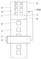
図3に示すように、第3の材料ウェブ15の外側45には、第1の印刷領域61と、第1の印刷領域61と異なり第1の印刷領域61に続く第2の印刷領域62とが配置されている。第1の印刷領域61において、個々のインプリント66は搬送方向38に延びる1つの列に正確に配置されている。第2の印刷領域62には、個々のインプリント67が正確に2つの列に配置され、これらは搬送方向38に延び、互いに平行である。インプリント67は、インプリント66より小さい。代替として、インプリントの他の印刷領域も可能である。
As shown in FIG. 3, on the
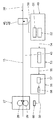
図2に示すように、センサ装置又はそれぞれのセンサ46,47及び/又は48は、信号線50を介して電子情報処理装置49と信号接続している。センサ装置又はそれぞれのセンサ46、47及び/又は48は、第3の材料ウェブ15の外側45の少なくとも大部分をカバーし、特にその外側縁部領域を含む検知領域68を有する。
As shown in FIG. 2, the sensor device or the
情報処理装置49は、印刷領域の変更に伴って変化するセンサ装置又はセンサ46、47、及び/又は48から信号線50を介して信号を受信する、印刷領域検出及び/又はマーク算出ユニット51を備える。
The
印刷領域認識及び/又はマーク算出ユニット51は、出力側で、情報処理装置49の一部でもある注文変更トリガユニット52と信号接続されている。
The print area recognition and / or
注文変更トリガユニット52は、その出力と共に、信号線54を介して注文変更制御部53と信号接続されている。
The order
注文変更制御部53は、その出力と共に、信号線55を介してショートクロスカット装置制御部56(それは、好ましくはショートクロスカット装置27の一部)と信号接続されている。
The order
ショートクロスカット装置制御部56は、信号線55を介して、注文変更制御部53に対応する注文変更のための信号を受信する切断アルゴリズムユニット57を有する。さらに、ショートクロスカット装置制御部56は、切断アルゴリズムユニット57から段ボールウェブ26の新しい部分への対応する信号を受け取る基準値駆動ユニット58を備える。
The short crosscut
基準値駆動ユニット58は、動作中に切断シリンダ28及び/又はカウンタシリンダ29を駆動する駆動モータ60と信号線59を介して信号接続されている。
The reference
印刷領域認識及び/又はマーク算出ユニット51は、センサ46,47及び/又は48の受信信号によって第1の印刷領域61から第2の印刷領域62への変化を識別することができ、この印刷領域変更情報は、注文変更トリガユニット52に伝達される。
The print area recognition and / or
注文変更トリガユニット52は、対応する注文変更トリガ信号を注文変更制御部53に送り、注文変更制御部53は、次いで注文変更サイクルをトリガ、又は開始する。
The order
次に、注文変更制御部53は、対応する注文変更信号をショートクロスカット装置制御部56に送信する。このショートクロスカット装置制御部56の基準値駆動ユニット58は、切断アルゴリズムユニット57から段ボールウェブ26を切断するための対応する切断信号を受信する。基準値駆動ユニット58は、駆動モータ60の基準値を与える。
Next, the order
印刷領域認識及び/又はマーク算出ユニット51は、例えば、画像認識によって印刷領域61,62の変更を直接認識することができる。このために、好ましくは、第3の材料ウェブ15の外側45が全幅にわたって感知される。
The print area recognition and / or
これに代えて、又はそれに加えて、印刷領域認識及び/又はマーク算出ユニット51は、第1の印刷領域61と第2の印刷領域62の間の外側45に配置された変更基準マーキング64を認識することができる。
Alternatively or additionally, the print area recognition and / or
印刷領域認識及び/又はマーク算出ユニット51は、代わりに、又はそれに加えて第3の材料ウェブ15の縁部に配置された、注文変更を示す位置合わせマーク65を認識することができる。変更基準マーキング64は、例えば、RFIDトランスポンダ、変更基準インプリントなどである。
The print area recognition and / or
対応する位置合わせマーク65が検知されたときに、センサ装置が作動されると有利である。位置合わせマーク65は、1つ以上のバーによって形成することができる。
It is advantageous if the sensor device is activated when the
情報処理装置49、注文変更制御部53、及びショートクロスカット装置制御部56は、共通のプロセッサの一部であってもよいし、別々のプロセッサであってもよい。それはプログラムで実行することもできる。これはオプションとみなすべきである。
The
信号は、ハードウェア信号、フィールドバス信号、あるいは制御又は回路内の信号であり得る。 The signal can be a hardware signal, a fieldbus signal, or a signal in a control or circuit.
あるいは、信号線50,54,55,59は無線として設計することができる。 Alternatively, the signal lines 50, 54, 55, 59 can be designed as wireless.
代わりの実施形態によれば、段ボール機は、上下に配置された3つ以上のウェブを有する段ボールを製造する。注文変更切断装置は、先の実施形態にしたがって作動される。 According to an alternative embodiment, the corrugated board machine produces corrugated board having three or more webs arranged one above the other. The order change cutting device is operated according to the previous embodiment.
さらに、センサ装置は、第3の材料ウェブ15の外側45に配置され、残りの情報を第3の材料ウェブ15又はそれぞれの注文に供給する、少なくとも1つの残りのマーキング69を認識することができる。
In addition, the sensor device can recognize at least one remaining
情報処理装置49は、次回注文を開始するための第3の展開装置16を、次に来る品質の変更の際に制御する。このために、情報処理装置49は、センサ装置の上流に配置された第3の展開装置16と信号接続されている。少なくとも1つの残りのマーキング69は、任意の形態での提供及び/又は外側45にランダムに配置することができる。
The
1 段ボール製造装置
2 第1の展開装置
3 第1の材料ウェブ
4 加熱装置
6 第2の材料ウェブ
7 第2の展開装置
8、9 波形成形ローラ
10 波形ウェブ
11 接着装置
12 プレス装置
13 段ボールウェブ
14 予熱装置
15 第3の材料ウェブ
16 第3の展開装置
17 加熱ローラ
18 接着ステーション
19 接着ローラ
20 接着槽
21 加圧装置
22 テーブル
23 ローラ
24 印刷ベルト
25 プレスギャップ
26 段ボールウェブ
27 ショートクロスカット装置
28 切断シリンダ
29 カウンタシリンダ
30 溝彫り装置
31 第1の長手方向切刃ユニット
32 第2の長手方向切刃ユニット
33 第1の溝彫りユニット
34 第2の溝彫りユニット
35 スイッチ
36 クロスカット装置
37 部分クロスカット装置
38 搬送方向
39 横断切断ローラ
40 クロスカット刃
41 部分段ボールウェブ
42 段ボールシート
43 コンベアベルト
44 スタックパイル
45 外側
46、47、48 センサ
49 情報処理装置
50、54、55、59 信号線
51 印刷領域認識及び/又はマーク算出ユニット
52 注文変更トリガユニット
53 注文変更制御部
56 ショートクロスカット装置制御部
57 切断アルゴリズムユニット
58 基準値駆動ユニット
60 駆動モータ
61 第1の印刷領域
62 第2の印刷領域
63 整合マーク装置
64 変更基準マーキング
65 位置合わせマーク
66、67 インプリント
68 検知領域
69 マーキング
1 Corrugated
Claims (13)
a)段ボールウェブ(26)の少なくとも1つの印刷ウェブ(15)を検出するための検出装置と、
b)前記検出装置の下流に配置された注文変更切断装置と、
c)前記検出装置と信号接続している情報処理装置(49)と、
d)前記情報処理装置(49)と信号接続し、前記注文変更切断装置と信号接続し、前記情報処理装置(49)によって認識された、前記段ボールウェブ(26)の前記ウェブ(15)に印刷された第1の印刷領域(61)から前記段ボールウェブ(26)の前記ウェブ(15)に印刷された第2の印刷領域(62)への変更の作用として、前記段ボールウェブ(26)の注文変更をもたらすための前記注文変更切断装置を作動する制御装置(53)と、
を備える段ボール機において、
前記検出装置は、前記ウェブ(15)上に配置された少なくとも1つの残りのランニングマーキング(69)も検出すること、及び、
前記少なくとも1つの検出された残りのランニングマーキング(69)に基づいて、前記情報処理装置(49)は、次の注文の開始時に前記ウェブ(15)を搬送するための展開装置(16)を制御することを特徴とする段ボール機。 A corrugated board machine for manufacturing corrugated board
a) A detector for detecting at least one print web (15) of the corrugated cardboard web (26), and
b) An order change cutting device located downstream of the detection device and
c) An information processing device (49) that is signal-connected to the detection device and
d) A signal is connected to the information processing device (49), a signal is connected to the order change cutting device, and printing is performed on the web (15) of the corrugated cardboard web (26) recognized by the information processing device (49). The order of the corrugated cardboard web (26) as an action of the change from the first printed area (61) to the second printed area (62) printed on the web (15) of the corrugated cardboard web (26). A control device (53) that operates the order change cutting device to bring about a change, and
In a corrugated cardboard machine equipped with
The detector also detects at least one remaining running marking (69) placed on the web (15), and
Based on the at least one remaining detected running marking (69), the information processing device (49) controls a deploying device (16) for transporting the web (15) at the start of the next order. A corrugated cardboard machine characterized by
Applications Claiming Priority (4)
| Application Number | Priority Date | Filing Date | Title |
|---|---|---|---|
| DE102015218318 | 2015-09-24 | ||
| DE102015218318.1 | 2015-09-24 | ||
| DE102015219630.5A DE102015219630A1 (en) | 2015-09-24 | 2015-10-09 | Corrugating machine |
| DE102015219630.5 | 2015-10-09 |
Publications (2)
| Publication Number | Publication Date |
|---|---|
| JP2017094716A JP2017094716A (en) | 2017-06-01 |
| JP6899206B2 true JP6899206B2 (en) | 2021-07-07 |
Family
ID=58281987
Family Applications (1)
| Application Number | Title | Priority Date | Filing Date |
|---|---|---|---|
| JP2016185059A Active JP6899206B2 (en) | 2015-09-24 | 2016-09-23 | Cardboard machine |
Country Status (6)
| Country | Link |
|---|---|
| US (1) | US10272633B2 (en) |
| EP (1) | EP3156199B1 (en) |
| JP (1) | JP6899206B2 (en) |
| CN (1) | CN106553386B (en) |
| DE (1) | DE102015219630A1 (en) |
| ES (1) | ES2687746T3 (en) |
Cited By (1)
| Publication number | Priority date | Publication date | Assignee | Title |
|---|---|---|---|---|
| KR102578505B1 (en) * | 2022-11-29 | 2023-09-19 | 화진포장산업 주식회사 | Packaging box processing method |
Families Citing this family (8)
| Publication number | Priority date | Publication date | Assignee | Title |
|---|---|---|---|---|
| WO2017131720A1 (en) | 2016-01-28 | 2017-08-03 | Hewlett-Packard Development Company, L.P. | Corrugator control information on a box liner |
| US20190016551A1 (en) | 2017-07-14 | 2019-01-17 | Georgia-Pacific Corrugated, LLC | Reel editor for pre-print paper, sheet, and box manufacturing systems |
| US11449290B2 (en) * | 2017-07-14 | 2022-09-20 | Georgia-Pacific Corrugated Llc | Control plan for paper, sheet, and box manufacturing systems |
| US10642551B2 (en) | 2017-07-14 | 2020-05-05 | Georgia-Pacific Corrugated Llc | Engine for generating control plans for digital pre-print paper, sheet, and box manufacturing systems |
| US11520544B2 (en) | 2017-07-14 | 2022-12-06 | Georgia-Pacific Corrugated Llc | Waste determination for generating control plans for digital pre-print paper, sheet, and box manufacturing systems |
| US11485101B2 (en) * | 2017-07-14 | 2022-11-01 | Georgia-Pacific Corrugated Llc | Controls for paper, sheet, and box manufacturing systems |
| CN109532118B (en) * | 2018-11-21 | 2020-05-26 | 杭州佳鹏电脑科技股份有限公司 | Paper splicing control method and device and production management system |
| IT202200000215A1 (en) | 2022-01-10 | 2023-07-10 | Fosber Spa | SYSTEM AND METHOD FOR THE PRODUCTION OF CORRUGATED CARDBOARD WITH ORDER CHANGE DETECTOR |
Family Cites Families (21)
| Publication number | Priority date | Publication date | Assignee | Title |
|---|---|---|---|---|
| GB1468013A (en) * | 1973-10-11 | 1977-03-23 | Robinson Sons Ltd | Observation of moving webs |
| US4380943A (en) | 1981-05-20 | 1983-04-26 | Molins Machine Company, Inc. | Automated cut-to-mark control for cut-off machine |
| US4576663A (en) * | 1984-08-31 | 1986-03-18 | Chesapeake Corporation | Order change method and apparatus for corrugator machine |
| JP2522128Y2 (en) * | 1990-07-06 | 1997-01-08 | 株式会社イソワ | Paper change notification device in production control of corrugating machine |
| US5437749A (en) * | 1993-10-04 | 1995-08-01 | Marquip, Inc. | Splice synchronization system |
| DE4420726A1 (en) | 1994-06-16 | 1995-12-21 | Bhs Corr Masch & Anlagenbau | Machine for producing a web of corrugated cardboard laminated at least on one side |
| DE19754799A1 (en) | 1997-12-10 | 1999-06-17 | Bhs Corr Masch & Anlagenbau | Slitting and creasing machine for corrugated cardboard webs |
| DE10131833A1 (en) | 2001-06-30 | 2003-01-16 | Bhs Corr Masch & Anlagenbau | Skew compensation device for corrugated cardboard |
| JP2003245894A (en) * | 2002-02-21 | 2003-09-02 | Isowa Corp | Image pickup method for object to be detected, and detecting device for the object at cutter of corrugate machine and for the object at corrugated cardboard box-manufacturing machine |
| DE10312600A1 (en) * | 2003-03-21 | 2004-10-07 | Bhs Corrugated Maschinen- Und Anlagenbau Gmbh | Corrugated cardboard plant and process for the production of corrugated sheets |
| DE10331357A1 (en) * | 2003-07-11 | 2005-01-27 | Bhs Corrugated Maschinen- Und Anlagenbau Gmbh | Manufacturing plant for corrugated paper has corrugated strip production device, pasting device and cutting device |
| DE102004003560A1 (en) | 2004-01-23 | 2005-08-18 | Bhs Corrugated Maschinen- Und Anlagenbau Gmbh | Device for cutting and/or slitting a continuous sheeting of corrugated cardboard comprises a knife cylinder with a knife, and a driven counter-cylinder carrying counter-elements |
| DE102004052451A1 (en) * | 2004-10-28 | 2006-05-04 | Sick Ag | Device for recognition of successive units of an endless web |
| JP4718981B2 (en) * | 2005-12-02 | 2011-07-06 | 三菱重工印刷紙工機械株式会社 | Corrugating machine and production management device used therefor |
| US8353591B2 (en) * | 2006-04-20 | 2013-01-15 | Kabushiki Kaisha Isowa | Apparatus and method for printing corrugated cardboard sheets |
| JP2009046296A (en) * | 2007-08-23 | 2009-03-05 | Mitsubishi Heavy Ind Ltd | Method and device for detecting paper splice part of corrugator |
| CN101259765A (en) * | 2008-04-18 | 2008-09-10 | 陈毅辉 | Corrugated cardboard and production method thereof |
| IT1393147B1 (en) * | 2009-03-09 | 2012-04-11 | Sacmi Labelling S P A Ora Sacmi Verona S P A | APPARATUS AND FEEDING METHOD |
| CN102173162B (en) * | 2010-11-30 | 2014-03-05 | 青岛美光机械有限公司 | Production method and production line for pre-printed surface paper corrugated paperboards |
| DE102012211118A1 (en) * | 2012-06-28 | 2014-05-08 | Bhs Corrugated Maschinen- Und Anlagenbau Gmbh | Corrugated board plant for the production of corrugated board |
| DE102014107384A1 (en) * | 2013-12-20 | 2015-06-25 | Manroland Web Systems Gmbh | Method and device for controlling and regulating a digital printing process |
-
2015
- 2015-10-09 DE DE102015219630.5A patent/DE102015219630A1/en not_active Ceased
-
2016
- 2016-09-21 ES ES16189850.7T patent/ES2687746T3/en active Active
- 2016-09-21 EP EP16189850.7A patent/EP3156199B1/en active Active
- 2016-09-22 US US15/272,985 patent/US10272633B2/en active Active
- 2016-09-23 JP JP2016185059A patent/JP6899206B2/en active Active
- 2016-09-26 CN CN201610853048.6A patent/CN106553386B/en active Active
Cited By (1)
| Publication number | Priority date | Publication date | Assignee | Title |
|---|---|---|---|---|
| KR102578505B1 (en) * | 2022-11-29 | 2023-09-19 | 화진포장산업 주식회사 | Packaging box processing method |
Also Published As
| Publication number | Publication date |
|---|---|
| EP3156199A3 (en) | 2017-05-17 |
| US10272633B2 (en) | 2019-04-30 |
| EP3156199A2 (en) | 2017-04-19 |
| ES2687746T3 (en) | 2018-10-29 |
| JP2017094716A (en) | 2017-06-01 |
| CN106553386B (en) | 2019-11-08 |
| EP3156199B1 (en) | 2018-07-25 |
| CN106553386A (en) | 2017-04-05 |
| DE102015219630A1 (en) | 2017-03-30 |
| US20170087794A1 (en) | 2017-03-30 |
Similar Documents
| Publication | Publication Date | Title |
|---|---|---|
| JP6899206B2 (en) | Cardboard machine | |
| US20040182503A1 (en) | Corrugating machine and method for the manufacture of sheets of corrugated board | |
| JP4871479B2 (en) | Method and apparatus for manufacturing a data carrier with a transponder | |
| KR101299908B1 (en) | Device for positioning a plate element in an insertion station of a processing machine | |
| JP5456034B2 (en) | Method and apparatus for sticking foil material on continuous sheet | |
| KR101980393B1 (en) | Method and device for hot stamping | |
| US20040182504A1 (en) | Method for the manufacture of corrugated board | |
| KR20180018701A (en) | Apparatus for cutting corrugated cardboard sheet and apparatus for manufacturing corrugated cardboard sheet | |
| EP2257434B1 (en) | Method and installation for applying foil material onto successive sheets | |
| WO2008104904A1 (en) | Method and installation for applying foil material onto successive sheets | |
| CN109532117B (en) | Corrugating plant and method for producing corrugated board | |
| JPH082787A (en) | Label and producing method and device thereof | |
| US20140246139A1 (en) | Print finishing method and corresponding device | |
| US20120037295A1 (en) | Sheet material with index openings and method for making and using | |
| CN101391512B (en) | Method of performing transfer printing on sheets of paper | |
| JP2007030178A (en) | Manufacturing apparatus of corrugated cardboard sheet | |
| JP4851419B2 (en) | Apparatus and method for finishing a sheet-like substrate in a sheet printer | |
| JP2007099514A (en) | Sheet printing machine | |
| JP2006062243A (en) | Manufacturing equipment for corrugated board | |
| JP5796807B2 (en) | Laminator double feed processing system | |
| JP4620384B2 (en) | CUTTING DEVICE AND PACKAGING MANUFACTURING METHOD | |
| JP4332880B2 (en) | Printing paper laminating device | |
| JP5307615B2 (en) | Continuous paper collating device | |
| CN118215561A (en) | Arrangement of corrugating machine | |
| JP2015020428A (en) | Manufacturing method of information communication body |
Legal Events
| Date | Code | Title | Description |
|---|---|---|---|
| A621 | Written request for application examination |
Free format text: JAPANESE INTERMEDIATE CODE: A621 Effective date: 20190514 |
|
| A131 | Notification of reasons for refusal |
Free format text: JAPANESE INTERMEDIATE CODE: A131 Effective date: 20200721 |
|
| A601 | Written request for extension of time |
Free format text: JAPANESE INTERMEDIATE CODE: A601 Effective date: 20201020 |
|
| A521 | Request for written amendment filed |
Free format text: JAPANESE INTERMEDIATE CODE: A523 Effective date: 20201218 |
|
| TRDD | Decision of grant or rejection written | ||
| A01 | Written decision to grant a patent or to grant a registration (utility model) |
Free format text: JAPANESE INTERMEDIATE CODE: A01 Effective date: 20210518 |
|
| A61 | First payment of annual fees (during grant procedure) |
Free format text: JAPANESE INTERMEDIATE CODE: A61 Effective date: 20210614 |
|
| R150 | Certificate of patent or registration of utility model |
Ref document number: 6899206 Country of ref document: JP Free format text: JAPANESE INTERMEDIATE CODE: R150 |
|
| R250 | Receipt of annual fees |
Free format text: JAPANESE INTERMEDIATE CODE: R250 |