JP6898765B2 - Pachinko machine - Google Patents
Pachinko machine Download PDFInfo
- Publication number
- JP6898765B2 JP6898765B2 JP2017082533A JP2017082533A JP6898765B2 JP 6898765 B2 JP6898765 B2 JP 6898765B2 JP 2017082533 A JP2017082533 A JP 2017082533A JP 2017082533 A JP2017082533 A JP 2017082533A JP 6898765 B2 JP6898765 B2 JP 6898765B2
- Authority
- JP
- Japan
- Prior art keywords
- game
- area
- medal
- program
- data
- Prior art date
- Legal status (The legal status is an assumption and is not a legal conclusion. Google has not performed a legal analysis and makes no representation as to the accuracy of the status listed.)
- Active
Links
Images


Description
本発明は、パチンコ遊技機やスロットマシン等の遊技機に関する。 The present invention relates to gaming machines such as pachinko gaming machines and slot machines.
この種の遊技機としては、遊技の進行に係る遊技プログラムが記憶される遊技プログラ
ム領域と、遊技の進行に係わらない非遊技プログラムが記憶される非遊技プログラム領域
と、がそれぞれ別個にROMに割り当てられたものが提案されている(例えば、特許文献
1参照)。
As this type of gaming machine, a game program area in which a game program related to the progress of the game is stored and a non-game program area in which a non-game program not related to the progress of the game is stored are separately allocated to the ROM. Has been proposed (see, for example, Patent Document 1).
特許文献1に記載の遊技機では、遊技プログラムにおいて、非遊技プログラムに含まれ
る処理を実行する度に、遊技プログラムから非遊技プログラムを呼び出すようにすると、
何度も遊技プログラムと非遊技プログラムとを行き来することとなり、処理が複雑化する
という問題が生じる。
In the gaming machine described in
The game program and the non-game program are switched back and forth many times, which causes a problem that the processing becomes complicated.
本発明は、このような問題点に着目してなされたものであり、遊技プログラムと非遊技
プログラムとの行き来を極力減らすことができる遊技機を提供することを目的とする。
The present invention has been made focusing on such problems, and an object of the present invention is to provide a gaming machine capable of reducing the exchange between a gaming program and a non-gaming program as much as possible.
(A) 遊技を行う遊技機において、
プログラムを記憶可能な記憶領域を有する記憶手段と、
記憶手段に記憶されたプログラムに基づいて制御を行う制御手段と、
を備え、
前記記憶手段の記憶領域は、
第1プログラムが記憶される第1プログラム領域と、
前記第1プログラムによって呼び出される第2プログラムが記憶される第2プログラム領域と、
を含み、
前記制御手段は、命令毎に指定される上位アドレスと下位アドレスから、呼出対象のプログラムが格納されたアドレスを特定し、特定したアドレスのプログラムを呼び出す第1呼出命令と、特定アドレスを上位アドレスとし、命令毎に指定されるアドレスを下位アドレスとして、呼出対象のプログラムが格納されたアドレスを特定し、特定したアドレスのプログラムを呼び出す第2呼出命令と、を用いてプログラムを呼び出すことが可能であり、
前記第1プログラムでは、前記第2呼出命令を用いてプログラムを呼び出すことが可能であり、
前記第2プログラムでは、前記第2呼出命令を用いずに前記第1呼出命令を用いてプログラムを呼び出し、
前記第1プログラムからの1回の第2プログラムの呼出により該第2プログラムにおいて異常判定及び遊技の履歴に基づく状態を表示させる表示制御を行う。
手段1の遊技機は、
遊技を行う遊技機(スロットマシン1)において、
プログラムを記憶可能な記憶領域を有する記憶手段(ROM41b)と、
記憶手段に記憶されたプログラムに基づいて制御を行う制御手段(メインCPU41a)と、
を備え、
前記記憶手段(ROM41b)の記憶領域は、
遊技の進行に係る遊技プログラムが記憶される遊技プログラム領域と、
前記遊技プログラムによって呼び出されるプログラムであり、遊技の進行に係わらない非遊技プログラムが記憶される非遊技プログラム領域と、
を含み、
前記遊技プログラムからの1回の非遊技プログラム(非遊技関連処理)の呼出により該非遊技プログラムにおいて異常判定(センサ監視処理)及び遊技の履歴に基づく状態を表示させる表示制御(役比モニタ表示データ選択処理)を行う
ことを特徴としている。
この特徴によれば、遊技の進行に係る遊技プログラムが記憶される遊技プログラム領域と、遊技プログラムによって呼び出されるプログラムであり、遊技の進行に係わらない非遊技プログラムが記憶される非遊技プログラム領域と、が別個に割り当てられた構成において、遊技プログラムからの1回の非遊技プログラムの呼出により該非遊技プログラムにおいて異常判定及び遊技の履歴に基づく状態を表示させる表示制御が行われるため、遊技プログラムと非遊技プログラムとの行き来を極力減らすことができる。
(A) In a gaming machine that plays a game
A storage means having a storage area that can store a program,
A control means that controls based on a program stored in the storage means,
With
The storage area of the storage means is
The first program area where the first program is stored and
A second program area in which the second program called by the first program is stored, and
Including
The control means identifies the address in which the program to be called is stored from the upper address and lower address specified for each instruction, and sets the first call instruction to call the program at the specified address and the specific address as the upper address. , The program can be called using the second call instruction, which specifies the address where the program to be called is stored and calls the program at the specified address, with the address specified for each instruction as the lower address. ,
In the first program, it is possible to call the program by using the second call instruction.
In the second program, the program is called by using the first calling instruction without using the second calling instruction.
By calling the second program once from the first program, display control is performed in the second program to display an abnormality determination and a state based on the game history.
Of the gaming
In a gaming machine (slot machine 1) that plays a game
A storage means (ROM41b) having a storage area capable of storing a program, and
A control means (
With
The storage area of the storage means (ROM41b) is
A game program area in which game programs related to the progress of the game are stored, and
A non-game program area that is a program called by the game program and stores a non-game program that is not related to the progress of the game, and a non-game program area.
Including
Display control (selection of combination monitor display data) for displaying an abnormality determination (sensor monitoring process) and a state based on the game history in the non-game program by calling one non-game program (non-game-related process) from the game program. It is characterized by performing processing).
According to this feature, a game program area in which a game program related to the progress of a game is stored, a non-game program area in which a non-game program that is a program called by the game program and is not related to the progress of the game is stored, and a non-game program area. In the configuration in which is separately assigned, since the display control for displaying the abnormality determination and the state based on the game history is performed in the non-game program by calling the non-game program once from the game program, the game program and the non-game are performed. You can reduce the number of trips to and from the program as much as possible.
本発明の手段2の遊技機は、手段1に記載の遊技機であって、
前記遊技プログラムから前記非遊技プログラム(非遊技関連処理)を呼び出すときに、
前記遊技プログラムにて用いていたデータ(レジスタの値)を退避するとともに、前記非
遊技プログラムから前記遊技プログラムに復帰するときに、退避したデータ(レジスタの
値)を復帰する
ことを特徴としている。
この特徴によれば、遊技プログラムから非遊技プログラムを呼び出すに際して、遊技プ
ログラムにて用いていたデータが破損してしまうことを防止できる。
The gaming machine of the
When calling the non-game program (non-game-related processing) from the game program,
The feature is that the data (register value) used in the game program is saved, and the saved data (register value) is restored when the non-game program returns to the game program.
According to this feature, when the non-game program is called from the game program, it is possible to prevent the data used in the game program from being damaged.
本発明の手段3の遊技機は、手段1または2に記載の遊技機であって、
前記非遊技プログラム(非遊技関連処理)において、異常判定を行う処理(センサ監視
処理)及び遊技の履歴に基づく状態を表示させる表示制御を行う処理(役比モニタ表示デ
ータ選択処理)がそれぞれサブルーチンとして呼び出される
ことを特徴としている。
この特徴によれば、異常判定を行う処理及び遊技の履歴に基づく状態を表示させる表示
制御を行う処理がそれぞれサブルーチンとして設定されているため、プログラムの管理が
容易となる。
The gaming machine of
In the non-game program (non-game-related processing), a processing for determining an abnormality (sensor monitoring processing) and a processing for performing display control for displaying a state based on the game history (combination ratio monitor display data selection processing) are respectively as subroutines. It is characterized by being called.
According to this feature, since the process of performing the abnormality determination and the process of performing the display control for displaying the state based on the game history are set as subroutines, the program can be easily managed.
本発明の手段4の遊技機は、手段1〜3のいずれかに記載の遊技機であって、
データを一時的に記憶可能な記憶領域を有する一時記憶手段(RAM41c)を備え、
前記一時記憶手段(RAM41c)の記憶領域は、遊技プログラムが用いる遊技データ
が読み出し及び書き込み可能に記憶される遊技データ領域(遊技RAM領域)と、非遊技
プログラムが用いる非遊技データが読み出し及び書き込み可能に記憶される非遊技データ
領域(非遊技RAM領域)と、を含み、
前記非遊技プログラム(非遊技関連処理)による異常判定の結果(センサエラー参照デ
ータ)は前記非遊技データ領域(非遊技RAM領域)に記憶され、
前記非遊技プログラム(非遊技関連処理)から前記遊技プログラムに復帰したときに、
他の処理を行うことなく、前記非遊技データ記憶領域(非遊技RAM領域)に記憶された
異常判定の結果(センサエラー参照データ)を参照する
ことを特徴としている。
この特徴によれば、非遊技プログラムによる異常判定の結果を他の処理を行うよりも前
に参照するため、異常判定の結果をいち早く遊技プログラムが行う処理に反映させること
ができる。
The gaming machine of
A temporary storage means (
The storage area of the temporary storage means (
The result of abnormality determination (sensor error reference data) by the non-game program (non-game-related processing) is stored in the non-game data area (non-game RAM area).
When returning to the game program from the non-game program (non-game-related processing),
It is characterized in that the result of abnormality determination (sensor error reference data) stored in the non-game data storage area (non-game RAM area) is referred to without performing other processing.
According to this feature, since the result of the abnormality determination by the non-game program is referred to before performing other processing, the result of the abnormality determination can be reflected in the processing performed by the game program as soon as possible.
本発明の手段5の遊技機は、手段1〜4のいずれかに記載の遊技機であって、
前記非遊技プログラム(非遊技関連処理)における遊技の履歴に基づく状態を表示させ
る表示制御(役比モニタ表示データ選択処理)で用いる表示データと、遊技プログラムに
おいて遊技の状態を表示させる表示制御(クレジット等の表示)で用いる表示データと、
が共通の表示態様を表示させる表示データものであっても、遊技プログラム領域(遊技デ
ータ領域)と、非遊技プログラム領域(非遊技データ領域)と、にそれぞれ記憶されてい
る
ことを特徴としている。
この特徴によれば、非遊技プログラムにおける遊技の履歴に基づく状態を表示させる表
示制御では、非遊技プログラム領域に記憶された表示データを用い、遊技プログラムにお
いて遊技の状態を表示させる表示制御では、遊技プログラム領域に記憶された表示データ
を用いることで、遊技プログラムと非遊技プログラムとの行き来を極力減らすことができ
る。
The gaming machine of
The display data used in the display control (role ratio monitor display data selection process) for displaying the state based on the game history in the non-game program (non-game-related processing) and the display control (credit) for displaying the game state in the game program. Display data used in) and
Is a display data that displays a common display mode, but is stored in a game program area (game data area) and a non-game program area (non-game data area), respectively.
According to this feature, in the display control for displaying the state based on the game history in the non-game program, the display data stored in the non-game program area is used, and in the display control for displaying the game state in the game program, the game is played. By using the display data stored in the program area, it is possible to reduce the traffic between the game program and the non-game program as much as possible.
本発明の手段6の遊技機は、手段1〜5のいずれかに記載の遊技機であって、
前記制御手段(メインCPU41a)は、プログラムに基づいて制御命令を実行可能で
あり、
前記制御命令は、プログラムにおいて指定された指定値及び所定値領域(ベクタテーブ
ル領域)に予め記憶されている所定値からなるアドレスにより特定される記憶領域に記憶
されているプログラムを呼び出す所定呼出命令(CALLF命令、RST命令)を含み、
前記遊技プログラムでは、所定呼出命令を用いてプログラムを呼び出し、
前記非遊技プログラムでは、所定呼出命令を用いずにプログラムを呼び出す。
ことを特徴としている。
この特徴によれば、非遊技プログラムから不用意に遊技プログラム領域にアクセスされ
てしまうことを防止できる。
The gaming machine of
The control means (
The control instruction is a predetermined call instruction (predetermined call instruction) that calls a program stored in a storage area specified by an address consisting of a specified value specified in the program and a predetermined value stored in advance in a predetermined value area (vector table area). Includes CALLF instruction, RST instruction)
In the game program, the program is called using a predetermined calling command, and the program is called.
In the non-game program, the program is called without using a predetermined calling command.
It is characterized by that.
According to this feature, it is possible to prevent the non-game program from inadvertently accessing the game program area.
本発明の手段7の遊技機は、手段1〜6のいずれかに記載の遊技機であって、
データを一時的に記憶可能な記憶領域を有する一時記憶手段(RAM41c)を備え、
前記一時記憶手段(RAM41c)の記憶領域は、遊技プログラムが用いる遊技データ
が読み出し及び書き込み可能に記憶される遊技データ領域(遊技RAM領域)と、非遊技
プログラムが用いる非遊技データが読み出し及び書き込み可能に記憶される非遊技データ
領域(非遊技RAM領域)と、を含み、
前記制御手段(メインCPU41a)は、プログラムに基づいて制御命令を実行可能で
あり、
前記制御命令は、
プログラムにおいて指定されたアドレスにより特定される記憶領域に記憶されているデ
ータを読み出す通常読出命令(LD命令)と、
プログラムにおいて指定された指定値及び特定値領域(Qレジスタ)に予め記憶されて
いる特定値からなるアドレスにより特定される記憶領域に記憶されているデータを読み出
す特定読出命令(LDQ命令)と、
を含み、
前記遊技データ領域(遊技RAM領域)は、遊技プログラムによるデータの書込が許容
される一方で、非遊技プログラムによるデータの書込が許容されず、
前記遊技プログラムでは特定読出命令(LDQ命令)を用いて遊技データ領域(遊技R
AM領域)からデータを読み出し、
前記非遊技プログラムでは通常読出命令(LD命令)を用いて遊技データ領域(遊技R
AM領域)からデータを読み出す
ことを特徴としている。
この特徴によれば、遊技プログラムでは、遊技データ領域からデータを読み出す際に、
特定値領域に予め記憶されている特定値により遊技データ領域を特定する特定読出命令を
用いてデータを読み出す一方で、非遊技プログラムでは、遊技データ領域からデータを読
み出す際に、特定読出命令を用いずに、特定値領域に予め記憶されている特定値によらず
に遊技データ領域を特定する通常読出命令を用いてデータを読み出すので、遊技プログラ
ムから非遊技プログラムに切り替わったときに特定値が破損した場合でも、非遊技プログ
ラムから遊技データ領域を特定してデータが読み出されるので、意図しないデータが読み
出されることを防止できる。
The gaming machine of
A temporary storage means (
The storage area of the temporary storage means (
The control means (
The control command is
A normal read instruction (LD instruction) that reads data stored in the storage area specified by the address specified in the program, and a normal read instruction (LD instruction).
A specific read instruction (LDQ instruction) for reading data stored in a storage area specified by an address consisting of a specified value specified in a program and a specific value stored in advance in a specific value area (Q register), and a specific read instruction (LDQ instruction).
Including
In the game data area (game RAM area), writing of data by a game program is permitted, but writing of data by a non-game program is not permitted.
In the game program, a game data area (game R) is used by using a specific read command (LDQ command).
Read the data from the AM area)
In the non-game program, a game data area (game R) is normally used by using a read command (LD command).
It is characterized by reading data from the AM area).
According to this feature, in the game program, when reading data from the game data area,
While the data is read by using the specific read command that specifies the game data area by the specific value stored in advance in the specific value area, in the non-game program, the specific read command is used when reading the data from the game data area. Instead, the data is read using the normal read command that specifies the game data area regardless of the specific value stored in advance in the specific value area, so the specific value is damaged when the game program is switched to the non-game program. Even in such a case, since the game data area is specified and the data is read from the non-game program, it is possible to prevent the unintended data from being read.
本発明の手段8の遊技機は、手段1〜6のいずれかに記載の遊技機であって、
データを一時的に記憶可能な記憶領域を有する一時記憶手段(RAM41c)を備え、
前記一時記憶手段(RAM41c)の記憶領域は、遊技プログラムが用いる遊技データ
が読み出し及び書き込み可能に記憶される遊技データ領域(遊技RAM領域)と、非遊技
プログラムが用いる非遊技データが読み出し及び書き込み可能に記憶される非遊技データ
領域(非遊技RAM領域)と、を含み、
前記制御手段(メインCPU41a)は、プログラムに基づいて制御命令を実行可能で
あり、
前記制御命令は、
プログラムにおいて指定されたアドレスにより特定される記憶領域に記憶されているデ
ータを読み出す通常読出命令(LD命令)と、
プログラムにおいて指定された指定値及び特定値領域(Qレジスタ)に予め記憶されて
いる特定値からなるアドレスにより特定される記憶領域に記憶されているデータを読み出
す特定読出命令(LDQ命令)と、
を含み、
前記遊技データ領域(遊技RAM領域)は、遊技プログラムによるデータの書込が許容
される一方で、非遊技プログラムによるデータの書込が許容されず、
前記遊技プログラムでは特定読出命令(LDQ命令)を用いて遊技データ領域(遊技R
AM領域)からデータを読み出し、
前記非遊技プログラム(非遊技プログラム)では、特定値領域(Qレジスタ)の特定値
を退避し、同じ値の特定値を入力した後、特定読出命令(LDQ命令)を用いて遊技デー
タ領域(遊技RAM領域)からデータを読み出す
ことを特徴としている。
この特徴によれば、遊技プログラムでは、遊技データ領域からデータを読み出す際に、
特定値領域に予め記憶されている特定値により遊技データ領域を特定する特定読出命令を
用いてデータを読み出す一方で、遊技プログラムでは、特定値領域の特定値を退避させ、
同じ値の特定値を入力した後、特定読出命令を用いてデータを読み出すことにより、遊技
プログラムから非遊技プログラムに切り替わったときに特定値が破損した場合でも、再設
定された特定値により遊技データ領域を特定してデータが読み出されるので、意図しない
データが読み出されることを防止できる。
The gaming machine of the
A temporary storage means (
The storage area of the temporary storage means (
The control means (
The control command is
A normal read instruction (LD instruction) that reads data stored in the storage area specified by the address specified in the program, and a normal read instruction (LD instruction).
A specific read instruction (LDQ instruction) for reading data stored in a storage area specified by an address consisting of a specified value specified in a program and a specific value stored in advance in a specific value area (Q register), and a specific read instruction (LDQ instruction).
Including
In the game data area (game RAM area), writing of data by a game program is permitted, but writing of data by a non-game program is not permitted.
In the game program, a game data area (game R) is used by using a specific read command (LDQ command).
Read the data from the AM area)
In the non-game program (non-game program), a specific value in a specific value area (Q register) is saved, a specific value of the same value is input, and then a specific read instruction (LDQ instruction) is used to save a specific value in a game data area (game). It is characterized by reading data from the RAM area).
According to this feature, in the game program, when reading data from the game data area,
While reading data using a specific read command that specifies the game data area based on the specific value stored in advance in the specific value area, the game program saves the specific value in the specific value area.
By reading the data using the specific read command after inputting the specific value of the same value, even if the specific value is damaged when switching from the game program to the non-game program, the game data is set according to the reset specific value. Since the data is read by specifying the area, it is possible to prevent unintended data from being read.
尚、本発明は、本発明の請求項に記載された発明特定事項のみを有するものであって良
いし、本発明の請求項に記載された発明特定事項とともに該発明特定事項以外の構成を有
するものであっても良い。
The present invention may have only the invention-specific matters described in the claims of the present invention, and has a configuration other than the invention-specific matters together with the invention-specific matters described in the claims of the present invention. It may be a thing.
本発明に係る遊技機を実施するための形態を実施例に基づいて以下に説明する。 A mode for carrying out the gaming machine according to the present invention will be described below based on examples.
本発明が適用された遊技機であるスロットマシンの実施例1について図面を用いて説明
すると、本実施例のスロットマシン1は、図1に示すように、前面が開口する筐体1aと
、この筐体1aの側端に回動自在に枢支された前面扉1bと、から構成されている。
When the first embodiment of the slot machine to which the present invention is applied will be described with reference to the drawings, the
本実施例のスロットマシン1の筐体1aの内部には、図2に示すように、外周に複数種
の図柄が配列されたリール2L、2C、2R(以下、左リール、中リール、右リール)が
水平方向に並設されており、図1に示すように、これらリール2L、2C、2Rに配列さ
れた図柄のうち連続する3つの図柄が前面扉1bに設けられた透視窓3から見えるように
配置されている。
As shown in FIG. 2, inside the
リール2L、2C、2Rの外周部には、互いに識別可能な複数種類の図柄(例えば、「
7」、「BAR」、「スイカ」、「チェリー」、「ベル」、「リプレイ」等)が所定の順
序で、それぞれ21個ずつ描かれている。リール2L、2C、2Rの外周部に描かれた図
柄は、前面扉1bの略中央に設けられた透視窓3において各々上中下三段に表示される。
On the outer periphery of the
7 ”,“ BAR ”,“ watermelon ”,“ cherry ”,“ bell ”,“ replay ”, etc.) are drawn in a predetermined order, 21 each. The symbols drawn on the outer peripheral portions of the
各リール2L、2C、2Rは、各々対応して設けられたリールモータ32L、32C、
32R(図3参照)によって回転されることで、各リール2L、2C、2Rの図柄が透視
窓3に連続的に変化しつつ表示される一方で、各リール2L、2C、2Rの回転が停止さ
れることで、透視窓3に3つの連続する図柄が表示結果として導出表示されるようになっ
ている。
Each
By being rotated by 32R (see FIG. 3), the symbols of each
尚、本実施例のリール2L、2C、2Rは、リールモータ32L、32C、32Rを用
いて、外周面に複数の図柄が配置されたリール2L、2C、2Rを回転させることで、遊
技者から視認可能な複数の図柄を移動させる変動表示を行うことが可能な構成であるが、
複数の図柄を移動させる変動表示を行う手段は、リール以外であっても良く、例えば、外
周面に複数の図柄が配置されたベルトを移動させることで変動表示を行うことが可能な構
成等であっても良い。
The
The means for performing the variable display for moving a plurality of symbols may be other than the reel. For example, the variable display can be performed by moving a belt on which a plurality of symbols are arranged on the outer peripheral surface. There may be.
リール2L、2C、2Rの内側には、リール2L、2C、2Rそれぞれに対して、基準
位置を検出するリールセンサ33L、33C、33Rと、リール2L、2C、2Rを背面
から照射するリールLED55と、が設けられている。また、リールLED55は、リー
ル2L、2C、2Rの連続する3つの図柄に対応する12のLEDからなり、各図柄をそ
れぞれ独立して照射可能とされている。
Inside the
また、リールセンサ33L、33C、33Rは、各リール2L、2C、2Rについて図
柄番号1の図柄の領域の下端が各リールにおける所定位置を通過するときに、検出信号を
出力するように配置されており、各リールについて図柄番号1の図柄の領域の下端がリー
ル基準位置となる。
Further, the reel sensors 33L, 33C, 33R are arranged so as to output a detection signal when the lower end of the symbol region of the
前面扉1bの各リール2L、2C、2Rの手前側(遊技者側)の位置には、液晶表示器
51(図1参照)の表示領域51aが配置されている。液晶表示器51は、液晶素子に対
して電圧が印加されていない状態で透過性を有する液晶パネルを有しており、表示領域5
1aの透視窓3に対応する透過領域51b及び透視窓3を介して遊技者側から各リール2
L、2C、2Rが視認できるようになっている。
A
Each
L, 2C and 2R can be visually recognized.
前面扉1bには、図1に示すように、メダルを投入可能なメダル投入部4、メダルが払
い出されるメダル払出口9、クレジット(遊技者所有の遊技用価値として記憶されている
メダル数)を用いて、その範囲内において遊技状態に応じて定められた規定数の賭数のう
ち最大の賭数を設定する際に操作されるMAXBETスイッチ6、クレジットとして記憶
されているメダル及び賭数の設定に用いたメダルを精算する(クレジット及び賭数の設定
に用いた分のメダルを返却させる)際に操作される精算スイッチ10、ゲームを開始する
際に操作されるスタートスイッチ7、リール2L、2C、2Rの回転を各々停止する際に
操作されるストップスイッチ8L、8C、8R、演出に用いられる演出用スイッチ56が
遊技者により操作可能にそれぞれ設けられている。
As shown in FIG. 1, the
尚、本実施例では、回転を開始した3つのリール2L、2C、2Rのうち、最初に停止
するリールを第1停止リールと称し、また、その停止を第1停止と称する。同様に、2番
目に停止するリールを第2停止リールと称し、また、その停止を第2停止と称し、3番目
に停止するリールを第3停止リールと称し、また、その停止を第3停止あるいは最終停止
と称する。
In this embodiment, of the three
また、前面扉1bには、図1に示すように、クレジットとして記憶されているメダル枚
数が表示されるクレジット表示器11、入賞の発生により払い出されたメダル枚数やエラ
ー発生時にその内容を示すエラーコード等が表示される遊技補助表示器12、賭数が1設
定されている旨を点灯により報知する1BETLED14、賭数が2設定されている旨を
点灯により報知する2BETLED15、賭数が3設定されている旨を点灯により報知す
る3BETLED16、メダルの投入が可能な状態を点灯により報知する投入要求LED
17、スタートスイッチ7の操作によるゲームのスタート操作が有効である旨を点灯によ
り報知するスタート有効LED18、ウェイト(前回のゲーム開始から一定期間経過して
いないためにリールの回転開始を待機している状態)中である旨を点灯により報知するウ
ェイト中LED19、リプレイゲーム中である旨を点灯により報知するリプレイ中LED
20が設けられた遊技用表示部13が設けられている。
Further, as shown in FIG. 1, the
17, Start
A
MAXBETスイッチ6の内部には、MAXBETスイッチ6の操作による賭数の設定
操作が有効である旨を点灯により報知するBETスイッチ有効LED21(図3参照)が
設けられており、ストップスイッチ8L、8C、8Rの内部には、該当するストップスイ
ッチ8L、8C、8Rによるリールの停止操作が有効である旨を点灯により報知する左、
中、右停止有効LED22L、22C、22R(図3参照)がそれぞれ設けられており、
演出用スイッチ56の内部には、演出用スイッチ56の操作が有効である旨を点灯により
報知する演出用LED56a(図3参照)が設けられている。
Inside the
Middle and right stop effective LEDs 22L, 22C, 22R (see FIG. 3) are provided, respectively.
Inside the
前面扉1bの内側には、図2に示すように、所定のキー操作により前面扉1bを開放す
ることなく後述するエラー状態及び打止状態を解除するためのリセット操作を検出するリ
セットスイッチ23、後述する設定値の変更中や設定値の確認中にその時点の設定値が表
示される設定値表示器24、所定の契機に打止状態(リセット操作がなされるまでゲーム
の進行が規制される状態)に制御する打止機能の有効/無効を選択するための打止スイッ
チ36a、所定の契機に自動精算処理(クレジットとして記憶されているメダルを遊技者
の操作によらず精算(返却)する処理)に制御する自動精算機能の有効/無効を選択する
ための自動精算スイッチ36b、メダル投入部4から投入されたメダルの流路を、筐体1
aの内部に設けられた後述のホッパータンク34a(図2参照)側またはメダル払出口9
側のいずれか一方に選択的に切り替えるための流路切替ソレノイド30、メダル投入部4
から投入され、ホッパータンク34a側に流下したメダルを検出する投入メダルセンサ3
1、投入メダルセンサ31の上流側で異物の挿入を検出する投入口センサ26を有するメ
ダルセレクタ29、前面扉1bの開放状態を検出するドア開放検出スイッチ25(図3参
照)が設けられている。
Inside the
The
Flow
Inserted
1. A
筐体1aの内部には、図2に示すように、前述したリール2L、2C、2R、リールモ
ータ32L、32C、32R(図3参照)、各リール2L、2C、2Rのリール基準位置
をそれぞれ検出可能なリールセンサ33L、33C、33R(図3参照)からなるリール
ユニット2、外部出力信号を出力するための外部出力基板1000(図3参照)、メダル
投入部4から投入されたメダルを貯留するホッパータンク34a、ホッパータンク34a
に貯留されたメダルをメダル払出口9より払い出すためのホッパーモータ34b(図3参
照)、ホッパーモータ34bの駆動により払い出されたメダルを検出する払出センサ34
c(図3参照)からなるホッパーユニット34、電源ボックス100が設けられている。
Inside the
A
A
ホッパーユニット34の側部には、ホッパータンク34aからあふれたメダルが貯留さ
れるオーバーフロータンク35が設けられている。オーバーフロータンク35の内部には
、貯留されたメダルが満タン状態となったことを検出する満タンセンサ35a(図3参照
)が設けられている。
An
電源ボックス100の前面には、図2に示すように、設定変更状態または設定確認状態
に切り替えるための設定キースイッチ37、通常時においてはエラー状態や打止状態を解
除するためのリセットスイッチとして機能し、設定変更状態においては後述する内部抽選
の当選確率(出玉率)の設定値を変更するための設定スイッチとして機能するリセット/
設定スイッチ38、電源をon/offする際に操作される電源スイッチ39が設けられ
ている。
As shown in FIG. 2, the front surface of the
A setting
尚、電源ボックス100は、筐体1aの内部に設けられており、さらに前面扉1bは、
店員等が所持する所定のキー操作により開放可能な構成であるため、これら電源ボックス
100の前面に設けられた設定キースイッチ37、リセット/設定スイッチ38、電源ス
イッチ39は、キーを所持する店員等の者のみが操作可能とされ、遊技者による操作がで
きないようになっている。また、所定のキー操作により検出されるリセットスイッチ23
も同様である。特に、設定キースイッチ37は、キー操作により前面扉1bを開放したう
えで、さらにキー操作を要することから、遊技店の店員のなかでも、設定キースイッチ3
7の操作を行うキーを所持する店員のみ操作が可能とされている。
The
Since the configuration can be opened by a predetermined key operation possessed by a clerk or the like, the setting
Is the same. In particular, since the setting
Only the clerk who has the key to perform the operation of 7 can operate it.
本実施例のスロットマシン1においてゲームを行う場合には、まず、メダルをメダル投
入部4から投入するか、あるいはクレジットを使用して賭数を設定する。クレジットを使
用するにはMAXBETスイッチ6を操作すれば良い。遊技状態に応じて定められた規定
数の賭数が設定されると、入賞ラインLN(図1参照)が有効となり、スタートスイッチ
7の操作が有効な状態、すなわち、ゲームが開始可能な状態となる。尚、遊技状態に対応
する規定数のうち最大数を超えてメダルが投入された場合には、その分はクレジットに加
算される。
When playing a game on the
入賞ラインとは、各リール2L、2C、2Rの透視窓3に表示された図柄の組合せが入
賞図柄の組合せであるかを判定するために設定されるラインである。本実施例では、図1
に示すように、リール2Lの中段、リール2Cの中段、リール2Rの中段、すなわち中段
に水平方向に並んだ図柄に跨がって設定された入賞ラインLNのみが入賞ラインとして定
められている。尚、本実施例では、1本の入賞ラインのみを適用しているが、複数の入賞
ラインを適用しても良い。
The winning line is a line set to determine whether the combination of symbols displayed on the
As shown in the above, only the winning line LN set across the symbols arranged horizontally in the middle stage of the
また、本実施例では、入賞ラインLNに入賞を構成する図柄の組合せが揃ったことを認
識しやすくするために、入賞ラインLNとは別に、無効ラインLM1〜4(LM1は、左
中右リールの各上段にわたるラインであり、LM2は、左中右リールの各中段にわたるラ
インであり、LM3は、左中右リールの各下段にわたるラインであり、LM4は、左リー
ルの下段、中リールの中段、右リールの上段にわたるラインである。)を設定している。
無効ラインLM1〜4は、これら無効ラインLM1〜4に揃った図柄の組合せによって入
賞が判定されるものではなく、入賞ラインLNに特定の入賞を構成する図柄の組合せが揃
った際に、無効ラインLM1〜4のいずれかに入賞ラインLNに揃った場合に入賞となる
図柄の組合せ(例えば、ベル‐ベル‐ベル)が揃う構成とすることで、入賞ラインLNに
特定の入賞を構成する図柄の組合せが揃ったことを認識しやすくするものである。
Further, in this embodiment, in order to make it easier to recognize that the winning line LN has a combination of symbols constituting the winning, the invalid lines LM1 to 4 (LM1 is the left middle right reel) separately from the winning line LN. LM2 is a line extending over each middle stage of the left middle right reel, LM3 is a line extending over each lower stage of the left middle right reel, and LM4 is a line extending over each lower stage of the left middle right reel and middle stage of the middle reel. , The line over the upper part of the right reel.) Is set.
The invalid lines LM1 to LM1 to 4 are not determined to win by the combination of the symbols aligned with the invalid lines LM1 to 4, but are invalid lines when the winning line LN has a combination of symbols constituting a specific winning. By configuring the combination of symbols (for example, bell-bell-bell) that will be awarded when the winning line LN is aligned with any of LM1 to LM4, the symbols constituting the winning line LN are the symbols that constitute a specific winning. This makes it easier to recognize that the combinations are complete.
本実施例では、図1に示すように、リール2Lの上段、リール2Cの上段、リール2R
の上段、すなわち上段に水平方向に並んだ図柄に跨がって設定された無効ラインLM1、
リール2Lの下段、リール2Cの下段、リール2Rの下段、すなわち下段に水平方向に並
んだ図柄に跨がって設定された無効ラインLM2、リール2Lの上段、リール2Cの中段
、リール2Rの下段、すなわち右下がりに並んだ図柄に跨がって設定された無効ラインL
M3、リール2Lの下段、リール2Cの中段、リール2Rの上段、すなわち右上がりに並
んだ図柄に跨がって設定された無効ラインLM4の4種類が無効ラインLMとして定めら
れている。
In this embodiment, as shown in FIG. 1, the upper stage of the
The invalid line LM1 set across the upper row, that is, the symbols arranged horizontally in the upper row,
Four types of invalid line LMs are defined as the invalid line LM: M3, the lower stage of the
また、本実施例では、入賞役として、入賞ラインLNに役として定められた所定の図柄
の組合せ(例えば、「ベル‐スイカ‐チェリー」)が揃ったときに入賞するとともに、か
つ所定の図柄組合せが揃うことにより無効ラインLM1〜LM4のいずれかに所定の図柄
組合せよりも認識しやすい指標となる図柄の組合せ(例えば、「スイカ‐スイカ‐スイカ
」)が揃うことにより、無効ラインLM1〜LM4のいずれかに揃った図柄の組合せによ
って入賞したように見せることが可能な役を含む。以下では、所定の図柄の組合せが入賞
ラインLNに揃ったときに無効ラインLM1〜LM4のいずれかに揃う図柄の組合せを、
指標となる図柄の組合せと呼び、指標となる図柄の組合せを構成する図柄を指標図柄と呼
ぶ。
Further, in this embodiment, as a winning combination, a prize is won when a predetermined combination of symbols (for example, "bell-watermelon-cherry") defined as a winning combination is prepared in the winning line LN, and a predetermined combination of symbols is obtained. When the invalid lines LM1 to LM4 are aligned, the combination of symbols (for example, "watermelon-watermelon-watermelon"), which is an index that is easier to recognize than the predetermined symbol combination, is aligned, so that the invalid lines LM1 to LM4 are aligned. Includes roles that can be made to look like a prize by combining any of the symbols. In the following, when a predetermined combination of symbols is aligned with the winning line LN, the combination of symbols aligned with any of the invalid lines LM1 to LM4 is described.
It is called a combination of symbols that serve as an index, and a symbol that constitutes a combination of symbols that serves as an index is called an index symbol.
ゲームが開始可能な状態でスタートスイッチ7を操作すると、各リール2L、2C、2
Rが回転し、各リール2L、2C、2Rの図柄が連続的に変動する。この状態でいずれか
のストップスイッチ8L、8C、8Rを操作すると、対応するリール2L、2C、2Rの
回転が停止し、透視窓3に表示結果が導出表示される。
If you operate the
R rotates, and the symbols of each
そして全てのリール2L、2C、2Rが停止されることで1ゲームが終了し、入賞ライ
ンLN上に予め定められた図柄の組合せ(以下、役ともいう)が各リール2L、2C、2
Rの表示結果として停止した場合には入賞が発生し、その入賞に応じて定められた枚数の
メダルが遊技者に対して付与され、クレジットに加算される。また、クレジットが上限数
(本実施例では50)に達した場合には、メダルが直接メダル払出口9(図1参照)から
払い出されるようになっている。また、入賞ラインLN上に、遊技状態の移行を伴う図柄
の組合せが各リール2L、2C、2Rの表示結果として停止した場合には図柄の組合せに
応じた遊技状態に移行するようになっている。
Then, when all
If the game is stopped as a result of displaying R, a prize is generated, and a number of medals determined according to the prize are given to the player and added to the credit. Further, when the maximum number of credits (50 in this embodiment) is reached, the medals are directly paid out from the medal payout outlet 9 (see FIG. 1). Further, when the combination of symbols accompanied by the transition of the gaming state stops on the winning line LN as the display result of each
尚、本実施例では、スタートスイッチ7の操作が有効な状態でスタートスイッチ7の操
作が検出されたときにゲームが開始し、全てのリールが停止したときにゲームが終了する
。また、ゲームを実行するための1単位の制御(ゲーム制御)は、前回のゲームの終了に
伴う全ての制御が完了したときに開始し、当該ゲームの終了に伴う全ての制御が完了した
ときに終了する。
In this embodiment, the game starts when the operation of the
また、本実施例では、3つのリールを用いた構成を例示しているが、リールを1つのみ
用いた構成、2つのリールを用いた構成、4つ以上のリールを用いた構成としても良く、
2以上のリールを用いた構成においては、2以上の全てのリールに導出された表示結果の
組合せに基づいて入賞を判定する構成とすれば良い。また、本実施例では、物理的なリー
ルにて可変表示装置が構成されているが、液晶表示器などの画像表示装置にて可変表示装
置が構成されていても良い。
Further, in this embodiment, a configuration using three reels is illustrated, but a configuration using only one reel, a configuration using two reels, and a configuration using four or more reels may be used. ,
In the configuration using two or more reels, the winning may be determined based on the combination of the display results derived to all the two or more reels. Further, in this embodiment, the variable display device is configured by a physical reel, but the variable display device may be configured by an image display device such as a liquid crystal display.
また、本実施例におけるスロットマシン1にあっては、ゲームが開始されて各リール2
L、2C、2Rが回転して図柄の変動が開始した後、いずれかのストップスイッチ8L、
8C、8Rが操作されたときに、当該ストップスイッチ8L、8C、8Rに対応するリー
ルの回転が停止して図柄が停止表示される。ストップスイッチ8L、8C、8Rの操作が
行われたときから、対応するリール2L、2C、2Rの回転を停止するまでの最大停止遅
延時間は190ミリ秒(ms)である。
Further, in the
After L, 2C, 2R rotate and the symbol starts to fluctuate, one of the stop switches 8L,
When the 8C and 8R are operated, the rotation of the reel corresponding to the stop switches 8L, 8C and 8R is stopped and the symbol is stopped and displayed. The maximum stop delay time from when the stop switches 8L, 8C, 8R are operated to when the rotation of the corresponding
リール2L、2C、2Rは、1分間に80回転し、80×20(1リール当たりの図柄
コマ数)=1600コマ分の図柄を変動させるので、190ミリ秒の間では最大で4コマ
の図柄を引き込むことができることとなる。つまり、停止図柄として選択可能なのは、ス
トップスイッチ8L、8C、8Rが操作されたときに表示されている図柄と、そこから4
コマ先までにある図柄、合計5コマ分の図柄である。
The
The symbols up to the frame ahead, the symbols for a total of 5 frames.
このため、例えば、ストップスイッチ8L、8C、8Rのいずれかが操作されたときに
当該ストップスイッチに対応するリールの下段に表示されている図柄を基準とした場合は
、当該基準とした図柄から4コマ先までの図柄を下段に表示させることができるため、リ
ール2L、2C、2R各々において、ストップスイッチ8L、8Rのうちいずれかが操作
されたときに当該ストップスイッチに対応するリールの入賞ライン上に表示されている図
柄を含めて5コマ以内に配置されている図柄を入賞ライン上に表示させることができる。
Therefore, for example, when any of the stop switches 8L, 8C, and 8R is operated and the symbol displayed on the lower part of the reel corresponding to the stop switch is used as a reference, the symbol displayed from the reference is 4 Since the symbols up to the frame destination can be displayed in the lower row, when any of the stop switches 8L and 8R is operated on each of the
以下では、特に区別する必要がない場合にはリール2L、2C、2Rを単にリールとい
う場合がある。また、リール2Lを左リール、リール2Cを中リール、リール2Rを右リ
ールという場合がある。また、ストップスイッチ8L、8C、8Rの操作によりリール2
L、2C、2Rを停止させる操作を停止操作という場合がある。
In the following,
The operation of stopping L, 2C, and 2R may be referred to as a stop operation.
図3は、スロットマシン1の構成を示すブロック図である。スロットマシン1には、図
3に示すように、遊技制御基板40、演出制御基板90、電源基板101が設けられてお
り、遊技制御基板40によって遊技の制御が行われ、演出制御基板90によって遊技状態
に応じた演出の制御が行われ、電源基板101によってスロットマシン1を構成する電気
部品の駆動電源が生成され、各部に供給される。
FIG. 3 is a block diagram showing the configuration of the
電源基板101には、外部からAC100Vの電源が供給されるとともに、このAC1
00Vの電源からスロットマシン1を構成する電気部品の駆動に必要な直流電圧が生成さ
れ、遊技制御基板40及び演出制御基板90に供給されるようになっている。また、電源
基板101には、前述したホッパーモータ34b、払出センサ34c、満タンセンサ35
a、設定キースイッチ37、リセット/設定スイッチ38、電源スイッチ39が接続され
ている。
AC100V power is supplied to the
A DC voltage required for driving the electric components constituting the
a, the setting
遊技制御基板40には、前述したMAXBETスイッチ6、スタートスイッチ7、スト
ップスイッチ8L、8C、8R、精算スイッチ10、リセットスイッチ23、打止スイッ
チ36a、自動精算スイッチ36b、投入メダルセンサ31、ドア開放検出スイッチ25
、リールセンサ33L、33C、33Rが接続されているとともに、電源基板101を介
して前述した払出センサ34c、満タンセンサ35a、設定キースイッチ37、リセット
/設定スイッチ38が接続されており、これら接続されたスイッチ類の検出信号が入力さ
れるようになっている。また、遊技制御基板40には、前述したクレジット表示器11、
遊技補助表示器12、1〜3BETLED14〜16、投入要求LED17、スタート有
効LED18、ウェイト中LED19、リプレイ中LED20、BETスイッチ有効LE
D21、左、中、右停止有効LED22L、22C、22R、設定値表示器24、流路切
替ソレノイド30、リールモータ32L、32C、32Rが接続されているとともに、電
源基板101を介して前述したホッパーモータ34bが接続されており、これら電気部品
は、遊技制御基板40に搭載されたメイン制御部41の制御に基づいて駆動されるように
なっている。
The
, Reel sensors 33L, 33C, 33R are connected, and the above-mentioned
Game
D21, left, middle, right stop effective LED 22L, 22C, 22R, set
遊技制御基板40には、メインCPU41a、ROM41b、RAM41c、I/Oポ
ート41dを備えたマイクロコンピュータにより構成され、内部抽選用の乱数を生成する
乱数回路等を備えており、遊技の進行に関する処理を行うとともに遊技制御基板40に搭
載された制御回路の各部を直接的または間接的に制御するメイン制御部41と、遊技制御
基板40に直接または電源基板101を介して接続されたスイッチ類から入力された検出
信号を取り込んでメイン制御部41に伝送するスイッチ検出回路44と、メイン制御部4
1から出力されたモータ駆動信号(ステッピングモータの位相信号)をリールモータ32
L、32C、32Rに伝送するモータ駆動回路45と、メイン制御部41から出力された
ソレノイド駆動信号を流路切替ソレノイド30に伝送するソレノイド駆動回路46と、メ
イン制御部41から出力されたLED駆動信号を遊技制御基板40に接続された各種表示
器やLEDに伝送するLED駆動回路47と、スロットマシン1に供給される電源の電圧
を監視して電圧の低下を検出したときに、その旨を示す電圧低下信号をメイン制御部41
に対して出力する電断検出回路48と、電源投入時または電源遮断時等の電力供給が不安
定な状態においてメイン制御部41にシステムリセット信号を与えるリセット回路49と
、が搭載されている。
The
The motor drive signal (phase signal of the stepping motor) output from 1 is used as the reel motor 32.
The
A power
メイン制御部41は、サブ制御部91に各種のコマンドを送信する。メイン制御部41
からサブ制御部91へ送信されるコマンドは一方向のみで送られ、サブ制御部91からメ
イン制御部41へ向けてコマンドが送られることはない。
The
The command transmitted from the
また、I/Oポート41dは、出力ポート0〜9を含み、メイン制御部41は、出力ポ
ート0及び出力ポート1よりリールモータ32L、32C、32Rの制御信号を出力可能
であり、出力ポート2より左・中・右停止有効LED22L、22C、22Rの制御信号
、流路切替ソレノイド30の制御信号を出力可能であり、出力ポート3よりホッパーモー
タ34bの制御信号、外部出力信号を出力可能であり、出力ポート4及び出力ポート5よ
りクレジット表示器11、遊技補助表示器12、1〜3BETLED14〜16、投入要
求LED17、スタート有効LED18、ウェイト中LED19、リプレイ中LED20
、BETスイッチ有効LED21の制御信号を出力可能であり、出力ポート6より試験信
号を出力可能であり、出力ポート7より外部出力信号を出力可能であり、出力ポート8及
び出力ポート9よりコマンドを出力可能である。
Further, the I /
, BET switch enabled
メイン制御部41は、メイン処理として遊技制御基板40に接続された各種スイッチ類
の検出状態が変化するまでは制御状態に応じた処理を繰り返しループし、各種スイッチ類
の検出状態の変化に応じて段階的に移行する処理を実行する。また、メイン制御部41は
、一定時間間隔(本実施例では、約0.56ミリ秒)毎にタイマ割込処理(メイン)を実
行する。尚、タイマ割込処理(メイン)の実行間隔は、メイン処理において制御状態に応
じて繰り返す処理が一巡する時間とタイマ割込処理(メイン)の実行時間とを合わせた時
間よりも長い時間に設定されており、今回と次回のタイマ割込処理(メイン)との間で必
ず制御状態に応じて繰り返す処理が最低でも一巡することとなる。
The
演出制御基板90には、演出用スイッチ56が接続されており、この演出用スイッチ5
6の検出信号が入力されるようになっている。また、液晶表示器51、演出効果LED5
2、スピーカ53、54、リールLED55等の演出装置が接続されており、これら演出
装置は、演出制御基板90に搭載されたサブ制御部91による制御に基づいて駆動される
ようになっている。尚、本実施例では、演出制御基板90に搭載されたサブ制御部91に
より、液晶表示器51、演出効果LED52、スピーカ53、54、リールLED55等
の演出装置の出力制御が行われる構成であるが、サブ制御部91とは別に演出装置の出力
制御を直接的に行う出力制御部を演出制御基板90または他の基板に搭載し、サブ制御部
91がメイン制御部41からのコマンドに基づいて演出装置の出力パターンを決定し、サ
ブ制御部91が決定した出力パターンに基づいて出力制御部が演出装置の出力制御を行う
構成としても良く、このような構成では、サブ制御部91及び出力制御部の双方によって
演出装置の出力制御が行われることとなる。また、本実施例では、演出装置として液晶表
示器51、演出効果LED52、スピーカ53、54、リールLED55を例示している
が、演出装置は、これらに限られず、例えば、機械的に駆動する表示装置や機械的に駆動
する役モノなどを演出装置として適用しても良い。
An
The detection signal of 6 is input. In addition, the
2. The effect devices such as the
演出制御基板90は、サブCPU91a、ROM91b、RAM91c、I/Oポート
91dを備えたマイクロコンピュータにより構成されて演出の制御を行うサブ制御部91
と、演出制御基板90に接続された液晶表示器51の表示制御を行う表示制御回路92と
、演出効果LED52と、リールLED55の駆動制御を行うLED駆動回路93と、ス
ピーカ53、54からの音声出力制御を行う音声出力回路94と、電源投入時またはサブ
CPU91aからの初期化命令が一定時間入力されないときにサブCPU91aにリセッ
ト信号を与えるリセット回路95と、演出制御基板90に接続されたスイッチ類から入力
された検出信号を検出するスイッチ検出回路96と、日付情報及び時刻情報を含む時間情
報を出力する時計装置97と、スロットマシン1に供給される電源電圧を監視し、電圧低
下を検出したときに、その旨を示す電圧低下信号をサブCPU91aに対して出力する電
断検出回路98と、その他の回路等、が搭載されている。
The
The
サブ制御部91は、遊技制御基板40から送信されるコマンドを受けて、演出を行うた
めの各種の制御を行うとともに、演出制御基板90に搭載された制御回路の各部を直接的
または間接的に制御する。
The
本実施例のスロットマシン1は、設定値に応じてメダルの払出率が変わる構成である。
詳しくは、内部抽選等の遊技者に対する有利度に影響する抽選において設定値に応じた当
選確率を用いることにより、メダルの払出率が変わるようになっている。設定値は1〜6
の6段階からなり、6が最も払出率が高く、5、4、3、2、1の順に値が小さくなるほ
ど払出率が低くなる。すなわち設定値として6が設定されている場合には、遊技者にとっ
て最も有利度が高く、5、4、3、2、1の順に値が小さくなるほど有利度が段階的に低
くなる。
The
Specifically, the medal payout rate is changed by using the winning probability according to the set value in the lottery that affects the advantage to the player such as the internal lottery. The set value is 1 to 6
6 has the highest payout rate, and the smaller the value in the order of 5, 4, 3, 2, and 1, the lower the payout rate. That is, when 6 is set as the set value, the advantage is highest for the player, and the smaller the value in the order of 5, 4, 3, 2, 1 is, the lower the advantage is.
設定値を変更するためには、設定キースイッチ37をon状態としてからスロットマシ
ン1の電源をonする必要がある。設定キースイッチ37をon状態として電源をonす
ると、設定値表示器24にRAM41cから読み出された設定値が表示値として表示され
、リセット/設定スイッチ38の操作による設定値の変更が可能な設定変更状態に移行す
る。設定変更状態において、リセット/設定スイッチ38が操作されると、設定値表示器
24に表示された表示値が1ずつ更新されていく(設定値6からさらに操作されたときは
、設定値1に戻る)。そして、スタートスイッチ7が操作されると表示値を設定値として
確定する。そして、設定キースイッチ37がoffされると、確定した表示値(設定値)
がメイン制御部41のRAM41cに格納され、遊技の進行が可能な状態に移行する。
In order to change the set value, it is necessary to turn on the power of the
Is stored in the
本実施例のスロットマシン1は、遊技状態に応じて設定可能な賭数の規定数が定められ
ており、遊技状態に応じて定められた規定数の賭数が設定されたことを条件にゲームを開
始させることが可能となる。尚、本実施例では、遊技状態に応じた規定数の賭数が設定さ
れた時点で、入賞ラインLNが有効化される。
In the
そして、本実施例では、全てのリール2L、2C、2Rが停止した際に、有効化された
入賞ライン(本実施例の場合、常に入賞ラインLNが有効化されるため、以下では、有効
化された入賞ラインLNを単に入賞ラインという)上に役と呼ばれる図柄の組合せが揃う
と入賞となる。役は、同一図柄の組合せであっても良いし、異なる図柄を含む組合せであ
っても良い。
Then, in this embodiment, the winning line that is activated when all the
入賞となる役の種類は、遊技状態に応じて定められているが、大きく分けて、メダルの
払い出しを伴う小役と、賭数の設定を必要とせずに次のゲームを開始可能となる再遊技役
と、遊技者にとって有利な遊技状態への移行を伴う特別役と、がある。以下では、小役と
再遊技役をまとめて一般役とも呼ぶ。遊技状態に応じて定められた各役の入賞が発生する
ためには、内部抽選に当選して、当該役の当選フラグがRAM41cに設定されている必
要がある。内部抽選は、メイン制御部41が、上記した各役への入賞を許容するか否かを
、全てのリール2L、2C、2Rの表示結果が導出される以前(具体的には、スタートス
イッチ7の検出時)に乱数を用いて決定するものである。尚、これら各役の当選フラグの
うち、小役及び再遊技役の当選フラグは、当該フラグが設定されたゲームにおいてのみ有
効とされ、次のゲームでは無効となるが、特別役の当選フラグは、当該フラグにより許容
された役の組合せが揃うまで有効とされ、許容された役の組合せが揃ったゲームにおいて
無効となる。すなわち特別役の当選フラグが一度当選すると、例え、当該フラグにより許
容された役の組合せを揃えることができなかった場合にも、その当選フラグは無効とされ
ずに、次のゲームへ持ち越されることとなる。
The types of winning roles are determined according to the game status, but they can be broadly divided into small winning roles that involve payout of medals and re-starting the next game without the need to set the number of bets. There is a gaming role and a special role that involves a transition to a gaming state that is advantageous to the player. In the following, the small role and the replay role will be collectively referred to as the general role. In order for each winning combination determined according to the game state to be won, it is necessary to win the internal lottery and set the winning flag of the winning combination in the
また、内部抽選では、特別役と重複して当選する一般役(以下、重複当選役と呼ぶ)が
設けられており、内部抽選にて当該重複当選役が当選した場合には、特別役も重複して当
選し得るようになっており、当該重複当選役を構成する図柄組合せがリール2L、2C、
2Rに停止することで、特別役が当選している可能性がある旨が示唆されるようになって
いる。
In addition, in the internal lottery, a general role (hereinafter referred to as a duplicate winning combination) that is won in duplicate with the special role is provided, and if the duplicate winning combination is won in the internal lottery, the special role is also duplicated. The symbol combinations that make up the duplicate winning combination are
By stopping at 2R, it is suggested that there is a possibility that a special role has been won.
また、内部抽選では、予め定められた所定の停止順で停止操作が行われる場合にのみ当
該役を構成する図柄を入賞ラインLNに揃えて停止させ、入賞を発生させることが可能な
小役、再遊技役(以下押し順役と呼ぶ場合がある)と、停止順によらず役を構成する図柄
を入賞ラインLNに揃えて停止させ、入賞を発生させることが可能な小役、再遊技役(非
押し順役と呼ぶ場合がある)とが当選し得るようになっている。
Further, in the internal lottery, a small winning combination that can generate a winning by aligning the symbols constituting the winning combination with the winning line LN and stopping only when the stopping operation is performed in a predetermined stop order. A re-game combination (hereinafter sometimes referred to as a push order combination), a small combination that can generate a prize by aligning the symbols that make up the combination with the winning line LN regardless of the stop order, and a re-game combination (replaying combination) (Sometimes called non-pushing order) can be won.
また、内部抽選では、当選し得る役として、通常の役とは異なる特殊役(特殊小役また
は特殊再遊技役)が含まれており、内部抽選にて特殊役が当選することで、規定のゲーム
数にわたり後述のアシストタイム(以下、ATという)に制御される権利(以下、ATの
権利という)が当選し得るようになっている。
In addition, in the internal lottery, as the winning combination, a special role (special small role or special replaying role) different from the normal role is included, and by winning the special role in the internal lottery, it is stipulated. The right (hereinafter referred to as AT right) controlled by the assist time (hereinafter referred to as AT) described later can be won over the number of games.
本実施例のスロットマシン1は、メイン制御部41により、内部抽選結果に応じて遊技
者にとって有利となるストップスイッチ8L、8C、8Rの操作態様を遊技補助表示器1
2の点灯態様により報知するナビ報知を実行可能な報知期間となるアシストタイム(以下
、ATという)に制御可能となっており、ATに制御される権利が当選し、所定の開始条
件(例えば、ATの権利の当選後、所定のゲーム数が経過すること、ATの権利の当選後
、所定の図柄組合せがリール2L、2C、2Rに停止すること等)が成立することで、メ
イン制御部41はATの制御を開始して、ATに制御する。そして、ATに制御している
場合には、遊技状態に応じたナビ対象役(前述の押し順役のうち該当する役)に当選する
ことにより、ナビ報知を実行して、遊技者にとって有利となるストップスイッチ8L、8
C、8Rの操作態様(押し順、操作タイミング)を報知するとともに、遊技者にとって有
利となる操作態様を特定可能なコマンドをサブ制御部91に対して送信することで、液晶
表示器51等を用いたナビ演出を実行させる。ナビ報知及びナビ演出により報知される操
作態様にて、ストップスイッチ8L、8C、8Rを操作することで、内部抽選にて当選し
た押し順役を確実に入賞させることができるようになっている。尚、本実施例においてメ
イン制御部41は、ATに制御していない通常状態であっても、一定の条件を満たすこと
により、ナビ報知を実行し、ナビ演出を実行させることが可能である。
In the
It is possible to control the assist time (hereinafter referred to as AT) which is the notification period in which the navigation notification to be notified by the lighting mode of 2 can be executed, the right to be controlled by the AT is won, and a predetermined start condition (for example, AT) After the winning of the AT right, the predetermined number of games elapses, and after the winning of the AT right, the predetermined symbol combination stops on the
The
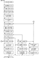
次に、メイン制御部41が行うリール2L、2C、2Rの停止制御について説明する。
メイン制御部41は、リールの回転が開始したとき、及びリールが停止し、かつ未だ回転
中のリールが残っているときに、当選番号及びROM41bに格納されているテーブルイ
ンデックス、テーブル作成用データを参照して、回転中のリール別に停止制御テーブルを
作成する。そして、ストップスイッチ8L、8C、8Rのうち、回転中のリールに対応す
るいずれかの操作が有効に検出されたときに、該当するリールの停止制御テーブルを参照
し、参照した停止制御テーブルの滑りコマ数に基づいて、操作されたストップスイッチ8
L、8C、8Rに対応するリール2L、2C、2Rの回転を停止させる制御を行う。
Next, the stop control of the
The
Control is performed to stop the rotation of the
本実施例では、滑りコマ数として0〜4の値が定められており、停止操作を検出してか
ら最大4図柄を引き込んでリールを停止させることが可能である。すなわち停止操作を検
出した停止操作位置を含め、最大5コマの範囲から図柄の停止位置を指定できるようにな
っている。また、1図柄分リールを移動させるのに1コマの移動が必要であるので、停止
操作を検出してから最大4図柄を引き込んでリールを停止させることが可能であり、停止
操作を検出した停止操作位置を含め、最大5図柄の範囲から図柄の停止位置を指定できる
こととなる。
In this embodiment, a value of 0 to 4 is set as the number of sliding frames, and it is possible to pull in a maximum of 4 symbols to stop the reel after detecting the stop operation. That is, the stop position of the symbol can be specified from a range of up to 5 frames including the stop operation position where the stop operation is detected. Further, since it is necessary to move one frame to move the reel for one symbol, it is possible to pull in a maximum of four symbols after detecting the stop operation to stop the reel, and stop when the stop operation is detected. The stop position of the symbol can be specified from a range of up to 5 symbols including the operation position.
本実施例では、いずれかの役に当選している場合には、停止操作が行われた際に、入賞
ライン上に最大4コマの引込範囲で当選している役を揃えて停止させることができれば、
これを揃えて停止させる制御が行われ、当選していない役は、最大4コマの引込範囲で揃
えずに停止させる制御が行われることとなる。
In this embodiment, when any of the winning combinations is won, when the stop operation is performed, the winning winning combinations are aligned and stopped on the winning line within a pull-in range of up to 4 frames. if you can,
Control is performed to align and stop these, and the winning combination is controlled to stop without aligning within a pull-in range of a maximum of 4 frames.
特別役が前ゲーム以前から持ち越されている状態で小役が当選した場合など、特別役と
小役が同時に当選している場合には、停止操作が行われた際に、入賞ライン上に最大4コ
マの引込範囲で当選している小役を揃えて停止させることができれば、これを揃えて停止
させる制御が行われ、入賞ライン上に最大4コマの引込範囲で当選している小役を引き込
めない場合には、入賞ライン上に最大4コマの引込範囲で当選している特別役を揃えて停
止させることができれば、これを揃えて停止させる制御が行われ、当選していない役は、
4コマの引込範囲で揃えずに停止させる制御が行われることとなる。すなわちこのような
場合には、特別役よりも小役を入賞ライン上に揃える制御が優先され、小役を引き込めな
い場合にのみ、特別役を入賞させることが可能となる。尚、特別役と小役を同時に引き込
める場合には、小役のみを引き込み、特別役と同時に小役が入賞ライン上に揃わないよう
になる。また、特別役と小役が同時に当選している場合に、小役よりも特別役を入賞ライ
ン上に揃える制御が優先され、特別役を引き込めない場合にのみ、小役を入賞ライン上に
揃える制御を行っても良い。
If the special role and the small role are won at the same time, such as when the special role is carried over from before the previous game and the small role is won, the maximum on the winning line is when the stop operation is performed. If it is possible to align and stop the winning small wins in the pull-in range of 4 frames, control is performed to align and stop the small wins that have been won in the pull-in range of up to 4 frames on the winning line. If it is not possible to draw in, if it is possible to align and stop the winning special roles in the drawing range of up to 4 frames on the winning line, control will be performed to align and stop, and the winning combination will be stopped. ,
Control is performed so that the four frames are stopped without being aligned within the pull-in range. That is, in such a case, the control of aligning the small winning combination on the winning line is prioritized over the special winning combination, and the special winning combination can be won only when the small winning combination cannot be drawn in. If the special role and the small role can be drawn in at the same time, only the small role will be drawn in, and the small role will not be aligned on the winning line at the same time as the special role. Also, when a special role and a small role are won at the same time, the control to align the special role on the winning line is prioritized over the small role, and only when the special role cannot be drawn in, the small role is placed on the winning line. Alignment control may be performed.
また、本実施例では、特別役が前ゲーム以前から持ち越されている状態で再遊技役が当
選した場合など、特別役と再遊技役が同時に当選している場合には、停止操作が行われた
際に、入賞ライン上に最大4コマの引込範囲で再遊技役の図柄を揃えて停止させる制御を
行う。尚、この場合、再遊技役を構成する図柄または同時当選する再遊技役を構成する図
柄は、リール2L、2C、2Rのいずれについても5図柄以内、すなわち4コマ以内の間
隔で配置されており、4コマの引込範囲で必ず任意の位置に停止させることができるので
、特別役と再遊技役が同時に当選している場合には、遊技者によるストップスイッチ8L
、8C、8Rの操作タイミングに関わらずに、必ず再遊技役が揃って入賞することとなる
。すなわちこのような場合には、特別役よりも再遊技役を入賞ライン上に揃える制御が優
先され、必ず再遊技役が入賞することとなる。尚、特別役と再遊技役を同時に引き込める
場合には、再遊技役のみを引き込み、再遊技役と同時に特別役が入賞ライン上に揃わない
ようになる。
Further, in this embodiment, when the special role and the re-game combination are won at the same time, such as when the special role is carried over from before the previous game and the re-game combination is won, the stop operation is performed. At that time, control is performed so that the symbols of the re-game combination are aligned and stopped within a pull-in range of up to 4 frames on the winning line. In this case, the symbols constituting the re-game combination or the symbols constituting the re-game combination to be elected at the same time are arranged within 5 symbols, that is, within 4 frames for each of the
, 8C, 8R, regardless of the operation timing, the re-game combination will always be the winner. That is, in such a case, the control of aligning the re-game combination on the winning line is prioritized over the special combination, and the re-game combination is sure to win the prize. If the special role and the re-game role can be drawn in at the same time, only the re-game role will be drawn in, and the special role will not be aligned on the winning line at the same time as the re-game role.
尚、本実施例では、停止操作が行われたタイミング別の滑りコマ数を特定可能な停止制
御テーブルを用いてリールの停止制御を行う構成であるが、停止可能な位置を特定可能な
停止位置テーブルから停止位置を特定し、特定した停止位置にリールを停止させる停止制
御を行う構成、停止制御テーブルや停止位置テーブルを用いずに、停止操作がされたタイ
ミングで停止可能な停止位置を検索・特定し、特定した停止位置にリールを停止させる停
止制御を行う構成、停止制御テーブルを用いた停止制御、停止位置テーブルを用いた停止
制御、停止制御テーブルや停止位置テーブルを用いずに停止可能な停止位置を検索・特定
することによる停止制御を併用する構成、停止制御テーブルや停止位置テーブルを一部変
更して停止制御を行う構成としても良い。
In this embodiment, the reel stop control is performed using a stop control table that can specify the number of slip frames for each timing when the stop operation is performed. However, the stop position that can specify the stop position can be specified. A configuration that specifies the stop position from the table and stops the reel at the specified stop position, and searches for a stop position that can be stopped at the timing when the stop operation is performed without using the stop control table or stop position table. Configuration that performs stop control to specify and stop the reel at the specified stop position, stop control using the stop control table, stop control using the stop position table, stop without using the stop control table or stop position table A configuration in which stop control by searching and specifying a stop position may be used together, or a configuration in which a stop control table or a stop position table is partially changed to perform stop control may be used.
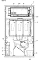
[メダルセレクタについて]
前面扉1bの内側に配置されたメダルセレクタ29の構造について、図4〜図6に基づ
いて説明する。尚、以下の説明において、前面扉1bの裏面側からメダルセレクタ29を
見た状態を、メダルセレクタ29の前面側として説明する。
[About medal selector]
The structure of the
メダルセレクタ29は、図4及び図5に示すように直方体形状に構成されており、当該
メダルセレクタ29の本体部の上側壁には、当該本体部の内部へメダルが流入可能な流入
口141が設けられ、本体部の左側壁には、当該本体部の内部からホッパータンク34a
側の外部へメダルが流出可能な流出口142が設けられ、本体部の下側壁には、当該本体
部の内部からメダル払出口9側の外部へメダルを排出可能な排出口143が設けられてい
る。そして、メダルセレクタ29の本体部の内部には、流入口141から流出口142に
連通する正面視略L字状のメダル流下流路が形成されている。このメダル流下流路の側壁
は、図4(b)及び図5(b)に示すように、流下するメダルの上端が下端よりも前方側
に傾く姿勢となるように下方から上方にかけて前面側に傾斜している。また、流入口14
1から排出口143に連通する正面視略S字状のメダル流下流路が形成されている。以下
、メダルセレクタ29の本体部の内部のメダル流下流路のうち流入口141側の流路をメ
ダル流入流路29a、流出口142側の流路をメダル受入流路29b、排出口143側の
流路をメダル返却流路29cと呼ぶ。
The
An
A substantially S-shaped medal flow flow path in front view is formed from 1 to the
メダルセレクタ29では、投入されたメダルの真偽(形状、大きさ、厚み等)が判別さ
れるようになっており、真正なメダルは、流入口141から流入した後、メダルセレクタ
29の本体部内部のメダル流入流路29a及びメダル受入流路29bを流下して、投入メ
ダルセンサ31a〜31cの検出範囲Aを通過することで、投入メダルセンサ31a〜3
1cにて検出された後、流出口142から流出される。そして、当該メダルは、メダルシ
ュート142a(図2参照)を介して、ホッパータンク34aに導かれるようになってい
る。一方、偽メダルは、流入口141から流入した後、メダル流入流路29aの流下中に
メダル返却流路29cへ落下させられて、当該メダル返却流路29cを流下し、排出口1
43から流出される。そして、当該メダルは、メダルセレクタ29の下方に設けられたメ
ダル返却通路(図示略)を介してメダル払出口9(図1参照)から下皿に返却されるよう
になっている。
In the
After being detected in 1c, it is discharged from the
It is leaked from 43. Then, the medal is returned to the lower plate from the medal payout outlet 9 (see FIG. 1) via the medal return passage (not shown) provided below the
また、メダル流入流路29a、メダル受入流路29b、メダル返却流路29cの合流部
分には、メダルセレクタ29の本体部の前面側に設けられる流路切替ソレノイド30(図
3参照)の励磁に連係して、メダル流入流路29aを流下するメダルがメダル受入流路2
9bへ流入する前に、当該メダルをメダル流入流路29aから下方に向けて強制的に落下
させて、当該メダルをメダル返却流路29cに流入させるための流路切替板147が揺動
自在に設けられている。
Further, at the confluence of the medal
Before flowing into 9b, the medal is forcibly dropped downward from the medal
流路切替板147は、流路切替ソレノイド30が励磁されていない状態、すなわちメダ
ルの受付が許可されていない状態において、図4(a)(b)に示すように、メダル流入
流路29aの下方側が開放状態となり、メダル流入流路29aとメダル返却流路29cが
連通した状態となるように搖動可能である。また、流路切替ソレノイド30が励磁されて
いる状態、すなわちメダルの受付が許可されている状態において、図5(a)(b)に示
すように、流路切替板147の上部が図中左方向(矢印A方向)に揺動することで、流路
切替板147の上端面がメダル流入流路29aの底面を構成する状態となり、メダル流入
流路29aの下方側を閉鎖状態として、メダル流入流路29aとメダル返却流路29cが
連通しない状態となるように搖動可能に構成されている。このような構成により、流路切
替ソレノイド30が励磁されている状態では、流入口141から流入してメダル流入流路
29aを流下するメダルは流路切替板147の上端面に沿って流下し、メダル受入流路2
9bに流入して流出口142から流出されるようになっている。
The flow
It flows into 9b and flows out from the
また、メダル流入流路29aの上流側には、流入口141から流入したメダルの通過を
検出する投入口センサ26が設けられており、メダル受入流路29bの下流側には、流出
口142に排出されるメダルの通過を検出する投入メダルセンサ31a〜31cが設けら
れている。
Further, an
投入メダルセンサ31a〜31cのうち投入メダルセンサ31a及び31cは、投光部
と受光部の間をメダルが通過することにより受光部が投光部からの光の遮断を検知するこ
とでメダルの通過を検出するフォトセンサであり、投入メダルセンサ31bは、メダルの
通過に連動して動作する可動片180の動作を検知器183により検知することでメダル
の通過を検出する物理センサである。尚、以下、投入メダルセンサ31aを投入メダルセ
ンサ1、投入メダルセンサ31bを投入メダルセンサ2、投入メダルセンサ31cを投入
メダルセンサ3と呼ぶ場合がある。また、投入メダルセンサ31a〜31cによりメダル
の通過が検出される範囲を検出範囲Aと呼ぶ場合がある。
Of the inserted
次に、物理センサである投入メダルセンサ31bの構成について、図4〜図6に基づい
て説明する。図6(a)(b)は、図4(a)のC−C断面図のうち投入メダルセンサ3
1bの周辺を示す図であり、図6(a)は、投入メダルセンサ31a〜31cの検出範囲
Aをメダルが通過していないときの図であり、図6(b)は、投入メダルセンサ31a〜
31cの検出範囲Aをメダルが通過しているときの図である。
Next, the configuration of the
It is a figure which shows the periphery of 1b, FIG. 6A is a figure when a medal has not passed through the detection range A of the
It is a figure when the medal passes through the detection range A of 31c.
図4(a)、図5(a)、図6(a)(b)に示すように、メダルセレクタ29におけ
るメダル受入流路29bの下流側の下方部分の側壁に、投入メダルセンサ31bの可動片
180が、メダル受入流路29bに出没可能に設けられている。また、図6(a)(b)
に示すように、メダル受入流路29bの外部における可動片180に対応する位置に、検
知器183が設置されている。検知器183は、検知部183aに投光部と受光部が設け
られている。
As shown in FIGS. 4 (a), 5 (a), 6 (a) and 6 (b), the inserted
As shown in the above, the
そして、図6(a)に示すように、可動片180は、メダル受入流路29bをメダルが
通過する際に、メダルが可動片180の先端部180bをメダル受入流路29b内から退
けることにより、可動片180の端部に設けられた被検知部180aを、検知部183a
の投光部と受光部の間に進入させるようになっており、投光部から受光部へ照射される光
が遮断されて、検知器183によりメダルの通過が検出されるようになっている。一方、
図6(b)に示すように、可動片180は、メダル受入流路29bをメダルが通過してい
ない状態では、当該可動片180の先端部180bがメダル受入流路29b内に突出する
ように付勢されている。この状態では、可動片180の被検知部180aが検知部183
aの投光部と受光部の間に進入せず、検知部183aの投光部から受光部に照射される光
を遮断することがないので、検知器183によりメダルの通過が検出されないようになっ
ている。
Then, as shown in FIG. 6A, when the medal passes through the medal receiving
It is designed to enter between the light emitting part and the light receiving part of the above, and the light emitted from the light emitting part to the light receiving part is blocked, and the passage of the medal is detected by the
As shown in FIG. 6B, in the
Since it does not enter between the light emitting part and the light receiving part of a and does not block the light emitted from the light emitting part of the
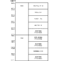
[メイン制御部のメモリ領域とプログラムについて]
図7は、メイン制御部41が用いるメモリ領域のアドレスマップである。図7に示すよ
うに、メイン制御部41が用いるメモリ領域は、ROM41bに割り当てられたメモリ領
域(0000H〜7FFFH)と、RAM41cに割り当てられたメモリ領域(F000
H〜FFFFH)と、を含む。
[About the memory area and program of the main control unit]
FIG. 7 is an address map of the memory area used by the
H to FFFFH) and.
ROM41bのメモリ領域は、プログラム及び固定データが格納されるプログラム/デ
ータ領域(0000H〜26FFH)と、プログラムのタイトル、バージョン等の任意の
データを設定可能なROMコメント領域(2700H〜277FH)と、後述するCAL
LV命令のサブルーチンの上位アドレス及びタイマ割込処理(メイン)の先頭アドレスが
設定されるベクタテーブル領域(2780H〜27A7H)と、メイン制御部41の内部
機能をハードウェア的に設定するためのパラメータが設定されるHWパラメータ領域(2
7A8H〜27FFH)と、アクセスが禁止される未使用領域(2800H〜7FFFH
)を含む。
The memory area of the
The vector table area (2780H to 27A7H) where the upper address of the subroutine of the LV instruction and the start address of the timer interrupt processing (main) are set, and the parameters for setting the internal function of the
7A8H to 27FFH) and unused areas (2800H to 7FFFH) where access is prohibited
)including.
ROM41bにおけるHWパラメータ領域に設定されるパラメータは、プログラム/デ
ータ領域で使用するROM領域の最終アドレス(HPRGEND)、アクセス禁止するR
AM領域の開始アドレス(HRAMSTAT)及び最終アドレス(HRAMEND)を含
む。
The parameters set in the HW parameter area in the
Includes the start address (HRAMSTART) and end address (HRAMEND) of the AM region.
RAM41cのメモリ領域は、ワークとして使用可能な使用可能領域(F000H〜F
400H)と、メイン制御部41に搭載されている各機能を制御するためのレジスタ群が
格納される内部機能レジスタ領域(F4B0H〜F6FFH)と、アクセスが禁止される
未使用領域(F401H〜F4AFH、F700H〜FFFFH)と、を含む。
The memory area of the
400H), an internal function register area (F4B0H to F6FFH) in which a register group for controlling each function mounted on the
図8は、メイン制御部41のROM41bにおけるプログラム/データ領域及びRAM
41cにおける使用可能領域のアドレスマップである。
FIG. 8 shows the program / data area and RAM in the
It is an address map of the usable area in 41c.
図8(a)に示すように、ROM41bにおけるプログラム/データ領域は、遊技の進
行に係わる遊技プログラムが記憶される遊技プログラム領域と、遊技プログラムが用いる
遊技データが記憶される遊技データ領域と、未使用領域1と、遊技の進行に係わらない非
遊技プログラムが記憶される非遊技プログラム領域と、非遊技プログラムが用いる非遊技
データが記憶される非遊技データ領域と、未使用領域2と、を含む。
As shown in FIG. 8A, the program / data area in the
尚、遊技の進行とは、遊技を構成する一連のプロセスを進行させることであり、スロッ
トマシンであれば、賭数を設定してゲームを開始可能とする段階、ゲームを開始してリー
ルを回転させる段階、リールを停止させて表示結果を導出させる段階、表示結果に応じて
メダル等の価値を付与する段階、を進行させることである。
The progress of the game is to proceed with a series of processes constituting the game, and if it is a slot machine, the stage where the bet number is set and the game can be started, the game is started and the reel is rotated. The stage of causing the reel to be stopped, the stage of deriving the display result, and the stage of giving the value of a medal or the like according to the display result are advanced.
遊技の進行に係わる遊技プログラム領域と、遊技の進行に係わらない非遊技プログラム
と、がそれぞれ別個に割り当てられているとともに、遊技プログラム領域及び非プログラ
ム領域のうちROM41bの記憶領域において後方に割り当てられていた非プログラム領
域の手前の領域は、少なくとも16バイト以上の未使用領域1が割り当てられているため
、遊技の進行に係わる遊技プログラム領域と、遊技の進行に係わらない非遊技プログラム
と、を記憶領域の違いに応じて容易に特定することができる。
The game program area related to the progress of the game and the non-game program not related to the progress of the game are separately allocated, and are allocated rearward in the storage area of
また、遊技プログラム領域と遊技データ領域、非遊技プログラム領域と非遊技データ領
域はそれぞれ連続する領域に割り当てられる一方、遊技の進行に係わる遊技プログラム領
域及び遊技データ領域と、遊技の進行に係わらない非遊技プログラム及び非遊技データ領
域と、が少なくとも16バイト以上の未使用領域1を挟んで連続しない領域に割り当てら
れているため、遊技の進行に係わる遊技プログラム領域及び遊技データ領域と、遊技の進
行に係わらない非遊技プログラム及び非遊技データ領域と、を記憶領域の違いに応じて容
易に特定することができる。
Further, the game program area and the game data area, and the non-game program area and the non-game data area are allotted to continuous areas, while the game program area and the game data area related to the progress of the game and the non-game area not related to the progress of the game. Since the game program and the non-game data area are allocated to areas that are not continuous with an
尚、上記において記憶領域の前後とは、記憶領域に割り当てられたアドレス値の大小関
係であり、アドレスが小さい方が前方となり、アドレスが大きい方が後方となる。このた
め、一の記憶領域よりも後方に割り当てられた記憶領域とは、一の記憶領域よりもアドレ
ス値が大きい記憶領域が該当し、一の記憶領域よりも前方に割り当てられた記憶領域とは
、一の記憶領域よりもアドレス値が小さい記憶領域が該当する。
In the above, the front and back of the storage area are the magnitude relations of the address values assigned to the storage area, and the smaller address is the front and the larger address is the rear. Therefore, the storage area allocated after one storage area corresponds to the storage area having an address value larger than that of one storage area, and is the storage area allocated before one storage area. , A storage area whose address value is smaller than that of one storage area is applicable.
また、非遊技プログラム領域よりも後方に遊技プログラムが割り当てられ、非遊技プロ
グラム領域よりも後方に割り当てられた遊技プログラムの手前に未使用領域が割り当てら
れた構成としても良く、このような構成においても遊技の進行に係わる遊技プログラム領
域と、遊技の進行に係わらない非遊技プログラムと、を記憶領域の違いに応じて容易に特
定することができる。
Further, the game program may be allocated behind the non-game program area, and the unused area may be allocated in front of the game program allocated behind the non-game program area. A game program area related to the progress of the game and a non-game program not related to the progress of the game can be easily specified according to the difference in the storage area.
また、遊技プログラム領域と、非遊技プログラム領域と、が未使用領域1を挟んで隣接
する領域に割り当てられる構成としても良く、このような構成であっても、遊技の進行に
係わる遊技プログラム領域と、遊技の進行に係わらない非遊技プログラムと、を記憶領域
の違いに応じて容易に特定することができる。
Further, the game program area and the non-game program area may be allocated to adjacent areas with the
また、ROM41bのプログラム/データ領域の未使用領域1、2には、全ての領域に
0値が格納されているため、遊技プログラム領域及び遊技データ領域と、非遊技プログラ
ム領域及び非遊技データと、未使用領域1、2と、を容易に区別することができるととも
に、未使用領域1、2に不正なデータが格納されている場合でも容易に発見することがで
きる。
Further, since 0 values are stored in all the
尚、ROM41bのプログラム/データ領域の未使用領域1、2における全ての領域に
1が格納される構成としても良く、このような構成とした場合でも、遊技プログラム領域
及び遊技データ領域と、非遊技プログラム領域及び非遊技データと、未使用領域1、2と
、を容易に区別することができるとともに、未使用領域1、2に不正なデータが格納され
ている場合でも容易に発見することができる。
It should be noted that 1 may be stored in all the
また、遊技プログラム領域と、非遊技プログラム領域と、が別個の領域に割り当たられ
た構成であれば、遊技プログラム領域と、非遊技プログラム領域と、が隣接する領域にわ
ら当てられる構成としても良く、このような構成であっても遊技の進行に係わる遊技プロ
グラム領域と、遊技の進行に係わらない非遊技プログラムと、を記憶領域の違いに応じて
容易に特定することができる。
Further, if the game program area and the non-game program area are allocated to separate areas, the game program area and the non-game program area may be allocated to adjacent areas. Even with such a configuration, the game program area related to the progress of the game and the non-game program not related to the progress of the game can be easily specified according to the difference in the storage area.
また、遊技プログラム領域及び非遊技プログラム領域はいずれも、アドレスを2進数表
記した場合に下位4桁の値が同じ0のアドレス(0H)から開始するようになっており、
ROM41bのプログラム/データ領域のうち遊技の進行に係る遊技プログラム領域と、
遊技の進行に係わらない非遊技プログラム領域と、を他の領域と容易に区別することがで
きる。
In addition, both the game program area and the non-game program area start from an address (0H) in which the lower four digits have the same value when the address is expressed in binary.
Of the program / data areas of
The non-game program area, which is not related to the progress of the game, can be easily distinguished from other areas.
また、遊技プログラム領域及び非遊技プログラム領域はいずれも、アドレスを2進数表
記した場合に下位4桁の値が同じ0のアドレスから開始するだけでなく、16進数表記し
た場合に下位1桁の値が同じ0のアドレス(0H)から開始するので、アドレスを2進数
表記した場合だけでなく、16進数表記した場合にも遊技プログラム領域と、非遊技プロ
グラム領域と、を他の領域と容易に区別することができる。
In addition, both the game program area and the non-game program area not only start from an address having the same lower four-digit value when the address is expressed in binary, but also start from the address where the lower four-digit value is the same, and when the address is expressed in hexadecimal, the lower one-digit value Starts from the same 0 address (0H), so the game program area and the non-game program area can be easily distinguished from other areas not only when the address is expressed in binary not only but also when it is expressed in hexadecimal. can do.
尚、遊技プログラム領域及び非遊技プログラム領域がいずれも、アドレスを2進数表記
したか、16進数表記したか、に関わらず、下位N(Nは1以上の自然数)桁が同じ値の
アドレスから開始する構成であれば、遊技プログラム領域と、非遊技プログラム領域と、
を他の領域と容易に区別することが可能であり、例えば、下位N(Nは1以上の自然数)
桁の値が同じ1のアドレスから開始する構成でも同様の効果が得られるものである。
In both the game program area and the non-game program area, regardless of whether the address is expressed in binary or hexadecimal, the lower N (N is a natural number of 1 or more) starts from the address having the same value. If it is configured to be, a game program area, a non-game program area, and
Can be easily distinguished from other regions, for example, lower N (N is a natural number of 1 or more).
The same effect can be obtained even in a configuration starting from an address having the same digit value of 1.
図8(b)に示すように、RAM41cの使用可能領域は、遊技プログラムがワークと
して用いる遊技RAM領域と、非遊技プログラムがワークとして用いる非遊技RAM領域
と、未使用領域4と、を含んでおり、遊技RAM領域には、特別ワークと、重要ワークと
、一般ワークと、未使用領域3と、遊技プログラムがデータを退避する遊技スタック領域
と、が含まれ、非遊技RAM領域には、遊技プログラムが参照可能な領域と、遊技プログ
ラムが参照不可能な領域と、非遊技プログラムがデータを退避する非遊技スタック領域と
、が含まれる。尚、本実施例では、遊技スタック領域と非遊技スタック領域とをそれぞれ
異なる領域に個別に備える構成であるが、遊技プログラム及び非遊技プログラムが共用す
る一のスタック領域を備える構成としても良い。
As shown in FIG. 8B, the usable area of the
未使用領域3は、遊技プログラム及び非遊技プログラムのいずれも使用しない領域であ
り、予め定められた容量の遊技RAM領域に対して余剰となった領域である。
The
また、未使用領域4は、遊技プログラム及び非遊技プログラムのいずれも使用しない1
6バイト以上の領域である。遊技RAM領域と、非遊技RAM領域とが、未使用領域4を
挟んで連続しない領域に割り当てられているため、遊技の進行に係わる遊技プログラムが
用いる遊技RAM領域と、遊技の進行に係わらない非遊技プログラムが用いる非遊技RA
M領域と、を記憶領域の違いに応じて容易に特定することができる。
Further, the
It is an area of 6 bytes or more. Since the game RAM area and the non-game RAM area are allocated to areas that are not continuous with the
The M area and the M area can be easily specified according to the difference in the storage area.
以下では、遊技プログラム領域、遊技データ領域及び遊技RAM領域をまとめて遊技領
域と称す場合があり、非遊技プログラム領域、非遊技データ領域及び非遊技RAM領域を
まとめて非遊技領域と称す場合がある。また、未使用領域1及び未使用領域2、未使用領
域3及び未使用領域4をまとめて未使用領域と称す場合がある。
In the following, the game program area, the game data area, and the game RAM area may be collectively referred to as a game area, and the non-game program area, the non-game data area, and the non-game RAM area may be collectively referred to as a non-game area. .. Further, the
メイン制御部41は、HWパラメータ領域に設定されるパラメータに基づいて、ROM
41bのプログラム/データ領域のうちアクセスが禁止された領域へのアクセスがあった
とき、RAM41cの使用可能領域のうちアクセスが許可に設定されていない領域へのア
クセスがあったとき、ROM41bのうちプログラム/データ領域以外の領域へのアクセ
スがあったとき、RAM41cのうち使用可能領域以外の領域へのアクセスがあったとき
に、すなわち正常な動作ではアクセスすることのないメモリ領域へのアクセスがあったと
きにイリーガルアクセスリセットを発生させることで、遊技の進行を不能化させるので、
ROM41bの未使用領域や動作とは関係しない領域、RAM41cの未使用領域等に不
正なプログラムが格納された場合であっても、不正なプログラムが実行されてしまうこと
を防止できる。
The
When there is an access to an area of the program / data area of 41b for which access is prohibited, when there is an access to an area of the usable area of the
Even when an illegal program is stored in an unused area of the
特に本実施例では、ROM41bのうちプログラムによってアクセスが許可されたプロ
グラム/データ領域に遊技プログラム領域と、非遊技プログラム領域と、が割り当てられ
、遊技プログラム領域よりも後方の非遊技プログラム領域の手前の領域に未使用領域1が
割り当てられるとともに、HWパラメータ領域に設定されるパラメータに基づいて、プロ
グラム/データ領域のうち遊技プログラム領域の先頭アドレスから非遊技プログラムの最
終アドレスまでの領域を含む一かたまりの領域(遊技プログラム領域から非遊技データ領
域までの領域)へのアクセスを一括して許可に設定する一方で、それ以外の領域、すなわ
ちプログラム/データ領域のうち遊技プログラムや遊技データ、非遊技プログラム、非遊
技データが格納されていない非遊技データよりも後の領域へのアクセスが禁止されるため
、不正プログラムや不正データによる意図しない制御が行われてしまうことを防止できる
。
In particular, in this embodiment, the game program area and the non-game program area are allocated to the program / data area of the
また、ROM41bのうちプログラムによってアクセスが許可されたプログラム/デー
タ領域において非遊技プログラム領域よりも後方に遊技領域が割り当てられ、非遊技プロ
グラム領域よりも後方の遊技プログラム領域の手前の領域に未使用領域が割り当てられる
とともに、HWパラメータ領域に設定されるパラメータに基づいて、プログラム/データ
領域のうち非遊技プログラム領域の先頭アドレスから遊技プログラムの最終アドレスまで
の領域を含む一かたまりの領域へのアクセスを一括して許可に設定する一方で、それ以外
の領域へのアクセスが禁止されるようにしても、不正プログラムや不正データによる意図
しない制御が行われてしまうことを防止できる。
Further, in the program / data area of the
尚、プログラム/データ領域に遊技プログラム領域と、非遊技プログラム領域と、が割
り当てられ、遊技プログラム領域よりも後方の非遊技プログラム領域の手前の領域に未使
用領域1が割り当てられるとともに、プログラム/データ領域のうち遊技プログラム領域
を含む一かたまりの領域(遊技プログラム領域から遊技データ領域までの領域)、非遊技
プログラムを含む一かたまりの領域(非遊技プログラム領域から非遊技データ領域までの
領域)へのアクセスをそれぞれ許可に設定し、他の領域へのアクセスを禁止する構成とし
ても良く、このような構成とした場合でも、プログラム/データ領域のうち遊技プログラ
ムや非遊技プログラムが格納されていない領域へのアクセスが禁止されるため、不正プロ
グラムや不正データによる意図しない制御が行われてしまうことを防止できる。また、R
OM41bのうちプログラムによってアクセスが許可されたプログラム/データ領域にお
いて非遊技プログラム領域よりも後方に遊技領域が割り当てられ、非遊技プログラム領域
よりも後方の遊技プログラム領域の手前の領域に未使用領域が割り当てられるとともに、
プログラム/データ領域のうち遊技プログラム領域を含む一かたまりの領域(遊技プログ
ラム領域から遊技データ領域までの領域)、非遊技プログラムを含む一かたまりの領域(
非遊技プログラム領域から非遊技データ領域までの領域)へのアクセスをそれぞれ許可に
設定し、他の領域へのアクセスを禁止する構成としても良く、このような構成とした場合
でも、プログラム/データ領域のうち遊技プログラムや非遊技プログラムが格納されてい
ない領域へのアクセスが禁止されるため、不正プログラムや不正データによる意図しない
制御が行われてしまうことを防止できる。
A game program area and a non-game program area are allocated to the program / data area, and an
In the program / data area of the OM41b that is permitted to be accessed by the program, the game area is allocated behind the non-game program area, and the unused area is allocated to the area in front of the game program area behind the non-game program area. As well as being
Of the program / data area, a group of areas including the game program area (area from the game program area to the game data area) and a group of areas including non-game programs (area from the game program area to the game data area).
Access to each of the non-gaming program areas to the non-gaming data area) may be set to allow and access to other areas may be prohibited. Even in such a configuration, the program / data area may be used. Of these, access to areas where game programs and non-game programs are not stored is prohibited, so it is possible to prevent unintended control by malicious programs and malicious data.
また、上記では、プログラム/データ領域においてアクセスを許可する領域そのものを
設定する構成であるが、プログラム/データ領域においてアクセスを禁止する領域を設定
することで、間接的にアクセスを許可する領域が設定される構成としても良い。
Further, in the above, the configuration is such that the area itself that allows access in the program / data area is set, but by setting the area that prohibits access in the program / data area, the area that indirectly permits access is set. It may be configured to be performed.
メイン制御部41は、HWパラメータ領域に設定されるパラメータに基づいて、プログ
ラム走行を許可する指定エリア以外の領域においてユーザプログラムが実行された場合、
すなわち正常な動作ではユーザプログラムが実行されることのない領域でユーザプログラ
ムが実行された場合に、IAT回路506aがIAT発生信号を出力することで、遊技の
進行を不能化させるので、ROM41bの未使用領域や動作とは関係しない領域、RAM
41cの未使用領域等に不正なプログラムが格納された場合であっても、不正なプログラ
ムが実行されてしまうことを防止できる。
When the user program is executed in an area other than the designated area where the program running is permitted, the
That is, when the user program is executed in an area where the user program is not executed in normal operation, the IAT circuit 506a outputs an IAT generation signal, which disables the progress of the game. Area that is not related to used area or operation, RAM
Even when an illegal program is stored in the unused area of 41c or the like, it is possible to prevent the illegal program from being executed.
特に本実施例では、ROM41bのうちプログラムによってアクセスが許可されたプロ
グラム/データ領域に遊技プログラム領域と、非遊技プログラム領域と、が割り当てられ
、遊技プログラム領域よりも後方の非遊技プログラム領域の手前の領域に未使用領域1が
割り当てられるとともに、HWパラメータ領域に設定されるパラメータに基づいて、プロ
グラム/データ領域のうち遊技プログラム領域、非遊技プログラム領域の各々について、
IAT回路506aがプログラム走行を許可する指定エリアとして設定する一方で、それ
以外の領域、すなわちプログラム/データ領域のうち遊技プログラムや非遊技プログラム
が格納されていない領域でのプログラム走行が禁止されるため、不正プログラムや不正デ
ータによる意図しない制御が行われてしまうことを防止できる。
In particular, in this embodiment, the game program area and the non-game program area are allocated to the program / data area of the
While the IAT circuit 506a sets it as a designated area that allows program running, program running is prohibited in other areas, that is, in the program / data area where game programs and non-game programs are not stored. , It is possible to prevent unintended control by malicious programs and malicious data.
また、ROM41bのうちプログラムによってアクセスが許可されたプログラム/デー
タ領域において非遊技プログラム領域よりも後方に遊技領域が割り当てられ、非遊技プロ
グラム領域よりも後方の遊技プログラム領域の手前の領域に未使用領域が割り当てられる
とともに、HWパラメータ領域に設定されるパラメータに基づいて、プログラム/データ
領域のうち遊技プログラム領域、非遊技プログラム領域の各々について、IAT回路50
6aがプログラム走行を許可する指定エリアとして設定する一方で、それ以外の領域での
プログラム走行が禁止されるようにしても、不正プログラムや不正データによる意図しな
い制御が行われてしまうことを防止できる。
Further, in the program / data area of the
While 6a is set as a designated area that allows program running, even if program running is prohibited in other areas, it is possible to prevent unintended control due to malicious programs or malicious data. ..
尚、プログラム/データ領域に遊技プログラム領域と、非遊技プログラム領域と、が割
り当てられ、遊技プログラム領域よりも後方の非遊技プログラム領域の手前の領域に未使
用領域1が割り当てられるとともに、HWパラメータ領域に設定されるパラメータに基づ
いて、プログラム/データ領域のうち遊技プログラム領域の先頭アドレスから非遊技プロ
グラムの最終アドレスまでの領域を含む一かたまりの領域(遊技プログラム領域から非遊
技データ領域までの領域)について、IAT回路506aがプログラム走行を許可する指
定エリアとして一括して設定し、他の領域でのプログラム走行が禁止される構成としても
良く、このような構成とした場合でも、プログラム/データ領域のうち遊技プログラムや
非遊技プログラムが格納されていない領域でのプログラム走行が禁止されるため、不正プ
ログラムや不正データによる意図しない制御が行われてしまうことを防止できる。また、
ROM41bのうちプログラムによってアクセスが許可されたプログラム/データ領域に
おいて非遊技プログラム領域よりも後方に遊技領域が割り当てられ、非遊技プログラム領
域よりも後方の遊技プログラム領域の手前の領域に未使用領域が割り当てられるとともに
、HWパラメータ領域に設定されるパラメータに基づいて、プログラム/データ領域のう
ち非遊技プログラム領域の先頭アドレスから遊技プログラムの最終アドレスまでの領域を
含む一かたまりの領域(遊技プログラム領域から非遊技データ領域までの領域)について
、IAT回路506aがプログラム走行を許可する指定エリアとして一括して設定し、他
の領域でのプログラム走行が禁止されるようにしても、不正プログラムや不正データによ
る意図しない制御が行われてしまうことを防止できる。
A game program area and a non-game program area are allocated to the program / data area, and an
In the program / data area of the
また、上記では、プログラム/データ領域においてプログラム走行を許可する領域その
ものを設定する構成であるが、プログラム/データ領域においてプログラム走行を禁止す
る領域を設定することで、間接的にプログラム走行を許可する領域が設定される構成とし
ても良い。
Further, in the above, the configuration is such that the area itself that allows the program running is set in the program / data area, but the program running is indirectly permitted by setting the area that prohibits the program running in the program / data area. The configuration may be such that an area is set.
[プログラムが用いる命令について]
メイン制御部41が実行するプログラムは、プログラム全体の進行を管理するメインル
ーチンと、他のプログラムの実行中に呼び出されるサブルーチンとを含む。
[Instructions used by the program]
The program executed by the
また、メイン制御部41にプログラム/データ領域に格納されたプログラムを実行させ
る命令として、CALL命令を含む。
Further, a CALL instruction is included as an instruction for causing the
CALL命令は、メインルーチンまたはサブルーチンにおいて指定されたアドレスに格
納されたサブルーチンを呼び出して実行させる命令である。メイン制御部41は、CAL
L命令によりサブルーチンを呼び出す場合には、呼び出し元のアドレスをスタック領域に
格納し、指定されたアドレスに格納されたサブルーチンを呼び出して実行する。そして、
当該サブルーチンの終了後、スタック領域に格納されている呼び出し元のアドレス、すな
わちCALL命令を実行した呼び出し元のメインルーチンまたはサブルーチンのプログラ
ムに復帰する。
The CALL instruction is an instruction that calls and executes a subroutine stored at an address specified in the main routine or the subroutine. The
When a subroutine is called by the L instruction, the address of the caller is stored in the stack area, and the subroutine stored at the specified address is called and executed. And
After the subroutine ends, the address of the caller stored in the stack area, that is, the program of the caller's main routine or subroutine that executed the CALL instruction is returned.
また、CALL命令は、通常のCALL命令と、特殊なCALL命令であるCALLV
命令と、を含む。通常のCALL命令は、上位アドレス及び下位アドレスの双方を指定し
て指定された上位アドレス及び下位アドレスによりアドレスを特定してサブルーチンを呼
び出す命令であるのに対して、CALLV命令は、下位アドレスのみを指定することで、
ROM41bのベクタテーブル領域に予め設定された上位アドレス及び指定された下位ア
ドレスによりアドレスを特定してサブルーチンを呼び出す命令であり、通常のCALL命
令に比較して少ないデータ量でサブルーチンを呼び出すことが可能となる。
Further, the CALL instruction is a normal CALL instruction and a special CALL instruction CALLV.
Including instructions. The normal CALL instruction is an instruction that calls a subroutine by specifying both the upper address and the lower address and specifying the address by the specified upper address and lower address, whereas the CALLV instruction only uses the lower address. By specifying
It is an instruction to specify an address by a preset upper address and a specified lower address in the vector table area of ROM41b and call a subroutine, and it is possible to call a subroutine with a smaller amount of data than a normal CALL instruction. Become.
RST命令は、予め定められた複数の特定アドレスに対応する値を指定することで、指
定された値に対応する特定アドレスに格納されたサブルーチンを呼び出して実行させる命
令であり、上記した通常のCALL命令やCALLV命令に比較して少ないデータ量でサ
ブルーチンを呼び出すことが可能となる。メイン制御部41は、RST命令によりサブル
ーチンを呼び出す場合には、呼び出し元のアドレスをスタック領域に格納し、指定された
値に対応する特定アドレスに格納されたサブルーチンを呼び出して実行する。そして、当
該サブルーチンの終了後、スタック領域に格納されている呼び出し元のアドレス、すなわ
ちRST命令を実行した呼び出し元のメインルーチンまたはサブルーチンに復帰する。
The RST instruction is an instruction to call and execute a subroutine stored in a specific address corresponding to a specified value by designating a value corresponding to a plurality of predetermined specific addresses, and is an instruction to execute the above-mentioned ordinary CALL. It is possible to call a subroutine with a smaller amount of data than an instruction or a CALLV instruction. When the subroutine is called by the RST instruction, the
ジャンプ命令は、メインルーチンまたはサブルーチンにおいて指定されたアドレスに格
納されたプログラムに移動する命令である。メイン制御部41は、ジャンプ命令により指
定されたアドレスに格納されたプログラムに移動し、移動先のプログラムを実行する。こ
の場合には、CALL命令やRST命令と異なり、移動後のプログラムが終了しても移動
元のプログラムに復帰することはない。
A jump instruction is an instruction to move to a program stored at an address specified in a main routine or a subroutine. The
ROM41bに格納された遊技プログラムのうち特に使用頻度の高いサブルーチンは、
ROM41bの遊技プログラム領域のうち先頭アドレスが特定値(例えば00H)となる
領域に格納されている。一方、ROM41bのベクタテーブル領域には、CALLV命令
で呼び出すサブルーチンの上位アドレスとして特定値が設定されている。そして、メイン
制御部41は、先頭アドレスの上位アドレスが特定値となるサブルーチンを呼び出すとき
に、CALLV命令を用いて下位アドレスのみ指定することで、上位アドレスとしてベク
タテーブル領域に設定された特定値を特定し、下位アドレスとして指定された下位アドレ
スを特定し、上位及び下位を合わせたアドレスに格納されたサブルーチンを呼び出して実
行する。このため、遊技プログラムのうち特に使用頻度の高いサブルーチンを呼び出す際
に用いるアドレスの一部を構成する上位アドレスが特定値として予めベクタテーブルに設
定されており、ベクタテーブルに設定された特定値に基づいてアドレスが特定されるため
、上位アドレス及び下位アドレスの双方を指定してプログラムを呼び出す通常のCALL
命令に比較して少ないデータ量にてサブルーチンを呼び出すことが可能となり、これらの
サブルーチンを呼び出す際にアドレスを指定するためのプログラムの無駄を削減すること
ができる。
Of the game programs stored in
It is stored in an area where the start address is a specific value (for example, 00H) in the game program area of the
It is possible to call subroutines with a smaller amount of data than instructions, and it is possible to reduce the waste of the program for specifying an address when calling these subroutines.
本実施例では、CALLV命令により用いられるROM41bのベクタテーブル領域、
及びRST命令により用いられるROM41bの特定アドレスの領域には、遊技プログラ
ムのサブルーチンの先頭が格納されており、CALLV命令及びRST命令では通常のC
ALL命令に比較して少ないデータ量でサブルーチンを呼び出すことが可能であるため、
遊技プログラムにおいてCALLV命令やRST命令を用いることで、当該遊技プログラ
ムのデータ容量を削減することができるようになっている。また、ROM41bのベクタ
テーブル領域及び特定アドレスの領域には、遊技プログラムのサブルーチンの先頭が格納
されており、非遊技プログラムの先頭が格納されないようになっており、CALLV命令
及びRST命令により非遊技プログラムが呼び出されるようになってしまい、遊技プログ
ラムのデータ容量の削減を阻害することがないようになっている。
In this embodiment, the vector table area of
The head of the subroutine of the game program is stored in the area of the specific address of the
Since it is possible to call a subroutine with a smaller amount of data than the ALL instruction,
By using the CALLV instruction and the RST instruction in the game program, the data capacity of the game program can be reduced. Further, the head of the subroutine of the game program is stored in the vector table area of the
尚、ROM41bに格納された非遊技プログラムのうち特に使用頻度の高いサブルーチ
ンを、ROM41bの非遊技プログラム領域のうち先頭アドレスが特定値となる領域に格
納するとともに、ROM41bのベクタテーブル領域に、CALLV命令で呼び出すサブ
ルーチンの上位アドレスとして特定値を設定し、メイン制御部41が先頭アドレスの上位
アドレスが特定値となるサブルーチンを呼び出すときに、CALLV命令を用いて下位ア
ドレスのみ指定することで、これらのサブルーチンを呼び出して実行する構成とした場合
でも、上位アドレス及び下位アドレスの双方を指定してプログラムを呼び出す通常のCA
LL命令に比較して少ないデータ量にてサブルーチンを呼び出すことが可能となり、これ
らのサブルーチンを呼び出す際にアドレスを指定するためのプログラムの無駄を削減する
ことができる。
It should be noted that the subroutines that are particularly frequently used among the non-game programs stored in the
It is possible to call subroutines with a smaller amount of data than the LL instruction, and it is possible to reduce the waste of the program for specifying an address when calling these subroutines.
また、CALLV命令で呼び出す際に用いる上位アドレスを、ベクタテーブル領域では
なく、メイン制御部41の特定のレジスタに設定する構成としても良い。
Further, the upper address used when calling by the CALLV instruction may be set to a specific register of the
また、CALLV命令に限らず、アドレスの一部が、ベクタテーブル領域に格納された
値、特定のレジスタに設定された値等を用いて特定され、アドレスの残りの部分を指定す
ることで、サブルーチンの格納アドレスが特定可能となる特殊なCALL命令を用いる構
成であれば、サブルーチンを呼び出す際にアドレスを指定するためのプログラムの無駄を
削減することができる。また、ベクタテーブル領域を構成する複数の領域に、それぞれア
ドレスよりもデータ量の小さい識別値を割り当て、これら複数の領域にそれぞれサブルー
チンの格納アドレスを設定するとともに、識別値を指定することで、識別値に対応する領
域に格納されたサブルーチンの格納アドレスを特定可能となる特殊なCALL命令を用い
る構成であっても、サブルーチンを呼び出す際にアドレスを指定するためのプログラムの
無駄を削減することができる。
Further, not limited to the CALLV instruction, a part of the address is specified by using the value stored in the vector table area, the value set in the specific register, etc., and the subroutine is specified by specifying the remaining part of the address. If the configuration uses a special CALL instruction that makes it possible to specify the storage address of the subroutine, it is possible to reduce the waste of the program for specifying the address when calling the subroutine. In addition, identification values that have a smaller amount of data than the addresses are assigned to each of the multiple areas that make up the vector table area, and the storage addresses of the subroutines are set in each of these multiple areas, and the identification values are specified to identify them. Even in a configuration that uses a special CALL instruction that makes it possible to specify the storage address of the subroutine stored in the area corresponding to the value, it is possible to reduce the waste of the program for specifying the address when calling the subroutine. ..
また、ROM41bに格納された遊技データのうち特に使用頻度の高い遊技データを、
ROM41bの遊技データ領域のうち先頭アドレスが特定値となる領域に格納するととも
に、ROM41bのベクタテーブル領域に、特殊なLD命令で読み出すデータの上位アド
レスとして特定値を設定し、メイン制御部41が先頭アドレスの上位アドレスが特定値と
なる遊技データを呼び出すときに、特殊なLD命令を用いて下位アドレスのみ指定するこ
とで、これらの遊技データを読み出す構成とした場合でも、上位アドレス及び下位アドレ
スの双方を指定してデータを読み出す通常のLD命令に比較して少ないデータ量にて遊技
データを呼び出すことが可能となり、これらの遊技データを読み出す際にアドレスを指定
するためのプログラムの無駄を削減することができる。
In addition, among the game data stored in the
The game data area of the
また、ROM41bに格納された非遊技データのうち特に使用頻度の高い非遊技データ
を、ROM41bの非遊技データ領域のうち先頭アドレスが特定値となる領域に格納する
とともに、ROM41bのベクタテーブル領域に、特殊なLD命令で読み出すデータの上
位アドレスとして特定値を設定し、メイン制御部41が先頭アドレスの上位アドレスが特
定値となる非遊技データを呼び出すときに、特殊なLD命令を用いて下位アドレスのみ指
定することで、これらの非遊技データを読み出す構成とした場合でも、上位アドレス及び
下位アドレスの双方を指定してデータを読み出す通常のLD命令に比較して少ないデータ
量にて非遊技データを呼び出すことが可能となり、これらの非遊技データを読み出す際に
アドレスを指定するためのプログラムの無駄を削減することができる。
In addition, the non-game data that is particularly frequently used among the non-game data stored in the
メイン制御部41は、システムリセット信号の入力によるシステムリセット、WDT(
ウォッチドックタイマ、図示略)によるWDTリセット、前述のイリーガルアクセスリセ
ットが発生することで起動することとなるが、この際、ベクタテーブル領域に設定された
値、すなわちCALLV命令のサブルーチンの上位アドレス及びタイマ割込処理(メイン
)の先頭アドレスが、プログラム領域のうちプログラム等が実際に格納された領域を示す
値であるか、またはFFFFH(未使用のベクタテーブル領域に設定される値)であるか
、を判定し、ベクタテーブル領域に設定された値がプログラムの設定される領域外を示す
値でもなく、FFFFHでもない場合には、起動しないようになっており、割込の発生等
により本来意図していない処理が実行されてしまうことを事前に防止できる。
The
It will be activated when the WDT reset by the watchdog timer (not shown) and the above-mentioned illegal access reset occur. At this time, the value set in the vector table area, that is, the upper address and timer of the subroutine of the CALLV instruction. Whether the start address of the interrupt process (main) is a value indicating the area in which the program or the like is actually stored in the program area, or FFFFH (value set in the unused vector table area). If the value set in the vector table area is neither a value indicating outside the area set in the program nor FFFFH, it will not start, and it was originally intended due to an interruption or the like. It is possible to prevent the processing that has not been performed from being executed in advance.
メイン制御部41にプログラム/データ領域に格納されたデータを読み出す命令として
LD命令を含む。LD命令は、メインルーチンまたはサブルーチンにおいて指定されたア
ドレスに格納されたデータを指定されたレジスタに読み出す命令である。メイン制御部4
1は、LD命令により指定されたアドレスに格納されたデータを読み出し、LD命令によ
り指定されたレジスタに読み出したデータを格納する。
The
1 reads the data stored at the address specified by the LD instruction and stores the read data in the register specified by the LD instruction.
また、LD命令は、通常のLD命令と、特殊なLD命令であるLDQ命令と、を含む。
通常のLD命令は、上位アドレス及び下位アドレスの双方を指定して指定された上位アド
レス及び下位アドレスによりROM41bまたはRAM41cの特定領域に格納されてい
るデータを読み出す命令であるのに対して、LDQ命令は、下位アドレスのみを指定する
ことで、前述のRAM41cの内部機能レジスタ領域における特別なレジスタ(Qレジス
タ)に予め設定された上位アドレス及び指定された下位アドレスによりアドレスを特定し
てROM41bまたはRAM41cの特定領域に格納されているデータを読み出して指定
されたレジスタに読み出したデータを格納する命令であり、通常のLD命令に比較して少
ないデータ量で所定のデータを所定のレジスタに格納することが可能となる。
Further, the LD instruction includes a normal LD instruction and an LDQ instruction which is a special LD instruction.
The normal LD instruction is an instruction to read the data stored in the specific area of the
メインルーチンまたはサブルーチンにおいてROM41b、RAM41cの特定領域に
格納されているデータを読み出す場合に、特殊なLD命令であるLDQ命令を用いること
で、特定領域を示す全てのアドレス(上位部分及び下位部分)を指定するのではなく、ア
ドレスの下位部分のみを指定して特定領域のデータを読み出すことが可能である。LDQ
命令を用いることで、上位アドレス及び下位アドレスの双方を指定してデータを読み出す
通常のLD命令に比較して少ないデータ量にてデータを読み出すことが可能となり、デー
タを読み出す際にアドレスを指定するためのプログラムの無駄を削減することができる。
When reading the data stored in the specific area of
By using an instruction, it is possible to read data with a smaller amount of data than a normal LD instruction that reads data by specifying both the upper address and the lower address, and the address is specified when reading the data. It is possible to reduce the waste of the program for.
また、RAM41cの遊技RAM領域に格納された遊技データのうち特に使用頻度の高
い遊技データを、遊技RAM領域のうち先頭アドレスが特定値となる領域に格納するとと
もに、当該特定値を特別なレジスタ(Qレジスタ)に遊技データの上位アドレスとして設
定し、当該遊技データをメイン制御部41が読み出すときに、LDQ命令を用いて下位ア
ドレスのみ指定することで、遊技データを読み出す構成とした場合に、上位アドレス及び
下位アドレスの双方を指定してデータを読み出す通常のLD命令に比較して少ないデータ
量にて遊技データを読み出すことが可能となり、これらの遊技データを読み出す際にアド
レスを指定するためのプログラムの無駄を削減することができる。
Further, among the game data stored in the game RAM area of the
また、メイン制御部41は、特別なレジスタ(Qレジスタ)に設定する値を、メインル
ーチンまたはサブルーチンにおいて変更することが可能であり、後述するように起動時に
おいて行う初期設定処理での内蔵レジスタの設定において、特別なレジスタ(Qレジスタ
)に、特に遊技プログラムによる使用頻度の高い遊技データの先頭アドレスを示す特定値
を設定するようになっている。また、遊技プログラムから非遊技プログラムを呼び出す際
には、特別なレジスタ(Qレジスタ)に設定する値を退避し、遊技プログラムに復帰した
際に、特別なレジスタ(Qレジスタ)に設定する値を退避していた値に再び設定するよう
になっている。これらにより、遊技プログラムが実行されているときには、遊技プログラ
ムによる使用頻度の高い遊技データの先頭アドレスを示す特定値が特別なレジスタ(Qレ
ジスタ)に設定されるようになっており、遊技プログラムは、LDQ命令を用いて使用頻
度の高い遊技データを読み出すことができるようになっている。
Further, the
尚、特殊なLD命令としてLDQ命令で読み出す際に用いる上位アドレスを、特別なレ
ジスタ(例えば、Qレジスタ)以外の所定の記憶領域、例えば、ベクタテーブル領域に設
定する構成としても良く、ベクタテーブル領域などの所定の記憶領域に格納された値を用
いてアドレスの一部が特定され、アドレスの残りの部分をプログラムにより指定すること
で、データの格納アドレスが特定可能となる特殊なLD命令を用いる構成であれば、デー
タを読み出す際にアドレスを指定するためのプログラムの無駄を削減することができる。
また、例えば、ベクタテーブル領域を構成する複数の領域に、それぞれアドレスよりもデ
ータ量の小さい識別値を割り当て、これら複数の領域にそれぞれデータの格納アドレスを
設定するとともに、識別値を指定することで、識別値に対応する領域に格納されたデータ
の格納アドレスを特定可能となる特殊なLD命令を用いる構成であっても、データを読み
出す際にアドレスを指定するためのプログラムの無駄を削減することができる。
It should be noted that the upper address used when reading with the LDQ instruction as a special LD instruction may be set in a predetermined storage area other than the special register (for example, the Q register), for example, the vector table area, and the vector table area may be set. A special LD instruction is used in which a part of the address is specified using the value stored in a predetermined storage area such as, and the data storage address can be specified by specifying the remaining part of the address by a program. With the configuration, it is possible to reduce the waste of the program for specifying the address when reading the data.
Further, for example, by assigning an identification value having a data amount smaller than the address to each of a plurality of areas constituting the vector table area, setting a data storage address in each of these plurality of areas, and specifying the identification value. , Even in a configuration that uses a special LD instruction that makes it possible to specify the storage address of the data stored in the area corresponding to the identification value, reduce the waste of the program for specifying the address when reading the data. Can be done.
また、本実施例では、Qレジスタに特定値として、特定プログラムにおいて用いられる
値と同一の値を記憶させる構成であるが、特定プログラムにおいて用いられる値と異なる
値を記憶させる構成としても良い。例えば、非特プログラムが呼び出される際に、Qレジ
スタに特定値として特定プログラムにおいて用いられる値と異なる値であって、非遊技プ
ログラムにおける使用頻度の高いデータの記憶されている記憶領域の先頭アドレスの値を
記憶させ、非特定プログラムにおいてデータを呼び出す際にLDQ命令を用いることで、
非特定プログラムのデータ容量を削減することができる。
Further, in this embodiment, the Q register is configured to store the same value as the value used in the specific program as the specific value, but it may be configured to store a value different from the value used in the specific program. For example, when a non-special program is called, a value different from the value used in the specific program as a specific value in the Q register, and the value of the start address of the storage area in which frequently used data in the non-game program is stored. By storing the data and using the LDQ instruction when calling the data in a non-specific program.
The data capacity of non-specific programs can be reduced.
遊技プログラムとは、遊技の進行に係わるプログラムであり、当該プログラムに基づく
処理を実行しないと、遊技の進行に支障をきたす処理を実行するためのプログラムである
。一方、非遊技プログラムとは、遊技の進行に係わらないプログラムであり、遊技プログ
ラムから呼び出されて当該プログラムに基づく処理が実行されずに遊技プログラムに復帰
した場合でも、遊技を進行させることが可能な処理を実行するためのプログラムである。
The game program is a program related to the progress of the game, and is a program for executing a process that hinders the progress of the game unless the process based on the program is executed. On the other hand, the non-game program is a program that is not related to the progress of the game, and even if it is called from the game program and returns to the game program without executing the process based on the program, the game can be progressed. It is a program for executing processing.
遊技プログラムでは、前述のCALL命令やLD命令について、特殊なCALL命令で
あるCALLV命令、RST命令、特殊なLD命令であるLDQ命令を含むいずれの命令
も使用されることがあり、特殊なCALL命令を用いてアドレスを特定してサブルーチン
を呼び出すことも、特殊なLD命令を用いてROM41b、RAM41cにおける特定の
遊技データ、非遊技データを読み出すことも可能になっている。
In the game program, with respect to the above-mentioned CALL instruction and LD instruction, any instruction including a CALLV instruction which is a special CALL instruction, an RST instruction, and an LDQ instruction which is a special LD instruction may be used, and a special CALL instruction may be used. It is possible to specify the address by using the above and call the subroutine, or to read the specific game data and non-game data in the
非遊技プログラムでは、前述のCALL命令について、通常のCALL命令が使用され
る一方、特殊なCALL命令であるCALLV命令が使用されないようになっており、通
常のCALL命令を用いてアドレスを特定してサブルーチンを呼び出すことがある一方で
、特殊なCALL命令を用いてサブルーチンを呼び出すことがなく、非遊技プログラムに
よりROM41bにおける遊技プログラム領域にアクセスされてしまうことがないように
なっている。
In the non-game program, the normal CALL instruction is used for the above-mentioned CALL instruction, while the CALLV instruction, which is a special CALL instruction, is not used, and the address is specified by using the ordinary CALL instruction. While the subroutine may be called, the subroutine is not called using a special CALL instruction, and the game program area in the
また、非遊技プログラムでは、前述のLD命令について、通常のLD命令、特殊なLD
命令であるLDQ命令も使用されることがあり、通常のLD命令を用いてアドレスを特定
して所定のデータを読み出すことも、特殊なLD命令を用いてサブルーチンやデータを読
み出すことも可能となっている。
Further, in the non-game program, regarding the above-mentioned LD instruction, a normal LD instruction and a special LD are used.
The LDQ instruction, which is an instruction, may also be used, and it is possible to specify the address and read the predetermined data by using the normal LD instruction, or to read the subroutine or data by using the special LD instruction. ing.
このように、本実施例では、特殊なCALL命令であるCALLV命令やRST命令に
より用いられるROM41bのベクタテーブル領域及び特定アドレスの領域には、遊技プ
ログラムのサブルーチンの先頭が格納されており、これらの特殊なCALL命令を用いる
ことで遊技プログラムを呼び出すことが可能になっている。このように特殊なCALL命
令により遊技プログラムのみを呼び出すことが可能な場合には、非遊技プログラムにより
特殊なCALL命令が用いられることで、非遊技プログラムにより遊技プログラムが呼び
出されてしまい、意図しない遊技の進行が行われたり、意図しない遊技プログラムにより
遊技データが書き換えられたりしてしまう虞がある。これに対して、非遊技プログラムに
より特殊なCALL命令によらず通常CALL命令によりプログラムを呼び出すことで、
ベクタテーブル領域及び特定アドレスの領域を用いないことにより、意図せず遊技プログ
ラムが呼び出されて遊技の進行が行われることを防止できるようになっている。
As described above, in this embodiment, the head of the subroutine of the game program is stored in the vector table area of the
By not using the vector table area and the area of the specific address, it is possible to prevent the game program from being unintentionally called to proceed with the game.
また、本実施例では、特殊なLD命令であるLDQ命令は、特別なレジスタ(Qレジス
タ)に記憶されている特定値を用いて遊技RAM領域を特定して、所定の遊技データを読
み出すことが可能になっており、非特定プログラムでも特殊なLD命令を使用することで
、非特定プログラムのデータ容量を削減しつつ、遊技データを容易に読み出すことができ
るようになっている。
Further, in the present embodiment, the LDQ instruction, which is a special LD instruction, specifies a game RAM area using a specific value stored in a special register (Q register) and reads out predetermined game data. By using a special LD instruction even in a non-specific program, it is possible to easily read the game data while reducing the data capacity of the non-specific program.
尚、特殊なLD命令であるLDQ命令は、特別なレジスタ(Qレジスタ)に記憶されて
いる特定値を用いて遊技RAM領域を特定して、所定の遊技データを読み出すことが可能
になっているが、特殊なLD命令により遊技データを読み出す際に、特別なレジスタ(Q
レジスタ)の特定値が破損している場合には、遊技RAM領域を正常に特定することがで
きず、意図しないデータが読み出されてしまう虞がある。これに対して、非遊技プログラ
ムにより特殊なLD命令であるLDQ命令によらず通常のLD命令によりデータを読み出
すようにすることで、遊技プログラムから非遊技プログラムに切り替わったときに特定値
が破損した場合でも、非遊技プログラムから遊技RAM領域を特定してデータが読み出さ
れるので、意図しないデータが読み出されることを防止できる。
The LDQ instruction, which is a special LD instruction, can specify a game RAM area using a specific value stored in a special register (Q register) and read predetermined game data. However, when reading the game data by a special LD instruction, a special register (Q)
If the specific value of the register) is damaged, the game RAM area cannot be specified normally, and there is a risk that unintended data will be read out. On the other hand, by making the non-game program read the data by the normal LD instruction instead of the LDQ instruction which is a special LD instruction, the specific value is damaged when the game program is switched to the non-game program. Even in this case, since the game RAM area is specified and the data is read from the non-game program, it is possible to prevent the unintended data from being read.
[遊技の流れについて]
本実施例においてメイン制御部41のメインCPU41aは、図9に示すように、遊技
プログラムに基づく処理において非遊技プログラムを呼び出して非遊技プログラムに基づ
く処理を実行し、非遊技プログラムに基づく処理の終了後、遊技プログラムに基づく処理
に復帰する。
[About the flow of the game]
In this embodiment, as shown in FIG. 9, the
図9に示すように、メインCPU41aは、原則として遊技プログラムに基づく処理を
実行するにあたり、遊技データ領域の遊技データを参照して遊技プログラムに基づく処理
を実行するとともに、遊技RAM領域をワークとして使用し、遊技RAM領域の内容を参
照及び更新することが可能である。また、メインCPU41aは、原則として非遊技プロ
グラムに基づく処理を実行するにあたり、非遊技データ領域の遊技データを参照して非遊
技プログラムに基づく処理を実行するとともに、非遊技RAM領域をワークとして使用し
、非遊技RAM領域の内容を参照及び更新することが可能である。
As shown in FIG. 9, in principle, when executing the process based on the game program, the
また、メインCPU41aは、遊技プログラムに基づく処理を実行するにあたり、非遊
技データ領域を参照することはなく、非遊技RAM領域を更新することはないが、非遊技
RAM領域を参照することは可能であり、非遊技プログラムに基づく処理を実行するにあ
たり、遊技データ領域を参照することはなく、遊技RAM領域を更新することはないが、
遊技RAM領域を参照することは可能である。
Further, the
It is possible to refer to the game RAM area.
また、遊技プログラムに基づく処理は、非遊技RAM領域のうち遊技プログラムに必要
な特定の領域(例えば、異常の検知を示すエラーフラグの設定領域等)のみ参照可能とさ
れており、非遊技プログラムに基づく処理は、遊技RAM領域のうち非遊技プログラムに
必要な特定の領域(例えば、内部当選フラグの設定領域、遊技状態の設定領域、RTの設
定領域等)のみ参照可能とされている。また、非遊技RAM領域のうち遊技プログラムに
基づく処理が参照可能な特定の領域、遊技RAM領域のうち非遊技プログラムに基づく処
理が参照可能な特定の領域は、連続するアドレス領域に割り当てられることが好ましいが
、一部または全部が連続しないアドレス領域に割り当てられる構成であっても良い。
Further, in the processing based on the game program, only a specific area required for the game program (for example, an error flag setting area indicating abnormality detection) can be referred to in the non-game RAM area, and the non-game program can be used. In the processing based on the game RAM area, only a specific area necessary for the non-game program (for example, an internal winning flag setting area, a game state setting area, an RT setting area, etc.) can be referred to. In addition, a specific area in the non-game RAM area where processing based on the game program can be referred to, and a specific area in the game RAM area where processing based on the non-game program can be referred to may be allocated to continuous address areas. Although it is preferable, the configuration may be such that a part or all of the address area is not contiguous.
このように本実施例では、遊技の進行に係る遊技プログラムが記憶される遊技プログラ
ム領域と、遊技プログラムが参照する遊技データが読み出し可能に記憶される遊技データ
領域と、遊技プログラムが参照するワークデータが読み出し及び書き込み可能に記憶され
る遊技RAM領域と、遊技プログラムによって呼び出されるプログラムであり、遊技の進
行に係わらない非遊技プログラムが記憶される非遊技プログラム領域と、非遊技プログラ
ムが参照する非遊技データが読み出し可能に記憶される非遊技データ領域と、非遊技プロ
グラムが参照するワークデータが読み出し及び書き込み可能に記憶される非遊技RAM領
域と、がそれぞれ別個に割り当てられているため、遊技プログラム、遊技データ及び遊技
プログラムのワークデータと、非遊技プログラム、非遊技データ及び非遊技プログラムの
ワークデータと、を記憶領域の違いに応じて容易に特定することができる。
As described above, in this embodiment, the game program area in which the game program related to the progress of the game is stored, the game data area in which the game data referred to by the game program is readable, and the work data referred to by the game program are stored. A game RAM area that is readable and writable, a non-game program area that is a program called by the game program and stores non-game programs that are not related to the progress of the game, and a non-game that the non-game program refers to. Since the non-game data area in which the data is readable and stored and the non-game RAM area in which the work data referred to by the non-game program is readable and writable are allocated separately, the game program, The game data and the work data of the game program and the non-game program, the non-game data, and the work data of the non-game program can be easily specified according to the difference in the storage area.
また、遊技プログラム領域及び遊技データ領域と、非遊技プログラム領域及び非遊技デ
ータ領域と、を分けることで、それぞれの機能に応じてROM41bに占める領域をコン
パクトに管理することができるため、各領域において該当するデータを特定することがさ
らに容易となる。
Further, by separating the game program area and the game data area from the non-game program area and the non-game data area, the area occupied by the
また、本実施例では、遊技プログラムを実行する際に、非遊技RAM領域を参照するこ
とが可能であり、非遊技プログラムを実行する際に、遊技RAM領域を参照することが可
能であるため、遊技プログラムを実行するにあたり、非遊技プログラムが使用していたデ
ータを簡単に利用することができ、非遊技プログラムを実行するにあたり、遊技プログラ
ムが使用していたデータを簡単に利用することができる。一方で、遊技プログラムを実行
する際に、非遊技RAM領域を更新することは不可能であり、非遊技プログラムを実行す
る際に、遊技RAM領域を更新することは不可能であるため、遊技プログラムが非遊技プ
ログラムの処理に影響を及ぼすことなく、非遊技プログラムが遊技プログラムの処理に影
響を及ぼすことがない。
Further, in the present embodiment, the non-game RAM area can be referred to when the game program is executed, and the game RAM area can be referred to when the non-game program is executed. When executing the game program, the data used by the non-game program can be easily used, and when executing the non-game program, the data used by the game program can be easily used. On the other hand, when executing the game program, it is impossible to update the non-game RAM area, and when executing the non-game program, it is impossible to update the game RAM area. Does not affect the processing of the non-game program, and the non-game program does not affect the processing of the game program.
また、本実施例では、遊技プログラムに基づく処理は、非遊技RAM領域のうち遊技プ
ログラムに必要な特定の領域(例えば、異常の検知を示すエラーフラグの設定領域等)の
み参照可能とされており、非遊技プログラムに基づく処理は、遊技RAM領域のうち非遊
技プログラムに必要な特定の領域(例えば、内部当選フラグの設定領域、遊技状態の設定
領域、RTの設定領域等)のみ参照可能とされているので、遊技プログラムが非遊技RA
M領域において参照可能なデータ、非遊技プログラムが参照可能なデータが特定の領域に
制限されているため、遊技プログラムまたは非遊技プログラムの参照先を容易に特定する
ことができる。
Further, in the present embodiment, the processing based on the game program can refer only to a specific area (for example, an error flag setting area indicating abnormality detection) required for the game program in the non-game RAM area. , The processing based on the non-game program can refer only to a specific area (for example, an internal winning flag setting area, a game state setting area, an RT setting area, etc.) required for the non-game program in the game RAM area. Because the game program is non-game RA
Since the data that can be referred to in the M area and the data that can be referred to by the non-game program are limited to a specific area, the reference destination of the game program or the non-game program can be easily specified.
メイン制御部41が遊技プログラム及び非遊技プログラムを実行することで行う各種処
理の制御内容について、図10〜図30に基づいて説明する。
The control contents of various processes performed by the
[メイン制御部41の起動時の処理と初期設定処理について]
メイン制御部41が行う起動時の処理と初期設定処理について、図10に基づいて説明
する。起動時の処理、初期設定処理は、遊技プログラムに含まれるサブルーチンである。
[About the processing at the time of starting the
The start-up process and the initial setting process performed by the
メイン制御部41は、スロットマシン1への電力供給が開始された際に、リセットの発
生によりタイマ割込みが禁止に設定された状態で起動し、ROM41bに格納されている
プログラムに従って各種処理を行う。起動した後は、まず、遊技プログラムに含まれる起
動時設定処理を行って、すべての出力ポート0〜9を初期化し、メイン制御部41が備え
る内部レジスタをROM41bの所定領域に予め設定されている内蔵レジスタ初期化テー
ブルに基づいて初期化した、遊技プログラムに含まれる初期設定処理を行う。
When the power supply to the
図10に示すように、初期設定処理はタイマ割込みが禁止された状態で開始され、初期
設定処理では、まず、入力ポートの所定領域を参照して(Sa1)、電断検出回路48か
ら出力される電断検出信号がON状態であるか否かを判定する(Sa2)。そして、電断
検出信号がON状態である場合には、電断検出信号がOFF状態となるまで待機する。そ
の後、スロットマシン1の電源電圧が正常となり、電断検出信号がOFF状態となった後
は、RAM41cの所定領域のパリティを算出し(Sa3)、スタックポインタに予め定
められた初期アドレスを設定する(Sa4)。そして、Sa3のステップにおいて算出し
たパリティが正常であるか否かを判定し(Sa5)、パリティが正常ある場合には、電断
時にRAM41cの所定領域に設定されたRAM破壊診断用固定データを取得して(Sa
6)、当該RAM破壊診断用固定データに基づきRAM41cの記憶内容が破壊されてい
ないか否かを診断する(Sa7)。
As shown in FIG. 10, the initial setting process is started in a state where timer interrupts are disabled. In the initial setting process, first, the predetermined area of the input port is referred to (Sa1), and the output is output from the power
6) It is diagnosed whether or not the stored contents of the
Sa5のステップにおいてパリティが正常であると判定した場合、及びSa7のステッ
プにおいてRAM41cの記憶内容を診断した場合は、Sa3のステップにおいて算出し
たRAMのパリティとSa7における診断の結果に基づいて、RAM41cに異常がある
か否かを判定する(Sa8)。尚、RAM41cに異常がある場合とは、パリティが正常
でない場合、またはパリティが正常であるが記憶内容に異常があると診断した場合である
。
When it is determined that the parity is normal in the step of Sa5, and when the stored content of the
そして、RAM41cに異常がある場合には、メイン制御部41が備えるレジスタのう
ち演算結果が格納されるフラグレジスタの値を、遊技RAM領域の遊技スタック領域に所
定の順序で記憶させることで退避させた後(Sa9)、非遊技プログラムに含まれる非遊
技RAM領域初期化処理を呼び出して行う(Sa10)。そして、非遊技RAM領域初期
化処理において、RAM41cの非遊技RAM領域を初期化した後、初期設定処理に戻る
。そして、初期設定処理に戻った際には、Sa9のステップにおいて遊技スタック領域に
退避させたフラグレジスタの値を、退避させるときと逆の順序で遊技スタック領域から順
次読み出してフラグレジスタに設定することで、RAM領域初期化処理を行う前の状態に
フラグレジスタを復帰させる(Sa11)。
Then, when there is an abnormality in the
非遊技RAM領域初期化処理では、まず、呼び出し元の遊技プログラムにより使用され
ていたスタックポインタSPにより示される遊技スタック領域の現在のアドレスの値を、
非遊技RAM領域の所定領域に記憶させて退避させる。その後、当該スタックポインタS
Pの値として非遊技スタック領域の所定値(前回の非遊技プログラムの終了時にスタック
ポインタSPにより示されるアドレスとして非遊技RAM領域の所定領域に記憶されてい
る値)を設定することで、スタックポインタSPを非遊技プログラム用に設定する。そし
て、上述のフラグレジスタを含むメイン制御部41が備えるすべてのレジスタの値を、ス
タックポインタSPにより特定される非遊技RAM領域の非遊技スタック領域に所定の順
序で記憶させることで退避させる。その後、初期化対象RAMの先頭アドレス(未使用領
域4の最初のアドレス)と終了アドレス(非遊技RAM領域の最後のアドレス)を指定し
、当該先頭アドレスを指定アドレスの初期値として指定アドレスのデータをクリアした後
に指定アドレスを次のアドレスに更新する処理を、指定アドレスが当該終了アドレスとな
るまで繰り返し実行することで、初期化対象RAMの先頭アドレスから終了アドレスまで
の領域(本実施例では、未使用領域4の最初から非遊技RAM領域の最後までの領域)を
初期化する。そして、非遊技RAM領域初期化処理を開始した際に非遊技スタック領域に
記憶させて退避させていたレジスタの値を、退避させるときと逆の順序で非遊技スタック
領域から順次読み出して、当該順序に対応するレジスタに設定することで、非遊技RAM
領域初期化処理を開始したときの状態にすべてのレジスタを復帰させる。その後、非遊技
RAM領域初期化処理を開始した際に非遊技RAM領域の所定領域に退避させたスタック
ポインタSPの値を、スタックポインタSPに設定することで、非遊技RAM領域初期化
処理を開始したときの状態にスタックポインタSPを復帰させて、非遊技RAM領域初期
化処理を終了させる。
In the non-game RAM area initialization process, first, the value of the current address of the game stack area indicated by the stack pointer SP used by the calling game program is set.
It is stored in a predetermined area of the non-game RAM area and saved. After that, the stack pointer S
By setting a predetermined value of the non-game stack area as the value of P (a value stored in the predetermined area of the non-game RAM area as the address indicated by the stack pointer SP at the end of the previous non-game program), the stack pointer Set the SP for non-gaming programs. Then, the values of all the registers included in the
Restores all registers to the state they were in when the area initialization process was started. After that, when the non-game RAM area initialization process is started, the value of the stack pointer SP saved in the predetermined area of the non-game RAM area is set in the stack pointer SP to start the non-game RAM area initialization process. The stack pointer SP is returned to the state at that time, and the non-game RAM area initialization process is terminated.
尚、非遊技RAM領域初期化処理において、初期化対象RAMの先頭アドレスと終了ア
ドレスとを指定することで、初期化対象RAMの容量を算出し、当該容量分のRAM領域
を初期化対象RAMの先頭アドレスから順次クリアすることで、初期化対象RAMの先頭
アドレスから終了アドレスまでの領域を初期化する構成としても良い。
In the non-gaming RAM area initialization process, the capacity of the initialization target RAM is calculated by designating the start address and end address of the initialization target RAM, and the RAM area corresponding to the capacity is used as the initialization target RAM. By clearing sequentially from the start address, the area from the start address to the end address of the initialization target RAM may be initialized.
Sa8のステップにおいてRAM41cに異常がないと判定した場合、及びSa11の
ステップにおいてレジスタを復帰させた場合は、RAM41cに設定されているRAM破
壊診断用固定データをクリアして(Sa12)、RAM41cに異常がある場合に初期化
処理を行う対象となる遊技RAM領域のアドレスを指定するためのRAM破壊時初期化開
始アドレスを設定する(Sa13)。その後、入力ポート2を参照して設定キースイッチ
37がON状態であるか否かを判定する(Sa14)。
When it is determined that there is no abnormality in the
Sa14のステップにおいて設定キースイッチ37がON状態であると判定した場合は
、設定変更処理を行う。設定変更処理では、リセット/設定スイッチ38及びスタートス
イッチ7が所定の手順で操作されることにより設定値が確定され、設定キースイッチ37
がOFFにされたことが検出されることで、設定変更処理を終了して、遊技を進行可能な
状態に移行する。また、設定変更処理では、設定変更処理を開始する際に、設定変更処理
を開始する旨を示す設定コマンド(開始)をサブ制御部91に対して送信し、設定変更処
理を終了する際に、設定変更処理を終了する旨を示す設定コマンド(終了)するようにな
っている。また、設定変更処理では、設定変更処理を終了する際に、設定変更時の初期化
対象RAM領域の先頭アドレスを指定し、メイン処理のSb47のステップに復帰する。
そして、Sb47のステップにおいてRAM初期化処理が行われることで、設定変更時の
初期化対象RAM領域の先頭アドレスから遊技RAM領域の終端のアドレスまでの領域、
すなわちすべての遊技RAM領域が初期化されるようになっている。尚、RAM41cの
使用中のスタック領域を除く全ての遊技RAM領域を初期する構成としても良い。
If it is determined in the step of Sa14 that the setting
When it is detected that is turned off, the setting change process is terminated and the game shifts to a state in which the game can proceed. Further, in the setting change process, when the setting change process is started, a setting command (start) indicating that the setting change process is started is transmitted to the
Then, by performing the RAM initialization process in the step of Sb47, the area from the start address of the initialization target RAM area at the time of setting change to the end address of the game RAM area,
That is, all the game RAM areas are initialized. It should be noted that the configuration may be such that all game RAM areas other than the stack area in use of the
Sa14のステップにおいて設定キースイッチ37がON状態でないと判定した場合は
、Sa3のステップにおいて算出したRAMのパリティとSa7における診断結果に基づ
いて、RAM41cに異常があるか否かを判定し(Sa15)、RAM41cに異常がな
いと判定した場合には、外部出力信号を出力するための出力バッファをクリアする(Sa
16)。また、RAM41cの所定領域に設定されており、後述のメイン処理においてリ
ールの回転エラーが検出された回数を計数するためのリールエラーカウンタをクリアする
(Sa17)。その後、RAM41cの記憶内容に基づいてスタックポインタSPに電断
時のアドレスを設定することで、スタックポインタを電断時の状態に復帰させ(Sa18
)、ポート入力処理を2回連続で行う(Sa19、Sa20)。
When it is determined that the setting
16). Further, it is set in a predetermined area of the
), The port input process is performed twice in succession (Sa19, Sa20).
ポート入力処理は、パラレル入力ポート511に入力される各種スイッチ類の検出信号
等の入力状態に関する入力状態データ(各種スイッチ類の現在の入力状態を示す入力デー
タ、前回と今回の入力データが同じ状態である旨を示す確定データ、前回から確定データ
が変化した旨を示すエッジデータ)を更新する処理である。RAM41cの遊技RAM領
域の所定領域には、各種スイッチ類の入力状態データを格納するポート入力バッファ0〜
2が設けられており、ポート入力処理により更新される各種スイッチ類の入力状態データ
は、その種類毎に予め定められたポート入力バッファの所定ビットに格納されるようにな
っている。ポート入力処理では、パラレル入力ポート511の入力ポート0〜2にされる
各種スイッチ類の検出状態(ON状態またはOFF状態)を入力データとして、ポート入
力バッファの所定ビットに格納する。また、前回と今回のポート入力処理での検出状態(
ON状態またはOFF状態)を比較して、今回と前回の入力データが同じ状態である場合
には、今回の入力データの検出状態を示すように確定データを更新する一方、今回と前回
の入力データが異なる状態である場合には、前回の確定データを維持する。また、今回と
前回の確定データを比較して、確定データがOFF状態からON状態に変化した場合には
、確定データがOFF状態からON状態に変化した旨を示すONエッジデータをポート入
力バッファ0〜2の所定ビットに格納し、確定データがON状態からOFF状態に変化し
た場合には、確定データがON状態からOFF状態に変化した旨を示すOFFエッジデー
タをポート入力バッファ0〜2の所定ビットに格納する。ポート入力バッファに格納され
た各種スイッチ類の入力データ、確定データ、エッジデータは、遊技プログラム及び非遊
技プログラムから参照することが可能である。
In the port input process, the input status data related to the input status of the detection signals of various switches input to the parallel input port 511 (input data indicating the current input status of various switches, the previous input data and the current input data are the same. This is a process of updating the definite data indicating that the definite data is, and the edge data indicating that the definite data has changed from the previous time. In the predetermined area of the game RAM area of the
2 is provided, and the input status data of various switches updated by the port input process is stored in a predetermined bit of a port input buffer predetermined for each type. In the port input process, the detection states (ON state or OFF state) of various switches set to the
When the input data of this time and the previous time are in the same state by comparing (ON state or OFF state), the confirmed data is updated to show the detection state of the input data of this time, while the input data of this time and the previous time If is in a different state, the previous confirmed data is maintained. Further, comparing the confirmed data of this time and the previous time, when the confirmed data changes from the OFF state to the ON state, the ON edge data indicating that the confirmed data has changed from the OFF state to the ON state is input to the
また、初期設定処理では、ポート入力処理を2回連続して行うことで、その後、ポート
入力処理が行われる際に、初期設定処理が行われた以後の各種スイッチ類の入力状態すな
わちスロットマシン1への電力供給が再開された後の各種スイッチ類の入力状態に基づい
て、各種スイッチ類の検出信号等の入力状態に関する入力状態データが作成されるので、
意図しない入力状況が特定されてしまうことを防止できるようになっている。また、ポー
ト入力処理において、3回以上のポート入力処理により取得された入力データ(例えば、
今回、前回及び前々回の入力データ)に基づいて確定データを作成する構成でも良い。こ
のような構成では、確定データを作成するために必要なポート入力処理の回数よりも1回
少ない回数連続してポート入力処理を初期設定処理において行う構成とすることで、初期
設定処理が行われた後にポート入力処理が行われる際に、初期設定処理が行われた以後の
各種スイッチ類の入力状態に基づいて入力状態データを作成させることができる。
Further, in the initial setting process, the port input process is performed twice in succession, and when the port input process is subsequently performed, the input state of various switches after the initial setting process is performed, that is, the
It is possible to prevent the unintended input situation from being identified. Further, in the port input process, the input data acquired by the port input process three or more times (for example,
This time, the confirmation data may be created based on the input data of the previous time and the time before the previous time. In such a configuration, the initial setting process is performed by continuously performing the port input process in the initial setting process one less than the number of port input processes required to create the finalized data. After that, when the port input process is performed, the input state data can be created based on the input state of various switches after the initial setting process is performed.
Sa19及びSa20のステップにおいてポート入力処理を行った後は、所定の入力ポ
ートを参照して(Sa21)、リセット/設定スイッチ38がON状態であるか否かを判
定し(Sa22)、リセット/設定スイッチ38がON状態である場合には、当該リセッ
ト/設定スイッチ38がON状態である旨を示すステータスデータをRAM41cの所定
領域に設定する(Sa23)。
After performing the port input processing in the steps of Sa19 and Sa20, referring to the predetermined input port (Sa21), it is determined whether or not the reset / setting
Sa22のステップにおいてリセット/設定スイッチ38がON状態でないと判定した
場合、及びSa23のステップにおいてステータスデータを設定した後は、電断前の制御
状態に復帰した旨を示す復帰コマンドをサブ制御部91に送信した後(Sa24)、タイ
マ割込み処理(メイン)のコマンド送信処理において、ドア開放検出スイッチ25の検出
状態を示すドアコマンドを送信する旨を示すドアコマンド送信フラグをRAM41cの所
定領域に設定する(Sa25)。コマンド送信処理では、通常、ドア開放検出スイッチ2
5の検出状態が変化した場合にドアコマンドを送信するが、RAM41cの所定領域にド
アコマンド送信フラグが設定されている場合には、ドア開放検出スイッチ25の検出状態
が変化したか否かにかかわらず、ドア開放検出スイッチ25の検出状態を示すドアコマン
ドを送信する。
When it is determined that the reset / setting
The door command is transmitted when the detection state of 5 changes, but when the door command transmission flag is set in the predetermined area of the
そして、Sa25のステップにおいてドアコマンド送信フラグを設定した後は、すべて
のレジスタをRAM41cに記憶されている電断前の状態に復帰させ(Sa26)、タイ
マ割込みを許可に設定して(Sa27)、初期設定処理を終了させてタイマ割込処理(メ
イン)に移行させた後、スロットマシン1への電力供給が停止される前に実行していたメ
イン処理における処理に復帰する。
Then, after setting the door command transmission flag in the step of Sa25, all the registers are returned to the state before the power failure stored in the
一方、Sa15のステップにおいて、RAM41cに異常があると判定した場合には、
遊技RAM初期化処理を行って(Sa28)、Sa13のステップにおいて設定したRA
M破壊時初期化開始アドレスからRAM41cの遊技RAM領域の終端までの領域を初期
化する。その後、Sa9〜Sa11のステップまでの処理と同様に、レジスタのうちフラ
グが設定されるフラグレジスタの値を遊技RAM領域の遊技スタック領域に退避させた後
(Sa29)、非遊技プログラムに含まれる非遊技RAM領域初期化処理を呼び出して行
って(Sa30)、RAM41cのすべての非遊技RAM領域を初期化した後、呼び出し
元に戻り、Sa29のステップにおいて退避させたレジスタを復帰させる(Sa31)。
On the other hand, if it is determined in the step of Sa15 that there is an abnormality in the
RA set in the step of Sa13 after performing the game RAM initialization process (Sa28)
The area from the initialization start address at the time of M destruction to the end of the game RAM area of the
Sa31のステップにおいてレジスタを復帰させた後は、ドアコマンド送信フラグを設
定し(Sa32)、タイマ割込みを許可に設定し(Sa33)、RAM41cに異常があ
る旨を示すRAM異常エラーコード(E8)を所定のレジスタに準備して(Sa34)、
初期設定処理を終了させてエラー処理に移行させる。
After returning the register in the step of Sa31, the door command transmission flag is set (Sa32), the timer interrupt is set to enable (Sa33), and the RAM error code (E8) indicating that there is an abnormality in the
End the initial setting process and shift to error processing.
尚、エラー処理では、遊技の進行が不能化されるエラー状態に制御する。また、所定の
レジスタに準備されているエラーコード(E8)を特定可能なエラーコマンドをサブ制御
部91に対して送信し、当該エラーコード(E8)をRAM41cの所定領域にその他の
処理(例えば、後述するセンサ監視処理等)でも参照可能なエラーフラグとして設定する
。また、当該エラーコード(E8)を遊技補助表示器12に表示させるように制御する。
その後は、所定のレジスタに準備されているエラーコード(E8)に応じたエラー状態の
解除条件が成立したことが特定されるまでエラー状態の制御を行う。RAM異常エラーコ
ード(E8)が所定のレジスタに準備されてエラー状態に移行された場合には、設定キー
スイッチ37をONにした状態で電源スイッチ39を投入することによって、設定変更状
態に移行させてすべての遊技RAM領域を初期化させることで、RAM41cのデータの
異常を確実に解消してエラー状態を解除することができるようになっている。一方、設定
キースイッチ37をON状態にせずに電源スイッチ39をONにした場合には、RAM4
1cの異常が再び検出されて、再度、エラー状態となる。
In the error processing, the error state is controlled so that the progress of the game is disabled. Further, an error command capable of identifying the error code (E8) prepared in the predetermined register is transmitted to the
After that, the error state is controlled until it is specified that the error state release condition corresponding to the error code (E8) prepared in the predetermined register is satisfied. When the RAM error error code (E8) is prepared in a predetermined register and the error state is entered, the setting change state is entered by turning on the
The abnormality of 1c is detected again, and an error state occurs again.
このように、メイン制御部41は、スロットマシン1への電力供給が開始された後には
、初期設定処理を最初に行うようになっており、初期設定処理では、スロットマシン1へ
の電力供給が開始された際のメイン制御部41の状態に応じて、タイマ割込処理(メイン
)、設定変更処理、エラー処理のいずれかに移行させる。そして、これらの処理に移行さ
せる際に、移行させる処理の種類を特定可能なコマンドをサブ制御部91に対して送信す
るようになっており、タイマ割込処理(メイン)に移行させる場合すなわちスロットマシ
ン1への電力供給が停止される前の制御状態に復帰した場合には、復帰コマンドをサブ制
御部91に対して送信し、設定変更処理を開始して設定変更状態に移行する場合には、設
定コマンド(開始)をサブ制御部91に対して送信し、RAM41cの異常によりエラー
処理を開始してエラー状態に移行する場合には、エラーコマンドをサブ制御部91に対し
て送信する。
In this way, the
尚、メイン制御部41は、初期設定処理から設定変更処理に移行した後は、設定変更状
態を経て、ゲームの進行が可能な状態に復帰するようになっており、当該ゲームの進行が
可能な状態に復帰する際には、当該設定変更状態が終了されることを特定可能な設定コマ
ンド(終了)をサブ制御部91に対して送信する一方で、復帰コマンドは送信しない。ま
た、RAM41cの異常によりエラー処理に移行した後は、上述のように設定変更処理に
移行されてエラー状態が解除されることで、ゲームの進行が可能な状態に復帰するように
なっており、エラー処理が終了されてゲームの進行が可能な状態に復帰する場合にも、サ
ブ制御部91に対して復帰コマンドを送信しない。
After shifting from the initial setting process to the setting change process, the
このように、本実施例のメイン制御部41は、スロットマシン1への電力供給が開始さ
れることで起動し、遊技プログラムに含まれる起動時設定処理を行い、当該起動時設定処
理によりすべての出力ポート0〜9を初期化するようになっている。
As described above, the
また、メイン制御部41は、起動時設定処理を行った後、遊技プログラムに含まれる初
期設定処理を行う。そして、初期設定処理では、RAM41cに異常があると判定した場
合に、非遊技プログラムに含まれる非遊技RAM領域初期化処理を呼び出して、RAM4
1cの非遊技RAM領域の所定領域を初期化する。また、初期設定処理では、遊技プログ
ラムに含まれるRAM初期化処理を呼び出して、RAM41cの遊技RAM領域の所定領
域を初期化するようになっており、遊技RAM領域は遊技プログラムにより初期化し、非
遊技RAM領域は非遊技プログラムにより初期化する構成になっている。
Further, the
Initialize a predetermined area of the non-gaming RAM area of 1c. Further, in the initial setting process, the RAM initialization process included in the game program is called to initialize a predetermined area of the game RAM area of the
[メイン処理について]
メイン制御部41が行うメイン処理の制御内容について、図11に基づいて説明する。
尚、メイン処理は、一単位の遊技毎に繰り返し実行される。そして、メイン処理の一周期
が遊技の一単位に相当している。また、メイン処理は、遊技プログラムに含まれ、複数の
処理を含む。以下、特に非遊技プログラムに含まれる旨を示さない処理は、遊技プログラ
ムに含まれる。尚、遊技プログラムにより呼び出される遊技プログラムには、非遊技プロ
グラムを呼び出すものもある。
[About main processing]
The control content of the main process performed by the
The main process is repeatedly executed for each unit of game. Then, one cycle of the main process corresponds to one unit of the game. Further, the main process is included in the game program and includes a plurality of processes. Hereinafter, processes not particularly indicated to be included in the non-game program are included in the game program. Some of the game programs called by the game program call non-game programs.
図11に示すように、メイン制御部41は、まず、レジスタのうち演算結果が格納され
るフラグレジスタの値を、遊技RAM領域の遊技スタック領域に所定の順序で記憶させる
ことで退避させて(Sb1)、非遊技プログラムに含まれるRT情報出力処理を行った後
(Sb2)、Sb1のステップにおいて退避させたレジスタの値を、退避させるときと逆
の順序で遊技スタック領域から順次読み出してフラグレジスタに設定することで復帰させ
る(Sb3)。
As shown in FIG. 11, the
RT情報出力処理では、まず、呼び出し元の遊技プログラムにより使用されていたスタ
ックポインタSPにより示される遊技スタック領域の現在のアドレスの値を、非遊技RA
M領域の所定領域に記憶させて退避させる。その後、当該スタックポインタSPの値とし
て非遊技スタック領域の所定値(前回の非遊技プログラムの終了時にスタックポインタS
Pにより示されるアドレスとして非遊技RAM領域の所定領域に記憶されている値)を設
定することで、スタックポインタSPを非遊技プログラム用に設定する。そして、上述の
フラグレジスタを含むメイン制御部41が備えるすべてのレジスタの値を、スタックポイ
ンタSPにより特定される非遊技RAM領域の非遊技スタック領域に所定の順序で記憶さ
せることで退避させる。その後、遊技RAM領域の所定領域に設定されているスロットマ
シン1の遊技状態に関する情報を参照し、当該遊技状態に関する情報(例えば、RTの状
態)を外部出力信号として出力ポート7より出力させるように設定する。そして、RT情
報出力処理を開始した際に非遊技スタック領域に記憶させて退避させていたレジスタの値
を、退避させるときと逆の順序で非遊技スタック領域から順次読み出して、当該順序に対
応するレジスタに設定することで、RT情報出力処理を開始したときの状態にすべてのレ
ジスタを復帰させる。その後、RT情報出力処理を開始した際に非遊技RAM領域の所定
領域に退避させたスタックポインタSPの値を、スタックポインタSPに設定することで
、RT情報出力処理を開始したときの状態にスタックポインタSPを復帰させて、RT情
報出力処理を終了させる。
In the RT information output process, first, the value of the current address of the game stack area indicated by the stack pointer SP used by the calling game program is set to the non-game RA.
It is stored in a predetermined area of the M area and saved. After that, as the value of the stack pointer SP, a predetermined value of the non-game stack area (the stack pointer S at the end of the previous non-game program).
The stack pointer SP is set for the non-game program by setting (a value stored in a predetermined area of the non-game RAM area) as the address indicated by P. Then, the values of all the registers included in the
Sb3のステップにおいてレジスタを復帰させた後は、タイマ割込みが1回行われるま
で待機する割込み1回待ち処理を行う(Sb4)。割込み1回待ち処理では、タイマ割込
みを許可に設定してタイマ割込み処理(メイン)が1回行われるまで待機する。そして、
タイマ割込み処理(メイン)が1回行われたことが特定されることで、当該割込み1回待
ち処理を終了する。割込み1回待ち処理を行うことにより、次のタイマ割込み処理(メイ
ン)が行われるまでの時間が最大限に確保されている状態で、割込み1回待ち処理の後に
行われる処理を行うことができ、割込み1回待ち処理の後に行われる一連の処理の途中で
意図せずタイマ割込みが行われてしまうことを防止できる。Sb4のステップにおいて割
込み1回待ち処理を行うことにより、割込み1回待ち処理の後に行われる遊技開始待ち処
理のSc1のステップ〜Sc10のステップまでの処理の途中で意図せずタイマ割込みが
行われてしまうことを防止して、Sc1のステップ〜Sc10のステップまでの処理を一
連の処理として行うことができる。
After returning the register in the step of Sb3, an interrupt wait process that waits until one timer interrupt is performed is performed (Sb4). In the interrupt one-time wait process, the timer interrupt is set to enable and waits until the timer interrupt process (main) is performed once. And
When it is specified that the timer interrupt process (main) has been performed once, the interrupt wait process is terminated once. By performing one interrupt wait processing, it is possible to perform processing that is performed after one interrupt wait processing while the maximum time until the next timer interrupt processing (main) is secured. , It is possible to prevent a timer interrupt from being unintentionally performed in the middle of a series of processes performed after the interrupt one-time wait process. By performing the one-interrupt wait process in the Sb4 step, a timer interrupt is unintentionally performed in the middle of the process from the Sc1 step to the Sc10 step of the game start wait process performed after the one interrupt wait process. It is possible to prevent the process from being carried out and perform the processes from the Sc1 step to the Sc10 step as a series of processes.
そして、タイマ割込み処理(メイン)が行われた後、遊技開始待ち処理を行って(Sb
5)、前の一遊技の制御の終了後から次の一遊技を開始させるまでの処理を行う。遊技開
始待ち処理では、メダルの投入等に応じて賭数を設定する処理を行い、規定数の賭数が設
定された状態でスタートスイッチ7の操作が検出されることで、次の一遊技を開始させる
処理を行う。
Then, after the timer interrupt processing (main) is performed, the game start waiting processing is performed (Sb).
5) The process from the end of the control of the previous game to the start of the next game is performed. In the game start waiting process, the number of bets is set according to the insertion of medals, etc., and the operation of the
そして、入賞の発生を許容するか否かを決定(内部抽選)するための内部抽選処理を行
う(Sb6)。内部抽選処理では、スロットマシン1において予め設定された設定値(1
〜6)やスタートスイッチ7の検出による遊技の開始と同時に取得された内部抽選用の乱
数値に基づいて、入賞の発生を許容するか否か(すなわち、表示結果の導出を許容するか
否か)を決定する内部抽選を行う。
Then, an internal lottery process for determining whether or not to allow the occurrence of a prize (internal lottery) is performed (Sb6). In the internal lottery process, a preset value (1) set in the
Whether or not to allow the occurrence of a prize (that is, whether or not to allow the derivation of the display result based on the random value for the internal lottery acquired at the same time as the start of the game by detecting ~ 6) or the start switch 7. ) Will be decided by an internal lottery.
その後、Sb1のステップと同様に、フラグレジスタの値を遊技RAM領域の遊技スタ
ック領域に所定の順序で記憶させることで退避させ(Sb7)、タイマ割込みを禁止に設
定し(Sb8)、非遊技プログラムに含まれる当選情報出力処理を行って(Sb9)、内
部抽選の抽選結果に関する情報を出力ポートより出力するための設定を行った後、タイマ
割込みを許可に設定する(Sb10)。そして、Sb3のステップと同様に、Sb7のス
テップにおいて遊技スタック領域に退避させたレジスタの値を、退避させるときと逆の順
序で遊技スタック領域から順次読み出してフラグレジスタに設定することで、当選情報出
力処理を行う前の状態にフラグレジスタを復帰させる(Sb11)。
After that, as in the step of Sb1, the value of the flag register is saved in the game stack area of the game RAM area in a predetermined order (Sb7), the timer interrupt is set to disabled (Sb8), and the non-game program. After performing the winning information output processing included in (Sb9) and setting to output the information related to the lottery result of the internal lottery from the output port, the timer interrupt is set to enable (Sb10). Then, similarly to the step of Sb3, the values of the registers saved in the game stack area in the step of Sb7 are sequentially read from the game stack area in the reverse order of the saving, and set in the flag register to win the winning information. The flag register is restored to the state before the output processing is performed (Sb11).
当選情報出力処理では、まず、上述のRT情報出力処理と同様にして、呼び出し元の遊
技プログラムにより使用されていたスタックポインタSPが示すアドレスの値を非遊技R
AM領域の所定領域に記憶させて退避させる。その後、当該スタックポインタSPの値と
して非遊技スタック領域の所定値(前回の非遊技プログラムの終了時に記憶された値)を
設定することで、スタックポインタSPを非遊技プログラム用に設定する。そして、メイ
ン制御部41が備えるすべてのレジスタの値を非遊技スタック領域に所定の順序で記憶さ
せることで退避させる。その後、遊技RAM領域の所定領域に設定されている内部抽選の
抽選結果を参照し、内部抽選における特別役の当選状況、一般役の当選状況を特定可能な
データを、非遊技プログラムである後述の試験信号出力処理から参照可能にRAM41c
の所定領域に設定する。そして、上述のRT情報出力処理と同様にして、当選情報出力処
理を開始した際に退避させていたレジスタの値を非遊技スタック領域から順次読み出して
、当選情報出力処理を開始したときの状態にすべてのレジスタを復帰させる。その後、当
選情報出力処理を開始した際に非遊技RAM領域の所定領域に退避させたスタックポイン
タSPの値を、スタックポインタSPに設定することで、当選情報出力処理を開始したと
きの状態にスタックポインタSPを復帰させて、当選情報出力処理を終了させる。尚、当
該当選情報出力処理によりRAM41cの所定領域に設定された特別役の当選状況、一般
役の当選状況は、後述の試験信号出力処理にて参照されて、試験信号として出力されるよ
うになっている。
In the winning information output process, first, in the same manner as the RT information output process described above, the value of the address indicated by the stack pointer SP used by the calling game program is set to the non-game R.
It is stored in a predetermined area of the AM area and saved. After that, the stack pointer SP is set for the non-game program by setting a predetermined value of the non-game stack area (a value stored at the end of the previous non-game program) as the value of the stack pointer SP. Then, the values of all the registers included in the
Set to the specified area of. Then, in the same manner as the RT information output processing described above, the values of the registers saved when the winning information output processing is started are sequentially read from the non-game stack area, and the state when the winning information output processing is started is set. Restores all registers. After that, by setting the value of the stack pointer SP saved in the predetermined area of the non-game RAM area when the winning information output processing is started in the stack pointer SP, the stack is set to the state when the winning information output processing is started. The pointer SP is returned to end the winning information output process. The winning status of the special combination and the winning status of the general combination set in the predetermined area of the
Sb11のステップにおいてレジスタを復帰させた後、演出制御処理(Sb12)、フ
リーズ制御設定処理(Sb13)、制御状態コマンド群送信処理(Sb14)、遊技開始
コマンド送信処理(Sb15)を順次行う。演出制御処理では、メイン制御部41が演出
制御を行う際に参照する演出用フラグの設定を行う。フリーズ制御設定処理では、所定終
了条件が成立するまで遊技の進行を遅延させるフリーズ制御について、当該フリーズ制御
を行う旨の要求の有無を確認して、要求がある場合にフリーズ制御の種類や当該フリーズ
制御を行うタイミングをRAM41cの所定領域に設定する。制御状態コマンド群送信処
理では、一遊技の開始時点における各種の制御状態を特定可能な複数のコマンドを含む制
御状態コマンド群をサブ制御部91に対して送信する。遊技開始コマンド送信処理では、
一遊技が開始された旨を特定可能な遊技開始コマンドをサブ制御部91に対して送信する
。
After returning the register in the step of Sb11, the effect control process (Sb12), the freeze control setting process (Sb13), the control state command group transmission process (Sb14), and the game start command transmission process (Sb15) are sequentially performed. In the effect control process, the effect flag to be referred to when the
(1) A game start command that can specify that the game has started is transmitted to the
Sa15のステップにおいて遊技開始コマンド処理と行った後は、Sb13のステップ
においてRAM41cに設定されたフリーズ制御の種類やタイミングに基づいてフリーズ
制御を実行するフリーズ実行処理を行う(Sb16)。フリーズ実行処理では、Sb13
のステップにおいて遊技の開始時にフリーズ制御を行う旨が設定されている場合には、フ
リーズ制御を実行して所定期間にわたり遊技の制御を遅延させる。また、フリーズ制御の
種類として、リール2L、2C、2Rを用いた演出(以下、リール演出と呼ぶ)を伴うフ
リーズ制御の種類が設定されている場合には、リールモータ32L、32C、32Rを励
磁させる励磁パターンとして演出用加速パターン(例えば、遊技でのリールの回転と異な
る方向に回転させる加速パターン、遊技でのリールの回転に比べて遅い速度で、遊技での
回転と同じ方向に回転を開始させる加速パターン、リールを振動させる加速パターン等)
をRAM41cの所定領域に設定して、フリーズ制御を行っている期間内においてリール
演出を行うように制御する。
After performing the game start command process in the step of Sa15, the freeze execution process of executing the freeze control based on the type and timing of the freeze control set in the
If it is set in
Is set in a predetermined area of the
Sb16のステップにおいてフリーズ制御実行処理を行った後は、演出制御を行ってい
る旨を示すウェイト中LED19をON状態(点灯状態)に制御し(Sb17)、前回の
遊技におけるリール回転開始時点からの経過時間を計時するためにRAM41cの所定領
域に設定されている一遊技時間管理用タイマを参照して(Sb18)、一遊技時間管理用
タイマに基づいて前回の遊技におけるリール回転開始時点から一遊技の規定時間(本実施
例では4.1秒)が経過したか否かを判定する(Sb19)。そして、一遊技の規定時間
が経過していないと判定した場合は、一遊技時間管理用タイマに基づいて一遊技の規定時
間が経過するまで待機し、一遊技時間管理用タイマに基づいて一遊技規定時間が経過した
後に、一遊技時間管理用タイマに予め定められた所定値(本実施例では、4.1秒に対応
する値)を設定して、新たにリール回転開始時点からの経過時間の計時を開始させ(Sb
20)、ウェイト中LED19をOFF状態(消灯状態)に制御し(Sb21)、リール
2L、2C、2Rの回転制御を開始させる旨を特定可能なリール回転開始コマンドをサブ
制御部91に対して送信するリール回転開始コマンド送信処理を行う(Sb22)。一方
、Sa19のステップにおいて一遊技の規定時間が経過していると判定した場合は、直ち
に、Sb20〜Sb22のステップの処理を行う。尚、一遊技時間管理用タイマは、Sb
20のステップにおいて所定値が設定された後は、所定時間毎に減算されて、遊技におけ
るリール回転開始時点から一遊技の規定時間(本実施例では4.1秒)が経過したときに
、0となるようになっており、一遊技時間管理用タイマが0か否かに基づいて一遊技規定
時間が経過したか否かを判定できるようになっている。
After the freeze control execution process is performed in the step of Sb16, the
20), the
After the predetermined value is set in the 20 steps, it is subtracted every predetermined time, and when the specified time of one game (4.1 seconds in this embodiment) elapses from the start of reel rotation in the game, it is 0. It is possible to determine whether or not one game specified time has elapsed based on whether or not the one game time management timer is 0.
Sa22のステップにおいてリール回転開始コマンド送信処理を行った後は、リールモ
ータ32L、32C、32Rを励磁制御する際の励磁パターンとして、遊技用の所定速度
でリールを回転制御する通常加速パターンをRAM41cの所定領域に設定し(Sb23
)、RAM41cに設定されている励磁パターンに基づいてリールモータ32L、32C
、32Rを励磁制御することでリールの回転を開始させるリール起動処理を行う(Sb2
4)。
After performing the reel rotation start command transmission process in the step of Sa22, as an excitation pattern for exciting control of the
),
, 32R is excited and controlled to start the reel rotation (Sb2).
4).
そして、ナビ報知処理を行う(Sb25)。ナビ報知処理では、ATの制御が行われて
おり、内部抽選にて報知対象役が当選している場合には、当該報知対象役に応じて遊技者
にとって有利な停止態様を特定可能なナビ番号を、遊技補助表示器12に表示させるよう
に制御する一方、ATの制御が行われていない場合には、ナビ番号を遊技補助表示器12
に表示させないように制御する。
Then, the navigation notification process is performed (Sb25). In the navigation notification process, the AT is controlled, and when the notification target combination is won in the internal lottery, the navigation number that can specify the stop mode advantageous to the player according to the notification target combination. Is controlled to be displayed on the game
Control so that it is not displayed on.
Sb25のステップにおいてナビ報知処理を行った後は、リールの停止制御に必要な各
種情報をRT状態及び内部抽選の抽選結果に応じて設定するリール停止初期設定処理(S
b26)を行う。そして、フリーズ制御処理を行い(Sb27)、Sb13のステップに
おいて、当該タイミングでフリーズ制御を行う旨が設定されている場合には、設定されて
いる種類のフリーズ制御を行う。
After performing the navigation notification process in the step of Sb25, the reel stop initial setting process (S) for setting various information necessary for reel stop control according to the RT state and the lottery result of the internal lottery.
b26) is performed. Then, the freeze control process is performed (Sb27), and when it is set in the step of Sb13 that the freeze control is performed at the relevant timing, the set type of freeze control is performed.
Sb27のステップにおいてフリーズ制御処理を行った後は、リールの停止制御を行う
リール停止制御処理を行う(Sb28)。リール停止制御処理では、回転制御中のリール
が所定の定速回転で回転されているかを判定し、定速回転で回転されていないリールがあ
る場合には、リールエラーを検出して、該当するリールについて定速回転まで加速させる
励磁パターンを設定して、回転制御中のすべてのリールが定速回転で回転されるように制
御する。一方、回転制御中のすべてのリールが定速回転で回転されている場合には、回転
制御中のリールの停止操作の受け付けを有効化し、ストップスイッチによる停止操作が行
われるまで待機する。そして、停止操作が有効化されているリールについて有効な停止操
作が検出されること(停止操作が有効なストップスイッチについてONエッジデータが検
出されること)で、有効な停止操作が行われたリールについて、リール停止初期設定処理
にて設定された情報等に基づいて所定の停止位置で停止させるリール停止制御を行う。こ
のようなリール停止制御を、回転制御中のリールについて繰り返し行って、すべてのリー
ルの回転を停止させることで、リール停止処理を終了させる。
After the freeze control process is performed in the step of Sb27, the reel stop control process for controlling the reel stop is performed (Sb28). In the reel stop control process, it is determined whether the reel under rotation control is rotating at a predetermined constant speed rotation, and if there is a reel that is not rotating at a constant speed rotation, a reel error is detected and the corresponding reel is applicable. An excitation pattern is set for the reels to accelerate to constant speed rotation, and all reels under rotation control are controlled to rotate at constant speed rotation. On the other hand, when all the reels under rotation control are rotated at a constant speed, the acceptance of the stop operation of the reels under rotation control is enabled, and the process waits until the stop operation by the stop switch is performed. Then, when a valid stop operation is detected for the reel for which the stop operation is enabled (ON edge data is detected for the stop switch for which the stop operation is valid), the reel for which the effective stop operation is performed is performed. Reel stop control is performed to stop the reel stop at a predetermined stop position based on the information set in the reel stop initial setting process. Such reel stop control is repeatedly performed for the reel under rotation control to stop the rotation of all the reels, thereby ending the reel stop process.
そして、リール停止処理を終了させた後は、フリーズ制御処理を行い(Sb29)、S
b13のステップにおいて、当該タイミングでフリーズ制御を行う旨が設定されている場
合には、設定されている種類のフリーズ制御を行う。
Then, after the reel stop process is completed, a freeze control process is performed (Sb29), and S
In step b13, when it is set to perform freeze control at the relevant timing, the set type of freeze control is performed.
その後、RT状態チェック処理(Sb30)、入賞判定処理(Sb31)を行う。RT
状態チェック処理では、リールにRT状態の移行を伴うRT移行図柄の組合せが停止して
いるか否かを判定し、RT移行図柄の組合せが停止している場合には、RAM41cの所
定領域に設定されている現在のRT状態を、当該RT移行図柄の組合せに応じたRT状態
に更新する。入賞判定処理では、内部抽選結果及びリール2L、2C、2Rに停止してい
る図柄組合せに基づいて不正入賞が発生しているか否かを判定する。
After that, the RT state check process (Sb30) and the winning determination process (Sb31) are performed. RT
In the state check process, it is determined whether or not the combination of RT transition symbols accompanied by the transition of the RT state to the reel is stopped, and if the combination of RT transition symbols is stopped, it is set in the predetermined area of the
そして、Sa31のステップにおける入賞判定処理を行った後は、メダル投入部4から
のメダルの投入に関する異常やホッパーからのメダルの払い出しに関する異常が検出され
ているか否かを判定する投入払出エラーチェック処理を行う(Sa32)。
Then, after the winning determination process in the step of Sa31 is performed, the insertion / withdrawal error check process for determining whether or not an abnormality related to the insertion of medals from the
投入払出エラーチェック処理では、払出センサ34cの信号(以下、メダル払出信号と
呼ぶ場合がある)の遷移に異常が検出された旨を示す払出エラーフラグや、投入メダルセ
ンサ31の信号(以下、メダル投入信号と呼ぶ場合がある)の遷移に異常が検出された旨
を示す投入エラーフラグが、RAM41cの所定領域に設定されているか否かを判定し、
払出エラーフラグや投入エラーフラグが設定されていない場合には、投入払出エラーチェ
ック処理を終了させる。一方、払出エラーフラグが設定されている場合には、メダル払出
信号の異常が検出された旨を示すエラーコード(E4)を所定のレジスタに準備して、エ
ラー処理を行う。また、投入エラーフラグがRAM41cの所定領域に設定されているか
否かを判定し、投入エラーフラグが設定されている場合には、メダル投入信号の異常が検
出された旨を示すエラーコード(E5)を所定のレジスタに準備して、エラー処理を行う
。
In the payout error check process, a payout error flag indicating that an abnormality has been detected in the transition of the signal of the
If the payout error flag or the throw-out error flag is not set, the pay-out error check process is terminated. On the other hand, when the payout error flag is set, an error code (E4) indicating that an abnormality in the medal payout signal has been detected is prepared in a predetermined register, and error processing is performed. Further, it is determined whether or not the insertion error flag is set in the predetermined area of the
エラー処理では、所定のレジスタに準備されているエラーコード(E4、E5)を特定
可能なエラーコマンドをサブ制御部91に対して送信し、当該エラーコード(E4、E5
)をRAM41cの所定領域にその他の処理でも参照可能なエラーフラグとして設定する
。また、当該エラーコード(E4、E5)を遊技補助表示器12に表示させるように制御
する。その後は、所定のレジスタに準備されているエラーコード(E4、E5)に応じた
エラー状態の解除条件が成立したことが特定されるまでエラー状態の制御を行う。エラー
コード(E4)が所定のレジスタに準備されてエラー状態に移行された場合には、エラー
状態の解除条件として、払出センサ34cの検出状態がOFF状態であり、かつリセット
/設定スイッチ38またはリセットスイッチ23がON状態となったことが成立するまで
待機し、当該解除条件が成立することで、エラー状態を解除する旨のエラーコマンド(解
除)をサブ制御部91に対して送信し、エラー処理を終了させて、投入払出エラーチェッ
ク処理に戻る。また、エラーコード(E5)がレジスタに準備されてエラー状態に移行さ
れた場合には、エラー状態の解除条件として、投入メダルセンサ31a〜31cの検出状
態がOFF状態であり、かつリセット/設定スイッチ38またはリセットスイッチ23が
ON状態となったことが成立するまで待機し、当該解除条件が成立することで、エラー状
態を解除する旨のエラーコマンド(解除)をサブ制御部91に対して送信し、エラー処理
を終了させて、投入払出エラーチェック処理に戻る。
In error processing, an error command capable of identifying an error code (E4, E5) prepared in a predetermined register is transmitted to the
) Is set in a predetermined area of the
そして、メダル払出信号の異常が検出されて移行されたエラー処理、メダル投入信号の
異常が検出されて移行されたエラー処理が終了された場合には、エラー処理を実行した旨
を示すエラー実行フラグを所定のレジスタに設定し、投入払出エラーチェック処理を終了
する。また、払出エラーフラグや投入エラーフラグが設定されておらず、エラー処理に移
行しなかった場合には、エラー実行フラグを設定することとなく、投入払出エラーチェッ
ク処理を終了する。
Then, when the error processing transferred when the abnormality of the medal payout signal is detected and the transferred error processing is completed when the abnormality of the medal insertion signal is detected, the error execution flag indicating that the error processing is executed is completed. Is set in a predetermined register, and the input / withdrawal error check process is completed. If the payout error flag and the input / payout error flag are not set and the process does not shift to the error processing, the input / payout error check process is terminated without setting the error execution flag.
Sb32のステップにおいてエラーチェック処理(Sb32)を行った後は、割込み1
回待ち処理を行い(Sb33)、タイマ割込み処理(メイン)が行われるまで待機する。
そして、タイマ割込み処理(メイン)が行われた後は、Sb3のステップやSb7のステ
ップと同様に、フラグレジスタの値を遊技RAM領域の遊技スタック領域に所定の順序で
記憶させることで退避させ(Sb34)、タイマ割込みを禁止に設定し(Sb35)、非
遊技プログラムに含まれる役比モニタ用データ処理を行う(Sb36)。そして、役比モ
ニタ用データ処理を行った後は、タイマ割込みを許可に設定する(Sb37)。
After performing the error check processing (Sb32) in the step of Sb32, interrupt 1
Waits for times (Sb33) and waits until timer interrupt processing (main) is performed.
Then, after the timer interrupt processing (main) is performed, the values of the flag registers are stored in the game stack area of the game RAM area in a predetermined order in the same manner as in the steps of Sb3 and Sb7 to save the data (save). Sb34), the timer interrupt is set to disabled (Sb35), and the combination monitoring data processing included in the non-game program is performed (Sb36). Then, after performing the data processing for the role ratio monitor, the timer interrupt is set to enable (Sb37).
このように、Sb33のステップにおいて割込み1回待ち処理を行った後に、役比モニ
タ用データ処理(Sb36)を行うことで、次のタイマ割込み処理(メイン)が行われる
までの時間が最大限に確保されている状態で、当該役比モニタ用データ処理を行うことが
でき、当該役比モニタ用データ処理の途中で意図せずタイマ割込みが行われてしまうこと
を防止できる。また、Sb35のステップにおいてタイマ割込みを禁止に設定して、タイ
マ割込みが禁止された状態で役比モニタ用データ処理を行い、その後のSb37のステッ
プにおいてタイマ割込みの禁止設定を解除することで、当該役比モニタ用データ処理の途
中で意図せずタイマ割込みが行われてしまうことを確実に防止できる。また、Sb33の
ステップにおいて、役比モニタ用データ処理を行うためにタイマ割込みを禁止状態に設定
する前に割込み1回待ち処理を行って、タイマ割込み処理(メイン)を行わせることで、
タイマ割込みが禁止されている状態(Sb35〜Sb37)であるときに、タイマ割込み
を行うタイミングとなることを防止できる。
In this way, by performing the data processing for role ratio monitoring (Sb36) after performing the interrupt one-time wait processing in the step of Sb33, the time until the next timer interrupt processing (main) is performed is maximized. In the secured state, the data processing for the role ratio monitor can be performed, and it is possible to prevent an unintentional timer interrupt from being performed during the data processing for the role ratio monitor. Further, by setting the timer interrupt to be disabled in the step of Sb35, performing the data processing for the role ratio monitor in the state where the timer interrupt is disabled, and canceling the timer interrupt prohibition setting in the subsequent step of Sb37, the said It is possible to reliably prevent a timer interrupt from being unintentionally performed during the data processing for the role ratio monitor. Further, in the step of Sb33, the timer interrupt processing (main) is performed by performing the interrupt wait processing once before setting the timer interrupt to the disabled state in order to perform the data processing for the role ratio monitor.
When the timer interrupt is disabled (Sb35 to Sb37), it is possible to prevent the timer interrupt from being performed at the timing.
役比モニタ用データ処理では、まず、上述のRT情報出力処理等と同様にして、呼び出
し元の遊技プログラムにより使用されていたスタックポインタSPが示すアドレスの値を
非遊技RAM領域の所定領域に記憶させて退避させる。その後、当該スタックポインタS
Pの値として非遊技スタック領域の所定値(前回の非遊技プログラムの終了時に記憶され
た値)を設定することで、スタックポインタSPを非遊技プログラム用に設定する。そし
て、メイン制御部41が備えるすべてのレジスタの値を非遊技スタック領域に所定の順序
で記憶させることで退避させる。その後、非遊技プログラムに含まれる各状態カウント処
理を行って、予め定められた所定期間(例えば、現在のゲームから6000ゲーム前まで
の期間、現在のゲームから175000ゲーム前までの期間、遊技者にとって有利な状態
に制御された区間(有利区間)等)におけるメダルの払い出し枚数に関するデータを更新
する。役比モニタ用データ処理を開始した際に非遊技スタック領域に記憶させて退避させ
ていたレジスタの値を、退避させるときと逆の順序で非遊技スタック領域から順次読み出
して、当該順序に対応するレジスタに設定することで、役比モニタ用データ処理を開始し
たときの状態にすべてのレジスタを復帰させる。その後、役比モニタ用データ処理を開始
した際に非遊技RAM領域の所定領域に退避させたスタックポインタSPの値を、スタッ
クポインタSPに設定することで、役比モニタ用データ処理を開始したときの状態にスタ
ックポインタSPを復帰させて、役比モニタ用データ処理を終了させる。
In the data processing for the role ratio monitor, first, in the same manner as the RT information output processing described above, the value of the address indicated by the stack pointer SP used by the calling game program is stored in a predetermined area of the non-game RAM area. Let me evacuate. After that, the stack pointer S
The stack pointer SP is set for the non-game program by setting a predetermined value of the non-game stack area (a value stored at the end of the previous non-game program) as the value of P. Then, the values of all the registers included in the
Sb36のステップにおいて役比モニタ用データ処理を行い、Sb37のステップにお
いてタイマ割込みを許可に設定した後は、Sb3のステップやSb11のステップと同様
に、Sb34のステップにおいて退避させたレジスタの値を、退避させるときと逆の順序
で遊技スタック領域から順次読み出してフラグレジスタに設定することで、役比モニタ用
データ処理を行う前の状態にフラグレジスタを復帰させる(Sb38)。その後、リプレ
イ中LED20をOFF状態(消灯状態)に制御し(Sb39)、リプレイ中である旨を
示す再遊技中フラグをクリアし(Sb40)、遊技補助表示器12におけるナビ番号の表
示をクリアした後(Sb41)、当該ゲームの結果として発生した入賞に応じた枚数のメ
ダルを払い出すメダル払出処理を行う(Sb42)。
After performing data processing for role ratio monitoring in the step of Sb36 and setting the timer interrupt to enable in the step of Sb37, the value of the register saved in the step of Sb34 is set in the same manner as in the steps of Sb3 and Sb11. By sequentially reading from the game stack area and setting it in the flag register in the reverse order of saving, the flag register is restored to the state before the data processing for the combination monitor is performed (Sb38). After that, the
メダル払出処理では、発生した入賞に応じて、入賞役毎に予め定められた所定枚数のメ
ダルを遊技者に対して付与して、付与するメダル枚数分をクレジットに加算し、クレジッ
トが上限数(本実施例では、50)に達した場合には、ホッパーモータ34bを駆動させ
てクレジットに加算されなかった分のメダルをメダル払出口9から払い出す。
In the medal payout process, a predetermined number of medals are given to the player according to the winning combination, and the number of medals to be given is added to the credits, and the credit is the maximum number (the maximum number of medals). In this embodiment, when 50) is reached, the
Sb42のステップにおいてメダル払出処理を行った後は、フリーズ制御処理を行い(
Sb43)、Sb13のステップにおいて、当該タイミングでフリーズ制御を行う旨が設
定されている場合には、設定されている種類のフリーズ制御を行う。
After the medal payout process is performed in the step of Sb42, the freeze control process is performed (
In the steps Sb43) and Sb13, when it is set to perform freeze control at the relevant timing, the set type of freeze control is performed.
そして、遊技終了時設定処理を行って(Sb44)、再遊技役の図柄組合せがリール2
L、2C、2Rに停止しているか否かを判定し、再遊技役の図柄組合せが停止している場
合には、次ゲームにおいて再遊技を行うための賭数を設定する処理(本実施例では、RA
M41cの所定領域に設定されている再遊技用メダルカウンタに、再遊技用メダルとして
3を設定する。)や、再遊技中フラグをRAM41cの所定領域に設定する処理、リプレ
イ中LED20をON状態(点灯状態)に制御する処理等を行う。
Then, the setting process at the end of the game is performed (Sb44), and the symbol combination of the re-game combination is the
A process of determining whether or not the game is stopped at L, 2C, and 2R, and setting the number of bets for replaying in the next game when the symbol combination of the replaying combination is stopped (this embodiment). Then RA
3 is set as the replay medal in the replay medal counter set in the predetermined area of M41c. ), A process of setting the replaying flag to a predetermined area of the
そして、遊技終了時の出玉制御を行う出玉制御処理を行った後(Sb45)、遊技終了
時における初期化対象のRAM41cの領域の先頭アドレスを設定し(Sb46)、RA
M初期化処理を行って(Sb47)、当該先頭アドレスからRAM41cの終端までの領
域を初期化する。
Then, after performing the ball ejection control process for controlling the ball ejection at the end of the game (Sb45), the start address of the area of the
The M initialization process is performed (Sb47) to initialize the area from the start address to the end of the
そして、RAM41cの所定領域に設定されており、当該ゲームにおける内部抽選の抽
選結果を示す当選フラグをクリアした後(Sb48)、一遊技が終了した旨を特定可能な
遊技終了コマンドをサブ制御部91に対して送信する遊技終了コマンド送信処理を行い(
Sb49)、Sb1のステップに戻り、Sb1〜Sb49のステップを繰り返し行う。メ
イン処理が一巡することで、一単位の遊技の制御に関する処理が終了することとなり、一
単位の遊技毎にメイン処理が繰り返し実行されることとなる。
Then, after clearing the winning flag (Sb48) that is set in the predetermined area of the
Sb49), the process returns to the step Sb1, and the steps Sb1 to Sb49 are repeated. When the main process goes through, the process related to the control of one unit of game is completed, and the main process is repeatedly executed for each unit of game.
このように、本実施例のメイン制御部41が行うメイン処理は、遊技プログラムに含ま
れており、非遊技プログラムに含まれる処理、例えば、RT情報出力処理、当選情報出力
処理、役比モニタ用データ処理等を呼び出すようになっている。そして、非遊技プログラ
ムに含まれる処理を呼び出す際には、該当する非遊技プログラムの処理を呼び出す毎に、
呼び出し元の遊技プログラム側で、メイン制御部41が備えるレジスタのうちフラグレジ
スタの値を遊技スタック領域に記憶させて退避させ、呼び出し先の非遊技プログラム側で
、遊技プログラムで使用しているスタックポインタSPの値を非遊技RAM領域に記憶さ
せて退避するとともに、メイン制御部41が備えるすべてのレジスタの値を非遊技スタッ
ク領域に記憶させて退避させる処理を行う。そして、呼び出された非遊技プログラムに応
じた処理(例えば、非遊技RAM領域初期化処理において非遊技RAM領域を初期化する
処理、後述のメダルセンサ処理におけるメダルセンサチェック処理、後述の役比モニタ用
データ処理における各状態カウント処理、後述の非遊技関連処理におけるセンサ監視処理
、試験信号出力処理、メダル通過時間タイマ更新処理、役比モニタ表示データ選択処理等
)を行うようになっている。
As described above, the main processing performed by the
On the calling game program side, the value of the flag register among the registers provided in the
また、メイン制御部41は、非遊技プログラムの処理を行った後には、非遊技プログラ
ム側で、当該非遊技プログラムの開始時に非遊技スタック領域に退避させた、すべてのレ
ジスタの値を該当するレジスタに読み込んで当該非遊技プログラムの開始時の状態にレジ
スタを復帰させるとともに、当該非遊技プログラムの開始時に非遊技RAM領域に記憶さ
せたスタックポインタSPの値をスタックポインタSPに設定して、当該非遊技プログラ
ムの開始時の状態にスタックポインタSPを復帰させ、さらに、呼び出し元の遊技プログ
ラム側で、非遊技プログラムの呼び出し前に遊技スタック領域に記憶させたフラグレジス
タの値を、該当するフラグレジスタに読み込んで当該非遊技プログラムの呼び出し前の状
態にレジスタを復帰させる処理を行うようになっている。
Further, the
また、メイン制御部41は、非遊技プログラムに従って各種処理を行う場合には、上述
のCALL命令等を用いて遊技プログラムから非遊技プログラムを呼び出すことで、当該
非遊技プログラムに従って各種処理を行い、当該非遊技プログラムに応じた各処理が終了
することで、呼び出し元の遊技プログラムに復帰ようになっている。
Further, when the
[遊技開始待ち処理について]
本実施例のメイン制御部41が行う遊技開始待ち処理の制御内容について、図12に基
づいて説明する。尚、遊技開始待ち処理は、遊技プログラムに含まれており、遊技プログ
ラムに含まれるメイン処理において呼び出されるサブルーチンである。
[About game start waiting processing]
The control content of the game start waiting process performed by the
図12に示すように、遊技開始待ち処理では、まず、メダル投入枚数表示処理を行い(
Sc1)、スロットマシン1に投入済みのメダル枚数に応じた1〜3BETLED14〜
16をON状態(点灯状態)に制御する。その後、ホッパータンク34aが満タン状態で
ある旨を特定可能なエラーコード(E1)を所定のレジスタに準備し(Sc2)、所定の
ポート入力バッファを参照して、満タンセンサ35aの確定データに基づいてホッパータ
ンク34aが満タン状態であるか否かを判定する(Sc3)。
As shown in FIG. 12, in the game start waiting process, first, the medal insertion number display process is performed (
Sc1), 1-3 BETLED14 ~ according to the number of medals already inserted in the
16 is controlled to the ON state (lighting state). After that, an error code (E1) capable of identifying that the
Sc3のステップにおいてホッパータンク34aが満タン状態であると判定した場合に
は、エラー処理を行う(Sc4)。エラー処理では、遊技の進行が不能化されるエラー状
態に制御する。また、所定のレジスタに準備されているエラーコード(E1)を特定可能
なエラーコマンドをサブ制御部91に対して送信し、当該エラーコード(E1)をRAM
41cの所定領域にその他の処理でも参照可能なエラーフラグとして設定する。また、当
該エラーコード(E1)を遊技補助表示器12に表示させるように制御する。その後は、
所定のレジスタに準備されているエラーコード(E1)に応じたエラー状態の解除条件が
成立したことが特定されるまでエラー状態の制御を行う。エラーコード(E1)がレジス
タに設定されてエラー状態に移行された場合には、満タンセンサ35aの確定データがO
FF状態となるまで待機し、当該満タンセンサ35aの確定データがOFF状態となるこ
とで、エラー状態を解除する旨のエラーコマンド(解除)をサブ制御部91に対して送信
し、エラー処理を終了させて、Sc5のステップへ進む。
If it is determined in the step of Sc3 that the
It is set as an error flag that can be referred to in other processes in the predetermined area of 41c. Further, the error code (E1) is controlled to be displayed on the game
The error state is controlled until it is specified that the error state release condition corresponding to the error code (E1) prepared in the predetermined register is satisfied. When the error code (E1) is set in the register and the state shifts to the error state, the confirmation data of the
It waits until the FF state is reached, and when the confirmed data of the
Sc3のステップにおいてホッパータンク34aが満タン状態でないと判定した場合、
及びSc4のステップにおけるエラー処理を終了した場合には、RAM41cの所定領域
に設定されている再遊技用メダルカウンタの値を所定のレジスタに読み込む(Sc5)。
尚、再遊技用メダルカウンタには、前回のメイン処理における遊技終了時設定処理により
、前回の遊技の結果に応じた値が設定されており、前回の遊技において再遊技役が入賞し
て再遊技が付与された場合には、遊技を行うために必要な賭数の規定数に相当する数値(
例えば、3)が設定されている一方で、前回の遊技において再遊技が付与されなかった場
合には、0が設定されている。
When it is determined in the Sc3 step that the
And when the error processing in the step of Sc4 is completed, the value of the replay medal counter set in the predetermined area of the
In the re-gambling medal counter, a value corresponding to the result of the previous game is set by the game end setting process in the previous main process, and the re-game combination wins a prize in the previous game and the re-game If is granted, a number equivalent to the specified number of bets required to play the game (
For example, while 3) is set, 0 is set when the re-game is not given in the previous game.
その後、RAM41cの再遊技用メダルカウンタをクリアし(Sc6)、Sc5のステ
ップにおいて読み込んだ再遊技用メダルカウンタの値が0より大きいか否か、すなわち再
遊技が付与されている否かを判定し(Sc7)、再遊技が付与されている場合には、メダ
ル投入実行処理を行う(Sc8)。メダル投入実行処理では、再遊技用メダルカウンタの
値を賭数に設定するとともに、1〜3BETLED14〜16をON状態(点灯状態)に
設定して規定数の賭数(本実施例では、3)が設定されている旨を報知する。また、賭数
の設定に使用されたメダル枚数を特定可能な投入枚数コマンドをサブ制御部91に対して
送信する。
After that, the replay medal counter of the
Sc7のステップにおいて再遊技用メダルカウンタの値が0である、すなわち再遊技が
付与されていないと判定した場合、及びSc8のステップにおいて再遊技が付与されたこ
とによりメダル投入実行処理を行った後は、メダル手入れ許可設定処理を行う(Sc9)
。メダル手入れ許可設定処理では、RAM41cの所定領域に設定されているクレジット
の値を参照し、当該クレジットの値が最大値(本実施例では、50)に達していない場合
に、メダル投入部4からのメダルの投入を許可する旨を示すメダル手入れ許可フラグをR
AM41cの所定領域に設定する。
When it is determined that the value of the medal counter for re-gaming is 0 in the step of Sc7, that is, the re-game is not given, and after the medal insertion execution process is performed because the re-game is given in the step of Sc8. Performs medal care permission setting process (Sc9)
.. In the medal care permission setting process, the value of the credit set in the predetermined area of the
It is set in a predetermined area of AM41c.
Sc9のステップにおいてメダル手入れ許可設定処理を行った後は、割込み1回待ち処
理を行う(Sc10)。割込み1回待ち処理を行うことで、タイマ割込み処理(メイン)
が行われて各種スイッチ類の検出状態やLEDの点灯状態、各種タイマ等が更新されるこ
ととなり、これらの各種スイッチ類の検出状態が更新された状態で、その後の処理(例え
ば、後述のメダル投入払出エラーチェック処理、メダル投入信号処理、操作入力受付処理
)を行わせることができる。
After performing the medal care permission setting process in the step of Sc9, the process of waiting for one interrupt is performed (Sc10). Timer interrupt processing (main) by performing one interrupt wait processing
Is performed to update the detection status of various switches, the lighting status of LEDs, various timers, etc., and the subsequent processing (for example, the medal described later) is performed in the state where the detection status of these various switches is updated. Input / withdrawal error check processing, medal insertion signal processing, operation input reception processing) can be performed.
Sc10のステップにおいて割込み1回待ち処理を行ってタイマ割込みが1回行われた
後は、上述のメイン処理のSb32のステップと同様の投入払出エラーチェック処理を行
う(Sc11)。そして、RAM41cの所定領域にエラー実行フラグが設定されている
か否かに基づいて、エラーチェック処理にてエラー処理が実行されたか否かを判定する(
Sc12)。
After the interrupt wait process is performed once in the Sc10 step and the timer interrupt is performed once, the input / payout error check process is performed in the same manner as in the Sb32 step of the main process described above (Sc11). Then, based on whether or not the error execution flag is set in the predetermined area of the
Sc12).
Sc12のステップにおいてエラーチェック処理にてエラー処理が実行されたと判定し
た場合は、Sc10のステップに戻り、Sc10〜Sc12のステップの各処理を再び行
う。その後、メダル払出信号の遷移やメダル投入信号の遷移に異常が検出されない状態で
、Sc10〜Sc12のステップの各処理が行われることで、エラー実行フラグが設定さ
れていない状態で、Sc12のステップの処理が行われることとなる。
If it is determined in the error check process that the error process has been executed in the Sc12 step, the process returns to the Sc10 step, and each process of the Sc10 to Sc12 steps is performed again. After that, each process of the steps Sc10 to Sc12 is performed in a state where no abnormality is detected in the transition of the medal payout signal or the transition of the medal insertion signal, so that the error execution flag is not set and the Sc12 step is performed. Processing will be performed.
一方、Sc12のステップにおいてエラー実行フラグが設定されていないと判定した場
合は、メダル投入信号処理を行う(Sc13)。メダル投入信号処理では、メダル投入信
号の遷移に基づいてメダルの投入状況を判定する。そして、正常なメダルの投入が検出さ
れた場合は、賭数の設定やクレジットにメダルを受け付けて、メダル投入信号処理を終了
する。一方、異常なメダルの投入が検出された場合は、エラーコード(E5)を準備して
エラー処理を行う。その後、エラー状態が解除されてエラー処理が終了されることで、メ
ダル投入信号処理を終了する。
On the other hand, when it is determined that the error execution flag is not set in the step of Sc12, the medal insertion signal processing is performed (Sc13). In the medal insertion signal processing, the medal insertion status is determined based on the transition of the medal insertion signal. Then, when a normal medal insertion is detected, the medal is accepted for setting the number of bets and credits, and the medal insertion signal processing is completed. On the other hand, when an abnormal medal insertion is detected, an error code (E5) is prepared and error processing is performed. After that, the error state is released and the error processing is completed, so that the medal insertion signal processing is completed.
Sc13のステップにおいてメダル投入信号処理を行った後は、各種スイッチの操作を
受け付ける有効化して、操作が有効化されているスイッチの操作が行われることで、当該
スイッチによる操作を受け付ける操作入力受付処理を行う(Sc14)。
After performing the medal insertion signal processing in the step of Sc13, the operation input reception process for accepting the operation by the switch is performed by enabling the operation of the various switches to be accepted and operating the switch for which the operation is enabled. (Sc14).
操作入力受付処理では、メダル投入信号の遷移に基づいてメダルが通過中でないときに
、RAM41cの所定領域に設定されているクレジットが、1以上である場合には、MA
XBETスイッチ6による操作の受け付けを有効化する。また、メダル投入信号の遷移に
基づいてメダルが通過中でないときに、RAM41cの所定領域に設定されている賭数が
規定数である場合には、スタートスイッチ7による操作の受け付けを有効化する。また、
メダル投入信号の遷移に基づいてメダルが通過中でない場合に、精算スイッチ10及び設
定キースイッチ37による操作の受け付けを有効化する。
In the operation input reception process, when the medal is not passing based on the transition of the medal insertion signal and the credit set in the predetermined area of the
Enables acceptance of operations by the
When the medal is not passing based on the transition of the medal insertion signal, the acceptance of the operation by the
また、操作入力受付処理では、スタートスイッチ7による操作が有効な状態で、スター
トスイッチ7の操作が検出された場合には、スタートスイッチ7が操作された旨を示すス
タートフラグを所定レジスタに設定した後、流路切替ソレノイド30をOFF状態として
メダルの流路をメダル払出口9側に切り替える処理を行う。また、設定キースイッチ37
による操作が有効な状態で、設定キースイッチ37による操作が検出された場合には、設
定値表示器24に設定値を表示させる設定値表示処理を行う。また、精算スイッチ10に
よる操作が有効な状態で、精算スイッチ10による操作が検出された場合には、クレジッ
トに記憶されている分のメダルを遊技者に返却する精算処理を行う。また、MAXBET
スイッチ6による操作が有効な状態で、MAXBETスイッチ6による操作が検出された
場合には、クレジットに基づいて可能な範囲で規定数までのメダル枚数を賭数に設定し、
賭数に設定した分のメダル枚数をクレジットから減算する処理を行う。操作が検出された
スイッチ類に応じた処理を行った後、操作入力受付処理を終了させる。
Further, in the operation input reception process, when the operation by the
When the operation by the setting
When the operation by the
The process of subtracting the number of medals set for the number of bets from the credit is performed. After performing the processing according to the switches for which the operation is detected, the operation input acceptance processing is terminated.
Sc14のステップにおいて操作入力受付処理を行った後は、スタートフラグに基づい
てスタートスイッチ7による有効な操作が検出されたか否かを判定する(Sc15)。所
定のレジスタにスタートフラグが設定されておらず、スタートスイッチ7による有効な操
作が検出されなかったと判定した場合は、Sc16のステップに進み、スタート有効LE
D18の点灯状態を制御するLED表示処理を行う。
After performing the operation input acceptance process in the step of Sc14, it is determined whether or not a valid operation by the
The LED display process for controlling the lighting state of D18 is performed.
LED表示処理では、Sc14のステップの操作入力受付処理によりスタートスイッチ
7による操作が有効に設定されている状態において、リセットスイッチ23以外のスイッ
チ類の操作が検出されない場合に、スタート有効LED18をON状態(点灯状態)に制
御し、スタートスイッチ7による操作が有効に設定されている状態において、リセットス
イッチ23以外のスイッチ類の操作が検出される場合、及びスタートスイッチ7による操
作が有効に設定されていない場合に、スタート有効LED18をOFF状態(消灯状態)
に制御して、スタート有効LED18の点灯状態によりスタートスイッチ7による操作が
有効であるか無効であるかを報知する。
In the LED display process, when the operation by the
To notify whether the operation by the
Sc15のステップにおいて、所定のレジスタにスタートフラグが設定されており、ス
タートスイッチ7による有効な操作が検出されたと判定した場合は、内部抽選用の乱数値
を乱数回路42から取得して、RAM41cの所定領域に設定する(Sc17)。その後
、設定されている賭数を特定可能なメダル投入状態データをRAM41cの所定領域に設
定し(Sc18)、スタート有効LED18をOFF状態(消灯状態)に設定し(Sc1
9)、メダル手入れ許可フラグをRAM41cの所定領域からクリアし(Sc20)、遊
技補助表示器12における払出枚数の表示をクリアするように制御して(Sc21)、遊
技開始待ち処理を終了させ、メイン処理に戻る。その後、メイン処理では、Sc17のス
テップにおいて取得された乱数値を用いて内部抽選が行われ、スタートスイッチ7の操作
が検出されたことに応じてリール2L、2C、2Rの回転が開始されることで、一遊技が
開始されることとなる。
In the step of Sc15, when the start flag is set in the predetermined register and it is determined that the effective operation by the
9), the medal care permission flag is cleared from the predetermined area of the
次に、本実施例のメイン制御部41が遊技開始待ち処理から呼び出して行うメダル投入
信号処理の制御内容について、図13に基づいて説明する。尚、メダル投入信号処理は、
遊技プログラムに含まれており、遊技プログラムに含まれる遊技開始待ち処理において呼
び出されるサブルーチンである。
Next, the control content of the medal insertion signal processing, which is called from the game start waiting processing by the
It is a subroutine included in the game program and called in the game start waiting process included in the game program.
図13に示すように、メダル投入信号処理では、まず、上述の遊技開始待ち処理のメダ
ル手入れ許可設定処理においてメダル投入部4からのメダルの投入を許可する旨を示すメ
ダル手入れ許可フラグが設定されているか否かを判定する(Sd1)。そして、メダル手
入れ許可フラグが設定されていない場合は、メダル投入信号処理を終了して、呼び出し元
の遊技開始待ち処理に戻る。一方、メダル手入れ許可フラグが設定されている場合は、R
AM41cの所定領域に設定されているメダル投入信号状態遷移データを参照する(Sd
2)。メダル投入信号状態遷移データは、投入メダルセンサ31a〜31cの検出信号(
以下、メダル投入信号と呼ぶ場合がある)の状態の遷移を特定可能なデータであり、非遊
技プログラムに含まれるメダルセンサチェック処理により、投入メダルセンサ31a〜3
1cの入力データ等に基づいて所定のタイミングで更新されて、RAM41cの非遊技R
AM領域の所定領域に設定されている。
As shown in FIG. 13, in the medal insertion signal processing, first, in the above-mentioned medal maintenance permission setting process of the game start waiting process, a medal maintenance permission flag indicating that the medal insertion from the
Refer to the medal insertion signal state transition data set in the predetermined area of AM41c (Sd).
2). The medal insertion signal state transition data is the detection signal of the
It is data that can identify the transition of the state (hereinafter, may be referred to as a medal insertion signal), and the
It is updated at a predetermined timing based on the input data of 1c and the like, and the non-game R of the
It is set in a predetermined area of the AM area.
そして、Sd2のステップにおいて参照したメダル投入信号状態遷移データに基づいて
、メダルセレクタ29における投入メダルセンサ31a〜31cの検出範囲A(図4、図
5参照)を、メダル投入部4から投入されたメダルが通過中であるか否かを判定する(S
d3)。投入メダルセンサ31a〜31cの検出範囲Aをメダルが通過中でないと判定し
た場合は、流路切替ソレノイド30をON状態に制御して(Sd4)、メダル投入部4か
ら投入されたメダルがメダルセレクタ29内のメダル流入流路29a及びメダル受入流路
29bを流下してホッパータンク34aに導かれるように、メダル投入部4から投入され
たメダルの流路を筐体1aの内部に設けられたホッパータンク34a側に切替えるように
制御する。その後、メダル投入部4からメダルを投入可能である旨を示す投入要求LED
17をON状態に制御し(Sd5)、メダル投入信号無視タイマをクリアする(Sd6)
。
Then, based on the medal insertion signal state transition data referred to in the step of Sd2, the detection range A (see FIGS. 4 and 5) of the
d3). When it is determined that the medal is not passing through the detection range A of the inserted
17 is controlled to the ON state (Sd5), and the medal insertion signal ignore timer is cleared (Sd6).
..
ここで、メダル投入信号無視タイマは、流路切替ソレノイド30をOFF状態に設定す
る際に、少なくとも流路切替ソレノイド30をOFF状態とする制御信号の出力を設定し
てから、当該流路切替ソレノイド30が作動してメダル投入部4から投入されたメダルの
流路がメダル払出口9側に実際に切り替えられるまでの切替時間の経過を計時して、切替
時間の計時中には所定処理においてメダル投入信号を無視するように制御するためのタイ
マである。メダル投入信号無視タイマには、メダルの流路を切り替えるために流路切替ソ
レノイド30の制御信号の出力が設定された際に、少なくとも流路切替ソレノイド30の
制御信号の出力設定を行ってから実際にメダルの流路が切り替えられるまでの所定時間(
本実施例では、504ミリ秒)が設定される。その後、タイマ割込み処理(メイン)によ
りメダル投入信号無視タイマが減算されて更新され、0となることで切替時間が経過した
ことを特定できるようになっている。
Here, when the medal insertion signal ignore timer is set to the OFF state, at least the output of the control signal for turning the flow
In this embodiment, 504 milliseconds) is set. After that, the medal insertion signal ignore timer is subtracted and updated by the timer interrupt process (main), and when it becomes 0, it is possible to specify that the switching time has elapsed.
Sd3のステップにおいて投入メダルセンサ31a〜31cの検出範囲Aをメダルが通
過中であると判定した場合、及びSd6のステップにおいてメダル投入信号無視タイマを
クリアした後は、メイン制御部41が備えるレジスタのうち演算結果が格納されるフラグ
レジスタの値を、遊技RAM領域の遊技スタック領域に所定の順序で記憶させることで退
避させた後(Sd7)、タイマ割込みを禁止に設定し(Sd8)、非遊技プログラムに含
まれるメダルセンサ処理を行った後(Sd9)、タイマ割込みを許可に設定し(Sd10
)、Sd7のステップにおいて退避させたレジスタの値を、退避させるときと逆の順序で
遊技スタック領域から順次読み出してフラグレジスタに設定することで、当選情報出力処
理を行う前の状態にフラグレジスタを復帰させる(Sd11)。
When it is determined that the medal is passing through the detection range A of the
), The value of the register saved in the step of Sd7 is sequentially read from the game stack area in the reverse order of saving and set in the flag register, so that the flag register is set to the state before the winning information output processing is performed. Restore (Sd11).
メダルセンサ処理では、まず、上述のRT情報出力処理と同様にして、呼び出し元の遊
技プログラムにより使用されていたスタックポインタSPが示すアドレスの値を非遊技R
AM領域の所定領域に記憶させて退避させる。その後、当該スタックポインタSPの値と
して非遊技スタック領域の所定アドレス(前回の非遊技プログラムの終了時に記憶された
アドレス)を設定することで、スタックポインタSPを非遊技プログラム用に設定する。
そして、メイン制御部41が備えるすべてのレジスタの値を非遊技スタック領域に所定の
順序で記憶させることで退避させる。その後、メダル投入信号状態遷移データが正常であ
るか否かを判定する。そして、メダル投入信号状態遷移データが正常である場合には、メ
ダルが投入メダルセンサ31a〜31cの検出範囲Aを正常に通過した旨を示すメダル通
過状態参照データ(正常通過)またはメダルが投入メダルセンサ31a〜31cの検出範
囲Aを通過し始めたことを検知した旨を示すメダル通過状態参照データ(メダル検知)、
投入メダルセンサ31a〜31cの検出範囲Aでのメダルの通過状態が前回の判定時から
変化していない旨を示すメダル通過状態参照データ(変化なし)をRAM41cの非遊技
RAM領域の所定領域に設定する。その後、投入メダルセンサ31a〜31cの入力デー
タに基づいてメダル投入信号状態遷移データを更新する。一方、メダル投入信号状態遷移
データに異常がある場合には、メダル投入信号に関する異常が検出された旨を示すエラー
コード(E5)を特定可能なメダル関連エラーデータを非遊技RAM領域の所定領域に設
定する等の処理を行う。そして、上述のRT情報出力処理と同様にして、メダルセンサ処
理を開始した際に退避させていたレジスタの値を非遊技スタック領域から順次読み出して
、メダルセンサ処理を開始したときの状態にすべてのレジスタを復帰させる。その後、メ
ダルセンサ処理を開始した際に非遊技RAM領域の所定領域に退避させたスタックポイン
タSPの値を、スタックポインタSPに設定することで、メダルセンサ処理を開始したと
きの状態にスタックポインタSPを復帰させて、当選情報出力処理を終了させる。
In the medal sensor processing, first, in the same manner as the RT information output processing described above, the value of the address indicated by the stack pointer SP used by the calling game program is set to the non-game R.
It is stored in a predetermined area of the AM area and saved. After that, the stack pointer SP is set for the non-game program by setting a predetermined address of the non-game stack area (the address stored at the end of the previous non-game program) as the value of the stack pointer SP.
Then, the values of all the registers included in the
The medal passing state reference data (no change) indicating that the medal passing state in the detection range A of the inserted
Sd11のステップにおいてレジスタを復帰させた後には、非遊技RAM領域の所定領
域を参照してメダル関連エラーデータを所定のレジスタに読み込み(Sd12)、エラー
コード(E5)が設定されているか否かを判定する(Sd13)。そして、エラーコード
(E5)が設定されている場合すなわちメダル関連エラーデータが所定のレジスタに読み
込まれて、エラーコード(E5)が所定のレジスタに準備されている場合には、エラー処
理を行って(Sd14)、遊技の進行を不能化するエラー状態に制御する。
After returning the register in the step of Sd11, the medal-related error data is read into the predetermined register (Sd12) with reference to the predetermined area of the non-game RAM area, and whether or not the error code (E5) is set is determined. Judgment (Sd13). Then, when the error code (E5) is set, that is, when the medal-related error data is read into the predetermined register and the error code (E5) is prepared in the predetermined register, error processing is performed. (Sd14), control is performed in an error state that disables the progress of the game.
エラー処理では、エラー処理では、遊技の進行が不能化されるエラー状態に制御する。
また、所定のレジスタに準備されているエラーコード(E5)を特定可能なエラーコマン
ドをサブ制御部91に対して送信し、当該エラーコード(E5)をRAM41cの所定領
域にその他の処理でも参照可能なエラーフラグとして設定する。また、当該エラーコード
(E5)を遊技補助表示器12に表示させるように制御する。その後は、所定のレジスタ
に準備されているエラーコード(E5)に応じたエラー状態の解除条件が成立したことが
特定されるまでエラー状態の制御を行う。エラーコード(E5)が所定のレジスタに準備
されてエラー状態に移行された場合には、エラー状態の解除条件として、投入メダルセン
サ31a〜31cの検出状態がOFF状態であり、かつリセット/設定スイッチ38また
はリセットスイッチ23がON状態となったことが成立するまで、遊技を進行させる制御
を行わずに待機する。そして、当該解除条件が成立することで、エラー状態を解除する旨
のエラーコマンド(解除)をサブ制御部91に対して送信し、エラー処理を終了させてメ
ダル投入信号処理に戻る。
In the error processing, the error processing controls the error state in which the progress of the game is disabled.
Further, an error command capable of identifying the error code (E5) prepared in the predetermined register is transmitted to the
Sd13のステップにおいてメダル関連エラーデータとしてエラーコード(E5)が設
定されていないと判定した場合、及びSd14のステップのエラー処理が終了した後は、
RAM41cの非遊技RAM領域の所定領域に設定されているメダル通過状態参照データ
を参照して(Sd15)、メダル通過状態参照データの内容を判定する(Sd16、Sd
17)。
When it is determined that the error code (E5) is not set as the medal-related error data in the step of Sd13, and after the error processing of the step of Sd14 is completed,
The content of the medal passing state reference data is determined by referring to the medal passing state reference data set in the predetermined area of the non-gaming RAM area of the
17).
Sd16のステップにおいて、メダル通過状態参照データ(変化なし)が設定されてい
ると判定した場合は、メダル投入信号処理を終了して遊技開始待ち処理に戻る。Sd17
のステップにおいて、メダル通過状態参照データ(メダル検知)が設定されていると判定
した場合は、Sd18のステップに進み、Sd17のステップにおいて、メダル通過状態
参照データ(正常通過)が設定されており、メダル通過状態参照データ(メダル検知)が
設定されていないと判定した場合には、Sd21のステップへ進む。
If it is determined in the step of Sd16 that the medal passing state reference data (no change) is set, the medal insertion signal processing is terminated and the process returns to the game start waiting process. Sd17
If it is determined that the medal passing state reference data (medal detection) is set in the step of Sd18, the process proceeds to the step of Sd18, and the medal passing state reference data (normal passing) is set in the step of Sd17. If it is determined that the medal passing state reference data (medal detection) is not set, the process proceeds to the step of Sd21.
Sd17のステップにおいてメダル通過状態参照データ(メダル通過)が設定されてい
ると判定した場合には、投入状況判定処理を行う(Sd18)。投入状況判定処理では、
RAM41cの所定領域に設定されている現在のクレジット数を計数するクレジットカウ
ンタを参照し、当該クレジットカウンタの値がスロットマシン1のクレジットの最大値(
本実施例では、50)より1少ない状況、すなわち次に受け付けるメダルがクレジットに
加算可能な最終メダルとなる状況であるか否かを判定する。そして、次に受け付けるメダ
ルがクレジットに加算可能な最終メダルであるか否かを特定可能な最終受付フラグを所定
のレジスタに設定して、投入状況判定処理を終了する。
When it is determined that the medal passing state reference data (medal passing) is set in the step of Sd17, the insertion status determination process is performed (Sd18). In the input status judgment process,
With reference to the credit counter that counts the current number of credits set in the predetermined area of the
In this embodiment, it is determined whether or not the situation is one less than 50), that is, whether or not the next accepted medal is the final medal that can be added to the credit. Then, a final acceptance flag that can specify whether or not the next medal to be accepted is the final medal that can be added to the credit is set in a predetermined register, and the insertion status determination process is completed.
Sd18のステップにおいて投入状況判定処理を行った後は、所定のレジスタに設定さ
れている最終受付フラグに基づいて、次に受け付けるメダルがクレジットに加算可能な最
終メダルであると判定される場合には、メダルブロッカオフ処理を行って(Sd20)、
流路切替ソレノイド30をOFF状態に設定することで、メダル投入部4から投入された
メダルの流路をホッパータンク34a側からメダル払出口9側に切り替えて、投入メダル
センサ31cにより検出されているメダルより後にメダル投入部4に投入されたメダルを
、メダル返却流路29cを介してメダル払出口9から返却するように制御する。また、メ
ダルブロッカオフ処理では、流路切替ソレノイド30をOFF状態に設定した後、遊技R
AM領域に設定されているメダル投入信号状態遷移データを参照して、投入メダルセンサ
31a〜31cの検出範囲Aをメダルが通過中か否かを判定し、当該検出範囲Aをメダル
が通過中である場合には、上述のメダル投入信号無視タイマに所定値(本実施例では、5
04ミリ秒に対応する値)を設定して、メダル投入信号無視タイマによる所定時間の計時
を開始させる。これにより、メダルブロッカオフ処理の終了後から所定時間にわたり後述
のセンサ監視処理において、メダル投入信号の状態にかかわらず、メダル投入信号の異常
が判定されてセンサエラー参照データ(投入メダルセンサ)が設定されるようなことがな
いようになっている。
After the insertion status determination process is performed in the step of Sd18, if it is determined that the next medal to be accepted is the final medal that can be added to the credit based on the final acceptance flag set in the predetermined register. , Perform medal blocker off processing (Sd20),
By setting the flow
With reference to the medal insertion signal state transition data set in the AM region, it is determined whether or not the medal is passing through the detection range A of the
(Value corresponding to 04 milliseconds) is set, and the time counting of a predetermined time by the medal insertion signal ignore timer is started. As a result, in the sensor monitoring process described later for a predetermined time after the end of the medal blocker off process, an abnormality of the medal insertion signal is determined regardless of the state of the medal insertion signal, and sensor error reference data (inserted medal sensor) is set. It is designed so that it will not be done.
Sd20のステップにおいてメダルブロッカオフ処理を行った後は、メダル投入信号処
理を終了させて遊技開始待ち処理に戻る。一方、最終受付フラグに基づいて、次に受け付
けるメダルがクレジットに加算可能な最終メダルでないと判定される場合には、メダルブ
ロッカオフ処理を行わずにメダル投入信号処理を終了させて遊技開始待ち処理に戻る。
After performing the medal blocker off processing in the step of Sd20, the medal insertion signal processing is terminated and the process returns to the game start waiting processing. On the other hand, if it is determined based on the final reception flag that the next medal to be accepted is not the final medal that can be added to the credit, the medal insertion signal processing is terminated without performing the medal blocker off processing, and the game start waiting processing is performed. Return to.
Sd17のステップにおいてメダル通過状態参照データ(正常通過)が設定されており
、メダル通過状態参照データ(正常通過)が設定されていないと判定した場合には、ポー
ト入力バッファの所定領域を参照して、投入メダルセンサ31bの確定データを取得し(
Sd21)、当該確定データがON状態であるか否かを判定する(Sd22)。そして、
投入メダルセンサ31bの確定データがON状態であると判定した場合は、ポート入力バ
ッファの所定領域を参照して、投入メダルセンサ31cの入力データを取得し(Sd23
)、当該入力データがOFF状態であるか否かを判定する(Sd24)。
When it is determined that the medal passing state reference data (normal passing) is set in the step of Sd17 and the medal passing state reference data (normal passing) is not set, the predetermined area of the port input buffer is referred to. , Acquire the confirmation data of the inserted
Sd21), it is determined whether or not the confirmed data is in the ON state (Sd22). And
When it is determined that the confirmed data of the inserted
), It is determined whether or not the input data is in the OFF state (Sd24).
Sd19のステップにおいて投入メダルセンサ31bの確定データがON状態でないと
判定した場合、及び、投入メダルセンサ31bの確定データがON状態であり、かつ、S
d20のステップにおいて当該投入メダルセンサ31bの入力データがOFF状態でない
と判定した場合、すなわちメダル受入流路29bをメダルが通過中である場合または当該
メダル受入流路29bにメダルがない場合には、メダル投入信号処理を終了させる。一方
、Sd22のステップにおいて投入メダルセンサ31bの確定データがON状態であると
判定し、かつ、Sd24のステップにおいて当該投入メダルセンサ31bの入力データが
OFF状態である判定した場合、すなわちメダル受入流路29bにおいて投入メダルセン
サ31cがメダルを検出可能な検出位置をメダルが通過し終えたときである場合には、メ
ダル投入処理を行う(Sd25)。
When it is determined in the step of Sd19 that the confirmed data of the inserted
When it is determined in the step d20 that the input data of the inserted
メダル投入処理では、RAM41cの所定領域に記憶されている現在設定されている賭
数を参照して、規定数の賭数が設定されているか否かを判定する。そして、規定数の賭数
が設定されていない場合には、現在の賭数に1加算し、既に、規定数の賭数が設定されて
いる場合には、クレジットカウンタに1加算する。
In the medal insertion process, it is determined whether or not a predetermined number of bets is set by referring to the currently set number of bets stored in the predetermined area of the
Sd25のステップにおいてメダル投入処理を行った後は、メダル手入れ許可設定処理
を行って(Sd26)、クレジットカウンタに基づいてクレジットの値が最大値(本実施
例では、50)に達していない場合に、メダル投入部4からのメダルの投入を許可する旨
を示すメダル手入れ許可フラグをRAM41cの所定領域に設定する。
After the medal insertion process is performed in the step of Sd25, the medal care permission setting process is performed (Sd26), and the credit value does not reach the maximum value (50 in this embodiment) based on the credit counter. , A medal care permission flag indicating that the medal insertion from the
Sd26のステップにおいてメダル手入れ許可設定処理を行った後、メダル手入れ許可
フラグが設定されていない場合は、メダル投入信号無視タイマに予め定められた所定値(
本実施例では、504ミリ秒に対応する値)を設定してメダル投入信号無視タイマによる
所定時間の計時を開始させた後(Sd28)、メダル投入信号処理を終了させる。一方、
メダル手入れ許可フラグが設定されている場合は、メダル投入信号無視タイマの設定を行
わずに、メダル投入信号処理を終了させる。尚、メダル投入信号無視タイマは、Sd28
のステップにおいて所定値(本実施例では、504ミリ秒に対応する値)が設定された後
、所定時間毎に減算されて、予め定められた所定時間(本実施例では4.1秒)が経過し
たときに、0となるようになっておりメダル投入信号無視タイマが0か否かに基づいて所
定時間が経過したか否かを判定できるようになっている。
If the medal care permission flag is not set after performing the medal care permission setting process in the step of Sd26, a predetermined value (predetermined value) set in the medal insertion signal ignore timer (
In this embodiment, after setting (a value corresponding to 504 milliseconds) and starting the time counting of the predetermined time by the medal insertion signal ignoring timer (Sd28), the medal insertion signal processing is terminated. on the other hand,
If the medal care permission flag is set, the medal insertion signal processing is terminated without setting the medal insertion signal ignore timer. The medal insertion signal ignore timer is Sd28.
After a predetermined value (value corresponding to 504 milliseconds in this embodiment) is set in the step of, it is subtracted every predetermined time to obtain a predetermined predetermined time (4.1 seconds in this embodiment). When it has elapsed, it becomes 0, and it is possible to determine whether or not a predetermined time has elapsed based on whether or not the medal insertion signal ignore timer is 0 or not.
[メダルセンサ処理及びメダルセンサチェック処理について]
本実施例のメイン制御部41が行うメダルセンサ処理及びメダルセンサチェック処理の
制御内容について、図14及び図15に基づいて説明する。尚、メダルセンサ処理は、非
遊技プログラムに含まれており、遊技プログラムに含まれるメダル投入信号処理において
呼び出されるサブルーチンである。また、メダルセンサチェック処理は、非遊技プログラ
ムに含まれており、非遊技プログラムに含まれるメダルセンサ処理において呼び出される
サブルーチンである。
[About medal sensor processing and medal sensor check processing]
The control contents of the medal sensor processing and the medal sensor check processing performed by the
図14に示すように、メダルセンサ処理では、まず、呼び出し元の遊技プログラムによ
り使用されていたスタックポインタSPの示すアドレスの値を非遊技RAM領域の所定領
域に記憶させて退避させる(Se1)。その後、当該スタックポインタSPの値として非
遊技スタック領域の所定値(前回の非遊技プログラムの終了時に記憶された値)を設定す
ることで、スタックポインタSPを非遊技プログラム用に設定する(Se2)。そして、
メイン制御部41が備えるすべてのレジスタの値を非遊技スタック領域に所定の順序で記
憶させることで退避させる(Se3)。その後、非遊技プログラムに含まれるメダルセン
サチェック処理を行う(Se4)。
As shown in FIG. 14, in the medal sensor processing, first, the value of the address indicated by the stack pointer SP used by the calling game program is stored in a predetermined area of the non-game RAM area and saved (Se1). After that, the stack pointer SP is set for the non-game program by setting a predetermined value of the non-game stack area (a value stored at the end of the previous non-game program) as the value of the stack pointer SP (Se2). .. And
The values of all the registers included in the
Se4のステップにおいてメダルセンサチェック処理を行った後は、Se3のステップ
において退避させていたレジスタの値を非遊技スタック領域から順次読み出して、当選情
報出力処理を開始したときの状態にすべてのレジスタを復帰させた後(Se5)、Se1
のステップにおいて非遊技RAM領域の所定領域に記憶させて退避させていたスタックポ
インタSPの値を、スタックポインタSPに設定することで、メダルセンサ処理を開始し
たときの状態にスタックポインタSPを復帰させ(Se6)、メダルセンサ処理を終了さ
せて呼び出し元のメダル投入信号処理に戻る。
After performing the medal sensor check process in the step of Se4, the values of the registers saved in the step of Se3 are sequentially read from the non-game stack area, and all the registers are set to the state when the winning information output process is started. After returning (Se5), Se1
By setting the value of the stack pointer SP stored and saved in the predetermined area of the non-game RAM area in the step of the step to the stack pointer SP, the stack pointer SP is returned to the state when the medal sensor processing was started. (Se6), the medal sensor processing is terminated, and the process returns to the caller's medal insertion signal processing.
図15に示すように、メダルセンサチェック処理では、まず、RAM41cのうち非遊
技RAM領域の所定領域に設定されているメダル通過状態参照データ及びメダル関連エラ
ー参照データをクリアする(Sf1、Sf2)。メダル通過状態参照データは、メダルセ
ンサチェック処理の処理結果として投入メダルセンサ31a〜31cの検出範囲Aにおけ
るメダルの通過状態を特定可能なデータであり、当該メダルセンサチェック処理により、
投入メダルセンサ31a〜31cの入力データ等に基づいて、メダルが投入メダルセンサ
31a〜31cの検出範囲Aを正常に通過したと判定されたことや、メダルが投入メダル
センサ31a〜31cの検出範囲Aを通過し始めたことを検知したと判定されたこと、投
入メダルセンサ31a〜31cによるメダルの検出状態が前回の判定時から変化していな
いと判定されたことを特定可能である。メダル通過状態参照データの初期値は、メダルの
検出状態が前回の判定時から変化していない旨を示すメダル通過状態参照データ(変化な
し)である。また、メダル関連エラー参照データは、メダルセンサチェック処理の処理結
果として、投入メダルセンサ31a〜31cの検出信号(以下、メダル投入信号と呼ぶ場
合がある)に関する異常(エラーコードE5)が検出された旨を特定可能なデータである
。また、メダル通過状態参照データ及びメダル関連エラー参照データは、RAM41cの
非遊技RAM領域に設定されることで、非遊技プログラムにより参照及び更新が可能であ
る一方で遊技プログラムからは参照のみが可能である。
As shown in FIG. 15, in the medal sensor check process, first, the medal passing state reference data and the medal-related error reference data set in the predetermined area of the non-gaming RAM area in the
Based on the input data of the inserted
Sf1、Sf2のステップにおいてメダル通過状態参照データ及びメダル関連エラー参
照データをクリアした後、ポート入力バッファの所定領域を参照して投入メダルセンサ3
1a〜31cの現在データを取得し(Sf3)、メダル投入信号の状態の遷移が正常であ
るか否かを判定するための正誤データを、ROM41bの所定領域を参照して取得し(S
f4)、RAM41cの所定領域を参照して前回以前のメダルセンタチェック処理におい
て格納されたメダル投入信号状態遷移データを取得する(Sf5)。
After clearing the medal passing status reference data and the medal-related error reference data in the steps Sf1 and Sf2, the inserted
The current data of 1a to 31c are acquired (Sf3), and the correct / incorrect data for determining whether or not the transition of the state of the medal insertion signal is normal is acquired with reference to the predetermined area of the
f4), the medal insertion signal state transition data stored in the medal center check process before the previous time is acquired by referring to the predetermined area of the
そして、Sf5のステップにおいて取得したメダル投入信号状態遷移データとSf4の
ステップにおいて取得した正誤データを比較して、メダル投入信号状態遷移データが正し
いか否かを判定する(Sf6)。
Then, the medal insertion signal state transition data acquired in the step of Sf5 is compared with the correct / incorrect data acquired in the step of Sf4, and it is determined whether or not the medal insertion signal state transition data is correct (Sf6).
Sf6のステップにおいてメダル投入信号状態遷移データが正しいと判定した場合は、
Sf3のステップにおいて取得した投入メダルセンサ31a〜31cの現在データに基づ
いてメダル投入信号状態遷移データを更新することで、新たなメダル投入信号状態遷移デ
ータを作成してRAM41cの非遊技RAM領域の所定領域に格納する(Sf7)。
If it is determined that the medal insertion signal state transition data is correct in the step of Sf6,
By updating the medal insertion signal state transition data based on the current data of the
そして、RAM41cの非遊技RAM領域の所定領域に設定されているメダル通過時間
タイマを参照し(Sf8)、Sf7のステップにおいて更新したメダル投入信号状態遷移
データに基づいて、投入メダルセンサ31a〜31cの今回及び前回の検出状態がOFF
状態であるか否かを判定する(Sf9、Sf10)。メダル通過時間タイマは、投入メダ
ルセンサ31a〜31cの検出範囲Aをメダルが通過している状態であると判定される期
間の継続時間を計時するタイマである。後述のするように、メダル投入信号状態遷移デー
タに基づいて、メダル投入信号がON状態となったときに計時が開始された後、タイマ割
込み処理(メイン)により更新されるようになっている。
Then, referring to the medal passing time timer set in the predetermined area of the non-gaming RAM area of the
It is determined whether or not it is in a state (Sf9, Sf10). The medal passing time timer is a timer that measures the duration of the period during which it is determined that the medal is passing through the detection range A of the inserted
Sf9、Sf10のステップにおいて投入メダルセンサ31a〜31cの今回の検出状
態がOFF状態であり、かつ前回の検出状態がOFF状態でないと判定した場合、すなわ
ち投入メダルセンサ31a〜31cの検出範囲Aの内にあったメダルが当該検出範囲を出
たことにより、当該投入メダルセンサ31a〜31cの検出状態がON状態からOFF状
態に変化した可能性がある場合には、Sf8のステップにおいて参照したメダル通過時間
タイマが、投入メダルセンサ31a〜31cの検出範囲Aをメダルが正常に通過するため
に要する正常通過時間範囲の最短値(本実施例では、10.08ミリ秒)未満であるか否
かを判定する(Sf11)。尚、正常通過時間範囲は、メダルが投入メダルセンサ31a
〜31cの検出範囲を通過するために要する時間の実測値や、メダルセレクタ29のメダ
ル受入流路29bの形状、メダル受入流路29bにおける投入メダルセンサ31a〜31
cの配置、投入メダルセンサ31a〜31cの特性等に基づいて予め定められている(本
実施例では、10.08ミリ秒〜99.68ミリ秒の範囲である)。
When it is determined in the steps of Sf9 and Sf10 that the current detection state of the inserted
The measured value of the time required to pass through the detection range of ~ 31c, the shape of the medal receiving
It is predetermined based on the arrangement of c, the characteristics of the inserted
そして、Sf11のステップにおいてメダル通過時間タイマが正常通過時間範囲の最短
値未満でないと判定した場合は、Sf7のステップにおいて格納されたメダル投入信号状
態遷移データをクリアし(Sf12)、メダル通過時間タイマをクリアした後(Sf13
)、メダルが投入メダルセンサ31a〜31cの検出範囲Aを正常に通過した旨を示すメ
ダル通過状態参照データ(正常通過)をRAM41cの非遊技RAM領域の所定領域に設
定して、メダルセンサチェック処理を終了する。一方、メダル通過時間タイマが正常通過
時間範囲の最短値未満でない場合は、後述するSf19のステップへ進む。
Then, when it is determined that the medal passing time timer is not less than the shortest value in the normal passing time range in the step of Sf11, the medal insertion signal state transition data stored in the step of Sf7 is cleared (Sf12), and the medal passing time timer is used. After clearing (Sf13)
), The medal passing state reference data (normal passing) indicating that the medal has normally passed the detection range A of the inserted
Sf9、Sf10のステップにおいて投入メダルセンサ31a〜31cの今回及び前回
の検出状態がともにOFF状態であると判定した場合、すなわち投入メダルセンサ31a
〜31cの検出範囲Aをメダルが通過しておらず、投入メダルセンサ31a〜31cの検
出状態が前回の判定時から変化していない場合には、メダル通過状態参照データがSf1
のステップにおいて初期化された状態、すなわちメダル通過状態参照データ(変化なし)
がRAM41cの所定領域に設定されている状態を維持して、メダルセンサチェック処理
を終了する。
When it is determined in the steps of Sf9 and Sf10 that both the current and previous detection states of the inserted
If the medal has not passed through the detection range A of ~ 31c and the detection state of the inserted
Initialized state in the step of, that is, medal passing state reference data (no change)
Maintains the state set in the predetermined area of the
Sf9のステップにおいて投入メダルセンサ31a〜31cの今回の検出状態がOFF
状態でないと判定した場合、すなわち投入メダルセンサ31a〜31cの検出範囲Aをメ
ダルが通過しており、投入メダルセンサ31a〜31cがON状態である場合には、Sf
8のステップにおいて参照したメダル通過時間タイマが正常通過時間範囲の最大値(本実
施例では、99.68ミリ秒)を超えたか否かを判定する(Sf15)。
In the step of Sf9, the current detection state of the inserted
When it is determined that the state is not met, that is, when the medal has passed the detection range A of the inserted
It is determined whether or not the medal passing time timer referred to in
そして、Sf15のステップにおいてメダル通過時間タイマが正常通過時間範囲の最大
値を超えていないと判定した場合は、メダル通過時間タイマが動作中であるか否かを判定
する(Sf16)。メダル通過時間タイマが作動中でない場合、すなわち投入メダルセン
サ31a〜31cの検出範囲Aにメダルが新たに進入したことにより、当該投入メダルセ
ンサ31a〜31cの検出状態がOFF状態からON状態に変化したときであり、未だメ
ダル通過時間タイマによる計時を開始していないときである場合には、メダル通過時間タ
イマを0に設定して始動させた後(Sf17)、メダルが投入メダルセンサ31a〜31
cの検出範囲Aを通過し始めたことを検知した旨を示すメダル通過状態参照データ(メダ
ル検知)をRAM41cの非遊技領域の所定領域に設定して、メダルセンサチェック処理
を終了する。一方、Sf15のステップにおいてメダル通過時間タイマが正常通過時間範
囲の最大値を超えたと判定した場合は、後述するSf19のステップへ進む。また、Sf
16のステップにおいてメダル通過時間タイマが作動中であると判定した場合、すなわち
投入メダルセンサ31a〜31cの検出範囲Aをメダルが通過しており、投入メダルセン
サ31a〜31cのON状態が継続されている場合には、メダル通過状態参照データがS
f1のステップにおいて初期化された状態、すなわちメダル通過状態参照データ(変化な
し)がRAM41cの所定領域に設定されている状態を維持して、メダルセンサチェック
処理を終了する。尚、メダル通過時間タイマは、Sf17のステップにおいて0に設定さ
れて始動された後、タイマ割込み処理により所定時間毎に加算されるようになっており、
Sf17のステップにおいて0に設定されてからの経過時間、すなわちメダル投入信号状
態遷移が正しく、かつ投入メダルセンサ31a〜31cがON状態となったことが判定さ
れたときからの経過時間がメダル通過時間タイマにより計時されるようになっている。
Then, when it is determined in the step of Sf15 that the medal passing time timer does not exceed the maximum value of the normal passing time range, it is determined whether or not the medal passing time timer is operating (Sf16). When the medal passing time timer is not operating, that is, when a medal newly enters the detection range A of the inserted
The medal passing state reference data (medal detection) indicating that it has detected that it has started to pass the detection range A of c is set in a predetermined area of the non-gaming area of the
When it is determined in
The medal sensor check process is terminated while maintaining the state initialized in the step f1, that is, the state in which the medal passing state reference data (no change) is set in the predetermined area of the
The elapsed time since it was set to 0 in the step of Sf17, that is, the elapsed time from when it is determined that the medal insertion signal state transition is correct and the
Sf6のステップにおいてメダル投入信号状態遷移データが正しくないと判定した場合
、Sf11のステップにおいてメダル通過時間タイマが正常通過時間範囲の最小値未満で
あると判定した場合、Sf15のステップにおいてメダル通過時間タイマが正常通過時間
範囲の最大値を超えたと判定した場合には、メダル投入信号に関して異常が生じている旨
を示すメダル関連エラー参照データ(E5)をRAM41cの非遊技RAM領域の所定領
域に設定し(Sf19)、Sf7のステップにおいてRAM41cの所定領域に格納した
メダル投入信号状態遷移データをクリアし(Sf20)、メダル通過時間タイマをクリア
して計時を停止させた後(Sf21)、メダルセンサチェック処理を終了してメダルセン
サ処理に戻る。尚、Sf19のステップにおいてメダル関連エラー参照データ(E5)が
設定されて、メダルセンサチェック処理に戻る場合には、その後、遊技プログラムに含ま
れる遊技開始待ち処理のメダル投入信号処理においてメダル関連エラー参照データ(E5
)が参照されることで、エラー状態に制御されることとなる。
If it is determined in the step of Sf6 that the medal insertion signal state transition data is incorrect, and if it is determined in the step of Sf11 that the medal passage time timer is less than the minimum value of the normal passage time range, the medal passage time timer is determined in the step of Sf15. When it is determined that the value exceeds the maximum value of the normal passing time range, the medal-related error reference data (E5) indicating that an abnormality has occurred in the medal insertion signal is set in a predetermined area of the non-gaming RAM area of the
) Is referred to, and it will be controlled to the error state.
図16に示すように、非遊技プログラムに含まれるメダルセンサチェック処理のSf6
のステップにおけるメダル投入信号状態遷移が正しいか否かの判定では、投入メダルセン
サ1〜3(投入メダルセンサ31a〜31c)により当該投入メダルセンサ1〜3の検出
範囲をメダルが通過し始めたことが検出される際には、投入メダルセンサ1(投入メダル
センサ31a)がOFF状態からON状態となった後、投入メダルセンサ2(投入メダル
センサ31b)がOFF状態からON状態となり、その後、投入メダルセンサ3(投入メ
ダルセンサ31b)がOFF状態からON状態となる遷移が、メダル投入信号遷移状態デ
ータに基づいて特定される場合に、メダル投入信号状態遷移が正しいと判定されるように
なっている。
As shown in FIG. 16, Sf6 of the medal sensor check process included in the non-game program.
In the determination of whether or not the medal insertion signal state transition in the step of is correct, the medals have started to pass through the detection range of the
また、投入メダルセンサ1〜3により当該投入メダルセンサ1〜3の検出範囲をメダル
が通過したことが検出される際には、投入メダルセンサ1がON状態からOFF状態とな
った後、投入メダルセンサ2がON状態からOFF状態となり、その後、投入メダルセン
サ3がON状態からOFF状態となる遷移が、メダル投入信号遷移状態データに基づいて
特定される場合、及び投入メダルセンサ1がON状態からOFF状態となった後、投入メ
ダルセンサ3がON状態からOFF状態となり、その後、投入メダルセンサ2がON状態
からOFF状態となる遷移が、メダル投入信号遷移状態データに基づいて特定される場合
に、メダル投入信号状態遷移が正しいと判定されるようになっている。
When it is detected by the inserted
そして、メダルセンサチェック処理では、メダル投入信号遷移状態データが正しいと判
定されており、かつ投入メダルセンサ1〜3のいずれかがON状態であると判定されるこ
とで、メダル通過状態参照データ(検知)が設定されることとなる。すなわち、投入メダ
ルセンサ1〜3のうち投入メダルセンサ1が最初にOFF状態からON状態に変化する場
合に、メダル投入信号遷移状態データが正しいと判定されるので、メダル投入信号遷移状
態データが正しいと判定されており、かつ投入メダルセンサ1がON状態となったときに
、メダル通過状態参照データ(検知)が設定されることとなる。
Then, in the medal sensor check process, it is determined that the medal insertion signal transition state data is correct, and it is determined that any of the
また、メダル投入信号遷移状態データが正しいと判定されており、かつ投入メダルセン
サ1〜3のすべてがON状態であると判定されることで、メダル通過状態参照データ(正
常通過)が設定されることとなる。すなわち、投入メダルセンサ1〜3のうち投入メダル
センサ2が最後にON状態からOFF状態に変化する場合、及び投入メダルセンサ3が最
後にON状態からOFF状態に変化する場合に、メダル投入信号遷移状態データが正しい
と判定されるので、メダル投入信号遷移状態データが正しいと判定されており、かつ投入
メダルセンサ2及び3がOFF状態となったときに、メダル通過状態参照データ(正常通
過)が設定されることとなる。
Further, the medal passing state reference data (normal passing) is set by determining that the medal insertion signal transition state data is correct and that all of the
遊技プログラムに含まれるメダル投入信号処理では、Sd16及びSd17のステップ
によりメダル通過状態参照データ(正常通過)が設定されていると判定した後に、Sd2
1〜Sd24のステップにより投入メダルセンサ1〜3の入力データがON状態からOF
F状態となったことが特定される場合に、その後のメダル投入処理等に進むようになって
いる。すなわち、メダルセンサチェック処理によりメダル通過状態参照データ(正常通過
)が設定された際に、投入メダルセンサ2または3のON状態からOFF状態への立下り
が検出されることで、正常なメダルの投入が検出されるようになっている。
In the medal insertion signal processing included in the game program, after determining that the medal passing state reference data (normal passing) is set by the steps of Sd16 and Sd17, Sd2
From the ON state, the input data of the inserted
When it is specified that the F state has been reached, the process proceeds to the subsequent medal insertion process or the like. That is, when the medal passing state reference data (normal passing) is set by the medal sensor check process, the falling of the inserted
[役比モニタ用データ処理について]
本実施例のメイン制御部41が行う役比モニタ用データ処理の制御内容について、図1
7〜図20に基づいて説明する。尚、役比モニタ用データ処理は、非遊技プログラムに含
まれており、遊技プログラムに含まれるメイン処理において呼び出されるサブルーチンで
ある。また、役比モニタ用データ処理は、非遊技プログラムに含まれるサブルーチンであ
る各状態カウント処理を呼び出し、当該各状態カウント処理は、非遊技プログラムに含ま
れるサブルーチンである役物比率更新処理を更に呼び出すようになっている。
[Data processing for role ratio monitor]
FIG. 1 shows the control contents of the data processing for the role ratio monitor performed by the
7 to 20 will be described. The combination monitor data processing is included in the non-game program and is a subroutine called in the main processing included in the game program. Further, the data processing for the role ratio monitor calls each state count process which is a subroutine included in the non-game program, and each state count process further calls the accessory ratio update process which is a subroutine included in the non-game program. It has become like.
メイン制御部41は、過去6000ゲーム間の役物払出比率と総累計払出数に対する役
物払出比率とを比率表示として、2桁の7セグメント表示器で構成されるクレジット表示
器11と遊技補助表示器12に表示させる制御を行う。クレジット表示器11と遊技補助
表示器12は、遊技の進行に応じた情報が表示される表示器であり、比率表示を常時表示
させることができないため、遊技が行われていない状況下で遊技店の店員などにより所定
の操作が行われたことにより比率表示を表示させる。
The
具体的には、ゲームが行われていないときに、通常施錠されている前面扉1bを遊技店
の店員が所持する鍵により解錠して開放状態とした上で、筐体1aの内部に設けられたリ
セット/設定スイッチ38を操作すると、メイン制御部41は、クレジット表示器11と
遊技補助表示器12における現在の表示内容が切り替えて比率表示の表示を開始させる。
Specifically, when the game is not being played, the normally locked
また、比率表示は、比率表示の種類を示す略記を構成する上位2桁の英数字と、比率を
示す下位2桁の数字とからなる4桁の英数字により構成されており、上位2桁の表示内容
をクレジット表示器11に、下位2桁の表示内容を遊技補助表示器12に表示させ、比率
表示の開始から予め定められた表示順で所定時間毎に切り替えて比率表示を表示させる。
In addition, the ratio display is composed of four-digit alphanumeric characters consisting of the upper two-digit alphanumeric characters that constitute the abbreviation indicating the type of ratio display and the lower two-digit numbers that indicate the ratio, and the upper two digits. The display content is displayed on the
クレジット表示器11と遊技補助表示器12とに比率表示を表示させた状態で、前面扉
1bの閉鎖、スロットマシン1へのメダルの投入、エラーの発生、設定キースイッチ37
の操作、精算スイッチ10の操作、スロットマシン1への電力供給の停止のいずれかが検
出される、比率表示を表示させる前に表示されていた元の表示内容へ切り替えて比率表示
を終了させる。
With the ratio display displayed on the
Operation, operation of the
メイン制御部41は、メイン処理の遊技終了時設定処理(図12のSb44のステップ
)において、各リール2L、2C、2Rに導出された表示結果に応じて入賞が発生したか
否かを判定する処理を行った後に、タイマ割込みを禁止に設定し、非遊技プログラムに含
まれる役比モニタ用データ処理を実行する。
The
図17に示すように、役比モニタ用データ処理では、まず、呼び出し元の遊技プログラ
ムにより使用されていたスタックポインタSPの示すアドレスの値を非遊技RAM領域の
所定領域に記憶させて退避させ(Sg1)、その後、当該スタックポインタSPの値とし
て非遊技スタック領域の所定値(前回の非遊技プログラムの終了時に記憶された値)を設
定することで、スタックポインタSPを非遊技プログラム用に設定する(Sg2)。そし
て、メイン制御部41が備えるすべてのレジスタの値を非遊技スタック領域に所定の順序
で記憶させることで退避させる(Sg3)。そして、非遊技プログラムに含まれる各状態
カウント処理(Sg4)を実行した後、Sg3のステップにおいて退避させていたレジス
タの値を非遊技スタック領域から順次読み出して、役比モニタ用データ処理を開始したと
きの状態にすべてのレジスタを復帰させた後(Sg5)、Sg1のステップにおいて非遊
技RAM領域の所定領域に記憶させて退避させていたスタックポインタSPの値を、スタ
ックポインタSPに設定することで、役比モニタ用データ処理を開始したときの状態にス
タックポインタSPを復帰させ(Sg6)、役比モニタ用データ処理を終了させて呼び出
し元のメイン処理に戻り、Sb37のステップへ進む。その後、メイン処理では、タイマ
割込みが許可されて(Sb37)、その後の処理が実行される。
As shown in FIG. 17, in the data processing for role ratio monitoring, first, the value of the address indicated by the stack pointer SP used by the calling game program is stored in a predetermined area of the non-game RAM area and saved ( Sg1), and then, by setting a predetermined value of the non-game stack area (a value stored at the end of the previous non-game program) as the value of the stack pointer SP, the stack pointer SP is set for the non-game program. (Sg2). Then, the values of all the registers included in the
図18に示すように、各状態カウント処理では、総累計ゲーム数の加算が可能であるか
が判定される(Sh1)。総累計ゲーム数は、3バイトの記憶領域に格納されており、上
限値として16777215ゲームまで計数可能である。
As shown in FIG. 18, in each state counting process, it is determined whether or not the total cumulative number of games can be added (Sh1). The total cumulative number of games is stored in a storage area of 3 bytes, and up to 16777215 games can be counted as an upper limit value.
総累計ゲーム数の加算ができない場合は、Sh22のステップに進む。総累計ゲーム数
の加算ができる場合、ゲームが行われたとして1を加算する(Sh2〜Sh4)。前述し
たとおり、遊技機に用いられるマイクロコンピュータは最大2バイトの値同士の演算しか
行うことができないため、この加算は3バイトデータ加算&格納処理(Sh4)のサブル
ーチンを呼び出して実行される。そして、加算した結果、総累計ゲーム数が上限に到達し
たかが判定される(Sh4)。総累計ゲーム数が上限値に到達していない場合はSh7の
ステップへ進む。総累計ゲーム数が上限値に到達している場合、総累計カウント停止フラ
グに上限値に到達した旨を示す値が設定され(Sh5、Sh6)、Sh7のステップへ進
む。なお、前述したSh1のステップでは総累計カウント停止フラグを参照して総累計ゲ
ーム数の加算が可能であるかが判定される。
If the total number of games cannot be added, the process proceeds to Sh22. If the total number of games can be added, 1 is added assuming that the game has been played (Sh2 to Sh4). As described above, since the microcomputer used in the game machine can only perform operations between values of a maximum of 2 bytes, this addition is executed by calling a subroutine of 3-byte data addition & storage processing (Sh4). Then, as a result of the addition, it is determined whether or not the total cumulative number of games has reached the upper limit (Sh4). If the total number of games has not reached the upper limit, the process proceeds to Sh7. When the total cumulative number of games has reached the upper limit, a value indicating that the upper limit has been reached is set in the total cumulative count stop flag (Sh5, Sh6), and the process proceeds to the step of Sh7. In the step of Sh1 described above, it is determined whether or not the total cumulative number of games can be added by referring to the total cumulative count stop flag.
Sh7からのステップでは、総累計ゲーム数が0〜5999ゲームの範囲にあるか、6
000〜174999ゲームの範囲にあるか、175000ゲーム以上の範囲にあるか、
が判定される(Sh7〜Sh20)。判定の結果に応じて、それぞれの範囲にあることを
示す値を点灯識別セグとして設定する(Sh8、Sh18、Sh19)。設定された点灯
識別セグは、表示モニタ消化遊技判定フラグに格納される。そして、非遊技プログラムに
含まれる役物比率更新処理(Sh22)を実行した後に、役比モニタ用データ処理に復帰
する。
In the steps from Sh7, is the total cumulative number of games in the range of 0 to 5999 games, or 6
Is it in the range of 000 to 174999 games, or is it in the range of 175,000 games or more?
Is determined (Sh7 to Sh20). Depending on the result of the determination, a value indicating that it is in each range is set as a lighting identification segment (Sh8, Sh18, Sh19). The set lighting identification segment is stored in the display monitor digestion game determination flag. Then, after executing the bonus ratio update process (Sh22) included in the non-game program, the process returns to the role ratio monitor data process.
図19に示すように、役物比率更新処理では、まず遊技回数判定用のゲーム回数の1加
算を行う(Si1)。ここで後述する判定用ゲーム数カウンタに1が加算される。次に今
回のゲームで入賞が発生したことにより払出される入賞メダル枚数の加算を行う(Si2
、Si3)。ここで累計バッファ1〜3の総払出カウンタにそれぞれ入賞メダル枚数の加
算が行われる。
As shown in FIG. 19, in the accessory ratio update process, first, 1 is added to the number of games for determining the number of games (Si1). Here, 1 is added to the judgment game number counter described later. Next, the number of winning medals paid out due to the winning in this game is added (Si2).
, Si3). Here, the number of winning medals is added to the total payout counters of the
累計バッファ1には3バイトの総払出カウンタと3バイトの役物払出カウンタとが設け
られており、ゲームで入賞が発生してメダルの払出が行われるとそれぞれのカウンタで計
数が行われる。計数を開始してから6000ゲームに到達すると総払出カウンタと役物払
出カウンタを初期値である0に更新し次のゲームは初期値から計数を開始する。
The
累計バッファ2も累計バッファ1と同様に3バイトの総払出カウンタと3バイトの役物
払出カウンタとが設けられており、ゲームで入賞が発生してメダルの払出が行われるとそ
れぞれのカウンタで計数が行われる。計数を開始してから6000ゲームに到達すると総
払出カウンタと役物払出カウンタを初期値である0に更新し次のゲームは初期値から計数
を開始する。但し、計数を開始するゲームは累計バッファ1と2000ゲームずれている
。
Like the
累計バッファ3も累計バッファ1、累計バッファ2と同様に3バイトの総払出カウンタ
と3バイトの役物払出カウンタとが設けられており、ゲームで入賞が発生してメダルの払
出が行われるとそれぞれのカウンタで計数が行われる。計数を開始してから6000ゲー
ムに到達すると総払出カウンタと役物払出カウンタを初期値である0に更新し次のゲーム
は初期値から計数を開始する。但し、計数を開始するゲームが累計バッファ1と4000
ゲーム、累計バッファ1と2000ゲームずれている。
Like the
The game,
続いて、総累計払出枚数の加算が可能であるかが判定される(Si4)。総累計払出枚
数の加算ができない場合は、Si10のステップに進む。総累計払出枚数の加算が可能で
ある場合、総累計払出枚数に入賞メダル枚数の加算が行われる。そして、加算した結果、
総累計払出枚数が上限に到達したかが判定される(Si7)。総累計払出枚数が上限値に
到達していない場合はSi10のステップへ進む。総累計払出枚数が上限値に到達してい
る場合、総累計カウント停止フラグに上限値に到達した旨を示す値が設定され(Si8、
Si9)、Si10のステップへ進む。なお、総累計払出枚数の加算が可能であるかは総
累計カウント停止フラグを参照して判定されるとともに、総累計ゲーム数が上限値に到達
したときと、総累計払出枚数が上限値に到達したときとで同じフラグが用いられる。
Subsequently, it is determined whether or not the total cumulative number of payouts can be added (Si4). If the total cumulative number of payouts cannot be added, the process proceeds to the Si10 step. If the total total number of payouts can be added, the number of winning medals will be added to the total number of total payouts. And as a result of addition,
It is determined whether the total cumulative number of payouts has reached the upper limit (Si7). If the total cumulative number of payouts has not reached the upper limit, the process proceeds to the Si10 step. When the total cumulative number of payouts has reached the upper limit, a value indicating that the upper limit has been reached is set in the total cumulative count stop flag (Si8,
Proceed to the steps of Si9) and Si10. Whether or not the total cumulative payout number can be added is determined by referring to the total cumulative count stop flag, and when the total cumulative number of games reaches the upper limit and the total cumulative payout reaches the upper limit. The same flag is used as when it was done.
Si10、Si11のステップでは遊技において役物が作動しているか否か、つまりB
BまたはRBに制御されている期間であるかが判定される。役物が作動していない場合、
Si17に進む。役物が作動している場合、今回のゲームで入賞が発生したことにより払
出される入賞メダル枚数を役物作動期間の払出枚数として加算を行う(Si12、Si1
3)。ここで累計バッファ1〜3の役物払出カウンタにそれぞれ入賞メダル枚数の加算が
行われる。
In the steps of Si10 and Si11, whether or not the accessory is operating in the game, that is, B
It is determined whether the period is controlled by B or RB. If the accessory is not working
Proceed to Si17. When the accessory is operating, the number of winning medals paid out due to the occurrence of a prize in this game is added as the number of medals to be paid out during the accessory operating period (Si12, Si1).
3). Here, the number of winning medals is added to the bonus payout counters of the
続いて、総累計役物払出枚数の加算が可能であるかが判定される(Si14)。総累計
役物払出枚数の加算ができない場合は、Si17のステップに進む。総累計役物払出枚数
の加算が可能である場合、総累計役物払出枚数に入賞メダル枚数の加算が行われ(Sb1
5、16)、Si17のステップへ進む。なお、総累計役物払出枚数の加算が可能である
かは総累計カウント停止フラグを参照して判定される。
Subsequently, it is determined whether or not the total number of cumulative bonuses paid out can be added (Si14). If the total number of bonuses to be paid out cannot be added, the process proceeds to the step of Si17. If the total number of cumulative bonuses paid out can be added, the number of winning medals will be added to the total number of cumulative bonuses paid out (Sb1).
5, 16), proceed to the step of Si17. It should be noted that whether or not the total cumulative number of bonuses to be paid out can be added is determined by referring to the total cumulative count stop flag.
以上のように更新された総累計払出枚数と総累計役物払出枚数から総累計払出数に対す
る役物払出比率の算出を行う(Si17、Si18)。そして算出された値が総累計払出
数に対する役物払出比率として格納される(Si19)。
From the total cumulative payout number and the total cumulative bonus payout number updated as described above, the bonus payout ratio to the total cumulative payout number is calculated (Si17, Si18). Then, the calculated value is stored as the bonus payout ratio with respect to the total cumulative payout number (Si19).
続いて、判定用ゲーム数カウンタを参照して、当該ゲームが更新ゲーム数か否かを判定
する(Si20〜Si23)。判定用ゲーム数カウンタは1〜6000ゲームの間で循環
して計数されるカウンタであり、計数を開始してからのゲーム数が2000ゲーム、40
00ゲーム、6000ゲームに到達したかを判定するために用いられるカウンタである。
上記判定は、判定用カウンタを2000で除算して余りが生じたか否かにより判定され、
余りが生じていた場合、当該ゲームが更新ゲーム数でないとして各状態カウント処理に復
帰する。
Subsequently, it is determined whether or not the game is the number of updated games by referring to the determination game number counter (Si20 to Si23). The judgment game number counter is a counter that circulates and counts between 1 to 6000 games, and the number of games since the start of counting is 2000 games and 40 games.
It is a counter used for determining whether or not the game has reached 00 or 6000 games.
The above judgment is made based on whether or not a remainder is generated by dividing the judgment counter by 2000.
If there is a remainder, it is assumed that the game is not the number of updated games, and the process returns to each state counting process.
判定用カウンタを2000で除算して余りが生じなかった場合、除算結果の商より当該
ゲームが2000ゲーム、4000ゲーム、6000ゲームのいずれの更新ゲームかを特
定する(Si24)。そして、累計バッファ1〜3のうち、特定された更新ゲームに対応
する累計バッファより総払出カウンタの値を読み出して6000回算出用バッファに60
00ゲーム累計払出枚数として格納するとともに読み出し元の総払出カウンタを初期値で
ある0に更新する(Si25〜Si27)。同様に特定された更新ゲームに対応する累計
バッファより役物払出カウンタの値を読み出して6000回算出用バッファに6000ゲ
ーム累計役物払出枚数として格納するとともに読み出し元の役物払出カウンタを初期値で
ある0に更新する(Si28〜Si30)。
When the determination counter is divided by 2000 and no remainder is generated, it is specified from the quotient of the division result whether the game is an updated game of 2000 games, 4000 games, or 6000 games (Si24). Then, out of the
It is stored as the cumulative number of games to be paid out for 00 games, and the total payout counter of the reading source is updated to the initial value of 0 (Si25 to Si27). Similarly, the value of the bonus payout counter is read from the cumulative buffer corresponding to the specified update game and stored in the 6000 times calculation buffer as the cumulative number of game payouts, and the read source bonus payout counter is set to the initial value. It is updated to a certain 0 (Si28 to Si30).
さらに、6000回算出用バッファに格納された6000ゲーム累計払出枚数と600
0ゲーム累計役物払出枚数とから6000ゲーム累計払出枚数に対する役物払出比率の算
出を行う。6000ゲーム累計払出枚数と6000ゲーム累計役物払出枚数はいずれも3
バイトのデータであるため、実施例1のスロットマシンにおいて説明した演算方法により
、役物払出比率の算出を行う(Si31、Si32)。そして算出された値が過去600
0ゲーム間の役物払出比率として格納される(Si33)。その後、各状態カウント処理
に復帰する。
In addition, the cumulative number of 6000 games paid out and 600 stored in the 6000 times calculation buffer.
From the total number of games paid out, the ratio of the total number of games paid out is calculated. The cumulative number of 6000 games paid out and the cumulative number of 6000 games paid out are 3
Since it is byte data, the accessory payout ratio is calculated by the calculation method described in the slot machine of the first embodiment (Si31, Si32). And the calculated value is the past 600
It is stored as a bonus payout ratio between 0 games (Si33). After that, it returns to each state counting process.
総累計払出数に対する役物払出比率、過去6000ゲーム間の役物払出比率は、表示モ
ニタ用データ選択処理において参照され、遊技店の店員等により所定操作が行われた際に
、遊技補助表示器12に順次表示されることとなる。この際、表示されている比率表示の
種類を示す略記は、クレジット表示器11に表示される。
The bonus payout ratio to the total cumulative payout number and the bonus payout ratio between the past 6000 games are referred to in the data selection process for the display monitor, and when a predetermined operation is performed by a clerk of the game store, the game auxiliary display is displayed. It will be displayed sequentially in 12. At this time, the abbreviation indicating the type of the displayed ratio display is displayed on the
図20を参照して、役比モニタ用データ処理による累計バッファ1〜3及び6000回
算出用バッファ、総累計払出枚数と総累計役物払出枚数が格納される総累計算出用バッフ
ァの更新状況を説明する。累計バッファ1〜3、6000回算出用バッファ及び総累計算
出用バッファの記憶内容は工場出荷時または何らかの原因でRAM41cのデータに異常
が生じて初期化されない限りは保持されている。
With reference to FIG. 20, the update status of the
各バッファ値が初期化された状態から累計バッファ1と総累計算出用バッファでの計数
が開始される。2000ゲームが経過すると累計バッファ2での計数が開始される。累計
バッファ1は計数を継続している。続いて2000ゲームが経過すると累計バッファ3で
の計数が開始される。累計バッファ1と累計バッファ2は計数を継続している。
Counting in the
さらに2000ゲームが経過すると累計バッファ1での計数期間が6000ゲームに達
する。ここで累計バッファ1の計数内容が6000回算出用バッファに格納される。そし
て累計バッファ1の計数内容は初期化され初期値(0)から計数を開始する。
When 2000 games have passed, the counting period in the
次の2000ゲームが経過すると累積バッファ2での計数期間が6000ゲームに達す
る。ここで累積バッファ2の計数内容が6000回算出用バッファに格納される。そして
累積バッファ2の計数内容は初期化され初期値(0)から計数を開始する。
When the next 2000 games have passed, the counting period in the
このように累計バッファ1〜3に計数された6000ゲーム間の計数結果が2000ゲ
ーム毎に6000回算出用バッファに格納されていく。なおこの間、総累計算出用バッフ
ァの計数結果は初期化されることなく累積して計数が行われている。
The counting result between the 6000 games counted in the
[タイマ割込み処理について]
本実施例のメイン制御部41が行うタイマ割込み処理(メイン)の制御内容について、
図21に基づいて説明する。尚、タイマ割込み処理(メイン)は、遊技プログラムに含ま
れるサブルーチンである。
[Timer interrupt processing]
Regarding the control contents of the timer interrupt processing (main) performed by the
This will be described with reference to FIG. The timer interrupt process (main) is a subroutine included in the game program.
図21に示すように、タイマ割込み処理(メイン)では、まず、すべての表レジスタと
裏レジスタを交換した後(Sj1)、タイマ割込を禁止に設定し(Sj2)、RAM41
cの所定領域に設定されている電圧低下状態カウンタの値を取得する(Sj3)。そして
、電断検出回路48から電圧低下信号が入力される入力ポートを参照して(Sj4)、電
圧低下信号が入力されているか否かを判定する(Sj5)。電圧低下信号が入力されてい
る場合には、電圧低下状態カウンタが予め定められた上限値(本実施例では、4)に達し
ているか否かを判定し(Sj6)、電圧低下状態カウンタが上限値に達している場合には
、後述する電断処理(メイン)を行う(Sj7)。
As shown in FIG. 21, in the timer interrupt processing (main), first, after exchanging all the front and back registers (Sj1), the timer interrupt is set to prohibit (Sj2), and the
The value of the voltage drop state counter set in the predetermined region of c is acquired (Sj3). Then, referring to the input port to which the voltage drop signal is input from the power failure detection circuit 48 (Sj4), it is determined whether or not the voltage drop signal is input (Sj5). When the voltage drop signal is input, the voltage drop state counter determines whether or not it has reached a predetermined upper limit value (4 in this embodiment) (Sj6), and the voltage drop state counter is the upper limit. When the value is reached, the power interruption process (main) described later is performed (Sj7).
Sj5のステップにおいて電圧低下信号が入力されていないと判定した場合、及びSj
6のステップにおいて電圧低下状態カウンタが上限値に達していないと判定した場合は、
Sj8のステップに進み、電圧低下状態カウンタを更新する。Sj5のステップからSj
8のステップに進んだ場合には、電圧低下状態カウンタに0を加算することで、現在の値
を維持する一方で、Sj5のステップからSj8のステップに進んだ場合には、電圧低下
状態カウンタに1加算するように更新する。
When it is determined that the voltage drop signal is not input in the step of Sj5, and Sj
If it is determined in
The process proceeds to step Sj8, and the voltage drop state counter is updated. From step Sj5 to Sj
When the process proceeds to step 8, the current value is maintained by adding 0 to the voltage drop state counter, while when the step progresses from the step Sj5 to the step Sj8, the voltage drop state counter is displayed. Update to add 1.
そして、入力ポートから各種スイッチ類の検出状態を入力し、入力データ、確定データ
、エッジデータ(ONエッジデータ及びOFFエッジデータ)を生成するポート入力処理
を行う(Sj9)。その後、メイン制御部41が備えるレジスタのうち演算結果が格納さ
れるフラグレジスタの値を、遊技RAM領域の遊技スタック領域に所定の順序で記憶させ
ることで退避させた後(Sj10)、非遊技プログラムに含まれる非遊技関連処理を行う
(Sj11)。その後、Sj10のステップにおいて遊技スタック領域に退避させたフラ
グレジスタの値を、退避させるときと逆の順序で遊技スタック領域から順次読み出してフ
ラグレジスタに設定することで、非遊技関連処理を行う前の状態にフラグレジスタを復帰
させる(Sj12)。
Then, the detection states of various switches are input from the input port, and the port input process for generating input data, confirmation data, and edge data (ON edge data and OFF edge data) is performed (Sj9). After that, among the registers provided in the
非遊技関連処理では、まず、呼び出し元の遊技プログラムにより使用されていたスタッ
クポインタSPにより示される遊技スタック領域の現在のアドレスの値を、非遊技RAM
領域の所定領域に記憶させて退避させる。その後、当該スタックポインタSPの値として
非遊技スタック領域の所定値(前回の非遊技プログラムの終了時に、非遊技プログラム用
のスタックポインタSPにより示されるアドレスとして非遊技RAM領域の所定領域に記
憶されている値)を設定することで、スタックポインタSPを非遊技プログラム用に設定
する。そして、上述のフラグレジスタを含むメイン制御部41が備えるすべてのレジスタ
の値を、スタックポインタSPにより特定される非遊技RAM領域の非遊技スタック領域
に所定の順序で記憶させることで退避させる。その後、投入メダルセンサ31a〜31c
や払出センサ34cに関する異常を検出するセンサ監視処理、遊技の結果に関連して発生
する試験信号を出力する試験信号出力処理、非遊技プログラムが用いる各種タイマを更新
する非遊技関連タイマ更新処理、役比モニタに表示させる出力データを選択する役比モニ
タ出データ選択処理を順次行う。また、センサ監視処理では、投入メダルセンサ31a〜
31cや払出センサ34cに関する異常が検出した場合に、検出された異常の種類を特定
可能なセンサエラー参照データをRAM41cの非遊技RAM領域の所定領域に設定する
ようになっている。そして、非遊技関連処理を開始した際に非遊技スタック領域に記憶さ
せて退避させていたレジスタの値を、退避させるときと逆の順序で非遊技スタック領域か
ら順次読み出して、当該順序に対応するレジスタに設定することで、非遊技関連処理を開
始したときの状態にすべてのレジスタを復帰させる。その後、非遊技関連処理を開始した
際に非遊技RAM領域の所定領域に退避させたスタックポインタSPの値を、スタックポ
インタSPに設定することで、非遊技関連処理を開始したときの状態にスタックポインタ
SPを復帰させて、非遊技関連処理を終了させる。
In the non-game-related processing, first, the value of the current address of the game stack area indicated by the stack pointer SP used by the calling game program is set to the non-game RAM.
It is stored in a predetermined area of the area and saved. After that, a predetermined value of the non-game stack area is stored as the value of the stack pointer SP (at the end of the previous non-game program, the address indicated by the stack pointer SP for the non-game program is stored in the predetermined area of the non-game RAM area. By setting the value), the stack pointer SP is set for the non-game program. Then, the values of all the registers included in the
Sensor monitoring process for detecting abnormalities related to the
When an abnormality related to 31c or the
Sj12のステップにおいてフラグレジスタを復帰させた後は、Sj11のステップに
おける非遊技関連処理により設定されたセンサエラー参照データを参照し(Sj13)、
今回のタイマ割込みにおける非遊技関連処理により設定されたセンサエラー参照データと
、前回のタイマ割込みにおける非遊技関連処理により設定されたセンサエラー参照データ
の論理和を算出する(Sj14)。そして、RAM41cの遊技RAM領域の所定領域に
設定されており、投入メダルセンサ31a〜31cや払出センサ34cに関する異常が検
出されているか否かを特定可能なセンサエラーフラグを、Sj14のステップで算出した
論理和に基づいて更新する。Sj13〜Sj15のステップを行うことで、センサエラー
参照データに基づいて異常が検出されていることが特定される場合には、センサエラーフ
ラグが異常が検出されていることを示す状態であるか否かにかかわらず、当該異常が検出
されている旨を示すように、センサエラーフラグを更新する。一方、センサエラー参照デ
ータに基づいて異常が検出されていないことが特定される場合には、センサエラーフラグ
の状態を維持する。すなわち、センサエラー参照データに基づいて異常が検出されている
ことが特定される場合には、センサエラー参照データの内容をセンサエラーフラグに反映
させる一方で、センサエラー参照データに基づいて異常が検出されていないことや異常が
解除されたことが特定される場合には、センサエラー参照データの内容をセンサエラーフ
ラグに反映させないようになっている。
After returning the flag register in the step of Sj12, the sensor error reference data set by the non-game-related processing in the step of Sj11 is referred to (Sj13).
The logical sum of the sensor error reference data set by the non-game-related processing in the current timer interrupt and the sensor error reference data set by the non-game-related processing in the previous timer interrupt is calculated (Sj14). Then, a sensor error flag, which is set in a predetermined area of the game RAM area of the
Sj15のステップにおいてセンサエラーフラグを更新した後は、メイン制御部41の
内部に設けられた乱数回路における乱数値を更新する乱数値更新処理を行い(Sj16)
、メイン制御部41の内部に設けられたウォッチドッグタイマ(WDT)のレジスタをク
リアする(Sj17)。その後、RAM41cの所定領域に設けられ、タイマ割込みに含
まれる処理を分岐させるための分岐用カウンタの値を所定のレジスタに読み込み、所定値
(本実施例では、1)を加算して更新し、更新された値を、RAM41cの所定領域の分
岐用カウンタの値として設定する(Sj18)。この分岐用カウンタを更新する処理では
、当該分岐用カウンタが0〜2である場合は1加算し、分岐用カウンタが3である場合は
初期化して0に戻すことで、0〜3の範囲で更新する。すなわち分岐用カウンタの値は、
タイマ割込み処理(メイン)が実行される毎に、0→1→2→3→0・・・の順番でルー
プする。そして、分岐用カウンタの値は、タイマ割込み処理(メイン)において実行され
る各処理において参照され、例えば、分岐用カウンタが所定値となったときに所定の制御
を実行する等、各処理内の制御が分岐されることとなる。
After updating the sensor error flag in the step of Sj15, a random number value update process for updating the random number value in the random number circuit provided inside the
, Clear the register of the watchdog timer (WDT) provided inside the main control unit 41 (Sj17). After that, the value of the branching counter provided in the predetermined area of the
Every time the timer interrupt process (main) is executed, it loops in the order of 0 → 1 → 2 → 3 → 0 .... Then, the value of the branch counter is referred to in each process executed in the timer interrupt process (main), and for example, when the branch counter reaches a predetermined value, a predetermined control is executed, and the like, in each process. Control will be branched.
Sj18のステップにおいて分岐用カウンタを更新した後、当該分岐用カウンタが4で
あるか否かを判定し(Sj19)、分岐用カウンタが4である場合には、RAM41cの
所定領域に設定されている所定の各種タイマを更新するタイマ更新処理(Sj20)、出
力ポートに接続された各種LED等の表示器(クレジット表示器11、遊技補助表示器1
2、1〜3BETLED14〜16、投入要求LED17、スタート有効LED18、ウ
ェイト中LED19、リプレイ中LED20等)の点灯状態をメイン処理等の各処理によ
る設定に応じてダイナミック点灯させるための点灯信号を設定して送信等を行うに制御す
るLEDダイナミック表示処理(Sj21)を行う。
After updating the branch counter in the step of Sj18, it is determined whether or not the branch counter is 4, and if the branch counter is 4, it is set in a predetermined area of the
2. Set a lighting signal to dynamically turn on the lighting state of 1 to 3
Sj19のステップにおいて分岐用カウンタが4でないと判定した場合、及びSj21
のステップにおいてLEDダイナミック表示処理を行った後は、外部出力信号のうちメダ
ルが投入された旨を示すメダル投入信号やメダルの払い出しが行われる旨を示すメダル払
出信号の出力設定を更新して、スロットマシン1の外部に送信するメダル投入払出信号送
信処理(Sj22)、外部出力信号のうちセキュリティ信号(ドア開放信号、設定変更信
号、投入エラー信号、払出エラー信号)の出力設定を更新して、スロットマシン1の外部
に送信するセキュリティ信号送信処理(Sj24)、コマンドキューに設定されたドアコ
マンドや操作終了コマンド等の各種コマンドを送信させる等を行うコマンド送信処理(S
j25)を順次行う。
When it is determined that the branch counter is not 4 in the step of Sj19, and Sj21
After performing the LED dynamic display processing in the step of, update the output settings of the medal insertion signal indicating that the medal has been inserted and the medal payout signal indicating that the medal has been paid out among the external output signals. Update the output settings of the security signal (door open signal, setting change signal, insertion error signal, payout error signal) among the external output signals, the medal insertion / withdrawal signal transmission process (Sj22) to be transmitted to the outside of the
j25) is sequentially performed.
その後、分岐用カウンタを参照して、当該分岐用カウンタが2であるか否かを判定し、
分岐用カウンタが2である場合には、リールに関する異常が生じている場合(リールエラ
ー中)に設定されるリールエラーフラグがRAM41cの所定領域に設定されているか否
かに基づいて、リールエラー中であるか否か判定する(Sj26)。そして、リールエラ
ー中でない場合は、ゲームの進行状況等に応じて各リールモータ32L、32C、32R
の励磁パターンの設定等を行ってリールの回転及び停止を制御するリール制御処理を行う
(Sj27)。
After that, with reference to the branch counter, it is determined whether or not the branch counter is 2.
When the branch counter is 2, a reel error is occurring based on whether or not the reel error flag set when an abnormality related to the reel has occurred (during a reel error) is set in a predetermined area of the
The reel control process for controlling the rotation and stop of the reel is performed by setting the excitation pattern and the like (Sj27).
そして、Sj25のステップにおいて分岐用タイマが2でないと判定した場合、Sj2
6のステップにおいてリールエラー中であると判定した場合、及びSj27のステップに
おけるリール制御処理を終了した場合は、リール制御処理により設定された励磁パターン
に応じた駆動信号を各リールモータ32L、32C、32Rに出力されることで、各リー
ルモータ32L、32C、32Rを所定の制御態様で回転、停止させるリールモータ駆動
信号出力処理(Sj29)、ソレノイド駆動回路46に対して制御信号を送信する処理や
左・中・右停止有効LED22L、22C、22Rの点灯状態を更新する処理等を行うポ
ート出力更新処理(Sj30)を順次行った後、すべての表レジスタと裏レジスタを交換
し(Sj31)、タイマ割込を許可に設定して(Sj32)、タイマ割込み処理(メイン
)を終了させて、当該タイマ割込み処理(メイン)が開始されたときのメイン処理に復帰
させる。
Then, when it is determined in the step of Sj25 that the branch timer is not 2, Sj2
When it is determined in
次いで、メイン制御部41が行う電断処理(メイン)の制御内容について、図22に基
づいて説明する。尚、電断処理(メイン)は、遊技プログラムに含まれるサブルーチンで
ある。
Next, the control content of the power interruption process (main) performed by the
メイン制御部41は、上述のタイマ割込処理(メイン)において電圧低下状態が所定時
間継続したと判定される場合に電断処理(メイン)を実行する。
The
図22に示すように、電断処理(メイン)では、まず、すべての表レジスタと裏レジス
タを交換し(Sk1)、メイン制御部41が備えるすべてのレジスタの値を、遊技RAM
領域の遊技スタック領域に所定の順序で記憶させることで退避させ(Sk2)、スタック
ポインタSPにより示される遊技スタック領域の現在のアドレスを遊技RAM領域の所定
領域に記憶させることで退避させる(Sk3)。尚、メイン制御部41がレジスタの値を
記憶させる遊技RAM領域の遊技スタック領域やスタックポインタSPにより示されるア
ドレスの値を記憶させる遊技RAM領域の所定領域を含む遊技RAM領域の所定領域は、
バックアップ電源によりバックアップされており、スロットマシン1への電力供給が停止
しても、バックアップ電源により電力が供給される限り当該遊技RAM領域の記憶内容が
保存されるようになっている。
As shown in FIG. 22, in the power interruption process (main), first, all the front registers and the back registers are exchanged (Sk1), and the values of all the registers included in the
It is saved by storing it in the game stack area of the area in a predetermined order (Sk2), and is saved by storing the current address of the game stack area indicated by the stack pointer SP in a predetermined area of the game RAM area (Sk3). .. The predetermined area of the game RAM area including the game stack area of the game RAM area in which the
It is backed up by the backup power supply, and even if the power supply to the
そして、まず、メイン制御部41が備えるパラレル出力ポートのうちホッパーモータ3
4bの駆動信号が出力される出力ポート3を初期化して(Sk4)、出力状態をOFF状
態にする。これにより、ホッパーユニット34によりメダルの払い出しが行われている場
合には、メダルの払い出しをまず優先的に停止させる。その後、パラレル出力ポートのう
ちリールモータ32L、32C、32Rの駆動信号が出力される出力ポート0、1を初期
化して(Sk5)、リール2L、2C、2Rが回転制御されている場合には、リール2L
、2C、2Rの回転を停止させる。
Then, first, among the parallel output ports provided in the
The
, 2C, 2R rotation is stopped.
その後、パラレル出力ポートのうち左・中・右停止有効LED22L、22C、22R
及び流路切替ソレノイド30の制御信号が出力される出力ポート2、クレジット表示器1
1、遊技補助表示器12の制御信号が出力される出力ポート4、5、試験用信号を出力す
る出力ポート6、7、サブ制御部91に対してコマンドを送信する出力ポート8、9を順
次初期化して(Sk6〜Sk11)、各種スイッチ類への制御信号等の出力を停止させる
。
After that, among the parallel output ports, left / middle / right stop effective LEDs 22L, 22C, 22R
And the
1.
Sk4〜Sk11のステップにおいて出力ポート0〜9を初期化した後、RAM41c
の所定領域に破壊診断用データ(本実施例では、5A(H))を設定し(Sk12)、R
AM41cの所定領域に設定されているパリティ調整用データをクリアする(Sk13)
。そして、RAM41cのすべての格納領域(未使用領域及び未使用スタック領域を含む
)の排他的論理和が0になるように新たなRAM41cのパリティ調整用データを計算し
て(Sk14)、当該パリティ調整用データをRAM41cの所定領域に設定し(Sk1
5)、RAM41cへのアクセスを禁止に設定し(Sk16)、ループ処理に入る。
After initializing the
Data for fracture diagnosis (5A (H) in this embodiment) is set in a predetermined area of (Sk12), and R
Clear the parity adjustment data set in the predetermined area of AM41c (Sk13).
.. Then, the parity adjustment data of the
5), the access to the
ループ処理では、電圧低下信号の出力状況を監視した状態で待機する。この状態で、電
圧低下信号が入力されなくなった場合に電圧の回復を判定し、起動処理(メイン)からプ
ログラムをスタートさせる。一方、電圧低下信号が入力されたまま電圧が低下すると内部
的に動作停止状態になる。
In the loop processing, the standby is performed while monitoring the output status of the voltage drop signal. In this state, when the voltage drop signal is no longer input, the voltage recovery is determined, and the program is started from the start processing (main). On the other hand, if the voltage drops while the voltage drop signal is being input, the operation is stopped internally.
以上の処理によって、AC100Vの電力供給が停止される場合には、電断処理(メイ
ン)が実行され、電断前のレジスタの値が遊技RAM領域の遊技スタック領域に退避され
るとともに、当該遊技スタック領域を含むRAM41cの遊技RAM領域の所定領域の内
容もバックアップ電源が供給されることで保持されるため、スロットマシン1への電力供
給が再開された際に実行される起動処理(メイン)において、電断前の制御状態に復帰さ
せることが可能となる。さらに電断前の制御状態において停止操作が有効であったか否も
特定できるようになっている。
When the power supply of AC100V is stopped by the above processing, the power interruption processing (main) is executed, the value of the register before the power interruption is saved in the game stack area of the game RAM area, and the game is concerned. Since the contents of the predetermined area of the game RAM area of the
[非遊技関連処理について]
本実施例のメイン制御部41が行う非遊技関連処理の制御内容について、図23〜図2
1に基づいて説明する。尚、非遊技関連処理は、非遊技プログラムに含まれており、遊技
プログラムに含まれるタイマ割込み処理(メイン)により呼び出されるサブルーチンであ
る。また、非遊技関連処理は、非遊技プログラムに含まれるセンサ監視処理、試験信号出
力処理、メダル通過時間タイマ更新処理、表示モニタ出力データ選択処理を順次呼び出す
ようになっている。
[About non-game related processing]
Regarding the control contents of the non-game-related processing performed by the
It will be described based on 1. The non-game-related processing is a subroutine that is included in the non-game program and is called by the timer interrupt processing (main) included in the game program. In addition, the non-game-related processing sequentially calls the sensor monitoring processing, the test signal output processing, the medal passage time timer update processing, and the display monitor output data selection processing included in the non-game program.
図23に示すように、非遊技関連処理では、まず、呼び出し元の遊技プログラムにより
使用されていたスタックポインタSPにより示される遊技スタック領域の現在のアドレス
の値を、非遊技RAM領域の所定領域に記憶させて退避させる(Sm1)。その後、当該
スタックポインタSPの値として非遊技スタック領域の所定値(前回の非遊技プログラム
の終了時にスタックポインタSPにより示されるアドレスとして非遊技RAM領域の所定
領域に記憶されている値)を設定することで、スタックポインタSPを非遊技プログラム
用に設定する(Sm2)。そして、上述のフラグレジスタを含むメイン制御部41が備え
るすべてのレジスタの値を、スタックポインタSPにより特定される非遊技RAM領域の
非遊技スタック領域に所定の順序で記憶させることで退避させる(Sm3)。その後、非
遊技プログラムに含まれており、投入メダルセンサ31a〜31c、払出センサ34cの
検出信号に異常が発生しているか否かを判定するセンサ監視処理(Sm4)、スロットマ
シン1に接続される試験装置に試験用信号を出力する試験信号出力処理(Sm5)、投入
メダルセンサ31a〜31cの検出範囲のメダルの通過時間を計時するタイマを更新する
メダル通過時間タイマ更新処理(Sm6)、役比モニタに表示させる役比データを選択す
る役比モニタ表示データ選択処理(Sm7)を順次行う。
As shown in FIG. 23, in the non-game-related processing, first, the value of the current address of the game stack area indicated by the stack pointer SP used by the calling game program is set to a predetermined area of the non-game RAM area. It is memorized and saved (Sm1). After that, a predetermined value of the non-game stack area (a value stored in a predetermined area of the non-game RAM area as an address indicated by the stack pointer SP at the end of the previous non-game program) is set as the value of the stack pointer SP. By doing so, the stack pointer SP is set for the non-game program (Sm2). Then, the values of all the registers included in the
Sm7のステップにおける役比モニタ表示データ選択処理の処理を行った後は、Sm3
のステップにおいて非遊技スタック領域に記憶させて退避させていたレジスタの値を、退
避させるときと逆の順序で非遊技スタック領域から順次読み出して、当該順序に対応する
レジスタに設定することで、非遊技関連処理を開始したときの状態にすべてのレジスタを
復帰させる(Sm8)。その後、Sm1のステップにおいて非遊技RAM領域の所定領域
に退避させた遊技プログラム用のスタックポインタSPの値を、スタックポインタSPに
設定することで、非遊技関連処理を開始したときの状態にスタックポインタSPを復帰さ
せて(Sm9)、非遊技関連処理を終了させて呼び出し元のタイマ割込み処理(メイン)
に戻る。
After performing the combination monitor display data selection process in the step of Sm7, Sm3
By sequentially reading the values of the registers stored and saved in the non-game stack area in
Return to.
このように、メイン制御部41は、非遊技プログラムに含まれる非遊技関連処理に従っ
て各種処理(センサ監視処理、試験信号出力処理、メダル通過時間タイマ更新処理、役比
モニタ表示データ選択処理)を行う場合には、遊技プログラムに含まれるタイマ割込み処
理(メイン)(Sj11)から非遊技関連処理を呼び出すことで、当該非遊技関連処理の
各種処理を行い、当該各処理が終了することで、呼び出し元のタイマ割込み処理(メイン
)に戻るようになっている。
In this way, the
また、非遊技関連処理では、遊技プログラムであるタイマ割込み処理(メイン)から呼
び出された後、まず、スタックポインタSP及びレジスタを退避させる処理を行って、そ
の後、センサ監視処理、試験信号出力処理、メダル通過時間タイマ更新処理、役比モニタ
表示データ選択処理等の複数の処理を行う。そして、これらの処理がすべて終了した後、
遊技プログラムから呼び出されたときに退避させたスタックポインタSP及びレジスタを
復帰させて、呼び出し元のタイマ割込み処理(メイン)に戻る構成になっている。このよ
うな構成すなわち遊技プログラムから1回の呼出処理により呼び出された非遊技プログラ
ムにおいて、複数の処理(例えば、センサ監視処理、試験信号出力処理、メダル通過時間
タイマ更新処理、役比モニタ表示データ選択処理等)を行う構成では、非遊技プログラム
において行う複数の各処理毎に、スタックポインタSP及びレジスタを退避させる処理及
びこれらを復帰させる処理を行わず、まとめて1回の処理とすることができる。
In the non-game related processing, after being called from the timer interrupt processing (main) which is a game program, first, the stack pointer SP and the register are saved, and then the sensor monitoring processing, the test signal output processing, and the like. Performs a plurality of processes such as a medal passing time timer update process and a combination monitor display data selection process. And after all these processes are finished
The stack pointer SP and registers saved when called from the game program are restored, and the timer interrupt processing (main) of the caller is returned. In such a configuration, that is, in a non-game program called from a game program by one call process, a plurality of processes (for example, sensor monitoring process, test signal output process, medal passage time timer update process, combination monitor display data selection) In the configuration for performing processing, etc.), the processing for saving the stack pointer SP and the register and the processing for restoring these are not performed for each of a plurality of processing performed in the non-game program, and the processing can be collectively performed once. ..
また、遊技プログラム(例えば、タイマ割込み処理(メイン))から非遊技プログラム
(例えば、非遊技関連処理)を呼び出す際に、遊技プログラム側において、メイン制御部
41が備えるレジスタのうち演算結果が格納されるフラグレジスタの値を、遊技RAM領
域の遊技スタック領域に記憶させることで退避させた後、非遊技プログラムを呼び出し、
当該非遊技プログラムが終了された後に、当該非遊技プログラムを呼び出す前に退避させ
たフラグレジスタの値を、遊技スタック領域から順次読み出して該当するフラグレジスタ
に設定することで、非遊技プログラムを呼び出す前の状態にフラグレジスタを復帰させる
ようになっている。これにより、遊技プログラムは、非遊技プログラムを呼び出すことで
、当該非遊技プログラムが演算を行うためにフラグレジスタを使用して、当該フラグレジ
スタの値を変更させた場合でも、遊技プログラムに復帰した際に、当該非遊技プログラム
を呼び出す前の状態にフラグレジスタの値を復帰させて、その後の処理を行うことができ
るようになっている。
Further, when a non-game program (for example, non-game-related processing) is called from a game program (for example, timer interrupt processing (main)), the calculation result of the registers provided in the
After the non-game program is terminated, the value of the flag register saved before calling the non-game program is sequentially read from the game stack area and set in the corresponding flag register before calling the non-game program. The flag register is restored to the state of. As a result, when the game program returns to the game program by calling the non-game program, even if the non-game program uses the flag register to perform an operation and changes the value of the flag register. In addition, the value of the flag register can be restored to the state before calling the non-game program, and the subsequent processing can be performed.
また、非遊技プログラム(例えば、非遊技関連処理)では、遊技プログラム(例えば、
タイマ割込み処理(メイン))により呼び出された際に、まず、呼び出し元の遊技プログ
ラムにより使用されていたスタックポインタSPにより示される遊技スタック領域の現在
のアドレスの値を、非遊技RAM領域の所定領域に記憶させて退避させる。そして、非遊
技プログラムに応じた所定の処理を行った後、当該非遊技プログラムを終了させる際に、
非遊技プログラムを開始した際に非遊技RAM領域の所定領域に退避させたスタックポイ
ンタSPの値をスタックポインタSPに設定することで、非遊技プログラムを開始したと
きの状態にスタックポインタSPを復帰させるようになっている。これにより、非遊技プ
ログラムは、当該非遊技プログラムにおいてスタックポインタSPを使用して、当該スタ
ックポインタSPを変更させた場合でも、非遊技プログラムを終了させる際に、当該非遊
技プログラムを開始したときの状態にスタックポインタSPを復帰させた状態で、呼び出
し元の遊技プログラムに復帰させることができるようになっている。
In addition, in a non-game program (for example, non-game related processing), a game program (for example, non-game related processing).
When called by timer interrupt processing (main)), first, the value of the current address of the game stack area indicated by the stack pointer SP used by the calling game program is set to a predetermined area of the non-game RAM area. To memorize and save. Then, when the non-game program is terminated after performing a predetermined process according to the non-game program, the non-game program is terminated.
By setting the value of the stack pointer SP saved in the predetermined area of the non-game RAM area when the non-game program is started in the stack pointer SP, the stack pointer SP is returned to the state when the non-game program was started. It has become like. As a result, even if the non-game program uses the stack pointer SP in the non-game program to change the stack pointer SP, when the non-game program is terminated, the non-game program is started. With the stack pointer SP returned to the state, it is possible to return to the calling game program.
また、非遊技プログラム(例えば、非遊技関連処理)では、遊技プログラム(例えば、
タイマ割込み処理(メイン))により呼び出された際に、メイン制御部41が備えるすべ
てのレジスタの値を、非遊技RAM領域の非遊技スタック領域に記憶させることで退避さ
せる。そして、非遊技プログラムに応じた所定の処理を行った後、当該非遊技プログラム
を終了させる際に、当該非遊技プログラムを開始した際に非遊技スタック領域に記憶させ
て退避させていたレジスタの値を、非遊技スタック領域から順次読み出して、該当するレ
ジスタに設定することで、当該非遊技プログラムを開始したときの状態にすべてのレジス
タを復帰させるようになっている。これにより、非遊技プログラムは、当該非遊技プログ
ラムにおいて、各種処理を行うためにレジスタを使用して、当該レジスタの値を変更させ
た場合でも、非遊技プログラムを終了させる際に、当該非遊技プログラムを開始したとき
の状態にすべてのレジスタの値を復帰させた状態で、呼び出し元の遊技プログラムに復帰
させることができるようになっている。
In addition, in a non-game program (for example, non-game related processing), a game program (for example, non-game related processing).
When called by the timer interrupt process (main)), the values of all the registers included in the
また、非遊技プログラムでは、遊技プログラムにより呼び出された際に、メイン制御部
41が備える全てのレジスタの値を、非遊技RAM領域の非遊技スタック領域に記憶させ
ることで退避させ、当該非遊技プログラムを終了させる際に、非遊技スタック領域に記憶
させて退避させていたレジスタの値を該当するレジスタに設定することで、当該非遊技プ
ログラムを開始したときの状態にすべてのレジスタを復帰させるようになっている。遊技
プログラムにより使用されていたレジスタの値を、非遊技RAM領域の非遊技スタック領
域に記憶させて退避させ、当該非遊技スタック領域からレジスタに復帰させるので、遊技
スタック領域に全てのレジスタの値を退避させるための領域を設ける必要がなく、遊技ス
タック領域にはフラグレジスタの値を退避させるための領域のみを設ければ良いので、当
該遊技スタック領域の容量を低減することができる。
Further, in the non-game program, when called by the game program, the values of all the registers included in the
また、メイン制御部41がフラグレジスタの値を退避させる命令に1バイトのプログラ
ム容量を必要とする一方、メイン制御部41が全てのレジスタの値を退避させる命令に2
バイトのプログラム容量を必要とする。そして、遊技プログラムから非遊技プログラムを
呼び出す際に、遊技プログラム側において、メイン制御部41が備えるレジスタのうちフ
ラグレジスタの値を、遊技RAM領域の遊技スタック領域に退避させた後、非遊技プログ
ラムを呼び出し、非遊技プログラム側において、全てのレジスタの値を、非遊技RAM領
域の非遊技スタック領域に退避させるようになっており、遊技プログラム側で全てのレジ
スタを退避させる場合よりも遊技プログラムのプログラム容量を削減できるようになって
いる。
Further, the
Requires byte program capacity. Then, when the non-game program is called from the game program, the value of the flag register among the registers provided in the
[センサ監視処理について]
図24に示すように、センサ監視処理では、タイマ割込み処理(メイン)において更新
され、RAM41cの遊技RAM領域の所定領域に設定されるタイマ割込み処理(メイン
)の分岐用カウンタを参照して払出センサ34c、34dの検出状態に異常が生じている
か否かを監視する払出センサに関する処理を行うタイミング(分岐用タイマが0であるタ
イミング)であるか否かを判定する(Sn1)。そして、払出センサに関する処理を行う
タイミングである場合は、Sn2のステップに進む。一方、払出センサに関する処理をタ
イミングでない場合は、Sn16のステップに進み、投入メダルセンサ31a〜31cの
検出状態に異常が生じているか否かを監視する投入センサに関する処理を行う。
[About sensor monitoring processing]
As shown in FIG. 24, in the sensor monitoring process, the payout sensor is updated in the timer interrupt process (main) and is set in a predetermined area of the game RAM area of the
Sn1のステップにおいて払出センサに関する処理を行うタイミングであると判定した
場合は、当該センサ監視処理による監視結果を遊技プログラムに伝達するためにRAM4
1cの非遊技RAM領域の所定領域に設定されているセンサエラー参照データをクリアす
る(Sn2)。そして、RAM41cの遊技RAM領域の所定領域に設定されており、エ
ラーコードE1〜E5の異常が発生しているか否かを特定可能なエラーフラグを参照して
(Sn3)、エラーコードE2、E3、E4の異常が発生しているか否かを判定する(S
n4)。
When it is determined in the Sn1 step that it is time to perform the processing related to the payout sensor, the
Clear the sensor error reference data set in the predetermined area of the non-gaming RAM area of 1c (Sn2). Then, with reference to an error flag which is set in a predetermined area of the game RAM area of the
n4).
Sn4のステップにおいてエラーコードE2、E3、E4の異常が発生していると判定
した場合は、Sn16のステップに進む一方、エラーコードE2、E3、E4の異常が発
生していないと判定した場合は、払出センサ34c、34dの確定データが記憶されてい
るポート入力バッファの所定領域を参照した後(Sn5)、RAM41cの遊技RAM領
域の所定領域を参照して、ホッパーユニット34によりメダルを払い出す払出制御を行っ
ている旨を示す払出中フラグが設定されているか否かを判定する(Sn6)。
If it is determined that an error of error codes E2, E3, E4 has occurred in the step of Sn4, the process proceeds to the step of Sn16, while if it is determined that an error of error codes E2, E3, E4 has not occurred. After referring to the predetermined area of the port input buffer in which the confirmed data of the
Sn6のステップにおいて払出中フラグが設定されていると判定した場合は、Sn5の
ステップにおいて参照した払出センサ34c、34dの確定データに基づいて、払出セン
サ34c、34dの一方がON状態であるか否かを判定し(Sn7)、払出センサ34c
、34dの一方がON状態である場合は、払出センサ34c、34dのエッジデータが記
憶されているポート入力バッファの所定領域を参照し(Sn8)、エッジデータ(ONエ
ッジデータまたはOFFエッジデータ)が設定されているか否かを判定する(Sn9)。
When it is determined that the payout flag is set in the Sn6 step, whether or not one of the
When one of 34d and 34d is in the ON state, the edge data (ON edge data or OFF edge data) is displayed by referring to a predetermined area of the port input buffer in which the edge data of the
そして、Sn7のステップにおいて払出センサ34c、34dの一方がON状態であり
、かつSn7のステップにおいてエッジデータが設定されていると判定した場合、すなわ
ちホッパーユニット34から払出された1枚のメダルが払出センサ34c、34dの検出
範囲を通過し始めたとき、またはホッパーユニット34から払出された1枚のメダルが払
出センサの検出範囲を通過し終えたときである場合は、RAM41cの非遊技RAM領域
の所定領域に設定されているセンサチェックタイマ1を初期化して0に設定し(Sn10
)、新たなメダルの通過時間の計時を開始させる。そして、Sn9のステップにおいてエ
ッジデータが設定されていないと判定した場合、及びSn10のステップにおいてセンサ
チェックタイマ1を初期化した後は、センサチェックタイマ1に1を加算して更新する(
Sn11)。
Then, when it is determined that one of the
), Start timing the transit time of new medals. Then, when it is determined that the edge data is not set in the Sn9 step, and after the
Sn11).
センサチェックタイマ1は、払出センサ34c、34dの検出範囲をメダルが通過し始
めたときから通過し終えたときまでの時間と、払出センサ34c、34dの検出範囲をメ
ダルが通過し終えたときから次のメダルが通過し始めたときまでの時間とを計時するため
のタイマである。センサ監視処理におけるSn11のステップにより更新されることによ
り、センサチェックタイマ1は、払出中フラグが設定されている期間すなわちホッパーユ
ニット34によりメダルの払出制御が行われている期間中において、払出センサに関する
処理を行うタイミング(タイマ割込み処理(メイン)4回毎に1回のタイミングであり、
2.24ミリ秒)毎に更新されるようになっている。
The
It is updated every 2.24 milliseconds).
Sn7のステップにおいて払出センサ34c、34dの一方がON状態であり、かつS
n9のステップにおいてエッジデータが設定されていないと判定した場合、すなわちメダ
ル払出制御がホッパーユニット34から払出された1枚のメダルが払出センサ34c、3
4dの検出範囲を通過中である場合、または払出制御中において1枚のメダルが払出され
た後、次のメダルが払出されるまでの間の期間である場合は、センサチェックタイマ1を
一単位時間(本実施例では、2.24ミリ秒)分加算して更新する(Sn11)。
In the step of Sn7, one of the
When it is determined that the edge data is not set in the step n9, that is, one medal whose medal payout control is paid out from the
If the detection range of 4d is being passed, or if it is the period between the payout of one medal and the payout of the next medal during payout control, the
そして、Sn11のステップにおいてセンサチェックタイマ1を更新した後、当該セン
サチェックタイマ1の値が予め定められた監視時間の最大値(本実施例では、11.20
ミリ秒)を超えたか否かを判定する(Sn12)。
Then, after updating the
It is determined whether or not it exceeds (milliseconds) (Sn12).
ここで、センサチェックタイマ1の監視時間の最大値は、少なくともホッパーユニット
34により払出されてメダルが払出センサ34c、34dの検出範囲を通過し始めてから
通過し終えるまでに要する時間の最大値、及び、ホッパーユニット34により払い出され
たメダルが払出センサ34c、34dの検出範囲を通過し終えた後、次のメダルがホッパ
ーユニット34により払い出されて、払出センサ34c、34dの検出範囲を通過し始め
るまでに要する時間のうち長い方の時間以上の時間に設定されている。これにより、メダ
ルを払い出す払出制御が行われている期間において、センサチェックタイマ1に基づいて
、少なくとも、払出センサ34c、34dの検出状態がON状態で継続し得る時間、及び
払出センサ34c、34dの検出状態がOFF状態で継続し得る時間よりも長い期間が経
過したか否かが判定されるようになっている。
Here, the maximum value of the monitoring time of the
Sn12のステップにおいてセンサチェックタイマ1の値が監視時間の最大値を超えた
と判定した場合は、払出センサ34c、34dの検出状態に基づいて異常が検出された旨
を示すセンサエラー参照データ(払出センサ)をRAM14cの非遊技RAM領域の所定
領域に設定した後(Sn13)、センサチェックタイマ1を初期化して0に設定し(Sn
14)、新たなメダルの通過時間の計時を開始させて、Sn14のステップにおいて設定
したセンサチェックタイマ1の値(0)をRAM41cの所定領域に格納して(Sn15
)、Sn17のステップに進む。一方、j12のステップにおいてセンサチェックタイマ
1の値が監視時間の最大値を超えていないと判定した場合には、当該センサチェックタイ
マ1の値をRAM41cの所定領域に格納して(Sn15)、Sn17のステップに進む
。
When it is determined in the Sn12 step that the value of the
14), the time counting of the passing time of a new medal is started, and the value (0) of the
), Proceed to the step of Sn17. On the other hand, when it is determined in the step of j12 that the value of the
また、Sn6のステップにおいて払出中フラグが設定されていると判定した場合であり
、Sn7のステップにおいて払出センサ34c、34dの一方がON状態でないと判定し
た場合は、Sn8〜Sn13のステップの処理を行うことなく、Sn14のステップに進
むことで、センサエラー参照データをSn2のステップにおいてクリアした状態で維持し
て、Sn14のステップへ進み、センサチェックタイマ1を初期化して0に設定した後、
当該Sn14のステップにおいて設定したセンサチェックタイマ1の値(0)をRAM4
1cの所定領域に格納して(Sn15)、Sn17のステップに進む。
Further, when it is determined in the Sn6 step that the payout flag is set, and when it is determined in the Sn7 step that one of the
The value (0) of the
It is stored in the predetermined area of 1c (Sn15), and the process proceeds to the step of Sn17.
また、Sn6のステップにおいて払出中フラグが設定されていないと判定した場合は、
Sn5のステップにおいて参照した払出センサ34c、34dの確定データに基づいて、
払出センサ34c、34dの双方がOFF状態であるか否かを判定し(Sn16)、払出
センサ34c、34dの双方がOFF状態である場合は、Sn7のステップに進む。そし
て、Sn7のステップにおいて払出センサ34c、34dの一方がON状態でないと判定
されることで、センサエラー参照データ(払出センサ)を設定せずに、Sn17のステッ
プに進むこととなる。
If it is determined in the Sn6 step that the payout flag is not set,
Based on the definitive data of the
It is determined whether or not both the
一方で、Sn6のステップにおいて払出中フラグが設定されていないと判定した場合で
あって、Sn16のステップにおいて払出センサ34c、34dの双方がOFF状態でな
いと判定した場合は、Sn13のステップに進み、センサエラー参照データ(払出センサ
)をRAM14cの非遊技RAM領域の所定領域に設定した後、センサチェックタイマ1
を初期化し(Sn14)、当該センサチェックタイマ1の値をRAM41cの所定領域に
記憶させて(Sn15)、Sn17のステップに進む。
On the other hand, if it is determined in the Sn6 step that the payout flag is not set and it is determined in the Sn16 step that both the
Is initialized (Sn14), the value of the
以上のSn1〜16のステップの処理が行われることで、払出センサ34c、34dの
検出状態に基づいてメダルの払い出しに関する異常が生じているか否かを判定する払出セ
ンサに関する処理が行われることとなり、当該処理が行われた後は、Sn17のステップ
以降の処理を行うことで、投入センサに関する処理を払出センサに関する処理に続けて行
うようになっている。
By performing the above steps of Sn1 to 16, processing related to the payout sensor for determining whether or not an abnormality related to medal payout has occurred based on the detection states of the
図25に示すように、センサ監視処理における投入センサに関する処理では、まず、メ
ダル投入部4からのメダルの投入を許可する旨を示すメダル手入れ許可フラグがRAM4
1cの所定領域に設定されているか否かを判定し(Sn17)、メダル手入れ許可フラグ
が設定されていない場合は、センサ監視処理を終了させて、呼び出し元の非遊技関連処理
に戻る。
As shown in FIG. 25, in the process related to the insertion sensor in the sensor monitoring process, first, the medal care permission flag indicating that the medal insertion from the
It is determined whether or not it is set in the predetermined area of 1c (Sn17), and if the medal care permission flag is not set, the sensor monitoring process is terminated and the process returns to the caller's non-game related process.
Sn17のステップにおいてメダル手入れ許可フラグが設定されていると判定した場合
は、RAM41cの遊技RAM領域の所定領域を参照し(Sn18)、投入メダルセンサ
31a〜31cや払出センサ34cに関する異常(以下、メダルセンサエラーと呼ぶ場合
がある)が検出されているか否かを特定可能なセンサエラーフラグが設定されているか否
かに基づいて、メダルセンサエラー中であるか否かを判定する(Sn19)。そして、メ
ダルセンサエラー中である場合は、センサ監視処理を終了させて、呼び出し元の非遊技関
連処理に戻る。
When it is determined that the medal care permission flag is set in the step of Sn17, the predetermined area of the game RAM area of the
Sn19のステップにおいてメダルセンサエラー中でないと判定した場合は、遊技RA
M領域におけるポート入力バッファに設定されている投入メダルセンサ31a〜31c(
図26中では、投入メダルセンサ1、2、3)の現在データを参照し(Sn20)、投入
メダルセンサ31a〜31cがON状態であるか否かを判定する(Sn21)。
If it is determined in the Sn19 step that the medal sensor error is not occurring, the game RA
In FIG. 26, the current data of the inserted
Sn21のステップにおいて投入メダルセンサ31a〜31cがON状態であると判定
した場合は、投入メダルセンサ31a〜31cのON状態をRAM41cの非遊技RAM
領域の所定領域に退避させ(Sn22)、RAM41cの非遊技RAM領域の所定領域に
設定されているセンサチェックタイマ2を参照して、当該センサチェックタイマ2が0で
あるか否かを判定する(Sn23)。
When it is determined in the step of Sn21 that the inserted
It is saved in a predetermined area of the area (Sn22), and it is determined whether or not the
センサチェックタイマ2は、投入メダルセンサ31a〜31cの検出範囲をメダルが通
過し始めたときから通過し終えたときまでの時間を計時するためのタイマである。センサ
監視処理におけるSn27のステップにより更新されることにより、センサチェックタイ
マ1は、投入メダルセンサ31aがON状態である期間において、センサ監視処理が行わ
れるタイミング(タイマ割込み処理(メイン)毎であり、0.56ミリ秒)毎に更新され
るようになっている。
The
Sn23のステップにおいてセンサチェックタイマ2が0あると判定した場合は、Sn
20のステップにおいて参照した投入メダルセンサ31b、31c(図26中では、投入
メダルセンサ2、3)がON状態であるか否かを判定し(Sn24)、投入メダルセンサ
31b、31cがON状態でない場合は、RAM41cの所定領域にメダル投入信号処理
により設定されるメダル投入信号無視タイマに基づいて、メダル投入信号を参照しないメ
ダル投入信号無視時間内(本実施例では、流路切替ソレノイド30によるメダルの流路の
切替制御を開始してから504ミリ秒内)であるか否かを判定し(Sn25)、当該メダ
ル投入信号無視時間内でない場合は、センサチェックタイマ2に一単位時間(本実施例で
は、0.56ミリ秒)分加算して更新し(Sn26)、加算後のセンサチェックタイマ2
の値が、投入メダルセンサ31aの検出範囲をメダルが正常に通過するために要する正常
通過時間範囲の最大値(本実施例では、99.68m)を超えたか否かを判定する(Sn
27)。尚、正常通過時間範囲は、メダルが投入メダルセンサ31a〜31cの検出範囲
を通過するために要する時間の実測値や、メダルセレクタ29のメダル受入流路29bの
形状、メダル受入流路29bにおける投入メダルセンサ31a〜31cの配置、投入メダ
ルセンサ31a〜31cの特性等に基づいて予め定められている(本実施例では、10.
08ミリ秒〜99.68ミリ秒の範囲である)。
If it is determined that the
It is determined whether or not the inserted
It is determined whether or not the value of exceeds the maximum value (99.68 m in this embodiment) of the normal passing time range required for the medal to normally pass through the detection range of the inserted
27). The normal passing time range includes the measured value of the time required for the medal to pass through the detection range of the inserted
It ranges from 08 ms to 99.68 ms).
そして、Sn27のステップにおいてセンサチェックタイマ2の値が正常通過時間範囲
の最大値を超えたと判定した場合、Sn24のステップにおいて投入メダルセンサ31b
、31cがON状態であると判定した場合は、投入メダルセンサ31a〜31cの検出状
態に基づいて異常が検出された旨を示すセンサエラー参照データ(投入メダルセンサ)を
RAM14cの非遊技RAM領域の所定領域に設定した後(Sn28)、センサチェック
タイマ2を初期化して0に設定して(Sn29)、新たなメダルの通過時間の計時を開始
させる。そして、センサ監視処理を終了させて呼び出し元の非遊技関連処理に戻る。
Then, when it is determined that the value of the
When it is determined that 31c is in the ON state, the sensor error reference data (inserted medal sensor) indicating that an abnormality has been detected based on the detection states of the inserted
また、Sn21のステップにおいて投入メダルセンサ31a〜31cがON状態でない
と判定した場合、Sn26のステップにおいてメダル投入信号無視タイマに基づいてメダ
ル投入信号無視時間内でないと判定した場合、Sn27のステップにおいてセンサチェッ
クタイマ2の値が正常通過時間範囲の最大値を超えていないと判定した場合は、当該セン
サチェックタイマ2の値をRAM41cの所定領域に格納して(Sn30)、センサ監視
処理を終了させて呼び出し元の非遊技関連処理に戻る。
Further, when it is determined in the Sn21 step that the inserted
このように、センサ監視処理では、Sn1〜Sn16のステップの処理が行われること
で、払出センサに関する処理が行われて、払出センサ34c、34dの検出状態に基づい
てメダルの払い出しに関する異常が生じているか否かが判定されることとなり、Sn17
〜Sn30のステップの処理が行われることで、投入メダルセンサ31a〜31cの検出
状態に基づいてメダルの投入に関する異常が生じているか否かが判定されるようになって
いる。
As described above, in the sensor monitoring process, by performing the steps of Sn1 to Sn16, the process related to the payout sensor is performed, and an abnormality related to the payout of medals occurs based on the detection states of the
By performing the steps of ~ Sn30, it is determined whether or not an abnormality related to the insertion of medals has occurred based on the detection state of the
また、センサ監視処理では、払出センサに関する処理を行うことで、メダルの払い出し
に関する異常が生じているか否かを判定した後、判定の結果にかかわらず、投入センサに
関する処理を続けて行って、メダルの投入に関する異常が生じているか否かの判定を行う
ようになっている。
Further, in the sensor monitoring process, after determining whether or not an abnormality related to the payout of medals has occurred by performing the process related to the payout sensor, the process related to the insertion sensor is continuously performed regardless of the result of the determination to perform the medal. It is designed to determine whether or not there is an abnormality related to the input of.
[試験信号出力処理について]
メイン制御部41が行う試験信号出力処理について、図26に基づいて説明する。メイ
ン制御部41は、上述のセンサ監視処理を行った後、続けて試験信号処理を行う。
[About test signal output processing]
The test signal output process performed by the
図26に示すように、試験信号出力処理では、まず、メイン処理によりRAM41cの
遊技RAM領域の所定領域に設定される一遊技時間管理用タイマを参照し(Sp1)、一
遊技時間管理用タイマの値が所定値(本実施例では、一遊技時間管理用タイマによる計時
を開始させるときの値であり、4.1秒に対応する値)であるか否かを判定する(Sp2
)。尚、当該試験号出力処理を呼び出した非遊技関連処理の更に呼び出し元であるタイマ
割込み処理(メイン)が行われる前に、メイン処理のSb20のステップが行われていた
場合に、一遊技時間管理用タイマの値が所定値に設定されている。
As shown in FIG. 26, in the test signal output processing, first, the one-game time management timer set in a predetermined area of the game RAM area of the
). If the Sb20 step of the main process is performed before the timer interrupt process (main), which is the caller of the non-game-related process that called the test number output process, is performed, one game time management. The value of the timer is set to a predetermined value.
Sp2のステップにおいて一遊技時間管理用タイマが初期値であると判定した場合に、
タイマ割込み処理(メイン)によりRAM41cの遊技RAM領域の所定領域に設定され
る分岐用カウンタを参照し(Sp3)、当該分岐用カウンタが所定値(本実施例では、3
)である場合には、RAM41cの所定領域に設定されている試験信号出力タイマに予め
定められた所定値(試験装置に対して出力する出力データ数に応じた値であり、本実施例
では、一の出力データを特定可能な試験信号の出力を継続させる時間((22.4ミリ秒
)×出力データ数(4))を設定して計時を開始させる(Sp4)。一方、Sp2のステ
ップにおいて一遊技時間管理用タイマが初期値でないと判定した場合、Sp3のステップ
において分岐用タイマが3でないと判定した場合、Sp4のステップにおいて試験信号出
力タイマを設定した後は、試験信号として出力する出力データが記憶されているRAM4
1cの所定領域を特定するための出力データアドレスの初期アドレスを取得する(Sp5
)。尚、出力データは、内部抽選における特別役の当選状況、一般役の当選状況を特定可
能なデータである。また、当該出力データは、上述のメイン処理のSb9のステップにお
いて行われる当選情報出力処理により、RAM41cの所定領域に設定されている。
When it is determined in the step of Sp2 that the timer for managing one game time is the initial value,
Referencing the branch counter set in the predetermined area of the game RAM area of the
), A predetermined value (a value corresponding to the number of output data to be output to the test apparatus) set in the test signal output timer set in the predetermined area of the
Acquire the initial address of the output data address for specifying the predetermined area of 1c (Sp5).
). The output data is data that can identify the winning status of the special role and the winning status of the general role in the internal lottery. Further, the output data is set in a predetermined area of the
その後、試験信号出力タイマの値を参照して(Sp6)、試験信号出力タイマによる所
定時間の計時が終了しているか否かを判定する(Sp7)。そして、試験信号出力タイマ
が0でなく試験信号出力タイマによる所定時間の計時が終了していない場合は、出力デー
タ固定モードが設定されているか否かを判定する(Sp8)。出力データ固定モードは、
上述のメイン処理のSb2のステップにおいて行われるRT情報出力処理により設定され
る出力データを試験信号として出力する場合に設定される。
After that, the value of the test signal output timer is referred to (Sp6), and it is determined whether or not the time counting of the predetermined time by the test signal output timer has ended (Sp7). Then, when the test signal output timer is not 0 and the time counting of the predetermined time by the test signal output timer is not completed, it is determined whether or not the output data fixed mode is set (Sp8). Output data fixed mode is
It is set when the output data set by the RT information output process performed in the step Sb2 of the main process described above is output as a test signal.
そして、出力データ固定モードが設定されていない場合は、試験信号出力タイマを1単
位時間(本実施例では、0.56ミリ秒)分減算して更新させた後(Sp9)、Sp6の
ステップにおいて参照した試験信号出力タイマの値を所定値(本実施例では、一の出力デ
ータを特定可能な試験信号の出力を継続させる時間(22.4ミリ秒)に相当する値)で
除算したときの余り値が0であるか否かを判定する(Sp10)。そして、余り値が0で
ある場合は、Sp5のステップに戻り、Sp9のステップにおいて更新した試験信号出力
タイマの値に基づいてSp5〜Sp10のステップの処理を行う。一方、余り値が0でな
い場合は、Sp6のステップにおいて参照した試験信号出力タイマの値を所定値(本実施
例では、一の出力データを特定可能な試験信号の出力を継続させる時間(22.4ミリ秒
)に対応する値)で除算したときの商を算出し、Sp5のステップにおいて取得した初期
アドレスの出力データアドレスに商の値を加算して(Sp11)、Sp12のステップに
進む。そして、出力データアドレスを更に1アドレス分進めて、当該出力データアドレス
に基づいて特定されるRAM41cの所定領域に記憶されている出力データを取得する(
Sp13)。
Then, when the output data fixed mode is not set, the test signal output timer is updated by subtracting 1 unit time (0.56 milliseconds in this embodiment) (Sp9), and then in the step of Sp6. When the value of the referenced test signal output timer is divided by a predetermined value (in this embodiment, a value corresponding to the time (22.4 milliseconds) for continuing the output of the identifiable test signal). It is determined whether or not the remainder value is 0 (Sp10). Then, when the remainder value is 0, the process returns to the step of Sp5, and the steps of Sp5 to Sp10 are processed based on the value of the test signal output timer updated in the step of Sp9. On the other hand, when the remainder value is not 0, the value of the test signal output timer referred to in the step of Sp6 is set to a predetermined value (in this embodiment, the time for continuing the output of the test signal capable of specifying one output data (22. The quotient when divided by the value corresponding to (4 milliseconds)) is calculated, the quotient value is added to the output data address of the initial address acquired in the step of Sp5 (Sp11), and the process proceeds to the step of Sp12. Then, the output data address is further advanced by one address, and the output data stored in the predetermined area of the
Sp13).
また、Sp8のステップにおいて出力データ固定モードが設定されていると判定した場
合は、Sp12のステップに進み、Sp6のステップにおいて設定した初期アドレスの出
力データアドレスを1アドレス分進めて(Sp12)、当該出力データアドレスに基づい
て特定されるRAM41cの所定領域に記憶されている出力データを取得する(Sp13
)。
If it is determined that the output data fixed mode is set in the step of Sp8, the process proceeds to the step of Sp12, and the output data address of the initial address set in the step of Sp6 is advanced by one address (Sp12). Acquire the output data stored in the predetermined area of the
).
その後、Sp13のステップにおいて取得した出力データを試験信号出力として設定し
(Sp14)、試験信号出力を出力ポート6に設定して出力させる(Sp15)。また、
Sp7のステップにおいて、Sp6のステップにおいて参照した試験信号出力タイマの値
が0であると判定した場合は、試験信号出力をOFF状態に設定し(Sp16)、試験信
号出力を出力ポート6に設定して出力させる(Sp15)。Sp15のステップにおいて
試験信号の出力を設定した後は、試験信号出力処理を終了させて呼び出し元の非遊技関連
処理に戻る。
After that, the output data acquired in the step of Sp13 is set as the test signal output (Sp14), and the test signal output is set to the
When it is determined in the step of Sp7 that the value of the test signal output timer referred to in the step of Sp6 is 0, the test signal output is set to the OFF state (Sp16), and the test signal output is set to the
このような制御により、メイン制御部41は、一遊技時間管理用タイマが初期値に設定
されて始動されたとき、すなわち遊技としてリール2L、2C、2Rの回転制御が開始さ
れたときかた、所定期間(本実施例では、89.6ミリ秒(22.4ミリ秒×4))にわた
り試験信号を出力ポート6から出力させるようになっている。
By such control, the
また、メイン制御部41は、試験信号として、内部抽選における一般役及び特別役の当
選状況を特定可能な4つの出力データを、所定時間(本実施例では、22.4ミリ秒)毎
に順次切り替えられて出力ポート6より出力させるようになっている。
Further, as a test signal, the
次に、メイン制御部41が行うメダル通過時間タイマ更新処理について、図27に基づ
いて説明する。メイン制御部41は、上述の試験信号出力処理を行った後、続けてメダル
通過時間タイマ更新処理を行う。
Next, the medal passing time timer update process performed by the
図27に示すように、メダル通過時間タイマ更新処理では、まず、非遊技プログラムに
含まれるメダルセンサ処理により、RAM41cの非遊技RAM領域の所定領域に設定さ
れているメダル通過時間タイマを参照し、当該メダル通過時間タイマの値が0であるか否
かを判定する(Sq1)。
As shown in FIG. 27, in the medal passing time timer update processing, first, the medal passing time timer set in the predetermined area of the non-game RAM area of the
メダル通過時間タイマの値が0である場合、すなわちメダルセンサ処理により投入メダ
ルセンサ31a〜31cの検出範囲をメダルが通過する時間を計時していない場合は、メ
ダル通過時間タイマ更新処理を終了して、呼び出し元の非遊技関連処理に戻る。
If the value of the medal passing time timer is 0, that is, if the time for the medal to pass through the detection range of the inserted
一方、メダル通過時間タイマの値が0でない場合、すなわちメダルセンサ処理により投
入メダルセンサ31a〜31cの検出範囲をメダルが通過する時間を計時している場合は
、メダル通過時間タイマに所定値を加算することで更新した後(Sq2)、メダル通過時
間タイマ更新処理を終了して、呼び出し元の非遊技関連処理に戻る。
On the other hand, when the value of the medal passing time timer is not 0, that is, when the time for the medal to pass through the detection range of the inserted
[表示モニタ出力データ選択処理について]
メイン制御部41が行う表示モニタ出力データ選択処理について、図28及び図29に
基づいて説明する。メイン制御部41は、上述のメダル通過時間タイマ更新処理を行った
後、続けて表示モニタ出力データ選択処理を行う。
[Display monitor output data selection process]
The display monitor output data selection process performed by the
表示モニタ出力データ選択処理は、メイン制御部41により0.56ミリ秒毎に行われ
るタイマ割込処理(メイン)においてポート入力処理の後に開始され、タイマ割込処理(
メイン)のLEDダイナミック表示処理で用いられるLEDの点灯データを設定する処理
である。また、表示モニタ出力データ選択処理は、表示モニタ出力データ選択処理(1)
(図28参照)及び表示モニタ出力データ選択処理(2)(図29参照)により構成され
(以下、表示モニタ出力データ選択処理(1)及び(2)をまとめて表示モニタ出力デー
タ選択処理と呼ぶ場合がある)、表示モニタ出力データ選択処理(1)において表示モニ
タ出力データ選択処理(2)が呼び出されて実行されるようになっている。
The display monitor output data selection process is started after the port input process in the timer interrupt process (main) performed every 0.56 milliseconds by the
This is a process for setting LED lighting data used in the LED dynamic display process of (main). The display monitor output data selection process includes the display monitor output data selection process (1).
(See FIG. 28) and display monitor output data selection process (2) (see FIG. 29) (hereinafter, display monitor output data selection process (1) and (2) are collectively referred to as display monitor output data selection process). In some cases), the display monitor output data selection process (1) calls and executes the display monitor output data selection process (2).
図28に示すように、表示モニタ出力データ選択処理(1)が開始されると、遊技RA
M領域に格納されているクレジット表示器11と遊技補助表示器12、及び1BETLE
D14などの点灯用データを非遊技RAM領域の点灯用データ格納領域にコピーする(S
r1〜Sr4)。
As shown in FIG. 28, when the display monitor output data selection process (1) is started, the game RA
The
Copy the lighting data such as D14 to the lighting data storage area of the non-gaming RAM area (S).
r1 to Sr4).
続いて、メダルが投入可能な状態であるかが、遊技メダルブロッカーの状態によって判
定される。ゲーム中やエラー中、設定変更や設定確認が行われている状態では遊技メダル
ブロッカーがオフとなっており、メダルを投入することができない。メダルが投入可能な
状態でなければ、後述するSr8のステップでのリセット/設定スイッチ38の操作の判
定が行われることなくSr13のステップに進み、表示モニタフラグにオフデータが設定
される。メダルが投入可能な状態であればSr6のステップに進む。
Subsequently, whether or not the medal can be inserted is determined by the state of the game medal blocker. During the game, during an error, or when the settings are being changed or confirmed, the game medal blocker is off and medals cannot be inserted. If the medal cannot be inserted, the process proceeds to the Sr13 step without determining the operation of the reset / setting
Sr6のステップでは、前面扉1bの開放状態を検出するドア開放検出スイッチ25の
状態を参照して前面扉1bが開放状態であるかが判定される。前面扉1bが開放状態でな
い場合、後述するSr8のステップでのリセット/設定スイッチ38の操作の判定が行わ
れることなくSr13のステップに進み、表示モニタフラグにオフデータが設定される。
前面扉1bが開放状態である場合、Sr7のステップに進む。
In the step of Sr6, it is determined whether or not the
When the
Sr7のステップでは、遊技RAM領域に格納されている投入済みメダル数の値を参照
して賭数が設定されているかが判定される。賭数が設定されている場合、後述するSr8
のステップでのリセット/設定スイッチ38の操作の判定が行われることなくSr13の
ステップに進み、表示モニタフラグにオフデータが設定される。賭数が設定されていない
場合、Sr8のステップに進む。
In the step of Sr7, it is determined whether or not the bet number is set by referring to the value of the number of inserted medals stored in the game RAM area. If the number of bets is set, Sr8, which will be described later.
The process proceeds to the step of Sr13 without determining the operation of the reset / setting
Sr8のステップでは、リセット/設定スイッチ38が操作されているかが判定される
。リセット/設定スイッチ38が操作されていない場合、Sr15のステップに進み、後
述する表示モニタフラグの内容の判定が行われる。リセット/設定スイッチ38が操作さ
れている場合、Sr9のステップに進んで、クレジット表示器11と遊技補助表示器12
に比率表示を行うための設定が行われる。
In the step of Sr8, it is determined whether the reset / setting
Settings are made to display the ratio.
クレジット表示器11と遊技補助表示器12に比率表示を行うための設定として、表示
モニタ選択用タイマと表示モニタ表示内容ベクタの初期化を行う(Sr9〜Sr11)。
続いて、表示モニタフラグにオンデータを設定し(Sr12、Sr14)、表示モニタフ
ラグの内容の判定を行うためSr15のステップに進む。なお、表示モニタ選択用タイマ
は一の比率表示を表示する所定期間(例えば5秒)を計測するためのタイマであり、当該
所定期間の計時を開始する際に、当該所定期間に相当する値(本実施例では、8927)
が初期値として設定された後、タイマ割込み処理(メイン)が行われる毎に一単位時間(
本実施例では、0.56ミリ秒)分減算され、当該表示モニタ選択用タイマの値が0とな
ることで所定期間の経過が計時されるようになっている。また、表示モニタ表示内容ベク
タは所定順序で切り替えて表示される比率表示の種類を特定するためのデータである。
As a setting for displaying the ratio on the
Subsequently, on-data is set in the display monitor flag (Sr12, Sr14), and the process proceeds to the step of Sr15 in order to determine the content of the display monitor flag. The display monitor selection timer is a timer for measuring a predetermined period (for example, 5 seconds) for displaying one ratio display, and is a value corresponding to the predetermined period (for example, when the time measurement of the predetermined period is started). In this example, 8927)
Is set as the initial value, and then one unit time (1 unit time) each time timer interrupt processing (main) is performed.
In this embodiment, 0.56 milliseconds) is subtracted, and the value of the display monitor selection timer becomes 0, so that the elapse of a predetermined period is timed. The display monitor display content vector is data for specifying the type of ratio display that is displayed by switching in a predetermined order.
具体的に、表示モニタ表示内容ベクタに設定されるデータとして、「0」に総累計ゲー
ム数に対する有利区間割合が対応し、「1」に過去6000ゲーム間の連役払出比率が対
応し、「2」に過去6000ゲーム間の役物払出比率が対応し、「3」に総累計払出数に
対する連役払出比率が対応し、「4」に総累計払出数に対する役物払出比率が対応してい
る。但し、本実施例では、比率表示をクレジット表示器11及び遊技補助表示器12に表
示させる際には、総累計ゲーム数に対する有利区間割合、過去6000ゲーム間の連役払
出比率、総累計払出数に対する連役払出比率の算出及び表示は行われない。
Specifically, as the data set in the display content vector of the display monitor, "0" corresponds to the advantageous section ratio to the total total number of games, and "1" corresponds to the continuous payout ratio between the past 6000 games. "2" corresponds to the bonus payout ratio between the past 6000 games, "3" corresponds to the consecutive payout ratio to the total cumulative payout number, and "4" corresponds to the bonus payout ratio to the total cumulative payout number. There is. However, in this embodiment, when the ratio display is displayed on the
Sr15、Sr16のステップでは表示モニタフラグの値が取得されて、オンデータが
設定されているかオフデータが設定されているかの判定が行われる。表示モニタフラグは
比率表示が行われる場合にオンデータが設定され、比率表示が行われない場合にオフデー
タが設定されている。
In the steps of Sr15 and Sr16, the value of the display monitor flag is acquired, and it is determined whether on-data or off-data is set. The display monitor flag is set to on-data when the ratio is displayed, and off-data when the ratio is not displayed.
Sr16のステップにおいて表示モニタフラグにオフデータが設定されていると判定さ
れた場合、以降のステップが実行されることなく、タイマ割込処理(メイン)に復帰する
。なお、タイマ割込処理(メイン)におけるSd15のLEDダイナミック表示処理では
、非遊技RAM領域の点灯用データ格納領域に格納されている点灯用データを参照して、
クレジット表示器11と遊技補助表示器12、及び1BETLED14などを点灯させる
。Sr16以降のステップが実行されることなく、タイマ割込処理(メイン)に復帰した
場合、非遊技RAM領域の点灯用データ格納領域にはSr1〜Sr4のステップでコピー
された遊技RAMに格納されていた点灯データ、つまり比率表示が行われないときに表示
されるその他の表示(クレジット表示器11によるクレジット数の表示、遊技補助表示器
12による払出枚数の表示等)を行う点灯データが格納されている。従って、その他の表
示がクレジット表示器11と遊技補助表示器12、及び1BETLED14などで行われ
る。
When it is determined that the display monitor flag is set to off-data in the step of Sr16, the timer interrupt process (main) is returned to without the subsequent steps being executed. In the LED dynamic display process of Sd15 in the timer interrupt process (main), the lighting data stored in the lighting data storage area of the non-game RAM area is referred to.
The
図29を参照して、Sr16のステップにおいて表示モニタフラグにオンデータが設定
されていると判定された場合に実行される表示モニタ出力データ選択処理(2)を説明す
る。
The display monitor output data selection process (2) executed when it is determined that the on-data is set in the display monitor flag in the step of Sr16 will be described with reference to FIG. 29.
表示モニタ出力データ選択処理(2)では、まず、表示モニタ選択用タイマを更新して
、比較値に達しているかが判定される(Ss1〜Ss4)。表示モニタ選択用タイマが比
較値に達していない場合、Ss7のステップに進む。表示モニタ選択用タイマが比較値に
達している場合、表示モニタ選択用タイマが0クリアされるとともに、比率表示の種類を
切り替えるために表示モニタ表示内容ベクタが更新され(Ss5、Ss6)、Ss7のス
テップに進む。
In the display monitor output data selection process (2), first, the display monitor selection timer is updated to determine whether or not the comparison value has been reached (Ss1 to Ss4). If the display monitor selection timer has not reached the comparison value, the process proceeds to the step of Ss7. When the display monitor selection timer reaches the comparison value, the display monitor selection timer is cleared to 0, the display monitor display content vector is updated to switch the ratio display type (Ss5, Ss6), and Ss7. Go to the step.
Ss7からのステップでは、表示モニタ表示内容ベクタの値より7SEG表示モニタ出
力用テーブルに格納されたデータを読み出して、クレジット表示器11に現在表示中の表
示内容を示す略記(例えば、表示順1の過去6000ゲーム間の有利区間比率が表示され
ている場合には、「1A」)を表示するためのデータが取得される(Ss7〜Ss10)
。
In the step from Ss7, the data stored in the 7SEG display monitor output table is read from the value of the display monitor display content vector, and the abbreviation indicating the display content currently displayed on the credit display 11 (for example, in the display order 1). When the advantageous section ratio between the past 6000 games is displayed, data for displaying "1A") is acquired (Ss7 to Ss10).
..
続いて、表示モニタ消化遊技判定フラグを参照して、総累計ゲーム数が5999ゲーム
を超えているかを判定する(Ss11、Ss12)。
Subsequently, it is determined whether or not the total cumulative number of games exceeds 5999 games by referring to the display monitor digestion game determination flag (Ss11, Ss12).
総累計ゲーム数が5999ゲームを超えていない場合、現在表示中の表示内容を示す略
記を点滅させるために表示モニタ選択用タイマが取得され、該タイマ値を0.3秒にあた
る値で除算して点灯期間か消灯期間かが判定される(Ss13〜Ss15)。消灯期間と
判定された場合(演算結果が奇数の場合)、現在表示中の表示内容を示す略記を表示する
ためのデータとしてクリアデータが取得され、クレジット表示器11に対応する点灯用デ
ータ格納領域に格納され(Ss16、Ss17)、クレジット表示器11が消灯される。
また、点灯期間と判定された場合(演算結果が偶数の場合)、先に取得された現在表示中
の表示内容を示す略記を表示するためのデータがクレジット表示器11に対応する点灯用
データ格納領域に格納され(Ss17)、クレジット表示器11に現在表示中の表示内容
を示す略記が表示される。これにより、総累計ゲーム数が5999ゲームを超えていない
場合、クレジット表示器11に現在表示中の表示内容を示す略記が0.3秒間隔で点灯消
灯を繰り返す。
If the total number of games does not exceed 5999 games, a timer for selecting a display monitor is acquired to blink the abbreviation indicating the currently displayed display content, and the timer value is divided by a value corresponding to 0.3 seconds. Whether the lighting period or the extinguishing period is determined (Ss13 to Ss15). When it is determined that the light is off (when the calculation result is odd), clear data is acquired as data for displaying an abbreviation indicating the display content currently being displayed, and the lighting data storage area corresponding to the
Further, when the lighting period is determined (when the calculation result is an even number), the data for displaying the previously acquired abbreviation indicating the currently displayed display content is stored in the lighting data corresponding to the
総累計ゲーム数が5999ゲームを超えている場合、一律に先に取得された現在表示中
の表示内容を示す略記を表示するためのデータがクレジット表示器11に対応する点灯用
データ格納領域に格納され(Ss17)、クレジット表示器11に現在表示中の表示内容
を示す略記が表示される。これにより、総累計ゲーム数が5999ゲームを超えている場
合、クレジット表示器11に現在表示中の表示内容を示す略記が点滅することなく表示さ
れる。
When the total cumulative number of games exceeds 5999 games, the data for displaying the abbreviation indicating the currently displayed display content acquired earlier is stored in the lighting data storage area corresponding to the
次に、前述の略記に対応する現在表示すべき比率を表示するためのデータとして一旦、
「−−」を表示するためのデータが取得される(Ss18)。そして、表示モニタ表示内
容ベクタを参照していずれの比率を表示するかが判定される(Ss20、Ss21)。
Next, once as data for displaying the ratio to be displayed at present corresponding to the above-mentioned abbreviation.
Data for displaying "---" is acquired (Ss18). Then, it is determined which ratio is to be displayed by referring to the display monitor display content vector (Ss20, Ss21).
ここで、表示モニタ表示内容ベクタに累計ゲーム数に対する有利区間割合に対応する値
、過去6000ゲーム間の連役払出比率に対応する値、総累計払出数に対する連役払出比
率に対応する値が格納されている場合、これらの割合や比率の元となるデータは集計され
ていない。このため、Ss38のステップに進み、「−−」を表示するためのデータが遊
技補助表示器12への表示内容として点灯用データ格納領域に格納され、タイマ割込処理
(メイン)に復帰する。前述したとおり、タイマ割込処理(メイン)におけるSd15の
LEDダイナミック表示処理では、非遊技RAM領域の点灯用データ格納領域に格納され
ている点灯用データを参照して、クレジット表示器11と遊技補助表示器12、及び1B
ETLED14などを点灯させる。従って、クレジット表示器11と遊技補助表示器12
には総累計ゲーム数に対する有利区間割合、過去6000ゲーム間の連役払出比率、総累
計払出数に対する連役払出比率のいずれかを示す略記と「−−」が表示されることになる
。
Here, the value corresponding to the advantageous section ratio to the cumulative number of games, the value corresponding to the consecutive payout ratio between the past 6000 games, and the value corresponding to the consecutive payout ratio to the total cumulative number of games are stored in the display monitor display content vector. If so, the data on which these ratios and ratios are based are not aggregated. Therefore, the process proceeds to the step of Ss38, the data for displaying "---" is stored in the lighting data storage area as the display content on the game
Turn on the
Will display an abbreviation and "---" indicating any of the advantageous section ratio to the total cumulative number of games, the continuous combination payout ratio between the past 6000 games, and the continuous combination payout ratio to the total total number of games to be paid out.
続いて、役物比率の規定割合(しきい値)となる70%が設定される(Ss22)。比
率表示は表示値が規定割合を超える場合には通常と異なる表示態様で行われる。なお、表
示値が規定割合を超える場合、表示値を点滅表示する。
Subsequently, 70%, which is a specified ratio (threshold value) of the accessory ratio, is set (Ss22). When the displayed value exceeds the specified ratio, the ratio display is performed in a display mode different from the usual one. If the displayed value exceeds the specified ratio, the displayed value is blinked.
そして、過去6000ゲーム間の役物払出比率が格納された領域のアドレスが初期値と
してセットされるとともに、該初期値に対して表示モニタ表示内容ベクタの値を用いて演
算を行い、過去6000ゲーム間の役物払出比率と総累計払出数に対する役物払出比率と
から表示モニタ表示内容ベクタの値に対応した役物払出比率が取得される(Ss23〜S
s25)。
Then, the address of the area in which the bonus payout ratio between the past 6000 games is stored is set as the initial value, and the calculation is performed on the initial value using the value of the display monitor display content vector, and the past 6000 games are performed. From the bonus payout ratio in between and the bonus payout ratio to the total cumulative number of payouts, the bonus payout ratio corresponding to the value of the display content vector on the display monitor is acquired (Ss23 to S).
s25).
そして、取得した役物払出比率と設定された規定割合とを比較し、取得した役物払出比
率がしきい値以上の値である場合、点滅表示を行うための設定がなされる(Ss26〜S
s29)。
Then, the acquired accessory payout ratio is compared with the set specified ratio, and when the acquired accessory payout ratio is a value equal to or higher than the threshold value, a setting for blinking display is made (Ss26 to S).
s29).
さらに、取得した役物払出比率にもとづいて遊技補助表示器12の10の位、1の位の
各々に表示するデータを特定する(Ss30〜Ss32)。さらに、点滅表示を行うため
の設定がなされているかを判定する(Ss33)。点滅表示を行うための設定がなされて
いない場合、特定されたデータが遊技補助表示器12への表示内容として点灯用データ格
納領域に格納され、タイマ割込処理(メイン)に復帰する。前述したとおり、タイマ割込
処理(メイン)におけるSd15のLEDダイナミック表示処理では、非遊技RAM領域
の点灯用データ格納領域に格納されている点灯用データを参照して、クレジット表示器1
1と遊技補助表示器12、及び1BETLED14などを点灯させる。従って、クレジッ
ト表示器11と遊技補助表示器12には、過去6000ゲーム間の役物払出比率を示す略
記と過去6000ゲーム間の役物払出比率、または総累計払出数に対する役物払出比率を
示す略記と総累計払出数に対する役物払出比率が表示されることになる。
Further, the data to be displayed in each of the tens place and the ones place of the game
1 and the game
点滅表示を行うための設定がなされている場合は、総累計ゲーム数が5999ゲームを
超えていない場合と同様に、役物払出比率を点滅させるために表示モニタ選択用タイマが
取得され、該タイマ値を0.3秒にあたる値で除算して点灯期間か消灯期間かが判定され
る(Ss34〜Ss36)。点灯期間である場合、遊技補助表示器12への表示内容とし
て役物比率を表示するためのデータが点灯用データ格納領域に格納され、タイマ割込処理
(メイン)に復帰する。消灯期間である場合、役物比率を表示するためのデータとしてク
リアデータが取得される。そして、遊技補助表示器12への表示内容としてクリアデータ
が点灯用データ格納領域に格納され(Ss37、Ss38)、タイマ割込処理(メイン)
に復帰する。
When the blinking display is set, a display monitor selection timer is acquired to blink the accessory payout ratio, as in the case where the total cumulative number of games does not exceed 5999 games, and the timer is obtained. The value is divided by a value corresponding to 0.3 seconds to determine whether the lighting period or the extinguishing period is (Ss34 to Ss36). In the case of the lighting period, the data for displaying the accessory ratio as the display content on the game
Return to.
これにより、役物払出比率がしきい値以上の値である場合、クレジット表示器11と遊
技補助表示器12には、過去6000ゲーム間の役物払出比率を示す略記と過去6000
ゲーム間の役物払出比率、または総累計払出数に対する役物払出比率を示す略記と総累計
払出数に対する役物払出比率が表示されるとともに、遊技補助表示器12に表示される役
物払出比率を示す数値が0.3秒間隔で点灯消灯を繰り返すこととなる。
As a result, when the bonus payout ratio is equal to or higher than the threshold value, the
The abbreviation indicating the bonus payout ratio between games or the bonus payout ratio to the total cumulative payout and the bonus payout ratio to the total cumulative payout number are displayed, and the bonus payout ratio displayed on the game
具体的には、図30に示すように、クレジット表示器11に表示させる比率表示の種類
を示す略記を、0.3秒間隔で繰り返し点灯消灯させる点滅制御(オン‐オフ制御)を行
う際には、一の比率表示を表示する期間(例えば5秒)を計測するための表示モニタ選択
用タイマの値(本実施例では、8927〜0)を、0.3秒にあたる値(本実施例では、
536)で除算して得られる商が偶数である場合、すなわち2進数表記で最下位ビットの
値が0である場合は、クレジット表示器11の出力データとしてクリアデータを設定する
ことで、クレジット表示器11を消灯状態に制御する。一方、表示モニタ選択用タイマの
値を、0.3秒にあたる値で除算して得られる商が奇数である場合、すなわち2進数表記
で最下位ビットの値が1である場合は、クレジット表示器11の出力データとして役物比
率の略記を表示するためのデータを設定することで、クレジット表示器11を点灯状態に
制御する。
Specifically, as shown in FIG. 30, when performing blinking control (on-off control) in which the abbreviation indicating the type of ratio display to be displayed on the
If the quotient obtained by dividing by 536) is even, that is, if the value of the least significant bit in binary notation is 0, clear data can be set as the output data of the
また、遊技補助表示器12に役物払出比率を示す数値を、0.3秒間隔で繰り返し点灯
消灯させる点滅制御を行う際には、略記を点滅制御する場合と同様に、表示モニタ選択用
タイマの値(本実施例では、8927〜0)を、0.3秒にあたる値(本実施例では、5
36)で除算して、得られる商が偶数である場合は、遊技補助表示器12の出力データと
してクリアデータを設定することで、クレジット表示器11を消灯状態に制御する。一方
、表示モニタ選択用タイマの値を、0.3秒にあたる値で除算して得られる商が奇数であ
る場合は、遊技補助表示器12の出力データとして役物比率の略記を表示するためのデー
タを設定することで、クレジット表示器11を点灯状態に制御する。
In addition, when performing blinking control to repeatedly turn on and off the numerical value indicating the accessory payout ratio on the game
If the quotient obtained by dividing by 36) is an even number, the
このように、本実施例のメイン制御部41は、表示モニタ選択用タイマの値に対して特
定値(0.3秒に対応する536)を用いた演算の結果(例えば、表示モニタ選択用タイ
マの値を特定値で除算した商)に基づいてクレジット表示器11及び遊技補助表示器12
の出力データを設定する制御を、表示モニタ用データ選択処理を行う毎、すなわちタイマ
割込み処理(メイン)を行う毎に繰り返し行うことで、クレジット表示器11及び遊技補
助表示器12での表示を点滅制御するようになっている。
As described above, the
By repeating the control for setting the output data of the above every time the display monitor data selection process is performed, that is, every time the timer interrupt process (main) is performed, the display on the
また、メイン制御部41は、表示モニタ選択用タイマの値に対して特定値を用いた演算
の結果に基づいてクレジット表示器11及び遊技補助表示器12の出力データを設定する
制御を、表示モニタ用データ選択処理を行う毎に繰り返し行うことで、クレジット表示器
11及び遊技補助表示器12の表示を点滅制御するようになっており、当該点滅制御にお
いて、表示モニタ選択用タイマの初期値に対して特定値を用いた演算の結果に基づいて行
う制御すなわち点滅制御の最初の制御をオフ制御とするようになっている。
Further, the
また、当該点滅制御において、表示モニタ選択用タイマの最終値(0)に対して特定値
を用いた演算の結果に基づいて行う制御すなわち点滅制御の最後の制御をオフ制御とする
ようになっている。
Further, in the blinking control, the control performed based on the result of the calculation using the specific value with respect to the final value (0) of the display monitor selection timer, that is, the final control of the blinking control is turned off control. There is.
以上のように、本実施例のメイン制御部41は、役比モニタ用データ処理により総累計
ゲーム数が達している範囲を特定可能な点灯識別セグが表示モニタ消化遊技判定フラグに
格納する。そして、過去6000ゲーム間の役物払出比率や総累計ゲーム数に対する役物
払出比率の略記をクレジット表示器11に表示させるとともに、略記に対応する役物払出
比率を示す数値を遊技補助表示器12に表示させる場合に、表示モニタ消化遊技判定フラ
グに格納された点灯識別セグに基づいて、総累計ゲーム数が0〜5999ゲームの範囲で
あるときには、クレジット表示器11での役物払出比率の略記の表示を点灯消灯に繰り返
し制御する点滅制御を行い、総累計ゲーム数が6000ゲーム以上の範囲であるときには
、クレジット表示器11での役物払出比率の略記の表示を点滅させることなく点灯させる
ように制御する。クレジット表示器11での略記の表示を点滅制御することにより、集計
が6000ゲームに到達していないことが認識できるようになっており、表示されている
割合、比率に偏りが生じている可能性が認識できるようになっている。ここで、メイン制
御部41が役物払出比率の略記の表示を点滅制御する累計ゲーム数の範囲(本実施例では
、0〜5999ゲーム)は、スロットマシン1の設計値に応じて定められるものであり、
少なくともスロットマシン1において役物払出比率が概ね設計値に収束するために必要な
ゲーム数までの範囲である。
As described above, in the
At least in the
尚、本実施例では、メイン制御部41は、比率表示として、過去6000ゲーム間の役
物払出比率及び総累計払出数に対する役物払出比率の算出を行い、クレジット表示器11
及び遊技補助表示器12に表示させることが可能である一方で、比率表示として、総累計
ゲーム数に対する有利区間割合、過去6000ゲーム間の連役払出比率、総累計払出数に
対する連役払出比率を算出せず、クレジット表示器11及び遊技補助表示器12に表示さ
せない構成であるが、比率表示として、総累計ゲーム数に対する有利区間割合、過去60
00ゲーム間の連役払出比率、総累計払出数に対する連役払出比率等の比率表示を算出し
て表示させる構成としても良い。例えば、比率表示として総累計ゲーム数に対する有利区
間割合を表示させる構成では、有利区間割合が概ねスロットマシンの設計値に収束する規
定ゲーム数(例えば、175000ゲーム)に累計ゲーム数が達するまでは、クレジット
表示器11及び遊技補助表示器12における当該有利区間割合の表示を点滅制御し、規定
ゲーム数に累計ゲーム数が達した以降は、当該有利区間割合の表示を点滅させずに点灯さ
せるように制御することが好ましい。また、例えば、比率表示として総累計払出数に対す
る連役払出比率や過去6000ゲーム間の連役払出比率を表示させる構成では、連役払出
比率が概ねスロットマシンの設計値に収束する規定ゲーム数(例えば、17500ゲーム
)に累計ゲーム数が達するまでは、クレジット表示器11及び遊技補助表示器12におけ
る当該連役払出比率の表示を点滅制御し、規定ゲーム数に累計ゲーム数が達した以降は、
当該連役払出比率の表示を点滅させずに点灯させるように制御することが好ましい。
In this embodiment, the
And while it is possible to display on the game
It is also possible to calculate and display the ratio display such as the joint payout ratio between 00 games and the joint payout ratio to the total cumulative number of payouts. For example, in a configuration in which the ratio of advantageous sections to the total number of cumulative games is displayed as a ratio display, until the total number of games reaches the specified number of games (for example, 175,000 games) in which the ratio of advantageous sections generally converges to the design value of the slot machine. The display of the advantageous section ratio on the
It is preferable to control so that the display of the continuous payout ratio is turned on without blinking.
[作用効果について]
従来の遊技機として、遊技の進行に係る遊技プログラムが記憶される遊技プログラム領
域と、遊技の進行に係わらない非遊技プログラムが記憶される非遊技プログラム領域と、
がそれぞれ別個にROMに割り当てられた構成のものがある。このような構成では、遊技
プログラムにおいて、非遊技プログラムに含まれる処理を実行する度に、遊技プログラム
から非遊技プログラムを呼び出すようにすると、何度も遊技プログラムと非遊技プログラ
ムとを行き来することとなり、処理が複雑化するという問題が生じる。
[About action]
As a conventional gaming machine, a game program area in which a game program related to the progress of a game is stored, a non-game program area in which a non-game program not related to the progress of the game is stored, and a non-game program area.
There is a configuration in which each is separately assigned to the ROM. In such a configuration, if the non-game program is called from the game program each time the process included in the non-game program is executed in the game program, the game program and the non-game program are switched back and forth many times. , The problem that the processing becomes complicated arises.
これに対して、本実施例の遊技機であるスロットマシン1は、プログラムが記憶される
記憶領域を有するROM41bと、当該ROM41bに記憶されたプログラムに基づいて
制御を行うメイン制御部41と、を備え、ROM41bの記憶領域は、遊技の進行に係る
遊技プログラムが記憶される遊技プログラム領域と、遊技プログラムによって呼び出され
るプログラムであり、遊技の進行に係わらない非遊技プログラムが記憶される非遊技プロ
グラム領域と、を含み、遊技プログラムであるタイマ割込み処理から非遊技プログラムで
ある非遊技関連処理の1回の呼出により該非遊技プログラムにおいて複数種類の異常判定
(メダルの払い出しに関する異常の判定及びメダルの投入に関する異常の判定)を行う構
成である。このような構成では、遊技の進行に係る遊技プログラムが記憶されるROM4
1bの遊技プログラム領域と、遊技プログラムによって呼び出されるプログラムであり、
遊技の進行に係わらない非遊技プログラムが記憶されるROM41bの非遊技プログラム
領域と、が別個に割り当てられた構成において、遊技プログラムからの1回の非遊技プロ
グラムの呼出により該非遊技プログラムにおいて複数種類の異常判定が行われるため、遊
技プログラムと非遊技プログラムとの行き来を極力減らすことができる。
On the other hand, the
The game program area of 1b and the program called by the game program.
In a configuration in which the non-game program area of
尚、本実施例では、遊技プログラムに含まれるタイマ割込み処理から呼び出される非遊
技プログラムに含まれる非遊技関連処理において、メダルの払い出しに関する異常の判定
及びメダルの投入に関する異常の判定の2種類の異常の判定を行う構成であるが、遊技プ
ログラムから1回の呼出により呼び出される非遊技プログラムにおいて、3種類以上の複
数種類の異常の判定を行う構成でも良い。
In this embodiment, in the non-game-related processing included in the non-game program called from the timer interrupt process included in the game program, there are two types of abnormalities: determination of an abnormality related to medal payout and determination of an abnormality related to medal insertion. However, in a non-game program called from the game program by one call, a configuration in which a plurality of types of abnormalities of three or more types are determined may be used.
また、本実施例では、遊技プログラムから非遊技プログラムを呼び出す構成であり、非
遊技プログラムに含まれるタイマ割込み処理から、非遊技プログラムに含まれ、複数種類
の異常の判定を行う非遊技関連処理を呼び出す構成であるが、複数種類の異常の判定を行
う非遊技プログラムを呼び出す遊技プログラムとして、タイマ割込み処理以外の遊技プロ
グラムに含まれる処理を適用しても良い。
Further, in this embodiment, the non-game program is called from the game program, and the non-game-related processing included in the non-game program and determining a plurality of types of abnormalities is performed from the timer interrupt process included in the non-game program. Although it is configured to be called, as a game program that calls a non-game program that determines a plurality of types of abnormalities, a process included in the game program other than the timer interrupt process may be applied.
また、本実施例では、遊技プログラムに含まれるタイマ割込み処理から呼び出される非
遊技プログラムに含まれる非遊技関連処理において、一のサブルーチンであるセンサ監視
処理を行うことで、メダルの払い出しに関する異常の判定及びメダルの投入に関する異常
の判定を行う構成すなわち一のサブルーチンにより複数種類の異常の判定を行う構成であ
るが、遊技プログラムにより呼び出される非遊技プログラムが複数のサブルーチンにより
構成され、サブルーチン毎に一種類の異常の判定を行う構成、例えば、非遊技関連処理に
おいて、メダルの払い出しに関する異常の判定を行う第1サブルーチンと、メダルの投入
に関する異常の判定を行う第2サブルーチンが行われることで、複数種類の異常の判定を
行う構成でも良い。このような構成では、複数種類の異常判定を行う処理を異常判定の種
類毎にそれぞれサブルーチンとして設定することで、プログラムの管理が容易となる。
Further, in the present embodiment, in the non-game-related processing included in the non-game program called from the timer interrupt processing included in the game program, the sensor monitoring process, which is one subroutine, is performed to determine an abnormality related to the payout of medals. And, it is a configuration that determines anomalies related to the insertion of medals, that is, a configuration that determines a plurality of types of abnormalities by one subroutine. In a configuration for determining an abnormality of, for example, in a non-game-related process, a first subroutine for determining an abnormality related to payout of a medal and a second subroutine for determining an abnormality related to inserting a medal are performed, so that there are a plurality of types. It may be configured to determine the abnormality of. In such a configuration, the program management becomes easy by setting the processing for performing a plurality of types of abnormality determination as a subroutine for each type of abnormality determination.
本実施例のスロットマシン1は、遊技プログラムが記憶される遊技プログラム領域及び
非遊技プログラムが記憶される非遊技プログラム領域を有するROM41bと、当該RO
M41bに記憶されたプログラムに基づいて制御を行うメイン制御部41と、を備える構
成であり、遊技プログラムであるタイマ割込み処理から非遊技プログラムである非遊技関
連処理を呼び出すときに、遊技プログラムにて用いていたレジスタ及びスタックポインタ
SPを退避させるとともに、非遊技プログラムから遊技プログラムに復帰するときに、退
避したレジスタ及びスタックポインタSPを復帰させる構成である。このような構成では
、遊技プログラムから非遊技プログラムを呼び出すに際して、遊技プログラムにて用いて
いたレジスタ及びスタックポインタSPのデータが破損してしまうことを防止できる。
The
It is configured to include a
本実施例のスロットマシン1は、遊技プログラムが記憶される遊技プログラム領域及び
非遊技プログラムが記憶される非遊技プログラム領域を有するROM41bと、当該RO
M41bに記憶されたプログラムに基づいて制御を行うメイン制御部41と、データを一
時的に記憶可能な記憶領域を有するRAM41cと、を備え、RAM41cは、遊技プロ
グラムが用いる遊技データが読み出し及び書き込み可能に記憶される遊技RAM領域と、
非遊技プログラムが用いる非遊技データが読み出し可能に記憶される非遊技RAM領域と
、を含み、遊技プログラムに含まれるタイマ割込み処理から、非遊技プログラムに含まれ
る非遊技関連処理を1回呼出すことにより、該非遊技関連処理において複数種類の異常判
定として、メダルの払い出しに関する異常の判定及びメダルの投入に関する異常の判定を
行って、当該異常判定の結果を特定可能なセンサエラー参照データを非遊技RAM領域に
記憶させ、非遊技関連処理からタイマ割込み処理に復帰したときに、該遊技プログラムで
あるタイマ割込み処理では、他の処理を行うことなく、非遊技RAM記憶領域に記憶され
たセンサエラー参照データを参照する構成である。このような構成では、非遊技プログラ
ムによる異常判定の結果を他の処理を行うよりも前に参照するため、異常判定の結果をい
ち早く遊技プログラムが行う処理に反映させることができる。また、異常判定を行う非遊
技プログラムから遊技プログラムに復帰後、他の処理を行うよりも前にセンサエラー参照
データを参照するため、最新のセンサエラー参照データが反映されたエラーフラグに基づ
いて他の処理を行わせることができる。
The
A
By calling the non-game related process included in the non-game program once from the timer interrupt process included in the game program, including the non-game RAM area in which the non-game data used by the non-game program is readable and stored. As a plurality of types of abnormality determinations in the non-game-related processing, an abnormality determination related to medal payout and an abnormality determination related to medal insertion are performed, and sensor error reference data capable of identifying the result of the abnormality determination is used in the non-game RAM area. When the non-game-related processing returns to the timer interrupt processing, the timer interrupt processing, which is the game program, stores the sensor error reference data stored in the non-game RAM storage area without performing any other processing. It is a reference configuration. In such a configuration, since the result of the abnormality determination by the non-game program is referred to before performing other processing, the result of the abnormality determination can be reflected in the processing performed by the game program as soon as possible. In addition, since the sensor error reference data is referred to after returning to the game program from the non-game program that determines the abnormality and before performing other processing, other information is based on the error flag that reflects the latest sensor error reference data. Can be processed.
本実施例のスロットマシン1は、遊技プログラムが記憶される遊技プログラム領域及び
非遊技プログラムが記憶される非遊技プログラム領域を有するROM41bと、当該RO
M41bに記憶されたプログラムに基づいて制御を行うメイン制御部41と、を備え、遊
技プログラムに含まれるタイマ割込み処理から、非遊技プログラムに含まれる非遊技関連
処理を1回呼出すことにより、該非遊技関連処理において複数種類の異常判定として、メ
ダルの払い出しに関する異常の判定及びメダルの投入に関する異常の判定を行う構成であ
り、非遊技関連処理では、メダルの払い出しに関する異常の判定を行って異常が判定され
た場合でも、メダルの払い出しに関する異常の判定の後に、メダルの投入に関する異常の
判定を続けて行う構成である。このような構成では、遊技プログラムであるタイマ割込み
処理から呼び出される非遊技プログラムである非遊技関連処理において、メダルの払いだ
しに関する異常の判定を行って異常が判定されたか否かに関わらず、他の種類の異常であ
るメダルの投入に関する異常についても判定を行うことができる。
The
A
尚、本実施例では、遊技プログラムに含まれるタイマ割込み処理から呼び出される非遊
技プログラムに含まれる非遊技関連処理において、メダルの払い出しに関する異常の判定
及びメダルの投入に関する異常の判定の2種類の異常の判定を行う構成であるが、遊技プ
ログラムから1回の呼出により呼び出される非遊技プログラムにおいて、2種類以上の複
数種類の異常の判定を行う構成でも良く、このような構成においては、非遊技プログラム
において行われる複数種類の異常の判定のうち一の種類の異常が判定されても他の種類の
異常判定を続けて行う構成とすることで、いずれかの種類の異常が判定されたか否かに関
わらず、他の種類の異常についても異常判定を行うことができる。
In this embodiment, in the non-game-related processing included in the non-game program called from the timer interrupt processing included in the game program, there are two types of abnormalities: determination of an abnormality related to medal payout and determination of an abnormality related to medal insertion. However, in the non-game program called from the game program by one call, a configuration in which a plurality of types of abnormalities of two or more types are determined may be used. In such a configuration, the non-game program Even if one type of abnormality is determined among the multiple types of abnormality determination performed in, the other type of abnormality determination is continuously performed to determine whether or not any type of abnormality is determined. Regardless, it is possible to determine anomalies for other types of anomalies.
本実施例のスロットマシン1は、遊技プログラムに含まれるタイマ割込み処理から、非
遊技プログラムに含まれる非遊技関連処理を1回呼出すことにより、該非遊技関連処理に
おいて複数種類の異常判定として、遊技媒体であるメダルの払い出しに関する異常の判定
及びメダルの投入に関する異常の判定を行う構成である。このような構成では、遊技媒体
であるメダルの払い出しに関する異常判定と、メダルの投入に関する異常判定と、を1回
の非遊技プログラムの呼出により行うことができる。
The
本実施例の遊技機であるスロットマシン1は、プログラムが記憶される記憶領域を有す
るROM41bと、当該ROM41bに記憶されたプログラムに基づいて制御を行うメイ
ン制御部41と、を備え、ROM41bの記憶領域は、遊技の進行に係る遊技プログラム
が記憶される遊技プログラム領域と、遊技プログラムによって呼び出されるプログラムで
あり、遊技の進行に係わらない非遊技プログラムが記憶される非遊技プログラム領域と、
を含み、遊技プログラム(タイマ割込み処理)からの1回の非遊技プログラム(非遊技関
連処理)の呼出により該非遊技プログラムにおいて、異常判定(センサ監視処理における
メダルの払い出しに関する異常の判定、メダルの投入に関する異常の判定)、スロットマ
シン1に接続される外部機器へ出力される外部出力信号のうち試験装置へ出力される試験
信号の出力制御(試験信号出力処理)、遊技の履歴に基づく状態である役比を所定表示器
(クレジット表示器11、遊技補助表示器12)に表示させる表示制御(役比モニタ表示
データ選択処理)を含む複数の制御を行う構成である。このような構成では、遊技の進行
に係る遊技プログラムが記憶されるROM41bの遊技プログラム領域と、遊技プログラ
ムによって呼び出されるプログラムであり、遊技の進行に係わらない非遊技プログラムが
記憶されるROM41bの非遊技プログラム領域と、が別個に割り当てられた構成におい
て、遊技プログラムからの1回の非遊技プログラムの呼出により該非遊技プログラムにお
いて異常判定、試験信号の出力制御、遊技の履歴に基づく状態である役比を所定表示器に
表示させる表示制御を含む複数の制御が行われるため、遊技プログラムと非遊技プログラ
ムとの行き来を極力減らすことができる。
The
Including, in the non-game program by calling one non-game program (non-game related processing) from the game program (timer interrupt processing), abnormality determination (abnormality determination regarding medal payout in sensor monitoring processing, insertion of medals) (Abnormality determination), output control of the test signal output to the test device among the external output signals output to the external device connected to the slot machine 1 (test signal output processing), and a state based on the game history. It is configured to perform a plurality of controls including display control (combination ratio monitor display data selection process) for displaying the combination ratio on a predetermined display (
尚、本実施例では、メイン制御部41は、遊技プログラム(タイマ割込み処理)からの
1回の非遊技プログラム(非遊技関連処理)の呼出により該非遊技プログラムにおいて、
複数の制御として、異常判定(センサ監視処理におけるメダルの払い出しに関する異常の
判定、メダルの投入に関する異常の判定)、試験装置へ出力される試験信号の出力制御(
試験信号出力処理)、遊技の履歴に基づく状態である役比を所定表示器に表示させる表示
制御(役比モニタ表示データ選択処理)、タイマを更新する制御(メダル通過時間タイマ
更新処理)を行う構成であるが、1回の非遊技プログラムの呼出により少なくとも2種類
以上の制御を行う構成でも良く、遊技プログラムからの1回の非遊技プログラムの呼出に
より、例えば、異常判定及び試験信号の出力制御を行う構成、異常判定及び役比を所定表
示器に表示させる表示制御を行う構成、試験信号の出力制御及び役比を所定表示器に表示
させる表示制御を行う構成、異常判定及びタイマを更新する制御を行う構成等でも良い。
これらの構成でも、遊技プログラムと非遊技プログラムとの行き来を極力減らすことがで
きる。
In this embodiment, the
As multiple controls, abnormality judgment (judgment of abnormality related to medal payout in sensor monitoring processing, judgment of abnormality related to medal insertion), output control of test signal output to the test device (judgment of abnormality related to medal insertion)
Test signal output processing), display control to display the winning combination ratio based on the game history on a predetermined display (combination ratio monitor display data selection processing), and control to update the timer (medal passing time timer update processing). Although it is configured, at least two or more types of control may be performed by calling the non-game program once, and by calling the non-game program once from the game program, for example, abnormality determination and output control of a test signal may be performed. The configuration for performing the operation, the abnormality determination and the display control for displaying the combination ratio on the predetermined display, the output control for the test signal and the display control for displaying the combination ratio on the predetermined display, the abnormality determination and the timer are updated. A configuration for controlling may be used.
Even with these configurations, it is possible to reduce the traffic between the game program and the non-game program as much as possible.
また、本実施例では、メイン制御部41は、遊技プログラム(タイマ割込み処理)から
の1回の非遊技プログラム(非遊技関連処理)の呼出により該非遊技プログラムにおいて
異常判定、試験装置へ出力される試験信号の出力制御、遊技の履歴に基づく状態である役
比を所定表示器に表示させる表示制御を含む複数の制御を行う構成であり、当該異常判定
では、2種類の異常判定(メダルの払い出しに関する異常の判定及びメダルの投入に関す
る異常の判定)を行う構成であるが、異常判定において1種類の異常判定を行う構成とし
ても良いし、3種類以上の複数の異常判定を行う構成としても良い。このような構成でも
、遊技プログラムと非遊技プログラムとの行き来を極力減らすことができる。
Further, in the present embodiment, the
本実施例のスロットマシン1は、遊技プログラムが記憶される遊技プログラム領域及び
非遊技プログラムが記憶される非遊技プログラム領域を有するROM41bと、当該RO
M41bに記憶されたプログラムに基づいて制御を行うメイン制御部41と、を備える構
成であり、遊技プログラムに含まれるタイマ割込み処理から非遊技プログラムに含まれる
非遊技関連処理の1回の呼出により該非遊技関連処理において異常判定(メダルの払い出
しに関する異常の判定、メダルの投入に関する異常の判定)を行う処理であるセンサ監視
処理及び試験装置へ出力される試験信号の出力制御を行う処理である試験信号出力処理を
行う構成であり、該非遊技関連処理において、センサ監視処理及び試験信号出力処理がそ
れぞれサブルーチンとして呼び出される構成である。このような構成では、異常判定を行
う処理及び外部機器へ出力される外部出力信号の出力制御を行う処理がそれぞれサブルー
チンとして設定されているため、プログラムの管理が容易となる。
The
The configuration includes a
本実施例のスロットマシン1は、遊技プログラムであるタイマ割込み処理から非遊技プ
ログラムである非遊技関連処理の1回の呼出により該非遊技プログラムにおいて異常判定
(例えば、メダルの払い出しに関する異常の判定、メダルの投入に関する異常の判定)を
行う処理であるセンサ監視処理及び試験信号の出力制御を行う処理である試験信号出力処
理を行う構成であり、非遊技プログラムにおける試験信号出力処理では、遊技プログラム
の処理ではオンデータやオフデータが設定されることのない出力ポート(本実施例では、
出力ポート6)すなわち遊技プログラムの処理で用いられない出力ポートを用いて試験信
号の出力状態を設定する構成である。このような構成では、非遊技プログラムにおける試
験信号出力処理によって、遊技プログラムの処理によって出力状態が制御される信号が意
図せずに出力状態に制御されてしまうことを防止できる。
The
Output port 6) That is, the output state of the test signal is set using the output port that is not used in the processing of the game program. In such a configuration, it is possible to prevent the signal whose output state is controlled by the processing of the game program from being unintentionally controlled to the output state by the test signal output processing in the non-game program.
本実施例のスロットマシン1は、遊技プログラムが記憶される遊技プログラム領域及び
非遊技プログラムが記憶される非遊技プログラム領域を有するROM41bと、当該RO
M41bに記憶されたプログラムに基づいて制御を行うメイン制御部41と、を備える構
成であり、遊技プログラムに含まれるタイマ割込み処理から非遊技プログラムに含まれる
非遊技関連処理の1回の呼出により該非遊技関連処理において異常判定(メダルの払い出
しに関する異常の判定、メダルの投入に関する異常の判定)を行う処理であるセンサ監視
処理及び遊技の履歴に基づく状態である役比を所定表示器(クレジット表示器11、遊技
補助表示器12)に表示させる表示制御を行う表示モニタ用データ選択処理を行う構成で
あり、該非遊技関連処理において、センサ監視処理及び表示モニタ用データ選択処理がそ
れぞれサブルーチンとして呼び出される構成である。このような構成では、異常判定を行
う処理及び役比の表示制御を行う処理がそれぞれサブルーチンとして設定されているため
、プログラムの管理が容易となる。
The
The configuration includes a
本実施例のスロットマシン1は、クレジット表示器11に、クレジットを示す数字また
は役比の種類を示す数字及び記号のいずれかを表示させることが可能であるとともに、遊
技補助表示器12に、払い出されるメダルの払出枚数を示す数字、ナビ報知によるナビ番
号を示す数字、エラーコード、または役比の比率を示す数字のいずれかを表示させること
が可能であり、遊技プログラムは、遊技の状態を示す表示としてクレジット、払出枚数、
ナビ番号、エラーコードを、遊技プログラム領域に記憶されている表示データを用いて表
示する表示制御を行い、非遊技プログラムは、遊技の履歴に基づく状態を示す表示として
役比の種類及び比率を、非遊技プログラム領域に記憶されている表示データを用いて表示
する表示制御を行う構成であり、非遊技プログラムにおける遊技の履歴に基づく状態を表
示させる表示制御で用いる表示データと、遊技プログラムにおいて遊技の状態を表示させ
る表示制御で用いる表示データと、が共通の表示態様(例えば、数字「0」〜「9」)を
表示させるものであっても、遊技プログラム領域と、非遊技プログラム領域と、にそれぞ
れ表示データが記憶されている構成である。このような構成では、非遊技プログラムにお
ける遊技の履歴に基づく状態を表示させる役比の表示制御では、非遊技プログラム領域に
記憶された表示データを用い、遊技プログラムにおいて遊技の状態を表示させるクレジッ
ト等の表示制御では、遊技プログラム領域に記憶された表示データを用いることで、遊技
プログラムと非遊技プログラムとの行き来を極力減らすことができる。
The
Display control is performed to display the navigation number and error code using the display data stored in the game program area, and the non-game program displays the type and ratio of the combination ratio as a display indicating the state based on the game history. It is a configuration that performs display control to display using the display data stored in the non-game program area, and the display data used in the display control to display the state based on the game history in the non-game program and the game in the game program. Even if the display data used in the display control for displaying the state displays a common display mode (for example, the numbers "0" to "9"), the game program area and the non-game program area Each display data is stored. In such a configuration, in the display control of the combination ratio for displaying the state based on the game history in the non-game program, the display data stored in the non-game program area is used, and the credit for displaying the game state in the game program, etc. In the display control of, by using the display data stored in the game program area, it is possible to reduce the exchange between the game program and the non-game program as much as possible.
本実施例のスロットマシン1は、遊技プログラムが記憶される遊技プログラム領域及び
非遊技プログラムが記憶される非遊技プログラム領域を有するROM41bと、当該RO
M41bに記憶されたプログラムに基づいて制御を行うメイン制御部41と、を備える構
成であり、遊技プログラムに含まれるタイマ割込み処理から非遊技プログラムに含まれる
非遊技関連処理の1回の呼出により該非遊技関連処理においてスロットマシン1に接続さ
れる外部機器へ出力される外部出力信号のうち試験装置へ出力される試験信号の出力制御
を行う処理である試験信号出力処理及び遊技の履歴に基づく状態である役比を所定表示器
(クレジット表示器11、遊技補助表示器12)に表示させる表示制御を行う表示モニタ
用データ選択処理を行う構成であり、該非遊技関連処理において、試験信号出力処理及び
表示モニタ用データ選択処理がそれぞれサブルーチンとして呼び出される構成である。こ
のような構成では、試験信号の出力制御を行う処理及び役比の表示制御を行う処理がそれ
ぞれサブルーチンとして設定されているため、プログラムの管理が容易となる。
The
The configuration includes a
従来の遊技機では、遊技の進行に係る遊技プログラムが記憶される遊技プログラム領域
と、遊技の進行に係わらない非遊技プログラムが記憶される非遊技プログラム領域と、が
それぞれ別個にROMに割り当てられた構成のものがある。このような構成では、遊技プ
ログラムで用いる遊技データの記憶領域と、非遊技プログラムで用いる非遊技データの記
憶領域と、についても別個の領域に割り当てられているが、遊技プログラムにおいて非遊
技データを参照する処理を実行する度に、遊技プログラムから非遊技データ領域のデータ
を参照することとすると、遊技プログラムから何度も遊技データ領域と非遊技データ領域
の双方にアクセスする必要があり、処理が複雑化するという問題が生じる。
In the conventional gaming machine, a game program area in which a game program related to the progress of the game is stored and a non-game program area in which a non-game program not related to the progress of the game is stored are separately assigned to the ROM. There is a configuration. In such a configuration, the storage area of the game data used in the game program and the storage area of the non-game data used in the non-game program are also assigned to separate areas, but the non-game data is referred to in the game program. If the data in the non-game data area is referred to from the game program each time the processing is executed, it is necessary to access both the game data area and the non-game data area from the game program many times, which complicates the processing. The problem of conversion arises.
これに対して、本実施例の遊技機であるスロットマシン1は、プログラムを記憶可能な
記憶領域を有するROM41bと、当該ROM41bに記憶されたプログラムに基づいて
制御を行うメイン制御部41と、データを一時的に記憶可能な記憶領域を有するRAM4
1cと、を備え、ROM41bの記憶領域は、遊技の進行に係る遊技プログラムが記憶さ
れる遊技プログラム領域と、遊技プログラムによって呼び出されるプログラムであり、遊
技の進行に係わらない非遊技プログラムが記憶される非遊技プログラム領域と、を含み、
RAM41cの記憶領域は、遊技プログラムが用いる遊技データが読み出し及び書き込み
可能に記憶される遊技RAM領域と、非遊技プログラムが用いる非遊技データが読み出し
可能に記憶される非遊技RAM領域と、を含み、非遊技プログラムである非遊技関連処理
のセンサ監視処理において、異常判定としてメダルの払い出しに関する異常の判定、メダ
ルの投入に関する異常の判定を行うとともに、これらの異常判定の結果に基づいて非遊技
RAM領域に記憶されている第1異常データとしてセンサエラー参照データを更新し、非
遊技関連処理を呼び出した遊技プログラムであるタイマ割込み処理(メイン)では、非遊
技関連処理から遊技プログラムに復帰したときに、非遊技RAM領域に記憶されている第
1異常データを参照して、該第1異常データに基づいて遊技RAM領域に記憶されている
第2異常データとしてセンサエラーフラグを更新可能であり、その後行われる遊技プログ
ラムであるメイン処理では、遊技RAM領域に記憶されている第2異常データを参照して
、遊技の進行を不能化するエラー状態に移行させるか否かを判断する構成である。
On the other hand, the
The storage area of the
The storage area of the
このような構成では、遊技の進行に係る遊技プログラムが記憶される遊技プログラム領
域と、遊技プログラムによって呼び出されるプログラムであり、遊技の進行に係わらない
非遊技プログラムが記憶される非遊技プログラム領域と、が別個に割り当てられ、さらに
遊技プログラムが用いる遊技データが読み出し及び書き込み可能に記憶される遊技RAM
領域と、非遊技プログラムが用いる非遊技データが読み出し可能に記憶される非遊技RA
M領域と、が別個に割り当てられた構成において、遊技プログラムでは、非遊技プログラ
ムから遊技プログラムに復帰したときに、非遊技データ領域に記憶されている第1異常デ
ータを参照して、該第1異常データに基づいて遊技データ領域に記憶されている第2異常
データを更新し、さらに遊技プログラムでは、遊技データ領域に記憶されている第2異常
データを参照して、遊技の進行を不能化するエラー状態に移行させるか否かを判断するの
で、一度、非遊技データ領域の第1異常データを参照し、遊技データ領域の第2異常デー
タを更新することで、その後行われるメイン処理等の遊技プログラムにおいて、異常判定
に関連する処理を行う毎に何度も非遊技データ領域の第1異常データにアクセスすること
なく、非遊技プログラムによる異常判定の結果を参照することが可能となるため、遊技プ
ログラムから非遊技データ領域を参照する頻度を極力減らすことができる。
In such a configuration, a game program area in which a game program related to the progress of the game is stored, a non-game program area in which a non-game program that is a program called by the game program and is not related to the progress of the game is stored, and a non-game program area. Are assigned separately, and the game data used by the game program is stored in a readable and writable game RAM.
Non-game RA where the area and non-game data used by the non-game program are readable and stored.
In the configuration in which the M area and the M area are separately assigned, in the game program, when returning from the non-game program to the game program, the first abnormality data stored in the non-game data area is referred to, and the first abnormality data is referred to. The second abnormal data stored in the game data area is updated based on the abnormal data, and in the game program, the progress of the game is disabled by referring to the second abnormal data stored in the game data area. Since it is determined whether or not to shift to the error state, once the first abnormal data in the non-game data area is referred to and the second abnormal data in the game data area is updated, the game such as the main processing performed thereafter is performed. In the program, it is possible to refer to the result of the abnormality determination by the non-game program without accessing the first abnormality data in the non-game data area many times each time the processing related to the abnormality determination is performed. The frequency of referencing the non-game data area from the program can be reduced as much as possible.
本実施例のスロットマシン1は、非遊技プログラムである非遊技関連処理から遊技プロ
グラムであるタイマ割込み処理に復帰したときに、非遊技RAM領域に記憶されている第
1異常データとしてメダル関連エラー参照データを参照して、該第1異常データに基づい
て遊技RAM領域に記憶されている第2異常データとしてセンサエラーフラグを更新可能
な構成であり、非遊技プログラムから遊技プログラムに復帰したときに、非遊技RAM領
域に記憶されている第1異常データを参照して、当該第1異常データと遊技RAM領域に
記憶されているセンサエラーフラグの論理和を演算して、当該演算結果に応じてセンサエ
ラーフラグを更新することで、該第1異常データから異常の発生が特定される場合には第
2異常データを更新し、該第1異常データから異常の発生が特定されない場合には第2異
常データを更新しない構成である。このような構成では、第1異常データから異常の発生
が特定される場合には第2異常データが更新され、第1異常データから異常の発生が特定
されない場合には第2異常データが更新されないので、異常が発生した後、異常が解消さ
れて非遊技プログラムで第1異常データが更新された場合でも、遊技プログラム側で異常
の発生が確認されるまでは、第2異常データから異常の発生を特定することができる。
When the
本実施例のスロットマシン1は、遊技プログラムであるタイマ割込み処理(メイン)に
より呼び出される非遊技プログラムである非遊技関連処理において、異常判定を行って該
異常判定の結果を特定可能な第1異常データとしてメダル関連エラー参照データを非遊技
RAM領域に記憶させる構成であり、遊技プログラムであるタイマ割込み処理(メイン)
は、非遊技プログラムである非遊技関連処理から遊技プログラムに復帰したときに、他の
処理を行うことなく、非遊技RAM領域に記憶されている第1異常データとしてメダル関
連エラー参照データを参照し、該第1異常データに基づいて遊技RAM領域に記憶されて
いる第2異常データとしてセンサエラーフラグを更新可能である構成である。このような
構成では、非遊技プログラムによる異常判定の結果を他の処理を行うよりも前に参照する
ため、異常判定の結果をいち早く遊技プログラムが行う処理に反映させることができる。
また、このような構成では、非遊技関連処理が行われた後に、他の処理により、第1異常
データに基づいて更新される前の第2異常データを用いた処理が行われてしまうことを防
止できる。
The
Refers to the medal-related error reference data as the first abnormal data stored in the non-game RAM area without performing other processing when returning to the game program from the non-game-related processing which is the non-game program. The sensor error flag can be updated as the second abnormality data stored in the game RAM area based on the first abnormality data. In such a configuration, since the result of the abnormality determination by the non-game program is referred to before performing other processing, the result of the abnormality determination can be reflected in the processing performed by the game program as soon as possible.
Further, in such a configuration, after the non-game-related processing is performed, the processing using the second abnormal data before being updated based on the first abnormal data is performed by another processing. Can be prevented.
従来の遊技機では、遊技の進行に係る遊技プログラムが記憶される遊技プログラム領域
と、遊技の進行に係わらない非遊技プログラムが記憶される非遊技プログラム領域と、が
それぞれ別個にROMに割り当てられた構成のものがある。このような構成では、遊技プ
ログラムによる信号出力と、非遊技プログラムによる信号出力と、を共通の出力ポートを
用いて行った場合に、非遊技プログラムによって設定された信号の出力データが残ってし
まうことにより、遊技プログラムによる出力信号として出力されてしまう虞がある。
In the conventional gaming machine, a game program area in which a game program related to the progress of the game is stored and a non-game program area in which a non-game program not related to the progress of the game is stored are separately assigned to the ROM. There is a configuration. In such a configuration, when the signal output by the game program and the signal output by the non-game program are performed using a common output port, the output data of the signal set by the non-game program remains. Therefore, there is a possibility that it will be output as an output signal by the game program.
これに対して、本実施例の遊技機であるスロットマシン1は、プログラムを記憶可能な
記憶領域を有するROM41bと、当該ROM41bに記憶されたプログラムに基づいて
制御を行うメイン制御部41と、信号を出力するための出力ポート0〜9と、を備え、R
OM41bの記憶領域は、遊技の進行に係る遊技プログラムが記憶される遊技プログラム
領域と、遊技プログラムによって呼び出されるプログラムであり、遊技の進行に係わらな
い非遊技プログラムが記憶される非遊技プログラム領域と、を含み、出力ポート0〜9は
、遊技プログラムにおいて出力データ、例えば、リールモータ32L、32C、32Rの
制御信号や流路切替ソレノイド30の制御信号、クレジット表示器11の制御信号、サブ
制御部91へのコマンド等が設定され、非遊技プログラムにおいては出力データが設定さ
れることのない第1出力ポート(出力ポート0〜5、7〜9)と、非遊技プログラムにお
いて出力データ、例えば、試験信号等が設定され、遊技プログラムにおいては出力データ
が設定されることのない第2出力ポート(出力ポート6)と、を含み、第1出力ポート及
び第2出力ポートの初期化は遊技プログラムである起動時設定処理や電断処理(メイン)
から行う構成である。このような構成では、遊技の進行に係る遊技プログラムが記憶され
る遊技プログラム領域と、遊技プログラムによって呼び出されるプログラムであり、遊技
の進行に係わらない非遊技プログラムが記憶される非遊技プログラム領域と、が別個に割
り当てられた構成において、遊技プログラムにおいて出力データが設定され、非遊技プロ
グラムにおいては出力データが設定されることのない第1出力ポートと、非遊技プログラ
ムにおいて出力データが設定され、遊技プログラムにおいては出力データが設定されるこ
とのない第2出力ポートと、をそれぞれ別個に備えるので、非遊技プログラムによって設
定された信号の出力データが残ってしまうことにより、遊技プログラムによる出力信号と
して出力されてしまうようなことがなく、遊技プログラムによる制御と非遊技プログラム
による制御の独立性を担保することができるとともに、第1出力ポート及び前記第2出力
ポートの初期化は遊技プログラムから行うことで、出力ポートの初期化に際しての制御を
簡素化できる。
On the other hand, the
The storage area of the OM41b includes a game program area in which a game program related to the progress of the game is stored, a non-game program area in which a non-game program that is called by the game program and is not related to the progress of the game is stored, and a non-game program area.
It is a configuration to be performed from. In such a configuration, a game program area in which a game program related to the progress of the game is stored, a non-game program area in which a non-game program that is a program called by the game program and is not related to the progress of the game is stored, and a non-game program area. In the configuration in which is separately assigned, the output data is set in the game program, the output data is not set in the non-game program, and the output data is set in the non-game program. Since the second output port for which the output data is not set is provided separately in the above, the output data of the signal set by the non-game program remains, so that the output signal is output as the output signal by the game program. It is possible to ensure the independence of the control by the game program and the control by the non-game program, and the first output port and the second output port are initialized from the game program. The control when initializing the output port can be simplified.
本実施例のスロットマシン1は、遊技プログラムにおいて出力データが設定され、非遊
技プログラムにおいては出力データが設定されることのない第1出力ポート(出力ポート
0〜5、7〜9)と、非遊技プログラムにおいて出力データが設定され、遊技プログラム
においては出力データが設定されることのない第2出力ポート(出力ポート6)と、を備
える構成であり、遊技プログラムは、初期化条件として、スロットマシン1への電力供給
が開始されたこと、電断が検出されたことが成立したときに、第1出力ポート及び第2出
力ポートの初期化を行う構成である。このような構成では、初期化条件が成立したときの
制御を簡素化できる。
The
本実施例のスロットマシン1は、遊技プログラムにおいて出力データが設定され、非遊
技プログラムにおいては出力データが設定されることのない第1出力ポート(出力ポート
0〜5、7〜9)と、非遊技プログラムにおいて出力データが設定され、遊技プログラム
においては出力データが設定されることのない第2出力ポート(出力ポート6)と、を備
える構成であり、第2出力ポートから試験信号を出力する構成である。このような構成で
は、遊技を進行するために必須とならない試験信号を出力するための制御を非遊技プログ
ラムにおいて行うことで、遊技プログラムの容量を削減することができる。
The
本実施例のスロットマシン1は、データを一時的に記憶可能な記憶領域を有するRAM
41cを備え、当該RAM41cの記憶領域は、遊技プログラムが用いる遊技データが読
み出し及び書き込み可能に記憶される遊技RAM領域と、非遊技プログラムが用いる非遊
技データが読み出し可能に記憶される非遊技RAM領域と、を含み、遊技RAM領域は、
遊技プログラムであり、初期設定処理やメイン処理から呼び出すRAM初期化処理によっ
て初期化し、非遊技RAM領域は、非遊技プログラムであり、初期設定処理から呼び出す
非遊技RAM領域初期化処理によって初期化する構成である。このような構成では、遊技
プログラムと非遊技プログラムでは、遊技データと、非遊技データと、を互いに参照する
ことは可能であるが、初期化を含め、互いに書き換えを不能とすることで、遊技プログラ
ムによる制御と非遊技プログラムによる制御の独立性を担保することができる。
The
The
A configuration in which the game program is initialized by the RAM initialization process called from the initial setting process or the main process, and the non-game RAM area is initialized by the non-game RAM area initialization process called from the initial setting process. Is. In such a configuration, in the game program and the non-game program, the game data and the non-game data can be referred to each other, but the game program can be rewritten by making it impossible to rewrite each other including initialization. It is possible to ensure the independence of the control by the control and the control by the non-game program.
本実施例のスロットマシン1は、データを一時的に記憶可能な記憶領域を有するRAM
41cを備え、当該RAM41cの記憶領域は、遊技プログラムが用いる遊技データが読
み出し及び書き込み可能に記憶される遊技RAM領域と、非遊技プログラムが用いる非遊
技データが読み出し可能に記憶される非遊技RAM領域と、を含み、設定変更処理が行わ
れる場合には、遊技RAM領域初期化処理を行うことで、遊技RAM領域を初期化する一
方で非遊技RAM領域を初期化しない構成である。このような構成では、遊技RAM領域
の初期化を伴う設定変更処理が行われる場合でも、非遊技RAM領域が初期化されること
がないので、非遊技RAM領域に記憶されている記憶内容、例えば、遊技の履歴に基づく
状態である役比を所定表示器に表示させるためのデータ等が初期化されてしまうことを防
止できる。
The
The
本実施例のスロットマシン1は、データを一時的に記憶可能な記憶領域を有するRAM
41cを備え、当該RAM41cの記憶領域は、遊技プログラムが用いる遊技データが読
み出し及び書き込み可能に記憶される遊技RAM領域と、非遊技プログラムが用いる非遊
技データが読み出し可能に記憶される非遊技RAM領域と、を含み、非遊技RAM領域は
、初期設定処理においてRAMパリティやRAM破壊診断用固定データを用いてRAM4
1cの異常を判定し、RAM41cの記憶内容に異常があると判定したときに、遊技RA
M領域初期化処理及び非遊技RAM領域初期化処理を行うことで、RAM41cのすべて
の領域を初期化する構成である。このような構成では、RAM41cに記憶されている内
容に異常があり、遊技の制御が正常に行われない虞がある場合にRAM41cの非遊技R
AM領域を初期化することができる。また、RAM41cに記憶されている内容に異常が
ある場合に、非遊技RAM領域を初期化するので、設定変更がされても初期化されない非
遊技RAM領域に記憶されている記憶内容、例えば、遊技の履歴に基づく状態である役比
を所定表示器に表示させるためのデータ等を正常化させて、非遊技RAM領域に記憶され
ている記憶内容に基づく処理の正常な動作を担保することができる。
The
The
When an abnormality in 1c is determined and it is determined that there is an abnormality in the stored contents of the
By performing the M area initialization process and the non-game RAM area initialization process, all the areas of the
The AM area can be initialized. Further, when there is an abnormality in the content stored in the
従来の遊技機では、遊技の進行に係る遊技プログラムが記憶される遊技プログラム領域
と、遊技の進行に係わらない非遊技プログラムが記憶される非遊技プログラム領域と、が
それぞれ別個にROMに割り当てられた構成のものがある。このような構成では、非遊技
プログラムにおいてメダルの通過の不正を検知しているが、遊技プログラムにおいては投
入されたメダルの通過のみを判定しているため、非遊技プログラムが正常に動作しなかっ
た場合に、不正が行われていてもメダルの通過が判定されてしまう虞がある。
In the conventional gaming machine, a game program area in which a game program related to the progress of the game is stored and a non-game program area in which a non-game program not related to the progress of the game is stored are separately assigned to the ROM. There is a configuration. In such a configuration, the non-game program detects fraudulent passage of medals, but the game program determines only the passage of inserted medals, so the non-game program does not operate normally. In that case, there is a risk that the passage of the medal will be determined even if the fraud is performed.
これに対して、本実施例の遊技機であるスロットマシン1は、プログラムを記憶可能な
記憶領域を有するROM41bと、当該ROM41bに記憶されたプログラムに基づいて
制御を行うメイン制御部41と、を備え、ROM41bの記憶領域は、遊技の進行に係る
遊技プログラムが記憶される遊技プログラム領域と、遊技プログラムによって呼び出され
るプログラムであり、遊技の進行に係わらない非遊技プログラムが記憶される非遊技プロ
グラム領域と、を含み、遊技プログラムにおいて第1条件として、投入メダルセンサ31
bまたは31cの確定データがON状態であり、かつ入力データがOFF状態であること
、すなわち入力データがON状態からOFF状態に変化したことが成立することで、遊技
媒体であるメダルの通過を検出する第1検出処理(メダル投入信号処理)を行い、非遊技
プログラムにおいて第2条件として、投入メダルセンサ31a〜31cの検出状態に基づ
いて特定されるメダル投入信号状態遷移データが正常であり、かつ投入メダルセンサ31
bまたは31cの確定データがON状態からOFF状態に変化したことが成立することで
遊技媒体であるメダルの通過を検出する第2検出処理(メダルセンサチェック処理)を行
い、遊技プログラムでは、第1検出処理及び第2検出処理の双方で遊技媒体の通過が検出
されたときに賭け数及びクレジットに加算する遊技媒体が通過したことを判定する構成で
ある。
On the other hand, the
The passage of the medal, which is the game medium, is detected when the confirmed data of b or 31c is in the ON state and the input data is in the OFF state, that is, it is established that the input data has changed from the ON state to the OFF state. The first detection process (medal insertion signal processing) is performed, and as the second condition in the non-game program, the medal insertion signal state transition data specified based on the detection states of the
When it is established that the confirmed data of b or 31c has changed from the ON state to the OFF state, the second detection process (medal sensor check process) for detecting the passage of the medal, which is the game medium, is performed, and in the game program, the first When the passage of the game medium is detected in both the detection process and the second detection process, it is determined that the game medium to be added to the bet number and the credit has passed.
このような構成では、遊技の進行に係る遊技プログラムが記憶される遊技プログラム領
域と、遊技プログラムによって呼び出されるプログラムであり、遊技の進行に係わらない
非遊技プログラムが記憶される非遊技プログラム領域と、が別個に割り当てられた構成に
おいて、遊技プログラムにおいて第1条件が成立することで遊技媒体の通過を検出する第
1検出処理、及び遊技プログラムにおいて第2条件が成立することで遊技媒体の通過を検
出する第2検出処理の双方で遊技媒体の通過が検出されたときに遊技媒体の通過を判定す
るので、遊技プログラムの容量を増やすことなく、遊技媒体の通過を適切に判定すること
ができる。
In such a configuration, a game program area in which a game program related to the progress of the game is stored, a non-game program area in which a non-game program that is a program called by the game program and is not related to the progress of the game is stored, and a non-game program area. Is separately assigned, the first detection process for detecting the passage of the game medium when the first condition is satisfied in the game program, and the detection of the passage of the game medium when the second condition is satisfied in the game program. Since the passage of the game medium is determined when the passage of the game medium is detected in both of the second detection processes, the passage of the game medium can be appropriately determined without increasing the capacity of the game program.
本実施例のスロットマシン1は、第1条件として、投入メダルセンサ31bまたは31
cの確定データがON状態であり、かつ入力データがOFF状態であることが成立するこ
とで、遊技媒体であるメダルの通過を検出する第1検出処理(メダル投入信号処理)を行
い、第2条件として、投入メダルセンサ31a〜31cの検出状態に基づいて特定される
メダル投入信号状態遷移データが正常であり、かつ投入メダルセンサ31bまたは31c
の確定データがON状態からOFF状態に変化したことが成立することで遊技媒体である
メダルの通過を検出する第2検出処理(メダルセンサチェック処理)を行う構成であり、
第2条件は、第1条件よりも多くの情報を含むメダル投入信号の状態遷移に基づいて成立
する構成である。このような構成では、遊技プログラムの容量を増やすことなく、遊技媒
体の通過に係る不正を排除することができる。
In the
When it is established that the confirmed data of c is in the ON state and the input data is in the OFF state, the first detection process (medal insertion signal process) for detecting the passage of the medal, which is the game medium, is performed, and the second As a condition, the medal insertion signal state transition data specified based on the detection states of the
The configuration is such that the second detection process (medal sensor check process) for detecting the passage of the medal, which is the game medium, is performed when the confirmation data of is changed from the ON state to the OFF state.
The second condition is configured to be satisfied based on the state transition of the medal insertion signal containing more information than the first condition. With such a configuration, fraud related to the passage of the game medium can be eliminated without increasing the capacity of the game program.
本実施例のスロットマシン1は、非遊技プログラムであるメダルセンサチェック処理に
おいて、第2条件として、投入メダルセンサ31a〜31cの検出状態に基づいて特定さ
れるメダル投入信号状態遷移データが正常であり、かつ投入メダルセンサ31bまたは3
1cの確定データがON状態からOFF状態に変化したことが成立することで遊技媒体で
あるメダルの通過を検出する第2検出処理(メダルセンサチェック処理)を行う構成であ
り、第2検出処理により遊技媒体の通過が正常に検出されなかったときに異常と判定して
、メダル関連エラー参照データ(E5)を設定する構成である。このような構成では、遊
技プログラムの容量を増やすことなく、遊技媒体の通過に係る不正を検知することができ
る。
In the
The second detection process (medal sensor check process) for detecting the passage of the medal, which is the game medium, is performed when the confirmation data of 1c is changed from the ON state to the OFF state. When the passage of the game medium is not normally detected, it is determined to be abnormal, and the medal-related error reference data (E5) is set. With such a configuration, fraud related to the passage of the game medium can be detected without increasing the capacity of the game program.
本実施例のスロットマシン1は、第1条件として、投入メダルセンサ31bまたは31
cの確定データがON状態であり、かつ入力データがOFF状態であることが成立するこ
とで、遊技媒体であるメダルの通過を検出する第1検出処理(メダル投入信号処理)を行
い、第2条件として、投入メダルセンサ31a〜31cの検出状態に基づいて特定される
メダル投入信号状態遷移データが正常であり、かつ投入メダルセンサ31bまたは31c
の確定データがON状態からOFF状態に変化したことが成立することで遊技媒体である
メダルの通過を検出する第2検出処理(メダルセンサチェック処理)を行う構成であり、
第1検出処理及び第2検出処理において、共通の投入メダルセンサ31a〜31cを用い
て遊技媒体の通過を検出する構成である。このような構成では、共通のセンサを対象とし
て遊技プログラムと非遊技プログラムの双方で遊技媒体の通過を検出するため、遊技プロ
グラムの容量を増やすことなく、遊技媒体の通過を適切に判定することができる。
In the
When it is established that the confirmed data of c is in the ON state and the input data is in the OFF state, the first detection process (medal insertion signal process) for detecting the passage of the medal, which is the game medium, is performed, and the second As a condition, the medal insertion signal state transition data specified based on the detection states of the
The configuration is such that the second detection process (medal sensor check process) for detecting the passage of the medal, which is the game medium, is performed when the confirmation data of is changed from the ON state to the OFF state.
In the first detection process and the second detection process, the common
本実施例のスロットマシン1は、一定期間毎に定期処理を実行するタイマ割込み処理(
メイン)により、投入メダルセンサ31a〜31cの検出状態を取得可能であり、第1条
件として、投入メダルセンサ31bまたは31cの確定データがON状態であり、かつ入
力データがOFF状態であることが成立することで、遊技媒体であるメダルの通過を検出
する第1検出処理(メダル投入信号処理)を行い、第2条件として、投入メダルセンサ3
1a〜31cの検出状態に基づいて特定されるメダル投入信号状態遷移データが正常であ
り、かつ投入メダルセンサ31bまたは31cの確定データがON状態からOFF状態に
変化したことが成立することで遊技媒体であるメダルの通過を検出する第2検出処理(メ
ダルセンサチェック処理)を行う構成であり、第1検出処理及び第2検出処理では、同じ
タイマ割込み処理(メイン)にて取得された投入メダルセンサ31a〜31cの検出状態
を用いて遊技媒体の通過を検出する構成である。このような構成では、同じタイマ割込み
処理(メイン)にて取得した投入メダルセンサ31a〜31cの検出状態を用いて遊技プ
ログラムと非遊技プログラムの双方で遊技媒体の通過を検出するため、遊技プログラムの
容量を増やすことなく、遊技媒体の通過を適切に判定することができる。
The
The detection state of the inserted
The game medium is established when the medal insertion signal state transition data specified based on the detection states of 1a to 31c is normal and the confirmation data of the
従来の遊技機では、例えば、リールのバックライトを点滅させる等、オンとオフを繰り
返す制御を行う構成のものがある。このような構成では、リールのバックライトのオンと
オフを繰り返す制御を行うために、所定回の割込毎に点灯と消灯を繰り返すデータに基づ
いて制御しており、そのためのデータを必要とする。
Some conventional gaming machines have a configuration that repeatedly turns on and off, such as blinking the backlight of a reel. In such a configuration, in order to control the reel backlight to be turned on and off repeatedly, the control is performed based on the data of repeating turning on and off at each interruption of a predetermined time, and the data for that is required. ..
これに対して、本実施例の遊技機であるスロットマシン1のメイン制御部41は、所定
時間にわたり電子部品、例えば、7セグメント表示器で構成されるクレジット表示器11
、遊技補助表示器12のオン制御とオフ制御とを繰り返す制御を行うことが可能であり、
所定時間を計測するためのタイマ値を更新するとともに、該タイマ値と特定値を用いて演
算し、演算の結果に応じてオン制御とオフ制御とを切り替える構成である。このような構
成では、所定時間を計測するためのタイマ値と特定値を用いて演算し、演算の結果に応じ
てオン制御とオフ制御とを切り替えるので、切り替えのためのデータを別個に必要としな
いため、オン制御とオフ制御とを繰り返す制御を行うためのデータ容量を削減することが
できる。
On the other hand, the
, It is possible to perform control that repeats on control and off control of the game
The timer value for measuring a predetermined time is updated, a calculation is performed using the timer value and a specific value, and on control and off control are switched according to the result of the calculation. In such a configuration, a timer value for measuring a predetermined time and a specific value are used for calculation, and on control and off control are switched according to the result of the calculation, so data for switching is required separately. Therefore, it is possible to reduce the data capacity for performing control that repeats on control and off control.
尚、本実施例では、メイン制御部41は、電子部品として7セグメント表示器で構成さ
れるクレジット表示器11、遊技補助表示器12に対してオン制御とオフ制御を行って、
点滅させることが可能な構成であるが、メイン制御部41は、電子部品として7セグメン
ト表示器以外の発光手段、例えば、LEDやランプ(本実施例では、ウェイト中LED1
9やリプレイ中LED20、演出効果LED52等)や、ソレノイド等で動作する動作手
段、バイブレータなどの振動手段などを適用する構成でも良い。
In this embodiment, the
Although it is configured to be able to blink, the
9., LED20 during replay, effect LED52, etc.), operating means operated by a solenoid or the like, vibration means such as a vibrator, or the like may be applied.
また、本実施例では、メイン制御部41が、電子部品のオン制御とオフ制御を行う際に
、タイマ値と特定値を用いた演算の結果に応じてオン制御とオフ制御とを切り替える構成
であるが、サブ制御部91やその他の制御手段が、タイマ値と特定値を用いた演算の結果
に応じて、所定の電子部品のオン制御とオフ制御を行う構成でも良い。
Further, in the present embodiment, when the
本実施例のメイン制御部41は、タイマ値と特定値を用いた演算の結果に応じてオン制
御とオフ制御とを切り替えることで、所定時間にわたり電子部品のオン制御とオフ制御と
を繰り返す制御を行う構成であり、タイマ値を特定値で除算し、除算した商の最下位ビッ
トの値によってオン制御とオフ制御とを切り替える構成である。このような構成では、簡
単な処理でオン制御とオフ制御とを切り替えることができる。
The
尚、本実施例では、メイン制御部41は、タイマ値を特定値で除算し、除算した商の最
下位ビットの値によってオン制御とオフ制御とを切り替える構成であるが、タイマ値を特
定値で除算する以外の演算、例えば、タイマ値を所定ビット数シフトさせて得られる値の
最下位ビットの値によってオン制御とオフ制御とを切り替える構成でも良いし、四則演算
を行う構成でも良い。
In this embodiment, the
本実施例のメイン制御部41は、タイマ値と特定値を用いた演算の結果に応じてオン制
御とオフ制御とを切り替えることで、所定時間にわたり電子部品のオン制御とオフ制御と
を繰り返す制御を行う構成であり、タイマ値が更新される毎に特定値を用いて演算する構
成である。このような構成では、簡単な処理でオン制御とオフ制御とを切り替えることが
できる。
The
尚、本実施例では、メイン制御部41は、タイマ値が更新される毎に特定値を用いて演
算する構成であるが、タイマ値の更新が所定回数行われる毎に特定値を用いて演算する構
成でも良い。このような構成では、演算の回数を削減して処理負担を軽減できる。
In this embodiment, the
本実施例のメイン制御部41は、タイマ値と特定値を用いた演算の結果に応じてオン制
御とオフ制御とを切り替えることで、所定時間にわたり電子部品のオン制御とオフ制御と
を繰り返す制御を行う構成であり、電子部品は、7セグメント表示器で構成されるクレジ
ット表示器11、遊技補助表示器12、遊技機情報表示器50などの発光手段である。こ
のような構成では、所定時間にわたり発光手段を点滅させる場合のデータ容量を削減する
ことができる。
The
本実施例のメイン制御部41は、タイマ値と特定値を用いた演算の結果に応じてオン制
御とオフ制御とを切り替えることで、所定時間にわたり電子部品のオン制御とオフ制御と
を繰り返すオン‐オフ制御を行う構成であり、当該オン‐オフ制御において、タイマ値の
初期値に対する特定値を用いた演算の結果によって行われる制御をオフ制御とする構成で
ある。このような構成では、オン制御の状態である電子部品に対して、オン‐オフ制御を
開始させる場合でも、当該オン‐オフ制御を開始させるときにまずオフ制御を行った後、
オン制御とオフ制御を繰り返すので、オン‐オフ制御を開始したことを認識させることが
できる。
The
Since the on-off control and the off-control are repeated, it is possible to recognize that the on-off control has been started.
尚、本実施例では、メイン制御部41は、タイマ値と特定値を用いた演算の結果に応じ
てオン制御とオフ制御とを切り替えることで、所定時間にわたり電子部品に対してオン‐
オフ制御を行う構成であり、当該オン‐オフ制御において、タイマ値の初期値に対する特
定値を用いた演算の結果によって行われる制御をオフ制御とする構成であるが、メイン制
御部41は、タイマ値の初期値に対する特定値を用いた演算の結果によって行われる制御
をオン制御とする構成でも良く、このような構成では、電子部品に対してオン‐オフ制御
を開始する前に、一旦、電子部品をオフ制御した後、当該オン‐オフ制御を開始する構成
とすることで、当該オン‐オフ制御を開始したことを認識させることができる。
In this embodiment, the
The off control is performed, and in the on-off control, the control performed by the result of the calculation using the specific value with respect to the initial value of the timer value is the off control. The
本実施例のメイン制御部41は、タイマ値と特定値を用いた演算の結果に応じてオン制
御とオフ制御とを切り替えることで、所定時間にわたり電子部品のオン制御とオフ制御と
を繰り返すオン‐オフ制御を行う構成であり、タイマ値の最終値に対する特定値を用いた
演算の結果によって行われる制御をオフ制御とする構成である。このような構成では、所
定時間にわたる電子部品に対するオン‐オフ制御の終了時の制御をオフ制御とすることで
、当該オン‐オフ制御の終了後に、電子部品をオン状態とする制御が行われる場合(例え
ば、クレジット表示器11及び遊技補助表示器12において、表示モニタ用データ選択処
理により役物の比率表示を表示させる制御を行った後、当該比率表示を表示させる前に表
示されていた表示内容(例えば、クレジット、払出枚数、エラーコード)を再び表示させ
る場合や、複数種類の比率表示のうち一の比率表示を表示させた後、他の比率表示を表示
させる場合等)でも、オフ制御を行った後にオン状態とする制御を行うこととなるので、
オン‐オフ制御とその後のオン制御との区切りを認識させることができる。
The
It is possible to recognize the division between the on-off control and the subsequent on control.
尚、本実施例では、メイン制御部41は、タイマ値と特定値を用いた演算の結果に応じ
てオン制御とオフ制御とを切り替えることで、所定時間にわたり電子部品に対してオン‐
オフ制御を行う構成であり、当該オン‐オフ制御において、タイマ値の最終値に対する特
定値を用いた演算の結果によって行われる制御をオフ制御とする構成であるが、メイン制
御部41は、タイマ値の最終値に対する特定値を用いた演算の結果によって行われる制御
をオン制御とする構成でも良く、このような構成では、電子部品に対するオン‐オフ制御
を終了するときに、電子部品をオフ制御する構成とすることで、当該オン‐オフ制御とそ
の後のオン制御との区切りを認識させることができる。
In this embodiment, the
The off control is performed, and in the on-off control, the control performed by the result of the calculation using the specific value with respect to the final value of the timer value is the off control. The
本実施例のスロットマシン1は、小役の入賞に伴い所定枚数のメダルを付与し、特別役
の入賞に伴い遊技者にとって有利に制御し、予め定められた特定期間、例えば、過去60
00ゲーム間、工場出荷時または何らかの原因でRAM41cのデータが初期化されてか
ら現在までの期間等において付与されたメダルの総数である総累計払出数を計数すること
や、特定期間のうち有利に制御された期間(BB、RB)において付与されたメダルの総
数である役物払出枚数を計数することが可能であり、計数された総累計払出数に占める役
物払出枚数により計数された役物払出枚数の割合である役物払出比率を算出し、算出され
た役物払出比率を特定可能にクレジット表示器11及び遊技補助表示器12に表示するこ
とが可能な構成であり、特定期間(本実施例では、6000ゲーム)に到達するタイミン
グが異なる複数の累計バッファ1〜3を有しており、特定期間に到達する毎に該当するカ
ウンタの計数値を用いて役物払出比率を算出し、累計バッファ1〜3による計数開始から
最初に特定期間に到達するまでの期間において、役物払出比率の表示を点滅させる構成で
ある。このような構成では、クレジット表示器11及び遊技補助表示器12に表示された
役物払出比率が正常な値ではないことを認識させることができる。また、特定期間に到達
するタイミングが異なる複数の累計バッファ1〜3をそれぞれ有しているため、最初の累
計バッファが特定期間に一度到達した後は、当該累計バッファが次回特定期間に到達する
まで待つことなく、他の累計バッファが特定期間に到達する毎に、役物払出比率を最新の
情報に更新させることができる。
The
Counting the total cumulative number of medals awarded during the period from the initialization of the
尚、本実施例1では、メイン制御部41は、過去6000ゲーム間の役物払出比率と総
累計払出数に対する役物払出比率とを比率表示として、クレジット表示器11及び遊技補
助表示器12に表示させることが可能な構成であるが、実施例1でも実施例2と同様に、
過去6000ゲーム間の有利区間割合、総累計ゲーム数に対する有利区間割合、過去60
00ゲーム間の連役払出比率、過去6000ゲーム間の有利区間払出比率、総累計払出数
に対する連役払出比率、総累計払出数に対する有利区間払出比率を算出して、これらの割
合や比率をクレジット表示器11及び遊技補助表示器12に表示させることが可能な構成
としても良い。
In the first embodiment, the
Advantageous section ratio between the past 6000 games, advantageous section ratio to the total cumulative number of games, past 60
Calculate the joint payout ratio between 00 games, the advantageous section payout ratio between the past 6000 games, the joint payout ratio to the total cumulative payouts, and the advantageous section payout ratio to the total cumulative payouts, and credit these ratios and ratios. It may be configured so that it can be displayed on the
以上、本発明の実施例を図面により説明してきたが、本発明はこの実施例に限定される
ものではなく、本発明の主旨を逸脱しない範囲における変更や追加があっても本発明に含
まれることは言うまでもない。
Although examples of the present invention have been described above with reference to the drawings, the present invention is not limited to the present invention, and is included in the present invention even if there are changes or additions within the scope of the gist of the present invention. Needless to say.
前記実施例では、本発明を遊技用価値としてメダル並びにクレジットを用いて賭数が設
定されるスロットマシンに適用した例について説明したが、遊技用価値として遊技球を用
いて賭数を設定するスロットマシンや、遊技用価値としてクレジットのみを使用して賭数
を設定する完全クレジット式のスロットマシンに適用しても良い。遊技球を遊技用価値と
して用いる場合は、例えば、メダル1枚分を遊技球5個分に対応させることができ、前記
実施例で賭数として3を設定する場合は、15個の遊技球を用いて賭数を設定するものに
相当する。
In the above embodiment, an example in which the present invention is applied to a slot machine in which the bet number is set by using medals and credits as the game value has been described, but the slot in which the bet number is set by using the game ball as the game value has been described. It may be applied to machines or fully credited slot machines that set bets using only credits as game value. When the game ball is used as the game value, for example, one medal can correspond to five game balls, and when the bet number is set to 3 in the above embodiment, 15 game balls are used. Corresponds to setting the number of bets using.
さらに、メダル及び遊技球等の複数種類の遊技用価値のうちいずれか1種類のみを用い
るものに限定されるものではなく、例えば、メダル及び遊技球等の複数種類の遊技用価値
を併用できるものであっても良い。すなわち、メダル及び遊技球等の複数種類の遊技用価
値のいずれを用いても賭数を設定してゲームを行うことが可能であり、かつ入賞の発生に
よってメダル及び遊技球等の複数種類の遊技用価値のいずれをも払い出し得るスロットマ
シンを適用しても良い。
Further, the value is not limited to using only one of a plurality of types of game values such as medals and game balls, and for example, a plurality of types of game values such as medals and game balls can be used together. It may be. That is, it is possible to set the number of bets and play a game by using any of a plurality of types of game values such as medals and game balls, and a plurality of types of games such as medals and game balls are generated when a prize is generated. A slot machine that can pay out any value may be applied.
また、前記実施例及び変形例では、本発明が遊技機の一例であるスロットマシン1に適
用された例が示されていたが、本発明はこれに限定されるものではなく、遊技機の他の一
例であり、遊技領域に遊技球を発射することにより遊技を行うパチンコ遊技機であって、
遊技の進行に係る遊技プログラムが記憶される遊技プログラム領域と、遊技の進行に係わ
らない非遊技プログラムが記憶される非遊技プログラム領域と、がそれぞれ別個にROM
に割り当てられた構成である遊技機等においても適用可能である。また、パチンコ遊技機
であって、演出用LEDを点滅させる等、電子部品についてオンとオフを繰り返す制御を
行う構成である遊技機等においても適用可能である。
Further, in the above-described embodiment and the modified example, an example in which the present invention is applied to the
The ROM is a separate ROM for the game program area in which the game program related to the progress of the game is stored and the non-game program area in which the non-game program not related to the progress of the game is stored.
It can also be applied to a gaming machine or the like having the configuration assigned to. It is also applicable to pachinko gaming machines that have a configuration in which electronic components are repeatedly turned on and off, such as blinking an effect LED.
本発明が適用されたスロットマシンの実施例2について説明する。尚、本実施例のスロ
ットマシンの構成は、前述した実施例1と同一の構成を含むため、ここでは異なる点につ
いて主に説明する。
The second embodiment of the slot machine to which the present invention is applied will be described. Since the configuration of the slot machine of this embodiment includes the same configuration as that of the first embodiment described above, different points will be mainly described here.
実施例1のメイン制御部41は、役比モニタ用データ処理により集計された、過去60
00ゲーム間の役物払出比率と総累計払出数に対する役物払出比率とを比率表示として、
クレジット表示器11及び遊技補助表示器12に表示させることが可能な構成であるが、
実施例2のメイン制御部41は、遊技制御基板40に7セグメント表示器で構成される遊
技機情報表示器50を備え、過去6000ゲーム間の役物払出比率や総累計払出数に対す
る役物払出比率などの比率表示を、遊技機情報表示器50に表示させる構成である。
The
The ratio of the character payout between 00 games and the character payout ratio to the total cumulative number of games is displayed as a ratio.
Although it is a configuration that can be displayed on the
The
また、実施例1のメイン制御部41は、比率表示として、役比モニタ用データ処理によ
り、過去6000ゲーム間の役物払出比率と総累計払出数に対する役物払出比率とを表示
させる構成であるが、実施例2のメイン制御部41は、比率表示として、過去6000ゲ
ーム間の有利区間割合、総累計ゲーム数に対する有利区間割合、過去6000ゲーム間の
連役払出比率、過去6000ゲーム間の役物払出比率、過去6000ゲーム間の有利区間
払出比率、総累計払出数に対する連役払出比率、総累計払出数に対する役物払出比率、総
累計払出数に対する有利区間払出比率を表示させる構成である。
Further, the
また、実施例1のメイン制御部41は、6000ゲーム分のメダルの払い出しに関する
データを計数可能な3つの累計バッファ1〜3を用いて、比率表示を行うためのデータを
集計する構成であるが、実施例2のメイン制御部41は、1セットで2バイトのデータを
格納可能なバッファが15セット設けられている5つのリングバッファを用いて、比率表
示を行うためのデータを集計する構成である。
Further, the
以下、本実施例2のスロットマシン1について、図31〜図35に基づいて説明する。
図31に示すように、遊技制御基板40が筐体1aの内部の所定位置に取り付けられた状
態において、遊技制御基板40の正面側(遊技者側)の下部には7セグメント表示器で構
成される遊技機情報表示器50が配置されている。遊技機情報表示器50は、遊技制御基
板40が基板ケース120aに封入されている状態で、当該基板ケース120aの外部か
ら表示内容を視認可能となっており、メイン制御部41により集計され、遊技機情報表示
器50に表示されるスロットマシン1における有利区間割合等の情報を、店員等が認識で
きるようになっている。
Hereinafter, the
As shown in FIG. 31, in a state where the
このため、前面扉1bを開放した状態において基板ケース120aを介して遊技機情報
表示器50の表示内容が視認できるようになっている。また、筐体1aの内部では、遊技
機情報表示器50の表示内容の視認性が妨げられないようになっている。詳しくは、遊技
機情報表示器50の表示側の位置に、スロットマシン1に設けられたリール等の部品全般
、他の基板等が設けられることがなく、遊技機情報表示器50の表示側の位置を、スロッ
トマシン1に設けられた電子部品同士を接続する配線が通過しないようになっている。ま
た、遊技機情報表示器50を搭載した遊技制御基板40を収納する基板ケース120aに
おいて、封印シールや開封者を記入するための記入部、スロットマシン1や遊技制御基板
40の管理情報や管理履歴等の情報が表示されるラベル、当該ラベルが貼着される貼着部
、当該情報が印字、刻印される表示部、放熱穴、放熱用のファン等の部品などが遊技機情
報表示器50の表示側の位置を避けて設けられている。
Therefore, the display content of the gaming
また、基板ケース120aは、遊技制御基板40を収容した後封止されるようになって
おり、封止された状態では、痕跡を残すことなく封止を解除して開放することができない
ようになっている。封止する方法としては、封止片をワンウェイネジで封止したり、ケー
スの一部を溶着したり、剥がした跡が残る封印シールを貼着したりする方法などがある。
これにより、遊技機情報表示器50と遊技制御基板40とを接続する接続線を断線させて
、基板ケース120aに封入された遊技制御基板40に搭載されている遊技機情報表示器
50が正しく表示内容を表示することができないようにしたり、遊技機情報表示器50の
表示面にシール等を貼着して視認性を阻害するような不正が行われることを防止できる。
Further, the
As a result, the connection line connecting the game
メイン制御部41は、図32に示すように、過去6000ゲーム間の有利区間割合、総
累計ゲーム数に対する有利区間割合、過去6000ゲーム間の連役払出比率、過去600
0ゲーム間の役物払出比率、過去6000ゲーム間の有利区間払出比率、総累計払出数に
対する連役払出比率、総累計払出数に対する役物払出比率、総累計払出数に対する有利区
間払出比率を遊技機情報表示器50に表示させる制御を行う。
As shown in FIG. 32, the
Game with 0 games, advantageous section payout ratio between past 6000 games, consecutive payout ratio to total cumulative payouts, bonus payout ratio to total cumulative payouts, advantageous section payout ratio to total cumulative payouts Control is performed so that the
過去6000ゲーム間の有利区間割合とは、過去6000ゲーム間においてATに関連
する有利区間に制御されたゲーム数の割合である。ATに関連する有利区間とは、AT非
当選の状態においてATに当選したときから、当選したATに伴うATの制御が全て終了
し、非ATに移行するまでの期間である。総累計ゲーム数に対する有利区間割合は、工場
出荷時或いは何らかの原因でRAM41cのデータが初期化されてからの累計ゲーム数で
ある総累計ゲーム数に対してATに関連する有利区間に制御されたゲーム数の割合である
。過去6000ゲーム間の連役払出比率とは、過去6000ゲーム間において払い出され
たメダル数の累計である総払出枚数に占める過去6000ゲーム間において制御されたB
B中に払い出されたメダル数の累計である連役払出枚数の比率である。過去6000ゲー
ム間の役物払出比率とは、過去6000ゲーム間において払い出されたメダル数の累計で
ある総払出枚数に占める過去6000ゲーム間において制御されたBB中及びRB中に払
い出されたメダル数の累計である役物払出枚数の比率である。過去6000ゲーム間の有
利区間払出比率とは、過去6000ゲーム間において払い出されたメダル数の累計である
総払出枚数に占める過去6000ゲーム間において制御されたATに関連する有利区間中
に払い出されたメダル数の累計である有利区間払出枚数の比率である。総累計払出数に対
する連役払出比率とは、工場出荷時或いは何らかの原因でRAM41cのデータが初期化
されてからのメダルの払出枚数の累計である総累計払出数に占める工場出荷時或いは何ら
かの原因でRAM41cのデータが初期化されてから現在までにおいて制御されたBB中
に払い出されたメダル数の累計である連役払出枚数の比率である。総累計払出数に対する
役物払出比率とは、総累計払出数に占める工場出荷時或いは何らかの原因でRAM41c
のデータが初期化されてから現在までにおいて制御されたBB中及びRB中に払い出され
たメダル数の累計である役物払出枚数の比率である。総累計払出数に対する有利区間払出
比率とは、総累計払出数に占める工場出荷時或いは何らかの原因でRAM41cのデータ
が初期化されてから現在までにおいて制御されたATに関連する有利区間中に払い出され
たメダル数の累計である有利区間払出枚数の比率である。
The advantageous section ratio between the past 6000 games is the ratio of the number of games controlled in the advantageous section related to AT in the past 6000 games. The advantageous section related to AT is a period from when the AT is won in the state where the AT is not won until all the control of the AT accompanying the winning AT is completed and the shift to the non-AT is completed. The ratio of advantageous sections to the total total number of games is a game controlled to an advantageous section related to AT with respect to the total number of games, which is the total number of games since the data of
This is the ratio of the number of consecutive medals paid out, which is the cumulative number of medals paid out during B. The bonus payout ratio between the past 6000 games is the total number of medals paid out during the past 6000 games, which is paid out during the BB and RB controlled during the past 6000 games in the total number of medals paid out. It is the ratio of the number of bonuses paid out, which is the cumulative number of medals. The advantageous section payout ratio between the past 6000 games is the total number of medals paid out during the past 6000 games, which is paid out during the advantageous section related to AT controlled during the past 6000 games. It is the ratio of the number of medals paid out in the advantageous section, which is the cumulative number of medals. The ratio of consecutive payouts to the total cumulative payouts is the total number of medals paid out at the time of shipment from the factory or for some reason after the data of the
This is the ratio of the number of medals paid out, which is the cumulative number of medals paid out during the BB and RB controlled from the initialization of the data to the present. The advantageous section payout ratio to the total cumulative payout number is the payout during the advantageous section related to the AT controlled from the time when the data of the
尚、本実施例では、ボーナスとして、RBと、RBが連続して作動するBBのみを搭載
する構成であるが、全ての種類の小役の入賞が許容されるが、一部のリールについて引込
が制限されるCT、CTが連続して作動するCBを搭載する構成であっても良く、CTを
搭載する場合には、CT中に払い出されたメダル数は、役物払出比率に反映され、CBを
搭載する場合には、CB中に払い出されたメダル数は、連役払出比率に反映されることと
なる。
In this embodiment, as a bonus, only the RB and the BB in which the RB operates continuously are installed. Although all kinds of small winning medals are allowed to be won, some reels are pulled in. The number of medals paid out during the CT may be reflected in the bonus payout ratio when the CT and the CB in which the CT operates continuously may be mounted. , When the CB is installed, the number of medals paid out during the CB will be reflected in the consecutive payout ratio.
メイン制御部41は、電源投入後、電力供給が停止するまでの期間において過去600
0ゲーム間の有利区間割合、総累計ゲーム数に対する有利区間割合、過去6000ゲーム
間の連役払出比率、過去6000ゲーム間の役物払出比率、過去6000ゲーム間の有利
区間払出比率、総累計払出数に対する連役払出比率、総累計払出数に対する役物払出比率
、総累計払出数に対する有利区間払出比率を、図32に示す表示順にて所定期間(本実施
例では、30秒間)毎に切り替えて遊技機情報表示器50に表示させる。
The
Advantageous section ratio between 0 games, advantageous section ratio to total cumulative number of games, consecutive payout ratio between past 6000 games, character payout ratio between past 6000 games, advantageous section payout ratio between past 6000 games, total cumulative payout The consecutive payout ratio to the number, the bonus payout ratio to the total cumulative payout number, and the advantageous section payout ratio to the total cumulative payout number are switched every predetermined period (30 seconds in this embodiment) in the display order shown in FIG. It is displayed on the game
この際、遊技機情報表示器50には、上位2桁に現在表示中の表示内容を示す略記(例
えば、表示順1の過去6000ゲーム間の有利区間比率が表示されている場合には、「1
A」)が表示される。現在表示中の表示内容を示す略記は、表示される2桁のうち最下位
の桁の表示内容が数字以外の文字(本実施例では、「A」「C」「F」の英字)となって
おり、遊技機情報表示器50において、略記及び割合、比率が表示されているときに、略
記の数字部分が、割合、比率と隣り合うことがないようになっている。これにより、略記
の数字部分と割合、比率とが隣り合って割合、比率の表示内容が誤認されてしまうことを
防止できる。
At this time, when the game
A ") is displayed. The abbreviation indicating the display content currently being displayed is that the display content of the lowest digit of the two displayed digits is a character other than a number (in this embodiment, the letters "A", "C", and "F"). When the abbreviation, the ratio, and the ratio are displayed on the game
また、この際、遊技機情報表示器50には、下2桁に前述の略記に対応する現在表示す
べき割合、比率(以下、表示すべきデータと呼ぶ場合がある)が表示され、いずれのデー
タについても%で表示されるようになっている。遊技機情報表示器50の下2桁に表示さ
れるデータとして、0〜99%が表示されることとなるが、本実施例では、遊技機情報表
示器50の下2桁双方を用いて表示すべきデータを表示するようになっており、例えば、
表示すべきデータが1桁の場合には、遊技機情報表示器50の下2桁のうち上位の桁に「
0」を表示する一方で、下位の桁に表示すべきデータの値を表示する(例えば、5%を表
示する場合には、遊技機情報表示器50の下2桁に「05」を表示する)。また、表示す
べきデータが2桁の場合には、遊技機情報表示器50の下2桁に表示すべきデータを表示
する(例えば、15%を表示する場合には、遊技機情報表示器50の下2桁に「15」を
表示する)。このように、遊技機情報表示器50に表示すべきデータが、1桁であるか2
桁であるかにかかわらず、遊技機情報表示器50の下2桁双方を用いて表示すべきデータ
を表示することで、割合、比率の表示内容が誤認されてしまうことを防止できる。また、
1桁であるか2桁であるかにかかわらず、遊技機情報表示器50の下2桁双方を用いて表
示すべきデータを表示することで、常に遊技機情報表示器50の下2桁にいずれかのデー
タが表示されることとなり、例えば、下2桁の表示器の一方にデータが表示されない場合
に、当該表示器の異常を認識させることができる。
At this time, the gaming
If the data to be displayed is one digit, the upper digit of the last two digits of the gaming
While displaying "0", the value of the data to be displayed is displayed in the lower digit (for example, when displaying 5%, "05" is displayed in the last two digits of the gaming
By displaying the data to be displayed using both the last two digits of the gaming
Regardless of whether it is one digit or two digits, by displaying the data to be displayed using both the last two digits of the gaming
尚、現在表示中の表示内容を示す略記を、表示される2桁のうち最上位の桁の表示内容
が数字以外の文字(例えば、「A1」)となるようにして、遊技機情報表示器50におけ
る下2桁に当該略記を表示させるとともに、遊技機情報表示器50における上2桁に現在
表示すべきデータ(例えば、過去6000ゲーム間の有利区間比率)を表示させる構成で
も、略記の数字部分と割合、比率とが隣り合って割合、比率の表示内容が誤認されてしま
うことを防止できる。
In addition, the abbreviation indicating the display content currently being displayed is set so that the display content of the most significant digit among the two displayed digits is a character other than a number (for example, "A1"), and the gaming machine information display is displayed. Even in a configuration in which the abbreviation is displayed in the last two digits of 50 and the data to be currently displayed (for example, the advantageous section ratio between the past 6000 games) is displayed in the first two digits of the gaming
また、遊技機情報表示器50における下2桁、上2桁のいずれに略記と現在表示すべき
データとを表示させるかにかかわらず、略記を表示する2桁と、現在表示すべきデータを
表示する2桁の色彩を異ならせる構成でも、略記の数字部分と割合、比率とが隣り合って
割合、比率の表示内容が誤認されてしまうことを防止できる。
Further, regardless of whether the abbreviation and the data to be currently displayed are displayed in the last two digits or the first two digits of the game
また、本実施例のメイン制御部41は、有利区間割合、連役払出比率、役物払出比率、
有利区間払出比率、連役払出比率、役物払出比率、有利区間払出比率を、図32に示す表
示順にて所定期間毎に切り替えて表示させる際に、これらの表示が一巡し終えるまでの一
の期間内においては、ゲームが進行されて、これらの値が新たな値に更新され得る場合で
あっても、新たな値に更新することを制限して、元の値を用いて表示を一巡させる。詳し
くは、これらの表示が一巡し終えるまでの一の期間内において、ゲームが進行されて、こ
れらの値が新たな値に更新され得る場合には、新たな値を演算してRAM41cの所定領
域に記憶させるが、遊技機情報表示器50に表示内容を表示させるための出力バッファに
当該新たな値を設定することなく、元の値を設定することで、遊技機情報表示器50にお
ける表示を元の値を用いて一巡させ、一巡の表示が終了したときから、新たな値を出力バ
ッファに設定することで、その後、新たな値で表示を行うようにしても良いし、これらの
表示が一巡し終えるまでの一の期間内において、これらの値が新たな値に更新され得る場
合には、新たな値を求めるための演算を行うことを制限して、遊技機情報表示器50にお
ける表示を一巡させ、一巡の表示が終了した際に、新たな値を求めるための演算を行い、
その後、当該新たな値を用いて遊技機情報表示器50における表示を行うようにしても良
い。このようにすることで、遊技機情報表示器50における表示内容が一巡するまでの期
間において、異なる時期に演算された有利区間割合等の表示内容が混在してしまうことを
防止できる。
Further, the
When the advantageous section payout ratio, the continuous combination payout ratio, the accessory payout ratio, and the advantageous section payout ratio are switched and displayed at predetermined intervals in the display order shown in FIG. Within the period, even if the game progresses and these values can be updated to new values, the update to the new values is restricted and the display is cycled using the original values. .. Specifically, if the game progresses and these values can be updated to new values within one period until these displays are completed, the new values are calculated and the predetermined area of the
After that, the new value may be used for display on the gaming
また、メイン制御部41は、過去6000ゲーム間の有利区間割合、総累計ゲーム数に
対する有利区間割合が規定割合(例えば、70%)を超える場合には、通常と異なる表示
態様(例えば、通常が常時点灯であれば点滅点灯等)にて有利区間割合を表示する。また
、メイン制御部41は、過去6000ゲーム間の連役払出比率、総累計払出数に対する連
役払出比率が規定割合(例えば、60%)を超える場合には、通常と異なる表示態様(例
えば、通常が常時点灯であれば点滅点灯等)にて連役払出比率を表示する。また、メイン
制御部41は、過去6000ゲーム間の役物払出比率、総累計払出数に対する役物払出比
率が規定割合(例えば、70%)を超える場合には、通常と異なる表示態様(例えば、通
常が常時点灯であれば点滅点灯等)にて役物払出比率を表示する。また、メイン制御部4
1は、過去6000ゲーム間の有利区間払出比率、総累計払出数に対する有利区間払出比
率が規定割合(例えば、80%)を超える場合には、通常と異なる表示態様(例えば、通
常が常時点灯であれば点滅点灯等)にて有利区間払出比率を表示する。
Further, when the advantageous section ratio between the past 6000 games and the advantageous section ratio with respect to the total cumulative number of games exceeds the specified ratio (for example, 70%), the
1 is a display mode different from the usual display mode (for example, the normal is always lit) when the advantageous section payout ratio between the past 6000 games and the advantageous section payout ratio to the total cumulative number of payouts exceed the specified ratio (for example, 80%). If there is, it blinks and lights up, etc.) to display the advantageous section payout ratio.
このように有利区間割合、連役払出比率、役物払出比率、有利区間払出比率が規定割合
を超えると、通常と異なる表示態様にて表示されるようになっており、射幸性が高い状態
に制御されている可能性があることを警告できるようになっている。
In this way, when the advantageous section ratio, the continuous combination payout ratio, the accessory payout ratio, and the advantageous section payout ratio exceed the specified ratio, they are displayed in a display mode different from the usual one, and the gambling is high. It is possible to warn that it may be controlled.
また、メイン制御部41は、過去6000ゲーム間の有利区間割合、過去6000ゲー
ム間の連役払出比率、過去6000ゲーム間の役物払出比率、過去6000ゲーム間の有
利区間払出比率を遊技機情報表示器50に表示させる場合において、過去のゲーム数が6
000ゲームに到達していない状態であるときには、例えば、遊技機情報表示器50の上
位2桁の表示を点滅させる等、通常とは異なる表示態様に制御することで、集計が600
0ゲームに到達していないことが認識できるようになっており、表示されている割合、比
率に偏りが生じている可能性が認識できるようになっている。
In addition, the
When the 000 games have not been reached, for example, the display of the upper two digits of the gaming
It is possible to recognize that the game has not reached 0, and it is possible to recognize the possibility that the displayed ratios and ratios are biased.
また、メイン制御部41は、総累計ゲーム数に対する有利区間割合を遊技機情報表示器
50に表示させる場合において、過去のゲーム数が有利区間割合が概ねスロットマシンの
設計値に収束する規定ゲーム数(例えば、175000ゲーム)に到達していない状態で
あるときには、例えば、遊技機情報表示器50の上位2桁の表示を点滅させる等、通常と
は異なる表示態様に制御することで、有利区間割合が概ねスロットマシンの設計値に収束
する規定ゲーム数に到達していないことが認識できるようになっており、表示されている
割合、比率に偏りが生じている可能性が認識できるようになっている。
Further, when the
また、メイン制御部41は、総累計払出数に対する連役払出比率を遊技機情報表示器5
0に表示させる場合において、過去のゲーム数が連役払出比率が概ねスロットマシンの設
計値に収束する規定ゲーム数(例えば、17500ゲーム)に到達していない状態である
ときには、例えば、遊技機情報表示器50の上位2桁の表示を点滅させる等、通常とは異
なる表示態様に制御することで、連役払出比率が概ねスロットマシンの設計値に収束する
規定ゲーム数に到達していないことが認識できるようになっており、表示されている割合
、比率に偏りが生じている可能性が認識できるようになっている。
In addition, the
In the case of displaying 0, when the number of past games has not reached the specified number of games (for example, 17,500 games) in which the continuous payout ratio generally converges to the design value of the slot machine, for example, game machine information. By controlling the display mode to be different from the usual one, such as blinking the display of the upper two digits of the
また、メイン制御部41は、総累計払出数に対する役物払出比率を遊技機情報表示器5
0に表示させる場合において、過去のゲーム数が役物払出比率が概ねスロットマシンの設
計値に収束する規定ゲーム数(例えば、6000ゲーム)に到達していない状態であると
きには、例えば、遊技機情報表示器50の上位2桁の表示を点滅させる等、通常とは異な
る表示態様に制御することで、役物払出比率が概ねスロットマシンの設計値に収束する規
定ゲーム数に到達していないことが認識できるようになっており、表示されている割合、
比率に偏りが生じている可能性が認識できるようになっている。
In addition, the
In the case of displaying 0, when the number of past games has not reached the specified number of games (for example, 6000 games) in which the bonus payout ratio generally converges to the design value of the slot machine, for example, game machine information. By controlling the display mode to be different from the usual one, such as blinking the display of the upper two digits of the
It has become possible to recognize the possibility that the ratio is biased.
また、メイン制御部41は、総累計払出数に対する有利区間払出比率を遊技機情報表示
器50に表示させる場合において、過去のゲーム数が有利区間払出比率が概ねスロットマ
シンの設計値に収束する規定ゲーム数(例えば、175000ゲーム)に到達していない
状態であるときには、例えば、遊技機情報表示器50の上位2桁の表示を点滅させる等、
通常とは異なる表示態様に制御することで、有利区間払出比率が概ねスロットマシンの設
計値に収束する規定ゲーム数に到達していないことが認識できるようになっており、表示
されている割合、比率に偏りが生じている可能性が認識できるようになっている。
Further, the
By controlling the display mode different from the usual one, it is possible to recognize that the advantageous section payout ratio has not reached the specified number of games that generally converges to the design value of the slot machine, and the displayed ratio, It has become possible to recognize the possibility that the ratio is biased.
尚、メイン制御部41は、6000ゲームに到達していない状態では、遊技機情報表示
器50の下位2桁に「00」を表示し、6000ゲームに到達した以降の状態では、遊技
機情報表示器50の下位2桁に表示すべき割合、比率を表示する、すなわち6000ゲー
ムに到達した以降の状態では、遊技機情報表示器50の下位2桁の表示態様を、6000
ゲーム以降の表示態様とは異なる表示態様とする構成とすることが好ましく、このような
構成とすることで、6000ゲームに到達していない状態では、遊技機情報表示器50の
上位2桁の表示(例えば、「1A」)により特定される有利区間割合等の集計が6000
ゲームに到達していないことが認識でき、表示されている割合、比率に偏りが生じている
可能性が認識できる。また、6000ゲームに到達していない状態では、遊技機情報表示
器50の下位2桁に「00」を表示する構成とすることで、6000ゲームに到達してい
ない状態では、常に遊技機情報表示器50の下2桁にデータが表示されることとなり、例
えば、下2桁の表示器の一方にデータが表示されない場合に、当該表示器の異常を認識さ
せることができる。
The
It is preferable that the display mode is different from the display mode after the game, and by such a configuration, the upper two digits of the gaming
It can be recognized that the game has not been reached, and it is possible to recognize that the displayed ratios and ratios may be biased. Further, by displaying "00" in the lower two digits of the game
また、メイン制御部41は、過去6000ゲーム間の有利区間割合、総累計ゲーム数に
対する有利区間割合、過去6000ゲーム間の連役払出比率、過去6000ゲーム間の役
物払出比率、過去6000ゲーム間の有利区間払出比率、総累計払出数に対する連役払出
比率、総累計払出数に対する役物払出比率、総累計払出数に対する有利区間払出比率を算
出するために用いるデータが正常か否かを判定し、異常と判定された場合(総払出枚数よ
り役物払出枚数、連役払出枚数、有利区間払出枚数が多い場合、格納された値がある一定
のデータ形式(01繰り返しなど)である場合等)には、異常と判定されたデータ及び当
該データに関連するデータを初期化し、遊技機情報表示器50に異常が検知された旨の表
示(例えば、「FFFF」)をさせて、その旨を報知するようになっており、これらのデ
ータの算出が正常に行われていないことを認識できるようになっている。
In addition, the
尚、異常と判定されたデータ及び当該データに関連するデータを初期化する際には、例
えば、過去6000ゲーム間に対する有利区間割合、連役払出比率、役物払出比率、有利
区間払出比率のうちの少なくともいずれか1つが異常と判定された場合には、これら全て
に関するデータを初期化するようにしても良いし、一部のデータのみを初期化するように
しても良い。総累計ゲーム数に対する有利区間割合、連役払出比率、役物払出比率、有利
区間払出比率のうちの少なくともいずれか1つが異常と判定された場合には、これらの全
てに関するデータを初期化するようにしても良いし、一部データのみを初期化するように
しても良い。また、過去6000ゲーム間に対するデータの一部に異常が判定された際に
、過去6000ゲーム間及び総累計ゲーム数に対するデータの全てを初期化したり、逆に
、総累計ゲーム数に対するデータの一部に異常が判定された際に、過去6000ゲーム間
及び総累計ゲーム数に対するデータの全てを初期化するようにしても良い。
When initializing the data determined to be abnormal and the data related to the data, for example, among the advantageous section ratio, the continuous combination payout ratio, the accessory payout ratio, and the advantageous section payout ratio with respect to the past 6000 games. If at least one of the above is determined to be abnormal, the data relating to all of them may be initialized, or only a part of the data may be initialized. If at least one of the advantageous section ratio, the consecutive combination payout ratio, the accessory payout ratio, and the advantageous section payout ratio to the total cumulative number of games is determined to be abnormal, the data related to all of them should be initialized. Alternatively, only some data may be initialized. In addition, when an abnormality is determined in a part of the data for the past 6000 games, all the data for the past 6000 games and the total cumulative number of games is initialized, or conversely, a part of the data for the total cumulative number of games is initialized. When an abnormality is determined, all the data for the past 6000 games and the total total number of games may be initialized.
また、過去6000ゲーム間及び総累計ゲーム数に対する有利区間割合、連役払出比率
、役物払出比率、有利区間払出比率を算出するために用いるデータが正常か否かを判定し
、異常と判定された場合には、その旨を報知し、その後、所定の操作(例えば、スタート
スイッチ7、ストップスイッチ8L、8C、8R、設定キースイッチ37等のスイッチ類
が所定の手順で操作されること)されることで、当該データに関する初期化を行うように
しても良い。
In addition, it is determined whether or not the data used for calculating the advantageous section ratio, the continuous combination payout ratio, the accessory payout ratio, and the advantageous section payout ratio for the past 6000 games and the total cumulative number of games is normal, and it is determined to be abnormal. In that case, a predetermined operation (for example, the switches such as the
また、異常が判定された旨の報知では、上述のように、遊技機情報表示器50に異常が
検知された旨の表示(例えば、「FFFF」)をさせて、その旨を報知しても良いし、異
常が判定された際に、その旨を特定可能なコマンドをサブ制御部91に対して送信し、サ
ブ制御部91側において液晶表示器51等により異常が判定された旨を報知させるように
しても良い。
Further, in the notification that an abnormality has been determined, as described above, even if the gaming
また、メイン制御部41は、データの収集を開始してから6000ゲームに到達するま
での期間、すなわち過去6000ゲーム間の有利区間割合、総累計ゲーム数に対する有利
区間割合、過去6000ゲーム間の連役払出比率、過去6000ゲーム間の役物払出比率
、過去6000ゲーム間の有利区間払出比率、総累計払出数に対する連役払出比率、総累
計払出数に対する役物払出比率、総累計払出数に対する有利区間払出比率等を算出するた
めのデータが不十分な期間において、遊技機情報表示器50の表示内容が、データの収集
を開始してから6000ゲーム以降の表示態様とは異なる態様で表示されるようになって
おり、表示内容を算出するためのデータが不十分な期間であることを認識できるようにな
っている。
In addition, the
尚、本実施例では、電源投入後、電力供給が停止するまでの期間において過去6000
ゲーム間の有利区間割合、総累計ゲーム数に対する有利区間割合、過去6000ゲーム間
の連役払出比率、過去6000ゲーム間の役物払出比率、過去6000ゲーム間の有利区
間払出比率、総累計払出数に対する連役払出比率、総累計払出数に対する役物払出比率、
総累計払出数に対する有利区間払出比率が、所定期間毎に切り替えて表示されるようにな
っているが、前面扉1bの開放状態が検出されている場合のみ表示されるようにしたり、
所定の操作スイッチ(例えばリセット/設定スイッチ38)の操作が検出されている場合
のみ表示されるようにしたり、ゲーム中でないときに表示されるようにしたり、設定変更
状態や設定確認中に表示されるようにしたり、電源投入後から所定期間のみ表示されるよ
うにしたりしても良い。また、所定期間毎に自動で切り替わるのではなく、所定の操作が
される毎に表示内容が切り替わるようにしても良い。
In this embodiment, the past 6000 is used in the period from when the power is turned on until the power supply is stopped.
Advantageous section ratio between games, advantageous section ratio to total cumulative number of games, consecutive payout ratio between past 6000 games, character payout ratio between past 6000 games, advantageous section payout ratio between past 6000 games, total cumulative number of payouts The ratio of consecutive payments to the total number of payments, the ratio of payments to the total number of payments,
The advantageous section payout ratio to the total cumulative payout number is switched and displayed at predetermined intervals, but it is displayed only when the open state of the
It is displayed only when the operation of a predetermined operation switch (for example, reset / setting switch 38) is detected, it is displayed when the game is not in progress, or it is displayed during the setting change status or setting confirmation. Or it may be displayed only for a predetermined period after the power is turned on. Further, the display content may be switched every time a predetermined operation is performed, instead of automatically switching at each predetermined period.
また、本実施例では、遊技機情報表示器50の表示内容を算出するために用いるデータ
異常が判定されたことや表示内容を算出するためのデータが不十分な期間であることが遊
技機情報表示器50を用いて報知される構成であるが、その旨を特定可能なコマンドをサ
ブ制御部91に送信し、サブ制御部91が制御する表示器や演出装置にて確認できるよう
にしても良い。
Further, in the present embodiment, the game machine information indicates that the data abnormality used for calculating the display content of the game
また、本実施例では、過去6000ゲーム間の有利区間割合、総累計ゲーム数に対する
有利区間割合、過去6000ゲーム間の連役払出比率、過去6000ゲーム間の役物払出
比率、過去6000ゲーム間の有利区間払出比率、総累計払出数に対する連役払出比率、
総累計払出数に対する役物払出比率、総累計払出数に対する有利区間払出比率が、遊技機
情報表示器50に表示される構成であるが、これらの表示に加えて設定変更によってRA
M41cが初期化されたこと、スロットマシン1に設けられた配線(バックアップ電源の
配線等)の断線検出があったときなどに、その旨が認識可能となる内容が遊技機情報表示
器50に表示されるようにしても良い。
Further, in this embodiment, the advantageous section ratio between the past 6000 games, the advantageous section ratio to the total cumulative number of games, the continuous combination payout ratio between the past 6000 games, the character payout ratio between the past 6000 games, and the past 6000 games. Advantageous section payout ratio, linked payout ratio to total cumulative payouts,
The payout ratio of the accessory to the total cumulative payout and the advantageous section payout ratio to the total cumulative payout are displayed on the gaming
When the M41c is initialized, or when the wiring provided in the slot machine 1 (wiring of the backup power supply, etc.) is detected as a disconnection, the content that can be recognized is displayed on the gaming
特に、ボーナス中、有利区間中やボーナスの持越中に設定変更がされてボーナスや有利
区間が強制的に終了されたり、持越中のボーナスがクリアされた場合、ボーナスの持越中
のままゲームが規定数以上行われたり、故意に有利区間を終了させる操作が行われたりし
たこと(例えば、AT中のRT2、RT3において、故意にRT1移行再遊技やSBを入
賞させたり、特定図柄を停止させてRT1に移行させる操作が行われる場合、すなわち故
意に遊技者にとって相対的に有利な遊技状態から不利な遊技状態に移行された場合等)を
検出した場合、及び、遊技機情報表示器50が断線等が生じたことにより正常に接続され
ていない可能性を検出した場合には、その旨を特定可能に報知する。このようにすること
で、有利区間割合、役物払出比率、連役払出比率、有利区間払出比率等として正しい情報
が表示されないように不正に操作された可能性があることを認識することができる。
In particular, if the setting is changed during the bonus, during the advantageous section or during the carry-over of the bonus and the bonus or advantageous section is forcibly terminated, or if the bonus being carried over is cleared, the game is defined while the bonus is being carried over. More than a few were performed, or an operation to intentionally end the advantageous section was performed (for example, in RT2 and RT3 during AT, the RT1 transition replay or SB was intentionally won, or the specific symbol was stopped. When an operation to shift to RT1 is performed, that is, when a game state that is relatively advantageous to the player is intentionally shifted to a game state that is unfavorable to the player, etc.) is detected, and the game
また、後述するように総累計データのオーバーフローを回避する処理において、当該総
累計データ等を初期化した場合には、その旨を特定可能に、上述のように有利区間割合、
役物払出比率、連役払出比率、有利区間払出比率等として正しい情報が表示されないよう
に不正に操作された可能性がある場合とは異なる態様で、報知することが好ましく、この
ようにすることで、オーバーフローを回避する処理より総累計データが初期化されたこと
を、有利区間割合等として正しい情報が表示されないようにするための不正な操作による
初期化とは、別に認識させることができる。
In addition, as will be described later, in the process of avoiding the overflow of the total cumulative data, when the total cumulative data or the like is initialized, that fact can be specified.
It is preferable to notify in a manner different from the case where there is a possibility that the correct information is not displayed as the accessory payout ratio, the continuous combination payout ratio, the advantageous section payout ratio, etc. Therefore, it is possible to recognize that the total cumulative data has been initialized by the process of avoiding the overflow, separately from the initialization by an illegal operation for preventing the correct information from being displayed as the advantageous section ratio or the like.
尚、上述のように有利区間割合、役物払出比率、連役払出比率、有利区間払出比率等と
して正しい情報が表示されないように不正に操作された可能性がある場合には、その旨を
検出して当該検出の履歴をメイン制御部41側で記録し、当該検出時には報知することな
く、その後、所定の操作(例えば、スタートスイッチ7やストップスイッチ8L、8C、
8R、設定キースイッチ37等のスイッチ類を所定の手順で操作すること、遊技制御基板
40に検査用端末等の所定の外部機器を接続すること等)が行われることで、これらの履
歴を、メイン制御部41側に設けられた表示器(例えば、遊技機情報表示器50等)やサ
ブ制御部91側に設けられた表示器(例えば、液晶表示器51等)、スロットマシン1の
外部の表示器等により確認できるようにしても良い。
In addition, if there is a possibility that the correct information is not displayed as the advantageous section ratio, the accessory payout ratio, the continuous combination payout ratio, the advantageous section payout ratio, etc. as described above, that fact is detected. Then, the history of the detection is recorded on the
8R, operating switches such as the setting
また、設定変更がされたこと、断線検出がされたこと、遊技機情報表示器50の接続不
良が発生して有利区間割合、役物払出比率、連役払出比率、有利区間払出比率等として正
しい情報が表示されない可能性があること、上述のように有利区間割合、役物払出比率、
連役払出比率、有利区間払出比率等として正しい情報が表示されないように不正に操作さ
れた可能性があること、をサブ制御部91が制御する表示器や演出装置にて確認できるよ
うにしても良い。また、ボーナス中、有利区間中やボーナスの持越中に設定変更がされて
ボーナスや有利区間が強制的に終了されたり、持越中のボーナスがクリアされたこと、有
利区間割合、役物払出比率、連役払出比率、有利区間払出比率等として正しい情報が表示
されないように不正に操作された可能性があることが検出されたことの履歴をサブ制御部
91側で記録し、所定の操作でこれらの履歴を確認できるようにしても良い。
In addition, the settings have been changed, the disconnection has been detected, and the connection failure of the gaming
Even if it is possible to confirm with the display or the effect device controlled by the
次に、メイン制御部41が、これらの情報を表示するためのデータの集計、計算方法に
ついて説明する。
Next, the
メイン制御部41は、上述の有利区間割合等のスロットマシン1に関する情報を集計し
て計算し、当該計算結果に基づく情報を、遊技制御基板40に搭載された遊技機情報表示
器50に表示させる処理として遊技機情報表示処理を実行することが可能である。遊技機
情報表示処理を行うためのプログラムは、前述の非遊技プログラムに含まれており、遊技
機情報表示処理を実行する際にメイン制御部41が用いる各種データは、ROM41bの
非遊技データ領域に記憶されている。また、メイン制御部41は、当該遊技機情報表示処
理を実行する際に、RAM41cの非遊技RAM領域をワークとして使用するようになっ
ている。尚、メイン制御部41が遊技機情報表示処理を実行する際に使用する当該非遊技
RAM領域は、バックアップ電源によりバックアップされており、スロットマシン1への
電力供給が停止しても、バックアップ電源により電力が供給される限り当該非遊技RAM
領域の記憶内容が保存されるようになっている。また、メイン制御部41は、上述のよう
に設定値を変更する操作が行われることで、RAM41cの遊技RAM領域に記憶されて
いるデータは初期化されることとなるが、遊技機情報表示処理を実行する際に使用する当
該非遊技RAM領域は、設定値を変更する操作が行われる際や他の遊技RAM領域につい
て初期化条件が成立した際にも、初期化対象とされないようになっており、特に、上述の
有利区間割合等のスロットマシン1に関する情報を集計し、計算し、表示させるためのデ
ータが初期化されることがないようになっている。
The
The stored contents of the area are saved. Further, the
[遊技機情報表示器に表示されるデータの集計方法について]
図33に示すように、メイン制御部41のRAM41cにおける非遊技RAM領域の所
定領域には、スロットマシン1において行われたゲーム回数を計数可能なゲーム回数カウ
ンタ、1ゲーム毎に1加算され、特定期間(本実施例では、6000ゲーム)が経過する
毎に初期化される第1のゲーム数カウンタ、1ゲーム毎に1加算され、特定期間(本実施
例では、6000ゲーム)を所定数(本実施例では、15)で分割した所定期間(本実施
例では、400ゲーム)が経過する毎に初期化される第2のゲーム数カウンタ、1ゲーム
毎に1加算されるが初期化されることがない第3のゲーム数カウンタが設けられている。
また、1セット分のデータを計数可能な第1〜第5のデータ計数バッファ、1セットで2
バイトのデータを格納可能なバッファが15セット設けられている第1〜第5のリングバ
ッファが設定されている。
[How to aggregate the data displayed on the gaming machine information display]
As shown in FIG. 33, a game count counter capable of counting the number of games played in the
In addition, the first to fifth data counting buffers capable of counting one set of data, one set is two.
The first to fifth ring buffers provided with 15 sets of buffers capable of storing byte data are set.
メイン制御部41は、第1〜第5のデータ計数バッファ及び第1〜第5のリングバッフ
ァを用いて、特定期間(本実施例では、6000ゲーム)において付与されたメダルの総
枚数である総払出枚数、特定期間(本実施例では、6000ゲーム)においてBBまたは
RBに制御されている期間に付与されたメダルの枚数である役物払出枚数、特定期間(本
実施例では、6000ゲーム)においてBBに制御されている期間に付与されたメダルの
枚数である連役払出枚数、特定期間(本実施例では、6000ゲーム)においてATに制
御される有利区間(ATに当選した後、ATに制御されてからATの残りゲーム数が0と
なりATの制御が終了されるまでの期間)において付与されたメダルの枚数である有利区
間払出枚数、特定期間(本実施例では、6000ゲーム)においてATに制御される有利
区間(ATに当選した後、ATに制御されてからATの残りゲーム数が0となりATの制
御が終了されるまでの期間)のゲーム数である遊技区間ゲーム回数を計数することが可能
である。
The
具体的には、メイン制御部41は、小役の入賞に伴いメダルの払い出しが行われた場合
には、第1のデータ計数バッファに、払い出されたメダルの枚数を加算し、BBまたはR
Bに制御されている期間において、小役の入賞に伴いメダルが払出された際に、当該払い
出されたメダルの枚数を第2のデータ計数バッファに加算し、BBに制御されている期間
において、小役の入賞に伴いメダルが払出された際に、当該払い出されたメダルの枚数を
第3のデータ計数バッファに加算し、ATに制御される有利区間(ATに当選した後、A
Tに制御されてからATの残りゲーム数が0となりATの制御が終了されるまでの期間)
において、小役の入賞に伴いメダルが払出された際に、当該払い出されたメダルの枚数を
第4のデータ計数バッファに加算し、ATに制御される有利区間(ATに当選した後、A
Tに制御されてからATの残りゲーム数が0となりATの制御が終了されるまでの期間)
においてゲームが行われた際に、第5のデータ計数バッファに1ゲームを加算する。尚、
本実施例では、メイン制御部41は、小役入賞の発生が判定されたタイミングで、第1〜
第4のデータ計数バッファにメダル数を加算する構成であるが、第1〜第4のデータ計数
バッファにメダル数が加算されるタイミングは、小役入賞の発生により実際にメダルが付
与されたタイミング(クレジットの加算または実際のメダルの払出の検出)でも良い。
Specifically, when the medals are paid out due to the winning of the small winning combination, the
In the period controlled by B, when medals are paid out due to the winning of a small winning combination, the number of medals paid out is added to the second data counting buffer, and in the period controlled by BB. , When medals are paid out due to the winning of a small role, the number of medals paid out is added to the third data counting buffer, and the advantageous section controlled by AT (after winning AT, A
The period from when the game is controlled by T until the number of games remaining in the AT becomes 0 and the control of the AT is completed)
In, when medals are paid out due to the winning of a small winning combination, the number of medals paid out is added to the fourth data counting buffer, and the advantageous section controlled by AT (after winning AT, A).
The period from when the game is controlled by T until the number of games remaining in the AT becomes 0 and the control of the AT is completed)
When a game is played in, one game is added to the fifth data counting buffer. still,
In this embodiment, the
The number of medals is added to the fourth data counting buffer, but the timing when the number of medals is added to the first to fourth data counting buffers is the timing when the medals are actually given due to the occurrence of the small winning combination. (Addition of credits or detection of actual medal payout) may be used.
そして、第2のゲーム数カウンタに基づいて、所定期間が経過したことが特定される毎
に、第1〜第5のリングバッファの所定のセットのバッファ(前回更新されたセット+1
セット目のバッファ、初回または前回更新されたセットが15セット目の場合は1セット
目のバッファ)を初期化し、第1〜第5のデータ計数カウンタ値を、第1〜第5のリング
バッファの所定のセットのバッファに加算するとともに、第1〜第5のデータ計数バッフ
ァ値を、RAM41cの非遊技RAM領域に設けられた3バイトの集計データ領域A’〜
D’、F’にそれぞれ加算する。また、RAM41cの非遊技RAM領域に設けられた3
バイトの集計データ領域a’〜d’、f’を初期化し、第1〜第5のリングバッファの1
セット目から15セット目までの全てのセットのバッファのデータを、対応する集計デー
タ領域a’〜d’、f’に順次加算する。その後、第1〜第5のデータバッファを初期化
する。また、集計データ領域E’を第3のゲーム数カウンタの値に更新する。
Then, every time it is determined that the predetermined period has elapsed based on the second game number counter, a predetermined set of buffers of the first to fifth ring buffers (previously updated set + 1).
Initialize the first set buffer, the first set buffer if the first or last updated set is the fifteenth set), and set the first to fifth data count counter values to the first to fifth ring buffers. In addition to adding to a predetermined set of buffers, the first to fifth data counting buffer values are added to the 3-byte aggregated data area A'to provided in the non-gaming RAM area of the
Add to D'and F', respectively. Further, 3 provided in the non-gaming RAM area of the
Initialize the aggregated data areas a'to d'and f'of the bytes, and 1 of the 1st to 5th ring buffers.
The data in the buffers of all sets from the first set to the fifteenth set are sequentially added to the corresponding aggregated data areas a'to d'and f'. After that, the first to fifth data buffers are initialized. In addition, the aggregated data area E'is updated to the value of the third game number counter.
これらの処理を行うことにより、所定期間毎に、第1〜第5のリングバッファの所定の
セットのバッファのデータ、集計データ領域a’〜d’、f’、A’〜F’がそれぞれ最
新の情報に更新されることとなる。
By performing these processes, the data of the buffers of a predetermined set of the first to fifth ring buffers and the aggregated data areas a'to d', f', and A'to F'are the latest in each predetermined period. It will be updated to the information of.
また、メイン制御部41は、所定期間が経過したことが特定される毎に、集計データ領
域a’〜d’、A’〜D’をそれぞれ最新の情報に更新した後、当該集計データ領域のう
ち集計データ領域a’、A’に設定されているデータが3バイトに達しているか否かを判
定して、3バイトに達していないデータについては、当該集計データ領域a’、A’のデ
ータをRAM41cの非遊技RAM領域に設けられた2バイトの二次演算データ領域a、
Aに設定する。一方、3バイトに達しているデータについて所定の16ビット分のデータ
を抽出する抽出処理を行い、抽出されたデータを対応する二次演算データ領域a、Aに設
定する。図34(a)に示すように、抽出処理では、集計データ領域のデータを参照して
、最上位の位を特定し、当該最上の位を示す最上位データをRAM41cの非遊技RAM
領域の所定領域に設定する。そして、当該最上位の位以下の16ビットのデータを抽出す
る。
Further, the
Set to A. On the other hand, an extraction process for extracting a predetermined 16-bit amount of data having reached 3 bytes is performed, and the extracted data is set in the corresponding secondary calculation data areas a and A. As shown in FIG. 34 (a), in the extraction process, the highest rank is specified by referring to the data in the aggregated data area, and the highest rank data indicating the highest rank is used as the non-gaming RAM of the
Set to a predetermined area of the area. Then, 16-bit data below the highest digit is extracted.
また、当該集計データ領域のうちb’〜d’については、集計データ領域b’〜d’の
データにそれぞれ100を乗算した値を、RAM41cの非遊技RAM領域に設けられた
3バイトの一次演算データ領域b”〜d”にそれぞれ設定する。その後、集計データ領域
aについて抽出処理が行われたか否かを参照し、集計データ領域aについて抽出処理が行
われていない場合には、当該集計データ領域b”〜d”のデータをRAM41cの非遊技
RAM領域に設けられた2バイトの二次演算データ領域b〜dに設定する。一方、集計デ
ータ領域aについて抽出処理が行われている場合には、抽出処理を行い、集計データ領域
aの抽出処理において特定された最上位を特定し、当該最上位以下の16ビット分のデー
タを抽出して、二次演算データ領域b〜dに設定する。
Further, for b'to d'of the aggregated data area, the value obtained by multiplying the data of the aggregated data
また、当該集計データ領域のうちB’〜D’については、集計データ領域B’〜D’の
データにそれぞれ100を乗算した値を、RAM41cの非遊技RAM領域に設けられた
3バイトの一次演算データ領域B”〜D”にそれぞれ設定する。その後、集計データ領域
Aについて抽出処理が行われたか否かを参照し、集計データ領域Aについて抽出処理が行
われていない場合には、当該集計データ領域B”〜D”のデータをRAM41cの非遊技
RAM領域に設けられた2バイトの二次演算データ領域B〜Dに設定する。一方、集計デ
ータ領域Aについて抽出処理が行われている場合には、抽出処理を行い、集計データ領域
Aの抽出処理において特定された最上位を特定し、当該最上位以下の16ビット分のデー
タを抽出して、二次演算データ領域B〜Dに設定する。
Further, for B'to D'of the aggregated data area, the value obtained by multiplying the data of the aggregated data
そして、メイン制御部41は、二次演算データ領域bのデータを、二次演算データ領域
aのデータで除算することで、特定期間(本実施例では、6000ゲーム)における総払
出枚数の割合を算出し、二次演算データ領域cのデータを、二次演算データ領域aのデー
タで除算することで、特定期間(本実施例では、6000ゲーム)における役物出枚数の
割合を算出し、二次演算データ領域cのデータを、二次演算データ領域aのデータで除算
することで、特定期間(本実施例では、6000ゲーム)における連役出枚数の割合を算
出し、二次演算データ領域dのデータを、二次演算データ領域aのデータで除算すること
で、特定期間(本実施例では、6000ゲーム)における有利区間払出枚数の割合を算出
する。
Then, the
また、二次演算データ領域Bのデータを、二次演算データ領域Aのデータで除算するこ
とで、スロットマシン1における累計の総払出枚数の割合を算出し、二次演算データ領域
Bのデータを、二次演算データ領域Aのデータで除算することで、スロットマシン1にお
ける累計の役物出枚数の割合を算出し、二次演算データ領域Cのデータを、二次演算デー
タ領域Aのデータで除算することで、スロットマシン1における累計の連役出枚数の割合
を算出し、二次演算データ領域Dのデータを、二次演算データ領域Aのデータで除算する
ことで、スロットマシン1における累計の有利区間払出枚数の割合を算出する。
Further, by dividing the data in the secondary calculation data area B by the data in the secondary calculation data area A, the ratio of the cumulative total number of sheets to be paid out in the
また、メイン制御部41は、所定期間が経過したことが特定される毎に、集計データ領
域f’、E’、F’をそれぞれ最新の情報に更新した後、当該集計データ領域のうち集計
データ領域E’に設定されているデータが3バイトに達しているか否かを判定して、3バ
イトに達していない場合には、当該集計データ領域E’のデータをRAM41cの非遊技
RAM領域に設けられた2バイトの二次演算データ領域Eに設定する。一方、3バイトに
達している場合には抽出処理を行い、抽出されたデータを対応する二次演算データ領域E
に設定する。図34(b)に示すように、抽出処理では、集計データ領域のデータを参照
して、最上位の位を特定し、当該最上の位を示す最上位データをRAM41cの非遊技R
AM領域の所定領域に設定する。そして、当該最上位の位以下の16ビットのデータを抽
出する。
Further, the
Set to. As shown in FIG. 34 (b), in the extraction process, the highest-level data is specified by referring to the data in the aggregated data area, and the highest-level data indicating the highest-level data is the non-game R of the
Set to a predetermined area of the AM area. Then, 16-bit data below the highest digit is extracted.
また、当該集計データ領域f’については、集計データ領域f’のデータに100を乗
算した値を、RAM41cの非遊技RAM領域に設けられた3バイトの一次演算データ領
域f”に設定する。その後、集計データ領域f”に設定されているデータが3バイトに達
しているか否かを判定して、3バイトに達していない場合には、当該集計データ領域f”
のデータをRAM41cの非遊技RAM領域に設けられた2バイトの二次演算データ領域
fに設定する。一方、3バイトに達している場合には抽出処理を行い、抽出されたデータ
を対応する二次演算データ領域fに設定する。
Further, for the aggregated data area f', a value obtained by multiplying the data of the aggregated
Data is set in the 2-byte secondary calculation data area f provided in the non-gaming RAM area of the
また、集計データ領域fについて抽出処理が行われたか否かを参照し、集計データ領域
fについて抽出処理が行われていない場合には、所定期間のゲーム数である6000をR
AM41cの非遊技RAM領域に設けられた2バイトの二次演算データ領域gに設定する
。一方、集計データ領域fについて抽出処理が行われている場合には、所定期間のゲーム
数である6000について抽出処理を行い、集計データ領域fの抽出処理において特定さ
れた最上位を特定し、当該最上位以下の16ビット分のデータを抽出して、二次演算デー
タ領域gに設定する。
Further, it is referred to whether or not the extraction process is performed on the aggregated data area f, and if the extraction process is not performed on the aggregated data area f, 6000, which is the number of games in the predetermined period, is R.
It is set in the 2-byte secondary calculation data area g provided in the non-gaming RAM area of AM41c. On the other hand, when the aggregation data area f is subjected to the extraction processing, the extraction processing is performed for 6000, which is the number of games in a predetermined period, and the highest level specified in the extraction processing of the aggregation data area f is specified. The data for 16 bits below the highest level is extracted and set in the secondary calculation data area g.
また、当該集計データ領域F’については、集計データ領域F’のデータに100を乗
算した値を、RAM41cの非遊技RAM領域に設けられた3バイトの一次演算データ領
域F”に設定する。その後、集計データ領域Eについて抽出処理が行われたか否かを参照
し、集計データ領域Eについて抽出処理が行われていない場合には、当該集計データ領域
F”のデータをRAM41cの非遊技RAM領域に設けられた2バイトの二次演算データ
領域Fに設定する。一方、集計データ領域Eについて抽出処理が行われている場合には、
抽出処理を行い、集計データ領域Eの抽出処理において特定された最上位を特定し、当該
最上位以下の16ビット分のデータを抽出して、二次演算データ領域Fに設定する。
Further, for the aggregated data area F', the value obtained by multiplying the data of the aggregated
The extraction process is performed, the highest level specified in the extraction process of the aggregated data area E is specified, 16 bits of data below the highest level are extracted, and the data is set in the secondary operation data area F.
そして、メイン制御部41は、二次演算データ領域Fのデータを、二次演算データ領域
Eのデータで除算することで、スロットマシン1における総累計のゲーム数における有利
区間ゲーム回数の割合を算出し、二次演算データ領域fのデータを、二次演算データ領域
gで除算することで、所定期間における有利区間ゲーム回数の割合を算出する。
Then, the
メイン制御部41は、所定時間毎に、二次演算データ領域の該当領域を参照して、所定
期間の総払出枚数の割合、総累計の総払出枚数の割合、所定期間の連役払出枚数の割合、
所定期間の役物払出枚数の割合、所定期間の有利区間払出枚数の割合、総累計の連役払出
枚数の割合、総累計の役物払出枚数の割合、総累計の有利区間払出枚数の割合を特定して
、遊技機情報表示器50の出力バッファに設定することで、遊技機情報表示器50に表示
させる。
The
The ratio of the number of pachinko machines paid out for a predetermined period, the ratio of the number of pachinko machines paid out in an advantageous section for a predetermined period, the ratio of the total number of consecutive pachinko machines paid out, the ratio of the total number of pachinko machines paid out, the ratio of the total number of pachinko machines paid out By specifying and setting it in the output buffer of the game
メイン制御部41は、所定期間が経過したときに、第1〜第5リングバッファのデータ
に基づいて二次演算データを算出する、すなわち所定期間が経過する毎に、二次演算デー
タを更新するので、所定期間が経過するまでは前回算出された二次演算データが維持され
、当該二次演算データに基づいて、遊技機情報表示器50に総払出枚数等を表示させるの
で、前回の所定期間が経過した後、次の所定期間が経過するまでは、前回の所定期間が経
過したときの、総払出枚数等が遊技機情報表示器50に表示されることとなる。
The
尚、所定時間毎に、上述の総払出枚数等に加えて、所定期間の有利区間ゲーム回数、累
計の有利区間ゲーム回数を特定して、遊技機情報表示器50の出力バッファに設定するこ
とで、遊技機情報表示器50に表示させる構成としても良い。
By specifying the number of advantageous section games and the cumulative number of advantageous section games in a predetermined period in addition to the above-mentioned total number of payouts and the like for each predetermined time, and setting them in the output buffer of the gaming
また、本実施例では、3バイトからなる総累計データがオーバーフローし得る場合、す
なわち総支払枚数等のデータが3バイト以上の数値に達し得る場合には、オーバーフロー
を回避する処理を実行して、一度関連するデータを消去する。
Further, in this embodiment, when the total cumulative data consisting of 3 bytes can overflow, that is, when the data such as the total number of payments can reach a numerical value of 3 bytes or more, a process for avoiding the overflow is executed. Erase the related data once.
詳しくは、総累計データが予め定められた規定数に達したときに、当該規定数に達した
総累計データ及び当該総累計データに関連するデータを初期化する。この際、規定数に達
した総累計データに関連するデータは、演算に用いられる全てのデータ(本実施例では、
総支払枚数、役物払出枚数、連役払出枚数、ゲーム回数、有利区間ゲーム回数の集計デー
タの全て)を初期化するようにしても良いし、相対的に関連性の高い一部データ(例えば
、総累計データとして総払出枚数の集計データA’が規定数に達した場合には、連役払出
比率、役物払出比率、有利区間払出比率の演算の際に集計データA’とともに用いられる
連役払出枚数の集計データB’比率、役物払出枚数の集計データC’、有利区間払出枚数
の集計データD’、総累計データとしてゲーム数の集計データE’が規定数に達した場合
には、有利区間割合(F/E)の演算の際に集計データE’とともに用いられる有利区間
ゲーム回数の集計データF’)を初期化するようにしても良い。
Specifically, when the total cumulative data reaches a predetermined specified number, the total cumulative data that has reached the specified number and the data related to the total cumulative data are initialized. At this time, the data related to the total cumulative data that has reached the specified number is all the data used in the calculation (in this embodiment,
The total number of payments, the number of bonuses paid out, the number of consecutive payouts, the number of games, and the aggregated data of the number of advantageous section games) may be initialized, or some relatively relevant data (for example,) may be initialized. , When the aggregated data A'of the total number of payouts reaches the specified number as the total cumulative data, the consecutive data used together with the aggregated data A'when calculating the consecutive payout ratio, the accessory payout ratio, and the advantageous section payout ratio. When the aggregated data B'ratio of the number of bonuses paid out, the aggregated data C'of the number of bonuses paid out, the aggregated data D'of the number of advantageous section payouts, and the aggregated data E'of the number of games as the total cumulative data reach the specified number , The aggregated data F') of the number of advantageous section games used together with the aggregated data E'in the calculation of the advantageous section ratio (F / E) may be initialized.
尚、総累計データが予め定められた規定数に達したときに、当該規定数に達した総累計
データ及び当該総累計データに関連するデータを、所定の比率で減少させる(例えば、総
累計データを現在の値を0.5倍する等)ことで、総累計データのオーバーフローを回避
するようにしても良く、この際に、規定数に達した総累計データ及び当該総累計データに
関連するデータの全てのデータを所定の比率で減少させるようにしても良いし、規定数に
達した総累計データ及び当該総累計データと相対的に関連性の高い一部データを所定の比
率で減少させるようにしても良い。
When the total cumulative data reaches a predetermined specified number, the total cumulative data that has reached the specified number and the data related to the total cumulative data are reduced by a predetermined ratio (for example, the total cumulative data). To avoid overflow of the total cumulative data by multiplying the current value by 0.5, etc.), at this time, the total cumulative data that has reached the specified number and the data related to the total cumulative data. You may reduce all the data of the above by a predetermined ratio, or reduce the total cumulative data that has reached the specified number and some data that are relatively related to the total cumulative data by a predetermined ratio. You can do it.
また、総累計データが予め定められた規定数に達したときに、当該規定数に達した総累
計データ及び当該総累計データに関連するデータを初期化または減少等する場合において
、総累計データの規定数は、総累計データの最大値(RAM41cの各集計データ領域(
3バイト)に格納可能な値の最大値)であっても良いし、総累計データの最大値よりも小
さな所定の値(3バイト内で切りの良い値、例えば、「16000000(10進数)」
等)であっても良い。
In addition, when the total cumulative data reaches a predetermined specified number, when the total cumulative data that has reached the specified number and the data related to the total cumulative data are initialized or reduced, etc., the total cumulative data The specified number is the maximum value of the total cumulative data (each aggregated data area of
It may be a predetermined value (a value that can be cut within 3 bytes, for example, "16000000 (decimal number)") that is smaller than the maximum value of the total cumulative data.
Etc.).
また、本実施例では、3バイトからなる総累計データがオーバーフローし得る場合、す
なわち総支払枚数等のデータが3バイト以上の数値に達し得る場合には、オーバーフロー
を回避する処理として、一度関連するデータを消去する構成であるが、関連するデータを
消去せずに、計数を停止する構成であっても良い。
Further, in this embodiment, when the total cumulative data consisting of 3 bytes can overflow, that is, when the data such as the total number of payments can reach a numerical value of 3 bytes or more, it is related once as a process for avoiding the overflow. Although the configuration is such that the data is erased, the counting may be stopped without erasing the related data.
また、これら遊技機情報表示器50に表示されるデータは、1ゲーム毎に実施するよう
にしても良いし、入賞が発生したゲームだけ実施するようにしても良い。
Further, the data displayed on the gaming
遊技機に用いられるマイクロコンピュータは小数点以下の演算を行うことができないた
め、本実施例では、以下の第1の演算方法を用いて演算を行っている。第1の演算方法に
おいては、まず、分子の値を100倍する。そしてこの100倍した値を分母の値で除算
する。これにより小数点以下の演算を行うことなく割合を算出することができる。つまり
、被除数を100倍することにより、小数点以下2桁までの演算結果を求められるように
している。ここで、小数点以下3桁までの演算結果を求める場合1000倍すれば良い。
Since the microcomputer used in the gaming machine cannot perform the calculation after the decimal point, in this embodiment, the calculation is performed by using the following first calculation method. In the first calculation method, first, the value of the numerator is multiplied by 100. Then, this value multiplied by 100 is divided by the value of the denominator. As a result, the ratio can be calculated without performing the calculation after the decimal point. That is, by multiplying the divisor by 100, the calculation result up to two digits after the decimal point can be obtained. Here, when obtaining the calculation result up to three digits after the decimal point, it may be multiplied by 1000.
尚、小数点以下の演算を行うことができないマイクロコンピュータが行う演算方法とし
ては、以下の第2の演算方法を用いても良い。第2の演算方法では、まず、分母の値を1
00で除算する。そしてこの100で除算した値で分子の値を除算する。これにより小数
点以下の演算を行うことなく割合を算出することができる。つまり、除数を100で除算
することにより、小数点以下2桁までの演算結果を求められるようにしている。ここで、
小数点以下3桁までの演算結果を求める場合1000で除算すれば良い。
As the calculation method performed by the microcomputer that cannot perform the calculation after the decimal point, the following second calculation method may be used. In the second calculation method, first, the value of the denominator is set to 1.
Divide by 00. Then, the value of the numerator is divided by the value divided by 100. As a result, the ratio can be calculated without performing the calculation after the decimal point. That is, by dividing the divisor by 100, the calculation result up to two digits after the decimal point can be obtained. here,
If you want to find the calculation result up to 3 digits after the decimal point, divide by 1000.
また、遊技機に用いられるマイクロコンピュータは最大2バイトの値同士の演算しか行
うことができない。従って、本実施例では、演算を容易にするために、下位ビットを必要
に応じて切り捨てるようになっている。このような演算方法を用いることで遊技機におい
て用いられるマイクロコンピュータでの演算が容易になる一方で誤差が生じる。ただし、
算出するための期間が長くなることにより誤差は縮小され、本来の数値に近似することと
なる。このため、本実施例では、演算の対象となる値が2バイト以下の場合には、下位ビ
ットを切り捨てることなく、そのままの値を用いて演算を行い、演算の対象となる値が2
バイトを超える場合に、下位ビットを切り捨てた値を用いて演算を行うようになっている
。
In addition, the microcomputer used in the gaming machine can only perform calculations between values of up to 2 bytes. Therefore, in this embodiment, the lower bits are truncated as necessary in order to facilitate the calculation. By using such a calculation method, the calculation by the microcomputer used in the gaming machine becomes easy, but an error occurs. However,
By lengthening the calculation period, the error is reduced and approximates the original value. Therefore, in this embodiment, when the value to be calculated is 2 bytes or less, the calculation is performed using the value as it is without truncating the lower bits, and the value to be calculated is 2.
When the number of bytes is exceeded, the operation is performed using the value obtained by truncating the lower bits.
従来のスロットマシンでは、予め定められた設計値に基づいて遊技者にとって有利な状
態に制御されるようになっている。
In the conventional slot machine, the state is controlled to be advantageous to the player based on a predetermined design value.
しかしながら、このような従来の方法では、遊技店に設置された後は、予め定められた
設計値に基づいて有利な状態に制御されているか否かを確認することが困難であった。
However, with such a conventional method, it is difficult to confirm whether or not the control is performed in an advantageous state based on a predetermined design value after the device is installed in the game store.
これに対して本実施例では、特定期間(過去6000ゲーム間、工場出荷時または何ら
かの原因でRAM41cのデータが初期化されてから現在までの期間)において付与され
たメダルの総数に占める特定期間における有利期間(BB、RB、有利区間)において付
与されたメダルの総数の割合である連役払出比率、役物払出比率、有利区間払出比率が算
出され、遊技機情報表示器50に表示されるので、スロットマシン1が市場に出荷された
後も予め定められた設計値に基づいて有利な状態に制御されているか否かを確認すること
ができる。
On the other hand, in this embodiment, in a specific period (the period from the time when the data of the
また、本実施例では、特定期間(過去6000ゲーム間、工場出荷時または何らかの原
因でRAM41cのデータが初期化されてから現在までの期間)において有利期間(有利
区間)に制御されたゲーム数の割合である有利区間比率が算出され、遊技機情報表示器5
0に表示されるので、市場に出荷された後も射幸性の度合いとなる情報を確認することが
できる。
Further, in this embodiment, the number of games controlled in an advantageous period (advantageous section) in a specific period (between the past 6000 games, at the time of shipment from the factory, or the period from the initialization of the data of the
Since it is displayed as 0, it is possible to confirm the information that is the degree of gambling even after it is shipped to the market.
尚、本実施例では、特定期間(過去6000ゲーム間、工場出荷時または何らかの原因
でRAM41cのデータが初期化されてから現在までの期間)において有利区間に制御さ
れたゲーム数の割合である有利区間比率が算出され、遊技機情報表示器50に表示される
構成であるが、特定期間(過去6000ゲーム間、工場出荷時または何らかの原因でRA
M41cのデータが初期化されてから現在までの期間)においてBB、RB等のボーナス
に制御されたゲーム数の割合が算出され、遊技機情報表示器50に表示される構成として
も良く、このような構成でも市場に出荷された後も射幸性の度合いとなる情報を確認する
ことができる。
In this embodiment, the ratio of the number of games controlled in the advantageous section during a specific period (between the past 6000 games, at the time of shipment from the factory, or the period from the initialization of the data of the
The ratio of the number of games controlled by bonuses such as BB and RB in the period from the initialization of the M41c data to the present) may be calculated and displayed on the gaming
また、本実施例では、特定期間(過去6000ゲーム間、工場出荷時または何らかの原
因でRAM41cのデータが初期化されてから現在までの期間)の連役払出比率、役物払
出比率、有利区間払出比率を算出する際に、これらの元となるデータが所定条件を満たす
か否かに応じて異なる算出方法により連役払出比率、役物払出比率、有利区間払出比率を
算出するので、これらの元となるデータに合わせて最適な算出方法を選択することができ
る。例えば、特定期間における払出総数、特定期間の有利区間における払出総数が、2バ
イト以内であれば、算出の元となるデータを加工することなくそのまま用いて連役払出比
率、役物払出比率、有利区間払出比率を算出する一方、特定期間における払出総数、特定
期間の有利区間における払出総数が、2バイトを超える場合であれば、算出の元となるデ
ータを2バイト以内のデータに加工してから連役払出比率、役物払出比率、有利区間払出
比率を算出することで、誤差の少ない最適な算出方法にて連役払出比率、役物払出比率、
有利区間払出比率を算出することができる。
Further, in this embodiment, the continuous combination payout ratio, the accessory payout ratio, and the advantageous section payout for a specific period (the period from the time when the data of the
The advantageous section payout ratio can be calculated.
尚、本実施例では、第1の期間(過去6000ゲーム間)において付与されたメダルの
総数に占める第1の期間における有利期間(BB、RB、有利区間)において付与された
メダルの総数の割合である連役払出比率、役物払出比率、有利区間払出比率、第2の期間
(工場出荷時または何らかの原因でRAM41cのデータが初期化されてから現在までの
期間)において付与されたメダルの総数に占める第2の期間における有利期間(BB、R
B、有利区間)において付与されたメダルの総数の割合である連役払出比率、役物払出比
率、有利区間払出比率が算出され、それぞれ遊技機情報表示器50に表示されるとともに
、第1の期間における連役払出比率、役物払出比率、有利区間払出比率を算出する場合に
も、第2の期間における連役払出比率、役物払出比率、有利区間払出比率を算出する場合
にも、共通の算出方法により連役払出比率、役物払出比率、有利区間払出比率が算出され
る構成であるが、第1の期間における連役払出比率、役物払出比率、有利区間払出比率を
算出する方法と、第2の期間における連役払出比率、役物払出比率、有利区間払出比率を
算出する方法とが異なる構成としても良い。例えば、上記の例では、連役払出比率、役物
払出比率、有利区間払出比率を算出するにあたり、分子を100倍して結果が%となるよ
うにしているが、分母を1/100倍して結果が%となるようにすると、第1の期間にお
ける総払出枚数は、2バイト以内に収めることができる。このような構成においては、第
1の期間における連役払出比率、役物払出比率、有利区間払出比率を算出する場合には、
算出の元となるデータを加工することなくそのまま用いて連役払出比率、役物払出比率、
有利区間払出比率を算出する一方、第2の期間における連役払出比率、役物払出比率、有
利区間払出比率を算出する場合には、算出の元となるデータを2バイト以内のデータに加
工してから連役払出比率、役物払出比率、有利区間払出比率を算出することで、用いるデ
ータの容量に応じて最適な方法で連役払出比率、役物払出比率、有利区間払出比率を算出
することができるようになる。
In this embodiment, the ratio of the total number of medals awarded in the advantageous period (BB, RB, advantageous section) to the total number of medals awarded in the first period (between the past 6000 games). The total number of medals awarded in the second period (the period from the factory shipment or the period from the initialization of the
The ratio of the total number of medals awarded in (B, advantageous section), the continuous combination payout ratio, the accessory payout ratio, and the advantageous section payout ratio are calculated and displayed on the gaming
The data that is the basis of the calculation is used as it is without processing.
While calculating the advantageous section payout ratio, when calculating the continuous combination payout ratio, the accessory payout ratio, and the advantageous section payout ratio in the second period, the data that is the basis of the calculation is processed into data within 2 bytes. After that, by calculating the joint combination payout ratio, the accessory payout ratio, and the advantageous section payout ratio, the consecutive combination payout ratio, the accessory payout ratio, and the advantageous section payout ratio are calculated by the optimum method according to the amount of data used. You will be able to do it.
また、本実施例では、特定期間(過去6000ゲーム間、工場出荷時または何らかの原
因でRAM41cのデータが初期化されてから現在までの期間)の連役払出比率、役物払
出比率、有利区間払出比率を算出する際に用いるデータが、特定期間における総払出枚数
、特定期間における有利区間の総払出枚数とは別個に記憶されるので、特定期間の連役払
出比率、役物払出比率、有利区間払出比率を簡単な手順で算出することができる。
Further, in this embodiment, the continuous combination payout ratio, the accessory payout ratio, and the advantageous section payout for a specific period (the period from the time when the data of the
また、本実施例では、特定ゲーム数(6000ゲーム)の期間における連役払出比率、
役物払出比率、有利区間払出比率を算出するにあたり、特定ゲーム数を所定数(15)で
分割した所定ゲーム数(400ゲーム)の期間の総払出枚数、所定ゲーム数の期間の役物
払出枚数、所定ゲーム数の期間の連役払出枚数、所定ゲーム数の期間の有利区間払出枚数
をそれぞれ記憶する15セットのバッファからなるリングバッファを備え、これらリング
バッファに記憶された総払出枚数、役物払出枚数、連役払出枚数、有利区間払出枚数をそ
れぞれ合算することで、特定ゲーム数の期間における総払出枚数、役物払出枚数、連役払
出枚数、有利区間払出枚数を算出し、特定ゲーム数(6000ゲーム)の期間における連
役払出比率、役物払出比率、有利区間払出比率を算出するようになっており、直近の特定
ゲーム数における連役払出比率、役物払出比率、有利区間払出比率を容易に算出すること
ができる。
Further, in this embodiment, the continuous payout ratio in the period of the specific number of games (6000 games),
In calculating the bonus payout ratio and the advantageous section payout ratio, the total number of payouts during the predetermined number of games (400 games) divided by the predetermined number (15), and the number of bonuses paid out during the predetermined number of games. A ring buffer consisting of 15 sets of buffers for storing the number of consecutive payouts during a predetermined number of games and the number of payouts in an advantageous section during a predetermined number of games is provided. By adding up the number of payouts, the number of consecutive payouts, and the number of advantageous section payouts, the total number of payouts, the number of bonuses paid out, the number of consecutive payouts, and the number of advantageous section payouts during the period of the specific number of games are calculated, and the number of specific games is calculated. The consecutive role payout ratio, the accessory payout ratio, and the advantageous section payout ratio in the period of (6000 games) are calculated, and the consecutive role payout ratio, the accessory payout ratio, and the advantageous section payout ratio in the latest specific number of games Can be easily calculated.
また、本実施例では、特定ゲーム数(6000ゲーム)の期間における有利区間割合を
算出するにあたり、特定ゲーム数を所定数(15)で分割した所定ゲーム数(400ゲー
ム)の期間の有利区間のゲーム数をそれぞれ記憶する15セットのバッファからなるリン
グバッファを備え、これらリングバッファに記憶された有利区間のゲーム数を合算するこ
とで、特定ゲーム数の期間における有利区間のゲーム数を算出し、特定ゲーム数(600
0ゲーム)の期間における有利区間のゲーム数を算出するようになっており、直近の特定
ゲーム数における有利区間のゲーム数を容易に算出することができる。
Further, in the present embodiment, in calculating the advantageous section ratio in the period of the specific number of games (6000 games), the advantageous section of the period of the predetermined number of games (400 games) obtained by dividing the specific number of games by the predetermined number (15). A ring buffer consisting of 15 sets of buffers for storing the number of games is provided, and the number of games in the advantageous section in the period of a specific number of games is calculated by adding up the number of games in the advantageous section stored in these ring buffers. Specific number of games (600
The number of games in the advantageous section in the period of (0 games) is calculated, and the number of games in the advantageous section in the latest specific number of games can be easily calculated.
また、本実施例では、遊技制御基板40は、透明な樹脂を成形した基板ケース120a
に収容された状態で筐体1aに取り付けられており、遊技機情報表示器50は、遊技制御
基板40が基板ケース120aに収容され、筐体1aに取り付けられた状態で、基板ケー
ス120aを介してその表示内容を視認できるようなっている。また、基板ケース120
aは、遊技制御基板40を収容した後封止されるようになっており、封止された状態では
、痕跡を残すことなく封止を解除して開放することができないようになっている。このた
め、遊技機情報表示器50に不正な細工がされることを防止できる。
Further, in the present embodiment, the
The gaming
A is designed to be sealed after accommodating the
また、本実施例では、RAM41cに遊技の進行に応じたデータが記憶される遊技RA
M領域と、遊技機情報表示器50に役払出比率、役物払出比率、有利区間払出比率等を表
示するために用いられるデータが記憶される非遊技RAM領域と、を備え、設定変更状態
への移行等によりRAM41cの初期化条件が成立した場合に、遊技RAM領域のデータ
は初期化される一方、非遊技RAM領域のデータは初期化されないので、初期化条件が成
立した場合でも、それ以前のデータを加味して役払出比率、役物払出比率、有利区間払出
比率等を算出して表示することができる。
Further, in this embodiment, the game RA in which data according to the progress of the game is stored in the
The game
本実施例では、メイン制御部41により、特定期間(過去6000ゲーム間、工場出荷
時または何らかの原因でRAM41cのデータが初期化されてから現在までの期間)にお
いて付与されたメダルの総数に占める特定期間における有利期間(BB、RB、有利区間
)において付与されたメダルの総数の割合である連役払出比率、役物払出比率、有利区間
払出比率を算出し、遊技制御基板40に搭載された遊技機情報表示器50に表示させる構
成であり、遊技機情報表示器50は、遊技制御基板40が基板ケース120aに封入され
ている状態で、当該基板ケース120aの外部から表示内容を視認可能となっているとと
もに、遊技制御基板40に封入された基板ケース120aは、筐体1aの内部に配置され
るようになっており、筐体1aの内部は、遊技機情報表示器50の視認性を妨げないよう
に構成されているため、スロットマシン1の前面扉1bを開放するだけで遊技機情報表示
器50の表示を確認することが可能であり、遊技機情報表示器50の表示に基づいて、設
計値に基づいて有利な状態に制御されているか否かを容易に確認することができる。
In this embodiment, the
本実施例では、メイン制御部41により、特定期間(過去6000ゲーム間、工場出荷
時または何らかの原因でRAM41cのデータが初期化されてから現在までの期間)にお
いて付与されたメダルの総数に占める特定期間における有利期間(BB、RB、有利区間
)において付与されたメダルの総数の割合である連役払出比率、役物払出比率、有利区間
払出比率を算出し、遊技制御基板40に搭載された遊技機情報表示器50に表示させる構
成であり、ボーナス中、有利区間中やボーナスの持越中に設定変更がされてボーナスや有
利区間が強制的に終了されたり、持越中のボーナスがクリアされたり、ボーナスの持越中
のままゲームが規定数以上行われたり、故意に有利区間を終了させる操作が行われたり、
遊技機情報表示器50に接続不良が生じたりしたこと、すなわち有利区間割合、役物払出
比率、連役払出比率、有利区間払出比率等として正しい情報が表示されないように不正に
操作された可能性があることを検出するようになっており、有利区間割合、役物払出比率
、連役払出比率、有利区間払出比率等として正しい情報が遊技機情報表示器50により適
正に表示されなくなる可能性のある事象が発生したことが検知されるので、これらの情報
が適正に表示されないようにする不正を防止できる。
In this embodiment, the
There is a possibility that the game
本実施例では、メイン制御部41により、特定期間(過去6000ゲーム間、工場出荷
時または何らかの原因でRAM41cのデータが初期化されてから現在までの期間)にお
いて付与されたメダルの総数に占める特定期間における有利期間(BB、RB、有利区間
)において付与されたメダルの総数の割合である連役払出比率、役物払出比率、有利区間
払出比率を算出し、遊技制御基板40に搭載された遊技機情報表示器50に表示させる構
成であり、連役払出比率、役物払出比率、有利区間払出比率を算出する際に用いる総支払
枚数等のデータが3バイト以上の数値に達する場合には、オーバーフローを回避する処理
を実行して、一度関連するデータを消去することで、連役払出比率、役物払出比率、有利
区間払出比率を算出する際に用いる総支払枚数等のデータが上限値を超えることが回避さ
れるため、連役払出比率等を算出する際に用いる総支払枚数等のデータが上限値を超えて
しまう状況に至っても、連役払出比率、役物払出比率、有利区間払出比率を算出して、こ
れらの情報を遊技機情報表示器50に表示させることができる。
In this embodiment, the
本実施例では、メイン制御部41により、特定期間(過去6000ゲーム間、工場出荷
時または何らかの原因でRAM41cのデータが初期化されてから現在までの期間)にお
いて付与されたメダルの総数に占める特定期間における有利期間(BB、RB、有利区間
)において付与されたメダルの総数の割合である連役払出比率、役物払出比率、有利区間
払出比率を算出し、遊技制御基板40に搭載された遊技機情報表示器50に表示させる構
成であり、メイン制御部41は、遊技機情報表示器50において連役払出比率、役物払出
比率、有利区間払出比率等の情報を、所定の表示順にて周期的(本実施例では、30秒毎
)に切り替えて表示するようになっており、これら連役払出比率等の表示が一巡し終える
までの一の期間内においては、これらの値が新たな値に更新され得る場合であっても、新
たな値に更新することを制限して、元の値を用いて表示を一巡させるので、遊技機情報表
示器50において連役払出比率等の多くの情報を効率良く表示することができるとともに
、一の周期で表示される複数種類の情報として同時期に更新された情報が表示されるので
、一の周期中に異なる時期の情報が混在してしまうことを防止できる。
In this embodiment, the
本実施例では、メイン制御部41により、特定期間(過去6000ゲーム間、工場出荷
時または何らかの原因でRAM41cのデータが初期化されてから現在までの期間)にお
いて付与されたメダルの総数に占める特定期間における有利期間(BB、RB、有利区間
)において付与されたメダルの総数の割合である連役払出比率、役物払出比率、有利区間
払出比率を算出し、遊技制御基板40に搭載された遊技機情報表示器50に表示させる構
成であり、メイン制御部41は、過去6000ゲーム間の有利区間割合、総累計ゲーム数
に対する有利区間割合、過去6000ゲーム間の連役払出比率、過去6000ゲーム間の
役物払出比率、過去6000ゲーム間の有利区間払出比率、総累計払出数に対する連役払
出比率、総累計払出数に対する役物払出比率、総累計払出数に対する有利区間払出比率を
算出するために用いるデータが正常か否かを判定し、これらのデータの少なくともいずれ
かに異常と判定された場合には、異常と判定されたデータ及び当該データに関連するデー
タを初期化し、異常が検知された旨の表示(例えば、「FFFF」)を遊技機情報表示器
50にさせて、その旨を報知するようになっているので、有利区間割合等を算出するのに
必要なデータが初期化されたことで、これらのデータの算出が正常に行われておらず、有
利区間割合等が正常な値ではない可能性を認識させることができる。
In this embodiment, the
尚、メイン制御部41は、RAM41cの異常が検出された場合には、過去6000ゲ
ーム間の有利区間割合、総累計ゲーム数に対する有利区間割合、過去6000ゲーム間の
連役払出比率、過去6000ゲーム間の役物払出比率、過去6000ゲーム間の有利区間
払出比率、総累計払出数に対する連役払出比率、総累計払出数に対する役物払出比率、総
累計払出数に対する有利区間払出比率を算出するために用いるデータが記憶される非遊技
RAM領域を初期化する構成としても良く、このような構成とすることで、これらのデー
タのうち異常が生じているデータを特定せずに、簡素な処理で、これらのデータを新たに
算出させることができる。
When an abnormality in the
本実施例では、メイン制御部41により、特定期間(過去6000ゲーム間、工場出荷
時または何らかの原因でRAM41cのデータが初期化されてから現在までの期間)にお
いて付与されたメダルの総数に占める特定期間における有利期間(BB、RB、有利区間
)において付与されたメダルの総数の割合である連役払出比率、役物払出比率、有利区間
払出比率を算出し、遊技制御基板40に搭載された遊技機情報表示器50に表示させる構
成であり、メイン制御部41は、ゲームの進行に応じて小役入賞の発生が判定されたタイ
ミング、すなわち、メダルが払い出される小役の図柄組合せリールに停止されたときに、
メダルが実際に払い出されて、払い出しが完了するのを待つことなく、データ計数バッフ
ァにメダル数を加算するので、小役の入賞に伴う払い出しが完了するのを待つことなく連
役払出比率、役物払出比率、有利区間払出比率の算出に用いられるデータを更新すること
ができる。
In this embodiment, the
Since the number of medals is added to the data counting buffer without waiting for the medals to be actually paid out and the payout is completed, the continuous payout ratio without waiting for the payout accompanying the winning of the small winning combination is completed. The data used to calculate the bonus payout ratio and the advantageous section payout ratio can be updated.
尚、本実施例では、メイン制御部41は、ゲームの進行に応じて小役入賞の発生が判定
されたタイミングで、データ計数バッファにメダル数を加算する構成であるが、データ計
数バッファにメダル数が加算されるタイミングは、小役入賞の発生により実際にメダルが
付与されたタイミング(クレジットの加算または実際のメダルの払出の検出)とする構成
であっても良く、このような構成とすることで、メダルが払い出される小役の図柄組合せ
リールに停止されたときに、メダルが実際に払い出されて、払い出しが完了してから、連
役払出比率、役物払出比率、有利区間払出比率の算出に用いられるデータを更新すること
ができる。
In this embodiment, the
以上、本発明の実施例2を説明してきたが、本発明はこの実施例2に限定されるもので
はなく、本発明の主旨を逸脱しない範囲における変更や追加があっても本発明に含まれる
ことは言うまでもない。また、実施例1と同一もしくは類似する構成については、実施例
1で説明したものと同様の効果を有するものである。また、実施例1について例示した変
形例についても実施例2に適用可能である。
Although the second embodiment of the present invention has been described above, the present invention is not limited to the second embodiment, and is included in the present invention even if there are changes or additions within a range that does not deviate from the gist of the present invention. Needless to say. Further, the same or similar configuration as that of Example 1 has the same effect as that described in Example 1. Further, the modified example exemplified for Example 1 can also be applied to Example 2.
1 スロットマシン
2L、2C、2R リール
6 MAXBETスイッチ
7 スタートスイッチ
8L、8C、8R ストップスイッチ
41 メイン制御部
91 サブ制御部
1
Claims (1)
プログラムを記憶可能な記憶領域を有する記憶手段と、
記憶手段に記憶されたプログラムに基づいて制御を行う制御手段と、
を備え、
前記記憶手段の記憶領域は、
第1プログラムが記憶される第1プログラム領域と、
前記第1プログラムによって呼び出される第2プログラムが記憶される第2プログラム領域と、
を含み、
前記制御手段は、命令毎に指定される上位アドレスと下位アドレスから、呼出対象のプログラムが格納されたアドレスを特定し、特定したアドレスのプログラムを呼び出す第1呼出命令と、特定アドレスを上位アドレスとし、命令毎に指定されるアドレスを下位アドレスとして、呼出対象のプログラムが格納されたアドレスを特定し、特定したアドレスのプログラムを呼び出す第2呼出命令と、を用いてプログラムを呼び出すことが可能であり、
前記第1プログラムでは、前記第2呼出命令を用いてプログラムを呼び出すことが可能であり、
前記第2プログラムでは、前記第2呼出命令を用いずに前記第1呼出命令を用いてプログラムを呼び出し、
前記第1プログラムからの1回の第2プログラムの呼出により該第2プログラムにおいて異常判定及び遊技の履歴に基づく状態を表示させる表示制御を行う、遊技機。 In a gaming machine that plays a game
A storage means having a storage area that can store a program,
A control means that controls based on a program stored in the storage means,
With
The storage area of the storage means is
A first program area where the first program is stored,
A second program area in which the second program that is invoked by the first program is stored,
Including
The control means identifies the address in which the program to be called is stored from the upper address and lower address specified for each instruction, and sets the first call instruction to call the program at the specified address and the specific address as the upper address. , The program can be called using the second call instruction, which specifies the address where the program to be called is stored and calls the program at the specified address, with the address specified for each instruction as the lower address. ,
In the first program, it is possible to call the program by using the second call instruction.
In the second program, the program is called by using the first calling instruction without using the second calling instruction.
Performs display control to display a state based on the abnormality determination and a game history in said second program by calling once second program from the first program, the gaming machine.
Priority Applications (1)
| Application Number | Priority Date | Filing Date | Title |
|---|---|---|---|
| JP2017082533A JP6898765B2 (en) | 2017-04-19 | 2017-04-19 | Pachinko machine |
Applications Claiming Priority (1)
| Application Number | Priority Date | Filing Date | Title |
|---|---|---|---|
| JP2017082533A JP6898765B2 (en) | 2017-04-19 | 2017-04-19 | Pachinko machine |
Publications (3)
| Publication Number | Publication Date |
|---|---|
| JP2018175616A JP2018175616A (en) | 2018-11-15 |
| JP2018175616A5 JP2018175616A5 (en) | 2020-08-06 |
| JP6898765B2 true JP6898765B2 (en) | 2021-07-07 |
Family
ID=64281878
Family Applications (1)
| Application Number | Title | Priority Date | Filing Date |
|---|---|---|---|
| JP2017082533A Active JP6898765B2 (en) | 2017-04-19 | 2017-04-19 | Pachinko machine |
Country Status (1)
| Country | Link |
|---|---|
| JP (1) | JP6898765B2 (en) |
Family Cites Families (6)
| Publication number | Priority date | Publication date | Assignee | Title |
|---|---|---|---|---|
| JPH0934725A (en) * | 1995-07-15 | 1997-02-07 | Nec Corp | Device and method for processing language |
| JP4161393B2 (en) * | 1997-11-08 | 2008-10-08 | タイヨーエレック株式会社 | Game machine |
| JP6406622B2 (en) * | 2013-12-06 | 2018-10-17 | 株式会社平和 | Game machine |
| JP6608588B2 (en) * | 2014-11-07 | 2019-11-20 | 山佐株式会社 | Game machine |
| JP6033384B1 (en) * | 2015-10-05 | 2016-11-30 | 山佐株式会社 | Game machine |
| JP6250010B2 (en) * | 2015-10-07 | 2017-12-20 | 株式会社三共 | Slot machine |
-
2017
- 2017-04-19 JP JP2017082533A patent/JP6898765B2/en active Active
Also Published As
| Publication number | Publication date |
|---|---|
| JP2018175616A (en) | 2018-11-15 |
Similar Documents
| Publication | Publication Date | Title |
|---|---|---|
| JP6586118B2 (en) | Game machine | |
| JP2018175782A (en) | Game machine | |
| JP7164686B2 (en) | game machine | |
| JP6600660B2 (en) | Game machine | |
| JP6826488B2 (en) | Game machine | |
| JP6570565B2 (en) | Game machine | |
| JP6570566B2 (en) | Game machine | |
| JP6943652B2 (en) | Pachinko machine | |
| JP7027134B2 (en) | Pachinko machine | |
| JP7026482B2 (en) | Pachinko machine | |
| JP6570564B2 (en) | Game machine | |
| JP6586121B2 (en) | Game machine | |
| JP6600659B2 (en) | Game machine | |
| JP7096416B2 (en) | Pachinko machine | |
| JP6898765B2 (en) | Pachinko machine | |
| JP6898764B2 (en) | Pachinko machine | |
| JP6898763B2 (en) | Pachinko machine | |
| JP6959026B2 (en) | Pachinko machine | |
| JP6886332B2 (en) | Pachinko machine | |
| JP6943653B2 (en) | Pachinko machine | |
| JP6928476B2 (en) | Pachinko machine | |
| JP6586119B2 (en) | Game machine | |
| JP6586120B2 (en) | Game machine | |
| JP6570563B2 (en) | Game machine | |
| JP6615147B2 (en) | Game machine |
Legal Events
| Date | Code | Title | Description |
|---|---|---|---|
| A621 | Written request for application examination |
Free format text: JAPANESE INTERMEDIATE CODE: A621 Effective date: 20200227 |
|
| A521 | Written amendment |
Free format text: JAPANESE INTERMEDIATE CODE: A523 Effective date: 20200618 |
|
| A131 | Notification of reasons for refusal |
Free format text: JAPANESE INTERMEDIATE CODE: A131 Effective date: 20201215 |
|
| A977 | Report on retrieval |
Free format text: JAPANESE INTERMEDIATE CODE: A971007 Effective date: 20201216 |
|
| TRDD | Decision of grant or rejection written | ||
| A01 | Written decision to grant a patent or to grant a registration (utility model) |
Free format text: JAPANESE INTERMEDIATE CODE: A01 Effective date: 20210608 |
|
| A61 | First payment of annual fees (during grant procedure) |
Free format text: JAPANESE INTERMEDIATE CODE: A61 Effective date: 20210611 |
|
| R150 | Certificate of patent or registration of utility model |
Ref document number: 6898765 Country of ref document: JP Free format text: JAPANESE INTERMEDIATE CODE: R150 |