以下、本発明の一実施形態について図面を参照して説明する。参照する図面は、本発明が採用しうる技術的特徴を説明するために用いられるものである。図面に記載されている装置の構成は、それのみに限定する趣旨ではなく、単なる説明例である。なお、参照する図面では、便宜上、各ギアの歯は図示されていない。
Hereinafter, an embodiment of the present invention will be described with reference to the drawings. The reference drawings are used to illustrate the technical features that can be adopted by the present invention. The configuration of the device described in the drawings is not intended to be limited thereto, but is merely an example of explanation. In the drawings to be referred to, the teeth of each gear are not shown for convenience.
図1および図2を参照し、印刷装置1の概略構成を説明する。以下では、図1の左下側、右上側、右下側、左上側、上側、および下側を、それぞれ、印刷装置1の左側、右側、前側、後側、上側、および下側と定義する。印刷装置1は、各種(例えば、レセプタタイプ、サーマルタイプ、ラミネートタイプ等)のカセットを1台で使用できる汎用タイプである。図2は、レセプタタイプのカセット7を模式的に示す。以下、カセットに収容される長尺状の各種印刷媒体(例えば、レセプタテープ5、ダイカットテープ9、感熱テープ、ステンシルテープ、両面粘着テープ、透明フィルムテープ)を、総称して「テープ」という。印刷装置1は、ネットワーク、ケーブル(図示略)等を介して外部端末(図示略)に接続できる。外部端末は、パーソナルコンピュータ、スマートフォン等である。例えば印刷装置1は、外部端末から送信される印刷データに基づいて、キャラクタをテープに印刷する。キャラクタは、文字、数字、記号、図形等である。
A schematic configuration of the printing apparatus 1 will be described with reference to FIGS. 1 and 2. In the following, the lower left side, upper right side, lower right side, upper left side, upper side, and lower side of FIG. 1 are defined as the left side, right side, front side, rear side, upper side, and lower side of the printing apparatus 1, respectively. The printing device 1 is a general-purpose type in which various cassettes (for example, receptor type, thermal type, laminated type, etc.) can be used by one unit. FIG. 2 schematically shows a receptor type cassette 7. Hereinafter, various long-shaped printing media (for example, a receptacle tape 5, a die-cut tape 9, a heat-sensitive tape, a stencil tape, a double-sided adhesive tape, and a transparent film tape) housed in a cassette are collectively referred to as “tapes”. The printing device 1 can be connected to an external terminal (not shown) via a network, a cable (not shown), or the like. The external terminal is a personal computer, a smartphone, or the like. For example, the printing device 1 prints a character on a tape based on print data transmitted from an external terminal. Characters are letters, numbers, symbols, figures and the like.
図1に示すように、印刷装置1は、筐体2とカバー3とを備える。筐体2は、略直方体状である。カバー3は、筐体2の上面の後端部によって回動可能に支持され、筐体2の上面に対して開閉できる。筐体2の前面の左上角部には、入力部4が設けられる。入力部4は、各種情報を印刷装置1に入力するためのボタンである。筐体2の前面において入力部4の右側には、排出口11が設けられる。排出口11は、上下方向に延びる開口であり、筐体2の内部と外部とに連通する。筐体2の上面には、装着部6が設けられる。装着部6は、筐体2の上面から下方に凹み、カセット7が着脱可能に装着される。
As shown in FIG. 1, the printing apparatus 1 includes a housing 2 and a cover 3. The housing 2 has a substantially rectangular parallelepiped shape. The cover 3 is rotatably supported by the rear end portion of the upper surface of the housing 2, and can be opened and closed with respect to the upper surface of the housing 2. An input unit 4 is provided at the upper left corner of the front surface of the housing 2. The input unit 4 is a button for inputting various information to the printing device 1. A discharge port 11 is provided on the right side of the input unit 4 on the front surface of the housing 2. The discharge port 11 is an opening extending in the vertical direction and communicates with the inside and the outside of the housing 2. A mounting portion 6 is provided on the upper surface of the housing 2. The mounting portion 6 is recessed downward from the upper surface of the housing 2, and the cassette 7 is detachably mounted.
図2に示すように、装着部6には、サーマルヘッド60、テープ駆動軸61、リボン巻取軸62、およびマーク検出センサ31が設けられる。サーマルヘッド60は、ヘッドホルダ69の左面に設けられ、上下方向に並んだ複数の発熱体を含む。ヘッドホルダ69は、装着部6の左部に設けられ、左右方向に直交して延びる板状である。テープ駆動軸61は、ヘッドホルダ69の前側で上下方向に延び、回転可能である。リボン巻取軸62は、ヘッドホルダ69の右側で上下方向に延び、回転可能である。マーク検出センサ31は、透過型のフォトセンサであり、後述するダイカットテープ9に設けられたマーク99(図3参照)を検出する。
As shown in FIG. 2, the mounting portion 6 is provided with a thermal head 60, a tape drive shaft 61, a ribbon winding shaft 62, and a mark detection sensor 31. The thermal head 60 is provided on the left surface of the head holder 69 and includes a plurality of heating elements arranged in the vertical direction. The head holder 69 is provided on the left side of the mounting portion 6 and has a plate shape extending orthogonally in the left-right direction. The tape drive shaft 61 extends in the vertical direction on the front side of the head holder 69 and is rotatable. The ribbon winding shaft 62 extends in the vertical direction on the right side of the head holder 69 and is rotatable. The mark detection sensor 31 is a transmissive photo sensor, and detects a mark 99 (see FIG. 3) provided on the die-cut tape 9 described later.
装着部6の左側には、プラテンホルダ63が設けられる。プラテンホルダ63の後端部は、軸64によって回転可能に支持される。軸64は、上下方向に延びる。プラテンホルダ63は、プラテンローラ65および搬送ローラ66を、それぞれ、平面視で時計回り方向および反時計回り方向に回転可能に支持する。プラテンローラ65は、サーマルヘッド60に左側から対向する。搬送ローラ66は、プラテンローラ65の前側に設けられ、テープ駆動軸61に左側から対向する。プラテンホルダ63の前端部が軸64を中心に略左右方向に揺動することで、プラテンローラ65および搬送ローラ66は、それぞれ、サーマルヘッド60およびテープ駆動軸61に対して、近接する位置(図2参照)と離隔する位置(図示略)とに移動する。
A platen holder 63 is provided on the left side of the mounting portion 6. The rear end of the platen holder 63 is rotatably supported by the shaft 64. The shaft 64 extends in the vertical direction. The platen holder 63 rotatably supports the platen roller 65 and the transport roller 66 in the clockwise direction and the counterclockwise direction, respectively, in a plan view. The platen roller 65 faces the thermal head 60 from the left side. The transport roller 66 is provided on the front side of the platen roller 65 and faces the tape drive shaft 61 from the left side. The front end of the platen holder 63 swings substantially in the left-right direction about the shaft 64, so that the platen roller 65 and the transport roller 66 are located close to the thermal head 60 and the tape drive shaft 61, respectively (FIG. FIG. 2) and a position separated (not shown).
テープ駆動軸61、リボン巻取軸62、プラテンローラ65、および搬送ローラ66は、ギア(図示略)を介して搬送モータ68(図18参照)と連結する。搬送モータ68は、順送方向および逆送方向に回転駆動できる。順送方向および逆送方向は、互いに反対の回転方向である。
The tape drive shaft 61, the ribbon take-up shaft 62, the platen roller 65, and the transfer roller 66 are connected to the transfer motor 68 (see FIG. 18) via gears (not shown). The transfer motor 68 can be rotationally driven in the forward feed direction and the reverse feed direction. The forward feed direction and the reverse feed direction are rotational directions opposite to each other.
筐体2の内部において、排出口11の後側近傍には、内部ユニット10が設けられる。内部ユニット10は、切断ユニット100と排出ユニット200とを備える。切断ユニット100は、テープに対して幅方向に沿って厚み方向の少なくとも一部を切断する切断動作を実行する。排出ユニット200は、切断ユニット100によって切断されるテープを保持し、切断ユニット100によって切断されたテープを排出口11から印刷装置1の外部へ排出する。切断ユニット100および排出ユニット200の詳細は、後述する。
Inside the housing 2, an internal unit 10 is provided near the rear side of the discharge port 11. The internal unit 10 includes a cutting unit 100 and a discharge unit 200. The cutting unit 100 performs a cutting operation of cutting at least a part of the tape in the thickness direction along the width direction. The discharge unit 200 holds the tape cut by the cutting unit 100, and discharges the tape cut by the cutting unit 100 from the discharge port 11 to the outside of the printing apparatus 1. Details of the cutting unit 100 and the discharging unit 200 will be described later.
図2を参照し、カセット7を説明する。カセット7は、ケース70を備える。ケース70は、箱状であり、テープ駆動ローラ72、支持孔75〜78を有する。テープ駆動ローラ72は、ケース70の左前角部において上下方向に延びる円筒体であり、ケース70によって回転可能に支持される。テープ駆動ローラ72の左端部は、ケース70から外部に露出する。
The cassette 7 will be described with reference to FIG. The cassette 7 includes a case 70. The case 70 is box-shaped and has a tape drive roller 72 and support holes 75 to 78. The tape drive roller 72 is a cylindrical body extending in the vertical direction at the left front corner of the case 70, and is rotatably supported by the case 70. The left end of the tape drive roller 72 is exposed to the outside from the case 70.
支持孔75は、ケース70を上下方向に貫通し、第一テープスプール41を回転可能に支持する。第一テープスプール41は、上下方向に延び、第一のテープが巻回される。支持孔77は、ケース70を上下方向に貫通し、リボンスプール43を回転可能に支持する。リボンスプール43は、上下方向に延び、印刷に使用される前のインクリボン8が巻回される。支持孔78は、ケース70を上下方向に貫通し、リボン巻取スプール45を回転可能に支持する。リボン巻取スプール45は、上下方向に延びる筒状体であり、印刷に使用された後のインクリボン8が巻き取られて巻回される。支持孔76は、ケース70を上下方向に貫通し、第二テープスプール(図示略)を回転可能に支持する。第二テープスプールは、上下方向に延び、第二のテープが巻回される。
The support hole 75 penetrates the case 70 in the vertical direction and rotatably supports the first tape spool 41. The first tape spool 41 extends in the vertical direction, and the first tape is wound around the first tape spool 41. The support hole 77 penetrates the case 70 in the vertical direction and rotatably supports the ribbon spool 43. The ribbon spool 43 extends in the vertical direction, and the ink ribbon 8 before being used for printing is wound around the ribbon spool 43. The support hole 78 penetrates the case 70 in the vertical direction and rotatably supports the ribbon take-up spool 45. The ribbon winding spool 45 is a tubular body extending in the vertical direction, and the ink ribbon 8 after being used for printing is wound and wound. The support hole 76 penetrates the case 70 in the vertical direction and rotatably supports the second tape spool (not shown). The second tape spool extends in the vertical direction, and the second tape is wound around it.
ケース70には、ヘッド開口71および一対の孔79が設けられる。ヘッド開口71は、ケース70の左部を上下方向に貫通する。ヘッド開口71の左前部では、テープが露出する。一対の孔79は、ケース70を上下方向に貫通し、第一テープスプール41から引き出されるテープを間に挟んで互いに対向する。
The case 70 is provided with a head opening 71 and a pair of holes 79. The head opening 71 penetrates the left portion of the case 70 in the vertical direction. The tape is exposed at the left front portion of the head opening 71. The pair of holes 79 penetrate the case 70 in the vertical direction and face each other with the tape drawn from the first tape spool 41 in between.
カセット7は、ケース70の内部に収容されるテープの種類、インクリボン8の有無等を適宜変更することによって、先述のサーマルタイプ、レセプタタイプ、ラミネートタイプ、チューブタイプ等に実装できる。
The cassette 7 can be mounted on the above-mentioned thermal type, receptor type, laminate type, tube type, etc. by appropriately changing the type of tape housed inside the case 70, the presence or absence of the ink ribbon 8, and the like.
レセプタタイプのカセット7では、支持孔75は、第一のテープとしてレセプタテープ5またはダイカットテープ9が巻回された第一テープスプール41を支持する。レセプタタイプのカセット7では第二のテープが使用されないので、支持孔76は第二テープスプールを支持しない。支持孔77は、リボンスプール43を支持する。
In the receptor type cassette 7, the support hole 75 supports the first tape spool 41 around which the receptor tape 5 or the die-cut tape 9 is wound as the first tape. Since the second tape is not used in the receptor type cassette 7, the support hole 76 does not support the second tape spool. The support hole 77 supports the ribbon spool 43.
サーマルタイプのカセット(図示略)では、支持孔75は、第一のテープとして感熱テープまたはステンシルテープが巻回された第一テープスプール41を支持する。支持孔76は、第二テープを支持しない。支持孔77は、リボンスプール43を支持しない。
In a thermal type cassette (not shown), the support hole 75 supports a first tape spool 41 wound with a thermal tape or a stencil tape as the first tape. The support hole 76 does not support the second tape. The support hole 77 does not support the ribbon spool 43.
ラミネートタイプのカセット(図示略)では、支持孔75は、第一のテープとして透明フィルムテープが巻回された第一テープスプール41を支持する。支持孔76は第二のテープとして両面粘着テープが巻回された第二テープスプールを支持する。支持孔77は、リボンスプール43を支持する。
In a laminated type cassette (not shown), the support hole 75 supports a first tape spool 41 on which a transparent film tape is wound as the first tape. The support hole 76 supports a second tape spool around which a double-sided adhesive tape is wound as a second tape. The support hole 77 supports the ribbon spool 43.
図3を参照し、テープの一例として、レセプタテープ5、ダイカットテープ9、感熱テープ(図示略)、透明フィルムテープ(図示略)、および両面粘着テープ(図示略)を説明する。図3(A)に示すように、レセプタテープ5は、基材51と剥離紙52とを有する。基材51には、粘着層53が設けられる。粘着層53は、粘着剤が塗布された層である(後述する粘着層93も同様)。基材51のうち粘着層53が設けられた面とは反対側の面は、キャラクタが印刷される印刷面である。剥離紙52は、粘着層53を介して基材51に剥離可能に貼り付けられる。
With reference to FIG. 3, as an example of the tape, a receptacle tape 5, a die-cut tape 9, a heat-sensitive tape (not shown), a transparent film tape (not shown), and a double-sided adhesive tape (not shown) will be described. As shown in FIG. 3A, the receptor tape 5 has a base material 51 and a release paper 52. The base material 51 is provided with an adhesive layer 53. The adhesive layer 53 is a layer to which an adhesive is applied (the same applies to the adhesive layer 93 described later). The side of the base material 51 opposite to the side on which the adhesive layer 53 is provided is the printed side on which the character is printed. The release paper 52 is releasably attached to the base material 51 via the adhesive layer 53.
図3(B)に示すように、ダイカットテープ9は、複数の基材91と剥離紙92とを有する。複数の基材91には、それぞれ、粘着層93が設けられる。剥離紙92は長尺状である。剥離紙92には、複数の基材91が、剥離紙92の長手方向に一定間隔で並んで、粘着層93を介して剥離可能に貼り付けられる。複数の基材91のうち粘着層93が設けられた面とは反対側の面は、キャラクタが印刷される印刷面である。剥離紙92のうち、基材91が設けられていない部分には、マーク99が設けられる。マーク99は、長手方向に一定間隔で並ぶ貫通孔である。レセプタテープ5およびダイカットテープ9は、インクリボン8のインクがサーマルヘッド60によって基材51、91の印刷面に熱転写されることで、キャラクタが印刷されるテープである。
As shown in FIG. 3B, the die-cut tape 9 has a plurality of base materials 91 and a release paper 92. An adhesive layer 93 is provided on each of the plurality of base materials 91. The release paper 92 has a long shape. A plurality of base materials 91 are lined up at regular intervals in the longitudinal direction of the release paper 92 and are releasably attached to the release paper 92 via the adhesive layer 93. Of the plurality of base materials 91, the side opposite to the side on which the adhesive layer 93 is provided is the printed side on which the character is printed. A mark 99 is provided on a portion of the release paper 92 where the base material 91 is not provided. The marks 99 are through holes arranged at regular intervals in the longitudinal direction. The receptor tape 5 and the die-cut tape 9 are tapes on which characters are printed by thermally transferring the ink of the ink ribbon 8 to the printing surfaces of the base materials 51 and 91 by the thermal head 60.
感熱テープ(図示略)は、サーマルヘッド60によって熱が加えられることで、キャラクタが印刷されるテープである。ステンシルテープ(図示略)は、サーマルヘッド60によって熱が加えられることで、キャラクタの形状を模した孔が形成されるテープである。本実施形態の「印刷」は、キャラクタの形状を模した孔をテープに形成する動作も含む。
The thermal tape (not shown) is a tape on which a character is printed by applying heat to the thermal head 60. The stencil tape (not shown) is a tape in which holes imitating the shape of a character are formed by applying heat to the thermal head 60. The "printing" of the present embodiment also includes an operation of forming holes in the tape that imitate the shape of a character.
透明フィルムテープは、インクリボン8のインクがサーマルヘッド60によって印刷面に熱転写されることで、キャラクタが印刷されるテープである。印刷された透明フィルムテープの印刷面には、両面粘着テープが貼り合わされる。以下、印刷された透明フィルムテープに両面粘着テープが貼り合わされたテープを、「ラミネートテープ」ともいう。
The transparent film tape is a tape on which characters are printed by thermally transferring the ink of the ink ribbon 8 to the printing surface by the thermal head 60. A double-sided adhesive tape is attached to the printed surface of the printed transparent film tape. Hereinafter, a tape in which a double-sided adhesive tape is attached to a printed transparent film tape is also referred to as a "laminated tape".
本実施形態では、ダイカットテープ9は、レセプタテープ5および感熱テープよりも撓みやすい。レセプタテープ5および感熱テープは、ラミネートテープよりも撓みやすい。ラミネートテープは、ステンシルテープよりも撓みやすい。テープの撓みやすさは、テープの厚み、テープのヤング率等によって決定される。例えば、テープの厚みが厚いほど、またはテープのヤング率が大きいほど、テープは撓みにくい。レセプタテープ5、感熱テープ、ステンシルテープ、およびラミネートテープは、ダイカットテープ9に比べて損傷しやすい。テープの損傷しやすさは、テープの表面の材質(コーティングの有無を含む)、テープの表面の形状(例えば、凹凸の有無)等によって決定される。例えば、テープの表面の硬度が大きいほど、テープは損傷しにくい。なお、テープの種類はこれらに限定されず、チューブテープ等でもよい。上述した各テープの撓みやすさ、および損傷しやすさは、単なる一例である。
In this embodiment, the die-cut tape 9 is more flexible than the receptor tape 5 and the thermal tape. The receptor tape 5 and the thermal tape are more flexible than the laminated tape. Laminated tape is more flexible than stencil tape. The flexibility of the tape is determined by the thickness of the tape, the Young's modulus of the tape, and the like. For example, the thicker the tape, or the higher the Young's modulus of the tape, the less likely the tape will bend. The receptor tape 5, the thermal tape, the stencil tape, and the laminated tape are more easily damaged than the die-cut tape 9. The susceptibility of the tape to damage is determined by the material of the surface of the tape (including the presence or absence of coating), the shape of the surface of the tape (for example, the presence or absence of unevenness), and the like. For example, the harder the surface of the tape, the less likely it is to damage the tape. The type of tape is not limited to these, and tube tape or the like may be used. The flexibility and damage of each tape described above are merely examples.
図1および図2を参照し、一例としてレセプタタイプのカセット7を使用して印刷装置1によって印刷が行われる手順を説明する。カバー3が開かれた状態では、プラテンローラ65および搬送ローラ66が、それぞれ、サーマルヘッド60およびテープ駆動軸61から左方に離隔する位置にある。この状態で、ユーザは、装着部6にカセット7を装着する。装着部6にカセット7が装着されると、リボン巻取スプール45にリボン巻取軸62が挿入される。テープ駆動ローラ72にテープ駆動軸61が挿入される。ヘッド開口71にヘッドホルダ69が挿入される。一対の孔79からマーク検出センサ31の発光部および受光部がケース70内に進入する。マーク検出センサ31の発光部および受光部は、第一テープスプール41から引き出されたテープを間にして対向する。レセプタテープ5およびインクリボン8は、幅方向が上下方向を向く姿勢で配置される。
With reference to FIGS. 1 and 2, a procedure in which printing is performed by the printing apparatus 1 using a receptor type cassette 7 as an example will be described. When the cover 3 is opened, the platen roller 65 and the transport roller 66 are positioned to be separated from the thermal head 60 and the tape drive shaft 61 to the left, respectively. In this state, the user mounts the cassette 7 on the mounting portion 6. When the cassette 7 is mounted on the mounting portion 6, the ribbon winding shaft 62 is inserted into the ribbon winding spool 45. The tape drive shaft 61 is inserted into the tape drive roller 72. The head holder 69 is inserted into the head opening 71. The light emitting portion and the light receiving portion of the mark detection sensor 31 enter the case 70 through the pair of holes 79. The light emitting portion and the light receiving portion of the mark detection sensor 31 face each other with the tape drawn from the first tape spool 41 in between. The receptor tape 5 and the ink ribbon 8 are arranged in a posture in which the width direction faces the vertical direction.
カバー3が閉じられると、プラテンローラ65および搬送ローラ66が、それぞれ、サーマルヘッド60およびテープ駆動軸61に左側から近接する位置に移動する。これにより、プラテンローラ65はレセプタテープ5のうち基材51の印刷面側にインクリボン8を重ね合わせてサーマルヘッド60に押圧する。搬送ローラ66は、レセプタテープ5をテープ駆動ローラ72に押圧する。以上のように、装着部6にカセット7が装着され、且つカバー3が閉じられた状態を、「印刷準備状態」という。
When the cover 3 is closed, the platen roller 65 and the transport roller 66 move to positions closer to the thermal head 60 and the tape drive shaft 61 from the left side, respectively. As a result, the platen roller 65 superimposes the ink ribbon 8 on the printing surface side of the base material 51 of the receptor tape 5 and presses it against the thermal head 60. The transport roller 66 presses the receptor tape 5 against the tape drive roller 72. As described above, the state in which the cassette 7 is mounted on the mounting portion 6 and the cover 3 is closed is referred to as a “print ready state”.
以下、プラテンローラ65がサーマルヘッド60との間でテープを挟む搬送方向位置を、「印刷位置P1」という。搬送ローラ66がテープ駆動ローラ72との間でテープを挟む搬送方向位置を、「第一挟持位置P2」という。プラテンローラ65がサーマルヘッド60との間でテープを挟む荷重を、「印刷位置P1の挟持荷重」という。搬送ローラ66がテープ駆動ローラ72との間でテープを挟む荷重を、「第一挟持位置P2の挟持荷重」という。第一挟持位置P2は、印刷位置P1よりも搬送方向下流側にある。第一挟持位置P2の挟持荷重は、印刷位置P1の挟持荷重よりも小さい。
Hereinafter, the position in the transport direction in which the platen roller 65 sandwiches the tape with the thermal head 60 is referred to as "printing position P1". The position in the transport direction in which the transport roller 66 sandwiches the tape with the tape drive roller 72 is referred to as "first pinch position P2". The load that the platen roller 65 sandwiches the tape with the thermal head 60 is referred to as the “pinching load at the printing position P1”. The load that the transport roller 66 sandwiches the tape with the tape drive roller 72 is referred to as "the sandwiching load of the first sandwiching position P2". The first pinching position P2 is on the downstream side in the transport direction from the printing position P1. The pinching load at the first pinching position P2 is smaller than the pinching load at the printing position P1.
印刷装置1は、テープ駆動軸61、プラテンローラ65、および搬送ローラ66を回転させることで、テープを搬送できる。本実施形態の「搬送」は、「順送」と「逆送」とを含む。順送は、テープを搬送方向下流側へ搬送することである。すなわち、順送は、テープを第一テープスプール41から引き出すように搬送することである。逆送は、テープを搬送方向上流側へ搬送することである。
The printing apparatus 1 can transfer the tape by rotating the tape drive shaft 61, the platen roller 65, and the transfer roller 66. The "transportation" of the present embodiment includes "forward delivery" and "reverse delivery". Sequential feeding is to transport the tape to the downstream side in the transport direction. That is, the progressive feed is to carry the tape so as to be pulled out from the first tape spool 41. Reverse feed is to transport the tape upstream in the transport direction.
テープを順送する場合、印刷装置1は、搬送モータ68(図18参照)を順送方向に回転駆動することで、テープ駆動軸61を平面視で反時計回り方向に回転させ、且つプラテンローラ65および搬送ローラ66を平面視で時計回り方向に回転させる。この場合、テープ駆動ローラ72が平面視で反時計回り方向に回転する。これにより、テープが搬送ローラ66とテープ駆動ローラ72との間で挟まれて、順送される(すなわち、搬送方向下流側に搬送される)。プラテンローラ65とサーマルヘッド60との間でレセプタテープ5が挟まれて順送される。
When the tape is sequentially fed, the printing apparatus 1 rotates the transport motor 68 (see FIG. 18) in the progressive direction to rotate the tape drive shaft 61 in the counterclockwise direction in a plan view, and the platen roller. The 65 and the transport roller 66 are rotated clockwise in a plan view. In this case, the tape drive roller 72 rotates counterclockwise in a plan view. As a result, the tape is sandwiched between the transport roller 66 and the tape drive roller 72 and sequentially fed (that is, transported downstream in the transport direction). The receptor tape 5 is sandwiched between the platen roller 65 and the thermal head 60 and is sequentially fed.
テープを逆送する場合、印刷装置1は、搬送モータ68を逆送方向に回転駆動することで、テープ駆動軸61を平面視で時計回り方向に回転させ、且つプラテンローラ65および搬送ローラ66を平面視で反時計回り方向に回転させる。この場合、テープ駆動ローラ72が平面視で時計回り方向に回転する。これにより、テープが搬送ローラ66とテープ駆動ローラ72との間で挟まれて、逆送される(すなわち、搬送方向上流側に搬送される)。プラテンローラ65とサーマルヘッド60との間でレセプタテープ5が挟まれて逆送される。以下、テープを順送する動作を、「順送動作」ともいい、テープを逆送する動作を、「逆送動作」ともいう。
When the tape is fed back, the printing apparatus 1 rotates the transport motor 68 in the reverse feed direction to rotate the tape drive shaft 61 in the clockwise direction in a plan view, and causes the platen roller 65 and the transport roller 66 to be fed in the clockwise direction. Rotate counterclockwise in plan view. In this case, the tape drive roller 72 rotates clockwise in a plan view. As a result, the tape is sandwiched between the transport roller 66 and the tape drive roller 72 and is fed back (that is, transported upstream in the transport direction). The receptor tape 5 is sandwiched between the platen roller 65 and the thermal head 60 and is fed back. Hereinafter, the operation of progressively feeding the tape is also referred to as a "forward feed operation", and the operation of reversely feeding the tape is also referred to as a "reverse feed operation".
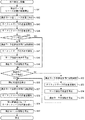
印刷装置1は、印刷動作を実行する前に、頭出し動作を実行する。頭出し動作では、印刷装置1は、搬送モータ68を制御することで、逆送動作および順送動作のうち少なくとも逆送動作を実行する。これにより、テープの頭出しが行われる。
The printing device 1 executes a cueing operation before executing the printing operation. In the cueing operation, the printing apparatus 1 controls at least the reverse feed operation among the reverse feed operation and the forward feed operation by controlling the transfer motor 68. As a result, the tape is cueed.
頭出し動作の実行後、印刷装置1は、印刷動作を実行する。印刷動作では、印刷装置1は、テープを順送しながらテープに印刷を行う。詳細には、印刷装置1は、サーマルヘッド60を発熱させることで、インクリボン8を加熱する。これにより、インクリボン8のインクがレセプタテープ5のうち基材51の印刷面に熱転写されることで、印刷位置P1においてキャラクタが印刷される。印刷装置1は、搬送モータ68を順送方向に駆動させることで、リボン巻取軸62、テープ駆動軸61、プラテンローラ65、および搬送ローラ66を回転させる。リボン巻取軸62の回転によってリボン巻取スプール45が回転することで、リボン巻取スプール45にインクリボン8が巻き取られる。テープ駆動軸61の回転によってテープ駆動ローラ72が平面視で反時計回り方向に回転する。テープ駆動ローラ72および搬送ローラ66の回転によって第一挟持位置P2において搬送ローラ66とテープ駆動ローラ72との間でレセプタテープ5が挟まれて順送される。プラテンローラ65の回転によってプラテンローラ65とサーマルヘッド60との間でレセプタテープ5が挟まれて順送される。
After executing the cueing operation, the printing device 1 executes the printing operation. In the printing operation, the printing device 1 prints on the tape while sequentially feeding the tape. Specifically, the printing apparatus 1 heats the ink ribbon 8 by generating heat from the thermal head 60. As a result, the ink of the ink ribbon 8 is thermally transferred to the printing surface of the base material 51 of the receptor tape 5, so that the character is printed at the printing position P1. The printing device 1 drives the transfer motor 68 in the progressive direction to rotate the ribbon winding shaft 62, the tape drive shaft 61, the platen roller 65, and the transfer roller 66. The rotation of the ribbon take-up shaft 62 causes the ribbon take-up spool 45 to rotate, so that the ink ribbon 8 is taken up by the ribbon take-up spool 45. The rotation of the tape drive shaft 61 causes the tape drive roller 72 to rotate counterclockwise in a plan view. Due to the rotation of the tape drive roller 72 and the transfer roller 66, the receptor tape 5 is sandwiched between the transfer roller 66 and the tape drive roller 72 at the first holding position P2 and is sequentially fed. Due to the rotation of the platen roller 65, the receptor tape 5 is sandwiched between the platen roller 65 and the thermal head 60 and is sequentially fed.
印刷されたレセプタテープ5は、カセット7から排出された後、後述する切断ユニット100によって切断される。切断されたレセプタテープ5は、排出ユニット200によって排出口11から印刷装置1の外部へと排出される。
The printed receptor tape 5 is ejected from the cassette 7 and then cut by the cutting unit 100 described later. The cut receptor tape 5 is discharged from the discharge port 11 to the outside of the printing device 1 by the discharge unit 200.
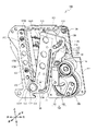
図4から図8を参照し、切断ユニット100の詳細構造を説明する。図5、図6では、切断ユニット100の構成要素のうち、第二フレーム109、および連結ギア105B、125、126の図示を省略する(図9、図10も同様)。切断ユニット100は、排出口11の後方、且つ搬送ローラ66の前方で筐体2の内部に設けられる。
The detailed structure of the cutting unit 100 will be described with reference to FIGS. 4 to 8. In FIGS. 5 and 6, among the components of the cutting unit 100, the second frame 109 and the connecting gears 105B, 125, and 126 are not shown (the same applies to FIGS. 9 and 10). The cutting unit 100 is provided inside the housing 2 behind the discharge port 11 and in front of the transport roller 66.
図4に示すように、切断ユニット100は固定フレーム106を備える。固定フレーム106は筐体2(図1参照)の内部に固定される。固定フレーム106は、第一フレーム118と第二フレーム109とを備える。第二フレーム109は、背面視で矩形状であり、二点鎖線によって図示される。第一フレーム118は、第二フレーム109の前方に配置され、第一通過口118Aを備える。第一通過口118Aは、第一フレーム118を前後方向に貫通し、後述する第二通過口201の後方に並ぶ。テープは第一通過口118A内を通過する。第一通過口118Aの左側開口端には、案内部材147が設けられる。案内部材147には、右方に向けて凸状の複数のリブが、上下方向に並んで配置される。案内部材147は、順送されるテープを第二通過口201に向けて案内する。
As shown in FIG. 4, the cutting unit 100 includes a fixed frame 106. The fixed frame 106 is fixed inside the housing 2 (see FIG. 1). The fixed frame 106 includes a first frame 118 and a second frame 109. The second frame 109 has a rectangular shape when viewed from the rear, and is illustrated by a two-dot chain line. The first frame 118 is arranged in front of the second frame 109 and includes a first passage port 118A. The first passage port 118A penetrates the first frame 118 in the front-rear direction and is lined up behind the second passage port 201, which will be described later. The tape passes through the first passage port 118A. A guide member 147 is provided at the left opening end of the first passage port 118A. A plurality of ribs convex toward the right are arranged side by side in the vertical direction on the guide member 147. The guide member 147 guides the tape to be sequentially fed toward the second passage port 201.
第一フレーム118には、受台173が固定される。受台173は、板状である。受台173の下端173Aは、第一通過口118Aの下方に配置される。下端173Aは、凸部178を含む。凸部178は、下端173Aから前方に突出する。凸部178には、固定孔が形成される。固定孔は、正面視で円形状である。固定孔には、軸177が固定される。軸177は、前後方向に延びる。受台173は、延設部173Cおよび受板173Dを備える。延設部173Cは、受台173の下端173Aと上端173Bとの間で延びる。延設部173Cは、第一通過口118Aの左側において、二つの螺子176により、第一フレーム118に固定される。受板173Dは、延設部173Cの右端から前方に突出し、右側面視で上下方向に延びる矩形状である。受板173Dには、案内部材147よりも搬送方向上流側(すなわち後側)にあるテープが配置される。
A pedestal 173 is fixed to the first frame 118. The cradle 173 has a plate shape. The lower end 173A of the cradle 173 is arranged below the first passage port 118A. The lower end 173A includes a convex portion 178. The convex portion 178 projects forward from the lower end 173A. A fixing hole is formed in the convex portion 178. The fixing hole has a circular shape when viewed from the front. A shaft 177 is fixed in the fixing hole. The shaft 177 extends in the front-rear direction. The pedestal 173 includes an extension portion 173C and a receiving plate 173D. The extension portion 173C extends between the lower end 173A and the upper end 173B of the cradle 173. The extension portion 173C is fixed to the first frame 118 by two screws 176 on the left side of the first passage port 118A. The receiving plate 173D has a rectangular shape that protrudes forward from the right end of the extending portion 173C and extends in the vertical direction when viewed from the right side. On the receiving plate 173D, a tape located on the upstream side (that is, the rear side) in the transport direction with respect to the guide member 147 is arranged.
第一通過口118Aよりも右側では、切断モータ105が第二フレーム109の下端に固定される。切断モータ105の出力軸105Aは、切断モータ105から上方に延びる。出力軸105Aには、連結ギア105Bが固定される。
On the right side of the first passage port 118A, the cutting motor 105 is fixed to the lower end of the second frame 109. The output shaft 105A of the cutting motor 105 extends upward from the cutting motor 105. A connecting gear 105B is fixed to the output shaft 105A.
切断モータ105の右下側且つ後側には、回転体150が設けられる。回転体150は、軸177よりも右側に配置され、正面視で円形状である。回転体150は、軸159(図8参照)によって回転可能に支持される。軸159は、第一フレーム118を前後方向に貫通し、第一フレーム118に固定される。
A rotating body 150 is provided on the lower right side and the rear side of the cutting motor 105. The rotating body 150 is arranged on the right side of the shaft 177 and has a circular shape when viewed from the front. The rotating body 150 is rotatably supported by a shaft 159 (see FIG. 8). The shaft 159 penetrates the first frame 118 in the front-rear direction and is fixed to the first frame 118.
出力軸105Aの右側には、ギア列124が設けられる。ギア列124は、連結ギア125〜127、およびカムギア128を含む。連結ギア125〜127、カムギア128は、上側から順に上下方向に並び、いずれも前後方向を軸方向として回転可能である。連結ギア125〜127は、二段歯車である。連結ギア125、126は、第二フレーム109によって回転可能に支持される。連結ギア125は、連結ギア105Bと噛み合う。連結ギア127は第一フレーム118によって回転可能に支持される。カムギア128は、ギア列124のなかで最も従動側のギアであり、回転体150の外周面と一体的に形成される。連結ギア125〜127、カムギア128は、互いに噛み合う。従って、切断モータ105の駆動力は、連結ギア105Bとギア列124を介して回転体150に伝達される。
A gear train 124 is provided on the right side of the output shaft 105A. The gear train 124 includes connecting gears 125-127 and cam gear 128. The connecting gears 125 to 127 and the cam gear 128 are arranged in the vertical direction in order from the upper side, and all of them can rotate with the front-rear direction as the axial direction. The connecting gears 125 to 127 are two-stage gears. The connecting gears 125 and 126 are rotatably supported by the second frame 109. The connecting gear 125 meshes with the connecting gear 105B. The connecting gear 127 is rotatably supported by the first frame 118. The cam gear 128 is the most driven gear in the gear train 124, and is integrally formed with the outer peripheral surface of the rotating body 150. The connecting gears 125 to 127 and the cam gear 128 mesh with each other. Therefore, the driving force of the cutting motor 105 is transmitted to the rotating body 150 via the connecting gear 105B and the gear train 124.
図5および図6に示すように、回転体150には、溝カム151、152が設けられる。溝カム151、152は、前方に開口し、互いに連続して一体的に形成される。溝カム151は、その両端である始端151Aから終端151Bまで、軸159に接近する方向に延びる。溝カム152は、始端151Aから正面視で時計回り方向に、軸159を中心とした円弧状に延びる。以下、溝カム151、152を総称する場合、「溝カム153」という。
As shown in FIGS. 5 and 6, the rotating body 150 is provided with groove cams 151 and 152. The groove cams 151 and 152 are opened forward and are formed continuously and integrally with each other. The groove cam 151 extends from the start end 151A at both ends thereof to the end end 151B in a direction approaching the shaft 159. The groove cam 152 extends clockwise from the start end 151A in a clockwise direction in a front view in an arc shape centered on the shaft 159. Hereinafter, when the groove cams 151 and 152 are generically referred to, they are referred to as "groove cam 153".
回転体150の左上方には、支軸119が設けられる。支軸119は、第一フレーム118から前方に突出し、第一リンク部材110を揺動可能に支持する。第一リンク部材110は、第一フレーム118と前後方向に隙間を空けて対向し、上下方向に延びる。第一リンク部材110のうち支軸119よりも下方の部位は、前方に延び、さらに下方に折れ曲がって延びる。第一リンク部材110のうち支軸119よりも上方の部位は、上下方向に延びる。第一リンク部材110の下端部116は、回転体150の前方に配置される。下端部116には、ピン111が設けられる。ピン111は、下端部116から後方に突出し、溝カム153に係合する。回転体150の回転に伴い、溝カム151がピン111に対して摺動することで、第一リンク部材110は支軸119を中心にして揺動できる。
A support shaft 119 is provided on the upper left side of the rotating body 150. The support shaft 119 projects forward from the first frame 118 and swingably supports the first link member 110. The first link member 110 faces the first frame 118 with a gap in the front-rear direction and extends in the vertical direction. The portion of the first link member 110 below the support shaft 119 extends forward and further bends downward to extend. A portion of the first link member 110 above the support shaft 119 extends in the vertical direction. The lower end 116 of the first link member 110 is arranged in front of the rotating body 150. A pin 111 is provided at the lower end 116. The pin 111 projects rearward from the lower end 116 and engages with the groove cam 153. As the rotating body 150 rotates, the groove cam 151 slides with respect to the pin 111, so that the first link member 110 can swing around the support shaft 119.
第一リンク部材110の上端部117には、ピン112と凹部139とが設けられる。ピン112は、上端部117から後方に突出し、貫通孔197(図8参照)に挿入される。貫通孔197は、第一フレーム118を前後方向に貫通する。凹部139は、支軸119を中心に正面視で時計回り方向に凹む。
A pin 112 and a recess 139 are provided at the upper end 117 of the first link member 110. The pin 112 projects rearward from the upper end 117 and is inserted into the through hole 197 (see FIG. 8). The through hole 197 penetrates the first frame 118 in the front-rear direction. The recess 139 is recessed clockwise about the support shaft 119 in the front view.
第一リンク部材110と第一フレーム118との間には、第二リンク部材120が設けられる。第二リンク部材120は、支軸129によって、揺動可能に支持される。支軸129は、上端173Bよりも右側において、第一フレーム118から前方に突出する。第二リンク部材120は、支軸129を中心とした扇形状に形成された板状であり、第一フレーム118に前方から対向して接触する。第二リンク部材120のうち支軸129から離隔する方向側の端部121は、上端部117に後方から対向する。
A second link member 120 is provided between the first link member 110 and the first frame 118. The second link member 120 is swingably supported by the support shaft 129. The support shaft 129 projects forward from the first frame 118 on the right side of the upper end 173B. The second link member 120 has a plate shape formed in a fan shape centered on a support shaft 129, and comes into contact with the first frame 118 so as to face each other from the front. The end portion 121 of the second link member 120 on the direction side separated from the support shaft 129 faces the upper end portion 117 from the rear.
図7に示すように、端部121には、溝カム122が設けられる。溝カム122は、ピン112と係合し、カム122A、122Bを備える。カム122A、122Bは、互いに連続して一体的に形成された溝であり、支軸129に近接する側から順に配置される。カム122Aは、支軸129から離隔する方向に延び、カム122Bは、支軸129からさらに離隔する方向にカム122Aから延びる。カム122Aの延設方向とカム122Bの延設方向とは、互いに交差する。第一リンク部材110の揺動に伴い、ピン112が溝カム122に対して摺動することで、第二リンク部材120は支軸129を中心にして揺動できる。端部121には、ピン113が設けられる。図7で示されるピン113は、端部121から前方に突出し、凹部139の内側に配置される。
As shown in FIG. 7, a groove cam 122 is provided at the end portion 121. The groove cam 122 engages with the pin 112 and includes cams 122A and 122B. The cams 122A and 122B are grooves that are continuously and integrally formed with each other, and are arranged in order from the side closest to the support shaft 129. The cam 122A extends in a direction away from the support shaft 129, and the cam 122B extends from the cam 122A in a direction further away from the support shaft 129. The extension direction of the cam 122A and the extension direction of the cam 122B intersect with each other. As the first link member 110 swings, the pin 112 slides with respect to the groove cam 122, so that the second link member 120 can swing around the support shaft 129. A pin 113 is provided at the end 121. The pin 113 shown in FIG. 7 projects forward from the end 121 and is arranged inside the recess 139.
図5および図6に示すように、第二リンク部材120の前側には、可動ホルダ130が設けられる。可動ホルダ130は、軸177によって揺動可能に支持される。可動ホルダ130の下端部137は、受台173の下端173Aよりも前方において、軸177に揺動可能に連結する。可動ホルダ130の上端部138は、第一リンク部材110の上端部117と前方から対向する。
As shown in FIGS. 5 and 6, a movable holder 130 is provided on the front side of the second link member 120. The movable holder 130 is swingably supported by a shaft 177. The lower end 137 of the movable holder 130 is swingably connected to the shaft 177 in front of the lower end 173A of the pedestal 173. The upper end portion 138 of the movable holder 130 faces the upper end portion 117 of the first link member 110 from the front.
可動ホルダ130は、固着部134、パーシャルカット刃103、および突部131を備える。固着部134は、下端部137と上端部138との間で延び、切断モータ105(図4参照)に後側から対向する。パーシャルカット刃103は、前後方向に厚さを有する板状であり、固着部134の後面に固着される。パーシャルカット刃103の左端は、刃付けされた刃先103Aである。刃先103Aは、可動ホルダ130の揺動方向に沿って左側へ、延設部173Cから僅かに突出する。刃先103Aは、可動ホルダ130の揺動方向に沿って、受台173の受板173Dと対向する。突部131は、可動ホルダ130の揺動方向に沿って左側へ上端部138から突出し、可動ホルダ130の揺動方向に沿って受板173Dと対向する。突部131の先端(すなわち左端)は、刃先103Aよりも僅かに左側にある。
The movable holder 130 includes a fixing portion 134, a partial cut blade 103, and a protrusion 131. The fixing portion 134 extends between the lower end portion 137 and the upper end portion 138 and faces the cutting motor 105 (see FIG. 4) from the rear side. The partial cut blade 103 has a plate shape having a thickness in the front-rear direction, and is fixed to the rear surface of the fixing portion 134. The left end of the partial cut blade 103 is the blade edge 103A attached. The cutting edge 103A slightly protrudes from the extending portion 173C to the left along the swing direction of the movable holder 130. The cutting edge 103A faces the receiving plate 173D of the pedestal 173 along the swinging direction of the movable holder 130. The protrusion 131 projects from the upper end portion 138 to the left along the swing direction of the movable holder 130, and faces the receiving plate 173D along the swing direction of the movable holder 130. The tip (that is, the left end) of the protrusion 131 is slightly to the left of the cutting edge 103A.
図7に示すように、上端部138には、溝カム133が設けられる。溝カム133は、ピン113と係合し、溝133A、133Bを備える。溝133A、133Bは、互いに連続して一体的に形成される。溝133Aは、軸177(図6参照)から遠ざかる方向に延びる。溝133Bは、軸177からさらに遠ざかる方向に溝133Aから延びる。溝133A、133Bは、互いに異なる方向に延びる。
As shown in FIG. 7, a groove cam 133 is provided at the upper end portion 138. The groove cam 133 engages with the pin 113 and includes grooves 133A and 133B. The grooves 133A and 133B are formed continuously and integrally with each other. The groove 133A extends in a direction away from the shaft 177 (see FIG. 6). The groove 133B extends from the groove 133A in a direction further away from the shaft 177. The grooves 133A and 133B extend in different directions from each other.
第二リンク部材120の揺動に伴い、ピン113が溝カム133に対して摺動することで、可動ホルダ130は、軸177を中心にして、パーシャルカット位置(図9参照)と退避位置(図5参照)とにわたって揺動できる。パーシャルカット位置は、突部131の先端が受板173Dと当接する可動ホルダ130の揺動位置である。退避位置は、パーシャルカット位置から右側に退避した可動ホルダ130の揺動位置である。可動ホルダ130が退避位置にある場合、刃先103Aは、受板173Dに配置されたテープから右側に離隔する。刃先103Aは、突部131の先端よりも右側にある。従って、可動ホルダ130がパーシャルカット位置にあるとき、刃先103Aと受台173との間には隙間が形成される。可動ホルダ130の揺動方向におけるこの隙間の大きさは、テープの厚さよりも小さい。
As the second link member 120 swings, the pin 113 slides with respect to the groove cam 133, so that the movable holder 130 moves to the partial cut position (see FIG. 9) and the retracted position (see FIG. 9) with the shaft 177 as the center. It can swing over (see FIG. 5). The partial cut position is the swing position of the movable holder 130 in which the tip of the protrusion 131 abuts on the receiving plate 173D. The retracted position is the swinging position of the movable holder 130 retracted to the right from the partial cut position. When the movable holder 130 is in the retracted position, the cutting edge 103A is separated to the right from the tape arranged on the receiving plate 173D. The cutting edge 103A is on the right side of the tip of the protrusion 131. Therefore, when the movable holder 130 is in the partial cut position, a gap is formed between the cutting edge 103A and the pedestal 173. The size of this gap in the swing direction of the movable holder 130 is smaller than the thickness of the tape.
図8に示すように、第一フレーム118の後側には、固定刃179およびフルカット刃140が設けられる。固定刃179は、第一通過口118Aよりも右側で第一フレーム118に固定される。固定刃179は、背面視で上下方向に延びる矩形状の板状部材である。固定刃179の下端179Aには、軸199が固定される。軸199は前後方向に延び、第一フレーム118から後方に突出する。固定刃179は、刃先179Cを備える。刃先179Cは、固定刃179の左端に、上下方向に沿って刃付けされる。テープは、固定刃179の下端179Aと上端179Bとの間で刃先179Cに配置される。
As shown in FIG. 8, a fixed blade 179 and a full-cut blade 140 are provided on the rear side of the first frame 118. The fixed blade 179 is fixed to the first frame 118 on the right side of the first passage port 118A. The fixed blade 179 is a rectangular plate-shaped member extending in the vertical direction when viewed from the rear. A shaft 199 is fixed to the lower end 179A of the fixed blade 179. The shaft 199 extends in the front-rear direction and projects rearward from the first frame 118. The fixed blade 179 includes a cutting edge 179C. The cutting edge 179C is attached to the left end of the fixed blade 179 along the vertical direction. The tape is arranged at the cutting edge 179C between the lower end 179A and the upper end 179B of the fixed blade 179.
フルカット刃140は、第一フレーム118とフルカット刃140の間となる前後位置において、軸199によって揺動可能に支持され、正面視でL字状の板状部材である。フルカット刃140は、アーム141、142を備える。アーム141は、軸199から上側へ延びる。アーム142は、軸199から右側へ延びる。軸199を中心とした背面視で反時計回り方向側におけるアーム141の端には、アーム141の延設方向に沿って刃先141Aが刃付けされる。刃先141Aは、フルカット刃140の揺動方向に沿って、固定刃179の刃先179Cと対向する。
The full-cut blade 140 is an L-shaped plate-shaped member that is swingably supported by a shaft 199 at a front-rear position between the first frame 118 and the full-cut blade 140. The full-cut blade 140 includes arms 141 and 142. The arm 141 extends upward from the shaft 199. The arm 142 extends from the shaft 199 to the right. A cutting edge 141A is attached to the end of the arm 141 on the counterclockwise side in the rear view centered on the shaft 199 along the extending direction of the arm 141. The cutting edge 141A faces the cutting edge 179C of the fixed blade 179 along the swing direction of the full-cut blade 140.
アーム142の右部には、溝カム144が設けられる。溝カム144は、前後方向に開口し、ピン114と係合する。ピン114は、回転体150から後方に突出し、挿入孔115に挿入される。挿入孔115は、第一フレーム118を前後方向に貫通し、軸159を中心に円弧状に延びる。
A groove cam 144 is provided on the right side of the arm 142. The groove cam 144 opens in the front-rear direction and engages with the pin 114. The pin 114 protrudes rearward from the rotating body 150 and is inserted into the insertion hole 115. The insertion hole 115 penetrates the first frame 118 in the front-rear direction and extends in an arc shape about the shaft 159.
溝カム144は、円弧カム145と延伸カム146を備える。円弧カム145と延伸カム146は、互いに連続して一体的に形成される溝である。円弧カム145は、その両端である始端145Aから終端145Bまで、軸159を中心に背面視で反時計回り方向側へ円弧状に延びる。延伸カム146は、円弧カム145の始端145Aから軸199に向けて直線状に延びる。
The groove cam 144 includes an arc cam 145 and an extension cam 146. The arc cam 145 and the extension cam 146 are grooves that are continuously and integrally formed with each other. The arc cam 145 extends in an arc shape from the start end 145A to the end end 145B, which are both ends thereof, in the counterclockwise direction in the rear view with respect to the axis 159. The extension cam 146 extends linearly from the start end 145A of the arc cam 145 toward the shaft 199.
回転体150の回転に伴い、ピン114が延伸カム146に対して摺動することで、フルカット刃140は、軸199を中心にして、フルカット位置(図12参照)と離隔位置(図8参照)とにわたって揺動できる。フルカット位置は、刃先141Aが固定刃179の刃先179Cよりも右側に配置されるフルカット刃140の揺動位置である。離隔位置は、刃先179Cに配置されたテープから刃先141Aが左側へ離隔するフルカット刃140の揺動位置である。フルカット刃140の揺動方向は、可動ホルダ130の揺動方向と平行である。
As the pin 114 slides with respect to the extension cam 146 as the rotating body 150 rotates, the full-cut blade 140 moves from the full-cut position (see FIG. 12) to the separation position (see FIG. 8) with the shaft 199 as the center. Can swing over (see). The full-cut position is the swing position of the full-cut blade 140 in which the blade edge 141A is arranged on the right side of the blade edge 179C of the fixed blade 179. The separation position is the swing position of the full-cut blade 140 in which the cutting edge 141A separates from the tape arranged on the cutting edge 179C to the left side. The swing direction of the full-cut blade 140 is parallel to the swing direction of the movable holder 130.
図6、および図9から図11を参照し、切断ユニット100によるパーシャルカット動作を説明する。パーシャルカット動作は、テープの厚み方向の一部を残して、幅方向に沿って切断する切断動作である。パーシャルカット動作の開始前、テープは、印刷装置1の複数のローラによって第一通過口118Aを通過する位置まで搬送されており、受板173Dに配置されている。パーシャルカット動作の開始前、切断ユニット100は初期状態にある(図6、図8参照)。切断ユニット100が初期状態にある場合、ピン111は始端151Aと接触している。ピン112はカム122Aの上端と接触している。ピン113は溝133Aの下部と接触している。可動ホルダ130は退避位置に配置されている。ピン114は始端145Aと接触している。フルカット刃140は離隔位置に配置されている。
The partial cutting operation by the cutting unit 100 will be described with reference to FIGS. 6 and 9 to 11. The partial cutting operation is a cutting operation of cutting along the width direction, leaving a part in the thickness direction of the tape. Before the start of the partial cutting operation, the tape is conveyed to a position where it passes through the first passage port 118A by a plurality of rollers of the printing apparatus 1, and is arranged on the receiving plate 173D. Before the start of the partial cut operation, the cutting unit 100 is in the initial state (see FIGS. 6 and 8). When the cutting unit 100 is in the initial state, the pin 111 is in contact with the starting end 151A. The pin 112 is in contact with the upper end of the cam 122A. The pin 113 is in contact with the lower part of the groove 133A. The movable holder 130 is arranged at the retracted position. Pin 114 is in contact with the starting end 145A. The full-cut blade 140 is arranged at a separated position.
切断モータ105(図4参照)が駆動を開始することで、連結ギア105Bは出力軸105Aと共に回転する。ギア列124が、切断モータ105の駆動力を回転体150に伝達することで、回転体150は正面視で時計回り方向に回転する(矢印H0)。回転体150の溝カム151は、ピン111を右側に押圧しながら回転する(図6、図10参照)。これにより、第一リンク部材110は正面視で反時計回り方向に揺動する(矢印H1)。第一リンク部材110の揺動により、ピン112は、溝カム122のカム122Aを左側に押圧しながら揺動する。これにより、第二リンク部材120は、第一フレーム118に対して摺動しながら、正面視で時計回り方向に揺動する(矢印H2)。このとき、ピン112は、凹部139よりも上方に、第二リンク部材120に対して相対的に揺動する。第二リンク部材120の揺動により、ピン113は溝カム133の溝133Aを左側へ押圧する。これにより、可動ホルダ130は、退避位置からパーシャルカット位置に向けて揺動する(矢印H3)。このとき、ピン113は、溝カム133の延設方向の一方側(図7、図11の矢印V1方向側)から、他方側(矢印V2方向側)に向けて摺動する。
When the cutting motor 105 (see FIG. 4) starts driving, the connecting gear 105B rotates together with the output shaft 105A. The gear train 124 transmits the driving force of the cutting motor 105 to the rotating body 150, so that the rotating body 150 rotates clockwise in the front view (arrow H0). The groove cam 151 of the rotating body 150 rotates while pressing the pin 111 to the right (see FIGS. 6 and 10). As a result, the first link member 110 swings counterclockwise in front view (arrow H1). Due to the swing of the first link member 110, the pin 112 swings while pressing the cam 122A of the groove cam 122 to the left side. As a result, the second link member 120 swings clockwise in the front view while sliding with respect to the first frame 118 (arrow H2). At this time, the pin 112 swings above the recess 139 relative to the second link member 120. Due to the swing of the second link member 120, the pin 113 presses the groove 133A of the groove cam 133 to the left side. As a result, the movable holder 130 swings from the retracted position to the partial cut position (arrow H3). At this time, the pin 113 slides from one side (arrow V1 direction side in FIGS. 7 and 11) of the groove cam 133 in the extending direction toward the other side (arrow V2 direction side).
可動ホルダ130がパーシャルカット位置に向けて揺動する間、ピン114(図8参照)は、円弧カム145の始端145Aから終端145Bに向けて摺動するので、フルカット刃140を押圧しない。従って、フルカット刃140は離隔位置に停止した状態を維持する。
While the movable holder 130 swings toward the partial cut position, the pin 114 (see FIG. 8) slides from the start end 145A to the end end 145B of the arc cam 145, so that it does not press the full cut blade 140. Therefore, the full-cut blade 140 maintains the state of being stopped at the separated position.
図9から図11に示すように、回転体150の回転に伴い、ピン111が終端151Bに向けて摺動する間に、ピン112は、カム122Aに代えてカム122Bに対して摺動し、ピン113は、溝133Aに代えて溝133Bに対して摺動する。可動ホルダ130が継続して揺動することで、刃先103Aは、下側から徐々にテープに切れ込みを入れ始める。
As shown in FIGS. 9 to 11, the pin 112 slides with respect to the cam 122B instead of the cam 122A while the pin 111 slides toward the end 151B as the rotating body 150 rotates. The pin 113 slides with respect to the groove 133B instead of the groove 133A. As the movable holder 130 continuously swings, the cutting edge 103A gradually starts to cut the tape from the lower side.
刃先103Aがテープに切れ込みを入れ始めるとき、摺動するピン112は、支軸129から離隔する方向に揺動しながら、カム122Bに対して摺動する。テープの上端まで切れ込みが入った後、突部131が受板173Dと当接したとき、可動ホルダ130はパーシャルカット位置に到達する。テープのうち刃先103Aと受台173との間に形成された隙間に配置された部分(すなわち、テープの幅方向の一部)は切断されない。これにより、パーシャルカット刃103は刃先103Aでテープを幅方向にわたってパーシャルカットする。切断モータ105は駆動を終了する。以下、パーシャルカット刃103がテープを幅方向にわたってパーシャルカットする搬送方向位置を、「第二切断位置P4」という(図2参照)。第二切断位置P4は、後述する第一切断位置P3よりも搬送方向下流側にある。
When the cutting edge 103A begins to make a cut in the tape, the sliding pin 112 slides with respect to the cam 122B while swinging in a direction away from the support shaft 129. The movable holder 130 reaches the partial cut position when the protrusion 131 comes into contact with the receiving plate 173D after the notch is made to the upper end of the tape. The portion of the tape arranged in the gap formed between the cutting edge 103A and the pedestal 173 (that is, a part in the width direction of the tape) is not cut. As a result, the partial cut blade 103 partially cuts the tape in the width direction at the blade edge 103A. The cutting motor 105 ends driving. Hereinafter, the position in the transport direction in which the partial cut blade 103 partially cuts the tape in the width direction is referred to as "second cutting position P4" (see FIG. 2). The second cutting position P4 is on the downstream side in the transport direction from the first cutting position P3 described later.
切断モータ105は、パーシャルカット動作の開始時とは反対方向に駆動する。回転体150、第一リンク部材110、第二リンク部材120、および可動ホルダ130は、パーシャルカット動作の開始時とは反対方向に動作する。ピン113は、上端部117の凹部139の内側まで戻る。切断ユニット100は初期状態に戻る。切断モータ105が駆動を終了することで、パーシャルカット動作は完了する。
The cutting motor 105 is driven in the direction opposite to that at the start of the partial cut operation. The rotating body 150, the first link member 110, the second link member 120, and the movable holder 130 operate in the direction opposite to the start of the partial cut operation. The pin 113 returns to the inside of the recess 139 of the upper end portion 117. The cutting unit 100 returns to the initial state. When the cutting motor 105 ends driving, the partial cut operation is completed.
図6、図8、および図12を参照し、切断ユニット100によるフルカット動作を説明する。フルカット動作は、テープの厚み方向の全部を幅方向に沿って切断する切断動作である。フルカット動作の開始前、切断ユニット100は初期状態にある。
A full-cut operation by the cutting unit 100 will be described with reference to FIGS. 6, 8 and 12. The full-cut operation is a cutting operation that cuts the entire tape in the thickness direction along the width direction. Before the start of the full cut operation, the cutting unit 100 is in the initial state.
切断モータ105は、パーシャルカット動作の開始時とは反対方向への回転駆動を開始する。これにより、回転体150は正面視で反時計回りに回転する(矢印F0)。このとき、溝カム153の溝カム152(図6参照)がピン111と摺動するので、溝カム153がピン111を押圧しない。従って、可動ホルダ130は退避位置に停止した状態を維持する。
The cutting motor 105 starts rotational driving in a direction opposite to that at the start of the partial cut operation. As a result, the rotating body 150 rotates counterclockwise in front view (arrow F0). At this time, since the groove cam 152 (see FIG. 6) of the groove cam 153 slides with the pin 111, the groove cam 153 does not press the pin 111. Therefore, the movable holder 130 maintains the stopped state at the retracted position.
回転体150の回転に伴い、ピン114は、延伸カム146に対して、下側に押圧しながら摺動する。これにより、可動ホルダ130は、フルカット位置に向けた揺動を開始する(矢印F1)。ピン114が、延伸カム146に対して摺動するに従い、フルカット刃140の刃先141Aは、下側から徐々に、固定刃179の刃先179Cとの間でテープを挟み込む。よって、テープは、下側から徐々に二つに切り離される。切れ込みが上下方向にわたってテープに入った後、フルカット刃140はフルカット位置に到達する。フルカット刃140は、刃先141A、179Cでテープをフルカットする。切断モータ105は駆動を停止する。以下、フルカット刃140がテープをフルカットする搬送方向位置を、「第一切断位置P3」という。第一切断位置P3は、第一挟持位置P2よりも搬送方向下流側にある。
As the rotating body 150 rotates, the pin 114 slides with respect to the extension cam 146 while pressing downward. As a result, the movable holder 130 starts swinging toward the full cut position (arrow F1). As the pin 114 slides with respect to the drawing cam 146, the cutting edge 141A of the full-cut blade 140 gradually sandwiches the tape from the lower side with the cutting edge 179C of the fixed blade 179. Therefore, the tape is gradually separated into two from the lower side. After the notch has entered the tape in the vertical direction, the full-cut blade 140 reaches the full-cut position. The full-cut blade 140 fully cuts the tape with the cutting edges 141A and 179C. The cutting motor 105 stops driving. Hereinafter, the position in the transport direction in which the full-cut blade 140 fully cuts the tape is referred to as "first cutting position P3". The first cutting position P3 is on the downstream side in the transport direction from the first holding position P2.
切断モータ105は、フルカット動作の開始時とは反対方向に駆動する。回転体150とフルカット刃140は、フルカット動作の開始時とは反対方向に動作し、切断ユニット100は初期状態に戻る。切断モータ105が駆動を終了することで、フルカット動作は完了する。
The cutting motor 105 is driven in the direction opposite to that at the start of the full cut operation. The rotating body 150 and the full-cut blade 140 operate in the directions opposite to those at the start of the full-cut operation, and the cutting unit 100 returns to the initial state. When the cutting motor 105 ends driving, the full cut operation is completed.
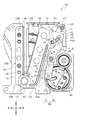
図13から図17を参照し、排出ユニット200の詳細構造を説明する。図14は、排出ユニット200の構成要素のうち、第三フレーム213、案内フレーム214、および位置検出センサ295の図示を省略する。排出ユニット200は、排出口11の後方、且つ切断ユニット100よりも搬送方向下流側(すなわち、前側)で筐体2の内部に設けられる(図2参照)。
The detailed structure of the discharge unit 200 will be described with reference to FIGS. 13 to 17. FIG. 14 omits the illustration of the third frame 213, the guide frame 214, and the position detection sensor 295 among the components of the discharge unit 200. The discharge unit 200 is provided inside the housing 2 behind the discharge port 11 and on the downstream side (that is, the front side) in the transport direction from the cutting unit 100 (see FIG. 2).
図13および図14に示すように、排出ユニット200は、固定フレーム210、排出ローラ220、対向ローラ230、排出モータ299、第一連結機構280、移動機構250、第二連結機構240、および位置検出センサ295を備える。固定フレーム210は、排出口11の後側近傍で筐体2の内部に固定され、第一フレーム211と第二フレーム212と第三フレーム213とを備える。
As shown in FIGS. 13 and 14, the discharge unit 200 includes a fixed frame 210, a discharge roller 220, an opposing roller 230, a discharge motor 299, a first connecting mechanism 280, a moving mechanism 250, a second connecting mechanism 240, and a position detection. It is equipped with a sensor 295. The fixed frame 210 is fixed to the inside of the housing 2 in the vicinity of the rear side of the discharge port 11, and includes a first frame 211, a second frame 212, and a third frame 213.
第一フレーム211は、排出ユニット200の下部に設けられ、上下方向に直交して延びる。第二フレーム212および第三フレーム213は、それぞれ、第一フレーム211から上方に、左右方向に直交して延びる。第三フレーム213は、第二フレーム212に対して左側から所定の隙間を開けて対向する。第二フレーム212と第三フレーム213との間の隙間は、第二通過口201である。第二通過口201は、第一通過口118Aの前側に並び、且つ排出口11の後側に並ぶ(図16、図17参照)。テープは、第一通過口118A、第二通過口201、排出口11の順に搬送方向上流側(すなわち、後側)から下流側(すなわち、前側)に向けて順送される。
The first frame 211 is provided at the lower part of the discharge unit 200 and extends orthogonally in the vertical direction. The second frame 212 and the third frame 213 extend upward from the first frame 211 at right angles to the left and right, respectively. The third frame 213 faces the second frame 212 with a predetermined gap from the left side. The gap between the second frame 212 and the third frame 213 is the second passage port 201. The second passage port 201 is arranged on the front side of the first passage port 118A and on the rear side of the discharge port 11 (see FIGS. 16 and 17). The tape is sequentially fed from the upstream side (that is, the rear side) to the downstream side (that is, the front side) in the transport direction in the order of the first passage port 118A, the second passage port 201, and the discharge port 11.
例えばテープがレセプタテープ5の場合、レセプタテープ5は、基材51側が右側を向き、剥離紙52側が左側を向いた状態で、第一通過口118A、第二通過口201、排出口11を通過する。テープがダイカットテープ9の場合、ダイカットテープ9は、基材91側が右側を向き、剥離紙92側が左側を向いた状態で、第一通過口118A、第二通過口201、排出口11を通過する。
For example, when the tape is the receptor tape 5, the receptor tape 5 passes through the first passage port 118A, the second passage port 201, and the discharge port 11 with the base material 51 side facing the right side and the release paper 52 side facing the left side. To do. When the tape is a die-cut tape 9, the die-cut tape 9 passes through the first passage port 118A, the second passage port 201, and the discharge port 11 with the base material 91 side facing the right side and the release paper 92 side facing the left side. ..
排出ローラ220は、搬送ローラ66およびテープ駆動軸61に対して搬送方向下流側(前側)において、第二通過口201の左側に設けられる(図16、図17参照)。すなわち、排出ローラ220は、レセプタテープ5のうち剥離紙52側に配置される。排出ローラ220は、上下方向に延びる円筒状の弾性体であり、孔213A(図16、図17参照)内に配置される。孔213Aは、第三フレーム213の後端部を左右方向に貫通し、側面視で上下方向に長い矩形状に延びる。
The discharge roller 220 is provided on the left side of the second passage port 201 on the downstream side (front side) in the transport direction with respect to the transport roller 66 and the tape drive shaft 61 (see FIGS. 16 and 17). That is, the discharge roller 220 is arranged on the release paper 52 side of the receptor tape 5. The discharge roller 220 is a cylindrical elastic body extending in the vertical direction, and is arranged in the hole 213A (see FIGS. 16 and 17). The hole 213A penetrates the rear end portion of the third frame 213 in the left-right direction and extends in a long rectangular shape in the up-down direction in a side view.
対向ローラ230は、搬送ローラ66およびテープ駆動軸61に対して搬送方向下流側(前側)において、第二通過口201の右側に設けられる(図16、図17参照)。すなわち、対向ローラ230は、レセプタテープ5のうち基材51側に配置される。対向ローラ230は、第二通過口201を間にして排出ローラ220に右側から対向する。対向ローラ230は、上下方向に延びる複数の円筒状の弾性体であり、孔212A内に配置される。複数の円筒状の弾性体は、上下方向に一定間隔を空けて並ぶ。孔212Aは、第二フレーム212の後端部を左右方向に貫通し、側面視で上下方向に長い矩形状に延びる。対向ローラ230の左端部は、第二フレーム212の左面よりも左側に配置される。対向ローラ230の中心孔には、回転軸230Aが回転可能に挿入される。回転軸230Aは、上下方向に延びる円柱体である。回転軸230Aの両端部は、孔212Aの上側および下側の内壁に固定される。
The opposing roller 230 is provided on the right side of the second passage port 201 on the downstream side (front side) in the transport direction with respect to the transport roller 66 and the tape drive shaft 61 (see FIGS. 16 and 17). That is, the opposing roller 230 is arranged on the substrate 51 side of the receptor tape 5. The opposing roller 230 faces the discharge roller 220 from the right side with the second passage port 201 in between. The opposing roller 230 is a plurality of cylindrical elastic bodies extending in the vertical direction, and is arranged in the hole 212A. A plurality of cylindrical elastic bodies are arranged at regular intervals in the vertical direction. The hole 212A penetrates the rear end portion of the second frame 212 in the left-right direction and extends in a long rectangular shape in the up-down direction in a side view. The left end portion of the opposing roller 230 is arranged on the left side of the left surface of the second frame 212. The rotating shaft 230A is rotatably inserted into the center hole of the opposing roller 230. The rotation shaft 230A is a cylindrical body extending in the vertical direction. Both ends of the rotating shaft 230A are fixed to the upper and lower inner walls of the hole 212A.
排出モータ299は、第一フレーム211の左端部に固定され、DCモータである。排出モータ299の出力軸299Aは、排出モータ299から下方に延びる。排出モータ299は、出力軸299Aを底面視で反時計回り方向(矢印R1)、および時計回り方向(矢印R2)に回転駆動できる。以下、排出モータ299が出力軸299Aを底面視で反時計回り方向に回転駆動することを、「正転駆動」といい、排出モータ299が出力軸299Aを底面視で時計回り方向に回転駆動することを、「逆転駆動」という。
The discharge motor 299 is fixed to the left end of the first frame 211 and is a DC motor. The output shaft 299A of the discharge motor 299 extends downward from the discharge motor 299. The discharge motor 299 can rotationally drive the output shaft 299A in the counterclockwise direction (arrow R1) and the clockwise direction (arrow R2) when viewed from the bottom. Hereinafter, the discharge motor 299 rotationally driving the output shaft 299A in the counterclockwise direction in the bottom view is referred to as "forward rotation drive", and the discharge motor 299 rotationally drives the output shaft 299A in the clockwise direction in the bottom view. This is called "reverse drive".
第一連結機構280は、排出ユニット200の下部に設けられ、排出モータ299と排出ローラ220を駆動連結する。第一連結機構280は、連結ギア281〜284と移動ギア285と回転軸285Aとを備える。連結ギア281〜284および移動ギア285の回転軸線は、いずれも上下方向に延びる。連結ギア281は、出力軸299Aの下端部に固定され、平歯車である。
The first connection mechanism 280 is provided in the lower part of the discharge unit 200, and drives and connects the discharge motor 299 and the discharge roller 220. The first connecting mechanism 280 includes connecting gears 281 to 284, moving gears 285, and a rotating shaft 285A. The rotation axes of the connecting gears 281 to 284 and the moving gear 285 both extend in the vertical direction. The connecting gear 281 is fixed to the lower end of the output shaft 299A and is a spur gear.
連結ギア282は、連結ギア281の前右側に設けられ、大径ギアおよび小径ギアからなる二段歯車である。連結ギア282の大径ギアの後左端部は、連結ギア281の前右端部に噛み合う。連結ギア282の中心孔には、回転軸282Aが回転可能に挿入される。回転軸282Aは、第一フレーム211に固定され、第一フレーム211から下方に延びる円柱体である。連結ギア283は、連結ギア282の前右側に設けられ、大径ギアおよび小径ギアからなる二段歯車である。連結ギア283の大径ギアの後左端部は、連結ギア282の小径ギアの前右端部に噛み合う。連結ギア283の中心孔には、回転軸283Aの下端部が挿入固定される。回転軸283Aは、上下方向に延び、第一フレーム211を貫通する。回転軸283Aの上端部は、第一フレーム211の上面よりも上側まで延びる。回転軸283Aは、第一フレーム211によって回転可能に支持される。回転軸283Aのうち第一フレーム211よりも上側の部位は、円柱状である。回転軸283Aのうち第一フレーム211よりも下側の部位は、Dカット形状である。
The connecting gear 282 is a two-stage gear provided on the front right side of the connecting gear 281 and composed of a large-diameter gear and a small-diameter gear. The rear left end of the large diameter gear of the connecting gear 282 meshes with the front right end of the connecting gear 281. A rotary shaft 282A is rotatably inserted into the center hole of the connecting gear 282. The rotating shaft 282A is a cylindrical body fixed to the first frame 211 and extending downward from the first frame 211. The connecting gear 283 is a two-stage gear provided on the front right side of the connecting gear 282 and composed of a large-diameter gear and a small-diameter gear. The rear left end of the large diameter gear of the connecting gear 283 meshes with the front right end of the small diameter gear of the connecting gear 282. The lower end of the rotating shaft 283A is inserted and fixed in the center hole of the connecting gear 283. The rotation shaft 283A extends in the vertical direction and penetrates the first frame 211. The upper end of the rotating shaft 283A extends above the upper surface of the first frame 211. The rotating shaft 283A is rotatably supported by the first frame 211. The portion of the rotating shaft 283A above the first frame 211 is cylindrical. The portion of the rotating shaft 283A below the first frame 211 has a D-cut shape.
連結ギア284は、連結ギア283の右側に設けられ、大径ギアおよび小径ギアからなる二段歯車である。連結ギア284の大径ギアの左端部は、連結ギア283の小径ギアの右端部に噛み合う。連結ギア284の中心孔には、回転軸284Aが回転可能に挿入される。回転軸284Aは、第一フレーム211に固定され、第一フレーム211から下方に延びる円柱体である。移動ギア285は、連結ギア284の後側に設けられ、平歯車である。移動ギア285の前端部は、連結ギア284の小径ギアの後端部に噛み合う。回転軸285Aは、回転軸230Aと平行に延びる。回転軸285Aの下端部は、Dカット形状である。回転軸285Aのうち下端部以外の部位は、円柱状である。回転軸285Aの下端部は、第一フレーム211の下側まで延び、移動ギア285の中心孔に挿入固定される。回転軸285Aの上端部は、孔213Aの上端まで延び、排出ローラ220の中心孔に挿入固定される。
The connecting gear 284 is a two-stage gear provided on the right side of the connecting gear 283 and composed of a large-diameter gear and a small-diameter gear. The left end of the large diameter gear of the connecting gear 284 meshes with the right end of the small diameter gear of the connecting gear 283. A rotary shaft 284A is rotatably inserted into the center hole of the connecting gear 284. The rotation shaft 284A is a cylindrical body fixed to the first frame 211 and extending downward from the first frame 211. The moving gear 285 is provided behind the connecting gear 284 and is a spur gear. The front end of the moving gear 285 meshes with the rear end of the small diameter gear of the connecting gear 284. The rotating shaft 285A extends parallel to the rotating shaft 230A. The lower end of the rotating shaft 285A has a D-cut shape. The portion of the rotating shaft 285A other than the lower end is cylindrical. The lower end of the rotating shaft 285A extends to the lower side of the first frame 211 and is inserted and fixed in the center hole of the moving gear 285. The upper end of the rotating shaft 285A extends to the upper end of the hole 213A and is inserted and fixed in the center hole of the discharge roller 220.
第一フレーム211には、案内孔211Aが設けられる。案内孔211Aは、第一フレーム211のうち連結ギア284の後側を上下方向に貫通し、平面視で連結ギア284の歯が設けられた外周面284Bに沿った円弧状(図17参照)に延びる。なお、図17は、案内孔211Aのうち排出ローラ220等で隠れている部分を破線で示す。案内孔211Aには、回転軸285Aのうち移動ギア285よりも上側の部位が挿入される。回転軸285Aは、案内孔211A内を案内孔211Aに沿って移動可能である。
The guide hole 211A is provided in the first frame 211. The guide hole 211A penetrates the rear side of the connecting gear 284 in the first frame 211 in the vertical direction, and has an arc shape (see FIG. 17) along the outer peripheral surface 284B provided with the teeth of the connecting gear 284 in a plan view. Extend. In FIG. 17, a portion of the guide hole 211A hidden by the discharge roller 220 or the like is shown by a broken line. A portion of the rotating shaft 285A above the moving gear 285 is inserted into the guide hole 211A. The rotary shaft 285A can move in the guide hole 211A along the guide hole 211A.
移動機構250は、排出ローラ220を、対向ローラ230に対して接近する方向または離隔する方向に移動させる。本実施形態では、移動機構250は、排出ローラ220を、対向ローラ230に左側から近接する位置(以下、「ニップ位置」という。図13、図16参照)と対向ローラ230から左側に離隔する位置(以下、「リリース位置」という。図14、図17参照)とに移動させる。
The moving mechanism 250 moves the discharge roller 220 in a direction approaching or separating from the opposing roller 230. In the present embodiment, the moving mechanism 250 separates the discharge roller 220 from the left side of the opposing roller 230 to the left side of the opposing roller 230 (hereinafter referred to as “nip position”; see FIGS. 13 and 16). (Hereinafter referred to as "release position". See FIGS. 14 and 17).
移動機構250は、回転体251、偏心部材252、およびローラホルダ255を備える。回転体251は、第一フレーム211に対して連結ギア283とは反対側に設けられ、円筒体である。回転体251の中心孔には、回転軸283Aの上端部が回転可能に挿入される。偏心部材252は、回転体251のうち、回転軸283Aに対して偏心した位置から上方に延びる円柱体である。従って、偏心部材252は、回転体251の回転に伴って平面視で回転軸283Aを中心として回転する。
The moving mechanism 250 includes a rotating body 251, an eccentric member 252, and a roller holder 255. The rotating body 251 is provided on the side opposite to the connecting gear 283 with respect to the first frame 211, and is a cylindrical body. The upper end of the rotating shaft 283A is rotatably inserted into the center hole of the rotating body 251. The eccentric member 252 is a cylindrical body of the rotating body 251 extending upward from a position eccentric with respect to the rotating shaft 283A. Therefore, the eccentric member 252 rotates about the rotation shaft 283A in a plan view as the rotating body 251 rotates.
偏心部材252の下端部には、拡径部253が設けられる。拡径部253は、偏心部材252と回転体251の上面との固定部である。拡径部253は、偏心部材252よりも拡径し、平面視で半円状である。拡径部253には、凹部253A(図13参照)が設けられる。凹部253Aは、拡径部253の円弧部から回転軸283A(すなわち、偏心部材252の回転中心)に向かって凹む。凹部253Aには、付勢部材297が係合できる。付勢部材297は、固定部213Bに固定され、トーションばねである。固定部231Bは、第三フレーム213の上面のうち、回転体251の上前側近傍に設けられる。付勢部材297の両端は、後方に延びる。拡径部253が回転軸283Aに対して右側に配置されると、凹部253Aが右方に開口するので、付勢部材297の端部が凹部253Aに右側から係合する(図13参照)。拡径部253が回転軸283Aに対して左側に配置されると、凹部253Aが左方に開口するので、付勢部材297の端部は凹部253Aから離隔する(図示略)。
A diameter-expanded portion 253 is provided at the lower end of the eccentric member 252. The enlarged diameter portion 253 is a fixing portion between the eccentric member 252 and the upper surface of the rotating body 251. The diameter-expanded portion 253 has a diameter larger than that of the eccentric member 252 and has a semicircular shape in a plan view. The enlarged diameter portion 253 is provided with a recess 253A (see FIG. 13). The recess 253A is recessed from the arc portion of the enlarged diameter portion 253 toward the rotation shaft 283A (that is, the center of rotation of the eccentric member 252). An urging member 297 can be engaged with the recess 253A. The urging member 297 is fixed to the fixing portion 213B and is a torsion spring. The fixing portion 231B is provided near the upper front side of the rotating body 251 on the upper surface of the third frame 213. Both ends of the urging member 297 extend rearward. When the enlarged diameter portion 253 is arranged on the right side with respect to the rotating shaft 283A, the recess 253A opens to the right, so that the end portion of the urging member 297 engages with the recess 253A from the right side (see FIG. 13). When the enlarged diameter portion 253 is arranged on the left side with respect to the rotation shaft 283A, the recess 253A opens to the left, so that the end portion of the urging member 297 is separated from the recess 253A (not shown).
図15に示すように、ローラホルダ255は、第一部材260と第二部材270と付勢部材256(図14参照)とを備える。第一部材260は、正面視で右方に開口するU字状である。第一部材260の上側の壁部260Aおよび下側の壁部260Bには、それぞれ、係止孔262が設けられる。なお、壁部260A側の係止孔262の図示は省略する。係止孔262は、壁部260A、260Bの左端部を上下方向に貫通し、平面視で左右方向に長い矩形状である。壁部260Bには、凹部263が設けられる。凹部263は、壁部260Bの右端部から左方に凹む。
As shown in FIG. 15, the roller holder 255 includes a first member 260, a second member 270, and an urging member 256 (see FIG. 14). The first member 260 has a U shape that opens to the right when viewed from the front. Locking holes 262 are provided in the upper wall portion 260A and the lower wall portion 260B of the first member 260, respectively. The illustration of the locking hole 262 on the wall portion 260A side is omitted. The locking hole 262 penetrates the left end of the wall portions 260A and 260B in the vertical direction, and has a rectangular shape that is long in the horizontal direction in a plan view. The wall portion 260B is provided with a recess 263. The recess 263 is recessed to the left from the right end of the wall 260B.
第一部材260の左側の壁部260Cには、突出部265と検出片269とが設けられる。突出部265は、壁部260Cの前面の右端部から前方に突出する。突出部265には、第一支持孔266が設けられる。第一支持孔266は、突出部265を上下方向に貫通し、前後方向に長い長孔である。第一支持孔266には、偏心部材252(図13参照)が挿入される。第一支持孔266は、偏心部材252を前後方向に移動可能に支持する。検出片269は、壁部260Cの左面の上端部から左方に延び、さらに上方に延びる。
A protrusion 265 and a detection piece 269 are provided on the left wall portion 260C of the first member 260. The protruding portion 265 projects forward from the right end portion on the front surface of the wall portion 260C. The protrusion 265 is provided with a first support hole 266. The first support hole 266 is an elongated hole that penetrates the protruding portion 265 in the vertical direction and is long in the front-rear direction. An eccentric member 252 (see FIG. 13) is inserted into the first support hole 266. The first support hole 266 supports the eccentric member 252 so as to be movable in the front-rear direction. The detection piece 269 extends to the left from the upper end of the left surface of the wall portion 260C, and further extends upward.
第二部材270は、正面視で右方に開口するU字状であり、第一部材260よりも小さい。第二部材270は、第一部材260の凹部の内側に配置される。第二部材270の凹部内、すなわち、第二部材270の上側の壁部270Aおよび下側の壁部270Bの間には、排出ローラ220(図14参照)が配置される。第二部材270の右端部は、ローラホルダ255の右端部である。排出ローラ220の右端部は、ローラホルダ255の右端部よりも右側に配置される。壁部270A、270Bには、それぞれ、第二支持孔271が設けられる。第二支持孔271は、それぞれ、壁部270A、270Bの右端部を上下方向に貫通し、前後方向に長い長孔である。各第二支持孔271には、回転軸285Aが挿入される。第二支持孔271は、回転軸285Aを回転可能、且つ、前後方向に移動可能に支持する。
The second member 270 has a U-shape that opens to the right when viewed from the front, and is smaller than the first member 260. The second member 270 is arranged inside the recess of the first member 260. A discharge roller 220 (see FIG. 14) is arranged in the recess of the second member 270, that is, between the upper wall portion 270A and the lower wall portion 270B of the second member 270. The right end of the second member 270 is the right end of the roller holder 255. The right end portion of the discharge roller 220 is arranged on the right side of the right end portion of the roller holder 255. Second support holes 271 are provided in the wall portions 270A and 270B, respectively. The second support holes 271 are elongated holes that penetrate the right end portions of the wall portions 270A and 270B in the vertical direction and are long in the front-rear direction, respectively. A rotation shaft 285A is inserted into each second support hole 271. The second support hole 271 supports the rotation shaft 285A so as to be rotatable and movable in the front-rear direction.
壁部270A、270Bには、それぞれ、係止片274が設けられる。なお、壁部270A側の係止片274の図示は省略する。係止片274は、壁部270A、270Bの各左端部から左方に突出し、互いに反対側を向く鉤状である。各係止片274の鉤状部は、各係止孔262に左右方向に移動可能に係合する。これにより、第二部材270は、第一部材260によって左右方向(すなわち、対向ローラ230に接近または離隔する方向)に移動可能に支持される。
Locking pieces 274 are provided on the wall portions 270A and 270B, respectively. The illustration of the locking piece 274 on the wall portion 270A side is omitted. The locking piece 274 is a hook shape that protrudes to the left from each left end of the wall portions 270A and 270B and faces opposite sides to each other. The hook-shaped portion of each locking piece 274 engages with each locking hole 262 so as to be movable in the left-right direction. As a result, the second member 270 is movably supported by the first member 260 in the left-right direction (that is, in the direction of approaching or separating from the opposing roller 230).
図14に示すように、付勢部材256は、壁部260Cの右面と第二部材270の左側の壁部270Cの左面との間に設けられる。付勢部材256は、圧縮コイルばねであり、第一部材260に対して第二部材270を対向ローラ230に向けて右方に付勢する。従って、第二部材270に左方への力が働かない場合、第二部材270は、付勢部材256の付勢力により、各係止孔262の右端部に各係止片274の鉤状部が接触する位置に維持される。
As shown in FIG. 14, the urging member 256 is provided between the right surface of the wall portion 260C and the left surface of the wall portion 270C on the left side of the second member 270. The urging member 256 is a compression coil spring, and urges the second member 270 to the right with respect to the first member 260 toward the opposing roller 230. Therefore, when a force to the left does not act on the second member 270, the second member 270 has a hook-shaped portion of each locking piece 274 at the right end of each locking hole 262 due to the urging force of the urging member 256. Is maintained in a contact position.
図13、図16、および図17に示すように、ローラホルダ255は、第三フレーム213の左面の後部において、案内フレーム214の内側に設けられる。案内フレーム214は、第三フレーム213から左方に延び、左側面視でローラホルダ255の形状に沿った略矩形状である。案内フレーム214には開口部214A、214Bが設けられる。開口部214Aは、案内フレーム214の前下角部において、前方に開口する。突出部265は、開口部214Aから前側に突出する。開口部214Bは、案内フレーム214の左端において左方に開口する。検出片269は、開口部214Bから左方に突出する。案内フレーム214は、ローラホルダ255を左右方向に直動するように案内する。
As shown in FIGS. 13, 16 and 17, the roller holder 255 is provided inside the guide frame 214 at the rear of the left side of the third frame 213. The guide frame 214 extends to the left from the third frame 213 and has a substantially rectangular shape that follows the shape of the roller holder 255 when viewed from the left side. The guide frame 214 is provided with openings 214A and 214B. The opening 214A opens forward at the front lower corner of the guide frame 214. The protrusion 265 projects forward from the opening 214A. The opening 214B opens to the left at the left end of the guide frame 214. The detection piece 269 protrudes to the left from the opening 214B. The guide frame 214 guides the roller holder 255 so as to move linearly in the left-right direction.
図13から図14に示すように、第二連結機構240は、排出ユニット200の下部に設けられ、排出モータ299と移動機構250を駆動連結する。第二連結機構240は、複数の連結ギア281〜283と回転軸283Aとワンウェイクラッチ290とを備える。すなわち、複数の連結ギア281〜283は、排出モータ299と排出ローラ220を駆動連結し、且つ排出モータ299と移動機構250を駆動連結する。
As shown in FIGS. 13 to 14, the second connecting mechanism 240 is provided in the lower part of the discharging unit 200, and drives and connects the discharging motor 299 and the moving mechanism 250. The second connecting mechanism 240 includes a plurality of connecting gears 281 to 283, a rotating shaft 283A, and a one-way clutch 290. That is, the plurality of connecting gears 281 to 283 drive and connect the discharge motor 299 and the discharge roller 220, and drive and connect the discharge motor 299 and the moving mechanism 250.
ワンウェイクラッチ290は、回転体251の内壁と回転軸283Aの上端部との間に設けられる。図13は、回転軸283Aのうち連結ギア283、第一フレーム211、および回転体251の内側に配置される部位と、ワンウェイクラッチ290とを破線で示す。
The one-way clutch 290 is provided between the inner wall of the rotating body 251 and the upper end portion of the rotating shaft 283A. In FIG. 13, a portion of the rotating shaft 283A arranged inside the connecting gear 283, the first frame 211, and the rotating body 251 and the one-way clutch 290 are shown by broken lines.
ワンウェイクラッチ290は、排出モータ299の逆転駆動時に、排出モータ299と回転体251を駆動連結し、排出モータ299の正転駆動時に、排出モータ299と回転体251との駆動連結を解除する。本実施形態では、排出モータ299が逆転駆動すると(矢印R2)、連結ギア281〜283を介して、回転軸283Aが底面視で時計回り方向に回転する。ワンウェイクラッチ290は、回転軸283Aが底面視で時計回り方向に回転した場合に、回転体251を回転軸283Aと共に回転させる。排出モータ299が正転駆動すると(矢印R1)、連結ギア281〜283を介して、回転軸283Aが底面視で反時計回り方向に回転する。ワンウェイクラッチ290は、回転軸283Aが底面視で反時計回り方向に回転した場合に、回転軸283Aに対して回転体251を空転させる。
The one-way clutch 290 drives and connects the discharge motor 299 and the rotating body 251 when the discharge motor 299 is reversely driven, and releases the drive connection between the discharge motor 299 and the rotating body 251 when the discharge motor 299 is driven in the forward rotation. In the present embodiment, when the discharge motor 299 is reversely driven (arrow R2), the rotation shaft 283A rotates clockwise in the bottom view via the connecting gears 281 to 283. The one-way clutch 290 rotates the rotating body 251 together with the rotating shaft 283A when the rotating shaft 283A rotates clockwise in the bottom view. When the discharge motor 299 is driven in the forward rotation (arrow R1), the rotation shaft 283A rotates in the counterclockwise direction in the bottom view via the connecting gears 281 to 283. The one-way clutch 290 causes the rotating body 251 to idle with respect to the rotating shaft 283A when the rotating shaft 283A rotates in the counterclockwise direction when viewed from the bottom.
図13に示すように、位置検出センサ295は、案内フレーム214の上側において、第三フレーム213の左面に固定される。位置検出センサ295は、スイッチセンサであり、可動片295Aを有する。可動片295Aは、検出片269の上端部の右側に設けられる。可動片295Aは、常時左方に付勢され、且つ所定の係止位置で係止される。可動片295Aが右方に向かって所定の可動位置まで揺動すると、位置検出センサ295は検出信号を出力する。位置検出センサ295は、排出ローラ220がニップ位置にあるか否かを検出する。
As shown in FIG. 13, the position detection sensor 295 is fixed to the left surface of the third frame 213 on the upper side of the guide frame 214. The position detection sensor 295 is a switch sensor and has a movable piece 295A. The movable piece 295A is provided on the right side of the upper end portion of the detection piece 269. The movable piece 295A is always urged to the left and locked at a predetermined locking position. When the movable piece 295A swings to the right to a predetermined movable position, the position detection sensor 295 outputs a detection signal. The position detection sensor 295 detects whether or not the discharge roller 220 is in the nip position.
図13から図14を参照し、排出モータ299が正転駆動した場合の排出ユニット200の各部材の動作を説明する。排出モータ299が正転駆動(矢印R1)したときの駆動力(以下、「排出モータ299の正転駆動力」という。)は、第一連結機構280によって、出力軸299Aから連結ギア281、282、283、284、移動ギア285、回転軸285Aの順に、排出ローラ220まで伝達する。これにより、排出モータ299の正転駆動時には、排出ローラ220が底面視で反時計回り方向(以下、「排出方向」という。矢印R3)に回転する。排出方向に回転している排出ローラ220にテープが接触すると、テープは順送される。
The operation of each member of the discharge unit 200 when the discharge motor 299 is driven in the normal direction will be described with reference to FIGS. 13 to 14. The driving force when the discharge motor 299 is driven in the forward direction (arrow R1) (hereinafter referred to as "forward rotation driving force of the discharge motor 299") is determined by the first connecting mechanism 280 from the output shaft 299A to the connecting gears 281 and 282. , 283, 284, the moving gear 285, and the rotary shaft 285A, in this order, are transmitted to the discharge roller 220. As a result, when the discharge motor 299 is driven in the forward rotation, the discharge roller 220 rotates in the counterclockwise direction (hereinafter, referred to as “discharge direction”; arrow R3) when viewed from the bottom. When the tape comes into contact with the discharge roller 220 rotating in the discharge direction, the tape is sequentially fed.
さらに、排出モータ299の正転駆動力は、第二連結機構240によって、出力軸299Aから連結ギア281、282、283、回転軸283Aの順に伝達する。この場合、排出モータ299と回転体251の駆動連結をワンウェイクラッチ290が解除するので、排出モータ299の正転駆動力は、回転軸283Aから回転体251へは伝達しない。よって、排出モータ299が正転駆動しても、回転体251は回転しない。従って、印刷装置1は、排出モータ299を正転駆動することで、排出ローラ220が配置されている位置を維持した状態で、排出ローラ220を排出方向に回転させることができる。すなわち、印刷装置1は、排出モータ299を正転駆動することで、排出ローラ220をニップ位置(図13、図16参照)とリリース位置(図14、図17参照)との間で移動させることなく、排出ローラ220を排出方向に回転させることができる。
Further, the forward rotation driving force of the discharge motor 299 is transmitted from the output shaft 299A to the connecting gears 281, 282, 283, and the rotating shaft 283A in this order by the second connecting mechanism 240. In this case, since the one-way clutch 290 disengages the drive connection between the discharge motor 299 and the rotating body 251 the forward rotation driving force of the discharge motor 299 is not transmitted from the rotating shaft 283A to the rotating body 251. Therefore, even if the discharge motor 299 is driven in the forward rotation, the rotating body 251 does not rotate. Therefore, the printing device 1 can rotate the discharge roller 220 in the discharge direction while maintaining the position where the discharge roller 220 is arranged by driving the discharge motor 299 in the forward rotation. That is, the printing device 1 moves the discharge roller 220 between the nip position (see FIGS. 13 and 16) and the release position (see FIGS. 14 and 17) by driving the discharge motor 299 in the forward rotation. Instead, the discharge roller 220 can be rotated in the discharge direction.
図13から図14、図16、および図17を参照し、排出モータ299が逆転駆動した場合の排出ユニット200の各部材の動作を説明する。図13から図14に示すように、排出モータ299が逆転駆動(矢印R2)したときの駆動力(以下、「排出モータ299の逆転駆動力」という。)は、第一連結機構280によって、出力軸299Aから連結ギア281、282、283、284、移動ギア285、回転軸285Aの順に、排出ローラ220まで伝達する。これにより、排出モータ299の逆転駆動時には、排出ローラ220が底面視で時計回り方向、すなわち排出方向とは反対方向(以下、「戻り方向」という。矢印R4)に回転する。
With reference to FIGS. 13 to 14, 16 and 17, the operation of each member of the discharge unit 200 when the discharge motor 299 is reversely driven will be described. As shown in FIGS. 13 to 14, the driving force when the discharge motor 299 is reversely driven (arrow R2) (hereinafter, referred to as “reverse driving force of the discharge motor 299”) is output by the first connecting mechanism 280. It is transmitted from the shaft 299A to the discharge roller 220 in the order of the connecting gears 281, 282, 283, 284, the moving gear 285, and the rotating shaft 285A. As a result, when the discharge motor 299 is reversely driven, the discharge roller 220 rotates in the clockwise direction when viewed from the bottom, that is, in the direction opposite to the discharge direction (hereinafter, referred to as “return direction”; arrow R4).
さらに、排出モータ299の逆転駆動力は、第二連結機構240によって、出力軸299Aから連結ギア281、282、283、回転軸283Aの順に伝達する。この場合、排出モータ299と回転体251とをワンウェイクラッチ290が駆動連結するので、排出モータ299の逆転駆動力は、回転軸283Aから回転体251へ伝達する。これにより、排出モータ299が逆転駆動すると、回転体251が回転軸283Aを中心に底面視で時計回り方向に回転する。この場合、偏心部材252が回転軸283Aを中心に底面視で時計回り方向に回転する。
Further, the reversing driving force of the discharge motor 299 is transmitted from the output shaft 299A to the connecting gears 281, 282, 283, and the rotating shaft 283A in this order by the second connecting mechanism 240. In this case, since the one-way clutch 290 drives and connects the discharge motor 299 and the rotating body 251, the reversing driving force of the discharge motor 299 is transmitted from the rotating shaft 283A to the rotating body 251. As a result, when the discharge motor 299 is driven in the reverse direction, the rotating body 251 rotates clockwise around the rotating shaft 283A in the bottom view. In this case, the eccentric member 252 rotates clockwise about the rotation shaft 283A in the bottom view.
この場合、図16および図17に示すように、偏心部材252は第一支持孔266内を前後方向に移動しながら突出部265を左方または右方に押圧する。これにより、ローラホルダ255が案内フレーム214内を、案内フレーム214に沿って左方または右方に移動する。ローラホルダ255の左方または右方への移動に伴って、第二支持孔271(図15参照)の内壁または凹部263(図15参照)が回転軸285Aを左方または右方に押圧する。これにより、回転軸285Aが左方または右方に移動することで、排出ローラ220がニップ位置とリリース位置との間を移動する。従って、印刷装置1は、排出モータ299を逆転駆動することで、移動機構250によって排出ローラ220をニップ位置(図16参照)とリリース位置(図17参照)とに移動させることができる。
In this case, as shown in FIGS. 16 and 17, the eccentric member 252 presses the protrusion 265 to the left or right while moving in the front-rear direction in the first support hole 266. As a result, the roller holder 255 moves in the guide frame 214 to the left or right along the guide frame 214. As the roller holder 255 moves to the left or right, the inner wall or recess 263 (see FIG. 15) of the second support hole 271 (see FIG. 15) presses the rotating shaft 285A to the left or right. As a result, the rotating shaft 285A moves to the left or right, so that the discharge roller 220 moves between the nip position and the release position. Therefore, the printing device 1 can move the discharge roller 220 to the nip position (see FIG. 16) and the release position (see FIG. 17) by the moving mechanism 250 by reversely driving the discharge motor 299.
排出ローラ220がニップ位置とリリース位置との間を移動する場合、回転軸285Aは、第二支持孔271(図15参照)内を前後方向に移動しながら案内孔211Aに沿って移動する。すなわち、回転軸285Aは、連結ギア284の外周面284Bに沿って移動する。よって、リリース位置からニップ位置に排出ローラ220が移動する場合、排出ローラ220は、対向ローラ230に対して、若干左斜め前側から接近する(図17参照)。移動ギア285は、回転軸285Aと一体的に、連結ギア284の外周面284Bに沿って移動する。従って、移動ギア285は、連結ギア284に噛み合った状態で移動する。このように、第一連結機構280によって排出モータ299と排出ローラ220とが駆動連結された状態が維持されたまま、排出ローラ220がニップ位置とリリース位置との間を移動する。すなわち、ニップ位置およびリリース位置のいずれに排出ローラ220がある場合でも、排出モータ299と排出ローラ220とは第一連結機構280により駆動連結される。
When the discharge roller 220 moves between the nip position and the release position, the rotating shaft 285A moves along the guide hole 211A while moving in the second support hole 271 (see FIG. 15) in the front-rear direction. That is, the rotating shaft 285A moves along the outer peripheral surface 284B of the connecting gear 284. Therefore, when the discharge roller 220 moves from the release position to the nip position, the discharge roller 220 approaches the opposing roller 230 slightly diagonally to the left from the front side (see FIG. 17). The moving gear 285 moves integrally with the rotating shaft 285A along the outer peripheral surface 284B of the connecting gear 284. Therefore, the moving gear 285 moves in a state of being meshed with the connecting gear 284. In this way, the discharge roller 220 moves between the nip position and the release position while the state in which the discharge motor 299 and the discharge roller 220 are driven and connected by the first connecting mechanism 280 is maintained. That is, regardless of whether the discharge roller 220 is located at the nip position or the release position, the discharge motor 299 and the discharge roller 220 are driven and connected by the first connecting mechanism 280.
ニップ位置に排出ローラ220がある場合、排出ローラ220は、対向ローラ230との間でテープを挟む。テープがない場合には、排出ローラ220は、対向ローラ230と接触する。なお、排出ローラ220は、テープの厚みより小さい距離を開けて対向ローラ230と対向してもよい。リリース位置に排出ローラ220がある場合、排出ローラ220は、テープから左方に離隔する。以下、排出ローラ220が対向ローラ230との間でテープを挟む搬送方向位置を、「第二挟持位置P5」という。排出ローラ220と対向ローラ230との間でテープを挟む荷重を、「第二挟持位置P5の挟持荷重」という。第二挟持位置P5は、第二切断位置P4よりも搬送方向下流側にある。第二挟持位置P5の挟持荷重は、第一挟持位置P2の挟持荷重よりも小さい。
When the discharge roller 220 is located at the nip position, the discharge roller 220 sandwiches the tape with the opposing roller 230. In the absence of tape, the discharge roller 220 comes into contact with the opposing roller 230. The discharge roller 220 may face the opposing roller 230 with a distance smaller than the thickness of the tape. If there is a discharge roller 220 at the release position, the discharge roller 220 is separated to the left from the tape. Hereinafter, the position in the transport direction in which the discharge roller 220 sandwiches the tape with the opposing roller 230 is referred to as a "second pinch position P5". The load of sandwiching the tape between the discharge roller 220 and the opposing roller 230 is referred to as "the sandwiching load of the second sandwiching position P5". The second pinching position P5 is on the downstream side in the transport direction from the second cutting position P4. The pinching load at the second pinching position P5 is smaller than the pinching load at the first pinching position P2.
より詳細には、図17に示すように、回転軸283Aの左側に偏心部材252がある場合、偏心部材252は、偏心部材252の左右方向の移動範囲の左端にある。この場合、ローラホルダ255は、ローラホルダ255の左右方向の移動範囲の左端にあり、排出ローラ220は、リリース位置にある。この状態で、偏心部材252が平面視で回転軸283Aを中心として反時計回り方向に回転すると、偏心部材252が第一支持孔266内を後方に移動しながら突出部265を右方に押圧する。この場合、排出ローラ220がニップ位置に配置されるまで、すなわち、排出ローラ220が対向ローラ230との間でテープを挟む位置に配置されるまでは、第一部材260、第二部材270、および排出ローラ220は、一体的に右方に移動する。
More specifically, as shown in FIG. 17, when the eccentric member 252 is on the left side of the rotating shaft 283A, the eccentric member 252 is at the left end of the horizontal movement range of the eccentric member 252. In this case, the roller holder 255 is at the left end of the horizontal movement range of the roller holder 255, and the discharge roller 220 is at the release position. In this state, when the eccentric member 252 rotates counterclockwise around the rotation shaft 283A in a plan view, the eccentric member 252 pushes the protrusion 265 to the right while moving backward in the first support hole 266. .. In this case, the first member 260, the second member 270, and until the discharge roller 220 is arranged at the nip position, that is, until the discharge roller 220 is arranged at a position where the tape is sandwiched between the discharge roller 220 and the opposing roller 230. The discharge roller 220 integrally moves to the right.
図16に示すように、本実施形態では、偏心部材252が偏心部材252の左右方向の移動範囲の右端に配置される前に、排出ローラ220が対向ローラ230との間でテープを挟む位置(すなわち、ニップ位置)に配置される。排出ローラ220がニップ位置に配置された後、偏心部材252が偏心部材252の左右方向の移動範囲の右端までさらに移動すると、第一部材260が右方に移動する。この場合、第二部材270および排出ローラ220は、対向ローラ230によって、右方への移動が規制されている。すなわち、第一部材260が、付勢部材256の付勢力に抗って第二部材270および排出ローラ220に対して接近する。従って、偏心部材252が偏心部材252の左右方向の移動範囲の左端と右端との間で移動する場合、排出ローラ220および第二部材270の左右方向の移動量よりも第一部材260の左右方向の移動量の方が大きい。
As shown in FIG. 16, in the present embodiment, before the eccentric member 252 is arranged at the right end of the horizontal movement range of the eccentric member 252, the discharge roller 220 sandwiches the tape with the opposing roller 230 ( That is, it is arranged at the nip position). After the discharge roller 220 is arranged at the nip position, when the eccentric member 252 further moves to the right end of the horizontal movement range of the eccentric member 252, the first member 260 moves to the right. In this case, the second member 270 and the discharge roller 220 are restricted from moving to the right by the opposing roller 230. That is, the first member 260 approaches the second member 270 and the discharge roller 220 against the urging force of the urging member 256. Therefore, when the eccentric member 252 moves between the left end and the right end of the left-right end of the eccentric member 252 in the left-right direction, the left-right direction of the first member 260 is larger than the left-right movement amount of the discharge roller 220 and the second member 270. The amount of movement of is larger.
第一部材260が、付勢部材256の付勢力に抗って第二部材270および排出ローラ220に対して接近した場合、排出ローラ220を対向ローラ230に向けて付勢する付勢部材256の付勢力が大きくなる。よって、印刷装置1は、偏心部材252の左右方向位置に応じて第二挟持位置P5の挟持荷重を調整できる。排出ローラ220がニップ位置にある場合、対向ローラ230は、テープの厚みに応じて第一部材260に対して接近または離隔する。この場合、テープの厚みが厚くなるに従って、第一部材260に第二部材270が接近するので、付勢部材256の付勢力が大きくなる。従って、印刷装置1は、テープの厚みに応じて第二挟持位置P5の挟持荷重を変化させることができる。
When the first member 260 approaches the second member 270 and the discharge roller 220 against the urging force of the urging member 256, the urging member 256 that urges the discharge roller 220 toward the opposing roller 230. The urging power increases. Therefore, the printing device 1 can adjust the holding load of the second holding position P5 according to the position in the left-right direction of the eccentric member 252. When the discharge roller 220 is in the nip position, the opposing roller 230 approaches or separates from the first member 260 depending on the thickness of the tape. In this case, as the thickness of the tape increases, the second member 270 approaches the first member 260, so that the urging force of the urging member 256 increases. Therefore, the printing device 1 can change the holding load at the second holding position P5 according to the thickness of the tape.
図13に示すように、排出ローラ220がニップ位置にある場合、拡径部253は回転軸283Aに対して右側に配置される。従って、付勢部材297が凹部253Aに係合する。この場合、付勢部材297は、拡径部253を左斜め前側に付勢する。すなわち、付勢部材297は、回転体251を底面視で反時計回り方向に付勢する。付勢部材297は、回転体251が底面視で時計回り方向に回転することで、排出ローラ220がニップ位置からリリース位置に移動することを規制する。付勢部材297の付勢力は、回転体251を底面視で反時計回り方向に回転させるときに要する力よりも小さい。従って、排出ローラ220は、付勢部材297の付勢力によってニップ位置に保持される。
As shown in FIG. 13, when the discharge roller 220 is in the nip position, the diameter-expanded portion 253 is arranged on the right side with respect to the rotating shaft 283A. Therefore, the urging member 297 engages with the recess 253A. In this case, the urging member 297 urges the enlarged diameter portion 253 to the diagonally front left side. That is, the urging member 297 urges the rotating body 251 in the counterclockwise direction when viewed from the bottom. The urging member 297 restricts the discharge roller 220 from moving from the nip position to the release position by rotating the rotating body 251 clockwise in the bottom view. The urging force of the urging member 297 is smaller than the force required to rotate the rotating body 251 in the counterclockwise direction when viewed from the bottom. Therefore, the discharge roller 220 is held at the nip position by the urging force of the urging member 297.
排出ローラ220がリリース位置にある場合、検出片269は可動片295Aから左方に離隔する(図示略)。排出ローラ220がリリース位置からニップ位置に移動する過程で、検出片269は可動片295Aを右方に押圧する。排出ローラ220がニップ位置まで移動すると、可動片295Aは、検出片269によって右方に押圧されながら可動位置まで揺動する。本実施形態では、偏心部材252が偏心部材252の左右方向の移動範囲の右端に配置された場合、検出片269の左右方向の移動範囲の右端に配置される。この場合、可動片295Aが可動位置に配置される。このように、位置検出センサ295は、検出片269(すなわち、第一部材260)が、検出片269の左右方向の移動範囲の右端に配置されているか否かを検出することで、排出ローラ220がニップ位置にあるか否かを検出できる。
When the discharge roller 220 is in the release position, the detection piece 269 is separated to the left from the movable piece 295A (not shown). In the process of moving the discharge roller 220 from the release position to the nip position, the detection piece 269 pushes the movable piece 295A to the right. When the discharge roller 220 moves to the nip position, the movable piece 295A swings to the movable position while being pressed to the right by the detection piece 269. In the present embodiment, when the eccentric member 252 is arranged at the right end of the horizontal movement range of the eccentric member 252, it is arranged at the right end of the horizontal movement range of the detection piece 269. In this case, the movable piece 295A is arranged at the movable position. In this way, the position detection sensor 295 detects whether or not the detection piece 269 (that is, the first member 260) is arranged at the right end of the movement range in the left-right direction of the detection piece 269, and thereby the discharge roller 220. Can be detected whether or not is in the nip position.
図18を参照し、印刷装置1の電気的構成を説明する。印刷装置1は、CPU81を備える。CPU81は、後述するメイン処理を実行するプロセッサとして機能し、印刷装置1を統括制御する。CPU81には、フラッシュメモリ82、ROM83、RAM84、サーマルヘッド60、搬送モータ68、切断モータ105、排出モータ299、入力部4、位置検出センサ295、マーク検出センサ31、およびテープ検出センサ32が接続される。フラッシュメモリ82は、非一時的な記憶媒体であり、CPU81にメイン処理を実行させるためのプログラム等を記憶する。ROM83は、非一時的な記憶媒体であり、各種プログラムの実行時にCPU81が必要な各種パラメータを記憶する。RAM84は、一時的な記憶媒体であり、タイマ、カウンタ等の一時的なデータを記憶する。
The electrical configuration of the printing apparatus 1 will be described with reference to FIG. The printing device 1 includes a CPU 81. The CPU 81 functions as a processor that executes the main processing described later, and controls the printing device 1 in an integrated manner. A flash memory 82, a ROM 83, a RAM 84, a thermal head 60, a transfer motor 68, a cutting motor 105, an discharge motor 299, an input unit 4, a position detection sensor 295, a mark detection sensor 31, and a tape detection sensor 32 are connected to the CPU 81. To. The flash memory 82 is a non-temporary storage medium, and stores a program or the like for causing the CPU 81 to execute the main process. The ROM 83 is a non-temporary storage medium, and stores various parameters required by the CPU 81 when executing various programs. The RAM 84 is a temporary storage medium, and stores temporary data such as a timer and a counter.
テープ検出センサ32は、テープ駆動軸61および搬送ローラ66よりも搬送方向下流側、且つ排出ローラ220よりも搬送方向上流側に設けられる。テープ検出センサ32は、透過型のフォトセンサであり、搬送方向において第一挟持位置P2と第二挟持位置P5との間の所定の検出位置(図示略)にテープがあるか否かを検出する。テープ検出センサ32は、検出位置にテープがある場合、検出信号を出力する。
The tape detection sensor 32 is provided on the downstream side in the transport direction from the tape drive shaft 61 and the transport roller 66, and on the upstream side in the transport direction from the discharge roller 220. The tape detection sensor 32 is a transmissive photo sensor, and detects whether or not the tape is present at a predetermined detection position (not shown) between the first pinch position P2 and the second pinch position P5 in the transport direction. .. The tape detection sensor 32 outputs a detection signal when there is a tape at the detection position.
図19から図24を参照し、メイン処理を説明する。ユーザは、印刷装置1を印刷準備状態にした後、印刷装置1の電源を投入する。印刷装置1の電源が投入されると、CPU81は、フラッシュメモリ82に記憶されたプログラムをRAM84において展開することで、メイン処理を開始する。
The main process will be described with reference to FIGS. 19 to 24. The user turns on the power of the printing device 1 after the printing device 1 is in the print ready state. When the power of the printing device 1 is turned on, the CPU 81 starts the main process by expanding the program stored in the flash memory 82 in the RAM 84.
図19に示すように、CPU81は、初期処理を行う(S11)。初期処理では、CPU81は、切断モータ105を制御することで、切断ユニット100を初期状態とする。CPU81は、排出モータ299を逆転駆動することで、排出ユニット200を初期状態とする。排出ユニット200が初期状態にある場合、排出ローラ220はリリース位置に配置されている。CPU81は、位置検出センサ295から検出信号が出力されていないことを検出することで、排出ユニット200が初期状態にあることを確認する。なお、ニップ位置に排出ローラ220が配置されている状態が、排出ユニット200の初期状態とされてもよい。CPU81は、RAM84に記憶されている情報をクリアする。特に、CPU81は、印刷実行回数カウンタの値Kに「0」を設定する。印刷実行回数カウンタは、RAM84に記憶され、印刷動作が実行された回数を計数する。
As shown in FIG. 19, the CPU 81 performs initial processing (S11). In the initial process, the CPU 81 controls the cutting motor 105 to bring the cutting unit 100 into the initial state. The CPU 81 reversely drives the discharge motor 299 to bring the discharge unit 200 into the initial state. When the discharge unit 200 is in the initial state, the discharge roller 220 is arranged at the release position. The CPU 81 confirms that the discharge unit 200 is in the initial state by detecting that the detection signal is not output from the position detection sensor 295. The state in which the discharge roller 220 is arranged at the nip position may be the initial state of the discharge unit 200. The CPU 81 clears the information stored in the RAM 84. In particular, the CPU 81 sets the value K of the print execution count counter to "0". The print execution count counter is stored in the RAM 84 and counts the number of times the print operation is executed.
CPU81は、テープ情報を取得する(S12)。テープ情報は、テープの種類(レセプタテープ5、ダイカットテープ9、感熱テープ、透明フィルムテープ、両面粘着テープ等)を示し、入力部4を介してユーザによって入力される。ユーザは、使用するカセットに収容されたテープの種類に応じて、テープ情報を入力する。取得されたテープ情報は、RAM84に記憶される。
The CPU 81 acquires the tape information (S12). The tape information indicates the type of tape (receptor tape 5, die-cut tape 9, heat-sensitive tape, transparent film tape, double-sided adhesive tape, etc.) and is input by the user via the input unit 4. The user inputs tape information according to the type of tape contained in the cassette to be used. The acquired tape information is stored in the RAM 84.
CPU81は、取得されたテープ情報が示すテープが、ダイカットテープ9であるか否かを判断する(S13)。テープがダイカットテープ9でない場合(S13:NO)、CPU81は、処理をS21へ進める。
The CPU 81 determines whether or not the tape indicated by the acquired tape information is the die-cut tape 9 (S13). When the tape is not the die-cut tape 9 (S13: NO), the CPU 81 advances the process to S21.
ダイカットテープ9では、長手方向(搬送方向)において、基材91がある部分と基材91がない部分とで厚みが異なるので、基材91がある部分と基材91がない部分との間には段差が形成される。このため、装着部6にカセットが装着された状態でダイカットテープ9の先端(搬送方向下流側の端部)が厚み方向に揺動すると、ダイカットテープ9の段差に固定刃179の刃先179C等が接触する可能性がある。ダイカットテープ9の段差には粘着層93があるので、粘着層93に固定刃179の刃先179C等が接触すると、剥離紙92から基材91が剥がれる可能性がある。ダイカットテープ9は、印刷装置1が搬送モータ68を順送方向に回転駆動しなくても、ダイカットテープ9自身の重さによって、カセットから意図せず排出される可能性がある。
In the die-cut tape 9, in the longitudinal direction (transportation direction), the thickness differs between the portion with the base material 91 and the portion without the base material 91, so that between the portion with the base material 91 and the portion without the base material 91. A step is formed. Therefore, when the tip of the die-cut tape 9 (the end on the downstream side in the transport direction) swings in the thickness direction while the cassette is mounted on the mounting portion 6, the cutting edge 179C of the fixed blade 179 or the like is placed on the step of the die-cut tape 9. There is a possibility of contact. Since there is an adhesive layer 93 on the step of the die-cut tape 9, when the cutting edge 179C or the like of the fixed blade 179 comes into contact with the adhesive layer 93, the base material 91 may be peeled off from the release paper 92. The die-cut tape 9 may be unintentionally ejected from the cassette due to the weight of the die-cut tape 9 itself, even if the printing device 1 does not rotationally drive the transport motor 68 in the progressive direction.
テープがダイカットテープ9の場合(S13:YES)、CPU81は、排出モータ299の逆転駆動を開始することで、排出ローラ220のニップ位置(図16参照)への移動を開始する(S14)。CPU81は、位置検出センサ295からの検出信号を取得すると、排出モータ299の逆転駆動を停止することで、排出ローラ220をニップ位置に停止させる(S15)。このように、印刷装置1は、排出ローラ220と対向ローラ230との間でダイカットテープ9を挟むことで、ダイカットテープ9の先端の揺動を抑制できる。よって、印刷装置1は、ダイカットテープ9において、剥離紙92から基材91が剥がれることを抑制できる。印刷装置1は、排出ローラ220と対向ローラ230との間でダイカットテープ9を挟むことで、第二挟持位置P5で搬送方向下流側へのダイカットテープ9の移動を規制できる。よって、印刷装置1は、ダイカットテープ9がカセットから意図せず排出されることを抑制できる。先述したように、位置検出センサ295は、排出ローラ220がニップ位置にあるときに、検出信号を出力する。従って、CPU81は、位置検出センサ295からの検出信号に基づいて、排出ローラ220を確実にニップ位置に停止させることができる。
When the tape is the die-cut tape 9 (S13: YES), the CPU 81 starts moving the discharge roller 220 to the nip position (see FIG. 16) by starting the reverse drive of the discharge motor 299 (S14). When the CPU 81 acquires the detection signal from the position detection sensor 295, the CPU 81 stops the reverse drive of the discharge motor 299 to stop the discharge roller 220 at the nip position (S15). In this way, the printing apparatus 1 can suppress the swing of the tip of the die-cut tape 9 by sandwiching the die-cut tape 9 between the discharge roller 220 and the opposing roller 230. Therefore, the printing apparatus 1 can prevent the base material 91 from peeling off from the release paper 92 in the die-cut tape 9. By sandwiching the die-cut tape 9 between the discharge roller 220 and the opposing roller 230, the printing apparatus 1 can regulate the movement of the die-cut tape 9 to the downstream side in the transport direction at the second holding position P5. Therefore, the printing device 1 can prevent the die-cut tape 9 from being unintentionally ejected from the cassette. As described above, the position detection sensor 295 outputs a detection signal when the discharge roller 220 is in the nip position. Therefore, the CPU 81 can reliably stop the discharge roller 220 at the nip position based on the detection signal from the position detection sensor 295.
CPU81は、印刷数を取得する(S21)。印刷数は、印刷動作を繰り返し実行する回数を示し、入力部4を介してユーザによって入力される。取得された印刷数は、RAM84に記憶される。CPU81は、印刷指示を取得する(S22)。印刷指示は、入力部4を介してユーザによって入力される。印刷指示には、印刷データが含まれる。CPU81は、印刷データに基づいて、排出停止時間を算出する(S23)。排出停止時間は、印刷動作の開始から印刷動作の停止までにかかる印刷時間と所定の基準時間との差分の時間である。基準時間の長さは、モータ駆動時間の長さよりも短い。モータ駆動時間は、排出ローラ220をニップ位置からリリース位置まで移動するために排出モータ299を逆転駆動する時間である。すなわち、偏心部材252が偏心部材252の左右方向の移動範囲の右端から左端まで(または左端から右端まで)移動するために排出モータ299を逆転駆動する時間である。基準時間およびモータ駆動時間は、ROM83に予め記憶されている。なお、基準時間は、モータ駆動時間の長さを超えない範囲で変更可能であってもよい。算出された排出停止時間は、RAM84に記憶される。
The CPU 81 acquires the number of prints (S21). The number of prints indicates the number of times the print operation is repeatedly executed, and is input by the user via the input unit 4. The acquired number of prints is stored in the RAM 84. The CPU 81 acquires a print instruction (S22). The print instruction is input by the user via the input unit 4. The print instruction includes print data. The CPU 81 calculates the discharge stop time based on the print data (S23). The discharge stop time is the time difference between the print time required from the start of the print operation to the stop of the print operation and the predetermined reference time. The length of the reference time is shorter than the length of the motor drive time. The motor drive time is a time for reversely driving the discharge motor 299 in order to move the discharge roller 220 from the nip position to the release position. That is, it is a time for the eccentric member 252 to reversely drive the discharge motor 299 in order to move the eccentric member 252 from the right end to the left end (or from the left end to the right end) of the movement range in the left-right direction. The reference time and the motor drive time are stored in the ROM 83 in advance. The reference time may be changed within a range not exceeding the length of the motor driving time. The calculated discharge stop time is stored in the RAM 84.
CPU81は、S12で取得されたテープ情報が示すテープの種類が、ダイカットテープ9であるか否かを判断する(S24)。テープがダイカットテープ9でない場合(S24:NO)、CPU81は、第一頭出し処理を実行する(S25)。テープがダイカットテープ9の場合(S24:YES)、CPU81は、第二頭出し処理を実行する(S26)。第一頭出し処理または第二頭出し処理の後、CPU81は、処理をS61(図20参照)へ進める。
The CPU 81 determines whether or not the type of tape indicated by the tape information acquired in S12 is the die-cut tape 9 (S24). When the tape is not the die-cut tape 9 (S24: NO), the CPU 81 executes the first cueing process (S25). When the tape is the die-cut tape 9 (S24: YES), the CPU 81 executes the second cueing process (S26). After the first cueing process or the second cueing process, the CPU 81 advances the process to S61 (see FIG. 20).
図22を参照し、第一頭出し処理を説明する。第一頭出し処理では、ダイカットテープ9以外のテープ(レセプタテープ5、感熱テープ、ステンシルテープ、ラミネートテープ等)の頭出しが行われる。
The first cueing process will be described with reference to FIG. 22. In the first cueing process, tapes other than the die-cut tape 9 (receptor tape 5, heat-sensitive tape, stencil tape, laminated tape, etc.) are cueed.
CPU81は、搬送モータ68の逆送方向への回転駆動を開始することで、テープの逆送を開始する(S31)。これにより、サーマルヘッド60よりも搬送方向下流側にあるテープの長さが短くなる。CPU81は、逆送動作によってテープを所定量逆送させると、搬送モータ68の回転駆動を停止することで、テープの逆送を停止する(S32)。CPU81は、テープ検出センサ32からの検出信号に基づいて、検出位置にテープがあるか否かを判断する(S33)。テープの先端(搬送方向下流側の端部)が検出位置よりも搬送方向下流側にある場合、テープ検出センサ32は検出信号を出力する(S33:YES)。この場合、CPU81は、処理をメイン処理(図19参照)へ戻す。
The CPU 81 starts the reverse feed of the tape by starting the rotary drive of the transfer motor 68 in the reverse feed direction (S31). As a result, the length of the tape on the downstream side in the transport direction with respect to the thermal head 60 becomes shorter. When the tape is back-fed by a predetermined amount by the back-feed operation, the CPU 81 stops the rotation drive of the transfer motor 68 to stop the back-feed of the tape (S32). The CPU 81 determines whether or not there is a tape at the detection position based on the detection signal from the tape detection sensor 32 (S33). When the tip of the tape (the end on the downstream side in the transport direction) is on the downstream side in the transport direction from the detection position, the tape detection sensor 32 outputs a detection signal (S33: YES). In this case, the CPU 81 returns the process to the main process (see FIG. 19).
テープの先端が検出位置よりも搬送方向上流側にある場合、テープ検出センサ32は検出信号を出力しない(S33:NO)。この場合、CPU81は、排出モータ299の正転駆動を開始することで、排出ローラ220の排出方向への回転を開始する(S34)。これにより、排出ローラ220は、リリース位置に配置された状態のまま、排出方向(矢印R3)へ回転する(図17参照)。この状態で、排出ローラ220にテープが接触しても、テープは第一挟持位置P2で挟まれているので、順送されない。
When the tip of the tape is on the upstream side in the transport direction from the detection position, the tape detection sensor 32 does not output a detection signal (S33: NO). In this case, the CPU 81 starts the forward rotation drive of the discharge motor 299 to start the rotation of the discharge roller 220 in the discharge direction (S34). As a result, the discharge roller 220 rotates in the discharge direction (arrow R3) while being arranged at the release position (see FIG. 17). Even if the tape comes into contact with the discharge roller 220 in this state, the tape is sandwiched at the first sandwiching position P2, so that the tape is not sequentially fed.
CPU81は、搬送モータ68の順送方向への回転駆動を開始することで、テープの順送を開始する(S35)。この状態で、排出ローラ220にテープが接触しても、排出ローラ220が排出方向(矢印R3)へ回転しているので、テープの順送は妨げられない(図17参照)。CPU81は、テープ検出センサ32から検出信号を取得すると、搬送モータ68の回転駆動を停止することで、テープの順送を停止する(S36)。これにより、テープの先端がテープ検出センサ32による検出位置、または検出位置よりも搬送方向下流側に配置される。CPU81は、排出モータ299の正転駆動を停止することで、排出ローラ220の回転を停止する(S37)。CPU81は、処理をメイン処理へ戻す。
The CPU 81 starts the progressive feed of the tape by starting the rotary drive of the transport motor 68 in the progressive feed direction (S35). Even if the tape comes into contact with the discharge roller 220 in this state, the discharge roller 220 is rotating in the discharge direction (arrow R3), so that the tape is not prevented from being fed forward (see FIG. 17). When the CPU 81 acquires the detection signal from the tape detection sensor 32, the CPU 81 stops the rotary drive of the transfer motor 68 to stop the tape feed (S36). As a result, the tip of the tape is arranged at the detection position by the tape detection sensor 32 or on the downstream side in the transport direction from the detection position. The CPU 81 stops the rotation of the discharge roller 220 by stopping the forward rotation drive of the discharge motor 299 (S37). The CPU 81 returns the process to the main process.
第一頭出し処理が行われることで、印刷位置P1よりも搬送方向下流側にあるテープの長さが短くなる。よって、印刷装置1は、テープのうちキャラクタが印刷されない部分の面積を小さくできる。テープの先端が少なくともテープ検出センサ32による検出位置、または検出位置よりも搬送方向下流側に配置される。検出位置は第一挟持位置P2よりも搬送方向下流側にある。よって、印刷装置1は、テープが第一挟持位置P2で挟持されないことに起因するテープの搬送不良を抑制できる。
By performing the first cueing process, the length of the tape on the downstream side in the transport direction from the printing position P1 becomes shorter. Therefore, the printing device 1 can reduce the area of the portion of the tape where the character is not printed. The tip of the tape is arranged at least at the detection position by the tape detection sensor 32 or on the downstream side in the transport direction from the detection position. The detection position is on the downstream side in the transport direction from the first pinching position P2. Therefore, the printing apparatus 1 can suppress a tape transport defect caused by the tape not being sandwiched at the first sandwiching position P2.
図23を参照し、第二頭出し処理を説明する。第二頭出し処理では、ダイカットテープ9の頭出しが行われる。第二頭出し処理のうち主に第一頭出し処理とは異なる部分を説明する。
The second cueing process will be described with reference to FIG. 23. In the second cueing process, the die-cut tape 9 is cueed. The part of the second cueing process that is different from the first cueing process will be mainly described.
CPU81は、排出モータ299の逆転駆動を開始することで、排出ローラ220のリリース位置への移動を開始する(S41)。CPU81は、モータ駆動時間だけ排出モータ299を逆転駆動すると、排出モータ299の逆転駆動を停止することで、排出ローラ220をリリース位置に停止させる(S42)。なお、排出モータ299には、ステッピングモータが採用されてもよい。この場合、CPU81は、ニップ位置に排出ローラ220があるときから、逆転駆動する排出モータ299の回転量を制御することで、排出ローラ220をリリース位置に停止させることができる。
The CPU 81 starts moving the discharge roller 220 to the release position by starting the reverse drive of the discharge motor 299 (S41). When the discharge motor 299 is reversely driven for the motor drive time, the CPU 81 stops the reverse drive of the discharge motor 299 to stop the discharge roller 220 at the release position (S42). A stepping motor may be adopted as the discharge motor 299. In this case, the CPU 81 can stop the discharge roller 220 at the release position by controlling the rotation amount of the discharge motor 299 that reversely drives the discharge roller 220 from the time when the discharge roller 220 is located at the nip position.
S43〜S49は、それぞれ、S31〜S37と同じ処理である。CPU81は、ダイカットテープ9の搬送中、すなわち、ダイカットテープ9の逆送中(S43、S44)またはダイカットテープ9の順送中(S47、S48)に、マーク検出センサ31によってマーク99が検出されたか否かを判断する(S51)。マーク検出センサ31は、マーク99を検出した場合、検出信号を出力する。ダイカットテープ9の搬送中にマーク検出センサ31からの検出信号を取得した場合(S51:YES)、CPU81は、処理をS56へ進める。
S43 to S49 are the same processes as S31 to S37, respectively. Whether the mark 99 is detected by the mark detection sensor 31 during the transfer of the die-cut tape 9, that is, during the reverse feed of the die-cut tape 9 (S43, S44) or the progressive feed of the die-cut tape 9 (S47, S48). It is determined whether or not (S51). When the mark detection sensor 31 detects the mark 99, the mark detection sensor 31 outputs a detection signal. When the detection signal from the mark detection sensor 31 is acquired while the die-cut tape 9 is being conveyed (S51: YES), the CPU 81 advances the process to S56.
ダイカットテープ9の搬送中にマーク検出センサ31からの検出信号を取得しなかった場合(S51:NO)、CPU81は、排出モータ299の正転駆動を開始することで、排出ローラ220の排出方向への回転を開始する(S52)。これにより、排出ローラ220は、リリース位置に配置された状態のまま、排出方向(矢印R3)へ回転する(図17参照)。CPU81は、搬送モータ68の順送方向への回転駆動を開始することで、ダイカットテープ9の順送を開始する(S53)。CPU81は、マーク検出センサ31からの検出信号を取得すると、搬送モータ68の順送方向への回転駆動を停止することで、ダイカットテープ9の順送を停止する(S54)。CPU81は、排出モータ299の正転駆動を停止することで、排出ローラ220の回転を停止する(S55)。
When the detection signal from the mark detection sensor 31 is not acquired during the transfer of the die-cut tape 9 (S51: NO), the CPU 81 starts the forward rotation drive of the discharge motor 299 to move in the discharge direction of the discharge roller 220. Starts rotation (S52). As a result, the discharge roller 220 rotates in the discharge direction (arrow R3) while being arranged at the release position (see FIG. 17). The CPU 81 starts the progressive feeding of the die-cut tape 9 by starting the rotary drive of the transport motor 68 in the progressive feeding direction (S53). When the CPU 81 acquires the detection signal from the mark detection sensor 31, the CPU 81 stops the progressive feed of the die-cut tape 9 by stopping the rotational drive of the transport motor 68 in the progressive feed direction (S54). The CPU 81 stops the rotation of the discharge roller 220 by stopping the forward rotation drive of the discharge motor 299 (S55).
CPU81は、補正順送量を算出する(S56)。補正順送量は、ダイカットテープ9のうち基材91を印刷位置P1上に配置するためにダイカットテープ9を順送する量である。ダイカットテープ9において、基材91およびマーク99は、それぞれ、一定間隔で配置されている。このため、CPU81は、マーク検出センサ31によってマーク99が検出されたときのダイカットテープ9の搬送方向位置を基準として、補正順送量を算出できる。算出された補正順送量は、RAM84に記憶される。
The CPU 81 calculates the correction progressive feed amount (S56). The correction progressive feed amount is the amount of the die-cut tape 9 that is progressively fed in order to arrange the base material 91 on the printing position P1. In the die-cut tape 9, the base material 91 and the mark 99 are respectively arranged at regular intervals. Therefore, the CPU 81 can calculate the correction progressive feed amount with reference to the transport direction position of the die-cut tape 9 when the mark 99 is detected by the mark detection sensor 31. The calculated correction progressive amount is stored in the RAM 84.
CPU81は、排出モータ299の正転駆動を開始することで、排出ローラ220の排出方向への回転を開始する(S57)。これにより、排出ローラ220は、リリース位置に配置された状態のまま、排出方向(矢印R3)へ回転する(図17参照)。CPU81は、搬送モータ68の順送方向への回転駆動を開始することで、ダイカットテープ9の順送を開始する(S58)。CPU81は、S56で算出された補正順送量だけダイカットテープ9を順送すると、搬送モータ68の回転駆動を停止することで、ダイカットテープ9の順送を停止する(S59)。これにより、ダイカットテープ9のうち基材91が印刷位置P1上に配置される。よって、ダイカットテープ9のうち隣り合う基材91の間(すなわち、剥離紙92)にキャラクタが印刷されることが抑制される。CPU81は、排出モータ299の正転駆動を停止することで、排出ローラ220の回転を停止する(S60)。CPU81は、処理をメイン処理(図19参照)へ戻す。
The CPU 81 starts the forward rotation drive of the discharge motor 299 to start the rotation of the discharge roller 220 in the discharge direction (S57). As a result, the discharge roller 220 rotates in the discharge direction (arrow R3) while being arranged at the release position (see FIG. 17). The CPU 81 starts the progressive feeding of the die-cut tape 9 by starting the rotary drive of the transport motor 68 in the progressive feeding direction (S58). When the CPU 81 sequentially feeds the die-cut tape 9 by the amount of the correction progressive feed calculated in S56, the CPU 81 stops the rotary drive of the transport motor 68 to stop the progressive feed of the die-cut tape 9 (S59). As a result, the base material 91 of the die-cut tape 9 is arranged on the printing position P1. Therefore, it is possible to prevent the characters from being printed between the adjacent base materials 91 of the die-cut tape 9 (that is, the release paper 92). The CPU 81 stops the rotation of the discharge roller 220 by stopping the forward rotation drive of the discharge motor 299 (S60). The CPU 81 returns the process to the main process (see FIG. 19).
図20に示すように、CPU81は、排出モータ299の正転駆動を開始することで、排出ローラ220の排出方向への回転を開始する(S61)。これにより、排出ローラ220は、リリース位置に配置された状態のまま、排出方向(矢印R3)へ回転する(図17参照)。この状態で、CPU81は、印刷動作を開始する(S62)。詳細には、CPU81は、搬送モータ68の順送方向への回転駆動を開始する。CPU81は、サーマルヘッド60の複数の発熱体を選択的に発熱させる。これにより、テープは、順送されながらライン単位でキャラクタが印刷される。
As shown in FIG. 20, the CPU 81 starts the forward rotation drive of the discharge motor 299 to start the rotation of the discharge roller 220 in the discharge direction (S61). As a result, the discharge roller 220 rotates in the discharge direction (arrow R3) while being arranged at the release position (see FIG. 17). In this state, the CPU 81 starts the printing operation (S62). Specifically, the CPU 81 starts rotationally driving the transport motor 68 in the progressive direction. The CPU 81 selectively generates heat from a plurality of heating elements of the thermal head 60. As a result, the characters are printed line by line while the tape is sequentially fed.
CPU81は、S62で印刷動作を開始してから、S23で算出された排出停止時間が経過したか否かを判断する(S63)。排出停止時間が経過していない場合(S63:NO)、CPU81は、排出停止時間が経過するまで待機する。排出停止時間が経過した場合(S63:YES)、CPU81は、排出モータ299の正転駆動を停止することで、排出ローラ220の回転を停止する(S64)。これにより、印刷動作の実行中に、排出ローラ220の排出方向への回転が停止する。CPU81は、排出モータ299の逆転駆動を開始することで、排出ローラ220のニップ位置(図16参照)への移動を開始する(S65)。すなわち、印刷動作の実行中に排出ローラ220のニップ位置への移動が開始される。基準時間の長さがモータ駆動時間の長さよりも短いので、印刷動作の実行中に排出ローラ220がニップ位置まで移動することはない。
The CPU 81 determines whether or not the discharge stop time calculated in S23 has elapsed since the printing operation was started in S62 (S63). If the discharge stop time has not elapsed (S63: NO), the CPU 81 waits until the discharge stop time elapses. When the discharge stop time has elapsed (S63: YES), the CPU 81 stops the rotation of the discharge roller 220 by stopping the forward rotation drive of the discharge motor 299 (S64). As a result, the rotation of the discharge roller 220 in the discharge direction is stopped during the execution of the printing operation. The CPU 81 starts moving the discharge roller 220 to the nip position (see FIG. 16) by starting the reverse drive of the discharge motor 299 (S65). That is, the movement of the discharge roller 220 to the nip position is started during the execution of the printing operation. Since the length of the reference time is shorter than the length of the motor drive time, the discharge roller 220 does not move to the nip position during the printing operation.
CPU81は、印刷動作を停止する(S66)。詳細には、CPU81は、サーマルヘッド60の制御を停止した後、搬送モータ68の回転駆動を停止する。これにより、テープの印刷が停止され、その後、テープの順送が停止する。より詳細には、CPU81は、印刷動作の後にフルカット動作を行うのであれば、第一切断位置P3にテープの切断位置が配置されるように、テープの順送を停止する。CPU81は、印刷動作の後にパーシャルカット動作を行うのであれば、第二切断位置P4にテープの切断位置が配置されるように、テープの順送を停止する。さらに、テープがダイカットテープ9の場合には、印刷動作の後にフルカット動作を行うのであれば、CPU81は、マーク検出センサ31からの検出信号に基づいて、マーク99の搬送方向位置を特定する。CPU81は、特定されたマーク99の搬送方向位置に基づいて、ダイカットテープ9のうち隣り合う基材91の間が第一切断位置P3に配置されるように、ダイカットテープ9の順送を停止する。
The CPU 81 stops the printing operation (S66). Specifically, the CPU 81 stops the rotational drive of the transfer motor 68 after stopping the control of the thermal head 60. As a result, printing of the tape is stopped, and then progressive tape feeding is stopped. More specifically, if the full-cut operation is performed after the printing operation, the CPU 81 stops the tape feed so that the tape cutting position is arranged at the first cutting position P3. If the partial cut operation is performed after the printing operation, the CPU 81 stops the tape feed so that the tape cutting position is arranged at the second cutting position P4. Further, when the tape is the die-cut tape 9, if the full-cut operation is performed after the printing operation, the CPU 81 specifies the position of the mark 99 in the transport direction based on the detection signal from the mark detection sensor 31. The CPU 81 stops the progressive feed of the die-cut tape 9 so that the adjacent base materials 91 of the die-cut tape 9 are arranged at the first cutting position P3 based on the position in the transport direction of the specified mark 99. ..
CPU81は、印刷実行回数カウンタの値Kに「1」を加算する(S67)。CPU81は、位置検出センサ295からの検出信号を取得すると、排出モータ299の逆転駆動を停止することで、排出ローラ220をニップ位置に停止させる(S68)。
The CPU 81 adds "1" to the value K of the print execution count counter (S67). When the CPU 81 acquires the detection signal from the position detection sensor 295, the CPU 81 stops the reverse drive of the discharge motor 299 to stop the discharge roller 220 at the nip position (S68).
図21に示すように、CPU81は、回転量決定テーブル30(図24参照)を参照することで、排出ローラ220の切断前回転量を決定する(S71)。排出ローラ220の切断前回転量は、後述するS75およびS76において排出ローラ220が回転する量である。
As shown in FIG. 21, the CPU 81 determines the rotation amount of the discharge roller 220 before cutting by referring to the rotation amount determination table 30 (see FIG. 24) (S71). The amount of rotation of the discharge roller 220 before cutting is the amount of rotation of the discharge roller 220 in S75 and S76 described later.
図24に示すように、回転量決定テーブル30には、テープの種類毎に排出ローラ220の切断前回転量が対応付けられている。図24では、便宜的に、排出ローラ220の切断前回転量を、「大」、「中」「小」、「無し」で示している。排出ローラ220の切断前回転量は、「大」、「中」、「小」の順に小さくなる。「小」は、「0」よりも大きい回転量である。「無し」は、排出ローラ220の切断前回転量が「0」、すなわち、排出ローラ220を回転させる制御を行わないことを示す。
As shown in FIG. 24, the rotation amount determination table 30 is associated with the rotation amount of the discharge roller 220 before cutting for each type of tape. In FIG. 24, for convenience, the amount of rotation of the discharge roller 220 before cutting is indicated by “large”, “medium”, “small”, and “none”. The amount of rotation of the discharge roller 220 before cutting decreases in the order of "large", "medium", and "small". "Small" is a rotation amount larger than "0". “None” indicates that the amount of rotation of the discharge roller 220 before cutting is “0”, that is, control for rotating the discharge roller 220 is not performed.
本実施形態では、レセプタテープ5および感熱テープに、「大」が対応付けられている。ラミネートテープに、「中」が対応付けられている。ステンシルテープに、「小」が対応付けられている。ダイカットテープ9に、「無し」が対応付けられている。すなわち、回転量決定テーブル30は、ダイカットテープ9を除き、テープが撓みやすいほど、排出ローラ220の切断前回転量が大きくなるように構成されている。S71では、CPU81は、回転量決定テーブル30を参照することで、S12で取得されたテープ情報に基づいて、テープの種類に対応する排出ローラ220の切断前回転量に決定する。決定された排出ローラ220の切断前回転量は、RAM84に記憶される。
In the present embodiment, "large" is associated with the receptor tape 5 and the thermal tape. "Medium" is associated with the laminated tape. "Small" is associated with the stencil tape. "None" is associated with the die-cut tape 9. That is, the rotation amount determination table 30 is configured such that the rotation amount before cutting of the discharge roller 220 increases as the tape bends more easily, except for the die-cut tape 9. In S71, the CPU 81 determines the amount of rotation before cutting of the discharge roller 220 corresponding to the type of tape based on the tape information acquired in S12 by referring to the rotation amount determination table 30. The determined amount of rotation of the discharge roller 220 before cutting is stored in the RAM 84.
図21に示すように、CPU81は、S71で排出ローラ220の切断前回転量が「無し」に決定されたか否かを判断する(S72)。例えばダイカットテープ9の場合には、排出ローラ220の切断前回転量が「無し」に決定される(S72:YES)。この場合、CPU81は、処理をS81へ進める。
As shown in FIG. 21, the CPU 81 determines whether or not the pre-cutting rotation amount of the discharge roller 220 is determined to be “none” in S71 (S72). For example, in the case of the die-cut tape 9, the amount of rotation of the discharge roller 220 before cutting is determined to be “none” (S72: YES). In this case, the CPU 81 advances the process to S81.
例えば、レセプタテープ5、感熱テープ、ステンシルテープ、およびラミネートテープの場合には、排出ローラ220の切断前回転量が「無し」に決定されない(S72:NO)。この場合、CPU81は、印刷実行回数カウンタの値Kが「1」であるか否かを判断する(S73)。上述したように、印刷実行回数カウンタの値Kは、1回の印刷動作が実行される毎にS67(図20参照)で「1」ずつ加算される。よって、1回目の印刷動作が実行された後、2回目の印刷動作が実行される前までは、印刷実行回数カウンタの値Kは「1」である(S73:YES)。この場合、CPU81は、処理をS75へ進める。
For example, in the case of the receptor tape 5, the thermal tape, the stencil tape, and the laminated tape, the amount of rotation of the discharge roller 220 before cutting is not determined to be “none” (S72: NO). In this case, the CPU 81 determines whether or not the value K of the print execution count counter is “1” (S73). As described above, the value K of the print execution count counter is added by "1" in S67 (see FIG. 20) each time one print operation is executed. Therefore, the value K of the print execution count counter is "1" after the first print operation is executed and before the second print operation is executed (S73: YES). In this case, the CPU 81 advances the process to S75.
2回目の印刷動作が実行された後は、印刷実行回数カウンタの値Kは「2」以上である(S73:NO)。この場合、CPU81は、排出ローラ220の切断前回転量を補正する(S74)。具体的には、CPU81は、S71で決定された排出ローラ220の切断前回転量から所定量小さい回転量に設定する。「大」、「中」、「小」のそれぞれに対応する所定量が、ROM83に予め記憶されている。「大」、「中」、「小」のそれぞれに対応する所定量は、「大」、「中」、「小」のそれぞれに対応する切断前回転量よりも小さい回転量である。補正された回転量は、排出ローラ220の切断前回転量としてRAM84に記憶される。
After the second printing operation is executed, the value K of the printing execution count counter is "2" or more (S73: NO). In this case, the CPU 81 corrects the amount of rotation of the discharge roller 220 before cutting (S74). Specifically, the CPU 81 is set to a rotation amount smaller than the rotation amount before cutting of the discharge roller 220 determined in S71 by a predetermined amount. A predetermined amount corresponding to each of "large", "medium", and "small" is stored in the ROM 83 in advance. The predetermined amount corresponding to each of "large", "medium", and "small" is a rotation amount smaller than the rotation amount before cutting corresponding to each of "large", "medium", and "small". The corrected rotation amount is stored in the RAM 84 as the rotation amount before cutting of the discharge roller 220.
CPU81は、排出モータ299の正転駆動を開始することで、排出ローラ220の排出方向への回転を開始する(S75)。これにより、排出ローラ220は、ニップ位置に配置された状態のまま、排出方向(矢印R3)へ回転する(図16参照)。この場合、第二挟持位置P5の挟持荷重が第一挟持位置P2の挟持荷重よりも小さいので、テープは順送されない。よって、テープには搬送方向下流側に向かって張力がかかるので、仮にS68(図20参照)でテープに皺がある状態で排出ローラ220と対向ローラ230との間でテープが挟まれていたとしても、テープの皺が解消される。これにより、テープの幅方向が上下方向を向くので、印刷装置1は、後述のS83またはS91で精度よくテープを切断できる。上述したように、ダイカットテープ9の場合、S75、S76の処理が行われない。ダイカットテープ9は、隣り合う基材91間にある剥離紙92が切断されるので、精度よく切断する必要がない。すなわち、仮にダイカットテープ9に皺があったとしても、皺を解消する必要がないためである。
The CPU 81 starts the forward rotation drive of the discharge motor 299 to start the rotation of the discharge roller 220 in the discharge direction (S75). As a result, the discharge roller 220 rotates in the discharge direction (arrow R3) while being arranged at the nip position (see FIG. 16). In this case, since the pinching load at the second pinching position P5 is smaller than the pinching load at the first pinching position P2, the tapes are not sequentially fed. Therefore, since tension is applied to the tape toward the downstream side in the transport direction, it is assumed that the tape is sandwiched between the discharge roller 220 and the opposing roller 230 with wrinkles in the tape in S68 (see FIG. 20). However, the wrinkles on the tape are eliminated. As a result, the width direction of the tape faces up and down, so that the printing apparatus 1 can cut the tape with high accuracy in S83 or S91 described later. As described above, in the case of the die-cut tape 9, the processes of S75 and S76 are not performed. Since the release paper 92 between the adjacent base materials 91 is cut in the die-cut tape 9, it is not necessary to cut the die-cut tape 9 with high accuracy. That is, even if the die-cut tape 9 has wrinkles, it is not necessary to eliminate the wrinkles.
CPU81は、S71で決定され、またはS74で補正された切断前回転量(すなわち、RAM84に記憶されている切断前回転量)だけ排出ローラ220を回転させると、排出モータ299の正転駆動を停止することで、排出ローラ220の回転を停止する(S76)。
When the CPU 81 rotates the discharge roller 220 by the pre-cut rotation amount determined in S71 or corrected in S74 (that is, the pre-cut rotation amount stored in the RAM 84), the CPU 81 stops the forward rotation drive of the discharge motor 299. By doing so, the rotation of the discharge roller 220 is stopped (S76).
CPU81は、印刷実行回数カウンタの値KがS21(図19参照)で取得された印刷数と等しいか否かを判断する(S81)。印刷数分の印刷動作が終了するまでは、印刷実行回数カウンタの値Kは、印刷数よりも小さい(S81:NO)。この場合、CPU81は、S12(図19参照)で取得されたテープ情報が示すテープの種類が、ダイカットテープ9であるか否かを判断する(S82)。テープがダイカットテープ9の場合(S82:YES)、CPU81は、処理をS24(図19参照)へ戻す。
The CPU 81 determines whether or not the value K of the print execution count counter is equal to the number of prints acquired in S21 (see FIG. 19) (S81). Until the printing operation for the number of prints is completed, the value K of the print execution count counter is smaller than the number of prints (S81: NO). In this case, the CPU 81 determines whether or not the type of tape indicated by the tape information acquired in S12 (see FIG. 19) is the die-cut tape 9 (S82). When the tape is the die-cut tape 9 (S82: YES), the CPU 81 returns the process to S24 (see FIG. 19).
テープがダイカットテープ9でない場合(S82:NO)、CPU81は、切断モータ105を制御することで、パーシャルカット動作を実行する(S83)。これにより、テープは排出ローラ220と対向ローラ230との間で挟まれた状態でパーシャルカットされる。CPU81は、排出モータ299の逆転駆動を開始することで、排出ローラ220のリリース位置への移動を開始する(S84)。CPU81は、モータ駆動時間だけ排出モータ299を逆転駆動すると、排出モータ299の逆転駆動を停止することで、排出ローラ220をリリース位置に停止させる(S85)。CPU81は、処理をS24へ戻す。これにより、印刷実行回数カウンタの値Kが印刷数と等しくなるまで、すなわち、印刷数分の印刷動作が終了するまで、上述したS24〜S76が繰り返し実行される。
When the tape is not the die-cut tape 9 (S82: NO), the CPU 81 executes the partial cut operation by controlling the cutting motor 105 (S83). As a result, the tape is partially cut while being sandwiched between the discharge roller 220 and the opposing roller 230. The CPU 81 starts moving the discharge roller 220 to the release position by starting the reverse drive of the discharge motor 299 (S84). When the discharge motor 299 is reversely driven for the motor drive time, the CPU 81 stops the reverse drive of the discharge motor 299 to stop the discharge roller 220 at the release position (S85). The CPU 81 returns the process to S24. As a result, the above-mentioned S24 to S76 are repeatedly executed until the value K of the print execution count counter becomes equal to the number of prints, that is, until the print operation for the number of prints is completed.
S81において、印刷数分の印刷動作が終了した場合、印刷実行回数カウンタの値Kは、印刷数と等しくなる(S81:YES)。この場合、CPU81は、切断モータ105を制御することで、フルカット動作を実行する(S91)。これにより、テープは排出ローラ220と対向ローラ230との間で挟まれた状態でフルカットされる。第二挟持位置P5が第一切断位置P3よりも搬送方向下流側にあるので、切断されたテープ(元巻側から分断されたテープ)は、排出ローラ220と対向ローラ230との間で保持される。CPU81は、排出モータ299の正転駆動を開始することで、排出ローラ220の排出方向への回転を開始する(S92)。これにより、排出ローラ220は、ニップ位置に配置された状態のまま、排出方向(矢印R3)へ回転する(図16参照)。よって、切断されたテープが順送されて、排出口11から印刷装置1の外部へ排出される。
When the printing operation for the number of prints is completed in S81, the value K of the print execution count counter becomes equal to the number of prints (S81: YES). In this case, the CPU 81 executes the full cut operation by controlling the cutting motor 105 (S91). As a result, the tape is fully cut while being sandwiched between the discharge roller 220 and the opposing roller 230. Since the second holding position P5 is on the downstream side in the transport direction from the first cutting position P3, the cut tape (tape separated from the original winding side) is held between the discharge roller 220 and the opposing roller 230. To. The CPU 81 starts the forward rotation drive of the discharge motor 299 to start the rotation of the discharge roller 220 in the discharge direction (S92). As a result, the discharge roller 220 rotates in the discharge direction (arrow R3) while being arranged at the nip position (see FIG. 16). Therefore, the cut tape is sequentially fed and discharged from the discharge port 11 to the outside of the printing apparatus 1.
CPU81は、切断されたテープの長さに応じて、排出モータ299の正転駆動を停止することで、排出ローラ220の回転を停止する(S93)。詳細には、切断されたテープの搬送方向上流側の端部が第二挟持位置P5に配置された場合に、CPU81は、排出モータ299の正転駆動を停止する。これにより、切断されたテープの搬送方向上流側の端部が排出ローラ220と対向ローラ230との間で挟まれる。よって、切断されたテープは、排出口11から印刷装置1の外部に落下することなく、切断されたテープの先端(搬送方向下流側の端部)が排出口11から突出した状態に維持される。
The CPU 81 stops the rotation of the discharge roller 220 by stopping the forward rotation drive of the discharge motor 299 according to the length of the cut tape (S93). Specifically, when the end portion of the cut tape on the upstream side in the transport direction is arranged at the second pinching position P5, the CPU 81 stops the forward rotation drive of the discharge motor 299. As a result, the end portion of the cut tape on the upstream side in the transport direction is sandwiched between the discharge roller 220 and the opposing roller 230. Therefore, the cut tape is maintained in a state in which the tip end (the end on the downstream side in the transport direction) of the cut tape protrudes from the discharge port 11 without falling from the discharge port 11 to the outside of the printing device 1. ..
CPU81は、排出モータ299の逆転駆動を開始することで、排出ローラ220のリリース位置への移動を開始する(S94)。CPU81は、モータ駆動時間だけ排出モータ299を逆転駆動すると、排出モータ299の逆転駆動を停止することで、排出ローラ220をリリース位置に停止させる(S95)。これにより、切断されたテープが排出口11から印刷装置1の外部へと落下する。なお、ユーザは、S93の後であってS94の前、すなわち切断されたテープの先端(搬送方向下流側の端部)が排出口11から突出した状態において、切断されたテープを取ってもよい。CPU81は、処理をS11(図19参照)へ戻す。
The CPU 81 starts moving the discharge roller 220 to the release position by starting the reverse drive of the discharge motor 299 (S94). When the discharge motor 299 is reversely driven for the motor drive time, the CPU 81 stops the reverse drive of the discharge motor 299 to stop the discharge roller 220 at the release position (S95). As a result, the cut tape falls from the discharge port 11 to the outside of the printing apparatus 1. The user may take the cut tape after S93 and before S94, that is, when the tip of the cut tape (the end on the downstream side in the transport direction) protrudes from the discharge port 11. .. The CPU 81 returns the process to S11 (see FIG. 19).
以上説明したように、印刷装置1は、搬送ローラ66、サーマルヘッド60、排出ローラ220、対向ローラ230、排出モータ299と、第一連結機構280、および移動機構250を備える。搬送ローラ66は、テープを搬送する。サーマルヘッド60は、搬送ローラ66によって搬送されるテープに印刷する。排出ローラ220は、サーマルヘッド60に対してテープの搬送方向下流側に設けられる。対向ローラ230は、排出ローラ220と対向する。第一連結機構280は、排出モータ299と排出ローラ220を駆動連結する。第一連結機構280は、排出モータ299の正転駆動時に、排出ローラ220を排出方向(矢印R3)に回転駆動する。排出方向は、テープを搬送方向下流側に搬送する回転方向である。移動機構250は、排出ローラ220を、ニップ位置とリリース位置とに移動させる。ニップ位置において、排出ローラ220は、対向ローラ230との間でテープを挟む。リリース位置において、排出ローラ220は、テープから離隔する。ニップ位置およびリリース位置において、排出ローラ220は、第一連結機構280により排出モータ299と駆動連結される。
As described above, the printing device 1 includes a transport roller 66, a thermal head 60, a discharge roller 220, an opposing roller 230, a discharge motor 299, a first connecting mechanism 280, and a moving mechanism 250. The transport roller 66 transports the tape. The thermal head 60 prints on the tape conveyed by the transfer roller 66. The discharge roller 220 is provided on the downstream side in the tape transport direction with respect to the thermal head 60. The opposing roller 230 faces the discharge roller 220. The first connection mechanism 280 drives and connects the discharge motor 299 and the discharge roller 220. The first connection mechanism 280 rotationally drives the discharge roller 220 in the discharge direction (arrow R3) when the discharge motor 299 is driven in the forward rotation. The discharge direction is the rotation direction in which the tape is transported downstream in the transport direction. The moving mechanism 250 moves the discharge roller 220 to the nip position and the release position. At the nip position, the discharge roller 220 sandwiches the tape with the opposing roller 230. At the release position, the discharge roller 220 separates from the tape. At the nip position and the release position, the discharge roller 220 is driven and connected to the discharge motor 299 by the first connecting mechanism 280.
これによれば、ニップ位置およびリリース位置のいずれに排出ローラ220が配置されても、排出ローラ220は、第一連結機構280により排出モータ299と駆動連結される。すなわち、ニップ位置およびリリース位置のいずれに排出ローラ220が配置されても、排出モータ299は排出ローラ220を排出方向に回転駆動できる。このため、例えばリリース位置にローラがある場合、排出方向に回転する排出ローラ220に搬送中のテープが接触したとしても、テープは搬送方向下流側に搬送される。これにより、テープの順送が妨げられることが抑制される。よって、印刷装置1は、ジャムの発生を抑制できる。
According to this, regardless of whether the discharge roller 220 is arranged at the nip position or the release position, the discharge roller 220 is driven and connected to the discharge motor 299 by the first connecting mechanism 280. That is, regardless of whether the discharge roller 220 is arranged at the nip position or the release position, the discharge motor 299 can rotationally drive the discharge roller 220 in the discharge direction. Therefore, for example, when the roller is located at the release position, the tape is conveyed downstream in the conveying direction even if the tape being conveyed comes into contact with the discharging roller 220 rotating in the discharging direction. As a result, it is possible to prevent the tape from being hindered from being sequentially fed. Therefore, the printing device 1 can suppress the occurrence of jam.
第一連結機構280は、連結ギア284と移動ギア285とを備える。連結ギア284は、排出モータ299と駆動連結する。移動ギア285は、排出ローラ220の回転軸285Aに設けられ、連結ギア284と噛み合う。移動機構250は、排出ローラ220をニップ位置とリリース位置とに移動させる場合に、排出ローラ220の回転軸285Aを連結ギア284の歯が設けられた外周面284Bに沿って移動させる。このため、移動ギア285が連結ギア284と噛み合った状態が維持されたまま、排出ローラ220は、ニップ位置とリリース位置とに移動する。これにより、ニップ位置とリリース位置とに排出ローラ220が移動しても、排出モータ299の駆動力は、連結ギア284、移動ギア285の順に排出ローラ220に伝達される。よって、印刷装置1は、ニップ位置およびリリース位置のいずれに排出ローラ220が配置されても、排出モータ299を駆動することで、排出ローラ220を排出方向(矢印R3)に回転駆動できる。
The first connecting mechanism 280 includes a connecting gear 284 and a moving gear 285. The connecting gear 284 is driven and connected to the discharge motor 299. The moving gear 285 is provided on the rotating shaft 285A of the discharge roller 220 and meshes with the connecting gear 284. When the discharge roller 220 is moved to the nip position and the release position, the moving mechanism 250 moves the rotating shaft 285A of the discharge roller 220 along the outer peripheral surface 284B provided with the teeth of the connecting gear 284. Therefore, the discharge roller 220 moves to the nip position and the release position while the state in which the moving gear 285 is meshed with the connecting gear 284 is maintained. As a result, even if the discharge roller 220 moves between the nip position and the release position, the driving force of the discharge motor 299 is transmitted to the discharge roller 220 in the order of the connecting gear 284 and the moving gear 285. Therefore, the printing device 1 can rotationally drive the discharge roller 220 in the discharge direction (arrow R3) by driving the discharge motor 299 regardless of whether the discharge roller 220 is arranged at the nip position or the release position.
印刷装置1は、第一フレーム211を備える。第一フレーム211には、案内孔211Aが設けられる。案内孔211Aは、外周面284Bに沿って延びる。案内孔211Aには、排出ローラ220の回転軸285Aが挿入される。これによれば、ニップ位置とリリース位置とに排出ローラ220が移動する場合に、案内孔211Aが排出ローラ220の回転軸285Aを連結ギア284の外周面284Bに沿って案内する。よって、ニップ位置とリリース位置とに排出ローラ220が移動しても、印刷装置1は、移動ギア285を連結ギア284と噛み合った状態に確実に維持できる。
The printing device 1 includes a first frame 211. The guide hole 211A is provided in the first frame 211. The guide hole 211A extends along the outer peripheral surface 284B. The rotating shaft 285A of the discharge roller 220 is inserted into the guide hole 211A. According to this, when the discharge roller 220 moves to the nip position and the release position, the guide hole 211A guides the rotating shaft 285A of the discharge roller 220 along the outer peripheral surface 284B of the connecting gear 284. Therefore, even if the discharge roller 220 moves between the nip position and the release position, the printing device 1 can surely maintain the moving gear 285 in the meshed state with the connecting gear 284.
移動機構250は、回転体251と偏心部材252とローラホルダ255とを備える。回転体251は、第二連結機構240により排出モータ299に連結される。偏心部材252は、回転体251の回転軸283Aに対して偏心して回転体251に固定される。ローラホルダ255には、第一支持孔266と第二支持孔271とが設けられる。第一支持孔266は、偏心部材252を支持する。第二支持孔271は、排出ローラ220の回転軸285Aを回転可能に支持する。これによれば、ローラホルダ255は、排出ローラ220を支持する。排出モータ299により回転体251が回転すると、偏心部材252が左右方向に移動する。これにより、偏心部材252がローラホルダ255を左右方向に移動させる。ローラホルダ255の左右方向への移動に伴って、排出ローラ220も左右方向に移動する。このように、移動機構250は、排出ローラ220をニップ位置とリリース位置とに移動させることができる。
The moving mechanism 250 includes a rotating body 251, an eccentric member 252, and a roller holder 255. The rotating body 251 is connected to the discharge motor 299 by the second connecting mechanism 240. The eccentric member 252 is eccentrically fixed to the rotating body 251 with respect to the rotating shaft 283A of the rotating body 251. The roller holder 255 is provided with a first support hole 266 and a second support hole 271. The first support hole 266 supports the eccentric member 252. The second support hole 271 rotatably supports the rotating shaft 285A of the discharge roller 220. According to this, the roller holder 255 supports the discharge roller 220. When the rotating body 251 is rotated by the discharge motor 299, the eccentric member 252 moves in the left-right direction. As a result, the eccentric member 252 moves the roller holder 255 in the left-right direction. As the roller holder 255 moves in the left-right direction, the discharge roller 220 also moves in the left-right direction. In this way, the moving mechanism 250 can move the discharge roller 220 to the nip position and the release position.
第一支持孔266は、偏心部材252を、前後方向に移動可能に支持する。第二支持孔271は、排出ローラ220の回転軸285Aを前後方向に移動可能に支持する。印刷装置1の前後方向は、回転体251の回転軸283Aが延びる方向(印刷装置1の上下方向)およびローラホルダ255が移動する方向(印刷装置1の左右方向)に直交する。これによれば、偏心部材252が回転体251の回転軸283Aを中心に回転し、且つ排出ローラ220の回転軸285Aが連結ギア284の回転軸284Aを中心に回転しても、回転軸283A、285Aがローラホルダ255に対して前後方向に移動できる。このため、印刷装置1は、排出ローラ220をニップ位置とリリース位置との間を移動させる場合に、ローラホルダ255の移動態様を、排出ローラ220と偏心部材252の移動態様に合わせる必要がない。よって、印刷装置1は、ローラホルダ255の設計自由度を高くできる。
The first support hole 266 supports the eccentric member 252 so as to be movable in the front-rear direction. The second support hole 271 movably supports the rotating shaft 285A of the discharge roller 220 in the front-rear direction. The front-rear direction of the printing device 1 is orthogonal to the direction in which the rotating shaft 283A of the rotating body 251 extends (the vertical direction of the printing device 1) and the direction in which the roller holder 255 moves (the horizontal direction of the printing device 1). According to this, even if the eccentric member 252 rotates around the rotating shaft 283A of the rotating body 251 and the rotating shaft 285A of the discharge roller 220 rotates around the rotating shaft 284A of the connecting gear 284, the rotating shaft 283A, The 285A can move in the front-rear direction with respect to the roller holder 255. Therefore, when the printing device 1 moves the discharge roller 220 between the nip position and the release position, it is not necessary to match the movement mode of the roller holder 255 with the movement mode of the discharge roller 220 and the eccentric member 252. Therefore, the printing device 1 can increase the degree of freedom in designing the roller holder 255.
印刷装置1は、案内フレーム214を備える。案内フレーム214は、ニップ位置とリリース位置とに排出ローラ220が移動する場合に、ローラホルダ255を左右方向に直動するように案内する。これによれば、印刷装置1は、ニップ位置とリリース位置とに排出ローラ220が移動する際におけるローラホルダ255の移動量を小さくできる。よって、印刷装置1は、装置の大型化を抑制できる。
The printing device 1 includes a guide frame 214. The guide frame 214 guides the roller holder 255 to move linearly in the left-right direction when the discharge roller 220 moves to the nip position and the release position. According to this, the printing apparatus 1 can reduce the amount of movement of the roller holder 255 when the discharge roller 220 moves to the nip position and the release position. Therefore, the printing device 1 can suppress the increase in size of the device.
印刷装置1において、ローラホルダ255は、第一部材260と第二部材270と付勢部材256とを備える。第一部材260には、第一支持孔266が設けられる。第二部材270には、第二支持孔271が設けられる。第二部材270は、第一部材260によって対向ローラ230に接近または離隔する方向(印刷装置1の左右方向)に移動可能に支持される。付勢部材256は、第一部材260と第二部材270との間に設けられ、第一部材260を対向ローラ230に接近する方向に付勢する。これによれば、テープの厚みが厚くなるに従って、第一部材260に第二部材270が接近するので、付勢部材256の付勢力が大きくなる。従って、印刷装置1は、テープの厚みに応じて第二挟持位置P5の挟持荷重を変化させることができる。よって、印刷装置1は、付勢部材256の付勢力によって、第二挟持位置P5の挟持荷重を、テープの厚みに応じて調整できる。
In the printing apparatus 1, the roller holder 255 includes a first member 260, a second member 270, and an urging member 256. The first member 260 is provided with a first support hole 266. The second member 270 is provided with a second support hole 271. The second member 270 is movably supported by the first member 260 in a direction (left-right direction of the printing device 1) that approaches or separates from the opposing roller 230. The urging member 256 is provided between the first member 260 and the second member 270, and urges the first member 260 in a direction approaching the opposing roller 230. According to this, as the thickness of the tape increases, the second member 270 approaches the first member 260, so that the urging force of the urging member 256 increases. Therefore, the printing device 1 can change the holding load at the second holding position P5 according to the thickness of the tape. Therefore, the printing device 1 can adjust the pinching load of the second pinching position P5 according to the thickness of the tape by the urging force of the urging member 256.
印刷装置1は、位置検出センサ295を備える。位置検出センサ295は、第一部材260の位置を検出することで、ニップ位置に排出ローラ220があるか否かを検出する。これによれば、印刷装置1は、位置検出センサ295から検出信号を取得した場合、排出ローラ220がニップ位置にあることを確実に検出できる。ニップ位置とリリース位置とに排出ローラ220が移動する場合、排出ローラ220の移動量よりも第一部材260の移動量の方が大きい。よって、印刷装置1は、第一部材260の位置を検出することで、排出ローラ220の位置を直接検出する場合に比べ、容易に排出ローラ220の位置を検出できる。
The printing device 1 includes a position detection sensor 295. The position detection sensor 295 detects whether or not there is a discharge roller 220 at the nip position by detecting the position of the first member 260. According to this, when the printing device 1 acquires the detection signal from the position detection sensor 295, it can reliably detect that the discharge roller 220 is in the nip position. When the discharge roller 220 moves between the nip position and the release position, the movement amount of the first member 260 is larger than the movement amount of the discharge roller 220. Therefore, the printing apparatus 1 can detect the position of the discharge roller 220 more easily by detecting the position of the first member 260 than in the case of directly detecting the position of the discharge roller 220.
CPU81は、リリース位置に排出ローラ220が配置された状態で、印刷動作を制御する(S62)。印刷動作では、CPU81は、搬送モータ68を制御することでテープを順送しながらサーマルヘッド60を制御することでテープに印刷を行う。CPU81は、印刷動作が実行される場合、排出モータ299を駆動することで、排出ローラ220を排出方向に回転駆動する(S61)。これにより、印刷動作の実行中には、排出ローラ220はリリース位置で排出方向に回転する。このため、仮にテープが排出ローラ220側に浮き上がって排出ローラ220に接触しても、順送が妨げられることが抑制される。よって、印刷装置1は、印刷動作の実行中にジャムが発生することを抑制できる。
The CPU 81 controls the printing operation with the discharge roller 220 arranged at the release position (S62). In the printing operation, the CPU 81 prints on the tape by controlling the thermal head 60 while sequentially feeding the tape by controlling the transport motor 68. When the printing operation is executed, the CPU 81 rotates the discharge roller 220 in the discharge direction by driving the discharge motor 299 (S61). As a result, the discharge roller 220 rotates in the discharge direction at the release position during the printing operation. Therefore, even if the tape floats toward the discharge roller 220 and comes into contact with the discharge roller 220, it is possible to prevent the progressive feed from being hindered. Therefore, the printing device 1 can suppress the occurrence of jam during the execution of the printing operation.
さらに、上記実施形態は以下の効果も奏する。印刷装置(印刷装置1)は、印刷媒体(テープ)を搬送する搬送手段(搬送ローラ66)と、搬送ローラ66によって搬送されるテープに印刷する印刷手段(サーマルヘッド60)と、サーマルヘッド60に対してテープの搬送方向下流側に設けられたローラ(排出ローラ220)と、排出ローラ220と対向する対向部材(対向ローラ230)と、正転方向(矢印R1)および正転方向とは反対方向である逆転方向(矢印R2)に回転駆動するモータ(排出モータ299)と、排出モータ299と排出ローラ220を駆動連結する連結機構であって、排出モータ299の正転方向への回転駆動時に、テープを搬送方向下流側に搬送する回転方向である第一方向(排出方向、矢印R3)に排出ローラ220を回転駆動する第一連結機構(第一連結機構280)と、排出ローラを、対向ローラ230との間でテープを挟む第一位置(ニップ位置)と、テープから離隔する第二位置(リリース位置)とに移動させる移動機構(移動機構250)と、排出モータ299と移動機構250を駆動連結する連結機構であって、排出モータ299の逆転方向への回転駆動時に排出モータ299と移動機構250を駆動連結し、排出モータ299の正転方向への回転駆動時に排出モータ299と移動機構250との駆動連結を解除する第一切換機構(ワンウェイクラッチ290)を有する第二連結機構(第二連結機構240)とを備える。
Further, the above embodiment also has the following effects. The printing apparatus (printing apparatus 1) includes a conveying means (conveying roller 66) for conveying a printing medium (tape), a printing means (thermal head 60) for printing on the tape conveyed by the conveying roller 66, and a thermal head 60. On the other hand, a roller (discharge roller 220) provided on the downstream side in the tape transport direction, an opposing member (opposing roller 230) facing the discharge roller 220, and a direction opposite to the normal rotation direction (arrow R1) and the normal rotation direction. It is a connecting mechanism that drives and connects a motor (discharge motor 299) that is rotationally driven in the reverse direction (arrow R2), and a discharge motor 299 and a discharge roller 220. The first connecting mechanism (first connecting mechanism 280) that rotationally drives the discharge roller 220 in the first direction (discharge direction, arrow R3), which is the rotation direction in which the tape is transported downstream in the transport direction, and the discharge roller are opposed to each other. A moving mechanism (moving mechanism 250) that moves the tape between the 230 and the first position (nip position) and a second position (release position) that separates the tape, and drives the discharge motor 299 and the moving mechanism 250. It is a connecting mechanism that connects the discharge motor 299 and the moving mechanism 250 when the discharge motor 299 is rotationally driven in the reverse direction, and the discharge motor 299 and the moving mechanism 250 when the discharge motor 299 is rotationally driven in the forward rotation direction. A second coupling mechanism (second coupling mechanism 240) having a first switching mechanism (one-way clutch 290) for releasing the drive coupling with the vehicle is provided.
これによれば、排出モータ299が正転駆動しても、ワンウェイクラッチ290によって排出モータ299と移動機構250との駆動連結が解除されるので、移動機構250は、排出ローラ220をニップ位置とリリース位置との間を移動させない。よって、印刷装置1は、排出ローラ220を所定の位置に維持した状態で、排出ローラ220を排出方向(矢印R3)に回転駆動できる。すなわち、印刷装置1は、1つの排出モータ299の回転方向を制御することで、排出方向への排出ローラ220の回転と、ニップ位置とリリース位置との間の排出ローラ220の移動とを、それぞれ制御できる。このため、印刷装置1は、排出ローラ220を排出方向に回転させるためのモータと、排出ローラ220をニップ位置とリリース位置とに移動させるためのモータの2つを備える必要がない。よって、印刷装置1は、装置の大型化を抑制できる。
According to this, even if the discharge motor 299 is driven in the normal direction, the drive connection between the discharge motor 299 and the moving mechanism 250 is released by the one-way clutch 290, so that the moving mechanism 250 releases the discharge roller 220 to the nip position. Do not move between positions. Therefore, the printing device 1 can rotationally drive the discharge roller 220 in the discharge direction (arrow R3) while maintaining the discharge roller 220 at a predetermined position. That is, the printing device 1 controls the rotation direction of one discharge motor 299 to rotate the discharge roller 220 in the discharge direction and move the discharge roller 220 between the nip position and the release position, respectively. Can be controlled. Therefore, the printing device 1 does not need to include two motors for rotating the discharge roller 220 in the discharge direction and a motor for moving the discharge roller 220 to the nip position and the release position. Therefore, the printing device 1 can suppress the increase in size of the device.
印刷装置1において、排出ローラ220がニップ位置にある場合に、排出ローラ220をニップ位置に保持するように回転体(回転体251)を付勢する付勢部材(付勢部材297)を備える。これによれば、排出ローラ220がニップ位置にある場合には、排出モータ299の逆転駆動力が回転体251に駆動力が伝わっても、印刷装置1は、付勢部材297による付勢力によって排出ローラ220をニップ位置に保持できる。
The printing apparatus 1 includes an urging member (a urging member 297) that urges a rotating body (rotating body 251) so as to hold the discharging roller 220 at the nip position when the discharging roller 220 is in the nip position. According to this, when the discharge roller 220 is in the nip position, even if the reverse driving force of the discharge motor 299 is transmitted to the rotating body 251, the printing device 1 discharges by the urging force of the urging member 297. The roller 220 can be held in the nip position.
上記実施形態において、テープが、本発明の「印刷媒体」に相当する。搬送ローラ66が、本発明の「搬送手段」に相当する。サーマルヘッド60が、本発明の「印刷手段」に相当する。排出ローラ220が、本発明の「ローラ」に相当する。対向ローラ230が、本発明の「対向部材」に相当する。排出モータ299が、本発明の「モータ」に相当する。排出方向(矢印R3)が、本発明の「第一方向」に相当する。第一連結機構280が、本発明の「連結機構」に相当する。ニップ位置が、本発明の「第一位置」に相当する。リリース位置が、本発明の「第二位置」に相当する。移動機構250が、本発明の「移動機構」に相当する。
In the above embodiment, the tape corresponds to the "printing medium" of the present invention. The transport roller 66 corresponds to the "transport means" of the present invention. The thermal head 60 corresponds to the "printing means" of the present invention. The discharge roller 220 corresponds to the "roller" of the present invention. The opposing roller 230 corresponds to the "opposing member" of the present invention. The discharge motor 299 corresponds to the "motor" of the present invention. The discharge direction (arrow R3) corresponds to the "first direction" of the present invention. The first connecting mechanism 280 corresponds to the "connecting mechanism" of the present invention. The nip position corresponds to the "first position" of the present invention. The release position corresponds to the "second position" of the present invention. The moving mechanism 250 corresponds to the "moving mechanism" of the present invention.
連結ギア284が、本発明の「第一ギア」に相当する。回転軸285Aが、本発明の「ローラの回転軸」に相当する。移動ギア285が、本発明の「第二ギア」に相当する。外周面284Bが、本発明の「外周面」に相当する。案内孔211Aが、本発明の「案内孔」に相当する。第一フレーム211が、本発明の「第一案内部材」に相当する。回転体251が、本発明の「回転体」に相当する。回転軸283Aが、本発明の「回転体の回転軸」に相当する。偏心部材252が、本発明の「偏心部材」に相当する。第一支持孔266が、本発明の「第一支持部」に相当する。第二支持孔271が、本発明の「第二支持部」に相当する。ローラホルダ255が、本発明の「ホルダ」に相当する。印刷装置1の前後方向が、本発明の「第二方向」に相当する。案内フレーム214が、本発明の「第二案内部材」に相当する。第一部材260が、本発明の「第一部材」に相当する。第二部材270が、本発明の「第二部材」に相当する。付勢部材256が、本発明の「付勢部材」に相当する。位置検出センサ295が、本発明の「検出手段」に相当する。図20のS62を実行するCPU81が、本発明の「第一制御手段」に相当する。図20のS61を実行するCPU81が、本発明の「第二制御手段」に相当する。
The connecting gear 284 corresponds to the "first gear" of the present invention. The rotating shaft 285A corresponds to the "roller rotating shaft" of the present invention. The moving gear 285 corresponds to the "second gear" of the present invention. The outer peripheral surface 284B corresponds to the "outer peripheral surface" of the present invention. The guide hole 211A corresponds to the "guide hole" of the present invention. The first frame 211 corresponds to the "first guide member" of the present invention. The rotating body 251 corresponds to the "rotating body" of the present invention. The rotating shaft 283A corresponds to the "rotating shaft of the rotating body" of the present invention. The eccentric member 252 corresponds to the "eccentric member" of the present invention. The first support hole 266 corresponds to the "first support portion" of the present invention. The second support hole 271 corresponds to the "second support portion" of the present invention. The roller holder 255 corresponds to the "holder" of the present invention. The front-back direction of the printing apparatus 1 corresponds to the "second direction" of the present invention. The guide frame 214 corresponds to the "second guide member" of the present invention. The first member 260 corresponds to the "first member" of the present invention. The second member 270 corresponds to the "second member" of the present invention. The urging member 256 corresponds to the "urging member" of the present invention. The position detection sensor 295 corresponds to the "detection means" of the present invention. The CPU 81 that executes S62 in FIG. 20 corresponds to the "first control means" of the present invention. The CPU 81 that executes S61 in FIG. 20 corresponds to the "second control means" of the present invention.
本発明は、上記実施形態から種々の変更が可能である。例えば、上記実施形態では、排出ローラ220がニップ位置とリリース位置との間を移動する場合、回転軸285Aが連結ギア284の外周面284Bに沿って移動する。これに対し、排出ローラ220がニップ位置とリリース位置との間を移動する場合、回転軸285Aは、外周面284Bに沿って移動しなくてもよい。一例として、図25を参照し、第一変形例に係る排出ユニット200Aを説明する。なお、上記実施形態と同一の形状および機能を有する部材および同一の処理には、上記実施形態と同一または対応する符号を付し、説明を省略または簡略化する。第一変形例では、印刷装置1の構成要素のうち排出ユニット200A以外の構成要素は、上記実施形態と同じである(後述する第二変形例、第三変形例、第四変形例、第五変形例も同様)。
The present invention can be variously modified from the above embodiment. For example, in the above embodiment, when the discharge roller 220 moves between the nip position and the release position, the rotating shaft 285A moves along the outer peripheral surface 284B of the connecting gear 284. On the other hand, when the discharge roller 220 moves between the nip position and the release position, the rotating shaft 285A does not have to move along the outer peripheral surface 284B. As an example, the discharge unit 200A according to the first modification will be described with reference to FIG. 25. Members having the same shape and function as those in the above embodiment and the same processing are designated by the same or corresponding reference numerals as those in the above embodiment, and the description thereof will be omitted or simplified. In the first modification, the components other than the discharge unit 200A among the components of the printing apparatus 1 are the same as those in the above embodiment (second modification, third modification, fourth modification, fifth modification described later). The same applies to the modified example).
排出ユニット200Aは、第一連結機構280の代わりに第一連結機構280Aを備える点で、上記実施形態の排出ユニット200と異なる。第一連結機構280Aは、排出ユニット200Aの下部に設けられ、排出モータ299と排出ローラ220を駆動連結する。第一連結機構280Aは、連結ギア281〜284と移動ギア285と回転軸285Aとを備え、さらに連結ギア286を備える。連結ギア281〜284、286および移動ギア285の回転軸線は、いずれも上下方向に延びる。
The discharge unit 200A is different from the discharge unit 200 of the above embodiment in that the first connection mechanism 280A is provided instead of the first connection mechanism 280. The first connection mechanism 280A is provided in the lower part of the discharge unit 200A, and drives and connects the discharge motor 299 and the discharge roller 220. The first connecting mechanism 280A includes a connecting gear 281 to 284, a moving gear 285, a rotating shaft 285A, and further includes a connecting gear 286. The rotation axes of the connecting gears 281 to 284 and 286 and the moving gear 285 all extend in the vertical direction.
連結ギア286は、連結ギア283の後側に設けられ、大径ギアおよび小径ギアからなる二段歯車である。連結ギア286の大径ギアの前端部は、連結ギア283の小径ギアの後端部に噛み合う。連結ギア286の中心孔には、回転軸286Aが回転可能に挿入される。回転軸286Aは、第四フレーム215から下方に延びる円柱体である。第四フレーム215は、第一フレーム211の左端部から後方に延びる。移動ギア285は、連結ギア284の後側、且つ連結ギア286の右側の位置に設けられる。
The connecting gear 286 is a two-stage gear provided behind the connecting gear 283 and composed of a large-diameter gear and a small-diameter gear. The front end of the large diameter gear of the connecting gear 286 meshes with the rear end of the small diameter gear of the connecting gear 283. A rotary shaft 286A is rotatably inserted into the center hole of the connecting gear 286. The rotation shaft 286A is a cylinder extending downward from the fourth frame 215. The fourth frame 215 extends rearward from the left end of the first frame 211. The moving gear 285 is provided at a position on the rear side of the connecting gear 284 and on the right side of the connecting gear 286.
第一フレーム211には、上記実施形態の案内孔211Aの代わりに案内孔211Bが設けられる。案内孔211Bは、第一フレーム211のうち連結ギア284の後側を上下方向に貫通し、左右方向に長い長孔である。案内孔211Bには、回転軸285Aのうち移動ギア285よりも上側の部位が挿入される。回転軸285Aは、案内孔211B内を案内孔211Bに沿って左右方向に移動可能である。
The first frame 211 is provided with a guide hole 211B instead of the guide hole 211A of the above embodiment. The guide hole 211B is an elongated hole that penetrates the rear side of the connecting gear 284 of the first frame 211 in the vertical direction and is long in the horizontal direction. A portion of the rotating shaft 285A above the moving gear 285 is inserted into the guide hole 211B. The rotary shaft 285A can move in the guide hole 211B in the left-right direction along the guide hole 211B.
回転軸285Aが案内孔211Bの右端にある場合、移動ギア285の前端部は、連結ギア284の小径ギアの後端部に噛み合う(図25参照)。この場合、移動ギア285は、連結ギア286の小径ギアから右方に離隔した位置にある。すなわち、移動ギア285の左端部は、連結ギア286の小径ギアの右端部に噛み合っていない。回転軸285Aが案内孔211Bの左端にある場合、移動ギア285の左端部は、連結ギア286の小径ギアの右端部に噛み合う(図示略)。この場合、移動ギア285は、連結ギア284の小径ギアから左斜め後側に離隔した位置にある。すなわち、回転軸285Aが案内孔211Bの左端にある場合、移動ギア285の前端部は、連結ギア284の小径ギアの後端部に噛み合わない。
When the rotary shaft 285A is at the right end of the guide hole 211B, the front end of the moving gear 285 meshes with the rear end of the small diameter gear of the connecting gear 284 (see FIG. 25). In this case, the moving gear 285 is located at a position separated to the right from the small diameter gear of the connecting gear 286. That is, the left end portion of the moving gear 285 does not mesh with the right end portion of the small diameter gear of the connecting gear 286. When the rotating shaft 285A is located at the left end of the guide hole 211B, the left end portion of the moving gear 285 meshes with the right end portion of the small diameter gear of the connecting gear 286 (not shown). In this case, the moving gear 285 is located at a position obliquely rearward to the left from the small diameter gear of the connecting gear 284. That is, when the rotating shaft 285A is located at the left end of the guide hole 211B, the front end portion of the moving gear 285 does not mesh with the rear end portion of the small diameter gear of the connecting gear 284.
排出モータ299が正転駆動した場合の排出ユニット200Aの各部材の動作について、上記実施形態と異なる点を説明する。移動ギア285の前端部が連結ギア284の小径ギアの後端部に噛み合う場合、排出モータ299の正転駆動力は、第一連結機構280Aによって、出力軸299Aから連結ギア281、282、283、284、移動ギア285、回転軸285Aの順に、排出ローラ220まで伝達する。これにより、排出ローラ220が排出方向(矢印R3)に回転する。移動ギア285の左端部が連結ギア286の小径ギアの右端部に噛み合う場合、排出モータ299の正転駆動力は、第一連結機構280Aによって、出力軸299Aから連結ギア281、282、283、286、移動ギア285、回転軸285Aの順に、排出ローラ220まで伝達する。これにより、排出ローラ220が排出方向(矢印R3)に回転する。
The operation of each member of the discharge unit 200A when the discharge motor 299 is driven in the forward rotation will be described as being different from the above-described embodiment. When the front end of the moving gear 285 meshes with the rear end of the small diameter gear of the connecting gear 284, the forward rotation driving force of the discharge motor 299 is applied from the output shaft 299A to the connecting gears 281, 282, 283 by the first connecting mechanism 280A. The transmission is transmitted to the discharge roller 220 in the order of 284, the moving gear 285, and the rotary shaft 285A. As a result, the discharge roller 220 rotates in the discharge direction (arrow R3). When the left end of the moving gear 285 meshes with the right end of the small diameter gear of the connecting gear 286, the forward rotation driving force of the discharge motor 299 is applied from the output shaft 299A to the connecting gears 281, 282, 283, 286 by the first connecting mechanism 280A. , The moving gear 285 and the rotating shaft 285A are transmitted to the discharge roller 220 in this order. As a result, the discharge roller 220 rotates in the discharge direction (arrow R3).
排出モータ299が逆転駆動した場合の排出ユニット200Aの各部材の動作について、上記実施形態と異なる点を説明する。移動ギア285の前端部が連結ギア284の小径ギアの後端部に噛み合う場合、排出モータ299の逆転駆動力は、第一連結機構280Aによって、出力軸299Aから連結ギア281、282、283、284、移動ギア285、回転軸285Aの順に、排出ローラ220まで伝達する。これにより、排出ローラ220が底面視で時計回り方向、すなわち戻り方向(矢印R4)に回転する。
The operation of each member of the discharge unit 200A when the discharge motor 299 is reversely driven will be described as being different from the above embodiment. When the front end of the moving gear 285 meshes with the rear end of the small diameter gear of the connecting gear 284, the reversing driving force of the discharge motor 299 is applied from the output shaft 299A to the connecting gears 281, 282, 283, 284 by the first connecting mechanism 280A. , The moving gear 285 and the rotating shaft 285A are transmitted to the discharge roller 220 in this order. As a result, the discharge roller 220 rotates in the clockwise direction, that is, in the return direction (arrow R4) when viewed from the bottom.
さらに、排出モータ299の逆転駆動力は、上記実施形態と同様に、第二連結機構240によって、出力軸299Aから連結ギア281、282、283、回転軸283Aの順に伝達する。この場合、上記実施形態と同様に、移動機構250は、排出ローラ220をニップ位置(図示略)とリリース位置(図25参照)とに移動させることができる。
Further, the reversing driving force of the discharge motor 299 is transmitted from the output shaft 299A to the connecting gears 281, 282, 283, and the rotating shaft 283A in this order by the second connecting mechanism 240, as in the above embodiment. In this case, as in the above embodiment, the moving mechanism 250 can move the discharge roller 220 to the nip position (not shown) and the release position (see FIG. 25).
排出ローラ220がニップ位置とリリース位置との間を移動する場合、回転軸285Aは、案内孔211Bに沿って左右方向に移動する。よって、リリース位置からニップ位置に排出ローラ220が移動する場合、排出ローラ220は、対向ローラ230に対して、左側(すなわち、搬送方向に対して直交する方向)から接近する。移動ギア285は、回転軸285Aと一体的に左右方向に移動する。排出ローラ220がニップ位置にある場合、回転軸285Aは、案内孔211Bの右端にある。排出ローラ220がリリース位置にある場合、回転軸285Aは、案内孔211Bの左端にある。従って、排出ローラ220がニップ位置とリリース位置との間を移動する場合、移動ギア285は、連結ギア284に噛み合った位置と連結ギア286に噛み合った位置との間を移動する。このように、ニップ位置およびリリース位置のいずれに排出ローラ220がある場合でも、排出モータ299と排出ローラ220とは第一連結機構280Aにより駆動連結される。
When the discharge roller 220 moves between the nip position and the release position, the rotation shaft 285A moves in the left-right direction along the guide hole 211B. Therefore, when the discharge roller 220 moves from the release position to the nip position, the discharge roller 220 approaches the opposing roller 230 from the left side (that is, a direction orthogonal to the transport direction). The moving gear 285 moves in the left-right direction integrally with the rotating shaft 285A. When the discharge roller 220 is in the nip position, the rotating shaft 285A is at the right end of the guide hole 211B. When the discharge roller 220 is in the release position, the rotating shaft 285A is at the left end of the guide hole 211B. Therefore, when the discharge roller 220 moves between the nip position and the release position, the moving gear 285 moves between the position where it meshes with the connecting gear 284 and the position where it meshes with the connecting gear 286. In this way, regardless of whether the discharge roller 220 is located at the nip position or the release position, the discharge motor 299 and the discharge roller 220 are driven and connected by the first connecting mechanism 280A.
排出ユニット200Aでは、排出ローラ220がニップ位置とリリース位置との間を移動する場合、回転軸285Aが左右方向に直動するので、第二支持孔271は、前後方向に長い長孔でなくてもよい。すなわち、第二支持孔271は、回転軸285Aを回転可能に支持するだけでよい。
In the discharge unit 200A, when the discharge roller 220 moves between the nip position and the release position, the rotating shaft 285A moves linearly in the left-right direction, so that the second support hole 271 is not a long hole long in the front-rear direction. May be good. That is, the second support hole 271 only needs to rotatably support the rotary shaft 285A.
第一変形例において、第一連結機構280Aは、連結ギア286を備えなくてもよい。この場合、リリース位置に排出ローラ220がある場合、移動ギア285はいずれの連結ギアとも噛み合わない。従って、この場合には、排出モータ299が駆動しても、排出ローラ220は回転しない。
In the first modification, the first connecting mechanism 280A does not have to include the connecting gear 286. In this case, when the discharge roller 220 is in the release position, the moving gear 285 does not mesh with any of the connecting gears. Therefore, in this case, the discharge roller 220 does not rotate even if the discharge motor 299 is driven.
上記実施形態では、1つの排出モータ299の正転駆動および逆転駆動が切り替えられることで、排出ローラ220の回転と、排出ローラ220のニップ位置およびリリース位置の移動とが切り替えられる。これに対し、排出ローラ220の回転と、排出ローラ220のニップ位置およびリリース位置の移動とを、異なるモータで駆動してもよい。一例として、図26を参照し、第二変形例に係る排出ユニット200Bを説明する。排出ユニット200Bは、排出モータ298をさらに備え、第一連結機構280の代わりに第一連結機構280Bを備え、第二連結機構240の代わりに第二連結機構240Bを備える点で、上記実施形態の排出ユニット200と異なる。排出モータ298は、第一フレーム211の右端部において、第二フレーム212の右側に固定され、CPU81(図18参照)に接続する。排出モータ298の出力軸298Aは、排出モータ298から下方に延びる。排出モータ298は、出力軸298Aを底面視で時計回り方向(矢印R5)、および反時計回り方向(矢印R6)に回転駆動できる。
In the above embodiment, the rotation of the discharge roller 220 and the movement of the nip position and the release position of the discharge roller 220 are switched by switching the forward rotation drive and the reverse rotation drive of one discharge motor 299. On the other hand, the rotation of the discharge roller 220 and the movement of the nip position and the release position of the discharge roller 220 may be driven by different motors. As an example, the discharge unit 200B according to the second modification will be described with reference to FIG. 26. The discharge unit 200B further includes a discharge motor 298, a first connecting mechanism 280B instead of the first connecting mechanism 280, and a second connecting mechanism 240B instead of the second connecting mechanism 240. It is different from the discharge unit 200. The discharge motor 298 is fixed to the right side of the second frame 212 at the right end of the first frame 211 and is connected to the CPU 81 (see FIG. 18). The output shaft 298A of the discharge motor 298 extends downward from the discharge motor 298. The discharge motor 298 can rotationally drive the output shaft 298A in the clockwise direction (arrow R5) and the counterclockwise direction (arrow R6) when viewed from the bottom.
第一連結機構280Bは、排出ユニット200Bの下部に設けられ、排出モータ298と排出ローラ220を駆動連結する。第一連結機構280Bは、連結ギア284、移動ギア285、および回転軸285Aを備え、さらに連結ギア281〜283の代わりに連結ギア287〜289を備える。連結ギア284、287〜289、移動ギア285の回転軸線は、いずれも上下方向に延びる。連結ギア287は、出力軸298Aの下端部に固定され、平歯車である。
The first connection mechanism 280B is provided in the lower part of the discharge unit 200B, and drives and connects the discharge motor 298 and the discharge roller 220. The first connecting mechanism 280B includes a connecting gear 284, a moving gear 285, and a rotating shaft 285A, and further includes connecting gears 287 to 289 instead of the connecting gears 281 to 283. The rotation axes of the connecting gears 284, 287 to 289, and the moving gear 285 all extend in the vertical direction. The connecting gear 287 is fixed to the lower end of the output shaft 298A and is a spur gear.
連結ギア288は、連結ギア287の後左側に設けられ、平歯車である。連結ギア288の前右端部は、連結ギア287の後左端部に噛み合う。連結ギア288の中心孔には、回転軸288Aが回転可能に挿入される。回転軸288Aは、第一フレーム211に固定され、第一フレーム211から下方に延びる円柱体である。連結ギア289は、連結ギア288の前左側に設けられ、平歯車である。連結ギア289の後右端部は、連結ギア288の前左端部に噛み合う。連結ギア289の中心孔には、回転軸289Aが回転可能に挿入される。回転軸289Aは、第一フレーム211に固定され、第一フレーム211から下方に延びる円柱体である。連結ギア284は、連結ギア289の左側に設けられる。連結ギア284の右端部は、連結ギア289の左端部に噛み合う。
The connecting gear 288 is provided on the rear left side of the connecting gear 287 and is a spur gear. The front right end of the connecting gear 288 meshes with the rear left end of the connecting gear 287. A rotary shaft 288A is rotatably inserted into the center hole of the connecting gear 288. The rotating shaft 288A is a cylindrical body fixed to the first frame 211 and extending downward from the first frame 211. The connecting gear 289 is provided on the front left side of the connecting gear 288 and is a spur gear. The rear right end of the connecting gear 289 meshes with the front left end of the connecting gear 288. A rotary shaft 289A is rotatably inserted into the center hole of the connecting gear 289. The rotation shaft 289A is a cylindrical body fixed to the first frame 211 and extending downward from the first frame 211. The connecting gear 284 is provided on the left side of the connecting gear 289. The right end of the connecting gear 284 meshes with the left end of the connecting gear 289.
図26には図示しないが、上記実施形態と同様に、移動ギア285は、連結ギア284の後側に設けられる。回転軸285Aの下端部は、連結ギア284に挿入固定される。第一フレーム211には、案内孔211Aが設けられる。
Although not shown in FIG. 26, the moving gear 285 is provided on the rear side of the connecting gear 284 as in the above embodiment. The lower end of the rotating shaft 285A is inserted and fixed in the connecting gear 284. The guide hole 211A is provided in the first frame 211.
第二連結機構240Bは、排出ユニット200Bの下部に設けられ、排出モータ299と移動機構250を駆動連結する。第二連結機構240Bは、複数の連結ギア281、282と回転軸283Aとを備え、連結ギア283の代わりに、連結ギア241を備える。第二連結機構240Bは、ワンウェイクラッチ290を備えない。連結ギア241は、連結ギア282の前右側に設けられ、平歯車である。連結ギア241の後左端部は、連結ギア282の小径ギアの前右端部に噛み合う。回転軸283Aの下端部は、連結ギア241の中心孔に挿入固定される。上記実施形態の連結ギア283とは異なり、連結ギア241は、連結ギア284とは噛み合わない。
The second connection mechanism 240B is provided below the discharge unit 200B and drives and connects the discharge motor 299 and the moving mechanism 250. The second connecting mechanism 240B includes a plurality of connecting gears 281 and 282 and a rotating shaft 283A, and includes a connecting gear 241 instead of the connecting gear 283. The second coupling mechanism 240B does not include a one-way clutch 290. The connecting gear 241 is provided on the front right side of the connecting gear 282 and is a spur gear. The rear left end of the connecting gear 241 meshes with the front right end of the small diameter gear of the connecting gear 282. The lower end of the rotating shaft 283A is inserted and fixed in the center hole of the connecting gear 241. Unlike the connecting gear 283 of the above embodiment, the connecting gear 241 does not mesh with the connecting gear 284.
排出モータ298が駆動した場合の排出ユニット200Bの各部材の動作を説明する。排出モータ298の駆動力は、第一連結機構280Bによって、出力軸298Aから連結ギア287、288、289、284、移動ギア285、回転軸285Aの順に、排出ローラ220まで伝達する。これにより、排出モータ298が底面視で時計回り方向(矢印R5)に回転駆動した場合、排出ローラ220は排出方向(矢印R3)に回転する。排出モータ298が底面視で反時計回り方向(矢印R6)に回転駆動した場合、排出ローラ220は戻り方向(矢印R4)に回転する。印刷装置1は、排出モータ298を駆動することで、排出ローラ220が配置されている位置を維持した状態で、排出ローラ220を排出方向および戻り方向に回転させることができる。すなわち、印刷装置1は、排出モータ298を駆動することで、排出ローラ220をニップ位置とリリース位置との間で移動させることなく、排出ローラ220を排出方向および戻り方向に回転させることができる。
The operation of each member of the discharge unit 200B when the discharge motor 298 is driven will be described. The driving force of the discharge motor 298 is transmitted from the output shaft 298A to the discharge roller 220 in the order of the connecting gear 287, 288, 289, 284, the moving gear 285, and the rotating shaft 285A by the first connecting mechanism 280B. As a result, when the discharge motor 298 is rotationally driven in the clockwise direction (arrow R5) when viewed from the bottom, the discharge roller 220 rotates in the discharge direction (arrow R3). When the discharge motor 298 is rotationally driven in the counterclockwise direction (arrow R6) when viewed from the bottom, the discharge roller 220 rotates in the return direction (arrow R4). By driving the discharge motor 298, the printing device 1 can rotate the discharge roller 220 in the discharge direction and the return direction while maintaining the position where the discharge roller 220 is arranged. That is, by driving the discharge motor 298, the printing device 1 can rotate the discharge roller 220 in the discharge direction and the return direction without moving the discharge roller 220 between the nip position and the release position.
排出モータ299が駆動した場合の排出ユニット200Bの各部材の動作を説明する。排出モータ299の駆動力は、第二連結機構240Bによって、出力軸299Aから連結ギア281、282、241、回転軸283Aの順に回転体251まで伝達する。これにより、排出モータ299が逆転駆動すると(矢印R2)、回転体251が回転軸283Aを中心に底面視で時計回り方向に回転する。この場合、上記実施形態と同様に、移動機構250は、排出ローラ220をニップ位置とリリース位置とに移動させることができる。
The operation of each member of the discharge unit 200B when the discharge motor 299 is driven will be described. The driving force of the discharge motor 299 is transmitted from the output shaft 299A to the rotating body 251 in the order of the connecting gears 281, 282, 241 and the rotating shaft 283A by the second connecting mechanism 240B. As a result, when the discharge motor 299 is driven in the reverse direction (arrow R2), the rotating body 251 rotates clockwise around the rotating shaft 283A in the bottom view. In this case, as in the above embodiment, the moving mechanism 250 can move the discharge roller 220 to the nip position and the release position.
第二変形例に排出ユニット200Bによれば、印刷装置1は、排出モータ298、299を同時に駆動することで、排出ローラ220をニップ位置とリリース位置との間を移動させながら、排出ローラ220を排出方向および戻り方向に回転させることができる。この場合、第二変形例に係るCPU81は、上記実施形態の第一頭出し処理に代えて、以下説明する第一頭出し処理を実行してもよい。
According to the discharge unit 200B as a second modification, the printing device 1 simultaneously drives the discharge motors 298 and 299 to move the discharge roller 220 between the nip position and the release position while moving the discharge roller 220. It can be rotated in the discharge direction and the return direction. In this case, the CPU 81 according to the second modification may execute the first cueing process described below instead of the first cueing process of the above embodiment.
図27を参照し、第二変形例に係る第一頭出し処理を説明する。CPU81は、排出モータ298の底面視で反時計回り方向(矢印R6)への回転駆動を開始することで、排出ローラ220の戻り方向(矢印R4)への回転を開始する(S131)。CPU81は、搬送モータ68の逆送方向への回転駆動を開始することで、テープの逆送を開始する(S31)。CPU81は、搬送モータ68の回転駆動を停止することで、テープの逆送を停止する(S32)。CPU81は、排出モータ298の回転駆動を停止することで、排出ローラ220の回転を停止する(S132)。S33以降の処理は、上記実施形態の第一頭出し処理のS33以降の処理と同じであるので、説明を省略する。CPU81は、第二頭出し処理において、S42の後においてS43の前にS131と同じ処理を行い、S44の後においてS45の前にS132と同じ処理を行ってもよい。
The first cueing process according to the second modification will be described with reference to FIG. 27. The CPU 81 starts the rotation drive of the discharge roller 220 in the return direction (arrow R4) by starting the rotation drive in the counterclockwise direction (arrow R6) when viewed from the bottom of the discharge motor 298 (S131). The CPU 81 starts the reverse feed of the tape by starting the rotary drive of the transfer motor 68 in the reverse feed direction (S31). The CPU 81 stops the reverse feed of the tape by stopping the rotary drive of the transfer motor 68 (S32). The CPU 81 stops the rotation of the discharge roller 220 by stopping the rotation drive of the discharge motor 298 (S132). Since the processing after S33 is the same as the processing after S33 of the first cueing processing of the above embodiment, the description thereof will be omitted. In the second cueing process, the CPU 81 may perform the same process as S131 after S42 and before S43, and may perform the same process as S132 after S44 and before S45.
第二変形例に係る第一頭出し処理によれば、逆送動作の実行中には、排出ローラ220は、戻り方向に回転する。このため、逆送動作中にテープが排出ローラ220に接触しても、逆送動作が妨げられることが抑制される。よって、印刷装置1は、逆送動作の実行中にジャムが発生することを抑制できる。
According to the first cueing process according to the second modification, the discharge roller 220 rotates in the return direction during the reverse feed operation. Therefore, even if the tape comes into contact with the discharge roller 220 during the reverse feed operation, it is possible to prevent the reverse feed operation from being hindered. Therefore, the printing device 1 can suppress the occurrence of jam during the execution of the reverse feed operation.
なお、第二変形例に係る移動機構250は、回転体251と偏心部材252の代わりにラックアンドピニオン機構を有してもよい。例えば、回転軸283Aの上端部にピニオンが設けられる。ラックは、左右方向に延び、ピニオンと噛み合う。ラックには、上下方向に延びる棒が設けられる。棒は、第一支持孔266に挿入される。印刷装置1は、排出モータ299の正転駆動と逆転駆動とを切り替えることで、ラックアンドピニオン機構により、ローラホルダ255を左右方向に移動させてもよい。この場合、第一支持孔266は、前後方向に長い長孔でなくてもよい。
The moving mechanism 250 according to the second modification may have a rack and pinion mechanism instead of the rotating body 251 and the eccentric member 252. For example, a pinion is provided at the upper end of the rotating shaft 283A. The rack extends laterally and meshes with the pinion. The rack is provided with rods that extend in the vertical direction. The rod is inserted into the first support hole 266. The printing device 1 may move the roller holder 255 in the left-right direction by the rack and pinion mechanism by switching between the forward rotation drive and the reverse rotation drive of the discharge motor 299. In this case, the first support hole 266 does not have to be a long hole long in the front-rear direction.
上記実施形態では、排出ローラ220がニップ位置とリリース位置とに移動し、且つ排出モータ299によって回転駆動される。これに対し、排出ローラ220は、排出モータ299によって回転駆動されなくてもよい。一例として、図28を参照し、第三変形例に係る排出ユニット200Cを説明する。排出ユニット200Cは、排出モータ296をさらに備え、第一連結機構280の代わりに第一連結機構280Cを備え、第二連結機構240の代わりに第二連結機構240Cを備える点で、上記実施形態の排出ユニット200と異なる。排出モータ296は、第一フレーム211の右端部において、第二フレーム212の右側に固定され、CPU81(図18参照)に接続する。排出モータ296の出力軸296Aは、排出モータ296から下方に延びる。排出モータ296は、出力軸296Aを底面視で時計回り方向(矢印R7)、および反時計回り方向(矢印R8)に回転駆動できる。
In the above embodiment, the discharge roller 220 moves to the nip position and the release position, and is rotationally driven by the discharge motor 299. On the other hand, the discharge roller 220 does not have to be rotationally driven by the discharge motor 299. As an example, the discharge unit 200C according to the third modification will be described with reference to FIG. 28. The discharge unit 200C further includes a discharge motor 296, a first connecting mechanism 280C instead of the first connecting mechanism 280, and a second connecting mechanism 240C instead of the second connecting mechanism 240. It is different from the discharge unit 200. The discharge motor 296 is fixed to the right side of the second frame 212 at the right end of the first frame 211 and is connected to the CPU 81 (see FIG. 18). The output shaft 296A of the discharge motor 296 extends downward from the discharge motor 296. The discharge motor 296 can rotationally drive the output shaft 296A in the clockwise direction (arrow R7) and the counterclockwise direction (arrow R8) when viewed from the bottom.
第一連結機構280Cは、排出ユニット200Cの下部に設けられ、排出モータ296と対向ローラ230を駆動連結する。第一連結機構280Cは、連結ギア243〜246、および回転軸230Bを備える。連結ギア243〜246の回転軸線は、いずれも上下方向に延びる。連結ギア243は、出力軸296Aの下端部に固定され、平歯車である。
The first connection mechanism 280C is provided below the discharge unit 200C and drives and connects the discharge motor 296 and the opposing roller 230. The first connecting mechanism 280C includes connecting gears 243 to 246 and a rotating shaft 230B. The rotation axes of the connecting gears 243 to 246 extend in the vertical direction. The connecting gear 243 is fixed to the lower end of the output shaft 296A and is a spur gear.
連結ギア244は、連結ギア243の後左側に設けられ、平歯車である。連結ギア244の前右端部は、連結ギア243の後左端部に噛み合う。連結ギア244の中心孔には、回転軸244Aが回転可能に挿入される。回転軸244Aは、第一フレーム211に固定され、第一フレーム211から下方に延びる円柱体である。連結ギア245は、連結ギア244の前左側に設けられ、大径ギアおよび小径ギアからなる二段歯車である。連結ギア245の小径ギアの後右端部は、連結ギア244の前左端部に噛み合う。連結ギア245の中心孔には、回転軸245Aが回転可能に挿入される。回転軸245Aは、第一フレーム211に固定され、第一フレーム211から下方に延びる円柱体である。連結ギア246は、連結ギア245の前左側に設けられ、平歯車である。連結ギア246の後右端部は、連結ギア245の大径ギアの前左端部に噛み合う。
The connecting gear 244 is provided on the rear left side of the connecting gear 243 and is a spur gear. The front right end of the connecting gear 244 meshes with the rear left end of the connecting gear 243. A rotary shaft 244A is rotatably inserted into the center hole of the connecting gear 244. The rotation shaft 244A is a cylindrical body fixed to the first frame 211 and extending downward from the first frame 211. The connecting gear 245 is a two-stage gear provided on the front left side of the connecting gear 244 and composed of a large-diameter gear and a small-diameter gear. The rear right end of the small diameter gear of the connecting gear 245 meshes with the front left end of the connecting gear 244. A rotary shaft 245A is rotatably inserted into the center hole of the connecting gear 245. The rotation shaft 245A is a cylindrical body fixed to the first frame 211 and extending downward from the first frame 211. The connecting gear 246 is provided on the front left side of the connecting gear 245 and is a spur gear. The rear right end of the connecting gear 246 meshes with the front left end of the large diameter gear of the connecting gear 245.
回転軸230Bは、上記実施形態の回転軸230Aの代わりに設けられ、回転軸285Aと平行に延びる。図28では、回転軸230Bのうち、対向ローラ230の下端よりも下側の部位を破線で示す。回転軸230Bの下端部は、Dカット形状である。回転軸230Bのうち下端部以外の部位は、円柱状である。回転軸230Bの下端部は、第一フレーム211の下側まで延び、連結ギア246の中心孔に挿入固定される。回転軸230Bの上端部は、孔212Aの上端まで延び、対向ローラ230の中心孔に挿入固定される。回転軸230Bは、孔212Aの上側および下側の内壁によって、回転可能に支持される。第二連結機構240Cは、第二変形例に係る第二連結機構240Bと同じ機構であるので、説明を省略する。
The rotary shaft 230B is provided in place of the rotary shaft 230A of the above embodiment and extends in parallel with the rotary shaft 285A. In FIG. 28, a portion of the rotating shaft 230B below the lower end of the opposing roller 230 is indicated by a broken line. The lower end of the rotating shaft 230B has a D-cut shape. The portion of the rotating shaft 230B other than the lower end is cylindrical. The lower end of the rotating shaft 230B extends to the lower side of the first frame 211 and is inserted and fixed in the center hole of the connecting gear 246. The upper end of the rotating shaft 230B extends to the upper end of the hole 212A and is inserted and fixed in the center hole of the opposing roller 230. The rotating shaft 230B is rotatably supported by inner walls on the upper and lower sides of the hole 212A. Since the second connecting mechanism 240C is the same mechanism as the second connecting mechanism 240B according to the second modification, the description thereof will be omitted.
排出モータ296が駆動した場合の排出ユニット200Cの各部材の動作を説明する。排出モータ296の駆動力は、第一連結機構280Cによって、出力軸296Aから連結ギア243、244、245、246、回転軸230Bの順に、対向ローラ230まで伝達する。これにより、排出モータ296が底面視で反時計回り方向(矢印R7)に回転駆動した場合、対向ローラ230は底面視で時計回り方向に回転する。底面視で反時計回り方向に回転している対向ローラ230にテープが接触すると、テープは順送される。排出モータ296が底面視で時計回り方向(矢印R8)に回転駆動した場合、対向ローラ230は底面視で時計回り方向に回転する。底面視で時計回り方向に回転している対向ローラ230にテープが接触すると、テープは逆送される。排出モータ299が駆動した場合の排出ユニット200Cの各部材の動作は、排出モータ299が駆動した場合の排出ユニット200Bの各部材の動作と同じであるので、説明を省略する。
The operation of each member of the discharge unit 200C when the discharge motor 296 is driven will be described. The driving force of the discharge motor 296 is transmitted from the output shaft 296A to the connecting gear 243, 244, 245, 246, and the rotating shaft 230B in this order by the first connecting mechanism 280C to the opposing roller 230. As a result, when the discharge motor 296 is rotationally driven in the counterclockwise direction (arrow R7) when viewed from the bottom, the opposing roller 230 rotates clockwise when viewed from the bottom. When the tape comes into contact with the opposing roller 230 rotating counterclockwise when viewed from the bottom, the tape is sequentially fed. When the discharge motor 296 is rotationally driven in the clockwise direction (arrow R8) when viewed from the bottom, the opposing roller 230 rotates clockwise when viewed from the bottom. When the tape comes into contact with the opposing roller 230 rotating clockwise in the bottom view, the tape is fed back. The operation of each member of the discharge unit 200C when the discharge motor 299 is driven is the same as the operation of each member of the discharge unit 200B when the discharge motor 299 is driven, and thus the description thereof will be omitted.
上記実施形態では、偏心部材252が偏心部材252の左右方向の移動範囲の左端にある場合、排出ローラ220は、テープから離隔する。すなわち、排出ローラ220はリリース位置に配置される。これに対し、排出ローラ220は、リリース位置に移動しなくてもよい。すなわち、偏心部材252が偏心部材252の左右方向の移動範囲の左端にある場合に、排出ローラ220は、対向ローラ230との間でテープを挟んでもよい。一例として、第四変形例に係る排出ユニット(図示略)を説明する。この場合、上記実施形態と比較して、偏心部材252と回転軸283Aとの間の径方向の距離が小さくなるように、偏心部材252が設けられるとよい。より詳細には、偏心部材252が偏心部材252の左右方向の移動範囲の左端にある場合、排出ローラ220の右端と対向ローラ230の左端との間の距離がテープの厚みよりも小さければよい。偏心部材252が偏心部材252の左右方向の移動範囲の左端にある場合、テープがない状態で、排出ローラ220の右端と対向ローラ230の左端とが接触してもよい。
In the above embodiment, when the eccentric member 252 is at the left end of the horizontal movement range of the eccentric member 252, the discharge roller 220 is separated from the tape. That is, the discharge roller 220 is arranged at the release position. On the other hand, the discharge roller 220 does not have to move to the release position. That is, when the eccentric member 252 is at the left end of the moving range of the eccentric member 252 in the left-right direction, the discharge roller 220 may sandwich the tape with the opposing roller 230. As an example, a discharge unit (not shown) according to the fourth modification will be described. In this case, the eccentric member 252 may be provided so that the radial distance between the eccentric member 252 and the rotating shaft 283A is smaller than that of the above embodiment. More specifically, when the eccentric member 252 is at the left end of the horizontal movement range of the eccentric member 252, the distance between the right end of the discharge roller 220 and the left end of the opposing roller 230 may be smaller than the thickness of the tape. When the eccentric member 252 is at the left end of the moving range of the eccentric member 252 in the left-right direction, the right end of the discharge roller 220 and the left end of the opposing roller 230 may come into contact with each other without the tape.
この構成によれば、第四変形例に係る印刷装置1は、偏心部材252が配置される左右方向位置に応じて、第二挟持位置P5の挟持荷重を調整できる。印刷装置1は、第二挟持位置P5の挟持荷重を、第一荷重、第三荷重、および第四荷重の3段階に調整できる。以下では、第三荷重と第四荷重とを総称する場合、「第二荷重」ともいう。なお、印刷装置1は、第二挟持位置P5の挟持荷重を、第一荷重と第二荷重の2段階のみに調整できてもよいし、4段階以上に調整できてもよい。
According to this configuration, the printing device 1 according to the fourth modification can adjust the holding load of the second holding position P5 according to the position in the left-right direction in which the eccentric member 252 is arranged. The printing device 1 can adjust the holding load at the second holding position P5 in three stages of a first load, a third load, and a fourth load. Hereinafter, when the third load and the fourth load are collectively referred to, they are also referred to as "second load". The printing device 1 may be able to adjust the holding load at the second holding position P5 in only two stages of the first load and the second load, or may be adjusted in four or more stages.
第二荷重は、第一荷重よりも小さい。第四荷重は、第三荷重よりも小さい。第四変形例に係る印刷装置1では、第一荷重は、偏心部材252が偏心部材252の左右方向の移動範囲の右端にある場合における第二挟持位置P5の挟持荷重である。第三荷重は、偏心部材252が偏心部材252の左右方向の移動範囲の中央にある場合における第二挟持位置P5の挟持荷重である。第四荷重は、偏心部材252が偏心部材252の左右方向の移動範囲の左端にある場合における第二挟持位置P5の挟持荷重である。この場合、CPU81は、以下説明するメイン処理を実行してもよい。
The second load is smaller than the first load. The fourth load is smaller than the third load. In the printing apparatus 1 according to the fourth modification, the first load is the pinching load of the second pinching position P5 when the eccentric member 252 is at the right end of the moving range of the eccentric member 252 in the left-right direction. The third load is the pinching load of the second pinching position P5 when the eccentric member 252 is in the center of the moving range of the eccentric member 252 in the left-right direction. The fourth load is the holding load of the second holding position P5 when the eccentric member 252 is at the left end of the moving range in the left-right direction of the eccentric member 252. In this case, the CPU 81 may execute the main process described below.
図29から図33を参照し、第四変形例に係るメイン処理を説明する。なお、主に上記実施形態のメイン処理と異なる点を説明する。
The main process according to the fourth modification will be described with reference to FIGS. 29 to 33. It should be noted that the points different from the main processing of the above-described embodiment will be mainly described.
図29に示すように、CPU81は、初期処理を行う(S211)。S211の初期処理は、第二挟持位置P5の挟持荷重が第四荷重に調整される点が上記実施形態の初期処理(S11)とは異なる。具体的には、CPU81は、排出モータ299を逆転駆動することで、偏心部材252を偏心部材252の左右方向の移動範囲の左端まで移動させる。CPU81は、処理をS12へ進める。
As shown in FIG. 29, the CPU 81 performs initial processing (S211). The initial process of S211 is different from the initial process (S11) of the above embodiment in that the sandwiched load at the second sandwiched position P5 is adjusted to the fourth load. Specifically, the CPU 81 reversely drives the discharge motor 299 to move the eccentric member 252 to the left end of the horizontal movement range of the eccentric member 252. The CPU 81 advances the process to S12.
S13において、テープがダイカットテープ9の場合(S13:YES)、CPU81は、第二挟持位置P5の挟持荷重を第一荷重に調整する(S212)。具体的には、CPU81は、排出モータ299を位置検出センサ295から検出信号を取得するまで逆転駆動する。これにより、偏心部材252が偏心部材252の左右方向の移動範囲の右端まで移動する。CPU81は、処理をS21へ進める。S25、S26では、それぞれ、以下説明する第一頭出し処理および第二頭出し処理が行われる。
In S13, when the tape is the die-cut tape 9 (S13: YES), the CPU 81 adjusts the pinching load at the second pinching position P5 to the first load (S212). Specifically, the CPU 81 reversely drives the discharge motor 299 until a detection signal is acquired from the position detection sensor 295. As a result, the eccentric member 252 moves to the right end of the horizontal movement range of the eccentric member 252. The CPU 81 advances the process to S21. In S25 and S26, the first cueing process and the second cueing process described below are performed, respectively.
図32を参照し、第四変形例に係る第一頭出し処理を説明する。CPU81は、搬送モータ68の逆送方向への回転駆動を開始することで、テープの逆送を開始する(S31)。これにより、第二挟持位置P5の挟持荷重が第四荷重の状態で、テープが逆送する。CPU81は、調整時間が経過したか否かを判断する(S231)。調整時間は、ROM83に予め記憶される。調整時間は、テープを逆送する時間(すなわち、S31を実行してからS32を実行するまでの間の時間)よりも短い。調整時間が経過していない場合(S231:NO)、CPU81は、調整時間が経過するまで待機する。
The first cueing process according to the fourth modification will be described with reference to FIG. 32. The CPU 81 starts the reverse feed of the tape by starting the rotary drive of the transfer motor 68 in the reverse feed direction (S31). As a result, the tape is fed back in the state where the holding load at the second holding position P5 is the fourth load. The CPU 81 determines whether or not the adjustment time has elapsed (S231). The adjustment time is stored in the ROM 83 in advance. The adjustment time is shorter than the time for backfeeding the tape (that is, the time between executing S31 and executing S32). If the adjustment time has not elapsed (S231: NO), the CPU 81 waits until the adjustment time elapses.
調整時間が経過した場合(S231:YES)、CPU81は、第二挟持位置P5の挟持荷重を第三荷重に調整する(S232)。具体的には、CPU81は、排出モータ299を所定の時間だけ逆転駆動することで、偏心部材252を偏心部材252の左右方向の移動範囲の中央まで移動させる。これにより、第二挟持位置P5の挟持荷重が第三荷重の状態で、テープが逆送する。CPU81は、搬送モータ68の回転駆動を停止することで、テープの逆送を停止する(S32)。
When the adjustment time has elapsed (S231: YES), the CPU 81 adjusts the pinching load at the second pinching position P5 to the third load (S232). Specifically, the CPU 81 reversely drives the discharge motor 299 for a predetermined time to move the eccentric member 252 to the center of the horizontal movement range of the eccentric member 252. As a result, the tape is backfed while the pinching load at the second pinching position P5 is the third load. The CPU 81 stops the reverse feed of the tape by stopping the rotary drive of the transfer motor 68 (S32).
図33を参照し、第四変形例に係る第二頭出し処理を説明する。CPU81は、第二挟持位置P5の挟持荷重を第四荷重に調整する(S241)。具体的には、CPU81は、排出モータ299を所定の時間だけ逆転駆動することで、偏心部材252を偏心部材252の左右方向の移動範囲の左端まで移動させる。S242、S243は、それぞれ、S231、S232と同じ処理である。
The second cueing process according to the fourth modification will be described with reference to FIG. 33. The CPU 81 adjusts the pinching load at the second pinching position P5 to the fourth load (S241). Specifically, the CPU 81 reversely drives the discharge motor 299 for a predetermined time to move the eccentric member 252 to the left end of the horizontal movement range of the eccentric member 252. S242 and S243 are the same processes as S231 and S232, respectively.
図30に示すように、第一頭出し処理または第二頭出し処理の後、CPU81は、排出モータ299を逆転駆動することで、第二挟持位置P5の挟持荷重を第四荷重に調整する(S261)。CPU81は、S64、S66、S67の順に処理を実行した後、処理をS271(図31参照)へ進める。すなわち、上記実施形態のメイン処理におけるS65、S68(図20参照)は省略される。
As shown in FIG. 30, after the first cueing process or the second cueing process, the CPU 81 reversely drives the discharge motor 299 to adjust the pinching load at the second pinching position P5 to the fourth load ( S261). The CPU 81 executes the processes in the order of S64, S66, and S67, and then proceeds to the process in S271 (see FIG. 31). That is, S65 and S68 (see FIG. 20) in the main process of the above embodiment are omitted.
図31に示すように、CPU81は、排出モータ299を逆転駆動することで、第二挟持位置P5の挟持荷重を第一荷重に調整する(S271)。CPU81は、処理をS71へ進める。S83の後、CPU81は、排出モータ299を逆転駆動することで、第二挟持位置P5の挟持荷重を第四荷重に調整する(S281)。CPU81は、処理をS24(図29参照)へ戻す。S93の後、CPU81は、排出モータ299を逆転駆動することで、第二挟持位置P5の挟持荷重を第四荷重に調整する(S291)。CPU81は、処理をS211(図29参照)へ戻す。
As shown in FIG. 31, the CPU 81 reversely drives the discharge motor 299 to adjust the pinching load at the second pinching position P5 to the first load (S271). The CPU 81 advances the process to S71. After S83, the CPU 81 reversely drives the discharge motor 299 to adjust the pinching load at the second pinching position P5 to the fourth load (S281). The CPU 81 returns the process to S24 (see FIG. 29). After S93, the CPU 81 reversely drives the discharge motor 299 to adjust the pinching load at the second pinching position P5 to the fourth load (S291). The CPU 81 returns the process to S211 (see FIG. 29).
図34を参照し、第五変形例に係る排出ユニット200Dを説明する。排出ユニット200Dは、第一連結機構280の代わりに第一連結機構280Dを備える点で、上記実施形態と異なる。第一連結機構280Dは、連結ギア281〜284と移動ギア285と回転軸285Aとを備え、さらにワンウェイクラッチ291を備える。ワンウェイクラッチ291は、移動ギア285の中心孔と回転軸285Aの下端部との間に設けられる。図34は、回転軸285Aのうち移動ギア285および第一フレーム211の内側に配置される部位と、ワンウェイクラッチ291とを破線で示す。この場合、回転軸285Aは、の下端部は、移動ギア285の中心孔に回転可能に挿入される。なお、ワンウェイクラッチ291は、回転軸285Aの上端部と排出ローラ220の中心孔との間に設けられてもよい。
The discharge unit 200D according to the fifth modification will be described with reference to FIG. 34. The discharge unit 200D is different from the above embodiment in that the first connecting mechanism 280D is provided instead of the first connecting mechanism 280. The first connecting mechanism 280D includes connecting gears 281 to 284, moving gears 285, and a rotating shaft 285A, and further includes a one-way clutch 291. The one-way clutch 291 is provided between the center hole of the moving gear 285 and the lower end portion of the rotating shaft 285A. In FIG. 34, a portion of the rotating shaft 285A arranged inside the moving gear 285 and the first frame 211 and the one-way clutch 291 are shown by broken lines. In this case, the lower end of the rotary shaft 285A is rotatably inserted into the center hole of the moving gear 285. The one-way clutch 291 may be provided between the upper end of the rotating shaft 285A and the center hole of the discharge roller 220.
ワンウェイクラッチ291は、排出モータ299の正転駆動時に、排出モータ299と回転軸285A(排出ローラ220)を駆動連結し、排出モータ299の逆転駆動時に、排出モータ299と回転体251(排出ローラ220)との駆動連結を解除する。排出モータ299が正転駆動すると(矢印R1)、連結ギア281〜284を介して、移動ギア285が底面視で反時計回り方向に回転する。ワンウェイクラッチ291は、移動ギア285が底面視で反時計回り方向に回転した場合に、回転軸285Aを移動ギア285と共に回転させる。排出モータ299が逆転駆動すると(矢印R2)、連結ギア281〜284を介して、移動ギア285が底面視で時計回り方向に回転する。ワンウェイクラッチ291は、移動ギア285が底面視で時計回り方向に回転した場合に、回転軸285Aを移動ギア285に対して空転させる。
The one-way clutch 291 drives and connects the discharge motor 299 and the rotary shaft 285A (discharge roller 220) when the discharge motor 299 is driven in the forward direction, and the discharge motor 299 and the rotating body 251 (discharge roller 220) when the discharge motor 299 is driven in the reverse direction. ) Is released from the drive connection. When the discharge motor 299 is driven to rotate in the forward direction (arrow R1), the moving gear 285 rotates counterclockwise in the bottom view via the connecting gears 281 to 284. The one-way clutch 291 rotates the rotating shaft 285A together with the moving gear 285 when the moving gear 285 rotates in the counterclockwise direction when viewed from the bottom. When the discharge motor 299 is driven in the reverse direction (arrow R2), the moving gear 285 rotates clockwise in the bottom view via the connecting gears 281 to 284. The one-way clutch 291 causes the rotating shaft 285A to idle with respect to the moving gear 285 when the moving gear 285 rotates clockwise in the bottom view.
第一連結機構280Dは、排出モータ299の正転方向への回転駆動時に排出モータ299と排出ローラ220を駆動連結し、排出モータ299の逆転方向への回転駆動時に排出モータ299と排出ローラ220との駆動連結を解除する第二切換機構(ワンウェイクラッチ291)を有する。
The first connection mechanism 280D drives and connects the discharge motor 299 and the discharge roller 220 when the discharge motor 299 is rotationally driven in the forward rotation direction, and connects the discharge motor 299 and the discharge roller 220 when the discharge motor 299 is rotationally driven in the reverse direction. It has a second switching mechanism (one-way clutch 291) for releasing the drive connection of the above.
この場合、排出モータ299の逆転駆動力は、移動ギア285から排出ローラ220へは伝達しない。このため、排出モータ299が逆転駆動しても、排出ローラ220は戻り方向(矢印R4)に回転しない。従って、印刷装置1は、排出モータ299を逆転駆動することで、排出ローラ220の回転が停止した状態を維持したまま、排出ローラ220をニップ位置とリリース位置とに移動させることができる。よって、第五変形例に係る印刷装置1は、排出ローラ220のニップ位置とリリース位置との移動中に、排出ローラ220にテープが接触しても、テープが逆送されることを抑制できる。
In this case, the reverse driving force of the discharge motor 299 is not transmitted from the moving gear 285 to the discharge roller 220. Therefore, even if the discharge motor 299 is driven in reverse, the discharge roller 220 does not rotate in the return direction (arrow R4). Therefore, the printing device 1 can move the discharge roller 220 to the nip position and the release position while maintaining the state in which the rotation of the discharge roller 220 is stopped by reversely driving the discharge motor 299. Therefore, the printing apparatus 1 according to the fifth modification can prevent the tape from being fed back even if the tape comes into contact with the discharge roller 220 during the movement between the nip position and the release position of the discharge roller 220.
上記実施形態は、さらに以下のような変形も可能である。例えば、上記実施形態では、付勢部材297は、トーションばねであるが、圧縮コイルばね、皿ばね、板ばね等、他の種類のばねでもよいし、ゴム等の弾性体でもよい。付勢部材256は、圧縮コイルばねであるが、皿ばね、板ばね等、他の種類のばねでもよいし、ゴム等の弾性体でもよい。
The above embodiment can be further modified as follows. For example, in the above embodiment, the urging member 297 is a torsion spring, but may be another type of spring such as a compression coil spring, a disc spring, a leaf spring, or an elastic body such as rubber. The urging member 256 is a compression coil spring, but may be another type of spring such as a disc spring, a leaf spring, or an elastic body such as rubber.
印刷装置1は、付勢部材(図示略)をさらに備えてもよい。付勢部材は、固定部に固定され、例えばトーションばねである。なお、この付勢部材も、付勢部材297と同様に、トーションばねに限定されない。固定部は、回転体251の下後側近傍に設けられる。付勢部材の両端は、前方に延びる。排出ローラ220がニップ位置にある場合、拡径部253が回転軸283Aに対して右側に配置される。この場合、凹部253Aが右方に開口するので、付勢部材の端部は凹部253Aから離隔する。排出ローラ220がリリース位置にある場合、拡径部253が回転軸283Aに対して左側に配置される。この場合、凹部253Aが左方に開口するので、付勢部材の端部が凹部253Aに左側から係合する。付勢部材は、拡径部253を右斜め後側に付勢する。すなわち、付勢部材は、回転体251を底面視で反時計回り方向に付勢する。付勢部材は、回転体251が底面視で反時計回り方向に回転することで、排出ローラ220がリリース位置からニップ位置に移動することを規制する。付勢部材の付勢力は、回転体251を底面視で反時計回り方向に回転させるときに要する力よりも小さい。従って、排出ローラ220は、付勢部材の付勢力によってリリース位置に保持される。すなわち、印刷装置1は、排出ローラ220がリリース位置にある場合に、排出ローラ220をリリース位置に保持するように回転体251を付勢する付勢部材を備えてもよい。この場合、印刷装置1は、排出ローラ220が意図せずリリース位置からニップ位置に移動することを抑制できる。なお、この付勢部材と付勢部材297とは、一体をなす部材であってもよい。すなわち、付勢部材297は、排出ローラ220がリリース位置にある場合に、排出ローラ220をリリース位置に保持するように回転体251を付勢してもよい。
The printing device 1 may further include an urging member (not shown). The urging member is fixed to the fixed portion and is, for example, a torsion spring. The urging member is not limited to the torsion spring as well as the urging member 297. The fixing portion is provided near the lower rear side of the rotating body 251. Both ends of the urging member extend forward. When the discharge roller 220 is in the nip position, the enlarged diameter portion 253 is arranged on the right side with respect to the rotation shaft 283A. In this case, since the recess 253A opens to the right, the end portion of the urging member is separated from the recess 253A. When the discharge roller 220 is in the release position, the enlarged diameter portion 253 is arranged on the left side with respect to the rotation shaft 283A. In this case, since the recess 253A opens to the left, the end portion of the urging member engages with the recess 253A from the left side. The urging member urges the enlarged diameter portion 253 diagonally to the right and rearward. That is, the urging member urges the rotating body 251 in the counterclockwise direction when viewed from the bottom. The urging member restricts the discharge roller 220 from moving from the release position to the nip position by rotating the rotating body 251 in the counterclockwise direction when viewed from the bottom. The urging force of the urging member is smaller than the force required to rotate the rotating body 251 in the counterclockwise direction when viewed from the bottom. Therefore, the discharge roller 220 is held at the release position by the urging force of the urging member. That is, the printing device 1 may include an urging member that urges the rotating body 251 so as to hold the discharge roller 220 in the release position when the discharge roller 220 is in the release position. In this case, the printing device 1 can prevent the discharge roller 220 from unintentionally moving from the release position to the nip position. The urging member and the urging member 297 may be an integral member. That is, the urging member 297 may urge the rotating body 251 so as to hold the discharge roller 220 in the release position when the discharge roller 220 is in the release position.
切断ユニット100の構成は、上記実施形態に限定されない。例えば、切断ユニット100は、フルカット動作またはパーシャルカット動作のいずれか一方だけを実行できる構成でもよい。切断ユニット100は、1つの切断刃でテープをフルカットまたはパーシャルカットできる構成を採用してもよい。切断ユニット100は、円盤状であり、回転することでテープを切断する所謂ロータリカッタを採用してもよい。切断ユニット100は、テープの幅方向に沿って移動することでテープを切断する所謂スライド式カッタを採用してもよい。切断ユニット100は、切断モータ105を備えず、手動式のカッタを採用してもよい。切断ユニット100は、幅方向に延びるミシン目を形成することで、テープをパーシャルカットしてもよい。
The configuration of the cutting unit 100 is not limited to the above embodiment. For example, the cutting unit 100 may be configured to be capable of performing either a full cut operation or a partial cut operation. The cutting unit 100 may adopt a configuration in which the tape can be fully cut or partially cut with one cutting blade. The cutting unit 100 has a disk shape, and a so-called rotary cutter that cuts the tape by rotating may be adopted. The cutting unit 100 may employ a so-called sliding cutter that cuts the tape by moving along the width direction of the tape. The cutting unit 100 may not include the cutting motor 105 and may employ a manual cutter. The cutting unit 100 may partially cut the tape by forming perforations extending in the width direction.
連結ギア281〜284の個数は、上記実施形態に限定されない。第一連結機構280および第二連結機構240は、それぞれ、ベルト、プーリ等を備えてもよい。印刷装置1は、搬送ローラ66の代わりにベルト等によってテープを搬送してもよい。
The number of connecting gears 281 to 284 is not limited to the above embodiment. The first connecting mechanism 280 and the second connecting mechanism 240 may each include a belt, a pulley, and the like. The printing apparatus 1 may convey the tape by a belt or the like instead of the conveying roller 66.
上記実施形態では、ローラホルダ255は、案内フレーム214によって、左右方向に直動する。これに対し、印刷装置1は、ローラホルダ255を連結ギア284の外周面284Bに沿って移動するように案内する部材を案内フレーム214の代わりに備えてもよい。この場合、第二支持孔271は、前後方向に長い長孔でなくてもよい。すなわち、第二支持孔271は、回転軸285Aを回転可能に支持するだけでよい。
In the above embodiment, the roller holder 255 is linearly moved in the left-right direction by the guide frame 214. On the other hand, the printing apparatus 1 may include a member for guiding the roller holder 255 so as to move along the outer peripheral surface 284B of the connecting gear 284 instead of the guide frame 214. In this case, the second support hole 271 does not have to be a long hole long in the front-rear direction. That is, the second support hole 271 only needs to rotatably support the rotary shaft 285A.
第一フレーム211は、移動ギア285の下側にあってもよい。この場合、第一フレーム211には、案内孔211Aの代わりに案内溝が設けられてもよい。案内溝は、第一フレーム211から下方に凹む。回転軸285Aの下端部は、案内溝内を摺動する。第一支持孔266および第二支持孔271の代わりに、それぞれ、突起が設けられてもよい。この場合、偏心部材252および回転軸285Aの上端に、それぞれ凹部が設けられてもよい。凹部に突起が挿入されることで、偏心部材252および回転軸285Aが支持される。
The first frame 211 may be below the moving gear 285. In this case, the first frame 211 may be provided with a guide groove instead of the guide hole 211A. The guide groove is recessed downward from the first frame 211. The lower end of the rotating shaft 285A slides in the guide groove. Protrusions may be provided in place of the first support hole 266 and the second support hole 271, respectively. In this case, recesses may be provided at the upper ends of the eccentric member 252 and the rotating shaft 285A, respectively. By inserting the protrusion into the recess, the eccentric member 252 and the rotating shaft 285A are supported.
上記実施形態では、第二挟持位置P5の挟持荷重は、第一挟持位置P2の挟持荷重よりも小さい。第一挟持位置P2の挟持荷重は、印刷位置P1の挟持荷重よりも小さい。これに対し、第二挟持位置P5の挟持荷重は、第一挟持位置P2の挟持荷重以上でもよく、印刷位置P1の挟持荷重以上でもよい。第一挟持位置P2の挟持荷重は、印刷位置P1の挟持荷重以上でもよい。
In the above embodiment, the pinching load at the second pinching position P5 is smaller than the pinching load at the first pinching position P2. The pinching load at the first pinching position P2 is smaller than the pinching load at the printing position P1. On the other hand, the pinching load at the second pinching position P5 may be equal to or greater than the pinching load at the first pinching position P2, or may be equal to or greater than the pinching load at the printing position P1. The pinching load at the first pinching position P2 may be equal to or greater than the pinching load at the printing position P1.
上記実施形態では、マーク検出センサ31およびテープ検出センサ32は、透過型のフォトセンサであるが、反射型のフォトセンサ等、他のセンサでもよい。位置検出センサ295は、スイッチセンサであるが、フォトセンサ等、他のセンサでもよい。上記実施形態では、位置検出センサ295は、第一部材260の位置を検出することで、排出ローラ220がニップ位置にあるか否かを検出する。これに対し、位置検出センサ295は、排出ローラ220の位置を直接検出してもよい。例えば、位置検出センサ295の可動片295Aは、回転軸285Aの移動経路上に設けられてもよい。位置検出センサ295は、排出ローラ220がリリース位置にあるか否かを検出してもよい。マーク99は、貫通孔に限定されず、凹凸、色彩等、マーク検出センサ31によって検出可能な印であればよい。マーク99が設けられる位置は、隣り合う基材91間の剥離紙92に限定されず、基材91でもよいし、剥離紙92のうち基材91とは反対側でもよい。
In the above embodiment, the mark detection sensor 31 and the tape detection sensor 32 are transmissive photo sensors, but other sensors such as a reflective photo sensor may be used. The position detection sensor 295 is a switch sensor, but may be another sensor such as a photo sensor. In the above embodiment, the position detection sensor 295 detects whether or not the discharge roller 220 is in the nip position by detecting the position of the first member 260. On the other hand, the position detection sensor 295 may directly detect the position of the discharge roller 220. For example, the movable piece 295A of the position detection sensor 295 may be provided on the movement path of the rotation shaft 285A. The position detection sensor 295 may detect whether or not the discharge roller 220 is in the release position. The mark 99 is not limited to the through hole, and may be any mark such as unevenness, color, etc. that can be detected by the mark detection sensor 31. The position where the mark 99 is provided is not limited to the release paper 92 between the adjacent base materials 91, and may be the base material 91 or the side of the release paper 92 opposite to the base material 91.
対向ローラ230は、複数の円筒体であるが、1つの円筒体でもよい。排出ローラ220は、1つの円筒体であるが、複数の円筒体でもよい。排出ローラ220および対向ローラ230は、弾性体であるが、金属等の弾性を有しない物体でもよい。対向ローラ230は、回転不能でもよく、例えば板状の弾性体でもよい。
The opposing roller 230 is a plurality of cylinders, but may be one cylinder. The discharge roller 220 is one cylinder, but may be a plurality of cylinders. The discharge roller 220 and the opposing roller 230 are elastic bodies, but may be objects having no elasticity such as metal. The opposing roller 230 may be non-rotatable, for example, a plate-shaped elastic body.
印刷装置1は、排出モータ299を省略してもよい。すなわち、排出ローラ220および対向ローラ230は、搬送されるテープに接触することで、回転してもよい。排出ローラ220は、手動でニップ位置とリリース位置とに移動するように構成されてもよい。
The printing device 1 may omit the discharge motor 299. That is, the discharge roller 220 and the opposing roller 230 may rotate by coming into contact with the tape to be conveyed. The discharge roller 220 may be configured to manually move to a nip position and a release position.
上記実施形態では、回転量決定テーブル30において、排出ローラ220の切断前回転量は、「大」、「中」、「小」、「無し」の4段階あるが、5段階以上でもよいし、3段階以下でもよい。例えば、ダイカットテープ9は、「無し」以外と対応付けられていてもよいし、ダイカットテープ9以外のテープが「無し」と対応付けられていてもよい。回転量決定テーブル30には、他のテープ(チューブテープ等)と排出ローラ220の切断前回転量とが対応付けられていてもよい。
In the above embodiment, in the rotation amount determination table 30, the rotation amount before cutting of the discharge roller 220 has four stages of "large", "medium", "small", and "none", but may be five or more stages. It may be 3 levels or less. For example, the die-cut tape 9 may be associated with something other than "none", or a tape other than the die-cut tape 9 may be associated with "none". The rotation amount determination table 30 may be associated with another tape (tube tape or the like) and the rotation amount before cutting of the discharge roller 220.
上記実施形態では、印刷装置1は、各種のカセットを1台で使用できる汎用タイプである。これに対し、印刷装置1は、特定の1種類のカセットを使用する専用タイプであってもよい。この場合、印刷装置1は、テープ情報を取得しなくてもよい。例えばダイカットテープ9が収容されたカセット専用の印刷装置の場合、CPU81は、初期処理において、排出ローラ220をニップ位置に移動させてもよい。この場合、印刷装置1は、ダイカットテープ9において、剥離紙92から基材91が剥がれることをさらに抑制できる。印刷装置1は、ダイカットテープ9がカセットから意図せず排出されることをさらに抑制できる。
In the above embodiment, the printing apparatus 1 is a general-purpose type in which various cassettes can be used by one unit. On the other hand, the printing apparatus 1 may be a dedicated type that uses one specific type of cassette. In this case, the printing device 1 does not have to acquire the tape information. For example, in the case of a printing device dedicated to a cassette containing a die-cut tape 9, the CPU 81 may move the discharge roller 220 to the nip position in the initial process. In this case, the printing apparatus 1 can further suppress the peeling of the base material 91 from the release paper 92 in the die-cut tape 9. The printing device 1 can further prevent the die-cut tape 9 from being unintentionally ejected from the cassette.
上記実施形態では、CPU81は、入力部4を介してテープ情報が入力されることで、テープ情報を取得する。これに対し、CPU81は、外部端末を介してテープ情報が印刷装置1に入力されることで、テープ情報を取得してもよい。カセット7は、テープ情報を示す識別部を備え、印刷装置1は、識別部からテープ情報を読み取るセンサを備えてもよい。識別部は、例えばテープの種類に応じたパターンで形成される凹凸、QRコード(登録商標)、ICチップ等である。CPU81は、センサによって読み取られたテープ情報を取得してもよい。
In the above embodiment, the CPU 81 acquires the tape information by inputting the tape information via the input unit 4. On the other hand, the CPU 81 may acquire the tape information by inputting the tape information to the printing device 1 via the external terminal. The cassette 7 may include an identification unit that indicates tape information, and the printing device 1 may include a sensor that reads the tape information from the identification unit. The identification unit is, for example, an unevenness formed in a pattern according to the type of tape, a QR code (registered trademark), an IC chip, or the like. The CPU 81 may acquire the tape information read by the sensor.
上記実施形態では、CPU81は、入力部4を介して印刷指示が入力されることで、印刷指示を取得する。これに対し、CPU81は、外部端末を介して印刷指示が印刷装置1に入力されることで、印刷指示を取得してもよい。
In the above embodiment, the CPU 81 acquires the print instruction by inputting the print instruction via the input unit 4. On the other hand, the CPU 81 may acquire the print instruction by inputting the print instruction to the printing device 1 via the external terminal.
印刷装置1は、テープを逆送しながら、テープに印刷する機能を有してもよい。この場合、印刷装置1は、排出ローラ220をリリース位置に配置した状態で、テープを逆送しながら、テープに印刷してもよい。
The printing device 1 may have a function of printing on the tape while feeding the tape back. In this case, the printing device 1 may print on the tape while feeding the tape back with the discharge roller 220 arranged at the release position.
上記実施形態では、印刷実行回数カウンタの値Kが「2」以上の場合における排出ローラ220の切断前回転量は、印刷実行回数カウンタの値Kが「1」の場合における排出ローラ220の切断前回転量よりも小さいが、等しくてもよいし、大きくてもよい。すなわち、印刷装置1は、S73、S74を省略してもよい。
In the above embodiment, the rotation amount before cutting of the discharge roller 220 when the value K of the print execution count counter is “2” or more is before cutting of the discharge roller 220 when the value K of the print execution count counter is “1”. It is smaller than the amount of rotation, but may be equal or larger. That is, the printing device 1 may omit S73 and S74.
上記実施形態では、CPU81は、S62で印刷動作を開始する前に、S61で排出ローラ220の排出方向への回転を開始する。これに対し、CPU81は、S62で印刷動作を開始した後、テープの先端が第二挟持位置P5まで順送された場合に、排出ローラ220の排出方向への回転を開始してもよい。テープの先端が第二挟持位置P5よりも搬送方向上流側にある場合には、テープが排出ローラ220に接触しない。このような場合に排出モータ299の駆動を行わないことにより、印刷装置1は、消費電力を抑制できる。
In the above embodiment, the CPU 81 starts the rotation of the discharge roller 220 in the discharge direction in S61 before starting the printing operation in S62. On the other hand, the CPU 81 may start the rotation of the discharge roller 220 in the discharge direction when the tip of the tape is sequentially fed to the second holding position P5 after starting the printing operation in S62. When the tip of the tape is on the upstream side in the transport direction from the second holding position P5, the tape does not come into contact with the discharge roller 220. In such a case, the printing device 1 can suppress the power consumption by not driving the discharge motor 299.
上記実施形態では、CPU81は、S66で印刷動作を停止する前に、S65で排出ローラ220のニップ位置への移動を開始する。これに対し、CPU81は、S66で印刷動作を停止した後に、排出ローラ220のニップ位置への移動を開始してもよい。この場合、印刷装置1は、確実にテープが搬送されていない状態で、排出ローラ220と対向ローラ230との間でテープを挟むことができる。よって、印刷装置1は、テープの搬送中に排出ローラ220がテープに接触することで、テープの搬送が妨げられることを抑制できる。この場合、CPU81は、S66で印刷動作を停止した後、排出ローラ220のニップ位置への移動を開始する前に、排出ローラ220の排出方向への回転を停止してもよい。これにより、印刷動作の実行中には、排出ローラ220は、常に排出方向に回転する。よって、印刷装置1は、印刷動作の実行中にテープが排出ローラ220に接触しても、テープの搬送が妨げられることを抑制できる。
In the above embodiment, the CPU 81 starts moving the discharge roller 220 to the nip position in S65 before stopping the printing operation in S66. On the other hand, the CPU 81 may start moving the discharge roller 220 to the nip position after stopping the printing operation in S66. In this case, the printing apparatus 1 can sandwich the tape between the discharge roller 220 and the opposing roller 230 in a state where the tape is not reliably conveyed. Therefore, the printing apparatus 1 can prevent the discharge roller 220 from coming into contact with the tape during the transfer of the tape, thereby hindering the transfer of the tape. In this case, the CPU 81 may stop the rotation of the discharge roller 220 in the discharge direction after stopping the printing operation in S66 and before starting the movement of the discharge roller 220 to the nip position. As a result, the discharge roller 220 always rotates in the discharge direction during the printing operation. Therefore, the printing device 1 can prevent the tape from being hindered even if the tape comes into contact with the discharge roller 220 during the printing operation.
上記実施形態では、排出停止時間が経過した場合(S63:YES)、CPU81は、排出ローラ220の回転を停止する(S64)。印刷動作中の排出ローラ220の回転を停止するタイミングは、これに限定されない。例えば、CPU81は、サーマルヘッド60の制御を停止した後、搬送モータ68の回転駆動を停止するまでの間に、排出ローラ220の回転を停止してもよい。複数のキャラクタを印刷する場合には、CPU81は、最後に印刷されるキャラクタから所定の個数前のキャラクタの印刷が完了した場合に、排出ローラ220の回転を停止してもよい。CPU81は、印刷されるキャラクタの総ライン数から所定のライン数前のラインが印刷された場合に、排出ローラ220の回転を停止してもよい。例えば、印刷動作の途中からスルーダウン印刷が行われてもよい。スルーダウン印刷は、搬送モータ68を制御することで、テープの搬送速度を減速させながら、サーマルヘッド60を制御することで、テープに印刷を行うことをいう。この場合、CPU81は、スルーダウン印刷が開始された場合に、排出ローラ220の回転を停止してもよい。
In the above embodiment, when the discharge stop time has elapsed (S63: YES), the CPU 81 stops the rotation of the discharge roller 220 (S64). The timing at which the rotation of the ejection roller 220 is stopped during the printing operation is not limited to this. For example, the CPU 81 may stop the rotation of the discharge roller 220 after the control of the thermal head 60 is stopped until the rotation drive of the transfer motor 68 is stopped. When printing a plurality of characters, the CPU 81 may stop the rotation of the discharge roller 220 when the printing of a predetermined number of characters before the last printed character is completed. The CPU 81 may stop the rotation of the discharge roller 220 when a predetermined number of lines before the total number of lines of the characters to be printed is printed. For example, through-down printing may be performed from the middle of the printing operation. Through-down printing refers to printing on tape by controlling the thermal head 60 while reducing the tape transport speed by controlling the transport motor 68. In this case, the CPU 81 may stop the rotation of the discharge roller 220 when the through-down printing is started.
CPU81は、S54でマーク99を検出するまでダイカットテープ9を順送する。これに対し、CPU81は、一定量だけダイカットテープ9を順送してもよい。この場合、CPU81は、ダイカットテープ9を一定量順送した後、マーク検出センサ31から検出信号を取得したか否かを判断してもよい。マーク検出センサ31からの検出信号がない場合、CPU81は、スピーカ(図示略)、表示画面(図示略)等により、エラー報知をしてもよい。
The CPU 81 sequentially feeds the die-cut tape 9 until the mark 99 is detected in S54. On the other hand, the CPU 81 may sequentially feed the die-cut tape 9 by a fixed amount. In this case, the CPU 81 may determine whether or not a detection signal has been acquired from the mark detection sensor 31 after the die-cut tape 9 is sequentially fed in a certain amount. When there is no detection signal from the mark detection sensor 31, the CPU 81 may notify an error by using a speaker (not shown), a display screen (not shown), or the like.
上記実施形態の第二頭出し処理では、CPU81は、S43、S44でダイカットテープ9の逆送を実行する前に、S41、S42で排出ローラ220のリリース位置への移動を実行する。これに対し、CPU81は、排出ローラ220のリリース位置への移動を実行する前に、ダイカットテープ9の逆送を実行してもよい。すなわち、CPU81は、第二頭出し処理が開始された場合に、S43、S44、S41、S42の順に処理を実行してもよい。なお、ダイカットテープ9に限定されず、CPU81は、テープの種類に応じて、テープの逆送を実行する前に、排出ローラ220のリリース位置への移動を実行するか否かを決定してもよい。例えば、CPU81は、撓みにくいテープの場合には、テープの逆送を実行する前に、排出ローラ220のリリース位置への移動を実行しないことを決定してもよい。
In the second cueing process of the above embodiment, the CPU 81 moves the discharge roller 220 to the release position in S41 and S42 before executing the back feed of the die-cut tape 9 in S43 and S44. On the other hand, the CPU 81 may execute the reverse feed of the die-cut tape 9 before executing the movement of the discharge roller 220 to the release position. That is, when the second cueing process is started, the CPU 81 may execute the process in the order of S43, S44, S41, S42. Not limited to the die-cut tape 9, the CPU 81 may determine whether or not to move the discharge roller 220 to the release position before executing the reverse feed of the tape, depending on the type of tape. Good. For example, in the case of a tape that is hard to bend, the CPU 81 may decide not to move the discharge roller 220 to the release position before executing the reverse feed of the tape.
CPU81の代わりに、マイクロコンピュータ、ASIC(Application Specific Integrated Circuits)、FPGA(Field Programmable Gate Array)等が、プロセッサとして用いられてもよい。メイン処理は、複数のプロセッサによって分散処理されてもよい。非一時的な記憶媒体は、情報を記憶する期間に関わらず、情報を留めておくことが可能な記憶媒体であればよい。非一時的な記憶媒体は、一時的な記憶媒体(例えば、伝送される信号)を含まなくてもよい。プログラムは、例えば、ネットワークに接続されたサーバからダウンロードされて(すなわち、伝送信号として送信され)、フラッシュメモリ82に記憶されてもよい。この場合、プログラムは、サーバに備えられたハードディスクドライブ等の非一時的な記憶媒体に保存されていればよい。
Instead of the CPU 81, a microcomputer, an ASIC (Application Specific Integrated Circuits), an FPGA (Field Programmable Gate Array), or the like may be used as the processor. The main processing may be distributed processing by a plurality of processors. The non-temporary storage medium may be any storage medium capable of storing information regardless of the period for storing the information. The non-temporary storage medium may not include a temporary storage medium (eg, a signal to be transmitted). The program may be downloaded from, for example, a server connected to the network (that is, transmitted as a transmission signal) and stored in the flash memory 82. In this case, the program may be stored in a non-temporary storage medium such as a hard disk drive provided in the server.