JP6898397B2 - Press molding equipment and press molding method - Google Patents
Press molding equipment and press molding method Download PDFInfo
- Publication number
- JP6898397B2 JP6898397B2 JP2019148177A JP2019148177A JP6898397B2 JP 6898397 B2 JP6898397 B2 JP 6898397B2 JP 2019148177 A JP2019148177 A JP 2019148177A JP 2019148177 A JP2019148177 A JP 2019148177A JP 6898397 B2 JP6898397 B2 JP 6898397B2
- Authority
- JP
- Japan
- Prior art keywords
- frame
- fixed
- movable
- blank material
- mold
- Prior art date
- Legal status (The legal status is an assumption and is not a legal conclusion. Google has not performed a legal analysis and makes no representation as to the accuracy of the status listed.)
- Active
Links
Images


Classifications
-
- B—PERFORMING OPERATIONS; TRANSPORTING
- B21—MECHANICAL METAL-WORKING WITHOUT ESSENTIALLY REMOVING MATERIAL; PUNCHING METAL
- B21D—WORKING OR PROCESSING OF SHEET METAL OR METAL TUBES, RODS OR PROFILES WITHOUT ESSENTIALLY REMOVING MATERIAL; PUNCHING METAL
- B21D24/00—Special deep-drawing arrangements in, or in connection with, presses
- B21D24/04—Blank holders; Mounting means therefor
-
- B—PERFORMING OPERATIONS; TRANSPORTING
- B21—MECHANICAL METAL-WORKING WITHOUT ESSENTIALLY REMOVING MATERIAL; PUNCHING METAL
- B21D—WORKING OR PROCESSING OF SHEET METAL OR METAL TUBES, RODS OR PROFILES WITHOUT ESSENTIALLY REMOVING MATERIAL; PUNCHING METAL
- B21D22/00—Shaping without cutting, by stamping, spinning, or deep-drawing
- B21D22/20—Deep-drawing
- B21D22/22—Deep-drawing with devices for holding the edge of the blanks
Landscapes
- Engineering & Computer Science (AREA)
- Mechanical Engineering (AREA)
- Shaping Metal By Deep-Drawing, Or The Like (AREA)
Description
本発明は、プレス成形装置及びプレス成形方法に関する。 The present invention relates to a press molding apparatus and a press molding method.
特許文献1には、ブランク材の端部を挟持した状態でブランク材をプレス成形する装置が記載されている。
かかるプレス成形装置では、ダイとブランクホルダとが当接した段階でブランク材の端部の挟持が完了し、挟持完了後は、挟持する力は一定である。このように、ブランク材の端部を挟持する力が一定である場合には、製品の形状によっては、反り、皺、亀裂等が発生するおそれがある。 In such a press forming apparatus, the pinching of the end portion of the blank material is completed when the die and the blank holder are in contact with each other, and the pinching force is constant after the pinching is completed. As described above, when the force for holding the end portion of the blank material is constant, warpage, wrinkles, cracks, etc. may occur depending on the shape of the product.
本発明は、前記した事項に鑑みて創案されたものであり、反り、皺、亀裂等の発生を抑制することが可能なプレス成形装置及びプレス成形方法を提供することを課題とする。 The present invention has been devised in view of the above matters, and an object of the present invention is to provide a press molding apparatus and a press molding method capable of suppressing the occurrence of warpage, wrinkles, cracks and the like.
前記した課題を解決するため、本発明のプレス成形装置は、互いに対向するように配置されており、ブランク材を挟持することによって当該ブランク材を成形する可動型及び固定型と、前記固定型の周囲に設けられて前記可動型と対向し、前記可動型と協働して前記ブランク材の端部を挟持可能な固定型クッションと、前記可動型の型面に形成された開口部に設けられており、前記可動型及び前記固定型の配置方向に移動可能な第一コマと、前記固定型クッションに設けられており、当該固定型クッションに対して独立して変位可能であるとともに前記第一コマを押圧可能な第二コマと、を備え、前記第一コマ及び前記第二コマが前記ブランク材の端部を挟持して移動可能な距離は、前記可動型及び前記固定型クッションが前記ブランク材の端部を挟持して移動可能な距離よりも短く、前記可動型及び前記第一コマが前記固定型クッション及び前記第二コマと協働して前記ブランク材の端部を挟持して移動した後に、前記ブランク材の端部が挟持された状態で、前記可動型が前記固定型と協働して前記ブランク材の中央部を挟持して成形するように構成されていることを特徴とする。 In order to solve the above-mentioned problems, the press forming apparatus of the present invention is arranged so as to face each other, and the movable type and the fixed type for forming the blank material by sandwiching the blank material, and the fixed type and the fixed type It is provided in a fixed cushion that is provided around and faces the movable mold and can hold an end portion of the blank material in cooperation with the movable mold, and an opening formed in the mold surface of the movable mold. The first piece, which is movable in the arrangement direction of the movable type and the fixed type, and the fixed type cushion are provided, and can be displaced independently of the fixed type cushion, and the first piece. The movable type and the fixed type cushion have the blank so that the first piece and the second piece can move while sandwiching the end portion of the blank material. It is shorter than the distance that can be moved by sandwiching the end of the material, and the movable type and the first piece move by sandwiching the end of the blank material in cooperation with the fixed cushion and the second piece. After that, the movable mold is configured to sandwich and form the central portion of the blank material in cooperation with the fixed mold in a state where the end portion of the blank material is sandwiched. To do.
また、本発明のプレス成形方法は、前記可動型及び前記固定型クッションが前記ブランク材の端部を挟持するとともに前記第一コマ及び前記第二コマが前記ブランク材の端部を挟持した状態で、前記可動型、前記固定型クッション、前記第一コマ及び前記第二コマが前記固定型側へ移動するステップと、前記可動型及び前記固定型クッションが前記固定型側へ移動しつつ、前記第一コマ及び前記第二コマが前記可動型側へ相対的に変位するステップと、前記ブランク材の端部が挟持された状態で、前記可動型及び前記固定型が前記ブランク材の中央部を挟持することによって当該ブランク材の中央部を成形するステップと、を含むことを特徴とする。 Further, in the press molding method of the present invention, the movable type and the fixed type cushion sandwich the end portion of the blank material, and the first frame and the second frame sandwich the end portion of the blank material. The step of moving the movable type, the fixed type cushion, the first frame and the second piece to the fixed type side, and the first while the movable type and the fixed type cushion move to the fixed type side. The movable mold and the fixed mold sandwich the central portion of the blank material in a state where the one frame and the second frame are relatively displaced toward the movable mold side and the end portion of the blank material is sandwiched. It is characterized by including a step of forming a central portion of the blank material by the above.
本発明によれば、ブランク材の端部を挟持する張力を成形中に増加させることによって、反り、皺、亀裂等の発生を抑制することができる。 According to the present invention, the occurrence of warpage, wrinkles, cracks, etc. can be suppressed by increasing the tension for sandwiching the end portion of the blank material during molding.
本発明の実施形態について、適宜図面を参照しながら説明する。同一の構成要素には同一の符号を付し、重複する説明を省略する。以下の説明では、可動型が上に配置されるとともに固定型が下に配置されており、可動型の閉方向が下方となるケースを例にとっているが、プレス成形装置の各構成の位置、移動方向等についてはこれに限定されない。 Embodiments of the present invention will be described with reference to the drawings as appropriate. The same components are designated by the same reference numerals, and duplicate description will be omitted. In the following description, an example is taken in which the movable mold is arranged at the top and the fixed mold is arranged at the bottom, and the closing direction of the movable mold is downward. The direction is not limited to this.
<プレス成形装置>
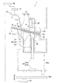
図1に示すように、本発明の実施形態に係るプレス成形装置1は、プレス成形によってブランク材2を所望の形状に加工する装置である。プレス成形装置1は、可動型10と、固定型20と、固定型クッション30と、第一コマ41と、第二コマ42と、可動型移動部51と、第一コマ付勢部52と、第二コマ変位規制部53と、固定型クッション付勢部54と、制御部60と、を備える。かかるプレス成形装置1において、可動型10の延長部12、固定型クッション30、第一コマ41、第二コマ42等は、ブランク材2において成形途中で張力を増加すべき位置に適宜設けられている。
<Press molding equipment>
As shown in FIG. 1, the
<可動型>
可動型10は、固定型20及び固定型クッション30と対向配置される、いわゆる上型である。可動型10は、固定型20と対向する可動型本体部11と、固定型クッション30と対向する延長部12と、を一体的に備える。
<Movable type>
The
可動型本体部11における延長部12側端部は、傾斜が大きい絞り成形部11aを構成する。
The end portion on the
延長部(可動型クッションともいう)12は、可動型本体部11側から順に、凹凸部12aと、第一コマ41が収容される収容部12bと、を備える。
The extension portion (also referred to as a movable cushion) 12 includes a concave-
凹凸部12aは、ブランク材2の端部2aを挟んで凹凸部31の凹凸と嵌合するように形成された凸状又は凹状のビードである。かかるビードによる凹凸部12aは、可動型本体部11及び延長部12の配列方向に交差するように延設されている。
The
収容部12bは、固定型クッション30の反対側に窪む凹部であり、固定型クッション30側に開口部12cを有する。
The
<固定型>
固定型20は、可動型10の可動型本体部11と対向配置される、いわゆる下型である。固定型20は、可動型本体部11と対向する固定型本体部21を備える。固定型本体部21において絞り成形部11aと対向する部位は、傾斜が大きい絞り成形部21aを構成する。
<Fixed type>
The fixed
<固定型クッション>
固定型クッション30は、固定型20と同側において、延長部12と対向配置される。固定型クッション30は、固定型クッション付勢部54によって延長部12側へ付勢可能であるとともに、延長部12から押されることによって、固定型クッション付勢部54の付勢力に抗して、可動型10とともに閉方向へ移動可能に構成されている(図1の両矢印参照)。固定型クッション30は、凹凸部12aと対向する凹凸部31と、収容部12bと対向して第二コマ42が収容される収容部32と、を備える。
<Fixed cushion>
The
凹凸部31の凹凸は、ブランク材2の端部2aを挟んで凹凸部12aの凹凸と嵌合するように形成された凹状又は凸状のビードである。かかるビードによる凹凸部31は、固定型本体部21及び固定型クッション30の配列方向に交差するように延設されている。
The unevenness of the
収容部32は、延長部12の反対側に窪む凹部であり、延長部12側に開口部33を有する。収容部32の固定型本体部21側端部は、収容部12bの可動型本体部11側端部よりも固定型本体部21側端部から離間する方向に位置する。
The
<第一コマ>
第一コマ41は、可動型10(延長部12)の型面に形成された開口部12cに設けられており、可動型10及び固定型20の配置方向に移動可能である。第一コマ41は、収容部12b内に、可動型10の移動方向(上下方向)に移動可能に収容されている。第一コマ41の先端面(下面)は、延長部12の収容部12b周囲の面と面一となるように形成されている。第一コマ41の軸方向寸法は、収容部12bの軸方向寸法よりも小さい。
<First frame>
The
<第二コマ>
第二コマ42は、固定型クッション30に設けられており、固定型クッション30に対して独立して変位可能であるとともに第一コマ41を押圧可能である。第二コマ42は、収容部32内に、当該収容部32から可動型10側へ突出可能に収容されている。第二コマ42の先端面(上面)は、固定型クッション30の収容部32周囲の面と面一となるように形成されている。第二コマ42の軸方向寸法は、収容部32の軸方向寸法と等しい。
<Second frame>
The
<可動型移動部>
可動型移動部51は、油圧モータ等によって構成されており、制御部60からの制御信号に基づいて可動型10を開閉方向に移動させる。
<Movable moving part>
The movable
<第一コマ付勢部>
第一コマ付勢部52は、ガススプリング、コイルスプリング等によって構成されており、収容部12bの底面と第一コマ41の上面との間に設けられて、第一コマ41を第二コマ42方向へ付勢する。
<First frame urging department>
The first
<第二コマ変位規制部>
第二コマ変位規制部53は、第二コマ42から延設されて収容部32の底面に形成された貫通孔34を介して固定型クッション30から露出する軸部53aと、軸部53aの先端部(下端部)と当接可能な当接部53bと、を備える。
<Second frame displacement control unit>
The second frame
<固定型クッション付勢部>
固定型クッション付勢部54は、エアシリンダ、油圧シリンダ、サーボモータ等によって構成されており、制御部60からの制御信号(例えば、サーボモータの場合にはNC制御)に基づいて、クッションパッド55a及び固定型20を貫通するクッションピン55bを介して、固定型クッション30を可動型10(延長部12)側へ付勢する。なお、固定型クッション付勢部54及びクッションパッド55aは、図3〜図8では記載を省略されている。
<Fixed cushion urging part>
The fixed
<動作例>
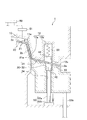
続いて、プレス成形装置1の動作例について、図2等を参照して説明する。
<Operation example>
Subsequently, an operation example of the
まず、ブランク材2が固定型20の固定型本体部21及び固定型クッション30に載置された状態で、制御部60が、可動型移動部51及び第二コマ付勢部54を制御する(ステップS1)。かかる制御により、第一コマ41が第一コマ付勢部52によって閉方向に付勢された状態で、可動型10が閉方向に移動開始する(図1参照)。また、固定型クッション付勢部54は、固定型クッション30が初期位置(図1参照)に配置された状態で、当該固定型クッション30を延長部12側へ付勢可能な状態となる。
First, the
続いて、延長部12の凹凸部12a及び固定型クッション30の凹凸部31がブランク材2の端部2aを挟持する(ステップS2)。ここで、第一コマ付勢部52及び固定型クッション付勢部54の付勢力によって、第一コマ41及び第二コマ42がブランク材2の端部2aを挟持する。
Subsequently, the
続いて、かかる状態で可動型10、第一コマ41、固定型クッション30及び第二コマ42が固定型クッション付勢部54の付勢力に抗して閉方向(下方)へ移動することによって、ブランク材2の端部近傍2bの加工が開始される(ステップS3、図3、図4及び図5参照)。
Subsequently, in such a state, the
続いて、第二コマ変位規制部53における軸部53aの先端部が、当接部53bと当接する(ステップS4、図6参照)。これにより、第一コマ41及び第二コマ42は、変位が規制され、これ以上閉方向へ移動することができなくなる。
Subsequently, the tip of the
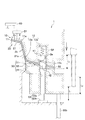
続いて、可動型10及び固定型クッション30がさらに閉方向へ移動し、第一コマ41及び第二コマ42は、ブランク材2の端部2aを挟持した状態でその場に留まる。換言すると、第一コマ41及び第二コマ42は、可動型10及び固定型クッション30に対して、可動型10側へ相対的に変位し、ブランク材2の端部2aを持ち上げた状態となる(ステップS5、図7参照)。ここで、第二コマ42の先端部は、収容部32から突出して収容部12bに進入する。また、ブランク材2の端部2aは、第二コマ42の外周面と収容部12bの内周面とに沿って屈曲される。すなわち、収容部12bの幅方向寸法は、第二コマ42の幅方向寸法とブランク材2の端部2aの厚みとの合計以上に設定されている。かかる状態では、ブランク材2の端部2aに作用する張力は、凹凸部12a,31による挟持による力に対して、第二コマ42の外周面と収容部12bの内周面による挟持による力が加わるため、ブランク材2の端部2aが屈曲する前よりも大きくなる。
Subsequently, the
続いて、可動型10及び固定型クッション30がさらに閉方向へ移動し、可動型本体部11及び固定型本体部21は、ブランク材2の中央部2cを所望の形状に加工する(ステップS6、図8参照)。ここで、ブランク材2の端部近傍2bは、絞り成形部11a,21aによって挟持され、中央部2cよりも深く絞った状態に加工される。
Subsequently, the
ここで、第一コマ41及び第二コマ42がブランク材2の端部2aを挟持して移動可能な距離L1は、可動型10(延長部12)及び固定型クッション30がブランク材2の端部2aを挟持して移動可能な距離L2よりも短い。換言すると、ブランク材2の端部2aを挟持した可動型10及び固定型クッション30の閉方向への移動の途中で、ブランク材2の端部2aを挟持した第一コマ41及び第二コマ42は、閉方向への移動が規制され、固定型20に対して停止する。かかる第一コマ41及び第二コマ42は、可動型10(延長部12)及び固定型クッション30に対して相対的にみて可動型10側へ変位するともいえる。かかる距離L1,L2の大きさの関係は、ブランク材2の加工形状等に応じて、ブランク材2への反り、皺、亀裂等の発生を抑制可能な値に適宜設定可能である。また、収容部12bの軸方向寸法と第一コマ41及び第一コマ付勢部52の軸方向寸法の合計との差は、距離L2と距離L1との差以上の大きさに設定されている。
Here, the
その後、所望形状に加工されたブランク材2は、端部2aがカットされることによって製品形状になる。
After that, the
本発明の実施形態に係るプレス成形装置1は、互いに対向するように配置されており、ブランク材2を挟持することによって当該ブランク材2を成形する可動型10及び固定型20と、前記固定型20の周囲に設けられて前記可動型10と対向し、前記可動型10と協働して前記ブランク材2の端部2aを挟持可能な固定型クッション30と、前記可動型10の型面に形成された開口部12cに設けられており、前記可動型10及び前記固定型20の配置方向に移動可能な第一コマ41と、前記固定型クッション30に設けられており、当該固定型クッション30に対して独立して変位可能であるとともに前記第一コマ41を押圧可能な第二コマ42と、を備え、前記第一コマ41及び前記第二コマ42が前記ブランク材2の端部2aを挟持して移動可能な距離L1は、前記可動型10及び前記固定型クッション30が前記ブランク材2の端部2aを挟持して移動可能な距離L2よりも短いことを特徴とする。
したがって、プレス成形装置1は、ブランク材2の端部2aを挟持する張力を成形中に増加させることによって、反り、皺、亀裂等の発生を抑制することができる。
The
Therefore, the
また、プレス成形装置1は、前記可動型10及び前記固定型クッション30が前記ブランク材2の端部2aを挟持するとともに前記第一コマ41及び前記第二コマ42が前記ブランク材2の端部2aを挟持した状態で、前記第一コマ41及び前記第二コマ42が前記可動型10側へ前記可動型10及び前記固定型クッション30に対して相対的に変位しつつ、前記可動型10及び前記固定型20が前記ブランク材2を挟持することによって当該ブランク材2を成形することを特徴とする。
したがって、プレス成形装置1は、ブランク材2の端部2aを挟持する張力を成形中に増加させることによって、反り、皺、亀裂等の発生を抑制することができる。
Further, in the
Therefore, the
また、本発明の実施形態に係るプレス成形方法は、前記プレス成形装置1によるプレス成形方法であって、前記可動型10及び前記固定型クッション30が前記ブランク材2の端部2aを挟持するとともに前記第一コマ41及び前記第二コマ42が前記ブランク材2の端部2aを挟持した状態で、前記可動型10、前記固定型クッション30、前記第一コマ41及び前記第二コマ42が前記固定型20側へ移動するステップと、前記可動型10及び前記固定型クッション30が前記固定型20側へ移動しつつ、前記第一コマ41及び前記第二コマ42が前記可動型10側へ相対的に変位するステップと、を含むことを特徴とする。
したがって、プレス成形方法は、ブランク材2の端部2aを挟持する張力を成形中に増加させることによって、反り、皺、亀裂等の発生を抑制することができる。
Further, the press molding method according to the embodiment of the present invention is a press molding method by the
Therefore, in the press molding method, the occurrence of warpage, wrinkles, cracks, etc. can be suppressed by increasing the tension for sandwiching the
以上、本発明の実施形態について説明したが、本発明は前記実施形態に限定されず、本発明の要旨を逸脱しない範囲で適宜変形可能である。例えば、可動型10及び固定型20の配置関係は、前記した上下に限定されない。
Although the embodiments of the present invention have been described above, the present invention is not limited to the above-described embodiments and can be appropriately modified without departing from the gist of the present invention. For example, the arrangement relationship between the
1 プレス成形装置
2 ブランク材
2a 端部
2b 端部近傍
2c 中央部
10 可動型
11 可動型本体部
11a 絞り成形部
12 延長部
12a 凹凸部
12b 収容部
20 固定型
21 固定型本体部
30 固定型クッション
31 凹凸部
32 収容部
41 第一コマ
42 第二コマ
51 可動型移動部
52 第一コマ付勢部
53 第二コマ変位規制部
54 固定型クッション付勢部
60 制御部
1
Claims (4)
前記固定型の周囲に設けられて前記可動型と対向し、前記可動型と協働して前記ブランク材の端部を挟持可能な固定型クッションと、
前記可動型の型面に形成された開口部に設けられており、前記可動型及び前記固定型の配置方向に移動可能な第一コマと、
前記固定型クッションに設けられており、当該固定型クッションに対して独立して変位可能であるとともに前記第一コマを押圧可能な第二コマと、
を備え、
前記第一コマ及び前記第二コマが前記ブランク材の端部を挟持して移動可能な距離は、前記可動型及び前記固定型クッションが前記ブランク材の端部を挟持して移動可能な距離よりも短く、
前記可動型及び前記第一コマが前記固定型クッション及び前記第二コマと協働して前記ブランク材の端部を挟持して移動した後に、前記ブランク材の端部が挟持された状態で、前記可動型が前記固定型と協働して前記ブランク材の中央部を挟持して成形するように構成されている
ことを特徴とするプレス成形装置。 Movable molds and fixed molds that are arranged so as to face each other and that mold the blank material by sandwiching the blank material,
A fixed cushion provided around the fixed mold, facing the movable mold, and capable of holding an end portion of the blank material in cooperation with the movable mold.
A first frame provided in an opening formed in the movable mold surface and movable in the arrangement direction of the movable mold and the fixed mold, and
A second frame provided on the fixed cushion, which can be displaced independently of the fixed cushion and can press the first frame,
With
The distance that the first frame and the second frame can move while sandwiching the end of the blank material is greater than the distance that the movable type and the fixed cushion can move by sandwiching the end of the blank material. Also short
After the movable type and the first piece cooperate with the fixed type cushion and the second piece to sandwich and move the end portion of the blank material, the end portion of the blank material is sandwiched and moved. A press molding apparatus characterized in that the movable mold is configured to sandwich and form a central portion of the blank material in cooperation with the fixed mold.
ことを特徴とする請求項1に記載のプレス成形装置。The press molding apparatus according to claim 1.
ことを特徴とする請求項1又は請求項2に記載のプレス成形装置。 The first frame and the second frame are in a state where the movable type and the fixed type cushion sandwich the end portion of the blank material and the first frame and the second frame sandwich the end portion of the blank material. Is characterized in that the blank material is formed by sandwiching the blank material between the movable mold and the fixed mold while being displaced toward the movable mold side with respect to the movable mold and the fixed mold cushion. The press molding apparatus according to claim 1 or 2.
前記可動型及び前記固定型クッションが前記ブランク材の端部を挟持するとともに前記第一コマ及び前記第二コマが前記ブランク材の端部を挟持した状態で、前記可動型、前記固定型クッション、前記第一コマ及び前記第二コマが前記固定型側へ移動するステップと、
前記可動型及び前記固定型クッションが前記固定型側へ移動しつつ、前記第一コマ及び前記第二コマが前記可動型側へ相対的に変位するステップと、
前記ブランク材の端部が挟持された状態で、前記可動型及び前記固定型が前記ブランク材の中央部を挟持することによって当該ブランク材の中央部を成形するステップと、
を含むことを特徴とするプレス成形方法。 The press molding method using the press molding apparatus according to claim 1 or 2.
With the movable type and the fixed type cushion sandwiching the end portion of the blank material and the first frame and the second frame sandwiching the end portion of the blank material, the movable type and the fixed type cushion, The step of moving the first frame and the second frame to the fixed mold side, and
A step in which the first frame and the second frame are relatively displaced toward the movable type side while the movable type and the fixed type cushion move to the fixed type side.
A step of forming the central portion of the blank material by sandwiching the central portion of the blank material between the movable mold and the fixed mold while the end portions of the blank material are sandwiched.
A press molding method comprising.
Priority Applications (2)
| Application Number | Priority Date | Filing Date | Title |
|---|---|---|---|
| JP2019148177A JP6898397B2 (en) | 2019-08-09 | 2019-08-09 | Press molding equipment and press molding method |
| CN202010756404.9A CN112338036A (en) | 2019-08-09 | 2020-07-31 | Press forming device and press forming method |
Applications Claiming Priority (1)
| Application Number | Priority Date | Filing Date | Title |
|---|---|---|---|
| JP2019148177A JP6898397B2 (en) | 2019-08-09 | 2019-08-09 | Press molding equipment and press molding method |
Publications (2)
| Publication Number | Publication Date |
|---|---|
| JP2021028080A JP2021028080A (en) | 2021-02-25 |
| JP6898397B2 true JP6898397B2 (en) | 2021-07-07 |
Family
ID=74358301
Family Applications (1)
| Application Number | Title | Priority Date | Filing Date |
|---|---|---|---|
| JP2019148177A Active JP6898397B2 (en) | 2019-08-09 | 2019-08-09 | Press molding equipment and press molding method |
Country Status (2)
| Country | Link |
|---|---|
| JP (1) | JP6898397B2 (en) |
| CN (1) | CN112338036A (en) |
Families Citing this family (5)
| Publication number | Priority date | Publication date | Assignee | Title |
|---|---|---|---|---|
| JP7617399B2 (en) * | 2021-03-12 | 2025-01-20 | 日本製鉄株式会社 | Pressing device and method for manufacturing press-molded products |
| CN115703138B (en) * | 2021-08-13 | 2026-01-02 | 广州汽车集团股份有限公司 | A drawing die and its design and manufacturing method |
| CN113414292B (en) * | 2021-08-24 | 2022-01-11 | 宁波明讯实业有限公司 | Stamping detection method for upper cover of new energy automobile battery pack |
| CN113414293B (en) * | 2021-08-24 | 2022-01-11 | 宁波明讯实业有限公司 | Stamping system of new energy automobile battery package upper cover |
| CN119585924A (en) * | 2022-08-12 | 2025-03-07 | 株式会社Lg新能源 | Pouch-type battery casing and molding equipment thereof |
Family Cites Families (5)
| Publication number | Priority date | Publication date | Assignee | Title |
|---|---|---|---|---|
| US3000274A (en) * | 1959-04-03 | 1961-09-19 | Kaiser Aluminium Chem Corp | Apparatus for making receptacles |
| JPS61167214U (en) * | 1985-04-03 | 1986-10-17 | ||
| US5187966A (en) * | 1989-12-11 | 1993-02-23 | Sollac | Method and device for drawing containers of frustoconical shape and a container drawn thereby |
| FR3018465B1 (en) * | 2014-03-11 | 2016-11-18 | Peugeot Citroen Automobiles Sa | MATRIX WITH EJECTOR FOR EMBOUTIZER WITH GUTTER IN EDGE |
| JP6200917B2 (en) * | 2015-06-03 | 2017-09-20 | 株式会社コガネイ | Shock absorber and press working apparatus using the same |
-
2019
- 2019-08-09 JP JP2019148177A patent/JP6898397B2/en active Active
-
2020
- 2020-07-31 CN CN202010756404.9A patent/CN112338036A/en active Pending
Also Published As
| Publication number | Publication date |
|---|---|
| CN112338036A (en) | 2021-02-09 |
| JP2021028080A (en) | 2021-02-25 |
Similar Documents
| Publication | Publication Date | Title |
|---|---|---|
| JP6898397B2 (en) | Press molding equipment and press molding method | |
| US8490455B2 (en) | Mold for press apparatus, and open-drawing method | |
| JP2003236623A (en) | Sequential molding equipment | |
| JP5385732B2 (en) | Press molding apparatus and press molding method | |
| JP2017001040A (en) | Orifice molding device | |
| JP7182269B2 (en) | Press molding equipment | |
| JP2005021945A (en) | Metallic mold for press-forming and method for producing panel using it | |
| JP2015077621A (en) | Press working method | |
| JP2016002590A (en) | Bending die | |
| JP2016032833A (en) | Press molding method | |
| JP2018051584A (en) | Press molding apparatus | |
| KR101965392B1 (en) | Coining apparatus having punch adopting variable groove pin | |
| JP2018083203A (en) | Press forming equipment | |
| JP6199694B2 (en) | Press working method | |
| JP2017080747A (en) | Press forming method and press forming device | |
| WO2020031318A1 (en) | Paper container production device, paper container production method, and paper container | |
| KR101461793B1 (en) | apparatus for press-forming | |
| JPS5947028A (en) | Back drawing press die | |
| JP4493472B2 (en) | Optical element molding method | |
| JP6986370B2 (en) | Paper container manufacturing equipment, paper container manufacturing method and paper container | |
| JP2005334917A (en) | Method and apparatus for bending metallic sheet into circular-arc shape | |
| JP2015085362A (en) | Positioning device | |
| JP2015080808A (en) | Punching processing method of a planar workpiece and punch | |
| KR101600003B1 (en) | Press molding apparatus | |
| JP5290823B2 (en) | Molding method and molding apparatus |
Legal Events
| Date | Code | Title | Description |
|---|---|---|---|
| A621 | Written request for application examination |
Free format text: JAPANESE INTERMEDIATE CODE: A621 Effective date: 20200327 |
|
| A131 | Notification of reasons for refusal |
Free format text: JAPANESE INTERMEDIATE CODE: A131 Effective date: 20210216 |
|
| A521 | Written amendment |
Free format text: JAPANESE INTERMEDIATE CODE: A523 Effective date: 20210408 |
|
| TRDD | Decision of grant or rejection written | ||
| A01 | Written decision to grant a patent or to grant a registration (utility model) |
Free format text: JAPANESE INTERMEDIATE CODE: A01 Effective date: 20210608 |
|
| A61 | First payment of annual fees (during grant procedure) |
Free format text: JAPANESE INTERMEDIATE CODE: A61 Effective date: 20210610 |
|
| R150 | Certificate of patent or registration of utility model |
Ref document number: 6898397 Country of ref document: JP Free format text: JAPANESE INTERMEDIATE CODE: R150 |