JP6896657B2 - Systems and methods that reduce the time it takes to print layers on a 3D object and enhance the color fidelity of the surface of the 3D object. - Google Patents
Systems and methods that reduce the time it takes to print layers on a 3D object and enhance the color fidelity of the surface of the 3D object. Download PDFInfo
- Publication number
- JP6896657B2 JP6896657B2 JP2018009469A JP2018009469A JP6896657B2 JP 6896657 B2 JP6896657 B2 JP 6896657B2 JP 2018009469 A JP2018009469 A JP 2018009469A JP 2018009469 A JP2018009469 A JP 2018009469A JP 6896657 B2 JP6896657 B2 JP 6896657B2
- Authority
- JP
- Japan
- Prior art keywords
- droplets
- layer
- color
- average number
- boxel
- Prior art date
- Legal status (The legal status is an assumption and is not a legal conclusion. Google has not performed a legal analysis and makes no representation as to the accuracy of the status listed.)
- Active
Links
Images


Classifications
-
- B—PERFORMING OPERATIONS; TRANSPORTING
- B29—WORKING OF PLASTICS; WORKING OF SUBSTANCES IN A PLASTIC STATE IN GENERAL
- B29C—SHAPING OR JOINING OF PLASTICS; SHAPING OF MATERIAL IN A PLASTIC STATE, NOT OTHERWISE PROVIDED FOR; AFTER-TREATMENT OF THE SHAPED PRODUCTS, e.g. REPAIRING
- B29C67/00—Shaping techniques not covered by groups B29C39/00 - B29C65/00, B29C70/00 or B29C73/00
- B29C67/0007—Manufacturing coloured articles not otherwise provided for, e.g. by colour change
-
- B—PERFORMING OPERATIONS; TRANSPORTING
- B29—WORKING OF PLASTICS; WORKING OF SUBSTANCES IN A PLASTIC STATE IN GENERAL
- B29C—SHAPING OR JOINING OF PLASTICS; SHAPING OF MATERIAL IN A PLASTIC STATE, NOT OTHERWISE PROVIDED FOR; AFTER-TREATMENT OF THE SHAPED PRODUCTS, e.g. REPAIRING
- B29C64/00—Additive manufacturing, i.e. manufacturing of three-dimensional [3D] objects by additive deposition, additive agglomeration or additive layering, e.g. by 3D printing, stereolithography or selective laser sintering
- B29C64/30—Auxiliary operations or equipment
- B29C64/307—Handling of material to be used in additive manufacturing
- B29C64/321—Feeding
- B29C64/336—Feeding of two or more materials
-
- B—PERFORMING OPERATIONS; TRANSPORTING
- B29—WORKING OF PLASTICS; WORKING OF SUBSTANCES IN A PLASTIC STATE IN GENERAL
- B29C—SHAPING OR JOINING OF PLASTICS; SHAPING OF MATERIAL IN A PLASTIC STATE, NOT OTHERWISE PROVIDED FOR; AFTER-TREATMENT OF THE SHAPED PRODUCTS, e.g. REPAIRING
- B29C64/00—Additive manufacturing, i.e. manufacturing of three-dimensional [3D] objects by additive deposition, additive agglomeration or additive layering, e.g. by 3D printing, stereolithography or selective laser sintering
- B29C64/10—Processes of additive manufacturing
- B29C64/106—Processes of additive manufacturing using only liquids or viscous materials, e.g. depositing a continuous bead of viscous material
- B29C64/112—Processes of additive manufacturing using only liquids or viscous materials, e.g. depositing a continuous bead of viscous material using individual droplets, e.g. from jetting heads
-
- B—PERFORMING OPERATIONS; TRANSPORTING
- B29—WORKING OF PLASTICS; WORKING OF SUBSTANCES IN A PLASTIC STATE IN GENERAL
- B29C—SHAPING OR JOINING OF PLASTICS; SHAPING OF MATERIAL IN A PLASTIC STATE, NOT OTHERWISE PROVIDED FOR; AFTER-TREATMENT OF THE SHAPED PRODUCTS, e.g. REPAIRING
- B29C64/00—Additive manufacturing, i.e. manufacturing of three-dimensional [3D] objects by additive deposition, additive agglomeration or additive layering, e.g. by 3D printing, stereolithography or selective laser sintering
- B29C64/30—Auxiliary operations or equipment
- B29C64/386—Data acquisition or data processing for additive manufacturing
- B29C64/393—Data acquisition or data processing for additive manufacturing for controlling or regulating additive manufacturing processes
-
- B—PERFORMING OPERATIONS; TRANSPORTING
- B33—ADDITIVE MANUFACTURING TECHNOLOGY
- B33Y—ADDITIVE MANUFACTURING, i.e. MANUFACTURING OF THREE-DIMENSIONAL [3-D] OBJECTS BY ADDITIVE DEPOSITION, ADDITIVE AGGLOMERATION OR ADDITIVE LAYERING, e.g. BY 3-D PRINTING, STEREOLITHOGRAPHY OR SELECTIVE LASER SINTERING
- B33Y10/00—Processes of additive manufacturing
-
- B—PERFORMING OPERATIONS; TRANSPORTING
- B33—ADDITIVE MANUFACTURING TECHNOLOGY
- B33Y—ADDITIVE MANUFACTURING, i.e. MANUFACTURING OF THREE-DIMENSIONAL [3-D] OBJECTS BY ADDITIVE DEPOSITION, ADDITIVE AGGLOMERATION OR ADDITIVE LAYERING, e.g. BY 3-D PRINTING, STEREOLITHOGRAPHY OR SELECTIVE LASER SINTERING
- B33Y30/00—Apparatus for additive manufacturing; Details thereof or accessories therefor
-
- B—PERFORMING OPERATIONS; TRANSPORTING
- B33—ADDITIVE MANUFACTURING TECHNOLOGY
- B33Y—ADDITIVE MANUFACTURING, i.e. MANUFACTURING OF THREE-DIMENSIONAL [3-D] OBJECTS BY ADDITIVE DEPOSITION, ADDITIVE AGGLOMERATION OR ADDITIVE LAYERING, e.g. BY 3-D PRINTING, STEREOLITHOGRAPHY OR SELECTIVE LASER SINTERING
- B33Y40/00—Auxiliary operations or equipment, e.g. for material handling
-
- B—PERFORMING OPERATIONS; TRANSPORTING
- B33—ADDITIVE MANUFACTURING TECHNOLOGY
- B33Y—ADDITIVE MANUFACTURING, i.e. MANUFACTURING OF THREE-DIMENSIONAL [3-D] OBJECTS BY ADDITIVE DEPOSITION, ADDITIVE AGGLOMERATION OR ADDITIVE LAYERING, e.g. BY 3-D PRINTING, STEREOLITHOGRAPHY OR SELECTIVE LASER SINTERING
- B33Y50/00—Data acquisition or data processing for additive manufacturing
- B33Y50/02—Data acquisition or data processing for additive manufacturing for controlling or regulating additive manufacturing processes
-
- H—ELECTRICITY
- H04—ELECTRIC COMMUNICATION TECHNIQUE
- H04N—PICTORIAL COMMUNICATION, e.g. TELEVISION
- H04N1/00—Scanning, transmission or reproduction of documents or the like, e.g. facsimile transmission; Details thereof
- H04N1/46—Colour picture communication systems
- H04N1/56—Processing of colour picture signals
- H04N1/60—Colour correction or control
-
- B—PERFORMING OPERATIONS; TRANSPORTING
- B29—WORKING OF PLASTICS; WORKING OF SUBSTANCES IN A PLASTIC STATE IN GENERAL
- B29K—INDEXING SCHEME ASSOCIATED WITH SUBCLASSES B29B, B29C OR B29D, RELATING TO MOULDING MATERIALS OR TO MATERIALS FOR MOULDS, REINFORCEMENTS, FILLERS OR PREFORMED PARTS, e.g. INSERTS
- B29K2105/00—Condition, form or state of moulded material or of the material to be shaped
- B29K2105/0058—Liquid or visquous
-
- B—PERFORMING OPERATIONS; TRANSPORTING
- B29—WORKING OF PLASTICS; WORKING OF SUBSTANCES IN A PLASTIC STATE IN GENERAL
- B29K—INDEXING SCHEME ASSOCIATED WITH SUBCLASSES B29B, B29C OR B29D, RELATING TO MOULDING MATERIALS OR TO MATERIALS FOR MOULDS, REINFORCEMENTS, FILLERS OR PREFORMED PARTS, e.g. INSERTS
- B29K2995/00—Properties of moulding materials, reinforcements, fillers, preformed parts or moulds
- B29K2995/0018—Properties of moulding materials, reinforcements, fillers, preformed parts or moulds having particular optical properties, e.g. fluorescent or phosphorescent
- B29K2995/002—Coloured
Landscapes
- Engineering & Computer Science (AREA)
- Chemical & Material Sciences (AREA)
- Materials Engineering (AREA)
- Manufacturing & Machinery (AREA)
- Mechanical Engineering (AREA)
- Physics & Mathematics (AREA)
- Optics & Photonics (AREA)
- Multimedia (AREA)
- Signal Processing (AREA)
Description
本開示は、一般に、三次元(3D)物体印刷に関し、特に、三次元物体を印刷するために必要な時間を短縮し、印刷された三次元物体の表面でより正確に色を作成することに関する。 The present disclosure relates generally to three-dimensional (3D) object printing, and in particular to reducing the time required to print a three-dimensional object and creating more accurate colors on the surface of the printed three-dimensional object. ..
3D物体印刷では、物体は一度に1つの層で造形される。液滴を排出する1つまたは複数のプリントヘッドは、複数回にわたって物体上を移動する。物体を作成するのに必要な通過の数は、一般的な物体の作成に非常に長い時間を要する可能性がある。物体の中には大きいものもあり、物体の形成に数日かかることもある。物体の構造を形成する3D印刷システムによって排出される材料に加えて、いくつかの印刷システムはまた、作成された部品の表面上に画像を重ね合わせる着色材料を含む。これらのシステムでは、物体構造は、一般的には、クリアおよびホワイト造形材料、ならびに二次元印刷に一般的に使用される色のような着色材料を使用して形成され、つまり、シアン、マゼンタ、イエローおよびブラック(C、M、YおよびK)を使用して画像を形成する。本明細書において、「着色材料」または「顔料着色材料」とは、レッドからバイオレットおよびブラックの光スペクトル範囲に色相を有する材料を意味する。各層は、1つのタイプの材料のみ、すなわち、造形材料または着色材料のいずれかで作られる。物体の形成に必要な時間を短縮する1つの方法は、複数の層を1回の通過で印刷することである。この目標を達成するためには、各材料に割り当てられる排出装置の数も増やさなければならない。当然、排出装置の数の増加は、ハードウェアの費用であるため、システムのコストも増加する。したがって、3D物体印刷システムには、速度とコストとの間に直接の関係が存在する。 In 3D object printing, an object is modeled in one layer at a time. The one or more printheads that eject the droplets move over the object multiple times. The number of passes required to create an object can take a very long time to create a typical object. Some objects are large and can take several days to form. In addition to the materials ejected by the 3D printing systems that form the structure of the object, some printing systems also include coloring materials that overlay the image on the surface of the created part. In these systems, the object structure is generally formed using clear and white modeling materials, as well as coloring materials such as colors commonly used in 2D printing, ie cyan, magenta, and so on. Yellow and black (C, M, Y and K) are used to form the image. As used herein, the term "coloring material" or "pigment coloring material" means a material having hues in the optical spectral range of red to violet and black. Each layer is made of only one type of material, i.e. either a modeling material or a coloring material. One way to reduce the time required to form an object is to print multiple layers in a single pass. To achieve this goal, the number of discharge devices assigned to each material must also be increased. Of course, the increase in the number of discharge devices is the cost of the hardware, so the cost of the system also increases. Therefore, in 3D object printing systems, there is a direct relationship between speed and cost.
3D物体の表面に色を印刷することは、表面に塗料を塗ることと同じではないため、着色剤を使用する画像の印刷でも問題が発生する。塗料は、プリントヘッドによって排出可能な材料に組み込むことができるよりはるかに大きい着色剤濃度を有する。色を印刷する際には、ホワイト材料を画像のベースとして使用し、次に画像を様々な色の組み合わせで形成することができる。しかし、厚い色の層は高解像度の画像を形成することができない。加えて、多くの3D物体印刷システムは、材料を除去して表面を平坦化するために製造プロセスで時折使用されるレベリング装置を含む。平坦でない表面の上に他の層を追加すると、製造する物体の構成が乱れることがあるのでこの平滑化は必要である。除去する材料の量はまた、色の許容できない変化を生じ得る。製造時間を短縮し、物体の表面に確実に色を再現する3D物体印刷表面が有益であろう。 Printing a color on the surface of a 3D object is not the same as painting the surface, so printing an image with a colorant also causes problems. The paint has a much higher colorant concentration than can be incorporated into a material that can be ejected by the printhead. When printing colors, a white material can be used as the basis for the image, and then the image can be formed with various color combinations. However, thick colored layers cannot form high resolution images. In addition, many 3D object printing systems include leveling equipment that is occasionally used in the manufacturing process to remove material and flatten the surface. This smoothing is necessary because adding other layers on top of an uneven surface can disrupt the composition of the object being manufactured. The amount of material removed can also cause unacceptable changes in color. A 3D object print surface that reduces manufacturing time and reliably reproduces colors on the surface of the object would be beneficial.
新規の3D物体印刷システムは、物体製造時間を短縮し、物体の表面上でより正確な色の再現を可能にするように構成される。システムは、第1の色を有する第1の材料液滴を排出するように構成された第1の複数の排出装置と、第2の色を有する第2の材料液滴を排出するように構成された第2の複数の排出装置であって、第1の色は第2の色と異なる、第2の複数の排出装置と、第3の色を有する第3の材料液滴を排出するように構成された第3の複数の排出装置であって、第3の色は第2の色および第1の色と異なる、第3の複数の排出装置と、第1の複数の排出装置、第2の複数の排出装置、および第3の複数の排出装置に動作可能に接続された少なくとも1つのアクチュエータと、少なくとも1つのアクチュエータ、第1の複数の排出装置、第2の複数の排出装置、および第3の複数の排出装置に動作可能に接続されたコントローラとを含む。コントローラは、製造する物体の各層における各材料のボクセル毎の材料液滴の平均数を識別し、物体の画像データを、各層のボクセル毎の第2の材料液滴の平均数と各層のボクセル毎の第3の材料液滴の平均数との合計の第1の関数と、全ての材料のボクセル毎の材料液滴の平均数の合計の目標値と、物体の層と最も近い表面との間の距離とを基準として、第1の材料、第2の材料および第3の材料の各々用の材料液滴データに変換し、材料液滴データを各層の各ボクセルの材料液滴を識別する液滴データに変換し、変換した材料液滴データを基準として、第1の複数の排出装置、第2の複数の排出装置、および第3の複数の排出装置を操作して第1の材料液滴、第2の材料液滴、および第3の材料液滴を排出し、画像データに対応する物体の層を形成するように構成される。 The new 3D object printing system is configured to reduce object manufacturing time and enable more accurate color reproduction on the surface of an object. The system is configured to eject a first plurality of ejectors configured to eject a first material droplet having a first color and a second material droplet having a second color. A second plurality of ejectors whose first color is different from the second color, so as to eject a second plurality of ejectors and a third material droplet having a third color. A third plurality of discharge devices configured in the above, wherein the third color is different from the second color and the first color, the third plurality of discharge devices, the first plurality of discharge devices, and the first At least one actuator operably connected to two plurality of discharge devices, and a third plurality of discharge devices, and at least one actuator, a first plurality of discharge devices, a second plurality of discharge devices, and a plurality of discharge devices. Includes a controller operably connected to a third plurality of discharge devices. The controller identifies the average number of material droplets per boxel of each material in each layer of the object to be manufactured, and outputs the image data of the object to the average number of second material droplets per boxel of each layer and each boxel of each layer. Between the first function of the sum of the average number of third material droplets and the target value of the sum of the average number of material droplets per boxel of all materials and the surface closest to the layer of the object. A liquid that converts the material droplet data for each of the first material, the second material, and the third material based on the distance of the material droplet data, and identifies the material droplet data of each boxel of each layer. The first material droplets are converted into drop data, and the first plurality of ejectors, the second plurality of ejectors, and the third plurality of ejectors are operated with reference to the converted material droplet data. , A second material droplet, and a third material droplet are ejected to form a layer of objects corresponding to the image data.
新規の3D印刷システムを操作する方法は、物体の製造時間を短縮し、物体の表面上の色のより正確な再現を可能にする。本方法は、コントローラを使用して製造する物体の各層における各材料のボクセル毎の材料液滴の平均数を識別し、コントローラを使用して物体の画像データを、識別された各層のボクセル毎の第2の材料液滴の平均数と識別された各層のボクセル毎の第3の材料液滴の平均数との合計の第1の関数と、識別された全ての材料のボクセル毎の材料液滴の平均数の合計の目標値と、物体の層と最も近い表面との間の距離とを基準として、第1の材料、第2の材料および第3の材料の各々用の材料液滴データに変換し、コントローラを使用して材料液滴データを各層の各ボクセルの材料液滴を識別する液滴データに変換し、コントローラを使用して変換した材料液滴データを基準として、第1の複数の排出装置、第2の複数の排出装置、および第3の複数の排出装置を操作して第1の材料液滴、第2の材料液滴、および第3の材料液滴を排出し、画像データに対応する物体の層を形成し、複数の排出装置の各々は、他の複数の排出装置によって排出された材料液滴の色と異なる色を有する材料液滴を排出することを含む。 The method of operating a new 3D printing system reduces the manufacturing time of an object and enables more accurate reproduction of colors on the surface of the object. The method identifies the average number of material droplets per boxel of each material in each layer of an object manufactured using the controller, and uses the controller to obtain image data of the object for each boxel of each identified layer. The first function of the sum of the average number of second material droplets and the average number of third material droplets per boxel of each identified layer and the material droplets per boxel of all identified materials. In the material droplet data for each of the first, second, and third materials, based on the target value of the total number of averages and the distance between the layer of the object and the closest surface. Convert, use the controller to convert the material droplet data to droplet data that identifies the material droplets for each boxel in each layer, and use the controller to convert the material droplet data to the first plurality. The first material droplet, the second material droplet, and the third material droplet are discharged by operating the discharge device, the second plurality of discharge devices, and the third plurality of discharge devices. Forming a layer of objects corresponding to the data, each of the ejector comprises ejecting a material droplet having a color different from the color of the material droplet ejected by the other ejector.
本開示の前述した態様および他の特徴は、添付図面に関連して以下の記述において説明される。 The aforementioned aspects and other features of the present disclosure are described in the following description in connection with the accompanying drawings.
本実施形態の一般的な理解のために、図面を参照する。図面において、同様の参照番号は同様の要素を示すために全体を通して使用されている。 Refer to the drawings for a general understanding of this embodiment. In the drawings, similar reference numbers are used throughout to indicate similar elements.
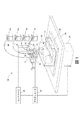
図1は、三次元物体または部品10を作成する印刷システム100内の構成要素の構成を示す。本明細書で使用する「三次元プリンタ」という用語は、物体の画像データを基準として材料液滴を排出して三次元物体を形成する任意の装置を指す。印刷システム100は、支持材料リザーバ14、着色造形材料リザーバ18、クリア造形材料リザーバ60、ホワイト造形材料リザーバ64、複数の排出装置22、26、68、72、および76、造形基板30、平面支持部材34、柱状支持部材38、アクチュエータ42ならびにコントローラ46を含む。導管50は、排出装置22および76を支持材料リザーバ14に接続し、導管54は、排出装置26を着色造形材料リザーバ18に接続する。導管80および84はそれぞれ、排出装置68および72を、造形材料リザーバ60およびホワイト造形材料リザーバ64にそれぞれ接続する。排出装置は、コントローラに動作可能に接続されたメモリ内の三次元画像データを基準としてコントローラ46によって操作され、各排出装置に供給される支持および造形材料液滴を排出する。三次元画像データ内の単一の位置に格納された各データは、本明細書では「ボクセル」として定義される。造形材料は、製造される部品10の構造を形成するが、支持材料液滴によって形成される支持構造58は、造形材料液滴がその形状を維持することを可能にし、部品が構築されるにつれて材料液滴が凝固する。部品が完成した後、支持構造58は、洗浄、吹きつけ、または溶解によって除去される。
FIG. 1 shows the configuration of components in a
コントローラ46はまた、平面支持部材34、柱状支持部材38、および排出装置22、26、68、72、および76の互いに対する動きを制御するために、少なくとも1つのアクチュエータ42に動作可能に接続される。すなわち、1つまたは複数のアクチュエータを排出装置を支持する構造体に動作可能に接続して、排出装置を平面支持部材の表面を基準としてプロセス方向Pおよびクロスプロセス方向C−Pに移動させることができる。あるいは、1つまたは複数のアクチュエータを平面支持部材34に動作可能に接続して、部品が作成される面をプロセスおよびプロセス方向に、平面支持部材34の平面において移動させることができる。本明細書で使用する「プロセス方向」という用語は、平面支持部材34の表面における1つの軸に沿った移動を指し、「クロスプロセス方向」は、平面支持部材表面におけるプロセス方向軸に直交する、その表面における軸に沿った移動を指す。これらの方向は、図1において文字「P」および「C−P」で示されている。排出装置22、26、68、72、および76ならびに柱状支持部材38も平面支持部材34に対して直交する方向に移動する。この方向は、本明細書では垂直方向と呼ばれ、柱状支持部材38に平行であり、図1では文字「V」で示されている。垂直方向の移動は、柱状部材38に動作可能に接続された1つまたは複数のアクチュエータを使用して、排出装置に動作可能に接続された1つまたは複数のアクチュエータによって、または柱状支持部材38と排出装置の両方に動作可能に接続された1つまたは複数のアクチュエータによって達成される。この様々な構成のこれらのアクチュエータは、アクチュエータを操作して柱状部材38、排出装置、またはこれらの構成要素の全てを垂直方向に移動させるコントローラ46に動作可能に接続される。
The
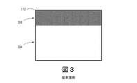
従来知られている3D印刷システムでは、着色材料の層が表面の近くに印刷され、クリア材料層で覆われることがあり、一方下層はホワイト材料からなり、着色材料およびクリア材料の背景を提供する。この構造の一例を図3に示す。図に示すように、内層304は、ホワイト材料のみの液滴で形成されている。次層308は、着色材料のみで形成され、次いで、所望により、着色材料を保護するために、クリア材料の1つまたは複数の層312で覆うことができる。図1に示すプリンタでは、着色材料液滴は次層408において増加する割合で導入され、図4に示すようなよりぼかされた配色を提供する。部品の表面に最も近い層412では、着色材料液滴が層を支配するが、クリア材料液滴やホワイト材料液滴も層に含まれている。着色、クリア、およびホワイトの材料の比率の変更を増やす方法は、色管理された面のサイズを増やすことによって、着色された色域を保存することを可能にする。すなわち、表面付近の色管理された量の深さは、層308および412と比較して層408および412の深さが深くなることによって示されるように、より大きい。着色された色がブラックである場合、図5Aおよび図5Bにそれぞれ示されるように、黒っぽい色または灰色の表面が形成され得る。図5Bに示すように、ぼかされた黒っぽい色または灰色の表面を達成するための方策の一部の例が図6Aに示されている。表面から所定の距離では、ブラック材料は排出されず、ボクセル内の材料の80%はホワイトであり、ボクセル内の材料の20%はクリアである。表面に近い層が形成されるにつれて、ホワイト材料はボクセル内の材料の割合が小さくなり、ブラック材料はボクセル内の材料の80%まで上昇し、ボクセル内のクリア材料はゼロに下がる。表面までの距離が減少するにつれて、ボクセル内のブラック材料の割合はゼロに減少し、一方ホワイト材料は100%に増加する。より飽和した色を達成するための方策の一部が図6Bに示されている。表面から所定の距離で、ボクセル内の材料の80%はブラックであり、ボクセル内の材料の20%はクリアであり、一方ホワイト材料は排出されない。層が表面に近づくにつれて、ボクセルに排出されるクリア材料がゼロになるまで、ホワイト材料がボクセルに排出される。その距離では、ブラック材料はボクセル内の材料の70%に減少し、ボクセル内のホワイト材料は30%に増加する。これらの割合は、ボクセル内のブラック材料の割合がゼロに直線的に減少し、ホワイト材料の割合が100%に直線的に増加する表面からの別の所定の距離に達するまで、後の層に継続する。
In conventionally known 3D printing systems, a layer of coloring material may be printed near the surface and covered with a layer of clear material, while the underlayer consists of a white material, providing a background for the coloring material and the clear material. .. An example of this structure is shown in FIG. As shown in the figure, the
表面を基準にした深さの関数として、着色材料とクリア材料およびホワイト材料とを組み合わせる方策または色モデルによって形成された色は、表面で色のレンダリングを改善する。この方策は、一枚の紙が印刷された色に白い背景を提供するのと同じように、表面の色に白い下地を提供する。ホワイトおよびクリア材料はオプションを提供し、特に層の深さを基準として、データテーブルとして構成でき、かつコントローラが3D印刷システムで作成された物体の演色のために使用できる包括的な3D色方策または色モデルを提供する。本明細書では、「色モデル」とは、材料で作成される物体の表面を基準として深さの関数として排出される材料を分配する複数の関数を指し、プリンタによって排出される各材料毎に1つである。 As a function of surface-based depth, colors formed by a strategy or color model that combines colored and clear and white materials improve color rendering on the surface. This strategy provides a white background for the surface color, much like a piece of paper provides a white background for the printed color. White and clear materials offer options and can be configured as a data table, especially relative to layer depth, and a comprehensive 3D color scheme or strategy that the controller can use for color rendering of objects created in 3D printing systems. Provide a color model. As used herein, the term "color model" refers to a plurality of functions that distribute materials discharged as a function of depth with respect to the surface of an object created of materials, for each material discharged by a printer. There is one.
このような方策の一部の一例では、クリア材料が、表面近くの色で満たされていないボクセルに主として使用され、直線的に増加する量のホワイト材料が層に加えられ、さらに表面から除去される。このような方策は、図7にグラフで示されている。物体の内部では、グラフの領域604に層を形成するためにホワイト材料のみが使用される。領域608における表面からの所定の距離では、50%の着色材料と50%のホワイト材料で層が形成される。移行領域612では、着色材料は層の50%を形成し続け、一方ホワイト材料は50%から0%に直線的に減少し、クリア材料は0%から50%に直線的に増加する。領域616の表面の近くで、層は50%の着色材料と50%のクリア材料で形成される。この方式下では、シアン材料のような100%の着色材料で形成された色、または50%のシアンと50%のマゼンタのような着色材料の組み合わせで形成された色は、適切なレンダリングのために追加のクリアまたはホワイト材料を必要としない。
In some examples of such measures, clear material is mainly used for voxels that are not filled with color near the surface, and a linearly increasing amount of white material is added to the layer and further removed from the surface. To. Such measures are shown graphically in FIG. Inside the object, only white material is used to form layers in
図8に示す別の例では、表面からの深さの関数としての演色方策の一部は、最初に表面で100%に等しいものも含む全ての色にホワイト材料を加えることを含む。この図に描写されているように、物体の内部は、グラフの領域704でホワイト材料のみで形成されている。領域708の表面から所定の距離で、層は、着色材料の割合が50%に達するまで直線的に増加する量の着色材料と、またホワイト材料の割合が50%に達するまで直線的に減少する量のホワイト材料とを使用して形成される。移行領域712では、着色材料は層の50%を形成し続け、一方ホワイト材料は50%から0%に直線的に減少し、クリア材料は0%から50%に直線的に増加する。領域716の表面の近くで、層は50%の着色材料と50%のクリア材料で形成される。この方式の規則は、所定の深さで、層は着色材料で形成され始めるということである。ホワイトが最初に置き換えられ、次に色は一定のままであり、一方ホワイト材料は各層で減少し、クリア材料は各層で増加する。図8は、50%の着色材料の適用範囲に対するこの方策を示し、一方、図9は、100%の着色材料の適用範囲に対する方策を示す。図9のグラフは、ホワイト材料のみの領域804、移行領域808、および着色のみの領域812の、3つの領域のみを有する。移行領域808において、層のホワイト材料の割合は0%に直線的に減少するが、層の着色材料は0%から100%に直線的に増加する。方策のこの部分では、ホワイトおよび着色材料のみが使用される。
In another example shown in FIG. 8, some color rendering strategies as a function of depth from the surface involve first adding a white material to all colors, including those equal to 100% on the surface. As depicted in this figure, the interior of the object is made entirely of white material in
色、ホワイト、およびクリア材料液滴を使用するための上記の方策は、所望の色レベルを達成するために、各材料を物体の表面からの深さの関数として使用するための関数を含む。一般に、ホワイトを優先して着色材料液滴が使用されない深さに達するまで、着色材料液滴よりも多くのホワイト材料液滴が、表面からより深いところに位置する層で使用される。さらに、使用される着色材料液滴の量が、物体を満たすのに必要な材料の量よりも少ない場合、表面に近い層ではホワイト液滴の代わりに、クリア液滴が優先的に使用される。この方策では、製造者が物体の観察者に知覚させたい色の飽和レベルが方策に影響を与える。これらの移行を定義する関数は、図6〜図10に示す線形関数に加えて、多項式または指数関数として表すことができる。より高い飽和色レベルが必要な場合は、表面近くの層でより多くの色材料液滴が必要となる。同様に、より低い飽和色レベルが望ましい場合には、より多くのクリア、あるいはホワイトの材料液滴が表面により近い層で使用される。したがって、関数は、色、色の所望の飽和レベル、および各層の表面からの深さによって決定される。提案された関数が物体を形成するために使用され、物体の色が評価されて、作成された色が色の所望の飽和レベルを達成することが決定される。この目標を達成する関数が定義されると、その後の色較正が実行されて、物体の表面からの距離の関数として対象層に使用される色の成分である、3D部品の表面における所望の色間のマッピングを識別し、さらに物体を印刷する前に各ボクセル内の液滴の色を決定するためにハーフトーニングが識別される。 The above measures for using color, white, and clear material droplets include a function for using each material as a function of depth from the surface of the object to achieve the desired color level. Generally, more white material droplets are used in the layer located deeper than the surface until the white material droplets reach a depth where they are not used in preference to white. In addition, if the amount of colored material droplets used is less than the amount of material required to fill the object, clear droplets are preferentially used instead of white droplets in layers near the surface. .. In this strategy, the level of color saturation that the manufacturer wants the observer of the object to perceive affects the strategy. The functions that define these transitions can be represented as polynomials or exponential functions in addition to the linear functions shown in FIGS. 6-10. If higher saturated color levels are needed, more color material droplets are needed in the layers near the surface. Similarly, more clear or white material droplets are used in layers closer to the surface when lower saturated color levels are desired. Therefore, the function is determined by the color, the desired saturation level of the color, and the depth of each layer from the surface. The proposed function is used to form the object and the color of the object is evaluated to determine that the color created achieves the desired saturation level of color. Once a function that achieves this goal is defined, subsequent color calibration is performed to obtain the desired color on the surface of the 3D component, which is the component of the color used in the target layer as a function of the distance from the surface of the object. Half toning is identified to identify the mapping between and also to determine the color of the droplets within each voxel before printing the object.
上述の方策は、物体のボクセルと最も近い表面との間の距離の関数として、より一般的な方法で表現することができる。各層の各ボクセルの材料液滴は、ボクセルと最も近い表面との間の距離と、物体の各層の各ボクセルにおける材料液滴の平均数の合計と、各層の各ボクセルにおける液滴の平均数の合計の目標値との関数として表現される。ボクセルでの材料液滴の平均数の合計Sを得るために、着色材料のコントーン値が一緒に加算される。さらに、目標値Vは、各ボクセルで活動中でなければならない排出装置の数に比例した固定値である。合計Sは、ハーフトーニング、誤差拡散、またはデジタルバイナリ検索アルゴリズムなどのレンダリングアルゴリズムにより、ボクセルの実際の液滴数に変換される。初期の色空間からの変換と、ホワイトおよびクリア色を含むマッピングとを1つの工程に結合することができる。 The above measures can be expressed in a more general way as a function of the distance between the voxel of the object and the closest surface. The material droplets of each voxel in each layer are the distance between the voxel and the closest surface, the sum of the average number of material droplets in each voxel in each layer of the object, and the average number of droplets in each voxel in each layer. Expressed as a function with the total target value. To obtain the total S of the average number of material droplets in voxels, the contone values of the coloring material are added together. Further, the target value V is a fixed value proportional to the number of discharge devices that must be active in each voxel. The total S is converted to the actual number of droplets in the voxel by a rendering algorithm such as half toning, error diffusion, or a digital binary search algorithm. The conversion from the initial color space and the mapping including white and clear colors can be combined in one step.
合計Sの100%以下の目標値について、ホワイトおよびクリア着色剤を決定できる方法の例がここで提示される。ホワイトは、合計S0と最も近い表面からの距離Dとの関数として表すことができ、W=F(S0,D)、ここで、関数Fは指数関数または多項式であり得るゼロまたは正の二次導関数を使用する単調増加関数である。S0は、最も近い表面から距離Dにあるボクセルに対する材料液滴の初期平均数である。着色剤が表面で知覚される色に寄与しない所定の距離では、ホワイトおよびクリアのみが使用される。本明細書で使用される用語「着色剤」は、レッドからバイオレットの範囲の色相およびブラック色を有する材料を指す。着色された色が使用されていない表面からの最小距離をDfとし、最も近い表面からこの距離以上でのホワイトとクリアの合計Sは、Vに等しいかまたはVに非常に近い。表面からの距離がDfより小さい距離では着色剤が使用される。計算された距離D0より大きい距離では、ホワイト材料液滴が使用される。値D0は、表面での非ホワイトまたは非クリア色の外観の飽和度に依存して変化し得る。したがって、D0 maxは、D0を設定できる最大値であり、飽和した色に対して発生する。飽和した色について、例えば、S0>V/2の場合、D0=D0 maxであり、
S0≦V/2の場合、D0=2*(S0/V)*D0 maxであり、
次にWについて、D≦D0の場合、W=0、ここでDは、最も近い表面からのボクセルの距離であり、
D0<D<Dfの場合、W=V*(D−D0)2/(Df−D0)2であり、
D≧Dfの場合、W=Vである。
Examples of methods by which white and clear colorants can be determined for a target value of 100% or less of the total S are presented here. White can be expressed as a function of the sum S 0 and the distance D from the nearest surface, W = F (S 0 , D), where the function F can be an exponential function or a polynomial of zero or positive. It is a monotonically increasing function that uses a quadratic derivative. S 0 is the initial average number of material droplets for voxels at a distance D from the nearest surface. Only white and clear are used at predetermined distances where the colorant does not contribute to the color perceived on the surface. As used herein, the term "colorant" refers to a material having a hue ranging from red to violet and a black color. Let D f be the minimum distance from the surface where the colored color is not used, and the total S of white and clear above this distance from the nearest surface is equal to or very close to V. Colorants are used at distances less than D f from the surface. At distances greater than the calculated distance D 0 , white material droplets are used. The value D 0 can vary depending on the saturation of the non-white or non-clear color appearance on the surface. Therefore, D 0 max is the maximum value at which D 0 can be set and occurs for saturated colors. For saturated colors, for example, when S 0 > V / 2, D 0 = D 0 max .
When S 0 ≤ V / 2, D 0 = 2 * (S 0 / V) * D 0 max .
Next, regarding W, when D ≦ D 0 , W = 0, where D is the distance of the voxel from the nearest surface.
When D 0 <D <D f , W = V * (DD 0 ) 2 / (D f −D 0 ) 2 and
When D ≧ Df, W = V.
W+S0>Vの場合、CMYKのような着色材料の合計はV−Wによって減じられ、各色は同じ割合で減少する。最も近い表面からある距離では、Sはゼロに減少する。W+SがVよりも小さい場合、クリアCLを使用して差を補い、
CL=V−W−S
と表すことができる。
If W + S 0 > V, the sum of the colored materials such as CMYK is decremented by V-W, and each color is decremented at the same rate. At some distance from the nearest surface, S decreases to zero. If W + S is less than V, use Clear CL to make up for the difference.
CL = VWS
It can be expressed as.
上記の関係は、ボクセルの最も近い表面からの様々な距離を通してクリアCLの量を制御するが、クリアは、0からD0の範囲の最も近い表面からの距離に関して自身の関数を有することができる。クリアの関数は、D0で負の二次導関数を有する必要がある。ボクセルと表面との間の距離が減少するにつれて、顔料インク(IB)の量は表面外観に一層寄与するので増加する。クリア関数の一例は、
D<D0の場合、クリア量(CL)=(V−S0−IB)+IB*{(1−e−αD)/α−D e−αD0}/N
であり、ここでNは関数の範囲を0から1にするノーマライザである。(すなわち、N={(1−e−αD0)/α−D0 e−αD0})。ボクセル内でホワイトとクリアの両方が使用される場合、すなわち最も近い表面までの距離がD0≦D≦Dfの範囲内である場合、クリア値は関数CL=V−W−Sを基準として決定され、最も近い表面までの距離がD0未満になると、正規化された関数が使用される。
The above relationship is to control the amount of the clear CL through different distances from the nearest surface of the voxel, clear, may have its own function with respect to the distance from the nearest surface of the range of 0 to D 0 .. The clear function must have a negative quadratic derivative at D 0. As the distance between the voxel and the surface decreases, the amount of pigment ink (IB) increases as it further contributes to the surface appearance. An example of a clear function is
When D <D 0 , the amount of clearing (CL) = ( VS 0 -IB) + IB * {(1-e- αD ) / α-D e- αD0 } / N
Where N is a normalizer that sets the range of the function from 0 to 1. (That is, N = {(1-e- αD0 ) / α-D 0 e- αD0 }). If both white and clear are used in the voxel, that is, if the distance to the nearest surface is within the range D 0 ≤ D ≤ Df, the clear value is determined relative to the function CL = V-WS. And when the distance to the nearest surface is less than D 0 , the normalized function is used.
着色された領域の適用範囲の総量は変更することができる。ホワイト材料なしでクリア材料が使用され、CL+S0<Vである表面からの距離では、CMYKのような着色された色の合計は、(V−C)によって増加し、各色は材料液滴の初期平均数S0から同じ割合で増加する。すなわち、
S=S0+IB*(1−{(1−e−αD)/α−D e−αD0}/N)
となる。
The total amount of coverage of the colored area can be changed. A clear material is used without the white material, and at a distance from the surface where CL + S 0 <V, the sum of colored colors such as CMYK is increased by (VC), and each color is the initial stage of the material droplets. It increases at the same rate from the average number S 0. That is,
S = S 0 + IB * (1-{(1-e- αD ) / α-D e- αD0 } / N)
Will be.
クリア材料を使用しないシステムでは、合計S0とホワイトの合計はVに等しくなければならない。この要件は計算を単純化する。例えば、
D≦D0の場合、W=V−S0
D0<D<Dfの場合、W=V−S0*(1−(D−D0)2/(Df−D0)2)
D≧Dfの場合、W=V
となる。
100%より大きい目標値Vについては、ホワイト(W)のみではVに等しくならないので、クリア(CL)が必要となる。この要求は、最大ホワイト量Wmaxおよび最大クリア量CLmaxを含むために上記の式を変更し、その各々は100%以下であり、
Wmax+CLmax≧V
となる。
In a system that does not use clear material, the sum of S 0 and white must be equal to V. This requirement simplifies the calculation. For example
When D ≦ D 0 , W = VS 0
When D 0 <D <D f , W = VS 0 * (1- (D-D 0 ) 2 / (D f- D 0 ) 2 )
When D ≧ D f , W = V
Will be.
For the target value V larger than 100%, clear (CL) is required because white (W) alone is not equal to V. This requirement modifies the above equations to include the maximum white amount W max and the maximum clear amount CL max , each of which is less than or equal to 100%.
W max + CL max ≧ V
Will be.
ホワイトが導入され始める最も近い表面からの距離(D0)は、S0の関数であり、S=0のときD0はゼロになる。例えば、
S0>V/4の場合、D0=D0 max
S0≦V/4の場合、D0=2*(S0/V)*D0 max
となる。
次にWについて、
D≦D0の場合、W=0
D0<D<Dfの場合、W=Wmax*(D−D0)2/(Df−D0)2
D≧Dfの場合、W=Wmax
となる。
W+S0>Vのとき、CMYKのような着色材料の合計は、V−Wによって減じられる合計Sになり、各色は同じ比率で減少し、ある深さでは、Sはゼロに減少する。W+SがVよりも小さい場合、クリアCLを使用してCL=V−W−Sの量の差を補う。
The distance (D 0 ) from the nearest surface where white begins to be introduced is a function of S 0 , where D 0 becomes zero when S = 0. For example
When S 0 > V / 4, D 0 = D 0 max
When S 0 ≤ V / 4, D 0 = 2 * (S 0 / V) * D 0 max
Will be.
Next, about W
When D ≦ D 0 , W = 0
When D 0 <D <D f , W = W max * (D-D 0 ) 2 / (D f- D 0 ) 2
When D ≧ D f , W = W max
Will be.
When W + S 0 > V, the sum of the coloring materials such as CMYK becomes the sum S subtracted by V-W, each color decreases by the same ratio, and at some depth S decreases to zero. If W + S is less than V, clear CL is used to compensate for the difference in the amount of CL = V-WS.
物体のボクセルにおける材料液滴のタイプに影響を与え得る別の特徴は、物体を作成する時間である。3D物体を印刷する時間を短縮するために、ボクセル毎に1滴以上でボクセルを形成することができる。物体において、全てのボクセルがほぼ同じ量の材料を平均化する必要がある。この特性を達成する1つの方法は、各色を印刷するために使用する排出装置の数を2倍にすることである。しかしながら、このアプローチは費用が高い。この費用を回避するために、色、ホワイト、およびクリア材料液滴を排出する異なる排出装置を、ボクセル毎に2滴を排出するために使用し、各液滴は異なる色である。例えば、ホワイトのボクセルを作成するために、ホワイト材料液滴およびクリア材料液滴がボクセルに排出される。CMYK色印刷のような4色印刷では、色液滴およびクリア液滴がボクセルに排出され、色液滴のボクセルをより迅速に形成する。二次色を有するボクセルは、2滴で印刷することができ、例えばCMYKプリンタにおいて各液滴は異なる色を有する。 Another feature that can affect the type of material droplets in an object's voxels is the time it takes to create the object. Voxels can be formed with one or more drops per voxel in order to reduce the time required to print a 3D object. In an object, all voxels need to average about the same amount of material. One way to achieve this property is to double the number of ejectors used to print each color. However, this approach is expensive. To avoid this cost, different discharge devices that discharge color, white, and clear material droplets are used to discharge two drops per voxel, each droplet being of a different color. For example, white material droplets and clear material droplets are ejected into the voxels to create white voxels. In four-color printing such as CMYK color printing, color droplets and clear droplets are discharged into voxels to form voxels of color droplets more quickly. Voxels with a secondary color can be printed with two drops, for example in a CMYK printer, each drop has a different color.
より迅速に3D物体を形成するこの方法を、図1および図2のプリンタを参照して説明する。例えば、図1のコントローラ46は、プリンタ100を操作して、2通過で2滴をボクセルに排出するのではなく、1通過で各ボクセルに2滴の材料204を排出させることができる。具体的には、コントローラ46が1つまたは複数のアクチュエータ42を操作して排出装置をプロセス方向Pに動かすと、コントローラは1つの排出装置を操作して、他の排出装置によって排出された支持材料204の液滴の上に材料204の液滴を排出させる。図2に示すように、最下部の液滴204は排出装置22からのものであり、次の最上部の液滴は排出装置76からのものである。排出装置の経路が逆転すると、次の最上部の液滴が排出装置76によって排出され、排出装置76によって排出された液滴の上に排出装置22が液滴204を排出する。従来公知の3Dプリンタでは、排出装置が1方向に移動されると、排出装置22のような単一の排出装置が連続した液滴の線を排出し、その後、排出装置が逆方向に移動されると、排出装置が液滴の第1の線上に液滴の連続線を排出する。このタイプの動作は、2本の線を形成するために2回の通過を必要とするが、第2の排出装置76を含むことにより、2本の線を1回の通過で形成することができる。
This method of forming a 3D object more quickly will be described with reference to the printers of FIGS. 1 and 2. For example, the
同様に、コントローラ46はまた、排出装置68および72を操作して、これらの排出装置によって排出されたクリアおよびホワイト材料の連続線を形成させる。具体的には、コントローラ46は、排出装置がプロセス方向Pに移動すると、排出装置68を操作して、クリア材料液滴を排出させ、排出装置72がクリア液滴上を通過すると、コントローラは排出装置72を操作して、クリア液滴上にホワイト液滴を排出させる。プロセス方向が逆転するとき、排出装置72を操作して、先に排出されたホワイト液滴上にホワイト液滴を排出させ、排出装置68がホワイト液滴の線上を通過するとき、コントローラは排出装置68を操作して、ホワイト液滴の線上にクリア液滴を排出させる。このように、排出装置68および72は、1回の通過で一方向にクリア層上にホワイト層を形成し、その後、1回の通過で逆方向にホワイト層上にクリア層を形成する。ホワイト/クリア層は、通常は色は内部領域の構成要素の重要な特徴ではないので、部品10の内部において特に有益である。さらに、この組み合わせは、部品10の表面付近の構成層として着色造形材料を有する着色領域の形成のための適切な背景を形成する。
Similarly, the
また、図2に示すように、着色材料液滴216の2層が形成され、一方の層上にホワイト材料液滴212の層が、他方の層上にクリア材料液滴の層が形成される。クリア液滴の層またはホワイト液滴の層のいずれかに着色材料液滴216の層を置き換えることによって、以下でより詳細に説明するように、色を部品10に段階的に導入することができる。さらに、着色された液滴の線は、部分的に着色された液滴で、また部分的にホワイト材料液滴、クリア材料液滴、またはその両方で形成することができる。同様に、クリアまたはホワイト液滴の線は、部分的にクリア液滴で形成され、また部分的にホワイト液滴で形成され得る。この他の材料液滴の部分的な導入は、部品10への色の導入をより柔軟にするのに役立つ。
Further, as shown in FIG. 2, two layers of the
上述の方法により、いずれかの排出装置によって落とすことができる最大液滴量より大きい平均の量の材料を有する層において、異なる色を有する異なる材料を排出した排出装置を操作して、ボクセルを形成させるようにコントローラを構成することができる。これらのボクセルは、同じ材料、異なる材料、または異なる色を有する材料の液滴で形成することができる。この排出装置の操作方法により、1回の通過でボクセル毎に1滴を必要とするのではなく、通過毎に2滴をボクセルに排出することができるので、単一の通過でより厚い層を形成することが可能になる。 By the method described above, voxels are formed by operating a discharger that discharges different materials of different colors in a layer that has an average amount of material that is greater than the maximum amount of droplets that can be dropped by either discharger. The controller can be configured to do so. These voxels can be formed with droplets of the same material, different materials, or materials of different colors. This method of operation of the discharge device allows two drops to be discharged into a voxel per passage, rather than requiring one drop per voxel per passage, thus providing a thicker layer with a single passage. It becomes possible to form.
Claims (14)
第2の色を有する第2の材料の液滴を排出するように構成された第2の複数の排出装置であって、前記第1の色は前記第2の色と異なる、第2の複数の排出装置と、
第3の色を有する第3の材料の液滴を排出するように構成された第3の複数の排出装置であって、前記第3の色は前記第2の色および前記第1の色と異なる、第3の複数の排出装置と、
前記第1の複数の排出装置、前記第2の複数の排出装置、および前記第3の複数の排出装置に動作可能に接続された少なくとも1つのアクチュエータと、
前記少なくとも1つのアクチュエータ、前記第1の複数の排出装置、前記第2の複数の排出装置、および前記第3の複数の排出装置に動作可能に接続されたコントローラと
を含むシステムであって、前記コントローラは、
製造する物体の各層における各材料のボクセル毎の材料液滴の平均数を識別し、
前記物体の画像データを、各層のボクセル毎の材料液滴データに変換し、各層の各ボクセルの前記第1の材料の材料液滴の数と、前記第2の材料の材料液滴の数と、前記第3の材料の材料液滴の数を識別し、前記材料液滴データへの前記変換は、(1)前記物体の各層における各ボクセルと最も近い表面との間の距離、(2)各層におけるボクセル毎の第1の材料の材料液滴の前記平均数、各層におけるボクセル毎の第2の材料の材料液滴の前記平均数、および各層におけるボクセル毎の第3の材料の材料液滴の前記平均数の合計、(3)各層におけるボクセル毎の前記第1の材料液滴の前記平均数、前記第2の材料液滴の前記平均数、および前記第3の材料液滴の前記平均数の合計の目標値、の第1の関数を用いて行われ、
前記変換した材料液滴データを用いて、前記第1の複数の排出装置、前記第2の複数の排出装置、および前記第3の複数の排出装置を操作して、前記変換した材料液滴データによって識別された前記第1の材料の材料液滴の数、前記第2の材料の材料液滴の数、および前記第3の材料の材料液滴の数を排出し、前記物体の各層の前記ボクセルを形成する
ように構成される、システム。 A first plurality of ejectors configured to eject droplets of a first material having a first color, and
A second plurality of ejectors configured to eject droplets of a second material having a second color, wherein the first color is different from the second color. Discharge device and
A third plurality of ejectors configured to eject droplets of a third material having a third color, wherein the third color is the second color and the first color. Different, third plurality of discharge devices,
With the first plurality of discharge devices, the second plurality of discharge devices, and at least one actuator operably connected to the third plurality of discharge devices.
A system including the at least one actuator, the first plurality of ejection devices, the second plurality of ejection devices, and a controller operably connected to the third plurality of ejection devices. The controller is
Identify the average number of material droplets per voxel for each material in each layer of the object to be manufactured.
The image data of the object is converted into material droplet data for each boxel of each layer, and the number of material droplets of the first material of each boxel of each layer and the number of material droplets of the second material are obtained. The conversion to the material droplet data identifies the number of material droplets of the third material: (1) the distance between each boxel and the nearest surface in each layer of the object, (2). The average number of material droplets of the first material per boxel in each layer, the average number of material droplets of the second material per boxel in each layer, and the material droplets of the third material per boxel in each layer. the sum of the average number, (3) the average number of the first material droplets for each voxel in each layer, the average number of the second material droplets, and pre-Symbol third material droplets The target value of the sum of the average numbers of the above, is performed using the first function of
Using the converted material droplet data, the first plurality of discharge devices, the second plurality of discharge devices, and the third plurality of discharge devices are operated to perform the converted material droplet data. Discharges the number of material droplets of the first material, the number of material droplets of the second material , and the number of material droplets of the third material identified by A system that is configured to form a boxel.
前記第1の材料、前記第2の材料、および前記第3の材料とは異なる色であるクリアの第4の材料液滴を排出するように、前記第2のリザーバに動作可能に接続されている第4の複数の排出装置と、をさらに含む、請求項3に記載のシステム。 With a second reservoir, which contains a fourth material that is clear,
Operatively connected to the second reservoir to eject a fourth material droplet of clear, which is a different color than the first material, the second material, and the third material. The system according to claim 3, further comprising a fourth plurality of discharge devices.
ブラック色を有する第5の材料液滴を排出するように構成された第5の複数の排出装置であって、前記第2の色はシアンであり、前記第3の色はイエローである、第5の複数の排出装置と、をさらに含み、
各層におけるボクセル毎の第2の材料液滴の前記平均数と、各層におけるボクセル毎の第3の材料液滴の前記平均数との合計は、各層のボクセル毎の第4の材料液滴の前記平均数と各層のボクセル毎の第5の材料液滴の前記平均数とを含む、請求項1に記載のシステム。 A plurality of fourth ejection devices configured to eject a fourth material droplet having a magenta color.
A fifth plurality of ejectors configured to eject a fifth material droplet having a black color, wherein the second color is cyan and the third color is yellow. Further including a plurality of discharge devices of 5.
The sum of the average number of the second material droplets per boxel in each layer and the average number of the third material droplets per boxel in each layer is the sum of the fourth material droplets per boxel in each layer. The system of claim 1, comprising an average number and said average number of fifth material droplets per boxel in each layer.
Applications Claiming Priority (2)
| Application Number | Priority Date | Filing Date | Title |
|---|---|---|---|
| US15/434,689 US10457034B2 (en) | 2017-02-16 | 2017-02-16 | System and method for decreasing time for printing layers in three-dimensional objects and for enhancing color fidelity at the surface of three-dimensional objects |
| US15/434,689 | 2017-02-16 |
Publications (3)
| Publication Number | Publication Date |
|---|---|
| JP2018130954A JP2018130954A (en) | 2018-08-23 |
| JP2018130954A5 JP2018130954A5 (en) | 2021-03-04 |
| JP6896657B2 true JP6896657B2 (en) | 2021-06-30 |
Family
ID=61054192
Family Applications (1)
| Application Number | Title | Priority Date | Filing Date |
|---|---|---|---|
| JP2018009469A Active JP6896657B2 (en) | 2017-02-16 | 2018-01-24 | Systems and methods that reduce the time it takes to print layers on a 3D object and enhance the color fidelity of the surface of the 3D object. |
Country Status (5)
| Country | Link |
|---|---|
| US (1) | US10457034B2 (en) |
| EP (1) | EP3364641B1 (en) |
| JP (1) | JP6896657B2 (en) |
| KR (1) | KR102279557B1 (en) |
| CN (1) | CN108437443B (en) |
Families Citing this family (7)
| Publication number | Priority date | Publication date | Assignee | Title |
|---|---|---|---|---|
| CN106466920B (en) * | 2015-08-10 | 2019-08-30 | 珠海赛纳打印科技股份有限公司 | A kind of Method of printing and system of 3D object |
| JP6922323B2 (en) * | 2017-03-28 | 2021-08-18 | セイコーエプソン株式会社 | Three-dimensional object modeling device, three-dimensional object modeling method, and control program of the three-dimensional object modeling device |
| US11417047B2 (en) | 2018-09-28 | 2022-08-16 | Stratasys Ltd. | Method and system for diffusing color error into additive manufactured objects |
| CN111072382B (en) * | 2018-10-18 | 2022-05-17 | 苏州鼎安科技有限公司 | Zirconia ceramic block for all-ceramic false tooth and preparation process thereof |
| EP3840938A4 (en) * | 2019-03-15 | 2022-03-23 | Hewlett-Packard Development Company, L.P. | Coloured objects in additive manufacturing |
| US11794255B2 (en) * | 2021-01-27 | 2023-10-24 | Xerox Corporation | Method and apparatus for forming overhang structures with a metal drop ejecting three-dimensional (3D) object printer |
| CN114889122A (en) * | 2022-04-06 | 2022-08-12 | 哈尔滨工业大学 | 3D printing device based on micro-droplet generator array |
Family Cites Families (17)
| Publication number | Priority date | Publication date | Assignee | Title |
|---|---|---|---|---|
| US6188415B1 (en) * | 1997-07-15 | 2001-02-13 | Silverbrook Research Pty Ltd | Ink jet printer having a thermal actuator comprising an external coil spring |
| US6165406A (en) | 1999-05-27 | 2000-12-26 | Nanotek Instruments, Inc. | 3-D color model making apparatus and process |
| US20040080078A1 (en) | 2002-10-25 | 2004-04-29 | Collins David C. | Methods and systems for producing a desired apparent coloring in an object produced through rapid prototyping |
| AU2003900180A0 (en) * | 2003-01-16 | 2003-01-30 | Silverbrook Research Pty Ltd | Method and apparatus (dam001) |
| US20090217882A1 (en) * | 2003-07-11 | 2009-09-03 | Dennis Jenkins | Dry Bed Agglomeration Process and Product Formed Thereby |
| US7991498B2 (en) | 2009-02-03 | 2011-08-02 | Objet Geometries Ltd. | Method and system for building painted three-dimensional objects |
| US9248623B2 (en) | 2011-10-14 | 2016-02-02 | Makerbot Industries, Llc | Grayscale rendering in 3D printing |
| US8699751B2 (en) * | 2012-03-02 | 2014-04-15 | The Procter & Gamble Company | Method for quantifying the effective height of fibers emanating from a surface |
| JP2013208845A (en) * | 2012-03-30 | 2013-10-10 | Japan Science & Technology Agency | Three-dimensional surface printing method |
| US9114625B2 (en) | 2013-06-26 | 2015-08-25 | Nike, Inc. | Additive color printing |
| US8827684B1 (en) | 2013-12-23 | 2014-09-09 | Radiant Fabrication | 3D printer and printhead unit with multiple filaments |
| US9415546B2 (en) * | 2014-01-29 | 2016-08-16 | Xerox Corporation | System and method for controlling material drop volume in three dimensional object printing |
| JP6389061B2 (en) * | 2014-05-22 | 2018-09-12 | 株式会社ミマキエンジニアリング | Three-dimensional object modeling apparatus, three-dimensional object modeling method, and three-dimensional object |
| JP2016107406A (en) * | 2014-12-02 | 2016-06-20 | 株式会社リコー | Image processing device, image processing system, image processing program, and method of producing three-dimensional object |
| CN107851176A (en) * | 2015-02-06 | 2018-03-27 | 阿克伦大学 | Optical imaging system and its method |
| US9751263B2 (en) * | 2015-04-20 | 2017-09-05 | Xerox Corporation | Injection molding to finish parts printed with a three-dimensional object printer |
| CN205009603U (en) * | 2015-09-28 | 2016-02-03 | 研能科技股份有限公司 | Three -dimensional full -color composite printer device |
-
2017
- 2017-02-16 US US15/434,689 patent/US10457034B2/en active Active
-
2018
- 2018-01-24 JP JP2018009469A patent/JP6896657B2/en active Active
- 2018-01-25 EP EP18153534.5A patent/EP3364641B1/en active Active
- 2018-02-02 KR KR1020180013183A patent/KR102279557B1/en active IP Right Grant
- 2018-02-02 CN CN201810107003.3A patent/CN108437443B/en active Active
Also Published As
| Publication number | Publication date |
|---|---|
| CN108437443B (en) | 2021-04-27 |
| JP2018130954A (en) | 2018-08-23 |
| US10457034B2 (en) | 2019-10-29 |
| KR102279557B1 (en) | 2021-07-19 |
| KR20180094780A (en) | 2018-08-24 |
| EP3364641A1 (en) | 2018-08-22 |
| US20180229447A1 (en) | 2018-08-16 |
| EP3364641B1 (en) | 2022-09-07 |
| CN108437443A (en) | 2018-08-24 |
Similar Documents
| Publication | Publication Date | Title |
|---|---|---|
| JP6896657B2 (en) | Systems and methods that reduce the time it takes to print layers on a 3D object and enhance the color fidelity of the surface of the 3D object. | |
| US10868943B2 (en) | Color mapping | |
| CN106470822B (en) | Three-dimensional printing device and three-dimensional printing method | |
| US20160057314A1 (en) | Creating a color gamut look-up-table | |
| US9286554B1 (en) | System and method for halftone printing in a three-dimensional object printer | |
| CN108605079B (en) | Colorant calibration using calibration elements | |
| JP6305760B2 (en) | Manufacturing method of 3D objects | |
| JP2010052225A (en) | Printing method and apparatus | |
| US9674402B2 (en) | Method for printing an object with images | |
| US11057545B2 (en) | Weighting functions which vary with intended area color values | |
| US7125091B2 (en) | Method for creating printing data applied to a printer capable of generating ink droplets of different sizes | |
| JP2016093995A (en) | Image formation apparatus and image formation method | |
| US11477346B2 (en) | Color calibration in a printing system | |
| US20230129355A1 (en) | Printing with different types of masks | |
| WO2021206705A1 (en) | Creating a set of printing masks | |
| JP2016175191A (en) | Image formation apparatus, image formation method and program | |
| US20210382666A1 (en) | Generating color space mappings | |
| US11665304B1 (en) | Encoding plural colorant vectors in a Neugebauer Primary area coverage vector | |
| EP2989783B1 (en) | Creating a color gamut look-up-table | |
| US11876944B2 (en) | Neugebauer primaries halftone level adjustment | |
| US20230202164A1 (en) | Image processing apparatus, medium, and method | |
| JP2015205475A (en) | Ink jet recording device | |
| JP2023004012A (en) | Printer, and method for controlling printer |
Legal Events
| Date | Code | Title | Description |
|---|---|---|---|
| RD02 | Notification of acceptance of power of attorney |
Free format text: JAPANESE INTERMEDIATE CODE: A7422 Effective date: 20180202 |
|
| RD04 | Notification of resignation of power of attorney |
Free format text: JAPANESE INTERMEDIATE CODE: A7424 Effective date: 20180426 |
|
| A521 | Request for written amendment filed |
Free format text: JAPANESE INTERMEDIATE CODE: A523 Effective date: 20210119 |
|
| A621 | Written request for application examination |
Free format text: JAPANESE INTERMEDIATE CODE: A621 Effective date: 20210119 |
|
| A871 | Explanation of circumstances concerning accelerated examination |
Free format text: JAPANESE INTERMEDIATE CODE: A871 Effective date: 20210119 |
|
| A975 | Report on accelerated examination |
Free format text: JAPANESE INTERMEDIATE CODE: A971005 Effective date: 20210129 |
|
| A131 | Notification of reasons for refusal |
Free format text: JAPANESE INTERMEDIATE CODE: A131 Effective date: 20210216 |
|
| RD03 | Notification of appointment of power of attorney |
Free format text: JAPANESE INTERMEDIATE CODE: A7423 Effective date: 20210226 |
|
| RD04 | Notification of resignation of power of attorney |
Free format text: JAPANESE INTERMEDIATE CODE: A7424 Effective date: 20210409 |
|
| A521 | Request for written amendment filed |
Free format text: JAPANESE INTERMEDIATE CODE: A523 Effective date: 20210419 |
|
| TRDD | Decision of grant or rejection written | ||
| A01 | Written decision to grant a patent or to grant a registration (utility model) |
Free format text: JAPANESE INTERMEDIATE CODE: A01 Effective date: 20210510 |
|
| A61 | First payment of annual fees (during grant procedure) |
Free format text: JAPANESE INTERMEDIATE CODE: A61 Effective date: 20210609 |
|
| R150 | Certificate of patent or registration of utility model |
Ref document number: 6896657 Country of ref document: JP Free format text: JAPANESE INTERMEDIATE CODE: R150 |