EP3364641B1 - System and method for decreasing time for printing layers in three-dimensional objects and for enhancing color fidelity at the surface of three-dimensional objects - Google Patents
System and method for decreasing time for printing layers in three-dimensional objects and for enhancing color fidelity at the surface of three-dimensional objects Download PDFInfo
- Publication number
- EP3364641B1 EP3364641B1 EP18153534.5A EP18153534A EP3364641B1 EP 3364641 B1 EP3364641 B1 EP 3364641B1 EP 18153534 A EP18153534 A EP 18153534A EP 3364641 B1 EP3364641 B1 EP 3364641B1
- Authority
- EP
- European Patent Office
- Prior art keywords
- ejectors
- drops
- color
- layer
- controller
- Prior art date
- Legal status (The legal status is an assumption and is not a legal conclusion. Google has not performed a legal analysis and makes no representation as to the accuracy of the status listed.)
- Active
Links
- 238000000034 method Methods 0.000 title claims description 22
- 238000007639 printing Methods 0.000 title claims description 20
- 230000003247 decreasing effect Effects 0.000 title description 3
- 230000002708 enhancing effect Effects 0.000 title 1
- 239000000463 material Substances 0.000 claims description 194
- 239000003086 colorant Substances 0.000 claims description 27
- 238000009877 rendering Methods 0.000 claims description 11
- 238000009792 diffusion process Methods 0.000 claims description 5
- 238000010845 search algorithm Methods 0.000 claims description 3
- 230000006870 function Effects 0.000 description 25
- 239000004566 building material Substances 0.000 description 10
- 230000007423 decrease Effects 0.000 description 9
- 230000015572 biosynthetic process Effects 0.000 description 5
- 238000004519 manufacturing process Methods 0.000 description 5
- 229920006395 saturated elastomer Polymers 0.000 description 5
- 230000007704 transition Effects 0.000 description 5
- 238000010146 3D printing Methods 0.000 description 4
- 238000013507 mapping Methods 0.000 description 2
- 239000003973 paint Substances 0.000 description 2
- 230000009286 beneficial effect Effects 0.000 description 1
- 238000007664 blowing Methods 0.000 description 1
- 238000004364 calculation method Methods 0.000 description 1
- 238000006243 chemical reaction Methods 0.000 description 1
- 238000012886 linear function Methods 0.000 description 1
- 238000002844 melting Methods 0.000 description 1
- 230000008018 melting Effects 0.000 description 1
- 238000012986 modification Methods 0.000 description 1
- 230000004048 modification Effects 0.000 description 1
- 238000004321 preservation Methods 0.000 description 1
- 238000001228 spectrum Methods 0.000 description 1
- 239000000758 substrate Substances 0.000 description 1
- 238000005406 washing Methods 0.000 description 1
Images


Classifications
-
- B—PERFORMING OPERATIONS; TRANSPORTING
- B29—WORKING OF PLASTICS; WORKING OF SUBSTANCES IN A PLASTIC STATE IN GENERAL
- B29C—SHAPING OR JOINING OF PLASTICS; SHAPING OF MATERIAL IN A PLASTIC STATE, NOT OTHERWISE PROVIDED FOR; AFTER-TREATMENT OF THE SHAPED PRODUCTS, e.g. REPAIRING
- B29C67/00—Shaping techniques not covered by groups B29C39/00 - B29C65/00, B29C70/00 or B29C73/00
- B29C67/0007—Manufacturing coloured articles not otherwise provided for, e.g. by colour change
-
- B—PERFORMING OPERATIONS; TRANSPORTING
- B29—WORKING OF PLASTICS; WORKING OF SUBSTANCES IN A PLASTIC STATE IN GENERAL
- B29C—SHAPING OR JOINING OF PLASTICS; SHAPING OF MATERIAL IN A PLASTIC STATE, NOT OTHERWISE PROVIDED FOR; AFTER-TREATMENT OF THE SHAPED PRODUCTS, e.g. REPAIRING
- B29C64/00—Additive manufacturing, i.e. manufacturing of three-dimensional [3D] objects by additive deposition, additive agglomeration or additive layering, e.g. by 3D printing, stereolithography or selective laser sintering
- B29C64/30—Auxiliary operations or equipment
- B29C64/307—Handling of material to be used in additive manufacturing
- B29C64/321—Feeding
- B29C64/336—Feeding of two or more materials
-
- B—PERFORMING OPERATIONS; TRANSPORTING
- B29—WORKING OF PLASTICS; WORKING OF SUBSTANCES IN A PLASTIC STATE IN GENERAL
- B29C—SHAPING OR JOINING OF PLASTICS; SHAPING OF MATERIAL IN A PLASTIC STATE, NOT OTHERWISE PROVIDED FOR; AFTER-TREATMENT OF THE SHAPED PRODUCTS, e.g. REPAIRING
- B29C64/00—Additive manufacturing, i.e. manufacturing of three-dimensional [3D] objects by additive deposition, additive agglomeration or additive layering, e.g. by 3D printing, stereolithography or selective laser sintering
- B29C64/10—Processes of additive manufacturing
- B29C64/106—Processes of additive manufacturing using only liquids or viscous materials, e.g. depositing a continuous bead of viscous material
- B29C64/112—Processes of additive manufacturing using only liquids or viscous materials, e.g. depositing a continuous bead of viscous material using individual droplets, e.g. from jetting heads
-
- B—PERFORMING OPERATIONS; TRANSPORTING
- B29—WORKING OF PLASTICS; WORKING OF SUBSTANCES IN A PLASTIC STATE IN GENERAL
- B29C—SHAPING OR JOINING OF PLASTICS; SHAPING OF MATERIAL IN A PLASTIC STATE, NOT OTHERWISE PROVIDED FOR; AFTER-TREATMENT OF THE SHAPED PRODUCTS, e.g. REPAIRING
- B29C64/00—Additive manufacturing, i.e. manufacturing of three-dimensional [3D] objects by additive deposition, additive agglomeration or additive layering, e.g. by 3D printing, stereolithography or selective laser sintering
- B29C64/30—Auxiliary operations or equipment
- B29C64/386—Data acquisition or data processing for additive manufacturing
- B29C64/393—Data acquisition or data processing for additive manufacturing for controlling or regulating additive manufacturing processes
-
- B—PERFORMING OPERATIONS; TRANSPORTING
- B33—ADDITIVE MANUFACTURING TECHNOLOGY
- B33Y—ADDITIVE MANUFACTURING, i.e. MANUFACTURING OF THREE-DIMENSIONAL [3-D] OBJECTS BY ADDITIVE DEPOSITION, ADDITIVE AGGLOMERATION OR ADDITIVE LAYERING, e.g. BY 3-D PRINTING, STEREOLITHOGRAPHY OR SELECTIVE LASER SINTERING
- B33Y10/00—Processes of additive manufacturing
-
- B—PERFORMING OPERATIONS; TRANSPORTING
- B33—ADDITIVE MANUFACTURING TECHNOLOGY
- B33Y—ADDITIVE MANUFACTURING, i.e. MANUFACTURING OF THREE-DIMENSIONAL [3-D] OBJECTS BY ADDITIVE DEPOSITION, ADDITIVE AGGLOMERATION OR ADDITIVE LAYERING, e.g. BY 3-D PRINTING, STEREOLITHOGRAPHY OR SELECTIVE LASER SINTERING
- B33Y30/00—Apparatus for additive manufacturing; Details thereof or accessories therefor
-
- B—PERFORMING OPERATIONS; TRANSPORTING
- B33—ADDITIVE MANUFACTURING TECHNOLOGY
- B33Y—ADDITIVE MANUFACTURING, i.e. MANUFACTURING OF THREE-DIMENSIONAL [3-D] OBJECTS BY ADDITIVE DEPOSITION, ADDITIVE AGGLOMERATION OR ADDITIVE LAYERING, e.g. BY 3-D PRINTING, STEREOLITHOGRAPHY OR SELECTIVE LASER SINTERING
- B33Y40/00—Auxiliary operations or equipment, e.g. for material handling
-
- B—PERFORMING OPERATIONS; TRANSPORTING
- B33—ADDITIVE MANUFACTURING TECHNOLOGY
- B33Y—ADDITIVE MANUFACTURING, i.e. MANUFACTURING OF THREE-DIMENSIONAL [3-D] OBJECTS BY ADDITIVE DEPOSITION, ADDITIVE AGGLOMERATION OR ADDITIVE LAYERING, e.g. BY 3-D PRINTING, STEREOLITHOGRAPHY OR SELECTIVE LASER SINTERING
- B33Y50/00—Data acquisition or data processing for additive manufacturing
- B33Y50/02—Data acquisition or data processing for additive manufacturing for controlling or regulating additive manufacturing processes
-
- H—ELECTRICITY
- H04—ELECTRIC COMMUNICATION TECHNIQUE
- H04N—PICTORIAL COMMUNICATION, e.g. TELEVISION
- H04N1/00—Scanning, transmission or reproduction of documents or the like, e.g. facsimile transmission; Details thereof
- H04N1/46—Colour picture communication systems
- H04N1/56—Processing of colour picture signals
- H04N1/60—Colour correction or control
-
- B—PERFORMING OPERATIONS; TRANSPORTING
- B29—WORKING OF PLASTICS; WORKING OF SUBSTANCES IN A PLASTIC STATE IN GENERAL
- B29K—INDEXING SCHEME ASSOCIATED WITH SUBCLASSES B29B, B29C OR B29D, RELATING TO MOULDING MATERIALS OR TO MATERIALS FOR MOULDS, REINFORCEMENTS, FILLERS OR PREFORMED PARTS, e.g. INSERTS
- B29K2105/00—Condition, form or state of moulded material or of the material to be shaped
- B29K2105/0058—Liquid or visquous
-
- B—PERFORMING OPERATIONS; TRANSPORTING
- B29—WORKING OF PLASTICS; WORKING OF SUBSTANCES IN A PLASTIC STATE IN GENERAL
- B29K—INDEXING SCHEME ASSOCIATED WITH SUBCLASSES B29B, B29C OR B29D, RELATING TO MOULDING MATERIALS OR TO MATERIALS FOR MOULDS, REINFORCEMENTS, FILLERS OR PREFORMED PARTS, e.g. INSERTS
- B29K2995/00—Properties of moulding materials, reinforcements, fillers, preformed parts or moulds
- B29K2995/0018—Properties of moulding materials, reinforcements, fillers, preformed parts or moulds having particular optical properties, e.g. fluorescent or phosphorescent
- B29K2995/002—Coloured
Definitions
- This disclosure relates generally to three-dimensional (3D) object printing, and, in particular, to reducing the time required to print three-dimensional objects and to producing colors more accurately at the surfaces of printed three-dimensional objects.
- objects are built one layer at a time.
- the one or more printheads ejecting the drops are moved over the object multiple times.
- the number of passes required to produce an object can result in extremely long times for production of a typical object.
- Some objects are so large that several days may be required to form the object.
- some printing systems also include pigmented materials of overlaying images on the surface of a produced part.
- the object structure is typically formed with clear and white build materials and colored materials, such as the colors commonly used in two-dimensional printing, namely, cyan, magenta, yellow and black (C, M, Y, and K), are used to form the images.
- colored material or “pigmented material” refers to materials having a hue in the light spectrum range from red to violet and black.
- Each layer is made of only one type of the material, that is, either build material or pigmented material.
- One way to reduce the time required to form an object is to print multiple layers in a single pass.
- the number of ejectors assigned to each material must also be increased.
- this increase in the number of ejectors also increases the cost of the system since it is a hardware expense. Therefore, a direct relationship between speed and cost exists in the 3D object printing systems.
- 3D object printing systems include a leveling device that is used from time to time in the manufacturing process to remove some material to level the surface. This leveling is required because the addition of other layers on top of an unlevel surface can disrupt the configuration of the object being manufactured. The amount of material removed can also produce unacceptable variations in color.
- a 3D object printing surface that reduces the manufacturing time and that reliably reproduces colors at the surface of the objects would be beneficial.
- a new 3D object printing system is configured to reduce object manufacturing times and to enable more accurate reproduction of colors on the surface of the objects.
- the invention provides a system as defined in claim 1 hereto.
- the invention also provides a method as defined in claim 6 hereto. This method reduces object manufacturing times and enables more accurate reproduction of colors on the surface of the objects.
- FIG. 1 shows a configuration of components in a printing system 100, which produces a three-dimensional object or part 10.
- the term "three-dimensional printer” refers to any device that ejects drops of material with reference to image data of an object to form a three-dimensional object.
- the printing system 100 includes a support material reservoir 14, a pigmented building material reservoir 18, a clear building material reservoir 60, a white building material reservoir 64, a plurality of ejectors 22, 26, 68, 72, and 76, a build substrate 30, a planar support member 34, a columnar support member 38, an actuator 42, and a controller 46.
- Conduits 50 connect ejectors 22 and 76 to support material reservoir 14 and conduit 54 connects ejector 26 to pigmented building material reservoir 18.
- Conduits 80 and 84 connect ejectors 68 and 72, respectively, to clear building material reservoir 60 and to white building material reservoir 64, respectively.
- the ejectors are operated by the controller 46 with reference to three-dimensional image data in a memory operatively connected to the controller to eject drops of the support and building materials supplied to each respective ejector.
- Each datum stored in a single location in the three-dimensional image data is defined as a "voxel" in this document.
- the building material forms the structure of the part 10 being produced, while the support structure 58 formed by the support material drops enables the building material drops to maintain their shape while the material drops solidify as the part is being constructed.
- the support structure 58 is removed by washing, blowing, or melting.
- the controller 46 is also operatively connected to at least one and possibly more actuators 42 to control movement of the planar support member 34, the columnar support member 38, and the ejectors 22, 26, 68, 72, 76 relative to one another. That is, one or more actuators can be operatively connected to structure supporting the ejectors to move the ejectors in a process direction P and a cross-process C-P direction with reference to the surface of the planar support member. Alternatively, one or more actuators can be operatively connected to the planar support member 34 to move the surface on which the part is being produced in the process and cross-process directions in the plane of the planar support member 34.
- process direction refers to movement along one axis in the surface of the planar support member 34 and "cross-process direction” refers to movement along an axis in the planar support member surface that is orthogonal to the process direction axis in that surface.
- These directions are denoted with the letters “P” and "C-P” in FIG. 1 .
- the ejectors 22, 26, 68, 72, 76 and the columnar support member 38 also move in a direction that is orthogonal to the planar support member 34. This direction is called the vertical direction in this document, is parallel to the columnar support member 38, and is denoted with the letter "V” in FIG. 1 .
- Movement in the vertical direction is achieved with one or more actuators operatively connected to the columnar member 38, by one or more actuators operatively connected to the ejectors or by one or more actuators operatively connected to both the columnar support member 38 and the ejectors.
- These actuators in these various configurations are operatively connected to the controller 46, which operates the actuators to move the columnar member 38, the ejectors, or all of these components in the vertical direction.
- FIG. 3 An example of this structure is presented in FIG. 3 .
- the interior layers 304 are formed with drops of white material alone.
- the next layers 308 are formed with pigmented material alone and then can be covered with one or more layers 312 of clear material, if desired, to protect the pigmented material.
- the pigmented material drops are introduced in increasing proportions in the next layers 408 to provide a more gradated color scheme as shown in FIG. 4 .
- the drops of pigmented material dominate the layers although drops of clear material, and even some drops of white material, are included in the layers.
- the method of increasing altering the proportions of the pigmented, clear, and white materials enables the preservation of the gamut of the pigmented color by increasing the size of the color managed planes. That is, the depth of the color managed volume near the surface is larger as demonstrated by the increased depth of the layers 408 and 412 as compared to the layers 308 and 412.
- the pigmented color is black, a gradated dark or gray color surface can be formed as shown in FIG. 5A and 5B , respectively.
- FIG. 6A An example of a portion of a strategy for achieving a gradated dark or gray color surface as depicted in FIG. 5B is shown in FIG. 6A .
- no black material is ejected, 80% of the material in the voxels are white, and 20% of the material in the voxels are clear.
- the white material falls to a small percentage of the material in the voxels, black material rises to 80% of the material in the voxels, and the clear material in the voxels falls to zero.
- the percentage of the black material in the voxels decreases to zero while the white material increases to 100 percent.
- FIG. 6B A portion of a strategy for achieving a more saturated color is shown in FIG. 6B .
- 80 percent of the material in the voxels is black and 20 percent of the materials in the voxels is clear, while no white material is ejected.
- white material is ejected into voxels as clear material ejected into the voxels is decreased until it becomes zero.
- the black material decreases to be 70 percent of the material in the voxels, while the white material in the voxels increases to 30 percent.
- Colors formed by a strategy or color model of combining pigmented material with clear material and white material as a function of depth with reference to the surface improves the rendering of the colors at the surface.
- This strategy provides a white backing for the surface colors in much the same way a piece of paper provides a white background for printed colors.
- the white and clear materials provide options, particularly with reference to the depth of layer, to deliver a comprehensive 3D color strategy or color model that can be configured as data tables and used by a controller for rendering colors in objects produced by 3D printing systems.
- a portion of such a strategy is one in which clear material is predominantly used for voxels not filled with color near the surface and linearly increasing amounts of white material are added to layers further removed from the surface.
- Such a strategy is depicted graphically in FIG. 7 .
- white material is used to formed the layers in the region 604 of the graph.
- layers are formed with 50% pigmented material and 50% white material.
- the pigmented material continues to form 50% of the layers, while the white material decreases linearly from 50% to 0% and the clear material increase linearly from 0% to 50%.
- the layers are formed with 50% pigmented material and 50% clear material.
- a color formed with 100% of a pigmented material such as a cyan material, or one formed with a combination of pigmented materials, such as 50% cyan and 50% magenta, does not require additional clear or white materials for a proper rendering.
- a portion of the color rendering strategy as a function of depth from the surface includes the addition of white material into all colors, even those that are initially at the surface equal to 100%.
- the interior of the object is formed with only white material in the region 704 of the graph.
- layers are formed with a linearly increasing amount of pigmented material until the percentage of the pigmented material reaches 50% and with a linearly decreasing amount of white material until the percentage of white material reaches 50%.
- the pigmented material continues to form 50% of the layers, while the white material decreases linearly from 50% to 0% and the clear material increase linearly from 0% to 50%.
- the layers are formed with 50% pigmented material and 50% clear material.
- the rule in this scheme is that at some predetermined depth a layer begins to be formed with pigmented material.
- White is replaced first and then the color remains a constant while white material decreases in each layer and clear material increases in each layer.
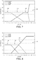
- FIG. 8 shows this strategy for a 50% coverage of a pigmented material
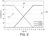
- FIG. 9 shows the strategy for a 100% coverage of the pigmented material.
- the graph in FIG. 9 has only three regions, namely, a white material only region 804, a transition region 808, and a pigmented only region 812. In the transition region 808, the white material percentage of the layers decreases linearly to 0%, while the pigmented material of the layers increases linearly to 100% from 0%. In this portion of the strategy, only white and pigmented materials are used.
- the strategy described above for using color, white, and clear material drops includes functions for the use of each material as a function of depth from the surface of an object to achieve a desired color level. Generally, more white material drops than pigmented material drops are used in layers located at greater depths from the surface until a depth is reached at which no pigmented material drops are used in favor of white. Additionally, clear drops are used preferentially instead of white drops in layers located nearer to the surface when the amount of pigmented material drops used is lower than the volume of material needed to fill the object. In this strategy, the saturation level of the color that a manufacturer wants a viewer of the object to perceive affects the strategy.
- the functions defining these transitions can be expressed as polynomials or exponential functions in addition to the linear functions shown in figures 6 -10.
- the functions are determined by the color, the desired saturation level for the color, and the depth of each layer from the surface.
- a proposed function is used to form an object and the color of the object is evaluated to determine that the produced color achieves the desired saturation level for the color.
- a subsequent color calibration is performed to identify a mapping between the desired color at the surface of a 3D part, the fractions of colors used in object layers as a function of distance from the surface of the object, and halftoning is identified to determine the colors of the drops within each voxel prior to printing the object.
- the strategies presented above can be expressed in a more general manner as a function of a distance between a voxel and a closest surface of an object.
- the material drops in each voxel in each layer are expressed as a function of the distance between the voxel and the closest surface, a sum of the average number of material drops at each voxel in each layer of the object, and a target value for the sum of the average number of drops in each voxel of each layer.
- a target value V is a fixed value proportional to the number of ejectors that must be active at each voxel.
- the sum S is converted to an actual number of drops for a voxel via a rendering algorithm such as halftoning, error diffusion, or digital binary search algorithms.
- a rendering algorithm such as halftoning, error diffusion, or digital binary search algorithms.
- the term colorant refers to a material having a color hue in the range of red to violet and the color black.
- Df The minimum distance from the surface where no pigmented color is used is denoted as Df and the sum S of the white and clear at this distance from the closest surface and greater is equal to or very close to V. At distances from the surface less than Df colorant materials are used. At distances greater than a calculated distance Do white material drops are used.
- Do can vary depending upon the degree of saturation for the appearance of a non-white or non-clear color at the surface.
- D 0 max is the maximum value to which Do can be set and it occurs for saturated colors.
- D 0 D 0 max for S 0 > V / 2
- clear can have its own function with respect to distance from a closest surface in the range of 0 to Do.
- the function for clear should have a negative second derivative at Do.
- IB pigmented ink
- D 0 D 0 max for S 0 > V / 4
- Another property that can affect the types of material drops in voxels of an object is the time to produce an object. To reduce the time for printing a 3D object, voxels can be formed with more than one drop per voxel. In an object, all voxels need to average roughly the same amount of material.
- One way to achieve this property is to double the number of ejectors used to print each color. This approach, however, is expensive. To avoid this expense, different ejectors ejecting drops of color, white, and clear materials are used to eject two drops per voxel with each drop being a different color. For example, to make a white voxel, a white material drop and a clear material drop are ejected into the voxel.
- a color drop and a clear drop are ejected into voxels to form voxels of the color drop more quickly.
- a voxel having a secondary color can be printed with two drops, each drop having a different color in a CMYK printer, for example.
- the controller 46 of FIG. 1 can operate the printer 100 to eject two drops of material 204 in each voxel in single pass rather than ejecting the two drops into the voxel during two passes.
- the controller 46 operates one or more actuators 42 to move the ejectors in the process direction P
- the controller operates one ejector to eject drops of material 204 on top of drops of support material 204 ejected by the other ejector.
- the lowest drop 204 is from ejector 22 and the next highest drop is from ejector 76.
- ejector 76 When the path of the ejectors is reversed, the next highest drop is ejected by ejector 76 and ejector 22 ejects a drop 204 on top of the drop ejected by ejector 76.
- a single ejector such as ejector 22, ejects a continuous line of drops as the ejector is moved in one direction and then the ejector ejects a continuous line of drops on the first line of drops as the ejector is moved in the reverse direction.
- This type of operation requires two passes to form two lines, while the inclusion of the second ejector 76 enables two lines to be formed in a single pass.
- the controller 46 also operates the ejectors 68 and 72 to form continuous lines of clear and white materials ejected by these ejectors. Specifically, the controller 46 operates the ejector 68 to eject drops of clear material as the ejectors move in the process direction P and as the ejector 72 passes over the clear drop, the controller operates the ejector 72 to eject a white drop on the clear drop. When the process direction is reversed, the ejector 72 is operated to eject white drops on top of the previously ejected white drops and when the ejector 68 passes over the line of white drops, the controller operates the ejector 68 to eject clear drops on the line of white drops.
- the ejectors 68 and 72 form a white layer on a clear layer in one direction in a single pass and then form a clear layer on a white layer in the reverse direction in a single pass.
- the white/clear layers are particularly advantageous in the interior of the part 10 since color is not usually an important property of the component in the interior regions. Additionally, this combination forms an appropriate background for the formation of colored regions with the pigmented building material as the component layers near the surface of the part 10.
- the above-described methods enable a controller to be configured to operate ejectors that ejected different materials having different colors to form voxels in a layer having an average volume of material that is greater than the volume of the largest drop that can be dropped by any of the ejectors. These voxels can be formed with drops of the same material, different materials, or material having different colors.
- This method of operating the ejectors enables thicker layers to be formed in a single pass since two drops can be ejected into voxels per pass rather than requiring a single drop per voxel in a single pass.
Landscapes
- Engineering & Computer Science (AREA)
- Chemical & Material Sciences (AREA)
- Materials Engineering (AREA)
- Manufacturing & Machinery (AREA)
- Mechanical Engineering (AREA)
- Physics & Mathematics (AREA)
- Optics & Photonics (AREA)
- Multimedia (AREA)
- Signal Processing (AREA)
Description
- This disclosure relates generally to three-dimensional (3D) object printing, and, in particular, to reducing the time required to print three-dimensional objects and to producing colors more accurately at the surfaces of printed three-dimensional objects.
- In 3D object printing, objects are built one layer at a time. The one or more printheads ejecting the drops are moved over the object multiple times. The number of passes required to produce an object can result in extremely long times for production of a typical object. Some objects are so large that several days may be required to form the object. In addition to the materials ejected by a 3D printing system that form the structure of an object, some printing systems also include pigmented materials of overlaying images on the surface of a produced part. In these systems, the object structure is typically formed with clear and white build materials and colored materials, such as the colors commonly used in two-dimensional printing, namely, cyan, magenta, yellow and black (C, M, Y, and K), are used to form the images. As used in this document, "colored material" or "pigmented material" refers to materials having a hue in the light spectrum range from red to violet and black. Each layer is made of only one type of the material, that is, either build material or pigmented material. One way to reduce the time required to form an object is to print multiple layers in a single pass. In order to achieve this goal, the number of ejectors assigned to each material must also be increased. Of course, this increase in the number of ejectors also increases the cost of the system since it is a hardware expense. Therefore, a direct relationship between speed and cost exists in the 3D object printing systems.
- Issues also arise with the printing of images with pigmented materials because printing color on the surface of 3D objects is not the same as applying paint to a surface. Paint has colorant concentrations that are far greater than those that can be incorporated into materials that can be ejected by printheads. In printing colors, white material may be used as a base for an image and then the image is formed with various color combinations. Thick layers of colors, however, cannot form high resolution images. Additionally, many 3D object printing systems include a leveling device that is used from time to time in the manufacturing process to remove some material to level the surface. This leveling is required because the addition of other layers on top of an unlevel surface can disrupt the configuration of the object being manufactured. The amount of material removed can also produce unacceptable variations in color. A 3D object printing surface that reduces the manufacturing time and that reliably reproduces colors at the surface of the objects would be beneficial.
- "Pushing the Limits of 3D Color Printing: Error Diffusion with Translucent Materials" by A. Brunton et al., ACM Transactions of Graphics, 2015, discloses an error diffusion halftoning approach to achieve full color with multi-jet printers, which operate on multiple isosurfaces or layers within the object to be printed.
- A new 3D object printing system is configured to reduce object manufacturing times and to enable more accurate reproduction of colors on the surface of the objects. In order to achieve this, the invention provides a system as defined in
claim 1 hereto. - The invention also provides a method as defined in
claim 6 hereto. This method reduces object manufacturing times and enables more accurate reproduction of colors on the surface of the objects. - The foregoing aspects and other features of the present disclosure are explained in the following description, taken in connection with the accompanying drawings.
-
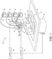
FIG. 1 is an illustration of a 3D printing system configured to increase layer formation in a single pass over previously known systems. -
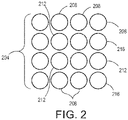
FIG. 2 is an illustration of the drops ejected by the system ofFIG. 1 . -
FIG. 3 depicts the formation of color at the surface of an object formed by a prior art 3D printer. -
FIG. 4 illustrates the formation of color at the surface of an object formed by the 3D printer ofFIG. 1 . -
FIG. 5A and 5B illustrate the formation of a dark surface and a gray surface, respectively, of an object formed by the 3D printer ofFIG. 1 . -
FIG. 6A and 6B are graphical representations of a portion of a color rendering strategy for producing a less saturated color and a more saturated color, respectively. -
FIG. 7 is a graphical representation of a color rendering strategy that can be performed by the 3D printer ofFIG. 1 . -
FIG. 8 is a graphical representation of another color rendering strategy that can be performed by the 3D printer ofFIG. 1 . -
FIG. 9 is a graphical representation of another color rendering strategy that can be performed by the 3D printer ofFIG. 1 . - For a general understanding of the present embodiments, reference is made to the drawings. In the drawings, like reference numerals have been used throughout to designate like elements.
-
FIG. 1 shows a configuration of components in aprinting system 100, which produces a three-dimensional object orpart 10. As used in this document, the term "three-dimensional printer" refers to any device that ejects drops of material with reference to image data of an object to form a three-dimensional object. Theprinting system 100 includes asupport material reservoir 14, a pigmentedbuilding material reservoir 18, a clearbuilding material reservoir 60, a whitebuilding material reservoir 64, a plurality ofejectors build substrate 30, aplanar support member 34, acolumnar support member 38, anactuator 42, and acontroller 46.Conduits 50 connectejectors material reservoir 14 andconduit 54 connectsejector 26 to pigmentedbuilding material reservoir 18.Conduits ejectors building material reservoir 60 and to whitebuilding material reservoir 64, respectively. The ejectors are operated by thecontroller 46 with reference to three-dimensional image data in a memory operatively connected to the controller to eject drops of the support and building materials supplied to each respective ejector. Each datum stored in a single location in the three-dimensional image data is defined as a "voxel" in this document. The building material forms the structure of thepart 10 being produced, while thesupport structure 58 formed by the support material drops enables the building material drops to maintain their shape while the material drops solidify as the part is being constructed. After the part is finished, thesupport structure 58 is removed by washing, blowing, or melting. - The
controller 46 is also operatively connected to at least one and possiblymore actuators 42 to control movement of theplanar support member 34, thecolumnar support member 38, and theejectors planar support member 34 to move the surface on which the part is being produced in the process and cross-process directions in the plane of theplanar support member 34. As used herein, the term "process direction" refers to movement along one axis in the surface of theplanar support member 34 and "cross-process direction" refers to movement along an axis in the planar support member surface that is orthogonal to the process direction axis in that surface. These directions are denoted with the letters "P" and "C-P" inFIG. 1 . Theejectors columnar support member 38 also move in a direction that is orthogonal to theplanar support member 34. This direction is called the vertical direction in this document, is parallel to thecolumnar support member 38, and is denoted with the letter "V" inFIG. 1 . Movement in the vertical direction is achieved with one or more actuators operatively connected to thecolumnar member 38, by one or more actuators operatively connected to the ejectors or by one or more actuators operatively connected to both thecolumnar support member 38 and the ejectors. These actuators in these various configurations are operatively connected to thecontroller 46, which operates the actuators to move thecolumnar member 38, the ejectors, or all of these components in the vertical direction. - In previously known 3D printing systems, layers of pigmented material are printed near the surface and sometimes covered with clear material layers, while the lower layers consist of white material to provide a background for the colored and clear material. An example of this structure is presented in
FIG. 3 . As shown in the figure, theinterior layers 304 are formed with drops of white material alone. Thenext layers 308 are formed with pigmented material alone and then can be covered with one ormore layers 312 of clear material, if desired, to protect the pigmented material. With the printer shown inFIG. 1 , the pigmented material drops are introduced in increasing proportions in thenext layers 408 to provide a more gradated color scheme as shown inFIG. 4 . For thelayers 412 closest to the surface of the part, the drops of pigmented material dominate the layers although drops of clear material, and even some drops of white material, are included in the layers. The method of increasing altering the proportions of the pigmented, clear, and white materials enables the preservation of the gamut of the pigmented color by increasing the size of the color managed planes. That is, the depth of the color managed volume near the surface is larger as demonstrated by the increased depth of thelayers layers FIG. 5A and 5B , respectively. An example of a portion of a strategy for achieving a gradated dark or gray color surface as depicted inFIG. 5B is shown inFIG. 6A . At a predetermined distance from the surface, no black material is ejected, 80% of the material in the voxels are white, and 20% of the material in the voxels are clear. As the layers closer to the surface are formed, the white material falls to a small percentage of the material in the voxels, black material rises to 80% of the material in the voxels, and the clear material in the voxels falls to zero. As the distance to the surface decreases, the percentage of the black material in the voxels decreases to zero while the white material increases to 100 percent. A portion of a strategy for achieving a more saturated color is shown inFIG. 6B . At a predetermined distance from the surface, 80 percent of the material in the voxels is black and 20 percent of the materials in the voxels is clear, while no white material is ejected. As the layers approach the surface, white material is ejected into voxels as clear material ejected into the voxels is decreased until it becomes zero. At that distance, the black material decreases to be 70 percent of the material in the voxels, while the white material in the voxels increases to 30 percent. These percentages continue for subsequent layers until another predetermined distance from the surface is reached at which the percentage of black material in the voxels decreases linearly to zero, while the percentage of white material increases linearly to 100 percent. - Colors formed by a strategy or color model of combining pigmented material with clear material and white material as a function of depth with reference to the surface improves the rendering of the colors at the surface. This strategy provides a white backing for the surface colors in much the same way a piece of paper provides a white background for printed colors. The white and clear materials provide options, particularly with reference to the depth of layer, to deliver a comprehensive 3D color strategy or color model that can be configured as data tables and used by a controller for rendering colors in objects produced by 3D printing systems. As used in this document, "color model" refers to a plurality of functions, one for each material being ejected by a printer, that distribute the materials being ejected as a function of depth with reference to a surface of an object being produced with the materials.
- One example of a portion of such a strategy is one in which clear material is predominantly used for voxels not filled with color near the surface and linearly increasing amounts of white material are added to layers further removed from the surface. Such a strategy is depicted graphically in
FIG. 7 . In the interior of the object, only white material is used to formed the layers in theregion 604 of the graph. At some predetermined distance from the surface inregion 608, layers are formed with 50% pigmented material and 50% white material. In atransition region 612, the pigmented material continues to form 50% of the layers, while the white material decreases linearly from 50% to 0% and the clear material increase linearly from 0% to 50%. Near the surface inregion 616, the layers are formed with 50% pigmented material and 50% clear material. Under this scheme, a color formed with 100% of a pigmented material, such as a cyan material, or one formed with a combination of pigmented materials, such as 50% cyan and 50% magenta, does not require additional clear or white materials for a proper rendering. - In another example shown in
FIG. 8 , a portion of the color rendering strategy as a function of depth from the surface includes the addition of white material into all colors, even those that are initially at the surface equal to 100%. As portrayed in this figure, the interior of the object is formed with only white material in theregion 704 of the graph. At some predetermined distance from the surface inregion 708, layers are formed with a linearly increasing amount of pigmented material until the percentage of the pigmented material reaches 50% and with a linearly decreasing amount of white material until the percentage of white material reaches 50%. In atransition region 712, the pigmented material continues to form 50% of the layers, while the white material decreases linearly from 50% to 0% and the clear material increase linearly from 0% to 50%. Near the surface inregion 716, the layers are formed with 50% pigmented material and 50% clear material. The rule in this scheme is that at some predetermined depth a layer begins to be formed with pigmented material. White is replaced first and then the color remains a constant while white material decreases in each layer and clear material increases in each layer.FIG. 8 shows this strategy for a 50% coverage of a pigmented material, whileFIG. 9 shows the strategy for a 100% coverage of the pigmented material. The graph inFIG. 9 has only three regions, namely, a white materialonly region 804, atransition region 808, and a pigmentedonly region 812. In thetransition region 808, the white material percentage of the layers decreases linearly to 0%, while the pigmented material of the layers increases linearly to 100% from 0%. In this portion of the strategy, only white and pigmented materials are used. - The strategy described above for using color, white, and clear material drops includes functions for the use of each material as a function of depth from the surface of an object to achieve a desired color level. Generally, more white material drops than pigmented material drops are used in layers located at greater depths from the surface until a depth is reached at which no pigmented material drops are used in favor of white. Additionally, clear drops are used preferentially instead of white drops in layers located nearer to the surface when the amount of pigmented material drops used is lower than the volume of material needed to fill the object. In this strategy, the saturation level of the color that a manufacturer wants a viewer of the object to perceive affects the strategy. The functions defining these transitions can be expressed as polynomials or exponential functions in addition to the linear functions shown in
figures 6 -10. If higher saturation color levels are required, then more color material drops in layers near the surface are required. Similarly, if lower saturation color levels are desired, then more clear, and possibly white, material drops are used in layers closer to the surface. Thus, the functions are determined by the color, the desired saturation level for the color, and the depth of each layer from the surface. A proposed function is used to form an object and the color of the object is evaluated to determine that the produced color achieves the desired saturation level for the color. Once a function is defined that achieves this goal, a subsequent color calibration is performed to identify a mapping between the desired color at the surface of a 3D part, the fractions of colors used in object layers as a function of distance from the surface of the object, and halftoning is identified to determine the colors of the drops within each voxel prior to printing the object. - The strategies presented above can be expressed in a more general manner as a function of a distance between a voxel and a closest surface of an object. The material drops in each voxel in each layer are expressed as a function of the distance between the voxel and the closest surface, a sum of the average number of material drops at each voxel in each layer of the object, and a target value for the sum of the average number of drops in each voxel of each layer. To obtain a sum S of the average number of material drops at a voxel, the contone values for the colorant materials are added together. Additionally, a target value V is a fixed value proportional to the number of ejectors that must be active at each voxel. The sum S is converted to an actual number of drops for a voxel via a rendering algorithm such as halftoning, error diffusion, or digital binary search algorithms. The conversion from the initial color space and the mapping that includes white and clear colors may be combined into a single step.
- For a target value of 100% or less of the sum S, an examsple of how white and clear colorants can be determined is now presented. White can be expressed as a function of the sum So and distance D from the closest surface:


- When W + So > V then the sum of the pigmented materials, such as CMYK, is reduced by V - W with each color being reduced by the same proportion. At some distance from the closest surface, S is reduced to zero. In cases where W + S is less than V then clear CL is used to make up the difference and can be represented as:

- While the above relationships control the amount of clear CL through the various distances from a closest surface for the voxels, clear can have its own function with respect to distance from a closest surface in the range of 0 to Do. The function for clear should have a negative second derivative at Do. As the distance between a voxel and a surface decreases, the amount of pigmented ink (IB) increases since they contribute more to the surface appearance. One example of a clear function is:

function 0 to 1 (i.e. N ={(1 - e -αD0) / α - Do e-αD0}). In cases where both white and clear are used in the voxels, namely where the distance to the closest surface is in the range Do ≤ D ≤ Df, the value for clear is determined with reference to the function CL = V - W - S, but once the distance to the closest surface is less than Do, the normalized function is used. - The total amount of pigmented area coverage can be modified. At distances from a surface where clear materials are used without any white materials and CL + So < V, then the sum of pigmented colors, such as CMYK, is increased by (V - C) with each color increased from the initial average number of material drops So by the same proportion. That is:

- In systems that do not use clear materials, the sum So plus white is required to equal V. This requirement simplifies the calculations. For example:


- The distance from the closest surface where white begins to be introduced (Do) is a function of So so that Do goes to zero when S = 0. For example:


- Then for W:


- Another property that can affect the types of material drops in voxels of an object is the time to produce an object. To reduce the time for printing a 3D object, voxels can be formed with more than one drop per voxel. In an object, all voxels need to average roughly the same amount of material. One way to achieve this property is to double the number of ejectors used to print each color. This approach, however, is expensive. To avoid this expense, different ejectors ejecting drops of color, white, and clear materials are used to eject two drops per voxel with each drop being a different color. For example, to make a white voxel, a white material drop and a clear material drop are ejected into the voxel. For four color printing, such as CMYK color printing, a color drop and a clear drop are ejected into voxels to form voxels of the color drop more quickly. A voxel having a secondary color can be printed with two drops, each drop having a different color in a CMYK printer, for example.
- This method of forming a 3D object more quickly is now discussed with reference to the printer of
FIG. 1 andFIG. 2 . For example, thecontroller 46 ofFIG. 1 can operate theprinter 100 to eject two drops ofmaterial 204 in each voxel in single pass rather than ejecting the two drops into the voxel during two passes. Specifically, as thecontroller 46 operates one ormore actuators 42 to move the ejectors in the process direction P, the controller operates one ejector to eject drops ofmaterial 204 on top of drops ofsupport material 204 ejected by the other ejector. As shown inFIG. 2 , thelowest drop 204 is fromejector 22 and the next highest drop is fromejector 76. When the path of the ejectors is reversed, the next highest drop is ejected byejector 76 andejector 22 ejects adrop 204 on top of the drop ejected byejector 76. In previously known 3D printers, a single ejector, such asejector 22, ejects a continuous line of drops as the ejector is moved in one direction and then the ejector ejects a continuous line of drops on the first line of drops as the ejector is moved in the reverse direction. This type of operation requires two passes to form two lines, while the inclusion of thesecond ejector 76 enables two lines to be formed in a single pass. - In a similar manner, the
controller 46 also operates theejectors controller 46 operates theejector 68 to eject drops of clear material as the ejectors move in the process direction P and as theejector 72 passes over the clear drop, the controller operates theejector 72 to eject a white drop on the clear drop. When the process direction is reversed, theejector 72 is operated to eject white drops on top of the previously ejected white drops and when theejector 68 passes over the line of white drops, the controller operates theejector 68 to eject clear drops on the line of white drops. Thus, theejectors part 10 since color is not usually an important property of the component in the interior regions. Additionally, this combination forms an appropriate background for the formation of colored regions with the pigmented building material as the component layers near the surface of thepart 10. - Also, as shown in
FIG. 2 , two layers of pigmented material drops 216 are formed with a layer of white material drops 212 over one layer and a layer of clear material drops over the other layer. By substituting the layer of pigmented material drops 216 for either a layer of clear drops or a layer of white drops, color can be gradually introduced into thepart 10 as described more fully below. Additionally, a line of pigmented drops can be formed partially with pigmented drops and partially with either white material drops, clear material drops, or both. Similarly, a line of clear or white drops can be formed partially with clear drops and partially with white drops. This partial introduction of other material drops helps make the introduction of color to thepart 10 more flexible. - The above-described methods enable a controller to be configured to operate ejectors that ejected different materials having different colors to form voxels in a layer having an average volume of material that is greater than the volume of the largest drop that can be dropped by any of the ejectors. These voxels can be formed with drops of the same material, different materials, or material having different colors. This method of operating the ejectors enables thicker layers to be formed in a single pass since two drops can be ejected into voxels per pass rather than requiring a single drop per voxel in a single pass.
- Those skilled in the art will recognize that numerous modifications can be made to the specific implementations described above. Therefore, the following claims are not to be limited to the specific embodiments illustrated and described above.
Claims (10)
- A 3D object printing system comprising:a planar support member;a first plurality of ejectors configured to eject drops of a first material having a first color;a second plurality of ejectors configured to eject drops of a second material having a second color, the first color being different than the second color;a third plurality of ejectors configured to eject drops of a third material having a third color, the third color being different than the second color and the first color;at least one actuator operatively connected to the first plurality of ejectors, the second plurality of ejectors, and the third plurality of ejectors; anda controller operatively connected to the at least one actuator, the first plurality of ejectors, the second plurality of ejectors, and the third plurality of ejectors, the controller being configured to:identify an average number of material drops per voxel for each material in each layer of an object to be manufactured, each layer being composed of voxels each positioned at a respective distance from a closest surface of the object to be manufactured, wherein the voxels constitute image data representing the object to be manufactured, andwherein the step of identifying comprises converting the image data to material drop data which defines the fraction of each of the first material, the second material, and the third material within each layer of the object to be manufactured, wherein the material drop data is obtained with reference to a first function of a sum of the average number of second material drops per voxel of each layer and the average number of third material drops per voxel in each layer, a target value for the sum of the average number of material drops per voxel of all materials, and the distance between the voxels in the layer and a closest surface of the object, such that a produced object color achieves a desired saturation level for the color;convert the material drop data to a number of drops of each material for each voxel in each layer by a rendering algorithm selected from a halftoning algorithm, an error diffusion algorithm, and a digital binary search algorithm; andoperate with reference to the converted material drop data the first plurality of ejectors, the second plurality of ejectors, and the third plurality of ejectors to eject drops of the first material, drops of the second material, and drops of the third material to form the layers of the object corresponding to the image data on the planar support member such that each layer is arranged parallel to the planar support member.
- The system of claim 1, the controller being further configured to operate the at least one actuator to move the first plurality of ejectors, the second plurality of ejectors, and the third plurality of ejectors to position the pluralities of ejectors for ejecting material drops into voxels of each layer of the object.
- The system of claim 1, the first plurality of ejectors being configured to eject white material drops.
- The system of claim 3 further comprising:
a fourth plurality of ejectors configured to eject drops of a fourth material that is clear, which is a different color than the white material drops, the second color, and the third color. - The system of claim 4, the controller being further configured to convert the image data for the object to material drop data by calculating material drop data for clear fourth material with reference to a second function of an output of the first function and a distance between the layer and a closest surface of the object.
- A method for operating a 3D object printer comprising:identifying with a controller an average number of material drops per voxel for each material in each layer of an object to be manufactured, each layer being composed of voxels each positioned at a respective distance from a closest surface of the object to be manufactured, wherein the voxels constitute image data representing the object to be manufactured, andwherein the step of identifying comprises converting with the controller the image data to material drop data which defines the fraction of each of a first material, a second material, and a third material within each layer of the object to be manufactured, wherein the material drop data is obtained with reference to a first function of a sum of the identified average number of second material drops per voxel of each layer and the identified average number of third material drops per voxel in each layer, a target value for the sum of the identified average number of material drops per voxel of all materials, and the distance between the voxels in the layer and a closest surface of the object, such that a produced object color achieves a desired saturation level for the color;converting with the controller the material drop data to a number of drops for each voxel in each layer by a rendering algorithm selected from a halftoning algorithm, an error diffusion algorithm, and a digital binary search algorithm; andoperating a first plurality of ejectors, a second plurality of ejectors, and a third plurality of ejectors with the controller with reference to the converted material drop data to eject drops of the first material, drops of the second material, and drops of the third material to form the layers of the object corresponding to the image data, each plurality of ejectors ejecting material drops having a color different than a color of the material drops ejected by the other pluralities of ejectors, and the formed layers being arranged parallel to a planar support member.
- The method of claim 6 further comprising:
operating with the controller at least one actuator to move the first plurality of ejectors, the second plurality of ejectors, and the third plurality of ejectors to position the pluralities of ejectors for ejecting material drops into voxels of each layer of the object. - The method of claim 6 wherein operation of the first plurality of ejectors ejects white material drops.
- The method of claim 8 further comprising:
operating with the controller a fourth plurality of ejectors to eject drops of a fourth material that is clear, which is a different color than the white material drops, the colors of the material drops ejected by the second plurality of ejectors and the third plurality of ejectors. - The method of claim 9 further comprising:
converting the image data for the object to material drop data with the controller by calculating material drop data for the clear fourth material with reference to a second function of an output of the first function and a distance between the layer and a closest surface of the object.
Applications Claiming Priority (1)
| Application Number | Priority Date | Filing Date | Title |
|---|---|---|---|
| US15/434,689 US10457034B2 (en) | 2017-02-16 | 2017-02-16 | System and method for decreasing time for printing layers in three-dimensional objects and for enhancing color fidelity at the surface of three-dimensional objects |
Publications (2)
| Publication Number | Publication Date |
|---|---|
| EP3364641A1 EP3364641A1 (en) | 2018-08-22 |
| EP3364641B1 true EP3364641B1 (en) | 2022-09-07 |
Family
ID=61054192
Family Applications (1)
| Application Number | Title | Priority Date | Filing Date |
|---|---|---|---|
| EP18153534.5A Active EP3364641B1 (en) | 2017-02-16 | 2018-01-25 | System and method for decreasing time for printing layers in three-dimensional objects and for enhancing color fidelity at the surface of three-dimensional objects |
Country Status (5)
| Country | Link |
|---|---|
| US (1) | US10457034B2 (en) |
| EP (1) | EP3364641B1 (en) |
| JP (1) | JP6896657B2 (en) |
| KR (1) | KR102279557B1 (en) |
| CN (1) | CN108437443B (en) |
Families Citing this family (7)
| Publication number | Priority date | Publication date | Assignee | Title |
|---|---|---|---|---|
| CN106466920B (en) * | 2015-08-10 | 2019-08-30 | 珠海赛纳打印科技股份有限公司 | A kind of Method of printing and system of 3D object |
| JP6922323B2 (en) * | 2017-03-28 | 2021-08-18 | セイコーエプソン株式会社 | Three-dimensional object modeling device, three-dimensional object modeling method, and control program of the three-dimensional object modeling device |
| US11417047B2 (en) | 2018-09-28 | 2022-08-16 | Stratasys Ltd. | Method and system for diffusing color error into additive manufactured objects |
| CN111072382B (en) * | 2018-10-18 | 2022-05-17 | 苏州鼎安科技有限公司 | Zirconia ceramic block for all-ceramic false tooth and preparation process thereof |
| EP3840938A4 (en) * | 2019-03-15 | 2022-03-23 | Hewlett-Packard Development Company, L.P. | Coloured objects in additive manufacturing |
| US11794255B2 (en) * | 2021-01-27 | 2023-10-24 | Xerox Corporation | Method and apparatus for forming overhang structures with a metal drop ejecting three-dimensional (3D) object printer |
| CN114889122A (en) * | 2022-04-06 | 2022-08-12 | 哈尔滨工业大学 | 3D printing device based on micro-droplet generator array |
Family Cites Families (17)
| Publication number | Priority date | Publication date | Assignee | Title |
|---|---|---|---|---|
| US6188415B1 (en) * | 1997-07-15 | 2001-02-13 | Silverbrook Research Pty Ltd | Ink jet printer having a thermal actuator comprising an external coil spring |
| US6165406A (en) | 1999-05-27 | 2000-12-26 | Nanotek Instruments, Inc. | 3-D color model making apparatus and process |
| US20040080078A1 (en) | 2002-10-25 | 2004-04-29 | Collins David C. | Methods and systems for producing a desired apparent coloring in an object produced through rapid prototyping |
| AU2003900180A0 (en) * | 2003-01-16 | 2003-01-30 | Silverbrook Research Pty Ltd | Method and apparatus (dam001) |
| US20090217882A1 (en) * | 2003-07-11 | 2009-09-03 | Dennis Jenkins | Dry Bed Agglomeration Process and Product Formed Thereby |
| US7991498B2 (en) | 2009-02-03 | 2011-08-02 | Objet Geometries Ltd. | Method and system for building painted three-dimensional objects |
| US9248623B2 (en) | 2011-10-14 | 2016-02-02 | Makerbot Industries, Llc | Grayscale rendering in 3D printing |
| US8699751B2 (en) * | 2012-03-02 | 2014-04-15 | The Procter & Gamble Company | Method for quantifying the effective height of fibers emanating from a surface |
| JP2013208845A (en) * | 2012-03-30 | 2013-10-10 | Japan Science & Technology Agency | Three-dimensional surface printing method |
| US9114625B2 (en) | 2013-06-26 | 2015-08-25 | Nike, Inc. | Additive color printing |
| US8827684B1 (en) | 2013-12-23 | 2014-09-09 | Radiant Fabrication | 3D printer and printhead unit with multiple filaments |
| US9415546B2 (en) * | 2014-01-29 | 2016-08-16 | Xerox Corporation | System and method for controlling material drop volume in three dimensional object printing |
| JP6389061B2 (en) * | 2014-05-22 | 2018-09-12 | 株式会社ミマキエンジニアリング | Three-dimensional object modeling apparatus, three-dimensional object modeling method, and three-dimensional object |
| JP2016107406A (en) * | 2014-12-02 | 2016-06-20 | 株式会社リコー | Image processing device, image processing system, image processing program, and method of producing three-dimensional object |
| CN107851176A (en) * | 2015-02-06 | 2018-03-27 | 阿克伦大学 | Optical imaging system and its method |
| US9751263B2 (en) * | 2015-04-20 | 2017-09-05 | Xerox Corporation | Injection molding to finish parts printed with a three-dimensional object printer |
| CN205009603U (en) * | 2015-09-28 | 2016-02-03 | 研能科技股份有限公司 | Three -dimensional full -color composite printer device |
-
2017
- 2017-02-16 US US15/434,689 patent/US10457034B2/en active Active
-
2018
- 2018-01-24 JP JP2018009469A patent/JP6896657B2/en active Active
- 2018-01-25 EP EP18153534.5A patent/EP3364641B1/en active Active
- 2018-02-02 KR KR1020180013183A patent/KR102279557B1/en active IP Right Grant
- 2018-02-02 CN CN201810107003.3A patent/CN108437443B/en active Active
Also Published As
| Publication number | Publication date |
|---|---|
| CN108437443B (en) | 2021-04-27 |
| JP2018130954A (en) | 2018-08-23 |
| US10457034B2 (en) | 2019-10-29 |
| JP6896657B2 (en) | 2021-06-30 |
| KR102279557B1 (en) | 2021-07-19 |
| KR20180094780A (en) | 2018-08-24 |
| EP3364641A1 (en) | 2018-08-22 |
| US20180229447A1 (en) | 2018-08-16 |
| CN108437443A (en) | 2018-08-24 |
Similar Documents
| Publication | Publication Date | Title |
|---|---|---|
| EP3364641B1 (en) | System and method for decreasing time for printing layers in three-dimensional objects and for enhancing color fidelity at the surface of three-dimensional objects | |
| US9636937B2 (en) | Image processing apparatus, image processing method, and storage medium | |
| US10105907B2 (en) | Method of printing an object having a surface of varying height | |
| US20180036951A1 (en) | Forming method, forming system, and forming apparatus | |
| US9286554B1 (en) | System and method for halftone printing in a three-dimensional object printer | |
| US20180108170A1 (en) | Data processing apparatus, three-dimensional object creating system, and non-transitory computer readable medium | |
| US9955041B2 (en) | System and method for tone reproduction curve color resolution enhancement in a three-dimensional object printer | |
| US8705111B2 (en) | Inkjet printing apparatus and print data generating method | |
| US7410235B2 (en) | Printing darkness non-uniformities correction method and printing darkness non-uniformities correction apparatus | |
| US9674402B2 (en) | Method for printing an object with images | |
| JP2018083361A (en) | Molding device and molding method | |
| US7125091B2 (en) | Method for creating printing data applied to a printer capable of generating ink droplets of different sizes | |
| US10556419B2 (en) | System and method for missing ejector compensation in three-dimensional object printing | |
| US9851651B2 (en) | Image processing apparatus and image processing method to control the gloss of an image to be printed | |
| US9282217B2 (en) | Generating data to control the ejection of ink drops | |
| JP6750280B2 (en) | Printing device, method for setting boundary of printing device, and head unit | |
| EP3229455B1 (en) | Image processing apparatus, image processing method and program | |
| KR102061222B1 (en) | Image processing apparatus and image processing method | |
| EP2902211B1 (en) | Ghosting compensation in relief images for directional prints | |
| JP6385109B2 (en) | Image forming apparatus, image forming method, and program | |
| JP2024010312A (en) | Printer and printer control method | |
| WO2021045725A1 (en) | Print material element sets | |
| JP2015205475A (en) | Ink jet recording device | |
| JP2011143731A (en) | Image recorder and image recording method | |
| JP2017196813A (en) | Inkjet recording device and inkjet recording method |
Legal Events
| Date | Code | Title | Description |
|---|---|---|---|
| PUAI | Public reference made under article 153(3) epc to a published international application that has entered the european phase |
Free format text: ORIGINAL CODE: 0009012 |
|
| STAA | Information on the status of an ep patent application or granted ep patent |
Free format text: STATUS: THE APPLICATION HAS BEEN PUBLISHED |
|
| AK | Designated contracting states |
Kind code of ref document: A1 Designated state(s): AL AT BE BG CH CY CZ DE DK EE ES FI FR GB GR HR HU IE IS IT LI LT LU LV MC MK MT NL NO PL PT RO RS SE SI SK SM TR |
|
| AX | Request for extension of the european patent |
Extension state: BA ME |
|
| STAA | Information on the status of an ep patent application or granted ep patent |
Free format text: STATUS: REQUEST FOR EXAMINATION WAS MADE |
|
| 17P | Request for examination filed |
Effective date: 20190222 |
|
| RBV | Designated contracting states (corrected) |
Designated state(s): AL AT BE BG CH CY CZ DE DK EE ES FI FR GB GR HR HU IE IS IT LI LT LU LV MC MK MT NL NO PL PT RO RS SE SI SK SM TR |
|
| STAA | Information on the status of an ep patent application or granted ep patent |
Free format text: STATUS: EXAMINATION IS IN PROGRESS |
|
| STAA | Information on the status of an ep patent application or granted ep patent |
Free format text: STATUS: EXAMINATION IS IN PROGRESS |
|
| 17Q | First examination report despatched |
Effective date: 20201204 |
|
| STAA | Information on the status of an ep patent application or granted ep patent |
Free format text: STATUS: EXAMINATION IS IN PROGRESS |
|
| GRAP | Despatch of communication of intention to grant a patent |
Free format text: ORIGINAL CODE: EPIDOSNIGR1 |
|
| STAA | Information on the status of an ep patent application or granted ep patent |
Free format text: STATUS: GRANT OF PATENT IS INTENDED |
|
| INTG | Intention to grant announced |
Effective date: 20220408 |
|
| GRAS | Grant fee paid |
Free format text: ORIGINAL CODE: EPIDOSNIGR3 |
|
| GRAA | (expected) grant |
Free format text: ORIGINAL CODE: 0009210 |
|
| STAA | Information on the status of an ep patent application or granted ep patent |
Free format text: STATUS: THE PATENT HAS BEEN GRANTED |
|
| AK | Designated contracting states |
Kind code of ref document: B1 Designated state(s): AL AT BE BG CH CY CZ DE DK EE ES FI FR GB GR HR HU IE IS IT LI LT LU LV MC MK MT NL NO PL PT RO RS SE SI SK SM TR |
|
| REG | Reference to a national code |
Ref country code: GB Ref legal event code: FG4D |
|
| REG | Reference to a national code |
Ref country code: CH Ref legal event code: EP Ref country code: AT Ref legal event code: REF Ref document number: 1518011 Country of ref document: AT Kind code of ref document: T Effective date: 20220915 |
|
| REG | Reference to a national code |
Ref country code: DE Ref legal event code: R096 Ref document number: 602018040216 Country of ref document: DE |
|
| REG | Reference to a national code |
Ref country code: IE Ref legal event code: FG4D |
|
| REG | Reference to a national code |
Ref country code: LT Ref legal event code: MG9D |
|
| REG | Reference to a national code |
Ref country code: NL Ref legal event code: MP Effective date: 20220907 |
|
| PG25 | Lapsed in a contracting state [announced via postgrant information from national office to epo] |
Ref country code: SE Free format text: LAPSE BECAUSE OF FAILURE TO SUBMIT A TRANSLATION OF THE DESCRIPTION OR TO PAY THE FEE WITHIN THE PRESCRIBED TIME-LIMIT Effective date: 20220907 Ref country code: RS Free format text: LAPSE BECAUSE OF FAILURE TO SUBMIT A TRANSLATION OF THE DESCRIPTION OR TO PAY THE FEE WITHIN THE PRESCRIBED TIME-LIMIT Effective date: 20220907 Ref country code: NO Free format text: LAPSE BECAUSE OF FAILURE TO SUBMIT A TRANSLATION OF THE DESCRIPTION OR TO PAY THE FEE WITHIN THE PRESCRIBED TIME-LIMIT Effective date: 20221207 Ref country code: LV Free format text: LAPSE BECAUSE OF FAILURE TO SUBMIT A TRANSLATION OF THE DESCRIPTION OR TO PAY THE FEE WITHIN THE PRESCRIBED TIME-LIMIT Effective date: 20220907 Ref country code: LT Free format text: LAPSE BECAUSE OF FAILURE TO SUBMIT A TRANSLATION OF THE DESCRIPTION OR TO PAY THE FEE WITHIN THE PRESCRIBED TIME-LIMIT Effective date: 20220907 Ref country code: FI Free format text: LAPSE BECAUSE OF FAILURE TO SUBMIT A TRANSLATION OF THE DESCRIPTION OR TO PAY THE FEE WITHIN THE PRESCRIBED TIME-LIMIT Effective date: 20220907 |
|
| REG | Reference to a national code |
Ref country code: AT Ref legal event code: MK05 Ref document number: 1518011 Country of ref document: AT Kind code of ref document: T Effective date: 20220907 |
|
| PG25 | Lapsed in a contracting state [announced via postgrant information from national office to epo] |
Ref country code: HR Free format text: LAPSE BECAUSE OF FAILURE TO SUBMIT A TRANSLATION OF THE DESCRIPTION OR TO PAY THE FEE WITHIN THE PRESCRIBED TIME-LIMIT Effective date: 20220907 Ref country code: GR Free format text: LAPSE BECAUSE OF FAILURE TO SUBMIT A TRANSLATION OF THE DESCRIPTION OR TO PAY THE FEE WITHIN THE PRESCRIBED TIME-LIMIT Effective date: 20221208 |
|
| PG25 | Lapsed in a contracting state [announced via postgrant information from national office to epo] |
Ref country code: SM Free format text: LAPSE BECAUSE OF FAILURE TO SUBMIT A TRANSLATION OF THE DESCRIPTION OR TO PAY THE FEE WITHIN THE PRESCRIBED TIME-LIMIT Effective date: 20220907 Ref country code: RO Free format text: LAPSE BECAUSE OF FAILURE TO SUBMIT A TRANSLATION OF THE DESCRIPTION OR TO PAY THE FEE WITHIN THE PRESCRIBED TIME-LIMIT Effective date: 20220907 Ref country code: PT Free format text: LAPSE BECAUSE OF FAILURE TO SUBMIT A TRANSLATION OF THE DESCRIPTION OR TO PAY THE FEE WITHIN THE PRESCRIBED TIME-LIMIT Effective date: 20230109 Ref country code: ES Free format text: LAPSE BECAUSE OF FAILURE TO SUBMIT A TRANSLATION OF THE DESCRIPTION OR TO PAY THE FEE WITHIN THE PRESCRIBED TIME-LIMIT Effective date: 20220907 Ref country code: CZ Free format text: LAPSE BECAUSE OF FAILURE TO SUBMIT A TRANSLATION OF THE DESCRIPTION OR TO PAY THE FEE WITHIN THE PRESCRIBED TIME-LIMIT Effective date: 20220907 Ref country code: AT Free format text: LAPSE BECAUSE OF FAILURE TO SUBMIT A TRANSLATION OF THE DESCRIPTION OR TO PAY THE FEE WITHIN THE PRESCRIBED TIME-LIMIT Effective date: 20220907 |
|
| PG25 | Lapsed in a contracting state [announced via postgrant information from national office to epo] |
Ref country code: SK Free format text: LAPSE BECAUSE OF FAILURE TO SUBMIT A TRANSLATION OF THE DESCRIPTION OR TO PAY THE FEE WITHIN THE PRESCRIBED TIME-LIMIT Effective date: 20220907 Ref country code: PL Free format text: LAPSE BECAUSE OF FAILURE TO SUBMIT A TRANSLATION OF THE DESCRIPTION OR TO PAY THE FEE WITHIN THE PRESCRIBED TIME-LIMIT Effective date: 20220907 Ref country code: IS Free format text: LAPSE BECAUSE OF FAILURE TO SUBMIT A TRANSLATION OF THE DESCRIPTION OR TO PAY THE FEE WITHIN THE PRESCRIBED TIME-LIMIT Effective date: 20230107 Ref country code: EE Free format text: LAPSE BECAUSE OF FAILURE TO SUBMIT A TRANSLATION OF THE DESCRIPTION OR TO PAY THE FEE WITHIN THE PRESCRIBED TIME-LIMIT Effective date: 20220907 |
|
| REG | Reference to a national code |
Ref country code: DE Ref legal event code: R097 Ref document number: 602018040216 Country of ref document: DE |
|
| PG25 | Lapsed in a contracting state [announced via postgrant information from national office to epo] |
Ref country code: NL Free format text: LAPSE BECAUSE OF FAILURE TO SUBMIT A TRANSLATION OF THE DESCRIPTION OR TO PAY THE FEE WITHIN THE PRESCRIBED TIME-LIMIT Effective date: 20220907 Ref country code: AL Free format text: LAPSE BECAUSE OF FAILURE TO SUBMIT A TRANSLATION OF THE DESCRIPTION OR TO PAY THE FEE WITHIN THE PRESCRIBED TIME-LIMIT Effective date: 20220907 |
|
| PLBE | No opposition filed within time limit |
Free format text: ORIGINAL CODE: 0009261 |
|
| STAA | Information on the status of an ep patent application or granted ep patent |
Free format text: STATUS: NO OPPOSITION FILED WITHIN TIME LIMIT |
|
| PG25 | Lapsed in a contracting state [announced via postgrant information from national office to epo] |
Ref country code: DK Free format text: LAPSE BECAUSE OF FAILURE TO SUBMIT A TRANSLATION OF THE DESCRIPTION OR TO PAY THE FEE WITHIN THE PRESCRIBED TIME-LIMIT Effective date: 20220907 |
|
| 26N | No opposition filed |
Effective date: 20230608 |
|
| PG25 | Lapsed in a contracting state [announced via postgrant information from national office to epo] |
Ref country code: SI Free format text: LAPSE BECAUSE OF FAILURE TO SUBMIT A TRANSLATION OF THE DESCRIPTION OR TO PAY THE FEE WITHIN THE PRESCRIBED TIME-LIMIT Effective date: 20220907 |
|
| REG | Reference to a national code |
Ref country code: CH Ref legal event code: PL |
|
| PG25 | Lapsed in a contracting state [announced via postgrant information from national office to epo] |
Ref country code: LU Free format text: LAPSE BECAUSE OF NON-PAYMENT OF DUE FEES Effective date: 20230125 |
|
| REG | Reference to a national code |
Ref country code: BE Ref legal event code: MM Effective date: 20230131 |
|
| PG25 | Lapsed in a contracting state [announced via postgrant information from national office to epo] |
Ref country code: LI Free format text: LAPSE BECAUSE OF NON-PAYMENT OF DUE FEES Effective date: 20230131 Ref country code: CH Free format text: LAPSE BECAUSE OF NON-PAYMENT OF DUE FEES Effective date: 20230131 |
|
| PG25 | Lapsed in a contracting state [announced via postgrant information from national office to epo] |
Ref country code: BE Free format text: LAPSE BECAUSE OF NON-PAYMENT OF DUE FEES Effective date: 20230131 |
|
| PGFP | Annual fee paid to national office [announced via postgrant information from national office to epo] |
Ref country code: GB Payment date: 20231219 Year of fee payment: 7 |
|
| PG25 | Lapsed in a contracting state [announced via postgrant information from national office to epo] |
Ref country code: IE Free format text: LAPSE BECAUSE OF NON-PAYMENT OF DUE FEES Effective date: 20230125 |
|
| PGFP | Annual fee paid to national office [announced via postgrant information from national office to epo] |
Ref country code: FR Payment date: 20231219 Year of fee payment: 7 |
|
| PGFP | Annual fee paid to national office [announced via postgrant information from national office to epo] |
Ref country code: DE Payment date: 20231219 Year of fee payment: 7 |