JP6894583B2 - Maneuverable catheter with piezoelectric transducer - Google Patents
Maneuverable catheter with piezoelectric transducer Download PDFInfo
- Publication number
- JP6894583B2 JP6894583B2 JP2020543822A JP2020543822A JP6894583B2 JP 6894583 B2 JP6894583 B2 JP 6894583B2 JP 2020543822 A JP2020543822 A JP 2020543822A JP 2020543822 A JP2020543822 A JP 2020543822A JP 6894583 B2 JP6894583 B2 JP 6894583B2
- Authority
- JP
- Japan
- Prior art keywords
- pull wire
- piezoelectric transducer
- medical catheter
- conductive member
- longitudinal axis
- Prior art date
- Legal status (The legal status is an assumption and is not a legal conclusion. Google has not performed a legal analysis and makes no representation as to the accuracy of the status listed.)
- Active
Links
- 230000003014 reinforcing effect Effects 0.000 claims description 20
- 239000004020 conductor Substances 0.000 claims description 7
- 239000000523 sample Substances 0.000 description 29
- 238000002604 ultrasonography Methods 0.000 description 24
- 238000012285 ultrasound imaging Methods 0.000 description 22
- 238000003384 imaging method Methods 0.000 description 18
- 239000000463 material Substances 0.000 description 15
- 238000000034 method Methods 0.000 description 12
- 239000002033 PVDF binder Substances 0.000 description 8
- 229920002981 polyvinylidene fluoride Polymers 0.000 description 8
- 238000010292 electrical insulation Methods 0.000 description 5
- 239000000853 adhesive Substances 0.000 description 4
- 230000001070 adhesive effect Effects 0.000 description 4
- -1 for example Substances 0.000 description 4
- 238000012544 monitoring process Methods 0.000 description 4
- 229920000642 polymer Polymers 0.000 description 4
- 239000004812 Fluorinated ethylene propylene Substances 0.000 description 3
- 239000004820 Pressure-sensitive adhesive Substances 0.000 description 3
- 229920009441 perflouroethylene propylene Polymers 0.000 description 3
- 229920001343 polytetrafluoroethylene Polymers 0.000 description 3
- 239000004810 polytetrafluoroethylene Substances 0.000 description 3
- RTZKZFJDLAIYFH-UHFFFAOYSA-N Diethyl ether Chemical compound CCOCC RTZKZFJDLAIYFH-UHFFFAOYSA-N 0.000 description 2
- 239000004593 Epoxy Substances 0.000 description 2
- 239000004696 Poly ether ether ketone Substances 0.000 description 2
- XECAHXYUAAWDEL-UHFFFAOYSA-N acrylonitrile butadiene styrene Chemical compound C=CC=C.C=CC#N.C=CC1=CC=CC=C1 XECAHXYUAAWDEL-UHFFFAOYSA-N 0.000 description 2
- 229920000122 acrylonitrile butadiene styrene Polymers 0.000 description 2
- 239000004676 acrylonitrile butadiene styrene Substances 0.000 description 2
- 230000009286 beneficial effect Effects 0.000 description 2
- 230000017531 blood circulation Effects 0.000 description 2
- 238000006243 chemical reaction Methods 0.000 description 2
- 230000006378 damage Effects 0.000 description 2
- 238000001514 detection method Methods 0.000 description 2
- 230000002526 effect on cardiovascular system Effects 0.000 description 2
- 229920000840 ethylene tetrafluoroethylene copolymer Polymers 0.000 description 2
- 238000002608 intravascular ultrasound Methods 0.000 description 2
- 230000037361 pathway Effects 0.000 description 2
- 229920002530 polyetherether ketone Polymers 0.000 description 2
- 230000001225 therapeutic effect Effects 0.000 description 2
- XPIIYLUXKKHAPJ-UHFFFAOYSA-N 1,1,2-trifluoroethene;hydrofluoride Chemical group F.FC=C(F)F XPIIYLUXKKHAPJ-UHFFFAOYSA-N 0.000 description 1
- 229910000619 316 stainless steel Inorganic materials 0.000 description 1
- 206010003658 Atrial Fibrillation Diseases 0.000 description 1
- 241000272201 Columbiformes Species 0.000 description 1
- 239000004677 Nylon Substances 0.000 description 1
- 229920002614 Polyether block amide Polymers 0.000 description 1
- 239000004698 Polyethylene Substances 0.000 description 1
- 238000005452 bending Methods 0.000 description 1
- JUPQTSLXMOCDHR-UHFFFAOYSA-N benzene-1,4-diol;bis(4-fluorophenyl)methanone Chemical compound OC1=CC=C(O)C=C1.C1=CC(F)=CC=C1C(=O)C1=CC=C(F)C=C1 JUPQTSLXMOCDHR-UHFFFAOYSA-N 0.000 description 1
- 210000004204 blood vessel Anatomy 0.000 description 1
- 230000000747 cardiac effect Effects 0.000 description 1
- 239000000919 ceramic Substances 0.000 description 1
- UUAGAQFQZIEFAH-UHFFFAOYSA-N chlorotrifluoroethylene Chemical compound FC(F)=C(F)Cl UUAGAQFQZIEFAH-UHFFFAOYSA-N 0.000 description 1
- 238000005253 cladding Methods 0.000 description 1
- 230000008021 deposition Effects 0.000 description 1
- 238000003618 dip coating Methods 0.000 description 1
- 238000013455 disruptive technology Methods 0.000 description 1
- 239000012777 electrically insulating material Substances 0.000 description 1
- QHSJIZLJUFMIFP-UHFFFAOYSA-N ethene;1,1,2,2-tetrafluoroethene Chemical group C=C.FC(F)=C(F)F QHSJIZLJUFMIFP-UHFFFAOYSA-N 0.000 description 1
- HQQADJVZYDDRJT-UHFFFAOYSA-N ethene;prop-1-ene Chemical group C=C.CC=C HQQADJVZYDDRJT-UHFFFAOYSA-N 0.000 description 1
- 238000001125 extrusion Methods 0.000 description 1
- 229920002313 fluoropolymer Polymers 0.000 description 1
- 239000004811 fluoropolymer Substances 0.000 description 1
- 230000006870 function Effects 0.000 description 1
- 238000009499 grossing Methods 0.000 description 1
- 238000009413 insulation Methods 0.000 description 1
- 210000004072 lung Anatomy 0.000 description 1
- 238000004519 manufacturing process Methods 0.000 description 1
- 230000007246 mechanism Effects 0.000 description 1
- 229910052751 metal Inorganic materials 0.000 description 1
- 239000002184 metal Substances 0.000 description 1
- 150000002739 metals Chemical class 0.000 description 1
- 238000000465 moulding Methods 0.000 description 1
- 229920001778 nylon Polymers 0.000 description 1
- 238000011017 operating method Methods 0.000 description 1
- 239000003973 paint Substances 0.000 description 1
- 229920013745 polyesteretherketone Polymers 0.000 description 1
- 229920000573 polyethylene Polymers 0.000 description 1
- 239000002861 polymer material Substances 0.000 description 1
- 229920002635 polyurethane Polymers 0.000 description 1
- 239000004814 polyurethane Substances 0.000 description 1
- 230000008569 process Effects 0.000 description 1
- 230000002685 pulmonary effect Effects 0.000 description 1
- 230000005855 radiation Effects 0.000 description 1
- 238000002271 resection Methods 0.000 description 1
- 238000000926 separation method Methods 0.000 description 1
- 229910001220 stainless steel Inorganic materials 0.000 description 1
- 239000010935 stainless steel Substances 0.000 description 1
- 230000001960 triggered effect Effects 0.000 description 1
- 230000002792 vascular Effects 0.000 description 1
- 238000003466 welding Methods 0.000 description 1
Images


Classifications
-
- A—HUMAN NECESSITIES
- A61—MEDICAL OR VETERINARY SCIENCE; HYGIENE
- A61B—DIAGNOSIS; SURGERY; IDENTIFICATION
- A61B8/00—Diagnosis using ultrasonic, sonic or infrasonic waves
- A61B8/12—Diagnosis using ultrasonic, sonic or infrasonic waves in body cavities or body tracts, e.g. by using catheters
-
- A—HUMAN NECESSITIES
- A61—MEDICAL OR VETERINARY SCIENCE; HYGIENE
- A61M—DEVICES FOR INTRODUCING MEDIA INTO, OR ONTO, THE BODY; DEVICES FOR TRANSDUCING BODY MEDIA OR FOR TAKING MEDIA FROM THE BODY; DEVICES FOR PRODUCING OR ENDING SLEEP OR STUPOR
- A61M25/00—Catheters; Hollow probes
- A61M25/01—Introducing, guiding, advancing, emplacing or holding catheters
- A61M25/0105—Steering means as part of the catheter or advancing means; Markers for positioning
- A61M25/0133—Tip steering devices
- A61M25/0147—Tip steering devices with movable mechanical means, e.g. pull wires
-
- A—HUMAN NECESSITIES
- A61—MEDICAL OR VETERINARY SCIENCE; HYGIENE
- A61B—DIAGNOSIS; SURGERY; IDENTIFICATION
- A61B8/00—Diagnosis using ultrasonic, sonic or infrasonic waves
- A61B8/44—Constructional features of the ultrasonic, sonic or infrasonic diagnostic device
- A61B8/4444—Constructional features of the ultrasonic, sonic or infrasonic diagnostic device related to the probe
- A61B8/445—Details of catheter construction
-
- A—HUMAN NECESSITIES
- A61—MEDICAL OR VETERINARY SCIENCE; HYGIENE
- A61M—DEVICES FOR INTRODUCING MEDIA INTO, OR ONTO, THE BODY; DEVICES FOR TRANSDUCING BODY MEDIA OR FOR TAKING MEDIA FROM THE BODY; DEVICES FOR PRODUCING OR ENDING SLEEP OR STUPOR
- A61M25/00—Catheters; Hollow probes
- A61M25/01—Introducing, guiding, advancing, emplacing or holding catheters
- A61M25/0105—Steering means as part of the catheter or advancing means; Markers for positioning
- A61M25/0133—Tip steering devices
- A61M25/0158—Tip steering devices with magnetic or electrical means, e.g. by using piezo materials, electroactive polymers, magnetic materials or by heating of shape memory materials
-
- A—HUMAN NECESSITIES
- A61—MEDICAL OR VETERINARY SCIENCE; HYGIENE
- A61M—DEVICES FOR INTRODUCING MEDIA INTO, OR ONTO, THE BODY; DEVICES FOR TRANSDUCING BODY MEDIA OR FOR TAKING MEDIA FROM THE BODY; DEVICES FOR PRODUCING OR ENDING SLEEP OR STUPOR
- A61M25/00—Catheters; Hollow probes
- A61M25/01—Introducing, guiding, advancing, emplacing or holding catheters
- A61M25/0105—Steering means as part of the catheter or advancing means; Markers for positioning
- A61M2025/0166—Sensors, electrodes or the like for guiding the catheter to a target zone, e.g. image guided or magnetically guided
-
- A—HUMAN NECESSITIES
- A61—MEDICAL OR VETERINARY SCIENCE; HYGIENE
- A61M—DEVICES FOR INTRODUCING MEDIA INTO, OR ONTO, THE BODY; DEVICES FOR TRANSDUCING BODY MEDIA OR FOR TAKING MEDIA FROM THE BODY; DEVICES FOR PRODUCING OR ENDING SLEEP OR STUPOR
- A61M2205/00—General characteristics of the apparatus
- A61M2205/02—General characteristics of the apparatus characterised by a particular materials
- A61M2205/0272—Electro-active or magneto-active materials
- A61M2205/0294—Piezoelectric materials
Landscapes
- Health & Medical Sciences (AREA)
- Life Sciences & Earth Sciences (AREA)
- Engineering & Computer Science (AREA)
- Animal Behavior & Ethology (AREA)
- Veterinary Medicine (AREA)
- Biophysics (AREA)
- Public Health (AREA)
- Biomedical Technology (AREA)
- Heart & Thoracic Surgery (AREA)
- General Health & Medical Sciences (AREA)
- Anesthesiology (AREA)
- Hematology (AREA)
- Pulmonology (AREA)
- Radiology & Medical Imaging (AREA)
- Physics & Mathematics (AREA)
- Nuclear Medicine, Radiotherapy & Molecular Imaging (AREA)
- Pathology (AREA)
- Medical Informatics (AREA)
- Molecular Biology (AREA)
- Surgery (AREA)
- Mechanical Engineering (AREA)
- Ultra Sonic Daignosis Equipment (AREA)
- Media Introduction/Drainage Providing Device (AREA)
- Surgical Instruments (AREA)
Description
本発明は、医療用途における使用のための操縦可能カテーテルに関する。より具体的には、本発明は、その遠位端に圧電変換器(トランスデューサ)を含む操縦可能カテーテルに関する。圧電変換器は、様々な感知及び作動用途において使用されることがある。想定される1つの用途において、圧電変換器は、ビーム形成超音波撮像プローブの超音波場に対するカテーテルの遠位端の位置を追跡するために使用されることがある。 The present invention relates to steerable catheters for use in medical applications. More specifically, the present invention relates to a maneuverable catheter that includes a piezoelectric transducer at its distal end. Piezoelectric transducers may be used in a variety of sensing and operating applications. In one envisioned application, piezoelectric transducers may be used to track the position of the distal end of the catheter with respect to the ultrasound field of the beam-forming ultrasound imaging probe.
操縦可能なカテーテルは、数多くの医療診断及び治療用途において使用される。心臓血管処置、血管内処置及び肺処置は、カテーテルの操縦可能な性質が身体内の経路をナビゲートする際に重要である3つのそのような例示的な用途である。操縦可能なカテーテルは、しばしば、カテーテルの長さに沿ってその遠位端にあるアンカポイントまで延びる、1つ又はそれよりも多くのいわゆるプルワイヤを備える。アンカポイントは、プルワイヤを引っ張ることによって、軸方向にオフセットされた力がカテーテルの遠位端に対して湾曲を与えるように、カテーテルの長手軸からオフセットされる。そのようなカテーテルは、特許文献1に記載されている。 Maneuverable catheters are used in a number of medical diagnostic and therapeutic applications. Cardiovascular, endovascular and pulmonary procedures are three such exemplary applications in which the maneuverable nature of the catheter is important in navigating pathways within the body. Maneuverable catheters often include one or more so-called pullwires that extend along the length of the catheter to the anchor point at its distal end. The anchor point is offset from the longitudinal axis of the catheter by pulling on the pull wire so that the axially offset force provides curvature to the distal end of the catheter. Such a catheter is described in Patent Document 1.
一般的に、カテーテルは、ますます、医療処置中の感知及び作動のための変換器を備えている。変換器が提供する広範囲の変換器機能の故に、圧電材料がこれらの変換器において使用されることがある。特定の非限定的な例は、変換すること、すなわち、1つの形態のエネルギから別の形態のエネルギ、すなわち、超音波、音響、振動、及び熱エネルギの形態のエネルギへの信号の変換を含む。そのような変換器は、超音波ベースの追跡、超音波撮像、血流モニタリング、心拍数決定、温度モニタリング、及び高周波超音波「HIFU」処理を含む、広範囲の用途において使用されることがある。Mung, J., et alによる非特許文献1に記載される1つの例示的な超音波ベースのトラッキング用途には、針に取り付けられた超音波センサを使用してビーム形成超音波撮像プローブからの超音波信号を検出する、超音波ベースの位置決定システムが記載されている。 In general, catheters are increasingly equipped with transducers for sensing and operation during medical procedures. Piezoelectric materials may be used in these transducers because of the wide range of transducer functions provided by the transducers. Certain non-limiting examples include conversion, i.e., conversion of a signal from one form of energy to another form of energy, i.e., ultrasonic, acoustic, vibration, and thermal energy forms of energy. .. Such converters may be used in a wide range of applications, including ultrasound-based tracking, ultrasound imaging, blood flow monitoring, heart rate determination, temperature monitoring, and high frequency ultrasound "HIFU" processing. One exemplary ultrasound-based tracking application described in Non-Patent Document 1 by Mung, J., et al uses a beam-forming ultrasound imaging probe using a needle-mounted ultrasound sensor. An ultrasonic-based positioning system that detects ultrasonic signals is described.
そのような用途で直面する問題は、カテーテルの遠位端で変換器と電気的に接触する問題である。電気的相互接続は、典型的には、カテーテルのナビゲーション性を制限することがあるカテーテル直径の増加を要求する。この問題に対する1つの解決策において、変換器及びその相互接続部は、カテーテルの自由ルーメン内に一時的に挿入され、医療処置の実行前に除去されることがある。 The problem faced in such applications is the problem of electrical contact with the transducer at the distal end of the catheter. Electrical interconnections typically require an increase in catheter diameter that may limit the navigation of the catheter. In one solution to this problem, the transducer and its interconnect may be temporarily inserted into the free lumen of the catheter and removed before performing the medical procedure.
特許文献2は、プルワイヤカテーテルのような医療デバイスに関する。1つの開示のプルワイヤカテーテルは、近位端領域と、遠位端領域と、近位端領域と遠位端領域との間に延在する管腔とを有する、細長い管状部材を含むことがある。治療要素が遠位端領域に配置されることがある。プルワイヤが管腔を通じて遠位端領域まで延びることがあり、プルワイヤと管状部材近位領域との間の相対的な動きが遠位端領域を変更するように遠位端領域に固定されることがある。プルワイヤは、第1の伝導率を有する第1の材料を含むコアと、第2の伝導率を有する第2の材料を含むクラッディングとを有することがある。Patent Document 2 relates to a medical device such as a pull wire catheter. One disclosed pullwire catheter may include an elongated tubular member having a proximal end region, a distal end region, and a lumen extending between the proximal and distal end regions. is there. The therapeutic element may be located in the distal end region. The pullwire may extend through the lumen to the distal end region, and the relative movement between the pullwire and the proximal region of the tubular member may be anchored to the distal end region so as to alter the distal end region. is there. The pull wire may have a core containing a first material having a first conductivity and a cladding containing a second material having a second conductivity.
別の特許文献3は、超音波の波をリング状の焼灼領域に方向付けて集束させることによって心房細動を処置する心臓切除デバイスに関する。デバイスは、操縦可能であることが望ましく、ループ状の損傷を切除するために切除領域が心臓の壁と平行に位置する通常配置と、短い実質的に線形の損傷のみを切除するようリング状の焦点領域が心臓の壁に対して傾けられる傾斜配置との間の移動可能である。Another Patent Document 3 relates to a cardiac resection device that treats atrial fibrillation by directing and focusing ultrasonic waves on a ring-shaped cauterized region. The device should be maneuverable, with a normal arrangement in which the excision area is parallel to the wall of the heart to excise loop-like injuries, and a ring to excise only short, substantially linear injuries. The focal area is movable between tilted arrangements that are tilted relative to the wall of the heart.
本発明は、その遠位端での圧電変換器への改良された電気的相互接続を有する操縦可能な医療カテーテルを提供することを目指す。 The present invention aims to provide a steerable medical catheter with improved electrical interconnection to a piezoelectric transducer at its distal end.
そこで、操縦可能な医療カテーテルが提供される。操縦可能な医療カテーテルは、長手軸と、被験者に挿入する遠位部分とを有する、管状体と、第1のプルワイヤと、第2のプルワイヤと、圧電変換器とを含む。圧電変換器は、第1の電極と、第2の電極とを含む。カテーテルの遠位部分で、第1のプルワイヤ及び前記第2のプルワイヤは、それぞれ、カテーテルの前記遠位部分に湾曲を与えるために、長手軸に対するそれぞれの第1及び第2のオフセット位置で管状体に機械的に結合される。カテーテルの遠位部分で、第1のプルワイヤは、圧電変換器の第1の電極に電気的に接続され、第2のプルワイヤは、圧電変換器の第2の電極に電気的に接続される。 Therefore, a steerable medical catheter is provided. The steerable medical catheter includes a tubular body having a longitudinal axis and a distal portion to be inserted into the subject, a first pull wire, a second pull wire, and a piezoelectric transducer. The piezoelectric transducer includes a first electrode and a second electrode. In the distal portion of the catheter, the first pull wire and the second pull wire are tubular at their respective first and second offset positions with respect to the longitudinal axis to give curvature to the distal portion of the catheter, respectively. Is mechanically coupled to. At the distal portion of the catheter, the first pullwire is electrically connected to the first electrode of the piezoelectric transducer and the second pullwire is electrically connected to the second electrode of the piezoelectric transducer.
有利には、操縦可能カテーテルのプルワイヤを用いて圧電変換器との電気的接触を行うことは、別個の導電体を収容するためにカテーテルの直径を増加させる必要性を制限する。そうすることにより、操縦可能なカテーテルの可撓性が維持されることがある。 Advantageously, making electrical contact with the piezoelectric transducer using the pull wire of the steerable catheter limits the need to increase the diameter of the catheter to accommodate a separate conductor. By doing so, the flexibility of the maneuverable catheter may be maintained.
1つの態様によれば、操縦可能カテーテルの管状体は、補強層を含む。補強層は、第1のプルワイヤ及び第2のプルワイヤを取り囲み、それによって、それらを電気的に遮蔽(シールド)する導電性材料を含む。 According to one aspect, the tubular body of the maneuverable catheter comprises a reinforcing layer. The reinforcing layer comprises a conductive material that surrounds the first pull wire and the second pull wire, thereby electrically shielding them.
添付の特許請求の範囲を参照して、更なる態様及び有益な効果を記載する。その上、本発明の更なる利点も当業者に明らかであろう。 Further aspects and beneficial effects are described with reference to the appended claims. Moreover, further advantages of the present invention will be apparent to those skilled in the art.
本発明の原理を例示するために、特に追跡(トラッキング)用途を参照して、操縦可能な医療カテーテルを記載する。この例示的な用途において、心臓血管カテーテルの位置は、カテーテルに取り付けられる圧電変換器(トランスデューサ)によって検出される超音波信号によって追跡される。しかしながら、操縦可能な医療カテーテルは、血管内処置及び肺処置を含む他の医療処置にも用途を見出すことが理解されるべきである。その上、圧電変換器は、例えば、超音波撮像、血流モニタリング、心拍数決定、温度モニタリング、及び高周波超音波「HIFU」処理等のような、位置追跡を越えた感知及び作動用途に用途を見出す。 To illustrate the principles of the invention, maneuverable medical catheters are described, with particular reference to tracking applications. In this exemplary application, the location of a cardiovascular catheter is tracked by an ultrasonic signal detected by a piezoelectric transducer attached to the catheter. However, it should be understood that maneuverable medical catheters also find applications in other medical procedures, including intravascular and lung procedures. Moreover, piezoelectric converters are used in sensing and operating applications beyond location tracking, such as, for example, ultrasound imaging, blood flow monitoring, heart rate determination, temperature monitoring, and high frequency ultrasound "HIFU" processing. Find out.
そこで、図1Aは、第1のプルワイヤ104と、第2のプルワイヤ105と、圧電変換器106とを含む、操縦可能な医療カテーテル100を例示している。図1Bは、図1Aの三次元図のB−B’を通じる断面を示しており、図1Cは、C−C’での遠位端103を通じる対応する断面を示している。操縦可能な医療カテーテル100は、長手軸102と、被験者に挿入する遠位部分103とを備える、管状体101を有する。操縦可能な医療カテーテル100は、一般には、可撓(フレキシブル)であるが、遠位部分103は、血管内の複雑な経路を通じてカテーテルを誘導するのを助けるために、その長さに沿う他の部分よりも大きな程度の可撓性を示すことがある。これは、例えば、管状体101に沿う他の場所と比較して、より高い可撓性を有する又はより薄い直径を有する材料から遠位端103を形成することによって達成されてよい。遠位端103は、代替的に、管状体101に沿う他の場所と比較してより高い程度の可撓性を提供するために、遠位端103に沿って、1つ又はそれよりも多くの切欠部分を含んでよく、或いは、例えば、十字型パターンの、複数の溝又は穴を含んでよく、或いは螺旋の形態で成形されてよい。
Therefore, FIG. 1A illustrates a steerable
遠位部分103で、第1のプルワイヤ104及び第2のプルワイヤ105は、それぞれ、遠位部分103に湾曲を与えるために、長手軸102に対する第1及び第2のオフセット位置109、110のそれぞれで、管状体101に機械的に結合される。プルワイヤ104、105は、例えば、それぞれ、後述のように、管状体101の壁又はフレーム117に取り付けられてよい。プルワイヤ104、105は、それぞれ、別個の管腔111、112によって管状体101内に誘導され、管腔111、112は、それぞれ、長手軸102に平行に延びる。プルワイヤは、管状体101の近位端にある張力機構(図示せず)と、それらのそれぞれの第1及び第2のオフセット位置109、110との間に延在する。プルワイヤ管腔は、それぞれ、電気絶縁を提供する電気絶縁壁を含む。使用中、プルワイヤの一方に対する張力は、長手軸102に対するそのオフセット位置によって、遠位端103で軸外力をもたらし、それによって、遠位端103に湾曲形状を取らせる。よって、プルワイヤ104、105の各々を引っ張ることによって、ユーザは、脈管構造内の方向の変化をナビゲートすることができ、身体内の意図される位置への操縦可能な医療カテーテル100の円滑な通過を確実にすることができる。オフセット位置109、110は、長手軸102に対して正反対の位置にあり、それによって、2つの対向する方向のそれぞれに湾曲をもたらするものとして、図1に例示されている。例えば、90度である、又は、実際には、例えば、5度〜180度との間の任意の角度である、長手軸102についての回転分離を伴うオフセット位置109、110を配置することのような、オフセット位置の代替的な配置も想定される。その上、各オフセット位置109、110の軸外半径は、図1では等しいものとして例示されているが、これらの軸外半径は、代替的に等しくなくてよい。2つ又はそれよりも多くのプルワイヤを有する代替の構成も想定される。
At the
図1を引き続き参照すると、圧電変換器106は、第1の電極107と、第2の電極108とを含む。遠位部分103で、第1のプルワイヤ104が第1の電極107に電気的に接続され、第2のプルワイヤ105が第2の電極108に電気的に接続される。有利には、操縦可能カテーテルのプルワイヤを用いて圧電変換器と電気的に接触させることは、別個の導電体を収容するためにカテーテルの直径を増加させる必要性を制限する。そうすることにより、操縦可能なカテーテルの可撓性が維持されることがある。
With reference to FIG. 1, the
圧電変換器106は、管状体101の一部分の周りに巻き付けられた層として図1Cに例示されている。第1電極107及び第2電極108は、この層の主要面に配置されており、その結果、図1Cに例示する断面において、第1電極107及び第2電極108は、それぞれ、圧電変換器106の内面及び外面に配置されている。各電極107、108とその対応するプルワイヤ104、105との間の電気的接触は、例えば、ボンドワイヤ、導電性接着剤又は塗料等を用いて達成されてよい。
The
圧電変換器103は、例えば、ポリフッ化ビニリデン、すなわち、PVDFの層、又はポリフッ化ビニリデントリフルオロエチレン(P(VDF−TrFE))のようなPVDF共重合体の層、又はP(VDF−TrFE−CTFE)のようなPVDF三重合体の層によって提供されてよい。取扱い及び組立てを容易にするために、例示的なPVDF層は、感圧接着剤、すなわち、PSAの層−変換器ストリップの形態の被覆されたPET上に配置されてよい。感圧接着剤は、圧力を適用後に接着結合を形成する材料の種類を形成する。そのような感圧接着剤のシートは、3M社製の製品2811CLを含む。これらは、3M社によって供給される製品9019のようなPSA被覆ポリマシートとして供給されてよい。代替的に、ポリマ材料及びPZTのような従来的な硬質圧電材料から作られる予備製造された別個の圧電素子の使用と同様に、圧電変換器106は、他の軟質の、又は、実際には、硬質の圧電材料から作られてよい。浸漬コーティング、成形、ゾルゲル堆積の使用を含む製造技術も想定される。
The
任意的に、図1に例示するように、操縦可能な医療カテーテル100は、中央管腔116を含んでよい。中央管腔116は、カテーテル又は針のようなインターベンショナルデバイス、又は医療カテーテル100の遠位端で処置を行うための別の医療ツールを受け入れるような大きさとされてよい。好ましい構成において、管状体101は、内側ライナ113と、補強層114と、外側シース115とを含む。内側ライナは、例えば、フッ化エチレンプロピレン、すなわち、FEP、又はポリテトラフルオロエチレン、すなわち、PTFEのような、フルオロポリマ材料から形成されてよい。例示のように、内側ライナ113は、好ましくは、円筒形の断面を有するチューブの形態である。補強層114は、曲げ中に、管状体101をライナのキンク(よじれ)及び楕円化から補強する働きをし、例えば、編組又は1つ又はそれよりも多くのコイルの形態であってよく、タイプ314又は316のステンレス鋼、ポリエステル、及びポリエーテルエーテルケトン、すなわち、PEEKのような材料から形成されてよい。外側シース115は、例えば、Arkema, Colombes, Franceによって商標登録されているPEBAXとして知られている材料、FEP、ナイロン、ポリエチレン、ポリウレタン、エチレンテトラフルオロエチレン、すなわち、ETFE、又はPTFEのような、ポリエーテルブロックアミドのような材料から形成されてよい。内側ライナ113、補強層114、及び外側シース115は、それぞれ、補強層114が内側ライナ113と外側シース115との間に配置されるように、カテーテル100の長手軸102に沿って同軸に延在する。内側ライナ113は中央管腔116を画定し、これは長手軸102と同軸である。中央管腔116は、インターベンショナルデバイスがカテーテル100に挿入されるときに、医療処置がカテーテル100の遠位端で実施されることを可能にする。
Optionally, as illustrated in FIG. 1, the steerable
好ましい構成では、カテーテル100の遠位部分103で、第1のプルワイヤ管腔111及び第2のプルワイヤ管腔112が、それぞれ、内側ライナ113内に配置される。管腔111、112を備える内側ライナ113は、例えば、単一の押出プロセスで形成されてよい。補強層114は、任意的に、導電性材料を含んでよい。図1に例示される構成において、補強層114は、第1のプルワイヤ104及び第2のプルワイヤ105を取り囲み、それによって、電気シールド(電気遮蔽)(electrical shielding)を提供する。
In a preferred configuration, at the
幾つかの実装において、操縦可能な医療カテーテル100は、操縦フレーム(ステアリングフレーム)を含む。操縦フレームは、第1のオフセット位置109に配置される第1のアンカポイントと、第2のオフセット位置110に配置される第2のアンカポイントとを含む。その上、第1のプルワイヤ104及び第2のプルワイヤ105は、操縦フレームが第1のプルワイヤ104及び第2のプルワイヤ105を管状体101に機械的に結合するように、第1のアンカポイント及び第2のアンカポイントにそれぞれ取り付けられる。特に図1Dに例示する1つの例示的な実装において、操縦フレーム117は、円筒状の形状を有する。操縦フレームは、代替的に、プレート、キャップ、バー等のような、他の形状を有してよい。図1C及び図1Dを参照すると、操縦フレーム117は、この例において、一体の材料片から形成されている。プルワイヤ104、105は、対応するオフセット位置109、110で、アンカポイントで操縦フレーム117に取り付けられる。プルワイヤ104、105の間に電気絶縁を提供するために、操縦フレーム117は、好ましくは、電気絶縁材料から形成される。ポリマ及びセラミックは、操縦フレーム117に適した材料の例である。カテーテルの遠位部分103に再現可能な曲線を提供することに鑑みれば、高いショア硬度値を有する材料が好ましい。アクリロニトリルブタジエンスチレン、すなわち、ABSは、この点において、操縦フレーム117に適したポリマである。任意的に、図1Dに例示するように、操縦フレーム117は、管状体101の長手軸102と同軸に配置された内側管腔118を含んでよい。そうすることにより、内側管腔118は、中央管腔116と連通して、操縦可能な医療カテーテル100の長さに沿って連続した管腔を提供することがある。任意的に、図1Dに例示するように、操縦フレーム117は、外周119を有してよく、圧電変換器106が、この外周の周囲に配置されてよい。代替的に、圧電変換器106は、管状体101の外周の周りに配置されてよい。圧電変換器106は、それによって、操縦可能な医療カテーテルの外周の周りに感知又は作動を提供することがある。圧電変換器106は、外周の周りに連続したバンドを形成するか或いはギャップを含んでよく、或いは各サブエレメント間にギャップを有する1つ又はそれよりも多くの電気的に相互接続されたサブエレメントを含んでよい。その上、圧電変換器106は、少なくとも部分的に、対応する方向において感知又は作動を提供するために、操縦フレーム117の端面120に配置されてよい。
In some implementations, the steerable
代替的に、操縦フレーム117は、導電性材料から形成されてよい。ステンレス鋼を含む様々な金属が使用されてよく、強固なアンカポイントを容易にするために、プルワイヤ104、105は、例えば、溶接によって、そこに確実に取り付けられる。ここで、図2は、第2の例示的な操縦フレーム117を例示している。図2の第2の例示的な操縦フレームは、図1Aのアイテム117の位置で使用されてよく、例えば、外側シース115からの圧縮力によって提供される摩擦又は接着剤によって所定の場所に保持されてよい。図1のフレーム117とは対照的に、図2のフレーム117は、第1の導電性部材121と、第2の導電性部材122とを含む。第1の導電性部材及び第2の導電性部材は、絶縁層123によって分離される。その結果、絶縁層123は、プルワイヤ104、105の間に電気絶縁を提供する。絶縁層123は、例えば、電気絶縁接着剤、ポリマ、誘電体等によって提供されてよい。その上、第1のアンカポイントは、第1の導電性部材121上に配置され、第2のアンカポイントは、第2の導電性部材122上に配置される。よって、一般に言えば、第1の導電性部材121は、円筒状シェルの第1の部分によって提供され、第2の導電性部材122は、円筒状シェルの第2の部分によって提供される。第1の部分及び第2の部分は、絶縁層123によって操縦フレーム117の軸方向の広がりに沿って互いに対して機械的に取り付けられて、円筒状シェルを提供する。図2において、絶縁層は、長手軸102に沿って延在し、導電性部材121、122は、2つの半シリンダによって提供される。任意的な内側管腔118は、操縦フレーム117内に含められてもよく、内側管腔118は、管状体101の長手軸102と同軸に配置される。図1におけるように、圧電変換器106は、操縦フレーム117の外周の周りに配置されてよい。
Alternatively, the
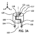
図3は、第3の例示的な操縦フレーム117を例示している。図2の操縦フレーム117とは対照的に、図3の操縦フレームの第1の導電性部材121及び第2の導電性部材122は、それぞれ、長手軸102に沿った連動ステップ(interlocking step)を含む。連動ステップは、長手軸102に沿って増大した強度を提供する。例示の容易さのために、圧電変換器106は図3において省略されている。図3Aにおいて、プルワイヤ104、105は、両方とも、フレーム117の近位端に取り付けられるのに対し、図3Bにおいて、各プルワイヤ104、105は、各プルワイヤ104、105に対する引張力が連動ステップを互いに圧縮的に押し付けるように、そのそれぞれの導電性部材121、122の連動ステップに取り付けられる。これは導電性部材121、122の間の接合部の強度を向上させる。アンカポイント109及び110は、例えば、図3Bの導電性部材109、110の各々の端面120に位置付けられてよい。図3Bの反対の導電性部材121を通過するプルワイヤ105間の電気絶縁は、例えば、ワイヤ上又は管腔の表面上に絶縁層を有するプルワイヤ105を設けるか或いはプルワイヤ105の周りにエポキシ井戸を設けることによって達成されてよい。
FIG. 3 illustrates a third
図4は、第4の例示的な操縦フレーム117を例示している。図4の操縦フレーム117は、第1の円筒状部材によって提供される第1の導電性部材121と、第2の円筒状部材によって提供される第2の導電性部材122とを含む。第1の円筒状部材及び第2の円筒状部材は、第1の円筒状部材が第2の円筒状部材内にあるように、同軸に配置される。その上、絶縁層123が、第1の円筒状部材と第2の円筒状部材との間に配置される。図4Aでは、圧電変換器106が、第2の円筒状部材の外周の周りに配置されている。図4Bに例示する代替的な実装において、第1の円筒状部材は、第2の円筒状部材の軸方向の広がりを越えて延在する延長部分124を含み、圧電変換器106は、第1の円筒状部材の外周の周りに配置される。第1及び第2のオフセット位置109、110にあるアンカポイントは、それぞれ、第1の導電性部材121及び第2の導電性部材122に設けられる。例えば、プルワイヤ105の周りのエポキシ井戸の形態の電気絶縁を使用して、プルワイヤ105を第1の導電性部材121から電気絶縁してよい。代替的に、絶縁層がプルワイヤ105上に又はその管腔の表面上に設けられてよい。
FIG. 4 illustrates a fourth
図5は、第5の例示的な操縦フレーム117を例示している。図5の操縦フレーム117は、第1の導電性部材121と、第2の導電性部材122とを含む。第1の導電性部材121は、長手軸102と整列させられる軸を有する第1のワッシャの形態であり、第2の導電性部材122は、長手軸102と整列させられる軸を有する第2のワッシャの形態である。その上、圧電変換器106は、第1のプルワイヤ104が第1のワッシャを介して圧電変換器106の第1の電極107に電気的に接続されるように、並びに、第2のプルワイヤ105が第2のワッシャを介して圧電変換器106の第2の電極108に電気的に接続されるように、第1のワッシャと第2のワッシャとの間に挟装される。そうすることにより、導電性部材121、122の間の追加的な絶縁の必要性が回避される。図5の圧電変換器106は、例えば、導電性部材121、122の間の接触領域から管状体101又はフレーム117の外周に延びる電極被覆PVDF層によって提供されてよい。代替的に、硬質圧電材料が、軸方向に分離された導電性部材121、122の間に配置されてよい。
FIG. 5 illustrates a fifth
上記実装は及び例は、単一の圧電変換器を有するものとして記載されたが、1つ又はそれよりも多くの追加的な圧電変換器が、管状体101の長手軸102に沿う軸方向に離間した位置に配置されてよいことが理解されるべきである。これらの追加的な変換器は、任意的に、圧電変換器106と並列に電気的に接続されてよい。これは、カテーテルの長さに沿う追加的な電気的相互接続を必要とせずに、追加的な変換器機能性を提供する。そのような並列接続された変換器は、例えば、電気的に相互接続された離散的な圧電変換器によって、或いは、変換器が望まれる位置で、電極が層の両側にのみ存在するように、連続PVDF層上にパターン化された電極を配置することによって、提供されてよい。
The above implementations and examples have been described as having a single piezoelectric transducer, but one or more additional piezoelectric transducers are axially along the
上述の実装に対する代替的な実装では、圧電変換器106に電気的に接続される1つのプルワイヤと、導電性補強層114とを有する、操縦可能な医療カテーテルが開示されている。この操縦可能な医療カテーテルは、長手軸102及び被験者に挿入する遠位部分103を有する、管状体101と、プルワイヤと、第1の電極107及び第2の電極108を含む、圧電変換器106とを含む。管状体101は、内側ライナ113と、導電性補強層114と、外側シース115とを有する。内側ライナ113、補強層114、及び外側シース115は、それぞれ、補強層114が内側ライナ113と外側シース115との間に配置されるように、カテーテル100の長手軸102に沿って同軸的に延在する。内側ライナ113は、インターベンショナルデバイスを受け入れるための長手軸102と同軸な中央管腔116を画定する。カテーテル100の遠位部分103で、プルワイヤ104は、カテーテルの遠位部分103に湾曲を与するために、長手軸102に対するオフセット位置109で管状体に機械的に結合される。カテーテルの遠位部分103で、プルワイヤ104は、圧電変換器106の第1の電極107に電気的に接続され、導電性補強層114は、圧電変換器106の第2の電極108に電気的に接続される。そのようにして、操縦可能な医療カテーテルには、単純化された電気的相互接続を有する圧電デバイスを備える。
An alternative implementation to the above implementation discloses a steerable medical catheter having one pull wire electrically connected to the
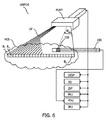
図6は、本明細書に記載の操縦可能な医療カテーテルが使用されることがある例示的な超音波ベースの位置決定システムUBPDSを例示している。超音波ベースの位置決定システムUBPDSは、操縦可能な医療カテーテル100と、超音波場UFを生成するように構成されるビーム形成超音波撮像プローブBUIPと、ビーム形成超音波撮像プローブBUIPの超音波場UFに対応する再構成超音波画像を提供するように構成される画像再構成ユニットIRUと、ビーム形成超音波撮像プローブBUIPと圧電変換器116との間で送信される超音波信号に基づいて、超音波場UFに対するインターベンショナルデバイス110の圧電変換器116の位置を計算するように構成される位置決定ユニットPDUと、圧電変換器116の計算された位置に基づいて再構成される超音波画像内にアイコンを提供するように構成されるアイコン提供ユニットIPUとを含む。
FIG. 6 illustrates an exemplary ultrasound-based positioning system UBPDS in which the steerable medical catheters described herein may be used. The ultrasonic-based positioning system UBPDS includes a maneuverable
図6において、ビーム形成超音波撮像プローブBUIPは、画像再構成ユニットIRU、撮像システムプロセッサISP、撮像システムインタフェースISI及びディスプレイDISPと通信している。全体的に、ユニットBUIP、IRU、ISP、ISI及びDISPは、従来的な超音波撮像システムによって提供されてよい。ユニットIRU、ISP、ISI及びDISPは、従来的には、ビーム形成超音波撮像プローブBUIPと有線又は無線通信するコンソール内に配置される。ユニットIRU、ISP、ISI及びDISPの一部は、代替的に、ビーム形成超音波撮像プローブBUIP内に組み込まれてよい。ビーム形成超音波撮像プローブBUIPは、超音波場UFを生成する。図6には、関心ボリューム(volume of interest)VOIを遮断する(intercepts)超音波場UF内で超音波エネルギを送受信する線形超音波送受信器アレイを含む2Dビーム形成超音波撮像プローブBUIPが例示されている。超音波場は、図6において扇形状であり、例示の画像平面を全体的に提供する複数の超音波ビームB1...kを含む。図6には、例示の目的で扇形状のビームが例示されているが、本発明は、超音波場の特定の形状に限定されないことに留意のこと。 In FIG. 6, the beam-forming ultrasonic imaging probe BUIP communicates with the image reconstruction unit IRU, the imaging system processor ISP, the imaging system interface ISI, and the display DISP. Overall, the units BUIP, IRU, ISP, ISI and DISP may be provided by conventional ultrasound imaging systems. The units IRU, ISP, ISI and DISP are conventionally located in a console that communicates wired or wirelessly with the beam-forming ultrasound imaging probe BUIP. Some of the units IRU, ISP, ISI and DISP may be instead incorporated within the beam-forming ultrasound imaging probe BUIP. The beam-forming ultrasound imaging probe BUIP creates an ultrasound field UF. FIG. 6 illustrates a 2D beam forming ultrasound imaging probe BUIP including a linear ultrasound transmitter / receiver array that transmits and receives ultrasound energy within an ultrasound field UF that intercepts the volume of interest VOI. ing. The ultrasonic field is fan-shaped in FIG. 6, and a plurality of ultrasonic beams B 1. that provide an overall illustrated image plane. .. .. Including k. Although the fan-shaped beam is illustrated in FIG. 6 for the purpose of illustration, it should be noted that the present invention is not limited to a specific shape of the ultrasonic field.
使用中、上述の従来的な超音波撮像システムは、以下のように作動する。操作者は、撮像システムインタフェースISIを介して超音波処置を計画してよい。ひとたび操作手順が選択されると、撮像システムインタフェースISIは、撮像システムプロセッサISPを始動(トリガ)して、ビーム形成超音波撮像プローブBUIPに送信され且つビーム形成超音波撮像プローブBUIPによって検出される信号を生成し且つ解釈するアプリケーション特有プログラムを実行する。メモリ(図示せず)を使用してそのようなプログラムを格納してよい。メモリは、例えば、ビーム形成超音波撮像プローブBUIPによって送信及び/又は受信される超音波信号のシーケンスを制御するように構成される超音波ビーム制御ソフトウェアを格納してよい。画像再構成ユニットIRUは、代替的に、撮像システムプロセッサISPの一部を形成することがある。画像再構成ユニットIRUは、ビーム形成超音波撮像プローブBUIPの超音波場UFに対応する再構成された超音波画像を提供する。それによって、IRUは、超音波場UFによって画定される画像平面に対応する画像を提供し、よって、それは関心ボリュームVOIを遮断する。引き続き、画像は、ディスプレイDISPに表示される。再構成された画像は、例えば、さもなければ「2Dモード」画像として知られる、超音波輝度モード「Bモード」画像、「Cモード」画像又はドップラーモード画像であってよく、或いは実際には任意の超音波画像であってよい。 During use, the conventional ultrasound imaging system described above operates as follows. The operator may plan the ultrasound procedure via the imaging system interface ISI. Once the operating procedure is selected, the imaging system interface ISI initiates (triggers) the imaging system processor ISP, a signal transmitted to the beam-forming ultrasound imaging probe BUIP and detected by the beam-forming ultrasound imaging probe BUIP. Executes an application-specific program that generates and interprets. Memory (not shown) may be used to store such programs. The memory may store, for example, ultrasonic beam control software configured to control the sequence of ultrasonic signals transmitted and / or received by the beam-forming ultrasonic imaging probe BUIP. The image reconstruction unit IRU may instead form part of the imaging system processor ISP. The image reconstruction unit IRU provides a reconstructed ultrasound image corresponding to the ultrasound field UF of the beam-forming ultrasound imaging probe BUIP. Thereby, the IRU provides an image corresponding to the image plane defined by the ultrasonic field UF, which blocks the volume of interest VOI. The image is subsequently displayed on the display DISP. The reconstructed image may be, for example, an ultrasonic brightness mode "B mode" image, a "C mode" image or a Doppler mode image, otherwise known as a "2D mode" image, or in fact arbitrary. It may be an ultrasonic image of.
圧電変換器106を含む操縦可能な医療カテーテル100も図6に示されている。この例示的な用途において、圧電変換器106、結果的に、操縦可能な医療カテーテル100は、位置決定ユニットPDU及びアイコン提供ユニットIPUによって提供される信号に基づいて、それぞれ超音波場UFで追跡されることがある。これらのユニットは、相互接続矢印によって例示するように、互いに、並びにユニットBUIP、IRU、ISP、ISI及びDISP、すなわち、従来的な超音波撮像システムと通信する。ユニットPDU及びIPUの1つ又はそれよりも多くは、従来的な超音波撮像システムのメモリ又はプロセッサ内に組み込まれてよい。
A maneuverable
使用中、圧電変換器106の位置は、ビーム形成超音波撮像プローブBUIPと圧電変換器106との間で送信される超音波信号に基づいて位置決定ユニットPDUによって超音波場UFに対して計算される。
During use, the position of the
1つの構成において、圧電変換器106は、ビームB1...kに対応する超音波信号を受信する検出器である。位置決定ユニットPDUは、ビーム形成超音波撮像プローブBUIPによって放射される超音波信号を圧電変換器106によって検出される超音波信号と相関させることによって、圧電変換器106の位置を識別する。引き続き、アイコン提供ユニットIPUは、圧電変換器106の計算された位置に基づいて、再構成された超音波画像内にアイコンを提供する。より具体的には、相関は、i)圧電変換器106によって検出される各ビームB1...kに対応する超音波信号の振幅に基づいて、並びにii)各ビーム1...kの放射と圧電変換器106によるその検出との間の時間遅延、すなわち、飛行時間に基づいて、超音波場UFに対する圧電変換器106の最良適合位置(best fit position)を決定する。これは以下のように例示されてよい。圧電変換器106が超音波場UFの近傍にあるとき、ビーム1...kのうちの最も近いビームから変換器への超音波信号は、比較的より大きな振幅で検出されるのに対し、より遠いビームは、比較的より小さな振幅で検出される。典型的には、最大振幅で検出されるビームは、圧電変換器106に最も近いビームとして識別される。このビームは、ビーム形成超音波撮像プローブBUIPと圧電変換器106との間の面内角θIPA(in-plane angle)を画定する。対応する範囲は、最大振幅ビーム1...kの放射とその後の検出との間の時間遅延、すなわち、飛行時間に依存する。その範囲は、超音波伝搬速度を時間遅延に乗じることによって決定される。よって、その範囲及び最大振幅で検出されるビームの対応する面内角θIPAを用いて超音波場UFに対する圧電変換器106の最良適合位置を識別することができる。
In one configuration, the
別の構成において、圧電変換器106は、1つ又はそれよりも多くの超音波パルスを放射するエミッタであってよい。そのようなパルスは、例えば、従来的な超音波撮像システムの撮像フレーム間にインターリーブされる追跡フレームの間に放射されてよい。そのような追跡フレームにおいて、ビーム形成超音波撮像プローブBUIPは、それが超音波場UFの近傍から発生する超音波信号を聴取する受信専用モードで作動してよい。よって、ビーム形成超音波撮像プローブBUIPは、そのような追跡フレーム中に一方向受信専用ビームフォーマとして構成される。位置決定ユニットPDUは、ビーム形成超音波撮像プローブBUIPの受信器素子に遅延を適用することによって、仮想ビームB1...kのどのビームから(複数の)パルスが発生したかを識別する。遅延は、仮想ビームB1...kの各々に対応する。上記検出器構成と同様に、位置決定ユニットPDUは、最大振幅及び飛行時間に基づいて、超音波信号が放射された位置に最も近いビームB1...k、及び圧電変換器106への対応する範囲を識別する、相関手順を使用してよい。引き続き、アイコン提供ユニットIPUは、圧電変換器106上の識別された位置に基づいて、再構成された超音波画像内にアイコンを提供する。よって、圧電変換器106が超音波エミッタであるときには、相関手順を再び使用して各追跡フレームについての超音波場UFに対する圧電変換器106の最良適合位置を決定してよい。
In another configuration, the
別の構成において、圧電変換器106は、受信器及びエミッタの両方として作用するように構成されてよく、或いは別個の受信器及びエミッタを含んでよい。この構成において、圧電変換器106は、ビーム形成超音波撮像プローブBUIPから超音波信号を受信した後に、1つ又はそれよりも多くの超音波パルスを放射するように始動(トリガ)されてよい。このようにして、撮像モード中に圧電変換器106によって放射される(複数の)パルスは、ビーム形成超音波撮像プローブBUIPによって受信され、関連するビームB1...kに対応する面内角度位置で、すなわち、画像ライン(image line)内に再構成された超音波中のエコーとして現れる。よって、圧電変換器106は、再構成された画像において明るいスポットとして現れる。引き続き、位置決定ユニットPDUは、再構成された画像内のこの明るいスポットを識別し、よって、超音波場UFに対する圧電変換器106の位置を計算してよい。
In another configuration, the
例示のビーム形成超音波撮像プローブBUIPは、操縦可能な医療カテーテル100が使用されることがあるビーム形成超音波撮像システムの一例に過ぎないことも理解されるべきである。操縦可能な医療カテーテル100は、他のタイプの2D又は3Dビーム形成超音波撮像システムを含む超音波ベースの位置決定システムにも用途を見出す。これらは、例えば、「TRUS」経直腸超音波検査プローブ、「IVUS」血管内超音波プローブ、「TEE」経食道プローブ、「TTE」経胸腔プローブ、「TNE」経鼻プローブ、「ICE」心臓内プローブを含んでよい。
It should also be understood that the exemplary beam-forming ultrasound imaging probe BUIP is just one example of a beam-forming ultrasound imaging system in which a maneuverable
その上、圧電変換器は、位置決定以外の医療分野における他の感知及び作動用途にも用途を見出すことも理解されるべきである。 Moreover, it should be understood that piezoelectric transducers will also find applications in other sensing and operating applications in the medical field other than position fixing.
様々な例示的な実装を以下に例1〜15によって記載する。 Various exemplary implementations are described below by Examples 1-15.
例1。長手軸(102)と、被験者に挿入する遠位部分(103)とを有する、管状体(101)と、
第1のプルワイヤ(104)と、
第2のプルワイヤ(105)と、
第1の電極(107)と、第2の電極(108)とを含む、圧電変換器(106)とを含む、
操縦可能な医療カテーテル(100)であって、
カテーテル(100)の遠位部分(103)で、第1のプルワイヤ(104)及び第2のプルワイヤ(105)は、それぞれ、カテーテルの遠位部分(103)に湾曲を付与するために、長手軸(102)に対するそれぞれの第1及び第2のオフセット位置(109,110)で管状体に機械的に結合され、
カテーテルの遠位部分(103)で、第1のプルワイヤ(104)は、圧電変換器(106)の第1の電極(107)に電気的に接続され、第2のプルワイヤ(105)は、圧電変換器(106)の第2の電極(108)に電気的に接続される、
操縦可能な医療カテーテル(100)。
Example 1. A tubular body (101) having a longitudinal axis (102) and a distal portion (103) to be inserted into the subject.
The first pull wire (104) and
With the second pull wire (105),
Includes a piezoelectric transducer (106), including a first electrode (107) and a second electrode (108).
A steerable medical catheter (100)
At the distal portion (103) of the catheter (100), the first pull wire (104) and the second pull wire (105) are respectively longitudinal axes to impart curvature to the distal portion (103) of the catheter. Mechanically coupled to the tubular body at the respective first and second offset positions (109, 110) with respect to (102).
At the distal portion (103) of the catheter, the first pull wire (104) is electrically connected to the first electrode (107) of the piezoelectric transducer (106) and the second pull wire (105) is piezoelectric. Electrically connected to the second electrode (108) of the transducer (106),
Maneuverable medical catheter (100).
例2。管状体(101)は、それぞれ長手軸(102)に平行に延在する、第1のプルワイヤ管腔(111)及び第2のプルワイヤ管腔(112)を含み、
第1のプルワイヤ(104)は、第1のプルワイヤ管腔(111)内に配置され、
第2のプルワイヤ(105)は、第2のプルワイヤ管腔(112)内に配置され、
第1のプルワイヤ管腔(111)及び第2のプルワイヤ管腔(112)は、それぞれ、電気絶縁管腔壁を含む、
例1に従った操縦可能な医療カテーテル。
Example 2. The tubular body (101) includes a first pullwire lumen (111) and a second pullwire lumen (112) extending parallel to the longitudinal axis (102), respectively.
The first pullwire (104) is located within the first pullwire lumen (111).
The second pullwire (105) is located within the second pullwire lumen (112).
The first pullwire lumen (111) and the second pullwire lumen (112) each include an electrically insulated lumen wall.
A steerable medical catheter according to Example 1.
例3。管状体(101)は、内側ライナ(113)と、補強層(114)と、外側シース(115)とを含み、
内側ライナ(113)、補強層(114)及び外側シース(115)は、それぞれ、補強層(114)が内側ライナ(113)と外側シース(115)との間に配置されるように、カテーテル(100)の長手軸(102)に沿って同軸に延在し、
内側ライナ(113)は、インターベンショナルデバイスを受け入れるために長手軸(102)と同軸な中央管腔(116)を画定する、
例1又は2に従った操縦可能な医療カテーテル(100)。
Example 3. The tubular body (101) includes an inner liner (113), a reinforcing layer (114), and an outer sheath (115).
The inner liner (113), reinforcing layer (114) and outer sheath (115) are respectively catheterized so that the reinforcing layer (114) is located between the inner liner (113) and the outer sheath (115). Extends coaxially along the longitudinal axis (102) of 100)
The inner liner (113) defines a central lumen (116) coaxial with the longitudinal axis (102) to accommodate the interventional device.
A steerable medical catheter (100) according to Example 1 or 2.
例4。カテーテル(100)の遠位部分(103)で、第1のプルワイヤ管腔(111)及び第2のプルワイヤ管腔(112)は、それぞれ、内側ライナ(113)内に配置される、例3に従った操縦可能な医療カテーテル(100)。 Example 4. In Example 3, in the distal portion (103) of the catheter (100), the first pullwire lumen (111) and the second pullwire lumen (112) are respectively located within the medial liner (113). A maneuverable medical catheter (100).
例5。補強層(114)は、第1のプルワイヤ(104)及び第2のプルワイヤ(105)を電気的に遮蔽する導電性材料を含む、例4に従った操縦可能な医療カテーテル(100)。 Example 5. The stiffening layer (114) is a steerable medical catheter (100) according to Example 4, comprising a conductive material that electrically shields the first pull wire (104) and the second pull wire (105).
例6。操縦フレーム(117)を更に含み、
操縦フレーム(117)は、第1のオフセット位置(109)に配置される第1のアンカポイントと、第2のオフセット位置(110)に配置される第2のアンカポイントとを含み、
第1のプルワイヤ(104)及び第2のプルワイヤ(105)は、操縦フレームが第1のプルワイヤ(104)及び第2のプルワイヤ(105)を管状体(101)に機械的に結合するように、第1のアンカポイント及び第2のアンカポイントにそれぞれ取り付けられる、
例1に従った操縦可能な医療カテーテル(100)。
Example 6. Including the maneuvering frame (117)
The maneuvering frame (117) includes a first anchor point located at the first offset position (109) and a second anchor point located at the second offset position (110).
The first pull wire (104) and the second pull wire (105) are such that the control frame mechanically connects the first pull wire (104) and the second pull wire (105) to the tubular body (101). Attached to the first anchor point and the second anchor point, respectively,
A steerable medical catheter (100) according to Example 1.
例7。操縦フレーム(117)は、内側管腔(118)を更に含み、内側管腔は、管状体(101)の長手軸(102)と同軸に配置される、例6に従った操縦可能な医療カテーテル(100)。 Example 7. The maneuvering frame (117) further includes an inner lumen (118), which is a steerable medical catheter according to Example 6, which is located coaxially with the longitudinal axis (102) of the tubular body (101). (100).
例8。操縦フレーム(117)は、外周(119)を含み、
圧電変換器(106)は、操縦フレームの外周の周りに配置される、
例7に従った操縦可能な医療カテーテル(100)。
Example 8. The maneuvering frame (117) includes the outer circumference (119).
Piezoelectric transducers (106) are arranged around the perimeter of the control frame.
A steerable medical catheter (100) according to Example 7.
例9。操縦フレーム(117)は、端面(120)を含み、
圧電変換器(106)は、操縦フレームの端面に配置される、
例6乃至8のうちのいずれか1つに従った操縦可能な医療カテーテル(100)。
Example 9. The maneuvering frame (117) includes an end face (120).
The piezoelectric transducer (106) is arranged on the end face of the control frame.
A steerable medical catheter (100) according to any one of Examples 6-8.
例10。操縦フレーム(117)は、第1の導電性部材(121)と、第2の導電性部材(122)とを含み、第1の導電性部材及び第2の導電性部材は、絶縁層(123)によって分離され、
第1のアンカポイントは、第1の導電性部材(121)に配置され、第2のアンカポイントは、第2の導電性部材(122)に配置される、
例6乃至9のうちのいずれか1つに従った操縦可能な医療カテーテル(100)。
Example 10. The control frame (117) includes a first conductive member (121) and a second conductive member (122), and the first conductive member and the second conductive member are an insulating layer (123). ) Separated by
The first anchor point is located on the first conductive member (121) and the second anchor point is located on the second conductive member (122).
A steerable medical catheter (100) according to any one of Examples 6-9.
例11。第1の導電性部材(121)は、円筒状シェルの第1の部分によって提供され、第2の導電性部材(122)は、円筒状シェルの第2の部分によって提供され、
第1の部分及び第2の部分は、円筒状シェルを提供するよう、絶縁層(123)によって操縦フレーム(117)の軸方向の広がりに沿って互いに機械的に取り付けられ、
圧電変換器(106)は、円筒状シェルの外周の周りに配置される、
例10に従った操縦可能な医療カテーテル(100)。
Example 11. The first conductive member (121) is provided by the first portion of the cylindrical shell and the second conductive member (122) is provided by the second portion of the cylindrical shell.
The first and second parts are mechanically attached to each other by an insulating layer (123) along the axial spread of the control frame (117) to provide a cylindrical shell.
The piezoelectric transducer (106) is arranged around the outer circumference of the cylindrical shell.
A steerable medical catheter (100) according to Example 10.
例12。第1の導電性部材(121)は、第1の円筒状部材によって提供され、第2の導電性部材(122)は、第2の円筒状部材によって提供され、
第1の円筒状部材及び第2の円筒状部材は、第1の円筒状部材が第2の円筒状部材内にあるように、並びに絶縁層(123)が第1の円筒状部材と第2の円筒状部材との間に配置されるように、同軸に配置され、
i)圧電変換器(106)は、第2の円筒状部材の外周の周りに配置されるか、或いは
ii)第1の円筒状部材は、第2の円筒状部材の軸方向の広がりを越えて延びる延長部分(124)を含み、圧電変換器(106)は、第1の円筒状部材の外周の周りに配置される、
例10に従った操縦可能な医療カテーテル(100)。
Example 12. The first conductive member (121) is provided by the first cylindrical member and the second conductive member (122) is provided by the second cylindrical member.
In the first cylindrical member and the second cylindrical member, the first cylindrical member is in the second cylindrical member, and the insulating layer (123) is the first cylindrical member and the second cylindrical member. Arranged coaxially so that it is arranged between the cylindrical members of
i) The piezoelectric converter (106) is placed around the perimeter of the second cylindrical member, or ii) the first cylindrical member exceeds the axial extent of the second cylindrical member. A piezoelectric converter (106) is arranged around the outer circumference of the first cylindrical member, including an extension portion (124) that extends.
A steerable medical catheter (100) according to Example 10.
例13。操縦フレーム(117)は、第1の導電性部材(121)と、第2の導電性部材(122)とを含み、第1の導電性部材(121)は、長手軸(102)と整列させられる軸を有する第1のワッシャの形態にあり、第2の導電性部材(122)は、長手軸(102)と整列させられる軸を有する第2のワッシャの形態にあり、
圧電変換器(106)は、第1のプルワイヤ(104)が第1のワッシャを介して圧電変換器(106)の第1の電極(107)に電気的に接続されるように、並びに第2のプルワイヤ(105)が第2のワッシャを介して圧電変換器(106)の第2の電極(108)に電気的に接続されるように、第1のワッシャと第2のワッシャとの間に挟装される、
例6乃至9のうちのいずれか1つに従った操縦可能な医療カテーテル(100)。
Example 13. The control frame (117) includes a first conductive member (121) and a second conductive member (122), and the first conductive member (121) is aligned with the longitudinal axis (102). The second conductive member (122) is in the form of a second washer having a shaft aligned with the longitudinal axis (102).
The piezoelectric transducer (106) is arranged so that the first pull wire (104) is electrically connected to the first electrode (107) of the piezoelectric converter (106) via the first washer, and the second. Between the first washer and the second washer so that the pull wire (105) of the is electrically connected to the second electrode (108) of the piezoelectric transducer (106) via the second washer. Be sandwiched,
A steerable medical catheter (100) according to any one of Examples 6-9.
例14。少なくとも第2の圧電変換器を更に含み、
圧電変換器(106)及び少なくとも第2の圧電変換器は、管状体(101)の長手軸(102)に沿う軸方向に分離された位置に配置される、
例1乃至13のうちのいずれか1つに従った操縦可能な医療カテーテル(100)。
Example 14. Further including at least a second piezoelectric transducer,
The piezoelectric transducer (106) and at least the second piezoelectric transducer are arranged at axially separated positions along the longitudinal axis (102) of the tubular body (101).
A steerable medical catheter (100) according to any one of Examples 1-13.
例15。圧電変換器(106)及び少なくとも第2の圧電変換器は、並列に電気的に接続される、例14に従った操縦可能な医療カテーテル(100)。 Example 15. The piezoelectric transducer (106) and at least the second piezoelectric transducer are electrically connected in parallel, a steerable medical catheter (100) according to Example 14.
要約すると、操縦可能な医療カテーテルが記載されている。操縦可能な医療カテーテルは、長手軸と、被験者に挿入する遠位部分とを有する、管状体と、第1のプルワイヤと、第2のプルワイヤと、圧電変換器とを含む。圧電変換器は、第1の電極と、第2の電極とを含む。カテーテルの遠位部分で、第1のプルワイヤ及び第2のプルワイヤは、それぞれ、カテーテルの遠位部分に湾曲を与えるために、長手軸に対するそれぞれの第1及び第2のオフセット位置で管状体に機械的に結合される。カテーテルの遠位部分で、第1のプルワイヤは、圧電変換器の第1の電極に電気的に接続され、第2のプルワイヤは、圧電変換器の第2の電極に電気的に接続される。 In summary, maneuverable medical catheters are described. The steerable medical catheter includes a tubular body having a longitudinal axis and a distal portion to be inserted into the subject, a first pull wire, a second pull wire, and a piezoelectric transducer. The piezoelectric transducer includes a first electrode and a second electrode. In the distal portion of the catheter, the first pull wire and the second pull wire mechanically into the tubular body at their respective first and second offset positions with respect to the longitudinal axis to give curvature to the distal portion of the catheter, respectively. Are combined. At the distal portion of the catheter, the first pullwire is electrically connected to the first electrode of the piezoelectric transducer and the second pullwire is electrically connected to the second electrode of the piezoelectric transducer.
様々な実装及び選択肢が操縦可能な医療カテーテルに関連して記載されており、様々な実施形態を組み合わせて更なる有利な効果を達成してよいことに留意のこと。 Note that various implementations and options have been described in relation to steerable medical catheters, and various embodiments may be combined to achieve additional beneficial effects.
Claims (11)
第1のプルワイヤと、
第2のプルワイヤと、
第1の電極と、第2の電極とを含む、圧電変換器とを含む、
操縦可能な医療カテーテルであって、
前記管状体は、前記長手軸にそれぞれ平行に延在する、第1のプルワイヤ管腔及び第2のプルワイヤ管腔を含み、
前記第1のプルワイヤは、前記第1のプルワイヤ管腔内に配置され、
前記第2のプルワイヤは、前記第2のプルワイヤ管腔内に配置され、
前記第1のプルワイヤ管腔及び前記第2のプルワイヤ管腔は、それぞれ、電気絶縁管腔壁を含み、
当該医療カテーテルの前記遠位部分で、前記第1のプルワイヤ及び前記第2のプルワイヤは、それぞれ、当該医療カテーテルの前記遠位部分に湾曲を付与するために前記長手軸に対するそれぞれの第1及び第2のオフセット位置で前記管状体に機械的に結合され、
当該医療カテーテルの前記遠位部分で、前記第1のプルワイヤは、前記圧電変換器の前記第1の電極に電気的に接続され、前記第2のプルワイヤは、前記圧電変換器の前記第2の電極に電気的に接続され、
前記管状体は、内側ライナと、補強層と、外側シースとを含み、
前記内側ライナ、前記補強層及び前記外側シースは、それぞれ、前記補強層が前記内側ライナと前記外側シースとの間に配置されるように、当該医療カテーテルの前記長手軸に沿って同軸に延在し、
前記内側ライナは、インターベンショナルデバイスを受け入れるために前記長手軸と同軸な中央管腔を画定し、
当該医療カテーテルの前記遠位部分で、前記第1のプルワイヤ管腔及び前記第2のプルワイヤ管腔は、それぞれ、内側ライナ内に配置され、
前記補強層は、前記第1のプルワイヤ及び前記第2のプルワイヤを電気的に遮蔽する導電性材料を含むことを特徴とする、
操縦可能な医療カテーテル。 A tubular body having a longitudinal axis and a distal portion to be inserted into the subject,
The first pull wire and
With the second pull wire,
Includes a piezoelectric transducer, including a first electrode and a second electrode,
A steerable medical catheter
The tubular body comprises a first pullwire lumen and a second pullwire lumen extending parallel to the longitudinal axis, respectively.
The first pull wire is placed in the first pull wire lumen and
The second pull wire is placed in the second pull wire lumen and
The first pullwire lumen and the second pullwire lumen each include an electrically insulated lumen wall.
In the distal portion of the medical catheter, the first pull wire and the second pull wire, respectively, are first and first relative to the longitudinal axis to impart curvature to the distal portion of the medical catheter, respectively. Mechanically attached to the tubular body at an offset position of 2
At the distal portion of the medical catheter, the first pullwire is electrically connected to the first electrode of the piezoelectric transducer and the second pullwire is the second pullwire of the piezoelectric transducer. Electrically connected to the electrodes
The tubular body includes an inner liner, a reinforcing layer, and an outer sheath.
The inner liner, the reinforcing layer and the outer sheath each extend coaxially along the longitudinal axis of the medical catheter so that the reinforcing layer is located between the inner liner and the outer sheath. And
The inner liner defines a central lumen coaxial with the longitudinal axis to accommodate the interventional device.
In the distal portion of the medical catheter, the first pullwire lumen and the second pullwire lumen are respectively located in the medial liner.
The reinforcing layer is characterized by containing a conductive material for electrically shielding the first pull wire and the second pull wire,
Maneuverable medical catheter.
該操縦フレームは、前記第1のオフセット位置に配置される第1のアンカポイントと、前記第2のオフセット位置に配置される第2のアンカポイントとを含み、
前記第1のプルワイヤ及び前記第2のプルワイヤは、前記操縦フレームが前記第1のプルワイヤ及び前記第2のプルワイヤを前記管状体に機械的に結合するように、前記第1のアンカポイント及び前記第2のアンカポイントにそれぞれ取り付けられる、
請求項1に記載の操縦可能な医療カテーテル。 Including the maneuvering frame
The control frame includes a first anchor point located at the first offset position and a second anchor point located at the second offset position.
The first pull wire and the second pull wire are the first anchor point and the first pull wire so that the control frame mechanically connects the first pull wire and the second pull wire to the tubular body. Attached to each of the 2 anchor points,
The steerable medical catheter according to claim 1.
前記圧電変換器は、前記操縦フレームの前記外周の周りに配置される、
請求項3に記載の操縦可能な医療カテーテル。 The control frame includes an outer circumference.
The piezoelectric transducer is arranged around the outer circumference of the control frame.
The steerable medical catheter according to claim 3.
前記圧電変換器は、前記操縦フレームの前記端面に配置される、
請求項2乃至4のうちのいずれか1項に記載の操縦可能な医療カテーテル。 The control frame includes an end face and
The piezoelectric transducer is arranged on the end face of the control frame.
The steerable medical catheter according to any one of claims 2 to 4.
前記第1のアンカポイントは、前記第1の導電性部材に配置され、前記第2のアンカポイントは、前記第2の導電性部材に配置される、
請求項2乃至5のうちのいずれか1項に記載の操縦可能な医療カテーテル。 The control frame includes a first conductive member and a second conductive member, and the first conductive member and the second conductive member are separated by an insulating layer.
The first anchor point is arranged on the first conductive member, and the second anchor point is arranged on the second conductive member.
The steerable medical catheter according to any one of claims 2 to 5.
前記第1の部分及び前記第2の部分は、前記円筒状シェルを提供するよう、前記絶縁層によって前記操縦フレームの軸方向の広がりに沿って互いに機械的に取り付けられ、
前記圧電変換器は、前記円筒状シェルの外周の周りに配置される、
請求項6に記載の操縦可能な医療カテーテル。 The first conductive member is provided by a first portion of the cylindrical shell and the second conductive member is provided by a second portion of the cylindrical shell.
The first portion and the second portion are mechanically attached to each other by the insulating layer along the axial spread of the control frame to provide the cylindrical shell.
The piezoelectric transducer is arranged around the outer circumference of the cylindrical shell.
The steerable medical catheter according to claim 6.
前記第1の円筒状部材及び前記第2の円筒状部材は、前記第1の円筒状部材が前記第2の円筒状部材内にあるように、並びに前記絶縁層が前記第1の円筒状部材と前記第2の円筒状部材との間に配置されるように、同軸に配置され、
i)前記圧電変換器は、前記第2の円筒状部材の外周の周りに配置されるか、或いは
ii)前記第1の円筒状部材は、前記第2の円筒状部材の軸方向の広がりを越えて延びる延長部分を含み、前記圧電変換器は、前記第1の円筒状部材の外周の周りに配置される、
請求項6に記載の操縦可能な医療カテーテル。 The first conductive member is provided by a first cylindrical member, and the second conductive member is provided by a second cylindrical member.
In the first cylindrical member and the second cylindrical member, the first cylindrical member is in the second cylindrical member, and the insulating layer is the first cylindrical member. Is arranged coaxially so that it is arranged between the second cylindrical member and the second cylindrical member.
i) The piezoelectric converter is arranged around the outer circumference of the second cylindrical member, or ii) the first cylindrical member expands the second cylindrical member in the axial direction. The piezoelectric converter is arranged around the outer circumference of the first cylindrical member, including an extension portion extending beyond.
The steerable medical catheter according to claim 6.
前記圧電変換器は、前記第1のプルワイヤが前記第1のワッシャを介して前記圧電変換器の前記第1の電極に電気的に接続されるように、並びに前記第2のプルワイヤが前記第2のワッシャを介して前記圧電変換器の前記第2の電極に電気的に接続されるように、前記第1のワッシャと前記第2のワッシャとの間に挟装される、
請求項2乃至5のうちのいずれか1項に記載の操縦可能な医療カテーテル。 The control frame includes a first conductive member and a second conductive member, the first conductive member in the form of a first washer having an axis aligned with the longitudinal axis. The second conductive member is in the form of a second washer having an axis aligned with the longitudinal axis.
The piezoelectric transducer is such that the first pull wire is electrically connected to the first electrode of the piezoelectric converter via the first washer, and the second pull wire is the second. It is sandwiched between the first washer and the second washer so as to be electrically connected to the second electrode of the piezoelectric converter via the washer.
The steerable medical catheter according to any one of claims 2 to 5.
前記圧電変換器及び前記少なくとも第2の圧電変換器は、前記管状体の前記長手軸に沿って軸方向に分離された位置に配置される、
請求項1乃至9のうちのいずれか1項に記載の操縦可能な医療カテーテル。 Further including at least a second piezoelectric transducer,
The piezoelectric transducer and at least the second piezoelectric transducer are arranged at positions separated in the axial direction along the longitudinal axis of the tubular body.
The steerable medical catheter according to any one of claims 1 to 9.
Applications Claiming Priority (5)
| Application Number | Priority Date | Filing Date | Title |
|---|---|---|---|
| US201862632632P | 2018-02-20 | 2018-02-20 | |
| US62/632,632 | 2018-02-20 | ||
| EP18167284.1A EP3552552A1 (en) | 2018-04-13 | 2018-04-13 | Steerable catheter with piezoelectric transducer |
| EP18167284.1 | 2018-04-13 | ||
| PCT/EP2019/053474 WO2019162150A1 (en) | 2018-02-20 | 2019-02-13 | Steerable catheter with piezoelectric transducer |
Publications (2)
| Publication Number | Publication Date |
|---|---|
| JP2021511166A JP2021511166A (en) | 2021-05-06 |
| JP6894583B2 true JP6894583B2 (en) | 2021-06-30 |
Family
ID=62001993
Family Applications (1)
| Application Number | Title | Priority Date | Filing Date |
|---|---|---|---|
| JP2020543822A Active JP6894583B2 (en) | 2018-02-20 | 2019-02-13 | Maneuverable catheter with piezoelectric transducer |
Country Status (4)
| Country | Link |
|---|---|
| US (1) | US11617860B2 (en) |
| EP (2) | EP3552552A1 (en) |
| JP (1) | JP6894583B2 (en) |
| CN (1) | CN111902089B (en) |
Family Cites Families (17)
| Publication number | Priority date | Publication date | Assignee | Title |
|---|---|---|---|---|
| US4920980A (en) * | 1987-09-14 | 1990-05-01 | Cordis Corporation | Catheter with controllable tip |
| US6123699A (en) * | 1997-09-05 | 2000-09-26 | Cordis Webster, Inc. | Omni-directional steerable catheter |
| US6224587B1 (en) | 1999-11-22 | 2001-05-01 | C.R. Bard, Inc. | Steerable catheter |
| EP2380487B1 (en) | 2002-04-17 | 2021-03-31 | Covidien LP | Endoscope structures for navigating to a target in branched structure |
| US7130700B2 (en) * | 2002-11-19 | 2006-10-31 | Medtronic, Inc. | Multilumen body for an implantable medical device |
| US6945956B2 (en) * | 2002-12-23 | 2005-09-20 | Medtronic, Inc. | Steerable catheter |
| EP1596746B1 (en) * | 2003-02-20 | 2016-10-19 | ReCor Medical, Inc. | Ultrasonic ablation devices |
| EP1725289A4 (en) * | 2004-01-29 | 2007-11-14 | Ekos Corp | Small vessel ultrasound catheter |
| US20070265637A1 (en) * | 2006-04-21 | 2007-11-15 | Xtent, Inc. | Devices and methods for controlling and counting interventional elements |
| EP2355736A1 (en) * | 2008-09-02 | 2011-08-17 | Medtronic Ablation Frontiers LLC | Irrigated ablation catheter system and methods |
| FR2939139B1 (en) | 2008-12-03 | 2012-12-21 | Arkema France | COMPOSITION COMPRISING POLYPROPYLENE AND / OR COPOLYMER OF PROPYLENE OBTAINED FROM RENEWABLE MATERIALS AND USES THEREOF |
| US8784800B2 (en) * | 2009-03-09 | 2014-07-22 | Medtronic, Inc. | Method of delivering cell therapy to a target site |
| WO2012058473A1 (en) * | 2010-10-27 | 2012-05-03 | Gore Enterprise Holdings, Inc. | Imaging catheter with rotatble array |
| EP2455133A1 (en) * | 2010-11-18 | 2012-05-23 | Koninklijke Philips Electronics N.V. | Catheter comprising capacitive micromachined ultrasonic transducers with an adjustable focus |
| US9393070B2 (en) * | 2012-04-24 | 2016-07-19 | Cibiem, Inc. | Endovascular catheters and methods for carotid body ablation |
| US20140257130A1 (en) * | 2013-03-11 | 2014-09-11 | Boston Scientific Scimed, Inc. | Powered pull wire design for ablation catheters |
| WO2015027094A1 (en) * | 2013-08-23 | 2015-02-26 | Boston Scientific Scimed, Inc. | Catheters and catheter shafts |
-
2018
- 2018-04-13 EP EP18167284.1A patent/EP3552552A1/en not_active Withdrawn
-
2019
- 2019-02-13 JP JP2020543822A patent/JP6894583B2/en active Active
- 2019-02-13 US US16/970,886 patent/US11617860B2/en active Active
- 2019-02-13 EP EP19703365.7A patent/EP3755232B1/en active Active
- 2019-02-13 CN CN201980020631.0A patent/CN111902089B/en active Active
Also Published As
| Publication number | Publication date |
|---|---|
| EP3755232A1 (en) | 2020-12-30 |
| EP3755232B1 (en) | 2021-07-07 |
| CN111902089A (en) | 2020-11-06 |
| EP3552552A1 (en) | 2019-10-16 |
| US11617860B2 (en) | 2023-04-04 |
| CN111902089B (en) | 2023-03-07 |
| JP2021511166A (en) | 2021-05-06 |
| US20200376232A1 (en) | 2020-12-03 |
Similar Documents
| Publication | Publication Date | Title |
|---|---|---|
| US10667753B2 (en) | Catheter system and methods of medical uses of same, including diagnostic and treatment uses for the heart | |
| US6277077B1 (en) | Catheter including ultrasound transducer with emissions attenuation | |
| US20180064415A1 (en) | Acoustic ablation assisted intra-cardiac echocardiography catheter | |
| JP7292448B2 (en) | Lined Variable Blade Differential Durometer Hardness Double-Tube Shaft with Cruciform Internal Contour | |
| JP2012514521A (en) | Ultrasound catheter with rotary transducer | |
| JP2019528964A (en) | Intracardiac echocardiography (ICE) catheter tip assembly | |
| JP2009517178A (en) | Echogenic needle catheter configured to generate improved ultrasound images | |
| EP1737348A1 (en) | Ultrasound imaging probe featuring wide field of view | |
| Nikoozadeh et al. | Forward-looking intracardiac imaging catheters using fully integrated CMUT arrays | |
| JP2021505260A (en) | Rewind-type flexible substrate for intracavitary ultrasound imaging equipment | |
| JP6894583B2 (en) | Maneuverable catheter with piezoelectric transducer | |
| JP2021505263A (en) | Retractable flexible substrate with integrated window for intracavitary ultrasound imaging | |
| CN116115900A (en) | Catheter pump assembly with ultrasonic development function | |
| WO2019162150A1 (en) | Steerable catheter with piezoelectric transducer | |
| EP3932324A1 (en) | Ultrasonic vibrator | |
| CN112584939B (en) | Interventional device with PVDF ultrasound detector | |
| US11819291B2 (en) | Interventional device with PVDF ultrasound detector | |
| JP7059438B2 (en) | Intervention device with electrical connection | |
| JP2021534846A (en) | Intervention device with ultrasonic transducer | |
| JP6907415B2 (en) | Intervention device with piezoelectric transducer | |
| JP7313431B2 (en) | diagnostic imaging catheter |
Legal Events
| Date | Code | Title | Description |
|---|---|---|---|
| A521 | Request for written amendment filed |
Free format text: JAPANESE INTERMEDIATE CODE: A523 Effective date: 20200821 |
|
| A521 | Request for written amendment filed |
Free format text: JAPANESE INTERMEDIATE CODE: A523 Effective date: 20210310 |
|
| A621 | Written request for application examination |
Free format text: JAPANESE INTERMEDIATE CODE: A621 Effective date: 20210310 |
|
| A871 | Explanation of circumstances concerning accelerated examination |
Free format text: JAPANESE INTERMEDIATE CODE: A871 Effective date: 20210310 |
|
| A975 | Report on accelerated examination |
Free format text: JAPANESE INTERMEDIATE CODE: A971005 Effective date: 20210422 |
|
| TRDD | Decision of grant or rejection written | ||
| A01 | Written decision to grant a patent or to grant a registration (utility model) |
Free format text: JAPANESE INTERMEDIATE CODE: A01 Effective date: 20210511 |
|
| A61 | First payment of annual fees (during grant procedure) |
Free format text: JAPANESE INTERMEDIATE CODE: A61 Effective date: 20210603 |
|
| R150 | Certificate of patent or registration of utility model |
Ref document number: 6894583 Country of ref document: JP Free format text: JAPANESE INTERMEDIATE CODE: R150 |
|
| R250 | Receipt of annual fees |
Free format text: JAPANESE INTERMEDIATE CODE: R250 |