JP2021534846A - Intervention device with ultrasonic transducer - Google Patents
Intervention device with ultrasonic transducer Download PDFInfo
- Publication number
- JP2021534846A JP2021534846A JP2021506265A JP2021506265A JP2021534846A JP 2021534846 A JP2021534846 A JP 2021534846A JP 2021506265 A JP2021506265 A JP 2021506265A JP 2021506265 A JP2021506265 A JP 2021506265A JP 2021534846 A JP2021534846 A JP 2021534846A
- Authority
- JP
- Japan
- Prior art keywords
- ultrasonic transducer
- transducer
- ultrasonic
- adhesive layer
- intervention device
- Prior art date
- Legal status (The legal status is an assumption and is not a legal conclusion. Google has not performed a legal analysis and makes no representation as to the accuracy of the status listed.)
- Pending
Links
- 239000012790 adhesive layer Substances 0.000 claims abstract description 78
- 230000001681 protective effect Effects 0.000 claims abstract description 59
- 239000002654 heat shrinkable material Substances 0.000 claims abstract description 10
- 239000010410 layer Substances 0.000 claims description 72
- 239000011888 foil Substances 0.000 claims description 66
- 239000004020 conductor Substances 0.000 claims description 45
- 239000004820 Pressure-sensitive adhesive Substances 0.000 claims description 40
- 238000003384 imaging method Methods 0.000 claims description 37
- 239000000523 sample Substances 0.000 claims description 30
- 238000002604 ultrasonography Methods 0.000 claims description 21
- 238000000034 method Methods 0.000 claims description 19
- 239000000758 substrate Substances 0.000 claims description 17
- 238000012546 transfer Methods 0.000 claims description 14
- 239000002033 PVDF binder Substances 0.000 claims description 13
- 229920002981 polyvinylidene fluoride Polymers 0.000 claims description 13
- 239000000463 material Substances 0.000 claims description 11
- 238000004519 manufacturing process Methods 0.000 claims description 9
- 238000012285 ultrasound imaging Methods 0.000 claims description 9
- 238000005096 rolling process Methods 0.000 claims description 8
- 229920000642 polymer Polymers 0.000 claims description 6
- 230000001154 acute effect Effects 0.000 claims description 4
- 238000001574 biopsy Methods 0.000 claims description 3
- XPIIYLUXKKHAPJ-UHFFFAOYSA-N 1,1,2-trifluoroethene;hydrofluoride Chemical group F.FC=C(F)F XPIIYLUXKKHAPJ-UHFFFAOYSA-N 0.000 claims description 2
- 238000001990 intravenous administration Methods 0.000 claims description 2
- 229920001897 terpolymer Polymers 0.000 claims description 2
- 239000000853 adhesive Substances 0.000 description 16
- 230000001070 adhesive effect Effects 0.000 description 16
- 230000035945 sensitivity Effects 0.000 description 12
- 238000004804 winding Methods 0.000 description 9
- 230000008901 benefit Effects 0.000 description 7
- 239000004952 Polyamide Substances 0.000 description 6
- 239000004642 Polyimide Substances 0.000 description 6
- 229920002647 polyamide Polymers 0.000 description 6
- 229920001721 polyimide Polymers 0.000 description 6
- 238000005259 measurement Methods 0.000 description 5
- 229920000728 polyester Polymers 0.000 description 5
- 238000000576 coating method Methods 0.000 description 4
- 238000002608 intravascular ultrasound Methods 0.000 description 4
- 238000003780 insertion Methods 0.000 description 3
- 230000037431 insertion Effects 0.000 description 3
- -1 polyethylene terephthalate Polymers 0.000 description 3
- 239000005020 polyethylene terephthalate Substances 0.000 description 3
- 229920000139 polyethylene terephthalate Polymers 0.000 description 3
- 210000003484 anatomy Anatomy 0.000 description 2
- 238000001514 detection method Methods 0.000 description 2
- 230000006870 function Effects 0.000 description 2
- 239000012212 insulator Substances 0.000 description 2
- 230000001788 irregular Effects 0.000 description 2
- 239000000615 nonconductor Substances 0.000 description 2
- 229920006254 polymer film Polymers 0.000 description 2
- QZHBYNSSDLTCRG-LREBCSMRSA-N 5-bromo-n-(4,5-dihydro-1h-imidazol-2-yl)quinoxalin-6-amine;(2r,3r)-2,3-dihydroxybutanedioic acid Chemical compound OC(=O)[C@H](O)[C@@H](O)C(O)=O.C1=CC2=NC=CN=C2C(Br)=C1NC1=NCCN1 QZHBYNSSDLTCRG-LREBCSMRSA-N 0.000 description 1
- 101100137546 Arabidopsis thaliana PRF2 gene Proteins 0.000 description 1
- RYGMFSIKBFXOCR-UHFFFAOYSA-N Copper Chemical compound [Cu] RYGMFSIKBFXOCR-UHFFFAOYSA-N 0.000 description 1
- 239000004593 Epoxy Substances 0.000 description 1
- VGGSQFUCUMXWEO-UHFFFAOYSA-N Ethene Chemical compound C=C VGGSQFUCUMXWEO-UHFFFAOYSA-N 0.000 description 1
- 206010028980 Neoplasm Diseases 0.000 description 1
- 238000005411 Van der Waals force Methods 0.000 description 1
- 101100191501 Zea mays PRO2 gene Proteins 0.000 description 1
- 238000002679 ablation Methods 0.000 description 1
- 230000009286 beneficial effect Effects 0.000 description 1
- 230000002457 bidirectional effect Effects 0.000 description 1
- 230000015572 biosynthetic process Effects 0.000 description 1
- 201000011510 cancer Diseases 0.000 description 1
- 239000011248 coating agent Substances 0.000 description 1
- 238000004891 communication Methods 0.000 description 1
- 229910052802 copper Inorganic materials 0.000 description 1
- 239000010949 copper Substances 0.000 description 1
- 238000010586 diagram Methods 0.000 description 1
- 238000013455 disruptive technology Methods 0.000 description 1
- 239000012777 electrically insulating material Substances 0.000 description 1
- 125000003700 epoxy group Chemical group 0.000 description 1
- 229920006225 ethylene-methyl acrylate Polymers 0.000 description 1
- 229920002313 fluoropolymer Polymers 0.000 description 1
- 239000004811 fluoropolymer Substances 0.000 description 1
- 239000011521 glass Substances 0.000 description 1
- PCHJSUWPFVWCPO-UHFFFAOYSA-N gold Chemical compound [Au] PCHJSUWPFVWCPO-UHFFFAOYSA-N 0.000 description 1
- 229910052737 gold Inorganic materials 0.000 description 1
- 239000010931 gold Substances 0.000 description 1
- 238000010438 heat treatment Methods 0.000 description 1
- 229920001903 high density polyethylene Polymers 0.000 description 1
- 239000004700 high-density polyethylene Substances 0.000 description 1
- 238000009434 installation Methods 0.000 description 1
- 239000007788 liquid Substances 0.000 description 1
- 238000002690 local anesthesia Methods 0.000 description 1
- 229920001684 low density polyethylene Polymers 0.000 description 1
- 239000004702 low-density polyethylene Substances 0.000 description 1
- 238000011017 operating method Methods 0.000 description 1
- 239000004033 plastic Substances 0.000 description 1
- 229920003023 plastic Polymers 0.000 description 1
- 229920000647 polyepoxide Polymers 0.000 description 1
- 239000002861 polymer material Substances 0.000 description 1
- 229920000098 polyolefin Polymers 0.000 description 1
- 230000002441 reversible effect Effects 0.000 description 1
- 230000001225 therapeutic effect Effects 0.000 description 1
- 239000010409 thin film Substances 0.000 description 1
- 230000001960 triggered effect Effects 0.000 description 1
- 238000009281 ultraviolet germicidal irradiation Methods 0.000 description 1
- 210000005166 vasculature Anatomy 0.000 description 1
Images


Classifications
-
- A—HUMAN NECESSITIES
- A61—MEDICAL OR VETERINARY SCIENCE; HYGIENE
- A61B—DIAGNOSIS; SURGERY; IDENTIFICATION
- A61B8/00—Diagnosis using ultrasonic, sonic or infrasonic waves
- A61B8/08—Detecting organic movements or changes, e.g. tumours, cysts, swellings
- A61B8/0833—Detecting organic movements or changes, e.g. tumours, cysts, swellings involving detecting or locating foreign bodies or organic structures
- A61B8/0841—Detecting organic movements or changes, e.g. tumours, cysts, swellings involving detecting or locating foreign bodies or organic structures for locating instruments
-
- A—HUMAN NECESSITIES
- A61—MEDICAL OR VETERINARY SCIENCE; HYGIENE
- A61B—DIAGNOSIS; SURGERY; IDENTIFICATION
- A61B17/00—Surgical instruments, devices or methods, e.g. tourniquets
- A61B17/34—Trocars; Puncturing needles
- A61B17/3403—Needle locating or guiding means
-
- H—ELECTRICITY
- H10—SEMICONDUCTOR DEVICES; ELECTRIC SOLID-STATE DEVICES NOT OTHERWISE PROVIDED FOR
- H10N—ELECTRIC SOLID-STATE DEVICES NOT OTHERWISE PROVIDED FOR
- H10N30/00—Piezoelectric or electrostrictive devices
- H10N30/01—Manufacture or treatment
- H10N30/02—Forming enclosures or casings
-
- H—ELECTRICITY
- H10—SEMICONDUCTOR DEVICES; ELECTRIC SOLID-STATE DEVICES NOT OTHERWISE PROVIDED FOR
- H10N—ELECTRIC SOLID-STATE DEVICES NOT OTHERWISE PROVIDED FOR
- H10N30/00—Piezoelectric or electrostrictive devices
- H10N30/01—Manufacture or treatment
- H10N30/07—Forming of piezoelectric or electrostrictive parts or bodies on an electrical element or another base
- H10N30/072—Forming of piezoelectric or electrostrictive parts or bodies on an electrical element or another base by laminating or bonding of piezoelectric or electrostrictive bodies
- H10N30/073—Forming of piezoelectric or electrostrictive parts or bodies on an electrical element or another base by laminating or bonding of piezoelectric or electrostrictive bodies by fusion of metals or by adhesives
-
- A—HUMAN NECESSITIES
- A61—MEDICAL OR VETERINARY SCIENCE; HYGIENE
- A61B—DIAGNOSIS; SURGERY; IDENTIFICATION
- A61B17/00—Surgical instruments, devices or methods, e.g. tourniquets
- A61B17/34—Trocars; Puncturing needles
- A61B17/3403—Needle locating or guiding means
- A61B2017/3413—Needle locating or guiding means guided by ultrasound
-
- A—HUMAN NECESSITIES
- A61—MEDICAL OR VETERINARY SCIENCE; HYGIENE
- A61B—DIAGNOSIS; SURGERY; IDENTIFICATION
- A61B90/00—Instruments, implements or accessories specially adapted for surgery or diagnosis and not covered by any of the groups A61B1/00 - A61B50/00, e.g. for luxation treatment or for protecting wound edges
- A61B90/39—Markers, e.g. radio-opaque or breast lesions markers
- A61B2090/3925—Markers, e.g. radio-opaque or breast lesions markers ultrasonic
- A61B2090/3929—Active markers
-
- A—HUMAN NECESSITIES
- A61—MEDICAL OR VETERINARY SCIENCE; HYGIENE
- A61M—DEVICES FOR INTRODUCING MEDIA INTO, OR ONTO, THE BODY; DEVICES FOR TRANSDUCING BODY MEDIA OR FOR TAKING MEDIA FROM THE BODY; DEVICES FOR PRODUCING OR ENDING SLEEP OR STUPOR
- A61M25/00—Catheters; Hollow probes
- A61M25/01—Introducing, guiding, advancing, emplacing or holding catheters
- A61M25/0105—Steering means as part of the catheter or advancing means; Markers for positioning
- A61M25/0108—Steering means as part of the catheter or advancing means; Markers for positioning using radio-opaque or ultrasound markers
-
- H—ELECTRICITY
- H10—SEMICONDUCTOR DEVICES; ELECTRIC SOLID-STATE DEVICES NOT OTHERWISE PROVIDED FOR
- H10N—ELECTRIC SOLID-STATE DEVICES NOT OTHERWISE PROVIDED FOR
- H10N30/00—Piezoelectric or electrostrictive devices
- H10N30/80—Constructional details
- H10N30/88—Mounts; Supports; Enclosures; Casings
Landscapes
- Health & Medical Sciences (AREA)
- Life Sciences & Earth Sciences (AREA)
- Engineering & Computer Science (AREA)
- Surgery (AREA)
- Medical Informatics (AREA)
- General Health & Medical Sciences (AREA)
- Biomedical Technology (AREA)
- Heart & Thoracic Surgery (AREA)
- Pathology (AREA)
- Molecular Biology (AREA)
- Animal Behavior & Ethology (AREA)
- Nuclear Medicine, Radiotherapy & Molecular Imaging (AREA)
- Public Health (AREA)
- Veterinary Medicine (AREA)
- Physics & Mathematics (AREA)
- Biophysics (AREA)
- Radiology & Medical Imaging (AREA)
- Manufacturing & Machinery (AREA)
- Ultra Sonic Daignosis Equipment (AREA)
Abstract
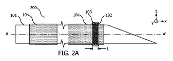
介入デバイス100、200、300は、長手軸A−A’を有する細長いシャフト101と、超音波トランスデューサ102と、接着層103と、熱収縮性材料から形成された保護チューブ104とを備える。超音波トランスデューサ102は、超音波トランスデューサ102が長手軸A−A’に沿って軸方向の広さLを有するように、細長いシャフト101上に配設される。少なくとも超音波トランスデューサ102の軸方向の広さLに沿って、保護チューブ104が超音波トランスデューサ102を囲み、接着層103が超音波トランスデューサ102と保護チューブ104との間に配設される。Intervention devices 100, 200, 300 include an elongated shaft 101 with longitudinal axes AA', an ultrasonic transducer 102, an adhesive layer 103, and a protective tube 104 formed of a heat shrinkable material. The ultrasonic transducer 102 is arranged on an elongated shaft 101 so that the ultrasonic transducer 102 has an axial width L along the longitudinal axis AA'. A protective tube 104 surrounds the ultrasonic transducer 102 and an adhesive layer 103 is disposed between the ultrasonic transducer 102 and the protective tube 104, at least along an axial width L of the ultrasonic transducer 102.
Description
本発明は、超音波トランスデューサを備える介入デバイスに関する。この介入デバイスは、医療分野における様々な介入手順で使用され得る。企図される用途の1つでは、超音波トランスデューサは、超音波イメージングプローブの超音波場に対する介入デバイスの位置を追跡するために使用される超音波検出器である。 The present invention relates to an intervention device comprising an ultrasonic transducer. This intervention device can be used in various intervention procedures in the medical field. In one of the intended applications, an ultrasonic transducer is an ultrasonic detector used to track the position of an intervention device with respect to the ultrasonic field of an ultrasonic imaging probe.
医療分野における介入手順では、患者の解剖学的構造に関するより多くの情報を得る、又は解剖学的構造を治療するために超音波を使用することがますます増えている。これに関して、超音波デバイスは、追跡、イメージング、又は治療などの感知及び作動の用途で使用するために超音波トランスデューサを具備することがあり、超音波トランスデューサは本明細書において超音波検出器、又は超音波エミッタ、又は超音波信号の検出と放出の両方を行うことが可能なデバイスと定義される。 Intervention procedures in the medical field are increasingly using ultrasound to obtain more information about the patient's anatomy or to treat the anatomy. In this regard, ultrasonic devices may be equipped with ultrasonic transducers for use in sensing and actuation applications such as tracking, imaging, or treatment, where the ultrasonic transducers are referred to herein as ultrasonic detectors, or. It is defined as an ultrasonic emitter, or device capable of both detecting and emitting ultrasonic signals.
Jay Mung、Francois Vignon、及びAmeet Jainによる文献「A Non−disruptive Technology for Robust 3D Tool Tracking for Ultrasound−Guided Interventions」(MICCAI 2011、Part I、LNCS 6891、pp.153−160、2011、A.Martel及びT.Peters(編集者))により詳細に記載される一例示的用途では、超音波検出器を医療用針に取り付け、その超音波検出器を使用して、検出器によって検出される超音波信号のタイミングに基づいてビーム形成超音波イメージングプローブの超音波場に対する針の位置を追跡する。 Jay Mung, Francois Vignon, and Ameet Jain's literature "A Non-disruptive Technology for Robust 3D Tool Tracking for Ultrasound 20Mirson10 In an exemplary application detailed by T. Peters (Editor), an ultrasonic detector is attached to a medical needle and the ultrasonic detector is used to detect an ultrasonic signal by the detector. The position of the needle with respect to the ultrasonic field of the beam-forming ultrasonic imaging probe is tracked based on the timing of.
追跡の用途で使用するために介入デバイスに超音波トランスデューサを取り付けるための別の方法が、文献WO2016207041A1に開示されている。同文献は、トランスデューサを含む周囲部内にある箔の一部を、医療デバイスや医療用針などの物品に移送するための移送スタックを記載している。移送スタックは、キャリア基板と、トランスデューサが内部に組み込まれた箔とを含み、トランスデューサは周囲部によって横方向に囲まれている。箔は、第1の剥離保持力に打ち勝つことによってキャリア基板から分離することができる。接着層も箔に取り付けられる。接着層は、この接着層を介して物品が箔に取り付けられたときに、第2の剥離保持力に打ち勝つことによって箔が物品の表面から分離可能となるように、箔と物品との間の接着を提供するように構成される。第2の剥離保持力(PRF2)は第1の剥離保持力よりも大きい。 Another method for attaching an ultrasonic transducer to an intervention device for use in tracking applications is disclosed in Ref. WO 2016207041A1. The document describes a transfer stack for transferring a portion of the foil within the perimeter, including the transducer, to an article such as a medical device or medical needle. The transfer stack includes a carrier substrate and a foil in which the transducer is incorporated, the transducer being laterally surrounded by a perimeter. The foil can be separated from the carrier substrate by overcoming the first peeling holding force. The adhesive layer is also attached to the foil. The adhesive layer is between the foil and the article so that when the article is attached to the foil through this adhesive layer, the foil can be separated from the surface of the article by overcoming the second peeling holding force. It is configured to provide adhesion. The second peel holding force (PRF2) is larger than the first peel holding force.
別の文献WO2017013224A1も、超音波に基づく追跡の目的で超音波トランスデューサを介入デバイスに取り付けることに関連する。同文献は、電気導体とトランスデューサ層との間で電気的接触がなされるトランスデューサ積層体を記載している。トランスデューサ積層体は、接着剤で被覆された2つの箔を含み、箔の接着剤被覆は、互いに向き合うように配置される。2つの電気導体の長さに沿った第1の位置において、2つの電気導体は、接着剤で被覆された2つの箔の接着剤被覆の間に挟まれていて、またトランスデューサ層も、トランスデューサ層上の電極との電気的接触がなされるように、2つの電気導体の間に挟まれている。2つの電気導体の長さに沿った第2の位置において、2つの電気導体は、接着剤で被覆された2つの箔の接着剤被覆の間に挟まれていて、2つの電気導体の間に挟まれたトランスデューサ層は存在しない。 Another document, WO20170132224A1, also relates to attaching an ultrasonic transducer to an intervention device for ultrasonic based tracking purposes. The document describes a transducer stack in which electrical contact is made between an electrical conductor and a transducer layer. The transducer laminate comprises two foils coated with an adhesive, the adhesive coatings of the foils being arranged facing each other. At the first position along the length of the two electrical conductors, the two electrical conductors are sandwiched between the adhesive coatings of the two foils coated with the adhesive, and the transducer layer is also the transducer layer. It is sandwiched between two electrical conductors so that electrical contact with the upper electrode is made. In a second position along the length of the two electrical conductors, the two electrical conductors are sandwiched between the adhesive coatings of the two foils coated with adhesive and between the two electrical conductors. There is no sandwiched transducer layer.
別の文献米国特許出願第2017/172544(A1)号は、薄膜圧電センサを備えた針に関する。センサデバイスは、複数の層を含む可撓性の平面ストリップを含む。ストリップは、医療デバイスを少なくとも部分的に封入するように構成される。ストリップは、第1の誘電層と、第1の誘電層の上に配設された導電性遮蔽層と、導電性遮蔽層の上に形成された第2の誘電層と、センサ電極、ハブ電極、及びセンサ電極とハブ電極を接続する配線を含む、パターン形成された導電性層とを含む。 Another U.S. Patent Application No. 2017/172544 (A1) relates to a needle with a thin film piezoelectric sensor. The sensor device includes a flexible planar strip containing multiple layers. The strip is configured to enclose the medical device at least partially. The strip includes a first dielectric layer, a conductive shielding layer disposed on the first dielectric layer, a second dielectric layer formed on the conductive shielding layer, a sensor electrode, and a hub electrode. , And a patterned conductive layer, including wiring connecting the sensor electrode and the hub electrode.
血管内超音波(すなわちIVUS)イメージングなどの他の例示的用途も、脈管系の画像を生成するために、カテーテルなどの介入デバイス上の1つ又は複数の超音波トランスデューサを含む。 Other exemplary applications such as intravascular ultrasound (ie IVUS) imaging also include one or more ultrasound transducers on an intervention device such as a catheter to generate images of the vasculature.
この分野における近年の進歩にも関わらず、そのような応用分野での介入デバイスへの超音波トランスデューサの取り付けを改善する余地が残っている。 Despite recent advances in this area, there remains room for improved attachment of ultrasonic transducers to intervention devices in such applications.
本発明は、介入デバイスへの超音波トランスデューサの取り付けを改良することを目的とする。この問題に対する知られている解決法のいくつかは、超音波トランスデューサの近傍への水分の侵入を来たすことがあり、それがトランスデューサ性能に影響を与える。この問題に対する他の知られている解決法は、特に超音波トランスデューサの近傍で、介入デバイスが不規則なトポロジーを有することがある。その結果、医療の専門家であるユーザが、そのような介入デバイスを身体内に挿入する際に挿入のための変動する抵抗を経験する可能性がある。 It is an object of the present invention to improve the attachment of an ultrasonic transducer to an intervention device. Some of the known solutions to this problem can result in the ingress of moisture into the vicinity of the ultrasonic transducer, which affects the transducer performance. Another known solution to this problem is that the intervention device may have an irregular topology, especially in the vicinity of the ultrasonic transducer. As a result, users who are medical professionals may experience variable resistance for insertion when inserting such an intervention device into the body.
上記の欠点の1つ又は複数に対処するために、介入デバイスが提供される。その介入デバイスを組み込む、関連する超音波に基づく位置判定システム、及び介入デバイスを製造する関連する方法も提供される。介入デバイスは、長手軸を有する細長いシャフトと、超音波トランスデューサと、接着層と、熱収縮性材料から形成された保護チューブとを備える。超音波トランスデューサは、超音波トランスデューサが長手軸に沿って軸方向の広さを有するように、細長いシャフト上に配設される。さらに、少なくとも超音波トランスデューサの軸方向の広さに沿って、保護チューブが超音波トランスデューサを囲み、接着層が超音波トランスデューサと保護チューブとの間に配設される。 Intervention devices are provided to address one or more of the above drawbacks. Also provided are relevant ultrasound-based positioning systems that incorporate the intervention device, as well as related methods of manufacturing the intervention device. The intervention device comprises an elongated shaft with a longitudinal axis, an ultrasonic transducer, an adhesive layer, and a protective tube made of heat shrinkable material. The ultrasonic transducer is arranged on an elongated shaft so that the ultrasonic transducer has an axial width along the longitudinal axis. Further, a protective tube surrounds the ultrasonic transducer and an adhesive layer is disposed between the ultrasonic transducer and the protective tube, at least along the axial width of the ultrasonic transducer.
保護チューブは、超音波トランスデューサ内への水分の侵入を低減する。また、保護チューブは、超音波トランスデューサ全体にわたってより滑らかなトポロジーももたらし、それにより身体内に介入デバイスをより滑らかに挿入できるようにする。保護チューブを熱収縮性材料から形成することにより、信頼性の高い製造方法が提供される。さらに、本発明者らは、接着層を超音波トランスデューサと保護チューブとの間に配設することにより、改善された超音波トランスデューサ性能が実現されることを発見した。そのような保護チューブが超音波トランスデューサの上に配設されるときに、通例、空気の薄い層が超音波トランスデューサと保護チューブとの間に閉じ込められることが分かっている。この空気の層は、超音波の反射体及び/又は減衰体として作用し、また保護チューブを中心とした回転に関して厚みが不規則であるために、結果として、超音波感度及び/又は放射超音波信号強度の回転変動を生じさせる可能性がある。接着層は、そのような空気の層が生じる傾向を低減し、それにより、超音波トランスデューサの感度及び/又は放射超音波信号強度、並びにそれらパラメータの回転変動性を改善する。さらに、接着層は、水分が超音波トランスデューサに到達する可能性も低減し、それは、超音波トランスデューサの性能を経時的に維持する働きをする。 The protective tube reduces the ingress of moisture into the ultrasonic transducer. The protective tube also provides a smoother topology throughout the ultrasonic transducer, thereby allowing the intervention device to be inserted more smoothly into the body. Forming the protective tube from a heat shrinkable material provides a reliable manufacturing process. Furthermore, the present inventors have found that by disposing the adhesive layer between the ultrasonic transducer and the protective tube, improved ultrasonic transducer performance is realized. It has been found that when such a protective tube is placed over the ultrasonic transducer, a thin layer of air is typically trapped between the ultrasonic transducer and the protective tube. This layer of air acts as a reflector and / or attenuator of ultrasonic waves, and is irregular in thickness with respect to rotation around the protective tube, resulting in ultrasonic sensitivity and / or radiated ultrasonic waves. It may cause rotational fluctuation of signal strength. The adhesive layer reduces the tendency of such layers of air to form, thereby improving the sensitivity and / or radiated ultrasonic signal intensity of the ultrasonic transducers, as well as the rotational variability of their parameters. In addition, the adhesive layer also reduces the likelihood of moisture reaching the ultrasonic transducer, which serves to maintain the performance of the ultrasonic transducer over time.
添付の特許請求の範囲を参照しながらさらなる態様が説明される。記載される発明からのさらなる利点も当業者には明らかになろう。 Further embodiments will be described with reference to the appended claims. Further benefits from the inventions described will also be apparent to those of skill in the art.
本発明の原理を説明するために、例示的な位置追跡の用途を特に参照して、医療用針の形態である介入デバイスが説明され、ここでは、針上の超音波検出器の位置が、ビーム形成超音波イメージングシステムの超音波場に対して判定される。しかし、本発明は、超音波イメージングや治療の用途など、超音波トランスデューサを用いる他の応用分野でも使用されることは理解されるべきである。また、超音波検出器の形態の超音波トランスデューサが参照されるが、超音波トランスデューサは、代替として、超音波エミッタ、又は実際、超音波信号の検出及び放出の両方を行うことが可能であり、又は実際、超音波エミッタ及び超音波検出器の両方を備えてもよいことも理解されるべきである。本発明は、これらに限定されないが、カテーテル、ガイドワイヤ、生検デバイス、ペースメーカの導線、静脈内ライン、又は外科用器具全般を含む、医療用針以外の介入デバイスにも用途を有する。介入デバイスは、例えば、局部麻酔のための日常的な針の挿入から、癌の生検及び経皮アブレーション、並びにより高度な介入手順にわたる、幅広い医療手順で使用される。 To illustrate the principles of the invention, intervention devices in the form of medical needles are described with particular reference to exemplary position tracking applications, where the position of the ultrasonic detector on the needle is described. Beam formation Determined for the ultrasonic field of the ultrasonic imaging system. However, it should be understood that the present invention is also used in other applications using ultrasonic transducers, such as ultrasonic imaging and therapeutic applications. Also referred to is an ultrasonic transducer in the form of an ultrasonic detector, which, as an alternative, can either be an ultrasonic emitter or, in fact, both detect and emit an ultrasonic signal. Or, in fact, it should be understood that both an ultrasonic emitter and an ultrasonic detector may be provided. The present invention also has applications for intervention devices other than medical needles, including, but not limited to, catheters, guide wires, biopsy devices, pacemaker leads, intravenous lines, or surgical instruments in general. Intervention devices are used in a wide range of medical procedures, from routine needle insertion for local anesthesia, to cancer biopsy and percutaneous ablation, as well as more advanced intervention procedures.
図1は、超音波トランスデューサ102と接着層103とを含む介入デバイス100の正射影図を示す。介入デバイス100は、長手軸A−A’を有する細長いシャフトを有する。超音波トランスデューサ102は、超音波トランスデューサ102が長手軸A−A’に沿って軸方向の広さLを有するように、細長いシャフト101上に配設される。さらに、少なくとも超音波トランスデューサ102の軸方向の広さLに沿って、保護チューブ104が超音波トランスデューサ102を囲み、接着層103が、超音波トランスデューサ102と保護チューブ104との間に配設される。保護チューブ104は、熱収縮性材料から形成される。
FIG. 1 shows a normal projection view of an
好ましい一実施態様では、超音波トランスデューサ102は圧電材料から形成される。様々ないわゆる硬質又は軟質の圧電材料が使用され得る。圧電材料は、例えば、ポリフッ化ビニリデン、すなわちPVDFなどのポリマー、ポリフッ化ビニリデントリフルオロエチレン(P(VDF−TrFE))層などのPVDFコポリマー、又はP(VDF−TrFE−CTFE)などのPVDFターポリマーである。適切なPVDFポリマーの例示的供給者の1つは、英国ケンブリッジのGoodfellowである。代替として、超音波トランスデューサ102は、静電容量型微小機械超音波トランスデューサ、すなわちCMUTデバイスであってもよい。好ましい一例では、超音波トランスデューサ102は単一のトランスデューサを備えるが、2つ以上のそのようなトランスデューサの配列の使用も企図される。
In a preferred embodiment, the
図1の接着層103として使用するために様々な接着剤材料が企図される。EPO−TEK301を含むエポキシなどの接着剤が例えば使用され、またUV硬化性接着剤の使用も企図される。好ましい一実施態様では、接着層103は、感圧接着剤、すなわちPSAによって提供される。感圧接着剤は、圧力を加えられると接着結合を形成する部類の材料である。利点として、感圧接着剤は、熱収縮性保護チューブ104が収縮すると確実な結合をもたらし、それにより、迅速に組み立てられる堅牢な構造をもたらす。適切な感圧接着剤としては、3M Corporationによって製造される製品8211CLがある。それらは、3M Corporationによって供給される製品9019のように、PSA被覆ポリマーシート、すなわち箔として供給されることがある。片面又は両面にPSAを備える箔が入手可能である。PSA被覆ポリマーシートは、通常、接着剤被覆を露出させるために剥離される取り外し可能な除去層を備え、それにより、接着層の接着性が必要とされるまで接着層を保護する。箔は、各種のポリマー材料、例えば、ポリエチレンテレフタレート(PET)、ポリイミド(PI)、又はポリアミド(PA)から形成される。通常、箔は、電気絶縁材料から形成される。
Various adhesive materials are contemplated for use as the
様々な熱収縮性材料が、保護チューブ104として使用するのに企図される。PVDF、HDPE、LDPE、EMAを含む、ポリオレフィン及びフルオロポリマーが、企図される材料の中に含まれる。保護チューブ104に適する材料としては、米国コロラド州のNordson Medicalによって提供されるポリエステル(PET)材料、及び米国のRaychem Corporationによって供給される製品MT5500がある。
Various heat shrinkable materials are intended for use as
図1に示す例示的介入デバイス100では、細長いシャフト101は医療用針によって提供される。超音波トランスデューサ102は、針の遠位端に、針の斜端に隣接して配設される。後で説明するように、この位置は、針の先端の位置を追跡するために選択されるが、この位置及び医療用針自体は例示に過ぎない。別の実施態様では、超音波トランスデューサ102は代替として、遠位端、すなわち斜端を有する端部よりも、細長いシャフト101の近位端に近い。
In the
図1に示す例示的介入デバイス100では、超音波トランスデューサ102は、長手軸A−A’に沿って軸方向の広さLを有するパッチの形態で示されている。トランスデューサの他の形状も企図される。さらに、少なくとも超音波トランスデューサ102の軸方向の広さLに沿って、保護チューブ104が超音波トランスデューサ102を囲み、接着層103が、超音波トランスデューサ102と保護チューブ104との間に配設される。図1では、細長いシャフト101の長さ全体に沿って滑らかな外側表面を提供するために、細長いシャフト101の長さのかなりの部分が保護チューブ104によって覆われるものとして示されているが、これは純粋に説明のためである。しかし、保護チューブ104は、超音波トランスデューサ102への水分の侵入に対する良好な封止を提供するために、超音波トランスデューサ102の軸方向の広さLを超えて一方の方向又は両方向に軸方向に延在することが好ましい。さらに、接着層103は、超音波トランスデューサ102の軸方向の広さにのみ沿っているものとして示されている。他の実施態様では、接着層103は、超音波トランスデューサ102の軸方向の広さLを超えて一方の方向又は両方向に軸方向に延在し、これは位置合わせの許容誤差を緩和するのに有利である。したがって、図示されるように、接着層103は、保護チューブ104の軸方向の広さ以内にあり且つ保護チューブ104の軸方向の広さのうちわずかな部分のみを形成する軸方向の広さを有する。これにより、保護チューブ104の取り付けを簡素化しつつ、超音波トランスデューサ102の上方に空気の層が生じる傾向を低減する。
In the
1つの例示的な製作工程では、図1の介入デバイス100は、まず超音波トランスデューサ102を細長いシャフト101上に配設することによって作られる。この目的に接着剤が使用され、又はファン・デル・ワールス力を介した取り付けで十分である。接着層103は、その後、液体の形態で超音波トランスデューサ102の外側表面に適用される。その後、保護チューブ104が、超音波トランスデューサ102に重ねて細長いシャフト101上に配置され、保護チューブ104を径方向に収縮させるために加熱される。その後、例えば、所定の時間が経過するのを待つことにより、又は加熱により、又はUV硬化接着剤が使用される場合には接着剤をUV照射にさらすことにより、接着剤を硬化させる。
In one exemplary manufacturing process, the
代替の例示的製作工程では、感圧接着剤が接着層103として使用される。超音波トランスデューサ102を細長いシャフト101に取り付けた後に、PSAの層が、例えば、超音波トランスデューサ102の外側表面に置かれる。代替として、超音波トランスデューサ102は、それを細長いシャフト101に取り付ける前に、両面にPSAを有するPSA被覆箔の一部分に取り付けられる。保護チューブ104に熱を印加すると、保護チューブが収縮するのに伴って保護チューブ104の内側表面が一番外側のPSA層に取り付けられた状態になる。
In an alternative exemplary manufacturing process, a pressure sensitive adhesive is used as the
図2は、帯の形態の超音波トランスデューサ102と、接着層103とを含む介入デバイス200の正射影図を示す。図2の特徴の参照は、図1との関係で説明された特徴と同じ意味を有する。図2では、超音波トランスデューサ102は、細長いシャフトの長手軸A−A’の周りに巻き付けられた帯の形態で介入デバイス上に配設される。帯は、切れ目がなく、長手軸A−A’に対して垂直な平面内にあるものとして示されるが、代替としてその外周の周りに1つ又は複数の隙間を有してもよい。さらに、帯は、代替として、長手軸A−A’に垂直な平面に対して傾斜していてもよい。図1との関連で説明した製作工程は、図2のデバイスを作るためにも使用されてよい。図1の利点に加えて、図2の超音波トランスデューサ102は、細長いシャフト101の長手軸A−A’を中心とした超音波感知及び/又は放出を可能にする。
FIG. 2 shows a normal projection view of an
図9及び図10は、図2に示される介入デバイス200の中で接着層103を使用することの利益を示す。それに加えて、図9は、接着層が一切存在しない状態で介入デバイスの周りに巻き付けられた2つの実験的超音波トランスデューサN121−15及びN121−22について、任意の単位における感度測定値と、度の単位における角度位置との対比を示す。図10は、接着層の存在下で介入デバイスの周りに巻き付けられた2つの実験的超音波トランスデューサN126−9及びN126−13について、任意の単位における感度測定値と、度の単位における角度位置との対比を示す。図9及び図10に示す各感度測定で使用された超音波トランスデューサは、図2に示すように、帯の形態で針N121−15、N121−22、N126−9及びN126−13の各々の周りに巻き付けられたPVDF箔であった。図9に見られるように、接着層が存在しない場合には、回転角度に伴う感度の大きな変動が、針N121−15、N121−22の各々に観察される。絶対感度と感度変動の低減との両方における著しい改善が、図10の針N126−9及びN126−13についての結果にて示され、接着層103の利益を明らかにしている。
9 and 10 show the benefits of using the
図3は、帯の形態の超音波トランスデューサ102と、接着層103と、電気的遮蔽層105とを含む介入デバイス300の正射影図を示す。図3の特徴の参照は、図2との関係で説明された特徴と同じ意味を有する。図2の特徴に加えて、図3は、超音波トランスデューサ102と保護チューブ104との間に配設された電気的遮蔽層105を含む。電気的遮蔽層105は銅や金などの導体から形成され、代替としてメッシュの形態であってもよい。電気的遮蔽層105は、超音波トランスデューサ102、及び、存在し得るそれに接続された電気導体(図3には図示せず)を電気的に遮蔽する働きをし、それにより電磁気干渉を低減する。また、電気絶縁体層106も、図3に示されるように、超音波トランスデューサ102と遮蔽層105との間に配設される。電気絶縁体層106は、超音波トランスデューサ102を遮蔽層105から電気的に絶縁する働きをする。絶縁体層106は、ポリマー、又はポリエチレンテレフタレート(PET)、ポリイミド(PI)、又はポリアミド(PA)などの絶縁体から形成される。電気的遮蔽層105及び電気絶縁体層106は、図1の介入デバイス100と同じ要領で使用されてよい。
FIG. 3 shows a normal projection view of an
超音波トランスデューサ102を介入デバイスに取り付ける別の企図される方法は、超音波トランスデューサ102をトランスデューサストリップとして提供し、これを、介入デバイス200の細長いシャフト101の周りに螺旋の形態で巻き付けるものである。それに加えて、図4は、介入デバイス200の正射影図を示し、ここでは、超音波トランスデューサ102は、介入デバイス200の細長いシャフト101の周りに螺旋の形態で巻き付けられたトランスデューサストリップ410によって提供される。接着層103及び保護チューブ104は、図示を容易にするために図4から省略されているが、図2との関連で説明したのと同じ要領で適用されてよい。そのようなトランスデューサストリップを使用すると、利点として、特に、図4には図示されないトランスデューサストリップ410中の電気導体も、介入デバイス200の細長いシャフト101の周りに螺旋の形態で巻き付けられる場合に、介入デバイスに滑らかな外形が得られる。この方法において使用するための例示的トランスデューサストリップ410が図5及び図6に示される。
Another contemplated method of attaching the
図5は、超音波トランスデューサ102と接着層103とを含むトランスデューサストリップ410を示す。長斜方形形状として示される超音波トランスデューサ102及び接着層103のための支持体は、ポリエチレンテレフタレート(PET)、ポリイミド(PI)、又はポリアミド(PA)などのポリマーフィルムによって提供される。本明細書に記載されるPSA被覆箔の形態のポリマーフィルムが、例えばこの支持体を提供することができる。図4の配置は、図4の例示的トランスデューサストリップ410を、図4に示されるように螺旋の形態で細長いシャフト101の周りに巻き付けることによって得られる。
FIG. 5 shows a
図5を参照すると、トランスデューサストリップ410は、第1の縁部111及び反対側の第2の縁部112を含み、それらの縁部は幅寸法Wだけ離れている。第1の縁部111及び第2の縁部112は各々、トランスデューサストリップ410の長さ方向113に沿って延びている。長さ方向113は、幅寸法Wが測定される方向に対して直交する。トランスデューサストリップ410は、トランスデューサ方向114に沿って延びる超音波トランスデューサ102を含む。トランスデューサ方向114は、トランスデューサストリップ410の長さ方向113に対して鋭角αをなす。さらに、接着層103は、超音波トランスデューサ102を覆う。図5の例示的トランスデューサストリップ410が、図4の介入デバイス200の細長いシャフト101の周りに螺旋の形態で巻き付けられたとき、超音波トランスデューサ102は、細長いシャフト101の周りに帯を形成する。
Referring to FIG. 5, the
任意選択で、図5における幅寸法Wは、螺旋の連続した巻きの隣接する第1及び第2の縁部111、112が互いと当接する又は重なり合うように定義されてよい。
Optionally, the width dimension W in FIG. 5 may be defined such that adjacent first and
螺旋の連続した巻きが互いと当接する、すなわちちょうど触れ合うためには、以下の式が満たされなければならない。
W=π・D・Sin(α) 式1
In order for the continuous windings of the spirals to abut, or just touch, each other, the following equation must be satisfied.
W = π ・ D ・ Sin (α)
ここで、αは、長さ方向113に対してトランスデューサ方向114によって定義される鋭角であり、Dは、細長いシャフト101の直径である。Wが上記値を超えるようにすることにより、螺旋の連続した巻きが互いと重なり合う。同様に、Wがこの値未満になるようにすることにより、螺旋の連続した巻き同士の間に小さな隙間が設けられる。
Here, α is an acute angle defined by the
図4の螺旋巻き付けの配置は、超音波トランスデューサ102を細長いシャフト101に取り付ける簡易な方法を提供する。介入デバイスは、例えば、図8を参照して後で説明されるように、トランスデューサストリップにわたって転がされ、接着剤を用いて介入デバイスに取り付けられる。隣接する巻き同士の当接又は重なり合いは、それぞれ、滑らかな外側表面を介入デバイス110に提供し、それにより身体内に挿入するための抵抗を下げ、巻き付けられたトランスデューサストリップの下にある材料の露出を回避するように働く。
The spiral winding arrangement of FIG. 4 provides a simple method of attaching the
よって、図4及び図5は併せて、超音波トランスデューサ102及び接着層103がトランスデューサストリップ410によって提供される介入デバイス300を示している。トランスデューサストリップ410は、超音波トランスデューサ102と、接着層103と、第1の縁部111及び反対側の第2の縁部112とを含み、第1の縁部111及び第2の縁部112は幅寸法Wだけ離れていて、第1の縁部111及び第2の縁部112は各々、トランスデューサストリップ410の長さ方向113に沿って延びている。超音波トランスデューサ102は、トランスデューサストリップ410上に配設され、トランスデューサストリップ410の長さ方向113に対して鋭角αをなすトランスデューサ方向114に沿って延びている。接着層103は、超音波トランスデューサ102を覆う。トランスデューサストリップ410は、超音波トランスデューサ102が細長いシャフト101の周りに帯を形成するように、介入デバイス200の細長いシャフト101の周りに螺旋の形態で巻き付けられる。
Thus, FIGS. 4 and 5 together show the
図6は、第1の電気導体115、第2の電気導体116、第1の電極117、及び第2の電極118を含むトランスデューサストリップ410の様々な図を示す。図6Aは平面図を示し、図6BはB−B’に沿った断面を示し、図6CはC−C’に沿った断面を示し、図6DはB−B’に沿った分解断面を示し、図6EはC−C’に沿った分解断面を示す。図6のトランスデューサストリップ410は、図5のものの代替であり、同じように介入デバイス200の細長いシャフト101の周りに螺旋の形態に巻き付けられる。図5の要素に加えて、図6は、第1の電気導体115及び第2の電気導体116を含む。第1の電気導体115及び第2の電気導体116は各々、トランスデューサストリップ410の長さ方向113に沿って延びている。さらに、超音波トランスデューサ102は、第1の電極117及び第2の電極118をさらに含む。第1の電気導体115は、第1の電極117と電気的に接触していて、第2の電気導体116は第2の電極118と電気的に接触していて、それにより、トランスデューサストリップ410が図4に示されるように介入デバイス200の細長いシャフト101の周りに螺旋の形態で巻き付けられたとき、第1の電気導体115及び第2の電気導体116は、超音波トランスデューサ102に対して細長いシャフト101に沿って軸方向に離れた位置で超音波トランスデューサ102と電気的に接触するために、各々細長いシャフト101に沿って延びる。
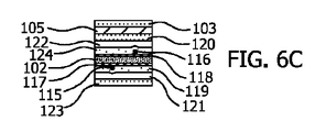
FIG. 6 shows various diagrams of a
図6B〜図6Eの分解図に示すように、トランスデューサストリップ410は様々な積層箔を備える。これにより簡易な製造技術がもたらされる。それに加えて、第1の位置B−B’に、図6B及び図6Dは、各面に感圧接着剤の層119、123(PSA)を備える第1の箔ストリップ121と、第1の電気導体115と、第2の電気導体116と、接着層103と、各面に感圧接着剤の層120、124(PSA)を備える第2の箔ストリップ122と、電気的遮蔽層105とを含む。第1の箔ストリップ121及び第2の箔ストリップ122は、第1の電気導体115及び第2の電気導体116を挟むように配置され、電気的遮蔽層105は、第2の箔ストリップ122の外側向きのPSA層124上に配設される。第2の位置C−C’に、図6C及び図6Eはさらに、その各面に第1の電極117及び第2の電極118を有する超音波トランスデューサ102を含む。第2の位置C−C’において、第1の電極117及び第2の電極118を有する超音波トランスデューサ102は、第1の箔ストリップ121のPSA層119と第2の箔ストリップ122のPSA層124との間に挟まれ、それにより、第1の電気導体115と第1の電極117との間、及び第2の電気導体116と第2の電極118との間で電気的接触がなされる。
As shown in the exploded views of FIGS. 6B-6E, the
代替の巻き付け実施態様では、介入デバイスが、長手軸を有する細長いシャフトと、超音波トランスデューサと、接着層と、熱収縮性材料から形成された保護チューブとを含む。超音波トランスデューサは、超音波トランスデューサが長手軸に沿って軸方向の広さを有するように、細長いシャフト上に配設される。少なくとも超音波トランスデューサの軸方向の広さに沿って、保護チューブが超音波トランスデューサを囲み、接着層が超音波トランスデューサと保護チューブとの間に配設され、それにより、接着層が保護チューブの内側面に接着する。さらに、この実施態様では、超音波トランスデューサ及び接着層がトランスデューサストリップによって提供される。トランスデューサストリップは、超音波トランスデューサと、接着層と、第1の縁部及び反対側の第2の縁部とを備え、第1の縁部と第2の縁部とは幅寸法だけ離れていて、第1の縁部及び第2の縁部は各々、トランスデューサストリップの長さ方向に沿って延びている。超音波トランスデューサは、トランスデューサストリップ上に配設され、トランスデューサストリップの長さ方向に対して垂直であるトランスデューサ方向に沿って延びる。接着層は、超音波トランスデューサを覆う。さらに、トランスデューサストリップは、第1の縁部が細長いシャフトの長手軸と平行になるように、且つ超音波トランスデューサが細長いシャフトの周りに帯を形成するように、介入デバイスの細長いシャフトの周りに巻きつけられる。第1の縁部を細長いシャフトの長手軸と平行に配置することにより、介入デバイスの細長いシャフトへのトランスデューサストリップの取り付けが簡素化される。任意選択で、幅寸法は、この実施態様において、第1の縁部及び第2の縁部が互いと当接する又は重なり合うように定義されてよい。隣接する巻き同士の当接又は重なり合いは、巻き付けられたトランスデューサストリップの下にある材料の露出を回避する働きをする。この実施態様では、介入デバイスは、トランスデューサストリップを介入デバイスに取り付けるために、トランスデューサストリップにわたって転がされてもよい。この代替の巻き付け実施態様で使用される用語「平行」及び「垂直」は、厳密に平行又は厳密に垂直から3度以内にある配置を含むものと解釈すべきである。 In an alternative wrapping embodiment, the intervention device comprises an elongated shaft with a longitudinal axis, an ultrasonic transducer, an adhesive layer, and a protective tube made of heat shrinkable material. The ultrasonic transducer is arranged on an elongated shaft so that the ultrasonic transducer has an axial width along the longitudinal axis. A protective tube surrounds the ultrasonic transducer, at least along the axial width of the ultrasonic transducer, and an adhesive layer is placed between the ultrasonic transducer and the protective tube so that the adhesive layer is inside the protective tube. Adhere to the side. Further, in this embodiment, the ultrasonic transducer and the adhesive layer are provided by a transducer strip. The transducer strip comprises an ultrasonic transducer, an adhesive layer, a first edge and a second edge on the opposite side, with the first edge and the second edge separated by a width dimension. , The first edge and the second edge each extend along the length of the transducer strip. The ultrasonic transducer is disposed on the transducer strip and extends along the transducer direction perpendicular to the length direction of the transducer strip. The adhesive layer covers the ultrasonic transducer. In addition, the transducer strip is wound around the elongated shaft of the intervention device so that the first edge is parallel to the longitudinal axis of the elongated shaft and the ultrasonic transducer forms a band around the elongated shaft. Can be attached. Placing the first edge parallel to the longitudinal axis of the elongated shaft simplifies the attachment of the transducer strip to the elongated shaft of the intervention device. Optionally, the width dimension may be defined in this embodiment such that the first and second edges abut or overlap each other. The contact or overlap between adjacent windings serves to avoid exposure of the material beneath the wound transducer strips. In this embodiment, the intervention device may be rolled across the transducer strip to attach the transducer strip to the intervention device. The terms "parallel" and "vertical" as used in this alternative winding embodiment should be construed to include configurations that are strictly parallel or within 3 degrees of exactly vertical.
上述のように、本明細書に記載される介入デバイスは、例えば超音波に基づく追跡の用途に使用される。その場合、超音波トランスデューサは、超音波信号を検出する、又は放出する、又は検出と放出の両方を行い、超音波トランスデューサの位置は、したがって、超音波検出器102とビーム形成超音波イメージングシステムとの間で送信される超音波信号に基づいて判定される。
As mentioned above, the intervention devices described herein are used, for example, in ultrasound-based tracking applications. In that case, the ultrasonic transducer detects or emits an ultrasonic signal, or both detects and emits, and the position of the ultrasonic transducer is therefore with the
それに加えて、図7は、介入デバイスを含む、例示的な超音波に基づく位置判定システム700を示す。図7で、超音波に基づく位置判定システム700は、ビーム形成超音波イメージングプローブ730を含み、イメージングプローブ730は、画像再構成ユニット732、イメージングシステムプロセッサ736、イメージングシステムインターフェース735及びディスプレイ734と通信する。ユニット730、732、734、735及び736は共に、従来の超音波イメージングシステムを形成する。ユニット732、734、735及び736は、従来、ビーム形成超音波イメージングプローブ730と有線又は無線通信するコンソール内に位置する。ユニット732、734、735及び736の一部は、代替として、例えばPhilips Lumify超音波イメージングシステムのように、ビーム形成超音波イメージングプローブ730の内部に組み込まれてもよい。ビーム形成超音波イメージングプローブ730は、超音波場731を生成する。図7には、関心領域ROIに交差する超音波場731の中で超音波エネルギーを送信及び受信する線形超音波トランシーバ配列を含む2Dビーム形成超音波イメージングプローブ730が示されている。超音波場は、図7では扇型であり、図示される画像面を共に提供する複数の超音波ビームB1..kを含む。図7は扇型のビームを示すが、本発明は、特定の形状の超音波場、又は実際、平面の超音波場に限定されないことに留意されたい。ビーム形成超音波イメージングプローブ730は、超音波信号を生成し、超音波ビームB1..k中の超音波信号を検出するために、送信又は受信する信号の位相を増幅する及び/又は調整するように構成された、図示されない電子ドライバ及び受信器回路も含む。
In addition, FIG. 7 shows an exemplary ultrasound-based
使用中、上記で説明した従来の超音波イメージングシステムは、以下のように操作される。作業者が、イメージングシステムインターフェース735を介して超音波手順を計画する。操作手順が選択されると、イメージングシステムインターフェース735がイメージングシステムプロセッサ736をトリガして、ビーム形成超音波イメージングプローブ730に対して送信される信号を生成し、プローブ730によって検出された信号を解釈する、特定用途向けプログラムを実行させる。そのようなプログラムを記憶するために、図示されないメモリが使用される。メモリは、例えば、ビーム形成超音波イメージングプローブ730によって送信及び/又は受信される一連の超音波信号を制御するように構成された超音波ビーム制御ソフトウェアを記憶する。画像再構成ユニット732の機能は、代替としてイメージングシステムプロセッサ736によって実行されてもよい。画像再構成ユニット732は、ビーム形成超音波イメージングプローブ730の超音波場731に対応する再構成超音波画像を提供する。画像再構成ユニット732は、したがって、超音波場731によって定められ、関心領域ROIに交差する画像面に対応する画像を提供する。画像は、その後ディスプレイ734に表示される。再構成画像は、例えば、「2Dモード」画像としても知られる超音波輝度モード「Bモード」画像、「Cモード」画像若しくはドップラーモード画像、又は実際どのような超音波画像でもよい。
During use, the conventional ultrasonic imaging system described above is operated as follows. The operator plans the ultrasonic procedure via the
図7には、圧電トランスデューサ102を含む、医療用針によって例示される介入デバイス100も示される。介入デバイスのこの例示的用途では、介入デバイス100、より具体的にはその上に配設された超音波トランスデューサ102が、位置判定ユニット733によって提供される信号に基づいて超音波場731に対して追跡される。位置判定ユニットは、相互を接続するリンクによって示されるように、ユニット730、732、734、735及び736、すなわち従来の超音波イメージングシステムと通信する。位置判定ユニット733は、超音波トランスデューサ102とも通信し、この通信は例えば有線又は無線である。位置判定ユニット733の機能は、実施態様によっては、従来の超音波イメージングシステムのプロセッサによって実行される。
FIG. 7 also shows an
使用中、超音波トランスデューサ102の位置は、ビーム形成超音波イメージングプローブ730と超音波トランスデューサ102との間で送信される超音波信号に基づいて、位置判定ユニット733により超音波場731に対して算出される。
During use, the position of the
一構成では、超音波トランスデューサ102は、ビームB1..kに対応する超音波信号を受信する検出器である。位置判定ユニット733は、圧電トランスデューサ102によって検出された超音波信号を比較することによって、超音波トランスデューサ102の位置を特定する。位置判定ユニット733は、その後、算出された超音波トランスデューサ102の位置に基づいて再構成超音波画像中にアイコンを提供する。より具体的には、比較は、i)超音波トランスデューサ102によって検出される各ビームB1..kに対応する超音波信号の振幅に基づいて、及びii)各ビームB1..kの放出と、超音波トランスデューサ102によるその検出との間の時間遅延、すなわち飛行時間に基づいて、超音波場731に対する超音波トランスデューサ102の最適位置を決定する。これは次のように説明される。超音波トランスデューサ102が超音波場731の近傍にあるとき、ビームB1..kのうちトランスデューサに最も近いものからの超音波信号は、相対的に大きい振幅をもって検出されるのに対し、より遠いビームは、相対的に小さい振幅をもって検出される。通例、最も大きい振幅をもって検出されるビームが、超音波トランスデューサ102に最も近いビームとして特定される。このビームは、ビーム形成超音波イメージングプローブ730と超音波トランスデューサ102との間の面内角度θIPAを定める。それに対応する範囲は、最も大きい振幅のビームB1..kの放出と、その後のその検出との間の時間遅延、すなわち飛行時間に依存する。この範囲は、時間遅延に超音波伝搬の速度を乗算することによって決定される。したがって、最も大きい振幅をもって検出されるビームの範囲及び対応する面内角度θIPAを使用して、超音波場731に対する超音波トランスデューサ102の最適位置を特定することができる。
In one configuration, the
上記の例では、超音波ビームB1..kは、イメージングビームである。別の構成では、超音波ビームB1..kは、ビーム形成超音波イメージングプローブ730によって、所定の方向に連続するイメージングフレーム間の追跡フレーム内で放出される専用の追跡ビームである。
In the above example, the ultrasonic beam B 1. .. k is an imaging beam. In another configuration, the ultrasonic beam B 1. .. reference numeral k is a dedicated tracking beam emitted by the beam forming
さらに別の構成では、超音波トランスデューサ102は、1つ又は複数の超音波パルスを放出するエミッタである。そのようなパルスは、例えば、従来の超音波イメージングシステムの連続するイメージングフレームの間に交互に配置される追跡フレーム中に放出される。そのような追跡フレーム内では、ビーム形成超音波イメージングプローブ730は、超音波場731の近傍から発する超音波信号をリッスンする受信専用モードで動作する。ビーム形成超音波イメージングプローブ730は、したがって、そのような追跡フレームの間は一方向の受信専用ビームフォーマとして構成される。位置判定ユニット733は、ビーム形成超音波イメージングプローブ730の受信器要素に遅延を適用することにより、仮想ビームB1..kのうちどのビームからパルスが発したのかを特定する。遅延は、仮想ビームB1..kの各々に対応する。上記の超音波検出器構成の場合と同様に、位置判定ユニット733は、最大振幅及び飛行時間に基づいて、超音波信号が放出された位置に最も近いビームB1..kを特定する比較手順を使用する。位置判定ユニット733は、その後、特定された超音波トランスデューサ102の位置に基づいて、再構成超音波画像中にアイコンを提供する。
In yet another configuration, the
別の構成では、超音波トランスデューサ102は、受信器及びエミッタの両方として動作するように構成される。この構成では、超音波トランスデューサ102は、ビーム形成超音波イメージングプローブ730から超音波信号を受信すると1つ又は複数の超音波パルスを放出するようにトリガされる。そのようにして、イメージングモード中に超音波トランスデューサ102によって放出されたパルスは、ビーム形成超音波イメージングプローブ730によって受信され、再構成された超音波内で、関連するビームB1..kに対応する面内角度位置、すなわち画像線において、エコーとして見える。超音波トランスデューサ102は、したがって、再構成画像の中で明るい点として見える。位置判定ユニット733は、その後、再構成画像の中でこの明るい点を特定し、したがって、超音波場731に対する超音波トランスデューサ102の位置を算出する。
In another configuration, the
上記で説明した超音波に基づく位置判定システム730では、介入デバイスの回転角度に対する、圧電トランスデューサ102の感度プロファイル、若しくは放出プロファイルの依存性、又はより具体的にはその大きさ及び/又は依存性が、超音波場731に対する位置決めに影響する。それに加えて、上記で説明した介入デバイスの使用は、向上した信頼性及び感度という利益を有する。
In the ultrasonic-based
例示されたビーム形成超音波イメージングプローブ730は、介入デバイス100が使用されるビーム形成超音波イメージングシステムの一例に過ぎないことが理解されるべきである。介入デバイス100は、他の種類の2D又は3Dビーム形成超音波イメージングシステムを含む、超音波に基づく位置判定システムにも応用可能である。それらには、例えば、「TRUS」経直腸超音波検査プローブ、「IVUS」血管内超音波プローブ、「TEE」経食道プローブ、「TTE」経胸壁プローブ、「TNE」経鼻プローブ、「ICE」心臓内プローブが含まれる。さらに、介入デバイス100は、位置の追跡以外の医療分野における他の感知及び作動用途にも応用可能であることが理解されるべきである。
It should be understood that the exemplified beam-forming
図8は、図8Aに、介入デバイスの細長いシャフト101を、超音波トランスデューサ移送スタック840にわたって転がすこと(842)によって、介入デバイス100、200、300を製造する方法を示し、図8Bに、D−D’に沿ったスタックの断面端面図を示し、図8Cに、E−E’に沿ったスタックの断面端面図を示している。図8中の要素は、図6の同じ参照符号の要素に対応している。図8は、加えて基板801を含み、これは、例えばガラスやプラスチックから形成され、スタックがその上に構築される層の役割を果たす。さらに、図8では、トランスデューサ移送スタック840は、図6のものとは逆の順序で示されている。これは、図8は、細長いシャフト101に移送される前の、すなわち接着層103が基板841に隣接している状態の、スタックを示しているためである。
FIG. 8 shows how the
それに加えて、図8を参照すると、介入デバイス100、200、300を製造する方法は、
超音波トランスデューサ移送スタック840を用意するステップを有し、超音波トランスデューサ移送スタック840は、
基板841と、
感圧接着剤119、123、すなわちPSA、の層を各表面に備える第1の箔ストリップ121と、
超音波トランスデューサ102と、
接着層103と、
感圧接着剤120、124、すなわちPSA、の層を各表面に備える第2の箔ストリップ122と、
電気的遮蔽層105とを備える。
In addition, referring to FIG. 8, the method of manufacturing the
The ultrasonic
A
A
It is provided with an
電気的遮蔽層105、第1の箔ストリップ121、超音波トランスデューサ102及び第2の箔ストリップ122は、基板841上に層状に配置され、それにより、トランスデューサ移送スタック840に沿った第1の位置D−D’において、電気的遮蔽層105が基板841と第2の箔ストリップ122との間に配設され、第1の箔ストリップ121が、第1の箔ストリップ121のPSA層123の一方が基板841に対して外側を向いた状態で、第2の箔ストリップ122の上に配置され、及び、トランスデューサ移送スタック840に沿った第2の位置E−E’において、接着層103が基板841と電気的遮蔽層105との間に配設され、第2の箔ストリップ122が電気的遮蔽層105の上に配置され、超音波トランスデューサ102が第2の箔ストリップ122の上に配置され、第1の箔ストリップ121が、第1の箔ストリップ121のPSA層123の一方が基板841に対して外側を向いた状態で、超音波トランスデューサ102の上に配置される。
The
方法はまた、介入デバイス100、200、300の細長いシャフト101を、第1の箔ストリップ121の外側向きのPSA層123にわたって転がすステップ(842)であって、それにより、第1の箔ストリップ123の外側向きのPSA層が細長いシャフト101に接着し、且つ、第1の箔ストリップ121及び超音波トランスデューサ102及び接着層103及び第2の箔ストリップ122及び電気的遮蔽層105が、接着層103が細長いシャフト101に対して外側を向いた状態で、細長いシャフト101に取り付けられた状態になる、転がすステップを有する。
The method is also a step (842) of rolling the
方法はまた、熱収縮性材料を備える保護チューブ104を、少なくとも超音波トランスデューサ102を覆うように細長いシャフト101の一部分の上に配置するステップと、保護チューブ104に熱を印加するステップであって、それにより、保護チューブ104が細長いシャフト101の長手軸A−A’に対して径方向に収縮し、且つ接着層103が保護チューブ104の内側面に接着する、熱を印加するステップと、を有する。
The method also comprises placing a
図8には図示していないが、基板841と超音波トランスデューサ移送スタック840との間に配設された除去層が追加的にあってもよい。これは、接着層103を基板841から除去する助けとなる。代替として、PSA層123及び接着層103の相対強度は、層103が転がすステップ842の間に除去されることを確実にするように指定される。さらに、図示されるように、転がすステップ842の前に、箔が細長いシャフトの周りに螺旋の形態で巻き付けられるように、ストリップ121、122が細長いシャフト101の長手軸に対してある角度で配置される。第1の箔ストリップ121及び第2の箔ストリップ122は、図示されるように、好ましくは、長さ方向及び幅方向を有する細長いストリップの形態であり、長さが幅よりも大きい。接着層103は、図1との関連で上記で説明されたように提供される。好ましくは、接着層103は、感圧接着剤(PSA)層を備える。さらに、図8B及び図8Cに示すように、超音波トランスデューサ移送スタック840はさらに、第1の位置D−D’及び第2の位置E−E’の両方に、第1の箔ストリップ121と第2の箔ストリップ122との間に配設された第1の電気導体115及び第2の電気導体116を備え、第1の電気導体115及び第2の電気導体116は、超音波トランスデューサ102と電気的に接触している。
Although not shown in FIG. 8, there may be an additional removal layer disposed between the
要約すると、介入デバイスが提供された。介入デバイス100、200、300は、長手軸A−A’を有する細長いシャフト101と、超音波トランスデューサ102と、接着層103と、熱収縮性材料から形成された保護チューブ104とを含む。超音波トランスデューサ102は、超音波トランスデューサ102が長手軸A−A’に沿って軸方向の広さLを有するように、細長いシャフト101上に配設される。少なくとも超音波トランスデューサ102の軸方向の広さLに沿って、保護チューブ104が超音波トランスデューサ102を囲み、接着層103が超音波トランスデューサ102と保護チューブ104との間に配設される。
In summary, an intervention device was provided. The
様々な実施形態及び代替形態が介入デバイスとの関連で説明されたが、様々な実施形態を組み合わせてさらなる有利な効果を実現することが可能であることに留意されたい。特許請求の範囲内に参照符号がある場合、本発明の範囲を制限するものと解釈すべきでない。 Although various embodiments and alternatives have been described in the context of intervention devices, it should be noted that it is possible to combine various embodiments to achieve further beneficial effects. The presence of reference numerals within the claims should not be construed as limiting the scope of the invention.
Claims (17)
超音波トランスデューサと、
接着層と、
熱収縮性材料から形成された保護チューブと、を備える介入デバイスであって、
前記超音波トランスデューサは、前記超音波トランスデューサが前記長手軸に沿って軸方向の広さを有するように、前記細長いシャフト上に配設され、
少なくとも前記超音波トランスデューサの前記軸方向の広さに沿って、前記保護チューブが前記超音波トランスデューサを囲み、前記接着層が前記超音波トランスデューサと前記保護チューブとの間に配設され、それにより前記接着層が前記保護チューブの内側面に接着する、
介入デバイス。 An elongated shaft with a longitudinal axis and
Ultrasonic transducer and
With an adhesive layer,
An intervention device comprising a protective tube made of a heat shrinkable material.
The ultrasonic transducer is arranged on the elongated shaft so that the ultrasonic transducer has an axial width along the longitudinal axis.
The protective tube surrounds the ultrasonic transducer and an adhesive layer is disposed between the ultrasonic transducer and the protective tube, whereby the protective tube surrounds the ultrasonic transducer, at least along the axial width of the ultrasonic transducer. The adhesive layer adheres to the inner surface of the protective tube,
Intervention device.
前記電気的遮蔽層が、前記超音波トランスデューサと前記保護チューブとの間に配設される、
請求項1に記載の介入デバイス。 With an additional electrical shielding layer,
The electrical shielding layer is disposed between the ultrasonic transducer and the protective tube.
The intervention device according to claim 1.
前記斜端は、前記針の前記遠位端に配設され、
前記超音波トランスデューサが、前記近位端よりも前記遠位端の近くに配設される、
請求項1に記載の介入デバイス。 The elongated shaft is provided by a needle having a proximal end, a distal end, and an oblique end.
The oblique end is disposed at the distal end of the needle.
The ultrasonic transducer is disposed closer to the distal end than to the proximal end.
The intervention device according to claim 1.
前記トランスデューサストリップが、
前記超音波トランスデューサと、
前記接着層と、
第1の縁部及び反対側の第2の縁部であって、前記第1の縁部と前記第2の縁部とは幅寸法だけ離れていて、前記第1の縁部及び前記第2の縁部は各々、前記トランスデューサストリップの長さ方向に沿って延びている、第1の縁部及び反対側の第2の縁部と、を備え、
前記超音波トランスデューサは、前記トランスデューサストリップ上に配設され、前記トランスデューサストリップの前記長さ方向に対して鋭角をなすトランスデューサ方向に沿って延び、
前記接着層は前記超音波トランスデューサを覆い、
前記トランスデューサストリップは、前記超音波トランスデューサが前記細長いシャフトの周りに帯を形成するように、前記介入デバイスの前記細長いシャフトの周りに螺旋の形態で巻き付けられる、
請求項1に記載の介入デバイス。 The ultrasonic transducer and the adhesive layer are provided by a transducer strip.
The transducer strip
With the ultrasonic transducer
With the adhesive layer
A first edge portion and a second edge portion on the opposite side, wherein the first edge portion and the second edge portion are separated by a width dimension, and the first edge portion and the second edge portion are separated from each other by a width dimension. Each edge of the transducer strip comprises a first edge and a second contralateral edge extending along the length of the transducer strip.
The ultrasonic transducer is disposed on the transducer strip and extends along a transducer direction that makes an acute angle with respect to the length direction of the transducer strip.
The adhesive layer covers the ultrasonic transducer and
The transducer strip is spirally wound around the elongated shaft of the intervention device such that the ultrasonic transducer forms a band around the elongated shaft.
The intervention device according to claim 1.
前記第1の電気導体が前記第1の電極と電気的に接触していて、前記第2の電気導体が前記第2の電極と電気的に接触していて、それにより、前記トランスデューサストリップが前記介入デバイスの前記細長いシャフトの周りに螺旋の形態で巻き付けられたとき、前記第1の電気導体及び前記第2の電気導体は、前記超音波トランスデューサに対して前記細長いシャフトに沿って軸方向に離れた位置で前記超音波トランスデューサと電気的に接触するために、各々、前記細長いシャフトに沿って延びる、請求項11に記載の介入デバイス。 The transducer strip further comprises a first electrical conductor and a second electrical conductor, wherein the first electrical conductor and the second electrical conductor extend along the length direction of the transducer strip and are super. The sonic transducer further comprises a first electrode and a second electrode.
The first electrical conductor is in electrical contact with the first electrode and the second electrical conductor is in electrical contact with the second electrode, whereby the transducer strip is said to be in contact with the second electrode. When wound in the form of a spiral around the elongated shaft of the intervention device, the first electrical conductor and the second electrical conductor are axially separated along the elongated shaft with respect to the ultrasonic transducer. 11. The intervention device of claim 11, each extending along the elongated shaft for electrical contact with the ultrasonic transducer in a vertical position.
超音波場を生成するビーム形成超音波イメージングプローブと、
前記ビーム形成超音波イメージングプローブの前記超音波場に対応する再構成超音波画像を提供する画像再構成ユニットと、
位置判定ユニットであって、前記ビーム形成超音波イメージングプローブと前記超音波トランスデューサとの間で送信される超音波信号に基づいて前記超音波場に対する前記介入デバイスの前記超音波トランスデューサの位置を算出し、算出された前記超音波トランスデューサの前記位置に基づいて前記再構成超音波画像中にアイコンを提供する、位置判定ユニットと
を備える、超音波に基づく位置判定システム。 The intervention device according to claim 1 and
Beam-forming ultrasonic imaging probes that generate ultrasonic fields, and
An image reconstruction unit that provides a reconstruction ultrasound image corresponding to the ultrasound field of the beam-forming ultrasound imaging probe.
The position determination unit calculates the position of the ultrasonic transducer of the intervention device with respect to the ultrasonic field based on the ultrasonic signal transmitted between the beam forming ultrasonic imaging probe and the ultrasonic transducer. An ultrasound-based position determination system comprising a position determination unit that provides an icon in the reconstructed ultrasound image based on the calculated position of the ultrasound transducer.
超音波トランスデューサ移送スタックを用意するステップであって、前記超音波トランスデューサ移送スタックが、
基板と、
感圧接着剤の層を各表面に備える第1の箔ストリップと、
超音波トランスデューサと、
接着層と、
感圧接着剤の層を各表面に備える第2の箔ストリップと、
電気的遮蔽層と、を備え、
前記電気的遮蔽層、前記第1の箔ストリップ、前記超音波トランスデューサ、及び前記第2の箔ストリップが、前記基板上に層状に配置され、それにより、第1の位置において、前記電気的遮蔽層が前記基板と前記第2の箔ストリップとの間に配設され、前記第1の箔ストリップが、前記第1の箔ストリップの前記感圧接着剤層の一方が前記基板に対して外側を向いた状態で、前記第2の箔ストリップの上に配置され、及び、第2の位置において、前記接着層が、前記基板と前記電気的遮蔽層との間に配設され、前記第2の箔ストリップが前記電気的遮蔽層の上に配置され、前記超音波トランスデューサが前記第2の箔ストリップの上に配置され、前記第1の箔ストリップが、前記第1の箔ストリップの前記感圧接着剤層の一方が前記基板に対して外側を向いた状態で、前記超音波トランスデューサの上に配置される、用意するステップと、
前記介入デバイスの前記細長いシャフトを、前記第1の箔ストリップの前記外側向きの感圧接着剤層にわたって転がすステップであって、それにより、前記第1の箔ストリップの前記外側向きの感圧接着剤層が前記細長いシャフトに接着し、且つ、前記第1の箔ストリップ及び前記超音波トランスデューサ及び前記接着層及び前記第2の箔ストリップ及び前記電気的遮蔽層が、前記接着層が前記細長いシャフトに対して外側を向いた状態で、前記細長いシャフトに取り付けられた状態になる、転がすステップと、
熱収縮性材料を備える保護チューブを、少なくとも前記超音波トランスデューサを覆うように、前記細長いシャフトの一部分の上に配置するステップと、
前記保護チューブに熱を印加するステップであって、それにより、前記保護チューブが前記細長いシャフトの前記長手軸に対して径方向に収縮し、且つ前記接着層が前記保護チューブの内側面に接着する、熱を印加するステップと
を有する、方法。 The method of manufacturing the intervention device according to claim 1, wherein the method is:
The step of preparing the ultrasonic transducer transfer stack, wherein the ultrasonic transducer transfer stack is
With the board
A first foil strip with a layer of pressure sensitive adhesive on each surface,
Ultrasonic transducer and
With an adhesive layer,
A second foil strip with a layer of pressure sensitive adhesive on each surface,
With an electrical shielding layer,
The electrical shielding layer, the first foil strip, the ultrasonic transducer, and the second foil strip are layered on the substrate, thereby, in the first position, the electrical shielding layer. Is disposed between the substrate and the second foil strip, the first foil strip has one of the pressure sensitive adhesive layers of the first foil strip facing outward with respect to the substrate. The adhesive layer is disposed on the second foil strip in the state of being, and at the second position, the adhesive layer is disposed between the substrate and the electrical shielding layer, and the second foil. The strip is placed on the electrical shielding layer, the ultrasonic transducer is placed on the second foil strip, and the first foil strip is the pressure sensitive adhesive of the first foil strip. A prepared step, which is placed on the ultrasonic transducer with one of the layers facing outward with respect to the substrate.
The step of rolling the elongated shaft of the intervention device over the outward pressure sensitive adhesive layer of the first foil strip, thereby the outward pressure sensitive adhesive of the first foil strip. The layer adheres to the elongated shaft, and the first foil strip and the ultrasonic transducer and the adhesive layer and the second foil strip and the electrical shielding layer have the adhesive layer with respect to the elongated shaft. The rolling step, which is attached to the elongated shaft while facing outward.
A step of placing a protective tube with a heat shrinkable material over a portion of the elongated shaft so as to cover at least the ultrasonic transducer.
A step of applying heat to the protective tube, whereby the protective tube contracts radially with respect to the longitudinal axis of the elongated shaft and the adhesive layer adheres to the inner surface of the protective tube. A method having a step of applying heat.
Applications Claiming Priority (5)
| Application Number | Priority Date | Filing Date | Title |
|---|---|---|---|
| US201862716144P | 2018-08-08 | 2018-08-08 | |
| US62/716,144 | 2018-08-08 | ||
| EP18198820.5A EP3632334A1 (en) | 2018-10-05 | 2018-10-05 | Interventional device with an ultrasound transducer |
| EP18198820.5 | 2018-10-05 | ||
| PCT/EP2019/071159 WO2020030662A1 (en) | 2018-08-08 | 2019-08-07 | Interventional device with an ultrasound transducer |
Publications (2)
| Publication Number | Publication Date |
|---|---|
| JP2021534846A true JP2021534846A (en) | 2021-12-16 |
| JPWO2020030662A5 JPWO2020030662A5 (en) | 2022-08-15 |
Family
ID=67614561
Family Applications (1)
| Application Number | Title | Priority Date | Filing Date |
|---|---|---|---|
| JP2021506265A Pending JP2021534846A (en) | 2018-08-08 | 2019-08-07 | Intervention device with ultrasonic transducer |
Country Status (3)
| Country | Link |
|---|---|
| EP (1) | EP3833264B1 (en) |
| JP (1) | JP2021534846A (en) |
| WO (1) | WO2020030662A1 (en) |
Families Citing this family (1)
| Publication number | Priority date | Publication date | Assignee | Title |
|---|---|---|---|---|
| US20200297307A1 (en) * | 2019-03-20 | 2020-09-24 | Avent, Inc. | Catheter with Seal Layer |
Citations (8)
| Publication number | Priority date | Publication date | Assignee | Title |
|---|---|---|---|---|
| JP2002519095A (en) * | 1998-06-29 | 2002-07-02 | イコス コーポレイション | Sheath used for ultrasonic element |
| JP2003507105A (en) * | 1999-08-16 | 2003-02-25 | イコス コーポレイション | Ultrasound assembly for use with a catheter |
| WO2017013224A1 (en) * | 2015-07-21 | 2017-01-26 | Koninklijke Philips N.V. | Transducer laminate |
| JP2017512586A (en) * | 2014-04-11 | 2017-05-25 | コーニンクレッカ フィリップス エヌ ヴェKoninklijke Philips N.V. | Needle with thin film piezoelectric sensor |
| WO2018060499A1 (en) * | 2016-09-30 | 2018-04-05 | Koninklijke Philips N.V. | Tracking a feature of an interventional device |
| WO2018095793A1 (en) * | 2016-11-24 | 2018-05-31 | Koninklijke Philips N.V. | Electromagnetic interference reduction in a medical device |
| US20180146981A1 (en) * | 2015-06-24 | 2018-05-31 | Koninklijke Philips N.V. | Transducer transfer stack |
| JP2018519081A (en) * | 2015-06-30 | 2018-07-19 | コーニンクレッカ フィリップス エヌ ヴェKoninklijke Philips N.V. | Intravascular ultrasound device having impedance matching structure |
-
2019
- 2019-08-07 EP EP19752675.9A patent/EP3833264B1/en active Active
- 2019-08-07 JP JP2021506265A patent/JP2021534846A/en active Pending
- 2019-08-07 WO PCT/EP2019/071159 patent/WO2020030662A1/en unknown
Patent Citations (8)
| Publication number | Priority date | Publication date | Assignee | Title |
|---|---|---|---|---|
| JP2002519095A (en) * | 1998-06-29 | 2002-07-02 | イコス コーポレイション | Sheath used for ultrasonic element |
| JP2003507105A (en) * | 1999-08-16 | 2003-02-25 | イコス コーポレイション | Ultrasound assembly for use with a catheter |
| JP2017512586A (en) * | 2014-04-11 | 2017-05-25 | コーニンクレッカ フィリップス エヌ ヴェKoninklijke Philips N.V. | Needle with thin film piezoelectric sensor |
| US20180146981A1 (en) * | 2015-06-24 | 2018-05-31 | Koninklijke Philips N.V. | Transducer transfer stack |
| JP2018519081A (en) * | 2015-06-30 | 2018-07-19 | コーニンクレッカ フィリップス エヌ ヴェKoninklijke Philips N.V. | Intravascular ultrasound device having impedance matching structure |
| WO2017013224A1 (en) * | 2015-07-21 | 2017-01-26 | Koninklijke Philips N.V. | Transducer laminate |
| WO2018060499A1 (en) * | 2016-09-30 | 2018-04-05 | Koninklijke Philips N.V. | Tracking a feature of an interventional device |
| WO2018095793A1 (en) * | 2016-11-24 | 2018-05-31 | Koninklijke Philips N.V. | Electromagnetic interference reduction in a medical device |
Also Published As
| Publication number | Publication date |
|---|---|
| EP3833264B1 (en) | 2022-01-26 |
| EP3833264A1 (en) | 2021-06-16 |
| WO2020030662A1 (en) | 2020-02-13 |
Similar Documents
| Publication | Publication Date | Title |
|---|---|---|
| JP6606095B2 (en) | Sensor device and method for applying it | |
| JP6636446B2 (en) | Needle with piezoelectric polymer sensor | |
| JP6458199B2 (en) | Transducer laminate | |
| US6277077B1 (en) | Catheter including ultrasound transducer with emissions attenuation | |
| CN112654303B (en) | Interventional device with ultrasound transducer | |
| JP2020501642A (en) | Reduction of electromagnetic interference in medical equipment | |
| JP2021534846A (en) | Intervention device with ultrasonic transducer | |
| CN112584939B (en) | Interventional device with PVDF ultrasound detector | |
| US11819291B2 (en) | Interventional device with PVDF ultrasound detector | |
| JP7059438B2 (en) | Intervention device with electrical connection | |
| JP6907415B2 (en) | Intervention device with piezoelectric transducer | |
| EP4346619A1 (en) | Transducer for ultrasound measuring systems and methods | |
| US11832896B2 (en) | Interventional device with electrical connections | |
| JP2021524352A (en) | Reduction of sensor interference in medical devices | |
| EP3755232B1 (en) | Steerable catheter with piezoelectric transducer |
Legal Events
| Date | Code | Title | Description |
|---|---|---|---|
| A521 | Request for written amendment filed |
Free format text: JAPANESE INTERMEDIATE CODE: A523 Effective date: 20211029 |
|
| A521 | Request for written amendment filed |
Free format text: JAPANESE INTERMEDIATE CODE: A523 Effective date: 20220804 |
|
| A621 | Written request for application examination |
Free format text: JAPANESE INTERMEDIATE CODE: A621 Effective date: 20220804 |
|
| A131 | Notification of reasons for refusal |
Free format text: JAPANESE INTERMEDIATE CODE: A131 Effective date: 20230208 |
|
| A521 | Request for written amendment filed |
Free format text: JAPANESE INTERMEDIATE CODE: A523 Effective date: 20230502 |
|
| A02 | Decision of refusal |
Free format text: JAPANESE INTERMEDIATE CODE: A02 Effective date: 20230530 |
|
| A521 | Request for written amendment filed |
Free format text: JAPANESE INTERMEDIATE CODE: A821 Effective date: 20231004 |