JP6894234B2 - Applicator to apply product to eyelashes and / or eyebrows - Google Patents
Applicator to apply product to eyelashes and / or eyebrows Download PDFInfo
- Publication number
- JP6894234B2 JP6894234B2 JP2016517728A JP2016517728A JP6894234B2 JP 6894234 B2 JP6894234 B2 JP 6894234B2 JP 2016517728 A JP2016517728 A JP 2016517728A JP 2016517728 A JP2016517728 A JP 2016517728A JP 6894234 B2 JP6894234 B2 JP 6894234B2
- Authority
- JP
- Japan
- Prior art keywords
- tooth
- teeth
- core
- adjacent teeth
- height
- Prior art date
- Legal status (The legal status is an assumption and is not a legal conclusion. Google has not performed a legal analysis and makes no representation as to the accuracy of the status listed.)
- Active
Links
- 210000000720 eyelash Anatomy 0.000 title claims description 25
- 210000004709 eyebrow Anatomy 0.000 title claims description 11
- 238000004806 packaging method and process Methods 0.000 claims description 5
- 239000011248 coating agent Substances 0.000 description 7
- 238000000576 coating method Methods 0.000 description 7
- 239000000463 material Substances 0.000 description 6
- 229920001971 elastomer Polymers 0.000 description 4
- 239000000806 elastomer Substances 0.000 description 4
- 238000000926 separation method Methods 0.000 description 4
- 210000004513 dentition Anatomy 0.000 description 3
- 230000036346 tooth eruption Effects 0.000 description 3
- 239000004698 Polyethylene Substances 0.000 description 2
- 230000007423 decrease Effects 0.000 description 2
- 230000005484 gravity Effects 0.000 description 2
- 238000010438 heat treatment Methods 0.000 description 2
- 238000012986 modification Methods 0.000 description 2
- 230000004048 modification Effects 0.000 description 2
- 238000000465 moulding Methods 0.000 description 2
- 239000007787 solid Substances 0.000 description 2
- 239000012815 thermoplastic material Substances 0.000 description 2
- 229920004939 Cariflex™ Polymers 0.000 description 1
- 229920002943 EPDM rubber Polymers 0.000 description 1
- 239000004952 Polyamide Substances 0.000 description 1
- 229920002614 Polyether block amide Polymers 0.000 description 1
- 238000009825 accumulation Methods 0.000 description 1
- 239000000853 adhesive Substances 0.000 description 1
- 230000001070 adhesive effect Effects 0.000 description 1
- 238000013459 approach Methods 0.000 description 1
- 230000015572 biosynthetic process Effects 0.000 description 1
- 125000000484 butyl group Chemical group [H]C([*])([H])C([H])([H])C([H])([H])C([H])([H])[H] 0.000 description 1
- 210000001520 comb Anatomy 0.000 description 1
- 239000002537 cosmetic Substances 0.000 description 1
- 238000002788 crimping Methods 0.000 description 1
- VYQRBKCKQCRYEE-UHFFFAOYSA-N ctk1a7239 Chemical compound C12=CC=CC=C2N2CC=CC3=NC=CC1=C32 VYQRBKCKQCRYEE-UHFFFAOYSA-N 0.000 description 1
- 230000000694 effects Effects 0.000 description 1
- 210000000887 face Anatomy 0.000 description 1
- 210000003128 head Anatomy 0.000 description 1
- 238000002347 injection Methods 0.000 description 1
- 239000007924 injection Substances 0.000 description 1
- 238000001746 injection moulding Methods 0.000 description 1
- 238000005304 joining Methods 0.000 description 1
- 239000004816 latex Substances 0.000 description 1
- 229920000126 latex Polymers 0.000 description 1
- 238000000034 method Methods 0.000 description 1
- 150000002825 nitriles Chemical class 0.000 description 1
- 230000000149 penetrating effect Effects 0.000 description 1
- 229920003229 poly(methyl methacrylate) Polymers 0.000 description 1
- 229920002647 polyamide Polymers 0.000 description 1
- 229920000728 polyester Polymers 0.000 description 1
- -1 polyethylene Polymers 0.000 description 1
- 229920000573 polyethylene Polymers 0.000 description 1
- 239000004926 polymethyl methacrylate Substances 0.000 description 1
- 229920000098 polyolefin Polymers 0.000 description 1
- 229920001296 polysiloxane Polymers 0.000 description 1
- 229920003031 santoprene Polymers 0.000 description 1
- 238000003860 storage Methods 0.000 description 1
- 229920001935 styrene-ethylene-butadiene-styrene Polymers 0.000 description 1
- 239000000126 substance Substances 0.000 description 1
- 229920001169 thermoplastic Polymers 0.000 description 1
- 229920002725 thermoplastic elastomer Polymers 0.000 description 1
- 239000004416 thermosoftening plastic Substances 0.000 description 1
- 238000011282 treatment Methods 0.000 description 1
- 125000000391 vinyl group Chemical group [H]C([*])=C([H])[H] 0.000 description 1
- 229920002554 vinyl polymer Polymers 0.000 description 1
- 238000003466 welding Methods 0.000 description 1
Images


Classifications
-
- A—HUMAN NECESSITIES
- A45—HAND OR TRAVELLING ARTICLES
- A45D—HAIRDRESSING OR SHAVING EQUIPMENT; EQUIPMENT FOR COSMETICS OR COSMETIC TREATMENTS, e.g. FOR MANICURING OR PEDICURING
- A45D40/00—Casings or accessories specially adapted for storing or handling solid or pasty toiletry or cosmetic substances, e.g. shaving soaps or lipsticks
- A45D40/26—Appliances specially adapted for applying pasty paint, e.g. using roller, using a ball
- A45D40/262—Appliances specially adapted for applying pasty paint, e.g. using roller, using a ball using a brush or the like
- A45D40/265—Appliances specially adapted for applying pasty paint, e.g. using roller, using a ball using a brush or the like connected to the cap of the container
-
- A—HUMAN NECESSITIES
- A46—BRUSHWARE
- A46B—BRUSHES
- A46B1/00—Brush bodies and bristles moulded as a unit
-
- A—HUMAN NECESSITIES
- A46—BRUSHWARE
- A46B—BRUSHES
- A46B3/00—Brushes characterised by the way in which the bristles are fixed or joined in or on the brush body or carrier
- A46B3/005—Bristle carriers and bristles moulded as a unit
-
- A—HUMAN NECESSITIES
- A46—BRUSHWARE
- A46B—BRUSHES
- A46B9/00—Arrangements of the bristles in the brush body
- A46B9/02—Position or arrangement of bristles in relation to surface of the brush body, e.g. inclined, in rows, in groups
- A46B9/021—Position or arrangement of bristles in relation to surface of the brush body, e.g. inclined, in rows, in groups arranged like in cosmetics brushes, e.g. mascara, nail polish, eye shadow
-
- A—HUMAN NECESSITIES
- A46—BRUSHWARE
- A46D—MANUFACTURE OF BRUSHES
- A46D1/00—Bristles; Selection of materials for bristles
- A46D1/02—Bristles details
- A46D1/0238—Bristles with non-round cross-section
-
- A—HUMAN NECESSITIES
- A46—BRUSHWARE
- A46B—BRUSHES
- A46B2200/00—Brushes characterized by their functions, uses or applications
- A46B2200/10—For human or animal care
- A46B2200/1046—Brush used for applying cosmetics
- A46B2200/1053—Cosmetics applicator specifically for mascara
Landscapes
- Brushes (AREA)
- Physics & Mathematics (AREA)
- Geometry (AREA)
- Cosmetics (AREA)
Description
本発明は、成形されたアプリケータ部材を有する、睫毛および/または眉毛に製品を塗布するアプリケータと、そのようなアプリケータを備える包装および塗布デバイスとに関する。 The present invention relates to an applicator having a molded applicator member for applying a product to eyelashes and / or eyebrows, and a packaging and application device comprising such an applicator.
コアおよびそれと一体成形された歯を有するアプリケータ部材を有する多数のアプリケータが、既に提案されている。 A number of applicators having an applicator member with a core and teeth integrally molded with it have already been proposed.
欧州特許出願公開第1070466号明細書および仏国特許出願公開第2837077号明細書は、2つの歯列を有するコームを開示しており、各列の歯は、その自由端の方へ徐々に細くされた扁平な断面を有している。 European Patent Application Publication No. 1070466 and French Patent Application Publication No. 2837077 disclose combs with two dentitions, with the teeth in each row gradually narrowing towards its free end. It has a flat cross section.
仏国特許出願公開第2962888号明細書は、正面図で非対称な形状をもつ歯を有するブラッシを開示している。 French Patent Application Publication No. 2962888 discloses a brush having teeth having an asymmetrical shape in the front view.
仏国特許出願公開第2961384号明細書および仏国特許出願公開第2922422号明細書は、平坦な形状をもつ第1長手方向面と、丸められた、特に凸状の形状をもつ第2長手形状面とを有する、正面図で非対称な形状をもつ歯を有するブラシを開示しており、該歯はそれらの自由端の方へ徐々に細くなる。 The French Patent Application Publication No. 2961384 and the French Patent Application Publication No. 29224222 have a first longitudinal plane having a flat shape and a second longitudinal shape having a rounded, particularly convex shape. Disclosed are brushes having faces and teeth having an asymmetrical shape in the front view, the teeth gradually tapering towards their free ends.
睫毛が可能な限り効果的に塗られかつ分離されるように使用者がメーキャップすることを可能にするために、成形されたアプリケータ部材を有しているアプリケータをさらに改善する必要がある。 Applicators with molded applicator members need to be further improved to allow the user to make up so that the eyelashes are applied and separated as effectively as possible.
また、製品ですでに被覆されているか否かにかかわらず、睫毛または眉毛にメーキャップを施すことを可能にするアプリケータから利益を得る必要がある。 You also need to benefit from an applicator that allows you to apply make-up to your eyelashes or eyebrows, whether or not they are already covered with the product.
本発明の主題は、その局面の1つによれば、成形されたアプリケータ部材を備える、睫毛および/または眉毛に製品を塗布するアプリケータであって、このアプリケータ部材は、
‐ 長手方向軸を有するコア、
‐ 複数の歯であって、その各々が該コアから外側へ該歯の自由端の方向に延在するもの、
を有し、
少なくとも1つの歯、より良好には歯の1列、さらに良好には歯の全てが、正面図で、非対称の形状および凸状縁を有し、該歯は、その高さの少なくとも一部にわたり上方へ且つ該凸状縁の方への両方で、より薄くなる、上記アプリケータである。
The subject matter of the present invention is, according to one of the aspects, an applicator comprising a molded applicator member, which applies a product to the eyelashes and / or eyebrows.
-A core with a longitudinal axis,
-Multiple teeth, each extending outward from the core towards the free end of the tooth,
Have,
At least one tooth, better a row of teeth, and even better all of the teeth have an asymmetrical shape and convex edges in the front view, the tooth over at least a portion of its height. The applicator that becomes thinner both upwards and towards the convex edges.
そのような1の歯は、「半花弁」と呼ばれうる。この形状は、ブラシが化粧製品、特にマスカラで用いられるとき、歯に製品を保持することを促進すること、および睫毛と歯の間の比較的大きな接触面積を有することを可能にし、このことは塗布中、睫毛に製品を適切に塗ることを可能にする。 One such tooth can be called a "half petal". This shape makes it possible to facilitate the holding of the product on the teeth when the brush is used in cosmetic products, especially mascara, and to have a relatively large contact area between the eyelashes and the teeth, which is Allows the product to be properly applied to the eyelashes during application.
該歯が、その高さの少なくとも一部分にわたり上方により薄くなるという事実はまた、塗布または梳いている間に良く画定された睫毛の多数の塊を生成するように、そして睫毛の過度に大きな塊の形成を防ぐように、睫毛の並びの分離を促進する。 The fact that the tooth becomes thinner upwards over at least a portion of its height also produces a large number of well-defined masses of eyelashes during application or combing, and of excessively large masses of eyelashes. Promotes separation of eyelash alignment to prevent formation.
該歯が該凸状縁の方へ薄くなるという事実は、ブラシとの最初の接触から正しく睫毛を導き、且つそれら歯の間の適切な係合を容易にすることを可能にする。 The fact that the teeth thin towards the convex edges makes it possible to properly guide the eyelashes from initial contact with the brush and facilitate proper engagement between those teeth.
本発明は、ユーザーにより所望されるならば、塊の睫毛、および/または、眉毛で、即ち、小さな塊に集められた睫毛で、メーキャップ結果を得ることを可能にし、それにより睫毛を組織化し睫毛にボリュームを与える。 The present invention makes it possible to obtain makeup results with mass eyelashes and / or eyebrows, ie, eyelashes collected in small masses, if desired by the user, thereby organizing and organizing the eyelashes. Give volume to.
歯は、それがコアの長手方向軸に垂直な平面への投影において見られるとき、正面図で見られる。 The tooth is seen in the front view when it is seen in a projection onto a plane perpendicular to the longitudinal axis of the core.
「コアの長手方向軸」という表現は、コアの断面の重心の全てを結ぶ線を指している。長手方向軸は、特にコアが円形断面又は正多角形の全体の形状における断面を有するとき、中心軸またはコアの対称軸でありうる。コアの長手方向軸は、直線的または曲げられていてもよく、かつコアの断面のいくつか又は全てに対する対称面でありうる平面内に含まれていてもよい。好ましくは、コアの長手方向軸は、直線的である。 The expression "longitudinal axis of the core" refers to the line connecting all the centers of gravity of the cross section of the core. The longitudinal axis can be the central axis or the axis of symmetry of the core, especially when the core has a circular cross section or a cross section in the overall shape of a regular polygon. The longitudinal axis of the core may be linear or bent and may be contained in a plane which can be a plane of symmetry with respect to some or all of the cross sections of the core. Preferably, the longitudinal axis of the core is linear.
「歯」という表現は、製品を塗布するために及び睫毛を分離するために用いられる、個別的に扱いうる突出要素を指しており、本発明に従い製作される。 The expression "tooth" refers to a individually treatable protruding element used to apply a product and to separate eyelashes and is made in accordance with the present invention.
「正面図で、非対称の形状を有する歯」という表現は、それが正面図で見られたとき、歯が対称面を有さないように作られた歯を指す。そのような歯は、好ましくは異なる形状をもつ左側と右側の縁を有する。 The expression "a tooth with an asymmetrical shape in the front view" refers to a tooth made so that the tooth does not have a plane of symmetry when viewed in the front view. Such teeth preferably have left and right edges with different shapes.
「凸状縁」という表現は、それが正面図で見られたとき、歯の外側の方へ丸くされた曲率を有する歯の縁を指す。 The expression "convex edge" refers to the edge of a tooth that has a curvature that is rounded outwards of the tooth when it is viewed in the front view.
「歯は、その高さの少なくとも一部分にわたり上方へより薄くなる」という表現は、その断面で測られた最大の厚さが、上方にその自由端の方向に減少することを意味すると理解されるべきである。 The expression "tooth becomes thinner upwards over at least a portion of its height" is understood to mean that the maximum thickness measured in its cross section decreases upwards towards its free end. Should be.
「歯は、凸状縁の方へより薄くなる」という表現は、断面において、歯の厚さが、該凸状縁へ近づくほど減少することを意味すると理解されるべきである。 The expression "tooth becomes thinner towards the convex edge" should be understood to mean that in cross section, the thickness of the tooth decreases as it approaches the convex edge.
好ましくは、歯は、それにより該コアに接続されるところのその基部から、その自由端へ、その全高さにわたってコア上方に延在している。 Preferably, the tooth extends above the core from its base where it is connected to the core, to its free end, and over its entire height.
好ましくは、歯は、その全高さにわたり上方へより薄くなり、そしてその自由端の方向へ徐々に細くなりうる。該自由端は、それから1点を形成しうる。 Preferably, the tooth can become thinner upwards over its entire height and gradually narrow towards its free end. The free end may then form one point.
1変形形態において、歯は、全高さにわたり連続的により薄くなるわけではなく、特にその断面で、好ましくはコアの近くで狭隘部を有する。それにもかかわらず、歯は、その高さの少なくとも半分にわたり上方に薄くなりうる。そのような狭隘化は製品の蓄積に好都合な空洞を生成し得、及び/又は歯をより可撓性のあるようにしうる。 In one variant, the teeth are not continuously thinner over the entire height, but have a narrow portion, especially in its cross section, preferably near the core. Nevertheless, teeth can thin upwards over at least half their height. Such narrowing can create cavities that favor product accumulation and / or make the teeth more flexible.
「扁平な断面」という表現は、歯は、その高さの少なくとも一部分にわたり、平坦化面内に伸ばされた形状を有する、即ちそれは厚いよりもより幅が広い、伸ばされたその方向に垂直に測られた、断面を有していることを意味すると理解されるべきである。好ましくは、歯は、コアの長手方向軸に垂直な方向に扁平にされている。 The expression "flat cross section" means that the tooth has a stretched shape in the flattened plane over at least a portion of its height, i.e. it is wider than thick, perpendicular to its stretched direction. It should be understood to mean having a measured, cross section. Preferably, the teeth are flattened in a direction perpendicular to the longitudinal axis of the core.
歯は、好ましくはその高さの少なくとも半分にわたり、より良好には全高さにわたり、または場合により歯の基部に近い断面における狭隘部の上方にのみ、扁平な断面を有している。歯は、コアの長手方向軸に垂直な平坦化面内で平坦にされうる。 The tooth preferably has a flat cross section over at least half of its height, better over its entire height, or optionally above the narrow section in cross section close to the base of the tooth. The teeth can be flattened in a flattening plane perpendicular to the longitudinal axis of the core.
歯は、好ましくは、歯の軸に沿って見られるとき、閉じられた輪郭を有する単一基部から伸びている。 The tooth preferably extends from a single base with a closed contour when viewed along the axis of the tooth.
好ましくは、歯は中実である。歯は、好ましくは実質的に1点にされた自由端を有しうる。コアの回りの各歯の円周方向の広がりは、180°未満、より良好には90°未満でありうる。 Preferably, the teeth are solid. The tooth can preferably have a free end that is substantially pointed at one point. The circumferential spread of each tooth around the core can be less than 180 °, and better less than 90 °.
好ましくは、歯は、一点を形成するように遠位端で徐々に細くされる。歯の全高さの90%で取られた、正面図での各歯の表面に対する複数の接線は、相互間で90°以下の角度を形成しうる。 Preferably, the tooth is gradually tapered at the distal end to form a single point. Multiple tangents to the surface of each tooth in the front view, taken at 90% of the total height of the tooth, can form an angle of 90 ° or less between each other.
凸状縁は、各歯の角のある縁であり得、歯を通る断面においてリッジを構成しうる。 The convex edge can be the angular edge of each tooth and can form a ridge in cross section through the tooth.
凸形状縁は、歯の高さの少なくとも半分にわたり、より良好には歯の全高さにわたり、特に歯の基部から自由端まで延在しうる。 The convex edges can extend over at least half the height of the tooth, and better over the entire height of the tooth, especially from the base of the tooth to the free end.
凸形状縁は、楕円、円または放物線の一部分の形状である輪郭を有しうる。 Convex edges can have contours that are the shape of an ellipse, circle, or part of a parabola.
歯は、正面図で、歯の高さの少なくとも半分にわたり、より良好には歯の基部から自由端へ延在するところの直線状縁を有しうる。歯は、上記直線状縁を規定する平坦面を有しうる。該平坦面は、コアの長手方向軸に対して半径方向に向けられ得、そして好ましくは該凸状縁から離れて置かれうる。歯は、平坦面から該凸状縁へより薄くなり得、この薄くなることは好ましくは連続的である。該平坦面は、その基部でコアに垂直でありうる。 In the front view, the tooth may have a linear edge that extends over at least half the height of the tooth and better extends from the base of the tooth to the free end. The tooth may have a flat surface that defines the linear edge. The flat surface may be oriented radially with respect to the longitudinal axis of the core and may preferably be placed away from the convex edge. The teeth can be thinner from the flat surface to the convex edges, and this thinning is preferably continuous. The flat surface may be perpendicular to the core at its base.
歯は、正面図で、歯の高さの少なくとも半分にわたり、より良好には歯の基部から自由端へ延在するところの凹状縁を有しうる。 In the front view, the tooth may have a concave edge that extends over at least half the height of the tooth and better extends from the base of the tooth to the free end.
好ましくは、歯とコアとの接合部で歯の基部での角度広がりは、コアの長手方向軸の回りの歯の全体的な角度広がりを規定する。好ましくは、歯は、正面図で歯の最大の横寸法に等しい幅を有する長方形内に、正面図において内接させられる。 Preferably, the angular spread at the base of the tooth at the joint between the tooth and the core defines the overall angular spread of the tooth around the longitudinal axis of the core. Preferably, the tooth is inscribed in the front view within a rectangle having a width equal to the maximum lateral dimension of the tooth in the front view.
歯は、2つの対向する主要な長手方向面を有し得、それらは平坦または湾曲し、特にドーム状であり、各々は、例えば二次曲面の一部分の形状、特に楕円曲面の、双極面の、または放物面の一部分、または円錐面の一部分を有している。2つの対向する主要面は、歯の直線状縁を規定している平坦面を、リッジまたは凸状縁を規定している表面に接続しうる。 The teeth can have two opposing major longitudinal surfaces, which are flat or curved, especially dome-shaped, each of which is, for example, in the shape of a portion of a quadric surface, especially an elliptic surface, a bipolar surface. , Or a part of a paraboloid, or a part of a conical surface. The two opposing major surfaces may connect the flat surface defining the straight edge of the tooth to the surface defining the ridge or convex edge.
細長いその方向に垂直に取られた歯の断面は、近似的に三角形状を有しうる。 The cross section of the elongated tooth taken perpendicular to its direction can be approximately triangular in shape.
歯の最大幅は、断面で2mm以下、より良好には1.5mm以下でありうる。この最大幅は、歯の平坦化面Zに平行な歯の最大の寸法として定義されうる。それは、歯がその基部からその自由端まで連続的により薄くなるとき、特にその基部で測られる。歯の高さは5mm以下であり得、該歯の高さはその長手方向軸に沿う歯の寸法である。歯の最大厚さは、0.2mmと1mmの間、より良好には0.4mmと0.7mmの間であり得、歯の最大厚さは、歯を通過する断面における、最大幅の方向に直角の方向での歯の寸法である。歯の厚さは、歯の平坦化面が歯の長手方向軸に垂直であるとき、コアの長手方向軸に平行に測られうる。歯の最大厚さは、特に歯がその自由端の方向に連続的に薄くなるときに、その基部に置かれうる。 The maximum width of the tooth can be 2 mm or less in cross section, better preferably 1.5 mm or less. This maximum width can be defined as the maximum dimension of the tooth parallel to the flattening surface Z of the tooth. It is measured especially at the base when the tooth is continuously thinner from its base to its free end. The height of the tooth can be 5 mm or less, and the height of the tooth is the dimension of the tooth along its longitudinal axis. The maximum tooth thickness can be between 0.2 mm and 1 mm, better between 0.4 mm and 0.7 mm, and the maximum tooth thickness is in the direction of the maximum width in the cross section passing through the tooth. The size of the tooth in the direction perpendicular to. Tooth thickness can be measured parallel to the longitudinal axis of the core when the flattening surface of the tooth is perpendicular to the longitudinal axis of the tooth. The maximum thickness of a tooth can be placed at its base, especially when the tooth is continuously thinned towards its free end.
歯の最大幅のその高さに対する比は、好ましくは0.5と2の間である。 The ratio of the maximum width of a tooth to its height is preferably between 0.5 and 2.
1変形形態において、歯は、その表面に少なくとも1つのノッチまたは窪み部、及び/又は刻み目を有している。歯はまた、貫通開口を有し、及び/又は少なくとも部分的にフロック加工されうる。 In one variant, the tooth has at least one notch or recess and / or notch on its surface. The teeth also have through openings and / or can be at least partially flocked.
歯は、コアの一部分、より良好にはコア全体と同じ材料で作られうる。歯はこのように、コアの少なくとも一部分、より良好にはコアの全体と一緒に、熱可塑性物質から射出成形されうる。 Teeth can be made of the same material as part of the core, or better yet the entire core. Teeth can thus be injection molded from thermoplastics, along with at least a portion of the core, or better, the entire core.
コアは、円形または多角形、特に六角形の断面を有する。歯は、それらの最大幅の半分超にわたり、コアの同一の平坦面に取り付けられうる。好ましくは、歯は、それらの基部で、コアの同一の平坦面から、事実上それらの幅全体にわたり伸びている。 The core has a circular or polygonal, especially hexagonal cross section. The teeth can be attached to the same flat surface of the core over more than half of their maximum width. Preferably, the teeth extend from the same flat surface of the core at their base, virtually across their width.
1変形形態において、コアは捩じられている。 In one variant, the core is twisted.
先行の文書で、多くの実施態様の詳細が、歯について述べられてきた。勿論、複数の歯は、好ましくはアプリケータ部材の歯の全てに共通であるところの、同一の特徴を有しうる。 In previous documents, details of many embodiments have been described for teeth. Of course, the plurality of teeth may have the same characteristics, preferably common to all the teeth of the applicator member.
成形されたアプリケータ部材は、1対の歯を構成している、少なくとも2つの隣接する歯を有しえて、これらの歯は上に規定されたようであり、これら2つの歯の凸状縁は、相互に離れて置かれている。隣接する歯は、コアに沿って交互に続きうる。アプリケータ部材は、好ましくはその様な歯の対の多数の列を有しうる。 The molded applicator member may have at least two adjacent teeth that make up a pair of teeth, these teeth appear to be defined above and the convex edges of these two teeth. Are placed apart from each other. Adjacent teeth can alternate along the core. The applicator member may preferably have a large number of rows of such tooth pairs.
「相互に離れて置かれた凸状縁」という表現は、正面図で、もし、観察者に最も近い第1歯の凸状縁が、右側に向けられていると、そのとき第2歯の凸状縁は、左側に向けられているか、またはその逆であることを意味すると理解されるべきである。 The expression "convex edges placed apart from each other" is a front view, and if the convex edge of the first tooth closest to the observer is directed to the right, then the second tooth It should be understood that the convex edge means that it is oriented to the left or vice versa.
歯は、コアの長手方向軸に沿っておよび周りで、コア上でずらされうる。2つの歯は、正面図で、お互いにゼロでない角度分離であるところの方向に延在しえて、該角度分離は、第1歯とコアとの交差の弧の中央を通過するコアの半径と、第2歯とコアとの交差の弧の中央を通過するコアの半径との間の角度によって規定される。2つの歯の間の該角度分離は、15°と45°の間でありえる。2つの歯は、0.5mmと3mmの間の距離だけ長手方向に間隔を空けられうる。 The teeth can be displaced on the core along and around the longitudinal axis of the core. The two teeth may extend in the front view where they are non-zero angular separations from each other, with the angular separation being the radius of the core passing through the center of the arc of intersection of the first tooth and the core. , Defined by the angle between the radius of the core passing through the center of the arc of intersection of the second tooth and the core. The angular separation between the two teeth can be between 15 ° and 45 °. The two teeth can be longitudinally spaced by a distance between 0.5 mm and 3 mm.
好ましくは、正面図で、右側へずらされた歯の凸状縁は、右の方に向けられ、そして左側へずらされた歯の凸状縁は、左の方に向けられ、すると該2つの凸状縁は、該対応している歯の対の外側へ向けられる。 Preferably, in the front view, the convex edge of the tooth displaced to the right is directed to the right, and the convex edge of the tooth displaced to the left is directed to the left, and the two. The convex edges are directed outward of the corresponding pair of teeth.
好ましくは、2つの歯は、正面図で、それらの高さの少なくとも一部にわたり、より良好にはそれらの高さの半分超にわたり、さらにより良好にはそれらの全高さにわたり、部分的に重畳させられている。この重畳は、小さな広がりを有するのみでありえ、重なりの最大幅は例えば2mm以下である。この重なりの最大幅は、歯の基部で生じうる。 Preferably, the two teeth are partially superimposed in the front view over at least a portion of their height, better over more than half of their height, and even better over their total height. Have been made to. This superposition can only have a small spread and the maximum width of the overlap is, for example, 2 mm or less. The maximum width of this overlap can occur at the base of the tooth.
2つの歯は、同一の高さを有してもよく有さなくてもよい。2つの歯が同じ高さでないとき、1つの歯の他方の歯の対する高さの比、すなわちm/nは、好ましくは0.1と0.9の間であり、mは最小の歯の高さであり、nは最大の歯の高さである。 The two teeth may or may not have the same height. When the two teeth are not the same height, the ratio of the height of one tooth to the other, i.e. m / n, is preferably between 0.1 and 0.9, where m is the smallest tooth. The height, where n is the maximum tooth height.
本発明の別の主題は、
‐ 上述されたように本発明に従うアプリケータ、
‐ 該アプリケータの助けで睫毛または眉毛に塗布されるべき製品を容れている容器、
を有している、包装および塗布デバイスである。
Another subject of the present invention is
-Applicators according to the present invention as described above,
-A container containing a product that should be applied to the eyelashes or eyebrows with the help of the applicator,
Is a packaging and coating device that has.
本発明の別の主題は、本発明に従うアプリケータの助けにより睫毛、および/または、眉毛をメーキャップするための方法である。 Another subject of the invention is a method for making eyelashes and / or eyebrows with the help of an applicator according to the invention.
塗布されるべき製品は、マスカラまたはケア製品でありうる。 The product to be applied can be a mascara or a care product.
本発明は、非限定的な例示のための実施例に関する以下の詳細な記載を読み、添付された図面を検討するとより良く理解されうる。 The present invention may be better understood by reading the following detailed description of the examples for non-limiting examples and reviewing the accompanying drawings.
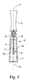
図1は、睫毛および/または眉毛へ塗布される製品Pを容れている容器3と、上記製品Pを塗布するためのアプリケータ1とを有する包装および塗布デバイスを示している。アプリケータ1は、本発明に従うアプリケータ部材8を有し、それは、軸体7によって、容器3を閉じるための部材をも構成するところの把持部材5へ接続されている。この閉じる部材5は、例えば図示されたように、容器の首9にねじ込まれよう設計されたキャップである。容器3は、アプリケータ1を払拭するための、容器3の首9に固定された払拭部材6を有しうる。
FIG. 1 shows a packaging and coating device having a container 3 containing a product P to be applied to the eyelashes and / or eyebrows and an applicator 1 for applying the product P. The applicator 1 has an
アプリケータ部材8は、塗布要素20、特に本発明に従う歯、およびもし必要ならスパイクを支持するコア10を有している。
The
もし必要ならば、軸体7は、貯蔵の間、払拭部材6に過度に機械的な応力を加えないように、該払拭部材6の唇部の反対に置かれているその部分で環状の狭隘部を有しうる。
If necessary, the
アプリケータ部材8は、様々な仕方で軸体7に接続され得、そして例えば示されたように、そのハウジング内で固定されるように設計された末端部4を有しうる。
The
アプリケータ部材8は、軸体7の端部に設けられた対応するハウジングにおいて、何らかの手段、特に圧入、ステープル止め、スナップ締め、接着剤による接合、溶接、または圧着により軸体7に固定されうる。
The
1の変形形態として、軸体7は、コア10内に設けられたハウジング内に挿入され得、または該軸体およびコアは、少なくとも部分的に一体として製作されうる。
コア
As a variant of 1, the
core
図2および3に示されたように、コアは、長手方向軸Xに沿う細長い形状を有し、直線的または湾曲され得、好ましくは直線的でありうる。 As shown in FIGS. 2 and 3, the core has an elongated shape along the longitudinal axis X and can be linear or curved, preferably linear.
図4に示されたように、コア10は、その長さの大部分に沿って、多角形、特に六角形の断面を有しえて、該コア10の複数の側面は長手方向面40を画定する。該長手方向面40は全て、塗布要素20、特に歯を備えうる。該面40は、湾曲している、または例示された例のように平坦でありうる。図示されていない1変形形態において、コア10の該複数の面の一部のみが塗布要素20を保持する。
As shown in FIG. 4, the
1の変形形態として図4Bに示されたように、コア10は、その長さの大部分に沿って円形断面を有しうる。
As shown in FIG. 4B as a variant of 1, the
図示されたように、長手方向軸Xは中央に在りえ、そしてコアは5mm以下の直径を有する円の断面に内接させられうる。 As shown, the longitudinal axis X can be central and the core can be inscribed in the cross section of a circle with a diameter of 5 mm or less.
図2および3に示されたように、コア10の断面は、端部片4の方向に太くされうる。1変形形態として、コア10の断面は、端部片4の方向に細くなりうる。1変形形態として、コア10は、一定の断面を有し得、特に円柱形状を有しうる。
As shown in FIGS. 2 and 3, the cross section of the core 10 can be thickened in the direction of the
コア10は中空であり得、該コア10の内径は好ましくは1mmと2.5mmの間である。
The core 10 can be hollow and the inner diameter of the
その遠位端で、コア10は、アプリケータ1を容器3内へ戻すのを容易にするように自由端42の方へ徐々に細くされた頭部を有しうる。
At its distal end, the
コア10は、比較的剛性であるか否かにかかわらず、熱可塑性材料、例えばSEBS、シリコーン、ラテックス、ブチル、EPDM、ニトリル、熱可塑性エラストマー、ポリエステルエラストマー、ポリアミドエラストマー、ポリエチレンエラストマーもしくはビニルエラストマー、ポリオレフィン、例えばPEもしくはPP、PVC、EVA、PS、PET、POM、PAまたはPMMAから作られうる。特に、Hytrel(商標)、Cariflex(商標)、Alixine(商標)、Santoprene(商標)またはPebax(商標)という商標で知られている材料を使用することが可能であるが、この一覧は限定的でない。
The
コア10は、それらを一緒に成形することにより軸体7と一体に製作されうる。
The core 10 can be manufactured integrally with the
コア10は捩じられえて、すると、歯20はコアによって作られた捩じれに従う。
歯
The core 10 can be twisted, and the
tooth
アプリケータ部材8は歯20を備え、各々の歯は、コア10から外部へ自由端26の方向に延在する。
歯の形状
The
Tooth shape
複数の図面に示されているように、少なくとも1つの歯20、より良好には歯20の列、さらにより良好には、図2に示されているように、歯20の全ては、正面図で凸状縁22を有している。上記凸状縁は、図5に示されたように、湾曲した一部分、特に円または放物線の一部分、特に楕円の一部分である。
As shown in the drawings, at least one
凸状縁22は、図5に示されたように、歯20の各々の高さhの半分超にわたり、より良好には歯20の各々の高さhの全体にわたり、延在しうる。
The
各歯20は、図6に示されたように歯20を通る断面において凸状縁22の方へ、特に頂角βでより薄くなりうる。該頂角βは、40°以下、より良好には15°以下である。この薄くすることは、睫毛がアプリケータ1と接触するやいなや、睫毛が移動することを可能にする。好ましくは、凸状縁22はリッジを画定する。
Each
図5に示されたように、各歯20は、正面から見て上方向に、その高さの少なくとも一部分B、より良好にはその高さの少なくとも半分にわたってより薄くなる。部分Bは、基部25から延在しうる。基部25の主要寸法は、例えば0.3mmと3mmの間である。
As shown in FIG. 5, each
好ましくは、各歯の自由端26は、図5に示されたように、正面から見て徐々に細くされ、特に、複数の睫毛の中へ入っていくこと、及び睫毛を分離すること、を容易にするところの一点を形成する。
Preferably, the
図6に示されたように、各歯20は、好ましくは、その高さの一部分にわたり、より良好にはその高さの半分超にわたり、さらにより良好にはその高さの全体hにわたり、扁平な断面を有している。
As shown in FIG. 6, each
図12Aに示されたように、より具体的には、歯20の平坦化面Zは、好ましくは、コア10に垂直に向けられる。平坦化面Zは、特に歯20に対する対称の正中面である。
More specifically, as shown in FIG. 12A, the flattening surface Z of the
図5および6に示されたように、各歯20は、正面から見て、直線状縁24を有し、それは特に、コア10の長手方向軸Xに関して半径方句であり、歯20の高さhの半分超にわたり、好ましくは歯20の高さ全体にわたり、延在する。
As shown in FIGS. 5 and 6, each
好ましくは、図5〜5Dに示されたように、歯20は、正面図で歯20の最大横寸法Lに実質的に等しい幅を有する四角形に正面図で内接させられている。
Preferably, as shown in FIGS. 5-5D, the
図5Dに示された変形形態において、各歯20は、正面図で、該歯20の該高さhの半分超にわたり、好ましくは該歯20の全高さhにわたり延在する凹状縁24を有している。
In the variant shown in FIG. 5D, each
各歯20は、好ましくは、図6に示されたように、この直線状縁を規定している平坦面24を有している。該平坦面24は、歯20の凸状縁22から離れている。好ましくは、各歯20は、平坦面24から凸状縁22へより薄くなっている。
Each
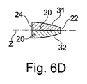
各歯20は、2つの対向する主要な長手方向面31および32を有し得、それらは平坦または曲げられ、凹状または、好ましくは図6に示されたように、外側に向けて凸状である。図6に示されたように、該面31および32は、好ましくは楕円面の部分である。
Each
好ましくは、各歯20は、歯の基部25の角度広がりに等しい角度広がりγを有している。
Preferably, each
図6〜6Cに示されたように、該面31および32は、好ましくは同一形状である。示された実施例において、該面31および32は、平坦面24を凸状縁22へ接続している。
As shown in FIGS. 6-6C, the
平坦化面Z上の歯20の最大寸法として定義された各歯20の最大幅Lは、0.3mmと2mmの間、より良好には0.5mmと1.5mmの間でありうる。図5に示されたように、この最大幅Lは、好ましくは歯20の基部から測られる。
The maximum width L of each
各歯20の高さhは、0.5mmと1cmの間、より良好には1mmと5mmの間でありうる。各歯20の最大厚さlは、0.2mmと2mmの間、より良好には0.4mmと1.5mmの間でありうる。最大厚さlは、歯20の基部で測られうる。自由端26での各歯20の厚さは、0.5mm以下でありうる。
The height h of each
歯20の最大幅Lの、歯20の高さhに対する比L/hは、0.5と2の間でありうる。
The ratio L / h of the maximum width L of the
好ましくは、歯20は中実である。変形形態として、歯20は、貫通口であるなしに関わらず開口部を有しうる。
Preferably, the
歯20は、単一の基部25から閉じられ輪郭線で延在しうる。コア上の歯20の周状の広がりγは、180°以下、より良好には90°以下でありうる。
The
歯20は、好ましくは、コア10の少なくとも一部分と、より良好にはコア10の全てと同一の材料で作られている。歯20は、好ましくは、熱可塑性物質の成形によりコア10と一体に作られる。
The
好ましくは、図5Eに示されたように、歯20は、その遠位端26で点を形成するように徐々に細くされている。好ましくは、正面図において、歯20の高さhの90%に等しい高さh’で取られた歯20の表面に対する接線t1とt2は90°以下の角度βを形成する。
Preferably, as shown in FIG. 5E, the
1変形形態として、そして図5Bおよび5Cに示されたように、各歯20は、その全高さにわたり薄くなることはない。各歯20はつぎに、その高さの一部分Aにわたって一定の幅または上方に増加する幅をもつ領域を有しうる。この部分Aは、好ましくは歯20の高さhの半分未満であるところの高さを有する。
As a variant and as shown in FIGS. 5B and 5C, each
図5Aに示されたような変形形態において、自由端26は、平坦線を形成する。図7に示されたような変形形態において、該自由端26は丸められている。
In the modified form as shown in FIG. 5A, the
図6Bに示されたように、該面31および32は、凸状であり得、そしてひいては例えば双曲面または放物面の部分でありうる。該面31および32はまた、図6Aの実施例に示されたように平坦でありうる。
As shown in FIG. 6B, the
該面31および32はまた、図6Dに示されたように異なる形状を有しうる。
The
図12Bに示され変形形態のように、平坦化面Zは、コア10の長手方向軸Xに対して、45°と90°の間の角度θで傾けた向きに置かれる。
As shown in FIG. 12B, the flattening surface Z is placed at an angle θ between 45 ° and 90 ° with respect to the longitudinal axis X of the
図5Bに示された変形形態のように、各歯20は、狭められた基部25を有している。基部25の主要寸法bは、その結果例えば0.1mmと1.5mmの間である。
As in the variant shown in FIG. 5B, each
示されていない1の変形形態において、平坦面24の中央軸は、該軸Xに対して垂直にではなく、それらに対して正面、すなわちアプリケータの遠位端の方へ、または背面の方へ傾けられて延在する。
In one variant not shown, the central axis of the
図8A〜9Cに示されたように、各歯20は、起伏部33、例えばその表面内に刻み目、窪み部、及び/又は、ノッチを有しうる。この起伏部33は、凸状縁22、及び/又は歯20の対向面24、及び/又はコア、及び/又は対向する主要面31および32の他方に置かれうる。各歯20はまた、それを貫通する開口部35、例えば平坦化面Zに垂直な軸をもつ開口部を有しうる。
As shown in FIGS. 8A-9C, each
歯20およびコア10は、別々の材料から、もし必要なら、2成分射出成形によって作られうる。歯20は、例えばコア10内の開口を通して成形される。歯20は、コアよりも柔軟な材料から作られ、または1変形形態としてコアよりもより硬い材料から作られうる。
2つの連続する隣接する歯の配置
The
Arrangement of two consecutive adjacent teeth
図2〜4Bおよび図10〜12Bに示したように、コア10は、その表面上に、隣接する歯の少なくとも1つの対15、より良好には隣接する歯の対15の少なくとも1つの列、さらに良好には図2に示されたように、隣接する歯の対15の複数の列、例えば上述された歯20を有しうる。
As shown in FIGS. 2-4B and 10-12B, the
対の2つの歯20aおよび20bは、図4Aに示されたように同じ高さでありうるか、または特に図4に示されたように、異なる高さを有しうる。この図4は、歯20aが、その前に置かれている、即ちアプリケータの遠位端により近い、隣接する歯20bよりも僅かに高いことを示している。
The pair of two
図11に示されたように、第1の歯20aの凸状縁22は、正面図で右に向けられ得、一方、第2の歯20bの凸状縁22は、左に向けられ得るか、またはその逆でありうる。複数の凸状縁22のこの反対の向きは、ブラシが、同じ効果を生みだしながら、どちらの方向にも使われることを可能にする。
As shown in FIG. 11, can the
該歯20aおよび20bは、好ましくは距離Dだけ軸方向にずれており、該距離は、該2つの歯20aおよび20bの平坦化面Zの間の距離である。該距離Dは、0.5mmと3mmの間、より良好には0.5mmと1.5mmの間でありうる。
The
該歯20aおよび20bは、好ましくはコアの長手方向軸Xの回りでずれている。2つの歯20aおよび20bの間の角度広がりαは、好ましくは15°と60°の間であり、この角度広がりαは、正面図において、第1の歯20aのコア10との交差の弧の中間Xaを通過するコア10の半径と第2の歯20bのコア10との交差の弧の中間Xbを通過するコア10の半径の間の角度αによって定義される。
The
該歯20aおよび20bは、少なくとも部分的に2つの歯20aおよび20bの高さhの少なくとも一部分にわたり、より良好には図11で分かるように、歯20aまたは20bの少なくとも1つの全高さにわたり重畳されうる。2つの歯20aおよび20bの間の角度間隔αは、歯20aおよび20bの各々によって取られた角度拡がりγ未満であり、これら角度拡がりは、その基部で歯によって取られた角度によって定義される。図11に示されたように、正面図で、長手方向軸Xに対して2つの歯20aと20bの間の重畳Sabの領域によって取られた角度、即ちγ―αとして定義された重なりの角度φは、30°以下でありうる。
The
図4、4B、および13に示されたように、該第1歯20aは、該第2歯20bよりも大きくあり得、またその反対もありうる。高さの比m/nは、好ましくは0.1と0.9の間である。ここで、mは小さな歯の高さであり、nは大きな歯の高さである。
As shown in FIGS. 4, 4B, and 13, the
図11および4Aで示されたように、歯20aおよび20bは同じ高さでもよく、第1歯20aは、好ましくは正面図で、コア10の長手方向軸Xに平行な対称面Mに対して第2歯20bの鏡像である。
歯の列
As shown in FIGS. 11 and 4A, the
Row of teeth
図2、4Bおよび14で示されたように、アプリケータ部材8は、歯の対15の少なくとも1つの列50、より良好には歯の対15の複数の列50を有しうる。ここで、該歯の対15は、上述された歯20aおよび20bを有している。列50は、好ましくはコア10の長手方向軸Xに沿って延在している。
As shown in FIGS. 2, 4B and 14, the
アプリケータ部材8は、コア10の長手方向軸Xの回りに置かれた、歯の対15の少なくとも2つの列50、より良好には少なくとも4列50、一層良好には少なくとも6列50を有しうる。
The
アプリケータ部材8の全ての列50は、好ましくは同一である。
All
各列50の歯は、隣接する列50における同一ランクの歯として、好ましくは長手方向軸Xに沿う同じ横座標を有している。これにより同一ランクの歯は、アプリケータ部材が側面から見られるとき、整列されて見える。
The teeth in each
列50は、好ましくはコア10の長手方向軸Xの周りに規則的に間隔を空けられている。
The
図4および4Bに示されたように、コア10の長手方向軸Xの周りの2つの連続した列50の間の角度間隔ωは、好ましくは一定であり、該角度間隔ωは、正面図で、上記複数の列の各重心を通るコア10の複数の半径の間の角度により定義される。該角度間隔ωは、好ましくは15°と95°の間、より良好には45°と75°の間であり、さらに良好には60°に等しい。
As shown in FIGS. 4 and 4B, the angular spacing ω between the two
そのような複数の列50は、夫々の歯20aおよび20bの2つの異なる配列の存在の故に「二重列」と呼ばれうる。
Such
図14に示されるように、列50の歯の2つの連続する対15の間の軸方向距離qは、好ましくは一定でありかつ0.8mmと4mmの間である。該軸方向距離qは、側面図で歯20aの配列50a内で第1歯20aの複数の平坦化面Zの間の距離によって定義される。
As shown in FIG. 14, the axial distance q between the two
該コアは、好ましくは、示されたように六角形の断面を有する。該アプリケータ部材8は、好ましくは6つの二重列50を有し、各二重列50は、コア10のリッジに沿い置かれたその長手方向軸を有している。該歯20aは、上記リッジに取り付けられている、コア10の平らな面40の1つの上のそれらの基部25のほとんど全てにわたり延在する。該歯20bは、上記リッジに取り付けられている、別の平らな面40の上に、それらの基部25のほとんど全てにわたり延在する。
The core preferably has a hexagonal cross section as shown. The
歯20の自由端26により画定された歯の包絡面Sは、回転面、特に円錐面でありうる。
The enveloping surface S of the tooth defined by the
該包絡面Sの半径rSは、好ましくは、列50のほぼ全長qmaxに沿って端部片4の方向に実質的に増加している。
The radius r S of the envelope surface S is preferably substantially increased in the direction of the
好ましくは、各配列50aおよび50bは、小さな歯(大きな歯よりも高さが低い)と交互に置かれる大きな歯を有している。各配列50aおよび50bの偶数ランクの歯は、例えば奇数ランクの歯よりも小さい、またはその逆である。高さの比m/nは、好ましくは0.1と0.9の間であり、mは小さな歯の高さ、nは大きな歯の高さである。
Preferably, each
第1配列50a内の奇数ランクの各歯は、好ましくは第2配列50b内の偶数ランクの隣接する歯と同じ高さhである。第1配列50a内の偶数ランクの各歯は、好ましくは第2配列50b内の奇数ランクの隣接する歯と同じ高さhである。歯20aおよび20bは、このように二重列50内の隣接する歯の各対について同一サイズである。
Each of the odd-ranked teeth in the
好ましくは、各二重列50について、第1配列50aは、図4に示されたように、54で、隣接する二重列50の第2配列50bと重畳される。この重畳は、小さな広がりのみを持つことが可能である。正面図で、歯の間の重なりの領域の基部25での幅として画定された重なりの幅は、例えば0.5mm以下である。1変形形態として、正面図で、隣接する列50の歯は、重畳されていない。
Preferably, for each
アプリケータ部材8の長手方向軸Xの回りの、2つの引き続く列50の間の角度間隔ωはまた、1つの変形形態において、コア10の回りで変化しうる。
The angular spacing ω between the two
図13に示されたように、歯の対15は、列50のほぼ全長qmaxに沿いコアの長手方向軸に沿って互いに関して増加する高さを有しうる。一列50内の、より良好には複数の歯列50の各々内の、歯20aおよび20bの高さhは、列50のほぼ全長qmaxに沿って交互に変化しうる。偶数ランクの歯20bの各々は、奇数ランクの直接隣り合う歯20aよりも大きいか、またはその逆である。2つの隣接する歯の間の比m/nは、好ましくは、0.1と0.9の間であり、mは小さな歯の1つの高さであり、nは、隣接する大きな歯の1つの高さである。
As shown in FIG. 13, tooth pairs 15 may have heights that increase relative to each other along the longitudinal axis of the core along the approximately overall length qmax of
各配列50aおよび50b内の歯20aおよび20bは、塗布の遠位端からの距離が増すにつれて増加する高さhを有しうる。第1配列50a内の歯20aは、同一ランクの第2配列50b内の歯20bよりも小さい、またはその逆である。
The
1つの列50内の2つの隣接する歯20aおよび20bの間の距離Dは、列50の長さqmaxの少なくとも半分に沿って変化しうる。
The distance D between two
アプリケータ部材8の列50は、互に異なりうる。2つの隣接する列50内の歯20aおよび20bの形状は、特に対応する歯20aおよび20bの高さによって、実質的に変わりうる。1つの列50内の歯は、隣接する列50の1つの同一ランクの歯よりも全て大きくありうる。
The
1変形形態として、隣接する列50の同一ランクの歯20aおよび20bは、長手方向軸Xの周りに整列されていない。隣接する列50の同一ランクの歯20aおよび20bは、長手方向軸Xに沿ってずらされうる。
In one variant, the
本発明は、二重列の場合に限定されない。該列は、一列であり得、上述のように歯20の1の配列、または並んだ歯20aおよび20bの対15を有しうる。
The present invention is not limited to the case of double columns. The row can be a single row and can have an array of 1 of
本発明は、これまで述べられた説明のための実施態様に限定されるものではなく、その特性は、図示されていない変形形態の部分として相互に組合せられうる。 The present invention is not limited to the explanatory embodiments described so far, and its properties can be combined with each other as parts of variants not shown.
アプリケータ部材は、特に歯の間に置かれうるスパイク、より良好には複数の歯列の間に置かれうるスパイクの列を有しうる。 The applicator member can have a row of spikes that can be placed, in particular between the teeth, and better, a row of spikes that can be placed between multiple dentitions.
アプリケータ部材は、振動可能でありうる、すなわち、振動が、製品を塗布、梳くまたは製品を取り出す間、アプリケータ部材8に与えられうる。
The applicator member may be vibrable, i.e., vibration may be applied to the
1変形形態として、アプリケータ部材は、回転可能でありうる、すなわち、例えば、製品を塗布、睫毛を梳く、または製品を取り出す間、コアの長手方向軸の回りの回転運動を実行するように作られうる。 In one variant, the applicator member may be rotatable, i.e., for example, to perform a rotational movement around the longitudinal axis of the core while applying the product, combing the eyelashes, or removing the product. Can be done.
別の変形形態として、アプリケータ部材は加熱される、すなわち、それは、睫毛および/または眉毛、および/または、アプリケータ部材の歯および/またはコアを加熱するための加熱要素を有しうる。 As another variant, the applicator member is heated, i.e. it may have a heating element for heating the eyelashes and / or eyebrows, and / or the teeth and / or core of the applicator member.
アプリケータ部材はまた、振動が可能でありえ、および/または回転が可能でありえ、および/または加熱されうる。 The applicator member can also be vibrating and / or rotating and / or heated.
該歯は、フロック加工され、その結果、粗さを有しうる、または睫毛または眉毛上の滑りを増す化学的または機械的処理を受けうる。 The teeth are flocked and, as a result, can have roughness or undergo chemical or mechanical treatments that increase slippage on the eyelashes or eyebrows.
表現「1の〜を有する」は、「少なくとも1つの〜を有する」と同義であると理解されるべきであり、「の間の」は特に反対のことを言わない限り、境界を包含するように理解される。 The expression "having one" should be understood to be synonymous with "having at least one", and "between" should include boundaries unless otherwise stated. Is understood by.
1 アプリケータ
3 容器
4 末端部、端部片
5 把持部材、閉じる部材
6 払拭部材
7 軸体
8 アプリケータ部材
9 容器の首
10 コア
20、20a、20b 歯、塗布要素
22 凸状縁
24 平坦面(凹状縁、直線状縁)
25 基部
26 自由端
31、32 長手方向面
40 コアの長手方向面
42 遠位端(アプリケータ部材の)
50、50a、50b 歯の列
1 Applicator 3
25
50, 50a, 50b tooth row
Claims (17)
‐ 長手方向軸(X)を有するコア(10)、
‐ 複数の歯であって、その各々が該コア(10)から外側へ該歯の自由端(26)の方向に延在するもの、
を有し、
少なくとも2つの隣接する歯(20;20a、20b)が、正面図で、非対称の形状および該歯の断面においてリッジを構成する凸状縁(22)を有し、前記2つの隣接する歯(20;20a、20b)は、夫々、2つの対向する主要な長手方向面(31、32)を備え、該2つの面は該リッジを、該リッジに対向する平坦面(24)へ直接的に接続し、該リッジは、該2つの対向する主要な長手方向面(31、32)の交差によって少なくとも部分的に形成されており、かつ前記2つの隣接する歯(20;20a、20b)は、その高さの少なくとも一部にわたり上方へ且つ該凸状縁(22)の方への両方で、より薄くなり、前記2つの隣接する歯(20;20a、20b)の上記凸状縁(22)は共に、該2つの隣接する歯(20;20a、20b)の外側に向けられ、または共に、該2つの隣接する歯(20;20a、20b)の内側に向けられ、前記2つの隣接する歯(20;20a、20b)は、正面図でそれらの高さの少なくとも一部にわたり部分的に重畳させられている、上記アプリケータ(1)。 An applicator (1) for applying a product to eyelashes and / or eyebrows, comprising a molded applicator member (8).
-Core (10) with longitudinal axis (X),
-Multiple teeth, each extending outward from the core (10) towards the free end (26) of the tooth,
Have,
The two adjacent teeth (20) have at least two adjacent teeth (20; 20a, 20b) having an asymmetrical shape and a convex edge (22) forming a ridge in the cross section of the tooth in the front view. Each of the 20a, 20b) comprises two opposing major longitudinal surfaces (31, 32), the two surfaces connecting the ridge directly to a flat surface (24) facing the ridge. The ridge is formed at least partially by the intersection of the two opposing major longitudinal planes (31, 32), and the two adjacent teeth (20; 20a, 20b) are such. Both upward over at least a portion of the height and towards the convex edge (22), the convex edge (22) of the two adjacent teeth (20; 20a, 20b) becomes thinner. Both are directed to the outside of the two adjacent teeth (20; 20a, 20b), or both are directed to the inside of the two adjacent teeth (20; 20a, 20b) , said two adjacent teeth (20; 20a, 20b). 20; 20a, 20b) are the applicators (1) that are partially superimposed over at least a portion of their height in the front view.
Applications Claiming Priority (3)
| Application Number | Priority Date | Filing Date | Title |
|---|---|---|---|
| FR1355191 | 2013-06-06 | ||
| FR1355191A FR3006566B1 (en) | 2013-06-06 | 2013-06-06 | APPLICATOR FOR APPLYING A PRODUCT ON THE LASHES AND / OR THE EYE |
| PCT/IB2014/062009 WO2014195914A1 (en) | 2013-06-06 | 2014-06-06 | Applicator for applying a product to the eyelashes and/or eyebrows |
Related Child Applications (1)
| Application Number | Title | Priority Date | Filing Date |
|---|---|---|---|
| JP2019220657A Division JP2020039930A (en) | 2013-06-06 | 2019-12-05 | Applicator for applying product on eyelash and/or eyebrow |
Publications (3)
| Publication Number | Publication Date |
|---|---|
| JP2016521603A JP2016521603A (en) | 2016-07-25 |
| JP2016521603A5 JP2016521603A5 (en) | 2016-11-17 |
| JP6894234B2 true JP6894234B2 (en) | 2021-06-30 |
Family
ID=49111394
Family Applications (2)
| Application Number | Title | Priority Date | Filing Date |
|---|---|---|---|
| JP2016517728A Active JP6894234B2 (en) | 2013-06-06 | 2014-06-06 | Applicator to apply product to eyelashes and / or eyebrows |
| JP2019220657A Pending JP2020039930A (en) | 2013-06-06 | 2019-12-05 | Applicator for applying product on eyelash and/or eyebrow |
Family Applications After (1)
| Application Number | Title | Priority Date | Filing Date |
|---|---|---|---|
| JP2019220657A Pending JP2020039930A (en) | 2013-06-06 | 2019-12-05 | Applicator for applying product on eyelash and/or eyebrow |
Country Status (8)
| Country | Link |
|---|---|
| US (1) | US10299565B2 (en) |
| EP (1) | EP3003092B1 (en) |
| JP (2) | JP6894234B2 (en) |
| KR (1) | KR102306530B1 (en) |
| CN (1) | CN105473024B (en) |
| ES (1) | ES2689929T3 (en) |
| FR (1) | FR3006566B1 (en) |
| WO (1) | WO2014195914A1 (en) |
Families Citing this family (13)
| Publication number | Priority date | Publication date | Assignee | Title |
|---|---|---|---|---|
| FR3032869B1 (en) * | 2015-02-25 | 2018-05-11 | Societe Industrielle De Matieres Plastiques | DEVICE FOR APPLYING A FLUID OR PASTY TYPE PRODUCT TO KERATIN FIBERS. |
| FR3034969B1 (en) * | 2015-04-14 | 2018-09-07 | Societe Industrielle De Matieres Plastiques | APPLICATOR DEVICE FOR A FLUID OR PASTY PRODUCT ON KERATIN FIBERS |
| FR3035779B1 (en) | 2015-05-06 | 2017-09-01 | Oreal | APPLICATOR FOR THE APPLICATION OF A COSMETIC PRODUCT |
| FR3039382B1 (en) | 2015-07-31 | 2017-08-11 | Montaigu Dev | DEVICE APPLICATOR OF A FLUID OR PASTY PRODUCT ON KERATIN FIBERS. |
| JP2019525816A (en) * | 2016-06-08 | 2019-09-12 | ソシエテ アンデュストリエル ドゥ マティエール プラスティック | Applicator device for applying liquid or paste keratin fibers |
| FR3070840B1 (en) * | 2017-09-12 | 2021-11-12 | Oreal | COSMETIC APPLICATOR |
| FR3070841B1 (en) | 2017-09-12 | 2021-07-16 | Oreal | COSMETIC APPLICATOR |
| FR3070839A1 (en) * | 2017-09-12 | 2019-03-15 | L'oreal | COSMETIC APPLICATOR |
| FR3070842B1 (en) * | 2017-09-12 | 2021-07-16 | Oreal | COSMETIC APPLICATOR |
| FR3090299B1 (en) | 2018-12-19 | 2021-04-30 | Oreal | Applicator comprising an application member manufactured by additive synthesis |
| FR3090301B1 (en) | 2018-12-19 | 2021-05-14 | Oreal | Applicator comprising an application member with an open branch |
| FR3090297B1 (en) | 2018-12-19 | 2021-10-15 | Oreal | Spiral cosmetic applicator |
| FR3110060B1 (en) * | 2020-05-18 | 2023-09-08 | Oreal | Applicator for applying a product to eyelashes and/or eyebrows |
Family Cites Families (14)
| Publication number | Priority date | Publication date | Assignee | Title |
|---|---|---|---|---|
| FR2690318A1 (en) * | 1992-04-27 | 1993-10-29 | Oreal | Brush intended for the application of a cosmetic product, in particular on the eyelashes or the hair, and method of manufacturing such a brush. |
| FR2796527B1 (en) * | 1999-07-21 | 2001-09-28 | Oreal | DEVICE FOR CONDITIONING AND APPLYING A PRODUCT TO EYELASHES OR EYEBROWS |
| FR2796528B1 (en) * | 1999-07-21 | 2001-09-21 | Oreal | DEVICE FOR CONDITIONING AND APPLYING A PRODUCT TO EYELASHES OR EYEBROWS |
| FR2796529B1 (en) * | 1999-07-21 | 2001-09-21 | Oreal | DEVICE FOR CONDITIONING AND APPLYING A PRODUCT TO EYELASHES OR EYEBROWS |
| FR2837077B1 (en) | 2002-03-13 | 2004-12-17 | Oreal | DEVICE FOR COMBING EYELASHES AND / OR EYEBROWS AND / OR APPLYING A PRODUCT THEREON |
| FR2872394B1 (en) | 2004-07-01 | 2007-04-20 | Oreal | DEVICE FOR APPLYING A PRODUCT TO KERATIN FIBERS |
| JP4783079B2 (en) * | 2005-07-08 | 2011-09-28 | 株式会社新和製作所 | Cosmetic applicator and cosmetic applicator mold |
| FR2902984B1 (en) * | 2006-06-28 | 2009-03-20 | Oreal | DEVICE FOR APPLYING A PRODUCT ON LACQUERS OR EYEILS. |
| FR2922422B1 (en) | 2007-10-23 | 2009-12-18 | Oreal | APPLICATOR TO COMBINE OR APPLY A PRODUCT ON THE LASHES |
| FR2934478B1 (en) | 2008-08-01 | 2011-08-26 | Oreal | APPLICATOR TO COMBINE AND / OR APPLY A PRODUCT ON LACQUERS AND / OR EYEBROWS |
| FR2937514B1 (en) * | 2008-10-29 | 2012-12-07 | Ile M V R Soc Civ | APPLICATOR DEVICE OF A COSMETIC FLUID OR PASTY PRODUCT, TYPICALLY MASCARA |
| FR2951359B1 (en) | 2009-10-15 | 2019-12-27 | L'oreal | DEVICE FOR APPLYING A PRODUCT TO EYELASHES OR EYEBROWS. |
| FR2961384B1 (en) | 2010-06-21 | 2019-08-09 | L'oreal | APPLICATOR OF A COSMETIC, MAKE-UP OR CARE PRODUCT ON LACQUERS OR EYEBROWS |
| FR2962888B1 (en) * | 2010-07-20 | 2012-08-31 | Oreal | APPLICATOR AND DEVICE FOR PACKAGING AND APPLICATION COMPRISING SUCH AN APPLICATOR. |
-
2013
- 2013-06-06 FR FR1355191A patent/FR3006566B1/en active Active
-
2014
- 2014-06-06 KR KR1020167000077A patent/KR102306530B1/en active IP Right Grant
- 2014-06-06 CN CN201480044097.4A patent/CN105473024B/en active Active
- 2014-06-06 US US14/896,615 patent/US10299565B2/en active Active
- 2014-06-06 ES ES14731820.8T patent/ES2689929T3/en active Active
- 2014-06-06 EP EP14731820.8A patent/EP3003092B1/en active Active
- 2014-06-06 WO PCT/IB2014/062009 patent/WO2014195914A1/en active Application Filing
- 2014-06-06 JP JP2016517728A patent/JP6894234B2/en active Active
-
2019
- 2019-12-05 JP JP2019220657A patent/JP2020039930A/en active Pending
Also Published As
| Publication number | Publication date |
|---|---|
| EP3003092B1 (en) | 2018-07-18 |
| US10299565B2 (en) | 2019-05-28 |
| US20160135568A1 (en) | 2016-05-19 |
| EP3003092A1 (en) | 2016-04-13 |
| CN105473024A (en) | 2016-04-06 |
| JP2020039930A (en) | 2020-03-19 |
| WO2014195914A1 (en) | 2014-12-11 |
| FR3006566B1 (en) | 2018-04-27 |
| JP2016521603A (en) | 2016-07-25 |
| FR3006566A1 (en) | 2014-12-12 |
| KR20160015362A (en) | 2016-02-12 |
| KR102306530B1 (en) | 2021-09-28 |
| CN105473024B (en) | 2017-11-28 |
| ES2689929T3 (en) | 2018-11-16 |
Similar Documents
| Publication | Publication Date | Title |
|---|---|---|
| JP6894234B2 (en) | Applicator to apply product to eyelashes and / or eyebrows | |
| JP6991171B2 (en) | Applicator to apply product to eyelashes and / or eyebrows | |
| US9723911B2 (en) | Device for applying a composition to the eyelashes or the eyebrows | |
| JP6529011B2 (en) | Applicator applying product to eyelashes and / or eyebrows | |
| US9427075B2 (en) | Applicator for combing the eyelashes or the eyebrows or for applying a composition thereto | |
| US8944714B2 (en) | Applicator for combing the eyelashes and/or eyebrows or for applying a composition thereto | |
| US8783268B2 (en) | Applicator for combing the eyelashes or the eyebrows, or for applying a composition thereto | |
| US8777503B2 (en) | Applicator for combing the eyelashes or the eyebrows or for applying a composition thereto | |
| JP6587611B2 (en) | Device for applying cosmetic products | |
| WO2011161584A1 (en) | An applicator for applying a cosmetic, makeup, or care product composition to the eyelashes or the eyebrows. | |
| KR102255086B1 (en) | Applicator for applying a cosmetic, makeup or care, product to the eyelashes and/or eyebrows | |
| WO2013153525A1 (en) | Applicator for applying a cosmetic product to the eyelashed and/or eyebrows |
Legal Events
| Date | Code | Title | Description |
|---|---|---|---|
| A521 | Request for written amendment filed |
Free format text: JAPANESE INTERMEDIATE CODE: A523 Effective date: 20160926 |
|
| A621 | Written request for application examination |
Free format text: JAPANESE INTERMEDIATE CODE: A621 Effective date: 20170406 |
|
| A131 | Notification of reasons for refusal |
Free format text: JAPANESE INTERMEDIATE CODE: A131 Effective date: 20180406 |
|
| A601 | Written request for extension of time |
Free format text: JAPANESE INTERMEDIATE CODE: A601 Effective date: 20180703 |
|
| A601 | Written request for extension of time |
Free format text: JAPANESE INTERMEDIATE CODE: A601 Effective date: 20180705 |
|
| A521 | Request for written amendment filed |
Free format text: JAPANESE INTERMEDIATE CODE: A523 Effective date: 20180911 |
|
| A131 | Notification of reasons for refusal |
Free format text: JAPANESE INTERMEDIATE CODE: A131 Effective date: 20181115 |
|
| A601 | Written request for extension of time |
Free format text: JAPANESE INTERMEDIATE CODE: A601 Effective date: 20190214 |
|
| A601 | Written request for extension of time |
Free format text: JAPANESE INTERMEDIATE CODE: A601 Effective date: 20190215 |
|
| A521 | Request for written amendment filed |
Free format text: JAPANESE INTERMEDIATE CODE: A523 Effective date: 20190514 |
|
| A02 | Decision of refusal |
Free format text: JAPANESE INTERMEDIATE CODE: A02 Effective date: 20190805 |
|
| A521 | Request for written amendment filed |
Free format text: JAPANESE INTERMEDIATE CODE: A523 Effective date: 20191205 |
|
| C60 | Trial request (containing other claim documents, opposition documents) |
Free format text: JAPANESE INTERMEDIATE CODE: C60 Effective date: 20191205 |
|
| C11 | Written invitation by the commissioner to file amendments |
Free format text: JAPANESE INTERMEDIATE CODE: C11 Effective date: 20191224 |
|
| A911 | Transfer to examiner for re-examination before appeal (zenchi) |
Free format text: JAPANESE INTERMEDIATE CODE: A911 Effective date: 20200207 |
|
| C21 | Notice of transfer of a case for reconsideration by examiners before appeal proceedings |
Free format text: JAPANESE INTERMEDIATE CODE: C21 Effective date: 20200218 |
|
| A912 | Re-examination (zenchi) completed and case transferred to appeal board |
Free format text: JAPANESE INTERMEDIATE CODE: A912 Effective date: 20200228 |
|
| C211 | Notice of termination of reconsideration by examiners before appeal proceedings |
Free format text: JAPANESE INTERMEDIATE CODE: C211 Effective date: 20200316 |
|
| C22 | Notice of designation (change) of administrative judge |
Free format text: JAPANESE INTERMEDIATE CODE: C22 Effective date: 20200811 |
|
| C22 | Notice of designation (change) of administrative judge |
Free format text: JAPANESE INTERMEDIATE CODE: C22 Effective date: 20201020 |
|
| C13 | Notice of reasons for refusal |
Free format text: JAPANESE INTERMEDIATE CODE: C13 Effective date: 20201110 |
|
| A521 | Request for written amendment filed |
Free format text: JAPANESE INTERMEDIATE CODE: A523 Effective date: 20210205 |
|
| C23 | Notice of termination of proceedings |
Free format text: JAPANESE INTERMEDIATE CODE: C23 Effective date: 20210405 |
|
| C03 | Trial/appeal decision taken |
Free format text: JAPANESE INTERMEDIATE CODE: C03 Effective date: 20210511 |
|
| C30A | Notification sent |
Free format text: JAPANESE INTERMEDIATE CODE: C3012 Effective date: 20210511 |
|
| A61 | First payment of annual fees (during grant procedure) |
Free format text: JAPANESE INTERMEDIATE CODE: A61 Effective date: 20210603 |
|
| R150 | Certificate of patent or registration of utility model |
Ref document number: 6894234 Country of ref document: JP Free format text: JAPANESE INTERMEDIATE CODE: R150 |
|
| R250 | Receipt of annual fees |
Free format text: JAPANESE INTERMEDIATE CODE: R250 |