JP6894090B2 - Stick-shaped dry noodle storage container with weighing function - Google Patents
Stick-shaped dry noodle storage container with weighing function Download PDFInfo
- Publication number
- JP6894090B2 JP6894090B2 JP2016147799A JP2016147799A JP6894090B2 JP 6894090 B2 JP6894090 B2 JP 6894090B2 JP 2016147799 A JP2016147799 A JP 2016147799A JP 2016147799 A JP2016147799 A JP 2016147799A JP 6894090 B2 JP6894090 B2 JP 6894090B2
- Authority
- JP
- Japan
- Prior art keywords
- stick
- storage container
- measuring
- container body
- shaped
- Prior art date
- Legal status (The legal status is an assumption and is not a legal conclusion. Google has not performed a legal analysis and makes no representation as to the accuracy of the status listed.)
- Active
Links
Images


Classifications
-
- A—HUMAN NECESSITIES
- A47—FURNITURE; DOMESTIC ARTICLES OR APPLIANCES; COFFEE MILLS; SPICE MILLS; SUCTION CLEANERS IN GENERAL
- A47J—KITCHEN EQUIPMENT; COFFEE MILLS; SPICE MILLS; APPARATUS FOR MAKING BEVERAGES
- A47J47/00—Kitchen containers, stands or the like, not provided for in other groups of this subclass; Cutting-boards, e.g. for bread
- A47J47/02—Closed containers for foodstuffs
- A47J47/08—Closed containers for foodstuffs for non-granulated foodstuffs
-
- B—PERFORMING OPERATIONS; TRANSPORTING
- B65—CONVEYING; PACKING; STORING; HANDLING THIN OR FILAMENTARY MATERIAL
- B65D—CONTAINERS FOR STORAGE OR TRANSPORT OF ARTICLES OR MATERIALS, e.g. BAGS, BARRELS, BOTTLES, BOXES, CANS, CARTONS, CRATES, DRUMS, JARS, TANKS, HOPPERS, FORWARDING CONTAINERS; ACCESSORIES, CLOSURES, OR FITTINGS THEREFOR; PACKAGING ELEMENTS; PACKAGES
- B65D83/00—Containers or packages with special means for dispensing contents
- B65D83/02—Containers or packages with special means for dispensing contents for dispensing rod-shaped articles, e.g. needles
-
- B—PERFORMING OPERATIONS; TRANSPORTING
- B65—CONVEYING; PACKING; STORING; HANDLING THIN OR FILAMENTARY MATERIAL
- B65D—CONTAINERS FOR STORAGE OR TRANSPORT OF ARTICLES OR MATERIALS, e.g. BAGS, BARRELS, BOTTLES, BOXES, CANS, CARTONS, CRATES, DRUMS, JARS, TANKS, HOPPERS, FORWARDING CONTAINERS; ACCESSORIES, CLOSURES, OR FITTINGS THEREFOR; PACKAGING ELEMENTS; PACKAGES
- B65D85/00—Containers, packaging elements or packages, specially adapted for particular articles or materials
- B65D85/20—Containers, packaging elements or packages, specially adapted for particular articles or materials for incompressible or rigid rod-shaped or tubular articles
- B65D85/22—Containers, packaging elements or packages, specially adapted for particular articles or materials for incompressible or rigid rod-shaped or tubular articles for macaroni, spaghetti or like flour products
-
- G—PHYSICS
- G01—MEASURING; TESTING
- G01F—MEASURING VOLUME, VOLUME FLOW, MASS FLOW OR LIQUID LEVEL; METERING BY VOLUME
- G01F19/00—Calibrated capacity measures for fluids or fluent solid material, e.g. measuring cups
Landscapes
- Engineering & Computer Science (AREA)
- Mechanical Engineering (AREA)
- Food Science & Technology (AREA)
- Physics & Mathematics (AREA)
- Fluid Mechanics (AREA)
- General Physics & Mathematics (AREA)
- Devices For Warming Or Keeping Food Or Tableware Hot (AREA)
- Details Of Rigid Or Semi-Rigid Containers (AREA)
- Closures For Containers (AREA)
Description
本発明は棒状乾麺保存容器に関するものであり、より詳しくは計量機能を有する棒状乾麺保存容器に関するものである。 The present invention relates to a stick-shaped dry noodle storage container, and more specifically, to a stick-shaped dry noodle storage container having a measuring function.
一定の長さに切り揃えられた棒状乾麺(スパゲッティ、うどん、そば、ラーメン等)であって結束されていないものを、箱状の保存容器(例えば、蓋付きのプラスチックケース)内に保存する場合がある。そのように保存した棒状乾麺の調理に際しては、必要量の棒状乾麺を容器から取り出す必要がある。必要量の棒状乾麺を計量するためのスケールとして、例えば、板状の本体に穿設した計量用の穴に棒状乾麺を束ねた状態で貫挿することにより、穴に貫挿可能な棒状乾麺の束の重量の目安を知るものが公知である(特許文献1:特開2003−339557号公報の段落[0002]参照)。 When storing stick-shaped dried noodles (spaghetti, udon, buckwheat noodles, ramen, etc.) cut to a certain length in a box-shaped storage container (for example, a plastic case with a lid) that is not bound. There is. When cooking the stick-shaped dry noodles stored in this way, it is necessary to take out the required amount of the stick-shaped dry noodles from the container. As a scale for measuring the required amount of stick-shaped dry noodles, for example, a stick-shaped dry noodle that can be inserted into a hole by inserting the stick-shaped dry noodles in a bundled state into a measurement hole formed in a plate-shaped main body. Those who know the guideline of the weight of the bundle are known (see paragraph [0002] of Patent Document 1: Japanese Patent Application Laid-Open No. 2003-339557).
特許文献2(特開2009−208814号公報)に記載の乾麺計量機能付き容器は、本体の落とし込み用開口部と窓材の受け入れ用開口部とが一致する第1位置にて、棒状乾麺を本体の計量部に落とし込み、窓材を移動させることによって、窓材の擦り切り用平板部が棒状乾麺を擦り切り、本体取り出し用開口部と窓材取り出し用切り欠き部とが一致する第2位置にて、計量部に落とし込まれた棒状乾麺を取り出せるようになっている(特許文献2の請求項1参照)。
The container with a dry noodle weighing function described in Patent Document 2 (Japanese Unexamined Patent Publication No. 2009-208814) has a rod-shaped dry noodle as a main body at a first position where the opening for dropping the main body and the opening for receiving the window material coincide with each other. By dropping it into the measuring part of the window material and moving the window material, the flat plate part for scraping the window material scrapes off the stick-shaped dried noodles, and at the second position where the opening for taking out the main body and the notch for taking out the window material match. The stick-shaped dried noodles dropped into the measuring unit can be taken out (see
また、棒状乾麺を計量する機能を備える保存容器として、特許文献3(特開2001−48261号公報)には、有底筒状に形成され棒状乾麺を収容する容器本体と、容器本体の上部を閉鎖する蓋であってテーパ形状に形成されたロート部を形成した蓋と、を有する容器であって、ロート部の中央に取出し孔が穿設され、取出し孔から所定量の棒状乾麺を取り出し得る容器が記載されている。 Further, as a storage container having a function of measuring rod-shaped dry noodles, Patent Document 3 (Japanese Unexamined Patent Publication No. 2001-48261) describes a container body formed in a bottomed tubular shape for accommodating rod-shaped dry noodles and an upper portion of the container body. A container having a lid that closes and has a funnel portion formed in a tapered shape, and a take-out hole is formed in the center of the funnel portion, and a predetermined amount of stick-shaped dried noodles can be taken out from the take-out hole. The container is listed.
また、棒状乾麺用ではないが、保存容器と計量器を一体化した構成の例として、特許文献4(特開2003−155080号公報)には、粒状物を収容する収容室と、収容室に収容された粒状物を取り出すための取出室と、取出室に対して開閉可能に設けられた蓋部材と、取出室に配置され、粒状物を保持する所定の個数の保持部が形成された個数調整部材と、蓋部材に取付けられ、該蓋部材を開けたときに収容室と取出室との間の連絡通路を閉塞する閉塞部材と備えた粒状物用容器が開示されている(特許文献4の請求項1参照)。 Further, although it is not for stick-shaped dry noodles, as an example of a configuration in which a storage container and a measuring instrument are integrated, Patent Document 4 (Japanese Unexamined Patent Publication No. 2003-155080) includes a storage chamber for accommodating granules and a storage chamber. A take-out chamber for taking out the contained granules, a lid member provided to be openable and closable with respect to the take-out chamber, and a predetermined number of holding portions arranged in the take-out chamber to hold the granules. A container for granules is disclosed, which includes an adjusting member and a closing member that is attached to a lid member and closes a communication passage between a storage chamber and an extraction chamber when the lid member is opened (Patent Document 4). 1).
特許文献2の技術のように乾麺保存容器が乾麺計量機能を備えていれば、乾麺計量器を別途用意する必要がなく便利である。しかしながら、特許文献2に記載の装置は、計量部の断面積が本体取り出し用開口部の開口面積とほぼ同一であるため、計量部に落とし込まれることで計量された棒状乾麺を本体取り出し用開口部から取り出す際に、棒状乾麺と本体取り出し用開口部の縁の間の摩擦により棒状乾麺が引っ掛かり、スムーズに取り出せないという問題がある。更には、棒状乾麺を計量するための機構が複雑であるため製造コストが高くなり、機構の故障により不具合が発生し易く、全体の寸法も大きくなるという問題があった。 If the dry noodle storage container has a dry noodle weighing function as in the technique of Patent Document 2, it is convenient because it is not necessary to separately prepare a dry noodle weighing device. However, in the apparatus described in Patent Document 2, since the cross-sectional area of the measuring portion is almost the same as the opening area of the opening for taking out the main body, the stick-shaped dry noodles weighed by being dropped into the measuring portion are opened for taking out the main body. When taking out from the portion, there is a problem that the stick-shaped dry noodles are caught by the friction between the stick-shaped dry noodles and the edge of the opening for taking out the main body, and cannot be taken out smoothly. Further, since the mechanism for measuring the stick-shaped dried noodles is complicated, the manufacturing cost is high, a failure of the mechanism is likely to occur, and the overall size is also large.
特許文献3に記載の容器は、棒状乾麺を計量する際、棒状乾麺と取出し孔の縁の摩擦や、棒状乾麺どうしの摩擦により、取出し孔を下に向けても棒状乾麺は容易に取出し孔から抜け切らず、途中まで抜け出た棒状乾麺を手で掴んで更に引っ張り出す必要があった。また、棒状乾麺と取出し孔の縁の摩擦や棒状乾麺どうしの摩擦にバラツキがあるため、棒状乾麺が均一に取出し孔から出て来ず、ばらけやすく、注意して棒状乾麺を掴まなければならないといった問題があった。これらの問題は、特許文献2のものにおいても同様に生じると考えられる。
特許文献4に記載のものは、保持部(計量部)は、対象となる単体の粒状物形状に対応した形状の凹部にて粒状物を保持する構造としていることから、棒状乾麺の計量には用いることができない。すなわち、特許文献4に記載の粒状物用容器で棒状乾麺を計量しようとして粒状物用容器を特許文献4の図4のような状態にして棒状乾麺を一旦保持部側へ流入させたとしても、保持部は棒状乾麺を保持できないため、粒状物用容器を特許文献4の図5のような状態に戻したときに、保持部側へ流入していた棒状乾麺が全て収容室側へ戻ってしまうからである。
また、特許文献4の粒状物用容器では、計量した粒状物を図7に示すように容器を傾けて計量された粒状物を落とすように取り出すことが記載されているが、この場合、落ちる粒状物を受ける手から落ちないよう注意を要し、容器取出し口付近に受け皿等を置くような配慮が必要となる。特許文献4の図6の状態で、計量された粒状物一粒一粒をつまみ出す場合には、手間が掛かる。
In the container described in
In the case described in Patent Document 4, since the holding part (measuring part) has a structure in which the granules are held in the recesses having a shape corresponding to the shape of the target single granular substance, it is suitable for measuring rod-shaped dried noodles. Cannot be used. That is, even if the container for granules described in Patent Document 4 is used to measure the dry noodles sticks and the container for granules is placed in the state as shown in FIG. 4 of Patent Document 4 and the dry noodles sticks are once flowed into the holding portion side. Since the holding portion cannot hold the stick-shaped dry noodles, when the container for granules is returned to the state as shown in FIG. 5 of Patent Document 4, all the stick-shaped dry noodles flowing into the holding portion side are returned to the storage chamber side. Because.
Further, in the container for granules of Patent Document 4, it is described that the weighed granules are taken out by tilting the container as shown in FIG. 7 so as to drop the weighed granules. Care must be taken not to drop it from the hand that receives the object, and consideration must be given to placing a saucer or the like near the container outlet. In the state of FIG. 6 of Patent Document 4, it takes time and effort to pick up each of the weighed granules.
本発明は上記の問題を解決するためになされたものであって、その目的は、棒状乾麺を計量する機能を有する保存容器であって、複雑な機構を使用せず、棒状乾麺に直接手を触れることなく、容器を傾ける動作のみで棒状乾麺を擦り切り、必要量の棒状乾麺を容易に計量することができ、計量した棒状乾麺は束形状にまとめられて容易に取り出すことができる棒状乾麺の保存容器を提供することにある。 The present invention has been made to solve the above problems, and an object of the present invention is a storage container having a function of measuring stick-shaped dry noodles, without using a complicated mechanism, and directly touching the stick-shaped dry noodles. You can easily weigh the required amount of stick-shaped dry noodles by simply tilting the container without touching it, and the weighed stick-shaped dry noodles can be bundled into a bundle and easily taken out. To provide a container.
本発明者は上記の課題を解決するために鋭意検討を重ねた結果、下記のように本発明の各局面に想到した。
すなわち、本発明の第1の局面による棒状乾麺の保存容器は、開口を有する容器本体と、容器本体に取付けられ、開口を開閉可能である蓋と、容器本体の内部に収容される計量部と、を有する保存容器であって、容器本体は、開口から受け入れた棒状乾麺を収容する収容部を有し、計量部は、底部と、底部の両側に配置される第1及び第2の側部を有し、第1の側部は収容部と計量部とを仕切り、第2の側部は第1の側部より高く、第1の側部と第2の側部の高さの差によって形成される第1の側部と蓋または容器本体の内面との隙間を介して、棒状乾麺が収容部と計量部との間を流通する。
As a result of diligent studies to solve the above problems, the present inventor has arrived at each aspect of the present invention as follows.
That is, the storage container for rod-shaped dried noodles according to the first aspect of the present invention includes a container body having an opening, a lid attached to the container body and capable of opening and closing the opening, and a measuring unit housed inside the container body. The container body has a storage portion for accommodating rod-shaped dried noodles received from the opening, and the measuring portion is a bottom portion and first and second side portions arranged on both sides of the bottom portion. The first side part separates the accommodating part and the measuring part, the second side part is higher than the first side part, and the difference in height between the first side part and the second side part The rod-shaped dried noodles flow between the accommodating portion and the measuring portion through the gap between the first side portion formed and the lid or the inner surface of the container body.
上記構成によれば、棒状乾麺を容器本体の収容部に収容し、蓋で容器本体の開口を閉じることで、棒状乾麺を容器内に保存することができる。その状態で容器を傾けて、第1の側部と第2の側部の高さの差によって形成される第1の側部と蓋または容器本体の内面との隙間を介して棒状乾麺を計量部へ入れることができる。更に、容器を逆に傾けることで余分な棒状乾麺を計量部から収容部へこぼして戻すことで棒状乾麺を擦り切り、必要量の棒状乾麺を計量することができる。このように、複雑な機構を用いることなく、簡易な方法で、棒状乾麺に直接手を触れることなく、棒状乾麺の計量を正確かつ素早く行うことができる。しかも、計量された棒状乾麺は計量部内で1つの束形状にまとめられるため、取出しが容易である。 According to the above configuration, the stick-shaped dry noodles can be stored in the container by storing the stick-shaped dry noodles in the storage portion of the container body and closing the opening of the container body with a lid. In that state, tilt the container and weigh the stick-shaped dry noodles through the gap between the first side portion formed by the height difference between the first side portion and the second side portion and the lid or the inner surface of the container body. You can join the club. Further, by tilting the container in the opposite direction, excess stick-shaped dry noodles are spilled back from the measuring section to the accommodating section, so that the stick-shaped dry noodles are scraped off and the required amount of stick-shaped dry noodles can be weighed. As described above, it is possible to accurately and quickly measure the stick-shaped dry noodles by a simple method without using a complicated mechanism and without directly touching the stick-shaped dry noodles. Moreover, since the weighed rod-shaped dried noodles are put together in a single bundle shape in the measuring unit, they can be easily taken out.
また、本発明の第2の局面によれば、上記の保存容器において、計量部はその長手方向において複数の部分に分かれている。このような構成によれば、計量部により計量した棒状乾麺を、計量部の分かれた部分に指を通して容易に掬い上げ、取り出すことができる。
また、本発明の第3の局面によれば、上記の保存容器において、容器本体は、計量部が分かれている部分に近接する箇所において、外側へ膨出する部分を有する。これによれば、計量部の分かれた部分に指を通して棒状乾麺を掬い上げる際、容器本体の膨出部分へ指先を通すことができ、スムーズに棒状乾麺を掬い上げることができる。
Further, according to the second aspect of the present invention, in the above-mentioned storage container, the measuring portion is divided into a plurality of portions in the longitudinal direction thereof. According to such a configuration, the stick-shaped dried noodles weighed by the measuring unit can be easily scooped up and taken out by passing a finger through the separated portions of the measuring unit.
Further, according to the third aspect of the present invention, in the above-mentioned storage container, the container body has a portion that bulges outward at a portion close to the portion where the measuring portion is divided. According to this, when the stick-shaped dry noodles are scooped up by passing a finger through the separated portions of the measuring portion, the fingertips can be passed through the bulging portion of the container body, and the stick-shaped dry noodles can be scooped up smoothly.
また、本発明の第4の局面によれば、第1の側部の上端の高さと底部の高さの差が可変である。このようにすることで、計量部により計量できる棒状乾麺の量を調整することができる。その例として、本発明の第5の局面によれば、第1の側部は上端部分が上下方向に動くことで上端の高さが可変である。 Further, according to the fourth aspect of the present invention, the difference between the height of the upper end and the height of the bottom of the first side portion is variable. By doing so, the amount of stick-shaped dried noodles that can be weighed by the measuring unit can be adjusted. As an example, according to the fifth aspect of the present invention, the height of the upper end of the first side portion is variable by moving the upper end portion in the vertical direction.
また、本発明の第6の局面によれば、上記の保存容器において、計量部は、容器本体に対して着脱可能な態様で取り付けられる。これによれば、必要な場合にのみ容器本体に計量部を取り付けて使用でき、利便性が高い。 Further, according to the sixth aspect of the present invention, in the above-mentioned storage container, the measuring unit is attached to the container body in a detachable manner. According to this, the measuring unit can be attached to the container body and used only when necessary, which is highly convenient.
また、本発明の第7の局面によれば、上記の保存容器において、容器本体はその長手方向の端部に開口を有する。これによれば、縦置きの容器にも本発明を好適に適用できる。 Further, according to the seventh aspect of the present invention, in the above-mentioned storage container, the container body has an opening at an end portion in the longitudinal direction thereof. According to this, the present invention can be suitably applied to a vertically placed container.
以下、本発明を具体化した複数の実施形態に係る棒状乾麺の保存容器について、図面を参照しながら説明する。
(第1実施形態)
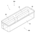
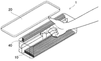
図1は、本発明の第1実施形態に係る保存容器1を示す斜視図である。なお、図中の破線は透明部材を通して見える各部材の輪郭、稜線、谷線を示す(図2、3、7、9〜17において同じ)。図2は、図1の保存容器1を示す分解斜視図である。図3(A)は図1の保存容器1を矢印IIIAの方向にみた平面図、図3(B)は図1の保存容器1を矢印IIIBの方向に見た正面図である。
Hereinafter, a storage container for stick-shaped dried noodles according to a plurality of embodiments embodying the present invention will be described with reference to the drawings.
(First Embodiment)
FIG. 1 is a perspective view showing a
保存容器1は全体的に長細い箱形状となっており、上部に開口を有する略直方体状の容器本体10と、容器本体10の開口を密閉可能な蓋20を有する。このような構成により、保存容器1は一定の長さに切り揃えられた棒状乾麺(スパゲッティ、うどん、そば、ラーメン等)を保存するのに適している。容器本体10はポリプロピレンなどの合成樹脂からなる。蓋20はポリエチレンやシリコーンゴムなどの合成樹脂からなり、一定の柔軟性を有する。好適な例においては、蓋20は容器本体10よりも柔軟な材料からなる。蓋20を取り付けるには、蓋20の縁を容器本体10の上縁の外側に嵌め合わせる。もしくは、蓋20が周縁に溝を有し、その溝を容器本体10の上縁に嵌合するものであってもよい。容器本体10と蓋20はいずれも透明であったり、容器本体10と蓋20のいずれか一方が透明であったり、容器本体10と蓋20の両方または一方の一部が透明であることによって、内部の棒状乾麺の状態、特に、後述する棒状乾麺の計量の状態が外から確認できるものとする。
The
容器本体10に蓋20を取り付けることで形成される密閉空間内に、ポリプロピレンなどの合成樹脂からなる2つの計量部材30が設置される。図示例の各計量部材30は複数の細長い板が組み合わされた形状を有する。図4は、図3(B)の保存容器の一点鎖線IV−IVにおける断面を矢印の方向に見た断面図である。図に示す計量部材30は、容器本体10の底面に略平行な板状の底部31と、底部31の一方の長手側の縁から上方向に壁状に立設される第1の壁部32と、底部31の同じ縁から下方向へ容器本体10の底面まで延在し底面に対して固着される壁状のスカート部33と、底部31の他方の長手側の縁から上方向に壁状に立設される第2の壁部34と、第2の壁部34の上端縁から容器本体10の底面に略平行に容器本体10の壁まで延在しその壁に対して固着または接触する板状の段部35とを有する。スカート部33または段部35を容器本体10の内面に対して固着する方法は接着や融着など、任意の方法を用い得る。図示例の計量部材30は透明な部材として描かれるが、計量部材30は不透明なものとしてもよく、その場合、合成樹脂製のもののほか、金属製や木製のもの等としてもよい。
Two measuring
図1、2、4に示すように、計量部材30の第1の壁部32と第2の壁部34の間は、上方が長手方向にわたって開放している。また、図1、3に示すように、2つの計量部材30は容器本体10内で長手方向に直列に並べられ、両計量部材30の間には人の指をスムーズに挿入できる程度の隙間(約2〜3センチメートルの隙間)が空けられている。
As shown in FIGS. 1, 2 and 4, the upper portion of the measuring
図4に示す通り、第1の壁部32と第2の壁部34は同じ高さである。第1の壁部32が本発明の「第1の側部」に該当し、第2の壁部34、段部35、容器本体の壁のうち段部35が固着または接触する部分から蓋20までの部分(壁部分36とする)が本発明の「第2の側部」に該当し、第2の側部は第1の側部より高い。この高さの差により、蓋20を容器本体10に取付けた状態においては、図4に示すように、第1の壁部32(第1の側部)と蓋20の間には高さ方向に所定の隙間ΔHが存在する。
底部31、第1の壁部32、第2の壁部34、段部35、壁部分36が本発明の「計量部」に該当する。
図4において、底部31、第1の壁部32、第2の壁部34が内側に画定する領域(一点鎖線アにより示す領域)を「計量領域」とすると、この計量領域内に充満するように入れられる棒状乾麺の量が、保存容器1で計量を行う目標となる量である。
As shown in FIG. 4, the
The
In FIG. 4, if the region defined inward by the
次に、図5を参照して、本実施形態に係る保存容器1を用いて棒状乾麺40の計量を行う際の使用例を説明する。
図5(A)は、容器本体10の内部にスパゲッティなどの棒状乾麺40を保存している状態を示す。図5(A)に示すように、棒状乾麺40は、容器本体10の底面と、壁と、スカート部33と、第1の壁部32によって区画される空間(図4において一点鎖線イにより示す領域。以下、「収容部」と呼ぶこととする)の内部に収容されている。保存容器1の長手方向の長さは、収容しようとする棒状乾麺40の長さよりある程度長く設定される。
Next, with reference to FIG. 5, an example of use when weighing the stick-shaped dried
FIG. 5A shows a state in which the stick-shaped dried
図5(A)の状態から、図5(B)に示すように保存容器1の全体を保存容器1の長手方向の軸を水平近くに保ちながら、計量部の側に傾けることで、収容部に収容されていた棒状乾麺40の少なくとも一部を計量部へ向けて流動させる。このとき、計量領域アを充満させる量よりも多い棒状乾麺40を、収容部から第1の壁部32を越えて計量部側へ流れ込ませる。計量部側へ流れ込んだ棒状乾麺40は、図5(B)に示すとおり、計量領域アを充満させるのみならず、計量部を形成する容器本体10の壁部分36とそれに接する蓋20の部分が成す隅部へも流れ込む。
From the state of FIG. 5 (A), as shown in FIG. 5 (B), the
次に、図5(B)の傾きとは反対の方向へ、保存容器1の長手方向の軸を水平近くに保ちながら、保存容器1全体を傾ける。より具体的には、図5(B)に示す様に計量部が下になった状態から、保存容器1の長手方向の軸を水平近くに保ちながら保存容器1全体を水平の位置まで一旦戻し、更に、保存容器1全体を収容部の側へ傾ける。これにより、図5(C)に示すように、計量部側へ流入していた棒状乾麺40の一部を、計量部側から第1の壁部32を越えてから収容部へとこぼして戻す。このとき、保存容器1の傾斜を調整して、計量領域アをほぼ過不足なく充満させる量の棒状乾麺40を擦り切るようにする。そのように棒状乾麺40を擦り切った状態で最初の姿勢に戻した状態を図5(D)に示す。これにより計量領域アを充満する量の棒状乾麺40を計量することができる。
このように計量した棒状乾麺40は、図6に示すように、蓋20を開けて2つの計量部材30間の隙間に指を入れて容易に掬い上げることができる。
Next, the
As shown in FIG. 6, the rod-shaped dried
このように、本実施形態の保存容器1は、保存容器1内に保管される棒状乾麺40が、保存容器1の長手方向に対して垂直な方向には流れるように移動する挙動を利用して、簡易な構造により、棒状乾麺40に直接手を触れることなく、必要量の棒状乾麺40を容易に計量できる。しかも、取出し開口の縁や他の棒状乾麺40との間で強い摩擦を生じることなく、かつ、計量された棒状乾麺40は1つの束形状にまとめられていることから、計量した棒状乾麺40を容易に取り出すことができるようになっている。
蓋20はヒンジ構造により容器本体10に取付けられていてもよい。
As described above, the
The
(第2実施形態)
次に、本発明の第2実施形態に係る保存容器101を、図7〜9に基づき説明する。図7は第2実施形態に係る保存容器101を示す斜視図である。本実施形態の保存容器101は、計量部材130の形状が、第1実施形態の保存容器1の計量部材30と異なる。図8は、図7の保存容器101の横断面図であり、第1実施形態の図4に代わるものである。ただし、図8に示す断面は後述する一つの凸部1371を通る断面である。図9は、本実施形態の計量部材130を取り出し分解して示す斜視図である。
(Second Embodiment)
Next, the
図8、9に基づきより具体的に説明すると、本実施形態の各計量部材130は、容器本体10の底面に略平行な板状の底部131と、底部131の一方の長手側の縁から上方向に壁状に立設される第1の壁部132と、底部131の同じ縁から下方向へ容器本体10の底面まで延在し底面に対して固着される壁状のスカート部133と、底部131の他方の長手側縁から上方向に壁状に立設される第2の壁部134と、第2の壁部134の上端部から容器本体10の底面に略平行に容器本体10の壁にまで延在しその壁に対して固着または接触する板状の段部135とを有する。
More specifically, each measuring
計量部材130は更に、第1の壁部132の収容部側の面に対して重ねられ、上下方向に移動可能な可動堰137を有する。更に、スカート部133の収容部側の面から上方へ向かって第1の壁部132と平行に延在する押さえ板138を有し、第1の壁部132と押さえ板138の間には所定の隙間が設けられ、その隙間に可動堰137を挿入できるようになっている。押さえ板138には上下方向に延在する2つの長円穴1381が、押さえ板138の長手方向に所定の間隔を空けて設けられており、可動堰137には長円穴1381の位置に対応する2箇所に2つの凸部1371が設けられている。可動堰137は第1の壁部132と押さえ板138の間の隙間に挿入されるとともに、可動堰137の2つの凸部1371はそれぞれ押さえ板138の2つの長円穴1381内に収められる。
The measuring
計量部材130の上記したような構造により、使用者は、可動堰137の2つの凸部1371を押さえ板138の2つの長円穴1381内で上下に移動させることで、可動堰137を第1の壁部132に対して上下動させることができる。こうして、可動堰137の高さを調整することができる。
計量部材130においては、第2の壁部134よりも第1の壁部132の方が低い。上記したような可動堰137の高さの調整により、可動堰137の上端の位置は、第2の壁部134より低い位置から、第2の壁部134と同じ高さの位置まで調節することができる。
Due to the above-mentioned structure of the measuring
In the measuring
本実施形態においては、底部131、第2の壁部134、可動堰137、第2の壁部134が画定する領域であって、可動堰137の高さを越えない領域(図8において一点鎖線アにより示す領域)が計量領域アに相当する。よって、可動堰137の高さを調整することによって、計量領域アの大きさを調整でき、図5の方法で計量できる棒状乾麺40の量を調整することができる。可動堰137に目盛を付して計量する棒状乾麺40の調整量を分かり易くしたり、ラッチ機構により、可動堰137の位置を固定し易くしたりしてもよい。
In the present embodiment, the region defined by the
第1の壁部132と可動堰137を組み合わせたものが本発明の「第1の側部」に該当し、第2の壁部134、段部135、容器本体の壁のうち段部135が固着または接触する部分から蓋20までの部分(壁部分136とする)が本発明の「第2の側部」に該当する。また、底部131、第1の壁部132、第2の壁部134、段部135、壁部分136、可動堰137が本発明の「計量部」を構成する。
The combination of the
(第3実施形態)
次に、本発明の第3実施形態に係る保存容器201を、図10、11に基づき説明する。図10は第3実施形態の保存容器201を示す斜視図であり、図11は分解斜視図である。本実施形態の保存容器201の計量部材30の形状は第1実施形態の計量部材30と同一である。ただし、本実施形態の計量部材30は、容器本体10に対して接着剤等により恒久的に固着されるのではなく、容器本体210の底面および壁の一部に延在する溝211に対して計量部材30のスカート部33を挿入することで容器本体10に対して固定される。このようにすることで、計量部材30を取り付ければ図5により説明したように棒状乾麺40の計量に用いることができ、計量部材30を取り外せば、容器本体1内に収容できる棒状乾麺40の量が増えるというように必要に応じて使い方を変更することができる。
(Third Embodiment)
Next, the
(第4実施形態)
次に、本発明の第4実施形態に係る保存容器301を、図12〜15に基づき説明する。図12は、本発明の第4実施形態に係る保存容器301を示す斜視図であり、図14は、図12の保存容器301を矢印XIVの方向に見た側面図である。第1実施形態との比較において、本実施形態の保存容器301の容器本体310は上部に開口を有する代わりに、長手方向の一端部側に開口を有する。蓋320は容器本体310の開口の上下の縁部分と摺接して横方向にスライドすることにより、容器本体310の開口を開閉可能となっている。
(Fourth Embodiment)
Next, the
図13は、図12の保存容器の使用例を示す斜視図であり、蓋320を一部開いた状態を示す。図15は、図13の保存容器を矢印XVの方向に見た側面図である。図5を参照して説明した第1実施形態に係る保存容器1による棒状乾麺40の計量方法と同様の方法により棒状乾麺40を計量し、計量領域アをほぼ過不足なく棒状乾麺40で満たした状態とした後、図15に示すように計量領域アを開放し、かつ、収容部を開放しない程度に蓋320を開く。この状態で保存容器301を開口側へ傾ければ、計量した棒状乾麺40を外部へ容易に取り出すことができる。計量領域アの上部が開放されており、計量された棒状乾麺40の見かけ上の断面積(すなわち計量領域アの面積)よりも容器本体部10の開口の開放部分の面積の方が大きく、かつ、所定量の棒状乾麺40が計量され、収容部に収容されている他の棒状乾麺40から分離されているため、計量した棒状乾麺40が計量部材330の底部331や壁部332、334や、他の棒状乾麺40と強い摩擦を生じることもない。結果、計量された棒状乾麺40が開口の縁や他の棒状乾麺40に引っ掛かることもなく、スムーズに取り出すことができる。
FIG. 13 is a perspective view showing an example of using the storage container of FIG. 12, and shows a state in which the
計量した棒状乾麺40を取り出すとき指で棒状乾麺40を掬い取る必要がないため、図12、13に示すように、本実施形態の計量部材330は長手方向に複数の部分に分かれていない。また、図12〜15に示すように、計量部材330は、底部331、第1の壁部332、スカート部333、第2の壁部334を有するが、第1実施形態の段部35に相当する部分を有さず、第2の壁部334が直接、容器本体310の壁に固着または接触する。なお、本実施形態において、「第2の側部」を構成する壁部分336は、第2の壁部334の上端と容器本体10の図示天面との間の壁の部分とすることができる。
更に第2の壁部334を廃して、底部331が直接、壁に固着または接触するようにしてもよい。この場合の壁部分336は、底部331との固着または接触部分と容器本体10の図示天面との間の壁の部分とすることができる。
蓋320はスライドにより開閉するものに限らず、ヒンジ構造により容器本体310の開口全体を開閉したり、収容部を除く開口の部分を開閉したりするものであってもよい。
As shown in FIGS. 12 and 13, the weighing
Further, the
The
(第5実施形態)
次に、本発明の第5実施形態に係る保存容器401を、図16、17に基づき説明する。図16は、本実施形態に係る保存容器401を示す斜視図であり、図17は、図16の保存容器401を示す平面図である。本実施形態の保存容器401は、第1実施形態の保存容器1の段部35を廃して、計量部材430の第2の壁部434が容器本体410の壁に直接固着または接触するようにし、計量部材430間の隙間に近接する容器本体410の壁の部分を外側へ膨出させ膨出部411としたものである。蓋420もその膨出に対応した形状となっている。これにより、計量した棒状乾麺を指で掬う際、指先が膨出部411内を通過できるため、棒状乾麺を容易に取り出すことができる。
なお、本実施形態において、「第2の側部」を構成する壁部分436は、第2の壁部434の上端と蓋420の間の壁の部分とすることができる。
更に第2の壁部434を廃して、底部431が直接、壁に固着または接触してもよい。この場合の壁部分436は、底部431との固着または接触部分と蓋420の間の壁の部分とすることができる
(Fifth Embodiment)
Next, the
In the present embodiment, the
Further, the
(変形例)
計量部材は2つでなく、3つ以上に分かれていてもよい。また、本明細書で説明した機能を発揮できる限り、計量部材を更に細分化してもよく、保存容器の長手方向に多数配列された櫛状の部材が集合したものとしてもよい。
第2実施形態では、可動堰137の高さを調整することによって、計量領域アの大きさを調整し、図5の方法で計量できる棒状乾麺40の量を調整したが、これに代えて、底部31、131、331、431の高さを調整することによって、計量領域アの大きさを調整し、図5の方法で計量できる棒状乾麺40の量を調整してもよい。例えば、底部31、131、331、431の内側底面に上げ底用の板を設置することにより、底部31、131、331、431の高さを調整してもよい。
本明細書の中で明示した公開特許公報等の内容は、その全ての内容を援用によって引用することとする。
(Modification example)
The measuring member may be divided into three or more instead of two. Further, as long as the functions described in the present specification can be exhibited, the measuring members may be further subdivided, or a large number of comb-shaped members arranged in the longitudinal direction of the storage container may be assembled.
In the second embodiment, the size of the measuring area a is adjusted by adjusting the height of the
The contents of published patent gazettes, etc. specified in this specification shall be cited by reference in their entirety.
1、101、201、301、401…保存容器
10、210、310、410…容器本体
20、320、420…蓋
30、130、330、430…計量部材
31、131、331、431…底部
32、132、332…第1の壁部
33、133、333…スカート部
34、134、334、434…第2の壁部
35、135…段部
36、136、336、436…壁部分
137…可動堰
138…押さえ板
211…溝
411…膨出部
1371…凸部
1381…長円穴
1, 101, 201, 301, 401 ...
Claims (5)
前記容器本体に取付けられ、前記開口を開閉可能である蓋と、
前記容器本体の内部に収容される計量部と、を有する棒状乾麺の保存容器であって、
前記容器本体は、前記開口から受け入れた棒状乾麺を収容する収容部を有し、
前記計量部は、底部と、該底部の両側に配置される第1及び第2の側部を有し、
前記計量部の底部は前記収容部の底部より高く、
前記第1の側部は前記収容部と前記計量部とを仕切り、
前記第2の側部は前記第1の側部より高く、
前記第1の側部と、前記蓋または前記容器本体の内面であって前記計量部及び前記収容部の底部に対向する内面と、の隙間を介して、前記棒状乾麺が前記収容部と前記計量部との間を流通する、棒状乾麺の保存容器であって、
前記計量部はその長手方向において複数の部分に分かれている保存容器。 A container body with an opening and
A lid attached to the container body and capable of opening and closing the opening,
A storage container for stick-shaped dried noodles having a measuring unit housed inside the container body.
The container body has an accommodating portion for accommodating rod-shaped dried noodles received from the opening.
The measuring portion has a bottom portion and first and second side portions arranged on both sides of the bottom portion.
The bottom of the weighing unit is higher than the bottom of the housing
The first side portion partitions the accommodating portion and the measuring portion.
The second side is higher than the first side
Through the gap between the first side portion and the inner surface of the lid or the container body facing the measuring portion and the bottom portion of the accommodating portion , the stick-shaped dried noodles form the accommodating portion and the weighing portion. A storage container for stick-shaped dried noodles that circulates between the parts.
The measuring unit is a storage container that is divided into a plurality of parts in the longitudinal direction thereof.
前記容器本体に取付けられ、前記開口を開閉可能である蓋と、
前記容器本体の内部に収容される計量部と、を有する棒状乾麺の保存容器であって、
前記容器本体は、前記開口から受け入れた棒状乾麺を収容する収容部を有し、
前記計量部は、底部と、該底部の両側に配置される第1及び第2の側部を有し、
前記計量部の底部は前記収容部の底部より高く、
前記第1の側部は前記収容部と前記計量部とを仕切り、
前記第2の側部は前記第1の側部より高く、
前記第1の側部と、前記蓋または前記容器本体の内面であって前記計量部及び前記収容部の底部に対向する内面と、の隙間を介して、前記棒状乾麺が前記収容部と前記計量部との間を流通する、棒状乾麺の保存容器であって、
前記第1の側部は上端部分が上下方向に動くことで上端の高さが可変である保存容器。 A container body with an opening and
A lid attached to the container body and capable of opening and closing the opening,
A storage container for stick-shaped dried noodles having a measuring unit housed inside the container body.
The container body has an accommodating portion for accommodating rod-shaped dried noodles received from the opening.
The measuring portion has a bottom portion and first and second side portions arranged on both sides of the bottom portion.
The bottom of the weighing unit is higher than the bottom of the housing
The first side portion partitions the accommodating portion and the measuring portion.
The second side is higher than the first side
Through the gap between the first side portion and the inner surface of the lid or the container body facing the measuring portion and the bottom portion of the accommodating portion , the stick-shaped dried noodles form the accommodating portion and the weighing portion. A storage container for stick-shaped dried noodles that circulates between the parts.
The first side portion is a storage container in which the height of the upper end is variable by moving the upper end portion in the vertical direction.
Priority Applications (2)
| Application Number | Priority Date | Filing Date | Title |
|---|---|---|---|
| JP2016147799A JP6894090B2 (en) | 2016-07-27 | 2016-07-27 | Stick-shaped dry noodle storage container with weighing function |
| PCT/JP2017/026322 WO2018021147A1 (en) | 2016-07-27 | 2017-07-20 | Stick-like dried noodle storage container having weight measuring function |
Applications Claiming Priority (1)
| Application Number | Priority Date | Filing Date | Title |
|---|---|---|---|
| JP2016147799A JP6894090B2 (en) | 2016-07-27 | 2016-07-27 | Stick-shaped dry noodle storage container with weighing function |
Publications (3)
| Publication Number | Publication Date |
|---|---|
| JP2018016352A JP2018016352A (en) | 2018-02-01 |
| JP2018016352A5 JP2018016352A5 (en) | 2019-09-05 |
| JP6894090B2 true JP6894090B2 (en) | 2021-06-23 |
Family
ID=61017310
Family Applications (1)
| Application Number | Title | Priority Date | Filing Date |
|---|---|---|---|
| JP2016147799A Active JP6894090B2 (en) | 2016-07-27 | 2016-07-27 | Stick-shaped dry noodle storage container with weighing function |
Country Status (2)
| Country | Link |
|---|---|
| JP (1) | JP6894090B2 (en) |
| WO (1) | WO2018021147A1 (en) |
Families Citing this family (1)
| Publication number | Priority date | Publication date | Assignee | Title |
|---|---|---|---|---|
| CN113335768B (en) * | 2021-06-15 | 2022-08-19 | 石家庄市雪芝莲文化传媒有限公司 | Medicine storage bottle convenient for taking medicine |
Family Cites Families (13)
| Publication number | Priority date | Publication date | Assignee | Title |
|---|---|---|---|---|
| JPS492260A (en) * | 1972-04-24 | 1974-01-10 | ||
| JPS53125567U (en) * | 1977-03-15 | 1978-10-05 | ||
| JPS5734156Y2 (en) * | 1977-11-29 | 1982-07-28 | ||
| JPS55100123U (en) * | 1979-01-01 | 1980-07-12 | ||
| JPH07309378A (en) * | 1994-05-15 | 1995-11-28 | Toooshiyou Rojitetsuku Kk | Small quantity measuring and supply structure, and small quantity measuring and supply stopper and container using the same structure |
| JPH08292085A (en) * | 1995-04-20 | 1996-11-05 | The Ikeda:Kk | Noodle weighing machine |
| JP2003237858A (en) * | 2002-02-12 | 2003-08-27 | Kaijirushi Hamono Kaihatsu Center:Kk | Storage container for food comprising fluid or aggregate of small solid matters |
| JP4231750B2 (en) * | 2003-08-05 | 2009-03-04 | アテナ工業株式会社 | Container with weighing function |
| JP2006105726A (en) * | 2004-10-04 | 2006-04-20 | Oizumi Bussan Tokyo:Kk | Instrument for measuring quantity of dried noodles |
| JP2009208814A (en) * | 2008-03-04 | 2009-09-17 | Shoichi Izeki | Container with function for measuring dried noodles |
| JP5746609B2 (en) * | 2011-12-21 | 2015-07-08 | 株式会社日清製粉グループ本社 | Dry noodle measuring instrument and dry noodle storage container |
| JP3179053U (en) * | 2012-08-02 | 2012-10-11 | 孝治 村岡 | Measuring instruments such as dry noodles |
| ES1081405Y (en) * | 2013-04-24 | 2013-09-02 | Gonzalez Antonio Serrano | FILIFORM FOOD METER DISPENSER |
-
2016
- 2016-07-27 JP JP2016147799A patent/JP6894090B2/en active Active
-
2017
- 2017-07-20 WO PCT/JP2017/026322 patent/WO2018021147A1/en active Application Filing
Also Published As
| Publication number | Publication date |
|---|---|
| WO2018021147A1 (en) | 2018-02-01 |
| JP2018016352A (en) | 2018-02-01 |
Similar Documents
| Publication | Publication Date | Title |
|---|---|---|
| US7997412B2 (en) | Dry ingredients container | |
| KR200386849Y1 (en) | A vessel cap having a keeping hall for a measuring spoon | |
| JP6894090B2 (en) | Stick-shaped dry noodle storage container with weighing function | |
| NL8002613A (en) | PACKAGING FOR POWDER MATERIAL. | |
| US3209961A (en) | Metering and dispensing container | |
| NL2007421C2 (en) | HOLDER FOR A LIQUID. | |
| US20170361985A1 (en) | Supplement Container System | |
| EP2526029B1 (en) | Test strip container with strip retainer and methods of manufacturing and utilization thereof | |
| US9863799B2 (en) | Powdered sugar scoop | |
| CA2254553C (en) | Measuring dispensing canister | |
| WO2006125292A1 (en) | Pill counting apparatus | |
| WO2014022112A1 (en) | Dry goods portion control container | |
| US1663103A (en) | Weight container | |
| US3511416A (en) | Metering spout | |
| US20150097002A1 (en) | Dry Ingredient Dispensing Unit | |
| JP7266280B2 (en) | weighing cap | |
| US4334361A (en) | Pasta gauge | |
| JP6745618B2 (en) | Measuring cup | |
| WO2017151739A1 (en) | Container | |
| KR101523932B1 (en) | Cruet | |
| US3456852A (en) | Measuring arrangement | |
| JP7364210B2 (en) | Cap for taking out solids and solids storage container using the same | |
| JP2011219151A (en) | Rod-like material reserving container | |
| JP2003237858A (en) | Storage container for food comprising fluid or aggregate of small solid matters | |
| SE514203C2 (en) | Storage and dispensing system |
Legal Events
| Date | Code | Title | Description |
|---|---|---|---|
| A521 | Written amendment |
Free format text: JAPANESE INTERMEDIATE CODE: A523 Effective date: 20190726 |
|
| A621 | Written request for application examination |
Free format text: JAPANESE INTERMEDIATE CODE: A621 Effective date: 20190726 |
|
| A131 | Notification of reasons for refusal |
Free format text: JAPANESE INTERMEDIATE CODE: A131 Effective date: 20201007 |
|
| A521 | Written amendment |
Free format text: JAPANESE INTERMEDIATE CODE: A523 Effective date: 20201204 |
|
| A131 | Notification of reasons for refusal |
Free format text: JAPANESE INTERMEDIATE CODE: A131 Effective date: 20210407 |
|
| TRDD | Decision of grant or rejection written | ||
| A01 | Written decision to grant a patent or to grant a registration (utility model) |
Free format text: JAPANESE INTERMEDIATE CODE: A01 Effective date: 20210511 |
|
| A61 | First payment of annual fees (during grant procedure) |
Free format text: JAPANESE INTERMEDIATE CODE: A61 Effective date: 20210525 |
|
| R150 | Certificate of patent or registration of utility model |
Ref document number: 6894090 Country of ref document: JP Free format text: JAPANESE INTERMEDIATE CODE: R150 |