US1663103A - Weight container - Google Patents
Weight container Download PDFInfo
- Publication number
- US1663103A US1663103A US57373A US5737325A US1663103A US 1663103 A US1663103 A US 1663103A US 57373 A US57373 A US 57373A US 5737325 A US5737325 A US 5737325A US 1663103 A US1663103 A US 1663103A
- Authority
- US
- United States
- Prior art keywords
- cover
- tray
- weights
- grooves
- holder
- Prior art date
- Legal status (The legal status is an assumption and is not a legal conclusion. Google has not performed a legal analysis and makes no representation as to the accuracy of the status listed.)
- Expired - Lifetime
Links
Images
Classifications
-
- G—PHYSICS
- G01—MEASURING; TESTING
- G01G—WEIGHING
- G01G21/00—Details of weighing apparatus
- G01G21/26—Counterweights; Poise-weights; Sets of weights; Holders for the reception of weights
Definitions
- This invention relates to holders of the kind in which the fractional parts of a set of Weights are kept in connection with Weighing instruments. -f
- the container and the cover are moreover so constructed that the cover can be easil removed when the Weights are to be use while under the same conditions the cover may be attached compactly at the bottom of the container to prevent the cover being lost or misplaced and to permit of placing theentire device inside the balance close to the scale pan in order to facilitate handling of the very small weights Without loss.
- a further object of the invention is to save space and material in the construction of the box which contains the full set of wei hts since by the use of my invention the holder for the. fractional Weights can be placed on edge without'loss or damage of 4o the Weights thereby permitting of making the box narrower than was formerly re-A quired where the holders were placed horizontally of the set.
- Figure 6 aperspective view showing the weight holder in an upright position in a box of the kind used in connection with weighing scales, to hold in addition to weights of larger size, ⁇ a container of the.
- the trays were usually closed when notin use by placing thereon a heavy slab of glass, sometimes provided with a knob or handle for its ready manipulation. This construction made it necessary that the Weight box be constantly maintained in a horizontal position to prevent the weights from spilling.
- my imroved weight holder consists of a. tray or ody member 5 which in common with the grooves 8 of hour-glass form which provide the means for the connection of the cover member of the device as will hereinafter be4 more fully explained.
- the cover member consists of a. vframe-part 9 preferably made of thin metal having at right angles to its body-portion 10, longitudinal flanges 12 adapted to slidably embrace the tray or body member 5 of the device as best shown in Figures 1 and .Il of the draw-- 1n s.
- top portion 10 of the frame has an oblong opening or window 13 through which the contents of the holder may be seen when the cover is in its normal position upon the tray member thereof and the flanges 12 of the frame are at their junctions with the top portion longitudinally beaded for the support of a glass plate 14k by means of which the window in the top is closed.
- the plate is slightly shorter than the cover and it is held against displacement by indentations 15 at the ends of the cover ⁇ engaging the ends thereof.
- the longitudinal Hanges are indented at central points to form inwardly projecting detents 17 adapted to enter the longitudinal grooves 8 in the sides of the tray member.
- the medial neck portions 8a of the grooves between their oppositely tapering sections correspond in width to the detents and the d-istance between the detents and the lower surface of the glass plate set in the frame of the cover, slightly exceeds the distance between the neck portions of the grooves and the upper surface of the tray so that when the cover is in place, it will be clampingly held in position by the frictional contact of the detents with thevslanting upper edges of the grooves., f
- a weight holder of the character described comprising a longitudinally grooved tray-member having a recessed top, and a flanged cover-member havingdetents fitted to ,the grooves o1 the tray member to hold the cover in contact with the recessed top of the same, and adapted to tighten the cover as the detents approach the longitudinal mid-point of the grooves.
- a weight holder of the character described comprising a tray member having a recessed tolp and tapering grooves at opposite sides t ereof, and a flanged cover-member having detents fitted to the grooves of thetray-member to hold the cover member in contact with the recessed top of the same, and adapted to tighten the cover as the detents approach the longitudinal mid-point 0f the grooves.
- a weight holder of the character described comprising a tray member having a recessed top and hour-glass shaped grooves at opposite sides thereof, and a anged cover-member having detents fitted to the grooves of the tray member to hold the cover Imember in contact with the recessed top of the same.
- a weight holder of the character described comprising a tray-member having a recessed top and longitudinally slantmg edges at opposite sides Ythere@incl a lianged cover-member having detents engagingsaid.,iN
- a weight holder of the c aracter described comprising a tray membrhzging a recessed top, and a removable cover-ineming means co-operative with the grooves to be held either in contact with the top of the tray or in a reversed position, beneath-the bottom of the same.
- a weight holder of the character described comprising a tray member havin grooves on the sides thereof; and a flangia? iliding cover member having detents to ti 13 1,ees,ws
Landscapes
- Physics & Mathematics (AREA)
- General Physics & Mathematics (AREA)
- Closures For Containers (AREA)
Description
K March zo, 192s. 1,663,103
E. w. THoMPsoN WEIGHT CONTAINER Filed Sept. 19. 1925 7 7 0 Willy V;
INVENTOR,
v F .Thompson S5 A i Patented Maf. 2o, 1928.
`UNITE) STATES A FRED w. THOMPSON, or DENVER, COLORADO.
WEIGHT CONTAINER.
vApplication led September 19, 1925. Serial No. 57,373.
This invention relates to holders of the kind in which the fractional parts of a set of Weights are kept in connection with Weighing instruments. -f
5 Heretofore, a piece of glass loosely laid over the compartments of the holder, which contain the fractionals, has been commonly lused to serve as a cover. In handling and transporting Weight boxes in which the holder is contained the smaller weights which are very thin, like tinfoil, are frequently jarred out of their compartments and damaged under the glass cover and since, when the weights are to be used, the
glass cover is merely laid aside, the latter is often lost and is subject to accidental breakage.
It is an object of the present invention to provide a suitable container with a practically non-breakable glass cover together with means for'holding it tightly in connection with the container when the weights are not in use.
vThe container and the cover are moreover so constructed that the cover can be easil removed when the Weights are to be use while under the same conditions the cover may be attached compactly at the bottom of the container to prevent the cover being lost or misplaced and to permit of placing theentire device inside the balance close to the scale pan in order to facilitate handling of the very small weights Without loss.
A further object of the invention is to save space and material in the construction of the box which contains the full set of wei hts since by the use of my invention the holder for the. fractional Weights can be placed on edge without'loss or damage of 4o the Weights thereby permitting of making the box narrower than was formerly re-A quired where the holders were placed horizontally of the set. In the old construction hereinbefore referred to, it was necessary to place the 4inner fractional container in a flat or horizontal position in order to keep the loose glass cover in position and pre-,
vent the small weights rombeing spilled in handling or transportation.
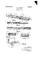
An embodiment of my invention has been illustrated in the accompan ing drawings in the several views of whic like parts are similarly designated and in which Figure 1 represents a perspective view of having its cover member in the reversed position to which it may be adjusted when the bo is opened to afford access to its contents; an
Figure 6, aperspective view showing the weight holder in an upright position in a box of the kind used in connection with weighing scales, to hold in addition to weights of larger size, `a container of the.
character of that ofthe present invention, 1n which the smaller weights are contained. It has been common practice to provide in connection with a weighing scale, holders y for Weights of small value, comprising a tra provided with a number of pockets in which the diierent Weights are arranged according to their sizes.
The trays were usually closed when notin use by placing thereon a heavy slab of glass, sometimes provided with a knob or handle for its ready manipulation. This construction made it necessary that the Weight box be constantly maintained in a horizontal position to prevent the weights from spilling.
When the tray was removed from its box in order to place it in convenient' proximity vto .the Weighing instrument, the utmost care was required to keep the Weights in their respective pockets, especially while the holder was moved from one place to another and a further objection to the old construction was that the glass lid was easily broken or misplaced.
All of the above disadvantages of the old method of closing the weight holder are eliminated by the use of my invention which` as stated before maintains the weights in place in the compartments of the holder irrespective of the position of the holder or the box in which it is contained.
Referrin further to the drawings,'my imroved weight holder consists of a. tray or ody member 5 which in common with the grooves 8 of hour-glass form which provide the means for the connection of the cover member of the device as will hereinafter be4 more fully explained. y
The cover member consists of a. vframe-part 9 preferably made of thin metal having at right angles to its body-portion 10, longitudinal flanges 12 adapted to slidably embrace the tray or body member 5 of the device as best shown in Figures 1 and .Il of the draw-- 1n s.
2gIhe top portion 10 of the frame has an oblong opening or window 13 through which the contents of the holder may be seen when the cover is in its normal position upon the tray member thereof and the flanges 12 of the frame are at their junctions with the top portion longitudinally beaded for the support of a glass plate 14k by means of which the window in the top is closed. The plate is slightly shorter than the cover and it is held against displacement by indentations 15 at the ends of the cover` engaging the ends thereof.
The longitudinal Hanges are indented at central points to form inwardly projecting detents 17 adapted to enter the longitudinal grooves 8 in the sides of the tray member.
The medial neck portions 8a of the grooves between their oppositely tapering sections correspond in width to the detents and the d-istance between the detents and the lower surface of the glass plate set in the frame of the cover, slightly exceeds the distance between the neck portions of the grooves and the upper surface of the tray so that when the cover is in place, it will be clampingly held in position by the frictional contact of the detents with thevslanting upper edges of the grooves., f
perform the three-fold function ofincreasing the rigidity of the cover, of providing thumb-ridges which facilitate the removalV of the cover from the tray, and of servin as feet for the stable support of' the ho der when the position of the cover relative to the body-member thereof is reversed as shown in Figure 5.
Having 'thus described thevstructural features of my improved weight holder, it will be readily apparent .that when the cover is in place on the tray, the clamping engagement of its detents in the grooves of the same will drew the glass plate tightly in contact with the recessed surfaceof the tray and hold the cover against accidental lengthwise displacement. The holder may thus be handled and placed in any position without danger of the weights spilling from their pockets, and when the weights are in use .the cover may be reversed and fastened beneath the holder to function as a supportas illustrated -in Figure 5.
What I claim and desire to secure by Letters Patent is:
1. A weight holder of the character described, comprising a longitudinally grooved tray-member having a recessed top, and a flanged cover-member havingdetents fitted to ,the grooves o1 the tray member to hold the cover in contact with the recessed top of the same, and adapted to tighten the cover as the detents approach the longitudinal mid-point of the grooves. e
2. A weight holder of the character described comprising a tray member having a recessed tolp and tapering grooves at opposite sides t ereof, and a flanged cover-member having detents fitted to the grooves of thetray-member to hold the cover member in contact with the recessed top of the same, and adapted to tighten the cover as the detents approach the longitudinal mid-point 0f the grooves.
3. A weight holder of the character described comprising a tray member having a recessed top and hour-glass shaped grooves at opposite sides thereof, and a anged cover-member having detents fitted to the grooves of the tray member to hold the cover Imember in contact with the recessed top of the same.
4:. A weight holder of the character described comprising a tray-member having a recessed top and longitudinally slantmg edges at opposite sides Ythere@incl a lianged cover-member having detents engagingsaid.,iN
edges to hold the covermembeiLin contact with the recessed top of the tra member. 5. A weight holder of the c aracter described comprising a tray membrhzging a recessed top, and a removable cover-ineming means co-operative with the grooves to be held either in contact with the top of the tray or in a reversed position, beneath-the bottom of the same.
rber held tightly in contact with the recessel\\V 1ra-W 7. A weight holder of the character described, comprising a tray member havin grooves on the sides thereof; and a flangia? iliding cover member having detents to ti 13 1,ees,ws
in they grooves the distance from the top of the detent to the under surface of the top of the cover being not more than the distance from the upper and' lower ed e of the groove 5 to tlhe top and bottomv of t e tray respective y.
A8. A weight holder ofthe character described, eomprising 'a tray member having grooves at the sides thereof, and a sliding vcover member having means cooperatin with '10'y Athe grooves of the tray, the cover mg adapted to slide on either the top orjlthe bottom of the tray member.
In testimony whereof I have aixed my signature. g
FRED W. THOMPSON.
Priority Applications (1)
| Application Number | Priority Date | Filing Date | Title |
|---|---|---|---|
| US57373A US1663103A (en) | 1925-09-19 | 1925-09-19 | Weight container |
Applications Claiming Priority (1)
| Application Number | Priority Date | Filing Date | Title |
|---|---|---|---|
| US57373A US1663103A (en) | 1925-09-19 | 1925-09-19 | Weight container |
Publications (1)
| Publication Number | Publication Date |
|---|---|
| US1663103A true US1663103A (en) | 1928-03-20 |
Family
ID=22010176
Family Applications (1)
| Application Number | Title | Priority Date | Filing Date |
|---|---|---|---|
| US57373A Expired - Lifetime US1663103A (en) | 1925-09-19 | 1925-09-19 | Weight container |
Country Status (1)
| Country | Link |
|---|---|
| US (1) | US1663103A (en) |
Cited By (13)
| Publication number | Priority date | Publication date | Assignee | Title |
|---|---|---|---|---|
| US2688307A (en) * | 1949-02-17 | 1954-09-07 | Nichols | Rubber stamp inking pad |
| US2708026A (en) * | 1950-06-26 | 1955-05-10 | Edith B Duell | Dispensing device |
| US2813653A (en) * | 1955-04-28 | 1957-11-19 | Arnold R Grossman | Display receptacle |
| US2965219A (en) * | 1959-03-16 | 1960-12-20 | Johannes A G Rhodin | Transparent sample holder for pathological specimens and the like |
| US2979742A (en) * | 1958-12-08 | 1961-04-18 | American Saw And Tool Company | Threading tool holder with slidable cover on hollow handle |
| US3003840A (en) * | 1960-07-26 | 1961-10-10 | Katzin Nathan | Chests for silverware and the like |
| US3004270A (en) * | 1958-12-08 | 1961-10-17 | Vermont American Corp | Multiple die receptacle for holding dies and for use as a die wrench |
| US3235062A (en) * | 1963-06-20 | 1966-02-15 | Ohaus Scale Corp | Storage container for laboratory weight sets |
| US4122944A (en) * | 1977-10-25 | 1978-10-31 | Vincent De Napoli | Tool box |
| USD339286S (en) | 1991-06-26 | 1993-09-14 | Glaxo Group Limited | Tablet case |
| US5974606A (en) * | 1996-12-19 | 1999-11-02 | Moberly; Jeffrey | CPR backboard and method of use |
| USD631513S1 (en) * | 2010-03-01 | 2011-01-25 | Weinert Tyson S | Carrier for business card and memory card |
| WO2017090302A1 (en) * | 2015-11-25 | 2017-06-01 | 株式会社明電舎 | Dynamometer-use calibration device, weight for dynamometer-use calibration device, weight shaft for dynamometer-use calibration device, and stowage box for weight for dynamometer-use calibration device |
-
1925
- 1925-09-19 US US57373A patent/US1663103A/en not_active Expired - Lifetime
Cited By (17)
| Publication number | Priority date | Publication date | Assignee | Title |
|---|---|---|---|---|
| US2688307A (en) * | 1949-02-17 | 1954-09-07 | Nichols | Rubber stamp inking pad |
| US2708026A (en) * | 1950-06-26 | 1955-05-10 | Edith B Duell | Dispensing device |
| US2813653A (en) * | 1955-04-28 | 1957-11-19 | Arnold R Grossman | Display receptacle |
| US2979742A (en) * | 1958-12-08 | 1961-04-18 | American Saw And Tool Company | Threading tool holder with slidable cover on hollow handle |
| US3004270A (en) * | 1958-12-08 | 1961-10-17 | Vermont American Corp | Multiple die receptacle for holding dies and for use as a die wrench |
| US2965219A (en) * | 1959-03-16 | 1960-12-20 | Johannes A G Rhodin | Transparent sample holder for pathological specimens and the like |
| US3003840A (en) * | 1960-07-26 | 1961-10-10 | Katzin Nathan | Chests for silverware and the like |
| US3235062A (en) * | 1963-06-20 | 1966-02-15 | Ohaus Scale Corp | Storage container for laboratory weight sets |
| US4122944A (en) * | 1977-10-25 | 1978-10-31 | Vincent De Napoli | Tool box |
| USD339286S (en) | 1991-06-26 | 1993-09-14 | Glaxo Group Limited | Tablet case |
| US5974606A (en) * | 1996-12-19 | 1999-11-02 | Moberly; Jeffrey | CPR backboard and method of use |
| USD631513S1 (en) * | 2010-03-01 | 2011-01-25 | Weinert Tyson S | Carrier for business card and memory card |
| WO2017090302A1 (en) * | 2015-11-25 | 2017-06-01 | 株式会社明電舎 | Dynamometer-use calibration device, weight for dynamometer-use calibration device, weight shaft for dynamometer-use calibration device, and stowage box for weight for dynamometer-use calibration device |
| JP2017096780A (en) * | 2015-11-25 | 2017-06-01 | 株式会社明電舎 | Calibration device of dynamometer, and weight, weight shaft, housing of weight for the same |
| CN108474708A (en) * | 2015-11-25 | 2018-08-31 | 株式会社明电舍 | Calibration device for dynamometer, weight for calibration device for dynamometer, weight shaft for calibration device for dynamometer, and storage box for weight for calibration device for dynamometer |
| US10317305B2 (en) | 2015-11-25 | 2019-06-11 | Meidensha Corporation | Dynamometer-use calibration device, weight for dynamometer-use calibration device, weight shaft for dynamometer-use calibration device, and stowage box for weight for dynamometer-use calibration device |
| CN108474708B (en) * | 2015-11-25 | 2020-02-11 | 株式会社明电舍 | Calibration device for load cell, weight for calibration device for load cell, weight shaft for calibration device for load cell, and storage box for weight for calibration device for load cell |
Similar Documents
| Publication | Publication Date | Title |
|---|---|---|
| US1663103A (en) | Weight container | |
| US4006821A (en) | Multi-tray container for storing elongate objects | |
| US2341600A (en) | Case for sound films | |
| US1968877A (en) | Bottle carrier | |
| US3362564A (en) | Sliding lid boxes | |
| US2723643A (en) | Beverage cup incorporating indicating means for designating character of contents | |
| NL9100709A (en) | HOLDER FOR STORING AND DELIVERING GOODS. | |
| US2921707A (en) | Combination bottle cap and dispenser | |
| US2034733A (en) | Measuring spoon | |
| US1984351A (en) | Container | |
| US4574978A (en) | Beverage container carrier | |
| US2525337A (en) | Noncrushable lunch-box pie container | |
| US505222A (en) | Physician s vial-case | |
| US3057524A (en) | Container structure | |
| US1991165A (en) | Hand-bag | |
| US2564244A (en) | Combined ledger tray and holder for business forms | |
| US2801453A (en) | Carton flap hold-down device | |
| US1867455A (en) | Carrying case | |
| US4334361A (en) | Pasta gauge | |
| US3463301A (en) | Slide shipping and storing container | |
| US2775368A (en) | Dispenser apparatus | |
| US1952016A (en) | Condiment container | |
| US1931372A (en) | Display case for cakes and crackers | |
| US3262559A (en) | Package with sliding sleeve | |
| US2089510A (en) | Pouring container |