JP6892629B2 - Recording device - Google Patents
Recording device Download PDFInfo
- Publication number
- JP6892629B2 JP6892629B2 JP2017055971A JP2017055971A JP6892629B2 JP 6892629 B2 JP6892629 B2 JP 6892629B2 JP 2017055971 A JP2017055971 A JP 2017055971A JP 2017055971 A JP2017055971 A JP 2017055971A JP 6892629 B2 JP6892629 B2 JP 6892629B2
- Authority
- JP
- Japan
- Prior art keywords
- medium
- transport
- sensor
- recording device
- recording
- Prior art date
- Legal status (The legal status is an assumption and is not a legal conclusion. Google has not performed a legal analysis and makes no representation as to the accuracy of the status listed.)
- Active
Links
Images


Classifications
-
- B—PERFORMING OPERATIONS; TRANSPORTING
- B41—PRINTING; LINING MACHINES; TYPEWRITERS; STAMPS
- B41J—TYPEWRITERS; SELECTIVE PRINTING MECHANISMS, i.e. MECHANISMS PRINTING OTHERWISE THAN FROM A FORME; CORRECTION OF TYPOGRAPHICAL ERRORS
- B41J11/00—Devices or arrangements of selective printing mechanisms, e.g. ink-jet printers or thermal printers, for supporting or handling copy material in sheet or web form
- B41J11/006—Means for preventing paper jams or for facilitating their removal
-
- B—PERFORMING OPERATIONS; TRANSPORTING
- B41—PRINTING; LINING MACHINES; TYPEWRITERS; STAMPS
- B41J—TYPEWRITERS; SELECTIVE PRINTING MECHANISMS, i.e. MECHANISMS PRINTING OTHERWISE THAN FROM A FORME; CORRECTION OF TYPOGRAPHICAL ERRORS
- B41J11/00—Devices or arrangements of selective printing mechanisms, e.g. ink-jet printers or thermal printers, for supporting or handling copy material in sheet or web form
- B41J11/0095—Detecting means for copy material, e.g. for detecting or sensing presence of copy material or its leading or trailing end
-
- B—PERFORMING OPERATIONS; TRANSPORTING
- B41—PRINTING; LINING MACHINES; TYPEWRITERS; STAMPS
- B41J—TYPEWRITERS; SELECTIVE PRINTING MECHANISMS, i.e. MECHANISMS PRINTING OTHERWISE THAN FROM A FORME; CORRECTION OF TYPOGRAPHICAL ERRORS
- B41J13/00—Devices or arrangements of selective printing mechanisms, e.g. ink-jet printers or thermal printers, specially adapted for supporting or handling copy material in short lengths, e.g. sheets
- B41J13/0009—Devices or arrangements of selective printing mechanisms, e.g. ink-jet printers or thermal printers, specially adapted for supporting or handling copy material in short lengths, e.g. sheets control of the transport of the copy material
- B41J13/0018—Devices or arrangements of selective printing mechanisms, e.g. ink-jet printers or thermal printers, specially adapted for supporting or handling copy material in short lengths, e.g. sheets control of the transport of the copy material in the sheet input section of automatic paper handling systems
-
- B—PERFORMING OPERATIONS; TRANSPORTING
- B41—PRINTING; LINING MACHINES; TYPEWRITERS; STAMPS
- B41J—TYPEWRITERS; SELECTIVE PRINTING MECHANISMS, i.e. MECHANISMS PRINTING OTHERWISE THAN FROM A FORME; CORRECTION OF TYPOGRAPHICAL ERRORS
- B41J13/00—Devices or arrangements of selective printing mechanisms, e.g. ink-jet printers or thermal printers, specially adapted for supporting or handling copy material in short lengths, e.g. sheets
- B41J13/0009—Devices or arrangements of selective printing mechanisms, e.g. ink-jet printers or thermal printers, specially adapted for supporting or handling copy material in short lengths, e.g. sheets control of the transport of the copy material
- B41J13/0027—Devices or arrangements of selective printing mechanisms, e.g. ink-jet printers or thermal printers, specially adapted for supporting or handling copy material in short lengths, e.g. sheets control of the transport of the copy material in the printing section of automatic paper handling systems
-
- B—PERFORMING OPERATIONS; TRANSPORTING
- B65—CONVEYING; PACKING; STORING; HANDLING THIN OR FILAMENTARY MATERIAL
- B65H—HANDLING THIN OR FILAMENTARY MATERIAL, e.g. SHEETS, WEBS, CABLES
- B65H29/00—Delivering or advancing articles from machines; Advancing articles to or into piles
- B65H29/66—Advancing articles in overlapping streams
- B65H29/6609—Advancing articles in overlapping streams forming an overlapping stream
-
- B—PERFORMING OPERATIONS; TRANSPORTING
- B65—CONVEYING; PACKING; STORING; HANDLING THIN OR FILAMENTARY MATERIAL
- B65H—HANDLING THIN OR FILAMENTARY MATERIAL, e.g. SHEETS, WEBS, CABLES
- B65H5/00—Feeding articles separated from piles; Feeding articles to machines
- B65H5/06—Feeding articles separated from piles; Feeding articles to machines by rollers or balls, e.g. between rollers
- B65H5/062—Feeding articles separated from piles; Feeding articles to machines by rollers or balls, e.g. between rollers between rollers or balls
-
- B—PERFORMING OPERATIONS; TRANSPORTING
- B65—CONVEYING; PACKING; STORING; HANDLING THIN OR FILAMENTARY MATERIAL
- B65H—HANDLING THIN OR FILAMENTARY MATERIAL, e.g. SHEETS, WEBS, CABLES
- B65H5/00—Feeding articles separated from piles; Feeding articles to machines
- B65H5/24—Feeding articles in overlapping streams, i.e. by separation of articles from a pile
-
- B—PERFORMING OPERATIONS; TRANSPORTING
- B65—CONVEYING; PACKING; STORING; HANDLING THIN OR FILAMENTARY MATERIAL
- B65H—HANDLING THIN OR FILAMENTARY MATERIAL, e.g. SHEETS, WEBS, CABLES
- B65H7/00—Controlling article feeding, separating, pile-advancing, or associated apparatus, to take account of incorrect feeding, absence of articles, or presence of faulty articles
- B65H7/02—Controlling article feeding, separating, pile-advancing, or associated apparatus, to take account of incorrect feeding, absence of articles, or presence of faulty articles by feelers or detectors
- B65H7/06—Controlling article feeding, separating, pile-advancing, or associated apparatus, to take account of incorrect feeding, absence of articles, or presence of faulty articles by feelers or detectors responsive to presence of faulty articles or incorrect separation or feed
- B65H7/12—Controlling article feeding, separating, pile-advancing, or associated apparatus, to take account of incorrect feeding, absence of articles, or presence of faulty articles by feelers or detectors responsive to presence of faulty articles or incorrect separation or feed responsive to double feed or separation
-
- B—PERFORMING OPERATIONS; TRANSPORTING
- B65—CONVEYING; PACKING; STORING; HANDLING THIN OR FILAMENTARY MATERIAL
- B65H—HANDLING THIN OR FILAMENTARY MATERIAL, e.g. SHEETS, WEBS, CABLES
- B65H2511/00—Dimensions; Position; Numbers; Identification; Occurrences
- B65H2511/20—Location in space
-
- B—PERFORMING OPERATIONS; TRANSPORTING
- B65—CONVEYING; PACKING; STORING; HANDLING THIN OR FILAMENTARY MATERIAL
- B65H—HANDLING THIN OR FILAMENTARY MATERIAL, e.g. SHEETS, WEBS, CABLES
- B65H2511/00—Dimensions; Position; Numbers; Identification; Occurrences
- B65H2511/40—Identification
- B65H2511/414—Identification of mode of operation
-
- B—PERFORMING OPERATIONS; TRANSPORTING
- B65—CONVEYING; PACKING; STORING; HANDLING THIN OR FILAMENTARY MATERIAL
- B65H—HANDLING THIN OR FILAMENTARY MATERIAL, e.g. SHEETS, WEBS, CABLES
- B65H2513/00—Dynamic entities; Timing aspects
- B65H2513/10—Speed
-
- B—PERFORMING OPERATIONS; TRANSPORTING
- B65—CONVEYING; PACKING; STORING; HANDLING THIN OR FILAMENTARY MATERIAL
- B65H—HANDLING THIN OR FILAMENTARY MATERIAL, e.g. SHEETS, WEBS, CABLES
- B65H2513/00—Dynamic entities; Timing aspects
- B65H2513/50—Timing
-
- B—PERFORMING OPERATIONS; TRANSPORTING
- B65—CONVEYING; PACKING; STORING; HANDLING THIN OR FILAMENTARY MATERIAL
- B65H—HANDLING THIN OR FILAMENTARY MATERIAL, e.g. SHEETS, WEBS, CABLES
- B65H2513/00—Dynamic entities; Timing aspects
- B65H2513/50—Timing
- B65H2513/52—Age; Duration; Life time or chronology of event
-
- B—PERFORMING OPERATIONS; TRANSPORTING
- B65—CONVEYING; PACKING; STORING; HANDLING THIN OR FILAMENTARY MATERIAL
- B65H—HANDLING THIN OR FILAMENTARY MATERIAL, e.g. SHEETS, WEBS, CABLES
- B65H2601/00—Problem to be solved or advantage achieved
- B65H2601/20—Avoiding or preventing undesirable effects
- B65H2601/25—Damages to handled material
- B65H2601/255—Jam
-
- B—PERFORMING OPERATIONS; TRANSPORTING
- B65—CONVEYING; PACKING; STORING; HANDLING THIN OR FILAMENTARY MATERIAL
- B65H—HANDLING THIN OR FILAMENTARY MATERIAL, e.g. SHEETS, WEBS, CABLES
- B65H2701/00—Handled material; Storage means
- B65H2701/10—Handled articles or webs
- B65H2701/13—Parts concerned of the handled material
- B65H2701/131—Edges
- B65H2701/1311—Edges leading edge
-
- B—PERFORMING OPERATIONS; TRANSPORTING
- B65—CONVEYING; PACKING; STORING; HANDLING THIN OR FILAMENTARY MATERIAL
- B65H—HANDLING THIN OR FILAMENTARY MATERIAL, e.g. SHEETS, WEBS, CABLES
- B65H2801/00—Application field
- B65H2801/03—Image reproduction devices
- B65H2801/06—Office-type machines, e.g. photocopiers
-
- B—PERFORMING OPERATIONS; TRANSPORTING
- B65—CONVEYING; PACKING; STORING; HANDLING THIN OR FILAMENTARY MATERIAL
- B65H—HANDLING THIN OR FILAMENTARY MATERIAL, e.g. SHEETS, WEBS, CABLES
- B65H2801/00—Application field
- B65H2801/03—Image reproduction devices
- B65H2801/15—Digital printing machines
Description
本発明は、媒体に記録を行う記録装置に関する。 The present invention relates to a recording device that records on a medium.
インクジェットプリンター(以下、単にプリンターと言う)に代表される記録装置において、記録処理のスループットを向上させる、すなわち、単位時間当たりの記録枚数を増加させるため、先に搬送される先行媒体の後端と後続媒体の先端とを重ねた状態で、記録ヘッドの記録領域に搬送する「重ね搬送」を行う場合がある(例えば、特許文献1)。 In a recording device typified by an inkjet printer (hereinafter, simply referred to as a printer), in order to improve the throughput of recording processing, that is, to increase the number of recording sheets per unit time, the rear end of the preceding medium conveyed first. In some cases, "overlapping transfer" is performed in which the tip of the succeeding medium is overlapped with the tip of the recording head to be conveyed to the recording area of the recording head (for example, Patent Document 1).
特許文献1において「重ね搬送」を実行する場合、記録ヘッド7の上流側に設けられる検知センサー16による媒体の検出結果に基づいて先行媒体や後続媒体の搬送位置を把握し、後続媒体の搬送を制御して搬送ローラ5の手前で後続媒体を先行媒体に追いつかせるとともに、先行媒体の後端に後続媒体の先端が重ねられる。
When "overlapping transfer" is executed in
しかし、搬送される媒体の種類や厚みの違いや、プリンターが使用される条件(温度や湿度など)の影響等によって媒体の搬送精度が変化すると、以下のような不具合が生じる場合がある。 例えば、後続媒体の実際の搬送量が予定搬送量より少ないと、先行媒体の後端と後続媒体の先端との重ね部分の量(以下、重ね量)が少なくなる。重ね量が少ないと、先行媒体の後端と後続媒体の先端が衝突して紙詰まりが生じたり、先行媒体と後続媒体の重なりの上下が逆になる等の不具合が生じる虞がある。 However, if the transport accuracy of the medium changes due to the difference in the type and thickness of the medium to be transported, the influence of the conditions (temperature, humidity, etc.) in which the printer is used, the following problems may occur. For example, when the actual transfer amount of the succeeding medium is smaller than the planned transfer amount, the amount of the overlapped portion between the rear end of the preceding medium and the front end of the succeeding medium (hereinafter referred to as the overlap amount) becomes small. If the stacking amount is small, the rear end of the preceding medium and the tip of the succeeding medium may collide with each other to cause a paper jam, or the overlapping of the preceding medium and the succeeding medium may be upside down.
また、後続媒体の実際の搬送量が予定搬送量より多いと、先行媒体に対して記録が行われている際には搬送ローラ5の手前で止まるはずの後続媒体の先端が、搬送ローラ5とピンチローラ6にニップされてしまう虞がある。このことにより、先行媒体の記録が終わる前に予期しない「重ね搬送」が行われてしまい、記録ヘッド7と媒体との距離が近くなることによる記録ヘッド7と媒体との擦れの発生や、本来は先行媒体に記録すべき内容を後続媒体に記録してしまう虞がある。
Further, if the actual transfer amount of the succeeding medium is larger than the planned transfer amount, the tip of the succeeding medium that should stop before the
本発明は、この様な問題に鑑み成されたものであり、その目的は、「重ね搬送」を行う際に、紙詰まりや記録画質の低下等の不具合の虞を抑制または回避できる記録装置を提供することにある。 The present invention has been made in view of such a problem, and an object of the present invention is to provide a recording device capable of suppressing or avoiding problems such as paper jams and deterioration of recording image quality when performing "stacking and transporting". To provide.
上記課題を解決するための、本発明の第1の態様に係る記録装置は、媒体を搬送する搬送部と、前記搬送部の下流側に位置し、搬送される媒体に記録を行う記録部と、前記搬送部の上流側において搬送される媒体の端部位置を検出する第1センサーと、前記第1センサーの上流側において搬送される媒体の端部位置を検出する第2センサーと、前記搬送部の上流側において、先に搬送された先行媒体の後端に後続媒体を追い付かせて重ねる重ね動作と、前記先行媒体の後端に前記後続媒体の先端を重ねた状態で前記搬送部による搬送を行う連送動作と、を含む重ね搬送制御を実行可能な制御部と、を備え、前記制御部は、前記先行媒体の先端の、前記第2センサーによる検出位置から前記第1センサーによる検出位置までの移動に係わる移動情報を取得し、前記移動情報をもとにして前記重ね搬送制御を行う、ことを特徴とする。 The recording device according to the first aspect of the present invention for solving the above problems includes a transport unit that conveys a medium and a recording unit that is located on the downstream side of the transport unit and records on the conveyed medium. The first sensor that detects the end position of the medium to be transported on the upstream side of the transport unit, the second sensor that detects the end position of the medium to be transported on the upstream side of the first sensor, and the transport. On the upstream side of the unit, a stacking operation in which the succeeding medium is made to catch up with the rear end of the previously transported preceding medium and stacked, and a transport by the transport unit with the tip of the succeeding medium superimposed on the rear end of the preceding medium. The control unit includes a control unit capable of performing stacking transfer control including a continuous feed operation for performing the above-mentioned operations, and the control unit is a detection position of the tip of the preceding medium from a detection position by the second sensor to a detection position by the first sensor. It is characterized in that the movement information related to the movement up to is acquired, and the stacking transfer control is performed based on the movement information.
本明細書において「先行媒体」とは、先に搬送される媒体であり、「後続媒体」とは、前記先行媒体に続いて搬送される媒体である。「先行媒体」は記録開始後の一枚目の媒体に限られず、「先行媒体」が記録開始後の二枚目の媒体であれば「後続媒体」は三枚目の媒体を意味するものとする。 また、前記先行媒体の先端の「前記第2センサーによる検出位置から前記第1センサーによる検出位置までの移動に係わる移動情報」は、例えば、前記先行媒体の先端の前記第2センサーによる検出位置から前記第1センサーによる検出位置までの移動速度や移動時間が挙げられる。 In the present specification, the "preceding medium" is a medium to be conveyed first, and the "successor medium" is a medium to be conveyed following the preceding medium. The "preceding medium" is not limited to the first medium after the start of recording, and if the "preceding medium" is the second medium after the start of recording, the "successor medium" means the third medium. To do. Further, the "movement information related to the movement from the detection position by the second sensor to the detection position by the first sensor" at the tip of the preceding medium is, for example, from the detection position by the second sensor at the tip of the preceding medium. Examples include the moving speed and the moving time to the detection position by the first sensor.
ここで、例えば、後続媒体が所定以上の距離を搬送されると、先行媒体の記録が終わる前に後続媒体が前記搬送部に進入して重ねて搬送されてしまう不具合が生じる虞がある。一方、後続媒体の搬送距離が所定以下であると、前記先行媒体の後端と前記後続媒体の先端の重ね量が少なくなり、紙詰まり等の不具合が生じる虞がある。 本態様によれば、前記制御部は、前記先行媒体の先端の、前記第2センサーによる検出位置から前記第1センサーによる検出位置までの移動に係わる移動情報を取得し、前記移動情報をもとにして前記重ね搬送制御を行うので、上記不具合を抑制または回避しつつ、前記連送動作の頻度を上げて記録処理のスループットを向上することができる。 Here, for example, if the succeeding medium is conveyed by a distance of a predetermined distance or more, there is a possibility that the succeeding medium may enter the conveying portion and be conveyed in an overlapping manner before the recording of the preceding medium is completed. On the other hand, if the transport distance of the succeeding medium is less than or equal to a predetermined distance, the amount of overlap between the rear end of the preceding medium and the tip of the succeeding medium is reduced, which may cause problems such as paper jams. According to this aspect, the control unit acquires movement information related to the movement of the tip of the preceding medium from the detection position by the second sensor to the detection position by the first sensor, and based on the movement information. Since the stacking transfer control is performed, the frequency of the continuous feeding operation can be increased to improve the throughput of the recording process while suppressing or avoiding the above-mentioned problems.
本発明の第2の態様は、第1の態様において、前記制御部は、前記先行媒体の後端側の余白量が予め設定される基準余白量よりも小さい場合に前記重ね搬送制御を実行せずに前記先行媒体の後端と前記後続媒体の先端との間に間隔を空けて搬送する非重ね搬送制御を行う、ことを特徴とする。 In the second aspect of the present invention, in the first aspect, the control unit executes the stacking transfer control when the margin amount on the rear end side of the preceding medium is smaller than the preset reference margin amount. It is characterized in that non-overlapping transport control is performed so that the trailing end of the preceding medium and the front end of the trailing medium are conveyed at intervals.
本態様によれば、前記制御部は、前記先行媒体の後端側の余白量が予め設定される基準余白量よりも小さい場合に前記重ね搬送制御を実行せずに前記先行媒体の後端と前記後続媒体の先端との間に間隔を空けて搬送する非重ね搬送制御を行うので、無理な重ね搬送制御のキャンセルにより重ね搬送制御の失敗を抑制できる。 According to this aspect, when the margin amount on the rear end side of the preceding medium is smaller than the preset reference margin amount, the control unit does not execute the stacking transfer control and is connected to the rear end of the preceding medium. Since the non-overlapping transport control for transporting the succeeding medium with a space between the tip of the succeeding medium is performed, it is possible to suppress the failure of the stacking transport control by forcibly canceling the stacking transport control.
本発明の第3の態様は、第2の態様において、前記第2センサーの上流側に、媒体を搬送する上流側搬送部を備え、前記制御部は、前記重ね動作の際に、前記後続媒体を前記搬送部の上流側の所定の待機位置まで搬送するように前記上流側搬送部を駆動する、ことを特徴とする。 In a third aspect of the present invention, in the second aspect, the upstream side transporting unit for transporting the medium is provided on the upstream side of the second sensor, and the control unit is the subsequent medium during the stacking operation. Is driven to a predetermined standby position on the upstream side of the transport unit.
本態様によれば、前記第2センサーの上流側に、媒体を搬送する上流側搬送部を備える記録装置において、前記制御部が、前記重ね動作の際に、前記後続媒体を前記搬送部の上流側の所定の待機位置まで搬送するように前記上流側搬送部を駆動し、前記重ね搬送制御を行うことができる。 According to this aspect, in a recording device provided with an upstream transport unit that transports a medium on the upstream side of the second sensor, the control unit moves the subsequent medium upstream of the transport unit during the stacking operation. The stacking transfer control can be performed by driving the upstream side transfer unit so as to transfer to a predetermined standby position on the side.
本発明の第4の態様は、第3の態様において、前記制御部は、前記移動情報から、前記移動情報に対して予め設定される基準情報を引いた差の絶対値が所定の許容値以上である場合に前記重ね搬送制御を実行せず、前記差の絶対値が前記所定の許容値未満である場合に前記重ね搬送制御を実行する、ことを特徴とする。 In the fourth aspect of the present invention, in the third aspect, the control unit has the absolute value of the difference obtained by subtracting the reference information preset for the movement information from the movement information is equal to or more than a predetermined allowable value. When the above is the case, the lap transfer control is not executed, and when the absolute value of the difference is less than the predetermined allowable value, the lap transfer control is executed.
前記移動情報から、前記移動情報に対して予め設定される基準情報を引いた差の絶対値が大きい場合、媒体の搬送が正常に行われていない可能性が高い。
本態様によれば、所定の許容値以上の場合には、前記媒体の搬送に異常があると判断し、前記重ね搬送制御を実行しないので、重ね搬送制御の失敗を抑制できる。
If the absolute value of the difference obtained by subtracting the preset reference information from the movement information is large, it is highly possible that the medium is not normally conveyed.
According to this aspect, when it is equal to or more than a predetermined allowable value, it is determined that there is an abnormality in the transport of the medium, and the stacking transport control is not executed, so that the failure of the stacking transport control can be suppressed.
本発明の第5の態様は、第4の態様において、前記移動情報は、前記先行媒体の先端が前記第2センサーによって検出されてから前記第1センサーによって検出されるまでの前記上流側搬送部の駆動量に基づいて算出される媒体搬送距離であり、前記基準情報は、予め取得された、前記第2センサーによる検出位置から前記第1センサーによる検出位置までの距離である、ことを特徴とする。 In a fifth aspect of the present invention, in the fourth aspect, the movement information is the upstream transport unit from the time when the tip of the preceding medium is detected by the second sensor to the time when the tip of the preceding medium is detected by the first sensor. It is a medium transport distance calculated based on the driving amount of the above, and the reference information is a distance from a detection position by the second sensor to a detection position by the first sensor, which is acquired in advance. To do.
本態様によれば、前記制御部が、前記移動情報として、前記先行媒体の先端が前記第2センサーによって検出されてから前記第1センサーによって検出されるまでの前記上流側搬送部の駆動量に基づいて算出される媒体搬送距離を用い、前記基準情報として、予め取得された、前記第2センサーによる検出位置から前記第1センサーによる検出位置までの距離を用い、前記重ね搬送制御を実行するか否かを判断することができる。 According to this aspect, the control unit uses the movement information as the driving amount of the upstream transport unit from the time when the tip of the preceding medium is detected by the second sensor to the time when the tip of the preceding medium is detected by the first sensor. Whether to execute the stacking transport control using the medium transport distance calculated based on the above and using the distance from the detection position by the second sensor to the detection position by the first sensor acquired in advance as the reference information. It is possible to judge whether or not.
本発明の第6の態様は、第5の態様において、前記制御部は、前記差が0より大きく且つ前記差の絶対値が前記所定の許容値未満の場合に、前記基準余白量に前記差を足した値を新たな前記基準余白量とする、ことを特徴とする。 In a sixth aspect of the present invention, in the fifth aspect, when the difference is larger than 0 and the absolute value of the difference is less than the predetermined allowable value, the control unit makes the difference to the reference margin amount. The value obtained by adding the above is used as the new reference margin amount.
本態様によれば、前記先行媒体の後端と前記後続媒体の先端の重ね量が少なくなる虞を低減し、紙詰まりや前記先行媒体と前記後続媒体の上下が逆転する等の不具合が生じる虞を低減できる。 According to this aspect, the possibility that the amount of overlap between the rear end of the preceding medium and the tip of the succeeding medium is reduced is reduced, and problems such as paper jams and the possibility that the preceding medium and the succeeding medium are reversed upside down may occur. Can be reduced.
本発明の第7の態様は、第5の態様または第6の態様において、前記制御部は、前記差が0より小さく且つ前記差の絶対値が前記所定の許容値未満の場合に、前記重ね動作を実行する際の媒体の搬送量として予め定められた基準搬送量から前記差の絶対値を引いた量を新たな基準搬送量とする、ことを特徴とする。 In a seventh aspect of the present invention, in the fifth or sixth aspect, the control unit performs the overlap when the difference is less than 0 and the absolute value of the difference is less than the predetermined allowable value. A new reference transport amount is obtained by subtracting the absolute value of the difference from a predetermined reference transport amount as the transport amount of the medium when the operation is executed.
本態様によれば、後続媒体が所定以上の距離を搬送されて、先行媒体の記録が終わる前に後続媒体が前記搬送部に進入して重ねて搬送されてしまう虞を低減できる。 According to this aspect, it is possible to reduce the possibility that the succeeding medium is transported a predetermined distance or more and the succeeding medium enters the transport unit and is stacked and transported before the recording of the preceding medium is completed.
本発明の第8の態様は、第7の態様において、前記基準余白量に前記差の絶対値を足した値を新たな前記基準余白量とすることを特徴とする。 An eighth aspect of the present invention is characterized in that, in the seventh aspect, a value obtained by adding the absolute value of the difference to the reference margin amount is used as the new reference margin amount.
前記連送動作を実行する前に、前記後続媒体を前記待機位置よりも前記差だけ上流側まで搬送するように前記上流側搬送部を駆動すると、当該後続媒体が、前記先行媒体(前記差がマイナス)よりも前記基準情報に近い搬送状態で搬送されたときに、前記先行媒体の後端と前記後続媒体の先端との重ね量が少なくなってしまう。前記重ね量が少ないと、前記先行媒体の後端と前記後続媒体の先端とが衝突して紙詰まりが生じたり、前記先行媒体と前記後続媒体の重なりの上下が逆になる等の不具合が生じる虞がある。
本態様によれば、後続媒体が、前記先行媒体(前記差がマイナス)よりも前記基準情報に近い搬送状態で搬送されたとしても、上記不具合が生じる虞を抑制または回避することができる。
When the upstream transport unit is driven so as to transport the trailing medium to the upstream side by the difference from the standby position before executing the continuous feed operation, the trailing medium becomes the preceding medium (the difference is When the vehicle is transported in a transport state closer to the reference information than the minus), the amount of overlap between the rear end of the preceding medium and the front end of the succeeding medium is reduced. If the stacking amount is small, the rear end of the preceding medium and the tip of the succeeding medium may collide with each other to cause a paper jam, or the overlapping of the preceding medium and the succeeding medium may be reversed. There is a risk.
According to this aspect, even if the succeeding medium is transported in a transport state closer to the reference information than the preceding medium (the difference is minus), the possibility of the above-mentioned trouble occurring can be suppressed or avoided.
本発明の第9の態様は、第2の態様から第7の態様のいずれか一つにおいて、前記制御部が取得する前記先行媒体の後端側の余白量は、前記第2センサーによる前記先行媒体の後端の検出情報に基づいて算出される、前記先行媒体に対する記録終了時の余白量である、ことを特徴とする。 In a ninth aspect of the present invention, in any one of the second to seventh aspects, the margin amount on the rear end side of the preceding medium acquired by the control unit is the preceding by the second sensor. The margin amount at the end of recording with respect to the preceding medium, which is calculated based on the detection information at the rear end of the medium.
本態様によれば、前記制御部が取得する前記先行媒体の後端側の余白量は、前記第2センサーによる前記先行媒体の後端の検出情報に基づいて算出される、前記先行媒体に対する記録終了時の余白量であるので、前記制御部による前記連送動作の当否の判断の確実性が増す。 According to this aspect, the margin amount on the rear end side of the preceding medium acquired by the control unit is calculated based on the detection information of the rear end of the preceding medium by the second sensor, and is recorded with respect to the preceding medium. Since it is the margin amount at the end, the certainty of the determination by the control unit as to whether or not the continuous feed operation is correct is increased.
本発明の第10の態様は、第1の態様から第9の態様のいずれか一つにおいて、前記制御部は、前記第1センサーと前記第2センサーとの間において、前記先行媒体の後端と前記後続媒体の先端との間に間隔がある際に前記移動情報の取得を行う、ことを特徴とする。 A tenth aspect of the present invention is any one of the first to ninth aspects, wherein the control unit is a rear end of the preceding medium between the first sensor and the second sensor. The movement information is acquired when there is a gap between the moving information and the tip of the succeeding medium.
本態様によれば、前記重ね搬送制御を行う頻度を高め、記録処理のスループットを向上することができる。 According to this aspect, it is possible to increase the frequency of performing the stacking transfer control and improve the throughput of the recording process.
本発明の第11の態様は、第4の態様から第8の態様のいずれか一つにおいて、前記基準情報は、装置における総記録枚数に応じて更新されることを特徴とする。 An eleventh aspect of the present invention is characterized in that, in any one of the fourth to eighth aspects, the reference information is updated according to the total number of recorded sheets in the apparatus.
装置における総記録枚数が増加すると、ローラー等の各種搬送手段の構成部材の摩耗等により、前記移動情報から前記基準情報を引いた差の絶対値が大きくなり易い傾向がある。前記差の絶対値が大きくなり易いと、前記連送動作を実行する頻度が減少する。これにより、記録処理のスループットが低下する場合がある。
本態様によれば、前記基準情報を、装置における総記録枚数に応じた前記構成部材の摩耗等を考慮した値に更新することができるので、記録装置の経時使用による記録処理のスループットの低下を抑制できる。
As the total number of recorded sheets in the device increases, the absolute value of the difference obtained by subtracting the reference information from the movement information tends to increase due to wear of constituent members of various conveying means such as rollers. When the absolute value of the difference tends to be large, the frequency of executing the continuous feed operation decreases. This may reduce the throughput of the recording process.
According to this aspect, the reference information can be updated to a value in consideration of wear of the constituent members according to the total number of recorded sheets in the apparatus, so that the throughput of the recording process can be reduced due to the use of the recording apparatus over time. Can be suppressed.
[実施例1]
まず、本発明の一実施例に係る記録装置の概略について説明する。記録装置の一例として、インクジェットプリンター1(以下、単にプリンター1という)を例に挙げる。
図1は、本発明に係るプリンターの外観を表す斜視図である。図2は、本発明に係るプリンターの側断面図である。図3は、本発明に係るプリンターにおける用紙搬送経路を表す図である。図4は、重ね搬送制御における重ね動作について説明する図である。図5は、重ね搬送制御における連送動作について説明する図である。図6は、重ね搬送制御について説明する図である。図7は、重ね搬送制御について説明する図である。図8は、重ね搬送制御の一例を示すフローチャートである。図9は、移動情報に基づく重ね搬送制御について説明する図である。図10は、移動情報に基づく重ね搬送制御の一例を示すフローチャートである。
[Example 1]
First, an outline of the recording device according to an embodiment of the present invention will be described. As an example of the recording device, an inkjet printer 1 (hereinafter, simply referred to as a printer 1) will be taken as an example.
FIG. 1 is a perspective view showing the appearance of the printer according to the present invention. FIG. 2 is a side sectional view of the printer according to the present invention. FIG. 3 is a diagram showing a paper transport path in the printer according to the present invention. FIG. 4 is a diagram illustrating a stacking operation in the stacking transfer control. FIG. 5 is a diagram illustrating a continuous feed operation in the stacking transport control. FIG. 6 is a diagram illustrating stacking transfer control. FIG. 7 is a diagram illustrating stacking transfer control. FIG. 8 is a flowchart showing an example of stacking transfer control. FIG. 9 is a diagram illustrating stacking transport control based on movement information. FIG. 10 is a flowchart showing an example of overlapping transport control based on movement information.
尚、各図において示すX−Y−Z座標系は、X方向が記録ヘッドの走査方向であり、記録が行われる媒体の幅方向である。Y方向が装置奥行き方向であり、媒体の長さ方向である。Z方向は重力方向であり、装置高さ方向である。また、+Y方向側を装置前面側とし、−Y方向側を装置背面側とする。また、装置前面側から見て左側を+X方向、右側を−X方向とする。また、+Z方向を装置上方(上部、上面等を含む)とし、−Z方向側を装置下方(下部、下面等を含む)とする。
また、以下において、プリンター1において用紙が搬送されていく搬送方向を「下流」といい、これと反対の方向を「上流」という。
In the XYZ coordinate system shown in each figure, the X direction is the scanning direction of the recording head, and the width direction of the medium on which recording is performed. The Y direction is the device depth direction and the medium length direction. The Z direction is the direction of gravity and the height direction of the device. Further, the + Y direction side is the front side of the device, and the −Y direction side is the back side of the device. Further, the left side is the + X direction and the right side is the −X direction when viewed from the front side of the device. Further, the + Z direction is the upper side of the device (including the upper part, the upper surface, etc.), and the −Z direction side is the lower side of the device (including the lower part, the lower surface, etc.).
Further, in the following, the transport direction in which the paper is conveyed in the
■■■プリンターの概要■■■
プリンター1(図1)は、媒体としての用紙Pに記録を行うプリンターユニット2と、原稿の画像を読み取るスキャナーユニット3とを備える複合機として構成されている。スキャナーユニット3は、プリンターユニット2の上部に設けられている。
プリンターユニット2において記録が行われる用紙Pとしては、一例として普通紙や厚紙、写真用紙等が挙げられる。
■■■ Printer Overview ■■■
The printer 1 (FIG. 1) is configured as a multifunction device including a
Examples of the paper P on which recording is performed in the
プリンターユニット2内に設けられる記録ヘッド10(図2)による記録後の用紙Pは、図1において装置前面に設けられる排出口4から出て、排紙トレイ5に載置される。
装置前面において符号6は、電源ボタンや各種印刷設定・記録実行を行う操作ボタン、印刷設定内容や印刷画像のプレビュー表示などを行う表示部等を備えて成る操作パネルである。
The paper P after recording by the recording head 10 (FIG. 2) provided in the
■■■プリンターにおける用紙の搬送経路について■■■
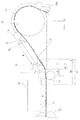
続いて、主として図2及び図3を参照して、プリンターユニット2における用紙Pの搬送経路について説明する。尚、図2及び図3において、一点鎖線Sが用紙の搬送経路を示している。
プリンターユニット2は、底部に複数の用紙を収容する2段の用紙トレイ7、用紙トレイ8を備え、用紙トレイ7、用紙トレイ8のいずれかから用紙が1枚ずつ給送される。
用紙は、用紙トレイ7から第1給送ローラー11(ピックアップローラーとも言う)により一旦装置背面側(−Y方向)に送られ、第1駆動源15(図3)によって駆動される中間ローラー13によって湾曲されて装置前面側(+Y方向)に送られる。また、用紙トレイ8からも同様に、第2給送ローラー12によって一旦装置背面側に送られ、中間ローラー13によって湾曲されて装置前面側に送られる。符号14a、14bは、中間ローラー13の回転に従動回転する従動ローラーである。
用紙トレイ7から給送される用紙の搬送経路と、用紙トレイ8から給送される用紙の搬送経路は、中間ローラー13と従動ローラー14aのニップ点の手前(上流側)で合流している。
■■■ About the paper transport route in the printer ■■■
Subsequently, the transport path of the paper P in the
The
Paper is once fed from the
The paper transport path fed from the
尚、第1給送ローラー11及び第2給送ローラー12は、それぞれ揺動軸11a、揺動軸12aを軸として揺動可能に構成され、用紙トレイ7、用紙トレイ8に収容される複数枚の用紙の一番上の用紙に接触するように構成されている。
また、第1給送ローラー11は、中間ローラー13と共通の第1駆動源15(図3)によって駆動されるように構成されている。第1駆動源15は、正転及び逆転が可能なモーターであり、例えば、第1駆動源15が正転で駆動されるときは、第1給送ローラー11と中間ローラー13の双方が搬送方向に回転し、第1駆動源15が逆転で駆動されるときは、中間ローラー13のみが搬送方向に回転するようになっている。第2給送ローラー12は、第1駆動源15とは別の駆動源(不図示)により駆動される。
用紙トレイ7から給紙する際は、第1駆動源15を正転で駆動して第1給送ローラー11と中間ローラー13の双方を搬送方向に回転させるとともに、第2給送ローラー12用の前記駆動源は停止されている。一方、用紙トレイ8から給紙する際は、第1駆動源15を逆転で駆動して中間ローラー13のみを搬送方向に回転させるとともに、第2給送ローラー12用の前記駆動源を駆動するようになっている。
第1駆動源15及び第2給送ローラー12用の駆動源の駆動は、後述する制御部20(図3)によって制御される。
The
Further, the
When feeding paper from the
The drive of the drive source for the
また、図3に示すように、中間ローラー13と従動ローラー14bとのニップ箇所よりも直ぐ下流側の位置には、そのニップ箇所から送り出された用紙を案内してその送り出し方向を目標方向へ変更させる案内部材26が配置されている。用紙の給送時に、中間ローラー13と従動ローラー14bとのニップ箇所から送り出された用紙は、斜状の案内面27(図3)に沿って上限高さを保ちつつ斜め下方へ向かうように搬送される。また、案内面27の下方には、給送された用紙が案内部材26から垂れ下がった状態にあるときにその垂れ下がり部分を支持したり、案内部材26から落下した後の用紙の後端部を支持したりする支持部材24が配置されている。
Further, as shown in FIG. 3, the paper fed from the nip portion is guided to a position immediately downstream of the nip portion between the
中間ローラー13の下流側には、用紙を搬送する「搬送部」としての搬送ローラー対16が設けられている。搬送ローラー対16は、第2駆動源17(図3)によって回転駆動される搬送駆動ローラー16aと、搬送駆動ローラー16aに接して従動回転する搬送従動ローラー16bとを備えている。
On the downstream side of the
用紙の搬送経路において中間ローラー13と搬送ローラー対16の間には、搬送ローラー対16の上流側において搬送される用紙の端部位置を検出する第1センサー21(図3)と、第1センサー21の上流側において搬送される用紙の端部位置を検出する第2センサー22(図3)と、が設けられている。尚、本実施形態において、第1センサー21及び第2センサー22はレバー式のセンサーが用いられているが、例えば光学式のセンサーを用いることもできる。
Between the
搬送ローラー対16の下流側(装置前面側、+Y軸方向)には、用紙に記録を行う「記録部」としての記録ヘッド10が設けられている。用紙は搬送ローラー対16によって記録ヘッド10の下へと送られる。
A
記録ヘッド10は、用紙搬送方向(Y軸方向)と交差する幅方向(X軸方向)に移動可能に構成されるキャリッジ18に保持されており、記録ヘッド10による記録領域K(図4)に送られる用紙に対して「液体」としてのインクを吐出することにより記録が行われるように構成されている。キャリッジ18には、記録ヘッド10にインクを供給するインクカートリッジ19が搭載されている。
また、記録ヘッド10には、用紙搬送方向(Y軸方向)の端部位置と用紙Pの幅方向(X軸方向)の端部位置とを検出するための第3センサー25を備えている。第3センサー25は、用紙Pに向けて光を照射する不図示の発光部と、前記発光部から照射された光の反射光を受ける受光部を備える光学式のセンサーである。
The
Further, the
記録ヘッド10の下流側(装置前面側、+Y方向)には、排出ローラー対23が設けられている。排出ローラー対23は、排出駆動ローラー23aと、排出駆動ローラー23aに接して従動回転する排出従動ローラー23bとを備え、記録後の用紙は、排出駆動ローラー23aと排出従動ローラー23bにニップされて、装置前面側に設けられる排紙トレイ5に排出される。
尚、プリンター1は、両面印刷が可能に構成されており、図3において二点鎖線で示すスイッチバック経路Rを備えている。おもて面への記録が終了した用紙は、搬送ローラー対16或いは排出ローラー対23を逆回転させることにより−Y軸方向に送られてスイッチバック経路Rを通り、再度中間ローラー13と従動ローラー14aにニップされるとともに反転されて、搬送経路Sに入るように構成されている。搬送経路Rは、支持部材24(図3)の下方を通る経路である。
A
The
またプリンター1は、図4に示すように、先に搬送された先行媒体P1の後端に後続媒体P2の先端を重ねた状態で搬送ローラー対16による搬送を行う「重ね搬送」を実行可能に構成されている。 「重ね搬送」は、制御部20が、搬送ローラー対16の上流側において、先行媒体P1の後端に後続媒体P2を追い付かせて重ねる「重ね動作」と、先行媒体P1の後端に後続媒体P2の先端を重ねた状態で搬送ローラー対16による搬送を行う「連送動作」と、を含む重ね搬送制御を実行することにより行われる。 以下、制御部20による「重ね搬送制御」について説明する。
Further, as shown in FIG. 4, the
■■■重ね搬送制御について■■■
まず、図4〜図7を参照して、制御部20による「重ね搬送制御」の基本的な動作について説明する。
先行媒体P1(本実施形態においては分かり易くするため一枚目の用紙とする)が中間ローラー13により搬送されると、先行媒体P1の先端が第2センサー22によって検出される(図6の上図)。
先行媒体P1が更に搬送されると、先行媒体P1の先端が第1センサー21によって検出される(図6の中図)。
第1センサー21の検出位置A1を通過した先行媒体P1は、搬送ローラー対16により更に下流側に搬送される。そして、図6の下図のように先行媒体P1の先端が記録ヘッド10による記録領域Kに入ると、記録ヘッド10による先行媒体P1への記録が開始される。
■■■ About stacking transfer control ■■■
First, with reference to FIGS. 4 to 7, the basic operation of the "overlapping transfer control" by the
When the preceding medium P1 (referred to as the first sheet in the present embodiment is used as the first sheet for clarity) is conveyed by the
When the preceding medium P1 is further conveyed, the tip of the preceding medium P1 is detected by the first sensor 21 (middle view of FIG. 6).
The preceding medium P1 that has passed through the detection position A1 of the
先行媒体P1は、搬送ローラー対16によって下流側に搬送されつつ記録が実行される。図7の上図に示すように、先行媒体P1の後端が第2センサー22による検出位置A2を通過した後、先行媒体P1と間隔を空けて後続媒体P2が中間ローラー13により送られてくる。後続媒体P2の先端が第2センサー22により検出されると、制御部20(図3)が、中間ローラー13を駆動する第1駆動源15(図3)を制御して、先行媒体P1の後端に後続媒体P2を追い付かせて重ねる「重ね動作」を実行する(図7の中図)。
Recording is executed while the leading medium P1 is conveyed downstream by the
具体的には、制御部20は、後続媒体P2の先端が第2センサー22によって検出されてから、第1センサー21と第2センサー22との間の距離Mと所定距離L1とを足した距離を基準搬送量(M+L1)として搬送するように中間ローラー13を駆動する。これにより、後続媒体P2の先端が待機位置Tまで搬送される。
待機位置Tは、搬送ローラー対16のニップ点から距離L2上流側に離れた位置に設定されており、距離L2は、待機状態にある後続媒体P2が搬送ローラー対16にニップされる虞が無い距離として設定されている。したがって、所定距離L1は、後続媒体P2の先端が待機位置Tに位置するように、距離L2に基づいて予め算出される。
Specifically, the
The standby position T is set at a position away from the nip point of the
後続媒体P2は、先端が待機位置Tにある状態で、先行媒体P1に対する記録が終わるまで待機する。先行媒体P1に対する記録が終わると(図7の下図、及び図4)、制御部20が中間ローラー13及び搬送ローラー対16を駆動し、先行媒体P1の後端に後続媒体P2の先端を重ねた状態で搬送ローラー対16による搬送を行う「連送動作」(図5)を実行する。
The succeeding medium P2 waits until the recording with respect to the preceding medium P1 is completed with the tip end in the standby position T. When the recording with respect to the preceding medium P1 is completed (the lower figure of FIG. 7 and FIG. 4), the
尚、「重ね動作」は、先行媒体P1の記録の最終パスを実行中(搬送ローラー対16は停止している)に、後続媒体P2の先端を搬送ローラー対16のニップ点に突き当たるまで送ることにより行うこともできる。
「重ね動作」を行うと、後続媒体の先端を第3センサー25により検出することができない。したがって、先行媒体P1の記録の最終パスを実行中に後続媒体P2の先端を搬送ローラー対16のニップ点に突き当てることにより後続媒体P2のスキュー取りをするとともに、この位置を後続媒体P2の先端の基準位置として後続媒体P2に対する記録を行うことができる。
In the "overlapping operation", while the final path of recording of the preceding medium P1 is being executed (the
When the "stacking operation" is performed, the tip of the succeeding medium cannot be detected by the
また、「重ね動作」における重ね方には、後続媒体P2の先端部を先行媒体P1の後端部の上側に重ねる上重ねと、後続媒体P2の先端部を先行媒体P1の後端部の下側に重ねる下重ねとがある。本実施形態の重ね動作は上重ねで行われる。そのため、後続媒体P2の先端部を先行媒体P1の後端部の上側に重ねる必要がある。そこで、案内部材26は、重ね動作で先行媒体P1と後続媒体P2とが正しい重ね順で重なるように、中間ローラー13の従動ローラー14bとのニップ箇所から送り出される用紙の送り出し方向を上重ねし易い上側寄りの案内方向へ変更する。中間ローラー13の最終ニップ(従動ローラー14bとのニップ箇所)から所定の給送速度で送り出された用紙を、案内部材26の上面に沿わせることでその送り出し方向をより上側の略水平方向へ変更し、略水平方向へ送り出されたのちの用紙を斜状の案内面27に沿って上限位置を保ちつつ搬送ローラー対16へ向かって搬送させるようにしている。これにより後続媒体P2を先行媒体P1に対して上側(記録面側)から重ねる上重ねがより高い頻度で成功する。
Further, in the stacking method in the "stacking operation", the tip portion of the succeeding medium P2 is superposed on the upper side of the rear end portion of the preceding medium P1, and the tip portion of the succeeding medium P2 is placed below the rear end portion of the preceding medium P1. There is a bottom layer that overlaps on the side. The stacking operation of the present embodiment is performed by stacking on top. Therefore, it is necessary to superimpose the front end portion of the succeeding medium P2 on the upper side of the rear end portion of the preceding medium P1. Therefore, the
図3に示す案内部材26は、重ね動作時の送り出し方向へ用紙を案内可能な姿勢(例えば水平姿勢)に固定されていてもよいが、「重ね動作」を行わないときに、送り出し方向を上側寄りへ変更するときに搬送中の用紙に抵抗負荷を与えることは好ましくない。そのため、案内部材26を「重ね動作」時に用紙を案内するときの姿勢をとる案内位置(図3に示す位置)と、重ね動作以外のときに媒体Pを案内しない姿勢もしくは案内される媒体Pが受ける負荷を軽減する姿勢をとる退避位置(図示省略)との間を変位可能に設けることが好ましい。
The
案内部材26は、例えば、案内部材26の後端側(−Y軸方向側)に揺動軸を設け、前記案内位置(図3)と、案内部材26の先端(+Y軸方向側端部)が斜め下向きの姿勢をとる前記退避位置(図示省略)と、の間で揺動させる揺動方式で変位させることができる。
また、案内部材26を、図3に示す案内位置と、前記案内位置よりも−Y軸方向に位置して案内部材26が経路中に突出しない退避位置(図示省略)と、の間でスライドさせるスライド方式で変位させることもできる。
The
Further, the
また、案内部材26は、ばねの付勢力(ばね荷重)で前記案内位置に保持し、用紙のコシの強さに応じてばね荷重が用紙のコシに負けて前記退避位置に変位する方式で変位させることもできる。例えば写真用紙などの厚紙からなる用紙の場合、用紙のコシに負けて案内部材26が退避位置へ変位するときの変位量が相対的に大きく、普通紙などの薄紙からなる用紙の場合、用紙のコシが弱いので、案内部材26が退避するときの変位量が相対的に小さい。このように用紙のコシの強さに応じた変位量で案内部材26が退避するので、用紙が案内部材26から受ける負荷を軽減できる。なお、ばね加重で案内部材26を変位させる機構は、揺動方式にもスライド方式にも適用できる。
案内部材26は、勿論、ソレノイドや電動モーター等の動力源を用いて実現することもできる。すなわち、動力源の動力により案内部材26を前記案内位置と前記退避位置とに変位させる。この動力源を用いた機構は、揺動方式にもスライド方式にも適用可能である。
Further, the
Of course, the
ここで、図4において、後続媒体P2の先端は、先行媒体P1の後端側において記録が行われない余白(図4において符号Dで示す部分)の一部に重ねられる。先行媒体P1の後端の余白に後続媒体P2の先端を少しでも重ねて記録ヘッド10の記録領域Kに搬送すれば、記録処理のスループットは向上するが、実際には、記録ヘッド10や搬送ローラー対16の配置等の設計上の理由から、「重ね搬送制御」を実行可能な余白量Dには制限がある。
Here, in FIG. 4, the tip of the succeeding medium P2 is overlapped with a part of the margin (the portion indicated by reference numeral D in FIG. 4) where recording is not performed on the rear end side of the preceding medium P1. If the tip of the trailing medium P2 is overlapped with the margin at the rear end of the leading medium P1 as much as possible and transported to the recording area K of the
「重ね搬送制御」を実行可能な余白量Dの制限は、以下のような理由による。
すなわち、図4における余白量Dが少なくなると、先行媒体P1に対する記録終了時に搬送ローラー対16のニップ点より上流側(−Y軸方向側)に残る部分が少なくなる。距離L2は待機状態にある後続媒体P2が搬送ローラー対16にニップされる虞が無いように設定されるので短くできない。したがって、余白量Dが少なくなると、先行媒体P1の後端と後続媒体P2の先端との重ね部分の量(以下、重ね量F)が少なくなる。重ね量Fが少ないと、図5に示す「連送動作」を実行する際に先行媒体P1の後端と後続媒体P2の先端が衝突して紙詰まりが生じたり、先行媒体P1と後続媒体P2の重なりの上下が逆になる等の不具合が生じる虞がある。
The limitation of the margin amount D capable of executing the "layered transfer control" is due to the following reasons.
That is, when the margin amount D in FIG. 4 is reduced, the portion remaining on the upstream side (−Y axis direction side) of the nip point of the
そのため、本実施形態では、先行媒体P1の後端の余白量Dが予め設定される基準余白量D0以上である場合に「重ね搬送制御」を制御部20が実行する。言い換えると、制御部20は、先行媒体P1の後端側の余白量Dが基準余白量D0よりも小さい場合に「重ね搬送制御」を実行せずに先行媒体P1の後端と後続媒体P2の先端との間に間隔を空けて搬送する「非重ね搬送制御」を行う。
Therefore, in the present embodiment, the
以下において、図8のフローチャートを参照して、先行媒体P1の後端の余白量Dを参照して行う「重ね搬送制御」の流れを説明する。
まず、先行媒体P1の後端に後続媒体P2の先端を重ねる「重ね動作(図7の中図)」を行う(ステップS1)。ステップS1に続き、制御部20が先行媒体P1に対する記録終了時(図4、及び図7の下図)の余白量Dが基準余白量D0以上であるか否かを判断する(ステップS2)。ステップS2において、余白量Dが基準余白量D0以上である(YES)である場合には「連送動作」を実行する(ステップS3)。後続媒体P2に続く次の後続媒体がある場合(ステップS4においてYES)には、次の後続媒体に対して重ね動作(ステップS1)から繰り返す。後続媒体P2に続く次の後続媒体がない場合(ステップS4においてNO)には、「重ね搬送制御」は終了する。
In the following, the flow of "overlapping transfer control" performed with reference to the margin amount D at the rear end of the preceding medium P1 will be described with reference to the flowchart of FIG.
First, a "stacking operation (middle view of FIG. 7)" is performed in which the tip of the trailing medium P2 is superposed on the rear end of the leading medium P1 (step S1). Following step S1, the
また、ステップS2において、余白量Dが基準余白量D0未満(NO)である場合には、「重ね搬送制御」がキャンセルされる(ステップS5)。「重ね搬送制御」がキャンセルされると、制御部20は、先行媒体P1の後端と後続媒体P2の先端との間に間隔を空けて搬送する「非重ね搬送制御」を実行する。
以上のように、先行媒体P1に対する記録終了時の余白量Dが少ない場合には無理な重ね搬送制御を行わないことにより、「重ね搬送制御」の失敗を抑制できる。
Further, in step S2, when the margin amount D is less than the reference margin amount D0 (NO), the "overlap transfer control" is canceled (step S5). When the "overlapping transport control" is canceled, the
As described above, when the margin amount D at the end of recording with respect to the preceding medium P1 is small, the failure of the "overlapping transfer control" can be suppressed by not performing the unreasonable overlap transfer control.
ところで、基準余白量D0を、「重ね搬送制御」を実行可能なぎりぎりの値に設定すると、「重ね動作」を行う際、すなわち、後続媒体P2が図7の上図から図7の中図のように搬送される際の、中間ローラー13の搬送精度の影響により、以下に説明する2つの不具合が生じる場合がある。 「重ね動作」の際に後続媒体P2が基準搬送量(M+L1)以上搬送されると、先行媒体P1の記録が終わる前に後続媒体P2が搬送ローラー対16にニップされて搬送されてしまう不具合[以下、不具合(1)と言う場合がある]が発生する虞がある。 逆に、後続媒体P2の搬送距離が基準搬送量(M+L1)に満たないと、先行媒体P1の後端と後続媒体P2の先端の重ね量Fが少なくなり、図5に示す「連送動作」の際に搬送ローラー対16における紙詰まりや先行媒体P1と後続媒体P2の重なりの上下が逆になる等の不具合[以下、不具合(2)と言う場合がある]が発生する虞がある。
By the way, when the reference margin amount D0 is set to a value at the limit where the "overlap transfer control" can be executed, when the "overlap operation" is performed, that is, the succeeding medium P2 is shown in the upper figure of FIG. 7 to the middle figure of FIG. Due to the influence of the transfer accuracy of the
一方で、基準余白量D0を大きく設定すると、不具合(1)や不具合(2)は回避することができるが、「重ね搬送制御」を実行する頻度が減少するため、プリンター1における記録処理のスループットが低下する。
On the other hand, if the reference margin amount D0 is set large, the defect (1) and the defect (2) can be avoided, but the frequency of executing the "overlap transfer control" decreases, so that the throughput of the recording process in the
このような、後続媒体P2の搬送精度に起因する不具合(1)や不具合(2)を抑制または回避しつつ、プリンター1における記録処理のスループットの向上を図るため、制御部20は、先行媒体P1の先端の、図4に示す第2センサー22による検出位置A2から第1センサー21による検出位置A1までの移動に係わる移動情報を取得し、前記移動情報をもとにして「重ね搬送制御」を行うように構成されている。
前記移動情報としては、例えば、先行媒体P1の先端の、第2センサー22による検出位置A2から第1センサー21による検出位置A1までの移動時間、移動速度、中間ローラー13の駆動量、第1駆動源15の駆動量、中間ローラー13の駆動量或いは第1駆動源15の駆動量に基づいて計算される先行媒体P1の搬送距離等が挙げられる。 以下、先行媒体P1の先端の、検出位置A2から検出位置A1までの移動に係わる前記移動情報に基づく「重ね搬送制御」について、具体例を挙げて説明する。
In order to improve the throughput of the recording process in the
The movement information includes, for example, the movement time, the movement speed, the driving amount of the
■■■移動情報に基づく重ね搬送制御について■■■
本実施形態では、前記「移動情報」として、先行媒体P1の先端が第2センサー22によって検出されてから第1センサー21によって検出されるまでの間の、中間ローラー13の駆動量に基づいて計算される先行媒体P1の「搬送距離M1」を用いる。 中間ローラー13の駆動量は、例えば、中間ローラー13にエンコーダー(不図示)を設けることにより検出することができる。もちろん、第1駆動源15にエンコーダー(不図示)を設け、第1駆動源15の駆動量に基づき中間ローラー13の駆動量を算出こともできる。
■■■ About stacking transfer control based on movement information ■■■
In the present embodiment, the "movement information" is calculated based on the driving amount of the
中間ローラー13の駆動量に基づく計算値である搬送距離M1は、中間ローラー13による搬送精度に全く異常がない場合であれば、予め取得される第2センサー22による検出位置A2から第1センサー21による検出位置A1までの距離M(検出位置A2から検出位置A1までの現実の距離)に等しいはずである。 しかし、搬送される用紙Pの種類や厚みの違いや、プリンター1が使用される条件(温度や湿度等)の影響などの何等かの理由によって用紙Pの搬送精度が変化する場合がある。したがって、中間ローラー13の駆動量から算出される搬送距離M1と、検出位置A2から検出位置A1までの実際の距離Mとの間には差がある場合がある。 また逆に、距離Mそれ自体が不適切な場合もある。具体的には、例えば距離Mは予め製品の組立工程において取得し、不揮発性メモリ等の記憶手段に保存されているが、組立工程において取得した際の距離Mそれ自体を誤った値として取得している場合もあり、この様な場合も上記搬送距離M1と、距離Mとの間には差が生じる。
The transport distance M1, which is a calculated value based on the drive amount of the
以下、搬送距離M1(中間ローラー13の駆動量に基づく計算値)から距離Mを引いた時の差をEとする(搬送距離M1−距離M=差E)。尚、本実施形態において、検出位置A2から検出位置A1までの「距離M」は、搬送距離M1(先行媒体P1の先端の、検出位置A2から検出位置A1までの移動に係わる移動情報)に対して、組立工程にて予め設定される「基準情報」である。また、以下において、搬送距離M1と距離Mとの差Eの絶対値を|E|で表す。 Hereinafter, the difference when the distance M is subtracted from the transport distance M1 (calculated value based on the driving amount of the intermediate roller 13) is defined as E (transport distance M1-distance M = difference E). In the present embodiment, the "distance M" from the detection position A2 to the detection position A1 is the transport distance M1 (movement information related to the movement of the tip of the preceding medium P1 from the detection position A2 to the detection position A1). This is "reference information" that is preset in the assembly process. Further, in the following, the absolute value of the difference E between the transport distance M1 and the distance M is represented by | E |.
通常、連続して記録を行う際の先行媒体P1と後続媒体P2は、同じ用紙トレイ(例えば図3に示す用紙トレイ7)から給送され、紙種等も同じである。したがって、後続媒体P2は、先行媒体P1と同様の搬送精度で中間ローラー13によって搬送されると考えられる。このことから、検出位置A2から検出位置A1までの先行媒体P1の先端の搬送距離M1(移動情報)に基づく搬送精度を、「重ね動作(図7の中図)」を実行する際における後続媒体P2の搬送精度と見なし、制御部20による制御を行う。以下、図10に示すフローチャートを参照し、搬送距離M1と距離Mとの差Eの値に応じた制御について説明する。
Normally, the preceding medium P1 and the succeeding medium P2 for continuous recording are fed from the same paper tray (for example, the
初めに、制御部20は、搬送距離M1と距離Mとの差Eの絶対値|E|が許容値|H1|以上であるか否かを判断する(ステップS11)。言い換えると、搬送距離M1と距離Mとの差Eがプラスである場合は、差Eが+H1以上であるか否かを判断し、差Eがマイナスである場合は、差Eが−H1以下であるか否かを判断する。 許容値|H1|は、例えば、5mm〜6mm程度(本実施形態のプリンター1においては5.8mm)に設定することができる。
First, the
◆◆|E|≧許容値|H1|のとき◆◆
差Eの絶対値|E|が大きすぎる場合、中間ローラー13による用紙の搬送が正常に行われていない可能性が高い。
したがって、制御部20は、搬送距離M1(移動情報)から、搬送距離M1に対して予め設定される距離M(基準情報)を引いた差Eの絶対値|E|が所定の許容値|H1|以上であるかどうかを判断し(ステップS11)、絶対値|E|が所定の許容値|H1|以上である場合(YES)に、「重ね搬送制御」をキャンセルして実行しない(ステップS20)ように構成されている。つまり、E≦−H1または+H1≦Eである場合にステップS20に進み、「重ね搬送制御」をキャンセルする。
◆◆ | E | ≧ Allowable value | H1 | ◆◆
If the absolute value | E | of the difference E is too large, it is highly possible that the paper is not normally conveyed by the
Therefore, in the
このことにより、「重ね搬送制御」が失敗する虞を抑制或いは回避することができる。「重ね搬送制御」をキャンセルすると、制御部20は、先行媒体P1の後端と後続媒体P2の先端との間に間隔を空けて搬送する「非重ね搬送制御」を実行する。
This makes it possible to suppress or avoid the possibility that the "layered transport control" will fail. When the "stacked transport control" is canceled, the
尚、許容値|H1|は、例えばドライバー情報の紙種に応じて変えることができる。一例として、搬送時に絶対値|E|が大きくなり易い傾向の用紙が設定された場合には、許容値|H1|を、普通紙の場合に比べて大きくすることができる。搬送時に絶対値|E|が大きくなり易い傾向の用紙としては、例えば、中間ローラー13により用紙の湾曲を伴って搬送する湾曲搬送経路において、所定の坪量よりも大きい用紙(普通紙よりも厚い用紙である専用紙など、いわゆる厚紙)が考えられる。すなわち、湾曲搬送経路における用紙に作用するバックテンションは、用紙の厚さが増すにつれて大きくなるため、厚紙を搬送する場合には想定よりも搬送されにくくなる。
搬送時に絶対値|E|が大きくなり易い傾向の用紙のその他の例としては、写真用紙のようなコーティングされた用紙が考えられる。すなわち、コーティングされた面と搬送ローラーとが接触する際に発生する摩擦力がコーティングされていない用紙と比べて小さくなるため、コーティングされている用紙を搬送する場合にはローラーと用紙との間に滑りが発生し、想定よりも搬送されにくくなる。尚、コーティングされた用紙の場合、所定の坪量より大きい用紙でないとしても、搬送時に絶対値|E|が大きくなり易い。
ステップS11において、絶対値|E|が所定の許容値|H1|未満である場合(NO)はステップS12に進む。つまり、−H1<E<+H1のときにステップS12に進む。
The permissible value | H1 | can be changed, for example, according to the paper type of the driver information. As an example, when a paper having a tendency for the absolute value | E | to be large during transportation is set, the permissible value | H1 | can be made larger than that of plain paper. As a paper in which the absolute value | E | tends to increase during transportation, for example, a paper having a basis weight larger than a predetermined basis weight (thicker than plain paper) in a curved transport path in which the
As another example of paper in which the absolute value | E | tends to increase during transportation, coated paper such as photo paper can be considered. That is, since the frictional force generated when the coated surface and the transport roller come into contact with each other is smaller than that of the uncoated paper, the coated paper is between the roller and the paper when the coated paper is transported. Sliding occurs, making it harder to transport than expected. In the case of coated paper, the absolute value | E | tends to increase during transportation even if the paper is not larger than the predetermined basis weight.
In step S11, if the absolute value | E | is less than the predetermined allowable value | H1 | (NO), the process proceeds to step S12. That is, when −H1 <E <+ H1, the process proceeds to step S12.
ステップS12では、差Eが−H1<E<+H1である場合のうち、搬送誤差が少なく、差Eの値がある程度の範囲に収まる状態(−H2<E<+H2)であるか、許容値|H1|未満であるものの、やや誤差が大きい状態(−H1<E<−H2、或いは+H2<E<+H1のとき)であるか、を判断する。 尚、|H2|は|H1|よりも小さくは0に近い値である。例えば、2mm程度(本実施形態のプリンター1においては2.3mm)に設定することができる。
In step S12, among the cases where the difference E is −H1 <E <+ H1, the transport error is small and the value of the difference E is within a certain range (−H2 <E <+ H2) or the allowable value | It is determined whether the error is slightly larger than H1 | (when −H1 <E <−H2 or + H2 <E <+ H1). Note that | H2 | is smaller than | H1 | and is a value close to 0. For example, it can be set to about 2 mm (2.3 mm in the
◆◆(1)−H2<E<+H2のとき◆◆ ステップS12において、(1)−H2<E<+H2であると判断された場合、中間ローラー13による先行媒体P1の搬送精度はほぼ目論見通りであるので、中間ローラー13が後続媒体P2を第2センサー22の検出位置A2(図4)から基準搬送量(M+L1)搬送する「重ね動作」を行う方向で一旦判断する(ステップS13)。 続いて、先行媒体P1に対する記録終了時(図4、及び図7の下図)における余白量Dが基準余白量D0以上であるか否かを判断するステップS14を行う。
◆◆ (1) -H2 <E <+ H2 ◆◆ In step S12, if it is determined that (1) -H2 <E <+ H2, the transfer accuracy of the preceding medium P1 by the
ステップS14において、余白量Dが基準余白量D0以上である(YES)である場合には「連送動作(図5)」を実行する(ステップS15)。
ステップS15の実行後、ステップS21において後続媒体P2のあとに次の後続媒体がないと判断される場合(NO)には「重ね搬送制御」を終了する。後続媒体P2のあとに次の後続媒体があると判断される場合(YES)には、(1)−H2<E<+H2である場合の「重ね動作」(ステップS13)から再度実行する。
また、ステップS14において、余白量Dが基準余白量D0未満(NO)である場合には、「重ね搬送制御」をキャンセルする(ステップS20)。
In step S14, if the margin amount D is equal to or greater than the reference margin amount D0 (YES), the “continuous feed operation (FIG. 5)” is executed (step S15).
After the execution of step S15, if it is determined in step S21 that there is no next succeeding medium after the succeeding medium P2 (NO), the "overlapping transfer control" is terminated. If it is determined that there is a next succeeding medium after the succeeding medium P2 (YES), the operation is executed again from (1) -H2 <E <+ H2 "overlapping operation" (step S13).
Further, in step S14, if the margin amount D is less than the reference margin amount D0 (NO), the "overlap transfer control" is canceled (step S20).
◆◆(2)+H2<E<+H1のとき◆◆ ステップS12において、差Eは許容値|H1|未満であるが、プラス側の値(正の数)で所定の誤差がある[(2)+H2<E<+H1]と判断された場合、中間ローラー13が後続媒体P2を第2センサー22の検出位置A2(図4)から基準搬送量(M+L1)搬送する「重ね動作」を行う(ステップS16)。 ここで、Eが正の数(E>0)、すなわち搬送距離M1(計算値)>距離M(基準情報)であるということは、先行媒体P1を距離Mだけ搬送するために、距離Mよりも多い搬送距離M1を搬送する駆動量で、中間ローラー13が駆動したことを意味する。言い換えると、中間ローラー13を搬送距離M1の分だけ駆動しても、先行媒体P1は距離Mしか進まなかったということである。
◆◆ (2) + H2 <E <+ H1 ◆◆ In step S12, the difference E is less than the permissible value | H1 |, but there is a predetermined error in the positive value (positive number) [(2). When it is determined that + H2 <E <+ H1], the
したがって、ステップS16において行う「重ね動作」の際に、後続媒体P2を第2センサー22の検出位置A2から基準搬送量(M+L1)だけ搬送するように中間ローラー13を駆動しても、後続媒体P2は基準搬送量(M+L1)より少ない距離しか進まず、図9に示すように後続媒体P2の先端が待機位置Tに到達しない虞がある。図9において、後続媒体P2の先端は待機位置Tより差Eの分だけ上流側に位置している。後続媒体P2の先端が待機位置Tまで到達しないと、先行媒体P1の後端と後続媒体P2の先端との重ね量は、後続媒体P2の先端が待機位置Tに位置する際の重ね量Fよりも、差Eの分だけ少ない重ね量F1となってしまい、上記不具合(2)が発生し易くなる。
Therefore, even if the
これを回避するため、ステップS12において、(2)+H2<E<+H1であると判断された場合には、ステップS16に続いて行うステップS17において、先行媒体P1の記録終了時の余白量Dに基づく判断を行う際に、基準余白量D0に差Eを足した値(D0+E)を新たな基準余白量D1(図9)とする。 すなわち、ステップS17において、制御部20は、先行媒体P1に対する記録終了時の余白量Dが基準余白量D1(=D0+E)以上であるか否かを判断する。ステップS17において、余白量Dが基準余白量D1以上である(YES)と判断される場合には、「連送動作」を実行(ステップS15)する。また、余白量Dが基準余白量D1未満(NO)である場合には、「重ね搬送制御」をキャンセルする(ステップS20)して終了する。
In order to avoid this, when it is determined in step S12 that (2) + H2 <E <+ H1, in step S17 performed following step S16, the margin amount D at the end of recording of the preceding medium P1 is set. When making a judgment based on this, the value (D0 + E) obtained by adding the difference E to the reference margin amount D0 is set as the new reference margin amount D1 (FIG. 9). That is, in step S17, the
このように、ステップS17において用いる基準余白量D1として、基準余白量D0に差Eの絶対値|E|を足した値(D0+|E|)を用いることにより、「重ね動作」の際の中間ローラー13による後続媒体P2の搬送に、許容範囲内ではあるものの無視するには大きい搬送誤差(+H2<E<+H1の範囲)があっても、先行媒体P1の後端と後続媒体P2の先端の重ね量が少なくなる虞を低減し、以って、不具合(2)が発生する虞を低減できる。
As described above, by using the value (D0 + | E |) obtained by adding the absolute value | E | of the difference E to the reference margin amount D0 as the reference margin amount D1 used in step S17, it is intermediate in the "overlapping operation". Even if there is a transfer error (+ H2 <E <+ H1 range) that is within the permissible range but is large to ignore in the transfer of the subsequent medium P2 by the
◆◆(3)−H1<E<−H2のとき◆◆
ステップS12において、差Eは許容値|H1|未満であるが、マイナス側の値(負の数)で所定の誤差がある[(3)−H1<E<−H2]と判断された場合、つまり搬送距離M1(計算値)<距離M(基準情報)である場合、先行媒体P1を、距離Mよりも少ない搬送距離M1を搬送する駆動量で中間ローラー13が駆動されたにもかかわらず、先行媒体P1が距離M搬送されたことを意味する。つまり、中間ローラー13により先行媒体P1が予定より多く搬送されている。
この場合、「重ね動作」の際の中間ローラー13の駆動を、(1)−H2<E<+H2の場合や(2)+H2<E<+H1の場合と同様に、後続媒体P2が第2センサー22の検出位置A2(図4)から基準搬送量(M+L1)搬送されるように行うと、後続媒体P2の先端が待機位置Tを越えてしまう虞がある。後続媒体P2の先端が待機位置Tを越えると、先行媒体P1の記録が終わる前に後続媒体P2が搬送ローラー対16により搬送される不具合(1)が発生する虞がある。
◆◆ (3) When -H1 <E <-H2 ◆◆
In step S12, when it is determined that the difference E is less than the permissible value | H1 |, but there is a predetermined error in the negative value (negative number) [(3) −H1 <E <−H2]. That is, when the transport distance M1 (calculated value) <distance M (reference information), even though the
In this case, the subsequent medium P2 is the second sensor for driving the
したがって、ステップS12において(3)−H1<E<−H2と判断されたときには、ステップS18において「重ね動作」を行う際に、通常の基準搬送量(M+L1)から差Eの分の距離(=差Eの絶対値|E|に相当)を差し引いた距離を、新たな基準搬送量(M+L1−|E|)とする。 このことにより、後続媒体P2が所定以上の距離を搬送されることにより起こる上記不具合(1)が発生する虞を低減できる。 Therefore, when it is determined in step S12 that (3) −H1 <E <−H2, the distance (=) of the difference E from the normal reference transport amount (M + L1) when performing the “overlapping operation” in step S18. The distance obtained by subtracting the absolute value | E | of the difference E is defined as the new reference transport amount (M + L1- | E |). As a result, it is possible to reduce the possibility that the above-mentioned problem (1) caused by the subsequent medium P2 being conveyed over a predetermined distance can be reduced.
尚、ステップS18において、中間ローラー13による搬送量を基準搬送量(M+L1−|E|)とする際、制御部20は、基準搬送量(M+L1)の搬送時と同様の平均駆動速度で中間ローラー13を駆動させるが、その駆動を基準搬送量(M+L1)の搬送時よりも早く停止することにより、基準搬送量(M+L1−|E|)の搬送を実現することができる。
また、他の方法として、中間ローラー13の駆動時間を変えず、中間ローラー13の平均駆動速度を減速することにより、基準搬送量(M+L1−|E|)の搬送を実現することもできる。
In step S18, when the transfer amount by the
Further, as another method, it is possible to realize the transfer of the reference transfer amount (M + L1- | E |) by decelerating the average drive speed of the
ステップS18を実行後、先行媒体P1に対する記録終了時における余白量Dを参照する判断を行う(ステップS19)。ここで、ステップS18の「重ね動作」において、中間ローラー13による後続媒体P2の搬送距離を短くした場合、何らかの理由により後続媒体P2が先行媒体P1よりも良好な搬送精度で搬送されると、図9に示すように後続媒体P2の先端は待機位置Tに到達しなくなる。すなわち、(2)+H2<E<+H1の場合と同様に、少ない重ね量F1に由来して起こる不具合(2)が発生する虞がある。
After executing step S18, a determination is made to refer to the margin amount D at the end of recording with respect to the preceding medium P1 (step S19). Here, in the "stacking operation" of step S18, when the transport distance of the trailing medium P2 by the
このため、ステップS19において先行媒体P1の記録終了時の余白量Dに基づく判断を行う際、基準余白量D0に差Eの絶対値|E|を足した値(D0+|E|)を新たな基準余白量D1(図9)として用いる。 すなわち、ステップS19において、制御部20は、先行媒体P1に対する記録終了時の余白量Dが基準余白量D1(=D0+E)以上であるか否かを判断する。ステップS17において、余白量Dが基準余白量D1以上である(YES)と判断される場合には、「連送動作」を実行し(ステップS15)、余白量Dが基準余白量D1未満(NO)である場合には、「重ね搬送制御」をキャンセルする(ステップS20)して終了する。 ステップS19において用いる基準余白量として基準余白量D1を用いることにより、ステップS18において後続媒体P2が、先行媒体P1(−H1<E<−H2)よりも良好な搬送精度で搬送されたとしても、上記不具合(2)が起こる虞を抑制または回避することができる。
Therefore, when making a judgment based on the margin amount D at the end of recording of the preceding medium P1 in step S19, a new value (D0 + | E |) obtained by adding the absolute value | E | of the difference E to the reference margin amount D0 is added. It is used as the reference margin amount D1 (FIG. 9). That is, in step S19, the
以上のように、制御部20が、先行媒体P1の先端の、第2センサー22による検出位置A2から第1センサー21による検出位置A1までの移動に係わる移動情報である搬送距離M1を取得し、搬送距離M1をもとにした「重ね搬送制御」を行うことにより、不具合(1)及び不具合(2)を抑制または回避しつつ、「連送動作」を実行する頻度を上げて記録処理のスループットを向上することができる。
As described above, the
また、ステップS1(図8)、ステップS14、ステップS17、及びステップS19(図10)を行う際に制御部20が取得して参照する先行媒体P1の後端側の余白量Dは、第2センサー22による先行媒体P1の後端の検出情報に基づいて算出される、先行媒体P1に対する記録終了時の余白量であることが望ましい。
余白量Dとしては、例えばプリンター1のドライバー情報(プリンター1に接続されるコンピューター等からのドライバー情報も含む)に基づく予定余白量を用いることもできるが、ドライバーに設定された用紙サイズ等の情報が間違っている場合、前記予定余白量と実際の余白量が大きく異なってしまうことがある。
先行媒体P1に対する記録が終了する前の実際の媒体検出情報(第2センサー22による検出情報)に基づいて算出される余白量を余白量Dとして用いることにより、制御部20による判断の確実性が増す。
Further, the margin amount D on the rear end side of the preceding medium P1 acquired and referenced by the
As the margin amount D, for example, the planned margin amount based on the driver information of the printer 1 (including the driver information from the computer connected to the printer 1) can be used, but the information such as the paper size set in the driver can be used. If is incorrect, the planned margin amount and the actual margin amount may differ significantly.
By using the margin amount calculated based on the actual medium detection information (detection information by the second sensor 22) before the recording for the preceding medium P1 is completed as the margin amount D, the certainty of the judgment by the
また、「重ね搬送制御」は、先行媒体P1としての一枚目の用紙が第2センサー22と第1センサー21を通過する際に、搬送距離M1(移動情報)を取得し、これに基づいて二枚目、三枚目・・・と連続して実行することができるが、例えば、「重ね搬送制御」がキャンセルされて「非重ね搬送制御」が実行された場合には、「非重ね搬送制御」後に搬送される一枚目の用紙を先行媒体P1として新たな搬送距離M1(移動情報)を取得し、この新たな搬送距離M1に基づいて「重ね搬送制御」を実行すると良い。
このことにより「重ね搬送制御」を行う頻度を高め、記録処理のスループットを向上することができる。また、「重ね搬送制御」を再開するにあたり、再開直前の用紙(先行媒体P1)の搬送距離M1を再取得するので、再開後の「重ね搬送制御」における不具合(1)及び不具合(2)の発生を効果的に抑制することができる。
Further, the "stacked transport control" acquires the transport distance M1 (movement information) when the first sheet of paper as the preceding medium P1 passes through the
As a result, the frequency of performing "overlapping transfer control" can be increased, and the throughput of recording processing can be improved. Further, when the "lapped transport control" is restarted, the transport distance M1 of the paper (preceding medium P1) immediately before the restart is reacquired, so that the defects (1) and (2) in the "stacked transport control" after the restart are performed. Occurrence can be effectively suppressed.
また、先行媒体P1としての一枚目の用紙の搬送距離M1(移動情報)を取得した後、
所定枚数(例えば五枚)以上の用紙に対して連続して「重ね搬送制御」が実行された場合には、六枚目の用紙に「重ね搬送制御」を実行可能な余白量Dがあっても一旦「重ね搬送制御」を終了し、「非重ね搬送制御」を実行することができる。そして、「非重ね搬送制御」後に「重ね搬送制御」を再開する際、搬送距離M1を再取得する。
これにより、連送動作を所定枚数行う毎に搬送距離M1を再取得して更新し、「重ね搬送制御」における不具合(1)及び不具合(2)の発生を効果的に抑制することができる。
Further, after acquiring the transport distance M1 (movement information) of the first sheet as the preceding medium P1,
When the "lap transfer control" is continuously executed for a predetermined number of sheets (for example, five sheets) or more, the sixth sheet has a margin amount D capable of executing the "stack transfer control". It is also possible to temporarily end the "layered transfer control" and execute the "non-layered transfer control". Then, when the "lapped transport control" is restarted after the "non-stacked transport control", the transport distance M1 is reacquired.
As a result, the transport distance M1 can be reacquired and updated every time the continuous feed operation is performed for a predetermined number of sheets, and the occurrence of defects (1) and defects (2) in the "stacked transport control" can be effectively suppressed.
また、搬送距離M1(移動情報)に対して予め設定される距離M(基準情報)は、プリンター1の使用に応じて更新されることが好ましい。例えば距離Mは、プリンター1における総記録枚数に応じて更新することができる。
プリンター1における総記録枚数が増加すると、中間ローラー13の摩耗等により、搬送距離M1から距離Mを引いた差Eの絶対値|E|が大きくなり易い傾向がある。絶対値|E|が大きくなることが多くなると、図10におけるステップS11において、絶対値|E|が許容値|H1|を越えると判断されて「重ね搬送制御」がキャンセルされることが多くなり、以って「連送動作」を実行する頻度が減少する。これにより、記録処理のスループットが低下する場合がある。
Further, it is preferable that the distance M (reference information) preset with respect to the transport distance M1 (movement information) is updated according to the use of the
As the total number of recorded sheets in the
したがって、所定の記録枚数毎に、距離M(基準情報)を、プリンター1における総記録枚数に応じた中間ローラー13の摩耗等を考慮した値に更新することにより、プリンター1の経時使用による記録処理のスループットの低下を抑制できる。
Therefore, by updating the distance M (reference information) to a value that takes into consideration the wear of the
距離M(基準情報)の更新タイミングは、所定の総記録枚数の記録が行われたタイミングに限られず、例えば、所定回数の「重ね搬送制御」を行ったときの絶対値|E|の平均値が所定の値を越えるようになったら距離M(基準情報)を更新してもよい。その際、前記所定回数の「重ね搬送制御」を行った際の搬送距離M1の平均値を、新たな基準情報としての距離Mとすることもできる。 The update timing of the distance M (reference information) is not limited to the timing when the predetermined total number of recorded sheets is recorded. For example, the average value of the absolute value | E | when the predetermined number of "overlapping transport control" is performed. The distance M (reference information) may be updated when the value exceeds a predetermined value. At that time, the average value of the transport distance M1 when the "lapped transport control" is performed a predetermined number of times may be set as the distance M as new reference information.
尚、本発明は上記実施例に限定されることなく、特許請求の範囲に記載した発明の範囲内で種々の変形が可能であり、それらも本発明の範囲内に含まれるものであることは言うまでもない。 It should be noted that the present invention is not limited to the above examples, and various modifications can be made within the scope of the invention described in the claims, and these are also included in the scope of the present invention. Needless to say.
1…インクジェットプリンター(記録装置)、2…プリンターユニット、
3…スキャナーユニット、4…排出口、5…排紙トレイ、6…操作パネル、
7…用紙トレイ、8…用紙トレイ、10…記録ヘッド(記録部)、
11…第1給送ローラー、11a…揺動軸、12…第2給送ローラー、
12a…揺動軸、13…中間ローラー、14a、14b…従動ローラー、
15…第1駆動源、16…搬送ローラー対(搬送部)、16a…搬送駆動ローラー、
16b…搬送従動ローラー、17…第2駆動源、18…キャリッジ、
19…インクカートリッジ、20…制御部、21…第1センサー、
22…第2センサー、23…排出ローラー対、23a…排出駆動ローラー、
23b…排出従動ローラー、24…支持部材、25…第3センサー、26…案内部材、
D…余白量、D0、D1…基準余白量、E…差、F、F1…重ね量、
H…許容値、K…記録領域、M…距離、M1…搬送距離、
P1…先行媒体、P2…後続媒体、R…スイッチバック経路、T…待機位置
1 ... Inkjet printer (recording device), 2 ... Printer unit,
3 ... Scanner unit, 4 ... Discharge port, 5 ... Paper output tray, 6 ... Operation panel,
7 ... Paper tray, 8 ... Paper tray, 10 ... Recording head (recording unit),
11 ... 1st feed roller, 11a ... swing shaft, 12 ... 2nd feed roller,
12a ... swing shaft, 13 ... intermediate roller, 14a, 14b ... driven roller,
15 ... 1st drive source, 16 ... Conveying roller pair (conveying unit), 16a ... Conveying drive roller,
16b ... Transfer driven roller, 17 ... Second drive source, 18 ... Carriage,
19 ... Ink cartridge, 20 ... Control unit, 21 ... First sensor,
22 ... 2nd sensor, 23 ... Discharge roller pair, 23a ... Discharge drive roller,
23b ... Discharge driven roller, 24 ... Support member, 25 ... Third sensor, 26 ... Guide member,
D ... Margin amount, D0, D1 ... Standard margin amount, E ... Difference, F, F1 ... Overlapping amount,
H ... Allowable value, K ... Recording area, M ... Distance, M1 ... Transport distance,
P1 ... leading medium, P2 ... succeeding medium, R ... switchback path, T ... standby position
Claims (10)
前記搬送部の下流側に位置し、搬送される媒体に記録を行う記録部と、
前記搬送部の上流側において搬送される媒体の搬送方向における端部位置を検出する第1センサーと、
前記第1センサーの上流側において搬送される媒体の搬送方向における端部位置を検出する第2センサーと、
前記搬送部の上流側において、先に搬送された先行媒体の後端に後続媒体を追い付かせて重ねる重ね動作と、前記先行媒体の後端に前記後続媒体の先端を重ねた状態で前記搬送部による搬送を行う連送動作と、を含む重ね搬送制御を実行可能な制御部と、を備え、
前記制御部は、前記先行媒体の先端の、前記第2センサーによる検出位置から前記第1センサーによる検出位置までの移動に係わる移動情報を取得し、前記移動情報をもとにして前記重ね搬送制御を行い、
前記制御部は、前記移動情報から、前記移動情報に対して予め設定される基準情報を引いた差の絶対値が所定の許容値以上である場合に前記重ね搬送制御を実行せず、前記差の絶対値が前記所定の許容値未満である場合に前記重ね搬送制御を実行する、
ことを特徴とする記録装置。 A transport unit that transports the medium and
A recording unit located on the downstream side of the transport unit and recording on a medium to be transported,
A first sensor that detects the position of the end of the medium to be transported on the upstream side of the transport unit in the transport direction, and
A second sensor that detects the end position of the medium to be transported on the upstream side of the first sensor in the transport direction, and a second sensor.
On the upstream side of the transport unit, a stacking operation in which the trailing medium is made to catch up with the rear end of the previously transported preceding medium and stacked, and a stacking operation in which the tip of the succeeding medium is stacked on the rear end of the preceding medium, It is equipped with a continuous feed operation for transporting by, and a control unit capable of executing stacking transport control including.
The control unit acquires movement information related to the movement of the tip of the preceding medium from the detection position by the second sensor to the detection position by the first sensor, and based on the movement information, the stacking transfer control. the stomach line,
The control unit does not execute the overlap transfer control when the absolute value of the difference obtained by subtracting the reference information preset for the movement information from the movement information is equal to or more than a predetermined allowable value, and the difference When the absolute value of is less than the predetermined allowable value, the stacking transfer control is executed.
A recording device characterized by that.
ことを特徴とする記録装置。 In the recording device according to claim 1, when the margin amount on the rear end side of the preceding medium is smaller than the preset reference margin amount, the control unit does not execute the stacking transfer control and said the preceding medium. Non-overlapping transport control for transporting with a gap between the rear end and the front end of the succeeding medium is performed.
A recording device characterized by that.
前記第2センサーの上流側に、媒体を搬送する上流側搬送部を備え、
前記制御部は、前記重ね動作の際に、前記後続媒体を前記搬送部の上流側の所定の待機位置まで搬送するように前記上流側搬送部を駆動する、
ことを特徴とする記録装置。 In the recording device according to claim 2,
An upstream transport unit for transporting the medium is provided on the upstream side of the second sensor.
The control unit drives the upstream transport unit so as to transport the succeeding medium to a predetermined standby position on the upstream side of the transport unit during the stacking operation.
A recording device characterized by that.
前記移動情報は、前記先行媒体の先端が前記第2センサーによって検出されてから前記第1センサーによって検出されるまでの前記上流側搬送部の駆動量に基づいて算出される媒体搬送距離であり、
前記基準情報は、予め取得された、前記第2センサーによる検出位置から前記第1センサーによる検出位置までの距離である、
ことを特徴とする記録装置。 In the recording device according to claim 3,
The movement information is a medium transport distance calculated based on the driving amount of the upstream transport unit from the detection of the tip of the preceding medium by the second sensor to the detection by the first sensor.
The reference information is the distance from the detection position by the second sensor to the detection position by the first sensor, which is acquired in advance.
A recording device characterized by that.
前記制御部は、前記差が0より大きく且つ前記差の絶対値が前記所定の許容値未満の場合に、前記基準余白量に前記差を足した値を新たな前記基準余白量とする、
ことを特徴とする記録装置。 In the recording device according to claim 4,
When the difference is larger than 0 and the absolute value of the difference is less than the predetermined allowable value, the control unit sets the value obtained by adding the difference to the reference margin amount as a new reference margin amount.
A recording device characterized by that.
前記制御部は、前記差が0より小さく且つ前記差の絶対値が前記所定の許容値未満の場合に、前記重ね動作を実行する際の媒体の搬送量として予め定められた基準搬送量から前記差の絶対値を引いた量を新たな基準搬送量とする、
ことを特徴とする記録装置。 In the recording device according to claim 4 or 5.
When the difference is smaller than 0 and the absolute value of the difference is less than the predetermined allowable value, the control unit starts with a reference transfer amount predetermined as a transfer amount of the medium when executing the stacking operation. The amount obtained by subtracting the absolute value of the difference is used as the new standard transport amount.
A recording device characterized by that.
ことを特徴とする記録装置。 In the recording device according to claim 6 , the value obtained by adding the absolute value of the difference to the reference margin amount is used as the new reference margin amount.
A recording device characterized by that.
前記制御部が取得する前記先行媒体の後端側の余白量は、前記第2センサーによる前記先行媒体の後端の検出情報に基づいて算出される、前記先行媒体に対する記録終了時の余白量である、
ことを特徴とする記録装置。 In the recording device according to any one of claims 2 to 6,
The margin amount on the rear end side of the preceding medium acquired by the control unit is the margin amount at the end of recording with respect to the preceding medium, which is calculated based on the detection information of the rear end of the preceding medium by the second sensor. is there,
A recording device characterized by that.
前記制御部は、前記第1センサーと前記第2センサーとの間において、前記先行媒体の後端と前記後続媒体の先端との間に間隔がある際に前記移動情報の取得を行う、
ことを特徴とする記録装置。 In the recording device according to any one of claims 1 to 8.
The control unit acquires the movement information when there is a gap between the rear end of the preceding medium and the front end of the succeeding medium between the first sensor and the second sensor.
A recording device characterized by that.
ことを特徴とする記録装置。 The recording apparatus according to any one of claims 1 to 7, wherein the reference information is updated according to the total number of recording sheets in the device,
A recording device characterized by that.
Priority Applications (2)
| Application Number | Priority Date | Filing Date | Title |
|---|---|---|---|
| JP2017055971A JP6892629B2 (en) | 2017-03-22 | 2017-03-22 | Recording device |
| US15/909,041 US10160234B2 (en) | 2017-03-22 | 2018-03-01 | Recording apparatus |
Applications Claiming Priority (1)
| Application Number | Priority Date | Filing Date | Title |
|---|---|---|---|
| JP2017055971A JP6892629B2 (en) | 2017-03-22 | 2017-03-22 | Recording device |
Publications (3)
| Publication Number | Publication Date |
|---|---|
| JP2018158776A JP2018158776A (en) | 2018-10-11 |
| JP2018158776A5 JP2018158776A5 (en) | 2020-02-27 |
| JP6892629B2 true JP6892629B2 (en) | 2021-06-23 |
Family
ID=63581450
Family Applications (1)
| Application Number | Title | Priority Date | Filing Date |
|---|---|---|---|
| JP2017055971A Active JP6892629B2 (en) | 2017-03-22 | 2017-03-22 | Recording device |
Country Status (2)
| Country | Link |
|---|---|
| US (1) | US10160234B2 (en) |
| JP (1) | JP6892629B2 (en) |
Families Citing this family (2)
| Publication number | Priority date | Publication date | Assignee | Title |
|---|---|---|---|---|
| JP6882854B2 (en) * | 2016-05-23 | 2021-06-02 | キヤノン株式会社 | Recording device, control method and program |
| JP2021172490A (en) | 2020-04-24 | 2021-11-01 | セイコーエプソン株式会社 | Recording apparatus |
Family Cites Families (16)
| Publication number | Priority date | Publication date | Assignee | Title |
|---|---|---|---|---|
| JP4478289B2 (en) | 2000-04-21 | 2010-06-09 | キヤノン株式会社 | Print processing device |
| US20060187287A1 (en) * | 2005-02-18 | 2006-08-24 | Lexmark International, Inc. | Method of printing with overlapping paper feed |
| JP2010271405A (en) | 2009-05-19 | 2010-12-02 | Canon Inc | Image forming apparatus |
| JP2011073841A (en) | 2009-09-30 | 2011-04-14 | Brother Industries Ltd | Image forming device |
| JP6306906B2 (en) | 2014-03-10 | 2018-04-04 | キヤノン株式会社 | Recording apparatus, control method therefor, program, and storage medium |
| JP6373073B2 (en) | 2014-06-04 | 2018-08-15 | キヤノン株式会社 | Recording apparatus and control method |
| JP6521592B2 (en) * | 2014-08-25 | 2019-05-29 | キヤノン株式会社 | Recording apparatus, control method therefor, program, storage medium |
| JP6733257B2 (en) * | 2016-03-28 | 2020-07-29 | セイコーエプソン株式会社 | Printer |
| JP2017178569A (en) | 2016-03-30 | 2017-10-05 | セイコーエプソン株式会社 | Printer |
| US10155402B2 (en) | 2016-03-30 | 2018-12-18 | Seiko Epson Corporation | Printing device |
| JP6668884B2 (en) | 2016-03-30 | 2020-03-18 | セイコーエプソン株式会社 | Printing equipment |
| US10029492B2 (en) | 2016-03-30 | 2018-07-24 | Seiko Epson Corporation | Printing device |
| JP2017177618A (en) | 2016-03-30 | 2017-10-05 | セイコーエプソン株式会社 | Printer |
| JP6705257B2 (en) | 2016-03-30 | 2020-06-03 | セイコーエプソン株式会社 | Printer |
| JP2017177617A (en) | 2016-03-30 | 2017-10-05 | セイコーエプソン株式会社 | Printer |
| JP6668885B2 (en) | 2016-03-30 | 2020-03-18 | セイコーエプソン株式会社 | Printing equipment |
-
2017
- 2017-03-22 JP JP2017055971A patent/JP6892629B2/en active Active
-
2018
- 2018-03-01 US US15/909,041 patent/US10160234B2/en active Active
Also Published As
| Publication number | Publication date |
|---|---|
| US10160234B2 (en) | 2018-12-25 |
| JP2018158776A (en) | 2018-10-11 |
| US20180272755A1 (en) | 2018-09-27 |
Similar Documents
| Publication | Publication Date | Title |
|---|---|---|
| JP5197162B2 (en) | Sheet conveying apparatus and image forming apparatus | |
| JP7359251B2 (en) | Image reading device | |
| US20150353308A1 (en) | Printing apparatus and control method therefor | |
| JP2008156035A (en) | Paper feed mechanism and recorder having the same | |
| JP6892629B2 (en) | Recording device | |
| JP4194536B2 (en) | Image processing device | |
| JP2018118430A (en) | Medium conveyance device and recording apparatus | |
| JP4570941B2 (en) | Paper transport device and image forming apparatus using the same | |
| JP5540922B2 (en) | Image recording device | |
| JP6905209B2 (en) | Recording device | |
| US20210253384A1 (en) | Feeding device | |
| JP4358086B2 (en) | Paper transport device and image forming apparatus using the same | |
| US20230312301A1 (en) | Printing apparatus and control method | |
| JP5970693B2 (en) | Recording device | |
| JP2011057352A (en) | Image recording device having double feed determination function | |
| JP6736949B2 (en) | Printing device and printing device control method | |
| JP2001287848A (en) | Image forming device | |
| JP5725223B2 (en) | Image recording device | |
| JP6107517B2 (en) | Conveying apparatus and recording apparatus having the same | |
| JP5586643B2 (en) | Paper processing apparatus and paper conveying method | |
| JP2021030612A (en) | Recording device | |
| JP2011116534A (en) | Sheet conveying device and image forming device | |
| JP2020117325A (en) | Sheet feeding device and image recording device | |
| JP2011084406A (en) | Sheet carrying device and image forming device | |
| KR20140084984A (en) | Apparatus and method for printing image on a paper |
Legal Events
| Date | Code | Title | Description |
|---|---|---|---|
| A521 | Request for written amendment filed |
Free format text: JAPANESE INTERMEDIATE CODE: A523 Effective date: 20200115 |
|
| A621 | Written request for application examination |
Free format text: JAPANESE INTERMEDIATE CODE: A621 Effective date: 20200115 |
|
| A977 | Report on retrieval |
Free format text: JAPANESE INTERMEDIATE CODE: A971007 Effective date: 20201124 |
|
| A131 | Notification of reasons for refusal |
Free format text: JAPANESE INTERMEDIATE CODE: A131 Effective date: 20201216 |
|
| A521 | Request for written amendment filed |
Free format text: JAPANESE INTERMEDIATE CODE: A523 Effective date: 20210208 |
|
| TRDD | Decision of grant or rejection written | ||
| A01 | Written decision to grant a patent or to grant a registration (utility model) |
Free format text: JAPANESE INTERMEDIATE CODE: A01 Effective date: 20210428 |
|
| A61 | First payment of annual fees (during grant procedure) |
Free format text: JAPANESE INTERMEDIATE CODE: A61 Effective date: 20210511 |
|
| R150 | Certificate of patent or registration of utility model |
Ref document number: 6892629 Country of ref document: JP Free format text: JAPANESE INTERMEDIATE CODE: R150 |