JP6891863B2 - Display control device and display control program - Google Patents
Display control device and display control program Download PDFInfo
- Publication number
- JP6891863B2 JP6891863B2 JP2018154863A JP2018154863A JP6891863B2 JP 6891863 B2 JP6891863 B2 JP 6891863B2 JP 2018154863 A JP2018154863 A JP 2018154863A JP 2018154863 A JP2018154863 A JP 2018154863A JP 6891863 B2 JP6891863 B2 JP 6891863B2
- Authority
- JP
- Japan
- Prior art keywords
- pitch angle
- vehicle
- torque
- display control
- unit
- Prior art date
- Legal status (The legal status is an assumption and is not a legal conclusion. Google has not performed a legal analysis and makes no representation as to the accuracy of the status listed.)
- Active
Links
- 230000001133 acceleration Effects 0.000 claims description 72
- 238000012937 correction Methods 0.000 claims description 49
- 230000008859 change Effects 0.000 claims description 22
- 238000012545 processing Methods 0.000 claims description 14
- 238000000034 method Methods 0.000 description 31
- 230000008569 process Effects 0.000 description 28
- 238000004364 calculation method Methods 0.000 description 21
- 238000001514 detection method Methods 0.000 description 9
- 238000005259 measurement Methods 0.000 description 8
- 238000006073 displacement reaction Methods 0.000 description 7
- 230000006870 function Effects 0.000 description 4
- 230000004048 modification Effects 0.000 description 4
- 238000012986 modification Methods 0.000 description 4
- 230000035939 shock Effects 0.000 description 4
- 230000001052 transient effect Effects 0.000 description 4
- 230000003190 augmentative effect Effects 0.000 description 3
- 238000010586 diagram Methods 0.000 description 3
- 230000000694 effects Effects 0.000 description 3
- 238000013473 artificial intelligence Methods 0.000 description 2
- 238000004891 communication Methods 0.000 description 2
- 230000003287 optical effect Effects 0.000 description 2
- 239000000725 suspension Substances 0.000 description 2
- 206010034719 Personality change Diseases 0.000 description 1
- 230000009471 action Effects 0.000 description 1
- 230000005484 gravity Effects 0.000 description 1
- 230000001172 regenerating effect Effects 0.000 description 1
- 230000004044 response Effects 0.000 description 1
Images


Classifications
-
- B—PERFORMING OPERATIONS; TRANSPORTING
- B60—VEHICLES IN GENERAL
- B60K—ARRANGEMENT OR MOUNTING OF PROPULSION UNITS OR OF TRANSMISSIONS IN VEHICLES; ARRANGEMENT OR MOUNTING OF PLURAL DIVERSE PRIME-MOVERS IN VEHICLES; AUXILIARY DRIVES FOR VEHICLES; INSTRUMENTATION OR DASHBOARDS FOR VEHICLES; ARRANGEMENTS IN CONNECTION WITH COOLING, AIR INTAKE, GAS EXHAUST OR FUEL SUPPLY OF PROPULSION UNITS IN VEHICLES
- B60K35/00—Arrangement of adaptations of instruments
Description
この明細書における開示は、虚像を表示する表示制御装置および制御プログラムに関する。 The disclosure herein relates to display controls and control programs that display virtual images.
特許文献1には、車両の前方風景に重畳表示される虚像の重畳位置を決定する技術が開示されている。この技術では、ジャイロセンサ、Gセンサ、ヨーレートセンサ等によって検出された車両の姿勢情報を利用して虚像の重畳位置を決定する。 Patent Document 1 discloses a technique for determining a superposed position of a virtual image superimposed and displayed on a landscape in front of a vehicle. In this technique, the superimposition position of the virtual image is determined by using the posture information of the vehicle detected by the gyro sensor, the G sensor, the yaw rate sensor and the like.
特許文献1の技術では、発生した車両の姿勢変化の検出結果に基づいて重畳位置を決定する。しかしこの場合、加速度の付与に伴う車両の過渡的な姿勢変化に対して重畳位置の決定が追従できない虞がある。すなわち、車両の姿勢変化を検出してから重畳位置を決定し、虚像を表示するまでの間に、さらに車両が姿勢変化してしまうことが考えられる。この結果、虚像の重畳位置のずれが発生し得る。 In the technique of Patent Document 1, the superimposition position is determined based on the detection result of the posture change of the vehicle that has occurred. However, in this case, there is a possibility that the determination of the superposed position cannot follow the transient posture change of the vehicle due to the application of acceleration. That is, it is conceivable that the posture of the vehicle changes further between the time when the change in the posture of the vehicle is detected, the position where the superposition is determined, and the time when the virtual image is displayed. As a result, the overlapping position of the virtual image may shift.
開示される目的は、車両の過渡的な姿勢変化に対する虚像の重畳位置のずれを抑制可能な表示制御装置および表示制御プログラムを提供することである。 An object of the disclosure is to provide a display control device and a display control program capable of suppressing a shift in the superimposed position of a virtual image due to a transient posture change of a vehicle.
この明細書に開示された複数の態様は、それぞれの目的を達成するために、互いに異なる技術的手段を採用する。また、特許請求の範囲およびこの項に記載した括弧内の符号は、ひとつの態様として後述する実施形態に記載の具体的手段との対応関係を示す一例であって、技術的範囲を限定するものではない。 The plurality of aspects disclosed herein employ different technical means to achieve their respective objectives. Further, the scope of claims and the reference numerals in parentheses described in this section are examples showing the correspondence with the specific means described in the embodiment described later as one embodiment, and limit the technical scope. is not it.
開示された表示制御装置のひとつは、車両において用いられ、乗員の前景中にある重畳対象に重畳される虚像(Vi)の表示を制御する表示制御装置であって、車両に加速度を与えるトルクの値またはトルクに関連する値であるトルク情報を取得するトルク情報取得部(71)と、取得したトルク情報に基づいて、車両のピッチ角を予測するピッチ角予測部(81)と、ピッチ角予測部の予測に基づいて、虚像の重畳位置を補正する位置補正部(99)と、車両の操舵角に関する情報を取得する操舵角情報取得部(75)と、を備え、ピッチ角予測部は、トルク情報に加えて操舵角に基づいてピッチ角を予測する。
開示された表示制御装置のひとつは、車両において用いられ、乗員の前景中にある重畳対象に重畳される虚像(Vi)の表示を制御する表示制御装置であって、車両に加速度を与えるトルクの値またはトルクに関連する値であるトルク情報を取得するトルク情報取得部(71)と、取得したトルク情報に基づいて、車両のピッチ角を予測するピッチ角予測部(81)と、ピッチ角予測部の予測に基づいて、虚像の重畳位置を補正する位置補正部(99)と、車両が変速したか否かを判定する変速判定部(81a)と、を備え、ピッチ角予測部は、さらに変速によるピッチ角の変化に基づいてピッチ角を予測する。
One of the disclosed display control devices is a display control device used in a vehicle to control the display of a virtual image (Vi) superimposed on a superposed object in the foreground of an occupant, and is a display control device for torque that gives acceleration to the vehicle. A torque information acquisition unit (71) that acquires torque information that is a value or a value related to torque, a pitch angle prediction unit (81) that predicts the pitch angle of a vehicle based on the acquired torque information, and a pitch angle prediction. The pitch angle prediction unit includes a position correction unit (99) that corrects the superposed position of the imaginary image based on the prediction of the unit, and a steering angle information acquisition unit (75) that acquires information on the steering angle of the vehicle. The pitch angle is predicted based on the steering angle in addition to the torque information.
One of the disclosed display control devices is a display control device used in a vehicle to control the display of a virtual image (Vi) superimposed on a superposed object in the foreground of an occupant, and is a display control device for torque that gives acceleration to the vehicle. A torque information acquisition unit (71) that acquires torque information that is a value or a value related to torque, a pitch angle prediction unit (81) that predicts the pitch angle of a vehicle based on the acquired torque information, and a pitch angle prediction unit. The pitch angle prediction unit further includes a position correction unit (99) that corrects the superimposed position of the imaginary image based on the prediction of the unit, and a shift determination unit (81a) that determines whether or not the vehicle has changed gears. The pitch angle is predicted based on the change in pitch angle due to shifting.
開示された表示制御プログラムのひとつは、車両において用いられ、乗員の前景中にある重畳対象に重畳される虚像(Vi)の表示を制御する制御プログラムであって、少なくとも1つの処理部(61)を、車両に加速度を与えるトルクの値またはトルクに関連する値であるトルク情報を取得するトルク情報取得部(71)、取得したトルク情報に基づいて、車両のピッチ角を予測するピッチ角予測部(81)、ピッチ角予測部の予測に基づいて、虚像の重畳位置を補正する位置補正部(99)、車両の操舵角に関する情報を取得する操舵角情報取得部(75)、として機能させ、ピッチ角予測部は、トルク情報に加えて操舵角に基づいてピッチ角を予測する。
開示された表示制御プログラムのひとつは、車両において用いられ、乗員の前景中にある重畳対象に重畳される虚像(Vi)の表示を制御する表示制御プログラムであって、少なくとも1つの処理部(61)を、車両に加速度を与えるトルクの値またはトルクに関連する値であるトルク情報を取得するトルク情報取得部(71)、取得したトルク情報に基づいて、車両のピッチ角の予測値を算出するピッチ角予測部(81)、予測値に基づいて、虚像の重畳位置を補正する位置補正部(99)、車両が変速したか否かを判定する変速判定部(81a)、として機能させ、ピッチ角予測部は、さらに変速によるピッチ角の変化に基づいてピッチ角を予測する。
One of the disclosed display control programs is a control program used in a vehicle to control the display of a virtual image (Vi) superimposed on a superimposed object in the foreground of an occupant, and is at least one processing unit (61). A torque information acquisition unit (71) that acquires torque information that is a value of torque that gives acceleration to the vehicle or a value related to torque, and a pitch angle prediction unit that predicts the pitch angle of the vehicle based on the acquired torque information. (81), the position correction unit (99) that corrects the superposed position of the imaginary image based on the prediction of the pitch angle prediction unit, and the steering angle information acquisition unit (75) that acquires information on the steering angle of the vehicle. The pitch angle prediction unit predicts the pitch angle based on the steering angle in addition to the torque information.
One of the disclosed display control programs is a display control program used in a vehicle and controlling the display of a virtual image (Vi) superimposed on a superposed object in the foreground of an occupant, and is at least one processing unit (61). ), A torque information acquisition unit (71) that acquires torque information that is a value of torque that gives acceleration to the vehicle or a value related to torque, and calculates a predicted value of the pitch angle of the vehicle based on the acquired torque information. It functions as a pitch angle prediction unit (81), a position correction unit (99) that corrects a superposed position of a virtual image based on a predicted value, and a shift determination unit (81a) that determines whether or not the vehicle has changed gears. The angle prediction unit further predicts the pitch angle based on the change in the pitch angle due to the shift.
これらの開示によれば、車両に加速度を与えるトルクの値からピッチ角の予測値が算出され、予測値に基づいて虚像の重畳位置が補正される。この予測値の算出により、加速度の付与に伴う車両のピッチ角変化が予測されることになる。したがって、車両のピッチ角変化を検出するよりも早く虚像の重畳位置を補正することができる。以上により、車両の過渡的な姿勢変化に対する虚像の重畳位置のずれを抑制可能な表示制御装置および表示制御プログラムを提供することができる。 According to these disclosures, the predicted value of the pitch angle is calculated from the value of the torque that gives acceleration to the vehicle, and the superposed position of the virtual image is corrected based on the predicted value. By calculating this predicted value, a change in the pitch angle of the vehicle due to the addition of acceleration is predicted. Therefore, it is possible to correct the superimposition position of the virtual image faster than detecting the change in the pitch angle of the vehicle. As described above, it is possible to provide a display control device and a display control program capable of suppressing the deviation of the superimposed position of the virtual image due to the transient posture change of the vehicle.
(第1実施形態)
第1実施形態の表示制御装置100について、図1〜図3を参照しながら説明する。表示制御装置100は、車両において用いられる虚像表示システムを、ヘッドアップディスプレイ(Head Up Display,以下、「HUD」)装置10等と共に構成している。虚像表示システムは、車両の乗員(例えばドライバ)の前景中の重畳対象、例えば他車両、歩行者およびサイクリスト、並びに走行経路等に重畳される虚像Viを表示する。虚像表示システムは、虚像Viを用いた拡張現実(Augmented Reality,以下「AR」)表示により、車両に関連する種々の情報をドライバに提示する。
(First Embodiment)
The
HUD装置10は、表示制御装置100と電気的に接続されており、表示制御装置100にて生成された映像データを取得する。HUD装置10は、プロジェクタ、スクリーンおよび拡大光学系等によって構成されている。HUD装置10は、ウィンドシールドWSの下方にて、インスツルメントパネル内の収容空間に収容されている。
The
HUD装置10は、虚像Viとして結像される表示像の光を、ウィンドシールドWSの投影領域PAへ向けて投影する。ウィンドシールドWSへ向けて投影された光は、投影領域PAにおいて運転席側へ反射され、ドライバによって知覚される。ドライバは、投影領域PAを通して見える前景中の重畳対象に、虚像Viが重畳された表示を視認する。
The
HUD装置10によって光を投影可能な投影領域PAは、ウィンドシールドWS全面のうちの限られた一部の領域である。投影領域PAは、ドライバの見た目上で虚像Viが表示可能となる領域である。ドライバのアイポイントEPから前景を見たとき、投影領域PAを通して見える範囲が、実質的に虚像Viを表示可能な範囲となる。
The projection area PA on which light can be projected by the
虚像Viは、例えばアイポイントEPから車両の前方向に10〜20m程度の空間中に結像される。虚像Viは、ドライバの見かけ上にて前景中の重畳対象(例えば路面や前走車等)に重畳されるAR表示を実現する。一例として、ナビゲーション装置に設定された走行経路を示す経路画像をAR表示によってドライバに提示する。 The virtual image Vi is formed in a space of about 10 to 20 m in the front direction of the vehicle from, for example, the eye point EP. The virtual image Vi realizes an AR display that is superposed on a superimposing object (for example, a road surface, a vehicle in front, etc.) in the foreground in appearance of the driver. As an example, a route image showing a traveling route set in the navigation device is presented to the driver by AR display.
表示制御装置100は、車両に搭載されたHUD装置10等の表示器による表示を制御する電子制御ユニットである。表示制御装置100は、HUD装置10による虚像表示を制御するための機能の1つとして、車両の姿勢を検出する機能を有している。表示制御装置100は、車両の姿勢変化に合わせて表示光像の投影位置および投影形状を補正し、前景中の適切な位置に適切な形状の虚像Viが結像されるよう制御する。
The
表示制御装置100は、車載ネットワークの通信バスを介して他の車載構成と相互に通信可能である。通信バスには、例えば、車軸トルクセンサ21、ブレーキ油圧センサ22、車高センサ23、3次元地図データベース24、操舵角センサ25、車速センサ26、ヨーレートセンサ27等が直接的または間接的に電気接続されている。
The
車軸トルクセンサ21は、車両の駆動源が出力する駆動トルクの値(駆動トルク情報)を測定するセンサである。車軸トルクセンサ21は、車両のドライブシャフトに設けられている。車軸トルクセンサ21は、出力された駆動トルクによるドライブシャフトのねじれ量を検出することにより駆動トルクの値を間接的に測定する。車軸トルクセンサ21は、検出値を示す信号を表示制御装置100へと逐次出力する。
The
ブレーキ油圧センサ22は、制動装置が出力する制動トルクの値(制動トルク情報)を測定するセンサである。制動装置は、ブレーキペダルの操作量に応じた制動トルクを車輪に与える。ブレーキ油圧センサ22は、制動装置におけるマスタシリンダの油圧値を検出することにより、制動トルクの値を間接的に測定する。ブレーキ油圧センサ22は、検出値を示す信号を表示制御装置100へと逐次出力する。
The brake
車高センサ23は、車両が置かれた路面からボディまでの高さを計測するため、車両に生じる上下方向の変位を検出するセンサである。車高センサ23は、ボディに懸架されたサスペンションアームの動作によって上下方向に変位する特定の車輪について、ボディに対する沈み込み量を計測する。車高センサ23は、車両の前後方向にて中央よりも後方に1つだけ取り付けられており、車両後部での上下方向の変位を計測する。車高センサ23は、ボディとサスペンションアームとの間の相対距離を検出値として取得し、表示制御装置100へ向けて逐次出力する。
The
3次元地図データベース(以下、「3次元地図DB」)24は、多数の3次元地図データおよび2次元地図データを格納した大容量の記憶媒体を主体とする構成である。3次元地図データは、車両の自動運転を可能にする高精度な地図データである。3次元地図データでは、地形および構造物が3次元の座標情報を持った点群によって表現されている。3次元地図DB24は、ネットワークを通じて、3次元地図データを最新の情報に更新可能である。3次元地図DB24は、表示制御装置100からの要求に応じて、車両の周辺および進行方向の3次元地図データを表示制御装置100に提供可能である。なお、提供を要求されたエリアの3次元地図データが未整備である場合、3次元地図DB24は、ナビゲーション等に用いられる通常の2次元地図データを表示制御装置100に提供する。
The three-dimensional map database (hereinafter, “three-dimensional map DB”) 24 is mainly composed of a large-capacity storage medium that stores a large number of three-dimensional map data and two-dimensional map data. The three-dimensional map data is high-precision map data that enables automatic driving of a vehicle. In the three-dimensional map data, the terrain and the structure are represented by a point cloud having three-dimensional coordinate information. The
操舵角センサ25および車速センサ26は、車両の状態を検出する状態検出センサである。操舵角センサ25は、例えばステアリングシャフトの回転方向および回転角度を検出する。回転角度は、直進時の角度位相(0°)が基準とされている。操舵角センサ25は、基準位置からの回転方向および回転角度(ステアリング角)を示す信号を表示制御装置100へ向けて逐次出力する。車速センサ26は、例えば車両の車輪の回転速度を検出する。車速センサ26は、車輪の回転速度を示す信号を表示制御装置100へ向けて逐次出力する。
The
ヨーレートセンサ27は、車両に作用するヨーレートを検出する。ヨーレートセンサ27は、検出したヨーレート値を示す信号を表示制御装置100に逐次出力する。
The
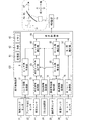
表示制御装置100は、図1に示すように、処理部61、RAM62、メモリ装置63および入出力インターフェースを有するコンピュータを主体に構成された電子制御ユニットである。処理部61は、CPU(Central Processing Unit)、GPU(Graphics Processing Unit)およびFPGA(Field-Programmable Gate Array)等の少なくとも1つを含む構成である。処理部61には、AI(Artificial Intelligence)の学習および推論に特化した専用のプロセッサが含まれていてもよい。
As shown in FIG. 1, the
メモリ装置63には、処理部61によって実行される種々のプログラムが格納されている。メモリ装置63に記憶された複数のプログラムには、虚像Viの表示を制御する表示制御プログラムが含まれている。表示制御プログラムは、前景中の重畳対象に虚像Viを重ねてなる拡張現実(以下、「AR(Augmented Reality)」)表示を実現するプログラムである。
The
ここで、前景中の路面を重畳対象として虚像Viを表示する場合を想定すると、投影領域PAを通して運転者に視認される路面の形状は、車両が平坦路を走行している場合と、車両が勾配のある路面を走行している場合とで異なってくる。すなわち、勾配の有無および勾配の大きさによって、車両の姿勢が変化し、視認される路面の形状が変化する。 Here, assuming that the virtual image Vi is displayed with the road surface in the foreground as a superimposing target, the shape of the road surface that is visible to the driver through the projection area PA is that the vehicle is traveling on a flat road and that the vehicle is traveling on a flat road. It will be different from when driving on a sloped road surface. That is, the posture of the vehicle changes depending on the presence or absence of the slope and the magnitude of the slope, and the shape of the visible road surface changes.
加えて、車両に加速度が与えられる場合には、慣性力により車両の姿勢が変化する。この姿勢変化により、投影領域PAを通して運転者に視認される路面の形状は過渡的に変化する。 In addition, when acceleration is applied to the vehicle, the posture of the vehicle changes due to the inertial force. Due to this attitude change, the shape of the road surface visible to the driver through the projection area PA changes transiently.
以上によれば、路面の勾配および車両の加速度に基づく表示光像の投影位置および投影形状の補正が実施されない場合、重畳対象からずれた虚像Viが表示され得る。表示制御プログラムは、表示光像の投影位置および投影形状を、道路勾配および車両の姿勢変化等に合わせて適切に制御するため、道路勾配、車両に生じているピッチ角、ロール角およびヨー角等を演算する。 Based on the above, if the projected position and projected shape of the displayed light image based on the slope of the road surface and the acceleration of the vehicle are not corrected, the virtual image Vi deviated from the superimposed object can be displayed. The display control program appropriately controls the projected position and projected shape of the displayed light image according to the road gradient, the posture change of the vehicle, etc., so that the road gradient, the pitch angle occurring in the vehicle, the roll angle, the yaw angle, etc. Is calculated.
表示制御装置100は、上述の表示制御プログラムの実行により、トルク情報取得部71、車高情報取得部73、勾配情報取得部74、操舵角情報取得部75、車速情報取得部76、ヨーレート取得部77を、各種情報を取得する機能ブロックとして有する。表示制御装置100は、取得した情報に基づいて車両姿勢を算出する機能ブロックとして、ロール角算出部85、ロール角補正部95、ヨー角補正部97、ピッチ角予測部81、測定ピッチ角算出部83およびピッチ角補正部93を有する。表示制御装置100は、虚像Viの重畳位置を決定する機能ブロックとして、表示制御部99を有する。
By executing the above-mentioned display control program, the
トルク情報取得部71は、車両に加速度を与えるトルクの値に関連する値をトルク情報として取得する。トルク情報取得部71は、車軸トルクセンサ21にて検出された車軸トルク値を、車両の駆動源が出力する駆動トルク情報として取得する。駆動トルク情報は、トルク情報のうち車両に正の加速度を与えるトルク情報である。トルク情報取得部71は、ブレーキ油圧センサ22にて検出されたブレーキ油圧値を、制動装置が出力する制動トルク情報として取得する。制動トルク情報は、トルク情報のうち車両に負の加速度を与えるトルク情報である。
The torque
車高情報取得部73は、車高センサ23が検出した検出値を取得する。車高情報取得部73は、上下方向の変位を車両に生じさせる負荷が作用していない無負荷状態での車高センサ23の出力値を、ピッチ角およびロール角がゼロの状態を示す車高センサ23の初期値として設定する。車高情報取得部73は、検出値の初期値からの変位分を車高情報として算出、取得する。
The vehicle height
勾配情報取得部74は、車両の現在位置および3次元地図データベース24から取得した3次元地図データを用いて、車両が走行する道路の勾配を算出する。車両の現在位置は、例えば衛星測位システムから取得した測位信号に基づき算出された車両位置情報と、車両位置情報の取得時における遅延時間での車両の移動距離を補正するための車速情報に基づいて特定されればよい。勾配情報取得部74は、緯度、経度および高度を示す情報と、路面の横断勾配を示す情報とを取得する。勾配情報取得部74は、緯度、経度および高度に基づき、車両が走行する路面の縦断勾配を算出して取得する。勾配情報取得部74は、取得した縦断勾配および横断勾配を、勾配情報として表示制御部99に逐次提供する。
The gradient
操舵角情報取得部75は、操舵角センサ25の検出値を操舵角情報として取得する。車速情報取得部76は、車速センサ26の検出値を車速情報として取得する。ヨーレート取得部77は、ヨーレートセンサ27からヨーレートを取得する。
The steering angle
ロール角算出部85は、操舵角情報および車速情報に基づいて、車両のロール角を算出する。ロール角算出部85は、例えば3次元地図データベース24等から走行中の道路のカーブ半径情報を取得し、カーブ半径情報、操舵角情報および車速情報を用いて、ロール角を算出する。ロール角算出部85は、算出したロール角をロール角補正部95に逐次提供する。
The roll
ロール角補正部95は、算出されたロール角に、勾配情報取得部74にて取得された横断勾配を加算する。ロール角補正部95は、この加算値を水平面に対する車両のロール角である補正ロール角として出力する。ヨー角補正部97は、取得されたヨーレートに基づいて、車両のヨー角を算出する。
The roll
ピッチ角予測部81は、取得されたトルク情報に基づいて、加速度ピッチ角を予測する。加速度ピッチ角は、車両に正の加速度が与えられて加速した際、または負の加速度が与えられて減速した際における、車両の路面に対するピッチ角である。ピッチ角予測部81は、例えばトルク情報に関連付けられた加速度ピッチ角の推定式に基づいて加速度ピッチ角を算出する。加速度ピッチ角をPとおくと、Pを算出する推定式は、例えば以下の式で与えられる。
The pitch
(式1)
P=a・Td+b・Tb+c
ここでTdは車軸トルク値、Tbはブレーキ油圧値、aおよびbはゲインである。したがって、a・Tdは、駆動トルクによるピッチ角変化を予測する項(駆動補正項)であり、b・bは、制動トルクによるピッチ角変化を予測する項(制動補正項)である。aおよびbは、車両の駆動方式、駆動源位置等によって決定される。例えば、aおよびbは、FF(フロントエンジン・フロントドライブ)方式、FR(フロントエンジン・リアドライブ)方式、AWD(全輪駆動)方式等の違いによって、車種ごとに異なる値となる。cは車種によって決定されるオフセット項である。推定式は、例えばメモリ装置63に予め記憶されている。
(Equation 1)
P = a ・ Td + b ・ Tb + c
Here, Td is an axle torque value, Tb is a brake oil pressure value, and a and b are gains. Therefore, a and Td are terms for predicting a pitch angle change due to driving torque (driving correction term), and b and b are terms for predicting a pitch angle change due to braking torque (braking correction term). a and b are determined by the drive system of the vehicle, the position of the drive source, and the like. For example, a and b have different values for each vehicle type due to differences in the FF (front engine / front drive) system, FR (front engine / rear drive) system, AWD (all-wheel drive) system, and the like. c is an offset term determined by the vehicle type. The estimation formula is stored in advance in, for example, the
ピッチ角予測部81は、上述の推定式に、取得された車軸トルク値およびブレーキ油圧値を代入して加速度ピッチ角を算出する。これによりピッチ角予測部81は、これらのトルクの作用による車両の加減速に起因して発生し得る車両のピッチ角変化を算出する。ピッチ角予測部81は、トルクが測定された段階で加速度ピッチ角を算出可能であるため、実際にトルクによって車両のピッチ角変化が発生するよりも早く、またはほぼ同時に加速度ピッチ角を予測する。
The pitch
測定ピッチ角算出部83は、傾斜ピッチ角を算出する。車両が勾配のある路面を走行する場合、重心位置等により、車両の路面に対するピッチ角はゼロにならず、路面に対して傾斜した状態となる。測定ピッチ角算出部83は、取得された車高情報に基づいて、この道路勾配に起因する路面に対するピッチ角である傾斜ピッチ角を算出する。測定ピッチ角算出部83は、車高情報およびロール角算出部85が算出したロール角に基づいて、傾斜ピッチ角を算出する。具体的には、測定ピッチ角算出部83は、車高情報が示す上下方向の変位量からロール角による変位量分を減算することで、ロール運動による車両の上下方向変位分を除いた傾斜ピッチ角を算出する。測定ピッチ角算出部83は、算出した傾斜ピッチ角をピッチ角補正部93に逐次提供する。
The measurement pitch
ピッチ角補正部93は、予測された加速度ピッチ角に基づいて補正された補正ピッチ角を算出する。第1実施形態においてピッチ角補正部93は、ピッチ角予測部81、測定ピッチ角算出部83および勾配情報取得部74からの縦断勾配情報に基づいて、補正ピッチ角を算出する。すなわちピッチ角補正部93は、傾斜ピッチ角に加速度ピッチ角および路面の縦断勾配を加算し、水平面に対する車両のピッチ角として補正ピッチ角を算出する。
The pitch
表示制御部99は、投影される表示光像の映像データを生成し、HUD装置10へ向けて逐次出力する。HUD装置10では、映像データに基づく表示光像の光が投影領域PAに投影され、虚像Viとして結像される。表示制御部99は、映像データの生成にあたり、映像データを構成する各フレームにて、虚像Viとなる元画像の描画位置および描画形状を、車両姿勢に合わせて補正する処理を繰り返し実施する。表示制御部99は、位置補正部の一例である。
The
次に、上述の機能ブロックにより実行される処理の一例を、図2、図3のフローチャートを参照して説明する。一連の処理において表示制御装置100は、車両に加速度を与えるトルクの値に基づいて、虚像Viの重畳位置をフィードフォワード制御する。一連の処理は、所定時間ごとまたは所定契機ごとに繰り返し実行される。
Next, an example of the processing executed by the above-mentioned functional block will be described with reference to the flowcharts of FIGS. 2 and 3. In a series of processes, the
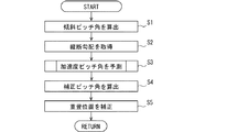
まず、ピッチ方向成分の重畳位置を補正する処理について図2のフローチャートを参照して説明する。ステップS1では、測定ピッチ角算出部83によって傾斜ピッチ角を算出する。次に、ステップS2では、勾配情報取得部74によって車両が走行している路面の縦断勾配を算出する。次に、ステップS3では、加速度ピッチ角を予測する。ステップS4では、ピッチ角補正部93によって、ステップS1〜3にて取得、算出された傾斜ピッチ角、縦断勾配および加速度ピッチ角が加算され、補正ピッチ角が算出される。
First, the process of correcting the superimposition position of the pitch direction component will be described with reference to the flowchart of FIG. In step S1, the measurement pitch
ステップS5では、算出された補正ピッチ角に基づき、ピッチ方向の虚像Viの重畳位置の補正処理が実行される。すなわち、道路勾配が実質的にゼロであり且つロールおよびピッチのいずれも生じていない場合の虚像Viの投影位置(基準位置)からの、投影領域PAの上下方向のずれを、補正ピッチ角に基づいて補正する。ステップS5の処理が終了すると、再びステップS1へと戻り、一連の補正処理を繰り返す。 In step S5, the correction process of the superimposed position of the virtual image Vi in the pitch direction is executed based on the calculated correction pitch angle. That is, the vertical deviation of the projection area PA from the projection position (reference position) of the virtual image Vi when the road gradient is substantially zero and neither roll nor pitch occurs is based on the correction pitch angle. To correct. When the process of step S5 is completed, the process returns to step S1 again, and a series of correction processes are repeated.
次に、上述の補正処理におけるステップS3の加速度ピッチ角の予測処理の詳細について、図3のフローチャートを参照して説明する。まずステップS10では、車軸トルク値を取得する。次にステップS20では、ブレーキ油圧値を取得する。次にステップS30では、取得された車軸トルク値およびブレーキ油圧値を推定式に代入する処理により、加速度ピッチ角の予測値を算出する。 Next, the details of the acceleration pitch angle prediction process in step S3 in the above-mentioned correction process will be described with reference to the flowchart of FIG. First, in step S10, the axle torque value is acquired. Next, in step S20, the brake oil pressure value is acquired. Next, in step S30, the predicted value of the acceleration pitch angle is calculated by substituting the acquired axle torque value and brake oil pressure value into the estimation formula.
次に第1実施形態の表示制御装置100の構成および作用効果について説明する。
Next, the configuration and operation / effect of the
表示制御装置100は、車両に加速度を与えるトルクの値またはトルクに関連する値であるトルク情報を取得するトルク情報取得部71と、取得したトルク情報に基づいて、車両のピッチ角を予測するピッチ角予測部81とを備える。表示制御装置100は、ピッチ角予測部81の予測に基づいて、虚像Viの重畳位置を補正する表示制御部99を備える。
The
これによれば、車軸に入力されるトルクの値からピッチ角の予測値が算出され、予測値に基づいて虚像Viの重畳位置が補正される。車軸に入力されるトルクは車両に付与される加速度に関連する値であるため、この予測値の算出により、加速度の付与に伴う車両のピッチ角変化が予測されることになる。したがって、車両のピッチ角変化を検出するよりも早く虚像Viの重畳位置を補正することができる。以上により、車両の過渡的な姿勢変化に対する虚像Viの重畳位置のずれを抑制可能な表示制御装置100および表示制御プログラムを提供することができる。
According to this, the predicted value of the pitch angle is calculated from the value of the torque input to the axle, and the superposed position of the virtual image Vi is corrected based on the predicted value. Since the torque input to the axle is a value related to the acceleration applied to the vehicle, the calculation of this predicted value predicts the change in the pitch angle of the vehicle due to the application of the acceleration. Therefore, the superimposed position of the virtual image Vi can be corrected faster than the change in the pitch angle of the vehicle is detected. As described above, it is possible to provide the
トルク情報取得部71は、車両の駆動源が出力する駆動トルク情報および制動装置が出力する制動トルク情報を少なくとも取得する。これによれば、車両に与えられる正の加速度および負の加速度の両方に基づいた加速度ピッチ角を予測可能となる。
The torque
トルク情報取得部71は、車軸トルクセンサ21によって検出された車軸トルクの検出値を取得する。これによれば、表示制御装置100は、車軸トルクの検出値を駆動トルク情報として利用することができる。車軸トルクの検出値は、アクセル開度等の他の駆動トルクに関連する情報と比較して精度が高いため、加速度ピッチ角の算出精度をより高めることが可能となる。
The torque
(第2実施形態)
第2実施形態では、第1実施形態における表示制御装置100の変形例について説明する。図4、図5において第1実施形態の図面中と同一符号を付した構成要素は、同様の構成要素であり、同様の作用効果を奏するものである。
(Second Embodiment)
In the second embodiment, a modification of the
第2実施形態においてピッチ角予測部81は、図4に示すように操舵角情報を操舵角情報取得部75から取得する。ピッチ角予測部81は、操舵角情報に基づき、旋回時における車両のロール運動のピッチ方向成分への影響を、加速度ピッチ角の予測に加味する。具体的には、ピッチ角予測部81は、加速度ピッチ角の算出に以下の推定式を用いる。
In the second embodiment, the pitch
(式2)
P=a・Td+b・Tb+c+d
ここでdは、操舵角情報に応じた加速度ピッチ角の補正項(旋回補正項)である。dは、操舵角の大きさに応じて変化する変数項である。またはdは定数項であってもよい。また、ピッチ角予測部81は、操舵角が操舵閾値を上回る場合には、加速度ピッチ角の算出時に旋回補正項を無視する。操舵角が大きくなると、操舵角が比較的小さい場合よりも推定式の精度が低下する。ピッチ角予測部81は、操舵角が操舵閾値を上回る場合に旋回補正項を無視することで、推定式の精度低下を回避する。
(Equation 2)
P = a ・ Td + b ・ Tb + c + d
Here, d is a correction term (turning correction term) for the acceleration pitch angle according to the steering angle information. d is a variable term that changes according to the magnitude of the steering angle. Alternatively, d may be a constant term. Further, when the steering angle exceeds the steering threshold value, the pitch
次に、第2実施形態の表示制御装置100が実行する加速度ピッチ角の算出処理について、図5のフローチャートを参照して説明する。図5のフローチャートにおけるステップS10、S20の処理は、図3の同符号のステップと同様の処理であるため説明を省略する。
Next, the calculation process of the acceleration pitch angle executed by the
ステップS21では、操舵角の値を取得する。ステップS22では、取得した操舵角の値が、予め設定された操舵閾値を上回るか否かを判定する。操舵角の値が操舵閾値を上回ると判定された場合には、推定式から旋回補正項を除いた状態でステップS30へと進む。一方で操舵角の値が操舵閾値を下回ると判定された場合には、推定式に旋回補正項を含んだ状態で、ステップS30へと進む。 In step S21, the value of the steering angle is acquired. In step S22, it is determined whether or not the acquired steering angle value exceeds a preset steering threshold value. If it is determined that the value of the steering angle exceeds the steering threshold value, the process proceeds to step S30 with the turning correction term removed from the estimation formula. On the other hand, when it is determined that the value of the steering angle is lower than the steering threshold value, the process proceeds to step S30 with the turning correction term included in the estimation formula.
ステップS30では、ステップS22の判定結果に基づいて設定された推定式に、取得された各値を代入して加速度ピッチ角を算出する。 In step S30, the acceleration pitch angle is calculated by substituting each acquired value into the estimation formula set based on the determination result in step S22.
第2実施形態の表示制御装置100によれば、ピッチ角予測部81は、トルク情報に加えて操舵角情報に基づいて加速度ピッチ角を算出する。このため、ピッチ角予測部81は、旋回時の車両のロール運動に伴うピッチ角変化を加速度ピッチ角の予測に加えることができる。したがって、旋回時の加速度ピッチ角の算出精度をより向上させることができる。
According to the
(第3実施形態)
第3実施形態では、第1実施形態における表示制御装置100の変形例について説明する。図6、図7において第1実施形態の図面中と同一符号を付した構成要素は、同様の構成要素であり、同様の作用効果を奏するものである。
(Third Embodiment)
In the third embodiment, a modification of the
第3実施形態の表示制御装置100は、アクセル開度センサ28およびエンジン回転数センサ29から情報を取得する。アクセル開度センサ28は、車両の運転者によるアクセル操作量に応じた電気信号を表示制御装置100へと逐次出力する。エンジン回転数センサ29は、エンジン回転数を示す信号を表示制御装置100へと逐次出力する。
The
表示制御装置100は、機能ブロックとしてアクセル開度取得部78、回転数情報取得部79、変速判定部81aを有する。アクセル開度取得部78は、アクセル開度センサ28の検出値をアクセル開度情報として取得する。回転数情報取得部79は、エンジン回転数センサ29の検出値を、エンジン回転数情報として取得する。
The
変速判定部81aは、変速したか否かを判定する。変速判定部81aは、例えばアクセル開度情報およびエンジン回転数情報に基づいて変速したか否かを判定する。具体的には、変速判定部81aは、アクセル開度が実質的に一定の場合に、エンジン回転数が所定値を下回ると、変速した(シフトダウンした)と判定する。また、加えてアクセル開度が実質的に一定の場合に、エンジン回転数が別の所定値を上回った場合にも変速した(シフトアップした)と判定してよい。変速判定部81aは、判定結果をピッチ角予測部81に逐次提供する。
The
ピッチ角予測部81は、車速情報取得部76から車速情報を取得する。ピッチ角予測部81は、車速情報に基づき、車両の停車状態時には制動トルクの値を用いることなく加速度ピッチ角を予測する。またピッチ角予測部81は、変速判定部81aの判定結果に基づき、変速がある場合には変速による振動(変速ショック)の影響を加味して加速度ピッチ角を予測する。具体的には、ピッチ角予測部81は、加速度ピッチ角の算出に以下の推定式を用いる。
The pitch
(式3)
P=a・Td+b・Tb+c+d+e
ここでeは、変速ショックに応じた加速度ピッチ角の補正項(変速補正項)である。eは、変速ショックの大きさに応じて変化する変数項である。またはeは定数項でもよい。
(Equation 3)
P = a ・ Td + b ・ Tb + c + d + e
Here, e is a correction term (shift correction term) for the acceleration pitch angle according to the shift shock. e is a variable term that changes according to the magnitude of the shift shock. Alternatively, e may be a constant term.
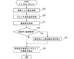
次に、第3実施形態の表示制御装置100が実行する加速度ピッチ角の算出処理について、図7のフローチャートを参照して説明する。図7のフローチャートにおけるステップS10〜S23の処理は、図5の同符号のステップと同様の処理であるため説明を省略する。
Next, the calculation process of the acceleration pitch angle executed by the
ステップS24では、車速を取得する。ステップS25では、車速が0km/hであるか否かを判定する。車速が0km/hを上回っている場合、すなわち車両が走行中である場合には、制動補正項を含んだ推定式を使用し、加速度ピッチ角の算出に制動トルクの値を使用する。ステップS25で車速が0km/hであると判定されると、車両が停車時であると判断し、ステップS26へと進む。ステップS26では、推定式から制動補正項を除き、停車時において制動トルクの値を加速度ピッチ角の算出に使用しないように処理し、ステップS27へと進む。一方でステップS25にて車速が0km/hでない、すなわち車両が走行中であると判断された場合、制動補正項を推定式に含んだ状態でステップS27へと進む。 In step S24, the vehicle speed is acquired. In step S25, it is determined whether or not the vehicle speed is 0 km / h. When the vehicle speed exceeds 0 km / h, that is, when the vehicle is running, the estimation formula including the braking correction term is used, and the value of the braking torque is used to calculate the acceleration pitch angle. If it is determined in step S25 that the vehicle speed is 0 km / h, it is determined that the vehicle is stopped, and the process proceeds to step S26. In step S26, the braking correction term is removed from the estimation formula, processing is performed so that the value of the braking torque is not used for calculating the acceleration pitch angle when the vehicle is stopped, and the process proceeds to step S27. On the other hand, if it is determined in step S25 that the vehicle speed is not 0 km / h, that is, the vehicle is running, the process proceeds to step S27 with the braking correction term included in the estimation formula.
ステップS27では、アクセル開度およびエンジン回転数を取得して、ステップS28へと進む。ステップS28では、変速があるか否かを判定する。変速がないと判定されるとステップS29へと進む。ステップS29では、推定式から変速補正項を除く処理をしてステップS30へと進む。一方で変速があると判定されると、推定式に変速補正項を含んだ状態でステップS30へと進む。ステップS30では、ステップS22、S25、S28の判定結果に基づいて設定された推定式に、取得された各値を代入して加速度ピッチ角を算出する。 In step S27, the accelerator opening degree and the engine speed are acquired, and the process proceeds to step S28. In step S28, it is determined whether or not there is a shift. If it is determined that there is no shift, the process proceeds to step S29. In step S29, processing for removing the shift correction term from the estimation formula is performed, and the process proceeds to step S30. On the other hand, if it is determined that there is a shift, the process proceeds to step S30 with the shift correction term included in the estimation formula. In step S30, the acceleration pitch angle is calculated by substituting each acquired value into the estimation formula set based on the determination results of steps S22, S25, and S28.
以上説明した第3実施形態の表示制御装置100によれば、ピッチ角予測部81は、車速が0km/hである場合に、制動トルク情報を加速度ピッチ角の算出に使用しない。車速が0km/hである場合、車両は停車状態であり、制動トルクが作用していないと判断できる。この場合に制動トルクの値を加速度ピッチ角の予測に使用しないことで、より正確な加速度ピッチ角を算出することができる。換言すれば、ピッチ角予測部81は、車両が走行中である場合に限り制動トルクの値を加速度ピッチ角の予測に使用する。
According to the
なお、ピッチ角予測部81は、車両が停車状態であるとみなせる場合に制動トルク情報を加速度ピッチ角の算出に使用しない構成であればよい。すなわち、ピッチ角予測部81は、車速が0km/hを上回っている場合でも、車両が停車状態であるとみなせる車速閾値を下回っていれば、制動トルクの値を加速度ピッチ角の予測に使用しないようにする構成であってもよい。換言すれば、ピッチ角予測部81は、車速が車速閾値を上回る場合に限り制動トルクの値を加速度ピッチ角の予測に使用する構成であればよく、車速閾値には0km/hまたは0km/hとみなせる大きさの車速を採用することができる。
The pitch
また、第3実施形態の表示制御装置100は、車両が変速したか否かを判定する変速判定部81aを有し、ピッチ角予測部81は、変速したことに基づいて予測値を補正する。これによれば、ピッチ角予測部81は、変速ショックを加速度ピッチ角の予測に含めることができる。したがって、より正確に加速度ピッチ角を予測できる。
Further, the
(他の実施形態)
この明細書における開示は、例示された実施形態に制限されない。開示は、例示された実施形態と、それらに基づく当業者による変形態様を包含する。例えば、開示は、実施形態において示された部品および/または要素の組み合わせに限定されない。開示は、多様な組み合わせによって実施可能である。開示は、実施形態に追加可能な追加的な部分をもつことができる。開示は、実施形態の部品および/または要素が省略されたものを包含する。開示は、ひとつの実施形態と他の実施形態との間における部品および/または要素の置き換え、または組み合わせを包含する。開示される技術的範囲は、実施形態の記載に限定されない。開示されるいくつかの技術的範囲は、特許請求の範囲の記載によって示され、さらに特許請求の範囲の記載と均等の意味および範囲内での全ての変更を含むものと解されるべきである。
(Other embodiments)
The disclosure herein is not limited to the illustrated embodiments. The disclosure includes exemplary embodiments and modifications by those skilled in the art based on them. For example, disclosure is not limited to the parts and / or element combinations shown in the embodiments. Disclosure can be carried out in various combinations. The disclosure can have additional parts that can be added to the embodiments. Disclosures include those in which the parts and / or elements of the embodiment are omitted. Disclosures include replacement or combination of parts and / or elements between one embodiment and another. The technical scope disclosed is not limited to the description of the embodiments. Some technical scopes disclosed are indicated by the description of the claims and should be understood to include all modifications within the meaning and scope equivalent to the description of the claims. ..
ここまで説明した表示制御のための処理は、上述の表示制御装置100とは異なる構成によって実施されてもよい。例えば表示制御装置は、コンビネーションメータおよびナビゲーション装置等に含まれる構成であってもよい。即ち、コンビネーションメータおよびナビゲーション装置が、上述の表示制御プログラムを制御回路にて実行することにより、表示制御装置の機能を獲得してもよい。さらに、上述の実施形態の姿勢検出部にて実施されていた姿勢検出のための演算は、車両に搭載された複数の制御装置の制御回路によって分散処理されてもよい。
The process for display control described so far may be carried out with a configuration different from that of the
さらに、フラッシュメモリおよびハードディスク等の種々の非遷移的実体的記憶媒体(non-transitory tangible storage medium)が表示制御プログラムを格納する構成として、メモリ装置63に採用可能である。加えて、表示制御プログラムを記憶する記憶媒体は、車載された電子制御ユニットに設けられた記憶媒体に限定されず、当該記憶媒体へのコピー元となる光学ディスクおよび汎用コンピュータのハードディスクドライブ等であってもよい。
Further, various non-transitory tangible storage media such as a flash memory and a hard disk can be adopted in the
上述の実施形態において、トルク情報取得部71は、駆動トルク情報として車軸トルク値を取得するとした。これに代えてトルク情報取得部71は、例えばアクセル開度を駆動トルク情報として取得する構成であってもよい。トルク情報取得部71が取得する駆動トルク情報は、車両の駆動源が出力する駆動トルクに関連する情報であればよい。
In the above-described embodiment, the torque
上述の実施形態において、車両の駆動源がエンジンである場合を説明したが、エンジンに加えてモータを駆動源として備える所謂ハイブリッド車両や、モータのみを駆動源として備える電気自動車等に表示制御装置100を適用してもよい。モータを駆動源として備える車両の場合、ピッチ角予測部81において、駆動トルク情報および制動トルク情報に加えて回生トルク情報を加速度ピッチ角の予測に使用する構成とすることで、より正確な加速度ピッチ角を検出可能となる。
In the above embodiment, the case where the drive source of the vehicle is an engine has been described, but the
上述の実施形態において、傾斜ピッチ角は車高センサ23の検出する車高値によって算出されるとしたが、例えばジャイロセンサ等、他の姿勢検出センサの検出値に基づいて算出されてもよい。
In the above-described embodiment, the inclination pitch angle is calculated based on the vehicle height value detected by the
上述の実施形態において、表示制御部99は、映像データの生成にあたり、虚像Viとなる元画像の描画位置を車両姿勢に合わせて補正するとした。これに代えて、表示制御部99は、虚像Viの重畳位置を補正するための補正情報を、HUD装置10に対して出力する構成であってもよい。この構成の場合、表示制御部99からの補正情報に基づいて、HUD装置10が虚像Viの重畳位置を補正する。すなわちこの構成において、表示制御部99は、HUD装置10を介して虚像Viの重畳位置を補正する。
In the above-described embodiment, the
21 車軸トルクセンサ、 61 処理部、 71 トルク情報取得部、 75 操舵角情報取得部、 81 ピッチ角予測部、 81a 変速判定部、 99 表示制御部(位置補正部)、 Vi 虚像、 100 表示制御装置。 21 Axle torque sensor, 61 Processing unit, 71 Torque information acquisition unit, 75 Steering angle information acquisition unit, 81 Pitch angle prediction unit, 81a Shift judgment unit, 99 Display control unit (position correction unit), Vi virtual image, 100 Display control device ..
Claims (9)
前記車両に加速度を与えるトルクの値または前記トルクに関連する値であるトルク情報を取得するトルク情報取得部(71)と、
取得した前記トルク情報に基づいて、前記車両のピッチ角を予測するピッチ角予測部(81)と、
前記ピッチ角予測部の予測に基づいて、前記虚像の重畳位置を補正する位置補正部(99)と、
前記車両の操舵角に関する情報を取得する操舵角情報取得部(75)と、
を備え、
前記ピッチ角予測部は、前記トルク情報に加えて前記操舵角に基づいて前記ピッチ角を予測する表示制御装置。 A display control device used in a vehicle that controls the display of a virtual image (Vi) superimposed on a superimposed object in the foreground of an occupant.
A torque information acquisition unit (71) that acquires torque information that is a value of torque that gives acceleration to the vehicle or a value that is related to the torque.
A pitch angle prediction unit (81) that predicts the pitch angle of the vehicle based on the acquired torque information,
A position correction unit (99) that corrects the superimposed position of the virtual image based on the prediction of the pitch angle prediction unit, and
A steering angle information acquisition unit (75) that acquires information on the steering angle of the vehicle, and
Equipped with a,
The pitch angle prediction unit is a display control device that predicts the pitch angle based on the steering angle in addition to the torque information.
前記ピッチ角予測部は、さらに変速による前記ピッチ角の変化に基づいて前記ピッチ角を予測する請求項1または請求項2に記載の表示制御装置。 It has a shift determination unit (81a) for determining whether or not the vehicle has shifted.
The display control device according to claim 1 or 2 , wherein the pitch angle prediction unit further predicts the pitch angle based on a change in the pitch angle due to a shift.
前記車両に加速度を与えるトルクの値または前記トルクに関連する値であるトルク情報を取得するトルク情報取得部(71)と、
取得した前記トルク情報に基づいて、前記車両のピッチ角を予測するピッチ角予測部(81)と、
前記ピッチ角予測部の予測に基づいて、前記虚像の重畳位置を補正する位置補正部(99)と、
前記車両が変速したか否かを判定する変速判定部(81a)と、
を備え、
前記ピッチ角予測部は、さらに変速による前記ピッチ角の変化に基づいて前記ピッチ角を予測する表示制御装置。 A display control device used in a vehicle that controls the display of a virtual image (Vi) superimposed on a superimposed object in the foreground of an occupant.
A torque information acquisition unit (71) that acquires torque information that is a value of torque that gives acceleration to the vehicle or a value that is related to the torque.
A pitch angle prediction unit (81) that predicts the pitch angle of the vehicle based on the acquired torque information,
A position correction unit (99) that corrects the superimposed position of the virtual image based on the prediction of the pitch angle prediction unit, and
A shift determination unit (81a) for determining whether or not the vehicle has shifted, and a shift determination unit (81a).
Equipped with a,
The pitch angle prediction unit is a display control device that predicts the pitch angle based on a change in the pitch angle due to a shift.
前記車両の駆動源が出力する駆動トルク情報および制動装置が出力する制動トルク情報を少なくとも取得する請求項1から請求項4のいずれか1項に記載の表示制御装置。 The torque information acquisition unit
The display control device according to any one of claims 1 to 4, wherein at least the drive torque information output by the drive source of the vehicle and the braking torque information output by the braking device are acquired.
前記ピッチ角予測部は、前記車速が車速閾値を下回っている場合に、前記制動トルク情報を前記ピッチ角の予測に使用しない請求項5に記載の表示制御装置。 It is equipped with a vehicle speed information acquisition unit (76) that acquires information on vehicle speed.
The display control device according to claim 5 , wherein the pitch angle prediction unit does not use the braking torque information for predicting the pitch angle when the vehicle speed is lower than the vehicle speed threshold value.
少なくとも1つの処理部(61)を、
前記車両に加速度を与えるトルクの値または前記トルクに関連する値であるトルク情報を取得するトルク情報取得部(71)、
取得した前記トルク情報に基づいて、前記車両のピッチ角の予測値を算出するピッチ角予測部(81)、
前記予測値に基づいて、前記虚像の重畳位置を補正する位置補正部(99)、
前記車両の操舵角に関する情報を取得する操舵角情報取得部(75)、
として機能させ、
前記ピッチ角予測部は、前記トルク情報に加えて前記操舵角に基づいて前記ピッチ角を予測する表示制御プログラム。 A display control program used in a vehicle to control the display of a virtual image (Vi) superimposed on a superimposed object in the foreground of an occupant.
At least one processing unit (61)
Torque information acquisition unit (71), which acquires torque information that is a value of torque that gives acceleration to the vehicle or a value related to the torque.
The pitch angle prediction unit (81), which calculates the predicted value of the pitch angle of the vehicle based on the acquired torque information,
A position correction unit (99) that corrects the superimposed position of the virtual image based on the predicted value.
Steering angle information acquisition unit (75) that acquires information on the steering angle of the vehicle,
To function as,
The pitch angle prediction unit is a display control program that predicts the pitch angle based on the steering angle in addition to the torque information.
少なくとも1つの処理部(61)を、
前記車両に加速度を与えるトルクの値または前記トルクに関連する値であるトルク情報を取得するトルク情報取得部(71)、
取得した前記トルク情報に基づいて、前記車両のピッチ角の予測値を算出するピッチ角予測部(81)、
前記予測値に基づいて、前記虚像の重畳位置を補正する位置補正部(99)、
前記車両が変速したか否かを判定する変速判定部(81a)、
として機能させ、
前記ピッチ角予測部は、さらに変速による前記ピッチ角の変化に基づいて前記ピッチ角を予測する表示制御プログラム。
A display control program used in a vehicle to control the display of a virtual image (Vi) superimposed on a superimposed object in the foreground of an occupant.
At least one processing unit (61)
Torque information acquisition unit (71), which acquires torque information that is a value of torque that gives acceleration to the vehicle or a value related to the torque.
The pitch angle prediction unit (81), which calculates the predicted value of the pitch angle of the vehicle based on the acquired torque information,
A position correction unit (99) that corrects the superimposed position of the virtual image based on the predicted value.
A shift determination unit (81a) for determining whether or not the vehicle has shifted.
To function as,
The pitch angle prediction unit is a display control program that predicts the pitch angle based on a change in the pitch angle due to a shift.
Priority Applications (2)
| Application Number | Priority Date | Filing Date | Title |
|---|---|---|---|
| JP2018154863A JP6891863B2 (en) | 2018-08-21 | 2018-08-21 | Display control device and display control program |
| PCT/JP2019/026015 WO2020039751A1 (en) | 2018-08-21 | 2019-07-01 | Display control device, display control program, and computer-readable non-transitory storage medium |
Applications Claiming Priority (1)
| Application Number | Priority Date | Filing Date | Title |
|---|---|---|---|
| JP2018154863A JP6891863B2 (en) | 2018-08-21 | 2018-08-21 | Display control device and display control program |
Publications (3)
| Publication Number | Publication Date |
|---|---|
| JP2020029130A JP2020029130A (en) | 2020-02-27 |
| JP2020029130A5 JP2020029130A5 (en) | 2020-09-10 |
| JP6891863B2 true JP6891863B2 (en) | 2021-06-18 |
Family
ID=69593105
Family Applications (1)
| Application Number | Title | Priority Date | Filing Date |
|---|---|---|---|
| JP2018154863A Active JP6891863B2 (en) | 2018-08-21 | 2018-08-21 | Display control device and display control program |
Country Status (2)
| Country | Link |
|---|---|
| JP (1) | JP6891863B2 (en) |
| WO (1) | WO2020039751A1 (en) |
Families Citing this family (1)
| Publication number | Priority date | Publication date | Assignee | Title |
|---|---|---|---|---|
| DE102019210670A1 (en) * | 2019-07-18 | 2021-01-21 | Robert Bosch Gmbh | Method and device for operating a brake system, computer program and computer program product, brake system |
Family Cites Families (6)
| Publication number | Priority date | Publication date | Assignee | Title |
|---|---|---|---|---|
| JP4697430B2 (en) * | 2006-01-19 | 2011-06-08 | 株式会社アドヴィックス | Tire longitudinal force estimation device |
| JP2009226985A (en) * | 2008-03-19 | 2009-10-08 | Honda Motor Co Ltd | Vehicle body attitude control device |
| JP5324367B2 (en) * | 2009-09-16 | 2013-10-23 | 株式会社デンソー | Control request arbitration device |
| JP2015074369A (en) * | 2013-10-10 | 2015-04-20 | 日産自動車株式会社 | Longitudinal acceleration control device |
| US20160216521A1 (en) * | 2013-10-22 | 2016-07-28 | Nippon Seiki Co., Ltd. | Vehicle information projection system and projection device |
| JP2018069998A (en) * | 2016-10-31 | 2018-05-10 | 株式会社ジェイテクト | Posture control device for vehicle |
-
2018
- 2018-08-21 JP JP2018154863A patent/JP6891863B2/en active Active
-
2019
- 2019-07-01 WO PCT/JP2019/026015 patent/WO2020039751A1/en active Application Filing
Also Published As
| Publication number | Publication date |
|---|---|
| JP2020029130A (en) | 2020-02-27 |
| WO2020039751A1 (en) | 2020-02-27 |
Similar Documents
| Publication | Publication Date | Title |
|---|---|---|
| CN108692699B (en) | Vehicle and method for collision avoidance assistance | |
| JP4161923B2 (en) | Vehicle stabilization control system | |
| JP6756327B2 (en) | Posture detection device and posture detection program | |
| JP6787297B2 (en) | Display control device and display control program | |
| JP4835054B2 (en) | Vehicle stabilization control system | |
| JP7204772B2 (en) | head up display system | |
| JP7211047B2 (en) | Road surface detection device and road surface detection program | |
| JP6724886B2 (en) | Virtual image display | |
| JP6724885B2 (en) | Virtual image display | |
| JP2019119380A (en) | Vehicle, vehicle motion state estimation device and vehicle motion state estimation method | |
| WO2021020145A1 (en) | Display control device | |
| US20210031776A1 (en) | Display control unit and non-transitory tangible computer readable storage medium | |
| CN110316197A (en) | Tilt evaluation method, inclination estimation device and the non-transitory computer-readable storage media for storing program | |
| WO2021020385A1 (en) | Display control device | |
| JP6891863B2 (en) | Display control device and display control program | |
| JP7211304B2 (en) | Display device | |
| US20220270527A1 (en) | Display control device | |
| JP2024005026A (en) | Vehicle display controller, vehicle display device, vehicle, vehicle display control method, and vehicle display control program | |
| CN114954507A (en) | Active trajectory tracking control for autonomous driving during altitude transitions | |
| JP7272252B2 (en) | Display control device, display control program and virtual image display system | |
| JP2021041789A (en) | Display device | |
| JP2014125154A (en) | Request quantity deduction unit | |
| JP2023039693A (en) | Display control device, display control program and virtual image display system | |
| CN117657175A (en) | Method and device for determining wear degree of vehicle wheel, medium and vehicle | |
| JP2023151394A (en) | Vehicle control method and vehicle control apparatus |
Legal Events
| Date | Code | Title | Description |
|---|---|---|---|
| A521 | Request for written amendment filed |
Free format text: JAPANESE INTERMEDIATE CODE: A523 Effective date: 20200722 |
|
| A621 | Written request for application examination |
Free format text: JAPANESE INTERMEDIATE CODE: A621 Effective date: 20200722 |
|
| TRDD | Decision of grant or rejection written | ||
| A01 | Written decision to grant a patent or to grant a registration (utility model) |
Free format text: JAPANESE INTERMEDIATE CODE: A01 Effective date: 20210427 |
|
| A61 | First payment of annual fees (during grant procedure) |
Free format text: JAPANESE INTERMEDIATE CODE: A61 Effective date: 20210510 |
|
| R151 | Written notification of patent or utility model registration |
Ref document number: 6891863 Country of ref document: JP Free format text: JAPANESE INTERMEDIATE CODE: R151 |