JP6890422B2 - Information processing equipment, control methods and programs for information processing equipment - Google Patents
Information processing equipment, control methods and programs for information processing equipment Download PDFInfo
- Publication number
- JP6890422B2 JP6890422B2 JP2017002117A JP2017002117A JP6890422B2 JP 6890422 B2 JP6890422 B2 JP 6890422B2 JP 2017002117 A JP2017002117 A JP 2017002117A JP 2017002117 A JP2017002117 A JP 2017002117A JP 6890422 B2 JP6890422 B2 JP 6890422B2
- Authority
- JP
- Japan
- Prior art keywords
- orientation
- assembly
- image
- information processing
- assembled
- Prior art date
- Legal status (The legal status is an assumption and is not a legal conclusion. Google has not performed a legal analysis and makes no representation as to the accuracy of the status listed.)
- Active
Links
Images


Landscapes
- Length Measuring Devices By Optical Means (AREA)
- Automatic Assembly (AREA)
- Manipulator (AREA)
- Image Processing (AREA)
- Image Analysis (AREA)
Description
本発明は、情報処理装置、情報処理装置の制御方法およびプログラムに関する。 The present invention relates to an information processing device, a control method and a program of the information processing device.
近年のロボット技術の発展とともに、工業製品の組み立てのような複雑なタスクをロボットが代わりに行うようになりつつある。このようなロボットでは、ハンドなどのエンドエフェクタにより部品を把持して組み付けを行う。ロボットによる部品の組み付け作業では、ハンドによる部品把持時のずれや正常でない部品の混入等の原因により組み付けに失敗することがある。そのため、部品を組み付けた後に、正常に組み付けが行われたかどうかを確認する部品組み付け後検査が必要になる。近年、この組み付け後検査を自動化する取り組みが行われ始めている。 With the development of robot technology in recent years, robots are taking the place of performing complex tasks such as assembling industrial products. In such a robot, parts are gripped and assembled by an end effector such as a hand. In the parts assembling work by the robot, the assembling may fail due to the cause such as the deviation when grasping the parts by the hand or the mixing of abnormal parts. Therefore, after assembling the parts, it is necessary to carry out a post-assembly inspection to confirm whether or not the parts have been assembled normally. In recent years, efforts have begun to automate this post-assembly inspection.
特許文献1では、2部品により構成される組み付け済み部品の撮影画像を用いて組み付け後検査を行う方法が開示されている。この方法では、ロボットにより把持・移動された組み付け元部品の位置姿勢と、組み付けの相手となる組付け先部品の位置姿勢とをそれぞれ算出し、両者の相対関係を理想的な組付け状態と比較することで、組み付けの良否を判定している。 Patent Document 1 discloses a method of performing post-assembly inspection using a photographed image of an assembled part composed of two parts. In this method, the position and orientation of the assembly source component gripped and moved by the robot and the position and orientation of the assembly destination component to be assembled are calculated, and the relative relationship between the two is compared with the ideal assembly state. By doing so, the quality of the assembly is judged.
しかしながら、組み付け済み部品の撮影画像では、組み付けられた部位の周辺で、一方の部品が他方の部品を隠蔽する領域が発生する。この隠蔽領域の影響により、組み付け先部品あるいは組み付け元部品の位置姿勢を安定して算出できない場合がある。特許文献1のように、部品の3次元形状モデルを用いて、画像上の幾何特徴との対応間距離を最小化する方法では、隠蔽領域が多いとロバスト性および精度が低下してしまい、部品の正しい位置姿勢が算出できないという課題がある。 However, in the photographed image of the assembled part, there is an area around the assembled part where one part hides the other part. Due to the influence of this concealed area, it may not be possible to stably calculate the position and orientation of the assembly destination component or the assembly source component. In the method of minimizing the distance between correspondences with geometric features on an image by using a three-dimensional shape model of a part as in Patent Document 1, robustness and accuracy deteriorate when there are many concealed areas, and the part There is a problem that the correct position and orientation of the can not be calculated.
本発明は、上記の課題を鑑みてなされたものであり、組み付けによって他の部品による隠蔽が発生する部品に対して精度よくロバストに位置姿勢を取得可能にする技術を提供することを目的とする。 The present invention has been made in view of the above problems, and an object of the present invention is to provide a technique capable of accurately and robustly acquiring a position and orientation with respect to a component whose assembly causes concealment by other components. ..
上記の目的を達成する本発明に係る情報処理装置は、
組み付け先の物体と組み付け元の物体とが組み付けられた場合における両物体間の理想の相対位置姿勢を取得する取得手段と、
前記組み付け先の物体の形状を表す第一の形状モデルおよび前記組み付け元の物体の形状を表す第二の形状モデルと前記理想の相対位置姿勢とに基づいて、前記組み付け先の物体と前記組み付け元の物体とが組み付けられた状態の画像から、前記組み付け元の物体が前記組み付け先の物体を隠蔽する隠蔽領域を特定する特定手段と、
前記隠蔽領域に対して、前記組み付け元の物体が前記組み付け先の物体を隠蔽する度合いに基づいて、前記組み付け先の物体の位置姿勢を取得する際の寄与度を設定する設定手段と、
前記第一の形状モデルまたは前記画像に基づいて、前記組み付け先の物体の位置姿勢を取得するための情報を生成する生成手段と、
前記生成手段により生成された情報と前記寄与度とに基づいて、前記組み付け先の物体の位置姿勢を取得する位置姿勢取得手段と、
を備えることを特徴とする。
The information processing device according to the present invention that achieves the above object is
An acquisition means for acquiring the ideal relative position / orientation between both objects when the assembly destination object and the assembly source object are assembled, and
Based on the relative position and orientation of the second shape model and the ideal representative of the first shape model and the assembly original shape of an object representing the assembly destination object shape, the assembly origin and the assembly destination object From the image of the state in which the object is assembled, the specific means for identifying the concealed area in which the assembly source object conceals the assembly destination object, and
For the covered area, a setting unit the assembled original object based on the degree of hiding the object of the assembly destination, sets the contribution degree when acquiring the position and orientation of the assembly destination object,
A generation means for generating information for acquiring the position and orientation of the object to be assembled based on the first shape model or the image.
A position / posture acquisition means for acquiring the position / orientation of the object to be assembled based on the information generated by the generation means and the contribution degree.
It is characterized by having.
本発明によれば、組み付けによって他の部品による隠蔽が発生する部品に対しても精度よくロバストに位置姿勢を取得することが可能となる。 According to the present invention, it is possible to accurately and robustly acquire the position and orientation of a component that is concealed by other components due to assembly.
以下、添付の図面を参照しながら、本発明の実施形態について詳述する。 Hereinafter, embodiments of the present invention will be described in detail with reference to the accompanying drawings.
(第1の実施形態:モデルから隠蔽領域を除外して位置姿勢を算出)
<概要>
本実施形態では、情報処理装置を組み付け先部品の位置姿勢算出に適用した場合について説明する。
(First embodiment: The position and orientation are calculated by excluding the concealed area from the model)
<Overview>
In this embodiment, a case where the information processing apparatus is applied to the position / orientation calculation of the assembly destination component will be described.
図1(c)に一例を示すような2部品(2物体)から構成される組み付け済み部品30を取り扱うものとする。組み付け済み部品30は、図1(a)に示すような、ロボットハンド(不図示)により把持・移動される組み付け元部品10と、当該組み付け元部品10を組み付ける相手となる図1(b)に示すような組み付け先部品20とを含んで構成される。本実施形態では、組み付け済み部品30の撮影画像に基づき、組み付け先部品20の位置姿勢を算出することを想定する。なお、本実施形態で述べる「位置姿勢」とは、組み付け先部品20と当該部品を撮影する撮影装置(不図示)との位置姿勢の関係のことを意味する。
It is assumed that the assembled
以下、本実施形態における位置姿勢算出処理の概要を簡単に述べる。まず、組み付け元部品10および組み付け先部品20の3次元形状モデルを用意する。さらに、理想的な組付け状態における、両者の相対位置姿勢を設定しておく。そして、組み付け済み部品30の画像を撮影して組み付け先部品20の位置姿勢を算出する。
Hereinafter, the outline of the position / orientation calculation process in the present embodiment will be briefly described. First, a three-dimensional shape model of the
まず、撮影画像における組み付け先部品20の概略位置姿勢を設定する。ここで、組み付け先部品20の概略位置姿勢と、理想的な組み付け状態における組み付け元部品10との相対位置姿勢から、撮影画像における組み付け元部品10の概略位置姿勢も求めることが可能である。そこで、それぞれの概略位置姿勢に基づいて組み付け先部品20および組み付け元部品10の3次元形状モデルを画像上に投影する。
First, the approximate position and orientation of the
そして、組み付け先部品20の三次元形状モデルと画像上の幾何特徴(画像特徴)との対応関係を用いて位置姿勢を算出する。このとき、組み付け先部品20の三次元形状モデルに対して、組み付け元部品10による隠蔽が生じている部位は利用しない。これにより、隠蔽領域によるモデルと計測データとの不一致の影響を受けず、ロバストかつ高精度に位置姿勢を算出することが可能である。
Then, the position and orientation are calculated using the correspondence between the three-dimensional shape model of the
以下の説明では、組み付け先部品と組み付け元部品との相対関係に基づき、計測対象の組み付け先部品20が画像上で隠蔽される領域を特定し、隠蔽されない部位の三次元形状モデルを用いて位置姿勢算出を行う方法について詳細を述べる。
In the following description, based on the relative relationship between the assembly destination component and the assembly source component, the region where the
<情報処理装置の構成>
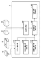
まずは図2を参照して、本実施形態に係る情報処理装置1の構成例を説明する。情報処理装置1は、モデル取得部110と、相対位置姿勢取得部120と、画像取得部130と、概略位置姿勢取得部140と、隠蔽領域特定部150と、位置姿勢取得部160とを備えている。
<Configuration of information processing device>
First, a configuration example of the information processing device 1 according to the present embodiment will be described with reference to FIG. The information processing device 1 includes a
モデル取得部110は、組み付け元部品10の形状を表す3次元形状モデル100と、組み付け先部品20の形状を表す3次元形状モデル200とを取得する。3次元形状モデルは、従来同様のものを用いればよいため、ここでは詳細な説明については省略するが、例えば、各点を結んで構成される面の情報、面を構成する線分の情報によって定義される。3次元形状モデル10および20は、モデル取得部110に保存されており、隠蔽領域特定部150に入力される。
The
相対位置姿勢取得部120は、組み付け元部品10および組み付け先部品20が理想的に組み付けられた時の2部品間の相対位置姿勢を隠蔽領域特定部150に入力する。以後、この相対位置姿勢を組み付け位置姿勢と呼ぶことにする。組み付け位置姿勢は、たとえば、2部品の3次元形状モデルを仮想空間上で操作して理想的な組み付け状態に配置し、その状態における2部品間の座標系の相対関係を求めることで事前に設定しておく。あるいは、あらかじめ2部品の寸法情報に基づき、数値計算で求めておいてもよい。そのほか、理想組み付け時の2部品間の配置関係が特定できればいかなる方法でもかまわない。
The relative position /
2次元画像撮影装置40は、2次元画像を撮影するカメラである。撮影される2次元画像は濃淡画像であってもよいしカラー画像であってもよい。本実施形態では、2次元画像撮影装置40は濃淡画像を出力する。2次元画像撮影装置40が撮影する画像は画像取得部130を介して情報処理装置1に入力される。カメラの焦点距離や主点位置、レンズ歪みパラメータなどの内部パラメータは、使用する機器の仕様を参照するか、または、非特許文献1で開示される方法によって事前にキャリブレーションしておく。
The two-dimensional
距離画像撮影装置50は、計測対象である物体表面上の点の3次元情報を計測する。距離画像撮影装置50として距離画像を出力する距離センサを用いる。距離画像は、各画素が奥行きの情報を持つ画像である。本実施形態では、距離センサとして、波長の異なる色IDを付与したマルチスリットラインを対象に照射し、その反射光をカメラで撮影して三角測量によって距離計測を行うワンショットアクティブ式のものを利用する。
The
しかしながら、距離センサはこれに限るものではなく、光の飛行時間を利用するTime−of−flight方式であってもよい。また、ステレオカメラが撮影する画像から三角測量によって各画素の奥行きを計算するパッシブ式であってもよい。その他、距離画像を計測するものであればいかなるものであっても本発明の本質を損なうものではない。 However, the distance sensor is not limited to this, and may be a Time-of-flight system that utilizes the flight time of light. Further, it may be a passive type that calculates the depth of each pixel by triangulation from the image taken by the stereo camera. In addition, anything that measures a distance image does not impair the essence of the present invention.
距離画像撮影装置50が計測した距離画像は、画像取得部130を介して情報処理装置1に入力される。また、距離画像撮影装置50と2次元画像撮影装置40との光軸は一致しており、2次元画像撮影装置40が出力する濃淡画像の各画素と、距離画像撮影装置が出力する距離画像の各画素との対応関係は既知であるものとする。しかしながら、本発明の適用は、濃淡画像と距離画像とが同一の視点である場合に限るものではない。
The distance image measured by the distance
例えば、濃淡画像を撮影する撮影装置と、距離画像を撮影する撮影装置とが別の位置姿勢にあり、濃淡画像と距離画像とをそれぞれ別の視点から撮影しても良い。この場合は、撮影装置間の相対的な位置姿勢は既知であるとして、距離画像中の3次元点群を濃淡画像に投影することにより、濃淡画像と距離画像の対応を取る。 For example, a photographing device that captures a grayscale image and a photographing device that captures a distance image may be in different positions and postures, and the grayscale image and the distance image may be photographed from different viewpoints. In this case, assuming that the relative position and orientation between the photographing devices are known, the grayscale image and the distance image are matched by projecting the three-dimensional point cloud in the distance image onto the grayscale image.
同一の物体を撮影する撮影装置間の相対的な位置姿勢が既知であり、その画像間の対応が計算できる限り、撮影装置の位置関係に特に制限はない。なお、2次元画像撮影装置40および距離画像撮影装置50には共通の座標系が設定されているものとする。この座標系を以後、撮影装置座標系と呼ぶことにする。
As long as the relative position and orientation between the photographing devices for photographing the same object are known and the correspondence between the images can be calculated, the positional relationship between the photographing devices is not particularly limited. It is assumed that a common coordinate system is set for the two-dimensional
概略位置姿勢取得部140は、情報処理装置1に対する組み付け先部品20の位置姿勢の概略値を取得する。本実施形態において、情報処理装置1に対する組み付け先部品20の位置姿勢とは、撮影装置座標系を基準とした組み付け先部品20の位置及び姿勢を表す。しかし、必ずしも撮影装置座標系を基準にする必要はない。
The approximate position /
例えば、撮影装置座標系に対して相対的な位置姿勢が既知であり、かつその位置姿勢が変化しないのであれば、その他の物体を基準としても良い。また、取得する位置姿勢は、組み付け元部品の位置姿勢であってもよい。その場合には、相対位置姿勢取得部120により入力される組み付け位置姿勢を用いて、組み付け先部品20の位置姿勢を算出すればよい。本実施形態においては、組み付け先部品20の置かれているおおよその位置や姿勢が予め分かっているものとして、事前に教示した値を利用する。
For example, if the position / orientation relative to the coordinate system of the photographing device is known and the position / orientation does not change, other objects may be used as a reference. Further, the position / orientation to be acquired may be the position / orientation of the assembly source component. In that case, the position / orientation of the
しかし、組み付け先部品20の位置姿勢の概略値は、必ずしもこのような値である必要はない。例えば、組み付け先部品20を含む情景を撮影した濃淡画像や距離画像に対して物体認識処理を実施することにより、物体の位置及び姿勢の概略値を計測するようにしても良いし、そのほかの方法で得た概略値を利用しても構わない。
However, the approximate value of the position and orientation of the
隠蔽領域特定部150は、組み付け完了後の組み付け先部品20を概略位置姿勢から観測した際に、組み付け元部品10の隠蔽により観測できない領域を特定する。より具体的には、仮想カメラを用意して、仮想カメラを基準として、それぞれ入力された概略位置姿勢および組み付け位置姿勢に基づき、組み付け先部品20と組み付け元部品10とを配置して、画像のレンダリングを行う。
When the
このとき、組み付け元部品10が投影された領域の画素が特定できるよう、固有の色を割りあてて描画を行う。描画により得られた画像は位置姿勢取得部160に入力される。入力された画像は、組み付け先部品20の位置姿勢算出時の精度低下を引き起こす隠蔽領域の影響除外のために利用される。処理の詳細は後述する。
At this time, a unique color is assigned and drawing is performed so that the pixels in the area where the
位置姿勢取得部160は、撮影装置座標系に対する組み付け先部品20の位置姿勢を算出する。処理の詳細については後述する。
The position /
以上が、情報処理装置1の構成の一例についての説明である。なお、情報処理装置1には、コンピュータが内蔵されている。コンピュータには、CPU等の主制御部、ROM(Read Only Memory)、RAM(Random Access Memory)、HDD(Hard Disk Drive)等の記憶部が具備される。また、コンピュータにはその他、ボタンやディスプレイ又はタッチパネル等の入出力部、ネットワークカード等の通信部等も具備されていてもよい。なお、これら各構成部は、バス等により接続され、主制御部が記憶部に記憶されたプログラムを読み出して実行することで制御される。 The above is a description of an example of the configuration of the information processing device 1. The information processing device 1 has a built-in computer. The computer is provided with a main control unit such as a CPU, and a storage unit such as a ROM (Read Only Memory), a RAM (Random Access Memory), and an HDD (Hard Disk Drive). In addition, the computer may also be provided with an input / output unit such as a button, a display or a touch panel, a communication unit such as a network card, and the like. Each of these components is connected by a bus or the like, and is controlled by the main control unit reading and executing a program stored in the storage unit.
<処理>
次に、本実施形態における、組み付け先部品20の位置姿勢算出の処理手順について説明する。図3は、本実施形態に係る情報処理装置1が実施する位置姿勢算出の処理手順を示すフローチャートである。
<Processing>
Next, the processing procedure for calculating the position and orientation of the
(ステップS1000)
画像取得部120は、2部品が組み付けられた状態の組み付け済み部品30の濃淡画像および距離画像を取得する。まず、2次元画像撮影装置40から濃淡画像を取得する。同様に、距離画像撮影装置50から距離画像を取得する。本実施形態では、距離画像には距離画像撮影装置50から計測対象物体の表面までの距離が格納されているものとする。
(Step S1000)
The
前述のように、2次元画像撮影装置40と距離画像撮影装置50との光軸は一致しているため、濃淡画像の各画素と距離画像の各画素との対応は既知である。図6に、組み付け完了後の、組み付け元部品10および組み付け先部品20の撮影画像60の例を示す。なお、説明簡略化のため図6では濃淡画像のみ示している。
As described above, since the optical axes of the two-dimensional
(ステップS1100)
概略位置姿勢取得部は、2次元画像撮影装置40と距離画像撮影装置50とを含んで構成される撮影装置に対する組み付け先部品20の位置および姿勢の概略値(後述の概略位置姿勢710)を取得する。前述のように、本実施形態では組み付け先部品20が置かれているおおよその位置や姿勢があらかじめわかっているものとして、その値を概略値として用いる。
(Step S1100)
The approximate position / orientation acquisition unit acquires approximate values of the position and orientation of the
(ステップS1200)
隠蔽領域特定部150は、ステップS1100で取得された位置および姿勢の概略値と、3次元形状モデル100および200と、組み付け位置姿勢とを用いて、濃淡画像および距離画像上で、組み付け先部品20が隠蔽される領域を特定する。
(Step S1200)
The concealed
以下、図4のフローチャートを参照して、ステップS1200における隠蔽領域の特定処理について説明する。 Hereinafter, the process of specifying the concealed area in step S1200 will be described with reference to the flowchart of FIG.
(ステップS1210)
図7に示すように、仮想カメラ700を用意し、仮想カメラ700を基準として、ステップS1100で取得された概略位置姿勢710に組み付け先部品20の3次元形状モデル200を配置する。ここで仮想カメラ700の内部パラメータは、2次元画像撮影装置40および距離画像撮影装置50とできるだけ同一の値にするのが望ましい。しかし、必ずしも同一の値を用いる必要はない。2次元画像撮影装置40および距離画像撮影装置50と、後述するステップS1230で作成する領域特定画像とで、画素の対応がとれるのであれば、異なる内部パラメータを用いてもかまわない。
(Step S1210)
As shown in FIG. 7, a
(ステップS1220)
ステップS1210で配置した組み付け先部品20の3次元形状モデル200を基準として、相対位置姿勢取得部120で取得された組み付け位置姿勢720に、組み付け元部品10の3次元形状モデル100を配置する。
(Step S1220)
With reference to the three-
(ステップS1230)
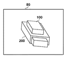
ステップS1210およびS1220で配置した2つのモデルを仮想カメラ700で観測した仮想画像80を図8に示す。本ステップでは、組み付け先部品20の3次元形状モデル200が、組み付け元部品10の3次元形状モデル100により隠蔽されうる領域を特定可能な画像80を作成する。具体的には、配置した2部品の3次元形状モデルを仮想画像平面730に描画して仮想画像80を作成する。このとき、隠面処理を行って視点からは陰になり見えない部分を消去して描画する。
(Step S1230)
FIG. 8 shows a
さらに、組み付け元部品10および組み付け先部品20の3次元形状モデルにはそれぞれ固有の色(輝度値)を割り当てて描画を行う。図9に、得られる仮想画像90を示す。仮想画像90の各画素の輝度値を参照することで、組み付け元部品10の投影領域900あるいは組み付け先部品20の投影領域910、あるいは背景領域920を特定可能である。本ステップで作成した画像を以後、領域特定画像と呼ぶことにする。
Further, a unique color (luminance value) is assigned to each of the three-dimensional shape models of the
なお、領域特定画像の作成方法はこれに限らない。たとえば、レンダリングを行わずに、仮想カメラ700から仮想画像平面730の各画素に対する視線ベクトルを計算し、視線ベクトルと3次元形状モデルとの交点位置により、各画素に投影される対象部品の領域を特定してもよい。具体的には、視線ベクトルと2部品の3次元形状モデルとの交差の有無をチェックし、交点が存在した場合には、その画素に、各3次元形状モデルに固有の輝度値を割り当てて画像を作成する。
The method of creating the area-specific image is not limited to this. For example, without rendering, the line-of-sight vector for each pixel of the
2部品とも交差があった画素については、交点が手前の3次元形状モデルに固有の輝度値を割り当てる。このほか、各画素に対して組み付け元部品10および組み付け先部品20の各モデルが投影された領域を特定できればいかなる方法であってもかまわない。
For pixels where both parts intersect, a unique brightness value is assigned to the 3D shape model whose intersection is in front. In addition, any method may be used as long as the region on which each model of the
(ステップS1300)
位置姿勢取得部160は、組み付け先部品20の3次元形状モデル200と、濃淡画像および距離画像との対応関係を用いて、組み付け先部品20の位置姿勢の算出を行う。その際、領域特定画像を参照することで、隠蔽領域の影響を低減する。以下、図5のフローチャートを用いて詳述する。
(Step S1300)
The position /
(ステップS1310)
位置姿勢取得部160は、領域特定画像を利用して、組み付け先部品20の3次元形状モデル200から位置姿勢を取得するための情報として幾何特徴を抽出、生成する。本実施形態においては、3次元形状モデルは、複数のNURBS(Non−UniformRational B−Spline)曲面で構成されているものとする。当該モデルの幾何特徴には、3次元の位置および法線とから構成される物体表面上の局所的な3次元平面情報(以後、「局所面特徴」と称する)と3次元の位置および方向とから構成される物体輪郭上の局所的な3次元線分情報(以後、「局所線特徴」と称する)を抽出するものとする。
(Step S1310)
The position /
なお、単に幾何特徴と称した場合は、局所面特徴と局所線特徴との両方を指すものとする。なお、抽出する幾何特徴は対象形状を表す3次元的な幾何情報であれば良く、特に制限はない。例えば、単純な3次元点の集合でもよいし、稜線を表す3次元ラインの集合でもよい。その他、位置姿勢に利用可能なものであれば、いかなるものであってもよい。 In addition, when it is simply referred to as a geometric feature, it means both a local surface feature and a local line feature. The geometric feature to be extracted may be any three-dimensional geometric information representing the target shape, and is not particularly limited. For example, it may be a set of simple three-dimensional points or a set of three-dimensional lines representing ridges. In addition, any one that can be used for the position and posture may be used.
幾何特徴の抽出は、領域特定画像上で組み付け先部品20が投影された画素をランダムにサンプリングし、その画素に対応する3次元形状モデル200上の幾何特徴を逆投影して算出することで行う。画素のサンプリングは全画素に対して行ってもよいし、均一に行ってもよい。このとき、領域特定画像の各画素の値を参照し、組み付け先部品以外が投影された領域からは幾何特徴を抽出しない。これにより、図10に示すように、組み付け元部品10による隠蔽部位を除外して、隠蔽が生じていない部位から、位置姿勢を取得するための情報としての幾何特徴(局所面特徴1001および局所線特徴1002)を抽出可能となる。ただし、3次元形状モデルの表面上から当該モデルの幾何特徴を抽出できれば、その方法は特に問わない。
Geometric features are extracted by randomly sampling the pixels on which the
なお、全方向から3次元形状モデルを描画して領域特定画像をそれぞれ作成し、各方向から隠蔽なく観測できるモデル幾何特徴を、各方向に対応付けて登録しておいてもよい。これにより、組み付け先部品20の位置及び姿勢の概略値とカメラパラメータとから算出される視線ベクトルに最も近い方向に登録された幾何特徴を選択することで幾何特徴の抽出が可能である。なお、各方向のベクトルと幾何特徴の法線との内積を比較し、方向ベクトルと幾何特徴の法線とが対向している幾何特徴のみを登録するようにしてもよい。
A three-dimensional shape model may be drawn from all directions to create a region-specific image, and model geometric features that can be observed from each direction without concealment may be registered in association with each direction. As a result, the geometric features can be extracted by selecting the geometric features registered in the direction closest to the line-of-sight vector calculated from the approximate values of the position and orientation of the
(ステップS1320)
位置姿勢取得部160は、ステップS1210において取得された、組み付け先部品20の概略位置姿勢に基づき、ステップS1000で計測された距離画像中の3次元点群と、3次元形状モデル200との対応付けを行う。部品の概略位置姿勢と距離画像撮影装置50の内部パラメータとを用いて、ステップS1310で抽出した各局所面特徴を距離画像上に投影する。そして、投影した各局所面特徴に対応する距離画像上の距離点を、各面に対応する3次元点として保持する。
(Step S1320)
The position /
次に、位置姿勢推定部160は、濃淡画像上のエッジと3次元形状モデルとの対応付けを行う。ステップS1320と同様に、組み付け先部品20の概略位置姿勢と2次元画像撮影装置40の内部パラメータとを用いて3次元形状モデルを構成する局所線特徴を画像へ投影し、画像上で検出されたエッジと3次元形状モデル中の局所線特徴とを対応付ける。エッジが各局所線特徴に対応して複数検出された場合には、複数検出されたエッジのうち、投影された局所線特徴に対して画像上で最も近いエッジを対応付ける。
Next, the position /
(ステップS1330)
位置姿勢取得部160は、ステップS1320で得られた、3次元形状モデル中の各面に対応する距離画像中の3次元点と、3次元形状モデル中の各線分に対応する濃淡画像上のエッジとの対応データに基づいて、組み付け先部品20および組み付け元部品10の位置姿勢を算出する。本ステップでは、算出した対応データに基づいて、計測データと3次元形状モデルとの間の誤差が最小になるように、線形連立方程式を解くことで、位置姿勢の更新を行う。
(Step S1330)
The position /
ここで、画像上の距離と3次元空間中での距離とでは尺度が異なるため、単純に連立方程式を解くだけでは計測データのどちらか一方に寄与率が偏ってしまう可能性がある。そこで本実施形態では、非特許文献2に示すような最尤推定に基づく最適化を行うことで、尺度を合わせた位置姿勢推定を行う。 Here, since the scale is different between the distance on the image and the distance in the three-dimensional space, there is a possibility that the contribution rate is biased to either one of the measurement data simply by solving the simultaneous equations. Therefore, in the present embodiment, the position / orientation estimation with the scale is performed by performing the optimization based on the maximum likelihood estimation as shown in Non-Patent Document 2.
最尤推定に基づく位置姿勢推定方法に関しては、本発明の本質に関わる話ではないため、詳細な説明は省略する。なお、位置及び姿勢の算出方法は、上述の最尤推定に基づく手法に限るものでなく、例えば、Levenberg−Marquardt法による繰り返し演算を行ってもよいし、よりシンプルな方法である最急降下法によって行ってもよい。また、共役勾配法やICCG法など、他の非線形最適化計算手法を用いてもよい。 Since the position and orientation estimation method based on maximum likelihood estimation is not related to the essence of the present invention, detailed description thereof will be omitted. The method for calculating the position and posture is not limited to the method based on the maximum likelihood estimation described above, and for example, iterative calculation by the Levenberg-Marquardt method may be performed, or a simpler method, the steepest descent method, may be used. You may go. Further, other nonlinear optimization calculation methods such as the conjugate gradient method and the ICCG method may be used.
なお、ここでは、位置合わせに濃淡画像および距離画像を利用する方法について述べたが、濃淡画像のみ、あるいは距離画像のみを用いて位置姿勢の算出を行う場合においてももちろん、同様の方法が利用できる。 In addition, although the method of using the shading image and the distance image for the alignment is described here, the same method can be used, of course, when the position and orientation are calculated using only the shading image or only the distance image. ..
(ステップS1400)
位置姿勢取得部160は、ステップS1330で更新した位置姿勢が、収束しているか否か、すなわち、さらに反復計算を必要とするか否かの判定を行う。具体的には、補正値がほぼ0である場合や、誤差ベクトルの二乗和の補正前と補正後との差がほぼ0である場合に収束したと判定する。収束していなければ(S1400;NO)、ステップS1100に戻り、更新した位置姿勢を用いて、再度位置姿勢推定処理を行う。収束していると判断した場合は(S1400;YES)、処理を終了し、撮影装置に対する、組み付け先部品20の位置姿勢の最終的な推定値が決定される。
(Step S1400)
The position /
以上、第1の実施形態では、組み付け先部品20と組み付け元部品10との相対関係に基づき、計測対象の組み付け先部品20が画像上で隠蔽される領域を特定し、隠蔽されない部位の3次元形状モデルを用いて位置姿勢算出を行う方法について述べた。
As described above, in the first embodiment, the region where the
本実施形態によれば、組み付け先部品の3次元形状モデルに対して、組み付け元部品による隠蔽が生じている部位を利用しないことで、隠蔽領域によるモデルと計測データとの不一致の影響を受けず、ロバストかつ高精度に位置姿勢を算出することが可能となる。 According to the present embodiment, the three-dimensional shape model of the assembly destination component is not affected by the discrepancy between the model and the measurement data due to the concealed area by not using the part where the assembly source component is concealed. , Robust and highly accurate position and orientation can be calculated.
(変形例1−1)
本実施形態では、組み付け先部品20の計測を例に説明した。しかし、組み付け元品10の位置姿勢算出においても同様の方法をもちろん適用可能である。組み付け元部品10が組み付け先部品20によって隠蔽される状況である場合には、本実施形態と同様の方法を用いて、組み付け先部品20による隠蔽部位の影響を除外して位置姿勢算出を行うことで、ロバストかつ高精度な推定が可能である。
(Modification 1-1)
In the present embodiment, the measurement of the
(変形例1−2)
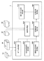
ここまで述べた方法を利用してさらに、組み付けが正しく行われたか否かの判定(組み付け成否判定)を行ってもよい。組み付け成否の判定は、図13に示すように、実施形態1の装置構成に、組み付け成否判定部170を追加することで実施可能である。まず、前述した方法により位置姿勢算出部160は、組み付けられた状態の組み付け元部品10、および、組み付け先部品20の位置姿勢をそれぞれ算出する。その後、算出したそれぞれの位置姿勢に基づき、両者の相対位置姿勢を算出する。これに対して、組み付け成否判定部170は、理想的な組み付け状態における、組み付け元部品10と組み付け先部品20との相対位置姿勢をあらかじめ保持しておき、算出された相対位置姿勢との比較を行う。この結果、位置姿勢に関する両者の差分が所定の値以上であった場合には組み付け失敗、所定の値未満であった場合には組み付け成功と判定する。なお、成否判定には、位置の差分あるいは姿勢の差分のいずれかのみ用いてもよい。これにより、組み付けにより部品間で相互に隠蔽が発生した状況においても組み付け成否を安定的に行うことが可能である。
(Modification 1-2)
Further, it may be determined whether or not the assembly has been performed correctly (assembly success / failure determination) by using the method described so far. As shown in FIG. 13, the determination of success or failure of assembly can be performed by adding the assembly success /
(変形例1−3)
上述の実施形態では、2つの部品から構成される組み付け済み部品30を対象とした事例について述べた。しかし、3つ以上の部品で構成される組み付け済み部品に対して、そのうちの1部品の位置姿勢を算出する場合にも同様の方法を適用可能である。この場合にも、構成部品の既知の組み付け情報に基づき、画像撮影上で計測対象の部品が隠蔽される領域を特定し、隠蔽部位からはモデル幾何特徴を抽出せずに位置姿勢算出を行う。これにより、隠蔽部位の影響を除外して、ロバストかつ高精度な推定が可能である。
(Modification 1-3)
In the above-described embodiment, an example of assembling the assembled
(第2の実施形態:モデル幾何特徴に付与した隠蔽情報に基づき位置姿勢を算出)
第1の実施形態では、隠蔽なく観測可能な部位からモデル幾何特徴を抽出して位置姿勢を算出する方法について述べた。
(Second embodiment: the position and orientation are calculated based on the concealment information given to the model geometric feature)
In the first embodiment, a method of extracting model geometric features from observable parts without concealment and calculating the position and orientation has been described.
これに対して、隠蔽の発生有無にかかわらずモデル幾何特徴は抽出しておき、その際に隠蔽が発生するか否かの属性を付与しておいてもよい。そして各モデル幾何特徴の属性に応じて位置姿勢算出時の寄与度を設定することで隠蔽による影響を軽減することが可能である。具体的には、第1の実施形態のステップS1310において、隠蔽が発生する部位についても組み付け先部品20の幾何特徴を抽出しておく。
On the other hand, the model geometric feature may be extracted regardless of whether or not concealment occurs, and an attribute as to whether or not concealment occurs may be added at that time. Then, it is possible to reduce the influence of concealment by setting the contribution degree at the time of position / orientation calculation according to the attribute of each model geometric feature. Specifically, in step S1310 of the first embodiment, the geometrical features of the
この際、領域特定画像の対応画素に基づき、隠蔽が発生する部位か否かを特定して、各幾何特徴とともに記録する。そして、ステップS1320において対応探索を行う際に、隠蔽領域の部位については対応探索を行わないようにする。もしくは、ステップS1330において位置姿勢を算出する際に、隠蔽が発生する幾何特徴の寄与度を低く、隠蔽が発生しない幾何特徴の寄与度を高く設定して位置姿勢を算出する。 At this time, based on the corresponding pixels of the region-specific image, it is specified whether or not it is a portion where concealment occurs, and it is recorded together with each geometric feature. Then, when performing the correspondence search in step S1320, the correspondence search is not performed for the portion of the concealed region. Alternatively, when calculating the position / orientation in step S1330, the contribution of the geometric feature in which concealment occurs is set low, and the contribution of the geometric feature in which concealment does not occur is set high to calculate the position / orientation.
あるいは、領域特定画像の画素値に、隠蔽度合いを示す値を記録しておき、この値に基づき各幾何特徴の寄与度を設定して位置姿勢を算出してもよい。具体的にはまず、領域特定画像の各画素に対して、計測対象の部品を遮蔽する別の部品が存在する場合には、遮蔽する面と計測対象の部品の面との奥行き(視線)方向の距離を隠蔽度として記録しておく。そして、ステップS1310においてモデル幾何特徴を抽出する際に、領域特定画像の対応画素を参照して、隠蔽度を付与しておく。そして、位置姿勢算出時に、モデル幾何特徴に付与された隠蔽度が大きいものは寄与度を低く、隠蔽度が小さいものは寄与度を高く設定して位置姿勢を算出する。なお、隠蔽度には、奥行き方向の距離以外の値を用いてもよい。たとえば、隠蔽が生じる部位の画素に対して、画像面上で隠蔽が発生しない部位までの最短距離を求め、この値を隠蔽度として利用してもよい。この場合も、隠蔽度が大きいものは寄与度を低く、小さいものは寄与度を高く設定して位置姿勢を算出する。このほか、隠蔽による位置姿勢算出への影響を考慮して、隠蔽度の算出および位置姿勢算出時の寄与度の設定は任意の方法で行えばよい。 Alternatively, a value indicating the degree of concealment may be recorded in the pixel value of the region-specific image, and the contribution degree of each geometric feature may be set based on this value to calculate the position and orientation. Specifically, first, when another component that shields the component to be measured exists for each pixel of the region-specific image, the depth (line-of-sight) direction between the shielding surface and the surface of the component to be measured Record the distance of as the degree of concealment. Then, when the model geometric feature is extracted in step S1310, the degree of concealment is given by referring to the corresponding pixel of the region-specific image. Then, at the time of calculating the position / orientation, the one having a large degree of concealment given to the model geometric feature has a low contribution degree, and the one having a small degree of concealment has a high contribution degree to calculate the position / orientation. The degree of concealment may be a value other than the distance in the depth direction. For example, the shortest distance to the portion where concealment does not occur on the image surface may be obtained for the pixel of the portion where concealment occurs, and this value may be used as the concealment degree. Also in this case, the position / posture is calculated by setting the contribution degree to be low when the degree of concealment is large and the contribution degree to be high when the degree of concealment is small. In addition, in consideration of the influence of concealment on the position / orientation calculation, the concealment degree may be calculated and the contribution degree at the time of position / orientation calculation may be set by any method.
以上、第2の実施形態によれば、モデル特徴に隠蔽部位か否かの属性を付与し、属性に基づいて位置姿勢算出への寄与度を変えることで、ロバストかつ高精度に位置姿勢の算出が可能となる。 As described above, according to the second embodiment, the position / orientation is calculated robustly and with high accuracy by giving the model feature an attribute of whether or not it is a concealed part and changing the degree of contribution to the position / orientation calculation based on the attribute. Is possible.
(変形例2−1:画像上で隠蔽領域を無効化)
第2の実施形態では、各部位が隠蔽されるか否かの判定結果に基づいてモデル幾何特徴を抽出することで、隠蔽による影響を受けずに位置姿勢を算出する方法について述べた。これに対して、モデル幾何特徴の代わりに、撮影画像から隠蔽が発生する部位を除外して、位置姿勢算出を行ってもよい。この場合、ステップS1310では、隠蔽の発生有無にかかわらず、モデル幾何特徴を抽出しておく。また、その際に、モデル幾何特徴に対する属性の付与も行わない。代わりに、ステップS1320においてモデル幾何特徴の対応探索実施後、対応づいた画素の領域特定画像を参照し、その画素が隠蔽領域の場合には、その対応を無効化して位置姿勢算出には利用しない。
(Modification example 2-1: Disable the hidden area on the image)
In the second embodiment, a method of calculating the position and orientation without being affected by the concealment by extracting the model geometric features based on the determination result of whether or not each part is concealed has been described. On the other hand, instead of the model geometric feature, the position / orientation calculation may be performed by excluding the part where the concealment occurs from the captured image. In this case, in step S1310, the model geometric features are extracted regardless of the presence or absence of concealment. At that time, no attribute is added to the model geometric feature. Instead, after performing the correspondence search of the model geometric feature in step S1320, the area-specific image of the corresponding pixel is referred to, and if the pixel is a concealed area, the correspondence is invalidated and the position / orientation is not calculated. ..
あるいは、ステップS1000で入力された濃淡画像および距離画像の各画素に対し、領域特定画像値を参照することで、組み付け先20部品の投影領域に該当する画素には無効値を設定しておく。図11は、第1の実施形態における図6の撮影画像60に対して、組み付け元部品10による隠蔽領域1100に無効値を設定した画像の例である。そして、ステップS1320において、無効値が設定されていない画素のみを対象に対応探索を行う。
Alternatively, by referring to the area-specific image value for each pixel of the shade image and the distance image input in step S1000, an invalid value is set for the pixel corresponding to the projection area of the
なお、本変形例においても、第2の実施形態と同様に、撮影画像に対して隠蔽度を設定して位置姿勢算出時の寄与度を設定してもよい。また、第1の実施形態と本変形例とを組み合わせ、領域特定画像に基づき、モデル幾何特徴と撮影画像との両方から隠蔽領域を除外して位置姿勢を算出してもよい。 In this modified example as well, as in the second embodiment, the degree of concealment may be set for the captured image and the degree of contribution at the time of calculating the position / orientation may be set. Further, the position and orientation may be calculated by combining the first embodiment and the present modification and excluding the concealed region from both the model geometric feature and the captured image based on the region-specific image.
以上、変形例2−1によれば、撮影画像に対して隠蔽部位か否かを判定し、隠蔽部位は位置姿勢算出に利用しないことで、その影響を受けず、ロバストかつ高精度に位置姿勢の算出を行うことが可能となる。 As described above, according to the modified example 2-1 by determining whether or not the captured image is a concealed portion and not using the concealed portion for the position / orientation calculation, the position / orientation is robust and highly accurate without being affected by the concealed portion. Can be calculated.
(第3の実施形態:ハンドで把持した部品を計測する際に、ハンドによる隠蔽を除外)
第1の実施形態および第2の実施形態では、複数部品の組み付けにより構成される組み付け済み部品のうちの1部品の位置姿勢算出を安定的に行う方法について述べた。
(Third embodiment: When measuring a part gripped by a hand, concealment by the hand is excluded)
In the first embodiment and the second embodiment, a method for stably calculating the position and orientation of one of the assembled parts configured by assembling a plurality of parts has been described.
本実施形態では、ロボットハンドにより把持を行った部品(把持部品)の画像を、ハンドに取り付けた撮影装置で撮影して位置姿勢を算出することを想定する。なお、撮影装置はハンドに取り付けず、ロボットの動作範囲内に固定で設置したものを用いてもよい。このとき、ハンドによる隠蔽の影響を受けずに安定的に位置姿勢を算出する方法について述べる。 In the present embodiment, it is assumed that an image of a part (grip part) gripped by a robot hand is photographed by a photographing device attached to the hand to calculate the position and orientation. The photographing device may not be attached to the hand, but may be fixedly installed within the operating range of the robot. At this time, a method of stably calculating the position and posture without being affected by the concealment by the hand will be described.
図12に一例を示すような、ロボットアーム12000の先端にロボットハンド12010を取り付け、ロボットハンド12010により把持した把持部品12020を、ロボットハンド12010に取り付けた撮影装置12030で撮影して、位置姿勢を算出することを想定する。なお、本実施形態で述べる「位置姿勢」とは、把持部品と当該部品を撮影する撮影装置との位置姿勢の関係のことを意味する。
As shown in FIG. 12, the
本実施形態は、第1の実施形態における、組み付け元部品10をロボットハンド12010、組み付け先部品20を把持部品12020とそれぞれ置き換えることで、基本的に第1の実施形態と同様の装置構成により実施可能である。ただし、本実施形態では、相対位置姿勢取得部120は、組み付け情報の代わりに、把持情報として、把持部品12020が理想的に把持された時の、ロボットハンド12010と把持部品12020との相対位置姿勢を隠蔽領域特定部150に入力する。
In the first embodiment, the
本実施形態によれば、把持を行ったロボットハンドによる隠蔽の影響を受けずに、把持部品の位置姿勢を高精度に算出可能である。 According to the present embodiment, the position and orientation of the gripped parts can be calculated with high accuracy without being affected by the concealment by the gripping robot hand.
(その他の実施形態)
本発明は、上述の実施形態の1以上の機能を実現するプログラムを、ネットワーク又は記憶媒体を介してシステム又は装置に供給し、そのシステム又は装置のコンピュータにおける1つ以上のプロセッサがプログラムを読出し実行する処理でも実現可能である。また、1以上の機能を実現する回路(例えば、ASIC)によっても実現可能である。
(Other embodiments)
The present invention supplies a program that realizes one or more functions of the above-described embodiment to a system or device via a network or storage medium, and one or more processors in the computer of the system or device reads and executes the program. It can also be realized by the processing to be performed. It can also be realized by a circuit (for example, ASIC) that realizes one or more functions.
1:情報処理装置、110:モデル取得部、120:相対位置姿勢取得部、130:画像取得部、140:概略位置姿勢取得部、150:隠蔽領域特定部、160:位置姿勢取得部 1: Information processing device, 110: Model acquisition unit, 120: Relative position / orientation acquisition unit, 130: Image acquisition unit, 140: Approximate position / orientation acquisition unit, 150: Concealed area identification unit, 160: Position / orientation acquisition unit
Claims (13)
前記組み付け先の物体の形状を表す第一の形状モデルおよび前記組み付け元の物体の形状を表す第二の形状モデルと前記理想の相対位置姿勢とに基づいて、前記組み付け先の物体と前記組み付け元の物体とが組み付けられた状態の画像から、前記組み付け元の物体が前記組み付け先の物体を隠蔽する隠蔽領域を特定する特定手段と、
前記隠蔽領域に対して、前記組み付け元の物体が前記組み付け先の物体を隠蔽する度合いに基づいて、前記組み付け先の物体の位置姿勢を取得する際の寄与度を設定する設定手段と、
前記第一の形状モデルまたは前記画像に基づいて、前記組み付け先の物体の位置姿勢を取得するための情報を生成する生成手段と、
前記生成手段により生成された情報と前記寄与度とに基づいて、前記組み付け先の物体の位置姿勢を取得する位置姿勢取得手段と、
を備えることを特徴とする情報処理装置。 An acquisition means for acquiring the ideal relative position / orientation between both objects when the assembly destination object and the assembly source object are assembled, and
Based on the relative position and orientation of the second shape model and the ideal representative of the first shape model and the assembly original shape of an object representing the assembly destination object shape, the assembly origin and the assembly destination object From the image of the state in which the object is assembled, the specific means for identifying the concealed area in which the assembly source object conceals the assembly destination object, and
For the covered area, a setting unit the assembled original object based on the degree of hiding the object of the assembly destination, sets the contribution degree when acquiring the position and orientation of the assembly destination object,
A generation means for generating information for acquiring the position and orientation of the object to be assembled based on the first shape model or the image.
A position / posture acquisition means for acquiring the position / orientation of the object to be assembled based on the information generated by the generation means and the contribution degree.
An information processing device characterized by being equipped with.
前記位置姿勢取得手段は、前記情報として生成された前記モデル特徴と前記画像中の画像特徴とを前記寄与度に基づいて対応付けて前記組み付け先の物体の位置姿勢を取得する請求項1または2に記載の情報処理装置。 It said generating means generates the model feature of the first shape model as the information,
The position / posture acquisition means claims 1 or 2 to acquire the position / orientation of the object to be assembled by associating the model feature generated as the information with the image feature in the image based on the contribution degree. The information processing device described in.
前記位置姿勢取得手段は、前記情報として生成された前記画像特徴と前記第一の形状モデルのモデル特徴とを前記寄与度に基づいて対応付けて前記組み付け先の物体の位置姿勢を取得する請求項1または2に記載の情報処理装置。 The generation means generates the image feature in the image as the information, and generates the image feature.
The claim that the position / posture acquisition means acquires the position / orientation of the object to be assembled by associating the image feature generated as the information with the model feature of the first shape model based on the contribution degree. The information processing apparatus according to 1 or 2.
前記推定された実際の相対位置姿勢に基づいて、前記組み付け先の物体と前記組み付け元の物体との組み付け状態を判定する判定手段を更に備えることを特徴とする請求項9に記載の情報処理装置。 And estimating means based on the position and orientation of the assembly original object and the position and orientation of the assembly destination object, estimating the actual relative position and orientation of said assembly original object and the assembly destination object,
The information processing apparatus according to claim 9 , further comprising a determination means for determining an assembling state of the assembling destination object and the assembling source object based on the estimated actual relative position and orientation. ..
組み付け先の物体と組み付け元の物体とが組み付けられた場合における両物体間の理想の相対位置姿勢を取得する取得工程と、
前記組み付け先の物体の形状を表す第一の形状モデルおよび前記組み付け元の物体の形状を表す第二の形状モデルと前記理想の相対位置姿勢とに基づいて、前記組み付け先の物体と前記組み付け元の物体とが組み付けられた状態の画像から、前記組み付け元の物体が前記組み付け先の物体を隠蔽する隠蔽領域を特定する特定工程と、
前記隠蔽領域に対して、前記組み付け元の物体が前記組み付け先の物体を隠蔽する度合いに基づいて、前記組み付け先の物体の位置姿勢を取得する際の寄与度を設定する設定工程と、
前記第一の形状モデルまたは前記画像に基づいて、前記組み付け先の物体の位置姿勢を取得するための情報を生成する生成工程と、
前記生成工程で生成された情報と前記寄与度とに基づいて、前記組み付け先の物体の位置姿勢を取得する位置姿勢取得工程と、
を有することを特徴とする情報処理装置の制御方法。 It is a control method for information processing equipment.
An acquisition process for acquiring the ideal relative position and orientation between both objects when the assembly destination object and the assembly source object are assembled, and
Based on the relative position and orientation of the second shape model and the ideal representative of the first shape model and the assembly original shape of an object representing the assembly destination object shape, the assembly origin and the assembly destination object From the image of the state in which the object of the assembly is assembled, a specific step of specifying a concealed area in which the object of the assembly source conceals the object of the assembly destination, and
For the covered area, a setting step of the assembling original object based on the degree of hiding the object of the assembly destination, sets the contribution degree when acquiring the position and orientation of the assembly destination object,
A generation step of generating information for acquiring the position and orientation of the object to be assembled based on the first shape model or the image.
A position / orientation acquisition step of acquiring the position / orientation of the object to be assembled based on the information generated in the generation step and the contribution degree.
A method for controlling an information processing device, which comprises.
Priority Applications (1)
| Application Number | Priority Date | Filing Date | Title |
|---|---|---|---|
| US15/443,429 US10252417B2 (en) | 2016-03-02 | 2017-02-27 | Information processing apparatus, method of controlling information processing apparatus, and storage medium |
Applications Claiming Priority (2)
| Application Number | Priority Date | Filing Date | Title |
|---|---|---|---|
| JP2016040445 | 2016-03-02 | ||
| JP2016040445 | 2016-03-02 |
Publications (3)
| Publication Number | Publication Date |
|---|---|
| JP2017162449A JP2017162449A (en) | 2017-09-14 |
| JP2017162449A5 JP2017162449A5 (en) | 2020-02-13 |
| JP6890422B2 true JP6890422B2 (en) | 2021-06-18 |
Family
ID=59857125
Family Applications (1)
| Application Number | Title | Priority Date | Filing Date |
|---|---|---|---|
| JP2017002117A Active JP6890422B2 (en) | 2016-03-02 | 2017-01-10 | Information processing equipment, control methods and programs for information processing equipment |
Country Status (1)
| Country | Link |
|---|---|
| JP (1) | JP6890422B2 (en) |
Families Citing this family (2)
| Publication number | Priority date | Publication date | Assignee | Title |
|---|---|---|---|---|
| JP7191569B2 (en) * | 2018-07-26 | 2022-12-19 | Ntn株式会社 | gripping device |
| US11006039B1 (en) | 2020-02-13 | 2021-05-11 | Mujin, Inc. | Method and system for determining occlusion within a camera field of view |
Family Cites Families (3)
| Publication number | Priority date | Publication date | Assignee | Title |
|---|---|---|---|---|
| JP6444027B2 (en) * | 2013-12-09 | 2018-12-26 | キヤノン株式会社 | Information processing apparatus, information processing apparatus control method, information processing system, and program |
| JP6306903B2 (en) * | 2014-03-06 | 2018-04-04 | キヤノン株式会社 | Information processing apparatus, information processing apparatus control method, and program |
| JP6264208B2 (en) * | 2014-06-30 | 2018-01-24 | 富士通株式会社 | Display program, display method, and display device |
-
2017
- 2017-01-10 JP JP2017002117A patent/JP6890422B2/en active Active
Also Published As
| Publication number | Publication date |
|---|---|
| JP2017162449A (en) | 2017-09-14 |
Similar Documents
| Publication | Publication Date | Title |
|---|---|---|
| JP6444027B2 (en) | Information processing apparatus, information processing apparatus control method, information processing system, and program | |
| US20200096317A1 (en) | Three-dimensional measurement apparatus, processing method, and non-transitory computer-readable storage medium | |
| JP5567908B2 (en) | Three-dimensional measuring apparatus, measuring method and program | |
| JP6465789B2 (en) | Program, apparatus and method for calculating internal parameters of depth camera | |
| JP5839929B2 (en) | Information processing apparatus, information processing system, information processing method, and program | |
| JP6573354B2 (en) | Image processing apparatus, image processing method, and program | |
| JP6426968B2 (en) | INFORMATION PROCESSING APPARATUS AND METHOD THEREOF | |
| JP6370038B2 (en) | Position and orientation measurement apparatus and method | |
| JP6271953B2 (en) | Image processing apparatus and image processing method | |
| JP6324025B2 (en) | Information processing apparatus and information processing method | |
| JP6092530B2 (en) | Image processing apparatus and image processing method | |
| JP6067175B2 (en) | Position measuring apparatus and position measuring method | |
| JP6677522B2 (en) | Information processing apparatus, control method for information processing apparatus, and program | |
| JP6836561B2 (en) | Image processing device and image processing method | |
| JP2016197287A (en) | Information processing apparatus, information processing method, and program | |
| JP2016170050A (en) | Position attitude measurement device, position attitude measurement method and computer program | |
| JP2017123087A (en) | Program, device and method for calculating normal vector of planar object reflected in continuous photographic images | |
| US10252417B2 (en) | Information processing apparatus, method of controlling information processing apparatus, and storage medium | |
| JP2016148649A (en) | Information processing apparatus, control method therefor, and program | |
| JP6890422B2 (en) | Information processing equipment, control methods and programs for information processing equipment | |
| JP6040264B2 (en) | Information processing apparatus, information processing apparatus control method, and program | |
| JP5976089B2 (en) | Position / orientation measuring apparatus, position / orientation measuring method, and program | |
| JP2014053018A (en) | Information processing device, control method for information processing device, and program | |
| JP6486083B2 (en) | Information processing apparatus, information processing method, and program | |
| KR20090070258A (en) | Procedure for estimating real-time pointing region using 3d geometric information |
Legal Events
| Date | Code | Title | Description |
|---|---|---|---|
| A521 | Written amendment |
Free format text: JAPANESE INTERMEDIATE CODE: A523 Effective date: 20191227 |
|
| A621 | Written request for application examination |
Free format text: JAPANESE INTERMEDIATE CODE: A621 Effective date: 20191227 |
|
| RD01 | Notification of change of attorney |
Free format text: JAPANESE INTERMEDIATE CODE: A7421 Effective date: 20210103 |
|
| A521 | Written amendment |
Free format text: JAPANESE INTERMEDIATE CODE: A523 Effective date: 20210113 |
|
| A977 | Report on retrieval |
Free format text: JAPANESE INTERMEDIATE CODE: A971007 Effective date: 20210201 |
|
| A131 | Notification of reasons for refusal |
Free format text: JAPANESE INTERMEDIATE CODE: A131 Effective date: 20210215 |
|
| A521 | Written amendment |
Free format text: JAPANESE INTERMEDIATE CODE: A523 Effective date: 20210409 |
|
| TRDD | Decision of grant or rejection written | ||
| A01 | Written decision to grant a patent or to grant a registration (utility model) |
Free format text: JAPANESE INTERMEDIATE CODE: A01 Effective date: 20210426 |
|
| A61 | First payment of annual fees (during grant procedure) |
Free format text: JAPANESE INTERMEDIATE CODE: A61 Effective date: 20210525 |
|
| R151 | Written notification of patent or utility model registration |
Ref document number: 6890422 Country of ref document: JP Free format text: JAPANESE INTERMEDIATE CODE: R151 |