JP6889896B2 - FRP mirror structure, manufacturing method of FRP mirror structure, and telescope - Google Patents
FRP mirror structure, manufacturing method of FRP mirror structure, and telescope Download PDFInfo
- Publication number
- JP6889896B2 JP6889896B2 JP2016116368A JP2016116368A JP6889896B2 JP 6889896 B2 JP6889896 B2 JP 6889896B2 JP 2016116368 A JP2016116368 A JP 2016116368A JP 2016116368 A JP2016116368 A JP 2016116368A JP 6889896 B2 JP6889896 B2 JP 6889896B2
- Authority
- JP
- Japan
- Prior art keywords
- layer
- frp
- mirror
- mirror structure
- mirror surface
- Prior art date
- Legal status (The legal status is an assumption and is not a legal conclusion. Google has not performed a legal analysis and makes no representation as to the accuracy of the status listed.)
- Expired - Fee Related
Links
Images


Landscapes
- Optical Elements Other Than Lenses (AREA)
- Laminated Bodies (AREA)
- Compositions Of Macromolecular Compounds (AREA)
Description
本発明は、FRP製ミラー構造体、FRP製ミラー構造体の製造方法、および、望遠鏡に関する。 The present invention relates to an FRP mirror structure, a method for manufacturing an FRP mirror structure, and a telescope.
FRP製ミラー構造体が知られている。FRP製ミラー構造体は、強度が高く、かつ、軽量である。 FRP mirror structures are known. The FRP mirror structure has high strength and is lightweight.
関連する技術として、特許文献1(特開平5−80212号公報)には、FRP製反射鏡が記載されている。特許文献1に記載のFRP製反射鏡は、FRP板と、当該FRP板の一方の表面に形成された平滑なガラス層と、当該ガラス層の表面に形成された反射膜と、前記FRP板の他方の面に形成された防湿層とを含む。特許文献1に記載のFRP製反射鏡では、FRP板の表面に防湿層が設けられているため、FRP板による湿気の吸収が防止される。そして、FRP板による湿気の吸収が防止されるので、FRP製反射鏡の膨潤による変形が防止される。
As a related technique, Patent Document 1 (Japanese Unexamined Patent Publication No. 5-80212) describes an FRP reflector. The FRP reflector described in
本発明の目的は、吸湿が抑制され、かつ、軽量化されたFRP製ミラー構造体、FRP製ミラー構造体の製造方法、および、望遠鏡を提供することにある。 An object of the present invention is to provide an FRP mirror structure in which moisture absorption is suppressed and light weight, a method for manufacturing the FRP mirror structure, and a telescope.
この発明のこれらの目的とそれ以外の目的と利益とは以下の説明と添付図面とによって容易に確認することができる。 These objectives and other objectives and benefits of the present invention can be easily confirmed by the following description and accompanying drawings.
以下に、課題を解決するための手段を説明する。 The means for solving the problem will be described below.
第1の態様におけるFRP製ミラー構造体の製造方法は、疎水性ポリマーを母材とするFRP層を準備する準備工程と、FRP層上に、非FRP層である中間層を介して、鏡面を備えた鏡面層を配置する配置工程とを具備する。疎水性ポリマーの繰り返し単位は、炭化水素によって構成されている。疎水性ポリマーの繰り返し単位は、炭素原子および水素原子以外の原子が含まれていない。疎水性ポリマーは二重結合を含まない。 The method for producing a mirror structure made of FRP in the first aspect is a preparatory step of preparing an FRP layer using a hydrophobic polymer as a base material, and a mirror surface on the FRP layer via an intermediate layer which is a non-FRP layer. It is provided with an arrangement step of arranging the provided mirror surface layer. The repeating unit of the hydrophobic polymer is composed of hydrocarbons. The repeating unit of the hydrophobic polymer does not contain atoms other than carbon and hydrogen atoms. Hydrophobic polymers do not contain double bonds.
第2の態様におけるFRP製ミラー構造体は、鏡面を備えた鏡面層と、FRP層と、非FRP層である中間層とを具備する。中間層は、鏡面層とFRP層との間に配置され、FRP層は、疎水性ポリマーを含む。疎水性ポリマーの繰り返し単位は、炭化水素によって構成されている。疎水性ポリマーの繰り返し単位は、炭素原子および水素原子以外の原子が含まれていない。疎水性ポリマーは二重結合を含まない。 The FRP mirror structure in the second aspect includes a mirror surface layer having a mirror surface, an FRP layer, and an intermediate layer which is a non-FRP layer. The intermediate layer is arranged between the mirror surface layer and the FRP layer, and the FRP layer contains a hydrophobic polymer. The repeating unit of the hydrophobic polymer is composed of hydrocarbons. The repeating unit of the hydrophobic polymer does not contain atoms other than carbon and hydrogen atoms. Hydrophobic polymers do not contain double bonds.
第3の態様におけるFRP製ミラー構造体においては、中間層は、接着剤層である。FRP層は、疎水性ポリマーを母材とする疎水性部分と、疎水性部分と接着剤層との間に配置された極性基含有ポリマー層とを含む。 In the FRP mirror structure according to the third aspect, the intermediate layer is an adhesive layer. The FRP layer includes a hydrophobic portion based on a hydrophobic polymer and a polar group-containing polymer layer arranged between the hydrophobic portion and the adhesive layer.
第4の態様におけるFRP製ミラー構造体においては、極性基含有ポリマー層の厚さは、0.1nm以上300nm以下である。 In the FRP mirror structure according to the fourth aspect, the thickness of the polar group-containing polymer layer is 0.1 nm or more and 300 nm or less.
第5の態様におけるFRP製ミラー構造体においては、中間層は、研削された表面を有する樹脂層である。 In the FRP mirror structure according to the fifth aspect, the intermediate layer is a resin layer having a ground surface.
第6の態様における望遠鏡は、上記に記載のFRP製ミラー構造体が搭載された望遠鏡であって、電磁波検出器を含み、鏡面層で反射された赤外線、可視光、紫外線、または、X線が、電磁波検出器に導入される。 The telescope according to the sixth aspect is a telescope equipped with the FRP mirror structure described above, and includes an electromagnetic wave detector, and emits infrared rays, visible light, ultraviolet rays, or X-rays reflected by the mirror surface layer. , Introduced in electromagnetic wave detectors.
本発明により、吸湿が抑制され、かつ、軽量化されたFRP製ミラー構造体、FRP製ミラー構造体の製造方法、および、望遠鏡が提供できる。 INDUSTRIAL APPLICABILITY According to the present invention, it is possible to provide an FRP mirror structure in which moisture absorption is suppressed and light weight, a method for manufacturing the FRP mirror structure, and a telescope.
以下、実施形態に係るFRP製ミラー構造体、ミラーの製造方法、および、望遠鏡に関して、添付図面を参照して説明する。なお、添付図面において、同一の機能を有する構成要素には、同一の符号が付与されている。同一の符号が付された構成要素についての繰り返しとなる説明は省略される。 Hereinafter, the FRP mirror structure, the mirror manufacturing method, and the telescope according to the embodiment will be described with reference to the accompanying drawings. In the attached drawings, the same reference numerals are given to the components having the same function. A repetitive description of the components with the same reference numerals is omitted.
(発明者によって認識された事項)
FRP製ミラー構造体において使用される樹脂としては、エポキシ樹脂およびシアネート樹脂が知られている。エポキシ樹脂およびシアネート樹脂は、親水性を有している。換言すれば、エポキシ樹脂、シアネート樹脂には、親水基が多く含まれている。このため、既存のFRP製ミラー構造体では、親水性樹脂(エポキシ樹脂、シアネート樹脂等)による吸湿または脱湿に伴い、FRP製ミラー構造体が変形するおそれがあった。FRP製ミラー構造体が変形した場合、鏡面の平滑性を維持することができない。特に、ミラーを、赤外線波長以下の波長の電磁波(電磁波には、光も包含される。)のように短波長の電磁波を反射するために用いる場合には、短波長に対応して、鏡面における高い平滑性が要求される。ミラーを、紫外線波長より短い波長の電磁波(例えば、X線)を反射するために用いる場合には、鏡面において、非常に高い平滑性が要求される。以上の観点から、赤外線波長以下の波長用のFRP製ミラー構造体(特に、X線波長以下の波長用のFRP製ミラー構造体)は、実用化されていないのが実情である。
(Matters recognized by the inventor)
Epoxy resins and cyanate resins are known as resins used in FRP mirror structures. Epoxy resins and cyanate resins have hydrophilicity. In other words, the epoxy resin and the cyanate resin contain a large amount of hydrophilic groups. Therefore, in the existing FRP mirror structure, the FRP mirror structure may be deformed due to moisture absorption or dehumidification by the hydrophilic resin (epoxy resin, cyanate resin, etc.). When the FRP mirror structure is deformed, the smoothness of the mirror surface cannot be maintained. In particular, when the mirror is used to reflect a short wavelength electromagnetic wave such as an electromagnetic wave having a wavelength lower than the infrared wavelength (the electromagnetic wave includes light), the mirror surface corresponds to the short wavelength. High smoothness is required. When a mirror is used to reflect an electromagnetic wave having a wavelength shorter than the ultraviolet wavelength (for example, X-ray), a very high smoothness is required on the mirror surface. From the above viewpoint, the fact is that the FRP mirror structure for wavelengths below the infrared wavelength (particularly, the FRP mirror structure for wavelengths below the X-ray wavelength) has not been put into practical use.
なお、FRPの周囲に、防湿層としての金属箔あるいはガラスを配置することが考えられる。しかし、FRPの周囲に防湿層を設ける場合には、FRP製ミラー構造体の重量が増加する。また、防湿層としてガラスを用いる場合には、鏡面またはFRPの形状に合わせてガラスを加工する必要がある。このため、FRP製ミラー構造体の製造コストあるいは製造時間が増加する。更には、ガラスには、割れるリスクがある。 It is conceivable to arrange a metal foil or glass as a moisture-proof layer around the FRP. However, when a moisture-proof layer is provided around the FRP, the weight of the FRP mirror structure increases. When glass is used as the moisture-proof layer, it is necessary to process the glass according to the shape of the mirror surface or FRP. Therefore, the manufacturing cost or manufacturing time of the FRP mirror structure increases. Moreover, glass has a risk of breaking.
(実施形態におけるFRP製ミラー構造体)
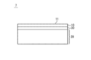
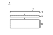
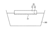
図1を参照して、実施形態におけるFRP製ミラー構造体7について説明する。図1は、FRP製ミラー構造体7の断面図である。FRP製ミラー構造体7は、鏡面11を備えた鏡面層10と、FRP層20と、中間層30とを含む。中間層30は、鏡面層10とFRP層20との間に配置されている。
(FRP mirror structure in the embodiment)
The
FRP層20は、繊維強化プラスチック層である。繊維は、例えば、炭素繊維であるが、炭素繊維以外の繊維を用いることも可能である。プラスチックは、マトリックス(換言すれば、母材)として機能する。FRP層20は、疎水性ポリマーをマトリックス(母材)として含む。FRP層20のマトリックスとして、疎水性ポリマーを採用することにより、FRP層20による吸湿が抑制される。
The
FRP層20は、表面には、繊維の存在に起因して、凹凸が存在する。このため、FRP層20上に、直接、鏡面層10を積層すると、鏡面11に凹凸が含まれることとなる。実施形態では、中間層30が平滑表面を備える。そして、平滑表面上に鏡面層10が積層される。このため、鏡面11における凹凸の発生が抑制される。
The surface of the
図1に記載の例では、中間層30の第1表面(平滑表面)が、鏡面層10に接し、中間層30の第2表面が、FRP層20に接触している。中間層30は、1層であっても、複数層であってもよい。
In the example described in FIG. 1, the first surface (smooth surface) of the
中間層30には、平滑表面を備えることと、鏡面層10およびFRP層20に対する良好な接着特性を有することとが要求される。このため、中間層30および/またはFRP層20には、様々な工夫が施されることが好ましい。以下、様々な工夫について、より詳細に説明する。
The
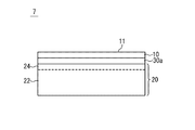
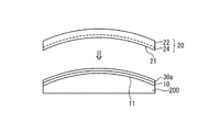
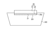
図2および図3を参照して、実施形態におけるFRP製ミラー構造体7について、より詳細に説明する。図2は、FRP製ミラー構造体7の断面図である。図3は、FRP製ミラー構造体7の鏡面層10の一例を示す断面図である。
The
FRP製ミラー構造体7は、鏡面11を備えた鏡面層10と、FRP層20と、鏡面層10とFRP層20との間に配置される接着剤層30aとを備える。接着剤層30aは、上述の中間層30として機能する。
The
鏡面11は、光、X線等の電磁波が入射する側のミラーの表面である。鏡面11は、平滑な表面である。鏡面11の表面粗さは、例えば、0.4mm×0.4mmの正方形の面積内で0.8nm以下の二乗平均平方根表面粗さ(RMS表面粗さ)を有する。鏡面層10は、電磁波を反射する層である。換言すれば、鏡面層10は、反射層として機能する。鏡面層10は、例えば、アルミニウム、プラチナ等の金属層である。鏡面層10は、FRP層よりも外側に配置される外層である。
The
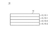
鏡面層10は、アルミニウム、プラチナ等の金属の単層であってもよいし、多層であってもよい。図3には、多層を有する鏡面層10の例が示されている。図3に記載の例では、鏡面層10は、第1材料層13と第2材料層15との繰り返し構造を含む。第1材料層13としてプラチナ層を用い、第2材料層15として炭素層が用いられてもよい。図3に記載の例では、鏡面層10は、第1プラチナ層13−1と、第1炭素層15−1と、第2プラチナ層13−2と、第2炭素層15−2とを含む。多層を有する鏡面層10は、例えば、高エネルギーの電磁波の反射のために用いることが可能である。図3に記載の例では、各プラチナ層において電磁波が反射される。図3に記載の例では、第1プラチナ層13−1の厚さと第2プラチナ層13−2の厚さとが互いに等しく、第1炭素層15−1の厚さと第2炭素層15−2の厚さとが互いに等しい。代替的に、第1プラチナ層13−1の厚さと第2プラチナ層13−2の厚さとが、互いに異なっていてもよい。代替的に、あるいは、付加的に、第1炭素層15−1の厚さと第2炭素層15−2の厚さとが互いに異なっていてもよい。
The
図2を参照して、FRP層20は、繊維強化プラスチック層である。FRP層20は、疎水性ポリマーをマトリックス(母材)とする疎水性部分22と、極性基含有ポリマー層24とを含む。図2に記載の例では、疎水性部分22である疎水層と、極性基含有ポリマー層24との境界が、破線で示されている。
With reference to FIG. 2, the
疎水性部分22は、繊維とマトリックス(母材)とを含む。マトリックスは、例えば、熱可塑性樹脂である。また、マトリックスは、疎水性ポリマーである。疎水性部分22における吸湿は小さい。その結果、疎水性部分22の変形(例えば、膨張、収縮等)が抑制され、鏡面11の平滑性が維持される。
The
疎水性ポリマーは、例えば、ポリマーの繰り返し単位が、炭化水素で構成されている。すなわち、ポリマーの繰り返し単位に、炭素原子および水素原子以外の原子が含まれていない。 In hydrophobic polymers, for example, the repeating unit of the polymer is composed of hydrocarbons. That is, the repeating unit of the polymer does not contain atoms other than carbon atoms and hydrogen atoms.
疎水性ポリマーには、原子間の二重結合が含まれていないことが好ましい。二重結合が含まれていない場合には、二重結合の開裂による組成変化が生じない。また、二重結合が含まれていない場合には、意図せぬ酸化により、疎水性ポリマーに親水基が導入されるリスクが小さくなる。 The hydrophobic polymer preferably does not contain double bonds between atoms. When the double bond is not included, the composition does not change due to the cleavage of the double bond. Also, if double bonds are not included, the risk of introducing hydrophilic groups into the hydrophobic polymer due to unintended oxidation is reduced.
疎水性ポリマーの例として、ポリオレフィンが挙げられる。ポリオレフィンは、ここでは、二重結合を有する鎖状炭化水素単量体を重合して得られる単独重合体、または、二重結合を有する鎖状炭化水素単量体と、二重結合を有する他の鎖状炭化水素単量体との共重合体を意味する。ポリオレフィンの具体例としては、ポリメチルペンテン、ポリエチレン、ポリプロピレン等が挙げられる。ポリメチルペンテンは、吸湿性が低いのに加えて、耐熱性が高いため、好適な材料の1つである。 Examples of hydrophobic polymers include polyolefins. Here, the polyolefin is a homopolymer obtained by polymerizing a chain hydrocarbon monomer having a double bond, or a chain hydrocarbon monomer having a double bond and another having a double bond. Means a copolymer with a chain hydrocarbon monomer of. Specific examples of polyolefins include polymethylpentene, polyethylene, polypropylene and the like. Polymethylpentene is one of the suitable materials because it has high heat resistance in addition to low hygroscopicity.
極性基含有ポリマー層24は、疎水性部分22よりも親水性が高く、極性基を含有するポリマー層である。極性基は、例えば、孤立電子対を含む官能基である。孤立電子対を含む官能基としては、例えば、酸素を含む官能基(ヒドロキシ基等)、窒素を含む官能基(アミノ基等)が例示される。なお、極性基含有ポリマー層24の厚さは、吸湿を抑制する観点から、出来るだけ薄い方が好ましい。極性基含有ポリマー層24の厚さは、例えば、0.1nm以上300nm以下、より好ましくは、1nm以上100nm以下である。極性基含有ポリマー層24の厚さは、例えば、FRP層20の厚さの1/100以下、より好ましくは、1/500以下である。なお、FRP層20の厚さは、例えば、0.05mm以上10mm以下である。また、FRP層20の裏面に、構造強化のためのリブを設けてもよい。代替的に、あるいは、付加的に、FRP層20の裏面に、芯材層、および、他のFRP層を配置したサンドイッチ構造が構造材として採用されてもよい。
The polar group-containing
なお、極性基含有ポリマー層24は、薄層である。極性基含有ポリマー層24の厚さは、例えば、FRP層中の単繊維の直径よりも小さい。
The polar group-containing
極性基含有ポリマー層24は、FRP層20の表面が改質された層(すなわち、FRP層の表面改質層)であってもよい。より具体的には、極性基含有ポリマー層24は、FRP層20を構成する疎水性ポリマーの表面を、プラズマ処理、または、紫外線処理することによって形成されてもよい。疎水性ポリマーの表面をプラズマ処理、または、紫外線処理することによって、例えば、疎水性ポリマー中のC−H結合中に(換言すれば、炭素原子と水素原子との間に)、酸素原子あるいは窒素原子を導入することが可能である。この場合、結果として、疎水性ポリマー中の水素原子が、極性基によって置換されることとなる。疎水性ポリマーの表面を表面処理することによって、極性基含有ポリマー層24を形成する場合には、極性基含有ポリマー層24中のポリマーの主鎖の基本骨格と、疎水性部分22中のポリマーの主鎖の基本骨格とを概ね一致させることが可能である。
The polar group-containing
FRP層20が疎水性ポリマーのみで構成される場合には、FRP層20と接着剤層30aとの間の親和性(接着性)が低い。例えば、疎水性ポリマーであるポリオレフィンは、離型材として用いられていることから把握されるように、接着剤層30aとの親和性が低い。このため、FRP層20と接着剤層30aとの間の剥離のリスクが高い。これに対し、実施形態におけるFRP製ミラー構造体7は、極性基含有ポリマー層24を含む。このため、FRP層20(極性基含有ポリマー層24)と接着剤層30aとの間の親和性(接着性)を高くすることが可能である。実施形態におけるFRP製ミラー構造体7では、FRP層と接着剤層との間の親和性を高めるために、疎水性ポリマーの表面に、敢えて、吸湿性を有する極性基含有ポリマー層が設けられている。しかし、極性基含有ポリマー層の厚さは薄いため、吸湿による悪影響は、最小限にとどまる。
When the
図2を参照して、接着剤層30aは、鏡面層10と、FRP層20(極性基含有ポリマー層24)とを接着する層である。すなわち、接着剤層30aの一方側の面は、鏡面層10の裏面(鏡面11とは反対側の面)に接着し、接着剤層30aの他方側の面は、極性基含有ポリマー層24に接着している。接着剤層30aは、例えば、エポキシ系(エポキシ樹脂)の接着剤、または、ビニルエステル系(ビニルエステル樹脂)の接着剤を含む。なお、FRP製ミラー構造体7を人工衛星に搭載する場合には、接着剤としては、アウトガス特性が、要求値を満たす接着剤が選択される。
With reference to FIG. 2, the
接着剤層30aは、例えば、常温で硬化する常温硬化接着剤層、または、低温(本明細書では、低温は、「摂氏70度以下」を意味する。)で硬化する低温硬化接着剤層であってもよい。摂氏70度以下、より好ましくは、摂氏50度以下、更により好ましくは、摂氏30度以下で硬化する接着剤層を用いる場合、FRP層20と鏡面層10との接着に際し、接着剤層30aおよびFRP層20を過度に加熱する必要がない。このため、接着工程におけるFRP層20の変形(例えば、膨張、収縮等)が抑制される。その結果、鏡面11の平滑性が維持される。なお、接着剤層30aの厚さは、例えば、50μm以下、より好ましくは、20μm以下である。
The
実施形態におけるFRP製ミラー構造体では、鏡面の形状を維持するための構造材として、FRP層が用いられている。このため、FRP製ミラー構造体の軽量化が可能となる。また、実施形態におけるFRP製ミラー構造体では、FRP層の大部分が、疎水性ポリマーを母材とする疎水性部分である。このため、FRP層における吸湿が効果的に抑制される。また、実施形態におけるFRP製ミラー構造体では、疎水性部分と接着剤層との間に配置された極性基含有ポリマー層を含む。このため、鏡面を有する鏡面層とFRP層とが、接着剤層を介して、強力に結合される。また、実施形態におけるFRP製ミラー構造体は、吸湿に伴う変形が小さい。このため、鏡面の平滑性が維持される。その結果、実施形態におけるFRP製ミラー構造体を、赤外線波長以下の電磁波(例えば、赤外線、可視光、紫外線、X線)の反射用に用いることが可能となる。また、実施形態におけるFRP製ミラー構造体を、紫外線波長より短い波長の電磁波(例えば、X線)の反射用に用いることが可能となる。 In the FRP mirror structure of the embodiment, an FRP layer is used as a structural material for maintaining the shape of the mirror surface. Therefore, the weight of the FRP mirror structure can be reduced. Further, in the FRP mirror structure of the embodiment, most of the FRP layer is a hydrophobic portion using a hydrophobic polymer as a base material. Therefore, moisture absorption in the FRP layer is effectively suppressed. Further, the FRP mirror structure in the embodiment includes a polar group-containing polymer layer arranged between the hydrophobic portion and the adhesive layer. Therefore, the mirror surface layer having a mirror surface and the FRP layer are strongly bonded to each other via the adhesive layer. Further, the FRP mirror structure in the embodiment is less deformed due to moisture absorption. Therefore, the smoothness of the mirror surface is maintained. As a result, the FRP mirror structure of the embodiment can be used for reflecting electromagnetic waves having an infrared wavelength or less (for example, infrared rays, visible light, ultraviolet rays, X-rays). Further, the FRP mirror structure in the embodiment can be used for reflecting electromagnetic waves (for example, X-rays) having a wavelength shorter than the ultraviolet wavelength.
実施形態におけるFRP製ミラー構造体では、吸湿が効果的に抑制されるため、FRP層を覆う防湿層を省略することが可能である。しかし、実施形態におけるFRP製ミラー構造体に関し、必要に応じて、FRP層を覆う防湿層を採用しても構わない。 In the FRP mirror structure of the embodiment, moisture absorption is effectively suppressed, so that the moisture-proof layer covering the FRP layer can be omitted. However, with respect to the FRP mirror structure in the embodiment, a moisture-proof layer covering the FRP layer may be adopted if necessary.
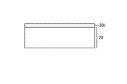
(FRP製ミラー構造体の変形例)
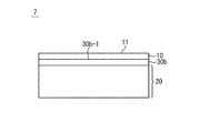
図4Aおよび図4Bを参照して、実施形態におけるFRP製ミラー構造体7の変形例について説明する。図4Aおよび図4Bは、変形例におけるFRP製ミラー構造体の断面図である。図4Aに記載の例では、樹脂層30bが、中間層30として機能する。樹脂層30bは、繊維を含まない非FRP層である。樹脂層30bの材質は、例えば、FRP層20のマトリックス(母材)と同じ材質である。樹脂層30bの材質は、例えば、熱可塑性樹脂である。樹脂層30b(例えば、樹脂フィルム)をFRP層20に接合するに際しては、まず、樹脂層30bをFRP層20上に配置する。次に、樹脂層30b(または、樹脂層30bおよびFRP層20)を加熱しつつ、樹脂層30bをFRP層20に圧着する。代替的に、FRP層20を作製するための複数のプリプレグ層の上に樹脂層30bを配置し、複数のプリプレグ層と樹脂層30bとを加熱しつつ圧着することにより、FRP層20と樹脂層30bとが一体化された積層体が作製されてもよい。
(Modification example of FRP mirror structure)
A modified example of the
なお、樹脂層30bの材質が、疎水性ポリマーである場合、樹脂層30bと鏡面層10との間の接着性が弱い可能性がある。この場合、図4Bに示されるように、樹脂層30bの表面を改質し、樹脂層30bが、極性基含有ポリマー層34を含むようにしてもよい。極性基含有ポリマー層34は、例えば、樹脂層30bの表面を表面改質処理(例えば、プラズマ処理、または、紫外線処理)することによって形成されてもよい。極性基含有ポリマー層34は、樹脂層30bにおいて表面改質がされていない部分よりも、親水性が高い。極性基含有ポリマー層34と鏡面層10との間の接着性は相対的に強いため、樹脂層30bと鏡面層10とが、極性基含有ポリマー層34を介して、強固に接着される。
When the material of the
なお、FRP層20の表面に凹凸が存在することに起因して、樹脂層30bの表面に凹凸が存在する可能性がある。この場合、鏡面層10を積層する前に、樹脂層30bの表面30b−1を研削(grinding)することが好ましい。すなわち、樹脂層30bの表面30b−1は、研削された表面であることが好ましい。図4Bに記載の例では、研削は、表面改質処理の前に実行されてもよい。研削によって、樹脂層30bの表面は、0.4mm×0.4mmの正方形の面積内で0.8nm以下の二乗平均平方根表面粗さ(RMS表面粗さ)とされてもよい。
It should be noted that there is a possibility that the surface of the
(実施形態におけるFRP製ミラー構造体の第1適用例)
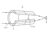
図5Aおよび図5Bを参照して、FRP製ミラー構造体7の第1適用例について説明する。図5Aは、FRP製ミラー構造体7の適用例を示す機能ブロック図である。図5Bは、図5Aに示された望遠鏡2の光学系3の一部を模式的に示す一部切欠き図である。
(First application example of the FRP mirror structure in the embodiment)
A first application example of the
FRP製ミラー構造体7は、例えば、望遠鏡等の電磁波検出機器(電磁波観測機器)の光学系3において用いられるミラー構造体である。なお、本明細書において、「光学系」は、電磁波を検出部に導く機構を意味する。図5Aには、FRP製ミラー構造体7を含む望遠鏡2が、人工衛星1に搭載されている例が示されている。
The
図5Bを参照して、望遠鏡2の光学系3は、FRP製ミラー構造体7と、検出器4とを備える。図5Bに記載の例では、FRP製ミラー構造体7は、2つの鏡面、すなわち、第1鏡面11−1と、第2鏡面11−2とを備えている。しかし、鏡面の数は、1つであってもよいし、3つ以上であってもよい。図5Bに記載の例では、第1鏡面11−1は、回転放物面であり、第2鏡面11−2は、回転双曲面である。回転放物面は、中心軸回りに、放物線を仮想的に回転させることにより得られる曲面であり、回転双曲面は、中心軸回りに、双曲線を仮想的に回転させることにより得られる曲面である。図5Bに記載の例では、望遠鏡2に入射した電磁波(例えば、X線)が、第1鏡面11−1で反射され、第1鏡面11−1で反射された電磁波が、さらに、第2鏡面11−2で反射され、第2鏡面11−2で反射された電磁波が検出器4に導入される。検出器4は、電磁波(例えば、X線)を検出する検出器である。
With reference to FIG. 5B, the
(実施形態におけるFRP製ミラー構造体の第2適用例)
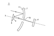
図5Cを参照して、FRP製ミラー構造体7の第2適用例について説明する。図5Cは、望遠鏡等の電磁波検出機器の光学系3の一部を模式的に示す図である。
(Second application example of the FRP mirror structure in the embodiment)
A second application example of the
図5Cを参照して、光学系3は、FRP製ミラー構造体7と、第2ミラー構造体8と、検出器4とを備える。図5Cに記載の例では、FRP製ミラー構造体7は、第2ミラー構造体8の鏡面9に対向配置される鏡面11を備えている。図5Cに記載の例では、鏡面11は、曲線を中心軸であるX軸まわりに仮想的に回転することによって得られる回転対称面である。図5Cに記載の例では、電磁波検出機器に入射した電磁波(例えば、赤外線、可視光、紫外線等)が、鏡面11で反射され、鏡面11で反射された電磁波が、さらに、第2ミラー構造体8の鏡面9で反射され、鏡面9で反射された電磁波が検出器4に導入される。検出器4は、電磁波(例えば、赤外線、可視光、紫外線等)を検出する検出器である。なお、図5Cに記載の例では、FRP製ミラー構造体7の中央部には、電磁波が通過可能な孔70が設けられている。
With reference to FIG. 5C, the
図5Cに記載の光学系3は、望遠鏡に搭載されてもよい。また、光学系3を含む望遠鏡が人工衛星に搭載されてもよい。
The
実施形態におけるFRP製ミラー構造体が、望遠鏡に搭載される場合、望遠鏡が軽量化される。また、実施形態におけるFRP製ミラー構造体は、湿気を吸収しにくいため、FRP製ミラー構造体の鏡面の平滑性が維持される。このため、望遠鏡における電磁波の検出精度が維持される。さらに、実施形態におけるFRP製ミラー構造体を含む望遠鏡が人工衛星に搭載される場合、人工衛星の重量が軽減される。このため、人工衛星の打ち上げコストが低減される。さらに、人工衛星に搭載された望遠鏡のメンテナンスは、困難な場合が多い。しかし、実施形態におけるFRP製ミラー構造体は、高強度であるとともに、湿気吸収に伴う変形のリスクが小さい。このため、FRP製ミラー構造体(および望遠鏡)のメンテナンスを行う必要がないか、あるいは、メンテナンス負担が軽減される。 When the FRP mirror structure according to the embodiment is mounted on the telescope, the weight of the telescope is reduced. Further, since the FRP mirror structure in the embodiment does not easily absorb moisture, the smoothness of the mirror surface of the FRP mirror structure is maintained. Therefore, the detection accuracy of electromagnetic waves in the telescope is maintained. Further, when the telescope including the FRP mirror structure in the embodiment is mounted on the artificial satellite, the weight of the artificial satellite is reduced. Therefore, the launch cost of the artificial satellite is reduced. Moreover, maintenance of telescopes mounted on artificial satellites is often difficult. However, the FRP mirror structure in the embodiment has high strength and a low risk of deformation due to moisture absorption. Therefore, it is not necessary to perform maintenance on the FRP mirror structure (and the telescope), or the maintenance burden is reduced.
(実施形態のFRP製ミラー構造体の製造方法)
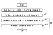
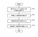
図6を参照して、実施形態におけるFRP製ミラー構造体7の製造方法の概要について説明する。まず、第1に、疎水性ポリマーを母材とするFRP層20が準備される。第2に、FRP層20上に、非FRP層である中間層30を介して、鏡面11を備えた鏡面層10が配置される。なお、中間層30と鏡面層10との接合は、中間層30とFRP層20との接合よりも前であってもよいし、後であってもよい。
(Manufacturing method of FRP mirror structure of embodiment)
The outline of the manufacturing method of the
図7乃至図12を参照して、実施形態におけるFRP製ミラー構造体の製造方法についてより詳細に説明する。図7は、FRP製ミラー構造体7の製造方法を示すフローチャートである。
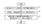
The method for manufacturing the FRP mirror structure according to the embodiment will be described in more detail with reference to FIGS. 7 to 12. FIG. 7 is a flowchart showing a manufacturing method of the
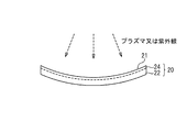
第1ステップS1において、疎水性ポリマーを母材とするFRP層20が準備される。FRP層20は、繊維と母材(マトリックス)とを含む。FRP層20は、プレス成型やオートクレーブ成形によって準備されてもよい。なお、図8に示されるように、FRP層20の形成に際しては、型材100を用いることが可能である。型材100の表面101の形状は、作製すべきFRP製ミラー構造体の鏡面11の形状と一致している。なお、本明細書において「一致」には、「概ね一致」が包含される。成形前のFRP層20を型材100の表面101上に載置した状態で、加熱することにより、鏡面11の形状と一致する第1表面21を有するFRP層20が形成される。
In the first step S1, the
なお、鏡面11の形状は、曲面形状であってもよい。鏡面11の形状は、例えば、曲線を中心軸回りに仮想的に回転させることにより得られる曲面の形状、回転放物面形状、回転双曲面形状、回転放物面の一部分に対応する形状、回転双曲面の一部分に対応する形状等である。鏡面11の形状を曲面形状にする場合には、型材100の表面101の形状は、鏡面11の曲面形状に一致する形状に設定される。
The shape of the
第2ステップS2において、FRP層20の第1表面層に極性基が導入される。その結果、FRP層20に極性基含有ポリマー層24が形成される。極性基含有ポリマー層24を形成する工程は、FRP層20の表面を表面処理することにより、FRP層20の第1表面層に極性基を導入することを含んでいてもよい。表面処理は、例えば、プラズマ照射処理、紫外線照射処理等である。
In the second step S2, a polar group is introduced into the first surface layer of the
図9に、FRP層20の第1表面層に極性基を導入する工程の一例が示されている。図9に記載の例では、第1表面21に向けて、プラズマまたは紫外線が照射される。第1表面21に向けて、酸素プラズマあるいは窒素プラズマを照射する場合には、第1表面層に、酸素原子または窒素原子が導入される。その結果、第1表面層が、極性基含有ポリマー層24となる。代替的に、大気雰囲気下、窒素雰囲気下、あるいは、酸素雰囲気下において、第1表面21に向けて、不活性ガスプラズマが照射されてもよい。この場合にも、第1表面層に、酸素原子または窒素原子が導入される。その結果、第1表面層が、極性基含有ポリマー層24となる。代替的に、大気雰囲気下、窒素雰囲気下、あるいは、酸素雰囲気下において、第1表面21に向けて、紫外線が照射されてもよい。この場合にも、第1表面層に、酸素原子または窒素原子が導入される。その結果、第1表面層が、極性基含有ポリマー層24となる。なお、上述の例では、FRP層20の第1表面層に酸素原子または窒素原子が導入されているが、FRP層20の第1表面層に導入される原子は、酸素原子または窒素原子以外の原子であってもよい。FRP層20の第1表面層に導入される原子は、例えば、炭素よりも電気陰性度が大きな任意の原子である。
FIG. 9 shows an example of a step of introducing a polar group into the first surface layer of the
第3ステップS3において、鏡面11を備えた鏡面層10が、接着剤層30aを介して、極性基含有ポリマー層24上に配置される。
In the third step S3, the
例えば、第3ステップS3において、鏡面11を備えた鏡面層10と、極性基含有ポリマー層24とが、接着剤層30aを介して接着されることにより、鏡面11を備えた鏡面層10が、接着剤層30aを介して、極性基含有ポリマー層24上に配置されてもよい。この場合、まず、図10に示されるように、鏡面層10の裏面(鏡面11とは反対側の面)および/または極性基含有ポリマー層24の第1表面21に、接着剤が適用される。図10に記載の例では、鏡面層10の裏面(鏡面11とは反対側の面)に、接着剤が適用され、その結果、接着剤層30aが形成されている。接着剤の適用は、接着剤を適用すべき表面に接着剤をスプレーすることにより実行されてもよい。
For example, in the third step S3, the
次に、鏡面層10の裏面と、接着剤層30aの一方側の面とが接触し、かつ、接着剤層30aの他方側の面と、第1表面21とが接触するように、鏡面層10とFRP層20とが、互いに近づくように相対移動される。図11には、相対移動後の状態が模式的に示されている。図10および図11に記載の例では、基板200上に鏡面層10が載置された状態にて、上述の相対移動が実行される。続いて、接着剤層30aが硬化されることにより、鏡面層10とFRP層20とが、接着剤層30aを介して、互いに接着する。なお、接着剤層30aの硬化は、常温環境下、または、低温環境下(摂氏70度以下の環境下)で実行されることが好ましい。
Next, the mirror surface layer is such that the back surface of the
接着剤層30aの硬化後に、FRP層20を、基板200から離れる方向に移動させると、鏡面層10は、基板200上の位置からFRP層20上の位置に移動する(換言すれば、鏡面層10は、FRP層上に転写される)。以上の工程により、FRP製ミラー構造体7を製造することができる。
When the
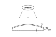
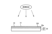
なお、上述の例では、基板上の層を、接着剤を用いて別の部材に転写する方法(具体的には、基板200上の鏡面層10を、接着剤層30aを用いてFRP層20に転写する方法)、すなわち、レプリカ法を用いて、鏡面層10と極性基含有ポリマー層24との間の接着が実行されている。レプリカ法では、基板200の平滑表面201を利用することにより、直接表面加工が困難な薄層(鏡面層10)に鏡面11を形成することが可能である。図12には、基板200の平滑表面201を利用することにより、鏡面層10に鏡面11を形成する工程の一例が示されている。レプリカ法を用いる場合、鏡面層10に鏡面11を形成する工程は、上述の第3ステップS3よりも前に実行される。図12に記載の例では、基板200の平滑表面201上に、金属材料(蒸着素材)を蒸着することにより、鏡面層10に鏡面11が形成される。基板200は、例えば、ガラス基板である。また、金属材料は、例えば、プラチナ、アルミニウム、金、銀等である。
In the above example, a method of transferring the layer on the substrate to another member using an adhesive (specifically, the
(実施形態のFRP製ミラー構造体の製造方法の変形例)
図13乃至図16を参照して、実施形態のFRP製ミラー構造体の製造方法の変形例について説明する。変形例における第1ステップS1および第2ステップS2は、上述の第1ステップS1および第2ステップS2と、それぞれ、同様である。よって、繰り返しとなる説明は省略する。
(Modified example of the method for manufacturing the FRP mirror structure of the embodiment)
A modified example of the method for manufacturing the FRP mirror structure of the embodiment will be described with reference to FIGS. 13 to 16. The first step S1 and the second step S2 in the modified example are the same as the first step S1 and the second step S2 described above, respectively. Therefore, a repetitive description will be omitted.
第3ステップS3において、鏡面11を備えた鏡面層10が、接着剤層30aを介して、極性基含有ポリマー層24上に配置される。変形例における第3ステップS3では、まず、ステップS3−1において、FRP層20の極性基含有ポリマー層24上に、接着剤層30aが配置される。次に、ステップS3−2において、接着剤層30aの上に、鏡面層10を堆積させることにより、鏡面11を備えた鏡面層10が、接着剤層30aを介して、極性基含有ポリマー層24上に配置される。
In the third step S3, the
図14乃至図16を参照して、第3ステップS3についてより詳細に説明する。ステップS3−1では、まず、FRP層20の極性基含有ポリマー層24上に、接着剤層30aが配置される。図14に記載の例では、FRP層20の極性基含有ポリマー層24を、接着剤300(例えば、接着剤300のゲル溶液)に接触させることにより、FRP層20の極性基含有ポリマー層24上に、接着剤が配置される。接着剤は、例えば、エポキシ系の接着剤、ビニルエステル系の接着剤等である。なお、図14において、FRP層20の形状は、平板形状であるが、FRP層20の形状は、図9に例示されるように、曲板形状であってもよい。
The third step S3 will be described in more detail with reference to FIGS. 14 to 16. In step S3-1, first, the
次に、FRP層20の極性基含有ポリマー層24に接触する接着剤300が硬化される。接着剤300の硬化は、常温環境下、または、低温環境下で実行されることが好ましい。
Next, the adhesive 300 in contact with the polar group-containing
続いて、極性基含有ポリマー層24に接着した接着剤300を精密に研削加工(grinding)することにより、平滑表面301を有する接着剤層30aが形成される。図15における一点鎖線は、切削加工により形成される接着剤層30aおよび平滑表面301を示す。
Subsequently, the adhesive 300 adhered to the polar group-containing
ステップS3−2では、接着剤層30aの上に、鏡面層10が堆積される。図16に示されるように、接着剤層30aへの鏡面層10の堆積は、接着剤層30aの平滑表面301上に、金属材料(蒸着素材)を蒸着することにより、実行されてもよい。また、金属材料は、例えば、プラチナ、アルミニウム、金、銀等である。
In step S3-2, the
変形例におけるFRP製ミラー構造体の製造方法では、鏡面層10を形成するための型材(例えば、図12に記載の基板200のような型材)が不要である。また、変形例におけるFRP製ミラー構造体の製造方法では、接着剤層30aの表面を平滑表面301とすることにより、鏡面層10を堆積した後の鏡面11が平滑面となる。
In the method of manufacturing the FRP mirror structure in the modified example, a mold material for forming the mirror surface layer 10 (for example, a mold material such as the
(実施形態のFRP製ミラー構造体の製造方法の第2変形例)
図17乃至図18を参照して、実施形態のFRP製ミラー構造体の製造方法の第2変形例について説明する。図17は、FRP製ミラー構造体7の製造方法を示すフローチャートである。図18は、FRP層20と樹脂層30bとが積層された状態を示す図である。
(Second modification of the method for manufacturing the FRP mirror structure of the embodiment)
A second modification of the method for manufacturing the FRP mirror structure of the embodiment will be described with reference to FIGS. 17 to 18. FIG. 17 is a flowchart showing a manufacturing method of the
第1ステップS101において、疎水性ポリマーを母材とするFRP層20が準備される。FRP層20は、繊維と母材(マトリックス)とを含む。
In the first step S101, the
第2ステップS102において、FRP層20上に非FRP層である樹脂層30b(中間層)が配置される。樹脂層30bは、例えば、繊維を含まない樹脂フィルムである。なお、第2ステップS102は、第1ステップS101と同時に実行されてもよい。換言すれば、FRP層20を作製するための複数のプリプレグ層の上に樹脂層30bが配置され、複数のプリプレグ層と樹脂層30bとを加熱しつつ圧着することにより、FRP層20と樹脂層30bとが一体化された積層体が準備されてもよい。図18は、第2ステップS102の実行後の状態を示す図である。
In the second step S102, the
第3ステップS103において、樹脂層30bの表面が研削される。なお、第2ステップS102の実行後に、樹脂層30bの表面が十分に平滑である場合には、研削工程は、省略されてもよい。また、第3ステップS103の前に、または、第3ステップS103の後に、樹脂層30bの表面が改質されて、樹脂層30bに、極性基含有ポリマー層34(図4Bを参照)が形成されてもよい。極性基含有ポリマー層34の厚さは、例えば、0.1nm以上300nm以下、より好ましくは、1nm以上100nm以下である。
In the third step S103, the surface of the
第4ステップS104において、樹脂層30b上に(または、樹脂層30bに含まれる極性基含有ポリマー層34上に)、鏡面層10が積層される。積層は、例えば、蒸着によって行われる。以上の工程により、図4Aまたは図4Bに示されるようなFRP製ミラー構造体7を製造することができる。
In the fourth step S104, the
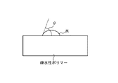
(疎水性の程度について)
疎水性ポリマーの疎水性の程度は、水の接触角θを測定することにより求めることができる。実施形態において、ポリマー(FRP層20)における水の接触角θが、80度以上、より好ましくは、90度以上である時には、当該ポリマーは、疎水性ポリマーと定義されてもよい。換言すれば、実施形態における疎水性ポリマー(FRP層20)における水の接触角は、例えば、80度以上、より好ましくは、90度以上である。他方、実施形態における極性基含有ポリマー層24、34における水の接触角は、例えば、80度より小さく、より好ましくは、50度より小さい。また、接触角は、ゴニオメーター、顕微鏡等で直接測定されてもよいし、ビデオカメラ等で撮影後、画像解析ソフトによる解析により算出されてもよい。
(About the degree of hydrophobicity)
The degree of hydrophobicity of the hydrophobic polymer can be determined by measuring the contact angle θ of water. In the embodiment, when the contact angle θ of water in the polymer (FRP layer 20) is 80 degrees or more, more preferably 90 degrees or more, the polymer may be defined as a hydrophobic polymer. In other words, the contact angle of water in the hydrophobic polymer (FRP layer 20) in the embodiment is, for example, 80 degrees or more, more preferably 90 degrees or more. On the other hand, the contact angle of water in the polar group-containing polymer layers 24 and 34 in the embodiment is, for example, less than 80 degrees, more preferably less than 50 degrees. The contact angle may be directly measured with a goniometer, a microscope, or the like, or may be calculated by analysis with image analysis software after shooting with a video camera or the like.
本発明は上記各実施形態に限定されず、本発明の技術思想の範囲内において、各実施形態は適宜変形又は変更され得ることは明らかである。また、各実施形態又は変形例で用いられる種々の技術は、技術的矛盾が生じない限り、他の実施形態又は変形例にも適用可能である。 The present invention is not limited to each of the above embodiments, and it is clear that each embodiment can be appropriately modified or modified within the scope of the technical idea of the present invention. In addition, the various techniques used in each embodiment or modification can be applied to other embodiments or modifications as long as there is no technical contradiction.
1 :人工衛星
2 :望遠鏡
3 :光学系
4 :検出器
7 :FRP製ミラー構造体
8 :第2ミラー構造体
9 :鏡面
10 :鏡面層
11 :鏡面
11−1 :第1鏡面
11−2 :第2鏡面
13 :第1材料層
13−1 :第1プラチナ層
13−2 :第2プラチナ層
15 :第2材料層
15−1 :第1炭素層
15−2 :第2炭素層
20 :FRP層
21 :第1表面
22 :疎水性部分
24 :極性基含有ポリマー層
30 :中間層
30a :接着剤層
30b :樹脂層
30b−1:研削された表面
34 :極性基含有ポリマー層
70 :孔
100 :型材
101 :表面
200 :基板
201 :平滑表面
300 :接着剤
301 :平滑表面
1: Artificial satellite 2: Telescope 3: Optical system 4: Detector 7: FRP mirror structure 8: Second mirror structure 9: Mirror surface 10: Mirror surface layer 11: Mirror surface 11-1: First mirror surface 11-2: 2nd mirror surface 13: 1st material layer 13-1: 1st platinum layer 13-2: 2nd platinum layer 15: 2nd material layer 15-1: 1st carbon layer 15-2: 2nd carbon layer 20: FRP Layer 21: First surface 22: Hydrophobic portion 24: Polar group-containing polymer layer 30:
Claims (6)
前記FRP層上に、非FRP層である中間層を介して、鏡面を備えた鏡面層を配置する配置工程と
を具備し、
前記疎水性ポリマーの繰り返し単位は、炭化水素によって構成されており、
前記疎水性ポリマーの繰り返し単位は、炭素原子および水素原子以外の原子が含まれておらず、
前記疎水性ポリマーは二重結合を含まない
FRP製ミラー構造体の製造方法。 The preparatory process for preparing an FRP layer using a hydrophobic polymer as a base material,
A step of arranging a mirror surface layer having a mirror surface on the FRP layer via an intermediate layer which is a non-FRP layer is provided.
The repeating unit of the hydrophobic polymer is composed of hydrocarbons.
The repeating unit of the hydrophobic polymer does not contain atoms other than carbon atoms and hydrogen atoms, and does not contain atoms.
A method for producing an FRP mirror structure in which the hydrophobic polymer does not contain a double bond.
FRP層と、
非FRP層である中間層と
を具備し、
前記中間層は、前記鏡面層と前記FRP層との間に配置され、
前記FRP層は、疎水性ポリマーを含み、
疎水性ポリマーの繰り返し単位は、炭化水素によって構成されており、
前記疎水性ポリマーの繰り返し単位は、炭素原子および水素原子以外の原子が含まれておらず、
前記疎水性ポリマーは二重結合を含まない
FRP製ミラー構造体。 A mirror layer with a mirror surface and
FRP layer and
It has an intermediate layer that is a non-FRP layer,
The intermediate layer is arranged between the mirror surface layer and the FRP layer, and is arranged.
The FRP layer contains a hydrophobic polymer and contains
The repeating unit of the hydrophobic polymer is composed of hydrocarbons and
The repeating unit of the hydrophobic polymer does not contain atoms other than carbon atoms and hydrogen atoms, and does not contain atoms.
The hydrophobic polymer is an FRP mirror structure that does not contain double bonds.
前記FRP層は、
前記疎水性ポリマーを母材とする疎水性部分と、
前記疎水性部分と前記接着剤層との間に配置された極性基含有ポリマー層と
を含む
請求項2に記載のFRP製ミラー構造体。 The intermediate layer is an adhesive layer and
The FRP layer is
The hydrophobic portion using the hydrophobic polymer as a base material and
The FRP mirror structure according to claim 2 , further comprising a polar group-containing polymer layer arranged between the hydrophobic portion and the adhesive layer.
請求項3に記載のFRP製ミラー構造体。 The FRP mirror structure according to claim 3 , wherein the thickness of the polar group-containing polymer layer is 0.1 nm or more and 300 nm or less.
請求項2に記載のFRP製ミラー構造体。 The FRP mirror structure according to claim 2 , wherein the intermediate layer is a resin layer having a ground surface.
電磁波検出器を含み、
前記鏡面層で反射された赤外線、可視光、紫外線、または、X線が、前記電磁波検出器に導入される
望遠鏡。 A telescope equipped with the FRP mirror structure according to any one of claims 2 to 5.
Including electromagnetic wave detector
A telescope in which infrared rays, visible light, ultraviolet rays, or X-rays reflected by the mirror surface layer are introduced into the electromagnetic wave detector.
Priority Applications (1)
| Application Number | Priority Date | Filing Date | Title |
|---|---|---|---|
| JP2016116368A JP6889896B2 (en) | 2016-06-10 | 2016-06-10 | FRP mirror structure, manufacturing method of FRP mirror structure, and telescope |
Applications Claiming Priority (1)
| Application Number | Priority Date | Filing Date | Title |
|---|---|---|---|
| JP2016116368A JP6889896B2 (en) | 2016-06-10 | 2016-06-10 | FRP mirror structure, manufacturing method of FRP mirror structure, and telescope |
Publications (2)
| Publication Number | Publication Date |
|---|---|
| JP2017219810A JP2017219810A (en) | 2017-12-14 |
| JP6889896B2 true JP6889896B2 (en) | 2021-06-18 |
Family
ID=60656453
Family Applications (1)
| Application Number | Title | Priority Date | Filing Date |
|---|---|---|---|
| JP2016116368A Expired - Fee Related JP6889896B2 (en) | 2016-06-10 | 2016-06-10 | FRP mirror structure, manufacturing method of FRP mirror structure, and telescope |
Country Status (1)
| Country | Link |
|---|---|
| JP (1) | JP6889896B2 (en) |
Family Cites Families (10)
| Publication number | Priority date | Publication date | Assignee | Title |
|---|---|---|---|---|
| JPH0618929B2 (en) * | 1984-03-28 | 1994-03-16 | チッソ株式会社 | Glass fiber reinforced polypropylene composition |
| JPS61102601A (en) * | 1984-10-25 | 1986-05-21 | Hitachi Chem Co Ltd | Preparation of fiber reinforced plastic mirror |
| JPH01267602A (en) * | 1988-04-20 | 1989-10-25 | Ishikawajima Harima Heavy Ind Co Ltd | Molding method of surface reflective mirror using FRP substrate |
| JPH04320201A (en) * | 1991-04-19 | 1992-11-11 | Nippon Oil Co Ltd | Reflection mirror |
| DE60041323D1 (en) * | 1999-11-29 | 2009-02-26 | Nikon Corp | OPTICAL ELEMENT SUCH AS MULTILAYER FILM REFLECTION MIRRORS, METHOD FOR THE PRODUCTION THEREOF AND THIS USE DEVICE |
| JP2006084910A (en) * | 2004-09-17 | 2006-03-30 | Ricoh Co Ltd | Reflector and manufacturing method thereof |
| FR2967242B1 (en) * | 2010-11-04 | 2014-11-07 | Cray Valley Sa | SOLAR REFLECTOR OF COMPOSITE MATERIAL BASED ON FIBER REINFORCED RESIN AND USES IN SOLAR POWER PLANTS |
| WO2015029746A1 (en) * | 2013-08-29 | 2015-03-05 | コニカミノルタ株式会社 | Reflecting mirror for solar thermal power generation and reflective device for solar thermal power generation |
| JP2015191073A (en) * | 2014-03-27 | 2015-11-02 | 株式会社ジェイエスピー | resin mirror |
| CN104155738B (en) * | 2014-07-25 | 2017-07-04 | 江苏泰瑞斯特新材料科技股份有限公司 | The Salar light-gathering reflector elements of the heat collector of trough type solar power generation |
-
2016
- 2016-06-10 JP JP2016116368A patent/JP6889896B2/en not_active Expired - Fee Related
Also Published As
| Publication number | Publication date |
|---|---|
| JP2017219810A (en) | 2017-12-14 |
Similar Documents
| Publication | Publication Date | Title |
|---|---|---|
| US8439511B2 (en) | Mirror and a method of manufacturing thereof | |
| CN108278928B (en) | A lightweight shielding square bulkhead board with infrared stealth function and preparation method thereof | |
| US20120075734A1 (en) | Mirror assembly | |
| CN109927943A (en) | Recoverable airship solar heat protection and carrying integral structure | |
| US9724893B2 (en) | Out-of-autoclave curing system | |
| JP6889896B2 (en) | FRP mirror structure, manufacturing method of FRP mirror structure, and telescope | |
| JP6889897B2 (en) | Manufacturing method of FRP mirror structure | |
| CA2996744C (en) | Composite materials cured with thermoplastic thin film coating | |
| WO2012002355A1 (en) | Composite material molding die and production method therefor | |
| JP7020184B2 (en) | Processing method of metal-thermoplastic fiber reinforced resin material composite member, metal-thermoplastic fiber reinforced resin material composite member and automobile parts. | |
| US10946600B1 (en) | Composite structure repair methods incorporating a lattice core material | |
| US11326064B2 (en) | Ultraviolet protective coating for fabricating epoxy-based components | |
| EP3772407B1 (en) | System for improving thermoset-thermoplastic interface adhesion | |
| JP7225943B2 (en) | Fiber reinforced resin molded product with hard coat layer | |
| US11633925B2 (en) | System and method for improving thermoset-thermoplastic interface adhesion | |
| WO2021199287A1 (en) | Joining method | |
| JP7207510B2 (en) | METHOD OF PROCESSING METAL-THERMOPLASTIC FIBER REINFORCED COMPOSITE MEMBER | |
| JP5092444B2 (en) | Manufacturing method of fiber reinforced composite material | |
| WO2009110185A1 (en) | Composite optical element and method for manufacturing the same | |
| JPH05100102A (en) | Production of lens joint | |
| US20060286362A1 (en) | Methods for preparing composite materials | |
| JP7188003B2 (en) | HARD COAT SUBSTRATE JOINT AND METHOD FOR MANUFACTURING SAME | |
| JP7363275B2 (en) | Hard coat resin base material with elastic body for bonding, hard coat base material bonded body, and manufacturing method of hard coat base material bonded body | |
| US20190299539A1 (en) | Thermo-fusion additive fabrication method, production method for thermo-fusion additive fabrication object, and structure partially including thermo-fusion additive fabrication object | |
| US20100034997A1 (en) | Metal-composite bonding methods and compositions |
Legal Events
| Date | Code | Title | Description |
|---|---|---|---|
| RD04 | Notification of resignation of power of attorney |
Free format text: JAPANESE INTERMEDIATE CODE: A7424 Effective date: 20160825 |
|
| RD03 | Notification of appointment of power of attorney |
Free format text: JAPANESE INTERMEDIATE CODE: A7423 Effective date: 20190226 |
|
| A621 | Written request for application examination |
Free format text: JAPANESE INTERMEDIATE CODE: A621 Effective date: 20190607 |
|
| A711 | Notification of change in applicant |
Free format text: JAPANESE INTERMEDIATE CODE: A711 Effective date: 20190607 |
|
| A521 | Request for written amendment filed |
Free format text: JAPANESE INTERMEDIATE CODE: A821 Effective date: 20190607 |
|
| RD03 | Notification of appointment of power of attorney |
Free format text: JAPANESE INTERMEDIATE CODE: A7423 Effective date: 20190719 |
|
| A521 | Request for written amendment filed |
Free format text: JAPANESE INTERMEDIATE CODE: A821 Effective date: 20190719 |
|
| RD04 | Notification of resignation of power of attorney |
Free format text: JAPANESE INTERMEDIATE CODE: A7424 Effective date: 20190820 |
|
| RD04 | Notification of resignation of power of attorney |
Free format text: JAPANESE INTERMEDIATE CODE: A7424 Effective date: 20190820 |
|
| A977 | Report on retrieval |
Free format text: JAPANESE INTERMEDIATE CODE: A971007 Effective date: 20200311 |
|
| A131 | Notification of reasons for refusal |
Free format text: JAPANESE INTERMEDIATE CODE: A131 Effective date: 20200421 |
|
| A601 | Written request for extension of time |
Free format text: JAPANESE INTERMEDIATE CODE: A601 Effective date: 20200611 |
|
| A521 | Request for written amendment filed |
Free format text: JAPANESE INTERMEDIATE CODE: A523 Effective date: 20200820 |
|
| A131 | Notification of reasons for refusal |
Free format text: JAPANESE INTERMEDIATE CODE: A131 Effective date: 20210106 |
|
| A521 | Request for written amendment filed |
Free format text: JAPANESE INTERMEDIATE CODE: A523 Effective date: 20210308 |
|
| TRDD | Decision of grant or rejection written | ||
| A01 | Written decision to grant a patent or to grant a registration (utility model) |
Free format text: JAPANESE INTERMEDIATE CODE: A01 Effective date: 20210420 |
|
| A61 | First payment of annual fees (during grant procedure) |
Free format text: JAPANESE INTERMEDIATE CODE: A61 Effective date: 20210517 |
|
| R150 | Certificate of patent or registration of utility model |
Ref document number: 6889896 Country of ref document: JP Free format text: JAPANESE INTERMEDIATE CODE: R150 |
|
| R250 | Receipt of annual fees |
Free format text: JAPANESE INTERMEDIATE CODE: R250 |
|
| LAPS | Cancellation because of no payment of annual fees |