JP6889843B2 - Video signal detector - Google Patents
Video signal detector Download PDFInfo
- Publication number
- JP6889843B2 JP6889843B2 JP2018112439A JP2018112439A JP6889843B2 JP 6889843 B2 JP6889843 B2 JP 6889843B2 JP 2018112439 A JP2018112439 A JP 2018112439A JP 2018112439 A JP2018112439 A JP 2018112439A JP 6889843 B2 JP6889843 B2 JP 6889843B2
- Authority
- JP
- Japan
- Prior art keywords
- frame
- video signal
- frames
- motion vector
- unit
- Prior art date
- Legal status (The legal status is an assumption and is not a legal conclusion. Google has not performed a legal analysis and makes no representation as to the accuracy of the status listed.)
- Active
Links
Images


Classifications
-
- H—ELECTRICITY
- H04—ELECTRIC COMMUNICATION TECHNIQUE
- H04N—PICTORIAL COMMUNICATION, e.g. TELEVISION
- H04N5/00—Details of television systems
- H04N5/14—Picture signal circuitry for video frequency region
- H04N5/144—Movement detection
- H04N5/145—Movement estimation
-
- G—PHYSICS
- G06—COMPUTING OR CALCULATING; COUNTING
- G06T—IMAGE DATA PROCESSING OR GENERATION, IN GENERAL
- G06T7/00—Image analysis
- G06T7/10—Segmentation; Edge detection
- G06T7/194—Segmentation; Edge detection involving foreground-background segmentation
-
- G—PHYSICS
- G06—COMPUTING OR CALCULATING; COUNTING
- G06T—IMAGE DATA PROCESSING OR GENERATION, IN GENERAL
- G06T7/00—Image analysis
- G06T7/20—Analysis of motion
- G06T7/223—Analysis of motion using block-matching
-
- H—ELECTRICITY
- H04—ELECTRIC COMMUNICATION TECHNIQUE
- H04N—PICTORIAL COMMUNICATION, e.g. TELEVISION
- H04N19/00—Methods or arrangements for coding, decoding, compressing or decompressing digital video signals
- H04N19/10—Methods or arrangements for coding, decoding, compressing or decompressing digital video signals using adaptive coding
- H04N19/134—Methods or arrangements for coding, decoding, compressing or decompressing digital video signals using adaptive coding characterised by the element, parameter or criterion affecting or controlling the adaptive coding
- H04N19/136—Incoming video signal characteristics or properties
- H04N19/137—Motion inside a coding unit, e.g. average field, frame or block difference
- H04N19/139—Analysis of motion vectors, e.g. their magnitude, direction, variance or reliability
-
- H—ELECTRICITY
- H04—ELECTRIC COMMUNICATION TECHNIQUE
- H04N—PICTORIAL COMMUNICATION, e.g. TELEVISION
- H04N19/00—Methods or arrangements for coding, decoding, compressing or decompressing digital video signals
- H04N19/20—Methods or arrangements for coding, decoding, compressing or decompressing digital video signals using video object coding
- H04N19/23—Methods or arrangements for coding, decoding, compressing or decompressing digital video signals using video object coding with coding of regions that are present throughout a whole video segment, e.g. sprites, background or mosaic
-
- H—ELECTRICITY
- H04—ELECTRIC COMMUNICATION TECHNIQUE
- H04N—PICTORIAL COMMUNICATION, e.g. TELEVISION
- H04N19/00—Methods or arrangements for coding, decoding, compressing or decompressing digital video signals
- H04N19/50—Methods or arrangements for coding, decoding, compressing or decompressing digital video signals using predictive coding
- H04N19/503—Methods or arrangements for coding, decoding, compressing or decompressing digital video signals using predictive coding involving temporal prediction
- H04N19/51—Motion estimation or motion compensation
- H04N19/513—Processing of motion vectors
- H04N19/521—Processing of motion vectors for estimating the reliability of the determined motion vectors or motion vector field, e.g. for smoothing the motion vector field or for correcting motion vectors
-
- H—ELECTRICITY
- H04—ELECTRIC COMMUNICATION TECHNIQUE
- H04N—PICTORIAL COMMUNICATION, e.g. TELEVISION
- H04N19/00—Methods or arrangements for coding, decoding, compressing or decompressing digital video signals
- H04N19/50—Methods or arrangements for coding, decoding, compressing or decompressing digital video signals using predictive coding
- H04N19/503—Methods or arrangements for coding, decoding, compressing or decompressing digital video signals using predictive coding involving temporal prediction
- H04N19/51—Motion estimation or motion compensation
- H04N19/527—Global motion vector estimation
-
- H—ELECTRICITY
- H04—ELECTRIC COMMUNICATION TECHNIQUE
- H04N—PICTORIAL COMMUNICATION, e.g. TELEVISION
- H04N19/00—Methods or arrangements for coding, decoding, compressing or decompressing digital video signals
- H04N19/50—Methods or arrangements for coding, decoding, compressing or decompressing digital video signals using predictive coding
- H04N19/503—Methods or arrangements for coding, decoding, compressing or decompressing digital video signals using predictive coding involving temporal prediction
- H04N19/51—Motion estimation or motion compensation
- H04N19/577—Motion compensation with bidirectional frame interpolation, i.e. using B-pictures
Landscapes
- Engineering & Computer Science (AREA)
- Multimedia (AREA)
- Signal Processing (AREA)
- Computer Vision & Pattern Recognition (AREA)
- Physics & Mathematics (AREA)
- General Physics & Mathematics (AREA)
- Theoretical Computer Science (AREA)
- Image Analysis (AREA)
- Studio Circuits (AREA)
- Two-Way Televisions, Distribution Of Moving Picture Or The Like (AREA)
- Television Systems (AREA)
Description
本発明は、入力された映像信号が特定の動画であるか否かを検出する映像信号検出装置に関する。 The present invention relates to a video signal detection device that detects whether or not the input video signal is a specific moving image.
映像信号のフレームレートを変換するフレームレート変換装置は、一対の実フレーム間に内挿する補間フレームを生成する補間フレーム生成装置を備える。フレームレート変換装置は、画像の動きを検出する動きベクトル検出装置を備え、補間フレーム生成装置は動きベクトルに基づいて補間フレームを構成する各画素位置の補間画素を生成する。 The frame rate conversion device that converts the frame rate of the video signal includes an interpolation frame generation device that generates an interpolation frame that is interpolated between a pair of real frames. The frame rate conversion device includes a motion vector detection device that detects the movement of the image, and the interpolation frame generation device generates interpolation pixels at each pixel position that constitutes the interpolation frame based on the motion vector.
動きベクトル検出装置が動きベクトルを誤検出すると、補間画素の誤補間が発生し、補間フレームに視覚的な違和感(画質劣化)が生じる。そこで、動きベクトル検出装置は誤検出を少なく動きベクトルを検出し、補間フレーム生成装置は画質劣化の少ない補間フレームを生成することが望まれる。 When the motion vector detection device erroneously detects the motion vector, erroneous interpolation of the interpolated pixels occurs, and a visual discomfort (image quality deterioration) occurs in the interpolated frame. Therefore, it is desired that the motion vector detection device detects the motion vector with less false detection and the interpolation frame generator generates an interpolation frame with less deterioration in image quality.
特定の動画の1つとしてアニメーション動画がある。特許文献1には、入力された映像信号のジャンルがアニメーション動画であるとき、動きベクトル検出装置によって検出する動きベクトルを0とすることにより、補間フレームの画質劣化を防止することが記載されている。
There is an animation video as one of the specific videos.
動きベクトル検出装置が誤検出を少なく動きベクトルを検出し、補間フレーム生成装置が画質劣化の少ない補間フレームを生成するには、入力された映像信号自体の特徴を判定して映像信号が特定の動画であるか否かを検出することが求められる。 In order for the motion vector detection device to detect the motion vector with less false positives and the interpolation frame generator to generate the interpolation frame with less deterioration in image quality, the characteristics of the input video signal itself are judged and the video signal is a specific moving image. It is required to detect whether or not it is.
本発明は、入力された映像信号自体の特徴を判定して映像信号が特定の動画であるか否かを検出することができる映像信号検出装置を提供することを目的とする。 An object of the present invention is to provide a video signal detection device capable of determining the characteristics of an input video signal itself and detecting whether or not the video signal is a specific moving image.
本発明は、入力された映像信号の各フレームである第1のフレームと、前記第1のフレームよりも1フレーム前の第2のフレームとに基づき、前記映像信号の複数の画素よりなるブロックごとに、前記第1のフレームと前記第2のフレームとの間の画像の動きを示す第1の動きベクトルを検出し、前記第2のフレームにおけるブロックを前記第1のフレームへと前記第1の動きベクトルだけ移動させたときのブロック間の画素の相違の程度を示す指標である第1のマッチング誤差を算出する第1の動きベクトル検出部と、前記第2のフレームと、前記第2のフレームよりも1フレーム前の第3のフレームとに基づき、前記ブロックごとに、前記第2のフレームと前記第3のフレームとの間の画像の動きを示す第2の動きベクトルを検出し、前記第3のフレームにおけるブロックを前記第2のフレームへと前記第2の動きベクトルだけ移動させたときのブロック間の画素の相違の程度を示す指標である第2のマッチング誤差を算出する第2の動きベクトル検出部と、前記ブロックごとに、前記第1の動きベクトルと前記第2の動きベクトルとの差分絶対値が第1の閾値より大きいか否か、第1のマッチング誤差が第2の閾値より大きいか否か、第2のマッチング誤差が第3の閾値より小さいか否かを判定することによって、連続して移動する背景内に不連続に動く物体が存在するか否かを判定する局所判定部と、前記局所判定部による前記ブロックごとの判定値をフレーム内で積算する積算部と、前記積算部による少なくとも2フレームの積算値のパターンに基づいて、前記映像信号が、連続して移動する背景内に不連続に動く物体が存在する特定の動画であるか否かを判定する判定部とを備える映像信号検出装置を提供する。 The present invention is based on a first frame, which is each frame of an input video signal, and a second frame, which is one frame before the first frame, for each block composed of a plurality of pixels of the video signal. First, the first motion vector indicating the motion of the image between the first frame and the second frame is detected, and the block in the second frame is transferred to the first frame. A first motion vector detection unit that calculates a first matching error, which is an index indicating the degree of difference in pixels between blocks when only a motion vector is moved, the second frame, and the second frame. Based on the third frame one frame before, for each block, a second motion vector indicating the motion of the image between the second frame and the third frame is detected, and the second motion vector is detected. A second motion for calculating a second matching error, which is an index indicating the degree of difference in pixels between blocks when a block in the third frame is moved to the second frame by the second motion vector. Whether or not the absolute difference between the first motion vector and the second motion vector is larger than the first threshold value for each of the vector detection unit and the block, and the first matching error is greater than the second threshold value. Local determination to determine if there is a discontinuously moving object in a continuously moving background by determining if it is large or if the second matching error is smaller than the third threshold. The video signal moves continuously based on the pattern of the unit, the integration unit that integrates the determination value for each block by the local determination unit within the frame, and the integration value pattern of at least two frames by the integration unit. Provided is a video signal detection device including a determination unit for determining whether or not a specific moving object has a discontinuously moving object in the background.
本発明の映像信号検出装置によれば、入力された映像信号自体の特徴を判定して映像信号が特定の動画であるか否かを検出することができる。 According to the video signal detection device of the present invention, it is possible to determine the characteristics of the input video signal itself and detect whether or not the video signal is a specific moving image.
以下、各実施形態の映像信号検出装置について、添付図面を参照して説明する。各実施形態においては、特定の動画を一例としてアニメーション動画とし、映像信号検出装置が、入力された映像信号自体の特徴を判定して映像信号がアニメーション動画であるか否かを検出する場合を説明する。 Hereinafter, the video signal detection device of each embodiment will be described with reference to the accompanying drawings. In each embodiment, a specific moving image is used as an animation moving image as an example, and a case where the video signal detection device determines the characteristics of the input video signal itself and detects whether or not the video signal is an animated moving image will be described. To do.
<第1実施形態>
まず、図2を用いて、アニメーション動画の特徴を説明する。図2において、(a)はアニメーション動画のフレームf1〜f4、(b)は隣接するフレーム間の背景BGの動きの状態、(c)は隣接するフレーム間のアニメーションキャラクタCR(以下、キャラクタCRと略記する)の動きの状態を示している。
<First Embodiment>
First, the features of the animation moving image will be described with reference to FIG. In FIG. 2, (a) is frames f1 to f4 of an animation moving image, (b) is a state of movement of a background BG between adjacent frames, and (c) is an animation character CR between adjacent frames (hereinafter referred to as character CR). Indicates the state of movement (abbreviated).
図2の(a)〜(c)に示すように、アニメーション動画は、背景BGがフレームごとにほぼ等速で連続的に動く一方で、背景BG内に存在するキャラクタCRが連続的には動かず、隣接するフレーム間でキャラクタCRが動く場合と動かない場合とがあるという特徴を有する。図2に示す例では、アニメーション動画は毎秒24フレームで構成されており、キャラクタCRは毎秒12フレームで構成されている。 As shown in FIGS. 2A to 2C, in the animation movie, the background BG moves continuously at almost constant speed for each frame, while the character CR existing in the background BG moves continuously. However, it has a feature that the character CR may or may not move between adjacent frames. In the example shown in FIG. 2, the animation moving image is composed of 24 frames per second, and the character CR is composed of 12 frames per second.
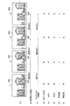
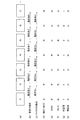
図1を用いて、第1実施形態の映像信号検出装置の構成及び動作を説明する。図1において、映像信号S0はフレームメモリ1及び動きベクトル検出部3に供給される。フレームメモリ1は、入力された映像信号S0を1フレーム期間遅延させ、1フレーム遅延の映像信号S(−1)をフレームメモリ2、動きベクトル検出部3及び4に供給する。フレームメモリ2は、入力された映像信号S(−1)をさらに1フレーム期間遅延させ、2フレーム遅延の映像信号S(−2)を動きベクトル検出部4に供給する。
The configuration and operation of the video signal detection device of the first embodiment will be described with reference to FIG. In FIG. 1, the video signal S0 is supplied to the
映像信号S0のフレームを現在フレーム(第1のフレーム)とすると、映像信号S(−1)のフレームは1フレーム前のフレーム(第2のフレーム)、映像信号S(−2)のフレームは2フレーム前のフレーム(第3のフレーム)である。 Assuming that the frame of the video signal S0 is the current frame (first frame), the frame of the video signal S (-1) is the frame one frame before (the second frame), and the frame of the video signal S (-2) is 2. This is the frame before the frame (third frame).
動きベクトル検出部3は、映像信号S0及びS(−1)に基づいて、1フレーム前のフレームから現在フレームへの画像の動きを検出して、画像の動きを示す動きベクトルMV1(第1の動きベクトル)を生成する。詳細には、動きベクトル検出部3は、映像信号S0における複数画素よりなるブロックと、映像信号S(−1)における複数画素よりなるブロックとの差分が最も小さい方向を動きベクトルMV1と検出する。1ブロックは、例えば水平8画素、垂直8画素の64画素である。
The motion
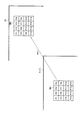
また、動きベクトル検出部3は、動きベクトルMV1を生成したブロック間のマッチング誤差SAD1(第1のマッチング誤差)を算出する。図3では簡略化のため1ブロックを水平4画素、垂直4画素の16画素とする。図3に示すように、動きベクトル検出部3は、映像信号S(−1)のフレームf(−1)におけるブロックBkと、映像信号S0のフレームf0におけるブロックBkとのマッチング誤差SAD1を算出する。
Further, the motion
フレームf0におけるブロックBkは、フレームf(−1)におけるブロックBkをフレームf0へと動きベクトルMV1だけ移動させたブロックである。マッチング誤差SAD1は、2つのブロックBk間の画素P1〜P16における同一位置の画素の差の絶対値の総和である。 The block Bk in the frame f0 is a block in which the block Bk in the frame f (-1) is moved to the frame f0 by the motion vector MV1. The matching error SAD1 is the sum of the absolute values of the differences between the pixels at the same position in the pixels P1 to P16 between the two blocks Bk.
マッチング誤差SAD1は、2つのブロックBk間の全画素の絶対値の総和ではなく、所定の規則またはランダムに間引いた一部の画素の差の絶対値の和であってもよい。マッチング誤差SAD1は、絶対値の総和(または和)に限らず、2乗値の総和、絶対値または2乗値の平均値等の統計値、絶対値または2乗値が所定の閾値未満である画素の画素数等であってもよい。マッチング誤差SAD1は、動きベクトルMV1を生成した2つのブロックBk間の画素の相違の程度を示す指標であればよい。 The matching error SAD1 may not be the sum of the absolute values of all the pixels between the two blocks Bk, but may be the sum of the absolute values of the differences of some pixels thinned out according to a predetermined rule or randomly. The matching error SAD1 is not limited to the sum (or sum) of absolute values, but the sum of squared values, statistical values such as absolute or average squared values, and absolute or squared values are less than a predetermined threshold value. It may be the number of pixels or the like. The matching error SAD1 may be an index indicating the degree of pixel difference between the two blocks Bk that generated the motion vector MV1.
動きベクトル検出部3は、動きベクトルMV1及びマッチング誤差SAD1を局所判定部5に供給する。
The motion
同様に、動きベクトル検出部4は、映像信号S(−1)及びS(−2)に基づいて、2フレーム前のフレームから1フレーム前のフレームへの画像の動きを検出して、動きベクトルMV2(第2の動きベクトル)を生成する。また、動きベクトル検出部4は、動きベクトルMV2を生成したブロック間のマッチング誤差SAD2(第2のマッチング誤差)を算出する。動きベクトル検出部4は、動きベクトルMV2及びマッチング誤差SAD2を局所判定部5に供給する。
Similarly, the motion
図2に示すアニメーション動画において背景BGはほぼ等速に動いているので、隣接するフレーム間で背景BGにおける動きベクトルMV1と動きベクトルMV2との差分はほぼ0である。一方、隣接するフレーム間でキャラクタCRが動かない場合にはキャラクタCRにおける動きベクトルMV1と動きベクトルMV2との差分はほぼ0である。隣接するフレーム間でキャラクタCRが動く場合にはキャラクタCRにおける動きベクトルMV1と動きベクトルMV2との差分は所定の大きさとなる。 Since the background BG moves at a substantially constant velocity in the animation moving image shown in FIG. 2, the difference between the motion vector MV1 and the motion vector MV2 in the background BG is almost 0 between adjacent frames. On the other hand, when the character CR does not move between adjacent frames, the difference between the motion vector MV1 and the motion vector MV2 in the character CR is almost 0. When the character CR moves between adjacent frames, the difference between the motion vector MV1 and the motion vector MV2 in the character CR has a predetermined magnitude.
従って、フレームの全体では、隣接するフレーム間で、動きベクトルMV1と動きベクトルMV2との差分絶対値は、図2の(d)に示すように、閾値th1より大きい状態が連続する。 Therefore, in the entire frame, the absolute difference value between the motion vector MV1 and the motion vector MV2 continues to be larger than the threshold value th1 as shown in FIG. 2D.
背景BGにおいては画像が単純に平行移動しているだけであるので、マッチング誤差SAD1及びSAD2はほぼ0となる。一方、隣接するフレーム間でキャラクタCRが動く場合、背景BGとキャラクタCRとの境界部分においては、画像が単純な平行移動ではないことからフレーム間で画像が一致せず、マッチング誤差SAD1及びSAD2は大きな値となる。従って、図2の(e)に示すように、マッチング誤差SAD1は閾値th2より大きい状態と閾値th2以下である小さい状態とを交互に繰り返す。図2の(f)に示すように、マッチング誤差SAD2は閾値th3より大きい状態と閾値th3以下である小さい状態とを交互に繰り返す。閾値th2と閾値th3とは同じ値であってもよい。 In the background BG, since the images are simply translated, the matching errors SAD1 and SAD2 are almost 0. On the other hand, when the character CR moves between adjacent frames, the images do not match between the frames at the boundary between the background BG and the character CR because the images are not simple translations, and the matching errors SAD1 and SAD2 are It will be a large value. Therefore, as shown in FIG. 2 (e), the matching error SAD1 alternately repeats a state of being larger than the threshold value th2 and a state of being smaller than the threshold value th2. As shown in FIG. 2 (f), the matching error SAD2 alternately repeats a state larger than the threshold value th3 and a small state equal to or less than the threshold value th3. The threshold value th2 and the threshold value th3 may have the same value.
図1において、局所判定部5は、フレーム内の各ブロックBkにおいて、動きベクトルMV1と動きベクトルMV2との差分絶対値が閾値th1(第1の閾値)より大きく、マッチング誤差SAD1が閾値th2(第2の閾値)より大きく、マッチング誤差SAD2が閾値th3(第3の閾値)より小さいという条件を満たすとき、判定値“1”を出力する。局所判定部5は、その条件を満たさないとき判定値“0”を出力する。
In FIG. 1, in each block Bk in the frame, the
局所判定部5が生成する判定値が“1”と“0”とで変化するということは、連続して移動する背景BG内にキャラクタCRのような不連続に動く物体が存在するということである。図2の(g)に示すように、局所判定部5が生成する判定値は、背景BGとキャラクタCRとの境界部分で“1”と“0”とを交互に繰り返す。
The fact that the determination value generated by the
積算部6は、各フレーム内で、局所判定部5が出力する判定値を積算する。図2の(h)に示すように、フレーム内の積算値は、キャラクタCRが直前のフレームにおけるそれと比較して動いたフレームにおいては閾値th4より大きい状態となり、動いていないフレームにおいては閾値th4以下の小さい状態となる。
The integrating unit 6 integrates the determination values output by the
積算部6は、積算値を判定部7の比較部71及び1フレーム保持部72に供給する。1フレーム保持部72は、入力された積算値を1フレーム期間保持して比較部71に供給する。比較部71には最新の積算値が入力される。比較部71は、積算部6より供給された現在フレームの積算値と1フレーム保持部72より供給された1フレーム前のフレームの積算値とを比較する。
The integrating unit 6 supplies the integrated value to the comparison unit 71 and the 1-
比較部71は、積算値が閾値th4より大きい状態から閾値th4以下の小さい状態に変化するか、閾値th4以下の小さい状態から閾値th4より大きい状態へと変化したことを検出したら、判定信号Sdetとして、映像信号S0はアニメーション動画である旨を示す第1の判定値を出力する。第1の判定値は例えば値“1”でよい。比較部71は、隣接する2フレームの積算値の差が所定の閾値以上であれば、積算値が大きい状態から小さい状態またはその逆に変化したと判定することができる。 When the comparison unit 71 detects that the integrated value has changed from a state larger than the threshold value th4 to a smaller state of the threshold value th4 or less, or a change from a small state of the threshold value th4 or less to a state larger than the threshold value th4, the comparison unit 71 uses it as a determination signal Sdet. , The video signal S0 outputs a first determination value indicating that it is an animation moving image. The first determination value may be, for example, a value "1". If the difference between the integrated values of the two adjacent frames is equal to or greater than a predetermined threshold value, the comparison unit 71 can determine that the integrated value has changed from a large state to a small state or vice versa.
比較部71は、比較結果に基づいて上記以外の状態を検出したら、判定信号Sdetとして、映像信号S0はアニメーション動画ではない通常の動画である旨を示す第2の判定値を出力する。第2の判定値は例えば値“0”でよい。 When the comparison unit 71 detects a state other than the above based on the comparison result, the comparison unit 71 outputs a second determination value indicating that the video signal S0 is a normal moving image other than the animation moving image as the determination signal Sdet. The second determination value may be, for example, a value "0".
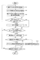
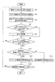
図4に示すフローチャートを用いて、第1実施形態の映像信号検出装置の動作を改めて説明する。第1実施形態の映像信号検出装置は、ハードウェアで構成されていてもよく、ソフトウェア(コンピュータプログラム)で構成されていてもよい。図4に示すフローチャートは、コンピュータプログラムがコンピュータの中央処理装置(CPU)に実行させる処理であってもよい。 The operation of the video signal detection device of the first embodiment will be described again with reference to the flowchart shown in FIG. The video signal detection device of the first embodiment may be composed of hardware or software (computer program). The flowchart shown in FIG. 4 may be a process in which a computer program causes a central processing unit (CPU) of a computer to execute the process.
図4において、映像信号検出装置は、映像信号S0が入力されて処理が開始されると、ステップS1にて、動きベクトルMV1及びMV2を検出する。映像信号検出装置は、ステップS2にて、マッチング誤差SAD1及びSAD2を算出する。映像信号検出装置は、ステップS3にて、動きベクトルMV1と動きベクトルMV2との差分絶対値を算出する。 In FIG. 4, when the video signal S0 is input and the process is started, the video signal detection device detects the motion vectors MV1 and MV2 in step S1. The video signal detection device calculates the matching errors SAD1 and SAD2 in step S2. The video signal detection device calculates the absolute difference between the motion vector MV1 and the motion vector MV2 in step S3.
映像信号検出装置は、ステップS4にて、差分絶対値が閾値th1より大きく、マッチング誤差SAD1が閾値th2より大きく、マッチング誤差SAD2が閾値th3より小さいという条件を満たすか否かを判定する。映像信号検出装置は、この条件を満たせば(YES)、ステップS5にて、値“1”を積算する。この条件を満たさなければ(NO)、または、ステップS5に続けて、映像信号検出装置は、ステップS6にて、フレーム内での全ブロックでの局所判定が完了したか否かを判定する。 In step S4, the video signal detection device determines whether or not the condition that the absolute difference value is larger than the threshold value th1, the matching error SAD1 is larger than the threshold value th2, and the matching error SAD2 is smaller than the threshold value th3 is satisfied. If this condition is satisfied (YES), the video signal detection device integrates the value “1” in step S5. If this condition is not satisfied (NO), or following step S5, the video signal detection device determines in step S6 whether or not the local determination in all the blocks in the frame is completed.
フレーム内での全ブロックでの局所判定が完了していなければ(NO)、映像信号検出装置は、ステップS1〜S6の処理を繰り返す。フレーム内での全ブロックでの局所判定が完了していれば(YES)、映像信号検出装置は、ステップS7にて、積算値をフレーム間で比較する。映像信号検出装置は、ステップS8にて、積算値の差が閾値以上であるか否かを判定する。 If the local determination in all the blocks in the frame is not completed (NO), the video signal detection device repeats the processes of steps S1 to S6. If the local determination in all the blocks in the frame is completed (YES), the video signal detection device compares the integrated value between the frames in step S7. In step S8, the video signal detection device determines whether or not the difference between the integrated values is equal to or greater than the threshold value.
積算値の差が閾値以上であれば(YES)、映像信号検出装置は、ステップS9にて、判定信号Sdetとして、映像信号S0はアニメーション動画である旨を示す第1の判定値を出力する。積算値の差が閾値以上でなければ(NO)、映像信号検出装置は、ステップS10にて、判定信号Sdetとして、アニメーション動画ではない通常の動画である旨を示す第2の判定値を出力する。 If the difference between the integrated values is equal to or greater than the threshold value (YES), the video signal detection device outputs a first determination value indicating that the video signal S0 is an animation moving image as the determination signal Sdet in step S9. If the difference between the integrated values is not equal to or greater than the threshold value (NO), the video signal detection device outputs a second determination value indicating that it is a normal moving image other than the animation moving image as the determination signal Sdet in step S10. ..
映像信号検出装置は、ステップS11にて、映像信号S0が継続的に入力されているか否かを判定する。映像信号S0が継続的に入力されていれば(YES)、映像信号検出装置は、ステップS1〜S11の処理を繰り返す。映像信号S0が継続的に入力されていなければ(NO)、映像信号検出装置は処理を終了させる。 In step S11, the video signal detection device determines whether or not the video signal S0 is continuously input. If the video signal S0 is continuously input (YES), the video signal detection device repeats the processes of steps S1 to S11. If the video signal S0 is not continuously input (NO), the video signal detection device ends the process.
<第2実施形態>
第1実施形態は、積算部6より出力される隣接する2フレームにおける積算値のパターンに基づき映像信号S0がアニメーション動画であるか否かを検出している。第2実施形態においては、誤検出を低減させるために、3フレーム以上の積算値のパターンに基づき映像信号S0がアニメーション動画であるか否かを検出する。
<Second Embodiment>
In the first embodiment, it is detected whether or not the video signal S0 is an animation moving image based on the pattern of the integrated values in the two adjacent frames output from the integrating unit 6. In the second embodiment, in order to reduce erroneous detection, it is detected whether or not the video signal S0 is an animation moving image based on a pattern of integrated values of 3 frames or more.
図5に示すように、第2実施形態の映像信号検出装置は、判定部7の代わりに、パターン判定部8を備える。パターン判定部8は記憶部81を有し、積算部6より出力される積算値を3フレーム以上記憶する。3フレームで判定する場合を例とすれば、パターン判定部8は、積算値が、閾値th4と比較して、大、小、大、または小、大、小のように変化すれば、判定信号Sdetとして第1の判定値を出力する。
As shown in FIG. 5, the video signal detection device of the second embodiment includes a
4フレームで判定する場合を例とすれば、パターン判定部8は、積算値が、閾値th4と比較して、大、小、大、小、または小、大、小、大のように変化すれば、判定信号Sdetとして第1の判定値を出力する。
Taking the case of determining in 4 frames as an example, in the
パターン判定部8は、これらのパターン以外のパターンを判定した場合には、判定信号Sdetとして第2の判定値を出力する。
When the
以上説明した第1及び第2実施形態においては、アニメーション動画が毎秒24フレームで構成されていて、キャラクタCRが毎秒12フレームで構成されているアニメーション動画(第1のアニメーション動画)である場合の動作を示している。キャラクタCRが8フレームで構成されているアニメーション動画(第2のアニメーション動画)も存在する。 In the first and second embodiments described above, the operation when the animation moving image is composed of 24 frames per second and the character CR is an animation moving image (first animation moving image) composed of 12 frames per second. Is shown. There is also an animation moving image (second animation moving image) in which the character CR is composed of 8 frames.
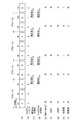
第2実施形態の映像信号検出装置は、キャラクタCRが毎秒12フレームで構成されているアニメーション動画と、キャラクタCRが8フレームで構成されているアニメーション動画との双方を検出する場合に好適な構成である。図6を参照しながら、キャラクタCRが8フレームで構成されている場合の第2実施形態の映像信号検出装置の動作を説明する。 The video signal detection device of the second embodiment has a configuration suitable for detecting both an animation moving image in which the character CR is composed of 12 frames per second and an animation moving image in which the character CR is composed of 8 frames. is there. The operation of the video signal detection device of the second embodiment when the character CR is composed of eight frames will be described with reference to FIG.
図6において、(a)はアニメーション動画のフレームf1〜f7を示している。図6の(b)に示すように背景BGはほぼ等速に動いており、図6の(c)に示すようにキャラクタCRは3フレームのうちの1フレームのみ動く。この場合、図6の(d)に示すように、フレームf3、f6、…においては、動きベクトルMV1と動きベクトルMV2との差分絶対値が閾値th1以下の小さい状態となる。差分絶対値は、閾値th1と比較して、大、大、小を繰り返すパターンとなる。 In FIG. 6, (a) shows frames f1 to f7 of the animation moving image. As shown in FIG. 6B, the background BG moves at a substantially constant velocity, and as shown in FIG. 6C, the character CR moves only one of the three frames. In this case, as shown in FIG. 6D, in the frames f3, f6, ..., The absolute difference between the motion vector MV1 and the motion vector MV2 is in a small state of the threshold value th1 or less. The difference absolute value becomes a pattern in which large, large, and small are repeated as compared with the threshold value th1.
図6の(e)に示すように、マッチング誤差SAD1は閾値th2と比較して、大、小、小を繰り返すパターンとなり、図6の(f)に示すように、マッチング誤差SAD2は閾値th3と比較して、小、大、小を繰り返すパターンとなる。 As shown in FIG. 6 (e), the matching error SAD1 has a pattern of repeating large, small, and small as compared with the threshold value th2, and as shown in FIG. 6 (f), the matching error SAD2 has a threshold value th3. In comparison, the pattern repeats small, large, and small.
図5において、局所判定部5は、フレーム内の各ブロックBkにおいて、動きベクトルMV1と動きベクトルMV2との差分絶対値が閾値th1より大きく、マッチング誤差SAD1が閾値th2より大きく、マッチング誤差SAD2が閾値th3より小さいという条件を満たすとき、判定値“1”を出力する。局所判定部5は、その条件を満たさないとき判定値“0”を出力する。
In FIG. 5, in each block Bk in the frame, the
図6の(g)に示すように、局所判定部5より出力される判定値は、背景BGとキャラクタCRとの境界部分で、“1”、“0”、“0”を繰り返すパターンとなる。従って、図6の(h)に示すように、積算部6より出力される積算値は、閾値th4と比較して、大、小、小を繰り返すパターンとなる。
As shown in FIG. 6 (g), the determination value output from the
4フレームで判定する場合を例とすれば、パターン判定部8は、積算値が、閾値th4と比較して、大、小、小、大のように変化するか、小、小、大、小のように変化するか、または小、大、小、小のように変化すれば、判定信号Sdetとして、映像信号S0はキャラクタCRが8フレームで構成されたアニメーション動画である旨を示す第1の判定値を出力する。
Taking the case of determining in 4 frames as an example, in the
パターン判定部8は、積算値が、閾値th4と比較して、大、小、大、小、または小、大、小、大のように変化すれば、判定信号Sdetとして、映像信号S0はキャラクタCRが12フレームで構成されたアニメーション動画である旨を示す第1の判定値を出力する。このとき、キャラクタCRが8フレームで構成されたアニメーション動画である旨を示す第1の判定値と、キャラクタCRが12フレームで構成されたアニメーション動画である旨を示す第1の判定値とは互いに異なる値である。
If the integrated value changes as large, small, large, small, or small, large, small, or large as compared with the threshold value th4, the
誤検出を低減させるために、5フレーム以上の積算値のパターンに基づき、映像信号S0がアニメーション動画であるか否か、キャラクタCRが12フレームで構成されたアニメーション動画であるか、8フレームで構成されたアニメーション動画であるかを検出してもよい。 In order to reduce false positives, based on the pattern of integrated values of 5 frames or more, whether the video signal S0 is an animation movie, the character CR is an animation movie composed of 12 frames, or is composed of 8 frames. It may be detected whether it is an animated moving image.
図7に示すフローチャートを用いて、第2実施形態の映像信号検出装置の動作を改めて説明する。同様に、図7に示すフローチャートは、コンピュータプログラムがコンピュータの中央処理装置(CPU)に実行させる処理であってもよい。図7においてステップS1〜S6は図4におけるステップS1〜S6と同じである。 The operation of the video signal detection device of the second embodiment will be described again with reference to the flowchart shown in FIG. 7. Similarly, the flowchart shown in FIG. 7 may be a process that a computer program causes a central processing unit (CPU) of a computer to execute. In FIG. 7, steps S1 to S6 are the same as steps S1 to S6 in FIG.
図7において、映像信号検出装置は、ステップS12にて、積算値が複数のフレームで特定のパターンであるか否かを判定する。積算値が複数のフレームで特定のパターンであれば(YES)、映像信号検出装置は、ステップS13にて、判定信号Sdetとして、
映像信号S0はアニメーション動画である旨を示す第1の判定値を出力する。積算値が複数のフレームで特定のパターンでなければ(NO)、映像信号検出装置は、ステップS14にて、判定信号Sdetとして、映像信号S0はアニメーション動画ではない通常の動画である旨を示す第2の判定値を出力する。
In FIG. 7, the video signal detection device determines in step S12 whether or not the integrated value has a specific pattern in a plurality of frames. If the integrated value is a specific pattern in a plurality of frames (YES), the video signal detection device sets the determination signal Sdet in step S13.
The video signal S0 outputs a first determination value indicating that the video signal S0 is an animation moving image. If the integrated value is not a specific pattern in a plurality of frames (NO), the video signal detection device indicates in step S14 that the video signal S0 is not an animation movie but a normal movie as a determination signal Sdet. The judgment value of 2 is output.
映像信号検出装置は、ステップS15にて、映像信号S0が継続的に入力されているか否かを判定する。映像信号S0が継続的に入力されていれば(YES)、映像信号検出装置は、ステップS1〜S6及びS12〜S15の処理を繰り返す。映像信号S0が継続的に入力されていなければ(NO)、映像信号検出装置は処理を終了させる。 In step S15, the video signal detection device determines whether or not the video signal S0 is continuously input. If the video signal S0 is continuously input (YES), the video signal detection device repeats the processes of steps S1 to S6 and S12 to S15. If the video signal S0 is not continuously input (NO), the video signal detection device ends the process.
<第3実施形態>
以上説明した第1及び第2実施形態においては、毎秒24フレームのアニメーション動画が映像信号S0として映像信号検出装置に入力される場合の動作を示している。毎秒24フレームのアニメーション動画が2−3プルダウンによって毎秒60フレームの映像信号とされていることがある。第3実施形態の映像信号検出装置は、2−3プルダウン変換された映像信号S0が入力される場合に、映像信号S0がアニメーション動画であるか否かを検出するように構成している。
<Third Embodiment>
In the first and second embodiments described above, the operation when the animation moving image of 24 frames per second is input to the video signal detection device as the video signal S0 is shown. An animation movie of 24 frames per second may be converted into a video signal of 60 frames per second by 2-3 pulldowns. The video signal detection device of the third embodiment is configured to detect whether or not the video signal S0 is an animation moving image when the video signal S0 that has been subjected to 2-3 pull-down conversion is input.
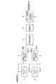
図8において、図5と同一部分には同一符号を付し、その説明を省略することがある。図8に示すように、第3実施形態の映像信号検出装置は、入力された映像信号S0が2−3プルダウン変換された映像信号であるか否かを検出し、2−3プルダウン変換された映像信号であるときにプルダウンシーケンスを出力する2−3プルダウン検出部9を備える。2−3プルダウン検出部9は、プルダウンシーケンスをパターン判定部8と、フレームメモリ1及び2に供給する。
In FIG. 8, the same parts as those in FIG. 5 are designated by the same reference numerals, and the description thereof may be omitted. As shown in FIG. 8, the video signal detection device of the third embodiment detects whether or not the input video signal S0 is a video signal that has been 2-3 pull-down converted, and has been 2-3 pull-down converted. A 2-3 pull-down detection unit 9 that outputs a pull-down sequence when it is a video signal is provided. 2-3 The pull-down detection unit 9 supplies the pull-down sequence to the
図8におけるフレームメモリ1及び2は、複数のフレーメモリで構成されている。後述するように、2−3プルダウン変換された映像信号S0は互いに同じ画像内容を有するフレームが3フレーム連続する状態と、同じ画像のフレームが2フレーム連続する状態とを交互に繰り返す。動きベクトル検出部3及び4が2−3プルダウン変換された映像信号S0の画像の動きを検出するには、互いに同じ画像内容を有する2フレームまたは3フレームをフレーム群としたとき、隣接するフレーム群内のフレームを比較する必要がある。
The
フレームメモリ1及び2は、動きベクトル検出部3及び4が2−3プルダウン変換された映像信号S0の画像の動きを検出するのに必要な複数のフレームメモリで構成されていればよい。具体的には、映像信号S0の各フレームにおいて画像の動きを検出するためには、フレームメモリ1及び2は5つのフレームメモリで構成される。映像信号S0の画像内容が切り替わったタイミングのフレームにおいて画像の動きを検出する場合には、フレームメモリ1及び2は4つのフレームメモリで構成することができる。
The
2−3プルダウン検出部9が入力された映像信号S0は2−3プルダウン変換された映像信号ではないと検出したとき、フレームメモリ1及び2はそれぞれ1フレーム遅延の映像信号S(−1)及び2フレーム遅延の映像信号S(−2)を出力する。この場合の第3実施形態の映像信号検出装置の動作は第2実施形態の映像信号検出装置と同じである。
When the 2-3 pull-down detection unit 9 detects that the input video signal S0 is not a 2-3 pull-down converted video signal, the
映像信号S0の現在のフレームが含まれているフレーム群を第1のフレーム群、第1のフレーム群の直前のフレーム群を第2のフレーム群、第2のフレーム群の直前のフレーム群を第3のフレーム群とする。2−3プルダウン検出部9が入力された映像信号S0は2−3プルダウン変換された映像信号であることを検出したとき、フレームメモリ1は第2のフレーム群内のフレームである映像信号S(−1g)を出力し、フレームメモリ2は第3のフレーム群内のフレームである映像信号S(−2g)を出力する。
The frame group including the current frame of the video signal S0 is the first frame group, the frame group immediately before the first frame group is the second frame group, and the frame group immediately before the second frame group is the first frame group. Let it be a group of 3 frames. When the video signal S0 input by the 2-3 pull-down detection unit 9 detects that the video signal S0 is a 2-3 pull-down converted video signal, the
動きベクトル検出部3は、第1のフレーム群内のフレームである映像信号S0と第2のフレーム群内のフレームである映像信号S(−1g)とに基づいて、動きベクトルMV1及びマッチング誤差SAD1を算出する。動きベクトル検出部4は、第2のフレーム群内のフレームである映像信号S(−1g)と第3のフレーム群内のフレームである映像信号S(−2g)に基づいて、動きベクトルMV2及びマッチング誤差SAD2を算出する。
The motion
図9は、図8に示す映像信号検出装置に、キャラクタCRが12フレームで構成された毎秒24フレームのアニメーション動画を2−3プルダウン変換した映像信号S0が入力される場合の動作を示している。図9の(a)に示すように、映像信号S0は、同じ画像内容のフレームが3フレーム連続する状態と、同じ画像内容のフレームが2フレーム連続する状態とを交互に繰り返す。 FIG. 9 shows an operation when a video signal S0 obtained by 2-3 pull-down conversion of an animation video of 24 frames per second composed of 12 frames of character CR is input to the video signal detection device shown in FIG. .. As shown in FIG. 9A, the video signal S0 alternately repeats a state in which frames having the same image content are continuous for three frames and a state in which frames with the same image content are continuous for two frames.
図9の(a)に示すフレームにおいて、“A”、“B”、“C”、“D”、“E”は画像内容を示している。例えば、フレームf1〜f3は画像内容が“A”である同じフレームであり、フレームf4及びf5は画像内容が“B”である同じフレームである。 In the frame shown in FIG. 9A, “A”, “B”, “C”, “D”, and “E” indicate the image contents. For example, frames f1 to f3 are the same frames having an image content of "A", and frames f4 and f5 are the same frames having an image content of "B".
図9の(b)に示すように、2−3プルダウン検出部9は、例えば、連続する2フレームの最初のフレームで値“0”であって、フレームの進行に伴って値“4”までカウントアップするプルダウンシーケンスを出力する。 As shown in FIG. 9B, the 2-3 pull-down detection unit 9 has a value of “0” in the first frame of two consecutive frames, and reaches a value of “4” as the frames progress. Outputs a pull-down sequence that counts up.
局所判定部5には、各フレームにおいて、動きベクトルMV1及びMV2とマッチング誤差SAD1及びSAD2が入力される。第2実施形態と同様に、局所判定部5は各フレームの各ブロックBkにおいて判定値“1”または“0”を生成し、積算部6は各フレームで判定値を積算する。
The motion vectors MV1 and MV2 and the matching errors SAD1 and SAD2 are input to the
映像信号S0がアニメーション動画であるか否かを検出するには、プルダウンシーケンスが値“0”を示すフレームと値“2”を示すフレームとにおける動きベクトルMV1及びMV2とマッチング誤差SAD1及びSAD2を判定すればよい。 In order to detect whether or not the video signal S0 is an animation moving image, the pull-down sequence determines the motion vectors MV1 and MV2 and the matching errors SAD1 and SAD2 in the frame showing the value "0" and the frame showing the value "2". do it.
そこで、記憶部81は、入力されるプルダウンシーケンスに基づき、プルダウンシーケンスが値“0”を示すフレームと値“2”を示すフレームとの積算値のみを記憶する。パターン判定部8は、第2実施形態と同様に、プルダウンシーケンスが値“0”を示すフレームと値“2”を示すフレームとにおける積算値のパターンに基づいて、判定信号Sdetとして第1の判定値を出力する。ここでも、判定信号SdetはキャラクタCRが12フレームで構成されたアニメーション動画である旨を示してもよい。
Therefore, the
図10は、図8に示す映像信号検出装置に、キャラクタCRが8フレームで構成された毎秒24フレームのアニメーション動画を2−3プルダウン変換した映像信号S0が入力される場合の動作を示している。 FIG. 10 shows an operation when a video signal S0 obtained by 2-3 pull-down conversion of an animation video of 24 frames per second composed of 8 frames of character CR is input to the video signal detection device shown in FIG. ..
この場合も同様に、パターン判定部8は、プルダウンシーケンスが値“0”を示すフレームと値“2”を示すフレームとにおける積算値のパターンに基づいて、判定信号Sdetとして第1の判定値を出力する。ここでも、判定信号SdetはキャラクタCRが8フレームで構成されたアニメーション動画である旨を示してもよい。
Similarly, in this case as well, the
このように、第3実施形態の映像信号検出装置は、同じ画像が連続する2フレームまたは3フレームの例えば最初のフレームに着目したときの少なくとも2フレームの積算値のパターンに基づいて、映像信号S0がアニメーション動画であるか否かを検出すればよい。第3実施形態の映像信号検出装置は、最初のフレームに着目することに限らず、同じ画像が連続する2フレームまたは3フレームのいずれか1つのフレームに着目すればよい。 As described above, the video signal detection device of the third embodiment is based on the pattern of the integrated value of at least two frames when focusing on, for example, the first frame of two frames or three frames in which the same image is continuous, and the video signal S0. It suffices to detect whether or not is an animation movie. The video signal detection device of the third embodiment is not limited to focusing on the first frame, but may focus on any one of two frames or three frames in which the same image is continuous.
図8においては、少なくとも3つのフレーム群における3フレームの積算値のパターンに基づいて、映像信号S0が、キャラクタCRが12フレームで構成された映像信号であるか8フレームで構成された映像信号であるかを判定するパターン判定部8を備える構成を示している。キャラクタCRが12フレームで構成されたアニメーション動画のみを検出の対象とする場合には、第1実施形態と同様に、パターン判定部8の代わりに、2つのフレーム群における2フレームの積算値のパターンに基づいて、アニメーション動画であるか否かを判定する判定部7を備える構成としてもよい。
In FIG. 8, based on the pattern of the integrated value of 3 frames in at least 3 frame groups, the video signal S0 is a video signal in which the character CR is composed of 12 frames or a video signal composed of 8 frames. The configuration including the
本発明は以上説明した第1〜第3実施形態に限定されるものではなく、本発明の要旨を逸脱しない範囲において種々変更可能である。連続して移動する背景内に不連続に動く物体が存在する特定の動画はアニメーション動画に限定されない。 The present invention is not limited to the first to third embodiments described above, and various modifications can be made without departing from the gist of the present invention. A specific moving object in which a continuously moving object exists in a continuously moving background is not limited to an animation moving image.
1,2 フレームメモリ
3,4 動きベクトル検出部
5 局所判定部
6 積算部
7 判定部
8 パターン判定部
9 2−3プルダウン検出部
71 比較部
72 1フレーム保持部
81 記憶部
1, 2,
Claims (5)
前記第2のフレームと、前記第2のフレームよりも1フレーム前の第3のフレームとに基づき、前記ブロックごとに、前記第2のフレームと前記第3のフレームとの間の画像の動きを示す第2の動きベクトルを検出し、前記第3のフレームにおけるブロックを前記第2のフレームへと前記第2の動きベクトルだけ移動させたときのブロック間の画素の相違の程度を示す指標である第2のマッチング誤差を算出する第2の動きベクトル検出部と、
前記ブロックごとに、前記第1の動きベクトルと前記第2の動きベクトルとの差分絶対値が第1の閾値より大きいか否か、第1のマッチング誤差が第2の閾値より大きいか否か、第2のマッチング誤差が第3の閾値より小さいか否かを判定することによって、連続して移動する背景内に不連続に動く物体が存在するか否かを判定する局所判定部と、
前記局所判定部による前記ブロックごとの判定値をフレーム内で積算する積算部と、
前記積算部による少なくとも2フレームの積算値のパターンに基づいて、前記映像信号が、連続して移動する背景内に不連続に動く物体が存在する特定の動画であるか否かを判定する判定部と、
を備える映像信号検出装置。 Based on the first frame, which is each frame of the input video signal, and the second frame, which is one frame before the first frame, the first frame is for each block composed of a plurality of pixels of the video signal. A first motion vector indicating the motion of the image between the first frame and the second frame is detected, and the block in the second frame is moved to the first frame by the first motion vector. A first motion vector detection unit that calculates a first matching error, which is an index indicating the degree of pixel difference between blocks when they are made to move.
Based on the second frame and the third frame one frame before the second frame, the movement of the image between the second frame and the third frame is performed for each block. It is an index showing the degree of pixel difference between blocks when the second motion vector shown is detected and the block in the third frame is moved to the second frame by the second motion vector. A second motion vector detector that calculates the second matching error, and
For each block, whether the absolute difference between the first motion vector and the second motion vector is larger than the first threshold value, and whether the first matching error is larger than the second threshold value. A local determination unit that determines whether or not there is a discontinuously moving object in the continuously moving background by determining whether or not the second matching error is smaller than the third threshold value.
An integration unit that integrates the determination values for each block by the local determination unit within the frame, and
A determination unit that determines whether or not the video signal is a specific moving object in which a discontinuously moving object exists in a continuously moving background based on a pattern of integrated values of at least two frames by the integrating unit. When,
A video signal detection device comprising.
前記比較部による2フレームの積算値の大きさの比較結果に基づいて、前記特定の動画であるか否かを判定する
請求項1に記載の映像信号検出装置。 The determination unit has a comparison unit that compares the integrated values of two frames.
The video signal detection device according to claim 1, wherein it is determined whether or not the moving image is the specific moving image based on the comparison result of the magnitudes of the integrated values of the two frames by the comparison unit.
前記2−3プルダウン検出部によって前記映像信号が2−3プルダウン変換した映像信号であると検出されたとき、
前記第1の動きベクトル検出部は、互いに同じ画像内容を有する2フレームまたは3フレームをフレーム群としたとき、第1のフレーム群内のフレームと、前記第1のフレーム群の直前の第2のフレーム群内のフレームとに基づき、第1の動きベクトル及び第1のマッチング誤差を算出し、
前記第2の動きベクトル検出部は、第2のフレーム群内のフレームと、前記第2のフレーム群の直前の第3のフレーム群内のフレームとに基づき、第2の動きベクトル及び第2のマッチング誤差を算出し、
前記判定部は、少なくとも2つのフレーム群における2フレームの積算値のパターンに基づいて、前記特定の動画であるか否かを判定する
請求項1に記載の映像信号検出装置。 2-3 pull-down detection that detects whether or not the video signal is a video signal obtained by 2-3 pull-down conversion of 24 frames per second to 60 frames per second, and when the video signal is 2-3 pull-down converted video signals, a pull-down sequence is detected. With more parts
When the video signal is detected as a video signal after 2-3 pull-down conversion by the 2-3 pull-down detection unit,
When two frames or three frames having the same image content are set as a frame group, the first motion vector detection unit includes a frame in the first frame group and a second frame immediately before the first frame group. The first motion vector and the first matching error are calculated based on the frames in the frame group.
The second motion vector detection unit is based on the frame in the second frame group and the frame in the third frame group immediately before the second frame group, and the second motion vector and the second motion vector detection unit. Calculate the matching error and
The video signal detection device according to claim 1, wherein the determination unit determines whether or not the moving image is the specific moving image based on a pattern of integrated values of two frames in at least two frame groups.
Priority Applications (2)
| Application Number | Priority Date | Filing Date | Title |
|---|---|---|---|
| JP2018112439A JP6889843B2 (en) | 2018-06-13 | 2018-06-13 | Video signal detector |
| US16/439,142 US10748292B2 (en) | 2018-06-13 | 2019-06-12 | Image signal detection device |
Applications Claiming Priority (1)
| Application Number | Priority Date | Filing Date | Title |
|---|---|---|---|
| JP2018112439A JP6889843B2 (en) | 2018-06-13 | 2018-06-13 | Video signal detector |
Publications (2)
| Publication Number | Publication Date |
|---|---|
| JP2019216354A JP2019216354A (en) | 2019-12-19 |
| JP6889843B2 true JP6889843B2 (en) | 2021-06-18 |
Family
ID=68840582
Family Applications (1)
| Application Number | Title | Priority Date | Filing Date |
|---|---|---|---|
| JP2018112439A Active JP6889843B2 (en) | 2018-06-13 | 2018-06-13 | Video signal detector |
Country Status (2)
| Country | Link |
|---|---|
| US (1) | US10748292B2 (en) |
| JP (1) | JP6889843B2 (en) |
Families Citing this family (2)
| Publication number | Priority date | Publication date | Assignee | Title |
|---|---|---|---|---|
| KR102296318B1 (en) * | 2019-12-19 | 2021-09-01 | 네이버 주식회사 | Apparatus and method for classifying videos |
| US12034967B2 (en) * | 2021-04-05 | 2024-07-09 | Nvidia Corporation | Superpixel generation and use |
Family Cites Families (6)
| Publication number | Priority date | Publication date | Assignee | Title |
|---|---|---|---|---|
| JP4181592B2 (en) | 2006-09-20 | 2008-11-19 | シャープ株式会社 | Image display apparatus and method, image processing apparatus and method |
| US8515134B2 (en) * | 2009-12-11 | 2013-08-20 | Nxp B.V. | System and method for motion estimation using image depth information |
| WO2011076682A1 (en) * | 2009-12-21 | 2011-06-30 | St-Ericsson (France) Sas | Method for regenerating the background of digital images of a video stream |
| US9916662B2 (en) * | 2015-03-17 | 2018-03-13 | Lyrical Labs Video Compression Technology, LLC | Foreground detection using fractal dimensional measures |
| US9098919B2 (en) * | 2012-10-04 | 2015-08-04 | Honeywell International Inc. | Detecting motion in a high resolution video |
| US9563960B2 (en) * | 2014-04-09 | 2017-02-07 | Mediatek Inc | Method for detecting foreground |
-
2018
- 2018-06-13 JP JP2018112439A patent/JP6889843B2/en active Active
-
2019
- 2019-06-12 US US16/439,142 patent/US10748292B2/en active Active
Also Published As
| Publication number | Publication date |
|---|---|
| JP2019216354A (en) | 2019-12-19 |
| US10748292B2 (en) | 2020-08-18 |
| US20190387233A1 (en) | 2019-12-19 |
Similar Documents
| Publication | Publication Date | Title |
|---|---|---|
| US20100142828A1 (en) | Image matching apparatus and method | |
| US20100302438A1 (en) | Image processing apparatus and image processing method | |
| JP2015019204A (en) | Image processing device and image processing method | |
| CN104219532B (en) | The method and apparatus for determining interpolation frame between the method in wisp region, frame of video | |
| US8319889B2 (en) | Frame rate conversion apparatus and method | |
| JP6631641B2 (en) | Image processing apparatus, image processing method, and image processing program | |
| JP6889843B2 (en) | Video signal detector | |
| CN102326394B (en) | Image processing method and device | |
| JP4385077B1 (en) | Motion vector detection device and image processing device | |
| US9106926B1 (en) | Using double confirmation of motion vectors to determine occluded regions in images | |
| JP5975791B2 (en) | Image processing apparatus and method, and image display apparatus and method | |
| KR20090017296A (en) | An image processing method for generating an image of an intermediate frame and an image processing apparatus using the same | |
| JP6604783B2 (en) | Image processing apparatus, imaging apparatus, and image processing program | |
| US10063880B2 (en) | Motion detecting apparatus, motion detecting method and program | |
| JP5123643B2 (en) | Video processing device | |
| CN109068140B (en) | Method and device for determining motion vector in video coding and decoding equipment | |
| JP5441555B2 (en) | Video signal processing apparatus and video signal processing method | |
| KR101620928B1 (en) | Fast face detection system using priority address allocation and moving window technique | |
| JP5574830B2 (en) | Image processing apparatus and method, and image display apparatus and method | |
| JP5026152B2 (en) | Dissolve detection device and program | |
| US20110221967A1 (en) | Motion vector measurement device and method | |
| JP2009124261A5 (en) | ||
| CN102487433B (en) | Multimedia device and method for detecting playing mode thereof | |
| WO2020075649A1 (en) | Interpolation frame generation device and method | |
| JP2012239121A (en) | Image processing device |
Legal Events
| Date | Code | Title | Description |
|---|---|---|---|
| A621 | Written request for application examination |
Free format text: JAPANESE INTERMEDIATE CODE: A621 Effective date: 20200831 |
|
| A977 | Report on retrieval |
Free format text: JAPANESE INTERMEDIATE CODE: A971007 Effective date: 20210413 |
|
| TRDD | Decision of grant or rejection written | ||
| A01 | Written decision to grant a patent or to grant a registration (utility model) |
Free format text: JAPANESE INTERMEDIATE CODE: A01 Effective date: 20210422 |
|
| A61 | First payment of annual fees (during grant procedure) |
Free format text: JAPANESE INTERMEDIATE CODE: A61 Effective date: 20210505 |
|
| R150 | Certificate of patent or registration of utility model |
Ref document number: 6889843 Country of ref document: JP Free format text: JAPANESE INTERMEDIATE CODE: R150 |