JP6889837B2 - Motor control device - Google Patents
Motor control device Download PDFInfo
- Publication number
- JP6889837B2 JP6889837B2 JP2017195157A JP2017195157A JP6889837B2 JP 6889837 B2 JP6889837 B2 JP 6889837B2 JP 2017195157 A JP2017195157 A JP 2017195157A JP 2017195157 A JP2017195157 A JP 2017195157A JP 6889837 B2 JP6889837 B2 JP 6889837B2
- Authority
- JP
- Japan
- Prior art keywords
- phase
- pwm
- count
- cycle
- current
- Prior art date
- Legal status (The legal status is an assumption and is not a legal conclusion. Google has not performed a legal analysis and makes no representation as to the accuracy of the status listed.)
- Active
Links
Images


Classifications
-
- H—ELECTRICITY
- H02—GENERATION; CONVERSION OR DISTRIBUTION OF ELECTRIC POWER
- H02M—APPARATUS FOR CONVERSION BETWEEN AC AND AC, BETWEEN AC AND DC, OR BETWEEN DC AND DC, AND FOR USE WITH MAINS OR SIMILAR POWER SUPPLY SYSTEMS; CONVERSION OF DC OR AC INPUT POWER INTO SURGE OUTPUT POWER; CONTROL OR REGULATION THEREOF
- H02M7/00—Conversion of AC power input into DC power output; Conversion of DC power input into AC power output
- H02M7/42—Conversion of DC power input into AC power output without possibility of reversal
- H02M7/44—Conversion of DC power input into AC power output without possibility of reversal by static converters
- H02M7/48—Conversion of DC power input into AC power output without possibility of reversal by static converters using discharge tubes with control electrode or semiconductor devices with control electrode
-
- H—ELECTRICITY
- H02—GENERATION; CONVERSION OR DISTRIBUTION OF ELECTRIC POWER
- H02P—CONTROL OR REGULATION OF ELECTRIC MOTORS, ELECTRIC GENERATORS OR DYNAMO-ELECTRIC CONVERTERS; CONTROLLING TRANSFORMERS, REACTORS OR CHOKE COILS
- H02P27/00—Arrangements or methods for the control of AC motors characterised by the kind of supply voltage
- H02P27/04—Arrangements or methods for the control of AC motors characterised by the kind of supply voltage using variable-frequency supply voltage, e.g. inverter or converter supply voltage
- H02P27/06—Arrangements or methods for the control of AC motors characterised by the kind of supply voltage using variable-frequency supply voltage, e.g. inverter or converter supply voltage using DC to AC converters or inverters
- H02P27/08—Arrangements or methods for the control of AC motors characterised by the kind of supply voltage using variable-frequency supply voltage, e.g. inverter or converter supply voltage using DC to AC converters or inverters with pulse width modulation
-
- B—PERFORMING OPERATIONS; TRANSPORTING
- B62—LAND VEHICLES FOR TRAVELLING OTHERWISE THAN ON RAILS
- B62D—MOTOR VEHICLES; TRAILERS
- B62D5/00—Power-assisted or power-driven steering
- B62D5/04—Power-assisted or power-driven steering electrical, e.g. using an electric servo-motor connected to, or forming part of, the steering gear
-
- H—ELECTRICITY
- H02—GENERATION; CONVERSION OR DISTRIBUTION OF ELECTRIC POWER
- H02M—APPARATUS FOR CONVERSION BETWEEN AC AND AC, BETWEEN AC AND DC, OR BETWEEN DC AND DC, AND FOR USE WITH MAINS OR SIMILAR POWER SUPPLY SYSTEMS; CONVERSION OF DC OR AC INPUT POWER INTO SURGE OUTPUT POWER; CONTROL OR REGULATION THEREOF
- H02M1/00—Details of apparatus for conversion
- H02M1/44—Circuits or arrangements for compensating for electromagnetic interference in converters or inverters
-
- H—ELECTRICITY
- H02—GENERATION; CONVERSION OR DISTRIBUTION OF ELECTRIC POWER
- H02M—APPARATUS FOR CONVERSION BETWEEN AC AND AC, BETWEEN AC AND DC, OR BETWEEN DC AND DC, AND FOR USE WITH MAINS OR SIMILAR POWER SUPPLY SYSTEMS; CONVERSION OF DC OR AC INPUT POWER INTO SURGE OUTPUT POWER; CONTROL OR REGULATION THEREOF
- H02M7/00—Conversion of AC power input into DC power output; Conversion of DC power input into AC power output
- H02M7/42—Conversion of DC power input into AC power output without possibility of reversal
- H02M7/44—Conversion of DC power input into AC power output without possibility of reversal by static converters
- H02M7/48—Conversion of DC power input into AC power output without possibility of reversal by static converters using discharge tubes with control electrode or semiconductor devices with control electrode
- H02M7/53—Conversion of DC power input into AC power output without possibility of reversal by static converters using discharge tubes with control electrode or semiconductor devices with control electrode using devices of a triode or transistor type requiring continuous application of a control signal
- H02M7/537—Conversion of DC power input into AC power output without possibility of reversal by static converters using discharge tubes with control electrode or semiconductor devices with control electrode using devices of a triode or transistor type requiring continuous application of a control signal using semiconductor devices only, e.g. single switched pulse inverters
- H02M7/5387—Conversion of DC power input into AC power output without possibility of reversal by static converters using discharge tubes with control electrode or semiconductor devices with control electrode using devices of a triode or transistor type requiring continuous application of a control signal using semiconductor devices only, e.g. single switched pulse inverters in a bridge configuration
- H02M7/53871—Conversion of DC power input into AC power output without possibility of reversal by static converters using discharge tubes with control electrode or semiconductor devices with control electrode using devices of a triode or transistor type requiring continuous application of a control signal using semiconductor devices only, e.g. single switched pulse inverters in a bridge configuration with automatic control of output voltage or current
-
- H—ELECTRICITY
- H02—GENERATION; CONVERSION OR DISTRIBUTION OF ELECTRIC POWER
- H02P—CONTROL OR REGULATION OF ELECTRIC MOTORS, ELECTRIC GENERATORS OR DYNAMO-ELECTRIC CONVERTERS; CONTROLLING TRANSFORMERS, REACTORS OR CHOKE COILS
- H02P21/00—Arrangements or methods for the control of electric machines by vector control, e.g. by control of field orientation
- H02P21/22—Current control, e.g. using a current control loop
-
- H—ELECTRICITY
- H02—GENERATION; CONVERSION OR DISTRIBUTION OF ELECTRIC POWER
- H02P—CONTROL OR REGULATION OF ELECTRIC MOTORS, ELECTRIC GENERATORS OR DYNAMO-ELECTRIC CONVERTERS; CONTROLLING TRANSFORMERS, REACTORS OR CHOKE COILS
- H02P27/00—Arrangements or methods for the control of AC motors characterised by the kind of supply voltage
- H02P27/04—Arrangements or methods for the control of AC motors characterised by the kind of supply voltage using variable-frequency supply voltage, e.g. inverter or converter supply voltage
- H02P27/06—Arrangements or methods for the control of AC motors characterised by the kind of supply voltage using variable-frequency supply voltage, e.g. inverter or converter supply voltage using DC to AC converters or inverters
- H02P27/08—Arrangements or methods for the control of AC motors characterised by the kind of supply voltage using variable-frequency supply voltage, e.g. inverter or converter supply voltage using DC to AC converters or inverters with pulse width modulation
- H02P27/085—Arrangements or methods for the control of AC motors characterised by the kind of supply voltage using variable-frequency supply voltage, e.g. inverter or converter supply voltage using DC to AC converters or inverters with pulse width modulation wherein the PWM mode is adapted on the running conditions of the motor, e.g. the switching frequency
-
- B—PERFORMING OPERATIONS; TRANSPORTING
- B62—LAND VEHICLES FOR TRAVELLING OTHERWISE THAN ON RAILS
- B62D—MOTOR VEHICLES; TRAILERS
- B62D5/00—Power-assisted or power-driven steering
- B62D5/04—Power-assisted or power-driven steering electrical, e.g. using an electric servo-motor connected to, or forming part of, the steering gear
- B62D5/0409—Electric motor acting on the steering column
-
- B—PERFORMING OPERATIONS; TRANSPORTING
- B62—LAND VEHICLES FOR TRAVELLING OTHERWISE THAN ON RAILS
- B62D—MOTOR VEHICLES; TRAILERS
- B62D5/00—Power-assisted or power-driven steering
- B62D5/04—Power-assisted or power-driven steering electrical, e.g. using an electric servo-motor connected to, or forming part of, the steering gear
- B62D5/0457—Power-assisted or power-driven steering electrical, e.g. using an electric servo-motor connected to, or forming part of, the steering gear characterised by control features of the drive means as such
- B62D5/046—Controlling the motor
- B62D5/0463—Controlling the motor calculating assisting torque from the motor based on driver input
-
- H—ELECTRICITY
- H02—GENERATION; CONVERSION OR DISTRIBUTION OF ELECTRIC POWER
- H02P—CONTROL OR REGULATION OF ELECTRIC MOTORS, ELECTRIC GENERATORS OR DYNAMO-ELECTRIC CONVERTERS; CONTROLLING TRANSFORMERS, REACTORS OR CHOKE COILS
- H02P21/00—Arrangements or methods for the control of electric machines by vector control, e.g. by control of field orientation
- H02P21/0003—Control strategies in general, e.g. linear type, e.g. P, PI, PID, using robust control
Landscapes
- Engineering & Computer Science (AREA)
- Power Engineering (AREA)
- Physics & Mathematics (AREA)
- Electromagnetism (AREA)
- Chemical & Material Sciences (AREA)
- Combustion & Propulsion (AREA)
- Transportation (AREA)
- Mechanical Engineering (AREA)
- Control Of Ac Motors In General (AREA)
- Control Of Motors That Do Not Use Commutators (AREA)
- Steering Control In Accordance With Driving Conditions (AREA)
- Power Steering Mechanism (AREA)
Description
この発明は、2系統の多相モータコイルを有する電動モータを制御するモータ制御装置に関する。 The present invention relates to a motor control device that controls an electric motor having two systems of multi-phase motor coils.
三相電動モータをベクトル制御するモータ制御装置においては、電流制御周期毎に、二相電流指令値が演算される。この二相電流指令値と二相電流検出値との偏差に基づいて二相電圧指令値が演算される。この二相電圧指令値が電動モータの回転角を用いて二相・三相変換されることにより、U相、V相およびW相の相電圧指令値(三相電圧指令値)が演算される。そして、このU相、V相およびW相の相電圧指令値にそれぞれ対応するデューティのU相PWM信号、V相PWM信号およびW相PWM信号が生成されて、三相インバータ回路に供給される。 In a motor control device that vector-controls a three-phase electric motor, a two-phase current command value is calculated for each current control cycle. The two-phase voltage command value is calculated based on the deviation between the two-phase current command value and the two-phase current detection value. By converting this two-phase voltage command value into two-phase and three-phase using the rotation angle of the electric motor, the U-phase, V-phase, and W-phase phase voltage command values (three-phase voltage command values) are calculated. .. Then, a U-phase PWM signal, a V-phase PWM signal, and a W-phase PWM signal having a duty corresponding to the phase voltage command values of the U-phase, V-phase, and W-phase are generated and supplied to the three-phase inverter circuit.
この三相インバータ回路を構成する6個のスイッチング素子が、U相PWM信号、V相PWM信号およびW相PWM信号によって制御されることにより、三相電圧指令値に相当する電圧が三相電動モータに印加されることになる。これにより、三相電動モータに流れるモータ電流が二相電流指令値に等しくなるように制御される。このようなモータ制御装置においては、各PWM周期において各相の出力電圧(相電圧)の立上り時点と立下り時点において、三相電動モータとフレームグランドとの間に存在する浮遊容量に電流が流れる。 The six switching elements that make up this three-phase inverter circuit are controlled by the U-phase PWM signal, V-phase PWM signal, and W-phase PWM signal, so that the voltage corresponding to the three-phase voltage command value is a three-phase electric motor. Will be applied to. As a result, the motor current flowing through the three-phase electric motor is controlled to be equal to the two-phase current command value. In such a motor control device, a current flows through a stray capacitance existing between the three-phase electric motor and the frame ground at the rising and falling points of the output voltage (phase voltage) of each phase in each PWM cycle. ..
この電流がフレームグランドに流れるため、フレームグランドからノイズが放射されるおそれがある。また、車両に搭載される電動パワーステアリング装置(EPS)に搭載されるモータ制御装置の場合、車両電源(バッテリー)からEPSへの正負電源供給ラインが長いため、フレームグランドを流れたノイズ電流が、正負電源供給ラインとフレームラウンドとの間にできる浮遊容量を通じて、車両電源の近傍で正負電源供給ラインに混入する。そして、ノイズ電流が長い正負電源供給ラインを流れることで、ラインから放射ノイズが発生する。これにより、コモンモードノイズが発生する。 Since this current flows to the frame ground, noise may be radiated from the frame ground. Further, in the case of the motor control device mounted on the electric power steering device (EPS) mounted on the vehicle, since the positive and negative power supply lines from the vehicle power supply (battery) to the EPS are long, the noise current flowing through the frame ground is generated. Through the floating capacity created between the positive and negative power supply lines and the frame round, the positive and negative power supply lines are mixed in the vicinity of the vehicle power supply. Then, by flowing through the positive and negative power supply lines having a long noise current, radiation noise is generated from the lines. This causes common mode noise.
2系統の三相モータコイルを有する三相電動モータ(2系統モータ)を、2系統の三相モータコイルそれぞれに電力を供給するための2系統の駆動回路を用いて制御するモータ制御装置が知られている。このような2系統モータを制御するモータ制御装置では、2系統の駆動回路毎に、各PWM周期において各相の出力電圧(相電圧)の立上り時点と立下り時点において、三相電動モータとフレームグランドとの間に存在する浮遊容量に電流が流れる。このため、2系統モータを制御する場合には、1系統の三相モータコイルを有する三相電動モータ(1系統モータ)を駆動制御する場合に比べて、コモンモードノイズの発生頻度が高くなる。 A motor control device that controls a three-phase electric motor (two-system motor) having two systems of three-phase motor coils using a two-system drive circuit for supplying power to each of the two systems of three-phase motor coils is known. Has been done. In a motor control device that controls such a two-system motor, a three-phase electric motor and a frame are used for each of the two drive circuits at the rising and falling points of the output voltage (phase voltage) of each phase in each PWM cycle. Current flows through the stray capacitance existing between the ground and the ground. Therefore, when controlling a two-system motor, the frequency of common mode noise is higher than when driving and controlling a three-phase electric motor (one-system motor) having one system of three-phase motor coils.
この発明の目的は、コモンモードノイズを低減させることができるモータ制御装置を提供することにある。 An object of the present invention is to provide a motor control device capable of reducing common mode noise.
請求項1に記載の発明は、2系統の多相モータコイル(18A,18B)を有する電動モータ(18)を制御するモータ制御装置(31)であって、複数のPWM周期を含む電流制御周期毎に、各系統の各相のPWMカウントを演算するPWMカウント演算手段(41)と、前記電流制御周期に対する各系統の各相のPWMカウントを、対応する系統および相における当該電流制御周期内の各PWM周期に対するPWMカウントとして設定するPWMカウント設定手段(42)と、前記電流制御周期内の少なくとも1つのPWM周期において、前記2系統のうちの一方の系統の1つの相の出力電圧に起因して浮遊容量に流れる電流が、他方の系統の少なくとも1つの相の出力電圧に起因して浮遊容量に流れる電流によって相殺されるように、当該他方の系統の少なくとも1つの相に対するPWM周期のPWMカウントを変更するコモンモードノイズ低減手段(42)とを含み、前記コモンモードノイズ低減手段は、各系統の各相における前記電流制御周期内の各PWM周期に対するPWM信号のうち、前記他方の系統の少なくとも1つの相のPWMカウントを、当該相のPWMカウントの当該電流制御周期内での合計値を変更することなく、少なくとも1つのPWM周期において、当該相の出力電圧波形が、前記一方の系統の1つの相の出力電圧波形を反転させた波形となるように変更するPWMカウント変更手段を含んでいる、モータ制御装置である。なお、括弧内の英数字は、後述の実施形態における対応構成要素等を表すが、むろん、この発明の範囲は当該実施形態に限定されない。以下、この項において同じ。
The invention according to
この構成では、電流制御周期内の少なくとも1つのPWM周期において、2系統のうちの一方の系統の1つの相の出力電圧に起因して浮遊容量に流れる電流が、他方の系統の少なくとも1つの相の出力電圧に起因して浮遊容量に流れる電流によって相殺される。これにより、コモンモードノイズを低減させることができる。
請求項2に記載の発明は、前記コモンモードノイズ低減手段は、前記電流制御周期内の各PWM周期において、前記2系統のうちの一方の系統の1つの相である第1相の出力電圧に起因して浮遊容量に流れる電流が、他方の系統の2つの相である第2相または第3相の出力電圧に起因して浮遊容量に流れる電流によって相殺されるように、当該第2相および第3相に対するPWM周期のPWMカウントを変更するものであり、前記コモンモードノイズ低減手段は、前記電流制御周期内の各PWM周期に対する前記第2相のPWMカウントを、当該第2相のPWMカウントの当該電流制御周期内での合計値を変更することなく、当該電流制御周期内の所定の半数のPWM周期において、当該第2相の出力電圧波形が、前記第1相の出力電圧波形を反転させた波形となるように変更する第1のPWMカウント変更手段と、前記電流制御周期内の各PWM周期に対する前記第3相のPWMカウントを、当該第3相のPWMカウントの当該電流制御周期内での合計値を変更することなく、前記電流制御周期内の前記所定の半数のPWM周期以外の他の半数のPWM周期において、当該第3相の出力電圧波形が、前記第1相の出力電圧波形を反転させた波形となるように変更する第2のPWMカウント変更手段とを含む、請求項1に記載のモータ制御装置である。
In this configuration, in at least one PWM cycle within the current control cycle, the current flowing through the stray capacitance due to the output voltage of one phase of one of the two systems is at least one phase of the other system. It is offset by the current flowing through the stray capacitance due to the output voltage of. Thereby, the common mode noise can be reduced.
According to the second aspect of the present invention, the common mode noise reducing means applies the output voltage of the first phase, which is one phase of one of the two systems, in each PWM cycle within the current control cycle. The second phase and the current flowing through the stray capacitance are offset by the current flowing through the stray capacitance due to the output voltage of the two phases of the other system, the second phase or the third phase. The PWM count of the PWM cycle for the third phase is changed, and the common mode noise reducing means sets the PWM count of the second phase for each PWM cycle in the current control cycle to the PWM count of the second phase. The output voltage waveform of the second phase inverts the output voltage waveform of the first phase in a predetermined half of the PWM cycles in the current control cycle without changing the total value in the current control cycle. The first PWM count changing means for changing the waveform so that the waveform is formed, and the PWM count of the third phase for each PWM cycle in the current control cycle are set within the current control cycle of the PWM count of the third phase. In the other half of the PWM cycles other than the predetermined half of the PWM cycles in the current control cycle, the output voltage waveform of the third phase is the output voltage of the first phase without changing the total value in. The motor control device according to
この構成では、電流制御周期内の各PWM周期において、2系統のうちの一方の系統の1つの相である第1相の出力電圧に起因して浮遊容量に流れる電流が、他方の系統の2つの相である第2相または第3相の出力電圧に起因して浮遊容量に流れる電流によって相殺される。これにより、コモンモードノイズをより低減させることができる。
請求項3に記載の発明は、前記電流制御周期内の各PWM周期において、前記2系統のうちの前記他方の系統の前記第2相および前記第3相以外の1つの相である第4相の出力電圧に起因して浮遊容量に流れる電流が、前記一方の系統の前記第1相以外の2つの相である第5相または第6相の出力電圧に起因して浮遊容量に流れる電流によって相殺されるように、当該第5相および第6相に対するPWM周期のPWMカウントを変更する、他のコモンモードノイズ低減手段をさらに含み、前記他のコモンモードノイズ低減手段は、前記電流制御周期内の各PWM周期に対する前記第5相のPWMカウントを、当該第5相のPWMカウントの当該電流制御周期内での合計値を変更することなく、当該電流制御周期内の所定の半数のPWM周期において、当該第5相の出力電圧波形が、前記第4相の出力電圧波形を反転させた波形となるように変更する第3のPWMカウント変更手段と、前記電流制御周期内の各PWM周期に対する前記第6相のPWMカウントを、当該第6相のPWMカウントの当該電流制御周期内での合計値を変更することなく、前記電流制御周期内の前記所定の半数のPWM周期以外の他の半数のPWM周期において、当該第6相の出力電圧波形が、前記第4相の出力電圧波形を反転させた波形となるように変更する第4のPWMカウント変更手段とを含む、請求項2に記載のモータ制御装置である。
In this configuration, in each PWM cycle within the current control cycle, the current flowing through the stray capacitance due to the output voltage of the first phase, which is one phase of one of the two systems, is 2 of the other system. It is offset by the current flowing through the stray capacitance due to the output voltage of the two phases, the second or third phase. Thereby, the common mode noise can be further reduced.
The invention according to
この構成では、さらに、電流制御周期内の各PWM周期において、2系統のうちの他方の系統の第2相および第3相以外の1つの相である第4相の出力電圧に起因して浮遊容量に流れる電流が、一方の系統の第1相以外の2つの相である第5相または第6相の出力電圧に起因して浮遊容量に流れる電流によって相殺される。これにより、コモンモードノイズをより低減させることができる。 In this configuration, further, in each PWM cycle within the current control cycle, the stray due to the output voltage of the fourth phase, which is one phase other than the second phase and the third phase of the other system of the two systems. The current flowing through the capacitance is offset by the current flowing through the stray capacitance due to the output voltage of the 5th or 6th phase, which is two phases other than the first phase of one system. Thereby, the common mode noise can be further reduced.
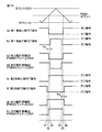
以下では、この発明を電動パワーステアリング装置に適用した場合の実施形態を、添付図面を参照して詳細に説明する。
図1は、本発明の一実施形態に係るモータ制御装置が適用された電動パワーステアリング装置の概略構成を示す模式図である。
電動パワーステアリング装置(EPS:electric power steering)1は、車両を操向するための操舵部材としてのステアリングホイール2と、このステアリングホイール2の回転に連動して転舵輪3を転舵する転舵機構4と、運転者の操舵を補助するための操舵補助機構5とを備えている。ステアリングホイール2と転舵機構4とは、ステアリングシャフト6および中間軸7を介して機械的に連結されている。
Hereinafter, embodiments when the present invention is applied to an electric power steering device will be described in detail with reference to the accompanying drawings.
FIG. 1 is a schematic view showing a schematic configuration of an electric power steering device to which the motor control device according to the embodiment of the present invention is applied.
The electric power steering device (EPS) 1 is a
ステアリングシャフト6は、ステアリングホイール2に連結された入力軸8と、中間軸7に連結された出力軸9とを含む。入力軸8と出力軸9とは、トーションバー10を介して相対回転可能に連結されている。
トーションバー10の近傍には、トルクセンサ11が配置されている。トルクセンサ11は、入力軸8および出力軸9の相対回転変位量に基づいて、ステアリングホイール2に与えられた操舵トルクTを検出する。この実施形態では、トルクセンサ11によって検出される操舵トルクTは、たとえば、右方向への操舵のためのトルクが正の値として検出され、左方向への操舵のためのトルクが負の値として検出され、その絶対値が大きいほど操舵トルクの大きさが大きくなるものとする。
The steering
A
転舵機構4は、ピニオン軸13と、転舵軸としてのラック軸14とを含むラックアンドピニオン機構からなる。ラック軸14の各端部には、タイロッド15およびナックルアーム(図示略)を介して転舵輪3が連結されている。ピニオン軸13は、中間軸7に連結されている。ピニオン軸13は、ステアリングホイール2の操舵に連動して回転するようになっている。ピニオン軸13の先端(図1では下端)には、ピニオン16が連結されている。
The
ラック軸14は、自動車の左右方向に沿って直線状に延びている。ラック軸14の軸方向の中間部には、ピニオン16に噛み合うラック17が形成されている。このピニオン16およびラック17によって、ピニオン軸13の回転がラック軸14の軸方向移動に変換される。ラック軸14を軸方向に移動させることによって、転舵輪3を転舵することができる。
The
ステアリングホイール2が操舵(回転)されると、この回転が、ステアリングシャフト6および中間軸7を介して、ピニオン軸13に伝達される。そして、ピニオン軸13の回転は、ピニオン16およびラック17によって、ラック軸14の軸方向移動に変換される。これにより、転舵輪3が転舵される。
操舵補助機構5は、操舵補助用の電動モータ18と、電動モータ18の出力トルクを転舵機構4に伝達するための減速機構19とを含む。電動モータ18は、第1系統の三相モータコイル18A(図2、図3参照)と第2系統の三相モータコイル18B(図2、図3参照)とを有する三相ブラシレスモータ(2系統モータ)である。第1系統の三相モータコイル18Aは、後述する第1系統の駆動回路32A(図2、図3参照)によって駆動され、第2系統の三相モータコイル18Bは第2系統の駆動回路32B(図2、図3参照)によって駆動される。
When the
The
電動モータ18には、電動モータ18のロータの回転角を検出するための、例えばレゾルバからなる回転角センサ23が配置されている。減速機構19は、ウォーム軸20と、このウォーム軸20と噛み合うウォームホイール21とを含むウォームギヤ機構からなる。
ウォーム軸20は、電動モータ18によって回転駆動される。また、ウォームホイール21は、ステアリングシャフト6とは一体的に回転可能に連結されている。ウォームホイール21は、ウォーム軸20によって回転駆動される。
The
The
電動モータ18によってウォーム軸20が回転駆動されると、ウォームホイール21が回転駆動され、ステアリングシャフト6が回転する。そして、ステアリングシャフト6の回転は、中間軸7を介してピニオン軸13に伝達される。ピニオン軸13の回転は、ラック軸14の軸方向移動に変換される。これにより、転舵輪3が転舵される。すなわち、電動モータ18によってウォーム軸20を回転駆動することによって、電動モータ18による操舵補助が可能となっている。
When the
車両には、車速Vを検出するための車速センサ24が設けられている。トルクセンサ11によって検出される操舵トルクT、車速センサ24によって検出される車速V、回転角センサ23の出力信号等は、ECU(電子制御ユニット:Electronic Control Unit)12に入力される。ECU12は、これらの入力信号に基づいて、電動モータ18を制御する。
The vehicle is provided with a
図2は、ECU12の全体的な電気的構成を示すブロック図である。
以下において、第1系統の三相モータコイル18Aを第1のモータコイル18Aといい、第2系統の三相モータコイル18Aを第2のモータコイル18Bということにする。第1のモータコイル18Aは、U相、V相およびW相のステータコイル18AU,18AV,18AW(図3参照)を有している。第2のモータコイル18Bは、U相、V相およびW相のステータコイル18BU,18BV,18BW(図3参照)を有している。第1のモータコイル18Aと第2のモータコイル18Bとの間の位相差は、0度、120度または240度であることが好ましい。
FIG. 2 is a block diagram showing an overall electrical configuration of the
In the following, the three-
ECU12は、マイクロコンピュータ31と、マイクロコンピュータ31によって制御され、電動モータ18の第1のモータコイル18Aに電力を供給する第1の駆動回路32Aと、マイクロコンピュータ31によって制御され、電動モータ18の第2のモータコイル18Bに電力を供給する第2の駆動回路32Bとを含んでいる。
図3は、主として第1のモータ駆動回路32Aおよび第2のモータ駆動回路32Bの構成を示す電気回路図である。
The
FIG. 3 is an electric circuit diagram mainly showing the configurations of the first
第1のモータ駆動回路32Aは、三相インバータ回路である。第1のモータ駆動回路32Aは、電源(バッテリー)100に直列に接続された第1の平滑コンデンサ101Aと、複数のスイッチング素子111A〜116Aと、複数のダイオード121A〜126Aとを含む。第1の平滑コンデンサ101Aは、電源100の両端子間に接続されている。この実施形態では、各スイッチング素子111A〜116Aは、nチャネル型のMOSFET(Metal Oxide Semiconductor Field Effect Transistor)から構成されている。以下において、スイッチング素子111A〜116AをFET111A〜116Aという場合がある。
The first
複数のFET111A〜116Aは、U相用の上段FET111Aと、それに直列に接続されたU相用の下段FET112Aと、V相用の上段FET113Aと、それに直列に接続されたV相用の下段FET114Aと、W相用の上段FET115Aと、それに直列に接続されたW相用の下段FET116Aとを含む。各スイッチング素子111A〜116Aには、それぞれダイオード121A〜126Aが逆並列接続されている。
The plurality of FETs 111A to 116A include a U-phase upper FET 111A, a U-phase
上段FET111A,113A,115Aのドレインは、第1の平滑コンデンサ101Aの正極側端子に接続されている。上段FET111A,113A,115Aのソースは、それぞれ下段FET112A,114A,116Aのドレインに接続されている。下段FET112A,114A,116Aのソースは、第1の平滑コンデンサ101Aの負極側端子に接続されている。
The drains of the
U相の上段FET111Aと下段FET112Aの接続点は、第1のモータコイル18AのU相ステータコイル18AUに接続されている。V相の上段FET113Aと下段FET114Aの接続点は、第1のモータコイル18AのV相ステータコイル18AVに接続されている。W相の上段FET115Aと下段FET116Aの接続点は、第1のモータコイル18AのW相ステータコイル18AWに接続されている。各FET111A〜116Aは、後述する第1のPWM出力部43A(図2参照)から出力されるPWM信号に基づいて制御される。
The connection point between the U-phase upper FET 111A and the
第2のモータ駆動回路32Bは、三相インバータ回路である。第2のモータ駆動回路32Bは、電源(バッテリー)100に直列に接続された第2の平滑コンデンサ101Bと、複数のスイッチング素子111B〜116Bと、複数のダイオード121B〜126Bとを含む。第2の平滑コンデンサ101Bは、電源100の両端子間に接続されている。この実施形態では、各スイッチング素子111B〜116Bは、nチャネル型のMOSFETから構成されている。以下において、スイッチング素子111B〜116BをFET111B〜116Bという場合がある。
The second
複数のFET111B〜116Bは、U相用の上段FET111Bと、それに直列に接続されたU相用の下段FET112Bと、V相用の上段FET113Bと、それに直列に接続されたV相用の下段FET114Bと、W相用の上段FET115Bと、それに直列に接続されたW相用の下段FET116Bとを含む。各スイッチング素子111B〜116Bには、それぞれダイオード121B〜126Bが逆並列接続されている。
The plurality of
上段FET111B,113B,115Bのドレインは、第2の平滑コンデンサ101Bの正極側端子に接続されている。上段FET111B,113B,115Bのソースは、それぞれ下段FET112B,114B,116Bのドレインに接続されている。下段FET112B,114B,116Bのソースは、第2の平滑コンデンサ101Bの負極側端子に接続されている。
The drains of the
U相の上段FET111Bと下段FET112Bの接続点は、第2のモータコイル18BのU相ステータコイル18BUに接続されている。V相の上段FET113Bと下段FET114Bの接続点は、第2のモータコイル18BのV相ステータコイル18BVに接続されている。W相の上段FET115Bと下段FET116Bの接続点は、第2のモータコイル18BのW相ステータコイル18BWに接続されている。各FET111B〜116Bは、後述する第2のPWM出力部43B(図2参照)から出力されるPWM信号に基づいて制御される。
The connection point between the U-phase
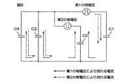
図3において、電源100は車両に搭載されている。電源100の負(−)極は、車両の金属性のフレーム(シャシー)130に電気的に接続されている。このため、フレーム130は、電源100の負極と同電位である。電動モータ18が搭載された電動パワーステアリング装置1はフレーム130にボルトなどで取り付けられる。ECUの+電源ライン、−電源ラインはそれぞれ長いラインを通じて電源100の正負極に接続される。このため、第1、第2のモータコイル18A、18Bとフレーム130との間には、それぞれ浮遊容量C1,C2が存在することになる。また、電源100と電動パワーステアリング装置1とを接続する正負のラインとフレームグランドとの間には浮遊容量C3,C4が存在する。
In FIG. 3, the
図2に戻り、第1の駆動回路32Aと第1のモータコイル18Aとを接続するための電力供給線には、2つの電流センサ33,34が設けられている。これらの電流センサ33,34は、第1の駆動回路32Aと第1のモータコイル18Aとを接続するための3本の電力供給線のうち、2本の電力供給線に流れる相電流を検出できるように設けられている。
Returning to FIG. 2, two
同様に、第2の駆動回路32Bと第2のモータコイル18Bとを接続するための電力供給線には、2つの電流センサ35,36が設けられている。これらの電流センサ35,36は、第2の駆動回路32Bと第2のモータコイル18Bとを接続するための3本の電力供給線のうち、2本の電力供給線に流れる相電流を検出できるように設けられている。
マイクロコンピュータ31は、CPUおよびメモリ(ROM、RAM、不揮発性メモリなど。)を備えており、所定のプログラムを実行することによって、複数の機能処理部として機能するようになっている。この複数の機能処理部には、系統および相別PWMカウント演算部41と、コモンモードノイズ低減部42と、第1のPWM出力部43Aと、第2のPWM出力部43Bとを含む。
Similarly, two
The
図4は、系統および相別PWMカウント演算部41の構成を示すブロック図である。
系統および相別PWMカウント演算部41は、各系統の各相の電流制御周期毎のPWMカウントを演算するものである。系統および相別PWMカウント演算部41は、アシスト電流値設定部51と、電流指令値設定部52と、指令値分配部53と、第1系統用演算部70Aと、第2系統用演算部70Bと、回転角演算部59と、回転速度演算部60と、回転角推定部61とを含む。
FIG. 4 is a block diagram showing the configuration of the system and the phase-specific PWM
The system and phase-specific PWM
第1系統用演算部70Aは、第1の電流偏差演算部54Aと、第1のPI(比例積分)制御部55Aと、第1の二相・三相変換部56Aと、第1のPWMデューティ演算部(PWM Duty演算部)57Aと、第1の三相・二相変換部58Aとを含む。第2系統用演算部70Bは、第2の電流偏差演算部54Bと、第2のPI(比例積分)制御部55Bと、第2の二相・三相変換部56Bと、第2のPWMデューティ演算部(PWM Duty演算部)57Bと、第2の三相・二相変換部58Bとを含む。
The first
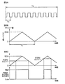
図5Aに示すように、PWM信号の周期(以下、「PWM周期」という。)Tcは、電流制御周期Taよりも小さい。ここで、電流制御周期Taとは、モータ電流の制御ループの演算周期のことである。つまり、図4において、第1系統用演算部70Aと、第2系統用演算部70Bにそれぞれ含まれる各ブロックの演算周期である。この電流制御周期Taはプログラムの規模やマイクロコンピュータ31の演算能力などを考慮して決まる。この実施形態では、今回の電流制御周期Ta内の最初のタイミングでPWMデューティ演算部57A,57BによりPWMデューティが更新され、更新されたPWMデューティCu1、Cv1、Cw1、Cu2、Cv2、Cw2が出力される。この実施形態では、TcはTaの1/10である。言い換えれば、電流制御周期Ta内に10周期分のPWM周期Tcが含まれる。10周期分のPWM周期Tcの最初の周期を1番目の周期といい、それ以降の周期を2,3,…,9,10番目の周期という場合がある。また、PWM周期の周期番号をi(i=1,2,…,9,10)で表す場合がある。なお、PWM信号の周波数(=1/Tc)は、キャリア周波数と呼ばれる。
As shown in FIG. 5A, the PWM signal cycle (hereinafter referred to as “PWM cycle”) Tc is smaller than the current control cycle Ta. Here, the current control cycle Ta is the calculation cycle of the motor current control loop. That is, in FIG. 4, it is the calculation cycle of each block included in the first
本実施形態でのPWM波形生成方法を説明する。マイクロコンピュータ31内で、図示しないクロック発生器で生成されるPWMクロック周波数のクロックをカウンタ(図示略)でアップカウントおよびダウンカウントする。このカウンタのカウント値を、時間を横軸にとり、カウント値を縦軸にとって図示すると、図5Bに示すようになる。ここで、カウント値は符号なし整数と解釈する。また、カウント値をキャリアカウントと呼ぶ場合がある。この実施形態では、図5Bの波形がキャリア波形である。キャリア波形は三角波である。三角波の1周期はTcに等しい。キャリア波形の最大値、つまりカウント値の最大値により、PWM信号の周波数(キャリア周波数)が決定される。本実施形態では、PWMクロック周波数が100[MHz]であり、PWM信号の周波数(以下、「PWM周波数」という。)が100[kHz]と設定しているので、カウント値の最大値は、100,000,000÷100,000÷2=500となる。アップダウンカウントするため、100,000,000/100,000を、2で割っている。
The PWM waveform generation method in this embodiment will be described. In the
図5Cに示すように、PWM出力部43A,43B(図2参照)は、与えられるPWMカウントとカウンタのカウント値とを比較し、駆動回路32A,32B(図2参照)に対して、High or Low信号を出力する。PWM出力部43A,43Bは、例えば、カウンタのカウント値≧PWMカウントが成立している間はHigh信号を、それ以外はLow信号を出力する。このHigh、Low信号がPWM信号となる。PWM出力部43A,43Bの動作の詳細については後述する。
As shown in FIG. 5C, the
図4に戻り、回転角演算部59は、回転角センサ23の出力信号に基づいて、電動モータ18のロータの回転角θ(電気角)を電流制御周期Ta毎に演算する。回転角演算部59によって演算されるロータ回転角θは、第1および第2の三相・二相変換部58A,58B、回転速度演算部60および回転角推定部61に与えられる。この実施形態では、ロータ回転角θが取得(検出)されるタイミングは、電流制御周期Taの中央時点であるものとする。
Returning to FIG. 4, the rotation
回転速度演算部60は、回転角演算部59によって演算されるロータ回転角θを時間微分することにより、電動モータ18のロータの回転速度(角速度)ωを演算する。回転速度演算部60によって演算される回転速度ωは、回転角推定部61に与えられる。
回転角推定部61は、前回の電流制御周期Taで取得された前回の電流制御周期Taの中央時点でのロータ回転角θ(m−1)を用いて、次式(1)に基づいて、次回の電流制御周期Taの中央時点でのロータ回転角θ(m+1)を推定する。
The rotation
The rotation angle estimation unit 61 uses the rotor rotation angle θ (m-1) at the center of the previous current control cycle Ta acquired in the previous current control cycle Ta, and is based on the following equation (1). The rotor rotation angle θ (m + 1) at the center of the next current control cycle Ta is estimated.
θ(m+1)=θ(m−1)+ω・2Ta …(1)
回転角推定部61によって推定された次回の電流制御周期Taでのロータ回転角θ(m+1)は、第1および第2の二相・三相変換部56A,56Bに与えられる。
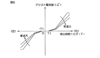
アシスト電流値設定部51は、トルクセンサ11によって検出される検出操舵トルクTと、車速センサ24によって検出される車速Vとに基づいて、アシスト電流値Ia*を電流制御周期Ta毎に設定する。検出操舵トルクTに対するアシスト電流値Ia*の設定例は、図6に示されている。検出操舵トルクTは、例えば右方向への操舵のためのトルクが正の値にとられ、左方向への操舵のためのトルクが負の値にとられている。また、アシスト電流値Ia*は、電動モータ18から右方向操舵のための操舵補助力を発生させるべきときには正の値とされ、電動モータ18から左方向操舵のための操舵補助力を発生させるべきときには負の値とされる。アシスト電流値Ia*は、検出操舵トルクTの正の値に対しては正をとり、検出操舵トルクTの負の値に対しては負をとる。
θ (m + 1) = θ (m-1) + ω ・ 2Ta… (1)
The rotor rotation angle θ (m + 1) in the next current control cycle Ta estimated by the rotation
The assist current value setting unit 51 sets the assist current value Ia * for each current control cycle Ta based on the detected steering torque T detected by the
検出操舵トルクTが−T1〜T1(たとえば、T1=0.4N・m)の範囲(トルク不感帯)の微小な値のときには、アシスト電流値Ia*は零とされる。そして、検出操舵トルクTが−T1〜T1の範囲外の値である場合には、アシスト電流値Ia*は、検出操舵トルクTの絶対値が大きくなるほど、その絶対値が大きくなるように設定される。また、アシスト電流値Ia*は、車速センサ24によって検出される車速Vが大きいほど、その絶対値が小さくなるように設定されるようになっている。これにより、低速走行時には操舵補助力が大きくされ、高速走行時には操舵補助力が小さくされる。
When the detected steering torque T is a minute value in the range of −T1 to T1 (for example, T1 = 0.4 Nm) (torque dead zone), the assist current value Ia * is set to zero. When the detected steering torque T is a value outside the range of −T1 to T1, the assist current value Ia * is set so that the larger the absolute value of the detected steering torque T, the larger the absolute value. To torque. Further, the assist current value Ia * is set so that the larger the vehicle speed V detected by the
電流指令値設定部52は、アシスト電流値設定部51によって設定されたアシスト電流値Ia*に基づいて、dq座標系の座標軸に流すべき電流値を電流指令値として設定する。具体的には、電流指令値設定部52は、d軸電流指令値Id *およびq軸電流指令値Iq *(以下、これらを総称するときには「二相電流指令値Idq *」という。)を設定する。さらに具体的には、電流指令値設定部52は、q軸電流指令値Iq *をアシスト電流値設定部51によって設定されたアシスト電流値Ia*とする一方で、d軸電流指令値Id *を零とする。電流指令値設定部52によって設定された二相電流指令値Idq *は、指令値分配部53に与えられる。
The current command
指令値分配部53は、二相電流指令値Idq *を、第1系統用演算部70Aおよび第2系統用演算部70Bに分配する。この実施形態では、指令値分配部53は、二相電流指令値Idq *を、第1系統用演算部70Aおよび第2系統用演算部70Bに、1/2ずつ分配する。つまり、この実施形態では、二相電流指令値Idq *の第1系統用演算部70Aへの分配率および二相電流指令値Idq *の第2系統用演算部70Bへの分配率は、共に50%となる。第1系統用演算部70Aに分配される二相電流指令値を、第1の二相電流指令値I1dq *ということにする。第1の二相電流指令値I1dq *は、第1のd軸電流指令値I1d *および第1のq軸電流指令値I1q *とからなる。第2系統用演算部70Bに分配される二相電流指令値を、第2の二相電流指令値I2dq *ということにする。第2の二相電流指令値I2dq *は、第2のd軸電流指令値I2d *および第2のq軸電流指令値I2q *とからなる。
The command
次に、第1系統用演算部70Aについて説明する。第1の三相・二相変換部58Aは、まず、電流センサ33,34によって検出される2相分の相電流から、第1系統のU相電流I1U、V相電流I1VおよびW相電流I1W(以下、これらを総称するときは、「三相検出電流I1UVW」という。)を演算する。そして、第1の三相・二相変換部58Aは、第1系統のUVW座標系の三相検出電流I1UVWを、第1系統のdq座標系の二相検出電流I1dqに座標変換する。第1系統の二相検出電流I1dqは、第1のd軸検出電流I1dおよび第1のq軸検出電流I1qからなる。この座標変換には、回転角演算部59によって演算されるロータ回転角θが用いられる。
Next, the
第1の電流偏差演算部54Aは、第1のd軸電流指令値I1d *に対する第1のd軸検出電流I1dの偏差および第1のq軸電流指令値I1q *に対する第1のq軸検出電流I1qの偏差を演算する。これらの偏差は、第1のPI制御部55Aに与えられる。
第1のPI制御部55Aは、第1の電流偏差演算部54Aによって演算された電流偏差に対するPI演算を行なうことにより、第1のモータコイル18Aに印加すべき第1の二相電圧指令値V1dq *(第1のd軸電圧指令値V1d *および第1のq軸電圧指令値V1q *)を生成する。第1の二相電圧指令値V1dq *は、第1の二相・三相変換部56Aに与えられる。
The first current
The first
第1の二相・三相変換部56Aは、今回の電流制御周期Taにおいて第1のPI制御部55Aによって演算された第1の二相電圧指令値V1dq *に対して、今回の電流制御周期Taにおいて回転角推定部61によって演算された次回の電流制御周期Taに対する回転角推定値θ(m+1)を用いて二相・三相変換を行うことにより、次回の電流制御周期Taに対する第1の三相電圧指令値V1UVW *を演算する。第1の三相電圧指令値V1UVW *は、第1のU相電圧指令値V1U *、第1のV相電圧指令値V1V *および第1のW相電圧指令値V1W *からなる。これにより、次回の電流制御周期Taに対する第1の三相電圧指令値V1UVW *が得られる。
The first two-phase / three-
第1の二相・三相変換部56Aによって得られた次回の電流制御周期Taに対する第1の三相電圧指令値V1UVW *は、第1のPWMデューティ演算部57Aに与えられる。
第1のPWMデューティ演算部57Aは、次回の電流制御周期Taに対する第1の三相電圧指令値V1UVW *に基づいて、次回の電流制御周期Taに対する第1のU相PWMカウント(PWMデューティ)Cu1、第1のV相PWMカウントCv1および第1のW相PWMカウントCw1を生成して、コモンモードノイズ低減部42(図2参照)に与える。
The first three-phase voltage command value V 1UVW * for the next current control cycle Ta obtained by the first two-phase / three-
The first PWM
たとえば、第1のU相のPWMカウントCu1は、次のようにして求められる。すなわち、第1のPWMデューティ演算部57Aは、第1の二相・三相変換部56Aによって得られたある電流制御周期Taに対する第1のU相電圧指令値V1U *と、PWMカウントの最大値(この例では500)とを用いて、次式(2)に基づいて、当該電流制御周期Taに対する第1のU相PWMカウントCu1を演算する。
For example, the first U-phase PWM count Cu 1 is obtained as follows. That is, the first PWM duty calculation unit 57A has the first U-phase voltage command value V 1U * for a certain current control cycle Ta obtained by the first two-phase / three-
Cu1=V1U *×(PWMカウントの最大値/Vb)
=V1U *×(500/Vb) …(2)
前記式(2)においてVbは、第1の駆動回路32Aの電源電圧(電源100の出力電圧)である。
前記式(2)の右辺の第1のU相電圧指令値V1U *の代わりに第1のV相電圧指令値V1V *を用いると、第1のV相PWMカウントCv1を演算することができ、第1のU相電圧指令値V1U *の代わりに第1のW相電圧指令値V1W *を用いるとW相のPWMカウントCw1を演算できる。
Cu 1 = V 1U * × (Maximum PWM count / Vb)
= V 1U * × (500 / Vb)… (2)
In the formula (2), Vb is the power supply voltage (output voltage of the power supply 100) of the
When the first V-phase voltage command value V 1V * is used instead of the first U-phase voltage command value V 1U * on the right side of the equation (2), the first V-phase PWM count Cv 1 is calculated. If the first W-phase voltage command value V 1W * is used instead of the first U-phase voltage command value V 1U * , the W-phase PWM count Cw 1 can be calculated.
次に、第2系統用演算部70Bについて説明する。第2の三相・二相変換部58Bは、まず、電流センサ35,36によって検出される2相分の相電流から、第2系統のU相電流I2U、V相電流I2VおよびW相電流I2W(以下、これらを総称するときは、「三相検出電流I2UVW」という。)を演算する。そして、第2の三相・二相変換部58Bは、第2系統のUVW座標系の三相検出電流I2UVWを、第2系統のdq座標系の二相検出電流I2dqに座標変換する。第2系統の二相検出電流I2dqは、第2のd軸検出電流I2dおよび第2のq軸検出電流I2qからなる。この座標変換には、回転角演算部59によって演算されるロータ回転角θが用いられる。
Next, the
第2の電流偏差演算部54Bは、第2のd軸電流指令値I2d *に対する第2のd軸検出電流I2dの偏差および第2のq軸電流指令値I2q *に対する第2のq軸検出電流I2qの偏差を演算する。これらの偏差は、第2のPI制御部55Bに与えられる。
第2のPI制御部55Bは、第2の電流偏差演算部54Bによって演算された電流偏差に対するPI演算を行なうことにより、第2のモータコイル18Bに印加すべき第2の二相電圧指令値V2dq *(第2のd軸電圧指令値V2d *および第2のq軸電圧指令値V2q *)を生成する。第2の二相電圧指令値V2dq *は、第2の二相・三相変換部56Bに与えられる。
The second current
The second
第2の二相・三相変換部56Bは、今回の電流制御周期Taにおいて第2のPI制御部55Bによって演算された第2の二相電圧指令値V2dq *に対して、今回の電流制御周期Taにおいて回転角推定部61によって演算された次回の電流制御周期Taに対する回転角推定値θ(m+1)を用いて二相・三相変換を行うことにより、次回の電流制御周期Taに対する第2の三相電圧指令値V2UVW *を演算する。第2の三相電圧指令値V2UVW *は、第2のU相電圧指令値V2U *、第2のV相電圧指令値V2V *および第2のW相電圧指令値V2W *からなる。これにより、次回の電流制御周期Taに対する第2の三相電圧指令値V2UVW *が得られる。
The second two-phase / three-
第2の二相・三相変換部56Bによって得られた次回の電流制御周期Taに対する第2の三相電圧指令値V2UVW *は、第2のPWMデューティ演算部57Bに与えられる。
第2のPWMデューティ演算部57Bは、次回の電流制御周期Taに対する第2の三相電圧指令値V2UVW *に基づいて、次回の電流制御周期Taに対する第2のU相PWMカウント(PWMデューティ)Cu2、第2のV相PWMカウントCv2および第2のW相PWMカウントCw2を生成して、コモンモードノイズ低減部42(図2参照)に与える。
The second three-phase voltage command value V 2UVW * for the next current control cycle Ta obtained by the second two-phase / three-
The second PWM
たとえば、第2のU相のPWMカウントCu2は、次のようにして求められる。すなわち、第2のPWMデューティ演算部57Bは、第2の二相・三相変換部56Bによって得られたある電流制御周期Taに対する第2のU相電圧指令値V2U *と、PWMカウントの最大値(この例では500)とを用いて、次式(3)に基づいて、当該電流制御周期Taに対する第2のU相のPWMカウントCu2を演算する。
For example, the second U-phase PWM count Cu 2 is obtained as follows. That is, the second PWM duty calculation unit 57B has the second U-phase voltage command value V 2U * for a certain current control cycle Ta obtained by the second two-phase / three-
Cu2=PWMカウントの最大値−{V2U *×(PWMカウントの最大値/Vb)}
=PWMカウントの最大値−{V2U *×(500/Vb)} …(3)
前記式(3)においてVbは、第2の駆動回路32Bの電源電圧(電源100の出力電圧)である。
前記式(3)の右辺の第2のU相電圧指令値V2U *の代わりに第2のV相電圧指令値V2V *を用いると、第2のV相PWMカウントCv2を演算することができ、第2のU相電圧指令値V2U *の代わりに第2のW相電圧指令値V2W *を用いると第2のW相PWMカウントCw2を演算できる。
Cu 2 = Maximum PWM count- {V 2U * × (Maximum PWM count / Vb)}
= Maximum value of PWM count- {V 2U * × (500 / Vb)} ... (3)
In the above formula (3), Vb is the power supply voltage (output voltage of the power supply 100) of the
When the second V-phase voltage command value V 2V * is used instead of the second U-phase voltage command value V 2U * on the right side of the above equation (3), the second V-phase PWM count Cv 2 is calculated. If the second W-phase voltage command value V 2W * is used instead of the second U-phase voltage command value V 2U * , the second W-phase PWM count Cw 2 can be calculated.
コモンモードノイズ低減部42は、第1の駆動回路32A内のスイッチング素子のオンオフによって生じるノイズ電流の一部を、第2の駆動回路32B内のスイッチング素子のオンオフによって生じるノイズ電流の一部によって相殺することにより、コモンモードノイズを低減するために設けられたものである。コモンモードノイズ低減部42は、第1および第2のPWMデューティ演算部57A,57Bから与えられる次回の電流制御周期Taに対する第1および第2のU相のPWMカウントCu1,Cu2、V相のPWMカウントCv1,Cv2およびW相のPWMカウントCw1,Cw2に対して、コモンモードノイズを低減するための処理(ノイズ低減処理)を行う。これにより、次回の電流制御周期Ta内の各PWM周期Tcに対する第1のU相のPWMカウント、V相のPWMカウントおよびW相のPWMカウントと、次回の電流制御周期Ta内の各PWM周期Tcに対する第2のU相のPWMカウント、V相のPWMカウントおよびW相のPWMカウントとが得られる。コモンモードノイズ低減部42の動作の詳細については、後述する。
The common mode noise reduction unit 42 cancels a part of the noise current generated by turning on / off the switching element in the
コモンモードノイズ低減部42によるノイズ低減処理後の、次回の電流制御周期Ta内の各PWM周期Tcに対する第1のU相のPWMカウント、V相のPWMカウントおよびW相のPWMカウントは、第1のPWM出力部43Aに与えられる。一方、コモンモードノイズ低減部42によるノイズ低減処理後の、次回の電流制御周期Ta内の各PWM周期Tcに対する第2のU相のPWMカウント、V相のPWMカウントおよびW相のPWMカウントは、第2のPWM出力部43Bに与えられる。
After the noise reduction processing by the common mode noise reduction unit 42, the first U-phase PWM count, V-phase PWM count, and W-phase PWM count for each PWM cycle Tc in the next current control cycle Ta are the first. It is given to the
第1のPWM出力部43Aは、コモンモードノイズ低減部42から与えられる電流制御周期Ta内の各PWM周期Tcに対する第1のU相のPWMカウント、V相のPWMカウントおよびW相のPWMカウントを、複数の電流制御周期分にわたって記憶している。第1のPWM出力部43Aは、前回の電流制御周期Taにおいてコモンモードノイズ低減部42から与えられた今回の電流制御周期Ta内の各PWM周期Tcに対する第1のU相のPWMカウント、V相のPWMカウントおよびW相のPWMカウントに基づいて、今回の電流制御周期Ta内の各PWM周期Tcに対する第1のU相PWM信号、V相PWM信号およびW相PWM信号を生成して、第1の駆動回路32Aに供給する。具体的には、第1のPWM出力部43Aは、今回の電流制御周期Ta内のPWM周期Tc毎に、当該電流制御周期Ta内の各PWM周期Tcに対する第1のU相のPWMカウント、V相のPWMカウントおよびW相のPWMカウントにそれぞれ対応するデューティのU相PWM信号、V相PWM信号およびW相PWM信号を生成して、第1の駆動回路32Aに供給する。
The first
第1の駆動回路32Aを構成する6つのFET111A〜116Aが第1のPWM出力部43Aから与えられるPWM信号によって制御されることにより、PWM周期Tc毎の第1の三相電圧指令値V1UVW *に相当する電圧が第1のモータコイル18Aの各相のステータコイル18AU,18AV,18AWに印加されることになる。
第1の電流偏差演算部54Aおよび第1のPI制御部55Aは、電流フィードバック制御手段を構成している。この電流フィードバック制御手段の働きによって第1のモータコイル18Aに流れるモータ電流が、指令値分配部53によって第1系統用演算部70Aに分配された第1の二相電流指令値I1dq *に近づくように制御される。
The six FETs 111A to 116A constituting the
The first current
第2のPWM出力部43Bは、コモンモードノイズ低減部42から与えられる電流制御周期Ta内の各PWM周期Tcに対する第2のU相のPWMカウント、V相のPWMカウントおよびW相のPWMカウントを、複数の電流制御周期分にわたって記憶している。第2のPWM出力部43Bは、前回の電流制御周期Taにおいてコモンモードノイズ低減部42から与えられた今回の電流制御周期Ta内の各PWM周期Tcに対する第2のU相のPWMカウント、V相のPWMカウントおよびW相のPWMカウントに基づいて、今回の電流制御周期Ta内の各PWM周期Tcに対する第2のU相PWM信号、V相PWM信号およびW相PWM信号を生成して、第2の駆動回路32Bに供給する。具体的には、第2のPWM出力部43Bは、今回の電流制御周期Ta内のPWM周期Tc毎に、当該電流制御周期Ta内の各PWM周期Tcに対する第2のU相のPWMカウント、V相のPWMカウントおよびW相のPWMカウントにそれぞれ対応するデューティのU相PWM信号、V相PWM信号およびW相PWM信号を生成して、第2の駆動回路32Bに供給する。
The second
第2の駆動回路32Bを構成する6つのFET111B〜116Bが第2のPWM出力部43Bから与えられるPWM信号によって制御されることにより、PWM周期Tc毎の第2の三相電圧指令値V2UVW *に相当する電圧が第2のモータコイル18Bの各相のステータコイル18BU,18BV,18BWに印加されることになる。
第2の電流偏差演算部54Bおよび第2のPI制御部55Bは、電流フィードバック制御手段を構成している。この電流フィードバック制御手段の働きによって第2のモータコイル18Bに流れるモータ電流が、指令値分配部53によって第2系統用演算部70Bに分配された第2の二相電流指令値I2dq *に近づくように制御される。
The six
The second current
以下、コモンモードノイズ低減部42について詳しく説明する。まず、図7を参照して、コモンモードノイズ低減部42によるコモンモードノイズ低減の基本的な考え方について説明する。
第1系統のある相の出力電圧(以下、第1の相電圧という)の波形が図7(a)である場合には、第1の相電圧に起因して、第1のモータコイル18Aとフレームグランドとの間に存在する浮遊容量C1(図3参照)に流れる電流は、図7(c)に示すようになる。つまり、第1の相電圧の立下り時点t1で−方向の電流が浮遊容量C1に流れ、第1の相電圧の立上り時点t2で+方向の電流が浮遊容量C1に流れる。
Hereinafter, the common mode noise reduction unit 42 will be described in detail. First, with reference to FIG. 7, the basic concept of common mode noise reduction by the common mode noise reduction unit 42 will be described.
When the waveform of the output voltage (hereinafter referred to as the first phase voltage) of a certain phase of the first system is shown in FIG. 7A, the
そこで、第2系統のある相の出力電圧(以下、第2の相電圧という)の波形を、図7(b)に示すように、図7(a)の第1の相電圧の波形を反転させた波形にすると、第2の相電圧に起因して、第2のモータコイル18Bとフレームグランドとの間に存在する浮遊容量C2(図3参照)に流れる電流は、図7(d)に示すようになる。つまり、第2の相電圧の立上り時点t1で+方向の電流が浮遊容量C2に流れ、第2の相電圧の立下り時点t2で−方向の電流が浮遊容量C2に流れる。したがって、時点t1および時点t2のそれぞれの時点において、第1の相電圧に起因して浮遊容量C1に流れる電流と第2の相電圧に起因して浮遊容量C2に流れる電流とが相殺される。このため、図7(e)に示すように、正負の電源ラインとフレームグランドとの間に存在する浮遊容量C3、C4(図3参照)に流れる電流は低下する。
Therefore, as shown in FIG. 7 (b), the waveform of the output voltage (hereinafter referred to as the second phase voltage) of a certain phase of the second system is inverted. According to the waveform, the current flowing in the stray capacitance C2 (see FIG. 3) existing between the
図8は、コモンモードノイズ電流に着目した等価回路である。第1の相電圧、第2の相電圧はノイズ発生源とみなすことができる。電源100はコモンモードノイズ電流のような交流的には正負電極間がショートされているとみなすことができる。図8において、第1の相電圧により実線矢印のようにコモンモードノイズ電流が流れる。第2の相電圧により一点鎖線の矢印のようにコモンモードノイズ電流が流れる。したがって、浮遊容量C3、C4に流れる各コモンモードノイズ電流は向きが互いに逆なので、打ち消し合い、結果としてトータルのコモンモードノイズ電流は低下する。
FIG. 8 is an equivalent circuit focusing on the common mode noise current. The first phase voltage and the second phase voltage can be regarded as noise sources. The
コモンモードノイズ低減部42は、電流制御周期内の少なくとも1つのPWM周期において、2系統のうちの一方の系統の1つの相の出力電圧に起因して浮遊容量に流れる電流が、他方の系統の少なくとも1つの相の出力電圧に起因して浮遊容量に流れる電流によって相殺されるように、当該他方の系統の少なくとも1つの相に対するPWM周期のPWMカウントを変更する。 In the common mode noise reduction unit 42, in at least one PWM cycle within the current control cycle, the current flowing in the stray capacitance due to the output voltage of one phase of one of the two systems is the current of the other system. The PWM count of the PWM cycle for at least one phase of the other system is changed so that it is offset by the current flowing through the stray capacitance due to the output voltage of at least one phase.
この実施形態では、コモンモードノイズ低減部42は、電流制御周期内の各PWM周期において、2系統のうちの一方の系統の1つの相の出力電圧に起因して浮遊容量に流れる電流が、他方の系統の2つの相の出力電圧のいずれかに起因して浮遊容量に流れる電流によって相殺されるように、当該他方の系統の2つの相に対するPWM周期のPWMカウントを変更する。 In this embodiment, in the common mode noise reduction unit 42, in each PWM cycle in the current control cycle, the current flowing in the stray capacitance due to the output voltage of one phase of one of the two systems is the other. The PWM count of the PWM cycle for the two phases of the other system is changed so as to be offset by the current flowing through the stray capacitance due to any of the output voltages of the two phases of the system.
図9は、コモンモードノイズ低減部の動作の一例を説明するためのフローチャートである。
コモンモードノイズ低減部42(図2参照)は、まず、第1のPWMデューティ演算部57A(図4参照)から与えられる次回の電流制御周期Taに対する第1のU相、V相およびW相のPWMカウントCu1、Cv1およびCw1を、次回の電流制御周期Ta内の各PWM周期Tcに対する第1のU相、V相およびW相のPWMカウントCu1、Cv1およびCw1として設定する(ステップS1)。
FIG. 9 is a flowchart for explaining an example of the operation of the common mode noise reduction unit.
The common mode noise reduction unit 42 (see FIG. 2) first of the first U-phase, V-phase, and W-phase with respect to the next current control cycle Ta given by the first PWM
同様に、コモンモードノイズ低減部42は、第2のPWMデューティ演算部57Bから与えられる次回の電流制御周期Taに対する第2のU相、V相およびW相のPWMカウントCu2、Cv2およびCw2を、次回の電流制御周期Ta内の各PWM周期Tcに対する第2のU相、V相およびW相のPWMカウントCu2、Cv2およびCw2として設定する(ステップS2)。 Similarly, the common mode noise reduction unit 42 has a second U-phase, V-phase, and W-phase PWM count Cu 2 , Cv 2, and Cw for the next current control cycle Ta given by the second PWM duty calculation unit 57B. 2 is set as the second U-phase, V-phase and W-phase PWM counts Cu 2 , Cv 2 and Cw 2 for each PWM cycle Tc in the next current control cycle Ta (step S2).
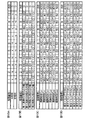
図12Aは、ステップS1で設定された、電流制御周期Ta内の各PWM周期Tcにおける第1のU相、V相およびW相のPWMカウントCu1、Cv1およびCw1と、ステップS2で設定された、電流制御周期Ta内の各PWM周期Tcにおける第2のU相、V相およびW相のPWMカウントCu2、Cv2およびCw2の一例を示す模式図である。
次に、コモンモードノイズ低減部42は、各系統の相毎に、デットタイムを考慮したスイッチングタイミングを設定する(ステップS3)。
FIG. 12A shows the first U-phase, V-phase, and W-phase PWM counts Cu 1 , Cv 1, and Cw 1 in each PWM cycle Tc in the current control cycle Ta set in step S1 and set in step S2. It is a schematic diagram which shows an example of the PWM counts Cu 2 , Cv 2 and Cw 2 of the 2nd U phase, V phase and W phase in each PWM cycle Tc in the current control cycle Ta.
Next, the common mode noise reduction unit 42 sets the switching timing in consideration of the dead time for each phase of each system (step S3).
図10は、主として、ある相のPWM周期単位の最終的なPWMカウントと、各系統の当該相の上段FET指令および下段FET指令との関係を示す模式図である。言い換えれば、第1のPWM出力部43Aおよび第2のPWM出力部43B(図2参照)のある相に対する動作の一例を説明するための模式図である。
この実施形態では、前述したように、キャリア波形は三角波であり、PWMカウントの出力可能カウントは0〜500に設定されている。また、この実施形態では、デットタイムに相当するカウント値を10とする。
FIG. 10 is a schematic diagram mainly showing the relationship between the final PWM count in the PWM cycle unit of a certain phase and the upper FET command and the lower FET command of the phase of each system. In other words, it is a schematic diagram for demonstrating an example of the operation with respect to a certain phase of the 1st
In this embodiment, as described above, the carrier waveform is a triangular wave, and the outputable count of the PWM count is set to 0 to 500. Further, in this embodiment, the count value corresponding to the dead time is set to 10.
第1系統の上段FET指令および下段FET指令について説明する。この実施形態では、キャリアカウントがPWMカウントよりも大きいときに、第1系統の上段FET指令がオフ指令となるように、第1系統の上段FETのスイッチングタイミングが設定されている。つまり、キャリアカウントのアップカウント中にキャリアカウントがPWMカウントと等しくなると(時点t2)、図10(a)に示すように、上段FET指令は、オン指令からオフ指令に変化する。そして、キャリアカウントのダウンカウント中にキャリアカウントがPWMカウントと等しくなると(時点t5)、上段FET指令は、オフ指令からオン指令に変化する。 The upper FET command and the lower FET command of the first system will be described. In this embodiment, the switching timing of the upper FET of the first system is set so that the upper FET command of the first system becomes an off command when the carrier count is larger than the PWM count. That is, when the carrier count becomes equal to the PWM count during the up-counting of the carrier count (time point t2), the upper FET command changes from the on command to the off command as shown in FIG. 10 (a). Then, when the carrier count becomes equal to the PWM count during the down count of the carrier count (time point t5), the upper FET command changes from the off command to the on command.
図10(b)に示すように、時点t2からデットタイムTdが経過すると(時点t3)、下段FET指令はオフ指令からオン指令に変化する。そして、時点t5に対してデットタイムTdだけ早い時点(時点t4)において、下段FET指令はオン指令からオフ指令に変化する。
第2系統の上段FET指令および下段FET指令について説明する。この実施形態では、キャリアカウントがPWMカウントよりも大きいときに、第2系統の上段FET指令がオン指令となるように、第2系統の上段FETのスイッチングタイミングが設定されている。つまり、キャリアカウントのアップカウント中にキャリアカウントがPWMカウントと等しくなると(時点t2)、図10(e)に示すように、上段FET指令は、オフ指令からオン指令に変化する。そして、キャリアカウントのダウンカウント中にキャリアカウントがPWMカウントと等しくなると(時点t5)、上段FET指令は、オン指令からオフ指令に変化する。
As shown in FIG. 10B, when the dead time Td elapses from the time point t2 (time point t3), the lower FET command changes from the off command to the on command. Then, at a time point (time point t4) earlier than the time point t5 by the dead time Td, the lower FET command changes from the on command to the off command.
The upper FET command and the lower FET command of the second system will be described. In this embodiment, the switching timing of the upper FET of the second system is set so that the upper FET command of the second system becomes an on command when the carrier count is larger than the PWM count. That is, when the carrier count becomes equal to the PWM count during the up-counting of the carrier count (time point t2), the upper FET command changes from the off command to the on command as shown in FIG. 10 (e). Then, when the carrier count becomes equal to the PWM count during the down count of the carrier count (time point t5), the upper FET command changes from the on command to the off command.
図10(f)に示すように、時点t2に対してデットタイムTdだけ早い時点(時点t1)において、下段FET指令はオン指令からオフ指令に変化する。時点t5からデットタイムTdが経過すると(時点t6)、下段FET指令はオフ指令からオン指令に変化する。
デットタイム期間中のある相の出力電圧(相電圧)について、図11Aおよび図11Bを参照して説明する。ここでは、第1系統のU相を例にとって説明するが、第1系統の他の2つの相や、第2系統の各相においても同様である。
As shown in FIG. 10 (f), the lower FET command changes from the on command to the off command at a time point (time point t1) earlier than the time point t2 by the dead time Td. When the dead time Td elapses from the time point t5 (time point t6), the lower FET command changes from the off command to the on command.
The output voltage (phase voltage) of a certain phase during the dead time period will be described with reference to FIGS. 11A and 11B. Here, the U phase of the first system will be described as an example, but the same applies to the other two phases of the first system and each phase of the second system.
図11Aに示すように、上段FET111Aおよび下段FET112Aの接続点から電動モータ18側に向かって電流が流れている状態では、デットタイム期間中においては、下段FET112Aに逆並列接続されたダイオード122Aを通じて電流が流れることになる。したがって、デットタイム期間中においては、出力電圧(相電圧)VuはLベルとなる。このため、相電圧VuのLレベルの期間は、上段FET111Aのオフ期間と同じになる。
As shown in FIG. 11A, in a state where a current is flowing from the connection point of the upper FET 111A and the
一方、図11Bに示すように、電動モータ18側から上段FET111Aおよび下段FET112Aの接続点に向かって電流が流れている状態では、デットタイム期間中においては、上段FET111Aに逆並列接続されたダイオード121Aを通じて電流が流れることになる。したがって、デットタイム期間中においては、出力電圧(相電圧)VuはHレベルとなる。このため、相電圧VuのLレベルの期間は上段FET111Aのオフ期間よりも短くなる。言い換えれば、相電圧VuのHレベルの期間は上段FET111Aのオン期間よりも長くなる。
On the other hand, as shown in FIG. 11B, in a state where a current is flowing from the
第1系統において、PWMカウントがPWMカウント最大値の1/2以上(250以上)である場合には、PWMカウントがPWMカウント最大値の1/2未満である場合に比べて、上段FETのオン時間が長くなる。そこで、この実施形態では説明の便宜上、PWMカウントが250以上である場合には、上段FETおよび下段FETの接続点から電動モータ18側に向かって電流が流れている状態(図11Aに示される状態)であると考えることにする。このため、デットタイム期間中においては、出力電圧(相電圧)はLベルとなると考えられる。したがって、この場合には、相電圧は、図10(c)に示すように変化すると考えられるので、相電圧のレベル変化タイミングと上段FETのスイッチングタイミングとは一致する。
In the first system, when the PWM count is 1/2 or more (250 or more) of the maximum PWM count value, the upper FET is turned on as compared with the case where the PWM count is less than 1/2 of the maximum PWM count value. The time will be longer. Therefore, in this embodiment, for convenience of explanation, when the PWM count is 250 or more, a current is flowing from the connection point of the upper FET and the lower FET toward the
一方、第1系統において、PWMカウントがPWMカウント最大値の1/2未満(250未満)である場合には、PWMカウントがPWMカウント最大値の1/2以上である場合に比べて、上段FETのオン時間が短くなる。そこで、この実施形態では説明の便宜上、PWMカウントが250未満である場合には、電動モータ18側から上段FETおよび下段FETの接続点に向かって電流が流れている状態(図11Bに示される状態)であると考えることにする。このため、デットタイム期間中においては、出力電圧(相電圧)はHレベルとなると考えられる。したがって、この場合には、相電圧は、図10(d)に示すように変化すると考えられるので、相電圧のレベル変化タイミングと上段FETのスイッチングタイミングとは一致しなくなる。上段FETのスイッチングタイミングが相電圧のレベル変化タイミングと一致する仮想のPWMカウント(デットタイムを考慮したスイッチングタイミング)は、実際のPWMカウントにデットタイムに相当するカウント値(この実施形態では“10”)を加算した値となる。
On the other hand, in the first system, when the PWM count is less than 1/2 (less than 250) of the maximum PWM count value, the upper FET is compared with the case where the PWM count is 1/2 or more of the maximum PWM count value. On time is shortened. Therefore, in this embodiment, for convenience of explanation, when the PWM count is less than 250, a current is flowing from the
第2系統において、PWMカウントがPWMカウント最大値の1/2以上(250以上)である場合には、PWMカウントがPWMカウント最大値の1/2以上である場合に比べて、上段FETのオン時間が短くなる。そこで、この実施形態では説明の便宜上、PWMカウントが250以上である場合には、電動モータ18側から上段FETおよび下段FETの接続点に向かって電流が流れている状態(図11Bに示される状態)であると考えることにする。このため、デットタイム期間中においては、出力電圧(相電圧)はHベルとなると考えられる。したがって、この場合には、相子電圧は、図10(g)に示すように変化すると考えられるので、相電圧のレベル変化タイミングと上段FETのスイッチングタイミングとは一致しなくなる。上段FETのスイッチングタイミングが相電圧のレベル変化タイミングと一致する仮想のPWMカウント(デットタイムを考慮したスイッチングタイミング)は、実際のPWMカウントにデットタイムに相当するカウント値(この実施形態では“10”)を減算した値となる。
In the second system, when the PWM count is 1/2 or more (250 or more) of the maximum PWM count value, the upper FET is turned on as compared with the case where the PWM count is 1/2 or more of the maximum PWM count value. The time is shortened. Therefore, in this embodiment, for convenience of explanation, when the PWM count is 250 or more, a current is flowing from the
一方、第2系統において、PWMカウントがPWMカウント最大値の1/2未満(250未満)である場合には、PWMカウントがPWMカウント最大値の1/2以上である場合に比べて、上段FETのオン時間が長くなる。そこで、この実施形態では説明の便宜上、PWMカウントが250未満である場合には、上段FETおよび下段FETの接続点から電動モータ18側に向かって電流が流れている状態(図11Aに示される状態)であると考えることにする。このため、デットタイム期間中においては、出力電圧(相電圧)はLベルとなると考えられる。したがって、この場合には、相電圧は、図10(h)に示すように変化すると考えられるので、相電圧のレベル変化タイミングと上段FETのスイッチングタイミングとは一致する。
On the other hand, in the second system, when the PWM count is less than 1/2 (less than 250) of the maximum PWM count value, the upper FET is compared with the case where the PWM count is 1/2 or more of the maximum PWM count value. On time becomes longer. Therefore, in this embodiment, for convenience of explanation, when the PWM count is less than 250, a current is flowing from the connection point of the upper FET and the lower FET toward the
この実施形態では、説明の便宜上、第1系統および第2系統において、相電流の方向をPWMカウントがPWMカウント最大値の1/2以上であるか否かに基づいて推定しているが、相電流を検出し、この検出値に基づいて相電流の方向を推定してもよい。
ステップS3では、コモンモードノイズ低減部42は、ステップS1およびS2で設定された各系統の各相のPWM周期TcのPWMカウント毎に、当該相の出力電圧(相電圧)のレベル変化タイミングに一致するPWMカウント(デットタイムを考慮したスイッチングタイミング)を演算する。
In this embodiment, for convenience of explanation, in the first system and the second system, the direction of the phase current is estimated based on whether or not the PWM count is ½ or more of the maximum PWM count value. The current may be detected and the direction of the phase current may be estimated based on this detected value.
In step S3, the common mode noise reduction unit 42 coincides with the level change timing of the output voltage (phase voltage) of the relevant phase for each PWM count of the PWM cycle Tc of each phase of each system set in steps S1 and S2. Calculate the PWM count (switching timing considering the dead time).
具体的には、コモンモードノイズ低減部42は、次回の電流制御周期Ta内の各PWM周期Tcに対する第1のU相、V相およびW相のPWMカウントCu1、Cv1およびCw1のうち、250以上のPWMカウントについては、その値をそのまま、当該相の出力電圧(相電圧)のレベル変化タイミングに一致するPWMカウントとして設定する。
前記第1のU相、V相およびW相のPWMカウントCu1、Cv1およびCw1のうち、250未満のPWMカウントについては、コモンモードノイズ低減部42は、その値にデットタイムに相当するカウント値(この実施形態では“10”)を加算した値を、当該相の出力電圧(相電圧)のレベル変化タイミングに一致するPWMカウントとして設定する。
Specifically, the common mode noise reduction unit 42 has one of the first U-phase, V-phase, and W-phase PWM counts Cu 1 , Cv 1, and Cw 1 for each PWM cycle Tc in the next current control cycle Ta. For a PWM count of 250 or more, the value is set as it is as a PWM count that matches the level change timing of the output voltage (phase voltage) of the relevant phase.
Of the first U-phase, V-phase, and W-phase PWM counts Cu 1 , Cv 1, and Cw 1 , for a PWM count of less than 250, the common mode noise reduction unit 42 corresponds to the value of the dead time. The value obtained by adding the count value (“10” in this embodiment) is set as the PWM count that matches the level change timing of the output voltage (phase voltage) of the phase.
コモンモードノイズ低減部42は、次回の電流制御周期Ta内の各PWM周期Tcに対する第2のU相、V相およびW相のPWMカウントCu2、Cv2およびCw2のうち、250以上のPWMカウントについては、その値からデットタイムに相当するカウント値(この実施形態では“10”)を減算した値を、当該相の出力電圧(相電圧)のレベル変化タイミングに一致するPWMカウントとして設定する。 The common mode noise reduction unit 42 has a PWM count of 250 or more of the second U-phase, V-phase, and W-phase PWM counts Cu 2 , Cv 2, and Cw 2 for each PWM cycle Tc in the next current control cycle Ta. Regarding the count, a value obtained by subtracting a count value (“10” in this embodiment) corresponding to the dead time from that value is set as a PWM count that matches the level change timing of the output voltage (phase voltage) of the relevant phase. ..
前記第2のU相、V相およびW相のPWMカウントCu2、Cv2およびCw2のうち、250未満のPWMカウントについては、コモンモードノイズ低減部42は、その値をそのまま、当該相の出力電圧(相電圧)のレベル変化タイミングに一致するPWMカウントとして設定する。
ステップS1およびS2によって設定された各系統の各相のPWM周期単位のPWMカウントが図12Aである場合、ステップS3によって設定される各系統の各相のPWM周期単位のPWMカウントを図12Bに示す。図12Aと図12Bとを比較すると、第1系統のV相のPWMカウントCv1が200から210に変化し、第1系統のW相のPWMカウントCw1が100から110に変化していることがわかる。また、第2系統のU相のPWMカウントCu2が350から340に変化し、第2系統のV相のPWMカウントCv2が300から290に変化していることがわかる。
Of the second U-phase, V-phase, and W-phase PWM counts Cu 2 , Cv 2, and Cw 2 , for a PWM count of less than 250, the common mode noise reduction unit 42 keeps the values as they are in the phase. It is set as a PWM count that matches the level change timing of the output voltage (phase voltage).
When the PWM count of each phase of each system set by steps S1 and S2 is shown in FIG. 12A, the PWM count of each phase of each system set by step S3 is shown in FIG. 12B. .. Comparing FIG. 12A and FIG. 12B, the PWM count Cv 1 of the V phase of the first system has changed from 200 to 210, and the PWM count Cw 1 of the W phase of the first system has changed from 100 to 110. I understand. It can also be seen that the U-phase PWM count Cu 2 of the second system has changed from 350 to 340, and the V-phase PWM count Cv 2 of the second system has changed from 300 to 290.
次に、コモンモードノイズ低減部42は、ステップS3の処理によって設定された各系統の各相のPWM周期単位のPWMカウントに基づいて、第1系統と第2系統との間でノイズ電流を相殺すべき相の組合せを決定する(ステップS4)。
具体的には、コモンモードノイズ低減部42は、まず、各系統の各相のうち、ステップS3の処理によって設定されたPWMカウントのうち、PWMカウント最大値(この実施形態では“500”)または最小値(この実施形態では“0”)に最も近いPWMカウントを有する相を、第1の基準相として設定する。図12Bの例では、各系統の各相のPWMカウントのうち、第2系統のW相のPWMカウントCw2(Cw2=50)が500または0に最も近いので、第2系統のW相が第1の基準相として設定される。
Next, the common mode noise reduction unit 42 phase the noise current between the first system and the second system based on the PWM count of each phase of each system set by the process of step S3 in the PWM cycle unit. The combination of phases to be killed is determined (step S4).
Specifically, the common mode noise reduction unit 42 first has the maximum PWM count value (“500” in this embodiment) or the PWM count maximum value (“500” in this embodiment) among the PWM counts set by the process of step S3 in each phase of each system. The phase having the PWM count closest to the minimum value (“0” in this embodiment) is set as the first reference phase. In the example of FIG. 12B, among the PWM counts of each phase of each system, the PWM count Cw 2 (Cw 2 = 50) of the W phase of the second system is the closest to 500 or 0, so that the W phase of the second system is It is set as the first reference phase.
次に、コモンモードノイズ低減部42は、第1の基準相(この例では第2系統のW相)とは系統が異なる他の系統(この例では第1系統)の各相のうち、第1の基準相のPWMカウント(この例ではCw2)にPWMカウントが近い2つの相を、第1の基準相のノイズ電流を相殺するためにPWMカウントが変更されるカウント変更対象相として割り当てる。図12Bの例では、第1の基準相である第2系統のW相に対して、第1系統のV相およびW相が第1の基準相のノイズ電流を相殺するためのカウント変更対象相として割り当てられる。 Next, the common mode noise reduction unit 42 is the first of the phases of another system (first system in this example) whose system is different from that of the first reference phase (W phase of the second system in this example). Two phases whose PWM count is close to the PWM count (Cw 2 in this example) of the reference phase of 1 are assigned as the count change target phase in which the PWM count is changed in order to cancel the noise current of the first reference phase. In the example of FIG. 12B, the count change target phase for canceling the noise current of the first reference phase by the V phase and the W phase of the first system with respect to the W phase of the second system which is the first reference phase. Assigned as.
また、コモンモードノイズ低減部42は、第1の基準相に対して割り当てられたカウント変更対象相が属する系統(この例では第1系統)の残りの1つの相(この例ではU相)を第2の基準相として設定する。そして、コモンモードノイズ低減部42は、第2の基準相(この例では第1系統のU相)とは系統が異なる他の系統(この例では第2系統)の各相のうちの2つの相を、第2の基準相のノイズ電流を相殺するためにPWMカウントが変更されるカウント変更対象相として割り当てる。例えば、コモンモードノイズ低減部42は、第2系統のうち第1の基準相以外の2つの相(この例ではU相およびV相)を、第2の基準相のノイズ電流を相殺するためのカウント変更対象相として割り当てる。 Further, the common mode noise reduction unit 42 sets the remaining one phase (U phase in this example) of the system (first system in this example) to which the count change target phase assigned to the first reference phase belongs. Set as the second reference phase. Then, the common mode noise reduction unit 42 is used for two of each phase of another system (second system in this example) having a system different from that of the second reference phase (U phase of the first system in this example). The phase is assigned as the count change target phase in which the PWM count is changed to cancel the noise current of the second reference phase. For example, the common mode noise reduction unit 42 cancels two phases (U phase and V phase in this example) other than the first reference phase in the second system to cancel the noise current of the second reference phase. Assign as the count change target phase.
次に、コモンモードノイズ低減部42は、各カウント変更対象相に対して、ノイズ電流を相殺するためのふり幅を設定する(ステップS5)。
あるカウント変更対象相に関して、電流制御周期Ta内のPWMカウント値の合計値が変更されないようにPWMカウント値を変更するには、当該カウント変更対象相のPWMカウント値に対して、例えば、図13Aに示されるA相用のふり幅パターンに応じたふり幅または図13Aに示されるB相用のふり幅パターンに応じたふり幅を加算すればよい。図13A内のxは、ふり幅の絶対値を規定するためのふり幅規定値である。
Next, the common mode noise reduction unit 42 sets a swing width for canceling the noise current for each count change target phase (step S5).
In order to change the PWM count value so that the total value of the PWM count values in the current control cycle Ta is not changed for a certain count change target phase, for example, with respect to the PWM count value of the count change target phase, FIG. 13A The swing width corresponding to the swing width pattern for the A phase shown in FIG. 13 or the swing width corresponding to the swing width pattern for the B phase shown in FIG. 13A may be added. X in FIG. 13A is a swing width specified value for defining the absolute value of the swing width.
A相用のふり幅パターンは、同じ系統内の2つのカウント変更対象相のうちの一方の相に適用され、B相用のふり幅パターンは他方の相に適用される。この例では、第1系統のV相に対してA相用のふり幅パターンが適用され、第1系統のW相に対してB相用のふり幅パターンが適用されるものとする。また、第2系統のU相に対してA相用のふり幅パターンが適用され、第2系統のV相に対してB相用のふり幅パターンが適用されるものとする。 The swing width pattern for the A phase is applied to one of the two count change target phases in the same system, and the swing width pattern for the B phase is applied to the other phase. In this example, it is assumed that the swing width pattern for the A phase is applied to the V phase of the first system, and the swing width pattern for the B phase is applied to the W phase of the first system. Further, it is assumed that the swing width pattern for the A phase is applied to the U phase of the second system, and the swing width pattern for the B phase is applied to the V phase of the second system.
コモンモードノイズ低減部42は、ステップS3の処理によって設定された各系統の各相のPWM周期単位のPWMカウントに基づいて、第1系統のV相、第1系統のW相、第2系統のU相および第2系統のV相それぞれに対するふり幅規定値xを次のようにして演算する。コモンモードノイズ低減部42は、第1系統のV相のPWMカウントと、ノイズ電流を相殺すべき第2系統のW相のPWMカウントとの差の絶対値を、第1系統のV相に対するふり幅規定値xとして演算する。この例では、第1系統のV相に対するふり幅規定値xは、160(=210−50)となる。 The common mode noise reduction unit 42 includes the V phase of the first system, the W phase of the first system, and the second system based on the PWM count of each phase of each system set by the process of step S3 in the PWM cycle unit. The swing width specified value x for each of the U phase and the V phase of the second system is calculated as follows. The common mode noise reduction unit 42 pretends the absolute value of the difference between the PWM count of the V phase of the first system and the PWM count of the W phase of the second system to cancel the noise current with respect to the V phase of the first system. Calculated as the specified width value x. In this example, the swing width specified value x for the V phase of the first system is 160 (= 210-50).
コモンモードノイズ低減部42は、第1系統のW相のPWMカウントと、ノイズ電流を相殺すべき第2系統のW相のPWMカウントとの差の絶対値を、第1系統のW相に対するふり幅規定値xとして演算する。この例では、第1系統のW相に対するふり幅規定値xは、60(=110−50)となる。
コモンモードノイズ低減部42は、第2統のU相のPWMカウントと、ノイズ電流を相殺すべき第1系統のU相のPWMカウントとの差の絶対値を、第2系統のU相に対するふり幅規定値xとして演算する。この例では、第2系統のU相に対するふり幅規定値xは、60(=400−340)となる。
The common mode noise reduction unit 42 pretends the absolute value of the difference between the PWM count of the W phase of the first system and the PWM count of the W phase of the second system to cancel the noise current with respect to the W phase of the first system. Calculated as the specified width value x. In this example, the swing width specified value x for the W phase of the first system is 60 (= 110-50).
The common mode noise reduction unit 42 pretends the absolute value of the difference between the PWM count of the U phase of the second system and the PWM count of the U phase of the first system to cancel the noise current with respect to the U phase of the second system. Calculated as the specified width value x. In this example, the swing width specified value x for the U phase of the second system is 60 (= 400-340).
コモンモードノイズ低減部42は、第2統のV相のPWMカウントと、ノイズ電流を相殺すべき第1系統のU相のPWMカウントとの差の絶対値を、第2系統のV相に対するふり幅規定値xとして演算する。この例では、第2系統のV相に対するふり幅規定値xは、110(=400−290)となる。
コモンモードノイズ低減部42は、このようにして演算された各カウント変更対象相に対するふり幅規定値xと当該相に適用されるふり幅パターンとに基づいて、各カウント変更対象相に対する各PWM周期Tcのふり幅を設定する。
The common mode noise reduction unit 42 pretends the absolute value of the difference between the PWM count of the V phase of the second system and the PWM count of the U phase of the first system to cancel the noise current with respect to the V phase of the second system. Calculated as the specified width value x. In this example, the swing width specified value x for the V phase of the second system is 110 (= 400-290).
The common mode noise reduction unit 42 has each PWM cycle for each count change target phase based on the swing width specified value x for each count change target phase calculated in this way and the swing width pattern applied to the phase. Set the swing width of Tc.
図12Bに示される各系統の各相のPWM周期単位のPWMカウントに基づいて設定された、第1系統のV相、第1系統のW相、第2系統のU相および第2系統のV相の各PWM周期Tcのふり幅を、図13Bに示す。
次に、コモンモードノイズ低減部42は、カウント変更対象相のPWMカウントを変更するためのPWMカウント変更処理を行う(ステップS6)。具体的には、コモンモードノイズ低減部42は、ステップS5で設定された各カウント変更対象相に対するふり幅にしたがって、ステップS1およびS2によって設定された次回の電流制御周期Ta内の各PWM周期Tcに対するカウント変更対象相のPWMカウントを変更する。
The V phase of the first system, the W phase of the first system, the U phase of the second system, and the V of the second system, which are set based on the PWM count of each phase of each system shown in FIG. 12B. The swing width of each PWM cycle Tc of the phase is shown in FIG. 13B.
Next, the common mode noise reduction unit 42 performs a PWM count change process for changing the PWM count of the count change target phase (step S6). Specifically, the common mode noise reduction unit 42 sets each PWM cycle Tc in the next current control cycle Ta set in steps S1 and S2 according to the swing width for each count change target phase set in step S5. The PWM count of the target phase is changed.
より具体的には、コモンモードノイズ低減部42は、ステップS1およびS2によって設定された各PWM周期Tcに対するカウント変更対象相のPWMカウントに、ステップS5で設定された対応するカウント変更対象相のふり幅を加算することによって、各PWM周期Tcに対するカウント変更対象相のPWMカウントを変更する。
次に、コモンモードノイズ低減部42は、ステップS6のPWMカウント変更処理後の各PWM周期に対する第1のU相、V相およびW相のPWMカウントCu1、Cv1およびCw1を、次回の電流制御周期Ta内の各PWM周期Tcに対する最終的な第1のU相、V相およびW相のPWMカウントCu1、Cv1およびCw1として、第1のPWM出力部43Aに与える(ステップS7)。
More specifically, the common mode noise reduction unit 42 pretends that the PWM count of the count change target phase for each PWM cycle Tc set in steps S1 and S2 is the corresponding count change target phase set in step S5. By adding the widths, the PWM count of the count change target phase for each PWM cycle Tc is changed.
Next, the common mode noise reduction unit 42 sets the first U-phase, V-phase, and W-phase PWM counts Cu 1 , Cv 1, and Cw 1 for each PWM cycle after the PWM count change processing in step S6 next time. The final first U-phase, V-phase, and W-phase PWM counts Cu 1 , Cv 1, and Cw 1 for each PWM cycle Tc in the current control cycle Ta are given to the first
また、コモンモードノイズ低減部42は、ステップS5のPWMカウント変更処理後の各PWM周期に対する第2のU相、V相およびW相のPWMカウントCu2、Cv2およびCw2を、次回の電流制御周期Ta内の各PWM周期Tcに対する最終的な第2のU相、V相およびW相のPWMカウントCu2、Cv2およびCw2として、第2のPWM出力部43Bに与える(ステップS8)。そして、コモンモードノイズ低減部42は、今回の電流制御周期Taでの処理を終了する。
Further, the common mode noise reduction unit 42 sets the second U-phase, V-phase, and W-phase PWM counts Cu 2 , Cv 2, and Cw 2 for each PWM cycle after the PWM count change processing in step S5 to the next current. The final second U-phase, V-phase, and W-phase PWM counts Cu 2 , Cv 2, and Cw 2 for each PWM cycle Tc in the control cycle Ta are given to the second
ステップS1およびS2によって設定された各系統の各相のPWM周期単位のPWMカウントが図12Aに示されるような値であり、カウント変更対象相のふり幅が図13Bに示すような値である場合、各系統の各相のPWM周期単位の最終的なPWMカウントは、図13Cに示されるようになる。
また、図13Cに示される最終的なPWMカウントに応じた各相の出力電圧に一致するスイッチングタイミング(デットタイムを考慮したスイッチングタイミング)は、図13Dに示すようになる。なお、図13Dにおけるカウント変更対象相に対するPWM周期単位のPWMカウントは、ステップS3によって設定されたカウント変更対象相のPWM周期単位のPWMカウントに、ステップS4で演算された対応するカウント変更対象相のふり幅を加算することによって得ることができる。
When the PWM count of each phase of each system set in steps S1 and S2 in PWM cycle units is a value as shown in FIG. 12A, and the swing width of the count change target phase is a value as shown in FIG. 13B. , The final PWM count of each phase of each system in PWM cycle units is as shown in FIG. 13C.
Further, the switching timing (switching timing in consideration of the dead time) corresponding to the output voltage of each phase according to the final PWM count shown in FIG. 13C is as shown in FIG. 13D. The PWM count in the PWM cycle unit for the count change target phase in FIG. 13D is the PWM count in the PWM cycle unit of the count change target phase set in step S3, and the corresponding count change target phase calculated in step S4. It can be obtained by adding the swing width.
図13Dに示すように、各PWM周期Tcにおける第2系統のW相のPWMカウントは、第1系統のV相またはW相のいずれかのPWMカウントと一致している。このため、第2系統のW相の出力電圧(相電圧)に起因して第2のモータコイル18B側の浮遊容量C2(図3参照)に流れるノイズ電流が、第1系統のV相またはW相のいずれかの出力電圧(相電圧)に起因して第1のモータコイル18A側の浮遊容量C1に流れるノイズ電流によって相殺される。これにより、コモンモードノイズが低減される。
As shown in FIG. 13D, the PWM count of the W phase of the second system in each PWM cycle Tc matches the PWM count of either the V phase or the W phase of the first system. Therefore, the noise current flowing in the stray capacitance C2 (see FIG. 3) on the
同様に、図13Dに示すように、各PWM周期Tcにおける第1系統のU相のPWMカウントは、第2系統のU相またはV相のいずれかのPWMカウントと一致している。このため、第1系統のU相の出力電圧(相電圧)に起因して第1のモータコイル18A側の浮遊容量C1を通じてC3,C4に流れるノイズ電流が、第2系統のU相またはV相のいずれかの出力電圧(相電圧)に起因して第2のモータコイル18B側の浮遊容量C2を通じてC3,C4に流れるノイズ電流によって相殺される。これにより、コモンモードノイズが低減される。
Similarly, as shown in FIG. 13D, the PWM count of the U phase of the first system in each PWM cycle Tc matches the PWM count of either the U phase or the V phase of the second system. Therefore, the noise current flowing through the floating capacitance C1 on the side of the
前記実施形態では、この発明を電動パワーステアリング装置のモータ制御装置に適用した場合について説明したが、この発明は、電動パワーステアリング装置以外に用いられるモータ制御装置にも適用することができる。
その他、特許請求の範囲に記載された事項の範囲で種々の設計変更を施すことが可能である。
In the above embodiment, the case where the present invention is applied to the motor control device of the electric power steering device has been described, but the present invention can also be applied to the motor control device used other than the electric power steering device.
In addition, various design changes can be made within the scope of the matters described in the claims.
1…電動パワーステアリング装置、12…ECU、18…電動モータ、18A,18B…三相モータコイル、31…マイクロコンピュータ、32A,32B…駆動回路、57A,57B…PWMデューティ演算部、42…コモンモードノイズ低減部、43A,43B…PWM出力部 1 ... Electric power steering device, 12 ... ECU, 18 ... Electric motor, 18A, 18B ... Three-phase motor coil, 31 ... Microcomputer, 32A, 32B ... Drive circuit, 57A, 57B ... PWM duty calculation unit, 42 ... Common mode Noise reduction unit, 43A, 43B ... PWM output unit
Claims (3)
複数のPWM周期を含む電流制御周期毎に、各系統の各相のPWMカウントを演算するPWMカウント演算手段と、
前記電流制御周期に対する各系統の各相のPWMカウントを、対応する系統および相における当該電流制御周期内の各PWM周期に対するPWMカウントとして設定するPWMカウント設定手段と、
前記電流制御周期内の少なくとも1つのPWM周期において、前記2系統のうちの一方の系統の1つの相の出力電圧に起因して浮遊容量に流れる電流が、他方の系統の少なくとも1つの相の出力電圧に起因して浮遊容量に流れる電流によって相殺されるように、当該他方の系統の少なくとも1つの相に対するPWM周期のPWMカウントを変更するコモンモードノイズ低減手段とを含み、
前記コモンモードノイズ低減手段は、各系統の各相における前記電流制御周期内の各PWM周期に対するPWM信号のうち、前記他方の系統の少なくとも1つの相のPWMカウントを、当該相のPWMカウントの当該電流制御周期内での合計値を変更することなく、少なくとも1つのPWM周期において、当該相の出力電圧波形が、前記一方の系統の1つの相の出力電圧波形を反転させた波形となるように変更するPWMカウント変更手段を含んでいる、モータ制御装置。 A motor control device that controls an electric motor having two polyphase motor coils.
A PWM count calculation means for calculating the PWM count of each phase of each system for each current control cycle including a plurality of PWM cycles.
A PWM count setting means for setting the PWM count of each phase of each system with respect to the current control cycle as a PWM count for each PWM cycle within the current control cycle in the corresponding system and phase.
In at least one PWM cycle within the current control cycle, the current flowing through the stray capacitance due to the output voltage of one phase of one of the two systems is the output of at least one phase of the other system. Includes a common mode noise reduction means that modifies the PWM count of the PWM cycle for at least one phase of the other system so that it is offset by the current flowing through the stray capacitance due to the voltage.
The common mode noise reducing means sets the PWM count of at least one phase of the other system among the PWM signals for each PWM cycle in the current control cycle in each phase of each system to the PWM count of the phase. The output voltage waveform of the phase is the inverted waveform of the output voltage waveform of one phase of the one system in at least one PWM cycle without changing the total value in the current control cycle. A motor control device that includes a PWM count changing means for changing.
前記コモンモードノイズ低減手段は、
前記電流制御周期内の各PWM周期に対する前記第2相のPWMカウントを、当該第2相のPWMカウントの当該電流制御周期内での合計値を変更することなく、当該電流制御周期内の所定の半数のPWM周期において、当該第2相の出力電圧波形が、前記第1相の出力電圧波形を反転させた波形となるように変更する第1のPWMカウント変更手段と、
前記電流制御周期内の各PWM周期に対する前記第3相のPWMカウントを、当該第3相のPWMカウントの当該電流制御周期内での合計値を変更することなく、前記電流制御周期内の前記所定の半数のPWM周期以外の他の半数のPWM周期において、当該第3相の出力電圧波形が、前記第1相の出力電圧波形を反転させた波形となるように変更する第2のPWMカウント変更手段とを含む、請求項1に記載のモータ制御装置。 In the common mode noise reducing means, in each PWM cycle within the current control cycle, the current flowing in the stray capacitance due to the output voltage of the first phase, which is one phase of one of the two systems, is generated. , The PWM count of the PWM cycle for the second and third phases so that they are offset by the current flowing through the stray capacitance due to the output voltage of the second or third phase, which is the two phases of the other system. Is to change
The common mode noise reducing means is
The PWM count of the second phase for each PWM cycle in the current control cycle is a predetermined value in the current control cycle without changing the total value of the PWM count of the second phase in the current control cycle. A first PWM count changing means for changing the output voltage waveform of the second phase to be a waveform obtained by inverting the output voltage waveform of the first phase in half the PWM cycles.
The predetermined PWM count in the current control cycle without changing the total value of the PWM count of the third phase in the current control cycle for each PWM cycle in the current control cycle. Second PWM count change that changes the output voltage waveform of the third phase to be the inverted waveform of the output voltage waveform of the first phase in the other half of the PWM cycles other than the PWM cycle of half of the above. The motor control device according to claim 1, further comprising means.
前記他のコモンモードノイズ低減手段は、
前記電流制御周期内の各PWM周期に対する前記第5相のPWMカウントを、当該第5相のPWMカウントの当該電流制御周期内での合計値を変更することなく、当該電流制御周期内の所定の半数のPWM周期において、当該第5相の出力電圧波形が、前記第4相の出力電圧波形を反転させた波形となるように変更する第3のPWMカウント変更手段と、
前記電流制御周期内の各PWM周期に対する前記第6相のPWMカウントを、当該第6相のPWMカウントの当該電流制御周期内での合計値を変更することなく、前記電流制御周期内の前記所定の半数のPWM周期以外の他の半数のPWM周期において、当該第6相の出力電圧波形が、前記第4相の出力電圧波形を反転させた波形となるように変更する第4のPWMカウント変更手段とを含む、請求項2に記載のモータ制御装置。 In each PWM cycle within the current control cycle, the stray capacitance is caused by the output voltage of the second phase of the other system of the two systems and the fourth phase which is one phase other than the third phase. The fifth is offset by the current flowing through the stray capacitance due to the output voltage of the fifth or sixth phase, which is two phases other than the first phase of the one system. Further including other common mode noise reduction means for changing the PWM count of the PWM cycle for the phase and the sixth phase.
The other common mode noise reducing means
The PWM count of the fifth phase for each PWM cycle in the current control cycle is a predetermined value in the current control cycle without changing the total value of the PWM count of the fifth phase in the current control cycle. A third PWM count changing means for changing the output voltage waveform of the fifth phase to be a waveform obtained by inverting the output voltage waveform of the fourth phase in half the PWM cycles.
The predetermined PWM count in the current control cycle without changing the total value of the PWM count of the sixth phase in the current control cycle for each PWM cycle in the current control cycle. In the other half of the PWM cycles other than the PWM cycle of half of the above, the output voltage waveform of the sixth phase is changed to be the inverted waveform of the output voltage waveform of the fourth phase. The motor control device according to claim 2, which includes means.
Priority Applications (4)
| Application Number | Priority Date | Filing Date | Title |
|---|---|---|---|
| JP2017195157A JP6889837B2 (en) | 2017-10-05 | 2017-10-05 | Motor control device |
| CN201811122795.8A CN109639167B (en) | 2017-10-05 | 2018-09-26 | Motor control device |
| US16/146,029 US10644636B2 (en) | 2017-10-05 | 2018-09-28 | Motor control device |
| EP18198627.4A EP3466796B1 (en) | 2017-10-05 | 2018-10-04 | Motor control device |
Applications Claiming Priority (1)
| Application Number | Priority Date | Filing Date | Title |
|---|---|---|---|
| JP2017195157A JP6889837B2 (en) | 2017-10-05 | 2017-10-05 | Motor control device |
Publications (2)
| Publication Number | Publication Date |
|---|---|
| JP2019068699A JP2019068699A (en) | 2019-04-25 |
| JP6889837B2 true JP6889837B2 (en) | 2021-06-18 |
Family
ID=63762377
Family Applications (1)
| Application Number | Title | Priority Date | Filing Date |
|---|---|---|---|
| JP2017195157A Active JP6889837B2 (en) | 2017-10-05 | 2017-10-05 | Motor control device |
Country Status (4)
| Country | Link |
|---|---|
| US (1) | US10644636B2 (en) |
| EP (1) | EP3466796B1 (en) |
| JP (1) | JP6889837B2 (en) |
| CN (1) | CN109639167B (en) |
Families Citing this family (1)
| Publication number | Priority date | Publication date | Assignee | Title |
|---|---|---|---|---|
| CN111541407B (en) * | 2020-05-28 | 2024-11-05 | 山西汾西重工有限责任公司 | A brushed DC motor control circuit for eliminating electrical noise of servo |
Family Cites Families (10)
| Publication number | Priority date | Publication date | Assignee | Title |
|---|---|---|---|---|
| JPS6450766A (en) | 1987-08-21 | 1989-02-27 | Toshiba Corp | Pwm controller |
| JP5155624B2 (en) * | 2007-08-29 | 2013-03-06 | ルネサスエレクトロニクス株式会社 | Motor drive device |
| WO2010150786A1 (en) * | 2009-06-22 | 2010-12-29 | アイシン・エィ・ダブリュ株式会社 | Control device for electric motor drive unit |
| CN102273058B (en) | 2009-11-26 | 2014-07-23 | 松下电器产业株式会社 | Load drive system, electric motor drive system and vehicle control system |
| JPWO2011135695A1 (en) * | 2010-04-28 | 2013-07-18 | 株式会社日立製作所 | Power converter |
| JP2014079150A (en) * | 2012-09-19 | 2014-05-01 | Toshiba Corp | Electromagnetic apparatus drive system and motor drive vehicle |
| EP3255783B1 (en) * | 2015-02-06 | 2022-03-30 | Hitachi Astemo, Ltd. | Motor drive device |
| JP2017163696A (en) * | 2016-03-09 | 2017-09-14 | 株式会社ジェイテクト | Inverter device and power steering device |
| FR3050337B1 (en) | 2016-04-14 | 2020-01-10 | Schneider Toshiba Inverter Europe Sas | CONTROL METHOD AND SYSTEM FOR AN ELECTRIC MOTOR CONTROL INSTALLATION |
| JP2018046712A (en) | 2016-09-16 | 2018-03-22 | 株式会社ジェイテクト | Motor control device |
-
2017
- 2017-10-05 JP JP2017195157A patent/JP6889837B2/en active Active
-
2018
- 2018-09-26 CN CN201811122795.8A patent/CN109639167B/en active Active
- 2018-09-28 US US16/146,029 patent/US10644636B2/en active Active
- 2018-10-04 EP EP18198627.4A patent/EP3466796B1/en active Active
Also Published As
| Publication number | Publication date |
|---|---|
| EP3466796A1 (en) | 2019-04-10 |
| JP2019068699A (en) | 2019-04-25 |
| US20190109555A1 (en) | 2019-04-11 |
| CN109639167B (en) | 2023-03-21 |
| US10644636B2 (en) | 2020-05-05 |
| EP3466796B1 (en) | 2021-03-24 |
| CN109639167A (en) | 2019-04-16 |
Similar Documents
| Publication | Publication Date | Title |
|---|---|---|
| JP7054435B2 (en) | Motor control device | |
| JP2018046712A (en) | Motor control device | |
| US10498282B2 (en) | Motor control device | |
| JP6944646B2 (en) | Motor control device | |
| JP7075587B2 (en) | Motor control device | |
| JP6889837B2 (en) | Motor control device | |
| JP6468461B2 (en) | Motor control device | |
| JP7064700B2 (en) | Motor control device | |
| JP2016192882A (en) | Motor control device | |
| JP6757494B2 (en) | Motor control device | |
| JP6970888B2 (en) | Motor control device | |
| US10348235B2 (en) | Motor control unit |
Legal Events
| Date | Code | Title | Description |
|---|---|---|---|
| A621 | Written request for application examination |
Free format text: JAPANESE INTERMEDIATE CODE: A621 Effective date: 20200828 |
|
| TRDD | Decision of grant or rejection written | ||
| A01 | Written decision to grant a patent or to grant a registration (utility model) |
Free format text: JAPANESE INTERMEDIATE CODE: A01 Effective date: 20210422 |
|
| A977 | Report on retrieval |
Free format text: JAPANESE INTERMEDIATE CODE: A971007 Effective date: 20210421 |
|
| A61 | First payment of annual fees (during grant procedure) |
Free format text: JAPANESE INTERMEDIATE CODE: A61 Effective date: 20210505 |
|
| R150 | Certificate of patent or registration of utility model |
Ref document number: 6889837 Country of ref document: JP Free format text: JAPANESE INTERMEDIATE CODE: R150 |