JP6889579B2 - Work machine - Google Patents
Work machine Download PDFInfo
- Publication number
- JP6889579B2 JP6889579B2 JP2017049397A JP2017049397A JP6889579B2 JP 6889579 B2 JP6889579 B2 JP 6889579B2 JP 2017049397 A JP2017049397 A JP 2017049397A JP 2017049397 A JP2017049397 A JP 2017049397A JP 6889579 B2 JP6889579 B2 JP 6889579B2
- Authority
- JP
- Japan
- Prior art keywords
- work
- bucket
- control
- angle
- target surface
- Prior art date
- Legal status (The legal status is an assumption and is not a legal conclusion. Google has not performed a legal analysis and makes no representation as to the accuracy of the status listed.)
- Active
Links
Images


Classifications
-
- E—FIXED CONSTRUCTIONS
- E02—HYDRAULIC ENGINEERING; FOUNDATIONS; SOIL SHIFTING
- E02F—DREDGING; SOIL-SHIFTING
- E02F3/00—Dredgers; Soil-shifting machines
- E02F3/04—Dredgers; Soil-shifting machines mechanically-driven
- E02F3/28—Dredgers; Soil-shifting machines mechanically-driven with digging tools mounted on a dipper- or bucket-arm, i.e. there is either one arm or a pair of arms, e.g. dippers, buckets
- E02F3/36—Component parts
- E02F3/42—Drives for dippers, buckets, dipper-arms or bucket-arms
- E02F3/43—Control of dipper or bucket position; Control of sequence of drive operations
- E02F3/435—Control of dipper or bucket position; Control of sequence of drive operations for dipper-arms, backhoes or the like
- E02F3/439—Automatic repositioning of the implement, e.g. automatic dumping, auto-return
-
- E—FIXED CONSTRUCTIONS
- E02—HYDRAULIC ENGINEERING; FOUNDATIONS; SOIL SHIFTING
- E02F—DREDGING; SOIL-SHIFTING
- E02F3/00—Dredgers; Soil-shifting machines
- E02F3/04—Dredgers; Soil-shifting machines mechanically-driven
- E02F3/28—Dredgers; Soil-shifting machines mechanically-driven with digging tools mounted on a dipper- or bucket-arm, i.e. there is either one arm or a pair of arms, e.g. dippers, buckets
- E02F3/36—Component parts
- E02F3/42—Drives for dippers, buckets, dipper-arms or bucket-arms
- E02F3/43—Control of dipper or bucket position; Control of sequence of drive operations
- E02F3/431—Control of dipper or bucket position; Control of sequence of drive operations for bucket-arms, front-end loaders, dumpers or the like
-
- E—FIXED CONSTRUCTIONS
- E02—HYDRAULIC ENGINEERING; FOUNDATIONS; SOIL SHIFTING
- E02F—DREDGING; SOIL-SHIFTING
- E02F3/00—Dredgers; Soil-shifting machines
- E02F3/04—Dredgers; Soil-shifting machines mechanically-driven
- E02F3/28—Dredgers; Soil-shifting machines mechanically-driven with digging tools mounted on a dipper- or bucket-arm, i.e. there is either one arm or a pair of arms, e.g. dippers, buckets
- E02F3/36—Component parts
- E02F3/42—Drives for dippers, buckets, dipper-arms or bucket-arms
- E02F3/43—Control of dipper or bucket position; Control of sequence of drive operations
- E02F3/435—Control of dipper or bucket position; Control of sequence of drive operations for dipper-arms, backhoes or the like
- E02F3/437—Control of dipper or bucket position; Control of sequence of drive operations for dipper-arms, backhoes or the like providing automatic sequences of movements, e.g. linear excavation, keeping dipper angle constant
-
- E—FIXED CONSTRUCTIONS
- E02—HYDRAULIC ENGINEERING; FOUNDATIONS; SOIL SHIFTING
- E02F—DREDGING; SOIL-SHIFTING
- E02F9/00—Component parts of dredgers or soil-shifting machines, not restricted to one of the kinds covered by groups E02F3/00 - E02F7/00
- E02F9/20—Drives; Control devices
-
- E—FIXED CONSTRUCTIONS
- E02—HYDRAULIC ENGINEERING; FOUNDATIONS; SOIL SHIFTING
- E02F—DREDGING; SOIL-SHIFTING
- E02F9/00—Component parts of dredgers or soil-shifting machines, not restricted to one of the kinds covered by groups E02F3/00 - E02F7/00
- E02F9/20—Drives; Control devices
- E02F9/22—Hydraulic or pneumatic drives
- E02F9/2246—Control of prime movers, e.g. depending on the hydraulic load of work tools
-
- E—FIXED CONSTRUCTIONS
- E02—HYDRAULIC ENGINEERING; FOUNDATIONS; SOIL SHIFTING
- E02F—DREDGING; SOIL-SHIFTING
- E02F9/00—Component parts of dredgers or soil-shifting machines, not restricted to one of the kinds covered by groups E02F3/00 - E02F7/00
- E02F9/26—Indicating devices
- E02F9/261—Surveying the work-site to be treated
- E02F9/262—Surveying the work-site to be treated with follow-up actions to control the work tool, e.g. controller
Description
本発明は,操作装置の操作時に,予め定めた条件に従って複数の油圧アクチュエータの少なくとも1つを制御する作業機械に関する。 The present invention relates to a work machine that controls at least one of a plurality of hydraulic actuators according to predetermined conditions when operating an operating device.
油圧アクチュエータで駆動される作業装置(例えばフロント作業装置)を備える作業機械(例えば油圧ショベル)の作業効率を向上する技術としてマシンコントロール(Machine Control:MC)がある。MCは,操作装置がオペレータに操作された場合に,予め定めた条件に従って作業装置を動作させる半自動制御を実行することでオペレータの操作支援を行う技術である。なお,以下では「MCを実行する」ことを単に「MCする」と表現することがある。 Machine control (MC) is a technique for improving the work efficiency of a work machine (for example, a hydraulic excavator) provided with a work device (for example, a front work device) driven by a hydraulic actuator. MC is a technology that supports the operation of an operator by executing semi-automatic control that operates the work device according to predetermined conditions when the operation device is operated by the operator. In the following, "execution of MC" may be simply referred to as "MC".
例えば特開2000−303492号公報には,バケット(作業具)の目標姿勢を設定し,その目標姿勢でバケットが目標掘削面(以下では目標面とも称する)に沿って移動するようにフロント作業装置をMCする技術が開示されている。この文献では,バケットの目標姿勢(対目標面バケット角度)の設定に関して,アーム用の操作レバー装置の操作レバー(アーム操作レバー)が中立である時,常にその時のバケット先端の位置及びバケット角を対目標面バケット角度としている。そして,MCは,アーム操作レバーが中立位置から操作された時点をもって制御開始とし,アーム操作レバーが中立に戻った時点をもって制御終了としている。つまり,アーム操作が開始された時点でのバケットの姿勢がバケットの目標姿勢(対目標面バケット角度)として設定され,アーム操作中はバケットをその目標姿勢に保持するMCが行われる。 For example, in Japanese Patent Application Laid-Open No. 2000-303492, a target posture of a bucket (working tool) is set, and a front working device is set so that the bucket moves along a target excavation surface (hereinafter, also referred to as a target surface) in the target posture. The technology for MC is disclosed. In this document, regarding the setting of the target posture (vessel angle with respect to the target surface) of the bucket, when the operation lever (arm operation lever) of the operation lever device for the arm is neutral, the position of the bucket tip and the bucket angle at that time are always set. It is the angle of the bucket against the target surface. The MC starts the control when the arm operating lever is operated from the neutral position, and ends the control when the arm operating lever returns to the neutral position. That is, the posture of the bucket at the time when the arm operation is started is set as the target posture of the bucket (the angle between the buckets on the target surface), and MC is performed to hold the bucket at the target posture during the arm operation.
上記文献では,オペレータによりアーム操作が開始された時点のバケットの姿勢がMC中の対目標面バケット角度として設定される。つまり,MCに際して,対目標面バケット角度(特許文献1では「バケット対地角度」と称されている)を所定値に制御することはなされていない。そのため,MC中の対目標面バケット角度を所望の値に設定するためには,アーム操作を開始する直前までに対目標面バケット角度をオペレータ操作で調整する必要がある。この角度調整に際してオペレータが対目標面バケット角度を目視することは困難であるため,対目標面バケット角度を所望の値にするには熟練を要する。 In the above document, the posture of the bucket at the time when the arm operation is started by the operator is set as the angle of the bucket against the target surface during MC. That is, at the time of MC, the bucket angle with respect to the target surface (referred to as “the angle with respect to the bucket” in Patent Document 1) is not controlled to a predetermined value. Therefore, in order to set the target surface bucket angle during MC to a desired value, it is necessary to adjust the target surface bucket angle by operator operation just before the start of the arm operation. Since it is difficult for the operator to visually check the target surface bucket angle during this angle adjustment, skill is required to set the target surface bucket angle to a desired value.
また,MCは,オペレータ操作による動作に対してそれと異なる動作を介入させる制御であるため,オペレータに違和感を与えるおそれがある。そのため,できるだけオペレータに違和感を与えないタイミングでMCを発動させることが好ましい。 In addition, since MC is a control that intervenes a different operation from the operation performed by the operator, it may give the operator a sense of discomfort. Therefore, it is preferable to activate the MC at a timing that does not give the operator a sense of discomfort as much as possible.
本発明の目的は,バケットに代表される作業具が目標面となす角度を,できるだけオペレータに違和感を与えることなく,容易に所望の値に設定できる作業機械を提供することにある。 An object of the present invention is to provide a work machine capable of easily setting an angle formed by a work tool represented by a bucket as a target surface to a desired value without giving the operator a sense of discomfort as much as possible.
本発明は,上記目的を達成するために,ブーム,アーム及び作業具を有する作業装置と,前記作業装置を駆動する複数の油圧アクチュエータと,オペレータの操作に応じて前記作業装置の動作を指示する操作装置と,前記操作装置の操作時に,予め定めた条件に従って前記複数の油圧アクチュエータの少なくとも1つを制御するアクチュエータ制御部を有する制御装置とを備え,前記作業具を作業開始位置に移動させた後に前記アームを動作させて作業を行う作業機械において,前記制御装置は,前記作業装置が前記作業具を前記作業開始位置に移動させる作業準備動作にあるか否かを前記操作装置への操作に基づいて判定する動作判定部をさらに備え,前記アクチュエータ制御部は,前記操作装置の操作時に,前記動作判定部において前記作業装置が前記作業準備動作にあると判定されたとき,前記作業装置による作業対象の目標形状を示す目標面に対する前記作業具の角度が予め設定した目標角度となるように前記複数の油圧アクチュエータのうち前記作業具に係る油圧アクチュエータを制御するマシンコントロール制御を実行し,前記動作判定部は,前記アームの回動速度がゼロであるとき,前記アームの回動速度が,前記作業装置が前記作業準備動作にあると判定することを特徴とする。 In order to achieve the above object, the present invention instructs a working device having a boom, an arm and a working tool, a plurality of hydraulic actuators for driving the working device, and an operation of the working device according to an operation of an operator. The work tool is provided with an operation device and a control device having an actuator control unit that controls at least one of the plurality of hydraulic actuators according to predetermined conditions when the operation device is operated, and the work tool is moved to a work start position. In a work machine that later operates the arm to perform work, the control device determines whether or not the work device is in a work preparation operation for moving the work tool to the work start position. The actuator control unit further includes an operation determination unit that determines based on the operation device, and when the operation determination unit determines that the work device is in the work preparation operation during the operation of the operation device, the actuator control unit works by the work device. Machine control control for controlling the hydraulic actuator related to the work tool among the plurality of hydraulic actuators is executed so that the angle of the work tool with respect to the target surface indicating the target shape of the target becomes a preset target angle, and the operation is performed. The determination unit is characterized in that when the rotation speed of the arm is zero, the rotation speed of the arm determines that the work device is in the work preparation operation .
本発明によれば,掘削などの作業開始時に必要となる目標面と作業具の位置合わせ作業において,目標面と作業具の角度合わせを違和感なく素早くでき,作業効率を向上させることができる。 According to the present invention, in the work of aligning the target surface and the work tool, which is required at the start of work such as excavation, the angle between the target surface and the work tool can be quickly adjusted without discomfort, and the work efficiency can be improved.
以下,本発明の実施形態について図面を用いて説明する。なお,以下では,作業装置の先端の作業具(アタッチメント)としてバケット10を備える油圧ショベルを例示するが,バケット以外のアタッチメントを備える作業機械で本発明を適用しても構わない。さらに,複数のリンク部材(アタッチメント,アーム,ブーム等)を連結して構成される多関節型の作業装置を有するものであれば油圧ショベル以外の作業機械への適用も可能である。
Hereinafter, embodiments of the present invention will be described with reference to the drawings. In the following, a hydraulic excavator provided with a
また,本稿では,或る形状を示す用語(例えば,目標面,設計面等)とともに用いられる「上」,「上方」又は「下方」という語の意味に関し,「上」は当該或る形状の「表面」を意味し,「上方」は当該或る形状の「表面より高い位置」を意味し,「下方」は当該或る形状の「表面より低い位置」を意味することとする。また,以下の説明では,同一の構成要素が複数存在する場合,符号(数字)の末尾にアルファベットを付すことがあるが,当該アルファベットを省略して当該複数の構成要素をまとめて表記することがある。例えば,3つのポンプ300a,300b,300cが存在するとき,これらをまとめてポンプ300と表記することがある。 Also, in this paper, regarding the meaning of the words "upper", "upper" or "lower" used together with terms indicating a certain shape (for example, target surface, design surface, etc.), "upper" means the certain shape. It means "surface", "upper" means "higher than the surface" of the certain shape, and "lower" means "lower than the surface" of the certain shape. In the following explanation, when the same component exists more than once, an alphabet may be added to the end of the sign (number), but the alphabet may be omitted and the plurality of components may be collectively described. is there. For example, when three pumps 300a, 300b, and 300c exist, they may be collectively referred to as pump 300.
<第1実施形態>
<基本構成>
図1は本発明の第1の実施形態に係る油圧ショベルの構成図であり,図2は本発明の実施形態に係る油圧ショベルの制御コントローラを油圧駆動装置と共に示す図であり,図3は図2中のフロント制御用油圧ユニット160の詳細図である。
<First Embodiment>
<Basic configuration>
FIG. 1 is a configuration diagram of a hydraulic excavator according to the first embodiment of the present invention, FIG. 2 is a diagram showing a control controller of the hydraulic excavator according to the embodiment of the present invention together with a hydraulic drive device, and FIG. 3 is a diagram. It is a detailed view of the front control
図1において,油圧ショベル1は,多関節型のフロント作業装置1Aと,車体1Bで構成されている。車体1Bは,左右の走行油圧モータ3a,3bにより走行する下部走行体11と,下部走行体11の上に取り付けられ,旋回油圧モータ4により旋回する上部旋回体12とからなる。
In FIG. 1, the
フロント作業装置1Aは,垂直方向にそれぞれ回動する複数の被駆動部材(ブーム8,アーム9及びバケット10)を連結して構成されている。ブーム8の基端は上部旋回体12の前部においてブームピンを介して回動可能に支持されている。ブーム8の先端にはアームピンを介してアーム9が回動可能に連結されており,アーム9の先端にはバケットピンを介してバケット10が回動可能に連結されている。ブーム8はブームシリンダ5によって駆動され,アーム9はアームシリンダ6によって駆動され,バケット10はバケットシリンダ7によって駆動される。
The
ブーム8,アーム9,バケット10の回動角度α,β,γ(図5参照)を測定可能なように,ブームピンにブーム角度センサ30,アームピンにアーム角度センサ31,バケットリンク13にバケット角度センサ32が取付けられ,上部旋回体12には基準面(例えば水平面)に対する上部旋回体12(車体1B)の傾斜角θ(図5参照)を検出する車体傾斜角センサ33が取付けられている。なお,角度センサ30,31,32はそれぞれ基準面(例えば水平面)に対する角度センサに代替可能である。
The
上部旋回体12に設けられた運転室内には,走行右レバー23a(図1)を有し走行右油圧モータ3a(下部走行体11)を操作するための操作装置47a(図2)と,走行左レバー23b(図1)を有し走行左油圧モータ3b(下部走行体11)を操作するための操作装置47b(図2)と,操作右レバー1a(図1)を共有しブームシリンダ5(ブーム8)及びバケットシリンダ7(バケット10)を操作するための操作装置45a,46a(図2)と,操作左レバー1b(図1)を共有しアームシリンダ6(アーム9)及び旋回油圧モータ4(上部旋回体12)を操作するための操作装置45b,46b(図2)図が設置されている。以下では,走行右レバー23a,走行左レバー23b,操作右レバー1aおよび操作左レバー1bを操作レバー1,23と総称することがある。
In the cab provided in the
上部旋回体12に搭載された原動機であるエンジン18は,油圧ポンプ2とパイロットポンプ48を駆動する。油圧ポンプ2はレギュレータ2aによって容量が制御される可変容量型ポンプであり,パイロットポンプ48は固定容量型ポンプである。本実施形態においては,図2に示すように ,パイロットライン144,145,146,147,148,149の途中にシャトルブロック162が設けられている。操作装置45,46,47から出力された油圧信号が,このシャトルブロック162を介してレギュレータ2aにも入力される。シャトルブロック162の詳細構成は省略するが,油圧信号がシャトルブロック162を介してレギュレータ2aに入力されており,油圧ポンプ2の吐出流量が当該油圧信号に応じて制御される。
The
パイロットポンプ48の吐出配管であるポンプライン148aはロック弁39を通った後,複数に分岐して操作装置45,46,47,フロント制御用油圧ユニット160内の各弁に接続している。ロック弁39は本例では電磁切換弁であり,その電磁駆動部は運転室(図1)に配置されたゲートロックレバー(不図示)の位置検出器と電気的に接続している。ゲートロックレバーのポジションは位置検出器で検出され,その位置検出器からロック弁39に対してゲートロックレバーのポジションに応じた信号が入力される。ゲートロックレバーのポジションがロック位置にあればロック弁39が閉じてポンプライン148aが遮断され,ロック解除位置にあればロック弁39が開いてポンプライン148aが開通する。つまり,ポンプライン148aが遮断された状態では操作装置45,46,47による操作が無効化され,旋回,掘削等の動作が禁止される。
After passing through the
操作装置45,46,47は,油圧パイロット方式であり,パイロットポンプ48から吐出される圧油をもとに,それぞれオペレータにより操作される操作レバー1,23の操作量(例えば,レバーストローク)と操作方向に応じたパイロット圧(操作圧と称することがある)を発生する。このように発生したパイロット圧は,コントロールバルブユニット20内の対応する流量制御弁15a〜15f(図2又は図3参照)の油圧駆動部150a〜155bにパイロットライン144a〜149b(図3参照)を介して供給され,これら流量制御弁15a〜15fを駆動する制御信号として利用される。
The operating devices 45, 46, and 47 are of the hydraulic pilot system, and the operating amount (for example, lever stroke) of the operating levers 1 and 23 operated by the operator based on the pressure oil discharged from the
油圧ポンプ2から吐出された圧油は,流量制御弁15a,15b,15c,15d,15e,15f(図3参照)を介して走行右油圧モータ3a,走行左油圧モータ3b,旋回油圧モータ4,ブームシリンダ5,アームシリンダ6,バケットシリンダ7に供給される。供給された圧油によってブームシリンダ5,アームシリンダ6,バケットシリンダ7が伸縮することで,ブーム8,アーム9,バケット10がそれぞれ回動し,バケット10の位置及び姿勢が変化する。また,供給された圧油によって旋回油圧モータ4が回転することで,下部走行体11に対して上部旋回体12が旋回する。そして,供給された圧油によって走行右油圧モータ3a,走行左油圧モータ3bが回転することで,下部走行体11が走行する。
The pressure oil discharged from the
図4は本実施形態に係る油圧ショベルが備えるマシンコントロール(MC)システムの構成図である。図4のシステムは,MCとして,操作装置45,46がオペレータに操作されたとき,フロント作業装置1Aを予め定められた条件に基づいて制御する処理を実行する。本稿ではマシンコントロール(MC)を,操作装置45,46の非操作時に作業装置1Aの動作をコンピュータにより制御する「自動制御」に対して,操作装置45,46の操作時にのみ作業装置1Aの動作をコンピュータにより制御する「半自動制御」と称することがある。次に本実施形態におけるMCの詳細を説明する。
FIG. 4 is a configuration diagram of a machine control (MC) system included in the hydraulic excavator according to the present embodiment. As an MC, the system of FIG. 4 executes a process of controlling the
フロント作業装置1AのMCとしては,操作装置45b,46aを介して掘削操作(具体的には,アームクラウド,バケットクラウド及びバケットダンプの少なくとも1つの指示)が入力された場合,目標面60(図5参照)と作業装置1Aの先端(本実施形態ではバケット10の爪先とする)の位置関係に基づいて,作業装置1Aの先端の位置が目標面60上及びその上方の領域内に保持されるように油圧アクチュエータ5,6,7のうち少なくとも1つを強制的に動作させる制御信号(例えば,ブームシリンダ5を伸ばして強制的にブーム上げ動作を行う)を該当する流量制御弁15a,15b,15cに出力する。
When the excavation operation (specifically, at least one instruction of the arm cloud, the bucket cloud, and the bucket dump) is input as the MC of the
このMCによりバケット10の爪先が目標面60の下方に侵入することが防止されるので,オペレータの技量の程度に関わらず目標面60に沿った掘削が可能となる。なお,本実施形態では,MC時のフロント作業装置1Aの制御点を,油圧ショベルのバケット10の爪先(作業装置1Aの先端)に設定しているが,制御点は作業装置1Aの先端部分の点であればバケット爪先以外にも変更可能である。例えば,バケット10の底面や,バケットリンク13の最外部も選択可能である。
Since this MC prevents the toes of the
図4のシステムは,作業装置姿勢検出装置50と,目標面設定装置51と,オペレータ操作検出装置52aと,運転室内に設置され,目標面60と作業装置1Aの位置関係が表示可能な表示装置(例えば液晶ディスプレイ)53と,MCによるバケット角度制御(作業具角度制御とも称する)の許可・禁止(ON・OFF)を択一的に選択するための制御選択スイッチ(制御選択装置)97と,MCによるバケット角度制御における目標面60に対するバケット10の角度(目標角度)を設定するための目標角度設定装置96と,MCを司るコンピュータである制御コントローラ(制御装置)40とを備えている。
The system of FIG. 4 is a display device installed in the cab, a work device
作業装置姿勢検出装置50は,ブーム角度センサ30,アーム角度センサ31,バケット角度センサ32,車体傾斜角センサ33から構成される。これらの角度センサ30,31,32,33は作業装置1Aの姿勢センサとして機能している。
The work device
目標面設定装置51は,目標面60に関する情報(各目標面の位置情報や傾斜角度情報を含む)を入力可能なインターフェースである。目標面設定装置51は,グローバル座標系(絶対座標系)上に規定された目標面の3次元データを格納した外部端末(図示せず)と接続されている。なお,目標面設定装置51を介した目標面の入力は,オペレータが手動で行っても良い。
The target
オペレータ操作検出装置52aは,オペレータによる操作レバー1a,1b(操作装置45a,45b,46a)の操作によってパイロットライン144,145,146に生じる操作圧(第1制御信号)を取得する圧力センサ70a,70b,71a,71b,72a,72bから構成される。すなわち,作業装置1Aに係る油圧シリンダ5,6,7に対する操作を検出している。
The operator
制御選択スイッチ97は,例えばジョイスティック形状の操作レバー1aにおける前面の上端部に設けられており,操作レバー1aを握るオペレータの親指により押下され制御選択スイッチ97は,モーメンタリスイッチであり,押下される度にバケット角度制御(作業具角度制御)の有効(ON)と無効(OFF)が切り替えられる。制御選択スイッチ97の切替位置(ON/OFF)は制御コントローラ40に入力される。なお,スイッチ97の設置箇所は操作レバー1a(1b)に限らず,その他の場所に設けても良い。
The
目標角度設定装置96は,バケット10の底面10aと目標面60がなす角度(以下では「対目標面バケット角度θTGT」とも称する)を入力可能なインターフェースであり,例えば複数段階に区分された角度から所望の角度を選択するロータリ式スイッチ(ダイヤル式スイッチ)が利用できる。対目標面バケット角度θTGTの設定は,目標角度設定装置96でオペレータが手動で行っても良いし,初期値を持っていても良いし,外部から取り込んでも良い。目標角度設定装置96で設定された対目標面バケット角度θTGTは制御コントローラ40に入力される。
The target
なお,制御選択スイッチ97や目標角度設定装置96は,ハードウェアで構成する必要は無く,例えば表示装置53をタッチパネル化し,その表示画面上に表示されるグラフィカルユーザインターフェース(GUI)で構成しても良い。
The
<フロント制御用油圧ユニット160>
図3に示すように,フロント制御用油圧ユニット160は,ブーム8用の操作装置45aのパイロットライン144a,144bに設けられ,操作レバー1aの操作量としてパイロット圧(第1制御信号)を検出する圧力センサ70a,70bと,一次ポート側がポンプライン148aを介してパイロットポンプ48に接続されパイロットポンプ48からのパイロット圧を減圧して出力する電磁比例弁54aと,ブーム8用の操作装置45aのパイロットライン144aと電磁比例弁54aの二次ポート側に接続され,パイロットライン144a内のパイロット圧と電磁比例弁54aから出力される制御圧(第2制御信号)の高圧側を選択し,流量制御弁15aの油圧駆動部150aに導くシャトル弁82aと,ブーム8用の操作装置45aのパイロットライン144bに設置され,制御コントローラ40からの制御信号を基にパイロットライン144b内のパイロット圧(第1制御信号)を低減して出力する電磁比例弁54bを備えている。
<Front control
As shown in FIG. 3, the front control
また,フロント制御用油圧ユニット160は,アーム9用のパイロットライン145a,145bに設置され,操作レバー1bの操作量としてパイロット圧(第1制御信号)を検出して制御コントローラ40に出力する圧力センサ71a,71bと,パイロットライン145bに設置され,制御コントローラ40からの制御信号を基にパイロット圧(第1制御信号)を低減して出力する電磁比例弁55bと,パイロットライン145aに設置され,制御コントローラ40からの制御信号を基にパイロットライン145a内のパイロット圧(第1制御信号)を低減して出力する電磁比例弁55aが設けられている。
Further, the front control
また,フロント制御用油圧ユニット160は,バケット10用のパイロットライン146a,146bには,操作レバー1aの操作量としてパイロット圧(第1制御信号)を検出して制御コントローラ40に出力する圧力センサ72a,72bと,制御コントローラ40からの制御信号を基にパイロット圧(第1制御信号)を低減して出力する電磁比例弁56a,56bと,一次ポート側がパイロットポンプ48に接続されパイロットポンプ48からのパイロット圧を減圧して出力する電磁比例弁56c,56dと,パイロットライン146a,146b内のパイロット圧と電磁比例弁56c,56dから出力される制御圧の高圧側を選択し,流量制御弁15cの油圧駆動部152a,152bに導くシャトル弁83a,83bとがそれぞれ設けられている。なお,図3では,圧力センサ70,71,72と制御コントローラ40との接続線は紙面の都合上省略している。
Further, the front control
電磁比例弁54b,55a,55b,56a,56bは,非通電時には開度が最大で,制御コントローラ40からの制御信号である電流を増大させるほど開度は小さくなる。一方,電磁比例弁54a,56c,56dは,非通電時には開度をゼロ,通電時に開度を有し,制御コントローラ40からの電流(制御信号)を増大させるほど開度は大きくなる。このように各電磁比例弁54,55,56の開度は制御コントローラ40からの制御信号に応じたものとなる。
The electromagnetic
上記のように構成される制御用油圧ユニット160において,制御コントローラ40から制御信号を出力して電磁比例弁54a,56c,56dを駆動すると,対応する操作装置45a,46aのオペレータ操作が無い場合にもパイロット圧(第2制御信号)を発生できるので,ブーム上げ動作,バケットクラウド動作,バケットダンプ動作を強制的に発生できる。また,これと同様に制御コントローラ40により電磁比例弁54b,55a,55b,56a,56bを駆動すると,操作装置45a,45b,46aのオペレータ操作により発生したパイロット圧(第1制御信号)を減じたパイロット圧(第2制御信号)を発生することができ,ブーム下げ動作,アームクラウド/ダンプ動作,バケットクラウド/ダンプ動作の速度をオペレータ操作の値から強制的に低減できる。
In the control
本稿では,流量制御弁15a〜15cに対する制御信号のうち,操作装置45a,45b,46aの操作によって発生したパイロット圧を「第1制御信号」と称する。そして,流量制御弁15a〜15cに対する制御信号のうち,制御コントローラ40で電磁比例弁54b,55a,55b,56a,56bを駆動して第1制御信号を補正(低減)して生成したパイロット圧と,制御コントローラ40で電磁比例弁54a,56c,56dを駆動して第1制御信号とは別に新たに生成したパイロット圧を「第2制御信号」と称する。
In this paper, among the control signals for the
第2制御信号は,第1制御信号によって発生される作業装置1Aの制御点の速度ベクトルが所定の条件に反するときに生成され,当該所定の条件に反しない作業装置1Aの制御点の速度ベクトルを発生させる制御信号として生成される。なお,同一の流量制御弁15a〜15cにおける一方の油圧駆動部に対して第1制御信号が,他方の油圧駆動部に対して第2制御信号が生成される場合は,第2制御信号を優先的に油圧駆動部に作用させるものとし,第1制御信号を電磁比例弁で遮断し,第2制御信号を当該他方の油圧駆動部に入力する。したがって,流量制御弁15a〜15cのうち第2制御信号が演算されたものについては第2制御信号を基に制御され,第2制御信号が演算されなかったものについては第1制御信号を基に制御され,第1及び第2制御信号の双方が発生しなかったものについては制御(駆動)されないことになる。上記のように第1制御信号と第2制御信号を定義すると,MCは,第2制御信号に基づく流量制御弁15a〜15cの制御ということもできる。
The second control signal is generated when the velocity vector of the control point of the working
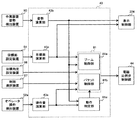
<制御コントローラ40>
図4において制御コントローラ40は,入力部91と,プロセッサである中央処理装置(CPU)92と,記憶装置であるリードオンリーメモリ(ROM)93及びランダムアクセスメモリ(RAM)94と,出力部95とを有している。入力部91は,作業装置姿勢検出装置50である角度センサ30〜32及び傾斜角センサ33からの信号と,目標面60を設定するための装置である目標面設定装置51からの信号と,操作装置45a,45b,46aからの操作量を検出する圧力センサ(圧力センサ70,71,72を含む)であるオペレータ操作検出装置52aからの信号と,制御選択スイッチ97の切替位置(許可・禁止)を示す信号と,目標角度設定装置96からの目標角度を示す信号を入力し,CPU92が演算可能なように変換する。ROM93は,後述するフローチャートに係る処理を含めMCを実行するための制御プログラムと,当該フローチャートの実行に必要な各種情報等が記憶された記録媒体であり,CPU92は,ROM93に記憶された制御プログラムに従って入力部91及びメモリ93,94から取り入れた信号に対して所定の演算処理を行う。出力部95は,CPU92での演算結果に応じた出力用の信号を作成し,その信号を電磁比例弁54〜56または表示装置53に出力することで,油圧アクチュエータ5〜7を駆動・制御したり,車体1B,バケット10及び目標面60等の画像を表示装置53の画面上に表示させたりする。
<
In FIG. 4, the
なお,図4の制御コントローラ40は,記憶装置としてROM93及びRAM94という半導体メモリを備えているが,記憶装置であれば特に代替可能であり,例えばハードディスクドライブ等の磁気記憶装置を備えても良い。
The
図6は,制御コントローラ40の機能ブロック図である。制御コントローラ40は,MC制御部43と,電磁比例弁制御部44と,表示制御部374を備えている。
FIG. 6 is a functional block diagram of the
表示制御部374は,MC制御部43から出力される作業装置姿勢及び目標面を基に表示装置53を制御する部分である。表示制御部374には,作業装置1Aの画像及びアイコンを含む表示関連データが多数格納されている表示ROMが備えられており,表示制御部374が,入力情報に含まれるフラグに基づいて所定のプログラムを読み出すとともに,表示装置53における表示制御をする。
The
図7は図6中のMC制御部43の機能ブロック図である。MC制御部43は,操作量演算部43aと,姿勢演算部43bと,目標面演算部43cと,ブーム制御部81aと,バケット制御部81bと,動作判定部81cを備えている。
FIG. 7 is a functional block diagram of the
操作量演算部43aは,オペレータ操作検出装置52aからの入力を基に操作装置45a,45b,46a(操作レバー1a,1b)の操作量を算出する。圧力センサ70,71,72の検出値から操作装置45a,45b,46aの操作量が算出できる。
The operation
なお,圧力センサ70,71,72による操作量の算出は一例に過ぎず,例えば各操作装置45a,45b,46aの操作レバーの回転変位を検出する位置センサ(例えば,ロータリーエンコーダ)で当該操作レバーの操作量を検出しても良い。また,操作量から動作速度を算出する構成に代えて,各油圧シリンダ5,6,7の伸縮量を検出するストロークセンサを取り付け,検出した伸縮量の時間変化を基に各シリンダの動作速度を算出する構成も適用可能である。
The calculation of the operation amount by the pressure sensors 70, 71, 72 is only an example. For example, a position sensor (for example, a rotary encoder) that detects the rotational displacement of the operation levers of the
姿勢演算部43bは作業装置姿勢検出装置50からの情報に基づき,ローカル座標系におけるフロント作業装置1Aの姿勢と,バケット10の爪先の位置を演算する。
The
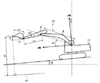
フロント作業装置1Aの姿勢は図5のショベル座標系(ローカル座標系)上に定義できる。図5のショベル座標系(XZ座標系)は,上部旋回体12に設定された座標系であり,上部旋回体12に回動可能に支持されているブーム8の基底部を原点とし,上部旋回体12における垂直方向にZ軸,水平方向にX軸を設定した。X軸に対するブーム8の傾斜角をブーム角α,ブーム8に対するアーム9の傾斜角をアーム角β,アームに対するバケット爪先の傾斜角をバケット角γとした。水平面(基準面)に対する車体1B(上部旋回体12)の傾斜角を傾斜角θとした。ブーム角αはブーム角度センサ30により,アーム角βはアーム角度センサ31により,バケット角γはバケット角度センサ32により,傾斜角θは車体傾斜角センサ33により検出される。図5中に規定したようにブーム8,アーム9,バケット10の長さをそれぞれL1,L2,L3とすると,ショベル座標系におけるバケット爪先位置の座標および作業装置1Aの姿勢はL1,L2,L3,α,β,γで表現できる。
The posture of the
目標面演算部43cは,目標面設定装置51からの情報に基づき目標面60の位置情報を演算し,これをROM93内に記憶する。本実施形態では,図5に示すように,3次元の目標面を作業装置1Aが移動する平面(作業機の動作平面)で切断した断面形状を目標面60(2次元の目標面)として利用する。
The target surface calculation unit 43c calculates the position information of the
なお,図5の例では目標面60は1つだが,目標面が複数存在する場合もある。目標面が複数存在する場合には,例えば,作業装置1Aから最も近いものを目標面と設定する方法や,バケット爪先の下方に位置するものを目標面とする方法や,任意に選択したものを目標面とする方法等がある。
In the example of FIG. 5, the
ブーム制御部81aとバケット制御部81bは,操作装置45a,45b,46aの操作時に,予め定めた条件に従って複数の油圧アクチュエータ5,6,7の少なくとも1つを制御するアクチュエータ制御部81を構成する。アクチュエータ制御部81は,各油圧シリンダ5,6,7の流量制御弁15a,15b,15cの目標パイロット圧を演算し,その演算した目標パイロット圧を電磁比例弁制御部44に出力する。
The
動作判定部81cは,アーム9(アームシリンダ6)をクラウド動作又はダンプ動作させて行う作業(「アーム作業」と称する)の開始位置(「作業開始位置」と称する)にバケット10を移動させる動作(「作業準備動作」と称する)にフロント作業装置1Aがあるか否かを操作装置45a,45b,46aへの操作を基に判定する部分である。なお,「作業準備動作」は,作業開始位置へのバケット10の位置合わせ動作又は位置合わせ作業とも称される。
The
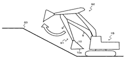
ここでアームクラウドによるアーム作業のための作業準備動作(バケット位置合わせ作業)の例を図8及び図9に示す。図8及び図9では,法面掘削の仕上げ作業時において,作業準備動作を実施する例を示す。 Here, FIGS. 8 and 9 show an example of a work preparation operation (bucket alignment work) for arm work by the arm cloud. 8 and 9 show an example of performing a work preparation operation during the finishing work of slope excavation.
例えば,法面掘削の仕上げ作業においては,バケット10の底面10aの角度と目標面60の角度を略平行にし(すなわち対目標面バケット角度θはゼロ),略平行の状態を保ったまま目標面60に沿ってバケット10を直線的に動かすことにより,目標面60の表面を滑らかな状態とすることが望ましい。そのため,作業開始位置において,バケット10の底面10aの角度と目標面60の角度が略平行となっていることが望ましい。ここで,バケット10の底面10aとはバケット10の前端部と後端部を結ぶ直線に相当するバケット10の面のことである。
For example, in the finishing work of slope excavation, the angle of the bottom surface 10a of the
この場合の作業準備動作(バケット位置合わせ作業)は,アーム9がフルクラウド状態でバケット10が目標面60から離れている状態S1(図8参照)から開始し,アーム9がダンプ方向に動かされバケット10が目標面60に近づきつつある状態S2(図8,9参照)を経て,目標面60を基準とする所定位置で対目標面バケット角度が設定値θTGT(=ゼロ)となるようバケット10が停止した状態S3(図9参照)となるまでの一連の動作である。図8は状態S1から状態S2へ遷移する状況を,図9は状態S2から状態S3へ遷移する状況を示している。
The work preparation operation (bucket alignment work) in this case starts from the state S1 (see FIG. 8) in which the arm 9 is in the full cloud state and the
なお,作業準備動作を開始する状態S1におけるアーム9の姿勢は,図8のようにフルクラウド姿勢である必要はなく任意の姿勢でよい。また,アームダンプによりアーム作業が可能な場合(例えば,後述する図22の吹き付け作業)にも本発明は適用可能である。この場合は状態S1のようにアームをクラウドさせた状態が作業開始位置となる。 The posture of the arm 9 in the state S1 at which the work preparation operation is started does not have to be the full cloud posture as shown in FIG. 8, and may be any posture. The present invention can also be applied when arm work can be performed by an arm dump truck (for example, the spraying work of FIG. 22 described later). In this case, the work start position is the state in which the arm is clouded as in the state S1.
ブーム制御部81aは,操作装置45a,45b,46aの操作時に,目標面60の位置と,フロント作業装置1Aの姿勢及びバケット10の爪先の位置と,操作装置45a,45b,46aの操作量とに基づいて,目標面60上またはその上方にバケット10の爪先(制御点)が位置するようにブームシリンダ5(ブーム8)の動作を制御するMCを実行するための部分である。ブーム制御部81aでは,ブームシリンダ5の流量制御弁15aの目標パイロット圧が演算される。ブーム制御部81aによるMCの詳細は図11及び図12を用いて後述する。
When operating the
バケット制御部81bは,操作装置45a,45b,46aの操作時に,MCによるバケット角度制御を実行するための部分である。具体的には,動作判定部81cでフロント作業装置1Aが作業準備動作にあると判定され,かつ,目標面60とバケット10の爪先の距離が所定値以下のとき,目標面60に対するバケット10の角度θが目標角度設定装置96で予め設定した対目標面バケット角度θTGTとなるようにバケットシリンダ7(バケット10)の動作を制御するMC(バケット角度制御)が実行される。バケット制御部81bでは,バケットシリンダ7の流量制御弁15cの目標パイロット圧が演算される。バケット制御部81bによるMCの詳細は図10を用いて後述する。
The bucket control unit 81b is a part for executing bucket angle control by the MC when operating the
電磁比例弁制御部44は,アクチュエータ制御部81から出力される各流量制御弁15a,15b,15cへの目標パイロット圧を基に,各電磁比例弁54〜56への指令を演算する。なお,オペレータ操作に基づくパイロット圧(第1制御信号)と,アクチュエータ制御部81で算出された目標パイロット圧が一致する場合には,該当する電磁比例弁54〜56への電流値(指令値)はゼロとなり,該当する電磁比例弁54〜56の動作は行われない。
The electromagnetic proportional
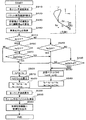
<バケット制御部81b及び動作判定部81cによるバケット角度制御のフロー>
バケット制御部81b及び動作判定部81cによるバケット角度制御のフローを図10に示す。まず,バケット制御部81bは,ステップ100で制御選択スイッチ97がON(すなわちバケット角度制御は有効)に切り替えられているか否かを判定する。制御選択スイッチ97がONの場合,ステップ101へ進む。
<Flow of bucket angle control by the bucket control unit 81b and the
FIG. 10 shows a flow of bucket angle control by the bucket control unit 81b and the
ステップ101では,動作判定部81cは,アーム9の回動速度が所定値ω1以下か否かを判定することで,作業装置1Aが作業準備動作にあるか否かを判定する。所定値ω1は,状態S2でのアーム操作が間もなく又は既に終了し,間もなく状態S3でのブーム下げ操作が開始されるタイミングを検出するために設定している。アーム回動速度が所定値ω1以下である場合,作業装置1Aが作業準備動作にあると判定してステップ102へ進む。ステップ101で利用するアームの回動速度は,流量制御弁15bへのパイロット圧とアーム回動速度の関係を定義した相関テーブルを予め設定しておき,その相関テーブルとオペレータ操作検出装置52aにより検出される流量制御弁15bへのパイロット圧から求めることができる。また,作業装置姿勢検出装置50で検出されたアーム9の角度を時間微分することでアーム回動速度を求めても良い。
In
なお,アーム回動速度の所定値ω1は,状態S2から状態S3に移行するためにオペレータがアーム9を操作している際に,バケット10又はブーム8のMCが発動することでバケット10又はブーム8がアーム9と同時に動いても,アーム9の速度が低下しない程度に十分小さい値に設定することが好ましい。このようにω1を設定するとアーム操作中にMCが発動してもオペレータに違和感を与えることがない。また,所定値ω1はゼロに設定することもできる。所定値ω1をゼロにすると,オペレータのアーム操作中に,バケット角度制御によりバケット10が動作することが防止されるので,複合動作による違和感は発生しない。
The predetermined value ω1 of the arm rotation speed is set to the
ステップ102では,バケット制御部81bは,バケット10の爪先と目標面60の距離Dが所定値D1以下か否かを判定する。バケット10と目標面60の距離が所定値D1以下である場合,ステップ103へ進む。
In
本実施形態でのバケット10と目標面60の距離の所定値D1は,MCであるバケット角度制御の開始タイミングを決定する値である。所定値D1は,バケット角度制御の発動がオペレータに与える違和感を低減する観点からはできるだけ小さい値に設定することが好ましく,例えばバケット10の底面10aの長さとすることができる。また,ステップ102で利用するバケット10の爪先から目標面60までの距離Dは,姿勢演算部43bで演算したバケット10の爪先の位置(座標)と,ROM93に記憶された目標面60を含む直線の距離から算出できる。なお,距離Dを算出する際のバケット10の基準点はバケット爪先(バケット10の前端)である必要は無く,バケット10のうち目標面60との距離が最小となる点であってもよく,バケット10の後端であっても良い。
The predetermined value D1 of the distance between the
ステップ103では,バケット制御部81bは,操作量演算部43aから信号を基にオペレータによるバケット10の操作信号があるか否かを判定する。バケット10の操作信号があると判定された場合には,一旦ステップ104へ進んだ後ステップ105へ進む。一方,バケット10の操作信号がないと判定された場合にはステップ105へ進む。
In
ステップ104では,バケット制御部81bは,バケット10のパイロットライン146a,146bにある電磁比例弁(バケット減圧弁)56a,56bを閉じるように指令を出力する。これにより操作装置46aを介したオペレータ操作によってバケット10が回動することが防止される。
In
ステップ105では,バケット制御部81bは,バケット10のパイロットライン148aにある電磁比例弁(バケット増圧弁)56c,56dを開くよう指令を出し,対目標面バケット角度が設定値θTGTとなるようバケットシリンダ7を制御する。なお,バケット角度制御は,距離Dが所定値D1に達した時点で開始されるが,その後,距離Dがゼロに達する以前に完了するように制御アルゴリズムを構築することが好ましい。
In
ステップ100,ステップ101,ステップ102のいずれかにおいて,条件を満たさないと判定された場合(NOと判定された場合)にはステップ106に進む。ステップ106ではバケット10の角度(対目標面バケット角度)を制御しないため,4つの電磁比例弁56a,56b,56c,56dのいずれにも指令は送られない。
If it is determined in any of
<ブーム制御部81aによるブーム上げ制御のフロー>
本実施の形態の制御コントローラ40は,上記のバケット制御部81bによるバケット角度制御に加えて,ブーム制御部81aによるブーム上げ制御もマシンコントロールとして実行する。このブーム制御部81aによるブーム上げ制御のフローを図11に示す。図11はブーム制御部81aで実行されるMCのフローチャートであり,操作装置45a,45b,46aがオペレータにより操作されると処理が開始される。
<Flow of boom raising control by
The
S410では,ブーム制御部81aは,操作量演算部43aで演算された操作量を基に各油圧シリンダ5,6,7の動作速度(シリンダ速度)を演算する。
In S410, the
S420では,ブーム制御部81aは,S410で演算された各油圧シリンダ5,6,7の動作速度と,姿勢演算部43bで演算された作業装置1Aの姿勢とを基に,オペレータ操作によるバケット先端(爪先)の速度ベクトルBを演算する。
In S420, the
S430では,ブーム制御部81aは,姿勢演算部43bで演算したバケット10の爪先の位置(座標)と,ROM93に記憶された目標面60を含む直線の距離から,バケット先端から制御対象の目標面60までの距離D(図5参照)を算出する。そして,距離Dと図12のグラフを基にバケット先端の速度ベクトルの目標面60に垂直な成分の制限値ayを算出する。
In S430, the
S440では,ブーム制御部81aは,S420で算出したオペレータ操作によるバケット先端の速度ベクトルBにおいて,目標面60に垂直な成分byを取得する。
In S440, the
S450では,ブーム制御部81aは,S430で算出した制限値ayが0以上か否かを判定する。なお,図11の右上に示したようにxy座標を設定する。当該xy座標では,x軸は目標面60と平行で図中右方向を正とし,y軸は目標面60に垂直で図中上方向を正とする。図11中の凡例では垂直成分by及び制限値ayは負であり,水平成分bx及び水平成分cx及び垂直成分cyは正である。そして,図12から明らかであるが,制限値ayが0のときは距離Dが0,すなわち爪先が目標面60上に位置する場合であり,制限値ayが正のときは距離Dが負,すなわち爪先が目標面60より下方に位置する場合であり,制限値ayが負のときは距離Dが正,すなわち爪先が目標面60より上方に位置する場合である。S450で制限値ayが0以上と判定された場合(すなわち,爪先が目標面60上またはその下方に位置する場合)にはS460に進み,制限値ayが0未満の場合にはS480に進む。
In S450, the
S460では,ブーム制御部81aは,オペレータ操作による爪先の速度ベクトルBの垂直成分byが0以上か否かを判定する。byが正の場合は速度ベクトルBの垂直成分byが上向きであることを示し,byが負の場合は速度ベクトルBの垂直成分byが下向きであることを示す。S460で垂直成分byが0以上と判定された場合(すなわち,垂直成分byが上向きの場合)にはS470に進み,垂直成分byが0未満の場合にはS500に進む。
In S460, the
S470では,ブーム制御部81aは,制限値ayと垂直成分byの絶対値を比較し,制限値ayの絶対値が垂直成分byの絶対値以上の場合にはS500に進む。一方,制限値ayの絶対値が垂直成分byの絶対値未満の場合にはS530に進む。
In S470, the
S500では,ブーム制御部81aは,マシンコントロールによるブーム8の動作で発生すべきバケット先端の速度ベクトルCの目標面60に垂直な成分cyを算出する式として「cy=ay−by」を選択し,その式とS430の制限値ayとS440の垂直成分byを基に垂直成分cyを算出する。そして,算出した垂直成分cyを出力可能な速度ベクトルCを算出し,その水平成分をcxとする(S510)。
In S500, the
S520では,目標速度ベクトルTを算出する。目標速度ベクトルTの目標面60に垂直な成分をty,水平な成分txとすると,それぞれ「ty=by+cy,tx=bx+cx」と表すことができる。これにS500の式(cy=ay−by)を代入すると目標速度ベクトルTは結局「ty=ay,tx=bx+cx」となる。つまり,S520に至った場合の目標速度ベクトルの垂直成分tyは制限値ayに制限され,マシンコントロールによる強制ブーム上げが発動される。
In S520, the target velocity vector T is calculated. Assuming that the component perpendicular to the
S480では,ブーム制御部81aは,オペレータ操作による爪先の速度ベクトルBの垂直成分byが0以上か否かを判定する。S480で垂直成分byが0以上と判定された場合(すなわち,垂直成分byが上向きの場合)にはS530に進み,垂直成分byが0未満の場合にはS490に進む。
In S480, the
S490では,ブーム制御部81adは,制限値ayと垂直成分byの絶対値を比較し,制限値ayの絶対値が垂直成分byの絶対値以上の場合にはS530に進む。一方,制限値ayの絶対値が垂直成分byの絶対値未満の場合にはS500に進む。 In S490, the boom control unit 81ad compares the absolute value of the limit value ay with the absolute value of the vertical component by, and proceeds to S530 when the absolute value of the limit value ay is equal to or greater than the absolute value of the vertical component by. On the other hand, if the absolute value of the limit value ay is less than the absolute value of the vertical component by, the process proceeds to S500.
S530に至った場合,マシンコントロールでブーム8を動作させる必要が無いので,フロント制御装置81dは,速度ベクトルCをゼロとする。この場合,目標速度ベクトルTは,S520で利用した式(ty=by+cy,tx=bx+cx)に基づくと「ty=by,tx=bx」となり,オペレータ操作による速度ベクトルBと一致する(S540)。
When the S530 is reached, it is not necessary to operate the
S550では,フロント制御装置81dは,S520またはS540で決定した目標速度ベクトルT(ty,tx)を基に各油圧シリンダ5,6,7の目標速度を演算する。なお,上記説明から明らかであるが,図11の場合に目標速度ベクトルTが速度ベクトルBに一致しないときには,マシンコントロールによるブーム8の動作で発生する速度ベクトルCを速度ベクトルBに加えることで目標速度ベクトルTを実現する。
In S550, the front control device 81d calculates the target speeds of the
S560では,ブーム制御部81aは,S550で算出された各シリンダ5,6,7の目標速度を基に各油圧シリンダ5,6,7の流量制御弁15a,15b,15cへの目標パイロット圧を演算する。
In S560, the
S590では,ブーム制御部81aは,各油圧シリンダ5,6,7の流量制御弁15a,15b,15cへの目標パイロット圧を電磁比例弁制御部44に出力する。
In S590, the
電磁比例弁制御部44は,各油圧シリンダ5,6,7の流量制御弁15a,15b,15cに目標パイロット圧が作用するように電磁比例弁54,55,56を制御し,これにより作業装置1Aによる掘削が行われる。例えば,オペレータが操作装置45bを操作して,アームクラウド動作によって水平掘削を行う場合には,バケット10の先端が目標面60に侵入しないように電磁比例弁55cが制御され,ブーム8の上げ動作が自動的に行われる。
The electromagnetic proportional
なお,本実施形態では,ブーム制御部81aによるアーム制御(強制ブーム上げ制御)と,バケット制御部81bによるバケット制御(バケット角度制御)がMCとして実行されるが,バケット10と目標面60の距離Dに応じたアーム制御をMCとして実行しても良い。
In this embodiment, arm control (forced boom raising control) by the
<動作・効果>
上記のように構成される油圧ショベルにおいて,状態S1(図8)から状態S2(図8,9)を経由して状態S3(図9)に遷移する場合のオペレータ操作と,制御コントローラ40(ブーム制御部81a及びバケット制御部81b)によるMCについて説明する。
<Operation / effect>
In the hydraulic excavator configured as described above, the operator operation when transitioning from the state S1 (FIG. 8) to the state S3 (FIG. 9) via the state S2 (FIGS. 8 and 9) and the control controller 40 (boom). The MC by the
まず,図8の状態S1から状態S2への遷移時のオペレータ操作と,制御コントローラ40によるMCについて説明する。オペレータは,アーム9のダンプ操作と,そのダンプ操作により目標面60の下方にバケット10が侵入しないようにブーム8の上げ操作を組み合わせて,フロント作業装置1Aを状態S1から状態S2へ遷移させる。このとき制御コントローラ40はバケット制御部81bによるバケット角度制御(MC)を行わない。一方で,アーム9のダンプ操作によりバケット10が目標面60に侵入すると判断するときには,ブーム制御部81aから電磁弁54aに指令を出し,ブーム8を上昇させる制御(MC)が実行される。
First, the operator operation at the time of transition from the state S1 to the state S2 in FIG. 8 and the MC by the
次に,図9の状態S2から状態S3への遷移時のオペレータ操作と,制御コントローラ40によるMCについて説明する。状態S2から状態S3への遷移時に,オペレータはブーム8の下げ操作によってバケット10を目標面60へ近づける。このとき,作業装置1Aが作業準備動作にあるという判定を動作判定部81cから受けた場合には,バケット制御部81bは,バケット10の底面10aと目標面60が略平行となるよう(対目標面バケット角度が設定値θTGT(=ゼロ)となるように),電磁弁56cあるいは56dに指令を出し,バケット10をクラウド方向あるいはダンプ方向に回動させる。
Next, the operator operation at the time of transition from the state S2 to the state S3 in FIG. 9 and the MC by the
つまり,上記のようにバケット制御部81bを構成すると,フロント作業装置1Aが作業準備動作にある場合(例えば,状態S2から状態S3に至るまでの間において),バケット10から目標面60までの距離Dが所定値D1以下に達した時点(つまりバケット10が目標面60に近接した時点)でバケット角度制御が実行され,バケット10の爪先が目標面60に到達するまでの間に対目標面バケット角度を目標角度設定装置96で設定した値θTGTに設定することができる。そのため,バケット角度制御の発動により対目標面バケット角度が容易に設定値θTGTに制御されるとともに,目標面60から遠く離れている状況での当該バケット角度制御の発動が防止され,オペレータに違和感を与える期間を比較的短期間に抑えることができる。
That is, when the bucket control unit 81b is configured as described above, the distance from the
また,一般に,同一の油圧ポンプの作動油で駆動する複数の油圧アクチュエータを同時に動かす場合,1つの油圧アクチュエータを動かす場合よりも油圧アクチュエータの動作速度が低下する傾向がある。作業準備動作では,車体前後方向におけるバケット10の位置決めは主にアーム9によって行う。そのため,アーム9の操作中に,アーム9と同一の油圧ポンプの作動油で駆動される他の油圧アクチュエータに対してMCが実行されると,オペレータの意図に反してアーム9の動作速度が低減して違和感を与えるおそれがある。この点に関し,本実施形態では,アーム9の操作量が大きい間(アーム回動速度が大きい間)はバケット角度制御が実行されないので,オペレータ操作に対してアーム9の速度低下はなくオペレータは違和感なくアーム9を動かすことができる。
Further, in general, when a plurality of hydraulic actuators driven by hydraulic oil of the same hydraulic pump are moved at the same time, the operating speed of the hydraulic actuators tends to be lower than when one hydraulic actuator is moved. In the work preparation operation, the position of the
したがって,上記のように構成した油圧ショベルによれば,アーム作業時の作業準備動作において,対目標面バケット角度を設定値θTGTに調節する作業をオペレータに違和感を与えることなく素早く実行でき,作業効率を向上させることができる。 Therefore, according to the hydraulic excavator configured as described above, in the work preparation operation during arm work, the work of adjusting the bucket angle to the target surface to the set value θTGT can be quickly executed without giving the operator a sense of discomfort, and the work efficiency. Can be improved.
なお,図9に示すように状態S2から状態S3へ遷移する際に,オペレータによるバケット10のクラウド操作またはダンプ操作がある場合には,電磁比例弁56aまたは電磁比例弁56bに指令を出し,オペレータによるバケット10のクラウド操作またはダンプ操作を停止させ,電磁比例弁56aまたは電磁比例弁56bの動作のみでバケット10が回動するようにしても良い。また,電磁比例弁56cまたは電磁比例弁56dに指令を出してバケット10を回動させる代わりに,電磁比例弁56aまたは電磁比例弁56bに指令を出しオペレータによるバケット10のクラウド操作またはダンプ操作のパイロット圧を低減することで,所望の角度θTGTとなるようバケット10を制御しても良い。またこのとき,所望の対目標面バケット角度θTGTとなるように,バケット10のクラウド操作(例えばフルクラウド操作)またはダンプ操作(例えばフルダンプ操作)を行うよう,油圧ショベル1の運転室内に設けられた表示装置53にオペレータへの指示を表示させてもよい。
When transitioning from the state S2 to the state S3 as shown in FIG. 9, if there is a cloud operation or a dump operation of the
<第2実施形態>
第1実施形態では,動作判定部81cは,アーム回動速度が所定値ω1以下のときに作業装置1Aが作業準備動作にあると判定したが,本実施形態では,アーム9の先端の速度ベクトルにおける目標面60に垂直な成分が目標面60に向かっているときに,作業装置1Aが作業準備動作にあると判定するように変更した。
<Second Embodiment>
In the first embodiment, the
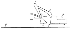
つまり,本実施形態では,所望の対目標面バケット角θTGTとなるようバケット10の角度をMCするか否かを,オペレータ操作によって生じる速度ベクトル100(図13参照)の方向から判断するようにし,その速度ベクトル100が,目標面60に向かう成分を持つと判断される時にバケット角度制御を実行する。ここで速度ベクトル100とは,図13に示すように,オペレータ操作によって生じる,フロント作業装置1Aのもつ速度ベクトルである。なお,先の実施形態と同じ部分は説明を省略し,これは他の実施形態の説明でも同様とする。
That is, in the present embodiment, whether or not to MC the angle of the
<バケット制御部81b及び動作判定部81cによるバケット角度制御のフロー>
本実施形態におけるバケット制御部81b及び動作判定部81cによるバケット角度制御のフローを図14に示す。図14における,ステップ100,ステップ102,ステップ103,ステップ104,ステップ105,ステップ106の処理は,図10に示したフローチャートと同様なので説明を省略する。
<Flow of bucket angle control by the bucket control unit 81b and the
FIG. 14 shows a flow of bucket angle control by the bucket control unit 81b and the
図14のステップ201において,動作判定部81cは,オペレータ操作によって生じるバケットピンの速度ベクトル100が,目標面60を向いているか否かを判断する。速度ベクトル100は,目標面60に水平な成分(水平方向成分)100Aと,目標面60に垂直な成分(鉛直方向成分)100Bに分解でき,鉛直方向成分100Bが目標面60を向いている場合,速度ベクトル100は目標面60に向かっていると判断できる。速度ベクトル100が目標面60を向いていると判定された場合には,フロント作業装置1Aがバケット10を作業開始位置に移動させる作業準備動作にあると判定してステップ102に進み,目標面60を向いていないと判定された場合には,フロント作業装置1Aは作業準備動作をしていないと判定してステップ106へ進む。
In
ステップ201の判定に利用する速度ベクトル100は,オペレータ操作検出装置52aから取得されるパイロット圧を,制御コントローラ40内部に保存されているパイロット圧対シリンダ速度の相関テーブルでもってシリンダ速度に変換し,そのシリンダ速度をフロント作業装置1Aの角速度に幾何学的に変換することで,算出可能である。
The
図15に示すように,速度ベクトル100の鉛直成分100Bが目標面60に向かっていていないときは,オペレータは作業準備動作(バケットの位置合わせ作業)を目的に作業装置1Aを操作していないと考えられる。そのため,図14のようにオペレータ操作によって生じる速度ベクトル100が目標面60に向かっていると判断される時のみ,オペレータの位置合わせ作業の意図を反映させてバケット角度制御を実行することで,第1実施形態同様に違和感なくバケット角度制御を実行できる。
As shown in FIG. 15, when the
なお,ここでは例としてバケットピン(アーム9の先端)に生じる速度ベクトル100を示して説明したが,バケット10の先端又はその他のバケット上の基準点に生じる速度ベクトルを算出し,そのベクトルにおける目標面への鉛直成分を制御に用いても良い。
Here, the
<第3実施形態>
本実施形態は,第1実施形態のバケット制御部81bの図10のフローにステップ301やステップ302を加えることでブーム下げやアームダンプ操作の発生を検出し,これにより作業準備動作(バケットの位置合わせ作業)の検出精度を向上させている点に特徴がある。
<Third Embodiment>
In this embodiment, the occurrence of boom lowering or arm dump operation is detected by adding
本実施形態におけるバケット制御部81b及び動作判定部81cによるバケット角度制御のフローを図16に示す。先の図と同じ処理は同じ符号を付して説明を省略する。
FIG. 16 shows a flow of bucket angle control by the bucket control unit 81b and the
ステップ301では,動作判定部81cは,オペレータによるアーム9の操作がないこと又はアームダンプ操作があるかを操作量演算部43aからの信号を基に判定する。言い換えれば,アームクラウド操作が無いことを判定する。作業準備動作では,アーム9は主にダンプ動作をし,その後ブーム下げ動作によりバケット10が目標面60に近づく。そのため,このステップ301においてアームクラウド操作が無いか否かを検出することで,フロント作業装置1Aが作業準備動作にあるか否かを第1実施形態よりも正確に判定できる。そして,ステップ301でYESの判定がされた場合には,ステップ101のアーム回動速度はアームダンプ動作における回動速度であることが判明する。ステップ301でアームクラウド操作が無いと判定された場合には,フロント作業装置1Aがこの時点では作業準備動作にあると判定してステップ102へ進み,アームクラウド操作が有ると判定された場合には,フロント作業装置1Aは作業準備動作にはないと判定してステップ106に進む。
In
ステップ102に続くステップ302では,動作判定部81cは,オペレータによりブーム下げが操作されているか否かを操作量演算部43aからの信号を基に判定する。既述の通り,作業準備動作ではブーム下げ動作によりバケット10が目標面に近づく。そのため,ステップ302でブーム下げ操作がされているか否かを検出することで,フロント作業装置1Aが作業準備動作にあるか否かを第1実施形態よりもさらに正確に検出できる。ステップ302でブーム下げ操作されていると判定された場合,ステップ103へ進む。
In
本実施形態のように構成した油圧ショベルによれば,ステップ301及びステップ302がバケット角度制御に追加されることにより,作業準備動作の検出精度が第1実施形態よりも向上するので,オペレータに与える違和感を更に低減できる。
According to the hydraulic excavator configured as in the present embodiment, by adding
なお,図16のフローにおけるステップ100,101,301,102,302の順番は適宜変更可能である。また,図14のフローにステップ301,302の一方又は両方を追加しても良い。
The order of
<第4実施形態>
本実施形態は図10,14,16におけるステップ105の具体的処理内容の一例に該当する。ステップ105の処理内容の詳細を図17に示す。
<Fourth Embodiment>
This embodiment corresponds to an example of the specific processing content of
図10,14,16のいずれかでステップ105が開始されると,バケット制御部81bは図17のフローを開始する。まずステップ105−1において,バケット制御部81bはアーム9に対するバケット10の回動角度γ(図5参照)を姿勢演算部43bから取得する。
When
次にステップ105−2において,バケット制御部81bはバケット10の回動角度γの目標値γTGTを算出する。γTGTは,α,β,δ,θTGT,γTGTの合計が180度であることを利用して以下の式(1)で算出でき,具体的には図18のフローにより算出される。
γTGT=180−(α+β+δ+θTGT) …式(1)
Next, in step 105-2, the bucket control unit 81b calculates the target value γTGT of the rotation angle γ of the
γTGT = 180- (α + β + δ + θTGT)… Equation (1)
上記式におけるδは,図19に示すように,アーム9とバケット10の接続点(連結点)9Fとバケット10の先端10Fを結んだ直線と,バケット10の先端10Fとバケット10の後端10Tを結んだ直線とがなす角度である。δはバケット10の形状で決まる一定の値でありROM93に記憶されている。また,既述のとおり,αはブーム8の回動角度(図5参照),βはアーム9の回動角度(図5参照),θTGTは目標角度設定装置96で決定される対目標面バケット角度の設定値θTGTである。なお,図5においてはショベルの座標系に対して目標面60が傾斜していない場合を記しているが,目標面60が傾斜していても良い。
As shown in FIG. 19, δ in the above equation is a straight line connecting the connection point (connection point) 9F of the arm 9 and the
図18のフローにおいて,バケット制御部81bは,姿勢演算部43bからβとαを取得し(ステップ1051,1052),ROM93内のδと,目標角度設定装置96からのθTGTと,上記式(1)から,γTGTを算出し(ステップ1053),ステップ105−3に移行する。
In the flow of FIG. 18, the bucket control unit 81b acquires β and α from the
ステップ105−3では,バケット制御部81bは,現在のバケット回動角度γとステップ105−2のγTGTを比較する。ステップ105−3の比較の結果,γの方が大きい場合は,ステップS105−4へ進み,それ以外の場合ステップS105−5へ進む。 In step 105-3, the bucket control unit 81b compares the current bucket rotation angle γ with the γTGT in step 105-2. As a result of the comparison in step 105-3, if γ is larger, the process proceeds to step S105-4, and in other cases, the process proceeds to step S105-5.
ステップS105−4では,バケット制御部81bは,バケット10をダンプ方向に回動させ回動角度γを減少させるために,バケット制御部81bは電磁比例弁56dへの指令を電磁比例弁制御部44に出し,ステップ105−1に戻る。
In step S105-4, the bucket control unit 81b rotates the
ステップS105−5では,バケット制御部81bは,γとγTGTを比較し,γが小さい場合はステップS105−6へ,それ以外の場合ステップS105−7へ進む。 In step S105-5, the bucket control unit 81b compares γ and γTGT, and if γ is small, proceeds to step S105-6, otherwise proceeds to step S105-7.
ステップS105−6では,バケット制御部81bは,バケットをクラウド方向に回動させ回動角度γを増加させるため,電磁比例弁56cへの指令を電磁比例弁制御部44に出し,ステップ105−1に戻る。
In step S105-6, the bucket control unit 81b issues a command to the electromagnetic
ステップS105−7では,バケットの回動角度γと,回動角度γの目標値γTGTとが等しいため,バケット制御部81bはバケットの回動制御を実行することなくステップ105を終了する。
In step S105-7, since the rotation angle γ of the bucket and the target value γTGT of the rotation angle γ are equal, the bucket control unit 81b ends
以上の処理によりバケット回動角度γを目標値γTGTに制御することができるので,対目標面バケット角度を設定値θTGTに制御できる。 Since the bucket rotation angle γ can be controlled to the target value γTGT by the above processing, the anti-target surface bucket angle can be controlled to the set value θTGT.
また,ステップ105−2におけるバケットの回動角度γTGTの算出は,次のように実行しても良い。図20に,バケット角度制御が実行され,バケット10が作業開始位置で最終的な姿勢となった油圧ショベルの状態を示す。また図20内に,位置合わせ時のバケット10の位置合わせ目標となる目標面60と,位置合わせ時の接続点9Fの目標位置となる,目標面60に対してオフセット量OF分だけオフセットさせたオフセット目標面60Aを示す。
Further, the calculation of the bucket rotation angle γTGT in step 105-2 may be executed as follows. FIG. 20 shows the state of the hydraulic excavator in which the bucket angle control is executed and the
γTGTは下記の式(2)で算出できる。式(2)のうち,β,δ,θTGTはそれぞれ既知の値であり,αTGTが算出できればγTGTが算出できる。オフセット量OFは,対目標面バケット角度の設定値θTGTが指定されると,バケット10の寸法情報から一意に定まる。例えば,オフセット量OF=L3sin(θTGT+δ),となる。このとき,位置合わせ時の接続点9Fの目標位置の高さ方向の座標Zaも一意に定まり,同目標位置の長手方向の座標Xaはアーム9の回動角度βとブーム8の回動角度の目標値αTGTに応じて定まる。アーム9の回動角度βはオペレータ操作により定まるため,最終的に位置合わせ時に取るべきブーム8の回動角度αTGTを演算できる。ここではγTGTを図21のフローにより算出する。
γTGT=180−(αTGT+β+δ+θTGT) …式(2)
γTGT can be calculated by the following formula (2). In equation (2), β, δ, and θTGT are known values, and if αTGT can be calculated, γTGT can be calculated. The offset amount OF is uniquely determined from the dimensional information of the
γTGT = 180- (αTGT + β + δ + θTGT)… Equation (2)
図21のフローにおいて,バケット制御部81bは,まずステップ1061で,アーム9の回動角度βを取得する。ステップ1062では,オフセット量OFと目標面60の高さ情報から,位置合わせ完了時の接続点9Fの高さ方向の座標Zaを算出する。ステップ1063では,位置合わせ完了時の接続点9Fの長手方向の座標Xaを算出する。ステップ1064では,ステップ1062のZaとステップ1063のXaを用いて位置合わせ完了時のブーム8の回動角度の目標値αTGTを幾何学的に算出する。この算出したαTGTと,既知のβ,δ,θTGTと,式(2)とにより,最終的に位置合わせ完了時のバケット10の回動角度の目標値γTGTを算出できる(ステップ1065)。
In the flow of FIG. 21, the bucket control unit 81b first acquires the rotation angle β of the arm 9 in step 1061. In
このようにバケット10の回動角度の目標値γTGTを算出すると,バケット10の回動制御量を抑えることができ,オペレータに違和感を与え得る時間を短縮できる。
By calculating the target value γTGT of the rotation angle of the
<第1実施形態の変形例>
第1実施形態では,動作判定部81cによってフロント作業装置1Aが作業準備動作にあり,かつ,バケット10から目標面60までの距離Dが所定値D1以下に達した時点でバケット角度制御を実行したが,本変形例では,動作判定部81cによってフロント作業装置1Aが作業準備動作にあると判定された時点でバケット角度制御を実行するように変更した。他の部分の構成は第1実施形態と同じであり説明は省略する。
<Modified example of the first embodiment>
In the first embodiment, the bucket angle control is executed when the
本変形例におけるバケット制御部81b及び動作判定部81cによるバケット角度制御のフローを図23に示す。この図に示すフローは図10のフローからステップ102を削除したものに相当する。図10と同じステップの説明は適宜省略する。
FIG. 23 shows a flow of bucket angle control by the bucket control unit 81b and the
ステップ101では,第1実施形態同様に,動作判定部81cが,アーム9の回動速度が所定値ω1以下か否かを判定することで,作業装置1Aが作業準備動作にあるか否かを判定している。アーム回動速度が所定値ω1以下である場合,作業装置1Aが作業準備動作にあると判定してステップ103へ進む。
In
ステップ103では,バケット制御部81bは,操作量演算部43aから信号を基にオペレータによるバケット10の操作信号があるか否かを判定する。バケット10の操作信号がないと判定された場合にはステップ105へ進む。
In
ステップ105では,バケット制御部81bは,バケット10のパイロットライン148aにある電磁比例弁(バケット増圧弁)56c,56dを開くよう指令を出し,対目標面バケット角度が設定値θTGTとなるようバケットシリンダ7を制御する。
In
上記のようにバケット制御部81bを構成すると,ステップ101でフロント作業装置1Aが作業準備動作にある場合と判定されたことをトリガーにバケット角度制御が実行され,対目標面バケット角度を目標角度設定装置96で設定した値θTGTに設定することができる。そのため,バケット角度制御の発動により対目標面バケット角度を容易に設定値θTGTに制御できる。
When the bucket control unit 81b is configured as described above, the bucket angle control is executed triggered by the determination that the
なお,本変形例では,動作判定部81cが,アーム9の回動速度が所定値ω1以下か否かを判定することで,作業装置1Aが作業準備動作にあるか否かを判定する構成を採用したが,その他の条件で作業装置1Aが作業準備動作にあるか否かを判定しても良い。例えば,ブームの下げ方向の回動速度が所定値ω2以下か否かを判定することで,作業装置1Aが作業準備動作にあるか否かを判定しても良いし,図14のステップ201で判定しても良い。また,図16のステップ301及びステップ302の少なくとも一方をステップ101の条件に加えて,作業装置1Aが作業準備動作にあるか否かを判定しても良い。
In this modified example, the
<付記>
なお,本発明は上記した実施形態に限定されるものではなく,さまざまな変形例が含まれる。例えば,上記した実施形態は本発明を分かりやすく説明するために詳細に説明したものであり,必ずしも説明したすべての構成を備えるものに限定されるものではない。
<Additional notes>
The present invention is not limited to the above-described embodiment, and includes various modifications. For example, the above-described embodiment has been described in detail in order to explain the present invention in an easy-to-understand manner, and is not necessarily limited to the one including all the described configurations.
例えば,上記の各実施形態では,フロント作業装置1Aが作業準備動作にあるか否かを,主に,アーム9の回動速度が所定値ω1以下か否か,または,アーム9若しくはバケット10の速度ベクトルにおける目標面60に垂直な成分が目標面60に向かっているか否か,に基づいて判定したが,これ以外の要素(例えば,油圧シリンダ5,6,7の負荷の時間変化等)に基づいて判定を行っても良い。
For example, in each of the above embodiments, whether or not the
上記の各実施形態においては作業具としてバケット10を備えた油圧ショベルについて説明したが,作業具はこれに限るものではなく,例えば図22に示すような,コンクリートやモルタル等を所定の吹き付け面(目標面)60Xに対して吹き付ける吹き付け機10Xを作業具として備えた作業機械にも適用可能である。
In each of the above embodiments, the hydraulic excavator provided with the
また,対目標面バケット角として,バケット10の底面の角度と目標面60の角度を略平行にする場合(すなわち,θTGT=0の場合)を説明したが,対目標面バケット角度の設定値はこれに限るものではない。例えば,θTGTを0より大きい値にすることでバケット10の先端を目標面60に対して食い込ませるような初期姿勢にして掘削作業を容易にしても良い。また,図22の吹き付け機10Xを作業具として作業機械に取り付けた場合には,吹き付け面60Xとノズル10Yの長軸方向が直交する角度をθTGT(=90度)に設定しても良い。
Further, as the target surface bucket angle, the case where the angle of the bottom surface of the
また,対目標面バケット角度が設定値θTGTに保持されるバケット位置は,目標面60上のみならず,目標面60と同形状の面上であって,目標面60を任意の量だけオフセットさせた面上であっても良い。このようにオフセットさせた面上で作業具の角度をθTGTに制御すると,例えば図22の吹き付け機10Xによる吹き付け作業において,吹き付け面60Xから所望の量だけ離れた位置にノズル10Yの噴出口を位置させ続けることができる。なお,目標面60をオフセットさせる量(目標面60からのオフセット距離)をオペレータが設定可能な入力装置をインターフェース部分として備えても良い。
Further, the bucket position in which the bucket angle with respect to the target surface is held at the set value θTGT is not only on the
上記の各実施形態ではブーム8,アーム9,バケット10の角度を検出する角度センサを用いたが,角度センサではなくシリンダストロークセンサによりショベルの姿勢情報を算出するとしても良い。また,油圧パイロット式のショベルを例として説明したが,電気レバー式のショベルであれば電気レバーから生成される指令電流を制御するような構成としても良い。フロント作業装置1Aの速度ベクトルの算出方法について,オペレータ操作によるパイロット圧ではなく,ブーム8,アーム9,バケット10の角度を微分することで算出される角速度から求めても良い。
In each of the above embodiments, an angle sensor for detecting the angles of the
上記の各実施形態で図9の状態S2から状態S3に遷移させる場合,オペレータがブーム8の下げ操作によってバケット10を目標面60へ近づけるときに,ブーム制御部81aにより,オペレータのブーム8の下げ操作によって目標面60にバケット10が侵入しないよう,ブーム制御部81aはブーム8の下げ操作を減速,あるいは停止させるよう必要に応じて電磁弁54bに指令を出しても良い。
In each of the above embodiments, when the state S2 of FIG. 9 is changed to the state S3, when the operator brings the
上記の制御コントローラ40に係る各構成や当該各構成の機能及び実行処理等は,それらの一部又は全部をハードウェア(例えば各機能を実行するロジックを集積回路で設計する等)で実現しても良い。また,上記の制御コントローラ40に係る構成は,演算処理装置(例えばCPU)によって読み出し・実行されることで当該制御コントローラ40の構成に係る各機能が実現されるプログラム(ソフトウェア)としてもよい。当該プログラムに係る情報は,例えば,半導体メモリ(フラッシュメモリ,SSD等),磁気記憶装置(ハードディスクドライブ等)及び記録媒体(磁気ディスク,光ディスク等)等に記憶することができる。
Each configuration related to the
D1…目標面と作業具の距離の所定値,θTGT…対目標面バケット角度の設定値(作業具の目標角度),ω1…アーム回動速度の所定値,1A…フロント作業装置,8…ブーム,9…アーム,10…バケット,30…ブーム角度センサ,31…アーム角度センサ,32…バケット角度センサ,40…制御コントローラ(制御装置),43…MC制御部,43a…操作量演算部,43b…姿勢演算部,43c…目標面演算部,44…電磁比例弁制御部,45…操作装置(ブーム,アーム),46…操作装置(バケット,旋回),50…作業装置姿勢検出装置,51…目標面設定装置,52a…オペレータ操作検出装置,53…表示装置,54,55,56…電磁比例弁,81…アクチュエータ制御部,81a…ブーム制御部,81b…バケット制御部,81c…動作判定部,96…目標角度設定装置,97…制御選択スイッチ(制御選択装置),374…表示制御部 D1 ... Predetermined value of the distance between the target surface and the work tool, θTGT ... Set value of the bucket angle with respect to the target surface (target angle of the work tool), ω1 ... Predetermined value of the arm rotation speed, 1A ... Front work device, 8 ... Boom , 9 ... arm, 10 ... bucket, 30 ... boom angle sensor, 31 ... arm angle sensor, 32 ... bucket angle sensor, 40 ... control controller (control device), 43 ... MC control unit, 43a ... operation amount calculation unit, 43b ... Attitude calculation unit, 43c ... Target surface calculation unit, 44 ... Electromagnetic proportional valve control unit, 45 ... Operation device (boom, arm), 46 ... Operation device (bucket, swivel), 50 ... Work device attitude detection device, 51 ... Target surface setting device, 52a ... Operator operation detection device, 53 ... Display device, 54, 55, 56 ... Electromagnetic proportional valve, 81 ... Actuator control unit, 81a ... Boom control unit, 81b ... Bucket control unit, 81c ... Operation judgment unit , 96 ... Target angle setting device, 97 ... Control selection switch (control selection device), 374 ... Display control unit
Claims (6)
前記作業装置を駆動する複数の油圧アクチュエータと,
オペレータの操作に応じて前記作業装置の動作を指示する操作装置と,
前記操作装置の操作時に,予め定めた条件に従って前記複数の油圧アクチュエータの少なくとも1つを制御するアクチュエータ制御部を有する制御装置とを備え,
前記作業具を作業開始位置に移動させた後に前記アームを動作させて作業を行う作業機械において,
前記制御装置は,前記作業装置が前記作業具を前記作業開始位置に移動させる作業準備動作にあるか否かを前記操作装置への操作に基づいて判定する動作判定部をさらに備え,
前記アクチュエータ制御部は,前記操作装置の操作時に前記動作判定部において前記作業装置が前記作業準備動作にあると判定されたとき,前記作業装置による作業対象の目標形状を示す目標面に対する前記作業具の角度が予め設定した目標角度となるように前記複数の油圧アクチュエータのうち前記作業具に係る油圧アクチュエータを制御するマシンコントロール制御を実行し、
前記動作判定部は,前記アームの回動速度がゼロであるとき,前記作業装置が前記作業準備動作にあると判定することを特徴とする作業機械。 Work equipment with booms, arms and work tools,
A plurality of hydraulic actuators for driving the work device and
An operation device that instructs the operation of the work device according to the operation of the operator, and
A control device having an actuator control unit that controls at least one of the plurality of hydraulic actuators according to predetermined conditions at the time of operating the operation device is provided.
In a work machine that operates the arm after moving the work tool to the work start position, the work is performed.
The control device further includes an operation determination unit that determines whether or not the work device is in a work preparation operation for moving the work tool to the work start position based on an operation on the operation device.
When the operation determination unit determines that the work device is in the work preparation operation when the operation device is operated, the actuator control unit uses the work tool with respect to a target surface indicating a target shape of a work target by the work device. The machine control control for controlling the hydraulic actuator related to the work tool among the plurality of hydraulic actuators is executed so that the angle of
The operation determination unit is a work machine characterized in that when the rotation speed of the arm is zero, the operation device determines that the work apparatus is in the work preparation operation.
前記アクチュエータ制御部は,前記操作装置の操作時に前記動作判定部において前記作業装置が前記作業準備動作にあると判定され,さらに,前記目標面と前記作業具の距離が所定値以下のとき,前記マシンコントロール制御を実行することを特徴とする作業機械。 In the work machine according to claim 1,
When the operation determination unit determines that the work device is in the work preparation operation when the operation device is operated, the actuator control unit further determines that the distance between the target surface and the work tool is equal to or less than a predetermined value. Machine control A work machine characterized by performing control.
前記作業装置を駆動する複数の油圧アクチュエータと,
オペレータの操作に応じて前記作業装置の動作を指示する操作装置と,
前記操作装置の操作時に,予め定めた条件に従って前記複数の油圧アクチュエータの少なくとも1つを制御するアクチュエータ制御部を有する制御装置とを備え,
前記作業具を作業開始位置に移動させた後に前記アームを動作させて作業を行う作業機械において,
前記制御装置は,前記作業装置が前記作業具を前記作業開始位置に移動させる作業準備動作にあるか否かを前記操作装置への操作に基づいて判定する動作判定部をさらに備え,
前記アクチュエータ制御部は,前記操作装置の操作時に前記動作判定部において前記作業装置が前記作業準備動作にあると判定されたとき,前記作業装置による作業対象の目標形状を示す目標面に対する前記作業具の角度が予め設定した目標角度となるように前記複数の油圧アクチュエータのうち前記作業具に係る油圧アクチュエータを制御するマシンコントロール制御を実行し,
前記動作判定部は,前記アームのダンプ動作における回動速度が所定値以下のとき,前記作業装置が前記作業準備動作にあると判定することを特徴とする作業機械。 Work equipment with booms, arms and work tools,
A plurality of hydraulic actuators for driving the work device and
An operation device that instructs the operation of the work device according to the operation of the operator, and
A control device having an actuator control unit that controls at least one of the plurality of hydraulic actuators according to predetermined conditions at the time of operating the operation device is provided.
In a work machine that operates the arm after moving the work tool to the work start position, the work is performed.
The control device further includes an operation determination unit that determines whether or not the work device is in a work preparation operation for moving the work tool to the work start position based on an operation on the operation device.
When the operation determination unit determines that the work device is in the work preparation operation when the operation device is operated, the actuator control unit uses the work tool with respect to a target surface indicating a target shape of a work target by the work device. The machine control control that controls the hydraulic actuator related to the work tool among the plurality of hydraulic actuators is executed so that the angle of
The operation determination unit is a work machine characterized in that when the rotation speed in the dump operation of the arm is equal to or less than a predetermined value, the operation determination unit determines that the work device is in the work preparation operation.
前記動作判定部は,前記アームの回動速度がゼロでかつ前記ブームの下げ動作があるとき,前記作業装置が前記作業準備動作にあると判定することを特徴とする作業機械。 In the work machine according to claim 1,
The operation determination unit is a work machine characterized in that when the rotation speed of the arm is zero and the boom is lowered, it is determined that the work apparatus is in the work preparation operation.
前記アクチュエータ制御部による前記マシンコントロール制御の実行の許可・禁止を択一的に選択する制御選択装置をさらに備えることを作業機械。 In the work machine according to claim 1,
A work machine further provided with a control selection device that selectively selects permission / prohibition of execution of the machine control control by the actuator control unit.
前記アクチュエータ制御部は,前記目標面を基準とする所望の位置で前記目標面に対する前記作業具の角度が前記目標角度となるように,前記マシンコントロール制御を実行することを特徴とする作業機械。 In the work machine according to claim 1,
The actuator control unit is a work machine that executes the machine control control so that the angle of the work tool with respect to the target surface becomes the target angle at a desired position with respect to the target surface.
Priority Applications (6)
| Application Number | Priority Date | Filing Date | Title |
|---|---|---|---|
| JP2017049397A JP6889579B2 (en) | 2017-03-15 | 2017-03-15 | Work machine |
| EP17901028.5A EP3597830B1 (en) | 2017-03-15 | 2017-11-08 | Work machinery |
| KR1020197014077A KR102327856B1 (en) | 2017-03-15 | 2017-11-08 | working machine |
| CN201780070822.9A CN109983182B (en) | 2017-03-15 | 2017-11-08 | Working machine |
| PCT/JP2017/040321 WO2018168062A1 (en) | 2017-03-15 | 2017-11-08 | Work machinery |
| US16/344,367 US11168459B2 (en) | 2017-03-15 | 2017-11-08 | Work machine |
Applications Claiming Priority (1)
| Application Number | Priority Date | Filing Date | Title |
|---|---|---|---|
| JP2017049397A JP6889579B2 (en) | 2017-03-15 | 2017-03-15 | Work machine |
Publications (3)
| Publication Number | Publication Date |
|---|---|
| JP2018150771A JP2018150771A (en) | 2018-09-27 |
| JP2018150771A5 JP2018150771A5 (en) | 2019-10-17 |
| JP6889579B2 true JP6889579B2 (en) | 2021-06-18 |
Family
ID=63523863
Family Applications (1)
| Application Number | Title | Priority Date | Filing Date |
|---|---|---|---|
| JP2017049397A Active JP6889579B2 (en) | 2017-03-15 | 2017-03-15 | Work machine |
Country Status (6)
| Country | Link |
|---|---|
| US (1) | US11168459B2 (en) |
| EP (1) | EP3597830B1 (en) |
| JP (1) | JP6889579B2 (en) |
| KR (1) | KR102327856B1 (en) |
| CN (1) | CN109983182B (en) |
| WO (1) | WO2018168062A1 (en) |
Families Citing this family (9)
| Publication number | Priority date | Publication date | Assignee | Title |
|---|---|---|---|---|
| KR20210089676A (en) * | 2018-11-14 | 2021-07-16 | 스미도모쥬기가이고교 가부시키가이샤 | shovel, shovel control device |
| JP7096425B2 (en) * | 2019-03-27 | 2022-07-05 | 日立建機株式会社 | Work machine |
| JP7412918B2 (en) * | 2019-08-01 | 2024-01-15 | 住友重機械工業株式会社 | excavator |
| US20220154742A1 (en) * | 2019-09-24 | 2022-05-19 | Hitachi Construction Machinery Co., Ltd. | Work machine |
| WO2021065384A1 (en) * | 2019-09-30 | 2021-04-08 | 日立建機株式会社 | Work machine |
| JP7402026B2 (en) * | 2019-11-27 | 2023-12-20 | 株式会社小松製作所 | Work machine control system, work machine, work machine control method |
| JPWO2022210613A1 (en) * | 2021-03-30 | 2022-10-06 | ||
| JP2022168730A (en) * | 2021-04-26 | 2022-11-08 | コベルコ建機株式会社 | Target locus generating system |
| DE102022105450A1 (en) | 2022-03-08 | 2023-09-14 | Wacker Neuson Linz Gmbh | Construction machine or agricultural machine |
Family Cites Families (30)
| Publication number | Priority date | Publication date | Assignee | Title |
|---|---|---|---|---|
| EP0512584B1 (en) * | 1988-08-02 | 1996-10-16 | Kabushiki Kaisha Komatsu Seisakusho | Method and apparatus for controlling working machines of a power shovel |
| JP2631757B2 (en) * | 1990-05-22 | 1997-07-16 | 油谷重工株式会社 | Excavation control method for construction machinery |
| KR0168992B1 (en) * | 1995-10-31 | 1999-02-18 | 유상부 | Control method for an excavator |
| US5950141A (en) * | 1996-02-07 | 1999-09-07 | Komatsu Ltd. | Dozing system for bulldozer |
| JPH10147953A (en) * | 1996-11-18 | 1998-06-02 | Komatsu Ltd | Dozing device for bulldozer |
| JPH10152865A (en) * | 1996-11-22 | 1998-06-09 | Yutani Heavy Ind Ltd | Battery driven working machine |
| JPH111937A (en) * | 1997-06-11 | 1999-01-06 | Hitachi Constr Mach Co Ltd | Front attachment angle control apparatus for construction machine |
| JP3782251B2 (en) * | 1999-03-31 | 2006-06-07 | 株式会社神戸製鋼所 | Work machine with battery |
| JP2000303492A (en) * | 1999-04-23 | 2000-10-31 | Hitachi Constr Mach Co Ltd | Front controller for construction machinery |
| US20060124323A1 (en) * | 2004-11-30 | 2006-06-15 | Caterpillar Inc. | Work linkage position determining system |
| US8190334B2 (en) * | 2007-02-21 | 2012-05-29 | Kobelco Construction Machinery Co., Ltd. | Rotation control device and working machine therewith |
| US7975410B2 (en) * | 2008-05-30 | 2011-07-12 | Caterpillar Inc. | Adaptive excavation control system having adjustable swing stops |
| US7914249B2 (en) * | 2009-02-12 | 2011-03-29 | Massey European Sales, Inc. | Shoveling apparatus with multi-positional shovel |
| DE112010004874B4 (en) * | 2009-12-18 | 2014-05-15 | Komatsu Ltd. | Operation vehicle monitoring device |
| US8994519B1 (en) * | 2010-07-10 | 2015-03-31 | William Fuchs | Method of controlling a vegetation removal system |
| KR20120052443A (en) * | 2010-11-15 | 2012-05-24 | 볼보 컨스트럭션 이큅먼트 에이비 | Excavator having automatic grading system |
| JP5778752B2 (en) * | 2011-02-21 | 2015-09-16 | 日立建機株式会社 | Electric construction machine |
| US8716973B1 (en) * | 2011-02-28 | 2014-05-06 | Moog Inc. | Haptic user interface |
| JP5562288B2 (en) * | 2011-05-25 | 2014-07-30 | 日立建機株式会社 | Electric drive for construction machinery |
| WO2014047564A1 (en) * | 2012-09-21 | 2014-03-27 | Harnischfeger Technologies, Inc. | Energy management system for machinery performing a predictable work cycle |
| US8935866B2 (en) * | 2013-01-23 | 2015-01-20 | Caterpillar Inc. | Power shovel having hydraulically driven dipper actuator |
| SE537716C2 (en) * | 2013-06-25 | 2015-10-06 | Steelwrist Ab | Systems, methods and computer programs to control movement of a construction machine's work tools |
| JP5952244B2 (en) | 2013-09-12 | 2016-07-13 | 日立建機株式会社 | Basic information calculation device for excavation area restriction control and construction machine |
| CN105339558B (en) * | 2014-06-04 | 2017-05-31 | 株式会社小松制作所 | The control method of the control system, building machinery and building machinery of building machinery |
| WO2016110726A1 (en) * | 2015-01-07 | 2016-07-14 | Volvo Construction Equipment Ab | Control method for controlling an excavator and excavator comprising a control unit implementing such a control method |
| US10161112B2 (en) * | 2015-05-22 | 2018-12-25 | Philip Paull | Valve systems and method for enhanced grading control |
| JP6373812B2 (en) * | 2015-09-10 | 2018-08-15 | 日立建機株式会社 | Construction machinery |
| JP6884702B2 (en) * | 2015-09-16 | 2021-06-09 | 住友重機械工業株式会社 | Excavator |
| DE112016000064B4 (en) * | 2016-03-29 | 2020-10-22 | Komatsu Ltd. | Control device for work machine, work machine and method for controlling the work machine |
| JP2017008719A (en) * | 2016-10-20 | 2017-01-12 | 株式会社小松製作所 | Hydraulic shovel excavation control system |
-
2017
- 2017-03-15 JP JP2017049397A patent/JP6889579B2/en active Active
- 2017-11-08 CN CN201780070822.9A patent/CN109983182B/en active Active
- 2017-11-08 KR KR1020197014077A patent/KR102327856B1/en active IP Right Grant
- 2017-11-08 US US16/344,367 patent/US11168459B2/en active Active
- 2017-11-08 EP EP17901028.5A patent/EP3597830B1/en active Active
- 2017-11-08 WO PCT/JP2017/040321 patent/WO2018168062A1/en unknown
Also Published As
| Publication number | Publication date |
|---|---|
| CN109983182A (en) | 2019-07-05 |
| JP2018150771A (en) | 2018-09-27 |
| EP3597830A4 (en) | 2021-04-14 |
| CN109983182B (en) | 2022-02-25 |
| WO2018168062A1 (en) | 2018-09-20 |
| US20200048861A1 (en) | 2020-02-13 |
| US11168459B2 (en) | 2021-11-09 |
| KR102327856B1 (en) | 2021-11-17 |
| KR20190062584A (en) | 2019-06-05 |
| EP3597830A1 (en) | 2020-01-22 |
| EP3597830B1 (en) | 2023-08-09 |
Similar Documents
| Publication | Publication Date | Title |
|---|---|---|
| JP6889579B2 (en) | Work machine | |
| JP6526321B2 (en) | Work machine | |
| US11053661B2 (en) | Work machine | |
| JP6633464B2 (en) | Work machine | |
| JP6860329B2 (en) | Work machine | |
| JP6666208B2 (en) | Work machine | |
| KR102154581B1 (en) | Working machine | |
| CN111032969B (en) | Working machine | |
| JP6752193B2 (en) | Work machine | |
| KR102414027B1 (en) | working machine | |
| KR102588223B1 (en) | working machine | |
| KR102520407B1 (en) | work machine | |
| WO2020065739A1 (en) | Work machine | |
| JP7149917B2 (en) | working machine |
Legal Events
| Date | Code | Title | Description |
|---|---|---|---|
| A521 | Request for written amendment filed |
Free format text: JAPANESE INTERMEDIATE CODE: A523 Effective date: 20190904 |
|
| A621 | Written request for application examination |
Free format text: JAPANESE INTERMEDIATE CODE: A621 Effective date: 20190904 |
|
| A131 | Notification of reasons for refusal |
Free format text: JAPANESE INTERMEDIATE CODE: A131 Effective date: 20201027 |
|
| A521 | Request for written amendment filed |
Free format text: JAPANESE INTERMEDIATE CODE: A523 Effective date: 20201217 |
|
| TRDD | Decision of grant or rejection written | ||
| A01 | Written decision to grant a patent or to grant a registration (utility model) |
Free format text: JAPANESE INTERMEDIATE CODE: A01 Effective date: 20210511 |
|
| A61 | First payment of annual fees (during grant procedure) |
Free format text: JAPANESE INTERMEDIATE CODE: A61 Effective date: 20210521 |
|
| R150 | Certificate of patent or registration of utility model |
Ref document number: 6889579 Country of ref document: JP Free format text: JAPANESE INTERMEDIATE CODE: R150 |