JP6888565B2 - Dermoscopy imaging device - Google Patents
Dermoscopy imaging device Download PDFInfo
- Publication number
- JP6888565B2 JP6888565B2 JP2018026288A JP2018026288A JP6888565B2 JP 6888565 B2 JP6888565 B2 JP 6888565B2 JP 2018026288 A JP2018026288 A JP 2018026288A JP 2018026288 A JP2018026288 A JP 2018026288A JP 6888565 B2 JP6888565 B2 JP 6888565B2
- Authority
- JP
- Japan
- Prior art keywords
- light source
- light
- dermoscopy
- imaging device
- led
- Prior art date
- Legal status (The legal status is an assumption and is not a legal conclusion. Google has not performed a legal analysis and makes no representation as to the accuracy of the status listed.)
- Active
Links
Images


Description
本発明は、ダーモスコピー用撮像装置に関する。 The present invention relates to an imaging device for dermoscopy.
近年、高齢化やオゾン層破壊によってメラノーマ(悪性黒色腫)などの皮膚疾患の増加が問題となっている。このような皮膚疾患の診断には、皮膚内部の色素分布や色合いを視認するためのダーモスコープと呼ばれる装置が活用されている。 In recent years, an increase in skin diseases such as melanoma (melanoma) has become a problem due to aging and ozone layer depletion. For diagnosing such skin diseases, a device called a dermoscope for visually recognizing the pigment distribution and color tone inside the skin is utilized.
例えば、特許文献1に開示のダーモスコープは、異なる偏光フィルタのそれぞれにダイオードを設置し、発光するダイオードを切り替えることで、皮膚表面を観察できる状態と、皮膚内部を観察できる状態とを切り替えることができる。
For example, the dermoscope disclosed in
しかしながら、特許文献1に開示のダーモスコープは、撮像装置と組み合わせて用いることを想定していない。そのため、ダーモスコピー撮影と通常撮影とを引用文献1に開示のダーモスコープを利用して一台の撮像装置で行うことは困難である。このように、引用文献1に開示のダーモスコープを利用した撮影に限られず、一台の撮像装置で異なる撮影状態への切り替えを容易に行うことができなかった。
However, the dermoscope disclosed in
本発明は、このような問題点に着目してなされたもので、異なる撮影状態への切り替えを容易に行えるダーモスコピー用撮像装置を提供することを目的とする。 The present invention has been made by paying attention to such a problem, and an object of the present invention is to provide an imaging device for dermoscopy that can easily switch to a different shooting state.
上記目的を達成するため、本発明のダーモスコピー用撮像装置は、通常の撮影状態で患部の撮影を行う第1撮影状態と、通常の撮影状態とは異なる撮影状態で患部の撮影を行う第2撮影状態とを有し、患部の診断を支援するための画像を撮像するダーモスコピー用撮像装置において、第1光源と、第2光源と、を備え、前記第1撮影状態の際に被写体に光を照射する光源として、少なくとも前記第1光源を採用し、前記第2撮影状態の際に前記被写体に光を照射する光源として、少なくとも前記第2光源を採用するように構成され、前記第2光源の照射方向と前記第1光源の照射方向とが互いに異なる方向に設定されていることによって、前記第1光源からの光によって照射される照射領域と、前記第2光源からの光によって照射される照射領域とが互いに異なっている、ことを特徴とする。 In order to achieve the above object, the dermoscopy imaging device of the present invention has a first imaging state in which the affected area is imaged in a normal imaging state and a second imaging state in which the affected area is imaged in a imaging state different from the normal imaging state. A dermoscopy imaging device that has a state and captures an image to support the diagnosis of the affected area includes a first light source and a second light source, and irradiates the subject with light in the first shooting state. At least the first light source is adopted as the light source to be used, and at least the second light source is adopted as the light source for irradiating the subject with light in the second shooting state. Since the direction and the irradiation direction of the first light source are set to be different from each other, the irradiation area irradiated by the light from the first light source and the irradiation area irradiated by the light from the second light source. It is characterized in that and are different from each other.
本発明によれば、異なる撮影状態への切り替えを容易に行うことができる。 According to the present invention, it is possible to easily switch to a different shooting state.
以下、本発明を適用したダーモスコピーカメラの実施形態について、図面を参照しながら説明する。なお、本願明細書では、「マイクロスコープ(Microscope):顕微鏡」及び「マイクロスコピー(Microscopy):顕微鏡による検査又は顕微鏡使用(法)」の使い分けに準じ、「ダーモスコープ(Dermoscope)」及び「ダーモスコピー(Dermoscopy)」の用語を、皮膚検査用の拡大鏡(装置)及び同拡大鏡を用いた皮膚検査又は同拡大鏡使用(行為)という意味で用いている。 Hereinafter, embodiments of a dermoscopy camera to which the present invention is applied will be described with reference to the drawings. In the specification of the present application, "Dermoscope" and "Dermoscopy" are used according to the proper use of "Microscope: Microscope" and "Microscopy: Examination by microscope or use of microscope (method)". ) ”Is used to mean a magnifying glass (device) for skin examination and skin examination using the same magnifying glass or use (act) of the same magnifying glass.
(第1の実施の形態)
(ダーモスコピーカメラ1の全体構成)
図1は、本発明を適用した第1の実施の形態のダーモスコピーカメラの図であり、ダーモスコピー撮影時のダーモスコピーカメラの斜視図である。図2は、本発明を適用した第1の実施の形態のダーモスコピーカメラの図であり、通常撮影時のダーモスコピーカメラの分解斜視図である。図3は、本発明を適用した第1の実施の形態のダーモスコピーカメラの正面図である。図4は、図3中の切断線IV−IVで切断したダーモスコピーカメラの分解切断面図である。図1〜図4に示すように、ダーモスコピーカメラ(医療用撮像装置)1は、カメラ本体(撮像装置本体)10と、カメラ本体10に着脱可能なアタッチメント40によって概略構成されている。
(First Embodiment)
(Overall configuration of dermoscopy camera 1)
FIG. 1 is a view of a dermoscopy camera according to the first embodiment to which the present invention is applied, and is a perspective view of the dermoscopy camera at the time of dermoscopy shooting. FIG. 2 is a view of a dermoscopy camera according to the first embodiment to which the present invention is applied, and is an exploded perspective view of the dermoscopy camera during normal shooting. FIG. 3 is a front view of the dermoscopy camera of the first embodiment to which the present invention is applied. FIG. 4 is an exploded cut-out view of the dermoscopy camera cut along the cutting line IV-IV in FIG. As shown in FIGS. 1 to 4, the dermoscopy camera (medical imaging device) 1 is roughly composed of a camera body (imaging device body) 10 and an
なお、以下の説明において、図1に示すように、撮像対象(被写体)側をダーモスコピーカメラ1の前方(前面、正面)、その反対側を後方とし、ダーモスコピーカメラ1を前方から見たときの上下左右方向をそのまま上下左右方向とした直交座標系に基づいて説明するものとする。また、各部材に関する取り付けは、特に言及がない限り、ネジ、ビス等を用いた取り付けや、嵌合等の取り付け等、適宜の方法で行えばよい。
In the following description, as shown in FIG. 1, the imaging target (subject) side is the front (front, front) of the
ダーモスコピーカメラ1は、図1に示すように、アタッチメント40をカメラ本体10の前方に取り付けてダーモスコピー撮影が可能なダーモスコピー撮影状態(第1撮影状態)と、図2に示すように、アタッチメント40をカメラ本体10の前方から取り外して通常撮影が可能な通常撮影状態(第2撮影状態)とに切り替えることができる。なお、通常撮影とは、例えば皮膚疾患部の表面を撮影するといった一般的なカメラの使用方法による撮影を意味している。
As shown in FIG. 1, the
(カメラ本体10の構成について)
カメラ本体10は筐体11を有し、この筐体11の内部に、レンズ群及びシャッタ25を有するレンズユニット12、光源としてのLED(Light Emitting Diode)が搭載されたLED基板13、カバープレート14、回路配線基板30、及び撮像素子31といった種々の構成部品を収容している。筐体11には、上面にシャッタボタン18(図3)、右面に電源ボタン17が設けられている。また、カメラ本体10には、撮像した画像を表示するとともに、ダーモスコピーカメラ1の各種設定を実行するためのタッチパネル式の画面(不図示)が設けられている。
(About the configuration of the camera body 10)
The
さらに、筐体11の内部には、シャッタボタン18の操作に応じて、撮像素子31が読み取った撮影画像を記憶する記憶部と、上述した各部を制御する制御部と、上述した各部に電源を供給するバッテリー部と、が設けられているが、これらの図示は省略する。
Further, inside the
撮像素子31は、公知の撮像素子の中から採用することができ、例えば、CCD(Charge Coupled Device)イメージセンサやCMOS(Complementary Metal Oxide Semiconductor)イメージセンサを用いることができる。カメラ本体10は、撮像素子31を用いて被写体を撮影することができる。カメラ本体10は、例えば静止画及び動画を撮影することができる。
The
レンズユニット12が有するレンズ群は、光軸OA上に位置し第1撮影レンズ20及び第2撮影レンズ21を含む。第1撮影レンズ20及び第2撮影レンズ21は、例えば平凸レンズから構成されている。第1撮影レンズ20及び第2撮影レンズ21は、被写体である皮膚疾患部と撮像素子31との間に介在する。後述するように、第1撮影レンズ20は前後方向に移動可能である。これにより、焦点距離が変化し、拡大倍率を変更することができる。第1撮影レンズ20及び第2撮影レンズ21には、両者を合わせて、患者の疾患部を10〜30倍に拡大可能なレンズが採用される。つまり、第1撮影レンズ20及び第2撮影レンズ21は、通常撮影時では広角レンズとして機能し、ダーモスコピー撮影時では拡大レンズ若しくはマクロレンズとして機能する。
The lens group included in the
またレンズユニット12は、撮影時に露光のために開閉するシャッタ25を含む。シャッタ25にはさまざまな形式のものを採用し得る。シャッタ25は、例えばレンズシャッタ又はフォーカルプレーンシャッターである。レンズシャッタでは小さな仕切り板が設けられており、バネの力で勢いよく開閉する。このように仕切り板が完全に開いてから完全に閉じるまでの時間が露出時間(シャッタースピード)になる。仕切り板が閉じると、レンズユニット12内に入った光は仕切り板により遮られるため、撮像素子31に届くことはない。
The
筐体11は、前方に向けて先細かつ筒状のカバー部15を有している。カバー部15の中央にはレンズユニット12が収容されている。また、筐体11には、レンズユニット12を取り囲むように、円環状の凹部からなる基板収容部11aが形成されている。第1LED50及び第2LED60を搭載した円環状のLED基板13は、基板収容部11aに収容されている。また、LED基板13の前方を覆う円環状のカバープレート14が、筐体11に設けられている。
The
LED基板13の前面には、4つの第1LED50と4つの第2LED60とが搭載されている。LED基板13は、レンズ群のうち、前方に位置する第2撮影レンズ21の近傍を取り囲むように配置されている。これにより第1LED50及び第2LED60は、レンズ群の周囲に配置される。
Four
第1LED50は、例えば砲弾型のLEDであり、砲弾状の部位が突出した方向に多くの光を出射する。第1LED50は、図2、図4に示すように、LED基板13に対して砲弾状の部位の突出方向が垂直となるように取り付けられている。これにより、第1LED50は、砲弾状の部位が光軸OAに対して平行となる方向に突出しており、前方を向いた状態でダーモスコピーカメラ1に設けられている。このようにしてダーモスコピーカメラ1に設けられた第1LED50は、図4中の矢印L1で示す出射方向、すなわち光軸OAに対して平行な方向である前方により多くの光を出射する。なお、光軸OAは、光学結像系の中心を通る対称軸であり、被写体と撮像素子31とを結ぶライン上に位置している。
The
第2LED60も同様に、例えば砲弾型のLEDから構成されている。しかしながら、第2LED60は、図2、図4に示すように、LED基板13に対して砲弾状の部位の突出方向が傾いた状態で取り付けられている。例えば、第2LED60は、砲弾状の部位の突出方向がLED基板13に対し垂直となるように取り付けられた状態から所定角度だけLED基板13の中心を向くようにして、LED基板13に取り付けられている。すなわち、第2LED60は、砲弾状の部位が光軸OAの方向を向くように取り付けられている。これにより、第2LED60は、図4中の矢印L2で示す前方から所定角度だけLED基板13の中心を向いた出射方向、すなわちダーモスコピーカメラ1の光軸OAに近づく方向に向けてより多くの光を出射する。このように、第1LED50は、図4中の矢印L1で示す前方向(光軸OAと平行な方向)を照射方向に設定されている。また、第2LED60は、図4中の矢印L2で示すように前方からやや中心(前方からやや光軸OA)を向いた方向を照射方向に設定されている。そのため、第1LED50の照射方向L1と、第2LED60の照射方向L2とは異なっている。
Similarly, the
第1LED50及び第2LED60は、LED基板13と中心を共有する円上に等間隔で配置されており、この円の周方向に沿って交互に配置されている。第1LED50及び第2LED60は、白色光を発する砲弾型のLEDから構成されている。後述するように、通常撮影時には、光軸OAに平行な方向により多くの光を出射する第1LED50を点灯させ、第2LED60は消灯させる。一方、ダーモスコピー撮影時には、ダーモスコピーカメラ1の光軸OA(前方からやや内側)に向けてより多くの光を出射する第2LED60を点灯させ、第1LED50は消灯させる。
The
カバープレート14は、例えば透光性を有する合成樹脂から構成されている。カバープレート14は、LED基板13の前方を覆うとともに、レンズユニット12の前方を開放する開口14aを有している。カバープレート14は、カメラ本体10にごみや塵などの異物の進入を抑制するとともに、第1LED50及び第2LED60から出射された光を通し前方へと出射する。
The
(アタッチメント40の構成について)
アタッチメント40は、図4に示すように、先端に円盤状の接触板41が形成された筒状体42と、筒状体42の外周面に取り付けられた装着リング45と、偏光部材としての偏光フィルタ23と、カバープレート24と、を有している。
(About the configuration of attachment 40)
As shown in FIG. 4, the
筒状体42は、例えばポリ塩化ビニル誘導体やアクリル系樹脂などの樹脂から構成されている。筒状体42は、円筒状をなしており、その先端には接触板41が形成されている。筒状体42の内周面は、光を反射するための鏡面加工が施されている。接触板41は、筒状体42の外周面から外側に突出した鍔状のプレートである。後述するように、ダーモスコピー撮影時には、接触板41を皮膚疾患部に接触させることで、ダーモスコピーカメラ1の姿勢を安定させることができる。
The
装着リング45は、筒状体42の外周面取り付けられており、撮影者が指を引っ掛けるための凹部45aが複数形成されている。撮影者は、例えばアタッチメント40をカバー部15にねじ込むことにより、カバー部15の先端に筒状体42を装着することができる。アタッチメント40とカバー部15とは、螺号や嵌合などの公知の方法によって着脱自在な構成となっている。
The mounting
偏光フィルタ23は、アタッチメント40の中空部に設けられている。アタッチメント40がカメラ本体10に装着されると、偏光フィルタ23は、カバープレート14の前方に配される。偏光フィルタ23は、光軸OA上に位置し、第2LED60から出射された光を通過させる際に偏光する。偏光された光は、皮膚表面での乱反射が抑制されながら皮膚下の物質によって反射される。
The
カバープレート24は、例えばガラス体から構成されている。カバープレート24は、図4の拡大図に示すように、その前面がアタッチメント40の前面から長さLだけ後退した位置となるように、筒状体42の中空部に設置されている。これにより、アタッチメント40の前面には、長さLの深さを有する円形状の凹部41aが形成される。長さLは、例えば1mmである。カバープレート24は、偏光フィルタ23から出射された光を前方へ通過させるとともに、皮膚疾患部からの反射光をダーモスコピーカメラ1内に入射させる。また、カバープレート24は、アタッチメント40内を湿気やほこりから保護する。また、偏光フィルタ23と偏光軸が交叉する第2の偏光フィルタを設けて、ダーモスコピーカメラ1内に入射する皮膚疾患部からの反射光を通過させるようにしても良い。
The
(ダーモスコピー撮影時におけるLED光の進行について)
図5は、ダーモスコピー撮影時におけるダーモスコピーカメラの切断面図である。ダーモスコピー撮影時には、第2LED60を点灯させる一方、第1LED50は消灯させる。図5には、説明のために点灯させる第2LED60のみを図示している。
(About the progress of LED light during dermoscopy shooting)
FIG. 5 is a cut-out view of the dermoscopy camera during dermoscopy shooting. At the time of dermoscopy photography, the
図5に示すように、第2LED60は、ダーモスコピーカメラ1の内側に傾けられ、砲弾状の部位の突出方向が光軸OAの方向を向くように設けられている。そのため、第2LED60から出射される光は、照射領域60aに示すように、砲弾状の部位の突出方向である光軸OAに近づく方向を中心に多く出射される。なお、第2LED60は、照射方向L2を中心に照射角度θ2を有するLEDである。第2LED60から出射された光は、カバープレート14と偏光フィルタ23をと通過し、筒状体42内に進入する。偏光フィルタ23により偏光された光は、その一部が筒状体の鏡面加工が施された内周面に反射されながら、矢印L3に示すように、カバープレート24を通り前方へと出射される。
As shown in FIG. 5, the
(通常撮影時におけるLED光の進行について)
図6は、通常撮影時におけるダーモスコピーカメラの切断面図である。通常撮影時には、カメラ本体10からアタッチメント40が取り外される。そして、第1LED50を点灯させる一方、第2LED60は消灯させる。図6の断面図には、説明のために、点灯させる第1LED50のみを図示している。
(About the progress of LED light during normal shooting)
FIG. 6 is a cut-out view of the dermoscopy camera during normal shooting. At the time of normal shooting, the
図6に示すように、第1LED50は、砲弾状の部位の突出方向が光軸OAに対して平行な方向である前方を向くように設けられている。そのため、第1LED50から出射される光は、照射領域50aに示すように、砲弾状の部位の突出方向である光軸OAに対して平行な方向である前方を中心に多く出射される。なお、第1LED50は、照射方向L1を中心に照射角度θ1を有するLEDである。本実施形態では、第1LED50の照射角度θ1と、第2LED60の照射角度θ2は同じである。第1LED50から出射された光は、カバープレート14を通過する。カバープレート14を通過した光は、徐々に広がりながら進み、矢印L4で示すように、やがて皮膚疾患部を照射する。
As shown in FIG. 6, the
(LED光の照度分布について)
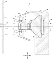
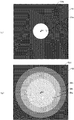
次に、ダーモスコピーカメラ1に設けられた光源である第1LED50及び第2LED60から出射された光の照度分布について説明する。図7は、光源から出射された光の照度分布の様子を示した概略図であり、(a)は図5に示す照射面における分布図、(b)は図6に示す照射面における分布図である。ここで、図5に示す照射面51は、ダーモスコピー撮影時における皮膚疾患部(被写体)の表面位置に相当する。また、図6に示す照射面52は、通常撮影時における皮膚疾患部(被写体)の表面位置に相当する。照射面52は、例えば、ダーモスコピーカメラ1から1メートル離間した位置にある。なお、図7各図においては、照度が高い領域ほど、白色に近い色で塗りつぶしている。また、図7(a)(b)においては、発明の理解を容易にするため、照射面51と光軸OAを延長した線との交点であるか仮想点O1と照射面52と光軸OAを延長した線との交点である仮想点O2とを図示している。
(About the illuminance distribution of LED light)
Next, the illuminance distribution of the light emitted from the
上述したように、ダーモスコピー撮影時においては、内側に傾けた第2LED60を点灯させ、第1LED50は消灯させる。図5に示すように、第2LED60が点灯すると、照射領域60aで示すように一定の照射角度を有する光が出射されるが、その出射方向は概ねダーモスコピーカメラ1の内側であり光軸OAに近づく方向を向いている。これにより、第2LED60から出射された光は、ダーモスコピーカメラ1の前方に向かうにつれて中央(光軸OA)に集光される。そのため、カバープレート24を介して出射される光(矢印L3)は、第2LED60からの光が集光された強い光となっている。ダーモスコピー撮影時には、接触板41の前面が、皮膚疾患部に接触した状態にあり、カバープレート24の直前に皮膚疾患部が位置する。そのため、図7(a)に示すように、皮膚疾患部の表面に相当する照射面51に、光が強く照射される仮想点O1を中心とした照射領域51aが形成され、その外側に光が照射されない非照射領域51bが形成される。この照射領域51aの大きさは、アタッチメント40の先端に形成される凹部41a(図5)の大きさとおおよそ同じである。このように、ダーモスコピー撮影時において、内側に向けて設けられた第2LED60によって集光した強い光を皮膚疾患部に照射することができる。そのため、皮膚下の物質に光を照射、反射させることができ、ダーモスコピー画像を撮影することができる。
As described above, at the time of dermoscopy photography, the
一方、通常撮影時においては、第1LED50を点灯させ、第2LED60は消灯させる。図6に示すように、同心円上に等間隔で設けれらた第1LED50からの光は、照射領域50aで示すように一定の照射角度を有する。第1LED50から出射された光は、カバープレート14を通り前方へと出射される。ダーモスコピーカメラ1と照射面52とは、例えば1m程度離間しているため、第1LED50から出射された光は広範囲に広がっていく。そのため、照射面52においては、ダーモスコピー撮影時よりも広い範囲が光に照射される一方、照射する光の強さは弱くなる。例えば、通常撮影時においては、図7(b)に示すように、照射面52に、照射領域51aよりも面積が大きいが低い照度の仮想点O2を中心とした照射領域52aと、照射領域52aよりも面積が大きく照度が低い照射領域52bと、照射領域52bよりも面積が大きく照度が低い照射領域52cと、その外側に光が照射されない非照射領域52dが形成される。このことから、通常撮影時には、皮膚疾患部を中心として広範囲に光を照射することができる。
On the other hand, during normal shooting, the
(ダーモスコピーカメラ1の使用例)
ダーモスコピーカメラ1を用いてダーモスコピー撮影を行う場合、撮影者は、図5に示すように、アタッチメント40をカメラ本体10の先端に取り付ける。次に、撮影者は、電源ボタン17を押してダーモスコピーカメラ1の電源を入れる。続いて、撮影者は、タッチパネル式の画面を操作して、ダーモスコピーカメラ1をダーモスコピー撮影状態に設定する。これにより、前後方向に移動可能な第1撮影レンズ20が、ダーモスコピー撮影位置(図5の実線位置)に合わされ、皮膚疾患部は所定の倍率(例えば10〜30倍)に拡大される。次に、撮影者は、皮膚疾患部に接触板41を接触させて、シャッタボタン18を半押しする。このとき、アタッチメント40の前面に形成された凹部41aが、皮膚疾患部との接触を抑制する。シャッタボタン18を半押しすることにより、第2LED60のみが点灯し、第1LED50は消灯状態が維持される。第2LED60から出射された光は、偏光フィルタ23により偏光されカバープレート24から出射される。カバープレート24から出射された光は、皮膚疾患部の表面での乱反射を抑制しながら皮膚下に到達し、皮膚下の物質によって反射される。この反射光は、カバープレート24及び偏光フィルタ23を介して、レンズユニット12に取り込まれる。レンズユニット12に取り込まれた光は、第2撮影レンズ21及び第1撮影レンズ20を介して10〜30倍に拡大され、カメラ本体10の撮像素子31上に結像される。任意のタイミングでカメラ本体10のシャッタボタン18を全押しすると、撮像素子31が読み取った撮像画像がカメラ本体10の記憶部に記憶される。このように記憶された撮像画像は、例えば、色素細胞母斑、悪性黒色腫、脂漏性角化症、基底細胞癌、血管病変及びボーエン病などの検査、及び診断に用いることができる。
(Example of using Dermoscopy camera 1)
When performing dermoscopy photography using the
続けてダーモスコピーカメラ1を用いて通常撮影を行う場合、撮影者は、アタッチメント40をカメラ本体10から取り外す(図6)。次に撮影者は、タッチパネル式の画面を操作してダーモスコピーカメラ1を通常撮影状態に設定する。これにより、前後方向に移動可能な第1撮影レンズ20が、通常撮影位置(図6の実線位置)に合わされる。なお、図6において、ダーモスコピー撮影位置にある第1撮影レンズ20を二点鎖線で示している。このように、通常撮影時の第1撮影レンズ20は、ダーモスコピー撮影時の第1撮影レンズ20よりも、撮像素子31の近く(後方)に配される。これにより、焦点距離を変更することができ、拡大倍率をより小さな値に変更することができる。そして、撮影者は、ダーモスコピーカメラ1を皮膚疾患部から所定距離離間させた状態で、例えばシャッタボタン18を半押しする。これにより、第1LED50のみが点灯し、第2LED60は消灯状態が維持される。第1LED50から出射された光は、カバープレート14を通り、皮膚疾患部を中心とした広い範囲を照射する。照射した光は、皮膚疾患部の表面で反射され、レンズユニット12に取り込まれて、カメラ本体10の撮像素子31上に結像される。任意のタイミングでカメラ本体10のシャッタボタン18を全押しすると、撮像素子31が読み取った撮像画像がカメラ本体10の記憶部に記憶される。これにより、皮膚表面の様子を撮影することができる。
When subsequent normal shooting is performed using the
(実施形態の効果について)
以上説明したように、本発明を適用したダーモスコピーカメラ1においては、ダーモスコピー撮影に適した光の照射を行うことができる第2LED60と、通常撮影に適した光の照射を行うことができる第1LED50とを設けている。このような構成により、ダーモスコピー撮影と通常撮影とを切り替える場合、発光させるLEDを選択するだけでよい。これにより、ダーモスコピー撮影状態と通常撮影状態との切り替えを容易に行うことができる。
(About the effect of the embodiment)
As described above, in the
また、第1LED50は、ダーモスコピーカメラ1の光軸OAに対して平行な方向である前方を中心に多くの光が出射されるようにダーモスコピーカメラ1に設けられている。これにより、通常撮影時に第1LED50から出射された光を、皮膚疾患部を中心として広範囲に照射することができる。これにより、通常撮影に適した光を照射することができる。
Further, the
また、第2LED60は、ダーモスコピーカメラ1の光軸OAに近づく方向を中心に多くの光が出射されるように、ダーモスコピーカメラ1の内側に傾けてLED基板13に取り付けられている。これにより、第2LED60から出射された光は、ダーモスコピーカメラ1の前方に向かうにつれて中央(光軸OA)に集光され、ダーモスコピー撮影に適した強い光を皮膚疾患部に照射することができる。
Further, the
また、LED基板13は、レンズユニット12に設けられたレンズ群のうち最前方に位置する第2撮影レンズ21の近傍に配置されている。そのため、第1LED50及び第2LED60は、カメラ本体10の前方(ダーモスコピーカメラ1の前方)に位置している。これにより、第1LED50及び第2LED60から出射された光は、光量をほとんど減ずることなく、ダーモスコピーカメラ1から出射される。これにより、被写体である皮膚疾患部を明るく照射することができる。
Further, the
また、アタッチメント40の先端に、皮膚疾患部に接触させるための接触板41を形成しておくことで、ダーモスコピー撮影の際に、ダーモスコピーカメラ1の姿勢を安定させることができる。さらに、皮膚疾患部とダーモスコピーカメラ1との距離を固定することができる。そのため、ダーモスコピー撮影時における第1撮影レンズ20及び第2撮影レンズ21の配置を予め決めておくことができ、レンズ群の制御を容易なものとすることができる。
Further, by forming the
また、アタッチメント40の前面には、円形状の凹部41aが形成されている。このように円形状の凹部41aを設けることで、押圧されていない皮膚疾患部を撮影することができる。これにより、自然な状態の皮膚疾患部のダーモスコピー画像を得ることができる。
Further, a
また、カメラ本体10にアタッチメント40を着脱可能な構成としている。そのため、ダーモスコピー撮影後に、アタッチメント40を取り外して、容易に洗浄することができる。また、アタッチメント40を複数用意しておくことで、アタッチメント40を交換することで、他の患者を続けて撮影を行うことができ、診察時間の短縮を図ることができる。また、アタッチメント40に光源を設ける必要がないため、アタッチメント40の構成を簡単なものとすることができる。これは、特に複数のアタッチメント40を用意する必要がある場合に、コストを抑制することができる。
Further, the
(他の形態について)
この発明は、上記実施の形態に限定されず、様々な変形及び応用が可能である。上述の実施形態では、カバープレート14は、後方からの光を前方に通す透光性を有する材料から構成されていると説明したが、このような形態に限定されない。例えば、カバープレート14を、その表面に微小な凹凸を形成し、通過する光を拡散する形態のものであってもよい。これにより、通常撮影時に、皮膚疾患部を中心としたより広い範囲に光を照射することができる。また、皮膚疾患部に照射される光のムラを抑制することができる。また、ダーモスコピー撮影時においては、カバープレート14によって拡散された光を、筒状体42の内周面で反射させることができるので、ダーモスコピー撮影に適した強い光を皮膚疾患部に照射することができる。
(About other forms)
The present invention is not limited to the above-described embodiment, and various modifications and applications are possible. In the above-described embodiment, the
また、ダーモスコピー撮影に際して、偏光作用を有するジェルを皮膚疾患部に塗布して撮影する場合には、アタッチメント40に設けた偏光フィルタ23を省略することができる。なお、偏光フィルタ23を有するアタッチメントと偏光フィルタ23を有しないアタッチメントとを準備しておくことで、ジェルを用いた撮影を行うか、偏光フィルタを用いた撮影を行うかを状況に応じて選択することができる。
Further, in the case of applying a gel having a polarizing action to a skin disease portion for dermoscopy photography, the
また、第1LED50及び第2LED60は、砲弾型の白色LEDから構成されると説明したが、他の白色のLEDを用いてもよいし、その他の光源を採用してもよい。その他の光源としては、ハロゲンランプなどの高輝度ライト、半導体発光素子、及び有機エレクトロルミネッセンスなどの発光素子を用いることができる。この場合においても、通常撮影時に点灯させる光源は前方を向くように、ダーモスコピー撮影時に点灯させる光源は中央を向くように設けるようにすればよい。更に、第1LED50及び第2LED60の光量や光特性を異ならせても良い。例えば、第1LED50は遠方の被写体まで届くのに十分な光量を広範囲に照射することができる光源とし、一方で第2LED60は光量は小さいながらも近くの被写体を集中的に照明する指向性の強い光を発する光源としてもよい。
Further, although it has been explained that the
また、第1LED50及び第2LED60は、白色光を発するLEDから構成されていると説明したが、例えば紫外線光源、青色光光源、あるいは緑色光光源を採用してもよい。また、通常撮影時に点灯する光源及びダーモスコピー撮影時に点灯する光源に、互いに異なる色の光源を設けるようにし、異なる色の光源ごとに独立して発光できるようにしてもよい。これにより、異なる色の光を照射することで、異なる像を得ることができ、得られた異なる像を比較したり、像を重ね合わせたりすることで、皮膚疾患部の検査、及び診断を容易なものとすることができる。
Further, although it has been explained that the
また、第1LED50は、砲弾状の部位の突出方向が前方を向くように設けられていると説明した。しかしながら、砲弾状の部位の突出方向が外側を向くように第1LED50を配置してもよい。これにより、照射方向L1を光軸OAから遠ざかる方向に設定することができ、通常撮影時においてより広範囲に光を照射することができる。
Further, it was explained that the
また、上述の実施形態では、通常撮影用の第1LED50と、ダーモスコピー撮影用の第2LED60とをダーモスコピーカメラ1に設けた。しかしながら、ダーモスコピーカメラに1つ又は1群のLEDのみを設け、設けたLEDから通常撮影及びダーモスコピー撮影のための光を出射するようにしてもよい。この場合、選択された撮影モードに応じて、1つ又は1群のLEDの向きを変更することができる構成を備えるようにすればよい。
Further, in the above-described embodiment, the
また、上述の実施形態では、通常撮影用の光源の取付方向と、ダーモスコピー用の光源の取付方向とを異ならせることで、それぞれの撮影に適した光の照射を実現していた。しかしながら、通常撮影時用の光源とダーモスコピー用の光源とに異なる光源を用いて、これらの取付方向は同じにしてもよい。例えば、ダーモスコピー用の光源には、照射角度の小さい(光を照射する範囲が狭い)光源を用い、通常撮影用の光源には、照射角度の大きい(光を照射する範囲が広い)光源を用いることができる。あるいは、LEDに付随する反射板の位置を異ならせることによって、照射する光の方向や照射範囲を異ならせてもよい。これにより、ダーモスコピー撮影時には集光した光を、通常撮影時には広範囲に広がった光を皮膚疾患部に照射することができる。 Further, in the above-described embodiment, by making the mounting direction of the light source for normal shooting different from the mounting direction of the light source for dermoscopy, irradiation of light suitable for each shooting is realized. However, different light sources may be used for the light source for normal shooting and the light source for dermoscopy, and the mounting directions thereof may be the same. For example, a light source having a small irradiation angle (a narrow range of light irradiation) is used as a light source for dermoscopy, and a light source having a large irradiation angle (a wide range of light irradiation) is used as a light source for normal photography. be able to. Alternatively, the direction of the light to be irradiated and the irradiation range may be different by changing the position of the reflector attached to the LED. As a result, it is possible to irradiate the skin diseased portion with the focused light at the time of dermoscopy photography and the light spread over a wide area at the time of normal photography.
また、上述の実施形態では、ダーモスコピー撮影時には第2LED60を点灯させ、通常撮影時には第1LED50を点灯させるとしたが、通常撮影時には両方のLEDを点灯させてより明るく撮影するようにしてもよい。
Further, in the above-described embodiment, the
また、第1LED50及び第2LED60を同時に点灯させるようにして、ダーモスコピー撮影時には、第1LED50を覆って光を遮り第2LED60からの光のみをカメラ本体10から出射させ、通常撮影時には、第2LED60を覆って光を遮り第1LED50からの光のみをカメラ本体10から出射させるようにしてもよい。また、通常撮影時には、いずれのLEDも覆わず、第1LED50からの光及び第2LED60からの光をカメラ本体10から出射させるようにしてもよい。
Further, the
また、第1LED50及び第2LED60を移動可能に設け、ダーモスコピー撮影時には、カメラ本体10から光を出射可能な位置まで第2LED60を移動させて、第2LEDを発光させ、通常撮影時には、カメラ本体10から光を出射可能な位置まで第1LED50を移動させて、第1LED50を発光させるようにしてもよい。また、通常撮影時には、第1LED50に加え、第2LED60も移動させて発光させるようにしてもよい。なお、点灯させないLEDは、カメラ本体10の後方に待機させておけばよい。
Further, the
また、ダーモスコピー撮影時には、接触板41は、皮膚疾患部に接触した状態にされると説明した。しかしながら、十分な照度の光を照射できるのであれば、ダーモスコピーカメラ1を皮膚疾患部に近づけることで、ダーモスコピー撮影が可能である。この場合、ダーモスコピー撮影後の洗浄作業が不要となり、診察時間の短縮を図ることができる。
Further, it was explained that the
また、第1撮影レンズ20及び第2撮影レンズ21は、平凸レンズであると説明したが、他の形態のものも採用することができる。例えば、第1撮影レンズ20及び第2撮影レンズ21は、2つ又は複数の凸レンズを組み合わせたレンズ、1つのアクロマートレンズ、2つ又は複数のアクロマートレンズを組み合わせたいずれかであってもよい。また、第1撮影レンズ20及び第2撮影レンズ21は、無収差レンズであってもよいし、球面レンズに非球面レンズを組み込んだものでも良い。また、これらのレンズが、反射防止膜やカラーフィルタを含むものであってもよい。また、レンズユニット12は、第1撮影レンズ20を移動可能な構成として、焦点距離を変化させることが可能なレンズ群を有していると説明したが、単焦点レンズを有する構成としてもよい。
Further, although the first photographing
また、本発明に係る医療用撮像装置は、上記実施形態で説明したダーモスコピーカメラ1のように、ダーモスコピー撮影状態と通常撮影状態との切り替え可能な医療用撮像装置に限定されない。また、被写体としても皮膚疾患部に限定されない。例えば、光干渉断層計(OCT(Optical Coherence Tomography))や、コルポスコピーカメラ(Colposcopy)等に適用可能である。また、例えば、構造物等に形成された穴の内部に光を照射して、光を照射した穴の内部を拡大して撮影する撮影状態(アタッチメントをカメラ本体に取り付けた状態)と、穴から離間した位置からから穴の周辺を含めた範囲を撮影する撮影状態(アタッチメントをカメラ本体から取り外した状態)とを切り替え可能な撮像装置等にも、本発明を適用することができる。
Further, the medical imaging device according to the present invention is not limited to the medical imaging device that can switch between the dermoscopy imaging state and the normal imaging state, such as the
また、上記のダーモスコピーカメラ1においては、カメラ本体10に、シャッタボタン18や、ダーモスコピーカメラ1の各種設定を実行するためのタッチパネル式の画面(不図示)が設けられていると説明した。しかしながら、シャッタボタン18やタッチパネル式の画面(不図示)等の操作受付部を、カメラ本体とは物理的に分離した操作部に設けるようにしてもよい。カメラ本体と操作部とは、既存の通信技術を用いて双方向に通信可能である。撮影者は、操作部を操作することにより、カメラ本体の各種設定やシャッタ操作等を行うことができる。
Further, it has been explained that in the above-mentioned
また、上記のダーモスコピーカメラ1において、アタッチメント40はカメラ本体10に着脱可能であると説明したが、アタッチメント40をカメラ本体10に移動可能に取り付けた構成としてもよいし、カメラ本体10とアタッチメント40とが分離不能な構成であってもよい。
Further, in the above-mentioned
(第2の実施の形態)
次に、アタッチメントをカメラ本体に移動可能に取り付けた第2の実施の形態について説明する。図8は、本発明を適用した第2の実施の形態のダーモスコピーカメラを示した図であり、通常撮影時におけるダーモスコピーカメラの切断面図である。ダーモスコピーカメラ100において、アタッチメント140は回動可能にカメラ本体110に取り付けられている。カメラ本体110の上部には、アタッチメント140を回動自在に指示する回動支持部119が形成されている。回動支持部119の左右の面には、それぞれアタッチメント140の回動軸となる回動突起(不図示)が形成されている。この回動突起(不図示)にアタッチメント140の回動部125が軸支されることにより、アタッチメント140はカメラ本体10に対して回動することができる。なお、ダーモスコピーカメラ100には、装着リング45(図1)は設けられていないが、その他の構成については、上記実施形態で説明したダーモスコピーカメラ1の構成と同様である。そのため、図8において、同様の構成については同じ符号を付している。
(Second Embodiment)
Next, a second embodiment in which the attachment is movably attached to the camera body will be described. FIG. 8 is a diagram showing a dermoscopy camera according to a second embodiment to which the present invention is applied, and is a cut-out view of the dermoscopy camera during normal shooting. In the
ダーモスコピー撮影時には、図8に示すように、撮影者はアタッチメント140をカメラ本体110の前方に位置させる。一方、通常撮影時には、アタッチメント140を上方に回動させて、カメラ本体110の前方を開放させる。このように、アタッチメント140を回動させることで、ダーモスコピー撮影状態と通常撮影状態とを切り替えることができる。
At the time of dermoscopy shooting, as shown in FIG. 8, the photographer positions the
また、アタッチメントの移動態様は、このような回動だけでなく、例えば、アタッチメントをカメラ本体に対してスライドさせる態様であってもよい。ダーモスコピー撮影の際は、カメラ本体の前方をアタッチメントで覆うように配置し、通常撮影の際は、アタッチメントをスライドさせてカメラ本体の前方から移動させればよい。 Further, the movement mode of the attachment may be not only such rotation but also a mode in which the attachment is slid with respect to the camera body, for example. In the case of dermoscopy shooting, the front of the camera body may be arranged so as to be covered with an attachment, and in the case of normal shooting, the attachment may be slid and moved from the front of the camera body.
(第3の実施の形態)
また、上記の実施の形態では、通常撮影用の光源と、ダーモスコピー撮影用の光源とを、同一の平面上(同一のLED基板13上)に設けたが、光源の配置態様はこれに限定されず、前後方向における位置を異ならせてもよい。次に、通常撮影用の光源を、ダーモスコピー撮影用の光源よりも後方に設けた第3の実施の形態のダーモスコピーカメラ200について説明する。なお、ダーモスコピーカメラ200においては、ダーモスコピー撮影用の光源として、可視光のLED211、可視光のLED212、及び近赤外光のLED215が設けられている。近赤外光のLED215は紫外光のLEDに置換してもよい。
(Third Embodiment)
Further, in the above embodiment, the light source for normal photography and the light source for dermoscopy photography are provided on the same plane (on the same LED substrate 13), but the arrangement mode of the light sources is limited to this. Instead, the positions in the front-rear direction may be different. Next, the
図9は、本発明を適用した第3の実施の形態のダーモスコピーカメラ200の分解斜視図である。図10は、図9におけるライトユニットの正面図である。図11は、図10におけるX−X線断面図である。図12は、図10におけるY−Y線断面図である。図13は、図11、図12におけるフィルタユニットの斜視図である。
FIG. 9 is an exploded perspective view of the
図9に示すように、ダーモスコピーカメラ200(医療用撮像装置)は、カメラ本体221と、カメラ本体221の前方に設けられたライトユニット223と、カメラ本体221の後方に設けられたコントローラ222とによって一体的に構成されている。カメラ本体221はレンズユニット221Aと枠体221Bとを含み、ライトユニット223は第1カバー体223Aと第2カバー体223Bとを含み、コントローラ222は本体部222Aと回路基板222Bと表示部222Cとを含んでいる。
As shown in FIG. 9, the dermoscopy camera 200 (medical imaging device) is composed of a
図10、図12に示すように、通常撮影用のLED216は、第2カバー体223Bの基端(後方側)の周囲に前方を向いて環状に配置されている。通常撮影用のLED216は、図10では、左右に3個ずつ、計6個が配置された例を示している。
As shown in FIGS. 10 and 12, the
通常撮影用のLED216は、第2カバー体223Bの中心に対して同心円上に等間隔で配置されている。LED216は、レンズユニット221Aの外周位置から光を前方に向けて出射するリングフラッシュとして機能する。LED216は、白色光を発するLEDから構成されている。第2カバー体223Bの先端の開口にはカバー部材226が嵌め込まれており、ダーモスコピー撮影時に被写体である皮膚疾患部に接触する。
The
なお、上記実施の形態では、ダーモスコピー撮影用の光源として、一種類の第2LED60(図2)のみを設けていた。一方、ダーモスコピーカメラ200においては、ダーモスコピー撮影用の光源として、可視光を出射するLED211、可視光を出射するLED212、及び近赤外光を出射するLED215の異なる3種類の光源が設けられている。これらの光源は、図10に示すように、上下方向に並んで一対となって配置されている。一対の光源のうち、上側の光源は、斜め下方に向けられており光軸OAに近づく方向により多くの光を出射する。一方、下側の光源は、斜め上方に向けられており光軸OAに近づく方向により多くの光を出射する。また、一対のLED211は偏光フィルタ213により覆われているが、一対のLED212は偏光フィルタに覆われていない。また、ダーモスコピー撮影用のLED211、LED212、及びLED215は、通常撮影用のLED216よりも前方に設けられている。
In the above embodiment, only one type of second LED 60 (FIG. 2) is provided as a light source for dermoscopy photography. On the other hand, in the
カメラ本体221は、レンズユニット221Aを囲うように支持する枠体221Bを介して第1カバー体223Aに取り付けられている。レンズユニット221Aの後方には、図11、図12に示すように、回路配線基板250と撮像素子260が収容されており、その前方にはシャッタ270とフィルタユニット280とが設けられている。
The
フィルタユニット280は、図13に示すように、ベースプレート281と、赤外カットフィルタ(IRCF)282を有する第1回転体283と、偏光フィルタ284を有する第2回転体285と、近赤外透過フィルタ286を有する第3回転体287とを備えている。偏光フィルタ284の偏光軸は、一対のLED211を覆う偏光フィルタ213の偏光軸に直交する。フィルタユニット280は、ベースプレート281を介してレンズユニット221Aに取り付けられている。ベースプレート281の中央には、円形状の光通過孔281aがあけられている。ベースプレート281は、光通過孔281aの中心がダーモスコピーカメラ200の光軸OA(図11、12)と一致するように設けられている。これにより、レンズユニット221Aに進入してきた反射光は、光通過孔281aを通り撮像素子260(図11、12)に到達する。なお、近赤外透過フィルタ286は、図10に示す近赤外光のLED215が紫外光のLEDに置換された場合には、紫外透過フィルタに置換される。
As shown in FIG. 13, the
第1回転体283は、回転軸283aを中心に回転可能にベースプレート281に取り付けられている。第1回転体283は、図13に示す第1状態と、第1状態から矢印Y1の方向に回転して赤外カットフィルタ282で光通過孔281aを覆う第2状態との間で変化する。第2回転体285は、回転軸285aを中心に回転可能にベースプレート281に取り付けられている。第2回転体285は、図13に示す第1状態と、第1状態から矢印Y2の方向に回転して偏光フィルタ284で光通過孔281aを覆う第2状態との間で変化する。第3回転体287は、回転軸287aを中心に回転可能にベースプレート281に取り付けられている。第3回転体287は、図13に示す第1状態と、第1状態から矢印Y3の方向に回転して近赤外透過フィルタ286で光通過孔281aを覆う第2状態との間で変化する。第1回転体283、第2回転体285、及び第3回転体287は、互いに前後方向の位置が異なっているため独立して回転可能である。そのため、光通過孔281aを覆うフィルタを一枚とすることができるとともに、複数枚とすることもできる。
The first
ここで、皮膚疾患部の診断に際し、可視光でのダーモスコピー撮影に加え、近赤外光及び紫外光を照射できるように構成しておくことが好適な理由は次のとおりである。皮膚の最深部(真皮)を撮影するには近赤外光でのダーモスコピー撮影が適しており、それより波長が短くなるほど光は深部に届かなくなる傾向がある。また、色素病変ではメラニン、血管腫ではヘモグロビンが皮膚疾患部の色調の変化をもたらす色素となり得る。しかしながら、後者のオキシヘモグロビンについては可視光の照射が適する一方、前者のドーパメラニンでは波長が長いほど光の吸収効率が低下するため、可視光より波長が短い紫外光がより効果的となる。 Here, the reason why it is preferable to irradiate near-infrared light and ultraviolet light in addition to dermoscopy photography with visible light when diagnosing a skin disease part is as follows. Dermoscopy photography with near-infrared light is suitable for photographing the deepest part of the skin (dermis), and the shorter the wavelength, the less the light tends to reach the deep part. In addition, melanin in pigment lesions and hemoglobin in hemangiomas can be pigments that cause changes in the color tone of skin diseases. However, while the latter oxyhemoglobin is suitable for irradiation with visible light, the former dopamelanin has a lower light absorption efficiency as the wavelength is longer, so that ultraviolet light having a shorter wavelength than visible light is more effective.
本実施の形態では、LED211、LED212、LED215、及びLED216により、4つのパターンで点灯することが可能となる。すなわち、近赤外光(又は紫外光)の上下一対のLED215を点灯させる第1パターン、偏光フィルタ213に覆われた可視光の上下一対のLED211を点灯させる第2パターン、偏光フィルタ213に覆われていない可視光の上下一対のLED212を点灯させる第3パターン、通常撮影用のLED216を点灯させる第4パターンである。また、このような点灯パターンに応じて、第1回転体283、第2回転体285、第3回転体287の回転動作を制御することにより、異なる撮影状態に容易に切り替えることができる。
In the present embodiment, the
このような、異なる撮影状態を1回のシャッタ操作によって一度に撮影することもできる。例えば、ダーモスコピー撮影に用いられる第1パターンから第3パターンを順不同に自動連写するように構成するこができる。さらには、通常撮影用の第4パターンも含めて自動連写するように構成することもできる。 Such different shooting states can be shot at once by one shutter operation. For example, the first pattern to the third pattern used for dermoscopy photography can be configured to be automatically continuously shot in no particular order. Further, it can be configured to automatically take continuous shots including the fourth pattern for normal shooting.
図11は、第1パターンから第3パターンにおいてダーモスコピー撮影を行った場合の垂直画角θxを示している。垂直方向には、LED215、LED211又はLED212は、光軸OAに向けてテーパ状に光を照射する。これにより、カバー部材226に接触した皮膚疾患部から反射された光のレンズユニット221Aへ入射する垂直画角θxは相対的に狭くなる。例えば、図11では、垂直画角θxは35.2°である。
FIG. 11 shows the vertical angle of view θx when dermoscopy photography is performed in the first to third patterns. In the vertical direction, the
なお、図11において、LED215(LED211及びLED212も含む)に制御信号を流すための有線228及び端子228aが上下一対に設けられている。また、第1カバー体223Aの外周近傍には、図12で示すLED216に制御信号を流すための有線229及び端子229aが設けられている。
In FIG. 11, a pair of upper and lower wired 228s and
図12は、第1パターンから第3パターンにおいてダーモスコピー撮影を行った場合の水平画角θyを示している。水平方向には、LED215、LED211又はLED212は光軸OAと平行に照射する。これにより、カバー部材226に接触した皮膚疾患部から反射された光のレンズユニット221Aへ入射する水平画角θyは相対的に広くなり、例えば、図12では、水平画角θyは47°である。
FIG. 12 shows the horizontal angle of view θy when dermoscopy photography is performed in the first to third patterns. In the horizontal direction, the
(実施の形態3の効果について)
以上説明したように、実施の形態3に係るダーモスコピーカメラ200においては、簡易な構成及び操作で、偏光のないLED212の照射下で皮膚表面を観察できる状態の画像と、偏光のあるLED211の照射下で皮膚内部を観察できる状態の画像と、近赤外光(又は紫外光)を発するLED215の照射下で皮膚表面を観察できる状態の画像と、通常の白色光を発するLED216の照射下で皮膚表面を観察できる状態の画像と、を得ることができる。また、フィルタユニット280の動作を制御することで、レンズユニット221Aを通る光が通過するフィルタを切り替えることができ、所望の撮像状態に容易に切り替えることができる。
(About the effect of Embodiment 3)
As described above, in the
また、ダーモスコピー撮影の際に光を透過させる偏光板をカメラ本体に設けることで、ダーモスコピー撮影用に用いるアタッチメントが不要になる。これにより、アタッチメントの取付け取り外し作業を省略することができ、撮影状態を容易に切り替えることができる。 Further, by providing the camera body with a polarizing plate that transmits light during dermoscopy photography, an attachment used for dermoscopy photography becomes unnecessary. As a result, the work of attaching and detaching the attachment can be omitted, and the shooting state can be easily switched.
ダーモスコピー撮影用のLEDの種類を、可視光タイプ、紫外タイプ、近赤外タイプとすることもできる。これにより、1回のシャッタ操作で3種類の光源を用いた撮影が可能となる。 The types of LEDs for dermoscopy photography can be visible light type, ultraviolet type, and near infrared type. This makes it possible to take pictures using three types of light sources with one shutter operation.
また、異なる撮影状態に切り替えて連写することができるため、撮像される画像が、外光の変化やAE、ホワイトバランス等のカメラの微妙な違いに影響されない。また、純粋な偏光/非偏光の同一画角の同一倍率の撮影が可能となることから、診断時間の短縮を図ることができるとともに、比較しやすい撮影画像を得ることができる。 Further, since continuous shooting can be performed by switching to different shooting states, the captured image is not affected by changes in external light, AE, white balance, and other subtle differences in the camera. In addition, since it is possible to shoot purely polarized / unpolarized images with the same angle of view and the same magnification, it is possible to shorten the diagnosis time and obtain a photographed image that is easy to compare.
上記実施の形態では、第1光源と第2光源が別に存在するものとして説明した。しかし、例えばLED又は偏光板の位置や照射方向を変えられるようにして、同じ光源を第1撮影状態と第2撮影状態とで共用することも可能である。 In the above embodiment, it has been described that the first light source and the second light source exist separately. However, it is also possible to share the same light source in the first imaging state and the second imaging state by making it possible to change the position and irradiation direction of the LED or the polarizing plate, for example.
上記では、いくつかの実施の形態とその変形例について説明したが、これらで説明した特徴を適宜組み合わせて医療用撮像装置を構成することができる。その他、上記実施の形態で示した構成などの具体的な細部は、本発明の趣旨を逸脱しない範囲において適宜変更可能である。 Although some embodiments and modifications thereof have been described above, the medical imaging apparatus can be configured by appropriately combining the features described above. In addition, specific details such as the configuration shown in the above embodiment can be appropriately changed without departing from the spirit of the present invention.
本発明のいくつかの実施形態を説明したが、本発明の範囲は、上述の実施の形態に限定するものではなく、特許請求の範囲に記載された発明の範囲とその均等の範囲を含む。以下に、この出願の願書に最初に添付した特許請求の範囲に記載した発明を付記する。付記の番号は、この出願の願書に最初に添付した特許請求の範囲の通りである。 Although some embodiments of the present invention have been described, the scope of the present invention is not limited to the above-described embodiments, but includes the scope of the invention described in the claims and the equivalent scope thereof. The inventions described in the claims originally attached to the application of this application are added below. The additional numbers are as specified in the claims originally attached to the application for this application.
(付記)
(付記1)
通常の撮影状態で患部の撮影を行う第1撮影状態と、通常の撮影状態とは異なる撮影状態で患部の撮影を行う第2撮影状態とを有し、患部の診断を支援するための画像を撮像する医療用撮像装置において、
第1光源と、第2光源と、を備え、
前記第1撮影状態の際に被写体に光を照射する光源として、少なくとも前記第1光源を採用し、前記第2撮影状態の際に前記被写体に光を照射する光源として、少なくとも前記第2光源を採用するように構成され、
前記第2光源の照射方向は、前記第1光源の照射方向と異なる方向に設定されている、
ことを特徴とする医療用撮像装置。
(Additional note)
(Appendix 1)
It has a first imaging state in which the affected area is photographed in a normal imaging state and a second imaging state in which the affected area is photographed in a imaging state different from the normal imaging state, and an image for supporting the diagnosis of the affected area is provided. In a medical imaging device for imaging
A first light source and a second light source are provided.
At least the first light source is adopted as the light source that irradiates the subject with light in the first shooting state, and at least the second light source is used as the light source that irradiates the subject with light in the second shooting state. Configured to adopt,
The irradiation direction of the second light source is set to be different from the irradiation direction of the first light source.
A medical imaging device characterized by this.
(付記2)
前記第1光源と、前記第2光源と、撮像素子と、前記撮像素子と前記被写体とを結ぶ光軸上に位置するレンズ群と、を有する撮像装置本体を備え、
前記第2光源の照射方向は、前記光軸に近づく方向に設定されている、
ことを特徴とする付記1に記載の医療用撮像装置。
(Appendix 2)
An image pickup apparatus main body including the first light source, the second light source, an image sensor, and a lens group located on an optical axis connecting the image sensor and the subject is provided.
The irradiation direction of the second light source is set to approach the optical axis.
The medical imaging device according to
(付記3)
前記第1光源の照射方向は、前記光軸に対して並行又は遠ざかる方向に設定されている、
ことを特徴とする付記2に記載の医療用撮像装置。
(Appendix 3)
The irradiation direction of the first light source is set to be parallel to or away from the optical axis.
The medical imaging device according to Appendix 2, wherein the image is characterized by the above.
(付記4)
前記第1撮影状態は、通常撮影状態であり、
前記第2撮影状態は、ダーモスコピー撮影状態であって、
前記レンズ群は、前記ダーモスコピー撮影状態では拡大レンズとして機能し、前記通常撮影状態では前記ダーモスコピー撮影状態よりも広角なレンズとして機能する、
ことを特徴とする付記2又は3に記載の医療用撮像装置。
(Appendix 4)
The first shooting state is a normal shooting state.
The second shooting state is a dermoscopy shooting state.
The lens group functions as a magnifying lens in the dermoscopy shooting state, and functions as a lens having a wider angle than the dermoscopy shooting state in the normal shooting state.
The medical imaging device according to Appendix 2 or 3, wherein the image pickup device is described.
(付記5)
前記撮像装置本体は、前記光軸上に位置する、ダーモスコピー撮影のために前記第2光源から出射された光を偏光するための偏光部材を備える、
ことを特徴とする付記4に記載の医療用撮像装置。
(Appendix 5)
The image pickup apparatus main body includes a polarizing member located on the optical axis for polarized light emitted from the second light source for dermoscopy photography.
The medical imaging device according to Appendix 4, wherein the image is characterized by the above.
(付記6)
前記第1光源と前記第2光源は、前記撮像装置本体の前方に設けられている、
ことを特徴とする付記2〜5のいずれか1つに記載の医療用撮像装置。
(Appendix 6)
The first light source and the second light source are provided in front of the image pickup apparatus main body.
The medical imaging device according to any one of Supplementary note 2 to 5, wherein the image pickup device is described.
(付記7)
前記第2光源の少なくとも一部は、偏光部材が設けられて偏光光を照射し、
前記第1光源は、非偏光光を照射し、
前記撮像素子の前方に、偏光軸の方向が前記偏光部材の偏光軸の方向と異なる偏光部材を備える、
ことを特徴とする付記2〜6のいずれか1つに記載の医療用撮像装置。
(Appendix 7)
At least a part of the second light source is provided with a polarizing member to irradiate polarized light.
The first light source irradiates unpolarized light and
A polarizing member whose polarization axis direction is different from that of the polarization axis of the polarizing member is provided in front of the image pickup device.
The medical imaging device according to any one of Supplementary Provisions 2 to 6, characterized in that.
(付記8)
前記第1光源と前記第2光源は、前記レンズ群の周囲に設けられている、
ことを特徴とする付記2〜7のいずれか1つに記載の医療用撮像装置。
(Appendix 8)
The first light source and the second light source are provided around the lens group.
The medical imaging device according to any one of Supplementary note 2 to 7, wherein the image pickup device is described.
(付記9)
前記第1光源は、前記第2光源よりも後方に設けられている、
ことを特徴とする付記1〜7のいずれか1つに記載の医療用撮像装置。
(Appendix 9)
The first light source is provided behind the second light source.
The medical imaging device according to any one of
(付記10)
前記第1光源の取り付け方向と、前記第2光源の取り付け方向とを異ならせことによって、前記第1光源の照射方向と前記第2光源の照射方向とを異ならせるとともに、前記第1光源からの光によって照射する照射領域と、前記第2光源からの光によって照射する照射領域とを異ならせる、
ことを特徴とする付記1〜9のいずれか1つに記載の医療用撮像装置。
(Appendix 10)
By making the mounting direction of the first light source different from the mounting direction of the second light source, the irradiation direction of the first light source and the irradiation direction of the second light source are different, and the irradiation direction from the first light source is different. The irradiation area irradiated with light and the irradiation area irradiated with light from the second light source are made different.
The medical imaging device according to any one of
(付記11)
前記第2光源の少なくとも一部は、偏光部材が設けられて偏光光を照射し、
前記第1光源は、非偏光光を照射する、
ことを特徴とする付記1に記載の医療用撮像装置。
(Appendix 11)
At least a part of the second light source is provided with a polarizing member to irradiate polarized light.
The first light source irradiates unpolarized light.
The medical imaging device according to
(付記12)
前記第1撮影状態の際に少なくとも前記第1光源を点灯し、前記第2撮影状態の際に少なくとも前記第2光源を点灯するように構成されている、
ことを特徴とする付記1〜11のいずれか1つに記載の医療用撮像装置。
(Appendix 12)
At least the first light source is turned on in the first shooting state, and at least the second light source is turned on in the second shooting state.
The medical imaging device according to any one of
(付記13)
前記第1撮影状態の際に前記第1光源を点灯し、前記第2撮影状態の際に前記第1光源及び前記第2光源の両方を点灯するように構成されている、
ことを特徴とする付記1〜11のいずれか1つに記載の医療用撮像装置。
(Appendix 13)
The first light source is turned on in the first shooting state, and both the first light source and the second light source are turned on in the second shooting state.
The medical imaging device according to any one of
(付記14)
前記第1光源と前記第2光源には照射角度が異なる光源が用いられている、
ことを特徴とする付記1〜13のいずれか1つに記載の医療用撮像装置。
(Appendix 14)
Light sources having different irradiation angles are used for the first light source and the second light source.
The medical imaging device according to any one of
(付記15)
前記第1光源と前記第2光源には照射強度が異なる光源が用いられている、
ことを特徴とする付記1〜14のいずれか1つに記載の医療用撮像装置。
(Appendix 15)
Light sources having different irradiation intensities are used for the first light source and the second light source.
The medical imaging device according to any one of
(付記16)
前記第1光源と前記第2光源には照射距離が異なる光源が用いられている、
ことを特徴とする付記1〜15のいずれか1つに記載の医療用撮像装置。
(Appendix 16)
Light sources having different irradiation distances are used for the first light source and the second light source.
The medical imaging device according to any one of
(付記17)
前記第1光源と前記第2光源には波長が異なる光源が用いられている、
ことを特徴とする付記1〜16のいずれか1つに記載の医療用撮像装置。
(Appendix 17)
Light sources having different wavelengths are used for the first light source and the second light source.
The medical imaging device according to any one of
(付記18)
前記第1光源と前記第2光源は、同じ光源であって、前記第1撮影状態と前記第2撮影状態とで、光の照射方向を変えるか、又は前記光軸上に偏光板を位置させる状態と位置させない状態とで切り替えるように構成されている、
ことを特徴とする付記2に記載の医療用撮像装置。
(Appendix 18)
The first light source and the second light source are the same light source, and the light irradiation direction is changed or the polarizing plate is positioned on the optical axis between the first shooting state and the second shooting state. It is configured to switch between a state and a non-positioned state,
The medical imaging device according to Appendix 2, wherein the image is characterized by the above.
1,100,200・・ダーモスコピーカメラ、10,110,221・・カメラ本体、11・・筐体、11a・・基板収容部、12・・レンズユニット、13・・LED基板、14・・カバープレート、14a・・開口、15・・カバー部、17・・電源ボタン、18・・シャッタボタン、20・・第1撮影レンズ、21・・第2撮影レンズ、23,213,284・・偏光フィルタ、24・・カバープレート、25,270・・シャッタ、30,250・・回路配線基板、31,260・・撮像素子、40,140・・アタッチメント、41・・接触板、41a・・凹部、42・・筒状体、45・・装着リング、45a・・凹部、50・・第1LED、50a・・照射領域、51,52・・照射面、51a,52a,52b,52c・・照射領域、51b,52d・・非照射領域、60・・第2LED、60a・・照射領域、119・・回動支持部、125・・回動部、221A・・レンズユニット、211,212,215,216・・LED、221B・・枠体、222・・コントローラ、222A・・本体部、222B・・回路基板、222C・・表示部、223・・ライトユニット、223A・・第1カバー体、223B・・第2カバー体、、226・・カバー部材、228,229・・有線、228a,229a・・端子、280・・フィルタユニット、281・・ベースプレート、281a・・光通過孔、282・・赤外カットフィルタ、283a,285a,287a・・回転軸、286・・近赤外透過フィルタ、OA・・光軸、L1,L2・・照射方向、θ1,θ2・・照射角度 1,100,200 ... Dermos copy camera, 10,110,221 ... Camera body, 11 ... Housing, 11a ... Board housing, 12 ... Lens unit, 13 ... LED board, 14 ... Cover plate , 14a ... Opening, 15 ... Cover, 17 ... Power button, 18 ... Shutter button, 20 ... 1st shooting lens, 21 ... 2nd shooting lens, 23,213,284 ... Polarization filter, 24 ... Cover plate, 25,270 ... Shutter, 30,250 ... Circuit wiring board, 31,260 ... Imaging element, 40,140 ... Attachment, 41 ... Contact plate, 41a ... Recess, 42 ...・ Cylindrical body, 45 ・ ・ Mounting ring, 45a ・ ・ Recessed, 50 ・ ・ First LED, 50a ・ ・ Irradiation area, 51, 52 ・ ・ Irradiation surface, 51a, 52a, 52b, 52c ・ ・ Irradiation area, 51b, 52d ... Non-irradiation area, 60 ... 2nd LED, 60a ... Irradiation area, 119 ... Rotation support part, 125 ... Rotation part, 221A ... Lens unit, 211,212,215,216 ... LED , 221B ... Frame body, 222 ... Controller, 222A ... Main body part, 222B ... Circuit board, 222C ... Display unit, 223 ... Light unit, 223A ... First cover body, 223B ... Second cover Body, 226 ... Cover member, 228, 229 ... Wired, 228a, 229a ... Terminal, 280 ... Filter unit, 281 ... Base plate, 281a ... Optical pass hole, 282 ... Infrared cut filter, 283a , 285a, 287a ... Rotation axis, 286 ... Near infrared transmission filter, OA ... Optical axis, L1, L2 ... Irradiation direction, θ1, θ2 ... Irradiation angle
Claims (18)
第1光源と、第2光源と、を備え、
前記第1撮影状態の際に被写体に光を照射する光源として、少なくとも前記第1光源を採用し、前記第2撮影状態の際に前記被写体に光を照射する光源として、少なくとも前記第2光源を採用するように構成され、
前記第2光源の照射方向と前記第1光源の照射方向とが互いに異なる方向に設定されていることによって、前記第1光源からの光によって照射される照射領域と、前記第2光源からの光によって照射される照射領域とが互いに異なっている、
ことを特徴とするダーモスコピー用撮像装置。 It has a first imaging state in which the affected area is photographed in a normal imaging state and a second imaging state in which the affected area is photographed in a imaging state different from the normal imaging state, and an image for supporting the diagnosis of the affected area is provided. In the dermoscopy imaging device for imaging
A first light source and a second light source are provided.
At least the first light source is adopted as the light source that irradiates the subject with light in the first shooting state, and at least the second light source is used as the light source that irradiates the subject with light in the second shooting state. Configured to adopt,
By setting the irradiation direction of the second light source and the irradiation direction of the first light source to different directions, the irradiation region irradiated by the light from the first light source and the light from the second light source The irradiation areas illuminated by are different from each other,
An imaging device for dermoscopy , which is characterized by this.
前記第2光源の照射方向は、前記光軸に近づく方向に設定されている、
ことを特徴とする請求項1に記載のダーモスコピー用撮像装置。 An image pickup apparatus main body including the first light source, the second light source, an image sensor, and a lens group located on an optical axis connecting the image sensor and the subject is provided.
The irradiation direction of the second light source is set to approach the optical axis.
The dermoscopy imaging device according to claim 1.
ことを特徴とする請求項2に記載のダーモスコピー用撮像装置。 The irradiation direction of the first light source is set to be parallel to or away from the optical axis.
The dermoscopy imaging device according to claim 2.
前記第2撮影状態は、ダーモスコピー撮影状態であって、
前記レンズ群は、前記ダーモスコピー撮影状態では拡大レンズとして機能し、前記通常撮影状態では前記ダーモスコピー撮影状態よりも広角なレンズとして機能する、
ことを特徴とする請求項2又は3に記載のダーモスコピー用撮像装置。 The first shooting state is a normal shooting state.
The second shooting state is a dermoscopy shooting state.
The lens group functions as a magnifying lens in the dermoscopy shooting state, and functions as a lens having a wider angle than the dermoscopy shooting state in the normal shooting state.
The dermoscopy imaging device according to claim 2 or 3.
ことを特徴とする請求項4に記載のダーモスコピー用撮像装置。 The image pickup apparatus main body includes a polarizing member located on the optical axis for polarized light emitted from the second light source for dermoscopy photography.
The dermoscopy imaging device according to claim 4.
ことを特徴とする請求項2〜5のいずれか1項に記載のダーモスコピー用撮像装置。 The first light source and the second light source are provided in front of the image pickup apparatus main body.
The dermoscopy imaging device according to any one of claims 2 to 5, characterized in that.
前記第1光源は、非偏光光を照射し、
前記撮像素子の前方に、偏光軸の方向が前記偏光部材の偏光軸の方向と異なる偏光部材を備える、
ことを特徴とする請求項2〜6のいずれか1項に記載のダーモスコピー用撮像装置。 At least a part of the second light source is provided with a polarizing member to irradiate polarized light.
The first light source irradiates unpolarized light and
A polarizing member whose polarization axis direction is different from that of the polarization axis of the polarizing member is provided in front of the image pickup device.
The dermoscopy imaging device according to any one of claims 2 to 6, characterized in that.
ことを特徴とする請求項2〜7のいずれか1項に記載のダーモスコピー用撮像装置。 The first light source and the second light source are provided around the lens group.
The dermoscopy imaging device according to any one of claims 2 to 7.
ことを特徴とする請求項1〜7のいずれか1項に記載のダーモスコピー用撮像装置。 The first light source is provided behind the second light source.
The dermoscopy imaging device according to any one of claims 1 to 7.
ことを特徴とする請求項1〜9のいずれか1項に記載のダーモスコピー用撮像装置。 By making the mounting direction of the first light source and the mounting direction of the second light source different from each other, the irradiation direction of the first light source and the irradiation direction of the second light source are made different from each other, and the first light source is used. The irradiation area irradiated by the light from the second light source and the irradiation area irradiated by the light from the second light source are different from each other.
The dermoscopy imaging device according to any one of claims 1 to 9, wherein the dermoscopy imaging device is characterized.
前記第1光源は、非偏光光を照射する、
ことを特徴とする請求項1に記載のダーモスコピー用撮像装置。 At least a part of the second light source is provided with a polarizing member to irradiate polarized light.
The first light source irradiates unpolarized light.
The dermoscopy imaging device according to claim 1.
ことを特徴とする請求項1〜11のいずれか1項に記載のダーモスコピー用撮像装置。 At least the first light source is turned on in the first shooting state, and at least the second light source is turned on in the second shooting state.
The dermoscopy imaging device according to any one of claims 1 to 11.
ことを特徴とする請求項1〜11のいずれか1項に記載のダーモスコピー用撮像装置。 The first light source is turned on in the first shooting state, and both the first light source and the second light source are turned on in the second shooting state.
The dermoscopy imaging device according to any one of claims 1 to 11.
ことを特徴とする請求項1〜13のいずれか1項に記載のダーモスコピー用撮像装置。 Light sources having different irradiation angles are used for the first light source and the second light source.
The dermoscopy imaging device according to any one of claims 1 to 13.
ことを特徴とする請求項1〜14のいずれか1項に記載のダーモスコピー用撮像装置。 Light sources having different irradiation intensities are used for the first light source and the second light source.
The dermoscopy imaging device according to any one of claims 1 to 14, characterized in that.
ことを特徴とする請求項1〜15のいずれか1項に記載のダーモスコピー用撮像装置。 Light sources having different irradiation distances are used for the first light source and the second light source.
The dermoscopy imaging device according to any one of claims 1 to 15, characterized in that.
ことを特徴とする請求項1〜16のいずれか1項に記載のダーモスコピー用撮像装置。 Light sources having different wavelengths are used for the first light source and the second light source.
The dermoscopy imaging device according to any one of claims 1 to 16.
ことを特徴とする請求項2に記載のダーモスコピー用撮像装置。 The first light source and the second light source are the same light source, and the light irradiation direction is changed or the polarizing plate is positioned on the optical axis between the first shooting state and the second shooting state. It is configured to switch between a state and a non-positioned state,
The dermoscopy imaging device according to claim 2.
Priority Applications (8)
| Application Number | Priority Date | Filing Date | Title |
|---|---|---|---|
| US15/926,221 US10542928B2 (en) | 2017-04-04 | 2018-03-20 | Medical imaging device including first and second light sources having different light emission directions |
| CN202110568707.2A CN113225469A (en) | 2017-04-04 | 2018-03-22 | Medical imaging device |
| CN201810238634.9A CN108696695B (en) | 2017-04-04 | 2018-03-22 | Medical imaging device |
| EP18163499.9A EP3384834B1 (en) | 2017-04-04 | 2018-03-23 | Medical imaging device |
| EP19207158.7A EP3626165A1 (en) | 2017-04-04 | 2018-03-23 | Medical imaging device |
| AU2018202243A AU2018202243B2 (en) | 2017-04-04 | 2018-03-29 | Medical imaging device |
| AU2020201748A AU2020201748B2 (en) | 2017-04-04 | 2020-03-10 | Medical imaging device |
| JP2021084242A JP7264188B2 (en) | 2017-04-04 | 2021-05-19 | MEDICAL IMAGING DEVICE, IMAGING METHOD AND PROGRAM |
Applications Claiming Priority (2)
| Application Number | Priority Date | Filing Date | Title |
|---|---|---|---|
| JP2017074362 | 2017-04-04 | ||
| JP2017074362 | 2017-04-04 |
Related Child Applications (1)
| Application Number | Title | Priority Date | Filing Date |
|---|---|---|---|
| JP2021084242A Division JP7264188B2 (en) | 2017-04-04 | 2021-05-19 | MEDICAL IMAGING DEVICE, IMAGING METHOD AND PROGRAM |
Publications (3)
| Publication Number | Publication Date |
|---|---|
| JP2018175848A JP2018175848A (en) | 2018-11-15 |
| JP2018175848A5 JP2018175848A5 (en) | 2019-11-28 |
| JP6888565B2 true JP6888565B2 (en) | 2021-06-16 |
Family
ID=64280290
Family Applications (2)
| Application Number | Title | Priority Date | Filing Date |
|---|---|---|---|
| JP2018026288A Active JP6888565B2 (en) | 2017-04-04 | 2018-02-16 | Dermoscopy imaging device |
| JP2021084242A Active JP7264188B2 (en) | 2017-04-04 | 2021-05-19 | MEDICAL IMAGING DEVICE, IMAGING METHOD AND PROGRAM |
Family Applications After (1)
| Application Number | Title | Priority Date | Filing Date |
|---|---|---|---|
| JP2021084242A Active JP7264188B2 (en) | 2017-04-04 | 2021-05-19 | MEDICAL IMAGING DEVICE, IMAGING METHOD AND PROGRAM |
Country Status (1)
| Country | Link |
|---|---|
| JP (2) | JP6888565B2 (en) |
Families Citing this family (5)
| Publication number | Priority date | Publication date | Assignee | Title |
|---|---|---|---|---|
| JP2020081392A (en) * | 2018-11-26 | 2020-06-04 | カシオ計算機株式会社 | Imaging method, imaging apparatus and diagnosis support method |
| JP6897712B2 (en) | 2019-03-29 | 2021-07-07 | カシオ計算機株式会社 | Lighting device and imaging device |
| KR102064971B1 (en) * | 2019-07-15 | 2020-01-10 | 주식회사 메디벨바이오 | Image acquisition device |
| JP2021061131A (en) * | 2019-10-04 | 2021-04-15 | 株式会社エンプラス | Lighting device and observation device |
| EP4298991A1 (en) | 2021-02-24 | 2024-01-03 | Canon Kabushiki Kaisha | Image capturing device |
Family Cites Families (17)
| Publication number | Priority date | Publication date | Assignee | Title |
|---|---|---|---|---|
| JP3980722B2 (en) * | 1997-04-03 | 2007-09-26 | 株式会社モリテックス | CCD microscope |
| JP2002014289A (en) * | 2000-06-29 | 2002-01-18 | Shiseido Co Ltd | Microscope for observing skin surface |
| JP2003024283A (en) * | 2001-07-18 | 2003-01-28 | Shiseido Co Ltd | Skin surface state observing apparatus |
| JP3716279B2 (en) | 2002-10-23 | 2005-11-16 | 広島県 | Color infrared photography attachment and color infrared photography apparatus |
| US7006223B2 (en) * | 2003-03-07 | 2006-02-28 | 3Gen, Llc. | Dermoscopy epiluminescence device employing cross and parallel polarization |
| JP3954533B2 (en) * | 2003-06-17 | 2007-08-08 | 株式会社モリテックス | Skin observation device |
| JP2006102360A (en) | 2004-10-08 | 2006-04-20 | Matsushita Electric Ind Co Ltd | Living body information presentation device |
| KR100866552B1 (en) * | 2007-01-24 | 2008-11-03 | 연세대학교 산학협력단 | Multi-functional digital skin imaging apparatus and image analysis method |
| KR100785279B1 (en) * | 2007-01-26 | 2007-12-13 | 한국전기연구원 | Apparatus for photo-diagnosis of skin disease using uniform illumination |
| US8849380B2 (en) | 2007-11-26 | 2014-09-30 | Canfield Scientific Inc. | Multi-spectral tissue imaging |
| DE102009044962A1 (en) * | 2009-09-24 | 2011-04-07 | W.O.M. World Of Medicine Ag | Dermatoscope and elevation measuring device |
| EP3466335A1 (en) | 2011-12-21 | 2019-04-10 | Catherine M. Shachaf | Fluorescence imaging autofocus method |
| JP6051558B2 (en) | 2012-03-28 | 2016-12-27 | ソニー株式会社 | Imaging apparatus and imaging method, program, imaging system, and accessory apparatus |
| US9176154B2 (en) * | 2012-12-12 | 2015-11-03 | Bio-Rad Laboratories, Inc. | Calibration process and system |
| JP2014180284A (en) * | 2013-03-16 | 2014-09-29 | Hitachi Maxell Ltd | Skin image generation system for analysis and skin image generation method for analysis |
| JP6161693B2 (en) | 2013-05-08 | 2017-07-12 | 株式会社島津製作所 | Fluorescence measuring apparatus and fluorescence measuring method |
| US9458990B2 (en) * | 2013-08-01 | 2016-10-04 | 3Gen, Inc. | Dermoscopy illumination device with selective polarization and orange light for enhanced viewing of pigmented tissue |
-
2018
- 2018-02-16 JP JP2018026288A patent/JP6888565B2/en active Active
-
2021
- 2021-05-19 JP JP2021084242A patent/JP7264188B2/en active Active
Also Published As
| Publication number | Publication date |
|---|---|
| JP7264188B2 (en) | 2023-04-25 |
| JP2018175848A (en) | 2018-11-15 |
| JP2021130014A (en) | 2021-09-09 |
Similar Documents
| Publication | Publication Date | Title |
|---|---|---|
| CN108696695B (en) | Medical imaging device | |
| JP6888565B2 (en) | Dermoscopy imaging device | |
| US20200390329A1 (en) | Wide field fundus camera | |
| KR101618684B1 (en) | Multi-camera for medical treatment | |
| JP6615748B2 (en) | Eyelid irradiation system and method for imaging meibomian glands for meibomian gland analysis | |
| JP7000933B2 (en) | Imaging device and imaging method | |
| JP6848585B2 (en) | Imaging device and lens unit for imaging device | |
| JP2008289706A (en) | Face photographing apparatus | |
| JP7006261B2 (en) | Imaging device and attachment | |
| JP6962107B2 (en) | Imaging device | |
| JP7172567B2 (en) | Imaging device and oral imaging appendage | |
| JP7327453B2 (en) | lens unit | |
| JP2019195557A (en) | Imaging device and filter unit | |
| JP7259929B2 (en) | Imaging device and attachment | |
| JP6981148B2 (en) | Imaging device and dermoscopy camera | |
| JP7031298B2 (en) | Imaging device, imaging method and program | |
| US11800237B2 (en) | Imaging device and imaging method | |
| JP2019115453A (en) | Imaging device |
Legal Events
| Date | Code | Title | Description |
|---|---|---|---|
| A521 | Written amendment |
Free format text: JAPANESE INTERMEDIATE CODE: A523 Effective date: 20191011 |
|
| A621 | Written request for application examination |
Free format text: JAPANESE INTERMEDIATE CODE: A621 Effective date: 20191011 |
|
| A977 | Report on retrieval |
Free format text: JAPANESE INTERMEDIATE CODE: A971007 Effective date: 20200819 |
|
| A131 | Notification of reasons for refusal |
Free format text: JAPANESE INTERMEDIATE CODE: A131 Effective date: 20200908 |
|
| A521 | Written amendment |
Free format text: JAPANESE INTERMEDIATE CODE: A523 Effective date: 20201102 |
|
| TRDD | Decision of grant or rejection written | ||
| A01 | Written decision to grant a patent or to grant a registration (utility model) |
Free format text: JAPANESE INTERMEDIATE CODE: A01 Effective date: 20210420 |
|
| A61 | First payment of annual fees (during grant procedure) |
Free format text: JAPANESE INTERMEDIATE CODE: A61 Effective date: 20210503 |
|
| R150 | Certificate of patent or registration of utility model |
Ref document number: 6888565 Country of ref document: JP Free format text: JAPANESE INTERMEDIATE CODE: R150 |