JP6848585B2 - Imaging device and lens unit for imaging device - Google Patents
Imaging device and lens unit for imaging device Download PDFInfo
- Publication number
- JP6848585B2 JP6848585B2 JP2017059849A JP2017059849A JP6848585B2 JP 6848585 B2 JP6848585 B2 JP 6848585B2 JP 2017059849 A JP2017059849 A JP 2017059849A JP 2017059849 A JP2017059849 A JP 2017059849A JP 6848585 B2 JP6848585 B2 JP 6848585B2
- Authority
- JP
- Japan
- Prior art keywords
- light
- lens
- lens unit
- dermoscopy
- light emitting
- Prior art date
- Legal status (The legal status is an assumption and is not a legal conclusion. Google has not performed a legal analysis and makes no representation as to the accuracy of the status listed.)
- Active
Links
Images


Description
本発明は、撮像装置、及び撮像装置用レンズユニットに関する。 The present invention relates to an imaging device and a lens unit for an imaging device.
近年、高齢化やオゾン層破壊によってメラノーマ(悪性黒色腫)などの皮膚疾患の増加が問題となっている。このような皮膚疾患の診断には、皮膚内部の色素分布や色合いを撮影できるダーモスコピーカメラと呼ばれる撮像装置が活用されている。 In recent years, an increase in skin diseases such as melanoma (melanoma) has become a problem due to aging and ozone layer depletion. For diagnosing such skin diseases, an imaging device called a dermoscopy camera capable of photographing the pigment distribution and color tone inside the skin is utilized.
例えば、特許文献1には、ダーモスコープの取り付け及び取り外しが可能なカメラ付き携帯電話が開示されている。ダーモスコピー撮影の際には、ダーモスコープを取り付けたカメラ付携帯電話で皮膚疾患部を撮影し、通常撮影の際には、ダーモスコープを取り外したカメラ付携帯電話で皮膚疾患部を撮影する。 For example, Patent Document 1 discloses a camera-equipped mobile phone to which a dermoscope can be attached and detached. During dermoscopy photography, the skin disease area is photographed with a camera-equipped mobile phone equipped with a dermoscope, and during normal photography, the skin disease area is photographed with a camera-equipped mobile phone with the dermoscope removed.
しかしながら、特許文献1に開示の発明では、ダーモスコピー撮影と通常撮影とを切り替える際、ダーモスコープの取付け取り外しが必要となる。また、ダーモスコピー撮影と通常撮影とを異なるカメラで撮影することもできるが、カメラの交換が必要となる。このように、異なる撮影の切り替えが容易でなかった。 However, in the invention disclosed in Patent Document 1, when switching between dermoscopy photography and normal photography, it is necessary to attach / detach the dermoscope. It is also possible to shoot dermoscopy and normal shooting with different cameras, but the camera needs to be replaced. In this way, it was not easy to switch between different shootings.
本発明は、このような問題点に着目してなされたもので、異なる撮影を容易に切り替えることができる撮像装置、及び撮像装置用レンズユニットを提供することを目的とする。 The present invention has been made by paying attention to such a problem, and an object of the present invention is to provide an image pickup apparatus capable of easily switching between different shootings, and a lens unit for the image pickup apparatus.
上記目的を達成するため、本発明に係る撮像装置は、第1のレンズと、前記第1のレンズの周囲を囲うように配列された複数の発光素子を含む光源と、を有する撮像装置本体と、第2のレンズと、前記第2のレンズの周囲を囲うように設けられた導光部材と、を有するレンズユニットと、前記撮像装置本体に対する前記レンズユニットの取り付け状態を、前記光源の発光面が前記導光部材における光入射面に覆われ且つ前記第1のレンズにおける第1の光軸と前記第2のレンズにおける第2の光軸とが一致する第1取り付け状態と、前記発光面が前記光入射面による覆いから解放され且つ前記第2のレンズが前記第1の光軸上から外れる第2取り付け状態との間で、切り替え可能に構成された取り付け手段と、を備え、前記導光部材は、前記光入射面が前記複数の発光素子の配列に対応させてリング状に形成されるとともに光出射面が前記光入射面よりも直径が小さいリング状に形成されることにより、前記第1の光軸上であって合焦距離に位置している被写体上での前記光源からの光の照度が、前記第2取り付け状態のときよりも前記第1取り付け状態のときの方が高くなるように構成されている、ことを特徴とする。
また、本発明に係る撮像装置用レンズユニットは、第2のレンズと、前記第2のレンズの周囲を囲うように設けられた導光部材と、を有する撮像装置用レンズユニットであって、第1のレンズと、前記第1のレンズの周囲を囲うように配列された複数の発光素子を含む光源と、を有する所定の撮像装置本体に対して前記撮像装置用レンズユニットを、第1取り付け状態で取り付けたときに、前記光源の発光面が前記導光部材における光入射面に覆われ且つ前記第1のレンズにおける第1の光軸と前記第2のレンズにおける第2の光軸とが一致する状態となるように構成され、且つ、前記第1取り付け状態とは異なる第2取り付け状態で取り付けたときに、前記発光面が前記光入射面による覆いから解放され且つ前記第2のレンズが前記第1の光軸上から外れる状態となるように構成され、前記導光部材は、前記光入射面が前記複数の発光素子の配列に対応させてリング状に形成されるとともに光出射面が前記光入射面よりも直径が小さいリング状に形成されることにより、前記第1の光軸上であって合焦距離に位置している被写体上での前記光源からの光の照度が、前記第2取り付け状態のときよりも前記第1取り付け状態のときの方が高くなるように構成されている、ことを特徴とする。
To achieve the above object, an imaging apparatus according to the present invention includes a first lens, an imaging apparatus main body having a light source and including a plurality of light emitting elements arranged so as to surround the periphery of said first lens , A lens unit having a second lens and a light guide member provided so as to surround the second lens , and a state in which the lens unit is attached to the image pickup apparatus main body, the light emitting surface of the light source. Is covered by the light incident surface of the light guide member, and the first mounting state in which the first optical axis of the first lens and the second optical axis of the second lens coincide with each other and the light emitting surface The light guide is provided with mounting means configured to be switchable between a second mounting state in which the second lens is released from the cover by the light incident surface and the second lens deviates from the first optical axis. The member is formed by forming the light incident surface into a ring shape corresponding to the arrangement of the plurality of light emitting elements and forming the light emitting surface into a ring shape having a diameter smaller than that of the light incident surface. The illuminance of the light from the light source on the subject located on the optical axis of 1 and located at the focusing distance is higher in the first mounting state than in the second mounting state. It is configured to, characterized and this.
Further, the lens unit for an imaging device according to the present invention is a lens unit for an imaging device having a second lens and a light guide member provided so as to surround the second lens. The first lens unit for an image pickup device is attached to a predetermined image pickup device main body having the lens 1 and a light source including a plurality of light emitting elements arranged so as to surround the first lens. The light emitting surface of the light source is covered with the light incident surface of the light guide member, and the first optical axis of the first lens and the second optical axis of the second lens coincide with each other. When mounted in a second mounting state different from the first mounting state, the light emitting surface is released from the cover by the light incident surface and the second lens is said to be in the state of The light guide member is configured so as to be off the first optical axis, the light incident surface is formed in a ring shape corresponding to the arrangement of the plurality of light emitting elements, and the light emitting surface is formed. By being formed in a ring shape having a diameter smaller than that of the light incident surface, the illuminance of light from the light source on the subject located on the first optical axis and at the focusing distance becomes the first. 2. It is characterized in that it is configured to be higher in the first mounted state than in the mounted state.
本発明によれば、異なる撮影を容易に切り替えることができる。 According to the present invention, different imaging can be easily switched.
以下、本発明を適用したダーモスコピーカメラの実施形態について、図面を参照しながら説明する。なお、本願明細書では、「マイクロスコープ(Microscope):顕微鏡」及び「マイクロスコピー(Microscopy):顕微鏡による検査又は顕微鏡使用(法)」の使い分けに準じ、「ダーモスコープ(Dermoscope)」及び「ダーモスコピー(Dermoscopy)」の用語を、皮膚検査用の拡大鏡(装置)及び同拡大鏡を用いた皮膚検査又は同拡大鏡使用(行為)という意味で用いている。 Hereinafter, embodiments of a dermoscopy camera to which the present invention is applied will be described with reference to the drawings. In the specification of the present application, "Dermoscope" and "Dermoscopy" are used according to the proper use of "Microscope: Microscope" and "Microscopy: Inspection by microscope or use of microscope (method)". ) ”Is used to mean a magnifying glass (device) for skin examination and skin examination using the magnifying glass or use (act) of the magnifying glass.
(ダーモスコピーカメラ1の全体構成)
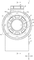
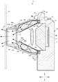
図1は、本発明を適用したダーモスコピーカメラの図であり、ダーモスコピー撮影時のダーモスコピーカメラの斜視図である。図2は、本発明を適用したダーモスコピーカメラの図であり、通常の撮影時のダーモスコピーカメラの斜視図である。図3は、本発明を適用したダーモスコピーカメラの正面図である。図4は、図3中の切断線IV−IVで切断したダーモスコピーカメラの分解切断面図である。図1〜図4に示すように、ダーモスコピーカメラ1は、カメラ本体(撮像装置本体)10と、カメラ本体10に回動可能に取り付けられたレンズユニット20とによって概略構成されている。
(Overall configuration of dermoscopy camera 1)
FIG. 1 is a view of a dermoscopy camera to which the present invention is applied, and is a perspective view of the dermoscopy camera at the time of dermoscopy shooting. FIG. 2 is a view of a dermoscopy camera to which the present invention is applied, and is a perspective view of the dermoscopy camera during normal shooting. FIG. 3 is a front view of a dermoscopy camera to which the present invention is applied. FIG. 4 is an exploded cut-out view of the dermoscopy camera cut along the cutting line IV-IV in FIG. As shown in FIGS. 1 to 4, the dermoscopy camera 1 is roughly composed of a camera body (imaging device body) 10 and a
なお、以下の説明において、図1に示すように、撮像対象側をダーモスコピーカメラ1の前方(前面、正面)、その反対側を後方とし、ダーモスコピーカメラ1を前方から見たときの上下左右方向をそのまま上下左右方向とした直交座標系に基づいて説明するものとする。また、各部材に関する取り付けは、特に言及がない限り、ネジ、ビス等を用いた取り付けや、嵌合等の取り付け等、適宜の方法で行えばよい。 In the following description, as shown in FIG. 1, the imaging target side is the front (front, front) of the dermoscopy camera 1, and the opposite side is the rear, and the vertical and horizontal directions when the dermoscopy camera 1 is viewed from the front are defined. The explanation will be given based on the Cartesian coordinate system in which the directions are up, down, left, and right. Further, unless otherwise specified, the attachment of each member may be performed by an appropriate method such as attachment using screws, screws or the like, attachment such as fitting, or the like.
ダーモスコピーカメラ1は、図1に示すように、レンズユニット20をカメラ本体10の前方に配置して(第1位置に配置して)ダーモスコピー撮影が可能なダーモスコピー撮影状態(第1撮影状態)と、図2に示すように、レンズユニット20を上方へ回動させて、カメラ本体10の前方を開放する配置として(第2位置に配置して)通常撮影が可能な通常撮影状態(第2撮影状態)とに切り替えることができる。なお、通常撮影とは、例えば皮膚疾患部の表面を撮影するといった一般的なカメラの使用方法による撮影を意味している。
As shown in FIG. 1, the dermoscopy camera 1 has a dermoscopy shooting state (first shooting state) in which the
(カメラ本体10の構成について)
カメラ本体10は、筐体11を有し、この筐体11の内部にズームレンズ部12、光源としての複数のLED(Light Emitting Diode)13aが搭載されたLED基板13、光拡散板14、回路配線基板30、及び撮像素子31といった種々の構成部品を収容している。筐体11には、上面にシャッタボタン18(図3)、右面に電源ボタン17が設けられている。
(About the configuration of the camera body 10)
The
さらに、筐体11の内部には、シャッタボタン18の操作に応じて、撮像素子31が読み取った撮影画像を記憶する記憶部と、上述した各部を制御する制御部と、上述した各部に電源を供給するバッテリー部と、が設けられているが、これらの図示は省略する。
Further, inside the
カメラ本体10には、通常の撮影に用いられる公知の撮影装置、例えば市販されているデジタルカメラの構成を採用することができ、例えば、ズームレンズ部12、回路配線基板30、及び撮像素子31は、公知の部品を用いることができる。ズームレンズ部12は公知の光学レンズを有している。また、撮像素子31としては、CCD(Charge Coupled Device)イメージセンサやCMOS(Complementary Metal Oxide Semiconductor)イメージセンサを用いることができる。また、カメラ本体10には、撮像した画像を表示するとともに、ダーモスコピーカメラ1の各種設定を実行するためのタッチパネル式の画面(不図示)が設けられている。
For the
筐体11には、ズームレンズ部12を取り囲むように、円環状の凹部からなる基板収容部11aが形成されている。LED13aを搭載したLED基板13は、基板収容部11aに収容されている。また、筐体11には、LED基板13の前方を覆うように光拡散部としての光拡散板14が載置されている。
The
LED基板13は円環状をなし、その前面には8つのLED13aが搭載されている。8つのLED13aは、図3に示すように、LED基板13の中心に対して同心円上に等間隔で配置されている。これにより、LED13aを搭載するLED基板13は、ズームレンズ部12の外周位置から光を前方に向けて出射するリングフラッシュとして機能する。LED13aは、白色光を発するLEDから構成されている。
The
光拡散板14は、例えば透光性を有する合成樹脂から構成されており、その表面に微小な凹凸が形成されている。光拡散板14は、LED13aから出射された光を通し、拡散光として前方へと出射する。
The
カメラ本体10の上部には、レンズユニット20を回動自在に支持する回動支持部19が形成されている。回動支持部19の左右の面にはそれぞれ、レンズユニット20の回動軸となる回動突起(不図示)が形成されている。この回動突起(不図示)にレンズユニット20の回動部25が軸支されることにより、レンズユニット20は回動軸Rを中心に回動することができる。
A
図2に示すように、筐体11の円環状の縁部には、前方に向けて突出した2つの係合凸部15が形成されているとともに、2箇所に磁性体16が取り付けられている。係合凸部15は、ダーモスコピーカメラ1がダーモスコピー撮影状態(図1)にある場合に、レンズユニット20の縁部に形成された係合凹部20aに係合する。これにより、カメラ本体10とレンズユニット20とを所定の位置関係とすることができる。また、カメラ本体10に設けられた磁性体16とレンズユニット20に設けられた磁性体26を互いに吸着させることにより、レンズユニット20がカメラ本体10に当接した状態を維持することができる。
As shown in FIG. 2, two engaging
(レンズユニット20の構成について)
レンズユニット20は、円錐体の先端がカットされたような筒状体のカバー体40、カバー体40の先端に取り付けられカバー体40と同様に円錐体の先端がカットされたような筒状体の先端カバー体41と、図4に示すように、カバー体40に取り付けられたコンバージョンレンズ21、及び導光板22と、先端カバー体41に取り付けられた偏光フィルタ23、及びカバーレンズ24と、を有している。レンズユニット20は、皮膚疾患部を拡大するためのダーモスコープとして機能する。
(About the configuration of the lens unit 20)
The
カバー体40は、例えばポリ塩化ビニル誘導体やアクリル系樹脂などの樹脂から構成されている。カバー体40の外形は、前方に向かうにつれて先細形状を有し、その内部は中空である。また、カバー体40の中空部も、前方に向かうにつれて縮径した形状を有している。
The
コンバージョンレンズ21は、両面凸レンズであり、カメラ本体10のズームレンズ部12と皮膚疾患部との間に介在し、撮像画像の拡大倍率を増大させる。具体的には、ズームレンズ部12の拡大倍率と合わせて、患者の疾患部を10〜30倍に拡大可能なレンズが採用される。コンバージョンレンズ21は図示しない支持部を介して、カバー体40の内周面に取り付けられている。
The
導光板22は、図4に示すように、入射した光を導光する導光板本体22bと、導光板本体22bの内周面に形成された反射膜22aと、導光板本体22bの外周面に形成された反射膜22cとを有している。導光板22は、前方に向けた縮径した中空の形態を有している。導光板22は、カバー体40の内周面に、自身の外周面を密着させた状態で取り付けられている。導光板本体22bは、例えば、アクリル等の透光性を有する合成樹脂から構成されている。導光板本体22bの後方側の端面は、光入射面22dを形成する。光入射面22dは、ダーモスコピー撮影状態の場合に、LED13aの前方に配され、LED13aから出射された光が入射する面である。一方、導光板本体22bの前方側の端面は、光出射面22eを形成する。光出射面22eは、導光板本体22bに導光された光が外部へ出射される面である。反射膜22a及び反射膜22cは、例えばアルミ等の金属膜であり、導光板本体22bの表面から導光される光が外部に漏れるのを防止する。これにより、光入射面22dから入射した光を弱めることなく、光出射面22eから出射することができる。
As shown in FIG. 4, the
先端カバー体41は、例えばポリ塩化ビニル誘導体やアクリル系樹脂などの樹脂から構成されている。先端カバー体41は、筒状体をなし、外周面には撮影者が指を引っ掛けるための凹部である引掛け部41aが複数形成されている。撮影者は、例えば先端カバー体41をカバー体40にねじ込むことにより、カバー体40の先端に先端カバー体41を装着することができる。このように、先端カバー体41とカバー体40とは螺号や嵌合などの公知の方法によって着脱自在な構成となっている。先端カバー体41の先端には、カバーレンズ24を嵌め込むための開口41bが形成されている。
The
偏光フィルタ23は、先端カバー体41の中空部に設けられる。先端カバー体41がカバー体40に装着されると、偏光フィルタ23は、導光板22の前方に配される。偏光フィルタ23は、導光板22の光出射面22eから出射された光を通過させる際に偏光する。偏光された光は、皮膚表面での乱反射が抑制されながら皮膚下の物質によって反射される。
The
カバーレンズ24は、先端カバー体41の先端に形成された開口41bに嵌合されている。カバーレンズ24は、透明の合成樹脂から構成されて、偏光フィルタ23から出射された光を前方へ通過させるとともに、反射光をダーモスコピーカメラ1内に入射させる。また、カバーレンズ24は、レンズユニット20内を湿気やほこりから保護する。ダーモスコピー撮影時には、カバーレンズ24は、皮膚疾患部に接触した状態にされる。
The
(ダーモスコピー撮影時におけるLED光の進行について)
図5は、ダーモスコピー撮影時におけるダーモスコピーカメラの切断面図である。LED13aから出射された光は、光拡散板14を通過し、光入射面22d(図4)から導光板本体22bに入射する。導光板本体22bに入射した光は、矢印L1、L2で示すように、反射膜22a、及び反射膜22cで反射されながら導光板本体22b内部で導光される。これにより導光される光は、先端に向かうにつれてレンズユニット20の中央に集光されていく。やがて、導光板本体22b内部で導光された光は、矢印L3に示すように、光出射面22eから出射され、偏光フィルタ23を通過する。偏光フィルタ23により偏光された光は、矢印L4に示すように、カバーレンズ24を通り前方へと出射される。
(About the progress of LED light during dermoscopy shooting)
FIG. 5 is a cut-out view of the dermoscopy camera during dermoscopy shooting. The light emitted from the
(通常撮影時におけるLED光の進行について)
図6は、通常撮影時におけるダーモスコピーカメラの切断面図である。LED13aから出射された光は、光拡散板14を通り、矢印L5に示すように、拡散光として前方へと出射される。このような光を出射するLED13aは、ズームレンズ部12の外側に設けられた円周上に等間隔で配置されており、ズームレンズ部12と略同一平面内に配置されている。
(About the progress of LED light during normal shooting)
FIG. 6 is a cut-out view of the dermoscopy camera during normal shooting. The light emitted from the
(LED光の照度分布について)
次に、ダーモスコピーカメラ1のLED13aから出射された光の照度分布について説明する。図7は、LEDから出射された光の照度分布の様子を示した概略図であり、(a)は図5に示す照射面における分布図、(b)は図6に示す照射面における分布図である。ここで、図5に示す照射面51は、ダーモスコピー撮影時における皮膚疾患部の表面位置に相当する。また、図6に示す照射面52は、通常撮影時における皮膚疾患部の表面位置に相当する。照射面52は、例えば、ダーモスコピーカメラ1から1メートル離間した位置にある。なお、図7各図においては、照度が高い領域ほど、白色に近い色で塗りつぶしてある。
(About the illuminance distribution of LED light)
Next, the illuminance distribution of the light emitted from the
上述したように、ダーモスコピー撮影時においては、LED13aから出射された光は、先端に向かうにつれてカバー体40の中央に向けて導光される。そのため、カバーレンズ24から出射される光は、LED13aからの光が集光された強い光となる。また、ダーモスコピー撮影時には、カバーレンズ24は皮膚疾患部に接触した状態にある。そのため、図7(a)に示すように、皮膚疾患部の表面に相当する照射面51に光が強く照射される照射領域51aが形成され、その外側に光が照射されない非照射領域51bが形成される。この照射領域51aの大きさは、カバーレンズ24(図5)の大きさとおおよそ同じである。このように、ダーモスコピー撮影時において、導光板22によって集光した強い光を皮膚疾患部に照射することができる。そのため、皮膚下の物質に光を照射、反射させることができ、ダーモスコピー画像を撮影することができる。
As described above, at the time of dermoscopy photography, the light emitted from the
一方、通常撮影時においては、図6に示すように、同心円上に等間隔で設けれらたLED13aからの光は光拡散板14により拡散されて前方へと出射される。これにより、照射面52に到達する光の照射範囲は、ダーモスコピー撮影時よりも広くなる一方、照射する光の強さは弱くなる。例えば、通常撮影時においては、図7(b)に示すように、照射面52に、照射領域51aよりも面積が大きいが低い照度の照射領域52aと、照射領域52aよりも面積が大きく照度が低い照射領域52bと、照射領域52bよりも面積が大きく照度が低い照射領域52cと、その外側に光が照射されない非照射領域52dが形成される。このことから、通常撮影時には、皮膚疾患部を中心として広範囲に光を照射することができる。また、通常撮影時には、ダーモスコピー撮影時よりも照度の低い照明での撮影が可能であることから、皮膚疾患部を含めた広い範囲を通常撮影することができる。
On the other hand, during normal shooting, as shown in FIG. 6, the light from the
(ダーモスコピーカメラ1の使用例)
ダーモスコピーカメラ1を用いてダーモスコピー撮影を行う場合、撮影者は、レンズユニット20を回動させて、図1に示すように、カメラ本体10にレンズユニット20を当接させた第1位置に移動させる。その際、カメラ本体10に形成された係合凸部(図2)をレンズユニット20に形成された係合凹部20aに挿入させるとともに、カメラ本体10の磁性体16とレンズユニット20の磁性体26とを吸着させる。これにより、カメラ本体10の前方をレンズユニットで覆ったダーモスコピー撮影状態を保持することができる。そして、撮影者は、電源ボタン17を押して電源を入れ、例えばシャッタボタン18を半押しすることによりLED13aを発光させる。そして、皮膚疾患部にカバーレンズ24を接触させる。これにより、偏光フィルタ23により偏光されカバーレンズ24から出射される光は、皮膚疾患部の表面での乱反射を抑制しながら皮膚下に到達し、皮膚下の物質によって反射される。この反射光は、カバーレンズ24及び偏光フィルタ23を介してダーモスコピーカメラ1内に取り込まれる。取り込まれた光は、コンバージョンレンズ21及びズームレンズ部12を介して10〜30倍に拡大され、カメラ本体10の撮像素子31上に結像される。任意のタイミングでカメラ本体10のシャッタボタン18を全押しすると、撮像素子31が読み取った撮像画像がカメラ本体10の記憶部に記憶される。このように記憶された撮像画像は、例えば、色素細胞母斑、悪性黒色腫、脂漏性角化症、基底細胞癌、血管病変及びボーエン病などの検査、及び診断に用いることができる。
(Example of using Dermoscopy camera 1)
When performing dermoscopy photography using the dermoscopy camera 1, the photographer rotates the
続いて、ダーモスコピーカメラ1を用いて通常撮影を行う場合、撮影者は、レンズユニット20を上方に回動させる。そして、図2に示すように、カメラ本体10の前方からレンズユニット20を移動させて、カメラ本体10の前方を開放する第2位置に配置する。そして、撮影者は、皮膚疾患部から所定距離離間させて、ズームレンズ部12を皮膚疾患部に向ける。続いて、撮影者は、例えばシャッタボタン18を半押しすることによりLED13aを発光させる。LED13aから出射された光は、拡散光となって、皮膚疾患部を中心とした広い範囲を照射する。照射した光は、皮膚疾患部の表面で反射され、ズームレンズ部12に取り込まれて、カメラ本体10の撮像素子31上に結像される。任意のタイミングでカメラ本体10のシャッタボタン18を全押しすると、撮像素子31が読み取った撮像画像がカメラ本体10の記憶部に記憶される。
Subsequently, when performing normal shooting using the dermoscopy camera 1, the photographer rotates the
(実施形態の効果について)
以上説明したように、本発明を適用したダーモスコピーカメラ1においては、カメラ本体10の前面をレンズユニット20で覆った状態で、ダーモスコピー撮影ができるとともに、カメラ本体の前面を開放した状態で、通常撮影をすることができる。そして、ダーモスコピー撮影と通常撮影との切り替えを、カメラ本体10の回動可能に取り付けられたレンズユニット20を回動させることだけで実現することができる。これにより、ダーモスコピーカメラ1において、ダーモスコピー撮影と通常撮影とを容易に切り替えることができる。
(About the effect of the embodiment)
As described above, in the dermoscopy camera 1 to which the present invention is applied, dermoscopy shooting can be performed with the front surface of the
また、ズームレンズ部12の外側の円周上に、等間隔でLED13aを配置することで、通常撮影時において、皮膚疾患部を中心として広範囲に光を照射することができる。さらに、LED13aの前方に光拡散板14を設置することによっても、通常撮影時に広範囲に光りを照射することができる。これにより、通常撮影時に、皮膚疾患部の周りを含めた広い範囲の画像を撮影することができる。
Further, by arranging the
また、ダーモスコピー撮影時に、LED13aから出射された光を導光し集光する導光板22を、レンズユニット20の内部に設けている。この導光板22により、LED13aから出射された光を弱めることなくダーモスコピーカメラ1から出射することができる。これにより、鮮明なダーモスコピー画像を得ることができる。
Further, a
また、導光板22の外周面及び内周面に反射膜22a、22cを形成することにより、導光板22が光を導光する際に外部に光が漏れることを抑制することができる。これにより、ダーモスコピー撮影時に、導光する光を弱めることなく、ダーモスコピーカメラ1から強い光を出射することができる。
Further, by forming the
また、導光板22の形状を、前方に向かうにつれ先細の形状とすることにより、導光板22に入射した光を先端に向けて集光することができる。これにより、ダーモスコピー撮影に必要な十分な光をダーモスコピーカメラ1から出射することができる。
Further, by making the shape of the
また、レンズユニット20に導光板22を設けることにより、通常撮影時及びダーモスコピー撮影時における光の照射を、共通のLED13aによって実現することができる。これにより、異なる撮影に合わせて複数種類の光源を設ける必要はなく、ダーモスコピーカメラ1の構成を簡略化することができる。
Further, by providing the
また、レンズユニット20において、カバー体40に先端カバー体41を取り外し自在な構成としている。ダーモスコピー撮影時には、カバーレンズ24は皮膚疾患部に接触させた状態で用いられるが、撮影が終了すると、カバーレンズ24が取り付けられた先端カバー体41を取り外して洗浄することができる。これにより、ダーモスコピー撮影後の洗浄作業を容易にすることができる。また、先端カバー体41を複数用意しておくことで、先端カバー体41を交換して、他の患者の撮影を行うことができ、診察時間の短縮を図ることができる。
Further, in the
(他の形態について)
この発明は、上記実施の形態に限定されず、様々な変形及び応用が可能である。上述の実施形態では、カメラ本体10に対してレンズユニット20を回動させることで、ダーモスコピー撮影と通常撮影とを切り換える形態について説明した。レンズユニット20の移動態様は、このような回動だけでなく、例えば、レンズユニット20をカメラ本体10に対してスライドさせる態様であってもよい。ダーモスコピー撮影の際は、ズームレンズ部12の前方をレンズユニット20で覆うように配置し、通常撮影の際は、レンズユニット20をスライドさせてズームレンズ部12の前方から移動させればよい。
(About other forms)
The present invention is not limited to the above-described embodiment, and various modifications and applications are possible. In the above-described embodiment, a mode for switching between dermoscopy photography and normal photography by rotating the
また、ダーモスコピー撮影に際して、偏光作用を有するジェルを皮膚疾患部に塗布して撮影する場合には、先端カバー体41に設けた偏光フィルタ23は省略することができる。なお、偏光フィルタ23を有する先端カバー体41と偏光フィルタ23を有しない先端カバー体41とを準備しておくことで、ダーモスコピー撮影時の撮影対応を状況に応じて選択することができる。
Further, in the case of applying a gel having a polarizing action to a skin disease portion for dermoscopy photography, the
また、上記実施形態では、光源は、円周上に配されたLED13aであると説明したが、他の光源を採用してもよい。例えば、ハロゲンランプなどの高輝度ライト、半導体発光素子、及び有機エレクトロルミネッセンスなどの発光素子を用いることができる。
Further, in the above embodiment, the light source is the
また、LED13aは、白色光を発するLEDから構成されていると説明したが、例えば紫外線光源、青色光光源、あるいは緑色光光源を採用してもよい。また発する光の色が互いに異なる光源を設けるようにして、異なる色の光源ごとに独立して発光できる態様であってもよい。このように、異なる色の光を照射して撮像画像を得ることで、異なる像をえることができ、異なる像を比較したり、像を重ね合わせたりすることで、皮膚疾患部の検査、及び診断を容易なものとすることができる。
Further, although it has been explained that the
また、上記実施形態では、LED13aの前方に光拡散板14を設置したが、通常撮影時に、照射面(図6)に広範囲に光を照射可能な光源を採用して、光拡散板14を省略してもよい。また、光拡散板14の代わりに、入射した光をそのまま透過する透明板を設置してもよい。
Further, in the above embodiment, the
また、ダーモスコピー撮影時には、カバーレンズ24は、皮膚疾患部に接触した状態にされると説明した。しかしながら、十分な照度の光を照射できるのであれば、カバーレンズ24を皮膚疾患部に近づけることで、ダーモスコピー撮影が可能である。この場合、ダーモスコピー撮影後の洗浄作業が不要となり、診察時間の短縮を図ることができる。
Further, it was explained that the
また、コンバージョンレンズ21は、一つの両面凸レンズであると説明したが、他の形態のものも採用することができる。例えば、コンバージョンレンズ21は、2つ又は複数の凸レンズを組み合わせたレンズ、1つのアクロマートレンズ、2つ又は複数のアクロマートレンズを組み合わせたいずれかであってもよい。また、コンバージョンレンズ21は、無収差レンズであってもよいし、球面レンズに非球面レンズを組み込んだものでも良い。また、これらのレンズが、反射防止膜やカラーフィルタを含むものであってもよい。
Further, although the
また、レンズユニット20に、LED13aからの光を先端に向けて集光する導光部材としての導光板22を設置したが、導光板22の代わりに他の公知の導光部材を設けるようにしてもよい。例えば、先端に向けて光を導光する光ファイバーを設けてもよい。
Further, although the
また、本発明に係る撮像装置は、上記実施形態で説明したダーモスコピーカメラ1のように、ダーモスコピー撮影状態と通常撮影状態との切り替え可能な撮像装置に限定されない。また、被写体としても皮膚疾患部に限定されない。例えば、構造物等に形成された穴の内部に光を照射して、光を照射した穴の内部を拡大して撮影する撮影状態(レンズユニットをカメラ本体の前方に位置させた状態)と、穴から離間した位置からから穴の周辺を含めた範囲を撮影する撮影状態(レンズユニットをカメラ本体の前方を開放する状態)とを切り替え可能な撮像装置等にも、本発明を適用することができる。 Further, the imaging device according to the present invention is not limited to an imaging device that can switch between a dermoscopy shooting state and a normal shooting state, such as the dermoscopy camera 1 described in the above embodiment. Further, the subject is not limited to the skin disease part. For example, a shooting state in which light is irradiated inside a hole formed in a structure or the like to enlarge the inside of the hole irradiated with light (a state in which the lens unit is positioned in front of the camera body). The present invention can also be applied to an imaging device or the like that can switch between a shooting state (a state in which the front of the camera body is opened with the lens unit) for photographing a range including the periphery of the hole from a position away from the hole. it can.
また、上記のダーモスコピーカメラ1においては、カメラ本体10に、シャッタボタン18や、ダーモスコピーカメラ1の各種設定を実行するためのタッチパネル式の画面(不図示)が設けられていると説明した。しかしながら、シャッタボタン18やタッチパネル式の画面(不図示)等の操作受付部を、カメラ本体とは物理的に分離した操作部に設けるようにしてもよい。カメラ本体と操作部とは、既存の通信技術を用いて双方向に通信可能である。撮影者は、操作部を操作することにより、カメラ本体の各種設定やシャッタ操作等を行うことができる。
Further, it has been explained that in the above-mentioned dermoscopy camera 1, the
また、上記のダーモスコピーカメラ1において、レンズユニット20はカメラ本体10に回動可能に取り付けられていると説明したが、レンズユニットをカメラ本体に対して着脱可能な構成としてもよい。図8は、本発明を適用したダーモスコピーカメラの他の実施形態を示した斜視図である。ダーモスコピーカメラ100は、レンズユニット120を回動可能に支持するための回動支持部19及び回動部25(共に図1参照)を有していない。一方で、ダーモスコピーカメラ100は、レンズユニット120をカメラ本体110に着脱する際に、撮影者が指を引っ掛けるための凹部160aが形成された装着リング160が形成されている。その他の構成については、上記実施形態で説明したダーモスコピーカメラ1の構成と同様である。そのため、図8において、同様の構成については同じ符号を付している。
Further, in the above-mentioned dermoscopy camera 1, the
通常撮影時には、レンズユニット120を取り外したカメラ本体110で皮膚疾患部を撮影する。一方、ダーモスコピー撮影時には、撮影者は、レンズユニット120をカメラ本体110にねじ込み装着する。レンズユニット120とカメラ本体110とは螺号や嵌合などの公知の方法によって着脱自在の構成となっている。そして、レンズユニット120が取り付けられたダーモスコピーカメラ100によって、ダーモスコピー撮影をすることができる。このように、レンズユニット120を、カメラ本体110に対して着脱することで、通常撮影状態と、ダーモスコピー撮影状態とを切り替えることができる。なお、通常撮影、及びダーモスコピー撮影の際における効果については、上記形態と同様である。
At the time of normal photographing, the skin disease portion is photographed by the
レンズユニット120は、上記実施形態のレンズユニット20と同様、カメラ本体110に設けられた光源(不図示)から発せられた光を導光板(不図示)で導光することで、ダーモスコピー撮影時に必要な光を照射する。そのため、レンズユニット120に光源を設ける必要がなく、レンズユニット120の構成を簡単なものとすることができる。
Similar to the
その他、上記実施の形態で示した構成などの具体的な細部は、本発明の趣旨を逸脱しない範囲において適宜変更可能である。 In addition, specific details such as the configuration shown in the above embodiment can be appropriately changed without departing from the spirit of the present invention.
本発明のいくつかの実施形態を説明したが、本発明の範囲は、上述の実施の形態に限定するものではなく、特許請求の範囲に記載された発明の範囲とその均等の範囲を含む。以下に、この出願の願書に最初に添付した特許請求の範囲に記載した発明を付記する。付記の番号は、この出願の願書に最初に添付した特許請求の範囲の通りである。 Although some embodiments of the present invention have been described, the scope of the present invention is not limited to the above-described embodiments, but includes the scope of the invention described in the claims and the equivalent scope thereof. The inventions described in the claims originally attached to the application of this application are added below. The additional numbers are as specified in the claims originally attached to the application for this application.
(付記1)
光源を有する撮像装置本体と、
前記撮像装置本体に移動可能に設けられ、入射した光を集光して出射する導光部材とコンバージョンレンズとを有するレンズユニットと、を備え、
前記光源から出射された光を前記導光部材に入射させる第1位置と、前記光源から出射された光を前記導光部材に入射させない第2位置との間で前記レンズユニットを移動させることで、第1撮影状態と第2撮影状態とを切り替える、
ことを特徴とする撮像装置。
(付記2)
前記レンズユニットは、前記撮像装置本体に回動可能に取り付けられており、
前記第1位置は、前記レンズユニットが前記撮像装置本体の前面を覆う位置であり、
前記第2位置は、前記レンズユニットが前記第1位置から回動して前記撮像装置本体の前面から離れた位置である、
ことを特徴とする付記1に記載の撮像装置。
(Appendix 1)
The main body of the imaging device that has a light source,
A lens unit that is movably provided in the main body of the image pickup apparatus and has a light guide member that collects and emits incident light and a conversion lens is provided.
By moving the lens unit between a first position where the light emitted from the light source is incident on the light guide member and a second position where the light emitted from the light source is not incident on the light guide member. , Switch between the first shooting state and the second shooting state,
An imaging device characterized by this.
(Appendix 2)
The lens unit is rotatably attached to the image pickup apparatus main body.
The first position is a position where the lens unit covers the front surface of the image pickup apparatus main body.
The second position is a position where the lens unit rotates from the first position and is separated from the front surface of the image pickup apparatus main body.
The imaging apparatus according to Appendix 1, wherein the image pickup apparatus is characterized by the above.
(付記3)
前記光源は、前記撮像装置本体に設けられた光学レンズの周囲に複数設けられている、
ことを特徴とする付記1又は2に記載の撮像装置。
(Appendix 3)
A plurality of the light sources are provided around the optical lens provided in the image pickup apparatus main body.
The imaging device according to Appendix 1 or 2, characterized in that.
(付記4)
前記第1撮影状態は、ダーモスコピー撮影状態であり、
前記第2撮影状態は、通常撮影状態である、
ことを特徴とする付記1乃至3のいずれか1項に記載の撮像装置。
(Appendix 4)
The first shooting state is a dermoscopy shooting state.
The second shooting state is a normal shooting state.
The imaging apparatus according to any one of Supplementary note 1 to 3, wherein the image pickup apparatus is characterized by the above.
(付記5)
前記導光部材は、先細の形状を有し、前記レンズユニットの内周面を覆うように取り付けられており、入射した光を先端に向けて導光することで、集光した光を出射する、
ことを特徴とする付記1乃至4のいずれか1項に記載の撮像装置。
(Appendix 5)
The light guide member has a tapered shape and is attached so as to cover the inner peripheral surface of the lens unit. By guiding the incident light toward the tip, the focused light is emitted. ,
The imaging apparatus according to any one of Supplementary Provisions 1 to 4, wherein the image pickup apparatus is characterized by the above.
(付記6)
前記撮像装置本体は、前記光源の光を拡散する光拡散部を有している、
ことを特徴とする付記1乃至5のいずれか1項に記載の撮像装置。
(Appendix 6)
The image pickup apparatus main body has a light diffusing portion that diffuses the light of the light source.
The imaging apparatus according to any one of Supplementary Provisions 1 to 5, wherein the image pickup apparatus is characterized by the above.
(付記7)
操作を受け付ける操作受付部を有し、受け付けた操作に基づいて前記撮像装置本体に指示を送る操作部をさらに備え、
前記操作部は、前記撮像装置本体と物理的に分離している、
ことを特徴とする付記1乃至6のいずれか1項に記載の撮像装置。
(Appendix 7)
It has an operation reception unit that accepts operations, and further includes an operation unit that sends an instruction to the image pickup apparatus main body based on the received operation.
The operation unit is physically separated from the image pickup apparatus main body.
The imaging apparatus according to any one of Supplementary Provisions 1 to 6, wherein the image pickup apparatus is characterized by the above.
(付記8)
光源を有する撮像装置本体に着脱可能な撮像装置用レンズユニットであって、
入射した光を集光して出射する導光部材と、コンバージョンレンズと、を備え、
前記撮像装置本体に取り付けられた際、前記光源から出射された光を前記導光部材に入射させて、前記コンバージョンレンズを介した撮影に必要な光を被写体に向けて照射する、
ことを特徴とする撮像装置用レンズユニット。
(Appendix 8)
A lens unit for an imaging device that can be attached to and detached from the main body of an imaging device that has a light source.
A light guide member that collects and emits incident light and a conversion lens are provided.
When attached to the main body of the imaging device, the light emitted from the light source is incident on the light guide member, and the light required for photographing through the conversion lens is directed toward the subject.
A lens unit for an imaging device.
1,100・・ダーモスコピーカメラ、10,110・・カメラ本体、11・・筐体、11a・・筐体、12・・ズームレンズ部、13・・LED基板、13a・・LED、14・・光拡散板、15・・係合凸部、16,26・・磁性体、17・・電源ボタン、18・・シャッタボタン、19・・回動支持部、20,120・・レンズユニット、20a・・係合凹部、21・・コンバージョンレンズ、22・・導光板、22a、22c・・反射膜、22b・・導光板本体、22d・・光入射面、22e・・光出射面、23・・偏光フィルタ、24・・カバーレンズ、25・・回動部、30・・回路配線基板、31・・撮像素子、40・・カバー体、41・・先端カバー体、41a・・引掛け部、41b・・開口、51,52・・照射面、51a,52a,52b,52c・・照射領域、51b,52d・・非照射領域 1,100 ... Dermos copy camera, 10,110 ... Camera body, 11 ... Housing, 11a ... Housing, 12 ... Zoom lens, 13 ... LED board, 13a ... LED, 14 ... Light Diffusing plate, 15 ... engaging convex part, 16,26 ... magnetic material, 17 ... power button, 18 ... shutter button, 19 ... rotating support part, 20,120 ... lens unit, 20a ... Engagement recess, 21 ... conversion lens, 22 ... light guide plate, 22a, 22c ... reflective film, 22b ... light guide plate body, 22d ... light incident surface, 22e ... light emitting surface, 23 ... polarizing filter , 24 ... Cover lens, 25 ... Rotating part, 30 ... Circuit wiring board, 31 ... Imaging element, 40 ... Cover body, 41 ... Tip cover body, 41a ... Hooking part, 41b ... Opening, 51, 52 ... Irradiated surface, 51a, 52a, 52b, 52c ... Irradiated area, 51b, 52d ... Non-irradiated area
Claims (6)
第2のレンズと、前記第2のレンズの周囲を囲うように設けられた導光部材と、を有するレンズユニットと、
前記撮像装置本体に対する前記レンズユニットの取り付け状態を、前記光源の発光面が前記導光部材における光入射面に覆われ且つ前記第1のレンズにおける第1の光軸と前記第2のレンズにおける第2の光軸とが一致する第1取り付け状態と、前記発光面が前記光入射面による覆いから解放され且つ前記第2のレンズが前記第1の光軸上から外れる第2取り付け状態との間で、切り替え可能に構成された取り付け手段と、
を備え、
前記導光部材は、前記光入射面が前記複数の発光素子の配列に対応させてリング状に形成されるとともに光出射面が前記光入射面よりも直径が小さいリング状に形成されることにより、前記第1の光軸上であって合焦距離に位置している被写体上での前記光源からの光の照度が、前記第2取り付け状態のときよりも前記第1取り付け状態のときの方が高くなるように構成されている、
ことを特徴とする撮像装置。 An image pickup apparatus main body having a first lens and a light source including a plurality of light emitting elements arranged so as to surround the first lens.
A lens unit having a second lens and a light guide member provided so as to surround the second lens.
The state in which the lens unit is attached to the image pickup apparatus main body is such that the light emitting surface of the light source is covered with the light incident surface of the light guide member, and the first optical axis of the first lens and the second lens of the second lens. Between the first mounting state in which the two optical axes coincide with each other and the second mounting state in which the light emitting surface is released from the cover by the light incident surface and the second lens is disengaged from the first optical axis. With the mounting means configured to be switchable,
With
The light guide member is formed by forming the light incident surface in a ring shape corresponding to the arrangement of the plurality of light emitting elements and forming the light emitting surface in a ring shape having a diameter smaller than that of the light incident surface. When the illuminance of the light from the light source on the subject located on the first optical axis and at the focusing distance is in the first mounting state than in the second mounting state. Is configured to be high,
An imaging device characterized by this.
ことを特徴とする請求項1に記載の撮像装置。 In the light guide member, the light emitting surface is inclined with respect to the light incident surface.
The imaging device according to claim 1.
ことを特徴とする請求項2に記載の撮像装置。 In the light guide member, the light emitting surface is inclined in a direction toward the second optical axis side.
The imaging device according to claim 2 , wherein the image pickup apparatus is characterized by the above.
ことを特徴とする請求項1乃至3のいずれか1項に記載の撮像装置。 The light guide member is formed in a hollow shape and is formed in a shape that tapers from the light incident surface side toward the light emitting surface side.
The imaging device according to any one of claims 1 to 3, wherein the image pickup apparatus is characterized by the above.
ことを特徴とする請求項1乃至4のいずれか1項に記載の撮像装置。 The second lens is formed so that the diameter of the second lens is smaller than the diameter of the light incident surface and larger than the diameter of the light emitting surface.
The imaging apparatus according to any one of claims 1 to 4.
第1のレンズと、前記第1のレンズの周囲を囲うように配列された複数の発光素子を含む光源と、を有する所定の撮像装置本体に対して前記撮像装置用レンズユニットを、第1取り付け状態で取り付けたときに、前記光源の発光面が前記導光部材における光入射面に覆われ且つ前記第1のレンズにおける第1の光軸と前記第2のレンズにおける第2の光軸とが一致する状態となるように構成され、且つ、前記第1取り付け状態とは異なる第2取り付け状態で取り付けたときに、前記発光面が前記光入射面による覆いから解放され且つ前記第2のレンズが前記第1の光軸上から外れる状態となるように構成され、 The lens unit for an image pickup device is first attached to a predetermined image pickup device main body having a first lens and a light source including a plurality of light emitting elements arranged so as to surround the first lens. When attached in this state, the light emitting surface of the light source is covered with the light incident surface of the light guide member, and the first optical axis of the first lens and the second optical axis of the second lens are aligned with each other. When mounted in a second mounting state different from the first mounting state and configured to match, the light emitting surface is released from the cover by the light incident surface and the second lens is released. It is configured so that it deviates from the first optical axis.
前記導光部材は、前記光入射面が前記複数の発光素子の配列に対応させてリング状に形成されるとともに光出射面が前記光入射面よりも直径が小さいリング状に形成されることにより、前記第1の光軸上であって合焦距離に位置している被写体上での前記光源からの光の照度が、前記第2取り付け状態のときよりも前記第1取り付け状態のときの方が高くなるように構成されている、 The light guide member is formed by forming the light incident surface in a ring shape corresponding to the arrangement of the plurality of light emitting elements and forming the light emitting surface in a ring shape having a diameter smaller than that of the light incident surface. When the illuminance of the light from the light source on the subject located on the first optical axis and at the focusing distance is in the first mounting state than in the second mounting state. Is configured to be high,
ことを特徴とする撮像装置用レンズユニット。 A lens unit for an imaging device.
Priority Applications (1)
| Application Number | Priority Date | Filing Date | Title |
|---|---|---|---|
| JP2017059849A JP6848585B2 (en) | 2017-03-24 | 2017-03-24 | Imaging device and lens unit for imaging device |
Applications Claiming Priority (1)
| Application Number | Priority Date | Filing Date | Title |
|---|---|---|---|
| JP2017059849A JP6848585B2 (en) | 2017-03-24 | 2017-03-24 | Imaging device and lens unit for imaging device |
Publications (3)
| Publication Number | Publication Date |
|---|---|
| JP2018163240A JP2018163240A (en) | 2018-10-18 |
| JP2018163240A5 JP2018163240A5 (en) | 2020-02-20 |
| JP6848585B2 true JP6848585B2 (en) | 2021-03-24 |
Family
ID=63860059
Family Applications (1)
| Application Number | Title | Priority Date | Filing Date |
|---|---|---|---|
| JP2017059849A Active JP6848585B2 (en) | 2017-03-24 | 2017-03-24 | Imaging device and lens unit for imaging device |
Country Status (1)
| Country | Link |
|---|---|
| JP (1) | JP6848585B2 (en) |
Families Citing this family (3)
| Publication number | Priority date | Publication date | Assignee | Title |
|---|---|---|---|---|
| JP7188469B2 (en) * | 2020-09-07 | 2022-12-13 | カシオ計算機株式会社 | IMAGING DEVICE COVER, IMAGING DEVICE, AND IMAGING METHOD |
| US20230314915A1 (en) * | 2020-09-07 | 2023-10-05 | Casio Computer Co., Ltd. | Imaging device cover, imaging device, and imaging method |
| WO2022130667A1 (en) * | 2020-12-15 | 2022-06-23 | デルマ医療合資会社 | Dermoscope, dermoscope adapter, and program |
Family Cites Families (4)
| Publication number | Priority date | Publication date | Assignee | Title |
|---|---|---|---|---|
| JPH07274048A (en) * | 1994-04-02 | 1995-10-20 | Sony Corp | Video data presenting device |
| JP4464164B2 (en) * | 2004-02-26 | 2010-05-19 | Hoya株式会社 | Lighting device for photography |
| EP2633678A4 (en) * | 2010-10-29 | 2015-05-20 | Univ California | Cellscope apparatus and methods for imaging |
| JP6323116B2 (en) * | 2014-03-28 | 2018-05-16 | カシオ計算機株式会社 | Dermoscope and lens unit for dermoscope |
-
2017
- 2017-03-24 JP JP2017059849A patent/JP6848585B2/en active Active
Also Published As
| Publication number | Publication date |
|---|---|
| JP2018163240A (en) | 2018-10-18 |
Similar Documents
| Publication | Publication Date | Title |
|---|---|---|
| CN108696695B (en) | Medical imaging device | |
| JP7264188B2 (en) | MEDICAL IMAGING DEVICE, IMAGING METHOD AND PROGRAM | |
| JP6848585B2 (en) | Imaging device and lens unit for imaging device | |
| US20160156820A1 (en) | Imaging apparatus and method for manufacturing imaging apparatus | |
| JP2023129440A (en) | Illumination device | |
| JP7310856B2 (en) | Lighting device and imaging device | |
| JP7139589B2 (en) | Imaging device | |
| JP6962107B2 (en) | Imaging device | |
| JP2004032068A (en) | Apparatus for imaging entire face | |
| JP2008289706A (en) | Face photographing apparatus | |
| JP7327453B2 (en) | lens unit | |
| JP2003043567A (en) | Camera housing | |
| TW201329607A (en) | Short-distance light source apparatus for image capturing device and image capturing device having the same | |
| JP7031298B2 (en) | Imaging device, imaging method and program | |
| JP2001027780A (en) | Lens unit for close-up | |
| JP6981148B2 (en) | Imaging device and dermoscopy camera | |
| JP7006261B2 (en) | Imaging device and attachment | |
| JP2006106388A (en) | Photographing range projecting display apparatus and electronic apparatus | |
| JP2019195557A (en) | Imaging device and filter unit | |
| JP7259929B2 (en) | Imaging device and attachment | |
| TWM541278U (en) | Oral mirror equipped with camera function | |
| JP3170199U (en) | Waterproof case with lighting device | |
| JP2008310227A (en) | Imaging apparatus | |
| WO2007034525A2 (en) | Device for taking digital photographs, especially for use in medical dermatology | |
| JP2019115453A (en) | Imaging device |
Legal Events
| Date | Code | Title | Description |
|---|---|---|---|
| A521 | Written amendment |
Free format text: JAPANESE INTERMEDIATE CODE: A523 Effective date: 20200110 |
|
| A621 | Written request for application examination |
Free format text: JAPANESE INTERMEDIATE CODE: A621 Effective date: 20200110 |
|
| A977 | Report on retrieval |
Free format text: JAPANESE INTERMEDIATE CODE: A971007 Effective date: 20201028 |
|
| A131 | Notification of reasons for refusal |
Free format text: JAPANESE INTERMEDIATE CODE: A131 Effective date: 20201117 |
|
| A521 | Written amendment |
Free format text: JAPANESE INTERMEDIATE CODE: A523 Effective date: 20210107 |
|
| TRDD | Decision of grant or rejection written | ||
| A01 | Written decision to grant a patent or to grant a registration (utility model) |
Free format text: JAPANESE INTERMEDIATE CODE: A01 Effective date: 20210202 |
|
| A61 | First payment of annual fees (during grant procedure) |
Free format text: JAPANESE INTERMEDIATE CODE: A61 Effective date: 20210215 |
|
| R150 | Certificate of patent or registration of utility model |
Ref document number: 6848585 Country of ref document: JP Free format text: JAPANESE INTERMEDIATE CODE: R150 |