JP6886918B2 - Computer system support design for dental equipment - Google Patents
Computer system support design for dental equipment Download PDFInfo
- Publication number
- JP6886918B2 JP6886918B2 JP2017535005A JP2017535005A JP6886918B2 JP 6886918 B2 JP6886918 B2 JP 6886918B2 JP 2017535005 A JP2017535005 A JP 2017535005A JP 2017535005 A JP2017535005 A JP 2017535005A JP 6886918 B2 JP6886918 B2 JP 6886918B2
- Authority
- JP
- Japan
- Prior art keywords
- patient
- removable dental
- dental device
- removable
- tooth
- Prior art date
- Legal status (The legal status is an assumption and is not a legal conclusion. Google has not performed a legal analysis and makes no representation as to the accuracy of the status listed.)
- Active
Links
- 238000013461 design Methods 0.000 title description 36
- 238000000034 method Methods 0.000 claims description 119
- 238000004519 manufacturing process Methods 0.000 claims description 90
- 230000001815 facial effect Effects 0.000 claims description 65
- 238000003860 storage Methods 0.000 claims description 31
- 238000010168 coupling process Methods 0.000 claims description 6
- 230000008878 coupling Effects 0.000 claims description 5
- 238000005859 coupling reaction Methods 0.000 claims description 5
- 230000008707 rearrangement Effects 0.000 claims description 5
- 229910052751 metal Inorganic materials 0.000 description 29
- 239000002184 metal Substances 0.000 description 29
- 239000000463 material Substances 0.000 description 18
- 238000000547 structure data Methods 0.000 description 16
- 210000000214 mouth Anatomy 0.000 description 14
- 230000006870 function Effects 0.000 description 12
- 210000002455 dental arch Anatomy 0.000 description 11
- 238000003384 imaging method Methods 0.000 description 11
- 230000008569 process Effects 0.000 description 11
- 238000010146 3D printing Methods 0.000 description 8
- 238000010586 diagram Methods 0.000 description 8
- 238000005266 casting Methods 0.000 description 7
- 238000003698 laser cutting Methods 0.000 description 7
- 230000036346 tooth eruption Effects 0.000 description 7
- 241000282465 Canis Species 0.000 description 6
- 210000004763 bicuspid Anatomy 0.000 description 6
- 210000004513 dentition Anatomy 0.000 description 6
- 238000003745 diagnosis Methods 0.000 description 6
- 238000005516 engineering process Methods 0.000 description 6
- 210000001847 jaw Anatomy 0.000 description 6
- 238000003801 milling Methods 0.000 description 6
- 238000005452 bending Methods 0.000 description 5
- 238000002591 computed tomography Methods 0.000 description 5
- 238000013500 data storage Methods 0.000 description 5
- 239000004033 plastic Substances 0.000 description 5
- 206010061274 Malocclusion Diseases 0.000 description 4
- 230000008901 benefit Effects 0.000 description 4
- 210000000988 bone and bone Anatomy 0.000 description 4
- 238000007408 cone-beam computed tomography Methods 0.000 description 4
- 238000012937 correction Methods 0.000 description 4
- 239000002861 polymer material Substances 0.000 description 4
- 238000007639 printing Methods 0.000 description 4
- 238000004458 analytical method Methods 0.000 description 3
- 230000015572 biosynthetic process Effects 0.000 description 3
- 230000008859 change Effects 0.000 description 3
- 238000005495 investment casting Methods 0.000 description 3
- 238000007726 management method Methods 0.000 description 3
- 210000002379 periodontal ligament Anatomy 0.000 description 3
- 238000009877 rendering Methods 0.000 description 3
- 238000012552 review Methods 0.000 description 3
- 239000007779 soft material Substances 0.000 description 3
- 238000003856 thermoforming Methods 0.000 description 3
- 238000012546 transfer Methods 0.000 description 3
- 208000006558 Dental Calculus Diseases 0.000 description 2
- KDLHZDBZIXYQEI-UHFFFAOYSA-N Palladium Chemical compound [Pd] KDLHZDBZIXYQEI-UHFFFAOYSA-N 0.000 description 2
- 230000005540 biological transmission Effects 0.000 description 2
- 239000000470 constituent Substances 0.000 description 2
- 238000010276 construction Methods 0.000 description 2
- 230000001054 cortical effect Effects 0.000 description 2
- 238000005520 cutting process Methods 0.000 description 2
- 230000001419 dependent effect Effects 0.000 description 2
- 210000004195 gingiva Anatomy 0.000 description 2
- 239000007943 implant Substances 0.000 description 2
- 238000001746 injection moulding Methods 0.000 description 2
- 238000002595 magnetic resonance imaging Methods 0.000 description 2
- 239000003550 marker Substances 0.000 description 2
- 238000012544 monitoring process Methods 0.000 description 2
- 230000003287 optical effect Effects 0.000 description 2
- BASFCYQUMIYNBI-UHFFFAOYSA-N platinum Chemical compound [Pt] BASFCYQUMIYNBI-UHFFFAOYSA-N 0.000 description 2
- 229920000642 polymer Polymers 0.000 description 2
- 210000003296 saliva Anatomy 0.000 description 2
- 239000000523 sample Substances 0.000 description 2
- 238000000110 selective laser sintering Methods 0.000 description 2
- 230000001360 synchronised effect Effects 0.000 description 2
- 210000001519 tissue Anatomy 0.000 description 2
- 238000013519 translation Methods 0.000 description 2
- FHVDTGUDJYJELY-UHFFFAOYSA-N 6-{[2-carboxy-4,5-dihydroxy-6-(phosphanyloxy)oxan-3-yl]oxy}-4,5-dihydroxy-3-phosphanyloxane-2-carboxylic acid Chemical compound O1C(C(O)=O)C(P)C(O)C(O)C1OC1C(C(O)=O)OC(OP)C(O)C1O FHVDTGUDJYJELY-UHFFFAOYSA-N 0.000 description 1
- BQCADISMDOOEFD-UHFFFAOYSA-N Silver Chemical compound [Ag] BQCADISMDOOEFD-UHFFFAOYSA-N 0.000 description 1
- 241001024096 Uleiota Species 0.000 description 1
- 239000006096 absorbing agent Substances 0.000 description 1
- 239000000853 adhesive Substances 0.000 description 1
- 238000004026 adhesive bonding Methods 0.000 description 1
- 230000001070 adhesive effect Effects 0.000 description 1
- 229940072056 alginate Drugs 0.000 description 1
- 229920000615 alginic acid Polymers 0.000 description 1
- 235000010443 alginic acid Nutrition 0.000 description 1
- 230000006399 behavior Effects 0.000 description 1
- 206010006514 bruxism Diseases 0.000 description 1
- 229910010293 ceramic material Inorganic materials 0.000 description 1
- 238000004040 coloring Methods 0.000 description 1
- 239000002131 composite material Substances 0.000 description 1
- 230000006835 compression Effects 0.000 description 1
- 238000007906 compression Methods 0.000 description 1
- 238000004590 computer program Methods 0.000 description 1
- 238000005094 computer simulation Methods 0.000 description 1
- 210000003464 cuspid Anatomy 0.000 description 1
- 239000002978 dental impression material Substances 0.000 description 1
- 230000009977 dual effect Effects 0.000 description 1
- 230000005489 elastic deformation Effects 0.000 description 1
- 239000003822 epoxy resin Substances 0.000 description 1
- 210000000887 face Anatomy 0.000 description 1
- 230000000977 initiatory effect Effects 0.000 description 1
- 239000010947 jewellery metal Substances 0.000 description 1
- 238000012423 maintenance Methods 0.000 description 1
- 230000014759 maintenance of location Effects 0.000 description 1
- 210000004373 mandible Anatomy 0.000 description 1
- 230000018984 mastication Effects 0.000 description 1
- 238000010077 mastication Methods 0.000 description 1
- 238000005259 measurement Methods 0.000 description 1
- 238000002844 melting Methods 0.000 description 1
- 230000008018 melting Effects 0.000 description 1
- 150000002739 metals Chemical class 0.000 description 1
- 238000012986 modification Methods 0.000 description 1
- 230000004048 modification Effects 0.000 description 1
- NJPPVKZQTLUDBO-UHFFFAOYSA-N novaluron Chemical compound C1=C(Cl)C(OC(F)(F)C(OC(F)(F)F)F)=CC=C1NC(=O)NC(=O)C1=C(F)C=CC=C1F NJPPVKZQTLUDBO-UHFFFAOYSA-N 0.000 description 1
- 230000000399 orthopedic effect Effects 0.000 description 1
- 239000005022 packaging material Substances 0.000 description 1
- 229910052763 palladium Inorganic materials 0.000 description 1
- 239000011505 plaster Substances 0.000 description 1
- 229910052697 platinum Inorganic materials 0.000 description 1
- 229920000647 polyepoxide Polymers 0.000 description 1
- -1 polyvinylsiloxane Polymers 0.000 description 1
- 238000002203 pretreatment Methods 0.000 description 1
- 229920005989 resin Polymers 0.000 description 1
- 239000011347 resin Substances 0.000 description 1
- 229910052703 rhodium Inorganic materials 0.000 description 1
- 239000010948 rhodium Substances 0.000 description 1
- MHOVAHRLVXNVSD-UHFFFAOYSA-N rhodium atom Chemical compound [Rh] MHOVAHRLVXNVSD-UHFFFAOYSA-N 0.000 description 1
- 238000005070 sampling Methods 0.000 description 1
- 230000011218 segmentation Effects 0.000 description 1
- 230000035939 shock Effects 0.000 description 1
- 229910052709 silver Inorganic materials 0.000 description 1
- 239000004332 silver Substances 0.000 description 1
- 239000007787 solid Substances 0.000 description 1
- 230000003319 supportive effect Effects 0.000 description 1
- 230000026676 system process Effects 0.000 description 1
- 239000003826 tablet Substances 0.000 description 1
- 230000001225 therapeutic effect Effects 0.000 description 1
- 238000003325 tomography Methods 0.000 description 1
- 230000036339 tooth positioning Effects 0.000 description 1
- 238000009966 trimming Methods 0.000 description 1
- 230000000007 visual effect Effects 0.000 description 1
- 239000003039 volatile agent Substances 0.000 description 1
Images


Classifications
-
- A—HUMAN NECESSITIES
- A61—MEDICAL OR VETERINARY SCIENCE; HYGIENE
- A61C—DENTISTRY; APPARATUS OR METHODS FOR ORAL OR DENTAL HYGIENE
- A61C7/00—Orthodontics, i.e. obtaining or maintaining the desired position of teeth, e.g. by straightening, evening, regulating, separating, or by correcting malocclusions
- A61C7/002—Orthodontic computer assisted systems
-
- A—HUMAN NECESSITIES
- A61—MEDICAL OR VETERINARY SCIENCE; HYGIENE
- A61C—DENTISTRY; APPARATUS OR METHODS FOR ORAL OR DENTAL HYGIENE
- A61C7/00—Orthodontics, i.e. obtaining or maintaining the desired position of teeth, e.g. by straightening, evening, regulating, separating, or by correcting malocclusions
- A61C7/08—Mouthpiece-type retainers or positioners, e.g. for both the lower and upper arch
-
- A—HUMAN NECESSITIES
- A61—MEDICAL OR VETERINARY SCIENCE; HYGIENE
- A61C—DENTISTRY; APPARATUS OR METHODS FOR ORAL OR DENTAL HYGIENE
- A61C7/00—Orthodontics, i.e. obtaining or maintaining the desired position of teeth, e.g. by straightening, evening, regulating, separating, or by correcting malocclusions
- A61C7/12—Brackets; Arch wires; Combinations thereof; Accessories therefor
- A61C7/20—Arch wires
-
- A—HUMAN NECESSITIES
- A61—MEDICAL OR VETERINARY SCIENCE; HYGIENE
- A61C—DENTISTRY; APPARATUS OR METHODS FOR ORAL OR DENTAL HYGIENE
- A61C7/00—Orthodontics, i.e. obtaining or maintaining the desired position of teeth, e.g. by straightening, evening, regulating, separating, or by correcting malocclusions
- A61C7/36—Devices acting between upper and lower teeth
Description
本開示は、歯列矯正に関し、より詳細には、歯科矯正診断及び治療を支援するためのコンピュータベースの方法に関する。 The present disclosure relates to orthodontics and, more particularly, to computer-based methods for assisting orthodontic diagnosis and treatment.
歯科矯正の分野は、機能及び美的外観を改善するために患者の歯群の位置を治すことに関する。例えば歯科矯正治療では、一般に患者の前歯、犬歯、及び小臼歯に固定される、ブラケットとして知られる小さな溝付き装置がしばしば使用される。アーチワイヤが各ブラケットの溝に受容され、望ましい向きに歯群の動きを案内するための軌道として機能する。アーチワイヤの端部は通常、患者の大臼歯に固定される、バッカルチューブとして知られる装置に受容される。アーチワイヤ及び装置は、一般的に「ブレース」と呼ばれる。歯科矯正治療は、透明なプラスチック歯位置決めトレイ又は他の機能的装置の使用によっても実施され得る。 The field of orthodontics relates to curing the position of the patient's tooth group to improve function and aesthetic appearance. For example, in orthodontic treatment, small grooved devices, commonly known as brackets, are often used, which are commonly fixed to the patient's anterior teeth, canines, and premolars. The arch wire is received by the groove of each bracket and functions as a trajectory to guide the movement of the tooth group in the desired direction. The end of the archwire is usually received by a device known as a buccal tube that is secured to the patient's molars. Archwires and devices are commonly referred to as "braces". Orthodontic treatment can also be performed by the use of clear plastic tooth positioning trays or other functional devices.
従来、歯科矯正の実施は、特定の患者に合った適正な装置の選択、口腔内への装置の配置、及び治療全体を通じた装置の調節などの手で行われる工程に頼っていた。より最近では、技術の進歩にともなって、これらの工程の一部は、コンピュータの使用によって支援されるようになりつつある。例えば、コンピュータを使用して個々の患者の歯群の配置を表すデータの取得を案内することができる。次いでこのデータを用いて患者の歯列を視覚化し、治療の任意の段階において歯科矯正治療の計画を診断して支援することができる。更に、これらのデータは、患者に合わせてカスタマイズされたブラケットなどの装置の製造に使用することができる。 Traditionally, orthodontic treatment has relied on manual steps such as selecting the right device for a particular patient, placing the device in the oral cavity, and adjusting the device throughout the treatment. More recently, with the advancement of technology, some of these processes are being assisted by the use of computers. For example, a computer can be used to guide the acquisition of data representing the placement of individual patient tooth groups. This data can then be used to visualize the patient's dentition to diagnose and assist with orthodontic treatment plans at any stage of treatment. In addition, these data can be used to manufacture devices such as brackets that are customized for the patient.
本開示は、歯の再配列及び/又は保守のための取り外し可能歯科用装置、並びに取り外し可能歯科用装置を設計、製造、及び使用するためのデバイス、システム、及び技術に関する。いくつかの例では、取り外し可能歯科用装置は、患者によって装着されたときに患者の歯群の咬合面を実質的に露出させる。咬合面を実質的に露出させる取り外し可能歯科用装置は、患者の歯群を実質的に閉塞する取り外し可能歯科用装置と比較して、患者の快適性の向上、歯科用装置の露出度の低下、歯間の空気及び唾液流の増加による歯石の増加の減少、及び患者が歯科用装置を取り外す必要なくある程度飲食することができるなど、いくつかの利点を提供し得る。 The present disclosure relates to removable dental devices for tooth rearrangement and / or maintenance, as well as devices, systems, and techniques for designing, manufacturing, and using removable dental devices. In some examples, the removable dental device substantially exposes the occlusal surface of the patient's tooth group when worn by the patient. A removable dental device that substantially exposes the occlusal surface improves patient comfort and reduces the exposure of the dental device compared to a removable dental device that substantially occludes the patient's calculus. It can provide several benefits, such as reduced tartar growth due to increased interdental air and saliva flow, and the ability for the patient to eat and drink to some extent without the need to remove the dental device.
一例では、本開示は、コンピュータシステムで、患者の1つ以上の歯の初期位置を提供する、患者の3次元(3D)歯牙構造のデジタル表現を受信することと、コンピュータシステムで、患者のための取り外し可能歯科用装置の寸法及び形状を決定することであって、取り外し可能歯科用装置の寸法及び形状が、取り外し可能歯科用装置が患者によって装着されたときに患者の1つ以上の歯を初期位置から調整された位置に再配置するように構成されている、ことと、コンピュータシステムで、取り外し可能歯科用装置の表現をコンピュータ支援製造システムに送信することとを含む方法を対象とする。取り外し可能歯科用装置は、患者の2つ以上の歯を囲むように構成された装置本体を含む。装置本体は、囲まれた歯群の顔面側に整合するように構成された顔面部分と、囲まれた歯群の舌側に整合するように構成された舌部分とを含む。装置本体は、取り外し可能歯科用装置が患者によって装着されたとき、患者の囲まれた歯群の咬合面が露出されるように構成されている。 In one example, the present disclosure is to receive a digital representation of a patient's three-dimensional (3D) tooth structure, which provides the initial position of one or more teeth of the patient in a computer system, and for the patient in a computer system. The size and shape of the removable dental device is to determine one or more teeth of the patient when the removable dental device is worn by the patient. It covers methods that are configured to reposition from an initial position to an adjusted position, and that the computer system sends a representation of the removable dental device to a computer-assisted manufacturing system. The removable dental device includes a device body configured to surround two or more teeth of the patient. The device body includes a facial portion configured to be aligned with the facial side of the enclosed tooth group and a tongue portion configured to be aligned with the lingual side of the enclosed tooth group. The device body is configured to expose the occlusal surface of the patient's enclosed tooth group when the removable dental device is worn by the patient.
加えて、本開示は、実行されると、そのような方法を実行するようにプロセッサを構成するコンピュータシステム実行可能命令を格納するコンピュータ可読記憶媒体を更に対象とする。 In addition, the present disclosure further covers computer-readable storage media that, when executed, store computer system executable instructions that configure the processor to perform such methods.
更なる例では、本開示は、実行されると、患者の1つ以上の歯の初期位置を提供する、患者の3次元(3D)歯牙構造のデジタル表現を受信し、患者のための取り外し可能歯科用装置の寸法及び形状を決定し、取り外し可能歯科用装置の寸法及び形状が、取り外し可能歯科用装置が患者によって装着されたときに患者の1つ以上の歯を初期位置から調整された位置に再配置するように構成されており、取り外し可能歯科用装置の表現をコンピュータ支援製造システムに送信するようにプロセッサを構成するコンピュータ実行可能命令を格納するコンピュータ可読記憶媒体を対象とする。取り外し可能歯科用装置は、患者の2つ以上の歯を囲むように構成された装置本体を含む。装置本体は、囲まれた歯群の顔面側に整合するように構成された顔面部分と、囲まれた歯群の舌側に整合するように構成された舌部分とを含む。装置本体は、取り外し可能歯科用装置が患者によって装着されたとき、患者の囲まれた歯群の咬合面が露出されるように構成されている。 In a further example, the disclosure, when implemented, receives a digital representation of the patient's three-dimensional (3D) tooth structure, which provides the initial position of one or more teeth of the patient, and is removable for the patient. Determines the dimensions and shape of the dental device, and the dimensions and shape of the removable dental device are the positions where one or more teeth of the patient are adjusted from their initial position when the removable dental device is worn by the patient. It is intended to be relocated to a computer-readable storage medium that stores computer-executable instructions that configure the processor to send a representation of a removable dental device to a computer-assisted manufacturing system. The removable dental device includes a device body configured to surround two or more teeth of the patient. The device body includes a facial portion configured to be aligned with the facial side of the enclosed tooth group and a tongue portion configured to be aligned with the lingual side of the enclosed tooth group. The device body is configured to expose the occlusal surface of the patient's enclosed tooth group when the removable dental device is worn by the patient.
別の例では、本開示は、患者の1つ以上の歯の初期位置を提供する、患者の3次元(3D)歯牙構造のデジタル表現を格納する1つ以上のデータベースと、1つ以上のプロセッサとを含むコンピュータシステムを対象とする。3D歯牙構造のデジタル表現にアクセスし、患者のための取り外し可能歯科用装置の寸法及び形状を決定し、取り外し可能歯科用装置の寸法及び形状が、取り外し可能歯科用装置が患者によって装着されたときに患者の1つ以上の歯を初期位置から調整された将来の位置に再配置するように構成されており、取り外し可能歯科用装置の表現をコンピュータ支援製造システムに送信するように構成されている1つ以上のプロセッサ。取り外し可能歯科用装置は、患者の2つ以上の歯を囲むように構成された装置本体を含む。装置本体は、囲まれた歯群の顔面側に整合するように構成された顔面部分と、囲まれた歯群の舌側に整合するように構成された舌部分とを含む。装置本体は、取り外し可能歯科用装置が患者によって装着されたとき、患者の囲まれた歯群の咬合面が露出されるように構成されている。 In another example, the disclosure provides one or more databases and one or more processors that store a digital representation of a patient's three-dimensional (3D) tooth structure that provides the initial position of one or more teeth of the patient. Targets computer systems including and. Access the digital representation of the 3D tooth structure to determine the dimensions and shape of the removable dental device for the patient, and the dimensions and shape of the removable dental device when the removable dental device is worn by the patient It is configured to reposition one or more teeth of the patient from the initial position to the adjusted future position and to transmit the representation of the removable dental device to the computer assisted manufacturing system. One or more processors. The removable dental device includes a device body configured to surround two or more teeth of the patient. The device body includes a facial portion configured to be aligned with the facial side of the enclosed tooth group and a tongue portion configured to be aligned with the lingual side of the enclosed tooth group. The device body is configured to expose the occlusal surface of the patient's enclosed tooth group when the removable dental device is worn by the patient.
更なる例では、本開示は、患者の1つ以上の歯を再配置するように構成された取り外し可能歯科用装置を対象とする。取り外し可能歯科用装置は、患者の2つ以上の歯を囲むように構成されたアクティブバンドを形成する装置本体を備えることを含む。装置本体は、囲まれた歯群の顔面側に整合するように構成された顔面部分と、囲まれた歯群の舌側に整合するように構成された舌部分とを含む。装置本体の顔面部分及び装置本体の舌部分は、受け部を形成する。各受け部は、囲まれた歯群のうちの少なくとも1つを受けるように構成されている。受け部は、装置本体の少なくとも前方部分に沿って、顔面部分を舌部分から分離する。アクティブバンドは、囲まれた歯群が装置本体のアクティブバンド内に配置された状態で、取り外し可能歯科用装置が患者によって装着されたとき、患者の囲まれた歯群の咬合面が露出されるように構成されている。 In a further example, the present disclosure is directed to a removable dental device configured to reposition one or more teeth of a patient. The removable dental device includes a device body that forms an active band configured to surround two or more teeth of the patient. The device body includes a facial portion configured to be aligned with the facial side of the enclosed tooth group and a tongue portion configured to be aligned with the lingual side of the enclosed tooth group. The face portion of the device body and the tongue portion of the device body form a receiving portion. Each receiving portion is configured to receive at least one of the enclosed tooth groups. The receiving portion separates the facial portion from the tongue portion along at least the anterior portion of the device body. The active band exposes the occlusal surface of the patient's enclosed tooth group when the removable dental device is worn by the patient with the enclosed tooth group placed within the active band of the device body. It is configured as follows.
別の例では、本開示は、患者の1つ以上の歯を再配置するように構成された取り外し可能歯科用装置の順序付けされたセットを含むシステムを対象とし、取り外し可能歯科用装置のセット内の各取り外し可能歯科用装置は、患者の2つ以上の歯を囲むように構成されたアクティブバンドを形成する装置本体を含む。装置本体は、囲まれた歯群の顔面側に整合するように構成された顔面部分と、囲まれた歯群の舌側に整合するように構成された舌部分とを含む。装置本体の顔面部分及び装置本体の舌部分は、受け部を形成する。各受け部は、囲まれた歯群のうちの少なくとも1つを受けるように構成されている。アクティブバンドは、装置本体の少なくとも前方部分に沿って、顔面部分を舌部分から分離する。アクティブバンドは、囲まれた歯群が装置本体のアクティブバンド内に配置された状態で、取り外し可能歯科用装置が患者によって装着されたとき、患者の囲まれた歯群の咬合面が露出されるように構成されている。 In another example, the disclosure relates to a system that includes an ordered set of removable dental devices configured to reposition one or more teeth of a patient, within a set of removable dental devices. Each removable dental device includes a device body that forms an active band configured to surround two or more teeth of the patient. The device body includes a facial portion configured to be aligned with the facial side of the enclosed tooth group and a tongue portion configured to be aligned with the lingual side of the enclosed tooth group. The face portion of the device body and the tongue portion of the device body form a receiving portion. Each receiving portion is configured to receive at least one of the enclosed tooth groups. The active band separates the facial portion from the tongue portion along at least the anterior portion of the device body. The active band exposes the occlusal surface of the patient's enclosed tooth group when the removable dental device is worn by the patient with the enclosed tooth group placed within the active band of the device body. It is configured as follows.
本開示の1つ以上の実施例の詳細を添付図面及び以下の説明に示す。本開示の他の特徴、目的、及び利点は、説明及び図面、並びに特許請求の範囲から明らかになるであろう。 Details of one or more embodiments of the present disclosure are shown in the accompanying drawings and the following description. Other features, objectives, and advantages of the present disclosure will become apparent from the description and drawings, as well as the claims.
図1は、診療所44及び製造施設48が患者42のための取り外し可能歯科用装置のセット52の製造プロセス全体にわたって情報を通信する例示的なコンピュータ環境40を示すブロック図である。最初に、診療所44の歯列矯正施術者は、任意の適切な画像化技術を使用して患者42の歯科構造体の1つ以上の画像を生成し、デジタル歯科構造体データ46(例えば、患者の42の歯牙構造のデジタル表示)を生成する。例えば、施術者は、デジタル走査することができるX線画像を生成し得る。あるいは、施術者は、例えば、従来のコンピュータ断層撮影法(CT)、レーザー走査、口腔内走査、歯科印象のCT走査、印象から注がれた歯科用キャストの走査、超音波計測、磁気共鳴イメージング(MRI)、又は3Dデータ取得の任意の他の適切な方法などを使用して、患者の歯牙構造のデジタル画像を捕捉することができる。他の実施形態では、デジタル画像は、Brontes Technologies,Inc.(マサチューセッツ州レキシントン)によって開発され、参照により本明細書に組み込まれるPCT国際公開第2007/084727号(Boerjesら)に記載されているアクティブ波面サンプリング(active wavefront sampling)を使用する口腔内スキャナのようなハンドヘルド口腔内スキャナを使用して提供され得る。あるいは、他の口腔内スキャナ又は口腔内コンタクトプローブを使用することもできる。別の選択肢として、デジタル構造データ48は、患者の歯群の陰の印象(negative impression)を走査することによって提供され得る。更に別の選択肢として、デジタル構造データ48は、患者の歯群の正の物理モデルを画像化することによって、又は患者の歯群のモデル上でコンタクトプローブを使用することによって提供され得る。走査に使用されるモデルは、例えば、アルギネート又はポリビニルシロキサン(PVS)などの好適な歯科印象材から、患者の歯列の印象をキャスティングし、キャスティング材料(例えば、歯科矯正石膏又はエポキシ樹脂)を歯科印象材に注ぎ、キャスティング材料を硬化させることによって作製され得る。上記のものを含めて、モデルの走査に任意の適切な走査技術が使用されてもよい。他の可能な走査方法は、参照により本明細書に組み込まれる米国特許公開第2007/0031791号(Cinaderら)に記載されている。
FIG. 1 is a block diagram illustrating an
歯の露出面を走査してデジタル画像を提供することに加え、歯列の隠れた特徴部、例えば、患者の歯根、及び患者の顎骨を画像化することが可能である。いくつかの実施形態では、デジタル歯牙構造データは、これらの特徴部のいくつかの3D画像を提供し、その後、それらを一緒に「つなぎ合わせる」ことによって形成される。これらの異なる画像は、同じ画像化技術を使用して提供される必要はない。例えば、CT走査で得られた歯根のデジタル画像が、口内可視光スキャナで得られた歯冠のデジタル画像と一体化されてもよい。3D歯科用画像に対する2D歯科用画像のスケーリング及び整合は、参照により本明細書に組み込まれる米国特許第6,845,175号(Kopelmanら)、及び同じく参照により本明細書に組み込まれる米国特許公開第2004/0029068号(Baduraら)に記載されている。参照により本明細書に組み込まれる発行された米国特許第7,027,642号(Imgrundら)、及び同じく参照により本明細書に組み込まれる同第7,234,937号(Sachdevaら)は、様々な3Dソースから提供されるデジタル画像を統合する技術を使用することを記載する。したがって、用語「画像化」は、これが本明細書において使用される際、視覚的に明らかな構造の、通常の写真画像化に限定されず、視界から隠れた歯牙構造の画像化をも含む。歯科構造体は、限定はしないが、歯列弓、歯肉、歯周靭帯、歯槽骨、皮質骨、インプラント、人工クラウン、ブリッジ、ベニア、義歯、歯科矯正装置、又は治療前、治療中、若しくは治療後の歯列の一部とみなされ得る任意の構造体の1つ以上の歯の冠部及び/又は根部の任意の部分を含み得る。 In addition to scanning the exposed surface of the tooth to provide a digital image, it is possible to image hidden features of the dentition, such as the root of the patient and the jawbone of the patient. In some embodiments, digital tooth structure data is formed by providing some 3D images of these features and then "stitching" them together. These different images need not be provided using the same imaging technique. For example, the digital image of the tooth root obtained by CT scanning may be integrated with the digital image of the crown obtained by the oral visible light scanner. Scaling and matching of 2D dental images to 3D dental images is incorporated herein by reference to US Pat. No. 6,845,175 (Kopelman et al.), And US Patent Publication, also incorporated herein by reference. No. 2004/0029068 (Badura et al.). U.S. Pat. Nos. 7,027,642 (Imgrund et al.), Which is incorporated herein by reference, and 7,234,937 (Sachdeva et al.), Which is also incorporated herein by reference, are various. Describes the use of techniques for integrating digital images provided by patented 3D sources. Thus, the term "imaging", when used herein, includes not only the normal photographic imaging of visually apparent structures, but also the imaging of tooth structures hidden from view. Dental structures are, but are not limited to, dental arches, gingiva, periodontal ligaments, alveolar bone, cortical bones, implants, artificial crowns, bridges, veneers, dentures, orthodontic appliances, or pre-treatment, during-treatment, or treatment. It may include any part of the crown and / or root of one or more teeth of any structure that can be considered part of the later dentition.
デジタル歯牙構造データ46を生成するために、コンピュータは、画像化システムからの生データを使用可能なデジタルモデルに変換しなければならない。例えば、コンピュータによって受信された歯群の形状を表す生データの場合、生データは、しばしば、3D空間内の点群にすぎない。通常、この点群は、1つ以上の歯、歯肉組織、及び他の周囲の口腔構造を含む患者の歯列の3Dオブジェクトモデルを形成するために表面処理される。このデータが歯科矯正診断及び治療に有用であるために、コンピュータは、歯列表面を「セグメント化」して、個々の歯を表す1つ以上の個別の可動の3Dの歯のオブジェクトモデルを生成し得る。コンピュータは、更に、これらの歯のモデルを歯肉から別個のオブジェクトに分離し得る。 To generate the digital tooth structure data 46, the computer must convert the raw data from the imaging system into a usable digital model. For example, in the case of raw data representing the shape of a tooth group received by a computer, the raw data is often just a point cloud in 3D space. Usually, this point cloud is surface treated to form a 3D object model of the patient's dentition, including one or more teeth, gingival tissue, and other surrounding oral structures. To make this data useful for orthodontic diagnosis and treatment, the computer "segments" the tooth row surface to generate one or more individual movable 3D tooth object models that represent individual teeth. Can be done. The computer can also separate these tooth models from the gingiva into separate objects.
セグメント化によって、使用者は、歯群の配列を一群の個々のオブジェクトとして特徴づけ、操作することが可能となる。好都合なことに、コンピュータは、これらのモデルから、アーチ長、咬合設定、及び米国矯正歯科矯正学会(American Board of Orthodontics、ABO)の客観的な評価などの診断情報を導出することができる。更なる利点として、デジタル歯科矯正のセットアップは、製造プロセスにおける柔軟性を提供し得る。物理的プロセスをデジタルプロセスに置き換えることによって、データ取得工程とデータ操作工程とを、歯型又は印象をある場所から別の場所へ輸送する必要なく、別々の場所で実行することができる。物理的物体を往復輸送する必要を低減又はなくすことにより、顧客及びカスタマイズされた装置の製造者の両者にとって大幅なコストの節減につながりうる。 Segmentation allows the user to characterize and manipulate the array of teeth as a group of individual objects. Conveniently, the computer can derive diagnostic information from these models, such as arch length, occlusal setting, and objective assessment of the American Board of Orthodontics (ABO). As a further advantage, the digital orthodontic setup may provide flexibility in the manufacturing process. By replacing the physical process with a digital process, the data acquisition process and the data manipulation process can be performed at different locations without the need to transport the tooth mold or impression from one location to another. Reducing or eliminating the need for reciprocating physical objects can lead to significant cost savings for both customers and manufacturers of customized equipment.
デジタル歯科構造体データ46を生成した後、診療所44は、データベース内の患者記録内にデジタル歯科構造体データ46を格納し得る。診療所44は、例えば、複数の患者記録を有するローカルデータベースを更新することができる。あるいは、診療所44は、ネットワーク50を介して(任意に製造施設48内の)中央データベースを遠隔から更新することができる。デジタル歯牙構造データ46が格納された後、診療所44は、デジタル歯科構造体データ46を製造施設48に電子的に通信する。あるいは、製造施設48は、中央データベースからデジタル歯科構造体データ46を取り出すことができる。
After generating the digital dental structure data 46, the
また、診療所44は、患者42についての施術者の診断及び治療計画に関する一般情報を製造施設48に伝達する処方データ47を転送し得る。いくつかの例では、処方データ47は、より具体的であり得る。例えば、デジタル歯科構造体データ46は、患者42の歯科構造体のデジタル表現であり得、診療所44の施術者は、デジタル表現をレビューし、デジタル歯科構造体データ46を製造施設48に転送する前に、取り外し可能歯科用装置のセット52で治療した後の患者42の個々の歯の所望の移動、間隔、又は最終位置を示すことができる。製造施設48は、離れた場所に設置されていてもよく、又は診療所44に設置されていてもよい。
The
例えば、各診療所44は、ローカルにインストールされたソフトウェアを使用して、臨床現場で、臨床施術者又は助手によって治療計画及びデジタル設計が完全に実行され得るように、製造施設48のためのそれ自体の設備を含み得る。製造は、3Dプリンタを使用することによって(又は追加の製造の他の方法によって)診療所で行うこともできる。3Dプリンタは、歯科用装置の複雑な特徴又は患者42の歯科構造体の物理的表現を追加の印刷によって製造を可能にする。3Dプリンタは、患者42の所望の歯科構造体を生成するようにカスタマイズされた複数のデジタル装置及び/又はデジタル装置パターンを生成するために、患者42の元の歯科構造体並びに患者42の所望の歯牙構造の反復デジタル設計を使用し得る。製造は、未硬化樹脂を取り除き、支持構造を取り除くため、又は様々な構成成分を組み立てるための後処理を含み得、これらも必要であり得、臨床的な環境で実施することもできる。
For example, each
製造施設48は、患者42の歯群を再配置するために、患者42のデジタル歯科構造体データ46を利用して、取り外し可能歯科用装置のセット52を構築する。その後、製造施設48は、取り外し可能歯科用装置のセット52を診療所44に、あるいは患者42に直接転送する。例えば、取り外し可能歯科用装置のセット52は、取り外し可能歯科用装置の順序付けされたセットであり得る。次いで、患者42は、患者42の歯群を再配置するために、所定のスケジュールに従って、時間の経過とともに順次、取り外し可能歯科用装置のセット52内の取り外し可能歯科用装置を装着する。例えば、患者42は、約2週間〜約12週間、例えば約3週間〜約10週間、又は約4週間〜約8週間の期間にわたって取り外し可能歯科用装置のセット52内の各取り外し可能歯科用装置を装着し得る。任意に、患者42は、取り外し可能歯科用装置52による治療の進行の定期的な監視のために、診療所44に戻ることができる。
The
そのような定期的な監視の間、臨床医は、時間の経過とともに順次、取り外し可能歯科用装置のセット52内の取り外し可能歯科用装置を装着するための患者42の所定のスケジュールを調整することができる。監視は、一般に、患者42の歯群の目視検査を含み、デジタル歯牙構造データを生成するための画像化も含み得る。比較的まれな状況では、臨床医は、例えば、新しい取り外し可能歯科用装置のセットを生成するために、新しく生成されたデジタル歯科構造体データを製造施設48に送ることによって、取り外し可能歯科用装置52のセットによる患者42の治療を中断することを決定することができる。同じ又は異なる例では、臨床医は、取り外し可能歯科用装置52による治療の所定のスケジュールの完了後、新しく生成されたデジタル歯科構造体データを製造施設48に送ることができる。加えて、取り外し可能歯科用装置52による治療の所定のスケジュールの完了後、臨床医は、患者42の治療を継続するために、製造施設48に新しい取り外し可能歯科用装置のセットを要求し得る。
During such regular monitoring, the clinician, over time, sequentially adjusts the patient 42's predetermined schedule for wearing the removable dental device within the
図2は、本開示の一例による診療所44で行われるプロセス60を示す流れ図である。最初に、診療所44の施術者は、患者42から患者識別情報及び他の情報を収集し、患者記録を作成する(62)。上述したように、患者記録は、診療所44内に置かれていてもよく、任意に、製造施設48内のデータベースとデータを共有するように構成されてもよい。あるいは、患者記録は、ネットワーク50を介して診療所44が遠隔でアクセス可能な製造施設48のデータベース内、又は製造施設48と診療所44の両方によって遠隔でアクセス可能なデータベース内に置かれていてもよい。
FIG. 2 is a flow chart showing a
次に、任意の適切な技術を使用して患者42の歯科構造体のデジタルデータ46が生成され得(64)、それによって、仮想の歯科構造体を作成することができる。デジタルデータ46は、歯科構造体の2次元(2D)画像及び/又は3次元(3D)表現で構成され得る。 Digital data 46 of the dental structure of patient 42 can then be generated using any suitable technique (64), thereby creating a virtual dental structure. The digital data 46 may consist of a two-dimensional (2D) image and / or a three-dimensional (3D) representation of the dental structure.
一例では、歯科構造体の3D表現は、Imaging Sciences International,LLC;1910 N Penn Road,Hatfield,PAから入手可能なi−CAT 3D歯科用画像化デバイスなど、コーンビームコンピュータ断層撮影(cone beam computerized tomography、CBCT)スキャナを使用して生成される。診療所44は、CBCTスキャナから生成された3Dデータ46(放射線画像の形態)を診療所44内あるいは製造施設48内に配置されたデータベースに格納する。コンピューティングシステムは、3Dモデリング環境内で操作され得る歯牙構造のデジタル表現を計算するために、複数のスライスの形態であり得る、CBCTスキャナからのデジタルデータ46を処理する。
In one example, the 3D representation of the dental structure is cone beam computerized tomography, such as the i-CAT 3D dental imaging device available from Imaging Sciences International, LLC; 1910 N Penn Road, Hatfield, PA. , CBCT) Generated using a scanner. The
2D放射線画像が使用される場合(65)、施術者は、3Dデジタルデータを更に生成することができる(66)。3Dデータ46は、例えば、患者42の歯牙構造の物理的な印象又はキャスティングを形成し、続いてデジタル的に走査することによって生成され得る。例えば、患者42の歯列弓の物理的印象又はキャスティングは、ミネソタ州ミネアポリスのLaser Design,Inc.から入手可能なOM−3Rスキャナなどの可視光スキャナを使用して走査され得る。あるいは、施術者は、患者42の歯列弓の口腔内走査又は既存の3D歯データを使用して、咬合サービスの3Dデータ46を生成し得る。一例では、「REGISTERING PHYSICAL AND VIRTUAL TOOTH STRUCTURES WITH PEDESTALS」という名称の2013年7月23に発行された米国特許第8,491,306号に記載されたキャスティング又は印象からデジタル走査を形成する方法が使用され得る。米国特許第8,491,306号は、その全体が参照により本明細書に組み込まれる。同じ又は異なる例では、「ORTHODONTIC DIGITAL SETUPS」という名称の2014年11月25日に公開された米国特許第8,897,902号に記載された仮想歯面及び仮想歯座標系を画定する技術が使用され得る。米国特許第8,897,902号は、その全体が参照により本明細書に組み込まれる。いずれにしても、デジタルデータは3Dモデリング環境内でデジタル的に整合され、歯根及び咬合面を含み得る歯牙構造の複合デジタル表現を形成する。 When 2D radiographic images are used (65), the practitioner can further generate 3D digital data (66). The 3D data 46 can be generated, for example, by forming a physical impression or casting of the tooth structure of patient 42, followed by digital scanning. For example, the physical impression or casting of the dental arch of patient 42 is available from Laser Design, Inc., Minneapolis, Minnesota. It can be scanned using a visible light scanner such as the OM-3R scanner available from. Alternatively, the practitioner may use an intraoral scan of the dental arch of patient 42 or existing 3D tooth data to generate 3D data 46 for occlusal services. In one example, the method of forming a digital scan from castings or impressions described in U.S. Pat. No. 8,491,306, issued July 23, 2013, entitled "REGISTERRING PHYSICAL AND VIRTUAL TOOTH STRUCTURES WITH PEDESTALS" is used. Can be done. U.S. Pat. No. 8,491,306 is incorporated herein by reference in its entirety. In the same or different example, the technique for defining virtual tooth surfaces and virtual tooth coordinate systems described in US Pat. No. 8,897,902, published November 25, 2014, entitled "ORTHODONTIC DIGITAL SETUPS" Can be used. U.S. Pat. No. 8,897,902 is incorporated herein by reference in its entirety. In any case, the digital data are digitally matched within the 3D modeling environment to form a composite digital representation of the tooth structure that may include the root and occlusal surface.
一例では、歯列弓の咬合面の2D放射線画像及び3Dデジタルデータは、放射線画像と3Dデジタル走査の両方を生成する前に、最初に整合マーカー(例えば、基準マーカー又は既知の幾何学的形状を有する台座)を患者42の歯牙構造に取り付けることによって整合される。その後、2D放射線画像及び3Dデジタルデータ内の整合マーカーのデジタル表現は、米国特許第8,491,306号に記載されている整合技術を使用して、3Dモデリング環境内で整列され得る。 In one example, the 2D radiographic and 3D digital data of the occlusal surface of the dental arch first place a matching marker (eg, a reference marker or a known geometry) before generating both the radiographic image and the 3D digital scan. The pedestal) is aligned by attaching it to the tooth structure of the patient 42. The digital representation of matching markers in 2D radiographic images and 3D digital data can then be aligned within the 3D modeling environment using the matching technique described in US Pat. No. 8,491,306.
別の例では、歯牙構造の3Dデジタルデータは、歯牙構造の2つの3Dデジタル表現を組み合わせることによって生成される。例えば、第1の3Dデジタル表現は、CBCTスキャナ(例えば、i−CAT 3D歯科用画像化デバイス)から取得された歯根の比較的低解像度の画像であり得、第2の3Dデジタル表現は、患者の歯列弓のキャスティングの可視光(例えばレーザー)走査又は印象の産業用CT走査から取得された歯群の冠部の比較的高解像度の画像であり得る。3Dデジタル表現は、コンピュータ環境内で3D表現を操作することを可能にするソフトウェアプログラム(例えば、3D Systems,Inc.;333 Three D Systems Circle,Rock Hill,SCから入手可能なGeomagic Studioソフトウェア)を使用して整合され得、あるいは、米国特許第8,491,306号に記載されている整合技術が使用され得る。 In another example, the 3D digital data of the tooth structure is generated by combining two 3D digital representations of the tooth structure. For example, the first 3D digital representation can be a relatively low resolution image of the root taken from a CBCT scanner (eg, an i-CAT 3D dental imaging device) and the second 3D digital representation can be a patient. It can be a relatively high resolution image of the crown of the dental group obtained from a visible light (eg laser) scan of the casting of the dental arch or an industrial CT scan of the impression. The 3D digital representation uses software programs that allow the manipulation of the 3D representation in a computer environment (eg, 3D Systems, Inc .; Geomagic Studio software available from 3D Systems Circle, Rock Hill, SC). Or the matching technique described in US Pat. No. 8,491,306 may be used.
次に、3Dモデリングソフトウェアを実行するコンピュータシステムは、患者の歯列弓の咬合表面及び歯根構造を含む歯牙構造の結果的なデジタル表現をレンダリングする。モデリングソフトウェアは、施術者が患者の歯列弓のデジタル表現に関連して3D空間内で歯群のデジタル表現を操作することを可能にするユーザインターフェイスを提供する。施術者は、コンピュータシステムと対話することによって、例えば、患者42の所望の最終位置又は歯の指示を選択することによって治療情報を生成する(67)。 A computer system running 3D modeling software then renders the resulting digital representation of the tooth structure, including the occlusal surface and root structure of the patient's dental arch. The modeling software provides a user interface that allows the practitioner to manipulate the digital representation of the dental group in 3D space in relation to the digital representation of the patient's dental arch. The practitioner generates treatment information by interacting with a computer system, for example, by selecting the desired final position or tooth indication of the patient 42 (67).
施術者が3D環境内で診断及び治療計画に関する一般情報を伝達し終えると、コンピュータシステムは、施術者によって指定された診断及び治療計画に関する一般情報を伝達する処方データ47を記録するために患者記録に関連するデータベースを更新する(68)。その後、製造施設48が取り外し可能歯科用装置52など1つ以上の取り外し可能歯科用装置を構築するために、処方データ47が製造施設48に中継される(70)。
Once the practitioner has completed communicating general information about the diagnosis and treatment plan in the 3D environment, the computer system records the patient record to record the
歯列矯正診療所にいる歯科矯正施術者に関して説明したが、図2に関して説明したステップのうちの1つ以上は、製造施設48にいる使用者など、遠隔の使用者によって実行されてもよい。例えば、歯科矯正施術者は、使用者が3Dモデリング環境内で治療計画を作成するためにコンピュータシステムと対話する製造施設48に、放射線画像データ及び患者の印象又はキャスティングを送るだけでよい。任意に、3Dモデリング環境内の治療計画のデジタル表現は、次いで、診療所44の歯列矯正医に送信され得、矯正医は治療計画をレビューし、自身の承認を送り返すか、又は所望の変更を示し得る。
Although the orthodontic practitioner in the orthodontic clinic has been described, one or more of the steps described with respect to FIG. 2 may be performed by a remote user, such as a user in
図3は、ネットワーク50を介して製造施設48に接続されたクライアントコンピューティングデバイス80の一例を示すブロック図である。図示の例では、クライアントコンピューティングデバイス80は、モデリングソフトウェア82のための動作環境を提供する。モデリングソフトウェア82は、患者42の歯群の3D表現をモデリングし、描写するためのモデリング環境を提示する。図示の例では、モデリングソフトウェア82は、ユーザインターフェイス84、整列モジュール86、及びレンダリングエンジン88を含む。
FIG. 3 is a block diagram showing an example of a
ユーザインターフェイス84は、患者42の歯群の3D表現を視覚的に表示するグラフィカルユーザインターフェイス(graphical user interface、GUI)を提供する。加えて、ユーザインターフェイス84は、モデル化された歯列弓内の患者の42の歯群を操作するために、例えばキーボード及びポインティングデバイスを介してクリニック44(図1)の施術者89から入力を受信するためのインターフェイスを提供する。 The user interface 84 provides a graphical user interface (GUI) that visually displays a 3D representation of the tooth group of the patient 42. In addition, the user interface 84 receives input from the practitioner 89 of the clinic 44 (FIG. 1), eg, via a keyboard and pointing device, to manipulate the patient's 42 tooth groups within the modeled dental arch. Provides an interface for receiving.
モデリングソフトウェア82は、ネットワークインターフェイス81を介して製造施設48からアクセス可能であり得る。モデリングソフトウェア82は、データベース90と対話して、治療データ92、患者42の歯牙構造に関する3Dデータ94、患者データ96など、様々なデータにアクセスする。データベース90は、データ格納ファイル、ルックアップテーブル、又は1つ以上のデータベースサーバで実行されるデータベース管理システム(database management system、DBMS)を含む、様々な形態で提示されることが可能である。データベース管理システムは、リレーショナル(RDBMS)、階層(HDBMS)、多次元(MDBMS)、オブジェクト指向(ODBMS若しくはOODBMS)、又はオブジェクトリレーショナル(ORDBMS)データベース管理システムであり得る。データは、例えば、マイクロソフト社(Microsoft Corporation)製のSQLサーバなど、単一のリレーショナルデータベース内に格納されてもよい。クライアントコンピュータデバイス80に対してローカルとして図示されているが、データベース90は、クライアントコンピューティングデバイスから遠隔に配置され、パブリック又はプライベートネットワーク、例えばネットワーク50を介してクライアントコンピューティングデバイスに結合されてもよい。
The modeling software 82 may be accessible from the
治療データ92は、施術者89によって選択され、3Dモデリング環境内に配置された患者42の歯群の診断及び/又は再配置情報を記述する。
The
患者データ96は、施術者89に関連する、例えば患者42などの1人以上の患者の組を記述する。例えば、患者データ96は、各患者に関する氏名、出生日、及び歯科疾病歴のような一般的な情報を特定する。 Patient data 96 describes a set of one or more patients associated with the practitioner 89, eg, patient 42. For example, patient data 96 identifies general information such as name, date of birth, and history of dental illness for each patient.
レンダリングエンジン88は、ユーザインターフェイス84によって施術者89に示される3D図を生成するために、3Dデータ94にアクセスしてレンダリングする。より具体的には、3Dデータ94は、3D環境内で各歯(任意に歯根を含む)及び顎骨を表す3Dオブジェクトを定義する情報を含む。レンダリングエンジン88は、3D環境内で施術者89の視点に基づき、3D三角メッシュをレンダリングするために各オブジェクトを加工する。ユーザインターフェイス84は、レンダリングされた3D三角メッシュを施術者89に対して表示し、施術者89が3D環境内で視点を変更し、オブジェクトを操作することを可能にする。 The rendering engine 88 accesses and renders the 3D data 94 in order to generate the 3D diagram shown to the practitioner 89 by the user interface 84. More specifically, the 3D data 94 contains information that defines a 3D object representing each tooth (optionally including a root) and jawbone in a 3D environment. The rendering engine 88 processes each object in the 3D environment to render the 3D triangular mesh based on the viewpoint of the practitioner 89. The user interface 84 displays the rendered 3D triangular mesh to the practitioner 89, allowing the practitioner 89 to change the viewpoint and manipulate the object in the 3D environment.
その全体が各々参照により組み込まれる、2012年6月5日に発行された「PLANAR GUIDES TO VISUALLY AID ORTHODONTIC APPLIANCE PLACEMENT WITHIN A THREE−DIMENSIONAL (3D) ENVIRONMENT」という名称の米国特許第8,194,067号、及び2010年6月8日に発行された「USER INTERFACE HAVING CROSS SECTION CONTROL TOOL FOR DIGITAL ORTHODONTICS」という名称の米国特許第7,731,495号は、本明細書に記載された技術とともに使用され得るユーザインターフェイスを有するコンピュータシステム及び3Dモデリングソフトウェアの他の例を記載している。 US patent No. 194, 1947, "PLANER GUIDES TO VISUALLY AID ORTHODONTIC APPLIANCE PLACEMENT WITH WITHIN A THREE-DIMENSIONAL (3D) ENVIRONMENT" issued on June 5, 2012, all of which are incorporated by reference. , And US Pat. No. 7,731,495, entitled "USER INTERFACE HAVING CROSS SECTION CONTROL TOOL FOR DIGITAL ORTHODONTICS" issued June 8, 2010, may be used in conjunction with the techniques described herein. Other examples of computer systems with user interfaces and 3D modeling software are described.
クライアントコンピューティングデバイス80は、モデリングソフトウェア82を格納し、実行するために、プロセッサ83及びメモリ85を含む。メモリ85は、任意の揮発性又は不揮発性記憶素子を表し得る。例には、同期ダイナミックランダムアクセスメモリ(synchronous dynamic random access memory、SDRAM)などのランダムアクセスメモリ(random access memor、RAM)、読み取り専用メモリ(read-only memory、ROM)、不揮発性ランダムアクセスメモリ(non-volatile random access memory、NVRAM)、電気的消去可能プログラマブル読み取り専用メモリ(electrically erasable programmable read-only memory、EEPROM)、FLASHメモリなどがある。例には、ハードディスク、磁気テープ、磁気又は光学データ記憶媒体、コンパクトディスク(compact disk、CD)、デジタル多用途ディスク(digital versatile disk、DVD)、ブルーレイディスク、及びホログラフィックデータ記憶媒体などの不揮発性ストレージもあり得る。
The
プロセッサ83は、汎用マイクロプロセッサ、特別に設計されたプロセッサ、特定用途向け集積回路(application specific integrated circuit、ASIC)、フィールドプログラマブルゲートアレイ(field programmable gate array、FPGA)、個別論理の集合、又は本明細書に記載された技術を実行することができる任意のタイプの処理装置など、1つ以上のプロセッサを表す。一例では、メモリ214は、本明細書に記載された技術を実行するためにプロセッサ212によって実行されるプログラム命令(例えば、ソフトウェア命令)を格納し得る。他の例では、技術は、プロセッサ83の具体的にプログラムされた回路によって実行され得る。これらの方法又は他の方法では、プロセッサ83は、本明細書に記載された技術を実行するように構成され得る。 The processor 83 is a general purpose microprocessor, a specially designed processor, an application specific integrated circuit (ASIC), a field programmable gate array (FPGA), a set of individual logics, or the present specification. Represents one or more processors, such as any type of processor capable of performing the techniques described in the document. In one example, memory 214 may store program instructions (eg, software instructions) executed by processor 212 to perform the techniques described herein. In another example, the technique can be performed by a specifically programmed circuit of processor 83. In these or other methods, processor 83 may be configured to perform the techniques described herein.
クライアントコンピューティングデバイス80は、患者の3D歯牙構造のデジタル表現、並びに任意に、治療データ92及び/又は患者データ96を、ネットワーク50を介して製造施設48のコンピュータ70に送るように構成されている。コンピュータ70は、ユーザインターフェイス72を含む。ユーザインターフェイス72は、歯群のデジタルモデルの3D表現を視覚的に表示するGUIを提供する。加えて、ユーザインターフェイス72は、患者の3D歯牙構造のデジタル表現内の患者の歯群を操作するために、例えば、キーボード及びポインティングデバイスを介して、使用者から入力を受信するためのインターフェイスを提供する。
The
コンピュータ70は、更に、患者のための取り外し可能歯科用装置のセットの寸法及び形状を決定するように構成され得、取り外し可能歯科用装置の寸法及び形状は、取り外し可能歯科用装置が患者によって装着されたときに患者の1つ以上の歯を初期位置から調整された位置に再配置するように構成されている。コンピュータ70は、患者のための取り外し可能歯科用装置のセットの寸法及び形状を、取り外し可能歯科用装置のセットを製造するために自動製造システム74に提供し得る。
The
クライアントコンピューティングデバイス80及びコンピュータ70は、例示的なコンピュータシステムの単なる概念的表現である。いくつかの例では、クライアントコンピューティングデバイス80及び/又はコンピュータ70に関して説明した機能は、単一のコンピューティングデバイスに結合されてもよく、又はコンピュータシステム内の複数のコンピューティングデバイスに分散されてもよい。例えば、本明細書に記載された歯科用装置のデジタル設計に、クラウドコンピューティングが使用されてもよい。一例では、歯牙構造のデジタル表現が診療所の1つのコンピュータで受信され、一方、コンピュータ70など異なるコンピュータが歯科用装置の形状及び寸法を決定するために使用される。加えて、コンピュータ70など異なるコンピュータが、形状及び寸法を決定するために同じデータのすべてを受信する必要はない。形状及び寸法は、当該の場合の完全な3D表現を受信することなく、既往症例の分析、又は模範的事例の仮想モデルを介して導出された知識に少なくとも部分的に基づいて決定され得る。そのような例では、クライアントコンピューティングデバイス80とコンピュータ70との間で送信されるデータ、又はカスタム歯科用装置を設計するために他の形で利用されるデータは、患者の完全なデジタル歯科模型を表す完全なデータセットよりかなり少ない可能性がある。
The
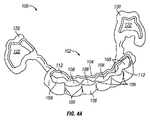
図4A及び図4Bは、患者の1つ以上の歯を再配置するように構成された例示的な取り外し可能歯科用装置100を示す。同様に、図5A及び図5Bは、患者の歯科構造体の3Dデジタルモデル130と組み合わせた取り外し可能歯科用装置100の3Dデジタルモデルを示す。
4A and 4B show an exemplary removable
取り外し可能歯科用装置100は、患者によって装着されたとき、患者の歯群の咬合面を実質的に露出させるように構成されている。咬合面が露出されることによって、取り外し可能歯科用装置100は、患者の歯群を実質的に囲む取り外し可能歯科用装置と比較して、患者の快適性の向上、歯科用装置の露出度の低下、歯間の空気及び唾液流の増加による歯石の増加の減少、及び患者が歯科用装置を取り外す必要なくある程度飲食することができるなど、いくつかの利点を提供し得る。
The removable
取り外し可能歯科用装置100は、装置本体102を含む。装置本体102は、患者の2つ以上の歯(図示の例では前歯)を囲むように構成されたアクティブバンド112を含む。アクティブバンド112は、顔面部分106及び舌部分104を含む。顔面部分106は、アクティブバンド112内の囲まれた歯群の顔側に整合するように構成され、一方、舌部分104は、囲まれた歯群の舌側に整合するように構成されている。
The removable
顔面部分106及び舌部分104は協働して受け部108を形成する。各受け部108は、顔面部分106のセクション及び舌部分104の対応するセクションを表し、これらのセクションは、歯科用装置100が患者によって装着されたとき、囲まれた歯群のうちの1つを受けるように構成されている。個々の受け部108は、装置本体102の顔面部分106内の顔面側隆起部109と舌部分104に関する舌側隆起部107によって分離され得る。舌側隆起部107及び顔面側隆起部109は、囲まれた歯群の隣接する歯の間の境界面に対応することができるが、任意の2つの隣接する歯の歯間領域に延びる必要はない。
The
受け部108は、装置本体102によって形成されるアクティブバンド112を少なくとも部分的に画定する。取り外し可能歯科用装置100が患者によって装着されたとき、患者の囲まれた歯群の咬合面が露出されるように、アクティブバンド112は開放端で構成されている。例えば、患者によって装着されたとき、囲まれた歯群は、装置本体102の個々の受け部108内に配置される。図示の例では、個々の受け部108は、舌側隆起部及び顔面側隆起部の少なくとも1つによって分離及び/又は個別に画定されている。他の例では、受け部は複数の隣接する歯群を受け得る。
The receiving
患者の歯群の配置を容易にするために、個々の受け部108のうちの少なくとも1つは、患者の対応する歯と比較して位置がずれている可能性がある。このようにして、装置本体102は、取り外し可能歯科用装置100が患者によって装着されたとき、患者の対応する歯に回転力及び/又は並進力を加えるように構成されている。同じ又は異なる例では、装置本体102は、個々の受け部108内の1つ以上の歯に並進力を加えるように構成されている。アクティブバンド112は、囲まれた歯群の唇側面及び舌側面の両方に対向する力を加えるようにも構成され得る。この圧縮的な「圧搾」は、歯科用装置100の動作を、開いた面の受け部を含む他の装置と区別することができる。
To facilitate the placement of the patient's tooth group, at least one of the
取り外し可能歯科用装置100は、アンカー120を更に含む。アンカー120は、装置本体102の各側から延びている。各アンカー120は、患者の歯を受けるように構成されたバンド122と、バンド122を装置本体/アクティブバンド112に結合するストラット121とを含む。図示の例では、アンカーバンド122は、患者の1つ以上の奥歯を囲んでいる。いくつかの例では、奥歯は患者の小臼歯又は大臼歯であり得る。取り外し可能歯科用装置100が、囲まれた歯群が装置本体102の個々の受け部108内に配置された状態で、患者によって装着されたとき、奥歯は、アンカー120のバンド122内に配置される。アンカー120は、取り外し可能歯科用装置100が患者によって装着されたときに、患者の受け入れられた奥歯の咬合面が露出したままであるように構成されている。他の例では、アクティブバンドは、アンカーがアクティブバンドから近位又は遠位に配置された状態で、1つ以上の奥歯を囲むように構成され得る。したがって、アンカーは、奥歯、前歯、又は両方の組み合わせを囲むことができる。
The removable
取り外し可能歯科用装置100は、装置本体102の舌部分104が囲まれた歯群のうちの1つ以上に概ね前方に力を加えるように構成され得るという点で、スプリングアライナー(spring aligner)として機能し得る。一方、アンカー120は、取り外し可能歯科用装置100が患者によって装着されたとき、受け入れられた奥歯に概ね後方に力を加えることによって、装置本体102の舌部分104によって概ね前方に加えられる力を支持するように構成されている。代替の実装形態(図示せず)では、装置本体は、舌部分又は顔面部分のいずれかがなくてもよく、その結果、1つ以上の対象歯は、前方又は後方の力のうちの1つのみを経験する。
The removable
いくつかの例では、取り外し可能歯科用装置100は、患者の口内の歯科矯正アンカーデバイスに接続するように構成された留め具を含み得る。このような留め具は、アンカー120の一方又は両方に配置され得る。
In some examples, the removable
同じ又は異なる例では、装置本体102及びアンカー120を含む取り外し可能歯科用装置100は、1つ以上のポリマーを含む。例えば、装置本体102及びアンカー120を含む取り外し可能歯科用装置100は、単一の連続した3D印刷構成成分からなり得る。いくつかの特定の例では、装置本体102及びアンカー120を含む取り外し可能歯科用装置100の構成成分の厚さは、例えば厚さ約0.5ミリメートル〜約1.0ミリメートル、又は厚さ約0.75ミリメートルなど、厚さ約0.25ミリメートル〜約2.0ミリメートルであり得る。いくつかの例では、取り外し可能歯科用装置100の特徴の厚さは、より調整された力を達成するように変更され得る。同じ又は異なる例において、取り外し可能歯科用装置100は、アクティブバンド112及び他の空間の縁部に面取り又はフィレットを含み得る。そのような面取り部又はフィレットは、患者の快適性を向上させ、取り外し可能歯科用装置100の露出度を低下させ得る。
In the same or different example, the removable
他の例では、取り外し可能歯科用装置100は、取り外し可能歯科用装置によって囲まれた歯群の1つ以上に加えられる力を高めるために、ポリマー成分に剛性を提供するように構成された金属構成成分を含み得る。例えば、金属構成成分は、装置本体102の舌部分104を介してアンカー120の間に延びるワイヤを含み得る。いくつかの例では、患者によって装着されたとき咬合面が露出される取り外し可能歯科用装置は、高圧咬合接触の応力に打ち勝つためにより大きい耐久性が必要とされる、金属咬合ジャンパなど1つ以上の他の金属構成成分を含み得る。金属咬合ジャンパの必要性は、歯ぎしりや咀嚼など、準拠していない患者の行動に起因し得る。同じ又は異なる例では、患者によって装着されたとき咬合面が露出される取り外し可能歯科用装置は、患者内に埋め込まれたアンカーデバイスに接続するためのキャッチを含み得る。このように、咬合面が露出されるそのような取り外し可能歯科用装置は、金属とプラスチックのハイブリッド構造を提供し得る。
In another example, the removable
プラスチック構成成分は、一般に、露出度を低下させるために透明であり得るが、金属構成成分は、患者によって装着されたときの取り外し可能歯科用装置の露出度を低下させるために、メッキ又は他の着色を含み得る。例えば、埋め込まれたときに患者の歯群の近くに配置された金属構成成分は、白色の着色を含み得るが、他の場所に配置された金属構成成分は、患者の口内の組織の色に概ね一致するように着色され得る。 Plastic components can generally be transparent to reduce exposure, while metal components are plated or other to reduce exposure of the removable dental device when worn by the patient. May include coloring. For example, metal components placed near the patient's tooth group when implanted may contain a white tint, while metal components placed elsewhere may color the tissue in the patient's mouth. It can be colored to roughly match.
取り外し可能歯科用装置100は、デジタル設計されてもよい。いくつかの例では、取り外し可能歯科用装置の順序付けされたセットは、一連のデジタルセットアップに基づいて順次装着されるように設計されている。そのような例では、セット内の各取り外し可能歯科用装置は、約2週間〜約12週間、例えば約3週間〜約10週間、又は約4週間〜約8週間、装着され得る。セット内の取り外し可能歯科用装置を所定の期間にわたって装着した後、セット内の取り外し可能歯科用装置は廃棄され、セット内の次の取り外し可能歯科用装置と交換され得る。取り外し可能歯科用装置100の設計は、セット内の取り外し可能歯科用装置の変更の間のより長い期間を容易にし得る。例えば、アクティブバンド112は、患者の2つ以上の歯を取り囲んでいるので、舌部分104及び顔面部分106は、各歯が別個の空洞内で隔離されている同様の歯科用装置の設計によるよりも、患者によって最初に装着されたときに、より大きく偏向する可能性がある。この理由から、取り外し可能歯科用装置100は、各歯が別個の空洞内で隔離される同様の歯科用装置の設計によるよりも大きい歯の移動を提供するように設計され得、それによって、セット内の次の歯科用装置に交換される前に、患者によってより長い期間にわたって装着されるように設計することができる。
The removable
取り外し可能歯科用装置100は、装置本体102内に個々の受け部108を含むが、他の例では、装置本体102は、装置本体102によって囲まれた患者の歯群の各々のための別個の空洞を画定する隆起を含まない場合がある。加えて、取り外し可能歯科用装置100は単一のアクティブバンド112を含むが、他の例は、1つを超えるアクティブバンドを含み得、各アクティブバンドが1つ以上の歯を囲む。図示されていないが、取り外し可能歯科用装置100及びそのような他の例は、任意に、1つ以上のアクティブバンドを互いに、歯に、又は歯に接合されているか若しくはその他の方法で直接歯に付けられた別個の装置に接続し、付着させ、又は固定する、1つ以上の追加のストラットを含んでいてもよい。
The removable
この例及び他の例では、アクティブバンドの形状及び寸法は、例えば、装置本体102の顔面部分106内の顔面隆起部109と、舌部分104に関する舌側隆起部107とを含む、囲まれた各歯の表面の一部が、取り外し可能歯科用装置100の内面によって再現されるように画定される。そのような再現は、取り外し可能歯科用装置100に対して歯が変位したとき、装置の表示のアクティブ期間中である、取り外し可能歯科用装置100の応力状態での弾性変形を容易にしながら、装置の表示の終わりに起こる弛緩状態の適合装置を提供し得る。
In this and other examples, the shape and dimensions of the active band are each enclosed, including, for example, a
咬合面のそれほど多くではないが、歯群の唇側面及び舌側面のある程度重要な部分を再現することによって、歯群が取り外し可能歯科用装置100に対してより変位すると、より大きいカップル(couple)の形成のために歯群の回転が影響を受ける可能性がある。取り外し可能歯科用装置100の内面の歯群の特徴を厳密に再現することによって、取り外し可能歯科用装置100は、わずかでも変形すると、カップルの存在により仕上げの場合に特に有効であり得る。対照的に、バネアライナー又はインマンアライナーのような多くの既存の取り外し可能装置は、単一の装置を使用して歯群をより大きい距離又は角度にわたって移動させることができるように、歯群が動く際の歯群の干渉を避けるために、これらの表面の細部の再現を避ける。これらの装置の細部の除去は、歯群が動く際に歯群が滑り得る滑らかな表面を提供する役割を果たすが、欠点は、意図された回転をもたらす接触点によって形成されたカップルがはるかに小さく、これによって、力がより小さくなり、装置の表示がより少なくなることである。
By reproducing some important parts of the labial and lingual flanks of the tooth group, although not so much of the occlusal surface, the larger couple is when the tooth group is more displaced with respect to the removable
たとえを用いると、顎の内面が対応するナットに密接に適合するように設計されているとき(すなわち、直線状で平行)は、オープンエンドレンチがより効果的である。しかし、顎の間の距離が中点で最小になり、両端で開口に向かって増加するように、顎の内面が丸みを帯びている場合、レンチにトルクをかけながら顎とナットとの間の接触点によって形成されたカップルは、(顎とナットとの間にある程度の裕度があると仮定して)顎が平行でその頂点でナットに接触している場合よりも小さい半径を有する。同様に、取り外し可能歯科用装置100のアクティブバンド112の幅(すなわち、咬合歯厚)の増加は、カップルの半径の増加をもたらし、これは、装置の変形の間に加えられる力を増加させる。いくつかの場合には、審美性又は患者の快適性のためにバンドの幅を最小にする(例えば、細いワイヤに至るまで)ことが動機であり得るが、他の場合には、取り外し可能歯科用装置100の内部表面エリアを増加させ、歯群の特徴を厳密に再現することによって、知覚される審美性をより大きい機能と引き換えることが有利である場合がある。
By analogy, an open-ended wrench is more effective when the inner surface of the jaw is designed to fit closely with the corresponding nut (ie, straight and parallel). However, if the inner surface of the jaw is rounded so that the distance between the jaws is minimized at the midpoint and increases towards the opening at both ends, torque the wrench between the jaw and the nut. The couple formed by the contact points has a smaller radius than if the jaws were parallel and in contact with the nut at its apex (assuming there was some margin between the jaw and the nut). Similarly, an increase in the width (ie, occlusal tooth thickness) of the
取り外し可能歯科用装置100は、コンピュータ70(図3)のようなコンピュータシステムによって生成された取り外し可能歯科用装置100のデジタルモデルに基づいて、自動製造システム74(図3)などの自動製造システムを使用して製造され得る。異なる例では、取り外し可能歯科用装置100は、例えば5軸ミリング加工又はレーザー切断でトリミングされたものなど、3D印刷又は熱成形及びトリミングを使用して形成され得る。3D印刷では、取り外し可能歯科用装置100は、3D印刷システムによって直接3D印刷され得るが、他の例では、取り外し可能歯科用装置100は、3D印刷を使用して形成された歯群の型上に熱成形され得る。いくつかの例では、取り外し可能歯科用装置100を、3D印刷を使用して形成された歯群の型の上に熱成形した後、材料を咬合表面エリアから除去する必要性を制限するために、3D印刷された歯群は、隆起した咬合面を有し得、又はその他の形で患者の歯群と異なる。
The removable
同じ又は異なる例において、取り外し可能歯科用装置100の自動又は半自動製造は、射出成型工程、ロストワックスキャスティング、5軸ミリング加工、レーザー切断、及び他の製造技術を含み得る。取り外し可能歯科用装置が金属咬合ジャンパのような1つ以上の金属構成成分を含む例では、自動製造は、ワイヤのような金属構成成分のロボットによる曲げのような金属構成成分のロボットによる操作を含み得る。金属及びプラスチックのハイブリッド構造を提供する取り外し可能歯科用装置は、オーバーモールド及び/又はスナップフィット技術を用いて製造することもできる。そのような金属構成成分は、3D印刷されたワックスモデルの金属インベストメントキャスティングから、選択的レーザー溶融(Selective Laser Melting、SLM)又は選択的レーザー焼結(Selective Laser Sintering、SLS)を含む「ダイレクトメタル」3D印刷から、又は金属ブロックの3軸、4軸、又は5軸のミリング加工から、デジタル式に設計され、金属ワイヤから製造され、ロボットによってカスタム曲げされてもよい。あるいは、取り外し可能歯科用装置のポリマー構成成分と組み合わせて使用するためのより強い構成成分を、透明又は歯色のセラミック材料から製造することができる。いくつかの例では、審美性を向上させるために、シルバー、プラチナ、パラジウム、又はロジウムなどの「白い」ジュエリーメタルで金属をメッキすることができる。一般に、より多くの構成成分を追加すると接合部を導入することになり、自動又は半自動の製造プロセスの後に何らかのアセンブリが必要になる場合がある。
In the same or different example, automatic or semi-automatic manufacturing of the removable
このようにして、咬合面が露出される取り外し可能歯科用装置に関して本明細書に開示された技術は、多くの様々な構成を容易にする。これらの技術は、治療された歯群及び固定歯群の両方の選択、並びに力部材、アンカー、及び他の特徴のカスタマイズされたサイズ、形状、及び配置の選択を容易にする。加えて、材料の組み合わせ及び接合部のタイプも、患者にとって望ましい治療結果を提供するように選択され得る。 In this way, the techniques disclosed herein with respect to removable dental devices with exposed occlusal surfaces facilitate many different configurations. These techniques facilitate selection of both treated and fixed tooth groups, as well as customized size, shape, and placement of force members, anchors, and other features. In addition, material combinations and joint types can also be selected to provide the desired therapeutic outcome for the patient.
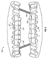
図6は、クラスIIの不正咬合の矯正を容易にする上部取り外し可能歯科用装置101及び下部取り外し可能歯科用装置100の3Dデジタルモデル140を示す。図6は更に、患者の下歯の3Dデジタルモデル130及び患者の上歯の3Dデジタルモデル131を示す。下部取り外し可能歯科用装置100は、図4A〜図5Bに示される取り外し可能歯科用装置100と同様であるが、弾性結紮糸142に接続するためのノブ、フック、ループ、キャッチ、又は他の特徴を追加している。加えて、上部取り外し可能歯科用装置101は、3Dデジタルモデル131に示される患者の上歯の上に装着されるように構成されていることを除いて、取り外し可能歯科用装置100と同様である。上部取り外し可能歯科用装置101はまた、弾性結紮糸142に接続するためのフック又は他の特徴を含む。他の例では、装置は、FORSUS Class II矯正器又はHerbst矯正器を使用して、上下のアーチを摺動式「ショックアブソーバ」を介して接続することができる。FORSUSコネクタの場合、下顎が閉じると、コイルばねが圧縮される。下顎が開くと、ばねは、その範囲の端に達すると自由に弛緩し、摺動する。FORSUS又はHerbstクラスII矯正器は、歯科用装置を引っ張るのではなく押すだけであり、取り外し可能装置内に含めるのに、上部取り外し可能歯科装置101及び下部取り外し可能歯科装置100を患者の歯群から引き離す傾向があり得る弾性結紮糸142よりも適している可能性がある。
FIG. 6 shows a 3D
取り外し可能歯科用装置100と同様に、取り外し可能歯科用装置101は、患者によって装着されたとき、患者の歯群の咬合面を露出させるように構成されている。取り外し可能歯科用装置100と同様に、取り外し可能歯科用装置101は、囲まれた歯群のうちの1つ以上に概ね前方に力を加えるように構成され得るという点で、スプリングアライナーとして機能し得る。取り外し可能歯科用装置101はまた、取り外し可能歯科用装置101が患者によって装着されたとき、概ね前方に加えられる力を支持するためのアンカーを含むが、アンカーは、他の例において、概ね遠位方向に加えられる力も支持し得る。1つ以上の歯が経験する力が概ね前方から変わり得るように、取り外し可能歯科用装置101によって加えられる力が歯群を一緒に締め付ける傾向があるため、概して前方の方向は、患者の歯の間で変わり得る。一般に、変位した歯群によって拡張された取り外し可能歯科用装置101及び取り外し可能歯科用装置101によって形成されたループは、より小さい外周を有するその平衡状態に弛緩しようとするとき、歯群を強制的に様々に並進させ、回転させる。上部取り外し可能歯科用装置101は、図4A〜図5Bに関して説明した技術及び取り外し可能歯科用装置100を使用して製造され得る。
Like the removable
上部取り外し可能歯科用装置101は、上部取り外し可能歯科用装置101と下部取り外し可能歯科用装置100の組み合わせが、クラスII不正咬合の矯正を容易にするように、下部取り外し可能歯科用装置100と相互作用するように構成されている。特に、上部取り外し可能歯科用装置101は、弾性結紮糸142に接続するためのフック又は他の特徴を含む。下部取り外し可能歯科用装置100も、弾性結紮糸142に接続するためのフック又は他の特徴を含む。弾性結紮糸142は、上部取り外し可能歯科用装置101及び下部取り外し可能歯科用装置100と組み合わせて患者によって装着されたとき、クラスII不正咬合の矯正を提供する。弾性結紮糸142が上部取り外し可能歯科用装置101及び下部取り外し可能歯科用装置100を歯群から引き離すのを防止するために、上部取り外し可能歯科用装置101及び下部取り外し可能歯科用装置100の一方又は両方は、歯群上の接着アタッチメント(bonded attachment)を係合し得る。例示的な接着アタッチメントは、2014年9月9日に発行された「LINGUAL ORTHODONTIC APPLIANCE WITH REMOVABLE SECTION」という名称のCinaderらの米国特許第8,827,697号に見つけられ得る。米国特許第8,827,697号は、その全体が参照により本明細書に組み込まれる。
The upper removable
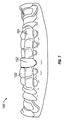
図7は、アクティブバンド103を有し、患者の歯群の3Dデジタルモデル133と組み合わせてポンティック152を含む取り外し可能歯科用装置150の3Dデジタルモデルの前方部分を示す。取り外し可能歯科用装置150は、図4A〜図5Bに示す取り外し可能歯科用装置100と同じ又は同様であるが、ポンティック152を追加したものである。
FIG. 7 shows the anterior portion of a 3D digital model of a removable
取り外し可能歯科用装置100と同様に、取り外し可能歯科用装置150は、患者によって装着されたとき、患者の歯群の咬合面を露出させるように構成されている。取り外し可能歯科用装置100と同様に、取り外し可能歯科用装置150は、囲まれた歯群のうちの1つ以上に概ね前方に力を加えるように構成され得るという点で、スプリングアライナーとして機能し得る。1つ以上の歯が経験する力が概ね前方から変わり得るように、取り外し可能歯科用装置100によって加えられる力が歯群を一緒に締め付ける傾向があるため、概して前方の方向は、患者の歯の間で変わり得る。一般に、変位した歯群によって拡張された取り外し可能歯科用装置100及び取り外し可能歯科用装置100によって形成されたループは、より小さい外周を有するその平衡状態に弛緩しようとするとき、歯群を強制的に様々に並進させ、回転させる。取り外し可能歯科用装置150は、取り外し可能歯科用装置150が患者によって装着されたとき、概ね前方に加えられる力を支持するためのアンカーも含む。取り外し可能歯科用装置150は、図4A〜図5Bに関して説明した技術及び取り外し可能歯科用装置100を使用して製造され得る。
Like the removable
ポンティック152は、患者の歯群の3Dデジタルモデル133で表されるように、患者の欠損歯から空間を満たすように構成されている。いくつかの例では、ポンティック152は、患者の歯群と一致するように着色されていてもよい。ポンティック152の幾何形状は、ポンティック152に隣接する歯の再配置を助けるために選択され得る。例えば、各々ポンティックを含む取り外し可能歯科用装置の順序付けされたセットにおいて、ポンティックは、所望のインプラント、ブリッジ、又は他の美顔用の歯のための十分な空間を作るために、取り外し可能歯科用装置の順序付けされたセットのシーケンスにわたって徐々に大きくなり得る。
The pontic 152 is configured to fill the space from the patient's missing tooth, as represented by the 3D
図8は、アクティブバンド105を有し、舌指162を含み、患者の歯群の3Dデジタルモデル130と組み合わせて咬合面が露出される取り外し可能歯科用装置160の3Dデジタルモデルの前方部分を示す。取り外し可能歯科用装置160は、図4A〜図5Bに示す取り外し可能歯科用装置100と同じ又は同様であるが、舌指162を追加したものである。
FIG. 8 shows the anterior portion of a 3D digital model of a removable
取り外し可能歯科用装置100と同様に、取り外し可能歯科用装置160は、患者によって装着されたとき、患者の歯群の咬合面を露出させるように構成されている。取り外し可能歯科用装置100と同様に、取り外し可能歯科用装置160は、囲まれた歯群のうちの1つ以上に概ね前方に力を加えるように構成され得るという点で、スプリングアライナーとして機能し得る。取り外し可能歯科用装置160は、取り外し可能歯科用装置160が患者によって装着されたとき、概ね前方に加えられる力を支持するためのアンカーも含む。
Like the removable
舌指162は、囲まれた歯群の各々に対して概ね前方に別々の力を加え得る。囲まれた歯群の各々に加えられる方向及び大きさは、舌指162のうちの隣接するものの設計に従ってカスタマイズされ得る。異なる例では、舌指162は、約0.25ミリメートル〜約2.0ミリメートルの厚さ、例えば約0.5ミリメートル〜約1.0ミリメートルの厚さ、又は約0.75ミリメートルの厚さであり得る。取り外し可能歯科用装置160は、図4A〜図5Bに関して説明した技術及び取り外し可能歯科用装置100を使用して製造され得る。
The tongue finger 162 may exert separate forces approximately anteriorly to each of the enclosed tooth groups. The orientation and size applied to each of the enclosed tooth groups can be customized according to the design of the adjacent one of the tongue fingers 162. In a different example, the tongue finger 162 is about 0.25 mm to about 2.0 mm thick, for example about 0.5 mm to about 1.0 mm thick, or about 0.75 mm thick. possible. The removable
取り外し可能歯科用装置160が患者によって装着されたとき、舌指162は、歯科用装置の舌部分に位置する場合、歯を唇弓(labial bow)(歯科用装置の前方部分)に対して前方に押すことによって、概ね前方に力を加える。しかしながら、取り外し可能歯科用装置160の唇弓も、舌方向に歯群を押し戻す。反対側及び反対方向から同時に押される歯群の二重の作用は、対向する接触点にカップルを形成させる。モーメントの中心に対してこれらのカップルが形成される場所が、達成されるてこの力の大きさ及び回転軸を決定する。接触が一方の側からのみ行われ、カップルが形成されない場合、歯は平行移動される。しかし、接触点は歯冠上にあり、モーメントの中心は歯根の中央のどこかにあるので、純粋な平行移動は達成されず、代わりに、長いアームの周りの回転として、接触点から歯根のモーメントの中心までの距離を表す。これは、回転に近似するにすぎない。純粋な平行移動は、局所的に歯をしっかりと包含し、歯科用装置の他のより遠くの部分を変形させて並進力を生じさせることによって達成され得る。したがって、グループとしてではなく個々にいくつかの歯を包含させ、これらの歯と他の固着歯群との間のストラットを弾性変形力部材として使用することが有利であり得る。このようにして、取り外し可能歯科用装置160は、アンカーとして機能する奥歯に対して前歯のすべてをグループとして前方に押すことによって(しかし、反対方向に移動する可能性もある)、前部セグメントと後部セグメントとの間に空間を作るために使用され得る。
When the removable
図9は、取り外し可能歯科用装置52(図1)の構成のための製造施設48で行われるプロセス100を示す流れ図である。いくつかの例では、取り外し可能歯科用装置52は、取り外し可能歯科用装置100、取り外し可能歯科用装置101、取り外し可能歯科用装置150、及び/又は取り外し可能歯科用装置160のうちの1つ以上を含み得る。製造施設48のコンピュータ70は、デジタル歯牙構造データ46、患者の1つ以上の歯の患者が提供する初期位置、及び処方データ47を診療所44から受信する(202)。あるいは、コンピュータ70は、コンピュータ70内に位置するか、又はコンピュータ70によってアクセス可能なデータベースから情報を取り出す。コンピュータ70に関連付けられた訓練された使用者は、コンピュータ70上で動作するコンピュータ化されたモデリング環境と対話して、診療所44がまだそうしていなければ、患者の歯牙構造のデジタル表示に対して治療計画を作成し、処方データ47を生成することができる。他の例では、コンピュータ70は、患者の歯牙構造及び所定の設計制約のみに基づいて治療計画を自動的に作成することができる。
FIG. 9 is a flow diagram showing a
コンピュータ70が患者の歯牙構造を受信すると、コンピュータ70は、患者のための取り外し可能歯科用装置の寸法及び形状を決定する(204)。取り外し可能歯科用装置の寸法及び形状は、取り外し可能歯科用装置が患者によって装着されたときに患者の1つ以上の歯を初期位置から調整された位置に再配置するように構成されている。同じ又は追加の例では、コンピュータ70は、患者のための取り外し可能歯科用装置のセットの寸法及び形状を決定し、患者のための取り外し可能歯科用装置のセットは、連続して装着されるように構成されている。
When the
いくつかの例では、取り外し可能歯科用装置の寸法及び形状を決定することは、コンピュータ70で、所定の設計制約のセットに従って取り外し可能歯科用装置の寸法及び形状を選択することを含む。予め設計された設計制約のセットは、限定はされないが、囲まれた歯群のうちの1つ以上に加えられる最大の局部的な力、囲まれた歯群のうちの1つ以上に加えられる最大回転力、囲まれた歯群のうちの1つ以上に加えられる最大並進力、囲まれた歯群のうちの1つ以上に加えられる最大合計力、及び囲まれた歯群が初期位置にあるときに患者によって装着されたときに取り外し可能歯科用装置に加えられる最大歪みを含む1つ以上の要因を含み得る。
In some examples, determining the dimensions and shape of a removable dental device involves selecting the dimensions and shape of the removable dental device on a
コンピュータ70は、有限要素解析(FEA)技術を使用して、取り外し可能歯科用装置の寸法及び形状を決定する間に患者の歯群並びに取り外し可能歯科用装置にかかる力を分析し得る。例えば、コンピュータ70は、モデル化された歯群が初期位置から取り外し可能歯科用装置の順序付けされたセットを含む治療を表す最終位置に移動するとき、患者の歯群のソリッドモデルにFEAを適用し得る。コンピュータ70は、取り外し可能歯科用装置の適切なFEA選択を使用して、歯群に所望の力を加え得る。加えて、コンピュータ70は、仮想咬合器を使用して、治療中にモデル化された歯群の移動を通じて歯の間の接触点を決定することができる。コンピュータ70は、取り外し可能歯科用装置の順序付けされたセットにおける取り外し可能歯科用装置の設計の間のデバイスからの力と組み合わせて、FEA力解析に、咬合力などの咬合接触力を更に含むことができる。
The
同じ又は異なる例では、取り外し可能歯科用装置の寸法及び形状を決定することは、取り外し可能歯科用装置が患者によって装着されたときに患者の1つ以上の歯を初期位置から調整された位置に再配置するのに適した剛性を提供するために、コンピュータ70で、歯科用装置本体の顔面部分及び舌部分の厚さを選択することを含む。異なる例では、そのような選択された厚さは、約0.25ミリメートル〜約2.0ミリメートルの厚さ、例えば約0.5ミリメートル〜約1.0ミリメートルの厚さの範囲であり得る。いくつかの例では、コンピュータ70は、所定の設計制約に従って取り外し可能歯科用装置(例えば、顔面及び舌の身体部分)の少なくとも一部の材料を更に選択し得る、又は厚さを必ずしも増加させることなく所望の剛性特性を提供し得る。
In the same or different example, determining the dimensions and shape of the removable dental device will bring one or more teeth of the patient into an adjusted position from the initial position when the removable dental device is worn by the patient. In order to provide suitable rigidity for rearrangement, the
患者のための取り外し可能歯科用装置の寸法及び形状は、コンピュータ70の72のユーザインターフェイスを介して使用者に提示され得る(206)。取り外し可能歯科用装置の寸法及び形状がコンピュータ70の72のユーザインターフェイスを介して使用者に提示される例では、使用者は、設計制約を調整する機会を有し得るか、又は設計データが自動製造システムに送られる前に、取り外し可能歯科用装置の寸法及び形状を直接調整し得る。
The dimensions and shape of the removable dental device for the patient may be presented to the user via 72 user interfaces of computer 70 (206). In the example where the dimensions and shape of the removable dental device are presented to the user through 72 user interfaces of the
代替的に又は追加で、患者のための取り外し可能歯科用装置の寸法及び形状は、自動製造システム74によって製造された取り外し可能歯科用装置としてコンピュータ70によって使用者に直接提示され得る(206)。そのような例では、コンピュータ70は、取り外し可能歯科用装置のデジタルモデルを自動製造システム74に送り、自動製造システム74は、コンピュータ70からのデジタルモデルに従って取り外し可能歯科用装置を製造する。
Alternatively or additionally, the dimensions and shape of the removable dental device for the patient may be presented directly to the user by the
しかしながら、患者のための取り外し可能歯科用装置の寸法及び形状が、コンピュータ70の72のユーザインターフェイスを介して使用者に提示され得る例であっても、使用者の承認に続いて、コンピュータ70が、取り外し可能歯科用装置のデジタルモデルを自動製造システム74に送り(208)、自動製造システム74が、コンピュータ70からのデジタルモデルに従って取り外し可能歯科用装置を製造する(210)。
However, even in an example where the dimensions and shape of the removable dental device for the patient can be presented to the user via the 72 user interfaces of the
いくつかの例では、自動製造システム74は、3Dプリンタを含み得る。歯科用装置本体のアクティブバンドの形状を形成することは、歯科用装置本体のアクティブバンドを形成する歯科用装置本体の表面を3Dプリンタで印刷することを含み得る。このようなアクティブバンドについては、取り外し可能歯科用装置100に関して先に記載されている。他の例では、歯科用装置本体のアクティブバンドの形状を形成することは、患者の歯群の表現を3Dプリンタで印刷し、患者の歯群の表現上に歯科用装置本体を熱成形することを含み得る。例えば、患者の歯群の表現は、熱成形された装置本体の舌部分から顔面部分を分離する空間の形成を容易にするために隆起した咬合面を含み得る。
In some examples, the automated
図9の技術は、患者のための取り外し可能歯科用装置の順序付けされたセットの各々の設計及び製造に適用され得る。例えば、取り外し可能歯科用装置の順序付けされたセット内の各取り外し可能歯科用装置は、患者の歯群を漸増的に再配置するように構成されてもよい。このようにして、取り外し可能歯科用装置の順序付けされたセットは、患者の歯群を、取り外し可能歯科用装置のセット内の取り外し可能歯科用装置のいずれよりも大きい程度に再配置するように構成され得る。患者のための取り外し可能歯科用装置のそのような順序付けされたセットは、具体的には、患者のための取り外し可能歯科用装置の順序付けされたセットの取り外し可能歯科用装置が患者によって順次装着されるにつれて、患者の1つ以上の歯を初期位置から最終的な調整された位置に漸増的に再配置するように構成され得る。 The technique of FIG. 9 can be applied to the design and manufacture of each ordered set of removable dental devices for a patient. For example, each removable dental device in an ordered set of removable dental devices may be configured to incrementally rearrange the patient's tooth group. In this way, the ordered set of removable dental devices is configured to reposition the patient's tooth group to a greater extent than any of the removable dental devices in the set of removable dental devices. Can be done. Such an ordered set of removable dental devices for a patient, specifically, a removable dental device of an ordered set of removable dental devices for a patient is sequentially worn by the patient. As it grows, one or more teeth of the patient may be configured to be incrementally rearranged from the initial position to the final adjusted position.
いくつかの例では、図9に関して説明した技術は、クライアントコンピューティングデバイス80(図3)及び/又はコンピュータ70(図3)のコンピュータ可読記憶媒体などのコンピュータ可読記憶媒体内に具体化され得る。実行されると、図9に関して説明した技術を実行するようにプロセッサを構成するコンピュータ実行可能命令を格納するコンピュータ可読記憶媒体。 In some examples, the techniques described with respect to FIG. 9 may be embodied within a computer-readable storage medium such as the computer-readable storage medium of the client computing device 80 (FIG. 3) and / or the computer 70 (FIG. 3). A computer-readable storage medium that stores computer-executable instructions that, when executed, configure the processor to perform the techniques described with respect to FIG.
取り外し可能歯科用装置52の設計に続いて、製造施設48は、デジタル歯牙構造データ46及び処方データ47に従って取り外し可能歯科用装置52を製作する(206)。取り外し可能歯科用装置52の構築は、3D印刷、熱成形、射出成形工程、ロストワックスキャスティング、5軸ミリング加工、レーザー切断、スナップ嵌め及びオーバーモールドなどのハイブリッドプラスチック及び金属製造技術、並びに他の製造技術を含み得る。
Following the design of the removable
図10は、取り外し可能歯科用装置の順序付けされたセットを使用する治療の連続的な反復を示す流れ図である。取り外し可能歯科用装置の順序付けされたセットは、患者の1つ以上の歯を再配置するように構成されている。様々な例では、取り外し可能歯科用装置の順序付けされたセットは、取り外し可能歯科用装置100、取り外し可能歯科用装置101、取り外し可能歯科用装置150、取り外し可能歯科用装置160、及び/又は以下に更に説明する他の取り外し可能歯科用装置のいずれかのうちの1つ以上を含み得る。したがって、治療は、本明細書に記載された複数の取り外し可能歯科用装置を特徴とすることができ、1つの特定の歯科用装置の実施形態の反復に限定される必要はない。1つの例示的な実装形態では、治療は、最初に、1つ以上の取り外し可能歯科用装置800(以下の図15A及び図15Bを参照)の反復で開始し、患者の歯群がある所望の量動くと、治療は、取り外し可能歯科用装置100の反復を続け得る。
FIG. 10 is a flow diagram showing a continuous repeat of treatment using an ordered set of removable dental devices. An ordered set of removable dental devices is configured to reposition one or more teeth of a patient. In various examples, an ordered set of removable dental devices is the removable
治療は、治療の最初の反復から始まる(302)。治療の最初の反復の開始時に、患者の歯群は、滞留状態Xによって表される初期位置にある(310)。取り外し可能歯科用装置の順序付けされたセットの設計を容易にするために、患者の歯群の走査が行われる(304)。患者の歯群の走査から、コンピュータは、順序付けされたセット内の取り外し可能歯科用装置の2つの異なる形状及び寸法、設計306a及び設計306bを決定する。患者の歯群のデジタルモデルを作成するための例示的な技術は、2014年5月27日に発行された「METHODS OF PREPARING A VIRTUAL DENTITION MODEL AND FABRICATING A DENTAL RETAINER THEREFROM」という名称のCinaderらの米国特許第8,738,165号に記載されている。米国特許第8,738,165号は、その全体が参照により本明細書に組み込まれる。コンピュータは、最初に患者の歯群のデジタルモデルを調整して、治療後の患者の歯群の所望の位置のモデルを作成することによって、順序付けされたセット内の取り外し可能歯科用装置の2つの異なる形状及び寸法を決定し得る。次いで、コンピュータは、初期位置から所望の位置に患者の歯群を移動させるのに必要な時間及び力に基づいて、順序付けされたセット内の取り外し可能歯科用装置の形状及び寸法を作成し得る。例えば、コンピュータモデルは、患者の歯群を初期位置から所望の位置に移動させるのに必要な力を生成するために、順序付けされたセット内の取り外し可能歯科用装置のばね状要素の厚さ及び他の寸法を調整し得る。順序付けされたセット内の取り外し可能歯科用装置によって加えられたモデル化された力は、治療中の患者の歯群の漸増的な位置の移動に更に基づき得る。このようにして、コンピュータは、順序付けされたセット内の取り外し可能歯科用装置が患者によって装着される治療中の時点に予測された位置で歯群に加えられる予想される力に従って順序付けされたセット内の取り外し可能歯科用装置の各々の形状及び寸法を設計し得る。
Treatment begins with the first iteration of treatment (302). At the beginning of the first iteration of treatment, the patient's tooth group is in the initial position represented by retention X (310). A scan of the patient's tooth group is performed to facilitate the design of an ordered set of removable dental devices (304). From the scan of the patient's tooth group, the computer determines two different shapes and dimensions,
いくつかの例では、取り外し可能歯科用装置のセット内に6つの取り外し可能歯科装置を製造するために、2つの異なる形状及び寸法の各々を使用して、取り外し可能歯科用装置のセット内の複数個、例えば3つの異なる取り外し可能歯科用装置を製造することができる。歯科用装置の順序付けされたセット内の第1から第3の歯科用装置は、同じ形状及び寸法であるが、異なる剛性特性を有する材料を含む。第2及び第3の歯科用装置は、第1の歯科用装置より高い剛性特性を有し、第3の歯科用装置も第2の歯科用装置より高い剛性特性を有する。同様に、歯科用装置の順序付けされたセット内の第4から第6の歯科用装置は、同じ形状及び寸法であるが、異なる剛性特性を有する材料を含む。第5及び第6の歯科用装置は、第4の歯科用装置より高い剛性特性を有し、第6の歯科用装置も、第5の歯科用装置より高い剛性特性を有する。いくつかの例では、第1の歯科用装置は、第4の歯科用装置と同じ剛性特性を有してもよい。同様に、いくつかの例では、第2の歯科用装置は、第5の歯科用装置と同じ剛性特性を有し得る。更に、いくつかの例では、第3の歯科用装置は、第6の歯科用装置と同じ剛性特性を有し得る。 In some examples, multiple in a set of removable dental devices, using each of two different shapes and dimensions to manufacture six removable dental devices in a set of removable dental devices. Pieces, eg, three different removable dental devices can be manufactured. The first to third dental devices in an ordered set of dental devices contain materials of the same shape and dimensions but with different stiffness properties. The second and third dental devices have higher rigidity characteristics than the first dental device, and the third dental device also has higher rigidity characteristics than the second dental device. Similarly, the fourth to sixth dental devices in an ordered set of dental devices contain materials of the same shape and dimensions but with different stiffness properties. The fifth and sixth dental devices have higher rigidity characteristics than the fourth dental device, and the sixth dental device also has higher rigidity characteristics than the fifth dental device. In some examples, the first dental device may have the same stiffness properties as the fourth dental device. Similarly, in some examples, the second dental device may have the same stiffness properties as the fifth dental device. Moreover, in some examples, the third dental device may have the same stiffness properties as the sixth dental device.
1つの例示的な治療方法では、取り外し可能歯科用装置の順序付けされたセット内の第1の取り外し可能歯科用装置は、比較的柔らかいポリマー材料などの比較的柔らかい材料から作られる。取り外し可能歯科用装置の順序付けされたセット内の第1の取り外し可能歯科用装置は、設計306aに準拠し、比較的軟質のポリマー材料のような比較的柔らかい材料から作られる。取り外し可能歯科用装置の順序付けされたセット内の第2の取り外し可能歯科用装置は、設計306aに準拠し、取り外し可能歯科用装置の順序付けされたセット内の第1の取り外し可能歯科用装置よりも比較的剛性の高いポリマー材料など、中程度の剛性の材料から作られる。取り外し可能歯科用装置の順序付けされたセット内の第3の取り外し可能歯科用装置は、設計306aに準拠し、取り外し可能歯科用装置の順序付けされたセット内の第2の取り外し可能歯科用装置よりも比較的剛性の高いポリマー材料など、剛性の高い材料から作られる。取り外し可能歯科用装置の順序付けされたセット内の第4の取り外し可能歯科用装置は、設計306bに準拠し、比較的柔らかい材料から作られる。取り外し可能歯科用装置の順序付けされたセット内の第5の取り外し可能歯科用装置は、設計306bに準拠し、中程度の剛性の材料から作られる。取り外し可能歯科用装置の順序付けされたセット内の第6の取り外し可能歯科用装置は、設計306bに準拠し、剛性の高い材料から作られる。
In one exemplary treatment method, the first removable dental device in an ordered set of removable dental devices is made from a relatively soft material, such as a relatively soft polymer material. The first removable dental device in the ordered set of removable dental devices conforms to Design 306a and is made from a relatively soft material such as a relatively soft polymer material. The second removable dental device in the ordered set of removable dental devices conforms to design 306a and is more than the first removable dental device in the ordered set of removable dental devices. It is made from a medium-rigidity material, such as a relatively rigid polymer material. The third removable dental device in the ordered set of removable dental devices conforms to design 306a and is more than the second removable dental device in the ordered set of removable dental devices. It is made from a rigid material, such as a relatively rigid polymer material. The fourth removable dental device in the ordered set of removable dental devices complies with
取り外し可能歯科用装置の順序付けされたセット内の第1〜第6の取り外し可能歯科用装置は、患者によって経時的に順に装着される。例えば、取り外し可能歯科用装置の順序付けされたセット内の取り外し可能歯科用装置の各々は、約2週間〜約12週間、例えば約3週間〜約10週間、又は約4週間〜約8週間の間装着され得る。第1〜第6の取り外し可能歯科用装置を使用する治療計画に続いて、患者の歯群は、拘留状態X+1(311)によって表される治療の最初の反復の間最終位置にある。 The first to sixth removable dental devices in the ordered set of removable dental devices are sequentially worn by the patient over time. For example, each of the removable dental devices in an ordered set of removable dental devices is between about 2 weeks to about 12 weeks, for example about 3 weeks to about 10 weeks, or about 4 weeks to about 8 weeks. Can be worn. Following a treatment plan using the first to sixth removable dental devices, the patient's tooth group is in the final position during the first repetition of treatment represented by detention status X + 1 (311).
この時点で、患者は臨床医に戻り得、臨床医は治療の最初の反復の結果を評価することができる(320)。治療の最初の反復が患者の歯群の満足できる最終位置をもたらした場合、治療が終了し得る(330)。しかしながら、治療の最初の反復が患者の歯群の所望の移動を完了しなかった場合、1回以上の追加の治療の反復が行われ得る。治療の次の反復を開始するために、臨床医は、取り外し可能歯科用装置の順序付けされたセットの設計を容易にするために、患者の歯群の別の走査を行い得る(304)。いくつかの例では、治療の最初の反復の結果の評価は、患者の歯の別の走査を行うことを含み得、その場合、取り外し可能歯科用装置の別の順序付けされたセットが、患者の歯群の新しい位置に基づいて患者のために製造され得るように、治療の次の反復の開始は、単に患者の歯群のデジタルモデルを製造施設に転送することを伴い得る。更に他の例では、新たに取得された走査を使用して、臨床医の施設内で取り外し可能歯科用装置の1つ以上の反復を作ることができる。 At this point, the patient can return to the clinician, who can evaluate the outcome of the first iteration of treatment (320). Treatment can be terminated if the first iteration of treatment results in a satisfactory final position in the patient's tooth group (330). However, if the first repeat of treatment does not complete the desired movement of the patient's tooth group, one or more additional treatment repeats may be made. To initiate the next iteration of treatment, the clinician may perform another scan of the patient's tooth group to facilitate the design of an ordered set of removable dental devices (304). In some examples, assessing the outcome of the first iteration of treatment may involve performing another scan of the patient's teeth, in which case another ordered set of removable dental devices will be used for the patient. The initiation of the next iteration of treatment may simply involve transferring a digital model of the patient's tooth group to the manufacturing facility so that it can be manufactured for the patient based on the new location of the tooth group. In yet another example, the newly acquired scan can be used to create one or more iterations of the removable dental device within the clinician's facility.
図10の技術は、1つの特定の例を表しており、本開示の趣旨の範囲内で様々な変更が図10の技術に対してなされてもよい。例えば、取り外し可能歯科用装置の順序付けされたセットは、6つより多い又は6つより少ない取り外し可能歯科用装置を含み得る。別の例として、取り外し可能歯科用装置の順序付けされたセット内の各取り外し可能歯科用装置は、一意の形状及び寸法を有してもよい。別の例として、コンピュータは、患者の歯群の最初の走査Xから順序付けされたセット内の取り外し可能歯科用装置の単一の形状及び寸法を決定する。 The technique of FIG. 10 represents one particular example, and various modifications may be made to the technique of FIG. 10 within the scope of the present disclosure. For example, an ordered set of removable dental devices may include more than or less than six removable dental devices. As another example, each removable dental device in an ordered set of removable dental devices may have a unique shape and dimensions. As another example, a computer determines a single shape and dimension of a removable dental device in an ordered set from the first scan X of a patient's tooth group.
図11A及び図11Bは、患者によって装着されたとき咬合面が露出される例示的な取り外し可能歯科用装置を示しており、例示的な取り外し可能歯科用装置は、各側の患者の2つの奥歯を受けるように構成されているアンカーを含む。図11Aは更に、患者の歯群の3Dデジタルモデル130と組み合わせた取り外し可能歯科用装置400の3Dデジタルモデルを示す。取り外し可能歯科用装置400は、アンカー420の構成を除いて、取り外し可能歯科用装置100(図4A〜図5B)と実質的に同様であり得る。簡潔にするために、取り外し可能歯科用装置100に関して前に説明した詳細と同じ又は類似の取り外し可能歯科用装置400の詳細は、取り外し可能歯科用装置400に関して限定的に記載されている、又は詳しく記載されていない。
11A and 11B show an exemplary removable dental device whose occlusal surface is exposed when worn by the patient, the exemplary removable dental device being the two molars of the patient on each side. Includes anchors that are configured to receive. FIG. 11A further shows a 3D digital model of the removable
取り外し可能歯科用装置400は、患者によって装着されたとき、患者の歯群の咬合面を露出させるように構成されている。取り外し可能歯科用装置400は、装置本体402を含む。装置本体402は、患者の2つ以上の歯を囲むように構成されたアクティブバンド412を形成する。装置本体402は、顔面部分406及び舌部分404を含む。顔面部分406は、囲まれた歯群の顔面に整合するように構成され、一方、舌部分404は、囲まれた歯群の舌側に整合するように構成されている。
The removable
顔面部分406及び舌部分404は受け部408を形成する。各受け部408は、歯科用装置400が患者によって装着されたとき、囲まれた歯群のうちの1つを受けるように構成されている顔面部分406のセクション及び舌部分404の対応するセクションを表す。受け部408は、装置本体402の顔面部分406内の顔面側隆起部409と舌部分404に関する舌側隆起部407によって分離され得る。舌側隆起部407及び顔面隆起部409は、囲まれた歯群の隣接する歯の間の境界面に対応し得る。
The
アクティブバンド412は、取り外し可能歯科用装置400が患者によって装着されたとき、患者の囲まれた歯群の咬合面が露出されるように構成されている。例えば、患者によって装着されたとき、囲まれた歯群は、装置本体402の受け部408内に配置される。
The
患者の歯群の配置を容易にするために、受け部408のうちの少なくとも1つは、患者の対応する歯と比較して位置がずれている可能性がある。このようにして、装置本体402は、取り外し可能歯科用装置400が患者によって装着されたとき、患者の対応する歯に回転力及び/又は並進力を加えるように構成され得る。いくつかの特定の例では、装置本体402は、圧縮力又は直線力のみを提供するように構成され得る。同じ又は異なる例では、装置本体402は、受け部408内の1つ以上の歯に並進力を加えるように構成され得る。
To facilitate the placement of the patient's teeth, at least one of the receiving
取り外し可能歯科用装置400は、アンカー420を更に含む。アンカー420は、装置本体402の各側から延びている。各アンカー420は、患者の奥歯を受けるように構成された2つの受け部422を含む。受け部422は、歯間ブレース421によってアクティブバンド412から分離されている。いくつかの例では、奥歯は患者の小臼歯及び/又は大臼歯を含み得る。取り外し可能歯科用装置400が、囲まれた歯群が装置本体402の受け部408内に配置された状態で、患者によって装着されたとき、奥歯は、アンカー420の受け部422内に配置される。アンカー420は、取り外し可能歯科用装置400が患者の歯列弓に着座すると、患者の受け入れられた奥歯の咬合面が露出したままであるように構成されている。
The removable
取り外し可能歯科用装置400は、装置本体402の舌部分404が囲まれた歯群のうちの1つ以上に概ね前方に力を加えるように構成され得るという点で、スプリングアライナーとして機能し得る。一方、アンカー420は、取り外し可能歯科用装置400が患者によって装着されたとき、受け入れられた奥歯に概ね後方に力を加えることによって、装置本体402の舌部分404によって概ね前方に加えられる力を支持するように構成されている。
The removable
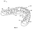
図12は、患者によって装着されたとき咬合面が露出される例示的な取り外し可能歯科用装置500を示しており、例示的な取り外し可能歯科用装置500は、患者の奥歯の舌側と噛み合うように構成されているアンカーを含む。図12は更に、患者の歯群の3Dデジタルモデル130と組み合わせた取り外し可能歯科用装置500の3Dデジタルモデルを示す。取り外し可能歯科用装置500は、アンカー520の構成を除いて、取り外し可能歯科用装置100(図4A〜図5B)と実質的に同様であり得る。簡潔にするために、取り外し可能歯科用装置100に関して前に説明した詳細と同じ又は類似の取り外し可能歯科用装置500の詳細は、取り外し可能歯科用装置500に関して限定的に記載されている、又は詳しく記載されていない。
FIG. 12 shows an exemplary removable
取り外し可能歯科用装置500は、患者によって装着されたとき、患者の歯群の咬合面を露出させるように構成されている。取り外し可能歯科用装置500は、装置本体502を含む。装置本体502は、患者の2つ以上の歯を囲むように構成されたアクティブバンド512を形成する。装置本体502は、顔面部分506及び舌部分504を含む。顔面部分506は、囲まれた歯群の顔面に整合するように構成され、一方、舌部分504は、囲まれた歯群の舌側に整合するように構成されている。取り外し可能歯科用装置100に関して説明したように、顔面部分506及び舌部分504は、歯科用装置500が患者によって装着されたときに、囲まれた歯群のうちの1つを受けるように構成された受け部を形成する。
The removable
装置本体502は、装置本体502の前方部分に沿って顔面部分506及び舌部分504を含むアクティブバンド512を形成する。アクティブバンド512は、取り外し可能歯科用装置500が患者によって装着されたとき、患者の囲まれた歯群の咬合面が露出されるように構成されている。例えば、患者によって装着されたとき、囲まれた歯群は、装置本体502の受け部内に配置される。
The
患者の歯群の配置を容易にするために、受け部のうちの少なくとも1つは、患者の対応する歯群と比較して位置がずれている可能性がある。このようにして、装置本体502は、取り外し可能歯科用装置500が患者によって装着されたとき、患者の対応する歯に回転力及び/又は並進力を加えるように構成され得る。いくつかの特定の例では、装置本体502は、圧縮力又は直線力のみを提供するように構成され得る。同じ又は異なる例では、装置本体502は、受け部内の1つ以上の歯に並進力を加えるように構成され得る。
To facilitate the placement of the patient's tooth group, at least one of the receiving portions may be misaligned relative to the patient's corresponding tooth group. In this way, the
取り外し可能歯科用装置500は、アンカー520を更に含む。アンカー520は、装置本体502の各側から延びている。各アンカー520は、患者の奥歯に係合するように構成されたフック522を含む。いくつかの例では、奥歯は患者の小臼歯又は大臼歯を含み得る。取り外し可能歯科用装置500が、囲まれた歯群が装置本体502の受け部内に配置された状態で、患者によって装着されたとき、奥歯は、アンカー520のフック522内によって係合される。アンカー520は、取り外し可能歯科用装置500が患者の歯列弓に着座すると、患者の受け入れられた奥歯の咬合面が露出したままであるように構成されている。
The removable
取り外し可能歯科用装置500は、装置本体502の舌部分504が囲まれた歯群のうちの1つ以上に概ね前方に力を加えるように構成され得るという点で、スプリングアライナーとして機能し得る。一方、アンカー520は、取り外し可能歯科用装置500が患者によって装着されたとき、受け入れられた奥歯に概ね後方に力を加えることによって、装置本体502の舌部分504によって概ね前方に加えられる力を支持するように構成されている。
The removable
図13A及び図13Bは、患者によって装着されたとき咬合面が露出される例示的な取り外し可能歯科用装置を示しており、例示的な取り外し可能歯科用装置は、患者の犬歯を受けるように構成されているアンカーを含む。図13A及び図13Bは更に、患者の歯群の3Dデジタルモデル130と組み合わせた取り外し可能歯科用装置500の3Dデジタルモデルを示す。取り外し可能歯科用装置600は、アンカー620の構成を除いて、取り外し可能歯科用装置100(図4A〜図5B)と実質的に同様であり得る。簡潔にするために、取り外し可能歯科用装置100に関して前に説明した詳細と同じ又は類似の取り外し可能歯科用装置600の詳細は、取り外し可能歯科用装置600に関して限定的に記載されている、又は詳しく記載されていない。
13A and 13B show an exemplary removable dental device whose occlusal surface is exposed when worn by the patient, the exemplary removable dental device configured to receive the patient's canines. Includes anchors that have been. 13A and 13B further show a 3D digital model of the removable
取り外し可能歯科用装置600は、患者によって装着されたとき、患者の歯群の咬合面を露出させるように構成されている。取り外し可能歯科用装置600は、装置本体602を含む。装置本体602は、患者の2つ以上の歯を囲むように構成されたアクティブバンド612を形成する。装置本体602は、顔面部分606及び舌部分604を含む。顔面部分606は、囲まれた歯群の顔面に整合するように構成され、一方、舌部分604は、囲まれた歯群の舌側に整合するように構成されている。取り外し可能歯科用装置100に関して説明したように、顔面部分606及び舌部分604は、歯科用装置600が患者によって装着されたときに、囲まれた歯群のうちの1つを受けるように構成された受け部を形成する。
The removable
装置本体602は、装置本体602の前方部分に沿って顔面部分606及び舌部分604を含むアクティブバンド612を形成する。アクティブバンド612は、取り外し可能歯科用装置600が患者によって装着されたとき、患者の囲まれた歯群の咬合面が露出されるように構成されている。例えば、患者によって装着されたとき、囲まれた歯群は、装置本体602の受け部内に配置される。
The
患者の歯群の配置を容易にするために、受け部のうちの少なくとも1つは、患者の対応する歯群と比較して位置がずれている可能性がある。このようにして、装置本体602は、取り外し可能歯科用装置600が患者によって装着されたとき、患者の対応する歯に回転力及び/又は並進力を加えるように構成され得る。いくつかの特定の例では、装置本体602は、圧縮力又は直線力のみを提供するように構成され得る。同じ又は異なる例では、装置本体602は、受け部内の1つ以上の歯に並進力を加えるように構成され得る。
To facilitate the placement of the patient's tooth group, at least one of the receiving portions may be misaligned relative to the patient's corresponding tooth group. In this way, the
取り外し可能歯科用装置600は、アンカー620を更に含む。アンカー620は、装置本体602の各側から直接延びている。各アンカー620は、患者の犬歯を受けるように構成された受け部622を含む。取り外し可能歯科用装置600が、囲まれた歯群が装置本体602の受け部内に配置された状態で、患者によって装着されたとき、犬歯は、アンカー620の受け部622内に配置される。アンカー620は、取り外し可能歯科用装置600が患者の歯列弓に着座すると、患者の受け入れられた奥歯の咬合面が露出したままであるように構成されている。
The removable
取り外し可能歯科用装置600は、装置本体602の舌部分604が囲まれた歯群のうちの1つ以上に概ね前方に力を加えるように構成され得るという点で、スプリングアライナーとして機能し得る。一方、アンカー620は、取り外し可能歯科用装置600が患者によって装着されたとき、受け入れられた犬歯に概ね後方に力を加えることによって、装置本体602の舌部分604によって概ね前方に加えられる力を支持するように構成されている。前の例と同様に、取り外し可能歯科用装置600は、奥歯、又は奥歯と前歯の両方を取り囲むように適合されてもよい。
The removable
図14A及び図14Bは、患者によって装着されたとき咬合面が露出される例示的な取り外し可能歯科用装置を示しており、例示的な取り外し可能歯科用装置は、ワイヤアンカーを含む。図14Aは更に、患者の歯群の3Dデジタルモデル130と組み合わせた取り外し可能歯科用装置700の3Dデジタルモデルを示す。取り外し可能歯科用装置700は、アンカー720の構成を除いて、取り外し可能歯科用装置100(図4A〜図7B)と実質的に同様であり得る。簡潔にするために、取り外し可能歯科用装置100に関して前に説明した詳細と同じ又は類似の取り外し可能歯科用装置700の詳細は、取り外し可能歯科用装置700に関して限定的に記載されている、又は詳しく記載されていない。
14A and 14B show an exemplary removable dental device whose occlusal surface is exposed when worn by the patient, the exemplary removable dental device including a wire anchor. FIG. 14A further shows a 3D digital model of the removable
取り外し可能歯科用装置700は、患者によって装着されたとき、患者の歯群の咬合面を露出させるように構成されている。取り外し可能歯科用装置700は、装置本体702を含む。装置本体702は、患者の2つ以上の歯を囲むように構成されたアクティブバンド712を形成する。装置本体702は、顔面部分706及び舌部分704を含む。顔面部分706は、囲まれた歯群の顔面に整合するように構成され、一方、舌部分704は、囲まれた歯群の舌側に整合するように構成されている。取り外し可能歯科用装置100に関して説明したように、顔面部分706及び舌部分704は、歯科用装置700が患者によって装着されたときに、囲まれた歯群のうちの1つを受けるように構成された受け部を形成する。
The removable
装置本体702は、装置本体702の前方部分に沿って顔面部分706及び舌部分704を含むアクティブバンド712を形成する。アクティブバンド712は、取り外し可能歯科用装置700が患者によって装着されたとき、患者の囲まれた歯群の咬合面が露出されるように構成されている。例えば、患者によって装着されたとき、囲まれた歯群は、装置本体702の受け部内に配置される。
The
患者の歯群の配置を容易にするために、受け部のうちの少なくとも1つは、患者の対応する歯群と比較して位置がずれている可能性がある。このようにして、装置本体702は、取り外し可能歯科用装置700が患者によって装着されたとき、患者の対応する歯に回転力及び/又は並進力を加えるように構成され得る。いくつかの特定の例では、装置本体702は、圧縮力又は直線力のみを提供するように構成され得る。同じ又は異なる例では、装置本体702は、受け部内の1つ以上の歯に並進力を加えるように構成され得る。
To facilitate the placement of the patient's tooth group, at least one of the receiving portions may be misaligned relative to the patient's corresponding tooth group. In this way, the
取り外し可能歯科用装置700は、アンカー720を更に含む。アンカー720は、装置本体702の各側から延びている。各アンカー720は、患者の奥歯の一部、典型的にはカスプと係合するように構成されたフック722を含む。いくつかの例では、奥歯は患者の小臼歯又は大臼歯を含み得る。取り外し可能歯科用装置700が、囲まれた歯群が装置本体702の受け部内に配置された状態で、患者によって装着されたとき、奥歯は、アンカー720のフック722内によって係合される。アンカー720は、取り外し可能歯科用装置700ときに、患者の受け入れられた奥歯の咬合面が露出したままであるように構成されている。異なる例では、フック722は、コンピュータ製造システムを使用して、又は患者の歯群及び口に適合するように臨床医によって手動で曲げられてもよい。
The removable
上述の取り外し可能歯科用装置とは対照的に、アンカー720は、金属ワイヤから形成され得る。特に、各アンカー720は、装置本体702に接続する近位部分724を含む。異なる例では、装置本体702は、アンカー720の近位部分726にオーバーモールドされてもよく、又は近位部分726は、例えば、接着又は他の結合技術によって装置本体702に直接固定されてもよい。アンカー720を装置本体702に固定するための他の適切な技術が使用されてもよい。
In contrast to the removable dental device described above, the
アンカー720は、本明細書で説明するポリマー材料から形成され得る装置本体702に剛性を提供することができる。取り外し可能歯科用装置700の特定の例では、アンカー720の近位部分726が、装置本体702の舌部分704と顔面部分706を接続し、装置本体702の舌部分704と顔面部分706はそれ以外では分離されている。他の例では、装置本体702の舌部分704と顔面部分706は、本明細書に記載の他の取り外し可能歯科用装置と同様に互いに接続することができる。
The
アンカー720は、直線部分と比較して、取り外し可能歯科用装置700が患者によって装着されたとき、取り外し可能歯科用装置700を所定位置によりしっかりと固定し、患者の装着部への侵入を制限するために、患者の歯肉線をたどって曲がり得る中央部分724を更に含む。異なる例では、中央部分724は、コンピュータ製造システムを使用して、又は患者の歯群及び口に適合するように臨床医によって手動で曲げられてもよい。いくつかの例では、アンカー720の任意の部分は、患者の歯科構造体のデジタルモデル130に基づいてCNCワイヤ曲げ機械を使用して形成され得る。他の例では、ワイヤ部分は、CNCレーザー切断機を使用して形成され得る。
The
取り外し可能歯科用装置700は、装置本体702の舌部分704が囲まれた歯群のうちの1つ以上に概ね前方に力を加えるように構成され得るという点で、スプリングアライナーとして機能し得る。一方、アンカー720は、取り外し可能歯科用装置700が患者によって装着されたとき、受け入れられた奥歯に概ね後方に力を加えることによって、装置本体702の舌部分704によって概ね前方に加えられる力を支持するように構成されている。
The removable
図15A及び図15Bは、患者によって装着されたとき咬合面が露出される例示的な取り外し可能歯科用装置を示しており、例示的な取り外し可能歯科用装置は、ワイヤアクティブバンド812及びワイヤアンカー820を含む。図15Aは更に、患者の歯群の3Dデジタルモデル130と組み合わせた取り外し可能歯科用装置800の3Dデジタルモデルを示す。取り外し可能歯科用装置800は、ワイヤアクティブバンド812の構成を除いて、取り外し可能歯科用装置700(図14A及び図14B)と実質的に同様であり得る。簡潔にするために、取り外し可能歯科用装置100に関して前に説明した詳細と同じ又は類似の取り外し可能歯科用装置800の詳細は、取り外し可能歯科用装置800に関して限定的に記載されている、又は詳しく記載されていない。
15A and 15B show an exemplary removable dental device whose occlusal surface is exposed when worn by a patient, the exemplary removable dental device being a wire
取り外し可能歯科用装置800は、患者によって装着されたとき、患者の歯群の咬合面を露出させるように構成されている。取り外し可能歯科用装置800は、装置本体802を含む。装置本体802は、患者の2つ以上の歯を囲むように構成されたワイヤアクティブバンド812を形成する。装置本体802は、顔面部分806及び舌部分804を含む。顔面部分806は、囲まれた歯群の顔面に整合するように構成され、一方、舌部分804は、囲まれた歯群の舌側に整合するように構成されている。取り外し可能歯科用装置700及び取り外し可能歯科用装置100に関して説明したように、顔面部分806及び舌部分804は、歯科用装置800が患者によって装着されたときに、囲まれた歯群のうちの1つを受けるように構成された受け部を形成する。
The removable
装置本体802は、装置本体802の前方部分に沿って顔面部分806及び舌部分804を含むワイヤアクティブバンド812を形成する。ワイヤアクティブバンド812は、取り外し可能歯科用装置800が患者800によって装着されたとき、患者の囲まれた歯群の咬合面が露出されるように構成されている。例えば、患者によって装着されたとき、囲まれた歯群は、装置本体802の受け部内に配置される。
The
患者の歯群の配置を容易にするために、受け部のうちの少なくとも1つは、患者の対応する歯群と比較して位置がずれている可能性がある。このようにして、装置本体802は、取り外し可能歯科用装置800が患者によって装着されたとき、患者の対応する歯に回転力及び/又は並進力を加えるように構成され得る。いくつかの特定の例では、装置本体802は、圧縮力又は直線力のみを提供するように構成され得る。同じ又は異なる例では、装置本体802は、受け部内の1つ以上の歯に並進力を加えるように構成され得る。
To facilitate the placement of the patient's tooth group, at least one of the receiving portions may be misaligned relative to the patient's corresponding tooth group. In this way, the
取り外し可能歯科用装置800は、アンカー820を更に含む。アンカー820は、装置本体802の各側から延びている。各アンカー820は、患者の奥歯に係合するように構成されたフック822を含む。いくつかの例では、奥歯は患者の小臼歯又は大臼歯を含み得る。取り外し可能歯科用装置800が、囲まれた歯群が装置本体802の受け部内に配置された状態で、患者によって装着されたとき、奥歯は、アンカー820のフック822内によって係合される。アンカー820は、取り外し可能歯科用装置800ときに、患者の受け入れられた奥歯の咬合面が露出したままであるように構成されている。異なる例では、フック822は、コンピュータ製造システムを使用して、又は患者の歯群及び口に適合するように臨床医によって手動で曲げられてもよい。
The removable
上述の取り外し可能歯科用装置とは対照的に、顔面部分806及び舌部分804並びに各アンカー820を含むアクティブバンド812は、金属ワイヤから形成され得る。特に、各アンカー820は、装置本体802に接続する近位部分826を含む。いくつかの例では、顔面部分806及び舌部分804並びにアンカー820の各々を含むアクティブバンド812のような歯科用装置800の任意の部分は、患者の歯科構造体のデジタルモデル130に基づいてCNCワイヤ曲げ機械を使用して形成され得る。
In contrast to the removable dental device described above, the
取り外し可能歯科用装置800の特定の例では、アンカー820の近位部分826が、装置本体802の舌部分804と顔面部分806を接続し、装置本体802の舌部分804と顔面部分806はそれ以外では分離されている。他の例では、装置本体802の舌部分804と顔面部分806は、本明細書に記載の他の取り外し可能歯科用装置と同様に互いに接続することができる。
In a particular example of the removable
アンカー820は、直線部分と比較して、取り外し可能歯科用装置800が患者によって装着されたとき、取り外し可能歯科用装置800を所定位置によりしっかりと固定し、患者の装着部への侵入を制限するために、患者の歯肉線をたどって曲がり得る中央部分824を更に含む。異なる例では、中央部分824は、コンピュータ製造システムを使用して、又は患者の歯群及び口に適合するように臨床医によって手動で曲げられてもよい。
The
取り外し可能歯科用装置800は、装置本体802の舌部分804が囲まれた歯群のうちの1つ以上に概ね前方に力を加えるように構成され得るという点で、スプリングアライナーとして機能し得る。一方、アンカー820は、取り外し可能歯科用装置800が患者によって装着されたとき、受け入れられた奥歯に概ね後方に力を加えることによって、装置本体802の舌部分804によって概ね前方に加えられる力を支持するように構成されている。
The removable
本開示の様々な技術は、サーバ(クラウドを含む)、ラップトップコンピュータ、デスクトップコンピュータ、ノートブックコンピュータ、タブレットコンピュータ、ハンドヘルドコンピュータ、スマートフォンなどの多種多様なコンピュータデバイスに実装することができる。任意の構成成分、モジュール、又はユニットは、機能的側面を強調するために記載されており、必ずしも異なるハードウェアユニットによる実現を必要としない。本明細書に記載の技術は、ハードウェア、ソフトウェア、ファームウェア、又はそれらの任意の組み合わせで実装することもできる。モジュール、ユニット、又は構成成分として記載された任意の機能は、一体化された論理デバイス内で一緒に実装されてもよく、又は個別ではあるが相互運用可能な論理デバイスとして実装されてもよい。いくつかの場合には、集積回路チップ又はチップセットのような集積回路デバイスとして様々な機能が実装され得る。加えて、いくつかの異なるモジュールが本明細書にわたって説明されており、その多くは一意の機能を実行するが、すべてのモジュールのすべての機能が単一のモジュールに結合されてもよく、更には、更なる追加のモジュールに分割されてもよい。本明細書に記載されるモジュールは単なる例示であり、より理解しやすくするためにそのように記載されている。 The various techniques of the present disclosure can be implemented in a wide variety of computer devices such as servers (including the cloud), laptop computers, desktop computers, notebook computers, tablet computers, handheld computers, smartphones and the like. Any component, module, or unit is described to emphasize functional aspects and does not necessarily require implementation by different hardware units. The techniques described herein can also be implemented in hardware, software, firmware, or any combination thereof. Any function described as a module, unit, or component may be implemented together within an integrated logical device, or as a separate but interoperable logical device. In some cases, various functions may be implemented as an integrated circuit device such as an integrated circuit chip or chipset. In addition, several different modules are described throughout the specification, many of which perform unique functions, but all functions of all modules may be combined into a single module, and even more. , May be subdivided into additional modules. The modules described herein are merely exemplary and are described as such for better understanding.
ソフトウェアに実装される場合、技術は、プロセッサ内で実行されると、上記の方法のうちの1つ以上を実行する命令を含むコンピュータ可読媒体によって少なくとも部分的に実現され得る。コンピュータ可読媒体は、有形のコンピュータ可読記憶媒体を含み得、包装材料を含み得るコンピュータプログラム製品の一部を形成し得る。コンピュータ可読記憶媒体には、同期ダイナミックランダムアクセスメモリ(SDRAM)などのランダムアクセスメモリ(RAM)、読み取り専用メモリ(ROM)、不揮発性ランダムアクセスメモリ(NVRAM)、電気的消去可能プログラマブル読み取り専用メモリ(EEPROM)、FLASHメモリ、磁気又は光学データ記憶媒体などがあり得る。コンピュータ可読記憶媒体には、ハードディスク、磁気テープ、コンパクトディスク(CD)、デジタル多用途ディスク(DVD)、ブルーレイディスク、ホログラフィックデータ記憶媒体、又は他の不揮発性記憶デバイスなどの不揮発性記憶デバイスもあり得る。 When implemented in software, the technique, when implemented in a processor, can be at least partially realized by a computer-readable medium containing instructions that perform one or more of the above methods. The computer-readable medium may include a tangible computer-readable storage medium and may form part of a computer program product that may include packaging material. Computer-readable storage media include random access memory (RAM) such as synchronous dynamic random access memory (SDRAM), read-only memory (ROM), non-volatile random access memory (NVRAM), and electrically erasable programmable read-only memory (EEPROM). ), DRAMH memory, magnetic or optical data storage medium, and the like. Computer-readable storage media also include non-volatile storage devices such as hard disks, magnetic tapes, compact discs (CDs), digital versatile discs (DVDs), Blu-ray discs, holographic data storage media, or other non-volatile storage devices. obtain.
本明細書で使用される「プロセッサ」という用語は、前述の構造のいずれか、又は本明細書で説明される技術の実施に適した他の任意の構造を指し得る。加えて、いくつかの態様では、本明細書に記載される機能は、本開示の技術を実行するように構成された専用ソフトウェアモジュール又はハードウェアモジュール内に提供され得る。ソフトウェアに実装されている場合でも、技術は、ソフトウェアを実行するためのプロセッサなどのハードウェア、及びソフトウェアを格納するためのメモリを使用し得る。いずれの場合においても、本明細書に記載されるコンピュータは、本明細書に記載の特定の機能を実行することができる特定のマシンを定義することができる。また、これらの技術を、プロセッサと見なすこともできる1つ以上の回路又は論理要素に完全に実装することもできる。 As used herein, the term "processor" can refer to any of the structures described above, or any other structure suitable for the practice of the techniques described herein. In addition, in some embodiments, the functionality described herein may be provided within a dedicated software module or hardware module configured to perform the techniques of the present disclosure. Even if implemented in software, the technology may use hardware such as a processor to run the software, and memory to store the software. In any case, the computer described herein can define a particular machine capable of performing the particular function described herein. These techniques can also be fully implemented in one or more circuits or logic elements that can also be considered processors.
様々な例が記載されている。これら及び他の例は、以下の特許請求の範囲内にある。
実施形態
1. コンピュータシステムで、患者の1つ以上の歯の初期位置を提供する、患者の3次元(3D)歯牙構造のデジタル表現を受信することと、コンピュータシステムで、患者のための取り外し可能歯科用装置の寸法及び形状を決定することであって、取り外し可能歯科用装置の寸法及び形状が、取り外し可能歯科用装置が患者によって装着されたとき、患者の1つ以上の歯を初期位置から調整された位置に再配置するように構成されている、ことと、コンピュータシステムで、取り外し可能歯科用装置の表現をコンピュータ支援製造システムに送信することとを含み、取り外し可能歯科用装置が、患者の2つ以上の歯を囲むように構成された装置本体を含み、装置本体、アクティブバンド、及び少なくとも1つのアンカーが、囲まれた歯群の顔面側に整合するように構成された顔面部分と、囲まれた歯群の舌側に整合するように構成された舌部分とを含み、装置本体が、取り外し可能歯科用装置が患者によって装着されたとき、患者の囲まれた歯群の咬合面が露出されるように構成されている、方法。
2. 患者の3次元(3D)歯科構造体が、歯根、歯肉、歯周靭帯(periodontal ligaments、PDL)、歯槽骨、又は皮質骨のうちの少なくとも一部を更に含む、実施形態1に記載の方法。
3. 顔面部分及び舌部分が協働してアクティブバンドを形成し、バンドが、囲まれた歯群を受容するための1つ以上の受け部を含む、前述の実施形態のいずれか一項に記載の方法。
4. コンピュータで、取り外し可能歯科用装置の寸法及び形状を決定することが、使用者からの入力を受けることを含み、入力が、寸法及び形状のうちの少なくとも1つに影響を与える、実施形態1〜3のいずれか一項に記載の方法。
5. コンピュータで、取り外し可能歯科用装置の寸法及び形状を決定することが、寸法及び形状のうちの少なくとも1つを自動的に決定することを含む、実施形態1〜3のいずれか一項に記載の方法。
6. コンピュータで、取り外し可能歯科用装置の寸法及び形状を決定することが、レビューのために取り外し可能歯科用装置の表現を使用者に提示することを含む、実施形態1〜5のいずれか一項に記載の方法。
7. 取り外し可能歯科用装置の表現を送信することが、取り外し可能歯科用装置のデジタルモデルをコンピュータシステムからコンピュータ支援製造システムに送ることと、コンピュータシステムからのデジタルモデルに従って、コンピュータ支援製造システムで、取り外し可能歯科用装置の少なくとも一部を製造することとを含む、実施形態1〜6のいずれか一項に記載の方法。
8. コンピュータ支援製造システムが3Dプリンタを含み、歯科用装置の少なくとも一部が3Dプリンタを使用して形成される、実施形態1〜7のいずれか一項に記載の方法。
9. 装置本体の顔面部分及び装置本体の舌部分が受け部を形成し、各受け部が、囲まれた歯群のうちの少なくとも1つを受けるように構成され、装置本体の受け部の形状を形成することが、3Dプリンタで受け部を形成する装置本体の表面を印刷することを含む、実施形態8に記載の方法。
10. コンピュータ支援製造システムがCNCワイヤ曲げ機械を含み、歯科用装置の少なくとも一部がCNCワイヤ曲げ機械を使用して形成される、実施形態1〜7のいずれか一項に記載の方法。
11. 製造システムがCNCミリング加工機械を含み、歯科用装置の少なくとも一部がCNCミリング加工機械を使用して形成される、実施形態1〜7及び10のいずれか一項に記載の方法。
12. 製造システムがCNCレーザー切断機を含み、歯科用装置の少なくとも一部がCNCレーザー切断機を使用して形成される、実施形態1〜7及び10のいずれか一項に記載の方法。
13. CNCレーザー切断機が、歯科用装置の少なくとも一部の形成を容易にするように、その切断経路に沿って切断の深さを変えるように構成されている、実施形態12に記載の方法。
14. コンピュータシステムで、患者のための取り外し可能歯科用装置の順序付けされたセットの各々の寸法及び形状を決定することを更に含み、取り外し可能歯科用装置が、患者のための取り外し可能歯科用装置の順序付けされたセットのうちの1つであり、取り外し可能歯科用装置の順序付けされたセット内の各取り外し可能歯科用装置が、取り外し可能歯科用装置のセットの中でより早期の取り外し可能歯科用装置のいずれよりも進んだ位置に患者の歯群を漸増的に再配置するように構成されている、実施形態1〜13のいずれか一項に記載の方法。
15. コンピュータシステムで、取り外し可能歯科用装置の寸法及び形状を決定することが、コンピュータシステムで、所定の設計制約のセットに従って取り外し可能歯科用装置の寸法及び形状を選択することを含み、所定の設計制約のセットが、囲まれた歯群のうちの1つ以上に加えられる最大の局部的な力と、囲まれた歯群のうちの1つ以上に加えられる最大回転力と、 囲まれた歯群のうちの1つ以上に加えられる最大並進力と、囲まれた歯群のうちの1つ以上に加えられる最大合計力と、囲まれた歯群が初期位置にあるときに患者によって装着されたときに取り外し可能歯科用装置に加えられる最大歪みとからなる群のうちの1つ以上を含む、実施形態14に記載の方法。
16. コンピュータシステムで、取り外し可能歯科用装置の材料を選択することを更に含む、実施形態15のいずれか一項に記載の方法。
17. コンピュータシステムで、取り外し可能歯科用装置の寸法及び形状を決定することが、取り外し可能歯科用装置が患者によって装着されたとき、患者の1つ以上の歯を初期位置から調整された位置に再配置するのに適した剛性を提供するために、装置本体の顔面部分及び舌部分の厚さを選択することを含む、実施形態1〜16のいずれか一項に記載の方法。
18. 装置本体の顔面部分及び装置本体の舌部分が、受け部を形成し、各受け部が、囲まれた歯群のうちの少なくとも1つを受けるように構成され、取り外し可能歯科用装置が患者によって装着されたとき、患者の対応する歯に回転力を加えるように装置本体が構成されるように、装置本体内の受け部のうちの少なくとも1つが、患者の対応する歯と比較して整列される、実施形態1〜17のいずれか一項に記載の方法。
19. 患者の1つ以上の歯に加えられる回転力が、装置本体の顔面及び舌の部分の対向する面と囲まれた歯群との間に形成された1つ以上のカップルから生じる、実施形態18に記載の方法。
20. 患者の1つ以上の歯に加えられる回転力が、装置本体の顔面及び舌の部分の内表面と1つ以上の対応する歯の根部との間に形成された1つ以上のカップルから生じる、実施形態18に記載の方法。
21. 歯科用装置の少なくとも一部が、取り外し可能歯科用装置が患者によって装着されたとき、1つ以上の歯に並進力を加えるように構成されている、実施形態1〜20のいずれか一項に記載の方法。
22. 患者の1つ以上の歯に加えられる並進力が、装置本体の顔面及び舌の部分の内表面と1つ以上の接触した歯との間の1つ以上の圧縮点から生じる、実施形態21に記載の方法。
23. 患者の1つ以上の歯に加えられる並進力が、装置本体の顔面及び舌の部分の内表面と患者の歯科構造体に直接取り付けられた1つ以上の別個の装置との間の1つ以上のテンションポイントから生じる、実施形態21に記載の方法。
24. 取り外し可能歯科用装置が、装置本体の側面から延びる1つ以上のアンカーを更に含む、実施形態1〜23のいずれか一項に記載の方法。
25. 囲まれた歯群が患者の前歯である、実施形態1〜23のいずれか一項に記載の方法。
26. 囲まれた歯群が囲まれた歯群の第1のセットであり、取り外し可能歯科用装置が、患者の歯群の第2のセットを囲むように構成されたバンドを更に含み、患者の歯群の第2のセットが、囲まれた歯群の第1のセットに直接隣接している、実施形態25に記載の方法。
27. 顔面及び舌の部分が取り外し可能歯科用装置のアクティブバンドを形成し、装置が、アクティブバンドに接続された1つ以上のストラットを更に含む、実施形態1〜26のいずれか一項に記載の方法。
28. 取り外し可能歯科用装置が、装置本体の各側から延びるアンカーを更に含み、ストラットがアクティブバンドをアンカーに結合する、実施形態27に記載の方法。
29. 取り外し可能歯科用装置が、1つ以上のストラットの遠心端に接続された1つ以上の追加のバンドを更に含む、実施形態28に記載の方法。
30. 1つ以上のストラットが1つ以上の中間歯群に及ぶ、実施形態29に記載の方法。
31. 1つ以上のストラットが、囲まれた歯群の間の1つ以上の隙間に及ぶ、実施形態29に記載の方法。
32. 取り外し可能歯科用装置の少なくとも1つがポンティックを組み込んでいる、実施形態28に記載の方法。
34. 取り外し可能歯科用装置が、複数の前歯に沿ってストラットを更に含み、ストラットが、ブレースの遠心端でアンカーバンドに接続される、実施形態1〜32のいずれか一項に記載の方法。
35. コンピュータシステムで、取り外し可能歯科用装置の寸法及び形状を決定することが、患者の1つ以上の歯の初期位置を提供する歯牙構造を修正して、修正された歯牙構造を生成することを含み、取り外し可能歯科用装置の寸法及び形状は、修正された歯牙構造に適合する、実施形態1〜34のいずれか一項に記載の方法。
36. 修正された歯牙構造が、患者の1つ以上の歯の初期位置と比較して、患者の1つ以上の歯の漸増的な再配置を表す、実施形態35に記載の方法。
37. コンピュータで、取り外し可能歯科用装置の表現を使用者に提示することを更に含む、実施形態1〜36のいずれか一項に記載の方法。
38. コンピュータシステムが、1つ以上のコンピュータネットワークを介して動作可能に接続された複数のコンピューティングデバイスを含む、実施形態1〜37のいずれか一項に記載の方法。
39. 実行されると、実施形態1〜38のいずれかの一項の方法を実行するようにプロセッサを構成するコンピュータシステム実行可能命令を格納するコンピュータ可読記憶媒体。
40. 実行されると、患者の1つ以上の歯の初期位置を提供する、患者の3次元(3D)歯牙構造のデジタル表現を受信し、患者のための取り外し可能歯科用装置の寸法及び形状を決定し、取り外し可能歯科用装置の寸法及び形状が、取り外し可能歯科用装置が患者によって装着されたとき、患者の1つ以上の歯を初期位置から調整された位置に再配置するように構成されており、取り外し可能歯科用装置の表現をコンピュータ支援製造システムに送信する、ようにプロセッサを構成するコンピュータシステム実行可能命令を格納したコンピュータ可読記憶媒体であって、取り外し可能歯科用装置が、患者の2つ以上の歯を囲むように構成された装置本体を含み、装置本体が、囲まれた歯群の顔面側に整合するように構成された顔面部分と、囲まれた歯群の舌側に整合するように構成された舌部分とを含み、装置本体が、取り外し可能歯科用装置が患者によって装着されたとき、患者の囲まれた歯群の咬合面が露出されるように構成されている、コンピュータ可読記憶媒体。
41. 取り外し可能歯科用装置の表現を送信することが、取り外し可能歯科用装置のデジタルモデルをコンピュータシステムからコンピュータ支援製造システムに送ることと、コンピュータシステムからのデジタルモデルに従って、コンピュータ支援製造システムで、取り外し可能歯科用装置の少なくとも一部を製造することとを含む、実施形態40に記載のコンピュータ可読記憶媒体。
42. 実行されると、患者のための取り外し可能歯科用装置の順序付けされたセットの各々の寸法及び形状を決定し、取り外し可能歯科用装置が、患者のための取り外し可能歯科用装置の順序付けされたセットのうちの1つであり、取り外し可能歯科用装置の順序付けされたセットが、取り外し可能歯科用装置のセットの中でより早期の取り外し可能歯科用装置のいずれよりも進んだ位置に患者の歯群を再配置するように構成されるように、取り外し可能歯科用装置の順序付けされたセット内の各取り外し可能歯科用装置が、患者の歯群を漸増的に再配置するように構成されており、取り外し可能歯科用装置の順序付けされたセットの各々の表現を使用者に提示する、ようにプロセッサを更に構成するコンピュータシステム実行命令、実施形態40〜41に記載のコンピュータ可読記憶媒体。
43. 取り外し可能歯科用装置の寸法及び形状を決定することが、所定の設計制約のセットに従って取り外し可能歯科用装置の寸法及び形状を選択することを含み、予め設計された設計制約のセットが、囲まれた歯群のうちの1つ以上に加えられる最大の局部的な力と、囲まれた歯群のうちの1つ以上に加えられる最大回転力と、囲まれた歯群のうちの1つ以上に加えられる最大並進力と、囲まれた歯群のうちの1つ以上に加えられる最大合計力と、囲まれた歯群が初期位置にあるときに患者によって装着されたときに取り外し可能歯科用装置に加えられる最大歪みとからなる群のうちの1つ以上を含む、実施形態40〜42に記載のコンピュータ可読記憶媒体。
44. 実行されると、取り外し可能歯科用装置の材料を選択するようにプロセッサを更に構成するコンピュータシステム実行命令、実施形態43に記載のコンピュータ可読記憶媒体。
45. 取り外し可能歯科用装置の寸法及び形状を決定することが、取り外し可能歯科用装置が患者によって装着されたとき、患者の1つ以上の歯を初期位置から調整された位置に再配置するのに適した剛性を提供するために、装置本体の材料特性を選択することを含む、実施形態40〜44のいずれか一項に記載のコンピュータ可読記憶媒体。
46. 装置本体の顔面部分及び装置本体の舌部分が、受け部を形成し、各受け部が、囲まれた歯群のうちの少なくとも1つを受けるように構成され、取り外し可能歯科用装置が患者によって装着されたとき、患者の対応する歯に回転力を加えるように装置本体が構成されるように、装置本体内の受け部のうちの少なくとも1つが、患者の対応する歯と比較して整列される、実施形態40〜45のいずれか一項に記載のコンピュータ可読記憶媒体。
47. 取り外し可能歯科用装置が、装置本体の各側から延びるアンカーを更に含む、実施形態40〜46のいずれか一項に記載のコンピュータ可読記憶媒体。
48. 囲まれた歯群が患者の前歯である、実施形態40〜47のいずれか一項に記載のコンピュータ可読記憶媒体。
49. 取り外し可能歯科用装置が、装置本体の各側から延びるアンカーを更に含み、アンカーが、装置本体から遠位に延び、患者の奥歯の部分を受ける、実施形態48に記載のコンピュータ可読記憶媒体。
50. 患者の1つ以上の歯の初期位置を提供する、患者の3次元(3D)歯牙構造のデジタル表現を記憶する1つ以上のデータベースと、3D歯牙構造のデジタル表現にアクセスし、患者のための取り外し可能歯科用装置の寸法及び形状を決定し、取り外し可能歯科用装置の寸法及び形状が、取り外し可能歯科用装置が患者によって装着されたとき、患者の1つ以上の歯を初期位置から調整された将来の位置に再配置するように構成されており、取り外し可能歯科用装置の表現をコンピュータ支援製造システムに送信し、取り外し可能歯科用装置が、患者の2つ以上の歯を囲むように構成された装置本体を含み、装置本体が、囲まれた歯群の顔面側に整合するように構成された顔面部分と、囲まれた歯群の舌側に整合するように構成された舌部分とを含み、装置本体が、取り外し可能歯科用装置が患者によって装着されたとき、患者の囲まれた歯群の咬合面が露出されるように構成されている、ように構成されている1つ以上のプロセッサとを含むコンピュータシステム。
51. コンピュータシステムで、患者の1つ以上の歯の初期位置を提供する、患者の3次元(3D)歯牙構造のデジタル表現を受信することと、コンピュータシステムで、患者のための取り外し可能歯科用装置の寸法及び形状を決定することであって、取り外し可能歯科用装置の寸法及び形状が、取り外し可能歯科用装置が患者によって装着されたとき、患者の1つ以上の歯を初期位置から調整された位置に再配置するように構成されている、ことと、コンピュータシステムで、取り外し可能歯科用装置の表現をコンピュータ支援製造システムに送信することとを含み、取り外し可能歯科用装置が、患者の2つ以上の歯と少なくとも1つのアンカーとを係合するように構成された装置本体を含み、装置本体が、囲まれた歯群の顔面側に整合するように構成された顔面部分と、囲まれた歯群の舌側に整合するように構成された舌部分とのいずれかを含み、装置本体が、取り外し可能歯科用装置が患者によって装着されたとき、患者の係合された歯群の咬合面が露出されるように構成されている、方法。
52. 取り外し可能歯科用装置が、装置本体から遠位方向に延びる1つ以上のストラットを含む、実施形態51に記載の方法。
53. ストラットが、装置本体を少なくとも1つのアンカーに結合する、実施形態52に記載の方法。
本発明の実施態様の一部を以下の〔態様1〕−〔態様25〕に記載する。
〔態様1〕
コンピュータシステムで、患者の1つ以上の歯の初期位置を提供する、前記患者の3次元(3D)歯牙構造のデジタル表現を受信することと、
前記コンピュータシステムで、前記患者のための取り外し可能歯科用装置の寸法及び形状を決定することであって、前記取り外し可能歯科用装置の前記寸法及び形状が、前記取り外し可能歯科用装置が前記患者によって装着されたときに前記患者の前記1つ以上の歯を初期位置から調整された位置に再配置するように構成されている、ことと、
前記コンピュータシステムで、前記取り外し可能歯科用装置の表現をコンピュータ支援製造システムに送信することと
を含み、前記取り外し可能歯科用装置が、前記患者の2つ以上の歯を囲むように構成された装置本体を含み、前記装置本体、アクティブバンド、及び少なくとも1つのアンカーが、
前記囲まれた歯群の顔面側に整合するように構成された顔面部分と、
前記囲まれた歯群の舌側に整合するように構成された舌部分とを含み、
前記装置本体が、前記取り外し可能歯科用装置が前記患者によって装着されたとき、前記患者の前記囲まれた歯群の咬合面が露出されるように構成されている方法。
〔態様2〕
前記顔面部分及び舌部分が協働してアクティブバンドを形成し、前記バンドが、前記囲まれた歯群を受容するための1つ以上の受け部を含む、態様1に記載の方法。
〔態様3〕
前記コンピュータで、取り外し可能歯科用装置の寸法及び形状を決定することが、使用者からの入力を受けることを含み、前記入力が、前記寸法及び形状のうちの少なくとも1つに影響を与える、態様1に記載の方法。
〔態様4〕
前記コンピュータで、取り外し可能歯科用装置の寸法及び形状を決定することが、前記寸法及び形状のうちの少なくとも1つを自動的に決定することを含む、態様1に記載の方法。
〔態様5〕
前記取り外し可能歯科用装置の前記表現を送信することが、前記取り外し可能歯科用装置のデジタルモデルを前記コンピュータシステムから前記コンピュータ支援製造システムに送ることと、前記コンピュータシステムからの前記デジタルモデルに従って、前記コンピュータ支援製造システムで、前記取り外し可能歯科用装置の少なくとも一部を製造することとを含む、態様1に記載の方法。
〔態様6〕
前記コンピュータ支援製造システムが3Dプリンタを含み、
前記歯科用装置の少なくとも一部が、前記3Dプリンタを使用して形成される、態様1に記載の方法。
〔態様7〕
前記装置本体の前記顔面部分及び前記装置本体の前記舌部分が受け部を形成し、各受け部が、前記囲まれた歯群のうちの少なくとも1つを受けるように構成され、
前記装置本体の前記受け部の形状を形成することが、前記3Dプリンタで前記受け部を形成する前記装置本体の表面を印刷することを含む、態様6に記載の方法。
〔態様8〕
前記コンピュータシステムで、前記患者のための取り外し可能歯科用装置の順序付けされたセットの各々の寸法及び形状を決定することであって、前記取り外し可能歯科用装置が、前記患者のための前記取り外し可能歯科用装置の順序付けされたセットのうちの1つである、こと
を更に含み、前記取り外し可能歯科用装置の順序付けされたセット内の各取り外し可能歯科用装置は、前記取り外し可能歯科用装置のセットの中でより早期の取り外し可能歯科用装置のいずれよりも進んだ位置に前記患者の前記歯群を漸増的に再配置するように構成されている、態様1に記載の方法。
〔態様9〕
前記コンピュータシステムで、前記取り外し可能歯科用装置の寸法及び形状を決定することが、前記コンピュータシステムで、所定の設計制約のセットに従って前記取り外し可能歯科用装置の前記寸法及び形状を選択することを含み、前記所定の設計制約のセットが、
前記囲まれた歯群のうちの1つ以上に加えられる最大の局部的な力と、
前記囲まれた歯群のうちの1つ以上に加えられる最大回転力と、
前記囲まれた歯群のうちの1つ以上に加えられる最大並進力と、
前記囲まれた歯群のうちの1つ以上に加えられる最大合計力と、
前記囲まれた歯群が初期位置にあるときに前記患者によって装着されたときに前記取り外し可能歯科用装置に加えられる最大歪みとからなる群のうちの1つ以上を含む、態様1に記載の方法。
〔態様10〕
前記コンピュータシステムで、前記取り外し可能歯科用装置の材料を選択することを更に含む、態様9に記載の方法。
〔態様11〕
前記コンピュータシステムで、前記取り外し可能歯科用装置の寸法及び形状を決定することが、前記取り外し可能歯科用装置が前記患者によって装着されたときに前記患者の前記1つ以上の歯を初期位置から調整された位置に再配置するのに適した剛性を提供するために、前記装置本体の前記顔面部分及び前記舌部分の厚さを選択することを含む、態様1に記載の方法。
〔態様12〕
前記装置本体の前記顔面部分及び前記装置本体の前記舌部分が受け部を形成し、各受け部が、前記囲まれた歯群のうちの少なくとも1つを受けるように構成され、
前記取り外し可能歯科用装置が前記患者によって装着されたとき、前記患者の対応する歯に回転力を加えるように前記装置本体が構成されるように、前記装置本体内の前記受け部のうちの少なくとも1つが、前記患者の前記対応する歯と比較して整列される、態様1に記載の方法。
〔態様13〕
前記歯科用装置の少なくとも一部が、前記取り外し可能歯科用装置が前記患者によって装着されたとき、1つ以上の歯に並進力を加えるように構成されている、態様1に記載の方法。
〔態様14〕
前記取り外し可能歯科用装置が、前記装置本体の側面から延びる1つ以上のアンカーを更に含む、態様1に記載の方法。
〔態様15〕
前記囲まれた歯群が前記患者の前歯である、態様1に記載の方法。
〔態様16〕
前記囲まれた歯群が、囲まれた歯群の第1のセットであり、前記取り外し可能歯科用装置が、前記患者の歯群の第2のセットを囲むように構成されたバンドを更に含み、前記患者の歯群の前記第2のセットが、前記囲まれた歯群の第1のセットに直接隣接している、態様15に記載の方法。
〔態様17〕
前記顔面部分及び前記舌部分が前記取り外し可能歯科用装置のアクティブバンドを形成し、前記装置が、前記アクティブバンドに接続された1つ以上のストラットを更に含み、前記取り外し可能歯科用装置が、前記装置本体の各側から延びるアンカーを更に含み、前記ストラットが前記アクティブバンドを前記アンカーに結合する、態様1に記載の方法。
〔態様18〕
前記取り外し可能歯科用装置が、前記1つ以上のストラットの遠心端に接続された1つ以上の追加のバンドを更に含む、態様17に記載の方法。
〔態様19〕
前記コンピュータシステムで、前記取り外し可能歯科用装置の寸法及び形状を決定することが、前記患者の1つ以上の歯の初期位置を提供する前記歯牙構造を修正して、修正された歯牙構造を生成することを含み、前記取り外し可能歯科用装置の前記寸法及び形状は、前記修正された歯牙構造に適合する、態様1に記載の方法。
〔態様20〕
前記修正された歯牙構造が、前記患者の前記1つ以上の歯の前記初期位置と比較して、前記患者の前記1つ以上の歯の漸増的な再配置を表す、態様19に記載の方法。
〔態様21〕
実行されると、
患者の1つ以上の歯の初期位置を提供する、前記患者の3次元(3D)歯牙構造のデジタル表現を受信し、
前記患者のための取り外し可能歯科用装置の寸法及び形状を決定し、前記取り外し可能歯科用装置の前記寸法及び形状が、前記取り外し可能歯科用装置が前記患者によって装着されたときに前記患者の前記1つ以上の歯を初期位置から調整された位置に再配置するように構成されており、
前記取り外し可能歯科用装置の表現をコンピュータ支援製造システムに送信する、ようにプロセッサを構成するコンピュータシステム実行可能命令を格納したコンピュータ可読記憶媒体であって、
前記取り外し可能歯科用装置が、前記患者の2つ以上の歯を囲むように構成された装置本体を含み、前記装置本体が、
前記囲まれた歯群の顔面側に整合するように構成された顔面部分と、
前記囲まれた歯群の舌側に整合するように構成された舌部分とを含み、
前記装置本体が、前記取り外し可能歯科用装置が前記患者によって装着されたとき、前記患者の前記囲まれた歯群の咬合面が露出されるように構成されている、コンピュータ可読記憶媒体。
〔態様22〕
前記取り外し可能歯科用装置の前記表現を送信することが、前記取り外し可能歯科用装置のデジタルモデルを前記コンピュータシステムから前記コンピュータ支援製造システムに送ることと、前記コンピュータシステムからの前記デジタルモデルに従って、前記コンピュータ支援製造システムで、前記取り外し可能歯科用装置の少なくとも一部を製造することとを含む、態様21に記載のコンピュータ可読記憶媒体。
〔態様23〕
前記取り外し可能歯科用装置の寸法及び形状を決定することが、所定の設計制約のセットに従って前記取り外し可能歯科用装置の前記寸法及び形状を選択することを含み、前記予め設計された設計制約のセットが、
前記囲まれた歯群のうちの1つ以上に加えられる最大の局部的な力と、
前記囲まれた歯群のうちの1つ以上に加えられる最大回転力と、
前記囲まれた歯群のうちの1つ以上に加えられる最大並進力と、
前記囲まれた歯群のうちの1つ以上に加えられる最大合計力と、
前記囲まれた歯群が初期位置にあるときに前記患者によって装着されたときに前記取り外し可能歯科用装置に加えられる最大歪みとからなる群のうちの1つ以上を含む、態様21に記載のコンピュータ可読記憶媒体。
〔態様24〕
前記取り外し可能歯科用装置の寸法及び形状を決定することが、前記取り外し可能歯科用装置が前記患者によって装着されたときに前記患者の前記1つ以上の歯を初期位置から調整された位置に再配置するのに適した剛性を提供するために、前記装置本体の材料特性を選択することを含む、態様21に記載のコンピュータ可読記憶媒体。
〔態様25〕
コンピュータシステムで、患者の1つ以上の歯の初期位置を提供する、前記患者の3次元(3D)歯牙構造のデジタル表現を受信することと、
前記コンピュータシステムで、前記患者のための取り外し可能歯科用装置の寸法及び形状を決定することであって、前記取り外し可能歯科用装置の前記寸法及び形状が、前記取り外し可能歯科用装置が前記患者によって装着されたときに前記患者の前記1つ以上の歯を初期位置から調整された位置に再配置するように構成されている、ことと、
前記コンピュータシステムで、前記取り外し可能歯科用装置の表現をコンピュータ支援製造システムに送信することと
を含み、前記取り外し可能歯科用装置が、前記患者の2つ以上の歯と少なくとも1つのアンカーとを係合するように構成された装置本体を含み、前記装置本体が、
前記囲まれた歯群の顔面側に整合するように構成された顔面部分と、
前記囲まれた歯群の舌側に整合するように構成された舌部分とのいずれかを含み、
前記装置本体が、前記取り外し可能歯科用装置が前記患者によって装着されたとき、前記患者の前記係合された歯群の咬合面が露出されるように構成されている方法。
Various examples are described. These and other examples are within the scope of the following claims.
Embodiment 1. A computer system that receives a digital representation of the patient's three-dimensional (3D) tooth structure that provides the initial position of one or more teeth of the patient, and a computer system that provides a removable dental device for the patient. Determining the dimensions and shape, where the dimensions and shape of the removable dental device are adjusted from the initial position of one or more teeth of the patient when the removable dental device is worn by the patient. Two or more removable dental devices, including being configured to relocate to, and transmitting a representation of the removable dental device to a computer-assisted manufacturing system in the computer system. A device body configured to surround the teeth of the tooth, the device body, an active band, and at least one anchor are enclosed with a facial portion configured to align with the face side of the enclosed tooth group. The device body, including the tongue portion configured to align with the lingual side of the tooth group, exposes the occlusal surface of the patient's enclosed tooth group when the removable dental device is worn by the patient. The method, which is configured to be.
2. The method of embodiment 1, wherein the patient's three-dimensional (3D) dental structure further comprises at least a portion of a periodontal ligaments (PDL), alveolar bone, or cortical bone.
3. 3. The section of any one of the above embodiments, wherein the facial and tongue parts work together to form an active band, the band comprising one or more receiving parts for receiving the enclosed tooth group. Method.
4. Determining the dimensions and shape of a removable dental device with a computer involves receiving input from the user, the input affecting at least one of the dimensions and shape, embodiments 1- The method according to any one of 3.
5. 13. A section of any one of embodiments 1-3, wherein determining the dimensions and shape of the removable dental device on a computer automatically determines at least one of the dimensions and shape. Method.
6. In any one of embodiments 1-5, determining the dimensions and shape of the removable dental device on a computer comprises presenting the user with a representation of the removable dental device for review. The method described.
7. Sending a representation of a removable dental device sends a digital model of the removable dental device from the computer system to the computer assisted manufacturing system, and according to the digital model from the computer system, is removable in the computer assisted manufacturing system. The method according to any one of embodiments 1 to 6, comprising manufacturing at least a portion of a dental device.
8. The method of any one of embodiments 1-7, wherein the computer-aided manufacturing system includes a 3D printer and at least a portion of the dental device is formed using the 3D printer.
9. The face portion of the device body and the tongue portion of the device body form a receiving portion, and each receiving portion is configured to receive at least one of the enclosed tooth groups, forming the shape of the receiving portion of the device body. 8. The method of embodiment 8, wherein the process comprises printing the surface of the apparatus body forming the receiving portion with a 3D printer.
10. The method of any one of embodiments 1-7, wherein the computer-assisted manufacturing system includes a CNC wire bending machine and at least a portion of the dental device is formed using the CNC wire bending machine.
11. The method according to any one of embodiments 1 to 7 and 10, wherein the manufacturing system includes a CNC milling machine and at least a part of the dental apparatus is formed using the CNC milling machine.
12. The method according to any one of embodiments 1-7 and 10, wherein the manufacturing system comprises a CNC laser cutting machine and at least a portion of the dental apparatus is formed using the CNC laser cutting machine.
13. 12. The method of embodiment 12, wherein the CNC laser cutting machine is configured to vary the cutting depth along its cutting path so as to facilitate the formation of at least a portion of the dental device.
14. The computer system further includes determining the dimensions and shape of each of the ordered sets of removable dental devices for the patient, and the removable dental device orders the removable dental devices for the patient. Each removable dental device in an ordered set of removable dental devices is one of the set of removable dental devices earlier in the set of removable dental devices. The method according to any one of embodiments 1 to 13, wherein the patient's tooth group is configured to be incrementally rearranged at a more advanced position.
15. Determining the dimensions and shape of a removable dental device in a computer system involves selecting the dimensions and shape of a removable dental device in a computer system according to a set of predetermined design constraints. The set of is the maximum local force exerted on one or more of the enclosed tooth groups, the maximum rotational force exerted on one or more of the enclosed tooth groups, and the enclosed tooth group. Maximum translational force applied to one or more of the, maximum total force applied to one or more of the enclosed tooth groups, and worn by the patient when the enclosed tooth group is in the initial position. 14. The method of embodiment 14, comprising one or more of the group consisting of the maximum strain sometimes applied to the removable dental device.
16. The method of any one of embodiments 15, further comprising selecting a material for a removable dental device in a computer system.
17. The computer system determines the dimensions and shape of the removable dental device, which repositions one or more teeth of the patient from the initial position to the adjusted position when the removable dental device is worn by the patient. The method of any one of embodiments 1-16, comprising selecting the thickness of the facial and tongue portions of the device body to provide suitable stiffness.
18. The facial part of the device body and the tongue part of the device body form a receiving part, each receiving part is configured to receive at least one of the enclosed tooth groups, and a removable dental device is provided by the patient. At least one of the receiving parts in the device body is aligned relative to the patient's corresponding tooth so that the device body is configured to exert rotational force on the patient's corresponding teeth when worn. The method according to any one of embodiments 1 to 17.
19. Embodiment 18: The rotational force applied to one or more teeth of a patient arises from one or more couples formed between the opposing faces of the face and tongue portions of the device body and the enclosed tooth group. The method described in.
20. The rotational force applied to one or more teeth of the patient arises from one or more couples formed between the inner surface of the facial and tongue parts of the device body and the roots of one or more corresponding teeth. The method according to embodiment 18.
21. In any one of embodiments 1-20, at least a portion of the dental device is configured to exert a translational force on one or more teeth when the removable dental device is worn by the patient. The method described.
22. In Embodiment 21, the translational force applied to one or more teeth of the patient arises from one or more compression points between the inner surface of the facial and tongue portions of the device body and the one or more contacted teeth. The method described.
23. The translational force applied to one or more teeth of the patient is one or more between the inner surface of the facial and tongue parts of the device body and one or more separate devices attached directly to the patient's dental structure. 21. The method of embodiment 21, which results from the tension point of.
24. The method of any one of embodiments 1-23, wherein the removable dental device further comprises one or more anchors extending from the sides of the device body.
25. The method according to any one of embodiments 1 to 23, wherein the enclosed tooth group is the anterior teeth of the patient.
26. The enclosed tooth group is the first set of enclosed tooth groups, the removable dental device further includes a band configured to surround the second set of the patient's tooth group, and the patient's teeth. 25. The method of embodiment 25, wherein the second set of groups is directly adjacent to the first set of enclosed tooth groups.
27. The method of any one of embodiments 1-26, wherein the facial and tongue portions form an active band of a removable dental device, wherein the device further comprises one or more struts connected to the active band. ..
28. 27. The method of embodiment 27, wherein the removable dental device further comprises an anchor extending from each side of the device body, the strut coupling the active band to the anchor.
29. 28. The method of embodiment 28, wherein the removable dental device further comprises one or more additional bands connected to the distal ends of one or more struts.
30. 29. The method of embodiment 29, wherein the method comprises one or more struts spanning one or more intermediate tooth groups.
31. 29. The method of embodiment 29, wherein the one or more struts span one or more gaps between the enclosed tooth groups.
32. 28. The method of embodiment 28, wherein at least one of the removable dental devices incorporates a pontic.
34. The method of any one of embodiments 1-32, wherein the removable dental device further includes struts along a plurality of anterior teeth, the struts being connected to the anchor band at the distal end of the brace.
35. Determining the dimensions and shape of a removable dental device in a computer system involves modifying the tooth structure that provides the initial position of one or more teeth of the patient to produce the modified tooth structure. The method according to any one of embodiments 1-34, wherein the dimensions and shape of the removable dental device are compatible with the modified tooth structure.
36. 35. The method of embodiment 35, wherein the modified tooth structure represents the gradual rearrangement of one or more teeth of the patient as compared to the initial position of the one or more teeth of the patient.
37. The method of any one of embodiments 1-36, further comprising presenting the user with a representation of the removable dental device on a computer.
38. The method of any one of embodiments 1-37, wherein the computer system comprises a plurality of computing devices operably connected via one or more computer networks.
39. A computer-readable storage medium that stores executable instructions for a computer system that, when executed, constitutes a processor to perform the method of any one of embodiments 1-38.
40. When performed, it receives a digital representation of the patient's 3D (3D) tooth structure, which provides the initial position of one or more teeth of the patient, and determines the dimensions and shape of the removable dental device for the patient. However, the dimensions and shape of the removable dental device are configured to reposition one or more teeth of the patient from the initial position to the adjusted position when the removable dental device is worn by the patient. A computer-readable storage medium containing executable instructions for a computer system that constitutes a processor to transmit a representation of a removable dental device to a computer-assisted manufacturing system, the removable dental device being the patient's 2 The device body includes a device body configured to surround one or more teeth, and the device body aligns with a facial portion configured to align with the face side of the enclosed tooth group and with the lingual side of the enclosed tooth group. The device body is configured to expose the occlusal surface of the patient's enclosed tooth group when the removable dental device is worn by the patient, including a tongue portion configured to. Computer-readable storage medium.
41. Sending a representation of a removable dental device can send a digital model of the removable dental device from the computer system to the computer assisted manufacturing system and, according to the digital model from the computer system, is removable in the computer assisted manufacturing system. The computer-readable storage medium according to
42. When performed, the removable dental device determines the dimensions and shape of each ordered set of removable dental devices for the patient, and the removable dental device is an ordered set of removable dental devices for the patient. One of these, an ordered set of removable dental devices, is located in the set of removable dental devices ahead of any of the earlier removable dental devices. Each removable dental device in an ordered set of removable dental devices is configured to incrementally reposition the patient's tooth group so that the patient's tooth group is repositioned. Computer-readable storage medium according to embodiments 40-41, computer system execution instructions that further configure the processor to present to the user each representation of an ordered set of removable dental devices.
43. Determining the dimensions and shape of a removable dental device involves selecting the dimensions and shape of a removable dental device according to a set of predetermined design constraints, and a set of pre-designed design constraints is enclosed. Maximum local force applied to one or more of the tooth groups, maximum rotational force applied to one or more of the enclosed tooth groups, and one or more of the enclosed tooth groups Maximum translational force applied to, maximum total force applied to one or more of the enclosed tooth groups, and removable dental when the enclosed tooth group is worn by the patient in the initial position. The computer-readable storage medium according to embodiments 40-42, comprising one or more of the groups consisting of the maximum strain applied to the device.
44. A computer-readable storage medium according to embodiment 43, a computer system execution instruction that, when executed, further configures the processor to select a material for the removable dental device.
45. Determining the dimensions and shape of the removable dental device is suitable for repositioning one or more teeth of the patient from the initial position to the adjusted position when the removable dental device is worn by the patient. The computer-readable storage medium according to any one of embodiments 40-44, comprising selecting the material properties of the device body to provide additional rigidity.
46. The facial part of the device body and the tongue part of the device body form a receiving part, each receiving part is configured to receive at least one of the enclosed tooth groups, and a removable dental device is provided by the patient. At least one of the receiving parts in the device body is aligned relative to the patient's corresponding tooth so that the device body is configured to exert rotational force on the patient's corresponding teeth when worn. The computer-readable storage medium according to any one of
47. The computer-readable storage medium according to any one of embodiments 40-46, wherein the removable dental device further comprises anchors extending from each side of the device body.
48. The computer-readable storage medium according to any one of embodiments 40-47, wherein the enclosed tooth group is the anterior teeth of the patient.
49. The computer-readable storage medium of
50. Access to one or more databases that store a digital representation of a patient's three-dimensional (3D) tooth structure, which provides the initial location of one or more teeth of the patient, and a digital representation of the 3D tooth structure for the patient. Determine the dimensions and shape of the removable dental device, and the dimensions and shape of the removable dental device will adjust one or more teeth of the patient from the initial position when the removable dental device is worn by the patient. It is configured to be repositioned in a future location, sending a representation of the removable dental device to a computer-assisted manufacturing system, and the removable dental device is configured to surround two or more teeth of the patient. A facial portion configured to align the device body with the face side of the enclosed tooth group and a tongue portion configured to align with the lingual side of the enclosed tooth group, including the device body. One or more of the device bodies are configured to expose the occlusal surface of the patient's enclosed tooth group when the removable dental device is worn by the patient. A computer system that includes a processor.
51. A computer system that receives a digital representation of the patient's three-dimensional (3D) tooth structure that provides the initial position of one or more teeth of the patient, and a computer system that provides a removable dental device for the patient. Determining the dimensions and shape, where the dimensions and shape of the removable dental device are adjusted from the initial position of one or more teeth of the patient when the removable dental device is worn by the patient. There are two or more removable dental devices in the patient, including being configured to relocate to, and the computer system transmitting a representation of the removable dental device to a computer-assisted manufacturing system. A facial portion configured to engage the tooth with at least one anchor, the device body being aligned with the face side of the enclosed tooth group, and the enclosed tooth. The occlusal surface of the patient's engaged tooth group when the device body is worn by the patient, including one with a tongue portion configured to align with the lingual side of the group. A method that is configured to be exposed.
52. 51. The method of embodiment 51, wherein the removable dental device comprises one or more struts extending distally from the device body.
53. 52. The method of
A part of the embodiment of the present invention is described in the following [Aspect 1]-[Aspect 25].
[Aspect 1]
To receive a digital representation of the patient's three-dimensional (3D) tooth structure that provides the initial position of one or more teeth of the patient in a computer system.
The computer system determines the dimensions and shape of the removable dental device for the patient, the dimensions and shape of the removable dental device being the removable dental device by the patient. It is configured to reposition the patient's one or more teeth from the initial position to the adjusted position when worn.
To transmit the representation of the removable dental device to the computer-aided manufacturing system in the computer system.
The removable dental device comprises a device body configured to surround two or more teeth of the patient, the device body, an active band, and at least one anchor.
A facial portion configured to be aligned with the facial side of the enclosed tooth group, and
Includes a tongue portion configured to align with the lingual side of the enclosed tooth group.
A method in which the device body is configured to expose the occlusal surface of the enclosed tooth group of the patient when the removable dental device is worn by the patient.
[Aspect 2]
The method of aspect 1, wherein the face portion and the tongue portion work together to form an active band, the band comprising one or more receiving portions for receiving the enclosed tooth group.
[Aspect 3]
Determining the dimensions and shape of a removable dental device on the computer comprises receiving input from the user, wherein the input affects at least one of the dimensions and shape. The method according to 1.
[Aspect 4]
The method of aspect 1, wherein determining the dimensions and shape of the removable dental device on the computer comprises automatically determining at least one of the dimensions and shape.
[Aspect 5]
The transmission of the representation of the removable dental device is said to send a digital model of the removable dental device from the computer system to the computer assisted manufacturing system and according to the digital model from the computer system. The method of aspect 1, comprising manufacturing at least a portion of the removable dental device in a computer-assisted manufacturing system.
[Aspect 6]
The computer-aided manufacturing system includes a 3D printer.
The method of aspect 1, wherein at least a portion of the dental device is formed using the 3D printer.
[Aspect 7]
The face portion of the device body and the tongue portion of the device body form a receiving portion, and each receiving portion is configured to receive at least one of the enclosed tooth groups.
The method according to aspect 6, wherein forming the shape of the receiving portion of the device main body includes printing the surface of the device main body forming the receiving portion with the 3D printer.
[Aspect 8]
The computer system is to determine the dimensions and shape of each of the ordered sets of removable dental devices for the patient, wherein the removable dental device is said to be removable for the patient. Being one of an ordered set of dental devices
Each removable dental device in the ordered set of removable dental devices further comprises any of the earlier removable dental devices in the set of removable dental devices. The method of aspect 1, wherein the tooth group of the patient is configured to be incrementally rearranged in position.
[Aspect 9]
Determining the dimensions and shape of the removable dental device in the computer system includes selecting the dimensions and shape of the removable dental device in the computer system according to a set of predetermined design constraints. , The set of predetermined design constraints
The maximum local force exerted on one or more of the enclosed tooth groups,
The maximum rotational force applied to one or more of the enclosed tooth groups,
The maximum translational force applied to one or more of the enclosed tooth groups,
The maximum total force applied to one or more of the enclosed tooth groups,
The first aspect of aspect 1, wherein the enclosed tooth group comprises one or more of the groups consisting of the maximum strain applied to the removable dental device when worn by the patient when in the initial position. Method.
[Aspect 10]
9. The method of aspect 9, further comprising selecting the material of the removable dental device in the computer system.
[Aspect 11]
Determining the dimensions and shape of the removable dental device with the computer system adjusts the patient's one or more teeth from an initial position when the removable dental device is worn by the patient. The method of aspect 1, comprising selecting the thickness of the face portion and the tongue portion of the device body to provide rigidity suitable for repositioning in the position.
[Aspect 12]
The face portion of the device body and the tongue portion of the device body form a receiving portion, and each receiving portion is configured to receive at least one of the enclosed tooth groups.
At least one of the receiving portions in the device body so that when the removable dental device is worn by the patient, the device body is configured to exert a rotational force on the patient's corresponding teeth. The method of aspect 1, wherein one is aligned relative to the patient's corresponding tooth.
[Aspect 13]
The method of aspect 1, wherein at least a portion of the dental device is configured to exert a translational force on one or more teeth when the removable dental device is worn by the patient.
[Aspect 14]
The method of aspect 1, wherein the removable dental device further comprises one or more anchors extending from the sides of the device body.
[Aspect 15]
The method of aspect 1, wherein the enclosed tooth group is the anterior teeth of the patient.
[Aspect 16]
The enclosed tooth group is a first set of enclosed tooth groups, and the removable dental device further includes a band configured to surround a second set of the patient's tooth groups. 15. The method of aspect 15, wherein the second set of the patient's tooth groups is directly adjacent to the first set of the enclosed tooth groups.
[Aspect 17]
The facial portion and the tongue portion form an active band of the removable dental device, the device further comprises one or more struts connected to the active band, and the removable dental device is said to be said. The method of aspect 1, wherein the strut further comprises an anchor extending from each side of the device body, the strut coupling the active band to the anchor.
[Aspect 18]
17. The method of aspect 17, wherein the removable dental device further comprises one or more additional bands connected to the distal ends of the one or more struts.
[Aspect 19]
In the computer system, determining the dimensions and shape of the removable dental device modifies the tooth structure that provides the initial position of one or more teeth of the patient to produce the modified tooth structure. The method of aspect 1, wherein the dimensions and shape of the removable dental device are compatible with the modified tooth structure.
[Aspect 20]
19. The method of aspect 19, wherein the modified tooth structure represents a gradual rearrangement of the one or more teeth of the patient as compared to the initial position of the one or more teeth of the patient. ..
[Aspect 21]
When executed,
Receives a digital representation of the patient's three-dimensional (3D) tooth structure that provides the initial position of one or more teeth of the patient.
The dimensions and shape of the removable dental device for the patient are determined so that the dimensions and shape of the removable dental device are such that the patient said when the removable dental device was worn by the patient. It is configured to reposition one or more teeth from the initial position to the adjusted position.
A computer-readable storage medium containing computer system executable instructions that constitute a processor to transmit a representation of the removable dental device to a computer-aided manufacturing system.
The removable dental device comprises a device body configured to surround two or more teeth of the patient, the device body.
A facial portion configured to be aligned with the facial side of the enclosed tooth group, and
Includes a tongue portion configured to align with the lingual side of the enclosed tooth group.
A computer-readable storage medium in which the device body is configured to expose the occlusal surface of the enclosed tooth group of the patient when the removable dental device is worn by the patient.
[Aspect 22]
The transmission of the representation of the removable dental device is said to send a digital model of the removable dental device from the computer system to the computer assisted manufacturing system and according to the digital model from the computer system. 21. The computer-readable storage medium according to aspect 21, comprising manufacturing at least a portion of the removable dental device in a computer-assisted manufacturing system.
[Aspect 23]
Determining the dimensions and shape of the removable dental device comprises selecting the dimensions and shape of the removable dental device according to a set of predetermined design constraints, the set of pre-designed design constraints. But,
The maximum local force exerted on one or more of the enclosed tooth groups,
The maximum rotational force applied to one or more of the enclosed tooth groups,
The maximum translational force applied to one or more of the enclosed tooth groups,
The maximum total force applied to one or more of the enclosed tooth groups,
21. Aspects 21, wherein the enclosed tooth group comprises one or more of the groups consisting of the maximum strain applied to the removable dental device when worn by the patient when in the initial position. Computer-readable storage medium.
[Aspect 24]
Determining the dimensions and shape of the removable dental device repositions the patient's one or more teeth from an initial position to an adjusted position when the removable dental device is worn by the patient. 21. The computer-readable storage medium of aspect 21, comprising selecting the material properties of the device body to provide rigidity suitable for placement.
[Aspect 25]
To receive a digital representation of the patient's three-dimensional (3D) tooth structure that provides the initial position of one or more teeth of the patient in a computer system.
The computer system determines the dimensions and shape of the removable dental device for the patient, the dimensions and shape of the removable dental device being the removable dental device by the patient. It is configured to reposition the patient's one or more teeth from the initial position to the adjusted position when worn.
To transmit the representation of the removable dental device to the computer-aided manufacturing system in the computer system.
The removable dental device comprises a device body configured to engage two or more teeth of the patient with at least one anchor.
A facial portion configured to be aligned with the facial side of the enclosed tooth group, and
Includes any portion of the tongue configured to be aligned with the lingual side of the enclosed tooth group.
A method in which the device body is configured such that the occlusal surface of the engaged tooth group of the patient is exposed when the removable dental device is worn by the patient.
Claims (3)
コンピュータシステムが、患者の1つ以上の歯の初期位置を提供する、前記患者の3次元(3D)歯牙構造のデジタル表現を受信することと、
前記コンピュータシステムが、前記患者のための取り外し可能歯科用装置の寸法及び形状を決定することであって、前記取り外し可能歯科用装置の前記寸法及び形状が、前記取り外し可能歯科用装置が前記患者によって装着されたときに前記患者の前記1つ以上の歯を初期位置から調整された位置に再配置するように構成され、前記再配置に適した剛性を提供するために、前記装置本体の前記顔面部分及び前記舌部分の厚さを選択することを含む、前記決定する、ことと、
前記コンピュータシステムが、前記取り外し可能歯科用装置の表現をコンピュータ支援製造システムに送信することと、
を含み、前記取り外し可能歯科用装置が、前記患者の2つ以上の歯を囲むように構成された装置本体を含み、前記装置本体、アクティブバンド、及び少なくとも1つのアンカーが、
前記囲まれた歯群の顔面側に整合するように構成された顔面部分と、
前記囲まれた歯群の舌側に整合するように構成された舌部分と、を含み、
前記装置本体が、前記取り外し可能歯科用装置が前記患者によって装着されたとき、前記患者の前記囲まれた歯群の咬合面が露出されるように構成され、
前記顔面部分及び前記舌部分が前記取り外し可能歯科用装置の前記アクティブバンドを形成し、前記取り外し可能歯科用装置が、前記アクティブバンドに接続された1つ以上のストラットを更に含み、前記取り外し可能歯科用装置が、前記装置本体の各側から延びるアンカーを更に含み、前記ストラットが前記アンカーと前記アクティブバンドとの間の歯の舌側のみにおいて前記アクティブバンドを前記アンカーに結合する方法。 How to operate a computer system
Upon receiving a digital representation of the patient's three-dimensional (3D) tooth structure, the computer system provides the initial position of one or more teeth of the patient.
The computer system determines the dimensions and shape of the removable dental device for the patient, the dimensions and shape of the removable dental device being the removable dental device by the patient. The face of the device body is configured to reposition the patient's one or more teeth from an initial position to an adjusted position when worn to provide rigidity suitable for the repositioning. comprises selecting portion and the thickness of the tongue portion, said determining, and that,
That the computer system transmits a representation of the removable dental device to a computer-aided manufacturing system.
The removable dental device comprises a device body configured to surround two or more teeth of the patient, the device body, an active band, and at least one anchor.
A facial portion configured to be aligned with the facial side of the enclosed tooth group, and
Includes a tongue portion configured to be aligned with the lingual side of the enclosed tooth group.
The device body is configured to expose the occlusal surface of the enclosed tooth group of the patient when the removable dental device is worn by the patient.
The facial portion and the tongue portion form the active band of the removable dental device, the removable dental device further comprising one or more struts connected to the active band, said removable dentistry. A method in which the device further comprises anchors extending from each side of the device body, the strut coupling the active band to the anchor only on the lingual side of the tooth between the anchor and the active band.
患者の1つ以上の歯の初期位置を提供する、前記患者の3次元(3D)歯牙構造のデジタル表現を受信し、
前記患者のための取り外し可能歯科用装置の寸法及び形状を決定し、前記取り外し可能歯科用装置の前記寸法及び形状が、前記取り外し可能歯科用装置が前記患者によって装着されたときに前記患者の前記1つ以上の歯を初期位置から調整された位置に再配置するように構成され、前記再配置に適した剛性を提供するために、前記装置本体の前記顔面部分及び前記舌部分の厚さを選択し、
前記取り外し可能歯科用装置の表現をコンピュータ支援製造システムに送信する、ようにプロセッサを構成するコンピュータシステム実行可能命令を格納したコンピュータ可読記憶媒体であって、
前記取り外し可能歯科用装置が、前記患者の2つ以上の歯を囲むように構成された装置本体を含み、前記装置本体が、
前記囲まれた歯群の顔面側に整合するように構成された顔面部分と、
前記囲まれた歯群の舌側に整合するように構成された舌部分と、を含み、
前記装置本体が、前記取り外し可能歯科用装置が前記患者によって装着されたとき、前記患者の前記囲まれた歯群の咬合面が露出されるように構成され、
前記顔面部分及び前記舌部分が前記取り外し可能歯科用装置の前記アクティブバンドを形成し、前記取り外し可能歯科用装置が、前記アクティブバンドに接続された1つ以上のストラットを更に含み、前記取り外し可能歯科用装置が、前記装置本体の各側から延びるアンカーを更に含み、前記ストラットが前記アンカーと前記アクティブバンドとの間の歯の舌側のみにおいて前記アクティブバンドを前記アンカーに結合する、コンピュータ可読記憶媒体。 When executed,
Receives a digital representation of the patient's three-dimensional (3D) tooth structure that provides the initial position of one or more teeth of the patient.
The dimensions and shape of the removable dental device for the patient are determined so that the dimensions and shape of the removable dental device are such that the patient said when the removable dental device was worn by the patient. The thickness of the face portion and the tongue portion of the device body is configured to reposition one or more teeth from the initial position to the adjusted position and to provide rigidity suitable for the rearrangement. Select and
A computer-readable storage medium containing computer system executable instructions that constitute a processor to transmit a representation of the removable dental device to a computer-aided manufacturing system.
The removable dental device comprises a device body configured to surround two or more teeth of the patient, the device body.
A facial portion configured to be aligned with the facial side of the enclosed tooth group, and
Includes a tongue portion configured to be aligned with the lingual side of the enclosed tooth group.
The device body is configured to expose the occlusal surface of the enclosed tooth group of the patient when the removable dental device is worn by the patient.
The facial portion and the tongue portion form the active band of the removable dental device, the removable dental device further comprising one or more struts connected to the active band, said removable dentistry. A computer-readable storage medium in which the device further comprises anchors extending from each side of the device body, the strut coupling the active band to the anchor only on the lingual side of the tooth between the anchor and the active band. ..
コンピュータシステムが、患者の1つ以上の歯の初期位置を提供する、前記患者の3次元(3D)歯牙構造のデジタル表現を受信することと、
前記コンピュータシステムが、前記患者のための取り外し可能歯科用装置の寸法及び形状を決定することであって、前記取り外し可能歯科用装置の前記寸法及び形状が、前記取り外し可能歯科用装置が前記患者によって装着されたときに前記患者の前記1つ以上の歯を初期位置から調整された位置に再配置するように構成され、前記再配置に適した剛性を提供するために、前記装置本体の前記顔面部分及び前記舌部分の厚さを選択することを含む、前記決定する、ことと、
前記コンピュータシステムが、前記取り外し可能歯科用装置の表現をコンピュータ支援製造システムに送信することと、
を含み、前記取り外し可能歯科用装置が、前記患者の2つ以上の歯と少なくとも1つのアンカーとを係合するように構成された装置本体を含み、前記装置本体が、
前記囲まれた歯群の顔面側に整合するように構成された顔面部分と、
前記囲まれた歯群の舌側に整合するように構成された舌部分と、のいずれかを含み、
前記装置本体が、前記取り外し可能歯科用装置が前記患者によって装着されたとき、前記患者の前記係合された歯群の咬合面が露出されるように構成され、
前記顔面部分及び前記舌部分が前記取り外し可能歯科用装置の前記アクティブバンドを形成し、前記取り外し可能歯科用装置が、前記アクティブバンドに接続された1つ以上のストラットを更に含み、前記取り外し可能歯科用装置が、前記装置本体の各側から延びるアンカーを更に含み、前記ストラットが前記アンカーと前記アクティブバンドとの間の歯の舌側のみにおいて前記アクティブバンドを前記アンカーに結合する方法。 How to operate a computer system
Upon receiving a digital representation of the patient's three-dimensional (3D) tooth structure, the computer system provides the initial position of one or more teeth of the patient.
The computer system determines the dimensions and shape of the removable dental device for the patient, the dimensions and shape of the removable dental device being the removable dental device by the patient. The face of the device body is configured to reposition the patient's one or more teeth from an initial position to an adjusted position when worn to provide rigidity suitable for the repositioning. comprises selecting portion and the thickness of the tongue portion, said determining, and that,
That the computer system transmits a representation of the removable dental device to a computer-aided manufacturing system.
The removable dental device comprises a device body configured to engage two or more teeth of the patient with at least one anchor.
A facial portion configured to be aligned with the facial side of the enclosed tooth group, and
Including any of the tongue portions configured to be aligned with the lingual side of the enclosed tooth group.
The device body is configured to expose the occlusal surface of the engaged tooth group of the patient when the removable dental device is worn by the patient.
The facial portion and the tongue portion form the active band of the removable dental device, the removable dental device further comprising one or more struts connected to the active band, said removable dentistry. A method in which the device further comprises anchors extending from each side of the device body, the strut coupling the active band to the anchor only on the lingual side of the tooth between the anchor and the active band.
Applications Claiming Priority (5)
| Application Number | Priority Date | Filing Date | Title |
|---|---|---|---|
| US201462097735P | 2014-12-30 | 2014-12-30 | |
| US201462097733P | 2014-12-30 | 2014-12-30 | |
| US62/097,733 | 2014-12-30 | ||
| US62/097,735 | 2014-12-30 | ||
| PCT/US2015/068041 WO2016109654A1 (en) | 2014-12-30 | 2015-12-30 | Computer system-aided design of dental appliances |
Publications (3)
| Publication Number | Publication Date |
|---|---|
| JP2018504191A JP2018504191A (en) | 2018-02-15 |
| JP2018504191A5 JP2018504191A5 (en) | 2019-01-31 |
| JP6886918B2 true JP6886918B2 (en) | 2021-06-16 |
Family
ID=56285035
Family Applications (2)
| Application Number | Title | Priority Date | Filing Date |
|---|---|---|---|
| JP2017534964A Active JP6698090B2 (en) | 2014-12-30 | 2015-12-30 | Dental prosthesis providing an exposed occlusal surface |
| JP2017535005A Active JP6886918B2 (en) | 2014-12-30 | 2015-12-30 | Computer system support design for dental equipment |
Family Applications Before (1)
| Application Number | Title | Priority Date | Filing Date |
|---|---|---|---|
| JP2017534964A Active JP6698090B2 (en) | 2014-12-30 | 2015-12-30 | Dental prosthesis providing an exposed occlusal surface |
Country Status (9)
| Country | Link |
|---|---|
| US (2) | US10426574B2 (en) |
| EP (2) | EP3240496B1 (en) |
| JP (2) | JP6698090B2 (en) |
| KR (2) | KR20170101283A (en) |
| CN (3) | CN107106260A (en) |
| BR (2) | BR112017014209A2 (en) |
| MX (2) | MX2017008545A (en) |
| RU (2) | RU2678411C1 (en) |
| WO (2) | WO2016109654A1 (en) |
Families Citing this family (98)
| Publication number | Priority date | Publication date | Assignee | Title |
|---|---|---|---|---|
| US10555792B2 (en) | 2014-01-31 | 2020-02-11 | Align Technology, Inc. | Direct fabrication of orthodontic appliances with elastics |
| JP6422502B2 (en) | 2014-01-31 | 2018-11-14 | アライン テクノロジー, インコーポレイテッド | Orthodontic appliance having an elastic body |
| EP3119347B1 (en) | 2014-03-21 | 2023-06-07 | Align Technology, Inc. | Segmented orthodontic appliance with elastics |
| CH709687B1 (en) * | 2014-05-23 | 2018-03-29 | Digital Smile Gmbh | Orthodontic apparatus and method for producing an orthodontic appliance. |
| EP3875053A1 (en) | 2014-06-20 | 2021-09-08 | Align Technology, Inc. | Aligners with elastic layer |
| EP3871633A1 (en) | 2014-06-20 | 2021-09-01 | Align Technology, Inc. | Elastic-coated orthodontic appliance |
| US10111730B2 (en) | 2014-11-12 | 2018-10-30 | Align Technology, Inc. | Orthodontic aligner with isolated segments |
| CN107106260A (en) | 2014-12-30 | 2017-08-29 | 3M创新有限公司 | The dental instrument of the occlusal surface of exposure is provided |
| US20160193014A1 (en) * | 2015-01-05 | 2016-07-07 | Align Technology, Inc. | Method to modify aligner by modifying tooth position |
| WO2016149008A1 (en) | 2015-03-13 | 2016-09-22 | 3M Innovative Properties Company | Orthodontic appliance including arch member |
| US10357336B2 (en) * | 2015-10-07 | 2019-07-23 | uLab Systems, Inc. | Systems and methods for fabricating dental appliances or shells |
| CN108348306B (en) | 2015-11-02 | 2021-01-15 | 3M创新有限公司 | Orthodontic appliance with continuous shape memory |
| FR3051352B1 (en) * | 2016-05-18 | 2021-08-27 | D & D | SHAPE MEMORY TAPE |
| US10524885B2 (en) * | 2016-05-23 | 2020-01-07 | Jessi Lew Pty Limited | Methods and apparatus for digital imaging of dental models |
| KR20190022777A (en) | 2016-06-30 | 2019-03-06 | 쓰리엠 이노베이티브 프로퍼티즈 컴파니 | Printable compositions comprising high viscosity components and methods for producing 3D articles therefrom |
| JP7223693B2 (en) | 2016-12-23 | 2023-02-16 | スリーエム イノベイティブ プロパティズ カンパニー | Printable compositions, articles comprising polymers and polymerizable components, and methods of making articles therefrom |
| KR101901646B1 (en) * | 2017-03-07 | 2018-10-01 | 주식회사 메가젠임플란트 | Orthognathic system using three-dimensional hybrid image constructing program |
| WO2018167616A1 (en) * | 2017-03-15 | 2018-09-20 | 3M Innovative Properties Company | Removable orthodontic appliance system |
| CN110997744B (en) | 2017-07-25 | 2022-06-24 | 3M创新有限公司 | Photopolymerizable compositions, articles, and methods comprising a urethane component and a reactive diluent |
| EP3688719A1 (en) * | 2017-09-28 | 2020-08-05 | 3Shape A/S | Method and system for generating a panoramic image |
| EP3687439A4 (en) * | 2017-09-29 | 2021-05-05 | Align Technology, Inc. | Cellular architecture for controlled focal stiffness across intraoral appliances |
| US11033359B2 (en) | 2017-10-05 | 2021-06-15 | Align Technology, Inc. | Virtual fillers |
| US10722328B2 (en) | 2017-10-05 | 2020-07-28 | Align Technology, Inc. | Virtual fillers for virtual models of dental arches |
| WO2019069162A1 (en) * | 2017-10-06 | 2019-04-11 | 3M Innovative Properties Company | Removable dental appliance including spring bellows |
| US20210386522A1 (en) | 2017-11-22 | 2021-12-16 | 3M Innovative Properties Company | Orthodontic articles comprising cured free-radically polymerizable composition comprising polymer or macromolecule with photoinitiator group |
| US11904031B2 (en) | 2017-11-22 | 2024-02-20 | 3M Innovative Properties Company | Orthodontic articles comprising polymerized composition comprising at least two free-radical initiators |
| WO2019104079A1 (en) | 2017-11-22 | 2019-05-31 | 3M Innovative Properties Company | Orthodontic articles comprising polymerized composition comprising at least two free-radical initiators |
| CN111372959B (en) | 2017-11-22 | 2022-09-02 | 3M创新有限公司 | Photopolymerizable compositions, articles, and methods comprising a urethane component and a monofunctional reactive diluent |
| US10485635B2 (en) | 2018-01-31 | 2019-11-26 | Won Moon | Orthodontic appliance |
| US10413386B2 (en) * | 2018-01-31 | 2019-09-17 | Won Moon | Hybrid orthodontic appliance |
| US20190231481A1 (en) * | 2018-01-31 | 2019-08-01 | Won Moon | Elastic orthodontic appliance |
| CA3089739A1 (en) * | 2018-02-05 | 2019-08-08 | Dean Ultra Thin Retainer, Llc | Metal orthodontic retainer or dental flipper |
| US10779917B2 (en) * | 2018-02-20 | 2020-09-22 | Ivoclar Vivadent Ag | Computer implemented method for modifying a digital three-dimensional model of a dentition |
| EP3765537A4 (en) * | 2018-03-15 | 2021-12-29 | 3M Innovative Properties Company | Photopolymerizable compositions including a polypropylene oxide component, articles, and methods |
| JP6945108B2 (en) * | 2018-03-20 | 2021-10-06 | SheepMedical株式会社 | Orthodontic appliance |
| WO2019185497A1 (en) * | 2018-03-28 | 2019-10-03 | Koninklijke Philips N.V. | Systems and methods for measuring an oral arch geometry and selecting a mouthpiece based on oral arch measurements |
| CN112367945A (en) * | 2018-05-09 | 2021-02-12 | 奥瑟弗西有限责任公司 | Generating a 3D printed medical instrument treatment plan and providing a 3D printed medical instrument according thereto |
| WO2019215511A2 (en) * | 2018-05-10 | 2019-11-14 | Cyberdontics Inc. | Apparatus and method for dental clamping |
| JP6424368B1 (en) * | 2018-06-04 | 2018-11-21 | 株式会社Takk | Dental brace |
| JP6421891B1 (en) * | 2018-06-04 | 2018-11-14 | 株式会社Takk | Dentition orthosis |
| CN112352002B (en) | 2018-06-19 | 2022-10-14 | 3M创新有限公司 | Aqueous dispersions comprising polyester particles, photopolymerizable compositions, articles, and methods |
| WO2020003169A1 (en) | 2018-06-29 | 2020-01-02 | 3M Innovative Properties Company | Orthodontic articles comprising cured free-radically polymerizable composition with improved strength in aqueous environment |
| WO2020003197A2 (en) | 2018-06-29 | 2020-01-02 | 3M Innovative Properties Company | Orthodontic articles prepared using a polycarbonate diol, polymerizable compositions, and methods of making the articles |
| EP3806774A4 (en) | 2018-06-29 | 2022-07-06 | 3M Innovative Properties Company | Orthodontic articles prepared using a polycarbonate diol, and methods of making same |
| JP2021523247A (en) | 2018-06-29 | 2021-09-02 | スリーエム イノベイティブ プロパティズ カンパニー | A photopolymerizable composition comprising a polycarbonate diol, an article, and a polyurethane methacrylate polymer prepared using the method. |
| CN112384188A (en) | 2018-06-29 | 2021-02-19 | 3M创新有限公司 | Orthodontic articles made using polycarbonate diols, polymerizable compositions, and methods of making articles |
| CN108961326B (en) * | 2018-07-03 | 2020-07-07 | 雅客智慧(北京)科技有限公司 | Registration method for visual navigation of dental implant surgery and electronic equipment |
| CN110680531A (en) * | 2018-07-06 | 2020-01-14 | 林昱璿 | Tooth protecting tooth socket with exposed occlusal surface |
| CN110916822A (en) * | 2018-09-19 | 2020-03-27 | 邓允文 | Orthodontic braces |
| CN110916824A (en) * | 2018-09-19 | 2020-03-27 | 邓允文 | Tooth socket |
| JP6624700B2 (en) * | 2018-10-01 | 2019-12-25 | 株式会社Takk | Dentition orthosis |
| US10315353B1 (en) | 2018-11-13 | 2019-06-11 | SmileDirectClub LLC | Systems and methods for thermoforming dental aligners |
| KR20230006609A (en) * | 2018-11-15 | 2023-01-10 | 쓰리엠 이노베이티브 프로퍼티즈 컴파니 | Removable dental appliance with gingival ridges |
| US11737855B2 (en) * | 2018-11-15 | 2023-08-29 | 3M Innovative Properties Company | Removable dental appliance with interproximal reinforcement |
| EP3883521A1 (en) | 2018-11-19 | 2021-09-29 | 3M Innovative Properties Company | Orthodontic articles comprising polyester urethane (meth)acrylate polymer and monofunctional (meth)acrylate monomer, methods, and polymerizable compositions |
| KR102487282B1 (en) * | 2018-11-28 | 2023-01-13 | 주식회사 메디센 | Anterior Orthodontic Appliance And Orthodontic Device Having The Same |
| KR20200063732A (en) * | 2018-11-28 | 2020-06-05 | 주식회사 메디센 | Anterior Orthodontic Appliance And Orthodontic Device Having The Same |
| CN109394365B (en) * | 2018-12-17 | 2021-03-26 | 东莞理工学院 | Ceramic tooth under-exposure type photocuring preparation method |
| CN111358583B (en) * | 2018-12-26 | 2022-09-20 | 无锡时代天使医疗器械科技有限公司 | Shell-like dental instrument accessory mounting system and method |
| CN116650153A (en) * | 2019-01-03 | 2023-08-29 | 阿莱恩技术有限公司 | Automatic appliance design using robust parameter optimization method |
| US11007042B2 (en) | 2019-02-06 | 2021-05-18 | Sdc U.S. Smilepay Spv | Systems and methods for marking models for dental aligner fabrication |
| US10482192B1 (en) | 2019-02-12 | 2019-11-19 | SmileDirectClub LLC | Systems and methods for selecting and marking a location on a dental aligner |
| FI129361B (en) * | 2019-03-11 | 2021-12-31 | Lm Instr Oy | Determination of at least one suitable removable orthodontic appliance |
| CN109935334A (en) * | 2019-03-22 | 2019-06-25 | 杭州师范大学 | Use the depth profile of layering and the virtual bracket exchange method of Point set matching |
| JP2022528184A (en) * | 2019-04-11 | 2022-06-08 | スリーエム イノベイティブ プロパティズ カンパニー | Detachable dental device including bendable flaps and arcuate members |
| CA3134239A1 (en) * | 2019-04-11 | 2020-10-15 | Candid Care Co. | Dental aligners and procedures for aligning teeth |
| US20220242991A1 (en) | 2019-05-21 | 2022-08-04 | 3M Innovative Properties Company | Orthodontic Articles Comprising Polymerized Composition with Pendent Cyclic Moieties, Methods, and Polymerizable Compositions |
| CN113891692B (en) * | 2019-05-31 | 2024-03-05 | 3M创新有限公司 | Automated creation of dental restoration appliances |
| US11944511B2 (en) * | 2019-06-17 | 2024-04-02 | Dentsply Sirona Inc. | Additively manufactured denture base with bracing body |
| US10624722B1 (en) | 2019-08-14 | 2020-04-21 | SmileDirectClub LLC | Systems and methods for laser trimming dental aligners |
| CN110638538A (en) * | 2019-09-26 | 2020-01-03 | 上海诚恒医疗器械有限公司 | Invisible orthodontic device without occlusal surface and manufacturing method thereof |
| CN110693618B (en) * | 2019-10-15 | 2021-11-16 | 浙江隐齿丽医学技术有限公司 | Method and device for determining cutting direction of shell-shaped tooth appliance and electronic equipment |
| EP4062863A4 (en) | 2019-11-18 | 2023-11-29 | Kuraray Noritake Dental Inc. | Dental intraoral device and manufacturing method thereof |
| RU2733161C1 (en) * | 2020-02-28 | 2020-09-29 | Сергей Дарчоевич Арутюнов | Method of making a removable denture |
| DE102020105853A1 (en) * | 2020-03-04 | 2020-05-14 | Michael Konik | Tooth splint, aligner set with such a tooth splint and process for its production |
| JP6945113B1 (en) * | 2020-05-21 | 2021-10-06 | SheepMedical株式会社 | Orthodontic appliance manufacturing equipment and methods |
| JP7418815B2 (en) * | 2020-05-27 | 2024-01-22 | 株式会社フィルダクト | How to match patients and dentists |
| CN111571033A (en) * | 2020-05-29 | 2020-08-25 | 上海正雅齿科科技股份有限公司 | Laser cutting system for preparing shell-shaped tooth appliance and preparation method |
| EP4171433A1 (en) * | 2020-06-25 | 2023-05-03 | Viax Dental Technologies LLC | System for preparing teeth for restoration |
| US20220061963A1 (en) * | 2020-09-01 | 2022-03-03 | Dean UltraThin Retainer, LLC | Patient specific dental appliances |
| US10993782B1 (en) | 2020-09-08 | 2021-05-04 | Oxilio Ltd | Systems and methods for determining a tooth trajectory |
| USD958170S1 (en) | 2020-09-08 | 2022-07-19 | Arkimos Ltd | Display screen or portion thereof with graphical user interface |
| US11590555B2 (en) | 2020-10-26 | 2023-02-28 | Joseph Oshman | Methods of creating bike rack hooks |
| US20230355352A1 (en) | 2020-11-20 | 2023-11-09 | 3M Innovative Properties Company | Articles, methods and compositions comprising polymerizable dicarbonyl polymers |
| US11278376B1 (en) | 2021-01-07 | 2022-03-22 | Ortho Future Technologies (Pty) Ltd | Orthodontic treatment staging |
| US11241301B1 (en) | 2021-01-07 | 2022-02-08 | Ortho Future Technologies (Pty) Ltd | Measurement device |
| US11229504B1 (en) | 2021-01-07 | 2022-01-25 | Ortho Future Technologies (Pty) Ltd | System and method for determining a target orthodontic force |
| US11291524B1 (en) | 2021-01-07 | 2022-04-05 | Ortho Future Technologies (Pty) Ltd | Orthodontic appliance configuration |
| US20230380939A1 (en) | 2021-01-08 | 2023-11-30 | 3M Innovative Properties Company | Prescription attachments for use in each phase of combination orthodontic treatment |
| CN112883997B (en) * | 2021-01-11 | 2023-05-12 | 武汉坤能轨道系统技术有限公司 | Rail transit fastener detection system and detection method |
| EP4284292A1 (en) | 2021-01-29 | 2023-12-06 | 3M Innovative Properties Company | Dental appliances from multilayer films having discrete structures covered by an ion permeable release layer |
| WO2023113132A1 (en) * | 2021-12-14 | 2023-06-22 | 오스템임플란트 주식회사 | Transparent orthodontic device |
| KR20230118726A (en) * | 2022-02-04 | 2023-08-14 | 연세대학교 산학협력단 | Tooth retainer and manufacturing method thereof |
| WO2023161744A1 (en) | 2022-02-25 | 2023-08-31 | 3M Innovative Properties Company | Systems and methods for visualization of oral care treatment timeline |
| JP2023127580A (en) * | 2022-03-01 | 2023-09-13 | 利彰 牛込 | orthodontic appliance |
| US11897205B2 (en) | 2022-06-02 | 2024-02-13 | Sdc U.S. Smilepay Spv | Laser-based support structure removal |
| JP2022173606A (en) * | 2022-07-08 | 2022-11-21 | 笑顔世界株式会社 | Mouthpiece type orthodontic retention device |
| US20240108440A1 (en) * | 2022-09-30 | 2024-04-04 | Align Technology, Inc. | Lower arch expansion |
Family Cites Families (85)
| Publication number | Priority date | Publication date | Assignee | Title |
|---|---|---|---|---|
| US4253828A (en) * | 1979-04-09 | 1981-03-03 | Coles Donna C | Orthodontic appliance |
| US4299568A (en) * | 1980-06-13 | 1981-11-10 | Crowley John A | Orthodontic appliance |
| US4413978A (en) * | 1982-05-17 | 1983-11-08 | Kurz Craven H | Orthodontic retainer |
| US4976614A (en) * | 1987-02-06 | 1990-12-11 | Tepper Harry W | Removable orthodontic appliance |
| US5055039A (en) | 1988-10-06 | 1991-10-08 | Great Lakes Orthodontics, Ltd. | Orthodontic positioner and methods of making and using same |
| RU2017655C1 (en) | 1989-06-09 | 1994-08-15 | Авиационный научно-технический комплекс им.О.К.Антонова | Method of producing tread casings of anti-icing system |
| US5096416A (en) | 1990-05-01 | 1992-03-17 | Tp Orthodontics, Inc. | Orthodontic retainer |
| US5145364A (en) | 1991-05-15 | 1992-09-08 | M-B Orthodontics, Inc. | Removable orthodontic appliance |
| US5242304A (en) | 1991-10-24 | 1993-09-07 | Tru-Tain, Inc. | Dental appliance including surface-mounted undercuts and method of manufacture |
| US5580243A (en) | 1995-06-01 | 1996-12-03 | Bloore; John A. | Removable orthodontic aligner with eyelet arm springs |
| US5536169A (en) * | 1995-08-07 | 1996-07-16 | Pro-Orthoappliance Corporation | Full arch spring orthodontic retainer |
| US5607300A (en) * | 1995-11-14 | 1997-03-04 | Tepper; Harry W. | Removable resilient orthodontic retainer |
| US5692894A (en) | 1996-04-08 | 1997-12-02 | Raintree Essix, Inc. | Thermoformed plastic dental retainer and method of construction |
| US6217334B1 (en) * | 1997-01-28 | 2001-04-17 | Iris Development Corporation | Dental scanning method and apparatus |
| US5975893A (en) * | 1997-06-20 | 1999-11-02 | Align Technology, Inc. | Method and system for incrementally moving teeth |
| US8496474B2 (en) | 1997-06-20 | 2013-07-30 | Align Technology, Inc. | Computer automated development of an orthodontic treatment plan and appliance |
| US6450807B1 (en) | 1997-06-20 | 2002-09-17 | Align Technology, Inc. | System and method for positioning teeth |
| AU744385B2 (en) | 1997-06-20 | 2002-02-21 | Align Technology, Inc. | Method and system for incrementally moving teeth |
| US6152731A (en) * | 1997-09-22 | 2000-11-28 | 3M Innovative Properties Company | Methods for use in dental articulation |
| IL126838A (en) | 1998-11-01 | 2003-04-10 | Cadent Ltd | Dental image processing method and system |
| US6572372B1 (en) * | 2000-04-25 | 2003-06-03 | Align Technology, Inc. | Embedded features and methods of a dental appliance |
| US20020192617A1 (en) * | 2000-04-25 | 2002-12-19 | Align Technology, Inc. | Embedded features and methods of a dental appliance |
| US6135767A (en) * | 1999-07-19 | 2000-10-24 | Tp Orthodontics, Inc. | Spring loop retainer and method of making same |
| US6350120B1 (en) * | 1999-11-30 | 2002-02-26 | Orametrix, Inc. | Method and apparatus for designing an orthodontic apparatus to provide tooth movement |
| US7234937B2 (en) | 1999-11-30 | 2007-06-26 | Orametrix, Inc. | Unified workstation for virtual craniofacial diagnosis, treatment planning and therapeutics |
| US6524101B1 (en) * | 2000-04-25 | 2003-02-25 | Align Technology, Inc. | System and methods for varying elastic modulus appliances |
| EP1274363B1 (en) * | 2000-04-25 | 2016-09-07 | Align Technology, Inc. | System for repositioning teeth with appliances having varying stiffness |
| US6454565B2 (en) * | 2000-04-25 | 2002-09-24 | Align Technology, Inc. | Systems and methods for varying elastic modulus appliances |
| US7027642B2 (en) | 2000-04-28 | 2006-04-11 | Orametrix, Inc. | Methods for registration of three-dimensional frames to create three-dimensional virtual models of objects |
| US7717708B2 (en) | 2001-04-13 | 2010-05-18 | Orametrix, Inc. | Method and system for integrated orthodontic treatment planning using unified workstation |
| US6830450B2 (en) | 2002-04-18 | 2004-12-14 | Align Technology, Inc. | Systems and methods for improved engagement between aligners and teeth |
| US20040009449A1 (en) | 2002-07-09 | 2004-01-15 | James Mah | Removable expansion appliance |
| US7458810B2 (en) * | 2002-09-20 | 2008-12-02 | Bergersen Earl O | Dental appliance having an altered vertical thickness between an upper shell and a lower shell with an integrated hinging mechanism to attach an upper shell and a lower shell and a system and a method for treating malocclusions |
| US6766802B1 (en) * | 2003-06-05 | 2004-07-27 | Bryan Keropian | Sleep appliance |
| JP4403489B2 (en) * | 2003-06-20 | 2010-01-27 | 株式会社 アソインターナショナル | Dental retention device |
| US8062031B2 (en) | 2003-08-11 | 2011-11-22 | Inman Donal P | Orthodontic appliance and method |
| WO2005032396A1 (en) | 2003-10-03 | 2005-04-14 | Joseph Da Cruz | Dental appliance |
| US8194067B2 (en) | 2004-02-04 | 2012-06-05 | 3M Innovative Properties Company | Planar guides to visually aid orthodontic appliance placement within a three-dimensional (3D) environment |
| JP2005304904A (en) | 2004-04-23 | 2005-11-04 | Olympus Corp | Method and apparatus for manufacturing for dental braces |
| WO2005115266A2 (en) | 2004-05-24 | 2005-12-08 | Great Lakes Orthodontics, Ltd. | Digital manufacturing of removable oral appliances |
| US20060078840A1 (en) * | 2004-10-08 | 2006-04-13 | Robson Farrand C | Dental orthotic for management of impaired oral functions |
| US20060110698A1 (en) | 2004-10-08 | 2006-05-25 | Robson Farrand C | Dental orthotic devices and methods for management of impaired oral functions and resultant indications |
| US20060099545A1 (en) * | 2004-11-08 | 2006-05-11 | 3M Innovative Properties Company | Methods of orthodontic treatment |
| US20070087300A1 (en) | 2005-07-20 | 2007-04-19 | Willison Brian D | Invisible spring aligner |
| US8491306B2 (en) | 2005-08-03 | 2013-07-23 | 3M Innovative Properties Company | Registering physical and virtual tooth structures with pedestals |
| US20070031791A1 (en) | 2005-08-03 | 2007-02-08 | 3M Innovative Properties Company | Scanning models for digital orthodontics |
| US7731495B2 (en) | 2005-12-20 | 2010-06-08 | 3M Innovative Properties Company | User interface having cross section control tool for digital orthodontics |
| US7912257B2 (en) | 2006-01-20 | 2011-03-22 | 3M Innovative Properties Company | Real time display of acquired 3D dental data |
| ATE468081T1 (en) | 2006-03-28 | 2010-06-15 | Panasonic Elec Works Co Ltd | ORTHODONTIC DEVICE |
| ES2258939B1 (en) | 2006-05-05 | 2007-03-16 | Juan Carlos Diaz Rendon | ORTHODONTIC DEVICE AND DEVICE. |
| US7653455B2 (en) | 2006-07-28 | 2010-01-26 | 3M Innovative Properties Company | Computer-aided implanting of orthodontic anchorage devices using surgical guides |
| US8939762B2 (en) * | 2007-03-14 | 2015-01-27 | Orthoaccel Technologies, Inc. | Vibrating orthodontic remodeling device and method thereof |
| US8882499B2 (en) | 2007-05-30 | 2014-11-11 | Velton C. White | Orthodontic appliance |
| JP5209725B2 (en) * | 2007-09-27 | 2013-06-12 | スリーエム イノベイティブ プロパティズ カンパニー | Method of digitally forming a dental model for manufacturing orthodontic craft instruments |
| US7914283B2 (en) * | 2007-12-06 | 2011-03-29 | Align Technology, Inc. | Activatable dental appliance |
| EP2242441B1 (en) | 2007-12-21 | 2019-01-23 | 3M Innovative Properties Company | Methods of preparing a virtual dentition model and fabricating a dental retainer therefrom |
| JP5186915B2 (en) * | 2007-12-25 | 2013-04-24 | 日本デンタルサポート株式会社 | Orthodontic appliance and biasing force applicator used therefor |
| EP2254502A1 (en) * | 2008-01-23 | 2010-12-01 | Sensable Technologies, Inc. | Haptically enabled dental modeling system |
| WO2009126433A2 (en) | 2008-04-09 | 2009-10-15 | 3M Innovative Properties Company | Lingual orthodontic appliance with removable section |
| US8172569B2 (en) | 2008-06-12 | 2012-05-08 | Align Technology, Inc. | Dental appliance |
| MX2010014252A (en) | 2008-06-19 | 2011-06-01 | Bite Tech Inc | Composite oral appliances and methods for manufacture. |
| US8152518B2 (en) * | 2008-10-08 | 2012-04-10 | Align Technology, Inc. | Dental positioning appliance having metallic portion |
| GB0821366D0 (en) * | 2008-11-21 | 2008-12-31 | Ortho Pro Teknica Ltd | Orthodontic teeth positioning appliances |
| CN102939056B (en) | 2010-06-07 | 2016-06-29 | B·嘉·苏 | System for repositioning teeth and preparation method thereof |
| US20120214121A1 (en) * | 2011-01-26 | 2012-08-23 | Greenberg Surgical Technologies, Llc | Orthodontic Treatment Integrating Optical Scanning and CT Scan Data |
| EP3906870B1 (en) | 2011-02-18 | 2023-07-26 | 3M Innovative Properties Company | Computer-implemented method of simulating a collision between two virtual teeth |
| KR101109424B1 (en) * | 2011-06-16 | 2012-01-30 | 김태원 | Manufacturing method for clear aligner |
| US10383704B2 (en) * | 2011-10-12 | 2019-08-20 | Ormco Corporation | Direct manufacture of orthodontic aligner appliance |
| EP2581062A3 (en) | 2011-10-12 | 2015-07-22 | Ormco Corporation | Direct manufacture of an orthodontic aligner |
| US20130230819A1 (en) * | 2011-12-15 | 2013-09-05 | Airton Arruda | Apparatus for orthodontic aligner tray retention |
| US20130323665A1 (en) | 2012-06-05 | 2013-12-05 | Paul D. Dinh | Orthodontic aligners, methods of using such aligners, and additive manufacturing methods and apparatus for making and using such aligners |
| RU2533051C2 (en) * | 2012-11-26 | 2014-11-20 | Ортоснэп Корп | Method for correction of dentofacial anomalies by elastic exposure of corrective trays on apical portions of dental roots, and system of corrective elastic trays |
| EP2942030B1 (en) * | 2013-01-02 | 2023-07-26 | Geniova Technologies S. L. | Removable lingual-vestibular dental alignment device and method for the production thereof |
| EP2754407A1 (en) * | 2013-01-10 | 2014-07-16 | Ormco Corporation | Direct manufacture of orthodontic aligner appliance |
| ITFI20130028A1 (en) | 2013-02-09 | 2014-08-10 | Leone Spa | ORTHODONTIC EXPANDER. |
| JP5366162B1 (en) * | 2013-03-29 | 2013-12-11 | 忠輝 平久 | Orthodontic retainer |
| CN104224330B (en) * | 2013-06-07 | 2019-01-22 | 无锡时代天使医疗器械科技有限公司 | Dental appliance, accessories apparatus and the method for manufacturing dental appliance |
| CN103340690A (en) | 2013-07-17 | 2013-10-09 | 上海正雅齿科科技有限公司 | Methods for manufacturing and using invisible orthodontic devices |
| CN203815613U (en) | 2014-03-20 | 2014-09-10 | 上海市徐汇区牙病防治所 | Tooth maintainer |
| CN203935287U (en) * | 2014-04-14 | 2014-11-12 | 中国人民解放军总医院 | The attached tongue side of Improvement type rustless steel hyperbolic arch wire removable retainer |
| CH709687B1 (en) * | 2014-05-23 | 2018-03-29 | Digital Smile Gmbh | Orthodontic apparatus and method for producing an orthodontic appliance. |
| CN104083223B (en) * | 2014-07-26 | 2017-04-19 | 何炳蔚 | Device for inducing reasonable arrangement of teeth of children and manufacturing method of device |
| US20160081767A1 (en) * | 2014-09-22 | 2016-03-24 | ClearRetain, LLC | Dental Retainer |
| CN107106260A (en) | 2014-12-30 | 2017-08-29 | 3M创新有限公司 | The dental instrument of the occlusal surface of exposure is provided |
| EP3081187B1 (en) | 2015-03-26 | 2019-11-20 | Cheng-Hsiang Hung | Orthognathic correction device |
-
2015
- 2015-12-30 CN CN201580071310.5A patent/CN107106260A/en active Pending
- 2015-12-30 CN CN202211341681.9A patent/CN115737158A/en active Pending
- 2015-12-30 WO PCT/US2015/068041 patent/WO2016109654A1/en active Application Filing
- 2015-12-30 EP EP15876254.2A patent/EP3240496B1/en active Active
- 2015-12-30 EP EP15876248.4A patent/EP3240500B1/en active Active
- 2015-12-30 JP JP2017534964A patent/JP6698090B2/en active Active
- 2015-12-30 KR KR1020177020824A patent/KR20170101283A/en unknown
- 2015-12-30 BR BR112017014209-0A patent/BR112017014209A2/en not_active Application Discontinuation
- 2015-12-30 BR BR112017014088-8A patent/BR112017014088A2/en not_active Application Discontinuation
- 2015-12-30 RU RU2017122625A patent/RU2678411C1/en not_active IP Right Cessation
- 2015-12-30 CN CN201580071361.8A patent/CN107106261A/en active Pending
- 2015-12-30 MX MX2017008545A patent/MX2017008545A/en unknown
- 2015-12-30 US US15/539,198 patent/US10426574B2/en active Active
- 2015-12-30 US US15/538,670 patent/US11103328B2/en active Active
- 2015-12-30 KR KR1020177020825A patent/KR20170101284A/en active IP Right Grant
- 2015-12-30 RU RU2017122798A patent/RU2687867C2/en active
- 2015-12-30 WO PCT/US2015/068054 patent/WO2016109660A1/en active Application Filing
- 2015-12-30 JP JP2017535005A patent/JP6886918B2/en active Active
- 2015-12-30 MX MX2017008598A patent/MX2017008598A/en unknown
Also Published As
| Publication number | Publication date |
|---|---|
| BR112017014209A2 (en) | 2018-03-06 |
| KR20170101284A (en) | 2017-09-05 |
| CN107106260A (en) | 2017-08-29 |
| MX2017008598A (en) | 2017-11-15 |
| CN107106261A (en) | 2017-08-29 |
| JP2018506329A (en) | 2018-03-08 |
| EP3240500A4 (en) | 2018-07-25 |
| EP3240500B1 (en) | 2020-03-25 |
| RU2687867C2 (en) | 2019-05-16 |
| RU2017122798A3 (en) | 2019-01-31 |
| WO2016109660A1 (en) | 2016-07-07 |
| CN115737158A (en) | 2023-03-07 |
| RU2678411C1 (en) | 2019-01-28 |
| US10426574B2 (en) | 2019-10-01 |
| US11103328B2 (en) | 2021-08-31 |
| KR20170101283A (en) | 2017-09-05 |
| JP2018504191A (en) | 2018-02-15 |
| US20170367792A1 (en) | 2017-12-28 |
| MX2017008545A (en) | 2017-10-20 |
| BR112017014088A2 (en) | 2018-01-09 |
| RU2017122798A (en) | 2019-01-31 |
| EP3240500A1 (en) | 2017-11-08 |
| EP3240496A1 (en) | 2017-11-08 |
| WO2016109654A1 (en) | 2016-07-07 |
| EP3240496A4 (en) | 2018-07-18 |
| JP6698090B2 (en) | 2020-05-27 |
| US20170367791A1 (en) | 2017-12-28 |
| EP3240496B1 (en) | 2020-09-16 |
Similar Documents
| Publication | Publication Date | Title |
|---|---|---|
| JP6886918B2 (en) | Computer system support design for dental equipment | |
| US11058516B2 (en) | Orthodontic palatal expander including split beams | |
| US11517401B2 (en) | Removable dental appliance including spring bellows | |
| CN111182848B (en) | Removable dental appliance including a positioning member | |
| CN111246819B (en) | Removable dental appliance including bendable tabs | |
| CN111182849B (en) | Removable dental appliance including a spring member | |
| JP2021534933A (en) | Detachable dental device with gingival ridge | |
| US11395718B2 (en) | Removable dental appliance including jumpers | |
| CN113056240B (en) | Removable dental appliance with interproximal reinforcement | |
| JP7153648B2 (en) | orthodontic bracket footing |
Legal Events
| Date | Code | Title | Description |
|---|---|---|---|
| A521 | Request for written amendment filed |
Free format text: JAPANESE INTERMEDIATE CODE: A523 Effective date: 20181214 |
|
| A621 | Written request for application examination |
Free format text: JAPANESE INTERMEDIATE CODE: A621 Effective date: 20181214 |
|
| A977 | Report on retrieval |
Free format text: JAPANESE INTERMEDIATE CODE: A971007 Effective date: 20191107 |
|
| A131 | Notification of reasons for refusal |
Free format text: JAPANESE INTERMEDIATE CODE: A131 Effective date: 20191203 |
|
| RD03 | Notification of appointment of power of attorney |
Free format text: JAPANESE INTERMEDIATE CODE: A7423 Effective date: 20191216 |
|
| RD04 | Notification of resignation of power of attorney |
Free format text: JAPANESE INTERMEDIATE CODE: A7424 Effective date: 20191220 |
|
| A521 | Request for written amendment filed |
Free format text: JAPANESE INTERMEDIATE CODE: A523 Effective date: 20200302 |
|
| A131 | Notification of reasons for refusal |
Free format text: JAPANESE INTERMEDIATE CODE: A131 Effective date: 20200825 |
|
| A521 | Request for written amendment filed |
Free format text: JAPANESE INTERMEDIATE CODE: A523 Effective date: 20201102 |
|
| TRDD | Decision of grant or rejection written | ||
| A01 | Written decision to grant a patent or to grant a registration (utility model) |
Free format text: JAPANESE INTERMEDIATE CODE: A01 Effective date: 20210420 |
|
| A61 | First payment of annual fees (during grant procedure) |
Free format text: JAPANESE INTERMEDIATE CODE: A61 Effective date: 20210517 |
|
| R150 | Certificate of patent or registration of utility model |
Ref document number: 6886918 Country of ref document: JP Free format text: JAPANESE INTERMEDIATE CODE: R150 |
|
| S111 | Request for change of ownership or part of ownership |
Free format text: JAPANESE INTERMEDIATE CODE: R313111 |