JP6885698B2 - Fault diagnostic equipment, methods, programs and electric mobiles - Google Patents
Fault diagnostic equipment, methods, programs and electric mobiles Download PDFInfo
- Publication number
- JP6885698B2 JP6885698B2 JP2016193577A JP2016193577A JP6885698B2 JP 6885698 B2 JP6885698 B2 JP 6885698B2 JP 2016193577 A JP2016193577 A JP 2016193577A JP 2016193577 A JP2016193577 A JP 2016193577A JP 6885698 B2 JP6885698 B2 JP 6885698B2
- Authority
- JP
- Japan
- Prior art keywords
- monitoring period
- diagnosis
- failure
- switch
- failure diagnosis
- Prior art date
- Legal status (The legal status is an assumption and is not a legal conclusion. Google has not performed a legal analysis and makes no representation as to the accuracy of the status listed.)
- Active
Links
Images


Description
本発明は、電源と電動負荷部との間に介設された保護用のリレー等のスイッチの故障の有無を診断する非常停止用スイッチの故障診断を行う技術に関する。 The present invention relates to a technique for diagnosing a failure of an emergency stop switch for diagnosing the presence or absence of a failure of a switch such as a protective relay interposed between a power supply and an electric load unit.
従来、車両用のモータに電力供給を行って走行を行わせる電源装置において、モータとの間に、非常停止用として機能する直列接続された複数のリレーを介設したものが提案されている。この種の電源装置においては、非常停止用としてのリレーの機能に鑑みて、リレーの故障診断が行われている。特許文献1には、電源オン時における起動初期化中に2個のリレーの故障診断を行うに際して、モータに並列接続されているコンデンサの蓄電状態を検出し、蓄電の有無に対応して故障診断方法を切換えてリレーの開閉を行うことが記載されており、これによって適切なリレー診断を短時間で行うようにしている。
Conventionally, in a power supply device that supplies electric power to a vehicle motor to perform traveling, a power supply device in which a plurality of relays connected in series that function as an emergency stop are interposed between the power supply device and the motor has been proposed. In this type of power supply device, failure diagnosis of the relay is performed in consideration of the function of the relay for emergency stop. According to
しかしながら、特許文献1に記載の電源装置は、故障診断シーケンス中に両方のリレーを同時にオンさせる期間が存在することから、その間、モータに電力が供給されて、車両が不用意に走行し始めたり、暴走したりする虞がある。一方、かかる故障診断方法では、車両を走行駆動状態にしてリレーの故障診断を行うこととなり、製品の品質上、故障診断手法に改善の余地があると考えられる。
However, in the power supply device described in
本発明は、前記課題に鑑みてなされたもので、電動負荷部に電力を供給することなく、スイッチの故障診断を可能にする非常停止用スイッチの故障診断を行う装置、方法、プログラム及び故障診断装置を搭載した電動移動体を提供することを目的とする。 The present invention has been made in view of the above problems, and is a device, a method, a program, and a failure diagnosis for performing a failure diagnosis of an emergency stop switch that enables a failure diagnosis of a switch without supplying electric power to an electric load unit. It is an object of the present invention to provide an electric moving body equipped with a device.
本発明に係る非常停止用スイッチの故障診断装置は、電源と前記電源から電力の供給を受けて駆動される電動負荷部との間に介設された、直列接続された負荷側の複数のスイッチの故障診断処理を行う非常停止用スイッチの故障診断装置において、前記負荷側の複数のスイッチの各出力端電圧をそれぞれ検出する電圧検出部と、予め設定された監視期間毎に前記電源側となる先頭のスイッチから最後尾のスイッチを除くスイッチまでに対して、1番目の監視期間では全てのスイッチをオフにする切換信号を、2番目以降の監視期間では順次選択的にオンさせる切換信号を出力し、各監視期間で各出力端電圧の検出を行う診断実行部と、前記各監視期間における各出力端電圧から、各スイッチの故障診断を行う診断結果処理部とを備えたものである。 The failure diagnosis device for an emergency stop switch according to the present invention is a plurality of switches on the load side connected in series between a power source and an electric load unit driven by receiving power from the power source. In the failure diagnosis device of the emergency stop switch that performs the failure diagnosis process, the voltage detection unit that detects each output end voltage of the plurality of switches on the load side and the power supply side for each preset monitoring period. Outputs a changeover signal that turns off all switches in the first monitoring period, and a changeover signal that selectively turns on in the second and subsequent monitoring periods, from the first switch to the switches other than the last switch. It is provided with a diagnosis execution unit that detects each output end voltage in each monitoring period, and a diagnosis result processing unit that performs failure diagnosis of each switch from each output end voltage in each monitoring period.
また、本発明に係る非常停止用スイッチの故障診断方法は、電源と前記電源から電力の供給を受けて駆動される電動負荷部との間に介設された、直列接続された負荷側の複数のスイッチの故障診断処理を行う非常停止用スイッチの故障診断方法において、前記負荷側の複数のスイッチの各出力端電圧をそれぞれ検出する電圧検出部を用いて、予め設定された監視期間毎に前記電源側となる先頭のスイッチから最後尾のスイッチを除くスイッチまでに対して、1番目の監視期間では全てのスイッチをオフにする切換信号を、2番目以降の監視期間では順次選択的にオンさせる切換信号を出力し、各監視期間で各出力端電圧の検出を行う診断実行ステップと、前記各監視期間における各出力端電圧から、各スイッチの故障診断を行う診断結果処理ステップとを備えたものである。 Further, the method for diagnosing an emergency stop switch according to the present invention is a plurality of load-side connections connected in series between a power supply and an electric load unit driven by receiving power from the power supply. In the emergency stop switch failure diagnosis method for performing the switch failure diagnosis process, the voltage detection unit that detects each output end voltage of the plurality of switches on the load side is used, and the above-mentioned is performed every preset monitoring period. For the switches from the first switch on the power supply side to the switches other than the last switch, the changeover signal that turns off all the switches in the first monitoring period is selectively turned on in the second and subsequent monitoring periods. It includes a diagnosis execution step that outputs a switching signal and detects each output end voltage in each monitoring period, and a diagnosis result processing step that performs a failure diagnosis of each switch from each output end voltage in each monitoring period. Is.
また、本発明に係る故障診断プログラムは、電源と前記電源から電力の供給を受けて駆動される電動負荷部との間に介設された、直列接続された負荷側の複数のスイッチの故障診断処理を故障診断装置に行わせる故障診断プログラムにおいて、前記負荷側の複数のスイッチの各出力端電圧をそれぞれ検出する電圧検出部を用いて、予め設定された監視期間毎に前記電源側となる先頭のスイッチから最後尾のスイッチを除くスイッチまでに対して、1番目の監視期間では全てのスイッチをオフにする切換信号を、2番目以降の監視期間では順次選択的にオンさせる切換信号を出力し、各監視期間で各出力端電圧の検出を行う診断実行手段、前記各監視期間における各出力端電圧から、各スイッチの故障診断を行う診断結果処理手段、として前記故障診断装置を機能させるものである。 Further, the failure diagnosis program according to the present invention is used for failure diagnosis of a plurality of switches on the load side connected in series between a power source and an electric load unit driven by receiving power from the power source. In a failure diagnosis program that causes a failure diagnosis device to perform processing, a voltage detection unit that detects each output end voltage of a plurality of switches on the load side is used, and the head of the power supply side is set for each preset monitoring period. Outputs a changeover signal that turns off all switches in the first monitoring period, and a changeover signal that selectively turns on in the second and subsequent monitoring periods from the switch of The failure diagnosis device functions as a diagnosis execution means for detecting each output end voltage in each monitoring period, and a diagnosis result processing means for performing failure diagnosis of each switch from each output end voltage in each monitoring period. is there.
かかる発明によれば、電源と電動負荷部との間に介設されたリレー等のスイッチの故障診断に際して、負荷電動部に電源からの電力が供給される手順を採用しないため、電動移動体が不用意に動いたり、暴走したりすることが抑制され、また故障診断処理の信頼性を高めることができる。 According to such an invention, when diagnosing a failure of a switch such as a relay interposed between a power source and an electric load unit, a procedure of supplying electric power from the power source to the electric load unit is not adopted, so that the electric moving body can be used. Careless movement or runaway can be suppressed, and the reliability of failure diagnosis processing can be improved.
また、前記負荷側の複数のスイッチは、第1、第2のスイッチであり、前記診断実行部は、2番目の監視期間で前記第1スイッチのみをオンさせる切換信号を出力するとともに、各出力端電圧の検出を行い、前記診断結果処理部は、前記1番目の監視期間で、各出力端電圧から前記第1、第2スイッチが常時導通状態の故障か否かを診断し、前記2番目の監視期間で、前記第1スイッチが常時遮断状態の故障か否かを診断するものである。この構成によれば、1番目と2番目の監視期間を利用して、第1、第2スイッチの故障診断が行われる。特に第1、第2スイッチの常時導通状態の故障か否かが診断し得るので、重度の故障診断が可能となる。 Further, the plurality of switches on the load side are first and second switches, and the diagnosis execution unit outputs a changeover signal for turning on only the first switch in the second monitoring period, and outputs each output. The end voltage is detected, and the diagnosis result processing unit diagnoses from each output end voltage whether or not the first and second switches are in a constantly conducting state during the first monitoring period, and the second During the monitoring period of, it is diagnosed whether or not the first switch is in a constantly shut-off state. According to this configuration, the failure diagnosis of the first and second switches is performed using the first and second monitoring periods. In particular, since it is possible to diagnose whether or not the failure is in the constantly conducting state of the first and second switches, it is possible to diagnose a severe failure.
また、前記診断実行部は、前記第2スイッチのみをオンさせる切換信号を出力する3番目の監視期間を設け、前記3番目の監視期間に各出力端電圧の検出を行い、前記診断結果処理部は、前記第1、第2スイッチへの切換信号の出力ライン上の異常の有無を診断する。この構成によれば、第1、第2スイッチ周りの信号ライン等に対する以上の有無の診断が可能となり、信頼性がより高まる。 Further, the diagnosis execution unit provides a third monitoring period for outputting a switching signal for turning on only the second switch, detects each output end voltage during the third monitoring period, and performs the diagnosis result processing unit. Diagnoses the presence or absence of an abnormality on the output line of the switching signal to the first and second switches. According to this configuration, it is possible to diagnose the presence or absence of the signal lines around the first and second switches, and the reliability is further improved.
また、前記診断実行部は、前記2番目の監視期間の開始から出力端電圧の検出までの時間を前記3番目の監視期間の開始から出力端電圧の検出までの時間に比して短時間に設定したことを特徴とする。この構成によれば、2番目の監視期間の開始から出力端電圧の検出までの時間が短くすることで、第2スイッチが仮にショート(故障)していた場合でも、電動負荷部に流れ込む電流が抑制される(リスク低減が図れる)。 Further, the diagnosis execution unit makes the time from the start of the second monitoring period to the detection of the output end voltage shorter than the time from the start of the third monitoring period to the detection of the output end voltage. The feature is that it has been set. According to this configuration, by shortening the time from the start of the second monitoring period to the detection of the output terminal voltage, even if the second switch is short-circuited (failed), the current flowing into the electric load section can be reduced. It is suppressed (risk can be reduced).
また、本発明は、前記電源と前記第1スイッチとの間に介設され、前記診断結果処理部からの異常信号を受けて回路を遮断する保護回路を備え、前記診断結果処理部は、前記第1、第2スイッチが常時通電状態の故障と診断された場合に、前記異常信号を前記保護回路に出力する。この構成によれば、第1、第2スイッチがいずれも常時導通状態の故障である場合、電源と電動負荷部とが短絡状態になることから、保護回路によって短絡を遮断することが可能となり、これによって、信頼性がより高まる。 Further, the present invention is provided with a protection circuit interposed between the power supply and the first switch to interrupt the circuit by receiving an abnormal signal from the diagnosis result processing unit, and the diagnosis result processing unit is the diagnosis result processing unit. When the first and second switches are diagnosed as having a failure in a constantly energized state, the abnormal signal is output to the protection circuit. According to this configuration, when both the first and second switches are in a continuous conductive state, the power supply and the electric load unit are short-circuited, so that the short-circuit can be interrupted by the protection circuit. This makes it more reliable.
また、本発明は、前記電源に、電力無供給時に前記電動負荷部の駆動に対して制動力を作用させ、かつ電力供給時に前記制動力を解除する制動部を備えたことを特徴とする。この構成によれば、制動部は電力無供給時に電動負荷部に制動力を作用させているので、電動負荷側の複数のスイッチに対する故障診断時に電動負荷部に誤って電流が流れても電動負荷部が暴走等の動作をすることはない。 Further, the present invention is characterized in that the power source is provided with a braking unit that causes a braking force to act on the drive of the electric load unit when power is not supplied and releases the braking force when power is supplied. According to this configuration, the braking unit exerts a braking force on the electric load unit when no power is supplied, so even if a current accidentally flows through the electric load unit when diagnosing a failure of a plurality of switches on the electric load side, the electric load is applied. The part does not run away.
また、本発明は、前記制動部と前記電源との間に介設された、直列接続された制動側の複数のスイッチを備え、前記監視実行部及び診断結果処理部は、前記電動負荷側の複数のスイッチに対する故障診断を実行した後に、前記制動部側の複数のスイッチに対する故障診断を実行することを特徴とする。この構成によれば、電動負荷側の故障診断時に電動負荷部が誤って暴走等の動作をすることはない。 Further, the present invention includes a plurality of switches on the braking side connected in series between the braking unit and the power supply, and the monitoring execution unit and the diagnosis result processing unit are on the electric load side. After executing the failure diagnosis for the plurality of switches, the failure diagnosis for the plurality of switches on the braking unit side is executed. According to this configuration, the electric load unit does not accidentally run out of control when diagnosing a failure on the electric load side.
また、電源と、前記電源から電力の供給を受けて駆動される電動負荷部と、非常停止用スイッチの故障診断装置とを備えた電動移動体を提供する。この構成によれば、信頼性の高い電動移動体が提供される。 Further, the present invention provides an electric mobile body including a power source, an electric load unit driven by receiving power supplied from the power source, and a failure diagnosis device for an emergency stop switch. According to this configuration, a highly reliable electric moving body is provided.
本発明によれば、電動負荷部に電力を供給することなく、非常停止用スイッチの故障診断を行うことができる。 According to the present invention, it is possible to perform a failure diagnosis of an emergency stop switch without supplying electric power to the electric load unit.
図1に示すように、電動移動体1は、車体10と、車体10の前後で左右両側の下部位置で支承された一対の車輪11とを有し、平地を走行可能なものである。電動移動体1は、種々の走行体に適用可能であり、例えばコンピュータで走行制御される自律型走行ロボットでもよい。また、電動移動体1は、設定電圧で電力供給を行う電源としてのバッテリー12、バッテリー12からの電力供給を受けて、車体10の前方側の車輪11を回転駆動させる電動負荷部としてのモータ17を備えている。また、必要に応じて(例えば後述する第3実施形態)、バッテリー12からの電力供給を受けて、モータ17の回転に制動力を作用させたり、解除させたりする電磁ブレーキ18(破線で示す)を備えている。
As shown in FIG. 1, the electric moving
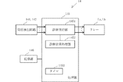
また、電動移動体1は、制御系として、非常停止用電源リレー回路部13、非常停止用電源リレー回路部13の故障診断を行う診断制御部14、モータ17への回転信号を出力する走行制御部15、及び必要に応じて例えば走行シーケンス全般を統括的乃至は自律的に制御して走行制御部15に走行指示内容を出力する上位制御部16を備えている。
Further, as a control system, the electric moving
以下、非常停止用スイッチの故障診断装置に係る第1〜第4実施形態の構成、動作を説明する。 Hereinafter, the configurations and operations of the first to fourth embodiments relating to the failure diagnosis device of the emergency stop switch will be described.
(第1実施形態)
第1実施形態を、図2〜図4を用いて説明する。第1実施形態では、バッテリー12〜モータ17の負荷ラインを備え、保護回路は設けられていない。また、各監視期間の開始から監視動作開始までの時間は通常時間、すなわちΔtに設定されている。
(First Embodiment)
The first embodiment will be described with reference to FIGS. 2 to 4. In the first embodiment, the load lines of the
図2において、非常停止用電源リレー回路部13は、並列接続されたバッテリー12からモータ17までの負荷ラインを備えている。なお、第1実施形態では、電磁ブレーキ18は備えていない。
In FIG. 2, the emergency stop power
バッテリー12からモータ17までの負荷ライン上には、直列接続されたリレーLa、Lbが介設されている。リレーLa、Lbは、励磁コイル(図略)に診断制御部14からオンオフ信号(図2中、破線で示す)が印加されることで、個々に導通(オン)と遮断(オフ)との切り替えを行う。なお、電磁式のリレーLa、Lbに代えて、機械的スイッチ、半導体スイッチ素子等のスイッチを適用してもよい。また、コンデンサC1は、モータ17の平滑用である。
Relays La and Lb connected in series are interposed on the load line from the
リレーLa、Lbの各出力端には、電圧検出回路141,142が接続されている。電圧検出回路141は、リレーLaの出力端の電圧V1を検出し、電圧検出回路142は、リレーLbの出力端の電圧V2を検出する。第1実施形態では、電圧検出回路141,142は、A−Dコンバータを内蔵し、検出電圧をデジタル値に変換して診断制御部14に導く。なお、電圧検出回路141,142は、アースとの間で出力端の電圧を検出しているが、対応する入力端との間で出力端の電圧を検出するものでもよい。
図3は、診断制御部14のブロック図で、第1実施形態では、コンピュータを含み、診断処理の一部をソフトウエアで行っている。なお、診断制御部14の機能をシーケンス回路で実行する態様としてもよい。
FIG. 3 is a block diagram of the
図3に示す診断制御部14は、例えばマイクロコンピュータで構成される処理部145を備えている。処理部145は、故障診断シーケンスプログラムを記憶した記憶部146、電圧検出回路141,142、及びリレーLa,Lbの励磁コイル(図略)と接続されている。
The
処理部145は、故障診断シーケンスプログラムを実行することで、診断実行部1451、診断結果処理部1452、及びタイマ1453として機能する。
The
診断実行部1451は、故障診断のシーケンスを実行するもので、例えば図4に示すように、予め設定された例えば一定の通常期間としての監視期間To,Ta,Tbで負荷ラインのリレーLa、Lbをオフに、また一方ずつオンさせる切換え信号を出力し、その間に電圧V1,V2の計測を行わせる。なお、診断実行部1451は、図4で説明するように、各監視期間が終了して起動が行われた後に一定の監視を行う。電圧V1,V2の計測は、監視期間の開始時点から一定時間Δt(監視開始時間)の経過時点で行われる。
The
診断結果処理部1452は、監視期間To,Ta,Tbで計測した電圧V1,V2からリレーLa,Lbの故障診断を行う。タイマ1453は、電源オン後の監視期間等をそれぞれ計測(計時)する。
The diagnosis
次に、図4のタイムチャートを用いて故障診断動作を説明する。なお、リレーの故障には、常時導通状態の故障と常時遮断状態の故障とがあり、以降の故障診断は、これらの一方に該当するか、あるいはいずれにも該当しない正常かを診断する。なお、故障のうち常時遮断状態の故障は電流を流さないため、モータ17を不用意に回転させることはなく、常時導通状態の重度の故障に比して軽度な故障といえる。
Next, the failure diagnosis operation will be described using the time chart of FIG. The relay failure includes a failure in a constantly conducting state and a failure in a constantly interrupted state, and the subsequent failure diagnosis diagnoses whether one of these is applicable or the normal condition is not applicable to either of them. It should be noted that, among the failures, the failure in the constantly cut-off state does not cause the
電源オンを受けると、まず、監視期間Toが開始される。監視期間Toでは、リレーLa、Lbにオフ信号を出力する。このとき、リレーLaが常時導通状態の故障でなければ、電圧V1は共に0レベル(ローレベル)となる。さらに、リレーLa、Lbのいずれもが常時導通状態の故障でなければ、電圧V1,V2は共に0レベル(ローレベル)となる。 When the power is turned on, the monitoring period To is first started. During the monitoring period To, an off signal is output to the relays La and Lb. At this time, if the relay La is not in a constantly conducting state, the voltage V1 is both at 0 level (low level). Further, if neither of the relays La and Lb is in a continuous conduction state, the voltages V1 and V2 are both at 0 level (low level).
一方、電圧V1のみがバッテリー12の電圧に相当する電圧レベル(ハイレベル)である場合(図4の電圧V1の破線V1o’で示す)、リレーLaが常時導通状態の故障であることが分かる。この場合、リレーLaの故障を示す報知用の異常信号が出力され、以降の監視動作が停止される。 On the other hand, when only the voltage V1 has a voltage level (high level) corresponding to the voltage of the battery 12 (indicated by the broken line V1o'of the voltage V1 in FIG. 4), it can be seen that the relay La is a failure in a constantly conducting state. In this case, an abnormal signal for notification indicating a failure of the relay La is output, and the subsequent monitoring operation is stopped.
さらに、電圧V1,V2が共にハイレベルの場合(図4の電圧V1の破線V1o’、電圧V2の破線V2o’で示す)、リレーLa、Lbがいずれも常時導通状態の故障であることが分かる。この場合、バッテリー12から負荷ラインに電流が流入するため、異常信号が出力され、以降の監視動作が停止される。また、この場合にはバッテリー12からモータ17に一時的に電流が流れるが、自動あるいはマニュアルで電源をオフにすることで異常動作が停止可能となる。なお、各監視期間の開始からの監視開始時間(電圧検出時点)は、検出精度と早期の検出の点から、監視期間のほぼ中間位置(図4のΔtを参照)に設定されている。また、診断結果として異常信号を出力する場合、報知部に出力するようにしてもよい。
Further, when the voltages V1 and V2 are both at high levels (indicated by the broken line V1o'of the voltage V1 and the broken line V2o'of the voltage V2 in FIG. 4), it can be seen that both the relays La and Lb are always in a conductive state. .. In this case, since the current flows from the
監視期間ToでリレーLaが常時導通状態の故障ではないと診断された場合、監視動作は、監視期間Taに進む。監視期間TaではリレーLaに対してオン信号が出力され、リレーLbに対してオフ信号が出力される。このとき、電圧V1がハイレベルであると(図4の電圧V1のV1aで示す)、リレーLaは常時遮断状態の故障ではないと診断される。すなわち、リレーLaは正常と診断される。 If it is diagnosed in the monitoring period To that the relay La is not a failure in the continuous conduction state, the monitoring operation proceeds to the monitoring period Ta. During the monitoring period Ta, an on signal is output to the relay La and an off signal is output to the relay Lb. At this time, if the voltage V1 is at a high level (indicated by V1a of the voltage V1 in FIG. 4), it is diagnosed that the relay La is not a failure in the constantly cut-off state. That is, the relay La is diagnosed as normal.
また、電圧V2もハイレベルの場合(図4の電圧V1のV1a、電圧V2の破線V2a’で示す)、リレーLbは常時導通状態の故障であると診断され、異常信号が出力される。一方、電圧V1がローレベルの場合、リレーLaは常時遮断状態の故障と診断される。 Further, when the voltage V2 is also at a high level (indicated by V1a of the voltage V1 in FIG. 4 and the broken line V2a'of the voltage V2), the relay Lb is diagnosed as a failure in the continuous conduction state, and an abnormal signal is output. On the other hand, when the voltage V1 is at a low level, the relay La is diagnosed as a failure in a constantly cut-off state.
次いで、監視期間Taで、リレーLaが正常で、かつリレーLbが常時導通状態の故障でないと診断された場合、監視動作は、監視期間Tbに進む。監視期間TbではリレーLaに対してオフ信号が出力され、リレーLbに対してオン信号が出力される。このとき、電圧V1,V2がいずれもローレベルであれば、診断制御部14からリレーLa、Lbへのオンオフ信号が対応するリレーに正常に出力されたと診断される。一方、既に正常と判断されているリレーLaの電圧V1がハイレベルになったり、電圧V2がハイレベルになったりすることは(図4の電圧V1の破線V1b’、電圧V2の破線V2b’で示す)、リレーLbの故障によるものではなく、電源ライン上の問題、例えば配線の誤接触の有無として診断される。このように、監視期間Tbは、リレーLa、Lbの故障診断では必ずしも必要ではない。
Then, in the monitoring period Ta, when it is diagnosed that the relay La is normal and the relay Lb is not a failure in the constantly conducting state, the monitoring operation proceeds to the monitoring period Tb. During the monitoring period Tb, an off signal is output to the relay La, and an on signal is output to the relay Lb. At this time, if the voltages V1 and V2 are both at low levels, it is diagnosed that the on / off signals from the
監視期間Tbが終了し、起動タイミングに移行すると、リレーLa,Lbのいずれもオンに切換えられてモータ17が回転駆動される。この間、診断制御部14はリレーLa,Lbの状態、少なくともリレーLbの状態を監視し、リレーLa、Lbにオン信号が出力されている間に、電圧V2がローレベルになっていないか否かを検出する。電圧V2がローレベルになっていると、リレーLbが常時遮断状態の故障として報知が行われ、電動移動体1の動作が停止される。一方、電圧V2がハイレベルであれば、リレーLbは正常として、走行動作が継続される。
When the monitoring period Tb ends and the start timing shifts, both the relays La and Lb are switched on and the
(第2実施形態)
第2実施形態を、図5、図6及び図4を用いて説明する。第2実施形態では、バッテリー12〜モータ17の負荷ラインを備え、さらに保護回路が設けられている。なお、各監視開始時間は通常時間、すなわちΔtに設定されている。なお、共通する部分の説明は省略する。
(Second Embodiment)
The second embodiment will be described with reference to FIGS. 5, 6 and 4. In the second embodiment, the load lines of the
図5は、図2に対して、バッテリー12とリレーLaとの間に保護回路131が介設されている点で相違する。保護回路131は、本実施形態ではヒューズである。保護回路131の出力端側には、さらにリレーLxが接続されている。リレーLxは、診断制御部14からの異常信号を受けるとオンするもので、このオンによってバッテリー12との間を短絡させて、保護回路131にバッテリー12から大電流を流してヒューズを溶断する。ヒューズの溶断によって、バッテリー12が負荷ラインから遮断される。なお、ヒューズに代えて導電性ポリマー等から製造される、繰り返し使用可能なポリスイッチを採用し、トリップさせることで一時的な遮断機能を発揮させる態様としてもよい。また、電動移動体1の走行状態によってはモータ17での回生発電に起因する過電圧がリレーLa、Lbに印加して故障原因となることから、保護回路131を動作させるようにしてもよい。
FIG. 5 differs from FIG. 2 in that a
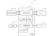
図6は、診断制御部14のブロック図で、本実施形態では、コンピュータを含み、診断処理の一部をソフトウエアで行っている。なお、診断制御部14の機能をシーケンス回路で実行する態様としてもよい。
FIG. 6 is a block diagram of the
図6に示す診断制御部14は、例えばマイクロコンピュータで構成される処理部145を備え、処理部145は、故障診断シーケンスプログラムを記憶した記憶部146、電圧検出回路141,142、及びリレーLa,Lb,Lxの励磁コイル(図略)と接続されている。
The
処理部145は、故障診断シーケンスプログラムを実行することで、診断実行部1451、診断結果処理部1452、タイマ1453及び保護処理部1454として機能する。
The
診断実行部1451は、故障診断のシーケンスを実行するもので、例えば図4と同様に、予め設定された例えば一定の通常期間としての監視期間To,Ta,Tbで負荷ライン側のリレーLa、Lbをオフに、また一方ずつオンさせる切換え信号を出力し、その間に電圧V1,V2の計測を行わせる。なお、診断実行部1451は、図4と同様に、各監視期間が終了して起動が行われた後に一定の監視を行う。電圧V1,V2の計測は、監視期間の開始から一定時間Δt(監視開始時間)の経過時点で行われる。
The
診断結果処理部1452は、監視期間To,Ta,Tbで計測した電圧V1,V2からリレーLa,Lbの故障診断を行う。保護処理部1454は、バッテリー12を負荷ラインから切り離すべく、リレーLxへ異常信号を出力させる。タイマ1453は、電源オン後の各監視期間等をそれぞれ計測する。
The diagnosis
第2実施形態における故障診断動作は、図4のタイムチャートと同様であり、保護回路131に対する動作のみが相違する。
The failure diagnosis operation in the second embodiment is the same as the time chart of FIG. 4, and only the operation with respect to the
監視期間Toにおいて、電圧V1,V2が共にハイレベルの場合(図4の電圧V1の破線V1o’、電圧V2の破線V2o’で示す)、リレーLa、Lbがいずれも常時導通状態の故障であることが分かる。この場合、バッテリー12から負荷ラインに電流が流入するため、リレーLxへヒューズ溶断用の異常信号が出力される。また、この場合にはバッテリー12からモータ17に一時的に電流が流れるが、ヒューズが溶断されるため異常動作は停止される。なお、診断結果として報知用、又はヒューズ溶断用の異常信号を出力する場合、報知部に出力するようにしてもよい。
When the voltages V1 and V2 are both at high levels during the monitoring period To (indicated by the broken line V1o'of the voltage V1 and the broken line V2o'of the voltage V2 in FIG. 4), both the relays La and Lb are always in a conductive state. You can see that. In this case, since the current flows from the
監視期間ToでリレーLaが常時導通状態の故障ではないと診断された場合、監視動作は、監視期間Taに進む。監視期間TaではリレーLaに対してオン信号が出力され、リレーLbに対してオフ信号が出力される。このとき、電圧V1,V2がハイレベルの場合(図4の電圧V1のV1a、電圧V2の破線V2a’で示す)、リレーLbは常時導通状態の故障であると診断され、リレーLxへヒューズ溶断用の異常信号が出力される。一方、電圧V1がローレベルの場合、リレーLaは常時遮断状態の故障と診断される。 If it is diagnosed in the monitoring period To that the relay La is not a failure in the continuous conduction state, the monitoring operation proceeds to the monitoring period Ta. During the monitoring period Ta, an on signal is output to the relay La and an off signal is output to the relay Lb. At this time, when the voltages V1 and V2 are at a high level (indicated by V1a of the voltage V1 in FIG. 4 and the broken line V2a'of the voltage V2), the relay Lb is diagnosed as having a failure in the continuous conduction state, and the fuse blows to the relay Lx. Abnormal signal is output. On the other hand, when the voltage V1 is at a low level, the relay La is diagnosed as a failure in a constantly cut-off state.
次いで、監視期間Taで、リレーLaが正常で、かつリレーLbが常時導通状態の故障でないと診断された場合、監視動作は、監視期間Tbに進む。監視期間Tbでは、電源ライン上の問題、例えば配線の誤接触の有無として診断される。このように、監視期間Tbは、リレーLa、Lbの故障診断では必ずしも必要ではない。また、起動タイミングの後は、リレーLbの診断が行われる。 Then, in the monitoring period Ta, when it is diagnosed that the relay La is normal and the relay Lb is not a failure in the constantly conducting state, the monitoring operation proceeds to the monitoring period Tb. During the monitoring period Tb, it is diagnosed as a problem on the power supply line, for example, the presence or absence of erroneous wiring contact. As described above, the monitoring period Tb is not always necessary for the failure diagnosis of the relays La and Lb. Further, after the start timing, the relay Lb is diagnosed.
(第3実施形態)
第3施形態を、図7〜図9を用いて説明する。第3実施形態では、バッテリー12〜モータ17の負荷ライン及びバッテリー12〜電磁ブレーキ18の制動ラインを備え、保護回路は設けられていない。また、各監視開始時間は通常時間、すなわちΔtである。なお、共通する部分の説明は省略する。
(Third Embodiment)
The third embodiment will be described with reference to FIGS. 7 to 9. In the third embodiment, the load line of the
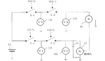
図7は、図2に対して、制動ラインを備えている点で相違する。すなわち、非常停止用電源リレー回路部13は、並列接続された、バッテリー12とモータ17間の負荷ラインとバッテリー12と電磁ブレーキ18間の制動ラインとを備えている。なお、電磁ブレーキ18は、モータ17への制動力を機械的に作用させる構成であり、本実施形態では、電力供給がされていない間、制動力が作用し、電力供給を受けると、制動力が解除される無励磁ブレーキ制御型を採用している。また、負荷ラインと制動ラインとはバッテリー12に対して並列に接続されていてもよいが、バッテリーを個別に設けて別の回路としてもよい。
FIG. 7 differs from FIG. 2 in that it is provided with a braking line. That is, the emergency stop power
バッテリー12と電磁ブレーキ18との制動ライン上には、直列接続されたリレーLc、Ldが介設されている。リレーLc、Ldは、励磁コイル(図略)に診断制御部14からオンオフ信号(図7中、破線で示す)が印加されることで、個々に導通(オン)と遮断(オフ)との切り替えを行う。なお、電磁式のリレーLc、Ldに代えて、機械的スイッチ、半導体スイッチ素子等のスイッチを適用してもよい。
Relays Lc and Ld connected in series are interposed on the braking line between the
リレーLc、Ldの各出力端には、電圧検出回路143,144が接続されている。電圧検出回路143は、リレーLcの出力端の電圧V3を検出し、電圧検出回路144は、リレーLdの出力端の電圧V4を検出する。本実施形態では、電圧検出回路143,144は、A−Dコンバータを内蔵し、検出電圧をデジタル値に変換して診断制御部14に導く。なお、電圧検出回路143,144は、アースとの間で出力端の電圧を検出しているが、対応する入力端との間で出力端の電圧を検出するものでもよい。
図8は、診断制御部14のブロック図で、本実施形態では、コンピュータを含み、診断処理の一部をソフトウエアで行っている。なお、診断制御部14の機能をシーケンス回路で実行する態様としてもよい。
FIG. 8 is a block diagram of the
図8に示す診断制御部14は、例えばマイクロコンピュータで構成される処理部145を備えている。処理部145は、故障診断シーケンスプログラムを記憶した記憶部146、電圧検出回路141〜144、及びリレーLa〜Ldの励磁コイル(図略)と接続されている。
The
処理部145は、故障診断シーケンスプログラムを実行することで、診断実行部1451、診断結果処理部1452、及びタイマ1453として機能する。
The
診断実行部1451は、故障診断のシーケンスを実行するもので、例えば図9に示すように、予め設定された例えば一定の通常期間としての監視期間To,Ta,Tbで負荷ライン側のリレーLa、Lbをオフに、また一方ずつオンさせる切換え信号を出力し、その間に電圧V1,V2の計測を行わせる。また、リレーLa、Lbと同期して、同様にリレーLc,Ldをオフに、また一方ずつオンさせる故障診断のシーケンスを実行させる。なお、診断実行部1451は、図9で説明するように、各監視期間が終了して起動が行われた後に一定の監視を行う。
The
診断結果処理部1452は、監視期間To,Ta,Tbで計測した電圧V1,V2からリレーLa,Lbの故障診断を行う。同様に、リレーLc,Ldの故障診断を行う。タイマ1453は、電源オン後の各監視期間等をそれぞれ計測する。
The diagnosis
次に、図9のタイムチャートを用いて故障診断動作を説明する。なお、図9に示すリレーLa、Lbの故障診断動作は、図4と同一であるので説明は省略し、リレーLc,Ldの故障診断に関する部分について説明する。 Next, the failure diagnosis operation will be described using the time chart of FIG. Since the failure diagnosis operation of the relays La and Lb shown in FIG. 9 is the same as that of FIG. 4, the description thereof will be omitted, and the part related to the failure diagnosis of the relays Lc and Ld will be described.
まず、監視期間Toで、診断制御部14は、リレーLc,Ldにオフ信号を出力すると共に、リレーLa、Lbにオフ信号を出力する。
First, during the monitoring period To, the
このとき、電圧V1,V2が共にハイレベルの場合(図9の電圧V1の破線V1o’、電圧V2の破線V2o’で示す)、リレーLa、Lbがいずれも常時導通状態の故障であることが分かる。この場合、バッテリー12からモータ17に一時的に電流が流れるが、リレーLc,Ldが共に常時導通状態の故障でない限り、電磁ブレーキ18による制動力が作用している状態にあるため、モータ17が回転、すなわち電動移動体1が不用意に走行することは規制される。なお、診断結果として報知用の異常信号を出力する場合、報知部に出力するようにすればよい。
At this time, when the voltages V1 and V2 are both at high levels (indicated by the broken line V1o'of the voltage V1 and the broken line V2o'of the voltage V2 in FIG. 9), it is possible that the relays La and Lb are always in a conductive state. I understand. In this case, a current temporarily flows from the
監視期間ToでリレーLaが常時導通状態の故障ではないと診断された場合、監視動作は、監視期間Taに進む。監視期間TaではリレーLaに対してオン信号が出力され、リレーLbに対してオフ信号が出力される。このとき、電圧V1,電圧V2がハイレベルの場合(図9の電圧V1のV1a、電圧V2の破線V2a’で示す)、リレーLdにオフ信号が出力されているので、電磁ブレーキ18による制動力が作用し、モータ17は回転が規制される。
If it is diagnosed in the monitoring period To that the relay La is not a failure in the continuous conduction state, the monitoring operation proceeds to the monitoring period Ta. During the monitoring period Ta, an on signal is output to the relay La and an off signal is output to the relay Lb. At this time, when the voltage V1 and the voltage V2 are at a high level (indicated by V1a of the voltage V1 in FIG. 9 and the broken line V2a'of the voltage V2), an off signal is output to the relay Ld, so that the braking force by the
次いで、監視動作は、監視期間Tbに進み、さらに起動後に移行する。なお、図9に示すように、リレーLc,Ldに対する故障監視動作も、診断実行部1451及び診断結果処理部1452によって、リレーLa、Lbに対する監視動作と同期して行われる。
Next, the monitoring operation proceeds to the monitoring period Tb, and further shifts after activation. As shown in FIG. 9, the failure monitoring operation for the relays Lc and Ld is also performed by the
なお、リレーLa、Lbに対する監視動作が終了した後に、リレーLc,Ldに対する故障監視動作を実行するようにしてもよい。これによれば、リレーLa、Lbの故障診断時に、リレーLc,Ldがオフ状態にあるので、モータ17が誤って暴走等の動作をすることを防止できる。
After the monitoring operation for the relays La and Lb is completed, the failure monitoring operation for the relays Lc and Ld may be executed. According to this, since the relays Lc and Ld are in the off state at the time of failure diagnosis of the relays La and Lb, it is possible to prevent the
(第4実施形態)
第4実施形態を、図10、図11を用いて説明する。第4実施形態では、バッテリー12〜モータ17の負荷ラインを備え、保護回路は設けられていない。第4実施形態では、監視期間Taの開始からの監視開始時間Δtsが、監視期間Tbの通常時間Δtに比して短く設定されている。なお、バッテリー12とモータ17間の負荷ラインは、図4と同一なので説明は省略する。
(Fourth Embodiment)
The fourth embodiment will be described with reference to FIGS. 10 and 11. In the fourth embodiment, the load lines of the
図10は、診断制御部14のブロック図で、本実施形態では、コンピュータを含み、診断処理の一部をソフトウエアで行っている。なお、診断制御部14の機能をシーケンス回路で実行する態様としてもよい。
FIG. 10 is a block diagram of the
図10に示す診断制御部14は、例えばマイクロコンピュータで構成される処理部145を備えている。処理部145は、故障診断シーケンスプログラムを記憶した記憶部146、電圧検出回路141,142、及びリレーLa,Lbの励磁コイル(図略)と接続されている。
The
処理部145は、故障診断シーケンスプログラムを実行することで、診断実行部1451、診断結果処理部1452及びタイマ1453として機能する。
The
診断実行部1451は、故障診断のシーケンスを実行するもので、例えば図11に示すように、監視期間To,Ta,Tbで負荷ラインのリレーLa、Lbをオフに、また一方ずつオンさせる切換え信号を出力し、その間に電圧V1,V2の計測を行わせる。診断実行部1451は、監視期間To,Tbでは開始時点からの監視開始時間をΔtに設定する一方、監視期間Taでは、Δts(<Δt)に設定している。各時間はタイマ1453によってそれぞれ計時される。
The
診断結果処理部1452は、監視期間To,Ta,Tbで計測した電圧V1,V2からリレーLa,Lbの故障診断を行う。
The diagnosis
次に、図11は第4実施形態の故障診断動作を示すタイムチャートである。図11に示すリレーLa、Lbの故障診断動作は、監視期間Taの開始から監視開始までの時間Δtsが相違する点を除いて、図4と同一であるので、主に監視期間Taでの動作について説明する。 Next, FIG. 11 is a time chart showing the failure diagnosis operation of the fourth embodiment. The failure diagnosis operation of the relays La and Lb shown in FIG. 11 is the same as that of FIG. 4 except that the time Δts from the start of the monitoring period Ta to the start of monitoring is different, so that the operation is mainly performed in the monitoring period Ta. Will be described.
監視期間ToでリレーLaが常時導通状態の故障ではないと診断された場合、監視動作は、監視期間Taに進む。監視期間Taでは、開始から監視開始までの時間Δts、すなわち電圧が立ち上がりきる前の時点で測定するのが好ましい。このようにすれば、リレーLbが故障していて、電流がショートした場合でも、モータ17に流れ込む電流を極力少なくすることが可能となる。一方、監視期間Tbでは、既に監視期間Taで、リレーLaのオフに問題がないことがわかっているため、モータ17に大電流が流れ込む心配がないことから、通常の測定時間Δt(電圧が立ち上がった後)で監視を行うことができ、検出精度が維持される。
If it is diagnosed in the monitoring period To that the relay La is not a failure in the continuous conduction state, the monitoring operation proceeds to the monitoring period Ta. In the monitoring period Ta, it is preferable to measure the time Δts from the start to the start of monitoring, that is, before the voltage rises completely. By doing so, even if the relay Lb is out of order and the current is short-circuited, the current flowing into the
なお、第1実施形態では、直列接続されるリレーの個数を2個としたが、3個又はそれ以上の個数を直列接続したものでもよい。 In the first embodiment, the number of relays connected in series is two, but three or more relays may be connected in series.
また、前記実施形態では、リレーLa、LbとリレーLc,Ldとを同期させて故障診断処理を実行させたが、リレーLa、Lbに対する故障診断処理が終了した後に、同様な手順でリレーLc,Ldの故障診断処理を行わせる態様としてもよい。これによれば、電磁ブレーキ18は電源オフ時にモータ17に制動力を作用させているので、負荷ラインの故障診断時にモータ17に電流が流れても電動移動体1が暴走することはない。
Further, in the above-described embodiment, the relays La and Lb are synchronized with the relays Lc and Ld to execute the failure diagnosis process, but after the failure diagnosis process for the relays La and Lb is completed, the relay Lc and Lb are subjected to the same procedure. The mode may be such that the failure diagnosis process of Ld is performed. According to this, since the
なお、前記実施形態では、電動移動体1として、車輪11による走行体としたが、これに限定されず、車輪以外の要素で走行したり、あるいは水上、空中を移動したりする移動体に適用可能である。また、電動負荷部としてのモータに代えて他電動駆動源を採用することができる。
In the above embodiment, the electric moving
また、上述の実施形態の説明は、すべての点で例示であって、制限的なものではないと考えられるべきである。本発明の範囲は、上述の実施形態ではなく、特許請求の範囲によって示される。さらに、本発明の範囲には、特許請求の範囲と均等の意味及び範囲内でのすべての変更が含まれることが意図される。 Also, the description of the embodiments described above should be considered to be exemplary in all respects and not restrictive. The scope of the present invention is shown not by the above-described embodiment but by the scope of claims. Furthermore, the scope of the present invention is intended to include all modifications within the meaning and scope equivalent to the claims.
1 電動移動体
12 バッテリー(電源)
13 非常停止用電源リレー回路部
131 保護回路
14 診断制御部
17 モータ(電動負荷部)
18 電磁ブレーキ(制動部)
141〜144 電圧検出回路
1451 診断実行部
1452 診断結果処理部
1453 保護処理部
La〜Ld リレー(スイッチ)
Lx リレー
1 Electric mobile 12 Battery (power supply)
13 Emergency stop power
18 Electromagnetic brake (braking part)
141-144
Lx relay
Claims (8)
前記第1、第2スイッチの各出力端電圧をそれぞれ検出する電圧検出部と、
1番目の監視期間では前記第1、第2スイッチをオフにする切換信号を、2番目の監視期間では前記第1スイッチのみをオンさせる切換信号を出力し、各監視期間で各出力端電圧の検出を行う診断実行部と、
前記各監視期間における各出力端電圧から、前記第1、第2スイッチの故障診断を行う診断結果処理部とを備え、
前記診断実行部は、前記2番目の監視期間の開始から出力端電圧の検出までの時間を前記1番目の監視期間の開始から出力端電圧の検出までの時間に比して短時間に設定し、
前記診断結果処理部は、前記1番目の監視期間で、前記各出力端電圧から前記第1、第2スイッチが常時導通状態の故障か否かを診断し、前記2番目の監視期間で、前記第1スイッチが常時遮断状態の故障か否かを診断することを特徴とする故障診断装置。 Failure diagnosis processing of the first and second switches from the power supply side, which is provided between the power supply and the electric load unit driven by receiving power from the power supply and is connected in series for emergency stop, is performed. In the failure diagnosis device
A voltage detection unit that detects the voltage at each output end of the first and second switches, and
Wherein the first monitoring period first, a switching signal for turning off the second switch, the monitoring period of second changeover signal to turn on only the first switch, the output end voltage at each monitoring period Diagnostic execution unit that detects
It is provided with a diagnosis result processing unit that performs failure diagnosis of the first and second switches from each output terminal voltage in each monitoring period.
The diagnosis execution unit sets the time from the start of the second monitoring period to the detection of the output end voltage to be shorter than the time from the start of the first monitoring period to the detection of the output end voltage. ,
In the first monitoring period, the diagnosis result processing unit diagnoses whether or not the first and second switches are in a constantly conducting state from the respective output terminal voltages, and in the second monitoring period, the diagnosis result processing unit diagnoses. A failure diagnosis device characterized by diagnosing whether or not the first switch is a failure in a constantly shut-off state.
前記診断結果処理部は、前記第1、第2スイッチへの切換信号の出力ライン上の異常の有無を診断する請求項1に記載の故障診断装置。 The diagnosis execution unit provides a third monitoring period for outputting a switching signal that turns on only the second switch, and is the third monitoring period, from the start of the first monitoring period to the output end voltage. Each output end voltage is detected in the same time as the time until detection,
The failure diagnosis device according to claim 1, wherein the diagnosis result processing unit diagnoses the presence or absence of an abnormality on the output line of the switching signal to the first and second switches.
前記診断実行部及び診断結果処理部は、前記第1、第2スイッチに対する故障診断の実行と同期して前記制動部側の前記制動用第1、第2スイッチに対する故障診断を実行することを特徴とする請求項4に記載の故障診断装置。 A series-connected first and second brake switches provided between the braking unit and the power supply are provided.
The diagnosis execution unit and the diagnostic result processing unit, the first, first for the braking of the braking portion in synchronism with the execution of failure diagnosis with respect to the second switch, wherein the executing the failure diagnosis for the second switch The failure diagnosis device according to claim 4.
診断実行手段が、前記第1、第2スイッチの各出力端電圧をそれぞれ検出する電圧検出部を用いて、1番目の監視期間では前記第1、第2スイッチをオフにする切換信号を、2番目の監視期間では前記第1スイッチのみをオンさせる切換信号を出力し、各監視期間で各出力端電圧の検出を行い、
診断結果処理手段が、前記各監視期間における各出力端電圧から、前記第1、第2スイッチの故障診断を行い、
前記診断実行手段は、前記2番目の監視期間の開始から出力端電圧の検出までの時間を前記1番目の監視期間の開始から出力端電圧の検出までの時間に比して短時間に設定し、
前記診断結果処理手段は、前記1番目の監視期間で、前記各出力端電圧から前記第1、第2スイッチが常時導通状態の故障か否かを診断し、前記2番目の監視期間で、前記第1スイッチが常時遮断状態の故障か否かを診断することを特徴とする故障診断方法。 Failure diagnosis processing of the first and second switches from the power supply side, which is provided between the power supply and the electric load unit driven by receiving the power supply from the power supply and is connected in series for emergency stop, is performed. In the failure diagnosis method
Diagnosis executing means, said first, using a voltage detector for detecting the respective output end voltage of the second switch, respectively, wherein the first monitoring period first, a switching signal for turning off the second switch, 2 the monitoring period turn th changeover signal to turn on only said first switch, performs detection of the output end voltage in each monitoring period,
The diagnosis result processing means diagnoses the failure of the first and second switches from each output terminal voltage in each monitoring period.
The diagnosis executing means sets the time from the start of the second monitoring period to the detection of the output end voltage shorter than the time from the start of the first monitoring period to the detection of the output end voltage. ,
The diagnosis result processing means diagnoses whether or not the first and second switches are in a constantly conducting state from the respective output terminal voltages in the first monitoring period, and in the second monitoring period, the diagnosis result processing means. A failure diagnosis method characterized by diagnosing whether or not the first switch is a failure in a constantly shut-off state.
前記第1、第2スイッチの各出力端電圧をそれぞれ検出する電圧検出部を用いて、1番目の監視期間では前記第1、第2スイッチをオフにする切換信号を、2番目の監視期間では前記第1スイッチのみをオンさせる切換信号を出力し、各監視期間で各出力端電圧の検出を行う診断実行手段、
前記各監視期間における各出力端電圧から、前記第1、第2スイッチの故障診断を行う診断結果処理手段として、前記故障診断装置を機能させ、
前記診断実行手段は、前記2番目の監視期間の開始から出力端電圧の検出までの時間を前記1番目の監視期間の開始から出力端電圧の検出までの時間に比して短時間に設定し、
前記診断結果処理手段は、前記1番目の監視期間で、前記各出力端電圧から前記第1、第2スイッチが常時導通状態の故障か否かを診断し、前記2番目の監視期間で、前記第1スイッチが常時遮断状態の故障か否かを診断することを特徴とする故障診断プログラム。 Failure diagnosis processing of the first and second switches from the power supply side, which is interposed between the power supply and the electric load unit driven by receiving power from the power supply and connected in series for an emergency stop , is performed. In the failure diagnosis program to be performed by the failure diagnosis device
The first, each output end voltage of the second switch with a voltage detection unit for detecting each of said at first monitoring period first, a switching signal for turning off the second switch, second monitoring period Then, a diagnostic execution means that outputs a switching signal for turning on only the first switch and detects each output end voltage in each monitoring period.
The failure diagnosis device is made to function as a diagnosis result processing means for performing a failure diagnosis of the first and second switches from each output terminal voltage in each monitoring period.
The diagnosis executing means sets the time from the start of the second monitoring period to the detection of the output end voltage shorter than the time from the start of the first monitoring period to the detection of the output end voltage. ,
The diagnosis result processing means diagnoses whether or not the first and second switches are in a constantly conducting state from the respective output terminal voltages in the first monitoring period, and in the second monitoring period, the diagnosis result processing means. A failure diagnosis program characterized by diagnosing whether or not the first switch is a failure in a constantly shut-off state.
Priority Applications (1)
| Application Number | Priority Date | Filing Date | Title |
|---|---|---|---|
| JP2016193577A JP6885698B2 (en) | 2016-09-30 | 2016-09-30 | Fault diagnostic equipment, methods, programs and electric mobiles |
Applications Claiming Priority (1)
| Application Number | Priority Date | Filing Date | Title |
|---|---|---|---|
| JP2016193577A JP6885698B2 (en) | 2016-09-30 | 2016-09-30 | Fault diagnostic equipment, methods, programs and electric mobiles |
Publications (2)
| Publication Number | Publication Date |
|---|---|
| JP2018057218A JP2018057218A (en) | 2018-04-05 |
| JP6885698B2 true JP6885698B2 (en) | 2021-06-16 |
Family
ID=61837300
Family Applications (1)
| Application Number | Title | Priority Date | Filing Date |
|---|---|---|---|
| JP2016193577A Active JP6885698B2 (en) | 2016-09-30 | 2016-09-30 | Fault diagnostic equipment, methods, programs and electric mobiles |
Country Status (1)
| Country | Link |
|---|---|
| JP (1) | JP6885698B2 (en) |
Families Citing this family (4)
| Publication number | Priority date | Publication date | Assignee | Title |
|---|---|---|---|---|
| CN110857084B (en) * | 2018-08-22 | 2022-02-01 | 瀚德万安(上海)电控制动系统有限公司 | Method and device for diagnosing electromagnetic brake and electromechanical brake system |
| US11088543B2 (en) | 2018-10-02 | 2021-08-10 | Toshiba Mitsubishi-Electric Industrial Systems Corporation | Failure diagnosis system |
| CN112198415B (en) * | 2020-09-04 | 2023-06-06 | 南京康尼电子科技有限公司 | Device and method for diagnosing in-place circuit of unlocking of motor train unit door |
| CN112162209B (en) * | 2020-09-14 | 2022-12-30 | 江苏中烟工业有限责任公司 | Driving power supply tripping diagnosis method of C800-BV packaging machine |
Family Cites Families (6)
| Publication number | Priority date | Publication date | Assignee | Title |
|---|---|---|---|---|
| JPH11108233A (en) * | 1997-10-08 | 1999-04-20 | Rb Controls Kk | Solenoid valve drive circuit |
| US6297569B1 (en) * | 1998-12-31 | 2001-10-02 | Honeywell International Inc. | Power switching system |
| JP2009259762A (en) * | 2008-03-28 | 2009-11-05 | Hitachi Ltd | Power source having a plurality of relays |
| JP5024839B2 (en) * | 2010-05-11 | 2012-09-12 | 日本輸送機株式会社 | Electromagnetic brake control device and cargo handling vehicle equipped with the same |
| JP5587749B2 (en) * | 2010-11-25 | 2014-09-10 | 株式会社ユーシン | Electric steering lock device |
| JP5910172B2 (en) * | 2012-03-01 | 2016-04-27 | 株式会社Gsユアサ | Switch failure diagnosis device, battery pack, switch failure diagnosis program, switch failure diagnosis method |
-
2016
- 2016-09-30 JP JP2016193577A patent/JP6885698B2/en active Active
Also Published As
| Publication number | Publication date |
|---|---|
| JP2018057218A (en) | 2018-04-05 |
Similar Documents
| Publication | Publication Date | Title |
|---|---|---|
| JP6885698B2 (en) | Fault diagnostic equipment, methods, programs and electric mobiles | |
| CN110719057B (en) | Abnormality determination system | |
| KR102121639B1 (en) | System and method for perventing the abnormal opening of the contactor using real-time detection | |
| US20150054517A1 (en) | Diagnosis apparatus and diagnosis method for relay circuit | |
| CN103941114B (en) | The self checking method of automobile permanent magnet synchronous motor system power module and current sensor | |
| US20140188359A1 (en) | Electric brake assist system for vehicle use | |
| JP2006320176A (en) | Method and device for diagnosing inverter | |
| JP2010279125A (en) | Motor control device | |
| KR20160046420A (en) | Relay Re-connection Method in Battery Management System | |
| WO2016017040A1 (en) | Vehicle system and control method therefor | |
| US11251739B2 (en) | Vehicle driving device | |
| US9899954B2 (en) | Motor drive apparatus having function of detecting failure of electric shunt | |
| US20210044245A1 (en) | Motor control device and failure detection method for motor control device | |
| KR102291762B1 (en) | Circuit for diagnosing a relay | |
| JP5994652B2 (en) | Vehicle power supply control device | |
| KR101785160B1 (en) | Relay unit and control method of relay circuit | |
| KR20170010999A (en) | Hybrid pra control method | |
| KR20150003168A (en) | Method for monitoring an on-load tap changer | |
| JP7238475B2 (en) | Abnormality judgment system | |
| PT2045683E (en) | Method and devices for testing redundant actuators in a safety output circuit | |
| JP5615470B1 (en) | Power supply control device and programmable logic controller | |
| JP2017079496A (en) | Contactor failure determining device and contactor failure determining method | |
| JP2017093008A (en) | Contactor failure determination device and contactor failure determination method | |
| JP5746781B2 (en) | Vehicle control apparatus and failure determination method | |
| KR20200111314A (en) | System and method for diagnosing high voltage relay of vehicle |
Legal Events
| Date | Code | Title | Description |
|---|---|---|---|
| A621 | Written request for application examination |
Free format text: JAPANESE INTERMEDIATE CODE: A621 Effective date: 20190320 |
|
| A977 | Report on retrieval |
Free format text: JAPANESE INTERMEDIATE CODE: A971007 Effective date: 20200131 |
|
| A131 | Notification of reasons for refusal |
Free format text: JAPANESE INTERMEDIATE CODE: A131 Effective date: 20200303 |
|
| A521 | Written amendment |
Free format text: JAPANESE INTERMEDIATE CODE: A523 Effective date: 20200408 |
|
| A131 | Notification of reasons for refusal |
Free format text: JAPANESE INTERMEDIATE CODE: A131 Effective date: 20200929 |
|
| A521 | Written amendment |
Free format text: JAPANESE INTERMEDIATE CODE: A523 Effective date: 20201118 |
|
| TRDD | Decision of grant or rejection written | ||
| A01 | Written decision to grant a patent or to grant a registration (utility model) |
Free format text: JAPANESE INTERMEDIATE CODE: A01 Effective date: 20210427 |
|
| A61 | First payment of annual fees (during grant procedure) |
Free format text: JAPANESE INTERMEDIATE CODE: A61 Effective date: 20210513 |
|
| R150 | Certificate of patent or registration of utility model |
Ref document number: 6885698 Country of ref document: JP Free format text: JAPANESE INTERMEDIATE CODE: R150 |