JP6885207B2 - Marker detection method and vehicle system - Google Patents
Marker detection method and vehicle system Download PDFInfo
- Publication number
- JP6885207B2 JP6885207B2 JP2017116977A JP2017116977A JP6885207B2 JP 6885207 B2 JP6885207 B2 JP 6885207B2 JP 2017116977 A JP2017116977 A JP 2017116977A JP 2017116977 A JP2017116977 A JP 2017116977A JP 6885207 B2 JP6885207 B2 JP 6885207B2
- Authority
- JP
- Japan
- Prior art keywords
- magnetic
- distribution
- marker
- vehicle
- detection method
- Prior art date
- Legal status (The legal status is an assumption and is not a legal conclusion. Google has not performed a legal analysis and makes no representation as to the accuracy of the status listed.)
- Active
Links
- 239000003550 marker Substances 0.000 title claims description 142
- 238000001514 detection method Methods 0.000 title claims description 99
- 238000009826 distribution Methods 0.000 claims description 163
- 238000000034 method Methods 0.000 claims description 54
- 238000005259 measurement Methods 0.000 claims description 32
- 230000005389 magnetism Effects 0.000 claims description 14
- 230000008569 process Effects 0.000 description 33
- 238000006073 displacement reaction Methods 0.000 description 10
- 230000008859 change Effects 0.000 description 7
- 230000035945 sensitivity Effects 0.000 description 6
- 238000013459 approach Methods 0.000 description 5
- 230000004907 flux Effects 0.000 description 5
- 238000004364 calculation method Methods 0.000 description 4
- 230000001771 impaired effect Effects 0.000 description 4
- 230000009471 action Effects 0.000 description 3
- 230000000694 effects Effects 0.000 description 3
- 238000005516 engineering process Methods 0.000 description 3
- 230000002123 temporal effect Effects 0.000 description 3
- XEEYBQQBJWHFJM-UHFFFAOYSA-N Iron Chemical compound [Fe] XEEYBQQBJWHFJM-UHFFFAOYSA-N 0.000 description 2
- UQSXHKLRYXJYBZ-UHFFFAOYSA-N Iron oxide Chemical compound [Fe]=O UQSXHKLRYXJYBZ-UHFFFAOYSA-N 0.000 description 2
- 238000010606 normalization Methods 0.000 description 2
- 230000004044 response Effects 0.000 description 2
- 229910000859 α-Fe Inorganic materials 0.000 description 2
- 230000002238 attenuated effect Effects 0.000 description 1
- 230000006399 behavior Effects 0.000 description 1
- 238000006243 chemical reaction Methods 0.000 description 1
- 230000007423 decrease Effects 0.000 description 1
- 238000001739 density measurement Methods 0.000 description 1
- 238000010586 diagram Methods 0.000 description 1
- 239000012530 fluid Substances 0.000 description 1
- 239000000446 fuel Substances 0.000 description 1
- 229910052742 iron Inorganic materials 0.000 description 1
- 239000000696 magnetic material Substances 0.000 description 1
- 239000006247 magnetic powder Substances 0.000 description 1
- 239000000463 material Substances 0.000 description 1
- 239000000203 mixture Substances 0.000 description 1
- 239000002861 polymer material Substances 0.000 description 1
Images


Classifications
-
- G—PHYSICS
- G05—CONTROLLING; REGULATING
- G05D—SYSTEMS FOR CONTROLLING OR REGULATING NON-ELECTRIC VARIABLES
- G05D1/00—Control of position, course, altitude or attitude of land, water, air or space vehicles, e.g. using automatic pilots
- G05D1/02—Control of position or course in two dimensions
- G05D1/021—Control of position or course in two dimensions specially adapted to land vehicles
- G05D1/0259—Control of position or course in two dimensions specially adapted to land vehicles using magnetic or electromagnetic means
- G05D1/0261—Control of position or course in two dimensions specially adapted to land vehicles using magnetic or electromagnetic means using magnetic plots
-
- G—PHYSICS
- G01—MEASURING; TESTING
- G01V—GEOPHYSICS; GRAVITATIONAL MEASUREMENTS; DETECTING MASSES OR OBJECTS; TAGS
- G01V3/00—Electric or magnetic prospecting or detecting; Measuring magnetic field characteristics of the earth, e.g. declination, deviation
- G01V3/15—Electric or magnetic prospecting or detecting; Measuring magnetic field characteristics of the earth, e.g. declination, deviation specially adapted for use during transport, e.g. by a person, vehicle or boat
- G01V3/165—Electric or magnetic prospecting or detecting; Measuring magnetic field characteristics of the earth, e.g. declination, deviation specially adapted for use during transport, e.g. by a person, vehicle or boat operating with magnetic or electric fields produced or modified by the object or by the detecting device
-
- B—PERFORMING OPERATIONS; TRANSPORTING
- B62—LAND VEHICLES FOR TRAVELLING OTHERWISE THAN ON RAILS
- B62D—MOTOR VEHICLES; TRAILERS
- B62D1/00—Steering controls, i.e. means for initiating a change of direction of the vehicle
- B62D1/24—Steering controls, i.e. means for initiating a change of direction of the vehicle not vehicle-mounted
- B62D1/28—Steering controls, i.e. means for initiating a change of direction of the vehicle not vehicle-mounted non-mechanical, e.g. following a line or other known markers
-
- G—PHYSICS
- G01—MEASURING; TESTING
- G01R—MEASURING ELECTRIC VARIABLES; MEASURING MAGNETIC VARIABLES
- G01R33/00—Arrangements or instruments for measuring magnetic variables
- G01R33/02—Measuring direction or magnitude of magnetic fields or magnetic flux
-
- G—PHYSICS
- G01—MEASURING; TESTING
- G01V—GEOPHYSICS; GRAVITATIONAL MEASUREMENTS; DETECTING MASSES OR OBJECTS; TAGS
- G01V3/00—Electric or magnetic prospecting or detecting; Measuring magnetic field characteristics of the earth, e.g. declination, deviation
- G01V3/38—Processing data, e.g. for analysis, for interpretation, for correction
-
- G—PHYSICS
- G08—SIGNALLING
- G08G—TRAFFIC CONTROL SYSTEMS
- G08G1/00—Traffic control systems for road vehicles
- G08G1/01—Detecting movement of traffic to be counted or controlled
- G08G1/042—Detecting movement of traffic to be counted or controlled using inductive or magnetic detectors
-
- G—PHYSICS
- G08—SIGNALLING
- G08G—TRAFFIC CONTROL SYSTEMS
- G08G1/00—Traffic control systems for road vehicles
- G08G1/01—Detecting movement of traffic to be counted or controlled
- G08G1/02—Detecting movement of traffic to be counted or controlled using treadles built into the road
Landscapes
- Physics & Mathematics (AREA)
- Engineering & Computer Science (AREA)
- General Physics & Mathematics (AREA)
- Life Sciences & Earth Sciences (AREA)
- Remote Sensing (AREA)
- Environmental & Geological Engineering (AREA)
- Geology (AREA)
- General Life Sciences & Earth Sciences (AREA)
- Geophysics (AREA)
- Electromagnetism (AREA)
- Aviation & Aerospace Engineering (AREA)
- Chemical & Material Sciences (AREA)
- Combustion & Propulsion (AREA)
- Transportation (AREA)
- Mechanical Engineering (AREA)
- Radar, Positioning & Navigation (AREA)
- Automation & Control Theory (AREA)
- Condensed Matter Physics & Semiconductors (AREA)
- Traffic Control Systems (AREA)
- Control Of Position, Course, Altitude, Or Attitude Of Moving Bodies (AREA)
- Measurement Of Length, Angles, Or The Like Using Electric Or Magnetic Means (AREA)
- Geophysics And Detection Of Objects (AREA)
Description
本発明は、道路に敷設された磁気マーカを検出するためのマーカ検出方法及び車両用システムに関する。 The present invention relates to a marker detection method and a vehicle system for detecting a magnetic marker laid on a road.
従来より、道路に敷設された磁気マーカを車両制御に利用するための車両用のマーカ検出システムが知られている(例えば、特許文献1参照。)。このようなマーカ検出システムを用いて、例えば車線に沿って敷設された磁気マーカを検出すれば、自動操舵制御や車線逸脱警報や自動運転など各種の運転支援を実現できる。 Conventionally, a marker detection system for a vehicle for using a magnetic marker laid on a road for vehicle control has been known (see, for example, Patent Document 1). If such a marker detection system is used to detect a magnetic marker laid along a lane, for example, various driving supports such as automatic steering control, lane departure warning, and automatic driving can be realized.
しかしながら、上記従来のマーカ検出システムでは、次のような問題がある。すなわち、磁気センサ等に作用する様々な外乱磁気に起因し、磁気マーカの検出確実性が損なわれるおそれがあるという問題がある。例えば鉄製のマンホールや他の車両なども外乱磁気の発生源となり得る。 However, the above-mentioned conventional marker detection system has the following problems. That is, there is a problem that the detection certainty of the magnetic marker may be impaired due to various disturbance magnetisms acting on the magnetic sensor or the like. For example, iron manholes and other vehicles can also be sources of disturbance magnetism.
本発明は、上記従来の問題点に鑑みてなされたものであり、誤検出を抑制するためのマーカ検出方法及び車両用システムを提供しようとするものである。 The present invention has been made in view of the above-mentioned conventional problems, and an object of the present invention is to provide a marker detection method and a vehicle system for suppressing erroneous detection.
本発明の一態様は、車両に取り付けられた磁気センサを用いて道路に敷設された磁気マーカを検出するためのマーカ検出方法であって、
前記磁気センサによる磁気計測値の位置的な分布である磁気分布の対称性を表す特徴量として、前記磁気分布を構成する値の合計値の大きさである第1の総和と、前記磁気分布の中心の両側のうちの一方の側に属する値の正負を反転した値、及び他方の側に属する値の合計値の大きさである第2の総和と、の差分を求める手順と、
該特徴量を処理することで前記磁気マーカ以外の外乱となる磁気発生源の存在可能性を判定する手順と、を含むマーカ検出方法にある(請求項1)。
本発明の一態様は、車両に取り付けられた磁気センサを用いて道路に敷設された磁気マーカを検出するためのマーカ検出方法であって、
前記磁気マーカの真上に当たる位置で正負が反転する磁気分布を取得する手順と、
前記磁気センサによる磁気計測値の位置的な分布である磁気分布の対称性を表す特徴量として、該磁気分布を構成する値の合計値の大きさを求める手順と、
該特徴量を処理することで前記磁気マーカ以外の外乱となる磁気発生源の存在可能性を判定する手順と、を含むマーカ検出方法にある(請求項3)。
One aspect of the present invention is a marker detection method for detecting a magnetic marker laid on a road using a magnetic sensor attached to a vehicle.
As feature quantities representing the symmetry of the magnetic distribution, which is the positional distribution of the magnetic measurement values by the magnetic sensor , the first sum, which is the magnitude of the total value of the values constituting the magnetic distribution, and the magnetic distribution A procedure for obtaining the difference between the positive and negative values of the values belonging to one of the two sides of the center and the second sum, which is the total value of the values belonging to the other side.
The marker detection method includes a procedure for determining the possibility of existence of a magnetic source that causes disturbance other than the magnetic marker by processing the feature amount (claim 1).
One aspect of the present invention is a marker detection method for detecting a magnetic marker laid on a road using a magnetic sensor attached to a vehicle.
The procedure for acquiring the magnetic distribution in which the positive and negative are reversed at the position directly above the magnetic marker, and
As a feature quantity representing the symmetry of the magnetic distribution, which is the positional distribution of the magnetic measurement values by the magnetic sensor, a procedure for obtaining the magnitude of the total value of the values constituting the magnetic distribution, and
The marker detection method includes a procedure for determining the possibility of existence of a magnetic source that causes disturbance other than the magnetic marker by processing the feature amount (claim 3).
本発明の一態様は、道路に敷設された磁気マーカを検出する車両用システムであって、
前記磁気マーカの磁気を検出する磁気センサと、
外乱となる磁気発生源の有無を判定する判定ユニットと、を有し、
前記一態様のマーカ検出方法の実行により前記磁気発生源の存在可能性を判定する車両用システムにある(請求項8)。
One aspect of the present invention is a vehicle system for detecting a magnetic marker laid on a road.
A magnetic sensor that detects the magnetism of the magnetic marker and
It has a determination unit that determines the presence or absence of a magnetic source that causes disturbance.
The vehicle system determines the possibility of existence of the magnetic source by executing the marker detection method of the above aspect (claim 8).
前記磁気マーカの付近に外乱となる磁気発生源が無い場合、磁気分布が対称に近づく一方、前記磁気マーカの付近に磁気発生源が有ると、該磁気マーカ周辺の磁界に乱れが生じ、磁気分布の対称性が損なわれる。本発明に係るマーカ検出方法は、このような磁気分布の対称性に着目して、外乱となる磁気発生源の存在可能性を判定する方法である。 When there is no magnetic source that causes disturbance near the magnetic marker, the magnetic distribution approaches symmetry, while when there is a magnetic source near the magnetic marker, the magnetic field around the magnetic marker is disturbed and the magnetic distribution becomes magnetic. The symmetry of is impaired. The marker detection method according to the present invention is a method of determining the possibility of existence of a magnetic source that causes disturbance by paying attention to the symmetry of such a magnetic distribution.
本発明に係るマーカ検出方法では、前記磁気分布の対称性を表す特徴量を処理することにより外乱となる磁気発生源の存在可能性を判定する。そして、本発明に係る車両用システムは、上記のマーカ検出方法を実行することで前記磁気発生源の存在可能性を判定する。 In the marker detection method according to the present invention, the possibility of existence of a magnetic source that becomes a disturbance is determined by processing the feature amount representing the symmetry of the magnetic distribution. Then, the vehicle system according to the present invention determines the possibility of existence of the magnetic source by executing the above marker detection method.
本発明によれば、外乱となる前記磁気発生源の存在可能性を判定することで、前記磁気マーカの誤検出を低減できる。 According to the present invention, erroneous detection of the magnetic marker can be reduced by determining the possibility of existence of the magnetic source that causes disturbance.
本発明における好適な態様について説明する。
本発明において、前記差分を求める手順は、前記第1の総和を求める手順と、前記第2の総和を求める手順と、を含むものであっても良い(請求項2)。
本発明に係るマーカ検出方法において、前記磁気分布は、車両の進行方向における分布であっても良い(請求項4)。
この場合には、車両が前記磁気マーカを通過する際、前記磁気センサに作用する磁気の時間的変化の分布を、前記磁気分布として取得できる。
A preferred embodiment of the present invention will be described.
In the present invention, the procedure for obtaining the difference may include the procedure for obtaining the first sum and the procedure for obtaining the second sum (claim 2).
In the marker detection method according to the present invention, the magnetic distribution may be a distribution in the traveling direction of the vehicle (claim 4 ).
In this case, when the vehicle passes through the magnetic marker, the distribution of the temporal change of the magnetism acting on the magnetic sensor can be acquired as the magnetic distribution.
前記磁気分布は、車幅方向に配列された複数の前記磁気センサによる磁気計測値の分布であっても良い。
この場合には、前記複数の磁気センサが同じタイミングで計測した磁気計測値の分布を、前記磁気分布として取得できる。
前記磁気分布は、車両の幅方向における分布であっても良い(請求項5)。
The magnetic distribution may be a distribution of magnetic measurement values by a plurality of the magnetic sensors arranged in the vehicle width direction .
In this case, the distribution of the magnetic measurement values measured by the plurality of magnetic sensors at the same timing can be acquired as the magnetic distribution.
The magnetic distribution may be a distribution in the width direction of the vehicle (claim 5).
前記特徴量に関する閾値処理により前記磁気発生源の有無を判定することも良い(請求項6)。
例えば、前記磁気発生源が有ると判定された場合には、前記磁気マーカを利用した車両側の制御を中断する等の対応を採用すると良い。
It is also possible to determine the presence or absence of the magnetic source by the threshold processing regarding the feature amount (claim 6 ).
For example, when it is determined that the magnetic source is present, it is preferable to take measures such as interrupting the control on the vehicle side using the magnetic marker.
前記磁気分布を構成する値の合計値の大きさである第1の総和と、
前記磁気分布の中心の両側のうちの一方の側に属する値の正負を反転した値、及び他方の側に属する値の合計値の大きさである第2の総和と、
の差分値の大きさを前記特徴量として取り扱うことも良い。
The first sum, which is the magnitude of the total value of the values constituting the magnetic distribution, and
The value obtained by reversing the positive and negative values of the values belonging to one of the two sides of the center of the magnetic distribution, and the second sum, which is the total value of the values belonging to the other side,
It is also possible to treat the magnitude of the difference value of the above as the feature amount .
前記磁気分布は、前記磁気マーカの真上に当たる位置で正負が反転する分布であり、該磁気分布を構成する値の合計値の大きさを前記特徴量として取り扱うことも良い。 The magnetic distribution is a distribution in which the positive and negative directions are reversed at a position directly above the magnetic marker, and the magnitude of the total value of the values constituting the magnetic distribution may be treated as the feature amount .
これらの場合には、比較的簡単なハードウェア構成で前記特徴量を生成できる。例えば、演算処理によりこの特徴量を生成する場合であれば、演算処理の負荷が小さいため、小規模なハードウェア構成を採用できる。 In these cases, the feature amount can be generated with a relatively simple hardware configuration. For example, when this feature amount is generated by arithmetic processing, a small-scale hardware configuration can be adopted because the load of arithmetic processing is small.
前記特徴量は、磁気分布のうちの最大値により正規化された値であると良い(請求項7)。
この場合には、前記磁気センサに作用する磁気の大きさの大小の影響を抑制できる。正規化を行えば、磁気の大きさに依らず、前記磁気発生源の存在可能性を確実性高く判定できる。
The feature amount may be a value normalized by the maximum value of the magnetic distribution (claim 7).
In this case, the influence of the magnitude of the magnetism acting on the magnetic sensor can be suppressed. If normalization is performed, the possibility of existence of the magnetic source can be determined with high certainty regardless of the magnitude of magnetism.
本発明に係る車両用システムにおいて、車両の運転を支援する制御を実行する制御ユニットを備え、該制御ユニットは、前記磁気発生源の存在可能性に応じて前記運転を支援する制御を実行するか否かを含めて制御の内容を切り替えると良い(請求項9)。
前記磁気発生源の存在可能性に応じて制御の内容を切り替えれば、前記磁気マーカ以外の前記磁気発生源に起因して制御が不安定に陥るおそれを未然に回避できる。
The vehicle system according to the present invention includes a control unit that executes control to support the driving of the vehicle, and whether the control unit executes the control to support the driving according to the possibility of existence of the magnetic source. It is preferable to switch the content of control including whether or not (claim 9).
By switching the control content according to the possibility of existence of the magnetic source, it is possible to avoid the possibility that the control becomes unstable due to the magnetic source other than the magnetic marker.
本発明の実施の形態につき、以下の実施例を用いて具体的に説明する。
(実施例1)
本例は、道路に敷設された磁気マーカ10を検出するためのマーカ検出方法及び車両用システム1に関する例である。この内容について、図1〜図14を用いて説明する。
Embodiments of the present invention will be specifically described with reference to the following examples.
(Example 1)
This example is an example relating to a marker detection method for detecting a
本例のマーカ検出方法は、図1及び図2のごとく、車幅方向に複数の磁気センサCn(nは1〜15の整数)が配列された車両5側のセンサユニット11を用いて磁気マーカ10を検出する方法である。このマーカ検出方法では、磁気マーカ10が発生する磁気分布の対称性に基づいて外乱となる磁気発生源の存在可能性が判定される。
In the marker detection method of this example, as shown in FIGS. 1 and 2, a magnetic marker is used by using a
外乱となる磁気発生源の存在可能性の判定処理では、センサユニット11を用いて磁気マーカ10が発生する磁気分布が取得され、この磁気分布の対称性を表す特徴量が生成される。そして、この特徴量に基づいて前記磁気発生源の存在可能性が判定される。
In the process of determining the possibility of existence of a magnetic source that becomes a disturbance, the magnetic distribution generated by the
車両用システム1は、磁気マーカ10を検出することにより、磁気マーカ10が敷設された車線100に追従して車両5を自動走行させる運転支援システムの例である。
車両用システム1は、磁気センサCnを備えるセンサユニット11のほか、検出ユニット12を含めて構成されている。検出ユニット12は、センサユニット11から磁気分布データを取り込み各種の演算処理を実行するユニットである。検出ユニット12は、磁気マーカ10を検出するためのマーカ検出処理において、磁気マーカ10以外の外乱となる磁気発生源の存在可能性を判定する判定処理を実行する。
The vehicle system 1 is an example of a driving support system that automatically travels the vehicle 5 by detecting the
The vehicle system 1 includes a
車両用システム1は、上記のセンサユニット11及び検出ユニット12に加えて、先行車両との距離等を計測する前方検知ユニット42、外部制御が可能な操舵ユニット45やエンジンスロットルユニット46やブレーキコントロールユニット47、各ユニットを制御する制御ユニット41等を備えている。
In addition to the
操舵ユニット45は、車両5の操舵輪の操舵角(舵角)を制御するユニットである。操舵ユニット45は、操舵角センサを備えており、操舵角を計測して外部出力可能である。エンジンスロットルユニット46は、エンジンに燃料を送り込むスロットル開度の制御によりエンジン出力を調節するユニットである。ブレーキコントロールユニット47は、ブレーキシステムの作動流体の液圧等を制御することで制動力を調節するユニットである。
The
以下、磁気マーカ10を概説した後、前方検知ユニット42、センサユニット11、検出ユニット12、及び制御ユニット41について順番に説明する。
(磁気マーカ)
磁気マーカ10は、車両5が走行する道路の路面100S(図1参照。)に敷設される道路マーカである。磁気マーカ10は、左右のレーンマークで区分された車線100の中央に沿って例えば3m間隔で配列されている。
Hereinafter, after the
(Magnetic marker)
The
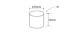
磁気マーカ10は、図3のごとく、直径20mm、高さ28mmの柱状をなし、路面100Sに設けた孔に収容された状態で敷設される。磁気マーカ10をなす磁石は、磁性材料である酸化鉄の磁粉を基材である高分子材料中に分散させたフェライトプラスチックマグネットであり、最大エネルギー積(BHmax)=6.4kJ/m3という特性を備えている。
As shown in FIG. 3, the
本例の磁気マーカ10の仕様の一部を表1に示す。

この磁気マーカ10は、センサユニット11の取付け高さとして想定する範囲100〜250mmの上限の250mm高さにおいて、8μT(マイクロテスラ)の磁束密度の磁気を作用できる。なお、磁気マーカ10をなす磁石の表面磁束密度Gsは45mT(ミリテスラ)となっている。
The
(前方検知ユニット)
図2の前方検知ユニット42は、レーザ光を利用して対象物までの距離を計測するユニットである。図示は省略するがこの前方検知ユニット42は、レーザ光の発光部と、反射光の受光部と、発光から反射光を受光するまでの遅延時間を計測する計時部と、を含めて構成されている。発光部は、レーザ光の出射方向を変更するためのポリゴンミラー(回転多面鏡)を備えている。
(Front detection unit)
The
ポリゴンミラーによる出射方向の変更範囲は、水平方向±15度の範囲となっている。前方検知ユニット42は、このようにレーザ光の方向を変更することで1次元的なラインスキャンが可能である。前方検知ユニット42は、水平方向±15度の1次元範囲の各位置について上記の遅延時間を計測し、この範囲に存在する物体までの距離を特定する。
The range of change of the emission direction by the polygon mirror is a range of ± 15 degrees in the horizontal direction. The
前方検知ユニット42は、出射方向の中心軸が車両5の前後方向に一致するように取り付けられる。車載状態の前方検知ユニット42は、車両5の正面側の水平方向±15度の1次元範囲に属する各位置に対して距離データがひも付けられた距離情報を生成して出力する。
The
(センサユニット)
センサユニット11(図1及び図2)は、車両5の底面に取り付けられる磁気検出ユニットである。センサユニット11は、例えば、フロントバンパーの内側に取り付けられる。本例の車両5の場合、路面100Sを基準とした取付け高さが200mmとなっている。
(Sensor unit)
The sensor unit 11 (FIGS. 1 and 2) is a magnetic detection unit attached to the bottom surface of the vehicle 5. The
センサユニット11は、車幅方向に沿って10cm間隔で配列された15個の磁気センサCnと、出力データを生成するデータ生成回路110と、を備えている(図2参照。)。センサユニット11は、15個の磁気センサCnのうちの中央の磁気センサC8が車両5の車幅方向の中心に位置するように車載されている。
The
データ生成回路110は、磁気センサCnの磁気計測値の車幅方向の磁気分布データを生成して外部出力する回路である。データ生成回路110は、各磁気センサCnを同期して動作させた後、各磁気センサCnの磁気計測値を順番に読み出して車幅方向の磁気分布データを生成するように構成されている。
The
磁気センサCnは、アモルファスワイヤなどの感磁体のインピーダンスが外部磁界に応じて敏感に変化するという公知のMI効果(Magnet Impedance Effect)を利用して磁気を計測するMIセンサである。磁気センサCnは、直交する2方向の磁気成分の大きさを検出可能に構成されている。センサユニット11では、車両5の進行方向及び車幅方向の磁気成分を感知するように磁気センサCnが組み込まれている。したがって、データ生成回路110が生成する車幅方向の磁気分布データとしては、以下の2種類の車幅方向の磁気分布データがある。
The magnetic sensor Cn is an MI sensor that measures magnetism by utilizing a known MI effect (Magnet Impedance Effect) in which the impedance of a magnetic sensor such as an amorphous wire changes sensitively in response to an external magnetic field. The magnetic sensor Cn is configured to be able to detect the magnitude of magnetic components in two orthogonal directions. In the
(第1の磁気分布データ)
センサユニット11を構成する各磁気センサCnの進行方向の磁気計測値の分布である磁気分布データ。
(第2の磁気分布データ)
センサユニット11を構成する各磁気センサCnの車幅方向の磁気計測値の分布である磁気分布データ。
(First magnetic distribution data)
Magnetic distribution data which is a distribution of magnetic measurement values in the traveling direction of each magnetic sensor Cn constituting the
(Second magnetic distribution data)
Magnetic distribution data which is a distribution of magnetic measurement values in the vehicle width direction of each magnetic sensor Cn constituting the
磁気センサCnは、磁束密度の測定レンジが±0.6mTであって、測定レンジ内の磁束分解能が0.02μTという高い感度を実現している。上記のように磁気マーカ10は、センサユニット11の取付け高さとして想定される範囲の上限である250mmにおいて8μT程度の磁気を作用する。磁束分解能が0.02μTの磁気センサCnによれば、磁気マーカ10の磁気を確実性高く感知できる。
The magnetic sensor Cn has a magnetic flux density measurement range of ± 0.6 mT and a magnetic flux resolution within the measurement range of 0.02 μT, which is a high sensitivity. As described above, the
磁気センサCnの仕様の一部を表2に示す。
(検出ユニット)
検出ユニット12は、センサユニット11から取得する上記の第1及び第2の磁気分布データを取得して各種の演算処理を実行する演算ユニットである。検出ユニット12は、演算処理を実行するCPU(central processing unit)のほか、ROM(read only memory)やRAM(random access memory)などのメモリ素子等を含んで構成されている。
(Detection unit)
The
検出ユニット12は、センサユニット11から取得する車幅方向の第1及び第2の磁気分布データについて各種の演算処理を実施する。演算処理としては、磁気マーカ10を検出するためのマーカ検出処理等がある。
The
マーカ検出処理では、進行方向の磁気計測値の分布である前記第1の磁気分布データを利用して磁気マーカ10が検出されると共に、車幅方向の磁気計測値の分布である前記第2の磁気分布データを利用して磁気マーカ10に対する車両5の横ずれ量が検出される。さらに、マーカ検出処理を構成する判定処理では、上記の第2の磁気分布データを利用して外乱となる磁気発生源の有無が判定される。
検出ユニット12は、これらの処理の結果を反映したマーカ検出情報を制御ユニット41に向けて出力する。
In the marker detection process, the
The
(制御ユニット)
制御ユニット41は、磁気マーカ10が敷設された車線100に沿って車両5を走行させるための車線追従制御を実行するユニットである。制御ユニット41は、前方検知ユニット42の距離情報、操舵ユニット45が出力する操舵角、検出ユニット12のマーカ検出情報などの取得情報に基づいて車線追従制御を実行する。
(Controller unit)
The
制御ユニット41は、上記の取得情報に基づいて操舵ユニット45やエンジンスロットルユニット46やブレーキコントロールユニット47などを制御し、先行車両との車間距離を保持しつつ車線100に追従して車両5を自動走行させる。なお、制御ユニット41は、外乱となる磁気発生源が有る旨の判定情報がマーカ検出情報に含まれる場合、車線追従制御の内容を切り替え、これにより誤制御を回避する。
The
次に、磁気マーカ10を検出する(1)マーカ検出処理、及び車線100に追従して車両5を自動走行させるための(2)車線追従制御について説明する。さらに、磁気マーカ10以外の(3)外乱となる磁気発生源の有無の判定処理、及び磁気発生源が有ると判定されたときの(4)外乱作用下の車線追従制御の内容について説明する。
Next, (1) marker detection processing for detecting the
(1)マーカ検出処理
マーカ検出処理は、センサユニット11から前記第1及び第2の磁気分布データを取得して検出ユニット12が実行する処理である。
ここでマーカ検出処理による磁気マーカ10の検出方法について簡単に説明しておく。上記のごとく、磁気センサCnは、車両5の進行方向及び車幅方向の磁気成分を計測するように構成されている。例えばいずれかの磁気センサCnが、進行方向に移動して磁気マーカ10の真上を通過するとき、進行方向の磁気計測値は、図4のごとく磁気マーカ10の前後で正負が反転すると共に、磁気マーカ10の真上の位置でゼロを交差するように変化する。したがって、車両5の走行中では、いずれかの磁気センサCnが検出する進行方向の磁気について、その正負が反転するゼロクロスX1が生じたとき、センサユニット11が磁気マーカ10の真上に位置すると判断できる。
(1) Marker detection process The marker detection process is a process of acquiring the first and second magnetic distribution data from the
Here, a method of detecting the
また例えば、磁気センサCnと同じ仕様の磁気センサについて、磁気マーカ10の真上を通過する車幅方向の仮想線に沿う移動を想定してみる。この磁気センサによる車幅方向の磁気計測値は、磁気マーカ10を挟んだ両側で正負が反転すると共に、磁気マーカ10の真上の位置でゼロを交差するように変化する。15個の磁気センサCnを車幅方向に配列したセンサユニット11の場合には、図5のごとく、磁気マーカ10を介してどちらの側にあるかによって磁気センサCnが検出する車幅方向の磁気の正負が異なってくる。
Further, for example, for a magnetic sensor having the same specifications as the magnetic sensor Cn, it is assumed that the magnetic sensor moves along a virtual line in the vehicle width direction passing directly above the
つまり、図5の磁気分布データ中のゼロクロスX2の位置が磁気マーカ10の真上の位置となる。例えば同図の場合、磁気センサC9とC10との中間辺りのC9.5のゼロクロスX2の位置が磁気マーカ10の真上の位置(以下、磁気マーカ10の位置という。)となる。ここで、上記のごとくセンサユニット11では、隣り合う磁気センサCnの間隔が10cmであると共に、磁気センサC8が車両5の車幅方向の中心となっている。したがって、図5の場合であれば、車両5の車幅方向の中心を基準として右側に(9.5−8)×10cm=15cmずれた位置が磁気マーカ10の位置となる。
That is, the position of the zero cross X2 in the magnetic distribution data of FIG. 5 is the position directly above the
なお、例えば車幅方向において車両5が左側に寄って走行すると、センサユニット11に相対して磁気マーカ10が右側にずれて、例えば図5のごとくゼロクロスX2の位置が磁気センサC8よりも右側の正値となる。車両5が右側に寄ったときの横ずれ量を正側とし左側に寄ったときの横ずれ量を負側とすると、例えば図5の場合には、磁気マーカ10の位置である上記の(9.5−8)×10cm=15cmの正負を反転した(−15)cmが車両5の横ずれ量となる。
For example, when the vehicle 5 travels toward the left side in the vehicle width direction, the
次に、図6を参照してマーカ検出処理の流れを説明する。
検出ユニット12は、上記第1の磁気分布データを構成する磁気センサCnの進行方向の磁気計測値を取得する(S101)。そして、少なくともいずれかの磁気センサCnの進行方向の磁気計測値の経時変化につき、図4のX1に相当するゼロクロスの検出を試みる(S102)。検出ユニット12は、このゼロクロスを検出するまで(S102:NO)、磁気センサCnの進行方向の磁気計測値を繰り返し取得する(S101)。
Next, the flow of the marker detection process will be described with reference to FIG.
The
検出ユニット12は、進行方向の磁気計測値の経時変化につき図4のX1に相当するゼロクロスを検出できたとき(S102:YES)、磁気マーカ10の真上にセンサユニット11が位置していると判断する。なお、磁気マーカ10の検出判断については、図4のX1に相当するゼロクロスの検出に加えて、進行方向の磁気計測値の経時変化の割合、すなわち磁気計測値の微分値(差分値)の大きさが所定の閾値以上であるという条件が設定されている。
When the
検出ユニット12は、図4のX1に相当するゼロクロスの検出に応じて磁気マーカ10を検出できたとき、磁気センサCnが同じタイミングで計測した車幅方向の磁気計測値のの分布を表す上記の第2の磁気分布データを取得する(S103)。
When the
検出ユニット12は、磁気マーカ10に対する車両5の横ずれ量を検出する処理を実行する一方(S104→S105)、外乱となる磁気発生源の存在可能性を判定する判定処理P1を実行する。なお、この判定処理P1の内容については、後で詳しく説明する。
The
検出ユニット12は、磁気センサCnの車幅方向の磁気計測値の分布である上記の第2の磁気分布データについて、図5のX2に相当するゼロクロスの車幅方向の位置を特定する(S104)。そして、このゼロクロスの車幅方向の位置に基づいて、磁気マーカ10に対する車両5の車幅方向の横ずれ量を特定する(S105)。具体的には、検出ユニット12は、図5のX2に相当するゼロクロスの車幅方向の位置を示す値の正負を反転し、車幅方向の横ずれ量とする。
The
(2)通常の車線追従制御
車線追従制御では、図7の車間制御と図9の操舵制御とが並行して実行される。
車間制御を実行する制御ユニット41は、図7のごとく、操舵ユニット45の操舵角や車速等の車両情報を取得し、予測される車両5の進路R(図8)を推定する演算を実行する(S201)。
(2) Normal lane following control In the normal lane following control, the inter-vehicle distance control of FIG. 7 and the steering control of FIG. 9 are executed in parallel.
As shown in FIG. 7, the
制御ユニット41は、前方検知ユニット42の距離情報を取得し、進路R上に物体が存在するか否かを判断する(S202)。図8のごとく進路Rに物体が存在していれば(S202:YES)、この物体を追従対象の先行車両として選択する。そして、この先行車両にひも付けされた距離データを上記の距離情報から読み取り、車間距離として特定する(S203)。なお、先行車両の選択に際しては、その物体の距離の経時変化から静止物であるか移動物であるかの判定を行い、移動物であることを前提として先行車両の選択を行うと良い。
The
制御ユニット41は、先行車両との車間距離を予め設定された目標車間距離と比較する(S204)。そして、制御ユニット41は、目標車間距離に対する実際の車間距離の偏差をゼロに近づけるようにエンジンスロットルユニット46やブレーキコントロールユニット47等を制御し、エンジン出力や制動力を調節する(S205)。
The
一方、自車線に先行する車両が存在せず先行車両がない場合には(S202:NO)、予めセットされた目標車速が設定される(S213)。制御ユニット41は、この目標車速を実現できるようにエンジンスロットルユニット46等を制御し、エンジン出力等を調節する(S205)。
On the other hand, when there is no preceding vehicle in the own lane and there is no preceding vehicle (S202: NO), a preset target vehicle speed is set (S213). The
次に、操舵制御を実行する制御ユニット41は、図9のごとく、検出ユニット12から取得したマーカ検出情報を参照して磁気マーカ10が検出されたか否かを判断する(S301)。磁気マーカ10が検出された場合には(S301:YES)、制御ユニット41は、マーカ検出情報に含まれる横ずれ量を取得する(S302)。
Next, as shown in FIG. 9, the
制御ユニット41は、操舵ユニット45が出力する操舵角、及びマーカ検出情報に含まれる横ずれ量に基づき、横ずれ量をゼロに近づけるための目標操舵角を演算する(S303)。そして、制御ユニット41は、操舵輪の操舵角を目標操舵角に一致させるように操舵ユニット45を制御し(S304)、これにより磁気マーカ10が敷設された車線に追従する車両5の自動走行を実現する。
The
(3)判定処理
図6中の判定処理P1は、磁気マーカ10以外の外乱となる磁気発生源の存在可能性を判定するために検出ユニット12(判定ユニットの一例。)が実行する処理である。この判定処理P1では、磁気センサCnの車幅方向の磁気計測値の分布である上記の第2の磁気分布データについて磁気分布の対称性を表す特徴量が生成され、外乱となる磁気発生源の存在可能性が判定される。
(3) Judgment process Judgment process P1 in FIG. 6 is a process executed by the detection unit 12 (an example of the determination unit) to determine the possibility of existence of a magnetic source that causes disturbance other than the
以下、図10及び図11を参照して特徴量の演算方法を説明し、図12のフロー図に沿って判定処理の流れを説明する。なお、本例の判定処理は、外乱となる磁気発生源の存在可能性として磁気発生源の有無を判定する処理の例である。 Hereinafter, the method of calculating the feature amount will be described with reference to FIGS. 10 and 11, and the flow of the determination process will be described with reference to the flow chart of FIG. The determination process of this example is an example of a process of determining the presence or absence of a magnetic source as a possibility of existence of a magnetic source that causes disturbance.
まず、図10を参照してこの特徴量の演算方法を説明する。同図中、(a)車幅方向の磁気分布(第1の分布)のゼロクロスX2の右側の各値の正負を反転すると、同図(b)のような第2の分布が得られる。特徴量の演算に当たっては、(a)車幅方向の磁気分布(第1の分布)の各値の合計値の大きさ(絶対値)である第1の総和、及び(b)第2の分布の各値の合計値の大きさ(絶対値)である第2の総和が演算される。 First, a method of calculating this feature amount will be described with reference to FIG. In the figure, by reversing the positive and negative of each value on the right side of the zero cross X2 in the magnetic distribution (first distribution) in the vehicle width direction (a), the second distribution as shown in the figure (b) is obtained. In calculating the feature amount, (a) the first sum, which is the magnitude (absolute value) of the total value of each value of the magnetic distribution (first distribution) in the vehicle width direction, and (b) the second distribution. The second sum, which is the magnitude (absolute value) of the total value of each value of, is calculated.
(a)車幅方向の磁気分布(第1の分布)についての前記第1の総和では、ゼロクロスX2に対して左側の正値が右側の負値により相殺されるため第1の総和がゼロに近くなる。第1の総和は、ゼロクロスX2の両側の山が点対称であるほどゼロに近くなり、ゼロクロスX2を基準とした理想的な点対称であれば第1の総和がゼロとなる。一方、(b)ゼロクロスX2の右側の各値の正負を反転した第2の分布では、左右両側の波形が正値となっているため、各値の合計の絶対値である第2の総和が大きくなる。 (A) In the first sum of the magnetic distribution in the vehicle width direction (first distribution), the positive value on the left side of the zero cross X2 is offset by the negative value on the right side, so that the first sum is zero. Get closer. The first sum is closer to zero as the peaks on both sides of the zero cross X2 are point symmetric, and the first sum is zero if the ideal point symmetry is based on the zero cross X2. On the other hand, (b) in the second distribution in which the positive and negative values of each value on the right side of the zero cross X2 are inverted, the waveforms on both the left and right sides are positive values, so that the second sum, which is the absolute value of the sum of the values, is growing.
特徴量は、(a)車幅方向の磁気分布についての第1の総和と、(b)第2の分布についての第2の総和と、の差分値の大きさ(絶対値)である。上記のごとく磁気分布の対称性が高いほど(a)車幅方向の磁気分布についての第1の総和がゼロに近くなり上記の特徴量が大きくなる。したがって、この特徴量が大きいほど、磁気分布の対称性が高いと判断できる。 The feature amount is the magnitude (absolute value) of the difference value between (a) the first sum of the magnetic distribution in the vehicle width direction and (b) the second sum of the second distribution. As described above, the higher the symmetry of the magnetic distribution, the closer (a) the first sum of the magnetic distributions in the vehicle width direction is to zero, and the larger the above-mentioned feature amount is. Therefore, it can be determined that the larger the feature amount, the higher the symmetry of the magnetic distribution.
一方、図11のように、ゼロクロスX2の両側の波形の大きさが相違する場合には、車幅方向の磁気分布(第1の分布)について、ゼロクロスX2の両側の正負が十分に相殺されない。そのため、上記第1の総和が十分に小さくならない。そうすると、この第1の総和と前記第2の総和との差分の絶対値である上記の特徴量が小さくなる。したがって、この特徴量が小さいほど、磁気分布の対称性が低いと判断できる。 On the other hand, as shown in FIG. 11, when the sizes of the waveforms on both sides of the zero cross X2 are different, the positive and negative values on both sides of the zero cross X2 are not sufficiently canceled with respect to the magnetic distribution (first distribution) in the vehicle width direction. Therefore, the first sum is not sufficiently small. Then, the above-mentioned feature amount, which is the absolute value of the difference between the first sum and the second sum, becomes smaller. Therefore, it can be determined that the smaller the feature amount, the lower the symmetry of the magnetic distribution.
図12の判定処理を実行するに当たって、検出ユニット12は、まず、車幅方向の磁気計測値の分布である前記第2の磁気分布データを取得し(S401)、磁気分布の対称性を表す上記の特徴量を演算する(S402)。そして、検出ユニット12は、この特徴量に関する閾値処理を実施する(S403)。
In executing the determination process of FIG. 12, the
予め設定された閾値よりも特徴量が大きな値である場合(S403:YES)、検出ユニット12は、磁気マーカ10が形成する磁気分布の対称性が高く、磁気マーカ10以外の外乱となる磁気発生源が無いと判定する(S404)。一方、特徴量が予め設定された閾値以下である場合(S403:NO)、検出ユニット12は、外乱となる磁気発生源が有るために磁気分布の対称性が損なわれていると判定する(S414)。
When the feature amount is larger than the preset threshold value (S403: YES), the
(4)外乱作用下の車線追従制御
制御ユニット41は、外乱となる磁気発生源が有る旨の判定結果を含むマーカ検出情報を検出ユニット12から取り込んだとき、車線追従制御の内容を通常の制御から外乱作用下の制御に切り換える。
(4) Lane Tracking Control Under Disturbance When the
外乱作用下の制御と通常の制御との違いは、操舵角の計測値及び磁気マーカ10に対する横ずれ量に基づいて目標操舵角を演算する際の制御ゲインの設定にある。外乱作用下の制御では、通常の制御と比べて制御ゲインが1/2に変更される。これにより、外乱となる磁気発生源によって磁気マーカ10の周囲の磁界が乱れた場合であっても、車両5の制御に対する影響度合いが抑制される。
The difference between the control under the disturbance action and the normal control lies in the setting of the control gain when calculating the target steering angle based on the measured value of the steering angle and the amount of lateral displacement with respect to the
なお、外乱となる磁気発生源が有る旨の判定がなされたとき、操舵制御を中止することも良い。この場合には、車線追従制御を一旦中断する旨の表示を例えば運転席の表示パネル等に表示することで運転者にハンドル操作を委ねると良い。なお、車間制御については、操舵角の計測値と前方検知ユニット42による距離情報に基づいてそのまま継続しても良い。
When it is determined that there is a magnetic source that causes disturbance, the steering control may be stopped. In this case, it is preferable to entrust the driver with the steering wheel operation by displaying a display indicating that the lane tracking control is temporarily interrupted, for example, on a display panel of the driver's seat. The inter-vehicle distance control may be continued as it is based on the measured value of the steering angle and the distance information by the
以上のように本例のマーカ検出方法は、磁気分布の対称性に着目し、外乱となる磁気発生源の存在可能性を判定する方法である。磁気マーカ10以外の磁気発生源が無ければ、磁気分布の対称性が高く確保される。一方、磁気マーカ10以外の外乱となる磁気発生源が有ると、磁気分布に乱れが生じて磁気分布の対称性が損なわれる可能性が高い。このように車幅方向の磁気分布の対称性に着目すれば、外乱となる磁気発生源の有無を確実性高く判定できる。
As described above, the marker detection method of this example focuses on the symmetry of the magnetic distribution and determines the possibility of the existence of a magnetic source that causes disturbance. If there is no magnetic source other than the
また、上記のマーカ検出方法を実行する車両用システム1は、外乱となる磁気発生源の有無に応じて車線に追従して車両5を自動走行させる際の制御を切り替える。外乱となる磁気発生源が有ると判定されたときには、制御ゲインを小さくして車両5側の反応を緩慢にすることで外乱となる磁気発生源に起因する挙動の乱れを抑制している。 Further, the vehicle system 1 that executes the above marker detection method switches the control when the vehicle 5 automatically travels following the lane according to the presence or absence of a magnetic source that causes disturbance. When it is determined that there is a magnetic source that causes disturbance, the control gain is reduced to slow down the reaction on the vehicle 5 side to suppress the disturbance of behavior caused by the magnetic source that causes disturbance.
なお、本例では、車幅方向の磁気分布の対称性に着目して外乱となる磁気発生源の存在可能性を判定している。これに代えて、あるいは加えて、進行方向の対称性に着目して外乱となる磁気発生源の存在可能性を判定することも良い。この場合には、車幅方向に複数の磁気センサが配列されたセンサユニットが必須ではなくなる。1つの磁気センサのみで進行方向の磁気分布を取得できる。 In this example, the possibility of the existence of a magnetic source that causes disturbance is determined by paying attention to the symmetry of the magnetic distribution in the vehicle width direction. Instead of or in addition to this, it is also possible to determine the possibility of existence of a magnetic source that causes disturbance by paying attention to the symmetry in the traveling direction. In this case, a sensor unit in which a plurality of magnetic sensors are arranged in the vehicle width direction is not essential. The magnetic distribution in the traveling direction can be acquired with only one magnetic sensor.
本例では、外乱となる磁気発生源の存在可能性として、その有無を判定するが、これに代えて、例えば100%、60%、20%など、外乱となる磁気発生源の存在可能性を確率的に表すことも良い。あるいは、レベル10を上限として、レベル2、レベル5、レベル9など、存在可能性を度数などにより表すことも良い。このように、上記の特徴量の値を確率的な数値あるいは度数に置き換える処理により存在可能性を判定することも良い。
In this example, the presence or absence of a magnetic source that causes disturbance is determined as the possibility of existence of a magnetic source that causes disturbance. Instead, the possibility of a magnetic source that causes disturbance, such as 100%, 60%, or 20%, is determined. It is also good to express it stochastically. Alternatively, the possibility of existence such as level 2, level 5, level 9, etc. may be expressed by a frequency or the like with
磁気発生源の存在可能性を確率的な数値あるいは度数によって表す場合の車線追従制御については、度数等によって制御ゲインを段階的に変更することも良い。あるいは、度数等に対する閾値処理により、度数が閾値以下であれば車線追従制御を実行する一方、度数が閾値を超えるときには車線追従制御を中断する等の制御であっても良い。 For lane-following control when the possibility of existence of a magnetic source is expressed by a probabilistic numerical value or a frequency, the control gain may be changed stepwise according to the frequency or the like. Alternatively, the lane tracking control may be executed when the frequency is equal to or less than the threshold value by the threshold processing for the frequency or the like, while the lane tracking control may be interrupted when the frequency exceeds the threshold value.
例えば鉄筋構造の橋などに由来する一様な磁場を車両5が通過する際、センサユニット11に作用する磁気が一様に近づいて磁気分布の対称性(線対称)が高くなり、図10のように演算する特徴量が比較的大きな値をとる可能性がある。これに対して、本例のマーカ検出処理では、図6中のS102のごとく、進行方向の磁気分布についてゼロクロスが発生して磁気マーカ10が検出されたときに判定処理P1を実行している。そのため、上記のような一様な磁場において特徴量が大きな値をとることが技術的な課題として顕在化するおそれはない。
For example, when the vehicle 5 passes through a uniform magnetic field derived from a reinforced bridge or the like, the magnetism acting on the
例えば、磁気センサによる磁気計測値の時間的な差分(微分)あるいは位置的な差分(微分)などの磁気勾配よりなる磁気分布を対象として特徴量を演算することも良い。磁気勾配は、上記のような一様な磁場ではゼロに近くなる。したがって、磁気勾配よりなる磁気分布を対象とすれば、上記のような一様な磁場において小さな特徴量が求まる。 For example, it is also possible to calculate the feature amount for a magnetic distribution consisting of a magnetic gradient such as a temporal difference (differential) or a positional difference (differential) of magnetic measurement values by a magnetic sensor. The magnetic gradient is close to zero in a uniform magnetic field as described above. Therefore, if a magnetic distribution consisting of a magnetic gradient is targeted, a small feature amount can be obtained in the above-mentioned uniform magnetic field.
なお、本例では、特徴量を算出するために前記第2の総和(図10及び図11)を算出するに当たって、ゼロクロスX2を磁気分布の中心として取扱い、一方の側の値の正負を反転して(b)第2の分布を得ている。磁気分布の中心が分らない場合には、中心と仮定する点の位置を車幅方向に変更しながら位置毎の特徴量を算出し、最も高い特徴量の値を採用しても良い。この場合には、磁気分布の対称性を表す特徴量を算出するに当たって、磁気分布の中心を特定する必要性が低くなる。 In this example, in calculating the second sum (FIGS. 10 and 11) in order to calculate the feature amount, the zero cross X2 is treated as the center of the magnetic distribution, and the positive and negative values on one side are inverted. (B) The second distribution is obtained. If the center of the magnetic distribution is not known, the feature amount for each position may be calculated while changing the position of the point assumed to be the center in the vehicle width direction, and the value of the highest feature amount may be adopted. In this case, it is less necessary to specify the center of the magnetic distribution in calculating the feature quantity representing the symmetry of the magnetic distribution.
また、本例では、車幅方向の磁気分布(第1の分布)のゼロクロスX2の右側の各値の正負を反転することにより、図10に例示する第2の分布を生成している。これに代えて、第1の分布の左側の各値の正負を反転して第2の分布を生成しても良い。上記のごとく第2の総和は、第2の分布の各値の合計値の大きさ(絶対値)である。そのため、第1の分布の右側の各値の正負を反転するか、第1の分布の左側の各値の正負を反転するか、によって第2の総和が変動することがない。 Further, in this example, the second distribution illustrated in FIG. 10 is generated by inverting the positive and negative of each value on the right side of the zero cross X2 in the magnetic distribution (first distribution) in the vehicle width direction. Instead of this, the positive and negative of each value on the left side of the first distribution may be inverted to generate the second distribution. As described above, the second sum is the magnitude (absolute value) of the total value of each value in the second distribution. Therefore, the second sum does not change depending on whether the positive or negative of each value on the right side of the first distribution is inverted or the positive or negative of each value on the left side of the first distribution is inverted.
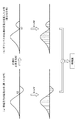
例えば鉛直方向に感度を有する磁気センサCnが車幅方向に配列されたセンサユニットを採用する場合、図13に例示するように、磁気マーカの真上が磁気計測値の最大値となると共に、この真上から車幅方向に離れるにつれて磁気計測値が次第に小さくなる正規分布のような線対称の磁気分布が得られる。同図のように正規分布をなしゼロクロスが現れない線対称の磁気分布については、最大値の位置であるピーク点Pを磁気分布の中心として取り扱うと良い。あるいは上記と同様に、磁気分布の中心として仮定する点の位置を車幅方向に変更しながら位置毎に特徴量を算出し、最も高い特徴量の値を採用しても良い。 For example, when a sensor unit in which magnetic sensors Cn having sensitivity in the vertical direction are arranged in the vehicle width direction is adopted, as illustrated in FIG. 13, the value directly above the magnetic marker becomes the maximum value of the magnetic measurement value, and this A line-symmetrical magnetic distribution such as a normal distribution in which the magnetic measurement value gradually decreases as the distance from directly above in the vehicle width direction is obtained can be obtained. For a line-symmetrical magnetic distribution that has a normal distribution and no zero cross as shown in the figure, it is preferable to treat the peak point P, which is the position of the maximum value, as the center of the magnetic distribution. Alternatively, similarly to the above, the feature amount may be calculated for each position while changing the position of the point assumed as the center of the magnetic distribution in the vehicle width direction, and the value of the highest feature amount may be adopted.
図13に例示の線対称の磁気分布と図5に例示の点対称の磁気分布とでは、第1の総和と第2の総和との大小関係が逆になる。点対称の磁気分布については、図10で例示した通り、第1の総和がゼロに近くなり、第2の総和が大きくなる。一方、図13の線対称の磁気分布については、以下に説明する通り、第1の総和が大きくなる一方、第2の総和がゼロに近くなる。 In the line-symmetrical magnetic distribution illustrated in FIG. 13 and the point-symmetrical magnetic distribution illustrated in FIG. 5, the magnitude relationship between the first sum and the second sum is reversed. As for the point-symmetrical magnetic distribution, as illustrated in FIG. 10, the first sum is close to zero and the second sum is large. On the other hand, regarding the line-symmetrical magnetic distribution in FIG. 13, as described below, the first sum is large, while the second sum is close to zero.
図14のごとく、(a)車幅方向の磁気分布(第1の分布)では、ピーク点Pの両側がいずれも正値となっている。そのため、(a)車幅方向の磁気分布(第1の分布)の各値の合計値の大きさ(絶対値)である第1の総和が大きくなる。一方、(b)ピーク点Pの右側の各値の正負を反転した第2の分布では、左右両側の波形の正負が逆になっている。左側の正値が右側の負値により相殺されるため、(b)第2の分布の各値の合計値の大きさ(絶対値)である第2の総和はゼロに近くなる。この第2の総和は、(a)車幅方向の磁気分布(第1の分布)がピーク点Pを挟んで線対称であるほどゼロに近くなり、ピーク位置Pの両側が理想的な線対称であれば第2の総和がゼロとなる。したがって、(a)車幅方向の磁気分布についての第1の総和と、(b)第2の分布についての第2の総和と、の差分値の大きさ(絶対値)である特徴量は、図13のような線対称の磁気分布についても、線対称の対称性が高くなるほど大きくなる。 As shown in FIG. 14, in (a) the magnetic distribution in the vehicle width direction (first distribution), both sides of the peak point P are positive values. Therefore, (a) the first sum, which is the magnitude (absolute value) of the total value of each value of the magnetic distribution (first distribution) in the vehicle width direction, becomes large. On the other hand, (b) in the second distribution in which the positive and negative of each value on the right side of the peak point P are reversed, the positive and negative of the waveforms on both the left and right sides are reversed. Since the positive value on the left side is offset by the negative value on the right side, (b) the second sum, which is the magnitude (absolute value) of the total value of each value in the second distribution, is close to zero. This second sum is closer to zero as (a) the magnetic distribution (first distribution) in the vehicle width direction is line-symmetric with respect to the peak point P, and both sides of the peak position P are ideally line-symmetric. If so, the second sum is zero. Therefore, the feature quantity, which is the magnitude (absolute value) of the difference between (a) the first sum of the magnetic distribution in the vehicle width direction and (b) the second sum of the second distribution, is The line-symmetrical magnetic distribution as shown in FIG. 13 also increases as the line-symmetry symmetry increases.
なお、図10及び図11のように特徴量を算出するに当たって、磁気分布の大きさの最大値や、第1及び第2の総和のうちの大きい方の値などにより特徴量を正規化することも良い。正規化によれば、磁気分布の分布値の大小の影響を抑制でき、磁気分布の対称性を精度高く反映する特徴量を生成できる。 In calculating the feature amount as shown in FIGS. 10 and 11, the feature amount should be normalized by the maximum value of the size of the magnetic distribution, the larger value of the first and second sums, and the like. Is also good. According to the normalization, the influence of the magnitude of the distribution value of the magnetic distribution can be suppressed, and a feature amount that accurately reflects the symmetry of the magnetic distribution can be generated.
図10のようなゼロクロスX2を生じる点対称の磁気分布であれば、(a)第1の分布の各値の合計値の大きさ(絶対値)である第1の総和を対称性の特徴量として取り扱うこともできる。この場合には、対称性が高いほど、特徴量である第1の総和がゼロに近くなる。このように対称性を表す特徴量については、本例に限定されず、適宜変更可能である。 In the case of a point-symmetrical magnetic distribution that produces zero cross X2 as shown in FIG. 10, (a) the first sum, which is the magnitude (absolute value) of the total value of each value of the first distribution, is the feature quantity of symmetry. It can also be treated as. In this case, the higher the symmetry, the closer the first sum, which is the feature quantity, to zero. The feature quantity representing the symmetry is not limited to this example, and can be changed as appropriate.
なお、車両が磁気マーカを通過する際、車幅方向における磁気マーカのオフセット量が大きいと、センサユニット11の検出エリアである磁気センサC1〜C15の範囲(図5参照。)の中で、ゼロクロスX2の位置が端に偏ってくる。ゼロクロスX2の位置が偏ると、ゼロクロスX2を基準として点対称をなす磁気分布(例えば図10(a)中の第1の分布)のうち、片側の裾野部分が磁気センサC1〜C15の範囲から外れるおそれが生じる。このような場合、ゼロクロスX2を基準とした両側の分布がアンバランスになり、図10のような特徴量の演算方法を実施する際に問題が生じ得る。点対称の磁気分布ではゼロ近くになるはずの上記の第1の総和が、上記の両側の分布のアンバランスのために大きくなり、特徴量の精度が損なわれるおそれがある。このようなおそれへの対処としては、例えば以下の対処が考えられる。
When the vehicle passes through the magnetic marker, if the offset amount of the magnetic marker in the vehicle width direction is large, zero crossing occurs in the range of the magnetic sensors C1 to C15 (see FIG. 5), which is the detection area of the
・車幅方向における磁気マーカのオフセット量が閾値を超える場合には、検出処理を実行しないという対処。
・磁気分布のうち、磁気センサC1〜C15の範囲から外れた裾野部分について、なめらかに磁気計測値が減衰すると仮定して分布を推定し、特徴量を演算する対処。
・センサユニット11の車幅方向の寸法を出来るだけ大きく確保することで、磁気分布が磁気センサC1〜C15の範囲から外れるおそれを低減する対処。
・ゼロクロスX2を基準として磁気分布の一方の側の裾野部分が磁気センサC1〜C15の範囲から外れる場合、磁気分布の他方の側の裾野部分についても演算対象から排除することで、特徴量の演算対象となる磁気分布の中心にゼロクロスX2を位置させるという対処。例えばゼロクロスX2が磁気センサC12とC13の間にある場合には、(C13〜C15)なる磁気センサ3つ分の範囲と、(C12〜C10)なる磁気センサ3つ分の範囲と、を合わせた(C10〜C15)の範囲の磁気分布を特徴量の演算対象とすると良い。
-If the offset amount of the magnetic marker in the vehicle width direction exceeds the threshold value, the detection process is not executed.
-A measure to estimate the distribution of the magnetic distribution at the base of the magnetic distribution outside the range of the magnetic sensors C1 to C15, assuming that the magnetic measurement value is smoothly attenuated, and calculate the feature amount.
-Measures to reduce the possibility that the magnetic distribution deviates from the range of the magnetic sensors C1 to C15 by ensuring the dimension of the
-When the base portion on one side of the magnetic distribution deviates from the range of the magnetic sensors C1 to C15 with reference to the zero cross X2, the base portion on the other side of the magnetic distribution is also excluded from the calculation target to calculate the feature amount. A countermeasure to position the zero cross X2 at the center of the target magnetic distribution. For example, when the zero cross X2 is between the magnetic sensors C12 and C13, the range of three magnetic sensors (C13 to C15) and the range of three magnetic sensors (C12 to C10) are combined. The magnetic distribution in the range of (C10 to C15) may be the calculation target of the feature amount.
本例では、車両の進行方向及び車幅方向に感度を有する磁気センサCnを採用している。これに代えて、鉛直方向や進行方向や車幅方向の1軸方向に感度を持つ磁気センサであっても良く、車幅方向と鉛直方向の2軸方向や、進行方向と鉛直方向の2軸方向に感度を持つ磁気センサであっても良く、車幅方向と進行方向と鉛直方向の3軸方向に感度を持つ磁気センサであっても良い。 In this example, a magnetic sensor Cn having sensitivity in the traveling direction and the vehicle width direction of the vehicle is adopted. Instead of this, a magnetic sensor having sensitivity in one axis direction in the vertical direction, the traveling direction, or the vehicle width direction may be used, and two axes in the vehicle width direction and the vertical direction, or two axes in the traveling direction and the vertical direction. It may be a magnetic sensor having sensitivity in the direction, or may be a magnetic sensor having sensitivity in three axial directions of the vehicle width direction, the traveling direction, and the vertical direction.
本例では、直径20mm、高さ28mmの柱状の磁気マーカ10を例示したが、例えば厚さ1〜5mmで直径80〜120mm程度のシート状の磁気マーカを採用することもできる。この磁気マーカの磁石としては、例えば、事務用あるいはキッチン等で利用されるマグネットシートに似通った磁石であるフェライトラバーマグネット等を採用すると良い。
In this example, a columnar
以上、実施例のごとく本発明の具体例を詳細に説明したが、これらの具体例は、特許請求の範囲に包含される技術の一例を開示しているにすぎない。言うまでもなく、具体例の構成や数値等によって、特許請求の範囲が限定的に解釈されるべきではない。特許請求の範囲は、公知技術や当業者の知識等を利用して上記具体例を多様に変形、変更あるいは適宜組み合わせた技術を包含している。 Although specific examples of the present invention have been described in detail as in the examples, these specific examples merely disclose an example of the technology included in the claims. Needless to say, the scope of claims should not be construed in a limited manner depending on the composition of specific examples, numerical values, and the like. The scope of claims includes technologies that are variously modified, modified, or appropriately combined with the above specific examples by utilizing known technologies, knowledge of those skilled in the art, and the like.
1 車両用システム
10 磁気マーカ
100 車線
11 センサユニット
110 データ生成回路
12 検出ユニット(判定ユニット)
41 制御ユニット
42 前方検知ユニット
5 車両
Cn 磁気センサ(nは1〜15の整数)
1
41
Claims (9)
前記磁気センサによる磁気計測値の位置的な分布である磁気分布の対称性を表す特徴量として、前記磁気分布を構成する値の合計値の大きさである第1の総和と、前記磁気分布の中心の両側のうちの一方の側に属する値の正負を反転した値、及び他方の側に属する値の合計値の大きさである第2の総和と、の差分を求める手順と、
該特徴量を処理することで前記磁気マーカ以外の外乱となる磁気発生源の存在可能性を判定する手順と、を含むマーカ検出方法。 It is a marker detection method for detecting a magnetic marker laid on a road using a magnetic sensor attached to a vehicle.
As feature quantities representing the symmetry of the magnetic distribution, which is the positional distribution of the magnetic measurement values by the magnetic sensor , the first sum, which is the magnitude of the total value of the values constituting the magnetic distribution, and the magnetic distribution A procedure for obtaining the difference between the positive and negative values of the values belonging to one of the two sides of the center and the second sum, which is the total value of the values belonging to the other side.
Marker detection method comprising: a determining procedure possible presence of a magnetic source to be disturbance other than the magnetic marker by processing the feature quantity.
前記磁気マーカの真上に当たる位置で正負が反転する磁気分布を取得する手順と、
前記磁気センサによる磁気計測値の位置的な分布である磁気分布の対称性を表す特徴量として、該磁気分布を構成する値の合計値の大きさを求める手順と、
該特徴量を処理することで前記磁気マーカ以外の外乱となる磁気発生源の存在可能性を判定する手順と、を含むマーカ検出方法。 It is a marker detection method for detecting a magnetic marker laid on a road using a magnetic sensor attached to a vehicle.
The procedure for acquiring the magnetic distribution in which the positive and negative are reversed at the position directly above the magnetic marker, and
As a feature quantity representing the symmetry of the magnetic distribution, which is the positional distribution of the magnetic measurement values by the magnetic sensor, a procedure for obtaining the magnitude of the total value of the values constituting the magnetic distribution, and
Marker detection method comprising: a determining procedure possible presence of a magnetic source to be disturbance other than the magnetic marker by processing the feature quantity.
前記磁気マーカの磁気を検出する磁気センサと、
外乱となる磁気発生源の有無を判定する判定ユニットと、を有し、
請求項1〜7のいずれか1項のマーカ検出方法の実行により前記磁気発生源の存在可能性を判定する車両用システム。 A vehicle system that detects magnetic markers laid on the road.
A magnetic sensor that detects the magnetism of the magnetic marker and
It has a determination unit that determines the presence or absence of a magnetic source that causes disturbance.
A vehicle system for determining the possibility of existence of the magnetic source by executing the marker detection method according to any one of claims 1 to 7.
Priority Applications (6)
| Application Number | Priority Date | Filing Date | Title |
|---|---|---|---|
| JP2017116977A JP6885207B2 (en) | 2017-06-14 | 2017-06-14 | Marker detection method and vehicle system |
| CN201880039157.1A CN110741286B (en) | 2017-06-14 | 2018-06-07 | Marker detection method and system for vehicle |
| PCT/JP2018/021791 WO2018230422A1 (en) | 2017-06-14 | 2018-06-07 | Marker detection method and vehicle system |
| US16/622,317 US11347236B2 (en) | 2017-06-14 | 2018-06-07 | Marker detection method and vehicular system |
| SG11201912108XA SG11201912108XA (en) | 2017-06-14 | 2018-06-07 | Marker detection method and vehicular system |
| EP18817135.9A EP3640683B1 (en) | 2017-06-14 | 2018-06-07 | Marker detection method and vehicle system |
Applications Claiming Priority (1)
| Application Number | Priority Date | Filing Date | Title |
|---|---|---|---|
| JP2017116977A JP6885207B2 (en) | 2017-06-14 | 2017-06-14 | Marker detection method and vehicle system |
Publications (2)
| Publication Number | Publication Date |
|---|---|
| JP2019002772A JP2019002772A (en) | 2019-01-10 |
| JP6885207B2 true JP6885207B2 (en) | 2021-06-09 |
Family
ID=64659742
Family Applications (1)
| Application Number | Title | Priority Date | Filing Date |
|---|---|---|---|
| JP2017116977A Active JP6885207B2 (en) | 2017-06-14 | 2017-06-14 | Marker detection method and vehicle system |
Country Status (6)
| Country | Link |
|---|---|
| US (1) | US11347236B2 (en) |
| EP (1) | EP3640683B1 (en) |
| JP (1) | JP6885207B2 (en) |
| CN (1) | CN110741286B (en) |
| SG (1) | SG11201912108XA (en) |
| WO (1) | WO2018230422A1 (en) |
Families Citing this family (4)
| Publication number | Priority date | Publication date | Assignee | Title |
|---|---|---|---|---|
| JP6928307B2 (en) * | 2017-03-28 | 2021-09-01 | 愛知製鋼株式会社 | Marker detection system and marker detection method |
| JP6965815B2 (en) * | 2018-04-12 | 2021-11-10 | 愛知製鋼株式会社 | Marker detection system and operation method of marker detection system |
| SG11202109174SA (en) * | 2019-02-23 | 2021-09-29 | Aichi Steel Corp | Magnetic marker diagnostic system and diagnostic method |
| JP2022158105A (en) * | 2021-04-01 | 2022-10-17 | 愛知製鋼株式会社 | Magnetic marker detection method and system |
Family Cites Families (22)
| Publication number | Priority date | Publication date | Assignee | Title |
|---|---|---|---|---|
| US4714124A (en) | 1986-06-09 | 1987-12-22 | Forest Grove Industries, Inc. | Guidance system for self-guided vehicle |
| US5347456A (en) * | 1991-05-22 | 1994-09-13 | The Regents Of The University Of California | Intelligent roadway reference system for vehicle lateral guidance and control |
| JPH08201006A (en) * | 1995-01-27 | 1996-08-09 | Nippon Soken Inc | Vehicle position detector |
| JPH1123209A (en) * | 1997-07-04 | 1999-01-29 | Nissan Motor Co Ltd | Running position sensor |
| JPH1194566A (en) * | 1997-09-16 | 1999-04-09 | Nissan Motor Co Ltd | Traveling position sensor |
| KR100374923B1 (en) * | 1997-09-29 | 2003-03-06 | 아이치 세이코우 가부시키가이샤 | Magnetic apparatus for detecting position of vehicle |
| JP3620375B2 (en) * | 1999-10-22 | 2005-02-16 | トヨタ自動車株式会社 | Magnetic body installation method, magnetic marker, and vehicle information acquisition apparatus |
| JP2001165605A (en) * | 1999-12-10 | 2001-06-22 | Hino Motors Ltd | Position detector for vehicle |
| JP3646648B2 (en) * | 2000-05-19 | 2005-05-11 | トヨタ自動車株式会社 | Magnetic marker detection apparatus and magnetic marker detection method |
| JP3613592B2 (en) * | 2002-03-27 | 2005-01-26 | 国土交通省国土技術政策総合研究所長 | Magnetic marker embedded error detection method |
| JP3866609B2 (en) * | 2002-04-18 | 2007-01-10 | 日立電線株式会社 | Vehicle detection device |
| JP2005122256A (en) * | 2003-10-14 | 2005-05-12 | Toyota Industries Corp | Vehicle position detection device and program |
| JP2005202478A (en) | 2004-01-13 | 2005-07-28 | Denso Corp | Automatic traveling system for vehicle |
| US7683617B2 (en) * | 2005-07-21 | 2010-03-23 | Johns Hopkins University | Non-invasive MRI measurement of tissue glycogen |
| JP2008077349A (en) * | 2006-09-20 | 2008-04-03 | Toyota Motor Corp | Vehicle status quantity estimating apparatus and vehicle steering control apparatus using the same |
| JP5435228B2 (en) * | 2007-06-29 | 2014-03-05 | 日本電気株式会社 | Electromagnetic field distribution measuring device |
| CN202171883U (en) * | 2011-08-03 | 2012-03-21 | 石家庄弗斯特机电设备有限公司 | Continuous obstacles testing system |
| JP6173660B2 (en) | 2012-06-20 | 2017-08-02 | 株式会社東芝 | Direction of arrival estimation device |
| US20150247719A1 (en) * | 2014-03-03 | 2015-09-03 | Tomorrow's Transportation Today | Position sensing system for intelligent vehicle guidance |
| JP6304126B2 (en) * | 2015-05-26 | 2018-04-04 | トヨタ自動車株式会社 | Vehicle control system |
| JP6172237B2 (en) | 2015-10-23 | 2017-08-02 | 愛知製鋼株式会社 | Magnetic marker detection method and magnetic marker detection apparatus |
| JP7036114B2 (en) * | 2017-06-14 | 2022-03-15 | 愛知製鋼株式会社 | Marker detection method and vehicle system |
-
2017
- 2017-06-14 JP JP2017116977A patent/JP6885207B2/en active Active
-
2018
- 2018-06-07 EP EP18817135.9A patent/EP3640683B1/en active Active
- 2018-06-07 SG SG11201912108XA patent/SG11201912108XA/en unknown
- 2018-06-07 US US16/622,317 patent/US11347236B2/en active Active
- 2018-06-07 WO PCT/JP2018/021791 patent/WO2018230422A1/en unknown
- 2018-06-07 CN CN201880039157.1A patent/CN110741286B/en active Active
Also Published As
| Publication number | Publication date |
|---|---|
| US11347236B2 (en) | 2022-05-31 |
| CN110741286A (en) | 2020-01-31 |
| US20210149414A1 (en) | 2021-05-20 |
| JP2019002772A (en) | 2019-01-10 |
| WO2018230422A1 (en) | 2018-12-20 |
| EP3640683B1 (en) | 2022-12-07 |
| SG11201912108XA (en) | 2020-01-30 |
| EP3640683A1 (en) | 2020-04-22 |
| EP3640683A4 (en) | 2021-03-17 |
| CN110741286B (en) | 2022-05-31 |
Similar Documents
| Publication | Publication Date | Title |
|---|---|---|
| JP7036114B2 (en) | Marker detection method and vehicle system | |
| JP6885207B2 (en) | Marker detection method and vehicle system | |
| EP2899076B1 (en) | Parking assistance device | |
| JP5852456B2 (en) | Peripheral object detection device | |
| US8736820B2 (en) | Apparatus and method for distinguishing ground and obstacles for autonomous mobile vehicle | |
| US20190184990A1 (en) | Method and apparatus with vehicular longitudinal velocity control | |
| JP5926069B2 (en) | Obstacle determination device | |
| WO2011092849A1 (en) | Road information detection device and vehicle travel control device | |
| US20190217856A1 (en) | Parking assistance device | |
| JP4888182B2 (en) | Control device for mobile body and mobile body having the same | |
| JP6828314B2 (en) | Learning system and learning method for vehicles | |
| JP2015155878A (en) | Obstacle detection device for vehicle | |
| JP6928307B2 (en) | Marker detection system and marker detection method | |
| CN109017776B (en) | Driving assistance system mounted in vehicle | |
| KR101735732B1 (en) | Edge detection apparatus and method for securing parking space | |
| JP6577767B2 (en) | Object detection apparatus and object detection method | |
| JP2010266225A (en) | Object detector | |
| US11142187B2 (en) | Parking assistance device | |
| JP2011086139A (en) | Device for avoiding collision of vehicle | |
| JP2018084987A (en) | Object recognition device | |
| KR100895350B1 (en) | Method for determining the position of a target object and radar system operating with said method | |
| JP2008097089A (en) | Autonomous travelling equipment, its program, and recording medium | |
| JP6541942B2 (en) | Parcel detection system | |
| JP2007240316A (en) | On-board distance measuring device | |
| JP2004101481A (en) | Radar apparatus |
Legal Events
| Date | Code | Title | Description |
|---|---|---|---|
| A621 | Written request for application examination |
Free format text: JAPANESE INTERMEDIATE CODE: A621 Effective date: 20200205 |
|
| A131 | Notification of reasons for refusal |
Free format text: JAPANESE INTERMEDIATE CODE: A131 Effective date: 20210119 |
|
| A521 | Request for written amendment filed |
Free format text: JAPANESE INTERMEDIATE CODE: A523 Effective date: 20210319 |
|
| TRDD | Decision of grant or rejection written | ||
| A01 | Written decision to grant a patent or to grant a registration (utility model) |
Free format text: JAPANESE INTERMEDIATE CODE: A01 Effective date: 20210413 |
|
| A61 | First payment of annual fees (during grant procedure) |
Free format text: JAPANESE INTERMEDIATE CODE: A61 Effective date: 20210426 |
|
| R150 | Certificate of patent or registration of utility model |
Ref document number: 6885207 Country of ref document: JP Free format text: JAPANESE INTERMEDIATE CODE: R150 |
|
| R250 | Receipt of annual fees |
Free format text: JAPANESE INTERMEDIATE CODE: R250 |