JP6883903B2 - Robot safety improvement method and safety evaluation method - Google Patents
Robot safety improvement method and safety evaluation method Download PDFInfo
- Publication number
- JP6883903B2 JP6883903B2 JP2020524025A JP2020524025A JP6883903B2 JP 6883903 B2 JP6883903 B2 JP 6883903B2 JP 2020524025 A JP2020524025 A JP 2020524025A JP 2020524025 A JP2020524025 A JP 2020524025A JP 6883903 B2 JP6883903 B2 JP 6883903B2
- Authority
- JP
- Japan
- Prior art keywords
- robot
- collision
- test
- safety
- pressure
- Prior art date
- Legal status (The legal status is an assumption and is not a legal conclusion. Google has not performed a legal analysis and makes no representation as to the accuracy of the status listed.)
- Active
Links
Images


Classifications
-
- B—PERFORMING OPERATIONS; TRANSPORTING
- B25—HAND TOOLS; PORTABLE POWER-DRIVEN TOOLS; MANIPULATORS
- B25J—MANIPULATORS; CHAMBERS PROVIDED WITH MANIPULATION DEVICES
- B25J9/00—Programme-controlled manipulators
- B25J9/16—Programme controls
- B25J9/1656—Programme controls characterised by programming, planning systems for manipulators
- B25J9/1671—Programme controls characterised by programming, planning systems for manipulators characterised by simulation, either to verify existing program or to create and verify new program, CAD/CAM oriented, graphic oriented programming systems
-
- B—PERFORMING OPERATIONS; TRANSPORTING
- B25—HAND TOOLS; PORTABLE POWER-DRIVEN TOOLS; MANIPULATORS
- B25J—MANIPULATORS; CHAMBERS PROVIDED WITH MANIPULATION DEVICES
- B25J19/00—Accessories fitted to manipulators, e.g. for monitoring, for viewing; Safety devices combined with or specially adapted for use in connection with manipulators
-
- B—PERFORMING OPERATIONS; TRANSPORTING
- B25—HAND TOOLS; PORTABLE POWER-DRIVEN TOOLS; MANIPULATORS
- B25J—MANIPULATORS; CHAMBERS PROVIDED WITH MANIPULATION DEVICES
- B25J9/00—Programme-controlled manipulators
- B25J9/16—Programme controls
- B25J9/1602—Programme controls characterised by the control system, structure, architecture
- B25J9/1605—Simulation of manipulator lay-out, design, modelling of manipulator
-
- B—PERFORMING OPERATIONS; TRANSPORTING
- B25—HAND TOOLS; PORTABLE POWER-DRIVEN TOOLS; MANIPULATORS
- B25J—MANIPULATORS; CHAMBERS PROVIDED WITH MANIPULATION DEVICES
- B25J9/00—Programme-controlled manipulators
- B25J9/16—Programme controls
- B25J9/1656—Programme controls characterised by programming, planning systems for manipulators
- B25J9/1664—Programme controls characterised by programming, planning systems for manipulators characterised by motion, path, trajectory planning
- B25J9/1666—Avoiding collision or forbidden zones
-
- B—PERFORMING OPERATIONS; TRANSPORTING
- B25—HAND TOOLS; PORTABLE POWER-DRIVEN TOOLS; MANIPULATORS
- B25J—MANIPULATORS; CHAMBERS PROVIDED WITH MANIPULATION DEVICES
- B25J9/00—Programme-controlled manipulators
- B25J9/16—Programme controls
- B25J9/1674—Programme controls characterised by safety, monitoring, diagnostic
-
- G—PHYSICS
- G05—CONTROLLING; REGULATING
- G05B—CONTROL OR REGULATING SYSTEMS IN GENERAL; FUNCTIONAL ELEMENTS OF SUCH SYSTEMS; MONITORING OR TESTING ARRANGEMENTS FOR SUCH SYSTEMS OR ELEMENTS
- G05B19/00—Programme-control systems
- G05B19/02—Programme-control systems electric
- G05B19/18—Numerical control [NC], i.e. automatically operating machines, in particular machine tools, e.g. in a manufacturing environment, so as to execute positioning, movement or co-ordinated operations by means of programme data in numerical form
- G05B19/4155—Numerical control [NC], i.e. automatically operating machines, in particular machine tools, e.g. in a manufacturing environment, so as to execute positioning, movement or co-ordinated operations by means of programme data in numerical form characterised by programme execution, i.e. part programme or machine function execution, e.g. selection of a programme
-
- G—PHYSICS
- G06—COMPUTING; CALCULATING OR COUNTING
- G06T—IMAGE DATA PROCESSING OR GENERATION, IN GENERAL
- G06T17/00—Three dimensional [3D] modelling, e.g. data description of 3D objects
-
- G—PHYSICS
- G05—CONTROLLING; REGULATING
- G05B—CONTROL OR REGULATING SYSTEMS IN GENERAL; FUNCTIONAL ELEMENTS OF SUCH SYSTEMS; MONITORING OR TESTING ARRANGEMENTS FOR SUCH SYSTEMS OR ELEMENTS
- G05B2219/00—Program-control systems
- G05B2219/30—Nc systems
- G05B2219/40—Robotics, robotics mapping to robotics vision
- G05B2219/40201—Detect contact, collision with human
-
- G—PHYSICS
- G05—CONTROLLING; REGULATING
- G05B—CONTROL OR REGULATING SYSTEMS IN GENERAL; FUNCTIONAL ELEMENTS OF SUCH SYSTEMS; MONITORING OR TESTING ARRANGEMENTS FOR SUCH SYSTEMS OR ELEMENTS
- G05B2219/00—Program-control systems
- G05B2219/30—Nc systems
- G05B2219/40—Robotics, robotics mapping to robotics vision
- G05B2219/40202—Human robot coexistence
-
- G—PHYSICS
- G05—CONTROLLING; REGULATING
- G05B—CONTROL OR REGULATING SYSTEMS IN GENERAL; FUNCTIONAL ELEMENTS OF SUCH SYSTEMS; MONITORING OR TESTING ARRANGEMENTS FOR SUCH SYSTEMS OR ELEMENTS
- G05B2219/00—Program-control systems
- G05B2219/30—Nc systems
- G05B2219/40—Robotics, robotics mapping to robotics vision
- G05B2219/40317—For collision avoidance and detection
-
- G—PHYSICS
- G05—CONTROLLING; REGULATING
- G05B—CONTROL OR REGULATING SYSTEMS IN GENERAL; FUNCTIONAL ELEMENTS OF SUCH SYSTEMS; MONITORING OR TESTING ARRANGEMENTS FOR SUCH SYSTEMS OR ELEMENTS
- G05B2219/00—Program-control systems
- G05B2219/30—Nc systems
- G05B2219/50—Machine tool, machine tool null till machine tool work handling
- G05B2219/50391—Robot
Description
本発明は、ロボットに対する安全性向上方法及び安全性評価方法に関し、より詳細には、一定の作業空間上にあるロボットと作業者との間の衝突時にロボットの各部位別形状によって作業者に加えられる衝突圧力及び衝突力をシミュレーションを通じて算出し、算出された値が国際標準化機構(ISO)規格を満足するようにロボットの速度及び姿勢を制御するロボットの安全性向上方法、及び国際標準化機構(ISO)規格内に該当するかどうかを判断し、安全性評価の正確度が向上した安全性評価方法に関する。 The present invention relates to a method for improving safety and a method for evaluating safety for a robot, and more specifically, in addition to a worker according to the shape of each part of the robot at the time of a collision between the robot and the worker in a certain work space. A method for improving robot safety and the International Organization for Standardization (ISO), which controls the speed and posture of the robot so that the calculated collision pressure and impact force are calculated through simulation and the calculated values satisfy the International Organization for Standardization (ISO) standards. ) Regarding the safety evaluation method that determines whether or not it falls within the standard and improves the accuracy of the safety evaluation.
近年、ロボットの高性能化の実現により、運転の便宜性を極大化すると同時に、ロボットの運行時における作業者との衝突防止を通じた安全性を確保するために多様な努力がなされている。 In recent years, various efforts have been made to maximize the convenience of driving by realizing high performance of robots and at the same time to ensure safety by preventing collisions with workers during operation of robots.
このようなロボットは、人間と同じ作業空間内に設置され得るので、作業時に衝突による事故が頻繁に発生するようになる。よって、ロボットにおいて必須的に要求されることは、(1)モーションの精密性及び(2)モーションの安全性である。1番目の要求事項であるモーションの精密性の場合は、モーター精密制御技術の発展を通じて現在一定の軌道に進入した実情にあるが、2番目の要求事項であるモーションの安全性の場合は、モーションの精密性に比べて技術的な完成度が非常に不備な実情にある。 Since such a robot can be installed in the same work space as a human being, accidents due to collisions frequently occur during work. Therefore, what is indispensable for a robot is (1) motion precision and (2) motion safety. In the case of motion precision, which is the first requirement, we are currently in a certain trajectory through the development of motor precision control technology, but in the case of motion safety, which is the second requirement, motion The actual situation is that the technical perfection is very inadequate compared to the precision of.
特に、最近は、ロボットシステムにおいて、安全性(safety)という用語が核心的な話頭に上り、ロボットの安全性を高めるための多様な研究が進められている。 In particular, recently, in robot systems, the term "safety" has come to the forefront, and various studies have been conducted to improve the safety of robots.
現在通用されている安全性を確保する方法は、ロボットの速度を一定速度以下に低下させるものである。しかし、このような方法は、ロボットの速度の適正性を評価することによってロボットの速度を制御するのではなく、ロボットの速度を大きく低下させることによって安全性を確保するものであるので、安全性を高めることはできるが、生産性が大きく低下し、効率性が良くないという問題を有する。 The currently accepted method of ensuring safety is to reduce the speed of the robot below a certain speed. However, such a method does not control the speed of the robot by evaluating the appropriateness of the speed of the robot, but secures the safety by greatly reducing the speed of the robot. However, there is a problem that productivity is greatly reduced and efficiency is not good.
このような問題を解決するために、ロボットにフェンスを構築し、人がフェンス内に存在していないときにのみロボットを正常に運用することによって生産性を増加させたが、協働ロボット、サービスロボットなどのように、ロボットと人が同じ空間に存在する場合に対する安全性を向上させるための解決策は未だに構築されていない実情にある。そこで、人とロボットが同じ空間内で作業をしながらもロボットによって傷害を受けないようにするための解決策の用意が必要である。 In order to solve such problems, we built a fence on the robot and increased productivity by operating the robot normally only when no one was inside the fence, but collaborative robots, services In reality, a solution for improving safety when a robot and a person exist in the same space, such as a robot, has not yet been constructed. Therefore, it is necessary to prepare a solution to prevent humans and robots from being injured by the robot while working in the same space.
また、現在開発されたほとんどのロボットの安全性評価方法は、実際のテストロボットに衝突圧力、衝突力、移動速度などを求めるための別途の装置を設置して評価するものであるので、評価費用が増加するという問題を有していた。 In addition, most of the robot safety evaluation methods currently developed are evaluated by installing a separate device for obtaining collision pressure, collision force, moving speed, etc. in an actual test robot. Had the problem of increasing.
そして、安全性の評価時、テストロボットは、必要以上に停止と作動を繰り返すようになるので、作業効率が減少し、テストロボットに無理が祟るという問題を有していた。 Then, at the time of safety evaluation, the test robot repeatedly stops and operates more than necessary, which reduces work efficiency and has a problem that the test robot is overwhelmed.
このような問題を解決するために、テストロボットの移動によって身体に加えられる衝突力を測定する方法が具現されたが、この方法は、テストロボットの衝突部位の形状と関係なく、一定の圧力を適用することによって衝突力を測定するものであるので、安全性評価の正確度が低いという問題を有していた。 In order to solve such a problem, a method of measuring the collision force applied to the body by the movement of the test robot was embodied, but this method applies a constant pressure regardless of the shape of the collision site of the test robot. Since the collision force is measured by applying it, there is a problem that the accuracy of the safety evaluation is low.
本発明の課題は、テストロボットの形状を考慮して各部位別移動速度及び移動経路によって作業者に加えられる衝突圧力及び衝突力を算出し、算出された値が国際標準化機構(ISO)規格を満足するようにテストロボットの速度及び姿勢を制御するロボットの安全性向上方法を提供することにある。 The subject of the present invention is to calculate the collision pressure and the collision force applied to the operator by the movement speed and the movement path for each part in consideration of the shape of the test robot, and the calculated value is the International Organization for Standardization (ISO) standard. It is an object of the present invention to provide a method for improving the safety of a robot, which controls the speed and attitude of a test robot so as to be satisfactory.
また、本発明の課題は、テストロボットの形状を考慮した各部位別移動速度及び移動経路によって作業者に加えられる衝突圧力及び衝突力を算出し、算出された値が国際標準化機構(ISO)規格内に該当するかどうかを判断し、安全性評価の正確度が向上したロボットの安全性評価方法を提供することにある。 Another object of the present invention is to calculate the collision pressure and the collision force applied to the operator by the movement speed and the movement path for each part in consideration of the shape of the test robot, and the calculated value is the International Organization for Standardization (ISO) standard. The purpose is to provide a safety evaluation method for a robot that determines whether or not the above applies and the accuracy of the safety evaluation is improved.
前記課題を達成するための本発明に係るロボットの安全性向上方法は、テストロボットの3次元形状を獲得する段階と、テストロボットの移動時間及び移動経路を設定する段階と、一定時間ごとにロボットの安全性を評価する段階と、衝突圧力及び衝突力の大きさが既に設定された許容安全基準値内に該当するテストロボットの最大速度を算出する段階と、テストロボットの移動時間及び移動経路を再設定する段階とを含む。テストロボットの3次元形状を獲得する段階は、実際のロボットの形状情報を含むテストロボットの3次元映像又は3次元模型を獲得する。テストロボットの移動時間及び移動経路を設定する段階は、テストロボットの移動時間情報及び移動経路情報を含むプロファイル情報を入力し、テストロボットの移動時間及び移動経路を設定する。一定時間ごとにロボットの安全性を評価する段階は、テストロボットの傷害誘発危険部位に対する形状、有効質量、移動速度、及び方向を考慮して被衝突体に加えられる衝突圧力及び衝突力を一定時間ごとに獲得し、一定時間ごとに獲得した衝突圧力及び衝突力の大きさが既に設定された最大衝突圧力及び最大衝突力の大きさ内に該当するかどうかを判断し、ロボットの安全性を評価する。衝突圧力及び衝突力の大きさが既に設定された許容安全基準値内に該当するテストロボットの最大速度を算出する段階は、衝突圧力及び衝突力の大きさが既に設定された最大衝突圧力及び最大衝突力の大きさより大きいと、衝突圧力及び衝突力の大きさが最大衝突圧力及び最大衝突力の大きさを満足する最大速度を算出する。テストロボットの移動時間及び移動経路を再設定する段階は、テストロボットが算出された最大速度で動けるようにプロファイル情報を修正し、テストロボットの移動時間及び移動経路を再設定する。 The method for improving the safety of the robot according to the present invention for achieving the above object is a stage of acquiring a three-dimensional shape of the test robot, a stage of setting the movement time and a movement path of the test robot, and a robot at regular intervals. The stage of evaluating the safety of the robot, the stage of calculating the maximum speed of the test robot whose collision pressure and the magnitude of the collision force correspond to the already set allowable safety standard values, and the movement time and movement path of the test robot. Including the stage of resetting. At the stage of acquiring the three-dimensional shape of the test robot, a three-dimensional image or a three-dimensional model of the test robot including the actual robot shape information is acquired. At the stage of setting the movement time and the movement route of the test robot, the profile information including the movement time information and the movement route information of the test robot is input, and the movement time and the movement route of the test robot are set. At the stage of evaluating the safety of the robot at regular intervals, the collision pressure and collision force applied to the collided object are determined for a fixed period of time in consideration of the shape, effective mass, moving speed, and direction of the test robot with respect to the injury-induced danger site. The safety of the robot is evaluated by determining whether the collision pressure and the magnitude of the collision force acquired at regular intervals fall within the already set maximum collision pressure and maximum collision force. To do. At the stage of calculating the maximum speed of the test robot in which the magnitudes of the collision pressure and the collision force are within the allowable safety standard values already set, the maximum collision pressure and the maximum with the magnitudes of the collision pressure and the collision force already set are calculated. When the magnitude of the collision force is larger than the magnitude of the collision force, the maximum speed at which the magnitudes of the collision pressure and the collision force satisfy the magnitudes of the maximum collision pressure and the maximum collision force is calculated. At the stage of resetting the movement time and movement route of the test robot, the profile information is modified so that the test robot can move at the calculated maximum speed, and the movement time and movement route of the test robot are reset.
一実施形態によると、テストロボットは、シミュレーションプログラムにロボットの形状情報を入力して形成された3次元映像であるか、又は3次元計測センサを通じて形成された3次元模型である。ここで、シミュレーションプログラムは、CAE(Computer Aided Engineering)プログラムからなり得る。 According to one embodiment, the test robot is a three-dimensional image formed by inputting the shape information of the robot into a simulation program, or a three-dimensional model formed through a three-dimensional measurement sensor. Here, the simulation program may consist of a CAE (Computer Aided Engineering) program.
一実施形態によると、最大衝突圧力及び最大衝突力の大きさは、国際標準化機構(ISO)規格によって決定される。 According to one embodiment, the magnitude of the maximum collision pressure and maximum collision force is determined by the International Organization for Standardization (ISO) standard.
一実施形態によると、テストロボットは、少なくとも1自由度を有するマニピュレータに形成される。 According to one embodiment, the test robot is formed into a manipulator with at least one degree of freedom.
一実施形態によると、テストロボットは、ジョイントを介して連結された少なくとも2個のリンク部と、リンク部のうち一つに連結されたエンドエフェクタ(End−effector)とを含む。そして、傷害誘発危険部位は、リンク部及びエンドエフェクタから選ばれた一つ又は二つ以上である。 According to one embodiment, the test robot includes at least two link portions connected via joints and an end-effector connected to one of the link portions. The injury-inducing risk site is one or more selected from the link portion and the end effector.
一実施形態によると、ロボットの安全性を評価する段階は、テストロボットのジョイント角度を調節し、リンク部及びエンドエフェクタの姿勢を変化させる段階と、姿勢の変化に従って被衝突体に加えられる最小衝突圧力及び最小衝突力を一定時間ごとに獲得する段階と、最小衝突圧力及び最小衝突力に対応する角度でジョイント角度を一定時間ごとに変化させながらテストロボットを移動させる段階とをさらに含む。 According to one embodiment, the stage of evaluating the safety of the robot is the stage of adjusting the joint angle of the test robot and changing the posture of the link portion and the end effector, and the minimum collision applied to the collided object according to the change of the posture. It further includes a step of acquiring the pressure and the minimum collision force at regular intervals, and a step of moving the test robot while changing the joint angle at regular intervals at an angle corresponding to the minimum collision pressure and the minimum collision force.
一実施形態によると、ロボットの安全性を評価する段階は、テストロボットの各部位別形状によって被衝突体に加えられる接触圧力を算出し、算出された接触圧力値を通じてテストロボットに対する少なくとも一つの傷害誘発危険部位を設定する段階をさらに含む。 According to one embodiment, the stage of evaluating the safety of the robot is to calculate the contact pressure applied to the collided body according to the shape of each part of the test robot, and at least one injury to the test robot through the calculated contact pressure value. It further includes the step of setting the induction risk site.
本発明に係るロボットの安全性向上方法は、テストマニピュレータの3次元形状を獲得する段階と、テストマニピュレータの移動時間及び移動経路を設定する段階と、マニピュレータの傷害誘発危険部位を設定する段階と、一定時間ごとにマニピュレータの安全性を評価する段階と、衝突圧力及び衝突力の大きさが既に設定された許容安全基準値内に該当するテストマニピュレータの最大速度を算出する段階と、テストマニピュレータの移動時間及び移動経路を再設定する段階とを含む。テストマニピュレータの3次元形状を獲得する段階は、実際のマニピュレータの形状情報を含み、少なくとも1自由度を有するテストマニピュレータの3次元映像又は3次元模型を獲得する。テストマニピュレータの移動時間及び移動経路を設定する段階は、テストマニピュレータの移動時間情報及び移動経路情報を含むプロファイル情報を入力し、テストマニピュレータの移動時間及び移動経路を設定する。テストマニピュレータの傷害誘発危険部位を設定する段階は、テストマニピュレータの各部位別形状によって被衝突体に加えられる接触圧力を算出し、算出された接触圧力値を通じてテストマニピュレータに対する少なくとも一つの傷害誘発危険部位を設定する。一定時間ごとにマニピュレータの安全性を評価する段階は、テストマニピュレータの傷害誘発危険部位に対する有効質量、移動速度、及び方向を考慮して被衝突体に加えられる衝突圧力及び衝突力を一定時間ごとに獲得し、衝突圧力及び衝突力の大きさが既に設定された最大衝突圧力及び最大衝突力の大きさ内に該当するかどうかを判断し、マニピュレータの安全性を評価する。衝突圧力及び衝突力の大きさが既に設定された許容安全基準値内に該当するテストマニピュレータの最大速度を算出する段階は、衝突圧力及び衝突力の大きさが既に設定された最大衝突圧力及び最大衝突力の大きさより大きいと、衝突圧力及び衝突力の大きさが最大衝突圧力及び最大衝突力の大きさ内に該当する移動方向別最大速度を算出する。テストマニピュレータの移動時間及び移動経路を再設定する段階は、テストマニピュレータが算出された最大速度で動けるようにプロファイル情報を修正し、テストマニピュレータの移動時間及び移動経路を再設定する。 The method for improving the safety of the robot according to the present invention includes a stage of acquiring the three-dimensional shape of the test manipulator, a stage of setting the movement time and movement route of the test manipulator, and a stage of setting the injury-inducing danger site of the manipulator. The stage of evaluating the safety of the manipulator at regular intervals, the stage of calculating the maximum speed of the test manipulator in which the collision pressure and the magnitude of the collision force are within the allowable safety standard values already set, and the movement of the test manipulator. Includes the step of resetting the time and travel route. The step of acquiring the 3D shape of the test manipulator includes the shape information of the actual manipulator and acquires a 3D image or a 3D model of the test manipulator having at least one degree of freedom. At the stage of setting the travel time and the travel route of the test manipulator, the profile information including the travel time information and the travel route information of the test manipulator is input, and the travel time and the travel route of the test manipulator are set. At the stage of setting the injury-inducing risk site of the test manipulator, the contact pressure applied to the collided body is calculated according to the shape of each site of the test manipulator, and at least one injury-inducing risk site for the test manipulator is calculated through the calculated contact pressure value. To set. At the stage of evaluating the safety of the manipulator at regular intervals, the collision pressure and collision force applied to the collided object are measured at regular intervals in consideration of the effective mass, moving speed, and direction of the test manipulator with respect to the injury-inducing danger site. Obtained, determine whether the magnitude of the collision pressure and the collision force falls within the already set magnitudes of the maximum collision pressure and the maximum collision force, and evaluate the safety of the manipulator. At the stage of calculating the maximum speed of the test manipulator corresponding to the allowable safety standard values for which the collision pressure and the magnitude of the collision force have already been set, the maximum collision pressure and the maximum for which the magnitude of the collision pressure and the collision force has already been set are calculated. If the magnitude of the collision force is larger than the magnitude of the collision force, the maximum speed for each moving direction is calculated so that the magnitude of the collision pressure and the collision force is within the magnitude of the maximum collision pressure and the maximum collision force. In the step of resetting the movement time and movement route of the test manipulator, the profile information is modified so that the test manipulator can move at the calculated maximum speed, and the movement time and movement route of the test manipulator are reset.
一実施形態によると、テストマニピュレータは、シミュレーションプログラムにマニピュレータの形状情報を入力して形成された3次元映像あるか、又は3次元計測センサを通じて形成された3次元模型である。ここで、シミュレーションプログラムは、CAE(Computer Aided Engineering)プログラムからなり得る。 According to one embodiment, the test manipulator is a 3D image formed by inputting the shape information of the manipulator into a simulation program, or a 3D model formed through a 3D measurement sensor. Here, the simulation program may consist of a CAE (Computer Aided Engineering) program.
一実施形態によると、最大衝突圧力及び最大衝突力の大きさは、国際標準化機構(ISO)規格によって決定される。 According to one embodiment, the magnitude of the maximum collision pressure and maximum collision force is determined by the International Organization for Standardization (ISO) standard.
一実施形態によると、テストマニピュレータは、ジョイントを介して連結された少なくとも2個のリンク部と、リンク部のうち一つに連結されたエンドエフェクタとを含む。そして、傷害誘発危険部位は、リンク部及びエンドエフェクタから選ばれた一つ又は二つ以上である。 According to one embodiment, the test manipulator includes at least two link portions connected via joints and an end effector connected to one of the link portions. The injury-inducing risk site is one or more selected from the link portion and the end effector.
一実施形態によると、マニピュレータの安全性を評価する段階は、テストマニピュレータのジョイント角度を調節し、リンク部及びエンドエフェクタの姿勢を変化させる段階と、姿勢の変化に従って被衝突体に加えられる最小衝突圧力及び最小衝突力を一定時間ごとに獲得する段階と、最小衝突圧力及び最小衝突力に対応する角度でジョイント角度を一定時間ごとに変化させながらテストマニピュレータを移動させる段階とをさらに含む。 According to one embodiment, the stage of evaluating the safety of the manipulator is the stage of adjusting the joint angle of the test manipulator and changing the posture of the link portion and the end effector, and the minimum collision applied to the collided body according to the change of the posture. It further includes a step of acquiring the pressure and the minimum collision force at regular intervals, and a step of moving the test manipulator while changing the joint angle at regular intervals at an angle corresponding to the minimum collision pressure and the minimum collision force.
また、前記課題を達成するための本発明に係るロボットの安全性評価方法は、テストロボットの3次元形状を獲得する段階と、テストロボットの移動時間及び移動経路を設定する段階と、テストロボットによって被衝突体に加えられる衝突圧力及び衝突力を算出する段階と、ロボットの安全性を評価する段階とを含む。テストロボットの3次元形状を獲得する段階は、実際のロボットの形状情報を含むテストロボットの3次元映像又は3次元模型を獲得する。テストロボットの移動時間及び移動経路を設定する段階は、テストロボットの移動時間情報及び移動経路情報を含むプロファイル情報を入力し、テストロボットの移動時間及び移動経路を設定する。テストロボットによって被衝突体に加えられる衝突圧力及び衝突力を算出する段階は、テストロボットの傷害誘発危険部位に対する形状、有効質量、移動速度、及び方向を考慮して被衝突体に加えられる衝突圧力及び衝突力を算出する。ロボットの安全性を評価する段階は、算出された衝突圧力及び衝突力の大きさが既に設定された最大衝突圧力及び最大衝突力の大きさ内に該当するかどうかを判断し、ロボットの安全性を評価する。 Further, the robot safety evaluation method according to the present invention for achieving the above object depends on the stage of acquiring the three-dimensional shape of the test robot, the stage of setting the movement time and the movement path of the test robot, and the test robot. It includes a step of calculating the collision pressure and the collision force applied to the collided object and a step of evaluating the safety of the robot. At the stage of acquiring the three-dimensional shape of the test robot, a three-dimensional image or a three-dimensional model of the test robot including the actual robot shape information is acquired. At the stage of setting the movement time and the movement route of the test robot, the profile information including the movement time information and the movement route information of the test robot is input, and the movement time and the movement route of the test robot are set. The stage of calculating the collision pressure and the collision force applied to the collided body by the test robot is the collision pressure applied to the collided body in consideration of the shape, effective mass, moving speed, and direction of the test robot with respect to the injury-inducing danger site. And the collision force is calculated. At the stage of evaluating the safety of the robot, it is determined whether the calculated collision pressure and the magnitude of the collision force fall within the already set maximum collision pressure and maximum collision force magnitude, and the robot safety is evaluated. To evaluate.
一実施形態によると、テストロボットは、シミュレーションプログラムにロボットの形状情報を入力して形成された3次元映像であるか、又は3次元計測センサを通じて形成された3次元模型である。そして、前記シミュレーションプログラムは、CAE(Computer Aided Engineering)プログラムからなり得る。 According to one embodiment, the test robot is a three-dimensional image formed by inputting the shape information of the robot into a simulation program, or a three-dimensional model formed through a three-dimensional measurement sensor. Then, the simulation program may consist of a CAE (Computer Aided Engineering) program.
一実施形態によると、衝突圧力及び衝突力の大きさが最大衝突圧力及び最大衝突力の大きさ以上であると、被衝突体に加えられる衝突圧力及び衝突力が最大衝突圧力及び最大衝突力の大きさ未満になるようにテストロボットの速度を制御する。 According to one embodiment, when the magnitude of the collision pressure and the collision force is equal to or greater than the magnitude of the maximum collision pressure and the maximum collision force, the collision pressure and the collision force applied to the collided object are the maximum collision pressure and the maximum collision force. Control the speed of the test robot so that it is less than the size.
一実施形態によると、最大衝突圧力及び最大衝突力の大きさは、国際標準化機構(ISO)規格によって決定される。 According to one embodiment, the magnitude of the maximum collision pressure and maximum collision force is determined by the International Organization for Standardization (ISO) standard.
一実施形態によると、テストロボットは、1自由度以上のマニピュレータに形成される。 According to one embodiment, the test robot is formed in a manipulator with one or more degrees of freedom.
一実施形態によると、テストロボットは、ジョイントを介して連結された少なくとも2個のリンク部と、リンク部のうち一つに連結されたエンドエフェクタとを含む。そして、傷害誘発危険部位は、リンク部及びエンドエフェクタから選ばれた一つ又は二つ以上である。 According to one embodiment, the test robot includes at least two link portions connected via joints and an end effector connected to one of the link portions. The injury-inducing risk site is one or more selected from the link portion and the end effector.
一実施形態によると、テストロボットによって被衝突体に加えられる衝突圧力及び衝突力を算出する段階は、テストロボットのジョイント角度を調節することによってリンク部及びエンドエフェクタの姿勢を変化させ、姿勢の変化に従ってテストロボットの傷害誘発危険部位によって被衝突体に加えられる衝突圧力及び衝突力を算出する段階をさらに含む。 According to one embodiment, in the step of calculating the collision pressure and the collision force applied to the collided object by the test robot, the postures of the link portion and the end effector are changed by adjusting the joint angle of the test robot, and the posture changes. It further includes the step of calculating the collision pressure and the collision force applied to the collided object by the injury-inducing danger site of the test robot according to.
一実施形態によると、テストロボットによって被衝突体に加えられる衝突圧力及び衝突力を算出する段階は、テストロボットの各部位別面積によって被衝突体に加えられる接触圧力を算出し、算出された接触圧力値を通じてテストロボットに対する少なくとも一つの傷害誘発危険部位を設定する段階をさらに含む。 According to one embodiment, the step of calculating the collision pressure and the collision force applied to the collided body by the test robot is to calculate the contact pressure applied to the collided body according to the area of each part of the test robot, and the calculated contact. It further includes the step of setting at least one injury-inducing risk site for the test robot through the pressure value.
一実施形態によると、テストロボットによって被衝突体に加えられる衝突圧力及び衝突力を算出する段階は、一定時間単位別に被衝突体に加えられる衝突圧力及び衝突力を算出する。 According to one embodiment, the step of calculating the collision pressure and the collision force applied to the collided body by the test robot calculates the collision pressure and the collision force applied to the collided body for each fixed time unit.
本発明に係るロボットの安全性評価方法は、テストマニピュレータの3次元形状を獲得する段階と、テストマニピュレータの移動時間及び移動経路を設定する段階と、テストマニピュレータの傷害誘発危険部位を設定する段階と、テストマニピュレータによって被衝突体に加えられる衝突圧力及び衝突力を算出する段階と、マニピュレータの安全性を評価する段階とを含む。マニピュレータの3次元形状を獲得する段階は、実際のマニピュレータの形状情報を含み、少なくとも1自由度を有するテストマニピュレータの3次元映像又は3次元模型を獲得する。テストマニピュレータの移動時間及び移動経路を設定する段階は、テストマニピュレータの移動時間情報及び移動経路情報を含むプロファイル情報を入力し、テストマニピュレータの移動時間及び移動経路を設定する。テストマニピュレータの傷害誘発危険部位を設定する段階は、テストマニピュレータの各部位別形状によって被衝突体に加えられる接触圧力を算出し、算出された接触圧力値を通じてテストマニピュレータに対する少なくとも一つの傷害誘発危険部位を設定する。テストマニピュレータによって被衝突体に加えられる衝突圧力及び衝突力を算出する段階は、テストマニピュレータの傷害誘発危険部位に対する有効質量、移動速度、及び方向を考慮して被衝突体に加えられる衝突圧力及び衝突力を算出する。マニピュレータの安全性を評価する段階は、算出された衝突圧力及び衝突力の大きさが既に設定された最大衝突圧力及び最大衝突力の大きさ内に該当するかどうかを判断し、マニピュレータの安全性を評価する。 The robot safety evaluation method according to the present invention includes a stage of acquiring a three-dimensional shape of the test manipulator, a stage of setting the movement time and movement path of the test manipulator, and a stage of setting an injury-inducing risk site of the test manipulator. , Includes a step of calculating the collision pressure and impact force applied to the object to be hit by the test manipulator, and a step of evaluating the safety of the manipulator. The step of acquiring the 3D shape of the manipulator includes the shape information of the actual manipulator and acquires a 3D image or a 3D model of the test manipulator having at least one degree of freedom. At the stage of setting the travel time and the travel route of the test manipulator, the profile information including the travel time information and the travel route information of the test manipulator is input, and the travel time and the travel route of the test manipulator are set. At the stage of setting the injury-inducing risk site of the test manipulator, the contact pressure applied to the collided body is calculated according to the shape of each site of the test manipulator, and at least one injury-inducing risk site for the test manipulator is calculated through the calculated contact pressure value. To set. The stage of calculating the collision pressure and collision force applied to the collided object by the test manipulator is the collision pressure and collision applied to the collided object in consideration of the effective mass, moving speed, and direction of the test manipulator with respect to the injury-inducing danger site. Calculate the force. The stage of evaluating the safety of the manipulator is to determine whether the calculated collision pressure and the magnitude of the collision force fall within the already set maximum collision pressure and maximum collision force magnitude, and to determine the safety of the manipulator. To evaluate.
一実施形態によると、マニピュレータによって被衝突体に加えられる衝突圧力及び衝突力を算出する段階は、一定時間単位別に被衝突体に加えられる衝突圧力及び衝突力を算出する。 According to one embodiment, the step of calculating the collision pressure and the collision force applied to the collided body by the manipulator calculates the collision pressure and the collision force applied to the collided body for each fixed time unit.
一実施形態によると、衝突圧力及び衝突力の大きさが最大衝突圧力及び最大衝突力の大きさ以上であると、被衝突体に加えられる衝突圧力及び衝突力が最大衝突圧力及び最大衝突力の大きさ未満になるようにマニピュレータの速度を制御する。 According to one embodiment, when the magnitude of the collision pressure and the collision force is equal to or greater than the magnitude of the maximum collision pressure and the maximum collision force, the collision pressure and the collision force applied to the collided object are the maximum collision pressure and the maximum collision force. Control the speed of the manipulator so that it is less than the size.
一実施形態によると、最大衝突圧力及び最大衝突力の大きさは、国際標準化機構(ISO)規格によって決定される。 According to one embodiment, the magnitude of the maximum collision pressure and maximum collision force is determined by the International Organization for Standardization (ISO) standard.
一実施形態によると、テストマニピュレータは、ジョイントを介して連結された少なくとも2個のリンク部と、リンク部のうち一つに連結されたエンドエフェクタとを含む。そして、傷害誘発危険部位は、リンク部及びエンドエフェクタから選ばれた一つ又は二つ以上である。 According to one embodiment, the test manipulator includes at least two link portions connected via joints and an end effector connected to one of the link portions. The injury-inducing risk site is one or more selected from the link portion and the end effector.
一実施形態によると、テストマニピュレータによって被衝突体に加えられる衝突圧力及び衝突力を算出する段階は、テストマニピュレータのジョイント角度を調節することによってリンク部及びエンドエフェクタの姿勢を変化させ、姿勢の変化に従ってテストマニピュレータの傷害誘発危険部位によって被衝突体に加えられる衝突圧力及び衝突力を算出する段階をさらに含む。 According to one embodiment, the step of calculating the collision pressure and the collision force applied to the collided body by the test manipulator changes the posture of the link portion and the end effector by adjusting the joint angle of the test manipulator. It further includes the step of calculating the collision pressure and the collision force applied to the collided object by the injury-inducing danger site of the test manipulator according to.
本発明によると、衝突体と被衝突体との間の衝突圧力及び衝突力の大きさをシミュレーションを通じて獲得し、獲得した衝突圧力及び衝突力が国際標準化機構(ISO)の基準を満足するようにロボットの速度を調節したり、姿勢を変えることによって、作業者の安全を保障しながらも生産性を最大化できるようになる。 According to the present invention, the magnitude of the collision pressure and the collision force between the colliding body and the collided body is acquired through simulation so that the acquired collision pressure and the collision force satisfy the standard of the International Standardization Organization (ISO). By adjusting the speed of the robot and changing its posture, it becomes possible to maximize productivity while ensuring the safety of workers.
このようなテストロボットは、実際のロボットと類似する形状及び駆動動作を有する3次元模型ロボット又は3次元映像ロボットに形成されるので、3次元形状を考慮してロボットの各部位別形状によって被衝突体に加えられる接触圧力を算出することによって傷害誘発危険部位を選択し、選択された傷害誘発危険部位で被衝突体に加えられる衝突圧力及び衝突力を算出するので、ロボットの形状に対応する衝突圧力及び衝突力を求めることができる。テストロボットの部位別形状によって被衝突体に加えられる接触圧力を算出し、この値を通じて傷害誘発危険部位を選択すると、テストロボットの衝突部位の形状に対応する衝突圧力及び衝突力を求めることができ、その正確度が向上する。 Since such a test robot is formed into a three-dimensional model robot or a three-dimensional video robot having a shape and driving motion similar to those of an actual robot, it is collided according to the shape of each part of the robot in consideration of the three-dimensional shape. By calculating the contact pressure applied to the body, the injury-inducing danger site is selected, and the collision pressure and collision force applied to the collided object at the selected injury-inducing danger site are calculated. The pressure and collision force can be determined. By calculating the contact pressure applied to the collided body according to the shape of each part of the test robot and selecting the injury-inducing risk part through this value, the collision pressure and collision force corresponding to the shape of the collision part of the test robot can be obtained. , Its accuracy is improved.
また、被衝突体に加えられる衝撃圧力及び衝突力の大きさがテストロボットの安全性評価の基準を満足しない場合、衝突圧力及び衝突力の大きさが安全性評価基準を満足するようにロボットの速度を制御するので、ロボットの安全性を向上できるようになる。 If the impact pressure and the magnitude of the collision force applied to the object to be collided do not satisfy the safety evaluation criteria of the test robot, the magnitude of the collision pressure and the collision force of the robot so as to satisfy the safety evaluation criteria. Since the speed is controlled, the safety of the robot can be improved.
併せて、テストロボットの姿勢の変化に従って被衝突体に加えられる最小衝突圧力及び最小衝突力の大きさを求めて格納した後、これに基づいてテストロボットの姿勢を一定時間ごとに制御するので、テストロボットは、同じ移動速度で同じ移動経路に沿って移動したとしても被衝突体に最小限の衝撃が加えられる姿勢を具現できるようになる。 At the same time, the minimum collision pressure and the minimum collision force applied to the collided body according to the change in the attitude of the test robot are obtained and stored, and then the attitude of the test robot is controlled at regular intervals based on this. The test robot will be able to realize a posture in which a minimum impact is applied to the collided body even if it moves along the same movement path at the same movement speed.
また、本発明によると、テストロボットによって被衝突体に加えられる衝突圧力及び衝突力の大きさをCAE(Computer Aided Engineering)プログラムなどからなるコンピュータープログラムを用いてシミュレーションを通じて求めたり、計算アルゴリズムをテストロボットシステムに適用することによってリアルタイムで衝突圧力及び衝突力を算出することができ、テストロボットの安全性をリアルタイムで評価することができる。これによって、テストロボットに作用する衝突圧力、衝突力、移動速度などを求めるための別途の装置を備えなくてもよいので、低廉な費用で安全性評価を行えるようになる。 Further, according to the present invention, the magnitude of the collision pressure and the collision force applied to the collided object by the test robot can be obtained through simulation using a computer program including a CAE (Computer Aided Engineering) program, or a calculation algorithm can be obtained by the test robot. By applying it to the system, the collision pressure and collision force can be calculated in real time, and the safety of the test robot can be evaluated in real time. As a result, it is not necessary to provide a separate device for obtaining the collision pressure, the collision force, the moving speed, etc. acting on the test robot, so that the safety evaluation can be performed at a low cost.
また、テストロボットの各部位別形状によって被衝突体に加えられる接触圧力を算出することによって傷害誘発危険部位を選択し、選択された傷害誘発危険部位で被衝突体に加えられる衝突圧力及び衝突力を算出できるようになる。 In addition, the injury-inducing risk site is selected by calculating the contact pressure applied to the collided body according to the shape of each part of the test robot, and the collision pressure and collision force applied to the collided body at the selected injury-inducing risk site. Can be calculated.
併せて、テストロボットの姿勢によって衝突圧力及び衝突力を求めることができ、被衝突体に最小限の衝撃が加えられる姿勢を具現できるようになる。よって、テストロボットが具現された姿勢を通じて移動すると、衝突圧力が最大圧力を超えない状態で最大の速度で移動できるようになる。 At the same time, the collision pressure and the collision force can be obtained from the posture of the test robot, and the posture in which the minimum impact is applied to the collided body can be realized. Therefore, when the test robot moves through the embodied posture, it can move at the maximum speed without the collision pressure exceeding the maximum pressure.
以下、添付の図面を参照して、好ましい実施形態に係るロボットの安全性向上方法及び安全性評価方法に対して詳細に説明する。ここで、同一の構成に対しては同一の符号を付し、繰り返される説明、発明の要旨を不明瞭にし得る公知機能及び構成に対する詳細な説明は省略する。発明の実施形態は、当業界で平均的な知識を有する者に本発明をより完全に説明するために提供されるものである。よって、図面における各要素の形状及び大きさなどは、より明確な説明のために誇張する場合がある。 Hereinafter, the robot safety improving method and the safety evaluation method according to the preferred embodiment will be described in detail with reference to the attached drawings. Here, the same reference numerals are given to the same configurations, and repeated description, detailed description of known functions and configurations that can obscure the gist of the invention will be omitted. Embodiments of the invention are provided to more fully explain the invention to those with average knowledge in the art. Therefore, the shape and size of each element in the drawings may be exaggerated for a clearer explanation.
図1は、本発明の一実施形態に係るロボットの安全性向上方法に対するブロック図で、図2は、図1において、テストロボットの移動時間及び移動経路を設定する段階に対する詳細な過程を説明するためのブロック図である。そして、図3は、実際のロボットと被衝突体が衝突する状態を概略的に示した図で、図4は、図3において、実際のロボットと衝突する被衝突体の表面変化を示した図である。そして、図5は、図1において、テストロボットの3次元形状を示した図である。 FIG. 1 is a block diagram for a method for improving robot safety according to an embodiment of the present invention, and FIG. 2 is a detailed process for setting a movement time and a movement path of a test robot in FIG. It is a block diagram for. FIG. 3 is a diagram schematically showing a state in which the actual robot collides with the collided body, and FIG. 4 is a diagram showing the surface change of the collided body colliding with the actual robot in FIG. Is. FIG. 5 is a diagram showing a three-dimensional shape of the test robot in FIG.
図1〜図5に示したように、ロボットの安全性向上方法(S100)は、テストロボットの3次元形状を獲得する段階(S110)と、テストロボットの移動時間及び移動経路を設定する段階(S120)と、一定時間ごとにロボットの安全性を評価する段階(S130)と、衝突圧力及び衝突力の大きさが既に設定された許容安全基準値内に該当するテストロボットの最大速度を算出する段階(S140)と、テストロボットの移動時間及び移動経路を再設定する段階(S150)とを含む。 As shown in FIGS. 1 to 5, the robot safety improving method (S100) includes a step of acquiring the three-dimensional shape of the test robot (S110) and a step of setting the moving time and moving path of the test robot (S100). S120), the stage of evaluating the safety of the robot at regular intervals (S130), and the calculation of the maximum speed of the test robot in which the magnitudes of the collision pressure and the collision force correspond to the already set allowable safety standard values. A step (S140) and a step (S150) of resetting the movement time and movement route of the test robot are included.
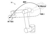
テストロボットの3次元形状を獲得する段階(S110)は、実際のロボットRの形状情報を含むテストロボット10の3次元映像又は3次元模型を獲得する。具体的に、テストロボット10は、シミュレーションプログラムにロボットRの形状情報を入力して形成された3次元映像からなるか、又は3次元計測センサを通じて形成された3次元模型からなり得る。すなわち、テストロボット10は、CAE(Computer Aided Engineering)プログラムなどのシミュレーションプログラムに実際のロボットRの形状情報を入力して形成された3次元映像からなるか、3次元計測センサを通じて具現され、実際のロボットRと同一に駆動及び制御される3次元模型からなり得る。
In the step of acquiring the three-dimensional shape of the test robot (S110), a three-dimensional image or a three-dimensional model of the
3DモデリングされるロボットRの種類は限定されないが、一定の作業空間で共同に業務を処理する協働ロボットであり得る。このような協働ロボッは、先端にメカニカルハンド(mechanical hand)を備えることによって特定物体を把持及び移送したり、特定作業を行えるように形成されたマニピュレータ(Manipulator)に形成され得る。そして、テストロボット10は、X軸方向、Y軸方向、Z軸方向、ピッチ方向、ヨー方向、及びロール方向のうち少なくとも一方向に移動可能な自由度を有するように形成され得る。すなわち、テストロボット10は、少なくとも1自由度を有するマニピュレータに形成され得る。
The type of robot R to be 3D modeled is not limited, but it may be a collaborative robot that jointly processes work in a certain work space. Such a collaborative robot can be formed on a manipulator formed so that a specific object can be gripped and transferred or a specific work can be performed by providing a mechanical hand at the tip. The
具体的に、テストロボット10は、ジョイント11を介して連結された少なくとも2個のリンク部12と、リンク部12のうち一つに連結されたエンドエフェクタ13とを含むマニピュレータに形成され得る。ここで、エンドエフェクタは、テストロボット10が作業するときに作業対象に直接作用する機能を有する部分であって、例えば、マニピュレータのメカニカルハンドであり得る。
Specifically, the
テストロボットの移動時間及び移動経路を設定する段階(S120)は、テストロボット10の移動時間情報及び移動経路情報を含むプロファイル情報を入力し、テストロボット10の移動時間及び移動経路を設定する。例えば、テストロボット10が3次元映像である場合は、シミュレーションプログラムに移動時間情報及び移動経路情報を含むプロファイル情報を入力し、テストロボット10の移動時間及び移動経路を設定する。そして、テストロボット10が3次元模型である場合は、テストロボット10の制御システムに移動時間情報及び移動経路情報を含むプロファイル情報を入力し、テストロボット10の移動時間及び移動経路を設定する。ここで、シミュレーションプログラム及びロボットの制御システムを通じてテストロボット10の駆動を制御する方法は既に公知となった技術であるので、これに対する説明は省略する。
In the step (S120) of setting the movement time and the movement route of the test robot, the profile information including the movement time information and the movement route information of the
一定時間ごとにロボットの安全性を評価する段階(S130)は、テストロボット10の傷害誘発危険部位に対する形状、有効質量、移動速度、及び方向を考慮して被衝突体20に加えられる衝突圧力(P)及び衝突力(force、FC)を一定時間ごとに獲得し、一定時間ごとに獲得した衝突圧力及び衝突力の大きさが既に設定された最大衝突圧力(PMAX)及び最大衝突力(FMAX)の大きさ内に該当するかどうかを判断し、ロボットRの安全性を評価する。
In the stage of evaluating the safety of the robot at regular intervals (S130), the collision pressure (S130) applied to the collided
ここで、既に設定された最大衝突圧力(PMAX)及び最大衝突力(FMAX)の大きさは、国際標準化機構(ISO)規格による大きさからなり得る。国際標準化機構(ISO)には、人の身体部位別に耐えられる最大許容圧力及び許容力に対して開示されているので、これを基準にして最大衝突圧力(PMAX)及び最大衝突力(FMAX)の大きさを設定すると、ロボットRの安全性を一層向上できるようになる。 Here, the magnitudes of the maximum collision pressure ( PMAX ) and the maximum collision force ( FMAX ) already set may consist of the magnitudes according to the International Organization for Standardization (ISO) standard. The International Standards Organization (ISO), since it is disclosed to the maximum allowable pressure and resilience to withstand another body part of a person, which was the reference maximum collision pressure (P MAX) and maximum impact force (F MAX ) Can be set to further improve the safety of the robot R.
被衝突体20に加えられる衝突圧力(P)及び衝突力(FC)を一定時間単位に分けて獲得する理由は、衝突圧力(P)及び衝突力(FC)を算出するためのデータの量を減少させることによって計算の速度を向上させ、負荷がかからないようにするためである。ここで、一定時間単位はテストロボット10の形状によって変わり得る。すなわち、テストロボット10の形状が複雑であるほど時間単位は短くなり得る。
The reason for acquiring separately collision pressure applied to the collision object 20 (P) and collision force (F C) in a predetermined time unit, the collision pressure (P) and collision force (F C) of the data for calculating the This is to improve the speed of calculation by reducing the amount and to prevent the load from being applied. Here, the fixed time unit may change depending on the shape of the
具体的に、被衝突体20に加えられる衝突力(FC)は、下記の数式1を通じて具現可能である。ここで、被衝突体20は人であり得る。また、テストロボットの衝突部位に対する有効質量(Mi)は、機構学的理論によって算出され、被衝突体の衝突部位に対する有効質量(Mh)は、ユーザによって入力されることによって予め定められ得る。テストロボットの衝突部位の変位(yi)及び被衝突体の衝突部位の変位(yh)はCAEシステムを通じて求めることができる。
Specifically, the collision force applied to the colliding body 20 (F C) may be embodied through

Mi:テストロボットの衝突部位に対する有効質量 M i: effective mass for collision site testing robots
Mh:被衝突体の衝突部位に対する有効質量 M h : Effective mass of the collided body with respect to the collision site
FC:衝突力 F C: collision force
yi:テストロボットの衝突部位の変位 y i : Displacement of the collision site of the test robot
yh:被衝突体の衝突部位の変位 y h : Displacement of the collision site of the collided body
そして、被衝突体20に加えられる衝突圧力(P)は、下記の数式2を通じて具現可能である。ここで、被衝突体の皮膚弾性(K)及び被衝突体の皮膚厚さ(h)は、CAEシステムを通じてユーザによって入力されることによって予め格納され得る。
Then, the collision pressure (P) applied to the collided
δ:被衝突体の皮膚の変形量 δ: Amount of deformation of the skin of the collided body
α:テストロボットと被衝突体との間の衝突角 α: Collision angle between the test robot and the collided object
FC:衝突力 p:衝突圧力 F C: collision force p: collision pressure
K:被衝突体の皮膚弾性 h:被衝突体の皮膚厚さ K: Skin elasticity of the collided body h: Skin thickness of the collided body
x、y:衝突面の座標系 x, y: Coordinate system of collision surface
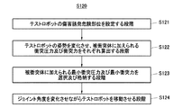
テストロボットの移動時間及び移動経路を設定する段階(S120)は、テストロボットの傷害誘発危険部位を設定する段階(S121)と、テストロボットの姿勢を変化させ、被衝突体に加えられる衝突圧力及び衝突力をそれぞれ算出する段階(S122)と、被衝突体に加えられる最小衝突圧力及び最小衝突力を選択及び格納する段階(S123)と、ジョイント角度を変化させながらテストロボットを移動させる段階(S124)とをさらに含んでもよい。 The stage of setting the movement time and movement path of the test robot (S120) is the stage of setting the injury-inducing danger site of the test robot (S121), and the collision pressure applied to the collided object by changing the posture of the test robot and the collision pressure applied to the collided object. A step of calculating the collision force (S122), a step of selecting and storing the minimum collision pressure and the minimum collision force applied to the collided object (S123), and a step of moving the test robot while changing the joint angle (S124). ) And may be further included.
テストロボットの傷害誘発危険部位を設定する段階(S121)は、テストロボット10の各部位別形状によって被衝突体20に加えられる接触圧力を算出し、算出された接触圧力値を通じてテストロボット10に対する少なくとも一つの傷害誘発危険部位を設定する。
In the step (S121) of setting the injury-inducing danger portion of the test robot, the contact pressure applied to the collided
例えば、テストロボット10が円柱状からなる場合、傷害誘発危険部位を設定するためのテストロボット10の各部位は、周面、上部面、下部面、上部コーナー、及び下部コーナーになり得る。そして、それぞれの部位別形状によって被衝突体20に加えられる接触圧力を算出する。ここで、接触圧力を算出する方法は、P=F/A(P:圧力、F:力、A:面積)の関係式を通じて計算可能である。
For example, when the
このような過程を通じてテストロボット10の各部位に対する接触圧力が算出されると、接触圧力のうち最も大きい値を有する部位又は接触圧力が既に設定された値を超える部位の全てを傷害誘発危険部位として選択することができる。
When the contact pressure for each part of the
一方、テストロボット10の傷害誘発危険部位は、ユーザの選択によって一つ又は二つ以上に定められてもよい。具体的に、テストロボット10の傷害誘発危険部位は、リンク部12及びエンドエフェクタ13から選ばれた一つ又は二つ以上であり得る。このようにテストロボット10の傷害誘発危険部位がユーザによって予め設定された場合は、テストロボットの傷害誘発危険部位を設定する段階(S121)を省略してもよい。
On the other hand, the injury-inducing danger site of the
テストロボットの姿勢を変化させ、被衝突体に加えられる衝突圧力及び衝突力をそれぞれ算出する段階(S122)は、テストロボット10のジョイント角度を調節することによってリンク部12及びエンドエフェクタ13の姿勢を変化させ、姿勢の変化に従って傷害誘発危険部位によって被衝突体20に加えられる衝突圧力(P)及び衝突力(FC)をそれぞれ算出する。
In the step (S122) of changing the posture of the test robot and calculating the collision pressure and the collision force applied to the collided object, the postures of the
このようにテストロボット10の姿勢を変化させ、被衝突体20に加えられる衝突圧力(P)及び衝突力(FC)を算出する理由は、リンク部12及びエンドエフェクタ13の姿勢の変化に従って被衝突体20とテストロボット10との距離及び接触部位が変わり、これによって、被衝突体20に加えられる衝突圧力(P)及び衝突力(FC)の大きさも変わるためである。
Thus changing the posture of the
被衝突体に加えられる最小衝突圧力及び最小衝突力を選択及び格納する段階(S123)は、前記段階(S122)で獲得した衝突圧力(P)及び衝突力(FC)のうち最も小さい値(以下、「最小衝突圧力(PMIN)及び最小衝突力(FMIN)」という。)を選択及び格納する。このとき、獲得した最小衝突圧力(PMIN)及び最小衝突力(FMIN)は、一定時間ごとに選択されて格納され得る。 Smallest value of the step of selecting and storing the minimum collision pressure and minimum impact force applied to the collision object (S123), the step (S122) acquired collision pressure (P) and collision force (F C) ( Hereinafter, "minimum collision pressure (P MIN ) and minimum collision force (F MIN )") will be selected and stored. At this time, the acquired minimum collision pressure (P MIN ) and minimum collision force (F MIN ) can be selected and stored at regular time intervals.
ジョイント角度を変化させながらテストロボットを移動させる段階(S124)は、最小衝突圧力(PMIN)及び最小衝突力(FMIN)に対応する角度でジョイント11の角度を一定時間ごとに変化させながらテストロボット10を移動させる。
In the stage (S124) of moving the test robot while changing the joint angle, the test is performed while changing the angle of the joint 11 at regular intervals at an angle corresponding to the minimum collision pressure (P MIN ) and the minimum collision force (F MIN). Move the
このようにテストロボット10の姿勢の変化に従って被衝突体20に加えられる最小衝突圧力(PMIN)及び最小衝突力(FMIN)の大きさを求めて格納した後、これに基づいてテストロボット10の姿勢を一定時間ごとに制御すると、テストロボット10は、同じ移動速度で同じ移動経路に沿って移動したとしても被衝突体20に最小限の衝撃が加えられる姿勢を具現できるようになる。
In this way, the magnitudes of the minimum collision pressure (P MIN ) and the minimum collision force (F MIN ) applied to the collided
衝突圧力及び衝突力の大きさが既に設定された許容安全基準値内に該当するようにテストロボットの最大速度を算出する段階(S140)は、衝突圧力(P)及び衝突力(FC)の大きさが既に設定された最大衝突圧力(PMAX)及び最大衝突力(FMAX)の大きさより大きいと、衝突圧力(P)及び衝突力(FC)の大きさが最大衝突圧力(PMAX)及び最大衝突力(FMAX)の大きさを満足する最大速度を算出する。すなわち、ロボットRの安全性が確保されないと、衝突圧力(P)及び衝突力(FC)の大きさが最大衝突圧力(PMAX)及び最大衝突力(FMAX)の大きさ内に該当するように最大速度を算出する。 Collision pressure and step size of the collision force is calculated already the maximum speed of the test robot to fall within the set allowable safety level (S140), the collision pressure (P) and the impact force of (F C) the size is already set maximum collision pressure (P MAX) and maximum impact force (F MAX) of the larger size, the collision pressure (P) and collision force (F C) of size up to a collision pressure (P MAX ) And the maximum speed satisfying the magnitude of the maximum collision force ( FMAX). That is, when the safety of the robot R is not ensured, the size of the collision pressure (P) and collision force (F C) corresponds to the size of the maximum collision pressure (P MAX) and maximum impact force (F MAX) Calculate the maximum speed as follows.
テストロボットの移動時間及び移動経路を再設定する段階(S150)は、テストロボット10が前段階(S140)で算出された最大速度で動けるようにプロファイル情報を修正し、テストロボット10の移動時間及び移動経路を再設定する。
In the stage (S150) of resetting the movement time and movement route of the test robot, the profile information is modified so that the
これは、テストロボット10の速度によって被衝突体20に加えられる力が変わるためである。すなわち、移動速度を減少させると被衝突体20に加えられる力が減少し、このように被衝突体20に加えられる力が減少すると圧力も減少するので、前段階(S140)で算出された最大速度でテストロボット10が動けるようにプロファイル情報を修正した場合、テストロボット10は、最大速度を出しながらも人体に傷害を与えないロボットに具現可能になる。
This is because the force applied to the collided
上述したように、ロボットの安全性向上方法は、テストロボットによって被衝突体に加えられる衝突圧力及び衝突力の大きさをシミュレーションを通じて獲得できるようになる。このようなテストロボットは、実際のロボットと類似する形状及び駆動動作を有する3次元模型ロボット又は3次元映像ロボットに形成されるので、従来のように、実際のロボットに作用する衝突圧力、衝突力、移動速度などを求めるための別途の装置を備えなくてもよく、低廉な費用で安全性評価を行えるようになる。 As described above, the method for improving the safety of the robot makes it possible to acquire the magnitude of the collision pressure and the collision force applied to the collided body by the test robot through simulation. Since such a test robot is formed into a three-dimensional model robot or a three-dimensional image robot having a shape and driving motion similar to those of an actual robot, the collision pressure and the collision force acting on the actual robot as in the conventional case. , It is not necessary to provide a separate device for determining the moving speed, etc., and the safety evaluation can be performed at a low cost.
また、テストロボットの各部位別形状によって被衝突体に加えられる接触圧力を算出することによって傷害誘発危険部位を選択し、選択された傷害誘発危険部位で被衝突体に加えられる衝突圧力及び衝突力を算出するので、テストロボットの形状に対応する衝突圧力及び衝突力を求めることができる。すなわち、従来は、ロボットの形状と関係なく接触圧力を一定に適用することによって被衝突体に加えられる衝突圧力及び衝突力を算出するので、算出された値の正確度が低いという短所があった。しかし、本発明のように、テストロボットの部位別形状によって被衝突体に加えられる接触圧力を算出し、この値を通じて傷害誘発危険部位を選択すると、テストロボットの衝突部位の形状に対応する衝突圧力及び衝突力を求めることができ、その正確度が向上し得る。 In addition, the injury-inducing risk site is selected by calculating the contact pressure applied to the collided body according to the shape of each part of the test robot, and the collision pressure and collision force applied to the collided body at the selected injury-inducing risk site. Therefore, the collision pressure and the collision force corresponding to the shape of the test robot can be obtained. That is, conventionally, since the collision pressure and the collision force applied to the collided body are calculated by applying the contact pressure constantly regardless of the shape of the robot, there is a disadvantage that the accuracy of the calculated values is low. .. However, as in the present invention, if the contact pressure applied to the collided body is calculated based on the shape of each part of the test robot and the injury-inducing risk part is selected through this value, the collision pressure corresponding to the shape of the collision part of the test robot is obtained. And the collision force can be obtained, and its accuracy can be improved.
また、被衝突体に加えられる衝撃圧力及び衝突力の大きさがテストロボットの安全性評価の基準を満足しない場合、衝突圧力及び衝突力の大きさが安全性評価基準を満足するようにテストロボットの姿勢を一定時間ごとに制御するので、ロボットの安全性を向上できるようになる。 If the impact pressure and the magnitude of the collision force applied to the collided body do not satisfy the safety evaluation criteria of the test robot, the test robot so that the magnitude of the collision pressure and the collision force satisfy the safety evaluation criteria. Since the posture of the vehicle is controlled at regular intervals, the safety of the robot can be improved.
併せて、被衝突体に加えられる衝撃圧力及び衝突力の大きさがテストロボットの安全性評価の基準を満足しない場合、衝突圧力及び衝突力の大きさが安全性評価基準を満足するようにテストロボットの速度を最大に制御するので、ロボットは、安全性が向上しながらも同一の移動経路を最大速度で移動できるようになる。 At the same time, if the impact pressure and the magnitude of the collision force applied to the collided object do not meet the safety evaluation criteria of the test robot, the collision pressure and the magnitude of the collision force are tested so as to satisfy the safety evaluation criteria. Since the speed of the robot is controlled to the maximum, the robot can move in the same movement path at the maximum speed while improving safety.
図6は、本発明の一実施形態に係るロボットの安全性評価方法に対するブロック図で、図7は、図6において、テストロボットによって被衝突体に加えられる衝突圧力及び衝突力を算出する段階に対する詳細な過程を説明するためのブロック図である。 FIG. 6 is a block diagram for the robot safety evaluation method according to the embodiment of the present invention, and FIG. 7 is for the step of calculating the collision pressure and the collision force applied to the collided object by the test robot in FIG. It is a block diagram for explaining a detailed process.
図3〜図7を参考にして説明すると、ロボットの安全性評価方法(S200)は、テストロボットの3次元形状を獲得する段階(S210)と、テストロボットの移動時間及び移動経路を設定する段階(S220)と、テストロボットによって被衝突体に加えられる衝突圧力及び衝突力を算出する段階(S230)と、ロボットの安全性を評価する段階(S240)とを含む。 Explaining with reference to FIGS. 3 to 7, the robot safety evaluation method (S200) includes a step of acquiring a three-dimensional shape of the test robot (S210) and a step of setting the movement time and movement path of the test robot. (S220), a step of calculating the collision pressure and the collision force applied to the collided object by the test robot (S230), and a step of evaluating the safety of the robot (S240) are included.
テストロボットの3次元形状を獲得する段階(S210)とテストロボットの移動時間及び移動経路を設定する段階(S220)は、図1を説明する過程で既に言及した通りであるので、上述した内容を援用することにする。 The step of acquiring the three-dimensional shape of the test robot (S210) and the step of setting the moving time and moving path of the test robot (S220) are as already mentioned in the process of explaining FIG. I will use it.
テストロボットによって被衝突体に加えられる衝突圧力及び衝突力を算出する段階(S230)は、テストロボット10の傷害誘発危険部位に対する形状、有効質量、移動速度、及び方向を考慮して被衝突体20に加えられる衝突圧力(P)及び衝突力(FC)を算出する。
In the step (S230) of calculating the collision pressure and the collision force applied to the collided body by the test robot, the collided
具体的に、被衝突体20に加えられる衝突力(FC)は、上述した数式1を通じて具現可能である。ここで、被衝突体20は人であり得る。また、テストロボットの衝突部位に対する有効質量(Mi)は、機構学的理論によって算出され、被衝突体の衝突部位に対する有効質量(Mh)は、ユーザによって入力されることによって予め定められ得る。テストロボットの衝突部位の変位(yi)及び被衝突体の衝突部位の変位(yh)はCAEシステムを通じて求めることができる。
Specifically, the collision force applied to the colliding body 20 (F C) may be embodied through
そして、被衝突体20に加えられる衝突圧力(P)は、上述した数式2を通じて具現可能である。ここで、被衝突体の皮膚弾性(K)及び被衝突体の皮膚厚さ(h)は、CAEシステムを通じてユーザによって入力されることによって予め格納され得る。
Then, the collision pressure (P) applied to the collided
テストロボットによって被衝突体に加えられる衝突圧力及び衝突力を算出する段階(S230)は、一定時間単位別に被衝突体20に加えられる衝突圧力(P)及び衝突力(FC)を算出することができる。これは、衝突圧力(P)及び衝突力(FC)を算出するためのデータの量を減少させることによって計算の速度を向上させ、負荷がかからないようにするためである。ここで、一定時間単位はテストロボット10の形状によって変わり得る。すなわち、テストロボット10の形状が複雑であるほど時間単位は短くなり得る。
Calculating a collision pressure and collision force applied to the collision object by the test robot (S230) is to calculate the collision pressure applied to the collision object 20 (P) and collision force (F C) by a predetermined time unit Can be done. This improves the speed of computation by reducing the amount of data for calculating the collision pressure (P) and collision force (F C), it is so that the load is not applied. Here, the fixed time unit may change depending on the shape of the
テストロボットによって被衝突体に加えられる衝突圧力及び衝突力を算出する段階(S230)は、テストロボットの傷害誘発危険部位を設定する段階(S231)をさらに含んでもよい。 The step of calculating the collision pressure and the collision force applied to the collided body by the test robot (S230) may further include the step of setting the injury-inducing danger portion of the test robot (S231).
テストロボットの傷害誘発危険部位を設定する段階(S231)は、テストロボット10の各部位別面積によって被衝突体20に加えられる接触圧力を算出し、算出された接触圧力値を通じてテストロボット10に対する少なくとも一つの傷害誘発危険部位を設定する。
In the stage (S231) of setting the injury-inducing danger portion of the test robot, the contact pressure applied to the collided
例えば、テストロボット10が円柱状からなる場合、傷害誘発危険部位を設定するためのテストロボット10の各部位は、周面、上部面、下部面、上部コーナー、及び下部コーナーになり得る。そして、それぞれの部位別面積によって被衝突体20に加えられる接触圧力を算出する。ここで、接触圧力を算出する方法は、P=F/A(P:圧力、F:力、A:面積)の関係式を通じて計算可能である。
For example, when the
このような過程を通じてテストロボット10の各部位に対する接触圧力が算出されると、接触圧力のうち最も大きい値を有する部位又は接触圧力が既に設定された値を超える部位の全てを傷害誘発危険部位として選択することができる。
When the contact pressure for each part of the
一方、テストロボット10の傷害誘発危険部位は、ユーザの選択によって一つ又は二つ以上に定められ得る。具体的に、テストロボット10の傷害誘発危険部位は、リンク部12及びエンドエフェクタ13から選ばれた一つ又は二つ以上であり得る。このようにテストロボット10の傷害誘発危険部位がユーザによって予め設定された場合は、テストロボットの傷害誘発危険部位を設定する段階(S231)を省略してもよい。
On the other hand, the injury-inducing danger site of the
テストロボットの安全性を評価する段階(S240)は、テストロボットによって被衝突体に加えられる衝突圧力及び衝突力を算出する段階(S230)で獲得した衝突圧力(P)及び衝突力(FC)の大きさが既に設定された最大衝突圧力(PMAX)及び最大衝突力(FMAX)の大きさ内に該当するかどうかを判断する。 Assessing the safety of the test robot (S240) is acquired collision pressure (P) and the collision force in step (S230) of calculating the collision pressure and collision force applied to the collision object by the test robot (F C) It is determined whether or not the magnitude of is within the already set magnitudes of the maximum collision pressure ( PMAX ) and the maximum collision force ( FMAX).
ロボットの安全性を評価する段階(S240)で被衝突体20に加えられる衝突圧力(P)及び衝突力(FC)の大きさが既に設定された最大衝突圧力(PMAX)及び最大衝突力(FMAX)の大きさ内に該当すると、テストロボット10は安全であると判断する。その一方で、衝突圧力(P)及び衝突力(FC)の大きさが最大衝突圧力(PMAX)及び最大衝突力(FMAX)の大きさ以上であると、テストロボット10は安全でないと判断する。
Assessing the safety of the robot (S240) a collision pressure applied to the
ロボットの安全性を評価する段階(S240)で衝突圧力(P)及び衝突力(FC)の大きさが最大衝突圧力(PMAX)及び最大衝突力(FMAX)の大きさ以上であると、被衝突体20に加えられる衝突圧力(P)及び衝突力(FC)が最大衝突圧力(PMAX)及び最大衝突力(FMAX)の大きさ未満になるようにテストロボット10の移動速度を制御することができる。これは、テストロボット10の移動速度を減少させると、被衝突体20に加えられる力が減少するためである。このように被衝突体20に加えられる力が減少すると圧力も減少するので、テストロボット10の移動速度を適宜調節すると、最大速度を出しながらも人体に傷害を与えないロボットRを具現できるようになる。
If it is at the stage of evaluating the safety of the robot (S240) the collision pressure (P) and collision force (F C) of size up to a collision pressure (P MAX) and maximum impact force (F MAX) of magnitude or more , the moving speed of the
ロボットの安全性を評価する段階(S240)で既に設定された最大衝突圧力(PMAX)及び最大衝突力(FMAX)の大きさは、国際標準化機構(ISO)、より具体的には、TS 15066規格による大きさからなり得る。国際標準化機構(ISO)のTS 15066には、人の身体部位別に耐えられる最大許容圧力及び許容力に対して開示されているので、これを基準にして最大衝突圧力(PMAX)及び最大衝突力(FMAX)の大きさを設定すると、ロボットRの安全性を一層向上できるようになる。 The size of the step of assessing the safety of the robot (S240) maximum collision pressure already set in (P MAX) and maximum impact force (F MAX), the International Organization for Standardization (ISO), and more specifically, TS It can consist of a size according to the 1566 standard. The International Organization for Standardization (ISO) TS 15066 discloses the maximum permissible pressure and permissible force that can be tolerated for each part of the human body, and based on this, the maximum collision pressure ( PMAX ) and maximum collision force. By setting the size of ( FMAX ), the safety of the robot R can be further improved.
一方、テストロボットによって被衝突体に加えられる衝突圧力及び衝突力を算出する段階(S230)は、テストロボットの姿勢の変化に従って被衝突体に加えられる衝突圧力及び衝突力を算出する段階(S232)をさらに含んでもよい。 On the other hand, the step of calculating the collision pressure and the collision force applied to the collided body by the test robot (S230) is the step of calculating the collision pressure and the collision force applied to the collided body according to the change in the posture of the test robot (S232). May be further included.
テストロボットの姿勢の変化に従って被衝突体に加えられる衝突圧力及び衝突力を算出する段階(S232)は、テストロボット10のジョイント11の角度を調節することによってリンク部12及びエンドエフェクタ13の姿勢を変化させ、姿勢の変化に従って傷害誘発危険部位によって被衝突体20に加えられる衝突圧力(P)及び衝突力(FC)を算出する。
In the step (S232) of calculating the collision pressure and the collision force applied to the collided body according to the change in the posture of the test robot, the postures of the
このようにテストロボット10の姿勢を変化させ、被衝突体20に加えられる衝突圧力(P)及び衝突力(FC)を算出する理由は、リンク部12及びエンドエフェクタ13の姿勢の変化に従って被衝突体20とテストロボット10との距離及び接触部位が変わるためである。そして、被衝突体20とテストロボット10との距離及び接触部位が変わると、被衝突体20に加えられる衝突圧力(P)及び衝突力(FC)の大きさも変わるようになる。
Thus changing the posture of the
したがって、姿勢の変化に従って被衝突体20に加えられる衝突圧力(P)及び衝突力(FC)の大きさを求めると、ロボットRが同じ移動速度で同じ移動経路に沿って移動したとしても被衝突体20に最小限の衝撃が加えられる姿勢を具現できるようになる。
Therefore, when determining the size of the
上述したように、ロボットの安全性評価方法は、テストロボットによって被衝突体に加えられる衝突圧力及び衝突力の大きさをシミュレーションを通じて獲得できるようになる。このようなテストロボットは、実際のロボットと類似する形状及び駆動動作を有する3次元模型ロボット又は3次元映像ロボットに形成されるので、従来のように、実際のロボットに作用する衝突圧力、衝突力、移動速度などを求めるための別途の装置を備えなくてもよく、低廉な費用で安全性評価を行えるようになる。 As described above, in the robot safety evaluation method, the magnitude of the collision pressure and the collision force applied to the collided body by the test robot can be obtained through simulation. Since such a test robot is formed into a three-dimensional model robot or a three-dimensional image robot having a shape and driving motion similar to those of an actual robot, the collision pressure and the collision force acting on the actual robot as in the conventional case. , It is not necessary to provide a separate device for determining the moving speed, etc., and the safety evaluation can be performed at a low cost.
また、テストロボットの各部位別面積によって被衝突体に加えられる接触圧力を算出することによって傷害誘発危険部位を選択し、選択された傷害誘発危険部位で被衝突体に加えられる衝突圧力及び衝突力を算出するので、テストロボットの形状に対応する衝突圧力及び衝突力を求めることができる。すなわち、従来は、ロボットの形状と関係なく接触圧力を一定に適用することによって被衝突体に加えられる衝突圧力及び衝突力を算出するので、算出された値の正確度が低いという短所があった。しかし、本発明のように、テストロボットの部位別面積によって被衝突体に加えられる接触圧力を算出し、この値を通じて傷害誘発危険部位を選択すると、テストロボットの衝突部位の形状に対応する衝突圧力及び衝突力を求めることができ、その正確度が向上し得る。 In addition, the injury-inducing risk site is selected by calculating the contact pressure applied to the collided body according to the area of each part of the test robot, and the collision pressure and collision force applied to the collided body at the selected injury-inducing risk site. Therefore, the collision pressure and the collision force corresponding to the shape of the test robot can be obtained. That is, conventionally, since the collision pressure and the collision force applied to the collided body are calculated by applying the contact pressure constantly regardless of the shape of the robot, there is a disadvantage that the accuracy of the calculated values is low. .. However, as in the present invention, if the contact pressure applied to the collided body is calculated based on the area of the test robot for each part and the injury-inducing risk part is selected through this value, the collision pressure corresponding to the shape of the collision part of the test robot is obtained. And the collision force can be obtained, and its accuracy can be improved.
併せて、テストロボットの姿勢を変化させながら衝突圧力及び衝突力を求めるので、被衝突体に最小限の衝撃が加えられる姿勢を具現できるようになる。よって、テストロボットが具現された姿勢を通じて移動すると、同じ移動経路に沿って移動しながらも最大の速度で移動できるようになる。 At the same time, since the collision pressure and the collision force are obtained while changing the posture of the test robot, it becomes possible to realize the posture in which the minimum impact is applied to the collided body. Therefore, when the test robot moves through the embodied posture, it can move at the maximum speed while moving along the same movement path.
図8は、テストロボットの部位別形状によって被衝突体に加えられる接触圧力の大きさを示した図である。そして、図9は、3Dモデリングプログラムを通じて獲得した衝突圧力及び衝突力の値を示した図である。 FIG. 8 is a diagram showing the magnitude of the contact pressure applied to the collided body depending on the shape of the test robot for each part. Then, FIG. 9 is a diagram showing the values of the collision pressure and the collision force acquired through the 3D modeling program.
以下、図1〜図9を参照してロボットの安全性向上方法及び安全性評価方法の過程を説明する。 Hereinafter, the process of the robot safety improvement method and the safety evaluation method will be described with reference to FIGS. 1 to 9.
まず、ユーザがシミュレーションプログラムに実際のロボットRの形状情報を入力することによって3次元映像テストロボットを獲得したり、3次元計測センサを通じて3次元模型テストロボットを獲得する。ここで、テストロボット10は、X軸方向、Y軸方向、Z軸方向、ピッチ方向、ヨー方向、及びロール方向のうち一つの方向に移動可能なマニピュレータからなり得る。すなわち、テストロボット10は、1自由度以上を有するマニピュレータであり得る。
First, the user acquires a 3D video test robot by inputting the shape information of the actual robot R into the simulation program, or acquires a 3D model test robot through a 3D measurement sensor. Here, the
そして、シミュレーションプログラム又はテストロボットシステムに移動時間情報及び移動経路情報を含むプロファイル情報を入力し、テストロボット10の移動時間及び移動経路を設定する。これによって、テストロボット10は、一定時間の間、定められた移動経路に沿って移動するシミュレーションを進めるようになる。
Then, the profile information including the movement time information and the movement route information is input to the simulation program or the test robot system, and the movement time and the movement route of the
そして、テストロボット10の各部位別形状によって被衝突体20に加えられる接触圧力を算出し、算出された接触圧力値を通じてテストロボット10に対する少なくとも一つの傷害誘発危険部位を設定する。これは、図8に示したように、テストロボットの部位別形状によって被衝突体20に加えられる接触圧力の大きさが変わるためである。
Then, the contact pressure applied to the collided
ここで、傷害誘発危険部位は、算出された接触圧力のうち最も大きい値を有する部位又は接触圧力が既に設定された値を超える部位の全てになり得るが、本実施形態では、エンドエフェクタ13及びリンク部12を傷害誘発危険部位として説明する。
Here, the injury-inducing risk site can be all the sites having the largest value of the calculated contact pressures or the sites where the contact pressure exceeds the already set value, but in the present embodiment, the
このようにテストロボット10の傷害誘発危険部位が設定されると、テストロボット10の傷害誘発危険部位に対する有効質量、移動速度、及び方向を考慮して被衝突体20に加えられる衝突圧力(P)及び衝突力(FC)を算出する。ここで、傷害誘発危険部位であるエンドエフェクタ13及びリンク部12から被衝突体20に加えられる衝突圧力(P)及び衝突力(FC)の値は図9に示した通りであり、衝突圧力(P)及び衝突力(FC)の値を算出する方法は上述した通りであるので、これに対する説明は省略する。
When the injury-inducing danger portion of the
このように衝突圧力(P)及び衝突力(FC)の大きさが決定されると、決定された衝突圧力(P)及び衝突力(FC)の大きさが既に設定された最大衝突圧力(FMAX)及び最大衝突力(FMAX)の大きさ内に該当するかどうかを判断する。すなわち、衝突圧力(P)及び衝突力(FC)の大きさが既に設定された最大衝突圧力(PMAX)及び最大衝突力(FMAX)の大きさ内に該当すると、ロボットRは安全であると判断する。その一方で、衝突圧力(P)及び衝突力(FC)の大きさが最大衝突圧力(PMAX)及び最大衝突力(FMAX)の大きさ以上であると、ロボットRは安全でないと判断する。ここで、既に設定された最大衝突圧力(PMAX)及び最大衝突力(FMAX)の大きさは、国際標準化機構(ISO)規格による大きさからなり得る。 With such the magnitude of the collision pressure (P) and collision force (F C) is determined, the maximum collision pressure magnitude of has already been set determined crash pressure (P) and collision force (F C) It is determined whether or not it falls within the magnitudes of (F MAX ) and maximum collision force (F MAX). That is, when corresponding to a collision pressure (P) and collision force (F C) of size up to a collision pressure already set (P MAX) and maximum impact force in the magnitude of the (F MAX), the robot R is unsafe Judge that there is. On the other hand, we determine that the is collision pressure (P) and collision force (F C) of size up to a collision pressure (P MAX) and maximum impact force (F MAX) of magnitude or more, the robot R is unsafe To do. Here, the magnitudes of the maximum collision pressure ( PMAX ) and the maximum collision force ( FMAX ) already set may consist of the magnitudes according to the International Organization for Standardization (ISO) standard.
図10は、速度制御を通じて生産性及び安全性を最大に具現したロボットの制御状態を示した図で、図11は、安全性を最大に高めるためにジョイント角度を設定し、経路を修正した状態を示した図である。 FIG. 10 is a diagram showing a control state of a robot that maximizes productivity and safety through speed control, and FIG. 11 is a state in which a joint angle is set and a path is corrected in order to maximize safety. It is a figure which showed.
以下、図1〜図11を参照してロボットの安全性向上方法の過程を説明する。 Hereinafter, the process of the robot safety improvement method will be described with reference to FIGS. 1 to 11.
ロボットRが安全でないと判断されると、図11に示したように、テストロボット10の衝突圧力(P)及び衝突力(FC)の大きさが既に設定された最大衝突圧力(PMAX)及び最大衝突力(FMAX)の大きさ内に該当するようにテストロボット10のジョイント角度を調節し、リンク部12及びエンドエフェクタ13の姿勢を変化させる。
When the robot R is determined to be unsafe, as shown in FIG. 11, the collision pressure (P) and the impact force of the
そして、ロボットRが安全であると判断されると、テストロボット10の衝突圧力(P)及び衝突力(FC)の大きさが既に設定された最大衝突圧力(PMAX)及び最大衝突力(FMAX)の大きさ内に該当するテストロボット10の最大速度を算出し、算出された最大速度をプロファイルに再入力することによってテストロボット10の速度を制御することができる。
When the robot R is determined to be safe, the collision pressure (P) and the impact force of the test robot 10 (F C) magnitude is already set maximum collision pressure (P MAX) and maximum impact force ( The speed of the
本発明は、添付の図面に示した一実施形態を参考にして説明したが、これは例示的なものに過ぎなく、当該技術分野で通常の知識を有する者であれば、これから多様な変形及び均等な他の実施形態が可能であることを理解できるだろう。よって、本発明の真の保護範囲は、添付の特許請求の範囲によってのみ定められるべきであろう。 The present invention has been described with reference to one embodiment shown in the accompanying drawings, but this is merely an example, and any person who has ordinary knowledge in the relevant technical field will be able to perform various modifications and modifications. It will be appreciated that other equal embodiments are possible. Therefore, the true scope of protection of the present invention should be defined only by the appended claims.
Claims (20)
前記テストロボットの移動時間情報及び移動経路情報を含むプロファイル情報を入力し、前記テストロボットの移動時間及び移動経路を設定する段階;
前記テストロボットの傷害誘発危険部位に対する形状、有効質量、移動速度、及び方向を考慮して被衝突体に加えられる衝突圧力及び衝突力を一定時間ごとに獲得し、一定時間ごとに獲得した前記衝突圧力及び衝突力の大きさが既に設定された最大衝突圧力及び最大衝突力の大きさ内に該当するかどうかを判断し、前記ロボットの安全性を評価する段階;
前記衝突圧力及び衝突力の大きさが前記既に設定された最大衝突圧力及び最大衝突力の大きさより大きいと、前記衝突圧力及び衝突力の大きさが前記最大衝突圧力及び最大衝突力の大きさを満足する最大速度を算出する段階;及び
前記テストロボットが前記算出された最大速度で動けるように前記プロファイル情報を修正し、前記テストロボットの移動時間及び移動経路を再設定する段階;
を含むロボットの安全性向上方法。 The stage of acquiring a 3D image or 3D model of a test robot that includes actual robot shape information;
A step of inputting profile information including the movement time information and the movement route information of the test robot and setting the movement time and the movement route of the test robot;
The collision pressure and the collision force applied to the collided object are acquired at regular intervals in consideration of the shape, effective mass, moving speed, and direction of the test robot with respect to the injury-inducing dangerous portion, and the collision acquired at regular intervals. The stage of determining whether the magnitudes of the pressure and the collision force fall within the already set magnitudes of the maximum collision pressure and the maximum collision force, and evaluating the safety of the robot;
When the magnitude of the collision pressure and the collision force is larger than the magnitude of the already set maximum collision pressure and the maximum collision force, the magnitude of the collision pressure and the collision force is the magnitude of the maximum collision pressure and the maximum collision force. The step of calculating a satisfactory maximum speed; and the step of modifying the profile information so that the test robot can move at the calculated maximum speed, and resetting the movement time and movement path of the test robot;
How to improve the safety of robots including.
シミュレーションプログラムに前記ロボットの形状情報を入力して形成された3次元映像であるか、又は3次元計測センサを通じて形成された3次元模型である、請求項1に記載のロボットの安全性向上方法。 The test robot
The method for improving the safety of a robot according to claim 1, which is a three-dimensional image formed by inputting the shape information of the robot into a simulation program, or a three-dimensional model formed through a three-dimensional measurement sensor.
前記傷害誘発危険部位は、前記リンク部及びエンドエフェクタから選ばれた一つ又は二つ以上である、請求項1に記載のロボットの安全性向上方法。 The test robot includes at least two link portions connected via joints and an end effector connected to one of the link portions.
The method for improving the safety of a robot according to claim 1, wherein the injury-inducing danger site is one or more selected from the link portion and the end effector.
前記テストロボットのジョイント角度を調節し、前記リンク部及びエンドエフェクタの姿勢を変化させる段階と、
前記姿勢の変化に従って前記被衝突体に加えられる最小衝突圧力及び最小衝突力を一定時間ごとに獲得する段階と、
前記最小衝突圧力及び最小衝突力に対応する角度で前記ジョイント角度を一定時間ごとに変化させながら前記テストロボットを移動させる段階;
をさらに含む、請求項6に記載のロボットの安全性向上方法。 The stage of evaluating the safety of the robot is
The stage of adjusting the joint angle of the test robot to change the posture of the link portion and the end effector, and
A step of acquiring the minimum collision pressure and the minimum collision force applied to the collided body according to the change in posture at regular intervals, and
A step of moving the test robot while changing the joint angle at regular intervals at an angle corresponding to the minimum collision pressure and the minimum collision force;
The method for improving the safety of a robot according to claim 6, further comprising.
前記テストロボットの各部位別形状によって前記被衝突体に加えられる接触圧力を算出し、前記算出された接触圧力値を通じて前記テストロボットに対する少なくとも一つの傷害誘発危険部位を設定する段階をさらに含む、請求項1に記載のロボットの安全性向上方法。 The stage of evaluating the safety of the robot is
The claim further includes a step of calculating the contact pressure applied to the collided body according to the shape of each part of the test robot and setting at least one injury-inducing risk part for the test robot through the calculated contact pressure value. Item 1. The method for improving the safety of a robot according to item 1.
前記テストマニピュレータの移動時間情報及び移動経路情報を含むプロファイル情報を入力し、前記テストマニピュレータの移動時間及び移動経路を設定する段階;
前記テストマニピュレータの各部位別形状によって被衝突体に加えられる接触圧力を算出し、前記算出された接触圧力値を通じて前記テストマニピュレータに対する少なくとも一つの傷害誘発危険部位を設定する段階;
前記テストマニピュレータの傷害誘発危険部位に対する有効質量、移動速度、及び方向を考慮して前記被衝突体に加えられる衝突圧力及び衝突力を一定時間ごとに獲得し、前記衝突圧力及び衝突力の大きさが既に設定された最大衝突圧力及び最大衝突力の大きさ内に該当するかどうかを判断し、前記マニピュレータの安全性を評価する段階;
前記衝突圧力及び衝突力の大きさが前記既に設定された最大衝突圧力及び最大衝突力の大きさより大きいと、前記衝突圧力及び衝突力の大きさが前記最大衝突圧力及び最大衝突力の大きさ内に該当する移動方向別最大速度を算出する段階:及び
前記テストマニピュレータが前記算出された最大速度で動けるように前記プロファイル情報を修正し、前記テストマニピュレータの移動時間及び移動経路を再設定する段階;
を含むロボットの安全性向上方法。 The stage of acquiring a 3D image or 3D model of a test manipulator that includes the shape information of the actual manipulator and has at least 1 degree of freedom;
A step of inputting profile information including travel time information and travel route information of the test manipulator and setting the travel time and travel route of the test manipulator;
The step of calculating the contact pressure applied to the collided body according to the shape of each part of the test manipulator and setting at least one injury-inducing risk part for the test manipulator through the calculated contact pressure value;
The collision pressure and the collision force applied to the collided object are acquired at regular intervals in consideration of the effective mass, the moving speed, and the direction of the test manipulator with respect to the injury-inducing danger portion, and the magnitude of the collision pressure and the collision force is obtained. The stage of determining whether or not is within the already set maximum collision pressure and maximum collision force, and evaluating the safety of the manipulator;
When the magnitude of the collision pressure and the collision force is larger than the magnitude of the already set maximum collision pressure and the maximum collision force, the magnitude of the collision pressure and the collision force is within the magnitude of the maximum collision pressure and the maximum collision force. The stage of calculating the maximum speed for each movement direction corresponding to the above: and the stage of modifying the profile information so that the test manipulator can move at the calculated maximum speed and resetting the movement time and movement route of the test manipulator;
How to improve the safety of robots including.
シミュレーションプログラムに前記マニピュレータの形状情報を入力して形成された3次元映像であるか、又は3次元計測センサを通じて形成された3次元模型である、請求項9に記載のロボットの安全性向上方法。 The test manipulator
The method for improving the safety of a robot according to claim 9, which is a three-dimensional image formed by inputting the shape information of the manipulator into a simulation program, or a three-dimensional model formed through a three-dimensional measurement sensor.
前記傷害誘発危険部位は、前記リンク部及びエンドエフェクタから選ばれた一つ又は二つ以上である、請求項9に記載のロボットの安全性向上方法。 The test manipulator includes at least two link portions connected via joints and an end effector connected to one of the link portions.
The method for improving the safety of a robot according to claim 9, wherein the injury-inducing danger site is one or more selected from the link portion and the end effector.
前記テストマニピュレータのジョイント角度を調節し、前記リンク部及びエンドエフェクタの姿勢を変化させる段階と、
前記姿勢の変化に従って前記被衝突体に加えられる最小衝突圧力及び最小衝突力を一定時間ごとに獲得する段階と、
前記最小衝突圧力及び最小衝突力に対応する角度で前記ジョイント角度を一定時間ごとに変化させながら前記テストマニピュレータを移動させる段階と、
をさらに含む、請求項13に記載のロボットの安全性向上方法。 The stage of evaluating the safety of the manipulator is
The stage of adjusting the joint angle of the test manipulator to change the posture of the link portion and the end effector, and
A step of acquiring the minimum collision pressure and the minimum collision force applied to the collided body according to the change in posture at regular intervals, and
A step of moving the test manipulator while changing the joint angle at regular intervals at an angle corresponding to the minimum collision pressure and the minimum collision force.
13. The method for improving the safety of a robot according to claim 13.
前記テストロボットの移動時間情報及び移動経路情報を含むプロファイル情報を入力し、前記テストロボットの移動時間及び移動経路を設定する段階;
前記テストロボットの傷害誘発危険部位に対する形状、有効質量、移動速度、及び方向を考慮して被衝突体に加えられる衝突圧力及び衝突力を算出する段階;及び
前記算出された衝突圧力及び衝突力の大きさが既に設定された最大衝突圧力及び最大衝突力の大きさ内に該当するかどうかを判断し、前記ロボットの安全性を評価する段階;
を含むロボットの安全性評価方法。 The stage of acquiring a 3D image or 3D model of a test robot that includes actual robot shape information;
A step of inputting profile information including the movement time information and the movement route information of the test robot and setting the movement time and the movement route of the test robot;
The step of calculating the collision pressure and the collision force applied to the collided object in consideration of the shape, effective mass, moving speed, and direction of the test robot with respect to the injury-inducing danger site; and the calculated collision pressure and the collision force. The stage of determining whether the magnitude falls within the already set maximum collision pressure and maximum collision force, and evaluating the safety of the robot;
Robot safety evaluation method including.
シミュレーションプログラムに前記ロボットの形状情報を入力して形成された3次元映像であるか、又は3次元計測センサを通じて形成された3次元模型である、請求項15に記載のロボットの安全性評価方法。 The test robot
The robot safety evaluation method according to claim 15, which is a three-dimensional image formed by inputting the shape information of the robot into a simulation program, or a three-dimensional model formed through a three-dimensional measurement sensor.
Applications Claiming Priority (5)
| Application Number | Priority Date | Filing Date | Title |
|---|---|---|---|
| KR10-2017-0143813 | 2017-10-31 | ||
| KR1020170143813A KR101976358B1 (en) | 2017-10-31 | 2017-10-31 | Safety improve method of robot |
| KR10-2017-0143802 | 2017-10-31 | ||
| KR1020170143802A KR102003126B1 (en) | 2017-10-31 | 2017-10-31 | Safety evaluation method of robot |
| PCT/KR2018/013056 WO2019088681A1 (en) | 2017-10-31 | 2018-10-31 | Safety improvement and safety evaluation method for robot |
Publications (2)
| Publication Number | Publication Date |
|---|---|
| JP2021501062A JP2021501062A (en) | 2021-01-14 |
| JP6883903B2 true JP6883903B2 (en) | 2021-06-09 |
Family
ID=66332112
Family Applications (1)
| Application Number | Title | Priority Date | Filing Date |
|---|---|---|---|
| JP2020524025A Active JP6883903B2 (en) | 2017-10-31 | 2018-10-31 | Robot safety improvement method and safety evaluation method |
Country Status (3)
| Country | Link |
|---|---|
| US (1) | US11511429B2 (en) |
| JP (1) | JP6883903B2 (en) |
| WO (1) | WO2019088681A1 (en) |
Families Citing this family (6)
| Publication number | Priority date | Publication date | Assignee | Title |
|---|---|---|---|---|
| US11154991B2 (en) * | 2018-09-26 | 2021-10-26 | Disney Enterprises, Inc. | Interactive autonomous robot configured for programmatic interpretation of social cues |
| US20210154831A1 (en) * | 2019-11-22 | 2021-05-27 | Canon Kabushiki Kaisha | Information processing method, robot system, article manufacturing method and information processing apparatus |
| CN111152264B (en) * | 2020-01-03 | 2021-06-11 | 北京理工大学 | Precision measurement module for detecting collision force and power of cooperative robot |
| US11816754B2 (en) | 2020-03-13 | 2023-11-14 | Omron Corporation | Measurement parameter optimization method and device, and computer control program stored on computer-readable storage medium |
| CN111251335B (en) * | 2020-03-24 | 2021-06-08 | 桂林电子科技大学 | High-precision mechanical arm collision detection method based on bounding box algorithm |
| DE102021208576B3 (en) * | 2021-08-06 | 2022-10-06 | Fraunhofer-Gesellschaft zur Förderung der angewandten Forschung eingetragener Verein | Specification of a permissible maximum speed of a robotic device |
Family Cites Families (14)
| Publication number | Priority date | Publication date | Assignee | Title |
|---|---|---|---|---|
| US6678582B2 (en) | 2002-05-30 | 2004-01-13 | Kuka Roboter Gmbh | Method and control device for avoiding collisions between cooperating robots |
| US7181314B2 (en) * | 2003-11-24 | 2007-02-20 | Abb Research Ltd. | Industrial robot with controlled flexibility and simulated force for automated assembly |
| FR2868180B1 (en) * | 2004-03-24 | 2006-06-16 | Commissariat Energie Atomique | METHOD AND DEVICE FOR INTERACTIVE SIMULATION OF CONTACT BETWEEN OBJECTS |
| EP1870211B1 (en) | 2006-06-22 | 2019-02-27 | Honda Research Institute Europe GmbH | Method for controlling a robot by assessing the fitness of a plurality of simulated behaviours |
| US7844398B2 (en) | 2008-07-09 | 2010-11-30 | Panasonic Corporation | Path risk evaluating apparatus |
| JP5983170B2 (en) * | 2012-08-10 | 2016-08-31 | 株式会社デンソーウェーブ | Robot simulation device |
| CN103894807A (en) * | 2012-12-28 | 2014-07-02 | Abb技术有限公司 | Method and device for reducing potential injury to operators |
| JP5910647B2 (en) * | 2014-02-19 | 2016-04-27 | トヨタ自動車株式会社 | Mobile robot movement control method |
| DE102014007624A1 (en) | 2014-05-23 | 2015-11-26 | Daimler Ag | Method for determining variables influencing the movement of a robot |
| DE102014011012A1 (en) * | 2014-07-24 | 2016-01-28 | Kuka Roboter Gmbh | Method and means for designing and / or operating a robot |
| JP5931167B1 (en) * | 2014-12-11 | 2016-06-08 | ファナック株式会社 | Human cooperative robot system |
| US9789610B1 (en) * | 2015-09-02 | 2017-10-17 | X Development Llc | Safe path planning for collaborative robots |
| DE102016002564A1 (en) * | 2016-03-03 | 2016-08-18 | Daimler Ag | Method for optimizing a cycle time of a robot |
| WO2018051151A1 (en) * | 2016-09-14 | 2018-03-22 | Siemens Industry Software Ltd. | A method and a system for simulating and certifying safety management for an area of a production plant |
-
2018
- 2018-10-31 WO PCT/KR2018/013056 patent/WO2019088681A1/en active Application Filing
- 2018-10-31 JP JP2020524025A patent/JP6883903B2/en active Active
- 2018-10-31 US US16/760,265 patent/US11511429B2/en active Active
Also Published As
| Publication number | Publication date |
|---|---|
| JP2021501062A (en) | 2021-01-14 |
| US11511429B2 (en) | 2022-11-29 |
| WO2019088681A1 (en) | 2019-05-09 |
| US20210362338A1 (en) | 2021-11-25 |
Similar Documents
| Publication | Publication Date | Title |
|---|---|---|
| JP6883903B2 (en) | Robot safety improvement method and safety evaluation method | |
| US10335951B2 (en) | Information processing apparatus, information processing method, robot control apparatus, and robot system | |
| JP3975959B2 (en) | Robot operation regulating method and apparatus, and robot equipped with the same | |
| CN109620410B (en) | Method and system for preventing collision of mechanical arm and medical robot | |
| CN110919627B (en) | Robot control method and control device | |
| KR102289375B1 (en) | Real-time safety evaluation method of robot based on the big data of collision physical force using graphic information | |
| WO2020222392A1 (en) | Method for robot safety evaluation on basis of collision force bigdata that enables real-time robot collision risk monitoring using graphic information | |
| US10493935B2 (en) | Method for controlling an occupant protection system of a vehicle, and control device | |
| US11602863B2 (en) | Device, method and program for estimating weight and position of gravity center of load by using robot | |
| JP2019198907A (en) | Robot system | |
| JP2013204260A (en) | Remote control device for vehicle, vehicle and remote control method of vehicle | |
| CN107850892B (en) | Work area estimation device, work area estimation method, control device, control system, and storage medium | |
| KR101976358B1 (en) | Safety improve method of robot | |
| Lemmerz et al. | A hybrid collaborative operation for human-robot interaction supported by machine learning | |
| JP6450273B2 (en) | Mobile robot operating environment information generator | |
| KR102003126B1 (en) | Safety evaluation method of robot | |
| CN115003463A (en) | Robot simulation device | |
| US11919171B2 (en) | Robot controller | |
| CN116490252A (en) | Information processing apparatus, information processing system, information processing method, and program | |
| JP2010009143A (en) | Deformed shape calculation method and program of flexible object | |
| CN107924181B (en) | Work area estimation device, work area estimation method, control device, control system, and storage medium | |
| KR101968751B1 (en) | Collision sensing apparatus, end effector having the same, robot, and collision detection method using the same | |
| JP2024006697A (en) | robot control device | |
| WO2023095926A1 (en) | Robot control device, robot control system, and robot control method | |
| Artemov et al. | Multi-Stage Energy-Aware Motion Control with Exteroception-Defined Dynamic Safety Metric |
Legal Events
| Date | Code | Title | Description |
|---|---|---|---|
| A521 | Request for written amendment filed |
Free format text: JAPANESE INTERMEDIATE CODE: A523 Effective date: 20200428 |
|
| A621 | Written request for application examination |
Free format text: JAPANESE INTERMEDIATE CODE: A621 Effective date: 20200428 |
|
| TRDD | Decision of grant or rejection written | ||
| A01 | Written decision to grant a patent or to grant a registration (utility model) |
Free format text: JAPANESE INTERMEDIATE CODE: A01 Effective date: 20210420 |
|
| A61 | First payment of annual fees (during grant procedure) |
Free format text: JAPANESE INTERMEDIATE CODE: A61 Effective date: 20210428 |
|
| R150 | Certificate of patent or registration of utility model |
Ref document number: 6883903 Country of ref document: JP Free format text: JAPANESE INTERMEDIATE CODE: R150 |
|
| S111 | Request for change of ownership or part of ownership |
Free format text: JAPANESE INTERMEDIATE CODE: R313113 |
|
| R350 | Written notification of registration of transfer |
Free format text: JAPANESE INTERMEDIATE CODE: R350 |