JP6882222B2 - Failure diagnosis method of the pressure gauge of the hydrogen filling system and calibration method of the pressure gauge of the hydrogen filling system - Google Patents
Failure diagnosis method of the pressure gauge of the hydrogen filling system and calibration method of the pressure gauge of the hydrogen filling system Download PDFInfo
- Publication number
- JP6882222B2 JP6882222B2 JP2018058795A JP2018058795A JP6882222B2 JP 6882222 B2 JP6882222 B2 JP 6882222B2 JP 2018058795 A JP2018058795 A JP 2018058795A JP 2018058795 A JP2018058795 A JP 2018058795A JP 6882222 B2 JP6882222 B2 JP 6882222B2
- Authority
- JP
- Japan
- Prior art keywords
- pressure
- dispenser
- hydrogen
- accumulator
- hydrogen fuel
- Prior art date
- Legal status (The legal status is an assumption and is not a legal conclusion. Google has not performed a legal analysis and makes no representation as to the accuracy of the status listed.)
- Active
Links
- UFHFLCQGNIYNRP-UHFFFAOYSA-N Hydrogen Chemical compound [H][H] UFHFLCQGNIYNRP-UHFFFAOYSA-N 0.000 title claims description 226
- 239000001257 hydrogen Substances 0.000 title claims description 223
- 229910052739 hydrogen Inorganic materials 0.000 title claims description 223
- 238000000034 method Methods 0.000 title claims description 44
- 238000003745 diagnosis Methods 0.000 title description 20
- 239000000446 fuel Substances 0.000 claims description 168
- 230000007704 transition Effects 0.000 claims description 10
- 230000008859 change Effects 0.000 claims description 6
- 230000006837 decompression Effects 0.000 claims description 5
- 239000002828 fuel tank Substances 0.000 description 63
- 238000007689 inspection Methods 0.000 description 24
- 238000004891 communication Methods 0.000 description 21
- 238000009530 blood pressure measurement Methods 0.000 description 17
- 238000000605 extraction Methods 0.000 description 13
- 238000004364 calculation method Methods 0.000 description 12
- 238000011084 recovery Methods 0.000 description 11
- 238000010586 diagram Methods 0.000 description 9
- 238000005259 measurement Methods 0.000 description 6
- 238000012545 processing Methods 0.000 description 6
- 238000005070 sampling Methods 0.000 description 6
- 238000006243 chemical reaction Methods 0.000 description 5
- 230000002950 deficient Effects 0.000 description 5
- 238000004519 manufacturing process Methods 0.000 description 5
- 230000007423 decrease Effects 0.000 description 4
- 230000007246 mechanism Effects 0.000 description 4
- 230000002159 abnormal effect Effects 0.000 description 3
- 238000012937 correction Methods 0.000 description 3
- 230000008569 process Effects 0.000 description 3
- 101150102700 pth2 gene Proteins 0.000 description 3
- 238000013459 approach Methods 0.000 description 2
- 230000008878 coupling Effects 0.000 description 2
- 238000010168 coupling process Methods 0.000 description 2
- 238000005859 coupling reaction Methods 0.000 description 2
- 239000000284 extract Substances 0.000 description 2
- 230000036962 time dependent Effects 0.000 description 2
- 238000011144 upstream manufacturing Methods 0.000 description 2
- 230000006835 compression Effects 0.000 description 1
- 238000007906 compression Methods 0.000 description 1
- 238000011161 development Methods 0.000 description 1
- 238000002474 experimental method Methods 0.000 description 1
- 239000000295 fuel oil Substances 0.000 description 1
- 239000003502 gasoline Substances 0.000 description 1
- 239000004065 semiconductor Substances 0.000 description 1
- 238000004088 simulation Methods 0.000 description 1
- 230000001360 synchronised effect Effects 0.000 description 1
Images


Classifications
-
- H—ELECTRICITY
- H01—ELECTRIC ELEMENTS
- H01M—PROCESSES OR MEANS, e.g. BATTERIES, FOR THE DIRECT CONVERSION OF CHEMICAL ENERGY INTO ELECTRICAL ENERGY
- H01M8/00—Fuel cells; Manufacture thereof
- H01M8/04—Auxiliary arrangements, e.g. for control of pressure or for circulation of fluids
- H01M8/04298—Processes for controlling fuel cells or fuel cell systems
- H01M8/04313—Processes for controlling fuel cells or fuel cell systems characterised by the detection or assessment of variables; characterised by the detection or assessment of failure or abnormal function
- H01M8/0438—Pressure; Ambient pressure; Flow
- H01M8/04425—Pressure; Ambient pressure; Flow at auxiliary devices, e.g. reformers, compressors, burners
-
- H—ELECTRICITY
- H01—ELECTRIC ELEMENTS
- H01M—PROCESSES OR MEANS, e.g. BATTERIES, FOR THE DIRECT CONVERSION OF CHEMICAL ENERGY INTO ELECTRICAL ENERGY
- H01M8/00—Fuel cells; Manufacture thereof
- H01M8/04—Auxiliary arrangements, e.g. for control of pressure or for circulation of fluids
- H01M8/04082—Arrangements for control of reactant parameters, e.g. pressure or concentration
- H01M8/04201—Reactant storage and supply, e.g. means for feeding, pipes
-
- B—PERFORMING OPERATIONS; TRANSPORTING
- B60—VEHICLES IN GENERAL
- B60L—PROPULSION OF ELECTRICALLY-PROPELLED VEHICLES; SUPPLYING ELECTRIC POWER FOR AUXILIARY EQUIPMENT OF ELECTRICALLY-PROPELLED VEHICLES; ELECTRODYNAMIC BRAKE SYSTEMS FOR VEHICLES IN GENERAL; MAGNETIC SUSPENSION OR LEVITATION FOR VEHICLES; MONITORING OPERATING VARIABLES OF ELECTRICALLY-PROPELLED VEHICLES; ELECTRIC SAFETY DEVICES FOR ELECTRICALLY-PROPELLED VEHICLES
- B60L3/00—Electric devices on electrically-propelled vehicles for safety purposes; Monitoring operating variables, e.g. speed, deceleration or energy consumption
- B60L3/0023—Detecting, eliminating, remedying or compensating for drive train abnormalities, e.g. failures within the drive train
- B60L3/0053—Detecting, eliminating, remedying or compensating for drive train abnormalities, e.g. failures within the drive train relating to fuel cells
-
- B—PERFORMING OPERATIONS; TRANSPORTING
- B60—VEHICLES IN GENERAL
- B60L—PROPULSION OF ELECTRICALLY-PROPELLED VEHICLES; SUPPLYING ELECTRIC POWER FOR AUXILIARY EQUIPMENT OF ELECTRICALLY-PROPELLED VEHICLES; ELECTRODYNAMIC BRAKE SYSTEMS FOR VEHICLES IN GENERAL; MAGNETIC SUSPENSION OR LEVITATION FOR VEHICLES; MONITORING OPERATING VARIABLES OF ELECTRICALLY-PROPELLED VEHICLES; ELECTRIC SAFETY DEVICES FOR ELECTRICALLY-PROPELLED VEHICLES
- B60L3/00—Electric devices on electrically-propelled vehicles for safety purposes; Monitoring operating variables, e.g. speed, deceleration or energy consumption
- B60L3/12—Recording operating variables ; Monitoring of operating variables
-
- B—PERFORMING OPERATIONS; TRANSPORTING
- B60—VEHICLES IN GENERAL
- B60L—PROPULSION OF ELECTRICALLY-PROPELLED VEHICLES; SUPPLYING ELECTRIC POWER FOR AUXILIARY EQUIPMENT OF ELECTRICALLY-PROPELLED VEHICLES; ELECTRODYNAMIC BRAKE SYSTEMS FOR VEHICLES IN GENERAL; MAGNETIC SUSPENSION OR LEVITATION FOR VEHICLES; MONITORING OPERATING VARIABLES OF ELECTRICALLY-PROPELLED VEHICLES; ELECTRIC SAFETY DEVICES FOR ELECTRICALLY-PROPELLED VEHICLES
- B60L50/00—Electric propulsion with power supplied within the vehicle
- B60L50/50—Electric propulsion with power supplied within the vehicle using propulsion power supplied by batteries or fuel cells
- B60L50/70—Electric propulsion with power supplied within the vehicle using propulsion power supplied by batteries or fuel cells using power supplied by fuel cells
- B60L50/72—Constructional details of fuel cells specially adapted for electric vehicles
-
- F—MECHANICAL ENGINEERING; LIGHTING; HEATING; WEAPONS; BLASTING
- F17—STORING OR DISTRIBUTING GASES OR LIQUIDS
- F17C—VESSELS FOR CONTAINING OR STORING COMPRESSED, LIQUEFIED OR SOLIDIFIED GASES; FIXED-CAPACITY GAS-HOLDERS; FILLING VESSELS WITH, OR DISCHARGING FROM VESSELS, COMPRESSED, LIQUEFIED, OR SOLIDIFIED GASES
- F17C13/00—Details of vessels or of the filling or discharging of vessels
- F17C13/02—Special adaptations of indicating, measuring, or monitoring equipment
- F17C13/025—Special adaptations of indicating, measuring, or monitoring equipment having the pressure as the parameter
-
- F—MECHANICAL ENGINEERING; LIGHTING; HEATING; WEAPONS; BLASTING
- F17—STORING OR DISTRIBUTING GASES OR LIQUIDS
- F17C—VESSELS FOR CONTAINING OR STORING COMPRESSED, LIQUEFIED OR SOLIDIFIED GASES; FIXED-CAPACITY GAS-HOLDERS; FILLING VESSELS WITH, OR DISCHARGING FROM VESSELS, COMPRESSED, LIQUEFIED, OR SOLIDIFIED GASES
- F17C5/00—Methods or apparatus for filling containers with liquefied, solidified, or compressed gases under pressures
- F17C5/002—Automated filling apparatus
- F17C5/007—Automated filling apparatus for individual gas tanks or containers, e.g. in vehicles
-
- F—MECHANICAL ENGINEERING; LIGHTING; HEATING; WEAPONS; BLASTING
- F17—STORING OR DISTRIBUTING GASES OR LIQUIDS
- F17C—VESSELS FOR CONTAINING OR STORING COMPRESSED, LIQUEFIED OR SOLIDIFIED GASES; FIXED-CAPACITY GAS-HOLDERS; FILLING VESSELS WITH, OR DISCHARGING FROM VESSELS, COMPRESSED, LIQUEFIED, OR SOLIDIFIED GASES
- F17C5/00—Methods or apparatus for filling containers with liquefied, solidified, or compressed gases under pressures
- F17C5/06—Methods or apparatus for filling containers with liquefied, solidified, or compressed gases under pressures for filling with compressed gases
-
- H—ELECTRICITY
- H01—ELECTRIC ELEMENTS
- H01M—PROCESSES OR MEANS, e.g. BATTERIES, FOR THE DIRECT CONVERSION OF CHEMICAL ENERGY INTO ELECTRICAL ENERGY
- H01M8/00—Fuel cells; Manufacture thereof
- H01M8/04—Auxiliary arrangements, e.g. for control of pressure or for circulation of fluids
- H01M8/04082—Arrangements for control of reactant parameters, e.g. pressure or concentration
- H01M8/04089—Arrangements for control of reactant parameters, e.g. pressure or concentration of gaseous reactants
-
- H—ELECTRICITY
- H01—ELECTRIC ELEMENTS
- H01M—PROCESSES OR MEANS, e.g. BATTERIES, FOR THE DIRECT CONVERSION OF CHEMICAL ENERGY INTO ELECTRICAL ENERGY
- H01M8/00—Fuel cells; Manufacture thereof
- H01M8/04—Auxiliary arrangements, e.g. for control of pressure or for circulation of fluids
- H01M8/04298—Processes for controlling fuel cells or fuel cell systems
- H01M8/04694—Processes for controlling fuel cells or fuel cell systems characterised by variables to be controlled
- H01M8/04746—Pressure; Flow
- H01M8/04753—Pressure; Flow of fuel cell reactants
-
- F—MECHANICAL ENGINEERING; LIGHTING; HEATING; WEAPONS; BLASTING
- F17—STORING OR DISTRIBUTING GASES OR LIQUIDS
- F17C—VESSELS FOR CONTAINING OR STORING COMPRESSED, LIQUEFIED OR SOLIDIFIED GASES; FIXED-CAPACITY GAS-HOLDERS; FILLING VESSELS WITH, OR DISCHARGING FROM VESSELS, COMPRESSED, LIQUEFIED, OR SOLIDIFIED GASES
- F17C2205/00—Vessel construction, in particular mounting arrangements, attachments or identifications means
- F17C2205/03—Fluid connections, filters, valves, closure means or other attachments
- F17C2205/0302—Fittings, valves, filters, or components in connection with the gas storage device
- F17C2205/0323—Valves
- F17C2205/0332—Safety valves or pressure relief valves
-
- F—MECHANICAL ENGINEERING; LIGHTING; HEATING; WEAPONS; BLASTING
- F17—STORING OR DISTRIBUTING GASES OR LIQUIDS
- F17C—VESSELS FOR CONTAINING OR STORING COMPRESSED, LIQUEFIED OR SOLIDIFIED GASES; FIXED-CAPACITY GAS-HOLDERS; FILLING VESSELS WITH, OR DISCHARGING FROM VESSELS, COMPRESSED, LIQUEFIED, OR SOLIDIFIED GASES
- F17C2221/00—Handled fluid, in particular type of fluid
- F17C2221/01—Pure fluids
- F17C2221/012—Hydrogen
-
- F—MECHANICAL ENGINEERING; LIGHTING; HEATING; WEAPONS; BLASTING
- F17—STORING OR DISTRIBUTING GASES OR LIQUIDS
- F17C—VESSELS FOR CONTAINING OR STORING COMPRESSED, LIQUEFIED OR SOLIDIFIED GASES; FIXED-CAPACITY GAS-HOLDERS; FILLING VESSELS WITH, OR DISCHARGING FROM VESSELS, COMPRESSED, LIQUEFIED, OR SOLIDIFIED GASES
- F17C2223/00—Handled fluid before transfer, i.e. state of fluid when stored in the vessel or before transfer from the vessel
- F17C2223/01—Handled fluid before transfer, i.e. state of fluid when stored in the vessel or before transfer from the vessel characterised by the phase
- F17C2223/0107—Single phase
- F17C2223/0123—Single phase gaseous, e.g. CNG, GNC
-
- F—MECHANICAL ENGINEERING; LIGHTING; HEATING; WEAPONS; BLASTING
- F17—STORING OR DISTRIBUTING GASES OR LIQUIDS
- F17C—VESSELS FOR CONTAINING OR STORING COMPRESSED, LIQUEFIED OR SOLIDIFIED GASES; FIXED-CAPACITY GAS-HOLDERS; FILLING VESSELS WITH, OR DISCHARGING FROM VESSELS, COMPRESSED, LIQUEFIED, OR SOLIDIFIED GASES
- F17C2223/00—Handled fluid before transfer, i.e. state of fluid when stored in the vessel or before transfer from the vessel
- F17C2223/03—Handled fluid before transfer, i.e. state of fluid when stored in the vessel or before transfer from the vessel characterised by the pressure level
- F17C2223/036—Very high pressure (>80 bar)
-
- F—MECHANICAL ENGINEERING; LIGHTING; HEATING; WEAPONS; BLASTING
- F17—STORING OR DISTRIBUTING GASES OR LIQUIDS
- F17C—VESSELS FOR CONTAINING OR STORING COMPRESSED, LIQUEFIED OR SOLIDIFIED GASES; FIXED-CAPACITY GAS-HOLDERS; FILLING VESSELS WITH, OR DISCHARGING FROM VESSELS, COMPRESSED, LIQUEFIED, OR SOLIDIFIED GASES
- F17C2225/00—Handled fluid after transfer, i.e. state of fluid after transfer from the vessel
- F17C2225/01—Handled fluid after transfer, i.e. state of fluid after transfer from the vessel characterised by the phase
- F17C2225/0107—Single phase
- F17C2225/0123—Single phase gaseous, e.g. CNG, GNC
-
- F—MECHANICAL ENGINEERING; LIGHTING; HEATING; WEAPONS; BLASTING
- F17—STORING OR DISTRIBUTING GASES OR LIQUIDS
- F17C—VESSELS FOR CONTAINING OR STORING COMPRESSED, LIQUEFIED OR SOLIDIFIED GASES; FIXED-CAPACITY GAS-HOLDERS; FILLING VESSELS WITH, OR DISCHARGING FROM VESSELS, COMPRESSED, LIQUEFIED, OR SOLIDIFIED GASES
- F17C2225/00—Handled fluid after transfer, i.e. state of fluid after transfer from the vessel
- F17C2225/03—Handled fluid after transfer, i.e. state of fluid after transfer from the vessel characterised by the pressure level
- F17C2225/036—Very high pressure, i.e. above 80 bars
-
- F—MECHANICAL ENGINEERING; LIGHTING; HEATING; WEAPONS; BLASTING
- F17—STORING OR DISTRIBUTING GASES OR LIQUIDS
- F17C—VESSELS FOR CONTAINING OR STORING COMPRESSED, LIQUEFIED OR SOLIDIFIED GASES; FIXED-CAPACITY GAS-HOLDERS; FILLING VESSELS WITH, OR DISCHARGING FROM VESSELS, COMPRESSED, LIQUEFIED, OR SOLIDIFIED GASES
- F17C2227/00—Transfer of fluids, i.e. method or means for transferring the fluid; Heat exchange with the fluid
- F17C2227/01—Propulsion of the fluid
- F17C2227/0128—Propulsion of the fluid with pumps or compressors
- F17C2227/0157—Compressors
-
- F—MECHANICAL ENGINEERING; LIGHTING; HEATING; WEAPONS; BLASTING
- F17—STORING OR DISTRIBUTING GASES OR LIQUIDS
- F17C—VESSELS FOR CONTAINING OR STORING COMPRESSED, LIQUEFIED OR SOLIDIFIED GASES; FIXED-CAPACITY GAS-HOLDERS; FILLING VESSELS WITH, OR DISCHARGING FROM VESSELS, COMPRESSED, LIQUEFIED, OR SOLIDIFIED GASES
- F17C2227/00—Transfer of fluids, i.e. method or means for transferring the fluid; Heat exchange with the fluid
- F17C2227/03—Heat exchange with the fluid
- F17C2227/0337—Heat exchange with the fluid by cooling
-
- F—MECHANICAL ENGINEERING; LIGHTING; HEATING; WEAPONS; BLASTING
- F17—STORING OR DISTRIBUTING GASES OR LIQUIDS
- F17C—VESSELS FOR CONTAINING OR STORING COMPRESSED, LIQUEFIED OR SOLIDIFIED GASES; FIXED-CAPACITY GAS-HOLDERS; FILLING VESSELS WITH, OR DISCHARGING FROM VESSELS, COMPRESSED, LIQUEFIED, OR SOLIDIFIED GASES
- F17C2227/00—Transfer of fluids, i.e. method or means for transferring the fluid; Heat exchange with the fluid
- F17C2227/03—Heat exchange with the fluid
- F17C2227/0367—Localisation of heat exchange
- F17C2227/0388—Localisation of heat exchange separate
-
- F—MECHANICAL ENGINEERING; LIGHTING; HEATING; WEAPONS; BLASTING
- F17—STORING OR DISTRIBUTING GASES OR LIQUIDS
- F17C—VESSELS FOR CONTAINING OR STORING COMPRESSED, LIQUEFIED OR SOLIDIFIED GASES; FIXED-CAPACITY GAS-HOLDERS; FILLING VESSELS WITH, OR DISCHARGING FROM VESSELS, COMPRESSED, LIQUEFIED, OR SOLIDIFIED GASES
- F17C2227/00—Transfer of fluids, i.e. method or means for transferring the fluid; Heat exchange with the fluid
- F17C2227/04—Methods for emptying or filling
- F17C2227/043—Methods for emptying or filling by pressure cascade
-
- F—MECHANICAL ENGINEERING; LIGHTING; HEATING; WEAPONS; BLASTING
- F17—STORING OR DISTRIBUTING GASES OR LIQUIDS
- F17C—VESSELS FOR CONTAINING OR STORING COMPRESSED, LIQUEFIED OR SOLIDIFIED GASES; FIXED-CAPACITY GAS-HOLDERS; FILLING VESSELS WITH, OR DISCHARGING FROM VESSELS, COMPRESSED, LIQUEFIED, OR SOLIDIFIED GASES
- F17C2250/00—Accessories; Control means; Indicating, measuring or monitoring of parameters
- F17C2250/03—Control means
- F17C2250/032—Control means using computers
-
- F—MECHANICAL ENGINEERING; LIGHTING; HEATING; WEAPONS; BLASTING
- F17—STORING OR DISTRIBUTING GASES OR LIQUIDS
- F17C—VESSELS FOR CONTAINING OR STORING COMPRESSED, LIQUEFIED OR SOLIDIFIED GASES; FIXED-CAPACITY GAS-HOLDERS; FILLING VESSELS WITH, OR DISCHARGING FROM VESSELS, COMPRESSED, LIQUEFIED, OR SOLIDIFIED GASES
- F17C2250/00—Accessories; Control means; Indicating, measuring or monitoring of parameters
- F17C2250/03—Control means
- F17C2250/034—Control means using wireless transmissions
-
- F—MECHANICAL ENGINEERING; LIGHTING; HEATING; WEAPONS; BLASTING
- F17—STORING OR DISTRIBUTING GASES OR LIQUIDS
- F17C—VESSELS FOR CONTAINING OR STORING COMPRESSED, LIQUEFIED OR SOLIDIFIED GASES; FIXED-CAPACITY GAS-HOLDERS; FILLING VESSELS WITH, OR DISCHARGING FROM VESSELS, COMPRESSED, LIQUEFIED, OR SOLIDIFIED GASES
- F17C2250/00—Accessories; Control means; Indicating, measuring or monitoring of parameters
- F17C2250/04—Indicating or measuring of parameters as input values
- F17C2250/0404—Parameters indicated or measured
- F17C2250/043—Pressure
- F17C2250/0434—Pressure difference
-
- F—MECHANICAL ENGINEERING; LIGHTING; HEATING; WEAPONS; BLASTING
- F17—STORING OR DISTRIBUTING GASES OR LIQUIDS
- F17C—VESSELS FOR CONTAINING OR STORING COMPRESSED, LIQUEFIED OR SOLIDIFIED GASES; FIXED-CAPACITY GAS-HOLDERS; FILLING VESSELS WITH, OR DISCHARGING FROM VESSELS, COMPRESSED, LIQUEFIED, OR SOLIDIFIED GASES
- F17C2250/00—Accessories; Control means; Indicating, measuring or monitoring of parameters
- F17C2250/04—Indicating or measuring of parameters as input values
- F17C2250/0404—Parameters indicated or measured
- F17C2250/0443—Flow or movement of content
-
- F—MECHANICAL ENGINEERING; LIGHTING; HEATING; WEAPONS; BLASTING
- F17—STORING OR DISTRIBUTING GASES OR LIQUIDS
- F17C—VESSELS FOR CONTAINING OR STORING COMPRESSED, LIQUEFIED OR SOLIDIFIED GASES; FIXED-CAPACITY GAS-HOLDERS; FILLING VESSELS WITH, OR DISCHARGING FROM VESSELS, COMPRESSED, LIQUEFIED, OR SOLIDIFIED GASES
- F17C2250/00—Accessories; Control means; Indicating, measuring or monitoring of parameters
- F17C2250/04—Indicating or measuring of parameters as input values
- F17C2250/0404—Parameters indicated or measured
- F17C2250/0473—Time or time periods
-
- F—MECHANICAL ENGINEERING; LIGHTING; HEATING; WEAPONS; BLASTING
- F17—STORING OR DISTRIBUTING GASES OR LIQUIDS
- F17C—VESSELS FOR CONTAINING OR STORING COMPRESSED, LIQUEFIED OR SOLIDIFIED GASES; FIXED-CAPACITY GAS-HOLDERS; FILLING VESSELS WITH, OR DISCHARGING FROM VESSELS, COMPRESSED, LIQUEFIED, OR SOLIDIFIED GASES
- F17C2250/00—Accessories; Control means; Indicating, measuring or monitoring of parameters
- F17C2250/06—Controlling or regulating of parameters as output values
- F17C2250/0605—Parameters
- F17C2250/0631—Temperature
-
- F—MECHANICAL ENGINEERING; LIGHTING; HEATING; WEAPONS; BLASTING
- F17—STORING OR DISTRIBUTING GASES OR LIQUIDS
- F17C—VESSELS FOR CONTAINING OR STORING COMPRESSED, LIQUEFIED OR SOLIDIFIED GASES; FIXED-CAPACITY GAS-HOLDERS; FILLING VESSELS WITH, OR DISCHARGING FROM VESSELS, COMPRESSED, LIQUEFIED, OR SOLIDIFIED GASES
- F17C2250/00—Accessories; Control means; Indicating, measuring or monitoring of parameters
- F17C2250/06—Controlling or regulating of parameters as output values
- F17C2250/0689—Methods for controlling or regulating
- F17C2250/0694—Methods for controlling or regulating with calculations
-
- F—MECHANICAL ENGINEERING; LIGHTING; HEATING; WEAPONS; BLASTING
- F17—STORING OR DISTRIBUTING GASES OR LIQUIDS
- F17C—VESSELS FOR CONTAINING OR STORING COMPRESSED, LIQUEFIED OR SOLIDIFIED GASES; FIXED-CAPACITY GAS-HOLDERS; FILLING VESSELS WITH, OR DISCHARGING FROM VESSELS, COMPRESSED, LIQUEFIED, OR SOLIDIFIED GASES
- F17C2260/00—Purposes of gas storage and gas handling
- F17C2260/02—Improving properties related to fluid or fluid transfer
- F17C2260/024—Improving metering
-
- F—MECHANICAL ENGINEERING; LIGHTING; HEATING; WEAPONS; BLASTING
- F17—STORING OR DISTRIBUTING GASES OR LIQUIDS
- F17C—VESSELS FOR CONTAINING OR STORING COMPRESSED, LIQUEFIED OR SOLIDIFIED GASES; FIXED-CAPACITY GAS-HOLDERS; FILLING VESSELS WITH, OR DISCHARGING FROM VESSELS, COMPRESSED, LIQUEFIED, OR SOLIDIFIED GASES
- F17C2265/00—Effects achieved by gas storage or gas handling
- F17C2265/06—Fluid distribution
- F17C2265/065—Fluid distribution for refueling vehicle fuel tanks
-
- F—MECHANICAL ENGINEERING; LIGHTING; HEATING; WEAPONS; BLASTING
- F17—STORING OR DISTRIBUTING GASES OR LIQUIDS
- F17C—VESSELS FOR CONTAINING OR STORING COMPRESSED, LIQUEFIED OR SOLIDIFIED GASES; FIXED-CAPACITY GAS-HOLDERS; FILLING VESSELS WITH, OR DISCHARGING FROM VESSELS, COMPRESSED, LIQUEFIED, OR SOLIDIFIED GASES
- F17C2270/00—Applications
- F17C2270/01—Applications for fluid transport or storage
- F17C2270/0134—Applications for fluid transport or storage placed above the ground
- F17C2270/0139—Fuel stations
-
- F—MECHANICAL ENGINEERING; LIGHTING; HEATING; WEAPONS; BLASTING
- F17—STORING OR DISTRIBUTING GASES OR LIQUIDS
- F17C—VESSELS FOR CONTAINING OR STORING COMPRESSED, LIQUEFIED OR SOLIDIFIED GASES; FIXED-CAPACITY GAS-HOLDERS; FILLING VESSELS WITH, OR DISCHARGING FROM VESSELS, COMPRESSED, LIQUEFIED, OR SOLIDIFIED GASES
- F17C2270/00—Applications
- F17C2270/01—Applications for fluid transport or storage
- F17C2270/0165—Applications for fluid transport or storage on the road
- F17C2270/0168—Applications for fluid transport or storage on the road by vehicles
- F17C2270/0178—Cars
-
- H—ELECTRICITY
- H01—ELECTRIC ELEMENTS
- H01M—PROCESSES OR MEANS, e.g. BATTERIES, FOR THE DIRECT CONVERSION OF CHEMICAL ENERGY INTO ELECTRICAL ENERGY
- H01M2250/00—Fuel cells for particular applications; Specific features of fuel cell system
- H01M2250/20—Fuel cells in motive systems, e.g. vehicle, ship, plane
-
- Y—GENERAL TAGGING OF NEW TECHNOLOGICAL DEVELOPMENTS; GENERAL TAGGING OF CROSS-SECTIONAL TECHNOLOGIES SPANNING OVER SEVERAL SECTIONS OF THE IPC; TECHNICAL SUBJECTS COVERED BY FORMER USPC CROSS-REFERENCE ART COLLECTIONS [XRACs] AND DIGESTS
- Y02—TECHNOLOGIES OR APPLICATIONS FOR MITIGATION OR ADAPTATION AGAINST CLIMATE CHANGE
- Y02E—REDUCTION OF GREENHOUSE GAS [GHG] EMISSIONS, RELATED TO ENERGY GENERATION, TRANSMISSION OR DISTRIBUTION
- Y02E60/00—Enabling technologies; Technologies with a potential or indirect contribution to GHG emissions mitigation
- Y02E60/30—Hydrogen technology
- Y02E60/32—Hydrogen storage
-
- Y—GENERAL TAGGING OF NEW TECHNOLOGICAL DEVELOPMENTS; GENERAL TAGGING OF CROSS-SECTIONAL TECHNOLOGIES SPANNING OVER SEVERAL SECTIONS OF THE IPC; TECHNICAL SUBJECTS COVERED BY FORMER USPC CROSS-REFERENCE ART COLLECTIONS [XRACs] AND DIGESTS
- Y02—TECHNOLOGIES OR APPLICATIONS FOR MITIGATION OR ADAPTATION AGAINST CLIMATE CHANGE
- Y02T—CLIMATE CHANGE MITIGATION TECHNOLOGIES RELATED TO TRANSPORTATION
- Y02T90/00—Enabling technologies or technologies with a potential or indirect contribution to GHG emissions mitigation
- Y02T90/40—Application of hydrogen technology to transportation, e.g. using fuel cells
Description
本発明は、水素充填システムの圧力計の故障診断方法及び水素充填システムの圧力計の校正方法に関し、例えば、蓄圧器からディスペンサまでの水素燃料の流路中に配置される複数の圧力計の故障を診断する方法に関する。 The present invention relates to a method for diagnosing a failure of a pressure gauge of a hydrogen filling system and a method of calibrating a pressure gauge of a hydrogen filling system, for example, a failure of a plurality of pressure gauges arranged in a flow path of hydrogen fuel from a pressure accumulator to a dispenser. Regarding how to diagnose.
自動車の燃料として、従来のガソリンを始めとした燃料油の他に、近年、クリーンなエネルギー源として水素燃料が注目を浴びている。これに伴い、水素燃料を動力源とする燃料電池自動車(FCV:Fuel Cell Vehicle)の開発が進められている。かかる燃料電池自動車(FCV)を普及させるためには水素燃料を急速に充填することができる水素ステーションを拡充する必要がある。水素ステーションでは、水素燃料(水素ガス)を急速にFCV車両に充填するために、圧縮機で高圧に圧縮された水素燃料を蓄圧する複数の蓄圧器による多段蓄圧器を配置する。そして、使用する蓄圧器を切り替えながらディスペンサ(計量器)を介して充填することで蓄圧器内の圧力とFCV車両の燃料タンクの圧力との差圧を大きく保ち、蓄圧器から燃料タンクへ差圧によって水素燃料を急速充填する(例えば、特許文献1参照)。 In recent years, hydrogen fuel has been attracting attention as a clean energy source in addition to conventional fuel oils such as gasoline as fuel for automobiles. Along with this, the development of a fuel cell vehicle (FCV: Fuel Cell Vehicle) powered by hydrogen fuel is underway. In order to popularize such fuel cell vehicles (FCVs), it is necessary to expand hydrogen stations capable of rapidly filling hydrogen fuel. At the hydrogen station, in order to rapidly fill the FCV vehicle with hydrogen fuel (hydrogen gas), a multi-stage accumulator with a plurality of accumulators accumulating hydrogen fuel compressed to a high pressure by a compressor is arranged. Then, by switching the accumulator to be used and filling it through a dispenser (measuring instrument), the differential pressure between the pressure inside the accumulator and the pressure of the fuel tank of the FCV vehicle is kept large, and the differential pressure from the accumulator to the fuel tank is maintained. (See, for example, Patent Document 1).
ここで、水素ステーションに配置される多段蓄圧器からディスペンサを介してFCV車両まで水素燃料を供給する流路の途中には、複数の圧力計が配置される。これらの複数の圧力計には、2年毎の校正検査が法により義務付けられている。水素ステーションの圧力計の校正は、取り外して工場で行うことが一般的である。しかし、校正した後、次の法定検査までの2年の期間内に生じる故障については把握できていないといった問題があった。次の法定検査までの期間内に、法定検査とは別に取り外して工場で校正検査を行うとなれば、コストと時間がかかってしまう。また、検査中は、水素ステーションの充填システムの運転が止まってしまう。そのため、通常の運転動作中に低コストで精度確認ができる手法が求められている。 Here, a plurality of pressure gauges are arranged in the middle of the flow path for supplying hydrogen fuel from the multi-stage accumulator arranged in the hydrogen station to the FCV vehicle via the dispenser. These pressure gauges are required by law to be calibrated every two years. Calibration of the pressure gauge of a hydrogen station is generally performed at the factory by removing it. However, there is a problem that it is not possible to grasp the failure that occurs within the period of two years from the calibration to the next legal inspection. If it is removed and calibrated at the factory separately from the legal inspection within the period until the next legal inspection, it will be costly and time consuming. Also, during the inspection, the operation of the filling system of the hydrogen station is stopped. Therefore, there is a demand for a method capable of confirming accuracy at low cost during normal operation.
ここで、ディスペンサのノズルの先端の充填口カップリングがFCV車両の燃料タンクに接続されていない、充填口カップリングの内臓弁が閉じた状態で、ディスペンサ内部の遮断弁を開にして、ディスペンサ内の入口側の圧力と、ディスペンサ内のプレクーラー出口の圧力とが同等かどうかでディスペンサ内の圧力計の故障診断を行う手法が開示されている(例えば、特許文献2参照)。しかし、かかる手法では、FCV車両への充填動作とは別に、チェック用にバルブ動作が必要になると共に、ディスペンサよりもさらに上流側の圧力計については確認が困難であった。 Here, with the filling port coupling at the tip of the nozzle of the dispenser not connected to the fuel tank of the FCV vehicle and the built-in valve of the filling port coupling closed, the shutoff valve inside the dispenser is opened and the inside of the dispenser is opened. A method of diagnosing a failure of a pressure gauge in a dispenser based on whether or not the pressure on the inlet side of the dispenser and the pressure at the outlet of the precooler in the dispenser are equal (see, for example, Patent Document 2). However, in such a method, a valve operation is required for checking in addition to the filling operation for the FCV vehicle, and it is difficult to confirm the pressure gauge on the upstream side of the dispenser.
そこで、本発明の一態様は、通常の運転動作を利用して、低コストで、少なくとも蓄圧器からディスペンサ内までの流路中に配置される複数の圧力計の精度確認が可能な方法を提供する。 Therefore, one aspect of the present invention provides a method capable of confirming the accuracy of a plurality of pressure gauges arranged at least in the flow path from the accumulator to the inside of the dispenser at low cost by utilizing normal operation operation. To do.
本発明の一態様の水素充填システムの圧力計の故障診断方法は、
水素燃料が蓄圧された蓄圧器からディスペンサを介して水素燃料を動力源とする燃料電池自動車に水素燃料を充填し、
充填終了に近い段階での充填される水素燃料の流量が閾値以下になったタイミングにおける、蓄圧器からディスペンサの出口までの間の水素燃料の流路中に場所を異にして配置される複数の圧力計から計測される各圧力を取得し、取得した圧力値を基に各圧力間のずれが閾値内かどうかを判定し、判定結果を出力する、
ことを特徴とする。
The method for diagnosing a failure of a pressure gauge of a hydrogen filling system according to one aspect of the present invention is as follows.
A fuel cell vehicle powered by hydrogen fuel is filled with hydrogen fuel from a pressure accumulator in which hydrogen fuel is accumulated via a dispenser.
Multiple locations are placed differently in the hydrogen fuel flow path from the accumulator to the outlet of the dispenser at the timing when the flow rate of the hydrogen fuel to be filled becomes below the threshold value near the end of filling. Each pressure measured from the pressure gauge is acquired, it is determined whether the deviation between each pressure is within the threshold value based on the acquired pressure value, and the determination result is output .
It is characterized by that.
また、本発明の他の態様の水素充填システムの圧力計の故障診断方法は、
水素燃料が蓄圧された蓄圧器からディスペンサを介して水素燃料を動力源とする燃料電池自動車に水素燃料を充填し、
蓄圧器からディスペンサの出口までの間の水素燃料の流路中に場所を異にして配置される複数の圧力計のうち、ディスペンサの出口に最も近い圧力計が水素燃料の充填中に最高値を示したタイミングにおける、複数の圧力計から計測される各圧力を取得し、取得した圧力値を基に各圧力間のずれが閾値内かどうかを判定し、判定結果を出力する、
ことを特徴とする。
Further, the method for diagnosing a failure of a pressure gauge of a hydrogen filling system according to another aspect of the present invention is described.
A fuel cell vehicle powered by hydrogen fuel is filled with hydrogen fuel from a pressure accumulator in which hydrogen fuel is accumulated via a dispenser.
Of the multiple pressure gauges placed at different locations in the hydrogen fuel flow path from the accumulator to the dispenser outlet, the pressure gauge closest to the dispenser outlet has the highest value during hydrogen fuel filling. Each pressure measured from a plurality of pressure gauges at the indicated timing is acquired, and based on the acquired pressure value, it is determined whether or not the deviation between the pressures is within the threshold value, and the determination result is output .
It is characterized by that.
また、本発明の他の態様の水素充填システムの圧力計の故障診断方法は、
水素燃料が蓄圧された蓄圧器からディスペンサを介して水素燃料を動力源とする複数の燃料電池自動車に日付を異にして順に水素燃料を充填し、
複数の燃料電池自動車の各燃料電池自動車に水素燃料を充填する毎に、水素燃料の充填を開始する前に蓄圧器から充填を受ける燃料電池自動車までの水素燃料の流路を一時的に開放した後にディスペンサの遮断弁を閉じたタイミングにおける、蓄圧器からディスペンサの遮断弁手前までの間の水素燃料の流路中に場所を異にして配置される複数の圧力計により計測される各圧力を取得し、日付と関連させて記録し、
圧力計毎に、異なる日付に記録された各圧力の推移における圧力変化が閾値内かどうかを判定し、判定結果を出力する、
ことを特徴とする。
Further, the method for diagnosing a failure of a pressure gauge of a hydrogen filling system according to another aspect of the present invention is described.
From a pressure accumulator in which hydrogen fuel is accumulated, multiple fuel cell vehicles powered by hydrogen fuel are filled with hydrogen fuel in order on different dates via a dispenser.
Each time each fuel cell vehicle of multiple fuel cell vehicles is filled with hydrogen fuel, the flow path of hydrogen fuel from the accumulator to the fuel cell vehicle to be filled is temporarily opened before the filling of hydrogen fuel is started. At the timing when the shutoff valve of the dispenser is closed later, each pressure measured by multiple pressure gauges arranged at different locations in the flow path of hydrogen fuel from the accumulator to the front of the shutoff valve of the dispenser is acquired. and, recorded in connection with the date,
For each pressure gauge, it is determined whether the pressure change in each pressure transition recorded on a different date is within the threshold value, and the determination result is output .
It is characterized by that.
また、上述した充填終了に近い段階での充填される水素燃料の流量が閾値以下になったタイミングで比較する方法と、水素燃料の充填中に最高値を示したタイミングで比較する方法とについては、
水素燃料の充填は、複数の燃料電池自動車に日付を異にして行われ、
複数の燃料電池自動車の各燃料電池自動車に水素燃料を充填する毎に、水素燃料の充填を開始する前に蓄圧器から充填を受ける燃料電池自動車までの水素燃料の流路を一時的に開放した後にディスペンサの遮断弁を閉じたタイミングにおける、蓄圧器からディスペンサの遮断弁手前までの間の水素燃料の流路中に場所を異にして配置される複数の圧力計により計測される各圧力を取得し、日付と関連させて記録し、
圧力計毎に、異なる日付に記録された各圧力の推移における圧力変化が閾値内かどうかを判定し、判定結果を出力する、
と好適である。
Further, regarding the method of comparing at the timing when the flow rate of the hydrogen fuel to be filled near the end of filling described above becomes below the threshold value and the method of comparing at the timing when the maximum value is shown during the filling of the hydrogen fuel. ,
Hydrogen fuel filling is done on multiple fuel cell vehicles on different dates,
Each time each fuel cell vehicle of multiple fuel cell vehicles is filled with hydrogen fuel, the flow path of hydrogen fuel from the accumulator to the fuel cell vehicle to be filled is temporarily opened before the filling of hydrogen fuel is started. At the timing when the shutoff valve of the dispenser is closed later, each pressure measured by multiple pressure gauges arranged at different locations in the flow path of hydrogen fuel from the accumulator to the front of the shutoff valve of the dispenser is acquired. and, recorded in connection with the date,
For each pressure gauge, it is determined whether the pressure change in each pressure transition recorded on a different date is within the threshold value, and the determination result is output .
To be suitable.
本発明の一態様の水素充填システムの圧力計の校正方法は、
上述した水素充填システムの圧力計の前記充填すること、及び、前記判定し、前記出力することを行い、
前記複数の圧力計は、前記ディスペンサの出口付近に並列配置された2つの圧力計を含み、
判定の結果、前記複数の圧力計のうち故障と診断される圧力計に対して、前記2つの圧力計のうち一方を基準にして自動校正することを特徴とする。
The method for calibrating the pressure gauge of the hydrogen filling system according to one aspect of the present invention is as follows.
The filling of the pressure gauge of the hydrogen filling system described above , the determination, and the output are performed.
The plurality of pressure gauges include two pressure gauges arranged in parallel near the outlet of the dispenser.
As a result of the determination, the pressure gauge is diagnosed a failure of the plurality of pressure gauge, characterized and Turkey to automatic calibration based on the one of the two pressure gauges.
本発明の他の態様の水素充填システムの圧力計の校正方法は、
水素燃料が蓄圧された蓄圧器からディスペンサを介して水素燃料を動力源とする燃料電池自動車に水素燃料を充填し、
前記充填終了後に、前記ディスペンサの遮断弁を閉にして遮断し、前記ディスペンサの出口側の流路を大気開放したタイミングにおける、前記蓄圧器から前記ディスペンサの出口までの間の前記水素燃料の流路中に場所を異にして配置される複数の圧力計のうち、前記ディスペンサの脱圧部位の圧力計がゲージ圧でゼロを示すかどうかを判定し、
前記ゲージ圧でゼロを示さない場合に前記ディスペンサの脱圧部位の圧力計を自動校正する、
ことを特徴とする。
The method for calibrating the pressure gauge of the hydrogen filling system according to another aspect of the present invention is as follows.
A fuel cell vehicle powered by hydrogen fuel is filled with hydrogen fuel from a pressure accumulator in which hydrogen fuel is accumulated via a dispenser.
After the filling is completed, the shutoff valve of the dispenser is closed to shut off, and the flow path of the hydrogen fuel between the accumulator and the outlet of the dispenser at the timing when the flow path on the outlet side of the dispenser is opened to the atmosphere. among the plurality of pressure gauge is disposed different from the location during the pressure gauge of de pressure portion position of the dispenser, it is determined whether to show zero gauge pressure,
When the gauge pressure does not show zero, the pressure gauge at the decompression site of the dispenser is automatically calibrated .
It is characterized by that.
本発明の一態様によれば、通常の運転動作を利用して、低コストで、少なくとも蓄圧器からディスペンサ内までの流路中に配置される複数の圧力計の精度確認ができる。よって、次の法定検査までの2年の期間内に生じる故障の診断ができる。 According to one aspect of the present invention, it is possible to check the accuracy of a plurality of pressure gauges arranged at least in the flow path from the accumulator to the inside of the dispenser at low cost by utilizing normal operation operation. Therefore, it is possible to diagnose a failure that occurs within a period of two years until the next legal inspection.
実施の形態1.
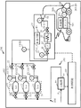
図1は、実施の形態1における水素ステーションの水素充填システムの構成を示す構成図の一例である。図1において、水素充填システム500は、水素ステーション102内に配置される。水素充填システム500は、多段蓄圧器101、ディスペンサ30、圧縮機40、及び制御回路100を備えている。多段蓄圧器101は、使用下限圧力を多段にした複数の蓄圧器10,12,14により構成される。図1の例では、3つの蓄圧器10,12,14により多段蓄圧器101が構成される。図1の例では、例えば、蓄圧器10が、使用下限圧力が低い1stバンクとして作用する。蓄圧器12が、例えば、使用下限圧力が中間の2ndバンクとして作用する。蓄圧器14が、例えば、使用下限圧力が高い3rdバンクとして作用する。但し、これに限るものではない。1stバンクから3rdバンクに使用する各蓄圧器は、必要に応じて入れ替える。水素ステーション102内には、その他、図示しないカードル、中間蓄圧器、及び/或いは水素製造装置が配置される。また、水素ステーション102内には、水素ガスを充填して配送する図示しない水素トレーラーが到来する。
FIG. 1 is an example of a configuration diagram showing a configuration of a hydrogen filling system of a hydrogen station according to the first embodiment. In FIG. 1, the
また、図1において、圧縮機40の吸込側は、上述したカードル、中間蓄圧器、水素トレーラーの充填タンク、或いは水素製造装置と配管により接続される。
Further, in FIG. 1, the suction side of the
圧縮機40の吐出側は、バルブ21を介して蓄圧器10と配管により接続される。同様に、圧縮機40の吐出側は、バルブ23を介して蓄圧器12と配管により接続される。同様に、圧縮機40の吐出側は、バルブ25を介して蓄圧器14と配管により接続される。
The discharge side of the
また、蓄圧器10は、バルブ22を介してディスペンサ30と配管により接続される。また、蓄圧器12は、バルブ24を介してディスペンサ30と配管により接続される。また、蓄圧器14は、バルブ26を介してディスペンサ30と配管により接続される。このように、ディスペンサ30が、多段蓄圧器101を構成する蓄圧器10,12,14に共通に接続される。
Further, the
図1において、ディスペンサ30内には、遮断弁36、流量計37、冷却器32(プレクーラー)、遮断弁38、緊急離脱カプラ41、及び制御回路43が配置され、ディスペンサ30には、さらにディスペンサ30外へと延びるノズル44が配置される。ディスペンサ30は、多段蓄圧器101から供給される水素燃料(水素ガス)を、遮断弁36及び流量計37を介して冷却器32に送る。その際、多段蓄圧器101から供給される水素燃料の単位時間あたりの流量は、図示しない流量調整弁により制御されると共に、流量計37により測定される。そして、冷却器32により、例えば、−40℃に冷却する。冷却された水素燃料は、遮断弁38、緊急離脱カプラ41、及びノズル44を介して、FCV車両200に搭載された燃料タンク202に差圧を利用して充填される。また、制御回路43は、水素ステーション102に到来したFCV車両200(水素燃料を動力源とする燃料電池自動車(FCV))内の車載器204と通信可能に構成される。例えば、赤外線を用いて無線通信可能に構成される。また、制御回路43は、水素充填システム500全体を制御する制御回路100に接続される。
In FIG. 1, a
また、図1における水素充填システム500では、複数の圧力計が、多段蓄圧器101からディスペンサ30の出口までの間の水素燃料の流路中に場所を異にして配置される。具体的には、蓄圧器10内の圧力(A1)は、圧力計11によって計測される。蓄圧器12内の圧力(A2)は、圧力計13によって計測される。蓄圧器14内の圧力(A3)は、圧力計15によって計測される。多段蓄圧器101とディスペンサ30とを繋ぐ配管の途中の圧力(B)は、圧力計19によって計測される。また、ディスペンサ30内では、ディスペンサ30に供給されるディスペンサ30入口付近の圧力(C1)は、圧力計27によって計測される。また、ディスペンサ30出口付近の圧力(C2)は、圧力計28によって計測される。図1の例では、圧力計27は、冷却器32の1次側に位置する遮断弁36の上流側(1次側)の圧力を測定する。圧力計28は、冷却器32の2次側であって緊急離脱カプラ41付近の圧力を測定する。各圧力計で測定される圧力データは、常時、或いは所定のサンプリング周期(例えば、10m秒〜数秒)で制御回路100に出力される。言い換えれば、制御回路100は、各圧力計で測定される圧力を常時、或いは所定のサンプリング周期(例えば、10m秒〜数秒)でモニタリングする。また、FCV車両200に搭載された燃料タンク202の圧力(D)は、FCV車両200に搭載された圧力計206によって計測される。後述するように、FCV車両200に搭載された燃料タンク202の圧力は、車載器204と制御回路43との通信が確立されている間、常時或いは所定のサンプリング間隔(例えば、10m秒〜数秒)で、モニタリングされる。
Further, in the
カードル、中間蓄圧器、或いは水素トレーラーのタンク内に蓄圧された水素燃料は、制御回路100により制御された図示しないそれぞれのレギュレータによって低圧(例えば、0.6MPa)に減圧された状態で、圧縮機40の吸込側に供給される。同様に、水素製造装置で製造された水素燃料は、低圧(例えば、0.6MPa)の状態で圧縮機40の吸込側に供給される。圧縮機40は、制御回路100による制御のもと、低圧で供給される水素燃料を圧縮しながら多段蓄圧器101の各蓄圧器10,12,14に供給する。圧縮機40は、多段蓄圧器101の各蓄圧器10,12,14内が所定の高圧(例えば、82MPa)になるまで圧縮する。言い換えれば、圧縮機40は、吐出側の2次側圧力POUTが所定の高圧(例えば、82MPa)になるまで圧縮する。圧縮機40の吸込側に水素燃料を供給する相手が、カードル、中間蓄圧器、水素トレーラー、及び水素製造装置のいずれにするかは、制御回路100が制御することによっていずれかに決定されればよい。同様に、圧縮機40が水素燃料を供給する相手が蓄圧器10,12,14のいずれにするかは、それぞれの配管上に配置された、対応するバルブ21,23,25の開閉を制御回路100が制御することによっていずれかに決定されればよい。或いは、2以上の蓄圧器に同時に供給するように制御しても良い。
The hydrogen fuel accumulated in the tank of the curdle, the intermediate accumulator, or the hydrogen trailer is compressed to a low pressure (for example, 0.6 MPa) by each regulator (not shown) controlled by the
なお、上述した例では、圧縮機40の吸込側に水素燃料を供給する圧力PINが所定の低圧(例えば、0.6MPa)に減圧制御されている場合を示したがこれに限るものではない。カードル、中間蓄圧器、或いは水素トレーラーに蓄圧された水素燃料の圧力を減圧せずに、或いは所定の低圧(例えば、0.6MPa)よりも高い圧力の状態で圧縮機40の吸込側に与えて圧縮する場合であっても構わない。
In the above-mentioned example, the pressure PIN for supplying hydrogen fuel to the suction side of the
多段蓄圧器101に蓄圧された水素燃料は、ディスペンサ30内の冷却器32によって冷却され、ディスペンサ30から水素ステーション102内に到来したFCV車両200に供給される。
The hydrogen fuel accumulated in the
図2は、実施の形態1における水素充填システム全体を制御する制御回路の内部構成の一例を示す構成図である。図2において、制御回路100内には、通信制御回路50、メモリ51、受信部52、終了圧・温度演算部54、システム制御部58、判定部59、復圧制御部61、供給制御部63、バンク圧力受信部66、ディスペンサ情報受信部67、圧力測定・抽出部68、比較部70、判定部71、比較部72、判定部73、出力部74、モニタ76、及び磁気ディスク装置等の記憶装置80,84,86が配置される。復圧制御部61は、バルブ制御部60、及び圧縮機制御部62を有する。供給制御部63は、ディスペンサ制御部64及びバルブ制御部65を有する。受信部52、終了圧・温度演算部54、システム制御部58、判定部59、復圧制御部61(バルブ制御部60、圧縮機制御部62)、供給制御部63(ディスペンサ制御部64、バルブ制御部65)、バンク圧力受信部66、ディスペンサ情報受信部67、圧力測定・抽出部68、比較部70、判定部71、比較部72、判定部73、及び出力部74、といった各「〜部」は、処理回路を含み、その処理回路には、電気回路、コンピュータ、プロセッサ、回路基板、或いは、半導体装置等が含まれる。また、各「〜部」は、共通する処理回路(同じ処理回路)を用いてもよい。或いは、異なる処理回路(別々の処理回路)を用いても良い。受信部52、終了圧・温度演算部54、システム制御部58、判定部59、復圧制御部61(バルブ制御部60、圧縮機制御部62)、供給制御部63(ディスペンサ制御部64、バルブ制御部65)、バンク圧力受信部66、ディスペンサ情報受信部67、圧力測定・抽出部68、比較部70、判定部71、比較部72、判定部73、及び出力部74内に必要な入力データ或いは演算された結果はその都度メモリ51に記憶される。
FIG. 2 is a configuration diagram showing an example of an internal configuration of a control circuit that controls the entire hydrogen filling system according to the first embodiment. In FIG. 2, the
また、記憶装置80内には、FCV車両200に搭載された燃料タンク202の圧力、温度、及び燃料タンク202の容積といったFCV情報と、FCV情報に対応する水素燃料の残量と、燃料タンク202に充填すべき最終圧、及び最終温度といった充填情報との相関関係を示す変換テーブル81が格納される。また、記憶装置80内には、変換テーブル81から得られる結果を補正する補正テーブル83が格納される。
Further, in the
ここで、上述したように、水素ステーション102に配置される多段蓄圧器101からディスペンサ30出口までの水素燃料を供給する流路の途中に配置された複数の圧力計11,13,15,19,21,23には、2年毎の校正検査が法により義務付けられている。水素ステーション102の圧力計の校正は、取り外して工場で行うことが一般的である。しかし、校正した後、次の法定検査までの2年の期間内に生じる故障については、従来、把握できていなかった。次の法定検査までの期間内に、法定検査とは別に取り外して工場で校正検査を行うとなれば、コストと時間がかかってしまう。また、検査中は、水素ステーション102の水素充填システム500の運転が止まってしまう。そのため、通常の運転動作中に低コストで精度確認ができる手法が求められている。そこで、実施の形態1では、水素充填システム500の通常の運転動作を利用して、複数の圧力計11,13,15,19,21,23の故障診断を行う。
Here, as described above, a plurality of
図3は、実施の形態1における水素充填方法の要部工程を示すフローチャート図である。図3において、実施の形態1における水素充填方法は、FCV情報受信工程(S102)と、終了圧演算工程(S104)と、流路全体瞬間開放工程(S110)と、初期圧測定工程(S114)と、データ記録工程(S116)と、充填工程(S120)と、流量判定工程(S122)と、終了圧測定(抽出)工程(S126)と、データ記録工程(S130)と、復圧工程(S131)と、終了圧故障判定工程(S132)と、初期圧故障判定工程(S140)と、いう一連の工程を実施する。終了圧故障判定工程(S132)は、内部工程として、差分演算工程(S134)と、圧力差判定工程(S136)とを実施する。初期圧故障判定工程(S140)は、内部工程として、差分演算工程(S142)と、圧力差判定工程(S144)とを実施する。かかる工程のうち、実施の形態1における水素充填システム500の圧力計11,13,15,19,21,23の故障診断方法は、初期圧測定工程(S114)と、データ記録工程(S116)と、流量判定工程(S122)と、終了圧測定(抽出)工程(S126)と、データ記録工程(S130)と、終了圧故障判定工程(S132)と、初期圧故障判定工程(S140)と、いう一連の工程を実施する。
FIG. 3 is a flowchart showing a main step of the hydrogen filling method according to the first embodiment. In FIG. 3, the hydrogen filling method according to the first embodiment is the FCV information receiving step (S102), the end pressure calculation step (S104), the entire flow path instantaneous opening step (S110), and the initial pressure measuring step (S114). , Data recording step (S116), filling step (S120), flow rate determination step (S122), end pressure measurement (extraction) step (S126), data recording step (S130), and recovery pressure step (S131). ), The end pressure failure determination step (S132), and the initial pressure failure determination step (S140). In the end pressure failure determination step (S132), a difference calculation step (S134) and a pressure difference determination step (S136) are carried out as internal steps. In the initial pressure failure determination step (S140), a difference calculation step (S142) and a pressure difference determination step (S144) are carried out as internal steps. Among such steps, the failure diagnosis methods of the pressure gauges 11, 13, 15, 19, 21, and 23 of the
FCV情報受信工程(S102)として、受信部52は、水素燃料を動力源とするFCV車両200(燃料電池自動車(FCV))に搭載された車載器204からFCV車両200に搭載された燃料タンク202(水素貯蔵容器)に関するFCV情報を受信する。具体的には以下のように動作する。FCV車両200が水素ステーション102内に到来し、ユーザ或いは水素ステーション102の作業員によってディスペンサ30のノズル44がFCV車両200の燃料タンク202の受け口(レセプタクル)に固定されると、車載器204と制御回路43(中継器)との通信が確立される。通信が確立されると、車載器204からは、燃料タンク202の現在の圧力、温度、及び燃料タンク202の容積といったFCV情報が、リアルタイムで出力(発信)される。FCV情報は、制御回路43を中継して、制御回路100に送信される。制御回路100内では、受信部52が、通信制御回路50を介してかかるFCV情報を受信する。FCV情報は、車載器204と制御回路43との通信が確立されている間、常時或いは所定のサンプリング間隔(例えば、10m秒〜数秒)で、モニタリングされる。受信されたFCV情報は、受信時刻の情報と共に、記憶装置80に記憶される。また、制御回路100は、図示しない温度計で測定された外気温度を併せて受信する。
In the FCV information receiving step (S102), the receiving
終了圧演算工程(S104)として、終了圧・温度演算部54は、記憶装置80から変換テーブル81を読み出し、受信された燃料タンク202の受信初期時の圧力、温度、燃料タンク202の容積、及び外気温度に対応する最終圧PFと最終温度を演算し、予測する。また、終了圧・温度演算部54は、記憶装置80から補正テーブル83を読み出し、変換テーブル81によって得られた数値を補正する。変換テーブル81のデータだけでは、得られた結果に誤差が大きい場合に、実験或いはシミュレーション等により得られた結果に基づいて補正テーブル83を設ければよい。演算された最終圧PFと最終温度は、システム制御部58に出力される。
As the end pressure calculation step (S104), the end pressure /
ここで、水素充填システム500では、通常の動作の1つとして、車載器204と制御回路43との通信が確立されると、FCV車両200への水素充填を開始する前に、多段蓄圧器101から充填を受けるFCV車両200までの水素燃料の流路中の水素燃料の初期圧をチェックする。そのために以下の動作を行う。
Here, in the
流路全体瞬間開放工程(S110)として、1stバンクとなる例えば蓄圧器10から充填を受けるFCV車両200までの水素燃料の流路を一時的に開放した後ディスペンサ30の遮断弁36を閉じる。言い換えれば瞬間だけ開放する。システム制御部58は、ディスペンサ制御部64、及びバルブ制御部65を制御する。ディスペンサ制御部64は、通信制御回路50を介してディスペンサ30の制御回路43と通信し、ディスペンサ30内の遮断弁36,38を開にする。また、同期して、バルブ制御部65は、通信制御回路50を介して、バルブ22を開にする。バルブ24,26は閉である。かかるバルブ制御により、1stバンクとなる例えば蓄圧器10から充填を受けるFCV車両200までの水素燃料の流路が開放される。その後、直ちにディスペンサ制御部64は、通信制御回路50を介してディスペンサ30の制御回路43と通信し、ディスペンサ30内の遮断弁36を閉じる。遮断弁38を同期させて一緒に閉じても構わない。これにより、蓄圧器10から燃料タンク202に水素燃料が一瞬だけ供給される。かかる動作中の各圧力計11,13,15,19で測定された圧力データは、バンク圧力受信部66によって受信され、記憶装置84に受信日時と関連させて記憶される。同様に、圧力計27,23で測定された圧力データは、制御回路43を介してディスペンサ情報受信部67によって受信され、記憶装置84に受信日時と関連させて記憶される。
As the entire flow path instantaneous opening step (S110), the hydrogen fuel flow path from, for example, the
初期圧測定(抽出)工程(S114)として、圧力測定・抽出部68は、1stバンク(例えば蓄圧器10)から充填を受けるFCV車両200までの水素燃料の流路を一時的に開放した後ディスペンサ30の遮断弁36を閉じたタイミングにおける、蓄圧器10からディスペンサ30の遮断弁36手前までの間の水素燃料の流路中に場所を異にして配置される複数の圧力計11(或いは13,或いは15),19,27により計測される各圧力を測定する。具体的には、圧力測定・抽出部68は、流路全体瞬間開放工程(S110)において一瞬だけ開放された直後のタイミングでの複数の圧力計11(或いは13,或いは15),19,27により計測される各圧力を記憶装置84から抽出する。
As an initial pressure measurement (extraction) step (S114), the pressure measurement /
データ記録工程(S116)として、圧力測定・抽出部68は、抽出(入力、或いは取得)された複数の圧力計11(或いは13,或いは15),19,27により計測される各圧力を日時と関連させて記録する。具体的には、圧力測定・抽出部68は、記憶装置84から抽出された、流路全体瞬間開放工程(S110)において瞬間だけ開放されたタイミングでの複数の圧力計11(或いは13,或いは15),19,27により計測される各圧力を記憶装置86に初期圧の記録データとして日時と関連させて記録する。
As a data recording step (S116), the pressure measurement /
図4は、実施の形態1における初期圧の記録データの一例を示す図である。図4では、日付を異にして測定された、各圧力が記録されている。なお、日付が「2017/10/1」の初期圧の記録データには、圧力A1,A3,C2,Dが記録されていない場合を示している。これは、初期圧測定時において、多段蓄圧器101のうちの蓄圧器12を1stバンクとして使用したことを示している。よって、その他の蓄圧器10,14の圧力A1,A3は記録から除外されている。また、遮断弁36を閉じた後の圧力を初期圧として記録しているので、遮断弁36より2次側の圧力C2,Dについても記録から除外されている。また、日付が「2017/11/1」、「2017/12/1」、及び「2018/1/1」の初期圧の記録データには、圧力A2,A3,C2,Dが記録されていない場合を示している。これは、初期圧測定時において、多段蓄圧器101のうちの蓄圧器10を1stバンクとして使用したことを示している。よって、その他の蓄圧器12,14の圧力A2,A3は記録から除外されている。遮断弁36より2次側の圧力C2,Dについても上述したように記録から除外されている。実施の形態1では、各圧力計の経時故障の有無を診断したいので、同日或いは近日中の複数の初期圧データを記録する必要はない。日時を異にして水素燃料の充填に到来した複数のFCV車両200について、各FCV車両200に水素燃料を充填する毎に、水素燃料の充填を開始する前に初期圧を測定し記録データを蓄積すればよい。例えば、1週間毎、1月毎、或いは数か月毎に初期圧の記録データを蓄積すればよい。もちろん、データ量が大きくなってしまうが、同日或いは近日中の複数のデータを記録しても構わない。
FIG. 4 is a diagram showing an example of recorded data of the initial pressure in the first embodiment. In FIG. 4, each pressure measured on different dates is recorded. The recorded data of the initial pressure whose date is "2017/10/1" shows the case where the pressures A1, A3, C2 and D are not recorded. This indicates that the
一方、システム制御部58は、通常動作の1つとして、同日中でもFCV車両200が到来するたびに、同タイミングでの複数の圧力計11,13,15,19,27により計測される各圧力を記憶装置84から読み出し、充填に来たFCV車両200に水素充填を行うにあたって支障のない範囲内に入っているかどうかを判断する。各圧力が支障のない範囲内に入っていれば充填動作を進めることになる。このように、故障診断に用いるための初期圧の記録データは、通常動作を利用して取得できる。
On the other hand, as one of the normal operations, the
充填工程(S120)として、水素燃料が蓄圧された多段蓄圧器101からディスペンサ30を介してFCV車両200に水素燃料を充填する。
As a filling step (S120), the
図5は、実施の形態1における多段蓄圧器を用いて水素燃料の差圧充填を行う場合の充填の仕方を説明するための図である。図5において縦軸は圧力を示し、横軸は時間を示す。FCV車両200に水素燃料の差圧充填を行う場合、通常、予め、多段蓄圧器101の各蓄圧器10,12,14は、同じ圧力P0(例えば、82MPa)に蓄圧されている。一方、水素ステーション102に到来したFCV車両200の燃料タンク202は圧力Paになっている。かかる状態からFCV車両200の燃料タンク202に充填を開始する場合について説明する。
FIG. 5 is a diagram for explaining a filling method when differential pressure filling of hydrogen fuel is performed using the multi-stage accumulator according to the first embodiment. In FIG. 5, the vertical axis represents pressure and the horizontal axis represents time. When the
まず、1stバンクとなる例えば蓄圧器10から燃料タンク202に充填を開始する。具体的には、以下のように動作する。供給制御部63は、システム制御部58による制御のもと、供給部106を制御して、FCV車両200の燃料タンク202に蓄圧器10から水素燃料を供給させる。具体的には、システム制御部58は、ディスペンサ制御部64、及びバルブ制御部65を制御する。ディスペンサ制御部64は、通信制御回路50を介してディスペンサ30の制御回路43と通信し、ディスペンサ30の動作を制御する。具体的にはバルブ制御部90は、ディスペンサ30内の遮断弁36,38を開にする。そして、バルブ制御部65は、通信制御回路50を介して、バルブ22,24,26に制御信号を出力し、各バルブの開閉を制御する。具体的には、バルブ22を開にして、バルブ24,26を閉に維持する。これにより、蓄圧器10から燃料タンク202に水素燃料が供給される。蓄圧器10と燃料タンク202との差圧によって蓄圧器10内に蓄圧された水素燃料は燃料タンク202側へと所望の単位時間あたりの流量(充填速度)で移動し、燃料タンク202の圧力は点線Ptに示すように徐々に上昇していく。それに伴い、蓄圧器10の圧力(「1st」で示すグラフ)は徐々に減少する。そして、1stバンクの使用下限圧力を割った、充填開始から時間T1が経過した時点で、蓄圧器10から2ndバンクとなる例えば蓄圧器12に使用する蓄圧器が切り替えられる。具体的には、バルブ制御部65は、通信制御回路50を介して、バルブ22,24,26に制御信号を出力し、各バルブの開閉を制御する。具体的には、バルブ24を開にして、バルブ22を閉し、バルブ26を閉に維持する。これにより、蓄圧器12と燃料タンク202との差圧が大きくなるため、充填速度が速い状態を維持できる。
First, filling of the
そして、2ndバンクとなる例えば蓄圧器12と燃料タンク202との差圧によって蓄圧器12内に蓄圧された水素燃料は燃料タンク202側へと所望の単位時間あたりの流量(充填速度)で移動し、燃料タンク202の圧力は点線Ptに示すように徐々にさらに上昇していく。それに伴い、蓄圧器12の圧力(「2nd」で示すグラフ)は徐々に減少する。そして、2ndバンクの使用下限圧力を割った、充填開始から時間T2が経過した時点で、蓄圧器12から3rdバンクとなる例えば蓄圧器14に使用する蓄圧器が切り替えられる。具体的には、バルブ制御部65は、通信制御回路50を介して、バルブ22,24,26に制御信号を出力し、各バルブの開閉を制御する。具体的には、バルブ26を開にして、バルブ24を閉し、バルブ22を閉に維持する。これにより、蓄圧器14と燃料タンク202との差圧が大きくなるため、充填速度が速い状態を維持できる。
Then, the hydrogen fuel accumulated in the
そして、3rdバンクとなる例えば蓄圧器14と燃料タンク202との差圧によって蓄圧器14内に蓄圧された水素燃料は燃料タンク202側へと所望の単位時間あたりの流量(充填速度)で移動し、燃料タンク202の圧力は点線Ptに示すように徐々にさらに上昇していく。それに伴い、蓄圧器14の圧力(「3rd」で示すグラフ)は徐々に減少する。そして、3rdバンクとなる蓄圧器14によって燃料タンク202の圧力が演算された最終圧PF(例えば65〜81MPa)になるまで充填する。
Then, the hydrogen fuel accumulated in the
ここで、水素ステーション102に到来するFCV車両200は、燃料タンク202の圧力が十分に低い場合に限るものではない。燃料タンク202の圧力が満タン時の例えば1/2より高い場合、例えば2本の蓄圧器10,12で足りる場合もあり得る。さらに、燃料タンク202の圧力が高い場合、例えば1本の蓄圧器10で足りる場合もあり得る。燃料タンク202の圧力は、FCV情報の一部として、車載器204と制御回路43との通信が確立されている間、常時或いは所定のサンプリング間隔で、モニタリングされる。そして、システム制御部58は、FCV情報に定義される燃料タンク202の現在の圧力が、最終圧PFに到達した時点で充填を終了する。具体的には、システム制御部58の制御のもと、ディスペンサ制御部64が制御回路43を介して遮断弁36,38を閉じる。
Here, the
かかる水素充填を行っている間、ディスペンサ30内の流量計37で測定される水素燃料の流量データ(単位時間あたりの流量のデータ:充填速度)は、常時、或いは所定のサンプリング周期(例えば、10m秒〜数秒)で制御回路100に出力される。制御回路100内では、ディスペンサ情報受信部67が通信制御回路50を介して流量データを受信し、受信日時と関連させて記憶装置84に記憶する。
During the hydrogen filling, the flow rate data of the hydrogen fuel (flow rate data per unit time: filling rate) measured by the
流量判定工程(S122)として、判定部59は、充填終了に近い段階での充填される水素燃料の流量Fが閾値F’以下になったかどうかを判定する。具体的には以下のように動作する。燃料タンク202の現在の圧力が、最終圧PFに近づくのに伴って、差圧が小さくなるので流れる水素燃料の流量は徐々に低下していく。最終段階では、3rdバンクとなる例えば蓄圧器14と燃料タンク202との差圧が小さいので、流量がゼロに近い状態で燃料タンク202の圧力が最終圧PFに到達するまで充填し続けることになる。そこで、判定部59は、記憶装置84から流量データを読み出し、遮断弁36,38を閉じる前の段階において、流量Fが閾値F’以下、例えば100g/min以下、好ましくは50mg/min以下になったかどうかを判定する。流量Fが閾値F’以下、例えば100g/min以下、好ましくは50mg/min以下になったら実質的に流量Fがゼロと同視でき、蓄圧器14と燃料タンク202との差圧が実質的に無くなったことを意味する。よって、このタイミングでの圧力A3(或いはA1,或いはA2)、B,C1,C2,Dは、ほぼ同じ値になるはずである。
In the flow rate determination step (S122), the
終了圧測定(抽出)工程(S126)として、圧力測定・抽出部68は、充填終了に近い段階での充填される水素燃料の流量Fが閾値F’以下になったタイミングにおける、蓄圧器14からディスペンサ30の出口までの間の水素燃料の流路中に場所を異にして配置される複数の圧力計15(或いは11、或いは13),19,21,23から計測される各圧力を測定する。具体的には、圧力測定・抽出部68は、流量判定工程(S122)において流量Fが閾値F’以下になったタイミングでの複数の圧力計15(或いは11、或いは13),19,27,28により計測される各圧力を記憶装置84から抽出する。また、圧力測定・抽出部68は、同じタイミングにおけるFCV車両200の燃料タンク202の圧力Dを記憶装置80から抽出する。
In the final pressure measurement (extraction) step (S126), the pressure measurement /
データ記録工程(S130)として、圧力測定・抽出部68は、抽出(入力、或いは取得)された複数の圧力計15(或いは11、或いは13),19,27,28,206により計測される各圧力を日時と関連させて記録する。具体的には、圧力測定・抽出部68は、記憶装置84から抽出された、流量判定工程(S122)において流量Fが閾値F’以下になったタイミングでの複数の圧力計11(或いは13,或いは15),19,27により計測される各圧力A3(或いはA1,或いはA2)、B,C1,C2を記憶装置86に終了圧の記録データとして日時と関連させて記録する。また、圧力測定・抽出部68は、流量判定工程(S122)において流量Fが閾値F’以下になったタイミングでのFCV車両200の燃料タンク202の圧力Dを記憶装置86に終了圧の記録データとして日時と関連させて記録する。
As a data recording step (S130), the pressure measurement /
図6は、実施の形態1における終了圧の記録データの一例を示す図である。図6では、ある日付に測定された、各圧力が記録されている。図6の例では、日付が「2018/1/20」に測定された、各圧力が記録されている。図6の例では、圧力A1,A2が記録されていない場合を示している。これは、終了圧測定時において、多段蓄圧器101のうちの蓄圧器14を3rdバンクとして使用したことを示している。よって、その他の蓄圧器10,12の圧力A1,A2は記録から除外されている。実施の形態1では、各圧力計の経時故障の有無を診断したいので、同日或いは近日中の複数の終了圧データを記録する必要はない。日時を異にして水素燃料の充填に到来した複数のFCV車両200について、終了圧を測定し記録データを蓄積すればよい。例えば、1週間毎、1月毎、或いは数か月毎に初期圧の記録データを蓄積すればよい。もちろん、データ量が大きくなってしまうが、同日或いは近日中の複数のデータを記録しても構わない。
FIG. 6 is a diagram showing an example of recorded data of the end pressure in the first embodiment. In FIG. 6, each pressure measured on a certain date is recorded. In the example of FIG. 6, each pressure measured on a date of "2018/1/20" is recorded. In the example of FIG. 6, the case where the pressures A1 and A2 are not recorded is shown. This indicates that the
以上により、FCV車両200の燃料タンク202への水素燃料の充填(供給)は終了し、ディスペンサ30のノズル44をFCV車両200の燃料タンク202の受け口(レセプタクル)から外し、ユーザは、例えば充填量に応じた料金を支払って、水素ステーション102から退場することになる。
As described above, the filling (supply) of hydrogen fuel into the
一方、かかる充填によって、各蓄圧器10,12,14内の水素燃料は減少し、圧力が低下している。
On the other hand, due to such filling, the hydrogen fuel in each
復圧工程(S131)として、復圧機構104は、各蓄圧器10,12,14を復圧する。圧縮機40、及びバルブ21,23,25等が復圧機構104を構成する。まず、システム制御部58は、図示しないカードル、中間蓄圧器、水素トレーラー、或いは水素製造装置の中から圧縮機40の吸込側につなぐ水素燃料の供給元を選択する。そして、復圧制御部61は、システム制御部58による制御のもと、復圧機構104を制御して、各蓄圧器10,12,14を復圧させる。具体的には、以下のように動作する。FCV車両200の燃料タンク202への充填に使用する各バンクの蓄圧器は、充填中に復圧も行われていても良い。しかしながら、規定の圧力まで復圧する時間が足りないため、充填後も復圧を行わなくてはならない。1stバンク、2ndバンク、3rdバンクの順で切り替わるので、まず、1stバンクとなる蓄圧器10を復圧する。バルブ制御部60は、バルブ21,23,25が閉じた状態から、バルブ21を開にする。
As the pressure recovery step (S131), the
そして、圧縮機制御部62は、圧縮機40を駆動して、水素燃料の供給元からの低圧(例えば0.6MPa)の水素燃料を圧縮しながら送り出し、蓄圧器10の圧力が所定の圧力P0(例えば、82MPa)になるまで蓄圧器10に水素燃料を充填することで蓄圧器10を復圧する。
Then, the compressor control unit 62 drives the
次に、バルブ制御部60は、バルブ21を閉じて、代わりにバルブ23を開にする。
Next, the valve control unit 60 closes the
そして、圧縮機制御部62は、圧縮機40を駆動して、低圧(例えば0.6MPa)の水素燃料を圧縮しながら送り出し、蓄圧器12の圧力が所定の圧力P0(例えば、82MPa)になるまで蓄圧器12に水素燃料を充填することで蓄圧器12を復圧する。
Then, the compressor control unit 62 drives the
次に、バルブ制御部60は、バルブ23を閉じて、代わりにバルブ25を開にする。
Next, the valve control unit 60 closes the
そして、圧縮機制御部62は、圧縮機40を駆動して、低圧(例えば0.6MPa)の水素燃料を圧縮しながら送り出し、蓄圧器14の圧力が所定の圧力P0(例えば、82MPa)になるまで蓄圧器14に水素燃料を充填することで蓄圧器14を復圧する。
Then, the compressor control unit 62 drives the
以上により、次のFCV車両200が水素ステーション102に到来しても、同様に、水素燃料の供給が可能となる。そして、複数のFCV車両200に日付を異にして順に水素燃料を充填することで、複数の日付での初期圧の記録データが蓄積される。同様に、複数の日付での終了圧の記録データが蓄積される。
As described above, even if the
終了圧故障判定工程(S132)として、制御回路100は、充填終了に近い段階での充填される水素燃料の流量Fが閾値F’以下になったタイミングにおける、蓄圧器14からディスペンサ30の出口までの間の水素燃料の流路中に場所を異にして配置される複数の圧力計から計測される各圧力を入力(取得)し、取得した圧力値を基に各圧力間のずれが閾値内かどうかを判定し、判定結果を出力する。具体的には、以下のように動作する。
In the end pressure failure determination step (S132), the
差分演算工程(S134)として、比較部70は、記憶装置86から終了圧の記録データを読み出し、記録される各圧力A1〜C2間のずれを演算する。水素燃料が充填されるFCV車両ごとに最終圧PFが異なるので、基準圧力を一意に設定することが困難である。そこで、例えば、記録される各圧力A1〜C2のうち1つを基準圧力として、記録される各圧力A1〜C2と基準圧力との差分を演算する。或いは、FCV車両200の燃料タンク202の圧力Dを基準圧力として、記録される各圧力A1〜C2と基準圧力との差分を演算する。
As the difference calculation step (S134), the
圧力差判定工程(S136)として、判定部71は、記録される各圧力A1〜C2について、それぞれ演算された基準圧力との差分が許容値Pth1以内かどうかを判定する。複数の圧力計が同時に故障することは通常発生しない。よって、差分が許容値Pth1以内であれば当該圧力計は正常であると判断する。逆に差分が許容値Pth1以内から外れた場合に当該圧力計は故障と判断する。もしも、2以上の圧力計が同時に故障と判定された場合には、基準圧力とする圧力計を他の圧力計に変更して、同様の処理を行えばよい。図6の例では、圧力C1だけ、他の圧力と比べて大きく低下している。よって、圧力C1については基準圧力との差分が大きくなる。そのため、かかる圧力C1を計測した圧力計27が故障していると判断できる。判定結果は、測定日と合わせて、例えば、モニタ76に出力され、モニタ76に表示される。或いは/及び、出力部74から通信制御回路50を介して外部に出力される。
In the pressure difference determination step (S136), the
以上により、水素充填の通常動作を利用して得られる終了圧を使って、蓄圧器14からディスペンサ30内までの流路中に配置される複数の圧力計の故障診断ができる。言い換えれば、複数の圧力計の精度確認ができる。よって、次の法定検査までの2年の期間内に生じる故障の診断ができる。また、終了圧の記録データが日付を異にして蓄積されれば、各圧力計の測定精度の推移がわかる。よって、2年の期間中のいつ故障するのかその指標を得ることができる。また、故障の程度が法定検査の要求精度を満たさなくなった場合に、次の法定検査を待たずして圧力計の交換/修理等を行うことができる。
As described above, it is possible to diagnose the failure of a plurality of pressure gauges arranged in the flow path from the
初期圧故障判定工程(S140)として、制御回路100は、蓄圧器10(或いは12、或いは14)からディスペンサ30の遮断弁36手前までの間の水素燃料の流路中に場所を異にして配置される複数の圧力計11(或いは13、或いは15)、19,27により計測される各圧力に対して、圧力計毎に、異なる日付に記録された各圧力の推移における圧力変化が閾値内かどうかを判定し、判定結果を出力する。具体的には、以下のように動作する。なお、初期圧故障判定工程(S140)は、日付を異にした複数のFCV車両200が水素充填に到来した場合に得られた、日付を異にした複数の初期圧の記録データが蓄積されている場合に実施される。
As the initial pressure failure determination step (S140), the
差分演算工程(S142)として、比較部72は、記憶装置86から初期圧の記録データを読み出し、記録される各圧力A1〜C1について、同じ圧力計での測定値間のずれを演算する。例えば、記録される複数の日付のうち1つの記録データにおける各圧力A1〜C1を基準圧力として、記録される各圧力A1〜C1について、同じ圧力計での測定値とそれぞれ対応する基準圧力との差分を演算する。
As the difference calculation step (S142), the
圧力差判定工程(S144)として、判定部73は、記録される各圧力A1〜C1について、それぞれ演算された基準圧力との差分が許容値Pth2以内かどうかを判定する。差分が許容値Pth2以内であれば当該圧力計は正常であると判断する。逆に差分が許容値Pth2以内から外れた場合に当該圧力計は故障と判断する。図4の例では、「2018/1/1」に測定された圧力Bが、他の日付に測定された圧力Bに比べて大きく低下している。よって、圧力Bについては基準圧力との差分が大きくなる。そのため、「2018/1/1」時点で、かかる圧力Bを計測した圧力計19が故障していると判断できる。判定結果は、測定日と合わせて、例えば、モニタ76に出力され、モニタ76に表示される。或いは/及び、出力部74から通信制御回路50を介して外部に出力される。
In the pressure difference determination step (S144), the
以上により、水素充填の通常動作を利用して得られる初期圧を使って、蓄圧器10からディスペンサ30内までの流路中に配置される複数の圧力計の故障診断ができる。言い換えれば、複数の圧力計の精度確認ができる。よって、次の法定検査までの2年の期間内に生じる故障の診断ができる。また、初期圧の記録データが日付を異にして蓄積されているので、各圧力計の測定精度の推移がわかる。よって、2年の期間中のいつ故障するのかその指標を得ることができる。また、故障の程度が法定検査の要求精度を満たさなくなった場合に、次の法定検査を待たずして圧力計の交換/修理等を行うことができる。
As described above, it is possible to diagnose the failure of a plurality of pressure gauges arranged in the flow path from the
ここで、上述した例では、終了圧による故障診断と初期圧による故障診断との両方を実施する場合について説明したがこれに限るものではない。終了圧による故障診断と初期圧による故障診断との一方だけを行う場合であっても構わない。 Here, in the above-mentioned example, the case where both the failure diagnosis based on the end pressure and the failure diagnosis based on the initial pressure are performed has been described, but the present invention is not limited to this. It is also possible to perform only one of the failure diagnosis based on the end pressure and the failure diagnosis based on the initial pressure.
また、終了圧による故障診断では、最終バンクとなる蓄圧器のデータが記録されるので、多段蓄圧器101のうち、最終バンクとなる蓄圧器を入れ替えて動作させることで、各蓄圧器の圧力計の故障診断を可能にできる。逆に、初期圧による故障診断では、1stバンクとなる蓄圧器のデータが記録されるので、多段蓄圧器101のうち、1stバンクとなる蓄圧器を入れ替えて動作させることで、各蓄圧器の圧力計の故障診断を可能にできる。
Further, in the failure diagnosis based on the end pressure, the data of the accumulator which is the final bank is recorded. Therefore, the pressure gauge of each accumulator can be operated by exchanging the accumulator which is the final bank among the
以上のように、実施の形態1によれば、通常の運転動作を利用して、低コストで、少なくとも蓄圧器からディスペンサ内までの流路中に配置される複数の圧力計の精度確認ができる。よって、次の法定検査までの2年の期間内に生じる故障の診断ができる。 As described above, according to the first embodiment, it is possible to confirm the accuracy of at least a plurality of pressure gauges arranged in the flow path from the accumulator to the inside of the dispenser at low cost by using the normal operation operation. .. Therefore, it is possible to diagnose a failure that occurs within a period of two years until the next legal inspection.
実施の形態2.
実施の形態1では、終了圧の判定時期を流量Fがほぼゼロと同視できる閾値F’以下になったタイミングとした場合について説明したが、判定手法はこれに限るものではない。実施の形態2では、終了圧の判定時期を別の判定手法で行う構成について説明する。実施の形態2における水素ステーションの水素充填システムの構成は図1と同様である。
In the first embodiment, the case where the determination timing of the end pressure is set to the timing when the flow rate F becomes equal to or less than the threshold value F'that can be regarded as almost zero has been described, but the determination method is not limited to this. In the second embodiment, a configuration in which the determination timing of the end pressure is determined by another determination method will be described. The configuration of the hydrogen filling system of the hydrogen station in the second embodiment is the same as that in FIG.
図7は、実施の形態2における水素充填方法の要部工程を示すフローチャート図である。図7において、流量判定工程(S122)の代わりに、ピーク判定工程(S124)を実施する点以外は、図3と同様である。以下、特に説明する点以外の内容は、実施の形態1と同様である。 FIG. 7 is a flowchart showing a main step of the hydrogen filling method according to the second embodiment. FIG. 7 is the same as FIG. 3 except that the peak determination step (S124) is performed instead of the flow rate determination step (S122). Hereinafter, the contents other than the points particularly described will be the same as those in the first embodiment.
FCV情報受信工程(S102)から充填工程(S120)までの各工程の内容は実施の形態1と同様である。 The contents of each step from the FCV information receiving step (S102) to the filling step (S120) are the same as those in the first embodiment.
ピーク判定工程(S124)として、判定部59は、ディスペンサ30の出口に最も近い圧力計28の圧力C2が水素燃料の充填中に最高値を示したかどうかを判定する。具体的には以下のように動作する。燃料タンク202の現在の圧力が、最終圧PFに近づくのに伴って、水素ステーション102側で燃料タンク202に最も近い圧力計となるディスペンサ30の出口に最も近い圧力計28が示す圧力C2も高くなっていく。そして、最終段階では、3rdバンクとなる例えば蓄圧器14が燃料タンク202の圧力が最終圧PFに到達するまで充填し続けることになる。よって、燃料タンク202の圧力が最終圧PFに到達した時点で、ディスペンサ30の出口に最も近い圧力計28が示す圧力C2も最高値(ピーク)に達することになる。かかる時点は、実施の形態1における流量Fがほぼゼロの状態と結果的に同じ状態と言える。そこで、判定部59は、記憶装置84から圧力計28の圧力データを読み出し、遮断弁36,38を閉じる前の段階において、圧力計28の圧力C2が最高値に達したかどうかを判定する。最高値に達したかは、FCV情報における現在の燃料タンク202が最終圧PFに到達間近の段階以降で圧力C2が最高値のまま収束した場合で判断すればよい。かかる時点で蓄圧器14と燃料タンク202との差圧が実質的に無くなったことを意味する。よって、このタイミングでの圧力A3(或いはA1,或いはA2)、B,C1,C2,Dは、ほぼ同じ値になるはずである。
As a peak determination step (S124), the
そして、終了圧測定(抽出)工程(S126)として、圧力測定・抽出部68は、ディスペンサ30の出口に最も近い圧力計28の圧力C2が水素燃料の充填中に最高値を示したタイミングにおける、蓄圧器14からディスペンサ30の出口までの間の水素燃料の流路中に場所を異にして配置される複数の圧力計15(或いは11、或いは13),19,21,23から計測される各圧力を測定する。具体的には、圧力測定・抽出部68は、ディスペンサ30の出口に最も近い圧力計28の圧力C2が水素燃料の充填中に最高値を示したタイミングでの複数の圧力計15(或いは11、或いは13),19,21,23により計測される各圧力を記憶装置84から抽出する。また、圧力測定・抽出部68は、同じタイミングにおけるFCV車両200の燃料タンク202の圧力Dを記憶装置80から抽出する。
Then, as the final pressure measurement (extraction) step (S126), the pressure measurement /
そして、データ記録工程(S130)として、圧力測定・抽出部68は、抽出(入力)された複数の圧力計15(或いは11、或いは13),19,21,23,206により計測される各圧力を日時と関連させて記録する。具体的には、圧力測定・抽出部68は、記憶装置84から抽出された、ピーク判定工程(S124)においてディスペンサ30の出口に最も近い圧力計28の圧力C2が水素燃料の充填中に最高値を示したタイミングでの複数の圧力計11(或いは13,或いは15),19,21により計測される各圧力A3(或いはA1,或いはA2)、B,C1,C2を記憶装置86に終了圧の記録データとして日時と関連させて記録する。また、圧力測定・抽出部68は、ピーク判定工程(S124)においてディスペンサ30の出口に最も近い圧力計28の圧力C2が水素燃料の充填中に最高値を示したタイミングでのFCV車両200の燃料タンク202の圧力Dを記憶装置86に終了圧の記録データとして日時と関連させて記録する。かかる手法によっても、図6と同様の終了圧の記録データが得られることになる。
Then, as a data recording step (S130), the pressure measurement /
復圧工程(S131)と、終了圧故障判定工程(S132)と、初期圧故障判定工程(S140)との各工程の内容は実施の形態1と同様である。言い換えれば、終了圧故障判定工程(S132)において、制御回路100は、ディスペンサ30の出口に最も近い圧力計28が水素燃料の充填中に最高値を示したタイミングにおける、複数の圧力計から計測される各圧力を入力(取得)し、取得した圧力値を基に各圧力間のずれが閾値内かどうかを判定し、判定結果を出力する。
The contents of each step of the pressure recovery step (S131), the end pressure failure determination step (S132), and the initial pressure failure determination step (S140) are the same as those in the first embodiment. In other words, in the end pressure failure determination step (S132), the
以上により、水素充填の通常動作を利用して得られる終了圧を使って、蓄圧器14からディスペンサ30内までの流路中に配置される複数の圧力計の故障診断ができる。言い換えれば、複数の圧力計の精度確認ができる。よって、次の法定検査までの2年の期間内に生じる故障の診断ができる。また、終了圧の記録データが日付を異にして蓄積されれば、各圧力計の測定精度の推移がわかる。よって、2年の期間中のいつ故障するのかその指標を得ることができる。また、故障の程度が法定検査の要求精度を満たさなくなった場合に、次の法定検査を待たずして圧力計の交換/修理等を行うことができる。
As described above, it is possible to diagnose the failure of a plurality of pressure gauges arranged in the flow path from the
また、実施の形態1と同様、水素充填の通常動作を利用して得られる初期圧を使って、蓄圧器10からディスペンサ30内までの流路中に配置される複数の圧力計の故障診断ができる。言い換えれば、複数の圧力計の精度確認ができる。よって、次の法定検査までの2年の期間内に生じる故障の診断ができる。また、初期圧の記録データが日付を異にして蓄積されているので、各圧力計の測定精度の推移がわかる。よって、2年の期間中のいつ故障するのかその指標を得ることができる。また、故障の程度が法定検査の要求精度を満たさなくなった場合に、次の法定検査を待たずして圧力計の交換/修理等を行うことができる。
Further, as in the first embodiment, the failure diagnosis of a plurality of pressure gauges arranged in the flow path from the
ここで、上述した例では、終了圧による故障診断と初期圧による故障診断との両方を実施する場合について説明したがこれに限るものではない。実施の形態1と同様、終了圧による故障診断と初期圧による故障診断との一方だけを行う場合であっても構わない。 Here, in the above-mentioned example, the case where both the failure diagnosis based on the end pressure and the failure diagnosis based on the initial pressure are performed has been described, but the present invention is not limited to this. Similar to the first embodiment, there may be a case where only one of the failure diagnosis based on the end pressure and the failure diagnosis based on the initial pressure is performed.
また、終了圧による故障診断では、最終バンクとなる蓄圧器のデータが記録されるので、実施の形態1と同様、多段蓄圧器101のうち、最終バンクとなる蓄圧器を入れ替えて動作させることで、各蓄圧器の圧力計の故障診断を可能にできる。逆に、初期圧による故障診断では、1stバンクとなる蓄圧器のデータが記録されるので、実施の形態1と同様、多段蓄圧器101のうち、1stバンクとなる蓄圧器を入れ替えて動作させることで、各蓄圧器の圧力計の故障診断を可能にできる。
Further, in the failure diagnosis based on the end pressure, the data of the accumulator that is the final bank is recorded. Therefore, as in the first embodiment, the accumulator that is the final bank of the
以上のように、実施の形態2によれば、実施の形態1と異なる判定手法を用いた場合でも、通常の運転動作を利用して、低コストで、少なくとも蓄圧器からディスペンサ内までの流路中に配置される複数の圧力計の精度確認ができる。よって、次の法定検査までの2年の期間内に生じる故障の診断ができる。 As described above, according to the second embodiment, even when a determination method different from that of the first embodiment is used, the flow path from the accumulator to the inside of the dispenser at least at low cost by utilizing the normal operation operation. You can check the accuracy of multiple pressure gauges placed inside. Therefore, it is possible to diagnose a failure that occurs within a period of two years until the next legal inspection.
実施の形態3.
図8は、実施の形態3における水素ステーションの水素充填システムの構成を示す構成図の一例である。図8において、ディスペンサ30内におけるディスペンサ30出口付近の圧力(C2)を測定する圧力計28と並列に圧力計29を配置した点、遮断弁38から緊急離脱カプラ41に繋がる配管を分岐させた脱圧ラインを配置した点、及び脱圧ラインにバルブ39を配置した点、以外は、図1と同様である。
Embodiment 3.
FIG. 8 is an example of a configuration diagram showing a configuration of a hydrogen filling system for a hydrogen station according to a third embodiment. In FIG. 8, the
実施の形態3では、水素燃料が蓄圧された多段蓄圧器101からディスペンサ30を介してFCV車両200に水素燃料を充填する充填工程(S120)が終了後に、遮断弁38を閉にして遮断し、バルブ39を開にして大気開放した場合に、大気開放したタイミングにおける圧力C2を計測する圧力計28(及び圧力計29)(脱圧部の圧力計)が0MPa(ゲージ圧)を示すかどうかを判定する。圧力計28(及び圧力計29)が0MPa(ゲージ圧)を示す場合であれば当該圧力計は正常と判断する。逆に、圧力計28(及び圧力計29)が0MPa(ゲージ圧)を示さない場合であれば当該圧力計は異常と判断し自動校正等を行う。校正量は、例えば、モニタ76に出力され、モニタ76に表示される。或いは/及び、出力部74から通信制御回路50を介して外部に出力される。かかる場合に、制御回路100内において、図示しない自動校正部により、異常と判断された圧力計(例えば圧力計28)が示す圧力値を0MPa(ゲージ圧)に補正(校正)して記録することにより、異常と判断された圧力計(例えば圧力計28)の自動校正ができる。
In the third embodiment, after the filling step (S120) of filling the
また、実施の形態3では、ディスペンサ30出口付近の圧力(C2)を2つの圧力計28,29により測定しているので、両者の圧力の差分が許容値Pth3以内であれば当該圧力計は正常であると判断する。逆に差分が許容値Pth3以内から外れた場合に、当該圧力計28,29の一方は故障と判断する。その場合に、上述した各実施の形態における終了圧測定のタイミングにおけるFCV車両200の燃料タンク202の圧力Dと比較して、2つの圧力計28,29が示す圧力のうち、燃料タンク202の圧力Dとの圧力差が大きい方の圧力計が故障していると判断できる。かかる場合には、制御回路100内において、図示しない自動校正部により、故障していると判断された圧力計(例えば圧力計28)が示す圧力値を正常な圧力計(例えば圧力計29)が示す圧力値に補正(校正)して記録することにより、故障している圧力計(例えば圧力計28)の自動校正ができる。
Further, in the third embodiment, since the pressure (C2) near the outlet of the
また、実施の形態3における水素充填システムの圧力計の校正方法は、上述した各実施の形態における水素充填システムの圧力計の故障診断方法の各工程を備え、複数の圧力計は、ディスペンサ30の出口付近に並列配置された2つの圧力計を含み、判定の結果、前記複数の圧力計のうち故障と診断される圧力計に対して、前記2つの圧力計のうち一方を基準にして自動校正する工程をさらに備えても好適である。具体的には、以下のように動作する。2つの圧力計28,29が同時に故障することは通常考えにくいので、上述した各実施の形態における故障診断を行い、多段蓄圧器101からディスペンサ30の出口までの間の水素燃料の流路中に場所を異にして配置される複数の圧力計のうち、故障と判断された圧力計について、図示しない自動校正部により、2つの圧力計28,29のうち一方を基準にして、計測される圧力値を補正(校正)して記録することにより、故障している圧力計の自動校正を行う。2つの圧力計28,29の1つが故障と判断されている場合には、正常と判断される他方を基準にすることは言うまでもない。
Further, the calibration method of the pressure gauge of the hydrogen filling system according to the third embodiment includes each step of the failure diagnosis method of the pressure gauge of the hydrogen filling system according to each of the above-described embodiments, and the plurality of pressure gauges are the
なお、自動校正するかどうかは、異なる複数のFCV車両200における燃料タンク202の圧力Dと比較することにより、すべてのFCV車両200における燃料タンク202の圧力Dとの圧力差が閾値より大きい場合に自動校正するようにしても好適である。すべてのFCV車両200の燃料タンク202の圧力計が故障することは通常あり得ないので、ランダムに到来する複数のFCV車両200と比較することで、故障の有無の判定精度を向上できる。
Whether or not to automatically calibrate is determined when the pressure difference between the pressure D of the
以上、具体例を参照しつつ実施の形態について説明した。しかし、本発明は、これらの具体例に限定されるものではない。例えば、上述した例では、FCV車両1台分の水素燃料の充填に、3つの蓄圧器10,12,14による多段蓄圧器101を用いた場合を示したが、これに限るものではない。蓄圧器10,12,14の容積等に応じて、1台分の充填にさらに多くの蓄圧器を用いる場合もあり得る。或いは、逆に1台分の充填に2つの蓄圧器で賄える場合もあり得る。
The embodiment has been described above with reference to a specific example. However, the present invention is not limited to these specific examples. For example, in the above-mentioned example, a case where a
また、装置構成や制御手法等、本発明の説明に直接必要しない部分等については記載を省略したが、必要とされる装置構成や制御手法を適宜選択して用いることができる。 In addition, although the description of parts that are not directly necessary for the description of the present invention, such as the device configuration and control method, is omitted, the required device configuration and control method can be appropriately selected and used.
その他、本発明の要素を具備し、当業者が適宜設計変更しうる全ての水素充填システムの圧力計の故障診断方法は、本発明の範囲に包含される。 In addition, a method for diagnosing a failure of a pressure gauge of all hydrogen filling systems having elements of the present invention and which can be appropriately redesigned by those skilled in the art are included in the scope of the present invention.
10,12,14 蓄圧器
11,13,15,19,27,28,29 圧力計
21,23,24,25,26,39 バルブ
30 ディスペンサ
32 冷却器
36 遮断弁
37 流量計
38 遮断弁
40 圧縮機
41 緊急離脱カプラ
43 制御回路
50 通信制御回路
51 メモリ
52 受信部
54 終了圧・温度演算部
58 システム制御部
59 判定部
60,65 バルブ制御部
62 圧縮機制御部
64 ディスペンサ制御部
66 バンク圧力受信部
67 ディスペンサ情報受信部
68 圧力測定・抽出部
70 比較部
71 判定部
72 比較部
73 判定部
74 出力部
76 モニタ
80,84,86 記憶装置
100 制御回路
101 多段蓄圧器
102 水素ステーション
104 復圧機構
106 供給部
200 FCV車両
202 燃料タンク
204 車載器
500 水素充填システム
10,12,14
Claims (6)
前記充填終了に近い段階での充填される水素燃料の流量が閾値以下になったタイミングにおける、前記蓄圧器から前記ディスペンサの出口までの間の前記水素燃料の流路中に場所を異にして配置される複数の圧力計から計測される各圧力を取得し、取得した圧力値を基に各圧力間のずれが閾値内かどうかを判定し、判定結果を出力し、
前記水素燃料の充填は、複数の燃料電池自動車に日付を異にして行われ、
前記複数の燃料電池自動車の各燃料電池自動車に水素燃料を充填する毎に、前記水素燃料の充填を開始する前に前記蓄圧器から充填を受ける燃料電池自動車までの前記水素燃料の流路を一時的に開放した後に前記ディスペンサの遮断弁を閉じたタイミングにおける、前記蓄圧器から前記ディスペンサの遮断弁手前までの間の前記水素燃料の流路中に場所を異にして配置される複数の圧力計により計測される各圧力を取得し、日付と関連させて記録し、
圧力計毎に、異なる日付に記録された各圧力の推移における圧力変化が閾値内かどうかを判定し、判定結果を出力する、
ことを特徴とする水素充填システムの圧力計の故障診断方法。 A fuel cell vehicle powered by hydrogen fuel is filled with hydrogen fuel from a pressure accumulator in which hydrogen fuel is accumulated via a dispenser.
Arranged at different locations in the flow path of the hydrogen fuel between the accumulator and the outlet of the dispenser at the timing when the flow rate of the hydrogen fuel to be filled becomes equal to or less than the threshold value near the end of filling. Each pressure measured from a plurality of pressure gauges is acquired, it is determined whether the deviation between each pressure is within the threshold value based on the acquired pressure value, and the determination result is output .
The hydrogen fuel filling is performed on a plurality of fuel cell vehicles on different dates.
Each time each fuel cell vehicle of the plurality of fuel cell vehicles is filled with hydrogen fuel, the flow path of the hydrogen fuel from the accumulator to the fuel cell vehicle to be filled is temporarily stopped before the filling of the hydrogen fuel is started. A plurality of pressure gauges arranged at different locations in the flow path of the hydrogen fuel between the accumulator and the front of the shutoff valve of the dispenser at the timing when the shutoff valve of the dispenser is closed after the dispenser is opened. Obtain each pressure measured by and record it in relation to the date,
For each pressure gauge, it is determined whether the pressure change in each pressure transition recorded on a different date is within the threshold value, and the determination result is output.
A method for diagnosing a failure of a pressure gauge of a hydrogen filling system.
前記蓄圧器から前記ディスペンサの出口までの間の前記水素燃料の流路中に場所を異にして配置される複数の圧力計のうち、前記ディスペンサの出口に最も近い圧力計が前記水素燃料の充填中に最高値を示したタイミングにおける、前記複数の圧力計から計測される各圧力を取得し、取得した圧力値を基に各圧力間のずれが閾値内かどうかを判定し、判定結果を出力し、
前記水素燃料の充填は、複数の燃料電池自動車に日付を異にして行われ、
前記複数の燃料電池自動車の各燃料電池自動車に水素燃料を充填する毎に、前記水素燃料の充填を開始する前に前記蓄圧器から充填を受ける燃料電池自動車までの前記水素燃料の流路を一時的に開放した後に前記ディスペンサの遮断弁を閉じたタイミングにおける、前記蓄圧器から前記ディスペンサの遮断弁手前までの間の前記水素燃料の流路中に場所を異にして配置される複数の圧力計により計測される各圧力を取得し、日付と関連させて記録し、
圧力計毎に、異なる日付に記録された各圧力の推移における圧力変化が閾値内かどうかを判定し、判定結果を出力する、
ことを特徴とする水素充填システムの圧力計の故障診断方法。 A fuel cell vehicle powered by hydrogen fuel is filled with hydrogen fuel from a pressure accumulator in which hydrogen fuel is accumulated via a dispenser.
Of the plurality of pressure gauges arranged at different locations in the flow path of the hydrogen fuel between the accumulator and the outlet of the dispenser, the pressure gauge closest to the outlet of the dispenser is filled with the hydrogen fuel. Each pressure measured from the plurality of pressure gauges at the timing showing the highest value is acquired, and based on the acquired pressure value, it is determined whether the deviation between the pressures is within the threshold value, and the determination result is output. And
The hydrogen fuel filling is performed on a plurality of fuel cell vehicles on different dates.
Each time each fuel cell vehicle of the plurality of fuel cell vehicles is filled with hydrogen fuel, the flow path of the hydrogen fuel from the accumulator to the fuel cell vehicle to be filled is temporarily stopped before the filling of the hydrogen fuel is started. A plurality of pressure gauges arranged at different locations in the flow path of the hydrogen fuel between the accumulator and the front of the shutoff valve of the dispenser at the timing when the shutoff valve of the dispenser is closed after the dispenser is opened. Obtain each pressure measured by and record it in relation to the date,
For each pressure gauge, it is determined whether the pressure change in each pressure transition recorded on a different date is within the threshold value, and the determination result is output.
A method for diagnosing a failure of a pressure gauge of a hydrogen filling system.
前記複数の燃料電池自動車の各燃料電池自動車に水素燃料を充填する毎に、前記水素燃料の充填を開始する前に前記蓄圧器から充填を受ける燃料電池自動車までの前記水素燃料の流路を一時的に開放した後に前記ディスペンサの遮断弁を閉じたタイミングにおける、前記蓄圧器から前記ディスペンサの遮断弁手前までの間の前記水素燃料の流路中に場所を異にして配置される複数の圧力計により計測される各圧力を取得し、日付と関連させて記録し、
圧力計毎に、異なる日付に記録された各圧力の推移における圧力変化が閾値内かどうかを判定し、判定結果を出力する、
ことを特徴とする水素充填システムの圧力計の故障診断方法。 From a pressure accumulator in which hydrogen fuel is accumulated, multiple fuel cell vehicles powered by hydrogen fuel are filled with hydrogen fuel in order on different dates via a dispenser.
Each time each fuel cell vehicle of the plurality of fuel cell vehicles is filled with hydrogen fuel, the flow path of the hydrogen fuel from the accumulator to the fuel cell vehicle to be filled is temporarily stopped before the filling of the hydrogen fuel is started. A plurality of pressure gauges arranged at different locations in the flow path of the hydrogen fuel between the accumulator and the front of the shutoff valve of the dispenser at the timing when the shutoff valve of the dispenser is closed after the dispenser is opened. takes each pressure measured by, and recorded in association with the date,
For each pressure gauge, it is determined whether the pressure change in each pressure transition recorded on a different date is within the threshold value, and the determination result is output .
A method for diagnosing a failure of a pressure gauge of a hydrogen filling system.
前記複数の圧力計は、前記ディスペンサの出口付近に並列配置された2つの圧力計を含み、
判定の結果、前記複数の圧力計のうち故障と診断される圧力計に対して、前記2つの圧力計のうち一方を基準にして自動校正することを特徴とする水素充填システムの圧力計の校正方法。 The filling, the determination, and the output of the method for diagnosing a failure of the pressure gauge of the hydrogen filling system according to claim 1 are performed.
The plurality of pressure gauges include two pressure gauges arranged in parallel near the outlet of the dispenser.
As a result of the determination, the pressure gauge is diagnosed a failure of the plurality of pressure gauge, the pressure gauge of the hydrogen filling system according to claim and Turkey to automatic calibration based on the one of the two pressure gauges Calibration method.
前記複数の圧力計は、前記ディスペンサの出口付近に並列配置された2つの圧力計を含み、
判定の結果、前記複数の圧力計のうち故障と診断される圧力計に対して、前記2つの圧力計のうち一方を基準にして自動校正することを特徴とする水素充填システムの圧力計の校正方法。 The filling, the determination, and the output of the method for diagnosing a failure of the pressure gauge of the hydrogen filling system according to claim 2 are performed.
The plurality of pressure gauges include two pressure gauges arranged in parallel near the outlet of the dispenser.
As a result of the determination, the pressure gauge is diagnosed a failure of the plurality of pressure gauge, the pressure gauge of the hydrogen filling system according to claim and Turkey to automatic calibration based on the one of the two pressure gauges Calibration method.
前記充填終了後に、前記ディスペンサの遮断弁を閉にして遮断し、前記ディスペンサの出口側の流路を大気開放したタイミングにおける、前記蓄圧器から前記ディスペンサの出口までの間の前記水素燃料の流路中に場所を異にして配置される複数の圧力計のうち、前記ディスペンサの脱圧部位の圧力計がゲージ圧でゼロを示すかどうかを判定し、
前記ゲージ圧でゼロを示さない場合に前記ディスペンサの脱圧部位の圧力計を自動校正する、
ことを特徴とする水素充填システムの圧力計の校正方法。 A fuel cell vehicle powered by hydrogen fuel is filled with hydrogen fuel from a pressure accumulator in which hydrogen fuel is accumulated via a dispenser.
After the filling is completed, the shutoff valve of the dispenser is closed to shut off, and the flow path of the hydrogen fuel between the accumulator and the outlet of the dispenser at the timing when the flow path on the outlet side of the dispenser is opened to the atmosphere. among the plurality of pressure gauge is disposed different from the location during the pressure gauge of de pressure portion position of the dispenser, it is determined whether to show zero gauge pressure,
When the gauge pressure does not show zero, the pressure gauge at the decompression site of the dispenser is automatically calibrated .
A method for calibrating a pressure gauge of a hydrogen filling system.
Priority Applications (8)
| Application Number | Priority Date | Filing Date | Title |
|---|---|---|---|
| JP2018058795A JP6882222B2 (en) | 2018-03-26 | 2018-03-26 | Failure diagnosis method of the pressure gauge of the hydrogen filling system and calibration method of the pressure gauge of the hydrogen filling system |
| EP19776713.0A EP3779263A4 (en) | 2018-03-26 | 2019-03-06 | Method for diagnosing fault in pressure gauge of hydrogen charging system, and method for calibrating pressure gauge of hydrogen charging system |
| PCT/JP2019/008743 WO2019188058A1 (en) | 2018-03-26 | 2019-03-06 | Method for diagnosing fault in pressure gauge of hydrogen charging system, and method for calibrating pressure gauge of hydrogen charging system |
| CN201980022405.6A CN111936782B (en) | 2018-03-26 | 2019-03-06 | Method for diagnosing failure of pressure gauge of hydrogen filling system and method for correcting pressure gauge of hydrogen filling system |
| AU2019246446A AU2019246446B2 (en) | 2018-03-26 | 2019-03-06 | Method for diagnosing fault in pressure gauge of hydrogen charging system, and method for calibrating pressure gauge of hydrogen charging system |
| US17/019,992 US20200411886A1 (en) | 2018-03-26 | 2020-09-14 | Method for diagnosing fault in pressure gauge of hydrogen filling system and method for calibrating pressure gauge of hydrogen filling system |
| JP2021078356A JP7078776B2 (en) | 2018-03-26 | 2021-05-06 | Failure diagnosis method of pressure gauge of hydrogen filling system and calibration method of pressure gauge of hydrogen filling system |
| AU2022259860A AU2022259860A1 (en) | 2018-03-26 | 2022-10-28 | Method For Diagnosing Fault In Pressure Gauge Of Hydrogen Charging System, And Method For Calibrating Pressure Gauge Of Hydrogen Charging System |
Applications Claiming Priority (1)
| Application Number | Priority Date | Filing Date | Title |
|---|---|---|---|
| JP2018058795A JP6882222B2 (en) | 2018-03-26 | 2018-03-26 | Failure diagnosis method of the pressure gauge of the hydrogen filling system and calibration method of the pressure gauge of the hydrogen filling system |
Related Child Applications (1)
| Application Number | Title | Priority Date | Filing Date |
|---|---|---|---|
| JP2021078356A Division JP7078776B2 (en) | 2018-03-26 | 2021-05-06 | Failure diagnosis method of pressure gauge of hydrogen filling system and calibration method of pressure gauge of hydrogen filling system |
Publications (3)
| Publication Number | Publication Date |
|---|---|
| JP2019173762A JP2019173762A (en) | 2019-10-10 |
| JP2019173762A5 JP2019173762A5 (en) | 2021-04-15 |
| JP6882222B2 true JP6882222B2 (en) | 2021-06-02 |
Family
ID=68058305
Family Applications (2)
| Application Number | Title | Priority Date | Filing Date |
|---|---|---|---|
| JP2018058795A Active JP6882222B2 (en) | 2018-03-26 | 2018-03-26 | Failure diagnosis method of the pressure gauge of the hydrogen filling system and calibration method of the pressure gauge of the hydrogen filling system |
| JP2021078356A Active JP7078776B2 (en) | 2018-03-26 | 2021-05-06 | Failure diagnosis method of pressure gauge of hydrogen filling system and calibration method of pressure gauge of hydrogen filling system |
Family Applications After (1)
| Application Number | Title | Priority Date | Filing Date |
|---|---|---|---|
| JP2021078356A Active JP7078776B2 (en) | 2018-03-26 | 2021-05-06 | Failure diagnosis method of pressure gauge of hydrogen filling system and calibration method of pressure gauge of hydrogen filling system |
Country Status (6)
| Country | Link |
|---|---|
| US (1) | US20200411886A1 (en) |
| EP (1) | EP3779263A4 (en) |
| JP (2) | JP6882222B2 (en) |
| CN (1) | CN111936782B (en) |
| AU (2) | AU2019246446B2 (en) |
| WO (1) | WO2019188058A1 (en) |
Families Citing this family (12)
| Publication number | Priority date | Publication date | Assignee | Title |
|---|---|---|---|---|
| JP6600430B1 (en) | 2019-02-01 | 2019-10-30 | 岩谷産業株式会社 | Inspection device for hydrogen gas dispenser |
| JP6800258B2 (en) * | 2019-02-12 | 2020-12-16 | 本田技研工業株式会社 | High-pressure tank residual pressure judgment system, high-pressure tank residual pressure judgment method, fuel cell vehicle |
| JP7211341B2 (en) * | 2019-11-11 | 2023-01-24 | トヨタ自動車株式会社 | Fuel cell system and method for detecting abnormality in fuel cell system |
| EP3879164A1 (en) * | 2020-03-09 | 2021-09-15 | Nproxx B.V. | Method and device for filling |
| US11293595B2 (en) * | 2020-04-01 | 2022-04-05 | Mirae EHS-code Research Institute | Hydrogen fueling system and method based on real-time communication information from CHSS for fuel cell |
| CN112054230B (en) * | 2020-09-15 | 2022-02-08 | 上海燃料电池汽车动力系统有限公司 | Fault diagnosis method and system for hydrogen fuel cell drainage and exhaust device |
| DE102021202271A1 (en) * | 2021-03-09 | 2022-09-15 | Robert Bosch Gesellschaft mit beschränkter Haftung | Method for status diagnosis of a hydrogen refueling device and/or a means of transport to be refueled with hydrogen |
| DE102021203385A1 (en) * | 2021-04-06 | 2022-10-06 | Robert Bosch Gesellschaft mit beschränkter Haftung | Method for refueling a means of transport using a hydrogen refueling facility |
| KR102640691B1 (en) | 2021-04-23 | 2024-02-23 | 김성훈 | High-pressure tester self-diagnosis apparatus for hydrogen car parts |
| US20230313947A1 (en) * | 2021-05-17 | 2023-10-05 | Estis Compression, LLC | Methane Retention System |
| CN115638365A (en) * | 2021-07-19 | 2023-01-24 | 丰田自动车株式会社 | Hydrogen filling method, hydrogen filling apparatus, program, and recording medium |
| KR20230165402A (en) | 2022-05-27 | 2023-12-05 | 성 훈 김 | Evaluation method of hydrogen car parts tester bench |
Family Cites Families (15)
| Publication number | Priority date | Publication date | Assignee | Title |
|---|---|---|---|---|
| JP3828219B2 (en) * | 1996-12-10 | 2006-10-04 | 東邦瓦斯株式会社 | Gas supply device |
| DE19860500B4 (en) * | 1998-12-28 | 2005-12-15 | Plöchinger, Heinz, Dipl.-Ing. | Apparatus and method for pressure measurement |
| JP2005283127A (en) * | 2004-03-26 | 2005-10-13 | Nissan Motor Co Ltd | Fuel amount processor |
| FR2874247B1 (en) * | 2004-08-12 | 2007-03-16 | Air Liquide | GAS STORAGE SYSTEM, METHOD OF IMPLEMENTATION AND VEHICLE INCORPORATING SUCH A SYSTEM |
| JP2011122657A (en) * | 2009-12-10 | 2011-06-23 | Toyota Motor Corp | Fuel gas station, fuel gas filling system, and fuel gas filling method |
| DE102009059137A1 (en) * | 2009-12-19 | 2010-07-29 | Daimler Ag | Diagnostic method for on-board determination of wear state of fuel cell system in motor vehicle, involves using values and measuring values from operating region, which comprises reduced model accuracy, for adaptation of model parameter |
| JP5888033B2 (en) * | 2012-03-16 | 2016-03-16 | トヨタ自動車株式会社 | Control device for hybrid vehicle |
| JP2013200019A (en) * | 2012-03-26 | 2013-10-03 | Honda Motor Co Ltd | Fuel gas filling method |
| JP6122722B2 (en) * | 2013-07-19 | 2017-04-26 | 日立オートモティブシステムズメジャメント株式会社 | Gas supply device |
| JP6034328B2 (en) * | 2013-11-01 | 2016-11-30 | 本田技研工業株式会社 | Moving body |
| JP6275527B2 (en) | 2014-03-31 | 2018-02-07 | Jxtgエネルギー株式会社 | Hydrogen station |
| JP6164200B2 (en) * | 2014-11-15 | 2017-07-19 | トヨタ自動車株式会社 | Control method and flow rate control device for flow rate regulating valve for oxidizing gas |
| JP6645796B2 (en) * | 2015-10-14 | 2020-02-14 | トキコシステムソリューションズ株式会社 | Gas filling equipment |
| JP2017207094A (en) * | 2016-05-16 | 2017-11-24 | 大陽日酸株式会社 | Hydrogen filling device and hydrogen filling method |
| JP2018058795A (en) | 2016-10-06 | 2018-04-12 | ライオン株式会社 | Composition for oral cavity and method for suppressing color change of preparation and liquid separation |
-
2018
- 2018-03-26 JP JP2018058795A patent/JP6882222B2/en active Active
-
2019
- 2019-03-06 EP EP19776713.0A patent/EP3779263A4/en active Pending
- 2019-03-06 WO PCT/JP2019/008743 patent/WO2019188058A1/en unknown
- 2019-03-06 CN CN201980022405.6A patent/CN111936782B/en active Active
- 2019-03-06 AU AU2019246446A patent/AU2019246446B2/en active Active
-
2020
- 2020-09-14 US US17/019,992 patent/US20200411886A1/en active Pending
-
2021
- 2021-05-06 JP JP2021078356A patent/JP7078776B2/en active Active
-
2022
- 2022-10-28 AU AU2022259860A patent/AU2022259860A1/en active Pending
Also Published As
| Publication number | Publication date |
|---|---|
| WO2019188058A1 (en) | 2019-10-03 |
| CN111936782A (en) | 2020-11-13 |
| EP3779263A4 (en) | 2022-01-05 |
| CN111936782B (en) | 2022-03-15 |
| JP2021121759A (en) | 2021-08-26 |
| JP2019173762A (en) | 2019-10-10 |
| AU2019246446A1 (en) | 2020-11-12 |
| EP3779263A1 (en) | 2021-02-17 |
| JP7078776B2 (en) | 2022-05-31 |
| AU2022259860A1 (en) | 2022-12-08 |
| US20200411886A1 (en) | 2020-12-31 |
| AU2019246446B2 (en) | 2022-07-28 |
Similar Documents
| Publication | Publication Date | Title |
|---|---|---|
| JP7078776B2 (en) | Failure diagnosis method of pressure gauge of hydrogen filling system and calibration method of pressure gauge of hydrogen filling system | |
| JP6927925B2 (en) | Flow meter failure diagnosis method of measuring machine and hydrogen filling device | |
| US6672340B2 (en) | Method for filling a vehicle fuel tank with gas | |
| US7322228B2 (en) | Evaluating the leaktightness of a device for storing fuel gas under high pressure | |
| US11754226B2 (en) | Hydrogen fuel filling system and hydrogen fuel filling method | |
| EP3631282B1 (en) | Method of refueling a hydrogen vehicle | |
| WO2020157996A1 (en) | Hydrogen gas dispenser inspecting device | |
| JP6645796B2 (en) | Gas filling equipment | |
| KR20190038625A (en) | Method and apparatus for detecting the amount of gas in a calibratable manner | |
| US20230324252A1 (en) | Monitoring and measuring device, and method for monitoring and for measuring parameters of an air supply system of vehicles, in particular rail vehicles | |
| EP2796848A1 (en) | Method and system for monitoring the integrity of a pressurised tank | |
| KR20090012171U (en) | Gas Pressure Measurement And Leakage Tester | |
| JP6604077B2 (en) | Fuel gas filling system | |
| CN113631853A (en) | Hydrogen inventory acquisition method, hydrogen inventory acquisition device, hydrogen inventory acquisition system, and hydrogen inventory management system | |
| WO2021256418A1 (en) | Flowmeter failure determination method and hydrogen filling device | |
| US8631662B2 (en) | Testing system and method for AC system in a vehicle | |
| JP2006105307A (en) | Gas supply device |
Legal Events
| Date | Code | Title | Description |
|---|---|---|---|
| A521 | Request for written amendment filed |
Free format text: JAPANESE INTERMEDIATE CODE: A523 Effective date: 20210225 |
|
| A621 | Written request for application examination |
Free format text: JAPANESE INTERMEDIATE CODE: A621 Effective date: 20210225 |
|
| TRDD | Decision of grant or rejection written | ||
| A01 | Written decision to grant a patent or to grant a registration (utility model) |
Free format text: JAPANESE INTERMEDIATE CODE: A01 Effective date: 20210406 |
|
| A61 | First payment of annual fees (during grant procedure) |
Free format text: JAPANESE INTERMEDIATE CODE: A61 Effective date: 20210506 |
|
| R150 | Certificate of patent or registration of utility model |
Ref document number: 6882222 Country of ref document: JP Free format text: JAPANESE INTERMEDIATE CODE: R150 |