JP6882147B2 - Operation guidance system - Google Patents
Operation guidance system Download PDFInfo
- Publication number
- JP6882147B2 JP6882147B2 JP2017228079A JP2017228079A JP6882147B2 JP 6882147 B2 JP6882147 B2 JP 6882147B2 JP 2017228079 A JP2017228079 A JP 2017228079A JP 2017228079 A JP2017228079 A JP 2017228079A JP 6882147 B2 JP6882147 B2 JP 6882147B2
- Authority
- JP
- Japan
- Prior art keywords
- operator
- image
- unit
- machine
- guidance system
- Prior art date
- Legal status (The legal status is an assumption and is not a legal conclusion. Google has not performed a legal analysis and makes no representation as to the accuracy of the status listed.)
- Active
Links
Images


Classifications
-
- G—PHYSICS
- G06—COMPUTING; CALCULATING OR COUNTING
- G06T—IMAGE DATA PROCESSING OR GENERATION, IN GENERAL
- G06T11/00—2D [Two Dimensional] image generation
-
- B—PERFORMING OPERATIONS; TRANSPORTING
- B25—HAND TOOLS; PORTABLE POWER-DRIVEN TOOLS; MANIPULATORS
- B25J—MANIPULATORS; CHAMBERS PROVIDED WITH MANIPULATION DEVICES
- B25J9/00—Programme-controlled manipulators
- B25J9/16—Programme controls
- B25J9/1656—Programme controls characterised by programming, planning systems for manipulators
- B25J9/1671—Programme controls characterised by programming, planning systems for manipulators characterised by simulation, either to verify existing program or to create and verify new program, CAD/CAM oriented, graphic oriented programming systems
-
- B—PERFORMING OPERATIONS; TRANSPORTING
- B25—HAND TOOLS; PORTABLE POWER-DRIVEN TOOLS; MANIPULATORS
- B25J—MANIPULATORS; CHAMBERS PROVIDED WITH MANIPULATION DEVICES
- B25J13/00—Controls for manipulators
- B25J13/02—Hand grip control means
-
- B—PERFORMING OPERATIONS; TRANSPORTING
- B25—HAND TOOLS; PORTABLE POWER-DRIVEN TOOLS; MANIPULATORS
- B25J—MANIPULATORS; CHAMBERS PROVIDED WITH MANIPULATION DEVICES
- B25J19/00—Accessories fitted to manipulators, e.g. for monitoring, for viewing; Safety devices combined with or specially adapted for use in connection with manipulators
- B25J19/02—Sensing devices
- B25J19/021—Optical sensing devices
- B25J19/023—Optical sensing devices including video camera means
-
- G—PHYSICS
- G05—CONTROLLING; REGULATING
- G05B—CONTROL OR REGULATING SYSTEMS IN GENERAL; FUNCTIONAL ELEMENTS OF SUCH SYSTEMS; MONITORING OR TESTING ARRANGEMENTS FOR SUCH SYSTEMS OR ELEMENTS
- G05B19/00—Programme-control systems
- G05B19/02—Programme-control systems electric
- G05B19/18—Numerical control [NC], i.e. automatically operating machines, in particular machine tools, e.g. in a manufacturing environment, so as to execute positioning, movement or co-ordinated operations by means of programme data in numerical form
- G05B19/409—Numerical control [NC], i.e. automatically operating machines, in particular machine tools, e.g. in a manufacturing environment, so as to execute positioning, movement or co-ordinated operations by means of programme data in numerical form characterised by using manual input [MDI] or by using control panel, e.g. controlling functions with the panel; characterised by control panel details, by setting parameters
-
- G—PHYSICS
- G06—COMPUTING; CALCULATING OR COUNTING
- G06F—ELECTRIC DIGITAL DATA PROCESSING
- G06F3/00—Input arrangements for transferring data to be processed into a form capable of being handled by the computer; Output arrangements for transferring data from processing unit to output unit, e.g. interface arrangements
- G06F3/01—Input arrangements or combined input and output arrangements for interaction between user and computer
- G06F3/011—Arrangements for interaction with the human body, e.g. for user immersion in virtual reality
-
- G—PHYSICS
- G06—COMPUTING; CALCULATING OR COUNTING
- G06F—ELECTRIC DIGITAL DATA PROCESSING
- G06F3/00—Input arrangements for transferring data to be processed into a form capable of being handled by the computer; Output arrangements for transferring data from processing unit to output unit, e.g. interface arrangements
- G06F3/14—Digital output to display device ; Cooperation and interconnection of the display device with other functional units
-
- G—PHYSICS
- G06—COMPUTING; CALCULATING OR COUNTING
- G06T—IMAGE DATA PROCESSING OR GENERATION, IN GENERAL
- G06T7/00—Image analysis
- G06T7/70—Determining position or orientation of objects or cameras
- G06T7/73—Determining position or orientation of objects or cameras using feature-based methods
-
- G—PHYSICS
- G05—CONTROLLING; REGULATING
- G05B—CONTROL OR REGULATING SYSTEMS IN GENERAL; FUNCTIONAL ELEMENTS OF SUCH SYSTEMS; MONITORING OR TESTING ARRANGEMENTS FOR SUCH SYSTEMS OR ELEMENTS
- G05B2219/00—Program-control systems
- G05B2219/30—Nc systems
- G05B2219/36—Nc in input of data, input key till input tape
- G05B2219/36167—Use camera of handheld device, pda, pendant, head mounted display
-
- G—PHYSICS
- G05—CONTROLLING; REGULATING
- G05B—CONTROL OR REGULATING SYSTEMS IN GENERAL; FUNCTIONAL ELEMENTS OF SUCH SYSTEMS; MONITORING OR TESTING ARRANGEMENTS FOR SUCH SYSTEMS OR ELEMENTS
- G05B2219/00—Program-control systems
- G05B2219/30—Nc systems
- G05B2219/39—Robotics, robotics to robotics hand
- G05B2219/39451—Augmented reality for robot programming
-
- G—PHYSICS
- G06—COMPUTING; CALCULATING OR COUNTING
- G06F—ELECTRIC DIGITAL DATA PROCESSING
- G06F3/00—Input arrangements for transferring data to be processed into a form capable of being handled by the computer; Output arrangements for transferring data from processing unit to output unit, e.g. interface arrangements
- G06F3/01—Input arrangements or combined input and output arrangements for interaction between user and computer
- G06F3/03—Arrangements for converting the position or the displacement of a member into a coded form
- G06F3/041—Digitisers, e.g. for touch screens or touch pads, characterised by the transducing means
- G06F3/044—Digitisers, e.g. for touch screens or touch pads, characterised by the transducing means by capacitive means
-
- G—PHYSICS
- G06—COMPUTING; CALCULATING OR COUNTING
- G06T—IMAGE DATA PROCESSING OR GENERATION, IN GENERAL
- G06T2207/00—Indexing scheme for image analysis or image enhancement
- G06T2207/10—Image acquisition modality
- G06T2207/10004—Still image; Photographic image
- G06T2207/10012—Stereo images
Description
本発明は、操作対象の操作を案内する操作案内システムに関する。 The present invention relates to an operation guidance system that guides an operation of an operation target.
従来、可動部を含む機械などの操作において、操作者に操作内容を分かりやすく提示するために操作の案内を表示することが行われていた。 Conventionally, in the operation of a machine including a movable part, the operation guide is displayed in order to present the operation contents to the operator in an easy-to-understand manner.
そのような操作案内の例として、拡張現実(AR:Augmented Reality)技術を用いて操作対象の画像に操作ガイダンスを重ねて表示することが挙げられる。 An example of such operation guidance is to display an operation guidance superimposed on an image to be operated by using augmented reality (AR) technology.
また、特許文献1には、取得したユーザの位置および視野の情報に基づいて、ロボットの動作状態を識別可能に示す線画像を生成し、当該線画像をメガネ型表示器においてユーザの視野に重ねて表示するロボット操作システムが開示されている。 Further, in Patent Document 1, a line image that can identify the operating state of the robot is generated based on the acquired information on the position and the field of view of the user, and the line image is superimposed on the user's field of view on the glasses-type display. The robot operation system that displays the image is disclosed.
また、特許文献2には、半押し操作および全押し操作可能な押圧型スイッチを有し、押圧型スイッチを全押し操作する前に、半押し操作によって選択された押圧型スイッチの配設位置を表示するヘッドマウントディスプレイが開示されている。
Further,
また、特許文献3には、可動部材を含むロボットを遠隔操作する操作装置が開示されている。この操作装置は、所定の操作量未満のスイッチ操作を検出すると、当該スイッチ操作に対応して作動する可動部材を示す可動部位画像を、作動しない他の可動部材の可動部位画像と、色などで識別可能に表示する。 Further, Patent Document 3 discloses an operating device for remotely controlling a robot including a movable member. When this operating device detects a switch operation that is less than a predetermined operation amount, a movable part image showing a movable member that operates in response to the switch operation is displayed in color or the like with a movable part image of another movable member that does not operate. Display identifiable.
拡張現実技術を用いるシステムおよび特許文献1に開示されたロボット操作システムでは、操作者と操作対象との位置関係を特定することにより、操作対象の位置や特定の部位に案内のための情報を表示することができる。しかしながら、操作者が、そのような情報に基づいて行う操作によって、操作対象がどのように動くかを操作対象の動作に先立って操作者に知らせることはできない。 In the system using augmented reality technology and the robot operation system disclosed in Patent Document 1, by specifying the positional relationship between the operator and the operation target, information for guidance is displayed at the position of the operation target or a specific part. can do. However, it is not possible for the operator to inform the operator of how the operation target moves by the operation performed based on such information prior to the operation of the operation target.
また、特許文献2に開示されたヘッドマウントディスプレイは、操作者と操作対象との位置関係を特定することができない。操作者と操作対象との位置関係によって、操作者から見た操作対象の動作方向が異なる。したがって、当該ヘッドマウントディスプレイは、操作対象の動作方向を特定して操作者に知らせることはできない。
Further, the head-mounted display disclosed in
また、特許文献3に開示された装置は、操作者が操作対象となる可動部材の動作方向を直感的に表示することができる。しかしながら、ロボットの可動部材を遠隔操作する操作装置が、固定位置に配置されていることから、操作装置とロボットとの位置関係は可動部材の動作方向に反映されない。このため、操作者が定位置に留まらずに可動部材を操作する場合、操作者の位置によっては移動方向が分かりづらいという問題がある。 Further, the device disclosed in Patent Document 3 can intuitively display the operating direction of the movable member to be operated by the operator. However, since the operating device for remotely controlling the movable member of the robot is arranged at a fixed position, the positional relationship between the operating device and the robot is not reflected in the operating direction of the movable member. Therefore, when the operator operates the movable member without staying at the fixed position, there is a problem that the moving direction is difficult to understand depending on the position of the operator.
例えば、図8の(a)に示すように、操作端末301を用いてクレーン300を操作するとき、図8の(b)に示すように、操作端末301のスイッチが押されたときのクレーン300の移動方向が文字によって操作ガイダンス画像に表示される。
For example, when operating the
しかしながら、操作者の位置に応じて操作者から見たクレーン300の移動方向が異なる。このため、常に同じ状態でクレーン300の移動方向を示しても、例えば操作者がクレーン300に対して逆の位置に移動すれば、操作ガイダンス画像に示されるクレーン300を移動方向が操作者にとって逆になり、操作方向を把握しにくくなる。
However, the moving direction of the
本発明の一態様は、操作対象の動作の方向を操作者の位置に関わらず理解しやすい形態で提供することを目的とする。 One aspect of the present invention is to provide a direction of operation of an operation target in a form that is easy to understand regardless of the position of an operator.
上記の課題を解決するために、本発明の一態様に係る操作案内システムは、操作対象となる可動部を含む可動装置の操作を操作者に案内する操作案内システムであって、操作者による前記可動部に対する操作指示を受け付けるとともに、前記操作指示を受け付け可能にする操作準備状態を検知する操作装置と、操作者の視線の方向にある撮影対象物を撮影する撮影装置と、操作者と前記可動装置との位置関係を推定する推定部と、前記操作装置が前記操作準備状態を検知すると、前記操作指示に応じて動作する前記可動部が動作する方向を表す動作方向指示画像を、前記位置関係に基づいて、操作者から前記可動装置を見た方向に応じた向きで生成する画像生成部と、前記動作方向指示画像を前記撮影装置によって撮影された前記可動部の撮影画像に合成した合成画像を生成する画像合成部と、前記合成画像を表示する表示装置とを備えている。 In order to solve the above problems, the operation guidance system according to one aspect of the present invention is an operation guidance system that guides an operator to operate a movable device including a movable portion to be operated, and is described by the operator. An operation device that receives an operation instruction to a movable part and detects an operation preparation state that enables the reception of the operation instruction, a photography device that photographs an image to be photographed in the direction of the operator's line of sight, an operator and the movable unit. An estimation unit that estimates the positional relationship with the device and an operation direction instruction image showing the direction in which the movable unit that operates in response to the operation instruction when the operation device detects the operation preparation state are displayed in the positional relationship. Based on the above, an image generation unit generated in a direction corresponding to the direction in which the movable device is viewed by the operator, and a composite image obtained by synthesizing the operation direction indicating image with the captured image of the movable portion captured by the photographing device. It is provided with an image synthesizing unit for generating the composite image and a display device for displaying the composite image.
上記の構成によれば、可動部の動作方向が動作方向指示画像によって撮影画像上で示されるので、操作者は容易に可動部の動作方向を確認することができる。また、動作方向指示画像は、操作者から可動装置を見た方向に応じた向きで生成されるので、操作者が位置を変えると、その位置に応じて動作方向指示画像の向きも変わる。これにより、操作者から見た可動部の動作方向を正確に把握することができる。したがって、操作者が操作指示を与える可動部の動作方向を操作者の位置に関わらず理解しやすい形態で提供することができる。 According to the above configuration, since the operating direction of the movable portion is indicated on the captured image by the operating direction indicating image, the operator can easily confirm the operating direction of the movable portion. Further, since the operation direction instruction image is generated in the direction corresponding to the direction in which the operator sees the movable device, when the operator changes the position, the direction of the operation direction instruction image also changes according to the position. As a result, the operating direction of the movable portion as seen by the operator can be accurately grasped. Therefore, it is possible to provide the operation direction of the movable portion to which the operator gives an operation instruction in a form that is easy to understand regardless of the position of the operator.
前記操作案内システムにおいて、前記画像生成部は、さらに、前記可動装置を制御する制御装置から取得した前記可動装置を制御するための制御情報に基づいて前記動作方向指示画像を生成してもよい。 In the operation guidance system, the image generation unit may further generate the operation direction instruction image based on the control information for controlling the movable device acquired from the control device that controls the movable device.
上記の構成によれば、制御情報から得られる、可動部の位置および角度といった可動部の現在の状態や、可動装置の動作モードといった可動部の動作状態を動作方向指示画像に反映させることができる。これにより、これらの情報を動作方向指示画像として視覚的に表現することができる。したがって、動作方向指示画像から複数種類の情報を得ることができる。よって、これらの情報に基づいて効率的な操作を行うことができる。 According to the above configuration, the current state of the movable part such as the position and angle of the movable part obtained from the control information and the operation state of the movable part such as the operation mode of the movable device can be reflected in the operation direction instruction image. .. Thereby, this information can be visually expressed as an operation direction instruction image. Therefore, a plurality of types of information can be obtained from the operation direction instruction image. Therefore, efficient operation can be performed based on this information.
前記操作案内システムは、前記撮影装置が前記可動装置を撮影していないときに、前記可動部の操作を禁止する操作禁止部をさらに備えていてもよい。 The operation guidance system may further include an operation prohibition unit that prohibits the operation of the movable portion when the photographing device is not photographing the movable device.
上記の構成によれば、撮影装置が可動部を撮影していない状態、すなわち操作者が可動部を見ていない状態では、可動部の操作が禁止されるので、操作者が可動部を見ていない状態で操作することによって生じる誤操作を回避できる。 According to the above configuration, when the photographing device is not photographing the moving part, that is, when the operator is not looking at the moving part, the operation of the moving part is prohibited, so that the operator is looking at the moving part. It is possible to avoid erroneous operation caused by operating in the absence state.
前記操作案内システムは、前記撮影装置が前記可動装置を撮影していないときに、操作者から前記可動装置の方向を前記表示装置に表示させる方向表示部をさらに備えていてもよい。 The operation guidance system may further include a direction display unit that causes the display device to display the direction of the movable device from the operator when the photographing device is not photographing the movable device.
上記の構成によれば、操作者が可動装置を見ていない状態で、可動装置を見ることを操作者に促すことができる。 According to the above configuration, it is possible to urge the operator to look at the movable device without the operator looking at the movable device.
前記操作案内システムは、前記撮影装置が前記可動装置を撮影していないときに、前記操作装置の前記操作準備状態または前記操作装置が前記操作指示を受け付けた状態が検知されると、警告を発する警告部をさらに備えていてもよい。 The operation guidance system issues a warning when the photographing device does not photograph the movable device and detects the operation ready state of the operating device or the state in which the operating device receives the operation instruction. An additional warning unit may be provided.
上記の構成によれば、操作者が可動装置を見ていない状態で、可動装置を見ることを操作者に促すことができる。 According to the above configuration, it is possible to urge the operator to look at the movable device without the operator looking at the movable device.
前記操作案内システムは、前記位置関係に応じて、前記操作指示に対応する前記可動部の動作方向を変更する方向変更部をさらに備えていてもよい。 The operation guidance system may further include a direction changing unit that changes the operating direction of the movable unit corresponding to the operation instruction according to the positional relationship.
上記の構成によれば、操作指示に対応する前記可動部の動作方向を変更することで、操作者の可動装置に対する位置によっては分かりにくくなる可動部の動作方向を、より分かりやすくすることができる。 According to the above configuration, by changing the operating direction of the movable portion corresponding to the operation instruction, it is possible to make the operating direction of the movable portion, which is difficult to understand depending on the position of the operator with respect to the movable device, more easily understood. ..
本発明の一態様によれば、操作対象の動作の方向を操作者の位置に関わらず理解しやすい形態で提供することができる。 According to one aspect of the present invention, it is possible to provide the direction of operation of the operation target in a form that is easy to understand regardless of the position of the operator.
〔実施形態1〕
本発明の実施形態1について図1〜図5に基づいて説明すると、以下の通りである。
[Embodiment 1]
The first embodiment of the present invention will be described below with reference to FIGS. 1 to 5.
図1は、本実施形態に係る操作案内システム101の構成を示すブロック図である。
FIG. 1 is a block diagram showing a configuration of an
図1に示すように、操作案内システム101は、機械制御装置1(制御装置)と、操作端末2(操作装置)と、ヘッドマウント型ディスプレイ3とを備えている。
As shown in FIG. 1, the
まず、機械制御装置1が制御する機械8(可動装置)について説明する。機械8は、可動部9と、アクチュエータ10とをそれぞれ少なくとも1つ含んでいる。可動部9は、所定の方向に所定の範囲内で動くことができるように設けられている。アクチュエータ10は、可動部9を駆動する装置であり、可動部9を動かす方向(軸)の数に応じた個数が設けられる。
First, the machine 8 (movable device) controlled by the machine control device 1 will be described. The
機械制御装置1は、機械8(アクチュエータ10)の動作を制御する装置である。機械制御装置1は、入力部11と、制御部12と、出力部13とを有している。
The machine control device 1 is a device that controls the operation of the machine 8 (actuator 10). The machine control device 1 has an
入力部11は、操作端末2からの情報およびヘッドマウント型ディスプレイ3からの情報が入力されるインターフェースの部分である。
The
制御部12は、入力部11から入力された情報に基づいて、機械8を制御するための機械制御情報(制御情報)を生成する。機械制御情報としては、機械8の動作モード、各種の設定、アクチュエータ10の現在の位置、アクチュエータ10の現在の角度などが挙げられる。
The
出力部13は、制御部12からの機械制御情報を出力するインターフェースの部分である。
The
操作端末2は、操作者が機械8を操作する操作指示を入力するための装置である。操作端末2は、スイッチ21と、タッチセンサ22とを有している。
The
スイッチ21は、操作指示を入力する押圧操作型の入力デバイスであり、操作者の押し操作によってON動作する。スイッチ21は、押し操作が行われたことを表すスイッチ情報を出力する。スイッチ21は、操作の種類に応じた個数が設けられている。
The
スイッチ21は、機械式であってもよいし、タッチパネルによって構成されるものであってもよい。タッチパネルによって構成されるスイッチ21は、操作者の指が触れる前にその位置を検出できるホバー検出型のタッチパネルが利用可能である。このようなスイッチ21を用いると、タッチセンサ22を不要にすることができる。
The
タッチセンサ22は、スイッチ21上に設けられており、操作者の指がスイッチ21に触れたことを静電容量の変化などによって検知する。タッチセンサ22は、操作者の指が触れたことを検知した結果を表すタッチセンサ情報を出力する。
The
指がスイッチ21に触れたことを検知するセンサとしては、タッチセンサ22以外に、フォトセンサ、二段階スイッチなどを用いることができる。
As a sensor for detecting that a finger touches the
また、操作端末2は、スイッチ21およびタッチセンサ22に代えて、イネーブルスイッチおよび操作スイッチを有していてもよい。操作スイッチのみが押された場合に、後述するようにガイダンス表示モデルを表示させ、イネーブルスイッチおよび操作スイッチの両方が押された場合に、機械8を動作させるようにしてもよい。
Further, the
操作端末2は、操作準備状態を認識すると、タッチセンサ22から出力されるタッチセンサ情報を外部に出力する。操作準備状態は、操作者の指がスイッチ21に触れているがONする程度にスイッチ21を押していない状態であって、操作指示の受け付けを可能にする状態である。また、操作端末2は、操作者の指がスイッチ21をONする程度に押した状態で操作指示を受け付けて、スイッチ21から出力されるON信号をスイッチ情報として外部に出力する。
When the
なお、1回押しただけでは操作として受け付けられず、2回押すと操作として受け付けられるスイッチも操作装置として用いることができる。このようなスイッチを用いる場合、1回目の操作が操作準備状態に相当する。 It should be noted that a switch that is not accepted as an operation when pressed once but is accepted as an operation when pressed twice can also be used as an operating device. When such a switch is used, the first operation corresponds to the operation ready state.
ヘッドマウント型ディスプレイ3は、頭部装着型の表示装置である。ヘッドマウント型ディスプレイ3は、画像センサ31(撮影装置)と、演算処理装置32と、映像出力デバイス33(表示装置)と、記憶部34とを有している。
The head-mounted display 3 is a head-mounted display device. The head-mounted display 3 includes an image sensor 31 (photographing device), an
画像センサ31は、ヘッドマウント型ディスプレイ3を装着している操作者の顔が向く方向にある撮影対象物を撮影して撮影画像情報を出力するセンサである。画像センサ31は、操作者の視線の方向(顔の向き)にある被写体を撮影する。
The
演算処理装置32は、入力情報に基づいて、操作者が見ている機械8の画像にガイダンス表示モデルを重ねて表示する合成画像を生成する。演算処理装置32への入力情報としては、画像センサ31からの撮影画像情報、機械制御装置1からの機械制御情報、操作端末2からのスイッチ情報およびタッチセンサ情報、後述する記憶部34に記憶された機械モデル情報などが挙げられる。また、演算処理装置32は、操作者が機械8を視認していることを表す視認情報を、画像センサ31から取得した撮影画像情報に基づいて機械制御装置1の入力部11に送出する。
Based on the input information, the
映像出力デバイス33は、演算処理装置32から出力された合成画像を操作者の眼前に表示するデバイス(液晶ディスプレイなど)である。
The
記憶部34は、メモリなどで構成されており、機械モデル情報を記憶している。機械モデル情報は、機械8の全体の形状、可動部9の形状などを表す情報であり、CAD(Computer Aided Design)データなどが用いられる。
The
なお、機械モデル情報を外部から取得できるようにしてもよい。 The machine model information may be acquired from the outside.
続いて、演算処理装置32について、より詳細に説明する。図2は、演算処理装置32の構成を示すブロック図である。
Subsequently, the
図2に示すように、演算処理装置32は、位置関係推定部321(推定部)と、ガイダンス表示モデル生成部322(画像生成部)と、座標変換部323(画像生成部)と、画像合成部324とを有している。
As shown in FIG. 2, the
位置関係推定部321は、画像センサ31からの撮影画像情報に基づいて、操作者と機械8との位置関係を推定する。具体的には、位置関係推定部321は、撮影画像情報から機械8の画像の大きさを認識し、基準となる機械8の画像の大きさと距離との関係と、認識した画像の大きさとを比較対照することにより、操作者と機械8との間の距離を算出する。また、位置関係推定部321は、機械8の正面に対する操作者の角度(向き)を、認識した画像の正面からの傾きに基づいて算出する。位置関係推定部321は、算出した距離および角度を位置関係の推定情報として出力する。位置関係推定部321によって推定された位置関係より、操作者から機械8を見た方向を特定できる。
The positional
また、位置関係推定部321は、画像センサ31からの撮影画像情報以外の情報に基づいて、操作者と機械8との位置関係を推定するようにしてもよい。
Further, the positional
このような情報としては、例えば、機械8に設けられたカメラで撮影した操作者の顔の画像情報が挙げられる。機械8は、操作者の顔の画像に基づいて顔認証を行い、機械8の操作が認められた操作者であると認証した操作者の顔画像を機械制御装置1を通じてヘッドマウント型ディスプレイ3に送信する。位置関係推定部321は、カメラから取得した操作者の顔画像に基づいて、上記の画像センサ31からの撮影画像情報に基づく位置関係の推定方法と同様の方法で操作者と機械8との位置関係を推定する。
Examples of such information include image information of the operator's face taken by a camera provided in the
また、上記の情報としては、機械8が設置された部屋の天井などに設けられた複数のカメラで撮影した操作者の画像情報が挙げられる。位置関係推定部321は、各カメラから取得した複数の画像情報を解析して、操作者が向いている方向と、操作者と機械8との間の距離とを特定することにより、操作者と機械8との位置関係を推定する。
Further, as the above information, image information of an operator taken by a plurality of cameras provided on the ceiling or the like of a room in which the
さらに、上記の情報としては、GPS(Global Positioning System)による操作者および機械8の位置検出信号が挙げられる。位置関係推定部321は、このような位置検出信号に基づいて操作者と機械8との位置関係を推定する。
Further, the above information includes position detection signals of the operator and the
ガイダンス表示モデル生成部322は、機械8の操作を案内するガイダンス表示モデルを表す三次元モデルデータを生成する。ガイダンス表示モデルは、機械8の可動部9が操作者によるスイッチ21の操作に応じて動作する方向などを表すモデルである。ガイダンス表示モデル生成部322は、記憶部34から取得した機械モデル情報と、機械制御装置1から取得した機械制御情報と、操作端末2から取得したスイッチ情報およびタッチセンサ情報とに基づいて、三次元モデルデータを生成する。
The guidance display
座標変換部323は、操作者から機械8を見た方向に応じた向きでガイダンス表示モデルを表示するように、ガイダンス表示モデル生成部322からの三次元モデルデータの座標を変換する。座標変換部323は、このようにガイダンス表示モデルを表示するために、操作者から機械8を見た方向を特定できる上記の位置関係に基づいて三次元モデルデータの座標を変換する。
The coordinate
画像合成部324は、座標が変換された三次元モデルデータを撮影画像に重ねるように、三次元モデルデータと撮影画像情報(撮影画像データ)とを合成する。画像合成部324は、合成した合成画像データを映像出力デバイス33に出力する。
The
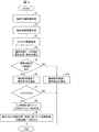
以上のように構成される操作案内システム101の動作について説明する。図3は、操作案内システム101の動作手順を示すフローチャートである。
The operation of the
図3に示すように、まず、ヘッドマウント型ディスプレイ3において、演算処理装置32は、画像センサ31からの撮影画像情報を取得する(ステップS1)。また、演算処理装置32は、機械制御装置1からの機械制御情報を取得し(ステップS2)、さらに、操作端末2からタッチセンサ情報を取得する(ステップS3)。
As shown in FIG. 3, first, in the head-mounted display 3, the
位置関係推定部321は、撮影画像情報に含まれる撮影画像データを解析し、機械8に対する撮影位置および撮影角度を推定する(ステップS4)。位置関係推定部321は、撮影位置および撮影角度を推定することにより、操作者と機械8との位置関係を推定する。
The positional
撮影位置は、操作者が装着しているヘッドマウント型ディスプレイ3が機械8を撮影したときの操作者の位置である。撮影角度は、操作者が機械8に面した部分の機械8の正面に対する傾斜角度である。
The shooting position is the position of the operator when the head-mounted display 3 worn by the operator shoots the
演算処理装置32の位置関係推定部321は、撮影画像情報に基づいて、画像センサ31が撮影する範囲である操作者の視野内に機械8があるか否かを判定する(ステップS5)。位置関係推定部321は、操作者の視野内に機械8があると判定すると(ステップS5のYES)、機械制御装置1に機械8の操作許可を通知する(ステップS6)。位置関係推定部321は、機械8の視認状態の情報(視認しているという情報)を送出することで、操作許可を通知する。
Based on the captured image information, the positional
ここで、演算処理装置32は、タッチセンサ22からのタッチセンサ情報の有無に応じて、タッチセンサ22がONしているか否かを判定する(ステップS7)。演算処理装置32がタッチセンサ22のON状態を判定すると(ステップS7のYES)、ガイダンス表示モデル生成部322は、入力情報に基づいて三次元モデルデータを生成する(ステップS8)。
Here, the
ガイダンス表示モデル生成部322は、操作者が触れたスイッチ21をタッチセンサ情報から特定する。また、ガイダンス表示モデル生成部322は、特定したスイッチ21によって操作される可動部9が動作する方向を示す画像の画像データを、機械モデル情報を用いて三次元モデルデータとして生成する。また、ガイダンス表示モデル生成部322は、機械制御情報によって特定される現在の可動部9の位置を基準として、三次元モデルを配置する位置を特定する。
The guidance display
座標変換部323は、推定された操作者と機械8との位置関係に基づいて、三次元モデルデータの座標を変換し、画像合成部324は、座標が変換された三次元モデルデータと撮影画像データとを合成することで合成画像データを出力する(ステップS9)。
The coordinate
座標変換部323は、上記の位置関係より、操作者の位置から機械8までの距離と、機械8の正面に対して操作者が機械8に面する角度とを認識し、主に角度に基づいて、操作者に対する三次元モデルが示す方向を認識する。そして、座標変換部323は、当該方向に基づいて、三次元モデルデータにおける方向を特定する方向特定座標を算出し、変換前の方向特定座標を、算出した方向特定座標に置き替える。
The coordinate
例えば、三次元モデルが矢印である場合、方向特定座標は、矢印の先端の座標および後端の座標である。そこで、座標変換部323は、矢印の先端と後端との方向特定座標を算出すると、ガイダンス表示モデル生成部322からの三次元モデルデータに含まれる方向特定座標を、算出した方向特定座標に置き替える。
For example, when the three-dimensional model is an arrow, the directional specific coordinates are the coordinates of the tip and the coordinates of the trailing edge of the arrow. Therefore, when the coordinate
また、位置関係推定部321(操作禁止部)は、操作者の視野内に機械8がないと判定すると(ステップS5のNO)、機械制御装置1に機械8の操作禁止を通知して(ステップS10)、処理を終える。位置関係推定部321は、機械制御装置1に機械8の視認状態の情報(視認していないという情報)を送出することで、操作禁止を通知する。
Further, when the positional relationship estimation unit 321 (operation prohibition unit) determines that the
また、演算処理装置32は、タッチセンサ22がONしていないと判定したときも(ステップS7のNO)、処理を終える。
Further, the
映像出力デバイス33は、合成画像データに基づいて、機械8の撮影画像にガイダンス表示モデル(三次元モデル)が示された合成画像を操作ガイダンス画像として表示する。
The
ところで、機械制御装置1の制御部12は、位置関係推定部321からの操作許可の通知(指令)を受けると、アクチュエータ10を動作させる。一方、制御部12は、位置関係推定部321からの操作禁止の通知(指令)を受けると、操作端末2からスイッチ情報を受けても、アクチュエータ10を動作させない。
By the way, the
このように、撮影画像に機械8(操作対象となる可動部9)が含まれていないとき、すなわち機械8が操作者の視野内にないとき、位置関係推定部321が機械8の操作を禁止する。これにより、操作端末2による操作を無効化することができる。したがって、操作者が機械8を見ていない状態で操作端末2を操作することによって生じる誤操作を回避できる。
In this way, when the captured image does not include the machine 8 (
また、位置関係推定部321(方向表示部)は、操作禁止を機械制御装置1に通知するときに、操作者から機械8の方向を映像出力デバイス33に表示させてもよい。これにより、機械8を見ることを操作者に促すことができる。
Further, the positional relationship estimation unit 321 (direction display unit) may display the direction of the
また、位置関係推定部321(警告部)は、操作禁止を機械制御装置1に通知するときに、タッチセンサ22のON状態がタッチセンサ情報によって検知されるか、またはスイッチ21のON状態がスイッチ情報によって検知されるかすると、操作禁止の警告を発してもよい。具体的には、位置関係推定部321は、警告を映像出力デバイス33に表示させてもよいし、あるいは、ヘッドマウント型ディスプレイ3に設けられたスピーカに当該警告を音声で出力させてもよい。これにより、機械8を見ることを操作者に促すことができる。
Further, when the positional relationship estimation unit 321 (warning unit) notifies the machine control device 1 of the operation prohibition, the ON state of the
また、位置関係推定部321(方向変更部)は、推定した位置関係に応じて、スイッチ21の操作によって入力される操作指示に応じて動作する可動部9の動作方向を変更するように機械制御装置1に指示を送出してもよい。機械制御装置1は、その指示を受けて、変更された動作方向に可動部9を動作させるようにアクチュエータ10を制御する。
Further, the positional relationship estimation unit 321 (direction changing unit) is mechanically controlled so as to change the operating direction of the
このように、操作指示に対応する可動部9の動作方向を変更することで、操作者の機械8に対する位置によっては分かりにくくなる可動部の動作方向を、より分かりやすくすることができる。例えば、通常、機械8の正面を向いて操作しているのに対し、機械8の背面側から操作する場合、可動部9の操作感覚が通常の操作感覚とは逆になる。そこで、スイッチ21による操作指示に対応する可動部9の動作方向を逆に変更することにより、機械8の背面側でも、正面側と同じ操作感覚を得ることができる。また、宇宙空間のように、定位置での操作が困難な場合も、操作感覚を一定に保つ観点から、必要に応じて、操作指示に対応する可動部9の動作方向を変更することが好ましい。
By changing the operating direction of the
ただし、操作者の意図しないタイミングで動作方向を変更すると、誤操作を生じる可能性が高まる。したがって、位置関係推定部321は、スイッチ21に対応した可動部9の動作方向が変更されたことを、上述の操作禁止の警告と同じ出力手段を用いて報知する。あるいは、位置関係推定部321は、操作者が操作端末2を操作しているときに(操作準備状態および直近の操作完了後の所定期間(例えば数秒)を含む)、上記の動作方向変更の指示を機械制御装置1に送出しないようにしてもよい。
However, if the operation direction is changed at a timing not intended by the operator, the possibility of erroneous operation increases. Therefore, the positional
続いて、操作案内システム101による操作案内の具体例について説明する。
Subsequently, a specific example of the operation guidance by the
図4の(a)は、操作案内システム101が操作対象とするクレーン150の可動部150aに対して操作者が操作をしている状態を示す斜視図である。図4の(b)は、操作案内システム101によって可動部150aの動作方向を含む操作ガイダンス画像201を示す図である。図4の(c)は、他の操作ガイダンス画像202を示す図である。図5の(a)〜(d)は、操作案内システム101が操作対象とするマニピュレータの操作ガイダンス画像210を示す図である。
FIG. 4A is a perspective view showing a state in which the operator is operating the
図4の(a)に示すように、操作対象となる機械8としてのクレーン150を操作端末2を用いて操作する場合、操作者が装着しているヘッドマウント型ディスプレイ3には、図4の(b)に示す操作ガイダンス画像201が表示されている。この状態では、クレーン150の可動部150aを含む部分が、画像センサ31によって撮影されており、操作者の視野内にある。この状態では、操作ガイダンス画像201に、可動部150aが動く方向を示す矢印201a(動作方向指示画像)がガイダンス表示モデルとして示される。これにより、操作者は、操作端末2で触れたスイッチ21によって操作される可動部150aの動作方向を把握することができる。そして、操作者は、スイッチ21を押すことにより、可動部150aを操作することができる。
As shown in FIG. 4A, when the
操作者が可動部150aを操作する位置を変えた場合、演算処理装置32が、操作者とクレーン150との位置関係を新たに算出し、その位置関係に基づいて生成した三次元モデルデータと操作者の位置からの撮影画像データとの合成画像データを出力する。これにより、新たに得られた操作ガイダンス画像201は、変更された操作者の位置から見たクレーン150と、可動部150aの動作方向が示された矢印201aとを含む。したがって、操作者がクレーン150に対する位置を変えても、その位置に応じて可動部150aの動作方向が示されるので、操作者にとって可動部150aの動く方向が把握しやすくなる。
When the operator changes the position where the
また、クレーン150の動作モードとして高速動作モードおよび低速動作モードが設けられている場合、矢印201aの長さを可動部150aの動作速度、すなわち高速動作モードおよび低速動作モードの相違として表してもよい。具体的には、低速動作モードの場合、図4の(b)に示す操作ガイダンス画像201には短い矢印201aが示され、高速動作モードの場合、図4の(c)に示す操作ガイダンス画像202には長い矢印202a(動作方向指示画像)が示される。これにより、操作者は視覚的に動作モードを判別することができる。
When a high-speed operation mode and a low-speed operation mode are provided as the operation modes of the
このように、矢印201a,202a(ガイダンス表示モデル)は、可動部150aの動作方向以外の情報を表現していてもよい。
As described above, the
操作対象となる機械8としてのマニピュレータを操作端末2を用いて操作する場合、操作者が装着しているヘッドマウント型ディスプレイ3には、図5の(a)〜(d)に示す操作ガイダンス画像210が表示されている。操作ガイダンス画像210には、マニピュレータ211の実画像と、マニピュレータ211の動く方向を表す矢印212(ガイダンス表示モデル)とが示されている。
When the manipulator as the
図5の(a)および(b)に示すように、矢印212,213は、操作者が触れたスイッチ21に対応する可動部9(マニピュレータ211のハンド)付近に設けられている。矢印212,213の位置は、ガイダンス表示モデル生成部322によって、機械制御情報から得られる、マニピュレータ211のアクチュエータ(アクチュエータ10)の現在位置および角度などに基づいて決定される。
As shown in FIGS. 5A and 5B, the
図5の(c)および(d)に示す操作ガイダンス画像210では、機械制御情報から得られる動作モードが反映されている。動作モードが単軸指定である場合、図5の(c)に示す操作ガイダンス画像210では、矢印214が可動部9(ハンド)が動作する単軸の2方向の矢印のうち、動作方向を示す矢印を他の方向の矢印と色を異ならせて示している。また、動作モードが先端位置指定である場合、図5の(d)に示す操作ガイダンス画像210では、4方向に向いた矢印215が可動部9(ハンド)の動作方向を示す矢印のみを他の方向の矢印と色を異ならせて示している。
The
以上のように、本実施形態の操作案内システム101は、操作端末2と、演算処理装置32を有するヘッドマウント型ディスプレイ3とを備えている。
As described above, the
操作端末2は、操作者による可動部9に対する操作指示を受け付けるとともに、操作指示を受け付け可能にする操作準備状態を検知する。
The
演算処理装置32は、画像センサ31から取得した機械8の画像および操作者の位置に基づいて、操作者と機械8との位置関係を推定する位置関係推定部321を有している。また、演算処理装置32は、操作端末2が操作準備状態を検知すると、操作指示に応じて動作する可動部9が動作する方向を表す三次元モデルを、上記の位置関係に基づいて、操作者から機械8を見た方向に応じた向きで生成するガイダンス表示モデル生成部322および座標変換部323を有する。また、演算処理装置32は、三次元モデルを画像センサ31によって撮影された機械8の撮影画像と合成する画像合成部324を有している。
The
これにより、可動部9の動作方向が三次元モデルによって撮影画像上で示されるので、操作者は容易に可動部9の動作方向を確認することができる。また、三次元モデルは、操作者から機械8(可動部9)を見た方向に応じた向きで生成されるので、操作者が位置を変えると、その位置に応じて三次元モデルの向きも変わる。
As a result, the operating direction of the
したがって、操作者から見た可動部9の動作方向を正確に把握することができる。よって、操作者が操作指示を与える可動部9の動作方向を操作者の位置に関わらず理解しやすい形態で提供することができる。
Therefore, the operating direction of the
また、三次元モデルがスイッチ21の機能に関する情報(動作方向)を直感的に示すことにより、誤操作を軽減することができるだけでなく、機械操作を効率的に習得することができる。
Further, since the three-dimensional model intuitively shows the information (operating direction) regarding the function of the
また、視線の移動を最小限に抑えることができる。これにより、作業効率の向上、操作者の不注意による事故の抑制などを図ることができる。 In addition, the movement of the line of sight can be minimized. As a result, it is possible to improve work efficiency and suppress accidents caused by carelessness of the operator.
なお、本実施形態では、操作端末2と、ヘッドマウント型ディスプレイ3とを備える操作案内システム101について説明したが、このような構成はあくまでも一例である。本実施形態を含む各実施形態は、このような構成以外に、タブレット端末や、ロボットのティーチングペンダントのように、操作部と表示部とが一体に設けられた構成にも適用される。
In the present embodiment, the
本実施形態では、機械8を撮影した画像に可動部9の動作方向を矢印で示す例について説明した。しかしながら、ガイダンス表示モデルが可動部9の動作方向を示す形態は矢印には限定されない。例えば、機械8の3Dモデルを表示して可動部9の動作方向をアニメーションによって示してもよいし、アイコン、ポップアップ画像などで可動部9の動作方向を示してもよい。
In the present embodiment, an example in which the operating direction of the
また、ヘッドマウント型ディスプレイ3には、スイッチ21が押されたことを示すマークなどの報知画像が表示されてもよい。この報知画像は、例えば、ガイダンス表示モデル生成部322によって生成される。
Further, the head-mounted display 3 may display a notification image such as a mark indicating that the
また、操作ガイダンス画像には、可動部9の動作方向だけでなく、操作者が触れたスイッチ21の名称や機能情報が含まれていてもよい。このような情報も、ガイダンス表示モデル生成部322によって生成される。
Further, the operation guidance image may include not only the operation direction of the
また、上述した操作ガイダンス画像を表示する形態は、ヘッドマウント型ディスプレイ3による表示形態に限定されず、プロジェクションマッピングのような投影手法による表示形態であってもよい。 Further, the form of displaying the above-mentioned operation guidance image is not limited to the display form of the head-mounted display 3, and may be a display form of a projection method such as projection mapping.
また、ヘッドマウント型ディスプレイ3には、多様な形状を有し、かつディスプレイ方式、投影方式などで様々な方式を用いるものがある。本実施形態を含む各実施形態は、ヘッドマウント型ディスプレイ3の形状や方式に依存しないことは勿論である。 Further, some head-mounted displays 3 have various shapes and use various methods such as a display method and a projection method. It goes without saying that each embodiment including the present embodiment does not depend on the shape and method of the head-mounted display 3.
また、演算処理装置32は、ヘッドマウント型ディスプレイ3に内蔵されていてもよいし、ヘッドマウント型ディスプレイ3の外部に設けられていてもよい。
Further, the
また、操作端末2は、可搬型であるかどうかに依存しない。例えば、大規模設備において、リモート操作によってカメラを移動させて撮影を行う装置を操作するシステム、キャスターで移動させるワゴン型の操作装置などは、可搬型の範疇には含まれない。
Further, the
また、機械8と操作者(画像センサ31)との位置関係の推定と、可動部9の動作方向のガイダンス表示モデルを表示する位置の検出とを行う手段として、マーカーを利用してもよい。
Further, a marker may be used as a means for estimating the positional relationship between the
また、本実施形態を含む各実施形態では、機械8を撮影する手段(カメラ)として、画像センサ31を用いているが、これに代えて距離画像センサを利用してもよい。また、カメラ以外に各種センサ(加速度センサ、ジャイロ、磁気センサなど)を併用することで、機械8とカメラとの位置関係を推定する精度を向上させてもよい。
Further, in each embodiment including the present embodiment, the
演算処理装置32が機械制御装置1および操作端末2から取得する情報には、前述のスイッチ21情報、タッチセンサ情報、機械制御情報などが含まれる。これらの情報の通知および取得には、通信(無線/有線)を利用してもよいし(後述する実施形態2,3を参照)、デジタル/アナログ入出力を利用してもよい。また、ヘッドマウント型ディスプレイ3が情報を取得する経路は、機械制御装置1や外部の通信機器を経由してもよい。
The information acquired by the
〔実施形態2〕
本発明の実施形態2について図6に基づいて説明すると、以下の通りである。なお、本実施形態において、実施形態1における構成要素と同一の機能を有する構成要素については、同一の符号を付記して、その説明を省略する。
[Embodiment 2]
The second embodiment of the present invention will be described below with reference to FIG. In the present embodiment, the same reference numerals will be added to the components having the same functions as the components in the first embodiment, and the description thereof will be omitted.
図6は、本実施形態に係る操作案内システム102の構成を示すブロック図である。
FIG. 6 is a block diagram showing the configuration of the
図6に示すように、操作案内システム102は、機械制御装置1A(制御装置)と、操作端末2A(操作装置)と、ヘッドマウント型ディスプレイ3Aとを備えている。
As shown in FIG. 6, the
機械制御装置1Aは、実施形態1の操作案内システム101における機械制御装置1と同じく、入力部11と、制御部12と、出力部13とを有している。また、機械制御装置1Aは、さらに通信部14,15を有している。
The machine control device 1A has an
通信部14は、操作端末2Aから受信した情報(スイッチ情報およびタッチセンサ情報)を入力部11に送出する。通信部15は、出力部13から出力される機械制御情報をヘッドマウント型ディスプレイ3に送信する。また、通信部15は、入力部11、制御部12および出力部13を経由して出力される操作端末2Aからの受信情報をヘッドマウント型ディスプレイ3に送信する。さらに、通信部15は、ヘッドマウント型ディスプレイ3Aから送信される機械8の視認状態についての情報を受信して入力部11に送出する。
The
操作端末2Aは、操作案内システム101における操作端末2と同じく、スイッチ21と、タッチセンサ22とを有している。また、操作端末2Aは、さらに通信部23を有している。通信部23は、機械制御装置1Aの通信部14にスイッチ情報およびタッチセンサ情報を送信する。
The
ヘッドマウント型ディスプレイ3Aは、操作案内システム101におけるヘッドマウント型ディスプレイ3と同じく、画像センサ31と、演算処理装置32と、映像出力デバイス33と、記憶部34とを有している。また、ヘッドマウント型ディスプレイ3Aは、さらに通信部35を有している。
The head-mounted
通信部35は、演算処理装置32から出力される機械8の視認状態についての情報を機械制御装置1Aの通信部15に送信する。また、通信部35は、機械制御装置1Aの通信部15から送信される、機械制御情報および操作端末2Aからの受信情報を受信して演算処理装置32に送出する。
The
このように構成される操作案内システム102では、各種の情報のやり取りが通信(有線または無線)によって行われる。これにより、LAN(Local Area Network)、近距離無線通信などを用いて、機械制御装置1A、操作端末2Aおよびヘッドマウント型ディスプレイ3Aの間で各種情報をやり取りすることができる。
In the
〔実施形態3〕
本発明の実施形態3について図7に基づいて説明すると、以下の通りである。なお、本実施形態において、実施形態1における構成要素と同一の機能を有する構成要素については、同一の符号を付記して、その説明を省略する。
[Embodiment 3]
The third embodiment of the present invention will be described below with reference to FIG. 7. In the present embodiment, the same reference numerals will be added to the components having the same functions as the components in the first embodiment, and the description thereof will be omitted.
図7は、本実施形態に係る操作案内システム103の構成を示すブロック図である。 FIG. 7 is a block diagram showing the configuration of the operation guidance system 103 according to the present embodiment.
図7に示すように、操作案内システム103は、機械制御装置1B(制御装置)と、操作端末2B(操作装置)と、ヘッドマウント型ディスプレイ3Bとを備えている。
As shown in FIG. 7, the operation guidance system 103 includes a
機械制御装置1Bは、実施形態1の操作案内システム101における機械制御装置1と同じく、入力部11と、制御部12と、出力部13とを有している。しかしながら、入力部11は、ヘッドマウント型ディスプレイ3Bから機械8の視認状態についての情報が入力されない。また、出力部13は、ヘッドマウント型ディスプレイ3Bに機械制御情報を出力しない。
The
操作端末2Bは、操作案内システム101における操作端末2と同じく、スイッチ21と、タッチセンサ22とを有している。また、操作端末2Bは、さらに通信部24を有している。通信部24は、ヘッドマウント型ディスプレイ3Bの通信部35にスイッチ情報およびタッチセンサ情報を送信する。
The
ヘッドマウント型ディスプレイ3Bは、実施形態2の操作案内システム102におけるヘッドマウント型ディスプレイ3Aと同じく、画像センサ31と、演算処理装置32と、映像出力デバイス33と、記憶部34と、通信部35とを有している。ただし、通信部35は、機械制御装置1Bの出力部13に機械8の視認状態についての情報を送出しない。
The head-mounted
このように構成される操作案内システム103では、機械制御装置1Bとヘッドマウント型ディスプレイ3Bとの間で情報の授受が行われない。このため、ヘッドマウント型ディスプレイ3Bは機械制御情報を機械制御装置1から取得しないし、機械制御装置1Bは機械8の視認状態についての情報をヘッドマウント型ディスプレイ3Bから取得しない。
In the operation guidance system 103 configured in this way, information is not exchanged between the
このため、演算処理装置32(ガイダンス表示モデル生成部322)は、機械制御情報を利用することなくガイダンス表示モデルを生成する。また、機械制御装置1Bは、操作案内システム101の機械制御装置1が行うような、操作者が機械8を視認していないときに機械8の制御を停止することを行わない。
Therefore, the arithmetic processing unit 32 (guidance display model generation unit 322) generates the guidance display model without using the machine control information. Further, the
したがって、操作案内システム103は、上述した操作案内システム101,102と比べて簡素に構成されており、簡易型のシステムとして安価に利用することができる。
Therefore, the operation guidance system 103 has a simpler configuration than the above-mentioned
〔ソフトウェアによる実現例〕
ヘッドマウント型ディスプレイ3,3A,3Bの演算処理装置32は、ソフトウェアによって実現される。ヘッドマウント型ディスプレイ3,3A,3Bは、各機能を実現するソフトウェアであるプログラムの命令を実行するコンピュータを備えている。このコンピュータは、例えば1つ以上のプロセッサを備えていると共に、上記プログラムを記憶したコンピュータ読み取り可能な記録媒体を備えている。そして、上記コンピュータにおいて、上記プロセッサが上記プログラムを上記記録媒体から読み取って実行することにより、本発明の目的が達成される。
[Example of realization by software]
The
上記プロセッサとしては、例えばCPU(Central Processing Unit)を用いることができる。上記記録媒体としては、「一時的でない有形の媒体」、例えば、ROM(Read Only Memory)等の他、テープ、ディスク、カード、半導体メモリ、プログラマブルな論理回路などを用いることができる。また、上記プログラムを展開するRAM(Random Access Memory)などをさらに備えていてもよい。また、上記プログラムは、該プログラムを伝送可能な任意の伝送媒体(通信ネットワークや放送波等)を介して上記コンピュータに供給されてもよい。なお、本発明の一態様は、上記プログラムが電子的な伝送によって具現化された、搬送波に埋め込まれたデータ信号の形態でも実現され得る。 As the processor, for example, a CPU (Central Processing Unit) can be used. As the recording medium, a "non-temporary tangible medium", for example, a ROM (Read Only Memory) or the like, a tape, a disk, a card, a semiconductor memory, a programmable logic circuit, or the like can be used. Further, a RAM (Random Access Memory) for expanding the above program may be further provided. Further, the program may be supplied to the computer via an arbitrary transmission medium (communication network, broadcast wave, etc.) capable of transmitting the program. It should be noted that one aspect of the present invention can also be realized in the form of a data signal embedded in a carrier wave, in which the above program is embodied by electronic transmission.
〔付記事項〕
本発明は上述した各実施形態に限定されるものではなく、請求項に示した範囲で種々の変更が可能であり、異なる実施形態にそれぞれ開示された技術的手段を適宜組み合わせて得られる実施形態についても本発明の技術的範囲に含まれる。
[Additional notes]
The present invention is not limited to the above-described embodiments, and various modifications can be made within the scope of the claims, and the embodiments obtained by appropriately combining the technical means disclosed in the different embodiments. Is also included in the technical scope of the present invention.
1,1A,1B 機械制御装置(制御装置)
2,2A,2B 操作端末(操作装置)
8 機械(可動装置)
9 可動部
31 画像センサ(撮影装置)
33 映像出力デバイス(表示装置)
321 位置関係推定部(推定部,操作禁止部,方向表示部,警告部)
322 ガイダンス表示モデル生成部(画像生成部)
323 座標変換部(画像生成部)
324 画像合成部
1,1A, 1B Machine control device (control device)
2,2A, 2B operation terminal (operation device)
8 Machine (movable device)
9 Moving
33 Video output device (display device)
321 Positional relationship estimation unit (estimation unit, operation prohibition unit, direction display unit, warning unit)
322 Guidance display model generation unit (image generation unit)
323 Coordinate conversion unit (image generation unit)
324 Image Synthesis Department
Claims (6)
操作者による前記可動部に対する、前記動作方向のいずれかに応じた操作指示を受け付ける前に前記操作指示を受け付け可能にする操作準備状態を生成する操作と、前記操作指示を受け付ける操作とが入力されるスイッチと、
操作者の視線の方向にある撮影対象物を撮影する撮影装置と、
操作者と前記可動装置との位置関係を推定する推定部と、
前記スイッチが前記操作準備状態を生成すると、限定された1つの前記動作方向を表す動作方向指示画像を、前記位置関係に基づいて、操作者から前記可動装置を見た方向に応じた向きで生成する画像生成部と、
前記動作方向指示画像を前記撮影装置によって撮影された前記可動装置の撮影画像に合成した合成画像を生成する画像合成部と、
前記合成画像を表示する表示装置とを備えていることを特徴とする操作案内システム。 It is an operation guidance system that guides the operator to the operation of a movable device including a movable part that can operate in a plurality of operation directions, which is an operation target.
An operation for generating an operation preparation state that enables the operator to accept the operation instruction before receiving the operation instruction corresponding to any of the operation directions to the movable portion, and an operation for receiving the operation instruction are input. Switch and
A shooting device that shoots an object to be shot in the direction of the operator's line of sight,
An estimation unit that estimates the positional relationship between the operator and the movable device,
When the switch generates the operation ready state, an operation direction instruction image representing one limited operation direction is generated in a direction corresponding to the direction in which the operator sees the movable device based on the positional relationship. Image generator and
An image synthesizing unit that generates a composite image obtained by synthesizing the operation direction indicating image with the captured image of the movable device captured by the photographing device.
An operation guidance system including a display device for displaying the composite image.
Priority Applications (5)
| Application Number | Priority Date | Filing Date | Title |
|---|---|---|---|
| JP2017228079A JP6882147B2 (en) | 2017-11-28 | 2017-11-28 | Operation guidance system |
| CN201880076541.9A CN111565898B (en) | 2017-11-28 | 2018-05-15 | Operation guidance system |
| US16/767,382 US11475606B2 (en) | 2017-11-28 | 2018-05-15 | Operation guiding system for operation of a movable device |
| PCT/JP2018/018684 WO2019106862A1 (en) | 2017-11-28 | 2018-05-15 | Operation guiding system |
| EP18882638.2A EP3718708A4 (en) | 2017-11-28 | 2018-05-15 | Operation guiding system |
Applications Claiming Priority (1)
| Application Number | Priority Date | Filing Date | Title |
|---|---|---|---|
| JP2017228079A JP6882147B2 (en) | 2017-11-28 | 2017-11-28 | Operation guidance system |
Publications (3)
| Publication Number | Publication Date |
|---|---|
| JP2019101476A JP2019101476A (en) | 2019-06-24 |
| JP2019101476A5 JP2019101476A5 (en) | 2020-12-17 |
| JP6882147B2 true JP6882147B2 (en) | 2021-06-02 |
Family
ID=66664763
Family Applications (1)
| Application Number | Title | Priority Date | Filing Date |
|---|---|---|---|
| JP2017228079A Active JP6882147B2 (en) | 2017-11-28 | 2017-11-28 | Operation guidance system |
Country Status (5)
| Country | Link |
|---|---|
| US (1) | US11475606B2 (en) |
| EP (1) | EP3718708A4 (en) |
| JP (1) | JP6882147B2 (en) |
| CN (1) | CN111565898B (en) |
| WO (1) | WO2019106862A1 (en) |
Families Citing this family (2)
| Publication number | Priority date | Publication date | Assignee | Title |
|---|---|---|---|---|
| JP7149440B1 (en) | 2022-04-21 | 2022-10-06 | 三菱製鋼株式会社 | Operating device |
| WO2023248439A1 (en) * | 2022-06-23 | 2023-12-28 | ファナック株式会社 | Robot system, robot control device, and robot control program |
Family Cites Families (22)
| Publication number | Priority date | Publication date | Assignee | Title |
|---|---|---|---|---|
| KR100819819B1 (en) * | 2004-03-26 | 2008-04-08 | 아츠시 타카하시 | 3d entity digital magnifying glass system having 3d visual instruction function and 3d visual instruction method for 3d entity digital magnifying glass system |
| JP5023632B2 (en) | 2006-09-15 | 2012-09-12 | ブラザー工業株式会社 | Head mounted display |
| JP4019200B2 (en) * | 2007-06-18 | 2007-12-12 | 富士フイルム株式会社 | Camera with image display |
| JP5022868B2 (en) * | 2007-11-16 | 2012-09-12 | キヤノン株式会社 | Information processing apparatus and information processing method |
| JP5422430B2 (en) | 2010-02-12 | 2014-02-19 | 株式会社タダノ | Working device |
| JP2012218120A (en) * | 2011-04-12 | 2012-11-12 | Seiko Epson Corp | Manipulator operation previous notice device, robot system and method for previously noticing manipulator operation |
| JP5784388B2 (en) * | 2011-06-29 | 2015-09-24 | オリンパス株式会社 | Medical manipulator system |
| JP5800616B2 (en) | 2011-07-15 | 2015-10-28 | オリンパス株式会社 | Manipulator system |
| JP6021353B2 (en) * | 2011-08-04 | 2016-11-09 | オリンパス株式会社 | Surgery support device |
| JP2013184257A (en) * | 2012-03-08 | 2013-09-19 | Sony Corp | Robot apparatus, method for controlling robot apparatus, and computer program |
| JP6080697B2 (en) * | 2013-05-31 | 2017-02-15 | 三菱電機株式会社 | Induction heating cooker |
| JP6266268B2 (en) * | 2013-08-28 | 2018-01-24 | Dmg森精機株式会社 | Display device |
| US9817396B1 (en) * | 2014-06-09 | 2017-11-14 | X Development Llc | Supervisory control of an unmanned aerial vehicle |
| US9849981B1 (en) * | 2014-08-28 | 2017-12-26 | X Development Llc | Payload-release device position tracking |
| US10179407B2 (en) * | 2014-11-16 | 2019-01-15 | Robologics Ltd. | Dynamic multi-sensor and multi-robot interface system |
| JP2016107379A (en) * | 2014-12-08 | 2016-06-20 | ファナック株式会社 | Robot system including augmented reality corresponding display |
| US9836117B2 (en) * | 2015-05-28 | 2017-12-05 | Microsoft Technology Licensing, Llc | Autonomous drones for tactile feedback in immersive virtual reality |
| JP6643843B2 (en) * | 2015-09-14 | 2020-02-12 | オリンパス株式会社 | Imaging operation guide device and imaging device operation guide method |
| JP6657858B2 (en) | 2015-11-30 | 2020-03-04 | 株式会社デンソーウェーブ | Robot operation system |
| US20180098052A1 (en) * | 2016-09-30 | 2018-04-05 | Sony Interactive Entertainment Inc. | Translation of physical object viewed by unmanned aerial vehicle into virtual world object |
| CN107223082B (en) | 2017-04-21 | 2020-05-12 | 深圳前海达闼云端智能科技有限公司 | Robot control method, robot device and robot equipment |
| US10852847B2 (en) * | 2017-07-26 | 2020-12-01 | Google Llc | Controller tracking for multiple degrees of freedom |
-
2017
- 2017-11-28 JP JP2017228079A patent/JP6882147B2/en active Active
-
2018
- 2018-05-15 WO PCT/JP2018/018684 patent/WO2019106862A1/en unknown
- 2018-05-15 US US16/767,382 patent/US11475606B2/en active Active
- 2018-05-15 CN CN201880076541.9A patent/CN111565898B/en active Active
- 2018-05-15 EP EP18882638.2A patent/EP3718708A4/en active Pending
Also Published As
| Publication number | Publication date |
|---|---|
| US20200394823A1 (en) | 2020-12-17 |
| WO2019106862A1 (en) | 2019-06-06 |
| CN111565898B (en) | 2023-04-21 |
| EP3718708A4 (en) | 2021-12-22 |
| EP3718708A1 (en) | 2020-10-07 |
| US11475606B2 (en) | 2022-10-18 |
| CN111565898A (en) | 2020-08-21 |
| JP2019101476A (en) | 2019-06-24 |
Similar Documents
| Publication | Publication Date | Title |
|---|---|---|
| JP5966510B2 (en) | Information processing system | |
| TWI722280B (en) | Controller tracking for multiple degrees of freedom | |
| JP5936155B2 (en) | 3D user interface device and 3D operation method | |
| JP6057396B2 (en) | 3D user interface device and 3D operation processing method | |
| JP5472056B2 (en) | Display system, display processing apparatus, display method, and display program | |
| JP5843340B2 (en) | 3D environment sharing system and 3D environment sharing method | |
| WO2014016992A1 (en) | Three-dimensional user-interface device, and three-dimensional operation method | |
| JP2019008623A (en) | Information processing apparatus, information processing apparatus control method, computer program, and storage medium | |
| JP5565331B2 (en) | Display system, display processing apparatus, display method, and display program | |
| JP2016122392A (en) | Information processing apparatus, information processing system, control method and program of the same | |
| JP6970858B2 (en) | Maintenance support system, maintenance support method, program and processed image generation method | |
| JPWO2018074045A1 (en) | Information processing apparatus, information processing method, and program | |
| JP6882147B2 (en) | Operation guidance system | |
| CN113498531A (en) | Head-mounted information processing device and head-mounted display system | |
| US9760180B2 (en) | User interface device and user interface method | |
| JP6685742B2 (en) | Operating device, moving device, and control system thereof | |
| JP2020120388A (en) | Operating device, mobile device, and control system thereof | |
| JP2019045997A (en) | Information processing device, method thereof and program | |
| JP5830899B2 (en) | Projection system, projection apparatus, projection method and program | |
| JP6689492B2 (en) | Terminal device, data processing system and program | |
| JP6164177B2 (en) | Information processing apparatus, information processing system, control method thereof, and program | |
| WO2022172335A1 (en) | Virtual guide display device, virtual guide display system, and virtual guide display method | |
| JP6748793B1 (en) | Maintenance support system, maintenance support method, program and method of generating processed image | |
| TWI831951B (en) | Maintenance support system, maintenance support method, program, method of generating processed image, and processed image | |
| JP2023021808A (en) | Support system, support-side device, support method, and program |
Legal Events
| Date | Code | Title | Description |
|---|---|---|---|
| A521 | Request for written amendment filed |
Free format text: JAPANESE INTERMEDIATE CODE: A523 Effective date: 20201102 |
|
| A621 | Written request for application examination |
Free format text: JAPANESE INTERMEDIATE CODE: A621 Effective date: 20201102 |
|
| TRDD | Decision of grant or rejection written | ||
| A01 | Written decision to grant a patent or to grant a registration (utility model) |
Free format text: JAPANESE INTERMEDIATE CODE: A01 Effective date: 20210427 |
|
| A61 | First payment of annual fees (during grant procedure) |
Free format text: JAPANESE INTERMEDIATE CODE: A61 Effective date: 20210506 |
|
| R150 | Certificate of patent or registration of utility model |
Ref document number: 6882147 Country of ref document: JP Free format text: JAPANESE INTERMEDIATE CODE: R150 |