JP6164177B2 - Information processing apparatus, information processing system, control method thereof, and program - Google Patents
Information processing apparatus, information processing system, control method thereof, and program Download PDFInfo
- Publication number
- JP6164177B2 JP6164177B2 JP2014157180A JP2014157180A JP6164177B2 JP 6164177 B2 JP6164177 B2 JP 6164177B2 JP 2014157180 A JP2014157180 A JP 2014157180A JP 2014157180 A JP2014157180 A JP 2014157180A JP 6164177 B2 JP6164177 B2 JP 6164177B2
- Authority
- JP
- Japan
- Prior art keywords
- virtual object
- image
- information processing
- state
- display
- Prior art date
- Legal status (The legal status is an assumption and is not a legal conclusion. Google has not performed a legal analysis and makes no representation as to the accuracy of the status listed.)
- Active
Links
Images


Landscapes
- Processing Or Creating Images (AREA)
- User Interface Of Digital Computer (AREA)
Description
情報処理装置、情報処理システム、その制御方法及びプログラムに関する。 The present invention relates to an information processing apparatus, an information processing system, a control method thereof, and a program.
近年、複合現実(Mixed Reality/以下、MRと記載)の技術が普及し、MR技術を用いて、室内に、現実物体とCGモデルが配置されることが行われている。MR空間(現実空間と仮想空間とを重ね合わせた複合現実空間)を生成するにあたり、仮想空間と現実空間の位置合わせに用いられる位置指標として、マーカを用いる場合がある。 In recent years, mixed reality (hereinafter referred to as MR) technology has become widespread, and real objects and CG models have been placed indoors using MR technology. In generating an MR space (a mixed reality space obtained by superimposing a real space and a virtual space), a marker may be used as a position index used for alignment between the virtual space and the real space.
特許文献1には、当該マーカの存在をユーザに意識させないために、マーカを検出した場合に、当該マーカを隠した画像を描画する技術が記載されている。
また、特許文献2では、仮想のペットを育成する複合現実感提示装置において、ユーザの所定部位による所定動作により、仮想のペットを示す3次元モデルの内部状態を遷移させ、仮想物体の存在感の認知を容易にするMRに関する技術が開示されている。
Further, in
例えば、特許文献1及び特許文献2に記載の技術を用いて仮想の画像を描画して現実の画像と重畳し、重畳画像であるMR画像を生成した場合、現実物体がCG(オブジェクト)によって隠れてしまうことがある。
For example, when a virtual image is drawn using the techniques described in
例えば、現実物体にマーカを貼り付けておき、現実物体よりも大きなCGをマーカの位置に重畳してMR画像を生成した場合、当該現実物体がCGによって隠れてしまうため、ユーザは、CGの裏側に現実物体が存在するか否かを認識することができない。 For example, when an MR image is generated by pasting a marker on a real object and superimposing a CG larger than the real object on the position of the marker, the real object is hidden by the CG. It is impossible to recognize whether or not a real object exists.
また、現実物体が存在している場合、どのような現実物体がCGによって隠されているのか確認することができない。 Moreover, when a real object exists, it cannot be confirmed what kind of real object is hidden by CG.
例えば、他のユーザからCGを受け取る場合、CGの中に隠れている現実物体を受け取る必要があるが、受け取る側のユーザが、CGによって隠されている現実物体の存在を認識出来ていなければ、受け渡しに際して当該現実物体を取り落としてしまうことが考えられる。 For example, when receiving a CG from another user, it is necessary to receive a real object hidden in the CG. However, if the receiving user cannot recognize the existence of the real object hidden by the CG, It is conceivable that the real object is dropped during the delivery.
本発明は、仮想オブジェクトの受け渡しに応じて、現実物体の存在をユーザに認識させることが可能な仕組みを提供することを目的とする。 The invention, in accordance with the delivery of virtual objects, and an object thereof is to provide a mechanism capable Rukoto to recognize the existence of the physical object to the user.
本発明の情報処理装置は、表示装置において現実物体に仮想オブジェクトの画像を重畳して表示することが可能な情報処理装置であり、前記仮想オブジェクトの3次元空間上の位置を記憶する記憶手段と、前記表示装置を用いた体験をしているユーザの位置姿勢と前記仮想オブジェクトの3次元空間上の位置に応じて前記表示装置に表示する仮想オブジェクトの画像を生成する画像生成手段と、前記画像生成手段により生成された仮想オブジェクトの画像を前記表示装置に出力する出力手段と、を備える情報処理装置であって、ユーザの身体の一部を検出する検出手段と、前記検出手段で検出した前記身体の一部の状態が前記仮想オブジェクトの受け渡し動作を示す場合に、前記仮想オブジェクトの画像の表示状態を、前記仮想オブジェクトの画像と重なる現実物体の存在を認識可能な表示状態に変更するべく制御する表示制御手段と、を備えることを特徴とする。 The information processing apparatus of the present invention, there is provided an information processing apparatus capable of displaying superimposed images of the virtual object to the current real object in the display device, storage means for storing a position on the three-dimensional space of the virtual object And image generation means for generating an image of a virtual object to be displayed on the display device according to a position and orientation of a user who has experienced using the display device and a position of the virtual object in a three-dimensional space; an information processing apparatus comprising an output means for outputting an image of a virtual object generated by the image generating unit on the display device, and a detection means for detecting a part of your body Yu chromatography the said detecting means in the case where the part of the state of the detected pre-Symbol body showing the delivery operation of the virtual object, the display state of the image of the virtual object, the virtual object Display control means for recognizable behenate rather control to change the display state of the presence of the physical object which overlaps with the image, in that it comprises the features.
本発明によれば、仮想オブジェクトの受け渡しに応じて、現実物体の存在をユーザに認識させることが可能な仕組みを提供することができる。 According to the present invention, it is possible to provide in accordance with the delivery of virtual objects, a mechanism that can be Rukoto to recognize the existence of the physical object to the user.
図1を参照して、本発明の実施形態における、情報処理システムの構成の一例について説明する。図1は、本発明の実施形態における、情報処理システムの構成の一例を示す図である。 With reference to FIG. 1, an example of the configuration of an information processing system in the embodiment of the present invention will be described. FIG. 1 is a diagram illustrating an example of the configuration of an information processing system in an embodiment of the present invention.
本発明の情報処理システムは、PC100A、HMD(ヘッドマウントディスプレイ)101A、PC100B、HMD101B、赤外線カメラ104等から構成される。以下、PC100A、PC100Bを総称する場合、PC100と記載する。また、HMD101A、HMD101Bを総称する場合、HMD101と記載する。
The information processing system of the present invention includes a PC 100A, an HMD (head mounted display) 101A, a PC 100B, an HMD 101B, an
PC100とHMD101(表示装置)、赤外線カメラ104は、図1に示すLAN150や、USB(Universal Serial Bus)等を介して通信可能に接続されている。
The PC 100, the HMD 101 (display device), and the
部屋には、3DCG(オブジェクト/3次元モデル)が対応付けられた二次元マーカであるターゲットマーカが貼り付けられた現実物体(モック103)が存在し、当該ターゲットマーカ105をHMD101のカメラが撮像して当該マーカの座標の情報をPC100が算出して記憶することで、PC100は、各種マーカに対応付けられたオブジェクトを外部メモリから読み出して当該オブジェクトを配置する空間上の座標を算出し、HMD101で撮像された現実画像上に、HMD101のから見た角度のオブジェクトを重畳して重畳画像(MR画像)の生成処理を行う。当該重畳画像の生成方法の具体的な内容は、各引用文献に示した通り公知であるため、ここでは詳細な説明は割愛する。
In the room, there is a real object (mock 103) to which a target marker, which is a two-dimensional marker associated with 3DCG (object / three-dimensional model), is attached. The
PC100Aは、HMD101Aから、HMD101Aで撮像した現実画像を取得して重畳画像を生成し、HMD101Aのディスプレイに表示させるべく、HMD101Aに重畳画像を送信する。また、PC100Bは、HMD101Bから、HMD101Bで撮像した現実画像を取得して重畳画像を生成し、HMD101Bのディスプレイに表示させるべく、HMD101Bに重畳画像を送信する。 The PC 100A acquires a real image captured by the HMD 101A from the HMD 101A, generates a superimposed image, and transmits the superimposed image to the HMD 101A so as to be displayed on the display of the HMD 101A. In addition, the PC 100B acquires a real image captured by the HMD 101B from the HMD 101B, generates a superimposed image, and transmits the superimposed image to the HMD 101B so as to be displayed on the display of the HMD 101B.
各PC100には、本発明の各種実施形態にて用いる各種データが予め記憶されている。PC100AとPC100Bに記憶されているデータは同様の構成を備えているため、例えばモック103に対して対応付けて記憶されている(モック103のターゲットマーカ105を認識した場合に描画される)オブジェクトはPC100AとPC100Bで共通である。
Each PC 100 stores in advance various data used in various embodiments of the present invention. Since the data stored in the PC 100A and the PC 100B have the same configuration, for example, an object stored in association with the mock 103 (drawn when the
また、ターゲットマーカ105に対するどの座標(位置)に当該オブジェクトを描画するかも共通である。つまり、ターゲットマーカ上の一点を原点とした、オブジェクトを配置する座標、及びオブジェクトを配置する角度が同一であるため、HMD101Aを被るユーザとHMD101Bを被るユーザは、各ユーザの視点から見た、同じオブジェクトを閲覧することができる。
In addition, it is common in which coordinate (position) with respect to the
例えばHMD101Aを被るユーザとHMD101Bを被るユーザが向かい合っている状態で、各ユーザの間にあるオブジェクト(モック103及びターゲットマーカ105)が、HMD101Aを被るユーザから見て右に傾いた場合、HMD101Bを被るユーザには当該オブジェクトが左に傾いたように見える。
For example, when the user wearing the HMD 101A and the user wearing the HMD 101B face each other, the object (the
ユーザは、当該モック103を持ち運ぶことで、当該モック103に貼付されたターゲットマーカに対応するオブジェクトを移動させる。マーカの移動に応じてオブジェクトを移動させる技術は、例えば「公開特許公報/特開2013−50883」等に記載の通り、既存の技術であるため、ここでは説明を割愛する。
The user moves the object corresponding to the target marker attached to the
赤外線カメラ104は、HMD101に設置された光マーカ(オプティカルマーカ)を撮影し、撮影した結果取得したHMD101の位置姿勢の情報(座標の情報)をPC100に送信する。
The
尚、図1に示す各種端末、マーカ等の構成は一例であり、用途や目的に応じて様々な構成例がある。例えば、図1の説明においては、HMD101の空間上の位置姿勢を特定するために赤外線カメラを用いたが、HMD101の位置や姿勢を特定できれば、どのような形態でも構わない。例えば、部屋の壁面に予め大きさ・識別情報が登録されたマーカを貼り付けておき、HMDが撮像した画像中の3つのマーカ(その位置は既知)それぞれのサイズから、HMD101からそれぞれまでの位置検出マーカまでの距離を求める。そして、逆に、3つの位置検出マーカから求めた3つの距離が重なる位置を、HMD101の位置として決定するようにしてもよい。HMDの向いている角度は、当該画像中のマーカの傾きから算出可能である。以上が図1の、本発明の実施形態における、情報処理システムの構成の一例についての説明である。
Note that the configurations of various terminals, markers, and the like shown in FIG. 1 are merely examples, and there are various configuration examples depending on applications and purposes. For example, in the description of FIG. 1, an infrared camera is used to specify the position and orientation of the
次に図2を参照して、本発明の実施形態における、各種装置のハードウェア構成の一例について説明する。図2は、本発明の実施形態における、各種装置のハードウェア構成の一例を示す図である。尚、図2のPC100とHMD101のハードウェアの構成は一例であり、用途や目的に応じて様々な構成例がある。 Next, an example of the hardware configuration of various devices in the embodiment of the present invention will be described with reference to FIG. FIG. 2 is a diagram illustrating an example of a hardware configuration of various apparatuses according to the embodiment of the present invention. Note that the hardware configurations of the PC 100 and the HMD 101 in FIG. 2 are merely examples, and there are various configuration examples depending on applications and purposes.
まず、PC100は、CPU201、ROM202、RAM203、システムバス204、入力コントローラ205、ビデオコントローラ206、メモリコントローラ207、通信I/Fコントローラ208、入力デバイス209、ディスプレイ210、外部メモリ211等を備える。
First, the
CPU201は、システムバス204に接続される各デバイスやコントローラを統括的に制御する。
The
また、ROM202あるいは外部メモリ211には、CPU201の制御プログラムであるBIOS(Basic Input / OutputSystem)やオペレーティングシステムや、各種装置の実行する機能を実現するために必要な後述する各種プログラム等が記憶されている。RAM203は、CPU201の主メモリ、ワークエリア等として機能する。
The
CPU201は、処理の実行に際して必要なプログラム等をRAM203にロードして、プログラムを実行することで各種動作を実現するものである。
The
また、入力コントローラ(入力C)205は、キーボードやマウス250等のポインティングデバイスからの入力を制御する。 An input controller (input C) 205 controls input from a pointing device such as a keyboard or a mouse 250.
ビデオコントローラ(VC)206は、ディスプレイ210等の表示器への表示を制御する。表示器は液晶ディスプレイでもCRTでも構わない。
A video controller (VC) 206 controls display on a display device such as the
メモリコントローラ(MC)207は、ブートプログラム、ブラウザソフトウエア、各種のアプリケーション、フォントデータ、ユーザファイル、編集ファイル、各種データ等を記憶するハードディスク(HD)やフレキシブルディスク(FD)或いはPCMCIAカードスロットにアダプタを介して接続されるカード型メモリ等の外部メモリ211へのアクセスを制御する。
The memory controller (MC) 207 is an adapter to a hard disk (HD), flexible disk (FD) or PCMCIA card slot for storing boot programs, browser software, various applications, font data, user files, editing files, various data, and the like. Controls access to an
通信I/Fコントローラ(通信I/FC)208は、ネットワークを介して、外部機器と接続・通信するものであり、ネットワークでの通信制御処理を実行する。例えば、TCP/IPを用いたインターネット通信等が可能である。通信I/Fコントローラ208は、赤外線カメラ104との通信を制御する。
A communication I / F controller (communication I / FC) 208 is connected to and communicates with an external device via a network, and executes communication control processing in the network. For example, Internet communication using TCP / IP is possible. A communication I /
尚、CPU201は、例えばRAM203内の表示情報用領域へアウトラインフォントの展開(ラスタライズ)処理を実行することにより、ディスプレイ210上での表示を可能としている。また、CPU201は、ディスプレイ210上の不図示のマウスカーソル等でのユーザ指示を可能とする。
Note that the
本発明のPC100が後述する各種処理を実行するために用いられる各種プログラム等は外部メモリ211に記録されており、必要に応じてRAM203にロードされることによりCPU201によって実行されるものである。さらに、本発明に係わるプログラムが用いる定義ファイルや各種情報テーブルは外部メモリ211に格納されている。
Various programs used by the
次に、HMD101は、右目ビデオカメラ221、左目ビデオカメラ222、右目ディスプレイ223、左目ディスプレイ224、コントローラ225等を備える。
Next, the
右目ビデオカメラ221と、左目ビデオカメラ222は、現実世界を撮影するビデオカメラである。右目ビデオカメラ221は、右目ディスプレイ223に表示するための画像を撮影し、左目ビデオカメラ222は、左目ディスプレイ224に表示するための画像を撮影する。撮影された画像(現実空間画像)は、コントローラ225がPC100に送信し、通信I/Fコントローラ208を通じてPC100が受信する。
The right
PC100から通信I/Fコントローラ208を通じて複合現実画像が送信されると、コントローラ225が受信し、受信した複合現実画像を右目ディスプレイ223と左目ディスプレイ224に表示させる。この時、右目ビデオカメラ221で撮影された現実空間画像に基づいて生成された複合現実画像は、右目ディスプレイ223に表示し、左目ビデオカメラ222で撮影された現実空間画像に基づいて生成された複合現実画像は、左目ディスプレイ224に表示する。以上が図2の、本発明の実施形態における、各種装置のハードウェア構成の一例についての説明である。
When the mixed reality image is transmitted from the
次に図3を参照して、本発明の実施形態における、各種装置の機能構成の一例について説明する。図3は、本発明の実施形態における、各種装置の機能構成の一例を示す図である。 Next, with reference to FIG. 3, an example of a functional configuration of various apparatuses in the embodiment of the present invention will be described. FIG. 3 is a diagram illustrating an example of a functional configuration of various apparatuses according to the embodiment of the present invention.
PC100のマーカ情報記憶部301は、マーカの画像(識別画像)、マーカのサイズ、マーカのID、いずれのオブジェクトと当該マーカが対応付けられているかを記憶する記憶部である。撮像画像受信部302は、HMD101より現実画像である撮像画像を受信して取得する処理部である。
The marker
位置情報受信部303は、赤外線カメラ104からHMD101の位置・姿勢の情報を受信して取得する処理部である。
The position
オブジェクト記憶部304は、オブジェクト(3次元モデル)の情報を記憶する記憶部である。オブジェクト配置位置特定部305は、オブジェクトを配置する位置を、撮像画像のマーカ位置等から特定する特定部である。
The
手情報取得部306は、撮像画像から手(手の画像)を検出し、検出した手の数、空間上の手の位置の情報を取得する。手の位置は、例えば、三角測量でHMDのカメラから手までの距離を測定し、PC100が、当該HMD101から手までの距離の情報とHMD101の位置・姿勢の情報から、空間上の手の位置(座標)を特定するものとする。
The hand
オブジェクト透過判定部307は、手情報取得部306で取得された手の情報(例えば手の数の情報)を用いて、オブジェクトを透過するか(オブジェクトを透過して重畳した重畳画像を生成するか)を判定する判定部である。例えば、撮像画像中の手の数が所定数以上か判定し、所定数以上である場合に、ターゲットマーカ105に対応するオブジェクトを透過するものと判定する。
The object
例えば、撮像画像において手が2つ以上検出された場合であって、ターゲットマーカ105が検出された場合、当該ターゲットマーカ105の添付されたモック103の受け渡しが行われるものと判断し、モック103が見えるように(受け渡しの際、受け取り側のユーザがモック103を取り落としたりすることのないように)、モック103に重畳された、ターゲットマーカ105に対応するオブジェクトを透過すると決定するものである。
For example, when two or more hands are detected in the captured image and the
オブジェクト透過処理部308は、オブジェクト透過判定部307による判定結果に従って、撮像画像と、HMDの位置・姿勢の情報、ターゲットマーカの大きさ・角度から特定されるオブジェクトの描画位置の情報、手情報取得部306で取得された手の情報(例えば手の数の情報)を用いて、透過したオブジェクトの描画処理を行う。
The object
重畳画像生成部309は、オブジェクト透過処理部308で描画した透過されたオブジェクトを、撮像画像に重畳した重畳画像(MR画像)を生成する生成部である。生成した重畳画像は、HMD101に表示させるにあたって視差合わせが行われる。
The superimposed
重畳画像送信部310は、重畳画像生成部309により生成された重畳画像を、HMD101に送信する送信部である。
The superimposed
HMD101の撮像処理部311は、現実画像(撮像画像)を撮像する。また、撮像画像送信部312は、撮像処理部で撮像して取得した撮像画像をPC100に送信する。重畳画像受信部313は、重畳画像を受信し、重畳画像表示部314は、受信した重畳画像をディスプレイに表示する。
The
赤外線カメラ104の撮像処理部321は、HMD101に設置された光マーカを撮像する処理部である。位置情報送信部322は、当該撮像処理部321で撮像した情報を以て、HMD101の位置・姿勢を特定し、当該位置・姿勢の情報をPC100に送信する。以上が図3の、本発明の実施形態における、各種装置の機能構成の一例についての説明である。
The
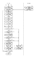
次に図4を参照して、本発明の実施形態における、重畳画像の表示処理の流れについて説明する。図4は、本発明の実施形態における、重畳画像の表示処理の流れを示すフローチャートである。 Next, with reference to FIG. 4, the flow of the superimposed image display process in the embodiment of the present invention will be described. FIG. 4 is a flowchart showing the flow of the superimposed image display process in the embodiment of the present invention.
図4の処理の説明後、図5の図を参照して、本発明の第1の実施形態〜第4の実施形態について説明する。図4は、第1の実施形態〜第4の実施形態における共通の処理である。 After the description of the processing in FIG. 4, the first to fourth embodiments of the present invention will be described with reference to the diagram in FIG. FIG. 4 shows common processing in the first to fourth embodiments.
HMD101は、撮像処理の開始指示を受け付ける(ステップS401)。また、一方、PC100のCPU201は、HMD101より撮像画像を取得した場合に、重畳画像を生成してHMDに返信する処理を開始する指示を受け付け、待機する(ステップS407)。
The
赤外線カメラ104は、HMD101の位置を検知すべく撮像処理の開始指示を受け付ける(ステップS413)。尚、HMD101には、赤外線カメラで位置を検出可能にすべく、赤外線センサが設置されているものとする。
The
HMD101は、撮像処理を行い(例えばマーカ画像を撮像して/ステップS402)、撮像した画像である撮像画像(現実画像)をPC100に順次送信する(ステップS403)。ここでいう撮像処理は例えばビデオ撮像である。
The
赤外線カメラ104は、撮像処理を行い(ステップS414)、HMDの位置、姿勢の情報をPC100に送信する(ステップS415)。当該HMDの位置とは、MR空間上の位置である。ここでは、予め定義された仮想空間の原点と、現実空間の所定の位置との位置合わせ(MR空間を定義)が行われていることを前提とし、赤外線カメラ104は、当該原点からのHMDの相対位置(相対座標)、及び、HMDの角度・方向の情報を取得して、PC100に送信する。
The
PC100のCPU201は、HMD101より撮像画像を受信して外部メモリに記憶し、(ステップS408)、赤外線カメラ104よりHMDの位置・姿勢の情報を受信して、随時外部メモリに記憶する(ステップS409)。
The
PC100のCPU201は、HMD101より受信した撮像画像(現実画像)に、仮想空間上に配置したオブジェクトの画像を重畳した重畳画像(MR画像)を生成する処理を実行する(ステップS410)。
The
本発明の第1の実施形態における、重畳画像の生成処理(ステップS410)の詳細については、図5〜図8の説明で後述する。 Details of the superimposed image generation processing (step S410) in the first embodiment of the present invention will be described later with reference to FIGS.
本発明の第2の実施形態における、重畳画像の生成処理(ステップS410)の詳細については、図9〜図11の説明で後述する。 Details of the superimposed image generation processing (step S410) in the second embodiment of the present invention will be described later with reference to FIGS.
本発明の第3の実施形態における、重畳画像の生成処理(ステップS410)の詳細については、図12〜図14の説明で後述する。 Details of the superimposed image generation process (step S410) in the third embodiment of the present invention will be described later with reference to FIGS.
本発明の第4の実施形態における、重畳画像の生成処理(ステップS410)の詳細については、図15〜図16の説明で後述する。 Details of the superimposed image generation processing (step S410) according to the fourth embodiment of the present invention will be described later with reference to FIGS.
PC100のCPU201は、ステップS410で生成した重畳画像をHMD101に送信し(ステップS411)、HMD101が重畳画像を受信して(ステップS404)、表示画面に表示する(ステップS405)。
The
HMD101は撮像処理の終了指示を受け付けたか判定し(ステップS406)、終了指示を受け付けた場合には処理を終了し(ステップS406でYES)、終了指示を受け付けていない場合は撮像処理を継続する(ステップS406でNO/ステップS402に処理を戻す)。
The
PC100のCPU201は、重畳画像を生成してHMDに返信する処理を終了する終了指示を受け付けたか判定し(ステップS412)、終了指示を受け付けた場合には処理を終了し(ステップS412でYES)、終了指示を受け付けていない場合は処理を継続する(ステップS412でNO/ステップS408に処理を戻す)。
The
赤外線カメラ104は撮像処理の終了指示を受け付けたか判定し(ステップS416)、終了指示を受け付けた場合には処理を終了し(ステップS416でYES)、終了指示を受け付けていない場合は撮像処理を継続する(ステップS416でNO/ステップS414に処理を戻す)。以上が図4の、本発明の実施形態における、重畳画像の表示処理の流れについての説明である。
The
<第1の実施形態> <First Embodiment>
次に図5〜図8を参照して、本発明の第1の実施形態について説明する。本発明の第1の実施形態においては、撮像画像から検出された手の数に応じて、ターゲットマーカに重畳するオブジェクトを透過し、現実物体の存在をユーザに通知する。 Next, a first embodiment of the present invention will be described with reference to FIGS. In the first embodiment of the present invention, according to the number of hands detected from the captured image, the object superimposed on the target marker is transmitted to notify the user of the presence of the real object.
図5を参照して、本発明の第1の実施形態における、重畳画像の生成処理の流れについて説明する。 With reference to FIG. 5, the flow of the superimposed image generation process in the first embodiment of the present invention will be described.
PC100のCPU201は、撮像画像を解析してターゲットマーカ105の画像を1つ取得し、外部メモリに記憶されているマーカ画像と比較して当該ターゲットマーカ105のどのIDのマーカかを特定する(ステップS501)。そして、当該マーカに対応する
オブジェクトを外部メモリより取得する。
The
ここで図6を参照して、本発明の第1の実施形態において用いる各種データの構成の一例について説明する。図6に示す各データは、PC100の外部メモリに記憶されているものとする。
Here, with reference to FIG. 6, an example of the configuration of various data used in the first embodiment of the present invention will be described. Each data shown in FIG. 6 is assumed to be stored in the external memory of the
マーカ情報600は、オブジェクトを空間上に配置するために用いられるマーカの情報である。マーカID601は、マーカの識別情報である。サイズ602は、マーカのサイズであり、マーカイメージは、それぞれ一意に識別可能なマーカの画像データ(識別画像)である。
The marker information 600 is marker information used for arranging an object in space. The
オブジェクト対応付け情報610は、マーカと、オブジェクトの対応付けを示し、オブジェクトの空間上の座標を記憶するテーブルである。オブジェクトID611は、オブジェクトを一意に識別するための識別情報である。
The object association information 610 is a table that indicates the association between a marker and an object, and stores the coordinates of the object in space. The
マーカID612は、マーカの識別情報であり、オブジェクトID611の示すオブジェクトがいずれのマーカIDのマーカに対応付けられているかを示す。PC100のCPU201は、マーカID612のマーカ(ターゲットマーカ)を検出した場合、当該マーカの中心点を原点とし、当該マーカの傾きからX軸、Y軸、Z軸を算出して、オブジェクトID611のオブジェクトを、オブジェクト相対座標613の示す位置に配置する。
The
オブジェクト世界座標614は、オブジェクトID611の示すオブジェクトの、空間上における原点からの相対座標(MR空間内における世界座標)を示す。オブジェクト世界座標は、当該オブジェクトに対応するターゲットマーカを撮像するHMD101の位置・姿勢の情報、及び当該HMD101によって撮像された当該ターゲットマーカの大きさ、方向、傾き等の情報を用いて、逐次、PC100のCPU201が算出し、オブジェクト世界座標614に記憶するものとする。つまり、オブジェクト世界座標614の値は、HMD101がマーカID612のターゲットマーカを撮像し、当該ターゲットマーカが空間上(MR空間上)を移動することで変動する。
The object world coordinates 614 indicate relative coordinates (world coordinates in the MR space) of the object indicated by the
オブジェクト情報620は、オブジェクト(PC100で読込可能な3次元画像ファイル(例えば3次元CADファイル)であるものとする)と、当該オブジェクトの識別情報であるオブジェクトID621の対応付け情報である。
The object information 620 is association information between an object (a three-dimensional image file (for example, a three-dimensional CAD file) that can be read by the PC 100) and an
また、当該オブジェクトID621のオブジェクトを透過して描画するか否かを示す透過フラグ623が対応付けて記憶されている。透過フラグ623=1の場合、当該オブジェクトの透過率を、透過率624の示す透過率に変更する。第1の実施形態においては、透過率624は一律で50%の値が設定されているものとする。透過フラグ623=0の場合、オブジェクトを透過しない。つまり、オブジェクトの透過率を0%とする。
Further, a
透過条件630は、オブジェクトを透過する条件(透過フラグ623を1に変更するための条件)である。第1の実施形態において、透過条件630は、手検出数631である。手検出数631において、n=撮像画像から検出された手の数である。
The transmission condition 630 is a condition for transmitting the object (a condition for changing the
つまり、第1の実施形態においては、撮像画像から検出された手の数≧2(所定の数)である場合に、透過フラグ623を1に変更する。当該手検出数631の値は、ユーザ操作に応じて、PC100に表示される不図示の設定画面から任意に変更可能であるものとする。以上が図6の説明である。
That is, in the first embodiment, the
図5の説明に戻る。PC100のCPU201は、HMD101から取得した撮像画像より手の画像を検出する(ステップS503)。例えば、手の形状、色を予めPC100の外部メモリに記憶しておき、当該手の形状、色と所定以上類似する画像を手の画像として特定し、手(ユーザの体の一部/請求項でいう身体情報)を検出するものとする。そして、手検出数631を参照して、所定数以上の手が検出されたか判定する(ステップS504)。
Returning to the description of FIG. The
所定数以上の手が検出されたと判定された場合(ステップS504でYES)、ステップS502で取得したオブジェクトの透過フラグ623を1に変更し、透過率を50%に変更して(ステップS505)、当該透過されたオブジェクトを撮像画像に重畳して重畳画像を生成する(ステップS506)。オブジェクトの透過表示(透過されたオブジェクトが重畳された重畳画像)の様子については、図7及び図8の説明に示す。
If it is determined that a predetermined number of hands or more have been detected (YES in step S504), the
手の検出に応じて、現実物体(ターゲットマーカ105が貼り付けられたモック103)の受け渡しに際し、オブジェクトを透過表示して、オブジェクトが重畳された、オブジェクトが対応付けられている現実物体が視認可能になる。つまり、現実物体の受け渡しが容易になる。
When a real object (mock 103 to which the
所定数以上の手が検出されなかったと判定された場合(ステップS504でNO)、ステップS502で取得したオブジェクトの透過フラグ623を0に変更し、透過率を0%に変更して(ステップS507)、当該非透過状態のオブジェクトを撮像画像に重畳して重畳画像を生成する(ステップS508)。
If it is determined that a predetermined number of hands or more have not been detected (NO in step S504), the
PC100のCPU201は、撮像画像中の全てのマーカについてステップS501〜S508の処理を適用したかを判定し(ステップS509)、全てのマーカについてステップS501〜S508の処理を適用していないと判定した場合(ステップS509でNO)、処理をステップS501の前に戻して、ステップS501で、未処理のマーカを取得する。
When the
全てのマーカについてステップS501〜S508の処理を適用したと判定した場合(ステップS509でYES)、処理を終了する。以上が図5の説明である。 If it is determined that the processing in steps S501 to S508 has been applied to all the markers (YES in step S509), the processing ends. The above is the description of FIG.
図7及び図8は、本発明の第1の実施形態における、オブジェクトの透過表示の様子を示す図である。図7は、透過条件630(手検出数631)=n≧2である場合の、オブジェクトの透過表示の様子を示す。状態700は、HMD101のカメラで撮像された現実画像である。状態710は、撮像画像に、モック103のターゲットマーカ105に対応付けられたオブジェクト711を重畳した重畳画像である。手の検出数は1であるため、オブジェクト711は透過率=0%で描画、重畳されている。
7 and 8 are diagrams showing a state of transparent display of an object in the first embodiment of the present invention. FIG. 7 shows a state of transparent display of an object when the transmission condition 630 (number of detected hands 631) = n ≧ 2. A state 700 is a real image captured by the
状態720は、手を2つ検出した場合の重畳画像を示す。手を2つ検出することで(モックの受け渡しが行われるものと推測して)、オブジェクトを透過している。オブジェクトが透過されることにより、状態720に示すように、状態710ではオブジェクトが重なって見えなかったモック103とマーカ105が視認可能となっている。
A state 720 shows a superimposed image when two hands are detected. By detecting two hands (assuming that a mock is delivered), the object is transmitted. When the object is transmitted, as shown in a state 720, the mock 103 and the
つまり、オブジェクトの受け渡しに際し、オブジェクトに対応する現実物体の存在をユーザに通知することが可能となっている。 That is, when the object is delivered, it is possible to notify the user of the existence of a real object corresponding to the object.
また、図8は、透過条件630(手検出数631)=n≧3である場合の、オブジェクトの透過表示の様子を示す。状態800は、図7の状態700と同様である。状態810は、撮像画像に、モック103のターゲットマーカ105に対応付けられたオブジェクト711を重畳した重畳画像である。手の検出数は2以下であるため、オブジェクト711は透過率=0%で描画、重畳されている。
FIG. 8 shows a state of transparent display of an object when the transmission condition 630 (number of detected hands 631) = n ≧ 3. State 800 is similar to state 700 of FIG. A state 810 is a superimposed image in which an
状態820は、手を3つ検出した場合の重畳画像を示す。手を3つ検出することで(モックの受け渡しが行われるものと推測して)、オブジェクトを透過している。オブジェクトが透過されることにより、状態820に示すように、状態810ではオブジェクトが重なって見えなかったモック103とマーカ105が視認可能となっている。
A state 820 shows a superimposed image when three hands are detected. By detecting three hands (assuming that a mock is delivered), the object is transmitted. By transmitting the object, as shown in a state 820, the mock 103 and the
以上が本発明の第1の実施形態の説明である。本発明の第1の実施形態によれば、オブジェクトの受け渡しに際し、オブジェクトに対応する現実物体の存在をユーザに通知することが可能である。 The above is the description of the first embodiment of the present invention. According to the first embodiment of the present invention, when an object is delivered, it is possible to notify the user of the presence of a real object corresponding to the object.
<第2の実施形態> <Second Embodiment>
次に図9〜図11を参照して、本発明の第2の実施形態について説明する。本発明の第2の実施形態においては、撮像画像から検出された手とオブジェクトとの距離に応じて、ターゲットマーカに重畳するオブジェクトを透過し、現実物体の存在をユーザに通知する。 Next, a second embodiment of the present invention will be described with reference to FIGS. In the second embodiment of the present invention, the object superimposed on the target marker is transmitted according to the distance between the hand and the object detected from the captured image, and the presence of the real object is notified to the user.
図9を参照して、本発明の第2の実施形態における、重畳画像の生成処理の流れについて説明する。図9の処理をするまでの前処理である図4の処理については上述したため説明は割愛する。 With reference to FIG. 9, the flow of the superimposed image generation process in the second embodiment of the present invention will be described. Since the process of FIG. 4 which is the pre-process until the process of FIG. 9 is described above, the description thereof is omitted.
また、ステップS501〜S503の処理は、第1の実施形態と同様の処理であるため、説明は割愛する。 Moreover, since the process of step S501-S503 is a process similar to 1st Embodiment, description is omitted.
PC100のCPU201は、検出した手の、MR空間上の座標を特定する(ステップS901)。具体的には、PC100のCPU201が、検出した手の画像を参照し、三角測量の技術を用いて、HMD101から見た手までの距離・手の位置を算出する。そして、HMD101の位置・姿勢から、当該三角測量で算出した手までの距離・手の位置の情報を用いて、MR空間上の手の座標(位置)を特定するものとする。当該手の座標の特定処理は、検出された手の数だけ行われる。
ステップS901で特定された手の座標の情報は、随時、PC100の外部メモリに記憶される。
The
Information on the hand coordinates specified in step S901 is stored in the external memory of the
ここで図10を参照して、本発明の第2の実施形態において用いる各種データの構成の一例を示す図である。図10に示す各データは、PC100の外部メモリに記憶されているものとする。
Here, with reference to FIG. 10, it is a figure which shows an example of a structure of the various data used in the 2nd Embodiment of this invention. Each data shown in FIG. 10 is assumed to be stored in the external memory of the
マーカ情報1000は、図6のマーカ情報600と同一のため、説明は割愛する。オブジェクト対応付け情報1010は、マーカとオブジェクトの対応付けを示し、オブジェクトの空間上の座標を記憶するテーブルである。更に、オブジェクトが他のオブジェクトと接触しているか、また、どのオブジェクトと接触しているかを記憶するテーブルである。 The marker information 1000 is the same as the marker information 600 in FIG. The object association information 1010 is a table that indicates the association between the marker and the object, and stores the coordinates of the object in space. Further, the table stores whether an object is in contact with another object and which object is in contact with the object.
オブジェクトID1011、マーカID1012、オブジェクト相対座標1013、オブジェクト世界座標1014は、図6のオブジェクトID611、マーカID612、オブジェクト相対座標613、オブジェクト世界座標614と同一のため、説明は割愛する。
The
接触先オブジェクト1015は、オブジェクトID1011が接触しているオブジェクトである。当該オブジェクトの接触判定(他のオブジェクトと接触しているか、及び、どのオブジェクトと接触しているか)は、PC100のCPU201が、各オブジェクトのオブジェクト世界座標1014、及び、各オブジェクトの形状(オブジェクト1022から特定)を用いて行う。当該オブジェクト同士の接触判定は、既存の技術のため、ここでは説明を割愛する。
The
接触フラグ1016は、接触しているオブジェクトの少なくともいずれか一方が手のオブジェクトである場合(図10でいう、オブジェクトID1011=hand111〜444)、接触状態であるものとして、1の値が挿入される。接触しているオブジェクトのいずれもが手のオブジェクトでない場合、非接触状態であるものとして、0の値が挿入される。
When at least one of the touching objects is a hand object (
オブジェクト情報1020は、図6のオブジェクト情報620と同一のため説明は割愛する。尚、透過フラグ1023=nullは、透過しない(透過不可能な)種別のオブジェクトであることを示す。
The object information 1020 is the same as the object information 620 in FIG. Note that the
透過条件1030は、オブジェクトを透過する条件(透過フラグ1023を1に変更するための条件)である。第2の実施形態において、透過条件1030は、手検出数1031、所定距離1032、接触フラグ1033である。手検出数1031において、n=撮像画像から検出された手の数である。また、所定距離1032は、HMD101からの所定距離内に手検出数1031を満たすだけの数の手があるかを判定するための条件である。接触フラグ1033は、当該所定距離1032にある手の内少なくとも1つの手が、オブジェクトに接触しているかを判定するための条件である。
The transmission condition 1030 is a condition for transmitting the object (a condition for changing the
第2の実施形態において、手検出数1031、所定距離1032、接触フラグ1033はAND条件である。つまり、透過条件1030によれば、撮像画像から検出された手の数≧2(所定の数)であって、且つ、当該2以上の手がHMD101の周囲2m以内(所定の距離範囲内)に存在し、当該HMD101の周囲2m以内に存在する手のいずれか1つでもオブジェクト(例えば後述の図11でいうオブジェクト1111)に接触している場合に、オブジェクト1111の透過フラグ1023を1に変更する。当該手検出数1031及び所定距離1032の値は、ユーザ操作に応じて、PC100に表示される不図示の設定画面から任意に変更可能であるものとする。以上が図10の説明である。
図9の説明に戻る。
In the second embodiment, the number of detected
Returning to the description of FIG.
PC100のCPU201は、外部メモリに記憶されている手のオブジェクトを1つ取得して(ステップS902)、手のオブジェクトをステップ0S901で特定した座標に、ステップS502で取得したオブジェクトをステップS501で特定されたターゲットマーカの座標に基づいて、それぞれ仮想空間上に配置する(ステップS903)。
The
尚、当該手のオブジェクトは、オブジェクトID1011=hand111〜のオブジェクトとして、予めPC100の外部メモリに記憶されている。当該手のオブジェクトは、手が検出されたタイミングで外部メモリから読み出され、オブジェクト情報1020、オブジェクト対応付け情報1010に追加され、手が検出されなくなったタイミングで、オブジェクト情報1020、オブジェクト対応付け情報1010から削除されるものとする。手のオブジェクトのオブジェクト世界座標1014には、ステップS901で特定された手の座標が記憶され、随時更新される。
The object of the hand is stored in advance in the external memory of the
PC100のCPU201は、所定距離1032を参照して、HMD101の位置(ステップS409で取得して、外部メモリに記憶されている座標)から周囲2m以内にある手のオブジェクトを、手のオブジェクトのオブジェクト世界座標1014を参照して特定する(ステップS904)。
The
PC100のCPU201は、手検出数1031を参照して、HMD101の周囲2m以内に、手が所定数以上あるか判定する(ステップS504)。HMD101の周囲2m以内に、手が所定数以上ないと判定された場合(ステップS504でNO)、処理をステップS507に移行する。ステップS507以降の処理は図5で説明した内容と同一のため、ここでは説明を割愛する。
The
HMD101の周囲2m以内に、手が所定数以上あると判定された場合(ステップS504でYES)、PC100のCPU201は、当該HMD101の周囲2m以内に存在する手のオブジェクトの接触先オブジェクト1015、接触フラグ1016を参照して、当該HMD101の周囲2m以内に存在する手のオブジェクトのいずれかが、ステップS502で取得したオブジェクトと接触しているかを判定する(ステップS905)。
When it is determined that there are a predetermined number of hands within 2 m around the HMD 101 (YES in step S504), the
HMD101の周囲2m以内に存在する手のオブジェクトのいずれも、オブジェクトと接触していないと判定された場合(ステップS905でNO)、処理をステップS507に移行する。HMD101の周囲2m以内に存在する手のオブジェクトのいずれかが、オブジェクトと接触していると判定された場合(ステップS905でYES)、処理をステップS505に移行する。ステップS505以降の処理は図5で説明した内容と同一のため、ここでは説明を割愛する。以上が図9の説明である。
If it is determined that none of the hand objects existing within 2 m around the
図11を参照して、本発明の第2の実施形態における、オブジェクトの透過表示の様子について説明する。状態1100は、HMD101のカメラで撮像された現実画像の状態を示す。状態1110は、撮像画像に、モック103のターゲットマーカ105に対応付けられたオブジェクト1111を重畳した重畳画像である。また、1112は、別途、MR空間上の所定の座標に配置されたオブジェクトである。
With reference to FIG. 11, a state of transparent display of an object in the second embodiment of the present invention will be described. A state 1100 indicates a state of a real image captured by the
状態1120は、手を2つ検出した場合の重畳画像を示す。手を2つ検出することで(モックの受け渡しが行われるものと推測して)、手の接触しているオブジェクト(受け渡しがされると推測されるオブジェクト)を透過している。一方、手が接触していないオブジェクトは(受け渡しがされないと推測し)、透過をせずに描画・重畳している。 A state 1120 shows a superimposed image when two hands are detected. By detecting two hands (assuming that a mock is transferred), the object in contact with the hand (an object estimated to be transferred) is transmitted. On the other hand, an object that is not in contact with the hand (assuming that it is not delivered) is drawn and superimposed without being transparent.
オブジェクトが透過されることにより、状態1120に示すように、状態1110ではオブジェクトが重なって見えなかったモック103とマーカ105が視認可能となっている。以上が図11の説明である。
When the object is transmitted, as shown in a state 1120, the mock 103 and the
以上が本発明の第2の実施形態の説明である。本発明の第2の実施形態によれば、オブジェクトの受け渡しに際し、オブジェクトに対応する現実物体の存在をユーザに通知することが可能である。 The above is the description of the second embodiment of the present invention. According to the second embodiment of the present invention, when an object is delivered, it is possible to notify the user of the existence of a real object corresponding to the object.
具体的には、HMDから所定範囲内に手があり、手のいずれかがターゲットマーカに対応するオブジェクトに接触している場合に、ターゲットマーカに対応するオブジェクト(接触中のオブジェクト)を透過させることで、ターゲットマーカの付された現実物体を視認可能にすることができる。 Specifically, when there is a hand within a predetermined range from the HMD and one of the hands is in contact with the object corresponding to the target marker, the object corresponding to the target marker (the object in contact) is transmitted. Thus, the real object with the target marker attached can be made visible.
例えば、2人以上のユーザのいずれかがオブジェクトに触れて相手に受け渡そうとしており、且つ、手が、HMDから近い位置にあるユーザ自身の手、又はオブジェクトを受け取るユーザ/渡すユーザの手であると判断された場合に、オブジェクトを透過するものである。 For example, one of two or more users is touching an object and trying to hand it over to the other party, and the hand is the user's own hand that is close to the HMD, or the user receiving or handing the object When it is determined that there is an object, the object is transmitted.
尚、上述した第2の実施形態においては、HMD101から所定距離内に、所定数以上の手があり、手がオブジェクトに接触している場合にオブジェクトの透過処理を行っているが、例えば、単純に所定数以上の手が検出され、手がオブジェクトに接触している場合にオブジェクトの透過処理を行うようにしてもよい。具体的には、図9のステップS904をスキップして、ステップS504の判定を、ステップS503で検出した手の総数に対して実行し、図9の処理を実行することで実現可能である。
In the second embodiment described above, the object transparency process is performed when there are a predetermined number of hands or more within a predetermined distance from the
<第3の実施形態> <Third Embodiment>
次に図12〜図14を参照して、本発明の第3の実施形態について説明する。本発明の第3の実施形態においては、撮像画像から検出された手の情報と、オブジェクトとHMDが接近しているか否かに応じて、ターゲットマーカに重畳するオブジェクトを透過し、現実物体の存在をユーザに通知する。 Next, a third embodiment of the present invention will be described with reference to FIGS. In the third embodiment of the present invention, the presence of a real object is transmitted through the object superimposed on the target marker according to hand information detected from the captured image and whether the object and the HMD are close to each other. To the user.
図12を参照して、本発明の第3の実施形態における、重畳画像の生成処理の流れについて説明する。図12の処理をするまでの前処理である図4の処理については上述したため説明は割愛する。 With reference to FIG. 12, the flow of the superimposed image generation process in the third embodiment of the present invention will be described. Since the process of FIG. 4 which is the pre-process until the process of FIG. 12 is described above, the description thereof is omitted.
ステップS501〜S504の処理は、第1の実施形態と同様の処理であるため、説明は割愛する。また、ステップS901〜S905の処理は、第2の実施形態と同様の処理であるため、説明は割愛する。 Since the processing in steps S501 to S504 is the same as that in the first embodiment, description thereof is omitted. Moreover, since the process of step S901-S905 is a process similar to 2nd Embodiment, description is omitted.
PC100のCPU201は、ステップS1201で、ステップS502で取得した(ステップS905でYESと判定された)オブジェクトの移動量を特定する。つまり、オブジェクトがどの程度の速度で、どの程度の距離、どの方向に向けて移動しているかを特定する。オブジェクトの移動量の情報は、例えば図13に示すような、PC100のCPU201が、PC100の外部メモリに随時記憶しているオブジェクトの座標の履歴を用いて特定される。
In step S1201, the
図13は、本発明の第3の実施形態において用いる各種データの構成の一例を示す図である。図13に示す各データは、PC100の外部メモリに記憶されているものとする。オブジェクト移動履歴1300は、オブジェクト(オブジェクトID1301)ごとに、所定のタイミングで(例えば、ステップS903でオブジェクトが配置されるタイミングで)随時記憶され、更新される。時刻1302は、オブジェクトID1301のオブジェクトが、オブジェクト世界座標1303に存在した時刻の情報である。
FIG. 13 is a diagram showing an example of the configuration of various data used in the third embodiment of the present invention. Each data shown in FIG. 13 is assumed to be stored in the external memory of the
また、HMD座標履歴1310は、HMD101(HMD ID1311)ごとに、所定のタイミングで(例えば、ステップS409でHMD101の位置・姿勢の情報を受信して記憶するタイミングで)随時記憶され、更新される。時刻1312は、HMD ID1311のHMD101が、HMD世界座標1313に存在した時刻の情報である。以上が図13の説明である。
Further, the HMD coordinate history 1310 is stored and updated as needed for each HMD 101 (HMD ID 1311) at a predetermined timing (for example, at the timing of receiving and storing information on the position / attitude of the
図12の説明に戻る。PC100のCPU201は、ステップS502で取得した(ステップS905でYESと判定された)オブジェクトが、HMD101に接近したか判定する(ステップS1202)。ここでは、1秒前から5cm以上(所定の値以上)HMD101と当該オブジェクトが接近したかを、オブジェクト座標履歴1300、HMD座標履歴1310を参照して判定するものとする。
Returning to the description of FIG. The
当該所定の値(不図示/XX秒前からXX以上接近したか、という条件を示す値)は、予め、PC100の外部メモリに記憶されているものとする。また、当該所定の値は、ユーザ操作に応じて、PC100に表示される不図示の設定画面から任意に変更可能であるものとする。
It is assumed that the predetermined value (not shown / a value indicating a condition of approaching more than XX seconds before XX seconds) is stored in advance in the external memory of the
PC100のCPU201は、オブジェクトがHMD101に接近したと判定した場合(ステップS1202でYES)、処理をステップS505に移行し、オブジェクトがHMD101に接近していないと判定した場合(ステップS1202でNO)、処理をステップS507に移行する。ステップS505以降の処理は図5で説明した内容と同一のため、ここでは説明を割愛する。以上が図12の説明である。
図14は、本発明の第3の実施形態における、各HMDにおけるオブジェクトの通常表示及び透過表示の様子を示す図である。
If the
FIG. 14 is a diagram illustrating a state of normal display and transparent display of an object in each HMD in the third embodiment of the present invention.
状態1400、状態1410は、オブジェクトを受け取る側のユーザが装着しているHMD101Aの画面状態を示す。状態1450、状態1460は、オブジェクトを渡す側のユーザが装着しているHMD101Bの画面状態を示す。
A state 1400 and a state 1410 indicate screen states of the
状態1400は、HMD101Aに表示されている、HMD101Bのユーザがオブジェクト1401(ターゲットマーカ105の付されたモック103)を持っている重畳画像の状態を示す。状態1410への画面遷移の様子から分かるとおり、HMD101A(受け取る側のユーザ)とオブジェクト1401が接近した場合に、オブジェクト1401を1411に示すように透過する。
A state 1400 indicates a state of a superimposed image displayed on the
状態1450は、HMD101Bに表示されている、HMD101Bのユーザがオブジェクト1401(ターゲットマーカ105の付されたモック103)を持っている重畳画像の状態を示す、状態1400と同時刻の画像である。状態1460は、状態1410と同時刻の画像である。状態1450から状態1460に移行するにあたり、オブジェクト1401はHMD101Bから離れている(接近していない)ため、透過処理は行わない。つまり、オブジェクト(ターゲットマーカ105の付されたモック103)の受け取り手のユーザに対して、オブジェクトを透過して確認させるものである。以上が図14の説明である。
A state 1450 is an image at the same time as the state 1400, which is displayed on the
以上が本発明の第3の実施形態の説明である。本発明の第3の実施形態によれば、オブジェクトの受け渡しに際し、オブジェクトに対応する現実物体の存在をユーザに通知することが可能である。 The above is the description of the third embodiment of the present invention. According to the third embodiment of the present invention, when an object is delivered, it is possible to notify the user of the presence of a real object corresponding to the object.
具体的には、手の状態(手が所定数以上か、手がオブジェクトに触れているか等)と、オブジェクトがユーザに接近している(ユーザがオブジェクトの受け取り手であると推測される)場合に、オブジェクトを透過するものである。 Specifically, the state of the hand (whether the hand is more than a predetermined number, whether the hand is touching the object, etc.) and the object is approaching the user (the user is assumed to be the recipient of the object) In addition, the object is transparent.
尚、上述した第3の実施形態においては、HMD101から所定距離内に、所定数以上の手があるか、また、手が接触しているオブジェクトがHMD101に接近したかに応じてオブジェクトの透過処理を行っているが、例えば、所定数以上の手が検出され、オブジェクトがHMD101に接近したかに応じてオブジェクトの透過処理を行うようにしてもよい。具体的には、図12のステップS902〜S904、S905をスキップして図12の処理を実行することで実現可能である。
In the third embodiment described above, object transparency processing is performed depending on whether there are a predetermined number of hands or more within a predetermined distance from the
また、例えば、手とオブジェクトが接触している状態で、オブジェクトがHMD101に接近したかに応じてオブジェクトの透過処理を行うようにしてもよい。具体的には、図12のステップS904、S504をスキップして図12の処理を実行することで実現可能である。
Further, for example, the object transparency process may be performed depending on whether the object approaches the
<第4の実施形態> <Fourth Embodiment>
次に図15、図16を参照して、本発明の第4の実施形態について説明する。本発明の第4の実施形態においては、2つ以上のHMD101のカメラで同じオブジェクトが撮像されている場合に、撮像画像から検出された手の状態に応じて、ターゲットマーカに重畳するオブジェクトを透過し、現実物体の存在をユーザに通知する。
Next, a fourth embodiment of the present invention will be described with reference to FIGS. In the fourth embodiment of the present invention, when two or
図15を参照して、本発明の第4の実施形態における、重畳画像の生成処理の流れについて説明する。図15の処理をするまでの前処理である図4の処理については上述したため説明は割愛する。 With reference to FIG. 15, the flow of the superimposed image generation process in the fourth embodiment of the present invention will be described. Since the process of FIG. 4 which is the pre-process until the process of FIG. 15 is described above, the description is omitted.
PC100AのCPU201は、PC100Bに対して、HMD101Bで撮像中のマーカの情報を要求する(ステップS1501)。尚、当該HMD101Bで撮像中のマーカの情報は、図16の撮像マーカID1602を示すものであり、後に実行するステップS501で撮像画像中より取得、特定されて、PC100の外部メモリに記憶されるものとする。ここでは、既に一度ステップS501の処理が行われ、HMD101で撮像中のマーカの情報が各PC100に記憶済みであるものとして説明を行う。
The
ここで図16を参照して、本発明の第4の実施形態において用いる各種データの構成の一例について説明する。図16に示す各データは、PC100の外部メモリに記憶されているものとする。
Here, with reference to FIG. 16, an example of the configuration of various data used in the fourth embodiment of the present invention will be described. Each data shown in FIG. 16 is assumed to be stored in the external memory of the
撮像マーカ情報1600(識別画像情報記憶手段に該当)は、いずれのHMD101(HMD ID1601)で、いずれのマーカが撮像中かを示す。撮像マーカID1602は、HMD ID1601の示すHMD101で撮像中のマーカIDである。
The imaging marker information 1600 (corresponding to the identification image information storage unit) indicates which HMD 101 (HMD ID 1601) and which marker is being imaged. The
透過率設定1610は、手の検出数と透過率の値を対応付けたテーブルである。手の検出数が2の場合は、オブジェクトの透過率(透過率1624)は、40%に設定される。また、手の検出数が3の場合は、オブジェクトの透過率(透過率1624)は、60%に設定される。また、手の検出数が4以上の場合は、オブジェクトの透過率(透過率1624)は、80%に設定される。 The transmittance setting 1610 is a table in which the number of detected hands is associated with the transmittance value. When the number of detected hands is 2, the transmittance of the object (transmittance 1624) is set to 40%. When the number of detected hands is 3, the transmittance of the object (transmittance 1624) is set to 60%. When the number of detected hands is 4 or more, the transmittance of the object (transmittance 1624) is set to 80%.
例えば、オブジェクトを片手で渡し、片手で受け取る場合、手の検出数は2であると考えられる。例えば片手で持てるような軽い現実物体(モック103)であれば、取り落とした際の危険性が低いと推測し、低い透過率でオブジェクトを描画する。また、オブジェクトを両手で渡し、両手で受け取る場合、手の検出数は4であると考えられる。両手で渡し両手受け取るような重い現実物体、また、重要物等であれば、取り落とす危険性をより確実に低減するため、現実物体がよく見えるよう、高い透過率でオブジェクトを描画する。 For example, when an object is delivered with one hand and received with one hand, the number of detected hands is considered to be two. For example, if it is a light real object (mock 103) that can be held with one hand, it is estimated that the risk of being dropped is low, and the object is drawn with low transmittance. Further, when the object is passed with both hands and received with both hands, the number of detected hands is considered to be four. If the object is a heavy real object that is passed between both hands and received by both hands, or an important object, the object is drawn with high transmittance so that the danger of dropping the object is more reliably reduced.
オブジェクト情報1620のオブジェクトID1621、オブジェクト1622、透過フラグ1623は、図6のオブジェクトID621、オブジェクト622、透過フラグ623はと同じであるため説明は割愛する。透過率1624は、PC100のCPU201が、手の検出数に応じて設定、変更する。以上が図16の説明である。
The
図15の説明に戻る。PC100BのCPU201は、PC100Aより、HMD101Bの撮像マーカ情報1600の要求を受け付け(ステップS1502)、外部メモリより、HMD101Bの撮像マーカ情報1600を取得して、PC100Aに送信する(ステップS1503)。PC100AのCPU201はこれを受信して、自装置内の撮像マーカ情報1600(HMD ID=HMD101Bに対応するデータ列)に記憶する。また、ステップS501において、HMD101Aの撮像画像よりマーカ画像を取得してマーカIDを特定し、自装置内の撮像マーカ情報1600(HMD ID=HMD101Aに対応するデータ列)に記憶する。
Returning to the description of FIG. The
ステップS502〜S504の処理は、第1の実施形態と同様の処理であるため、説明は割愛する。ステップS901〜S905の処理は、第2の実施形態と同様の処理であるため、説明は割愛する。ステップS1201、S1202の処理は、第3の実施形態と同様の処理であるため、説明は割愛する。 Since the processing in steps S502 to S504 is the same as that in the first embodiment, description thereof is omitted. Since the processing in steps S901 to S905 is the same as that in the second embodiment, description thereof is omitted. The processes in steps S1201 and S1202 are the same as those in the third embodiment, and thus the description thereof is omitted.
PC100AのCPU201は、ステップS502で取得したオブジェクト(ステップS1202でYESと判定されたオブジェクト)が、複数のHMD101で撮像されているか判定する(ステップS1505)。ここでは、当該オブジェクトに対応するターゲットマーカがHMD101AとHMD101Bで撮像されている場合、当該オブジェクトが複数のHMD101で撮像されていると判定するものとする。
The
ステップS502で取得したオブジェクト(ステップS1202でYESと判定されたオブジェクト)が、複数のHMD101で撮像されていないと判定された場合(ステップS1505でNO)、処理をステップS508に移行する。ステップS508以降の処理は図5の説明で前述したため、ここでは説明を割愛する。 If it is determined that the object acquired in step S502 (the object determined as YES in step S1202) is not captured by the plurality of HMDs 101 (NO in step S1505), the process proceeds to step S508. Since the processing after step S508 has been described above with reference to FIG. 5, the description thereof is omitted here.
ステップS502で取得したオブジェクト(ステップS1202でYESと判定されたオブジェクト)が、複数のHMD101で撮像されていると判定された場合(ステップS1505でYES)、処理をステップS1506に移行する。つまり、撮像マーカ情報1600において、HMD ID1601=HMD101Aの撮像マーカID1602と、HMD ID1601=HMD101Bの撮像マーカID1602との両方に、当該オブジェクトに対応するマーカID(図6でいうマーカID612)が記憶されていた場合、処理をステップS1506に移行する。
If it is determined that the object acquired in step S502 (the object determined as YES in step S1202) is captured by a plurality of HMDs 101 (YES in step S1505), the process proceeds to step S1506. That is, in the imaging marker information 1600, the marker ID (
PC100AのCPU201は、透過率設定1610を参照し、ステップS503で検出した手の検出数に基づいて、当該オブジェクトの透過率を決定する(ステップS1506/透過率決定手段に該当)。そして、当該オブジェクトに対応する透過フラグ1623を1に変更し、透過率1624に、ステップS1506で決定した透過率の値を挿入して(ステップS1507)、当該オブジェクトをステップS1506で決定した透過率に従って透過して配置した重畳画像を生成する(ステップS1508)。
その後処理をステップS510に移行する。ステップS510の処理は図5の説明で前述したため、ここでは説明を割愛する。
The
Thereafter, the process proceeds to step S510. Since the processing in step S510 has been described above with reference to FIG. 5, description thereof is omitted here.
以上が本発明の第4の実施形態の説明である。本発明の第4の実施形態によれば、オブジェクトの受け渡しに際し、オブジェクトに対応する現実物体の存在をユーザに通知することが可能である。 The above is the description of the fourth embodiment of the present invention. According to the fourth embodiment of the present invention, when an object is delivered, it is possible to notify the user of the existence of a real object corresponding to the object.
具体的には、手の状態(手が所定数以上か、手がオブジェクトに触れているか等)と、オブジェクトが複数のユーザによって見られている(2人以上のユーザ間でオブジェクトの受け渡しがあると推測される)場合に、オブジェクトを透過するものである。 Specifically, the state of the hand (whether the hand is more than a predetermined number, whether the hand is touching the object, etc.) and the object is viewed by multiple users (the object is passed between two or more users) The object is transparent.
また、検出した手の数によって、透過率を調整することができる。 Further, the transmittance can be adjusted according to the number of detected hands.
尚、上述した第4の実施形態においては、HMD101から所定距離内に、所定数以上の手があり、手が接触しているオブジェクトがHMD101に接近し、2人以上のユーザがオブジェクトを見ている(複数のHMDがオブジェクトを撮像している)場合に、手の数に応じて透過率を変更したオブジェクトを描画して、重畳画像を生成するようにしたが、例えば、所定数以上の手が検出され、2人以上のユーザがオブジェクトを見ている場合に、オブジェクトを透過するようにしてもよい。具体的には、図15のステップS901〜S904、S905、S1201、S1202をスキップして、ステップS1507及びS1508をそれぞれステップS505、S506に置き換えて図15の処理を実行することで実現可能である。
In the above-described fourth embodiment, there are a predetermined number of hands within a predetermined distance from the
また、例えば、オブジェクトに手が接触しており、2人以上のユーザがオブジェクトを見ている場合に、オブジェクトを透過するようにしてもよい。具体的には、図15のステップS904、S1201、S1202をスキップして、ステップS1507及びS1508をそれぞれステップS505、S506に置き換えて図15の処理を実行することで実現可能である。 Further, for example, when a hand is in contact with the object and two or more users are looking at the object, the object may be transmitted. Specifically, this can be realized by skipping steps S904, S1201, and S1202 in FIG. 15 and replacing steps S1507 and S1508 with steps S505 and S506, respectively, and executing the processing in FIG.
また、例えば、所定数以上の手が検知され、オブジェクトがHMD101に接近し、また、2人以上のユーザがオブジェクトを見ている場合に、オブジェクトを透過するようにしてもよい。具体的には、図15のステップS904をスキップして、ステップS1507及びS1508をそれぞれステップS505、S506に置き換えて図15の処理を実行することで実現可能である。
Further, for example, when a predetermined number of hands or more are detected, the object approaches the
また、例えば、手とオブジェクトが接触している状態で、オブジェクトがHMD101に接近し、また、2人以上のユーザがオブジェクトを見ている場合に、オブジェクトを透過するようにしてもよい。具体的には、図15のステップS504、S1201、S1202をスキップして、ステップS1507及びS1508をそれぞれステップS505、S506に置き換えて図15の処理を実行することで実現可能である。
Further, for example, when the object is close to the
また、上述した各実施形態において、PC100に透過率設定1610を記憶させ、ステップS505・S506の処理を、ステップS1506〜S1508に置き換えてPC100に実行させることで、手の検出数に応じて透過率を変更させることが可能である。
Further, in each of the above-described embodiments, the transmittance setting 1610 is stored in the
手の検出数に応じて透過率を変更する実施形態においては、例えば、オブジェクトを片手で渡し、片手で受け取る場合(手の検出数が2である場合/例えば片手で持てるような軽い現実物体であれば、取り落とした際の危険性が低いと推測し)、低い透過率でオブジェクトを描画し、また、オブジェクトを両手で渡し、両手で受け取る場合(手の検出数が4である場合/両手で渡し両手受け取るような重い現実物体、また、重要物等であれば、取り落とす危険性をより確実に低減するため)現実物体がよく見えるよう、高い透過率でオブジェクトを描画する。 In the embodiment in which the transmittance is changed according to the number of detected hands, for example, when an object is passed with one hand and received with one hand (when the number of detected hands is two / for example, a light real object that can be held with one hand) If there is, it is assumed that the risk of dropping is low, and the object is drawn with low transmittance, and the object is passed with both hands and received with both hands (when the number of detected hands is 4 / with both hands) The object is drawn with a high transmittance so that the real object can be seen well (to reduce the risk of dropping if it is a heavy real object that can be received by both hands, or an important object, etc.).
また、本発明の各実施形態においては、オブジェクト自体の透過率を変更して描画し、現実物体の存在をユーザに確認させるものとしたが、ユーザへの通知方法はこれに限るものではない。 In each embodiment of the present invention, the object itself is drawn by changing the transmittance, and the presence of the real object is confirmed by the user. However, the notification method to the user is not limited to this.
例えば図17に示すように、オブジェクトを透過する代わりに、手から所定範囲内にあるオブジェクト1701(オブジェクトの一部)を描画しないように制御する(1711)ことで、現実物体の存在をユーザに通知し、確認させるようにしてもよい。 For example, as shown in FIG. 17, instead of transmitting the object, control is performed not to draw the object 1701 (part of the object) within a predetermined range from the hand (1711), so that the presence of the real object is indicated to the user. You may make it notify and confirm.
また、例えば、オブジェクトを透過する代わりに、オブジェクトの色を変更することで、オブジェクトによって隠されている現実物体の存在をユーザに通知するようにしてもよい。 Further, for example, instead of transmitting the object, the user may be notified of the presence of a real object hidden by the object by changing the color of the object.
また、例えば、オブジェクトを透過する代わりに、オブジェクト自体のサイズを縮小して、オブジェクトと重なっている現実物体の存在をユーザに通知し、確認させるようにしてもよい。 Further, for example, instead of transmitting the object, the size of the object itself may be reduced to notify the user of the presence of a real object that overlaps the object and confirm it.
また、本発明の実施形態においては、オブジェクトの受け渡しがされるか否かの判定基準として手を検出することを条件としたが、手に限らず、ユーザの体の少なくとも一部を検出したか判定するようにしてもよい。 Further, in the embodiment of the present invention, the condition is that the hand is detected as a criterion for determining whether or not the object is delivered, but is not limited to the hand, is at least a part of the user's body detected? You may make it determine.
例えば、第1の実施形態における手の検出数の代わりに、肌色(ユーザの体のいずれか)の検出数を条件としてもよい。 For example, instead of the number of detected hands in the first embodiment, the number of detected skin colors (any of the user's bodies) may be used as a condition.
また、人感センサ等を用いて人の体温を検出し、手の検出数の代わりに、当該人感センサで検出された体温(人)の検出数を条件としてもよい。 Alternatively, the human body temperature may be detected using a human sensor, and the number of detected body temperatures (persons) detected by the human sensor may be used as a condition instead of the number of detected hands.
また、HMD101の位置を人の位置であるものとし、手の検出数の代わりに、視界内にHMD101が存在するかを特定して、当該特定されたHMDの数を条件としてもよい。
Alternatively, the position of the
以上説明したように、本発明によれば、オブジェクトの受け渡しに際し、オブジェクトに対応する現実物体の存在をユーザに通知することが可能な仕組みを提供することができる。 As described above, according to the present invention, it is possible to provide a mechanism capable of notifying the user of the existence of a real object corresponding to an object when the object is delivered.
本発明は、例えば、システム、装置、方法、プログラム若しくは記憶媒体等としての実施形態も可能であり、具体的には、複数の機器から構成されるシステムに適用してもよいし、また、1つの機器からなる装置に適用してもよい。 The present invention can be implemented as a system, apparatus, method, program, storage medium, or the like, and can be applied to a system including a plurality of devices. You may apply to the apparatus which consists of one apparatus.
なお、本発明は、前述した実施形態の機能を実現するソフトウェアのプログラムを、システム或いは装置に直接、或いは遠隔から供給するものを含む。そして、そのシステム或いは装置のコンピュータが前記供給されたプログラムコードを読み出して実行することによっても達成される場合も本発明に含まれる。 Note that the present invention includes a software program that implements the functions of the above-described embodiments directly or remotely from a system or apparatus. The present invention also includes a case where the system or the computer of the apparatus is achieved by reading and executing the supplied program code.
したがって、本発明の機能処理をコンピュータで実現するために、前記コンピュータにインストールされるプログラムコード自体も本発明を実現するものである。つまり、本発明は、本発明の機能処理を実現するためのコンピュータプログラム自体も含まれる。 Accordingly, since the functions of the present invention are implemented by computer, the program code installed in the computer also implements the present invention. That is, the present invention also includes a computer program for realizing the functional processing of the present invention.
その場合、プログラムの機能を有していれば、オブジェクトコード、インタプリタにより実行されるプログラム、OSに供給するスクリプトデータ等の形態であってもよい。 In that case, as long as it has the function of a program, it may be in the form of object code, a program executed by an interpreter, script data supplied to the OS, and the like.
プログラムを供給するための記録媒体としては、例えば、フレキシブルディスク、ハードディスク、光ディスク、光磁気ディスク、MO、CD−ROM、CD−R、CD−RWなどがある。また、磁気テープ、不揮発性のメモリカード、ROM、DVD(DVD−ROM,DVD−R)などもある。 Examples of the recording medium for supplying the program include a flexible disk, hard disk, optical disk, magneto-optical disk, MO, CD-ROM, CD-R, and CD-RW. In addition, there are magnetic tape, nonvolatile memory card, ROM, DVD (DVD-ROM, DVD-R), and the like.
その他、プログラムの供給方法としては、クライアントコンピュータのブラウザを用いてインターネットのホームページに接続する。そして、前記ホームページから本発明のコンピュータプログラムそのもの、若しくは圧縮され自動インストール機能を含むファイルをハードディスク等の記録媒体にダウンロードすることによっても供給できる。 As another program supply method, a browser on a client computer is used to connect to an Internet home page. The computer program itself of the present invention or a compressed file including an automatic installation function can be downloaded from the homepage by downloading it to a recording medium such as a hard disk.
また、本発明のプログラムを構成するプログラムコードを複数のファイルに分割し、それぞれのファイルを異なるホームページからダウンロードすることによっても実現可能である。つまり、本発明の機能処理をコンピュータで実現するためのプログラムファイルを複数のユーザに対してダウンロードさせるWWWサーバも、本発明に含まれるものである。 It can also be realized by dividing the program code constituting the program of the present invention into a plurality of files and downloading each file from a different homepage. That is, a WWW server that allows a plurality of users to download a program file for realizing the functional processing of the present invention on a computer is also included in the present invention.
また、本発明のプログラムを暗号化してCD−ROM等の記憶媒体に格納してユーザに配布し、所定の条件をクリアしたユーザに対し、インターネットを介してホームページから暗号化を解く鍵情報をダウンロードさせる。そして、ダウンロードした鍵情報を使用することにより暗号化されたプログラムを実行してコンピュータにインストールさせて実現することも可能である。 In addition, the program of the present invention is encrypted, stored in a storage medium such as a CD-ROM, distributed to users, and key information for decryption is downloaded from a homepage via the Internet to users who have cleared predetermined conditions. Let me. It is also possible to execute the encrypted program by using the downloaded key information and install the program on a computer.
また、コンピュータが、読み出したプログラムを実行することによって、前述した実施形態の機能が実現される。その他、そのプログラムの指示に基づき、コンピュータ上で稼動しているOSなどが、実際の処理の一部又は全部を行い、その処理によっても前述した実施形態の機能が実現され得る。 Further, the functions of the above-described embodiments are realized by the computer executing the read program. In addition, based on the instructions of the program, an OS or the like running on the computer performs part or all of the actual processing, and the functions of the above-described embodiments can also be realized by the processing.
さらに、記録媒体から読み出されたプログラムが、コンピュータに挿入された機能拡張ボードやコンピュータに接続された機能拡張ユニットに備わるメモリに書き込まれる。その後、そのプログラムの指示に基づき、その機能拡張ボードや機能拡張ユニットに備わるCPUなどが実際の処理の一部又は全部を行い、その処理によっても前述した実施形態の機能が実現される。 Further, the program read from the recording medium is written in a memory provided in a function expansion board inserted into the computer or a function expansion unit connected to the computer. Thereafter, the CPU of the function expansion board or function expansion unit performs part or all of the actual processing based on the instructions of the program, and the functions of the above-described embodiments are realized by the processing.
なお、前述した実施形態は、本発明を実施するにあたっての具体化の例を示したものに過ぎず、これらによって本発明の技術的範囲が限定的に解釈されてはならないものである。即ち、本発明はその技術思想、又はその主要な特徴から逸脱することなく、様々な形で実施することができる。 The above-described embodiments are merely examples of implementation in carrying out the present invention, and the technical scope of the present invention should not be construed as being limited thereto. That is, the present invention can be implemented in various forms without departing from the technical idea or the main features thereof.
100 PC
101 HMD
102 マーカ
103 モック
104 赤外線カメラ
105 原点マーカ
201 CPU
202 ROM
203 RAM
204 システムバス
205 入力コントローラ
206 ビデオコントローラ
207 メモリコントローラ
208 通信I/Fコントローラ
209 入力デバイス
210 ディスプレイ
211 外部メモリ
221 右目ビデオカメラ
222 左目ビデオカメラ
223 右目ディスプレイ
224 左目ディスプレイ
225 コントローラ
250 マウス
100 PC
101 HMD
102
202 ROM
203 RAM
204
Claims (15)
ユーザの身体の一部を検出する検出手段と、
前記検出手段で検出した前記身体の一部の状態が前記仮想オブジェクトの受け渡し動作を示す場合に、前記仮想オブジェクトの画像の表示状態を、前記仮想オブジェクトの画像と重なる現実物体の存在を認識可能な表示状態に変更するべく制御する表示制御手段と、
を備えることを特徴とする情報処理装置。 An information processing apparatus capable of displaying superimposed images of the virtual object to the current real object in the display device, storage means for storing a position on the three-dimensional space of the virtual object, using the display device Image generating means for generating an image of a virtual object to be displayed on the display device in accordance with the position and orientation of the user who is experiencing and the position of the virtual object in the three-dimensional space, and the virtual generated by the image generating means Output means for outputting an image of an object to the display device, and an information processing device comprising:
And detection means for detecting a part of your body Yu over The,
Recognized when part of the state indicates a transfer operation of the virtual object, the display state of the image of the virtual object, the presence of a real object that overlaps with the image of the virtual object before Symbol body detected by the detection means and display control means for behenate rather than control to change the display state as possible,
The information processing apparatus comprising: a.
前記オブジェクトの透過率を、前記検出手段で検出された前記身体の一部の数に応じて決定する透過率決定手段と、
を備え、
前記表示制御手段は、前記検出手段で検出した前記身体の一部の状態が、前記仮想オブジェクトの受け渡し動作を示す場合に、前記仮想オブジェクトの画像を、前記透過率決定手段で決定された透過率に従って透過した状態とすることを特徴とする請求項4に記載の情報処理装置。 The display state capable of recognizing the presence of a real object that overlaps the image of the virtual object is a state in which the image of the virtual object is transmitted,
Transmittance determining means for determining the transmittance of the object according to the number of parts of the body detected by the detecting means;
With
The display control means, when the state of the part of the body detected by the detection means indicates the delivery operation of the virtual object, the image of the virtual object is determined by the transmittance determined by the transmittance determination means. the information processing apparatus according to claim 4, characterized in that one is spent permeable follow.
ユーザの身体の一部を検出する検出工程と、
前記検出工程で検出した前記身体の一部の状態が前記仮想オブジェクトの受け渡し動作を示す場合に、前記仮想オブジェクトの画像の表示状態を、前記仮想オブジェクトの画像と重なる現実物体の存在を認識可能な表示状態に変更するべく制御する表示制御工程と、
を備えることを特徴とする情報処理装置の制御方法。 An information processing apparatus capable of displaying superimposed images of the virtual object to the current real object in the display device, storage means for storing a position on the three-dimensional space of the virtual object, using the display device Image generating means for generating an image of a virtual object to be displayed on the display device in accordance with the position and orientation of the user who is experiencing and the position of the virtual object in the three-dimensional space, and the virtual generated by the image generating means Output means for outputting an image of an object to the display device, and a control method for an information processing device comprising:
A detection step of detecting a part of your body Yu over The,
Recognized when part of the state indicates a transfer operation of the virtual object, the display state of the image of the virtual object, the presence of a real object that overlaps with the image of the virtual object before Symbol body detected by the detection step and a display control step of behenate rather than control to change the display state as possible,
Control method for an information processing apparatus comprising: a.
前記情報処理装置を、
ユーザの身体の一部を検出する検出手段と、
前記検出手段で検出した前記身体の一部の状態が前記仮想オブジェクトの受け渡し動作を示す場合に、前記仮想オブジェクトの画像の表示状態を、前記仮想オブジェクトの画像と重なる現実物体の存在を認識可能な表示状態に変更するべく制御する表示制御手段として機能させることを特徴とする情報処理装置のプログラム。 An information processing apparatus capable of displaying superimposed images of the virtual object to the current real object in the display device, storage means for storing a position on the three-dimensional space of the virtual object, using the display device Image generating means for generating an image of a virtual object to be displayed on the display device in accordance with the position and orientation of the user who is experiencing and the position of the virtual object in the three-dimensional space, and the virtual generated by the image generating means An output unit that outputs an image of an object to the display device, and a program that can be executed by an information processing device,
The information processing apparatus;
And detection means for detecting a part of your body Yu over The,
Recognized when part of the state indicates a transfer operation of the virtual object, the display state of the image of the virtual object, the presence of a real object that overlaps with the image of the virtual object before Symbol body detected by the detection means program of the information processing apparatus, characterized in that to function as a display control means for behenate rather controlled to change the display state as possible.
ユーザの身体の一部を検出する検出手段と、
前記検出手段で検出した前記身体の一部の状態が前記仮想オブジェクトの受け渡し動作を示す場合に、前記仮想オブジェクトの画像の表示状態を、前記仮想オブジェクトの画像と重なる現実物体の存在を認識可能な表示状態に変更するべく制御する表示制御手段と、
を備えることを特徴とする情報処理システム。 A display device capable of displaying an image of a virtual object superimposed on a real object, storage means for storing the position of the virtual object in a three-dimensional space , and a user who has experienced using the display device Image generating means for generating an image of a virtual object to be displayed on the display device according to the position and orientation of the virtual object in a three-dimensional space, and the image of the virtual object generated by the image generating means An information processing system comprising: an output means for outputting to the apparatus ;
And detection means for detecting a part of your body Yu over The,
Recognized when part of the state indicates a transfer operation of the virtual object, the display state of the image of the virtual object, the presence of a real object that overlaps with the image of the virtual object before Symbol body detected by the detection means and display control means for behenate rather than control to change the display state as possible,
The information processing system characterized by obtaining Bei a.
ユーザの身体の一部を検出する検出工程と、A detection step of detecting a part of the user's body;
前記検出工程で検出した前記身体の一部の状態が前記仮想オブジェクトの受け渡し動作を示す場合に、前記仮想オブジェクトの画像の表示状態を、前記仮想オブジェクトの画像と重なる現実物体の存在を認識可能な表示状態に変更するべく制御する表示制御工程と、When the state of the part of the body detected in the detection step indicates the delivery operation of the virtual object, the display state of the image of the virtual object can recognize the presence of a real object that overlaps the image of the virtual object A display control process for controlling to change to the display state;
を含むことを特徴とする情報処理システムの制御方法。A method for controlling an information processing system comprising:
前記情報処理システムを、The information processing system;
ユーザの身体の一部を検出する検出手段と、Detecting means for detecting a part of the user's body;
前記検出手段で検出した前記身体の一部の状態が前記仮想オブジェクトの受け渡し動作を示す場合に、前記仮想オブジェクトの画像の表示状態を、前記仮想オブジェクトの画像と重なる現実物体の存在を認識可能な表示状態に変更するべく制御する表示制御手段として機能させることを特徴とする情報処理システムのプログラム。When the state of the part of the body detected by the detection means indicates the delivery operation of the virtual object, the display state of the image of the virtual object can recognize the presence of a real object that overlaps the image of the virtual object A program for an information processing system, which functions as display control means for controlling to change to a display state.
Priority Applications (1)
| Application Number | Priority Date | Filing Date | Title |
|---|---|---|---|
| JP2014157180A JP6164177B2 (en) | 2014-07-31 | 2014-07-31 | Information processing apparatus, information processing system, control method thereof, and program |
Applications Claiming Priority (1)
| Application Number | Priority Date | Filing Date | Title |
|---|---|---|---|
| JP2014157180A JP6164177B2 (en) | 2014-07-31 | 2014-07-31 | Information processing apparatus, information processing system, control method thereof, and program |
Related Child Applications (1)
| Application Number | Title | Priority Date | Filing Date |
|---|---|---|---|
| JP2017121689A Division JP6376251B2 (en) | 2017-06-21 | 2017-06-21 | Information processing apparatus, information processing system, control method thereof, and program |
Publications (3)
| Publication Number | Publication Date |
|---|---|
| JP2016033800A JP2016033800A (en) | 2016-03-10 |
| JP2016033800A5 JP2016033800A5 (en) | 2016-09-23 |
| JP6164177B2 true JP6164177B2 (en) | 2017-07-19 |
Family
ID=55452649
Family Applications (1)
| Application Number | Title | Priority Date | Filing Date |
|---|---|---|---|
| JP2014157180A Active JP6164177B2 (en) | 2014-07-31 | 2014-07-31 | Information processing apparatus, information processing system, control method thereof, and program |
Country Status (1)
| Country | Link |
|---|---|
| JP (1) | JP6164177B2 (en) |
Families Citing this family (1)
| Publication number | Priority date | Publication date | Assignee | Title |
|---|---|---|---|---|
| CN114556441A (en) * | 2019-10-21 | 2022-05-27 | 索尼集团公司 | Information processing apparatus, information processing system, information processing method, and program |
Family Cites Families (5)
| Publication number | Priority date | Publication date | Assignee | Title |
|---|---|---|---|---|
| JP3517639B2 (en) * | 2000-09-27 | 2004-04-12 | キヤノン株式会社 | Mixed reality presentation apparatus and method, and storage medium |
| JP2005128877A (en) * | 2003-10-24 | 2005-05-19 | Canon Inc | Complex sense of reality providing system and method, information processing device and method, and computer program |
| JP5055402B2 (en) * | 2010-05-17 | 2012-10-24 | 株式会社エヌ・ティ・ティ・ドコモ | Object display device, object display system, and object display method |
| JP2012058838A (en) * | 2010-09-06 | 2012-03-22 | Sony Corp | Image processor, program, and image processing method |
| US9619911B2 (en) * | 2012-11-13 | 2017-04-11 | Qualcomm Incorporated | Modifying virtual object display properties |
-
2014
- 2014-07-31 JP JP2014157180A patent/JP6164177B2/en active Active
Also Published As
| Publication number | Publication date |
|---|---|
| JP2016033800A (en) | 2016-03-10 |
Similar Documents
| Publication | Publication Date | Title |
|---|---|---|
| JP7079231B2 (en) | Information processing equipment, information processing system, control method, program | |
| JP6978701B2 (en) | Information processing system, its control method, and program, and information processing device, its control method, and program. | |
| JP2015125641A (en) | Information processing device, control method therefor, and program | |
| JP6677890B2 (en) | Information processing system, its control method and program, and information processing apparatus, its control method and program | |
| JP6409861B2 (en) | Information processing apparatus, information processing system, control method thereof, and program | |
| JP7060778B2 (en) | Information processing system, information processing system control method and program | |
| JP2016122392A (en) | Information processing apparatus, information processing system, control method and program of the same | |
| JP6871501B2 (en) | Information processing equipment, information processing system, its control method and program | |
| JP6730577B2 (en) | Information processing apparatus, information processing system, control method thereof, and program | |
| JP6725827B2 (en) | Information processing apparatus, information processing system, control method thereof, and program | |
| JP7273325B2 (en) | Information processing device, information processing system, information processing method and program | |
| JP6011567B2 (en) | Information processing apparatus, control method thereof, and program | |
| JP6152888B2 (en) | Information processing apparatus, control method and program thereof, and information processing system, control method and program thereof | |
| JP6376251B2 (en) | Information processing apparatus, information processing system, control method thereof, and program | |
| JP6164177B2 (en) | Information processing apparatus, information processing system, control method thereof, and program | |
| JP7279113B2 (en) | IMAGE PROCESSING APPARATUS, IMAGE PROCESSING METHOD, COMPUTER PROGRAM | |
| JP2018190447A (en) | Information processing device, information processing system, control method thereof and program | |
| JP6810342B2 (en) | Information processing equipment, information processing system, its control method and program | |
| JP2016115148A (en) | Information processing apparatus, information processing system, information processing method, and program | |
| JP2016115230A (en) | Information processing apparatus, information processing system, control method thereof, and program | |
| JP2015121892A (en) | Image processing apparatus, and image processing method | |
| JP6741939B2 (en) | Information processing apparatus, information processing system, control method thereof, and program | |
| JP2018097645A (en) | Information processing apparatus, information processing system, control methods therefor, and program | |
| JP6744543B2 (en) | Information processing system, control method thereof, and program | |
| JP6734537B2 (en) | Information processing apparatus, control method and program therefor, information processing system, control method therefor, and program |
Legal Events
| Date | Code | Title | Description |
|---|---|---|---|
| A521 | Request for written amendment filed |
Free format text: JAPANESE INTERMEDIATE CODE: A523 Effective date: 20160805 |
|
| A621 | Written request for application examination |
Free format text: JAPANESE INTERMEDIATE CODE: A621 Effective date: 20160805 |
|
| RD03 | Notification of appointment of power of attorney |
Free format text: JAPANESE INTERMEDIATE CODE: A7423 Effective date: 20161101 |
|
| RD04 | Notification of resignation of power of attorney |
Free format text: JAPANESE INTERMEDIATE CODE: A7424 Effective date: 20161101 |
|
| A977 | Report on retrieval |
Free format text: JAPANESE INTERMEDIATE CODE: A971007 Effective date: 20170511 |
|
| TRDD | Decision of grant or rejection written | ||
| A01 | Written decision to grant a patent or to grant a registration (utility model) |
Free format text: JAPANESE INTERMEDIATE CODE: A01 Effective date: 20170523 |
|
| A61 | First payment of annual fees (during grant procedure) |
Free format text: JAPANESE INTERMEDIATE CODE: A61 Effective date: 20170605 |
|
| R150 | Certificate of patent or registration of utility model |
Ref document number: 6164177 Country of ref document: JP Free format text: JAPANESE INTERMEDIATE CODE: R150 |
|
| R250 | Receipt of annual fees |
Free format text: JAPANESE INTERMEDIATE CODE: R250 |
|
| S531 | Written request for registration of change of domicile |
Free format text: JAPANESE INTERMEDIATE CODE: R313531 |
|
| R350 | Written notification of registration of transfer |
Free format text: JAPANESE INTERMEDIATE CODE: R350 |
|
| R250 | Receipt of annual fees |
Free format text: JAPANESE INTERMEDIATE CODE: R250 |
|
| R250 | Receipt of annual fees |
Free format text: JAPANESE INTERMEDIATE CODE: R250 |
|
| R250 | Receipt of annual fees |
Free format text: JAPANESE INTERMEDIATE CODE: R250 |
|
| R250 | Receipt of annual fees |
Free format text: JAPANESE INTERMEDIATE CODE: R250 |