JP6882010B2 - Developer - Google Patents
Developer Download PDFInfo
- Publication number
- JP6882010B2 JP6882010B2 JP2017033910A JP2017033910A JP6882010B2 JP 6882010 B2 JP6882010 B2 JP 6882010B2 JP 2017033910 A JP2017033910 A JP 2017033910A JP 2017033910 A JP2017033910 A JP 2017033910A JP 6882010 B2 JP6882010 B2 JP 6882010B2
- Authority
- JP
- Japan
- Prior art keywords
- transport
- rotation
- developing
- center
- chamber
- Prior art date
- Legal status (The legal status is an assumption and is not a legal conclusion. Google has not performed a legal analysis and makes no representation as to the accuracy of the status listed.)
- Active
Links
Images


Description
本発明はトナー搬送装置、クリーニングユニット、プロセスカートリッジが着脱可能な電子写真画像形成装置に関するものである。 The present invention relates to an electrophotographic image forming apparatus to which a toner transfer device, a cleaning unit, and a process cartridge can be attached and detached.
ここで、電子写真画像形成装置(以下、単に「画像形成装置」ともいう)とは、電子写真画像形成方式を用いて記録材(記録媒体)に画像を形成するものである。画像形成装置の例としては、複写機、プリンタ(レーザービームプリンタ、LEDプリンタ等)、ファクシミリ装置、ワードプロセッサ、及び、これらの複合機(マルチファンクションプリンタ)が含まれる。 Here, the electrophotographic image forming apparatus (hereinafter, also simply referred to as “image forming apparatus”) is an apparatus that forms an image on a recording material (recording medium) by using an electrophotographic image forming method. Examples of the image forming apparatus include a copier, a printer (laser beam printer, LED printer, etc.), a facsimile apparatus, a word processor, and a multifunction printer thereof.
電子写真画像形成方式(電子写真プロセス)を用いたプリンタ等の画像形成装置では、像担持体としての電子写真感光体(以下、「感光体」という)を一様に帯電させる。次いで、帯電した感光体を選択的に露光することによって、感光体上に静電像を形成する。次いで、感光体上に形成された静電像を、現像剤としてのトナーでトナー像として顕像化する。そして、感光体上に形成されたトナー像を、記録用紙、プラスチックシート等の記録材に転写し、更に記録材上に転写されたトナー像に熱や圧力を加えることでトナー像を記録材に定着させることで画像記録を行う。 In an image forming apparatus such as a printer using an electrophotographic image forming method (electrophotographic process), an electrophotographic photosensitive member (hereinafter, referred to as “photoreceptor”) as an image carrier is uniformly charged. Next, an electrostatic image is formed on the photoconductor by selectively exposing the charged photoconductor. Next, the electrostatic image formed on the photoconductor is visualized as a toner image with toner as a developing agent. Then, the toner image formed on the photoconductor is transferred to a recording material such as recording paper or a plastic sheet, and heat or pressure is applied to the toner image transferred on the recording material to convert the toner image into a recording material. Image recording is performed by fixing.
このような画像形成装置には、一般に、各種のプロセス手段のメンテナンスを必要とする。このメンテナンスを容易にするために、上述のような感光ドラム、帯電手段、現像手段、クリーニング手段等を枠体内にまとめてカートリッジ化し、画像形成装置(装置本体)に着脱可能なプロセスカートリッジとすることが実用化されている。プロセスカートリッジ方式によれば、ユーザビリティーに優れた画像形成装置を提供することができる。 Such an image forming apparatus generally requires maintenance of various process means. In order to facilitate this maintenance, the above-mentioned photosensitive drum, charging means, developing means, cleaning means, etc. are collectively made into a cartridge in the frame to be a process cartridge that can be attached to and detached from the image forming apparatus (device main body). Has been put into practical use. According to the process cartridge method, it is possible to provide an image forming apparatus having excellent usability.
また、複数の感光体を鉛直方向と交差する方向に一列に配置したインライン方式の画像形成装置として、複数の感光体を、被転写体としての中間転写体、または被転写体としての記録材を搬送する記録材担持体の下方に配置したものがある。 Further, as an in-line image forming apparatus in which a plurality of photoconductors are arranged in a row in a direction intersecting the vertical direction, a plurality of photoconductors are used as an intermediate transfer body as a transfer body or a recording material as a transfer target body. Some are placed below the recording material carrier to be transported.
感光体を中間転写体や記録材担持体の下方に配置する場合、画像形成装置本体内において、中間転写体や記録材担持体を間に挟む態様で、例えば定着装置と現像装置(または露光装置)とを離れた位置に配置することができる。そのため、現像装置(または露光装置)が定着装置の熱の影響を受け難いなどの利点がある。 When the photoconductor is arranged below the intermediate transfer body or the recording material carrier, the fixing device and the developing device (or the exposure device) are arranged in such a manner that the intermediate transfer body or the recording material carrier is sandwiched in the image forming apparatus main body. ) And can be placed at a distant position. Therefore, there is an advantage that the developing device (or the exposure device) is not easily affected by the heat of the fixing device.
このように感光体を中間転写体または記録材担持体の下方に配置するような場合、現像装置において、重力に反して現像剤を搬送する必要がある。(特許文献1参照)
現像装置は、一般に、感光体に現像剤を供給する現像剤担持体や、現像剤担持体に現像剤を供給する現像剤供給部材などが設けられた現像室と、この現像室に現像剤を供給する搬送部材などが設けられた搬送室(現像剤収納室)とを有する。そして、現像室よりも下方に位置する搬送室から現像室へ、重力に反して現像剤を供給する必要がある。
When the photoconductor is arranged below the intermediate transfer body or the recording material carrier in this way, it is necessary to transport the developer against gravity in the developing apparatus. (See Patent Document 1)
The developing apparatus generally includes a developing chamber provided with a developing agent carrier that supplies a developing agent to a photoconductor, a developing agent supplying member that supplies a developing agent to the developing agent carrier, and a developing chamber in which the developing agent is provided. It has a transport chamber (developer storage chamber) provided with a transport member or the like to be supplied. Then, it is necessary to supply the developing agent from the transport chamber located below the developing chamber to the developing chamber against the force of gravity.
ここで、特許文献1には、搬送室から、その上方に配置された現像室へ現像剤を搬送する手段として、可撓性のシート部材を設けた搬送部材を回転可能に配置する方法が開示されている。 Here, Patent Document 1 discloses a method of rotatably arranging a transport member provided with a flexible sheet member as a means for transporting a developer from a transport chamber to a developing chamber arranged above the transport chamber. Has been done.
このような構成において、一度に大量の現像剤を搬送室から供給しても、現像室の容積を越えてしまった現像剤は現像剤担持体に供給されることなく、現像室から搬送室へ戻ってきてしまう。その為、搬送部材による現像剤の供給頻度が少ない場合には、現像室の現像剤が不足することがある。よって、適正な頻度で搬送部材による現像剤の供給を行う必要がある。しかし、供給頻度を上げる為に搬送部材の回転数(回転速度)を上げてしまうと搬送部材を回転させるのに必要なトルクが増加し、消費電力の増加を招く場合がある。また、搬送部材が現像室と搬送室との間にある開口部に当たる際に発生する衝撃音が増加する場合もある。 In such a configuration, even if a large amount of developer is supplied from the transport chamber at one time, the developer that exceeds the volume of the developing chamber is not supplied to the developer carrier and is transferred from the developing chamber to the transport chamber. I will come back. Therefore, when the frequency of supply of the developer by the transport member is low, the developer in the developing room may be insufficient. Therefore, it is necessary to supply the developer by the transport member at an appropriate frequency. However, if the number of rotations (rotational speed) of the transport member is increased in order to increase the supply frequency, the torque required to rotate the transport member increases, which may lead to an increase in power consumption. In addition, the impact noise generated when the transport member hits the opening between the developing chamber and the transport chamber may increase.
従って、本発明の目的は、重力に反して現像剤を搬送する構成において、搬送部材の回転速度を上げることなく、搬送室から現像室への現像剤の供給頻度を上げることができる現像装置を提供することである。 Therefore, an object of the present invention is to provide a developing apparatus capable of increasing the frequency of supply of the developing agent from the conveying chamber to the developing chamber without increasing the rotation speed of the conveying member in a configuration in which the developing agent is conveyed against gravity. To provide.
上記目的を達成するため、本出願に係る発明の構成の一つは以下のようなものである。 In order to achieve the above object, one of the configurations of the invention according to the present application is as follows.
搬送室と、画像形成時に前記搬送室に対して重力方向の上側に位置する現像室とが備えられた現像枠体と、
前記現像枠体の内部を、前記現像室と前記搬送室とに分け、前記現像室と前記搬送室を連通する開口が設けられた隔壁と、
前記現像室に収納された現像剤担持体と、
前記搬送室に収納され、回転することで前記開口から前記現像室に現像剤を搬送する搬送部材と、
前記搬送室の内側に設けられた内壁面であって、
前記搬送部材の回転中心に対して重力方向の下側に位置し、前記搬送部材の回転方向に沿って、重力方向の上側、かつ水平方向で前記回転中心から離れる方向に傾斜し、少なくとも一部は前記搬送部材と接触し、前記搬送部材を撓ませる傾斜面と、
前記傾斜面のうち、前記回転中心との距離が最も近い最近接部と、
前記最近接部に対して前記回転方向の下流側に設けられ、前記搬送部材の撓みを解放する第一の解放部と、
前記第一の解放部に対して前記回転方向の下流側に設けられ、前記回転中心よりも重力方向の上側まで延長される延長部と、
を有する内壁面と、
前記内壁面に対して前記回転方向の下流側に設けられ、前記第一の解放部から解放された前記搬送部材を撓ませる変形部と、
前記変形部に対して前記回転方向の下流側、かつ前記開口に対して前記回転方向の上流側に設けられ、前記搬送部材の撓みを解放する第二の解放部と、
前記延長部と前記変形部をつなぐ接続部と、
を備え、
前記接続部は、前記延長部から重力方向上側かつ水平方向で前記回転中心に近づく方向に傾斜する面であり、
前記第一の解放部と前記回転中心との距離と、前記延長部と前記回転中心との距離は、前記最近接部と前記回転中心の距離よりも大きいことを特徴とする現像装置。
A developing frame body provided with a transport chamber and a developing chamber located on the upper side in the direction of gravity with respect to the transport chamber at the time of image formation.
The inside of the developing frame is divided into the developing chamber and the transport chamber, and a partition wall provided with an opening that communicates the developing chamber and the transport chamber.
The developer carrier housed in the developing room and
A transport member that is housed in the transport chamber and that rotates to transport the developer from the opening to the developing chamber.
An inner wall surface provided inside the transport chamber.
It is located below the center of rotation of the transport member in the direction of gravity, is inclined above the center of gravity in the direction of rotation of the transport member, and is inclined in the horizontal direction away from the center of rotation, at least in part. With an inclined surface that comes into contact with the transport member and bends the transport member,
Of the inclined surfaces, the closest contact portion with the closest distance to the rotation center and
A first release portion provided on the downstream side in the rotational direction with respect to the closest contact portion to release the deflection of the transport member, and a first release portion.
An extension portion provided on the downstream side in the rotation direction with respect to the first release portion and extended to the upper side in the gravity direction from the rotation center.
With the inner wall surface
A deformed portion provided on the downstream side in the rotational direction with respect to the inner wall surface and bending the transport member released from the first released portion, and a deformed portion.
A second release portion provided on the downstream side in the rotation direction with respect to the deformed portion and on the upstream side in the rotation direction with respect to the opening to release the deflection of the transport member.
A connecting portion connecting the extension portion and the deformed portion,
With
The connecting portion is a surface that is inclined in a direction that approaches the center of rotation in the horizontal direction and upward in the direction of gravity from the extension portion.
A developing apparatus characterized in that the distance between the first release portion and the rotation center and the distance between the extension portion and the rotation center are larger than the distance between the closest contact portion and the rotation center.
以上説明したように、本発明によれば、重力に反して現像剤を搬送する構成において、搬送部材の回転速度を上げることなく、搬送室から現像室への現像剤の供給頻度を上げることができる現像装置を提供することが出来る。 As described above, according to the present invention, in a configuration in which the developer is transported against gravity, the frequency of supply of the developer from the transport chamber to the developing chamber can be increased without increasing the rotation speed of the transport member. It is possible to provide a developing device capable of this.
[実施例1]
[電子写真画像形成装置]
先ず、本発明に係る電子写真画像形成装置(画像形成装置)の一実施例の全体構成について図2、図3を用いて説明する。図2は、本実施例の画像形成装置100の概略断面図である。図3は、画像形成装置100へのプロセスカートリッジ7の装着を説明する斜視図である。
[Example 1]
[Electrophotograph image forming apparatus]
First, the overall configuration of an embodiment of the electrophotographic image forming apparatus (image forming apparatus) according to the present invention will be described with reference to FIGS. 2 and 3. FIG. 2 is a schematic cross-sectional view of the
画像形成装置100は、複数の画像形成部として、それぞれイエロー(Y)、マゼンタ(M)、シアン(C)、ブラック(K)の各色の画像を形成するための第1、第2、第3、第4の画像形成部SY、SM、SC、SKを有する。
The
本実施例では、第1〜第4の画像形成部の構成及び動作は、形成する画像の色が異なることを除いて実質的に同じである。従って、以下、特に区別を要しない場合は、Y、M、C、Kは省略して説明する。 In this embodiment, the configurations and operations of the first to fourth image forming portions are substantially the same except that the colors of the formed images are different. Therefore, Y, M, C, and K will be omitted below when no distinction is required.
本実施例では、画像形成装置100は、4個の像担持体としての感光ドラム1(1Y、1M、1C、1K)を有する。感光ドラム1は、図示矢印A方向に回転する。感光ドラム1の周囲には帯電ローラ2及びスキャナユニット(露光装置)3が配置されている。
In this embodiment, the
ここで、帯電ローラ2は、感光ドラム1の表面を均一に帯電する帯電手段である。そして、スキャナユニット3は、画像情報に基づきレーザーを照射して感光ドラム1上に静電像(静電潜像)を形成する露光手段である。 Here, the charging roller 2 is a charging means that uniformly charges the surface of the photosensitive drum 1. The scanner unit 3 is an exposure means that irradiates a laser based on image information to form an electrostatic image (electrostatic latent image) on the photosensitive drum 1.
また、感光ドラム1の周囲には、現像装置(以下、現像ユニット)4(4Y、4M、4C、4K)が配置されている。さらに、感光ドラム1上に残留している転写残トナー(廃トナー)を収容する除去クリーニング手段としてのクリーニングブレード6(6Y、6M、6C、6K)が配置されている。クリーニングブレード6の下方には、廃トナーを収容する除去現像剤収容部(以下廃トナー収容部と称す)が配置されている。
Further, a developing device (hereinafter, developing unit) 4 (4Y, 4M, 4C, 4K) is arranged around the photosensitive drum 1. Further, a cleaning blade 6 (6Y, 6M, 6C, 6K) is arranged as a removal cleaning means for accommodating the transfer residual toner (waste toner) remaining on the photosensitive drum 1. Below the
また、本実施例では、現像ユニット4は、現像剤として非磁性一成分現像剤、即ち、トナーT(TY、TM、TC、TK)を用いる。現像ユニット4は、トナーTを担持する現像剤担持体としての現像ローラ17を感光ドラム1に対して接触させて接触現像を行う。
Further, in this embodiment, the developing unit 4 uses a non-magnetic one-component developer, that is, toner T (TY, TM, TC, TK) as the developing agent. The developing unit 4 performs contact development by bringing the developing
さらに、本実施例では、感光ドラム1と、帯電ローラ2、および、クリーニングブレード6と、廃トナー収容部によって、感光体ユニット13が形成されている。
Further, in this embodiment, the
さらに、現像ユニット4および感光体ユニット13は、一体的にプロセスカートリッジ7を形成している。本実施例では、各色用のプロセスカートリッジ7は全て同一形状である。各色用のプロセスカートリッジ7内には、それぞれイエロー(TY)、マゼンタ(TM)、シアン(TC)、ブラック(TK)の各色のトナーT(TY、TM、TC、TK)が収納されている。
Further, the developing unit 4 and the
一方、4個の感光ドラム1の上側には、感光ドラム1に対向して、感光ドラム1上のトナー像を記録材12に転写するための中間転写体としての中間転写ベルト5が配置されている。 On the other hand, on the upper side of the four photosensitive drums 1, an intermediate transfer belt 5 as an intermediate transfer body for transferring the toner image on the photosensitive drum 1 to the recording material 12 is arranged so as to face the photosensitive drum 1. There is.
中間転写ベルト5は、全ての感光ドラム1に当接し、図示矢印B方向に回転する。中間転写ベルト5は、複数の支持部材(駆動ローラ26、二次転写対向ローラ27、従動ローラ28)に掛け渡されている。
The intermediate transfer belt 5 comes into contact with all the photosensitive drums 1 and rotates in the direction of arrow B in the drawing. The intermediate transfer belt 5 is hung on a plurality of support members (driving
中間転写ベルト5の内周面側には、各感光ドラム1に対向するように、一次転写手段としての、4個の一次転写ローラ8(8Y、8M、8C、8K)が並設されている。又、中間転写ベルト5の外周面側において二次転写対向ローラ27に対向する位置には、二次転写手段としての二次転写ローラ9が配置されている。
On the inner peripheral surface side of the intermediate transfer belt 5, four primary transfer rollers 8 (8Y, 8M, 8C, 8K) as primary transfer means are arranged side by side so as to face each photosensitive drum 1. .. Further, a secondary transfer roller 9 as a secondary transfer means is arranged at a position facing the secondary
プロセスカートリッジ7は、画像形成装置100に設けられた不図示の装着ガイド、位置決め部材などの装着手段を介して、画像形成装置100に着脱可能となっている。
The process cartridge 7 can be attached to and detached from the
本実施例では、プロセスカートリッジ7は、図3矢印Gで示すように、感光ドラム1の軸線方向に沿って、画像形成装置100に対して着脱可能である。
In this embodiment, the process cartridge 7 is removable from the
[画像形成プロセス]
画像形成時には、先ず、感光ドラム1の表面が帯電ローラ2によって一様に帯電される。次いで、スキャナユニット3から発された画像情報に応じたレーザー光によって、帯電した感光ドラム1の表面が走査露光され、感光ドラム1上に画像情報に従った静電潜像が形成される。次いで、感光ドラム1上に形成された静電潜像は、現像ユニット4によってトナー像として現像される。感光ドラム1上に形成されたトナー像は、一次転写ローラ8によって中間転写ベルト5上に転写(一次転写)される。
[Image formation process]
At the time of image formation, first, the surface of the photosensitive drum 1 is uniformly charged by the charging roller 2. Next, the surface of the charged photosensitive drum 1 is scanned and exposed by a laser beam corresponding to the image information emitted from the scanner unit 3, and an electrostatic latent image according to the image information is formed on the photosensitive drum 1. Next, the electrostatic latent image formed on the photosensitive drum 1 is developed as a toner image by the developing unit 4. The toner image formed on the photosensitive drum 1 is transferred (primary transfer) onto the intermediate transfer belt 5 by the
例えば、フルカラー画像の形成時には、上述のプロセスが、第1〜第4の画像形成部SY、SM、SC、SKにおいて順次に行われ、中間転写ベルト5上に各色のトナー像が順次に重ね合わせて一次転写される。その後、中間転写ベルト5の移動と同期して記録材12が二次転写部へと搬送される。そして、記録材12を介して中間転写ベルト5に当接している二次転写ローラ9によって、中間転写ベルト5上の4色トナー像は、一括して記録材12上に二次転写される。 For example, when forming a full-color image, the above-mentioned processes are sequentially performed in the first to fourth image forming units SY, SM, SC, and SK, and toner images of each color are sequentially superimposed on the intermediate transfer belt 5. Is primary transferred. After that, the recording material 12 is conveyed to the secondary transfer unit in synchronization with the movement of the intermediate transfer belt 5. Then, the four-color toner images on the intermediate transfer belt 5 are collectively secondarily transferred onto the recording material 12 by the secondary transfer roller 9 that is in contact with the intermediate transfer belt 5 via the recording material 12.
トナー像が転写された記録材12は、定着手段としての定着装置10に搬送される。定着装置10において記録材12に熱及び圧力を加えられることで、記録材12にトナー像が定着される。
The recording material 12 on which the toner image is transferred is conveyed to the fixing
一次転写工程後に感光ドラム1上に残留した一次転写残トナーは、クリーニングブレード6によって除去される。また、二次転写工程後に中間転写ベルト5上に残留した二次転写残トナーは、中間転写ベルトクリーニング装置11によって除去される。
The primary transfer residual toner remaining on the photosensitive drum 1 after the primary transfer step is removed by the
除去された二次転写残トナーは、画像形成装置100の廃トナーボックス(不図示)に排出される。
The removed secondary transfer residual toner is discharged to a waste toner box (not shown) of the
画像形成装置100は、単独又はいくつか(全てではない)の画像形成部のみを用いて、単色又はマルチカラーの画像を形成することもできるようになっている。
The
[プロセスカートリッジ]
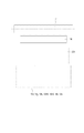
次に、本実施例の画像形成装置100に装着されるプロセスカートリッジ7の全体構成について、図1を用いて説明する。図1は、本実施例のプロセスカートリッジ7の断面図である。
[Process cartridge]
Next, the overall configuration of the process cartridge 7 mounted on the
プロセスカートリッジ7は、現像ユニット4と感光体ユニット13によって構成されている。
The process cartridge 7 is composed of a developing unit 4 and a
まず、現像ユニット4について説明する。現像ユニット4は、現像ユニット4内の各種要素を支持する現像枠体18を有する。現像ユニット4には、感光ドラム1と接触して図1に示す矢印D方向に回転する現像ローラ17が設けられている。現像ローラ17は、その長手方向(回転軸線方向)の両端部において、軸受を介して回転可能に現像枠体18に支持されている。
First, the development unit 4 will be described. The developing unit 4 has a developing
現像枠体18は、現像ローラ17に接触して矢印E方向に回転する現像剤供給部材としてのトナー供給ローラ20と、現像ローラ17のトナー層を規制するための現像剤規制部材としての現像ブレード21とを備えている。一方、画像形成装置100は、現像ローラ17とトナー供給ローラ20にそれぞれ接続する、不図示の電源を備えている。画像形成装置100は、制御部を備えており、現像ローラ17とトナー供給ローラ20への電源からの印加電圧を変えることにより、現像ローラ17へのトナー供給量を制御している。さらに、トナー供給ローラ20から現像ローラ17に供給されたトナーTは、現像ブレード21により規制および摩擦帯電されることにより、マイナスに帯電される。
The developing
また、現像枠体18には、弾性を有し、矢印F方向に回転することにより収納されたトナーTを搬送する搬送部材23が設けられている。搬送部材23は、現像ローラ17の軸線方向に延びる、回転軸23aを有する。また、搬送部材23は、弾性を有するシート状の搬送体である搬送シート23bを有する。搬送シート23bは、一端が回転軸23aに取り付けられ、トナーを撹拌搬送する。ここで、以下の説明中、回転軸23aの中心を搬送部材23の回転中心と呼ぶ。
Further, the developing
また、現像枠体18には、隔壁18jが設けられている。隔壁18jは現像枠体18の内部を、現像ローラ17が収納される現像室18bと、搬送部材23が収納される搬送室18aとに分けている。また、隔壁18jには開口18cが設けられ、開口18cが現像室18bと、搬送室18aとを連通している。搬送部材23は、開口18cを通じて現像室18bへとトナーTを供給する。
Further, the developing
ここで図1に示すように、本実施例では、現像ユニット4が画像形成を行う姿勢において、現像室18bは搬送室18aの重力方向上側に位置する。また、搬送部材23の回転中心よりも、開口18cは重力方向上側に位置している。すなわち、本実施例における現像ユニット4は、搬送室18aから現像室18bに向けて、重力方向下側から重力方向上側に(重力に反して)、トナーTをくみ上げている。
Here, as shown in FIG. 1, in this embodiment, the developing
ここで、現像ユニットが画像形成を行う姿勢とは、現像ローラ17が感光ドラム1に当接している姿勢を指す。
Here, the posture in which the developing unit forms an image means a posture in which the developing
次に感光体ユニット13について説明する。感光体ユニット13は、感光体ユニット13内の各種要素を支持する枠体としてのクリーニング枠体14を有する。クリーニング枠体14には、軸受部材を介して感光ドラム1が図4に示す矢印A方向に、回転可能に取り付けられている。
Next, the
また、クリーニング枠体14には、帯電ローラ軸受15が、帯電ローラ2の回転中心と感光ドラム1の軸線中心とを通る線に沿って、取り付けられている。ここで、帯電ローラ軸受15は、図1に示す矢印H方向に移動可能に取り付けられている。帯電ローラ2は、帯電ローラ軸受15に回転可能に取り付けられている。そして、帯電ローラ軸受15は、付勢手段としての帯電ローラ加圧バネ16により感光ドラム1に向かって付勢される。
Further, a charging
また、クリーニングブレード6は、一次転写後に感光ドラム1の表面に残った転写残トナー(廃トナー)を除去するための弾性部材6aと、弾性部材を支持するための支持部材6bとによって形成されている。
Further, the
クリーニングブレード6によって感光ドラム1の表面から除去された廃トナーは、クリーニングブレード6とクリーニング枠体14により形成される空間を重力方向に落下し、廃トナー収容部14a内に収容される。
The waste toner removed from the surface of the photosensitive drum 1 by the
[従来例におけるトナー搬送の構成]
次に、搬送室内のトナーを現像室へ搬送する従来の構成について、図4、図5を用いて説明する。図4、図5は、従来の現像ユニット104を用いた、プロセスカートリッジ107を示す断面図である。
[Structure of toner transfer in the conventional example]
Next, a conventional configuration for transporting toner in the transport chamber to the developing chamber will be described with reference to FIGS. 4 and 5. 4 and 5 are cross-sectional views showing a
搬送シート123bは、搬送室118aの内壁面に当接して、搬送シート123bが撓んだ状態で搬送部材123が回転する。搬送室118aには、搬送シート123bが撓み状態から解放される解放位置118eを有している。搬送シート123bは解放位置118eを通過する時に、搬送シート123bが撓み状態から解放される力によって搬送シート123b上に乗ったトナーを跳ね上げ、開口118cを介して現像室118b内のトナー供給ローラ20へ搬送する。
The
図4に示すように、搬送シート123bの長さは、回転軸123aの中心から搬送シート123b先端部までの長さW10が、回転軸23aの中心から搬送室118aの底部118fまでの長さW11に対して、W10>W11となるように設定される。これにより、搬送室118aの底部118fのトナーまで撹拌搬送できる。
As shown in FIG. 4, the length of the
ここで、搬送部材123が1周する間の搬送シート123b及びトナーの状態を、図5を用いて説明する。
Here, the states of the
図5(a)は、搬送シート123bがトナー面を押し始める位相となったときのトナーの状態を示している。搬送部材123は図示矢印Fの方向に回転し、搬送シート123bは、図5(b)の位相に到達して、トナーを上方に持ち上げて搬送する。さらに搬送部材123が矢印Fの方向に回転し、図5(c)に示すように、搬送シート123bが解放位置118eの位相に到達する。続いて、図5(d)のように、搬送シート123bが解放位置118eを通過した直後に、搬送シート123bが撓んだ状態から解放され、搬送シート123bの上のトナーが開口118cへ向けて跳ね上げられる。搬送シート123bは、撓んだ状態から解放され、弾性力によって戻る力でトナーを開口118cへ搬送するとともに、開口118cに衝突して、トナーを現像室118bへ押し込む。その後、搬送部材123が矢印Fの方向に回転し、再び図5(a)の搬送シート123b位相になる。このまま搬送部材123は矢印Fの方向に回転し続け、解放位置118eの位相を通過する度に、搬送シート123b上のトナーを跳ね上げ、開口118cを介してトナーを現像室118bに搬送する。このように従来のトナー搬送構成では、解放位置118eを通過直後に一度だけ搬送シート123bが撓んだ状態から解放されることにより、搬送室118aから現像室118bへトナーが供給される。
FIG. 5A shows the state of the toner when the
[本実施例における搬送室の構成]
本実施例における搬送室について、図1を用いて説明する。
[Structure of transport chamber in this embodiment]
The transport chamber in this embodiment will be described with reference to FIG.
搬送室18aの内側おいて、少なくとも一部が搬送部材23の搬送シート23bと接触し、搬送部材23を撓ませる、内壁面18kが設けられている。内壁面18kは、搬送部材23の重力方向下側にある底部18fから、搬送部材23の回転方向Fに沿って、搬送部材23の回転中心よりも重力方向上側まで延長されている。
Inside the
内壁面18kには、傾斜面としての搬送規制面18gが設けられている。搬送規制面18gは、搬送部材23の回転中心に対して重力方向下側に位置している。さらに、搬送規制面18gは、底部18fから回転方向Fに沿って、重力方向上側、かつ搬送部材23の回転中心から水平方向で離れる方向に傾斜している。搬送規制面18gは、少なくとも一部において搬送シート23bと接触し、搬送部材23を撓ませる。搬送部材23は、撓みながらトナーを上方に向けて搬送する。
The
ここで、搬送規制面18gのうち、搬送部材23の回転中心までの距離が最も近い部分を、最近接部と定義する。この最近接部と、搬送部材23の回転中心までの距離をW1とする。本実施例の搬送規制面18gは、W1よりも搬送部材23の回転中心までの距離が遠くなるように、最近接部より回転方向Fの下流側に延長されている。すなわち、搬送規制面18gと搬送部材23の回転中心との距離は、最近接部から回転方向下流側に向かって、徐々に遠くなる。よって搬送規制面18gに接触する搬送部材23の撓みは、回転方向下流側に向けて、徐々に減少する。
Here, the portion of the transport restricted
一方、最近接部に対して回転方向の下流側において、内壁面18kには、第一の解放部18hが設けられている。この第一の解放部18hと、搬送部材23の回転中心との距離をW2とすると、W2はW1よりも遠くなる。
On the other hand, on the downstream side in the rotational direction with respect to the closest contact portion, the
この第一の解放部18hについて、詳細に説明する。前述のように、搬送規制面18gは、搬送シート23bと接触し、搬送シート23bを撓ませている。このとき、搬送規制面18gは、搬送シート23bが弾性によって復帰しようとする力に抗して、搬送シート23bを保持している状態にある。しかし、搬送シート23bの撓みが減少し、搬送シート23bが弾性によって復帰しようとする力が、搬送規制面18gが搬送シート23bを保持しようとする力より大きくなると、搬送シート23bは、自身の弾性によって復帰する。このとき、搬送シート23bの撓みは解放され、撹拌シート23bが跳ね上げられる。この撓みの解放(跳ね上げ)が起きる時、搬送シート23bの先端の回転速度が、搬送部材23の回転中心の回転速度よりも早くなる。この撓みの解放(跳ね上げ)が起きる部分が、第一の解放部18hである。本実施例では、搬送規制面18gを搬送部材23の中心から徐々に離すことによって、第一の解放部18hを形成するようにした。
The
内壁面18kは、この第一の解放部18hに対して回転方向Fの下流側に、延長部18d1を有している。図1に示すように、第一の解放部18hと、延長部18d1は、連続して設けられている。延長部18d1は、搬送部材23の回転中心との距離を、W1よりも遠く保ったまま、搬送部材23の回転中心よりも重力方向上側まで、第一の解放部18hから延長されている。
The
すなわち、上述したように内壁面18kは、搬送規制面18gと、第一の解放部18hと、延長部18d1を備える。そして、図1に示すように、内壁面18kのうち、搬送部材23の回転中心との距離が最も近い部分は、上述した搬送規制面18gの最近接部(18g1)である。言い換えると、内壁面18kは、最近接部における距離W1よりも遠い距離を保ちながら、回転方向Fに沿って、最近接部から、搬送部材23の回転中心の上側(重力方向の上側)まで延長されている。
That is, as described above, the
このように、本実施例では、傾斜面を構成する搬送規制面18gは、搬送部材23の回転中心(23a)よりも下方に配置されると共に、最近接部18g1の位置より、搬送部材23の回転方向Fの下流側へ向けて搬送部材23(回転中心23a)との間の距離が大きくなるように延びている。言い換えれば、傾斜面(搬送規制面18g)は、最近接部18gの位置より、搬送部材23の回転方向Fの下流へ行くほど、搬送部材23の回転中心(23a)から離れて行くように延びている。
As described above, in this embodiment, the
ここで、搬送部材23の回転中心を通る水平面と、搬送部材23の回転中心を通り、水平面に直交する鉛直面によって、回転中心の周囲の領域を分けたとする。このとき、搬送部材23の回転中心を通る水平面より重力方向下側、かつ鉛直面より回転方向Fの下流側の領域を領域Q1と呼び、領域Q1から回転方向Fに沿って、各領域をQ2,Q3、Q4と呼ぶ。このとき、搬送規制面18gは、領域Q1に設けられる。さらに、最近接部も、領域Q1に設けられる。すなわち、本実施例においては、搬送規制面18gは、領域Q1の中に、搬送部材23の撓みが最大となる部分(最近接部)と、搬送部材23の撓みが徐々に解放されていく部分を有している。
Here, it is assumed that the region around the center of rotation is divided by a horizontal plane passing through the center of rotation of the
一方、内壁面18kに対して、回転方向Fの下流側には、第一の解放部18hから解放された搬送部材23と接触して受けとめ、再度撓ませる変形部18iが設けられている。この変形部18iも、搬送シート23bの弾性に抗して、搬送シート23bをたわんだ状態で保持するものである。本実施例では、第一の解放部18hから搬送シート23bが解放される時(第一の解放部18hに搬送シート23bの先端が到達した時)は、搬送部材23は、変形部18iから離れているように構成した。図1に示すように、変形部18iは、搬送部材23の回転中心に対して重力方向の上側に配置されている。
On the other hand, on the downstream side in the rotation direction F with respect to the
また、変形部18iに対して回転方向Fの下流側、かつ開口18cに対して回転方向Fの上流側には、変形部18iで撓まされた搬送部材23の撓みを解放する、第二の解放部18eが設けられている。さらに、本実施例では、第二の解放部18eは、搬送部材23の回転中心よりも重力方向上側に設けられ、上記の領域Q2に位置している。
Further, on the downstream side of the rotation direction F with respect to the
この第二の解放部18eにおける搬送部材23の撓みの解放は、第一の解放部18hと同じく、搬送シート23bの撓みが少なくなる、または搬送シート23bの先端が、変形部18iから外れる等によって、搬送シート23bの弾性によって起きる。すなわち、搬搬送シート23bが弾性によって復帰しようとする力が、搬送シート23bを保持しようとする力より大きくなり、搬送シート23bが、自身の弾性によって復帰する。このとき、搬送シート23bの撓みは解放され、撹拌シート23bが跳ね上げられる。この撓みの解放(跳ね上げ)が起きる時、搬送シート23bの先端の回転速度が、搬送部材23の回転中心の回転速度よりも早くなる。
The release of the deflection of the
一方、本実施例において、変形部18iと、内壁面18kの延長部18d1の間は、接続部18d2によってつながれている。この接続部18d2は、搬送部材23の回転方向の下流側に向けて、延長部18d1から重力方向上側、かつ搬送部材23の回転中心に水平方向で近づく方向に傾斜した面である。搬送室18aには、延長部18d1及び接続部18d2によって凹部18dが形成されている。このとき、搬送室18aの凹部18dは、前述の領域Q2に形成される。そして、図1に示すように、延長部18d1と接続部18d2が接続する部分と搬送部材23の回転中心までの距離は、上述したW2よりも遠い。
On the other hand, in this embodiment, the
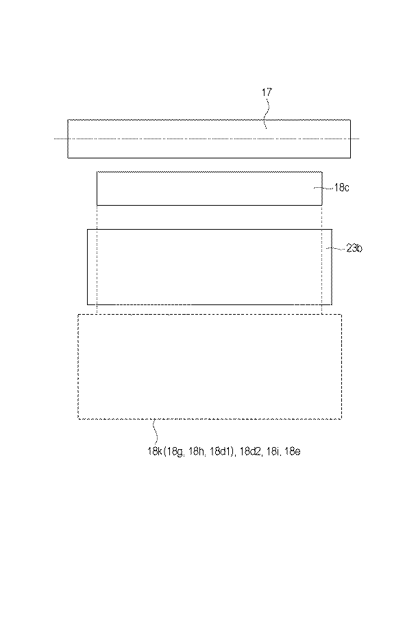
さらに、本実施例においては、内壁面18k、変形部18i、および第二の解放部18eは、現像ローラ17の軸線方向において、開口18cより長く形成される(図7)。これは、開口18cを通して現像室18bに長手全域にわたってトナーを供給するためである。
Further, in this embodiment, the
ここで、上述のように、搬送部材23の回転中心と、最近接部との距離をW1、第一の解放部18hとの距離をW2とした。そして変形部18iとの距離をW3とする。このとき、本実施例ではそれぞれの距離は、W1<W2、W3<W2となるように配置した。
Here, as described above, the distance between the center of rotation of the
また、本実施例において、延長部18d1は、水平面に対してトナーが自然に落下していく角度(以下、この角度を安息角と称す)より大きい角度で傾斜している。これにより、搬送部材23の回転で凹部18dを通過できなかったトナーは凹部18dに残ることなく、搬送室18aの下方へ落下する。
Further, in the present embodiment, the extension portion 18d1 is inclined at an angle larger than the angle at which the toner naturally falls with respect to the horizontal plane (hereinafter, this angle is referred to as an angle of repose). As a result, the toner that could not pass through the
さらに、変形部18iと搬送部材23の回転中心を結ぶ直線に対して、変形部18iを通る垂線N2(第二の垂線に相当する)と、回転中心を通る垂線N1(第一の垂線に相当する)を引いたとする。言い換えると、変形部18iと搬送部材23の回転中心を結ぶ直線に直交し、変形部18iを通る線がN2である。変形部18iと搬送部材23の回転中心を結ぶ直線に直交し、回転中心を通る線がN1である。このとき、開口18cは、これら垂線の間に少なくとも一部が重なっているように配置した。
Further, with respect to the straight line connecting the
[本実施例におけるトナー搬送]
本実施例におけるトナー搬送について図6を用いて説明する。
[Toner transfer in this embodiment]
The toner transfer in this embodiment will be described with reference to FIG.
まず、図6(a)のように、搬送部材23の回転により搬送シート23bがトナー面を押し始める。次に、図6(b)のように、搬送シート23bが搬送室18aの底部18f付近を通過すると、搬送シート23bが搬送規制面18gに沿ってトナーを上方に持ち上げながら搬送する。本実施例の構成においては、搬送シート23bは底部に到達後、搬送規制面18gが搬送部材の回転中心から徐々に離れるように形成されている為、図6(c)に示すように搬送シート23b先端の移動速度が徐々に上昇する。そして、凹部18dに到達する前に、第一の解放部18hにおいて搬送シート23bの撓みが解放され、跳ね上げられる。
First, as shown in FIG. 6A, the
搬送シート23bの先端が、この第一の解放部18hに位置したときは、搬送シート23bは変形部18iには接していない。よって、搬送シート23bの撓みが解放された時、搬送シート23bと搬送室18aの内壁面18kとの間にあるトナーTは、トナー圧の変化により押し出される。これが、1度目のトナー供給である。
When the tip of the
ここで前述のように、開口18cは、変形部18iと搬送部材23の回転中心を結ぶ直線に対して、変形部18iを通る垂線N2と、回転中心を通る垂線N1を引いたとすると、これら垂線の間に少なくとも一部が重なっているように配置されている。この為、押し出されたトナーが開口18cに向かいやすい。
Here, as described above, assuming that the
撓みが解放された搬送シート23bは、図6(d)に示すように変形部18iに受けとめられる。搬送シート23bは、変形部18iに接触することにより再び撓む。搬送シート23bが変形部18iを通過した後、第二の解放部18eにより、搬送シート23bが撓んだ状態から解放され、トナーが再度開口18cへ向けて跳ね上げられる(図6(e))。これが、2度目のトナー供給である。
The
このように本実施例の構成をとることによって、搬送部材が1回転する間に搬送シート23bの撓みが複数回解放され、跳ね上げられる。よって搬送部材23の回転数(回転速度)や搬送シート23bの枚数を増やすことなく、搬送室18aから現像室18bへのトナー供給回数を増やすことができる。
By adopting the configuration of this embodiment in this way, the deflection of the
ここで、本実施例では、搬送規制面18gが最近接部から搬送部材23の回転方向に沿って、搬送部材23の中心から徐々に離れることで、搬送部材23の撓みが徐々に減少させられる構成とした。それにより、搬送部材23が第一の解放部18hで跳ね上げられる。例えば、従来例で示したような、現像枠体18の内部に突出する解放位置118eのような凸形状(図4参照)を設けると、トナーを収納する搬送室18aの容積が減少してしまう。また、凸形状の設けられる位置等によっては、凸形状の上側にトナーが残留することにより、トナーを効率良く使用することが難しい場合がある。これに対して、本実施例に示した構成は、トナーを収納する搬送室18aの容積を減少させず、トナーを効率よく使用することができる構成である。
Here, in the present embodiment, the deflection of the
[本実施例における効果の検証]
本実施例の効果を確認する為、現像ローラ17とトナー供給ローラ20間に印加する電圧差とベタ画像濃度の追従性との関係を確認した。ここで、現像ローラ17に印加する電圧をVdr、トナー供給ローラ20に印加する電圧をVrsとし、電圧差ΔV=Vrs−Vdrとする。本実施例では、マイナスに帯電するトナーを用いている為、この電圧差ΔVがマイナスになるように電圧を印加するとトナー供給ローラ20から現像ローラ17へトナーがより多く供給される。そのため、電圧差ΔVがプラス側になったときであっても、ベタ画像濃度が確保できているほど、ベタ画像濃度の追従性が良いと言える。
[Verification of effect in this example]
In order to confirm the effect of this embodiment, the relationship between the voltage difference applied between the developing
トナーの供給性の比較として、高印字プリントを連続して行った際の濃度低下量を測定するベタ画像濃度追従性評価を実施した。評価条件として、画像形成装置を評価環境25.0℃、50%Rhにて1日放置して評価環境になじませた後、ベタ画像を連続3枚出力するものとした。評価は3枚目のベタ画像の出力先端と後端の濃度差を測定して評価するものであり、X−Rite製spectordensitometer 500を用いて行った。なお、評価画像は単色で出力した。 As a comparison of toner supply, a solid image density followability evaluation was performed to measure the amount of density reduction when high-print printing was continuously performed. As an evaluation condition, the image forming apparatus was allowed to stand in an evaluation environment of 25.0 ° C. and 50% Rh for one day to be acclimatized to the evaluation environment, and then three solid images were continuously output. The evaluation was carried out by measuring the density difference between the output front end and the rear end of the third solid image, and was carried out using a spectordensiometer 500 manufactured by X-Rite. The evaluation image was output in a single color.
表1は従来例と本実施例の構成におけるベタ画像濃度の濃度差と電位差ΔVの関係を示したものである。表中の○は紙先端と紙後端での濃度差が0.2未満、×は紙先端と紙後端での濃度差が0.2以上であることを表している。 Table 1 shows the relationship between the density difference of the solid image density and the potential difference ΔV in the configurations of the conventional example and the present embodiment. In the table, ◯ indicates that the density difference between the front edge of the paper and the rear edge of the paper is less than 0.2, and × indicates that the density difference between the front edge of the paper and the rear edge of the paper is 0.2 or more.
従来構成の現像装置においては電圧差ΔV=−50Vまでしかベタ画像濃度の追従性が確保できなかったのに対し、本実施例の構成においては電位差Δ=+25Vまでベタ画像濃度の追従性を確保することができた。これは、搬送室18aから現像室18bへのトナー供給の回数が増えたことにより、トナー供給ローラ20から現像ローラ17に供給されるトナー量が増加し、現像ローラ17に安定したトナーコートを形成できるようになったためである。
In the conventional developing apparatus, the followability of the solid image density can be ensured only up to the voltage difference ΔV = -50V, whereas in the configuration of this embodiment, the followability of the solid image density can be ensured up to the potential difference Δ = + 25V. We were able to. This is because the number of times the toner is supplied from the
以上、述べたように本実施例の構成をとることで搬送部材23の回転数(回転数)や搬送シート23bの枚数を増やすことなく、搬送室18aから現像室18bへのトナー供給回数を増やすことが可能となる。よって搬送室18aから現像室18bへのトナー供給量を増やすことができる。
As described above, by adopting the configuration of this embodiment, the number of times of toner supply from the
1 感光ドラム
2 帯電ローラ
3 スキャナユニット
4 現像ユニット(現像装置)
5 中間転写ベルト
6 クリーニングブレード
6a 弾性部材
6b 支持部材
7 プロセスカートリッジ
8 一次転写ローラ
9 二次転写ローラ
10 定着装置
11 中間転写ベルトクリーニング装置
12 記録材
13 感光体ユニット
14 クリーニング枠体
14a 廃トナー収容部
15 帯電ローラ軸受
16 帯電ローラ加圧バネ
17 現像ローラ
18 現像枠体
18a 搬送室
18b 現像室
18c 開口
18d 凹部
18d1 延長部
18d2 接続部
18e 第二の解放部
18f 底部
18g 搬送規制面
18h 第一の解放部
18i 変形部
18j 隔壁
18k 内壁面
20 トナー供給ローラ
21 現像ブレード
23 搬送部材
23a 回転軸
23b 搬送シート
100 画像形成装置
1 Photosensitive drum 2 Charging roller 3 Scanner unit 4 Developing unit (developer)
5
Claims (9)
前記現像枠体の内部を、前記現像室と前記搬送室とに分け、前記現像室と前記搬送室を連通する開口が設けられた隔壁と、
前記現像室に収納された現像剤担持体と、
前記搬送室に収納され、回転することで前記開口から前記現像室に現像剤を搬送する搬送部材と、
前記搬送室の内側に設けられた内壁面であって、
前記搬送部材の回転中心に対して重力方向の下側に位置し、前記搬送部材の回転方向に沿って、重力方向の上側、かつ水平方向で前記回転中心から離れる方向に傾斜し、少なくとも一部は前記搬送部材と接触し、前記搬送部材を撓ませる傾斜面と、
前記傾斜面のうち、前記回転中心との距離が最も近い最近接部と、
前記最近接部に対して前記回転方向の下流側に設けられ、前記搬送部材の撓みを解放する第一の解放部と、
前記第一の解放部に対して前記回転方向の下流側に設けられ、前記回転中心よりも重力方向の上側まで延長される延長部と、
を有する内壁面と、
前記内壁面に対して前記回転方向の下流側に設けられ、前記第一の解放部から解放された前記搬送部材を撓ませる変形部と、
前記変形部に対して前記回転方向の下流側、かつ前記開口に対して前記回転方向の上流側に設けられ、前記搬送部材の撓みを解放する第二の解放部と、
前記延長部と前記変形部をつなぐ接続部と、
を備え、
前記接続部は、前記延長部から重力方向上側かつ水平方向で前記回転中心に近づく方向に傾斜する面であり、
前記第一の解放部と前記回転中心との距離と、前記延長部と前記回転中心との距離は、前記最近接部と前記回転中心の距離よりも大きいことを特徴とする現像装置。 A developing frame body provided with a transport chamber and a developing chamber located on the upper side in the direction of gravity with respect to the transport chamber at the time of image formation.
The inside of the developing frame is divided into the developing chamber and the transport chamber, and a partition wall provided with an opening that communicates the developing chamber and the transport chamber.
The developer carrier housed in the developing room and
A transport member that is housed in the transport chamber and that rotates to transport the developer from the opening to the developing chamber.
An inner wall surface provided inside the transport chamber.
It is located below the center of rotation of the transport member in the direction of gravity, is inclined above the center of gravity in the direction of rotation of the transport member, and is inclined in the horizontal direction away from the center of rotation, at least in part. With an inclined surface that comes into contact with the transport member and bends the transport member,
Of the inclined surfaces, the closest contact portion with the closest distance to the rotation center and
A first release portion provided on the downstream side in the rotational direction with respect to the closest contact portion to release the deflection of the transport member, and a first release portion.
An extension portion provided on the downstream side in the rotation direction with respect to the first release portion and extended to the upper side in the gravity direction from the rotation center.
With the inner wall surface
A deformed portion provided on the downstream side in the rotational direction with respect to the inner wall surface and bending the transport member released from the first released portion, and a deformed portion.
A second release portion provided on the downstream side in the rotation direction with respect to the deformed portion and on the upstream side in the rotation direction with respect to the opening to release the deflection of the transport member.
A connecting portion where the front Symbol extension connecting the flexible portion,
With
The connecting portion is a surface that is inclined in a direction that approaches the center of rotation in the horizontal direction and upward in the direction of gravity from the extension portion.
A developing apparatus characterized in that the distance between the first release portion and the rotation center and the distance between the extension portion and the rotation center are larger than the distance between the closest contact portion and the rotation center.
請求項1から8のいずれか一項に記載の現像装置と、を備えることを特徴とするプロセスカートリッジ。 Image carrier and
A process cartridge comprising the developing apparatus according to any one of claims 1 to 8.
Priority Applications (1)
| Application Number | Priority Date | Filing Date | Title |
|---|---|---|---|
| US15/472,143 US9927737B2 (en) | 2016-03-30 | 2017-03-28 | Developing apparatus and process cartridge |
Applications Claiming Priority (2)
| Application Number | Priority Date | Filing Date | Title |
|---|---|---|---|
| JP2016069288 | 2016-03-30 | ||
| JP2016069288 | 2016-03-30 |
Publications (3)
| Publication Number | Publication Date |
|---|---|
| JP2017187747A JP2017187747A (en) | 2017-10-12 |
| JP2017187747A5 JP2017187747A5 (en) | 2018-03-29 |
| JP6882010B2 true JP6882010B2 (en) | 2021-06-02 |
Family
ID=60046479
Family Applications (1)
| Application Number | Title | Priority Date | Filing Date |
|---|---|---|---|
| JP2017033910A Active JP6882010B2 (en) | 2016-03-30 | 2017-02-24 | Developer |
Country Status (1)
| Country | Link |
|---|---|
| JP (1) | JP6882010B2 (en) |
Family Cites Families (2)
| Publication number | Priority date | Publication date | Assignee | Title |
|---|---|---|---|---|
| KR101236912B1 (en) * | 2010-12-09 | 2013-02-25 | 삼성전자주식회사 | Developing device and image forming apparatus using the same |
| JP6395617B2 (en) * | 2014-03-14 | 2018-09-26 | キヤノン株式会社 | Developer container, developing device, process cartridge, and image forming apparatus |
-
2017
- 2017-02-24 JP JP2017033910A patent/JP6882010B2/en active Active
Also Published As
| Publication number | Publication date |
|---|---|
| JP2017187747A (en) | 2017-10-12 |
Similar Documents
| Publication | Publication Date | Title |
|---|---|---|
| US10048622B2 (en) | Developer container, development device, process cartridge, and image forming apparatus | |
| JP2016161714A (en) | Developing device, process cartridge, and image forming apparatus | |
| US9927737B2 (en) | Developing apparatus and process cartridge | |
| JP5581846B2 (en) | Image forming apparatus and paper feeding apparatus | |
| JP6882010B2 (en) | Developer | |
| JP5910225B2 (en) | Fixing device and image forming apparatus | |
| US10261443B2 (en) | Developer container, developing apparatus, process cartridge and image forming apparatus | |
| JP6672235B2 (en) | Developing device and process cartridge | |
| JP4701003B2 (en) | Belt device, fixing device and image forming apparatus | |
| CN110244533B (en) | Developing apparatus and process cartridge | |
| US10656556B2 (en) | Developing device having conveying member for stably conveying developer, developer container, process cartridge, and image forming apparatus | |
| JP4047370B2 (en) | Image forming apparatus | |
| JP4541990B2 (en) | Sheet conveying apparatus and image forming apparatus | |
| JP2017116648A (en) | Developing device, process cartridge, and image forming apparatus | |
| JP4739431B2 (en) | Developing device and image forming apparatus | |
| JP6303478B2 (en) | Powder container, image forming apparatus | |
| JP6622565B2 (en) | Developing device, process cartridge, and image forming apparatus | |
| JP2002328522A (en) | Toner detecting device, developing device, recovered toner storing device and image forming device | |
| JP6209955B2 (en) | Charging device and image forming apparatus | |
| JP2006273498A (en) | Image forming device | |
| JP2004355016A (en) | Color image forming apparatus | |
| JP2006195490A (en) | Process cartridge and color image forming apparatus | |
| JP2006146278A (en) | Process cartridge and color image forming apparatus | |
| JP2005182082A (en) | Process cartridge and color image forming apparatus | |
| JP2004348153A (en) | Color image forming apparatus |
Legal Events
| Date | Code | Title | Description |
|---|---|---|---|
| A521 | Written amendment |
Free format text: JAPANESE INTERMEDIATE CODE: A523 Effective date: 20180216 |
|
| A621 | Written request for application examination |
Free format text: JAPANESE INTERMEDIATE CODE: A621 Effective date: 20200218 |
|
| A977 | Report on retrieval |
Free format text: JAPANESE INTERMEDIATE CODE: A971007 Effective date: 20201130 |
|
| A131 | Notification of reasons for refusal |
Free format text: JAPANESE INTERMEDIATE CODE: A131 Effective date: 20210105 |
|
| A521 | Written amendment |
Free format text: JAPANESE INTERMEDIATE CODE: A523 Effective date: 20210303 |
|
| TRDD | Decision of grant or rejection written | ||
| A01 | Written decision to grant a patent or to grant a registration (utility model) |
Free format text: JAPANESE INTERMEDIATE CODE: A01 Effective date: 20210406 |
|
| A61 | First payment of annual fees (during grant procedure) |
Free format text: JAPANESE INTERMEDIATE CODE: A61 Effective date: 20210506 |
|
| R151 | Written notification of patent or utility model registration |
Ref document number: 6882010 Country of ref document: JP Free format text: JAPANESE INTERMEDIATE CODE: R151 |