JP6882002B2 - Optical scanning device housing and optical scanning device - Google Patents
Optical scanning device housing and optical scanning device Download PDFInfo
- Publication number
- JP6882002B2 JP6882002B2 JP2017025995A JP2017025995A JP6882002B2 JP 6882002 B2 JP6882002 B2 JP 6882002B2 JP 2017025995 A JP2017025995 A JP 2017025995A JP 2017025995 A JP2017025995 A JP 2017025995A JP 6882002 B2 JP6882002 B2 JP 6882002B2
- Authority
- JP
- Japan
- Prior art keywords
- support portion
- housing
- light beam
- optical scanning
- transparent member
- Prior art date
- Legal status (The legal status is an assumption and is not a legal conclusion. Google has not performed a legal analysis and makes no representation as to the accuracy of the status listed.)
- Expired - Fee Related
Links
Images


Classifications
-
- G—PHYSICS
- G02—OPTICS
- G02B—OPTICAL ELEMENTS, SYSTEMS OR APPARATUS
- G02B26/00—Optical devices or arrangements for the control of light using movable or deformable optical elements
- G02B26/08—Optical devices or arrangements for the control of light using movable or deformable optical elements for controlling the direction of light
- G02B26/10—Scanning systems
- G02B26/12—Scanning systems using multifaceted mirrors
- G02B26/124—Details of the optical system between the light source and the polygonal mirror
-
- G—PHYSICS
- G02—OPTICS
- G02B—OPTICAL ELEMENTS, SYSTEMS OR APPARATUS
- G02B26/00—Optical devices or arrangements for the control of light using movable or deformable optical elements
- G02B26/08—Optical devices or arrangements for the control of light using movable or deformable optical elements for controlling the direction of light
- G02B26/10—Scanning systems
- G02B26/12—Scanning systems using multifaceted mirrors
- G02B26/121—Mechanical drive devices for polygonal mirrors
-
- G—PHYSICS
- G02—OPTICS
- G02B—OPTICAL ELEMENTS, SYSTEMS OR APPARATUS
- G02B26/00—Optical devices or arrangements for the control of light using movable or deformable optical elements
- G02B26/08—Optical devices or arrangements for the control of light using movable or deformable optical elements for controlling the direction of light
- G02B26/10—Scanning systems
- G02B26/12—Scanning systems using multifaceted mirrors
- G02B26/123—Multibeam scanners, e.g. using multiple light sources or beam splitters
-
- G—PHYSICS
- G02—OPTICS
- G02B—OPTICAL ELEMENTS, SYSTEMS OR APPARATUS
- G02B26/00—Optical devices or arrangements for the control of light using movable or deformable optical elements
- G02B26/08—Optical devices or arrangements for the control of light using movable or deformable optical elements for controlling the direction of light
- G02B26/10—Scanning systems
- G02B26/12—Scanning systems using multifaceted mirrors
- G02B26/125—Details of the optical system between the polygonal mirror and the image plane
-
- H—ELECTRICITY
- H04—ELECTRIC COMMUNICATION TECHNIQUE
- H04N—PICTORIAL COMMUNICATION, e.g. TELEVISION
- H04N1/00—Scanning, transmission or reproduction of documents or the like, e.g. facsimile transmission; Details thereof
- H04N1/024—Details of scanning heads ; Means for illuminating the original
- H04N1/032—Details of scanning heads ; Means for illuminating the original for picture information reproduction
- H04N1/036—Details of scanning heads ; Means for illuminating the original for picture information reproduction for optical reproduction
-
- H—ELECTRICITY
- H04—ELECTRIC COMMUNICATION TECHNIQUE
- H04N—PICTORIAL COMMUNICATION, e.g. TELEVISION
- H04N1/00—Scanning, transmission or reproduction of documents or the like, e.g. facsimile transmission; Details thereof
- H04N1/04—Scanning arrangements, i.e. arrangements for the displacement of active reading or reproducing elements relative to the original or reproducing medium, or vice versa
- H04N1/113—Scanning arrangements, i.e. arrangements for the displacement of active reading or reproducing elements relative to the original or reproducing medium, or vice versa using oscillating or rotating mirrors
-
- B—PERFORMING OPERATIONS; TRANSPORTING
- B41—PRINTING; LINING MACHINES; TYPEWRITERS; STAMPS
- B41J—TYPEWRITERS; SELECTIVE PRINTING MECHANISMS, i.e. MECHANISMS PRINTING OTHERWISE THAN FROM A FORME; CORRECTION OF TYPOGRAPHICAL ERRORS
- B41J2/00—Typewriters or selective printing mechanisms characterised by the printing or marking process for which they are designed
- B41J2/435—Typewriters or selective printing mechanisms characterised by the printing or marking process for which they are designed characterised by selective application of radiation to a printing material or impression-transfer material
- B41J2/44—Typewriters or selective printing mechanisms characterised by the printing or marking process for which they are designed characterised by selective application of radiation to a printing material or impression-transfer material using single radiation source per colour, e.g. lighting beams or shutter arrangements
- B41J2/442—Typewriters or selective printing mechanisms characterised by the printing or marking process for which they are designed characterised by selective application of radiation to a printing material or impression-transfer material using single radiation source per colour, e.g. lighting beams or shutter arrangements using lasers
-
- G—PHYSICS
- G02—OPTICS
- G02B—OPTICAL ELEMENTS, SYSTEMS OR APPARATUS
- G02B7/00—Mountings, adjusting means, or light-tight connections, for optical elements
- G02B7/18—Mountings, adjusting means, or light-tight connections, for optical elements for prisms; for mirrors
- G02B7/182—Mountings, adjusting means, or light-tight connections, for optical elements for prisms; for mirrors for mirrors
- G02B7/1821—Mountings, adjusting means, or light-tight connections, for optical elements for prisms; for mirrors for mirrors for rotating or oscillating mirrors
Landscapes
- Physics & Mathematics (AREA)
- Optics & Photonics (AREA)
- General Physics & Mathematics (AREA)
- Engineering & Computer Science (AREA)
- Multimedia (AREA)
- Signal Processing (AREA)
- Facsimile Scanning Arrangements (AREA)
- Laser Beam Printer (AREA)
- Mechanical Optical Scanning Systems (AREA)
Description
本発明は、電子写真プロセスを用いる画像形成装置に搭載される光走査装置の光学箱、及び当該光学箱を有する光走査装置に関する。 The present invention relates to an optical box of an optical scanning device mounted on an image forming apparatus using an electrophotographic process, and an optical scanning device having the optical box.
電子写真プロセスを用いて画像形成を行う画像形成装置は、光走査装置を備えているものがある。図9は、複数の画像形成部を有し、既知の電子写真プロセスを用いてカラー画像を用紙(記録材ともいう)に印刷する画像形成装置50の構成を示す断面図である。図9に示す画像形成装置50は、イエロー(Y)、マゼンタ(M)、シアン(C)、ブラック(K)のトナーを有する4つの画像形成部を有している。光走査装置20は、画像読取装置(不図示)又はパーソナルコンピュータ(不図示)等から送信された画像情報に基づいて、感光ドラム21Y、21M、21C、21Kにレーザ光を照射する。図10は、画像形成装置50に搭載される光走査装置20の構成を示す斜視図である。光走査装置20では、1つの回転多面鏡31が筐体35の中央部に設けられており、画像形成装置50の小型化を実現するために、1つの回転多面鏡31を用いて複数の画像形成部の感光ドラム21を露光する方式を用いている。光源ユニット31a、31bから出射されたレーザ光は、回転多面鏡31によって偏向された後に、各々の光源に対して設けられた走査光学系や反射ミラーを経由し、対応する感光ドラム21上を露光する。
Some image forming devices that form an image using an electrophotographic process include an optical scanning device. FIG. 9 is a cross-sectional view showing the configuration of an
回転多面鏡31の回転数は、解像度、シートの搬送速度、感光体の回転速度、感光体を露光する光ビームを出射する発光点の数などに基づいて設定される。即ち、製品の仕様によって回転多面鏡31の回転速度は異なる。光走査装置20を生産性の異なる複数の画像形成装置に対して同一構造の光走査装置を搭載する場合に、画像形成装置の仕様に応じて回転多面鏡の回転速度を適切に設定する必要がある。例えば、1分間の出力枚数(生産性)が70枚の画像形成装置Aと50枚の画像形成装置Bに関して、搬送するシート間隔を同一とした場合、画像形成装置Aの方が画像形成装置Bよりもシートの搬送速度及び感光体の回転速度を速い速度に設定する必要がある。このとき、画像形成装置A及び画像形成装置Bに同一構造の光走査装置を搭載した場合、各光ビームの各走査周期において形成される走査線の間隔を解像度相当にするために、回転多面鏡の回転速度を次のように設定しなければならない。即ち、画像形成装置Aの回転多面鏡の回転速度を画像形成装置Bの回転多面鏡の回転速度よりも速い速度に設定しなければならない。
The rotation speed of the rotary
一般的に回転多面鏡の回転速度が速くなると、回転多面鏡の回転による騒音レベル(風切り音)が大きくなる。騒音レベルを低減する手法としては、光走査装置の筐体(光学箱)内部に遮音壁を設ける方法が挙げられる。例えば、図11に示すように、画像形成装置Aの回転多面鏡31の周囲を遮音部材40、41で覆うことにより、騒音が光走査装置の筐体外部に漏れ難い構成とする手法がある。遮音部材40、41には回転多面鏡31により偏向されたレーザ光を透過させるための透明窓43a、43b(透明窓43aの対向側)が設けられている。遮音部材40、41には光源ユニット31a、31bから出射されて回転多面鏡31に向かうレーザ光を透過させるための透明窓42a、42bが設けられていても良い。一方、画像形成装置Bには遮音部材40を設置しない。そのため、画像形成装置Bには透明窓43a、43bは存在しない。
Generally, as the rotation speed of the rotating multi-sided mirror increases, the noise level (wind noise) due to the rotation of the rotating multi-sided mirror increases. As a method for reducing the noise level, a method of providing a sound insulation wall inside the housing (optical box) of the optical scanning device can be mentioned. For example, as shown in FIG. 11, there is a method in which noise is less likely to leak to the outside of the housing of the optical scanning device by covering the periphery of the rotating
このように、画像形成装置A及びBに対して遮音部材40、41の有無以外は同一構造の光走査装置を採用すると次のような課題が生じる。即ち、遮音部材40の透明窓43の影響により、図12に示すような光学的なズレ(ピントのズレや共役点のズレ)が発生する。なお、図9〜図12の詳細な説明については後述する。このようなピントズレや共役点のズレに対し、例えば特許文献1では、光路長の調整を可能とするために回転多面鏡の取付け位置を調整可能な光走査装置の筐体が提案されている。
As described above, if the optical scanning apparatus having the same structure is adopted for the image forming apparatus A and B except for the presence / absence of the
上述した従来技術では、遮音部材の有無に応じて回転多面鏡の位置が異なるため、光走査装置の筐体に回転多面鏡を取り付ける位置決め穴が交換可能な構成が提案されている。しかしながら、この構成では、遮音部材の有無に応じて、回転多面鏡を位置決めする部位のコマを入れ替えて成形するため、回転多面鏡と回転多面鏡によって偏向された光ビームを感光体上に導く走査光学系の各光学部品との相対的な位置関係が変わってしまう。その結果、少なくとも一方の仕様の画像形成装置に取り付けられた光学性能が劣化してしまう。光学性能の劣化を補完するために電気的な補正処理を画像形成装置に搭載すると、異なる仕様の画像形成装置に対して光走査装置を共用するというコストメリットが減少してしまう。 In the above-mentioned conventional technique, since the position of the rotating multifaceted mirror differs depending on the presence or absence of the sound insulating member, a configuration has been proposed in which the positioning hole for attaching the rotating multifaceted mirror is replaceable in the housing of the optical scanning device. However, in this configuration, the coma of the portion for positioning the rotary multifaceted mirror is exchanged and molded depending on the presence or absence of the sound insulating member, so that the scanning that guides the light beam deflected by the rotary multifaceted mirror and the rotary multifaceted mirror onto the photoconductor. The relative positional relationship with each optical component of the optical system changes. As a result, the optical performance attached to the image forming apparatus of at least one specification is deteriorated. If the image forming apparatus is equipped with an electrical correction process to compensate for the deterioration of the optical performance, the cost merit of sharing the optical scanning apparatus for the image forming apparatus having different specifications is reduced.
本発明は、このような状況のもとでなされたもので、回転多面鏡を覆う遮音部材の有無にかかわらず、安定した光学性能を確保することを目的とする。 The present invention has been made under such circumstances, and an object of the present invention is to ensure stable optical performance regardless of the presence or absence of a sound insulating member covering a rotating multifaceted mirror.
前述の課題を解決するために、本発明は、以下の構成を備える。 In order to solve the above-mentioned problems, the present invention includes the following configurations.
(1)複数の反射面を有し、回転駆動することによって光源から出射された光ビームを偏向する回転多面鏡と、前記回転多面鏡により偏向された前記光ビームを感光体に結像させる結像レンズと前記回転多面鏡に偏向された前記光ビームを前記感光体に導く反射ミラーの少なくとも一部を含む光学部材と、を内部に収容し、前記感光体を走査する前記光ビームを通過させる開口が形成された光走査装置の筐体であって、前記光学部材が配置された第1配置空間と前記回転多面鏡が配置された第2配置空間とを隔てて前記第2配置空間から前記第1配置空間への前記回転多面鏡の回転によって生じる音の伝播を低減する遮音部材であって、前記回転多面鏡により偏向された前記光ビームが出射される透明窓を有する前記遮音部材を取り付け可能な取付部と、前記取付部に前記遮音部材が取り付けられる場合に前記開口を塞ぐ透明部材であって、前記光ビームを前記筐体の内部から外部に通過させる前記透明部材を支持するための第1支持部と、前記取付部に前記遮音部材が取り付けられない場合に前記開口を塞ぐ透明部材であって、前記光ビームを前記筐体の内部から外部に通過させ且つ前記第1支持部が支持する前記透明部材よりも厚い透明部材を支持するための第2支持部と、を備え、前記第1支持部に支持される前記透明部材の光ビーム出射面と前記第2支持部に支持される前記透明部材の光ビーム出射面とが略同一平面となるように、前記第1支持部の前記透明部材に接触する座面よりも前記第2支持部の前記透明部材に接触する座面が前記光学部材が配置される前記筐体の内部側に位置することを特徴とする光走査装置の筐体。 (1) having a plurality of reflecting surfaces, imaging and rotating polygonal mirror you deflecting a light beam emitted from the light source by driving the rotation, the light beam deflected by said rotary polygon mirror to the photosensitive member and an optical member including at least part of the reflecting mirror for guiding the light beam deflected with the imaging lens to the rotating polygon mirror to the photosensitive member to the housing therein, the light beam scanning the photosensitive member a housing of the optical scanning device opening which passes is formed, the second arrangement space and the second arrangement space at a said rotary polygonal mirror and the first arrangement space where the optical member is disposed is placed the sound insulating member having said a sound insulating member to reduce the propagation of the sound generated by the rotation of the rotary polygon mirror, the transparent window where the light beam deflected by the rotary polygonal mirror is emitted to the first arrangement space from and attachable attachment portion, wherein a transparent member for closing the opening when the sound insulating member is Ri attached taken to the mounting portion, the transparent member for passing the light beam from the inside to the outside of the housing a first support portion for supporting said a transparent member for closing the opening when the sound insulating member is not Ri attached taken to the mounting portion, and is passed through the light beam from the inside to the outside of the housing and a second supporting portion for supporting a thick transparent member than the transparent member to which the first support portion for supporting said light beam emitting surface of the transparent member which is supported by the first support portion first as the second light beam emitting surface of the transparent member which is supported by the supporting portion is substantially flush, wherein the transparent member of the second supporting portion than the bearing surface in contact with the transparent member of the first support portion housing of the optical scanning apparatus seating surface in contact with which is characterized in that located on the inner side of the housing in which the optical member is disposed.
(2)前記(1)に記載の筐体を備えることを特徴とする光走査装置。 (2) An optical scanning apparatus including the housing according to (1) above.
本発明によれば、回転多面鏡を覆う遮音部材の有無にかかわらず、安定した光学性能を確保することができる。 According to the present invention, stable optical performance can be ensured regardless of the presence or absence of a sound insulating member covering the rotating multifaceted mirror.
以下に、図面を参照して本発明の実施の形態について詳細に説明する。 Hereinafter, embodiments of the present invention will be described in detail with reference to the drawings.
[画像形成装置の構成]
まず、後述する実施例との比較のために、従来の画像形成装置、光走査装置について、図9から図12を用いて説明する。図9は、複数の画像形成部を有し、既知の電子写真プロセスを用いてカラー画像を用紙(記録材ともいう)に印刷する画像形成装置50の構成を示す断面図である。図9に示す画像形成装置50は、図中、右側からイエロー(Y)(図中(Y)で表示)、マゼンタ(M)(図中(M)で表示)、シアン(C)(図中(C)で表示)、ブラック(K)(図中(K)で表示))のトナーを有する4つの画像形成部を有している。なお、以下ではトナーの色を表す符号Y、M、C、Kは、必要な場合を除き省略する。1つの画像形成部は、感光体である感光ドラム21、現像器22、帯電器27を有し、各画像形成部は同一構成である。光走査装置20は、画像読取装置(不図示)又はパーソナルコンピュータ(不図示)等から送信された画像情報に基づいて、感光ドラム21をレーザ光により露光する。光走査装置20は、各画像形成部の感光ドラム21を露光するために、画像形成部に対応した発光源を搭載している。
[Configuration of image forming apparatus]
First, for comparison with Examples described later, a conventional image forming apparatus and an optical scanning apparatus will be described with reference to FIGS. 9 to 12. FIG. 9 is a cross-sectional view showing the configuration of an
感光ドラム21は導電体に感光層を塗布したもので、帯電器27により所定の電位に帯電される。そして、光走査装置20から出射されたレーザ光により感光ドラム21の表面上に静電潜像が形成される。現像器22は、摩擦帯電されたトナーを感光ドラム21上の静電潜像に付着させることにより現像し、トナー像を形成する。中間転写ベルト23には、各感光ドラム21上に形成されたトナー像が転写される。給紙カセット24は、中間転写ベルト23上のトナー像が転写される用紙を格納している。給紙カセット24から給紙された用紙は、転写ローラ28へと搬送され、中間転写ベルト23上に形成されたトナー像が転写ローラ28により用紙に転写される。定着器25は、用紙上に転写されたトナー像を加熱、加圧し、用紙に定着させる。定着器25によりトナー像が定着された用紙は、排出トレイ26に排出される。なお、実施の形態はカラー画像形成装置に限られず、モノクロの画像形成装置であっても良い。
The
[光走査装置の構成]
図10は、画像形成装置50に搭載される光走査装置20の構成を示す斜視図である。図10に示す光走査装置20は、画像形成装置50の小型化を実現するために、1つの回転多面鏡31で複数の画像形成部の感光ドラム21を露光する方式を用いている。図10において、光走査装置20の中央部に複数の画像形成部に対して共通に用いられる回転多面鏡31が設けられている。光源ユニット31a、31bから出射されたレーザ光は、回転多面鏡31によって偏向された後に、各々の光源に対して設けられた走査光学系や反射ミラーを経由し、対応する感光ドラム21の表面を露光する。ここで、光走査装置20では、回転多面鏡31に対して図10の図中左右方向にそれぞれ光学系が配置され、光源ユニット31a、31bには、それぞれトナー2色分の発光部が設けられている。光源ユニット31aから出射される各レーザ光は、ブラック(K)とシアン(C)に対応する画像形成部の感光ドラム21K、21C上を露光する。一方、光源ユニット31bから出射される各レーザ光は、マゼンタ(M)とイエロー(Y)に対応する画像形成部の感光ドラム21M、21Y上を露光する。
[Configuration of optical scanning device]
FIG. 10 is a perspective view showing the configuration of the
ここで、光源ユニット31a、31bは、それぞれ半導体レーザ(不図示)と、半導体レーザから出射されたレーザ光を平行光に変換するコリメータレンズ(不図示)と、回転多面鏡31でレーザ光を線状に結像させるシリンダレンズ(不図示)と、を有する。そして各レーザ光は、レーザ光を感光ドラム21上で等速走査しつつ結像させる第1の結像レンズ32a、32b、第2の結像レンズ33a〜33dを通過する。走査光学系を構成する第1、第2の結像レンズを通過した各レーザ光は、レーザ光を対応する画像形成部の感光ドラム21へ導くために所定の方向へ反射させる(折り返す)各反射ミラー34a〜34hを経て、感光ドラム21上に静電潜像を形成する。また、光走査装置20は、筐体35(光学箱35ともいう)に図10中の各部品が収容されており、上部の開口面は、カバー部材である上カバー(不図示)により密閉される。
Here, the
[回転多面鏡の騒音対策]
回転多面鏡31の回転数は、解像度、シートの搬送速度、感光ドラム21の回転速度、感光ドラム21を露光するレーザ光を出射する発光点の数などに基づいて設定される。即ち、製品の仕様によって回転多面鏡31の回転速度は異なる。光走査装置20を生産性の異なる複数の画像形成装置に対して同一構造の光走査装置20を搭載する場合に、画像形成装置の仕様に応じて回転多面鏡の回転速度を適切に設定する必要がある。例えば、1分間の出力枚数(生産性)が70枚の画像形成装置Aと50枚の画像形成装置Bに関して、搬送するシート間隔を同一とした場合の速度設定を次のようにしなければならない。即ち、画像形成装置Aの方は、画像形成装置Bの方よりも、シートの搬送速度及び感光ドラム21の回転速度を速い速度に設定する必要がある。このとき、画像形成装置A及び画像形成装置Bに同一構造の光走査装置20を搭載した場合、各レーザ光の各走査周期において形成される走査線の間隔を解像度相当にするために、回転多面鏡31の回転速度の設定を次のようにしなければならない。即ち、画像形成装置Aの回転多面鏡31の回転速度を画像形成装置Bの回転多面鏡31の回転速度よりも速い速度に設定しなければならない。一般的に回転多面鏡31の回転速度が速くなると、回転多面鏡31の回転による騒音レベル(風切り音)が大きくなる。
[Noise measures for rotating multi-sided mirrors]
The rotation speed of the rotary
一方、回転多面鏡31の回転数の上昇を抑制する手法として、光源ユニット31a、31bで使用する半導体レーザのビーム数を増やす等で対応することが一般的に知られている。ところが、一般に広く流通している半導体レーザよりも多いビーム数を有する半導体レーザを使用する場合には、大きなコストアップとなる。更に、解像度と生産性を共に向上させる場合には対応可能な半導体レーザがなく、半導体レーザのビーム数の増加だけでは対応できなくなってしまう場合がある。このような場合は、回転多面鏡31の回転数を高めることで対応するしかないが、その際には、上述したように回転多面鏡31から発生する騒音レベルが課題となる。
On the other hand, as a method of suppressing an increase in the rotation speed of the rotary
騒音レベルを低減する手法としては、例えば図11に示すように、回転多面鏡31の周囲を遮音部材40、41で覆うことにより、騒音が外部に漏れにくい構成とする手法がある。図11(a)は、説明の都合上、遮音部材40の上部に設けられた蓋部分である遮音部材41を取り外した斜視図であり、図11(b)は、遮音部材41を遮音部材40に組み付けて回転多面鏡31の周囲を密閉した状態を示す斜視図である。遮音部材40は、筐体35に設けられた遮音部材40の取付部である取付座面にビス等の締結部材で固定されている。遮音部材40において、光源ユニット31a、31bから出射されたレーザ光が回転多面鏡31に進行する際に通過する部分には、レーザ光を透過させるための光透過部材として第1の透明窓である透明窓42a、42bが設けられている。また、回転多面鏡31により偏向されたレーザ光が進行する際に通過する部分には、レーザ光を透過させるための光透過部材として第2の透明窓である透明窓43a、43b(透明窓43aの対向側)が設けられている。なお、遮音部材40、41は1つのユニット(1対の遮音部材)として設けられるため、以下では、特に遮音部材40、41をそれぞれ区別して説明する場合を除き、遮音部材41を含めて、遮音部材40と呼ぶこととする。本実施例では透明窓42a、43aを異なる部材として説明するが、透明窓42a、43aを一体的な透明窓で構成しても良い。同様に、本実施例では透明窓42b、43bを異なる部材として説明するが、透明窓42b、43bを一体的な透明窓で構成しても良い。更に、透明窓42a、43a、42b、43bを一体的な透明窓で構成しても良い。
As a method for reducing the noise level, for example, as shown in FIG. 11, there is a method in which the noise is less likely to leak to the outside by covering the periphery of the rotating
回転多面鏡31の周囲を図11に示すような遮音部材40を用いて密閉することで、結像レンズや反射ミラーが配置された光学部材の配置空間と、光源からのレーザ光を偏向する回転多面鏡31が配置された回転多面鏡31の配置空間と、を隔てることができる。その結果、回転多面鏡31の近傍で発生する大きな騒音を遮音部材40内部に封じ込めることにより騒音の伝播を防ぐことができ、光走査装置20から発散される騒音レベルを低減することが可能となる。一方、遮音部材40を追加することによりコストアップとなるため、回転多面鏡31が低速回転で駆動され、騒音レベルの低い製品にも同じ遮音部材40を組み付けることはコスト面からは好ましくない。そのため、同一の筐体35であっても、回転多面鏡31が高速回転で駆動される製品には遮音部材40が設けられ、回転多面鏡31が低速回転で駆動される製品には遮音部材40が設けられない。なお、本実施例では、回転多面鏡31によって偏向された光ビームを感光ドラムに導くレンズ及び反射ミラーを含む光学部材のすべてが遮音部材40の外側に配置された構成を例示する。しかしながら、実施の形態はこれに限られず、実施の形態において、回転多面鏡31によって偏向された光ビームを感光ドラムに導く複数の光学部材のうちの一部、即ち結像レンズあるいは反射ミラーの少なくとも1つが遮音部材40の外側に有ればよい。言い換えれば、実施の形態において、回転多面鏡31によって偏向された光ビームを感光ドラムに導く複数の光学部材のうちの一部、即ち結像レンズあるいは反射ミラーの少なくとも1つが遮音部材40の内側にあっても良い。
By sealing the periphery of the rotating
ところが同一の筐体35を用いて、回転多面鏡31が低速回転する製品には遮音部材40を用いず、高速回転する製品にのみ遮音部材40を用いる場合には、遮音部材40のレーザ光の通過部分に設けた透明窓42、43の影響により、光学的なズレが発生する。図12は、回転多面鏡31へのレーザ光の通過部分に設けた透明窓42、43の有無によって発生する光学的な変化を説明するための模式図である。図12は、回転多面鏡31近傍を密閉する遮音部材40に設けた透明窓42、43と走査光学系を簡略化し、レーザ光の副走査方向(感光ドラム21を走査する主走査方向と直交する方向)の結像関係を説明するために、副走査方向の断面で示した図である。
However, when the
図12(a)は、回転多面鏡31の面倒れがない場合の光源ユニット31a、31bから出射されたレーザ光の光路を説明する模式図である。透明窓42、43には、通常、光透過部材としてガラスあるいはプラスチック(樹脂)が用いられている。走査光学系は、上述したように、感光ドラム21上にレーザ光を結像させる光学系であり、図を簡略化するため、前述した第1の結像レンズ32a、32bと、第2の結像レンズ33a〜33dを一枚のレンズ32、33として示している。結像レンズは、回転多面鏡31の反射面と感光ドラム21の表面とが共役の関係になるように光学設計されている。即ち、結像レンズは回転多面鏡31の反射面上のスポットと略同径のスポットが感光ドラム21の表面(感光体表面)上に再現されるように光学設計されている。また、図中、La1は遮音部材40を設けない場合の光路を示し、La2は光路La1が透明窓42により屈折した後の光路を示し、La3は光路La2が透明窓43により屈折した後の光路を示している。なお、図中中央の点線は、レーザ光の光軸を示す。
FIG. 12A is a schematic view illustrating the optical path of the laser beam emitted from the
図12(a)に示すように、回転多面鏡31に遮音部材40が設けられていない場合には、光源から出射されたレーザ光は光路La1により感光ドラム21上で結像する。一方、遮音部材40を用いた構成では、遮音部材40の入射部に設けられた透明窓42でレーザ光が屈折するため、レーザ光の光路は光路La1から光路La2となり、回転多面鏡31上で、レーザ光の進行方向にズレ量L2のピントズレが発生する。そして、回転多面鏡31によって偏向されたレーザ光は、遮音部材40の出射部に設けられた透明窓43を通過することでレーザ光が屈折するため、レーザ光の光路は光路La2から光路La3となる。この結果、更にズレ量が増大し、感光ドラム21上ではレーザ光の進行方向にズレ量L1(L2<L1)のピントズレが発生する。
As shown in FIG. 12A, when the rotating
図12(b)は、回転多面鏡31の面倒れがある場合の光源ユニット31a、31bから出射されたレーザ光の光路を説明する模式図であり、回転多面鏡31の面倒れの状態は図中、31(面倒れなし)、31(面倒れあり)で示している。面倒れがないときの感光ドラム21の表面は、図中、21(面倒れなし)で示し、面倒れがあるときの感光ドラム21の表面、即ち、面倒れがある場合の回転多面鏡31の反射面位置に対する共役位置は、図中、21(面倒れあり)で示す。また、図中、Lb1は遮音部材40を設けない場合の光路を示し、Lb2は光路Lb1が透明窓42により屈折した後の光路を示し、Lb3は光路Lb2が透明窓43により屈折した後の光路を示している。なお、図中中央の点線は、レーザ光の光軸を示す。その他の構成については、図12(a)と同様である。
FIG. 12B is a schematic view illustrating the optical path of the laser beam emitted from the
図12(b)に示すように、回転多面鏡31に遮音部材40が設けられていない場合には、光路Lb1は面倒れにより、図12(a)のように光軸に対称ではないが、光源から出射されたレーザ光は光路Lb1により感光ドラム21上で結像する。一方、遮音部材40を用いた構成では、遮音部材40の入射部に設けられた透明窓42でレーザ光が屈折するため、レーザ光の光路は光路Lb1から光路Lb2となり、回転多面鏡31上で、レーザ光の進行方向にズレ量L2のピントズレが発生する。そして、回転多面鏡31によって偏向されたレーザ光は、遮音部材40の出射部に設けられた(出射面相当の位置に設けられた)透明窓43を通過することでレーザ光が屈折するため、レーザ光の光路は光路Lb2から光路Lb3となる。この結果、回転多面鏡31により偏向された後に通過する透明窓43による屈折により、共役点のズレが発生し、共役点のズレ量は(L1−L2)となる。
As shown in FIG. 12B, when the rotating
[光走査装置の構成]
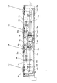
図1は、図10で説明した光走査装置20の構成を示す断面図である。図1は、図10に示す光走査装置20を図面奥側から手前方向に見たときの断面を示しており、レーザ光が出射される光源ユニット31a、31bは、図中、奥側に設けられているため、図1では不図示である。なお、図1では、図10と同じ部材には同じ符号を付している。
[Configuration of optical scanning device]
FIG. 1 is a cross-sectional view showing the configuration of the
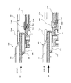
図1に示すように、光走査装置20の中央部には回転多面鏡31が設けられ、各々の光源ユニット31a、31b(不図示)から出射されたレーザ光は、回転多面鏡31によって偏向される。回転多面鏡31により偏向されたレーザ光は、遮音部材40の透明窓43a、43b、各々の光路に設けられた走査光学系を構成する結像レンズ32a、32b、33a〜33dや反射ミラー34a〜34hを経由し、各画像形成部の感光ドラム21を露光する。図1に示す光走査装置20は、図中、実線で示す左側の光路から順に、イエロー(Y)、マゼンタ(M)、シアン(C)、ブラック(K)の各画像形成部の感光ドラム21を露光するレーザ光LY、LM、LC、LKが上カバー10の出射口から出射される。なお、出射口は上カバー10に設けられた開口部である。また、筐体35の中央部に設けられた回転多面鏡31は、回転多面鏡31から生じる騒音を低減するための遮音部材40及び遮音部材40の蓋部分に相当する遮音部材41で覆われている。
As shown in FIG. 1, a rotating
[防塵ガラスの構成]
図2(a)は、図1に示す光走査装置20の筐体35の開放面を覆う上カバー10を装着した光走査装置20の斜視図である。上カバー10上には、各画像形成部の感光ドラム21を露光するレーザ光LY、LM、LC、LKが出射される開口部14a、14b、14c、14dが設けられている。開口部14a、14b、14c、14dには清掃棒ガイド13a、13b、13c、13dが設置されている。清掃棒ガイド13a〜13dは同じ構成を有しており、以下では、特定の清掃棒ガイドを指す場合を除き、清掃棒ガイド13a〜13dを清掃棒ガイド13と記載する。また、図2(a)の清掃棒ガイド13aに示すC−C線で清掃棒ガイド13aを含む上カバー10を切断した断面を示す模式図が図2(b)、図2(c)である。図9で示したような感光ドラム21の下部に設けられる光走査装置20では、トナーが光走査装置20内に侵入して画像不良が発生することを防ぐために、上カバー10の各開口部14a〜14dには、後述する防塵窓12が設けられている。なお、開口部14は、図2(b)、(c)から清掃棒ガイド13や防塵窓12を取り外したときの上カバー10の開口部分を指している。
[Structure of dustproof glass]
FIG. 2A is a perspective view of the
図2(b)は、レーザ光を筐体35内部(筐体内部)から外部に通過させる透明部材である防塵窓12aaを設置したときの断面図である。防塵窓12aaは、第1支持部の座面である座面15aaに支持され、後述する第1接触部である接触部11aaに当接している。図2(c)は、レーザ光を筐体35内部(筐体内部)から外部に通過させる透明部材である防塵窓12abを設置したときの断面図である。防塵窓12abは、第2支持部の座面である座面15abに支持され、後述する第2接触部である接触部11abに当接している。本実施例では、上述した回転多面鏡31の周囲を覆う遮音部材40を組み付ける場合に発生するピントや共役点のズレをキャンセルするために、それに対応した複数の厚さの防塵窓12aa、12abを選択して、上カバー10に設けられるようにしている。
FIG. 2B is a cross-sectional view when a dustproof window 12aa, which is a transparent member that allows laser light to pass from the inside of the housing 35 (inside the housing) to the outside, is installed. The dustproof window 12aa is supported by the seating surface 15aa, which is the seating surface of the first supporting portion, and is in contact with the contacting portion 11aa, which is the first contacting portion described later. FIG. 2C is a cross-sectional view when a dustproof window 12ab, which is a transparent member that allows laser light to pass from the inside of the housing 35 (inside the housing) to the outside, is installed. The dustproof window 12ab is supported by the seating surface 15ab, which is the seating surface of the second supporting portion, and is in contact with the contacting portion 11ab, which is the second contacting portion described later. In this embodiment, in order to cancel the deviation of the focus and the conjugate point that occurs when the
本実施例の上カバー10には、厚さ・幅・長さの異なる2種類の防塵窓12aa、12abを取り付けることを可能とするため、防塵窓12aaに対応する座面15aa、防塵窓12abに対応する座面15abを設けている。本実施例では、防塵窓12aaは厚さ(図中、上下方向(光学箱35の底面方向))1.8mm、幅(図中、左右方向)23mm、長さ(図中、奥行き方向)273mmであり、防塵窓12abは厚さ3.8mm、幅16mm、長さ265mmである。ここで、防塵窓12aaの厚さ、幅、長さをそれぞれt1、b1、L3とし、防塵窓12abの厚さ、幅、長さをそれぞれt2、b2、L4とする。防塵窓12aaと防塵窓12abの各サイズの大小関係は、厚さt1<厚さt2、幅b1>幅b2、長さL3>長さL4となる。また、2つの防塵窓12aa、12abの材質は、共に低コストのフロートガラスであり、屈折率は1.51程度である。
In order to make it possible to attach two types of dustproof windows 12aa and 12ab having different thicknesses, widths, and lengths to the
なお、ここで示す防塵窓12aa、12abのサイズ、材質、屈折率は一例であり、2つの防塵窓12aa、12abの上述した各サイズの大小関係が満足されていればよい。また、図2(b)、(c)に示すように、後述する清掃棒100(図7参照)での清掃性能を確保するために、座面15aa、15abは次のように構成されている。即ち、座面15aa、15abは、清掃棒100により清掃される防塵窓12aa、12abの光ビーム出射面である上面(清掃面)は略同一平面(同一の高さ)となるように構成されている。そのため、防塵窓12aaが支持される座面15aaと、防塵窓12abが支持される座面15abとは、図中上下方向に防塵窓12aaと防塵窓12abの厚さの差分2mm(=3.8mm−1.8mm)、高低差を設けた構成としている。
The sizes, materials, and refractive indexes of the dust-proof windows 12aa and 12ab shown here are examples, and it is sufficient that the magnitude relationship of each size of the two dust-proof windows 12aa and 12ab described above is satisfied. Further, as shown in FIGS. 2 (b) and 2 (c), the seat surfaces 15aa and 15ab are configured as follows in order to ensure the cleaning performance with the cleaning rod 100 (see FIG. 7) described later. .. That is, the seat surfaces 15aa and 15ab are configured so that the upper surfaces (cleaning surfaces), which are the light beam emitting surfaces of the dustproof windows 12aa and 12ab cleaned by the cleaning
[出力速度と回転多面鏡の回転数との関係]
次に、画像形成装置の単位時間当たりのスループットである出力速度と、光走査装置20の回転多面鏡31の回転数の関係について、図を用いて説明する。図3は、画像形成装置50の出力速度と、光走査装置20の回転多面鏡31の回転数との関係の一例を示したグラフである。図3において、横軸は1分間の出力枚数である出力速度(単位:ppm)、縦軸は回転多面鏡31の回転数(単位:rpm)を示す。図3の実線で示すグラフは回転多面鏡31が4面構成の場合の、破線で示すグラフは回転多面鏡31が5面構成(図11(a)参照)の場合の、出力速度と回転多面鏡31の回転数との関係を示している。図3に示すように、出力速度が大きくなるに伴い、回転多面鏡31の回転数も上昇する。そのため、本実施例の光走査装置20では、回転多面鏡31の回転数が所定の回転数を超える場合には、回転多面鏡31から生じる騒音を抑制するために、遮音部材40で回転多面鏡31の周囲を覆うことで対応している。図3では、回転多面鏡31の回転数が40000rpmを超える製品では、遮音部材40を搭載するように光走査装置20の構成の変更を行うことを例示している(図中、グレーで色付けされた領域)。
[Relationship between output speed and rotation speed of rotating multifaceted mirror]
Next, the relationship between the output speed, which is the throughput per unit time of the image forming apparatus, and the rotation speed of the rotating
[遮音部材の有無による反射ミラーの取付け座面の選択]
次に、遮音部材40の有無に応じた変更部分について詳細に説明する。ここでは一例として、図11(a)に示す回転多面鏡31の面数が5面の場合の光走査装置20を用いて説明する。図3に示すように、出力速度が70ppmの画像形成装置では、回転多面鏡31の回転数は所定の回転数である40000rpmを超えるため、搭載される光走査装置20は遮音部材40を必要とする。この場合、本実施例では、図11に示す遮音部材40で回転多面鏡31の周囲を密閉するため、遮音部材40に設けられた光透過部材である透明窓43a、43bをレーザ光が通過することにより、共役点のズレが発生する。本実施例の走査光学系は、レーザ光を出射する光源ユニット31a、31bから回転多面鏡31までの入射光学系の光路長が約170mm、回転多面鏡31の偏向面から感光ドラム21の画像中央部(主走査方向の中心部)までの光路長が約250mmである。そして、遮音部材40が追加されることにより、回転多面鏡31までの入射光学系の光路長と走査光学系での光路長において、それぞれ約0.7mmのズレが発生し、このズレは光路長が長くなる方向(レーザ光の進行方向)に発生する。
[Selection of seating surface for mounting reflective mirror depending on the presence or absence of sound insulation member]
Next, the changed portion depending on the presence or absence of the
そのため、出力速度が70ppmの製品では、図2(b)に示す座面15aaを使用して、厚さの薄い防塵窓12aaを設置する。一方、遮音部材40を使用しない出力速度が70ppm未満の製品では、遮音部材40を使用した場合のような光路長のズレが生じない。そこで、防塵窓12aaよりも厚さが厚い防塵窓12abを使用することにより、遮音部材40を設置した場合の光路長と同じ光路長となるように補正する。そのため、防塵窓12aaよりも厚い防塵窓12abは、防塵窓12aaが設置される座面15aaよりも厚さの差分(図中、上下方向で2mm)だけ筐体35の内部側(筐体内部側)の低い位置に設けられた座面15abに設置される。これにより、遮音部材40の有無に関係なく、光源から感光ドラム21表面上までの光路長は略同じになる。なお、防塵窓12aa、12abと座面15aa、15abの組み合わせは、一方のみを使用し、両方を同一の製品で使用することはない。
Therefore, for a product having an output speed of 70 ppm, a thin dustproof window 12aa is installed using the seat surface 15aa shown in FIG. 2B. On the other hand, in a product in which the
遮音部材40を備える出力速度が70ppmの製品において生じる光路長の変化は、遮音部材40の透明窓42、43に使用しているガラスに起因するものである。したがって、防塵窓12bの厚さは、防塵窓12aの厚さと遮音部材40の透明窓42、43に使用しているガラス2枚分の厚さの和となる。ただし、この場合の防塵窓12bの厚さは遮音部材40の透明窓42、43と防塵窓12a、12bとが同じ硝材及び表面コーティングである場合の厚さである。したがって、透明窓42、43と防塵窓12a、12bの材質が異なる場合は、上述した防塵窓12a、12bの厚さの関係は必ずしも一致しない。この場合には、防塵窓12a、12b及び透明窓42、43の屈折率に応じて、防塵窓12a、12bの厚さを設定することで、同等の効果を得ることができる。
The change in the optical path length that occurs in the product provided with the
[防塵窓の厚み差の設定]
ここで、2つの防塵窓12a、12bの厚さの差の設定について説明する。図12を用いて説明したように、回転多面鏡31を密閉する遮音部材40の有無により発生するピントズレ量と、回転多面鏡31に対する共役点のズレ量とは異なっている。そのため、ピントズレと共役点のズレの両方に最適な防塵窓12a、12bの厚さの差分に設定することはできない。そのため、実際には光学系に応じて最適な防塵窓12a、12bの厚さの差分を設計時に選択する必要がある。本実施例では、複数の条件を示し、その条件に対応した構成について説明する。
[Setting the thickness difference of the dustproof window]
Here, the setting of the difference in thickness between the two
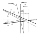
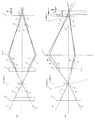
図4は、前述した回転多面鏡31の面倒れがある場合の光源ユニット31a、31bから出射されたレーザ光の光路を説明する図12(b)の感光ドラム21の周辺のレーザ光の光路を取り出した模式図である。図中、Lb1は遮音部材40を設けない場合の光路を示し、Lb2は光路Lb1が透明窓42により屈折した後の光路を示し、Lb3は光路Lb2が透明窓43により屈折した後の光路を示している。なお、図中中央の点線は、レーザ光の光軸を示す。
FIG. 4 shows the optical path of the laser beam around the
図4に示すズレ量L1は、遮音部材40の透明窓42、43によるピントズレ量を示し、感光ドラム21の表面からズレ量L1だけレーザ光の進行方向にずれた位置は遮音部材40が設置されているときの最もピントが良好な位置を示している。この位置は、ピントが良好であるため、鮮鋭な画像形成が可能であるが、面倒れにより結像点が副走査方向に変動するため、面倒れの程度が大きいとバンディングが発生してしまう。一方、ズレ量(L1−L2)は、遮音部材40の透明窓43による共役点ズレのズレ量、即ち透明窓43があるときの共役点を示している。感光ドラム21の表面から距離(L1−L2)だけレーザ光の進行方向にずれた位置は、回転多面鏡31の面倒れ量にかかわらず、副走査方向の結像重心が光軸上に乗る光路長の終端位置である。この位置は、面倒れによる光路のブレによる感光ドラム21の回転方向(副走査方向)における走査線の粗密の発生(画像の副走査方向におけるバンディングの発生)が最も抑制される光路長を示している位置である。
The deviation amount L1 shown in FIG. 4 indicates the amount of focus deviation due to the
第1の構成として、共役点のズレ量に合わせてシフトさせる場合の構成について説明する。回転多面鏡31により発生する、面倒れと呼ばれるレーザ光のズレは、感光ドラム21上に形成される画像に周期的なムラを発生させる。この面倒れは、レーザ光を出射する光源のビーム数や解像度、回転多面鏡31の面数によって画像上の空間周波数が決まり、そのピッチによっては、面倒れが大きくなり画像不良として認識されやすくなる。そこで、図4で示した共役点のズレ量(L1−L2)に相当する距離だけ光路長が変化するように、遮音部材40を用いる場合の防塵窓12a、12bの厚さや屈折率を変化させると、面倒れが最適な状態を維持し続けることができる。この場合、光走査装置20としては、感光ドラム21上でピントズレ量としてL2だけ残差が発生する。しかしながら、遮音部材40により発生するピントのズレ量L1と比べると、防塵窓12a、12bの厚さの差分により良化することができており、焦点深度が確保できている系であれば、ズレ量L2のピントズレによって光学性能が低下することはない。このように、防塵窓12a、12bの厚さの差分により吸収される光路長差を略(L1−L2)とすることで、光透過部材により発生する共役点のズレ量を吸収することができ、面倒れを良好に維持することができる。
As the first configuration, a configuration in the case of shifting according to the amount of deviation of the conjugate point will be described. The deviation of the laser beam, which is called "face-up", caused by the rotating
次に、第2の構成として、感光ドラム21上のピントズレ量に合わせて防塵窓12a、12bの厚さの差分を設定する場合の構成について説明する。光走査装置20で使用する光源のビーム数や回転多面鏡の面数が少ない場合は、面倒れの画像上の周期が短く、面倒れが多少大きくなったとしても画像上では認識し難い。一方、焦点深度に余裕がない光学系ではピントズレによりスポット径が変化してしまうことにより、静電潜像が浅くなり、ガサツキや濃度ムラを引き起こす要因となる。このような場合は、図4で示す感光ドラム21上のピントのズレ量L1に相当する距離だけ光路長が変化するように、遮音部材40を用いる場合の防塵窓12a、12bの厚さや屈折率を変化させることで、スポット径を最適な状態で維持し続けることができる。この場合には、共役点のズレ量L2だけが発生するが、画像上のピッチが狭い場合であれば画像としては十分許容範囲内に維持することができる。このように、防塵窓12a、12bの厚さの差分により吸収される光路長差を、光透過部材により発生するピントズレ量である略L1と一致させることにより、感光ドラム21上でのピントズレを抑制することができる。
Next, as a second configuration, a configuration in which the difference in thickness of the
最後に、第3の構成として、共役点のズレ量とピントのズレ量を共に重視してシフトする場合の構成について説明する。これは、面倒れによる生じる共役点のズレ量とピントズレ量をバランスよくシフト量を割り振る構成である。本構成では、ピントのズレ量L1と共役点のズレ量(L1−L2)の平均シフト量、即ち、(L1+(L1−L2))/2=(L1−(L2/2))を設定すればよい。この場合、各々の特性値は最適な値には補正できないが、防塵窓12a、12bの厚さの差分を両項目に分散させることができるため、面倒れの画像上のピッチが比較的見えやすく、焦点深度に十分な余裕がない光学系では有効な構成となる。このように、防塵窓12a、12bの厚さの差分により吸収される光路長差を略(L1−(L2/2))とすることで、光透過部材により発生するピントズレと共役点のズレの両方を考慮した位置に設定でき、ピントズレ及び面倒れを分散させることができる。
Finally, as a third configuration, a configuration in the case of shifting with emphasis on both the amount of deviation of the conjugate point and the amount of deviation of the focus will be described. This is a configuration in which the shift amount is allocated in a well-balanced manner with respect to the amount of deviation of the conjugate point and the amount of focus shift caused by troublesomeness. In this configuration, the average shift amount of the focus shift amount L1 and the conjugate point shift amount (L1-L2), that is, (L1 + (L1-L2)) / 2 = (L1- (L2 / 2)) should be set. Just do it. In this case, each characteristic value cannot be corrected to the optimum value, but the difference in thickness of the
[開口部の枠部材の構成]
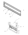
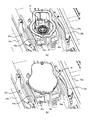
近年、新興国を中心に進む大気汚染によって、汚染物質の粒子が光走査装置20内部に侵入し、回転多面鏡31の鏡面が汚れ、その結果、画像不良が発生してしまう場合がある。画像不良の発生を防止するためには、光走査装置20の密閉度を上げて防塵性を向上させる必要がある。そのため、防塵窓12a、12bのどちらを設置しても、光走査装置20の高い防塵性を実現する必要性がある。図5は、光走査装置20の密閉度を上げるための、開口部14aの枠部材11の構成を説明する斜視図である。以下では、上カバー10の開口部14aに設けられた枠部材11aを代表に説明するが、枠部材11b〜11dは開口部14b〜14dにも同一の構成で適用される。
[Structure of frame member of opening]
In recent years, due to air pollution that progresses mainly in emerging countries, particles of pollutants may invade the inside of the
図5(a)は、上カバー10上の開口部14aに設けられた窓枠状の形状を有する窓部材である枠部材11aの形状を示す斜視図であり、図2(a)から清掃棒ガイド13を外した状態を示している。図5(b)は、枠部材11aを示す斜視図である。枠部材11aには、ゲート部11acが設けられている。ゲート部11acから注入された溶融した防塵部材である弾性部材による射出成形により、図2(b)、(c)に示す座面15aa、15abの外周に設けられた、弾性部材の流路である溝部に弾性部材が流し込まれ、接触部11aa、11abが形成される。弾性部材は、例えばホットメルトである。なお、本実施例の枠部材11aは、ゲート部11acの1箇所で、2つの接触部11aa、11abが成形され、上カバー10と一体的に構成されている。枠部材11aにおいて、防塵窓12abが接触する接触部11abは、防塵窓12aaが接触する接触部11aaよりも内側に形成されている。そのため、防塵窓12abの長手方向の長さL4は、防塵窓12aaの長手方向の長さL3よりも短い(長さL4<長さL3)。
FIG. 5A is a perspective view showing the shape of the
[清掃棒ガイド、防塵窓の取付け]
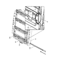
次に、上カバー10への防塵窓、清掃棒ガイド13の取付けについて、図を参照して説明する。図6は、上カバー10への防塵窓12(12a、12b)、固定部材である清掃棒ガイド13の取付けを説明する図である。図6において、上カバー10の枠部材11aの座面15a(15aa、15ab)上に防塵窓12a(12aa、12ab)を載せ、清掃棒ガイド13aを組み付ける。防塵窓12aは、遮音部材40が設置されている場合には防塵窓12aaが選択され、遮音部材40が設置されていない場合には防塵窓12abが選択される。そして、防塵窓12aaは座面15aaに当接するように設置され、防塵窓12abは座面15abに当接するように設置される。そして、防塵窓12a(12aa、12ab)を押圧した状態で、上カバー10上に設けられた複数の突起部131と清掃棒ガイド13aに設けられた穴(不図示)とが係合して、清掃棒ガイド13aの位置が決まる。更に、清掃棒ガイド13aのスナップフィット(不図示)が上カバー10上に設けられた穴部に係合することにより、清掃棒ガイド13aは固定される。更に、防塵窓12a(12aa、12ab)は、清掃棒ガイド13により座面15a(15aa、15ab)の方向に付勢される。
[Installation of cleaning rod guide and dustproof window]
Next, attachment of the dustproof window and the cleaning rod guide 13 to the
図2(b)において、防塵窓12aaは、清掃棒ガイド13aにより座面15aaの方向に押圧されて座面15aaに固定されると共に、枠部材11aの弾性部材で形成された接触部11aaの方向にも押圧され、固定される。同様に、図2(c)においても、防塵窓12abは、清掃棒ガイド13aにより座面15abの方向に押圧されて座面15abに固定されると共に、枠部材11aの弾性部材で形成された接触部11abの方向にも押圧され、固定される。なお、防塵窓12aa、12abは、清掃棒ガイド13aにより付勢される構成となっているため、防塵窓12aa、12abの短手方向の幅は、清掃棒ガイド13aの防塵窓12aを押圧する押圧部の間の開口部の幅t3(図2)よりも広い。このように、防塵窓12a(12aa、12ab)は、清掃棒ガイド13aにより押圧され、防塵窓12aに接触する枠部材11aに形成された接触部11a(11aa、11ab)に接触した状態となり、清掃棒ガイド13aと接触部11aを押圧する。その結果、防塵窓12a(12aa、12ab)が接触部11a(11aa、11ab)を押圧し、圧縮することで、防塵窓12aと接触部11aが密着し、図2(b)、(c)に示すような状態となる。これにより、防塵窓12aと上カバー10との間の密閉度が確保され、高い防塵性を実現することができる。
In FIG. 2B, the dustproof window 12aa is pressed in the direction of the seat surface 15aa by the cleaning
[防塵窓の清掃]
画像形成装置50内において、光走査装置20の上方に位置する感光ドラム21から落下するトナーや、外部から画像形成装置50内に侵入したゴミケバが、防塵窓12上に付着することがある。その結果、光走査装置20から出射されるレーザ光が遮られ、感光ドラム21上に静電潜像が正常に形成されなくなり、画像不良が発生する。このような場合に備えて、防塵窓12を清掃するための清掃棒が、画像形成装置50に備えられ、例えば画像形成装置50の前ドアの内側に備えられている。例えば画像形成装置50では、前ドアを開けると清掃棒の挿入口を有する案内部(不図示)が設けられている。そして、案内部は、清掃棒の挿入口に清掃棒を挿入すると、清掃棒の進行方向先端部を上述した清掃棒ガイド13へと案内する構成となっている。図7は清掃部材である清掃棒100による防塵窓12aの清掃を説明する斜視図である。図7は、イエロー(Y)の画像形成部の感光ドラム21aを露光するレーザ光LYが射出される開口部14aに設けられた清掃棒ガイド13aの防塵窓12aの清掃の様子を示している。レーザ光LM、LC、LKが射出される開口部14b〜14dに設けられた清掃棒ガイド13b〜13dの防塵窓12b〜12dの清掃についても、清掃棒ガイド13aの場合と同様であり、ここでは清掃棒ガイド13aの防塵窓12aの清掃について説明する。
[Cleaning dustproof windows]
In the
図7において、上述した案内部に設けられた清掃棒100の挿入口に挿入された清掃棒100は、矢印方向に案内され、清掃棒ガイド13aの清掃棒100の進行方向上流の挿入口(破線枠部Dで表示)へと進む。図7の清掃棒ガイド13aの拡大図に示すように、清掃棒ガイド13aの内部は、清掃棒100が防塵窓12aを清掃するために挿入される空間が設けられている。また、清掃棒ガイド13aの清掃棒100が挿入される端部は、清掃棒100が挿入されやすくするために、図中左右方向に広がった形状を有している。なお、受渡し部13aeについては後述する。
In FIG. 7, the cleaning
[清掃棒ガイドの構成]
図8は、清掃棒100が図7に示す清掃棒ガイド13aの破線枠部Dで示す端部に進んだときの様子を示す断面図である。図8(a)は、防塵窓12aaが設置された清掃棒ガイド13aの長手方向の破線枠部D近傍の断面を示す図であり、図8(b)は、防塵窓12abが設置された清掃棒ガイド13aの長手方向の破線枠部D近傍の断面を示す図である。図8(a)において、防塵窓12aaは、座面15aaに支持され、清掃棒ガイド13aにより押圧されることにより、接触部11aaに接触している。一方、図8(b)では、防塵窓12abは、清掃棒ガイド13aにより押圧されることにより、接触部11abに接触している。
[Cleaning rod guide configuration]
FIG. 8 is a cross-sectional view showing a state when the
清掃棒100は、清掃棒フレーム101と、清掃棒フレーム101の先端に設けられた弾性部材103と、弾性部材103の周囲に設けられた不織布である清掃布102とから構成されている。なお、清掃棒フレーム101は、その断面が凸形状の凸部を有している。また、図7に示す清掃棒ガイド13aの短手方向の断面も凸形状を有している。これにより、清掃棒100は、清掃棒ガイド13aに挿入可能であり、かつ上下、左右方向にぶれることなく、安定して清掃棒ガイド13aの溝部を移動することができ、防塵窓12aa、12abの表面を清掃可能である。
The cleaning
清掃棒100が清掃棒ガイド13aに挿入されたときには、清掃棒フレーム101が清掃棒ガイド13aの天面部13abに図中、下方向(防塵窓12a方向)に押付けられ、弾性部材103がつぶれる。これにより、清掃布102が防塵窓12aの表面に押し付けられ、清掃棒100を図中左右方向に移動させることにより、防塵窓12aの表面の汚れを拭き取ることができる。そのため、本実施例では、清掃布102が常に所定の圧力で防塵窓12aに押付けられて清掃を行うことができるように、防塵窓12aa、12abの表面(清掃面)の高さが同一の高さとなるように、座面15aa、15abを設定している。
When the
また、清掃棒ガイド13aは、清掃時に清掃布102が防塵窓12aの角部(エッジ)に当たり、清掃布102が毛羽立ったり破れたりしないように、清掃棒ガイド13aと一体となった橋部13aeを備えている。図8(a)、(b)に示すように、防塵窓12a(12aa、12ab)の長手方向の清掃棒100が挿入される側の端部と上カバー10との間には隙間(空空間)が生じている。そのため、上カバー10と清掃棒ガイド13a側(固定部材側)の面である防塵窓12aの上面(清掃面)を繋ぐ橋部13aeを設けている。これにより、清掃棒100による清掃時に、清掃布102が防塵窓12aの角部(エッジ)に当たることがなくなり、清掃布102の毛羽立ちや破れの発生を防ぐ効果を奏する。
Further, the cleaning
本実施例では光走査装置として1台の回転多面鏡を用いて複数の像担持体を露光する方式の構成を用いて例示したが、例示した構成である必要は無く、各色に個別の光走査装置を用いた構成でも同じ効果を得ることができる。 In this embodiment, an example is used as an optical scanning device using a configuration in which a plurality of image carriers are exposed using one rotating multi-sided mirror, but the configuration does not have to be exemplified, and individual optical scanning is performed for each color. The same effect can be obtained with a configuration using an apparatus.
以上説明したように、本実施例によれば、回転多面鏡を覆う遮音部材の有無にかかわらず、安定した光学性能を確保することができる。 As described above, according to the present embodiment, stable optical performance can be ensured regardless of the presence or absence of the sound insulating member covering the rotating multifaceted mirror.
12aa,12ab 防塵窓
15aa、15ab 座面
31 回転多面鏡
35 筐体
40 遮音部材
43 透明窓
12aa, 12ab Dustproof window 15aa,
Claims (16)
前記光学部材が配置された第1配置空間と前記回転多面鏡が配置された第2配置空間とを隔てて前記第2配置空間から前記第1配置空間への前記回転多面鏡の回転によって生じる音の伝播を低減する遮音部材であって、前記回転多面鏡により偏向された前記光ビームが出射される透明窓を有する前記遮音部材を取り付け可能な取付部と、
前記取付部に前記遮音部材が取り付けられる場合に前記開口を塞ぐ透明部材であって、前記光ビームを前記筐体の内部から外部に通過させる前記透明部材を支持するための第1支持部と、
前記取付部に前記遮音部材が取り付けられない場合に前記開口を塞ぐ透明部材であって、前記光ビームを前記筐体の内部から外部に通過させ且つ前記第1支持部が支持する前記透明部材よりも厚い透明部材を支持するための第2支持部と、
を備え、
前記第1支持部に支持される前記透明部材の光ビーム出射面と前記第2支持部に支持される前記透明部材の光ビーム出射面とが略同一平面となるように、前記第1支持部の前記透明部材に接触する座面よりも前記第2支持部の前記透明部材に接触する座面が前記光学部材が配置される前記筐体の内部側に位置することを特徴とする光走査装置の筐体。 A rotating multi-sided mirror that has a plurality of reflecting surfaces and deflects a light beam emitted from a light source by rotationally driving, and an imaging lens that forms an image of the light beam deflected by the rotating multi-sided mirror on a photoconductor. An optical member including at least a part of a reflection mirror that guides the light beam deflected by the rotating multifaceted mirror to the photoconductor is housed inside, and an opening is formed through which the light beam scanning the photoconductor is passed. The housing of the optical scanning device
The sound generated by the rotation of the rotating multifaceted mirror from the second arrangement space to the first arrangement space by separating the first arrangement space in which the optical member is arranged and the second arrangement space in which the rotating polyplane mirror is arranged. A mounting portion to which the sound insulating member can be attached, which is a sound insulating member having a transparent window from which the light beam deflected by the rotating multifaceted mirror is emitted.
A first support portion for supporting the transparent member that closes the opening when the sound insulating member is attached to the mounting portion and allows the light beam to pass from the inside to the outside of the housing.
A transparent member that closes the opening when the sound insulating member cannot be attached to the mounting portion, from the transparent member that allows the light beam to pass from the inside to the outside of the housing and is supported by the first support portion. A second support for supporting a thick transparent member,
With
The first support portion so that the light beam emitting surface of the transparent member supported by the first support portion and the light beam emitting surface of the transparent member supported by the second support portion are substantially flush with each other. An optical scanning apparatus characterized in that the seat surface of the second support portion that contacts the transparent member is located on the inner side of the housing in which the optical member is arranged, rather than the seat surface that contacts the transparent member. Case.
前記第2支持部に支持された前記透明部材の長手方向の長さをL4、短手方向の長さをb2、厚さをt2としたときの大小関係は、
前記L3>前記L4、前記b1>前記b2、前記t1<前記t2を満たすことを特徴とする請求項2に記載の光走査装置の筐体。 The length of the transparent member supported by the first support portion in the longitudinal direction is L3, the length in the lateral direction is b1, and the thickness is t1.
The magnitude relationship when the length of the transparent member supported by the second support portion in the longitudinal direction is L4, the length in the lateral direction is b2, and the thickness is t2 is
The housing of the optical scanning apparatus according to claim 2, wherein the L3> the L4, the b1> the b2, and the t1 <the t2 are satisfied.
前記光源から出射された前記光ビームを前記第2配置空間の外から当該第2配置空間に入射させるための透明窓及び前記回転多面鏡により偏向された前記光ビームを前記第2配置空間から前記第1配置空間に出射させるための透明窓により生じる前記感光体でのピントのズレ量をL1とすると、
前記第1支持部に支持された前記透明部材による光路長と前記第2支持部に支持された前記透明部材による光路長との差は、略L1であることを特徴とする請求項3に記載の光走査装置の筐体。 The sound insulating member further has a transparent window for allowing the light beam emitted from the light source to enter the second arrangement space from outside the second arrangement space.
The light beam deflected by the magnetic Akiramado and the rotary polygon mirror for causing incident the light beam emitted from the light source from outside of the second arrangement space in the second arrangement space from the second arrangement space If the defocus value in the photosensitive body caused by Toru Akiramado for emitting the first arrangement space and L1,
The third aspect of claim 3, wherein the difference between the optical path length of the transparent member supported by the first support portion and the optical path length of the transparent member supported by the second support portion is approximately L1. The housing of the optical scanning device.
前記光源から出射された前記光ビームを前記第2配置空間の外から当該第2配置空間に入射させるための透明窓及び前記回転多面鏡により偏向された前記光ビームを前記第2配置空間から前記第1配置空間に出射させるための透明窓により生じる前記感光体でのピントのズレ量をL1とし、前記光源から出射された前記光ビームを前記第2配置空間の外から当該第2配置空間に入射させるための前記透明窓によって生じるピントのズレ量をL2としたとき、
前記第1支持部に支持された前記透明部材による光路長と前記第2支持部に支持された前記透明部材による光路長との差は、略(L1−L2)であることを特徴とする請求項3に記載の光走査装置の筐体。 The sound insulating member further has a transparent window for allowing the light beam emitted from the light source to enter the second arrangement space from outside the second arrangement space.
The light beam deflected by the magnetic Akiramado and the rotary polygon mirror for causing incident the light beam emitted from the light source from outside of the second arrangement space in the second arrangement space from the second arrangement space wherein the defocus value of the photosensitive member and L1, the second arrangement from the outside of the light beam emitted from the light source and the second arrangement space caused by Toru Akiramado for emitting the first arrangement space When the amount of focus shift caused by the transparent window for incident on the space is L2,
The difference between the optical path length of the transparent member supported by the first support portion and the optical path length of the transparent member supported by the second support portion is approximately (L1-L2). Item 3. The housing of the optical scanning device according to item 3.
前記光源から出射された前記光ビームを前記第2配置空間の外から当該第2配置空間に入射させるための透明窓及び前記回転多面鏡により偏向された前記光ビームを前記第2配置空間から前記第1配置空間に出射させるための透明窓により生じる前記感光体でのピントのズレ量をL1とし、前記光源から出射された前記光ビームを前記第2配置空間の外から当該第2配置空間に入射させるための前記透明窓によって生じるピントのズレ量をL2としたとき、
前記第1支持部に支持された前記透明部材による光路長と前記第2支持部に支持された前記透明部材による光路長との差は、略(L1−L2/2)であることを特徴とする請求項3に記載の光走査装置の筐体。 The sound insulating member further has a transparent window for allowing the light beam emitted from the light source to enter the second arrangement space from outside the second arrangement space.
The light beam deflected by the magnetic Akiramado and the rotary polygon mirror for causing incident the light beam emitted from the light source from outside of the second arrangement space in the second arrangement space from the second arrangement space wherein the defocus value of the photosensitive member and L1, the second arrangement from the outside of the light beam emitted from the light source and the second arrangement space caused by Toru Akiramado for emitting the first arrangement space When the amount of focus shift caused by the transparent window for incident on the space is L2,
The difference between the optical path length of the transparent member supported by the first support portion and the optical path length of the transparent member supported by the second support portion is approximately (L1-L2 / 2). The housing of the optical scanning device according to claim 3.
前記清掃部材の前記フレームは、前記溝部に挿入可能な凸形状を有することを特徴とする請求項8に記載の光走査装置の筐体。 The fixing member has a groove having a convex cross section in the lateral direction.
The housing of the optical scanning device according to claim 8 , wherein the frame of the cleaning member has a convex shape that can be inserted into the groove.
前記窓部材は、前記第1支持部の前記座面の外周に沿って設けられ、前記第1支持部に支持された前記透明部材に接触する第1接触部と、前記第2支持部の前記座面の外周に沿って前記第1支持部の前記座面と前記第2支持部の前記座面との間に設けられ、前記第2支持部に支持された前記透明部材に接触する第2接触部と、を有することを特徴とする請求項11に記載の光走査装置の筐体。 A window member provided in the opening and having the first support portion and the second support portion is provided.
The window member is provided along the outer periphery of the seating surface of the first support portion, and has a first contact portion that contacts the transparent member supported by the first support portion and the second support portion. A second that is provided between the seat surface of the first support portion and the seat surface of the second support portion along the outer circumference of the seat surface and comes into contact with the transparent member supported by the second support portion. The housing of the optical scanning apparatus according to claim 11 , further comprising a contact portion.
Priority Applications (2)
| Application Number | Priority Date | Filing Date | Title |
|---|---|---|---|
| JP2017025995A JP6882002B2 (en) | 2017-02-15 | 2017-02-15 | Optical scanning device housing and optical scanning device |
| US15/891,080 US10473922B2 (en) | 2017-02-15 | 2018-02-07 | Casing of optical scanning apparatus and optical scanning apparatus |
Applications Claiming Priority (1)
| Application Number | Priority Date | Filing Date | Title |
|---|---|---|---|
| JP2017025995A JP6882002B2 (en) | 2017-02-15 | 2017-02-15 | Optical scanning device housing and optical scanning device |
Publications (3)
| Publication Number | Publication Date |
|---|---|
| JP2018132642A JP2018132642A (en) | 2018-08-23 |
| JP2018132642A5 JP2018132642A5 (en) | 2020-03-26 |
| JP6882002B2 true JP6882002B2 (en) | 2021-06-02 |
Family
ID=63105127
Family Applications (1)
| Application Number | Title | Priority Date | Filing Date |
|---|---|---|---|
| JP2017025995A Expired - Fee Related JP6882002B2 (en) | 2017-02-15 | 2017-02-15 | Optical scanning device housing and optical scanning device |
Country Status (2)
| Country | Link |
|---|---|
| US (1) | US10473922B2 (en) |
| JP (1) | JP6882002B2 (en) |
Families Citing this family (8)
| Publication number | Priority date | Publication date | Assignee | Title |
|---|---|---|---|---|
| JP6288995B2 (en) * | 2013-09-06 | 2018-03-07 | キヤノン株式会社 | Optical scanning apparatus and image forming apparatus |
| JP6964510B2 (en) * | 2017-12-25 | 2021-11-10 | シャープ株式会社 | Optical scanning device and image forming device |
| JP7051472B2 (en) | 2018-02-08 | 2022-04-11 | キヤノン株式会社 | Optical scanning device and image forming device |
| JP7175681B2 (en) | 2018-09-03 | 2022-11-21 | キヤノン株式会社 | Optical scanning device and image forming device |
| JP6929824B2 (en) | 2018-12-04 | 2021-09-01 | キヤノン株式会社 | Image forming device |
| JP7110077B2 (en) | 2018-12-04 | 2022-08-01 | キヤノン株式会社 | image forming device |
| JP2020129082A (en) * | 2019-02-08 | 2020-08-27 | キヤノン株式会社 | Image forming device |
| JP2020140016A (en) | 2019-02-27 | 2020-09-03 | キヤノン株式会社 | Optical scanning device |
Family Cites Families (36)
| Publication number | Priority date | Publication date | Assignee | Title |
|---|---|---|---|---|
| JP2711155B2 (en) * | 1989-10-20 | 1998-02-10 | 富士写真フイルム株式会社 | Light beam scanning device |
| JP2001249295A (en) * | 2000-03-06 | 2001-09-14 | Ricoh Co Ltd | Scanning optical device |
| JP4075978B2 (en) * | 2000-04-13 | 2008-04-16 | 株式会社リコー | Optical scanning apparatus and image forming apparatus |
| JP5013652B2 (en) | 2003-06-13 | 2012-08-29 | キヤノン株式会社 | Scanning optical device |
| JP2005329622A (en) * | 2004-05-20 | 2005-12-02 | Ricoh Co Ltd | Optical writing apparatus and image forming apparatus |
| US20050270612A1 (en) * | 2004-06-04 | 2005-12-08 | Konica Minolta Business Technologies, Inc. | Optical scanning apparatus |
| JP4328674B2 (en) | 2004-06-07 | 2009-09-09 | キヤノン株式会社 | Scanning optical apparatus and image forming apparatus |
| KR100619059B1 (en) * | 2004-12-01 | 2006-08-31 | 삼성전자주식회사 | Beam deflector, optical scanning device and image forming device employing the same |
| JP4634819B2 (en) * | 2005-02-22 | 2011-02-16 | 株式会社リコー | Optical scanning apparatus and image forming apparatus |
| JP4819446B2 (en) | 2005-09-02 | 2011-11-24 | キヤノン株式会社 | Scanning optical apparatus and image forming apparatus |
| JP4769526B2 (en) * | 2005-09-13 | 2011-09-07 | キヤノン株式会社 | Optical beam scanning device |
| JP5223199B2 (en) * | 2007-01-25 | 2013-06-26 | 株式会社リコー | Optical scanning apparatus and image forming apparatus |
| JP5388418B2 (en) | 2007-02-19 | 2014-01-15 | キヤノン株式会社 | Scanning optical apparatus and image forming apparatus |
| JP5121388B2 (en) | 2007-10-17 | 2013-01-16 | キヤノン株式会社 | Optical scanning device |
| JP5219548B2 (en) | 2008-02-22 | 2013-06-26 | キヤノン株式会社 | Optical scanning device |
| JP4506860B2 (en) * | 2008-03-14 | 2010-07-21 | 富士ゼロックス株式会社 | Optical scanning apparatus and image forming apparatus |
| JP5272523B2 (en) * | 2008-06-03 | 2013-08-28 | 株式会社リコー | Image forming apparatus |
| US8471883B2 (en) * | 2008-08-20 | 2013-06-25 | Ricoh Company, Ltd. | Optical scanner and image forming apparatus including same |
| JP2012150161A (en) * | 2011-01-17 | 2012-08-09 | Ricoh Co Ltd | Optical scanner and image forming device |
| JP5896117B2 (en) * | 2011-12-13 | 2016-03-30 | 株式会社リコー | Optical scanning apparatus and image forming apparatus |
| JP6141074B2 (en) | 2012-04-25 | 2017-06-07 | キヤノン株式会社 | Scanning optical apparatus and image forming apparatus |
| JP6053314B2 (en) | 2012-04-26 | 2016-12-27 | キヤノン株式会社 | Image forming apparatus |
| JP2013242547A (en) | 2012-04-26 | 2013-12-05 | Canon Inc | Optical scanner, and image forming apparatus including the optical scanner |
| JP6207186B2 (en) | 2013-03-18 | 2017-10-04 | キヤノン株式会社 | Optical scanning apparatus and image forming apparatus |
| JP6128988B2 (en) | 2013-06-26 | 2017-05-17 | キヤノン株式会社 | Optical scanning apparatus and image forming apparatus |
| JP6319961B2 (en) | 2013-07-24 | 2018-05-09 | キヤノン株式会社 | Optical scanning apparatus and image forming apparatus |
| JP5974074B2 (en) | 2014-01-17 | 2016-08-23 | キヤノン株式会社 | Image forming apparatus |
| JP6057980B2 (en) | 2014-01-30 | 2017-01-11 | キヤノン株式会社 | Optical scanning apparatus and image forming apparatus |
| WO2015159992A1 (en) | 2014-04-15 | 2015-10-22 | Canon Kabushiki Kaisha | Image forming apparatus |
| US9400444B2 (en) | 2014-04-15 | 2016-07-26 | Canon Kabushiki Kaisha | Image forming apparatus with improved timing for emitting beam detect light beam |
| JP6350901B2 (en) * | 2014-05-13 | 2018-07-04 | 株式会社リコー | Optical scanning apparatus and image forming apparatus |
| JP6410143B2 (en) * | 2014-11-27 | 2018-10-24 | 株式会社リコー | Image forming apparatus |
| JP6444182B2 (en) | 2015-01-19 | 2018-12-26 | キヤノン株式会社 | Optical scanning apparatus and image forming apparatus |
| JP6543038B2 (en) | 2015-01-28 | 2019-07-10 | キヤノン株式会社 | Optical scanning apparatus, image forming apparatus and rotary polygon mirror |
| US9975350B2 (en) | 2015-05-29 | 2018-05-22 | Canon Kabushiki Kaisha | Light scanning apparatus |
| JP2017049416A (en) | 2015-09-01 | 2017-03-09 | キヤノン株式会社 | Optical scanner and image forming apparatus |
-
2017
- 2017-02-15 JP JP2017025995A patent/JP6882002B2/en not_active Expired - Fee Related
-
2018
- 2018-02-07 US US15/891,080 patent/US10473922B2/en not_active Expired - Fee Related
Also Published As
| Publication number | Publication date |
|---|---|
| JP2018132642A (en) | 2018-08-23 |
| US10473922B2 (en) | 2019-11-12 |
| US20180231769A1 (en) | 2018-08-16 |
Similar Documents
| Publication | Publication Date | Title |
|---|---|---|
| JP6882002B2 (en) | Optical scanning device housing and optical scanning device | |
| JP6444182B2 (en) | Optical scanning apparatus and image forming apparatus | |
| JP3862950B2 (en) | Optical writing apparatus and image forming apparatus | |
| US10298797B2 (en) | Optical scanning apparatus and image forming apparatus | |
| JP2013113957A (en) | Optical scanner and image forming device | |
| JP2017040756A (en) | Optical scanner and image forming apparatus | |
| JP6918514B2 (en) | Optical scanning device housing and optical scanning device | |
| JP4689434B2 (en) | Optical scanning apparatus and image forming apparatus | |
| US6847474B2 (en) | Optical scanning device, scanning optical system, scanning imaging optical component, optical scanning method, ghost image preventing method and image forming apparatus | |
| KR100714334B1 (en) | Image forming apparatus | |
| JP4925623B2 (en) | Optical scanning apparatus and image forming apparatus | |
| US20080118287A1 (en) | Optical scanning device and image forming apparatus having the same | |
| JP6608225B2 (en) | Optical scanning device | |
| JP2019138996A (en) | Optical scanner and image forming apparatus | |
| US8957935B2 (en) | Light scanning unit and electro-photographic image forming apparatus employing the same | |
| US20070030496A1 (en) | Optical beam scanning device and image forming apparatus | |
| JP5123117B2 (en) | Optical scanning device and image forming apparatus | |
| US7218434B2 (en) | Optical scanning apparatus and image forming apparatus equipped with the same | |
| JP2022079099A (en) | Optical scanning device | |
| US12443124B2 (en) | Optical scanning device and image forming apparatus mounted with it | |
| KR100644686B1 (en) | Gwangju fraud and electrophotographic image forming apparatus having same | |
| JP2014052541A (en) | Optical scanner and image forming apparatus | |
| JP2020140057A (en) | Optical scanning device and image forming device | |
| JP7018324B2 (en) | Optical scanning device and image forming device equipped with it | |
| JP2017053959A (en) | Optical scanner |
Legal Events
| Date | Code | Title | Description |
|---|---|---|---|
| RD04 | Notification of resignation of power of attorney |
Free format text: JAPANESE INTERMEDIATE CODE: A7424 Effective date: 20171201 |
|
| A521 | Request for written amendment filed |
Free format text: JAPANESE INTERMEDIATE CODE: A523 Effective date: 20200213 |
|
| A621 | Written request for application examination |
Free format text: JAPANESE INTERMEDIATE CODE: A621 Effective date: 20200213 |
|
| A977 | Report on retrieval |
Free format text: JAPANESE INTERMEDIATE CODE: A971007 Effective date: 20210121 |
|
| A131 | Notification of reasons for refusal |
Free format text: JAPANESE INTERMEDIATE CODE: A131 Effective date: 20210202 |
|
| A521 | Request for written amendment filed |
Free format text: JAPANESE INTERMEDIATE CODE: A523 Effective date: 20210326 |
|
| TRDD | Decision of grant or rejection written | ||
| A01 | Written decision to grant a patent or to grant a registration (utility model) |
Free format text: JAPANESE INTERMEDIATE CODE: A01 Effective date: 20210406 |
|
| A61 | First payment of annual fees (during grant procedure) |
Free format text: JAPANESE INTERMEDIATE CODE: A61 Effective date: 20210506 |
|
| R151 | Written notification of patent or utility model registration |
Ref document number: 6882002 Country of ref document: JP Free format text: JAPANESE INTERMEDIATE CODE: R151 |
|
| LAPS | Cancellation because of no payment of annual fees |