JP6879265B2 - Electronics - Google Patents
Electronics Download PDFInfo
- Publication number
- JP6879265B2 JP6879265B2 JP2018098783A JP2018098783A JP6879265B2 JP 6879265 B2 JP6879265 B2 JP 6879265B2 JP 2018098783 A JP2018098783 A JP 2018098783A JP 2018098783 A JP2018098783 A JP 2018098783A JP 6879265 B2 JP6879265 B2 JP 6879265B2
- Authority
- JP
- Japan
- Prior art keywords
- unit
- touch panel
- display
- timing
- operation unit
- Prior art date
- Legal status (The legal status is an assumption and is not a legal conclusion. Google has not performed a legal analysis and makes no representation as to the accuracy of the status listed.)
- Active
Links
Images


Classifications
-
- G—PHYSICS
- G06—COMPUTING; CALCULATING OR COUNTING
- G06F—ELECTRIC DIGITAL DATA PROCESSING
- G06F3/00—Input arrangements for transferring data to be processed into a form capable of being handled by the computer; Output arrangements for transferring data from processing unit to output unit, e.g. interface arrangements
- G06F3/16—Sound input; Sound output
- G06F3/167—Audio in a user interface, e.g. using voice commands for navigating, audio feedback
-
- G—PHYSICS
- G06—COMPUTING; CALCULATING OR COUNTING
- G06F—ELECTRIC DIGITAL DATA PROCESSING
- G06F3/00—Input arrangements for transferring data to be processed into a form capable of being handled by the computer; Output arrangements for transferring data from processing unit to output unit, e.g. interface arrangements
- G06F3/01—Input arrangements or combined input and output arrangements for interaction between user and computer
- G06F3/016—Input arrangements with force or tactile feedback as computer generated output to the user
-
- G—PHYSICS
- G06—COMPUTING; CALCULATING OR COUNTING
- G06F—ELECTRIC DIGITAL DATA PROCESSING
- G06F3/00—Input arrangements for transferring data to be processed into a form capable of being handled by the computer; Output arrangements for transferring data from processing unit to output unit, e.g. interface arrangements
- G06F3/01—Input arrangements or combined input and output arrangements for interaction between user and computer
- G06F3/03—Arrangements for converting the position or the displacement of a member into a coded form
- G06F3/041—Digitisers, e.g. for touch screens or touch pads, characterised by the transducing means
- G06F3/044—Digitisers, e.g. for touch screens or touch pads, characterised by the transducing means by capacitive means
-
- G—PHYSICS
- G06—COMPUTING; CALCULATING OR COUNTING
- G06F—ELECTRIC DIGITAL DATA PROCESSING
- G06F3/00—Input arrangements for transferring data to be processed into a form capable of being handled by the computer; Output arrangements for transferring data from processing unit to output unit, e.g. interface arrangements
- G06F3/01—Input arrangements or combined input and output arrangements for interaction between user and computer
- G06F3/048—Interaction techniques based on graphical user interfaces [GUI]
- G06F3/0484—Interaction techniques based on graphical user interfaces [GUI] for the control of specific functions or operations, e.g. selecting or manipulating an object, an image or a displayed text element, setting a parameter value or selecting a range
- G06F3/04842—Selection of displayed objects or displayed text elements
-
- G—PHYSICS
- G06—COMPUTING; CALCULATING OR COUNTING
- G06F—ELECTRIC DIGITAL DATA PROCESSING
- G06F3/00—Input arrangements for transferring data to be processed into a form capable of being handled by the computer; Output arrangements for transferring data from processing unit to output unit, e.g. interface arrangements
- G06F3/01—Input arrangements or combined input and output arrangements for interaction between user and computer
- G06F3/048—Interaction techniques based on graphical user interfaces [GUI]
- G06F3/0487—Interaction techniques based on graphical user interfaces [GUI] using specific features provided by the input device, e.g. functions controlled by the rotation of a mouse with dual sensing arrangements, or of the nature of the input device, e.g. tap gestures based on pressure sensed by a digitiser
- G06F3/0488—Interaction techniques based on graphical user interfaces [GUI] using specific features provided by the input device, e.g. functions controlled by the rotation of a mouse with dual sensing arrangements, or of the nature of the input device, e.g. tap gestures based on pressure sensed by a digitiser using a touch-screen or digitiser, e.g. input of commands through traced gestures
-
- G—PHYSICS
- G06—COMPUTING; CALCULATING OR COUNTING
- G06F—ELECTRIC DIGITAL DATA PROCESSING
- G06F3/00—Input arrangements for transferring data to be processed into a form capable of being handled by the computer; Output arrangements for transferring data from processing unit to output unit, e.g. interface arrangements
- G06F3/14—Digital output to display device ; Cooperation and interconnection of the display device with other functional units
- G06F3/147—Digital output to display device ; Cooperation and interconnection of the display device with other functional units using display panels
-
- G—PHYSICS
- G06—COMPUTING; CALCULATING OR COUNTING
- G06F—ELECTRIC DIGITAL DATA PROCESSING
- G06F3/00—Input arrangements for transferring data to be processed into a form capable of being handled by the computer; Output arrangements for transferring data from processing unit to output unit, e.g. interface arrangements
- G06F3/16—Sound input; Sound output
-
- G—PHYSICS
- G09—EDUCATION; CRYPTOGRAPHY; DISPLAY; ADVERTISING; SEALS
- G09G—ARRANGEMENTS OR CIRCUITS FOR CONTROL OF INDICATING DEVICES USING STATIC MEANS TO PRESENT VARIABLE INFORMATION
- G09G5/00—Control arrangements or circuits for visual indicators common to cathode-ray tube indicators and other visual indicators
- G09G5/02—Control arrangements or circuits for visual indicators common to cathode-ray tube indicators and other visual indicators characterised by the way in which colour is displayed
-
- G—PHYSICS
- G09—EDUCATION; CRYPTOGRAPHY; DISPLAY; ADVERTISING; SEALS
- G09G—ARRANGEMENTS OR CIRCUITS FOR CONTROL OF INDICATING DEVICES USING STATIC MEANS TO PRESENT VARIABLE INFORMATION
- G09G5/00—Control arrangements or circuits for visual indicators common to cathode-ray tube indicators and other visual indicators
- G09G5/36—Control arrangements or circuits for visual indicators common to cathode-ray tube indicators and other visual indicators characterised by the display of a graphic pattern, e.g. using an all-points-addressable [APA] memory
- G09G5/37—Details of the operation on graphic patterns
- G09G5/373—Details of the operation on graphic patterns for modifying the size of the graphic pattern
-
- G—PHYSICS
- G06—COMPUTING; CALCULATING OR COUNTING
- G06F—ELECTRIC DIGITAL DATA PROCESSING
- G06F2203/00—Indexing scheme relating to G06F3/00 - G06F3/048
- G06F2203/01—Indexing scheme relating to G06F3/01
- G06F2203/014—Force feedback applied to GUI
-
- G—PHYSICS
- G09—EDUCATION; CRYPTOGRAPHY; DISPLAY; ADVERTISING; SEALS
- G09G—ARRANGEMENTS OR CIRCUITS FOR CONTROL OF INDICATING DEVICES USING STATIC MEANS TO PRESENT VARIABLE INFORMATION
- G09G2340/00—Aspects of display data processing
- G09G2340/04—Changes in size, position or resolution of an image
- G09G2340/045—Zooming at least part of an image, i.e. enlarging it or shrinking it
-
- G—PHYSICS
- G09—EDUCATION; CRYPTOGRAPHY; DISPLAY; ADVERTISING; SEALS
- G09G—ARRANGEMENTS OR CIRCUITS FOR CONTROL OF INDICATING DEVICES USING STATIC MEANS TO PRESENT VARIABLE INFORMATION
- G09G2354/00—Aspects of interface with display user
Description
本発明は、電子機器に関する。 The present invention relates to electronic devices.
タッチセンサを備えた機器、例えばスマートフォンや車載ナビなどのタッチセンサによる操作機能は、例えば液晶表示されたアイコン、スイッチ等を指で操作することで実行される。しかし、タッチセンサに表示されたスイッチ等を操作する場合、例えばタクトスイッチ、メタルコンタクトスイッチ等のメカ式スイッチに比べて、操作時のフィードバック、例えば、クリック感や凹凸感がユーザの指に伝わらない為、操作感が希薄であるという問題が有る。 An operation function by a device equipped with a touch sensor, for example, a touch sensor such as a smartphone or an in-vehicle navigation system, is executed by operating, for example, an icon or a switch displayed on a liquid crystal display with a finger. However, when operating a switch or the like displayed on a touch sensor, feedback during operation, such as a click feeling or unevenness, is not transmitted to the user's finger as compared with a mechanical switch such as a tact switch or a metal contact switch. Therefore, there is a problem that the operation feeling is weak.
そこで、ユーザが画面ボタンを操作した時、操作面を振動させる事で、操作感をユーザの指に伝える技術が提案されている(特許文献1)。また、画面の大型化などに伴い振動力が足りなく触感が弱くなる為、操作時の押圧力に合わせて振動とそれに応じた表示を出す技術が提案されている(特許文献2)。 Therefore, a technique has been proposed in which a feeling of operation is transmitted to a user's finger by vibrating the operation surface when the user operates a screen button (Patent Document 1). Further, since the vibration force is insufficient and the tactile sensation is weakened as the screen becomes larger, a technique has been proposed in which vibration and a display corresponding to the pressing force at the time of operation are displayed (Patent Document 2).
しかし、スライド操作など押圧力の変化がない操作の場合や、車の運転時等、表示を凝視できない場合は効果が少なくなる。また、実際のメカボタンの操作時に発生する音の情報がないため、操作リアリティが乏しい。 However, the effect is reduced when there is no change in pressing force such as a slide operation, or when the display cannot be stared at, such as when driving a car. Moreover, since there is no information on the sound generated when the actual mechanical button is operated, the operation reality is poor.
本発明は、上記課題に鑑みてなされたものであり、その目的は、タッチパネルに対する操作時に、ユーザに対して、よりリアリティのある操作感を提供し、ユーザにおける操作の認識を向上させることができる電子機器を提供することを目的とする。 The present invention has been made in view of the above problems, and an object of the present invention is to provide a more realistic operation feeling to the user when operating the touch panel, and to improve the recognition of the operation by the user. The purpose is to provide electronic devices.
請求項1に記載した電子機器(1)は、ユーザの指により操作するタッチパネル部(10)と、前記タッチパネル部を振動させる振動発生部(20)と、音声を発生する音声発生部(26)と、これらを制御する制御部(30)と、を備えており、前記タッチパネル部は、ユーザの指位置を検出可能な指位置検出部(10b)と、前記タッチパネル部に操作部を表示させる表示部(10a)と、を備え、前記制御部は、ユーザによる操作部への操作に応じて、前記タッチパネル部に振動を与えるように前記振動発生部に与える制御と、少なくとも、前記操作部に変化を与えるように前記表示部に与える制御、又は、音声を発生させるように前記音声発生部に与える制御の何れかを実施するものであり、前記タッチパネル部(10)には、スライド式であってディテント(D)を備える操作部(S2、S3)が表示されており、前記操作部が前記ディテントを跨ぐ際に、前記操作部の大きさを、ユーザの指の動きに対する速度比を1以下として前記操作部の表示サイズを大きく変化させる第1の表示制御を実行し、その後、ユーザの指の動きに対する速度比を1以上として前記操作部の表示サイズを小さく変化させる第2の表示制御を実行する。
The electronic device (1) according to
この構成によれば、タッチパネルの操作時において、所定の操作に応じて、視覚、触覚、聴覚による情報をリンクして発信する。これにより、タッチパネルに対する操作時に、ユーザに対して、よりリアリティのある操作感を提供することができるため、ユーザにおける操作の認識を向上させることができる。 According to this configuration, when the touch panel is operated, visual, tactile, and auditory information is linked and transmitted according to a predetermined operation. As a result, it is possible to provide the user with a more realistic operation feeling when operating the touch panel, and thus it is possible to improve the recognition of the operation by the user.
以下、本発明の複数の実施形態について図面を参照して説明する。以下の説明において前出と同様の要素については同様の符号を付し、その説明については省略する。 Hereinafter, a plurality of embodiments of the present invention will be described with reference to the drawings. In the following description, the same elements as those described above will be designated by the same reference numerals, and the description thereof will be omitted.
(第1実施形態)
第1実施形態に係る電子機器1は、例えば、車両用操作パネルとして用いられるものであり、多くの場合は車両内部の前方中央部の運転席又は助手席から視認及び操作可能な位置に配置されている。電子機器1は、例えば、カーナビゲーション、エアコン、オーディオ等の各機能を操作するための操作装置、車両の種々の情報を表示する表示装置等として機能している。
(First Embodiment)
The
図1〜図3に示すように、電子機器1は、タッチパネル部10、振動発生部20、隙間距離検出部24、音声発生部26、及び、これらを制御する制御部30を備えており、これらの裏面はケース25により覆われている。タッチパネル部10の表面は、オーバーレイ11により覆われている。タッチパネル部10とオーバーレイ11は積層されて一体構成されている。
As shown in FIGS. 1 to 3, the
タッチパネル部10は表示部10a及び指位置検出部10bを備えている。表示部10aは例えばTFT液晶表示装置であり、ユーザが操作するためのスイッチ、ボタン等の表示や種々の情報を表示する。
The
指位置検出部10bは、オーバーレイ11の裏面側すなわち表示部10a側に貼付されている。指位置検出部10bは、ユーザの指がオーバーレイ11にタッチした際に、タッチした指に電気力線の一部が吸収されることによる静電容量値の変化を検出し、これにより指によりタッチされた位置を検出可能に構成されている。
The finger
この構成により、タッチパネル部10は表示部及び指位置検出部として機能する。また、タッチパネル部10は、表示された例えばスイッチを、ユーザの指等によりタッチ操作することにより電子機器1を操作する操作部としても機能する。
With this configuration, the
タッチパネル部10下部にはバックライト14が設けられている。バックライト14は、タッチパネル部10に光を照明する光源である。タッチパネル部10を光で照射することで、タッチパネル部10に表示された文字等を視認することができる。
A
振動発生部20は、タッチパネル部10に振動を与える機能を備える。振動発生部20は電磁コイル20a及び固定鉄心20bを備えている。ケース25にはインサート成形により形成された固定ヨーク18が設けられており、振動発生部20はケース25に固定された固定ヨーク18上に固定配置されている。
The vibration generating
第1実施形態では、振動発生部20として、ソレノイド方式のアクチュエータが用いられた例を示している。アクチュエータとしては、他に、偏心回転体を用いた振動モータ型アクチュエータや、振動体の共振周波数に合わせたパルス波駆動によるリニア共振アクチュエータ等を用いることができる。振動発生部20は、電磁コイル20a及び固定鉄心20bを備えている。電磁コイル20a及び固定鉄心20bは固定ヨーク18に固定されている。
In the first embodiment, an example in which a solenoid type actuator is used as the
図2、図3に示すように、電子機器1では、板バネ16、基板23がネジ25aによりケース25に螺設固定されている。可動ヨーク17は、板バネ16にカシメなどの手段で固定され、これにより、板バネ16によって弾性的に支持されている。
As shown in FIGS. 2 and 3, in the
可動ヨーク17とタッチパネル部10は、可動フレーム15を介して一体的に接続されている。可動ヨーク17、可動フレーム15、及びタッチパネル部10は全体として板バネ16により弾性的に支持されているため、可動ヨーク17、可動フレーム15、及びタッチパネル部10の全体は外部からの力により一体的に上下に動くことができる。
The
可動ヨーク17は、固定鉄心20bの上側に対向した位置に、電磁コイル20aによって発生する磁力によって吸引可能な所定距離を備えて離間して配置されている。電磁コイル20aへの通電のオン、オフを繰り返すことにより、振動発生部20における磁界の発生、消滅を交互に実行される。
The
磁界が発生すると、可動ヨーク17は振動発生部20方向に吸引されて下方向に動き、磁界が消滅すると、板バネ16の弾性力により可動ヨーク17は振動発生部20から遠ざかる。これを繰り返すことによって、可動ヨーク17は上下方向に振動する。固定ヨーク18は、鉄などの透磁率の高い材料で構成されており、振動発生部20のON時の磁束密度を上げる作用を有している。
When a magnetic field is generated, the
可動フレーム15は、高剛性部材を用いて構成されており、例えば、Fe、Al、Mg等の金属もしくはこれらの合金、カーボンファイバー、ABS(アクリロニトリル、ブタジエン、スチレン共重合合成樹脂)、PC(ポリカーボネート樹脂)、PBT(ポリブチレンテレフタレート樹脂)等の樹脂、もしくはこれらに例えばガラスやタルク等を添加した強化材料、又は、ガラス、木材等により構成されている。これにより、可動ヨーク17の上下運動は可動フレーム15を介してタッチパネル部10に効率よく伝達され、タッチパネル部10を効率的に振動させることが可能となる。
The
隙間距離検出部24は、可動ヨーク17の下面に対向する位置に配置されており、可動ヨーク17との距離すなわち隙間距離を検出する。隙間距離検出部24は可動ヨーク17との距離の変位量を測定してユーザの指による押下量を検出する。第1実施形態では隙間距離検出部24は例えば基板23に設けられている。これにより、可動ヨーク17の上下運動、すなわちタッチパネル部10の上下運動を検出することができ、ユーザの指によるタッチパネル部10の押下量、押下速度等を検出することができる。音声発生部26は、音声を発生させる装置であり、例えばスピーカである。発生させる音声は、例えば、メカスイッチ、ボタン等を操作した際には発生する機械音や操作音などの音声をサンプリングしたもの、あるいはこれらの音声を模して作成した音声等を用いることができる。
The gap
制御部30は基板23に設けられている。制御部30は、例えばCPU、RAM、ROM、I/Oなどを備えて構成されたプロセッサである。制御部30において、例えば、ROMに格納されたプログラムが実行されることにより、タッチパネル部10、振動発生部20、隙間距離検出部24、音声発生部26に対する種々の制御が実行される。
The
振動発生部20は図4に示すように、複数に分散させて配置してもよい。図4には、タッチパネル部10の四隅に位置するように分散させて配置した構成を例示している。このように振動発生部20を分散させて配置すると、個々の振動発生部20が分担する可動部の質量が小さくなるため、発生する振動伝達の効率化を図ることができる。
As shown in FIG. 4, the
また、振動発生部20を分散させて配置すると、タッチパネル部10を介してユーザに付与される振動の減衰が抑制されるため、ユーザに対するタッチ感度を向上させることができる。また、個々の振動発生部20を小型化することができるため、ひいては電子機器1全体の小型化を実現することができる。
Further, when the
次に、上記に説明した電子機器1において実行される制御について説明する。
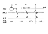
図5は、第1実施形態に係る制御と対比するために、一般的なメカスライドスイッチにおけるスイッチ動作の概略を説明するための図である。図5に示すように、メカスライドスイッチにおいては、指によりボタンS1をスライドさせることにより、例えばエアコンなどの温度設定を行う。
Next, the control executed in the
FIG. 5 is a diagram for explaining an outline of switch operation in a general mechanical slide switch in order to compare with the control according to the first embodiment. As shown in FIG. 5, in the mechanical slide switch, the temperature of an air conditioner or the like is set by sliding the button S1 with a finger.
ボタンS1は操作部として機能する。ボタンS1はユーザの指によるスライド操作で、図において左右方向へスライド移動するスライド式の操作部である。ボタンS1をスライドさせた場合に、26度、27度、、、の各温度領域の境界において、ディテントDが設けられている。 Button S1 functions as an operation unit. Button S1 is a slide-type operation unit that slides in the left-right direction in the figure by a slide operation with a user's finger. When the button S1 is slid, the detent D is provided at the boundary of each temperature region of 26 degrees, 27 degrees, and so on.
ディテントとは、実際のメカニカルなスイッチにおいて、人為的に作り出された抵抗によって操作部(ここでいうボタンS1)を所定位置に保持する機構等、例えば例えばノッチとばね抵抗を用いて構成された機構等を意味する。別の位置への移動は、この抵抗に打ちかつ力を加えることが必要である。ディテントDを超えた後は、スイッチはばね抵抗とノッチの作用により先行して移動することになり、操作力はマイナスとなって操作方向に指が引き込まれる感覚を得る。 A detent is a mechanism that holds an operation unit (button S1 here) in a predetermined position by an artificially created resistor in an actual mechanical switch, for example, a mechanism configured by using a notch and a spring resistor. Etc. Moving to another position requires striking and applying force to this resistor. After exceeding the detent D, the switch moves in advance due to the action of the spring resistance and the notch, the operating force becomes negative, and a feeling that the finger is pulled in the operating direction is obtained.
従って、ディテントDを跨ぐタイミングで、ボタンS1を操作する指に抵抗を伴うため、ユーザの指に図に示すように操作力が必要となる。また、ディテントDを跨ぐ際の指が引き込みを感じるタイミングで、図に示す音圧で示すように、音が発生する。 Therefore, since the finger that operates the button S1 is accompanied by resistance at the timing of straddling the detent D, an operating force is required for the user's finger as shown in the figure. Further, at the timing when the finger feels the pull-in when straddling the detent D, a sound is generated as shown by the sound pressure shown in the figure.
第1実施形態に係る制御では、図6に示すように、メカスライドスイッチと同様に、指によりボタンS2を矢印で示す方向にスライドさせることにより、例えば、エアコンなどの温度設定を行う場合の操作例を例示している。ボタンS2は操作部として機能する。 In the control according to the first embodiment, as shown in FIG. 6, the operation when the temperature of the air conditioner or the like is set by sliding the button S2 with a finger in the direction indicated by the arrow, as in the mechanical slide switch. An example is illustrated. Button S2 functions as an operation unit.
図6に示すように、タッチパネル部10において、ソフト的に表示させたボタンS2が表示されており、指でボタンS2をスライドさせることで26度、27度、、、の各温度領域の境界に設けられたディテントDを跨ぐ。ディテントDを跨ぐタイミングで、ボタンS2の表示サイズ、及び表示サイズ変化の対指速度比すなわち指の動く速度に対するボタンS2の表示サイズの変化速度の比を変化させる。指速度は、タッチパネル10で検出された指位置情報を用いて、制御部30が算出する。
As shown in FIG. 6, in the
ボタンS2の表示サイズの変化の制御は以下のとおりである。ディテントDを跨ぐタイミングに対応して、まず前半で、サイズ変化の対指速度比を1以下すなわち変化速度を遅くしてボタンS2の表示サイズを大きく変化させ(第1の表示制御)、次いで、後半ではサイズ変化の対指速度比を1以上すなわち変化速度を速くしてボタンS2の表示サイズを小さく変化させる(第2の表示制御)。また、ディテントDを跨ぐタイミングで、振動発生部20による振動を発生させ、上記第1の表示制御の終了時すなわち第2の表示制御の開始時に対応させて音声発生部26から音声を発生させる。
The control of the change in the display size of the button S2 is as follows. Corresponding to the timing of straddling the detent D, in the first half, the finger speed ratio of the size change is set to 1 or less, that is, the change speed is slowed down to greatly change the display size of the button S2 (first display control), and then. In the latter half, the finger speed ratio of the size change is set to 1 or more, that is, the change speed is increased to make the display size of the button S2 smaller (second display control). Further, the
上記の制御により、ユーザは、タッチパネル部10におけるボタンS2の表示変化については視覚で認識することができ、振動発生部20の振動によるタッチパネル部10における振動は指による触覚で認識することができ、音声発生部26による音声の発声は聴覚で認識することができる。
By the above control, the user can visually recognize the display change of the button S2 on the
第1実施形態に係る電子機器1によれば以下の効果を奏する。
第1の実施形態における電子機器1では、操作ボタンS2がディテントDを跨ぐタイミングで、タッチパネル部10におけるボタンS2の表示サイズを変化させる制御を行うとともに、振動発生部20における振動を発生させることによりタッチパネル部10を振動させる。さらに、音声発生部26から音声を発生させる。
According to the
In the
このようなソフトウェアボタンS2による操作時において、ディテントD通過のタイミングに応じて、視覚、触覚、聴覚による情報をリンクさせて発信することにより、ユーザに対する操作のフィードバック効果を向上させることが可能となる。これにより、タッチパネルに対する操作時に、ユーザに対して、よりリアリティのある操作感を提供することができるため、ユーザにおける操作の認識を向上させることができる。 At the time of such an operation by the software button S2, it is possible to improve the feedback effect of the operation to the user by transmitting the information by linking the visual, tactile, and auditory information according to the timing of passing the detent D. .. As a result, it is possible to provide the user with a more realistic operation feeling when operating the touch panel, and thus it is possible to improve the recognition of the operation by the user.
(第2実施形態)
第2実施形態について、図7を参照して説明する。第2実施形態に係る電子機器1においては、操作ボタンS3に対して、第1実施形態における第1の表示制御、及び第2の表示制御が実施される。ボタンS3は操作部として機能する。そして、第2の表示制御の終了時に、振動発生部20における振動発生によりタッチパネル部10を振動させるとともに、音声発生部26から音声を発生させる。その他の構成は第1実施形態と同じである。
(Second Embodiment)
The second embodiment will be described with reference to FIG. In the
第2実施形態によれば第1実施形態と同様の効果を奏する。また、第2実施形態に係る電子機器1によれば、タッチパネル部10の振動及び音声発生部26による音声の発生を第2の表示制御の終了時とすることにより、ユーザに対して、ボタンS3の操作時に、壁に当たったような強い境界感を演出できる。
According to the second embodiment, the same effect as that of the first embodiment is obtained. Further, according to the
(第3実施形態)
第3実施形態に係る電子機器1において、以下の制御が実行される。その他の構成は第2実施形態と同じである。
図8は、第1及び第2実施形態に係る制御と対比するために、一般的なメカプッシュスイッチボタンすなわち機械的な押下ボタンにおけるスイッチ動作の概略を説明するための図である。図8においては、指によりボタンP1を押下する場合の操作例を例示している。ボタンP1は操作部として機能する。ボタンP1の押下によって、例えばスイッチのオン、オフを操作するような場合が想定される。
(Third Embodiment)
In the
FIG. 8 is a diagram for explaining an outline of switch operation in a general mechanical push switch button, that is, a mechanical push button, in order to compare with the control according to the first and second embodiments. FIG. 8 illustrates an operation example when the button P1 is pressed with a finger. Button P1 functions as an operation unit. It is assumed that the switch is turned on and off by pressing the button P1.
図8には、ボタンP1の押下を開始するタイミングT1(押下開始タイミング)、押下力が第1の極大となるタイミングT2、押下力が極小となるタイミングT3、ボタンP1が底付きするタイミングT4、押下力が減少して極小となり、その後第2の極大となるタイミングT5、ボタンP1が押し戻されて押下力がなくなり押下が終了するタイミングT6(押下終了タイミング)が表示されている。ここで、底付きとは、メカプッシュスイッチボタンを押下した際に、ボタンが押下限界まで達して押下が停止すること、又はボタンが押下限界まで達して押下が停止するような疑似的感覚を意味する。底付きのタイミングT4は、押圧の戻し始めのタイミングでもある。 In FIG. 8, the timing T1 (pressing start timing) at which the button P1 is started, the timing T2 at which the pressing force becomes the first maximum, the timing T3 at which the pressing force becomes the minimum, and the timing T4 at which the button P1 bottoms out. The timing T5 at which the pressing force is reduced to the minimum and then the second maximum is displayed, and the timing T6 (pressing end timing) at which the button P1 is pushed back to eliminate the pressing force and the pressing is completed is displayed. Here, bottoming means that when the mechanical push switch button is pressed, the button reaches the pressing limit and the pressing is stopped, or the button reaches the pressing limit and the pressing is stopped. To do. The bottomed timing T4 is also the timing at which the pressing starts to return.
ボタンP1がメカボタンである場合には、操作力すなわち押下力は、タイミングT1からタイミングT3にかけて増加した後、タイミングT2で極大値となり、その後やや減少して、タイミングT3で極小値となり、再度増加してボタンP1のボタン底付きのタイミングT4で操作力がピークを持ち、その後、操作力が減少した後さらに再度増加してタイミングT5で極大値を採り、その後減少してタイミングT6で操作が終了し操作力がなくなる。 When the button P1 is a mechanical button, the operating force, that is, the pressing force increases from timing T1 to timing T3, then reaches a maximum value at timing T2, then decreases slightly, reaches a minimum value at timing T3, and increases again. The operating force peaks at the timing T4 with the button bottom of the button P1, then increases again after the operating force decreases and reaches the maximum value at the timing T5, then decreases and the operation ends at the timing T6. There is no operating power.
また、操作力が極大値を採るタイミングT2、T5に対応させて、図に示す音圧で示すように、操作に伴う音が発生する。第3実施形態では例えばタイミングT2で音声の発生開始のタイミングとし、例えばタイミングT5で音声発生の終了のタイミングとなっている。 Further, as shown by the sound pressure shown in the figure, a sound associated with the operation is generated corresponding to the timings T2 and T5 at which the operating force takes the maximum value. In the third embodiment, for example, the timing T2 is the timing for starting the generation of voice, and the timing T5 is the timing for ending the generation of voice, for example.
第3実施形態に係る制御では、図9に示すように制御される。
図9において、操作力はユーザがタッチパネル部10を押下する押下力を意味している。ボタンP2は制御部30により表示部10aをソフトウェア的に制御してタッチパネル部10に表示させたボタンであり、ユーザが指で操作可能に構成されている。ボタンP2は押下式ボタンを模した操作部として機能する。ボタンP2の押下量は隙間距離検出部24によって検出される。
In the control according to the third embodiment, it is controlled as shown in FIG.
In FIG. 9, the operating force means a pressing force for the user to press the
タイミングV1においてユーザはタッチパネル部10に表示されたボタンP2の押下を開始し、タイミングV3で操作力が極大となって底付きし、その後操作力は減少しタイミングV4で押下が終了して操作力がなくなる。タイミングV3は、おおよそメカプッシュスイッチボタンにおける底付きに対応している。
At the timing V1, the user starts pressing the button P2 displayed on the
振動発生部20による振動の発生は、タイミングV1とV3間の任意のタイミングV2と、タイミングV3とV6の間の任意のタイミングV4で実施される。音声発生部26による音声の発生は、振動の発生に合致させたタイミングV2と、振動の振幅の反転のタイミングに合致させたタイミングV5で実施される。
The vibration generated by the
また、タッチパネル部10におけるボタンP2の表示サイズは、タイミングV1から徐々に大きく変化させ、タイミングV2で極大となり、その後小さく変化させ、タイミングV3でサイズが極小となった後、徐々に大きく変化させ、タイミングV6で元の大きさとする。
Further, the display size of the button P2 on the
ユーザは、タッチパネル部10におけるボタンP2の表示サイズの変化については目による視覚で認識し、タッチパネル部10の振動は指による触覚で認識し、音声発生部26による音声の発声は耳による聴覚で認識する。
The user visually recognizes the change in the display size of the button P2 on the
第3実施形態に係る電子機器1によれば以下の効果を奏する。
第3実施形態における電子機器1では、ボタンP2の押下開始、底付き、戻しのタイミングに対応して、タッチパネル部10におけるボタンP2の表示サイズを変化させる制御を行うとともに、振動発生部20における振動を発生させることによりタッチパネル部10を振動させ、さらに、音声発生部26から音声を発生させる。
According to the
In the
このようにボタンP2の押下操作において、所定の操作に応じて、所定のタイミングで、視覚、触覚、聴覚による情報をリンクして発信することにより、ユーザに対する操作のフィードバック効果を向上させることが可能となる。これにより、タッチパネルに対する操作時に、ユーザに対して、よりリアリティのある操作感を提供することができるため、ユーザにおける操作の認識を向上させることができる。 In this way, in the button P2 pressing operation, it is possible to improve the feedback effect of the operation to the user by linking and transmitting the visual, tactile, and auditory information at a predetermined timing according to the predetermined operation. It becomes. As a result, it is possible to provide the user with a more realistic operation feeling when operating the touch panel, and thus it is possible to improve the recognition of the operation by the user.
(第4から第8実施形態)
次に第4実施形態から第8実施形態を、図10から図14を参照して説明する。
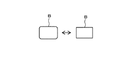
第4実施形態から第8実施形態においては、ボタンS1、S2によるディテントDの通過のタイミング、又は、ボタンP2の押下のタイミングにおいて、タッチパネル部10に表示されたボタンBの映像に変化を付与する制御が実施される。第4実施形態においては、図10に示すように、ボタンBに色の変化を付与する制御が実施される。第5実施形態においては、図11に示すように、ボタンBに形の変化を付与する制御が実施される。
(4th to 8th embodiments)
Next, the fourth to eighth embodiments will be described with reference to FIGS. 10 to 14.
In the fourth to eighth embodiments, the image of the button B displayed on the
第6実施形態においては、図12に示すように、ボタンBに影等のエフェクトを付与する制御が実施され、例えば影のエフェクトが付加された状態と、エフェクトを付加されない状態を切り替えるように制御される。ここで、エフェクトとは、ボタンBのような操作部に影などの修飾を付加したり、操作部を移動、回転、揺動させたりする効果を意味する。 In the sixth embodiment, as shown in FIG. 12, control is performed to give an effect such as a shadow to the button B, and for example, a state in which the shadow effect is added and a state in which the effect is not added are controlled to be switched. Will be done. Here, the effect means an effect of adding a modification such as a shadow to an operation unit such as button B, or moving, rotating, or swinging the operation unit.
第7実施形態においては、図13に示すように、第6実施形態に説明した構成に加えて、さらに、ボタンBを揺動させるエフェクトを付加する制御が実施される。例えば影のような修飾を付加するエフェクトが付加された状態と、エフェクトが付加されない状態を切り替えるとともに、修飾が付加された状態でボタンBを揺動させるようなエフェクトを付加する制御が実行される。ボタンBに付加されるエフェクトとしては、上記の他に、ボタンBの移動、回転、点滅、あるいは、脈動させて大きさを変化させる等が有る。 In the seventh embodiment, as shown in FIG. 13, in addition to the configuration described in the sixth embodiment, control is further performed to add an effect of swinging the button B. For example, a control is executed in which an effect that adds a modification such as a shadow is added and a state in which the effect is not added is switched, and an effect that causes the button B to swing in the modified state is added. .. In addition to the above, the effects added to the button B include moving, rotating, blinking, or pulsating the button B to change its size.
第8実施形態においては、図14に示すように、スライド式の操作部であるボタンBが表示されており、ボタンBをユーザの指でタッチしたまま右方向にスライドさせた際に、ボタンBの左辺はそのままで、右辺を右方向に移動させ、あたかもボタンBが指の動きに合わせて指のスライド方向すなわち右方向に延伸され、ボタンBの長さが長く伸びるように変化させる制御が実行される。
第4から第8実施形態によれば第1から第3実施形態と同様の効果を奏する。
In the eighth embodiment, as shown in FIG. 14, the button B, which is a slide-type operation unit, is displayed, and when the button B is slid to the right while being touched by the user's finger, the button B is displayed. The left side of the button is left as it is, the right side is moved to the right, and the button B is extended in the sliding direction of the finger, that is, to the right according to the movement of the finger, and the length of the button B is changed so as to be extended. Will be done.
According to the fourth to eighth embodiments, the same effect as that of the first to third embodiments is obtained.
以上のように複数の実施形態に分けて説明したが、これらはその趣旨を反しない範囲で組み合わせることが可能である。第1実施形態及び第2実施形態では、ボタンS2、S3の変化について、ディテントDを跨ぐタイミングで、まず前半で、サイズ変化の対指速度比を1以下にすなわち遅くしてボタンS2の表示サイズを大きく変化させ、次いで、後半では対指速度比を1以上すなわち速くしてボタンS2の表示サイズを小さく変化させる制御をおこなったが、これを逆にしてもよい。これを逆にすることで、溝落ち感のある操作感を提供することができるため、より強い印象を伴う操作感を提供できる。上記実施形態において、振動発生部20による振動を発生させるタイミング、音声発生部26から音声を発生させるタイミングを変更してもよい。また、上記説明において、ユーザの指によりタッチパネル部10に表示されたスイッチやボタンを操作するものとして説明したが、指の代わりに、例えば、タッチペンやスタイラスによってタッチ操作することとしてもよい。
Although the above description has been divided into a plurality of embodiments, these can be combined within a range that does not contradict the purpose. In the first embodiment and the second embodiment, regarding the change of the buttons S2 and S3, the display size of the button S2 is reduced to 1 or less, that is, by slowing down the finger speed ratio of the size change in the first half at the timing of straddling the detent D. Then, in the latter half, the finger speed ratio was increased by 1 or more, that is, the display size of the button S2 was changed to be small, but this may be reversed. By reversing this, it is possible to provide an operation feeling with a feeling of groove drop, so that an operation feeling with a stronger impression can be provided. In the above embodiment, the timing of generating vibration by the
本開示は、実施例に準拠して記述されたが、本開示は当該実施例や構造に限定されるものではないと理解される。本開示は、様々な変形例や均等範囲内の変形をも包含する。加えて、様々な組み合わせや形態、さらには、それらに一要素のみ、それ以上、あるいはそれ以下、を含む他の組み合わせや形態をも、本開示の範疇や思想範囲に入るものである。 Although the present disclosure has been described in accordance with the examples, it is understood that the present disclosure is not limited to the examples and structures. The present disclosure also includes various modifications and modifications within an equal range. In addition, various combinations and forms, as well as other combinations and forms that include only one element, more, or less, are also within the scope of the present disclosure.
1…電子機器、10…タッチパネル部、10a…表示部、10b…指位置検出部、 20…振動発生部、20a…電磁コイル、20b…固定鉄心、24…隙間距離検出部 、26…音声発生部、30…制御部 1 ... Electronic equipment, 10 ... Touch panel unit, 10a ... Display unit, 10b ... Finger position detection unit, 20 ... Vibration generation unit, 20a ... Electromagnetic coil, 20b ... Fixed iron core, 24 ... Gap distance detection unit, 26 ... Voice generation unit , 30 ... Control unit
Claims (10)
前記タッチパネル部を振動させる振動発生部(20)と、
音声を発生する音声発生部(26)と、
これらを制御する制御部(30)と、を備えており、
前記タッチパネル部は、ユーザの指位置を検出可能な指位置検出部(10b)と、前記タッチパネル部に操作部を表示させる表示部(10a)と、を備え、
前記制御部は、ユーザによる操作部への操作に応じて、前記タッチパネル部に振動を与えるように前記振動発生部に与える制御と、少なくとも、前記操作部の表示を変化させるように前記表示部に与える制御、又は、音声を発生させるように前記音声発生部に与える制御の何れか、とを実施するものであり、
前記タッチパネル部(10)には、スライド式であってディテント(D)を備える操作部(S2、S3)が表示されており、前記操作部が前記ディテントを跨ぐ際に、前記操作部の大きさを、ユーザの指の動きに対する速度比を1以下として前記操作部の表示サイズを大きく変化させる第1の表示制御を実行し、その後、ユーザの指の動きに対する速度比を1以上として前記操作部の表示サイズを小さく変化させる第2の表示制御を実行する電子機器(1)。 A touch panel unit (10) operated by the user's finger,
A vibration generating unit (20) that vibrates the touch panel unit and
A voice generator (26) that generates voice and
It is equipped with a control unit (30) that controls these.
The touch panel unit includes a finger position detecting unit (10b) capable of detecting a user's finger position and a display unit (10a) for displaying an operation unit on the touch panel unit.
The control unit controls the vibration generating unit so as to give vibration to the touch panel unit in response to the operation of the operation unit by the user, and at least the display unit changes the display of the operation unit. Either the giving control or the control giving to the voice generating unit so as to generate a voice is performed .
The touch panel unit (10) displays an operation unit (S2, S3) that is a slide type and includes a detent (D), and the size of the operation unit when the operation unit straddles the detent. The first display control for significantly changing the display size of the operation unit is executed with the speed ratio to the movement of the user's finger being 1 or less, and then the speed ratio to the movement of the user's finger is set to 1 or more. An electronic device (1) that executes a second display control that changes the display size of the device to a small size.
Priority Applications (3)
| Application Number | Priority Date | Filing Date | Title |
|---|---|---|---|
| JP2018098783A JP6879265B2 (en) | 2018-05-23 | 2018-05-23 | Electronics |
| PCT/JP2019/013671 WO2019225151A1 (en) | 2018-05-23 | 2019-03-28 | Electronic device |
| US16/951,613 US11276377B2 (en) | 2018-05-23 | 2020-11-18 | Electronic apparatus |
Applications Claiming Priority (1)
| Application Number | Priority Date | Filing Date | Title |
|---|---|---|---|
| JP2018098783A JP6879265B2 (en) | 2018-05-23 | 2018-05-23 | Electronics |
Publications (3)
| Publication Number | Publication Date |
|---|---|
| JP2019204272A JP2019204272A (en) | 2019-11-28 |
| JP2019204272A5 JP2019204272A5 (en) | 2020-05-28 |
| JP6879265B2 true JP6879265B2 (en) | 2021-06-02 |
Family
ID=68616289
Family Applications (1)
| Application Number | Title | Priority Date | Filing Date |
|---|---|---|---|
| JP2018098783A Active JP6879265B2 (en) | 2018-05-23 | 2018-05-23 | Electronics |
Country Status (3)
| Country | Link |
|---|---|
| US (1) | US11276377B2 (en) |
| JP (1) | JP6879265B2 (en) |
| WO (1) | WO2019225151A1 (en) |
Families Citing this family (2)
| Publication number | Priority date | Publication date | Assignee | Title |
|---|---|---|---|---|
| JP7072995B2 (en) * | 2018-09-12 | 2022-05-23 | アルパイン株式会社 | Operation device |
| JP2021067998A (en) * | 2019-10-18 | 2021-04-30 | 株式会社東海理化電機製作所 | Control device, program, and system |
Family Cites Families (18)
| Publication number | Priority date | Publication date | Assignee | Title |
|---|---|---|---|---|
| JP3949912B2 (en) * | 2000-08-08 | 2007-07-25 | 株式会社エヌ・ティ・ティ・ドコモ | Portable electronic device, electronic device, vibration generator, notification method by vibration and notification control method |
| JP4115198B2 (en) * | 2002-08-02 | 2008-07-09 | 株式会社日立製作所 | Display device with touch panel |
| JP2005332063A (en) * | 2004-05-18 | 2005-12-02 | Sony Corp | Input device with tactile function, information inputting method, and electronic device |
| US20090102805A1 (en) * | 2007-10-18 | 2009-04-23 | Microsoft Corporation | Three-dimensional object simulation using audio, visual, and tactile feedback |
| JP2011028555A (en) * | 2009-07-27 | 2011-02-10 | Sony Corp | Information processor and information processing method |
| JP4975789B2 (en) * | 2009-07-29 | 2012-07-11 | 京セラ株式会社 | Input device and control method of input device |
| US9927874B2 (en) | 2009-07-29 | 2018-03-27 | Kyocera Corporation | Input apparatus and control method for input apparatus |
| WO2012169176A1 (en) * | 2011-06-07 | 2012-12-13 | パナソニック株式会社 | Electronic apparatus |
| US9146655B2 (en) | 2012-04-06 | 2015-09-29 | Samsung Electronics Co., Ltd. | Method and device for executing object on display |
| WO2013151322A1 (en) * | 2012-04-06 | 2013-10-10 | Samsung Electronics Co., Ltd. | Method and device for executing object on display |
| US9377937B2 (en) | 2012-04-06 | 2016-06-28 | Samsung Electronics Co., Ltd. | Method and device for executing object on display |
| JP6149604B2 (en) * | 2013-08-21 | 2017-06-21 | ソニー株式会社 | Display control apparatus, display control method, and program |
| WO2015045063A1 (en) * | 2013-09-26 | 2015-04-02 | 富士通株式会社 | Drive control apparatus, electronic device, and drive control method |
| JP6264892B2 (en) | 2014-01-14 | 2018-01-24 | 富士通株式会社 | Electronics |
| WO2015121955A1 (en) * | 2014-02-14 | 2015-08-20 | 富士通株式会社 | Electronic device, input device, and drive control method |
| JP2015162152A (en) | 2014-02-28 | 2015-09-07 | 京セラドキュメントソリューションズ株式会社 | Touch panel device and image forming apparatus |
| JP2015222489A (en) * | 2014-05-22 | 2015-12-10 | 株式会社オープンエイト | Portable electronic equipment and display control program |
| JP6761225B2 (en) * | 2014-12-26 | 2020-09-23 | 和俊 尾花 | Handheld information processing device |
-
2018
- 2018-05-23 JP JP2018098783A patent/JP6879265B2/en active Active
-
2019
- 2019-03-28 WO PCT/JP2019/013671 patent/WO2019225151A1/en active Application Filing
-
2020
- 2020-11-18 US US16/951,613 patent/US11276377B2/en active Active
Also Published As
| Publication number | Publication date |
|---|---|
| WO2019225151A1 (en) | 2019-11-28 |
| US11276377B2 (en) | 2022-03-15 |
| JP2019204272A (en) | 2019-11-28 |
| US20210074244A1 (en) | 2021-03-11 |
Similar Documents
| Publication | Publication Date | Title |
|---|---|---|
| US10564727B2 (en) | Systems and methods for a low profile haptic actuator | |
| JP5660580B2 (en) | Electronics | |
| EP1752860B1 (en) | Mobile terminal with touch screen providing haptic feedback and corresponding method | |
| US10401961B2 (en) | Method and apparatus for generating haptic effects using actuators | |
| US10315518B2 (en) | Haptic feedback device for a motor vehicle | |
| KR101274861B1 (en) | Tactile display input device for smart phone | |
| EP2264562A2 (en) | Method and apparatus for generating haptic feedback and a haptic interface | |
| US20140028592A1 (en) | Haptic Input Stylus | |
| JP2006079136A (en) | Tactile sense presentation device | |
| JP2006285785A (en) | Touch panel device | |
| CN107635818B (en) | Operating device with fast haptic feedback | |
| US20210074244A1 (en) | Electronic apparatus | |
| JPWO2017010171A1 (en) | Operation feeling imparting type input device | |
| JPWO2017018055A1 (en) | Vibration generating device and operation feeling imparting type input device using the vibration generating device | |
| JP2019036159A (en) | Response force generation device | |
| JP2013008118A (en) | Electronic apparatus | |
| KR100731019B1 (en) | Touch screen assembly, mobile communication terminal having the same and method for applying key inputs thereto | |
| JP6777497B2 (en) | Force sensation device | |
| JP7441408B2 (en) | Vehicle display device | |
| JP7454383B2 (en) | operating device | |
| WO2021176992A1 (en) | Key input device | |
| US10725589B2 (en) | Method of implementing button click using control of input signal | |
| KR101059600B1 (en) | Touch screen with piezo actuator | |
| JP2022043469A (en) | Operating device |
Legal Events
| Date | Code | Title | Description |
|---|---|---|---|
| A521 | Written amendment |
Free format text: JAPANESE INTERMEDIATE CODE: A523 Effective date: 20200413 |
|
| A621 | Written request for application examination |
Free format text: JAPANESE INTERMEDIATE CODE: A621 Effective date: 20200413 |
|
| A131 | Notification of reasons for refusal |
Free format text: JAPANESE INTERMEDIATE CODE: A131 Effective date: 20210209 |
|
| A521 | Written amendment |
Free format text: JAPANESE INTERMEDIATE CODE: A523 Effective date: 20210301 |
|
| TRDD | Decision of grant or rejection written | ||
| A01 | Written decision to grant a patent or to grant a registration (utility model) |
Free format text: JAPANESE INTERMEDIATE CODE: A01 Effective date: 20210330 |
|
| A61 | First payment of annual fees (during grant procedure) |
Free format text: JAPANESE INTERMEDIATE CODE: A61 Effective date: 20210412 |
|
| R151 | Written notification of patent or utility model registration |
Ref document number: 6879265 Country of ref document: JP Free format text: JAPANESE INTERMEDIATE CODE: R151 |