JP6878448B2 - Vehicle seats with angular track planning during major events - Google Patents
Vehicle seats with angular track planning during major events Download PDFInfo
- Publication number
- JP6878448B2 JP6878448B2 JP2018543263A JP2018543263A JP6878448B2 JP 6878448 B2 JP6878448 B2 JP 6878448B2 JP 2018543263 A JP2018543263 A JP 2018543263A JP 2018543263 A JP2018543263 A JP 2018543263A JP 6878448 B2 JP6878448 B2 JP 6878448B2
- Authority
- JP
- Japan
- Prior art keywords
- seat
- vehicle
- rotation angle
- controller
- angle
- Prior art date
- Legal status (The legal status is an assumption and is not a legal conclusion. Google has not performed a legal analysis and makes no representation as to the accuracy of the status listed.)
- Active
Links
- 230000033001 locomotion Effects 0.000 claims description 31
- 238000000034 method Methods 0.000 claims description 31
- 238000006073 displacement reaction Methods 0.000 claims description 20
- 230000004044 response Effects 0.000 claims description 7
- 230000003213 activating effect Effects 0.000 claims 1
- 238000013016 damping Methods 0.000 claims 1
- 238000012544 monitoring process Methods 0.000 claims 1
- 230000007246 mechanism Effects 0.000 description 9
- 230000008569 process Effects 0.000 description 9
- 238000013019 agitation Methods 0.000 description 5
- 230000006399 behavior Effects 0.000 description 5
- 238000010586 diagram Methods 0.000 description 5
- 239000000725 suspension Substances 0.000 description 5
- 230000001133 acceleration Effects 0.000 description 4
- 230000008859 change Effects 0.000 description 4
- 230000006870 function Effects 0.000 description 4
- 238000012986 modification Methods 0.000 description 4
- 230000004048 modification Effects 0.000 description 4
- 238000013500 data storage Methods 0.000 description 3
- 230000006872 improvement Effects 0.000 description 3
- 238000013519 translation Methods 0.000 description 3
- 230000014616 translation Effects 0.000 description 3
- 238000013459 approach Methods 0.000 description 2
- 230000008901 benefit Effects 0.000 description 2
- 230000002457 bidirectional effect Effects 0.000 description 2
- 238000004364 calculation method Methods 0.000 description 2
- 238000004891 communication Methods 0.000 description 2
- 238000012937 correction Methods 0.000 description 2
- 230000000694 effects Effects 0.000 description 2
- 238000005516 engineering process Methods 0.000 description 2
- 230000014509 gene expression Effects 0.000 description 2
- 229920006395 saturated elastomer Polymers 0.000 description 2
- 238000000926 separation method Methods 0.000 description 2
- 230000003068 static effect Effects 0.000 description 2
- 230000007704 transition Effects 0.000 description 2
- 206010038743 Restlessness Diseases 0.000 description 1
- 230000009286 beneficial effect Effects 0.000 description 1
- 230000005540 biological transmission Effects 0.000 description 1
- 230000008878 coupling Effects 0.000 description 1
- 238000010168 coupling process Methods 0.000 description 1
- 238000005859 coupling reaction Methods 0.000 description 1
- 230000001066 destructive effect Effects 0.000 description 1
- 230000005484 gravity Effects 0.000 description 1
- 230000003287 optical effect Effects 0.000 description 1
- 230000000149 penetrating effect Effects 0.000 description 1
- 238000007639 printing Methods 0.000 description 1
- 238000012545 processing Methods 0.000 description 1
- 230000035807 sensation Effects 0.000 description 1
- 239000013589 supplement Substances 0.000 description 1
- 230000002123 temporal effect Effects 0.000 description 1
Images


Classifications
-
- B—PERFORMING OPERATIONS; TRANSPORTING
- B60—VEHICLES IN GENERAL
- B60N—SEATS SPECIALLY ADAPTED FOR VEHICLES; VEHICLE PASSENGER ACCOMMODATION NOT OTHERWISE PROVIDED FOR
- B60N2/00—Seats specially adapted for vehicles; Arrangement or mounting of seats in vehicles
- B60N2/02—Seats specially adapted for vehicles; Arrangement or mounting of seats in vehicles the seat or part thereof being movable, e.g. adjustable
- B60N2/0224—Non-manual adjustments, e.g. with electrical operation
- B60N2/0244—Non-manual adjustments, e.g. with electrical operation with logic circuits
- B60N2/0252—Non-manual adjustments, e.g. with electrical operation with logic circuits with relations between different adjustments, e.g. height of headrest following longitudinal position of seat
-
- B—PERFORMING OPERATIONS; TRANSPORTING
- B60—VEHICLES IN GENERAL
- B60N—SEATS SPECIALLY ADAPTED FOR VEHICLES; VEHICLE PASSENGER ACCOMMODATION NOT OTHERWISE PROVIDED FOR
- B60N2/00—Seats specially adapted for vehicles; Arrangement or mounting of seats in vehicles
- B60N2/02—Seats specially adapted for vehicles; Arrangement or mounting of seats in vehicles the seat or part thereof being movable, e.g. adjustable
- B60N2/0224—Non-manual adjustments, e.g. with electrical operation
- B60N2/0244—Non-manual adjustments, e.g. with electrical operation with logic circuits
- B60N2/0268—Non-manual adjustments, e.g. with electrical operation with logic circuits using sensors or detectors for adapting the seat or seat part, e.g. to the position of an occupant
-
- B—PERFORMING OPERATIONS; TRANSPORTING
- B60—VEHICLES IN GENERAL
- B60N—SEATS SPECIALLY ADAPTED FOR VEHICLES; VEHICLE PASSENGER ACCOMMODATION NOT OTHERWISE PROVIDED FOR
- B60N2/00—Seats specially adapted for vehicles; Arrangement or mounting of seats in vehicles
- B60N2/02—Seats specially adapted for vehicles; Arrangement or mounting of seats in vehicles the seat or part thereof being movable, e.g. adjustable
- B60N2/0224—Non-manual adjustments, e.g. with electrical operation
- B60N2/0244—Non-manual adjustments, e.g. with electrical operation with logic circuits
- B60N2/0272—Non-manual adjustments, e.g. with electrical operation with logic circuits using sensors or detectors for detecting the position of seat parts
-
- B—PERFORMING OPERATIONS; TRANSPORTING
- B60—VEHICLES IN GENERAL
- B60N—SEATS SPECIALLY ADAPTED FOR VEHICLES; VEHICLE PASSENGER ACCOMMODATION NOT OTHERWISE PROVIDED FOR
- B60N2/00—Seats specially adapted for vehicles; Arrangement or mounting of seats in vehicles
- B60N2/02—Seats specially adapted for vehicles; Arrangement or mounting of seats in vehicles the seat or part thereof being movable, e.g. adjustable
- B60N2/04—Seats specially adapted for vehicles; Arrangement or mounting of seats in vehicles the seat or part thereof being movable, e.g. adjustable the whole seat being movable
- B60N2/16—Seats specially adapted for vehicles; Arrangement or mounting of seats in vehicles the seat or part thereof being movable, e.g. adjustable the whole seat being movable height-adjustable
-
- B—PERFORMING OPERATIONS; TRANSPORTING
- B60—VEHICLES IN GENERAL
- B60N—SEATS SPECIALLY ADAPTED FOR VEHICLES; VEHICLE PASSENGER ACCOMMODATION NOT OTHERWISE PROVIDED FOR
- B60N2/00—Seats specially adapted for vehicles; Arrangement or mounting of seats in vehicles
- B60N2/24—Seats specially adapted for vehicles; Arrangement or mounting of seats in vehicles for particular purposes or particular vehicles
- B60N2/38—Seats specially adapted for vehicles; Arrangement or mounting of seats in vehicles for particular purposes or particular vehicles specially constructed for use on tractors or like off-road vehicles
- B60N2/39—Seats tiltable to compensate for roll inclination of vehicles
-
- B—PERFORMING OPERATIONS; TRANSPORTING
- B60—VEHICLES IN GENERAL
- B60N—SEATS SPECIALLY ADAPTED FOR VEHICLES; VEHICLE PASSENGER ACCOMMODATION NOT OTHERWISE PROVIDED FOR
- B60N2/00—Seats specially adapted for vehicles; Arrangement or mounting of seats in vehicles
- B60N2/02—Seats specially adapted for vehicles; Arrangement or mounting of seats in vehicles the seat or part thereof being movable, e.g. adjustable
- B60N2002/0204—Seats specially adapted for vehicles; Arrangement or mounting of seats in vehicles the seat or part thereof being movable, e.g. adjustable characterised by the seat or seat part turning about or moving along a non-standard, particular axis, i.e. an axis different from the axis characterising the conventional movement
- B60N2002/0212—Seats specially adapted for vehicles; Arrangement or mounting of seats in vehicles the seat or part thereof being movable, e.g. adjustable characterised by the seat or seat part turning about or moving along a non-standard, particular axis, i.e. an axis different from the axis characterising the conventional movement the seat or seat part turning about or moving along a longitudinal axis
Description
本開示の態様及び実装形態は、概して、積載重量物懸架装置に関し、一部の例では、より具体的に、車両のロール又はピッチを補償する車両シート及び方法に関する。 Aspects and implementations of the present disclosure generally relate to loaded heavy load suspension devices and, in some examples, more specifically to vehicle seats and methods for compensating for vehicle roll or pitch.
直交座標系(X、Y、Z方向)では、支持プラットフォームによって支持された積載重量物は、様々な方向の動作の影響を受けることがある。例えば、車両シートに配置された乗員、車椅子内に配置された乗員、又は新生児保育器内の占有者は、並進と各ロール、ピッチ、及びヨー軸の周りの回転とを含む最大6自由度までの動作の影響を受けることがある。地表面に凹凸があるために、積載重量物は、走行中、支持プラットフォームに取り付けられた車両が障害物に遭遇したときに動揺することが多い。特に、路面状態に起因する動揺は、支持プラットフォームが、トラクタ及び他の重機で通常見られるような剛性の又は堅い懸架システムを含む場合に特に激しいことがある。 In a Cartesian coordinate system (X, Y, Z directions), the load weight supported by the support platform can be affected by movement in various directions. For example, a occupant placed in a vehicle seat, a occupant placed in a wheelchair, or an occupant in a newborn incubator can have up to 6 degrees of freedom, including translation and rotation around each roll, pitch, and yaw axis. May be affected by the operation of. Due to the unevenness of the ground surface, the loaded heavy load is often upset when the vehicle mounted on the support platform encounters an obstacle while driving. In particular, sway due to road conditions can be particularly severe if the support platform includes rigid or rigid suspension systems commonly found on tractors and other heavy equipment.
本開示の態様によれば、積載重量物を動揺から能動的に分離するシステム及び方法が提供される。例えば、車両シートと、車両のためのシートシステムと、ロール軸又はピッチ軸などの1つ又は複数の軸の周りの車両シートの回転を制御する方法と、が提供される。一例では、シートシステムは、車両の床に対して所望の角度に配置されるシートと、車両の動作を補償するために、シートに連結されたアクチュエータに所望の角度に調整するように命令するコマンド信号を生成するように構成されたコントローラと、を含む。従って、様々な実装形態は、車両シートの乗員などの積載重量物を動作及び破壊力から能動的に分離するシステム及び方法を提示する。特に、本開示のいくつかの態様は、最大コマンド角との間でプラットフォームの回転を段階的にかつ滑らかに移行させ、ロール時、積載重量物又は積載重量物が配置されたプラットフォームと、プラットフォームを囲む構造物との間の干渉を回避するために、積載重量物を支持するプラットフォームに供給されるコマンド信号を調整する。そのような態様及び実装形態は、積載重量物にとってより分離された動揺のない走行体験をもたらす。車両シート又は車両シートシステムに関連して、様々な態様及び実装形態が本明細書で説明されるが、さらなる態様及び実装形態は、動揺の影響を受けやすい、積載重量物を支持するための他のプラットフォーム、例えば、車椅子、ガーニ、ベッド、新生児保育器、及び重機などを含むことができる。 According to aspects of the present disclosure, there is provided a system and method for actively separating a loaded heavy object from agitation. For example, a vehicle seat, a seat system for the vehicle, and a method of controlling the rotation of the vehicle seat around one or more axes such as a roll axis or a pitch axis are provided. In one example, the seat system commands the seat to be placed at the desired angle with respect to the floor of the vehicle and the actuator connected to the seat to adjust to the desired angle to compensate for the movement of the vehicle. Includes a controller configured to generate a signal. Thus, various implementations present systems and methods that actively separate loaded heavy objects, such as vehicle seat occupants, from motion and destructive forces. In particular, some aspects of the present disclosure allow the rotation of the platform to transition stepwise and smoothly to and from the maximum command angle, with the platform on which the load or load is placed during roll and the platform. Coordinate the command signal delivered to the platform supporting the load weight to avoid interference with the surrounding structure. Such embodiments and implementations provide a more isolated and restless driving experience for the loaded weight. Various aspects and embodiments are described herein in connection with vehicle seats or vehicle seat systems, but additional embodiments and implementations are for supporting heavy loads that are susceptible to agitation. Platforms such as wheelchairs, garni, beds, newborn incubators, and heavy equipment can be included.
1つの態様によれば、車両のシート動作を制御する方法が提示される。一例では、方法は、車両の動作を検出するように配置された少なくとも1つのセンサから信号を受け取ることと、シートに連結されたアクチュエータに、シートを車両中心線に対して動作させるように命令するコマンド信号を生成することと、コマンド信号により、シートが制限を超えるかどうかを決定することと、制限内において、シートの動作を車両の床の動作に合わせるようにコマンド信号を調整することと、調整されたコマンド信号に基づいてシートを動作させるために、アクチュエータにフォースコマンド(force command)を供給することと、を含む。 According to one aspect, a method of controlling the seat movement of the vehicle is presented. In one example, the method receives a signal from at least one sensor arranged to detect vehicle motion and commands an actuator attached to the seat to move the seat relative to the vehicle centerline. Generating a command signal, determining whether the seat exceeds the limit by the command signal, and adjusting the command signal to match the movement of the seat with the movement of the floor of the vehicle within the limit. Includes supplying force commands to the actuator to operate the seat based on the tuned command signal.
一例では、コマンド信号を調整することは、コマンド信号を最大コマンド角に移行させ、かつ最大コマンド角から移行させることを含む。さらなる例では、コマンド信号を最大コマンド角に移行させることは、下記:

に従って指数を計算することであって、飽和閾値は、コマンド信号のコマンド角であって、それを超えると調整が始まる、コマンド角を含む、計算することと、計算された指数に少なくとも部分的に基づいて第1の倍率を決定することとを含む。一例では、指数は、複数の倍率を有する減衰テーブルの指数を含み、及びコマンド信号を最大コマンド角に移行させることは、計算された指数に基づいて減衰テーブルを参照することをさらに含む。さらなる例では、複数の倍率は、1/4正弦波に基づいたある範囲の値を含む。
In one example, adjusting the command signal involves shifting the command signal to and from the maximum command angle. In a further example, shifting the command signal to the maximum command angle is described below:
To calculate the exponent according to, the saturation threshold is the command angle of the command signal, beyond which adjustment begins, including the command angle, to calculate and at least partially to the calculated exponent. Includes determining the first magnification based on. In one example, the exponent includes an exponent of an attenuation table with multiple magnifications, and shifting the command signal to the maximum command angle further comprises referencing the attenuation table based on the calculated exponent. In a further example, the multiple magnifications include a range of values based on a 1/4 sine wave.
一例によれば、コマンド信号を最大コマンド角に移行させることは、下記:
飽和閾値+((最大コマンド角−飽和閾値)*第1の倍率)
に従ってコマンド信号を調整することをさらに含む。
According to one example, shifting the command signal to the maximum command angle is as follows:
Saturation threshold + ((maximum command angle-saturation threshold) * first magnification)
It further includes adjusting the command signal according to.
一例では、コマンド信号を最大コマンド角から移行させることは、前の理想的なコマンド信号に基づいて車両の動作のピーク値を特定することを含む。さらなる例では、コマンド信号を最大コマンド角から移行させることは、下記:
第2の倍率*理想的なコマンド信号
に従ってコマンド信号を調整することと、を含む。
In one example, shifting the command signal from the maximum command angle involves identifying the peak value of vehicle movement based on the previous ideal command signal. In a further example, migrating the command signal from the maximum command angle is described below:
Second magnification * Includes adjusting the command signal according to the ideal command signal.
例によれば、シートは、車両の床から直角に延びる垂直軸に沿って動作するように配置され、及びコマンド信号を調整することは、車両の内部との干渉を防止するようにシートの動作を制限することを含む。さらなる例では、方法は、車両の床から直角に延びる垂直軸に沿ったシートの位置に少なくとも基づいて、コマンド信号の最大コマンド角を決定することを含む。例では、コマンド信号を調整することは、コマンド信号が最大コマンド角に達したことを決定することをさらに含み、及びフォースコマンドをアクチュエータに供給することは、アクチュエータに最大コマンド角でシートの動作を止めさせるようにフォースコマンドを生成することを含む。 According to the example, the seat is arranged to move along a vertical axis extending perpendicular to the floor of the vehicle, and adjusting the command signal moves the seat to prevent interference with the interior of the vehicle. Including limiting. In a further example, the method comprises determining the maximum command angle of a command signal, at least based on the position of the seat along a vertical axis extending perpendicular to the floor of the vehicle. In the example, adjusting the command signal further includes determining that the command signal has reached the maximum command angle, and supplying force commands to the actuator causes the actuator to operate the seat at the maximum command angle. Includes generating a force command to stop it.
別の態様によれば、車両のためのシートシステムが提示される。一例では、システムは、シートと、シートに連結され、かつ車両の動作に応じて、シートを車両の床に対してコマンド角で動作させるように構成されたアクチュエータを含む支持構造体と、車両の動作を検出するように配置された少なくとも1つのセンサと、コントローラであって、少なくとも1つのセンサから信号を受け取ることと、シートを車両の床に対して動作させるようにアクチュエータに命令するコマンド信号を生成することと、コマンド信号により、シートが制限を超えるかどうかを決定することと、制限内において、車両の動作に合わせるようにコマンド信号を調整することと、調整されたコマンド信号に基づいてシートを動作させるために、アクチュエータにフォースコマンドを供給することとを行うように構成されたコントローラと、を含む。 According to another aspect, a seat system for the vehicle is presented. In one example, the system comprises a seat, a support structure including an actuator connected to the seat and configured to move the seat at a command angle with respect to the vehicle floor in response to vehicle movement, and the vehicle. At least one sensor arranged to detect motion, a controller that receives signals from at least one sensor, and a command signal that commands the actuator to move the seat against the floor of the vehicle. Generate and determine whether the seat exceeds the limit by the command signal, adjust the command signal to match the movement of the vehicle within the limit, and the seat based on the adjusted command signal. Includes a controller configured to supply force commands to the actuator to operate.
一例では、コントローラは、コマンド信号を最大コマンド角に移行させ、かつ最大コマンド角から移行させることにより、コマンド信号を調整するように構成される。さらなる例では、コントローラは、下記:
一例では、指数は、複数の倍率を有する減衰テーブルの指数を含み、及びコマンド信号を最大コマンド角に移行させることは、計算された指数に基づいて減衰テーブルを参照することをさらに含む。さらなる例では、複数の倍率は、1/4正弦波に基づいたある範囲の値を含む。例によれば、コントローラは、下記:
飽和閾値+((最大コマンド角−飽和閾値)*第1の倍率)
に従ってコマンド信号を最大コマンド角に移行させるように構成される。
In one example, the exponent includes an exponent of an attenuation table with multiple magnifications, and shifting the command signal to the maximum command angle further comprises referencing the attenuation table based on the calculated exponent. In a further example, the multiple magnifications include a range of values based on a 1/4 sine wave. According to the example, the controller is:
Saturation threshold + ((maximum command angle-saturation threshold) * first magnification)
It is configured to shift the command signal to the maximum command angle according to.
一例では、コントローラは、前の理想的なコマンド信号に基づいて車両の動作のピーク値を特定するようにさらに構成される。さらなる例では、コントローラは、下記:
第2の倍率*理想的なコマンド信号
に従ってコマンド信号を調整することと、を行うようにさらに構成される。
In one example, the controller is further configured to identify peak values of vehicle activity based on previous ideal command signals. In a further example, the controller is:
Second magnification * Adjusting the command signal according to the ideal command signal, and further configured to do.
一例によれば、シートは、車両の床から直角に延びる垂直軸に沿って動作するように配置され、及びコントローラは、車両の内部との干渉を防止するようにシートの動作を制限するように構成される。さらなる例では、コントローラは、車両の床から直角に延びる垂直軸に沿ったシートの位置に少なくとも基づいて、コマンド信号の最大コマンド角を決定するように構成される。一例によれば、コントローラは、コマンド信号が最大コマンド角に達したことを決定することにより、コマンド信号を調整することと、アクチュエータに最大コマンド角でシートの動作を止めさせるようにアクチュエータにフォースコマンドを供給することとを行うように構成される。 According to one example, the seats are arranged to move along a vertical axis extending perpendicular to the floor of the vehicle, and the controller limits the movement of the seats to prevent interference with the interior of the vehicle. It is composed. In a further example, the controller is configured to determine the maximum command angle of the command signal, at least based on the position of the seat along a vertical axis extending perpendicular to the floor of the vehicle. According to one example, the controller adjusts the command signal by determining that the command signal has reached the maximum command angle, and forces the actuator to stop the movement of the seat at the maximum command angle. Is configured to supply and do.
態様によれば、車両シートが提示される。一例では、車両シートは、車両の床に対してコマンド角で配置されるシートと、コントローラであって、車両の動作に応じて、シートを車両の床に対して動作させるようにアクチュエータに命令するコマンド信号を生成することと、コマンド信号により、シートが制限を超えるかどうかを決定することと、制限内において、車両の動作に合わせるようにコマンド信号を調整することとを行うように構成されたコントローラと、を含む。 According to the embodiment, the vehicle seat is presented. In one example, the vehicle seat is a seat that is placed at a command angle with respect to the floor of the vehicle and a controller that commands the actuator to move the seat to the floor of the vehicle in response to the movement of the vehicle. It was configured to generate a command signal, determine if the seat would exceed the limit by the command signal, and adjust the command signal to match the movement of the vehicle within the limit. Including the controller.
一例では、コントローラは、調整されたコマンド信号に少なくとも基づいて、シートを動作させるフォースコマンドを生成するように構成される。一例によれば、コントローラは、コマンド信号を最大コマンド角に移行させ、かつ最大コマンド角から移行させることにより、コマンド信号を調整するように構成される。例では、シートは、車両の床から直角に延びる垂直軸に沿って動作するように配置され、及びコントローラは、車両の内部との干渉を防止するようにシートの動作を制限するように構成される。さらなる例では、コントローラは、車両の床から直角に延びる垂直軸に沿ったシートの位置に少なくとも基づいて、コマンド信号の最大コマンド角を決定するように構成される。例によれば、コントローラは、コマンド信号が最大コマンド角に達したことを決定することにより、コマンド信号を調整するように構成される。 In one example, the controller is configured to generate a force command to operate the seat, at least based on the tuned command signal. According to one example, the controller is configured to adjust the command signal by shifting the command signal to and from the maximum command angle. In the example, the seat is arranged to move along a vertical axis extending perpendicular to the floor of the vehicle, and the controller is configured to limit the movement of the seat to prevent interference with the interior of the vehicle. To. In a further example, the controller is configured to determine the maximum command angle of the command signal, at least based on the position of the seat along a vertical axis extending perpendicular to the floor of the vehicle. By way of example, the controller is configured to adjust the command signal by determining that the command signal has reached the maximum command angle.
これらの例示的な態様のさらに別の態様、例、及び利点が下記に詳細に説明される。さらなる実装形態は、本明細書に列挙する任意のプロセスを行うための手段を含むことができる。さらに、当然のことながら、前述の情報及び以下の詳細な説明の両方は、様々な態様の単なる用例であり、特許請求される主題の特質及び特徴を理解するための概説又はフレームワークを提示することを意図されている。本明細書で開示する任意の例は、任意の他の例と組み合わせることができる。「例」、「一部の例」、「代替例」、「様々な例」、「一例」、「少なくとも1つの例」、「この及び他の例」などの表現は、必ずしも相互排他的ではなく、例に関連して説明する特定の機能、構造、又は特徴が少なくとも1つの例に含まれ得ることを示すことを意図されている。本明細書において、そのような用語の出現は、必ずしもすべて同じ例に適用する必要はない。 Yet another aspect, example, and advantage of these exemplary embodiments is described in detail below. Further implementations can include means for performing any of the processes listed herein. Moreover, of course, both the above information and the detailed description below are merely examples of various aspects and provide an overview or framework for understanding the nature and characteristics of the claimed subject matter. Is intended to be. Any example disclosed herein can be combined with any other example. Expressions such as "example", "some examples", "alternative examples", "various examples", "one example", "at least one example", "this and other examples" are not necessarily mutually exclusive. Instead, it is intended to indicate that a particular function, structure, or feature described in relation to the example may be included in at least one example. As used herein, the appearance of such terms does not necessarily apply to the same example.
さらに、本明細書と、参照により本明細書に援用される文献との間で用語の使用に一貫性がない場合、援用される参照文献での用語の使用は、本明細書の用語の使用を補い、本明細書の用語の使用を調整する。さらに、添付図面は、様々な態様及び例を図解し、さらなる理解を提供するために含まれており、本明細書に組み込まれ、本明細書の一部を構成する。図面は、本明細書の他の部分と共に、説明されかつ特許請求される態様及び例の原理及び動作を説明する役割を果たす。 In addition, if the use of terms in the references incorporated herein is inconsistent between this specification and the references incorporated herein by reference, the use of the terms in the referenced references is referred to as the use of the terms herein. To supplement and adjust the use of terms herein. In addition, the accompanying drawings are included to illustrate various aspects and examples and provide further understanding, which are incorporated herein and form part of this specification. The drawings, along with other parts of the specification, serve to explain the principles and operations of the described and claimed aspects and examples.
本明細書で開示する態様及び実装形態は、以下の説明に記載されるか又は図面に示される構築物の細部及び構成要素の配置に限定されない。本明細書で開示する態様及び実装形態は、様々な方法で実施又は実行することができる。 The embodiments and implementations disclosed herein are not limited to the details and component arrangement of the structures described in the following description or shown in the drawings. The embodiments and implementations disclosed herein can be implemented or implemented in a variety of ways.
本開示の態様によれば、プラットフォームによって支持された積載重量物を動揺から能動的に分離するシステム及び方法が提示される。少なくとも1つの例では、本発明の態様は、車両シートと、車両のためのシートシステムと、車両シートの回転を制御する方法とを含むことができる。特に、斜めに縁石に進むなどの大きいロール又はピッチ事象時、本明細書で説明するシステムは、ロール(又はピッチ事象)により生じるロール(又はピッチ)を軽減するために、コマンド信号を生成し、ロール(又はピッチ)力をプラットフォームにもたらすことができるアクチュエータにフォースコマンドを送出することにより、プラットフォームのロール(又はピッチ)を能動的に制御する。提示される例示的な車両シートシステム内において、態様及び例は、車両の乗員を走行時の車両のピッチ又はロール軸の周りの1つ又は複数の回転もしくは並進から分離する。車両シート又は車両シートシステムに関連して、様々な態様及び実装形態が本明細書で説明されるが、さらなる態様及び実装形態は、動揺の影響を受けやすい、積載重量物を支持するための他のシステム及び装置を含むことができる。 According to aspects of the present disclosure, a system and method of actively separating a loaded load supported by a platform from agitation is presented. In at least one example, aspects of the invention can include a vehicle seat, a seat system for the vehicle, and a method of controlling the rotation of the vehicle seat. In particular, during large roll or pitch events such as going diagonally to the curb, the systems described herein generate command signals to mitigate the roll (or pitch) caused by the roll (or pitch event). Actively control the roll (or pitch) of the platform by sending force commands to actuators that can bring roll (or pitch) force to the platform. Within the illustrated vehicle seat system presented, embodiments and examples separate the occupants of the vehicle from one or more rotations or translations around the vehicle's pitch or roll axis during travel. Various aspects and embodiments are described herein in connection with vehicle seats or vehicle seat systems, but additional embodiments and implementations are for supporting heavy loads that are susceptible to agitation. Systems and equipment can be included.
本明細書で説明するいくつかの例は、車両シート及び車両のためのシートシステムを含む。図1A及び図1Bは、いくつかの実装形態による例示的なシート及び車両のためのシートシステムを示す。特に、図1Aは、ほぼ水平な路面を走行するトラクタの形態の車両102を示し、図1Bは、車両ロール角θ1でロール事象に遭遇したトラクタ102を示す。様々な実装形態の説明を容易にするために、図1A及び図1Bに示すトラクタ102の一部は省略されていることが分かる。図1A及び図1Bでは、シート106に着座している人104の身体を貫通している仮想基準垂直中心線108に沿ったほぼ垂直な向きで、人104がシート106に着座していることが示されている。この例では、垂直中心線108は、図1Aに示すように、シート106及び車両102の両方が標準の平らで水平な向きにあるとき、人104及びシート106を二等分する。これは、図1Aに示す通り、シート106が実質的に対称であるためである。他のタイプの車両では、シート106は、垂直中心線108の左又は右に配置することができる。
Some examples described herein include vehicle seats and seat systems for vehicles. 1A and 1B show exemplary seats and seat systems for vehicles in several implementations. In particular, FIG. 1A shows a
シート106は、支持構造物112により、車両の床110に固定されている。支持構造物112は、車両102が直線的に移動しているときに、シート106が、車両102が移動している方向に実質的に平行な軸114の周りで車両102に対して動作/回転することを可能にするピボット128を含む。図1A及び図1Bは、シート106の下で離れて配置された軸114を示し、様々な実装形態では、軸114は、示したものよりも高く又は低く配置することもできる。軸114は、車両102に対して固定される。様々な実装形態では、車両102は、軸114と、車両102が移動している方向とに実質的に平行な第2の軸116の周りで回転することができる。
The
図1A及び図1Bに示すように、距離L1は、軸114と第2の軸116との間の長さを表す。第2の距離L2は、軸114と車両102の乗員104の頭118の中心との間の長さを表す。様々な実装形態では、L2の上端は、シートに着座した人の頭に対応する位置に又はその位置より上にあり、例えば、3〜5フィートの範囲を取ることができる。
As shown in FIGS. 1A and 1B, the distance L1 represents the length between the
図1Bでは、車両102の左タイヤ120は、車両102が走行している路面の障害物122に当たって、車両102を反時計方向(前から見た場合)に回転させる。軸116の周りの回転は、右タイヤの底部の周りの車両102の回転に対する許容可能な微小角近似であり、対称性であることから使用される。車両102は、近似的に、垂直中心線108と車両中心線124との間の角度を表す角度θ1だけ回転している。シート102が車両102の中心に配置されていない(すなわち、中心の一方又は他方の側に配置されている)場合、θ1は、図1Aの標準位置から(例えば、図1Bの)回転位置への車両中心線124の回転によって定まる。いくつかの実施形態では、車両102が反時計方向に回転する場合、シート106は、軸114の周りを(車両102の回転方向とは逆の)時計方向に回転する。シート106は、支持構造物112に連結されたアクチュエータによって回転することができる。同様に、車両102が時計方向に回転する場合、シート106は、軸114の周りを反時計方向に回転する。両方の実装形態において、少なくともアクチュエータと通信するコントローラは、アクチュエータに角度θ2だけシートを回転させるようにフォースコマンドを供給し、この角度θ2は、車両中心線124とシート中心線126との間の角度である。
In FIG. 1B, the
様々な実施形態では、角度θ2は、θ2=θ1*(1+L1/L2)に従ってコントローラによって決定される。一部の実装形態では、軸114を床110の近くに配置することが好ましく、その理由は、L1がL2に対して大きくなると、θ2が大きくなるからである。従って、床110からの軸114の高さが高くなると、一定のロール量を補償するのにより大きい回転が必要とされる。その結果、人104は、左右及び/又は前後の動作を実質的に減らすか又は最小限にするために所定の位置の周りで回転する。様々な実装形態では、乗員の頭118は、実質的に元の垂直中心線108上にあるままである。「SEAT SYTEM FOR A VEHICLE」という名称の米国特許出願公開第2014/0316661号に記載された技術を使用して、路面での動揺による乗員の頭の水平方向の加速を小さくするさらなるシステム及び方法を実施することができ、この特許は、参照によりその全体が本明細書に援用される。
In various embodiments, the angle θ 2 is determined by the controller according to θ 2 = θ 1 * (1 + L 1 / L 2). In some implementations, it is preferable to place the
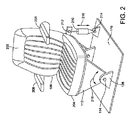
図1A〜図1Bを引き続き参照しながら、ここで、図2を参照すると、図1A及び図1Bに示す車両シート106などの車両シートを含む車両シートシステムの一例が示されている。底部204と底部204に連結された背もたれ206とを有するシート106が示されている。アーム208の対が背もたれ206から前方に延びている。このシートシステムの利点は、車両102の左右の揺動により、人104の胴体にかかるアーム208の任意の衝撃が実質的に弱まる(又は最小限になる)ことである。動揺の改善が背もたれ206にもたらされ、それにより、人の背中に対する背もたれの横並進も実質的に低減される。リニアアクチュエータ210は、(位置212で)支持構造物112に回転可能に連結され、シート106を軸114の周りで回転させるためにシート106と相互作用することができる。この例では、リニアアクチュエータ210は、位置214で車両の床110にも回転可能に連結されている。リニアアクチュエータ210は、シート106を軸114の周りで両方向矢印218の方向に回転させるために両方向矢印216の方向に伸縮する。リニアアクチュエータ210は、例えば、電磁式リニアモータ、油圧シリンダ、又は空気式シリンダとすることができる。リニアアクチュエータ210は、代わりに、シート106と床110との間に連結された回転アクチュエータ(電磁式、油圧式、又は空気駆動式)などの他の何らかのタイプのアクチュエータとすることができる。任意のタイプのアクチュエータは、シート106に直接連結することができ、又は何らかのタイプの歯車列、リンク機構、又は他の伝動機構を介して動作することもできる。アクチュエータ210は、支持構造物112の異なる部分又はシート106と、車両102の異なる部分(床110以外、例えば、運転室の壁)とに連結することができる。アクチュエータ210の制御について、少なくとも図3〜図7を参照して下記に説明される。
With reference to FIG. 2 while continuing to refer to FIGS. 1A-1B, an example of a vehicle seat system including vehicle seats such as the
車両102に対する軸114(ロール軸)の周りの単一自由度のみを有するシート106が示されている。この単一自由度は、代わりに、ピッチ軸、ヨー軸の周り、又は複数の軸(すなわち、ロール、ピッチ、及び/又はヨー)の周りとすることができる。この場合、軸114は、図1Aに示すように前後に向けられ、シート106が左右の回転に対して制御されることを可能にする。別の例では、シート106は、1つ又は複数のさらなる自由度でシート106を動作させるために、1つ又は複数のさらなるアクチュエータ(図示せず)を装備することができる。例えば、中間支持構造物112を床110に取り付ける代わりに、中間支持構造物112は、車両が道路を走行するときに運転者が感知する垂直振動を弱めるために、さらなるアクチュエータにより上下に動作するプラットフォーム(図示せず)に取り付けることができる(又はこの垂直アクチュエータは、構造物とシートとの間に挿入することができる)。このタイプの垂直能動懸架システムは、「ACTIVE SUSPENDING」という名称の米国特許第8,095,268号に示されており、この特許は、参照によりその全体が本明細書に援用される。垂直能動懸架システムは、回転シート106とは独立して動作することができる。L2の距離(図1A及び図1B)は、垂直分離機構に対応する動作と共に変わる。この作用は、プラットフォームと床との間の距離を検出するセンサからの入力に基づくプロセッサ計算に含めることができる。さらに、垂直分離システムを使用して、車両の(例えば、地面に対する)回転とシートの車両に対する回転との組み合わせによる、人の頭の任意の起こり得る上下動を相殺することができる。
A
図3を参照すると、アクチュエータ210の動作がコントローラ302によって制御されている。センサ304は、この例では車両のロール速度である動作の態様を測定することができる。コントローラ302は、センサ304からバス310を介してロール速度データの形態の信号(すなわち、入力)を受け取る。コントローラ302は、瞬間的な車両ロール角θ1(図1B)を決定するためにロール速度データの積分を計算する。次いで、コントローラ302は、上記の式でθ1をL2及びL1と共に使用して、瞬間的なコマンド角θ2(図1B)を含むコマンド信号を生成する。次に、コントローラ302は、計算されたθ2を実現するために、参照テーブルを使用して望ましいアクチュエータ位置を決定する。アクチュエータ位置参照テーブル(ならびに下記に説明する最大コマンド角参照テーブル及び減衰参照テーブルなどの本明細書で説明する他の参照テーブル)は、ランタイム計算の代わりに指数付け処理を使用する任意の配列を含むことができる。例えば、アクチュエータ位置参照テーブルは、静的プログラム記憶装置に保存された事前に計算済みの指数付きアクチュエータ位置の配列を含むことができる。コントローラ302は、アクチュエータ210からバス306を介して位置データを受け取ることに留意されたい。位置データは、軸114の周りのシート106の位置に相関するアクチュエータ210の位置を示す。従って、コントローラ302は、コマンド信号を生成するときに、アクチュエータ210の現在の位置(例えば変位)についての情報を伝えられる。なお、θ2を制御するために、プロセッサによって使用される特定の制御法則は重要ではなく、PI、PID、又は他の公知の制御法則などの様々な制御法則を本明細書で説明する実装形態で使用することができる。
Referring to FIG. 3, the operation of the
次いで、コントローラ302は、アクチュエータ210を所望のアクチュエータ位置に移動させるフォースコマンドを、バス308を介してアクチュエータ210に送出する。これらのステップを連続的に繰り返すことにより、コントローラ302は、センサ304からの入力を使用して軸114の周りのシート106の望ましい動作を決定し、次いで、この軸の周りのシート106の望ましい動作を引き起こすようにアクチュエータ210を動作させる。これは、シート106に着座した人の頭のほぼ水平方向の加速を大幅に小さくする(又は最小限にする)。好ましくは、コントローラ302は、車両102が(例えば、図1Bの軸116の周りで)回転するときに、基準垂直中心線108に沿った実際のピボット点の変位を小さくするために、シート106の動作を制御する。この例は、(a)(車両が左又は右に曲がるときに)方向転換によって引き起こされる横加速の影響を受けにくく、(b)最小限の動作センサで済ますことができるという点で有益である。この構成は、ロール中心高さが変わらない(すなわち、L1が変化しない)と想定している。
The
車両102が移動しているときにL1をリアルタイムで連続的に計算することが望ましい場合、例えば、車両102又はシート106に横加速度計(図示せず)を設けることができる。この加速度計は、軸114と実質的に同じ高さ(又は位置)に配置されることが好ましい。コントローラ302は、横加速度計及びセンサ304から入力を受け取り、次いで式L1=横速度/ロール速度を使用してL1を計算し、この場合、横速度は、横加速度信号を積分することで計算される。なお、本願で説明される任意の横加速度計の出力に対して重力補正を行うことが好ましい。これは、車両102及び/又はシート106が回転するときに、横加速度計に作用する重力成分が考慮されることを意味する。
If it is desired to continuously calculate the L 1 in real time as the
本明細書で説明する様々な態様及び実装形態はまた、プラットフォームの動作範囲限界を超える大きいロール事象から積載重量物を分離することを可能にする。例えば、大きい車両ロール事象時、シート106が動作範囲限界まで回転すると、さらに回転して最大限の車両ロール角に対処することができない。さらに、シート106の動作範囲限界でのコマンド信号の急な飽和により、乗員にとって乗り心地が不快なものになることがある。従って、様々な態様及び実装形態は、シート106が動作範囲限界との間で円滑に移行するように、コマンド信号を段階的にかつ漸進的に調整する。
The various aspects and implementations described herein also allow the load load to be separated from large roll events that exceed the operating range limits of the platform. For example, in the event of a large vehicle roll, if the
図4を参照すると、大きいロール事象が発生した期間にわたって、アクチュエータ(例えば、図3を参照して説明したアクチュエータ302)に命令するコマンド信号のグラフを示す。説明において、大きいロール事象は、車両の右又は左のタイヤが縁石又は他の大きい障害物(例えば、溝、排水路など)に遭遇した場合など、車両が走行している路面の任意の大きい障害物が車両のピッチ又はロール軸の周りの大回転を引き起こす場合に発生することがある。
FIG. 4 shows a graph of command signals commanding an actuator (eg,
第1の軌跡402は、アクチュエータに命令するための調整されたコマンド信号を示し、第2の軌跡404は、アクチュエータに命令するための未調整のコマンド信号を示し、第3の軌跡406は、コントローラによって生成された理想的なコマンド信号を示す。本明細書において、理想的なコマンド信号とは、シートの動作範囲限界がない場合に生成されるコマンド信号を指す。上記のように、コマンド信号は、シートがロール事象中に配置され得る一連の瞬間的なコマンド角を含む。様々な実装形態では、コントローラは、車両ロールを補償する望ましいシート位置が得られるようにアクチュエータを駆動するために、コマンド信号に基づいてコマンドフォースを生成することができる。図4は、最大コマンド角が±8°の動作範囲限界を示すが、当然のことながら、様々な実装形態では、最大コマンド角は、±8°よりも大きい又は小さいことがあり、一部の例では、シートと車両の床との間の距離又は特定の実装形態によって決まることがある。例えば、車両シートは、新生児保育器よりも大きいコマンド角を有することができる。
The
様々な飽和コマンド信号技術では、コマンド角が最大コマンド角で飽和した場合、コマンド信号に突然に「頂部が平らになる」期間が形成される。約20.8〜21秒の期間中に約8°の状態を保つそのような例が第2の軌跡404によって示されている。この突然の変化により、不自然な感覚がもたらされ、乗員は不快になる。従って、様々な実施形態では、最大コマンド角が近くなったときに又は最大コマンド角にほぼ達したときに、コントローラは、動作範囲限界に向かって漸進的に飽和させ、車両ロールが最大ロール角に達するのを待つようにコマンド信号を調整する。20.5〜21秒の期間中に約5°〜8°を取るそのような例が第1の軌跡402によって明示されている。車両の最大ロール角に達すると、コントローラは、理想的なコマンド信号の形状に従って、動作範囲限界から離れる方向に次第に小さくなるようにコマンド信号を調整する。コマンド信号が約8°から離れるときのその結果が第1の軌跡402に示されている。8°に到達したとき及び8°から離れるときに、急勾配で明瞭なエッジを有する第2の軌跡404とは対照的に、様々な実装形態において、コントローラは、不連続性を持たせる代わりに、コマンド信号のコーナを丸くするようにコマンド信号を調整する。
In various saturated command signal technologies, when the command angle is saturated at the maximum command angle, the command signal suddenly forms a "top flattened" period. A
従って、様々な実装形態において、コントローラは、シートの動作がシートの動作範囲限界内において車両の床の動作に合うようにコマンド信号を調整する。特に、コントローラは、理想的なコマンド信号、理想的なコマンド信号の以前のサンプル、飽和閾値、及び1つ又は複数の最大コマンド角に基づいてコマンド信号を調整することができる。プラス(+)及びマイナス(−)方向に等しいとして本明細書で説明したが、さらなる例では、最大コマンド角は、プラス及びマイナスの方向に異なる大きさを有することがある。これは、車両シートが車両の中心に置かれていないか、又は車両シートが実質的に対称でない場合に多い。大きいロール事象時、シートの動作を制御する制御プロセスの一例が、図5に示すブロック図に示されている。図5は、引き続き、図1〜図3を参照して上記に説明した車両シート及び車両シートシステムに関連して説明される。 Therefore, in various implementations, the controller adjusts the command signal so that the movement of the seat matches the movement of the floor of the vehicle within the operating range limit of the seat. In particular, the controller can adjust the command signal based on the ideal command signal, a previous sample of the ideal command signal, the saturation threshold, and one or more maximum command angles. Although described herein as equal to the plus (+) and minus (-) directions, in a further example, the maximum command angle may have different magnitudes in the plus and minus directions. This is often the case when the vehicle seats are not centered on the vehicle or the vehicle seats are not substantially symmetrical. An example of a control process that controls the operation of the seat during a large roll event is shown in the block diagram shown in FIG. FIG. 5 will continue to be described in connection with the vehicle seats and vehicle seat systems described above with reference to FIGS. 1-3.
図5において、RCはコマンド信号を表し、IRCは理想的なコマンド信号を表し、Tは飽和閾値を表し、LIMは最大コマンド角を表し、K1は第1の倍率を表し、K2は第2の倍率を表す。ブロック502では、コントローラは、コマンド信号を理想的なコマンド信号にほぼ等しく設定するように構成されている。様々な実装形態では、理想的なコマンド信号は、上記のように、θ2=θ1*(1+L1/L2)に従って生成されたコマンド角を含む。本明細書において離散値として説明したが、当然のことながら、様々な実装形態では、角度θ2は、車両が動作中のときにリアルタイムで連続して生成される。
In FIG. 5, RC represents a command signal, IRC represents an ideal command signal, T represents a saturation threshold, LIM represents the maximum command angle, K1 represents the first magnification, and K2 represents the second. Represents the magnification. At
コマンド信号の生成に続いて、コントローラは、コマンド信号により、シートが飽和閾値を超えるかどうかを決定するように構成されている。本明細書において、飽和閾値は、所定のシートロール角を画定し、コントローラは、このシートロール角を超えてからコマンド信号を調整し始めるように構成されている。例えば、図4に示す飽和閾値は約5°であるが、さらなる実装形態では、飽和閾値は5°よりも大きい又は小さいことができる。様々な実装形態では、飽和閾値は、車両シートの検出された高さなどの1つ又は複数の受信入力に基づいてコントローラが定めることができる。飽和閾値を超えたときの、コマンド信号の調整処理と、コントローラの対応した修正挙動とにより、コマンド角が、大きいロール事象の発生時にのみ調整されることが確実になる。 Following the generation of the command signal, the controller is configured to determine whether the sheet exceeds the saturation threshold by the command signal. As used herein, the saturation threshold defines a predetermined sheet roll angle, and the controller is configured to begin adjusting the command signal after the sheet roll angle is exceeded. For example, the saturation threshold shown in FIG. 4 is about 5 °, but in a further implementation, the saturation threshold can be greater than or less than 5 °. In various implementations, the saturation threshold can be determined by the controller based on one or more received inputs, such as the detected height of the vehicle seat. The command signal adjustment process when the saturation threshold is exceeded and the corresponding correction behavior of the controller ensure that the command angle is adjusted only when a large roll event occurs.
従って、決定ブロック504では、コントローラは、理想的なコマンド信号が飽和閾値を超える(すなわち、大きさがより大きい)かどうかを決定するように構成されている。理想的なコマンド信号が飽和閾値を超えない場合、コントローラは、コマンド信号と理想的なコマンド信号とを等しくし続ける。しかし、コントローラが、理想的なコマンド信号が飽和閾値を超えると決定した場合、コントローラは、車両シートの動作を動作範囲限界内に維持するようにコマンド信号を調整し始める。コマンド信号の生成後に実行されると上記に説明したが、様々なさらなる実装形態では、コントローラは、コマンド信号がコントローラによって生成され、フォースコマンドがアクチュエータに供給されている間に飽和閾値を超えるかどうかを決定することができる。
Therefore, in
ブロック506では、コントローラは指数を生成し、コマンド信号用の第1の倍率K1を決定するように構成されている。様々な実装形態が可能であるが、1つの特定の例では、指数は、複数の倍率を有する減衰参照テーブルの指数を含む。コントローラは、指数に基づいて減衰テーブルを参照することにより、第1の倍率K1を決定することができる。倍率は、最大コマンド角との間でコマンド信号を段階的に移行させるために、コントローラによってコマンド信号に適用され、第1の倍率K1は、コマンド信号を最大コマンド角に移行させるために適用され、第2の倍率K2は、コマンド信号を最大コマンド角から移行させるために適用される。図5に示すように、指数は下記:
上記のように、最大コマンド角は、シートの動作範囲限界に達したコマンド角を含む。例えば、最大コマンド角は、±8°として図4に示されている。 As mentioned above, the maximum command angle includes the command angle that has reached the operating range limit of the seat. For example, the maximum command angle is shown in FIG. 4 as ± 8 °.
指数を計算すると、コントローラは、計算された指数に対応する倍率を決定するために減衰テーブル又は倍率の他のリポジトリを参照する。様々な実装形態において、倍率は、1/4正弦波に基づく。計算された指数値は、0〜無限大の範囲を取ることができ、0〜1の値の倍率に対応する。指数が0の場合、第1の倍率も0である。指数が0〜1.55の値を取る場合、倍率は、1/4正弦波に従うことができ、指数が1.55に近づくにつれて、正弦波の最初の1/4に比例して値が増加する。指数が1.55以上の場合、第1の倍率は1に設定される。さらに、ブロック506では、コマンド信号の調整がコントローラによって行われる。いくつかの実装形態では、第1の倍率は、下記:
飽和閾値+((最大コマンド角−飽和閾値)*第1の倍率)
に従ってコマンド信号に適用される。
When calculating the exponent, the controller references the attenuation table or other repository of multipliers to determine the multiplier corresponding to the calculated exponent. In various implementations, the magnification is based on a 1/4 sine wave. The calculated exponential value can range from 0 to infinity and corresponds to a magnification of 0 to 1. When the exponent is 0, the first magnification is also 0. If the exponent takes a value between 0 and 1.55, the magnification can follow a 1/4 sine wave, increasing in proportion to the first 1/4 of the sine wave as the exponent approaches 1.55. To do. If the exponent is 1.55 or higher, the first magnification is set to 1. Further, in
Saturation threshold + ((maximum command angle-saturation threshold) * first magnification)
It is applied to the command signal according to.
様々な実装形態では、コントローラは、上記のように、得られた調整済みコマンド信号に基づいて、アクチュエータにシートを再配置させるフォースコマンドを生成することができる。 In various implementations, the controller can generate a force command that causes the actuator to reposition the seat based on the tuned command signal obtained, as described above.
決定ブロック508では、コントローラは、コマンド信号が最大コマンド角に達したかどうか、及び前回のコマンド角(「前のIRC」)が現在の理想的なコマンド信号(すなわち、理想的なコマンド信号「IRC」)よりも大きいかどうかを決定するように構成されている。これらの状態の両方が満たされた場合、コントローラは、第2の倍率を計算するために1つ又は複数の処理を行い、最大コマンド角から離れる方向にコマンド信号を漸進的にかつ段階的に小さくする。これらの状態のいずれか又は両方が満たされない(すなわち、理想的なコマンド信号が最大ロール角を超えておらず、かつ/又は前の理想的なコマンド信号が理想的なコマンド信号を超えていない)場合、コントローラは、ブロック506に戻って新たな指数及び第1の倍率を計算する。従って、コントローラは、前の理想なコマンド信号に基づいて車両の動作のピーク値を特定するように構成される。図5に示すように、このプロセスは、508に示す各条件が満たされるまで、コントローラによって連続的に繰り返すことができる。
In
ブロック510では、コントローラは、コマンド信号を最大コマンド角から段階的に移行させるために、第2の倍率を生成するように構成されている。いくつかの実装形態では、コントローラは、下記:
ブロック512では、コントローラは、生成した第2の倍率K2に少なくとも基づいてコマンドスケールをさらに調整するようにさらに構成されている。図5から、コントローラが、下記:
第2の倍率*理想的なコマンド信号
に従ってコマンド信号をさらに調整することが分かる。
At
Second magnification * It can be seen that the command signal is further adjusted according to the ideal command signal.
様々な実装形態では、コントローラは、第2の倍率を用いてコマンド信号を調整したことを受けて、調整したコマンド信号に基づき、シートを動作させるためにフォースコマンドをアクチュエータに供給する。そのような実装形態は、シートの乗員により自然な感覚の車両ロール補償をもたらす。 In various implementations, the controller receives the command signal adjusted using the second magnification and supplies a force command to the actuator to operate the seat based on the adjusted command signal. Such an implementation provides a more natural feeling of vehicle roll compensation for the seat occupants.
決定ブロック514では、コントローラは、理想的なコマンド信号が、例えば、0.2°未満のほぼ通常の位置に戻ったかどうかを決定するように構成することができる。当然のことながら、0.2°は、例として提示され、代替の実装形態では、他の値(例えば、0.1°、0.3°、0.5°、1.0°)を採用することもできる。コントローラが、理想的なコマンド信号が0.2°未満であると決定した場合、調整プロセスはブロック502に戻る。一方、コントローラが、理想的なコマンド信号が0.2°未満でないと決定した場合、コントローラはブロック512に戻り、コマンド信号を制御し続ける。従って、様々な実装形態では、コントローラは、理想的なコマンド信号がほぼ通常の位置(すなわち0°)に迅速に戻る場合、調整プロセスを早期に終了することができる。コマンド信号を調整するさらなる態様及び実装形態が図7を参照して下記に説明される。
In
いくつかの態様及び実装形態は、積載重量物又は積載重量物が支持されるプラットフォームと、プラットフォームの回転中に動作範囲の角度経路内にある障害物との間の干渉を補償することも可能にする。例えば、一実装形態では、上記の車両シートの最大コマンド角は、車両の内部及び他の内部障害物の寸法によって決まり得る。いくつかの例では、最大コマンド角は、車両の乗員又はオペレータが定めることができ、固定値(例えば、±8°)に設定することができる。しかし、さらなる実装形態では、コントローラは、最大コマンド角及びシートの動作範囲限界を自動的に決定することができる。そのような実装形態では、コントローラは、車両の床から直角に延びる垂直軸に沿ったシートの位置に少なくとも部分的に基づいて最大コマンド角を自動的に決定し、調整することができる。上記のように、一実装形態では、シートの垂直高さは、走行中に能動的に又は受動的に変えることができる。1つのそのような能動的な実装形態では、システムは、ロール事象を補償するためにシートの垂直高さを調整するように配置された第2のアクチュエータを含むことができる。そのような実装形態では、動作範囲限界に近づいているか又は到達したときに知らせるように、コントローラと通信する1つ又は複数のセンサを車両のシート又は内部に配置することができる。 Some embodiments and implementations also make it possible to compensate for interference between the loaded weight or the platform on which the loaded weight is supported and obstacles within the angular path of the operating range during rotation of the platform. To do. For example, in one implementation, the maximum command angle of the vehicle seat may be determined by the dimensions of the vehicle interior and other internal obstacles. In some examples, the maximum command angle can be set by the vehicle occupant or operator and can be set to a fixed value (eg ± 8 °). However, in a further implementation, the controller can automatically determine the maximum command angle and the operating range limit of the seat. In such an implementation, the controller can automatically determine and adjust the maximum command angle based at least in part on the position of the seat along a vertical axis extending perpendicular to the floor of the vehicle. As mentioned above, in one implementation, the vertical height of the seat can be actively or passively changed during travel. In one such active implementation, the system can include a second actuator arranged to adjust the vertical height of the seat to compensate for roll events. In such an implementation, one or more sensors that communicate with the controller can be placed in the seat or interior of the vehicle to notify when the operating range limit is approaching or reached.
ここで、図6を参照すると、車両シートの動作を示すグラフが示されている。図6は、引き続き、図1〜図3を参照して上記に説明した車両シート及び車両シートシステムと、図5を参照して上記に説明したブロック図とに関連して説明される。グラフの垂直軸は、車両シートの位置をメートル(m)で示し、水平軸は、コントローラによって生成されたコマンド信号のコマンド角を°で示す。第1の軌跡602は、車両の内部の近接度が無視された場合のシートの動作を表し、第2の軌跡604は、最大コマンド角が、車両の床に直角に延びる垂直軸(例えば、図1A〜図1Bの軸108)に沿ったシートの位置に基づいて決定された場合のシートの動作を表す。ロール限界の第1のセット606は、車両の内部と接触する位置を示し、ロール限界の第2のセット608は、シートが、車両の内部との接触点の20mm手前にある位置を示す。各限界セットは、ロール上限及びロール下限を含むことができる。
Here, referring to FIG. 6, a graph showing the operation of the vehicle seat is shown. FIG. 6 will continue to be described in relation to the vehicle seat and vehicle seat system described above with reference to FIGS. 1 to 3 and the block diagram described above with reference to FIG. The vertical axis of the graph indicates the position of the vehicle seat in meters (m), and the horizontal axis indicates the command angle of the command signal generated by the controller in °. The
図6に示すように、一部の大きいロール事象中、コントローラによって生成されたフォースコマンドは、アクチュエータにシートのロール限界を超えたコマンド角でシートを配置させることがある。例えば、第1の軌跡502は、約−0.05mの位置において、コントローラが、シートを約−7°のコマンド角で配置するようにアクチュエータに意図せず命令していることを示す。一部の特定のシート高さでは、これは安全な位置であり得るが、−0.05mの高さにおいて、−7°のコマンド角は、車両の内部との衝突を引き起こす。同様に、第1の軌跡502は、約−0.055mの位置において、コントローラが、シートを約6°のコマンド角で配置するようにアクチュエータに命令していることを示す。−0.03mの位置では、このコマンド角は問題を起こさないが、−0.055mの位置において、アクチュエータは、シートを車両の内部に衝突するまで動作させる。
As shown in FIG. 6, during some large roll events, the force command generated by the controller may cause the actuator to place the seat at a command angle that exceeds the roll limit of the seat. For example, the
対照的に、本明細書で説明した及び第2の軌跡604に関連して説明した様々な態様及び実装形態は、内部及び車両内の他の物体との衝突を回避するように車両シートの動作を調整する。例えば、車両の内部は、肘掛け、ドアフレーム、窓敷居、センタコンソール、窓、カップホルダ、及び車両シートの動作を制限することがある他の物体(例えば、ツールボックス、クーラ、個人の所持品、ラゲッジなど)を含むことができる。特に、コントローラは、車両の床から直角に延びる垂直軸に沿ったシートの高さに基づいて、シートを回転させるための最大コマンド角を決定するように構成することができる。図6に示す限界606、608によって示すように、シートの高さが高くなるにつれて、シートの動作範囲限界は大きくなり、より広い動作範囲を可能にする。
In contrast, the various aspects and implementations described herein and in connection with the
上記のように、いくつかの実装形態では、車両シート又はシートシステムは、車両の床に対するシートの近接度(すなわち、シートの高さ)を検出するように配置された1つ又は複数のセンサを含むことができる。一例では、コントローラは、1つ又は複数のセンサから受け取った信号に基づいてロール上限及びロール下限を決定するように構成されている。ロール上限は、軸114の周りの第1の方向の車両シートの動作範囲限界を含むことができ、下限は、軸114の周りの実質的に反対の第2の方向の車両シートの動作範囲限界を含むことができる。さらなる実装形態では、ロール上限及び/又はロール下限は、車両の内部との接触点から離れて、例えば、車両の内部から20mm離れて設定することができる。図6に示すように、ロール上限及びロール下限は、垂直軸に沿ったシートの高さが変わるにつれて変わる。例えば、−0.08mの高さにおいて、対応する上限及び下限は、約2°及び2°に定められ、−0.05mの高さにおいて、対応する上限及び下限は、約5°及び5°に定められた。
As mentioned above, in some implementations, the vehicle seat or seat system has one or more sensors arranged to detect the proximity of the seat to the floor of the vehicle (ie, the height of the seat). Can include. In one example, the controller is configured to determine the roll upper and lower limits based on signals received from one or more sensors. The roll upper limit can include the operating range limit of the vehicle seat in the first direction around the
様々な実装形態では、コントローラは、センサからの信号に基づいて、最大コマンド角参照テーブルを参照することにより、ロール上限及びロール下限を決定する。例えば、コントローラは、垂直軸に沿った特定のシート高さに対応する複数の最大コマンド角を参照テーブルに保存するように構成されている。そのような値は、車両のタイプ、モデル、もしくは構造に対応して事前に定めることができ、又は車両の内部を測量するように構成された位置センサなどの1つ又は複数のセンサによる車両の走査に基づいて生成することもできる。従って、コントローラは、特定のシート高さに基づいて、最大コマンド角参照テーブルを参照し、プラス及びマイナスの最大コマンド角を受け取るように構成することができる。そのような最大コマンド角は、次に上限及び下限を設定するために使用することができる。さらなる実装形態では、コントローラは、定めたロール上限及びロール下限に基づいて飽和閾値を調整するように構成することができる。例えば、−0.03mの高さに配置されたシートは、−0.07mの高さに配置されたシートよりもはるかに大きい動作範囲を有する。従って、−0.03mのシート高さに対応する飽和閾値は、適切な調整を可能にするために、はるかにより大きくすることができる。 In various implementations, the controller determines the roll upper and lower limits by referring to the maximum command angle reference table based on the signal from the sensor. For example, the controller is configured to store multiple maximum command angles corresponding to a particular seat height along the vertical axis in a reference table. Such values can be predetermined for the type, model, or structure of the vehicle, or of a vehicle with one or more sensors, such as a position sensor configured to survey the interior of the vehicle. It can also be generated based on scanning. Therefore, the controller can be configured to refer to the maximum command angle reference table and receive maximum plus and minus command angles based on a particular seat height. Such a maximum command angle can then be used to set the upper and lower bounds. In a further implementation, the controller can be configured to adjust the saturation threshold based on a defined roll upper and lower limit. For example, a sheet placed at a height of -0.03 m has a much larger operating range than a sheet placed at a height of -0.07 m. Therefore, the saturation threshold corresponding to a seat height of −0.03 m can be made much larger to allow for proper adjustment.
図7は、少なくとも1つの実装形態のコントローラによって行われるプロセスの流れを示すブロック図を提示する。図1〜図6を参照して上記に説明したように、コントローラは、車両の動作を検出するために配置された少なくとも1つのセンサと、シートの高さを測定するために配置された少なくとも1つのセンサとから信号を受け取ることができる。ブロック702では、コントローラは、少なくとも検出した動作に基づいて、理想的なコマンド信号を生成するために1つ又は複数のプロセスを実施するように構成されている。コントローラはまた、所定の遅延時間に基づいて前のコマンド信号を決定することができる(ブロック704)。次に又はこれらのプロセスと並行して、コントローラは、コマンド信号用のロール上限、ロール下限、及び飽和閾値を定めることができる(ブロック706)。ブロック708では、これらの決定(すなわち、理想的なコマンド信号、前のコマンド信号、ロール上限、ロール下限、及び飽和閾値)のすべては、車両のシートに連結された少なくとも1つのアクチュエータに車両の動作に応じてシートを回転させるように命令するコマンド信号を生成するために、コントローラにより使用することができる。コントローラは、コマンド信号に基づいて、アクチュエータがシートを望ましい位置まで動作させるようにするフォースコマンドを生成することができる(ブロック710)。そのような態様及び実装形態は、車両シートの動作範囲限界に対処し、シート又は乗員と車両の内部との間の任意の衝突を回避する。従って、本明細書に提示された様々な態様及び実装形態は、従来の積載重量物懸架システムの快適性及び安全性を改善する。
FIG. 7 presents a block diagram showing the flow of a process performed by a controller in at least one implementation. As described above with reference to FIGS. 1-6, the controller has at least one sensor arranged to detect vehicle motion and at least one arranged to measure the height of the seat. It can receive signals from two sensors. At
図8を参照すると、様々な態様及び機能が実施されるコントローラ800のブロック図が示されている。図8は、図1A〜図7を参照して上記に説明したいくつかの態様及び実装形態に関連して説明される。例えば、コントローラ800は、図3に示すコントローラ302を含み得る。示すように、コントローラ800は、情報を交換する1つ又は複数のシステム構成要素を含むことができる。より具体的は、コントローラ800は、少なくとも1つのプロセッサ802、電源(図示せず)、データ記憶装置810、システムインターフェイス812、ユーザインターフェイス808、メモリ804、及び1つ又は複数の相互接続機構806を含むことができる。コントローラ800はまた、他の構成要素に電力を供給する電源(図示せず)を含むこともできる。少なくとも1つのプロセッサ802は、任意のタイプのプロセッサ、又はマルチプロセッサとすることができ、例えば、デジタル信号プロセッサを含むことができる。少なくとも1つのプロセッサ802は、相互接続機構806により、1つ又は複数のメモリ装置804を含む他のシステム構成要素に接続されている。システムインターフェイス812は、1つ又は複数のセンサ又は構成要素(例えば、アクチュエータ210)を少なくとも1つのプロセッサ802に接続する。
With reference to FIG. 8, a block diagram of the
メモリ804は、プログラム(例えば、プロセッサ802によって実行可能な一連のコード化命令)とコントローラ800の動作時のデータとを保存する。このため、メモリ804は、性能が比較的高く、ダイナミックランダムアクセスメモリ(「DRAM」)又はスタティックメモリ(「SRAM」)などの揮発性ランダムアクセスメモリとすることができる。しかし、メモリ804は、ディスクドライブ又は他の不揮発性記憶装置など、データを保存する任意の装置を含み得る。様々な例は、本明細書に開示した機能を果たすために、特定の、場合により独自の構造でメモリ804を構成することができる。これらのデータ構造は、特定のデータ及びデータタイプの値を保存するようなサイズ及び構成とすることができる。
The
コントローラ800の構成要素は、相互接続機構806などの相互接続機構によって接続される。相互接続機構806は、1つ又は複数の物理バスなど、システム構成要素間の任意の通信結合体を含むことができる。相互接続機構806は、命令及びデータを含む情報が、コントローラ800のシステム構成要素間で交換されることを可能にする。
The components of the
コントローラ800はまた、入力装置、出力装置、及び組み合わせ入力/出力装置などの1つ又は複数のユーザインターフェイス装置808を含むことができる。インターフェイス装置は、入力を受け取るか又は出力を供給することができる。より詳細には、出力装置は、外部表示用の情報を提供することができる。入力装置は、外部発信源から情報を受け入れることができる。インターフェイス装置の例には、キーボード、マウス装置、トラックボール、マイクロフォン、タッチスクリーン、印刷装置、表示スクリーン、スピーカ、ネットワークインターフェイスカードなどがある。インターフェイス装置は、コントローラ800が情報を交換し、ユーザ及び他のシステムなどの外部構成要素と通信することを可能にする。
The
データ記憶要素810は、非一時的命令及び他のデータを保存するように構成されたコンピュータ読取り可能かつ書込み可能データ記憶媒体を含み、光もしくは磁気ディスク、ROM、又はフラッシュメモリなどの不揮発性記憶媒体、及びRAMなどの揮発性メモリの両方を含み得る。命令は、本明細書で下記に説明する任意の機能を果たすために、少なくとも1つのプロセッサ802で実行できる実行可能なプログラム又は他のコードを含み得る。
The
図8に示していないが、コントローラ800は、通信ネットワークインターフェイス(有線及び/又は無線)などのさらなる構成要素及び/又はインターフェイスを含むことができ、少なくとも1つのプロセッサ802は、省電力プロセッサ装置を含むことができる。
Although not shown in FIG. 8, the
以上で少なくとも1つの実装形態のいくつかの態様を説明したが、当業者が様々な改造形態、修正形態、及び改良形態を容易に想到することが理解される。そのような改造形態、修正形態、及び改良形態は、本開示の一部であることを意図され、本開示の趣旨及び範囲内であることを意図されている。本明細書で開示した任意の一例の1つ又は複数の特徴は、開示した任意の他の例の1つ又は複数の特徴と組み合わせるか、又は開示した任意の他の例の1つ又は複数の特徴に代えて使用することができる。従って、前述の説明及び図面は単なる例である。 Although some aspects of at least one implementation have been described above, it will be appreciated by those skilled in the art that various modifications, modifications, and improvements can be easily conceived. Such modifications, modifications, and improvements are intended to be part of this disclosure and are intended to be within the spirit and scope of this disclosure. One or more features of any other example disclosed herein may be combined with one or more features of any other example disclosed, or one or more of any other example disclosed. Can be used in place of features. Therefore, the above description and drawings are merely examples.
本明細書で使用した表現法及び用語は、説明することを目的としており、限定するものとみなすべきではない。本明細書において、「複数」という用語は、2つ以上の物品又は構成要素を指す。本明細書において、「実質的に同様」であると記載された大きさは、互いに約25%以内であるとみなすべきである。「含む」、「包含する」、「担持する」、「有する」、「含有する」、及び「伴う」という用語は、本明細書又は特許請求の範囲などのいずれにおいても非限定的な用語であり、すなわち、「含むが限定されない」ことを意味する。従って、そのような用語の使用は、続いて列挙される物品と、その物品の均等物と、さらなる物品とを包含することを意図されている。「からなる」及び「から本質的になる」という移行句のみが、それぞれ特許請求の範囲における閉鎖型又は半閉鎖型移行句である。クレーム要素を修飾する、特許請求の範囲での「第1の」、「第2の」、及び「第3の」などの順序を示す用語の使用は、それ自体、1つのクレーム要素の別のクレーム要素に対する任意の優先性、上位性、もしくは順序、又は方法の行為が行われる時間的順序を内包せず、単にクレーム要素を区別するために、特定の名称を有する1つのクレーム要素を、(順序を示す用語の使用を除いて)同じ名称を有する別の要素と区別する表記として使用される。 The expressions and terms used herein are for illustration purposes only and should not be considered limiting. As used herein, the term "plurality" refers to two or more articles or components. In the present specification, the sizes described as "substantially similar" should be considered to be within about 25% of each other. The terms "include," "include," "carry," "have," "contain," and "accompany" are non-limiting terms, either herein or in the claims. Yes, that is, "including but not limited". Therefore, the use of such terms is intended to include the articles listed below, their equivalents, and additional articles. Only the transitional phrases "consisting of" and "consisting of essentially" are closed or semi-closed transitional phrases in the claims, respectively. The use of order-indicating terms such as "first," "second," and "third" in the claims to modify a claim element is itself another of the claims elements. One claim element with a particular name, simply to distinguish the claim elements, without including any priority, superiority, or order, or temporal order in which the act of the method takes place over the claim elements, ( Used as a notation to distinguish it from other elements with the same name (except for the use of ordering terms).
Claims (23)
前記車両の動作を検出するように配置された少なくとも1つのセンサから信号を受け取ることと、
受け取った前記信号に少なくとも基づいて、車両中心線に対する前記シートの所望の変位値を特定することと、
前記所望の変位値が閾値を超えるかどうかを特定することと、
前記所望の変位値が前記閾値を超えたとの特定に応答して、前記所望の変位値より小さい調整された変位値を計算するために所望の変位値を調整することと、
床に対して、調整された前記変位値まで前記シートを変位させるようにアクチュエータを作動させることと、を含む方法。 A method of controlling the movement of the vehicle seat with respect to the vehicle.
Receiving signals from at least one sensor arranged to detect the movement of the vehicle
Identifying the desired displacement value of the seat with respect to the vehicle centerline, at least based on the signal received.
Identifying whether the desired displacement value exceeds the threshold and
And said desired displacement values in response to specific and exceeds the threshold value, adjusts the desired displacement values for calculating said desired displacement values smaller adjusted displacement value,
A method comprising activating an actuator to displace the seat to the adjusted displacement value with respect to the floor.
最大許容回転角度を特定することと、
前記所望の回転角度、前記閾値角度及び前記最大許容回転角度に基づいて指数を計算することと、
前記計算された指数に少なくとも部分的に基づいて倍率を特定することと、を含む、請求項1に記載の方法。 The desired displacement value is a desired rotation angle, the adjusted displacement value is an adjusted rotation angle, the threshold is a threshold angle, and the desired displacement value is specified to identify the adjusted displacement value. Adjusting the displacement value is
Identifying the maximum permissible rotation angle and
To calculate the exponent based on the desired rotation angle, the threshold angle and the maximum permissible rotation angle.
The method of claim 1, comprising identifying the magnification based at least in part on the calculated exponent.
少なくとも1つの倍率を含む減衰テーブルにアクセスすることであって、前記少なくとも1つの倍率のうちの各倍率はそれぞれの指数に対応する、アクセスすることと、
計算された前記指数に基づいて、前記減衰テーブルから、計算された前記指数に最も密接に対応する特定の倍率を識別することによって前記倍率を特定することと、を含む、請求項2に記載の方法。 Identifying the magnification based at least in part on the calculated exponent
Accessing an attenuation table containing at least one magnification, wherein each magnification of the at least one magnification corresponds to its own exponent.
And based on the calculated index, from said damping table comprises a method comprising identifying the magnification by identifying a specific magnification that most closely corresponds to the calculated the index, according to claim 2 Method.
検出された前記位置に基づいて前記閾値を特定することと、を含む、請求項1に記載の方法。 To detect the position of the seat with respect to a vertical axis extending at a right angle from the floor of the vehicle.
The method of claim 1, comprising identifying the threshold value based on the detected position.
所定の時点の前記シートの実際の回転角度が前記最大許容回転角度以上であることを特定することに応答して、前記シートの実際の前記回転角度を維持する又は小さくするために前記アクチュエータを作動させることと、をさらに含む、請求項2に記載の方法。 Identifying the maximum permissible rotation angle and
Actuating the actuator to maintain or reduce the actual rotation angle of the seat in response to identifying that the actual rotation angle of the seat at a given time point is greater than or equal to the maximum permissible rotation angle. The method according to claim 2, further comprising the operation.
前記車両に対して回転するように構成されたシートと、
前記シートに連結された支持構造体と、
前記シートを回転させるように構成されたアクチュエータと、
前記車両の動作を検出するように配置された少なくとも1つのセンサと、
コントローラと、を備え、前記コントローラは、
前記少なくとも1つのセンサから信号を受け取ることと、
受け取った前記信号に基づいて、前記シートの所望の回転角度を特定することと、
前記所望の回転角度が閾値角度を超えるかどうかを特定することと、
前記所望の回転角度が前記閾値角度を超えたとの特定に少なくとも応答して、調整された回転角度を特定するために前記所望の回転角度を調整することと、
調整された前記回転角度に少なくとも部分的に基づいて力の値を計算することと、
前記シートに前記力を付加するように前記アクチュエータに命令することと、を行うように構成される、シートシステム。 A seat system for vehicles
A seat configured to rotate with respect to the vehicle
A support structure connected to the sheet and
An actuator configured to rotate the seat and
With at least one sensor arranged to detect the movement of the vehicle,
The controller comprises a controller.
Receiving a signal from at least one of the sensors
Identifying the desired rotation angle of the sheet based on the received signal,
Identifying whether the desired rotation angle exceeds the threshold angle and
And said desired rotational angle, at least in response to specific and exceeds the threshold angle, to adjust the desired angle of rotation in order to identify the rotation angle has been adjusted,
To calculate the force value based at least in part on the adjusted rotation angle,
A seat system configured to instruct the actuator to apply the force to the seat.
最大許容回転角度を特定することと、
前記シートの実際の回転角度を所定期間にわたって監視することと、
所定の時点の前記シートの前記実際の回転角度が前記最大許容回転角度以上であるとの特定時、力を付加するように前記アクチュエータに命令することであって、前記シートへの前記力の付加は前記シートの実際の回転角度を維持する又は小さくする、命令することと、を行うようにさらに構成される、請求項8に記載のシートシステム。 The controller further
Identifying the maximum permissible rotation angle and
Monitoring the actual rotation angle of the sheet over a predetermined period and
When certain of the actual rotation angle of the sheet of a predetermined time is the maximum allowable rotation angle or more, the method comprising: instructing the actuator to add a force, the addition of the force to the sheet 8. The seat system of claim 8, further configured to maintain or reduce, command, and perform the actual rotation angle of the seat.
前記シートの最大許容回転角度を特定することと、
前記所望の回転角度、前記閾値角度及び前記最大許容回転角度に基づいて指数を計算することと、
計算された前記指数に少なくとも部分的に基づいて倍率を特定することと、を行うようにさらに構成される、請求項9に記載のシートシステム。 The controller further
Identifying the maximum permissible rotation angle of the sheet and
To calculate the exponent based on the desired rotation angle, the threshold angle and the maximum permissible rotation angle.
And identifying a ratio based at least in part on the calculated the exponent, further configured to perform, sheet system according to claim 9.
前記車両に対して第1位置角で配置されるシートと、
前記車両に対して前記シートを動作させるように配置されたアクチュエータと、
前記車両の動作を検出するように構成されたセンサと、
コントローラと、を備え、前記コントローラは、
前記センサから信号を受け取ることであって、前記信号は前記車両の動作に対応する、受け取ることと、
受け取った前記信号に応答して、前記車両に対する第2位置に前記シートを移動させるように前記アクチュエータに命令するためのコマンド信号を生成することと、
前記第2位置が制限を超えるかどうかを特定することと、
前記第2位置が制限を超えたとの特定時、コマンド信号を調整することと、を行うように構成される、車両のためのシートシステム。 It ’s a vehicle seat system.
The seat arranged at the first position angle with respect to the vehicle and
An actuator arranged to operate the seat with respect to the vehicle,
A sensor configured to detect the movement of the vehicle and
The controller comprises a controller.
Receiving a signal from the sensor, the signal corresponding to the operation of the vehicle, receiving and
In response to the received signal, generating a command signal for instructing the actuator to move the seat to a second position with respect to the vehicle.
Identifying whether the second position exceeds the limit and
Wherein when particular the second position exceeds the limit, and adjusting the command signal configured to perform, seating systems for vehicles.
Applications Claiming Priority (3)
| Application Number | Priority Date | Filing Date | Title |
|---|---|---|---|
| US14/934,465 US10029586B2 (en) | 2015-11-06 | 2015-11-06 | Vehicle seat with angle trajectory planning during large events |
| US14/934,465 | 2015-11-06 | ||
| PCT/US2016/060112 WO2017079296A2 (en) | 2015-11-06 | 2016-11-02 | Vehicle seat with angle trajectory planning during large events |
Publications (3)
| Publication Number | Publication Date |
|---|---|
| JP2018537363A JP2018537363A (en) | 2018-12-20 |
| JP2018537363A5 JP2018537363A5 (en) | 2019-12-12 |
| JP6878448B2 true JP6878448B2 (en) | 2021-05-26 |
Family
ID=57394668
Family Applications (1)
| Application Number | Title | Priority Date | Filing Date |
|---|---|---|---|
| JP2018543263A Active JP6878448B2 (en) | 2015-11-06 | 2016-11-02 | Vehicle seats with angular track planning during major events |
Country Status (5)
| Country | Link |
|---|---|
| US (1) | US10029586B2 (en) |
| JP (1) | JP6878448B2 (en) |
| KR (1) | KR102560926B1 (en) |
| CN (1) | CN108698524B (en) |
| WO (1) | WO2017079296A2 (en) |
Families Citing this family (25)
| Publication number | Priority date | Publication date | Assignee | Title |
|---|---|---|---|---|
| US10300760B1 (en) | 2015-03-18 | 2019-05-28 | Apple Inc. | Fully-actuated suspension system |
| US9902300B2 (en) | 2015-11-06 | 2018-02-27 | Clearmotion Acquisition I Llc | Lean-in cornering platform for a moving vehicle |
| US9944206B2 (en) | 2015-11-06 | 2018-04-17 | Clearmotion Acquisition I Llc | Controlling active isolation platform in a moving vehicle |
| US9758073B2 (en) | 2015-11-06 | 2017-09-12 | Bose Corporation | Variable gain control in roll compensating seat |
| US10029586B2 (en) * | 2015-11-06 | 2018-07-24 | Clearmotion Acquisition I Llc | Vehicle seat with angle trajectory planning during large events |
| US10814690B1 (en) | 2017-04-18 | 2020-10-27 | Apple Inc. | Active suspension system with energy storage device |
| CN110997362B (en) | 2017-05-08 | 2023-07-28 | 苹果公司 | Active suspension system |
| US10899340B1 (en) | 2017-06-21 | 2021-01-26 | Apple Inc. | Vehicle with automated subsystems |
| US11173766B1 (en) | 2017-09-07 | 2021-11-16 | Apple Inc. | Suspension system with locking structure |
| US11065931B1 (en) | 2017-09-15 | 2021-07-20 | Apple Inc. | Active suspension system |
| US11124035B1 (en) | 2017-09-25 | 2021-09-21 | Apple Inc. | Multi-stage active suspension actuator |
| US10960723B1 (en) | 2017-09-26 | 2021-03-30 | Apple Inc. | Wheel-mounted suspension actuators |
| US11285773B1 (en) | 2018-09-12 | 2022-03-29 | Apple Inc. | Control system |
| US11634167B1 (en) | 2018-09-14 | 2023-04-25 | Apple Inc. | Transmitting axial and rotational movement to a hub |
| CN111196186B (en) * | 2018-11-20 | 2021-07-20 | 宝沃汽车(中国)有限公司 | Vehicle, vehicle seat and control system and control method thereof |
| EP3715224B1 (en) * | 2019-03-29 | 2022-10-05 | Ningbo Geely Automobile Research & Development Co. Ltd. | A vehicle and a method of simulating a drifting/skidding movement of a vehicle |
| US11345209B1 (en) | 2019-06-03 | 2022-05-31 | Apple Inc. | Suspension systems |
| US11179991B1 (en) | 2019-09-23 | 2021-11-23 | Apple Inc. | Suspension systems |
| US11938922B1 (en) | 2019-09-23 | 2024-03-26 | Apple Inc. | Motion control system |
| US11133800B2 (en) * | 2019-11-20 | 2021-09-28 | Ford Global Technologies, Llc | Vehicle floor assembly having capacitive proximity sensor |
| US11707961B1 (en) | 2020-04-28 | 2023-07-25 | Apple Inc. | Actuator with reinforcing structure for torsion resistance |
| US11828339B1 (en) | 2020-07-07 | 2023-11-28 | Apple Inc. | Vibration control system |
| US20220179410A1 (en) * | 2020-12-04 | 2022-06-09 | Ford Global Technologies, Llc | Systems And Methods For Eliminating Vehicle Motion Interference During A Remote-Control Vehicle Maneuvering Operation |
| CN113442802B (en) * | 2021-06-29 | 2022-05-31 | 河南科技大学 | Active balance seat of tractor and control method thereof |
| WO2023106165A1 (en) * | 2021-12-09 | 2023-06-15 | 日立Astemo株式会社 | Vehicle control device, vehicle control method, and vehicle control system |
Family Cites Families (31)
| Publication number | Priority date | Publication date | Assignee | Title |
|---|---|---|---|---|
| US3153426A (en) * | 1961-07-31 | 1964-10-20 | Wagner Electric Corp | Anti-creep brake mechanism |
| AUPN786796A0 (en) | 1996-02-05 | 1996-02-29 | Verward Pty Ltd (trading as Brooks Merchants) | Vehicle seat |
| US6059253A (en) | 1996-05-14 | 2000-05-09 | Sears Manufacturing Company | Active suspension system for vehicle seats |
| US6068280A (en) * | 1996-09-13 | 2000-05-30 | Torres; Hank G. | Self-leveling seat for a wheelchair |
| DE60113980T2 (en) * | 2000-05-02 | 2006-06-29 | Lord Corp. | PROCEDURE FOR LIMITING THE PUNCH TO THE FINAL STOP IN SEMI ACTIVE SEAT MOUNTING SYSTEMS |
| WO2001083261A1 (en) | 2000-05-03 | 2001-11-08 | Lord Corporation | Method for adjusting the gain applied to a seat suspension control signal |
| GB2374280B (en) * | 2001-03-09 | 2003-02-26 | Visteon Global Tech Inc | Seating system for a vehicle having a deceleration sensor |
| KR100436717B1 (en) * | 2001-03-21 | 2004-06-22 | 주식회사 캄코 | System and method for controlling seat of a vehicle |
| US6886650B2 (en) * | 2002-11-13 | 2005-05-03 | Deere & Company | Active seat suspension control system |
| DE10258020B3 (en) * | 2002-12-12 | 2004-06-09 | Daimlerchrysler Ag | Automobile passenger seat with active seat suspension controlled by detected acceleration forces acting on spring-mounted seat frame |
| US7647999B2 (en) | 2004-02-13 | 2010-01-19 | Friedrich Geiser | Multitrack curve-tilting vehicle, and method for tilting a vehicle |
| US8095268B2 (en) * | 2004-10-29 | 2012-01-10 | Bose Corporation | Active suspending |
| JP2007253883A (en) | 2006-03-24 | 2007-10-04 | Aisin Seiki Co Ltd | Vehicular seat posture control device |
| US7558661B2 (en) | 2006-05-02 | 2009-07-07 | Delphi Technologies, Inc. | Adaptive maneuver based diagnostics for vehicle dynamics |
| JP2008030661A (en) * | 2006-07-31 | 2008-02-14 | Aisin Seiki Co Ltd | Occupant posture control device and occupant posture control method |
| US7669823B2 (en) * | 2007-02-06 | 2010-03-02 | Sears Manufacturing Co. | Swivel seat and suspension apparatus |
| CN102173304A (en) * | 2007-03-27 | 2011-09-07 | 爱考斯研究株式会社 | Vehicle |
| US20080255734A1 (en) * | 2007-04-13 | 2008-10-16 | Altshuller Dmitry A | System and method for controlling a vehicle seat |
| US20090088930A1 (en) * | 2007-10-02 | 2009-04-02 | Mazda Motor Corporation | Driving posture adjusting apparatus |
| US9452654B2 (en) * | 2009-01-07 | 2016-09-27 | Fox Factory, Inc. | Method and apparatus for an adjustable damper |
| US20130131923A1 (en) * | 2008-07-01 | 2013-05-23 | Ofer Tzipman | Vehicle and method of controlling thereof |
| US8504248B2 (en) * | 2008-09-11 | 2013-08-06 | Toyota Jidosha Kabushiki Kaisha | Vehicle and its control method |
| US10046677B2 (en) * | 2013-04-23 | 2018-08-14 | Clearmotion Acquisition I Llc | Seat system for a vehicle |
| US9199563B2 (en) * | 2013-06-04 | 2015-12-01 | Bose Corporation | Active suspension of a motor vehicle passenger seat |
| US9682603B2 (en) | 2014-10-10 | 2017-06-20 | Max Mobility, Llc | System and method for adjusting a wheelchair seat |
| US9610862B2 (en) * | 2014-10-14 | 2017-04-04 | Faurecia Automotive Seating, Llc | Seat position sensing and adjustment |
| CN104972932B (en) * | 2015-06-03 | 2017-09-26 | 西安电子科技大学 | A kind of method of anti-cinetosis seat and its adjustment |
| US9902300B2 (en) | 2015-11-06 | 2018-02-27 | Clearmotion Acquisition I Llc | Lean-in cornering platform for a moving vehicle |
| US9944206B2 (en) * | 2015-11-06 | 2018-04-17 | Clearmotion Acquisition I Llc | Controlling active isolation platform in a moving vehicle |
| US9758073B2 (en) * | 2015-11-06 | 2017-09-12 | Bose Corporation | Variable gain control in roll compensating seat |
| US10029586B2 (en) * | 2015-11-06 | 2018-07-24 | Clearmotion Acquisition I Llc | Vehicle seat with angle trajectory planning during large events |
-
2015
- 2015-11-06 US US14/934,465 patent/US10029586B2/en active Active
-
2016
- 2016-11-02 KR KR1020187016027A patent/KR102560926B1/en active IP Right Grant
- 2016-11-02 WO PCT/US2016/060112 patent/WO2017079296A2/en active Application Filing
- 2016-11-02 CN CN201680077915.XA patent/CN108698524B/en active Active
- 2016-11-02 JP JP2018543263A patent/JP6878448B2/en active Active
Also Published As
| Publication number | Publication date |
|---|---|
| US10029586B2 (en) | 2018-07-24 |
| CN108698524B (en) | 2020-11-03 |
| CN108698524A (en) | 2018-10-23 |
| KR102560926B1 (en) | 2023-07-31 |
| WO2017079296A3 (en) | 2017-07-20 |
| US20170129367A1 (en) | 2017-05-11 |
| WO2017079296A2 (en) | 2017-05-11 |
| JP2018537363A (en) | 2018-12-20 |
| KR20180101338A (en) | 2018-09-12 |
Similar Documents
| Publication | Publication Date | Title |
|---|---|---|
| JP6878448B2 (en) | Vehicle seats with angular track planning during major events | |
| US10926674B2 (en) | Lean-in cornering platform for a moving vehicle | |
| US10328827B2 (en) | Variable gain control in roll compensating seat | |
| US10882424B2 (en) | Controlling active isolation platform in a moving vehicle | |
| US9783086B2 (en) | Seat system for a vehicle | |
| CN108215946B (en) | Active vehicle seat structure for inertia compensation of a motor vehicle | |
| US10245984B2 (en) | Seat system for a vehicle | |
| CN110337381B (en) | Active vibration isolation system | |
| EP3793860B1 (en) | Method for controlling one or more actuators arranged to actively suspend a seat in a vehicle and system therefor | |
| US10821859B2 (en) | Seat system for a vehicle | |
| CN104955664A (en) | Motor vehicle | |
| CN114515228A (en) | Active vibration reduction method and system and active vibration reduction stretcher |
Legal Events
| Date | Code | Title | Description |
|---|---|---|---|
| A521 | Request for written amendment filed |
Free format text: JAPANESE INTERMEDIATE CODE: A523 Effective date: 20191031 |
|
| A621 | Written request for application examination |
Free format text: JAPANESE INTERMEDIATE CODE: A621 Effective date: 20191031 |
|
| A977 | Report on retrieval |
Free format text: JAPANESE INTERMEDIATE CODE: A971007 Effective date: 20201113 |
|
| A131 | Notification of reasons for refusal |
Free format text: JAPANESE INTERMEDIATE CODE: A131 Effective date: 20201124 |
|
| A521 | Request for written amendment filed |
Free format text: JAPANESE INTERMEDIATE CODE: A523 Effective date: 20210222 |
|
| TRDD | Decision of grant or rejection written | ||
| A01 | Written decision to grant a patent or to grant a registration (utility model) |
Free format text: JAPANESE INTERMEDIATE CODE: A01 Effective date: 20210402 |
|
| A61 | First payment of annual fees (during grant procedure) |
Free format text: JAPANESE INTERMEDIATE CODE: A61 Effective date: 20210428 |
|
| R150 | Certificate of patent or registration of utility model |
Ref document number: 6878448 Country of ref document: JP Free format text: JAPANESE INTERMEDIATE CODE: R150 |