JP6878148B2 - Translucent member and image reader - Google Patents
Translucent member and image reader Download PDFInfo
- Publication number
- JP6878148B2 JP6878148B2 JP2017106432A JP2017106432A JP6878148B2 JP 6878148 B2 JP6878148 B2 JP 6878148B2 JP 2017106432 A JP2017106432 A JP 2017106432A JP 2017106432 A JP2017106432 A JP 2017106432A JP 6878148 B2 JP6878148 B2 JP 6878148B2
- Authority
- JP
- Japan
- Prior art keywords
- document
- image
- manufacturing
- coating
- substrates
- Prior art date
- Legal status (The legal status is an assumption and is not a legal conclusion. Google has not performed a legal analysis and makes no representation as to the accuracy of the status listed.)
- Active
Links
Images


Classifications
-
- H—ELECTRICITY
- H04—ELECTRIC COMMUNICATION TECHNIQUE
- H04N—PICTORIAL COMMUNICATION, e.g. TELEVISION
- H04N1/00—Scanning, transmission or reproduction of documents or the like, e.g. facsimile transmission; Details thereof
- H04N1/00567—Handling of original or reproduction media, e.g. cutting, separating, stacking
- H04N1/0057—Conveying sheets before or after scanning
- H04N1/00596—Conveying sheets before or after scanning using at least a part of the apparatus in common for transporting to or from a plurality of scanning positions, e.g. for reading and printing
-
- H—ELECTRICITY
- H04—ELECTRIC COMMUNICATION TECHNIQUE
- H04N—PICTORIAL COMMUNICATION, e.g. TELEVISION
- H04N1/00—Scanning, transmission or reproduction of documents or the like, e.g. facsimile transmission; Details thereof
- H04N1/00567—Handling of original or reproduction media, e.g. cutting, separating, stacking
- H04N1/0057—Conveying sheets before or after scanning
- H04N1/00588—Conveying sheets before or after scanning to the scanning position
-
- H—ELECTRICITY
- H04—ELECTRIC COMMUNICATION TECHNIQUE
- H04N—PICTORIAL COMMUNICATION, e.g. TELEVISION
- H04N1/00—Scanning, transmission or reproduction of documents or the like, e.g. facsimile transmission; Details thereof
- H04N1/00567—Handling of original or reproduction media, e.g. cutting, separating, stacking
- H04N1/0057—Conveying sheets before or after scanning
- H04N1/00599—Using specific components
- H04N1/00602—Feed rollers
-
- H—ELECTRICITY
- H04—ELECTRIC COMMUNICATION TECHNIQUE
- H04N—PICTORIAL COMMUNICATION, e.g. TELEVISION
- H04N1/00—Scanning, transmission or reproduction of documents or the like, e.g. facsimile transmission; Details thereof
- H04N1/024—Details of scanning heads ; Means for illuminating the original
- H04N1/028—Details of scanning heads ; Means for illuminating the original for picture information pick-up
- H04N1/02815—Means for illuminating the original, not specific to a particular type of pick-up head
- H04N1/0282—Using a single or a few point light sources, e.g. a laser diode
- H04N1/02835—Using a single or a few point light sources, e.g. a laser diode in combination with a light guide, e.g. optical fibre, glass plate
-
- H—ELECTRICITY
- H04—ELECTRIC COMMUNICATION TECHNIQUE
- H04N—PICTORIAL COMMUNICATION, e.g. TELEVISION
- H04N1/00—Scanning, transmission or reproduction of documents or the like, e.g. facsimile transmission; Details thereof
- H04N1/04—Scanning arrangements, i.e. arrangements for the displacement of active reading or reproducing elements relative to the original or reproducing medium, or vice versa
- H04N1/12—Scanning arrangements, i.e. arrangements for the displacement of active reading or reproducing elements relative to the original or reproducing medium, or vice versa using the sheet-feed movement or the medium-advance or the drum-rotation movement as the slow scanning component, e.g. arrangements for the main-scanning
- H04N1/121—Feeding arrangements
-
- G—PHYSICS
- G03—PHOTOGRAPHY; CINEMATOGRAPHY; ANALOGOUS TECHNIQUES USING WAVES OTHER THAN OPTICAL WAVES; ELECTROGRAPHY; HOLOGRAPHY
- G03G—ELECTROGRAPHY; ELECTROPHOTOGRAPHY; MAGNETOGRAPHY
- G03G15/00—Apparatus for electrographic processes using a charge pattern
- G03G15/04—Apparatus for electrographic processes using a charge pattern for exposing, i.e. imagewise exposure by optically projecting the original image on a photoconductive recording material
- G03G15/04036—Details of illuminating systems, e.g. lamps, reflectors
- G03G15/04045—Details of illuminating systems, e.g. lamps, reflectors for exposing image information provided otherwise than by directly projecting the original image onto the photoconductive recording material, e.g. digital copiers
- G03G15/04072—Details of illuminating systems, e.g. lamps, reflectors for exposing image information provided otherwise than by directly projecting the original image onto the photoconductive recording material, e.g. digital copiers by laser
Description
本発明は、透光部材に関し、特に自動原稿搬送装置(ADF)を備えた画像読取装置の流し読みガラスとして好適なものである。 The present invention relates to a translucent member, and is particularly suitable as a scanning glass for an image reading device provided with an automatic document transporting device (ADF).
従来、自動原稿搬送装置(以下、ADF:Auto Document Feederと呼ぶ。)を備えた画像読取装置において、搬送される原稿から発生した紙粉や装置内の粉塵等の浮遊ゴミや、原稿に付着していたポストイットやテープ、未硬化の修正液等の糊状粘着物に起因する固着ゴミがプラテンガラスに付着することで、読取画像にスジ状の画像不良が発生する虞があることが知られている。
特許文献1は、表面から裏面にかけて導電性アルミシートを貼り付けると共に、表面に透明導電コーティングを施すことによって、除電により浮遊ゴミの付着を低減することができるプラテンガラスを備えた画像読取装置を開示している。
また、特許文献2は、防汚用のコーティングを表面の一部にのみ設けることによって、ゴミの付着を低減すると共に、ゴミの装置内への侵入を低減することができるプラテンガラスを備えた画像読取装置を開示している。
Conventionally, in an image reading device equipped with an automatic document transporting device (hereinafter referred to as ADF: Auto Document Feeder), it adheres to floating dust such as paper dust generated from the transported document and dust in the device, or to the document. It is known that sticky dust caused by paste-like adhesives such as post-it notes, tapes, and uncured correction fluid adheres to the platen glass, which may cause streak-like image defects in the scanned image. ing.
Further, Patent Document 2 is an image provided with a platen glass capable of reducing the adhesion of dust and the intrusion of dust into the device by providing an antifouling coating only on a part of the surface. The reader is disclosed.
ここで、特許文献1及び特許文献2のようにプラテンガラスの表面上にコーティングを設ける際に、表面の一部にのみコーティングを設けようとすると、従来の方法では、後に図10(a)及び(b)を用いて説明するように、複雑なマスキングが必要となる。そのため、加工数量が少なくなってしまい、高コスト化を招いてしまう。
そこで、本発明は、表面の一部にのみコーティングが設けられた、搬送される原稿の画像を読み取る画像読取装置用の透光部材を低コストで製造できる方法の提供を目的とする。
Here, when the coating is applied on the surface of the platen glass as in
Therefore, an object of the present invention is to provide a method capable of manufacturing a translucent member for an image reader for reading an image of a transported original, which is provided with a coating only on a part of the surface, at low cost.
本発明に係る搬送される原稿の画像を読み取る画像読取装置用の透光部材の製造方法は、夫々が互いに対向する第1及び第2の透光面を備える複数の基板を、隣接する二つの基板のうち一方の第1の透光面の一部と他方の第2の透光面の一部とが互いに接するように配置する第1のステップと、複数の基板の夫々の第1の透光面にコーティングを設ける第2のステップとを有することを特徴とする。 Manufacturing method of the light transmitting member for an image reading apparatus for reading an image of the document conveyed according to the present invention, a plurality of substrates comprising a first and a second light transmitting surface respectively are opposed to each other, two adjacent a first step one of the portion of the part and the other second light transmission surface of the first light transmitting surface of one of the substrates is disposed in contact with each other, a plurality of substrates each of the first It is characterized by having a second step of providing a coating on the translucent surface.
本発明によれば、表面の一部にのみコーティングが設けられた、搬送される原稿の画像を読み取る画像読取装置用の透光部材を低コストで製造できる方法を提供することができる。 INDUSTRIAL APPLICABILITY According to the present invention, it is possible to provide a method capable of manufacturing a translucent member for an image reader for reading an image of a conveyed document, which is provided with a coating only on a part of the surface, at low cost.
[第一実施形態]
以下に、本実施形態に係る透光部材を、添付の図面に基づいて詳細に説明する。なお、以下に示す図面は、本実施形態を容易に理解できるようにするために、実際とは異なる縮尺で描かれている場合がある。
[First Embodiment]
Hereinafter, the translucent member according to the present embodiment will be described in detail with reference to the attached drawings. The drawings shown below may be drawn at a scale different from the actual one in order to make the present embodiment easy to understand.
図5は、本実施形態に係る第1流し読みガラス(透光部材)212が搭載された画像読取形成装置100の模式的副走査断面図を示している。
なお、以下では、ユーザが画像読取形成装置100に対して各種入力/設定を行う不図示の操作部に臨む位置を画像読取形成装置100の「手前側」、逆の背面側を「奥側」と呼ぶこととする。
すなわち、図5は、手前側から見た画像読取形成装置100の内部構成を示す副走査断面図である。
FIG. 5 shows a schematic sub-scanning sectional view of the image reading and forming
In the following, the position facing the operation unit (not shown) in which the user makes various inputs / settings to the image reading / forming
That is, FIG. 5 is a sub-scanning cross-sectional view showing the internal configuration of the image reading and forming
図5に示されているように、画像読取形成装置100は、原稿積載トレイ221に積載されたシート状原稿Gの画像を読み取り可能な画像読取装置200と、画像読取装置200で読み取られた画像に基づいて、シートSに画像を形成可能な画像形成装置10とを備えている。
さらに、画像読取形成装置100は、画像読取装置200及び画像形成装置10等を制御する制御部50を備えている。
すなわち、画像読取形成装置100は、複写機や複合機等から構成可能である。
As shown in FIG. 5, the image
Further, the image reading and forming
That is, the image reading and forming
そして、画像読取装置200は、シート状原稿Gの画像を読み取るスキャナ部(読取部)210と、スキャナ部210に原稿Gを自動搬送可能な自動原稿搬送装置(以下、ADFと称する。)(搬送部)220とを備えている。
また、画像形成装置10は、記録媒体であるシートSに画像を形成する画像形成部20と、画像形成部20にシートSを給送するシート給送部30とを有している。さらに、画像形成装置10は、画像が形成されたシートSを画像形成装置10の外方(機外)に排出する排出ローラ対40と、排出されたシートSが積載されるシート排出トレイ45とを有している。
The
Further, the
画像形成部20は、表面上にトナー像が形成される感光ドラム22と、感光ドラム22の表面(感光面)上にレーザ光を照射するレーザスキャナユニット21と、トナー像をシートSに転写する転写部24と、トナー像を定着させる定着部25とを有している。シート搬送路における転写部24の上流には、レジストレーションローラ対11が配置されている。また、画像形成部20は、反転搬送路12を備えている。画像形成部20は、画像読取装置200によって原稿Gから読み取られた画像情報に基づいてシートSに画像を形成する画像形成手段を構成している。
The
シート給送部30は、シートSが積載されている給紙カセット31と、給紙カセット31内のシートSを給送する給送ローラ32と、シートSを1枚ずつに分離しながら搬送する搬送ローラ33a及び分離ローラ33bとを有している。
The
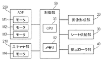
図6は、画像読取形成装置100の制御系を示すブロック図である。
図6に示されているように、画像読取形成装置100の制御手段としての制御部50には、モータM1、M2及びM3を有するADF220、モータM4を有するスキャナ部210、画像形成部20、シート給送部30、及び排出ローラ対40等が接続されている。
制御部50は、これら各部を制御するCPU51と、画像読取プログラムや画像形成プログラム等の各種プログラムや各種情報等を記憶するROM及びRAM等のメモリ52とを有している。
FIG. 6 is a block diagram showing a control system of the image reading and forming
As shown in FIG. 6, the
The
制御部50は、第1プラテンローラ237(図8参照)が所定の回転速度となるようにモータM1を制御し、また、第3搬送ローラ対236及び第4搬送ローラ対238(図8参照)を駆動するようにモータM2及びM3をそれぞれ制御する。
また、制御部50は、画像形成部20、シート給送部30、排出ローラ対40をそれぞれ制御する。
The
Further, the
次に、制御部50の制御による画像読取形成装置100の画像形成装置10における画像形成動作(制御部50による画像形成制御)について説明する。
Next, an image forming operation (image forming control by the control unit 50) in the
画像読取装置200においてADF220により給送され、スキャナ部210で読み取られた原稿Gの画像情報が画像形成装置10に入力されると、入力された画像情報に基づいて、レーザスキャナユニット21から感光ドラム22の感光面上にレーザ光が照射される。
このとき、感光ドラム22の感光面は、帯電器27を介して予め帯電されており、レーザ光が照射されることによって感光面上に静電潜像が形成される。そして、この静電潜像が現像器23によって現像され、感光面上にトナー像が形成される。
感光ドラム22の感光面上でのトナー像の形成動作と並行して、シート給送部30の給紙カセット31に収納されているシートSが給送ローラ32によって給送される。給送ローラ32によって給送されたシートSは、搬送ローラ33aと分離ローラ33bとの間の分離ニップ部で挟持されて1枚ずつに分離されて搬送される。
When the image information of the document G fed by the
At this time, the photosensitive surface of the photosensitive drum 22 is precharged via the
In parallel with the operation of forming the toner image on the photosensitive surface of the photosensitive drum 22, the sheet S housed in the
そして、1枚ずつ分離されたシートSは、レジストレーションローラ対11によって感光ドラム22上のトナー像形成と同期しながら、転写部24に送られる。送られたシートSには、転写部24において感光ドラム22の感光面上のトナー像が転写される。
トナー像が転写されたシートSは、定着部25において加熱及び加圧され、トナー像が溶融されてシートSに定着される。トナー像が定着されたシートSは、排出ローラ対40によってシート排出トレイ45に排出され、順次、積載されていく。
なお、シートSの両面に画像を形成する場合には、シートSの一方の面に画像が定着された後、反転搬送路12を介してシートSを反転させながらレジストレーションローラ対11に向けて再搬送し、上述した動作を再度行う。
Then, the sheets S separated one by one are sent to the
The sheet S to which the toner image is transferred is heated and pressurized in the
When forming an image on both sides of the sheet S, after the image is fixed on one surface of the sheet S, the sheet S is inverted through the
図7及び図8はそれぞれ、画像読取装置200の斜視図及び断面図を示している。
図7及び図8に示されているように、画像読取装置200は、スキャナ部210と、ADF220とを有している。
また、画像読取装置200では、後述する原稿台ガラス213が手前側から開閉可能となるように、奥側に配設された不図示のヒンジにより、ADF220がスキャナ部210に回動可能に支持されている。
7 and 8 show a perspective view and a cross-sectional view of the
As shown in FIGS. 7 and 8, the
Further, in the
スキャナ部210は、原稿Gの一方の面の画像を読み取る第1スキャナユニット211を有している。また、スキャナ部210は、透光部材である第1流し読みガラス212と、第1流し読みガラス212と副走査方向(図8の左右方向)に並んで配設された原稿台ガラス213とを有している。
第1スキャナユニット211は、例えば縮小結像光学系の光路を折り畳んで形成するような一体型の読取ユニットであり、LED等の光源から原稿Gの画像情報面に光を照射し、画像情報面で反射された反射光を縮小光学系によってセンサ素子上に集光して画像情報を読み取るものである。
The
The
第1スキャナユニット211は、不図示の駆動ベルトに接続されている。第1スキャナユニット211は、スキャナ部210に設けられた不図示のモータM4の駆動によって、図8に示される第1流し読みガラス212の下方の位置A(即ち画像読取位置91)と、原稿台ガラス213の下方の位置Bとの間を移動可能に構成されている。
また、第1スキャナユニット211の現在位置は、不図示のポジションセンサとモータM4の回転パルス数とによって、制御部50が把握することができる。
The
Further, the current position of the
図8に示されているように、第1スキャナユニット211は、原稿搬送路H上を搬送されてくる原稿Gの一方の面の画像を、第1流し読みガラス212を介して画像読取位置91で読み取ることができる。
As shown in FIG. 8, the
本実施形態では、第1スキャナユニット211を位置Aに停止させた状態で、ADF220によって原稿Gを第1流し読みガラス212上で移動させながら画像を読み取る形態を「流し読み(シートスルー方式)」と呼ぶこととする。また、原稿台ガラス213上に原稿Gを載置した状態で、第1スキャナユニット211を位置Bに向けて図8中の矢印T方向に移動させながら画像を読み取る形態を「固定読み」と呼ぶこととする。
In the present embodiment, a mode in which the image is read while the document G is moved on the
図7及び図8に示されているように、ADF220は、原稿積載トレイ221と、原稿搬送部222と、原稿排出部223とを有している。
原稿積載トレイ221には、流し読みのための原稿Gが積載される。原稿搬送部222は、流し読みを行う際に、原稿搬送路Hに沿って原稿Gを搬送する。原稿排出部223には、流し読みされた原稿Gが排出されて積載される。
また、ADF220は、固定読みを行う際に、原稿台ガラス213に載置された原稿Gが移動しないように、不図示の樹脂製プレートによって原稿Gを押圧可能に構成されている。
As shown in FIGS. 7 and 8, the
A document G for scanning is loaded on the
Further, the
図8に示されているように、原稿搬送部222は、原稿積載トレイ221に積載された原稿Gを給送する原稿給送ローラ231と、原稿Gを1枚ずつに分離する分離ローラ対232と、分離された原稿Gを引き抜く第1搬送ローラ対233とを有している。
さらに、原稿搬送部222は、原稿Gを搬送する第2搬送ローラ対234と、第3搬送ローラ対236と、第4搬送ローラ対238と、第5搬送ローラ対240とを有している。
また、原稿搬送部222は、レジストレーションローラ対235と、第1プラテンローラ237と、排出ローラ対241とを有している。
As shown in FIG. 8, the
Further, the
Further, the
レジストレーションローラ対235は、第2搬送ローラ対234と第3搬送ローラ対236との間に配置されており、原稿Gの斜行を矯正(補正)するように構成されている。
第1プラテンローラ237は、第3搬送ローラ対236と第4搬送ローラ対238との間で、第1流し読みガラス212の直上に配置されている。
そして、第1プラテンローラ237は、第1スキャナユニット211が搬送された原稿Gの一方の面である表面の画像を読取る際に、原稿Gを第1流し読みガラス212上に付勢しながら、第1流し読みガラス212に対して所定の間隔を空けて原稿Gを搬送する。
The
The
Then, the
第1プラテンローラ237は、画像読取位置91において、第1スキャナユニット211に対して第1流し読みガラス212を挟んで対向するように配置されている。
そして、第1プラテンローラ237は、原稿Gを他方の面である裏面側から押圧して、原稿Gの第1流し読みガラス212からの浮き上がりを抑制している。つまり、第1プラテンローラ237は、原稿Gの第1流し読みガラス212からの浮き上がりを抑制する抑制回転体を構成している。
また、排出ローラ対241は、第5搬送ローラ対240の下流に配置されており、画像読み取りが行われた原稿Gを原稿排出部223に排出する。
The
Then, the
Further, the
画像読取装置200では、デュアルスキャン方式ADFを採用しており、原稿搬送部222は、原稿搬送路H上において、第1スキャナユニット211及び第1流し読みガラス212よりも搬送方向下流側に、以下の部材をさらに備えている。
すなわち、原稿搬送部222は、原稿Gの他方の面である裏面の画像を読み取る第2スキャナユニット251と、第2流し読みガラス252と、第2流し読みガラス252に対して所定の間隔を空けて原稿Gを搬送する第2プラテンローラ239とをさらに有している。
第2プラテンローラ239は、第2流し読みガラス252の直上に設けられ、搬送される原稿Gの他方の面である裏面の画像を読取る際に、搬送される原稿Gを第2流し読みガラス252に向けて付勢する。
The
That is, the
The
画像読取装置200では、第2スキャナユニット251として、第1スキャナユニット211と同様の読取ユニットが用いられている。
第2スキャナユニット251は、第1スキャナユニット211の原稿搬送方向下流側で、第2流し読みガラス252の下方の読取位置Cに配置され、原稿搬送路H上を搬送される原稿Gの他方の面である裏面の画像を読み取る。
In the
The
次に、制御部50の制御による画像読取形成装置100の画像読取装置200における画像読取動作(制御部50による画像読取制御)について説明する。
Next, an image reading operation (image reading control by the control unit 50) in the
図8に示されているように、まず、原稿積載トレイ221上に載置された任意の枚数の原稿Gは、原稿給送ローラ231により給送されて、分離ローラ対232の分離ニップ部で1枚ずつに分離される。そして、分離された原稿Gは、第1搬送ローラ対233により引き抜かれた後、第2搬送ローラ対234によってレジストレーションローラ対235のニップ部まで搬送される。
そして、原稿Gがレジストレーションローラ対235のニップ部に到達した時点で、レジストレーションローラ対235を静止した状態にしておくことで、原稿Gの先端をニップ部に当接させて停止させる。
この状態で、原稿搬送方向上流側の第2搬送ローラ対234により原稿Gの後端を所定量押し込ませることで、原稿Gを撓ませて湾曲形状を生じさせる。
ここで、原稿Gが斜行している場合、主走査方向(原稿Gの幅方向)に対して原稿Gの先端は傾いているが、上述の湾曲による原稿Gのコシ(剛性)で、原稿Gの先端が、主走査方向に平行なレジストレーションローラ対235のニップ線に倣う。
このようにして、レジストレーションローラ対235によって、原稿Gの先端の傾きが解消、すなわち斜行が補正される。
As shown in FIG. 8, first, an arbitrary number of documents G placed on the
Then, when the document G reaches the nip portion of the
In this state, the rear end of the document G is pushed by a predetermined amount by the second
Here, when the document G is skewed, the tip of the document G is tilted with respect to the main scanning direction (width direction of the document G), but the stiffness (rigidity) of the document G due to the above-mentioned curvature makes the document The tip of G follows the nip line of the
In this way, the
そして斜行が補正された後、レジストレーションローラ対235による原稿Gの搬送が開始され、第3搬送ローラ対236によってさらに下流へと搬送されて、第1流し読みガラス212上の画像読取位置91に到達する。そして、第1スキャナユニット211によって原稿Gの一方の面である表面の画像読み取りが所定の速度で行われる。
その後、原稿Gは、第4搬送ローラ対238によって搬送される。このとき、ユーザによって原稿Gの他方の面である裏面も読み取る指示が出されていれば、制御部50の制御で、第1スキャナユニット211による画像読み取りの後、第2流し読みガラス252上の画像読取位置92において、第2スキャナユニット251による原稿Gの他方の面である裏面の画像読み取りが所定の速度で行われる。
Then, after the skew is corrected, the transfer of the document G by the
After that, the document G is conveyed by the fourth conveying
そして、画像読み取り後の原稿Gは、第5搬送ローラ対240及び排出ローラ対241によって、原稿排出部223に排出される。
そして、原稿積載トレイ221上に載置された原稿Gがなくなるまで、上述の動作は繰り返される。なお、原稿積載トレイ221上に載置された原稿Gの有無は、不図示のセンサによって検知可能になっている。
Then, the document G after reading the image is ejected to the
Then, the above operation is repeated until the document G placed on the
次に、本実施形態に係る搬送される原稿の画像を読み取る画像読取装置用の透光部材である第1流し読みガラス212の構成について説明する。
Next, the configuration of the first flow-reading
図1(a)、(b)及び(c)はそれぞれ、本実施形態に係る第1流し読みガラス212の、防汚コート212bが施されている様子を示した上面図、側面図及び上面図を示している。
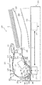
また、図9は、画像読取装置200の第1流し読みガラス212近傍の要部拡大副走査断面図を示している。
1 (a), (b) and (c) are a top view, a side view and a top view showing how the
Further, FIG. 9 shows an enlarged sub-scanning sectional view of a main part in the vicinity of the
図1(a)に示されているように、第1流し読みガラス212では、原稿Gと接する面であるガラス基板212aの一方の表面(第1の透光面)212c上の第1の領域213aに、撥油性、平滑性に優れた透明な防汚コート212bが施されている。
また、図1(b)に示されているように、表面212cに接続する側面212e上の第1の領域213aに接する第2の領域213bにも、撥油性、平滑性に優れた透明な防汚コート212bが施されている。
そして、図1(c)に示されているように、表面212c上の第1の領域213aの搬送方向上流側の第3の領域213cには、シート部材212sが貼り付けられている。
As shown in FIG. 1A, in the
Further, as shown in FIG. 1B, a transparent shield having excellent oil repellency and smoothness is also formed in the
Then, as shown in FIG. 1 (c), the
また、図9に示されているように、シート部材212sは、不図示の導電シート及び金属フレーム209bを介して接地されている。
シート部材212s自身も導電性を有しており、具体的には、シート部材212sは、導電性が付与された樹脂シートと導電性両面テープから構成されている。
Further, as shown in FIG. 9, the
The
シート部材212sは、大きく2つの機能を有している。1つは、接地されたシート部材212sと搬送された原稿Gを接触させることによって、原稿G、及び搬送経路中で発生し、原稿Gに静電吸着している紙粉などの帯電を除去(除電)することである。
これにより、搬送された原稿Gが第1流し読みガラス212との接触摩擦に伴って接触帯電することによって、第1流し読みガラス212の表面212cが帯電しても、除電された紙粉等が吸着することを防止することができる。
The
As a result, the conveyed document G is contact-charged due to the contact friction with the
もう1つは、シート部材212sの厚みを制御し、原稿Gの第1流し読みガラス212に対する入射角度や接触位置を最適化することで、防汚コート212bの耐久性と第1流し読みガラス212の表面212cについた浮遊ゴミに対する原稿通紙によるセルフクリーニング性能とを両立させることができる。
なお、ここで言うセルフクリーニング性能とは、原稿G自身が第1流し読みガラス212の表面212c上にある浮遊ゴミを掻き取る性能である。
The other is to control the thickness of the
The self-cleaning performance referred to here is a performance in which the document G itself scrapes off floating dust on the
すなわち、上述のように、紙粉等の浮遊ゴミはシート部材212sによって帯電除去されており、第1流し読みガラス212の表面212c上に静電吸着しにくくなっている。
そのため、原稿通紙によって第1流し読みガラス212の表面212c上に静電吸着されていない浮遊ゴミを容易にセルフクリーニングすることができる。
That is, as described above, the floating dust such as paper dust is charged and removed by the
Therefore, it is possible to easily self-clean the floating dust that is not electrostatically adsorbed on the
また、シート部材212sの厚みを制御することで、防汚コート212bの削れ等を最小減にすることができるため、防汚コート212bによる糊状粘着物に起因した固着ゴミの発生も有効に長期間低減することができる。
Further, by controlling the thickness of the
上述したように、防汚コート212bは、原稿Gと接する面である第1流し読みガラス212の一方の表面212c上の第1の領域213a、及び表面212cに接続する側面212e上の第1の領域213aに接する第2の領域213bに施されている。
また、表面212c上の第1の領域213aの搬送方向上流側の第3の領域213cには、シート部材212sが貼り付けられている。
ここで、表面212c上の第3の領域213cでは、防汚コート212bは施されていない。これは、シート部材212s、及びシート部材212sと金属フレーム209bを電気的に接続する導電性シートを貼り付ける際に、第3の領域213cに防汚コート212bを施してしまうと、これらを貼り付けることが不可能もしくは貼りつけても容易に剥離してしまうためである。
As described above, the
Further, the
Here, the
また、図1(c)に示されているように、表面212c上の搬送方向に垂直な主走査方向両端部には、防汚コート212bもシート部材212sも設けられていない第4の領域213dがある。なお、この第4の領域213dは、画像読取装置200のスキャナ部210の読取範囲外に配置されるように構成されている。
Further, as shown in FIG. 1C, a
上述のように、本実施形態に係る第1流し読みガラス212では、表面212cに接続する側面212e上の第1の領域213aに接する第2の領域213bにも防汚コート212bを施している。
これは以下の理由による。すなわち、図9に示されているように、第1流し読みガラス212は、画像読取装置200の筐体内に異物が侵入しないように、ハウジング209に嵌め込む方式になっており、その上から不図示の付勢部材で付勢されている。
ここで、第1流し読みガラス212の交換が必要になった際に、表面212cに接続する側面212e上の第1の領域213aに接する第2の領域213bにも防汚コート212bを施すことで、摺動性がよくなり着脱が容易になることから、第1流し読みガラス212のメンテナンス性能を向上させることができるためである。
As described above, in the
This is due to the following reasons. That is, as shown in FIG. 9, the first flow-reading
Here, when it becomes necessary to replace the
次に、本実施形態に係る搬送される原稿の画像を読み取る画像読取装置用の透光部材である第1流し読みガラス212を製造する方法について説明する。
Next, a method of manufacturing the first flow-reading
第1流し読みガラス212では、防汚コート212bは、フッ素含有有機化合物コーティングであり、特に撥油性に優れたケイ素含有パーフルポリエーテル化合物が用いられている。
このようなコート材は、真空蒸着や塗布加工等の様々な方式でガラス基板上にコーティングすることができる。なお、これらのコーティング方式の中では、比較的加工コストが安い塗布加工方式が普及しているが、コート材のガラスに対する密着性を向上させるためには、真空蒸着方式による成膜が好ましい。
なお、本実施形態に係る第1流し読みガラス212では、防汚コート212bは、ガラス基板212aの表面212c上に中間層を介さずに(他の部材を介さずに)直接蒸着成膜されている。
In the
Such a coating material can be coated on a glass substrate by various methods such as vacuum deposition and coating processing. Among these coating methods, a coating processing method having a relatively low processing cost is widely used, but in order to improve the adhesion of the coating material to glass, a vacuum vapor deposition method is preferable.
In the first flow-reading
ここで、真空蒸着によってコート材を加工する場合には、成膜コストは、1度に同時に加工することができる流し読みガラスの本数に依存する。 Here, when the coating material is processed by vacuum vapor deposition, the film forming cost depends on the number of scanning glasses that can be processed at one time at the same time.
図10(a)は、従来の真空蒸着加工のために、複数の流し読みガラス312が配置される、複数の開口部402を有するマスク治具401を示した上面図である。
また、図10(b)は、複数の流し読みガラス312が配置されたマスク治具401をC−C’線で切断した断面図である。
FIG. 10A is a top view showing a
Further, FIG. 10B is a cross-sectional view of the
図10(a)及び(b)に示されているように、単にガラス表面全体をコーティングする場合に比べて、本実施形態のように複雑なコーティングを施すためには、複雑なマスキングが必要となるため、加工数量が少なくなってしまい、高コスト化を招くという問題があった。 As shown in FIGS. 10A and 10B, more complicated masking is required to apply a complicated coating as in the present embodiment as compared with the case of simply coating the entire glass surface. Therefore, there is a problem that the processing quantity is reduced and the cost is increased.
そこで、本願出願人は、以下のように、マスク治具に対する複数の流し読みガラスの配置を工夫することで、本実施形態のような複雑なコーティングを施す場合でも、加工数量を多くすることができ、コストを削減できることを見いだした。 Therefore, the applicant of the present application can increase the processing quantity even when applying a complicated coating as in the present embodiment by devising the arrangement of a plurality of scanning glasses with respect to the mask jig as described below. I found that I could do it and reduce the cost.
図2(a)は、真空蒸着加工のために、本実施形態に係る複数の流し読みガラス212が配置される、開口部302を有するマスク治具(支持部材)301を示した上面図である。
また、図2(b)は、複数の流し読みガラス212が配置されたマスク治具301をA−A’線及びB−B’線それぞれで切断した断面図を示している。
FIG. 2A is a top view showing a mask jig (support member) 301 having an
Further, FIG. 2B shows a cross-sectional view of the
図2(a)及び(b)に示されているように、マスク治具301には、主走査方向両端部に階段部303が設けられていることを特徴としている。換言すると、マスク治具301は、複数の流し読みガラス212の基板212aのそれぞれの他方の表面212d(第2の透光面)に接する階段状の表面を備えている。
このような階段部303に、複数の流し読みガラス212の基板212aのそれぞれの他方の表面212d上の主走査方向両端部が支持されるように、複数の流し読みガラス212を配置することによって互いに重畳させることができる。すなわち、流し読みガラス212自身もコーティングにおけるマスクの役割を果たすことができる。
換言すると、本実施形態では、それぞれが互いに対向する表面212c及び212dを備える複数の流し読みガラス212の基板212aを、隣接する2つの流し読みガラス212の基板212aのうち一方の表面212cの一部と他方の表面212dの一部とが互いに接するように配置している。
As shown in FIGS. 2A and 2B, the
By arranging the plurality of
In other words, in the present embodiment, the
これにより、原稿Gと接する面である流し読みガラス212の基板212aの表面212c上の第1の領域213aに、防汚コート212bを施すことができる。
また、同時に、表面212c及び212dを接続する側面212e上の第1の領域213aに接する第2の領域213bにも、防汚コート212bを施すことができることに注意されたい。
これにより、複数の流し読みガラス212の基板212aを互いに重畳させて配置することによって、マスク治具301に配置することができる流し読みガラス212の数を多くする、すなわち加工数量を多くすることができ、コストを削減することができる。
As a result, the
At the same time, it should be noted that the
As a result, by arranging the
なお、単に複数の流し読みガラス212を互いに積み重ねただけでは、マスクの位置公差の管理やガラス基板同士の間に隙間ができることで、コーティング時に回りこみが発生する問題が想定される。
そこで、本実施形態では、上記のような階段部303を有するマスク治具301を使用することで、このような問題を発生させることなく、生産性を向上させることができる。
It should be noted that simply stacking a plurality of
Therefore, in the present embodiment, by using the
具体的には、例えば、従来のマスク治具401では、図10(a)及び(b)に示されているように、5本の流し読みガラス312しか配置することができないが、本実施形態におけるマスク治具301では、図2(a)及び(b)に示されているように、10本の流し読みガラス312を配置することができ、加工収率を2倍にすることができる。
Specifically, for example, in the
そして、本実施形態に係る流し読みガラス212の基板212aが配置されたマスク治具301を、図3に示されるように、蒸着傘311に取り付けて、図4に示されるように、真空蒸着機320にセットされ、成膜される。換言すると、それぞれが複数の流し読みガラス212の基板212aを支持する複数のマスク治具301を配列し、複数のマスク治具301のそれぞれにより支持された複数の流し読みガラス212の基板212aに防汚コート212bを同時に施している。
ここで、図4に示されているように、真空蒸着機320は、蒸発源321及びシャッター322を備えている。
なお、真空蒸着するコート材物質としては、フッ素系防汚コートとして市販されている材料である、例えばケイ素含有パーフルポリエーテル化合物等のフッ素含有有機化合物を用いている。
Then, the
Here, as shown in FIG. 4, the vacuum
As the coating material material to be vacuum-deposited, a fluorine-containing organic compound such as a silicon-containing perful polyether compound, which is a commercially available material as a fluorine-based antifouling coat, is used.
そして、真空蒸着コーティングがなされた流し読みガラス212の表面212c上の第1の領域213aの搬送方向上流側の第3の領域213cに、シート部材212sが貼り付けられる。
Then, the
なお、ここまで真空蒸着方式による成膜の場合について説明してきたが、マスク治具301を用いて塗布加工方式を行った場合でも、生産性を向上させることができコストを削減することができる。
Although the case of film formation by the vacuum vapor deposition method has been described so far, the productivity can be improved and the cost can be reduced even when the coating process method is performed using the
なお、本実施形態では、電子写真方式の画像形成装置10を備えた画像読取形成装置100を用いて説明してきたが、これに代えて、例えば、ノズルからインク液を吐出させることでシートに画像を形成するインクジェット方式の画像形成装置を備えた画像読取形成装置に、本実施形態に係る透光部材である流し読みガラスを適用することも可能である。
また、上記では、第1流し読みガラス212について説明したが、画像読取装置200の第2流し読みガラス252にも同様の構成が適用される。
In the present embodiment, the image reading and forming
Further, although the
212 第1流し読みガラス(透光部材)
212a ガラス基板(基板)
212b 防汚コート(コーティング)
212c、212d 表面(第1及び第2の透光面)
212 First flow reading glass (translucent member)
212a glass substrate (substrate)
212b Antifouling coat (coating)
212c, 212d surface (first and second translucent surface)
Claims (12)
夫々が互いに対向する第1及び第2の透光面を備える複数の基板を、隣接する二つの基板のうち一方の前記第1の透光面の一部と他方の前記第2の透光面の一部とが互いに接するように配置する第1のステップと、
前記複数の基板の夫々の前記第1の透光面にコーティングを設ける第2のステップとを有することを特徴とする製造方法。 A method for manufacturing a translucent member for an image reader that reads an image of a conveyed document.
A plurality of substrates each having a first and second translucent surface facing each other are formed by a part of the first translucent surface of one of two adjacent substrates and the second transmissive surface of the other. The first step of arranging the parts of the
A manufacturing method comprising a second step of providing a coating on the first translucent surface of each of the plurality of substrates.
Priority Applications (2)
| Application Number | Priority Date | Filing Date | Title |
|---|---|---|---|
| JP2017106432A JP6878148B2 (en) | 2017-05-30 | 2017-05-30 | Translucent member and image reader |
| US15/991,320 US10412245B2 (en) | 2017-05-30 | 2018-05-29 | Method of manufacturing light-transmitting member, light-transmitting member and image reading apparatus |
Applications Claiming Priority (1)
| Application Number | Priority Date | Filing Date | Title |
|---|---|---|---|
| JP2017106432A JP6878148B2 (en) | 2017-05-30 | 2017-05-30 | Translucent member and image reader |
Publications (3)
| Publication Number | Publication Date |
|---|---|
| JP2018207147A JP2018207147A (en) | 2018-12-27 |
| JP2018207147A5 JP2018207147A5 (en) | 2020-07-02 |
| JP6878148B2 true JP6878148B2 (en) | 2021-05-26 |
Family
ID=64460735
Family Applications (1)
| Application Number | Title | Priority Date | Filing Date |
|---|---|---|---|
| JP2017106432A Active JP6878148B2 (en) | 2017-05-30 | 2017-05-30 | Translucent member and image reader |
Country Status (2)
| Country | Link |
|---|---|
| US (1) | US10412245B2 (en) |
| JP (1) | JP6878148B2 (en) |
Families Citing this family (3)
| Publication number | Priority date | Publication date | Assignee | Title |
|---|---|---|---|---|
| JP6894764B2 (en) * | 2017-05-30 | 2021-06-30 | キヤノン株式会社 | Image reader |
| JP6961449B2 (en) | 2017-10-12 | 2021-11-05 | キヤノン株式会社 | Image reader |
| JP7346086B2 (en) * | 2019-05-31 | 2023-09-19 | キヤノン株式会社 | Sheet discharge device, image reading device, and image forming device |
Family Cites Families (8)
| Publication number | Priority date | Publication date | Assignee | Title |
|---|---|---|---|---|
| US5261013A (en) * | 1989-02-21 | 1993-11-09 | Canon Kabushiki Kaisha | Photoelectric converter and image reading apparatus mounting the same |
| JP2003215735A (en) * | 2002-01-21 | 2003-07-30 | Canon Inc | Image forming device |
| JP4235543B2 (en) | 2003-12-16 | 2009-03-11 | キヤノン株式会社 | Image reading apparatus and image forming apparatus having the same |
| JP2005223878A (en) * | 2004-01-05 | 2005-08-18 | Ricoh Co Ltd | Image scanner and recording apparatus with image scanner |
| JP4413790B2 (en) * | 2005-01-25 | 2010-02-10 | 株式会社リコー | Image reading apparatus and image forming apparatus |
| CN104039731B (en) * | 2012-01-10 | 2017-06-06 | Vitro可变资本股份有限公司 | The glass of the coating with low film resistor, smooth surface and/or low-heat emissivity |
| JP6065470B2 (en) * | 2012-08-31 | 2017-01-25 | セイコーエプソン株式会社 | Imaging apparatus, inspection apparatus, and electronic device manufacturing method |
| JP6700960B2 (en) * | 2015-06-04 | 2020-05-27 | キヤノン株式会社 | Image reading apparatus and image forming apparatus |
-
2017
- 2017-05-30 JP JP2017106432A patent/JP6878148B2/en active Active
-
2018
- 2018-05-29 US US15/991,320 patent/US10412245B2/en active Active
Also Published As
| Publication number | Publication date |
|---|---|
| US10412245B2 (en) | 2019-09-10 |
| US20180352101A1 (en) | 2018-12-06 |
| JP2018207147A (en) | 2018-12-27 |
Similar Documents
| Publication | Publication Date | Title |
|---|---|---|
| JP6878148B2 (en) | Translucent member and image reader | |
| JP7335550B2 (en) | Image reading device, image forming device | |
| US9975715B2 (en) | Document sheet conveyance device and image forming apparatus including the same | |
| US9170548B2 (en) | Sheet discharge device, and image forming apparatus provided with the same | |
| JP4816677B2 (en) | Belt unit and image forming apparatus | |
| US8840110B2 (en) | Sheet conveying device, image reading device provided with the same, and image forming apparatus provided with the same | |
| US7251450B2 (en) | Paper separator and processor cartridge | |
| JP5771590B2 (en) | Paper feeding device, and image reading device and image forming apparatus provided with the same | |
| JP2014036364A (en) | Image reading device | |
| JP6894764B2 (en) | Image reader | |
| JP6452408B2 (en) | Sheet conveying apparatus, image reading apparatus, and image forming apparatus | |
| JP6961449B2 (en) | Image reader | |
| JP2010091762A (en) | Fixing device | |
| JP2007159033A (en) | Image reader | |
| JP3905513B2 (en) | Recording medium peeling nail | |
| JP2004189345A (en) | Device and method for conveying paper | |
| JP6056217B2 (en) | Image forming apparatus | |
| JP2001253613A (en) | Paper conveying mechanism | |
| JP6739984B2 (en) | Image reading apparatus and image forming apparatus | |
| JP2010212846A (en) | Original reader and image forming device equipped with it | |
| JP2001337536A (en) | Image forming device | |
| JP3981756B2 (en) | Paper discharge device | |
| JP4119741B2 (en) | Paper feeder | |
| JP2006282380A (en) | Paper sheet carrying device | |
| JP2001339571A (en) | Original reader |
Legal Events
| Date | Code | Title | Description |
|---|---|---|---|
| RD05 | Notification of revocation of power of attorney |
Free format text: JAPANESE INTERMEDIATE CODE: A7425 Effective date: 20171214 |
|
| RD04 | Notification of resignation of power of attorney |
Free format text: JAPANESE INTERMEDIATE CODE: A7424 Effective date: 20180126 |
|
| A521 | Written amendment |
Free format text: JAPANESE INTERMEDIATE CODE: A523 Effective date: 20200518 |
|
| A621 | Written request for application examination |
Free format text: JAPANESE INTERMEDIATE CODE: A621 Effective date: 20200518 |
|
| A977 | Report on retrieval |
Free format text: JAPANESE INTERMEDIATE CODE: A971007 Effective date: 20201224 |
|
| A131 | Notification of reasons for refusal |
Free format text: JAPANESE INTERMEDIATE CODE: A131 Effective date: 20210112 |
|
| A521 | Written amendment |
Free format text: JAPANESE INTERMEDIATE CODE: A523 Effective date: 20210309 |
|
| TRDD | Decision of grant or rejection written | ||
| A01 | Written decision to grant a patent or to grant a registration (utility model) |
Free format text: JAPANESE INTERMEDIATE CODE: A01 Effective date: 20210330 |
|
| A61 | First payment of annual fees (during grant procedure) |
Free format text: JAPANESE INTERMEDIATE CODE: A61 Effective date: 20210428 |
|
| R151 | Written notification of patent or utility model registration |
Ref document number: 6878148 Country of ref document: JP Free format text: JAPANESE INTERMEDIATE CODE: R151 |