JP6877705B1 - Endoscope and imaging unit provided in the endoscope - Google Patents
Endoscope and imaging unit provided in the endoscope Download PDFInfo
- Publication number
- JP6877705B1 JP6877705B1 JP2020168514A JP2020168514A JP6877705B1 JP 6877705 B1 JP6877705 B1 JP 6877705B1 JP 2020168514 A JP2020168514 A JP 2020168514A JP 2020168514 A JP2020168514 A JP 2020168514A JP 6877705 B1 JP6877705 B1 JP 6877705B1
- Authority
- JP
- Japan
- Prior art keywords
- prism
- light
- visible light
- trimming filter
- image sensor
- Prior art date
- Legal status (The legal status is an assumption and is not a legal conclusion. Google has not performed a legal analysis and makes no representation as to the accuracy of the status listed.)
- Active
Links
- 238000003384 imaging method Methods 0.000 title claims abstract description 83
- 238000009966 trimming Methods 0.000 claims abstract description 115
- 230000000903 blocking effect Effects 0.000 claims abstract description 73
- 238000002834 transmittance Methods 0.000 claims description 36
- 230000005284 excitation Effects 0.000 claims description 23
- 230000003595 spectral effect Effects 0.000 claims description 14
- 210000003484 anatomy Anatomy 0.000 claims 1
- 238000001228 spectrum Methods 0.000 claims 1
- 238000004519 manufacturing process Methods 0.000 abstract description 12
- 238000010586 diagram Methods 0.000 abstract description 2
- 239000010408 film Substances 0.000 description 101
- 230000005540 biological transmission Effects 0.000 description 20
- 239000002131 composite material Substances 0.000 description 14
- 239000000853 adhesive Substances 0.000 description 13
- 230000001070 adhesive effect Effects 0.000 description 13
- 239000002872 contrast media Substances 0.000 description 10
- MOFVSTNWEDAEEK-UHFFFAOYSA-M indocyanine green Chemical compound [Na+].[O-]S(=O)(=O)CCCCN1C2=CC=C3C=CC=CC3=C2C(C)(C)C1=CC=CC=CC=CC1=[N+](CCCCS([O-])(=O)=O)C2=CC=C(C=CC=C3)C3=C2C1(C)C MOFVSTNWEDAEEK-UHFFFAOYSA-M 0.000 description 10
- 229960004657 indocyanine green Drugs 0.000 description 10
- 239000000463 material Substances 0.000 description 8
- 230000003287 optical effect Effects 0.000 description 8
- 238000003780 insertion Methods 0.000 description 7
- 230000037431 insertion Effects 0.000 description 7
- 238000000034 method Methods 0.000 description 6
- 230000002411 adverse Effects 0.000 description 5
- 238000000926 separation method Methods 0.000 description 5
- 238000010030 laminating Methods 0.000 description 4
- 230000002194 synthesizing effect Effects 0.000 description 4
- 239000010409 thin film Substances 0.000 description 4
- 229910004298 SiO 2 Inorganic materials 0.000 description 3
- 229910010413 TiO 2 Inorganic materials 0.000 description 3
- 239000011521 glass Substances 0.000 description 3
- 230000001678 irradiating effect Effects 0.000 description 3
- 230000015654 memory Effects 0.000 description 3
- 238000004040 coloring Methods 0.000 description 2
- 230000003111 delayed effect Effects 0.000 description 2
- 239000000428 dust Substances 0.000 description 2
- 238000002357 laparoscopic surgery Methods 0.000 description 2
- 238000012423 maintenance Methods 0.000 description 2
- 239000011159 matrix material Substances 0.000 description 2
- 239000000203 mixture Substances 0.000 description 2
- 238000003491 array Methods 0.000 description 1
- 238000006243 chemical reaction Methods 0.000 description 1
- 230000000295 complement effect Effects 0.000 description 1
- 239000004973 liquid crystal related substance Substances 0.000 description 1
- 229910044991 metal oxide Inorganic materials 0.000 description 1
- 150000004706 metal oxides Chemical class 0.000 description 1
- 239000013307 optical fiber Substances 0.000 description 1
- 229920003023 plastic Polymers 0.000 description 1
- 239000004065 semiconductor Substances 0.000 description 1
- 239000000758 substrate Substances 0.000 description 1
- 238000001356 surgical procedure Methods 0.000 description 1
- 210000003462 vein Anatomy 0.000 description 1
- 210000001835 viscera Anatomy 0.000 description 1
Images


Classifications
-
- A—HUMAN NECESSITIES
- A61—MEDICAL OR VETERINARY SCIENCE; HYGIENE
- A61B—DIAGNOSIS; SURGERY; IDENTIFICATION
- A61B1/00—Instruments for performing medical examinations of the interior of cavities or tubes of the body by visual or photographical inspection, e.g. endoscopes; Illuminating arrangements therefor
- A61B1/00002—Operational features of endoscopes
- A61B1/00004—Operational features of endoscopes characterised by electronic signal processing
- A61B1/00009—Operational features of endoscopes characterised by electronic signal processing of image signals during a use of endoscope
-
- A—HUMAN NECESSITIES
- A61—MEDICAL OR VETERINARY SCIENCE; HYGIENE
- A61B—DIAGNOSIS; SURGERY; IDENTIFICATION
- A61B1/00—Instruments for performing medical examinations of the interior of cavities or tubes of the body by visual or photographical inspection, e.g. endoscopes; Illuminating arrangements therefor
- A61B1/00064—Constructional details of the endoscope body
- A61B1/00071—Insertion part of the endoscope body
- A61B1/0008—Insertion part of the endoscope body characterised by distal tip features
- A61B1/00096—Optical elements
-
- A—HUMAN NECESSITIES
- A61—MEDICAL OR VETERINARY SCIENCE; HYGIENE
- A61B—DIAGNOSIS; SURGERY; IDENTIFICATION
- A61B1/00—Instruments for performing medical examinations of the interior of cavities or tubes of the body by visual or photographical inspection, e.g. endoscopes; Illuminating arrangements therefor
- A61B1/04—Instruments for performing medical examinations of the interior of cavities or tubes of the body by visual or photographical inspection, e.g. endoscopes; Illuminating arrangements therefor combined with photographic or television appliances
- A61B1/05—Instruments for performing medical examinations of the interior of cavities or tubes of the body by visual or photographical inspection, e.g. endoscopes; Illuminating arrangements therefor combined with photographic or television appliances characterised by the image sensor, e.g. camera, being in the distal end portion
- A61B1/051—Details of CCD assembly
-
- A—HUMAN NECESSITIES
- A61—MEDICAL OR VETERINARY SCIENCE; HYGIENE
- A61B—DIAGNOSIS; SURGERY; IDENTIFICATION
- A61B1/00—Instruments for performing medical examinations of the interior of cavities or tubes of the body by visual or photographical inspection, e.g. endoscopes; Illuminating arrangements therefor
- A61B1/00163—Optical arrangements
- A61B1/00186—Optical arrangements with imaging filters
-
- A—HUMAN NECESSITIES
- A61—MEDICAL OR VETERINARY SCIENCE; HYGIENE
- A61B—DIAGNOSIS; SURGERY; IDENTIFICATION
- A61B1/00—Instruments for performing medical examinations of the interior of cavities or tubes of the body by visual or photographical inspection, e.g. endoscopes; Illuminating arrangements therefor
- A61B1/04—Instruments for performing medical examinations of the interior of cavities or tubes of the body by visual or photographical inspection, e.g. endoscopes; Illuminating arrangements therefor combined with photographic or television appliances
- A61B1/046—Instruments for performing medical examinations of the interior of cavities or tubes of the body by visual or photographical inspection, e.g. endoscopes; Illuminating arrangements therefor combined with photographic or television appliances for infrared imaging
-
- A—HUMAN NECESSITIES
- A61—MEDICAL OR VETERINARY SCIENCE; HYGIENE
- A61B—DIAGNOSIS; SURGERY; IDENTIFICATION
- A61B1/00—Instruments for performing medical examinations of the interior of cavities or tubes of the body by visual or photographical inspection, e.g. endoscopes; Illuminating arrangements therefor
- A61B1/04—Instruments for performing medical examinations of the interior of cavities or tubes of the body by visual or photographical inspection, e.g. endoscopes; Illuminating arrangements therefor combined with photographic or television appliances
- A61B1/05—Instruments for performing medical examinations of the interior of cavities or tubes of the body by visual or photographical inspection, e.g. endoscopes; Illuminating arrangements therefor combined with photographic or television appliances characterised by the image sensor, e.g. camera, being in the distal end portion
-
- A—HUMAN NECESSITIES
- A61—MEDICAL OR VETERINARY SCIENCE; HYGIENE
- A61B—DIAGNOSIS; SURGERY; IDENTIFICATION
- A61B90/00—Instruments, implements or accessories specially adapted for surgery or diagnosis and not covered by any of the groups A61B1/00 - A61B50/00, e.g. for luxation treatment or for protecting wound edges
- A61B90/39—Markers, e.g. radio-opaque or breast lesions markers
-
- G—PHYSICS
- G02—OPTICS
- G02B—OPTICAL ELEMENTS, SYSTEMS OR APPARATUS
- G02B23/00—Telescopes, e.g. binoculars; Periscopes; Instruments for viewing the inside of hollow bodies; Viewfinders; Optical aiming or sighting devices
- G02B23/24—Instruments or systems for viewing the inside of hollow bodies, e.g. fibrescopes
- G02B23/2407—Optical details
- G02B23/2423—Optical details of the distal end
- G02B23/243—Objectives for endoscopes
-
- G—PHYSICS
- G02—OPTICS
- G02B—OPTICAL ELEMENTS, SYSTEMS OR APPARATUS
- G02B23/00—Telescopes, e.g. binoculars; Periscopes; Instruments for viewing the inside of hollow bodies; Viewfinders; Optical aiming or sighting devices
- G02B23/24—Instruments or systems for viewing the inside of hollow bodies, e.g. fibrescopes
- G02B23/2476—Non-optical details, e.g. housings, mountings, supports
- G02B23/2484—Arrangements in relation to a camera or imaging device
-
- G—PHYSICS
- G02—OPTICS
- G02B—OPTICAL ELEMENTS, SYSTEMS OR APPARATUS
- G02B5/00—Optical elements other than lenses
- G02B5/20—Filters
- G02B5/208—Filters for use with infrared or ultraviolet radiation, e.g. for separating visible light from infrared and/or ultraviolet radiation
-
- G—PHYSICS
- G02—OPTICS
- G02B—OPTICAL ELEMENTS, SYSTEMS OR APPARATUS
- G02B5/00—Optical elements other than lenses
- G02B5/20—Filters
- G02B5/28—Interference filters
- G02B5/281—Interference filters designed for the infrared light
- G02B5/282—Interference filters designed for the infrared light reflecting for infrared and transparent for visible light, e.g. heat reflectors, laser protection
-
- H—ELECTRICITY
- H04—ELECTRIC COMMUNICATION TECHNIQUE
- H04N—PICTORIAL COMMUNICATION, e.g. TELEVISION
- H04N23/00—Cameras or camera modules comprising electronic image sensors; Control thereof
- H04N23/45—Cameras or camera modules comprising electronic image sensors; Control thereof for generating image signals from two or more image sensors being of different type or operating in different modes, e.g. with a CMOS sensor for moving images in combination with a charge-coupled device [CCD] for still images
-
- H—ELECTRICITY
- H04—ELECTRIC COMMUNICATION TECHNIQUE
- H04N—PICTORIAL COMMUNICATION, e.g. TELEVISION
- H04N23/00—Cameras or camera modules comprising electronic image sensors; Control thereof
- H04N23/50—Constructional details
-
- H—ELECTRICITY
- H04—ELECTRIC COMMUNICATION TECHNIQUE
- H04N—PICTORIAL COMMUNICATION, e.g. TELEVISION
- H04N23/00—Cameras or camera modules comprising electronic image sensors; Control thereof
- H04N23/50—Constructional details
- H04N23/54—Mounting of pick-up tubes, electronic image sensors, deviation or focusing coils
-
- H—ELECTRICITY
- H04—ELECTRIC COMMUNICATION TECHNIQUE
- H04N—PICTORIAL COMMUNICATION, e.g. TELEVISION
- H04N23/00—Cameras or camera modules comprising electronic image sensors; Control thereof
- H04N23/50—Constructional details
- H04N23/55—Optical parts specially adapted for electronic image sensors; Mounting thereof
-
- H—ELECTRICITY
- H04—ELECTRIC COMMUNICATION TECHNIQUE
- H04N—PICTORIAL COMMUNICATION, e.g. TELEVISION
- H04N23/00—Cameras or camera modules comprising electronic image sensors; Control thereof
- H04N23/50—Constructional details
- H04N23/555—Constructional details for picking-up images in sites, inaccessible due to their dimensions or hazardous conditions, e.g. endoscopes or borescopes
-
- H—ELECTRICITY
- H04—ELECTRIC COMMUNICATION TECHNIQUE
- H04N—PICTORIAL COMMUNICATION, e.g. TELEVISION
- H04N23/00—Cameras or camera modules comprising electronic image sensors; Control thereof
- H04N23/57—Mechanical or electrical details of cameras or camera modules specially adapted for being embedded in other devices
-
- H—ELECTRICITY
- H04—ELECTRIC COMMUNICATION TECHNIQUE
- H04N—PICTORIAL COMMUNICATION, e.g. TELEVISION
- H04N23/00—Cameras or camera modules comprising electronic image sensors; Control thereof
- H04N23/70—Circuitry for compensating brightness variation in the scene
- H04N23/75—Circuitry for compensating brightness variation in the scene by influencing optical camera components
-
- H—ELECTRICITY
- H04—ELECTRIC COMMUNICATION TECHNIQUE
- H04N—PICTORIAL COMMUNICATION, e.g. TELEVISION
- H04N23/00—Cameras or camera modules comprising electronic image sensors; Control thereof
- H04N23/95—Computational photography systems, e.g. light-field imaging systems
- H04N23/951—Computational photography systems, e.g. light-field imaging systems by using two or more images to influence resolution, frame rate or aspect ratio
-
- H—ELECTRICITY
- H04—ELECTRIC COMMUNICATION TECHNIQUE
- H04N—PICTORIAL COMMUNICATION, e.g. TELEVISION
- H04N25/00—Circuitry of solid-state image sensors [SSIS]; Control thereof
- H04N25/10—Circuitry of solid-state image sensors [SSIS]; Control thereof for transforming different wavelengths into image signals
- H04N25/11—Arrangement of colour filter arrays [CFA]; Filter mosaics
- H04N25/13—Arrangement of colour filter arrays [CFA]; Filter mosaics characterised by the spectral characteristics of the filter elements
- H04N25/134—Arrangement of colour filter arrays [CFA]; Filter mosaics characterised by the spectral characteristics of the filter elements based on three different wavelength filter elements
-
- H—ELECTRICITY
- H04—ELECTRIC COMMUNICATION TECHNIQUE
- H04N—PICTORIAL COMMUNICATION, e.g. TELEVISION
- H04N5/00—Details of television systems
- H04N5/30—Transforming light or analogous information into electric information
- H04N5/33—Transforming infrared radiation
-
- A—HUMAN NECESSITIES
- A61—MEDICAL OR VETERINARY SCIENCE; HYGIENE
- A61B—DIAGNOSIS; SURGERY; IDENTIFICATION
- A61B90/00—Instruments, implements or accessories specially adapted for surgery or diagnosis and not covered by any of the groups A61B1/00 - A61B50/00, e.g. for luxation treatment or for protecting wound edges
- A61B90/39—Markers, e.g. radio-opaque or breast lesions markers
- A61B2090/3937—Visible markers
-
- A—HUMAN NECESSITIES
- A61—MEDICAL OR VETERINARY SCIENCE; HYGIENE
- A61B—DIAGNOSIS; SURGERY; IDENTIFICATION
- A61B90/00—Instruments, implements or accessories specially adapted for surgery or diagnosis and not covered by any of the groups A61B1/00 - A61B50/00, e.g. for luxation treatment or for protecting wound edges
- A61B90/39—Markers, e.g. radio-opaque or breast lesions markers
- A61B2090/3983—Reference marker arrangements for use with image guided surgery
Abstract
【課題】製造コストを抑えた上で、患者の生体組織を示す可視光画像データ及び近赤外画像データの画質を向上させることが可能な内視鏡及び撮像部を提供する。【解決手段】内視鏡は、スコープと、スコープ内に収容され、可視光及び近赤外光を受光することで生体組織を撮像する撮像部とを備える。撮像部は、第1プリズムと、第2プリズムと、可視光及び近赤外光を分離する反射膜と、可視域の光を透過させる一方で近赤外域の光を遮断する第1トリミングフィルタと、可視光を電気信号に変換する第1イメージセンサと、近赤外域の光を透過させる一方で可視域の光を遮断する第2トリミングフィルタと、前記近赤外光を電気信号に変換する第2イメージセンサとを備える。第1プリズムは、第2プリズムに固定され、第1トリミングフィルタは、第1プリズムに固定され、第2トリミングフィルタは、第2プリズムに固定されている。【選択図】図2PROBLEM TO BE SOLVED: To provide an endoscope and an imaging unit capable of improving the image quality of visible light image data and near infrared image data showing a patient's living tissue while suppressing the manufacturing cost. An endoscope includes a scope and an imaging unit that is housed in the scope and images a living tissue by receiving visible light and near-infrared light. The imaging unit includes a first prism, a second prism, a reflective film that separates visible light and near-infrared light, and a first trimming filter that transmits light in the visible region while blocking light in the near-infrared region. , A first image sensor that converts visible light into an electrical signal, a second trimming filter that transmits light in the near-infrared region while blocking light in the visible region, and a second that converts the near-infrared light into an electrical signal. It is equipped with two image sensors. The first prism is fixed to the second prism, the first trimming filter is fixed to the first prism, and the second trimming filter is fixed to the second prism. [Selection diagram] Fig. 2
Description
本開示は、内視鏡及び当該内視鏡に設けられた撮像部に関する。 The present disclosure relates to an endoscope and an imaging unit provided in the endoscope.
特許文献1では、RGBカラーフィルタ及びIR(赤外光)フィルタを備えた単一のイメージセンサがスコープの先端の付近に配置された内視鏡が開示されている。特許文献1の内視鏡では、可視光及び励起光が交互に患者の生体組織に照射されることで、単一のイメージセンサによって可視光画像データと近赤外光画像データが時間軸上において交互に取得されている。この点において、特許文献1の内視鏡では、可視光画像データ及び近赤外光画像データを同タイミングで取得することができないといった課題が存在する。さらに、赤色用画素、緑色用画素、青色用画素、IR用画素の4種類の画素が単一のイメージセンサ内に設けられている。このため、当該イメージセンサの各IR用画素から出力される赤外光映像信号にノイズが生じやすく、最終的に生成される近赤外光画像データの画質が低下してしまうといった課題が存在する。 Patent Document 1 discloses an endoscope in which a single image sensor including an RGB color filter and an IR (infrared light) filter is arranged near the tip of a scope. In the endoscope of Patent Document 1, visible light and excitation light are alternately irradiated to the living tissue of a patient, so that visible light image data and near-infrared light image data are displayed on the time axis by a single image sensor. It is acquired alternately. In this respect, the endoscope of Patent Document 1 has a problem that visible light image data and near infrared light image data cannot be acquired at the same timing. Further, four types of pixels, a red pixel, a green pixel, a blue pixel, and an IR pixel, are provided in a single image sensor. Therefore, there is a problem that noise is likely to occur in the infrared light image signal output from each IR pixel of the image sensor, and the image quality of the finally generated near infrared light image data is deteriorated. ..
一方、特許文献2では、4色分解プリズムと4つのイメージセンサがカメラヘッド内に配置された内視鏡が開示されている。特許文献2の内視鏡では、リレーレンズから出射された光が4色分解プリズムによって赤色光、緑色光、青色光及び近赤外光の4つの光成分に分解された後に、4つの光成分の各々が4つのイメージセンサのうちの対応する一つによって受光されている。特許文献2の内視鏡は、可視光画像データと近赤外光画像データを同時に取得できる。その一方で、4つのイメージセンサがスコープ(光学視管)の先端から離れた位置に配置されているため、患者の生体組織に関連付けられた可視光及び近赤外光が4つのイメージセンサに到達するまでの間において、当該可視光及び近赤外光(特に、近赤外光)の光強度(光量)が低下してしまう。この結果として、可視光画像データ及び近赤外光画像データの画質が低下してしまうといった課題が存在する。さらに、4色分解プリズムの全体寸法が大きいため、4色分解プリズムを例えば、カメラヘッド内に配置する必要がある。このため、患者の生体組織によって反射された可視光及び近赤外光をスコープ先端から4色分解プリズムまで導くために、リレーレンズ等の高価な光学部品を内視鏡に設ける必要があり、内視鏡全体の製造コストが高くなってしまうといった課題が存在する。
On the other hand,
上記観点より、本開示は、製造コストを抑えた上で、患者の生体組織を示す可視光画像データ及び近赤外画像データの画質を向上させることが可能な内視鏡及び当該内視鏡に設けられた撮像部を提供することを目的とする。 From the above viewpoint, the present disclosure relates to an endoscope capable of improving the image quality of visible light image data and near-infrared image data showing a patient's biological tissue while suppressing manufacturing costs, and the endoscope. It is an object of the present invention to provide the provided imaging unit.
本開示の一態様に係る内視鏡は、患者の体内に挿入されるスコープと、前記スコープ内に収容され、前記患者の生体組織に関連付けられた可視光及び近赤外光を受光することで前記生体組織を撮像するように構成された撮像部と、を備える。
前記撮像部は、
第1プリズムと、
前記第1プリズムに対向する第2プリズムと、
前記第1プリズムの斜面と前記第2プリズムの斜面との間に設けられ、前記生体組織に関連付けられた可視光及び近赤外光を分離するように構成された反射膜と、
可視域の光を透過させる一方で近赤外域の光を遮断するように構成され、前記反射膜を介して前記第1プリズムを透過した前記可視光が入射する第1トリミングフィルタと、
前記第1トリミングフィルタを透過した前記可視光を受光するように前記第1トリミングフィルタに対向すると共に、前記受光した可視光を電気信号に変換するように構成された第1イメージセンサと、
近赤外域の光を透過させる一方で可視域の光を遮断するように構成され、前記反射膜を介して前記第2プリズムを透過した前記近赤外光が入射する第2トリミングフィルタと、
前記第2トリミングフィルタを透過した前記近赤外光を受光するように前記第2トリミングフィルタに対向すると共に、前記受光した近赤外光を電気信号に変換するように構成された第2イメージセンサと、
を備える。
前記第1プリズムは、前記第2プリズムに固定されている。
前記第1トリミングフィルタは、前記第1プリズムに固定されている。
前記第2トリミングフィルタは、前記第2プリズムに固定されている。
The endoscope according to one aspect of the present disclosure receives a scope inserted into the body of a patient and visible light and near-infrared light housed in the scope and associated with the living tissue of the patient. It includes an imaging unit configured to image the living tissue.
The imaging unit
With the first prism
The second prism facing the first prism and
An antireflection film provided between the slope of the first prism and the slope of the second prism and configured to separate visible light and near-infrared light associated with the living tissue.
A first trimming filter configured to transmit light in the visible region while blocking light in the near infrared region, and to receive the visible light transmitted through the first prism through the reflective film, and a first trimming filter.
A first image sensor configured to face the first trimming filter so as to receive the visible light transmitted through the first trimming filter and to convert the received visible light into an electric signal.
A second trimming filter configured to transmit light in the near-infrared region while blocking light in the visible region, and to receive the near-infrared light that has passed through the second prism through the reflective film, and a second trimming filter.
A second image sensor configured to face the second trimming filter so as to receive the near-infrared light transmitted through the second trimming filter and to convert the received near-infrared light into an electric signal. When,
To be equipped.
The first prism is fixed to the second prism.
The first trimming filter is fixed to the first prism.
The second trimming filter is fixed to the second prism.
上記構成によれば、第1プリズムと第2プリズムが互いに固定されている。また、第1トリミングフィルタが第1プリズムに固定されると共に、第2トリミングフィルタが第2プリズムに固定されている。このような構成により、撮像部全体のサイズを小型化することができ、撮像部をスコープ内に収容することが可能となる。また、撮像部がスコープ内に収容されているため、患者の生体組織に関連付けられた可視光及び近赤外光は、第1イメージセンサ及び第2イメージセンサのそれぞれによって効率的に受光される。このように、SN比(信号対雑音比)を低下させずに第1イメージセンサによって生体組織を示す電気信号(可視光映像信号)が取得されるため、生体組織を示す可視光画像データの画質が向上する。さらに、SN比を低下させずに第2イメージセンサによって生体組織を示す電気信号(近赤外光映像信号)が取得されるため、生体組織を示す近赤外光画像データの画質が向上する。また、可視光映像信号と近赤外光映像信号が同タイミングで取得されるため、可視光画像データの各フレームの時間軸と近赤外光画像データの各フレームの時間軸が互いに一致する。このように、可視光画像データのフレームの時間軸と近赤外光画像データのフレームの時間軸が一致することから、可視光画像データと近赤外光画像データとの合成によって生成される合成画像データの精度が向上する。さらに、撮像部がスコープ内に収容されているため、患者の生体組織からの可視光及び近赤外光を撮像部に導くための高価なリレーレンズ等をスコープに設ける必要がないため、内視鏡全体の製造コストを低減することが可能となる。従って、製造コストを抑えた上で、患者の生体組織を示す可視光画像データ及び近赤外光画像データの画質を向上させることが可能な内視鏡を提供することができる。 According to the above configuration, the first prism and the second prism are fixed to each other. Further, the first trimming filter is fixed to the first prism, and the second trimming filter is fixed to the second prism. With such a configuration, the size of the entire imaging unit can be reduced, and the imaging unit can be accommodated in the scope. Further, since the imaging unit is housed in the scope, the visible light and the near-infrared light associated with the patient's living tissue are efficiently received by the first image sensor and the second image sensor, respectively. In this way, since the electric signal (visible light image signal) indicating the biological tissue is acquired by the first image sensor without lowering the SN ratio (signal-to-noise ratio), the image quality of the visible light image data indicating the biological tissue is obtained. Is improved. Further, since the electric signal (near-infrared optical image signal) indicating the biological tissue is acquired by the second image sensor without lowering the SN ratio, the image quality of the near-infrared optical image data indicating the biological tissue is improved. Further, since the visible light image signal and the near-infrared light image signal are acquired at the same timing, the time axis of each frame of the visible light image data and the time axis of each frame of the near-infrared light image data coincide with each other. In this way, since the time axis of the frame of the visible light image data and the time axis of the frame of the near infrared light image data match, the composition generated by synthesizing the visible light image data and the near infrared light image data. The accuracy of image data is improved. Further, since the imaging unit is housed in the scope, it is not necessary to provide the scope with an expensive relay lens or the like for guiding visible light and near-infrared light from the patient's biological tissue to the imaging unit. It is possible to reduce the manufacturing cost of the entire mirror. Therefore, it is possible to provide an endoscope capable of improving the image quality of visible light image data and near-infrared light image data showing a patient's living tissue while suppressing the manufacturing cost.
また、前記第1イメージセンサは、前記第1トリミングフィルタに固定されてもよい。
前記第2イメージセンサは、前記第2トリミングフィルタに固定されてもよい。
Further, the first image sensor may be fixed to the first trimming filter.
The second image sensor may be fixed to the second trimming filter.
上記構成によれば、撮像部全体のサイズを小型化することができ、撮像部をスコープ内に収容することが可能となる。この点において、例えば、撮像部を内径が小さいスコープ内に収容することが可能となる。 According to the above configuration, the size of the entire imaging unit can be reduced, and the imaging unit can be accommodated in the scope. In this respect, for example, the imaging unit can be housed in a scope having a small inner diameter.
また、前記撮像部は、前記生体組織に対向する前記内視鏡の先端面の付近に配置されてもよい。 Further, the imaging unit may be arranged near the tip surface of the endoscope facing the living tissue.
上記構成によれば、撮像部が生体組織に対向する内視鏡の先端面の付近に配置されているため、第1イメージセンサ及び第2イメージセンサは、患者の生体組織に関連付けられた可視光及び近赤外光を効率的に受光すること可能となる。この結果、内視鏡を通じて取得される可視光画像データ及び近赤外光画像データの画質が向上する。 According to the above configuration, since the imaging unit is arranged near the tip surface of the endoscope facing the living tissue, the first image sensor and the second image sensor are visible light associated with the living tissue of the patient. And, it becomes possible to efficiently receive near-infrared light. As a result, the image quality of the visible light image data and the near infrared light image data acquired through the endoscope is improved.
また、前記撮像部は、
前記第1トリミングフィルタと前記第1イメージセンサとの間に設けられ、可視域の光を透過させる一方で近赤外域の光を遮断するように構成された赤外光遮断膜と、
前記第2トリミングフィルタと前記第2イメージセンサとの間に設けられ、近赤外域の光を透過させる一方で可視域の光を遮断するように構成された可視光遮断膜と、
をさらに備えてもよい。
前記赤外光遮断膜と前記可視光遮断膜は、前記生体組織に照射され、中心波長が700nmから800nmの波長帯に含まれる励起光を遮断するように構成されてもよい。
In addition, the imaging unit
An infrared light blocking film provided between the first trimming filter and the first image sensor and configured to transmit light in the visible region while blocking light in the near infrared region.
A visible light blocking film provided between the second trimming filter and the second image sensor and configured to transmit light in the near infrared region while blocking light in the visible region.
May be further provided.
The infrared light blocking film and the visible light blocking film may be configured to irradiate the living tissue and block excitation light contained in a wavelength band having a central wavelength of 700 nm to 800 nm.
上記構成によれば、生体組織に照射され、中心波長が700nmから800nmの波長帯の励起光が赤外光遮断膜と可視光遮断膜によって遮断されるため、当該励起光が可視光画像データ及び近赤外光画像データの画質に悪影響を与える状況を好適に防止すること可能となる。 According to the above configuration, the living tissue is irradiated, and the excitation light in the wavelength band of 700 nm to 800 nm is blocked by the infrared light blocking film and the visible light blocking film. It is possible to preferably prevent a situation in which the image quality of the near-infrared light image data is adversely affected.
また、前記撮像部は、前記生体組織に関連付けられた前記可視光及び前記近赤外光を前記第1プリズムに向けて導くように前記第1プリズムに固定されたレンズユニットをさらに備えてもよい。 Further, the imaging unit may further include a lens unit fixed to the first prism so as to guide the visible light and the near infrared light associated with the living tissue toward the first prism. ..
上記構成によれば、レンズユニットによって生体組織に関連付けられた可視光及び近赤外光を効率的に第1プリズムに入射させることが可能となると共に、適切な撮像部の画角を確保することが可能となる。さらに、レンズユニットと第1プリズムとの間に空隙が設けられていないため、当該空隙内に埃等のゴミが進入することが好適に防止され、内視鏡のメンテナンスに要する負担が軽減されうる。 According to the above configuration, the lens unit makes it possible to efficiently inject visible light and near-infrared light associated with the living tissue into the first prism, and secure an appropriate angle of view of the imaging unit. Is possible. Further, since a gap is not provided between the lens unit and the first prism, it is possible to preferably prevent dust and the like from entering the gap, and reduce the burden required for maintenance of the endoscope. ..
また、前記レンズユニットの先端と前記生体組織に対向する内視鏡の先端面との間の距離は、0.5mmから5mmの範囲内であってもよい。 Further, the distance between the tip of the lens unit and the tip surface of the endoscope facing the living tissue may be in the range of 0.5 mm to 5 mm.
上記構成によれば、レンズユニットの先端と生体組織に対向する内視鏡の先端面との間の距離が0.5mmから5mmの範囲内となるため、第1イメージセンサ及び第2イメージセンサは、患者の生体組織によって反射された可視光及び近赤外光を効率的に受光することが可能となる。さらに、適切な撮像部の画角を確保することが可能となる。 According to the above configuration, the distance between the tip of the lens unit and the tip surface of the endoscope facing the living tissue is within the range of 0.5 mm to 5 mm, so that the first image sensor and the second image sensor can be used. , It becomes possible to efficiently receive visible light and near-infrared light reflected by the living tissue of the patient. Further, it is possible to secure an appropriate angle of view of the imaging unit.
また、前記内視鏡は、前記レンズユニットと、前記第1プリズムと、前記第2プリズムとを支持するように構成されると共に、前記スコープ内に収容される第1支持部材をさらに備えてもよい。
前記第1支持部材は、前記レンズユニットと、前記第1プリズムと、前記第2プリズムとに固定されてもよい。
Further, the endoscope may be configured to support the lens unit, the first prism, and the second prism, and may further include a first support member housed in the scope. Good.
The first support member may be fixed to the lens unit, the first prism, and the second prism.
上記構成によれば、第1レンズユニットと、第1プリズムと、第2プリズムが第1支持部材により支持及び固定されているため、第1支持部材によって撮像部全体の強度を向上させることが可能となる。 According to the above configuration, since the first lens unit, the first prism, and the second prism are supported and fixed by the first support member, the strength of the entire imaging unit can be improved by the first support member. It becomes.
また、前記内視鏡は、前記第1支持部材及び前記スコープに固定されると共に、前記スコープ内に収容される第2支持部材をさらに備えてもよい。 In addition, the endoscope may further include a second support member that is fixed to the first support member and the scope, and is housed in the scope.
上記構成によれば、撮像部に固定された第1支持部材は、第2支持部材を介してスコープに固定されている。このように、第1支持部材及び第2支持部材によって撮像部をスコープに確実に固定することが可能となる。 According to the above configuration, the first support member fixed to the imaging unit is fixed to the scope via the second support member. In this way, the first support member and the second support member make it possible to securely fix the imaging unit to the scope.
また、前記第1イメージセンサは、前記生体組織の反転像を形成する前記可視光から前記生体組織の正転像を示す可視光映像信号を生成するように構成されたCMOSイメージセンサであってもよい。 Further, the first image sensor may be a CMOS image sensor configured to generate a visible light image signal indicating a normal rotation image of the living tissue from the visible light forming an inverted image of the living tissue. Good.
上記構成によれば、第1イメージセンサが生体組織の正転像を示す可視光映像信号を生成するように構成されたCMOSイメージセンサであるため、可視光画像データと近赤外光画像データを同タイミングで取得することができる。具体的には、第1イメージセンサがCCDイメージセンサである場合には、生体組織の反転像を示す可視光映像信号から生体組織の正転像を示す可視光画像データを生成するための画像反転処理を映像処理回路側で別途実行する必要がある。このため、可視光画像データの生成タイミングが近赤外光画像データの生成タイミングよりも遅れてしまう状況が発生し、映像処理回路側において可視光画像データと近赤外光画像データを同タイミングで取得することが困難となる。一方で、第1イメージセンサがCMOSイメージセンサである場合には、映像処理回路側において当該画像反転処理を実行する必要がないため、映像処理回路側において可視光画像データと近赤外光画像データを同タイミングで取得することが可能となる。 According to the above configuration, since the first image sensor is a CMOS image sensor configured to generate a visible light image signal indicating a normal rotation image of a living tissue, the visible light image data and the near infrared light image data can be obtained. It can be acquired at the same timing. Specifically, when the first image sensor is a CCD image sensor, image inversion for generating visible light image data showing a normal rotation image of a living tissue from a visible light image signal showing an inverted image of the living tissue. It is necessary to separately execute the processing on the video processing circuit side. For this reason, a situation occurs in which the generation timing of the visible light image data is delayed from the generation timing of the near-infrared light image data, and the visible light image data and the near-infrared light image data are processed at the same timing on the image processing circuit side. It becomes difficult to obtain. On the other hand, when the first image sensor is a CMOS image sensor, it is not necessary to execute the image inversion process on the image processing circuit side, so that the visible light image data and the near infrared light image data are on the image processing circuit side. Can be acquired at the same timing.
また、前記第1イメージセンサと前記第2イメージセンサは、同一の構成を有してもよい。 Further, the first image sensor and the second image sensor may have the same configuration.
上記構成によれば、第1イメージセンサと第2イメージセンサ用に別々の種類のイメージセンサを用意する必要がないため、内視鏡の製造コストを低減することが可能となる。例えば、ベイヤー配列のカラーフィルタを備えたCMOSイメージセンサを第1イメージセンサ及び第2イメージセンサの両方に適用可能となる。 According to the above configuration, it is not necessary to prepare different types of image sensors for the first image sensor and the second image sensor, so that it is possible to reduce the manufacturing cost of the endoscope. For example, a CMOS image sensor having a Bayer array color filter can be applied to both the first image sensor and the second image sensor.
前記第1イメージセンサの撮像面と前記第2イメージセンサの撮像面は、互いに直交してもよい。 The imaging surface of the first image sensor and the imaging surface of the second image sensor may be orthogonal to each other.
上記構成によれば、第1イメージセンサの撮像面と第2イメージセンサの撮像面が互いに直交しているため、撮像部全体のサイズを小型化することができ、撮像部をスコープ内に首尾よく収容することが可能となる。 According to the above configuration, since the imaging surface of the first image sensor and the imaging surface of the second image sensor are orthogonal to each other, the size of the entire imaging unit can be reduced, and the imaging unit can be successfully placed in the scope. It can be accommodated.
また、前記反射膜と、前記第1トリミングフィルタと、前記赤外光遮断膜との組み合わせからなる可視光チャンネルは、720nmから1050nmの波長帯における光の透過率が0.1%以下となるような分光特性を有してもよい。
前記反射膜と、前記第2トリミングフィルタと、前記可視光遮断膜との組み合わせからなる近赤外光チャンネルは、400nmから798nmの波長帯における光の透過率が0.5%以下となるような分光特性を有してもよい。
Further, the visible light channel composed of the combination of the reflective film, the first trimming filter, and the infrared light blocking film has a light transmittance of 0.1% or less in the wavelength band of 720 nm to 1050 nm. It may have various spectral characteristics.
The near-infrared light channel composed of the combination of the reflective film, the second trimming filter, and the visible light blocking film has a light transmittance of 0.5% or less in the wavelength band of 400 nm to 798 nm. It may have spectral characteristics.
上記構成によれば、可視光反射膜と、第1トリミングフィルタと、赤外光遮断膜との組み合わせからなる可視光チャンネルは、720nmから1050nmの波長帯における光の透過率が0.1%以下となるような分光特性を有する。このため、生体組織に照射される700nmから800nmの波長帯の励起光及び近赤外光が可視光画像データの画質に悪影響を与える状況を好適に防止可能となる。また、可視光反射膜と、第2トリミングフィルタと、可視光遮断膜との組み合わせからなる近赤外光チャンネルは、400nmから798nmの波長帯における光の透過率が0.5%以下となるような分光特性を有する。このため、生体組織に照射される700nmから800nmの波長帯の励起光及び可視光が近赤外光画像データの画質に悪影響を与える状況を好適に防止可能となる。 According to the above configuration, the visible light channel composed of the combination of the visible light reflecting film, the first trimming filter, and the infrared light blocking film has a light transmittance of 0.1% or less in the wavelength band of 720 nm to 1050 nm. It has spectral characteristics such that Therefore, it is possible to suitably prevent a situation in which the excitation light and the near-infrared light in the wavelength band of 700 nm to 800 nm irradiated to the living tissue adversely affect the image quality of the visible light image data. Further, the near-infrared light channel composed of the combination of the visible light reflecting film, the second trimming filter, and the visible light blocking film has a light transmittance of 0.5% or less in the wavelength band of 400 nm to 798 nm. Has excellent spectral characteristics. Therefore, it is possible to preferably prevent a situation in which the excitation light and visible light in the wavelength band of 700 nm to 800 nm irradiated to the living tissue adversely affect the image quality of the near-infrared light image data.
本開示の一態様に係る撮像部は、内視鏡のスコープ内に収容され、患者の生体組織に関連付けられた可視光及び近赤外光を受光することで前記生体組織を撮像するように構成されている。
前記撮像部は、
第1プリズムと、
前記第1プリズムに対向する第2プリズムと、
前記第1プリズムの斜面と前記第2プリズムの斜面との間に設けられ、前記生体組織に関連付けられた可視光及び近赤外光を分離するように構成された反射膜と、
可視域の光を透過させる一方で近赤外域の光を遮断するように構成され、前記反射膜を介して前記第1プリズムを透過した前記可視光が入射する第1トリミングフィルタと、
前記第1トリミングフィルタを透過した前記可視光を受光するように前記第1トリミングフィルタに対向すると共に、前記受光した可視光を電気信号に変換するように構成された第1イメージセンサと、
近赤外域の光を透過させる一方で可視域の光を遮断するように構成され、前記反射膜を介して前記第2プリズムを透過した前記近赤外光が入射する第2トリミングフィルタと、
前記第2トリミングフィルタを透過した前記近赤外光を受光するように前記第2トリミングフィルタに対向すると共に、前記受光した近赤外光を電気信号に変換するように構成された第2イメージセンサと、
を備える。
前記第1プリズムは、前記第2プリズムに固定されている。
前記第1トリミングフィルタは、前記第1プリズムに固定されている。
前記第2トリミングフィルタは、前記第2プリズムに固定されている。
The imaging unit according to one aspect of the present disclosure is housed in the scope of an endoscope and is configured to image the living tissue by receiving visible light and near-infrared light associated with the living tissue of a patient. Has been done.
The imaging unit
With the first prism
The second prism facing the first prism and
An antireflection film provided between the slope of the first prism and the slope of the second prism and configured to separate visible light and near-infrared light associated with the living tissue.
A first trimming filter configured to transmit light in the visible region while blocking light in the near infrared region, and to receive the visible light transmitted through the first prism through the reflective film, and a first trimming filter.
A first image sensor configured to face the first trimming filter so as to receive the visible light transmitted through the first trimming filter and to convert the received visible light into an electric signal.
A second trimming filter configured to transmit light in the near-infrared region while blocking light in the visible region, and to receive the near-infrared light that has passed through the second prism through the reflective film, and a second trimming filter.
A second image sensor configured to face the second trimming filter so as to receive the near-infrared light transmitted through the second trimming filter and to convert the received near-infrared light into an electric signal. When,
To be equipped.
The first prism is fixed to the second prism.
The first trimming filter is fixed to the first prism.
The second trimming filter is fixed to the second prism.
本開示によれば、製造コストを抑えた上で、患者の生体組織を示す可視光画像データ及び近赤外画像データの画質を向上させることが可能な内視鏡及び当該内視鏡に設けられた撮像部を提供することができる。 According to the present disclosure, an endoscope capable of improving the image quality of visible light image data and near-infrared image data showing a patient's biological tissue and the endoscope are provided while suppressing the manufacturing cost. It is possible to provide an imaging unit.
以下、本開示の実施形態(以下、単に「本実施形態」という。)に係る内視鏡1について図面を参照しながら説明する。本図面に示された各部材の寸法は、説明の便宜上、実際の各部材の寸法とは異なる場合がある。 Hereinafter, the endoscope 1 according to the embodiment of the present disclosure (hereinafter, simply referred to as “the present embodiment”) will be described with reference to the drawings. The dimensions of each member shown in this drawing may differ from the actual dimensions of each member for convenience of explanation.
また、本実施形態の説明では、説明の便宜上、内視鏡1のX軸、Y軸、Z軸方向について適宜言及する場合がある。これらの方向は、図1に示す内視鏡1について設定された相対的な方向である。X軸、Y軸、Z軸のうちの一方は、残りの2軸に対して直交するものとする。Z軸は、内視鏡1のスコープ3の延出方向に相当する。
Further, in the description of the present embodiment, for convenience of explanation, the X-axis, Y-axis, and Z-axis directions of the endoscope 1 may be appropriately referred to. These directions are relative directions set for the endoscope 1 shown in FIG. One of the X-axis, Y-axis, and Z-axis shall be orthogonal to the remaining two axes. The Z-axis corresponds to the extension direction of the
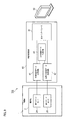
最初に、図1及び図2を参照することで、本実施形態に係る内視鏡1の構成について以下に説明する。図1は、本実施形態に係る内視鏡1を示す分解斜視図である。図2は、撮像部2がスコープ3内に収容された状態での内視鏡1を示す断面図である。
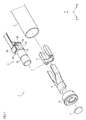
First, the configuration of the endoscope 1 according to the present embodiment will be described below with reference to FIGS. 1 and 2. FIG. 1 is an exploded perspective view showing the endoscope 1 according to the present embodiment. FIG. 2 is a cross-sectional view showing an endoscope 1 in a state where the
図1及び図2に示すように、内視鏡1は、スコープ3と、撮像部2と、ライトガイド4と、第1支持部材5と、第2支持部材6と、レンズカバー7とを備える。医療従事者は、内視鏡1を患者の体内に挿入することで、患者の内蔵等の生体組織をリアルタイムで観察することができる。内視鏡1は、例えば、腹腔鏡手術下で使用される硬性の内視鏡であってもよい。尚、内視鏡1は、硬性の内視鏡に限定されるものではない。
As shown in FIGS. 1 and 2, the endoscope 1 includes a
また、内視鏡1を通じて患者の生体組織の可視光画像データと近赤外画像データの両方を同時に取得することが可能となる。この点において、腹腔鏡手術下においては、ICG(インドシアニングリーン)等の近赤外光を発光する蛍光造影剤が使用されている。ICGに励起光(レーザ光)が照射されることで、ICGは近赤外光を発光する。励起光であるレーザ光の中心波長λは、例えば、700nmから800nmの範囲内、より具体的には、785nmから795nmの範囲内となる。医療従事者は、ICGを患者の静脈に注入した後に、内視鏡1を通じて取得された近赤外光画像データを視認することで、ICGが留まる患部を確実に特定することが可能となる。このように、外科医等の医療従事者は、ICGによって特定された患部に対して外科的処置(患部の切除等)を施すことができる。 In addition, both visible light image data and near-infrared image data of the patient's biological tissue can be acquired at the same time through the endoscope 1. In this respect, under laparoscopic surgery, a fluorescence contrast agent that emits near-infrared light such as ICG (indocyanine green) is used. When the ICG is irradiated with excitation light (laser light), the ICG emits near-infrared light. The central wavelength λ of the laser light, which is the excitation light, is, for example, in the range of 700 nm to 800 nm, and more specifically, in the range of 785 nm to 795 nm. After injecting the ICG into the vein of the patient, the medical staff can visually identify the affected area where the ICG stays by visually recognizing the near-infrared light image data acquired through the endoscope 1. In this way, a medical worker such as a surgeon can perform a surgical procedure (excision of the affected area, etc.) on the affected area specified by the ICG.
スコープ3は、内視鏡1のうち患者の体内に挿入される部分である。スコープ3は、例えば、空間Sを有する硬性のチューブとして構成されている。スコープ3の外径は、例えば、約10mmであると共に、スコープ3の内径は、例えば、約9mmである。撮像部2は、患者の生体組織に関連付けられた可視光及び近赤外光を受光することで生体組織を撮像するように構成されている。具体的には、撮像部2は、患者の生体組織によって反射された可視光及び生体組織に留まる蛍光造影剤(ICG等)から出射された近赤外光を受光することで生体組織を撮像するように構成されている。本実施形態では、撮像部2は、スコープ3の空間S内に収容されている。この点において、撮像部2は、内径が約9mmのスコープ3内に収容可能な程度に小型化されている。また、撮像部2は、スコープ3の先端3a(図2参照)の付近に配置されている。スコープ3の先端3aは、内視鏡1が患者の体内に挿入された状態において患者の生体組織に対向する。撮像部2の具体的構成については後述する。
The
ライトガイド4は、図示しない可視光光源から出射された可視光及び図示しない励起光光源から出射された励起光を患者の生体組織に向けて導くように構成されている。ライトガイド4は、可視光及び励起光が伝搬する多数の光ファイバによって構成されている。図1では、図示簡略化の観点より、ライトガイド4の一部のみが図示されているが、ライトガイド4は、スコープ3の空間S内に収容されていると共に、Z軸方向に沿って可視光光源及び励起光光源まで延出している。ライトガイド4から出射された可視光は、生体組織によって反射された後に、撮像部2によって受光される。また、ライトガイド4から出射された励起光は、生体組織内に留まるICG等の蛍光造影剤に照射される。その後、励起光の照射を通じて蛍光造影剤から出射された近赤外光(蛍光)が撮像部2によって受光される。
The light guide 4 is configured to guide the visible light emitted from a visible light source (not shown) and the excitation light emitted from an excitation light source (not shown) toward the living tissue of the patient. The light guide 4 is composed of a large number of optical fibers through which visible light and excitation light propagate. In FIG. 1, only a part of the light guide 4 is shown from the viewpoint of simplification of illustration, but the light guide 4 is housed in the space S of the
図2に示すように、第1支持部材5は、スコープ3の空間S内に収容されており、撮像部2を支持するように構成されている。特に、第1支持部材5は、接着剤によって撮像部2に固定されている。より具体的には、第1支持部材5は、撮像部2を構成するレンズユニット20と、第1プリズム21と、第2プリズム22とを支持するように構成されていると共に、接着剤によってレンズユニット20と、第1プリズム21と、第2プリズム22とに固定されている。このように、第1支持部材5によって撮像部2の全体の強度を向上させることが可能となる。
As shown in FIG. 2, the
第2支持部材6は、スコープ3の空間S内に収容されており、接着剤によって第1支持部材5及びスコープ3に固定されている。また、第2支持部材6は、ライトガイド4が挿入される挿入孔62と、レンズユニット20が挿入される挿入孔63と、レンズカバー7が挿入される挿入孔64とを有する。ライトガイド4が挿入孔62に挿入された状態で、ライトガイド4は第2支持部材6によって支持される。挿入孔63と挿入孔64は互いに連通している。レンズカバー7が挿入孔64に挿入された状態で、レンズカバー7は第2支持部材6によって固定及び支持される。第2支持部材6の前面65と、レンズカバー7の前面7aと、ライトガイド4の端面4aが、生体組織に対向する内視鏡1の先端面1aを構成する。
The second support member 6 is housed in the space S of the
このように、第1支持部材5は、撮像部2に固定されていると共に、第2支持部材6は、第1支持部材5及びスコープ3に固定されているため、第1支持部材5及び第2支持部材6によって撮像部2をスコープ3に確実に固定することが可能となる。
As described above, since the
(撮像部2の具体的な構成)
次に、図2を参照することで撮像部2の具体的な構成について以下に説明する。図2に示すように、撮像部2は、レンズユニット20と、第1プリズム21と、第2プリズム22と、可視光反射膜27(反射膜の一例)とを備える。撮像部2は、第1トリミングフィルタ23と、赤外光遮断膜28と、第1イメージセンサ24と、第1回路基板32とをさらに備える。撮像部2は、第2トリミングフィルタ25と、可視光遮断膜29と、第2イメージセンサ26と、第2回路基板33とをさらに備える。
(Specific configuration of the imaging unit 2)
Next, a specific configuration of the
レンズユニット20は、生体組織からの可視光及び近赤外光を第1プリズム21に向けて導くように構成されている。撮像部2の画角(視野角)を広げると共に、生体組織からの可視光及び近赤外光をより効率的に取り込むためには、レンズユニット20はスコープ3の先端3aの付近若しくは内視鏡1の先端面1aの付近に配置されていることが好ましい。本実施形態では、Z軸方向におけるレンズユニット20の先端となるレンズユニット20の入射面20aと内視鏡1の先端面1aとの間の距離は、0.5mmから5mmの範囲内となる。好ましくは、Z軸方向における入射面20aと先端面1aとの間の距離は、0.5mmから2mmの範囲内となる。より好ましくは、Z軸方向における入射面20aと先端面1aとの間の距離は、0.5mmから1mmの範囲内となる。
The
また、レンズユニット20と第1プリズム21は、第1支持部材5を介して互いに固定されている。この点において、レンズユニット20の出射面20bと第1プリズム21の入射面21bは、互いに接触しており、レンズユニット20と第1プリズム21との間に空隙が存在しない。このため、当該空隙内に埃等のゴミが進入することが好適に防止され、内視鏡1のメンテナンスに要する負担が軽減されうる。
Further, the
第1プリズム21及び第2プリズム22は、直角プリズムとして構成されている。第1プリズム21及び第2プリズム22は、例えば、透明のガラス材料若しくは透明のプラスチック材料により形成されている。第1プリズム21と第2プリズム22は、互いに対向としており、接着剤によって互いに固定されている。特に、第1プリズム21の斜面21aと第2プリズム22の斜面22aが互いに対向した状態で第1プリズム21と第2プリズム22が互いに固定されている。このように、互いに固定された第1プリズム21と第2プリズム22の2つの形状が直方体形状となるため、撮像部2の全体のサイズを小型化することが可能となり、撮像部2をスコープ3内に収容することができる。
The
可視光反射膜27(反射膜の一例)が第1プリズム21の斜面21aと第2プリズム22の斜面22aとの間に設けられている。本実施形態では、可視光反射膜27が斜面21a又は斜面22aのいずれか一方に形成された後に、接着剤を介して第1プリズム21と第2プリズム22とが互いに固定される。可視光反射膜27は、生体組織からの可視光及び近赤外光を分離するように構成されている。より具体的には、可視光反射膜27は、生体組織から出射されて、レンズユニット20及び第1プリズム21を透過した可視光を第1トリミングフィルタ23に向けて反射させるように構成されている。さらに、可視光反射膜27は、生体組織から出射されて、レンズユニット20及び第1プリズム21を透過した近赤外光を第2トリミングフィルタ25に向けて透過させるように構成されている。
A visible light reflecting film 27 (an example of a reflecting film) is provided between the
第1プリズム21の斜面21a及び第2プリズム22の斜面22aがZ軸方向に対して45度傾いているため、可視光反射膜27もZ軸方向に対して45度傾いている。このため、可視光反射膜27は、可視光の伝搬方向が90度だけ変化するように可視光を反射させる一方で、近赤外光の伝搬方向が変化しないように近赤外光を透過させる。このように、可視光の伝搬方向は、可視光反射膜27によってZ軸方向からY軸方向に変換される一方で、Z軸方向に進行する近赤外光の伝搬方向は可視光反射膜27によって変化しない。
Since the
可視光反射膜27は、高屈折率の誘電体薄膜(高屈折率層)と低屈折率の誘電体薄膜(低屈折率層)を交互に積層することで形成された誘電体多層膜からなるダイクロイックミラーである。高屈折率層の材料は、例えば、TiO2(屈折率nH=2.35)が使用されてもよい。低屈折率層の材料は、例えば、SiO2(屈折率nL=1.47)が使用されてもよい。高屈折率層の層数及び低屈折率層の層数は、例えば、80層である。
The visible
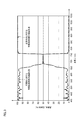
図3は、可視光に対する可視光反射膜27の反射特性及び近赤外光に対する可視光反射膜27の透過特性の一例を示している。図3に示すように、可視光反射膜27は、波長帯400nm〜650nmの可視光に対する反射率が90%以上となるように可視光を反射させる。その一方で、可視光反射膜27は、波長帯800nm〜1050nmの近赤外光を殆ど反射させない。換言すると、可視光反射膜27は、波長帯400nm〜650nmの可視光に対する透過率が10%以下となるように可視光を透過させる。また、可視光反射膜27は、波長帯800nm〜1050nmの近赤外光の殆どを透過させる。
FIG. 3 shows an example of the reflection characteristics of the visible
第1トリミングフィルタ23は、接着剤によって第1プリズム21に固定されている。第1トリミングフィルタ23の入射面23bと第1プリズム21の出射面21cは、接着剤を介して互いに接触している。第1トリミングフィルタ23は、可視域の光(可視光)を透過させる一方で、近赤外域の光(近赤外光)を遮断するように構成されている。可視光反射膜27によって反射されて、第1プリズム21を透過した光が、第1トリミングフィルタ23に入射する。第1トリミングフィルタ23は、第1トリミングフィルタ23に入射した入射光のうち可視光成分を透過させる一方、当該入射光のうち近赤外光成分を遮断する。図4に第1トリミングフィルタ23の透過特性の一例が示されている。図4に示すように、波長帯400nm〜600nmの可視光に対する第1トリミングフィルタ23の透過率が90%以上である一方で、800nm以上の波長の近赤外光に対する第1トリミングフィルタ23の透過率は20%以下となる。第1トリミングフィルタ23は、赤外光を遮断する色ガラスにより形成されている。
The
赤外光遮断膜28は、Y軸方向において第1トリミングフィルタ23と第1イメージセンサ24との間に設けられている。本実施形態では、赤外光遮断膜28が第1トリミングフィルタ23の出射面23a上に形成された後に、接着剤を介して第1トリミングフィルタ23と第1イメージセンサ24とが互いに固定される。赤外光遮断膜28は、可視域の光(可視光)を透過させる一方で、近赤外域の光(近赤外光)及び中心波長が700nm〜800nmの波長帯に含まれる生体組織に照射される励起光を遮断するように構成されている。赤外光遮断膜28は、第1トリミングフィルタ23を透過して赤外光遮断膜28に入射した入射光のうち可視光成分を透過させる一方、当該入射光の近赤外光成分を遮断する。図5に赤外光遮断膜28の透過特性の一例が示されている。図5に示すように、波長帯400nm〜650nmの可視光に対する赤外光遮断膜28の透過率が95%以上である一方で、700nm以上の波長の光に対する透過率が1%以下となる。
The infrared
赤外光遮断膜28は、高屈折率層と低屈折層を交互に積層することで形成された誘電体多層膜からなるダイクロイックミラーである。高屈折率層の材料は、例えば、TiO2(屈折率nH=2.35)が使用されてもよい。低屈折率層の材料は、例えば、SiO2(屈折率nL=1.47)が使用されてもよい。高屈折率層の層数及び低屈折率層の層数は、例えば、50層である。
The infrared
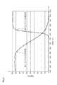
このように、患者の生体組織によって反射された可視光は、可視光反射膜27、第1トリミングフィルタ23及び赤外光遮断膜28との組み合わせからなる可視光チャンネルを通じて第1イメージセンサ24に入射する。図6は、可視光反射膜27、第1トリミングフィルタ23及び赤外光遮断膜28との組み合わせからなる可視光チャンネルの分光透過特性の一例を示している。図6に示すように、波長帯400nm〜600nmの可視光に対する可視光チャンネルの透過率が80%以上となる一方で、波長帯720nm〜1050nmの光の透過率が0.1%以下となる。この点において、可視光チャンネルは、720nm〜1050nmの波長帯における光の透過率が0.01%以下となるような分光特性を有するのが好ましい。
In this way, the visible light reflected by the living tissue of the patient is incident on the
第1イメージセンサ24は、第1回路基板32に搭載されていると共に、Y軸方向において撮像面が第1トリミングフィルタ23及び赤外光遮断膜28に対向するように配置されている。第1イメージセンサ24は、接着剤によって赤外光遮断膜28を介して第1トリミングフィルタ23に固定されている。第1イメージセンサ24は、可視光反射膜27、第1トリミングフィルタ23及び赤外光遮断膜28との組み合わせからなる可視光チャンネルを透過した可視光を受光すると共に、受光した可視光を電気信号に変換するように構成されている。
The
第1イメージセンサ24は、CMOS(Complementary Metal Oxide Semiconductor)イメージセンサ又はCCD(Charge Coupled Device)イメージセンサである。この点において、撮像部2に入射した可視光は、可視光反射膜27によって1回反射された後に第1イメージセンサ24に入射するため、第1イメージセンサ24に入射する生体組織の像は反転像となる。一方で、CMOSイメージセンサは、生体組織の反転像を形成する可視光から生体組織の正転像を示す可視光映像信号を生成することが可能であることから、第1イメージセンサ24は、CMOSイメージセンサであることが好ましい。この点において、CMOSイメージセンサの各フォトダイオードに蓄積された電荷の読み出す順番を調整することで、生体組織の正転像を示す可視光映像信号を生成することが可能となる。
The
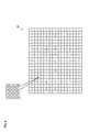
図8に示すように、第1イメージセンサ24は、ベイヤー配列のカラーフィルタアレイと、マトリックス状に配列された複数のフォトダイオードを有するフォトダイオードアレイとを備える。カラーフィルタアレイは、複数の赤色フィルタと、複数の緑色フィルタと、複数の青色フィルタとから構成されている。ベイヤー配列のカラーフィルタアレイでは、緑色フィルタの数は、赤色フィルタの数及び青色フィルタの数の2倍となる。フォトダイオードアレイに含まれる各フォトダイオードは、複数のカラーフィルタ(赤色フィルタ、緑色フィルタ、青色フィルタ)の一つに対向している。このように、第1イメージセンサ24は、受光した可視光を電気信号に変換することで生体組織の像を示す可視光映像信号(RAWデータ)を生成した上で、電気配線35を介して当該生成した可視光映像信号を可視光画像データ生成回路41(図9参照)に送信する。その後、可視光画像データ生成回路41は、可視光映像信号(RAWデータ)に対して画像データ変換処理等(RAWデータ→RGBデータ)を行うことで、可視光画像データを生成する。尚、以降の説明では、カラーフィルタアレイの赤色フィルタ、緑色フィルタ、青色フィルタを単に「RGBカラーフィルタ」と総称する場合がある。
As shown in FIG. 8, the
図7には、可視光チャンネル上のRGBカラーフィルタの透過特性が示されている。生体組織からの可視光は、撮像部2の可視光チャンネルを通過した後に、第1イメージセンサ24のRGBカラーフィルタを通過する。その後、RGBカラーフィルタを通過した可視光はフォトダイオードによって受光される。図7に示すように、可視光チャンネル上の赤色フィルタの透過特性では、720nm以上の波長の光の透過率が0.1%以下となる。可視光チャンネル上の緑色フィルタの透過特性では、720nm以上の波長の光の透過率が0.1%以下となる。可視光チャンネル上の青色フィルタの透過特性では、720nm以上の波長の光の透過率が0.1%以下となる。
FIG. 7 shows the transmission characteristics of the RGB color filter on the visible light channel. Visible light from the living tissue passes through the visible light channel of the
このように、生体組織に照射される中心波長が700nm〜800nmの励起光(より具体的には、中心波長が785nmから795nmの励起レーザ光)及び近赤外光がRGBカラーフィルタを透過することが好適に防止される。この結果、励起光及び近赤外光が第1イメージセンサ24のフォトダイオードによって受光されることが好適に防止されるため、生体組織を示す可視光画像データの精度又は信頼性が向上する。
As described above, the excitation light having a central wavelength of 700 nm to 800 nm (more specifically, the excitation laser light having a central wavelength of 785 nm to 795 nm) and the near infrared light that irradiate the living tissue pass through the RGB color filter. Is preferably prevented. As a result, the excitation light and the near-infrared light are preferably prevented from being received by the photodiode of the
第2トリミングフィルタ25は、接着剤によって第2プリズム22に固定されている。第2トリミングフィルタ25の入射面25bと第2プリズム22の出射面22bは、接着剤を介して互いに接触している。第2トリミングフィルタ25は、近赤外域の光(近赤外光)を透過させる一方で、可視域の光(可視光)を遮断するように構成されている。可視光反射膜27及び第2プリズム22を透過した光が、第2トリミングフィルタ25に入射する。第2トリミングフィルタ25は、第2トリミングフィルタ25に入射した入射光のうち近赤外光成分を透過させる一方、当該入射光のうち可視光成分を遮断する。図4に第2トリミングフィルタ25の透過特性の一例が示されている。図4に示すように、850nm以上の波長の近赤外光に対する第2トリミングフィルタ25の透過率が90%以上である一方で、波長帯400nm〜750nmの可視光に対する第2トリミングフィルタ25の透過率は1%以下となる。第2トリミングフィルタ25は、可視光を遮断する色ガラスにより形成されている。
The
可視光遮断膜29は、Z軸方向において第2トリミングフィルタ25と第2イメージセンサ26との間に設けられている。本実施形態では、可視光遮断膜29が第2トリミングフィルタ25の出射面25a上に形成された後に、接着剤を介して第2トリミングフィルタ25と第2イメージセンサ26とが互いに固定される。可視光遮断膜29は、近赤外域の光(近赤外光)を透過させる一方で、可視域の光(可視光)及び中心波長が700nm〜800nmの波長帯に含まれる生体組織に照射される励起光を遮断するように構成されている。可視光遮断膜29は、第2トリミングフィルタ25を透過して可視光遮断膜29に入射した入射光のうち赤外光成分を透過させる一方、当該入射光の可視光成分を遮断する。図5に可視光遮断膜29の透過特性の一例が示されている。図5に示すように、波長850nm以上の近赤外光に対する可視光遮断膜29の透過率が95%以上である一方で、700nm〜800nmの波長帯の光に対する可視光遮断膜29の透過率が1%以下となる。
The visible
可視光遮断膜29は、高屈折率層と低屈折層を交互に積層することで形成された誘電体多層膜からなるダイクロイックミラーである。高屈折率層の材料は、例えば、TiO2(屈折率nH=2.35)が使用されてもよい。低屈折率層の材料は、例えば、SiO2(屈折率nL=1.47)が使用されてもよい。高屈折率層の層数及び低屈折率層の層数は、例えば、50層である。
The visible
このように、生体組織内に存在する蛍光造影剤から出射された近赤外光は、可視光反射膜27、第2トリミングフィルタ25及び可視光遮断膜29との組み合わせからなる近赤外光チャンネルを通じて第2イメージセンサ26に入射する。図6は、可視光反射膜27、第2トリミングフィルタ25及び可視光遮断膜29との組み合わせからなる近赤外光チャンネルの分光透過特性の一例を示している。図6に示すように、870nm以上の波長の近赤外光に対する近赤外光チャンネルの透過率が90%以上となる一方で、400nm〜798nmの波長帯における光に対する近赤外光チャンネルの透過率が0.5%以下となる。この点において、近赤外光チャンネルは、400nm〜798nmの波長帯における光の透過率が0.01%以下となるような分光特性を有するのが好ましい。
In this way, the near-infrared light emitted from the fluorescence contrast agent existing in the living tissue is a near-infrared light channel composed of a combination of the visible
第2イメージセンサ26は、第2回路基板33に搭載されていると共に、Z軸方向において撮像面が第2トリミングフィルタ25及び可視光遮断膜29に対向するように配置されている。第2イメージセンサ26は、接着剤によって可視光遮断膜29を介して第2トリミングフィルタ25に固定されている。第2イメージセンサ26の撮像面と第1イメージセンサ24の撮像面は、互いに直交している。第2イメージセンサ26は、可視光反射膜27、第2トリミングフィルタ25及び可視光遮断膜29との組み合わせからなる赤外光チャンネルを透過した赤外光を受光すると共に、受光した赤外光を電気信号に変換するように構成されている。
The
第2イメージセンサ26は、受光した赤外光を電気信号に変換することで生体組織の像を示す近赤外光映像信号を生成した上で、電気配線36を介して当該生成した近赤外光映像信号を近赤外光画像データ生成回路42(図9参照)に送信する。その後、近赤外光画像データ生成回路42は、近赤外光映像信号に対して所定の処理を行うことで近赤外光画像データを生成する。
The
第2イメージセンサ26は、CMOSイメージセンサ又はCCDイメージセンサである。この点において、第2イメージセンサ26と第1イメージセンサ24が同一の構成を有することが内視鏡1の製造コストの観点から好ましい。この場合、第1イメージセンサ24と第2イメージセンサ26用に別々の種類のイメージセンサを用意する必要がないため、内視鏡1の製造コストを低減することが可能となる。例えば、第2イメージセンサ26は、第1イメージセンサ24と同様に、ベイヤー配列のカラーフィルタアレイと、マトリックス状に配列された複数のフォトダイオードを有するフォトダイオードアレイとを備えてもよい。以下の説明では、第2イメージセンサ26はベイヤー配列のカラーフィルタアレイを備えるものとする。
The
図7には、近赤外光チャンネル上のRGBカラーフィルタの透過特性が示されている。生体組織に存在する蛍光造影剤から出射された近赤外光は、撮像部2の近赤外光チャンネルを通過した後に、第2イメージセンサ26のRGBカラーフィルタを通過する。その後、RGBカラーフィルタを通過した近赤外光はフォトダイオードによって受光される。図7に示すように、赤外光チャンネル上の青色フィルタの透過特性では、400nm〜798nmの波長帯の光の透過率が0.5%以下となる一方で、波長850nm付近の光の透過率が最も高くなる。同様に、赤外光チャンネル上の緑色フィルタの透過特性では、400nm〜798nmの波長帯の光の透過率が0.5%以下となる一方で、波長850nm付近の光の透過率が最も高くなる。赤外光チャンネル上の赤色フィルタの透過特性では、400nm〜798nmの波長帯の光の透過率が0.5%以下となる一方で、波長850nm付近の光の透過率が最も高くなる。また、図7に示すように、蛍光造影剤から出力される蛍光(近赤外光)のスペクトル特性によれば、近赤外光の中心波長が波長830nm付近に存在する。
FIG. 7 shows the transmission characteristics of the RGB color filter on the near infrared light channel. The near-infrared light emitted from the fluorescence contrast agent present in the living tissue passes through the near-infrared light channel of the
このように、第2イメージセンサ26がベイヤー配列のカラーフィルタアレイを備えている場合であっても、蛍光造影剤から出力される近赤外光を電気信号に変換することができると共に、可視光及び励起光が第2イメージセンサ26のフォトダイオードによって受光されることが好適に防止される。このように、内視鏡1の製造コストを抑えると共に、生体組織を示す赤外光画像データの精度又は信頼性が向上する。
As described above, even when the
また、特許文献1に開示されている単一のイメージセンサでは、青色用画素、緑色用画素、赤色用画素、IR用画素の4種類の画素が存在している。このため、IR用画素の画素値が低くなり、単一のイメージセンサから出力される近赤外光映像信号にノイズが生じやすく、近赤外光画像データの画質が低下してしまうといった問題が存在する。一方で、第2イメージセンサ26では、全ての画素がIR用画素となるため、水平(H)方向及び垂直(V)方向に隣接する画素の画素値を加算する処理であるH/V画素加算処理を通じて、各IR用画素の画素値を大きくすることが可能となる。このように、第2イメージセンサ26では、H/V画素加算処理を通じて各IR用画素の画素値を大きくすることができるため、第2イメージセンサ26から出力される近赤外光映像信号にノイズが生じにくくなり、生体組織を示す赤外光画像データの精度又は信頼性が向上する。
Further, in the single image sensor disclosed in Patent Document 1, there are four types of pixels: a blue pixel, a green pixel, a red pixel, and an IR pixel. For this reason, the pixel value of the IR pixel becomes low, noise is likely to occur in the near-infrared light image signal output from a single image sensor, and the image quality of the near-infrared light image data deteriorates. Exists. On the other hand, in the
次に、図9を参照して内視鏡システム100について以下に説明する。図9は、内視鏡システム100の構成を説明するための図である。図9に示すように、内視鏡システム100は、撮像部2を備えた内視鏡1と、映像処理回路40と、表示部50とを備える。尚、図9では、説明の便宜上、内視鏡1及び映像処理回路40の一部の構成のみが図示されている。映像処理回路40は、可視光画像データ生成回路41と、近赤外光画像データ生成回路42と、合成画像データ生成回路43と、出力インターフェース44とを備える。
Next, the
映像処理回路40は、撮像部2から送信された映像信号(デジタル信号)に基づいて生体組織を示す画像データを生成した上で、当該生成された画像データを表示部50に送信するように構成されている。映像処理回路40は、所定のフレームレート(例えば、60fps)で画像データを生成する。画像データのフレームレートは特に限定されるものではない。本実施形態では、映像処理回路40は、同一タイミング及び同一フレームレートで可視光画像データ及び近赤外光画像データを生成することができる。
The
映像処理回路40は、1以上のプロセッサと1以上のメモリを含むマイクロコンピュータと、トランジスタ等のアクティブ素子及びパッシブ素子から構成される電子回路とを有してもよい。プロセッサは、例えば、CPU(Central Processing Unit)、MPU(Micro Processing Unit)、GPU(Graphics Processing Unit)のうちの少なくとも一つを含む。メモリは、ROM(Read Only Memory)と、RAM(Random Access Memory)とを含む。映像処理回路40は、マイクロコンピュータに加えて又は代えて、ASIC(Application Specific Integrated Circuit)やFPGA(Field−Programmable Gate Array)等の非ノイマン型コンピュータシステムを有してもよい。
The
可視光画像データ生成回路41は、上記したように、第1イメージセンサ24から可視光映像信号(RAWデータ)を受信した上で、当該可視光映像信号に基づいて可視光画像データを生成するように構成されている。可視光画像データ生成回路41は、可視光画像データを合成画像データ生成回路43及び出力インターフェース44に送信する。
As described above, the visible light image
近赤外光画像データ生成回路42は、第2イメージセンサ26から近赤外光映像信号を受信した上で、当該近赤外光映像信号に基づいて近赤外光画像データを生成するように構成されている。近赤外光画像データ生成回路42は、近赤外光画像データを合成画像データ生成回路43及び出力インターフェース44に送信する。
The near-infrared light image
合成画像データ生成回路43は、受信した可視光画像データ及び近赤外光画像データを合成することで合成画像データを生成するように構成されている。合成画像データ生成回路43は、近赤外光画像データを所定の色(蛍光色)で着色した上で合成画像データを生成してもよい。近赤外光画像データはICG等の蛍光造影剤が存在する生体組織を示しているため、近赤外光画像データが所定の色で着色されることで、蛍光造影剤が存在する生体組織(患部)が合成画像データ上において強調して表示される(例えば、図10参照)。このため、外科医等の医療従事者は、表示部50上に表示された合成画像データを視認することで、患部を明確に把握することができる。
The composite image
可視光画像データ、近赤外光画像データ及び合成画像データは、出力インターフェース44を通じて表示部50に送信される。表示部50は、可視光画像データ、近赤外光画像データ及び合成画像データのうちの少なくとも一方を表示するように構成されている。また、表示部50に送信される画像データは、内視鏡システム100に対する医療従事者の操作に応じて、適宜変更されてもよい。表示部50は、液晶ディスプレイ又は有機ELディスプレイであってもよいし、医療従事者の頭部に装着された透過型又は非透過型のヘッドマウントディスプレイであってもよい。
The visible light image data, the near infrared light image data, and the composite image data are transmitted to the
本実施形態によれば、直角プリズムである第1プリズム21と第2プリズム22が互いに固定されている。また、第1トリミングフィルタ23が第1プリズム21及び第1イメージセンサ24に固定されると共に、第2トリミングフィルタ25が第2プリズム22及び第2イメージセンサ26に固定されている。さらに、第1イメージセンサ24の撮像面と第2イメージセンサ26の撮像面が互いに直交している。このような構成により、撮像部2の全体のサイズを小型化することができ、撮像部2を内径が小さいスコープ3の空間S内に収容することが可能となる。また、撮像部2が内視鏡1の先端面1a付近の空間S内に収容されているため、患者の生体組織に関連付けられた可視光及び近赤外光は、第1イメージセンサ24及び第2イメージセンサ26のそれぞれによって効率的に受光される。このように、SN比(信号対雑音比)を低下させずに第1イメージセンサ24によって生体組織を示す可視光映像信号が取得されるため、生体組織を示す可視光画像データの画質が向上する。さらに、SN比を低下させずに第2イメージセンサ26によって生体組織を示す近赤外光映像信号が取得されるため、生体組織を示す近赤外光画像データの画質が向上する。また、可視光映像信号と近赤外光映像信号が同タイミングで取得されるため、可視光画像データの各フレームの時間軸と近赤外光画像データの各フレームの時間軸が互いに一致する。このように、可視光画像データのフレームの時間軸と近赤外光画像データのフレームの時間軸が一致することから、可視光画像データと近赤外光画像データとの合成によって生成される合成画像データの精度が向上する。さらに、撮像部2がスコープ3の空間S内に収容されているため、患者の生体組織からの可視光及び近赤外光を撮像部2に導くための高価なリレーレンズ等をスコープ3に設ける必要がないため、内視鏡1の全体の製造コストを低減することが可能となる。従って、製造コストを抑えた上で、患者の生体組織を示す可視光画像データ、近赤外光画像データ及び合成画像データの画質を向上させることが可能な内視鏡1を提供することができる。
According to this embodiment, the
また、本実施形態によれば、第1イメージセンサ24が生体組織の正転像を示す可視光映像信号を生成するように構成されたCMOSイメージセンサである場合に、可視光画像データと近赤外光画像データを同タイミングで取得することができる。具体的には、第1イメージセンサ24がCCDイメージセンサである場合には、生体組織の反転像を示す可視光映像信号から生体組織の正転像を示す可視光画像データを生成するための画像反転処理を映像処理回路40側で別途実行する必要がある。このため、可視光画像データの生成タイミングが近赤外光画像データの生成タイミングよりも遅れてしまう状況が発生し、映像処理回路40側において可視光画像データと近赤外光画像データを同タイミングで取得することが困難となる。一方で、第1イメージセンサ24がCMOSイメージセンサである場合には、映像処理回路40側において当該画像反転処理を実行する必要がないため、映像処理回路側において可視光画像データと近赤外光画像データを同タイミングで取得することが可能となる。
Further, according to the present embodiment, when the
また、本実施形態によれば、可視光反射膜27と、第1トリミングフィルタ23と、赤外光遮断膜28との組み合わせからなる可視光チャンネルは、720nmから1050nmの波長帯における光の透過率が0.1%以下となるような分光特性を有する。このため、生体組織に照射される700nmから800nmの波長帯の励起光及び近赤外光が可視光画像データの精度又は信頼性に悪影響を与える状況を好適に防止可能となる。また、可視光反射膜27と、第2トリミングフィルタ25と、可視光遮断膜29との組み合わせからなる近赤外光チャンネルは、400nmから798nmの波長帯における光の透過率が0.5%以下となるような分光特性を有する。このため、生体組織に照射される励起光及び可視光が近赤外光画像データの精度又は信頼性に悪影響を与える状況を好適に防止可能となる。さらに、第2イメージセンサ26では、H/V画素加算処理を通じて各IR用画素の画素値を大きくすることができるため、第2イメージセンサ26から出力される近赤外光映像信号にノイズが生じにくくなり、赤外光画像データの精度又は信頼性が向上する。
Further, according to the present embodiment, the visible light channel composed of the combination of the visible
以上、本発明の実施形態について説明をしたが、本発明の技術的範囲が本実施形態の説明によって限定的に解釈されるべきではないのは言うまでもない。本実施形態は単なる一例であって、特許請求の範囲に記載された発明の範囲内において、様々な実施形態の変更が可能であることが当業者によって理解されるところである。本発明の技術的範囲は特許請求の範囲に記載された発明の範囲及びその均等の範囲に基づいて定められるべきである。 Although the embodiments of the present invention have been described above, it goes without saying that the technical scope of the present invention should not be construed as being limited by the description of the present embodiments. It is understood by those skilled in the art that the present embodiment is merely an example, and various embodiments can be modified within the scope of the invention described in the claims. The technical scope of the present invention should be determined based on the scope of the invention described in the claims and the equivalent scope thereof.
本実施形態では、生体組織からの可視光及び近赤外光を分離する反射膜の一例として可視光反射膜27が挙げられているが、反射膜は可視光反射膜に限定されるものではない。例えば、可視光及び近赤外光を分離する反射膜は、可視光を透過させると共に、近赤外光を反射させるように構成された近赤外光反射膜であってもよい。この場合、第1プリズム21の位置と第2プリズム22の位置が互いに入れ替わると共に、赤外光遮断膜28が形成された第1トリミングフィルタ23の位置と可視光遮断膜29が形成された第2トリミングフィルタ25の位置が互いに入れ替わる。さらに、第1イメージセンサ24の位置と第2イメージセンサ26の位置が互いに入れ替わる。近赤外光反射膜の場合も同様に、高屈折率の誘電体薄膜(高屈折率層)と低屈折率の誘電体薄膜(低屈折率層)を交互に積層することで形成された誘電体多層膜からなるダイクロイックミラーとなる。
In the present embodiment, the visible light
また、本実施形態では、第1プリズム21と第2プリズム22は、直角プリズムとして構成されているが、第1プリズム21と第2プリズム22の形状は、直角三角柱に限定されるものではない。
Further, in the present embodiment, the
また、第1イメージセンサ24と第2イメージセンサ26は、互いに異なる構成を有してもよい。例えば、第2イメージセンサ26は、カラーフィルタアレイを備えていなくてもよい。この場合、第2イメージセンサ26の手前に配置された近赤外光チャンネルが、可視光及び励起光を遮断する一方で近赤外光を透過させるため、第2イメージセンサ26のフォトダイオードに近赤外光のみを入射させることが可能となる。
Further, the
1:内視鏡
2:撮像部
3:スコープ
4:ライトガイド
5:第1支持部材
6:第2支持部材
7:レンズカバー
20:レンズユニット
21:第1プリズム
22:第2プリズム
23:第1トリミングフィルタ
24:第1イメージセンサ
25:第2トリミングフィルタ
26:第2イメージセンサ
27:可視光反射膜
28:赤外光遮断膜
29:可視光遮断膜
32:第1回路基板
33:第2回路基板
40:映像処理回路
41:可視光画像データ生成回路
42:近赤外光画像データ生成回路
43:合成画像データ生成回路
44:出力インターフェース
50:表示部
100:内視鏡システム
1: Endoscope 2: Imaging unit 3: Scope 4: Light guide 5: First support member 6: Second support member 7: Lens cover 20: Lens unit 21: First prism 22: Second prism 23: First Trimming filter 24: First image sensor 25: Second trimming filter 26: Second image sensor 27: Visible light reflecting film 28: Infrared light blocking film 29: Visible light blocking film 32: First circuit board 33: Second circuit Substrate 40: Video processing circuit 41: Visible light image data generation circuit 42: Near infrared light image data generation circuit 43: Composite image data generation circuit 44: Output interface 50: Display unit 100: Endoscope system
Claims (12)
患者の体内に挿入される前記内視鏡の部分に相当するスコープと、
前記スコープ内に収容され、前記患者の生体組織に関連付けられた可視光及び近赤外光を受光することで前記生体組織を撮像するように構成された撮像部と、を備え、
前記撮像部は、
第1プリズムと、
前記第1プリズムに対向する第2プリズムと、
前記第1プリズムの斜面と前記第2プリズムの斜面との間に設けられ、前記生体組織に関連付けられた可視光及び近赤外光を分離するように構成された反射膜と、
可視域の光を透過させる一方で近赤外域の光を遮断するように構成され、前記反射膜を介して前記第1プリズムを透過した前記可視光が入射する第1トリミングフィルタと、
前記第1トリミングフィルタを透過した前記可視光を受光するように前記第1トリミングフィルタに対向すると共に、前記受光した可視光を電気信号に変換するように構成された第1イメージセンサと、
近赤外域の光を透過させる一方で可視域の光を遮断するように構成され、前記反射膜を介して前記第2プリズムを透過した前記近赤外光が入射する第2トリミングフィルタと、
前記第2トリミングフィルタを透過した前記近赤外光を受光するように前記第2トリミングフィルタに対向すると共に、前記受光した近赤外光を電気信号に変換するように構成された第2イメージセンサと、を備え、
前記第1プリズムは、前記第2プリズムに接着され、
前記第1トリミングフィルタは、前記第1プリズムに接着され、
前記第2トリミングフィルタは、前記第2プリズムに接着され、
前記第1イメージセンサは、前記第1トリミングフィルタに接着され、
前記第2イメージセンサは、前記第2トリミングフィルタに接着されている、
内視鏡。 It ’s an endoscope,
A scope corresponding to the part of the endoscope inserted into the patient's body,
An imaging unit that is housed in the scope and is configured to image the living tissue by receiving visible light and near-infrared light associated with the living tissue of the patient .
The imaging unit
With the first prism
The second prism facing the first prism and
An antireflection film provided between the slope of the first prism and the slope of the second prism and configured to separate visible light and near-infrared light associated with the living tissue.
A first trimming filter configured to transmit light in the visible region while blocking light in the near infrared region, and to receive the visible light transmitted through the first prism through the reflective film, and a first trimming filter.
A first image sensor configured to face the first trimming filter so as to receive the visible light transmitted through the first trimming filter and to convert the received visible light into an electric signal.
A second trimming filter configured to transmit light in the near-infrared region while blocking light in the visible region, and to receive the near-infrared light that has passed through the second prism through the reflective film, and a second trimming filter.
A second image sensor configured to face the second trimming filter so as to receive the near-infrared light transmitted through the second trimming filter and to convert the received near-infrared light into an electric signal. And with
The first prism is adhered to the second prism,
The first trimming filter is adhered to the first prism and is bonded to the first prism.
The second trimming filter is adhered to the second prism and is bonded to the second prism.
The first image sensor is adhered to the first trimming filter.
The second image sensor is adhered to the second trimming filter.
Endoscope.
前記第1トリミングフィルタと前記第1イメージセンサとの間に設けられ、可視域の光を透過させる一方で近赤外域の光を遮断するように構成された赤外光遮断膜と、
前記第2トリミングフィルタと前記第2イメージセンサとの間に設けられ、近赤外域の光を透過させる一方で可視域の光を遮断するように構成された可視光遮断膜と、をさらに備え、
前記赤外光遮断膜と前記可視光遮断膜は、前記生体組織に照射され、中心波長が700nmから800nmの波長帯に含まれる励起光を遮断するように構成されている、請求項1又は2に記載の内視鏡。 The imaging unit
An infrared light blocking film provided between the first trimming filter and the first image sensor and configured to transmit light in the visible region while blocking light in the near infrared region.
A visible light blocking film provided between the second trimming filter and the second image sensor and configured to transmit light in the near infrared region while blocking light in the visible region is further provided.
The visible light blocking layer and the infrared light blocking layer, the irradiated on the living body tissue, the central wavelength is configured to block the excitation light included in the wavelength band of 800nm from 700 nm, according to claim 1 or 2 The endoscope described in.
前記生体組織に関連付けられた前記可視光及び前記近赤外光を前記第1プリズムに向けて導くように前記第1プリズムに固定されたレンズユニットをさらに備える、請求項1から3のうちいずれか一項に記載の内視鏡。 The imaging unit
Any of claims 1 to 3 , further comprising a lens unit fixed to the first prism so as to guide the visible light and the near infrared light associated with the living tissue toward the first prism. The endoscope described in paragraph 1.
前記レンズユニットと、前記第1プリズムと、前記第2プリズムとを支持するように構成されると共に、前記スコープ内に収容される第1支持部材をさらに備え、
前記第1支持部材は、前記レンズユニットと、前記第1プリズムと、前記第2プリズムとに固定されている、請求項4又は5に記載の内視鏡。 The endoscope is
It is configured to support the lens unit, the first prism, and the second prism, and further includes a first support member housed in the scope.
The endoscope according to claim 4 or 5 , wherein the first support member is fixed to the lens unit, the first prism, and the second prism.
前記第1支持部材及び前記スコープに固定されると共に、前記スコープ内に収容される第2支持部材をさらに備える、請求項6に記載の内視鏡。 The endoscope is
The endoscope according to claim 6 , further comprising a first support member and a second support member fixed to the scope and housed in the scope.
前記生体組織の反転像を形成する前記可視光から前記生体組織の正転像を示す可視光映像信号を生成するように構成されたCMOSイメージセンサである、請求項1から7のうちいずれか一項に記載の内視鏡。 The first image sensor is
Any one of claims 1 to 7 , which is a CMOS image sensor configured to generate a visible light image signal indicating a normal rotation image of the living tissue from the visible light forming an inverted image of the living tissue. The endoscope described in the section.
請求項1から8のうちいずれか一項に記載の内視鏡。 The first image sensor and the second image sensor have the same configuration.
The endoscope according to any one of claims 1 to 8.
前記反射膜と、前記第2トリミングフィルタと、前記可視光遮断膜との組み合わせからなる近赤外光チャンネルは、400nmから798nmの波長帯における光の透過率が0.5%以下となるような分光特性を有する、請求項3に記載の内視鏡。 The visible light channel composed of the combination of the reflective film, the first trimming filter, and the infrared light blocking film has a spectrum such that the light transmittance in the wavelength band from 720 nm to 1050 nm is 0.1% or less. Has characteristics,
The near-infrared light channel composed of the combination of the reflective film, the second trimming filter, and the visible light blocking film has a light transmittance of 0.5% or less in the wavelength band of 400 nm to 798 nm. The endoscope according to claim 3 , which has spectral characteristics.
第1プリズムと、
前記第1プリズムに対向する第2プリズムと、
前記第1プリズムの斜面と前記第2プリズムの斜面との間に設けられ、前記生体組織に関連付けられた可視光及び近赤外光を分離するように構成された反射膜と、
可視域の光を透過させる一方で近赤外域の光を遮断するように構成され、前記反射膜を介して前記第1プリズムを透過した前記可視光が入射する第1トリミングフィルタと、
前記第1トリミングフィルタを透過した前記可視光を受光するように前記第1トリミングフィルタに対向すると共に、前記受光した可視光を電気信号に変換するように構成された第1イメージセンサと、
近赤外域の光を透過させる一方で可視域の光を遮断するように構成され、前記反射膜を介して前記第2プリズムを透過した前記近赤外光が入射する第2トリミングフィルタと、
前記第2トリミングフィルタを透過した前記近赤外光を受光するように前記第2トリミングフィルタに対向すると共に、前記受光した近赤外光を電気信号に変換するように構成された第2イメージセンサと、を備え、
前記第1プリズムは、前記第2プリズムに接着され、
前記第1トリミングフィルタは、前記第1プリズムに接着され、
前記第2トリミングフィルタは、前記第2プリズムに接着され、
前記第1イメージセンサは、前記第1トリミングフィルタに接着され、
前記第2イメージセンサは、前記第2トリミングフィルタに接着されている、
撮像部。 It housed within the scope corresponding to the portion of the endoscope which is inserted into a patient to image the body tissue by receiving the visible light and near-infrared light that is associated with the patient's anatomy It is a configured imaging unit
With the first prism
The second prism facing the first prism and
An antireflection film provided between the slope of the first prism and the slope of the second prism and configured to separate visible light and near-infrared light associated with the living tissue.
A first trimming filter configured to transmit light in the visible region while blocking light in the near infrared region, and to receive the visible light transmitted through the first prism through the reflective film, and a first trimming filter.
A first image sensor configured to face the first trimming filter so as to receive the visible light transmitted through the first trimming filter and to convert the received visible light into an electric signal.
A second trimming filter configured to transmit light in the near-infrared region while blocking light in the visible region, and to receive the near-infrared light that has passed through the second prism through the reflective film, and a second trimming filter.
A second image sensor configured to face the second trimming filter so as to receive the near-infrared light transmitted through the second trimming filter and to convert the received near-infrared light into an electric signal. And with
The first prism is adhered to the second prism,
The first trimming filter is adhered to the first prism and is bonded to the first prism.
The second trimming filter is adhered to the second prism and is bonded to the second prism.
The first image sensor is adhered to the first trimming filter.
The second image sensor is adhered to the second trimming filter.
Imaging unit.
Priority Applications (4)
| Application Number | Priority Date | Filing Date | Title |
|---|---|---|---|
| JP2020168514A JP6877705B1 (en) | 2020-10-05 | 2020-10-05 | Endoscope and imaging unit provided in the endoscope |
| JP2021068485A JP2022060992A (en) | 2020-10-05 | 2021-04-14 | Endoscope and imaging section provided in the endoscope |
| CN202111164001.6A CN113854932A (en) | 2020-10-05 | 2021-09-30 | Endoscope and image capturing unit provided therein |
| US17/493,014 US11369254B2 (en) | 2020-10-05 | 2021-10-04 | Endoscope and image capturing unit provided therein |
Applications Claiming Priority (1)
| Application Number | Priority Date | Filing Date | Title |
|---|---|---|---|
| JP2020168514A JP6877705B1 (en) | 2020-10-05 | 2020-10-05 | Endoscope and imaging unit provided in the endoscope |
Related Child Applications (1)
| Application Number | Title | Priority Date | Filing Date |
|---|---|---|---|
| JP2021068485A Division JP2022060992A (en) | 2020-10-05 | 2021-04-14 | Endoscope and imaging section provided in the endoscope |
Publications (2)
| Publication Number | Publication Date |
|---|---|
| JP6877705B1 true JP6877705B1 (en) | 2021-05-26 |
| JP2022060811A JP2022060811A (en) | 2022-04-15 |
Family
ID=75961530
Family Applications (2)
| Application Number | Title | Priority Date | Filing Date |
|---|---|---|---|
| JP2020168514A Active JP6877705B1 (en) | 2020-10-05 | 2020-10-05 | Endoscope and imaging unit provided in the endoscope |
| JP2021068485A Pending JP2022060992A (en) | 2020-10-05 | 2021-04-14 | Endoscope and imaging section provided in the endoscope |
Family Applications After (1)
| Application Number | Title | Priority Date | Filing Date |
|---|---|---|---|
| JP2021068485A Pending JP2022060992A (en) | 2020-10-05 | 2021-04-14 | Endoscope and imaging section provided in the endoscope |
Country Status (3)
| Country | Link |
|---|---|
| US (1) | US11369254B2 (en) |
| JP (2) | JP6877705B1 (en) |
| CN (1) | CN113854932A (en) |
Families Citing this family (1)
| Publication number | Priority date | Publication date | Assignee | Title |
|---|---|---|---|---|
| EP4057614A1 (en) * | 2021-03-12 | 2022-09-14 | Infineon Technologies AG | Method and imaging system for generating a gray-scale image |
Citations (8)
| Publication number | Priority date | Publication date | Assignee | Title |
|---|---|---|---|---|
| JP2010082041A (en) * | 2008-09-30 | 2010-04-15 | Fujifilm Corp | Electronic endoscope system |
| JP2011101763A (en) * | 2009-11-12 | 2011-05-26 | Fujifilm Corp | Image display device |
| JP2011211553A (en) * | 2010-03-30 | 2011-10-20 | Fujifilm Corp | Cmos imaging element, and endoscope device including the same |
| JP2012023492A (en) * | 2010-07-13 | 2012-02-02 | Sony Corp | Imaging apparatus, imaging system, surgical navigation system, and imaging method |
| JP2017221486A (en) * | 2016-06-16 | 2017-12-21 | ソニー株式会社 | Information processing device, information processing method, program, and medical observation system |
| JP2018027272A (en) * | 2016-08-19 | 2018-02-22 | ソニー株式会社 | Imaging System |
| JP2018175762A (en) * | 2017-04-21 | 2018-11-15 | 池上通信機株式会社 | Imaging device |
| JP2019136269A (en) * | 2018-02-09 | 2019-08-22 | 株式会社島津製作所 | Fluorescent imaging device |
Family Cites Families (17)
| Publication number | Priority date | Publication date | Assignee | Title |
|---|---|---|---|---|
| JP2001518241A (en) * | 1995-06-07 | 2001-10-09 | ストリカー・コーポレーション | An imaging system that processes visible light energy and infrared light energy separately |
| JP4531234B2 (en) | 2000-09-28 | 2010-08-25 | Hoya株式会社 | Electronic endoscope system |
| US20060241496A1 (en) | 2002-01-15 | 2006-10-26 | Xillix Technologies Corp. | Filter for use with imaging endoscopes |
| US6899675B2 (en) | 2002-01-15 | 2005-05-31 | Xillix Technologies Corp. | Fluorescence endoscopy video systems with no moving parts in the camera |
| US20050154319A1 (en) | 2002-01-15 | 2005-07-14 | Xillix Technologies Corporation | Fluorescence endoscopy video systems with no moving parts in the camera |
| JP2005176940A (en) | 2003-12-16 | 2005-07-07 | Olympus Corp | Electronic endoscope |
| JP4841391B2 (en) * | 2006-10-17 | 2011-12-21 | オリンパスメディカルシステムズ株式会社 | Endoscope |
| US20090236541A1 (en) * | 2008-03-24 | 2009-09-24 | General Electric Company | System and Methods for Optical Imaging |
| JP4987790B2 (en) * | 2008-04-15 | 2012-07-25 | オリンパスメディカルシステムズ株式会社 | Imaging device |
| US8295693B2 (en) | 2010-07-02 | 2012-10-23 | Intuitive Surgical Operations, Inc. | Dual optical path prism and camera in a minimally invasive surgical system |
| JP6019167B1 (en) | 2015-04-30 | 2016-11-02 | パナソニック株式会社 | Endoscope system and light source control method |
| JP7028574B2 (en) | 2017-06-14 | 2022-03-02 | パナソニックi-PROセンシングソリューションズ株式会社 | Endoscope and camera head |
| JP6407386B1 (en) | 2017-09-29 | 2018-10-17 | パナソニック株式会社 | Endoscope and endoscope system |
| US11382487B2 (en) * | 2018-04-03 | 2022-07-12 | Curadel, LLC | Micro CMOS scopes for medical imaging |
| US10694117B2 (en) * | 2018-06-07 | 2020-06-23 | Curadel, LLC | Masking approach for imaging multi-peak fluorophores by an imaging system |
| EP3829410A4 (en) * | 2018-08-01 | 2022-04-13 | 270 Surgical Ltd. | Distal tip of a multi camera medical imaging device |
| US10902572B1 (en) * | 2019-10-09 | 2021-01-26 | Karl Storz Imaging, Inc. | Enhanced fluorescence imaging for imaging system |
-
2020
- 2020-10-05 JP JP2020168514A patent/JP6877705B1/en active Active
-
2021
- 2021-04-14 JP JP2021068485A patent/JP2022060992A/en active Pending
- 2021-09-30 CN CN202111164001.6A patent/CN113854932A/en active Pending
- 2021-10-04 US US17/493,014 patent/US11369254B2/en active Active
Patent Citations (8)
| Publication number | Priority date | Publication date | Assignee | Title |
|---|---|---|---|---|
| JP2010082041A (en) * | 2008-09-30 | 2010-04-15 | Fujifilm Corp | Electronic endoscope system |
| JP2011101763A (en) * | 2009-11-12 | 2011-05-26 | Fujifilm Corp | Image display device |
| JP2011211553A (en) * | 2010-03-30 | 2011-10-20 | Fujifilm Corp | Cmos imaging element, and endoscope device including the same |
| JP2012023492A (en) * | 2010-07-13 | 2012-02-02 | Sony Corp | Imaging apparatus, imaging system, surgical navigation system, and imaging method |
| JP2017221486A (en) * | 2016-06-16 | 2017-12-21 | ソニー株式会社 | Information processing device, information processing method, program, and medical observation system |
| JP2018027272A (en) * | 2016-08-19 | 2018-02-22 | ソニー株式会社 | Imaging System |
| JP2018175762A (en) * | 2017-04-21 | 2018-11-15 | 池上通信機株式会社 | Imaging device |
| JP2019136269A (en) * | 2018-02-09 | 2019-08-22 | 株式会社島津製作所 | Fluorescent imaging device |
Also Published As
| Publication number | Publication date |
|---|---|
| US11369254B2 (en) | 2022-06-28 |
| US20220104691A1 (en) | 2022-04-07 |
| JP2022060992A (en) | 2022-04-15 |
| CN113854932A (en) | 2021-12-31 |
| JP2022060811A (en) | 2022-04-15 |
Similar Documents
| Publication | Publication Date | Title |
|---|---|---|
| JP7314976B2 (en) | Imaging device and imaging method | |
| US10335019B2 (en) | Image pickup element and endoscope device | |
| JP2018195908A (en) | Image element, image element manufacturing method, electronic apparatus, and imaging module | |
| US20210330177A1 (en) | Endoscope | |
| JP5795490B2 (en) | Light source device | |
| JP2012245285A (en) | Light source device | |
| EP3586716B1 (en) | Endoscope device | |
| WO2018216386A1 (en) | Color separation optical system, imaging unit, and imaging device | |
| US6749562B2 (en) | Video endoscope and system incorporating the same | |
| JP4855755B2 (en) | Biodiagnosis device | |
| JP6877705B1 (en) | Endoscope and imaging unit provided in the endoscope | |
| CN109864691A (en) | A kind of double tracer fluorescence endoscopes | |
| JP5627910B2 (en) | Electronic endoscope system and color image sensor | |
| CN109310311B (en) | Light source device for endoscope, and endoscope system | |
| JP2000131521A (en) | Interference film and image pickup device using the same | |
| US20230301499A1 (en) | Method of visible light and fluorescence imaging with reduced chromatic aberration | |
| JP6407386B1 (en) | Endoscope and endoscope system | |
| JP7028574B2 (en) | Endoscope and camera head | |
| WO2024057990A1 (en) | Imaging device and medical observation system | |
| US20110213204A1 (en) | Endoscope system and imaging device thereof | |
| WO2024058019A1 (en) | Imaging device and medical observation system | |
| JP7041226B2 (en) | Medical optical microscope | |
| JP7477158B2 (en) | 3-chip camera | |
| WO2017042980A1 (en) | Fluoroscopic apparatus and fluoroscopic endoscope apparatus | |
| WO2014041844A1 (en) | Electronic endoscope device and imaging module |
Legal Events
| Date | Code | Title | Description |
|---|---|---|---|
| A621 | Written request for application examination |
Free format text: JAPANESE INTERMEDIATE CODE: A621 Effective date: 20201023 |
|
| A871 | Explanation of circumstances concerning accelerated examination |
Free format text: JAPANESE INTERMEDIATE CODE: A871 Effective date: 20201023 |
|
| A521 | Request for written amendment filed |
Free format text: JAPANESE INTERMEDIATE CODE: A523 Effective date: 20201106 |
|
| A975 | Report on accelerated examination |
Free format text: JAPANESE INTERMEDIATE CODE: A971005 Effective date: 20201203 |
|
| A131 | Notification of reasons for refusal |
Free format text: JAPANESE INTERMEDIATE CODE: A131 Effective date: 20201208 |
|
| A521 | Request for written amendment filed |
Free format text: JAPANESE INTERMEDIATE CODE: A523 Effective date: 20210129 |
|
| TRDD | Decision of grant or rejection written | ||
| A01 | Written decision to grant a patent or to grant a registration (utility model) |
Free format text: JAPANESE INTERMEDIATE CODE: A01 Effective date: 20210323 |
|
| A61 | First payment of annual fees (during grant procedure) |
Free format text: JAPANESE INTERMEDIATE CODE: A61 Effective date: 20210414 |
|
| R150 | Certificate of patent or registration of utility model |
Ref document number: 6877705 Country of ref document: JP Free format text: JAPANESE INTERMEDIATE CODE: R150 |
|
| S111 | Request for change of ownership or part of ownership |
Free format text: JAPANESE INTERMEDIATE CODE: R313117 |
|
| R350 | Written notification of registration of transfer |
Free format text: JAPANESE INTERMEDIATE CODE: R350 |