JP6876279B2 - Mowing work method - Google Patents
Mowing work method Download PDFInfo
- Publication number
- JP6876279B2 JP6876279B2 JP2019137860A JP2019137860A JP6876279B2 JP 6876279 B2 JP6876279 B2 JP 6876279B2 JP 2019137860 A JP2019137860 A JP 2019137860A JP 2019137860 A JP2019137860 A JP 2019137860A JP 6876279 B2 JP6876279 B2 JP 6876279B2
- Authority
- JP
- Japan
- Prior art keywords
- combine
- cutting
- field
- traveling device
- outside
- Prior art date
- Legal status (The legal status is an assumption and is not a legal conclusion. Google has not performed a legal analysis and makes no representation as to the accuracy of the status listed.)
- Active
Links
Images


Landscapes
- Guiding Agricultural Machines (AREA)
- Combines (AREA)
Description
本発明は、複数台のコンバインを使用した穀稈の刈取作業方法に関するものである。 The present invention relates to a method for cutting a grain culm using a plurality of combines.
従来の穀稈の刈取作業方法では、穀稈の刈取作業方法では、圃場内に搬入された複数台のコンバインが、それぞれ測位衛星の信号に基づいて設定された刈取経路を走行しながら穀稈の刈取作業を行う方法が知られている。(特許文献1参照) In the conventional culm reaping work method, in the culm reaping work method, a plurality of combines brought into the field travel along a reaping route set based on a positioning satellite signal. There is a known method of performing harvesting work. (See Patent Document 1)
しかし、従来の穀稈の刈取作業方法では、穀稈の倒伏状態や圃場の湿田状態を考慮することなくコンバインを選択し、その刈取経路を設定しているので刈取作業時間が長くなる恐れがあった。また、コンバインの通信手段に異常が発生したり、測位衛星からの通信が遮断された場合には、同一圃場内で刈取作業を行っている相互のコンバインが接触する恐れがあった。 However, in the conventional harvesting work method of the grain culm, the combine is selected without considering the lodging state of the grain culm and the wet field condition of the field, and the cutting route is set, so that the cutting work time may become long. It was. In addition, if an abnormality occurs in the combine's communication means or the communication from the positioning satellite is cut off, there is a risk that the combines that are harvesting in the same field will come into contact with each other.
そこで、本発明は、穀稈の倒伏状態や圃場の湿田状態に基づいて好適なコンバインと刈取経路を設定して刈取作業効率が高い刈取作業方法を提供することにある。 Therefore, the present invention is to provide a cutting work method with high cutting work efficiency by setting a suitable combine and a cutting route based on the lodging state of the grain culm and the wet field state of the field.
上記課題を解決した本発明は次のとおりである。
すなわち、請求項1記載の発明は、複数のコンバインを使用して圃場内に植立した穀稈を刈り取る刈取作業方法であって、
大型の第1コンバイン(1A)で圃場における倒伏した穀稈又は湿田が少ない第1圃場部(60A)の刈取作業を行ない、前記第1コンバイン(1A)よりも小型の第2コンバイン(1B)で前記圃場における倒伏した穀稈又は湿田が多い第2圃場部(60B)の刈取作業を行い、前記第1コンバイン(1A)を、前記穀稈と湿田位置に基づいて設定された第1刈取経路(62A)に沿って走行させて穀稈の刈取作業を行わせた後に、前記第1圃場部(60A)の外部に移動させ、前記第2コンバイン(1B)を、前記第1コンバイン(1A)が第1圃場部(60A)の外部に移動した後に、前記第2圃場部(60B)の内部に移動させて、前記穀稈と湿田位置に基づいて設定された第2刈取経路(62B)に沿って未刈穀稈の刈取作業を行わせることを特徴とする刈取作業方法である。
The present invention that solves the above problems is as follows.
That is, the invention according to claim 1 is a cutting work method for cutting a grain culm planted in a field using a plurality of combines.
The large first combine (1A) is used to mow the first field (60A) where there are few fallen culms or wetlands in the field, and the second combine (1B), which is smaller than the first combine (1A), is used. The cutting work of the second field portion (60B) having many fallen culms or wet fields in the field is performed, and the first combine (1A) is set by the first cutting route (1A) set based on the culms and wet field positions. After running along 62A) to cut the culm, it is moved to the outside of the first field portion (60A), and the second combine (1B) is transferred to the first combine (1A). After moving to the outside of the first field part (60A), it is moved to the inside of the second field part (60B) along the second cutting route (62B) set based on the grain culm and the wet field position. This is a harvesting work method characterized in that the uncut grain culm is harvested.
請求項2記載の発明は、前記第1コンバイン(1A)の第1走行装置(3A)に多量の泥が付着している場合には、前記第1圃場部(60A)の外部に移動する前に、前記第1走行装置(3A)を前後方向に繰返し移動させて付着した泥を除去し、前記第2コンバイン(1B)の第2走行装置(3B)に多量の泥が付着している場合には、前記第2圃場部(60B)の外部に移動する前に、前記第2走行装置(3B)を前後方向に繰返し移動させて付着した泥を除去する請求項1記載の刈取作業方法である。
The invention according to
請求項3記載の発明は、前記第1コンバイン(1A)が前後又は左右方向に所定の角度以上傾斜した場合には、前記第1走行装置(3A)の速度を減速し、前記第2コンバイン(1B)が前後又は左右方向に所定の角度以上傾斜した場合には、前記第2走行装置(3B)の速度を減速する請求項2記載の刈取作業方法である。
According to the third aspect of the present invention, when the first combine (1A) is tilted in the front-rear or left-right direction by a predetermined angle or more, the speed of the first traveling device (3A) is reduced to reduce the speed of the second combine (1A). If the 1B) is inclined a predetermined angle or more in the longitudinal or lateral direction is a cutting work method according to
請求項4記載の発明は、前記第1コンバイン(1A)が第1刈取経路(62A)から左右方向に所定の幅以上離間にした場合には、前記第1走行装置(3A)の左右一対のクローラの回転を第1ブレーキ(43A)で制動し、前記第2コンバイン(1B)の中心部が第2刈取経路(62B)から左右方向に所定の幅以上離間にした場合には、前記第2走行装置(3B)の左右一対のクローラの回転を第2ブレーキ(43B)で制動する請求項2又は3記載の刈取作業方法である。
The invention according to
請求項5記載の発明は、前記第1コンバイン(1A)の第1刈取装置(4A)の刈取条数が5〜7条であり、前記第2コンバイン(1B)の第2刈取装置(4B)の刈取条数が1〜2条である請求項1〜4のいずれか1項に記載の刈取作業方法である。
In the invention according to
請求項6記載の発明は、前記第1コンバイン(1A)と第2コンバイン(1B)の中心部は、測位衛星(11)と予め位置が判明している基地局(12)からの情報に基づいて算出される請求項1〜5のいずれか1項に記載の刈取作業方法である。
The invention according to
請求項7記載の発明は、前記第2コンバイン(1B)は、前記第1コンバイン(1A)が第1圃場部(60A)の外部に移動したとの情報を第2コンバイン(1B)の通信部(23B)で受信した後に、前記第2圃場部(60B)の内部に移動する請求項1〜6のいずれか1項に記載の刈取作業方法である。
In the invention according to
請求項1記載の発明によれば、大型の第1コンバイン(1A)で圃場における倒伏した穀稈又は湿田が少ない第1圃場部(60A)の刈取作業を行ない、第1コンバイン(1A)よりも小型の第2コンバイン(1B)で圃場における倒伏した穀稈又は湿田が多い第2圃場部(60B)の刈取作業を行い、第1コンバイン(1A)を、穀稈と湿田位置に基づいて設定された第1刈取経路(62A)に沿って走行させて穀稈の刈取作業を行わせた後に、第1圃場部(60A)の外部に移動させ、第2コンバイン(1B)を、第1コンバイン(1A)が第1圃場部(60A)の外部に移動した後に、第2圃場部(60B)の内部に移動させて、穀稈と湿田位置に基づいて設定された第2刈取経路(62B)に沿って未刈穀稈の刈取作業を行わせるので、第1コンバイン(1A)で倒伏した穀稈又は湿田が少ない第1圃場部(60A)の刈取作業時間を大幅に短縮することができ、刈取作業の能率を高めることができる。また、軽量に形成された第2コンバイン(1B)で倒伏した穀稈又は湿田が多い第2圃場部(60B)の刈取作業を行うので、沈下等による走行トラブルを低減して刈取作業時間を短縮することができ、刈取作業の能率を高めることができる。さらに、通信手段に障害が発生しても第1コンバイン(1A)と第2コンバイン(1B)の接触を防止することができる。 According to the invention of claim 1, a large first combine (1A) is used to mow the first field portion (60A) having few fallen culms or wet fields in the field, as compared with the first combine (1A). A small second combine (1B) is used to mow the fallen culm or the second field (60B) where there are many wet fields, and the first combine (1A) is set based on the culm and wet field position. After the culm was harvested by running along the first harvesting route (62A), it was moved to the outside of the first field portion (60A), and the second combine (1B) was moved to the first combine (1B). After 1A) moves to the outside of the first field (60A), it is moved to the inside of the second field (60B) to the second cutting route (62B) set based on the culm and wet field position. Since the cutting work of the uncut grain culms is performed along the line, the cutting work time of the first field part (60A) where there are few culms or wet fields that have fallen down in the first combine (1A) can be significantly shortened, and the cutting work can be performed. Work efficiency can be improved. In addition, since the second combine (1B) formed in a lightweight manner cuts the fallen grain culm or the second field (60B) where there are many wet fields, running troubles due to subsidence and the like are reduced and the cutting work time is shortened. It is possible to improve the efficiency of the harvesting work. Further, even if a failure occurs in the communication means, it is possible to prevent the contact between the first combine (1A) and the second combine (1B).
請求項2記載の発明によれば、請求項1記載の発明による効果に加えて、第1コンバイン(1A)の第1走行装置(3A)に多量の泥が付着している場合には、第1圃場部(60A)の外部に移動する前に、第1走行装置(3A)を前後方向に繰返し移動させて付着した泥を除去し、第2コンバイン(1B)の第2走行装置(3B)に多量の泥が付着している場合には、第2圃場部(60B)の外部に移動する前に、第2走行装置(3B)を前後方向に繰返し移動させて付着した泥を除去するので、第1走行装置(3A)と第2走行装置(3B)に付着した泥が公道に落下するのを抑制することができる。
According to the invention of
請求項3記載の発明によれば、請求項2記載の発明による効果に加えて、第1コンバイン(1A)が前後又は左右方向に所定の角度以上傾斜した場合には、第1走行装置(3A)の速度を減速し、第2コンバイン(1B)が前後又は左右方向に所定の角度以上傾斜した場合には、第2走行装置(3B)の速度を減速するので、第1コンバイン(1A)と第2コンバイン(1B)が圃場の畦の近傍の穀稈も刈取ることができ、収穫ロスを少なくすることができる。
According to the invention of claim 3 , in addition to the effect of the invention of
請求項4記載の発明によれば、請求項2又は3記載の発明による効果に加えて、第1コンバイン(1A)が第1刈取経路(62A)から左右方向に所定の幅以上離間にした場合には、第1走行装置(3A)の左右一対のクローラの回転を第1ブレーキ(43A)で制動し、第2コンバイン(1B)の中心部が第2刈取経路(62B)から左右方向に所定の幅以上離間にした場合には、第2走行装置(3B)の左右一対のクローラの回転を第2ブレーキ(43B)で制動するので、第1コンバイン(1A)を第1刈取経路(62A)に沿って効率良く走行させ、第2コンバイン(1B)を第2刈取経路(62B)に沿って効率良く走行させることができる。
According to the invention of
請求項5記載の発明によれば、請求項1〜4のいずれか1項に記載の発明による効果に加えて、第1コンバイン(1A)の第1刈取装置(4A)の刈取条数が5〜7条であり、第2コンバイン(1B)の第2刈取装置(4B)の刈取条数が1〜2条であるので、第1コンバイン(1A)で第1圃場部(60A)の刈取作業時間をより大幅に短縮することができ、刈取作業の能率をより高めることができる。また、旋回性能に優れる第2コンバイン(1B)で第2圃場部(60B)の刈取作業を行うので、刈取作業時間をより短縮することができ、刈取作業の能率をより高めることができる。
According to the invention of
請求項6記載の発明によれば、請求項1〜5のいずれか1項に記載の発明による効果に加えて、第1コンバイン(1A)と第2コンバイン(1B)の中心部は、測位衛星(11)と予め位置が判明している基地局(12)からの情報に基づいて算出されるので、第1コンバイン(1A)と第2コンバイン(1B)の走行位置、停車位置等を正確に算出することができ、第1コンバイン(1A)と第2コンバイン(1B)の接触をより防止することができる。
According to the invention of
請求項7記載の発明によれば、請求項1〜6のいずれか1項に記載の発明による効果に加えて、第2コンバイン(1B)は、第1コンバイン(1A)が第1圃場部(60A)の外部に移動したとの情報を第2コンバイン(1B)の通信部(23B)で受信した後に、第2圃場部(60B)の内部に移動するので、測位衛星(11)や基地局(12)からの通信エラーによって測位ユニットに異常が発生した場合においても、第1コンバイン(1A)と第2コンバイン(1B)の衝突を防止して、刈取作業を安全に行うことができる。
According to the invention of
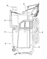
<大型コンバイン>
図1に示すように、コンバイン(請求項の「第1コンバイン」)1Aは、圃場の植立された5条〜7条の穀稈を刈取る刈幅を有した大型コンバインである。
<Large combine>
As shown in FIG. 1, the combine (“first combine” in the claim) 1A is a large combine having a cutting width for cutting 5 to 7 culms planted in the field.
コンバイン1Aは、機体フレーム2Aの下側に土壌面を走行する左右一対のクローラからなる走行装置(請求項の「第1走行装置」)3Aが設けられ、機体フレーム2Aの前側に圃場の穀稈を刈取る刈取装置(請求項の「第1刈取装置」)4Aが設けられ、刈取装置4Aの後方左側に刈取られた穀稈を脱穀・選別処理する脱穀装置(図示省略)が設けられ、刈取装置4Aの後方右側に操縦者が搭乗する操縦部6Aが設けられている。また、操縦部6Aの後側には脱穀・選別処理された穀粒を貯留するグレンタンク7Aが設けられ、グレンタンク7Aの後側に穀粒を外部に排出する上下方向に延在する揚穀部と前後方向に延在する横排出部からなる排出オーガ8Aが設けられている。
The
図2に示すように、RTK−GPS測位方式である測位ユニット10Aは、測位衛星11と、既知の位置に設けられた基地局12と、コンバイン1Aに設けられた移動局16Aで構成されている。これにより、測位衛星11から移動局16Aに送信されてくる位置情報と基地局12から移動局16Aに送信されてくる補正用の位置情報から移動局16Aの位置を正確に得ることができる。
As shown in FIG. 2, the
基地局12は、固定用通信機13と、測位衛星11からの位置情報を受信する固定用GPSアンテナ14と、移動局16Aに補正用の位置情報を送信する固定用データ送信アンテナ15で構成されている。また、移動局16Aは、移動用通信機17Aと、測位衛星11からの位置情報を受信する移動用GPSアンテナ18Aと、基地局12からの補正用の位置情報を受信する移動用データ送信アンテナ19Aで構成されている。
The
図3に示すように、コンバイン1Aのコントローラ20Aは、CPU等からなる処理部21Aと、ROM、RAM、ハードディスクドライブ、フラッシュメモリ等からなる記憶部22Aと、外部とのデータ通信用の通信部23Aから形成されている。
As shown in FIG. 3, the controller 20A of the
処理部21Aは、後述するドローン50から送信される圃場の穀稈の倒伏情報や湿田情報に基づいて、コンバイン1Aの搬入位置と、刈取経路と、搬出位置を設定する。
The processing unit 21A sets the carry-in position, the cutting route, and the carry-out position of the
また、処理部21Aは、記憶部22Aに保存された情報に基づいて、コンバイン1Aの搬入位置と、刈取経路と、搬出位置を前年と同一に設定することができる。なお、記憶部22Aには、圃場の位置、圃場の形状の他、前年度の倒伏した穀稈の位置、前年度の圃場の湿田位置、前年度の搬入位置、刈取経路、搬出位置等の情報が保存されている。
Further, the processing unit 21A can set the carry-in position, the cutting route, and the carry-out position of the
コントローラ20Aの入力側には、コンバイン1Aの位置情報である移動局16Aの移動用通信機17Aと、コンバイン1Bの通信部23Bと、ドローン50の通信部23Cと、コンバイン1Aに設けられた後方の圃場を撮影するリアカメラ30Aと、コンバイン1Aの左右方向の傾斜を測定する傾斜センサ31Aが所定の入力インターフェース回路を介して接続されている。
On the input side of the controller 20A, the
コントローラ20Aの出力側には、走行装置3Aを起動する起動スイッチ40Aと、刈取装置4A等を起動する刈脱スイッチ41Aと、排出オーガ8Aを起動させるオーガスイッチ42Aと、走行装置3Aの左右一対のクローラの回転を制動するブレーキ43Bが所定の出力インターフェース回路を介して接続されている。
On the output side of the controller 20A, a start switch 40A for activating the traveling
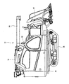
<小型コンバイン>
図4に示すように、コンバイン(請求項の「第2コンバイン」)1Bは、圃場の植立された2条の穀稈を刈取る小型コンバインである。なお、小型コンバインに替えて圃場の植立された3条ないし4条の穀稈を刈取る中型コンバインを使用することもできる。
<Small combine>
As shown in FIG. 4, the combine (“second combine” in the claim) 1B is a small combine that cuts two culms planted in a field. In addition, instead of the small combine, a medium-sized combine that cuts 3 to 4 culms planted in the field can also be used.
コンバイン1Bは、機体フレーム2Bの下側に土壌面を走行する左右一対のクローラからなる走行装置(請求項の「第2走行装置」)3Bが設けられ、機体フレーム2Bの前側に圃場の穀稈を刈取る刈取装置(請求項の「第2刈取装置」)4Bが設けられ、刈取装置4Bの後方左側に刈取られた穀稈を脱穀・選別処理する脱穀装置(図示省略)が設けられ、刈取装置4Bの後方右側に操縦者が搭乗する操縦部6Bが設けられている。また、操縦部6Bの後側には脱穀・選別処理された穀粒を貯留するグレンタンク7Bが設けられ、グレンタンク7Bの後側に穀粒を外部に排出する上下方向に延在する揚穀部と前後方向に延在する横排出部からなる排出オーガ8Bが設けられている。
The
図5に示すように、RTK−GPS測位方式である測位ユニット10Bは、測位衛星11と、既知の位置に設けられた基地局12と、コンバイン1Bに設けられた移動局16Bで構成されている。これにより、測位衛星11から移動局16Bに送信されてくる位置情報と基地局12から移動局16Bに送信されてくる補正用の位置情報から移動局16Bの位置を正確に得ることができる。
As shown in FIG. 5, the
移動局16Bは、移動用通信機17Bと、測位衛星11からの位置情報を受信する移動用GPSアンテナ18Bと、基地局12からの補正用の位置情報を受信する移動用データ送信アンテナ19Bで構成されている。また、基地局12の構成は上述したとおりである。
The
図6に示すように、コンバイン1Bのコントローラ20Bは、CPU等からなる処理部21Bと、ROM、RAM、ハードディスクドライブ、フラッシュメモリ等からなる記憶部22Bと、外部とのデータ通信用の通信部23Bから形成されている。
As shown in FIG. 6, the controller 20B of the
処理部21Bは、後述するドローン50から送信される圃場の穀稈の倒伏情報や湿田情報に基づいて、コンバイン1Bの搬入位置と、刈取経路と、搬出位置を設定することができる。
The processing unit 21B can set the carry-in position, the cutting route, and the carry-out position of the
また、処理部21Bは、記憶部22Bに保存された情報に基づいて、コンバイン1Bの搬入位置と、刈取経路と、搬出位置を前年と同一に設定することができる。なお、記憶部22Bには、圃場の位置、圃場の形状の他、前年度の倒伏した穀稈の位置、前年度の圃場の湿田位置、前年度の搬入位置、刈取経路、搬出位置等の情報が保存されている。
Further, the processing unit 21B can set the carry-in position, the cutting route, and the carry-out position of the
コントローラ20Bの入力側には、コンバイン1Bの位置情報である移動局16Bの移動用通信機17Bと、コンバイン1Aの通信部23Aと、ドローン50の通信部23Cと、コンバイン1Bに設けられた後方の圃場を撮影するリアカメラ30Bと、コンバイン1Bの左右方向の傾斜を測定する傾斜センサ31Bが所定の入力インターフェース回路を介して接続されている。
On the input side of the controller 20B, the
コントローラ20Bの出力側には、走行装置3Bを起動する起動スイッチ40Bと、刈取装置4B等を起動する刈脱スイッチ41Bと、排出オーガ8Bを起動させるオーガスイッチ42Bと、走行装置3Bの左右一対のクローラの回転を制動するブレーキ43Bが所定の出力インターフェース回路を介して接続されている。
On the output side of the controller 20B, a start switch 40B for activating the traveling
<ドローン>
図7に示すように、コンバイン1Aやコンバイン1Bの前方上空を飛行するドローン50は、本体の下部に圃場を撮影するカメラ51が搭載されている。
<Drone>
As shown in FIG. 7, the
図8に示すように、RTK−GPS測位方式である測位ユニット10Cは、測位衛星11と、既知の位置に設けられた基地局12と、ドローン50に設けられた移動局16Cで構成されている。これにより、測位衛星11から移動局16Cに送信されてくる位置情報と基地局12から移動局16Cに送信されてくる補正用の位置情報から移動局16Cの位置を正確に得ることができる。
As shown in FIG. 8, the positioning unit 10C, which is an RTK-GPS positioning method, is composed of a
移動局16Cは、移動用通信機17Cと、測位衛星11からの位置情報を受信する移動用GPSアンテナ18Cと、基地局12からの補正用の位置情報を受信する移動用データ送信アンテナ19Cで構成されている。また、基地局12の構成は上述したとおりである。
The mobile station 16C includes a
図9に示すように、ドローン50のコントローラ20Cは、CPU等からなる処理部21Cと、ROM、RAM、ハードディスクドライブ、フラッシュメモリ等からなる記憶部22Cと、外部とのデータ通信用の通信部23Cから形成されている。
As shown in FIG. 9, the controller 20C of the
処理部21Cは、予め記憶部22Cに保存された圃場の位置、圃場の形状、カメラの撮影可能距離に基づいて、ドローン50の飛行経路と、飛行高さを設定する。これにより、カメラ51で圃場の穀稈の倒伏状態や圃場の湿田状態を撮影して、コンバイン1Aのコントローラ20Aとコンバイン1Bのコントローラ20Bに圃場の穀稈の倒伏の情報や圃場の湿田の情報を送信することができる。
The processing unit 21C sets the flight path and flight height of the
コントローラ20Cの入力側には、ドローン50の位置情報である移動局16Cの移動用通信機17Cと、コンバイン1Aの通信部23Aと、コンバイン1Bの通信部23Bが所定の入力インターフェース回路を介して接続されている。
On the input side of the controller 20C, the
コントローラ20Cの出力側には、カメラ51が所定の出力インターフェース回路を介して接続されている。
A
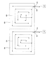
<大型コンバインと小型コンバインの協同作業>
図10に示すように、コンバイン1Aで倒伏していない多くの穀稈がある圃場部分の刈取作業を行った後に、コンバイン1Bで倒伏している多くの穀稈がある圃場部分の刈取作業を行う。これにより、コンバイン1Aで多くの倒伏していない穀稈がある圃場部分の刈取作業時間を大幅に短縮することができ、刈取作業の能率を高めることができる。また、旋回半径が小さいコンバイン1Bで倒伏している穀稈を刈取るので刈残し大幅に低減することができる。
<Cooperative work of large combine and small combine>
As shown in FIG. 10, after cutting the field portion with many culms that have not fallen with
また、コンバイン1Aで湿田が少ない圃場部分の刈取作業を行った後に、コンバイン1Bで湿田が多い圃場部分の刈取作業を行こともできる。これにより、コンバイン1Aで湿田が少ない圃場部分の刈取作業時間を大幅に短縮することができ、刈取作業の能率を高めることができる。また、軽量に形成されたコンバイン1Bで湿田が多い圃場部分の刈取作業を行うので沈下による走行トラブルを低減して刈取作業時間を短縮することができる。
Further, after the
本明細書では、倒伏していない多くの穀稈がある圃場部分や湿田が少ない圃場部分を総称して第1圃場部60Aと称呼し、倒伏している多くの穀稈がある圃場部分や湿田が多い圃場部分を総称して第2圃場部60Bと称呼する。
In the present specification, the field portion having many non-overturned culms and the field portion having few wet fields are collectively referred to as the
コンバイン1Aは、第1圃場部分内に移動して刈取作業を行い、刈取作業が終了するとい第1圃場内から圃場の外側に移動する。次に、コンバイン1Bは、第2圃場部分内に移動して刈取作業を行い、刈取作業が終了すると第2圃場内から圃場の外側に移動する。
The
コンバイン1Bは、コンバイン1Bの通信部23Bが、コンバイン1Aが圃場の外側に移動したとの情報を受信した後に、第2圃場部分内に移動して刈取作業を行う。これにより、測位衛星11や基地局12からの通信エラー等によって測位ユニット10A,10Bに異常が発生した場合においても、コンバイン1Aとコンバイン1Bの衝突を防止して、刈取作業を安全に行うことができる。
The
<大型コンバインと小型コンバインの協同作業の駆動方法>
図11に示すように、ステップS1で、コンバイン1Aは、圃場の外側の待機位置に停車し、次に、コンバイン1Aのコントローラ20Aは、ドローン50の通信部23Cから送信されてくる圃場内の穀稈の倒伏情報や湿田情報に基づいて、圃場内の倒伏した穀稈位置や湿田位置を設定してステップS2に進む。
<How to drive the cooperative work of a large combine and a small combine>
As shown in FIG. 11, in step S1, the
ステップS2では、コントローラ20Aは、圃場内の倒伏した穀稈位置や湿田位置を回避するようにコンバイン1Aの搬入位置61Aと、刈取経路(請求項の「第1刈取経路」)62Aと、搬出位置63Aを設定してステップS3に進む。
In step S2, the controller 20A has a carry-in
なお、ドローン50の通信部23Cからの送信がない場合には、コントローラ20Aの処理部21Aは、記憶部22Aに保存されている前年度の穀稈の倒伏位置、湿田位置、搬入位置、刈取経路、搬出位置等に基づいてコンバイン1Aの搬入位置61Aと、刈取経路62Aと、搬出位置63Aを設定することができる。
When there is no transmission from the communication unit 23C of the
ステップS3では、コントローラ20Aは、起動スイッチ40AをONにしてコンバイン1Aの走行装置3Aを起動しコンバイン1Aを搬入位置61Aから第1圃場部60Aに搬入してステップS4に進む。
In step S3, the controller 20A turns on the start switch 40A to activate the traveling
ステップS4では、コントローラ20Aは、刈脱スイッチ41AをONにして刈取装置4A等を起動しコンバイン1Aを刈取経路62Aに沿って刈取作業を行わせてステップS5に進む。これにより、コンバイン1Aで倒伏していない穀稈の刈取作業時間を短縮して刈取作業の能率を高めることができる。
In step S4, the controller 20A turns on the cutting / removing switch 41A, activates the
コントローラ20Aが傾斜センサ31Aから入力されてくる情報に基づいて、コンバイン1Aが前後又は左右方向に所定の角度以上傾斜していると判断した場合には、走行装置3Aの速度を減速する。これにより、コンバイン1Aの前後又は左右方向の傾斜を軽減することができる。
When the controller 20A determines that the
また、コントローラ20Aが移動用通信機17Aの位置情報に基づいて、コンバイン1Aが刈取経路62Aから左右方向に所定の距離外れていると判断した場合にはブレーキ(請求項の「第1ブレーキ」)43Aを作動する。これにより、コンバイン1Aの左右方向の中心部を刈取経路62A上に位置させることができる。
Further, when the controller 20A determines that the
ステップS5では、コントローラ20Aは、コンバイン1Aに装着されている移動用通信機17Aから送信されてくる位置情報に基づいて、コンバイン1Aが搬出位置63Aに移動したか否か、すなわち、コンバイン1Aによって第1圃場部60Aの穀稈の刈取作業が終了したか否か判断し、刈取作業が終了したと判断した場合には、刈脱スイッチ41AをOFFにして刈取装置4A等を停止しコンバイン1Aを第1圃場部60Aの外部に移動させてステップS6に進み、刈取作業が終了していないと判断した場合にはステップS4に戻る。
In step S5, the controller 20A determines whether or not the
コンバイン1Aを第1圃場部60Aの外部に移動する前に、コントローラ20Aがコンバイン1Aの後部に装着されているリアカメラ30Aやドローン50の通信部23Cから送信されてくる走行装置3A等の情報に基づいて、走行装置3A等に多くの泥が付着していると判断した場合には、走行装置3Aを搬出位置63Aの近傍で前後に走行させて走行装置3A等に付着した泥を除去するこが好ましい。これにより、走行装置3Aに付着した泥が公道に落下するのを抑制することができる。
Before moving the
ステップS6では、コントローラ20Aは、オーガスイッチ42AをONにしてコンバイン1Aのグレンタンク7Aに貯留された穀粒をコンバイン1A用のトラックの荷台に排出してステップS7に進む。なお、コンバイン1Bのグレンタンク7Bに貯留された穀粒は、コンバイン1A用のトラックとは異なるコンバイン1B用のトラックに排出される。これにより、水分量や汚れが異なる穀粒が混在するのを防止して、穀粒の品質に応じて穀粒を分別することができる。
In step S6, the controller 20A turns on the auger switch 42A, discharges the grains stored in the
ステップS7では、コントローラ20Aは、圃場内の倒伏した穀稈や湿田を走行するようにコンバイン1Aの搬入位置61Bと、刈取経路(請求項の「第2刈取経路」)62Bと、搬出位置63Bを設定してステップS8に進む。
In step S7, the controller 20A sets the carry-in
ステップS8では、コントローラ20Aは、ドローン50の通信部23Cから送信されてくる圃場内の穀稈の倒伏情報や湿田情報に基づいて、コンバイン1Aからコンバイン1Bに変更するか否か判断し、コンバイン1Aからコンバイン1Bに変更する場合にはステップS9に進み、引続いてコンバイン1Aを使用する場合にはステップS14に進む。
In step S8, the controller 20A determines whether to change from
ステップS9では、コントローラ20Aは、通信部23Aを介してコンバイン1Bの搬入位置61Bと、刈取経路62Bと、搬出位置63Bをコンバイン1Bのコントローラ20Bに送信してステップS10に進む。
In step S9, the controller 20A transmits the carry-in
なお、コントローラ20Aの通信部23Aからの送信がない場合には、コントローラ20Bの処理部21Bは、記憶部22Bに保存されている前年度の穀稈の倒伏位置、湿田位置、搬入位置、刈取経路、搬出位置等に基づいてコンバイン1Bの搬入位置61Bと、刈取経路62Bと、搬出位置63Bを設定することができる。
When there is no transmission from the communication unit 23A of the controller 20A, the processing unit 21B of the controller 20B uses the lodging position, the wet field position, the carry-in position, and the cutting route of the previous year's grain culm stored in the storage unit 22B. , The carry-in
ステップS10では、コントローラ20Bは、起動スイッチ40BをONにしてコンバイン1Bの走行装置3Bを起動しコンバイン1Bを搬入位置61Bから第2圃場部60Bに搬入してステップS11に進む。また、コントローラ20Bは、コンバイン1Aが第1圃場部60Aの外部に移動した情報を通信部23Bが受取った後に、起動スイッチ40BをONにするのが好ましい。これにより、測位衛星11や基地局12からの通信エラーによって測位ユニット10Bに異常が発生した場合においても、コンバイン1Aとコンバイン1Bの衝突を防止して、刈取作業を安全に行うことができる。
In step S10, the controller 20B turns on the start switch 40B to activate the traveling
ステップS11では、コントローラ20Bは、刈脱スイッチ41BをONにして刈取装置4B等を起動しコンバイン1Bを刈取経路62Bに沿って刈取作業を行わせてステップS12に進む。これにより、旋回半径が小さいコンバイン1Bで倒伏している穀稈を刈取るので刈残し大幅に低減することができる。また、軽量に形成されたコンバイン1Bで湿田が多い圃場部分の刈取作業を行うのでるので沈下による走行トラブルを低減して刈取作業時間を短縮することができる。
In step S11, the controller 20B turns on the cutting / removing switch 41B, activates the
コントローラ20Bが傾斜センサ31Bから入力されてくる情報に基づいて、コンバイン1Bが前後又は左右方向に所定の角度以上傾斜していると判断した場合には、走行装置3Bの速度を減速する。これにより、コンバイン1Bの前後又は左右方向の傾斜を軽減することができる。
When the controller 20B determines that the
また、コントローラ20Bが移動用通信機17Bの位置情報に基づいて、コンバイン1Bが刈取経路62Bから左右方向に所定の距離外れていると判断した場合にはブレーキ(請求項の「第2ブレーキ」)43Bを作動する。これにより、コンバイン1Bの左右方向の中心部を刈取経路62B上に位置させることができる。
Further, when the controller 20B determines that the
ステップS12では、コントローラ20Bは、コンバイン1Bに装着されている移動用通信機17Bから送信されてくる位置情報に基づいて、コンバイン1Bが搬出位置63Bに移動したか否か、すなわち、コンバイン1Bによって第2圃場部60Bの穀稈の刈取作業が終了したか否か判断し、刈取作業が終了したと判断した場合には、刈脱スイッチ41BをOFFにして刈取装置4B等を停止しコンバイン1Bを第2圃場部60Bの外部に移動させてステップS13に進み、刈取作業が終了していないと判断した場合にはステップS11に戻る。
In step S12, the controller 20B determines whether or not the
コンバイン1Bを第2圃場部60Bの外部に移動する前に、コントローラ20Bがコンバイン1Bの後部に装着されているリアカメラ30Bやドローン50の通信部23Cから送信されてくる走行装置3B等の情報に基づいて、走行装置3B等に多くの泥が付着していると判断した場合には、走行装置3Bを搬出位置63Bの近傍で前後に走行させて走行装置3B等に付着した泥を除去するこが好ましい。これにより、走行装置3Bに付着した泥が公道に落下するのを抑制することができる。
Before moving the
ステップS13では、コントローラ20Bは、オーガスイッチ42BをONにしてコンバイン1Bのグレンタンク7Bに貯留された穀粒をコンバイン1B用のトラックの荷台に排出する。
In step S13, the controller 20B turns on the auger switch 42B and discharges the grains stored in the
ステップS14では、コントローラ20Aは、起動スイッチ40AをONにしてコンバイン1Aの走行装置3Aを起動しコンバイン1Aを搬入位置61Bから第2圃場部60Bに搬入してステップS15に進む。
In step S14, the controller 20A turns on the start switch 40A to activate the traveling
ステップS15では、コントローラ20Aは、刈脱スイッチ41AをONにして刈取装置4A等を起動しコンバイン1Aを刈取経路62Bに沿って刈取作業を行わせてステップS16に進む。これにより、コンバイン1Aで倒伏した穀稈の刈取作業時間を短縮して刈取作業の能率を高めることができる。
In step S15, the controller 20A turns on the cutting / removing switch 41A, activates the
コントローラ20Aが傾斜センサ31Aから入力されてくる情報に基づいて、コンバイン1Aが前後又は左右方向に所定の角度以上傾斜していると判断した場合には、走行装置3Aの速度を減速する。これにより、コンバイン1Aの前後又は左右方向の傾斜を軽減することができる。
When the controller 20A determines that the
また、コントローラ20Aが移動用通信機17Aの位置情報に基づいて、コンバイン1Aが刈取経路62Bから左右方向に所定の距離外れていると判断した場合にはブレーキ43Aを作動する。これにより、コンバイン1Aの左右方向の中心部を刈取経路62B上に位置させることができる。
Further, when the controller 20A determines that the
ステップS16では、コントローラ20Aは、移動用通信機17Aから送信されてくる位置情報に基づいて、コンバイン1Aが搬出位置63Bに移動したか否か、すなわち、コンバイン1Aによって第2圃場部60Bの穀稈の刈取作業が終了したか否か判断し、刈取作業が終了したと判断した場合には、刈脱スイッチ41AをOFFにして刈取装置4A等を停止しコンバイン1Aを第2圃場部60Bの外部に移動させてステップS17に進み、刈取作業が終了していないと判断した場合にはステップS15に戻る。
In step S16, the controller 20A determines whether or not the
コンバイン1Aを第2圃場部60Bの外部に移動する前に、コントローラ20Aがコンバイン1Aの後部に装着されているリアカメラ30Aやドローン50の通信部23Cから送信されてくる走行装置3A等の情報に基づいて、走行装置3A等に多くの泥が付着していると判断した場合には、走行装置3Aを搬出位置63Bの近傍で前後に走行させて走行装置3A等に付着した泥を除去するこが好ましい。これにより、走行装置3Aに付着した泥が公道に落下するのを抑制することができる。
Before moving the
ステップS17では、コントローラ20Aは、オーガスイッチ42AをONにしてコンバイン1Aのグレンタンク7Aに貯留された穀粒をコンバイン1A用のトラックの荷台に排出する。
In step S17, the controller 20A turns on the auger switch 42A and discharges the grains stored in the
1A コンバイン(第1コンバイン)
1B コンバイン(第2コンバイン)
3A 走行装置(第1走行装置)
3B 走行装置(第2走行装置)
4A 刈取装置(第1刈取装置)
4B 刈取装置(第2刈取装置)
11 測位衛星
12 基地局
23B 通信部
43A ブレーキ(第1ブレーキ)
43B ブレーキ(第2ブレーキ)
60A 第1圃場部
60B 第2圃場部
62A 刈取経路(第1刈取経路)
62B 刈取経路(第2刈取経路)
1A combine (1st combine)
1B combine (second combine)
3A traveling device (first traveling device)
3B traveling device (second traveling device)
4A reaping device (first reaping device)
4B reaping device (second reaping device)
11
43B brake (second brake)
62B cutting route (second cutting route)
Claims (7)
大型の第1コンバイン(1A)で圃場における倒伏した穀稈又は湿田が少ない第1圃場部(60A)の刈取作業を行ない、
前記第1コンバイン(1A)よりも小型の第2コンバイン(1B)で前記圃場における倒伏した穀稈又は湿田が多い第2圃場部(60B)の刈取作業を行い、
前記第1コンバイン(1A)を、前記穀稈と湿田位置に基づいて設定された第1刈取経路(62A)に沿って走行させて穀稈の刈取作業を行わせた後に、前記第1圃場部(60A)の外部に移動させ、
前記第2コンバイン(1B)を、前記第1コンバイン(1A)が第1圃場部(60A)の外部に移動した後に、前記第2圃場部(60B)の内部に移動させて、前記穀稈と湿田位置に基づいて設定された第2刈取経路(62B)に沿って未刈穀稈の刈取作業を行わせることを特徴とする刈取作業方法。 It is a cutting work method that cuts the culms planted in the field using multiple combines.
A large first combine (1A) is used to mow the first field (60A) where there are few fallen culms or wet fields in the field.
The second combine (1B), which is smaller than the first combine (1A), is used to mow the second field (60B), which has many fallen culms or wet fields in the field.
The first combine (1A) is run along the first cutting route (62A) set based on the grain culm and the wet field position to perform the grain cutting work, and then the first field portion. Move it to the outside of (60A) and
The second combine (1B) is moved to the inside of the second field portion (60B) after the first combine (1A) is moved to the outside of the first field portion (60A) to form the grain culm. A cutting work method characterized in that the uncut grain culm is cut along a second cutting route (62B) set based on the wet field position.
前記第2コンバイン(1B)の第2走行装置(3B)に多量の泥が付着している場合には、前記第2圃場部(60B)の外部に移動する前に、前記第2走行装置(3B)を前後方向に繰返し移動させて付着した泥を除去する請求項1記載の刈取作業方法。 When a large amount of mud is attached to the first traveling device (3A) of the first combine (1A), the first traveling device (1A) is used before moving to the outside of the first field portion (60A). 3A) is repeatedly moved in the front-back direction to remove the adhering mud.
When a large amount of mud is attached to the second traveling device (3B) of the second combine (1B), the second traveling device (3B) is used before moving to the outside of the second field portion (60B). The mowing operation method according to claim 1, wherein 3B) is repeatedly moved in the front-rear direction to remove the adhering mud.
前記第2コンバイン(1B)が前後又は左右方向に所定の角度以上傾斜した場合には、前記第2走行装置(3B)の速度を減速する請求項2記載の刈取作業方法。 When the first combine (1A) is tilted in the front-rear or left-right direction by a predetermined angle or more, the speed of the first traveling device (3A) is reduced.
When said second combined (1B) is inclined a predetermined angle or more in the longitudinal or lateral direction, cutting work method according to claim 2, wherein for reducing the speed of the second travel unit (3B).
前記第2コンバイン(1B)の中心部が第2刈取経路(62B)から左右方向に所定の幅以上離間にした場合には、前記第2走行装置(3B)の左右一対のクローラの回転を第2ブレーキ(43B)で制動する請求項2又は3記載の刈取作業方法。 When the first combine (1A) is separated from the first cutting path (62A) by a predetermined width or more in the left-right direction, the rotation of the pair of left and right crawlers of the first traveling device (3A) is applied to the first brake (1A). Braking at 43A),
When the central portion of the second combine (1B) is separated from the second cutting path (62B) by a predetermined width or more in the left-right direction, the rotation of the pair of left and right crawlers of the second traveling device (3B) is second. 2. The cutting work method according to claim 2 or 3 , wherein braking is performed with a brake (43B).
Priority Applications (1)
| Application Number | Priority Date | Filing Date | Title |
|---|---|---|---|
| JP2019137860A JP6876279B2 (en) | 2019-07-26 | 2019-07-26 | Mowing work method |
Applications Claiming Priority (1)
| Application Number | Priority Date | Filing Date | Title |
|---|---|---|---|
| JP2019137860A JP6876279B2 (en) | 2019-07-26 | 2019-07-26 | Mowing work method |
Publications (2)
| Publication Number | Publication Date |
|---|---|
| JP2021019531A JP2021019531A (en) | 2021-02-18 |
| JP6876279B2 true JP6876279B2 (en) | 2021-05-26 |
Family
ID=74572909
Family Applications (1)
| Application Number | Title | Priority Date | Filing Date |
|---|---|---|---|
| JP2019137860A Active JP6876279B2 (en) | 2019-07-26 | 2019-07-26 | Mowing work method |
Country Status (1)
| Country | Link |
|---|---|
| JP (1) | JP6876279B2 (en) |
Family Cites Families (6)
| Publication number | Priority date | Publication date | Assignee | Title |
|---|---|---|---|---|
| JPS6029447B2 (en) * | 1974-09-11 | 1985-07-10 | ヤンマー農機株式会社 | Combine grain conveyor |
| JPS5740763Y2 (en) * | 1977-03-07 | 1982-09-07 | ||
| JP2001278136A (en) * | 2000-03-30 | 2001-10-10 | Iseki & Co Ltd | Travel gear for working vehicle |
| JP6688542B2 (en) * | 2016-02-04 | 2020-04-28 | ヤンマー株式会社 | Follow-up combine |
| CN109275411A (en) * | 2017-07-22 | 2019-01-29 | 西北农林科技大学 | A kind of Wheat lodging detection system based on laser sensor |
| JP7101488B2 (en) * | 2018-01-30 | 2022-07-15 | 株式会社クボタ | Work vehicle management system |
-
2019
- 2019-07-26 JP JP2019137860A patent/JP6876279B2/en active Active
Also Published As
| Publication number | Publication date |
|---|---|
| JP2021019531A (en) | 2021-02-18 |
Similar Documents
| Publication | Publication Date | Title |
|---|---|---|
| JP7034866B2 (en) | Harvester | |
| JP2019216744A (en) | Combine | |
| CN111343854A (en) | Work vehicle, travel route selection system for work vehicle, and travel route calculation system | |
| JP2017195804A (en) | combine | |
| JP7062602B2 (en) | Route generation system | |
| JP6884092B2 (en) | Travel route selection system for work vehicles and work vehicles | |
| JP2022103238A (en) | Travel route generating system | |
| JP2011072259A (en) | Combine harvester | |
| JP6876279B2 (en) | Mowing work method | |
| JP6843037B2 (en) | Combine control system | |
| JP7085152B2 (en) | Mowing work method | |
| JP6874893B2 (en) | Mowing work method | |
| US20240008383A1 (en) | Combine and method for generating travel route | |
| JP7466276B2 (en) | Work vehicle coordination system | |
| JP7530813B2 (en) | Combine harvester and method for creating a running route | |
| WO2020262416A1 (en) | Automatic traveling system, agricultural work machine, program, recording medium with program recorded thereon, and method | |
| JP6860860B2 (en) | combine | |
| JP2020137466A (en) | Harvesting work method | |
| JP7515436B2 (en) | Route Generation System | |
| JP7328394B2 (en) | Route generation system | |
| TW202233051A (en) | Harvesting operation method | |
| WO2022118566A1 (en) | Combine and travel control method | |
| JP7548802B2 (en) | Arrival information setting method and combine | |
| JP7555250B2 (en) | Combine harvester and automatic operation method | |
| JP7129032B1 (en) | Grain culm reaping work method |
Legal Events
| Date | Code | Title | Description |
|---|---|---|---|
| A621 | Written request for application examination |
Free format text: JAPANESE INTERMEDIATE CODE: A621 Effective date: 20191224 |
|
| A131 | Notification of reasons for refusal |
Free format text: JAPANESE INTERMEDIATE CODE: A131 Effective date: 20210108 |
|
| A521 | Written amendment |
Free format text: JAPANESE INTERMEDIATE CODE: A523 Effective date: 20210222 |
|
| TRDD | Decision of grant or rejection written | ||
| A01 | Written decision to grant a patent or to grant a registration (utility model) |
Free format text: JAPANESE INTERMEDIATE CODE: A01 Effective date: 20210326 |
|
| A61 | First payment of annual fees (during grant procedure) |
Free format text: JAPANESE INTERMEDIATE CODE: A61 Effective date: 20210408 |
|
| R150 | Certificate of patent or registration of utility model |
Ref document number: 6876279 Country of ref document: JP Free format text: JAPANESE INTERMEDIATE CODE: R150 |