JP6876120B2 - Rechargeable battery module - Google Patents
Rechargeable battery module Download PDFInfo
- Publication number
- JP6876120B2 JP6876120B2 JP2019501163A JP2019501163A JP6876120B2 JP 6876120 B2 JP6876120 B2 JP 6876120B2 JP 2019501163 A JP2019501163 A JP 2019501163A JP 2019501163 A JP2019501163 A JP 2019501163A JP 6876120 B2 JP6876120 B2 JP 6876120B2
- Authority
- JP
- Japan
- Prior art keywords
- secondary battery
- battery module
- fitting
- protruding portion
- bus bar
- Prior art date
- Legal status (The legal status is an assumption and is not a legal conclusion. Google has not performed a legal analysis and makes no representation as to the accuracy of the status listed.)
- Active
Links
- 238000001514 detection method Methods 0.000 claims description 30
- 239000000758 substrate Substances 0.000 claims description 16
- 239000007789 gas Substances 0.000 description 9
- 238000003466 welding Methods 0.000 description 6
- WHXSMMKQMYFTQS-UHFFFAOYSA-N Lithium Chemical compound [Li] WHXSMMKQMYFTQS-UHFFFAOYSA-N 0.000 description 4
- 229910052744 lithium Inorganic materials 0.000 description 4
- 238000000034 method Methods 0.000 description 3
- 238000012986 modification Methods 0.000 description 3
- 230000004048 modification Effects 0.000 description 3
- 238000011161 development Methods 0.000 description 2
- 239000011347 resin Substances 0.000 description 2
- 229920005989 resin Polymers 0.000 description 2
- 239000007864 aqueous solution Substances 0.000 description 1
- 230000000903 blocking effect Effects 0.000 description 1
- OJIJEKBXJYRIBZ-UHFFFAOYSA-N cadmium nickel Chemical compound [Ni].[Cd] OJIJEKBXJYRIBZ-UHFFFAOYSA-N 0.000 description 1
- 238000002788 crimping Methods 0.000 description 1
- 238000010586 diagram Methods 0.000 description 1
- 230000000694 effects Effects 0.000 description 1
- 230000005489 elastic deformation Effects 0.000 description 1
- 239000000446 fuel Substances 0.000 description 1
- 239000001257 hydrogen Substances 0.000 description 1
- 229910052739 hydrogen Inorganic materials 0.000 description 1
- 238000003780 insertion Methods 0.000 description 1
- 230000037431 insertion Effects 0.000 description 1
- 238000011160 research Methods 0.000 description 1
- 238000010792 warming Methods 0.000 description 1
Images


Classifications
-
- H—ELECTRICITY
- H01—ELECTRIC ELEMENTS
- H01M—PROCESSES OR MEANS, e.g. BATTERIES, FOR THE DIRECT CONVERSION OF CHEMICAL ENERGY INTO ELECTRICAL ENERGY
- H01M50/00—Constructional details or processes of manufacture of the non-active parts of electrochemical cells other than fuel cells, e.g. hybrid cells
- H01M50/50—Current conducting connections for cells or batteries
-
- H—ELECTRICITY
- H01—ELECTRIC ELEMENTS
- H01M—PROCESSES OR MEANS, e.g. BATTERIES, FOR THE DIRECT CONVERSION OF CHEMICAL ENERGY INTO ELECTRICAL ENERGY
- H01M10/00—Secondary cells; Manufacture thereof
- H01M10/42—Methods or arrangements for servicing or maintenance of secondary cells or secondary half-cells
- H01M10/48—Accumulators combined with arrangements for measuring, testing or indicating the condition of cells, e.g. the level or density of the electrolyte
-
- H—ELECTRICITY
- H01—ELECTRIC ELEMENTS
- H01M—PROCESSES OR MEANS, e.g. BATTERIES, FOR THE DIRECT CONVERSION OF CHEMICAL ENERGY INTO ELECTRICAL ENERGY
- H01M50/00—Constructional details or processes of manufacture of the non-active parts of electrochemical cells other than fuel cells, e.g. hybrid cells
- H01M50/20—Mountings; Secondary casings or frames; Racks, modules or packs; Suspension devices; Shock absorbers; Transport or carrying devices; Holders
- H01M50/204—Racks, modules or packs for multiple batteries or multiple cells
- H01M50/207—Racks, modules or packs for multiple batteries or multiple cells characterised by their shape
- H01M50/209—Racks, modules or packs for multiple batteries or multiple cells characterised by their shape adapted for prismatic or rectangular cells
-
- H—ELECTRICITY
- H01—ELECTRIC ELEMENTS
- H01R—ELECTRICALLY-CONDUCTIVE CONNECTIONS; STRUCTURAL ASSOCIATIONS OF A PLURALITY OF MUTUALLY-INSULATED ELECTRICAL CONNECTING ELEMENTS; COUPLING DEVICES; CURRENT COLLECTORS
- H01R4/00—Electrically-conductive connections between two or more conductive members in direct contact, i.e. touching one another; Means for effecting or maintaining such contact; Electrically-conductive connections having two or more spaced connecting locations for conductors and using contact members penetrating insulation
- H01R4/58—Electrically-conductive connections between two or more conductive members in direct contact, i.e. touching one another; Means for effecting or maintaining such contact; Electrically-conductive connections having two or more spaced connecting locations for conductors and using contact members penetrating insulation characterised by the form or material of the contacting members
-
- H—ELECTRICITY
- H01—ELECTRIC ELEMENTS
- H01M—PROCESSES OR MEANS, e.g. BATTERIES, FOR THE DIRECT CONVERSION OF CHEMICAL ENERGY INTO ELECTRICAL ENERGY
- H01M50/00—Constructional details or processes of manufacture of the non-active parts of electrochemical cells other than fuel cells, e.g. hybrid cells
- H01M50/20—Mountings; Secondary casings or frames; Racks, modules or packs; Suspension devices; Shock absorbers; Transport or carrying devices; Holders
- H01M50/262—Mountings; Secondary casings or frames; Racks, modules or packs; Suspension devices; Shock absorbers; Transport or carrying devices; Holders with fastening means, e.g. locks
- H01M50/264—Mountings; Secondary casings or frames; Racks, modules or packs; Suspension devices; Shock absorbers; Transport or carrying devices; Holders with fastening means, e.g. locks for cells or batteries, e.g. straps, tie rods or peripheral frames
-
- H—ELECTRICITY
- H01—ELECTRIC ELEMENTS
- H01M—PROCESSES OR MEANS, e.g. BATTERIES, FOR THE DIRECT CONVERSION OF CHEMICAL ENERGY INTO ELECTRICAL ENERGY
- H01M50/00—Constructional details or processes of manufacture of the non-active parts of electrochemical cells other than fuel cells, e.g. hybrid cells
- H01M50/20—Mountings; Secondary casings or frames; Racks, modules or packs; Suspension devices; Shock absorbers; Transport or carrying devices; Holders
- H01M50/289—Mountings; Secondary casings or frames; Racks, modules or packs; Suspension devices; Shock absorbers; Transport or carrying devices; Holders characterised by spacing elements or positioning means within frames, racks or packs
-
- H—ELECTRICITY
- H01—ELECTRIC ELEMENTS
- H01M—PROCESSES OR MEANS, e.g. BATTERIES, FOR THE DIRECT CONVERSION OF CHEMICAL ENERGY INTO ELECTRICAL ENERGY
- H01M50/00—Constructional details or processes of manufacture of the non-active parts of electrochemical cells other than fuel cells, e.g. hybrid cells
- H01M50/50—Current conducting connections for cells or batteries
- H01M50/569—Constructional details of current conducting connections for detecting conditions inside cells or batteries, e.g. details of voltage sensing terminals
-
- H—ELECTRICITY
- H01—ELECTRIC ELEMENTS
- H01R—ELECTRICALLY-CONDUCTIVE CONNECTIONS; STRUCTURAL ASSOCIATIONS OF A PLURALITY OF MUTUALLY-INSULATED ELECTRICAL CONNECTING ELEMENTS; COUPLING DEVICES; CURRENT COLLECTORS
- H01R13/00—Details of coupling devices of the kinds covered by groups H01R12/70 or H01R24/00 - H01R33/00
- H01R13/02—Contact members
- H01R13/22—Contacts for co-operating by abutting
- H01R13/24—Contacts for co-operating by abutting resilient; resiliently-mounted
-
- Y—GENERAL TAGGING OF NEW TECHNOLOGICAL DEVELOPMENTS; GENERAL TAGGING OF CROSS-SECTIONAL TECHNOLOGIES SPANNING OVER SEVERAL SECTIONS OF THE IPC; TECHNICAL SUBJECTS COVERED BY FORMER USPC CROSS-REFERENCE ART COLLECTIONS [XRACs] AND DIGESTS
- Y02—TECHNOLOGIES OR APPLICATIONS FOR MITIGATION OR ADAPTATION AGAINST CLIMATE CHANGE
- Y02E—REDUCTION OF GREENHOUSE GAS [GHG] EMISSIONS, RELATED TO ENERGY GENERATION, TRANSMISSION OR DISTRIBUTION
- Y02E60/00—Enabling technologies; Technologies with a potential or indirect contribution to GHG emissions mitigation
- Y02E60/10—Energy storage using batteries
Description
本発明は、二次電池モジュールに関する。 The present invention relates to a secondary battery module.
従来、再充電可能な二次電池の分野では、鉛電池、ニッケル−カドミウム電池、ニッケル−水素電池等の水溶液系電池が主流であった。しかしながら、電気機器の小型化、軽量化が進むにつれ、高エネルギー密度を有するリチウム二次電池が着目され、その研究、開発及び商品化が急速に進められた。 Conventionally, in the field of rechargeable secondary batteries, aqueous solution batteries such as lead batteries, nickel-cadmium batteries, and nickel-hydrogen batteries have been the mainstream. However, as electric devices have become smaller and lighter, attention has been paid to lithium secondary batteries having a high energy density, and their research, development and commercialization have been rapidly promoted.
一方、地球温暖化や枯渇燃料の問題から電気自動車(EV)や駆動の一部を電気モーターで補助するハイブリッド電気自動車(HEV)が各自動車メーカーで開発され、その電源として高容量で高出力な二次電池が求められるようになってきた。このような要求に合致する電源として、高電圧を有する非水溶液系のリチウム二次電池が注目されている。特に角形リチウム二次電池はパック化した際の体積効率が優れているため、HEV用あるいはEV用として角形リチウム二次電池の開発への期待が高まっている。 On the other hand, due to the problems of global warming and depleted fuel, electric vehicles (EVs) and hybrid electric vehicles (HEVs) that partially assist the drive with electric motors have been developed by each automobile manufacturer, and have high capacity and high output as their power source. Secondary batteries are being sought after. As a power source that meets such requirements, a non-aqueous lithium secondary battery having a high voltage is drawing attention. In particular, since the square lithium secondary battery is excellent in volumetric efficiency when packed, expectations for the development of a square lithium secondary battery for HEV or EV are increasing.
一方で、電池パック化する際に作業効率も考慮する必要がある。特許文献1には作業効率の向上をするために、電圧検出用端子を接続端子74aの穴に挿入して互いに接続する構造が開示されている。このように電圧検出用端子とバスバーとの接続工数を短縮化しようとすると、電圧検出線とバスバーを嵌め合わす構造が最も早くなる。 On the other hand, it is necessary to consider work efficiency when making a battery pack. Patent Document 1 discloses a structure in which voltage detection terminals are inserted into holes of connection terminals 74a and connected to each other in order to improve work efficiency. In order to shorten the man-hours for connecting the voltage detection terminal and the bus bar in this way, the structure for fitting the voltage detection line and the bus bar becomes the fastest.
しかし特許文献1に記載のように電圧検出用端子とバスバーとを単純に嵌め合わせただけでは、電圧検出用端子とバスバーの位置にばらつきがあるため接続部の位置調整が必要となり、調整が不十分の場合、その後の接合工程で信頼性の高い接合が出来ない、といった課題がある。本発明は、当該課題を解決することを目的とする。 However, if the voltage detection terminal and the bus bar are simply fitted as described in Patent Document 1, the positions of the voltage detection terminal and the bus bar vary, so that the position of the connection portion needs to be adjusted, and the adjustment is not possible. If it is sufficient, there is a problem that highly reliable joining cannot be performed in the subsequent joining process. An object of the present invention is to solve the problem.
本願は上記課題を解決する手段を複数含んでいるが、その一例を挙げるならば、本発明の電池モジュール(100)は、複数の電池(1)を並べ、互いにバスバー(7)で接続された電池群と、電池群上に配置され、電圧検出用端子である端子部(9)が配置された基板(8)と、を備え、端子部(9)とバスバー(7)とを互いに嵌め合わせ、バスバー(7)の一部は、基板(8)側に突出した突出部(17)を有し、端子部(9)は、基板(8)から突出し、突出部(17)と嵌り合う嵌合部(16)を有し、突出部(17)は、先端に向けて幅が狭くなる形状を成す第一ガイド部(14)を有し、端子部(9)は、中央部に第一ガイド部(14)を導く貫通孔(15b)が形成され、嵌合部(16)となる第二ガイド部(15a)と、を有し、突出部(17)と嵌合部(16)とが互いに嵌め合わされたことを特徴とする。
The present application includes a plurality of means for solving the above problems. For example, the battery module (100) of the present invention has a plurality of batteries (1) arranged side by side and connected to each other by a bus bar (7). A battery group and a substrate (8) on which a terminal portion (9) which is a voltage detection terminal is arranged are provided, and the terminal portion (9) and the bus bar (7) are fitted to each other. , A part of the bus bar (7) has a protruding portion (17) protruding toward the substrate (8), and the terminal portion (9) protrudes from the substrate (8) and fits with the protruding portion (17). engagement part (16) possess, projecting portion (17) has a first guide portion in the shape in which the width becomes narrower toward the distal end has a (14), the terminal portions (9), the first in the central portion A through hole (15b) for guiding the guide portion (14) is formed, and the second guide portion (15a) serving as the fitting portion (16) is provided, and the protruding portion (17) and the fitting portion (16) Are characterized in that they are fitted together.
本発明によれば、電圧検出用端子を容易に位置決めしてバスバーと簡単に接続できるようにした二次電池モジュールを提供することができる。またほかの目的として、電圧検出用端子とバスバー部に発生する応力を緩和する接続信頼性の高い二次電池モジュールを提供することができる。 According to the present invention, it is possible to provide a secondary battery module in which a voltage detection terminal is easily positioned so that it can be easily connected to a bus bar. For another purpose, it is possible to provide a secondary battery module having high connection reliability that relieves stress generated in the voltage detection terminal and the bus bar portion.
以下、実施例を図面を用いて説明する。 Hereinafter, examples will be described with reference to the drawings.
≪実施例1≫
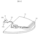
図1は、実施例1に係る二次電池モジュール100を示す分解斜視図である。なお、以降で上下左右前後という言葉を使用する場合には、図1の右下に記載の方向と対応する方向を指す。<< Example 1 >>
FIG. 1 is an exploded perspective view showing the
二次電池モジュール100は、二次電池1、セルホルダ2a、2b、一対のエンドプレート3、一対のサイドプレート4、二次電池1から噴出したガスを遮蔽するガス遮蔽板5、バスバーカバー6、バスバー7、基板8、電圧検出用端子9、上部カバー10から構成されている。
The
二次電池1はセルホルダ2bを介して積層され、その両端に端部のセルホルダ2aが配置される構造となり、電池群を構成する。そして、端部のセルホルダ2aの外にはエンドプレート3が配置され、電池群を両端から前後方向に押圧するように構成している。そして電池群の左右方向からは一対のサイドプレート4で押圧される構造となっている。なお、エンドプレート3は端部のセルホルダ2aとねじで固定される構造となっている。また、端部のセルホルダ2aには二次電池モジュールの外部端子と接続する端子台2a1が設けられている。
The secondary battery 1 is laminated via the cell holder 2b, and the
二次電池1の上面にはガス排出弁1aが設けられており、その上を覆うようにガス遮蔽板5が配置される構造となっている。このガス遮断板5が配置されることによって、二次電池からのガスが直接基板8にかかることなくなり、電池が過充電池になったとしても電池制御が不可能になるのを避けることができる。
A gas discharge valve 1a is provided on the upper surface of the secondary battery 1, and a gas shielding plate 5 is arranged so as to cover the gas discharge valve 1a. By arranging the gas blocking plate 5, the gas from the secondary battery does not directly hit the
続いてバスバーカバー6について説明する。本実施形態ではバスバーカバー6はガス遮蔽板5の左右に配置される。このバスバーカバー6は二次電池1の外部端子を露出させる穴が開いており、その穴に対応してバスバー7が配置される。なお、本実施形態ではバスバーカバーは左右に分割される構造となっているが、左右のバスバーカバー6が連結されて一つの部材で構成されていてもよい。
Next, the
バスバーカバー6上には電圧検出用端子9が設けられた基板8配置されている。そして基板8上には上部カバー10が配置される。
A
続いて本発明の特徴となる電圧検出用端子9とバスバー7との嵌め合い構造について説明する。図2は電圧検出用端子9とバスバー7を互いに嵌め合わせる前の図である。
Subsequently, the fitting structure of the
バスバー7には上方向に突出する突出部17が設けられている。この突出部の先端には、二つの傾斜部14a、14bが設けられており、先端に向かうにつれて徐々に幅が狭くなる第一ガイド部14を有する構造になっている。また本実施形態ではこの傾斜部14a、14bは上下前後の面と並行になるように設けられている。このように、寸法校差によって前後方向に突出部17がずれたとしても、第一ガイド部14によって穴15bに導かれる構造となっている。
The
一方で電圧検出用端子9は先端に嵌合部16を設けている。この嵌合部16は、穴15bと突出部の挿入方向(本実施形態では上方向)に向かうにつれて幅が狭くなるように傾斜する傾斜部15a1、15a2によって構成される第二ガイド部15aによって形成されている。また、本実施形態ではこの傾斜部15a1、15a2はそれぞれ上下左右の面と並行に設けられている。このように、寸法校差によって左右方向に突出部17がずれたとしても、第二ガイド部15aによって穴15bに導かれる構造となっている。
On the other hand, the
このように本実施形態では第一ガイド部14及び第二ガイド部15aによって、前後方向及び左右方向に突出部17がずれたとしても、バスバー7と電圧検出用端子9の位置調整が不要とした上で確実に接続部(突出部17と嵌合部16)を確実に接続することが可能となる。
As described above, in the present embodiment, even if the
さらに本実施形態では電圧検出用端子9に上下方向に変形した変形部13を有する構造とした。このような構造にすることによって、第一ガイド部14及び第二ガイド部15aによって発生した前後方向または左右方向、もしくは前後方向及び左右方向の位置ずれによって発生した応力を変形部13で吸収することが可能となり、電圧検出用端子9とバスバー7との間に発生する応力を緩和する構造となっている。そのため、その後の電圧検出用端子9とバスバー7との溶接工程での溶接信頼性が向上する。
Further, in the present embodiment, the
なお本実施形態では第一ガイド部14及び第二ガイド部15aの二つのガイド部を用いる構造としたが、第一ガイド部14または第二ガイド部15aのどちらか一方だけ設けるようにしてもよい。
In the present embodiment, the structure uses two guide portions, the
このように本実施形態では前後方向または左右方向、もしくは前後方向及び左右方向の位置決めを簡素化することによって発生する応力を電圧検出用端子9に設けた変形部13によって吸収するという点が特徴となる。このような構造とすることによって、位置決めを簡単に行いつつも、嵌合部16と突出部17との接触をより確実なものにすることができ、溶接信頼性が向上する。
As described above, the present embodiment is characterized in that the stress generated by simplifying the positioning in the front-rear direction or the left-right direction, or the front-back direction and the left-right direction is absorbed by the
図3は突出部17と嵌合部14が互いに嵌め合わされた構造を示す図である。図3に示すように突出部17の幅は穴15bの幅よりも広くなるように設けられている。このような構造にすることによって、嵌合部16と突出部17との接触をより確実なものにすることができ、溶接信頼性が向上する。
FIG. 3 is a diagram showing a structure in which the protruding
また、本実施形態の第一ガイド部14は前後方向の位置決め、第二ガイド部15aは左右方向の位置決めを行っているが、第一ガイド部14で左右方向の位置決め、第二ガイド部15aで前後方向の位置決めを置こうなうような構造としてもよい。要は、第一ガイド部14と第二ガイド部15aとで互いに位置決め方向が異なっていればよい。
Further, although the
また、本実施形態ではバスバー7側に突出部17を設け、電圧検出用端子9側に穴15bを有する嵌合部16を有することとしたが、バスバー7側に穴を有する嵌合部を設け、電圧検出用端子9側に突出部を設ける構造としてもよい。
Further, in the present embodiment, the protruding
また、本実施形態では変形部13は突出部17側に反り返った形状をしているが、逆方向に反る構造としてもよい。要は変形部13の機能としては、上下方向に変形可能なように構成されていればよいということである。なお、この変形部13は塑性変形によって構成されていてもよいし、弾性変形によって構成されていてもよい。
Further, in the present embodiment, the
また、本実施形態ではこの変形部13は電圧検出用端子9側に設けられている構造としたが、突出部17側に設けられていてもよい。ただし、その場合には上述した通り上下方向に変形可能なように変形部を設ける必要がある。
Further, in the present embodiment, the
また、図3には示していないが、本実施形態では突出部17と嵌合部16は互いに溶接で固定されるが、そのほかの固定方法、たとえば加締めによって互いに固定されていてもよい。
最後に図4を用いて、本発明の変形例を示す。本実施形態では基板8に直接電圧検出用端子9を接続していたが、本変形例では基板ではない板状の樹脂部材11に電圧検出用端子9を固定した上で、その後の配線を電線12を用いて行う。このような構造とした場合であっても、本実施形態と同様の効果を得ることができる。 以上、本発明について簡単にまとめる。本発明の電池モジュール(100)は、複数の電池(1)を並べ、互いにバスバー(7)で接続された電池群と、電池群上に配置された基板(8)と、を備え、バスバー(7)の一部は基板(8)側に突出した突出部(17)を有し、基板(17)は、基板(8)から突出し突出部(17)と嵌り合う嵌合部(16)を有する端子部(9)を備え、突出部(17)と、端子部(9)は、嵌合部(16)との嵌め合いを案内するガイド部(14、15a)を有し、突出部(17)及び端子部(9)の一方は変形部(13)を有する。このような構造にすることによって、前後方向または左右方向、もしくは前後方向及び左右方向の位置決めを簡素化することによって発生する応力を電圧検出用端子9に設けた変形部13によって吸収することができる。したがって、位置決めを簡単に行いつつも、嵌合部16と突出部17との接触をより確実なものにすることができ、溶接信頼性が向上することができる。Further, although not shown in FIG. 3, in the present embodiment, the protruding
Finally, FIG. 4 shows a modification of the present invention. In the present embodiment, the
また、本発明に記載の二次電池モジュール(100)は、ガイド部(14、15a)は、複数の電池(1)が並べられた方向に突出部(17)と嵌合部(16)との嵌め合いを案内する第一ガイド部(14)と、複数の電池(1)が並べられた方向に対して直交する方向に突出部(17)と嵌合部(16)との嵌め合いを案内する第二ガイド部(15a)と、を有する。このような構造にすることによって、前後左右方向の位置決めを容易にしたうえで、位置決め精度も向上する。 Further, in the secondary battery module (100) described in the present invention, the guide portions (14, 15a) have a protruding portion (17) and a fitting portion (16) in the direction in which the plurality of batteries (1) are arranged. The first guide portion (14) for guiding the fitting of the above, and the protruding portion (17) and the fitting portion (16) are fitted in a direction orthogonal to the direction in which the plurality of batteries (1) are arranged. It has a second guide unit (15a) for guiding. With such a structure, positioning in the front-back and left-right directions is facilitated, and positioning accuracy is also improved.
また、二次電池モジュール(100)において、第一ガイド部(14)は、突出部(17)及び端子部(9)のいずれか一方に一体に形成されており、第二ガイド部(15a)は、突出部(17)及び端子部(9)のいずれか他方に一体に形成されている。このように第一ガイド部14と第二ガイド部15aはそれぞれ突出部17に設けられていても、電圧検出用端子9に設けられていてもどちらでもよい。
Further, in the secondary battery module (100), the first guide portion (14) is integrally formed with either the protruding portion (17) or the terminal portion (9), and the second guide portion (15a). Is integrally formed with either the protruding portion (17) or the terminal portion (9). As described above, the
また、本発明に記載の二次電池モジュール(100)は、端子部(9)が、突出部(17)側に反り返った形状を成し、中央部に貫通孔(15b)が形成されており、突出部(17)が、先端に向けて幅が狭くなる形状を成している。 Further, in the secondary battery module (100) described in the present invention, the terminal portion (9) has a shape curved toward the protruding portion (17) side, and a through hole (15b) is formed in the central portion. The protruding portion (17) has a shape in which the width narrows toward the tip.
また、本発明に記載の二次電池モジュール(100)は、嵌合部(16)と突出部(17)が溶接接合されている。 Further, in the secondary battery module (100) described in the present invention, the fitting portion (16) and the protruding portion (17) are welded and joined.
また、本発明に記載の二次電池モジュール(100)は、突出部(17)が嵌合部(16)に加締められている。 Further, in the secondary battery module (100) described in the present invention, the protruding portion (17) is crimped to the fitting portion (16).
また、本発明に記載の二次電池モジュール(100)は、変形部(13)が塑性変形部である。 Further, in the secondary battery module (100) described in the present invention, the deformed portion (13) is a plastic deformed portion.
また本発明に記載の二次電池モジュール(100)は、変形部(13)が弾性変形部である。 Further, in the secondary battery module (100) described in the present invention, the deformed portion (13) is an elastic deformed portion.
以上、本発明の実施形態について詳述したが、本発明は、前記の実施形態に限定されるものではなく、特許請求の範囲に記載された本発明の精神を逸脱しない範囲で、種々の設計変更を行うことができるものである。例えば、前記した実施の形態は本発明を分かりやすく説明するために詳細に説明したものであり、必ずしも説明した全ての構成を備えるものに限定されるものではない。また、ある実施形態の構成の一部を他の実施形態の構成に置き換えることが可能であり、また、ある実施形態の構成に他の実施形態の構成を加えることも可能である。さらに、各実施形態の構成の一部について、他の構成の追加・削除・置換をすることが可能である。 Although the embodiments of the present invention have been described in detail above, the present invention is not limited to the above-described embodiments, and various designs are designed without departing from the spirit of the present invention described in the claims. You can make changes. For example, the above-described embodiment has been described in detail in order to explain the present invention in an easy-to-understand manner, and is not necessarily limited to the one including all the described configurations. Further, it is possible to replace a part of the configuration of one embodiment with the configuration of another embodiment, and it is also possible to add the configuration of another embodiment to the configuration of one embodiment. Further, it is possible to add / delete / replace a part of the configuration of each embodiment with another configuration.
1 二次電池
2a セルホルダ
2b セルホルダ
3 エンドプレート
4 サイドプレート
5 ガス遮断板
6 バスバーカバー
7 バスバー
8 基板
9 電圧検出用端子
10 上部カバー
11 樹脂部材
12 電線
13 変形部
14 第一ガイド部
15a 第二ガイド部
15b 穴
16 嵌合部17 突出部
100 二次電池モジュール1
Claims (7)
前記バスバーの一部は、前記基板側に突出した突出部を有し、
前記端子部は、前記基板から突出し、前記突出部と嵌り合う嵌合部を有し、
前記突出部は、先端に向けて幅が狭くなる形状を成す第一ガイド部を有し、
前記端子部は、中央部に前記第一ガイド部を導く貫通孔が形成され、前記嵌合部となる第二ガイド部と、を有し、
前記突出部と前記嵌合部とが互いに嵌め合わされたことを特徴とする二次電池モジュール。 A plurality of batteries are arranged and connected to each other by a bus bar, and a substrate arranged on the battery group and having a terminal portion as a voltage detection terminal is provided. The terminal portion and the bus bar are provided. In the secondary battery modules fitted to each other
A part of the bus bar has a protruding portion protruding toward the substrate, and has a protruding portion.
The terminal portion possess protrudes a fitting portion fitted with the protruding portion from the substrate,
The protruding portion has a first guide portion having a shape that narrows toward the tip.
The terminal portion has a second guide portion, which is formed with a through hole for guiding the first guide portion in the central portion and serves as the fitting portion.
A secondary battery module characterized in that the protruding portion and the fitting portion are fitted to each other.
前記第一ガイド部は、前記複数の電池が並べられた方向に前記突出部と前記嵌合部との嵌め合いを案内し、前記第二ガイド部は、前記複数の電池が並べられた方向に対して直交する方向に前記突出部と前記嵌合部との嵌め合いを案内することを特徴とする二次電池モジュール。 In the secondary battery module according to claim 1,
The first guide portion guides the fitting between the protrusion and the fitting portion in a direction in which the plurality of batteries are arranged, the second guide portion in a direction in which the plurality of batteries are arranged A secondary battery module characterized in that the fitting of the protruding portion and the fitting portion is guided in a direction orthogonal to the protrusion.
前記嵌合部と前記突出部は溶接接合されていることを特徴とする二次電池モジュール。 In the secondary battery module according to any one of claims 1 and 2.
A secondary battery module characterized in that the fitting portion and the protruding portion are welded and joined.
前記突出部は前記嵌合部に加締められていることを特徴とする二次電池モジュール。 In the secondary battery module according to any one of claims 1 and 2.
A secondary battery module characterized in that the protruding portion is crimped to the fitting portion.
前記端子部は前記突出部側に反り返った形状を成す変形部を有することを特徴とする二次電池モジュール。A secondary battery module characterized in that the terminal portion has a deformed portion having a curved shape on the protruding portion side.
前記変形部は塑性変形部であることを特徴とする二次電池モジュール。 In the secondary battery module according to claim 5.
A secondary battery module characterized in that the deformed portion is a plastic deformed portion.
前記変形部は弾性変形部であることを特徴とする二次電池モジュール。 In the secondary battery module according to claim 5.
A secondary battery module characterized in that the deformed portion is an elastic deformed portion.
Applications Claiming Priority (3)
| Application Number | Priority Date | Filing Date | Title |
|---|---|---|---|
| JP2017034281 | 2017-02-27 | ||
| JP2017034281 | 2017-02-27 | ||
| PCT/JP2018/002841 WO2018155093A1 (en) | 2017-02-27 | 2018-01-30 | Secondary battery module |
Publications (2)
| Publication Number | Publication Date |
|---|---|
| JPWO2018155093A1 JPWO2018155093A1 (en) | 2019-06-27 |
| JP6876120B2 true JP6876120B2 (en) | 2021-05-26 |
Family
ID=63252712
Family Applications (1)
| Application Number | Title | Priority Date | Filing Date |
|---|---|---|---|
| JP2019501163A Active JP6876120B2 (en) | 2017-02-27 | 2018-01-30 | Rechargeable battery module |
Country Status (2)
| Country | Link |
|---|---|
| JP (1) | JP6876120B2 (en) |
| WO (1) | WO2018155093A1 (en) |
Families Citing this family (1)
| Publication number | Priority date | Publication date | Assignee | Title |
|---|---|---|---|---|
| CN210403878U (en) * | 2019-08-15 | 2020-04-24 | 宁德时代新能源科技股份有限公司 | Battery module |
Family Cites Families (10)
| Publication number | Priority date | Publication date | Assignee | Title |
|---|---|---|---|---|
| JP4565968B2 (en) * | 2004-11-09 | 2010-10-20 | 三洋電機株式会社 | Pack battery |
| JP5080134B2 (en) * | 2007-05-18 | 2012-11-21 | 矢崎総業株式会社 | Terminal mounting structure |
| JP5518576B2 (en) * | 2010-05-29 | 2014-06-11 | 三洋電機株式会社 | Battery pack |
| KR101245286B1 (en) * | 2011-06-10 | 2013-03-19 | 주식회사 엘지화학 | Connecting structure for secondary battery and Battery pack including the same |
| JP2013105571A (en) * | 2011-11-11 | 2013-05-30 | Auto Network Gijutsu Kenkyusho:Kk | Battery wiring module |
| GB2500604A (en) * | 2012-03-26 | 2013-10-02 | Leclanche Sa | Battery Cell electrical connections |
| DE102012205909A1 (en) * | 2012-04-11 | 2013-10-17 | Elringklinger Ag | Cell contact system for flowing power current from and to accumulator cells of lithium-ion accumulator used for drive of motor car, has dimensionally-stable connecting element fixed at signal lines, cell connectors or power terminal |
| JP2013247100A (en) * | 2012-05-30 | 2013-12-09 | Sanyo Electric Co Ltd | Circuit board with lead pin |
| EP3082177B1 (en) * | 2013-12-13 | 2019-02-20 | Hitachi Automotive Systems, Ltd. | Secondary cell module |
| WO2017006763A1 (en) * | 2015-07-09 | 2017-01-12 | 日立オートモティブシステムズ株式会社 | Cell module |
-
2018
- 2018-01-30 JP JP2019501163A patent/JP6876120B2/en active Active
- 2018-01-30 WO PCT/JP2018/002841 patent/WO2018155093A1/en active Application Filing
Also Published As
| Publication number | Publication date |
|---|---|
| WO2018155093A1 (en) | 2018-08-30 |
| JPWO2018155093A1 (en) | 2019-06-27 |
Similar Documents
| Publication | Publication Date | Title |
|---|---|---|
| US11158912B2 (en) | Bus bar assembly for electrode lead bonding and battery module including same | |
| EP3675274B1 (en) | Battery module, battery pack including battery module, and vehicle including battery pack | |
| US10923701B2 (en) | Sensing block and battery package including same | |
| JP4990532B2 (en) | Battery device manufacturing method using secondary battery module | |
| CN110710027B (en) | Bus bar assembly and battery module including the same | |
| JP7034417B2 (en) | Battery module | |
| JP6681987B2 (en) | Battery module, battery pack including the battery module, and automobile including the battery pack | |
| EP3305460B1 (en) | Battery module, method of welding electrode leads of battery cells, and battery pack comprising the battery module | |
| KR20180038253A (en) | Battery module, battery pack comprising the battery module and vehicle comprising the battery pack | |
| US11413712B2 (en) | Laser welding jig and laser welding device comprising same | |
| CN104718643B (en) | Power storage module | |
| KR20190056013A (en) | Battery Module Having Sensing Assembly and Busbar Assembly | |
| CN109216638A (en) | battery module | |
| JP2020524888A (en) | Battery module, battery pack including the same, and automobile including the battery pack | |
| KR20150110078A (en) | Busbar | |
| JP2018519623A (en) | Battery module and battery pack including the same | |
| KR102392767B1 (en) | Battery Module Having Inner Cover | |
| JP6876120B2 (en) | Rechargeable battery module | |
| JP2013089382A (en) | Battery pack | |
| JP7120233B2 (en) | power storage device | |
| CN111971817A (en) | Battery module including connector having bidirectional coupling structure | |
| KR20130068971A (en) | A battery module manufacturing apparatus | |
| CN112204809B (en) | Battery module, battery pack and device comprising battery pack | |
| CN112042004B (en) | Battery module comprising a module housing | |
| KR20210156240A (en) | Battery Module, Battery Pack, Vehicle, and Method For Manufacturing Battery Pack |
Legal Events
| Date | Code | Title | Description |
|---|---|---|---|
| A621 | Written request for application examination |
Free format text: JAPANESE INTERMEDIATE CODE: A621 Effective date: 20190204 |
|
| A711 | Notification of change in applicant |
Free format text: JAPANESE INTERMEDIATE CODE: A712 Effective date: 20200123 |
|
| A131 | Notification of reasons for refusal |
Free format text: JAPANESE INTERMEDIATE CODE: A131 Effective date: 20200421 |
|
| A521 | Request for written amendment filed |
Free format text: JAPANESE INTERMEDIATE CODE: A523 Effective date: 20200610 |
|
| A131 | Notification of reasons for refusal |
Free format text: JAPANESE INTERMEDIATE CODE: A131 Effective date: 20201110 |
|
| A521 | Request for written amendment filed |
Free format text: JAPANESE INTERMEDIATE CODE: A523 Effective date: 20210112 |
|
| TRDD | Decision of grant or rejection written | ||
| A01 | Written decision to grant a patent or to grant a registration (utility model) |
Free format text: JAPANESE INTERMEDIATE CODE: A01 Effective date: 20210331 |
|
| A61 | First payment of annual fees (during grant procedure) |
Free format text: JAPANESE INTERMEDIATE CODE: A61 Effective date: 20210423 |
|
| R150 | Certificate of patent or registration of utility model |
Ref document number: 6876120 Country of ref document: JP Free format text: JAPANESE INTERMEDIATE CODE Ref document number: 6876120 Country of ref document: JP Free format text: JAPANESE INTERMEDIATE CODE: R150 |
|
| R250 | Receipt of annual fees |
Free format text: JAPANESE INTERMEDIATE CODE: R250 |