JP6875807B2 - Multicolor gravure offset printing equipment and printing method - Google Patents
Multicolor gravure offset printing equipment and printing method Download PDFInfo
- Publication number
- JP6875807B2 JP6875807B2 JP2016177094A JP2016177094A JP6875807B2 JP 6875807 B2 JP6875807 B2 JP 6875807B2 JP 2016177094 A JP2016177094 A JP 2016177094A JP 2016177094 A JP2016177094 A JP 2016177094A JP 6875807 B2 JP6875807 B2 JP 6875807B2
- Authority
- JP
- Japan
- Prior art keywords
- ink
- printed matter
- roll
- printing
- printed
- Prior art date
- Legal status (The legal status is an assumption and is not a legal conclusion. Google has not performed a legal analysis and makes no representation as to the accuracy of the status listed.)
- Active
Links
- 238000007639 printing Methods 0.000 title claims description 140
- 238000007645 offset printing Methods 0.000 title claims description 22
- 238000000034 method Methods 0.000 title description 37
- 239000000976 ink Substances 0.000 claims description 256
- 238000012546 transfer Methods 0.000 claims description 113
- 230000033001 locomotion Effects 0.000 claims description 26
- 239000003086 colorant Substances 0.000 claims description 20
- 230000008859 change Effects 0.000 claims description 9
- 238000012937 correction Methods 0.000 claims description 3
- 238000001035 drying Methods 0.000 description 32
- 238000009281 ultraviolet germicidal irradiation Methods 0.000 description 10
- 238000001816 cooling Methods 0.000 description 5
- 239000000463 material Substances 0.000 description 5
- 230000008569 process Effects 0.000 description 5
- 230000000903 blocking effect Effects 0.000 description 4
- 230000000694 effects Effects 0.000 description 4
- 239000002184 metal Substances 0.000 description 4
- 229910052751 metal Inorganic materials 0.000 description 4
- 239000012530 fluid Substances 0.000 description 3
- 230000002093 peripheral effect Effects 0.000 description 3
- 239000000126 substance Substances 0.000 description 3
- 238000013459 approach Methods 0.000 description 2
- 230000001678 irradiating effect Effects 0.000 description 2
- 238000004519 manufacturing process Methods 0.000 description 2
- 238000002156 mixing Methods 0.000 description 2
- 239000004033 plastic Substances 0.000 description 2
- 229920003023 plastic Polymers 0.000 description 2
- 238000002360 preparation method Methods 0.000 description 2
- 238000012545 processing Methods 0.000 description 2
- 239000011347 resin Substances 0.000 description 2
- 229920005989 resin Polymers 0.000 description 2
- 239000004065 semiconductor Substances 0.000 description 2
- 239000002966 varnish Substances 0.000 description 2
- 239000004593 Epoxy Substances 0.000 description 1
- LFQSCWFLJHTTHZ-UHFFFAOYSA-N Ethanol Chemical compound CCO LFQSCWFLJHTTHZ-UHFFFAOYSA-N 0.000 description 1
- JOYRKODLDBILNP-UHFFFAOYSA-N Ethyl urethane Chemical compound CCOC(N)=O JOYRKODLDBILNP-UHFFFAOYSA-N 0.000 description 1
- XUIMIQQOPSSXEZ-UHFFFAOYSA-N Silicon Chemical compound [Si] XUIMIQQOPSSXEZ-UHFFFAOYSA-N 0.000 description 1
- 239000004809 Teflon Substances 0.000 description 1
- 229920006362 Teflon® Polymers 0.000 description 1
- BZHJMEDXRYGGRV-UHFFFAOYSA-N Vinyl chloride Chemical compound ClC=C BZHJMEDXRYGGRV-UHFFFAOYSA-N 0.000 description 1
- 230000001174 ascending effect Effects 0.000 description 1
- 230000008901 benefit Effects 0.000 description 1
- 238000006243 chemical reaction Methods 0.000 description 1
- 239000002537 cosmetic Substances 0.000 description 1
- 230000006866 deterioration Effects 0.000 description 1
- 238000002845 discoloration Methods 0.000 description 1
- 230000005274 electronic transitions Effects 0.000 description 1
- 239000011521 glass Substances 0.000 description 1
- 238000007646 gravure printing Methods 0.000 description 1
- 239000010954 inorganic particle Substances 0.000 description 1
- 238000009434 installation Methods 0.000 description 1
- 239000007788 liquid Substances 0.000 description 1
- 150000002739 metals Chemical class 0.000 description 1
- 239000000203 mixture Substances 0.000 description 1
- 238000004776 molecular orbital Methods 0.000 description 1
- 239000011368 organic material Substances 0.000 description 1
- 238000007649 pad printing Methods 0.000 description 1
- 229920000642 polymer Polymers 0.000 description 1
- 229920001296 polysiloxane Polymers 0.000 description 1
- 239000010970 precious metal Substances 0.000 description 1
- 230000009467 reduction Effects 0.000 description 1
- 230000000630 rising effect Effects 0.000 description 1
- 238000007650 screen-printing Methods 0.000 description 1
- 238000004904 shortening Methods 0.000 description 1
- 229910052710 silicon Inorganic materials 0.000 description 1
- 239000010703 silicon Substances 0.000 description 1
- 229910052709 silver Inorganic materials 0.000 description 1
- 239000004332 silver Substances 0.000 description 1
- 239000010802 sludge Substances 0.000 description 1
- 238000007711 solidification Methods 0.000 description 1
- 230000008023 solidification Effects 0.000 description 1
- 239000000758 substrate Substances 0.000 description 1
- 238000013518 transcription Methods 0.000 description 1
- 230000035897 transcription Effects 0.000 description 1
- 239000002699 waste material Substances 0.000 description 1
Images


Classifications
-
- B—PERFORMING OPERATIONS; TRANSPORTING
- B41—PRINTING; LINING MACHINES; TYPEWRITERS; STAMPS
- B41F—PRINTING MACHINES OR PRESSES
- B41F1/00—Platen presses, i.e. presses in which printing is effected by at least one essentially-flat pressure-applying member co-operating with a flat type-bed
- B41F1/16—Platen presses, i.e. presses in which printing is effected by at least one essentially-flat pressure-applying member co-operating with a flat type-bed for offset printing
-
- B—PERFORMING OPERATIONS; TRANSPORTING
- B41—PRINTING; LINING MACHINES; TYPEWRITERS; STAMPS
- B41F—PRINTING MACHINES OR PRESSES
- B41F1/00—Platen presses, i.e. presses in which printing is effected by at least one essentially-flat pressure-applying member co-operating with a flat type-bed
- B41F1/26—Details
- B41F1/40—Inking units
-
- B—PERFORMING OPERATIONS; TRANSPORTING
- B41—PRINTING; LINING MACHINES; TYPEWRITERS; STAMPS
- B41F—PRINTING MACHINES OR PRESSES
- B41F1/00—Platen presses, i.e. presses in which printing is effected by at least one essentially-flat pressure-applying member co-operating with a flat type-bed
- B41F1/26—Details
- B41F1/56—Auxiliary devices
-
- B—PERFORMING OPERATIONS; TRANSPORTING
- B41—PRINTING; LINING MACHINES; TYPEWRITERS; STAMPS
- B41M—PRINTING, DUPLICATING, MARKING, OR COPYING PROCESSES; COLOUR PRINTING
- B41M1/00—Inking and printing with a printer's forme
- B41M1/10—Intaglio printing ; Gravure printing
-
- B—PERFORMING OPERATIONS; TRANSPORTING
- B41—PRINTING; LINING MACHINES; TYPEWRITERS; STAMPS
- B41M—PRINTING, DUPLICATING, MARKING, OR COPYING PROCESSES; COLOUR PRINTING
- B41M1/00—Inking and printing with a printer's forme
- B41M1/14—Multicolour printing
-
- B—PERFORMING OPERATIONS; TRANSPORTING
- B41—PRINTING; LINING MACHINES; TYPEWRITERS; STAMPS
- B41M—PRINTING, DUPLICATING, MARKING, OR COPYING PROCESSES; COLOUR PRINTING
- B41M1/00—Inking and printing with a printer's forme
- B41M1/40—Printing on bodies of particular shapes, e.g. golf balls, candles, wine corks
Description
本発明は、グラビアブランケットロールの1回転内(以下、1印刷サイクルという)で多様な形状の印刷物に対する、多色グラビアオフセット印刷作業を遂行する印刷装置およびその方法に関するものである。より詳細には、本発明は、平面、ボトル状または厚さのある非対称形状を含む 屈曲構造を持つ三次元立体印刷対象物、または3Dプリンターで作った3次元立体物自身などに、適切にそれぞれの色を重ねて印刷し、多色グラビア印刷を遂行すると共に1印刷サイクル内で乾燥させる、多色グラビアオフセット印刷装置および印刷方法に関する。 The present invention relates to a printing apparatus and a method for performing multicolor gravure offset printing work on printed matter of various shapes within one rotation of a gravure blanket roll (hereinafter referred to as one printing cycle). More specifically, the present invention is suitable for a three-dimensional three-dimensional print object having a bent structure including a flat surface, a bottle shape or a thick asymmetric shape, or a three-dimensional three-dimensional object itself made by a 3D printer, respectively. The present invention relates to a multicolor gravure offset printing apparatus and a printing method in which the above colors are printed in layers, and multicolor gravure printing is performed and dried within one printing cycle.
多色グラビアオフセット印刷は、従来、特開平9-277491などに記載される単一大半径のドラムの周りに複数個の版胴を設置する方式や、複数個のドラムを平行配置する方式(特開2008-168578)などがある。しかし現実にはそのドラム自体の位置調整・再現性の担保、印刷物をコンベア方式で移動させることによる100μm幅以下のオーダーの印刷精度の維持・再現性などに、困難を伴う場合が多い。更に温度変化による、複数個のドラム設置位置平行精度の歪み、平行位置の決定等、複数個のドラムに起因する様々な精度上の困難があることが多い。また、幅がこれ以下に細く出来たとしても厚さが数μm程度で、例えば電気抵抗が大きいこと、また十分な色の濃さを担保できないなどの問題点、更には以上を満たす高性能印刷物について、経済的高効率印刷の観点から全自動化・並列平行処理の困難な点、印刷中に印刷品質に経時変化が出てくる等の解決すべき問題があった。或いは乾燥プロセス時、紫外線(UV)がブランケットロールに一部当たると容易にUVインクが固化し、ロールを損傷させるなど、これら一連の印刷法の構成上、印刷肉厚の担保に伴う印刷歪みなどの課題点も含め、シルク印刷法などに比べて、グラビアオフセット印刷の普及を妨げる要因が多数有った。 Conventionally, multicolor gravure offset printing is a method of installing a plurality of plate cylinders around a drum having a single large radius described in Japanese Patent Application Laid-Open No. 9-277491, or a method of arranging a plurality of drums in parallel (special feature). Open 2008-168578) and the like. However, in reality, it is often difficult to adjust the position of the drum itself, guarantee the reproducibility, and maintain and reproducibility of the printing accuracy on the order of 100 μm width or less by moving the printed matter by a conveyor method. Further, there are often various accuracy difficulties caused by a plurality of drums, such as distortion of parallel accuracy of a plurality of drum installation positions due to temperature change, determination of parallel positions, and the like. In addition, even if the width can be reduced to less than this, the thickness is about several μm, and there are problems such as high electrical resistance and insufficient color depth, and high-performance printed matter that satisfies the above. From the viewpoint of economical and highly efficient printing, there are problems to be solved such as difficulty in fully automated / parallel / parallel processing and changes in print quality over time during printing. Alternatively, during the drying process, if ultraviolet rays (UV) partially hit the blanket roll, the UV ink easily solidifies and damages the roll. Due to the structure of these series of printing methods, printing distortion due to guaranteeing the printing wall thickness, etc. Compared to the silk printing method, there were many factors that hindered the spread of gravure offset printing.
本発明は、1印刷サイクル(=ブランケットロールの1回転)内で、一つのブランケットロールを用いて平面、円筒面または3次元などの立体形状に対してグラビアオフセット印刷を遂行する印刷装置およびその方法を提供することを発明が解決しようとする課題とする。 The present invention is a printing apparatus and a method for performing gravure offset printing on a three-dimensional shape such as a flat surface, a cylindrical surface, or three-dimensional shape using one blanket roll in one printing cycle (= one rotation of a blanket roll). Is the subject to be solved by the invention.
本発明が解決しようとする他の課題は、印刷者が、所望の複数の色を1印刷サイクル内で印刷することができる印刷装置およびその方法を提供することである。 Another problem to be solved by the present invention is to provide a printing apparatus and a method thereof capable of printing a plurality of desired colors in one printing cycle by a printer.
前記の目的を達成するために、本発明は、回転しながら第1方向に移動する円筒状のブランケットロールと、前記ブランケットロールの下端と接する一つ以上のインク転写版を含むインク転写部とを含むグラビアオフセット印刷(Gravure offset printing)装置であって、一端が前記インク転写版に接した状態で第2方向に移動するスキージ部を含み、前記第2方向は前記第1方向と所定の角度、または直交するグラビアオフセット印刷装置を提供する。 In order to achieve the above object, the present invention comprises a cylindrical blanket roll that moves in a first direction while rotating, and an ink transfer unit that includes one or more ink transfer plates that are in contact with the lower end of the blanket roll. A Gravure offset printing apparatus including a squeegee portion that moves in a second direction with one end in contact with the ink transfer plate, wherein the second direction is at a predetermined angle with the first direction. Alternatively, an orthogonal gravure offset printing apparatus is provided.
本発明によれば、多様な形態の印刷物に対して1印刷サイクル内でグラビアオフセット印刷が可能であるという効果を有する。特に、平面印刷物だけでなく、円筒形印刷物および屈曲構造を含む厚さを有する三次元立体印刷物にもグラビアオフセット印刷が可能である。 According to the present invention, there is an effect that gravure offset printing can be performed on various forms of printed matter within one printing cycle. In particular, gravure offset printing is possible not only on flat printed matter but also on cylindrical printed matter and three-dimensional three-dimensional printed matter having a thickness including a bent structure.
また、本発明によれば、複数の色のインクをそれぞれ印刷物上の同一位置に重なるように印刷することができるので、インクの色を組み合わせて所望の色を1印刷サイクル内で印刷することができる効果を有する。 Further, according to the present invention, since inks of a plurality of colors can be printed so as to overlap each other at the same position on the printed matter, it is possible to combine the colors of the inks and print a desired color within one printing cycle. Has the effect that can be done.
さらに、本発明によれば、1印刷サイクル内で複数個の印刷物に対する大量印刷が可能であるので、印刷速度の向上およびこれを通じた経済性を高めることができる。 Further, according to the present invention, since mass printing on a plurality of printed matter is possible within one printing cycle, it is possible to improve the printing speed and the economic efficiency through the printing speed.
以下、本発明の具体的な実施例について図面を参照して説明する。 Hereinafter, specific examples of the present invention will be described with reference to the drawings.
図1は本発明に係るグラビアオフセット印刷装置の全体的な構成を示している図面である。 FIG. 1 is a drawing showing an overall configuration of a gravure offset printing apparatus according to the present invention.
本発明のグラビアオフセット印刷装置は外観が平面印刷形状を有し、一対の平行する直線レールに沿って回転しながら移動するブランケットロール100、インクをインク転写部に均一に塗布するインク供給部200、ブランケットロールの下端に接するように位置して印刷する印刷模様をブランケットロールにインクを転写する一つ以上のインク転写部300(図2)、ブランケットロールの移動方向前方に位置してブランケットロールに転写したインク(印刷模様)が印刷される印刷物が位置する印刷部400を含み、追加的に印刷物に印刷されたインクを乾燥および冷却する乾燥部600をさらに含む。
The gravure offset printing apparatus of the present invention has a flat printing shape in appearance, and a
以下ブランケットロール100に対して詳細に説明する。
Hereinafter, the
ブランケットロール100(以下、記載の便宜上、ロールと称する)は円筒状または円筒形状(完全な円筒形ではなく、弾性を持ち、ほぼ円筒に近似できる形状、以下円筒形状という)を有し、本実施例では反時計回りに回転しながら図1に図示された第1方向に水平移動する。このために、本図面には図示されていないが、ロールがロールの回転長と同一に水平移動できるようにロール100が回転によってガイドレール110に可能な限り沿って移動できるように構成されることが好ましい。すなわち、ブランケットロール100は回転速度と同一に第1方向に水平移動をする。
The blanket roll 100 (hereinafter referred to as a roll for convenience of description) has a cylindrical shape or a cylindrical shape (not a perfect cylindrical shape, but an elastic shape that can be approximated to a cylindrical shape, hereinafter referred to as a cylindrical shape). In the example, the cylinder moves horizontally in the first direction shown in FIG. 1 while rotating counterclockwise. For this reason, although not shown in the present drawing, the
ブランケットロール100の材質は例えば、テフロン、シリコーン、塩化ビニル、ウレタン、エポキシなど中の一つまたはその組合せを主成分とする、いわゆるゴムロールである。さらに他の実施例として、ロールの材質は前記主成分に無機物粒子を含有するなどの組合せもあり得る。これはインクおよび印刷物間の分子間力などに依存するものであって、単位体積あたりのインクと印刷物の材質それぞれの持つ、エンタルピーの差が、小さいという条件に密接に関連している。特に分子間力が強い場合は近似的にこれが必要条件になる。
The material of the
印刷物の材質は例えば、弾性重合体、プラスチックなどの有機物、ガラス、更に半導体または太陽電池などに用いられるシリコン基板、その他の金属、紙など、非常に多様なものであり得る。 The material of the printed matter can be very diverse, for example, an elastic polymer, an organic substance such as plastic, glass, a silicon substrate used for a semiconductor or a solar cell, other metals, paper, and the like.
ブランケットロール100の硬度は常温(25度C)でJIS-A規格40度以下0度以上であり、特に立体印刷物の厚さに対して0.5〜40倍のロール厚さを有する。ブランケットロールの中心に金属軸芯がある場合、前記ロールの厚さは金属軸芯を除いた残り部分を意味する。
The hardness of the
転写時のロールの回転速度(および第1方向移動速度)は、転写部300の上で0.5〜12m/分、前記ロールの回転速度はグラビアオフセット印刷において、ブランケットロールへのインク転写時に重要なものであって、インクに対する流体運動方程式を満足するためのものである。このような特徴がパッド印刷・タンポ印刷(tampo print)またはスクリーン印刷方式との根本的な差と言える。
The rotation speed (and movement speed in the first direction) of the roll during transfer is 0.5 to 12 m / min on the
すなわち、ブランケットロールは適切なニップ(Nip)長を有するため、特に分子間力の小さいロールは、必要に応じて(例えば、銀などの貴金属を含有する伝導性インクなどの場合)インクの上昇流体物理運動を担保するために、ロール印刷時のロールの第1方向速度は0.5〜12m/分が好ましい。 That is, since blanket rolls have an appropriate Nip length, especially rolls with low intermolecular forces are required (for example, in the case of conductive inks containing precious metals such as silver) ascending fluid of ink. In order to ensure physical motion, the speed of the roll in the first direction during roll printing is preferably 0.5 to 12 m / min.
さらに、ロールに転写したインクと印刷物の間の分子間力は、上記のエンタルピーなどを考慮したものを選択することが好ましい。これによって、印刷時のインクの移動を促進・最適化させることができる。 Further, it is preferable to select an intermolecular force between the ink transferred to the roll and the printed matter in consideration of the above-mentioned enthalpy and the like. This makes it possible to promote and optimize the movement of ink during printing.
加えて、当方式と、他形式の印刷法との大きな差異は、当方式のグラビアロール上に版のインクを正確に写し取る方式のため、精密な再現性を担保できるため、以下に述べる、複雑な重ね印刷が容易に高速に出来ることである。 In addition, the major difference between this method and the printing method of other formats is that the ink of the plate is accurately copied onto the gravure roll of this method, so that precise reproducibility can be guaranteed. It is possible to easily perform high-speed overprinting.
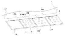
以下、図2を参照してインク供給部200に対して詳細に説明する。
Hereinafter, the
インク(I)は1色のみを用いることもできるが、本発明は多色印刷を仮定して以下の複数の色(添付された図面と以下の実施例では4つの色をそれぞれ有するインク部分(I1、I2、I3、I4)用いる。以下、説明のために、図2から見たとき、右側から一番目(I1)、2番目(I2)、3番目(I3)および4番目(I4)のインク部分と称する。好ましい実施例として、前記4つの色はCMYK(Cyan、Magenta、Yellow、Key plate/Black)色相表による4つの色であり、より好ましい実施例として、アルコールへの耐性を強化するために、UVニス(Varnish)等を最後のインクとして追加することもできる。 Although only one color can be used for the ink (I), the present invention assumes multicolor printing and has the following plurality of colors (in the attached drawing and the following examples, the ink portion having each of the four colors (ink portion (I)). I1, I2, I3, I4) are used. Hereinafter, for the sake of explanation, the first (I1), second (I2), third (I3) and fourth (I4) from the right side when viewed from FIG. Referred to as an ink portion. As a preferred embodiment, the four colors are four colors according to the CMYK (Cyan, Magenta, Yellow, Key plate / Black) hue table, and as a more preferred embodiment, the resistance to alcohol is enhanced. Therefore, UV varnish or the like can be added as the final ink.
それぞれの色別に、インクは所定の間隔(L+Δ)を有する複数のインクシリンジ210を通じて同時に滴下する。これと同時に前記複数のインクシリンジ210はリニアアクチュエータなどの水平移動手段を通じて第1方向(x方向)に必要なインクの幅(L)だけ動いてインク液を線形に滴下しながら移動する。また、本説明では多色インクと表現したが、これは発明の一実施例であって、インク以外の透明な有機物やワニス、更に同一色のインクであっても性質などが異なるインクを含む。
For each color, the ink is dropped simultaneously through a plurality of
スキージ 部230のブレードはブランケットロール100の移動方向(第1方向(x))とは直交する第2方向(y)にインク転写部の転写版310の上に接した状態で移動し、前記インクシリンジによって線形に供給されたインクを転写凹版溝・陰刻に充填する。
The blade of the
この時、それぞれの色が互いに混合されないようにインクが供給される幅を調節しなければならない。本発明の実施例において、説明の単純化のために、インクが供給される幅および陰刻のパターン模様が形成されたインク転写版310の幅をすべてLと表示した。すなわち、インクはインク転写版310の幅(L)だけ線形に供給される。但し、目的に応じ、同じL幅であるとは限らない。
At this time, the width of the ink supplied must be adjusted so that the colors are not mixed with each other. In the embodiment of the present invention, for the sake of simplification of the description, the width to which the ink is supplied and the width of the
図2に示されたように、インク転写版310は複数個を具備してもよく、この場合、インク転写版はインクが互いに混合されないように所定の間隔(Δ)を置いて転写版支持台330上に図2の形式で配置され得る。インク転写版310は説明の便宜上長方形で図示されたが、必ずしも長方形である必要はなく、必要に応じて多様な形状を有することができる。
As shown in FIG. 2, a plurality of
以下、図3および図4を参照してブレードを通じてインクをインク転写版310上の陰刻パターンに充填するスキージ段階を説明する。
Hereinafter, the squeegee step of filling the inscription pattern on the
図3はインク転写部300の版状の転写版支持台330上に配置される4つのインク転写版310を示している。
FIG. 3 shows four
インク転写版310は、好ましくは微細陰刻パターンを加工することができる金属製の版または樹脂フィルムなどであり得る。
The
インク転写部300は陰刻パターン311内のインクをブランケットロール100の表面上に転写する構成であって、版状の支持台300上に一つ以上のインク転写版310が固定される。前記インク転写版310は今後ロール100にインクを転写するため、後述する多色印刷のために正確な位置に固定されていなければならない。
The
インク転写版310を支持台上に固定する第1の固定方法として、図示されていない真空発生部を通じて発生する真空圧力を真空孔335を通じて発生させ、フィルム材質のインク転写版310を支持台330上に動かないように固定させることができる。第2の固定方法として、両面テープ336を用いてインク転写版310を支持台上に固定する。第3の固定方法として、留め金或いは回転固定ネジなどで固定させることもできる。
As a first fixing method for fixing the
図4はスキージ部230のブレード部がロール100が移動する第1方向と直交する第2方向に移動しながらインク転写版310上の陰刻パターン内にインクを充填することを示している。
FIG. 4 shows that the blade portion of the
ただし、図4では、スキージ 部230のブレードはブランケットロール100の移動方向(第1方向(x))が直交することを図示したが、直交ではなく、所定の角度(180度を除く角度(即ち、平行でない角度))を持ってもよい。
However, in FIG. 4, it is shown that the blades of the
インク転写版310は陰刻パターン311が形成されている。樹脂フィルム上に陰刻パターンを形成する方法は、すでに広く知られているインプリント方法などがあり、これは公知の技術であるため、詳細な説明は省略する。
An
スキージ部230のブレードは一端が直線形であるドクターブレードのように、一端がインク転写版310に接した状態でインク(I)を第2方向に押しながらインクを微細陰刻パターン311の中に充填する役割をする。図5はインク(I)が微細陰刻パターン311を充填する様子を示している図面である。このように微細陰刻パターン311内にのみインク(I)が充填され、その後、前記インクはロール100がこれと接した状態で第1方向に移動および回転しながら分子間力及び流体力学運動に基づく力によって引き上げられてロールの表面に転写する(図6)。
The blade of the
本発明の好ましい実施例において、前記ブレードはインクの間の混色を防止するために形成される支持台330の突出部または凹部331、332、333の形状に対応して、ブレードの一端中の一部の形状が変わることもありうる。
In a preferred embodiment of the present invention, the blade corresponds to the shape of the protrusions or recesses 331, 332, 333 of the
図4において、インク転写版310は合計4つが備えられ、それぞれのインク転写版310は同じ幅(L)を有し、それぞれのインク転写版は互いに所定の間隔(Δ)を有する。前述の通り、インク(I)の供給幅もLであるため、ブレードがインクを押しながら第2方向に移動する時、インクが両側に流れて隣り合って位置するインク転写版に入ってインクが互いに混合される恐れがある。
In FIG. 4, a total of four
これを防止するために、転写版支持台330は前記間隔(Δ)に凹部331、333または突出部332を第2方向に伸長するように具備してインクが混合されることを防ぐことができる。
In order to prevent this, the
この時、前記凹部または突出部の形状に対応してブレードの一端中の一部の形状が突出部または凹部231、232の形状を有することができる。もちろん、転写版支持台が凹部331、333の形状を有する場合、必ずしもブレードの一部が凸部231の形状を有する必要はないが、転写版支持台が突出部332の形状を有する場合、ブレード部の円滑な移動のためにブレード部の一端中の一部の形状は支持台の凸部332の形状に対応する凹部232を有することが望ましい。
At this time, a part of the shape in one end of the blade may have the shape of the protrusion or the
さらに他の好ましい実施例として、インクをブレード部を通じて微細陰刻パターンに充填した後、余分のインクを適切に拭き取るための補助ローラなどを設置することもできる。前記補助ローラは必要に応じて、前記ブレード部に付いたインクを自動的に拭き取るものであって、インクの粘度や使用量に応じて所定のスキージ回数ごとにブレード部のインクを拭き取るように設定することができる。 As yet another preferred embodiment, after filling the fine engraved pattern with the ink through the blade portion, an auxiliary roller or the like for appropriately wiping off the excess ink can be installed. The auxiliary roller automatically wipes off the ink attached to the blade portion as needed, and is set to wipe off the ink on the blade portion every predetermined number of times according to the viscosity and the amount of ink used. can do.
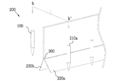
本発明に係るスキージブレード部のさらに他の実施例を図7および図8を参照して説明する。 Yet another embodiment of the squeegee blade portion according to the present invention will be described with reference to FIGS. 7 and 8.
インク供給部200のスキージブレード部は、図7に図示されているように、ブレード部を互いに所定の角度(a + b)を持ち、ブレード回転部260を中心に斜めに配置される2つの第1ブレード230a、第2ブレード230bで構成できる(以下本実施例をダブルブレードという)。この場合、インクシリンジ210もブレード回転部260を中心に第1ブレード側に配置される第1インクシリンジ210a及び第2ブレード側に配置される第2インクシリンジ210bで構成される。これは、インク供給部200がインクを第2方向に移動した後、もとの位置に戻る時にも、インク供給及びスキージ作業を遂行することが可能である構成である。
As shown in FIG. 7, the squeegee blade portion of the
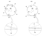
以下図8を参照してダブルブレードの動作を説明する。 The operation of the double blade will be described below with reference to FIG.
図8aは、ロール100がまだ転写部に入る前に1回目のインク供給をする時に、図7のインク供給部200のb - b'の端面である。第1インクシリンジ210aは、インクを転写部に供給し、第2ブレード230bの一端が転写版310に接したまま第2方向に移動する。この時第2インクシリンジ210bは、インクを供給しない。 ブレード回転部260は、第2ブレードの一端が転写版310に接するように回転し、第2ブレードは、ブレード回転部を中心に垂直軸に対して所定の角度(b)を持つ。この時、第1ブレード230aは、一端が転写部に接しないようにブレード回転部を中心に垂直軸に対して前記の第2ブレード230bの角度(b)より大きい角度(a)を持つ(a > b)。
FIG. 8a is the end face of b − b'of the
図8bは、1回目のインク供給が終わり、ロール100がすでに転写部を通過した後、元の位置にインク供給部200が戻りながら、インクの供給及びスキージ作業をすることを示す図面である。図8aの場合とは、逆に、第2インクシリンジ210bが、インクを転写部に供給し、第1ブレード230aの一端が転写版310に接したまま第2方向の逆の方向に移動する。この時、第2ブレード230bは、一端が転写部に接しない反面、第1ブレード230aの一端は転写部に接するようにブレード回転部が回転する。
FIG. 8b is a drawing showing that after the first ink supply is completed and the
図7及び図8に図示されるダブルブレード構成によると、一回目のインク供給が終わってから元の位置に戻ることと同時に次のインク転写のためのさらなるインク供給が可能になるため、インク供給作業の効率性及び経済性が高くなる。 According to the double blade configuration shown in FIGS. 7 and 8, the ink is supplied because the ink can be returned to the original position after the first ink supply is completed and at the same time, more ink can be supplied for the next ink transfer. Work efficiency and economy are improved.
特に、このことは被印刷物への印刷と、インク供給及びスキージ作業が独立にできることにより、印刷の作業性・短時間化に基づく経済性を著しく高める。 In particular, this significantly enhances the workability and economic efficiency of printing based on the workability and shortening of printing time because printing on the printed matter and ink supply and squeegee work can be performed independently.
加えて、ブレードは必要に応じて第2方向でロールの通り道の外側に配置したウエス(waste)やワイパーまたはキムワイプなどにより、被印刷物への印刷中に、ブレードを印刷時間のロスタイム無く独立に拭うことができ、美しい印刷を指向しやすい特徴を併せ持つ。 In addition, the blade wipes the blade independently during printing on the printed matter without loss of printing time, if necessary, with a waste, wiper, or Kimwipe placed outside the roll path in the second direction. It also has the feature that it is easy to aim for beautiful printing.
また、インク供給部200の移動範囲として、インク供給始点から終了点までの転写版上に、線形に供給された開始インク線は、ロールの第1方向移動する時、ロール移動範囲に入らないようにする。すなわち、全体的に、第2方向に移動するインク供給部200は、インクを転写版上に供給し、その後第2方向に移動しながらブレードでスキージ作業を行う。
Further, as the movement range of the
また、ここで、スキージ作業の最後にブレードがインクから離れる時、ブレード転写版及びインクの分子が各々相互分子間力を持っているため、ブレードの裏側に残るインクの残滓が、前記の分子間力のため、転写版やブレードに分け合ってしまい、残余インク線になる。開始インク線と同じく、スキージの最後のブレードの位置(残余インク線の位置)は、ロールの第1方向への移動範囲に入ってはいけない。したがって、ブレードの第2方向への移動距離は、ロールの移動範囲に入らないように、ロールの第2方向長さを超えて移動させねばならない。 Further, here, when the blade separates from the ink at the end of the squeegee work, the blade transfer plate and the ink molecules each have an intermolecular force, so that the ink residue remaining on the back side of the blade is between the above-mentioned molecules. Due to the force, it is divided into transfer plates and blades, resulting in residual ink lines. As with the start ink line, the position of the last blade of the squeegee (the position of the residual ink line) must not be within the range of movement of the roll in the first direction. Therefore, the moving distance of the blade in the second direction must be moved beyond the length of the roll in the second direction so as not to fall within the moving range of the roll.
その後、ロールは、第1方向移動範囲に、開始インク線及び残余インク線が入らないようにしながら、転写版からインクを転写しながら移動する。 After that, the roll moves while transferring the ink from the transfer plate while preventing the start ink line and the residual ink line from entering the first direction movement range.
その後の動作で、ロールは、転写領域を離れ、印刷領域に入るため、スキージ部及びインク供給部は、各々独自的に動くことができるため、次の印刷のために、前述したように転写版にインクを供給する動作が可能になる。 In the subsequent operation, the roll leaves the transfer area and enters the print area, so that the squeegee section and the ink supply section can each move independently. Therefore, for the next printing, the transfer plate as described above. The operation of supplying ink to the printer becomes possible.
前記残余インク線を軽減するためには、前述したように、第2方向の逆方向に移動するブレード及びスキージ動作を追加的に行い、印刷の品質の維持及びロールの保護、インク供給の経済性を高めることができる。 In order to reduce the residual ink line, as described above, the blade and squeegee operations that move in the opposite direction of the second direction are additionally performed to maintain the print quality, protect the roll, and economically supply the ink. Can be enhanced.
図9はロール100が第1方向に移動しながらインク転写版310からインクの転写を受ける全体的な形態を図示した図面である。
FIG. 9 is a drawing illustrating an overall form in which the
図9において、インク転写部310上のインクはLだけの幅を有して間に間隔(Δ)を有する。前述の通り、インクとロール100の間の分子間力および流体力学(流体方程式)に基づいて上側方向の力によってインクが転写版310からロール100に転写する。
In FIG. 9, the ink on the
これに基づいた時、図9に図示されたロール100の半径(r)は、[N(L+Δ)+δ]/(2π)より大きいか同じである。本明細書の実施例において、説明の便宜上ロールの半径(r)は[N(L+Δ)+δ]/(2π)と同じであるとして以下で説明する。
Based on this, the radius (r) of the
ここで、Nは印刷時に用いられる色の数、及び立体印刷物で単一色でも印刷形状が異なる(例えばθ方向に回転させ同じ色をもう一度重ね印刷する)場合、その色の数を意味する。または、Nは、転写版の個数とも言える。一例として、本発明の図1ないし図4の実施例でNは互いに異なる色のインク部分(I1、I2、I3、I4)=4)が使われるため、4である。もし、後述するようにθ方向に回転させ立体印刷物の場合は、同一な色をもう一回印刷するため、N=4×2=8になる。但し、ここでは説明の簡単化のため、θ回転をまずは省略してN=4として、一旦全体の骨子の説明を行う。 Here, N means the number of colors used at the time of printing, and the number of colors when the print shape is different even for a single color in a three-dimensional printed matter (for example, the same color is overprinted again by rotating in the θ direction). Alternatively, N can be said to be the number of transfer plates. As an example, in the examples of FIGS. 1 to 4 of the present invention, N is 4 because ink portions (I1, I2, I3, I4) = 4) having different colors are used. If the three-dimensional printed matter is rotated in the θ direction as described later, the same color is printed again, so N = 4 × 2 = 8. However, for the sake of simplification of the explanation, the whole outline will be explained once by omitting the θ rotation and setting N = 4.
Lは前述の通り、転写版上に塗布されたインクの幅で式の単純化のため、前述したようにθ方向に回転させ、異なる方向の印刷時も同じだと仮定して一定量とし、更にΔはインクの混色を防ぐための転写版(インク)の間の間隔である。この時、δは弾力性のあるローラが転写版及び印刷物にそれぞれ接して発生する半径の長さの変化(ニップ(Nip)を生む)に基づく、ロールの圧力などに依存する微小補正量を意味する。もし前記にニップが発生しない極限の(δ= 0)場合には、ロール100の外周の長さは、各々のインク転写版及び各々のインク転写版の間の所定の間隔の第1方向の長さを足した長さ、またはそれ以上の長さになる。
As described above, L is the width of the ink applied on the transfer plate, and for simplification of the formula, it is rotated in the θ direction as described above, and it is assumed that it is the same when printing in different directions, and the amount is fixed. Further, Δ is the distance between the transfer plates (inks) to prevent color mixing of the inks. At this time, δ means a minute correction amount depending on the pressure of the roll, etc., based on the change in the length of the radius (creating a nip) that occurs when the elastic roller comes into contact with the transfer plate and the printed matter, respectively. To do. If the nip does not occur in the limit (δ = 0), the length of the outer circumference of the
前記のブランケットロール100の外周の長さを一般化すると、下記の数式となる。

ここで、 Liは、第i番目の転写版の第1方向の長さを、Δjは、第j番目の転写版の後に続く第1方向の版の間隔の長さを意味する。 Here, L i means the length of the i-th transfer plate in the first direction, and Δ j means the length of the interval between the plates in the first direction following the j-th transfer plate.
図9において、それぞれのインク転写版310はその大きさが同一であるため、それぞれのインク転写版上の同一印刷位置地点(X1、X2、X3、X4)は第1方向(x)に互いにL+Δだけ離れている。これは後述する印刷段階で、印刷物上の同一地点に対して前記地点(X1、X2、X3、X4)から転写したそれぞれのインクが重なりながら印刷できるようにするためである。
In FIG. 9, since the
図9の下端に示された通り、ロール100が一周回転しながら第1方向に移動するにつれて転写版310上のインクがロール上に転写し、その後、印刷物に対する印刷作業が始まる。即ち、ロール100は1回転し、第1方向に移動すると同時に、一つ以上の転写版上のインクが前記ブランケットロールの表面に転写される。
As shown at the lower end of FIG. 9, as the
図10は印刷部400を図示したものであって、印刷物として厚さを有する立体印刷物410が図示されているが、これに限定されず、平面印刷物または円筒形印刷物にすべて適用することができる。
FIG. 10 illustrates the printed
印刷部400は転写部300を通じてインクを転写したロール100の移動方向(第1方向)の前面に、そして一対のガイドレールの間に位置する。図10において、印刷部400は版状の印刷物支持台420を具備し、前記印刷物支持台上に立体印刷物410が固定されている。
The
印刷物410の固定方法として、印刷物が平面である場合、前述した転写版のように真空圧力または両面テープ、留め金などの治具等を利用することができる。しかし、印刷物410が立体印刷物である場合、立体印刷物を支持台420上に固定させるために別途の固定部材430を具備することが好ましい。印刷物を大量に印刷するためには、印刷物を支持台上への着脱が容易であるとともに印刷中にその位置が強固に固定されている必要がある。好ましい実施例によれば、前記固定部材430は印刷物の内側面に対応する形状を有する3Dプリンタで製作されたプラスチックなど有機物の型である。3Dプリンタで固定部材を製作する場合、多様な形状の印刷物に最適化した固定部材を容易に生成することができるので好ましい。
As a method for fixing the printed
また、3Dプリンターで作った3次元立体自身へのカラー印刷・色づけが出来ることも、本機の大きな特色である。 Another major feature of this machine is that it can print and color 3D objects created with a 3D printer.
図11は印刷物支持台420が第1方向に対して上下に傾いた状態を示している図面である。
FIG. 11 is a drawing showing a state in which the printed
印刷物支持台420の両側面または一側面に備えられる回転手段(例えば、モーターなど)460を通じて、印刷物支持台420は所定の角度(φ)を有して第1方向に対して上下に傾くことができる(以下、印刷物の垂直回転という)。このような構成は、特に印刷物が厚さを有する立体印刷物である場合、非常に効果的である(図11および図16参照)。すなわち、一般的に印刷物を水平状態で置く場合、印刷物の厚さ(高さ)のために印刷がよくできない部分410a、410bもこのように印刷物を傾けることによって効果的に印刷することができる。
Through the rotating means (for example, a motor, etc.) 460 provided on both sides or one side of the printed
図16には、印刷物支持台420は第1方向に対して所定の角度(φ)を有して上下に傾き、ロール100は垂直移動なしに回転しながら第1方向に移動することが図示されている。このように、立体印刷物の場合、印刷物支持台420が傾く特徴を通じて印刷が難しい部分410a、410bに対しても印刷が可能である。
FIG. 16 shows that the printed
ただし、印刷物の傾き程度によって印刷物とロールの接点が互いに異なるため、最適の印刷距離を維持しながら印刷物が傾かなければならない。図16ではこのために、印刷部高低調節部450が印刷物の傾き程度に応じて上下に垂直移動をしながら最適の印刷距離を維持していることが分かる。
However, since the contact points between the printed matter and the roll differ depending on the degree of inclination of the printed matter, the printed matter must be tilted while maintaining the optimum printing distance. For this reason, it can be seen in FIG. 16 that the
印刷部は下端に印刷部高低調節部450を具備して印刷物支持台420の垂直高低を調節することができる。また、印刷部は前記ガイドレールとは別途に印刷物支持台420が第1方向に移動することができるように別途のガイドレールを具備する。前記印刷部支持台420は、印刷部高低調節部450を通じた垂直方向移動と前記ガイドレールを通じた水平方向の移動を互いに独立になすことができる。
The printing unit is provided with a printing unit
図12は印刷物支持台420上の印刷物410が第3方向(z軸)を中心に支持台420上で所定の角度(θ)を有して回転(以下、印刷物の水平回転という)していることを示している。これは後述するように、印刷物が立体印刷物である場合、第1方向にロール100が印刷することだけでは、うまく印刷されない印刷物の垂直近傍またはより鈍角にz軸方向に立ち上がっている側面の部分を印刷するためである。前記印刷物の水平回転のために印刷物支持台420に回転手段を具備することが好ましいが、別途の水平回転手段を具備せず手動で印刷物を回転させても良い。
In FIG. 12, the printed
図13はロールが印刷物に一番目のインク(I1)を印刷する形態を示している図面である。図13では、説明の便宜上平版印刷物を基準として説明するが、これは後述するように、円筒印刷物または立体印刷物に対しても同一に適用される。図面の簡略化のために印刷物支持台および印刷物支持台高さ調節部は図13では省略した。 FIG. 13 is a drawing showing a form in which the roll prints the first ink (I1) on the printed matter. In FIG. 13, for convenience of explanation, a lithographic printed matter will be used as a reference, but as will be described later, the same applies to a cylindrical printed matter or a three-dimensional printed matter. The printed matter support and the height adjusting portion of the printed matter support are omitted in FIG. 13 for the sake of simplification of the drawings.
図13で印刷方法を説明するために図9で説明したX1、X2、X3、X4を基準として以下で説明する。図13は、後述するように図14および図15までの多色印刷方法の一連の開始段階である。説明の便宜上立体物410の第1方向の長さをL+Δと同一にしたが、要求される印刷領域によってL+Δより小さくても良い。
In order to explain the printing method with reference to FIG. 13, X1, X2, X3, and X4 described with reference to FIG. 9 will be referred to below. FIG. 13 is a series of starting stages of the multicolor printing method up to FIGS. 14 and 15, as will be described later. For convenience of explanation, the length of the three-
図13aは、転写部300からロール100にインクが転写した後、平版印刷物410に一番目のインク部分(I1)が印刷される直前の状態を示している。ロール100は図13で反時計回りに回転しながら第1方向に移動する。図13において、TはX1、X2、X3およびX4がそれぞれ重なるように印刷される目標地点(Target Position)を意味する。図13aでTはまだインクが全く印刷されていないのでT0と表示された。図13aの下端の拡大図をみると、ロール100が回転しながら第1方向に移動することによって、被印刷物T0にロールX1上のインクが印刷される直前の図。図13bはインク X1(I1)がT0の位置に印刷された直後を図示している。インクが印刷されたことを示すために、図13a及び13bで丸印で囲んだインクが、ロールから被印刷物TX1に移動している。T0には、X1のインクが印刷された後、T0をTX1と表記した。
FIG. 13a shows a state immediately after the ink is transferred from the
2番目のインク部分(I2)を印刷するためには、ロール100は回転および第1方向移動を停止した状態で印刷物が図13aに対応する位置と同一位置に移動しなければならない。以下、図14は2番目のインク部分(I2)を印刷する前に印刷部(印刷物)が次の印刷位置に移動することを図示した図面である。
In order to print the second ink portion (I2), the
図14aは一番目のインク部分(I1)が印刷物にすべて印刷された直後の状態を示している図面である。前記図13に図示された通り、印刷目標地点(T)にはインク(X1)が印刷されたのでTX1と表示されている。本図面において、ロール100は1/4周回転し、2πr/4だけ第1方向に水平移動している。
FIG. 14a is a drawing showing a state immediately after the first ink portion (I1) is completely printed on the printed matter. As shown in FIG. 13, since the ink (X1) was printed at the print target point (T), it is displayed as TX1. In this drawing, the
図14bは印刷物を下方に垂直移動させることを示している図面である。印刷物がすぐにリニアスラーダーなどで第1方向に水平移動するが、印刷と同じ高さzではロールに印刷物が擦ってしまうため、先に必要な最小距離下方に垂直移動させる。このために印刷部は印刷物支持台高低調節部450を具備する。前記高低調節部450はモーターなどの駆動部を通じて垂直方向に印刷部を上下することができるすべての公知構成を用いることができる。
FIG. 14b is a drawing showing that the printed matter is vertically moved downward. The printed matter immediately moves horizontally in the first direction with a linear sludge or the like, but at the same height z as printing, the printed matter rubs against the roll, so the printed matter is moved vertically downward by the minimum required distance first. For this purpose, the printing unit includes a printed matter support base
図14cは下方に垂直移動した印刷物を第1方向に水平移動させることを示している図面である。この時、2番目のインク部分(I2)が一番目のインク部分(I1)と同一位置に重なるように印刷されるように、水平移動する距離はロール100が回転して移動した距離と同一の2πr/4、すなわち、(L+Δ)+δ/4=L+Δ+ε(ε=δ/4)である。ここで、δは上記のように弾力性のあるローラが転写版または印刷物に接して発生する長さの微小変化に起因する変化量を意味する。εは4つのインク部分(I1、I2、I3、I4)がロール100直径の1/4に該当するため、前記δを4で割った値である。
FIG. 14c is a drawing showing that the printed matter vertically moved downward is horizontally moved in the first direction. At this time, the horizontal movement distance is the same as the rotation distance of the
図14dは前記高低調節部450を通じて上方に印刷部が垂直移動して2番目のインク部分(I2)の印刷が行われる準備ができたことを図示している。
FIG. 14d illustrates that the printing section is vertically moved upward through the
図15は図14で示した2番目の印刷準備プロセスの終了後、即ち垂直移動(図14b、14d)および水平移動(図14c)された印刷部に対し、2番目のインク部分(I2)を印刷することを示している図面である。 FIG. 15 shows the second ink portion (I2) after the completion of the second print preparation process shown in FIG. 14, that is, with respect to the vertically moved (FIGS. 14b, 14d) and horizontally moved (FIG. 14c) printing portions. It is a drawing which shows to print.
図15の2番目のインク部分(I2)印刷方法において、図13との差異は印刷部にすでに図13で行われた1番目のインク部分(I1)が印刷されているという点である。図13でインク(X1)が印刷された目標地点がTX1で図示され、ロール100が図13に比べて90度反時計回りに回転していることが分かる。ただし、図15では図示されていないが、ロール100は図13の一番目のインク部分の印刷時に2πr/4、すなわち、(L+Δ)+δ/4=L+Δ+εだけ第1方向に水平移動された状態である。
In the second ink portion (I2) printing method of FIG. 15, the difference from FIG. 13 is that the first ink portion (I1) already performed in FIG. 13 is printed on the printing portion. In FIG. 13, the target point on which the ink (X1) is printed is illustrated by TX1, and it can be seen that the
図14で印刷物はL+Δ+εだけ第1方向に水平移動したのでインク(I1)が印刷された目標地点(TX1)は、図15aでロール100が回転しながら第1方向に移動するにつれて2番目のインク部分(I2)のインク(X2)が前記目標地点(TX1)に印刷されることになる。図15bはこのような印刷が行われた後、目標地点に二つのインク(X1およびX2)が互いに重なるように印刷されたことを表示するためにTX1X2と表示された。
Since the printed matter moved horizontally in the first direction by L + Δ + ε in FIG. 14, the target point (TX1) on which the ink (I1) was printed moved in the first direction while the
その後、再び図14でのように、印刷物がL+Δ+εだけ第1方向に水平移動して3番目のインク部分(I3)を印刷(TX1X2X3)し、最後にL+Δ+εだけ第1方向に再び水平移動して4番目のインク部分(I4)を印刷(TX1X2X3X4)する。 After that, as shown in FIG. 14, the printed matter moves horizontally by L + Δ + ε in the first direction to print the third ink portion (I3) (TX1X2X3), and finally L + Δ + ε is the second. The fourth ink portion (I4) is printed (TX1X2X3X4) by moving horizontally again in one direction.
前述の通り、4つのインク部分はCMYK色相表による色と仮定する時、4つのインク(I1、I2、I3、I4)を組み合わせることによって、いずれの色相(多色)でも所望のパターンに印刷物に印刷することができる効果を有する。何より、1印刷サイクル(ロール100の1回転)の間にこのような多色印刷が可能であるので印刷時間を節減でき、大量生産が可能となる効果を有する。 As described above, assuming that the four ink parts are the colors according to the CMYK hue table, by combining the four inks (I1, I2, I3, I4), any hue (multicolor) can be printed in the desired pattern. It has the effect of being able to print. Above all, since such multicolor printing is possible during one printing cycle (one rotation of the roll 100), the printing time can be saved and mass production is possible.
図17を参照して本発明に係る印刷部400のさらに他の実施例として、印刷物が小型である場合、第1および第2方向に複数個が印刷物支持部に備えられることによって多量の印刷物を一度に印刷することが可能になる。
As yet another embodiment of the printed
例えば、印刷物410の第2方向への長さが短い場合、ロール100の運動方向(第1方向)に対して直交する第2方向に印刷物を複数個並列配置することができる。または印刷物410の第1方向への長さが短い場合(L以下)、または印刷パターンが全インク領域において同一の場合には第1方向に複数個印刷物を配置しても良い。ただし、いずれの場合であっても第1方向へのすべての印刷物の長さの合計がL以下でなければならない。もちろん、印刷物自体の大きさが前記一つのインク部分に比べて非常に小さい場合、第1方向および第2方向の両方に並列配置して1回の印刷サイクル当たりの生産性をより高めることができる。
For example, when the length of the printed
ただし、以上では印刷方法の説明を、比較的簡単に、先に行ったが、各色の印刷が終わった後で、 短時間のUV光照射を行うことが好ましい。これは他のインクがロールの他の色の上に移らない様にすることと、UV光の固化は、多くはπ*反結合性分子軌道に、元々の低いエネルギー軌道上にある電子が、光子エネルギーを選択的に与えられ、電子遷移を行い、これにより電子雲の重なる確率が増加し、反応が起きて固まる方法であるため、UV光の周波数が合致する有機物を持つインクがありさえすれば、極めて短時間に固化できるためである。 However, although the printing method has been described above relatively simply, it is preferable to perform UV light irradiation for a short time after printing of each color is completed. This prevents other inks from moving onto the other colors of the roll, and the solidification of UV light is often in the π * antibonding molecular orbitals, with electrons in the original low energy orbitals. Photon energy is selectively given to perform electronic transitions, which increases the probability of electron clouds overlapping, and because it is a method in which reactions occur and solidify, even inks with organic substances that match the frequency of UV light are available. For example, it can be solidified in an extremely short time.
図18は印刷物に印刷されたインクを乾燥する乾燥部600を図示している。 FIG. 18 illustrates a drying portion 600 that dries the ink printed on the printed matter.
上述のように、本発明の場合、1印刷サイクル内で同じ印刷物に対しての多色または多種のインクが重なって印刷されるため、重ねて印刷する前のインクを1色印刷ごとに乾燥させる必要がある。もちろん、インクの種類や印刷物の特徴によっては、すべてのインクの印刷過程が完了した後で一括して乾燥させることも可能である場合がある。このことは例えば一旦印刷して、同じ色でθ回転を行って再度印刷をするという場合には、勿論その間にUV照射は必要無い。 As described above, in the case of the present invention, since multiple colors or various kinds of inks for the same printed matter are printed in an overlapping manner within one printing cycle, the inks before the overlapping printing are dried for each color printing. There is a need. Of course, depending on the type of ink and the characteristics of the printed matter, it may be possible to dry all the inks at once after the printing process is completed. This means that, for example, when printing once, rotating θ with the same color, and printing again, of course, UV irradiation is not required during that time.
まず、乾燥部の構成はインクの性質によって変わるが、本発明の場合、UVインクを使用することを仮定して説明する。UVインクは紫外線をインクに照射するだけで上記の原理でインクを迅速に乾燥させることが可能であるため、印刷速度を上げて大量生産を目標とする本発明に好ましい。 First, the composition of the dried portion changes depending on the properties of the ink, but in the case of the present invention, it will be described on the assumption that UV ink is used. Since UV ink can quickly dry ink by the above principle only by irradiating the ink with ultraviolet rays, it is preferable for the present invention in which the printing speed is increased and mass production is aimed at.
図1に示された通り、乾燥部600はロール100の移動方向、すなわち第1方向の延長線上に位置する。しかし、これに限定されず、以下の実施例によれば、ロール100を基準として第1方向の反対方向に配置されていることもある。好ましい実施例として、前記乾燥部600は以下で述べるように、一定の位置に固定される固定型と印刷部400の移動によって移動する移動式がある。
As shown in FIG. 1, the drying portion 600 is located on the moving direction of the
乾燥部600はUV光を照射するUV照射部610およびUV光が印刷物の他に他の位置に照射されないように、特にロール100に照射されないようにUV照射部610とロール100の間でUV光を遮断するUV遮断部620を含む。選択的に、乾燥部600はUV光によって発生する熱による印刷物の劣化、変形、変色を防ぐために冷却部630を含むことができる。
The drying unit 600 includes the UV irradiation unit 610 that irradiates the UV light and the UV light between the UV irradiation unit 610 and the
図19は固定型乾燥部を例示した図面である。 FIG. 19 is a drawing illustrating a fixed type drying portion.
図19aおよび図19bは図14aおよび図14bでロール100の第1方向の延長線側に乾燥部600が配置されたことを示している。図14のように、印刷部400は印刷部支持台高低調節部450を通じて一番目のインク部分(I1)が印刷された印刷物を下方に垂直移動させる。その後、図14ではすぐに2番目のインク部分(I2)の印刷のための位置(第1方向にL+Δ+εだけ水平移動、図14c参照)に移動するが、図19cでは乾燥のために乾燥部が位置する第1方向位置まで水平移動する。その後、乾燥部600はUV照射部610でUVを印刷物に照射し、選択的に冷却のために冷却部630で冷却作業を遂行する。UV照射時にまだ印刷物に印刷されていないロール100上のインク(I2、I3、I4、特にI2およびI3)にUVが照射されないようにUV遮断部610がUV照射部610とロール100の間に配置される。その後、短時間に乾燥が完了した印刷部は図14cと同一位置(一番目のインク部分が印刷された位置から第1方向にL+Δ+εだけ)に水平移動する(図19d、図19e)。
19a and 19b show that the drying portion 600 is arranged on the extension line side of the
このように、色の数に対応した回数の短時間UV照射を行えば、連続印刷を繰り返すことがロール1回転のうちに完了する。 In this way, if UV irradiation is performed for a short time corresponding to the number of colors, continuous printing can be repeated within one roll rotation.
ただし、図19でのように、固定型乾燥部を用いる場合、それぞれのインクの印刷ごとに印刷部が水平移動する距離が長くなるため、結果的に印刷時間が最大4πr/V程度長くなる点がある(Vは移動平均速度、rはロールの半径)。 However, as shown in FIG. 19, when the fixed drying portion is used, the distance that the printing portion moves horizontally becomes longer for each printing of each ink, and as a result, the printing time becomes longer by a maximum of about 4πr / V. (V is the moving average velocity, r is the radius of the roll).
図20はロール100と共に第1方向に移動する移動型乾燥部を図示した図面である。
FIG. 20 is a drawing illustrating a mobile drying portion that moves in the first direction together with the
図20で乾燥部600は図19の固定型乾燥部とは異なり、ロール100を基準として第1方向の反対方向に配置される。ただし、転写部300からロールにインク転写がなされた後、一番目のインク部分(I1)が印刷される時にロール100の移動を邪魔してはいけないので、ロールの直径(2r)より高く垂直方向(z方向)に上下移動可能であることが好ましい。しかし、これに限定されず、ロール100の転写部上で転写が行われる時もロール100についてロール100の後で一緒に移動するように構成しても良い。ただし、いずれの場合であっても一番目のインク部分(I1)の印刷が完了した後はロール100の後からロール100と共に第1方向に移動する。
In FIG. 20, unlike the fixed drying portion of FIG. 19, the drying portion 600 is arranged in the direction opposite to the first direction with respect to the
図20に図示された移動型乾燥部600の場合、ロール100と共に第1方向に移動して印刷が完了した印刷物が別途の水平移動することなく、印刷後すぐに乾燥作業を遂行することができるので図19の固定型乾燥部より印刷速度が速い長所がある。
In the case of the mobile drying unit 600 shown in FIG. 20, the printed matter that has moved in the first direction together with the
また、移動型乾燥部600においても、ロール100に対するUV照射を防ぐためのUV遮断部620がUV照射部610とロール100の間に配置される。
Further, also in the mobile drying unit 600, a UV blocking unit 620 for preventing UV irradiation on the
以下、本発明に係る多色グラビアオフセット印刷装置において、三つの印刷物の種類についてそれぞれ具体的な実施例を説明する。 Hereinafter, specific examples of each of the three types of printed matter in the multicolor gravure offset printing apparatus according to the present invention will be described.
まず、第1実施例として、印刷物が平面印刷物である場合を説明する。 First, as a first embodiment, a case where the printed matter is a flat printed matter will be described.
転写部300に設置された転写版310内に4つの色を塗布し、ロール100は第1方向に回転および水平移動しながらインクをロールに転写する。ロールは前記実施例でのように、それぞれのインク部分(I1、I2、I3、I4)の長さがLであり、互いにΔの間隔を有する。その後、ロール100は第1方向に回転しながら印刷部400に水平移動する。以下、印刷物は太陽電池のような平面印刷物を仮定して説明する。ここで平面とは、平面の持つ高さの変化の全くない平面ではなく、印刷物の高さ変化が印刷に影響を与えない程度(約1mm以下を想定)であり、平面全体にわたり高さの変化が殆どない平面に近い形状をいう。紙や、太陽電池を含む半導体面などがその例である。
Four colors are applied to the
ロール100はリニアアクチュエータなどを用いて第1ガイドレールのスライダーに置かれた状態で印刷物支持版に固定された印刷物400に近付く。この時、平版印刷物の場合、前述した転写版の固定方法のように両面テープまたは真空或いは留め金または固定器具などの治具を通じて固定され得る。その後、ロールが前面に位置した印刷物にロールの下方が接した状態で回転しながら第1方向水平移動することによって印刷がなされる。
The
その後、一番目の印刷部分(I1)の所定の位置(X1)が印刷物に印刷され、一番目の印刷部分(I1)の印刷が完了(TX1)すると、ロール100の回転および水平移動を停止させた状態で印刷物は印刷物支持台高低調節部450を通じて下方に移動した後、L+Δ+εだけ第1方向に水平移動(および再び上方に移動)する。仮に、平面印刷物上及びインク版上でロール100のニップ(Nip)が発生しない弱い圧力の場合、εは0になる。その後、引き続きロール100が回転および水平移動して2番目の印刷部分(I2)の印刷がなされる。この時、印刷物は第1方向にL+Δ+εだけ移動した状態であるので2番目の印刷部分(I2)の所定の位置(X2)が前記インク(X1)の上に重なるように印刷(TX1X2)される。このような方法で、4つの印刷部分(I1、I2、I3、I4)が4層に重なるので、多色印刷が可能である。
After that, the predetermined position (X1) of the first printed portion (I1) is printed on the printed matter, and when the printing of the first printed portion (I1) is completed (TX1), the rotation and horizontal movement of the
第2実施例として、印刷物が円筒形印刷物である場合を図21を参照して説明する。ただし、ロール100が転写版からインクを転写する部分までは前記第1実施例と同一であるため説明を省略する。例えば化粧瓶等のボトル、或いは表面が変形した円柱面もこれに含まれる。
As a second embodiment, a case where the printed matter is a cylindrical printed matter will be described with reference to FIG. However, since the portion of the
第1実施例と相異する点は円筒形の印刷物を横方向に高くし、その両終端のうちいずれか一つまたは両終端の両方に回転手段460を具備して円筒形の印刷物が第2方向(円筒形の長手方向)を軸に360度回転できるという点である。この時、印刷物の回転方向はロール100の回転方向と反対方向である。すなわち、ロール100が前記実施例で反時計回りに回転するとすれば、円筒形印刷物は時計回り方向に回転(逆回転)する。この時、円筒形印刷物の回転はロール100の回転に同期して円筒形印刷物がロールと接する部分が滑らないように等速に制御しなければならない。また、円筒形の両終端に設置された回転手段は印刷物が滑らないように固定具を具備する。
The difference from the first embodiment is that the cylindrical printed matter is raised in the lateral direction, and the cylindrical printed matter is provided with
その後、一番目のインク部分(I1)の印刷方法は印刷物が円筒形でロールと共に回転する点を除いては第1実施例と同一である。すなわち、第2実施例で印刷物の長さは円筒の周長を意味する。 After that, the printing method of the first ink portion (I1) is the same as that of the first embodiment except that the printed matter is cylindrical and rotates with the roll. That is, in the second embodiment, the length of the printed matter means the circumference of the cylinder.
その後、第1実施例と同じように、ロール100は停止した状態で円筒印刷物を下方に垂直移動した後、2番目のインク部分(I2)の印刷位置まで水平移動および垂直移動して2番目のインク部分の印刷準備を終える。その後、ロール100が再び回転および水平移動をしながら一番目のインクが印刷された位置(TX1)と同一位置に戻し、印刷物の回転角φの位相を揃えて2番目のインクが印刷される(TX1X2)。
Then, as in the first embodiment, the
以下、図22を参照して円筒形印刷物のさらに他の実施例を説明する。 Hereinafter, still another embodiment of the cylindrical printed matter will be described with reference to FIG.
前記説明した第2実施例の場合、2番目の印刷部分を印刷するために円筒形印刷物が下側に移動した後、L+Δ+εだけ水平移動して再び上側に移動しなければならないので印刷物が移動するのにかかる時間だけ印刷時間が最大4πr/V程度長くなる問題点がある(Vは移動平均速度、rはロールの半径)。また、乾燥のために乾燥部600が位置する地点まで再び来て帰るだけ印刷時間が長くかかる。 In the case of the second embodiment described above, after the cylindrical printed matter is moved downward in order to print the second printed portion, it must be horizontally moved by L + Δ + ε and moved upward again. There is a problem that the printing time becomes longer by a maximum of about 4πr / V by the time required for the printed matter to move (V is the moving average speed, r is the roll radius). In addition, it takes a long time to print because it comes back to the point where the drying portion 600 is located for drying.
しかし、円筒形印刷物の場合、第1実施例の平面印刷物や第3実施例の立体印刷物とは異なってロール100と共に接した状態でロール100の移動と共に移動しながら円筒印刷物が回転することだけでも多色印刷を行うことができる。すなわち、他の実施例の場合、印刷物が印刷される間に水平に移動しないが、円筒印刷物の場合、印刷が行われながらロール100の水平移動と同じ速度で第1方向に移動することによって、上記のような、乾燥目的を含め(後述)、印刷物の水平移動が不要となる特長は、印刷乾燥をも含む効率的印刷法として特筆できる。
However, in the case of a cylindrical printed matter, unlike the flat printed matter of the first embodiment and the three-dimensional printed matter of the third embodiment, the cylindrical printed matter rotates while moving with the movement of the
図22aは、円筒印刷物410がインクの転写されたロール100の真下に接した状態で一番目のインク部分(I1)の印刷の様子を示している。平面印刷物同様、ロール100は回転しながら第1方向に移動し、これに同期して円筒印刷物はロール100と反対方向に回転しながら同時にロール100の第1方向移動速度と同じ速度で水平移動しながら円筒形印刷物に一番目の印刷部分(I1)が印刷される(図22b)。なお、ここで言う速度は平面の接する面の相対速度であり、ロールとボトルの角速度ではない。図22で円筒形印刷物の周長はロール100の周長の1/4であるので、ロール100が1/4周回転すると円筒形印刷物は一周回転して図22aと同じ状態(ただし、水平にはL+Δ+εだけ移動する)に置かれる(図22c参照)。図22cで第1実施例と同じように目標印刷地点(T)は一番目の印刷部分(I1)が印刷されてTX1と図示された。その後、一番目の印刷部分の印刷と同一に2番目の印刷部分(I2)がロール100の回転および水平移動と共に印刷されると円筒形印刷物410も逆回転および水平移動をしながら2番目の印刷部分が印刷される。この結果、一番目の印刷部分が印刷された位置と同一に2番目の印刷部分が印刷されるので目標地点(TX1)にインク(X2)が重なるように印刷されてTX1TX2となった。
FIG. 22a shows a state in which the first ink portion (I1) is printed in a state where the cylindrical printed
図23を参照すれば、この場合、乾燥部600は円筒形印刷物の下端または第1方向の前面の対角線上に位置し、ロール100および円筒形印刷物の水平移動と共に第1方向に移動する。この時、第1実施例と同じようにUV遮断部はUV照射部とロール100の間に位置してUVがロールに転写したインクに照射されないように遮断・遮蔽する。
Referring to FIG. 23, in this case, the drying portion 600 is located on the lower end of the cylindrical printed matter or diagonally on the front surface in the first direction, and moves in the first direction with the horizontal movement of the
このように、円筒印刷物と乾燥部がロールと共に第1方向に移動すると、第1実施例と同じように円筒印刷物が水平方向に移動するなどの不要な動作を減らすことができ、別途の乾燥部への移動も不要となり、多色印刷をするとともに乾燥まで迅速に進行することができる効果を有する。 In this way, when the cylindrical printed matter and the drying portion move in the first direction together with the roll, unnecessary operations such as the movement of the cylindrical printed matter in the horizontal direction can be reduced as in the first embodiment, and the separate drying portion can be reduced. There is no need to move to, and it has the effect of being able to perform multicolor printing and quickly proceed to drying.
加えて重要なことは、特に図23の右斜めから照射する場合には、印刷中にUVインクを乾燥させるため、印刷効率は著しく高まり、印刷時間の縮減に寄与し経済性を高める。 In addition, it is important that the UV ink is dried during printing, particularly when irradiating from the diagonally right side of FIG. 23, so that the printing efficiency is remarkably increased, which contributes to the reduction of the printing time and the economic efficiency.
第3実施例として、印刷物がz軸に厚さを多様に有する立体印刷物である場合を説明する。ただし、基本的には第1および第2実施例と同一であるので同じ内容は省略する。 As a third embodiment, a case where the printed matter is a three-dimensional printed matter having various thicknesses on the z-axis will be described. However, since it is basically the same as the first and second embodiments, the same contents will be omitted.
第3実施例において、立体印刷物は図10〜図12に図示された印刷物410である。図10を参照する時、印刷物410の形状のうちz方向、すなわち紙面から垂直に近い面を図面で印刷困難なほぼz方向に垂直に立ち上がる面410a、410b、410c、410dと表示した。前述の通り、このような部分はロール100の弾性が大きいとしても平面上にそのまま印刷物が置かれた場合、印刷が容易ではない。すなわち、ロール100がJIS-A硬度が0に近いほどある程度の厚さ(高さ)をカバーすることができるが、硬度が低すぎると、こうした面のために印刷時にロールに鉛直圧力に対してロールの弾性に基づく斜めの水平方向の分力が発生して、ロールが局所的に広がったり、結果として印刷が潰れたり、ローラの寿命を短縮させる問題が生ずる。
In the third embodiment, the three-dimensional printed matter is the printed
したがって、図11および図16ではこのような印刷困難面中、最初の印刷物が置かれた方向を基準として第1方向にある面410a、410bに対する印刷を効果的に遂行するために、回転手段を通じて印刷物を第1方向に対して所定の角度(φ)を有するように回転させることを説明した。
Therefore, in FIGS. 11 and 16, in order to effectively perform printing on the
しかし、図11および図16に図示された方法でも第1方向に進行するローラが印刷困難面410cおよび410dに印刷をすることは難しいこともあり得る。したがって、この場合、図12に示した通り、印刷物それぞれをz軸を中心に所定の角度(θ)だけ回転させる必要がある。本実施例において、前記所定の角度(θ)は90度であるが、必要に応じて他の角度を用いてもよい。
However, even with the methods shown in FIGS. 11 and 16, it may be difficult for the rollers traveling in the first direction to print on the difficult-to-
以下、このような過程を含んで立体印刷物に対する印刷過程を説明する。 Hereinafter, the printing process for a three-dimensional printed matter including such a process will be described.
まず、基本的に転写部300からロール100にインクが転写することは同一であるが、従来の実施例とは違って印刷物がz軸を中心に所定の角度(θ、90度)で回転するため、同じインクを二度使用する必要がある。すなわち、4つの色を印刷物に使用するために本第3実施例では8つの転写版に対して1つのインクの種類(I)当たり2つずつ(I、I')塗布しなければならない。その後、8つの転写版に対してロール100で転写がなされる。或いは4つの転写版にして2つの模様を刻印しておいても良い。以下では説明を簡単にするため、8つの転写版として述べる。
First, the ink is basically transferred from the
印刷物にロールが接近して一番目のインク部分の一番目の印刷(I1)がなされる。その後の過程は図14と同一に、印刷版支持台高低調節部450によって垂直に下降した後、印刷物は第1方向にL+Δ+εだけ水平移動し、再び垂直移動して次の印刷を準備する。この時、印刷物はz軸を中心に所定の角度(θ、90度)だけ回転する。その後、一番目のインク部分の2番目の印刷(I1')がなされる。
The roll approaches the printed matter and the first printing (I1) of the first ink portion is performed. The subsequent process is the same as in FIG. 14, after the printed matter is vertically lowered by the printing plate support
このような過程を通じて1種類のインクを印刷物に印刷した後、同じインクを印刷物を90度水平回転させて再度印刷することによって、前述した印刷困難面410c、410dに対する印刷を容易に行うことができる。
By printing one type of ink on the printed matter through such a process and then reprinting the same ink by rotating the printed matter horizontally by 90 degrees, it is possible to easily print on the above-mentioned difficult-to-
ここで重要なことは、同じ色の印刷のため、この同じ色の印刷が終わるまで、UV光などを当てる乾燥過程が必要がないことである。 What is important here is that since printing of the same color is performed, there is no need for a drying process of applying UV light or the like until the printing of the same color is completed.
その後、二番目のインクの印刷には、印刷物を第1方向にL+Δ+εだけ移動してz軸を中心に所定の角度(θ、90度)だけ回転させるか、或いは版の模様を1色目の順番とは逆にして、今の角度θのままで二番目のインクの印刷を始め、二番目のインク部分の一番目の印刷(I2)を遂行し印刷時間を節減する。その後前記一番目のインク部分と同じように印刷物は第1方向にL+Δ+εだけ移動してz軸を中心に所定の角度(θ、90度)だけ回転した後、二番目のインク部分の2番目の印刷(I2')を遂行する。以下同様にして、多色印刷を立体物全面に施すと共に乾燥過程をロール1回転のみの中で実施する。 After that, for printing the second ink, the printed matter is moved in the first direction by L + Δ + ε and rotated by a predetermined angle (θ, 90 degrees) around the z-axis, or the pattern of the plate is printed. Reversed to the order of the first color, printing of the second ink is started with the current angle θ, and the first printing (I2) of the second ink portion is executed to save the printing time. After that, the printed matter moves by L + Δ + ε in the first direction and rotates by a predetermined angle (θ, 90 degrees) about the z-axis in the same manner as the first ink part, and then the second ink part. Perform the second print (I2') of. In the same manner below, multicolor printing is applied to the entire surface of the three-dimensional object, and the drying process is performed in only one roll.
本印刷法は、ロールの回転1回でできるため、リニアスライダーのロール移動方向との平行度や、制御ソフトウエアー等に不具合がなければ、高精度で高再現性のもとに、本印刷が可能となる。 Since this printing method can be performed with one rotation of the roll, if there is no problem with the parallelism with the roll movement direction of the linear slider, control software, etc., the main printing can be performed with high accuracy and high reproducibility. It will be possible.
Claims (7)
前記ブランケットロールの下端と接し、互いに異なる色のインクが塗布された二つ以上のインク転写版とを含むグラビアオフセット印刷(Gravure offset printing)装置であって、
前記互いに異なる色のインクがスキージ時に互いに混合されないように一端が前記インク転写版に接した状態で第1方向と直交する第2方向に移動するブレードを含み、
前記ブランケットロールが、1回転し、第1方向に移動しながら、二つ以上の転写版上のインクが前記ブランケットロールの表面に転写され、
前記ブランケットロールの表面に転写された二つ以上のインクが、前記ブランケットロールの正面に位置する印刷物上の同一な目標地点に重ね印刷されることで多色印刷をするが、
一番目のインク部分を印刷物に印刷した後、
印刷物が第1方向に単方向移動した後、二番目のインク部分を重ね印刷するために、前記ブランケットロールは上下移動せずに回転しながら回転したほどに第1方向に単方向移動することを特徴とする、グラビアオフセット印刷装置。 A cylindrical blanket roll that moves horizontally in the first direction while rotating,
A gravure offset printing apparatus that includes two or more ink transfer plates that are in contact with the lower end of the blanket roll and are coated with inks of different colors.
A blade that moves in a second direction orthogonal to the first direction with one end in contact with the ink transfer plate is included so that the inks of different colors are not mixed with each other during squeezing.
The ink on two or more transfer plates is transferred to the surface of the blanket roll while the blanket roll makes one rotation and moves in the first direction.
Two or more inks transferred to the surface of the blanket roll are overprinted on the same target point on the printed matter located in front of the blanket roll to perform multicolor printing .
After printing the first ink part on the printed matter
After the printed matter moves in one direction in the first direction, the blanket roll moves in one direction in the first direction as it rotates while rotating without moving up and down in order to overprint the second ink portion. A featured gravure offset printing device.
2πr/N = L+Δ+εであり、
ここで、Nは、 転写版の個数 、
Lは、転写版の第1方向の長さ、
Δは、転写版と転写版との間の第1方向の間隔、
εは、弾力性のあるローラが転写版及び印刷物に各々接して発生する半径の長さの変化(ニップ(Nip))による微小補正量であるδをNに分けた値を意味することを特徴とする請求項2のグラビアオフセット印刷装置。 The distance that the printed matter has moved in one direction in the first direction and the distance that the blanket roll has moved in one direction while rotating are the distances.
2πr / N = L + Δ + ε ,
Where N is the number of transfer plates,
L is the length of the transfer plate in the first direction,
Δ is the distance between the transfer plates in the first direction,
ε is characterized by dividing δ, which is a minute correction amount due to a change in the length of the radius (Nip) generated by the elastic roller in contact with the transfer plate and the printed matter, into N. The gravure offset printing apparatus according to claim 2.
前記ブランケットロールの外周の長さは、
各々のインク転写版の第1方向の長さと、各々のインク転写版の間の所定の間隔の第1方向の長さとを足した長さ以上であることを特徴とする請求項1のグラビアオフセット印刷装置。 Each ink transfer plate has a predetermined interval (Δ) in the first direction and is arranged.
The length of the outer circumference of the blanket roll is
The gravure offset according to claim 1 , wherein the length is equal to or greater than the sum of the length of each ink transfer plate in the first direction and the length of the first direction of a predetermined interval between the ink transfer plates. Printing device.
ここで、
Nは、 転写版の個数、
Liは、第i番目の転写版の第1方向の長さ、
Δjは、第j番目の転写版の後に続く転写版の間の第1方向の版の間隔、
δは、弾力性のあるローラが転写版及び印刷物に各々接して発生する半径の長さの変化(ニップ(Nip))による微小補正量を意味することを特徴とする請求項4のグラビアオフセット印刷装置。 The length of the outer circumference of the blanket roll is
here,
N is the number of transfer plates,
Li is the length of the i-th transfer plate in the first direction,
Δj is the spacing between the first-way plates between the j-th transfer plates and the subsequent transfer plates,
δ means a minute correction amount due to a change in the length of the radius (Nip) generated when the elastic roller is in contact with the transfer plate and the printed matter, respectively, and the gravure offset printing according to claim 4. apparatus.
前記ブランケットロールのロール回転速度及び第1方向への水平移動速度は、転写版上で0.5m/分以上12m/分以下であることを特徴とする請求項1のグラビアオフセット印刷装置。 The hardness of the blanket roll is JIS-A standard 40 degrees or less and exceeds 0 degrees.
The gravure offset printing apparatus according to claim 1 , wherein the roll rotation speed of the blanket roll and the horizontal movement speed in the first direction are 0.5 m / min or more and 12 m / min or less on the transfer plate.
Applications Claiming Priority (2)
| Application Number | Priority Date | Filing Date | Title |
|---|---|---|---|
| KR1020160051847A KR101847102B1 (en) | 2016-04-27 | 2016-04-27 | Multi color gravure offset printing device and method |
| KR10-2016-0051847 | 2016-04-27 |
Publications (3)
| Publication Number | Publication Date |
|---|---|
| JP2017196886A JP2017196886A (en) | 2017-11-02 |
| JP2017196886A5 JP2017196886A5 (en) | 2019-10-31 |
| JP6875807B2 true JP6875807B2 (en) | 2021-05-26 |
Family
ID=60238612
Family Applications (1)
| Application Number | Title | Priority Date | Filing Date |
|---|---|---|---|
| JP2016177094A Active JP6875807B2 (en) | 2016-04-27 | 2016-09-09 | Multicolor gravure offset printing equipment and printing method |
Country Status (2)
| Country | Link |
|---|---|
| JP (1) | JP6875807B2 (en) |
| KR (1) | KR101847102B1 (en) |
Families Citing this family (3)
| Publication number | Priority date | Publication date | Assignee | Title |
|---|---|---|---|---|
| JP7149768B2 (en) * | 2018-08-20 | 2022-10-07 | 株式会社Screenホールディングス | Printing method and printing device |
| JP2020179614A (en) * | 2019-04-26 | 2020-11-05 | 株式会社Screenホールディングス | Printing system and printing method |
| JP2020189461A (en) * | 2019-05-23 | 2020-11-26 | 株式会社アルバック | Transfer printing method |
Family Cites Families (8)
| Publication number | Priority date | Publication date | Assignee | Title |
|---|---|---|---|---|
| JPS57176791A (en) * | 1981-04-22 | 1982-10-30 | Toppan Printing Co Ltd | Printing method |
| JPH05169626A (en) * | 1991-12-25 | 1993-07-09 | Toppan Printing Co Ltd | Offset printer |
| JP3731937B2 (en) * | 1996-04-19 | 2006-01-05 | 住友ゴム工業株式会社 | Manufacturing method of liquid crystal color filter |
| JP5493908B2 (en) * | 2010-01-22 | 2014-05-14 | 大日本印刷株式会社 | Printing machine, light emitting layer forming method, and organic light emitting device |
| KR20120014746A (en) * | 2010-08-10 | 2012-02-20 | 삼성전자주식회사 | Pattern transfer device and pattern transfer method |
| JP2013218398A (en) * | 2012-04-05 | 2013-10-24 | Toppan Printing Co Ltd | Method of manufacturing touch panel sensor substrate, touch panel sensor substrate, and off-set printing device |
| JP2014033013A (en) * | 2012-08-01 | 2014-02-20 | Fujikura Ltd | Method for manufacturing printed wiring board and manufacturing device |
| JP6286994B2 (en) | 2013-09-27 | 2018-03-07 | 凸版印刷株式会社 | Offset printing device |
-
2016
- 2016-04-27 KR KR1020160051847A patent/KR101847102B1/en active IP Right Grant
- 2016-09-09 JP JP2016177094A patent/JP6875807B2/en active Active
Also Published As
| Publication number | Publication date |
|---|---|
| KR20170122625A (en) | 2017-11-06 |
| KR101847102B1 (en) | 2018-04-10 |
| JP2017196886A (en) | 2017-11-02 |
Similar Documents
| Publication | Publication Date | Title |
|---|---|---|
| JP2017196887A (en) | Multi-color gravure offset printing device and printing method | |
| EP1713311B1 (en) | Apparatus for manufacturing electronic devices using roll-to-roll rotary pressing process | |
| AU2017204911B2 (en) | High-speed manufacturing of printed product micro features | |
| Leach | The printing ink manual | |
| ES2360448T3 (en) | PRINTING PROCEDURE | |
| US9764542B2 (en) | Method of flexographically printing a plurality of lines | |
| JP6875807B2 (en) | Multicolor gravure offset printing equipment and printing method | |
| RU2517575C2 (en) | Method of flexographic printing and device of flexographic printing | |
| CA2981189C (en) | Variable printing process using flexible secondary plates and specialty inks | |
| US11001051B2 (en) | Multi-color gravure offset printing device and printing method | |
| JP5436914B2 (en) | Coating device | |
| JP5499822B2 (en) | Method for producing functional thin film | |
| KR20180021052A (en) | Multi color gravure offset printing device and method | |
| JP2013208826A (en) | Thin film printing method and thin film printer | |
| CN102259516A (en) | Thermal shrinkage film printing method and equipment, and printed thermal shrinkage film | |
| KR101776161B1 (en) | Printing method for scattered reflection pattern using gravure roll and printed matter manufactured by the same | |
| JP7161082B1 (en) | Intaglio printing device with inking unit cylinder | |
| JP2012206309A (en) | Relief printing machine and method for manufacturing functional thin film using the same | |
| JP4454056B2 (en) | High-definition printing method | |
| JP2005059348A (en) | Flatbed press for forming organic el luminous layer | |
| JP2012206308A (en) | Printer, and method for manufacturing functional thin film using the same | |
| JP2004276585A (en) | Printing method | |
| JP2012204137A (en) | Method for manufacturing polymer el element |
Legal Events
| Date | Code | Title | Description |
|---|---|---|---|
| A521 | Request for written amendment filed |
Free format text: JAPANESE INTERMEDIATE CODE: A523 Effective date: 20170224 |
|
| A521 | Request for written amendment filed |
Free format text: JAPANESE INTERMEDIATE CODE: A523 Effective date: 20190909 |
|
| A621 | Written request for application examination |
Free format text: JAPANESE INTERMEDIATE CODE: A621 Effective date: 20190909 |
|
| A977 | Report on retrieval |
Free format text: JAPANESE INTERMEDIATE CODE: A971007 Effective date: 20200729 |
|
| A131 | Notification of reasons for refusal |
Free format text: JAPANESE INTERMEDIATE CODE: A131 Effective date: 20200804 |
|
| A521 | Request for written amendment filed |
Free format text: JAPANESE INTERMEDIATE CODE: A523 Effective date: 20201104 |
|
| TRDD | Decision of grant or rejection written | ||
| A01 | Written decision to grant a patent or to grant a registration (utility model) |
Free format text: JAPANESE INTERMEDIATE CODE: A01 Effective date: 20210330 |
|
| A61 | First payment of annual fees (during grant procedure) |
Free format text: JAPANESE INTERMEDIATE CODE: A61 Effective date: 20210423 |
|
| R150 | Certificate of patent or registration of utility model |
Ref document number: 6875807 Country of ref document: JP Free format text: JAPANESE INTERMEDIATE CODE Ref document number: 6875807 Country of ref document: JP Free format text: JAPANESE INTERMEDIATE CODE: R150 |
|
| R250 | Receipt of annual fees |
Free format text: JAPANESE INTERMEDIATE CODE: R250 |