JP6875402B2 - Cold Pilger rolling mill - Google Patents
Cold Pilger rolling mill Download PDFInfo
- Publication number
- JP6875402B2 JP6875402B2 JP2018533657A JP2018533657A JP6875402B2 JP 6875402 B2 JP6875402 B2 JP 6875402B2 JP 2018533657 A JP2018533657 A JP 2018533657A JP 2018533657 A JP2018533657 A JP 2018533657A JP 6875402 B2 JP6875402 B2 JP 6875402B2
- Authority
- JP
- Japan
- Prior art keywords
- roll stand
- gear rack
- rolling mill
- rollers
- roller
- Prior art date
- Legal status (The legal status is an assumption and is not a legal conclusion. Google has not performed a legal analysis and makes no representation as to the accuracy of the status listed.)
- Active
Links
Images


Classifications
-
- B—PERFORMING OPERATIONS; TRANSPORTING
- B21—MECHANICAL METAL-WORKING WITHOUT ESSENTIALLY REMOVING MATERIAL; PUNCHING METAL
- B21B—ROLLING OF METAL
- B21B21/00—Pilgrim-step tube-rolling, i.e. pilger mills
- B21B21/005—Pilgrim-step tube-rolling, i.e. pilger mills with reciprocating stand, e.g. driving the stand
-
- B—PERFORMING OPERATIONS; TRANSPORTING
- B21—MECHANICAL METAL-WORKING WITHOUT ESSENTIALLY REMOVING MATERIAL; PUNCHING METAL
- B21B—ROLLING OF METAL
- B21B31/00—Rolling stand structures; Mounting, adjusting, or interchanging rolls, roll mountings, or stand frames
- B21B31/02—Rolling stand frames or housings; Roll mountings ; Roll chocks
- B21B31/028—Prestressing of rolls or roll mountings in stand frames
-
- B—PERFORMING OPERATIONS; TRANSPORTING
- B21—MECHANICAL METAL-WORKING WITHOUT ESSENTIALLY REMOVING MATERIAL; PUNCHING METAL
- B21B—ROLLING OF METAL
- B21B31/00—Rolling stand structures; Mounting, adjusting, or interchanging rolls, roll mountings, or stand frames
- B21B31/07—Adaptation of roll neck bearings
Description
本発明は、中空体をチューブに成形するためのピルガー圧延機であって、一つの運動方向に直線運動可能であるように支承された第1ロールスタンドを有し、このロールスタンドに、中空体をチューブに成形するために、二つのローラーが、それぞれのシャフトまわりに回転自在に支承されており、これらのローラーのうちの一方が、駆動ギアと一緒にシャフトまわりに配設されており、この駆動ギアが固定式ギアラックと噛み合っており、このギアラックが、ロールスタンドの並進運動によって、この駆動ギアとローラーの回転運動が引き起こされるように、ギアラックホルダに取り付けられており、さらに、ピルガー圧延機の運転中には、駆動モータの回転運動を、プッシュロッドを介して、ロールスタンドの振動する並進運動に転換するようになっている、ロールスタンドに接続されたクランクドライブとを有している、ピルガー圧延機に関する。 The present invention is a Pilger rolling mill for forming a hollow body into a tube, and has a first roll stand supported so as to be capable of linear motion in one direction of motion, and the hollow body is provided on this roll stand. Two rollers are rotatably supported around their respective shafts to form the tube, and one of these rollers is disposed around the shaft along with the drive gear. drive gear meshes with the stationary gear rack, the gear rack, the translational movement of the roll stand, so that the rotational motion of the drive gear and the roller is caused, it is attached to the gear rack holder further pilger During operation of the rolling mill, it has a crank drive connected to the roll stand, which is designed to convert the rotational motion of the drive motor into a vibrating translational motion of the roll stand via a push rod. Regarding the Pilger rolling mill.
特に鋼製の精密金属管を製造するためには、引き延ばされた中空円筒状の素管の圧縮応力による縮径加工が行われる。その際にはこの素管に成形加工が施されて、ある縮径後の定義済み外径と、ある定義済み肉厚とを有するチューブを得ている。 In particular, in order to manufacture a precision metal pipe made of steel, the diameter of the stretched hollow cylindrical raw pipe is reduced by the compressive stress. At that time, the raw tube is molded to obtain a tube having a defined outer diameter after a certain diameter reduction and a defined wall thickness.
最も広く普及しているチューブ用の縮径加工方案として知られるのが、冷間ピルガー圧延であるが、そこではこの素管を中空体(Luppe)と呼んでいる。圧延の際にはこの中空体が、チューブ完成品の内径を定義するようになっているテーパ付き圧延マンドレルに沿って押し込まれて、またその際には、同じくチューブ完成品の外径を定義するようになっている孔型が切られた二つのローラーにより、外側から挟み込まれて、圧延マンドレルに沿って長手方向に圧延されるようになっている。 Cold Pilger rolling is known as the most widely used method for reducing the diameter of tubes, and this raw tube is called a hollow body (Luppe). During rolling, this hollow is pushed along a tapered rolling mandrel that is designed to define the inner diameter of the finished tube, and also defines the outer diameter of the finished tube. It is sandwiched from the outside by two rollers with a hole shape so as to be rolled in the longitudinal direction along the rolling mandrel.
この冷間ピルガー圧延の間には、中空体が圧延マンドレルに向かって、もしくはこれを通り越すように、段階的に送られる一方で、それぞれのローラーは回転しながらマンドレルに沿って、ひいては中空体に沿って、水平方向に往復運動を行うようになっている。そこではこれらのローラーを回転自在に支承しているロールスタンドにより、ローラーの水平運動が規定されることになる。このロールスタンドは、公知の冷間ピルガー圧延機においては、クランクドライブを利用して、圧延マンドレルに対して平行な方向に往復運動されるようになっている。 During this cold Pilger rolling, the hollow body is gradually fed towards or past the rolling mandrel, while each roller rotates along the mandrel and thus into the hollow body . Along the way, it reciprocates in the horizontal direction. There, the roll stand that rotatably supports these rollers regulates the horizontal movement of the rollers. In a known cold Pilger rolling mill, this roll stand reciprocates in a direction parallel to the rolling mandrel by utilizing a crank drive.
このクランクドライブは、実施形態の一例においては、ロールスタンドの往復運動時にそれぞれの転向点で解放される運動エネルギを蓄えて、運動方向の転換後には引き続いてロールスタンドを加速するためにこのエネルギを使用するようになっている、トルク/マスバランスシステムに、接続されている。これに対してローラー自体は、それぞれの回転運動を、ロールスタンドに対して相対位置を固定されたギアラックから得るようになっているが、このギアラックには、それぞれのロール軸に固定接続されたギアが噛み合っている。 In one example of the embodiment, this crank drive stores kinetic energy released at each turning point during the reciprocating motion of the roll stand, and after the change of motion direction, this energy is continuously used to accelerate the roll stand. It is connected to the torque / mass balance system that you are supposed to use. Roller itself contrast, each of the rotational movement, but so obtained from the gear rack which is fixed relative position with respect to the roll stand, this gear rack is fixedly connected to the respective roll axis The gears are in mesh.
フィード用クランプキャリッジは、中空体と一緒に、圧延マンドレルに沿っていわゆる送り方向に運動される。ロールスタンド内に垂直方向に重なり合うように配設される、テーパ付きの孔型が切られたそれぞれのローラーは、フィード用クランプキャリッジによって中空体が固定保持される間に、逆方向に同じ角速度で回転する。その際に両方のローラーはいずれも、中空体の円筒軸に対して平行な同じ向きに、送り方向とは逆方向に、中空体の外筒面上を転動するようになっている。 The feed clamp carriage is moved along with the hollow body in the so-called feed direction along the rolling mandrel. Each of the tapered hole-shaped rollers , which are arranged so as to overlap vertically in the roll stand, have the same angular velocity in the opposite direction while the hollow body is fixedly held by the feed clamp carriage. Rotate. At that time, both rollers are adapted to roll on the outer cylinder surface of the hollow body in the same direction parallel to the cylindrical axis of the hollow body and in the direction opposite to the feeding direction.
実質的に円形の孔型が切られているこれらのローラーのカリバー形状は、連続的に小さくなっていき、カリバーの最後の断面のところでチューブ完成品の直径に達している。一般にこのカリバー形状の断面は、ピルガー圧延パスラインのテーパしたインレット部(Pilgermaul)と、形状が不変である円形のスムージングカリバー(Glaettkaliber)と、それに続く若干大きくなっていくアウトレット部とから成るワーキングカリバー(Arbeitskaliber)と、一回り大きい開口部を有するアイドルカリバー(Leerlaufkaliber)とから成っている。中空体はそれぞれのローラーにより形成されるインレット部により掴まれて、小径の軸状素材がそれぞれのローラーによって外側から圧延されて、ローラーのスムージングカリバーと圧延マンドレルとによって、予定される肉厚へと引き伸ばされて、最後にローラーのアイドルカリバーによって、チューブ完成品が解放される。この圧延の間にロールスタンドは、これに取り付けられたそれぞれのローラーと一緒に、中空体の送り方向とは逆方向に運動される。中空体が、ローラーのアイドルカリバーに到達した後には、フィード用クランプキャリッジを利用してさらにもう一段、圧延マンドレルに向かって送られる一方で、ローラーはロールスタンドと一緒にその水平な初期位置に戻るようになっている。それと同時に中空体がその軸線まわりに回転されることによって、チューブ完成品の周方向にも一様な形状が達成されるようにしている。チューブ各部を何度も繰り返して圧延することによって、チューブの一様な肉厚と真円度とならび、一様な内径および外径が達成される。 The caliber shape of these rollers , which have a substantially circular hole shape, is continuously reduced to reach the diameter of the finished tube at the last cross section of the caliber. Generally, the cross section of this caliber shape is a working caliber consisting of a tapered inlet portion (Pilgermal) of a Pilger rolled pass line, a circular smoothing caliber (Glaettkariber) having an invariant shape, and a subsequent outlet portion that becomes slightly larger. It is composed of (Arbeitskariber) and an idle caliber (Leerlaufkariber) having a slightly larger opening. The hollow body is grasped by the inlet formed by each roller , and the small-diameter shaft-shaped material is rolled from the outside by each roller , and the smoothing caliber and the rolling mandrel of the roller bring about the expected wall thickness. It is stretched and finally the idle caliber of the roller releases the finished tube. During this rolling, the roll stand is moved in the direction opposite to the feeding direction of the hollow body together with each roller attached to the roll stand. After the hollow has reached the roller 's idle caliber, it is fed one more step towards the rolling mandrel using the feed clamp carriage, while the roller returns to its horizontal initial position with the roll stand. It has become like. At the same time, the hollow body is rotated around its axis so that a uniform shape is achieved in the circumferential direction of the finished tube. By rolling each part of the tube over and over again, uniform wall thickness and roundness of the tube, as well as uniform inner and outer diameters are achieved.
従来技術にしたがったピルガー圧延機は、それぞれの仕上げ管の内径および外径の値が狭い範囲内に仕上げ管の生産に限定されている、というのも、それぞれのピルガー圧延機において使用されるロールスタンドは、例外なく、それにより加工することができるチューブの内径および外径を狭い範囲内に限定して設計されたものであるからである。したがって、仕上げ管の内径および外径に関して可能な限り多彩な仕様を当該販売市場に提供するためには、備えられるロールスタンドを異にするピルガー圧延機を多数そろえておく必要がある。この場合は、加工対象であるチューブの内外径に対するその時々の要求項目に応じて、ロールスタンドを選択することが要求される。 According to the prior art, the Pilger rolling mills are limited to the production of finished pipes within a narrow range of the inner and outer diameter values of each finished pipe, because the rolls used in each finished pipe. This is because, without exception, the stand is designed to limit the inner and outer diameters of the tubes that can be machined by it within a narrow range. Therefore, in order to provide the sales market with as many specifications as possible regarding the inner and outer diameters of the finished pipe, it is necessary to prepare a large number of Pilger rolling mills having different roll stands. In this case, it is required to select the roll stand according to the occasional requirements for the inner and outer diameters of the tube to be processed.
より大径の仕上げ管を製造するためには、ロールスタンドの幅およびその中で使用されるそれぞれのローラーの直径に関して、より大型のロールスタンドが必要となる。ロールスタンドの大型化に伴い、ロールスタンドの質量も増大する。 In order to produce a larger diameter finished tube, a larger roll stand is required with respect to the width of the roll stand and the diameter of each roller used therein. As the roll stand becomes larger, the mass of the roll stand also increases.
ある特定のサイズを有するロールスタンドは、このパラメータ範囲内であれば中空体の加工が、最善の形で、すなわち可能な限り一様に、行われるとされる、作製対象であるチューブの内外径のある特有のパラメータ範囲を対象として、設計されている。このパラメータ範囲から外れたチューブについても、圧延は可能ではあるが、しかしその場合はローラーが、それぞれの最適範囲外で作動することになる。その結果、加工プロセスの精度は低下し、仕上げ管の品質は、最適パラメータ範囲内で加工された仕上げ管と比べて劣悪なものとなる。 There roll stand having a specific size, this parameter ranges, if sooner hollow body machining, in the best form, i.e. as long as uniform as possible, is to take place, inner and outer diameter of the tube is fabricated object It is designed for a certain unique parameter range. Rolling is possible for tubes outside this parameter range, but in that case the rollers will operate outside their respective optimum range. As a result, the accuracy of the machining process is reduced and the quality of the finished tube is inferior to that of the finished tube machined within the optimum parameter range.
従来技術にしたがった方法では、任意のピルガー圧延機において、ある特定のロールスタンドと、これに収容されるローラーセットとを使用しない限り、加工対象となるある具体的な内径と外径とを持つチューブを製造するのは不可能である。仕上げ管の外径の値については、ロールスタンドのそれぞれのローラーを第2のローラー対と交換することによって、狭い範囲だけに限られてはいるが、拡張することができる。この第2のローラー対のローラーは、第1のローラー対のローラーとは、それぞれのカリバー形状に関して相違している。第2のロールスタンドのローラーのカリバー形状は、第1のロールスタンドのローラーのカリバー形状とは、ローラーの周方向への構成方式を異にしているために、それによって直径がほんの僅かだけ異なる中空体を、第2のローラー対のインレット部で掴んで、スムージングカリバーで成形して、仕上げ管を解放するためにアウトレット部からアイドルカリバーに引き渡すことができる。それにより仕上げ管の外径を、ある一定の狭い値の範囲内で変更できるようになっている。 According to the prior art, any Pilger rolling mill has a specific inner and outer diameters to be machined unless a particular roll stand and a roller set contained therein are used. It is impossible to make a tube. The value of the outer diameter of the finishing tube can be expanded, though limited to a narrow range, by replacing each roller of the roll stand with a second pair of rollers. The second roller pair of rollers includes a first roller pair of rollers, are different for each caliber shape. Caliber shape of the second roll stand rollers, the caliber shape of the first roll stand of the roller, in order to have different in configuration method in the circumferential direction of the roller, thereby only slightly different diameters hollow The body can be grabbed by the inlet portion of the second roller pair, molded with a smoothing caliber and handed over from the outlet portion to the idle caliber to release the finishing tube. As a result, the outer diameter of the finished pipe can be changed within a certain narrow value range.
この場合は、第2のローラー対のそれぞれのローラーを、ピルガー圧延機のロールスタンドになおも組付け可能であるものとすることによって、加工対象である管径の限界値のこのような拡張がもたらされることになる。この要件を満たすためには、一方では第2のローラー対のローラーを、それぞれの円筒軸に対して平行な大きさに関して、ロールスタンドの幅に対して適合化することが、条件として求められる。他方ではその前提として、第2のローラー対のローラーの直径が、第1のローラー対のローラーの直径と同一であることが求められるが、それにより、それぞれのローラーの回転軸のポジションを不変とすることができる。 In this case, the second of each roller of the roller pair, by which it is assumed that still can assembled to the roll stand of the pilger mill, is such an extension of the limit value of the pipe diameter as a processing target Will be brought. In order to meet this requirement, on the one hand, it is required that the rollers of the second pair of rollers be adapted to the width of the roll stand with respect to the size parallel to each cylindrical axis. On the other hand, as a premise, the diameter of the rollers of the second roller pair is required to be the same as the diameter of the rollers of the first roller pair, so that the position of the rotation axis of each roller does not change. can do.
しかしながらローラーの段取り替えには多くの時間が必要であり、その結果、ピルガー圧延機のダウンタイムの延長とならび、コストアップを来している。 However, it takes a lot of time to change the roller setup, and as a result, the downtime of the Pilger rolling mill is extended and the cost is increased.
このような背景事情のもと、本発明が解決しようとする課題は、同じピルガー圧延機において、従来技術にしたがった狭い値の範囲からさらに拡張された、ある一定の値の範囲内に内径および外径がある、様々なチューブの作製を可能にする、ピルガー圧延機を提供することにある。それに加えて本発明の課題は、同じピルガー圧延機において、作製対象である管径に関してより大きなフレキシビリティを担保することにある。本発明のさらにもう一つの課題は、ピルガー圧延機のダウンタイムの短縮とならび、ピルガー圧延機の各ローラーのより速やかな交換を可能にすることにある。 Under such background circumstances, the problem to be solved by the present invention is that in the same Pilger rolling mill, the inner diameter and the inner diameter within a certain value range further extended from the narrow value range according to the prior art. It is to provide a Pilger rolling mill that allows the fabrication of various tubes with an outer diameter. In addition, an object of the present invention is to ensure greater flexibility with respect to the pipe diameter to be manufactured in the same Pilger rolling mill. Yet another object of the present invention is to reduce the downtime of the Pilger rolling mill and to enable quicker replacement of each roller of the Pilger rolling mill.
これらの課題の内の少なくとも一つは、本発明によれば、中空体に成形加工を施してチューブを得るためのピルガー圧延機であって、直線運動可能であるように支承された第1のロールスタンドを有し、このロールスタンドに、中空体に成形加工を施してチューブを得るために、二つのローラーが、それぞれのシャフトまわりに回転自在に支承されており、これらのローラーのうちの一方が、駆動ギアと一緒に、同じ一本のシャフトまわりに配設されており、この駆動ギアが固定式ギアラックと噛み合っており、このギアラックが、ロールスタンドの並進運動によって、この駆動ギアとローラーの回転運動が引き起こされるように、ギアラックホルダに取り付けられており、さらに、ピルガー圧延機の運転中には、駆動モータの回転運動を、プッシュロッドを介して、ロールスタンドの振動する並進運動に転換するようになっている、ロールスタンドに接続されたクランクドライブとを有している、ピルガー圧延機において、第1のロールスタンドを、その第1の寸法とは異なる第2の寸法を有する第2のロールスタンドと交換可能であるように、ギアラックホルダが構成されている、ピルガー圧延機によって解決される。 At least one of these tasks is, according to the present invention, a Pilger rolling mill for forming a hollow body into a tube to obtain a tube, the first of which is supported to be linearly movable. It has a roll stand, on which two rollers are rotatably supported around each shaft in order to form a hollow body to obtain a tube, one of these rollers. but together with the drive gear, it is arranged on the same single shaft surrounding the drive gear meshes with the stationary gear rack, the gear rack, the translational movement of the roll stand, and the drive gear as the rotational motion of the roller is caused, is attached to the gear rack holder, furthermore, during operation of the pilger mill, the rotational movement of the drive motor, through the push rod to the vibration of the roll stand translation In a Pilger rolling mill, which has a crank drive connected to a roll stand, which is adapted to convert to, the first roll stand has a second dimension different from its first dimension. as is interchangeable with a second roll stand, the gear rack holder is configured, is solved by the pilger mill.
本発明にしたがったギアラックホルダにより、同じ一台のピルガー圧延機において内外径が異なる様々なチューブを製造可能であるように、圧延後のチューブ完成品の製造されなければならない管径に対して低コストで適合させることができる、ピルガー圧延機を提供することが可能となる。それに加えて、圧延後のチューブ完成品の管径に対する様々な要求項目に対してロールスタンドが適合化されることによって、チューブ完成品の正確さならびに精度が向上する。 By a gear rack holder according to the present invention, in the same single in pilger rolling mill as inner and outer diameters can be produced a variety of different tubes for tube diameter must be manufactured of tube finished products after rolling It is possible to provide a Pilger rolling mill that can be adapted at low cost. In addition, the roll stand is adapted to various requirements for the tube diameter of the finished tube after rolling, which improves the accuracy and accuracy of the finished tube.
ロールスタンドの寸法という概念には、本発明の主意においては、長さ、幅、高さの3次元の寸法、およびそれ以外にもローラーならびに駆動ギアの、それぞれの直径に関する寸法も包摂される。 The concept of roll stand dimensions also includes, in the spirit of the present invention, three-dimensional dimensions of length, width and height, as well as dimensions of rollers and drive gears with respect to their respective diameters.
本発明の実施形態の一例においては、第1のロールスタンドが、第2のロールスタンドとは異なる質量を有している。 In an example of an embodiment of the present invention, the first roll stand has a different mass than the second roll stand.
本発明の実施形態の一例においては、第1および第2のロールスタンドが、互いに異なる(運動方向に対して垂直な)幅と質量とを有している。 In an example of an embodiment of the present invention, the first and second roll stands have different widths and masses (perpendicular to the direction of motion).
本発明の実施形態の一例においては、中空体の材料は、いずれかの非合金鋼、いずれかの低合金鋼、およびいずれかの高合金鋼、またはそれらの任意の組み合わせから成る群から選択されている。さらにもう一つの実施形態においては、中空体がステンレス鋼から製造されている。 In one example of an embodiment of the invention, the hollow material is selected from the group consisting of any non-alloy steel, any low alloy steel, and any high alloy steel, or any combination thereof. ing. In yet another embodiment, the hollow body is made of stainless steel.
ほかにもさらに本発明にしたがったギアラックホルダにより、とりたてて言うほどのタイムロスもなく、ロールスタンドを寸法が異なる第2のロールスタンドと簡単に交換することが可能となる。従来のローラーの段取り替え方法とは対照的に、ロールスタンドの交換に起因する運転休止時間を大幅に低減することが可能であり、それにより圧延機の生産性を大幅に増大することができる。 By a gear rack holder according to even further the present invention in addition, there is no time loss of more say collection, it is possible to roll stand dimensions to easily replace the different second roll stand. In contrast to the conventional roller setup method, it is possible to significantly reduce the downtime caused by the replacement of the roll stand, which can greatly increase the productivity of the rolling mill.
本発明の実施形態の一例においては、ギアラックを、それぞれのローラーのシャフトに対して平行な向きに互いから離間している最低でも二つのポジションのところで、ギアラックホルダに収容可能であるように構成されているギアラックホルダを備えて、ピルガー圧延機が構成されている。 In an exemplary embodiment of the present invention, a gear rack, as at the two positions at least that are spaced apart from one another in parallel orientation with respect to each of the roller shafts can be accommodated in the gear rack holder includes a gear rack holder configured, pilger mill is constituted.
本発明にしたがったギアラックホルダにより、ロールスタンドの駆動ギアが、それぞれのローラーのシャフトに対して平行な向きに互いから離間している最低でも二つのポジションのところで、ギアラックホルダに取り付けられたギアラックと噛み合い可能であることを、可能としている。それにより、幅が二通りあるロールスタンドを最低でも二つ、同じピルガー圧延機に組み付けることができるが、ここで本出願に言うロールスタンドの幅とは、それぞれのローラーのシャフトに対して平行な向きのロールスタンドの大きさであると定義されるものである。これは、ローラーの直径が大きくなるほど、ロールスタンドもまた、よりずっしりとした頑丈なものに構成され、それに伴いロールスタンドの幅も最終的に増大する点で、有意である。 By a gear rack holder according to the present invention, the driving gear of the roll stand, at the two positions at least that are spaced apart from one another in parallel orientation with respect to each of the roller shaft, mounted on a gear rack holder that it is engageable with the gear rack, thereby enabling. Thereby, at least two roll stands having two widths can be assembled to the same Pilger rolling mill, but the width of the roll stands referred to in this application is parallel to the shaft of each roller. It is defined as the size of an oriented roll stand. This is significant in that the larger the diameter of the rollers , the more solid and sturdy the roll stand is constructed, and the width of the roll stand eventually increases accordingly.
本発明の実施形態の一例においては、ギアラックを、それぞれのローラーのシャフトに対して垂直であるとともに、ロールスタンドの運動方向に対しても垂直である向きに互いから離間している最低でも二つのポジションのところで、ギアラックホルダに収容可能であるように構成されているギアラックホルダを備えて、ピルガー圧延機が構成されており、そこではそれぞれのポジション間の個々の距離が最低でも10mmとなっている。これについて、実施形態の一例においては、このポジション間の距離とは、それぞれのローラーのシャフトに対して垂直であるとともに、ロールスタンドの運動方向に対しても垂直である向きに測った、それぞれの歯先の位置の間の距離であると解釈されるようになっている。 In an exemplary embodiment of the present invention, a gear rack, with which is perpendicular to each of the roller shafts, two at least of the orientation is also perpendicular direction of movement of the roll stand are spaced from each other One of at the position, provided with a gear rack holder that is configured to be accommodated in the gear rack holder is configured the pilger mill, in which a 10mm also individual distance is the lowest between the respective positions It has become. Regarding this, in an example of the embodiment, the distance between the positions is measured in a direction perpendicular to the shaft of each roller and also perpendicular to the moving direction of the roll stand. It has come to be interpreted as the distance between the positions of the tooth tips.
したがってギアラックは、最低でも二つの互いから離間しているポジションを取ることによって、上下位置を調節できるようになっており、その際にそれぞれのポジション間の個々の距離が最低でも10mmとなっており、このため、それぞれのローラーの回転軸は、最低でも二通りの相互間距離を有することになる。それにより、ローラー径が互いに異なる二つのロールスタンドを、同じピルガー圧延機に組付け可能であることを、可能としている。そこでは上側または下側のローラー、好適には下側のローラーのシャフトまわりの駆動ギアが、その時々のローラー径に適合されている一方で、それにもかかわらずこの駆動ギアは、ギアラックと噛み合うことができるようになっている。 Accordingly gear rack, by taking the position that is spaced from the two each other at least, being adapted to be adjusted in the vertical position, so the individual distances between the respective positions at that time and 10mm at least Therefore, the rotation axes of the respective rollers have at least two distances from each other. This makes it possible to assemble two roll stands with different roller diameters into the same Pilger rolling mill. Wherein the upper or lower side of the roller, preferably the driving gear around the shaft of the lower roller to the, while being adapted to prevailing roller diameter, nevertheless the driving gear meshes with a gear rack You can do it.
別の実施形態においては、それぞれのポジション間の個々の距離が最低でも20mmとなっている。これに対してさらにもう一つの実施形態においては、それぞれのポジション間の個々の距離が最高でも100mmとなっている。さらにもう一つの実施形態においては、それぞれのポジション間の個々の距離が最高でも40mmとなっている。 In another embodiment, the individual distance between each position is at least 20 mm. On the other hand, in yet another embodiment, the individual distance between the respective positions is at most 100 mm. In yet another embodiment, the individual distance between each position is at most 40 mm.
両方のローラーのうちの一方と一緒に、同じ一本のシャフトまわりに配設されているこの駆動ギアは、その回転運動をこのローラーに伝達するようになっており、このため、導入可能な様々なローラー径を用いることによって、それぞれにつきある狭い範囲内で、管径を高い正確さで加工することができる。それにより、品質損失を甘受する必要なく、同じピルガー圧延機を使用して製造することができる、圧延後のチューブ完成品の内外径の値の範囲が、拡張されることになる。 This drive gear, which is located around the same single shaft, along with one of both rollers , is designed to transmit its rotational motion to this roller, and thus the variety that can be introduced. By using a large roller diameter, it is possible to process the pipe diameter with high accuracy within a narrow range for each. This extends the range of values for the inner and outer diameters of the rolled tube finished product that can be manufactured using the same Pilger rolling mill without having to accept quality losses.
本発明のさらにもう一つの実施形態が、それぞれのローラーのシャフトに対して垂直に延びる基準面に対して鏡面対称に配設された二つのギアラックホルダを、そこに取り付けられるギアラックともども有している、ピルガー圧延機である。そこでは両方のローラーのうちの一方の、好適には下側のローラーのシャフトが、この基準面を挟んで両側に駆動ギアを一つずつ担持しており、その際には両方の駆動ギアがいずれもギアラックの一方と噛み合っており、さらにその際にはそれぞれのローラー間に受け入れられることになる中空体の円筒軸が、この基準面内に位置するようになっている。 Yet another embodiment of the present invention, the two gear racks holder arranged mirror-symmetrically with respect to a reference plane extending perpendicular to each of the roller shaft has a gear rack in company attached thereto It is a Pilger rolling mill. Wherein one of the both rollers, preferably the shaft of the lower roller to have, and one by one carries a drive gear on both sides of the reference plane, the drive gear both in that case both meshes with one gear rack further cylindrical axis of the hollow body in that time that will be accepted between the respective rollers, so as to position on the reference plane.
ギアラックホルダに取り付けられるギアラックが、この基準面に対して鏡面対称に配置されることによって、圧延プロセスに干渉作用を及ぼすトルクの発生が低減される、というのも、発生するトルクは、鏡面対称の配置方式により、互いに補償し合うからである。その結果、そのような鏡面対称の配置方式により、ピルガー圧延機の個々のコンポーネントの摩耗が大幅に低減されることになる。その成果は、運転コストならびに修理コストの削減となって現れ、それによりピルガー圧延機は一段と経済的なものとなる。 Gear rack attached to the gear rack holder, by being disposed in mirror symmetry with respect to the reference plane, the occurrence of torque on the interference acting on the rolling process is reduced, because the torque generated, mirror This is because they compensate each other by the symmetrical arrangement method. As a result, such a mirror-symmetrical arrangement method will significantly reduce the wear of the individual components of the Pilger rolling mill. The result is a reduction in operating and repair costs, which makes the Pilger rolling mill even more economical.
本発明のさらにもう一つの実施形態においては、ピルガー圧延機が、ロールスタンドの運動方向に対して平行に延びる軸線まわりに、ロールスタンドから遠ざかることができるように可倒式に配設された、ギアラックホルダを有しており、それによりロールスタンドの急速交換が可能となる。 In yet another embodiment of the invention, the Pilger rolling mill is foldably arranged around an axis extending parallel to the direction of motion of the roll stand so that it can be moved away from the roll stand. It has a gear rack holder becomes thereby possible rapid replacement of the roll stand.
この、ロールスタンドから遠ざかることができるようにギアラックホルダが可倒式である、という表現は、ギアラックホルダのための一種の跳ね上げ機構を説明したものである。ギアラックホルダをロールスタンドから跳ね上げてそこから遠ざけることによって、例えばクレーンを利用してロールスタンドを持ち上げる際には、ギアラックホルダに邪魔されることなく、ロールスタンドに自由にアクセスできるようになる。したがってピルガー圧延機からロールスタンドを、それぞれのローラーのシャフトに対して垂直であるとともに、ロールスタンドの運動方向に対しても垂直である向きに、何物にも妨げられることなく簡単に取り出すことができる。 This, gear rack holder to be able to move away from the roll stand is retractable, that representation is obtained by describing the type of flip-up mechanism for the gear rack holder. By distancing therefrom gear rack holder springing up from a roll stand, for example, when using a crane to lift the roll stand without being obstructed by the gear rack holder, it becomes possible to free access to the roll stand .. Therefore, it is easy to remove the roll stand from the Pilger rolling mill in a direction that is perpendicular to the shaft of each roller and also perpendicular to the direction of movement of the roll stand, without being hindered by anything. it can.
本発明のさらにもう一つの実施形態においては、ピルガー圧延機が、ロールスタンドの運動方向に対して平行に延びる軸線まわりに可倒式に配設されたギアラックホルダを有しているが、そこではこのギアラックホルダを、それぞれのローラーのシャフトに対して垂直な向きに油圧方式により緊締できるようになっており、それによりピルガー圧延機の運転中には、このギアラックホルダが、基準面に対して平行な向きに作用する様々な力を受け止めるようになっている。 In still another embodiment of the present invention, pilger rolling mill, has the gear rack holder disposed retractable about an axis extending parallel to the direction of movement of the roll stand, where the the gear rack holder being adapted to be tightened by a hydraulic system in a perpendicular orientation with respect to each of the roller shaft, whereby during operation of the pilger mill, the gear rack holder, the reference plane On the other hand, it receives various forces acting in parallel directions.
背圧もしくは反力を供給することによって、圧延運転の間に発生する大きな力やトルクについても、ギアラックによって受け止めることが可能となる。機械式のクランピングナットの代わりに油圧式のナットを使用することによって、組付け作業時の時間が節約される上に、より簡単な取扱いを可能としている。 By supplying the back pressure or reaction force, the large force and torque generated during the rolling operation, it becomes possible to receive by the gear rack. By using hydraulic nuts instead of mechanical clamping nuts, time is saved during assembly work and easier handling is possible.
本発明の実施形態の一例においては、ピルガー圧延機のギアラックホルダまたはその複数の部材を、別のギアラックホルダまたはその複数の部材と交換できるようにすることによって、ギアラックを、ギアラックホルダに、それぞれのローラーのシャフトに対して平行な向きに互いから離間している最低でも二つのポジションのところで収容できるようにしている。 In an exemplary embodiment of the present invention, by allowing the gear rack holder or more members of pilger rolling mill, can be replaced with another gear rack holder or more members, the gear rack, the gear rack holder In addition, it is possible to accommodate at least two positions separated from each other in a direction parallel to the shaft of each roller.
したがって、第1のギアラックホルダを第2のギアラックホルダと交換して、それぞれのローラーのシャフトに対して平行な向きに、第1のギアラックホルダのポジションから離間している第2のポジションに入れ替えることが可能であることによって、幅を異にしている最低でも二つのロールスタンドの幅に対してギアラックホルダを適合可能であることを、可能としている。 Therefore, the first gear rack holder and replace it with a second gear rack holder, oriented parallel with respect to each of the roller shaft, a second position spaced from the position of the first gear rack holder by that it is possible to replace the, that it is adaptable to a gear rack holder relative to the width of the two roll stands in different from to have a minimum width, are possible.
好ましい実施形態の一例においては、ギアラックホルダが二分割式に構成されて、ベースキャリヤとアダプタプレートから成っている。そこではベースキャリヤが、ロールスタンドの運動方向に対して平行に延びる軸線まわりに、ロールスタンドから遠ざかることができるように可倒式に配設されている。アダプタプレートは、ベースキャリヤに簡単に装着可能であるために、ギアラックホルダに取り付けられたギアラックは、それぞれのローラーのシャフトに対して平行な向きに互いから離間している最低でも二つのポジションを取ることができる。それぞれのローラーのシャフトに対して平行な向きのサイズが異なる様々なアダプタプレートを、そのようにベースキャリヤ上に装着したり、これらのアダプタプレートをベースキャリヤから取り外したりすることによって、幅を異にする最低でも二つのロールスタンドの幅に対して、さらに場合によってはそのそれぞれのローラーのシャフトのポジションに対して、ギアラックホルダに取り付けられるギアラックを簡単に適合させることができる。 In one preferred embodiment, the gear rack holder is configured into two split, is made from a base carrier and the adapter plate. There, the base carrier is foldably arranged around an axis extending parallel to the direction of motion of the roll stand so that it can be moved away from the roll stand. Adapter plate is a base in order to be easily attachable to the carrier, the gear rack is attached to the gear rack holder, two positions at least that are spaced apart from one another in parallel orientation with respect to each of the roller shaft Can be taken. Different widths can be obtained by mounting various adapter plates of different sizes parallel to the shaft of each roller on the base carrier, or by removing these adapter plates from the base carrier. the width of the two roll stands at a minimum of, further optionally can be the relative position of each of the roller shaft, easily fit the gear rack is attached to the gear rack holder.
この場合はさらにもう一つの長所として、ギアラックホルダ全体を交換する場合とは対照的に、アドオンユニットをただ単に装着するおよび/または取り外すことによって、可倒式ギアラックホルダの開閉運動に影響が出たり、いわんや支障を来したりすることはないために、ギアラックホルダの開閉運動時の旋回軸となる軸線の再調整が不要となる点を挙げられる。本発明の別の実施形態においては、ピルガー圧延機が、浮動式滑り軸受内に、好適には油圧昇降式のキャリッジ上に、可動式に支承されたロールスタンドを有している。そこではこの滑り軸受が、それぞれのローラーのシャフトに対して垂直であるとともに、ロールスタンドの運動方向に対しても垂直である向きの、駆動ギアとギアラック間の遊びの調整を可能とするように、構成されている。 As a still further advantage if, in the case of replacing the entire gear rack holder In contrast, by an add-on unit simply detached and / or attached, influence the opening and closing movement of the retractable gear rack holder out or, in order not to or Kitashi the Iwan'ya trouble, and the point at which re-adjustment of the axis as the pivot axis of the opening and closing movement of the gear rack holder is not required. In another embodiment of the invention, the Pilger rolling mill has a roll stand movably supported in a floating plain bearing, preferably on a hydraulic elevating carriage. The sliding bearing is there, with a perpendicular to the respective roller shaft, the direction is perpendicular with respect to the direction of movement of the roll stand, to permit adjustment of the play between the drive gear and the gear rack Is configured in.
メンテナンスフリーで低摩耗の滑り軸受を使用してキャリッジをガイドすることには、別途必要となる潤滑剤が皆無であるという長所がある。それにより、駆動ギアとギアラックとの噛み合いを極めて精確に確定することができるために、時間の経過に伴い発生する摩耗現象を低減することができるが、それに伴い、材料コストの節減とならび、ピルガー圧延機のダウンタイムの短縮によるコストメリットももたらされることになる。 Guided carriages using maintenance-free, low-wear plain bearings have the advantage of eliminating the need for additional lubricants. Thus, in order to be able to determine the engagement of the drive gear and the gear rack very precisely, but it is possible to reduce wear phenomenon occurring over time, with it, Alongside savings in material cost, There will also be cost benefits due to the reduced downtime of the Pilger rolling mill.
本発明のさらにもう一つの実施形態においては、ピルガー圧延機が垂直方向に重なり合うように配置される二つのローラーを有しており、そこでは、両方のローラーのうちの一方の回転運動によって、両方のローラーのうちの他方の逆方向への回転運動がもたらされるように、両方のローラーのシャフトが、互いに噛み合っている二つの歯車を介して、互いに接続されている。 In yet another embodiment of the invention, the Pilger rolling mill has two rollers arranged so that they overlap in the vertical direction, where both are due to the rotational motion of one of the rollers. as the rotational movement to the other opposite direction is brought out of the rollers, both rollers of the shaft, via two gears are engaged with each other, they are connected to each other.
本発明の実施形態の一例においては、ピルガー圧延機のそれぞれのローラーのシャフトがいずれも、最低でも一つの軸受を有しており、そこでは両方のローラーのうちの一方の最低でも一つの軸受と、両方のローラーのうちの他方の一つの軸受とが、油圧方式により互いに対して緊締されている。 In an example of an embodiment of the invention, each of the shafts of each roller of the Pilger rolling mill has at least one bearing, in which at least one bearing of one of both rollers. , The bearing of the other one of both rollers is hydraulically clamped to each other.
両方のローラーの軸受がそのように油圧方式により互いに対して緊締されることによって、ロールギャップを極めて精確に調整することが可能となる。これは、加工対象であるチューブの品質にプラスの形となって表れ、ロールギャップの精確な調整により、圧延プロセスの間にはチューブの極めて一様な賦形が行われることになる。ほかにもさらに、ローラーが運転中にすり減ることによって被る摩耗を、ロールギャップの正確な調整を通じて低減することができる。 The bearings of both rollers are thus hydraulically clamped to each other, allowing the roll gap to be adjusted very precisely. This manifests itself in a positive way to the quality of the tube being machined, and the precise adjustment of the roll gap results in a very uniform shaping of the tube during the rolling process. In addition to further even the wear incurred by the rollers wear down during operation, it can be reduced through precise adjustment of the roll gap.
本発明のさらにもう一つの実施形態においては、プッシュロッドを受け入れているリフトピン(Hubzapfen)の偏心距離により決まるロールスタンドのストローク長さが、加工可能な最大管径に合わせて設定されて、加工可能な全ての管径に対して不変となっている。 In yet another embodiment of the present invention, the stroke length of the roll stand, which is determined by the eccentric distance of the lift pin (Hubzapfen) receiving the push rod, is set according to the maximum pipe diameter that can be machined and can be machined. It is invariant for all pipe diameters.
圧延プロセスを高い正確さと品質で実施するためには、加工対象である管径が大きくなるほど、それぞれのローラーの直径も大きくしなければならない。ローラーの大径化は、ロールスタンドの質量増大と抱き合わせになっている。その結果圧延力も増大する。単位面積当たりのエネルギ分布が不変であることを担保するために、圧延力の増大に伴い、圧延が行われる面のサイズも同様に増大される。したがってローラーの直径がより大きければ、一回一回のストロークのフィード長さもまた、より大きくなるために、ロールスタンドのストローク長さもまた、より大きくなる。したがってロールスタンドのストローク長さは、ピルガー圧延機において加工されることになる最大管径により決まることになる。しかしながらこのストローク長さは、加工可能なそれよりも格段と小さい管径にとっては、一種の妥協策となる。加工対象である管径がより小さい場合は、ローラーにより小さな直径が選択されることになり、その結果一回一回のストロークのフィード長さが大幅に小さくなるために、この場合は圧延プロセス中により多いストローク回数が適用されることになる。しかしながら、圧延工程がある速度以上となると、チューブの加工が不正確なものとなって、発生する偏肉の箇所も増えてしまい、その結果、品質損失を生じるために、ストローク回数を好きなだけ増やしてやるというわけにもいかない。 In order to carry out the rolling process with high accuracy and quality, the diameter of each roller must be increased as the diameter of the pipe to be processed increases. Large diameter of the roller is adapted to tie the increase in mass of the roll stand. As a result, the rolling force also increases. As the rolling force increases, so does the size of the surface on which the rolling is performed, in order to ensure that the energy distribution per unit area is invariant. Therefore, the larger the diameter of the roller, the larger the feed length of each stroke, and therefore the larger the stroke length of the roll stand. Therefore, the stroke length of the roll stand is determined by the maximum pipe diameter to be machined in the Pilger rolling mill. However, this stroke length is a kind of compromise for much smaller tube diameters that can be machined. If the pipe diameter to be machined is smaller, the rollers will choose a smaller diameter, resulting in a significantly smaller feed length for each stroke, in this case during the rolling process. A larger number of strokes will be applied. However, when the rolling process exceeds a certain speed, the processing of the tube becomes inaccurate and the number of uneven thicknesses generated increases, resulting in quality loss. I can't increase it.
さらにもう一つの実施形態においては、プッシュロッドを受け入れているリフトピンの偏心距離により決まるロールスタンドのストローク長さを、加工可能な様々な管径に合わせて設定できるようになっている。この場合はストローク長さを調整するために、フライホイールまたはクランクドライブの回転軸と、フライホイール上のプッシュロッドの取付け点との間の距離が相応に適合化される、すなわちリフトピンの偏心距離が、選択式に調整可能であるように修正されることになる。それにより、タイプが異なる様々なチューブを製造するために、ピルガー圧延機を急速かつ安価な方法で適合化する可能性を与えている。 In yet another embodiment, the stroke length of the roll stand, which is determined by the eccentric distance of the lift pin receiving the push rod, can be set according to various machineable pipe diameters. In this case, in order to adjust the stroke length, the distance between the axis of rotation of the flywheel or crank drive and the attachment point of the push rod on the flywheel is adjusted accordingly, i.e. the eccentric distance of the lift pin. , Will be modified to be selectable and adjustable. This offers the possibility of adapting Pilger rolling mills in a rapid and inexpensive way to produce a variety of tubes of different types.
本発明の実施形態の一例においては、クランクドライブのクランクシャフトが共回りするバランスマスを有しているが、そこではこのバランスマスによって、ピルガー圧延機に収容された第1のロールスタンドにより加えられる1次のモーメントが補償される、またはほぼ補償されるように、このバランスマスが構成されており、そこでは第1のロールスタンドの質量が第2のロールスタンドの質量よりも小さくなっている。その際にはこのバランスマスが、クランクシャフトの回転軸に対してクランクピンから約180°オフセットして配設されていると好適である。 In one example of an embodiment of the present invention, the crankshaft of the crank drive has a co-rotating balance mass, where the balance mass is added by a first roll stand housed in a Pilger rolling mill. The balance mass is configured so that the primary moment is compensated or nearly compensated, where the mass of the first roll stand is smaller than the mass of the second roll stand. At that time, it is preferable that the balance mass is arranged so as to be offset by about 180 ° from the crank pin with respect to the rotation axis of the crankshaft.
本出願に言うクランクシャフトとは、これに偏心して配設される、プッシュロッドを受け入れるための一つのクランクピンを有している、ありとあらゆる種類のシャフトのことであると解釈されるものである。 The crankshaft referred to in this application is to be construed as any kind of shaft that is eccentrically arranged and has one crankpin for receiving a push rod.
クランクシャフトが、プッシュロッドと一緒に、クランクドライブのクランクシャフトに取り付けられるマスバランス機構がない状態で回転する場合は、その回転軸に関して偏心して配設される、回転するクランクピンによって、回転軸に対して半径方向のシャフトの振動として知覚可能な様々な力が、いわゆる回転慣性力が発生する。したがって、ロールスタンドのムラのない作動を担保し、ひいては圧延後のチューブの高品質を確保するためには、クランクドライブの可能な限り静かな作動を確保することが要求されるが、それにより、野放図な力や野放図なモーメントの発生は実質的に皆無となる、もしくは野放図な力や野放図なモーメントは最小限化されることになる。 If the crankshaft rotates with the push rod in the absence of a mass balance mechanism attached to the crankshaft of the crankdrive, the rotating crankpins, which are eccentric with respect to the axis of rotation, provide the axis of rotation. On the other hand, various forces that can be perceived as vibrations of the shaft in the radial direction generate so-called rotational inertial forces. Therefore, in order to ensure the uniform operation of the roll stand and, by extension, the high quality of the rolled tube, it is necessary to ensure the quietest possible operation of the crank drive. The generation of uncontrolled forces and uncontrolled moments is virtually eliminated, or uncontrolled forces and uncontrolled moments are minimized.
そのためには、クランクドライブのクランクシャフト上で共回りする最低でもバランスマスを利用して、クランクドライブに作用する1次モーメント全体をこのバランスマスにより最善の形で補償することによって、これらの野放図な力が打ち消されるようにすると好適である。 To do this, use at least the balance mass that co-rotates on the crankshaft of the crankdrive, and compensate the entire primary moment acting on the crankdrive in the best possible way with this balance mass. It is preferable that the force is counteracted.
ピルガー圧延機の運転の間に生じる回転慣性力は、クランクシャフトの回転軸に対して偏心して、プッシュロッドの連接点に対して180°オフセットして、クランクドライブ上に配設されたバランスマスを利用して、完全に打ち消すことができる。このバランスマスにより、プッシュロッドが備えられたクランクシャフトの、クランクシャフトの回転軸に関して回転対称な質量分布をもたらし、またそれにより1次モーメントの補償をもたらしている。 The rotational inertial force generated during the operation of the Pilger rolling mill is eccentric with respect to the axis of rotation of the crankshaft, offset by 180 ° with respect to the joint contacts of the push rods, and the balance mass disposed on the crank drive. It can be used to completely cancel it. This balance mass provides a rotationally symmetric mass distribution of the crankshaft with the push rod with respect to the axis of rotation of the crankshaft, thereby providing compensation for the primary moment.
実施形態の一例においては、このバランスマスが、ピルガー圧延機に収容された第1のロールスタンドにより加えられる1次のモーメントが補償される、またはほぼ補償されるように、構成されているが、そこではこの第1のロールスタンドの質量が、第2のロールスタンドの質量よりも小さくなっている。 In one example of the embodiment, the balance mass is configured such that the primary moment applied by the first roll stand housed in the Pilger rolling mill is compensated or nearly compensated. There, the mass of the first roll stand is smaller than the mass of the second roll stand.
質量が大きい第2のロールスタンドは、質量がより小さい第1のロールスタンドと比較して、より小さなクランクシャフトの角速度で駆動されるようになっている。回転慣性力は、クランクシャフトの角速度の2乗に比例して増大するが、これとは逆に回転質量とは正比例の関係だけとなる。したがって、第2のロールスタンドの質量が大きい場合は、角速度を相応に低減することによって、この第2のロールスタンドと、それよりも質量の小さい第1のロールスタンドとの質量差を、少なくとも部分的に埋め合わせることができる。その結果、第1のロールスタンド用に設計されたバランスマスによって、それよりも質量が大きい第2のロールスタンドに関しても、回転慣性力は良好に補償されることになる。 The second roll stand with a higher mass is driven at a smaller crankshaft angular velocity than the first roll stand with a lower mass. The rotational inertial force increases in proportion to the square of the angular velocity of the crankshaft, but on the contrary, it has only a direct proportional relationship with the rotational mass. Therefore, when the mass of the second roll stand is large, the mass difference between the second roll stand and the first roll stand having a smaller mass is at least partially reduced by reducing the angular velocity accordingly. Can be compensated for. As a result, the balance mass designed for the first roll stand will satisfactorily compensate for the rotational inertial force even for the second roll stand, which has a larger mass.
この実施形態の代替例として、第1および第2のロールスタンドの平均値として求められるロールスタンドの質量に関して、クランクドライブに作用するモーメントがバランスマスによって最善の形で補償されるように、バランスマスは構成されている。 As an alternative to this embodiment, the balance mass so that the moment acting on the crank drive is best compensated by the balance mass with respect to the mass of the roll stand, which is calculated as the average value of the first and second roll stands. Is configured.
この実施形態のさらにもう一つの代替例では、バランスマスがクランクドライブに着脱自在に取り付けられるようになっており、それにより、第1のロールスタンドを交換する際には、ピルガー圧延機に収容される第2のロールスタンドの質量に対する適合化が可能な限り正確に行われるようになることで、野放図な力またはモーメントのない、もしくは野放図な力やモーメントが最小限化された、クランクドライブの作動を可能としている。 In yet another alternative of this embodiment, the balance mass is detachably attached to the crank drive so that when the first roll stand is replaced, it is housed in the Pilger rolling mill. The operation of the crank drive with no uncontrolled force or moment, or with minimal uncontrolled force or moment, by making the adaptation to the mass of the second roll stand as accurate as possible. Is possible.
本発明の実施形態の一例においては、ピルガー圧延機が、第2の共回りするバランスマスを備えたバランスシャフトを有しており、その際には冷間ピルガー圧延機の運転中にこのバランスシャフトがクランクシャフトの2倍の角速度で回転するように、クランクシャフトとバランスシャフトとが、中央制御装置を介して、互いに作用し合うように接続されており、さらにその際には、ピルガー圧延機に収容された第1のロールスタンドから加えられる2次のモーメントが補償される、またはほぼ補償されるように、第2のバランスマスが構成されており、そこでは第1のロールスタンドの質量が、第2のロールスタンドの質量よりも小さくなっている。 In one example of an embodiment of the invention, the Pilger rolling mill has a balance shaft with a second co-rotating balance mass, in which case the balance shaft is during operation of the cold Pilger rolling mill. The crankshaft and the balance shaft are connected to each other via a central controller so that the crankshaft rotates at twice the angular velocity of the crankshaft. A second balance mass is constructed such that the secondary moments applied from the contained first roll stand are compensated or nearly compensated, in which the mass of the first roll stand is: It is smaller than the mass of the second roll stand.
補償される野放図な1次慣性力以外にも、ピルガー圧延機の運転時にロールスタンドが振動する直線運動を行う場合は、野放図な2次慣性力も付け加わることになる。この野放図な2次慣性力によって、2次モーメントがプッシュロッドを介してクランクシャフトに伝達されて、クランクシャフトのムラのない作動にマイナスの影響が出てしまう。 In addition to the uncontrolled primary inertial force that is compensated, when the roll stand vibrates in a linear motion during operation of the Pilger rolling mill, an uncontrolled secondary inertial force is also added. Due to this uncontrolled secondary inertial force, the secondary moment is transmitted to the crankshaft via the push rod, which has a negative effect on the even operation of the crankshaft.
野放図な2次慣性力は、その時間、クランクシャフトの2倍の角速度で振動する。このため、クランクシャフトに中央制御装置を介して作用するように接続されている、装着されているバランスウェイトともども、クランクシャフトの2倍の角速度で回転するようになっている、本発明にしたがったバランスシャフトを利用して、この2次慣性力を最小限化もしくは補償することができる。その際にはこのバランスマスの最適化が、第1のロールスタンドに関して2次モーメントを最善な形で打ち消すことができるように、行われるようになっており、そこでは第1のロールスタンドが第2のロールスタンドよりも小さな質量を有している。 The uncontrolled secondary inertial force vibrates at an angular velocity twice that of the crankshaft during that time. Therefore, according to the present invention, the balance weight, which is connected to the crankshaft so as to act via the central control device, rotates at twice the angular velocity of the crankshaft. The balance shaft can be used to minimize or compensate for this secondary inertial force. In that case, the optimization of this balance mass is performed so that the secondary moment can be canceled out in the best possible manner with respect to the first roll stand, in which the first roll stand is the first. It has a smaller mass than the roll stand of 2.
上記で既に詳述したように、第1のロールスタンド用に設計されたバランスマスは、それよりも質量が大きい第2のロールスタンドに関しても、回転慣性力を良好に補償することができる。それに加え、回転慣性力の合計に占める2次モーメントの寄与分は、1次モーメントよりも小さくなっている。 As already detailed above, the balance mass designed for the first roll stand can well compensate for the rotational inertial force even for the second roll stand, which has a larger mass. In addition, the contribution of the secondary moment to the total rotational inertial force is smaller than the primary moment.
本発明のそれ以外の長所、特徴および適用可能性は、以下の好ましい実施形態の一例に関する説明およびそれに付属するそれぞれの図を手掛かりにすると明らかになる。 Other advantages, features and applicability of the present invention will become apparent with reference to the following description of an example of a preferred embodiment and the respective figures accompanying it.
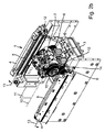
図1には、本発明にしたがったピルガー圧延機の構造が概略的な側面断面図で図示されているが、そこでは、本発明を理解する上で重要ではない特徴を省略している。図示のピルガー圧延機には、ローラー2、3を有するロールスタンド1、下側のローラー3のシャフトまわりに配設された二つの駆動ギア6、それぞれギアラックホルダ4に取り付けられている、二つのギアラック5、テーパ付きの圧延マンドレル7、ならびにフィード用クランプキャリッジ8が含まれている。駆動ギア6については、二つあるうちの一方が下側のローラー3の陰に隠れており、また図を見やすくするために他方も図示を省略した関係で、この図においては確認することができない。ギアラック5ならびにギアラックホルダ4も同様に、図1には描かれていない。
FIG. 1 illustrates the structure of a Pilger rolling mill according to the present invention in schematic side sectional views, but omits features that are not important for understanding the present invention. The illustrated pilger rolling mill roll stand 1 having a
図示の実施形態においては、ピルガー圧延機が、図1からは確認できないとはいえ、それぞれのローラーのシャフトに対して垂直に延びる基準面11に対して鏡面対称に配設された二つのギアラックホルダ4を、それに取り付けられた固定式ギアラック5ともども、有している。これらのギアラックホルダ4は、ここでは、ロールスタンド1の運動方向に対して平行に延びる旋回軸13まわりに、ロールスタンド1から遠ざかることができるように可倒式に配設されている。
In the illustrated embodiment, pilger rolling mill, said to not be confirmed from FIG. 1, the two gear racks arranged in mirror symmetry with respect to the
図1に示される圧延機上のピルガー圧延の間には、中空体9が圧延マンドレル7に向かって、もしくはこれを通り越すように、段階的に送られる一方で、ロールダイ2、3は回転しながら、マンドレル7に沿って、またそれにより中空体9に沿って、水平方向に往復運動を行うようになっている。その際には、ローラー2、3を回転自在に支承しているロールスタンド1により、ローラー2、3の水平運動が規定されることになる。ロールスタンド1が、クランクドライブを利用して圧延マンドレル7に対して平行な向きに往復運動される一方で、ローラー2、3自体は、それぞれの回転運動を、ロールスタンド1に対する相対位置を固定されたそれぞれのギアラック5から得るようになっているが、これらのギアラック5には、下側のロール軸に固定接続されている駆動ギア6が噛み合っている。そこではまずロールスタンド1の並進運動が、これらの駆動ギア6の回転運動に変換される。下側のローラー3のシャフトまわりには、これらの駆動ギア6が、図1には示されていないそれぞれの下側の変速歯車14の右側と左側とにそれぞれ配設されており、それによりこれらの駆動ギア6の回転運動によって、これらの下側の変速歯車14の回転運動も引き起こされるようになっている。これらの下側の変速歯車14もまた、垂直方向にこれに重ねて配設される、これと同じ直径の、図1には示されていない、上側のローラー2のシャフトまわりに配置された、それぞれ上側の変速歯車15と噛み合っている。それによりこれらの上側の変速歯車15は、下側の変速歯車14と同じ角速度で回転されるが、その回転方向は、下側の変速歯車14とは逆になっている。したがって、下側のローラー3のシャフトまわりに配設されたそれぞれの下側の変速歯車14が、上側のローラー2のシャフトまわりに配設されたそれぞれの上側の変速歯車15と係合することによって、これらのローラー2、3の互いに対して逆方向への回転運動が引き起こされることになる。
During Pilger rolling on the rolling mill shown in FIG. 1, the
さらにその上に、上側および下側のローラー2、3のシャフトはいずれも左右に軸受を一つずつ有しており、そこでは上側のローラーの左側の軸受が、下側のローラー3の左側の軸受に対して、ならびに上側のローラー2の右側の軸受が、下側のロースダイス3の右側の軸受に対して、油圧方式により緊締されている。両方のローラー2、3の左側および右側の軸受が互いに対して油圧方式により緊締されることによって、ロールギャップの精確な調整が可能となり、それにより圧延の間にはチューブの極めて一様な賦形が行われることになる。
On top of that, the shafts of the upper and
マンドレル7に沿った中空体9の送りは、圧延マンドレル7の軸線に対して平行な向きへの並進運動を可能とするフィード用クランプキャリッジ8を利用して行われる。ロールスタンド1内に垂直方向に重なり合うように配設される、テーパ付きの孔型が切られたローラー2、3は、チューブの円筒軸に対して平行な向きに、フィード用クランプキャリッジ8の送り方向とは逆向きに、加工対象であるチューブの外筒面上を転動するようになっている。それぞれのローラーにより形成される、いわゆるインレット部により中空体9は掴まれて、小径の軸状素材がそれぞれのローラー2、3によって外側から圧延されて、ローラー2、3のスムージングカリバーと圧延マンドレル7とによって、予定される肉厚へと引き伸ばされて、最後にローラー2、3のアイドルカリバーによって、チューブ完成品が解放される。この圧延工程の間、ロールスタンド1は、これに取り付けられたローラー2、3と一緒に、中空体9の送り方向とは逆向きに運動される。中空体9は、ローラー2、3のアイドルカリバーに到達した後には、フィード用クランプキャリッジ8を利用してさらにもう一段、圧延マンドレル7に向かって送られる一方で、ローラー2、3はロールスタンド1と一緒にその水平な初期位置に戻るようになっている。それと同時に中空体9はその軸線まわりに回転されることによって、チューブ完成品の一様な形状が達成されるようにしている。チューブ各部を何度も繰り返して圧延することによって、チューブの一様な肉厚と真円度とならび、一様な内径および外径が達成される。
The feeding of the
それぞれのローラー2、3のシャフトに対して垂直な、ロールスタンド1の運動方向に対して垂直な向きへの、駆動ギア6とギアラック5間の遊びを精確に調整するために、ロールスタンドは、図1においては、確認することができないとはいえ、ここでは油圧昇降式キャリッジにより実行されている浮動式軸受内に、可動式に支承されている。この油圧式支承は、駆動ギア6とギアラック5間の正確な調整可能性とならび、その易組付け性を特色とするが、それにより特にロールスタンド1の交換作業が大幅に簡素化されて加速化されることになる。その結果、ロールスタンドの交換と抱き合わせになった運転停止時間を大幅に低減することができる。さらにその上に、ローラー2、3をそのように支承することによって、摩耗を受けやすいシール類やピストンを使用せずに済むことになる、すなわち油圧支承部は実質的にメンテナンスフリーで摩耗ゼロとなる。
Perpendicular to the respective shafts of the
図1に図示されるピルガー圧延機のストローク長さは、全ての加工可能な管径に対して不変であって、ピルガー圧延機内で加工されることになる最大管径により決定されている。それにより、リフトピンの偏心距離21の工数がかかる変更が一切不要であるばかりか、偏心距離21は全ての加工プロセスに対して同じままとなるために、プロセスフローの簡素化が可能となる。
The stroke length of the Pilger rolling mill illustrated in FIG. 1 is invariant with respect to all processable pipe diameters and is determined by the maximum pipe diameter that will be machined in the Pilger rolling mill. As a result, not only is it unnecessary to change the lift pin
代替実施形態の一例において、ピルガー圧延機のストロール長さを、加工可能な異なる管径に合わせて調整可能であるように造形することも考えられるかもしれない。そのために、クランクドライブのフライホイールの回転軸と、フライホイール上のプッシュロッドの取付け点との間の距離が、相応に適合化される、すなわちリフトピンの偏心距離21が修正されるようになっている。その結果、加工対象である管径に対してストローク長さを最適な形で適合させることができるために、加工可能である様々な管径に対してストローク長さが不変である場合と比べて、より高精度で加工可能な異なる管径を製造することができる。しかしながらそのためには、リフトピンの偏心距離21の工数がかかる変更を甘受しなければならない。
In one example of the alternative embodiment, it may be considered that the stroll length of the Pilger rolling mill is shaped so that it can be adjusted to the different diameters that can be machined. Therefore, the distance between the axis of rotation of the flywheel of the crank drive and the attachment point of the push rod on the flywheel is adapted accordingly, that is, the
さらにその上に図示の実施形態においては中央制御装置20が備えられているが、これは、バランスシャフト17の駆動モータにも、またクランクシャフトの駆動モータにも接続されている。この制御装置20により、これらのモータは、それぞれの駆動軸が同じ回転方向に回転するように、またその際にはバランスシャフト17の回転数がクランクシャフトの回転数の2倍となるように、制御されるようになっている。
Further, in the illustrated embodiment, a
それ以外にもこの制御装置20は、クランクシャフトとバランスシャフト17の両方のバランスマス16、18の角度同期の回転を保証するようになっている。換言すると両方のバランスマス16、18は、クランクシャフトが1回転した後には同じ角度のところに位置することになるが、その際にバランスシャフト17のバランスマス18は、クランクシャフトが1回転するために要する時間内に2回、360°回転することになる。
In addition, the
図2aには、図1に由来するピルガー圧延機のロールスタンドの前面図が図示されている。質量M1を有するこのロールスタンド1は、直径が30mmと60mmの間である中空体の加工用に設計されている。ロールスタンドの最大ストローク数、すなわちロールスタンドの単位時間当たりの往復運動の最大回数は、図2aに描かれた実施形態の場合は、毎分200回である。冷間ピルガー圧延機の生産性は、ロールスタンドのストローク数により直接左右されるために、経済性の理由から、毎分当たりの作動ストロークを可能な限り大きくすることが模索される。 FIG. 2a shows a front view of the roll stand of the Pilger rolling mill derived from FIG. The roll stand 1 having a mass M 1 is designed for machining hollow bodies having diameters between 30 mm and 60 mm. The maximum number of strokes of the roll stand, that is, the maximum number of reciprocating motions per unit time of the roll stand is 200 times per minute in the case of the embodiment depicted in FIG. 2a. Since the productivity of the cold Pilger rolling mill is directly influenced by the number of strokes of the roll stand, for economic reasons, it is sought to make the operating stroke per minute as large as possible.
図2aのロールスタンド1では、それぞれのローラー2、3のシャフトに対して垂直に延びる基準面11に対して、それぞれのローラー2、3も、またそれぞれの駆動ギア6も、鏡面対称に配設されており、そこではこれらのローラー2、3間に受け入れられることになる中空体9の円筒軸が、この基準面11内に位置している。ここではそれぞれの駆動ギア6が、下側のローラー3のシャフトに固定して接続されて、同様に鏡面対称に配設されたそれぞれのギアラックホルダ4に取り付けられたギアラック5と噛み合っている。図2aにおいては、ギアラックホルダ4の陰にこれらのギアラック5が隠れているために、これらを確認するのは不可能である。
In the roll stand 1 of FIG. 2a, the
ピルガー圧延機の作動中にこの基準面11に対して平行な向きに作用する様々な力を受け止めるために、これらのギアラックホルダ4は、それぞれのローラーのシャフトに対して垂直な向きに、油圧方式により緊締できるようになっている。この油圧方式による緊締は、ここでは、いずれも実質的にリングピストンとシリンダとから成る複数の油圧ナット12から成るシステムにより行われるようになっている。一時的に圧力を加えることによって、それぞれのローラー2、3のシャフトに対して垂直な向きに力が立ち上げられる。それによりクランプ力または変位力を一時的に立ち上げることができるために、ロールスタンド1は、圧延プロセスの間には、それぞれのローラー2、3のシャフトに対して平行な向きに、ある固定ポジションのところに保持されて、それにより発生する様々なねじり力に起因して、ロールスタンド1がこのポジションから出て滑動するのを妨げるようになっている。
During operation of the pilger mill in order to receive the various forces acting on the parallel orientation with respect to the
それに加えて図2aに図示されるギアラックホルダ4は、ギアラック5に対して平行に延びる旋回軸13まわりに、ロールスタンドから遠ざかることができるように可倒式に配設されているが、図2aにおいてはこの旋回軸13が、その配向の関係上、図の面よりも奥の方に位置しているために、図2aからこれを確認することはできない。ギアラックホルダ4をただ単に跳ね上げてロールスタンドから遠ざけることによって、それぞれの駆動ギア6は、それぞれのギアラック5とのコンタクトを失うために、クレーンを用いてロールスタンド1を持ち上げる際に、ギアラックホルダ4により妨害されることはない。それによりロールスタンド1を、何物にも妨げられずに簡単かつ急速に交換することができる。これに随伴して、加工プロセスのフレキシビリティが、加工可能な管径の範囲が拡張される点で、必然的に増大されることになる。
Gear rack holder 4 illustrated in Figure 2a, in addition thereto, about the
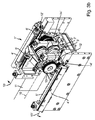
図2bには、図2aに由来するロールスタンドを、ギアラックホルダ4と共に上から見た斜視図が示されるが、このギアラックホルダ4は、その旋回軸13まわりに、図示される矢印の向きにロールスタンドから遠ざけて跳ね上げられた開放ポジションにあり、その結果、このギアラックホルダ4に取り付けられたギアラック5は、駆動ギア6との接触部をどこにも有していない。それによりロールスタンド1は、ギアラックホルダ4により最早妨害されることなく、クレーンを利用して持ち上げることによって簡単かつ急速にピルガー圧延機から取り出して、寸法が異なる第2のロールスタンド1’と交換することができる。
The FIG. 2b, the roll stand from Fig. 2a, but perspective view from above diagrams are shown with gear rack holder 4, the gear rack holder 4 around the
図3aには、図1に由来するピルガー圧延機の第2のロールスタンド1’の前面図が図示されている。これは、図2aとは異なり、3次元の寸法ならびにローラー2’、3’の直径および駆動ギア6’に関して、寸法が一回り大きくなってはいるものの、図1に示されるのと同じピルガー圧延機に組み付けることができる、ロールスタンド1’である。図3aに図示されるロールスタンド1’の一回り大きな寸法は、図2aおよび2bに示されるロールスタンド1と比較して増大する質量にも反映されている。第2のロールスタンドの質量は、本実施形態においては、図2aおよび2bに示されるロールスタンド1の質量M1の2・5倍である。さらにその上に図3aに図示されるローススタンド1’は、直径が40mmと88mmの間である中空体の加工用に、すなわち、図2aおよび2bに示されるロールスタンド1と比べてより大きな直径を対象として、設計されている。ここではロールスタンド1’の最大ストロール数が、毎分150回と、相応に少ない数値となっている。
FIG. 3a shows a front view of the second roll stand 1'of the Pilger rolling mill derived from FIG. This is the same Pilger rolling as shown in FIG. 1, although the dimensions are slightly larger with respect to the three-dimensional dimensions and the diameters of the rollers 2'3'and the drive gear 6', unlike FIG. 2a. It is a roll stand 1'that can be assembled to the machine. The slightly larger dimension of the roll stand 1'shown in FIG. 3a is also reflected in the increased mass as compared to the
本発明にしたがったギアラックホルダ4’は、図3aにおいては、図2aに図示されるギアラックホルダ4と比べて、基準面11’に対して垂直に基準面11’からさらに遠ざかったポジションにある。これは、図2aおよび3aの実施形態においては、ギアラックホルダ4、4’が二分割式に構成されることによって可能となる。これには、一方ではベースキャリヤが、他方ではアダプタプレートが含まれているが、このアダプタプレートは、ロールスタンド1、1’のそれぞれの駆動ギア6、6’が、基準面11に対して垂直な向きに互いから離間している最低でも二つのポジションのところで、それぞれのギアラックホルダ4、4’に取り付けられたギアラック5、5’に噛み合うことができるように、ベースキャリヤに装着できるようになっている。図2aの事例においては、このアダプタプレートが、ローラー2、3のシャフトに対して平行な向きに、図3aの事例よりも大きく作られているために、ギアラック5の基準面11の法線の向きの基準面11からの距離はより小さくなっている。
Gear rack holder 4 according to the present invention ', in the Figure 3a, as compared with the gear rack holder 4 illustrated in Figure 2a, the reference plane 11' to further away the position from the reference plane 11 'perpendicular to the is there. This, in the embodiment of FIGS. 2a and 3a is made possible by the gear rack holder 4, 4 'is configured in a two-split. This includes a base carrier on the one hand and an adapter plate on the other hand, in which the drive gears 6 and 6'of the roll stands 1 and 1'are perpendicular to the
しかしながら、それぞれのローラー2’、3’のシャフトに対して平行な向きのこのポジションとならび、それぞれのローラー2’、3’のシャフトに対して垂直である、ロールスタンド1’の運動方向に対しても垂直である向きについても、ギアラックホルダ4’の適合化は不可欠である。この適合化が必要となるのは、駆動ギア6’が、図2aに図示される駆動ギア6と比較して大径化されているからである。そのような適合化は、ベースキャリヤと、それに装着される、相応に構成されたアダプタプレートの形態をとる、二分割型のギアラックホルダ4’により実現されるようになっており、それによりロールスタンド1’の駆動ギア6’は、ギアラックホルダ4’に取り付けられたギアラック5’に噛み合うことができる。
However, each of the rollers 2 ', 3' Alongside this position oriented parallel to the shaft of each roller 2 ', 3' is perpendicular to the shaft, with respect to the direction of movement of the roll stand 1 ' for even orientation is also vertically, adaptation of the gear rack holder 4 'is essential. This adaptation is necessary because the drive gear 6'has a larger diameter than the
図3bには、図3aに由来するロールスタンド1’を上から見た斜視図が示される。ギアラックホルダ4’は、ここでは、ロールスタンド1’の運動方向に対して平行に延びる旋回軸13’まわりに旋回されることによって、ロールスタンド1’から遠ざかる、図2bと同様の開放ポジションにあるために、ギアラックホルダ4’に取り付けられたギアラック5’は、ロールスタンド1’の駆動ギア6’との接触部を最早どこにも有していない。図2aおよび2bに図示される寸法と比べて一回り大きい寸法を有するロールスタンド1’のこの実施形態においても、ロールスタンド1’を露出させる旋回装置を利用して、ロールスタンド1’を簡単かつ急速にピルガー圧延機から取り出すことができる。
FIG. 3b shows a perspective view of the roll stand 1'derived from FIG. 3a as viewed from above. Gear rack holder 4 'is here roll stand 1''by being pivoted around the roll stand 1'
本来の開示という目的のためにここで付言しておくが、この発明の詳細な説明、図面および特許請求の範囲から、当業者であれば推察するような特徴はみな、たとえそれらがさらに別の特定の特徴との関連だけにおいて具体的に記述されたものであったとしても、単独でも、またここに開示されるそれ以外の特徴または特徴群との任意の組み合わせにおいても、明文でその可能性が排除されていない限り、もしくは技術面での所与の条件が、そのような組み合わせを不可能または無意味なものとしない限り、使用することができるものである。ここでは、あくまでもこの発明の詳細な説明を簡潔で読みやすいものとするためだけに、考えられる全ての特徴の組み合わせについての、包括的で明示的な描写を割愛するものとする。 For the purposes of the original disclosure, all features that one of ordinary skill in the art would infer from the detailed description, drawings and claims of the invention are all yet different. The possibility, whether specifically described in relation to a particular feature alone, alone, or in any combination with other features or features disclosed herein. Can be used unless is excluded, or given technical conditions make such a combination impossible or meaningless. In order to make the detailed description of the present invention concise and easy to read, a comprehensive and explicit description of all possible combinations of features is omitted here.
それぞれの図においては本発明を細部にわたり描写した。また以上の説明でも、本発明について詳しく記述したが、これらの描写や説明は、あくまでも例示的に行ったものであり、また、特許請求の範囲により定義されるような保護範囲をそれにより限定することを意図したものでもない。本発明は、開示されるそれぞれの実施形態に限定されるものではない。 In each figure, the present invention is depicted in detail. Further, in the above description, the present invention has been described in detail, but these descriptions and explanations are merely exemplary, and the scope of protection as defined by the claims is thereby limited. It wasn't meant to be. The present invention is not limited to the respective embodiments disclosed.
当業者には、図面、発明の詳細な説明、および添付の特許請求の範囲から、開示される各実施形態の様々な変形例が明らかである。特許請求の範囲において用いられる「有している」という言葉は、それ以外の要素やステップが含まれる可能性を排除するものではないし、また「いずれかの」「何らかの」「(ある)一つの」などと訳される不定冠詞が付いた名詞についても、それが複数ある可能性を排除するものではない。異なる請求項において請求されている複数の特定の特徴についても、ただその事実だけをもってして、これらの特徴を組み合わせる可能性が排除されているというわけではない。特許請求の範囲で用いられる符号も、保護範囲を限定することを意図したものではない。 Various variations of each disclosed embodiment will be apparent to those skilled in the art from the drawings, detailed description of the invention, and the appended claims. The word "have" used in the claims does not exclude the possibility of including other elements or steps, and "any", "something", or "(is) one". It does not exclude the possibility that there are multiple nouns with indefinite articles translated as "." Even for a plurality of specific features claimed in different claims, the fact alone does not exclude the possibility of combining these features. The codes used in the claims are also not intended to limit the scope of protection.
1、1’ ロールスタンド
2、2’ 上側のローラー
3、3’ 下側のローラー
4、4’ ギアラックホルダ
5、5’ ギアラック
6、6’ 駆動ギア
7 テーパ付きの圧延マンドレル
8 フィード用クランプキャリッジ
9、9’ 中空体
10 中空体の円筒軸
11 基準面
12、12’ 油圧ナット
13、13’ ギアラックホルダの旋回軸
14、14’ 下側の変速歯車
15、15’ 上側の変速歯車
16 バランスマス
17 バランスシャフト
18 第2のバランスマス
19 プッシュロッド
20 中央制御装置
21 偏心距離
1,1 '
Claims (13)
一つの運動方向に直線運動可能であるように支承された第1のロールスタンド(1)であって、前記ロールスタンド(1)には、中空体(9)をチューブに成形するための二つのローラー(2,3)が、それぞれのシャフトに回転自在に支承されており、前記ローラー(2,3)のうちの一方が、駆動ギア(6)とともに、シャフトに配設されており、前記駆動ギア(6)が、固定式ギアラック(5)と噛み合っており、前記ギアラック(5)が、前記ロールスタンド(1)の並進運動によって、前記駆動ギア(6)および前記ローラー(2,3)の回転運動が引き起こされるように、ギアラックホルダ(4)に取り付けられている、第1のロールスタンド(1)と、
該ピルガー圧延機の運転中に、駆動モータの回転運動を、連結ロッドを介して、前記ロールスタンド(1)の振動する並進運動に転換するようになっている、前記ロールスタンド(1)に接続されたクランクドライブと、
を有している、ピルガー圧延機において、
前記第1のロールスタンド(1)を、その第1の寸法とは異なる第2の寸法を有する第2のロールスタンド(1’)と交換可能であるように、前記ギアラックホルダ(4)が構成されていて、
前記ギアラック(5)を、前記ローラー(2,3)の前記シャフトに対して平行な向きに互いから離間している最低でも二つのポジションのところで、前記ギアラックホルダ(4)に収容可能であるように、前記ギアラックホルダ(4)が構成されている、
ピルガー圧延機。 A Pilger rolling mill for forming a hollow body (9) into a tube.
It is a first roll stand (1) supported so as to be able to move linearly in one movement direction, and the roll stand (1) has two for forming a hollow body (9) into a tube. Rollers (2, 3) are rotatably supported on their respective shafts, and one of the rollers (2, 3) is arranged on the shaft together with the drive gear (6) to drive the drive. gear (6), fixed meshes with a gear rack (5), the gear rack (5) by translational movement of the roll stand (1), said driving gear (6) and the roller (2, 3 rotated such movement is caused in), it is attached to the gear rack holder (4), a first roll stand (1),
During the operation of the Pilger rolling mill, the rotary motion of the drive motor is connected to the roll stand (1) via a connecting rod so as to be converted into a vibrating translational motion of the roll stand (1). Crank drive and
In the Pilger rolling mill, which has
The first roll stand (1), as from its first dimension is interchangeable with the second roll stand having a different second dimension (1 '), the gear rack holder (4) It is composed and
The gear rack (5) can be accommodated in the gear rack holder (4) at at least two positions separated from each other in a direction parallel to the shaft of the rollers (2, 3). The gear rack holder (4) is configured in the above.
Pilger rolling mill.
The pilger mill has a balance shaft (17) provided with a balance mass (18) to rotate together, during operation of the pin Ruger mill, said balance shaft (17) of said crankshaft The crankshaft and the balance shaft (17) are connected so as to interact with each other so as to rotate at twice an angular speed, and are added from the first roll stand (1) housed in the Pilger rolling mill. primary moment is compensated for, or as substantially compensated, the and the balance Ma scan is configured, the mass of the first roll stand (1) is, the second roll stand (1 ' ) have smaller than the mass of pilger rolling mill according to claim 12.
Applications Claiming Priority (3)
| Application Number | Priority Date | Filing Date | Title |
|---|---|---|---|
| DE102015122701.0A DE102015122701A1 (en) | 2015-12-23 | 2015-12-23 | Cold pilger rolling mill |
| DE102015122701.0 | 2015-12-23 | ||
| PCT/EP2016/081913 WO2017108784A1 (en) | 2015-12-23 | 2016-12-20 | Cold-pilger rolling mill |
Publications (3)
| Publication Number | Publication Date |
|---|---|
| JP2019503871A JP2019503871A (en) | 2019-02-14 |
| JP2019503871A5 JP2019503871A5 (en) | 2021-03-18 |
| JP6875402B2 true JP6875402B2 (en) | 2021-05-26 |
Family
ID=57570761
Family Applications (1)
| Application Number | Title | Priority Date | Filing Date |
|---|---|---|---|
| JP2018533657A Active JP6875402B2 (en) | 2015-12-23 | 2016-12-20 | Cold Pilger rolling mill |
Country Status (8)
| Country | Link |
|---|---|
| US (1) | US11045848B2 (en) |
| EP (1) | EP3393689B1 (en) |
| JP (1) | JP6875402B2 (en) |
| KR (1) | KR102589419B1 (en) |
| CN (1) | CN108430660B (en) |
| DE (1) | DE102015122701A1 (en) |
| ES (1) | ES2819310T3 (en) |
| WO (1) | WO2017108784A1 (en) |
Families Citing this family (8)
| Publication number | Priority date | Publication date | Assignee | Title |
|---|---|---|---|---|
| CN107497863A (en) * | 2017-09-20 | 2017-12-22 | 张家港市圣鼎源制管有限公司 | A kind of cold pilger mill |
| DE102017221126A1 (en) * | 2017-11-27 | 2019-05-29 | Sms Group Gmbh | rolling mill |
| CN109317519A (en) * | 2018-10-22 | 2019-02-12 | 中国重型机械研究院股份公司 | A kind of stand arrangement and application method of two rollers hot pipe mill |
| CN111195653A (en) * | 2020-01-07 | 2020-05-26 | 宁波凯力精密机械有限公司 | Rolling structure and method for constant pure rolling |
| CN112808775A (en) * | 2020-12-19 | 2021-05-18 | 常熟市和新不锈钢管制造有限公司 | Cold rolling mill for improving quality of steel pipe |
| CN113578971A (en) * | 2021-07-01 | 2021-11-02 | 广东科莱博科技有限公司 | Transmission structure of working frame of reciprocating rolling mill |
| CN115090679A (en) * | 2022-07-05 | 2022-09-23 | 中国重型机械研究院股份公司 | Single-rack-driven high-speed cold pilger mill |
| CN117463887B (en) * | 2023-12-26 | 2024-04-09 | 成都正西液压设备制造有限公司 | Double-rail free movement forming production line |
Family Cites Families (23)
| Publication number | Priority date | Publication date | Assignee | Title |
|---|---|---|---|---|
| US2387515A (en) * | 1942-05-13 | 1945-10-23 | Rockrite Processes Inc | Reducing mill |
| US2537356A (en) * | 1942-11-28 | 1951-01-09 | See Fabriks Aktiebolag | Rolling mill for the production of conical tubes |
| US2738682A (en) * | 1952-12-30 | 1956-03-20 | Skardal Karl Arvid | Wire guide |
| GB786675A (en) * | 1955-08-05 | 1957-11-20 | W H A Robertson & Company Ltd | Rolling mills |
| US3369383A (en) * | 1965-07-16 | 1968-02-20 | Gen Dynamics Corp | Rolling mill system |
| FR1502302A (en) | 1966-11-25 | 1967-11-18 | Vni I Kt I Trubnoi Promy | Cage actuation mechanism of a cold rolling mill for tubes |
| DE6752062U (en) | 1968-04-09 | 1969-02-20 | Mannesmann Meer Ag | RACK ADJUSTMENT ON COLD PILGER ROLLING MILLS |
| US3600913A (en) * | 1968-09-04 | 1971-08-24 | Wean Ind Inc | Pilger mill die adjustment |
| FR2510913A1 (en) * | 1981-08-06 | 1983-02-11 | Vallourec | DEVICE FOR CHANGING TOOLS OF COLD ROLLING MILLS WITH NO PILGRIMS |
| US4660400A (en) | 1983-12-21 | 1987-04-28 | Moskovsky Institut Stali I Splavov | Pilger mill stand |
| EP0235332B1 (en) | 1986-03-04 | 1990-10-03 | MANNESMANN Aktiengesellschaft | Rolling mill stand |
| JPS6384707A (en) * | 1986-09-26 | 1988-04-15 | Kobe Steel Ltd | Bearing device for rolling mill |
| IT1220852B (en) * | 1988-03-01 | 1990-06-21 | Danieli Off Mecc | LAMINATION CAGE CYLINDER REPLACEMENT DEVICE |
| US4993251A (en) * | 1989-07-07 | 1991-02-19 | Sandvik Special Metals Corporation | Rollstand having easily replaceable roll dies |
| DE4124691C1 (en) * | 1991-07-22 | 1992-02-27 | Mannesmann Ag, 4000 Duesseldorf, De | |
| RU2086319C1 (en) | 1994-05-18 | 1997-08-10 | Акционерное общество "Электростальский завод тяжелого машиностроения" | Working stand of tube cold rolling mill |
| UA65925A (en) * | 2003-07-03 | 2004-04-15 | Novokramatorsk Machine Works Cjsc | Method for adjustment of value of forced rolling radius and cold-rolling pilger mill for tubes for its embodiment |
| CN2663041Y (en) | 2003-11-05 | 2004-12-15 | 上海兴森特殊钢有限公司 | Crank link mechanism for periodic dual-pipe cold-rolling mill having dual balance weight |
| US20090113975A1 (en) * | 2007-11-05 | 2009-05-07 | Fletcher Calvin Eddens | Roll die assemblies for pilger mills |
| DE102011052739B4 (en) * | 2011-08-16 | 2017-03-02 | Sandvik Materials Technology Deutschland Gmbh | Pilgrim rolling mill |
| DE102012112398B4 (en) | 2012-12-17 | 2018-05-30 | Sandvik Materials Technology Deutschland Gmbh | Pilger rolling mill with a crank mechanism |
| DE102013112371A1 (en) | 2013-11-11 | 2015-05-13 | Sandvik Materials Technology Deutschland Gmbh | Cold pilger rolling mill and method for forming a billet to a pipe |
| KR101552514B1 (en) * | 2014-04-25 | 2015-09-14 | 한전원자력연료 주식회사 | Gap controlling device for a pilger die assembly of cold pilger rolling mills |
-
2015
- 2015-12-23 DE DE102015122701.0A patent/DE102015122701A1/en not_active Withdrawn
-
2016
- 2016-12-20 US US16/064,493 patent/US11045848B2/en active Active
- 2016-12-20 JP JP2018533657A patent/JP6875402B2/en active Active
- 2016-12-20 ES ES16813355T patent/ES2819310T3/en active Active
- 2016-12-20 KR KR1020187020894A patent/KR102589419B1/en active IP Right Grant
- 2016-12-20 CN CN201680076154.6A patent/CN108430660B/en active Active
- 2016-12-20 WO PCT/EP2016/081913 patent/WO2017108784A1/en active Application Filing
- 2016-12-20 EP EP16813355.1A patent/EP3393689B1/en active Active
Also Published As
| Publication number | Publication date |
|---|---|
| JP2019503871A (en) | 2019-02-14 |
| KR20180096752A (en) | 2018-08-29 |
| US11045848B2 (en) | 2021-06-29 |
| KR102589419B1 (en) | 2023-10-13 |
| CN108430660B (en) | 2020-07-28 |
| ES2819310T3 (en) | 2021-04-15 |
| EP3393689B1 (en) | 2020-06-10 |
| EP3393689A1 (en) | 2018-10-31 |
| DE102015122701A1 (en) | 2017-06-29 |
| CN108430660A (en) | 2018-08-21 |
| WO2017108784A1 (en) | 2017-06-29 |
| US20190084020A1 (en) | 2019-03-21 |
Similar Documents
| Publication | Publication Date | Title |
|---|---|---|
| JP6875402B2 (en) | Cold Pilger rolling mill | |
| JP2019503871A5 (en) | ||
| JP7111903B2 (en) | Coreless Spinning Method for Multi-Variable Hollow Shafts with Large Diameter Reduction Ratio | |
| JP2011520614A (en) | Bushing expansion device and bushing blank forging method | |
| JP6712113B2 (en) | Interior finishing tools | |
| ITMI960407A1 (en) | DEVICE FOR OBLIQUE ROLLING OF TUBULAR OR BARS ROLLING MATERIAL | |
| BRPI0621813A2 (en) | retained seamless pipe chuck rolling mill | |
| CN109877606A (en) | A kind of intermediate supports tooling and coaxial method of adjustment for boring for shafting | |
| WO2012120526A1 (en) | A cold rolling system | |
| CN101623704A (en) | Multi-roll large-diameter thin-wall seamless pipe mill | |
| RU2401708C2 (en) | Method and rolling mill to produce seamless steel tubes | |
| US3357223A (en) | Tube reducing machine | |
| CN201239735Y (en) | Multi-roller heavy caliber thin wall seamless pipe rolling mill | |
| EP3885059A1 (en) | Method of and assembly for forming seamless rings by process of ring rolling | |
| KR102158892B1 (en) | Pilger rolling mill with a crank drive | |
| KR20020034859A (en) | Rotary drive of reciprocally transferable roller passes of a cold pilger rolling mill | |
| CN212652396U (en) | Quadruple independent support five-roller straight head machine for wide plate | |
| CN105722613B (en) | Pierre's format cold pilger mill for hollow shell to be configured to pipe and method | |
| RU2397033C1 (en) | Pipe cold-rolling mill | |
| RU79057U1 (en) | CART OF LONGITUDINAL ROLLING | |
| SU841743A1 (en) | Mill for rolling inner-thread articles | |
| RU124196U1 (en) | CARTRIDGE TUBE ROD CARTRIDGE | |
| US3777534A (en) | Working stand of multistrand roller cold-tube and -pipe rolling mill | |
| PL243823B1 (en) | Ring rolling mill and ring rolling method | |
| RU2562587C1 (en) | Centring unit |
Legal Events
| Date | Code | Title | Description |
|---|---|---|---|
| A521 | Request for written amendment filed |
Free format text: JAPANESE INTERMEDIATE CODE: A523 Effective date: 20181227 |
|
| A621 | Written request for application examination |
Free format text: JAPANESE INTERMEDIATE CODE: A621 Effective date: 20191023 |
|
| A977 | Report on retrieval |
Free format text: JAPANESE INTERMEDIATE CODE: A971007 Effective date: 20201023 |
|
| A131 | Notification of reasons for refusal |
Free format text: JAPANESE INTERMEDIATE CODE: A131 Effective date: 20201110 |
|
| A524 | Written submission of copy of amendment under article 19 pct |
Free format text: JAPANESE INTERMEDIATE CODE: A524 Effective date: 20210204 |
|
| TRDD | Decision of grant or rejection written | ||
| A01 | Written decision to grant a patent or to grant a registration (utility model) |
Free format text: JAPANESE INTERMEDIATE CODE: A01 Effective date: 20210413 |
|
| A61 | First payment of annual fees (during grant procedure) |
Free format text: JAPANESE INTERMEDIATE CODE: A61 Effective date: 20210422 |
|
| R150 | Certificate of patent or registration of utility model |
Ref document number: 6875402 Country of ref document: JP Free format text: JAPANESE INTERMEDIATE CODE: R150 |