JP6874850B2 - Object detection device, object detection method, and program - Google Patents
Object detection device, object detection method, and program Download PDFInfo
- Publication number
- JP6874850B2 JP6874850B2 JP2019546515A JP2019546515A JP6874850B2 JP 6874850 B2 JP6874850 B2 JP 6874850B2 JP 2019546515 A JP2019546515 A JP 2019546515A JP 2019546515 A JP2019546515 A JP 2019546515A JP 6874850 B2 JP6874850 B2 JP 6874850B2
- Authority
- JP
- Japan
- Prior art keywords
- distance
- frame
- image
- fisheye
- horizontal
- Prior art date
- Legal status (The legal status is an assumption and is not a legal conclusion. Google has not performed a legal analysis and makes no representation as to the accuracy of the status listed.)
- Active
Links
- 238000001514 detection method Methods 0.000 title claims description 70
- 238000000605 extraction Methods 0.000 claims description 71
- 230000003287 optical effect Effects 0.000 claims description 36
- 239000000284 extract Substances 0.000 claims description 26
- 241000251468 Actinopterygii Species 0.000 claims description 7
- 238000010586 diagram Methods 0.000 description 22
- 238000000034 method Methods 0.000 description 9
- 238000004891 communication Methods 0.000 description 5
- 230000005540 biological transmission Effects 0.000 description 3
- 238000006243 chemical reaction Methods 0.000 description 3
- 240000004050 Pentaglottis sempervirens Species 0.000 description 2
- 235000004522 Pentaglottis sempervirens Nutrition 0.000 description 2
- 230000006870 function Effects 0.000 description 2
- 239000004065 semiconductor Substances 0.000 description 2
- 238000013528 artificial neural network Methods 0.000 description 1
- 239000002131 composite material Substances 0.000 description 1
- 230000000694 effects Effects 0.000 description 1
- 238000003384 imaging method Methods 0.000 description 1
- 230000002093 peripheral effect Effects 0.000 description 1
- 238000007781 pre-processing Methods 0.000 description 1
- 230000002194 synthesizing effect Effects 0.000 description 1
Images


Classifications
-
- G—PHYSICS
- G06—COMPUTING; CALCULATING OR COUNTING
- G06V—IMAGE OR VIDEO RECOGNITION OR UNDERSTANDING
- G06V20/00—Scenes; Scene-specific elements
- G06V20/50—Context or environment of the image
- G06V20/56—Context or environment of the image exterior to a vehicle by using sensors mounted on the vehicle
- G06V20/58—Recognition of moving objects or obstacles, e.g. vehicles or pedestrians; Recognition of traffic objects, e.g. traffic signs, traffic lights or roads
-
- G—PHYSICS
- G06—COMPUTING; CALCULATING OR COUNTING
- G06V—IMAGE OR VIDEO RECOGNITION OR UNDERSTANDING
- G06V10/00—Arrangements for image or video recognition or understanding
- G06V10/40—Extraction of image or video features
- G06V10/44—Local feature extraction by analysis of parts of the pattern, e.g. by detecting edges, contours, loops, corners, strokes or intersections; Connectivity analysis, e.g. of connected components
Description
本発明は、魚眼カメラによって得られた画像から物体を検知するための、物体検知装置、及び物体検知方法に関し、更には、これらを実現するためのプログラムに関する。 The present invention for detecting an object from an image obtained by the fish-eye camera, the object detecting device, and relates to object detection method further relates to a program for realizing these.
近年、車両の駐車時において運転者を支援するため、車両に搭載されているカメラ(以下「車載カメラ」と表記する。)からの映像に基づいて、車両周辺に存在する物体を検知する装置がいくつか開示されている(例えば、特許文献1〜3参照)。
In recent years, in order to assist the driver when the vehicle is parked, a device that detects an object existing around the vehicle based on an image from a camera mounted on the vehicle (hereinafter referred to as an "in-vehicle camera") has been used. Some are disclosed (see, for example,
具体的には、特許文献1は、車載カメラからの撮像画像に基づいて、道路付属物、例えば道路標識を検出する装置を開示している。特許文献1に開示された装置は、撮影画像中の縦方向に並ぶエッジ画素の頻度をカウントして柱状の柱領域を検出し、更に、画像中の特定の色を有する領域と、特定の形状を有する領域とを検出し、検出した各領域に基づいて、対象となる道路標識を検出する。
Specifically,
特許文献2は、車両の前方又は後方を撮影するように配置された車載カメラからの撮影画像に基づいて、障害物を検出する装置を開示している。特許文献2に開示された装置は、撮影画像からエッジ画像を抽出し、抽出したエッジ画像と以前抽出されたエッジ画像とを平均化処理し、平均化処理されたエッジ画像に基づいて、前方又は後方にある障害物を検出する。 Patent Document 2 discloses a device that detects an obstacle based on an image taken from an in-vehicle camera arranged to take a picture of the front or the back of a vehicle. The apparatus disclosed in Patent Document 2 extracts an edge image from a captured image, averages the extracted edge image and the previously extracted edge image, and based on the averaged edge image, the front or the front or Detect obstacles behind.
また、特許文献3も、車載カメラからの撮影画像に基づいて、車両の周辺の物体を検出する装置を開示している。但し、特許文献3に開示された装置では、車載カメラからの撮影画像に対して、別のカメラ視点から撮影した画像となるように、画像変換が行われる。通常、車種により車載カメラの取り付け位置が異なり、物体の見え方が異なるため、本来であれば、車種毎に、物体検出のための識別機を作成する必要があり、コストが上昇するが、特許文献3に開示された装置によれば、このコストの上昇を抑制することができる。 Patent Document 3 also discloses a device that detects an object around a vehicle based on an image taken from an in-vehicle camera. However, in the device disclosed in Patent Document 3, image conversion is performed so that the image taken from the vehicle-mounted camera becomes an image taken from another camera viewpoint. Normally, the mounting position of the in-vehicle camera differs depending on the vehicle model, and the appearance of the object differs. Therefore, it is necessary to create an identification machine for object detection for each vehicle model, which increases the cost. According to the apparatus disclosed in Document 3, this increase in cost can be suppressed.
このように、特許文献1〜3に開示された装置を車両に搭載すれば、駐車時において、車両の周辺の物体が検出されるため、運転者は安心して駐車を行えると共に、周辺の安全も確保される。
In this way, if the device disclosed in
しかしながら、上述した特許文献1〜3に開示された装置には、駐車支援を目的として車両への搭載が進んでいる魚眼カメラと組み合わせた場合に、駐車時に障害となり易いポール等の棒状の物体を検出しにくいという問題がある。以下に具体的に説明する。
However, the device disclosed in
まず、車両の前方に搭載されたカメラによる物体検知では、上述の特許文献1及び2に開示されているように、撮影画像中の直線的なエッジを手がかりに物体を検出するのが一般的である。そして、この場合の車載カメラにおいては、レンズの視野角が比較的狭いためレンズ歪みが少なく、取り付け角度は水平に近い角度となるので、直線的な垂直エッジ及び水平エッジの抽出は容易である。
First, in object detection by a camera mounted in front of a vehicle, as disclosed in
これに対して、魚眼カメラにおいては、視野角が180度を越え、魚眼カメラの映像は、大きな樽型歪みを含んでおり、実空間において本来直線的な線分が映像上では曲がって観測される。そのため、装置において、撮影画像から縦エッジ又は横エッジを抽出することは困難である。 On the other hand, in the fisheye camera, the viewing angle exceeds 180 degrees, the image of the fisheye camera contains a large barrel distortion, and the originally straight line segment in the real space is bent in the image. Be observed. Therefore, it is difficult for the apparatus to extract the vertical edge or the horizontal edge from the captured image.
また、縦エッジ及び横エッジを抽出しやすくするために、レンズの歪みを補正する処理を前処理として採用することも考えられるが、駐車支援を目的として搭載される車載カメラは、多くの場合、光軸方向が斜め下向きとなるように設置されている。このため、従来からの歪補正方式を採用しても、図11及び図12に示すように、射影歪みの大きな画像しか得られないため、依然として垂直エッジ及び水平エッジの抽出は困難である。図11は、実空間における棒状の物体の一例を示す図である。図11において、201は棒状の物体を示している。図12は、魚眼レンズで撮影された棒状の物体に対して従来からの歪み補正を行った状態を示す図である。図12において、301は棒状の物体201の外形を示す一対の線分を示している。
Further, in order to make it easier to extract the vertical edge and the horizontal edge, it is conceivable to adopt a process of correcting the distortion of the lens as a preprocessing, but in many cases, the in-vehicle camera mounted for the purpose of parking assistance is installed. It is installed so that the direction of the optical axis is diagonally downward. Therefore, even if the conventional distortion correction method is adopted, as shown in FIGS. 11 and 12, only an image having a large projection distortion can be obtained, so that it is still difficult to extract vertical edges and horizontal edges. FIG. 11 is a diagram showing an example of a rod-shaped object in real space. In FIG. 11, 201 shows a rod-shaped object. FIG. 12 is a diagram showing a state in which conventional distortion correction is performed on a rod-shaped object photographed with a fisheye lens. In FIG. 12, 301 shows a pair of line segments showing the outer shape of the rod-
一方に、斜め下向きに向けられているカメラの光軸方向を仮想的に水平方向に向けて、歪みを補正することも可能である。このような補正を行った場合は、図13に示すように、棒状の物体201は垂直方向において真っ直ぐな形状へと画像変換される。図13は、カメラの光軸方向を仮想的に水平方向とすることで得られた撮影画像の一例を示す図である。しかしながら、図13に示す補正では、画像変換後の画像の水平方向のサイズが無限であったとしても、視野角180度を超える視野を1枚の画像で表現することはできないため、このような補正は、車両に搭載する物体検出装置には不向きである。
On the other hand, it is also possible to correct the distortion by virtually directing the optical axis direction of the camera, which is directed diagonally downward, to the horizontal direction. When such correction is performed, as shown in FIG. 13, the rod-
また、特許文献3に開示された技術では、物体の形状と実空間上での存在位置とを仮定することにより、別のカメラ視点から見たときの見え方に似せた画像を生成している。このため、特許文献3に開示された技術を採用して画像変換を行うためには、物体の存在位置をさまざまに仮定する必要があり、試行錯誤が必要となるという問題がある。 Further, in the technique disclosed in Patent Document 3, an image that resembles the appearance when viewed from another camera viewpoint is generated by assuming the shape of the object and the existence position in the real space. .. Therefore, in order to perform image conversion by adopting the technique disclosed in Patent Document 3, it is necessary to assume various existing positions of the object, and there is a problem that trial and error is required.
本発明の目的の一例は、上記問題を解消し、魚眼カメラを用いた場合であっても、撮影画像からの棒状の物体の検知を容易に行えるようにし得る、物体検知装置、物体検知方法、及びプログラムを提供することにある。 An example of an object of the present invention is an object detection device and an object detection method capable of solving the above problems and making it possible to easily detect a rod-shaped object from a captured image even when a fisheye camera is used. , And to provide the program.
上記目的を達成するため、本発明の一側面における物体検知装置は、
魚眼カメラから出力された時系列の魚眼画像を取得する、魚眼画像取得部と、
前記時系列の魚眼画像を、それを構成するフレーム毎に、実空間における鉛直方向がフレームの垂直方向に沿って表現され、且つ、フレームの水平方向において方位が等角で表現されている、水平パノラマ画像に変換する、水平パノラマ画像生成部と、
前記フレーム毎に、前記水平パノラマ画像から、垂直方向のエッジのペアを抽出する、エッジペア抽出部と、
前記フレーム間における、抽出された前記エッジのペアのエッジ間距離の変化割合を抽出する、変化割合抽出部と、
前記フレーム毎に、前記エッジのペアを構成していると予測される物体の下端に相当する領域を抽出する、下端領域抽出部と、
前記フレーム毎に、前記物体の下端に相当する領域の前記水平パノラマ画像上での位置から前記物体から前記魚眼カメラまでの距離を算出し、前記フレーム間における、前記物体から前記魚眼カメラまでの距離の変化割合を抽出する、距離変化割合抽出部と、
抽出された、前記エッジ間距離の変化割合、及び前記物体から前記魚眼カメラまでの距離の変化割合に基づいて、前記物体が存在しているかどうかを判定する、物体検知部と、
を備えたことを特徴とする。In order to achieve the above object, the object detection device in one aspect of the present invention is
A fisheye image acquisition unit that acquires time-series fisheye images output from the fisheye camera,
In the time-series fisheye image, the vertical direction in the real space is represented along the vertical direction of the frame, and the orientation is represented by the same angle in the horizontal direction of the frame for each frame constituting the fisheye image. A horizontal panorama image generator that converts to a horizontal panorama image,
An edge pair extraction unit that extracts a pair of edges in the vertical direction from the horizontal panoramic image for each frame.
A change rate extraction unit that extracts the change rate of the distance between the edges of the extracted pair of edges between the frames, and a change rate extraction unit.
For each frame, a lower end region extraction unit that extracts a region corresponding to the lower end of an object that is predicted to constitute the edge pair,
For each frame, the distance from the object to the fisheye camera is calculated from the position of the region corresponding to the lower end of the object on the horizontal panoramic image, and the distance from the object to the fisheye camera between the frames is calculated. Distance change rate extraction unit that extracts the change rate of the distance of
An object detection unit that determines whether or not the object exists based on the extracted rate of change in the distance between the edges and the rate of change in the distance from the object to the fisheye camera.
It is characterized by being equipped with.
また、上記目的を達成するため、本発明の一側面における物体検知方法は、
(a)魚眼カメラから出力された時系列の魚眼画像を取得する、ステップと、
(b)前記時系列の魚眼画像を、それを構成するフレーム毎に、実空間における鉛直方向がフレームの垂直方向に沿って表現され、且つ、フレームの水平方向において方位が等角で表現されている、水平パノラマ画像に変換する、ステップと、
(c)前記フレーム毎に、前記水平パノラマ画像から、垂直方向のエッジのペアを抽出する、ステップと、
(d)前記フレーム間における、抽出された前記エッジのペアのエッジ間距離の変化割合を抽出する、ステップと、
(e)前記フレーム毎に、前記エッジのペアを構成していると予測される物体の下端に相当する領域を抽出する、ステップと、
(f)前記フレーム毎に、前記物体の下端に相当する領域の前記水平パノラマ画像上での位置から前記物体から前記魚眼カメラまでの距離を算出し、前記フレーム間における、前記物体から前記魚眼カメラまでの距離の変化割合を抽出する、ステップと、
(g)抽出された、前記エッジ間距離の変化割合、及び前記物体から前記魚眼カメラまでの距離の変化割合に基づいて、前記物体が存在しているかどうかを判定する、ステップと、
を有することを特徴とする。Further, in order to achieve the above object, the object detection method in one aspect of the present invention is:
(A) Acquiring a time-series fisheye image output from the fisheye camera, steps and
(B) In the time-series fisheye image, the vertical direction in the real space is expressed along the vertical direction of the frame, and the orientation is expressed at the same angle in the horizontal direction of the frame for each frame constituting the fisheye image. To convert to a horizontal panoramic image, with steps,
(C) For each frame, a step of extracting a pair of vertical edges from the horizontal panoramic image, and
(D) A step of extracting the rate of change in the inter-edge distance of the extracted pair of the edges between the frames.
(E) For each frame, a step of extracting a region corresponding to the lower end of an object predicted to form the pair of edges, and
(F) For each frame, the distance from the object to the fisheye camera is calculated from the position on the horizontal panoramic image of the region corresponding to the lower end of the object, and the distance from the object to the fish between the frames is calculated. Steps to extract the rate of change in the distance to the eye camera,
(G) A step of determining whether or not the object exists based on the extracted rate of change in the distance between the edges and the rate of change in the distance from the object to the fisheye camera.
It is characterized by having.
更に、上記目的を達成するため、本発明の一側面におけるプログラムは、
コンピュータに、
(a)魚眼カメラから出力された時系列の魚眼画像を取得する、ステップと、
(b)前記時系列の魚眼画像を、それを構成するフレーム毎に、実空間における鉛直方向がフレームの垂直方向に沿って表現され、且つ、フレームの水平方向において方位が等角で表現されている、水平パノラマ画像に変換する、ステップと、
(c)前記フレーム毎に、前記水平パノラマ画像から、垂直方向のエッジのペアを抽出する、ステップと、
(d)前記フレーム間における、抽出された前記エッジのペアのエッジ間距離の変化割合を抽出する、ステップと、
(e)前記フレーム毎に、前記エッジのペアを構成していると予測される物体の下端に相当する領域を抽出する、ステップと、
(f)前記フレーム毎に、前記物体の下端に相当する領域の前記水平パノラマ画像上での位置から前記物体から前記魚眼カメラまでの距離を算出し、前記フレーム間における、前記物体から前記魚眼カメラまでの距離の変化割合を抽出する、ステップと、
(g)抽出された、前記エッジ間距離の変化割合、及び前記物体から前記魚眼カメラまでの距離の変化割合に基づいて、前記物体が存在しているかどうかを判定する、ステップと、
を実行させる、プログラム。
Further, in order to achieve the above object, the program in one aspect of the present invention is:
On the computer
(A) Acquiring a time-series fisheye image output from the fisheye camera, steps and
(B) In the time-series fisheye image, the vertical direction in the real space is expressed along the vertical direction of the frame, and the orientation is expressed at the same angle in the horizontal direction of the frame for each frame constituting the fisheye image. To convert to a horizontal panoramic image, with steps,
(C) A step of extracting a pair of vertical edges from the horizontal panoramic image for each frame.
(D) A step of extracting the rate of change in the inter-edge distance of the extracted pair of the edges between the frames.
(E) For each frame, a step of extracting a region corresponding to the lower end of an object predicted to form the pair of edges, and
(F) For each frame, the distance from the object to the fisheye camera is calculated from the position on the horizontal panoramic image of the region corresponding to the lower end of the object, and the distance from the object to the fish between the frames is calculated. Steps to extract the rate of change in the distance to the eye camera,
(G) A step of determining whether or not the object exists based on the extracted rate of change in the distance between the edges and the rate of change in the distance from the object to the fisheye camera.
Ru is the execution, program.
以上のように、本発明によれば、魚眼カメラを用いた場合であっても、撮影画像からの棒状の物体の検知を容易に行うことができる。 As described above, according to the present invention, it is possible to easily detect a rod-shaped object from a captured image even when a fisheye camera is used.
(実施の形態)
以下、本発明の実施の形態における、物体検知装置、物体検知方法、及びコンピュータ読み取り可能な記録媒体について、図1〜図10を参照しながら説明する。(Embodiment)
Hereinafter, the object detection device, the object detection method, and the computer-readable recording medium according to the embodiment of the present invention will be described with reference to FIGS. 1 to 10.
[装置構成]
最初に、本実施の形態における物体検知装置の概略構成について説明する。図1は、本発明の実施の形態における物体検知装置の概略構成を示すブロック図である。[Device configuration]
First, a schematic configuration of the object detection device according to the present embodiment will be described. FIG. 1 is a block diagram showing a schematic configuration of an object detection device according to an embodiment of the present invention.
図1に示す、本実施の形態における物体検知装置100は、魚眼カメラから出力された時系列の魚眼画像から、物体を検知するための装置である。図1に示すように、物体検知装置100は、魚眼画像取得部10と、水平パノラマ画像生成部20と、エッジペア抽出部30と、変化割合抽出部40と、下端領域抽出部50と、距離変化割合抽出部60と、物体検知部70とを備えている。
The
魚眼画像取得部10は、魚眼カメラから出力された時系列の魚眼画像を取得する。水平パノラマ画像生成部20は、時系列の魚眼画像を、それを構成するフレーム毎に、実空間における鉛直方向がフレームの垂直方向に沿って表現され、且つ、フレームの水平方向において方位が等角で表現されている、水平パノラマ画像に変換する。
The fisheye
エッジペア抽出部30は、フレーム毎に、水平パノラマ画像から、垂直方向のエッジのペアを抽出する。変化割合抽出部40は、フレーム間における、抽出されたエッジのペア(以下「エッジペア」と表記する。)のエッジ間距離の変化割合を抽出する。
The edge
下端領域抽出部50は、フレーム毎に、エッジペアを構成していると予測される物体の下端に相当する領域を抽出する。距離変化割合抽出部60は、フレーム毎に、物体の下端に相当する領域の水平パノラマ画像上での位置から物体から魚眼カメラまでの距離を算出する。また、距離変化割合抽出部60は、フレーム間における、物体から魚眼カメラまでの距離の変化割合を抽出する。
The lower end
物体検知部70は、変化割合抽出部40によって抽出されたエッジ間距離の変化割合、及び距離変化割合抽出部60によって抽出された物体から魚眼カメラまでの距離の変化割合に基づいて、物体が存在しているかどうかを判定する。
The
このように、本実施の形態では、魚眼カメラから出力された魚眼画像から、実空間における鉛直方向がフレームの垂直方向に沿って表現された水平パノラマ画像が生成される。このため、垂直方向のエッジのペアを容易に抽出できる。また、水平パノラマ画像では、フレームの水平方向において方位が等角で表現されるので、視野角180度を視野も一枚の画像で表現される。このため、本実施の形態によれば、魚眼カメラを用いた場合であっても、撮影画像からの棒状の物体の検知を容易に行うことができる。 As described above, in the present embodiment, a horizontal panoramic image in which the vertical direction in the real space is expressed along the vertical direction of the frame is generated from the fisheye image output from the fisheye camera. Therefore, a pair of edges in the vertical direction can be easily extracted. Further, in the horizontal panoramic image, since the orientations are represented by equal angles in the horizontal direction of the frame, the viewing angle of 180 degrees is represented by a single image. Therefore, according to the present embodiment, it is possible to easily detect a rod-shaped object from a captured image even when a fisheye camera is used.
続いて、図2を用いて、本実施の形態における物体検知装置100をより具体的に説明する。図2は、本発明の実施の形態における物体検知装置の構成をより具体的に示すブロック図である。
Subsequently, the
図2に示すように、本実施の形態においては、物体検知装置100は、魚眼カメラ80に接続されている。魚眼カメラ80は、光学系として魚眼レンズ系を備えた撮像装置である。魚眼カメラ80は、設定されたフレームレートで、撮影画像(魚眼画像)を出力する。また、魚眼カメラ80は、車両において、車両の周辺に存在する棒状の物体の検知を可能とするため、光軸方向が、水平面から鉛直方向下向きに傾斜した方向(斜め下方の方向)になるように、配置されている。なお、魚眼カメラ80は、車両のどの位置に配置されていても良い。
As shown in FIG. 2, in the present embodiment, the
水平パノラマ画像生成部20は、本実施の形態では、俯角を持った魚眼カメラ80による画像から、光軸が水平方向を向いたカメラを水平面上で180度前後回転させた場合に得られる画像(水平パノラマ画像)を生成する。このため、水平パノラマ画像生成部20は、視点補償ベクトル生成部21と、画像生成部22とを備えている。
In the present embodiment, the horizontal panorama
視点補償ベクトル生成部21は、検知対象となる物体の接地面に平行な面を基準とした、魚眼カメラ80の光軸回りのロール角及び光軸のピッチ角に基づいて、フレームを、物体を接地面に平行な方向から撮影して得られる画像に変換する、視点補償ベクトルを生成する。なお、魚眼カメラ80のロール角及びピッチ角は、設定値であっても良いし、車両に取り付けられたセンサから取得された値であっても良い。
The viewpoint compensation
具体的には、視点補償ベクトル生成部21は、視点補償ベクトルとして、魚眼カメラ80の光軸ベクトルと物体の接地面に平行なベクトルとの相対ベクトルを生成する。また、この相対ベクトルは、2つの座標系間の回転を表現するベクトルである。回転の表現手法としては、一般に、Quaternion、オイラー角表現などが挙げられ、本実施の形態では、いずれの表現手法が採用されていてもよい。
Specifically, the viewpoint compensation
画像生成部22は、まず、視点補償ベクトルを用いて変換されたフレームに対して、その水平方向に沿って、接地面に平行な視点を複数設定する。また、画像生成部22は、設定された視点毎に、変換後のフレームに対して、各視点からの視線を軸に含む座標系に基づいて、透視投影近似による歪み補正を行なう。更に、画像生成部22は、補正後のフレームそれぞれから抽出された垂直方向の画像要素を用いて、1つの新たなフレームを生成し、これを水平パノラマ画像とする。
First, the
具体的には、画像生成部22は、まず、魚眼画像のフレームに対し、視点補償ベクトルVを用いて、平行化視点の集合を設定する。次いで、画像生成部22は、水平方向の視野範囲を任意に分割し、各平行化視点の集合(平行化視点列)のそれぞれの平行化視点座標系において、透視投影近似による歪補正を実行する。そして、画像生成部22は、各視点の中心を通る垂直方向の画像要素を、平行化視点列の順序で水平方向に並べ、これらを連結することで、一枚の合成画像を生成する。
Specifically, the
ここで、画像生成部22の処理について、図3〜図5を用いてより詳細に説明する。図3は、本発明の実施の形態において対象となる魚眼画像の一例を模式的に示した図である。図4は、本発明の実施の形態において定義される平行化視点座標系の一例を示す図である。図5は、平行化視点が異なる2つの透視投影補正画像と、これら透視投影補正画像から得られる水平パノラマ画像とを示している。
Here, the processing of the
図3の例では、魚眼画像IFには、地面を接地面として、下向きの視点で撮影された人物(Person A、Person B、PersonC)が写っている。画像生成部22は、図4に示すように、視点補償ベクトルVを用いて平行化視点φnの集合を設定し、更に、平行化視点φn毎に、平行化視点座標系を設定して、透視投影近似による歪補正を実行する。これにより、平行化視点φn毎に、透視投影補正画像IP (φn)が設定される。In the example of FIG. 3, the fish-eye image I F, as a ground plane on the ground, the subject acquired by the downward point of view (Person A, Person B, PersonC ) is captured. As shown in FIG. 4, the
なお、nは、平行化視点の個数を示す自然数であり、図4中のi及びjは、n以下の自然数を示している。また、図4において、O(φn)は、視点補償ベクトルの限定を示し、z(φn)は、各平行化視点を通る視線を示している。また、u(φn)及びv(φn)は、平行化視点座標系における各軸を示している。Note that n is a natural number indicating the number of parallelized viewpoints, and i and j in FIG. 4 indicate a natural number of n or less. Further, in FIG. 4, O (φn) indicates the limitation of the viewpoint compensation vector, and z (φn) indicates the line of sight passing through each parallelized viewpoint. Further, u (φn) and v (φn) indicate each axis in the parallelized viewpoint coordinate system.
また、画像生成部22は、図5に示すように、透視投影補正画像IP (φn)の中心部分を垂直方向においてスライスして、スライス画像IS (φn)を切り出する。このスライス画像IS (φn)が、各視点の中心を通る垂直方向の画像要素となる。その後、画像生成部22は、各スライス画像IS (φn)を合成して1つのフレームとする。これにより、最終的な水平パノラマ画像が生成される。The
このようにして得られた水平パノラマ画像は、下記の(1)〜(3)に示す特徴的な性質を有している。以下に、図6〜図8を用いて、水平パノラマ画像の特徴的な性質(1)〜(3)について説明する。図6は、本発明の実施の形態において処理対象となる魚眼画像の一例とそれから生成された水平パノラマ画像の一例とを示す図である。図7は、魚眼カメラで撮影された実空間を上方から俯瞰した場合に得られるイメージを示す図である。図8は、図7に示された実空間の水平パノラマ画像を示す図である。 The horizontal panoramic image thus obtained has the characteristic properties shown in the following (1) to (3). Hereinafter, the characteristic properties (1) to (3) of the horizontal panoramic image will be described with reference to FIGS. 6 to 8. FIG. 6 is a diagram showing an example of a fisheye image to be processed in the embodiment of the present invention and an example of a horizontal panoramic image generated from the fisheye image. FIG. 7 is a diagram showing an image obtained when a bird's-eye view of a real space taken by a fisheye camera is taken from above. FIG. 8 is a diagram showing a horizontal panoramic image of the real space shown in FIG. 7.
(1)図6に示すように、魚眼画像では、棒状の物体201の外縁は、一対の曲がった線分301として観測される。これに対して、水平パノラマ画像は、スライス画像IS (φn)を合成して生成されているため、水平パノラマ画像では、棒状の物体201の外縁は、一対の直線状の線分401として観測される。水平パノラマ画像では、実空間上で鉛直方向を向いた線分は、垂直方向を向いた線分に変換される。(1) As shown in FIG. 6, in the fisheye image, the outer edge of the rod-shaped
(2)水平パノラマ画像では、1枚の画像によって、180度を越える魚眼画像の広い視野が網羅されており、且つ、水平方向のスケール歪みが排除されている。更に、水平パノラマ画像におけるx座標は、カメラを水平面上で仮想的に回転させた場合のカメラ方位と1対1で対応する。 (2) In the horizontal panoramic image, one image covers a wide field of view of a fisheye image exceeding 180 degrees, and scale distortion in the horizontal direction is eliminated. Further, the x-coordinate in the horizontal panoramic image has a one-to-one correspondence with the camera orientation when the camera is virtually rotated on a horizontal plane.
具体的には、図7に示すように、実空間において、魚眼カメラ80の光学中心601を中心とした仮想の円602を想定し、この仮想の円周上の9時の位置603から3時の位置604までに、30度刻みで点A〜Gが存在しているとする。この図7に示す実空間の魚眼画像から、水平パノラマ画像を生成すると、図8に示す通りとなる。つまり、図8に示すように、点A〜Gのx座標は、図7に示した点A〜Gの方位と1対1で対応し、各方位はx軸上に均等に割り当てられる。
Specifically, as shown in FIG. 7, in real space, a
(3)実空間(路面座標系上)における魚眼カメラ80から物体までの距離は、水平パノラマ画像におけるy座標と1対1で対応する。
(3) The distance from the
具体的には、図7に示すように、光学中心601を中心とした仮想の円605と仮想の円606とを想定する。このとき、円602、円605,円606それぞれの半径をr1、r2、r3とすると、r1>r2>r3の関係にある。この場合において、円602の円周上の点は、図8に示すように、水平パノラマ画像において、水平線701上にある。同様に、円605の円周上の点は、水平線702上にあり、円606の円周上の点は、水平線703上にある。つまり、魚眼カメラから物体までの距離は、水平パノラマ画像におけるy座標と1対1で対応する
Specifically, as shown in FIG. 7, a
なお、実空間での光学中心601からの距離と、水平パノラマ画像上でのy座標との関係は、魚眼カメラの内部パラメータ、外部パラメータ、水平パノラマ画像のサイズ、水平パノラマ画像の解像度等によって、一意に決定される。
The relationship between the distance from the
そして、エッジペア抽出部30、変化割合抽出部40、下端領域抽出部50、距離変化割合抽出部60、及び物体検知部70それぞれによる処理は、上記の(1)〜(3)の特徴的性質を活用することによって行われる。
Then, the processing by each of the edge
エッジペア抽出部30は、本実施の形態においては、水平パノラマ画像にエッジ抽出処理を適用し、画像上の垂直方向を向いたエッジを抽出する。更に、エッジペア抽出部30は、抽出したエッジの近傍に位置する別の垂直方向を向いたエッジも抽出し、両者をエッジペアとし、エッジペアの存在する矩形の領域を出力する。
In the present embodiment, the edge
なお、エッジペアの抽出方法としては、オーソドックスに局所的なエッジ抽出フィルタを適用してエッジ画素を求め、その後、直線抽出アルゴリズムを適用する方法が挙げられる。また、ニューラルネットワーク等を用いて直接エッジペアの画素位置を求める方法も挙げられる。また、エッジペア抽出部30は、複数組のエッジペアを抽出することもできる。その場合は、各ペアについて、以降の処理が独立に実行されれば良い。
As an edge pair extraction method, a method of applying a local edge extraction filter to orthodox to obtain edge pixels and then applying a linear extraction algorithm can be mentioned. Another method is to directly obtain the pixel position of the edge pair using a neural network or the like. The edge
変化割合抽出部40は、本実施の形態では、エッジペア抽出部30が抽出したエッジペアのエッジ間の距離をフレーム毎に画像上においてピクセル単位で特定し、そして、例えば、2フレーム分のエッジ間の距離の差分を求め、求めた差分から、エッジ間距離の変化割合を抽出する。なお、エッジ間距離の差分は、3フレーム以上を用いて求められていても良い。
In the present embodiment, the change
下端領域抽出部50は、本実施の形態では、エッジペア抽出部30によって出力された矩形の境域の画面下側の部分の周辺を探索し、棒状の物体の下端に該当する領域を抽出し、抽出した領域の位置を特定する。
In the present embodiment, the lower end
具体的には、通常、棒状の物体の下端は、水平パノラマ画像上では、下側に凸の円弧形状といった特有の形状を有している。このため、下端領域抽出部50は、まず、矩形の領域の画面下側の部分の周辺領域において、エッジ特徴抽出を実行する。次いで、下端領域抽出部50は、エッジ特徴抽出によって抽出されたエッジに対して、事前に棒状の物体の下端の形状を学習した識別器を用いて、スライディングウィンドウ処理を実行し、棒状の物体の下端に該当するエッジを特定し、特定したエッジの水平パノラマ画像上での座標を特定する。なお、識別器の出力する確信度又は類似度の値が、所定の閾値を上回らない場合は、下端領域抽出部50は、棒状の物体は存在していないと判断する。
Specifically, the lower end of a rod-shaped object usually has a peculiar shape such as a downwardly convex arc shape on a horizontal panoramic image. Therefore, the lower end
距離変化割合抽出部60は、本実施の形態では、まず、下端領域抽出部50によって抽出された、棒状の物体の下端に該当する領域の水平パノラマ画像上での座標から、棒状の物体から魚眼カメラ80での距離を算出する。
In the present embodiment, the distance change
具体的には、図7に示したように、魚眼カメラ80から物体までの距離は、水平パノラマ画像におけるy座標と1対1で対応し、更に、この距離とy座標との関係は一位に決定されている。このため、距離変化割合抽出部60は、この距離とy座標との関係を用いて、棒状の物体の下端に該当する領域の水平パノラマ画像上での座標を、魚眼カメラ80から物体までの距離に変換する。
Specifically, as shown in FIG. 7, the distance from the
また、魚眼カメラ80から物体までの距離とy座標との関係は、例えば、距離とy座標との具体的な数値の組合せによって作成されたルックアップテーブルによって提供されていても良い。
Further, the relationship between the distance from the
次に、距離変化割合抽出部60は、変化割合抽出部40による抽出対象となったフレームを対象として、フレーム間における、魚眼カメラ80から棒状の物体までの距離の差分を求め、求めた差分から、魚眼カメラ80から棒状の物体までの距離の変化割合を抽出する。なお、上述したように、抽出対象となったいずれかのフレームについて、下端領域抽出部50が、棒状の物体が存在していないと判断した場合は、距離変化割合抽出部60は、距離の変化割合は抽出不可能であると判断する。
Next, the distance change
物体検知部70は、上述したように、エッジペア間距離の変化割合と、物体からから魚眼カメラ80までの距離の変化割合とに基づいて、物体が存在しているかどうかを判定する。以下に具体的に説明する。
As described above, the
まず、エッジペアの間隔は、2つのエッジに対応する物体の側面の方位差、いいかえると角度に比例する。また、円弧の半径rと、中心角θと、円弧長lとの間にはl=r×θという比例関係がある。従って、円弧長lを棒状の物体の直径と近似し、円弧長lは普遍であると考える。そして、中心角θをエッジ間間隔wで置き換え、もし、変化割合抽出部40が抽出したエッジペアが真に棒状の物体の両側面に対応し、下端領域抽出部50が抽出した位置が真に棒状の物体の下端に対応するとする。このような場合、エッジペア間距離の変化割合と、物体から魚眼カメラ80までの距離の変化割合とは、逆比例の関係となるはずである。
First, the distance between the edge pairs is proportional to the directional difference of the side surface of the object corresponding to the two edges, in other words, the angle. Further, there is a proportional relationship of l = r × θ between the radius r of the arc, the central angle θ, and the arc length l. Therefore, the arc length l is approximated to the diameter of the rod-shaped object, and the arc length l is considered to be universal. Then, the central angle θ is replaced with the inter-edge spacing w, and if the edge pair extracted by the change
そこで、物体検知部70は、エッジペア間距離の変化割合と、物体から魚眼カメラ80までの距離の変化割合との積が、所定の範囲内に収まる場合は、このエッジペアおよび下端が棒状の物体に対応するものと考えて、棒状の物体が存在すると判断する。逆に、エッジペア間距離の変化割合と、物体から魚眼カメラ80までの距離の変化割合との積が、所定の範囲内に収まらない場合、エッジペア又は下端の位置が発見できていない場合は、物体検知部70は、棒状の物体は存在しないものと判断する。
Therefore, in the
[装置動作]
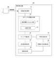
次に、本実施の形態における物体検知装置100の動作について図9を用いて説明する。図9は、本発明の実施の形態における物体検知装置の動作を示すフロー図である。以下の説明においては、適宜図1を参酌する。また、本実施の形態では、物体検知装置100を動作させることによって、物体検知方法が実施される。よって、本実施の形態における物体検知方法の説明は、以下の物体検知装置100の動作説明に代える。[Device operation]
Next, the operation of the
図9に示すように、最初に、魚眼画像取得部10が、魚眼カメラ80から出力された時系列の魚眼画像を取得し、取得した時系列の魚眼画像を水平パノラマ画像生成部20に入力する(ステップS1)。
As shown in FIG. 9, first, the fisheye
次に、水平パノラマ画像生成部20は、ステップS1で取得された時系列の魚眼画像を、それを構成するフレーム毎に、水平パノラマ画像に変換する(ステップS2)。
Next, the horizontal panorama
具体的には、ステップS2では、視点補償ベクトル生成部21が、まず、視点補償ベクトルを生成する。次いで、画像生成部22が、視点補償ベクトルを用いて変換されたフレームに対して、その水平方向に沿って、接地面に平行な視点を複数設定する。続いて、画像生成部22は、設定された視点毎に、変換後のフレームに対して、各視点からの視線を軸に含む座標系に基づいて、透視投影近似による歪み補正を行なう。更に、画像生成部22は、補正後のフレームそれぞれから抽出された垂直方向の画像要素を用いて、1つの新たなフレームを生成し、これを水平パノラマ画像とする。
Specifically, in step S2, the viewpoint compensation
次に、エッジペア抽出部30は、フレーム毎に、水平パノラマ画像から、垂直方向を向いたエッジのペアを抽出する(ステップS3)。
Next, the edge
次に、変化割合抽出部40は、フレーム毎に、ステップS3で抽出されたエッジペアのエッジ間距離を特定し、そして、フレーム間における、エッジ間距離の変化割合を抽出する(ステップS4)。
Next, the change
次に、下端領域抽出部50は、フレーム毎に、エッジペアを構成していると予測される物体の下端に相当する領域を抽出し、抽出した領域の水平パノラマ画像上での位置を特定する。(ステップS5)。
Next, the lower end
次に、距離変化割合抽出部60は、フレーム毎に、ステップS5で特定した位置から物体から魚眼カメラ80までの距離を算出し、更に、ステップS4と同じフレーム間において、物体から魚眼カメラ80までの距離の変化割合を抽出する(ステップS6)。
Next, the distance change
その後、物体検知部70は、ステップS4によって抽出されたエッジ間距離の変化割合と、ステップS6によって抽出された物体から魚眼カメラ80までの距離の変化割合とに基づいて、物体が真に存在するか否かを判定する(ステップS7)。
After that, the
[実施の形態における効果]
以上のように、本実施の形態によれば、魚眼カメラを用いた場合であっても、棒状の物体を容易に検知することができる。この理由としては、水平パノラマ画像では、実空間上における鉛直方向に伸びる物体は、垂直方向を向き、エッジを容易に抽出できることが挙げられる。また、水平パノラマ画像では、エッジペアにおけるエッジ間距離の変化割合と、物体から魚眼カメラまでの距離の変化割合とを容易に抽出でき、且つ、両者の間に略反比例の関係をあることに基づいて物体の有無を判定できることも挙げられる。[Effect in the embodiment]
As described above, according to the present embodiment, even when a fisheye camera is used, a rod-shaped object can be easily detected. The reason for this is that in a horizontal panoramic image, an object extending in the vertical direction in the real space faces in the vertical direction, and edges can be easily extracted. Further, in the horizontal panoramic image, it is possible to easily extract the change rate of the distance between edges in the edge pair and the change rate of the distance from the object to the fisheye camera, and it is based on the fact that there is a substantially inverse proportional relationship between the two. It is also possible to determine the presence or absence of an object.
更に、本実施の形態では、エッジペアのエッジ間距離の変化割合と、物体から魚眼カメラまでの距離の変化割合との関係性を検証することにより、抽出されたエッジペアが、実際の棒状の物体から抽出されているかどうかを高精度に判定することもできる。 Further, in the present embodiment, the extracted edge pair is an actual rod-shaped object by verifying the relationship between the rate of change in the distance between the edges of the edge pair and the rate of change in the distance from the object to the fisheye camera. It is also possible to determine with high accuracy whether or not it is extracted from.
[プログラム]
本実施の形態におけるプログラムは、コンピュータに、図9に示すステップS1〜S7を実行させるプログラムであれば良い。このプログラムをコンピュータにインストールし、実行することによって、本実施の形態における物体検知装置100と物体検知方法とを実現することができる。この場合、コンピュータのプロセッサは、魚眼画像取得部10、水平パノラマ画像生成部20、エッジペア抽出部30、変化割合抽出部40、下端領域抽出部50、距離変化割合抽出部60、及び物体検知部70として機能し、処理を行なう。また、コンピュータとしては、自動車に搭載されるコンピュータが挙げられるが、本実施の形態では、コンピュータはこれに限定されることはない。コンピュータは、汎用のコンピュータであっても良いし、家電、作業用機器等に搭載されるコンピュータであっても良い。[program]
The program in this embodiment may be any program that causes a computer to execute steps S1 to S7 shown in FIG. By installing this program on a computer and executing it, the
また、本実施の形態におけるプログラムは、複数のコンピュータによって構築されたコンピュータシステムによって実行されても良い。この場合は、例えば、各コンピュータが、それぞれ、魚眼画像取得部10、水平パノラマ画像生成部20、エッジペア抽出部30、変化割合抽出部40、下端領域抽出部50、距離変化割合抽出部60、及び物体検知部70のいずれかとして機能しても良い。
Further, the program in the present embodiment may be executed by a computer system constructed by a plurality of computers. In this case, for example, each computer has a fisheye
ここで、本実施の形態におけるプログラムを実行することによって、物体検知装置100を実現するコンピュータについて図10を用いて説明する。図10は、本発明の実施の形態における物体検知装置を実現するコンピュータの一例を示すブロック図である。
Here, a computer that realizes the
図10に示すように、コンピュータ110は、CPU111と、メインメモリ112と、記憶装置113と、入力インターフェイス114と、表示コントローラ115と、データリーダ/ライタ116と、通信インターフェイス117とを備える。これらの各部は、バス121を介して、互いにデータ通信可能に接続される。
As shown in FIG. 10, the
CPU111は、記憶装置113に格納された、本実施の形態におけるプログラム(コード)をメインメモリ112に展開し、これらを所定順序で実行することにより、各種の演算を実施する。メインメモリ112は、典型的には、DRAM(Dynamic Random Access Memory)等の揮発性の記憶装置である。また、本実施の形態におけるプログラムは、コンピュータ読み取り可能な記録媒体120に格納された状態で提供される。なお、本実施の形態におけるプログラムは、通信インターフェイス117を介して接続されたインターネット上で流通するものであっても良い。
The
また、記憶装置113の具体例としては、ハードディスクドライブの他、フラッシュメモリ等の半導体記憶装置が挙げられる。入力インターフェイス114は、CPU111と、キーボード及びマウスといった入力機器118との間のデータ伝送を仲介する。表示コントローラ115は、ディスプレイ装置119と接続され、ディスプレイ装置119での表示を制御する。
Further, specific examples of the
データリーダ/ライタ116は、CPU111と記録媒体120との間のデータ伝送を仲介し、記録媒体120からのプログラムの読み出し、及びコンピュータ110における処理結果の記録媒体120への書き込みを実行する。通信インターフェイス117は、CPU111と、他のコンピュータとの間のデータ伝送を仲介する。
The data reader /
また、記録媒体120の具体例としては、CF(Compact Flash(登録商標))及びSD(Secure Digital)等の汎用的な半導体記憶デバイス、フレキシブルディスク(Flexible Disk)等の磁気記録媒体、又はCD−ROM(Compact DiskRead Only Memory)などの光学記録媒体が挙げられる。
Specific examples of the
なお、本実施の形態における物体検知装置100は、プログラムがインストールされたコンピュータではなく、各部に対応したハードウェアを用いることによっても実現可能である。更に、物体検知装置100は、一部がプログラムで実現され、残りの部分がハードウェアで実現されていてもよい。
The
上述した実施の形態の一部又は全部は、以下に記載する(付記1)〜(付記12)によって表現することができるが、以下の記載に限定されるものではない。 A part or all of the above-described embodiments can be expressed by the following descriptions (Appendix 1) to (Appendix 12), but the present invention is not limited to the following description.
(付記1)
魚眼カメラから出力された時系列の魚眼画像を取得する、魚眼画像取得部と、
前記時系列の魚眼画像を、それを構成するフレーム毎に、実空間における鉛直方向がフレームの垂直方向に沿って表現され、且つ、フレームの水平方向において方位が等角で表現されている、水平パノラマ画像に変換する、水平パノラマ画像生成部と、
前記フレーム毎に、前記水平パノラマ画像から、垂直方向のエッジのペアを抽出する、エッジペア抽出部と、
前記フレーム間における、抽出された前記エッジのペアのエッジ間距離の変化割合を抽出する、変化割合抽出部と、
前記フレーム毎に、前記エッジのペアを構成していると予測される物体の下端に相当する領域を抽出する、下端領域抽出部と、
前記フレーム毎に、前記物体の下端に相当する領域の前記水平パノラマ画像上での位置から前記物体から前記魚眼カメラまでの距離を算出し、前記フレーム間における、前記物体から前記魚眼カメラまでの距離の変化割合を抽出する、距離変化割合抽出部と、
抽出された、前記エッジ間距離の変化割合、及び前記物体から前記魚眼カメラまでの距離の変化割合に基づいて、前記物体が存在しているかどうかを判定する、物体検知部と、
を備えたことを特徴とする物体検知装置。(Appendix 1)
A fisheye image acquisition unit that acquires time-series fisheye images output from the fisheye camera,
In the time-series fisheye image, the vertical direction in the real space is represented along the vertical direction of the frame, and the orientation is represented by the same angle in the horizontal direction of the frame for each frame constituting the fisheye image. A horizontal panorama image generator that converts to a horizontal panorama image,
An edge pair extraction unit that extracts a pair of edges in the vertical direction from the horizontal panoramic image for each frame.
A change rate extraction unit that extracts the change rate of the distance between the edges of the extracted pair of edges between the frames, and a change rate extraction unit.
For each frame, a lower end region extraction unit that extracts a region corresponding to the lower end of an object that is predicted to constitute the edge pair,
For each frame, the distance from the object to the fisheye camera is calculated from the position of the region corresponding to the lower end of the object on the horizontal panoramic image, and the distance from the object to the fisheye camera between the frames is calculated. Distance change rate extraction unit that extracts the change rate of the distance of
An object detection unit that determines whether or not the object exists based on the extracted rate of change in the distance between the edges and the rate of change in the distance from the object to the fisheye camera.
An object detection device characterized by being equipped with.
(付記2)
前記水平パノラマ画像生成部が、
前記物体の接地面に平行な面を基準とした、前記魚眼カメラの光軸回りのロール角及び光軸のピッチ角に基づいて、前記フレームを、前記物体を前記接地面に平行な方向から撮影して得られる画像に変換する、視点補償ベクトルを生成し、
取得した前記視点補償ベクトルを用いて変換された前記フレームに対して、その水平方向に沿って、前記接地面に平行な視点を複数設定し、
設定された前記視点毎に、変換後の前記フレームに対して、当該視点からの視線を軸に含む座標系に基づいて、透視投影近似による歪み補正を行ない、
補正後の前記フレームそれぞれから抽出された垂直方向の画像要素を用いて、1つの新たなフレームを生成し、これを前記水平パノラマ画像とする、
付記1に記載の物体検知装置。(Appendix 2)
The horizontal panorama image generation unit
Based on the roll angle around the optical axis of the fisheye camera and the pitch angle of the optical axis with reference to the plane parallel to the ground plane of the object, the frame is mounted from the direction parallel to the ground plane of the object. Generate a viewpoint compensation vector to convert to the image obtained by shooting,
A plurality of viewpoints parallel to the ground plane are set along the horizontal direction of the frame converted using the acquired viewpoint compensation vector.
For each of the set viewpoints, distortion correction by perspective projection approximation is performed on the converted frame based on a coordinate system including the line of sight from the viewpoint as an axis.
Using the vertical image elements extracted from each of the corrected frames, one new frame is generated, and this is used as the horizontal panoramic image.
The object detection device according to
(付記3)
前記物体検知部が、前記エッジ間距離の変化割合と、前記物体から前記魚眼カメラまでの距離の変化割合とが反比例の関係にあるときに、前記物体が存在するものと判定する、
付記1または2に記載の物体検知装置。(Appendix 3)
When the object detection unit has an inversely proportional relationship between the rate of change in the distance between the edges and the rate of change in the distance from the object to the fisheye camera, the object detection unit determines that the object exists.
The object detection device according to
(付記4)
前記魚眼カメラは、車両において、光軸方向が、水平面から鉛直方向下向きに傾斜した方向となるように、配置されている、
付記1〜3のいずれかに記載の物体検知装置(Appendix 4)
The fisheye camera is arranged in the vehicle so that the optical axis direction is a direction inclined downward in the vertical direction from the horizontal plane.
The object detection device according to any one of
(付記5)
(a)魚眼カメラから出力された時系列の魚眼画像を取得する、ステップと、
(b)前記時系列の魚眼画像を、それを構成するフレーム毎に、実空間における鉛直方向がフレームの垂直方向に沿って表現され、且つ、フレームの水平方向において方位が等角で表現されている、水平パノラマ画像に変換する、ステップと、
(c)前記フレーム毎に、前記水平パノラマ画像から、垂直方向のエッジのペアを抽出する、ステップと、
(d)前記フレーム間における、抽出された前記エッジのペアのエッジ間距離の変化割合を抽出する、ステップと、
(e)前記フレーム毎に、前記エッジのペアを構成していると予測される物体の下端に相当する領域を抽出する、ステップと、
(f)前記フレーム毎に、前記物体の下端に相当する領域の前記水平パノラマ画像上での位置から前記物体から前記魚眼カメラまでの距離を算出し、前記フレーム間における、前記物体から前記魚眼カメラまでの距離の変化割合を抽出する、ステップと、
(g)抽出された、前記エッジ間距離の変化割合、及び前記物体から前記魚眼カメラまでの距離の変化割合に基づいて、前記物体が存在しているかどうかを判定する、ステップと、
を有することを特徴とする物体検知方法。(Appendix 5)
(A) Acquiring a time-series fisheye image output from the fisheye camera, steps and
(B) In the time-series fisheye image, the vertical direction in the real space is expressed along the vertical direction of the frame, and the orientation is expressed at the same angle in the horizontal direction of the frame for each frame constituting the fisheye image. To convert to a horizontal panoramic image, with steps,
(C) For each frame, a step of extracting a pair of vertical edges from the horizontal panoramic image, and
(D) A step of extracting the rate of change in the inter-edge distance of the extracted pair of the edges between the frames.
(E) For each frame, a step of extracting a region corresponding to the lower end of an object predicted to form the pair of edges, and
(F) For each frame, the distance from the object to the fisheye camera is calculated from the position on the horizontal panoramic image of the region corresponding to the lower end of the object, and the distance from the object to the fish between the frames is calculated. Steps to extract the rate of change in the distance to the eye camera,
(G) A step of determining whether or not the object exists based on the extracted rate of change in the distance between the edges and the rate of change in the distance from the object to the fisheye camera.
An object detection method characterized by having.
(付記6)
前記(b)のステップにおいて、
前記物体の接地面に平行な面を基準とした、前記魚眼カメラの光軸回りのロール角及び光軸のピッチ角に基づいて、前記フレームを、前記物体を前記接地面に平行な方向から撮影して得られる画像に変換する、視点補償ベクトルを生成し、
取得した前記視点補償ベクトルを用いて変換された前記フレームに対して、その水平方向に沿って、前記接地面に平行な視点を複数設定し、
設定された前記視点毎に、変換後の前記フレームに対して、当該視点からの視線を軸に含む座標系に基づいて、透視投影近似による歪み補正を行ない、
補正後の前記フレームそれぞれから抽出された垂直方向の画像要素を用いて、1つの新たなフレームを生成し、これを前記水平パノラマ画像とする、
付記5に記載の物体検知方法。(Appendix 6)
In step (b) above
Based on the roll angle around the optical axis of the fisheye camera and the pitch angle of the optical axis with reference to the plane parallel to the ground plane of the object, the frame is mounted from the direction parallel to the ground plane of the object. Generate a viewpoint compensation vector to convert to the image obtained by shooting,
A plurality of viewpoints parallel to the ground plane are set along the horizontal direction of the frame converted using the acquired viewpoint compensation vector.
For each of the set viewpoints, distortion correction by perspective projection approximation is performed on the converted frame based on a coordinate system including the line of sight from the viewpoint as an axis.
Using the vertical image elements extracted from each of the corrected frames, one new frame is generated, and this is used as the horizontal panoramic image.
The object detection method according to Appendix 5.
(付記7)
前記(g)のステップにおいて、前記エッジ間距離の変化割合と、前記物体から前記魚眼カメラまでの距離の変化割合とが反比例の関係にあるときに、前記物体が存在するものと判定する、
付記5または6に記載の物体検知方法。(Appendix 7)
In step (g), when the rate of change in the distance between edges and the rate of change in the distance from the object to the fisheye camera are in an inversely proportional relationship, it is determined that the object exists.
The object detection method according to Appendix 5 or 6.
(付記8)
前記魚眼カメラは、車両において、光軸方向が、水平面から鉛直方向下向きに傾斜した方向となるように、配置されている、
付記5〜7のいずれかに記載の物体検知方法(Appendix 8)
The fisheye camera is arranged in the vehicle so that the optical axis direction is a direction inclined downward in the vertical direction from the horizontal plane.
The object detection method according to any one of Appendix 5 to 7.
(付記9)
コンピュータに、
(a)魚眼カメラから出力された時系列の魚眼画像を取得する、ステップと、
(b)前記時系列の魚眼画像を、それを構成するフレーム毎に、実空間における鉛直方向がフレームの垂直方向に沿って表現され、且つ、フレームの水平方向において方位が等角で表現されている、水平パノラマ画像に変換する、ステップと、
(c)前記フレーム毎に、前記水平パノラマ画像から、垂直方向のエッジのペアを抽出する、ステップと、
(d)前記フレーム間における、抽出された前記エッジのペアのエッジ間距離の変化割合を抽出する、ステップと、
(e)前記フレーム毎に、前記エッジのペアを構成していると予測される物体の下端に相当する領域を抽出する、ステップと、
(f)前記フレーム毎に、前記物体の下端に相当する領域の前記水平パノラマ画像上での位置から前記物体から前記魚眼カメラまでの距離を算出し、前記フレーム間における、前記物体から前記魚眼カメラまでの距離の変化割合を抽出する、ステップと、
(g)抽出された、前記エッジ間距離の変化割合、及び前記物体から前記魚眼カメラまでの距離の変化割合に基づいて、前記物体が存在しているかどうかを判定する、ステップと、
を実行させる、プログラム。
(Appendix 9)
On the computer
(A) Acquiring a time-series fisheye image output from the fisheye camera, steps and
(B) In the time-series fisheye image, the vertical direction in the real space is expressed along the vertical direction of the frame, and the orientation is expressed at the same angle in the horizontal direction of the frame for each frame constituting the fisheye image. To convert to a horizontal panoramic image, with steps,
(C) For each frame, a step of extracting a pair of vertical edges from the horizontal panoramic image, and
(D) A step of extracting the rate of change in the inter-edge distance of the extracted pair of the edges between the frames.
(E) For each frame, a step of extracting a region corresponding to the lower end of an object predicted to form the pair of edges, and
(F) For each frame, the distance from the object to the fisheye camera is calculated from the position on the horizontal panoramic image of the region corresponding to the lower end of the object, and the distance from the object to the fish between the frames is calculated. Steps to extract the rate of change in the distance to the eye camera,
(G) A step of determining whether or not the object exists based on the extracted rate of change in the distance between the edges and the rate of change in the distance from the object to the fisheye camera.
Ru is the execution, program.
(付記10)
前記(b)のステップにおいて、
前記物体の接地面に平行な面を基準とした、前記魚眼カメラの光軸回りのロール角及び光軸のピッチ角に基づいて、前記フレームを、前記物体を前記接地面に平行な方向から撮影して得られる画像に変換する、視点補償ベクトルを生成し、
取得した前記視点補償ベクトルを用いて変換された前記フレームに対して、その水平方向に沿って、前記接地面に平行な視点を複数設定し、
設定された前記視点毎に、変換後の前記フレームに対して、当該視点からの視線を軸に含む座標系に基づいて、透視投影近似による歪み補正を行ない、
補正後の前記フレームそれぞれから抽出された垂直方向の画像要素を用いて、1つの新たなフレームを生成し、これを前記水平パノラマ画像とする、
付記9に記載のプログラム。
(Appendix 10)
In step (b) above
Based on the roll angle around the optical axis of the fisheye camera and the pitch angle of the optical axis with reference to the plane parallel to the ground plane of the object, the frame is mounted from the direction parallel to the ground plane of the object. Generate a viewpoint compensation vector to convert to the image obtained by shooting,
A plurality of viewpoints parallel to the ground plane are set along the horizontal direction of the frame converted using the acquired viewpoint compensation vector.
For each of the set viewpoints, distortion correction by perspective projection approximation is performed on the converted frame based on a coordinate system including the line of sight from the viewpoint as an axis.
Using the vertical image elements extracted from each of the corrected frames, one new frame is generated, and this is used as the horizontal panoramic image.
The program described in Appendix 9.
(付記11)
前記(g)のステップにおいて、前記エッジ間距離の変化割合と、前記物体から前記魚眼カメラまでの距離の変化割合とが反比例の関係にあるときに、前記物体が存在するものと判定する、
付記9または10に記載のプログラム。
(Appendix 11)
In step (g), when the rate of change in the distance between edges and the rate of change in the distance from the object to the fisheye camera are in an inversely proportional relationship, it is determined that the object exists.
The program according to
(付記12)
前記魚眼カメラは、車両において、光軸方向が、水平面から鉛直方向下向きに傾斜した方向となるように、配置されている、
付記9〜11のいずれかに記載のプログラム。
(Appendix 12)
The fisheye camera is arranged in the vehicle so that the optical axis direction is a direction inclined downward in the vertical direction from the horizontal plane.
The program according to any one of Appendix 9-11.
以上、実施の形態を参照して本願発明を説明したが、本願発明は上記実施の形態に限定されるものではない。本願発明の構成や詳細には、本願発明のスコープ内で当業者が理解し得る様々な変更をすることができる。
Although the present invention has been described above with reference to the embodiments, the present invention is not limited to the above embodiments. Various changes that can be understood by those skilled in the art can be made within the scope of the present invention in terms of the structure and details of the present invention.
以上のように、本発明によれば、魚眼カメラを用いた場合であっても、撮影画像からの棒状の物体の検知を容易に行うことができる。本発明は、魚眼カメラが用いられる種々の分野に有用である。 As described above, according to the present invention, it is possible to easily detect a rod-shaped object from a captured image even when a fisheye camera is used. The present invention is useful in various fields in which fisheye cameras are used.
10 魚眼画像取得部
20 水平パノラマ画像生成部
21 視点補償ベクトル生成部
22 画像生成部
30 エッジペア抽出部
40 変化割合抽出部
50 下端領域抽出部
60 距離変化割合抽出部
70 物体検知部
100 物体検知装置
110 コンピュータ
111 CPU
112 メインメモリ
113 記憶装置
114 入力インターフェイス
115 表示コントローラ
116 データリーダ/ライタ
117 通信インターフェイス
118 入力機器
119 ディスプレイ装置
120 記録媒体
121 バス
201 棒状の物体
301 魚眼画像上における曲がった線分
401 水平パノラマ画像上の直線状の線分
601 光学中心(魚眼カメラの位置を鉛直方向に沿って地面に投射した位置)
602、605、606 仮想の円
603 光学中心からみた9時の方位
604 光学中心からみた3時の方位
605、606 光学中心からの等距離線の一例
701、702、703 水平線10 Fisheye
112
602, 605, 606
Claims (12)
前記時系列の魚眼画像を、それを構成するフレーム毎に、実空間における鉛直方向がフレームの垂直方向に沿って表現され、且つ、フレームの水平方向において方位が等角で表現されている、水平パノラマ画像に変換する、水平パノラマ画像生成部と、
前記フレーム毎に、前記水平パノラマ画像から、垂直方向のエッジのペアを抽出する、エッジペア抽出部と、
前記フレーム間における、抽出された前記エッジのペアのエッジ間距離の変化割合を抽出する、変化割合抽出部と、
前記フレーム毎に、前記エッジのペアを構成していると予測される物体の下端に相当する領域を抽出する、下端領域抽出部と、
前記フレーム毎に、前記物体の下端に相当する領域の前記水平パノラマ画像上での位置から前記物体から前記魚眼カメラまでの距離を算出し、前記フレーム間における、前記物体から前記魚眼カメラまでの距離の変化割合を抽出する、距離変化割合抽出部と、
抽出された、前記エッジ間距離の変化割合、及び前記物体から前記魚眼カメラまでの距離の変化割合に基づいて、前記物体が存在しているかどうかを判定する、物体検知部と、
を備えたことを特徴とする物体検知装置。 A fisheye image acquisition unit that acquires time-series fisheye images output from the fisheye camera,
In the time-series fisheye image, the vertical direction in the real space is represented along the vertical direction of the frame, and the orientation is represented by the same angle in the horizontal direction of the frame for each frame constituting the fisheye image. A horizontal panorama image generator that converts to a horizontal panorama image,
An edge pair extraction unit that extracts a pair of edges in the vertical direction from the horizontal panoramic image for each frame.
A change rate extraction unit that extracts the change rate of the distance between the edges of the extracted pair of edges between the frames, and a change rate extraction unit.
For each frame, a lower end region extraction unit that extracts a region corresponding to the lower end of an object that is predicted to constitute the edge pair,
For each frame, the distance from the object to the fisheye camera is calculated from the position of the region corresponding to the lower end of the object on the horizontal panoramic image, and the distance from the object to the fisheye camera between the frames is calculated. Distance change rate extraction unit that extracts the change rate of the distance of
An object detection unit that determines whether or not the object exists based on the extracted rate of change in the distance between the edges and the rate of change in the distance from the object to the fisheye camera.
An object detection device characterized by being equipped with.
前記物体の接地面に平行な面を基準とした、前記魚眼カメラの光軸回りのロール角及び光軸のピッチ角に基づいて、前記フレームを、前記物体を前記接地面に平行な方向から撮影して得られる画像に変換する、視点補償ベクトルを生成し、
取得した前記視点補償ベクトルを用いて変換された前記フレームに対して、その水平方向に沿って、前記接地面に平行な視点を複数設定し、
設定された前記視点毎に、変換後の前記フレームに対して、当該視点からの視線を軸に含む座標系に基づいて、透視投影近似による歪み補正を行ない、
補正後の前記フレームそれぞれから抽出された垂直方向の画像要素を用いて、1つの新たなフレームを生成し、これを前記水平パノラマ画像とする、
請求項1に記載の物体検知装置。 The horizontal panorama image generation unit
Based on the roll angle around the optical axis of the fisheye camera and the pitch angle of the optical axis with reference to the plane parallel to the ground plane of the object, the frame is mounted from the direction parallel to the ground plane of the object. Generate a viewpoint compensation vector to convert to the image obtained by shooting,
A plurality of viewpoints parallel to the ground plane are set along the horizontal direction of the frame converted using the acquired viewpoint compensation vector.
For each of the set viewpoints, distortion correction by perspective projection approximation is performed on the converted frame based on a coordinate system including the line of sight from the viewpoint as an axis.
Using the vertical image elements extracted from each of the corrected frames, one new frame is generated, and this is used as the horizontal panoramic image.
The object detection device according to claim 1.
請求項1または2に記載の物体検知装置。 When the object detection unit has an inversely proportional relationship between the rate of change in the distance between the edges and the rate of change in the distance from the object to the fisheye camera, the object detection unit determines that the object exists.
The object detection device according to claim 1 or 2.
請求項1〜3のいずれかに記載の物体検知装置。 The fisheye camera is arranged in the vehicle so that the optical axis direction is a direction inclined downward in the vertical direction from the horizontal plane.
The object detection device according to any one of claims 1 to 3.
(b)前記時系列の魚眼画像を、それを構成するフレーム毎に、実空間における鉛直方向がフレームの垂直方向に沿って表現され、且つ、フレームの水平方向において方位が等角で表現されている、水平パノラマ画像に変換する、ステップと、
(c)前記フレーム毎に、前記水平パノラマ画像から、垂直方向のエッジのペアを抽出する、ステップと、
(d)前記フレーム間における、抽出された前記エッジのペアのエッジ間距離の変化割合を抽出する、ステップと、
(e)前記フレーム毎に、前記エッジのペアを構成していると予測される物体の下端に相当する領域を抽出する、ステップと、
(f)前記フレーム毎に、前記物体の下端に相当する領域の前記水平パノラマ画像上での位置から前記物体から前記魚眼カメラまでの距離を算出し、前記フレーム間における、前記物体から前記魚眼カメラまでの距離の変化割合を抽出する、ステップと、
(g)抽出された、前記エッジ間距離の変化割合、及び前記物体から前記魚眼カメラまでの距離の変化割合に基づいて、前記物体が存在しているかどうかを判定する、ステップと、
を有することを特徴とする物体検知方法。 (A) Acquiring a time-series fisheye image output from the fisheye camera, steps and
(B) In the time-series fisheye image, the vertical direction in the real space is expressed along the vertical direction of the frame, and the orientation is expressed at the same angle in the horizontal direction of the frame for each frame constituting the fisheye image. To convert to a horizontal panoramic image, with steps,
(C) For each frame, a step of extracting a pair of vertical edges from the horizontal panoramic image, and
(D) A step of extracting the rate of change in the inter-edge distance of the extracted pair of the edges between the frames.
(E) For each frame, a step of extracting a region corresponding to the lower end of an object predicted to form the pair of edges, and
(F) For each frame, the distance from the object to the fisheye camera is calculated from the position on the horizontal panoramic image of the region corresponding to the lower end of the object, and the distance from the object to the fish between the frames is calculated. Steps to extract the rate of change in the distance to the eye camera,
(G) A step of determining whether or not the object exists based on the extracted rate of change in the distance between the edges and the rate of change in the distance from the object to the fisheye camera.
An object detection method characterized by having.
前記物体の接地面に平行な面を基準とした、前記魚眼カメラの光軸回りのロール角及び光軸のピッチ角に基づいて、前記フレームを、前記物体を前記接地面に平行な方向から撮影して得られる画像に変換する、視点補償ベクトルを生成し、
取得した前記視点補償ベクトルを用いて変換された前記フレームに対して、その水平方向に沿って、前記接地面に平行な視点を複数設定し、
設定された前記視点毎に、変換後の前記フレームに対して、当該視点からの視線を軸に含む座標系に基づいて、透視投影近似による歪み補正を行ない、
補正後の前記フレームそれぞれから抽出された垂直方向の画像要素を用いて、1つの新たなフレームを生成し、これを前記水平パノラマ画像とする、
請求項5に記載の物体検知方法。 In step (b) above
Based on the roll angle around the optical axis of the fisheye camera and the pitch angle of the optical axis with reference to the plane parallel to the ground plane of the object, the frame is mounted from the direction parallel to the ground plane of the object. Generate a viewpoint compensation vector to convert to the image obtained by shooting,
A plurality of viewpoints parallel to the ground plane are set along the horizontal direction of the frame converted using the acquired viewpoint compensation vector.
For each of the set viewpoints, distortion correction by perspective projection approximation is performed on the converted frame based on a coordinate system including the line of sight from the viewpoint as an axis.
Using the vertical image elements extracted from each of the corrected frames, one new frame is generated, and this is used as the horizontal panoramic image.
The object detection method according to claim 5.
請求項5または6に記載の物体検知方法。 In step (g), when the rate of change in the distance between edges and the rate of change in the distance from the object to the fisheye camera are in an inversely proportional relationship, it is determined that the object exists.
The object detection method according to claim 5 or 6.
請求項5〜7のいずれかに記載の物体検知方法 The fisheye camera is arranged in the vehicle so that the optical axis direction is a direction inclined downward in the vertical direction from the horizontal plane.
The object detection method according to any one of claims 5 to 7.
(a)魚眼カメラから出力された時系列の魚眼画像を取得する、ステップと、
(b)前記時系列の魚眼画像を、それを構成するフレーム毎に、実空間における鉛直方向がフレームの垂直方向に沿って表現され、且つ、フレームの水平方向において方位が等角で表現されている、水平パノラマ画像に変換する、ステップと、
(c)前記フレーム毎に、前記水平パノラマ画像から、垂直方向のエッジのペアを抽出する、ステップと、
(d)前記フレーム間における、抽出された前記エッジのペアのエッジ間距離の変化割合を抽出する、ステップと、
(e)前記フレーム毎に、前記エッジのペアを構成していると予測される物体の下端に相当する領域を抽出する、ステップと、
(f)前記フレーム毎に、前記物体の下端に相当する領域の前記水平パノラマ画像上での位置から前記物体から前記魚眼カメラまでの距離を算出し、前記フレーム間における、前記物体から前記魚眼カメラまでの距離の変化割合を抽出する、ステップと、
(g)抽出された、前記エッジ間距離の変化割合、及び前記物体から前記魚眼カメラまでの距離の変化割合に基づいて、前記物体が存在しているかどうかを判定する、ステップと、
を実行させる、プログラム。 On the computer
(A) Acquiring a time-series fisheye image output from the fisheye camera, steps and
(B) In the time-series fisheye image, the vertical direction in the real space is expressed along the vertical direction of the frame, and the orientation is expressed at the same angle in the horizontal direction of the frame for each frame constituting the fisheye image. To convert to a horizontal panoramic image, with steps,
(C) For each frame, a step of extracting a pair of vertical edges from the horizontal panoramic image, and
(D) A step of extracting the rate of change in the inter-edge distance of the extracted pair of the edges between the frames.
(E) For each frame, a step of extracting a region corresponding to the lower end of an object predicted to form the pair of edges, and
(F) For each frame, the distance from the object to the fisheye camera is calculated from the position on the horizontal panoramic image of the region corresponding to the lower end of the object, and the distance from the object to the fish between the frames is calculated. Steps to extract the rate of change in the distance to the eye camera,
(G) A step of determining whether or not the object exists based on the extracted rate of change in the distance between the edges and the rate of change in the distance from the object to the fisheye camera.
Ru is the execution, program.
前記物体の接地面に平行な面を基準とした、前記魚眼カメラの光軸回りのロール角及び光軸のピッチ角に基づいて、前記フレームを、前記物体を前記接地面に平行な方向から撮影して得られる画像に変換する、視点補償ベクトルを生成し、
取得した前記視点補償ベクトルを用いて変換された前記フレームに対して、その水平方向に沿って、前記接地面に平行な視点を複数設定し、
設定された前記視点毎に、変換後の前記フレームに対して、当該視点からの視線を軸に含む座標系に基づいて、透視投影近似による歪み補正を行ない、
補正後の前記フレームそれぞれから抽出された垂直方向の画像要素を用いて、1つの新たなフレームを生成し、これを前記水平パノラマ画像とする、
請求項9に記載のプログラム。 In step (b) above
Based on the roll angle around the optical axis of the fisheye camera and the pitch angle of the optical axis with reference to the plane parallel to the ground plane of the object, the frame is mounted from the direction parallel to the ground plane of the object. Generate a viewpoint compensation vector to convert to the image obtained by shooting,
A plurality of viewpoints parallel to the ground plane are set along the horizontal direction of the frame converted using the acquired viewpoint compensation vector.
For each of the set viewpoints, distortion correction by perspective projection approximation is performed on the converted frame based on a coordinate system including the line of sight from the viewpoint as an axis.
Using the vertical image elements extracted from each of the corrected frames, one new frame is generated, and this is used as the horizontal panoramic image.
The program according to claim 9.
請求項9または10に記載のプログラム。 In step (g), when the rate of change in the distance between edges and the rate of change in the distance from the object to the fisheye camera are in an inversely proportional relationship, it is determined that the object exists.
The program according to claim 9 or 10.
請求項9〜11のいずれかに記載のプログラム。 The fisheye camera is arranged in the vehicle so that the optical axis direction is a direction inclined downward in the vertical direction from the horizontal plane.
The program according to any one of claims 9 to 11.
Applications Claiming Priority (1)
| Application Number | Priority Date | Filing Date | Title |
|---|---|---|---|
| PCT/JP2017/036548 WO2019069469A1 (en) | 2017-10-06 | 2017-10-06 | Object detection device, object detection method, and computer readable recording medium |
Publications (2)
| Publication Number | Publication Date |
|---|---|
| JPWO2019069469A1 JPWO2019069469A1 (en) | 2020-10-22 |
| JP6874850B2 true JP6874850B2 (en) | 2021-05-19 |
Family
ID=65994463
Family Applications (1)
| Application Number | Title | Priority Date | Filing Date |
|---|---|---|---|
| JP2019546515A Active JP6874850B2 (en) | 2017-10-06 | 2017-10-06 | Object detection device, object detection method, and program |
Country Status (3)
| Country | Link |
|---|---|
| US (1) | US11417080B2 (en) |
| JP (1) | JP6874850B2 (en) |
| WO (1) | WO2019069469A1 (en) |
Families Citing this family (4)
| Publication number | Priority date | Publication date | Assignee | Title |
|---|---|---|---|---|
| US11288820B2 (en) * | 2018-06-09 | 2022-03-29 | Lot Spot Inc. | System and method for transforming video data into directional object count |
| US11282225B2 (en) * | 2018-09-10 | 2022-03-22 | Mapbox, Inc. | Calibration for vision in navigation systems |
| JP7192582B2 (en) * | 2019-03-11 | 2022-12-20 | オムロン株式会社 | Object tracking device and object tracking method |
| US11010641B2 (en) | 2019-03-14 | 2021-05-18 | Mapbox, Inc. | Low power consumption deep neural network for simultaneous object detection and semantic segmentation in images on a mobile computing device |
Family Cites Families (16)
| Publication number | Priority date | Publication date | Assignee | Title |
|---|---|---|---|---|
| JP4864295B2 (en) * | 2003-06-02 | 2012-02-01 | 富士フイルム株式会社 | Image display system, image display apparatus, and program |
| JP2005044196A (en) | 2003-07-23 | 2005-02-17 | Sharp Corp | Vehicle circumference monitoring device, automobile, vehicle circumference monitoring method, control program, and readable storage medium |
| JP5003395B2 (en) * | 2007-10-05 | 2012-08-15 | 日産自動車株式会社 | Vehicle periphery image processing apparatus and vehicle periphery state presentation method |
| JP2011210087A (en) | 2010-03-30 | 2011-10-20 | Panasonic Corp | Vehicle circumference monitoring device and vehicle circumference monitoring method |
| WO2011121741A1 (en) * | 2010-03-30 | 2011-10-06 | 富士通株式会社 | Image generation device, image generation program, synthesis table generation device, and synthesis table generation program |
| JP5966341B2 (en) | 2011-12-19 | 2016-08-10 | 大日本印刷株式会社 | Image processing apparatus, image processing method, program for image processing apparatus, and image display apparatus |
| CA2763649A1 (en) * | 2012-01-06 | 2013-07-06 | 9237-7167 Quebec Inc. | Panoramic camera |
| JP6261266B2 (en) * | 2013-10-02 | 2018-01-17 | 東芝アルパイン・オートモティブテクノロジー株式会社 | Moving body detection device |
| JP6434209B2 (en) * | 2013-12-20 | 2018-12-05 | 株式会社リコー | Image generating apparatus, image generating method, and program |
| US9906720B2 (en) * | 2014-12-05 | 2018-02-27 | Ricoh Company, Ltd. | Service system, information processing apparatus, and service providing method |
| JP6526449B2 (en) | 2015-03-05 | 2019-06-05 | 株式会社東芝 | Road attachment detection device and road attachment detection method |
| US10366509B2 (en) * | 2015-03-31 | 2019-07-30 | Thermal Imaging Radar, LLC | Setting different background model sensitivities by user defined regions and background filters |
| US20170195561A1 (en) * | 2016-01-05 | 2017-07-06 | 360fly, Inc. | Automated processing of panoramic video content using machine learning techniques |
| US10523865B2 (en) * | 2016-01-06 | 2019-12-31 | Texas Instruments Incorporated | Three dimensional rendering for surround view using predetermined viewpoint lookup tables |
| JP6611353B2 (en) * | 2016-08-01 | 2019-11-27 | クラリオン株式会社 | Image processing device, external recognition device |
| US11188768B2 (en) * | 2017-06-23 | 2021-11-30 | Nec Corporation | Object detection apparatus, object detection method, and computer readable recording medium |
-
2017
- 2017-10-06 JP JP2019546515A patent/JP6874850B2/en active Active
- 2017-10-06 US US16/753,650 patent/US11417080B2/en active Active
- 2017-10-06 WO PCT/JP2017/036548 patent/WO2019069469A1/en active Application Filing
Also Published As
| Publication number | Publication date |
|---|---|
| US20200242391A1 (en) | 2020-07-30 |
| US11417080B2 (en) | 2022-08-16 |
| WO2019069469A1 (en) | 2019-04-11 |
| JPWO2019069469A1 (en) | 2020-10-22 |
Similar Documents
| Publication | Publication Date | Title |
|---|---|---|
| JP6330987B2 (en) | Image processing apparatus, image processing method, and storage medium | |
| JP6874850B2 (en) | Object detection device, object detection method, and program | |
| US8908991B2 (en) | Image processing apparatus, image processing method and storage medium | |
| JP6891954B2 (en) | Object detection device, object detection method, and program | |
| CN106846409B (en) | Calibration method and device of fisheye camera | |
| US10839521B2 (en) | Image processing apparatus, image processing method, and computer-readable storage medium | |
| CN105049673A (en) | Image processing apparatus, and image processing method | |
| JP2008102620A (en) | Image processing device | |
| JP6897082B2 (en) | Computer program for face orientation estimation, face orientation estimation device and face orientation estimation method | |
| KR101808092B1 (en) | Apparatus and method for auto-correcting and generating avm image | |
| JP6031819B2 (en) | Image processing apparatus and image processing method | |
| JP4962304B2 (en) | Pedestrian detection device | |
| CN107209930B (en) | Method and device for stabilizing all-round looking image | |
| JP6795224B2 (en) | Mobile detection device, mobile detection method, and program | |
| KR101705558B1 (en) | Top view creating method for camera installed on vehicle and AVM system | |
| US10266116B2 (en) | Method and device for displaying a front-view of a vehicle's surrounding and respective vehicle | |
| KR102132527B1 (en) | Avm system and method for detecting matched point between images in avm system | |
| CN110832851B (en) | Image processing apparatus, image conversion method, and program | |
| KR101431378B1 (en) | Method for generating omni-directional image and apparatus therefor | |
| JP5955003B2 (en) | Image processing apparatus, image processing method, and program | |
| KR20190129433A (en) | Method for generating panoramic image and apparatus thereof | |
| JP6734136B2 (en) | Image processing device | |
| KR102472602B1 (en) | Apparatus and method for analyzing fisheye camera image | |
| JP2009077022A (en) | Driving support system and vehicle | |
| JP2021051348A (en) | Object distance estimation apparatus and object distance estimation method |
Legal Events
| Date | Code | Title | Description |
|---|---|---|---|
| A521 | Request for written amendment filed |
Free format text: JAPANESE INTERMEDIATE CODE: A523 Effective date: 20200327 |
|
| A621 | Written request for application examination |
Free format text: JAPANESE INTERMEDIATE CODE: A621 Effective date: 20200327 |
|
| TRDD | Decision of grant or rejection written | ||
| A01 | Written decision to grant a patent or to grant a registration (utility model) |
Free format text: JAPANESE INTERMEDIATE CODE: A01 Effective date: 20210323 |
|
| A61 | First payment of annual fees (during grant procedure) |
Free format text: JAPANESE INTERMEDIATE CODE: A61 Effective date: 20210405 |
|
| R150 | Certificate of patent or registration of utility model |
Ref document number: 6874850 Country of ref document: JP Free format text: JAPANESE INTERMEDIATE CODE: R150 |