JP6874120B2 - Anti-occlusion and dissociation thrombectomy equipment and methods - Google Patents
Anti-occlusion and dissociation thrombectomy equipment and methods Download PDFInfo
- Publication number
- JP6874120B2 JP6874120B2 JP2019507074A JP2019507074A JP6874120B2 JP 6874120 B2 JP6874120 B2 JP 6874120B2 JP 2019507074 A JP2019507074 A JP 2019507074A JP 2019507074 A JP2019507074 A JP 2019507074A JP 6874120 B2 JP6874120 B2 JP 6874120B2
- Authority
- JP
- Japan
- Prior art keywords
- tractor
- catheter
- distal end
- clot
- elongated
- Prior art date
- Legal status (The legal status is an assumption and is not a legal conclusion. Google has not performed a legal analysis and makes no representation as to the accuracy of the status listed.)
- Active
Links
- 238000013151 thrombectomy Methods 0.000 title claims description 54
- 238000000034 method Methods 0.000 title description 32
- 238000010494 dissociation reaction Methods 0.000 title description 3
- 230000005593 dissociations Effects 0.000 title description 3
- 239000000463 material Substances 0.000 claims description 106
- 238000000576 coating method Methods 0.000 claims description 61
- 210000004204 blood vessel Anatomy 0.000 claims description 39
- 230000006835 compression Effects 0.000 claims description 18
- 238000007906 compression Methods 0.000 claims description 18
- 230000001050 lubricating effect Effects 0.000 claims description 16
- 229910052751 metal Inorganic materials 0.000 claims description 15
- 239000002184 metal Substances 0.000 claims description 11
- 239000004744 fabric Substances 0.000 claims description 10
- 238000004804 winding Methods 0.000 claims description 7
- 239000000853 adhesive Substances 0.000 claims description 6
- 230000001070 adhesive effect Effects 0.000 claims description 6
- 239000000835 fiber Substances 0.000 claims description 6
- HTTJABKRGRZYRN-UHFFFAOYSA-N Heparin Chemical compound OC1C(NC(=O)C)C(O)OC(COS(O)(=O)=O)C1OC1C(OS(O)(=O)=O)C(O)C(OC2C(C(OS(O)(=O)=O)C(OC3C(C(O)C(O)C(O3)C(O)=O)OS(O)(=O)=O)C(CO)O2)NS(O)(=O)=O)C(C(O)=O)O1 HTTJABKRGRZYRN-UHFFFAOYSA-N 0.000 claims description 3
- 229940079593 drug Drugs 0.000 claims description 3
- 239000003814 drug Substances 0.000 claims description 3
- 229960002897 heparin Drugs 0.000 claims description 3
- 229920000669 heparin Polymers 0.000 claims description 3
- 230000002040 relaxant effect Effects 0.000 claims 1
- 208000007536 Thrombosis Diseases 0.000 description 43
- 239000011248 coating agent Substances 0.000 description 28
- 229910001000 nickel titanium Inorganic materials 0.000 description 19
- 229920000139 polyethylene terephthalate Polymers 0.000 description 18
- 239000005020 polyethylene terephthalate Substances 0.000 description 18
- 238000003698 laser cutting Methods 0.000 description 17
- 238000013461 design Methods 0.000 description 15
- 229920000295 expanded polytetrafluoroethylene Polymers 0.000 description 13
- 229920000642 polymer Polymers 0.000 description 13
- 230000033001 locomotion Effects 0.000 description 12
- 229920001343 polytetrafluoroethylene Polymers 0.000 description 12
- 239000004810 polytetrafluoroethylene Substances 0.000 description 12
- -1 polyethylene terephthalate Polymers 0.000 description 11
- 230000001965 increasing effect Effects 0.000 description 10
- 238000005520 cutting process Methods 0.000 description 9
- 238000009940 knitting Methods 0.000 description 9
- 239000000314 lubricant Substances 0.000 description 9
- 239000011148 porous material Substances 0.000 description 9
- 230000005855 radiation Effects 0.000 description 9
- 210000004027 cell Anatomy 0.000 description 8
- 230000002792 vascular Effects 0.000 description 8
- 238000005461 lubrication Methods 0.000 description 7
- 230000004048 modification Effects 0.000 description 7
- 238000012986 modification Methods 0.000 description 7
- 229920000728 polyester Polymers 0.000 description 7
- 238000005096 rolling process Methods 0.000 description 7
- 239000004677 Nylon Substances 0.000 description 6
- 229910000831 Steel Inorganic materials 0.000 description 6
- HZEWFHLRYVTOIW-UHFFFAOYSA-N [Ti].[Ni] Chemical compound [Ti].[Ni] HZEWFHLRYVTOIW-UHFFFAOYSA-N 0.000 description 6
- 238000005452 bending Methods 0.000 description 6
- 230000017531 blood circulation Effects 0.000 description 6
- 230000002209 hydrophobic effect Effects 0.000 description 6
- HLXZNVUGXRDIFK-UHFFFAOYSA-N nickel titanium Chemical compound [Ti].[Ti].[Ti].[Ti].[Ti].[Ti].[Ti].[Ti].[Ti].[Ti].[Ti].[Ni].[Ni].[Ni].[Ni].[Ni].[Ni].[Ni].[Ni].[Ni].[Ni].[Ni].[Ni].[Ni].[Ni] HLXZNVUGXRDIFK-UHFFFAOYSA-N 0.000 description 6
- 229920001778 nylon Polymers 0.000 description 6
- 239000010959 steel Substances 0.000 description 6
- 210000001519 tissue Anatomy 0.000 description 6
- 230000006870 function Effects 0.000 description 5
- 238000004904 shortening Methods 0.000 description 5
- 239000002759 woven fabric Substances 0.000 description 5
- 239000004743 Polypropylene Substances 0.000 description 4
- 210000003484 anatomy Anatomy 0.000 description 4
- 230000009286 beneficial effect Effects 0.000 description 4
- 210000004369 blood Anatomy 0.000 description 4
- 239000008280 blood Substances 0.000 description 4
- 239000003550 marker Substances 0.000 description 4
- 229920001296 polysiloxane Polymers 0.000 description 4
- 230000002829 reductive effect Effects 0.000 description 4
- 239000007787 solid Substances 0.000 description 4
- 239000004698 Polyethylene Substances 0.000 description 3
- 210000001367 artery Anatomy 0.000 description 3
- QVGXLLKOCUKJST-UHFFFAOYSA-N atomic oxygen Chemical compound [O] QVGXLLKOCUKJST-UHFFFAOYSA-N 0.000 description 3
- 230000015572 biosynthetic process Effects 0.000 description 3
- 230000023555 blood coagulation Effects 0.000 description 3
- 239000013013 elastic material Substances 0.000 description 3
- 230000002708 enhancing effect Effects 0.000 description 3
- 208000028867 ischemia Diseases 0.000 description 3
- 150000002739 metals Chemical class 0.000 description 3
- 229910052760 oxygen Inorganic materials 0.000 description 3
- 239000001301 oxygen Substances 0.000 description 3
- 230000002093 peripheral effect Effects 0.000 description 3
- 230000008569 process Effects 0.000 description 3
- 229910001220 stainless steel Inorganic materials 0.000 description 3
- 239000010935 stainless steel Substances 0.000 description 3
- 239000007858 starting material Substances 0.000 description 3
- 230000007704 transition Effects 0.000 description 3
- 241001269524 Dura Species 0.000 description 2
- 208000005189 Embolism Diseases 0.000 description 2
- 206010021143 Hypoxia Diseases 0.000 description 2
- WAIPAZQMEIHHTJ-UHFFFAOYSA-N [Cr].[Co] Chemical class [Cr].[Co] WAIPAZQMEIHHTJ-UHFFFAOYSA-N 0.000 description 2
- 230000001154 acute effect Effects 0.000 description 2
- 239000000654 additive Substances 0.000 description 2
- 238000002583 angiography Methods 0.000 description 2
- 238000013459 approach Methods 0.000 description 2
- 238000009954 braiding Methods 0.000 description 2
- 239000007799 cork Substances 0.000 description 2
- 210000004351 coronary vessel Anatomy 0.000 description 2
- 230000010339 dilation Effects 0.000 description 2
- 238000009826 distribution Methods 0.000 description 2
- 230000000694 effects Effects 0.000 description 2
- 238000005530 etching Methods 0.000 description 2
- 238000010438 heat treatment Methods 0.000 description 2
- 238000004519 manufacturing process Methods 0.000 description 2
- 210000003205 muscle Anatomy 0.000 description 2
- 210000005036 nerve Anatomy 0.000 description 2
- 229920009441 perflouroethylene propylene Polymers 0.000 description 2
- 229920000573 polyethylene Polymers 0.000 description 2
- 239000002861 polymer material Substances 0.000 description 2
- 229920001155 polypropylene Polymers 0.000 description 2
- 230000002787 reinforcement Effects 0.000 description 2
- 238000003860 storage Methods 0.000 description 2
- 230000003746 surface roughness Effects 0.000 description 2
- 229920001187 thermosetting polymer Polymers 0.000 description 2
- 239000010409 thin film Substances 0.000 description 2
- 230000002537 thrombolytic effect Effects 0.000 description 2
- 238000003466 welding Methods 0.000 description 2
- 206010002383 Angina Pectoris Diseases 0.000 description 1
- 206010003210 Arteriosclerosis Diseases 0.000 description 1
- 201000001320 Atherosclerosis Diseases 0.000 description 1
- 206010008479 Chest Pain Diseases 0.000 description 1
- 229910000684 Cobalt-chrome Inorganic materials 0.000 description 1
- JOYRKODLDBILNP-UHFFFAOYSA-N Ethyl urethane Chemical compound CCOC(N)=O JOYRKODLDBILNP-UHFFFAOYSA-N 0.000 description 1
- 239000004812 Fluorinated ethylene propylene Substances 0.000 description 1
- 239000004696 Poly ether ether ketone Substances 0.000 description 1
- 229920002614 Polyether block amide Polymers 0.000 description 1
- 238000009825 accumulation Methods 0.000 description 1
- 230000006978 adaptation Effects 0.000 description 1
- 230000000996 additive effect Effects 0.000 description 1
- 229910045601 alloy Inorganic materials 0.000 description 1
- 239000000956 alloy Substances 0.000 description 1
- 239000003146 anticoagulant agent Substances 0.000 description 1
- 208000011775 arteriosclerosis disease Diseases 0.000 description 1
- 230000004323 axial length Effects 0.000 description 1
- JUPQTSLXMOCDHR-UHFFFAOYSA-N benzene-1,4-diol;bis(4-fluorophenyl)methanone Chemical compound OC1=CC=C(O)C=C1.C1=CC(F)=CC=C1C(=O)C1=CC=C(F)C=C1 JUPQTSLXMOCDHR-UHFFFAOYSA-N 0.000 description 1
- 230000002457 bidirectional effect Effects 0.000 description 1
- 239000000560 biocompatible material Substances 0.000 description 1
- 230000000903 blocking effect Effects 0.000 description 1
- 210000000746 body region Anatomy 0.000 description 1
- 210000004413 cardiac myocyte Anatomy 0.000 description 1
- 210000001715 carotid artery Anatomy 0.000 description 1
- 210000002421 cell wall Anatomy 0.000 description 1
- 230000008859 change Effects 0.000 description 1
- 238000003486 chemical etching Methods 0.000 description 1
- 230000001055 chewing effect Effects 0.000 description 1
- 238000003776 cleavage reaction Methods 0.000 description 1
- 230000015271 coagulation Effects 0.000 description 1
- 238000005345 coagulation Methods 0.000 description 1
- 239000010952 cobalt-chrome Substances 0.000 description 1
- 239000002131 composite material Substances 0.000 description 1
- 238000010276 construction Methods 0.000 description 1
- 230000008602 contraction Effects 0.000 description 1
- 230000003247 decreasing effect Effects 0.000 description 1
- 238000010586 diagram Methods 0.000 description 1
- 201000010099 disease Diseases 0.000 description 1
- 208000037265 diseases, disorders, signs and symptoms Diseases 0.000 description 1
- 238000006073 displacement reaction Methods 0.000 description 1
- 230000010102 embolization Effects 0.000 description 1
- 238000005516 engineering process Methods 0.000 description 1
- 210000003743 erythrocyte Anatomy 0.000 description 1
- 238000001125 extrusion Methods 0.000 description 1
- 239000002657 fibrous material Substances 0.000 description 1
- 239000010408 film Substances 0.000 description 1
- 239000012530 fluid Substances 0.000 description 1
- 229920002313 fluoropolymer Polymers 0.000 description 1
- 239000004811 fluoropolymer Substances 0.000 description 1
- 238000002594 fluoroscopy Methods 0.000 description 1
- 238000013467 fragmentation Methods 0.000 description 1
- 238000006062 fragmentation reaction Methods 0.000 description 1
- PCHJSUWPFVWCPO-UHFFFAOYSA-N gold Chemical compound [Au] PCHJSUWPFVWCPO-UHFFFAOYSA-N 0.000 description 1
- 239000010931 gold Substances 0.000 description 1
- 229910052737 gold Inorganic materials 0.000 description 1
- 239000000017 hydrogel Substances 0.000 description 1
- 230000005660 hydrophilic surface Effects 0.000 description 1
- 238000003384 imaging method Methods 0.000 description 1
- 208000014674 injury Diseases 0.000 description 1
- 238000001361 intraarterial administration Methods 0.000 description 1
- 230000001788 irregular Effects 0.000 description 1
- 230000000670 limiting effect Effects 0.000 description 1
- 238000002803 maceration Methods 0.000 description 1
- 230000007246 mechanism Effects 0.000 description 1
- 238000002074 melt spinning Methods 0.000 description 1
- 239000007769 metal material Substances 0.000 description 1
- 238000005459 micromachining Methods 0.000 description 1
- 230000003278 mimic effect Effects 0.000 description 1
- 239000000203 mixture Substances 0.000 description 1
- 238000000465 moulding Methods 0.000 description 1
- 230000002107 myocardial effect Effects 0.000 description 1
- 208000010125 myocardial infarction Diseases 0.000 description 1
- 210000004165 myocardium Anatomy 0.000 description 1
- 230000036961 partial effect Effects 0.000 description 1
- 239000004033 plastic Substances 0.000 description 1
- 229920003023 plastic Polymers 0.000 description 1
- 229920000052 poly(p-xylylene) Polymers 0.000 description 1
- 229920002530 polyetherether ketone Polymers 0.000 description 1
- 239000004814 polyurethane Substances 0.000 description 1
- 229920002635 polyurethane Polymers 0.000 description 1
- 230000002028 premature Effects 0.000 description 1
- 238000012545 processing Methods 0.000 description 1
- 230000009467 reduction Effects 0.000 description 1
- 239000012779 reinforcing material Substances 0.000 description 1
- 230000002441 reversible effect Effects 0.000 description 1
- 230000007017 scission Effects 0.000 description 1
- 239000012781 shape memory material Substances 0.000 description 1
- 229910001285 shape-memory alloy Inorganic materials 0.000 description 1
- 238000007493 shaping process Methods 0.000 description 1
- 210000003625 skull Anatomy 0.000 description 1
- 239000007779 soft material Substances 0.000 description 1
- 239000000126 substance Substances 0.000 description 1
- 238000006467 substitution reaction Methods 0.000 description 1
- 238000001356 surgical procedure Methods 0.000 description 1
- 229920002994 synthetic fiber Polymers 0.000 description 1
- 239000012209 synthetic fiber Substances 0.000 description 1
- 238000003856 thermoforming Methods 0.000 description 1
- 230000008733 trauma Effects 0.000 description 1
- 150000003673 urethanes Chemical class 0.000 description 1
Images


Classifications
-
- A—HUMAN NECESSITIES
- A61—MEDICAL OR VETERINARY SCIENCE; HYGIENE
- A61B—DIAGNOSIS; SURGERY; IDENTIFICATION
- A61B17/00—Surgical instruments, devices or methods, e.g. tourniquets
- A61B17/22—Implements for squeezing-off ulcers or the like on the inside of inner organs of the body; Implements for scraping-out cavities of body organs, e.g. bones; Calculus removers; Calculus smashing apparatus; Apparatus for removing obstructions in blood vessels, not otherwise provided for
- A61B17/22031—Gripping instruments, e.g. forceps, for removing or smashing calculi
-
- A—HUMAN NECESSITIES
- A61—MEDICAL OR VETERINARY SCIENCE; HYGIENE
- A61B—DIAGNOSIS; SURGERY; IDENTIFICATION
- A61B17/00—Surgical instruments, devices or methods, e.g. tourniquets
- A61B17/22—Implements for squeezing-off ulcers or the like on the inside of inner organs of the body; Implements for scraping-out cavities of body organs, e.g. bones; Calculus removers; Calculus smashing apparatus; Apparatus for removing obstructions in blood vessels, not otherwise provided for
- A61B17/221—Gripping devices in the form of loops or baskets for gripping calculi or similar types of obstructions
-
- A—HUMAN NECESSITIES
- A61—MEDICAL OR VETERINARY SCIENCE; HYGIENE
- A61B—DIAGNOSIS; SURGERY; IDENTIFICATION
- A61B17/00—Surgical instruments, devices or methods, e.g. tourniquets
- A61B17/32—Surgical cutting instruments
- A61B17/3205—Excision instruments
- A61B17/3207—Atherectomy devices working by cutting or abrading; Similar devices specially adapted for non-vascular obstructions
- A61B17/320725—Atherectomy devices working by cutting or abrading; Similar devices specially adapted for non-vascular obstructions with radially expandable cutting or abrading elements
-
- A—HUMAN NECESSITIES
- A61—MEDICAL OR VETERINARY SCIENCE; HYGIENE
- A61B—DIAGNOSIS; SURGERY; IDENTIFICATION
- A61B17/00—Surgical instruments, devices or methods, e.g. tourniquets
- A61B17/32—Surgical cutting instruments
- A61B17/3205—Excision instruments
- A61B17/3207—Atherectomy devices working by cutting or abrading; Similar devices specially adapted for non-vascular obstructions
- A61B17/32075—Pullback cutting; combined forward and pullback cutting, e.g. with cutters at both sides of the plaque
-
- A—HUMAN NECESSITIES
- A61—MEDICAL OR VETERINARY SCIENCE; HYGIENE
- A61M—DEVICES FOR INTRODUCING MEDIA INTO, OR ONTO, THE BODY; DEVICES FOR TRANSDUCING BODY MEDIA OR FOR TAKING MEDIA FROM THE BODY; DEVICES FOR PRODUCING OR ENDING SLEEP OR STUPOR
- A61M25/00—Catheters; Hollow probes
- A61M25/0067—Catheters; Hollow probes characterised by the distal end, e.g. tips
- A61M25/0074—Dynamic characteristics of the catheter tip, e.g. openable, closable, expandable or deformable
-
- A—HUMAN NECESSITIES
- A61—MEDICAL OR VETERINARY SCIENCE; HYGIENE
- A61M—DEVICES FOR INTRODUCING MEDIA INTO, OR ONTO, THE BODY; DEVICES FOR TRANSDUCING BODY MEDIA OR FOR TAKING MEDIA FROM THE BODY; DEVICES FOR PRODUCING OR ENDING SLEEP OR STUPOR
- A61M25/00—Catheters; Hollow probes
- A61M25/0067—Catheters; Hollow probes characterised by the distal end, e.g. tips
- A61M25/0082—Catheter tip comprising a tool
-
- A—HUMAN NECESSITIES
- A61—MEDICAL OR VETERINARY SCIENCE; HYGIENE
- A61B—DIAGNOSIS; SURGERY; IDENTIFICATION
- A61B17/00—Surgical instruments, devices or methods, e.g. tourniquets
- A61B2017/00367—Details of actuation of instruments, e.g. relations between pushing buttons, or the like, and activation of the tool, working tip, or the like
- A61B2017/00398—Details of actuation of instruments, e.g. relations between pushing buttons, or the like, and activation of the tool, working tip, or the like using powered actuators, e.g. stepper motors, solenoids
-
- A—HUMAN NECESSITIES
- A61—MEDICAL OR VETERINARY SCIENCE; HYGIENE
- A61B—DIAGNOSIS; SURGERY; IDENTIFICATION
- A61B17/00—Surgical instruments, devices or methods, e.g. tourniquets
- A61B17/22—Implements for squeezing-off ulcers or the like on the inside of inner organs of the body; Implements for scraping-out cavities of body organs, e.g. bones; Calculus removers; Calculus smashing apparatus; Apparatus for removing obstructions in blood vessels, not otherwise provided for
- A61B2017/22001—Angioplasty, e.g. PCTA
-
- A—HUMAN NECESSITIES
- A61—MEDICAL OR VETERINARY SCIENCE; HYGIENE
- A61B—DIAGNOSIS; SURGERY; IDENTIFICATION
- A61B17/00—Surgical instruments, devices or methods, e.g. tourniquets
- A61B17/22—Implements for squeezing-off ulcers or the like on the inside of inner organs of the body; Implements for scraping-out cavities of body organs, e.g. bones; Calculus removers; Calculus smashing apparatus; Apparatus for removing obstructions in blood vessels, not otherwise provided for
- A61B17/22031—Gripping instruments, e.g. forceps, for removing or smashing calculi
- A61B2017/22034—Gripping instruments, e.g. forceps, for removing or smashing calculi for gripping the obstruction or the tissue part from inside
-
- A—HUMAN NECESSITIES
- A61—MEDICAL OR VETERINARY SCIENCE; HYGIENE
- A61B—DIAGNOSIS; SURGERY; IDENTIFICATION
- A61B17/00—Surgical instruments, devices or methods, e.g. tourniquets
- A61B17/22—Implements for squeezing-off ulcers or the like on the inside of inner organs of the body; Implements for scraping-out cavities of body organs, e.g. bones; Calculus removers; Calculus smashing apparatus; Apparatus for removing obstructions in blood vessels, not otherwise provided for
- A61B17/22031—Gripping instruments, e.g. forceps, for removing or smashing calculi
- A61B2017/22035—Gripping instruments, e.g. forceps, for removing or smashing calculi for retrieving or repositioning foreign objects
-
- A—HUMAN NECESSITIES
- A61—MEDICAL OR VETERINARY SCIENCE; HYGIENE
- A61B—DIAGNOSIS; SURGERY; IDENTIFICATION
- A61B17/00—Surgical instruments, devices or methods, e.g. tourniquets
- A61B17/22—Implements for squeezing-off ulcers or the like on the inside of inner organs of the body; Implements for scraping-out cavities of body organs, e.g. bones; Calculus removers; Calculus smashing apparatus; Apparatus for removing obstructions in blood vessels, not otherwise provided for
- A61B2017/22038—Implements for squeezing-off ulcers or the like on the inside of inner organs of the body; Implements for scraping-out cavities of body organs, e.g. bones; Calculus removers; Calculus smashing apparatus; Apparatus for removing obstructions in blood vessels, not otherwise provided for with a guide wire
-
- A—HUMAN NECESSITIES
- A61—MEDICAL OR VETERINARY SCIENCE; HYGIENE
- A61B—DIAGNOSIS; SURGERY; IDENTIFICATION
- A61B17/00—Surgical instruments, devices or methods, e.g. tourniquets
- A61B17/22—Implements for squeezing-off ulcers or the like on the inside of inner organs of the body; Implements for scraping-out cavities of body organs, e.g. bones; Calculus removers; Calculus smashing apparatus; Apparatus for removing obstructions in blood vessels, not otherwise provided for
- A61B2017/22079—Implements for squeezing-off ulcers or the like on the inside of inner organs of the body; Implements for scraping-out cavities of body organs, e.g. bones; Calculus removers; Calculus smashing apparatus; Apparatus for removing obstructions in blood vessels, not otherwise provided for with suction of debris
-
- A—HUMAN NECESSITIES
- A61—MEDICAL OR VETERINARY SCIENCE; HYGIENE
- A61B—DIAGNOSIS; SURGERY; IDENTIFICATION
- A61B17/00—Surgical instruments, devices or methods, e.g. tourniquets
- A61B17/22—Implements for squeezing-off ulcers or the like on the inside of inner organs of the body; Implements for scraping-out cavities of body organs, e.g. bones; Calculus removers; Calculus smashing apparatus; Apparatus for removing obstructions in blood vessels, not otherwise provided for
- A61B17/221—Gripping devices in the form of loops or baskets for gripping calculi or similar types of obstructions
- A61B2017/2215—Gripping devices in the form of loops or baskets for gripping calculi or similar types of obstructions having an open distal end
-
- A—HUMAN NECESSITIES
- A61—MEDICAL OR VETERINARY SCIENCE; HYGIENE
- A61B—DIAGNOSIS; SURGERY; IDENTIFICATION
- A61B17/00—Surgical instruments, devices or methods, e.g. tourniquets
- A61B17/32—Surgical cutting instruments
- A61B2017/320064—Surgical cutting instruments with tissue or sample retaining means
-
- A—HUMAN NECESSITIES
- A61—MEDICAL OR VETERINARY SCIENCE; HYGIENE
- A61B—DIAGNOSIS; SURGERY; IDENTIFICATION
- A61B17/00—Surgical instruments, devices or methods, e.g. tourniquets
- A61B17/34—Trocars; Puncturing needles
- A61B17/3417—Details of tips or shafts, e.g. grooves, expandable, bendable; Multiple coaxial sliding cannulas, e.g. for dilating
- A61B17/3421—Cannulas
- A61B2017/3435—Cannulas using everted sleeves
-
- A—HUMAN NECESSITIES
- A61—MEDICAL OR VETERINARY SCIENCE; HYGIENE
- A61M—DEVICES FOR INTRODUCING MEDIA INTO, OR ONTO, THE BODY; DEVICES FOR TRANSDUCING BODY MEDIA OR FOR TAKING MEDIA FROM THE BODY; DEVICES FOR PRODUCING OR ENDING SLEEP OR STUPOR
- A61M25/00—Catheters; Hollow probes
- A61M25/0067—Catheters; Hollow probes characterised by the distal end, e.g. tips
- A61M25/0074—Dynamic characteristics of the catheter tip, e.g. openable, closable, expandable or deformable
- A61M2025/0079—Separate user-activated means, e.g. guidewires, guide tubes, balloon catheters or sheaths, for sealing off an orifice, e.g. a lumen or side holes, of a catheter
-
- A—HUMAN NECESSITIES
- A61—MEDICAL OR VETERINARY SCIENCE; HYGIENE
- A61M—DEVICES FOR INTRODUCING MEDIA INTO, OR ONTO, THE BODY; DEVICES FOR TRANSDUCING BODY MEDIA OR FOR TAKING MEDIA FROM THE BODY; DEVICES FOR PRODUCING OR ENDING SLEEP OR STUPOR
- A61M2210/00—Anatomical parts of the body
- A61M2210/12—Blood circulatory system
Landscapes
- Health & Medical Sciences (AREA)
- Life Sciences & Earth Sciences (AREA)
- Surgery (AREA)
- Animal Behavior & Ethology (AREA)
- Veterinary Medicine (AREA)
- Public Health (AREA)
- General Health & Medical Sciences (AREA)
- Engineering & Computer Science (AREA)
- Heart & Thoracic Surgery (AREA)
- Biomedical Technology (AREA)
- Medical Informatics (AREA)
- Molecular Biology (AREA)
- Nuclear Medicine, Radiotherapy & Molecular Imaging (AREA)
- Vascular Medicine (AREA)
- Orthopedic Medicine & Surgery (AREA)
- Pulmonology (AREA)
- Biophysics (AREA)
- Anesthesiology (AREA)
- Hematology (AREA)
- Surgical Instruments (AREA)
- Epidemiology (AREA)
- Chemical & Material Sciences (AREA)
- Dispersion Chemistry (AREA)
- Media Introduction/Drainage Providing Device (AREA)
Description
関連出願の相互参照
本特許出願は、2016年4月25日に出願された「DOZER THROMBECTOMY SYSTEM」と題する米国仮特許出願第62/327,024号、2016年6月3日出願された「DOZER THROMBECTOMY SYSTEM 2」と題する米国仮特許出願第62/345,152号、および2016年9月12日に出願された「DOZER II THROMBECTOMY SYSTEM PROV」と題する米国仮特許出願第62/393,460号の優先権を主張するものである。
Mutual reference of related applications This patent application is a US provisional patent application No. 62 / 327,024 entitled "DOZER THROMBECTOMY SYSTEM" filed on April 25, 2016, and "DOZER" filed on June 3, 2016. US Provisional Patent Application No. 62 / 345,152 entitled "THROMBECTOMY SYSTEM 2" and US Provisional Patent Application No. 62 / 393,460 entitled "DOZER II THROMBECTOMY SYSTEM PROV" filed on September 12, 2016. It claims priority.
本特許出願は、2016年10月11日に出願された「MECHANICAL THROMBECTOMY APPARATUSES AND METHODS」と題する米国特許出願第15/291,015号と関連し得る。これは、2016年2月15日に出願された米国特許出願第15/043,996号の継続であり、現在米国特許出願第9,463,035号は、次の各仮特許出願に対して優先権を主張する:2015年9月28日出願の米国仮特許出願第62/284,300号、2015年10月8日出願の米国仮特許出願第62/284,752号、および2015年10月23日出願の米国仮特許出願第62/245,560号。 This patent application may be related to US Patent Application No. 15 / 291,015, entitled "MEMHANICAL THROMBECTOMY APPARATUSES AND METHODS", filed October 11, 2016. This is a continuation of U.S. Patent Application No. 15 / 043,996 filed on February 15, 2016, and currently U.S. Patent Application No. 9,463,035 is for each of the following provisional patent applications: Claim priority: U.S. Provisional Patent Application No. 62 / 284,300 filed September 28, 2015, U.S. Provisional Patent Application No. 62 / 284,752 filed October 8, 2015, and October 2015. U.S. Provisional Patent Application No. 62 / 245,560 filed on March 23.
これらの特許および特許出願の各々は、その全体が参照により本明細書に組み込まれる。 Each of these patents and patent applications is incorporated herein by reference in their entirety.
参照による引用
本明細書中で言及されている全ての刊行物および特許出願は、個々の刊行物または特許出願が参照により具体的かつ個別に組み込まれるように示されているのと同じ程度に、その全体が参照により本明細書に組み込まれる。
Citation by Reference All publications and patent applications referred to herein are to the same extent that individual publications or patent applications are indicated to be specifically and individually incorporated by reference. The whole is incorporated herein by reference.
本明細書に記載される装置および方法は、身体内からの物体の機械的除去に関する。特に、本明細書では、機械的血栓除去装置および方法について説明する。 The devices and methods described herein relate to the mechanical removal of objects from within the body. In particular, the present specification describes mechanical thrombectomy devices and methods.
他の組織に損傷を与えないように、可能な限り低侵襲的に身体から組織を除去することがしばしば望ましい。例えば、血液凝固のような脈管内から組織を除去することは、患者の状態および生活の質を改善し得る。 It is often desirable to remove tissue from the body as minimally as possible without damaging other tissues. Removal of tissue from the vessel, such as blood coagulation, can improve the patient's condition and quality of life.
多くの血管系の問題は、血管を通る不充分な血流に起因する。血流が不足したり不規則になったりする原因の1つに、血液凝固または血栓と呼ばれる血管内の閉塞がある。血栓は、手術などの外傷の後や、その他の原因で生じることがある。例えば、米国における120万件を超える心臓発作の大部分は、冠動脈内に形成される血液凝固(血栓)が原因である。 Many vascular problems result from inadequate blood flow through the blood vessels. One of the causes of insufficient or irregular blood flow is obstruction in blood vessels called blood clots or blood clots. Blood clots can occur after trauma such as surgery or for other causes. For example, the majority of over 1.2 million heart attacks in the United States are due to blood clots (thrombus) that form in the coronary arteries.
例えば血栓が形成されると、形成領域を通る血流を効果的に停止させる可能性がある。血栓が動脈の内径を越えて広がると、動脈を通る血流が遮断されることがある。冠動脈の1本が100%血栓化されると、その動脈では血液の流れが止まり、赤血球を運ぶ酸素が不足し、心臓壁の筋肉(心筋)に血液を供給できなくなる。このような血栓症は、血液の損失を防ぐためには不必要であるが、動脈硬化性疾患による動脈壁の損傷によって動脈内で誘発されることがある。このように、アテローム性動脈硬化症の基礎疾患は急性酸素欠乏(虚血)を引き起こさないが、誘発血栓症を介して急性虚血を誘発する可能性がある。同様に、頸動脈の1つの血栓症は、頭蓋内の重要な神経中枢への酸素供給が不充分なために脳卒中を引き起こすことがある。酸素欠乏は筋肉活動を減少または阻害し、胸痛(狭心症)を引き起こし、心筋死に至ることがあり、これはある程度まで永久的に心臓を障害する。心筋細胞の死が広範囲に及ぶと、心臓は生命維持に必要な量の血液を供給するのに充分な量の血液を送り出すことができなくなる。虚血の程度は、側副血管の存在や必要な酸素を供給できる血流など、多くの因子によって影響される。 For example, when a thrombus is formed, it can effectively stop blood flow through the area of formation. When a blood clot spreads beyond the inner diameter of an artery, blood flow through the artery may be blocked. When one of the coronary arteries is 100% thrombus, blood flow stops in that artery, oxygen that carries red blood cells is insufficient, and blood cannot be supplied to the muscles (myocardium) of the heart wall. Such thrombosis, although unnecessary to prevent blood loss, can be induced intra-arterial by damage to the arterial wall due to arteriosclerosis. Thus, the underlying disease of atherosclerosis does not cause acute oxygen deficiency (ischemia), but can induce acute ischemia through induced thrombosis. Similarly, one thrombosis of the carotid artery can cause a stroke due to an inadequate supply of oxygen to important nerve centers within the skull. Oxygen deficiency reduces or inhibits muscle activity, causes chest pain (angina) and can lead to myocardial death, which to some extent permanently damages the heart. When cardiomyocyte death is widespread, the heart is unable to pump enough blood to supply the amount of blood needed to sustain life. The degree of ischemia is influenced by many factors, including the presence of collateral vessels and blood flow that can supply the necessary oxygen.
臨床データは、凝血塊除去が転帰を改善するために有益であるか、または必要であることを示している。例えば、末梢血管系では、発明や手技によって切断の必要性を80%減らすことができる。動脈または静脈系のこれらの状態を治療するためのいずれかの治療法の最終目標は、閉塞を除去するか、または開通性を迅速かつ安全に、かつ費用対効果に優れて回復させることである。これは、血栓溶解、フラグメンテーション、血栓吸引、またはこれらの方法の組み合わせによって達成され得る。 Clinical data indicate that clot removal is beneficial or necessary to improve outcomes. For example, in the peripheral vascular system, inventions and procedures can reduce the need for cutting by 80%. The ultimate goal of any treatment for treating these conditions of the arterial or venous system is to eliminate the obstruction or restore patency quickly, safely and cost-effectively. .. This can be achieved by thrombolysis, fragmentation, thrombus aspiration, or a combination of these methods.
機械的血栓除去装置は特に有利である。凝血塊の大きさ、位置および範囲に応じて、安全かつ有効な方法で凝血塊を機械的に回収および分解することも、特に有利であり得る。血栓除去装置、特に体内から凝血塊のような組織を除去するのにより効果的であり得る機械的血栓除去装置が明確に必要とされている。本明細書では、上述した必要および問題に対処し得る装置(装置、システム、およびキット)、ならびにそれらの使用方法について説明する。 Mechanical thrombectomy devices are particularly advantageous. Depending on the size, location and extent of the clot, it may also be particularly advantageous to mechanically collect and decompose the clot in a safe and effective manner. There is a clear need for thrombectomy devices, especially mechanical thrombectomy devices that can be more effective in removing tissues such as clots from the body. This specification describes devices (devices, systems, and kits) that can address the above-mentioned needs and problems, and how to use them.
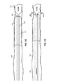
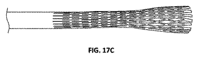
本明細書では、機械的血栓除去装置(デバイス、システムなど)、およびそれらの使用ならびに製造方法について説明する。これらの装置は、詰まりを防止または低減し、除去される血栓、例えば、凝血塊の把持および/または解離を強化するように構成することができる。典型的には、本明細書に記載される機械的血栓除去装置は、細長い反転支持体の遠位端開口部上を回転する際にそれ自体を反転する柔軟な材料の管を含むトラクター(例えば、トラクター領域、トラクター部分など)を含む反転トラクター血栓除去装置である。細長い反転支持体は、典型的には、トラクターが反転する遠位端開口部を有するカテーテルを含む。可撓性トラクターは、それ自体に反転およびロールバックし、コンベアのような動きで細長い反転支持体に引き込まれ得る。外側に向かう領域は、例えば、細長い反転支持体の内腔内で、内側に向かう領域になるように回転する。このように、回転運動は、細長い反転支持体に、血管内の凝血塊または他の物体を引き寄せることができる。 This specification describes mechanical thrombectomy devices (devices, systems, etc.) and their use and manufacturing methods. These devices can be configured to prevent or reduce clogging and enhance gripping and / or dissociation of the thrombus being removed, such as a clot. Typically, the mechanical thrombectomy device described herein is a tractor containing a tube of flexible material that inverts itself as it rotates over the distal end opening of an elongated inversion support (eg,). , Tractor area, tractor part, etc.) inversion tractor thrombectomy device. The elongated inversion support typically includes a catheter with a distal end opening in which the tractor inverts. The flexible tractor can flip and roll back to itself and be pulled into an elongated flip support in a conveyor-like motion. The outward region rotates, for example, within the lumen of an elongated inverted support to become an inward region. Thus, the rotational movement can attract a clot or other object within a blood vessel to an elongated inverted support.
遠位端(例えば、カテーテル上)で容易に圧延するのに充分に柔軟であるが、細長い反転支持体の遠位端での閉塞を防止するのに充分に剛性である圧延トラクターの実現は困難であることが証明された。 It is difficult to achieve a rolling tractor that is flexible enough to roll easily at the distal end (eg, on a catheter) but rigid enough to prevent blockage at the distal end of an elongated inverted support. It was proved to be.
本明細書に記載される装置の細長い反転支持部は、(特に遠位端)任意の適切なカテーテル、例えば、より柔軟なトラクター部分が細長い反転支持部に引っ張られることによって引っ込めることができる身体血管(例えば、血管)に挿入することができる柔軟な管を含んであってもよいし、または含んでもよい。細長い反転支持体は、トラクターの反転を支持するので、いくつかの変形において、外側カテーテル(例えば、トラクターのためのプーラーが内部カテーテルと呼ばれる場合)および/または反転カテーテルおよび/または支持カテーテルとも呼ばれ得る。細長い反転支持体を形成するカテーテルを含む細長い反転支持体は、編まれたまたは織られた部分、螺旋状またはコイル状の部分など(例えば、編組されたシャフトを有する)を含むことができ、単層または多層を有することができ、ポリマー、金属など(例:PTFE)を含む生体適合性材料で形成されることができる。細長い反転支持体を形成し得る血管カテーテルの例には、マイクロカテーテルが含まれる。 The elongated inverted support of the device described herein can be retracted by any suitable catheter (especially the distal end), eg, a more flexible tractor portion pulled by the elongated inverted support. It may or may include a flexible tube that can be inserted into (eg, a blood vessel). The elongated inversion support supports the inversion of the tractor, so in some variants it is also referred to as the outer catheter (eg, when the puller for the tractor is called the internal catheter) and / or the inversion catheter and / or the support catheter. obtain. An elongated inverted support, including a catheter forming an elongated inverted support, can include a woven or woven portion, a spiral or coiled portion, etc. (eg, having a braided shaft) and simply. It can have layers or layers and can be made of biocompatible materials including polymers, metals and the like (eg PTFE). Examples of vascular catheters that can form elongated inverted supports include microcatheter.
本明細書に記載される機械的血栓除去装置は、トラクター領域および/または細長い反転支持体を含み、これらは、閉塞を防止するように構成されている一方で、血管内から凝血塊を効率的に「掴む」ことができる。例えば、本明細書に記載されている機械的血栓除去装置は、凝血塊が除去のために装置内に機械的に引き込まれる際に、凝血塊を掴んだり、把持したり、および/または解離させたりするように構成することができる。吸引は、凝血塊を機械的に掴むことに加えて使用されることもあるが、一部の変形例では吸引は使用されない。 The mechanical thrombectomy devices described herein include a tractor area and / or an elongated inverted support, which are configured to prevent obstruction while efficiently removing clots from within the blood vessel. Can be "grabbed". For example, the mechanical thrombectomy device described herein grabs, grips, and / or dissociates a clot as it is mechanically drawn into the device for removal. It can be configured to do so. Aspiration may be used in addition to mechanically grasping the clot, but in some variants aspiration is not used.
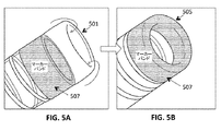
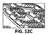
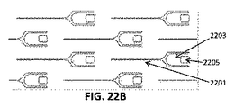
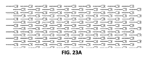
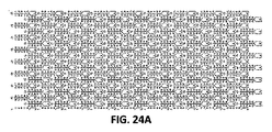
本明細書に記載されるトラクター領域は、特に、反転(例えば、装置の遠位端)中にそれが周囲を曲がる際に、トラクター領域から延びる突起を含み得る。これらの突起は、トラクターが細長い反転支持体と平行に保持されている場合、平坦なままであってもよく、または伸長していなくてもよい。あるいは、突起は、常に伸長してもよい。トラクターは、一般に、織布、ニット材料、または材料のレーザーカットシートで構成され得る。ニットおよび/または織布材料は、繊維材料(天然繊維、合成繊維等を含む)、ポリマー材料、または同様のものであってもよい。例えば、織編物を形成する材料(例えば、ストランド)は、モノフィラメント重合体、マルチフィラメントポリマー、NiTiフィラメント、放射線不透過性金属中心を有するNiTi管、コバルトクロム合金フィラメント、放射線不透過性金属中心を有するコバルトクロム合金管、ナイロン、ポリエステル、ポリエチレンテレフタレート、およびポリプロピレンのうちの1つ以上であってよい。トラクター領域に形成される材料シート(例えば、材料の固体シート)は、ポリマー材料(例:PTFE)、シリコーン材料、ポリウレタン、形状記憶合金、鋼などの1つ以上であり、シートは押出成形、接着などである。シートは、細孔および/または突起を形成するために切断されてもよい。例えば、シートは、1つ以上のレーザー切断突起を含むことができる。これらの装置のいずれも、親水性および/または疎水性コーティングで被覆されてもよく、および/または細孔を含んでもよい。トラクターの空隙率は60%以上(70%以上、75%以上、80%以上、85%以上など、60〜95%、65〜95%、70〜95%など)であってもよい。 The tractor region described herein may include, in particular, a protrusion extending from the tractor region as it bends around during inversion (eg, the distal end of the device). These protrusions may remain flat or may not extend if the tractor is held parallel to the elongated inverted support. Alternatively, the protrusions may always extend. The tractor can generally consist of a woven fabric, knit material, or a laser cut sheet of material. The knit and / or woven fabric material may be a fiber material (including natural fibers, synthetic fibers, etc.), a polymer material, or the like. For example, the material (eg, strand) forming the woven or knitted fabric has a monofilament polymer, a multifilament polymer, a NiTi filament, a NiTi tube with a radiation opaque metal center, a cobalt-chromium alloy filament, a radiation opaque metal center. It may be one or more of cobalt-chromium alloy tubes, nylon, polyester, polyethylene terephthalate, and polypropylene. The material sheet (eg, solid sheet of material) formed in the tractor region is one or more of a polymeric material (eg, PTFE), silicone material, polyurethane, shape memory alloy, steel, etc., and the sheet is extruded, bonded, etc. And so on. The sheet may be cut to form pores and / or protrusions. For example, the sheet can include one or more laser cutting protrusions. Any of these devices may be coated with a hydrophilic and / or hydrophobic coating and / or may contain pores. The porosity of the tractor may be 60% or more (70% or more, 75% or more, 80% or more, 85% or more, 60 to 95%, 65 to 95%, 70 to 95%, etc.).
例えば、ここでは、トラクター領域を含む、凝血塊把持機械的血栓除去装置について説明する。トラクター領域は、トラクターの一方の面から延びる複数の凝血塊把持突起を含むことができる。いくつかの変形例では、凝血塊把持突起は、トラクター領域が、例えば、細長い反転支持体のカテーテルの遠位端の周りで屈曲して反転する場合、伸長するように移動するように構成されてもよい(例えば、トラクターの平面外)。 For example, here we describe a clot-grasping mechanical thrombectomy device that includes a tractor area. The tractor area can include multiple clot grasping projections extending from one side of the tractor. In some variants, the clot gripping process is configured to move to extend when the tractor region flexes and flips, for example, around the distal end of the catheter of an elongated flip support. It may be (for example, out of the plane of the tractor).
一般に、血管から凝血塊を除去するための機械的血栓除去装置は、以下:遠位端および遠位端開口部を有するカテーテルを含む細長い反転支持体;カテーテルの遠位端に沿って延びるためにカテーテルの遠位端の上に折り返してカテーテルの遠位端に沿って延びる可撓管を含むトラクターであって、内部プーラーはトラクターの遠位端に連結されている;および、カテーテル、トラクターおよび内部プーラーを通って延び、ガイドワイヤを通過するように構成されたガイドワイヤ内腔;を備える。トラクターの近位端は、緩んでいてもよい(例えば、カテーテル上を自由にスライドしてもよい。トラクターはまた、カテーテルの外径に対してそれ自体を保持するようにバイアスされ、同時にカテーテル内で反転されたときに膨張するようにバイアスされるように構成されてもよい。この構成では、トラクターの反転遠位対向端部は、トラクターの直径が装置の遠位対向反転端部の近くでわずかに拡大するように、わずかに外側にフレアされてもよい。この構成はまた、カテーテル内のトラクターの部分を、カテーテルの内径に近いように維持することができる。例えば、カテーテル内のトラクターの部分の内径は、カテーテルの内径の50%以上、カテーテルの内径の55%以上、カテーテルの内径の60%以上、カテーテルの内径の65%以上、カテーテルの内径の70%以上、カテーテルの内径の75%以上であってもよい。 In general, a mechanical thrombectomy device for removing a clot from a blood vessel is as follows: an elongated inverted support containing a catheter with distal and distal end openings; to extend along the distal end of the catheter. A tractor containing a flexible tube that folds over the distal end of the catheter and extends along the distal end of the catheter, with an internal puller connected to the distal end of the catheter; and the catheter, tractor and internal. It comprises a guidewire lumen that extends through the puller and is configured to pass through the guidewire. The proximal end of the tractor may be loose (eg, it may slide freely over the catheter; the tractor is also biased to hold itself against the outer diameter of the catheter and at the same time within the catheter. It may be configured to be biased to inflate when flipped in. In this configuration, the inverted distal facing end of the tractor is such that the diameter of the tractor is near the distal facing inverted end of the device. It may be flared slightly outwards so that it expands slightly. This configuration can also keep the portion of the tractor within the catheter close to the inner diameter of the catheter, eg, of the tractor within the catheter. The inner diameter of the part is 50% or more of the inner diameter of the catheter, 55% or more of the inner diameter of the catheter, 60% or more of the inner diameter of the catheter, 65% or more of the inner diameter of the catheter, 70% or more of the inner diameter of the catheter, 75 of the inner diameter of the catheter. It may be% or more.
例えば、血管から凝血塊を除去するための機械的血栓除去装置は、以下:遠位端および遠位端開口部を有するカテーテルを含む細長い反転支持体;カテーテル内の第1の構成で遠位に延び、カテーテルの遠位端開口部を越えて反転し、カテーテルの遠位端に沿って第2の構成(最初の配置に対して反転された)で近位に延びる可撓管を含むトラクターであって、トラクターは管状壁を備え、さらに、トラクターの第1の端部がカテーテル内で近位側に引っ張られたときに、カテーテルの遠位端開口部を上で回転させることによって反転するように構成されている;および、トラクターがカテーテルの遠位端開口部を回転する際に、カテーテルの遠位端開口部を越えて反転されたトラクターの一部から延在する複数の突起であって、複数の突起は、カテーテルの遠位端に沿って反転された構成で近位に延在するので、トラクターから延在しない;を、含んでいてもよい。 For example, a mechanical thrombosis remover for removing clots from a blood vessel is as follows: an elongated inverted support containing a catheter with distal end and distal end openings; distal in the first configuration within the catheter. In a tractor that includes a flexible tube that extends, flips over the distal end opening of the catheter, and extends proximally along the distal end of the catheter in a second configuration (reversed for the initial placement). The tractor is equipped with a tubular wall so that when the first end of the tractor is pulled proximally within the catheter, it flips by rotating the distal end opening of the catheter up. Consists of; and multiple protrusions extending from a portion of the tractor inverted over the distal end opening of the catheter as the tractor rotates through the distal end opening of the catheter. May include, the protrusions extend proximally in an inverted configuration along the distal end of the catheter and therefore do not extend from the tractor;
上述したように、一般に、本明細書に記載する機械的血栓除去装置は、凝血塊把持突起を含むことができる。例えば、血管から凝血塊を除去するための機械的血栓除去装置は、以下:遠位端および遠位端開口部を有するカテーテルを含む細長い反転支持体;カテーテル内に延在し、カテーテルの遠位端に沿って延在するようにカテーテルの遠位端の上に倍増して戻る可撓管を含むトラクターであって、管状壁を含む可撓管であって、トラクターの第1の端がカテーテル内で近位側に引っ張られると、トラクターが遠位端開口部を反転するように構成され、さらに、前記トラクターは、前記複数の突起が、前記管状壁が前記遠位端開口部を越えて反転するときに前記管状壁の平面から延びるように構成された複数の突起を含み、前記複数の突起は、前記管状壁が前記カテーテルの遠位端に沿って延びるときに前記管状壁の平面内に残る;および、カテーテルおよびトラクターを通って延び、ガイドワイヤを通過するように構成されたガイドワイヤ内腔;を、含んでいてもよい。 As mentioned above, in general, the mechanical thrombectomy device described herein can include a clot grasping process. For example, a mechanical thrombosis remover for removing clots from a blood vessel is as follows: an elongated inverted support containing a catheter with distal end and distal end openings; extending within the catheter and distal to the catheter. A tractor containing a flexible tube that doubles back over the distal end of the catheter to extend along the end, a flexible tube containing a tubular wall, with the first end of the catheter being the catheter. When pulled inward to the proximal side, the tractor is configured to flip the distal end opening, and the tractor further has the plurality of protrusions and the tubular wall beyond the distal end opening. It comprises a plurality of protrusions configured to extend from the plane of the tubular wall when flipped, the plurality of protrusions within the plane of the tubular wall as the tubular wall extends along the distal end of the catheter. And may include a guidewire lumen configured to extend through the catheter and tractor and pass through the guidewire.
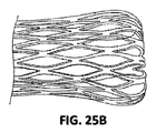
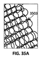
特に、トラクターは、織リボンの管であってもよく、さらに、複数の突起は、リボンの縁部から形成される。リボンは、少なくとも1つ(通常は4回)の細長い端を有する平坦なストリップまたは材料のストランドを含んでもよい。例えば、リボンは長方形の断面を有することができる。いくつかの変形では、リボンは、1つまたは複数の縁部を有する正方形または三角形または他の断面を有することができる。縁部を有するリボンは、例えば、それらが細長い反転支持体の遠位端上に延在するときに螺旋状パターンに配列されるように、織られてもよい。したがって、トラクターが反転するとき、リボンの縁は、トラクターの平面から外側に延びることができる。これらの延在する縁部は、湾曲し、トラクターの湾曲領域上にスクープ、切断、および/または把持突起を形成することができる。リボンは、金属またはポリマー材料のような、上述したものを含む任意の適切な材料で形成することができる。 In particular, the tractor may be a tube of woven ribbon, and moreover, a plurality of protrusions are formed from the edges of the ribbon. The ribbon may include flat strips or strands of material with at least one (usually four times) elongated ends. For example, the ribbon can have a rectangular cross section. In some variants, the ribbon can have a square or triangle or other cross section with one or more edges. Ribbons with edges may be woven, for example, so that they are arranged in a spiral pattern as they extend over the distal ends of the elongated inverted support. Therefore, when the tractor flips, the edges of the ribbon can extend outward from the plane of the tractor. These extending edges can be curved to form scoops, cuts, and / or gripping projections on the curved area of the tractor. The ribbon can be made of any suitable material, including those mentioned above, such as metal or polymeric materials.
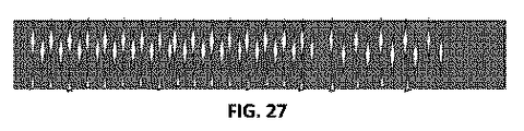
本明細書に記載されるトラクター領域からの突起は、トラクター材料内の切欠き領域によって形成されてもよい。例えば、材料のシートまたは管は、鋼(例えば、ステンレス鋼)、ポリエステル、ナイロン、延伸ポリテトラフルオロエチレン(ePTFE)、ニチノール、または織物の管といったトラクターを形成するのに使用してもよく、突起は、管またはシートから切断することによって形成してもよい。例えば、突起を管状壁から切断することができる。変形例によっては、開口部、スリット、スロット、または間隙(例えば、孔を形成すること)に加えて、突起を切断することができる。例えば、トラクターは、幅が約0.005インチ未満の細孔間の縦方向の間隔を有する細孔パターンを有する少なくとも1つの多孔質セクションを有してもよい。いくつかの変形例では、管状壁に接する90°未満の角度で管状壁から突起を切断することができる。例えば、複数の突起の各々は、可撓管に対して横方向の幅と、可撓管の長軸に沿った方向の長さとを有することができる。長さと幅との比は、例えば、2〜100の間(例えば、5〜100、10〜100、5〜90、5〜80、5〜70、5〜50、10〜90、10〜80、10〜70、10〜60など)であり得る。 The protrusions from the tractor region described herein may be formed by cutout regions within the tractor material. For example, a sheet or tube of material may be used to form a tractor such as steel (eg, stainless steel), polyester, nylon, stretched polytetrafluoroethylene (ePTFE), nitinol, or woven tube, with protrusions. May be formed by cutting from a tube or sheet. For example, the protrusion can be cut from a tubular wall. In some variants, in addition to openings, slits, slots, or gaps (eg, forming holes), protrusions can be cut. For example, the tractor may have at least one porous section having a pore pattern with longitudinal spacing between pores less than about 0.005 inches wide. In some variants, protrusions can be cut from the tubular wall at an angle of less than 90 ° in contact with the tubular wall. For example, each of the plurality of protrusions can have a lateral width with respect to the flexible tube and a length along the long axis of the flexible tube. The ratio of length to width is, for example, between 2 and 100 (eg, 5 to 100, 10 to 100, 5 to 90, 5 to 80, 5 to 70, 5 to 50, 10 to 90, 10 to 80, 10-70, 10-60, etc.).
突起は、凝血塊を掴み、および/または解離するように形成され得る。例えば、複数の突起の全部または一部が、パドル形状、スコップ形状、スパイク形状のうちの1つまたは複数を有していてもよい。これらの突起はトラクター(例えば、突起が伸びるトラクター表面に対して90°または垂直に、あるいはトラクター表面の平面から約45〜135°の間など)の平面を延長できる。突起は鋭いことがある(例えば、鋭い端部を有することがある)。突起はトラクター表面から0.01〜5mmの間(例えば、0.01〜2mmの間、0.05〜1mmの間など)で伸びる。突起のサイズは、トラクターのサイズおよび/または装置が挿入されることが意図されている血管のサイズにスケーリングされ得る。 The protrusions can be formed to grab and / or dissociate the clot. For example, all or part of the plurality of protrusions may have one or more of a paddle shape, a scoop shape, and a spike shape. These protrusions can extend the plane of the tractor (eg, 90 ° or perpendicular to the tractor surface on which the protrusion extends, or between about 45-135 ° from the plane of the tractor surface). The protrusions may be sharp (eg, may have sharp edges). The protrusions extend between 0.01 and 5 mm (eg, between 0.01 and 2 mm, between 0.05 and 1 mm, etc.) from the surface of the tractor. The size of the protrusion can be scaled to the size of the tractor and / or the size of the blood vessel in which the device is intended to be inserted.
本明細書に記載される装置のいずれにおいても、細長い反転支持体(例えば、カテーテル)は、遠位端上のトラクター領域(反転)の回転を促進するように適合され得る。例えば、本明細書に記載された装置のいずれにおいても、カテーテルの材料硬度が、遠位端開口部までカテーテルの遠位端にわたって減少するように、カテーテルを構成することができ、遠位端開口部は、遠位端のすぐ近位領域の材料硬度よりも大きい材料硬度を有し、さらに、遠位端開口部は丸いリッププロファイルを有する。カテーテルの遠位端は、それがより厚いので、より剛性であり得る(例えば、カテーテルの遠位端をそれ自体の上で逆にすることによって形成され得る、および/またはそれは、隣接するより近位の領域(補強材料を含む)よりも剛性の材料で形成され得る。 In any of the devices described herein, an elongated inversion support (eg, a catheter) may be adapted to facilitate rotation of the tractor region (inversion) over the distal end. For example, in any of the devices described herein, the catheter can be configured such that the material hardness of the catheter is reduced over the distal end of the catheter to the distal end opening and the distal end opening. The portion has a material hardness greater than the material hardness of the region immediately proximal to the distal end, and the distal end opening has a round lip profile. The distal end of the catheter can be more rigid because it is thicker (eg, it can be formed by reversing the distal end of the catheter on itself, and / or it is closer than adjacent. It can be made of a material that is more rigid than the region of the position (including the reinforcing material).
凝血塊を掴むのを助けるように構成された突起は、トラクターの全長にわたって分布されてもよいし、トラクターの領域(例えば、遠位端領域、例えば、遠位5mm、7mm、10mm、15mm、20mm等以下)のみにわたって分布されてもよい。いくつかの変形例では、突起の分布は不均一に分布してもよく、例えば、トラクターは、トラクターの長さに沿った突起の不均一な密度を含んでもよい。突起は、トラクターがカテーテルの外径上にあるときに突起が遠位方向に延びるように、トラクターに対して配向されてもよく、これは、トラクターが凝血塊を掴むのを助ける。 The protrusions configured to help grab the clot may be distributed over the entire length of the tractor or in the area of the tractor (eg, the distal end area, eg, the distal 5 mm, 7 mm, 10 mm, 15 mm, 20 mm. Etc. or less) may be distributed only. In some variations, the distribution of protrusions may be non-uniformly distributed, for example, the tractor may include a non-uniform density of protrusions along the length of the tractor. The protrusions may be oriented with respect to the tractor so that the protrusions extend distally when the tractor is on the outer diameter of the catheter, which helps the tractor grab the clot.
突起は、トラクターを通る複数のスロットまたは開口として構成されてもよい(例えば、トラクターを形成する管をレーザー切断することによって)。 The protrusions may be configured as multiple slots or openings through the tractor (eg, by laser cutting the tube forming the tractor).
本明細書に記載される装置のいずれにおいても、トラクターは、潤滑性コーティング、金属コーティング、ヘパリンコーティング、接着性コーティング、および薬物コーティングの群からの1つ以上のコーティングを含むことができる。特に、トラクターは、均一または不均一な潤滑性(例えば、親水性)コーティングを含むことができる。このようなコーティングは、トラクターをより容易に反転(例えば、カテーテルの遠位端上)させるのを助けるが、凝血塊を掴むのを特に困難にする。本明細書に記載される予測は、この問題に対処し得る。 In any of the devices described herein, the tractor can include one or more coatings from the group of lubricating coatings, metal coatings, heparin coatings, adhesive coatings, and drug coatings. In particular, the tractor can include a uniform or non-uniform lubricity (eg, hydrophilic) coating. Such a coating helps the tractor flip more easily (eg, on the distal end of the catheter), but makes it particularly difficult to grab a clot. The predictions described herein may address this issue.
本明細書に記載される装置のいずれもが、トラクターと細長い反転支持体(例えば、カテーテル)の外面との間の取り外し可能な取り付け部を含んでもよく、これは、トラクターが所定の力閾値より大きい力で引っ張られたときに解放されるように構成される。これは、装置の早期展開を防止することができる。剥離可能なアタッチメントは、例えば、接着剤などの破壊可能な(例えば、壊れやすい)領域、または剥離可能なタイなどであり得る。剥離可能な付着は、異なる疎水性/親水性の領域によって形成され得る。これらの装置のいずれも、装置を展開するのに必要な力が所定の閾値より大きいように構成することができ、例えば、解放可能な力の閾値は、50g、100g、200g、300g、400g、500g、600g、700g、800g、900g、1000g等の力より大きくすることができる(例えば、200gを超える力)。加えて、これらの装置のいずれも、カバー、カテーテル、スリーブ、シース等を含む外側の細長い反転支持体を含み、展開する準備ができるまでカテーテルに対してトラクターの近位端を保持する。展開とは、解除可能なアタッチメントから末端(例えば、カテーテルの外面の端部)を解放することを意味する。一旦展開されると、トラクターをカテーテルの外径に沿って引き出すこと、トラクターを反転させること、およびトラクターをカテーテルの遠位端開口部(トラクターの中の凝血塊や他の物質なしで)内に引くことを含む、トラクターをカテーテルの近位側に引っ張るのに必要な力は、初期展開力よりも実質的に小さくなり得る。例えば、トラクターを近位方向にカテーテルに引き込むのに必要な力は、1グラム(g)以下の力(または2g、3g、4g、5g、6g、7g、8g、9g、10g、20g、30g、40g、50g以下の力など)であり得る。代替的または追加的に、これらの装置のいずれかは、カテーテルの遠位端上でカテーテルを反転させるのに必要な力の量を減少させるため、および/またはカテーテル内でのトラクターの閉塞を防止するために、トラクターとカテーテルの間に材料(例えば、スリーブ、コーティング等)を含んでもよい。 Any of the devices described herein may include a removable attachment between the tractor and the outer surface of an elongated inverted support (eg, catheter), which causes the tractor to exceed a predetermined force threshold. It is configured to be released when pulled with great force. This can prevent premature deployment of the device. The peelable attachment can be, for example, a destructible (eg, fragile) area such as an adhesive, or a peelable tie. Detachable deposits can be formed by different hydrophobic / hydrophilic regions. Any of these devices can be configured such that the force required to deploy the device is greater than a predetermined threshold, for example, the releasable force thresholds are 50 g, 100 g, 200 g, 300 g, 400 g, The force can be greater than the force of 500 g, 600 g, 700 g, 800 g, 900 g, 1000 g, etc. (for example, a force exceeding 200 g). In addition, each of these devices includes an outer elongated inverted support that includes a cover, catheter, sleeve, sheath, etc., and holds the proximal end of the tractor to the catheter until it is ready to be deployed. Deployment means releasing the end (eg, the outer end of the catheter) from the detachable attachment. Once deployed, pull the tractor along the outer diameter of the catheter, flip the tractor, and pull the tractor into the distal end opening of the catheter (without clots or other substances in the tractor). The force required to pull the tractor proximal to the catheter, including pulling, can be substantially less than the initial deployment force. For example, the force required to pull the tractor proximally into the catheter is less than 1 gram (g) (or 2 g, 3 g, 4 g, 5 g, 6 g, 7 g, 8 g, 9 g, 10 g, 20 g, 30 g, It can be a force of 40 g, 50 g or less, etc.). Alternatively or additionally, either of these devices reduces the amount of force required to flip the catheter over the distal end of the catheter and / or prevents blockage of the tractor within the catheter. In order to do so, a material (eg, sleeve, coating, etc.) may be included between the tractor and the catheter.
前述したように、これらの装置のいずれも、牽引装置、例えば、トラクターの遠位端に連結された細長い牽引装置を含むことができる。これらの装置のいずれも、トラクターの遠位端に連結されたカテーテル内に細長い引張り装置を含むことができる。細長いプーラーは、可撓管を介してガイドワイヤ管腔に連続する内側管腔を有するハイポチューブを含むことができる。 As mentioned above, any of these devices can include a traction device, eg, an elongated traction device connected to the distal end of the tractor. Any of these devices can include an elongated pulling device within a catheter connected to the distal end of the tractor. The elongated puller can include a hypotube having an inner lumen that is continuous with the guidewire lumen via a flexible tube.
一般に、トラクターは、任意の適切な長さであってもよい。例えば、トラクターは、3〜100cmの長さ(例えば、3〜50cm、3〜40cm、3〜30cm、3〜cm、20〜cm、10〜100cm、10〜50cm、20〜100cm、20〜50cmなどである)であり得る。 In general, the tractor may be of any suitable length. For example, the tractor has a length of 3 to 100 cm (eg, 3 to 50 cm, 3 to 40 cm, 3 to 30 cm, 3 to cm, 20 to cm, 10 to 100 cm, 10 to 50 cm, 20 to 100 cm, 20 to 50 cm, etc. Can be).
これらの装置のいずれにおいても、装置は、可撓管の遠位端に300グラム未満の力(例えば、400g未満の力、300g未満の力、200g未満の力、100g未満の力、90g未満の力、80g未満の力、70g未満の力、60g未満の力、50g未満の力、10g未満の力など)を加えることによって、トラクターをカテーテル内に引き込むことができるように構成することができる。例えば、上述したように、装置は、親水性コーティング、カテーテルおよび/またはトラクター上の潤滑剤、トラクターとカテーテルとの間のスリーブなどを含むことができる。トラクターをカテーテル内に引き込むのに必要なこの力は、典型的には、トラクターの遠位端上でトラクターを転がすのに必要な力を指す。初期展開力(例えば、カテーテルの外側のトラクターの端部を解放すること)は、カテーテルを引き込むのに必要な力(例えば、100gを超える力、200gの力、300gの力、400gの力、500gの力、600gの力、700gの力、800gの力、900gの力、1000gの力、1500gの力、2000gの力など)よりも大きいことがある。 In any of these devices, the device has a force of less than 300 grams at the distal end of the flexible tube (eg, less than 400 g, less than 300 g, less than 200 g, less than 100 g, less than 90 g. A force, less than 80 g, less than 70 g, less than 60 g, less than 50 g, less than 10 g, etc.) can be applied to allow the tractor to be pulled into the catheter. For example, as mentioned above, the device can include a hydrophilic coating, a lubricant on the catheter and / or tractor, a sleeve between the tractor and the catheter, and the like. This force required to pull the tractor into the catheter typically refers to the force required to roll the tractor over the distal end of the tractor. The initial deployment force (eg, releasing the end of the tractor on the outside of the catheter) is the force required to pull in the catheter (eg, force greater than 100 g, force 200 g, force 300 g, force 400 g, 500 g. Power, 600g power, 700g power, 800g power, 900g power, 1000g power, 1500g power, 2000g power, etc.).
例えば、血管から凝血塊を除去するための機械的血栓除去装置は、以下:遠位端および遠位端開口部を有するカテーテルを含む細長い反転支持体;カテーテル内の第1の(例えば、「非反転」)構成で遠位に延び、カテーテルの遠位端開口部を第2の構成(最初の配置に対して反転された)に反転し、カテーテルの遠位端に沿って反転した構成で近位に延びる可撓管を含むトラクターであって、可撓管は、一緒に織られた正方形または長方形の断面を有する複数のリボンを含み、トラクターは、トラクターの第1の端部がカテーテル内で近位側に引っ張られたときにカテーテルの遠位端開口部を回転することによって反転するように構成され、複数のリボンの複数の縁部が、トラクターがカテーテルの遠位端開口部を回転する際にカテーテルの遠位端開口部から延在し、さらに、突出縁は、カテーテルの遠位端を越えて延びるトラクターの一部において、トラクターから延長されない;および、カテーテルおよびトラクターを通って延び、ガイドワイヤを通過するように構成されたガイドワイヤ内腔;を、含んでいてもよい。 For example, a mechanical thrombosis remover for removing clots from a blood vessel is as follows: an elongated inverted support including a catheter with distal end and distal end openings; a first (eg, "non" in the catheter. Inverted ") configuration extends distally, flipping the distal end opening of the catheter to a second configuration (inverted relative to the initial placement) and nearing in an inverted configuration along the distal end of the catheter. A tractor that includes a flexible tube that extends to the position, the flexible tube containing multiple ribbons with a square or rectangular cross section woven together, the tractor having the first end of the tract within the catheter. It is configured to flip by rotating the distal end opening of the catheter when pulled proximally, with multiple edges of multiple ribbons causing the tractor to rotate the distal end opening of the catheter. When extending from the distal end opening of the catheter, the protruding edge is not extended from the tract in some of the tractors extending beyond the distal end of the catheter; and extending through the catheter and tractor, A guide wire lumen configured to pass through the guide wire; may be included.
血管から凝血塊を除去するための機械的血栓除去装置は、以下:遠位端と遠位端開口部を有するカテーテルを含む細長い反転支持体を含む細長い反転支持体;カテーテル内に延在し、カテーテルの遠位端に沿って延在してカテーテルの遠位端に沿って延在し、カテーテルの遠位端に沿って折り返している可撓管を含むトラクターであって、可撓管は、正方形または長方形の断面を有する複数の織リボンから形成された管状壁を含むトラクター、トラクターは、トラクターの第1の端部がカテーテル内で近位側に引っ張られたときに遠位端開口部を越えて反転するように構成され、トラクターは、管状壁が遠位端開口部を越えて反転するときに複数の突起が管状壁の平面から延びるように構成された複数の突起をさらに含む、さらに、複数の突起がリボンの縁部から形成され、管状壁がカテーテルの遠位端に沿って延びるにつれて、突起が管状壁の平面内に残る;および、カテーテルおよびトラクターを通って延び、ガイドワイヤを通過するように構成されたガイドワイヤ内腔;を、含んでいてもよい。 Mechanical thrombosis removers for removing clots from blood vessels include: elongated inverted supports, including elongated inverted supports, including catheters with distal and distal end openings; extending within the catheter, A tractor that includes a flexible tube that extends along the distal end of the catheter, extends along the distal end of the catheter, and folds back along the distal end of the catheter. A tractor containing a tubular wall formed from multiple woven ribbons with a square or rectangular cross section, the tractor has a distal end opening when the first end of the tractor is pulled proximally within the catheter. Constructed to flip over, the tractor further includes multiple protrusions configured to extend from the plane of the tubular wall as the tubular wall flips over the distal end opening. , Multiple protrusions are formed from the edges of the ribbon, and as the tubular wall extends along the distal end of the catheter, the protrusions remain in the plane of the tubular wall; and extend through the catheter and tractor to extend the guide wire. A guide wire lumen configured to pass through; may be included.
血管から凝血塊を除去するための機械的血栓除去装置は、以下:遠位端および遠位端開口部を有するカテーテル;カテーテル内に延在し、カテーテルの遠位端の上で折り返している可撓管を含むトラクターであって、管状壁を含む可撓管であって、トラクターの第1の端がカテーテル内で近位側に引っ張られたときに、トラクターが遠位端開口部の上で反転するように構成されているトラクター、さらに、前記トラクターが、前記管状壁に形成され、前記複数の突起が、前記トラクターが前記遠位端開口部を越えて反転し、前記管状壁の平面内に留まるとき、前記複数の突起が前記トラクターを自慢するように延在するように構成された複数の突起を備えることを特徴とする;前記複数の凸部の各々は、前記可撓管を横切る方向の幅と、前記可撓管の長軸に沿った方向の長さとを有し、さらに、長さと幅の比が10〜100の間である;および、カテーテルと、ガイドワイヤを通過するように構成されたトラクターとを通るガイドワイヤ内腔;を、含んでいてもよい。 Mechanical thrombolytic devices for removing clots from blood vessels include: catheters with distal and distal end openings; can extend within the catheter and fold over the distal end of the catheter. A tractor containing a flexible tube, a flexible tube containing a tubular wall, in which the tractor is over the distal end opening when the first end of the tractor is pulled proximally within the catheter. A tractor configured to flip, in addition the tractor is formed on the tubular wall and the plurality of protrusions allow the tractor to flip over the distal end opening and within the plane of the tubular wall. When staying in, the plurality of protrusions comprises a plurality of protrusions configured to brag about the tractor; each of the plurality of protrusions crosses the flexible tube. It has a width in the direction and a length in the direction along the long axis of the flexible tube, and the ratio of the length to the width is between 10 and 100; and to pass through the catheter and the guide wire. A guide wire lumen through which the tractor is configured; may be included.
本明細書に記載される装置のいずれも、トラクターが非常に軟質であり、したがって、カテーテルの遠位端部の周りを容易に回転して細長い反転支持体を形成し、および/またはカテーテルの遠位端開口部上でトラクターを回転させるための大きな力を必要としないように構成することができる。特に、低軸圧縮強度を有するトラクターであっても、細長い反転支持体に対しては、典型的にはバックルであり、トラクターが反転するときに細長い反転支持体の閉塞を防止することが見出されている。特に、約500g未満の力(例えば、約500g未満の力、約400gの力、約300gの力、約200gの力、約150gの力、約100gの力、約50gの力など)の軸方向圧縮下で半径方向に崩壊するように構成された支持されていないトラクター(例えば、カテーテルに支持された環状開口部の上を転がっていないトラクター)は、閉塞を防止するのに特に有用である。本明細書に記載されたものを含む、ほとんどの編まれた、編まれたトラクターでは、トラクターがこの量の軸圧縮力に耐えるように構成されている場合、トラクターは、詰まり、および/または反転するために過剰な力を必要とする。したがって、本明細書に記載される装置および方法のいずれにおいても、トラクターは、カテーテルからの支持なしに、トラクターが反転(その代わりに)時に200g未満の力の軸方向圧縮の下で半径方向に崩壊するように、充分に柔らかくてもよい。 In any of the devices described herein, the tractor is very soft and therefore easily rotates around the distal end of the catheter to form an elongated inverted support and / or the distance of the catheter. It can be configured so that it does not require a large force to rotate the tractor over the distal opening. In particular, it has been found that even tractors with low axial compression strength are typically buckles for elongated reversing supports, preventing blockage of the elongated reversing support when the tractor flips. Has been done. In particular, the axial direction of a force of less than about 500 g (for example, a force of less than about 500 g, a force of about 400 g, a force of about 300 g, a force of about 200 g, a force of about 150 g, a force of about 100 g, a force of about 50 g, etc.) An unsupported tractor configured to collapse radially under compression (eg, a tractor that does not roll over an annular opening supported by a catheter) is particularly useful in preventing occlusion. In most knitted, knitted tractors, including those described herein, the tractor is clogged and / or inverted if the tractor is configured to withstand this amount of axial compressive force. Requires excessive force to do. Thus, in any of the devices and methods described herein, the tractor is radially under axial compression of less than 200 g of force when the tractor is inverted (instead) without support from the catheter. It may be soft enough to collapse.
さらに、本明細書に記載される装置のいずれにおいても、トラクターは、トラクターがカテーテルの外径を超えて延びている第2の構成(最初の配置に対して反転された)において、カテーテルの外径よりも大きく拡張するようにバイアスされてもよい。第1の構成(例えば、非反転)では、トラクターが細長い反転支持体のカテーテル内にある構成において、同じトラクターを、細長い反転支持体のカテーテルの内径よりも大きく拡張するようにバイアスすることができる。このように、弛緩した構成では、細長い反転支持体を組み立てる前に、トラクターは、細長い反転支持体のカテーテルと比較して大型化してもよい。「非反転」と称される細長い反転支持体のカテーテル内に延在するトラクターの部分は、カテーテルの内径よりも大きい内径を有することができ、カテーテル内に崩れ落ちることなくカテーテルの内径の壁に向かってトラクターを駆動する傾向がある。さらに、「反転」構成におけるトラクターの内径、例えば、細長い反転支持体のカテーテル上およびそれに沿って折り返している部分の構成は、細長い反転支持体のカテーテルの外径よりも大きくてもよい。この構成により、閉塞が防止され、トラクターと細長い反転支持体のカテーテルの外側との間の抵抗が増加する。カテーテルは、例えば、熱設定によって、反転された構成および非反転構成の両方で拡張するようにバイアスされ得る。トラクターは、カテーテルの遠位端上を回転することによって、第1の構成と第2の構成との間を移行するように反転されてもよい。したがって、「反転」および「非反転」という用語は相対的な用語である。 Further, in any of the devices described herein, the tractor is outside the catheter in a second configuration (inverted relative to the initial arrangement) in which the tractor extends beyond the outer diameter of the catheter. It may be biased to extend larger than the diameter. In the first configuration (eg, non-inverted), the same tractor can be biased to extend more than the inner diameter of the elongated inverted support catheter in a configuration where the tractor is within the elongated inverted support catheter. .. Thus, in a relaxed configuration, the tractor may be larger than the catheter of the elongated inverted support before assembling the elongated inverted support. The portion of the tractor extending within the catheter of the elongated inverted support, referred to as "non-reversing", can have an inner diameter larger than the inner diameter of the catheter and faces the wall of the inner diameter of the catheter without collapsing into the catheter. Tends to drive the tractor. Further, the inner diameter of the tractor in the "reversal" configuration, eg, the configuration of the elongated inverted support on the catheter and the portion folded along it, may be larger than the outer diameter of the elongated inverted support catheter. This configuration prevents obstruction and increases resistance between the tractor and the outside of the catheter on the elongated inverted support. The catheter can be biased to expand in both inverted and non-inverted configurations, for example by thermal setting. The tractor may be flipped to transition between the first configuration and the second configuration by rotating over the distal end of the catheter. Therefore, the terms "inverted" and "non-inverted" are relative terms.
機械的血栓除去装置を用いて凝血塊を除去する方法も本明細書に記載する。例えば、機械的血栓除去装置を使用して凝血塊を除去する方法は、以下;機械的血栓除去装置の遠位端を血管内の凝血塊に隣接して位置決めすることであって、機械的血栓除去装置が、カテーテルを有する細長い反転支持体の遠位領域に沿って延在し、カテーテルの遠位端を越えて反転して、カテーテル内でトラクターの遠位端が近位に延在するトラクター領域を含むことを特徴とする;トラクターの遠位端をカテーテル内で近位側に引いて、トラクターをカテーテルの遠位端の上で反転させて、トラクターから複数の突起を延在させ、凝血塊を掴むこと;および、凝血塊を引っ張ること;を、含んでいてもよい。 A method of removing a clot using a mechanical thrombectomy device is also described herein. For example, a method of removing a clot using a mechanical clot remover is as follows; positioning the distal end of the mechanical clot remover adjacent to the clot in the blood vessel, the mechanical clot. A tractor with a removal device extending along the distal region of an elongated inverted support with a catheter, flipping over the distal end of the catheter, and extending the distal end of the tractor proximally within the catheter. Containing an area; pulling the distal end of the tractor proximally within the catheter, flipping the tractor over the distal end of the catheter, extending multiple protrusions from the tractor, blood clots. It may include grabbing the clot; and pulling the clot.
これらの方法のいずれも、複数の突起で凝血塊を解離させることを含み得る。 Any of these methods may involve dissociating a clot at multiple processes.
例えば、機械的血栓除去装置を使用して凝血塊を除去する方法は、以下;機械的血栓除去装置の遠位端を血管内の凝血塊に隣接して位置決めすることであって、機械的血栓除去装置は、カテーテルの遠位領域に沿って延び、カテーテルの遠位端を反転して、トラクター内の第1の端が近位に延びるようにするトラクター領域を含む;トラクターがカテーテルの遠位端を越えて反転し、トラクターからの複数の突起を伸長するように、トラクターをカテーテルの遠位端を越えて回転させるために、カテーテル内でトラクターの第1の端を近位側に引っ張ること;および、複数の突起で凝血塊を掴むこと;凝血塊を引っ張ること;を、含んでいてもよい。 For example, a method of removing a clot using a mechanical clot remover is as follows; positioning the distal end of the mechanical clot remover adjacent to the clot in the blood vessel, the mechanical clot. The removal device includes a tractor area that extends along the distal area of the catheter and inverts the distal end of the catheter so that the first end within the tract extends proximally; the tractor extends distal to the catheter. Pulling the first end of the tractor proximally within the catheter to rotate the tractor beyond the distal end of the catheter so that it flips over the end and extends multiple protrusions from the tractor. And, grasping the clot with a plurality of protrusions; pulling the clot; may be included.
上述のように、トラクターは、正方形または長方形の断面を有する複数の織リボンを備えることができる。さらに、トラクターの遠位端をカテーテル内で近位側に引いて、トラクターをカテーテルの遠位端上で反転させて、トラクターから複数の突起を伸長させるステップは、トラクターがカテーテルの遠位端上で反転されて、カテーテルの遠位端から織リボンの複数の縁を伸長させて、拡張された縁で凝血塊を掴むステップを含む。 As mentioned above, the tractor can include a plurality of woven ribbons having a square or rectangular cross section. In addition, the step of pulling the distal end of the tractor proximally within the catheter, flipping the tractor over the distal end of the catheter and extending multiple protrusions from the tractor is a step in which the tractor is over the distal end of the catheter. Inverted with, it involves extending multiple edges of the woven ribbon from the distal end of the catheter and grabbing the clot with the expanded edges.
代替的または追加的に、トラクターは、トラクター内に形成された複数の切欠き領域を含むことができ、さらに、カテーテル内でトラクターの遠位端を近位側に引き、カテーテルの遠位端を越えてトラクターを反転させることにより、複数の突起を形成する切欠き領域をトラクターから延長して、凝血塊を掴む。これらの方法のいずれも、トラクターの遠位端が近位側に引っ張られるときに、トラクターの緩い近位端をカテーテルの上にスライドさせることを含み得る。 Alternatively or additionally, the tractor can include multiple notched areas formed within the tractor, and further pull the distal end of the tractor proximally within the catheter to pull the distal end of the catheter. By flipping the tractor over, the notched areas that form the multiple protrusions are extended from the tractor to grab the clot. Any of these methods may include sliding the loose proximal end of the tractor onto the catheter as the distal end of the tractor is pulled proximally.
これらの方法のいずれも、ガイドワイヤを使用することを含み得る。例えば、機械的血栓除去装置の遠位端を位置決めすることは、ガイドワイヤ上で機械的血栓除去装置をスライドさせることを含むことができる。 Any of these methods may involve the use of guide wires. For example, positioning the distal end of a mechanical thrombectomy device can include sliding the mechanical thrombectomy device on a guide wire.
同様に、これらの方法のいずれも、トラクターとカテーテルの外表面との間の解放可能な取り付けを解放することを含み得る。 Similarly, any of these methods may include releasing the releasable attachment between the tractor and the outer surface of the catheter.
トラクターの遠位端を近位側に引っ張ることは、トラクターがカテーテルの遠位端上でロックするのを防止するために、カテーテルの内径の60%より大きいところでカテーテル内のトラクターの内径を維持することを含むことができる。 Pulling the distal end of the tractor proximally maintains the inner diameter of the tractor within the catheter above 60% of the inner diameter of the catheter to prevent the tractor from locking on the distal end of the catheter. Can include that.
また、ここでは、トラクターの長さに沿って剛性が変化するトラクター領域を有する装置についても説明する。これらの装置は、ラチェット運動によりトラクターの遠位対向端で反転(回転)できる。これらの装置およびそれらを使用する方法は、閉塞を防止する運動を提供することができ、また、凝血塊を掴むのを助けることができる。 In addition, a device having a tractor region whose rigidity changes along the length of the tractor will also be described here. These devices can be inverted (rotated) at the distal facing ends of the tractor by ratcheting. These devices and the methods in which they are used can provide exercise to prevent obstruction and can also help grab a clot.
例えば、本明細書では、以下:遠位端および遠位端開口部を有するカテーテル;カテーテル内で長手方向に延在し、カテーテルの遠位端に沿って延在してカテーテルの遠位端に沿って折返して延びる可撓管を含むトラクターであって、可撓管は、より高い剛性とより低い剛性との長手方向に交互の領域を含み、より高い剛性の領域は、より低い剛性の領域より大きい剛性の領域より大きい剛性を有するトラクター;トラクターの遠位端に連結された内部プーラー;および、カテーテル、トラクターおよび内部プーラーを通って延び、ガイドワイヤを通過するように構成されたガイドワイヤ内腔;を、含み得る、血管から凝血塊を除去するための機械的血栓除去装置について説明する。 For example, herein: a catheter with distal and distal end openings; extending longitudinally within the catheter and extending along the distal end of the catheter to the distal end of the catheter. A tractor that includes a flexible tube that folds back along and extends, the flexible tube containing alternating longitudinal regions of higher and lower rigidity, the higher rigidity region being the lower rigidity region. Area of greater rigidity Within a tractor with greater rigidity; an internal puller connected to the distal end of the tractor; and within a guidewire configured to extend through the catheter, tractor and internal puller and pass through the guidewire. A mechanical thrombosis remover for removing a clot from a blood vessel, which may include a cavity;
血管から凝血塊を除去するための機械的血栓除去装置は、以下:遠位端および遠位端開口部を有するカテーテル;カテーテルの遠位端に沿って延びるためにカテーテルの遠位端の上を折り返してカテーテルの遠位端に沿って延びる可撓管を含むトラクターであって、可撓管は、より高い剛性とより低い剛性との長手方向に交互の領域を含み、より高い剛性の領域は、より低い剛性の領域よりも大きい剛性を有し、さらに、トラクターの遠位に面する端の直径は、トラクターがカテーテル内で近位に引っ張られてカテーテルの遠位端の上でトラクターを反転させるにつれて振動する;トラクターの遠位端に連結された内部プーラー;および、カテーテル、トラクターおよび内部プーラーを通って延び、ガイドワイヤを通過するように構成されたガイドワイヤ内腔;を、含んでいてもよい。 Mechanical thrombosis removers for removing clots from blood vessels include: catheters with distal and distal end openings; over the distal end of the catheter to extend along the distal end of the catheter. A tractor that includes a flexible tube that folds back and extends along the distal end of the catheter, the flexible tube containing alternating longitudinal regions of higher and lower rigidity, the higher stiffness regions. In addition, the diameter of the distal end of the tractor is such that the tractor is pulled proximally within the catheter and flips the tractor over the distal end of the catheter. Includes an internal puller attached to the distal end of the tractor; and a guidewire lumen configured to extend through the catheter, tractor and internal puller and pass through the guidewire; May be good.
血管から血栓を除去するための機械的血栓除去装置は、以下:遠位端および半径を有する遠位端開口部を有するカテーテル;カテーテル内で長手方向に延在し、カテーテルの遠位端に沿って延在し、カテーテルの遠位端に沿って折返して延在している可撓管を備えたトラクターであって、可撓管は、可撓管の周りに螺旋状に配置された高剛性と低剛性の長手方向に交互する領域を備え、第1の長さはカテーテルの半径の約0.1〜1.1倍である;トラクターの遠位端に連結された内部プーラー;ならびに、カテーテル、トラクター、および内部プーラーを通って延び、ガイドワイヤを通過するように構成されたガイドワイヤ内腔;を、含んでいてもよい。 A mechanical thrombectomy device for removing a thrombus from a blood vessel is as follows: a catheter with a distal end and a distal end opening with a radius; extending longitudinally within the catheter and along the distal end of the catheter. A tractor with a flexible tube that extends and folds back along the distal end of the catheter, where the flexible tube is spirally arranged around the flexible tube with high rigidity. The first length is about 0.1-1.1 times the radius of the catheter; an internal puller connected to the distal end of the tract; as well as the catheter. , The tractor, and the guide wire lumen configured to extend through the internal puller and pass through the guide wire;
したがって、より高い剛性の領域は、カテーテルの半径の約0.05〜1.2倍の間(例えば、0.1〜1.1の間、0.2〜1の間、0.3〜1の間、0.5〜1の間、0.5〜1.1の間など)の柔軟な管に沿った長手方向の長さを有することがある。剛性の高い領域および剛性の低い領域は、可撓管の周囲に螺旋状に配置されてもよい。これらの装置のいずれにおいても、ラチェット運動は、トラクターがカテーテルの上を回転するときに、トラクターの遠位端に面する端部の直径の振動によって見ることができる。例えば、トラクターの遠位に面する端部の直径は、トラクターがカテーテル内で近位側に引っ張られ、トラクターがカテーテルの遠位端部を越えて倒されるときに振動し得る。 Therefore, the region of higher rigidity is between about 0.05 to 1.2 times the radius of the catheter (eg, between 0.1 and 1.1, between 0.2 and 1, 0.3 to 1). May have a longitudinal length along a flexible tube (between 0.5 and 1, between 0.5 and 1.1, etc.). The high-rigidity region and the low-rigidity region may be spirally arranged around the flexible tube. In any of these devices, ratchet motion can be seen by the vibration of the diameter of the end facing the distal end of the tractor as the tractor rotates over the catheter. For example, the diameter of the distal end of the tractor can vibrate as the tractor is pulled proximally within the catheter and the tractor is tilted over the distal end of the catheter.
前述のように、トラクターは、織布および/または編物から形成されてもよい。例えば、トラクターは、スチール、ポリエステル、ナイロン、延伸ポリテトラフルオロエチレン(ePTFE)、およびニチノールのうちの1つまたは複数を含む編物を含むことができる。トラクターは、鋼、ポリエステル、ナイロン、延伸ポリテトラフルオロエチレン(ePTFE)、ニチノール、または織物の1つ以上のシートを含むことができる。シートは、剛性を修正する複数の切欠き領域を含むことができる。 As mentioned above, the tractor may be formed from woven and / or knitted fabrics. For example, the tractor can include a knit containing one or more of steel, polyester, nylon, stretched polytetrafluoroethylene (ePTFE), and nitinol. The tractor can include one or more sheets of steel, polyester, nylon, stretched polytetrafluoroethylene (ePTFE), nitinol, or woven fabric. The seat can include multiple notched areas that modify stiffness.
本明細書に記載される装置(ラチェットまたはシーソートラクターを含む装置を含む)のいずれかを操作する方法もまた、本明細書に記載される。 Methods of operating any of the devices described herein, including devices including ratchets or seesaw tractors, are also described herein.
上述のように、本明細書に記載される装置のいずれも、カテーテルの管腔(便宜上、ここでは、カテーテルの遠位端開口部を回転したトラクターの部分の構成に関連して、「非反転」構成と呼ばれる)内の第1の構成における内径がカテーテルの内径よりも大きい外径を有するように、トラクター領域を予めバイアスすることによって閉塞を防止するように構成することができる。さらに、本明細書に記載される装置のいずれも、カテーテルの外径よりも大きい第2の構成のカテーテル(第1の構成に関して、ここでは「反転」構成と呼ばれる)上の内径を有してもよい。 As mentioned above, any of the devices described herein is "non-inverted" in relation to the configuration of the lumen of the catheter (for convenience, here, the portion of the tractor that has rotated the distal end opening of the catheter. The tractor region can be pre-biased to prevent occlusion so that the inner diameter in the first configuration within (referred to as the configuration) has an outer diameter greater than the inner diameter of the catheter. In addition, any of the devices described herein has an inner diameter on a catheter of second configuration (referred to herein as a "reversed" configuration with respect to the first configuration) that is larger than the outer diameter of the catheter. May be good.
例えば、本明細書に記載されているのは、閉塞することなく血管から凝血塊を除去するための機械的血栓除去装置は、以下:遠位端および遠位端開口部を有するカテーテルを含む、細長い反転支持体;カテーテル内において非反転構成で遠位方向に延在し、カテーテルの遠位端開口部を越えて反転し、カテーテルの遠位端に沿って反転構成で近位方向に延在する可撓管を含むトラクターであって、トラクターは、管状壁を備え、さらに、トラクターの第1の端部がカテーテル内で近位側に引っ張られた際に、トラクターがカテーテルの遠位端開口部を回転することによって反転するように構成されている;トラクターは、反転構成におけるカテーテルの外径よりも大きい内径を有するように拡張するように付勢され、非反転構成におけるカテーテルの内径よりも大きい内径を有するように拡張するように付勢されている;および、トラクターの最初の端に連結された、細長いプーラー;を含む、細長い反転支持体を備える。 For example, as described herein, a mechanical thrombosis remover for removing a clot from a blood vessel without obstruction includes a catheter having a distal end and a distal end opening. Elongated reversal support; non-reversal extending distally within the catheter, reversing beyond the distal end opening of the catheter and extending proximally in the reversing configuration along the distal end of the catheter A tractor that includes a flexible tube that provides a tubular wall that allows the tractor to open the distal end of the catheter when the first end of the tractor is pulled proximally within the catheter. The tractor is configured to flip by rotating the section; the tractor is urged to expand to have an inner diameter greater than the outer diameter of the catheter in the flip configuration and greater than the inner diameter of the catheter in the non-reversal configuration. It comprises an elongated inverted support that includes an elongated puller that is urged to extend to have a larger inner diameter; and an elongated puller attached to the first end of the tractor.
閉塞することなく血管から凝血塊を除去するための機械的血栓除去装置は、以下:遠位端および遠位端開口部を有するカテーテルを含む、細長い反転支持体;カテーテル内において非反転構成で遠位に延在し、カテーテルの遠位端開口部を越えて反転し、カテーテルの遠位端に沿って反転構成で近位に延在する可撓管を含むトラクターであって、トラクターは、管状壁を備え、さらに、トラクターの第1の端部がカテーテル内で近位側に引っ張られた際に、カテーテルの遠位端開口部を回転することによって反転するように構成されている;トラクターは、反転構成におけるカテーテルの外径よりも大きく拡張するように付勢され、非反転構成におけるカテーテルの内径よりも大きく拡張するように付勢されている;トラクターの第1の端部に連結され、遠位端開口部の上でトラクターを反転させるためにトラクターを近位に引っ張るように構成された細長いプーラー;ならびに、ガイドワイヤを通すように構成された細長い反転支持体、プーラー、およびトラクターを通って延びるガイドワイヤ内腔;を、含んでいてもよい。トラクターは、本明細書に記載される任意のトラクター、例えば、織布管、編組管、編物材料などであり得る。 Mechanical thrombosis removers for removing clots from blood vessels without obstruction include: elongated inverted supports, including catheters with distal and distal end openings; far in a non-inverted configuration within the catheter. A tractor that includes a flexible tube that extends to the position, flips over the distal end opening of the catheter, and extends proximally in a flip configuration along the distal end of the catheter, the tractor being tubular. It features a wall and is configured to flip by rotating the distal end opening of the catheter when the first end of the tractor is pulled proximally within the catheter; Buried to extend greater than the outer diameter of the catheter in the inverted configuration and to extend greater than the inner diameter of the catheter in the non-inverted configuration; connected to the first end of the tractor An elongated puller configured to pull the tractor proximally to invert the tract over the distal end opening; as well as an elongated inverted support, puller, and tractor configured to pass a guide wire. Guide wire lumen extending through; may be included. The tractor can be any tractor described herein, such as a woven fabric tube, a braided tube, a knitted material, and the like.
本明細書に記載される装置のいずれも、細長い反転支持体が遠位方向に延在する外側カテーテルと共に使用することができ、またはそれを含むことができる。この外側カテーテルは、スリーブまたはシースと呼ばれてもよいし、場合によっては「中間」カテーテルと呼ばれてもよい。例えば、ガイドワイヤを用いて、またはそれ自体で、最初に脈管構造内に配置され、次いで、細長い反転支持体およびトラクターが、ガイドワイヤを除去した後、または離脱した後を含めて、除去すべき凝血塊にガイドするためにそれらを挿入される。これらの装置のいずれかを真空と共に使用して、凝血塊を捕捉し、引っ張るのを助けることができる。例えば、外側カテーテルが使用される場合、外側カテーテル(細長い反転支持体が遠位に延びることができる)は、真空源に近位結合され得る。細長い反転支持体は、真空を細長い反転支持体および/または外側カテーテルの端部に引き出すことができるように、本明細書に記載されるように構成することができる。例えば、細長い反転支持体は、充分なクリアランスを残す直径を有することができる。特に、装置は、カテーテルの外径と外カテーテルの内径との間に少なくとも約0.002インチ以上(例えば、インチ以上、0.004インチ以上、0.005インチ以上、0.006インチ以上、0.003インチ以上など)あるように構成することができる。細長い反転支持体は、遠位端開口部を有するカテーテルを有してもよく、この遠位端開口部を中心として、トラクターは、遠位端部から近位端部に向かって部分的にのみ延びるように反転する。例えば、細長い反転支持体の完全なカテーテル部分は、0.5cm以下、1cm以下、2cm以下、3cm以下、4cm以下、または5cm以下等に伸長し得る。いくつかの変形例では、細長い反転支持体は、近位端で傾斜しているカテーテルを含む。カテーテル、特に細長い反転支持体の遠位端領域は、外側スリーブから真空を通過させ、装置の遠位端からの真空の流れのチョークを防止するための1つ以上の開口部、スロット、穴、窓、切欠き領域等を含むことができる。 Any of the devices described herein can be used with, or can include, an elongated inverted support with an lateral catheter extending distally. This lateral catheter may be referred to as a sleeve or sheath, and in some cases an "intermediate" catheter. For example, with a guide wire or by itself, it is first placed in the vascular structure and then removed, including after the guide wire has been removed or detached by an elongated inverted support and tractor. They are inserted to guide the clots that should be. Any of these devices can be used with vacuum to help capture and pull the clot. For example, if an lateral catheter is used, the lateral catheter (an elongated inverted support can extend distally) can be proximally coupled to the vacuum source. The elongated inverted support can be configured as described herein so that the vacuum can be drawn to the elongated inverted support and / or the end of the lateral catheter. For example, the elongated inverted support can have a diameter that leaves sufficient clearance. In particular, the device is at least about 0.002 inches or more (eg, inches or more, 0.004 inches or more, 0.005 inches or more, 0.006 inches or more, 0) between the outer diameter of the catheter and the inner diameter of the outer catheter. It can be configured to be .003 inches or more). The elongated inverted support may have a catheter with a distal end opening, around which the tractor is only partially directed from the distal end to the proximal end. Invert to extend. For example, the complete catheter portion of an elongated inverted support can extend to 0.5 cm or less, 1 cm or less, 2 cm or less, 3 cm or less, 4 cm or less, or 5 cm or less. In some variants, the elongated inverted support includes a catheter that is tilted at the proximal end. The distal end region of the catheter, especially the elongated inverted support, has one or more openings, slots, holes, to allow the vacuum to pass through the outer sleeve and prevent the vacuum flow from choking from the distal end of the device. It can include windows, notched areas, etc.
上述のように、本明細書に記載される変形例のいずれにおいても、トラクターは、200g未満の力の軸方向圧縮の下で半径方向に崩壊するように構成することができる。このように、トラクターは充分に柔らかく、遠位端開口部(細長い反転支持体のカテーテルの遠位端開口部)を越えて容易に回転する(および反転する)。同様に、細長い反転支持体は、500gを超える力の軸方向圧縮の座屈に耐えるように構成することができ、これは、細長い反転支持体を潰す、ねじれさせる、または変位させることなく、細長い反転支持体の遠位端開口部(例えば、隙間)上でトラクターを引っ張ることを可能にするのに充分である。いくつかの変形例、特に末梢血管変形例では、細長い反転支持体は、1500gを超える力の軸方向圧縮の座屈に耐えるように構成される。 As mentioned above, in any of the modifications described herein, the tractor can be configured to collapse radially under axial compression of a force of less than 200 g. Thus, the tractor is soft enough to easily rotate (and flip) over the distal end opening (the distal end opening of the catheter with an elongated inversion support). Similarly, the elongated reversing support can be configured to withstand buckling of axial compression of forces exceeding 500 g, which is elongated without crushing, twisting, or displacement of the elongated reversing support. Sufficient to allow the tractor to be pulled over the distal end opening (eg, gap) of the reversing support. In some variants, especially peripheral vascular variants, the elongated inversion support is configured to withstand buckling of axial compression of forces exceeding 1500 g.
本明細書に記載される装置のいずれも、潤滑性コーティング、金属コーティング、ヘパリンコーティング、接着性コーティング、および薬物コーティングの群からの1つ以上のコーティングを有するトラクターを含み得る。 Any of the devices described herein may include a tractor having one or more coatings from the group of lubricating coatings, metal coatings, heparin coatings, adhesive coatings, and drug coatings.
本発明の新規な特徴は、以下の特許請求の範囲に具体的に記載されている。本発明の特徴および利点のより良い理解は、本発明の原理が利用される例示的な実施形態および添付の図面を記載する以下の詳細な説明を参照することによって得られる。 The novel features of the present invention are specifically described in the following claims. A better understanding of the features and advantages of the present invention can be obtained by referring to the following detailed description, which describes exemplary embodiments in which the principles of the invention are utilized and the accompanying drawings.
一般に、本明細書では、閉塞を防止し、血液凝固を把持するように構成された反転トラクターを有する機械的血栓除去装置について説明する。これらの装置は、トラクターが遠位端で反転する環を支持する細長い反転支持体を含むことができる。トラクターは、細長い反転支持体の環状開口内に延在するように、細長い反転支持体(例えば、カテーテル)の遠位端の上で(例えば、反転)の上に折り返している可撓管、およびトラクターが近位側に引っ張られて、細長い支持体の遠位端の環状体上でトラクターを反転して凝血塊を回転及び捕捉するように、トラクターの内端と連結される内部プーラーを備える。トラクターが近位側に引っ張られて、遠位端の環状体上でトラクターを引っ張り、反転させることができるように、トラクターの内端に連結される。この装置は、細長い反転支持体を通って延びるガイドワイヤ内腔、および/またはガイドワイヤを通過するように構成されたトラクター引き具を含むことができる。 In general, the present specification describes a mechanical thrombectomy device having a reversing tractor configured to prevent obstruction and grip blood coagulation. These devices can include an elongated reversing support in which the tractor supports a reversing ring at the distal end. The tractor is a flexible tube that folds over (eg, inversion) the distal end of the elongated inversion support (eg, catheter) so that it extends within the annular opening of the elongated inversion support, and An internal puller is provided that connects the tractor to the inner end of the tractor so that the tractor is pulled proximally and flips over the annulus at the distal end of the elongated support to rotate and capture the clot. The tractor is pulled proximally and is connected to the inner end of the tractor so that it can be pulled and flipped over the ring at the distal end. The device can include a guide wire lumen extending through an elongated inverted support and / or a tractor puller configured to pass through the guide wire.
本明細書に記載される装置のいずれも、例えば、遠位端上のトラクターの摺動および反転を強化するためのコーティング(例えば、親水性、潤滑性コーティング等)などを含むことによって、閉塞を防止するように適合され得る。さらに、これらの装置のいずれも、凝血塊の把持および/または凝血塊を強化するように構成された1つまたは複数の突起を含むことができる。凝血塊の把持は、特に有用であるが、必ずしも有用ではない。潤滑性のあるトラクターは閉塞に抵抗し、例えば、カテーテルの遠位端上で反転するなど、操作するために必要な力が少ないが、トラクターがより潤滑性である場合には、最初に凝血塊を掴むかまたは掴むことがより困難である可能性がある。また、細長い反転支持体(例えば、カテーテル)の外径に隣接するトラクターの長さに沿って引っ込められた突起を含むことは、例えば、装置を血管内に位置決めする場合には特に有用であるが、凝血塊を掴むために回転および反転する場合には、突起をトラクターから外側に伸ばす。 Any of the devices described herein can be blocked by including, for example, a coating (eg, a hydrophilic, lubricating coating, etc.) to enhance sliding and reversal of the tractor over the distal end. Can be adapted to prevent. In addition, any of these devices can include one or more protrusions configured to grip and / or reinforce the clot. Gripping a clot is particularly useful, but not always useful. Lubricating tractors resist occlusion and require less force to operate, for example flipping over the distal end of the catheter, but if the tractor is more lubricious, clots first Can be grabbed or more difficult to grab. Also, including a protrusion retracted along the length of the tractor adjacent to the outer diameter of the elongated inverted support (eg, catheter) is particularly useful, for example, when positioning the device within a blood vessel. Extend the protrusion outward from the tractor when rotating and flipping to grab a clot.
一般に、血管から凝血塊を除去するための機械的血栓除去装置は、遠位端および遠位環を有する細長い反転支持体と、細長い反転支持体の遠位環にわたってロールおよび反転するように少なくとも部分的に反転および構成された可撓性トラクターアセンブリとを含むシステム、アセンブリまたは装置であってもよい。 In general, a mechanical thrombectomy device for removing a clot from a blood vessel is an elongated inverted support with a distal end and a distal ring and at least a portion to roll and invert over the distal ring of the elongated inverted support. It may be a system, assembly or device that includes a flexible tractor assembly that is flipped and constructed.
本明細書に記載される実施例の多くにおいて、細長い反転支持体はカテーテル(または遠位端のカテーテルの一部)であり、環はカテーテルの遠位端開口部によって形成される。トラクターはカテーテル内に延び、カテーテルの遠位端でカテーテルの外径を越えて延びるようにカテーテルの遠位端を越えて後方に2倍になっているが、適切な距離(1〜30cm、2〜20cm、1cm以上、2cm、3cm、4cm、5cm、6cm、7cm、8cm、9cm、10cm、11cm、12cm、15cm、20cmなどを含む)であれば近位に延びてもよい。カテーテル内のトラクターの端部は、引張り装置(例えば、トラクターの遠位端または内側端に接続された近位引張り領域)に連結されてもよい。管状トラクターは、ガイドワイヤを通過させるように構成された細長い管腔を含むことができる。管状トラクターはまた、近位端領域が近位側に引っ張られたときに、カテーテル内腔内で長軸に沿ってスライドし、カテーテルの遠位端開口部を越えて反転するように構成されてもよい。トラクターは、本明細書では、トラクターアセンブリ、トラクター部分、トラクター管、または単にトラクターと呼ぶことができ、典型的には、カテーテル内に位置決めされて縦方向に摺動可能であり、トラクター(「遠位トラクター領域」または「遠端面」トラクター領域と呼ばれることもある)の一部がそれ自体の上で2倍になるように配置される。 In many of the examples described herein, the elongated inversion support is the catheter (or part of the catheter at the distal end) and the ring is formed by the distal end opening of the catheter. The tractor extends into the catheter and doubles posteriorly beyond the distal end of the catheter so that it extends beyond the outer diameter of the catheter at the distal end of the catheter, but at an appropriate distance (1-30 cm, 2). ~ 20 cm, 1 cm or more, 2 cm, 3 cm, 4 cm, 5 cm, 6 cm, 7 cm, 8 cm, 9 cm, 10 cm, 11 cm, 12 cm, 15 cm, 20 cm, etc.) may be extended proximally. The end of the tractor within the catheter may be connected to a tensioning device (eg, a proximal tension region connected to the distal or medial end of the tractor). Tubular tractors can include elongated lumens configured to allow guide wires to pass through. Tubular tractors are also configured to slide along the longitudinal axis within the lumen of the catheter and flip over the distal end opening of the catheter when the proximal end region is pulled proximally. May be good. A tractor can be referred to herein as a tractor assembly, a tractor portion, a tractor tube, or simply a tractor, typically positioned within a catheter and slid vertically, the tractor ("far"). Part of the "position tractor area" or "far end surface" tractor area) is placed so that it doubles on itself.
例えば、図1Aは、本明細書に記載の装置の一部を形成し得る細長い反転支持体のカテーテルの変形例を示す。この例では、細長い反転支持体は、遠位端開口部105を含む遠位端領域103を有するカテーテル100を含む。遠位端領域は、非常に遠位の端領域(遠位端開口部を含む遠位端105)がそれに近接する領域よりも実質的に弱いことを除いて、増大する柔らかさ(デュロメータ、例えば、ショアーデュロメーターによって測定される)を有することができる。このように、カテーテルの遠位先端領域(例えば、最も遠位のxの直線寸法、ここでxは、10cm、7cm、5cm、4cm、3cm、2cm、1cm、9mm、8mm、7mm、6mm、5mm、4mm、3mmである)は近位端から遠位端に延びる増大する柔らかさ/減少するハーネスを有するが、非常に遠位の端部領域107(例えば、最も遠位のzの直線寸法として測定すると、ここでzは、1cm、9mm、8mm、7mm、6mm、5mm、4mm、3mm、2mm、1mm、0.8mm、0.5mm、0.3mm、0.2mm等であり、zは常にxより少なくとも3倍小さい)は、そのすぐ近位の領域の硬さよりも大きく、遠位の先端領域の近位の最遠位の領域と同程度に硬くてもよい。
For example, FIG. 1A shows a modification of a catheter with an elongated inverted support that can form part of the device described herein. In this example, the elongated inverted support includes a
図1Aにおいて、細長い反転支持体は、カテーテルが遠位環(遠位端開口部)上に引っ張られたときに座屈を防止するのに充分なカラム強度を有する細長い中空カテーテルである。このように、細長い反転支持体は、500gまたはそれ以下の圧縮力が神経血管応用のため(例えば、少なくとも約700g、600g、500g、400g、300g等の圧縮力)に適用されたとき(例えば、バックル)、それが崩壊しないように構成され得る。末梢血管適用のために、細長い反転支持体は、少なくとも1500gの圧縮力(例えば、少なくとも約2000g、1900g、1800g、1700g、1600g、1500g、1400g等の圧縮力)に耐えるように選択または構成することができる。一般に、本明細書に記載される装置のいずれも、全長カテーテルではない細長い反転支持体を含んでもよいが、ロッド、ワイヤ、ハイポチューブ等(図42A〜43Dを参照して以下により詳細に説明されるように)に接続された、典型的には遠位端にあるカテーテルの一部を含んでもよいし、スキップされてもよい。したがって、本明細書に記載される装置および方法のいずれもが、カテーテルに限定されない、カテーテルの一部を含む、または遠位端において環を形成するリングまたは他の構造を含む、細長い反転支持体と共に使用するように適合され得る。図1Aにおいて、細長い反転支持体のカテーテル100は、神経血管使用に適したマイクロカテーテルを含む、任意の適切なタイプのカテーテルまたはカテーテルの一部であってもよい。
In FIG. 1A, the elongated inversion support is an elongated hollow catheter having sufficient column strength to prevent buckling when the catheter is pulled over the distal ring (distal end opening). Thus, the elongated inverted support is such that when a compressive force of 500 g or less is applied for neurovascular application (eg, at least about 700 g, 600 g, 500 g, 400 g, 300 g, etc.) (eg, at least about 700 g, 600 g, 500 g, 400 g, 300 g, etc.). Buckle), it can be configured so that it does not collapse. For peripheral vascular application, the elongated inversion support shall be selected or configured to withstand at least 1500 g of compressive force (eg, at least about 2000 g, 1900 g, 1800 g, 1700 g, 1600 g, 1500 g, 1400 g, etc.). Can be done. In general, any of the devices described herein may include an elongated inverted support that is not a full-length catheter, but rods, wires, hypotubes and the like (described in more detail below with reference to FIGS. 42A-43D). It may include a portion of the catheter, typically at the distal end, connected to (such as) or may be skipped. Thus, any of the devices and methods described herein is an elongated inverted support that includes, but is not limited to, a catheter, including a portion of the catheter, or a ring or other structure that forms a ring at the distal end. Can be adapted for use with. In FIG. 1A, the elongated
いくつかの変形例では、細長い反転支持体の遠位端105は、トラクターが、捕捉されることなく(バインド、紙詰まり)または実質的な摩擦なしに、カテーテルの遠位端を越えてスライドまたはロールおよび反転するように適合される。例えば、いくつかの変形例では、遠位先端(末端)は、図1Bに示されるように、特に外面(例えば、外径から内径への移行)に湾曲していてもよいし、半径が109であってもよい。
In some variants, the
図1Cは、引張り装置146に結合された可撓性トラクター144の例を示している。この例では、引張り可能なトラクター組立体140を形成するために、トラクターは、引張り装置と一体化されて、組立体を形成するように示されている。図1Cにおいて、トラクターは、柔軟で細長い材料の管(例えば、織物、編まれたもの、組編されたもの)である。トラクターは、第1の構成において、プーラーから延びて示される。この第1の構成における可撓性トラクターの弛緩した外径が、トラクターが反転する前にその中に配置される細長い反転支持体のカテーテルの外径よりも大きい外径を有する場合、特に有益であり得る。可撓性および管状トラクター144は、細長い反転支持体の遠位開口部を容易にロールおよび折り曲げられるように、充分に軟質で可撓性(例えば、崩壊強度が低い)であってもよい。引張り装置146は、典型的には、拡張性の低い(または拡張不可)構造(管、プーラー等)であってもよい。図1Cに示す例では、トラクター144は、例えば、形状設定(熱硬化等)によって、緩和された第1の構成において、図1Dに示すように、拘束されていない場合、細長い反転支持体のカテーテルの内径の直径の1.1〜10倍の半径の直径まで拡張するように構成される。図1Dにおいて、図1Cのトラクターは、拡張された弛緩した構成で示されている。したがって、拡張可能なトラクターは、開放を拡張するためにバイアスされ得る。トラクターは、メッシュ、編組、織られ、編まれ、または材料のシートから形成されてもよく、一般に、除去される対象物(例えば、血液凝固)を把持するように適合される。
FIG. 1C shows an example of a
図1Cおよび1Dにおいて、トラクターおよびプーラーは、トラクター144と、該プーラー146を含む拡張性の低い(または拡張不可)基端部との2つの部分を有し、該プーラーは、ワイヤ、カテーテルまたはハイポチューブのような別個の領域であってもよく、トラクターの末端領域(例えば、柔軟なメッシュ、織られた、編まれたなど)、例えば、末端または末端付近に接続される。トラクターの反転領域は、カテーテルの遠位端開口部上で回転し、反転するが、これはトラクターの遠位対向領域と呼ばれ、これは、回転する際に、能動的に凝血塊を掴むことができる。
In FIGS. 1C and 1D, the tractor and puller have two parts, a
図1Eでは、図1Cの可撓性トラクターが示されており、トラクターは、細長い反転支持体101のカテーテルの遠位端の上で、それ自身の上に二重にされている。遠位端領域は、例えば、滑車および細長い反転支持体の上に折り畳まれ、折り畳まれてもよい。この例では、トラクター保持器188を使用して、細長い反転支持体の外径上に折り畳まれたトラクターを保持することができる。しかしながら、図1Fに示すように、拘束されていないまたは配置された構成では、この第2の構成のトラクター(例えば、カテーテルの遠位端上で反転される部分)は、細長い反転支持体のカテーテルの外径よりも大きい外径を有する。このように、トラクター144は、装置の細長い反転支持部分のカテーテルの内径(ID)よりも大きい第1の構成(図1Cに示すように)において弛緩した拡張構成を有するようにバイアスされ、カテーテルのODよりも大きいODを有する第2の構成(図1Fに示す)において、カテーテルのODよりも上方に反転された弛緩した拡張構成を有する。トラクターは、拡張可能であり、かつ、引張り装置に連結されてもよい。いくつかの変形例では、可撓性トラクターおよび引張り装置は、同じ材料を含んでもよいが、トラクターは、より可撓性および/または膨張性であってもよく、またはプッシュ/プルワイヤまたはカテーテルに接続されてもよい。
FIG. 1E shows the flexible tractor of FIG. 1C, where the tractor is doubled on itself, above the distal end of the catheter of the elongated
図1Gおよび1Hは、図1Aおよび1Eの構成要素から組み立てられた装置のような装置を使用した凝血塊の除去を示す。この例では、装置は、細長い反転支持体101のカテーテルと、カテーテルの遠位端領域を越えて延び、カテーテルの遠位端でそれ自身を反転させて、外側のトラクター端領域が内側の拡張性の低い(本実施例では、低拡張性は非拡張性を含む)第2の遠位端領域146(プーラー)と連続して、カテーテル内で近位に延びることができるようになる可撓性トラクターのカテーテルを含む、血栓除去装置として構成される。トラクターの遠位端領域に連続するロッドまたは他の部材であってもよい押し込み/引き出し部材。図1Gでは、装置は、凝血塊155の近くの血管160内に配置されて配置されている。矢印182で示されるように、可撓性トラクター(例えば、図示されていないハンドルを使用すること)の内側部分を引っ張ることを示す矢印180で示されるように、トラクター140をカテーテル101の近位側に引っ張ることによって、凝血塊をカテーテル内に引き込むことができ、その結果、トラクターがカテーテルの端開口部を越えてカテーテルの遠位端部内に転がし、膨張可能な遠位端部領域を反転させ、矢印で示される。カテーテルの外側のトラクターの端部は、カテーテルの外壁に対して「緩く」てもよい。図1Iは、引張り装置156に連結されたトラクター144を含むトラクター組立体154の別の例を示している。この例の引張り装置は、先細(先細りの領域161を持つ)であり、したがって、近位端領域とは異なる遠位端領域の柔軟性を有し得る。例えば、近位端領域は、トラクターが結合されるより狭い直径の遠位端領域195よりも柔軟性が低くてもよい。この組立体は、放射線不透過性マーカー165を含み、トラクターは、任意の適切な手段によって、プーラーに取り付けられ得る。例えば、トラクターは、クリンプされてもよく、接着されてもよく、融着されてもよく、または他の方法で、典型的には永久的に、プーラーに取り付けられてもよい。
1G and 1H show the removal of clots using a device such as a device assembled from the components of FIGS. 1A and 1E. In this example, the device extends beyond the catheter of the
一般に、本明細書に記載する機械的血栓除去装置は、作動前および作動中の両方において、高度に可撓性であり得る。例えば、可撓性トラクターは、特に神経血管系の蛇行した血管内での操作性に影響を与えることを回避するために、細長い反転支持体のカテーテルの剛性/可撓性、特にカテーテルの遠位端領域を過度に増大させないことができる。ここでは、カテーテルの最後のy cm(例えば、遠位最遠位20cm、18cm、15cm、12cm、10cm、9cm、8cm、7cm、6cm、5cm、4cm、3cm、2cm、1cmなど)の剛性を所定のパーセンテージ(例えば、10%未満、12%、15%、18%、20%、25%、30%など)未満に増加させる可撓性トラクター管部分について説明する。例えば、本明細書に記載されているのは、カテーテルを通過し、カテーテルの遠位端の上で二重に戻るが、カテーテルの遠位5cmの剛性をカテーテルの遠位5cmの剛性の15%未満だけ増加させる可撓性のあるトラクター管部分であり、可撓管がカテーテルを通って延び、カテーテルの遠位端の上で二重に戻る。 In general, the mechanical thrombectomy devices described herein can be highly flexible both before and during operation. For example, flexible tractors have the stiffness / flexibility of a catheter with an elongated inverted support, especially distal to the catheter, to avoid affecting maneuverability within the meandering vessels of the neurovascular system. The edge region can not be increased excessively. Here, the stiffness of the last y cm of the catheter (eg, distal most distal 20 cm, 18 cm, 15 cm, 12 cm, 10 cm, 9 cm, 8 cm, 7 cm, 6 cm, 5 cm, 4 cm, 3 cm, 2 cm, 1 cm, etc.) is defined. Flexible tractor tube portions that increase to less than a percentage of (eg, less than 10%, 12%, 15%, 18%, 20%, 25%, 30%, etc.) will be described. For example, what is described herein is to pass through the catheter and double back over the distal end of the catheter, but the rigidity of 5 cm distal to the catheter is 15% of the rigidity of 5 cm distal to the catheter. A flexible tractor tube portion that increases by less than, a flexible tube that extends through the catheter and doubles back over the distal end of the catheter.
図2Aおよび2Bに示すように、トラクターがカテーテルの遠位端を容易に反転できない場合には、閉塞が発生する可能性がある。図2Aでは、延長反転支持体のカテーテル207内からトラクター201を近位側に引っ張ること、例えば、内部プーラーカテーテル205上で204を引っ張ることによって、通常、トラクターが生じる。トラクターが反転してカテーテルに入るようにトラクターを引くのに必要な力が大きすぎる場合、例えば、200gの力(例えば、10gを超える力、20gを超える力、30gを超える力、40gを超える力、50gを超える力、60gを超える力、70gを超える力、80gを超える力、90gを超える力、100gを超える力、等)で、トラクターを解放するための初期展開力を除いて、本明細書に記載されるように、装置は詰まっている。典型的には、トラクターは、この閉塞力よりもかなり小さい力で、遠位端開口部を越えて引っ張られ、反転され得る。閉塞は、細長い反転支持体の崩壊、およびデバイス故障をもたらす可能性がある。閉塞は、例えば、トラクターが細長い反転支持体のカテーテルの遠位端開口部に引っかかったときに発生し得る。図2Aでは、図に示すように、カテーテル213内のトラクターの部分が内側につぶれると、閉塞につながる1つの故障モードが生じる。発明者らは、カテーテル内のトラクターの部分が、カテーテルの内径の40%以上の直径(例えば、内径)を有するように崩壊する場合にのみ、閉塞を防止することが望ましいことを見出した(カテーテル内径の45%以上、50%以上、以上、以上、65%以上、70%以上、60%以上、75%以上、55%以上等)。
Obstruction can occur if the tractor cannot easily flip the distal end of the catheter, as shown in FIGS. 2A and 2B. In FIG. 2A, pulling the
同様に、図2Bは、「X」によって示されるように、カテーテル204’内のトラクターの近位移動およびトラクターの遠位側反転部分の211’の回転を示す矢印を介して閉塞が発生した装置の別の例を示す。図2Bにおいて、トラクターは、カテーテルの遠位端の周りで鋭く湾曲する。この鋭い屈曲は、図示されているように、カテーテルの遠位端を越えて詰まる結果となり得る。 Similarly, FIG. 2B shows the device in which the obstruction occurred via an arrow indicating the proximal movement of the tractor within the catheter 204'and the rotation of the distal inverted portion of the tractor 211', as indicated by an "X". Here is another example of. In FIG. 2B, the tractor curves sharply around the distal end of the catheter. This sharp flexion can result in clogging beyond the distal end of the catheter, as shown.
カテーテル上のトラクターの閉塞を防止するために単独でまたは任意の組み合わせで使用され得る種々の特徴が本明細書に記載される。例えば、図2Cにおいて、トラクターは、第1の構成223(例えば、図2Cの反転されていない構成で引張り装置から延びる)におけるカテーテル内のトラクターの部分が、カテーテルのID(例えば、トラクターの弛緩ODは、カテーテルのIDの0.8xから3xの間である)とほぼ等しいか、またはそれより大きい弛緩した外径(外径)を有するようにバイアスされ得る。第2の構成(第1の構成に対する反転)221におけるトラクターのODは、典型的には、カテーテルのODよりも大きいか、またはほぼ等しい(例えば、第2の構成におけるトラクターの弛緩ODは、カテーテルのODの約0.9xと5xの間、例えば、カテーテルのODの>1xなどである)。注意すべきことであるが、トラクターは、トラクターの第1の構成の緩和ODが、第2の(反転)構成のトラクターの緩和ODよりも大きいか、またはその逆であるように構成されてもよい。このバイアスの組み合わせにより、図に示すように、わずかにトランペット形状の227である遠位に面した反転領域が得られる。このトランペット形状は、図2Cを図2Aおよび2Bと比較することによって分かるように、トラクターの表面とカテーテルの開放端との間の、開放端に対して垂直に近い接近角をもたらすことができる。したがって、外側に広がる遠位に面したトラクター領域は、閉塞を防止することができる。図3A〜3Cは、カテーテルの遠位端を回転する際に遠位側の回転/反転領域で外側に広がるトラクター領域を含む装置の動作を示す。図3Aでは、装置305は、凝血塊155に近接して血管160を下降する。図2Bの代替図に示されているように、位置決めを補助するためにガイドワイヤ309を使用することができる。例えば、最初にガイドワイヤを凝血塊に案内し、次いで装置をガイドワイヤ上にスライドさせて凝血塊に隣接して位置決めすることができる。ガイドワイヤは、図3Cに示すように装置を作動させて凝血塊を除去する前に、所定の位置に置いたままにしてもよいし、除去してもよい。図3Cでは、装置は、図に示すように、トラクター311の内側部分上に近位309を描くことによって作動され、カテーテルの遠位端上で182を回転させ、反転させる。反転トラクターは、カテーテル内に凝血塊を引き込む際に、その凝血塊を把持して、カテーテル内に引き込み、圧縮および/または歪みを生じさせる。装置は、トラクターが近位側に引っ張られるときに遠位側に進むことができる。いくつかの変形例では、トラクターは、織布、編物、または弾性材料であり得るので、カテーテル内で近位に引き出されるとき、カテーテル内で長手方向(遠位近位)に拡張され得る。これにより、凝血塊を迅速に吸引することができ、カテーテル内に固定することができる。
Various features that can be used alone or in any combination to prevent blockage of the tractor on the catheter are described herein. For example, in FIG. 2C, the tractor has a portion of the tractor within the catheter in the first configuration 223 (eg, extending from the pulling device in the non-inverted configuration of FIG. 2C) that the catheter ID (eg, tractor relaxation OD). Can be biased to have a relaxed outer diameter (outer diameter) approximately equal to or greater than (between 0.8x and 3x) of the catheter ID). The tractor OD in the second configuration (reversal to the first configuration) 221 is typically greater than or approximately equal to the catheter OD (eg, the tractor relaxation OD in the second configuration is the catheter. Between about 0.9x and 5x of the OD of the catheter, eg> 1x of the OD of the catheter). It should be noted that the tractor may be configured such that the relaxation OD of the first configuration of the tractor is greater than or vice versa of the relaxation OD of the tractor of the second (reversing) configuration. Good. This combination of biases provides a slightly trumpet-shaped 227 distally facing inversion region, as shown in the figure. This trumpet shape can provide a near perpendicular approach angle between the surface of the tractor and the open end of the catheter, as can be seen by comparing FIGS. 2C with FIGS. 2A and 2B. Therefore, the distally facing tractor area that extends outward can prevent obstruction. 3A-3C show the operation of the device including a tractor region that extends outward in the distal rotation / reversal region as the distal end of the catheter is rotated. In FIG. 3A,
トラクターは、織られ、編まれ、および/または組編された材料であってもよい。反転管を形成するために織られたまたは編まれた複数の繊維を含んでもよい織編組された材料については、これらの構造を調整して、閉塞を防止し、および/またはトラクターを引いてカテーテル先端を反転させるのに必要な力を低減することができる。例えば、機械式アテローム切除装置は、曲がりくねった解剖学的構造であっても、また、編組構造の1つまたは複数を調整すること;編組角度の最小化;カテーテルの外径(外径)または編組の内径(ID)の遠位側面の親水性コーティングを含むこと(トラクター等);カテーテルの放射線壁を含むこと;および/または隣接する近位領域に対する遠位先端領域の剛性を増加させること;によって凝血塊を掴むときに、カテーテルの先端の周りを自由に回転することができる編組型トラクターを含むことができる。 The tractor may be a woven, knitted and / or braided material. For woven and braided materials that may contain multiple fibers woven or woven to form a reversing tube, adjust these structures to prevent obstruction and / or pull the tractor to the catheter. The force required to invert the tip can be reduced. For example, a mechanical atherosctomy device can adjust one or more of the braided structures, even if it is a winding anatomical structure; minimize the braided angle; the outer diameter (outer diameter) or braid of the catheter. By including a hydrophilic coating on the distal flank of the inner diameter (ID) of the catheter (such as a tractor); including the radiation wall of the catheter; and / or increasing the rigidity of the distal tip region relative to the adjacent proximal region; A braided tractor that can freely rotate around the tip of the catheter when grabbing a clot can be included.
前述したように、トラクター(編んだもの、編んだもの、組編したものなど)は、カテーテルの内径(ID)にできるだけ崩れ落ちるように構成することができる。例えば、トラクターがカテーテル内径(ID)/カテーテルチップODの90%、85%、75%、70%、65%、60%、または50%以上、または以内のIDに崩壊する可能性がある。なぜなら、トラクターがカテーテルチップの周りに引っ張られると、トラクター(三つ編み、ニットなど)に軸方向の張力が生じ、不注意にカテーテル上で詰まりを引き起こす可能性があるからである。トラクターがカテーテル先端の周りに引っ張られるとき、トラクターは、トラクターがカテーテルIDを通って引っ張られるときに、トラクター構造に軸方向張力を生じさせるように軸方向に引っ張られる。トラクター要素をカテーテルID(またはOD)の90%、85%、75%、70%、65%、60%、または50%以上のIDで閉塞させることにより、軸方向に張力を加えたときに、トラクターがカテーテル先端部を掴む/同期する可能性が低くなり、使用者によって加えられた軸方向の力が小さくなり、編組がカテーテル先端部の周りをロールする助けとなる。使用者がトラクター構造体を先端の周りに引っ張るのに必要な軸方向の力がより少ない場合、カテーテル先端は、トラクターを引き戻す際に座屈したり撓んだりする可能性が低い。カテーテル先端が座屈する可能性を最小限に抑えることが有利である。トラクターは、以下の変数のいずれかを制御することによって、および任意の組み合わせで、特定のIDで「閉塞」ように調整することができる:特定の数の編組端を選択すること、編組端のサイズ/直径を選択すること;編組材の選定(例えば、マルチフィラメントまたはモノフィラメント);三つ編みにバイアスをかける熱(編組直径等);1×2、1×1などのパターンを選択する。 As mentioned above, the tractor (knitted, knitted, braided, etc.) can be configured to collapse as much as possible into the inner diameter (ID) of the catheter. For example, the tractor can collapse to an ID of 90%, 85%, 75%, 70%, 65%, 60%, or 50% or more or less than the catheter inner diameter (ID) / catheter tip OD. This is because pulling the tractor around the catheter tip creates axial tension in the tractor (braids, knits, etc.) that can inadvertently cause a blockage on the catheter. When the tractor is pulled around the tip of the catheter, the tractor is pulled axially to create axial tension in the tractor structure as the tractor is pulled through the catheter ID. When axial tension is applied by occluding the tractor element with an ID of 90%, 85%, 75%, 70%, 65%, 60%, or 50% or more of the catheter ID (or OD). The tractor is less likely to grab / synchronize the catheter tip, reducing the axial force exerted by the user and helping the braid roll around the catheter tip. If the user requires less axial force to pull the tractor structure around the tip, the catheter tip is less likely to buckle or bend as the tractor is pulled back. It is advantageous to minimize the possibility of catheter tip buckling. The tractor can be adjusted to "block" with a particular ID by controlling any of the following variables, and in any combination: selecting a certain number of braid ends, of the braid ends. Select size / diameter; select braid material (eg, multifilament or monofilament); heat to bias the braid (braid diameter, etc.); select a pattern such as 1x2, 1x1.
編組角度は、カテーテルの端部開口上でのトラクターの回転のロックアップを防止するために最小化され得る。典型的には、編組角度(例えば、45度以下、40度以下、35度以下、30度以下、25度以下、45度以下、20度以下など)が低いほど、編組交差点がカテーテル先端に引っかかる可能性は低い。 The braid angle can be minimized to prevent lockup of tractor rotation over the end opening of the catheter. Typically, the lower the braid angle (eg, 45 degrees or less, 40 degrees or less, 35 degrees or less, 30 degrees or less, 25 degrees or less, 45 degrees or less, 20 degrees or less), the more the braid intersection gets caught in the catheter tip. Unlikely.
本明細書に記載される変形例のいずれにおいても、カテーテルおよび/またはトラクターの表面は、カテーテルの遠位端領域上での回転を促進するようにコーティングされ得る。カテーテルODの遠位側面またはトラクターのIDに親水性コーティングを有することは、トラクターがカテーテルの内側を通って引っ張られたときにカテーテルの遠位端を越えてカテーテルの先端の周りを容易に側方にできるように、有用であり得る。 In any of the variants described herein, the surface of the catheter and / or tractor may be coated to facilitate rotation of the catheter over the distal end region. Having a hydrophilic coating on the distal side of the catheter OD or on the tractor ID makes it easy to laterally cross the distal end of the catheter and around the tip of the catheter when the tractor is pulled through the inside of the catheter Can be useful as it can be.
カテーテル先端の半径壁は、摺動可能な範囲内に選択/設定することができる。例えば、カテーテルの先端は、可能な限り最大の半径を有するが、カテーテル上の少なくとも0.0025インチの半径の壁、理想的には約0.005インチの半径の壁を有することが有用であり得る。 The radial wall at the tip of the catheter can be selected / set within a slidable range. For example, the tip of the catheter has the largest possible radius, but it is useful to have a wall with a radius of at least 0.0025 inches on the catheter, ideally a wall with a radius of about 0.005 inches. obtain.
カテーテルの遠位部の剛性は、トラクターが引っ張られるときに、崩壊を防止するのに充分に剛性であり得る。潤滑性もある(例えば、コーティングまたは材料特性によって)。カテーテル先端部の最も遠位の部分(例えば、最後の5mm)は、編組構造体がカテーテル先端部の周りを回転しているときに、カテーテルの遠位の先端部が潰れたり内向きに座屈したりしないように、充分に剛性がありかつ潤滑性のある材料で製造することができる。したがって、遠位先端部は、カテーテルの遠位端部におけるより近位の領域よりも大きい剛性を有し得る。 The stiffness of the distal portion of the catheter can be stiff enough to prevent collapse when the tractor is pulled. It is also lubricious (eg, depending on the coating or material properties). The most distal portion of the catheter tip (eg, the last 5 mm) is where the distal tip of the catheter collapses or buckles inward as the braided structure rotates around the catheter tip. It can be manufactured from a material that is sufficiently rigid and lubricious so as not to cause a dent. Therefore, the distal tip may have greater stiffness than the more proximal region at the distal end of the catheter.
以下により詳細に説明するように、トラクター内に孔を有することは有用であり、または望ましい。間隙の欠如または小さな孔の大きさは、編組の凝血塊を掴む能力を制限し得る。代替的または追加的に、テクスチャを有する編組構造を形成することが望ましい場合がある。1つの例は、2つ以上の異なる直径の編組端部を同じ構造に編組することである。編組端部の直径の違いは、編組構造の外表面に組織を形成するのを助け、カテーテル先端の周りに編組ドーズを巻く際に凝血塊を掴むのを助ける。 It is useful or desirable to have holes in the tractor, as described in more detail below. The lack of gaps or the size of small holes can limit the ability of the braid to grab a clot. Alternatively or additionally, it may be desirable to form a textured braided structure. One example is braiding two or more braided ends of different diameters into the same structure. The difference in the diameter of the braided ends helps to form tissue on the outer surface of the braided structure and helps to grab the clot when wrapping the braided dose around the tip of the catheter.
あるいは(または加えて)、トラクターは、所望の直径で組編にコーティング、ラミネートまたは接着剤を加えることによって、軸方向荷重の間に直径が圧縮されないようにロックするように構成することができる。薄いコーティング、ラミネートまたは接着剤を添加することにより、編組要素が互いに摺動するのを抑制し、それによって編組を特定の直径に固定することができる。コーティングは、大部分の細孔および細孔領域を実質的に開いたままで適用することができる。薄いコーティングの例には、親水性コーティングを伴うまたは伴わないウレタンおよびシリコーン、ならびにタイ層を伴わない親水性コーティングが含まれる。 Alternatively (or in addition), the tractor can be configured to lock the diameter from compression during axial loads by applying a coating, laminate or adhesive to the braid at the desired diameter. By adding a thin coating, laminate or adhesive, the braided elements can be prevented from sliding against each other, thereby fixing the braid to a particular diameter. The coating can be applied with most of the pores and pore areas substantially open. Examples of thin coatings include urethanes and silicones with or without a hydrophilic coating, as well as hydrophilic coatings without a tie layer.
トラクターの外側カテーテル壁への摺動摩擦を減少させること、トラクターの先端回転を改善すること、および/またはトラクターの内側カテーテルへの摺動を強化することもまた、摺動スキンまたはスリーブを含むことによって達成され得る。例えば、薄い(例:極薄)スリーブを使用してもよい。スリーブは編組、編物、織物、押出、メルトブロー、メルトスピニングなどによる低摩擦ポリマー(PET、PE、PP、PTFE、ePTFE、ペバックス、ウレタン)から作られる。スリーブは、レーザースロット管、化学エッチング、マイクロマシニングから作ることができる。スリーブは、親水性コーティングのような潤滑性コーティングで被覆することもできる。潤滑性コーティングは、外側表面および/または内側表面に配置することができる。スリーブは、ドーザ素子とカテーテル壁との間に配置され、プーラー要素に取り付けられる。スリーブは、厚さが0.002インチ未満であってもよく、理想的には、壁の厚さが0.001インチ未満であってもよい。スリーブは、トラクター凝血塊把持システムをカテーテル壁、先端回転および内部カテーテル引き抜き摩擦から切り離すことができる。スリーブは、トラクターから完全に解放されてもよく、別個の位置でトラクターに接続されてもよく、またはトラクターに完全に接続されてもよい。これにより、トラクターは凝血塊(より大きなワイヤの場合は、神経に対して0.001〜0.002インチ、その他の装置の場合は0.002〜0.007インチ)を掴むように設計され、皮膚は摩擦と皮膚の曲げ剛性を低減するために厚さと構造が最小化される。 Reducing sliding friction of the tractor to the outer catheter wall, improving tractor tip rotation, and / or enhancing sliding of the tractor to the inner catheter can also be done by including a sliding skin or sleeve. Can be achieved. For example, a thin (eg, ultra-thin) sleeve may be used. Sleeves are made from low friction polymers (PET, PE, PP, PTFE, ePTFE, polyethylene, urethane) by braiding, knitting, woven, extruded, melt blow, melt spinning and the like. Sleeves can be made from laser slot tubes, chemical etching and micromachining. The sleeve can also be coated with a lubricating coating such as a hydrophilic coating. Lubricating coatings can be placed on the outer and / or inner surfaces. The sleeve is placed between the dozer element and the catheter wall and attached to the puller element. The sleeve may be less than 0.002 inch thick and ideally the wall may be less than 0.001 inch thick. The sleeve can separate the tractor clot grasping system from catheter wall, tip rotation and internal catheter withdrawal friction. The sleeve may be completely released from the tractor, may be connected to the tractor in a separate position, or may be fully connected to the tractor. This allows the tractor to grab a blood clot (0.001 to 0.002 inches for larger wires, 0.002 to 0.007 inches for other devices). The skin is minimized in thickness and structure to reduce friction and flexural rigidity of the skin.
図4Aは、使用可能なスリーブの一例を示す。この例では、上述したようなスリーブ403は、カテーテル401の外径とトラクター405との間に配置することができ、スリーブ(または「皮膚」)はトラクターと逆にしてもよいし、外径に保持してトラクターをそれの上に移動してもよい。図4Bは、牽引ワイヤ409によってトラクターが牽引される別の例である。図4Aにおいて、トラクターは、外側デバイスカテーテル401内のプーラーカテーテル408によって引っ張られる。
FIG. 4A shows an example of a sleeve that can be used. In this example, the
いくつかの変形例では、トラクター領域は、混合構造またはハイブリッド構造で形成され得、1つまたは複数の織り合わされた編組ポリマーフィラメントを金属フィラメントと組み合わせる。混合構造(ハイブリッド構造)は低摩擦ポリマー要素と織り合わされた両方の金属要素を利用することができる。金属フィラメントは、凝血塊を把持/掴むことができる剛性要素を生成し得る。ポリマーフィラメントは、凝血塊を掴むのに役立つが、外側カテーテル壁、カテーテル先端および内側カテーテル壁に表面摩擦の減少を、先端の周りに1回提供することができる。 In some variations, the tractor region may be formed in a mixed or hybrid structure, combining one or more woven braided polymer filaments with metal filaments. The mixed structure (hybrid structure) can utilize both low friction polymer elements and woven metal elements. The metal filament can produce a rigid element that can grip / grab the clot. The polymer filament helps to grab the clot, but can provide a reduction in surface friction to the outer catheter wall, catheter tip and inner catheter wall once around the tip.
本明細書に記載される装置のいずれも、カテーテルの外側と接触している編組/編組の内側表面(カテーテルの外径と内径の接触)上の、例えば、編組/編組のための内側表面上の親水性/潤滑性コーティングを有するトラクターを含んでもよい。潤滑性コーティングの例には、親水性コーティング(例えば、ヒドロゲル)および疎水性コーティング(例えば、PTFE&FEP、パリレン、シリコーン、シロキサン(シリコーン添加剤)のようなフッ素コーティングを、あらゆる材料をより潤滑にするためにペバックスを含む様々なポリマーに添加する)が含まれる。 All of the devices described herein are on the inner surface of the braid / braid that is in contact with the outer side of the catheter (contact between the outer and inner diameters of the catheter), eg, on the inner surface for the braid / braid. It may include a tractor having a hydrophilic / lubricating coating of. Examples of lubricious coatings include hydrophilic coatings (eg, hydrogels) and hydrophobic coatings (eg, PTFE & FEP, parylene, silicones, siloxanes (silicone additives)) to make any material more lubricious. Is added to various polymers including Pevacs).
上述のように、これらの装置のいずれも、遠位先端のより近位の領域よりも剛性が低い(例えば、「柔らかい」)遠位先端を含むことができる。これは、遠位先端を補強する構造支持部材を有することによって、または遠位先端を形成する材料を改質することによって達成することができる。いくつかの変形例では、カテーテルの遠位先端部は、カテーテルの端部を越えて反転することによって補強されてもよい(より堅くする)。例えば、カテーテルの逆ソフトチップを示す図5A〜5Bを参照されたい。この例では、図5Bに示すように、72末端PET編組を使用して、0.071カテーテルの先端501をそれ自体505の上に反転させた。カテーテル先端の遠位部分を反転させ、カテーテルの内側の親水性コーティングおよび(この例では必要ではないが)放射線不透過性マーカーバンド507を含むことができる。これは、先端よりも相対的に剛性であり、カテーテルの最後の2〜5mm上の外径および内径の周囲全体に親水性コーティングを有する、より大きな半径の先端を折り目付けることがある。任意に、カテーテルは、図5Aに示すものと同様の先端で送達されてもよいが、トラクターが最初にカテーテル内に引き込まれると、カテーテルの遠位端が反転して図5Bに示すような先端を形成してもよい。
As mentioned above, any of these devices can include a distal tip that is less rigid (eg, "soft") than the more proximal region of the distal tip. This can be achieved by having a structural support member that reinforces the distal tip or by modifying the material that forms the distal tip. In some variants, the distal tip of the catheter may be reinforced (hardened) by flipping over the end of the catheter. See, for example, FIGS. 5A-5B showing the inverted soft tip of the catheter. In this example, as shown in FIG. 5B, a 72-terminal PET braid was used to flip the
図6Aおよび6Bは、トラクター601(この例では、72の端部と4×0.0008インチの材料を有するPET編組)がその上を覆う逆ソフトチップカテーテルの別の例を示す。図6Aのトラクターは、大きな崩壊した半径(例えば、それ自体では崩壊しない)を示す親水性コーティングされた先端603の上を回転される。親水性材料のコーティングは、カテーテル上での材料の回転を促進した。カテーテルに、カテーテルODが非常に小さな(2mm)ID管を有するトラクターを装着した。この例では、図5Bに示すように、先端がロール状になったカテーテルに、23cmのトラクターを容易に引き込むことができた。本実施例では、先端が潰れることはなかったが、他のトラクター材料(例えば、ニチノール材料のような金属)では、図のように反転しても先端が潰れることがあった。
6A and 6B show another example of an inverted soft tip catheter over which a tractor 601 (in this example, a PET braid with 72 ends and 4 x 0.0008 inch material) covers it. The tractor of FIG. 6A is rotated over a hydrophilic
図7A〜7Fは、使用され得る編組トラクターの例を示す。これらの例では、図7A〜7Cは、0.085インチID(395°Fで10分間)に加熱セットされたPET組編を示す。例えば、図7Aは0.001インチPETであり、9mmで36の端部と77°の三つ編み角と0.008ODフィラメントとを有する。この実施例は、非常に多孔性であったが、図7A〜7Fに示される全ての実施例の中で最も安定性が低かった。図7Bは、8mm、90°の編組角度の72端部0.001ポリエステル編組であり、各編組に4本のフィラメントを有する。図7Cは、9mmのマンドレル上で90°の角度を有する0.002インチポリエステルの48端編組トラクターである。図7Aに示す編組は直径の50%を崩壊させ、一方、図7Bに示す編組トラクターは直径の5%未満を崩壊させ、図7Cの編組トラクターは直径の25%未満を崩壊させた。図7Dおよび7Eは、0.085インチID(510℃で8分間)に加熱セットされたニチノール編組トラクターを示す。これらの編組されたトラクターは0.07インチに拘束され、0.071カテーテルに引き込む際の孔のサイズを示した。編組トラクターの他の例は、<35°の編組角度を有する0.0005”〜0.0015”PETモノまたは0.0005”〜0.001”フィラメントの96または144の端部を有していた。 7A-7F show examples of braided tractors that can be used. In these examples, FIGS. 7A-7C show PET braids heat-set to 0.085 inch ID (395 ° F for 10 minutes). For example, FIG. 7A is a 0.001 inch PET with 36 ends at 9 mm, a 77 ° braid angle and a 0.008 OD filament. This example was very porous, but was the least stable of all the examples shown in FIGS. 7A-7F. FIG. 7B is a 72-end 0.001 polyester braid with a braid angle of 8 mm and 90 °, with each braid having four filaments. FIG. 7C is a 0.002 inch polyester 48-end braided tractor with a 90 ° angle on a 9 mm mandrel. The braid shown in FIG. 7A collapsed 50% of the diameter, while the braided tractor shown in FIG. 7B collapsed less than 5% of the diameter, and the braided tractor of FIG. 7C collapsed less than 25% of the diameter. 7D and 7E show a Nitinol braided tractor heated to 0.085 inch ID (510 ° C. for 8 minutes). These braided tractors were constrained to 0.07 inches and showed the size of the holes when retracting into the 0.071 catheter. Other examples of braided tractors had 96 or 144 ends of 0.0005 "to 0.0015" PET mono or 0.0005 "to 0.001" filaments with a braided angle of <35 °. ..
図8A〜8Dは、モデル血管内の凝血塊を捕捉する72端0.001インチNiTiトラクターの動作を示す。この例では、凝血塊をカテーテルに引き込むことを示しているが、血管のIDはカテーテル先端のODとほぼ同じである。トラクターを血管内に引き込むことは、図に示すように、トラクター領域が血管内に反転されて崩壊せず、端部のロックを防止し、かつ凝血塊を引き込むための空間を残すことを示す。図8Eおよび8Fは、装置から凝血塊を排出するために装置の回転運動を反転することを示す。 8A-8D show the operation of a 72-end 0.001 inch NiTi tractor that captures a clot in a model vessel. This example shows that the clot is drawn into the catheter, but the ID of the blood vessel is about the same as the OD at the tip of the catheter. Retracting the tractor into the blood vessel indicates that, as shown in the figure, the tractor area is inverted into the blood vessel and does not collapse, preventing end locking and leaving space for the clot to be drawn in. 8E and 8F show reversing the rotational movement of the device in order to drain the clot from the device.
同様に、図9A〜9Cは、48端部0.002インチPETモノフィラメント編組トラクターを使用して、血管内の凝血塊を捕捉することを示す。図9Dは、凝血塊を排出するための同じ装置の反転を示す。図9E〜9Gは、図示されているように、トラクター領域をカテーテルに巻き込むことによって凝血塊をデバイスに引き込む72端0.001”PET(4x0.0008インチフィル)材料を含む編組トラクターの別の例を示す。 Similarly, FIGS. 9A-9C show that a 48-end 0.002 inch PET monofilament braided tractor is used to capture blood clots in blood vessels. FIG. 9D shows an inversion of the same device for draining a clot. 9E-9G are another example of a braided tractor containing a 72-end 0.001 "PET (4x0.0008 inch fill) material that draws a clot into the device by wrapping the tractor area into a catheter, as shown. Is shown.
上述したように、トラクターは、編物で形成されてもよい。編物材料は、通常、同じフィラメント(縦列につながった一連のフィラメント)がそれ自体に編まれてトラクターを形成する材料を含む。本明細書に記載されるように、トラクターを形成するためにニットを使用することは、特に有利であり得る。例えば、図10A〜10Fは、0.002インチPETモノフィラメント26針ヘッドGreige(Secant Medicalより)の円形緯糸ニットである0.002インチ編トラクター26針(SN5923)材料の例を示す。図10A〜10Cにおいて、ニット材料は熱セットではない。図10Eに示すトラクター領域はヒートセット、ノット後熱処理(395°F、10分、0.085インチマンドレル)である。 As mentioned above, the tractor may be made of knitted fabric. Knitted material typically includes a material in which the same filament (a series of filaments connected in a column) is knitted into itself to form a tractor. As described herein, the use of knits to form tractors can be particularly advantageous. For example, FIGS. 10A-10F show an example of a 0.002 inch PET monofilament 26 needle head Greige (from Secant Medical) circular weft knit 0.002 inch knit tractor 26 needle (SN5923) material. In FIGS. 10A-10C, the knit material is not a heat set. The tractor region shown in FIG. 10E is a heat set, post-knot heat treatment (395 ° F, 10 minutes, 0.085 inch mandrel).
本明細書に記載される装置のいずれも、凝血塊を把持するように構成されたトラクター領域を含むことができる。特に、本明細書に記載される装置は、特に、トラクターがカテーテルの遠位端の周りを回転し、反転する場合、トラクターから延びる複数の突起を有するトラクター領域を含むことができる装置である。これらの突起は凝血塊を掴みおよび/または浸軟させるのに役立つことがある。 Any of the devices described herein can include a tractor area configured to grip a clot. In particular, the devices described herein are devices that can include a tractor region with multiple protrusions extending from the tractor, in particular if the tractor rotates and flips around the distal end of the catheter. These protrusions may help to grab and / or soak the clot.
例えば、トラクター領域の一部として形成された複数の突起を含む装置について説明する。例えば、これらの装置のいずれかは、切断(例えば、レーザー切断)またはトラクターから形成される突起を含むように構成されてもよい。切断し、NiTi、薄膜NiTi、コバルトクロム、ステンレス鋼などのシートまたは管のような材料(または加工中に管に形成されたシート)の管から突起または突起を形成するために使用することができる。これらのデバイスのいずれにも、溶接によって突起を形成することができる。例えば、突起は、薄膜NiTi管またはシートに溶接することによって形成することができる。切断または形成されたトラクター領域は、実質的に任意のパターンまたは形状を有するように構成することができる。例えば、反転/回転トラクター領域から延びる突起を有するトラクター領域は、任意の切断または形状パターンを含むことができる金属材料またはポリマー材料で形成され得、その結果、パターンは、カテーテルの外側に平坦(例えば、トラクターの平面内)に横たわり、カテーテルの周りを回転するにつれてトラクター(例えば、トラクターの平面外)から延びる。突出部は、牽引子領域パターンの一部を含むことができ、この部分は、例えば、マセレート(macerate)のように、凝血塊が凝血塊に付着する際に、その凝塊を掴みおよび/または切断したりすることができる。次いで、トラクターのこれらの同じ領域は、完全に反転されてカテーテルに引き込まれたときに、カテーテルのIDに対して比較的平坦であり得る。 For example, a device containing a plurality of protrusions formed as part of a tractor area will be described. For example, any of these devices may be configured to include cutting (eg, laser cutting) or protrusions formed from the tractor. It can be cut and used to form protrusions or protrusions from pipes of materials such as sheets or pipes (or sheets formed on pipes during processing) such as NiTi, thin film NiTi, cobalt chrome, stainless steel. .. Protrusions can be formed on any of these devices by welding. For example, the protrusions can be formed by welding to a thin film NiTi tube or sheet. The cut or formed tractor area can be configured to have virtually any pattern or shape. For example, a tractor region with protrusions extending from an inverted / rotating tractor region can be formed of a metal or polymer material that can contain any cutting or shape pattern, so that the pattern is flat on the outside of the catheter (eg,). Lying (in the plane of the tractor) and extending from the tractor (eg, out of the plane of the tractor) as it rotates around the catheter. The protrusion can include a portion of the traction region pattern, which grips and / or clots as the clot attaches to the clot, such as maceration. It can be cut. These same areas of the tractor can then be relatively flat relative to the catheter ID when fully inverted and pulled into the catheter.
一般に、柔軟性、多孔性を高めるため、および/または、それが可撓管(例えば、管に形成されるシート)の遠位端開口部(例えば、カテーテル)上に巻かれるときに、トラクターから延在する可能性のある突起を追加するために、管またはシートにおいて切断されてもよい。したがって、トラクターは、それが充分に可撓性である限り、任意の適切なパターンに形成され得る。 Generally, from a tractor to increase flexibility, porosity, and / or when it is wound over a distal end opening (eg, a catheter) of a flexible tubing (eg, a sheet formed in the tubing). It may be cut in a tube or sheet to add potentially extending protrusions. Therefore, the tractor can be formed in any suitable pattern as long as it is sufficiently flexible.
例えば、図11A〜11Dは、可撓性トラクター領域に使用され得るパターンの例を示す。これらの二次元(2次元)パターン(例えば、テクスチャ処理された表面)は、カテーテル遠位端上での回転および反転におけるトラクター領域の柔軟性を提供する可能性がある。このようなパターンは、トラクターを回転させてカテーテルに引き込む際に凝血塊を掴むのに役立つ場合がある。これらのパターンまたはテクスチャは、レーザー切断、プラスチックまたは薄膜金属(例:NiTi Technology)の成形、スタンピング、エッチングなどによって形成することができる。図11A〜11Dに示されるパターンは、一般に、セル壁を形成する角度付きアームを有する閉じたセル形状を形成する。この角度によって、1つまたは複数の方向に変形することができる。パターンは、織られた、編まれたおよび/または編まれた材料のパターンを模倣してもよく、または異なるものであってもよい。 For example, FIGS. 11A-11D show examples of patterns that can be used in the flexible tractor region. These two-dimensional (two-dimensional) patterns (eg, textured surfaces) may provide flexibility in the tractor region in rotation and inversion on the distal end of the catheter. Such a pattern may help to grab the clot as the tractor is rotated and pulled into the catheter. These patterns or textures can be formed by laser cutting, molding of plastic or thin metal (eg, NiTi Technology), stamping, etching and the like. The patterns shown in FIGS. 11A-11D generally form a closed cell shape with angled arms forming the cell wall. Depending on this angle, it can be deformed in one or more directions. The pattern may mimic or be different from the pattern of the woven, woven and / or woven material.
本明細書に記載される装置のいずれにおいても、トラクター領域は、トラクター上に付加または形成され得る表面マイクロパターンを含んでもよい。これらのマイクロパターンは凝血塊を掴むのに役立つかもしれない。例えば、図12A〜12Iは、トラクターの表面から延びることができるマイクロパターン突起、突起、ノブ、隆起、スパイクなどを示す。いくつかの変形例、例えば、図12A〜12C、12Eおよび12Fにおいて、マイクロパターンは、カテーテルの端部を回転するときだけでなく、常にトラクター領域から延びることができる。図14の装置には、トラクターのカテーテル上の部分を含むトラクターから延びる突起を有するトラクターを含む装置の別の例が示されている。図15において、トラクター1401は、カテーテルの遠位端開口部(遠位側トラクター部分)上を回転するトラクターの部分と、カテーテルの外径を超えてカテーテルの内径内を含む、トラクターから常に延びる複数の突起1403を含む。他の変形例(例えば、図12D〜12I、図13A〜13B、および16A〜16B)は、カテーテルの遠位端開口部上を転がっているトラクターの部分からのみ突出してもよい。
In any of the devices described herein, the tractor region may include surface micropatterns that can be added or formed on the tractor. These micropatterns may help to grab a clot. For example, FIGS. 12A-12I show micropatterned protrusions, protrusions, knobs, ridges, spikes, etc. that can extend from the surface of the tractor. In some variations, such as FIGS. 12A-12C, 12E and 12F, the micropattern can always extend from the tractor region, not just when rotating the end of the catheter. The device of FIG. 14 shows another example of a device comprising a tractor having a protrusion extending from the tractor, including a portion of the tractor on the catheter. In FIG. 15, a plurality of
例えば、図13Aおよび13Bは、トラクターの表面の一部が反転および回転している場合にのみ、トラクターの表面の一部から延びる複数の突起を有するトラクター領域の例を示す。図13Bは、トラクターが遠位カテーテル開口部1109上を回転して反転する際の、トラクターからの突起1105の伸長を示す。この例では、トラクターは、バックボーンを形成するトラクター材料1103の長手方向に配列された長さを有する管状構造1101である。これらの平坦で細長い領域1103の間のスパンは、隣接する細長い領域の間に、最初に長軸において遠位に、次いで近位に戻るように延びる領域である。トラクターがカテーテル開口部の端部を回転すると、例えば、図13Bの断面図に示されるように、材料1105のループがトラクター(トラクターの長軸によって定義されるトラクターの平面から)の外に延び、トラクターがそれ自体を回転すると(反転)、図11Bに示されるように、外側に延びる突起1105を形成する。これらの突起は、凝血塊を掴むのに役立つ。
For example, FIGS. 13A and 13B show an example of a tractor region having a plurality of protrusions extending from a portion of the tractor surface only if a portion of the tractor surface is inverted and rotated. FIG. 13B shows the extension of
トラクターに形成される突起は、切削(レーザー切断、プレス切断等)、エッチング等によって形成されてもよく、また、トラクターに織り込まれていてもよく、編まれていてもよく、組編されていてもよい。例えば、トラクターが管または材料シートから形成される場合、材料を除去することによって、材料の平面から突起を形成して、材料の上方および外側に延びる突起を残すことができる。トラクターが曲がっていない場合(例えば、反転)、突起は、装置を位置決めする際に、例えば、患者の解剖学的構造の中の血管を通ってそれを移動させる際に、カテーテルの先端の周りを回転することを可能にしかつ強化しながら、トラクター領域の追跡に実質的に影響を及ぼさない低プロファイルを有し得る。凝血塊を掴むのに役立つ突起が遠位側(例えば、外側カテーテル表面上に配置されたときにカテーテルの遠位先端に向かって)に伸びていることがあり、その結果、トラクターがカテーテルに巻き込まれると遠位側(例えば、図11Bに示される)に伸びる。したがって、これらの突起は、グラッビング効果を生じ得る。変化によっては、突起が凝血塊に切り込まれ、それが浸軟することもある。この突起はカテーテルの抜去にも役立つ。 The protrusions formed on the tractor may be formed by cutting (laser cutting, press cutting, etc.), etching, etc., may be woven into the tractor, may be knitted, or may be braided. May be good. For example, if the tractor is formed from a tube or material sheet, removing the material can form protrusions from the plane of the material, leaving protrusions that extend above and outside the material. If the tractor is not bent (eg, inverted), the protrusions will move around the tip of the catheter when positioning the device, eg, moving it through a blood vessel in the patient's anatomy. It may have a low profile that does not substantially affect the tracking of the tractor area while allowing and enhancing rotation. Protrusions that help grab the clot may extend distally (eg, towards the distal tip of the catheter when placed on the outer catheter surface), resulting in the tractor getting caught in the catheter. Then it extends to the distal side (eg, shown in FIG. 11B). Therefore, these protrusions can produce a grabbing effect. Depending on the change, the protrusions may be cut into the clot, which may soften. This protrusion also helps remove the catheter.
いくつかの変形例では、トラクターは、カテーテルの遠位端を回転する際にトラクターの平面から突出し得る1つまたは複数の(例:2、3、4など)端を有する1つまたは複数のストランドから形成され得る、織布、編組、または編まれたトラクターである。トラクターを形成するストランドが丸いプロファイル(例えば、図15C参照)を有する場合、トラクターがカテーテル上で反転するとき、図15Aに示されるように、反転遠位対向トラクター領域の面は滑らかなままである。図15Bは、カテーテルの遠位端開口部上で反転する単一のストランドを示す。 In some variants, the tractor has one or more strands with one or more (eg, 2, 3, 4, etc.) ends that can protrude from the plane of the tractor as it rotates the distal end of the catheter. A woven, braided, or woven tractor that can be formed from. If the strands forming the tractor have a rounded profile (see, eg, FIG. 15C), the surface of the inverted distal opposed tractor region remains smooth when the tractor flips over the catheter, as shown in FIG. 15A. .. FIG. 15B shows a single strand that flips over the distal end opening of the catheter.
編組されたまたは織られたトラクター領域を形成するストランドが端(例えば、図15Dに示されるような、長方形のプロファイルを有するリボンといったリボン)を有する材料で代わりに形成される場合、トラクターがカテーテルの遠位端開口部を回転するとき、特にストランド(例えば、リボン)が遠位端開口部(トラクターの遠位側反転部)に対してある角度にあるとき、図15Eに示すように、ストランドの端部は、トラクターの平面から上方へかつトラクターから離れて突出する。これは図15Eに概略的に示されており、例えば、螺旋状の織物で織られることができる長方形のストランドまたはリボンを示しており、図15Eに示されているように、突起1507を形成するためにカテーテル上で反転する際に、織られたストランドの端1505がトラクターの平面からねじれている。この突起は、たとえトラクターが潤滑されているおよび/または潤滑性であっても、凝血塊を把持するのに役立ち得るスコップまたはシャベル様要素として作用し得る。 If the strands that form the braided or woven tractor area are instead formed of a material with ends (eg, a ribbon such as a ribbon with a rectangular profile, as shown in FIG. 15D), the tractor is of the catheter. As shown in FIG. 15E, of the strands when rotating the distal end opening, especially when the strand (eg, ribbon) is at an angle with respect to the distal end opening (distal inversion of the tractor). The ends project upward from the plane of the tractor and away from the tractor. This is shown schematically in FIG. 15E, for example a rectangular strand or ribbon that can be woven in a spiral fabric, forming protrusions 1507 as shown in FIG. 15E. Because of the flipping on the catheter, the ends of the woven strands 1505 are twisted from the plane of the tractor. This protrusion can act as a scoop or shovel-like element that can help grip the clot, even if the tractor is lubricated and / or lubricious.
図16A〜16Bは、端を有する複数のストランドから形成されるトラクターの一例を示す。ここでは、縁を持つリボンであるストランドとして示される(長方形プロファイルの形成)。 16A-16B show an example of a tractor formed from a plurality of strands having ends. Here it is shown as a strand, which is a ribbon with edges (formation of a rectangular profile).
図16Aおよび16Bにおいて、装置は、遠位端および遠位端開口部(示されたトラクターの遠位端面の下には見えない)を有するカテーテルと、カテーテル内に延び、カテーテルの遠位端開口部を越えて反転し、カテーテルの遠位端を越えて延びる可撓管を含むトラクター1600とを含む。トラクターは管状壁を形成し、図16Aに示すように、トラクターの第1の端部がカテーテル内で近位側に引っ張られると、カテーテルの遠位端開口部を回転することによって反転するように構成される。トラクターは、複数の突起1603(この例では、リボン状ストランドの縁部によって形成され、カテーテルの遠位端開口部を越えて倒されるにつれてトラクターの遠位面部から延びる)を含む。トラクターがカテーテルの遠位端開口部を回転すると、リボン状のストランドがツイストしてトラクターの1603が出てくる。このようなねじれた縁が突起を形成して、凝血塊を掴みやすくする。したがって、図16Aは、トラクター反転領域がカテーテルの遠位端開口部上を外径からカテーテルの内径まで回転する際の、トラクター反転領域の遠位端面を示す。複数の突出領域1603は、ストランド(リボン)の端がトラクターの平面から上方に延びるように、ストランドがねじれて形成される。図16Bに示されるように、トラクターがカテーテルの外径を超えている場合、カテーテルの遠位端およびより近位の領域を含めて、これらのストランドは、トラクターから突出することはなく、カテーテル、したがってトラクターが曲がって、曲がりくねった血管内に配置されている場合でも、外径に対してフラッシュしたままである。逆向きにするときだけ外向きに突出する。したがって、突起は、カテーテルの遠位端を越えて延びるトラクターの部分において、トラクターから伸長されない。この装置の中心は、カテーテルおよびトラクターを通って延びるガイドワイヤ内腔を形成し、ガイドワイヤを通過することができる。トラクターが反転領域の近位側のカテーテルの外径に沿って延伸されると、トラクターを形成するために螺旋状に織られたストランドは、トラクターの平らな円筒面(「平面」)において平坦なままである。
In FIGS. 16A and 16B, the device extends into a catheter with distal and distal end openings (not visible below the distal end face of the indicated tractor) and extends into the catheter's distal end opening. Includes the
以下により詳細に説明するように、編地トラクターのバリエーションを含むいくつかのバリエーションにおいて、トラクターの細胞は、カテーテルの周りを回転するにつれて、反転遠位対向領域の上方および外側に延びることができる。これらの突起はスコップやシャベルなどとしても機能し、凝血塊を掴むのに役立つ。 As described in more detail below, in some variations, including variations of knitted tractors, tractor cells can extend above and outside the inverted distal facing region as they rotate around the catheter. These protrusions also act as scoops and shovels, helping to grab blood clots.
本明細書に記載されるトラクターのいくつかの変形例は、不織布、非編組および非編物材料から形成されてもよい。トラクターは、直接製造することができる材料のシートおよび/または管から形成することができる(例えば、押し出し等)。このトラクターは、スロットを形成するためにレーザー切断を含めて切断され得る。変形例によっては、これらの切断が突起を形成することがある。例えば、トラクターは、上述したような突起を生成するパターンを含むパターン(例えば、スロット、切欠き領域等)が形成される固体(多孔性を含む)材料で形成されてもよい。トラクター領域は、スロットまたは切欠き領域が形成された材料の管から形成することができる。このような装置は、ePTFE(比較的柔らかく、張力が強く、ラジアル圧縮が強い)、NiTi(超弾性および/または熱的に設定可能な材料)、布(それは、適度に高い半径方向/軸方向の強度を有する軟質の薄い壁の材料であり得る)等のような材料の管から形成されたトラクターを含むことができる。トラクターは、凝血塊を掴むのに適した材料摩擦特性および材料表面硬度を有することができる。一般に、より柔らかい材料は、解剖学的構造において装置を追跡することがより容易であり得る。前述したように、トラクターは、孔を有することができ、したがって、管孔を有することができる。孔は材料(開口部を形成したり)を除去することによって形成することができ、柔軟性、回転および/または組織把持を助けるように配向させることができる。トラクターを形成する管は、軸方向の長さに対してある角度でレーザー切断されてもよく、またはレーザー切断(例えば、管の厚さに対して垂直対角度)されてもよい。斜めに切られた部分は、凝血塊を細かく刻んだり、汚したりするための切断面を形成することがあるが、トラクターの厚さに垂直に切られた部分や丸みを帯びた部分は、凝血塊の捕獲を促進することがある。本明細書に記載されるトラクターのいずれも、熱硬化および/またはマンドレル(例えば、熱処理マンドレル上に設定された形状)上に形成される最終形状断面を有してもよい。本明細書に記載のトラクター領域は、自己膨張性であってもよい。例えば、特に、トラクターは、反転された場合に外側に拡張するように(例えば、形状記憶材料として)設定されてもよく(例えば、カテーテル内)、したがって、カテーテルの外側を越えて反転された場合に内側にわずかに縮小してもよい。図2Cおよび3A〜3Cを参照して上述したように、これは、トラクターがそれ自体の上に反転される、トラクターのトランペット形状の遠位対向領域を形成するのに役立つ。トラクターのいくつかのバリエーションは、自己拡張型ではないかもしれません。前述のように、トラクターは、ポリマー材料(例:ePTFE、PET、PP、ナイロン)、金属(合金を含む)、またはこれらの組み合わせから形成されてもよい。トラクターは低プロファイル(例:最小厚)であり、非常に柔軟で曲がりくねった血管をナビゲートすることができ、カテーテル先端の周りを反転することができ、凝血塊把持特性(突起および/または表面粗さを含む)を有し、圧縮におけるカラム強度(ストラット剛性等)を提供することができ、部分的または完全に放射線不透過性である。本明細書に記載のトラクターは、完全に形成された1mmOD〜15mmまでスケールすることができる。これらのトラクターのいずれも、片側または両側(特に、外径を超えて延在する場合に外側に面する側)に潤滑性表面を含むことができる。 Some variants of the tractors described herein may be formed from non-woven, non-braided and non-knitted materials. The tractor can be formed from sheets and / or tubes of material that can be manufactured directly (eg, extrusion, etc.). This tractor can be cut, including laser cutting, to form slots. In some modifications, these cuts may form protrusions. For example, the tractor may be made of a solid (including porous) material on which a pattern (eg, a slot, a notch region, etc.) is formed that includes a pattern that produces the protrusions as described above. The tractor area can be formed from a tube of material in which a slot or notch area is formed. Such devices include ePTFE (relatively soft, high tension, strong radial compression), NiTi (superelastic and / or thermally configurable material), cloth (it is reasonably high radial / axial). It can include a tractor formed from a tube of material such as (which can be a soft thin wall material with the strength of). The tractor can have material friction properties and material surface hardness suitable for gripping blood clots. In general, softer materials may make it easier to track the device in the anatomy. As mentioned above, the tractor can have holes and therefore can have tube holes. Holes can be formed by removing material (such as forming openings) and can be oriented to aid flexibility, rotation and / or tissue grip. The tubes forming the tractor may be laser cut at an angle with respect to the axial length, or may be laser cut (eg, perpendicular to the thickness of the tube). Diagonal cuts may form a cut surface for finely chopping or soiling the clot, while those cut perpendicular to the thickness of the tractor or rounded are clots. May promote mass capture. Any of the tractors described herein may have a final shape cross section formed on a thermosetting and / or mandrel (eg, a shape set on a heat treated mandrel). The tractor regions described herein may be self-expanding. For example, in particular, the tractor may be set to extend outward (eg, as a shape memory material) when flipped (eg, inside the catheter) and thus beyond the outside of the catheter. May be slightly reduced inward. As mentioned above with reference to FIGS. 2C and 3A-3C, this helps to form a trumpet-shaped distal facing region of the tractor that the tractor flips over itself. Some variations of the tractor may not be self-expanding. As mentioned above, the tractor may be formed from polymeric materials (eg, ePTFE, PET, PP, nylon), metals (including alloys), or combinations thereof. The tractor has a low profile (eg, minimum thickness), is very flexible and can navigate winding vessels, can be flipped around the tip of the catheter, and has clot gripping properties (protrusions and / or surface roughness). (Including), can provide column strength in compression (such as strut stiffness), and is partially or completely opaque to radiation. The tractors described herein can scale from fully formed 1 mm OD to 15 mm. Any of these tractors can include a lubricious surface on one or both sides, especially the side facing the outside if it extends beyond the outer diameter.
トラクターを形成するスロット付きレーザー切断管の例が、図17A〜25Bに示されるものを含めて、本明細書に提供される。例えば、ePTFEまたは高密度織物(例えば、編んだもの、織ったもの、組編)のような材料の柔らかい可撓性の管、ストリップ、またはロールを使用することができる。可撓管は、トラクターおよび/またはトラクターおよびカテーテルの組み合わせを提供することができ、これにより、曲がりくねった血管においても装置を治療部位まで追跡することができる。追跡することにより、装置を、その導入部位から人体までの長距離にわたって、ある用途では1メートルを超える長さにわたって、小さな口径の曲がりくねった血管を通して押すことができる。可撓管(トラクターを形成するためのプレレーザー切断)は、微孔性ポリマーベースの管のような、低い半径方向の破砕力をもたらす柔らかさを有することがある。管は、柔軟性(例えば、トラクターをカテーテル内に引き込み、反転させ、カテーテル外径にわたって拡張する能力)を提供するため、および/または、凝血塊(例えば、塞栓)(例えば、切断または本明細書に記載の他の技術のいずれかによって)を掴むのを補助するテクスチャ処理された/多孔性表面を生成するため、および/または、塞栓を貯蔵および/または咀嚼するのを補助し、装置内での貯蔵および輸送を容易にする自由空間(空)を提供するために、処理される。トラクター内に形成する前に、シートまたは管(例えば、フィルム、ロール等)は、滑らかな表面を有することができる。パターンは、トラクターを形成するためにシートまたは管に形成することができる。例えば、レーザースロットパターンは、マクロ表面粗さを増加させるために材料内に形成され得る。穴、スロット、端、ディボット、およびバンプを材料上に形成することができる。塞栓を掴んで保持するのを助けることに加えて、そのような穴またはスロットは、凝血塊を切断しおよび/またはそれを持ち去るために管状壁に自由空間を形成することができる。本明細書に記載されるトラクターのいずれかを形成するために使用されるパターンは、より短いストラット長さ対ストラット幅比を有することができる。短くて幅の広いストラットは、より硬く、凝血塊をよりよく掴むことができるトラクターを作ることがある。ストラットの長さと幅との組み合わせにおいて、いくつかの変形では、より厚い壁が好ましい。スロットのある壁の厚さを大きくすると、より硬い支柱が作成され、凝血塊を掴むためのより攻撃的な表面テクスチャが作成されることがある。さらに、より厚い壁は、スロットギャップ内の凝血塊蓄積容量を高めることができる。 Examples of slotted laser cutting tubes forming a tractor are provided herein, including those shown in FIGS. 17A-25B. For example, soft flexible tubes, strips, or rolls of materials such as ePTFE or high density fabrics (eg, knitted, woven, braided) can be used. The flexible tube can provide a tractor and / or a combination of tractor and catheter, which allows the device to be traced to the treatment site even in winding vessels. By tracking, the device can be pushed through a small caliber of winding blood vessels over long distances from its site of introduction to the human body, and in some applications over a meter. Flexible tubes (pre-laser cutting to form tractors) may have softness that provides low radial crushing forces, such as microporous polymer-based tubes. The tube provides flexibility (eg, the ability to pull the tractor into the catheter, invert it, and extend it over the outer diameter of the catheter) and / or clots (eg, embolization) (eg, cutting or herein). To produce a textured / porous surface that assists in grabbing (by any of the other techniques described in) and / or assists in storing and / or chewing the embolus within the device. Processed to provide free space (empty) for facilitating storage and transport of. Before forming in the tractor, the sheet or tube (eg, film, roll, etc.) can have a smooth surface. The pattern can be formed on a sheet or tube to form a tractor. For example, a laser slot pattern can be formed in the material to increase macro surface roughness. Holes, slots, edges, divot, and bumps can be formed on the material. In addition to helping to grab and hold the embolus, such holes or slots can form a free space in the tubular wall to cut and / or remove the clot. The patterns used to form any of the tractors described herein can have a shorter strut length to strut width ratio. Short, wide struts may create a tractor that is stiffer and better able to grab clots. In the combination of strut length and width, for some deformations, thicker walls are preferred. Increasing the thickness of the wall with slots may create stiffer struts and a more aggressive surface texture for gripping clots. In addition, thicker walls can increase the clot accumulation capacity within the slot gap.
いくつかの変形例では、短縮しないスロット設計を提供することが有益であり得る。例えば、スロット付き管設計が軸方向に引っ張られた場合(例えば、その長さに沿って)、管直径は減少しない。直径が減少したスロット付き管は、カテーテルの外側をつかんでクリートし、管が引っ張られるときの抵抗力を増加させることがある。 In some variants, it may be beneficial to provide a slot design that does not shorten. For example, if a slotted tube design is pulled axially (eg, along its length), the tube diameter does not decrease. Slotted tubing with reduced diameter may grab the outside of the catheter and cleat, increasing resistance when the tubing is pulled.
トラクター管を形成するために使用される材料の初期管またはシートが比較的剛性である変動(例えば、スチール、ニチノール、ポリエステル、PTFE、ナイロンなどの材料で形成される)において、初期管剛性/硬度は、トラクターが適切にスロットされたときに、柔軟性、膨張および圧延の両方を増加させるために、凝血塊把持能力を高めることができる。例えば、剛性管は、カテーテルのトラッキングに焦点を合わせ、カテーテル(反転)構造内に引き込むことができる最小の縮み率で柔軟に曲げられるトラクターを生成するスロット設計を含むことができる。上述したより柔軟な出発管と同様に、より剛性の出発材料から形成されたトラクターは、凝血塊を把持して移動させることができ、スロットおよび/または空隙の数を増加させて、凝血塊把持および/または搬送能力を増加させることができる。トラクターを形成するスロット付き管は、チャネル/コルゲーション(例えば、上記図12A〜12Iに示されるような任意の微細構造)などの表面把持特徴を含むことができる。より剛性の高い管は、より硬いまたはより剛性の高いスロット付きトラクターを生成することができる。例えば、ストラットがトラクター(例えば、切るなどして)内に形成される場合、ストラット幅に対するスロットストラットの長さは、より剛性の低い出発材料の場合より大きく、剛性管の弾性係数の関数であり得る。高弾性材料(例:Niti、PET、PTFE)は、ストラットの長さと幅の比が10〜100であることがあり、スティファー材料(例:鋼、MP35N)は、長さと幅の比が50より大きいことがあり、弾性材料の肉厚とストラットの幅との比は、例えば、0.5〜10であることがある。より硬い材料では、0.25〜5の間である。 Initial tube stiffness / hardness in variations where the initial tube or sheet of material used to form the tractor tube is relatively rigid (eg, formed of materials such as steel, nitinol, polyester, PTFE, nylon) Can increase the ability to grip blood clots to increase both flexibility, expansion and rolling when the tractor is properly slotted. For example, a rigid tube can include a slot design that focuses on catheter tracking and produces a tractor that flexibly bends with the minimum contraction rate that can be pulled into the catheter (reversal) structure. Similar to the more flexible starting tube described above, a tractor formed from a more rigid starting material can grip and move the clot, increasing the number of slots and / or voids to grip the clot. And / or the carrying capacity can be increased. The slotted tube forming the tractor can include surface gripping features such as channels / corrugations (eg, any microstructure as shown in FIGS. 12A-12I above). A stiffer tube can produce a stiffer or stiffer slotted tractor. For example, if the struts are formed in a tractor (eg, cut), the length of the slot struts relative to the strut width is greater than in the less rigid starting material and is a function of the elastic modulus of the rigid tube. obtain. Highly elastic materials (eg Niti, PET, PTFE) can have a strut length to width ratio of 10 to 100, while stiffer materials (eg steel, MP35N) have a length to width ratio of 50. It can be larger, and the ratio of the wall thickness of the elastic material to the width of the struts can be, for example, 0.5-10. For harder materials, it is between 0.25 and 5.
上述したように、本明細書に記載する装置のいずれも、非短縮形のトラクター領域を含むことができる。トラクターの短縮は、少なくとも部分的には、不織布、非編組、非編まれたデザイン(例えば、材料のストランドから形成されていないトラクター)のためのスロットデザインに依存する。図17A〜17Dは、非短縮化設計の一例を示す。また、不織トラクターを形成する可撓性および剛性開始管の両方について、管内径は、カテーテル管外径プリスロットよりもわずかに大きくすることができる。先細にするスロット付き管の設計は、軸方向に張力を加えたときに、その最小直径限界に達することがある。管のサイズがカテーテル外径よりもわずかに大きい場合は、カテーテル外径に切断される前に管が詰まり(縮み防止)することがある。初期剛性材料から形成されたトラクター領域は、同等の厚さを有するが、より柔軟な材料から形成されたトラクターよりも効率的に凝血塊を把持することができる。より柔軟な材料は、剛性の関数として変形することがある。 As mentioned above, any of the devices described herein can include a non-abbreviated tractor area. Tractor shortening depends, at least in part, on slot designs for non-woven, non-braided, non-braided designs (eg, tractors that are not formed from strands of material). 17A to 17D show an example of a non-shortening design. Also, for both flexible and rigid starting tubes forming non-woven tractors, the tube inner diameter can be slightly larger than the catheter tube outer diameter preslot. The tapered slotted tube design can reach its minimum diameter limit when tension is applied in the axial direction. If the size of the tube is slightly larger than the outer diameter of the catheter, the tube may become clogged (prevents shrinkage) before being cut to the outer diameter of the catheter. The tractor region formed from the initial rigid material has the same thickness but can grip the clot more efficiently than the tractor formed from the more flexible material. More flexible materials can deform as a function of stiffness.
図17A〜17Dは、スロットおよび/または窓を材料の管に切断することによって形成されるトラクターの例を示す。図17A〜17Dにおいて、最初は軟質材料(例:ePTFE)を、軟質可撓管内のスロット、細孔およびテクスチャへの減法製造技術によって形成した。図17A〜17Dにおいて、3mm IDのePTFE管(2.9mm ODカテーテルと共に使用するように構成された)は、高い可撓性を有し、管状壁へのレーザー切断スロットパターンによるある程度のカラム剛性および半径/フープ剛性を有し、凝血塊把持および回転を与えるテクスチャおよび曲げゾーンを形成した。ePTFE自体は非常に潤滑性が高い。潤滑剤(例えば、親水性コーティング)の添加はトラッキングと回転を改善する。潤滑剤は、IDおよびODに、または別々に塗布することができる。図17Aは、装置のカテーテル1703部分の周りのトラクターの滑らかな回転を作り出すための最小限のカットを有する第1のパターン1701を示す。
17A-17D show examples of tractors formed by cutting slots and / or windows into tubes of material. In FIGS. 17A-17D, initially soft materials (eg, ePTFE) were formed by subtractive manufacturing techniques into slots, pores and textures within soft flexible tubes. In FIGS. 17A-17D, the 3 mm ID ePTFE tube (configured for use with a 2.9 mm OD catheter) has high flexibility and some column stiffness due to the laser cutting slot pattern to the tubular wall. It has radius / hoop stiffness and forms textures and bending zones that provide clot grip and rotation. The ePTFE itself is very lubricious. The addition of a lubricant (eg, a hydrophilic coating) improves tracking and rotation. The lubricant can be applied to the ID and OD, or separately. FIG. 17A shows a
第2の例示的なパターンが、図17Bに示されている。この例では、装置は、より良好な凝血塊把持特性およびより多くの凝血塊ホールディング容量を生成する可能性がある、わずかに大きい切欠き領域1709(この例ではレーザー切断によって除去される)を有する。図17(b)において、トラクター領域を形成するePTFE管は、カテーテルの外側にスロットされている。空隙率(円周14穴)は、コルトをつかんで保持するのに役立つことに注意すること。図17Aおよび17Bの両方において、レーザーパターンは、短縮されてもよいが、カテーテル外面を把持/クリートする前に、詰まってもよい。 A second exemplary pattern is shown in FIG. 17B. In this example, the device has a slightly larger notched area 1709 (removed by laser cutting in this example) that may produce better clot gripping properties and more clot holding capacity. .. In FIG. 17 (b), the ePTFE tube forming the tractor region is slotted outside the catheter. Note that the porosity (14 holes around) helps to grab and hold the Colt. In both FIGS. 17A and 17B, the laser pattern may be shortened, but may be clogged before gripping / cleating the outer surface of the catheter.
トラクターの別の例は、2.9mm OD ePTFE管(3mm IDカテーテルで使用するように構成された)から作成した。この例は、高い柔軟性を有し、一定レベルのカラム剛性および半径/フープ剛性を有するように作られ、テクスチャを形成するためのパターンで管状壁にレーザー切断スロットパターンを挿入し、凝血塊把持および回転を与える曲げゾーンを含むように構成された。同様に、トラクターは、例えば、2.9mm OD PET織布管(3mm IDカテーテル用)から作製され得る。トラクターは、厚さ0.003インチの30デニールPETマルチフィラメントで形成することができる。得られたトラクターは、柔軟であるように構成することができ、かつ、スロットパターンを管状壁内にレーザー切断することにより、凝血塊把持および回転を与えるテクスチャおよび曲げゾーンを提供するパターンにおいて、ある程度の列剛性および半径方向/フープ剛性を有する。ePTFEの場合と同様に、PET材料自体が潤滑性であってもよいが、トラッキングおよび回転を改善するために追加の潤滑剤を添加してもよい。潤滑剤は、IDおよびODに、または別々に塗布することができる。 Another example of a tractor was made from a 2.9 mm OD ePTFE tube (configured for use with a 3 mm ID catheter). This example is made to be highly flexible, have a certain level of column stiffness and radius / hoop stiffness, insert a laser cutting slot pattern into the tubular wall with a pattern to form a texture, and grab a clot. And configured to include a bending zone that gives rotation. Similarly, the tractor can be made, for example, from a 2.9 mm OD PET woven tube (for a 3 mm ID catheter). The tractor can be made of 30 denier PET multifilaments with a thickness of 0.003 inches. The resulting tractor can be configured to be flexible and to some extent in a pattern that provides a texture and bending zone that gives clot gripping and rotation by laser cutting the slot pattern into a tubular wall. Has column stiffness and radial / hoop stiffness. As with ePTFE, the PET material itself may be lubricious, but additional lubricants may be added to improve tracking and rotation. The lubricant can be applied to the ID and OD, or separately.
幾分剛性の出発材料から作られたトラクターの例は、3mm OD(例えば、2.9mm IDカテーテルと共に使用することができる)を有するニッケルチタン(ニチ)管から形成された。これらの例における壁の厚さは、0.001”〜0.002”であった。レーザースロットパターンを様々なパターンで管状壁に切断して、凝血塊の把持と回転を促進するためのテクスチャおよび目的に応じて設計された曲げゾーンを作成した。潤滑剤は、例えば、コーティングとして、IDおよびODに、または別々に塗布され得る。図17Aに示すものと同様の第1のパターンは、滑らかな転動トラクターを形成するために最小のレーザー切断によって作製された。ストラットの長さと幅の比は25〜50であった。より大きなスロット/開口(図17Bに示されるものと同様の)を有する第二のパターンをレーザー切断により形成した。これらのパターンは短縮してもよいが、典型的には、トラクターがカテーテル外面(閉塞を受ける可能性がある)を把持/洗浄する前に短縮を最小化または停止する。Nitiの設計には、放射線不透過性、熱成形、超弾性などの利点がある。 An example of a tractor made from a somewhat rigid starting material was formed from nickel titanium (nichi) tubing with a 3 mm OD (eg, which can be used with a 2.9 mm ID catheter). The wall thickness in these examples ranged from 0.001 "to 0.002". The laser slot pattern was cut into tubular walls in various patterns to create textures and purpose-designed bending zones to facilitate gripping and rotation of the clot. The lubricant can be applied to the ID and OD, for example, as a coating, or separately. A first pattern similar to that shown in FIG. 17A was created by minimal laser cutting to form a smooth rolling tractor. The strut length-to-width ratio was 25-50. A second pattern with larger slots / openings (similar to that shown in FIG. 17B) was formed by laser cutting. These patterns may be shortened, but typically the shortening is minimized or stopped before the tractor grips / cleans the outer surface of the catheter (which can be occluded). Niti's design has advantages such as radiation impermeable, thermoforming, and superelasticity.
これらの設計またはパターンのいずれも、上述したように、トラクターの回転する遠位に面する部分および反転部分から延びることができる突出部に対して行うことができる。このような突起は、「歯」または細長い部材として切り出され得る。突起を形成する領域は、尖っていてもよく、例えば、尖っていてもよく、および/または切断されていてもよい。鋭利な突起は咀嚼し、成熟した凝血塊を切断することがある。これらの突出領域は、短くても長くてもよく、1つまたは複数の方向(例えば、前方または後方または双方向)に延びてもよく、また、スコップ状(例えば、パドル形)であってもよい。突起の数は、所望の粗さ、例えば、突起の数、サイズ(長さ/幅/厚さ)などに基づいて選択することができ、突起の長さに応じて密度を変化させることができる。例えば、レーザーパターンは、トラクターの回転(例えば、長い支柱)をより簡単に始められるように設計することができ、その後、より高い密度で歯を掴むことができる。代替的に、トラクターは、より多くの初期把持、より多くおよび/またはより大きな突起を有するパターンを最初に有し(遠位に)、次いで近位端に向かってより多くのスリット(柔軟性)に移行するように構成されてもよく、これにより牽引が容易になる。さらに、突起の分布は、管の周囲で均一であり、および/または不均一であり得る(例えば、螺旋パターンを形成すること、パッチ状に分布すること、開口領域を有することなど)。 Any of these designs or patterns can be made for protrusions that can extend from the rotating distal facing and reversing parts of the tractor, as described above. Such protrusions can be cut out as "teeth" or elongated members. The area forming the protrusion may be pointed, for example, may be pointed and / or may be cut. Sharp protrusions may chew and cut mature clots. These protruding areas may be short or long, may extend in one or more directions (eg, anterior or posterior or bidirectional), or may be scoop-shaped (eg, paddle-shaped). Good. The number of protrusions can be selected based on the desired roughness, for example, the number of protrusions, size (length / width / thickness), etc., and the density can be changed according to the length of the protrusions. .. For example, the laser pattern can be designed to make it easier to start the rotation of the tractor (eg, long stanchions) and then grab the teeth at a higher density. Alternatively, the tractor first has a pattern with more initial grip, more and / or larger protrusions (distal), then more slits (flexibility) towards the proximal end. It may be configured to transition to, which facilitates traction. In addition, the distribution of protrusions can be uniform and / or non-uniform around the tube (eg, forming a spiral pattern, patching, having an opening area, etc.).
本明細書に記載されるトラクターのいずれも、マーカーまたはマーカー(例えば、金、Pt等の放射線不透過性マーカー)を含み得る。管またはシートからトラクターを形成する場合、管は、切断され、次いで、真っ直ぐな、先端を回転する、近位端でフレアを発生するなどの任意のプロフィールを有するように形成されてもよい。本明細書に記載される任意の微細構造は、上述のように、例えば、ストラット上のウェルは、凝血塊を運び、掴む助けとなる。材料が除去された管から形成されたトラクター(または管状のシート)は、特に織布、編物、または編物された材料と比較して、トラクターの凝血塊の外径への劈開が少なく、閉塞を防止するように構成され得る。しかしながら、本明細書に記載されるスロット付き管トラクター構成のいずれも、平行または直列のいずれかを含む、例えば、編組または編組またはポリマースリーブと組み合わせて使用することができる。一般に、これらのトラクターのいずれも、多層として形成することができ、特にこれらのスロット付き管トラクターである。 Any of the tractors described herein may include markers or markers (eg, radiation opaque markers such as gold, Pt, etc.). When forming a tractor from a tube or sheet, the tube may be cut and then formed to have any profile such as straightening, rotating tip, flaring at the proximal end, and so on. Any microstructure described herein, as described above, for example, wells on struts, aids in carrying and grabbing clots. A tractor (or tubular sheet) formed from a tube from which the material has been removed has less cleavage to the outer diameter of the tractor's blood clot and obstruction, especially compared to woven, knitted, or knitted materials. It can be configured to prevent. However, any of the slotted tube tractor configurations described herein can be used in combination with, for example, braids or braids or polymer sleeves, including either parallel or series. In general, any of these tractors can be formed in multiple layers, especially these slotted tube tractors.
例えば、装置のトラクター部分は、使用されるカテーテルの内径より僅かに小さいNiti管から材料を除去することによって形成されてもよく、またはカテーテルの外径より僅かに大きい管から形成されてもよい。管は、外面の粗さを増加させるパターン(例えば、支柱/スクープ/歯のような突起を含む)で切断することができる。例えば、管状壁の厚さが0.001インチ以下のものを使用することができる。 For example, the tractor portion of the device may be formed by removing material from a Niti tube that is slightly smaller than the inner diameter of the catheter used, or may be formed from a tube that is slightly larger than the outer diameter of the catheter. The tube can be cut in a pattern that increases the roughness of the outer surface, including, for example, struts / scoops / tooth-like protrusions. For example, a tubular wall having a thickness of 0.001 inch or less can be used.
図17Cと17Dは、紙から切断されたトラクター領域の一例を示す図である。図17Cでは、硬質の紙管がスロットを含むように切断され、遠位端が拡大されて示されている。それ自体を反転させてトラクター領域として使用することができる。このパターンの有効性を説明するためにプロトタイプを作成した。同様に、図17Dはプロトタイプトラクター領域の一例である。 17C and 17D are diagrams showing an example of a tractor region cut from paper. In FIG. 17C, a rigid paper tube is cut to include a slot and the distal end is shown enlarged. It can be inverted and used as a tractor area. A prototype was created to illustrate the effectiveness of this pattern. Similarly, FIG. 17D is an example of a prototype tractor area.
図18A〜18Cは、トラクター(スロットトラクター等)を形成するために平坦なシートまたは管状部材に形成され得るパターンの例を示す。図17A〜17Dに示されるものと同様に、図18Aにおいて、パターンは、トラクターを形成するために切断され得る。白い領域1801はストラットを表すかまたは形成することができ、線は材料が除去されるスロット1803を示す。このパターンは、スタウトストラットを有する可撓管をもたらす多くのパターンの1つである。図18Bは、より薄いストラットを形成するより高密度のスロットと、潜在的により高い空隙率を有する同様の例を示し、これは、より大きな凝血塊担持容量をもたらすことができる。図18Cは、わずかにより曲げ可能な(曲げ剛性の柔軟性)スロット付きトラクターを生成し得る曲線を有するパターンの例を示す。図18A〜18Cにおいて、パターンは、パターンによって形成されたトラクターの遠位方向が図示のパターンの右側または左側になるように配向される(例えば、管は、図に対して左右に配向され、管は、図の下から巻き上げることによって形成される)。
18A-18C show examples of patterns that can be formed on flat sheets or tubular members to form tractors (slot tractors, etc.). Similar to those shown in FIGS. 17A-17D, in FIG. 18A the pattern can be cut to form a tractor. The
図19は、複数のスロット1903および切欠き領域1901(穴)を有するトラクターの一部として管に形成され得るパターンの一例である。複数の切欠孔2001が形成されたパターンの他の例を図20Aおよび20Bに示す。図20Bは、拡大図を示す。
FIG. 19 is an example of a pattern that can be formed on a tube as part of a tractor with multiple slots 1903 and notched areas 1901 (holes). Other examples of patterns in which a plurality of
複数の突起を有するパターンの例は、図21A〜24Bに示されている。例えば、図21Aおよび21Bにおいて、パターンは、複数のスロット2101と、突出した支柱または歯2105を後に残す切欠き領域とを含む。これらの実施例では、歯2105は、ページの左側を向いており、これはトラクターの遠位端方向であってもよい。(例えば、画像の左側は、トラクターの遠位端に対応することができる);したがって、パターンが管状体に形成されてトラクターを形成し、トラクターがそれ自体の上で反転された場合(例えば、カテーテルの遠位端開口部を回転すること)、複数の尖った突起2105がトラクターの外に延びて、カテーテル内に凝血塊を掴んで引き込むのを助けることができる。
Examples of patterns with multiple protrusions are shown in FIGS. 21A-24B. For example, in FIGS. 21A and 21B, the pattern includes a plurality of
同様に、図22A〜22Bに示すパターンは、別の例を示しており、スロット2201、突起2203および切り欠き部2205を含んでいる。図21Aおよび21Bと同様に、突起は、管状トラクター(ロールアップしてトラクター領域を形成しても、ここでは用紙の平面として示される)の平面外に延びていてもよい。図23Aおよび24Bの拡大図は、図21A〜21Bに示されるものと同様であるが、より小さな突出領域を有するトラクターのためのパターンの別の例を示す。この例では、突起2305は尖っており、スロット2301に接続された開口2303に開口している。図24A〜24Bに示されるパターンは、図23A〜23Bに示されるパターンと同様であるが、トラクター領域の搬送能力(例えば、凝血塊運搬能)を増加させる可能性がある追加の開口部(切欠き領域2407)を有する。
Similarly, the patterns shown in FIGS. 22A-22B show another example, including
図25A〜25Cは、トラクター領域のレーザー切断管プロトタイプの例である。図25Bおよび25Cにおいて、トラクター領域は、カテーテルの遠位端開口部上で反転される。 25A-25C are examples of laser cutting tube prototypes in the tractor region. In FIGS. 25B and 25C, the tractor region is flipped over the distal end opening of the catheter.
本明細書に記載されるトラクター領域のいずれにおいても、トラクターは、凝血塊を掴むのに充分な粗さを有し得るが、カテーテル先端の周りを容易にロールすることができる。粗さは、トラクター領域の厚さプロファイルに関係し得る。例えば、編まれたトラクターはマクロ構造(例えば、細胞、ワイヤクロスオーバー、細胞の形状)のため編まれたトラクターよりもコースが多いかもしれない。カテーテルを介して(コンベアのように)凝血塊材料を捕捉し、輸送するトラクターの能力は、より粗いマクロ構造により支援される。さらに、上述したように、突起は粗さを増し、凝血塊を掴むのに役立つ。しかしながら、トラクターを反転させる場合にのみ延びる突起が望ましい場合がある;例えば、トラクターは、ドーザが角を曲がっていない限り、接触に対して滑らかに感じることがある。トラクターを回転させる行為は、受動把持要素(投影)を露出または活性化することがある。前述したように、これらの装置のいずれにも孔が含まれていてもよい。例えば、これらの装置のいずれも、カテーテル周囲の1/50より大きいサイズを有する細孔を含んでもよい。例えば、孔径は200μm以上(例えば、300μm以上、400μm以上、500μm以上等)であってもよい。いくつかのバリエーションにおいて、円周当たりの孔数(開口部)は、トラクター上のカテーテル円周当たりの5〜20、5〜10、10〜15、15〜20の間の孔であり得る。前述したように、突起は鋭い、鈍い、または拡大した表面積(例えば、パドル形)を有することがある。鋭利なストラットの端部は、凝血塊を掴みおよび/または切断することができ、一方、突起は凝血塊を掴むのに役立つこともある。例えば、トラクターは、0.0005インチまたはそれ以上(例:0.0001”〜0.001”)のテクスチャ/粗さを有することができる。トラクターは、本質的に潤滑性のある材料で形成されてもよく、および/または吸引カテーテルのトラクターおよび/またはOD上の親水性コーティングの使用、またはポリエチレン、ポリプロピレン、フルオロポリマー、FEP、PTFEなどの潤滑性のある疎水性材料の構築を介して潤滑されてもよい。 In any of the tractor regions described herein, the tractor may have sufficient roughness to grab a clot, but can easily roll around the catheter tip. Roughness can be related to the thickness profile of the tractor area. For example, a woven tractor may have more courses than a woven tractor due to its macrostructure (eg, cells, wire crossovers, cell shape). The ability of the tractor to capture and transport the clot material through the catheter (like a conveyor) is supported by a coarser macrostructure. In addition, as mentioned above, the protrusions increase the roughness and help to grab the clot. However, protrusions that extend only when the tractor is flipped may be desirable; for example, the tractor may feel smooth to contact unless the dozer is around a corner. The act of rotating the tractor may expose or activate the passive gripping element (projection). As mentioned above, any of these devices may include holes. For example, any of these devices may include pores with a size greater than 1/50 of the circumference of the catheter. For example, the pore diameter may be 200 μm or more (for example, 300 μm or more, 400 μm or more, 500 μm or more, etc.). In some variations, the number of holes per circumference (opening) can be between 5-20, 5-10, 10-15, 15-20 per circumference of the catheter on the tractor. As mentioned above, the protrusions may have a sharp, blunt, or expanded surface area (eg, paddle shape). The ends of sharp struts can grab and / or cut the clot, while the protrusions can also help grab the clot. For example, the tractor can have a texture / roughness of 0.0005 inches or more (eg 0.0001 "to 0.001"). The tractor may be made of an essentially lubricating material and / or the use of a hydrophilic coating on the tractor and / or OD of the suction catheter, or polyethylene, polypropylene, fluoropolymers, FEP, PTFE, etc. It may be lubricated through the construction of a lubricious hydrophobic material.
交互不撓性を有するトラクター
また、ここでは、その長さに沿って剛性が交互に変化するトラクターについても説明する。例えば、血管から凝血塊を除去するための機械的血栓除去装置は、カテーテルを含む、遠位端および遠位端開口部を有する細長い反転支持体と、カテーテル内で長手方向に延び、カテーテルの遠位端を越えて延びるようにカテーテルの遠位端を折り返している可撓管として構成されたトラクターとを含み得る。トラクターは、より高い剛性およびより低い剛性の長手方向に交互に配置された領域で形成することができ、より高い剛性の領域は、より低い剛性の領域よりも大きい剛性を有する。いくつかの変形例では、これにより、トラクターがカテーテルに引き込まれるときに、より剛性の低い領域がより剛性の高い領域に対してヒンジ領域として作用することが可能となる。これらの変化は、トラクターが反転されてカテーテルに引き込まれるとき、カテーテルの遠位端開口部でシーソー運動を生じ得る。これは、図30A〜30Dに概略的に示されている。例えば、トラクターの長さの一部は、図30Aに概略的に示されているように、トラクターの長軸に沿って交互に配置された、より剛性の高い領域3001およびより剛性の低い領域3003を含んでもよい。トラクター領域がカテーテルの遠位開口部(カテーテル壁の一部が示されている図30Bに示されている3009)上で反転されると、トラクターを壁3009上に引っ張ると、柔軟性の高い部分が壁上で曲がり、柔軟性の低い領域3001はほとんど曲がらないか全く曲がらない。図30B〜30Dは、より剛性の低い/より可撓性のある領域3003が壁を越えて屈曲している一方で、より剛性の低い/より可撓性のある領域3001が屈曲していないことを示す、遠位端開口部上のトラクター部分の進行を示す。その結果、下部の矢印で示すように、トラクターがカテーテル内に引き込まれると、遠位対向領域の直径が変化し、振動する。
A tractor having alternating inflexibility Also, here, a tractor whose rigidity changes alternately along its length will be described. For example, a mechanical thrombectomy device for removing a clot from a blood vessel is an elongated inverted support with distal and distal end openings, including a catheter, that extends longitudinally within the catheter and is far away from the catheter. It may include a tractor configured as a flexible tube with the distal end of the catheter folded back to extend beyond the distal end. The tractor can be formed in regions with higher stiffness and lower stiffness alternating in the longitudinal direction, where the higher stiffness regions have greater stiffness than the lower stiffness regions. In some variants, this allows the less rigid region to act as a hinge region with respect to the more rigid region when the tractor is pulled into the catheter. These changes can result in seesaw movement at the distal end opening of the catheter as the tractor is flipped and pulled into the catheter. This is schematically shown in FIGS. 30A-30D. For example, parts of the length of the tractor are alternated along the long axis of the tractor, the more
このように、トラクターは、他の部分よりも剛性の高いトラクターの部分がより剛性の領域と交互になるラチェット式にインバートを開口するカテーテル先端の周りを回転するように構成することができる。これらの異なる剛性セクションは、カテーテル先端部の周りを回転するトラクターを、半剛性の内部で移動させ、および/またはカテーテル開口部の遠位面および遠位開口部に隣接する領域の周りを旋回/シーソー運動させることができる。 In this way, the tractor can be configured to rotate around the tip of the catheter that opens the invert in a ratchet manner, with parts of the tractor that are stiffer than the rest alternating with regions of rigidity. These different stiffness sections move the tractor rotating around the catheter tip within the semi-rigidity and / or swivel around the distal surface of the catheter opening and the area adjacent to the distal opening. You can exercise the seesaw.
カテーテル(螺旋状に長い方へ螺旋状に配列されたものを含む)の長さに沿って剛性/剛性の低い領域を交互に有するトラクターは、組編、レーザーカット管、ニット、ウィーブ、およびラミネートを構成することを含む様々な異なる方法で形成することができる。例えば、図31A〜31Dは、この構成の編成トラクター領域の一例を示している。可変剛性トラクターがカテーテルの周りを回転するとき、トラクターのセクションは、カテーテルIDの中心に向かって一時的に飛び込むことができ、これはまた、カテーテルに引き込むために凝血塊または異物を掴むのを助けることができる。装置は、トラクターがカテーテル先端部の周りにシーソーを含むように構成され、ドーザがカテーテルの内側半径長さの5%、10、15%、20%、25%、30%、40%、50%、70%、80%、90%に相当する遠位分だけカテーテルIDの中に突出するようにしてもよい。 Tractors with alternating rigid / low stiffness regions along the length of the catheter (including those spirally arranged in the longer spiral) are braided, laser cut tubes, knits, weaves, and laminates. Can be formed in a variety of different ways, including constructing. For example, FIGS. 31A-31D show an example of a knitting tractor region of this configuration. As the variable stiffness tractor rotates around the catheter, the section of the tractor can temporarily dive towards the center of the catheter ID, which also helps to grab a clot or foreign body to pull into the catheter. be able to. The device is configured such that the tractor contains a seesaw around the tip of the catheter and the dozer is 5%, 10, 15%, 20%, 25%, 30%, 40%, 50% of the medial radius length of the catheter. , 70%, 80%, 90% of the distal portion may be projected into the catheter ID.
図31Aに示されるトラクターは、より剛性の部分が、より剛性の低い他の部分と交互になっているニット構造体である。図31Aの第1の領域2401は、隣接する第2の領域2403よりも剛性であり、別の剛性領域2401’にも隣接している。より剛性の高い/より剛性の低い領域は、トラクターの長さに沿って螺旋状に交互に螺旋状になる。図31Aに示される編物トラクターがカテーテルの周りを回転するとき、示される編物のより剛性の低い部分2403は、一時的に曲がって、より剛性の領域2401をシーソー運動でカテーテル内径の中心に向かって潜水する。図21Bは、図31Aに示されるような、トラクターの長さを下方に延びる交互の剛性/非剛性領域を有するニットトラクターを含む装置の側面図を示す。図31Cは、カテーテルの遠位端開口部の上を回転する遠位対向および反転トラクター(シーソーで)を示す。図31Dおよび31Eは、それぞれ、図31Aに示されるようなトラクター領域を含む機械的血栓除去装置の代替側面および端面図を示す。
The tractor shown in FIG. 31A is a knit structure in which more rigid parts alternate with other less rigid parts. The
この例では、トラクターがカテーテルの遠位端開口部上を回転すると、剛性/剛性が低い交互の構造により、剛性領域がカテーテルの中心に向かって移動し、これにより、凝血塊または異物がカテーテルに引き込まれるのを助けることができる。したがって、トラクターは、引き抜く前にカテーテルの内径の長さの5%、10、%、15%、20%、25%、30%、40%、50%等に相当する遠位部だけカテーテルID内に突出するように、カテーテル先端開口部の周りを縫うことができ、その後、サイクルを繰り返す。 In this example, as the tractor rotates over the distal end opening of the catheter, the stiff / less rigid alternating structure moves the rigid region towards the center of the catheter, causing clots or foreign bodies to move into the catheter. Can help you be drawn in. Therefore, before the tractor is pulled out, only the distal portion corresponding to 5%, 10,%, 15%, 20%, 25%, 30%, 40%, 50%, etc. of the inner diameter length of the catheter is in the catheter ID. It can be sewn around the catheter tip opening so that it protrudes into the catheter, after which the cycle is repeated.
硬膜と硬膜が交互に形成される領域は、カテーテルの内径に関連する距離(例えば、トラクターの長軸に沿った軸方向距離)を有することがある。特に、剛性領域がカテーテル内径に対して大きすぎる場合には、図32Aおよび32Bに示すように、トラクターがカテーテル内で詰まることがある。例えば、図32Aおよび32Bでは、剛性領域はカテーテル内径の半分よりも大きい。図32Bに示すように、トラクターをカテーテル内に引き込むと、カテーテルの端部でトラクターがロックまたは閉塞する。いくつかの変形例では、剛性領域は、例えば、隣接する剛性および剛性の低い領域がトラクターの周りを充分に大きな角度(例えば、10度以上、15度、20度など)で巻き、剛性領域のサブセットのみがカテーテルの内径に同時に移動する場合、閉塞することなく直径の半分よりも僅かに大きくすることができる。したがって、より硬い領域の長さは、カテーテルIDの直径の0.7倍またはそれ以下(例えば、0.65回、0.6回、0.55回、0.5回、0.45回、0.4回等、カテーテルIDの直径以下)であり得る。これはまた、硬い領域の長さがカテーテルIDの半径の1.3倍以下であることを表してもよい(例:カテーテルIDの半径が1.2回、1.1回、1.0回、0.9回、0.8回以下)。 The region where the dura and dura are alternately formed may have a distance associated with the inner diameter of the catheter (eg, an axial distance along the major axis of the tractor). In particular, if the rigid region is too large relative to the inner diameter of the catheter, the tractor may become clogged within the catheter, as shown in FIGS. 32A and 32B. For example, in FIGS. 32A and 32B, the stiffness region is greater than half the inner diameter of the catheter. As shown in FIG. 32B, pulling the tractor into the catheter locks or occludes the tractor at the end of the catheter. In some variants, the stiffness region is, for example, an adjacent stiffness and low stiffness region wrapped around the tractor at a sufficiently large angle (eg, 10 degrees or more, 15 degrees, 20 degrees, etc.) and the stiffness region. If only a subset moves simultaneously to the inner diameter of the catheter, it can be slightly larger than half the diameter without occlusion. Therefore, the length of the harder region is 0.7 times or less than the diameter of the catheter ID (eg, 0.65 times, 0.6 times, 0.55 times, 0.5 times, 0.45 times, It can be less than or equal to the diameter of the catheter ID, such as 0.4 times. This may also indicate that the length of the rigid region is less than or equal to 1.3 times the radius of the catheter ID (eg, the radius of the catheter ID is 1.2, 1.1, 1.0 times). , 0.9 times, 0.8 times or less).
同様に、剛性領域の長さが小さすぎる場合には、あらゆる相当量でシーソー運動をせず、いくつかの変形例において、図32Cおよび32Dに図示されるように、カテーテルの端部にて詰まることがあり得る。図32Cおよび32Dにおいて、剛性領域の長さがカテーテルの厚さ(例えば、カテーテルのIDとODの間の距離)よりも実質的に大きくないので、シーソー運動は生じない。例えば、硬い領域の長さは、カテーテルの厚さ(例えば、カテーテルの厚さよりも1.2倍、1.3倍、1.4倍、1.5倍、1.6倍、1.7倍、1.8倍、1.9倍、2倍等)の1.1倍またはそれ以上である。あるいは、硬い領域の長さは、カテーテルの半径の0.1倍またはそれ以上(例えば、カテーテルの半径の0.2倍、カテーテルの半径の0.3倍など)である。 Similarly, if the length of the rigid region is too small, the seesaw movement will not occur in any significant amount and in some variants it will clog at the end of the catheter, as illustrated in FIGS. 32C and 32D. It is possible. In FIGS. 32C and 32D, seesaw motion does not occur because the length of the rigid region is not substantially greater than the thickness of the catheter (eg, the distance between the ID and OD of the catheter). For example, the length of the hard region is 1.2 times, 1.3 times, 1.4 times, 1.5 times, 1.6 times, 1.7 times the thickness of the catheter (eg, 1.2 times, 1.3 times, 1.4 times, 1.5 times, 1.6 times, 1.7 times the thickness of the catheter. It is 1.1 times or more of 1.8 times, 1.9 times, 2 times, etc.). Alternatively, the length of the rigid region is 0.1 times or more than the radius of the catheter (eg, 0.2 times the radius of the catheter, 0.3 times the radius of the catheter, etc.).
図32A〜32Bでは、図32Cおよび32Dに示されたものとは異なるサイズの後熱処理(例えば、0.085インチのマンドレルで熱処理された0.002インチのニット26針(SN5923))を有する編物材料で形成されたトラクターが示されているが、図32A〜32Bでは、編物材料は固定されており、カテーテル上で回転することができなかった。ニットのサイズに対して、カテーテル(0.045インチID/0.055インチOD)のIDは小さすぎた。対照的に、図32Cおよび32Dでは、カテーテルの寸法は、編物(例:0.085インチID72D Pebax、0.95インチOD)に対して大きすぎた。ニット素材はこのサイズの管を牽引および反転することができなかった。 In FIGS. 32A-32B, a knit having a post-heat treatment of a size different from that shown in FIGS. 32C and 32D (eg, 0.002 inch knit 26 needles (SN5923) heat treated with a 0.085 inch mandrel). A tractor made of material is shown, but in FIGS. 32A-32B, the knitted material was fixed and could not rotate on the catheter. The ID of the catheter (0.045 inch ID / 0.055 inch OD) was too small for the size of the knit. In contrast, in FIGS. 32C and 32D, the dimensions of the catheter were too large for the knit (eg 0.085 inch ID72D Pebax, 0.95 inch OD). The knit material was unable to tow and flip a tube of this size.
図33Aおよび33Bは、編物から形成されたシーソー式トラクターの別の例を示す。図34は、トラクターを構成する編地の一部の拡大図である。編トラクターは、自身で編まれたフィラメント(フィラメントに集められた単繊維または繊維のグループ)から形成される。編物は、図34に示すように、相互係止ループを形成するフィラメント(単繊維またはフィラメントのグループ)から形成された管状編物であってもよい。この例では、ループ間のオーバーラップ3401の領域がより剛性の領域を形成し、オーバーラップしない領域がより剛性の低い領域3403を形成する。本明細書に記載された変形例のいずれにおいても、編物によって形成されたループは、上述したように突出部としても作用し得、また、凝血塊をカテーテル内に引き込みおよび/または凝血塊を浸軟させるのを補助し得る。例えば、図35A〜35Cの一連の例示は、ニッケルチタンのループを有する編んだトラクターの一部を示しており、ニッケルチタンがカテーテルの遠位端開口部上をシーソー状に回転する際に、交互の剛性/剛性の低い領域(トラクターの長軸に沿って配置される)を形成する。この例では、単一のループ3501が示されており、トラクターがカテーテルに引き込まれる際にカテーテルの外径の壁に対してフラッシュから進行し、カテーテルの遠位開口部に近づくにつれて、ループ部分3501をトラクターの平面から振り出し、図35B〜35Cに示すように凝血塊材料を掴むのに役立つ。編成されたトラクターのシーソー運動は、図36A〜36Bおよび37A〜37Cにも見られ得る。機械的血栓除去装置の例は、端部および側面透視図から図36A〜36Bに示されている。図37A〜37Cは、トラクター(この例では編んだ縫い目のあるシーソー式トラクターは)の遠位端をカテーテルの近位側に引っ張ることを含む方法(例えば、血管から凝血塊を掴んで除去するために使用され得る)を示す。図37Aに示すように、トラクターは、最初に、カテーテル開口部に向かって剛性領域3703を引っ張ることができる。カテーテルの端部を超えて曲がらないほど充分に剛性であるが、トラクターが近位側に引っ張られるとき、隣接する剛性領域に蝶番で固定されるので、剛性領域は端部を越えて最終的に傾斜し(シーソー運動で)、図37B(セグメント3703が示されている)に示されるように、一端が開口部から離れるようにフリップする。最後に、図37Cに示すように、カテーテルの内径内に前方にスライドする。
33A and 33B show another example of a seesaw tractor made from knitted fabric. FIG. 34 is an enlarged view of a part of the knitted fabric constituting the tractor. Knitting tractors are formed from self-knitted filaments (single fibers or groups of fibers collected in filaments). The knit may be a tubular knit formed from filaments (single fibers or groups of filaments) forming interlocking loops, as shown in FIG. In this example, the region of overlap 3401 between the loops forms a more rigid region and the non-overlapping region forms a less
上述したように、充分および/または選択的に粗いトラクター領域を有することが望ましく、その結果、該トラクター領域は、凝血塊を掴むことができる。いくつかの変形例では、粗いトラクターは、トラクターの潤滑性にもかかわらず、凝血塊を掴むことができる。ニットは、そのマクロ構造(例えば、細胞、ワイヤクロスオーバー、細胞の形状)のため、一般的に組編よりもコースが多い。また、上述した所望の空隙率(例えば、トラクターが凝血塊/凝血塊運搬能力を掴んで貯蔵することを可能にする多孔性を有すること)を有することもできる。孔のサイズは、例えば、円周当たりトラクター上の5〜20個、5〜10個、10〜15個または15〜20個の孔であってよい。ニットは、例えば、ニッケルチタン(Niti)ワイヤを含む任意の適切な材料で形成することができる。例えば、ニットは、PETモノフィラメント、PTFEモノフィラメント等から形成されてもよい。ニットトラクターは、材料特性(例えば、金属、ポリマー等)または添加潤滑剤(内側外側両方)のいずれかに基づく表面潤滑性を有してもよく、放射線不透過性(例えば、Ptのインターウィーブを含む、DFT、Ptを使用した編組ワイヤ上など)であってもよい。 As mentioned above, it is desirable to have a sufficiently and / or selectively coarse tractor region so that the tractor region can grab a clot. In some variants, a coarse tractor can grab a clot, despite the lubricity of the tractor. Knits generally have more courses than braids because of their macrostructure (eg, cells, wire crossovers, cell shapes). It can also have the desired porosity described above (eg, having porosity that allows the tractor to grab and store the clot / clot carrying capacity). The hole size may be, for example, 5 to 20, 5 to 10, 10 to 15 or 15 to 20 holes on the tractor per circumference. The knit can be formed of any suitable material, including, for example, nickel titanium (Niti) wire. For example, the knit may be formed from PET monofilament, PTFE monofilament, or the like. Knit tractors may have surface lubricity based on either material properties (eg, metal, polymer, etc.) or additive lubricants (both inside and outside), and may be radiation impermeable (eg, Pt interweave). Including, on a braided wire using DFT, Pt, etc.).
パターン化トラクター
また、本明細書では、外側に面する表面上に潤滑および/または非潤滑領域のパターンを有するトラクターについても説明する。これらのパターン化された領域は、コーティングおよび/または表面改質であってもよく、トラクターの材料特性によって形成されてもよく、および/またはパターンにおける潤滑材料(例えば、潤滑剤)の適用によるものであってもよい。潤滑および/または非潤滑材料のパターンは、凝血塊把持を強化しながら摩擦を低減するのに役立つ場合がある。トラクターの外側に面した表面上の均一な潤滑剤(例えば、親水性表面)は、特に上述し図示した突出部および縁部のような他の凝血塊把持機構がない場合に、トラクターが凝血塊を把持する能力を低下させることが分かった。したがって、本明細書では、トラクターを装置の近位側に引っ張ること(例えば、細長い反転支持体のカテーテル)およびトラクターを反転させることを強化する一方で、依然として凝血塊把持を可能にするか、または強化することさえできる、トラクターの外向き表面に含まれ得る潤滑および/または非潤滑(潤滑性が低く、粘着性または粘着性のものを含む)材料のパターンを記載する。
Patterned Tractors Also described herein are tractors that have a pattern of lubricated and / or non-lubricated areas on an outward facing surface. These patterned areas may be coating and / or surface modification, may be formed by the material properties of the tractor, and / or by application of a lubricating material (eg, lubricant) in the pattern. May be. Patterns of lubricated and / or non-lubricated materials may help reduce friction while enhancing clot gripping. A uniform lubricant (eg, a hydrophilic surface) on the surface facing the outside of the tractor will cause the tractor to clot, especially in the absence of other clot gripping mechanisms such as the protrusions and edges illustrated above. It was found to reduce the ability to grip. Thus, the present specification enhances pulling the tractor to the proximal side of the device (eg, a catheter with an elongated reversing support) and reversing the tractor, while still allowing or clot grasping. Describe patterns of lubricated and / or non-lubricated (including less lubricious, sticky or sticky) materials that can even be reinforced on the outward surface of the tractor.
例えば、本明細書に記載された方法および装置のいずれも、非均一な親水性および/または疎水性コーティング(例えば、パターン化された潤滑性コーティング)のパターンを含んでもよく、これは、凝血塊を掴む前または掴む間に、蛇行した血管内で装置を位置決めするのを補助してもよい。トラクター要素の外側に面した表面上の部分的な親水性コーティング(例えば、潤滑性コーティング)でさえも、血管ID内の摩擦を減少させることができ、これらの潤滑領域(コーティング等)は、交互領域(例えば、バンド、ストライプ、チェッカーボードパターン、グリッド、スポットなど)のようなパターンで配置され得る。例えば、例えば、5mmの被覆された組編の長さに続いて5mmの非被覆部分を使用するなど、親水性材料でトラクター(三つ編みなど)を部分的に被覆することが好ましい。このコーティングは、ストリップ(縦ストリップ)、螺旋パターンコーティング、ランダムパターンコーティングなどを含む、上述した他のパターンであってもよい。図40A〜40Cは、親水性コーティングオプションの例を示す。 For example, any of the methods and devices described herein may include a pattern of non-uniform hydrophilic and / or hydrophobic coatings (eg, patterned lubrication coatings), which is a clot. It may assist in positioning the device within the meandering vessel before or during grasping. Even partial hydrophilic coatings (eg, lubrication coatings) on the surface facing the outside of the tractor element can reduce friction within the vessel ID, and these lubrication areas (coatings, etc.) alternate. It can be arranged in a pattern such as an area (eg, band, stripe, checkerboard pattern, grid, spot, etc.). It is preferable to partially cover the tractor (such as a braid) with a hydrophilic material, for example by using a 5 mm uncoated portion following a 5 mm covered braid length. This coating may be any of the other patterns described above, including strips (longitudinal strips), spiral pattern coatings, random pattern coatings and the like. 40A-40C show examples of hydrophilic coating options.
例えば、図40Aは、トラクター領域と、トラクターの遠位端においてトラクターが反転されて近位に引き出される細長い反転支持体4005のカテーテルとを含む装置の例を示す。トラクター4001は、トラクターの遠位端からカテーテル内のトラクターを引っ張る、またはこれらの変形例のいずれかにおいて、トラクターを押すおよび引っ張るために、引き具4009(例えば、プルワイヤまたはプルカテーテル)に取り付けられてもよい。トラクターの近位端は、外側カテーテル4005の外面(外径)上に取り付けられる。図40A〜40Cにおいて、トラクターは編組トラクターとして示されているが、本明細書に記載される任意のトラクタータイプ(編んだもの、編んだもの、編んだもの、切り抜きなど)は、より潤滑性の高い領域のパターンを含むように構成されてもよい。
For example, FIG. 40A shows an example of a device comprising a tractor region and a catheter for an elongated
図40Aに示すトラクターは、トラクターの遠位から近位への細長い長さに沿って帯状に配置された潤滑領域のパターンを含む。例えば、潤滑性材料4011で被覆された領域と被覆されていない(ぬるぬるしていない、または粘着性でさえない)領域4013は、トラクターの長さを交互に減少させる。代わりに、パターンは、格子状または格子状パターン、トラクターの長さに沿った螺旋/螺旋状パターンなどから形成されてもよい。トラクターがカテーテル内に引き込まれ、反転4017されると、交互の潤滑/非潤滑領域は、凝血塊を掴むのに役立つことがあり、それは、最初に凝血塊材料を逆トラクター内に引っ張るときに特に重要である。
The tractor shown in FIG. 40A includes a pattern of lubrication areas arranged in strips along an elongated length from the distal to the proximal of the tractor. For example, the area covered with the
図40Bは、細長い(トラクターの長軸)長の潤滑領域4021と非潤滑領域4023とが交互にトラクターの長さに沿ってストライプパターンを形成するトラクター4001の別の例を示す。これらの「ストライプ」は、大きさが様々で(例:直径)、曲がったり、ジグザグになったり、波状になったりする。
FIG. 40B shows another example of a
いくつかの変形において、潤滑領域は、最小および/または最大距離だけ非潤滑領域によって分離されてもよい。例えば、潤滑領域は、0.05mmから15mm(例えば、少なくとも0.005mm、0.01mm、0.02mm、0.03mm、0.04mm、0.05mm、0.06mm、0.07mm、0.08mm、0.09mm、0.1mm、0.2mm、0.3mm、0.4mm、0.5mm、0.6mm、0.7mm、0.8mm、0.9mm、1mm、2mm、3mm、4mm、5mmなど以上)の間で非潤滑領域(潤滑性および/または粘着性/接着性の低い領域を含む)と交互に設けてもよい。同様に、潤滑領域間の最大間隔は、約20mm、15mm、10mm、9mm、8mm、7mm、6mm、5mmなどより小さくてもよい)。最小距離および最大距離は、トラクターのサイズ(例:直径)、および/またはトラクターが引っ張られる速度に基づいて決定され得る。また、最小距離は、または代替的に、コーティングの潤滑性に基づいてもよい。より高度に潤滑性のある材料は、より大きな最小距離によって分離することができる。 In some variants, the lubricated regions may be separated by non-lubricated regions by a minimum and / or maximum distance. For example, the lubrication region is 0.05 mm to 15 mm (eg, at least 0.005 mm, 0.01 mm, 0.02 mm, 0.03 mm, 0.04 mm, 0.05 mm, 0.06 mm, 0.07 mm, 0.08 mm). , 0.09mm, 0.1mm, 0.2mm, 0.3mm, 0.4mm, 0.5mm, 0.6mm, 0.7mm, 0.8mm, 0.9mm, 1mm, 2mm, 3mm, 4mm, 5mm Etc.) may be provided alternately with non-lubricated regions (including regions having low lubricity and / or adhesiveness / adhesiveness). Similarly, the maximum spacing between lubrication areas may be smaller than about 20 mm, 15 mm, 10 mm, 9 mm, 8 mm, 7 mm, 6 mm, 5 mm, etc.). The minimum and maximum distances can be determined based on the size of the tractor (eg diameter) and / or the speed at which the tractor is pulled. Also, the minimum distance may, or alternative, be based on the lubricity of the coating. Higher lubrication materials can be separated by a larger minimum distance.
一部の変形例では、トラクターの一部のみが完全にまたはパターンで被覆され、近位端部(例えば、最後の部分をカテーテルに引き込む)は潤滑性がない(例えば、コーティングされていないか、粘着性/粘着性材料でコーティングされている)。それより遠位の領域(例えば、トラクターの最初の遠位に面する反転部分の近くの領域は、潤滑性である。あるいは、近位端部は潤滑性(例えば、潤滑性のある材料でコーティングされている)であるが、その遠位部(例えば、トラクターの最初の遠位に面する反転部分の近くの領域)はコーティングされていないか、または粘着性/粘着性であり、最初に凝血塊を掴むのに役立つ。 In some variants, only part of the tractor is completely or patterned, and the proximal end (eg, pulling the last part into the catheter) is not lubricated (eg, uncoated or coated). (Coated with sticky / sticky material). The area distal to it (eg, the area near the first distally facing reversal of the tractor is lubricious, or the proximal end is lubricated (eg, coated with a lubricating material). (Is), but its distal part (eg, the area near the first distally facing inversion of the tractor) is uncoated or sticky / sticky and blood clots first Useful for grabbing lumps.
例えば、図40Cは、トラクター4001の最近位端の上にスリーブ4035またはカバーを含む装置の一例を示している。このスリーブは、それ自体が外側に面した表面上で潤滑性であり、カテーテル上で遠位に引き出され、露出され、把持/プル凝血塊4017に反転されるまで、トラクターを所定の位置に保持する。スリーブの下のトラクターの近位端は潤滑性および/または非潤滑性(例えば、パターン化された)4033とすることができ、反転部分の近位およびスリーブの遠位領域4037は潤滑性または(好ましくは)非潤滑性および/または非潤滑性および/または非潤滑性領域のパターンとすることができる。
For example, FIG. 40C shows an example of a device that includes a
細長い反転支持体
一般に、本明細書に記載の細長い反転支持体は、トラクターで操作され、トラクターが細長い反転支持体の遠位端開口部(開口部)を越えて反転するように構成されたカテーテルであってもよいし、カテーテルを含んでいてもよい。任意の適切な細長い反転支持体を使用してもよく、カテーテル(マイクロカテーテル)として構成してもよい。トラクター領域がカテーテルに対して引っ張られて反転するので、カテーテルは、ヒト血管系内の遠位血管セグメントに到達することを可能にする優れた先端屈曲(例えば、可撓性チップ)を維持しながら、高い圧縮抵抗を有するように構成することができる。
Elongated Inversion Support Generally, the elongated inversion support described herein is a catheter operated by a tractor and configured such that the tractor inverts over the distal end opening (opening) of the elongated inversion support. It may be, or it may include a catheter. Any suitable elongated inverted support may be used or configured as a catheter (microcatheter). As the tractor area is pulled and flipped relative to the catheter, the catheter maintains excellent tip flexion (eg, flexible tip) that allows it to reach the distal vascular segment within the human vascular system. , Can be configured to have high compression resistance.
本明細書で使用するためのものを含む小口径カテーテルは、コイル補強と組み合わせた編組補強セグメントを有することができる。編組をカテーテルの近位端に使用して、カラムの剛性および中軸の柔軟性を提供することができ、コイルは、典型的には遠位に使用して、カラムの強度を犠牲にしながら柔軟性を高める。本明細書に記載される装置は、スロット付き管遠位セグメント要素を有するカテーテルを使用することができ、これは、活性化されると、カテーテルシャフト全体を通して軸方向カラム圧縮を有意に発生させることができる。典型的には、このカラム圧迫は、いくつかのカテーテルの短縮およびカテーテルの屈曲(例えば、コルクのねじ込み)をもたらす。本明細書中では、スロット付き管要素をカテーテル遠位セグメント(例えば、最後の8cm以下)内に活用することによって、この短縮およびコルク抜きを減少させることができるカテーテルについて説明する。 Small diameter catheters, including those for use herein, can have braided reinforcement segments in combination with coil reinforcement. Braids can be used at the proximal end of the catheter to provide column stiffness and center pole flexibility, and coils are typically used distally to provide flexibility at the expense of column strength. To increase. The device described herein can use a catheter with a slotted tube distal segment element, which, when activated, significantly causes axial column compression throughout the catheter shaft. Can be done. Typically, this column compression results in some catheter shortening and catheter flexion (eg, cork screwing). As used herein, catheters that can reduce this shortening and corkscrew by leveraging slotted tubing elements within the distal segment of the catheter (eg, the last 8 cm or less) are described.
図26Aは、典型的な小口径カテーテル遠位先端部の屈曲を示す。図21Aに見られるように、カテーテルは小さな半径(基準寸法との比較)の周りで曲がることがある。このカテーテルの遠位セグメントは、コイルと、比較的柔らかく、可撓性で、伸縮性のある低デュロメータ薄壁ポリマーとを含むことができる。 FIG. 26A shows the flexion of the distal tip of a typical small diameter catheter. As can be seen in FIG. 21A, the catheter may bend around a small radius (compared to reference dimensions). The distal segment of this catheter can include a coil and a relatively soft, flexible, stretchable low durometer thin wall polymer.
比較のために、図26B〜26Cは、カテーテルの全長に沿って延びるキー溝付き管を含むカテーテルを示す。この変形では、設計の連動キーセグメント2601は、構造体がその円周の周りの1つ以上の点を積み重ねまたは接触させる連動セグメントを介して軸方向に圧縮荷重を見たときに軸方向剛性を提供する。この構造は、ねじれた解剖学(すなわち、神経蛇行血管)を通して押せることを可能にする狭い半径の周りの適切な適合性を依然として可能にする。曲げの柔軟性を高め、したがってよりきついターンをする能力を高めるために、キーは、より短いか、より長いか、および/または入れ子にすることができる。
For comparison, FIGS. 26B-26C show a catheter containing a keyway tube that extends along the entire length of the catheter. In this variant, the design interlocking
一般に、カテーテルの曲げ剛性は、材料、材料複合構造、壁厚、ストラット長さ、ストラット幅、セル角度、ストラット形状、およびセル長の関数である。図27は、スロット付き管として形成されたカテーテル設計の一例を示す。管は、カラム強度を残しつつ柔軟性を提供する切欠き領域を含む。 In general, the flexural rigidity of a catheter is a function of material, material composite structure, wall thickness, strut length, strut width, cell angle, strut shape, and cell length. FIG. 27 shows an example of a catheter design formed as a slotted tube. The tube contains a notched area that provides flexibility while retaining column strength.
全体の長さに沿って高いカラム強度および剛性を有するように構成されたカテーテルの別の例が、図28A〜28Bに示されている。図28Aにおいて、ハイブリッドレーザー形成コイル(らせん)は、カテーテルの全体の連続した長さに沿って、圧縮耐性の特徴を有する。この設計におけるコイル曲げ剛性は、材料、壁厚、コイル幅、螺旋角、ヒンジ形状、ヒンジ高さ、ヒンジ位置(例えば、直線軸方向、または位相/螺旋の外れ)、コイル表面の形状およびカテーテル材料剛性の関数である。 Another example of a catheter configured to have high column strength and stiffness along its overall length is shown in FIGS. 28A-28B. In FIG. 28A, the hybrid laser forming coil (helix) has compression resistance characteristics along the entire continuous length of the catheter. Coil bending stiffness in this design includes material, wall thickness, coil width, spiral angle, hinge shape, hinge height, hinge position (eg, linear axis or phase / spiral deviation), coil surface shape and catheter material. It is a function of rigidity.
図29A〜28Bに示すカテーテル構成は、個々のフープ/リングセグメントがカテーテルのポリマー壁によってのみ連結される変形例を示す。リング曲げ剛性は、材料、壁厚、リング幅、ヒンジ形状、ヒンジ高さ、ヒンジ位置(直線軸方向または位相/螺旋のずれ)、リング表面の形状およびカテーテル材料剛性の関数である。 The catheter configuration shown in FIGS. 29A-28B shows a variant in which the individual hoop / ring segments are connected only by the polymer walls of the catheter. Ring flexural rigidity is a function of material, wall thickness, ring width, hinge shape, hinge height, hinge position (linear axis or phase / spiral deviation), ring surface shape and catheter material rigidity.
本明細書に記載される装置のいずれも、硬質の遠位先端部(例えば、PTFE、PEEK、ステンレス鋼などで形成される)を有するカテーテルを含んでもよく、回転を促進するために放射されてもよい。先端開口部は、カテーテル壁の中央から外側半径なしで放射することができる。これらのカテーテルのいずれも、潤滑性コーティングを含むことができる。最後に、これらのカテーテルのいずれも、それらを通して吸引(吸引等)を可能にするように構成することができ、これは有用であり得る。 Any of the devices described herein may include a catheter with a rigid distal tip (eg, made of PTFE, PEEK, stainless steel, etc.) and is radiated to facilitate rotation. May be good. The tip opening can radiate from the center of the catheter wall without an lateral radius. Any of these catheters can include a lubricating coating. Finally, any of these catheters can be configured to allow aspiration (such as aspiration) through them, which can be useful.
以下により詳細に説明される図42A〜43Dは、説明される装置のいずれかにおいて使用され得る細長い反転支持体の例を含む。 42A-43D, described in more detail below, include examples of elongated inverted supports that may be used in any of the devices described.
例えば、本明細書に記載される装置のいずれも、真空と共に使用するように構成されてもよい。真空は、最初に血栓をガス化または把持するのに役立つことがある。真空は、装置の遠位端、および/または本明細書に記載の装置(例えば、細長い反転支持体および反転トラクター)で使用される中間カテーテルまたは外部カテーテルまたはスリーブから適用され得る。また、本明細書では、真空で使用するように適合された装置が記載されており、これには、装置を凝血塊に送達することができる中間カテーテルまたは外部カテーテルでの使用が含まれる。この装置は、外側カテーテルの内部から凝血塊を把持してもよいし、中間カテーテルまたは外側カテーテルから遠位方向に拡張してもよい。 For example, any of the devices described herein may be configured for use with vacuum. Vacuum may help to gasify or grab the thrombus first. Vacuum can be applied from the distal end of the device and / or from an intermediate catheter or external catheter or sleeve used in the devices described herein (eg, elongated inversion supports and inversion tractors). Also described herein are devices adapted for use in vacuum, including use with intermediate or external catheters capable of delivering the device to a clot. The device may grab the clot from inside the lateral catheter or extend distally from the intermediate or lateral catheter.
図41Aは、高い可撓性を有する外側/中間カテーテルまたはスリーブが、例えば、ガイドワイヤを用いて、装置の遠位端に操作され得る構成の例を示す。したがって、中間カテーテルは、血栓の近く、または血栓に隣接して操作され得る。本明細書に記載されるこれらの使用方法のいずれかと同様に、イメージング(X線透視、造影など)を使用してもよい。一旦位置決めされると、ガイドワイヤは、除去されるか、または所定の位置に残され、細長い反転支持体および反転トラクターを含む装置は、中間カテーテル/スリーブ内で伸長され得る。図41Aにおいて、中間カテーテル4104は、遠位側の血管4109内に配置されて示されている。ここに示した他の図と同様に、血管内では非常に曲がりくねって枝分かれしているかもしれないが、便宜上図では直線で示されている。装置4100は、示されるように、中間カテーテルを通って遠位方向に延在し、中間カテーテルの遠位開口部から延在して、血栓4111を掴む。このように、引張り装置4105は、近位側(図の左側)に引き込まれて、延長反転支持体4113のカテーテル部分の上からトラクター4103を引っ張り、それが反転して延長反転支持体の管腔に入り、それと共に凝血塊を捕捉し、引き込むことができる。凝血塊が圧迫されることがある。
FIG. 41A shows an example of a configuration in which a highly flexible outer / intermediate catheter or sleeve can be operated to the distal end of the device, eg, using a guide wire. Therefore, the intermediate catheter can be operated near or adjacent to the thrombus. Imaging (fluoroscopy, contrast, etc.) may be used as in any of these uses described herein. Once positioned, the guidewire is removed or left in place and the device, including the elongated reversing support and reversing tractor, can be extended within the intermediate catheter / sleeve. In FIG. 41A, the
したがって、この構成は、血管洗浄機と呼ばれ得る。凝塊を掴んで引っ張るためのトラクターの回転に加えて、凝塊は、中間カテーテル4121および/または細長い反転支持体4123の一方または両方から加えられる真空によって引っ張られてもよい。真空は、例えば、中間カテーテル内で、装置が遠位側に配置される前(中間カテーテル内でさえ)または中間カテーテルから遠位側に拡張された後に適用され得る。図41Aに示すこの構成は、外部カテーテルを介してトラクターを凝固面に導入することができる。上述したように、機械的血栓除去装置は、遠位方向に押し出すことによって、および/または、示されるように、中間カテーテルを引き戻してトラクターの全部または一部を血管内に展開することによって、中間カテーテルから遠位方向に伸長され得る。カテーテルを介して真空が適用される場合、細長い反転支持体を形成するカテーテルは、このカテーテルを介して吸引できるようにジャケットまたはシールされてもよい。
Therefore, this configuration may be referred to as a blood vessel washer. In addition to the rotation of the tractor to grab and pull the clot, the clot may be pulled by a vacuum applied from one or both of the
必要に応じて、外側および/または内側および/またはプーラーを真空引きする。上述のように、その後、トラクターは、細長い反転支持体に対して近位側に引っ張られて、凝血塊を引っ張ることができる。次いで、中間カテーテルを遠位側に進めてもよく、および/または機械的血栓除去装置を近位側に引き抜いて、血栓が除去された後に装置を除去してもよい。その後、血栓が除去されたことを確認するために血管造影を行うことがある。 If necessary, evacuate the outer and / or inner and / or puller. As mentioned above, the tractor can then be pulled proximal to the elongated inverted support to pull the clot. The intermediate catheter may then be advanced distally and / or the mechanical thrombectomy device may be withdrawn proximally to remove the device after the thrombus has been removed. Angiography may then be performed to confirm that the blood clot has been removed.
あるいは、図41Bにおいて、機械的血栓除去装置を用いて中間カテーテルの管腔(例えば、遠位端の近くであるが、遠位端から完全には伸びていない)内に真空を引くために、中間カテーテルを用いて凝血塊を除去してもよい。図41Aで説明したように、図41Bでは、末端が凝固物の近くに位置するように、中間カテーテルを血管(例えば、ガイドワイヤを使用すること)に挿入することができる。吸引は、機械的血栓除去装置が挿入される前または挿入された後のいずれかで、中間カテーテルに凝血塊を引き込むために使用され得る。 Alternatively, in FIG. 41B, a mechanical thrombectomy device is used to draw a vacuum into the lumen of the intermediate catheter (eg, near the distal end but not completely extending from the distal end). An intermediate catheter may be used to remove the clot. As described in FIG. 41A, in FIG. 41B, an intermediate catheter can be inserted into a blood vessel (eg, using a guide wire) so that the end is located near the coagulum. Aspiration can be used to draw the clot into the intermediate catheter either before or after the mechanical thrombectomy device is inserted.
図41Bでは、細長い反転支持体4113’は、装置を囲む中間カテーテル4104を通して適用される真空での使用に特に適している。例えば、図41Bでは、細長い反転支持体4113’は、凝血塊が吸引される遠位端開口部からわずか数cmだけ延びる遠位カテーテル領域4125を含む。次いで、細長い反転支持体は、ワイヤ、ハイポチューブまたはスキブ領域によって形成され得る細長い支持体まで先細りになる。この構成は、カテーテルが中間カテーテルの管腔をブロックすることを防止し、したがって、それが開口した遠位端に到達する前に真空の抵抗を増加させ、吸引を適用して凝血塊を吸引することができる。代替的または追加的に、細長い反転支持体のカテーテル部分の外径は、より多くの真空を通過させることができるような大きさにすることができる。例えば、装置は、カテーテルの外径と中間カテーテルの内径(「外カテーテル」)との間に少なくとも約0.002インチ以上(例えば、0.003、0.004、0.005、0.006など、インチ)があるような寸法にすることができる。これはまた、細長い反転支持体の遠位端開口部上でのトラクターの閉塞されない回転を可能にする。
In FIG. 41B, the elongated inverted support 4113'is particularly suitable for use in vacuum applied through an
動作中、図41Bに示すような凝血塊を除去する方法は、真空4121を使用して、少なくとも凝血塊の先端を中間カテーテルに引き込むことを含み得る。本明細書に記載の機械的血栓除去装置を使用して、中間カテーテル内から血栓を除去することができる。例えば、真空を維持したまま、機械的血栓除去装置を挿入し(または、記載されているように中間カテーテルに予め装填されていてもよい)、そしてトラクタープーラー4105を引っぱって、中間カテーテルおよび血管から血栓を引き抜き、圧縮および/または浸軟させ、それを装置および中間カテーテルに引き込み、そこで、例えば、機械的血栓除去装置を取り外すことによって、それを近位側に引き込むことができる。前述のように、血栓が除去されたことを確認するために、中間カテーテル(例えば、機械的血栓除去装置が再挿入され、より多くの血栓を除去するために使用される必要がある場合には、それを所定の位置に残す)を介して血管造影を行うことがある。
During operation, a method of removing a clot as shown in FIG. 41B may include using
前述したように、図41Aに示すような完全カテーテルは、真空が中間血管の遠位端に到達するのをブロックまたは防止することができる。したがって、図41Bに示されるように、機械的血栓除去装置を、中間カテーテルまたはスリーブ内で真空と共に使用できるように適合させることが有益であり得る。これは、トラクターが反転する遠位端開口部を形成する細長い反転支持体のより大きな直径のカテーテル部分を最小化することによって、上述のように達成され得る。例えば、図42Aにおいて、細長い反転支持体700は、より近位の領域703よりも大きな直径を有する遠位カテーテル部分701を有し、また、細長い反転支持体を通る真空の流れをより容易にすることができる複数の開口、穴、ギャップ、切欠き領域、スロット等709を含む。図示された細長い反転支持体はまた、図42Bに示されるように、トラクター711が反転する遠位端707を含み、図42Bにおいて、細長い反転支持体は、引張り器713および細長い反転支持体内のトラクターが見えるように透明に示される。
As mentioned above, a complete catheter as shown in FIG. 41A can block or prevent the vacuum from reaching the distal end of the intermediate vessel. Therefore, it may be beneficial to adapt the mechanical thrombectomy device for use with vacuum in an intermediate catheter or sleeve, as shown in FIG. 41B. This can be achieved as described above by minimizing the larger diameter catheter portion of the elongated inversion support that forms the distal end opening in which the tractor inverts. For example, in FIG. 42A, the elongated
同様に、図42Bおよび42Cにおいて、細長い反転支持体の全長は、装置内の真空または他の流体の流れを可能にする能力を増大させることができる複数の切欠き領域713を含むが、それでも、例えば、トラクターによって加えられた少なくとも500gの圧縮縦方向力の引上げに耐えるカラム強度を提供することができる。同様に、図42Eおよび42Fの細長い反転支持体は、その長さに沿って開口部709も含む傾斜カテーテルを示す。図42Fの細長い反転支持体内には、引張り機およびトラクター412が示されている。図42Gおよび42Hは、カテーテルの湾曲した部分ではなく、細長い反転支持体の遠位カテーテル領域が、遠位端でカテーテルに取り付けられるワイヤ、バー、管、721などによって形成される例を示す。カテーテルは、必要に応じて開口部709を含んでもよい。図42Iおよび42Jの細長い反転支持体は、図示されているように、その長さ(特に遠位端領域の近く)の全てまたは大部分に沿って開口部709’を含んでいる。
Similarly, in FIGS. 42B and 42C, the overall length of the elongated reversing support includes a plurality of notched
最後に、図42Kに示す細長い反転支持体の変形は、ワイヤ、バー、管、ハイポチューブ、横滑り領域などに接続される最小カテーテル部分732を含む。
Finally, the variant of the elongated inverted support shown in FIG. 42K includes a
図43A〜43Dは、同様の最小細長反転支持体800の動作を示している。この例では、装置は、細長支持体を形成するワイヤ、バー、管、ハイポチューブ、スキブ領域等746に固定された遠位開口743を含む。細長い支持体は、中空(例えば、ガイドワイヤのための管腔を含むことができる)または中実であってもよい。細長い支持体はまた、図43Bに示すように、1つ以上の追加の支持ガイド750を含んでもよい。これらの支持体は、細長い反転支持体内に引張り機および/またはトラクターを収容するのを助けることができる。本明細書に記載される細長い反転支持体のいずれも、追加の支持ガイドを含むことができる。図8Bの細長い反転支持体は、図43Cのトラクター711および引き具712と共に示されている。述べたように、この変形は、図43Dに示されるように、中間(例えば、「外側の」)カテーテル、スリーブなど809と共に使用するのに特に適している。
FIGS. 43A to 43D show the operation of the same minimum elongated
動力駆動トラクター
また、トラクターを動力駆動する機械的血栓除去装置についても説明する。本明細書に記載されるトラクターのいずれも、記載される手動駆動トラクターの代わりに、またはそれに加えて、モータによって駆動されてもよい。例えば、動力駆動トラクターは、図38A〜38Bおよび39A〜39Cに示されてもよい。図38Aにおいて、トラクターは、連続トラクターである。図38Bは、図38Aに示すモータを含まないカテーテルおよびトラクター領域を示す。トラクターは、長手方向に延びる複数のベルト、チェーン、長さ等を含み、装置内に凝塊を引き込むコンベアのように作用することができる。したがって、材料のループは、動力駆動トラクターとして動作することができる。図39A〜39Cは、血栓を把持する図38A〜38Bの装置の動作を示す。
Powered tractor A mechanical thrombectomy device that powers the tractor will also be described. Any of the tractors described herein may be driven by a motor in place of or in addition to the manually driven tractors described. For example, powered tractors may be shown in FIGS. 38A-38B and 39A-39C. In FIG. 38A, the tractor is a continuous tractor. FIG. 38B shows the motor-free catheter and tractor region shown in FIG. 38A. The tractor includes a plurality of belts, chains, lengths, etc. extending in the longitudinal direction and can act like a conveyor that draws agglomerates into the device. Therefore, the loop of material can operate as a power driven tractor. 39A-39C show the operation of the device of FIGS. 38A-38B for gripping the thrombus.
本明細書に記載される方法(ユーザー・インタフェースを含む)のいずれも、ソフトウェア、ハードウェアまたはファームウェアとして実施することができ、プロセッサによって実行されると、プロセッサが、表示、ユーザとの通信、分析、(タイミング、周波数、強度など)、決定、警告または同様ものといったパラメータの修正を含むが、これらに限定されないステップのいずれかを実行するようにプロセッサに制御させる、プロセッサによって実行可能な命令のセット(例:コンピュータ、タブレット、スマートフォンなど)を格納する非一時的コンピュータ読み取り可能な記憶媒体として記載することができる。 Any of the methods described herein (including the user interface) can be performed as software, hardware or firmware, and when executed by the processor, the processor displays, communicates with the user, analyzes. A set of instructions that can be executed by a processor, including, but not limited to, modifying parameters such as, (timing, frequency, intensity, etc.), decision, warning, or the like, to control the processor to perform any of these steps. It can be described as a non-temporary computer-readable storage medium (eg, computer, tablet, smartphone, etc.).
拡張性遠位端
本明細書に記載される機械的血栓除去装置のいずれもが、より小さな直径の開口(例えば、遠位端開口部)からより大きな直径の開口まで拡張可能な遠位端を有する細長い反転支持体を含むことができる。この拡張は、カテーテル内の凝血塊を引っ張ることによって行うことができる。例えば、図44A〜44Cは、拡張可能な遠位端を有するカテーテルとして構成された細長い反転支持体の一例の動作を示す。この変形例では、カテーテルの遠位端4401は、細長い反転支持体のカテーテルの遠位端に、例えば、レーザー切断によって形成または切断されたスロットまたはスリット4403を含むことができる。この装置は、図44Bに示すように、上述のように操作され、凝血塊(例えば、それに対して、またはそれに隣接して)の近くに位置決めされ、そして、トラクター4405をカテーテル内に引き込むために、プーラーの近位に引っ張ることができる。本明細書に記載される装置は概して凝血塊を大いに圧縮することができるものの、圧縮は半径方向の直径をより穏やかに減少させることによって、より容易および/またはより効率的にすることができる。また、図44Bに示すように、トラクターを先端開口部に巻き付けて反転させた場合には、トラクターとともに血栓を引き込むことができる。大きな塊4413が遠位端開口部内に持ち込まれると、図44Cに示すように、遠位端開口部はスロットまたはスリット4403に沿って拡張して開口し、遠位端開口部はフレアアウトする。いくつかの変形例では、弾性スリーブ、ガスケット、リングまたはカバー(図44A〜44Cには示されていない)が、少なくとも部分的に遠位端を被覆して、端がトラクターに引っかかるのを防止するように含まれてもよい。例えば、弾性層または伸縮性層は、切断された遠位端を覆い、遠位端が開放されて外向きフレアを形成することができる。図44Cでは、外側に広がった遠位端が漏斗形を形成しており、そこに凝塊が引っ張られる。この漏斗形の開口部は、凝血塊が機械的血栓除去装置に引き込まれるように、凝血塊を圧縮するのを助けることができる。
Expandable Distal End Any of the mechanical thrombectomy devices described herein has a distal end that is expandable from a smaller diameter opening (eg, a distal end opening) to a larger diameter opening. It can include an elongated inverted support having. This dilation can be done by pulling on a clot in the catheter. For example, FIGS. 44A-44C show the operation of an example of an elongated inverted support configured as a catheter with an expandable distal end. In this variant, the
いくつかの変形例では、細長い反転支持体は、遠位に面する端部に漏斗形状を有するか、または有するように構成することができる。遠位に面する端部は、常に遠位端開口部に漏斗形の口を有してもよく、または遠位端開口部は、図44A〜44Cに示されるように、漏斗形になるように構成されてもよい。いくつかの変形では、細長い反転支持体の遠位端は、半径方向に直接弾性であるが、近位−遠位軸(圧縮荷重)に沿って剛性を維持するように構成される。例えば、細長い反転支持体の遠位端は、高い圧縮荷重強度を有するが、互いに分離して遠位端開口部を拡大することができる近位〜遠位軸に延びるストランドまたはロッドで構成することができる。例えば、それらは、より遠位のリングがより近位のリングよりも弾性的/伸長可能であるリングによって連結され得る。 In some variants, the elongated inverted support may have or may be configured to have a funnel shape at the distally facing end. The distally facing end may always have a funnel-shaped mouth at the distal end opening, or the distal end opening should be funnel-shaped, as shown in FIGS. 44A-44C. It may be configured in. In some variants, the distal end of the elongated inverted support is configured to be elastic directly in the radial direction, but maintain stiffness along the proximal-distal axis (compressive load). For example, the distal end of an elongated inverted support may consist of strands or rods extending to the proximal to distal axis that have high compressive load strength but can be separated from each other to enlarge the distal end opening. Can be done. For example, they can be connected by a ring in which the more distal ring is more elastic / extensible than the more proximal ring.
ここで、特徴または要素が別の特徴または要素である「オン」と称される場合、それは他の特徴または要素上に直接存在してもよく、または介在する特徴および/または要素が存在してもよい。対照的に、特徴または要素が別の特徴または要素である「直接」と呼ばれる場合、介在する特徴または要素は存在しない。また、ある特徴または要素が別の特徴または要素に対して「接続された」、「添付された」または「結合」と呼ばれる場合、それは他の特徴または要素に直接接続され、取り付けられ、または結合され得るか、または介在する特徴または要素が存在し得ることも理解されるであろう。対照的に、ある特徴または要素が別の特徴または要素に対して「直接接続」、「直接接続」または「直接結合」と呼ばれる場合、介在する特徴または要素は存在しない。1つの実施形態に関して説明または図示したが、そのように説明または図示した特徴および要素は、他の実施形態にも適用することができる。また、当業者には理解されるように、別の特徴が配置された構造または特徴「隣接した」を参照することは、隣接する特徴と重複または下に位置する部分を有し得る。 Here, when a feature or element is referred to as "on" which is another feature or element, it may be directly on top of the other feature or element, or there is an intervening feature and / or element. May be good. In contrast, when a feature or element is called "directly" which is another feature or element, there are no intervening features or elements. Also, when one feature or element is referred to as "connected," "attached," or "joined" to another feature or element, it is directly connected, attached, or combined to another feature or element. It will also be appreciated that there may be features or elements that can or intervene. In contrast, when one feature or element is referred to as "directly connected", "directly connected" or "directly connected" to another feature or element, there are no intervening features or elements. Although described or illustrated for one embodiment, the features and elements so described or illustrated can also be applied to other embodiments. Also, as will be appreciated by those skilled in the art, reference to a structure or feature "adjacent" in which another feature is located may have a portion that overlaps or is located below the adjacent feature.
本明細書で使用される用語は、特定の実施形態のみを説明するためのものであり、本発明の限定を意図するものではない。例えば、本明細書で使用されているように、単数形「ひとつの(a)」、「ひとつの(an)」、および「その(the)」とは、文脈が他のことを明確に示さない限り、複数形も含むことを意図している。本明細書中で使用される場合、用語「含む(comprise)」および/または「含んでいる(comprising)」とは、記載された特徴、ステップ、操作、要素、および/または構成要素の存在を明記するが、1つ以上の他の特徴、ステップ、操作、要素、構成要素、および/またはそれらのグループの存在または追加を排除しないことがさらに理解される。本明細書中で使用される場合、用語「および/または」は、1つまたは複数の関連するリストされた項目の任意のおよび全ての組み合わせを含み、「/」と略記することができる。 The terms used herein are for the purposes of describing only certain embodiments and are not intended to limit the invention. For example, as used herein, the singular forms "one (a)", "one (an)", and "the" clearly indicate that the context is something else. Unless otherwise intended, it is intended to include the plural. As used herein, the terms "complying" and / or "comprising" refer to the presence of the features, steps, operations, elements, and / or components described. As specified, it is further understood that it does not preclude the existence or addition of one or more other features, steps, operations, elements, components, and / or groups thereof. As used herein, the term "and / or" includes any and all combinations of one or more related listed items and may be abbreviated as "/".
「下(under)」、「下方(below)」、「低位(lower)」、「上位(over)」、「上(upper)」等のような空間的に相対的な用語は、図に示されるように、1つの要素または特徴と別の要素または特徴との関係を説明するのを容易にするために、本明細書において使用され得る。空間的に相対的な用語は、図に示される向きに加えて、使用中または動作中の装置の異なる向きを包含することを意図していることが理解されるであろう。例えば、図中の装置が反転されている場合、「下(under)」または「下方(beneath)」と記載されている要素、その他の要素または特徴は、他の要素または特徴の方向「上位(over)」に向けられる。したがって、例示的な用語「下(under)」は、上下の配向の両方を含むことができる。装置は、そうでなければ方向付けられてもよく(90度または他の方向に回転した)、本明細書で使用される空間的に相対的な記述子は、それに応じて解釈される。同様に、「上向きに(upwardly)」、「下向きに(downwardly)」、「垂直(vertical)」、「水平(horizontal)」等の用語は、特に断りのない限り、説明の目的でのみ使用される。 Spatial relative terms such as "under", "lower", "lower", "over", "upper", etc. are shown in the figure. As such, it may be used herein to facilitate the description of the relationship between one element or feature and another. It will be understood that the spatially relative terms are intended to include different orientations of the device in use or in operation, in addition to the orientations shown in the figure. For example, when the device in the figure is inverted, the element, other element or feature described as "under" or "beneath" is the direction "upper (upper)" of the other element or feature. Over) ”. Thus, the exemplary term "under" can include both vertical orientations. The device may otherwise be oriented (rotated 90 degrees or in any other direction) and the spatially relative descriptors used herein are interpreted accordingly. Similarly, terms such as "upwardly," "downwardly," "vertical," and "horizontal" are used for explanatory purposes only, unless otherwise noted. To.
本明細書では、「第1(first)」および「第2(second)」という用語は、様々な特徴/要素(ステップを含む)を説明するために使用することができるが、これらの特徴/要素は、文脈が他の意味を示さない限り、これらの用語によって制限されるべきではない。これらの用語は、1つの特徴/要素を別の特徴/要素から区別するために使用することができる。したがって、以下に説明する第1の特徴/要素を第2の特徴/要素と呼ぶことができ、同様に、以下に説明する第2の特徴/要素を、本発明の教示から逸脱することなく第1の特徴/要素と呼ぶことができる。 As used herein, the terms "first" and "second" can be used to describe various features / elements (including steps), but these features / Elements should not be restricted by these terms unless the context indicates other meanings. These terms can be used to distinguish one feature / element from another. Therefore, the first feature / element described below can be referred to as the second feature / element, and similarly, the second feature / element described below can be described without departing from the teachings of the present invention. It can be called the feature / element of 1.
本明細書および以下の特許請求の範囲において、文脈上別異の解釈を必要としない限り、「含む(comprise)」という用語、ならびに「含む(comprises)」および「含んでいる(comprising)」のような変形は、方法および物品において様々な構成要素を共同して使用することができることを意味する(例えば、装置および方法を含む組成物および装置)。例えば、「次のものを含む」という用語は、記載された要素または工程を含むことを意味するが、他の要素または工程を除外することを意味するものではない。 In the specification and the following claims, the term "comprise", as well as "comprises" and "comprising", unless contextually different interpretations are required. Such modifications mean that various components can be used jointly in methods and articles (eg, compositions and devices including devices and methods). For example, the term "contains" means to include the described elements or steps, but does not mean to exclude other elements or steps.
一般的に、本明細書に記載される装置および方法のいずれかが包含的であると理解されるべきであるが、構成要素および/またはステップのすべてまたはサブセットは、代替的に排他的であり得、「から成る(consisting of)」または代替的に「本質的に」として表され得る。 In general, it should be understood that any of the devices and methods described herein is inclusive, but all or a subset of the components and / or steps are alternative and exclusive. Obtained, may be expressed as "consisting of" or alternative as "essentially".
本明細書および特許請求の範囲において使用されているように、実施例において使用されているように、および特に明記されていない限り、用語が明示的に現れない場合であっても、すべての数字は、単語「約(about)」または「およそ(approximately)」によって前置されているかのように読み取ることができる。「約」または「およそ」という表現は、大きさおよび/または位置を記述するときに、記述された値および/または位置が合理的に期待される値および/または位置の範囲内にあることを示すために使用することができる。例えば、数値は、記載された値の+/−0.1%(または値の範囲)、記載された値の+/−1%(または値の範囲)、記載された値の+/−2%(または値の範囲)、記載された値の+/−5%(または値の範囲)、記載された値の+/−10%(または値の範囲)などである。例えば、「10」という値が開示されると、「約10人」も開示される。本明細書に記載される任意の数値範囲は、その中に包含されるすべてのサブ範囲を含むことが意図される。また、当業者によって適切に理解されるように、値が開示される場合、「以下」、値、「値以上」、および値の間の可能な範囲も開示されることが理解される。例えば、「X」「X以下」という値が開示されている場合には、「X以上」(例えば、Xは数値である)も開示される。また、装置全体を通して、データは多数の異なるフォーマットで提供され、このデータは、エンドポイントと出発点、およびデータ・ポイントの任意の組み合わせに対する範囲を表すことも理解される。例えば、特定のデータ点「10」および特定のデータ点「15」が開示されている場合には、10との間だけでなく、15以上、10以下、15以下、および以下が開示されているものと理解され、また、2つの特定のユニット間の各ユニットも開示されているものと理解される。例えば、10および15が開示される場合、11、12、13および14も開示される。 As used herein and in the claims, as used in the examples, and unless otherwise stated, all numbers, even if the term does not explicitly appear. Can be read as if prefixed by the word "about" or "approximately". The expression "about" or "approximately" means that when describing size and / or position, the value and / or position described is within the range of values and / or positions reasonably expected. Can be used to indicate. For example, the numbers are +/- 0.1% (or range of values) of the stated value, +/- 1% (or range of values) of the stated value, +/- 2 of the stated value. % (Or range of values), +/- 5% of listed values (or range of values), +/- 10% of listed values (or range of values), and so on. For example, when the value "10" is disclosed, "about 10 people" is also disclosed. Any numerical range described herein is intended to include all subranges contained therein. It is also understood that when a value is disclosed, the possible range between "less than or equal to", value, "greater than or equal to value", and value is also disclosed, as will be appreciated by those skilled in the art. For example, when the values "X" and "X or less" are disclosed, "X or more" (for example, X is a numerical value) is also disclosed. It is also understood that data is provided in a number of different formats throughout the device, and that this data represents a range for any combination of endpoints and starting points, and data points. For example, when a specific data point "10" and a specific data point "15" are disclosed, not only between 10 but also 15 or more, 10 or less, 15 or less, and the following are disclosed. It is understood that each unit between two specific units is also disclosed. For example, if 10 and 15 are disclosed, then 11, 12, 13 and 14 are also disclosed.
様々な例示的な実施形態が上述されているが、特許請求の範囲に記載されているように、本発明の範囲から逸脱することなく、様々な実施形態に多くの変更を加えることができる。例えば、種々の記載された方法ステップが実行される順序は、代替の実施形態ではしばしば変更され得、他の代替の実施形態では、1つ以上の方法ステップが完全にスキップされ得る。様々な装置およびシステムの実施形態の任意の特徴は、いくつかの実施形態に含まれてもよく、他の実施形態には含まれなくてもよい。したがって、上記の説明は、主に例示的な目的のために提供され、特許請求の範囲に記載されているように本発明の範囲を限定すると解釈されるべきではない。 Although various exemplary embodiments have been described above, many modifications can be made to the various embodiments without departing from the scope of the invention, as described in the claims. For example, the order in which the various described method steps are performed can often be changed in alternative embodiments, and in other alternative embodiments, one or more method steps can be skipped altogether. Any feature of the various device and system embodiments may or may not be included in some embodiments. Therefore, the above description is provided primarily for illustrative purposes and should not be construed as limiting the scope of the invention as described in the claims.
本明細書に含まれる実施例および例示は、限定ではなく例示として、主題が実施され得る特定の実施形態を示す。上述したように、構造的および論理的な置換および変更が、本開示の範囲から逸脱することなく行われるように、他の実施形態を利用し、そこから派生させることができる。本発明の主題のこのような実施形態は、単に便宜のために、かつ、2以上が実際に開示されている場合には、本出願の範囲を任意に単一の発明または発明概念に限定することを意図することなく、ここでは個別にまたは集合的に「発明」という用語で言及することができる。したがって、特定の実施形態を本明細書に図示し説明したが、同じ目的を達成するために計算された任意の構成を、示された特定の実施形態に置き換えてもよい。本開示は、様々な実施形態の任意および全ての適合または変形をカバーすることを意図している。上述の実施形態、および本明細書に具体的に記載されていない他の実施形態の組み合わせは、上記の説明を検討することにより、当業者には明らかであろう。 The examples and examples contained herein show, by way of example, but not limited to, specific embodiments in which the subject may be implemented. As mentioned above, other embodiments may be utilized and derived from such that structural and logical substitutions and modifications are made without departing from the scope of the present disclosure. Such embodiments of the subject matter of the present invention optionally limit the scope of the present application to a single invention or concept of invention solely for convenience and where two or more are actually disclosed. Without intending to do so, they can be referred to here individually or collectively by the term "invention". Therefore, although specific embodiments have been illustrated and described herein, any configuration calculated to achieve the same object may be replaced with the specific embodiments shown. The present disclosure is intended to cover any and all adaptations or variations of various embodiments. A combination of the above embodiments and other embodiments not specifically described herein will be apparent to those skilled in the art by examining the above description.
Claims (11)
遠位端および遠位端開口部を有するカテーテルを含む、細長い反転支持体と、
前記カテーテル内において非反転構成で遠位方向に延在し、前記カテーテルの遠位端開口部を越えて反転し、前記カテーテルの遠位端に沿って反転構成で近位方向に延在する可撓管を含むトラクターであって、当該トラクターは管状壁を備え、さらに、前記トラクターの第1の端部が前記カテーテル内で近位側に引っ張られた際に、前記トラクターがカテーテルの遠位端開口部を巻回することによって反転するように構成されており、
前記トラクターは、反転構成において前記カテーテルの外径よりも大きい内径を有するように拡張するように付勢され、非反転構成において前記カテーテルの内径よりも大きい内径を有するように拡張するように付勢され、非反転構成における前記トラクターの弛緩外径が、反転構成における前記トラクターの弛緩外径よりも大きい、トラクターと、
前記トラクターの第1の端部に連結された細長いプーラーと、を含む装置。 A mechanical thrombectomy device for removing clots from blood vessels without obstruction.
An elongated inverted support, including a catheter with a distal end and a distal end opening,
Can extend distally in a non-inverted configuration within the catheter, flip beyond the distal end opening of the catheter, and extend proximally in an inverted configuration along the distal end of the catheter. A tractor that includes a flexible tube, the tractor having a tubular wall, and when the first end of the tractor is pulled proximally within the catheter, the tractor is at the distal end of the catheter. It is configured to be inverted by winding the opening.
The tractor is urged to expand to have an inner diameter greater than the outer diameter of the catheter in the inverted configuration and to expand to have an inner diameter greater than the inner diameter of the catheter in the non-inverted configuration. The tractor and the tractor, wherein the relaxed outer diameter of the tractor in the non-reversing configuration is larger than the relaxing outer diameter of the tractor in the inverted configuration
A device comprising an elongated puller connected to a first end of the tractor.
Priority Applications (1)
| Application Number | Priority Date | Filing Date | Title |
|---|---|---|---|
| JP2021072088A JP7239254B2 (en) | 2016-04-25 | 2021-04-21 | Anti-occlusion and dissection thrombectomy device and method |
Applications Claiming Priority (7)
| Application Number | Priority Date | Filing Date | Title |
|---|---|---|---|
| US201662327024P | 2016-04-25 | 2016-04-25 | |
| US62/327,024 | 2016-04-25 | ||
| US201662345152P | 2016-06-03 | 2016-06-03 | |
| US62/345,152 | 2016-06-03 | ||
| US201662393460P | 2016-09-12 | 2016-09-12 | |
| US62/393,460 | 2016-09-12 | ||
| PCT/US2017/029345 WO2017189535A2 (en) | 2016-04-25 | 2017-04-25 | Anti-jamming and macerating thrombectomy apparatuses and methods |
Related Child Applications (1)
| Application Number | Title | Priority Date | Filing Date |
|---|---|---|---|
| JP2021072088A Division JP7239254B2 (en) | 2016-04-25 | 2021-04-21 | Anti-occlusion and dissection thrombectomy device and method |
Publications (3)
| Publication Number | Publication Date |
|---|---|
| JP2019519341A JP2019519341A (en) | 2019-07-11 |
| JP2019519341A5 JP2019519341A5 (en) | 2020-05-21 |
| JP6874120B2 true JP6874120B2 (en) | 2021-05-19 |
Family
ID=59297346
Family Applications (2)
| Application Number | Title | Priority Date | Filing Date |
|---|---|---|---|
| JP2019507074A Active JP6874120B2 (en) | 2016-04-25 | 2017-04-25 | Anti-occlusion and dissociation thrombectomy equipment and methods |
| JP2021072088A Active JP7239254B2 (en) | 2016-04-25 | 2021-04-21 | Anti-occlusion and dissection thrombectomy device and method |
Family Applications After (1)
| Application Number | Title | Priority Date | Filing Date |
|---|---|---|---|
| JP2021072088A Active JP7239254B2 (en) | 2016-04-25 | 2021-04-21 | Anti-occlusion and dissection thrombectomy device and method |
Country Status (6)
| Country | Link |
|---|---|
| US (3) | US10888342B2 (en) |
| EP (2) | EP3590446B1 (en) |
| JP (2) | JP6874120B2 (en) |
| CN (2) | CN109890304B (en) |
| ES (2) | ES2859656T3 (en) |
| WO (1) | WO2017189535A2 (en) |
Families Citing this family (171)
| Publication number | Priority date | Publication date | Assignee | Title |
|---|---|---|---|---|
| US7686825B2 (en) | 2004-03-25 | 2010-03-30 | Hauser David L | Vascular filter device |
| CA2625826C (en) | 2005-10-19 | 2014-08-05 | Pulsar Vascular, Inc. | Methods and systems for endovascularly clipping and repairing lumen and tissue defects |
| US8070694B2 (en) | 2008-07-14 | 2011-12-06 | Medtronic Vascular, Inc. | Fiber based medical devices and aspiration catheters |
| US9402707B2 (en) | 2008-07-22 | 2016-08-02 | Neuravi Limited | Clot capture systems and associated methods |
| KR101652804B1 (en) | 2008-09-05 | 2016-08-31 | 펄사 배스큘라, 아이엔씨. | Systems and methods for supporting or occluding a physiological opening or cavity |
| US9463036B2 (en) | 2010-10-22 | 2016-10-11 | Neuravi Limited | Clot engagement and removal system |
| US9301769B2 (en) | 2011-03-09 | 2016-04-05 | Neuravi Limited | Clot retrieval device for removing clot from a blood vessel |
| US12076037B2 (en) | 2011-03-09 | 2024-09-03 | Neuravi Limited | Systems and methods to restore perfusion to a vessel |
| US11259824B2 (en) | 2011-03-09 | 2022-03-01 | Neuravi Limited | Clot retrieval device for removing occlusive clot from a blood vessel |
| CN103582460B (en) | 2011-06-03 | 2019-03-19 | 帕尔萨维斯库勒公司 | Aneurysm devices and related systems and methods with additional anchoring mechanism |
| US9119625B2 (en) | 2011-10-05 | 2015-09-01 | Pulsar Vascular, Inc. | Devices, systems and methods for enclosing an anatomical opening |
| US8784434B2 (en) | 2012-11-20 | 2014-07-22 | Inceptus Medical, Inc. | Methods and apparatus for treating embolism |
| US10561509B2 (en) | 2013-03-13 | 2020-02-18 | DePuy Synthes Products, Inc. | Braided stent with expansion ring and method of delivery |
| US10603157B2 (en) | 2013-03-13 | 2020-03-31 | DePuy Synthes Products, Inc. | Braid implant delivery and retraction device with distal engagement |
| TR201901830T4 (en) | 2013-03-14 | 2019-03-21 | Neuravi Ltd | Devices and methods for the removal of acute blockages from blood vessels. |
| CN105208950A (en) | 2013-03-14 | 2015-12-30 | 尼尔拉维有限公司 | A clot retrieval device for removing occlusive clot from a blood vessel |
| US9433429B2 (en) | 2013-03-14 | 2016-09-06 | Neuravi Limited | Clot retrieval devices |
| WO2015061365A1 (en) | 2013-10-21 | 2015-04-30 | Inceptus Medical, Llc | Methods and apparatus for treating embolism |
| US10285720B2 (en) | 2014-03-11 | 2019-05-14 | Neuravi Limited | Clot retrieval system for removing occlusive clot from a blood vessel |
| US11154302B2 (en) | 2014-03-31 | 2021-10-26 | DePuy Synthes Products, Inc. | Aneurysm occlusion device |
| US11076860B2 (en) | 2014-03-31 | 2021-08-03 | DePuy Synthes Products, Inc. | Aneurysm occlusion device |
| EP3154452B1 (en) | 2014-06-13 | 2024-09-18 | Neuravi Limited | Devices for removal of acute blockages from blood vessels |
| US10265086B2 (en) | 2014-06-30 | 2019-04-23 | Neuravi Limited | System for removing a clot from a blood vessel |
| US9918718B2 (en) | 2014-08-08 | 2018-03-20 | DePuy Synthes Products, Inc. | Embolic coil delivery system with retractable mechanical release mechanism |
| US10206796B2 (en) | 2014-08-27 | 2019-02-19 | DePuy Synthes Products, Inc. | Multi-strand implant with enhanced radiopacity |
| US9782178B2 (en) | 2014-09-19 | 2017-10-10 | DePuy Synthes Products, Inc. | Vasculature occlusion device detachment system with tapered corewire and heater activated fiber detachment |
| WO2016083472A1 (en) | 2014-11-26 | 2016-06-02 | Neuravi Limited | A clot retrieval device for removing occlusive clot from a blood vessel |
| US11253278B2 (en) | 2014-11-26 | 2022-02-22 | Neuravi Limited | Clot retrieval system for removing occlusive clot from a blood vessel |
| US10617435B2 (en) | 2014-11-26 | 2020-04-14 | Neuravi Limited | Clot retrieval device for removing clot from a blood vessel |
| EP3355829B1 (en) | 2015-09-28 | 2020-09-16 | Stryker Corporation | Mechanical thrombectomy apparatuses |
| CA3241647A1 (en) | 2015-10-23 | 2017-04-27 | Inari Medical, Inc. | Intravascular treatment of vascular occlusion and associated devices, systems, and methods |
| US10716915B2 (en) | 2015-11-23 | 2020-07-21 | Mivi Neuroscience, Inc. | Catheter systems for applying effective suction in remote vessels and thrombectomy procedures facilitated by catheter systems |
| US11896247B2 (en) | 2016-04-25 | 2024-02-13 | Stryker Corporation | Inverting mechanical thrombectomy apparatuses |
| JP6874120B2 (en) | 2016-04-25 | 2021-05-19 | ストライカー コーポレイションStryker Corporation | Anti-occlusion and dissociation thrombectomy equipment and methods |
| US11497512B2 (en) | 2016-04-25 | 2022-11-15 | Stryker Corporation | Inverting thrombectomy apparatuses and methods |
| ES2809160T3 (en) | 2016-04-25 | 2021-03-03 | Stryker Corp | Inversion mechanical thrombectomy appliance |
| CN113576607A (en) | 2016-04-25 | 2021-11-02 | 斯瑞克公司 | Preloaded eversion retractor thrombectomy devices and methods |
| US10285710B2 (en) | 2016-06-01 | 2019-05-14 | DePuy Synthes Products, Inc. | Endovascular detachment system with flexible distal end and heater activated detachment |
| US10517624B2 (en) | 2016-06-03 | 2019-12-31 | Stryker Corporation | Inverting thrombectomy apparatuses and methods |
| KR102457315B1 (en) | 2016-08-17 | 2022-10-24 | 뉴라비 리미티드 | A thrombus recovery system to remove an occlusive thrombus from a blood vessel |
| US10076428B2 (en) | 2016-08-25 | 2018-09-18 | DePuy Synthes Products, Inc. | Expansion ring for a braided stent |
| EP3509509B1 (en) | 2016-09-06 | 2021-03-31 | Neuravi Limited | A clot retrieval device for removing occlusive clot from a blood vessel |
| JP2019526381A (en) | 2016-09-12 | 2019-09-19 | ストライカー コーポレイションStryker Corporation | Self-rolling thrombectomy device and method |
| US10292851B2 (en) | 2016-09-30 | 2019-05-21 | DePuy Synthes Products, Inc. | Self-expanding device delivery apparatus with dual function bump |
| FI3528717T3 (en) | 2016-10-24 | 2024-08-09 | Inari Medical Inc | Devices for treating vascular occlusion |
| US10517708B2 (en) | 2016-10-26 | 2019-12-31 | DePuy Synthes Products, Inc. | Multi-basket clot capturing device |
| US10905853B2 (en) | 2017-01-17 | 2021-02-02 | DePuy Synthes Products, Inc. | System and method for delivering a catheter |
| US10881497B2 (en) | 2017-01-26 | 2021-01-05 | DePuy Synthes Products, Inc. | Composite vascular flow diverter |
| WO2018156833A1 (en) | 2017-02-23 | 2018-08-30 | DePuy Synthes Products, Inc. | Aneurysm device and delivery system |
| US10478535B2 (en) | 2017-05-24 | 2019-11-19 | Mivi Neuroscience, Inc. | Suction catheter systems for applying effective aspiration in remote vessels, especially cerebral arteries |
| US11234723B2 (en) * | 2017-12-20 | 2022-02-01 | Mivi Neuroscience, Inc. | Suction catheter systems for applying effective aspiration in remote vessels, especially cerebral arteries |
| AU2018328011B2 (en) | 2017-09-06 | 2022-09-15 | Inari Medical, Inc. | Hemostasis valves and methods of use |
| CA3195810A1 (en) | 2017-10-16 | 2022-04-21 | Michael Bruce Horowitz | Clot removal methods and devices with multiple independently controllable elements |
| US20220104839A1 (en) | 2017-10-16 | 2022-04-07 | Retriever Medical, Inc. | Clot Removal Methods and Devices with Multiple Independently Controllable Elements |
| US10172634B1 (en) | 2017-10-16 | 2019-01-08 | Michael Bruce Horowitz | Catheter based retrieval device with proximal body having axial freedom of movement |
| EP4176830A1 (en) | 2017-11-09 | 2023-05-10 | Stryker Corporation | Inverting thrombectomy apparatuses having enhanced tracking |
| US10806462B2 (en) | 2017-12-21 | 2020-10-20 | DePuy Synthes Products, Inc. | Implantable medical device detachment system with split tube and cylindrical coupling |
| US10751065B2 (en) | 2017-12-22 | 2020-08-25 | DePuy Synthes Products, Inc. | Aneurysm device and delivery system |
| US10905430B2 (en) | 2018-01-24 | 2021-02-02 | DePuy Synthes Products, Inc. | Aneurysm device and delivery system |
| US11154314B2 (en) | 2018-01-26 | 2021-10-26 | Inari Medical, Inc. | Single insertion delivery system for treating embolism and associated systems and methods |
| US10918390B2 (en) | 2018-03-30 | 2021-02-16 | DePuy Synthes Products, Inc. | Helical balloon assist device and method for using the same |
| US10786259B2 (en) | 2018-03-30 | 2020-09-29 | DePuy Synthes Products, Inc. | Split balloon assist device and method for using the same |
| US10806461B2 (en) | 2018-04-27 | 2020-10-20 | DePuy Synthes Products, Inc. | Implantable medical device detachment system with split tube |
| EP3793457A1 (en) * | 2018-05-14 | 2021-03-24 | Stryker Corporation | Inverting thrombectomy apparatuses and methods of use |
| US11058430B2 (en) | 2018-05-25 | 2021-07-13 | DePuy Synthes Products, Inc. | Aneurysm device and delivery system |
| US11596412B2 (en) | 2018-05-25 | 2023-03-07 | DePuy Synthes Products, Inc. | Aneurysm device and delivery system |
| US10939915B2 (en) | 2018-05-31 | 2021-03-09 | DePuy Synthes Products, Inc. | Aneurysm device and delivery system |
| US10667833B2 (en) | 2018-06-08 | 2020-06-02 | Neuravi Limited | Guidewire with an atraumatic clot-circumventing configured distal end for use in an endovascular medical system |
| US10898216B2 (en) | 2018-06-13 | 2021-01-26 | DePuy Synthes Products, Inc. | Vasculature obstruction capture device |
| AU2019204522A1 (en) * | 2018-07-30 | 2020-02-13 | DePuy Synthes Products, Inc. | Systems and methods of manufacturing and using an expansion ring |
| US10905431B2 (en) | 2018-08-03 | 2021-02-02 | DePuy Synthes Products, Inc. | Spiral delivery system for embolic braid |
| US10278848B1 (en) | 2018-08-06 | 2019-05-07 | DePuy Synthes Products, Inc. | Stent delivery with expansion assisting delivery wire |
| US10456280B1 (en) | 2018-08-06 | 2019-10-29 | DePuy Synthes Products, Inc. | Systems and methods of using a braided implant |
| US10813780B2 (en) | 2018-08-08 | 2020-10-27 | DePuy Synthes Products, Inc. | Intraluminal implant delivery system and method |
| US11051825B2 (en) | 2018-08-08 | 2021-07-06 | DePuy Synthes Products, Inc. | Delivery system for embolic braid |
| CN112867455A (en) | 2018-08-13 | 2021-05-28 | 伊纳里医疗有限公司 | Systems for treating emboli and related devices and methods |
| EP3984477B1 (en) * | 2018-09-10 | 2023-07-19 | Stryker Corporation | Inverting thrombectomy apparatuses |
| WO2020055866A1 (en) * | 2018-09-10 | 2020-03-19 | Stryker Corporation | Laser slotted grabbing device |
| US10842498B2 (en) | 2018-09-13 | 2020-11-24 | Neuravi Limited | Systems and methods of restoring perfusion to a vessel |
| JP2020044335A (en) | 2018-09-20 | 2020-03-26 | デピュイ・シンセス・プロダクツ・インコーポレイテッド | Stent with shaped wire |
| US11123077B2 (en) | 2018-09-25 | 2021-09-21 | DePuy Synthes Products, Inc. | Intrasaccular device positioning and deployment system |
| US11406416B2 (en) | 2018-10-02 | 2022-08-09 | Neuravi Limited | Joint assembly for vasculature obstruction capture device |
| US11253287B2 (en) | 2018-10-04 | 2022-02-22 | Neuravi Limited | Retrograde blood flow occlusion flushing device |
| US11076861B2 (en) | 2018-10-12 | 2021-08-03 | DePuy Synthes Products, Inc. | Folded aneurysm treatment device and delivery method |
| US11406392B2 (en) | 2018-12-12 | 2022-08-09 | DePuy Synthes Products, Inc. | Aneurysm occluding device for use with coagulating agents |
| US11147562B2 (en) | 2018-12-12 | 2021-10-19 | DePuy Synthes Products, Inc. | Systems and methods for embolic implant detachment |
| US11272939B2 (en) | 2018-12-18 | 2022-03-15 | DePuy Synthes Products, Inc. | Intrasaccular flow diverter for treating cerebral aneurysms |
| US11039944B2 (en) | 2018-12-27 | 2021-06-22 | DePuy Synthes Products, Inc. | Braided stent system with one or more expansion rings |
| US11134953B2 (en) | 2019-02-06 | 2021-10-05 | DePuy Synthes Products, Inc. | Adhesive cover occluding device for aneurysm treatment |
| US11273285B2 (en) | 2019-02-07 | 2022-03-15 | DePuy Synthes Products, Inc. | Ancillary device for detaching implants |
| ES2910600T3 (en) | 2019-03-04 | 2022-05-12 | Neuravi Ltd | Powered Clot Recovery Catheter |
| US11382633B2 (en) | 2019-03-06 | 2022-07-12 | DePuy Synthes Products, Inc. | Strut flow diverter for cerebral aneurysms and methods for preventing strut entanglement |
| US11337706B2 (en) | 2019-03-27 | 2022-05-24 | DePuy Synthes Products, Inc. | Aneurysm treatment device |
| US11185334B2 (en) | 2019-03-28 | 2021-11-30 | DePuy Synthes Products, Inc. | Single lumen reduced profile occlusion balloon catheter |
| US11051928B2 (en) | 2019-04-11 | 2021-07-06 | Neuravi Limited | Floating carotid filter |
| US11607531B2 (en) | 2019-05-09 | 2023-03-21 | Neuravi Limited | Balloon catheter with venting of residual air in a proximal direction |
| US11571553B2 (en) | 2019-05-09 | 2023-02-07 | Neuravi Limited | Balloon guide catheter with thermally expandable material |
| US11931522B2 (en) | 2019-05-09 | 2024-03-19 | Neuravi Limited | Inflation lumen kink protection and balloon profile |
| US11957855B2 (en) | 2019-05-09 | 2024-04-16 | Neuravi Limited | Balloon guide catheter with positive venting of residual air |
| USD959659S1 (en) | 2019-05-10 | 2022-08-02 | DePuy Synthes Products, Inc. | Implant release handle |
| US11672542B2 (en) | 2019-05-21 | 2023-06-13 | DePuy Synthes Products, Inc. | Aneurysm treatment with pushable ball segment |
| US10653425B1 (en) | 2019-05-21 | 2020-05-19 | DePuy Synthes Products, Inc. | Layered braided aneurysm treatment device |
| US11607226B2 (en) | 2019-05-21 | 2023-03-21 | DePuy Synthes Products, Inc. | Layered braided aneurysm treatment device with corrugations |
| US11602350B2 (en) | 2019-12-05 | 2023-03-14 | DePuy Synthes Products, Inc. | Intrasaccular inverting braid with highly flexible fill material |
| US11497504B2 (en) | 2019-05-21 | 2022-11-15 | DePuy Synthes Products, Inc. | Aneurysm treatment with pushable implanted braid |
| US11413046B2 (en) | 2019-05-21 | 2022-08-16 | DePuy Synthes Products, Inc. | Layered braided aneurysm treatment device |
| US11278292B2 (en) | 2019-05-21 | 2022-03-22 | DePuy Synthes Products, Inc. | Inverting braided aneurysm treatment system and method |
| US11406403B2 (en) | 2019-06-14 | 2022-08-09 | Neuravi Limited | Visibility of mechanical thrombectomy device during diagnostic imaging |
| US11109939B2 (en) | 2019-06-14 | 2021-09-07 | DePuy Synthes Products, Inc. | Intravascular devices with radiopaque body markers |
| US11253265B2 (en) | 2019-06-18 | 2022-02-22 | DePuy Synthes Products, Inc. | Pull wire detachment for intravascular devices |
| US11426174B2 (en) | 2019-10-03 | 2022-08-30 | DePuy Synthes Products, Inc. | Medical device delivery member with flexible stretch resistant mechanical release |
| US11207494B2 (en) | 2019-07-03 | 2021-12-28 | DePuy Synthes Products, Inc. | Medical device delivery member with flexible stretch resistant distal portion |
| US11266426B2 (en) | 2019-07-10 | 2022-03-08 | DePuy Synthes Products, Inc. | Streamlined treatment of clot removal, angioplasty and prevention of restenosis using a single integrated intravascular device |
| US11266427B2 (en) | 2019-07-10 | 2022-03-08 | Neuravi Limited | Self-expanding intravascular medical device |
| US11395675B2 (en) | 2019-07-11 | 2022-07-26 | DePuy Synthes Products, Inc. | Clot retriever cleaning for reinsertion |
| JP2021041169A (en) | 2019-09-11 | 2021-03-18 | ニューラヴィ・リミテッド | Expandable mouth catheter |
| US11439403B2 (en) | 2019-09-17 | 2022-09-13 | DePuy Synthes Products, Inc. | Embolic coil proximal connecting element and stretch resistant fiber |
| JP2022551992A (en) | 2019-10-16 | 2022-12-14 | イナリ メディカル, インコーポレイテッド | Systems, devices and methods for treating vascular occlusions |
| US11712231B2 (en) | 2019-10-29 | 2023-08-01 | Neuravi Limited | Proximal locking assembly design for dual stent mechanical thrombectomy device |
| US11376013B2 (en) | 2019-11-18 | 2022-07-05 | DePuy Synthes Products, Inc. | Implant delivery system with braid cup formation |
| US11628282B2 (en) | 2019-11-25 | 2023-04-18 | Neuravi Limited | No preparation balloon guide catheter |
| US11779364B2 (en) | 2019-11-27 | 2023-10-10 | Neuravi Limited | Actuated expandable mouth thrombectomy catheter |
| US11839725B2 (en) | 2019-11-27 | 2023-12-12 | Neuravi Limited | Clot retrieval device with outer sheath and inner catheter |
| US11517340B2 (en) | 2019-12-03 | 2022-12-06 | Neuravi Limited | Stentriever devices for removing an occlusive clot from a vessel and methods thereof |
| US11457926B2 (en) | 2019-12-18 | 2022-10-04 | DePuy Synthes Products, Inc. | Implant having an intrasaccular section and intravascular section |
| US11457922B2 (en) | 2020-01-22 | 2022-10-04 | DePuy Synthes Products, Inc. | Medical device delivery member with flexible stretch resistant distal portion |
| WO2021150232A1 (en) * | 2020-01-23 | 2021-07-29 | Stryker Corporation | Inverting capture apparatuses having material depots |
| US11617865B2 (en) | 2020-01-24 | 2023-04-04 | Mivi Neuroscience, Inc. | Suction catheter systems with designs allowing rapid clearing of clots |
| US11992241B2 (en) | 2020-01-31 | 2024-05-28 | DePuy Synthes Products, Inc. | System to assist delivery of a mechanical intravascular treatment device |
| US11957354B2 (en) | 2020-02-10 | 2024-04-16 | DePuy Synthes Products, Inc. | Aneurysm implant support device |
| WO2021162678A1 (en) * | 2020-02-11 | 2021-08-19 | Stryker Corporation | Anti-locking thrombectomy apparatuses and methods |
| US11432822B2 (en) | 2020-02-14 | 2022-09-06 | DePuy Synthes Products, Inc. | Intravascular implant deployment system |
| US11642498B2 (en) * | 2020-02-25 | 2023-05-09 | Bioflow Inc | Isolating drainage catheter |
| US11633198B2 (en) | 2020-03-05 | 2023-04-25 | Neuravi Limited | Catheter proximal joint |
| US11944327B2 (en) | 2020-03-05 | 2024-04-02 | Neuravi Limited | Expandable mouth aspirating clot retrieval catheter |
| US11883043B2 (en) | 2020-03-31 | 2024-01-30 | DePuy Synthes Products, Inc. | Catheter funnel extension |
| US11759217B2 (en) | 2020-04-07 | 2023-09-19 | Neuravi Limited | Catheter tubular support |
| US11717308B2 (en) | 2020-04-17 | 2023-08-08 | Neuravi Limited | Clot retrieval device for removing heterogeneous clots from a blood vessel |
| US11730501B2 (en) | 2020-04-17 | 2023-08-22 | Neuravi Limited | Floating clot retrieval device for removing clots from a blood vessel |
| US11871946B2 (en) | 2020-04-17 | 2024-01-16 | Neuravi Limited | Clot retrieval device for removing clot from a blood vessel |
| US11523831B2 (en) | 2020-04-30 | 2022-12-13 | DePuy Synthes Products, Inc. | Intrasaccular flow diverter |
| US11737771B2 (en) | 2020-06-18 | 2023-08-29 | Neuravi Limited | Dual channel thrombectomy device |
| US11937836B2 (en) | 2020-06-22 | 2024-03-26 | Neuravi Limited | Clot retrieval system with expandable clot engaging framework |
| US11439418B2 (en) | 2020-06-23 | 2022-09-13 | Neuravi Limited | Clot retrieval device for removing clot from a blood vessel |
| US11395669B2 (en) | 2020-06-23 | 2022-07-26 | Neuravi Limited | Clot retrieval device with flexible collapsible frame |
| US11951026B2 (en) | 2020-06-30 | 2024-04-09 | DePuy Synthes Products, Inc. | Implantable medical device detachment system with flexible braid section |
| EP4181800A4 (en) * | 2020-07-20 | 2024-07-24 | Elixir Medical Corp | Devices and methods for aspiration of thrombus |
| US11864781B2 (en) | 2020-09-23 | 2024-01-09 | Neuravi Limited | Rotating frame thrombectomy device |
| EP4232131A1 (en) * | 2020-10-23 | 2023-08-30 | Vicora, Inc. | Actuated thrombectomy device |
| US11826520B2 (en) | 2020-12-08 | 2023-11-28 | DePuy Synthes Products, Inc. | Catheter designs for enhanced column strength |
| US11786698B2 (en) | 2020-12-08 | 2023-10-17 | DePuy Synthes Products, Inc. | Catheter with textured surface |
| US11937837B2 (en) | 2020-12-29 | 2024-03-26 | Neuravi Limited | Fibrin rich / soft clot mechanical thrombectomy device |
| US12029442B2 (en) | 2021-01-14 | 2024-07-09 | Neuravi Limited | Systems and methods for a dual elongated member clot retrieval apparatus |
| US11471183B1 (en) | 2021-02-18 | 2022-10-18 | Boston Scientific Scimed, Inc. | Thrombectomy methods |
| US11986196B2 (en) | 2021-02-18 | 2024-05-21 | Boston Scientific Scimed, Inc. | Thrombectomy apparatuses and methods |
| US11872354B2 (en) | 2021-02-24 | 2024-01-16 | Neuravi Limited | Flexible catheter shaft frame with seam |
| US12064130B2 (en) | 2021-03-18 | 2024-08-20 | Neuravi Limited | Vascular obstruction retrieval device having sliding cages pinch mechanism |
| WO2022251678A1 (en) * | 2021-05-27 | 2022-12-01 | Vascular Development Corp, Llc | Improved funnel catheter and novel methods of utilization |
| WO2022256512A1 (en) * | 2021-06-02 | 2022-12-08 | Boston Scientific Scimed, Inc. | Introducer lock apparatus |
| US11974764B2 (en) | 2021-06-04 | 2024-05-07 | Neuravi Limited | Self-orienting rotating stentriever pinching cells |
| US11998213B2 (en) | 2021-07-14 | 2024-06-04 | DePuy Synthes Products, Inc. | Implant delivery with modified detachment feature and pull wire engagement |
| US11937839B2 (en) | 2021-09-28 | 2024-03-26 | Neuravi Limited | Catheter with electrically actuated expandable mouth |
| US12011186B2 (en) | 2021-10-28 | 2024-06-18 | Neuravi Limited | Bevel tip expandable mouth catheter with reinforcing ring |
| US11751881B2 (en) | 2021-11-26 | 2023-09-12 | DePuy Synthes Products, Inc. | Securement wire withstanding forces during deployment of implantable intravascular treatment device using a delivery and detachment system |
| US11844490B2 (en) | 2021-12-30 | 2023-12-19 | DePuy Synthes Products, Inc. | Suture linkage for inhibiting premature embolic implant deployment |
| US11937824B2 (en) | 2021-12-30 | 2024-03-26 | DePuy Synthes Products, Inc. | Implant detachment systems with a modified pull wire |
| US12011171B2 (en) | 2022-01-06 | 2024-06-18 | DePuy Synthes Products, Inc. | Systems and methods for inhibiting premature embolic implant deployment |
| US11937825B2 (en) | 2022-03-02 | 2024-03-26 | DePuy Synthes Products, Inc. | Hook wire for preventing premature embolic implant detachment |
| US11937826B2 (en) | 2022-03-14 | 2024-03-26 | DePuy Synthes Products, Inc. | Proximal link wire for preventing premature implant detachment |
| US20240016512A1 (en) | 2022-07-12 | 2024-01-18 | Boston Scientific Scimed, Inc. | Thrombectomy Apparatuses and Methods |
| WO2024086279A1 (en) * | 2022-10-19 | 2024-04-25 | Phase One Medical, Llc | Single-loop or multiple-loop snare and method of forming same |
Family Cites Families (120)
| Publication number | Priority date | Publication date | Assignee | Title |
|---|---|---|---|---|
| US1013038A (en) | 1910-04-14 | 1911-12-26 | John Mitchell | Construction of buildings. |
| US1001626A (en) | 1910-05-05 | 1911-08-29 | Thomas E Dockery | Device for making expansion-joints in concrete-work. |
| US1001033A (en) | 1910-11-25 | 1911-08-22 | Harold P Mcentee | Railway-car-moving device. |
| US1002875A (en) | 1911-04-06 | 1911-09-12 | Peter Jacob Adolph Schnoor | Swivel. |
| US1027186A (en) | 1911-12-04 | 1912-05-21 | Margaret S Dambach | Smoke-bell. |
| GB1588072A (en) | 1977-02-11 | 1981-04-15 | Beecher W H | Extracting device for removing objects from human body passages |
| US4222380A (en) | 1977-12-02 | 1980-09-16 | Olympus Optical Co., Ltd. | Celiac injector |
| US4324262A (en) | 1979-01-02 | 1982-04-13 | University Of Virginia Alumni Patents Foundation | Aspirating culture catheter and method of use |
| US4243040A (en) | 1979-09-17 | 1981-01-06 | Beecher William H | Extracting device for removing objects from human body passages |
| US4469100A (en) | 1983-03-14 | 1984-09-04 | Hardwick Charles W | Intussuscepting balloon catheter for stone extraction |
| US4604094A (en) | 1984-09-06 | 1986-08-05 | The United States Of America As Represented By The Secretary Of The Department Of Health And Human Services | Toposcopic catheter and method of fabrication |
| US4646736A (en) | 1984-09-10 | 1987-03-03 | E. R. Squibb & Sons, Inc. | Transluminal thrombectomy apparatus |
| US4863440A (en) | 1985-12-23 | 1989-09-05 | Thomas J. Fogarty | Pressurized manual advancement dilatation catheter |
| US4946440A (en) | 1988-10-05 | 1990-08-07 | Hall John E | Evertible membrane catheter and method of use |
| US5329923A (en) | 1991-02-15 | 1994-07-19 | Lundquist Ingemar H | Torquable catheter |
| US5364345A (en) * | 1991-10-18 | 1994-11-15 | Imagyn Medical, Inc. | Method of tubal recanalization and catheter system therefor |
| US5389100A (en) | 1991-11-06 | 1995-02-14 | Imagyn Medical, Inc. | Controller for manipulation of instruments within a catheter |
| WO1996032078A1 (en) | 1995-04-14 | 1996-10-17 | Schneider (Usa) Inc. | Rolling membrane stent delivery device |
| US5971938A (en) | 1996-04-02 | 1999-10-26 | Hart; Charles C. | Access device with expandable containment member |
| WO1998039053A1 (en) | 1997-03-06 | 1998-09-11 | Scimed Life Systems, Inc. | Distal protection device and method |
| US5814064A (en) | 1997-03-06 | 1998-09-29 | Scimed Life Systems, Inc. | Distal protection device |
| JP4083241B2 (en) | 1997-04-23 | 2008-04-30 | アーテミス・メディカル・インコーポレイテッド | Bifurcated stent and distal protection system |
| US20100030256A1 (en) | 1997-11-12 | 2010-02-04 | Genesis Technologies Llc | Medical Devices and Methods |
| US6238412B1 (en) | 1997-11-12 | 2001-05-29 | William Dubrul | Biological passageway occlusion removal |
| US6221006B1 (en) | 1998-02-10 | 2001-04-24 | Artemis Medical Inc. | Entrapping apparatus and method for use |
| JP2003522550A (en) | 1998-02-10 | 2003-07-29 | アーテミス・メディカル・インコーポレイテッド | Occlusion, fixation, tensioning, and diverting devices and methods of use |
| US6544278B1 (en) | 1998-11-06 | 2003-04-08 | Scimed Life Systems, Inc. | Rolling membrane stent delivery system |
| WO2000032119A1 (en) | 1998-12-01 | 2000-06-08 | Atropos Limited | A medical device comprising an evertable sleeve |
| US6156055A (en) | 1999-03-23 | 2000-12-05 | Nitinol Medical Technologies Inc. | Gripping device for implanting, repositioning or extracting an object within a body vessel |
| JP3533107B2 (en) | 1999-04-26 | 2004-05-31 | ペンタックス株式会社 | Endoscope snare |
| US6620179B2 (en) | 1999-08-10 | 2003-09-16 | Neurovasx, Inc. | Clot disrupting wire/catheter assembly |
| US20030153873A1 (en) | 2000-03-13 | 2003-08-14 | Luther Ronald B. | Hard tip over-the-needle intravenous catheter |
| US8298257B2 (en) | 2000-06-29 | 2012-10-30 | Concentric Medical, Inc. | Systems, methods and devices for removing obstructions from a blood vessel |
| US7766921B2 (en) | 2000-06-29 | 2010-08-03 | Concentric Medical, Inc. | Systems, methods and devices for removing obstructions from a blood vessel |
| US6569181B1 (en) | 2000-12-20 | 2003-05-27 | Advanced Cardiovascular Systems, Inc. | Stent retrieval system |
| US6635070B2 (en) | 2001-05-21 | 2003-10-21 | Bacchus Vascular, Inc. | Apparatus and methods for capturing particulate material within blood vessels |
| US6846029B1 (en) | 2001-08-09 | 2005-01-25 | Gary Dean Ragner | Torus-shaped mechanical gripper |
| JP4043216B2 (en) * | 2001-10-30 | 2008-02-06 | オリンパス株式会社 | Stent |
| US7147656B2 (en) | 2001-12-03 | 2006-12-12 | Xtent, Inc. | Apparatus and methods for delivery of braided prostheses |
| US20030176884A1 (en) | 2002-03-12 | 2003-09-18 | Marwane Berrada | Everted filter device |
| US6866679B2 (en) | 2002-03-12 | 2005-03-15 | Ev3 Inc. | Everting stent and stent delivery system |
| US8070769B2 (en) | 2002-05-06 | 2011-12-06 | Boston Scientific Scimed, Inc. | Inverted embolic protection filter |
| US6830561B2 (en) | 2002-05-08 | 2004-12-14 | Scimed Life Systems, Inc. | Catheter with protective sleeve |
| US7232452B2 (en) * | 2002-07-12 | 2007-06-19 | Ev3 Inc. | Device to create proximal stasis |
| US7736300B2 (en) | 2003-04-14 | 2010-06-15 | Softscope Medical Technologies, Inc. | Self-propellable apparatus and method |
| US8388630B2 (en) | 2003-09-18 | 2013-03-05 | Boston Scientific Scimed, Inc. | Medical retrieval devices and methods |
| US20050085826A1 (en) | 2003-10-21 | 2005-04-21 | Scimed Life Systems, Inc. | Unfolding balloon catheter for proximal embolus protection |
| US7637903B2 (en) | 2004-02-09 | 2009-12-29 | Cryocor, Inc. | Catheter articulation segment with alternating cuts |
| WO2005079678A1 (en) | 2004-02-19 | 2005-09-01 | Applied Medical Resources Corporation | Embolectomy capture sheath |
| JP4638683B2 (en) * | 2004-03-25 | 2011-02-23 | テルモ株式会社 | Intravascular foreign body removal aspiration catheter |
| US7686825B2 (en) | 2004-03-25 | 2010-03-30 | Hauser David L | Vascular filter device |
| US20160022293A1 (en) | 2004-04-15 | 2016-01-28 | Genesis Technologies Llc | Medical device and method |
| US20050283166A1 (en) | 2004-06-17 | 2005-12-22 | Secant Medical, Llc | Expandible snare |
| CN100529637C (en) | 2004-09-01 | 2009-08-19 | 鸿富锦精密工业(深圳)有限公司 | Heat pipe and its manufacturing method |
| US20060173525A1 (en) | 2005-02-02 | 2006-08-03 | Percutaneous Systems, Inc. | Methods and systems for deploying luminal prostheses |
| US7632296B2 (en) | 2005-03-03 | 2009-12-15 | Boston Scientific Scimed, Inc. | Rolling membrane with hydraulic recapture means for self expanding stent |
| US20060293696A1 (en) | 2005-04-18 | 2006-12-28 | Salviac Limited | Retrieval catheter |
| US8663312B2 (en) | 2005-05-27 | 2014-03-04 | Hlt, Inc. | Intravascular cuff |
| WO2007022055A1 (en) | 2005-08-12 | 2007-02-22 | Massicotte J Mathieu | Method and device for extracting objects from the body |
| US8252017B2 (en) | 2005-10-18 | 2012-08-28 | Cook Medical Technologies Llc | Invertible filter for embolic protection |
| US20070149996A1 (en) | 2005-12-28 | 2007-06-28 | Medtronic Vascular, Inc. | Low profile filter |
| EP2407559A3 (en) | 2006-08-07 | 2012-03-21 | Nsure Holding B.V. | Genomics-based quality diagnostics for fresh agricultural products |
| US7722568B2 (en) | 2007-01-29 | 2010-05-25 | Onset Medical Corporation | Expandable intra-aortic balloon pump sheath |
| US9125683B2 (en) | 2007-06-26 | 2015-09-08 | Roxwood Medical Inc. | Method and apparatus for placing a catheter within a vasculature |
| US9358037B2 (en) | 2007-06-26 | 2016-06-07 | Roxwood Medical, Inc. | Method and apparatus for centering a microcatheter within a vasculature |
| EP2164409B1 (en) * | 2007-06-29 | 2018-08-08 | Atheromed, Inc. | Atherectomy system |
| US8066757B2 (en) | 2007-10-17 | 2011-11-29 | Mindframe, Inc. | Blood flow restoration and thrombus management methods |
| EP2231037B1 (en) | 2007-12-26 | 2015-08-12 | Lazarus Effect, Inc. | Retrieval systems |
| US8721714B2 (en) | 2008-09-17 | 2014-05-13 | Medtronic Corevalve Llc | Delivery system for deployment of medical devices |
| US8057496B2 (en) | 2008-10-06 | 2011-11-15 | Cook Medical Technologies Llc | Mechanical thrombectomy device |
| US8986291B2 (en) | 2008-12-01 | 2015-03-24 | Percutaneous Systems, Inc. | Methods and systems for capturing and removing urinary stones from body cavities |
| GB0823658D0 (en) | 2008-12-30 | 2009-02-04 | Angiomed Ag | Stent delivery device |
| US8672835B2 (en) | 2009-02-16 | 2014-03-18 | Fujifilm Corporation | Propellable apparatus and related methods |
| US20100249815A1 (en) * | 2009-03-25 | 2010-09-30 | Cook Incorporated | Everted sheath thrombectomy device |
| AU2015210338B2 (en) | 2009-06-24 | 2018-02-01 | Shifamed Holdings, Llc | Steerable medical delivery devices and methods of use |
| US20110034987A1 (en) | 2009-08-04 | 2011-02-10 | Kennedy Kenneth C | Roll sleeve mechanism for proximal release stent |
| US20110118817A1 (en) | 2009-11-17 | 2011-05-19 | Boston Scientific Scimed, Inc. | Stent delivery system |
| US8801748B2 (en) | 2010-01-22 | 2014-08-12 | Lazarus Effect, Inc. | Retrieval systems and methods for use thereof |
| US9126016B2 (en) | 2010-05-19 | 2015-09-08 | Nfusion Vascular Systems Llc | Augmented delivery catheter and method |
| JP4846044B1 (en) | 2010-06-30 | 2011-12-28 | テルモ株式会社 | Medical device |
| WO2012009675A2 (en) | 2010-07-15 | 2012-01-19 | Lazarus Effect, Inc. | Retrieval systems and methods for use thereof |
| US9039749B2 (en) | 2010-10-01 | 2015-05-26 | Covidien Lp | Methods and apparatuses for flow restoration and implanting members in the human body |
| US9381028B2 (en) | 2010-10-15 | 2016-07-05 | Endogrowth (Proprietary) Limited | Inversible tubular member and a gripping device including such a member |
| US9301769B2 (en) | 2011-03-09 | 2016-04-05 | Neuravi Limited | Clot retrieval device for removing clot from a blood vessel |
| WO2012132725A1 (en) | 2011-03-25 | 2012-10-04 | 富士フイルム株式会社 | Self-propelled device |
| US9107576B2 (en) | 2011-04-20 | 2015-08-18 | Fujifilm Corporation | Endoscope insertion assisting device |
| WO2012162437A1 (en) | 2011-05-23 | 2012-11-29 | Lazarus Effect, Inc. | Retrieval systems and methods for use thereof |
| US8784442B2 (en) | 2011-08-19 | 2014-07-22 | Empirilon Technology, Llc | Methods and systems for performing thrombectomy procedures |
| GB2498349B (en) * | 2012-01-10 | 2013-12-11 | Cook Medical Technologies Llc | Object capture device |
| US9445828B2 (en) | 2012-07-05 | 2016-09-20 | Cognition Medical Corp. | Methods, devices, and systems for postconditioning with clot removal |
| ES2704498T3 (en) * | 2012-07-29 | 2019-03-18 | Vvt Medical Ltd | Ablation catheter for ablation of blood vessels and methods for their use |
| EP2879617A4 (en) * | 2012-08-03 | 2016-03-23 | J D Franco&Company | Devices and methods for treating occlusion of the ophthalmic artery |
| CN105208949B (en) | 2013-03-11 | 2018-10-02 | 波士顿科学医学有限公司 | Medical Devices handle and relevant application method |
| US20140276403A1 (en) | 2013-03-13 | 2014-09-18 | DePuy Synthes Products, LLC | Ischemic stroke device |
| CN105208950A (en) | 2013-03-14 | 2015-12-30 | 尼尔拉维有限公司 | A clot retrieval device for removing occlusive clot from a blood vessel |
| US10258455B2 (en) | 2013-04-12 | 2019-04-16 | Don Michael International, Llc | Apparatus and procedure for trapping embolic debris |
| US20140330286A1 (en) | 2013-04-25 | 2014-11-06 | Michael P. Wallace | Methods and Devices for Removing Obstructing Material From the Human Body |
| US20140364896A1 (en) | 2013-06-07 | 2014-12-11 | Abott Cardiovascular Systems, Inc. | Device, system, and method for thrombus retrieval |
| KR101455630B1 (en) * | 2013-06-30 | 2014-10-28 | 안지용 | Manual thrombectomy device |
| US9259237B2 (en) | 2013-07-12 | 2016-02-16 | Inceptus Medical, Llc | Methods and apparatus for treating pulmonary embolism |
| US9782186B2 (en) | 2013-08-27 | 2017-10-10 | Covidien Lp | Vascular intervention system |
| US9814477B2 (en) | 2013-09-24 | 2017-11-14 | Cook Medical Technologies Llc | Clot retrieval system with inverted sleeve |
| US9028401B1 (en) | 2013-11-11 | 2015-05-12 | Cross Bay Medical, Inc. | Apparatus and methods for accessing and sealing bodily vessels and cavities |
| AU2014356053A1 (en) | 2013-11-28 | 2016-06-02 | Innoventions Ltd. | Filtration and entrapment apparatus and method of use |
| EP4194917A1 (en) | 2014-01-02 | 2023-06-14 | Lg Innotek Co., Ltd. | Lens driving device and camera module comprising same |
| US9155552B2 (en) | 2014-01-03 | 2015-10-13 | Legacy Ventures LLC | Clot retrieval system |
| US10792056B2 (en) | 2014-06-13 | 2020-10-06 | Neuravi Limited | Devices and methods for removal of acute blockages from blood vessels |
| WO2016040550A1 (en) | 2014-09-10 | 2016-03-17 | Vascular Solutions, Inc. | Capture assembly and method |
| US20160074627A1 (en) | 2014-09-15 | 2016-03-17 | Orbusneich Medical, Inc. | Vascular Re-entry Catheter |
| EP3355829B1 (en) | 2015-09-28 | 2020-09-16 | Stryker Corporation | Mechanical thrombectomy apparatuses |
| US20170100142A1 (en) * | 2015-10-09 | 2017-04-13 | Incuvate, Llc | Systems and methods for management of thrombosis |
| US9700332B2 (en) | 2015-10-23 | 2017-07-11 | Inari Medical, Inc. | Intravascular treatment of vascular occlusion and associated devices, systems, and methods |
| CN113576607A (en) | 2016-04-25 | 2021-11-02 | 斯瑞克公司 | Preloaded eversion retractor thrombectomy devices and methods |
| ES2809160T3 (en) | 2016-04-25 | 2021-03-03 | Stryker Corp | Inversion mechanical thrombectomy appliance |
| JP6874120B2 (en) | 2016-04-25 | 2021-05-19 | ストライカー コーポレイションStryker Corporation | Anti-occlusion and dissociation thrombectomy equipment and methods |
| US10517624B2 (en) | 2016-06-03 | 2019-12-31 | Stryker Corporation | Inverting thrombectomy apparatuses and methods |
| JP2019526381A (en) | 2016-09-12 | 2019-09-19 | ストライカー コーポレイションStryker Corporation | Self-rolling thrombectomy device and method |
| CN110913778B (en) | 2017-07-06 | 2023-04-14 | 斯瑞克公司 | Inverted thrombectomy device and method |
| EP4176830A1 (en) | 2017-11-09 | 2023-05-10 | Stryker Corporation | Inverting thrombectomy apparatuses having enhanced tracking |
| EP3793457A1 (en) | 2018-05-14 | 2021-03-24 | Stryker Corporation | Inverting thrombectomy apparatuses and methods of use |
-
2017
- 2017-04-25 JP JP2019507074A patent/JP6874120B2/en active Active
- 2017-04-25 CN CN201780039370.8A patent/CN109890304B/en active Active
- 2017-04-25 US US16/096,031 patent/US10888342B2/en active Active
- 2017-04-25 ES ES17737084T patent/ES2859656T3/en active Active
- 2017-04-25 EP EP19191925.7A patent/EP3590446B1/en active Active
- 2017-04-25 EP EP17737084.8A patent/EP3448280B1/en active Active
- 2017-04-25 WO PCT/US2017/029345 patent/WO2017189535A2/en active Application Filing
- 2017-04-25 ES ES19191925T patent/ES2863415T3/en active Active
- 2017-04-25 US US15/496,570 patent/US10028759B2/en active Active
- 2017-04-25 CN CN202111217159.5A patent/CN113876391B/en active Active
-
2018
- 2018-10-24 US US16/169,334 patent/US10888343B2/en active Active
-
2021
- 2021-04-21 JP JP2021072088A patent/JP7239254B2/en active Active
Also Published As
| Publication number | Publication date |
|---|---|
| ES2859656T3 (en) | 2021-10-04 |
| US20190117244A1 (en) | 2019-04-25 |
| EP3448280A2 (en) | 2019-03-06 |
| EP3590446A1 (en) | 2020-01-08 |
| JP2021129994A (en) | 2021-09-09 |
| WO2017189535A3 (en) | 2018-03-29 |
| EP3448280B1 (en) | 2020-12-16 |
| JP2019519341A (en) | 2019-07-11 |
| EP3590446B1 (en) | 2021-01-06 |
| US20170303948A1 (en) | 2017-10-26 |
| US10888343B2 (en) | 2021-01-12 |
| JP7239254B2 (en) | 2023-03-14 |
| US10888342B2 (en) | 2021-01-12 |
| CN109890304B (en) | 2021-11-09 |
| CN113876391B (en) | 2024-08-02 |
| CN109890304A (en) | 2019-06-14 |
| CN113876391A (en) | 2022-01-04 |
| US10028759B2 (en) | 2018-07-24 |
| US20190133622A1 (en) | 2019-05-09 |
| WO2017189535A2 (en) | 2017-11-02 |
| ES2863415T3 (en) | 2021-10-11 |
Similar Documents
| Publication | Publication Date | Title |
|---|---|---|
| JP6874120B2 (en) | Anti-occlusion and dissociation thrombectomy equipment and methods | |
| JP7170116B2 (en) | Inverting thrombectomy device | |
| US11627973B2 (en) | Self-rolling apparatuses and methods for removing material from a body lumen | |
| JP7224308B2 (en) | Inverted thrombectomy device and method | |
| US11896247B2 (en) | Inverting mechanical thrombectomy apparatuses | |
| US12042161B2 (en) | Inverting thrombectomy apparatuses and methods | |
| EP4103076B1 (en) | Anti-locking thrombectomy apparatuses | |
| JP2022500116A (en) | Inverted thrombectomy device and how to use |
Legal Events
| Date | Code | Title | Description |
|---|---|---|---|
| A521 | Request for written amendment filed |
Free format text: JAPANESE INTERMEDIATE CODE: A523 Effective date: 20200410 |
|
| A621 | Written request for application examination |
Free format text: JAPANESE INTERMEDIATE CODE: A621 Effective date: 20200410 |
|
| TRDD | Decision of grant or rejection written | ||
| A01 | Written decision to grant a patent or to grant a registration (utility model) |
Free format text: JAPANESE INTERMEDIATE CODE: A01 Effective date: 20210323 |
|
| A61 | First payment of annual fees (during grant procedure) |
Free format text: JAPANESE INTERMEDIATE CODE: A61 Effective date: 20210421 |
|
| R150 | Certificate of patent or registration of utility model |
Ref document number: 6874120 Country of ref document: JP Free format text: JAPANESE INTERMEDIATE CODE: R150 |
|
| R250 | Receipt of annual fees |
Free format text: JAPANESE INTERMEDIATE CODE: R250 |