JP6873754B2 - Multi-row self-aligning roller bearing - Google Patents
Multi-row self-aligning roller bearing Download PDFInfo
- Publication number
- JP6873754B2 JP6873754B2 JP2017045679A JP2017045679A JP6873754B2 JP 6873754 B2 JP6873754 B2 JP 6873754B2 JP 2017045679 A JP2017045679 A JP 2017045679A JP 2017045679 A JP2017045679 A JP 2017045679A JP 6873754 B2 JP6873754 B2 JP 6873754B2
- Authority
- JP
- Japan
- Prior art keywords
- rollers
- roller
- bearing
- rows
- row
- Prior art date
- Legal status (The legal status is an assumption and is not a legal conclusion. Google has not performed a legal analysis and makes no representation as to the accuracy of the status listed.)
- Active
Links
Images


Description
この発明は、軸受幅方向に並ぶ2列のころに不均等な荷重が負荷される用途、例えば風力発電装置や産業機械の主軸を支持する軸受等に適用される複列自動調心ころ軸受に関する。 The present invention relates to a double-row self-aligning roller bearing applied to an application in which an uneven load is applied to two rows of rollers arranged in the bearing width direction, for example, a bearing that supports a spindle of a wind power generator or an industrial machine. ..
風力発電装置の主軸を支持する軸受には、ブレードやロータヘッドの自重によるラジアル荷重の他に、風力によるアキシアル荷重が作用する。主軸支持用の軸受が図10に示すような複列自動調心ころ軸受41である場合、内輪42と外輪43間に介在する2列のころ44,45のうち、主にアキシアル荷重Faに対して後ろ側となる一方の列のころ45だけがアキシアル荷重Faを受ける。つまり、一方の列のころ45がラジアル荷重とアキシアル荷重の両方を受けるのに対し、他方の列のころ44はほぼラジアル荷重だけを受ける。このため、アキシアル荷重を受ける列のころ45は、ラジアル荷重だけを受ける列のころ44と比べて接触面圧が大きくなり、ころ45の転動面および外輪43の軌道面43aの表面損傷や摩耗が生じやすく、転がり寿命が短い。よって、アキシアル荷重を受けるころ45の列の転がり寿命により、軸受全体の実質寿命が決定される。
In addition to the radial load due to the weight of the blades and rotor heads, the axial load due to wind power acts on the bearings that support the spindle of the wind power generator. When the bearing for supporting the spindle is a double-row self-aligning roller bearing 41 as shown in FIG. 10, among the two rows of
上記課題に対して、図11に示す複列自動調心ころ軸受51のように、内輪52と外輪53との間に介在する2列のころ54,55の長さL1,L2を互いに異ならせることで、アキシアル荷重を受ける列のころ55の負荷容量を、アキシアル荷重を殆ど受けない列のころ54の負荷容量よりも大きくすることが提案されている(特許文献1)。各列のころ54,55の負荷容量が適切な大きさとなるようにころ長さL1,L2を設定することにより、各列のころ54,55の転がり寿命がほぼ同じになり、軸受全体の実質寿命を向上させることができる。
In response to the above problem, the lengths L1 and L2 of the two rows of
また、図12に示す複列自動調心ころ軸受61のように、内輪62と外輪63との間に介在する2列のころ64,65の接触角θ1,θ2を互いに異ならせ、接触角θ2が大きいころ65で大きなアキシアル荷重を受けられるようにした提案がされている(特許文献2)。各列のころ64,65の負荷容量が適切な大きさとなるように接触角θ1,θ2を設定することにより、各列のころ64,65の転がり寿命がほぼ同じになり、軸受全体の実質寿命を向上させることができる。
Further, as in the double row self-aligning roller bearing 61 shown in FIG. 12, the contact angles θ1 and θ2 of the two rows of
前述したように、図11のように2列のころ54,55の長さL1,L2を互いに異ならせることによっても、あるいは図12のように2列のころ64,65の接触角θ1,θ2を互いに異ならせることによっても、アキシアル荷重を受ける列のころ55,65の負荷容量を大きくして、軸受全体の実質寿命を向上させることができる。しかし、軸受の寸法規格(ISO規格;JIS B 1512)の制限があるため、上記2通りの手法のうち片方の手法を用いるだけでは、アキシアル荷重を受ける列のころ55,65の負荷容量を適正な値まで高めることが難しい。つまり、寸法規格によって呼び番号に対して内径、外径、および軸受幅がそれぞれ決まっているため、図11におけるアキシアル荷重を受ける列のころ55の長さL2を長くし過ぎると、軸受幅Bが規格値を超える。また、図12におけるアキシアル荷重を受ける列のころ65の接触角θ2を大きくし過ぎると、内径dが規格値を超える。
As described above, the lengths L1 and L2 of the
そこで、各部の寸法が軸受の寸法規格から外れることなく、アキシアル荷重を受ける列とラジアル荷重だけを受ける列の接触面圧を均等化するために、2列のころの長さを互いに異ならせる手法と、2列のころの接触角を互いに異ならせる手法とを組み合わせることを試みた。その場合、アキシアル荷重を受ける列のころの接触角を大きくして、当該ころの負荷容量を十分に大きくすることが重要であり、そのための両列のころの接触角の適正な比率を規格の範囲内で見つけ出す必要がある。 Therefore, in order to equalize the contact surface pressure between the row that receives the axial load and the row that receives only the radial load without the dimensions of each part deviating from the dimensional standard of the bearing, a method of making the lengths of the rollers of the two rows different from each other. We tried to combine the method of making the contact angles of the two rows different from each other. In that case, it is important to increase the contact angle of the rollers of the row that receives the axial load so that the load capacity of the roller is sufficiently large, and the appropriate ratio of the contact angles of the rollers of both rows for that purpose is specified in the standard. You need to find it within range.
この発明の目的は、アキシアル荷重およびラジアル荷重を受け、軸方向に並ぶ2列のころに互いに大きさが異なる荷重が作用する用途で用いるのに適し、寸法規格の制約の範囲内で両列のころの接触角の比を適正に定めることで、アキシアル荷重を受ける列のころの負荷容量を十分に大きくすることができる複列自動調心ころ軸受を提供することである。 An object of the present invention is to be suitable for use in an application where loads of different sizes act on two rows of rollers arranged in the axial direction under an axial load and a radial load, and both rows are within the constraints of the dimensional standard. It is an object of the present invention to provide a double-row self-aligning roller bearing capable of sufficiently increasing the load capacity of the rollers in a row that receives an axial load by appropriately determining the ratio of the contact angles of the rollers.
この発明の複列自動調心ころ軸受は、内輪と外輪との間に、軸受幅方向に並んで2列にころが介在し、前記外輪の軌道面が球面状であり、前記2列のころは外周面が前記外輪の軌道面に沿う断面形状であって、
前記2列のころは互いに長さが異なり、長さが長いころの長さは軸受幅の39%以上であり、かつ長さが短いころの接触角と長さが長いころの接触角の比が1:2ないし1:4の範囲内にある。
In the double-row self-aligning roller bearing of the present invention, rollers are interposed between the inner ring and the outer ring in two rows arranged in the bearing width direction, and the raceway surface of the outer ring is spherical. Has a cross-sectional shape in which the outer peripheral surface follows the raceway surface of the outer ring.
The two rows of rollers have different lengths, the length of the long roller is 39% or more of the bearing width, and the ratio of the contact angle of the short roller to the contact angle of the long roller. There 1: 2 to 1: Ru near within the range of 4.
この構成によると、2列のころの長さを互いに異ならせることにより、長さの長いころが長さの短いころよりも、大きな負荷容量を持つようになる。また、長さの長いころの接触角を長さの短いころの接触角よりも大きくしたことにより、長さの長いころが大きなアキシアル荷重を負担することが可能となる。長さの長いころの接触角を長さの短いころの接触角よりも大きくすることで、逆に長さの短いころの接触角は小さくなり、長さの短いころのラジアル荷重の負荷容量が向上する。 According to this configuration, by making the lengths of the two rows of rollers different from each other, the longer rollers have a larger load capacity than the shorter rollers. Further, by making the contact angle of the long roller larger than the contact angle of the short roller, the long roller can bear a large axial load. By making the contact angle of the long roll larger than the contact angle of the short roll, the contact angle of the short roll becomes smaller, and the load capacity of the radial load of the short roll becomes smaller. improves.
この複列自動調心ころ軸受を、アキシアル荷重およびラジアル荷重が作用する条件下で用いる場合、長さが長く接触角が大きなころでアキシアル荷重のほぼすべてとラジアル荷重の一部を負担させ、長さが短く接触角が小さなころでラジアル荷重の残りを負担させる。このような分担割合で2列のころでアキシアル荷重とラジアル荷重を分担して負担することにより、両列のころの接触面圧をが均等にすることができる。これにより、軸受全体で大きな負荷容量を確保すると共に、軸受全体の実質寿命を向上することができる。 When this double-row self-aligning roller bearing is used under conditions where axial load and radial load act, it is long when the length is long and the contact angle is large, and almost all of the axial load and part of the radial load are borne. When the length is short and the contact angle is small, the rest of the radial load is borne. By sharing and bearing the axial load and the radial load between the rollers in the two rows at such a sharing ratio, the contact surface pressure between the rollers in both rows can be made uniform. As a result, a large load capacity can be secured for the entire bearing, and the actual life of the entire bearing can be improved.
両列のころの接触角の比率が異なる複数の複列自動調心ころ軸受を用意し、各複列自動調心ころ軸受について、風力発電装置の主軸支持用軸受として使用する場合に想定されるアキシアル荷重およびラジアル荷重にて、そのときの両列のころの接触面圧を解析した。その結果、接触角の比が1:3である場合に、両列のころの接触面圧が最も均等化することが分かった。 It is assumed that multiple double-row self-aligning roller bearings with different ratios of roller contact angles in both rows are prepared and each double-row self-aligning roller bearing is used as a bearing for supporting the spindle of a wind power generator. The contact surface pressures of the rollers in both rows at that time were analyzed under axial load and radial load. As a result, it was found that when the contact angle ratio was 1: 3, the contact surface pressures of the rollers in both rows were most equalized.
前記想定されるアキシアル荷重およびラジアル荷重とは、発電能力、設置場所等の諸条件を考慮して平均的な風力発電装置が最も通常に運転しているときのアキシアル荷重およびラジアル荷重を指す。よって、平均的な風力発電装置と比べて前記条件が異なる風力発電装置に用いられる複列自動調心ころ軸受では、最適な接触角の比が1:3でないことが有り得る。しかし、その場合でも、最適な接触角の比は1:2ないし1:4の範囲内に収まる。このため、両列のころの接触角の比を、1:2ないし1:4の範囲内とするのがよい。なお、接触角の比が1:4以上であると、寸法制約の関係から内輪の肉厚が薄くなり過ぎるため、長さが長く接触角が大きなころを配置することが困難になる。 The assumed axial load and radial load refer to the axial load and radial load when the average wind power generation device is operating most normally in consideration of various conditions such as power generation capacity and installation location. Therefore, in a double-row self-aligning roller bearing used in a wind power generation device having different conditions as compared with an average wind power generation device, the optimum contact angle ratio may not be 1: 3. However, even in that case, the optimum contact angle ratio is within the range of 1: 2 to 1: 4. Therefore, the ratio of the contact angles of the rollers in both rows should be in the range of 1: 2 to 1: 4. If the contact angle ratio is 1: 4 or more, the wall thickness of the inner ring becomes too thin due to dimensional restrictions, and it becomes difficult to arrange rollers having a long length and a large contact angle.
これにつき、長さが長いころの長さは軸受幅の39%以上であるという条件を付加することにより、寸法規格の範囲内で両列のころの接触角の比が上記適正な範囲となる複列自動調心ころ軸受が得られることが判明した。 By adding the condition that the length of the long roller is 39% or more of the bearing width, the ratio of the contact angles of the rollers in both rows becomes the above-mentioned appropriate range within the range of the dimensional standard. It has been found that multi-row self-aligning roller bearings can be obtained.
前記2列のころは、最大径の位置がころ長さの中央から外れた非対称ころであり、前記内輪の外周面における前記2列のころ間に前記2列のころを案内する中つばを有していている。
非対称ころの場合、誘起スラスト荷重が発生する。この誘起スラスト荷重を中つばが支持する。非対称ころと中つばの組合せは、ころの案内精度が良い。
この発明において、前記内輪の前記中つばの軸受幅方向の中心位置が、両列の接触角を成す作用線が互いに交わる点の軸受幅方向の位置よりも、前記長さの長いころの側にずれていてもよい。
The two-row rollers are asymmetric rollers whose maximum diameter is deviated from the center of the roller length, and have a middle brim that guides the two-row rollers between the two-row rollers on the outer peripheral surface of the inner ring. It is not.
In the case of asymmetric rollers, an induced thrust load is generated. The middle brim supports this induced thrust load. The combination of the asymmetric roller and the middle brim has good roller guidance accuracy.
In the present invention, the center position of the inner ring of the middle brim in the bearing width direction is on the side of the longer roller than the position in the bearing width direction of the point where the action lines forming the contact angles of both rows intersect with each other. It may be out of alignment.
この複列自動調心ころ軸受は、風力発電装置の主軸の支持に適する。
風力発電装置の主軸を支持する複列自動調心ころ軸受には、ブレードやロータヘッドの自重によるラジアル荷重、および風力によるアキシアル荷重が作用する。軸受幅方向に並ぶ2列のころのうち片方のころ列はラジアル荷重とアキシアル荷重の両方を受け、もう片方の列のころは殆どラジアル荷重だけを受ける。その場合、アキシアル荷重を受ける列のころは、長さが長く接触角が大きいころとし、殆どラジアル荷重だけを受ける列のころは、長さが短く接触角が小さいころとすることで、左右各列のころの接触面圧をほぼ均等にすることができる。
This multi-row self-aligning roller bearing is suitable for supporting the spindle of a wind power generator.
Radial loads due to the weight of the blades and rotor heads and axial loads due to wind power act on the double-row self-aligning roller bearings that support the spindle of the wind power generator. Of the two rows of rollers lined up in the bearing width direction, one roller row receives both radial and axial loads, and the other row receives almost only radial loads. In that case, the rows that receive the axial load are long and the contact angle is large, and the rows that receive almost only the radial load are short and the contact angle is small. The contact surface pressure around the rows can be made almost even.
前記各列のころをそれぞれ保持する保持器を備え、各保持器は、各列のころの軸方向内側の端面を案内する環状の円環部と、この円環部から軸方向に延び且つ円周方向に沿って定められた間隔置きに設けられた複数の柱部とを備え、これら柱部間に前記ころを保持するポケットが設けられ、前記長いころを保持する一方の保持器は、前記柱部の外径面が基端側から先端側に向かうに従って半径方向内方に傾斜する傾斜角度を有し、
前記各ころは、ころ転動面にDLC被膜、且つ前記ころ転動面の端部にクラウニングを有し、
前記内輪は、この内輪の外周面における前記2列のころ間に設けられ前記2列のころを案内する中つばと、前記外周面の両端にそれぞれ設けられ各列のころの軸方向外側の端面に臨む小つばとを備え、前記内輪は、前記各小つばのうち、前記長いころの軸方向外側の端面に臨む小つばに、前記長いころを軸受内に挿入する入れ溝を備えても良い。
前記定められた間隔は、設計等によって任意に定める間隔であって、例えば、試験およびシミュレーションのいずれか一方または両方等により適切な間隔を求めて定められる。
前記DLCは、ダイヤモンドライクカーボン(Diamond-like Carbon)の略称である。
Each cage is provided with a cage for holding the rollers of each row, and each cage has an annular ring portion that guides the axially inner end face of the rollers of each row, and an annular portion that extends axially and is circular from the annular portion. A plurality of pillars provided at intervals determined along the circumferential direction are provided, pockets for holding the rollers are provided between the pillars, and one cage for holding the long rollers is described as described above. The outer diameter surface of the pillar has an inclination angle that inclines inward in the radial direction from the base end side toward the tip end side.
Each of the rollers has a DLC coating on the roller rolling surface and crowning at the end of the roller rolling surface.
The inner ring is provided between the rollers of the two rows on the outer peripheral surface of the inner ring, and is provided at both ends of the outer peripheral surface and has an axially outer end surface of the rollers of each row. The inner ring may be provided with a small brim facing the bearing, and the inner ring may be provided with a groove for inserting the long roller into the bearing in the small brim facing the axially outer end face of the long roller. ..
The predetermined interval is an interval arbitrarily determined by design or the like, and is determined by, for example, one or both of test and simulation to obtain an appropriate interval.
The DLC is an abbreviation for Diamond-like Carbon.
この構成によると、各ころがころ転動面にDLC被膜を有するため、耐摩耗性の向上を図ることができる。これにより、前記DLC被膜が無いものより、ころ転動面および内輪、外輪の軌道面の摩耗が生じ難くなる。またころ転動面の端部にクラウニングが設けられているため、エッジ応力の緩和を図ることができる。
長いころを保持する一方の保持器は、柱部の外径面が基端側から先端側に向かうに従って半径方向内方に傾斜する傾斜角度を有するため、保持器のポケット面がころの最大径位置を抱えることができる。これにより、長いころの姿勢安定性が損なわれることがなく、また長いころの組込性も容易に行うことが可能となる。内輪は、各小つばのうち、長いころの軸方向外側の端面に臨む小つばに、長いころを軸受内に挿入する入れ溝を備えたため、長いころの組込性をさらに向上させることができる。
According to this configuration, since each roller has a DLC coating on the roller rolling surface, wear resistance can be improved. As a result, wear of the roller rolling surface, the inner ring, and the raceway surface of the outer ring is less likely to occur than the one without the DLC coating. Further, since the crowning is provided at the end of the roller rolling surface, the edge stress can be relaxed.
One of the cages that holds the long rollers has an inclination angle in which the outer diameter surface of the column portion is inclined inward in the radial direction from the proximal end side to the distal end side, so that the pocket surface of the cage is the maximum diameter of the rollers. You can hold the position. As a result, the posture stability at a long time is not impaired, and it is possible to easily incorporate the product at a long time. Of each small brim, the inner ring is provided with a groove for inserting the long roller into the bearing on the small brim facing the outer end surface in the axial direction of the long roller, so that the ease of incorporation of the long roller can be further improved. ..
この発明の複列自動調心ころ軸受は、内輪と外輪との間に、軸受幅方向に並んで2列にころが介在し、前記外輪の軌道面が球面状であり、前記2列のころは外周面が前記外輪の軌道面に沿う断面形状であって、前記2列のころは互いに長さが異なり、長さが長いころの長さは軸受幅の39%以上であり、かつ長さが短いころの接触角と長さが長いころの接触角の比が1:2ないし1:4の範囲内にあるため、アキシアル荷重およびラジアル荷重を受け、軸方向に並ぶ2列のころに互いに大きさが異なる荷重が作用する用途で用いるのに適し、寸法規格の制約の範囲内で両列のころの接触角の比を適正に定めることで、アキシアル荷重を受ける列のころの負荷容量を十分に大きくすることができる。
また、最大径の位置がころ長さの中央から外れた非対称ころであり、前記内輪の外周面における前記2列のころ間に前記2列のころを案内する中つばを有しており、非対称ころであるため、誘起スラスト荷重が発生するが、この誘起スラスト荷重を中つばが支持する。非対称ころと中つばの組合せは、ころの案内精度が良い。
In the double-row self-aligning roller bearing of the present invention, rollers are interposed between the inner ring and the outer ring in two rows arranged in the bearing width direction, and the raceway surface of the outer ring is spherical. Has a cross-sectional shape in which the outer peripheral surface follows the raceway surface of the outer ring, the rollers in the two rows have different lengths from each other, and the length of the long rollers is 39% or more of the bearing width, and the length is long. Since the ratio of the contact angle when the bearing is short to the contact angle when the length is long is in the range of 1: 2 to 1: 4, it is subjected to axial load and radial load, and the two rows of rollers arranged in the axial direction are placed on each other. It is suitable for use in applications where loads of different sizes act, and by properly determining the ratio of the contact angles of the rollers in both rows within the limits of the dimensional standard, the load capacity of the rollers in the row that receives the axial load can be adjusted. It can be large enough.
Further, the position of the maximum diameter is an asymmetric roller deviated from the center of the roller length, and an asymmetrical roller having a middle brim for guiding the two rows of rollers between the two rows of rollers on the outer peripheral surface of the inner ring. Since it is a roller, an induced thrust load is generated, and the middle brim supports this induced thrust load. The combination of the asymmetric roller and the middle brim has good roller guidance accuracy.
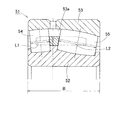
この発明の一実施形態を図1と共に説明する。
この複列自動調心ころ軸受1は、内輪2と外輪3との間に軸受幅方向に並ぶ左右2列のころ4,5を介在させてある。外輪3の軌道面3aは球面状であり、左右各列のころ4,5は外周面が外輪3の軌道面3aに沿う断面形状である。言い換えると、ころ4,5の外周面は、外輪3の軌道面3aに沿った円弧を中心線C1,C2回りに回転させた回転曲面である。内輪2には、左右各列のころ4,5の外周面に沿う断面形状の複列の軌道面2a,2bが形成されている。内輪2の外周面の両端には、つば(小つば)6,7がそれぞれ設けられている。内輪2の外周面の中央部、すなわち左列のころ4と右列のころ5間に、中つば8が設けられている。
An embodiment of the present invention will be described with reference to FIG.
In this double-row self-aligning
図2に誇張して示すように、左右各列のころ4,5は、いずれも最大径D1max,D2maxの位置がころ長さの中央A1,A2から外れた非対称ころである。左列のころ4の最大径D1maxの位置はころ長さの中央A1よりも右側にあり、右列のころ5の最大径D2maxの位置はころ長さの中央A2よりも左側にある。このような非対称ころからなる左右各列のころ4,5は、誘起スラスト荷重が発生する。この誘起スラスト荷重を受けるために、内輪2の前記中つば8が設けられる。非対称ころ4,5と中つば8の組合せは、ころ4,5を内輪2、外輪3、および中つば8の3箇所で案内するので、案内精度が良い。
As shown exaggerated in FIG. 2, the
図1に示すように、左列のころ4と右列のころ5は、最大径D1max,D2maxが互いに同じで、中心線C1,C2に沿った長さL1,L2が互いに異なっている。長さが長いころ5の長さL2は、軸受幅Bの39%以上である。
As shown in FIG. 1, the
また、長さの長いころ5の接触角θ2の方が、長さの短いころ4の接触角θ1よりも大きくなっている。長さが短いころ4の接触角θ1と長さが長いころ5の接触角θ2の比は、1:2ないし1:4の範囲内に設定されている。最も好ましい接触角θ1,θ2の比は、1:3である。その理由については、後で説明する。具体的には、接触角θ1の範囲は例えば5°〜7°であり、接触角θ2の範囲は例えば14°〜16°である。
Further, the contact angle θ2 of the
両列の接触角θ1,θ2を成す作用線S1,S2が互いに交わる点Pの軸受幅方向位置は、前記中つば8の軸受幅方向の中心位置Qよりも、長さの短いころ4の側に距離Kだけずらしてある。これにより、長さの長いころ5を必要以上に長くすることなく、長さの長いころ5の接触角θ2を大きくすることができる。なお、前記作用線S1,S2は、ころ4,5と内輪2および外輪3との接触部に働く力の合成力が作用する線である。作用線S1,S2が互いに交わる点Pは、軸受中心軸O上に位置する。
The position in the bearing width direction of the point P where the action lines S1 and S2 forming the contact angles θ1 and θ2 of both rows intersect each other is on the side of the
左右各列のころ4,5は、それぞれ保持器10L,10Rにより保持されている。左列用の保持器10Lは、円環部11から複数の柱部12が左側に延び、これら柱部12間のポケットに左列のころ4が保持される。右列用の保持器10Rは、円環部11から複数の柱部12が右側に延び、これら柱部12間のポケットに右列のころ5が保持される。
The
この構成の複列自動調心ころ軸受1は、アキシアル荷重およびラジアル荷重を受け、左右のころ列に互いに大きさが異なる荷重が作用する用途、例えば風力発電装置の主軸支持軸受として用いられる。その場合、旋回翼に近い側(フロント側)に左列のころ4が位置し、遠い側(リア側)に右列のころ5が位置するように、複列自動調心ころ軸受1を設置する。これにより、長さL2が長くかつ接触角θ2が大きい右列のころ5が、アキシアル荷重のほぼすべてとラジアル荷重の一部を負担し、長さL1が短くかつ接触角θ1が小さい左列のころ4が、ラジアル荷重の残りを負担する。
The multi-row self-aligning
ころ4,5の長さL1,L2および接触角θ1,θ2を適切に設定することにより、左右各列のころ4,5が持つ負荷容量に応じた比率で荷重を分担させることができる。その結果、左右各列のころ4,5の面圧が均等になる。これにより、軸受全体で大きな負荷容量を確保すると共に、軸受全体の実質寿命を向上させることができる。
By appropriately setting the lengths L1 and L2 of the
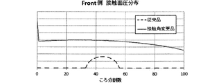
図10に示す従来の複列自動調心ころ軸受41および図1に示す本発明の複列自動調心ころ軸受1について、風力発電装置の主軸支持用軸受として使用する場合に想定されるアキシアル荷重とラジアル荷重との合成荷重の際左右両列のころの接触面圧を解析した。図3はフロント側すなわち左列のころ44,4の接触面圧分布を示し、図4はリア側すなわち右列のころ45,5の接触面圧解析結果分布を示す。
Axial load assumed when the conventional double row self-aligning
図3、図4から次のことが分かる。図10の従来品は、フロント側にて接触面圧が小さく、リア側で接触面圧が大きくなっており、フロント側とリア側とで荷重負担が不均一な状態となっている。これに対し、図1の接触角変更品は、フロント側にてころ全体に接触面圧が発生することにより、リア側の接触面圧の最大値が下がり、両列での接触面圧差が小さくなり均等化されている。 The following can be seen from FIGS. 3 and 4. In the conventional product of FIG. 10, the contact surface pressure is small on the front side and the contact surface pressure is large on the rear side, and the load load is uneven on the front side and the rear side. On the other hand, in the product with the changed contact angle shown in FIG. 1, the contact surface pressure on the entire roller is generated on the front side, so that the maximum value of the contact surface pressure on the rear side is lowered and the contact surface pressure difference between the two rows is small. It is equalized.
また、左列のころ4の接触角θ1と右列のころ5の接触角θ2との比がそれぞれ異なる3種類の複列自動調心ころ軸受にて、前記同様にして左右両列のころの接触面圧を解析した。図5はリア側すなわち左列のころ5の接触面圧解析結果分布を示し、図6はフロント側すなわち右列のころ4の接触面圧解析結果分布を示す。接触角の比が1:1であるものは従来品であり、接触角の比が1:2、1:3であるものは本発明の接触角変更品である。
Further, in the same manner as described above, three types of double-row self-aligning roller bearings having different ratios between the contact angle θ1 of the
図5、図6から次のことが分かる。各接触角の比について接触面圧分布を比較すると、接触角の比が1:3のものが、フロント側とリア側とで最も接触面圧が均等化されている。接触角の比が1:2のものは、接触角の比が1:3のものに比べると均等化はされていないが、接触角の比が1:1のものに比べれば十分に均等化されている。図1からも分かるように、ころ5の接触角θ2が大きくなると、寸法制約の関係から内輪2の肉厚が薄くなり過ぎるため、長さが長いころ5を配置することが困難になる。これらのことから、接触角の比は、1:2以上で1:4以内とするのが望ましい。
The following can be seen from FIGS. 5 and 6. Comparing the contact surface pressure distributions for each contact angle ratio, those with a contact angle ratio of 1: 3 have the most uniform contact surface pressure on the front side and the rear side. A contact angle ratio of 1: 2 is not equalized as compared with a contact angle ratio of 1: 3, but is sufficiently equalized as compared with a contact angle ratio of 1: 1. Has been done. As can be seen from FIG. 1, when the contact angle θ2 of the
なお、前記想定されるアキシアル荷重およびラジアル荷重とは、発電能力、設置場所等の諸条件を考慮して平均的な風力発電装置が最も通常に運転しているときのアキシアル荷重およびラジアル荷重を指す。よって、平均的な風力発電装置と比べて前記条件が異なる風力発電装置に用いられる複列自動調心ころ軸受では、最適な接触角の比が1:3でないことが有り得る。しかし、その場合でも、最適な接触角の比は1:2ないし1:4の範囲内に収まる。 The assumed axial load and radial load refer to the axial load and radial load when the average wind power generation device is operating most normally in consideration of various conditions such as power generation capacity and installation location. .. Therefore, in a double-row self-aligning roller bearing used in a wind power generation device having different conditions as compared with an average wind power generation device, the optimum contact angle ratio may not be 1: 3. However, even in that case, the optimum contact angle ratio is within the range of 1: 2 to 1: 4.
また、長さが長いころ5の長さL2は軸受幅Bの39%以上であるという条件を付加することにより、寸法規格の範囲内で両列のころの接触角の比が上記適正とされた複列自動調心ころ軸受が得られる。なお、従来の複列自動調心ころ軸受について、軸受幅Bに対するころ5の長さL2の比率を調査した。その結果、図7に示すように、前記比率が39%以上であることが判明した。上記寸法規格は、内径、外径、および軸受幅を定めた規格である。
Further, by adding the condition that the length L2 of the
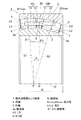
図8、図9は、風力発電装置の主軸支持装置の一例を示す。支持台21上に旋回座軸受22(図9)を介してナセル23のケーシング23aが水平旋回自在に設置されている。ナセル23のケーシング23a内には、軸受ハウジング24に設置された主軸支持軸受25を介して主軸26が回転自在に設置され、主軸26のケーシング23a外に突出した部分に、旋回翼となるブレード27が取り付けられている。主軸26の他端は、増速機28に接続され、増速機28の出力軸が発電機29のロータ軸に結合されている。ナセル23は、旋回用モータ30により、減速機31を介して任意の角度に旋回させられる。主軸支持軸受25は、図示の例では2個並べて設置してあるが、1個であっても良い。
8 and 9 show an example of the spindle support device of the wind power generation device. The
他の実施形態について説明する。
以下の説明においては、各実施の形態で先行して説明している事項に対応している部分には同一の参照符号を付し、重複する説明を略する。構成の一部のみを説明している場合、構成の他の部分は、特に記載のない限り先行して説明している形態と同様とする。同一の構成から同一の作用効果を奏する。実施の各形態で具体的に説明している部分の組合せばかりではなく、特に組合せに支障が生じなければ、実施の形態同士を部分的に組合せることも可能である。
Other embodiments will be described.
In the following description, the same reference numerals will be given to the parts corresponding to the matters previously described in each embodiment, and duplicate description will be omitted. When only a part of the configuration is described, the other parts of the configuration are the same as those described above unless otherwise specified. It produces the same action and effect from the same configuration. Not only the combination of the parts specifically described in each embodiment, but also the combinations of the embodiments can be partially combined as long as the combination does not cause any trouble.
他の実施形態に係る複列自動調心ころ軸受を図13〜図17と共に説明する。
図13に示すように、この複列自動調心ころ軸受1Aは、(1)傾斜角度付きの保持器10RA、(2)クラウニング13、(3)DLC被膜14、および(4)入れ溝15を備えている。
The double row self-aligning roller bearings according to another embodiment will be described with reference to FIGS. 13 to 17.
As shown in FIG. 13, this double row self-aligning
<(1)傾斜角度付きの保持器等について>
同図13に示す右列用の一方の保持器10RAは、軸方向長さの長いころ5を保持する保持器である。この保持器10RAは、柱部12Aの外径面12Aaが基端側から先端側に向かうに従って半径方向内方に傾斜する傾斜角度βを有する。この傾斜角度βは、軸受中心軸Oに対する角度である。保持器10RAの外径面12Aaの傾斜角度βは、零よりも大きく、右列のころ5の最大径角α2以下の範囲(0<β≦α2)に設定されている。最大径角α2は、軸受中心軸Oに垂直な平面に対する、右列のころ5の最大径D2maxの位置の傾き角である。
<(1) Cage with tilt angle, etc.>
One cage 10RA for the right column shown in FIG. 13 is a cage that holds the
この例の右列用の保持器10RAにおける、柱部12Aの内径面は、傾斜面部12Abと、この傾斜面部12Abに繋がる平坦面部12Acとを有する。傾斜面部12Abは、柱部12Aの内径面の基端側から同内径面の軸方向中間付近まで延び、基端側から軸方向中間付近に向かうに従って半径方向内方に傾斜する傾斜角度γを有する。この傾斜角度γも軸受中心軸Oに対する角度であり、傾斜角度γは傾斜角度β以上(γ≧β)となるように設定されている。この例では、傾斜角度γは傾斜角度βよりも数度大きく設定されている。但し、この関係(γ≧β)に限定されるものではない。平坦面部12Acは、傾斜面部12Abの先端縁から軸方向に延びる軸受中心軸Oに平行な平坦面である。なお左列用の他方の保持器10Lは、柱部12の外径面および内径面が、傾斜角度を有しない、換言すれば、軸受中心軸Oに対して平行である。
In the cage 10RA for the right column of this example, the inner diameter surface of the
<(2)クラウニング13について>
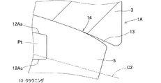
図14は、図13の一部(XIV部)を拡大して示す拡大断面図である。図13および図14に示すように、左右各列のころ4,5は、それぞれころ転動面の端部にクラウニング13を有する。この例のころ転動面は、対数曲線で表現される対数クラウニング形状とされている。但し、クラウニング13は対数クラウニング形状に限定されるものではなく、例えば、ころ転動面を複合Rクラウニング形状にしても良い。クラウニング部のR寸法を、ころ転動面の基準Rよりも小さくすることで、ドロップ量を大きくする前記複合Rクラウニング形状を形成し得る。
<(2) About
FIG. 14 is an enlarged cross-sectional view showing a part (XIV portion) of FIG. 13 in an enlarged manner. As shown in FIGS. 13 and 14, the
<(3)DLC被膜14について>
図15に示すように、各ころ4,5は、ころ転動面にDLC被膜14を有する。この例のDLC被膜14は、基材であるころ4,5との密着性が高い多層構造が採用されている。DLC被膜14は、表面層16と、中間層17と、応力緩和層18とを有する。表面層16は、炭素供給源として固体ターゲットのグラファイトのみを使用し、水素混入量を抑えたDLCを主体とする膜である。中間層16は、表面層16と前記基材との間に形成される、少なくともCrまたはWを主体とする層である。応力緩和層18は、中間層17と表面層16との間に形成される。
<(3) About
As shown in FIG. 15, each of the
中間層17は、組成の異なる複数の層を含む構造であり、図15では17a〜17cの三層構造を例示している。例えば、基材の表面にCrを主体とする層17cを形成し、その上にWを主体とする層17bを形成し、その上にWおよびCを主体とする層17aを形成する。図15では3層構造を例示したが、中間層17は、必要に応じて、これ以下または以上の数の層を含むものであっても良い。
The
応力緩和層18に隣接する層17aは、他方で隣接する層17bの主体となる金属と、炭素とを主体することで、中間層17と応力緩和層18との間の密着性を向上できる。例えば、層17aがWとCとを主体とする場合、Wを主体とする中間層17b側からCを主体とする応力緩和層18側に向けて、Wの含有量を減少させ、一方、Cの含有量を増加させる(組成傾斜)ことで、より密着性の向上が図れる。
The
応力緩和層18は、Cを主体とし、その硬度が中間層17側から表面層16側へ連続的または段階的に上昇する傾斜層である。具体的には、UBMS法においてグラファイト製ターゲットを用い、基材に対するバイアス電圧を連続的または段階的に上昇させて成膜することで得られるDLC傾斜層である。硬度が連続的または段階的に上昇するのは、DLC構造におけるグラファイト構造(SP2)とダイヤモンド構造(SP3)との構成比率が、バイアス電圧の上昇により後者に偏っていくためである。
The stress relaxation layer 18 is an inclined layer mainly composed of C and whose hardness increases continuously or stepwise from the
表面層16は、応力緩和層18の延長で形成されるDLCを主体とする膜であり、特に、構造中の水素含有量を低減したDLC膜である。水素含有量を低減させたことで、耐摩耗性が向上する。このようなDLC膜を形成するためには、例えばUBMS法を用いて、スパッタリング処理に用いる原料およびスパッタリングガス中に水素および水素を含む化合物を混入させない方法を用いる。
The
応力緩和層18および表面層16の成膜法に関して、UBMS法を用いる場合を例示したが、硬度を連続的または段階的に変化させることができる成膜法であれば、その他公知の成膜法を採用することができる。中間層17と、応力緩和層18と、表面層16とを含む多層の膜厚の合計が0.5μm〜3.0μmとすることが好ましい。膜厚の合計が0.5μm未満であれば、耐摩耗性および機械的強度に劣り、膜厚の合計が3.0μmを超えると剥離し易くなるので好ましくない。
なお、この例では、各ころ4,5の外周面のみにDLC被膜14を設けているが、さらに各ころ4,5の両端面にDLC被膜14を設けても良い。特に、中つば8(図13)に案内される各ころ4,5の一端面にDLC被膜14を設けた場合、各ころ4,5の前記一端面が摩耗し難くなり、ころ4,5の耐摩耗性をより高め得る。
Regarding the film forming method of the stress relaxation layer 18 and the
In this example, the
<(4)入れ溝について>
図16に示すように、内輪2は、各小つば6,7(図13)のうち、長いころ5の軸方向外側の端面に臨む小つば7に、長いころ5を軸受内に挿入する入れ溝15を備えている。図17に示すように、内輪2の前記小つば7の円周方向一箇所に、円弧形状の入れ溝15が設けられている。この入れ溝15の円弧15aの曲率半径は、挿入すべきころ5(図16)の最大径に応じて適宜設定されている。
その他前述の実施形態と同様の構成を備えている。
<(4) Insertion groove>
As shown in FIG. 16, the
Others have the same configuration as the above-described embodiment.
<作用効果について>
他の実施形態に係る複列自動調心ころ軸受1Aによれば、各ころ4,5がころ転動面にDLC被膜14を有するため、耐摩耗性の向上を図ることができる。これにより、前記DLC被膜が無いものより、ころ転動面および内輪2、外輪3の軌道面3aの摩耗が生じ難くなる。またころ転動面の端部にクラウニング13が設けられているため、エッジ応力の緩和を図ることができる。
<About action and effect>
According to the double row self-aligning
長いころ5を保持する一方の保持器10RAは、柱部12Aの外径面12Aaが基端側から先端側に向かうに従って半径方向内方に傾斜する傾斜角度βを有するため、保持器10RAのポケットPt面がころ5の最大径位置を抱えることができる。換言すれば、一方の保持器10RAが前述のような傾斜角度βを有するため、保持器10RAのポケットPt面がころ5のピッチ円直径付近で維持され、軸受運転時に保持器10RAのポケットPt面がころ5の最大径位置を円滑に抱えることができる。これにより、長いころ5の姿勢安定性が損なわれることがなく、また長いころ5の組込性も容易に行うことが可能となる。内輪2は、各小つば6,7のうち、長いころ5の軸方向外側の端面に臨む小つば7に、長いころ5を軸受内に挿入する入れ溝15を備えたため、長いころ5の組込性をさらに向上させることができる。
One of the cages 10RA that holds the
図18に示す複列自動調心ころ軸受1Bでは、一方の保持器10RBにおける、柱部12Bの外径面12Baの傾斜角度βが、零よりも大きく、右列のころ5の最大径角α2以下の範囲に設定され、且つ、柱部12Bの内径面の傾斜角度γが外径面の傾斜角度βと同一に設定されている。この例の傾斜角度βは、最大径角α2以下で最大径角α2に略近い角度に設定されている。また柱部12Bの内径面は、傾斜面部のみから成り、前述の平坦面部が設けられていない。
この図18の構成によれば、保持器10RBが前述のような傾斜角度βを有するため、保持器10RBのポケットPt面がころ5のピッチ円直径付近でより確実に維持され、軸受運転時に保持器10RBのポケットPt面がころ5の最大径位置を円滑に且つ確実に抱えることができる。また長いころ5の組込性もより容易に行うことができる。
In the double-row self-aligning
According to the configuration of FIG. 18, since the cage 10RB has the inclination angle β as described above, the pocket Pt surface of the cage 10RB is more reliably maintained near the pitch circle diameter of the
以上、実施例に基づいて本発明を実施するための形態を説明したが、ここで開示した実施の形態はすべての点で例示であって制限的なものではない。本発明の範囲は上記した説明ではなくて特許請求の範囲によって示され、特許請求の範囲と均等の意味および範囲内でのすべての変更が含まれることが意図される。 Although the embodiments for carrying out the present invention have been described above based on the examples, the embodiments disclosed here are examples in all respects and are not limiting. The scope of the present invention is shown by the scope of claims rather than the above description, and it is intended to include all modifications within the meaning and scope equivalent to the scope of claims.
1,1A,1B…複列自動調心ころ軸受
2…内輪
3…外輪
3a…軌道面
4,5…ころ
6,7…小つば
8…中つば
10L,10R,10RA,10RB…保持器
11,11A…円環部
12,12A,12B…柱部
13…クラウニング
14…DLC被膜
15…入れ溝
26…主軸
A1,A2…ころ長さの中央
B…軸受幅
D1max,D2max…最大径
L1,L2…長さ
θ1,θ2…接触角
1,1A, 1B ... Double row self-aligning
Claims (4)
前記2列のころは互いに長さが異なり、長さが長いころの長さは軸受幅の39%以上であり、かつ長さが短いころの接触角と長さが長いころの接触角の比が1:2ないし1:4の範囲内にあり、
前記2列の各列のころは、最大径の位置がころ長さの中央よりも前記軸受幅方向中央側にある非対称ころであり、
前記内輪の外周面における前記2列のころ間に前記2列のころを案内する中つばを有する
複列自動調心ころ軸受。 Rollers are interposed between the inner ring and the outer ring in two rows arranged in the bearing width direction, the raceway surface of the outer ring is spherical, and the outer peripheral surface of the two rows of rollers is a cross section along the raceway surface of the outer ring. It is a double-row self-aligning roller bearing that has a shape.
The two rows of rollers have different lengths, the length of the long roller is 39% or more of the bearing width, and the ratio of the contact angle of the short roller to the contact angle of the long roller. Is in the range of 1: 2 to 1: 4
The rollers in each of the two rows are asymmetric rollers in which the position of the maximum diameter is closer to the center in the bearing width direction than the center of the roller length.
A double-row self-aligning roller bearing having a center brim that guides the two rows of rollers between the two rows of rollers on the outer peripheral surface of the inner ring.
前記各列のころをそれぞれ保持する保持器を備え、各保持器は、各列のころの軸方向内側の端面を案内する環状の円環部と、この円環部から軸方向に延び且つ円周方向に沿って定められた間隔置きに設けられた複数の柱部とを備え、これら柱部間に前記ころを保持するポケットが設けられ、前記長いころを保持する一方の保持器は、前記柱部の外径面が基端側から先端側に向かうに従って半径方向内方に傾斜する傾斜角度を有し、
前記各ころは、ころ転動面にDLC被膜、且つ前記ころ転動面の端部にクラウニングを有し、
前記内輪は、前記中つばと、前記外周面の両端にそれぞれ設けられ各列のころの軸方向外側の端面に臨む小つばとを備え、前記内輪は、前記各小つばのうち、前記長いころの軸方向外側の端面に臨む小つばに、前記長いころを軸受内に挿入する入れ溝を備えた複列自動調心ころ軸受。 In the double row self-aligning roller bearing according to any one of claims 1 to 3.
Each cage is provided with a cage for holding the rollers of each row, and each cage has an annular ring portion that guides the axially inner end face of the rollers of each row, and an annular portion that extends axially and is circular from the annular portion. A plurality of pillars provided at intervals determined along the circumferential direction are provided, pockets for holding the rollers are provided between the pillars, and one cage for holding the long rollers is described as described above. The outer diameter surface of the pillar has an inclination angle that inclines inward in the radial direction from the base end side toward the tip end side.
Each of the rollers has a DLC coating on the roller rolling surface and crowning at the end of the roller rolling surface.
The inner ring includes a middle brim and small brims provided at both ends of the outer peripheral surface and facing the axially outer end faces of the rollers of each row, and the inner ring is the long roller of the small brims. A double-row self-aligning roller bearing provided with a groove for inserting the long roller into the bearing on a small brim facing the outer end surface in the axial direction of the bearing.
Priority Applications (5)
| Application Number | Priority Date | Filing Date | Title |
|---|---|---|---|
| EP17770365.9A EP3434918B1 (en) | 2016-03-24 | 2017-03-23 | Double-row self-aligning roller bearing |
| ES17770365T ES2959734T3 (en) | 2016-03-24 | 2017-03-23 | Double row self-aligning roller bearing |
| PCT/JP2017/011775 WO2017164325A1 (en) | 2016-03-24 | 2017-03-23 | Double-row spherical roller bearing |
| CN201780019166.XA CN108884867B (en) | 2016-03-24 | 2017-03-23 | Double-row self-aligning roller bearing |
| US16/138,504 US10655674B2 (en) | 2016-03-24 | 2018-09-21 | Double-row self-aligning roller bearing |
Applications Claiming Priority (2)
| Application Number | Priority Date | Filing Date | Title |
|---|---|---|---|
| JP2016059473 | 2016-03-24 | ||
| JP2016059473 | 2016-03-24 |
Publications (2)
| Publication Number | Publication Date |
|---|---|
| JP2017180831A JP2017180831A (en) | 2017-10-05 |
| JP6873754B2 true JP6873754B2 (en) | 2021-05-19 |
Family
ID=60005752
Family Applications (1)
| Application Number | Title | Priority Date | Filing Date |
|---|---|---|---|
| JP2017045679A Active JP6873754B2 (en) | 2016-03-24 | 2017-03-10 | Multi-row self-aligning roller bearing |
Country Status (1)
| Country | Link |
|---|---|
| JP (1) | JP6873754B2 (en) |
Families Citing this family (2)
| Publication number | Priority date | Publication date | Assignee | Title |
|---|---|---|---|---|
| DK3783237T3 (en) | 2018-04-20 | 2024-01-08 | Ntn Toyo Bearing Co Ltd | Double-row, self-aligning roller bearing |
| CN112739922B (en) | 2018-09-26 | 2023-02-28 | Ntn株式会社 | Rolling bearing and main shaft support device for wind power generation |
Family Cites Families (6)
| Publication number | Priority date | Publication date | Assignee | Title |
|---|---|---|---|---|
| JP2004245251A (en) * | 2003-02-10 | 2004-09-02 | Nsk Ltd | Automatic centering rolling bearing |
| JP2005083467A (en) * | 2003-09-08 | 2005-03-31 | Nsk Ltd | Cylindrical roller bearing |
| DE102004047881A1 (en) * | 2004-10-01 | 2006-04-06 | Fag Kugelfischer Ag & Co. Ohg | Self-aligning roller bearing for use in applications where axial loading is predominantly on one side has two rows of rollers which are inclined to vertical in opposite directions, angle being greater on side with higher loading |
| JP2007040520A (en) * | 2005-07-01 | 2007-02-15 | Nsk Ltd | Tapered roller bearing |
| JP2007247678A (en) * | 2006-03-13 | 2007-09-27 | Ntn Corp | Double row roller bearing and its assembling method |
| JP2007255601A (en) * | 2006-03-23 | 2007-10-04 | Ntn Corp | Double row roller bearing and method for assembling the same |
-
2017
- 2017-03-10 JP JP2017045679A patent/JP6873754B2/en active Active
Also Published As
| Publication number | Publication date |
|---|---|
| JP2017180831A (en) | 2017-10-05 |
Similar Documents
| Publication | Publication Date | Title |
|---|---|---|
| WO2017164325A1 (en) | Double-row spherical roller bearing | |
| US10655674B2 (en) | Double-row self-aligning roller bearing | |
| JP7029249B2 (en) | Multi-row self-aligning roller bearings and pop-out prevention jigs | |
| JP6871767B2 (en) | Double row self-aligning roller bearing | |
| WO2005050038A1 (en) | Double-row self-aligning roller bearing and device for supporting wind turbine generator main shaft | |
| US9206847B2 (en) | Roller bearing assemblies, apparatuses, and related methods of manufacture | |
| JP6912966B2 (en) | Multi-row self-aligning roller bearing | |
| JP2024040292A (en) | Double row spherical roller bearing | |
| JP6873754B2 (en) | Multi-row self-aligning roller bearing | |
| US11773901B2 (en) | Self-aligning roller bearing | |
| WO2017047506A1 (en) | Double-row self-aligning roller bearing | |
| JP6909089B2 (en) | Multi-row self-aligning roller bearing | |
| WO2018131618A1 (en) | Double-row self-aligning roller bearing | |
| EP3783237B1 (en) | Double-row self-aligning roller bearing | |
| WO2018131617A1 (en) | Double-row self-aligning roller bearing and protrusion prevention jig | |
| JP2021055831A (en) | Double-row tapered roller bearing |
Legal Events
| Date | Code | Title | Description |
|---|---|---|---|
| A621 | Written request for application examination |
Free format text: JAPANESE INTERMEDIATE CODE: A621 Effective date: 20200226 |
|
| A131 | Notification of reasons for refusal |
Free format text: JAPANESE INTERMEDIATE CODE: A131 Effective date: 20200708 |
|
| A521 | Written amendment |
Free format text: JAPANESE INTERMEDIATE CODE: A523 Effective date: 20200826 |
|
| A131 | Notification of reasons for refusal |
Free format text: JAPANESE INTERMEDIATE CODE: A131 Effective date: 20201007 |
|
| A521 | Written amendment |
Free format text: JAPANESE INTERMEDIATE CODE: A523 Effective date: 20201120 |
|
| RD01 | Notification of change of attorney |
Free format text: JAPANESE INTERMEDIATE CODE: A7421 Effective date: 20210106 |
|
| TRDD | Decision of grant or rejection written | ||
| RD03 | Notification of appointment of power of attorney |
Free format text: JAPANESE INTERMEDIATE CODE: A7423 Effective date: 20210201 |
|
| A01 | Written decision to grant a patent or to grant a registration (utility model) |
Free format text: JAPANESE INTERMEDIATE CODE: A01 Effective date: 20210330 |
|
| A61 | First payment of annual fees (during grant procedure) |
Free format text: JAPANESE INTERMEDIATE CODE: A61 Effective date: 20210421 |
|
| R150 | Certificate of patent or registration of utility model |
Ref document number: 6873754 Country of ref document: JP Free format text: JAPANESE INTERMEDIATE CODE: R150 |