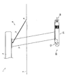
以下、図面を参照しつつ、本開示の実施形態を詳細に説明する。まず、本実施形態に係る水中推進装置20を備える水上乗り物1の構成について詳細に説明する。図1は、本開示の実施形態の一例としての水中推進装置20を備える水上乗り物1が示された側面図である。なお、以下では、説明の便宜上、水中推進装置20の推進方向(水上乗り物1の進行方向)である図1における左側を船首方向とし、右側を船尾方向とする。また、推進方向に対して直交して、かつ水平である図1における手前側を左方向、奥側を右方向とする。また、推進方向に対して直交して、かつ鉛直である図1における上側を上方向、下側を下方向とする。また、図1において、水上乗り物1は進行状態であり、後述する水上浮遊部2の船首側の記載は省略されている。
Hereinafter, embodiments of the present disclosure will be described in detail with reference to the drawings. First, the configuration of the surface vehicle 1 including the underwater propulsion device 20 according to the present embodiment will be described in detail. FIG. 1 is a side view showing a surface vehicle 1 including an underwater propulsion device 20 as an example of the embodiment of the present disclosure. In the following, for convenience of explanation, the left side in FIG. 1, which is the propulsion direction of the underwater propulsion device 20 (the traveling direction of the surface vehicle 1), is the bow direction, and the right side is the stern direction. Further, the front side in FIG. 1, which is orthogonal to and horizontal to the propulsion direction, is the left direction, and the back side is the right direction. Further, the upper side in FIG. 1, which is orthogonal to the propulsion direction and is vertical, is the upward direction, and the lower side is the downward direction. Further, in FIG. 1, the water vehicle 1 is in an advanced state, and the description on the bow side of the water floating portion 2 described later is omitted.
図1に示されるように、水上乗り物1は、水上浮遊部2と、水中推進装置20と、船首水中翼43及び船尾水中翼44と、水面センサ4とを備える。水中推進装置20は、支柱3を介して水上浮遊部2に連結される。水面センサ4は、支柱3に取り付けられている。図1では省略されているが、水上乗り物1は、バッテリ、水中推進装置20を操作するための操作具、水中推進装置20を制御する制御部等をさらに備えていてもよい。
As shown in FIG. 1, the water vehicle 1 includes a water floating portion 2, an underwater propulsion device 20, a bow hydrofoil 43, a stern hydrofoil 44, and a water surface sensor 4. The underwater propulsion device 20 is connected to the floating portion 2 on the water via the support column 3. The water level sensor 4 is attached to the support column 3. Although omitted in FIG. 1, the water vehicle 1 may further include a battery, an operating tool for operating the underwater propulsion device 20, a control unit for controlling the underwater propulsion device 20, and the like.
水上乗り物1は、水の中で使用される。使用者は、水上浮遊部2の上面に搭乗する。水中推進装置20は、水上浮遊部2の下方であって、水中に配置される。水上乗り物1は、水中推進装置20の推進力によって船首方向へ進む。
The water vehicle 1 is used in water. The user gets on the upper surface of the floating portion 2 on the water. The underwater propulsion device 20 is below the floating portion 2 on the water and is arranged in water. The surface vehicle 1 advances toward the bow by the propulsive force of the underwater propulsion device 20.
水上浮遊部2は、進行方向に延びた板状部材である。水上浮遊部2の材料としては、水に対して浮力を生じる材料、例えば、ポリウレタンやポリスチレン等の合成樹脂に発泡剤を加えて生成される発泡樹脂等を用いることができるが、特に限定されるものではない。水上浮遊部2には、バッテリ、制御部等が防水処理されて内蔵されるとともに、操作具が取り付けられる。なお、防水の方法は特に限定されるものではない。例えば、ガスケット等を用いて防水構造とされた収容室に、バッテリ、制御部等を収容させても良い。
The floating portion 2 on the water is a plate-shaped member extending in the traveling direction. As the material of the floating portion 2 on water, a material that generates buoyancy with respect to water, for example, a foamed resin produced by adding a foaming agent to a synthetic resin such as polyurethane or polystyrene can be used, but is particularly limited. It's not a thing. A battery, a control unit, and the like are waterproofed and built into the floating portion 2 on the water, and an operating tool is attached to the floating portion 2. The waterproofing method is not particularly limited. For example, a battery, a control unit, or the like may be housed in a storage room having a waterproof structure using a gasket or the like.
バッテリは、充電が可能な二次電池であり、直流電力を供給する。バッテリから供給される直流電力の電圧は、例えば30V〜60V程度である。バッテリとしては、鉛蓄電池やリチウムイオン電池等を用いることができる。
The battery is a rechargeable secondary battery that supplies DC power. The voltage of the DC power supplied from the battery is, for example, about 30V to 60V. As the battery, a lead storage battery, a lithium ion battery, or the like can be used.
操作具としては、使用者に把持されるグリップに防水構造とされた押圧式スイッチが取り付けられた構成が例示できる。なお、水上浮遊部2は、使用者が搭乗した際に水中に沈まない浮力を有するように構成にされる。水上浮遊部2としては、例えば、既存のサーフボード、ボディーボード、パドルボード、あるいはウインドサーフボード等を流用することができる。
As the operating tool, a configuration in which a pressure-type switch having a waterproof structure is attached to a grip gripped by the user can be exemplified. The floating portion 2 on the water is configured to have a buoyancy that does not sink in water when the user gets on board. As the floating portion 2 on the water, for example, an existing surfboard, body board, paddle board, wind surfboard or the like can be diverted.
支柱3は、上下方向に延びる筒状部材である。支柱3は、例えば、左右方向の幅が狭く、水平断面形状が進行方向に延びた流線形に形成される。支柱3の材料としては、軽量かつ高い強度を有する材料、例えばジュラルミン等のアルミニウム合金等を用いることができるが、特に限定されるものではない。支柱3の上端は、水上浮遊部2の下面に固定される。支柱3の下端には、水中推進装置20が取り付けられる。
The support column 3 is a tubular member extending in the vertical direction. The columns 3 are formed in a streamlined manner, for example, having a narrow width in the left-right direction and a horizontal cross-sectional shape extending in the traveling direction. As the material of the support column 3, a material having light weight and high strength, for example, an aluminum alloy such as duralumin can be used, but the material is not particularly limited. The upper end of the support column 3 is fixed to the lower surface of the floating portion 2 on the water. An underwater propulsion device 20 is attached to the lower end of the support column 3.
水面センサ4は、バー5と、当接板6とを備える。バー5は、進行方向に延びる。バー5の前端は、支柱3の上端近傍に上下方向へ回動自在に取り付けられる。バー5の後端には、当接板6が取り付けられる。
The water level sensor 4 includes a bar 5 and a contact plate 6. The bar 5 extends in the direction of travel. The front end of the bar 5 is rotatably attached to the vicinity of the upper end of the support column 3 in the vertical direction. A contact plate 6 is attached to the rear end of the bar 5.
水面センサ4は、水上乗り物1が水上浮遊部2を水面7より上方に浮上させた状態で進行する際に、自重によって下方へ回動する。これにより、当接板6が水面7と当接する。水面センサ4は、支柱3に対する回動量によって、水上浮遊部2と水面7との距離を検出できるように構成されている。バー5と当接板6の材料としては、ステンレス鋼等を例示できるが、特に限定されるものではない。
The water surface sensor 4 rotates downward due to its own weight when the water vehicle 1 advances in a state where the water floating portion 2 is levitated above the water surface 7. As a result, the contact plate 6 comes into contact with the water surface 7. The water surface sensor 4 is configured to be able to detect the distance between the floating portion 2 on the water and the water surface 7 by the amount of rotation with respect to the support column 3. Examples of the material of the bar 5 and the contact plate 6 include stainless steel, but the material is not particularly limited.
次に本実施形態に係る水中推進装置20の構成について詳細に説明する。図2は水中推進装置20の斜視図であり、図3は水中推進装置20の側面図であり、図4は水中推進装置20の底面図であり、図5は水中推進装置20の背面図であり、図6は図3のVI−VI線断面図であり、図7は図6の船尾側の拡大図である。なお、図2は、船首側の斜め上方から見る水中推進装置20の斜視図である。また、図3におけるVI−VI線は、水中推進装置20の中心を通り水平に延びる直線であり、図6は水中推進装置20の水平断面図である。また、図5において、船首水中翼43、船尾水中翼44等の記載は省略されている。また、図6、図7において、船首水中翼43、船尾水中翼44、後述するインバータ25、制御部26、冷却水路としての配管等の記載は省略されている。また、図6、図7において、後述するモータ22と動力伝達軸24は断面ではなく、平面視で示されている。
Next, the configuration of the underwater propulsion device 20 according to the present embodiment will be described in detail. FIG. 2 is a perspective view of the underwater propulsion device 20, FIG. 3 is a side view of the underwater propulsion device 20, FIG. 4 is a bottom view of the underwater propulsion device 20, and FIG. 5 is a rear view of the underwater propulsion device 20. Yes, FIG. 6 is a sectional view taken along line VI-VI of FIG. 3, and FIG. 7 is an enlarged view of the stern side of FIG. FIG. 2 is a perspective view of the underwater propulsion device 20 viewed from diagonally above the bow side. The VI-VI line in FIG. 3 is a straight line extending horizontally through the center of the underwater propulsion device 20, and FIG. 6 is a horizontal cross-sectional view of the underwater propulsion device 20. Further, in FIG. 5, the description of the bow hydrofoil 43, the stern hydrofoil 44, and the like is omitted. Further, in FIGS. 6 and 7, the description of the bow hydrofoil 43, the stern hydrofoil 44, the inverter 25 described later, the control unit 26, the piping as the cooling water channel, and the like is omitted. Further, in FIGS. 6 and 7, the motor 22 and the power transmission shaft 24, which will be described later, are shown in a plan view rather than a cross section.
図2及び図3に示すように、水中推進装置20は、本体部21と、モータ22と、プロペラ23と、動力伝達軸24と、インバータ25と、制御部26とを備える。本体部21は、推進方向に延びている。本体部21は、中空に形成されている。動力伝達軸24は、モータ22とプロペラ23とを接続する。本実施形態において、インバータ25は、モータ駆動回路に相当する。
As shown in FIGS. 2 and 3, the underwater propulsion device 20 includes a main body 21, a motor 22, a propeller 23, a power transmission shaft 24, an inverter 25, and a control unit 26. The main body 21 extends in the propulsion direction. The main body 21 is hollow. The power transmission shaft 24 connects the motor 22 and the propeller 23. In this embodiment, the inverter 25 corresponds to a motor drive circuit.
図6に示すように、本体部21の内部は、船首側の第1室27と船尾側の第2室28とに区画されている。第1室27は、防水構造とされている。第1室27には、モータ22、インバータ25、制御部26等が収容される。第2室28には、プロペラ23が収容される。第2室28は導水口29と、噴流口30とを有する。導水口29は、第2室28において、プロペラ23よりも船首側に形成される。噴流口30は、第2室28の船尾側の端に形成される。水中推進装置20は、モータ22によってプロペラ23を回転させて、導水口29から第2室28に水を吸い込み、噴流口30から水を噴出することによって、船首方向へ進む推進力を発生させることができるように構成される。
As shown in FIG. 6, the inside of the main body 21 is divided into a first chamber 27 on the bow side and a second chamber 28 on the stern side. The first room 27 has a waterproof structure. The motor 22, the inverter 25, the control unit 26, and the like are housed in the first chamber 27. The propeller 23 is housed in the second room 28. The second chamber 28 has a water inlet 29 and a jet port 30. The headrace 29 is formed in the second chamber 28 on the bow side of the propeller 23. The jet port 30 is formed at the stern-side end of the second chamber 28. The underwater propulsion device 20 rotates the propeller 23 by the motor 22, sucks water from the water guide port 29 into the second chamber 28, and ejects water from the jet port 30 to generate a propulsive force traveling in the bow direction. Is configured to be able to.
本体部21は、図6、図7、図8に示すように、船首部31と、胴部32と、蓋部33と、船尾部34とを備える。ここで、図8は、本体部21の構成が示された分解斜視図であり、船尾側の斜め上方から見る本体部21の分解斜視図である。なお、図8において、本体部21は、船首部31、胴部32、蓋部33、及び船尾部34が分離されて示されている。また、図8には、支柱3の下端部も分離されて示されている。また、図8において、本体部21に収容される部材、例えば、モータ22、プロペラ23、動力伝達軸24等の記載は省略されている。
As shown in FIGS. 6, 7, and 8, the main body 21 includes a bow 31, a fuselage 32, a lid 33, and a stern 34. Here, FIG. 8 is an exploded perspective view showing the configuration of the main body portion 21, and is an exploded perspective view of the main body portion 21 viewed from diagonally above on the stern side. In FIG. 8, the main body 21 is shown with the bow 31, the fuselage 32, the lid 33, and the stern 34 separated. Further, in FIG. 8, the lower end portion of the support column 3 is also shown separately. Further, in FIG. 8, the description of the members housed in the main body 21, for example, the motor 22, the propeller 23, the power transmission shaft 24, and the like is omitted.
船首部31は、船尾側の端が開放した中空状に形成される。船首部31は、例えば、船首側へ向かって先細りの砲弾状に形成される。船首部31の船尾側の端部は、胴部32の船首側の端部にシール部材35を介して嵌合される。
The bow portion 31 is formed in a hollow shape with an open end on the stern side. The bow portion 31 is formed, for example, in the shape of a cannonball that tapers toward the bow side. The stern-side end of the bow 31 is fitted to the bow-side end of the fuselage 32 via a seal member 35.
胴部32は、円筒状をなす。胴部32は、実質的に同一径で水中推進装置20の進行方向に延びている。
The body portion 32 has a cylindrical shape. The body portion 32 has substantially the same diameter and extends in the traveling direction of the underwater propulsion device 20.
蓋部33は、嵌合部36と、突出部37とを有する。嵌合部36は、円柱状をなす。突出部37は、略円錐台状に形成される。突出部37は、嵌合部36から船尾側へ向かって縮径している。嵌合部36の船首側は、胴部32の船尾側の端部にシール部材38を介して嵌合される。
The lid portion 33 has a fitting portion 36 and a protruding portion 37. The fitting portion 36 has a columnar shape. The protruding portion 37 is formed in a substantially truncated cone shape. The protruding portion 37 has a reduced diameter from the fitting portion 36 toward the stern side. The bow side of the fitting portion 36 is fitted to the stern side end of the fuselage 32 via the seal member 38.
船尾部34は、概略円筒状をなす。船尾部34の船首側の端部の外径は胴部32の外径と実質的に等しい。船尾部34の船尾側の外径は、船尾側に向かって徐々に小さくなっている。船尾部34の船首側の端部は、蓋部33の嵌合部36の船尾側に嵌合される。この際、蓋部33の突出部37は、船尾部34の内部に挿入される。
The stern portion 34 has a substantially cylindrical shape. The outer diameter of the bow-side end of the stern 34 is substantially equal to the outer diameter of the fuselage 32. The outer diameter of the stern portion 34 on the stern side gradually decreases toward the stern side. The bow-side end of the stern portion 34 is fitted to the stern side of the fitting portion 36 of the lid portion 33. At this time, the protruding portion 37 of the lid portion 33 is inserted into the inside of the stern portion 34.
本体部21の内部は、蓋部33によって船首側の第1室27と船尾側の第2室28とに区画されている。第1室27は、船首部31と、円柱状の胴部32と、蓋部33とから構成されている。船首部31は、シール部材35を介して円柱状の胴部32に嵌合される。蓋部33は、シール部材38を介して胴部32に嵌合される。これにより、第1室27は、防水構造とされている。シール部材35,38は、Oリングに限定されるものではなく、ゴムシート等であっても良い。
The inside of the main body 21 is divided into a first chamber 27 on the bow side and a second chamber 28 on the stern side by a lid portion 33. The first chamber 27 is composed of a bow portion 31, a columnar body portion 32, and a lid portion 33. The bow portion 31 is fitted to the columnar fuselage portion 32 via the seal member 35. The lid portion 33 is fitted to the body portion 32 via the seal member 38. As a result, the first chamber 27 has a waterproof structure. The sealing members 35 and 38 are not limited to O-rings, and may be rubber sheets or the like.
第2室28は、船尾部34によって構成されている。船尾部34は、船首側の端部の左右に、側面視で矩形状の導水口29を有する。導水口29は、フィルタ39によって覆われている。フィルタ39は、推進方向に延びる複数のスリットを有する。フィルタ39は、例えば、船尾部34の外形に沿うように円弧状に湾曲している。船尾部34の外径は、導水口29よりも船尾側の部分から船尾方向に向かって徐々に小さくなっている。船尾部34は、船尾側の端に噴流口30を有する。噴流口30は、背面視で円形状である。
The second chamber 28 is composed of a stern portion 34. The stern portion 34 has water guide ports 29 having a rectangular shape in a side view on the left and right sides of the end portion on the bow side. The headrace 29 is covered by a filter 39. The filter 39 has a plurality of slits extending in the propulsion direction. The filter 39 is curved in an arc shape, for example, along the outer shape of the stern portion 34. The outer diameter of the stern portion 34 gradually decreases from the portion on the stern side of the headrace 29 toward the stern. The stern portion 34 has a jet port 30 at the end on the stern side. The jet port 30 has a circular shape when viewed from the rear.
船首部31、胴部32、及び船尾部34の材料としては、ステンレス鋼等を例示できるが、特に限定されるものではない。また、蓋部33の材料としては、アルミニウム等を例示できるが特に限定されるものではない。
Examples of materials for the bow portion 31, the body portion 32, and the stern portion 34 include stainless steel, but are not particularly limited. Further, as the material of the lid portion 33, aluminum and the like can be exemplified, but the material is not particularly limited.
船首部31及び蓋部33は、胴部32の筒軸方向に働く締結力によって胴部32に固定される。船尾部34は、胴部32の筒軸方向に働く締結力によって蓋部33に固定される。より詳細には、図8に示されるように、船首部31及び蓋部33は、3つのねじ40によって胴部32に固定され、船尾部34は、4つのねじ41によって蓋部33に固定される。
The bow portion 31 and the lid portion 33 are fixed to the fuselage portion 32 by a fastening force acting in the tubular axial direction of the fuselage portion 32. The stern portion 34 is fixed to the lid portion 33 by a fastening force acting in the tubular axis direction of the body portion 32. More specifically, as shown in FIG. 8, the bow 31 and the lid 33 are fixed to the fuselage 32 by the three screws 40, and the stern 34 is fixed to the lid 33 by the four screws 41. The stern.
ねじ40の各々は、胴部32の筒軸方向に延びる。ねじ40は、船首部31を貫通して蓋部33の嵌合部36まで延びる。ねじ40の船尾側の部分には、おねじが形成されている。ねじ40のおねじは、嵌合部36に形成されるめねじ(図示略)に螺合される。ねじ40が締め付けられることで、船首部31は胴部32に押し付けられ、蓋部33は胴部32に引き付けられる。ねじ40は、胴部32の内周面の近傍に配置される。ねじ40は、胴部32の周方向に略等間隔に配置される。好ましくは、船首部31のねじ40が貫通する部位には防水処理が施され、第1室27への水の浸入が防止される。防水の方法は、特に限定されるものではなく、例えばOリングによる防水であっても良い。
Each of the screws 40 extends in the axial direction of the body portion 32. The screw 40 penetrates the bow portion 31 and extends to the fitting portion 36 of the lid portion 33. A male screw is formed on the stern side of the screw 40. The screw of the screw 40 is screwed into a female screw (not shown) formed in the fitting portion 36. By tightening the screw 40, the bow 31 is pressed against the fuselage 32, and the lid 33 is attracted to the fuselage 32. The screw 40 is arranged in the vicinity of the inner peripheral surface of the body portion 32. The screws 40 are arranged at substantially equal intervals in the circumferential direction of the body portion 32. Preferably, the portion of the bow portion 31 through which the screw 40 penetrates is waterproofed to prevent water from entering the first chamber 27. The waterproofing method is not particularly limited, and may be waterproofing by, for example, an O-ring.
ねじ41の各々は、胴部32の筒軸方向に延びる。ねじ41は、船尾部34を貫通して蓋部33の突出部37まで延びる。ねじ41の船首側の部分には、おねじが形成されている。ねじ41のおねじは、突出部37に形成されるめねじ42に螺合される。ねじ41が締め付けられることで、船尾部34は蓋部33に押し付けられる。2つのねじ41は、船尾部34の上部を貫通し、他の2つのねじ41は船尾部34の下部を貫通する(図5参照)。ねじ41は、側面視で導水口29を横切らないように配置されている。したがって、ねじ41は、導水口29からプロペラ23へ流れる水の流れに影響を与えにくい。
Each of the screws 41 extends in the axial direction of the body portion 32. The screw 41 penetrates the stern portion 34 and extends to the protruding portion 37 of the lid portion 33. A male screw is formed on the bow side portion of the screw 41. The screw of the screw 41 is screwed into the female screw 42 formed on the protrusion 37. By tightening the screw 41, the stern portion 34 is pressed against the lid portion 33. The two screws 41 penetrate the upper part of the stern 34, and the other two screws 41 penetrate the lower part of the stern 34 (see FIG. 5). The screw 41 is arranged so as not to cross the water guide port 29 in a side view. Therefore, the screw 41 does not easily affect the flow of water flowing from the water guide port 29 to the propeller 23.
ねじ40及びねじ41による胴部32の筒軸方向に働く締結力によって、船首部31及び蓋部33が胴部32に固定され、船尾部34が蓋部33に固定される。したがって、胴部32に船首部31、蓋部33、及び船尾部34をねじ締結するための貫通孔等を設ける必要がなく、簡易な構成で第1室27の防水性を確保することができ、水中推進装置20の生産性が向上される。
The bow 31 and the lid 33 are fixed to the fuselage 32, and the stern 34 is fixed to the lid 33 by the fastening force of the screw 40 and the screw 41 acting in the tubular axis direction of the fuselage 32. Therefore, it is not necessary to provide a through hole or the like for screw-fastening the bow portion 31, the lid portion 33, and the stern portion 34 on the fuselage portion 32, and the waterproofness of the first chamber 27 can be ensured with a simple configuration. , The productivity of the underwater propulsion device 20 is improved.
ねじ40及びねじ41の配置や数等は上述の構成に限定されるものではなく、適宜設計できる。また、船首部31及び蓋部33の胴部32への固定、船尾部34の蓋部33への固定は、上述のねじ40及びねじ41によるものに限定されるものではない。
The arrangement and number of the screws 40 and 41 are not limited to the above configuration, and can be appropriately designed. Further, the fixing of the bow portion 31 and the lid portion 33 to the body portion 32 and the fixing of the stern portion 34 to the lid portion 33 are not limited to those by the above-mentioned screws 40 and screws 41.
例えば、船首部31の船尾側の端部の外周面に形成されるおねじ構造と、胴部32の船首側の端部の内周面に形成されるめねじ構造とが螺合されることによって、船首部31が胴部32に固定される構成であっても良い。同様に、蓋部33の嵌合部36の船首側の端部の外周面に形成されるおねじ構造と、胴部32の船尾側の端部の内周面に形成されるめねじ構造とが螺合されることによって、蓋部33が胴部32へ固定される構成であっても良い。更に、船尾部34の船首側の端部の内周面に形成されるめねじ構造と、蓋部33の嵌合部36の船尾側の端部の外周面に形成されるおねじ構造とが螺合されることによって、船尾部34が蓋部33に固定される構成であっても良い。
For example, the male thread structure formed on the outer peripheral surface of the stern side end of the bow portion 31 and the female thread structure formed on the inner peripheral surface of the bow side end of the fuselage 32 are screwed together. The bow portion 31 may be fixed to the body portion 32. Similarly, a male thread structure formed on the outer peripheral surface of the bow side end of the fitting portion 36 of the lid portion 33 and a female thread structure formed on the inner peripheral surface of the stern side end of the body portion 32. The lid portion 33 may be fixed to the body portion 32 by screwing the lid portion 33. Further, a female thread structure formed on the inner peripheral surface of the bow-side end of the stern portion 34 and a male-thread structure formed on the outer peripheral surface of the stern-side end of the fitting portion 36 of the lid portion 33. The stern portion 34 may be fixed to the lid portion 33 by being screwed.
このような構成であっても、胴部32の筒軸方向に働く締結力によって、船首部31及び蓋部33が胴部32に固定され、船尾部34が蓋部33に固定され、上述と同様の効果が得られる。また、船首部31にねじ40が貫通される貫通孔を設ける必要がなく、第1室27の密閉性が向上される。
Even with such a configuration, the bow 31 and the lid 33 are fixed to the fuselage 32 and the stern 34 is fixed to the lid 33 by the fastening force acting in the tubular axis direction of the fuselage 32, as described above. A similar effect can be obtained. Further, it is not necessary to provide a through hole through which the screw 40 is penetrated in the bow portion 31, and the airtightness of the first chamber 27 is improved.
図9に示されるように、本体部21には、船首水中翼43及び船尾水中翼44が取り付けられる。より詳細には、船首部31には、船首水中翼43が着脱可能に取り付けられる。船尾部34には、船尾水中翼44が着脱可能に取り付けられる。つまり、船首部31は、船首水中翼43を有することが可能な構成である。船尾部34は、船尾水中翼44を有することが可能な構成である。ここで、図9は、本体部21に船首水中翼43及び船尾水中翼44が取り付けられる状態が示された斜視図である。なお、図9において、本体部21は支柱3に取り付けられた状態である。
As shown in FIG. 9, the bow hydrofoil 43 and the stern hydrofoil 44 are attached to the main body 21. More specifically, the bow hydrofoil 43 is detachably attached to the bow portion 31. A stern hydrofoil 44 is detachably attached to the stern portion 34. That is, the bow portion 31 has a configuration capable of having the bow hydrofoil 43. The stern portion 34 has a configuration capable of having a stern hydrofoil 44. Here, FIG. 9 is a perspective view showing a state in which the bow hydrofoil 43 and the stern hydrofoil 44 are attached to the main body 21. In FIG. 9, the main body 21 is attached to the support column 3.
船首水中翼43は、左右対称形状である。船首水中翼43は、ドーム45と、右翼46と、左翼47とを有する。ドーム45は、船首方向へ向けて膨らんだ形状を有する。右翼46は、ドーム45の右側から右方向に延びる。左翼47は、ドーム45の左側から左方向に延びる。
The bow hydrofoil 43 has a symmetrical shape. The bow hydrofoil 43 has a dome 45, a right wing 46, and a left wing 47. The dome 45 has a shape that bulges toward the bow. The right wing 46 extends from the right side of the dome 45 to the right. The left wing 47 extends from the left side of the dome 45 to the left.
ドーム45は、船首部31に対応した形状である。ドーム45の内面には、内方へ向かって突出するリブ48が形成される。リブ48は、ドーム45の右側から船首側の端を通って左側まで水平に延びる。また、ドーム45の船首側の端には、ねじ49を挿通するための図示せぬ貫通孔が形成される。右翼46のドーム45の側の端は、その船首側がドーム45に接合されている。同様に、左翼47のドーム45の側の端は、その船首側がドーム45に接合されている。
The dome 45 has a shape corresponding to the bow portion 31. A rib 48 projecting inward is formed on the inner surface of the dome 45. The rib 48 extends horizontally from the right side of the dome 45 through the bow side end to the left side. Further, a through hole (not shown) for inserting the screw 49 is formed at the bow end of the dome 45. The bow side of the end of the right wing 46 on the dome 45 side is joined to the dome 45. Similarly, the bow side of the end of the left wing 47 on the dome 45 side is joined to the dome 45.
ここで、図6に示されるように、船首部31の船首側の端には、ねじ49と螺合するめねじ50が形成されている。船首部31の外面には、内方へ向かって窪む溝51が形成される。溝51は、ドーム45のリブ48に対応している。溝51は、船首部31の右側から船首側の端を通って左側まで水平に延びている。
Here, as shown in FIG. 6, a female screw 50 screwed with the screw 49 is formed at the end of the bow portion 31 on the bow side. A groove 51 that is recessed inward is formed on the outer surface of the bow portion 31. The groove 51 corresponds to the rib 48 of the dome 45. The groove 51 extends horizontally from the right side of the bow portion 31 to the left side through the end on the bow side.
図9に戻り、ドーム45は、船首部31を船首側から覆うようにして船首部31に被せられる。この際、リブ48が溝51に嵌合され、船首水中翼43の周方向の位置決めがされる。ねじ49を船首部31のめねじ50(図6)に螺合させることで、船首水中翼43が船首部31に固定される。
Returning to FIG. 9, the dome 45 is put on the bow portion 31 so as to cover the bow portion 31 from the bow side. At this time, the rib 48 is fitted into the groove 51, and the bow hydrofoil 43 is positioned in the circumferential direction. By screwing the screw 49 into the female screw 50 (FIG. 6) of the bow portion 31, the bow hydrofoil 43 is fixed to the bow portion 31.
船首水中翼43は、水上乗り物1が進行することで上向きの揚力が生じるように構成される。船首水中翼43の右翼46及び左翼47の形状や大きさ等は、水上乗り物1の重量、水上乗り物1の重心に対する船首水中翼43及び船尾水中翼44の位置等に応じて適宜設計される。船首水中翼43の材料としては、軽量かつ高い強度を有する材料、例えば炭素繊維強化プラスチック等の繊維強化プラスチック等を用いることができるが、特に限定されるものではない。
The bow hydrofoil 43 is configured to generate upward lift as the surface vehicle 1 advances. The shapes and sizes of the right wing 46 and the left wing 47 of the bow hydrofoil 43 are appropriately designed according to the weight of the water vehicle 1, the positions of the bow hydrofoil 43 and the stern hydrofoil 44 with respect to the center of gravity of the water vehicle 1, and the like. As the material of the bow hydrofoil 43, a material having light weight and high strength, for example, a fiber reinforced plastic such as a carbon fiber reinforced plastic can be used, but is not particularly limited.
船尾水中翼44は、左右対称形状である。船尾水中翼44は、リング52と、平板53と、右翼54と、左翼55と、取り付け部56とを有する。
The stern hydrofoil 44 has a symmetrical shape. The stern hydrofoil 44 has a ring 52, a flat plate 53, a right wing 54, a left wing 55, and a mounting portion 56.
リング52は、胴部32の筒軸方向に延びる円筒状をなす。平板53は、リング52の内部を上下に分割する。平板53は、リング52の筒軸を通って水平に延びる。平板53は、リング52の内周面に接合される。平板53は、平面視で矩形状をなす。平板53は、船首側の端はリング52の船首側の端に位置し、船尾側の端はリング52の船尾側の端よりも船尾側に位置している。つまり、平板53は、リング52から船尾側に突出している。
The ring 52 has a cylindrical shape extending in the tubular axis direction of the body portion 32. The flat plate 53 divides the inside of the ring 52 into upper and lower parts. The flat plate 53 extends horizontally through the tubular axis of the ring 52. The flat plate 53 is joined to the inner peripheral surface of the ring 52. The flat plate 53 has a rectangular shape in a plan view. The bow-side end of the flat plate 53 is located at the bow-side end of the ring 52, and the stern-side end is located at the stern-side of the stern-side end of the ring 52. That is, the flat plate 53 protrudes from the ring 52 toward the stern side.
右翼54は、リング52から右方向に延びる。左翼55は、リング52から左方向に延びる。右翼54のリング52の側の端は、リング52及び平板53に接合されている。同様に、左翼55のリング52の側の端は、リング52及び平板53に接合されている。
The right wing 54 extends to the right from the ring 52. The left wing 55 extends to the left from the ring 52. The end of the right wing 54 on the ring 52 side is joined to the ring 52 and the flat plate 53. Similarly, the end of the left wing 55 on the ring 52 side is joined to the ring 52 and the flat plate 53.
取り付け部56は、側面視で胴部32の筒軸方向に延びた略矩形状に形成される。取り付け部56の船首側の端部には、ねじ57を挿通するための図示せぬ貫通孔が形成される。取り付け部56は、右翼54と左翼55にそれぞれ連結される。右側の取り付け部56の船尾側の端部は、右翼54に対して上下方向へ揺動自在に連結される。左側の取り付け部56の船尾側の端部は、左翼55に対して上下方向へ揺動自在に連結される。
The mounting portion 56 is formed in a substantially rectangular shape extending in the tubular axis direction of the body portion 32 in a side view. At the bow-side end of the mounting portion 56, a through hole (not shown) for inserting the screw 57 is formed. The attachment portion 56 is connected to the right wing 54 and the left wing 55, respectively. The stern-side end of the right mounting portion 56 is swingably connected to the right wing 54 in the vertical direction. The stern-side end of the left mounting portion 56 is swingably connected to the left wing 55 in the vertical direction.
船尾水中翼44を船尾部34に取り付ける際、リング52は、胴部32の筒軸と同心で配置される。ここで、図7に示されるように、船尾部34の船尾側の左右には、ねじ57と螺合するめねじ58が形成されている。左右の取り付け部56の船首側の端部が、それぞれねじ57によって船尾部34に取り付けられることで、船尾水中翼44が船尾部34に取り付けられる。
When attaching the stern hydrofoil 44 to the stern 34, the ring 52 is arranged concentrically with the barrel of the fuselage 32. Here, as shown in FIG. 7, female screws 58 screwed with the screws 57 are formed on the left and right sides of the stern portion 34 on the stern side. The stern hydrofoil 44 is attached to the stern 34 by attaching the ends of the left and right attachment portions 56 on the bow side to the stern 34 with screws 57, respectively.
船尾水中翼44は、進行時の水上乗り物1の船首方向及び船尾方向への傾倒を抑制し、水上乗り物1の進行の安定を図るように構成される。右翼54及び左翼55の形状や大きさ等は、水上乗り物1の重量、水上乗り物1の重心に対する船首水中翼43及び船尾水中翼44の位置等に応じて適宜設計できる。船尾水中翼44の材料としては、軽量かつ高い強度を有する材料、例えば炭素繊維強化プラスチック等の繊維強化プラスチック等を用いることができるが、特に限定されるものではない。また、船尾水中翼44を構成する各部材を異なる材料から形成しても良く、例えば、リング52及び平板53がステンレス鋼から形成され、右翼54、左翼55、取り付け部56が炭素繊維強化プラスチックから形成されても良い。
The stern hydrofoil 44 is configured to suppress tilting of the water vehicle 1 in the bow direction and the stern direction during travel, and to stabilize the progress of the water vehicle 1. The shapes and sizes of the right wing 54 and the left wing 55 can be appropriately designed according to the weight of the water vehicle 1, the positions of the bow hydrofoil 43 and the stern hydrofoil 44 with respect to the center of gravity of the water vehicle 1, and the like. As the material of the stern hydrofoil 44, a material having light weight and high strength, for example, a fiber reinforced plastic such as a carbon fiber reinforced plastic can be used, but is not particularly limited. Further, each member constituting the stern hydrofoil 44 may be formed of different materials. For example, the ring 52 and the flat plate 53 are made of stainless steel, and the right wing 54, the left wing 55, and the mounting portion 56 are made of carbon fiber reinforced plastic. It may be formed.
上述した通り、船首水中翼43は、ねじ49による締結で船首部31に固定されるため、着脱が容易である。船尾水中翼44は、ねじ57による締結で船尾部34に取り付けられるため、着脱が容易である。したがって、水中推進装置20は、船首水中翼43及び船尾水中翼44を取り外した状態に容易にすることができ、水上乗り物1の携帯性が向上される。
As described above, since the bow hydrofoil 43 is fixed to the bow portion 31 by fastening with screws 49, it is easy to attach and detach. Since the stern hydrofoil 44 is attached to the stern portion 34 by fastening with screws 57, it is easy to attach and detach. Therefore, the underwater propulsion device 20 can be easily removed from the bow hydrofoil 43 and the stern hydrofoil 44, and the portability of the surface vehicle 1 is improved.
船首水中翼43及び船尾水中翼44は、本体部21に直接取り付けられる。このため、本体部21において、船首水中翼43及び船尾水中翼44の取付部材を設ける必要がない。
The bow hydrofoil 43 and the stern hydrofoil 44 are directly attached to the main body 21. Therefore, it is not necessary to provide mounting members for the bow hydrofoil 43 and the stern hydrofoil 44 in the main body 21.
本体部21は、図9に示されるように、胴部32の上部に形成される台座部59が、支柱3の下端のフランジ8にねじ締結される。台座部59は、平面視で胴部32の筒軸方向に延びた矩形状である。台座部59は、胴部32の上部に溶接等で固定される。台座部59の材料としては、ステンレス鋼等を用いることができるが、特に限定されるものではない。
As shown in FIG. 9, the main body portion 21 has a pedestal portion 59 formed on the upper portion of the body portion 32 screwed to the flange 8 at the lower end of the support column 3. The pedestal portion 59 has a rectangular shape extending in the tubular axis direction of the body portion 32 in a plan view. The pedestal portion 59 is fixed to the upper portion of the body portion 32 by welding or the like. As the material of the pedestal portion 59, stainless steel or the like can be used, but the material is not particularly limited.
図8に戻り、台座部59の上面60は、水平な平坦面である。台座部59は、上面60に下方へ向けて窪んだ凹部61を有する。凹部61は、台座部59の左右方向の中央に位置する。凹部61は、台座部59の推進方向の略中央から船尾側の端まで延びている。台座部59において、凹部61よりも船首側には、貫通孔62が形成されている。貫通孔62は、胴部32及び台座部59を貫通して第1室27に連通する。貫通孔62には、第1室27に収容される装置と、水上浮遊部2に配設される装置とを電気的に接続する信号線と動力線等が通される。これらの信号線と動力線は、第1室27に収容される装置から、貫通孔62を介して支柱3の内部を通り、水上浮遊部2に配設される装置に接続される。
Returning to FIG. 8, the upper surface 60 of the pedestal portion 59 is a horizontal flat surface. The pedestal portion 59 has a recess 61 recessed downward on the upper surface 60. The recess 61 is located at the center of the pedestal portion 59 in the left-right direction. The recess 61 extends from substantially the center of the pedestal portion 59 in the propulsion direction to the end on the stern side. In the pedestal portion 59, a through hole 62 is formed on the bow side of the recess 61. The through hole 62 penetrates the body portion 32 and the pedestal portion 59 and communicates with the first chamber 27. A signal line, a power line, or the like that electrically connects the device accommodated in the first chamber 27 and the device arranged in the floating portion 2 on the water are passed through the through hole 62. These signal lines and power lines pass from the device accommodated in the first chamber 27 through the inside of the support column 3 through the through hole 62, and are connected to the device arranged in the floating portion 2 on the water.
フランジ8は、平面視で推進方向に延びた矩形状である。フランジ8は、台座部59に対応した形状を有する。フランジ8は、下面が台座部59の上面60に重ね合わされ、四隅がねじ締結されて台座部59に固定される。なお、台座部59は、接着剤を用いてフランジ8に固定されても構わない。
The flange 8 has a rectangular shape extending in the propulsion direction in a plan view. The flange 8 has a shape corresponding to the pedestal portion 59. The lower surface of the flange 8 is overlapped with the upper surface 60 of the pedestal portion 59, and the four corners are screwed together to be fixed to the pedestal portion 59. The pedestal portion 59 may be fixed to the flange 8 using an adhesive.
フランジ8の下面の船尾側には、上方へ向けて窪んだ凹部9が形成されている。凹部9は、台座部59の凹部61に対応している。そして、台座部59がフランジ8に固定された際、フランジ8の凹部9と台座部59の凹部61とによって、支柱3の内部と外部とを連通させる通路63が形成される(図5参照)。
A recess 9 recessed upward is formed on the stern side of the lower surface of the flange 8. The recess 9 corresponds to the recess 61 of the pedestal portion 59. Then, when the pedestal portion 59 is fixed to the flange 8, the recess 9 of the flange 8 and the recess 61 of the pedestal portion 59 form a passage 63 for communicating the inside and the outside of the support column 3 (see FIG. 5). ..
貫通孔62には防水処理が施され、貫通孔62から第1室27に水が入り込まないようにされることが好ましい。防水の方法は、特に限定されるものではなく、ゴムチューブの密着嵌合による防水が例示できる。図示による説明は省略するが、貫通孔62に対応して支柱3の内部へと延びる円筒状の固定管を台座部59に溶接等で固着させる。固定管は、剛性を有する管であって、例えばアルミニウムから形成される。固定管の外径は、ゴムチューブの内径よりも大とされる。ゴムチューブは、支柱3の内部を通って水上浮遊部2まで延びる。ゴムチューブの下端部に固定管を圧入させる。そして、ゴムチューブに、貫通孔62を通過する信号線と動力線等が通される。このような構成にすることで、第1室27への水の浸入を防止できる。なお、ゴムチューブと固定管との嵌合部には、締め付けバンドが取り付けられても良い。
It is preferable that the through hole 62 is waterproofed to prevent water from entering the first chamber 27 through the through hole 62. The waterproofing method is not particularly limited, and waterproofing by close fitting of rubber tubes can be exemplified. Although the description by illustration is omitted, a cylindrical fixing pipe extending into the support column 3 corresponding to the through hole 62 is fixed to the pedestal portion 59 by welding or the like. The fixed tube is a rigid tube, for example made of aluminum. The outer diameter of the fixed tube is larger than the inner diameter of the rubber tube. The rubber tube extends through the inside of the support column 3 to the floating portion 2 on the water. Press-fit the fixed tube into the lower end of the rubber tube. Then, a signal line and a power line passing through the through hole 62 are passed through the rubber tube. With such a configuration, it is possible to prevent water from entering the first chamber 27. A tightening band may be attached to the fitting portion between the rubber tube and the fixed tube.
図7に戻り、本体部21の内部の構成について詳細に説明する。本体部21の第1室27に収容されるモータ22は、交流モータであり、アウターロータ型である。モータ22は、直流モータであっても良く、インナーロータ型であっても良く、特に限定されるものではない。モータ22は、第1室27の蓋部33の近傍に配置される。
Returning to FIG. 7, the internal configuration of the main body 21 will be described in detail. The motor 22 housed in the first chamber 27 of the main body 21 is an AC motor and is an outer rotor type. The motor 22 may be a DC motor or an inner rotor type, and is not particularly limited. The motor 22 is arranged in the vicinity of the lid 33 of the first chamber 27.
モータ22の出力軸64は、胴部32の筒軸上に配置され、蓋部33に向かって延びている。モータ22の出力軸64には、カップリング65を介して動力伝達軸24の船首側の端部が接続される。動力伝達軸24は、胴部32の筒軸上に配置される。動力伝達軸24は、蓋部33を貫通して第2室28の船尾側の端部の近傍まで延びている。動力伝達軸24は、ベアリング66によって、蓋部33に回転自在に支持されている。ベアリング66よりも船尾側には、パッキン67が配設されている。このパッキン67によって、第1室27への水の浸入が防止される。
The output shaft 64 of the motor 22 is arranged on the cylinder shaft of the body portion 32 and extends toward the lid portion 33. The bow-side end of the power transmission shaft 24 is connected to the output shaft 64 of the motor 22 via a coupling 65. The power transmission shaft 24 is arranged on the cylinder shaft of the body portion 32. The power transmission shaft 24 penetrates the lid 33 and extends to the vicinity of the stern-side end of the second chamber 28. The power transmission shaft 24 is rotatably supported by the lid 33 by the bearing 66. A packing 67 is arranged on the stern side of the bearing 66. The packing 67 prevents water from entering the first chamber 27.
プロペラ23は、円筒状の筒部68と、筒部68から径方向外方へ延びる3つの翼69とを備える(図5参照)。プロペラ23は、第2室28内において、導水口29よりも船尾側に配置される。プロペラ23は、筒部68に動力伝達軸24が挿通された上で、動力伝達軸24に固定される。プロペラ23は、回転することで、導水口29から第2室28に水を吸い込み、噴流口30から水を噴出するように構成される。なお、プロペラ23の動力伝達軸24への固定方法は、特に限定されるものではない。プロペラ23は、例えば、ねじ締結、キー溝、スプライン、圧入等によって動力伝達軸24に固定される。
The propeller 23 includes a cylindrical tubular portion 68 and three wings 69 extending radially outward from the tubular portion 68 (see FIG. 5). The propeller 23 is arranged in the second chamber 28 on the stern side of the headrace 29. The propeller 23 is fixed to the power transmission shaft 24 after the power transmission shaft 24 is inserted into the tubular portion 68. The propeller 23 is configured to suck water into the second chamber 28 from the water guide port 29 and eject water from the jet port 30 by rotating. The method of fixing the propeller 23 to the power transmission shaft 24 is not particularly limited. The propeller 23 is fixed to the power transmission shaft 24 by, for example, screw fastening, keyway, spline, press fitting, or the like.
筒部68の外径は、蓋部33の突出部37の船尾側の端の外径と略同一である。また、突出部37と筒部68との間には、動力伝達軸24に挿通された円筒状のスペーサ70が配置される。スペーサ70の外径は、筒部68の外径と略同一である。突出部37の外周面、スペーサ70の外周面、及び筒部68の外周面は、滑らかに接続している。これにより、導水口29からプロペラ23へ流れる水の流れに乱れが生じるのを抑制することができる。
The outer diameter of the tubular portion 68 is substantially the same as the outer diameter of the stern-side end of the protruding portion 37 of the lid portion 33. Further, a cylindrical spacer 70 inserted through the power transmission shaft 24 is arranged between the protruding portion 37 and the tubular portion 68. The outer diameter of the spacer 70 is substantially the same as the outer diameter of the tubular portion 68. The outer peripheral surface of the protruding portion 37, the outer peripheral surface of the spacer 70, and the outer peripheral surface of the tubular portion 68 are smoothly connected. As a result, it is possible to prevent the flow of water flowing from the headrace 29 to the propeller 23 from being disturbed.
船尾部34の内径は、導水口29の船尾側の端から船尾方向に向かって徐々に小さくなり、プロペラ23が位置する部位ではプロペラ23の外径と略同一となる。船尾部34の内径は、船尾部34の船尾側の端部において、船尾方向に向かって徐々に小さくなっている。つまり、導水口29から噴流口30へ流れる水の流路の断面積は、導水口29からプロペラ23へ向かって漸次減少し、プロペラ23の位置で一定になった後、噴流口30の近傍で更に減少するように構成されている。したがって、プロペラ23の回転によって導水口29から噴流口30へ流れる水の流速は、流路の断面積の減少に応じて速くなり、噴流口30の近傍で最速となる。
The inner diameter of the stern portion 34 gradually decreases from the stern-side end of the headrace 29 toward the stern, and becomes substantially the same as the outer diameter of the propeller 23 at the portion where the propeller 23 is located. The inner diameter of the stern portion 34 gradually decreases toward the stern at the end of the stern portion 34 on the stern side. That is, the cross-sectional area of the flow path of the water flowing from the water inlet 29 to the jet port 30 gradually decreases from the water head port 29 toward the propeller 23, becomes constant at the position of the propeller 23, and then near the jet port 30. It is configured to be further reduced. Therefore, the flow velocity of the water flowing from the water guide port 29 to the jet port 30 due to the rotation of the propeller 23 increases as the cross-sectional area of the flow path decreases, and becomes the fastest in the vicinity of the jet port 30.
蓋部33の突出部37の外周面は、内方へ窪むように湾曲している。これにより、導水口29からプロペラ23へ流れる水の流れに乱れが生じるのを抑制することができる。しかしながら、突出部37の外周面は、このような形状に限定されるものではない。例えば、突出部37の外周面は、外方へ向けて膨らむように湾曲していても構わない。
The outer peripheral surface of the protruding portion 37 of the lid portion 33 is curved so as to be recessed inward. As a result, it is possible to prevent the flow of water flowing from the headrace 29 to the propeller 23 from being disturbed. However, the outer peripheral surface of the protruding portion 37 is not limited to such a shape. For example, the outer peripheral surface of the protruding portion 37 may be curved so as to bulge outward.
動力伝達軸24の船尾側の端部は、支持部71によって回転自在に支持される。支持部71は、円筒状の筒部72と、3つの整流板73とを備える(図5参照)。整流板73は、筒部72から径方向外方へ延びて船尾部34の内周面に接合される。整流板73は、プロペラ23の翼69とは逆向きに捻られている。
The stern-side end of the power transmission shaft 24 is rotatably supported by the support 71. The support portion 71 includes a cylindrical tubular portion 72 and three straightening vanes 73 (see FIG. 5). The straightening vane 73 extends radially outward from the tubular portion 72 and is joined to the inner peripheral surface of the stern portion 34. The straightening vane 73 is twisted in the opposite direction to the blade 69 of the propeller 23.
動力伝達軸24の船尾側の端部は、筒部72に挿入されてベアリング(図示略)によって支持部71に回転自在に支持される。つまり、動力伝達軸24は、船首側の端部とともに船尾側の端部が回転自在に支持され、回転振れが低減されている。また、プロペラ23の回転によって噴流口30から噴出される水は、整流板73によって動力伝達軸24周りの回転が打ち消された状態となる。したがって、水中推進装置20は、効果的な推進力を発生させることができる。
The stern-side end of the power transmission shaft 24 is inserted into the tubular portion 72 and rotatably supported by the support portion 71 by a bearing (not shown). That is, the power transmission shaft 24 is rotatably supported together with the end on the bow side and the end on the stern side, so that rotational runout is reduced. Further, the water ejected from the jet port 30 due to the rotation of the propeller 23 is in a state in which the rotation around the power transmission shaft 24 is canceled by the straightening vane 73. Therefore, the underwater propulsion device 20 can generate an effective propulsive force.
動力伝達軸24は、推進方向に延びてモータ22とプロペラ23を接続すれば良く、上述の構成に限定されるものではない。例えば、動力伝達軸24は、船尾側の端部が支持部71によって支持されず、蓋部33によって片持ち状に回転自在に支持される構成であっても構わない。また、プロペラ23の翼69及び整流板73の数や形状は特に限定されるものではなく、適宜設計できる。
The power transmission shaft 24 may extend in the propulsion direction to connect the motor 22 and the propeller 23, and is not limited to the above configuration. For example, the power transmission shaft 24 may have a configuration in which the end portion on the stern side is not supported by the support portion 71 but is rotatably supported by the lid portion 33 in a cantilever shape. Further, the number and shape of the blades 69 and the straightening vane 73 of the propeller 23 are not particularly limited, and can be appropriately designed.
プロペラ23は、その外径が第1室27の最大径よりも小さい。つまり、プロペラ23の外径は、胴部32の外径よりも小さく形成されている。好ましくは、プロペラ23の外径は、胴部32の内径よりも小さい。このような構成にすることで、第1室27に収容されるモータ22に対するプロペラ23の大きさが大きくなり過ぎることがない。よって、モータ22には過剰な負荷がかからず、モータ22の故障、寿命の低下が防止される。また、水中推進装置20は、長時間連続駆動することも可能となり、使い勝手が良い。また、水中推進装置20は、減速機を用いることなく、モータ22を小型である低トルク高速回転のモータとすることができる。したがって、水中推進装置20は、推進出力を低下させることなく、コンパクト化、軽量化、及び抗力の低減が図れる。
The outer diameter of the propeller 23 is smaller than the maximum diameter of the first chamber 27. That is, the outer diameter of the propeller 23 is formed to be smaller than the outer diameter of the body portion 32. Preferably, the outer diameter of the propeller 23 is smaller than the inner diameter of the body 32. With such a configuration, the size of the propeller 23 with respect to the motor 22 housed in the first chamber 27 does not become too large. Therefore, an excessive load is not applied to the motor 22, and failure of the motor 22 and shortening of the life of the motor 22 are prevented. Further, the underwater propulsion device 20 can be continuously driven for a long time, which is convenient. Further, the underwater propulsion device 20 can make the motor 22 a small, low-torque, high-speed rotation motor without using a speed reducer. Therefore, the underwater propulsion device 20 can be made compact, lightened, and dragged without reducing the propulsion output.
一般に、プロペラの外径が大きくなると、高トルクを出すことができるモータが必要になる。ところが、高トルクを出すことができるモータの直径は当然ながら大きいため、モータを水中に存在させる場合にはそのモータの直径を小さくしたいという要請と相反する。一方、小径、すなわち高速回転のモータでトルクを増すには、モータとプロペラとの間に減速機を取り付ける必要があるところ、減速機を設けると水中推進装置の機構が複雑になり、コスト面でも好ましくない。これに対して、本実施形態に係る水中推進装置20では、プロペラ23の外径が第1室27の径よりも小さいため、減速機を用いることなく、小径で高速回転のモータを使用することが可能となる。また、プロペラ23を本体部21内に完全に収容することができる。
Generally, as the outer diameter of the propeller increases, a motor capable of producing high torque is required. However, since the diameter of a motor capable of producing high torque is naturally large, it contradicts the request to reduce the diameter of the motor when the motor is present in water. On the other hand, in order to increase the torque with a motor with a small diameter, that is, a high-speed rotation, it is necessary to install a reduction gear between the motor and the propeller. Not preferable. On the other hand, in the underwater propulsion device 20 according to the present embodiment, since the outer diameter of the propeller 23 is smaller than the diameter of the first chamber 27, a motor having a small diameter and high speed rotation is used without using a speed reducer. Is possible. Further, the propeller 23 can be completely housed in the main body 21.
導水口29と噴流口30の各断面積は、プロペラ23及びモータ22の性能に応じて適宜設計できる。また、導水口29は、プロペラ23よりも船首側で動力伝達軸24の周方向に形成されていれば良く、形状や周方向の位置は特に限定されるものではない。例えば、導水口29は、動力伝達軸24の周方向の全周に形成されていても構わない。
The cross-sectional areas of the water guide port 29 and the jet port 30 can be appropriately designed according to the performance of the propeller 23 and the motor 22. Further, the water guide port 29 may be formed in the circumferential direction of the power transmission shaft 24 on the bow side of the propeller 23, and the shape and the position in the circumferential direction are not particularly limited. For example, the water guide port 29 may be formed on the entire circumference of the power transmission shaft 24 in the circumferential direction.
一般的な水上バイク等は下側(船底)に導水口が形成されている。しかしながら、本実施形態に係る水中推進装置20の本体部21は、完全に水中に没した中空の推進体であり、導水口29は、下方へ向けて開口していないことが好ましい。以下、図10を参照しつつ、好ましい導水口29の構成について説明する。図10は水中推進装置20の鉛直断面図であり、より詳細には、図3のX−X線断面図である。
A general watercraft or the like has a water inlet formed on the lower side (bottom of the ship). However, it is preferable that the main body 21 of the underwater propulsion device 20 according to the present embodiment is a hollow propulsion body completely submerged in water, and the water guide port 29 does not open downward. Hereinafter, a preferable configuration of the headrace 29 will be described with reference to FIG. FIG. 10 is a vertical sectional view of the underwater propulsion device 20, and more specifically, it is a sectional view taken along line XX of FIG.
図10において、L1は、動力伝達軸24の軸心Oを通って鉛直上方向に延びる直線である。L2は、動力伝達軸24の軸心Oと導水口29の下端29aとを通る直線である。導水口29は、直線L1と直線L2とのなす角θが90°以上、160°以下となるように構成されることが好ましい。このような構成にすることで、導水口29の面積を確保しつつ、水中推進装置20が水底(海底、湖底、川底等)に近づいた際に、水底の砂礫等の異物が第2室28に吸い込まれにくくなり、水中推進装置20の異物の吸い込みによる破損が防止される。
In FIG. 10, L1 is a straight line extending vertically upward through the axis O of the power transmission shaft 24. L2 is a straight line passing through the axis O of the power transmission shaft 24 and the lower end 29a of the water guide port 29. The water guide port 29 is preferably configured such that the angle θ formed by the straight line L1 and the straight line L2 is 90 ° or more and 160 ° or less. With such a configuration, while securing the area of the headrace 29, when the underwater propulsion device 20 approaches the water bottom (seabed, lake bottom, riverbed, etc.), foreign matter such as gravel on the water bottom is removed from the second chamber 28. It becomes difficult to be sucked into the water, and damage to the underwater propulsion device 20 due to sucking of foreign matter is prevented.
上述した通り、導水口29がフィルタ39によって覆われている。このため、第2室28への藻、ゴミ等の異物の侵入が防止されている。したがって、水中推進装置20は、異物の吸い込みよる破損が防止され、耐久性が向上する。
As described above, the headrace 29 is covered by the filter 39. Therefore, foreign substances such as algae and dust are prevented from entering the second chamber 28. Therefore, the underwater propulsion device 20 is prevented from being damaged by sucking foreign matter, and the durability is improved.
フィルタ39は、第2室28への異物の侵入を防止できる構成であれば良く、スリットの数や幅等は適宜設計できる。また、フィルタ39は、例えばスリットが周方向に延びる構成であっても良く、金属線をより合わせて形成される金網等であっても良く、スリットと金網が組み合わされた構成であっても良い。しかしながら、フィルタ39は、本実施形態のように、推進方向に延びる複数のスリットを有する構成であることが好ましい。この構成であれば、フィルタ39に異物が引っ掛かりにくく、異物によって導水口29が閉塞されにくいため、水中推進装置20の推進力の低下を抑制することができる。
The filter 39 may have a configuration that can prevent foreign matter from entering the second chamber 28, and the number and width of slits can be appropriately designed. Further, the filter 39 may have, for example, a configuration in which the slit extends in the circumferential direction, a wire mesh formed by twisting metal wires, or the like, or a configuration in which the slit and the wire mesh are combined. .. However, it is preferable that the filter 39 has a plurality of slits extending in the propulsion direction as in the present embodiment. With this configuration, foreign matter is less likely to be caught in the filter 39, and the water guide port 29 is less likely to be blocked by the foreign matter, so that a decrease in the propulsive force of the underwater propulsion device 20 can be suppressed.
防水構造の第1室27には、上述したように、モータ22、インバータ25、制御部26等が収容される。インバータ25、制御部26等は、図11に示すインナーケース74によって支持された状態で、胴部32に収容される。図11は、インナーケース74の一例が示された斜視図であり、船首側の斜め上方から見るインナーケース74の斜視図である。図11において、モータ22、蓋部33、インナーケース74は、ここでは図示せぬ胴部32に収容された位置関係で示されている。図11において、右側が船首側であり、左側が船尾側である。
As described above, the motor 22, the inverter 25, the control unit 26, and the like are housed in the first chamber 27 of the waterproof structure. The inverter 25, the control unit 26, and the like are housed in the body portion 32 in a state of being supported by the inner case 74 shown in FIG. FIG. 11 is a perspective view showing an example of the inner case 74, and is a perspective view of the inner case 74 viewed from diagonally above the bow side. In FIG. 11, the motor 22, the lid 33, and the inner case 74 are shown in a positional relationship in which they are housed in a body 32 (not shown here). In FIG. 11, the right side is the bow side and the left side is the stern side.
インナーケース74は、図11に示されるように、胴部32の筒軸方向に延びる筒状の収容部75と、収容部75から船尾側へ延びる3つの脚部76a,76b,76cと、モータ22を囲う保護部77とを備える。
As shown in FIG. 11, the inner case 74 includes a tubular accommodating portion 75 extending in the axial direction of the body portion 32, three legs 76a, 76b, 76c extending from the accommodating portion 75 toward the stern side, and a motor. A protective unit 77 that surrounds 22 is provided.
収容部75は、上部に水平な平坦面78を有する。収容部75の下部は、円弧状に形成される。収容部75の内径はモータ22の外径よりも大である。収容部75の内部は、仕切板79によって上室80と下室81とに仕切られている。インバータ25は下室81に収容される。制御部26は上室80に収容される。インバータ25及び制御部26は、インナーケース74に固定される。
The accommodating portion 75 has a horizontal flat surface 78 at the top. The lower portion of the accommodating portion 75 is formed in an arc shape. The inner diameter of the accommodating portion 75 is larger than the outer diameter of the motor 22. The inside of the accommodating portion 75 is divided into an upper chamber 80 and a lower chamber 81 by a partition plate 79. The inverter 25 is housed in the lower chamber 81. The control unit 26 is housed in the upper chamber 80. The inverter 25 and the control unit 26 are fixed to the inner case 74.
下側の脚部76aは、モータ22の下方を覆うように収容部75の船尾側の端から船尾方向へ延びる。脚部76aは、円弧状の収容部75の下部が延長されるようにして形成される。上側の脚部76b,76cは、収容部75の船尾側の端から船尾方向へ延びる。脚部76b,76cは、収容部75の上部の左右の隅が延長されるようにして形成される。脚部76a,76b,76cの船尾側の端は、蓋部33の嵌合部36の船首側の端に当接している。
The lower leg portion 76a extends in the stern direction from the stern-side end of the accommodating portion 75 so as to cover the lower part of the motor 22. The leg portion 76a is formed so that the lower portion of the arc-shaped accommodating portion 75 is extended. The upper legs 76b and 76c extend in the stern direction from the stern-side end of the accommodating portion 75. The legs 76b and 76c are formed so that the left and right corners of the upper portion of the accommodating portion 75 are extended. The stern-side ends of the legs 76a, 76b, 76c are in contact with the bow-side ends of the fitting portion 36 of the lid 33.
保護部77は、モータ22の船首側に配置される円形状の保護板82と、モータ22の左右の側方に配置される2つの保護板83等によって構成される。保護板82の外径は、モータ22の外径よりも大である。保護板82の下部は、脚部76aに接合されている。保護板83は、モータ22の外周面に沿って円弧状に湾曲されている。保護板83の上部は、脚部76b,76cに接合される。保護板83の船首側の端部は、保護板82に接合されている。保護部77によって、モータ22の左右及びモータ22の船首側が覆われている。
The protective portion 77 is composed of a circular protective plate 82 arranged on the bow side of the motor 22, two protective plates 83 arranged on the left and right sides of the motor 22, and the like. The outer diameter of the protective plate 82 is larger than the outer diameter of the motor 22. The lower portion of the protective plate 82 is joined to the leg portion 76a. The protective plate 83 is curved in an arc shape along the outer peripheral surface of the motor 22. The upper portion of the protective plate 83 is joined to the legs 76b and 76c. The bow-side end of the protective plate 83 is joined to the protective plate 82. The protection unit 77 covers the left and right sides of the motor 22 and the bow side of the motor 22.
インナーケース74内において、モータ22の左右両側及び船首側には、保護部77によってモータ22と隔離された空間が形成される(図7参照)。この空間、及び収容部75の平坦面78と胴部32の内周面との間の空間等に、図示せぬ動力線及び信号線や、後述する冷却水路等が配索される。動力線、信号線、及び冷却水路等は、モータ22と接触することがないように保護部77によってモータ22から隔離されている。
In the inner case 74, a space isolated from the motor 22 is formed by the protective portion 77 on both the left and right sides of the motor 22 and on the bow side (see FIG. 7). Power lines and signal lines (not shown), cooling water channels, etc., which will be described later, are arranged in this space and the space between the flat surface 78 of the accommodating portion 75 and the inner peripheral surface of the body portion 32. The power line, signal line, cooling water channel, and the like are isolated from the motor 22 by the protection unit 77 so as not to come into contact with the motor 22.
インナーケース74の材料としては、軽量かつ加工が容易な材料、例えばプラスチック(ABS樹脂)等を用いることができるが、特に限定されるものではない。なお、インナーケース74には、胴部32の筒軸と平行に延び、収容部75と脚部76a,76b,76cを貫通する3つの取り付け孔84が形成されている。また、蓋部33の嵌合部36には、この取り付け孔84に対応したここでは図示せぬめねじが形成される。上述した船首部31及び蓋部33を胴部32に固定させるねじ40は、取り付け孔84に挿通されて、嵌合部36のめねじに螺合される。
As the material of the inner case 74, a lightweight and easy-to-process material such as plastic (ABS resin) can be used, but the material is not particularly limited. The inner case 74 is formed with three mounting holes 84 extending in parallel with the cylinder shaft of the body portion 32 and penetrating the accommodating portion 75 and the leg portions 76a, 76b, 76c. Further, the fitting portion 36 of the lid portion 33 is formed with a female screw (not shown here) corresponding to the mounting hole 84. The screw 40 for fixing the bow portion 31 and the lid portion 33 to the body portion 32 described above is inserted into the mounting hole 84 and screwed into the female screw of the fitting portion 36.
インバータ25は、スイッチング素子等を備え、バッテリから供給される直流電力を所望の周波数の交流電力に変換するように構成される。モータ22へ供給される交流電力の周波数を変更することで、モータ22の回転数が変更される。インバータ25は、インナーケース74に収容された状態で胴部32に収容され、モータ22の船首側に隣接して配置される。なお、インバータ25の構成は特に限定されるものではない。また、モータ駆動回路は、インバータ25に限定されるものではなく、モータ22の構成に応じて適宜設計できる。例えば、モータ22が直流モータである場合には、モータ駆動回路は、バッテリから供給される直流電力を所望の電圧でモータ22に供給できるような構成とされる。そして、モータ22へ供給される直流電力の電圧を変更することで、モータ22の回転数が変更される。
The inverter 25 is provided with a switching element or the like, and is configured to convert DC power supplied from the battery into AC power having a desired frequency. By changing the frequency of the AC power supplied to the motor 22, the rotation speed of the motor 22 is changed. The inverter 25 is housed in the body 32 in a state of being housed in the inner case 74, and is arranged adjacent to the bow side of the motor 22. The configuration of the inverter 25 is not particularly limited. Further, the motor drive circuit is not limited to the inverter 25, and can be appropriately designed according to the configuration of the motor 22. For example, when the motor 22 is a DC motor, the motor drive circuit is configured so that the DC power supplied from the battery can be supplied to the motor 22 at a desired voltage. Then, by changing the voltage of the DC power supplied to the motor 22, the rotation speed of the motor 22 is changed.
制御部26は、インバータ25を制御することでモータ22を制御するように構成される。制御部26は、インバータ25と電気的に接続されている。制御部26は、特に図示しないが、水上浮遊部2に内蔵されるコンバータを介してバッテリに接続され、バッテリから所定の電圧の直流電力が供給される。詳細については後述するが、制御部26は、水上浮遊部2に内蔵される制御部にも電気的に接続されている。
The control unit 26 is configured to control the motor 22 by controlling the inverter 25. The control unit 26 is electrically connected to the inverter 25. Although not particularly shown, the control unit 26 is connected to the battery via a converter built in the floating unit 2 on the water, and DC power of a predetermined voltage is supplied from the battery. Although the details will be described later, the control unit 26 is also electrically connected to the control unit built in the water floating unit 2.
制御部26としては、演算処理及び制御処理を行うCPU(Central Processing Unit)、データが格納される主記憶装置、タイマ、入力回路、出力回路等の含まれた制御盤が例示される。ROM(Read Only Memory)、EEPROM(Electrically Erasable Programmable Read Only Memory)に例示される主記憶装置には、制御プログラム、各種データが格納されている。制御部26は、インナーケース74に収容された状態で胴部32に収容される。制御部26の構成は特に限定されるものではなく、例えば、複数の制御盤から構成されても構わない。
Examples of the control unit 26 include a control panel including a CPU (Central Processing Unit) that performs arithmetic processing and control processing, a main storage device that stores data, a timer, an input circuit, an output circuit, and the like. A control program and various data are stored in a main storage device exemplified by a ROM (Read Only Memory) and an EEPROM (Electrically Erasable Programmable Read Only Memory). The control unit 26 is housed in the body 32 in a state of being housed in the inner case 74. The configuration of the control unit 26 is not particularly limited, and may be composed of, for example, a plurality of control panels.
インバータ25及び制御部26は、インナーケース74ごと胴部32に収容することができる。したがって、インバータ25及び制御部26を胴部32に容易に収容させることができ、水中推進装置20の生産性が向上される。
The inverter 25 and the control unit 26 can be housed in the body portion 32 together with the inner case 74. Therefore, the inverter 25 and the control unit 26 can be easily housed in the body portion 32, and the productivity of the underwater propulsion device 20 is improved.
インバータ25は、推進方向において、モータ22よりも船首側に配置される。すなわち、モータ22、インバータ25、及びプロペラ23が、推進方向に並べて配置されることになる。これにより、本体部21の径方向(上下方向及び左右方向)の寸法をコンパクトにすることができ、水中推進装置20の推進抵抗を低減することができる。
The inverter 25 is arranged on the bow side of the motor 22 in the propulsion direction. That is, the motor 22, the inverter 25, and the propeller 23 are arranged side by side in the propulsion direction. As a result, the dimensions of the main body 21 in the radial direction (vertical direction and horizontal direction) can be made compact, and the propulsion resistance of the underwater propulsion device 20 can be reduced.
より好ましくは、インバータ25は、モータ22よりも船首側であって、モータ22に隣接して配置される。したがって、モータ22とインバータ25との間の動力線を短くすることができ、水中推進装置20のコンパクト化が図れる。また、この動力線が短くなることで、動力線から生じる発熱量、動力線における電圧降下、動力線から発生する電磁ノイズ等を低減することができる。
More preferably, the inverter 25 is located on the bow side of the motor 22 and adjacent to the motor 22. Therefore, the power line between the motor 22 and the inverter 25 can be shortened, and the underwater propulsion device 20 can be made compact. Further, by shortening the power line, it is possible to reduce the amount of heat generated from the power line, the voltage drop in the power line, the electromagnetic noise generated from the power line, and the like.
また、モータ22とインバータ25との距離が近いため、モータ22とインバータ25との間の動力線として、絶縁体で被覆された電線ではなく、バスバーを用いることができる。バスバーの断面積は、電線の断面積と比較して小さい。このため、動力線としてバスバーを使用した場合、本体部21を小径化することができ、水中推進装置20をコンパクトに形成することができる。
Further, since the distance between the motor 22 and the inverter 25 is short, a bus bar can be used as a power line between the motor 22 and the inverter 25 instead of an electric wire coated with an insulator. The cross-sectional area of the bus bar is small compared to the cross-sectional area of the electric wire. Therefore, when the bus bar is used as the power line, the diameter of the main body 21 can be reduced, and the underwater propulsion device 20 can be compactly formed.
モータ22が三相交流モータである場合には、モータ22とインバータ25との間の動力線は3本となるため、この動力線を配索するための広いスペースを確保する必要がある。しかしながら、インバータ25がモータ22に隣接して配置されることで、動力線を配索するために必要なスペースを小さくすることができ、モータ22が三相交流モータであっても水中推進装置20のコンパクト化が図れる。
When the motor 22 is a three-phase AC motor, there are three power lines between the motor 22 and the inverter 25, so it is necessary to secure a large space for arranging the power lines. However, by arranging the inverter 25 adjacent to the motor 22, the space required for arranging the power lines can be reduced, and even if the motor 22 is a three-phase AC motor, the underwater propulsion device 20 can be used. Can be made compact.
水上乗り物1は、水上浮遊部2にインバータ25を内蔵するのではなく、水中推進装置20がインバータ25を備える構成である。したがって、水上乗り物1は、モータ22が三相交流モータであっても支柱3の内部に3本の動力線を通す必要がなく、支柱3を細くすることができ、水の抵抗が減少された進行ができる。
The water vehicle 1 does not have the inverter 25 built in the floating portion 2 on the water, but the underwater propulsion device 20 includes the inverter 25. Therefore, in the water vehicle 1, even if the motor 22 is a three-phase AC motor, it is not necessary to pass three power lines inside the support column 3, and the support column 3 can be made thin, and the resistance of water is reduced. You can proceed.
インナーケース74は、インバータ25及び制御部26を収容できる構成であれば、上述の構成に限定されるものではない。例えば、インナーケース74は、仕切板79によって、収容部75の内部が左右に仕切られる構成であっても構わない。
The inner case 74 is not limited to the above configuration as long as it can accommodate the inverter 25 and the control unit 26. For example, the inner case 74 may be configured such that the inside of the accommodating portion 75 is partitioned to the left and right by the partition plate 79.
図11に示すように、モータ22は、連結部材86を介して蓋部33の嵌合部36に固定される。連結部材86は、円環状の接合部87と、接合部87から船尾側へ延びる3つの脚部88等を備える。脚部88は、周方向に略等間隔で配設されている。接合部87には、モータ22の出力軸64が挿通され(図7参照)、モータ22の船尾側の端部が固定される。
As shown in FIG. 11, the motor 22 is fixed to the fitting portion 36 of the lid portion 33 via the connecting member 86. The connecting member 86 includes an annular joint portion 87, three leg portions 88 extending from the joint portion 87 toward the stern side, and the like. The legs 88 are arranged at substantially equal intervals in the circumferential direction. The output shaft 64 of the motor 22 is inserted through the joint 87 (see FIG. 7), and the stern-side end of the motor 22 is fixed.
連結部材86の脚部88は、蓋部33の嵌合部36に固定される。すなわち、モータ22は、胴部32に支持されるのではなく、連結部材86を介して蓋部33に片持ち支持されている。このように構成することで、胴部32にモータ22をねじ締結するための貫通孔等を設ける必要がなく、第1室27の密閉性が向上される。また、胴部32は、内部にモータ22を支持する台等を設けた複雑な構造とする必要がない。そして、モータ22が固定された状態の蓋部33を胴部32に挿入することで、モータ22が胴部32の内部に配置される。したがって、水中推進装置20は、胴部32の内部へのモータ22の配置が容易であり、生産性が向上される。
The leg portion 88 of the connecting member 86 is fixed to the fitting portion 36 of the lid portion 33. That is, the motor 22 is not supported by the body portion 32, but is cantilevered by the lid portion 33 via the connecting member 86. With this configuration, it is not necessary to provide a through hole or the like for screwing the motor 22 to the body portion 32, and the airtightness of the first chamber 27 is improved. Further, the body portion 32 does not need to have a complicated structure in which a table or the like for supporting the motor 22 is provided inside. Then, by inserting the lid portion 33 in which the motor 22 is fixed into the body portion 32, the motor 22 is arranged inside the body portion 32. Therefore, in the underwater propulsion device 20, the motor 22 can be easily arranged inside the body portion 32, and the productivity is improved.
モータ22が蓋部33に固定可能であることにより、水中推進装置20の組立前に駆動機構部が完結する。このため、駆動機構部の取付精度や取付剛性が低下するのを抑制することができる。
Since the motor 22 can be fixed to the lid portion 33, the drive mechanism portion is completed before the assembly of the underwater propulsion device 20. Therefore, it is possible to suppress a decrease in the mounting accuracy and mounting rigidity of the drive mechanism unit.
水中推進装置20は、図12に示されるように、配管89,90を更に備える。配管89,90は、第1室27の内部を通過する冷却水路である。図12は、配管89,90の一例が示された斜視図であり、船首側の斜め下方から見る配管89,90の斜視図である。図12には、モータ22、インバータ25、及び蓋部33も記載されており、モータ22、インバータ25、及び蓋部33は、ここでは図示せぬ胴部32に収容された位置関係で示されている。また、図12において、右側が船尾側であり、左側が船首側である。
The underwater propulsion device 20 further includes pipes 89 and 90, as shown in FIG. The pipes 89 and 90 are cooling water channels that pass through the inside of the first chamber 27. FIG. 12 is a perspective view showing an example of the pipes 89 and 90, and is a perspective view of the pipes 89 and 90 viewed from diagonally below on the bow side. FIG. 12 also describes the motor 22, the inverter 25, and the lid 33, and the motor 22, the inverter 25, and the lid 33 are shown in a positional relationship housed in a body 32 (not shown here). ing. Further, in FIG. 12, the right side is the stern side and the left side is the bow side.
配管89の一端部には、吸入口91が形成される。配管89は、インバータ25の内部を推進方向に往復するように通過する。配管89の他端は、モータ22の冷却水路(図示略)の一端に接続される。モータ22の冷却水路の他端には、配管90の一端が接続される。配管90の他端には、排出口92が形成されている。
A suction port 91 is formed at one end of the pipe 89. The pipe 89 passes through the inside of the inverter 25 so as to reciprocate in the propulsion direction. The other end of the pipe 89 is connected to one end of a cooling water channel (not shown) of the motor 22. One end of the pipe 90 is connected to the other end of the cooling water channel of the motor 22. A discharge port 92 is formed at the other end of the pipe 90.
胴部32のうち、配管89が貫通する部位及び蓋部33の配管90が貫通する部位には防水処理が施され、第1室27への水の浸入が防止されることが好ましい。防水の方法は、特に限定されるものではなく、Oリングによる防水、エポキシ樹脂やシリコン樹脂等によって隙間を埋める防水等が例示できる。
Of the body portion 32, the portion through which the pipe 89 penetrates and the portion through which the pipe 90 of the lid portion 33 penetrates are preferably waterproofed to prevent water from entering the first chamber 27. The waterproofing method is not particularly limited, and examples thereof include waterproofing with an O-ring, waterproofing with an epoxy resin, a silicone resin, or the like to fill a gap.
配管89,90には水が流される。この配管89,90を流れる水によって、モータ22及びインバータ25は冷却される。水は、吸入口91から配管89に取り込まれる。そして、この水は、インバータ25の内部を通過する配管89、モータ22の冷却水路、配管90の順に流れ、配管90の他端である排出口92から排出される。
Water flows through the pipes 89 and 90. The motor 22 and the inverter 25 are cooled by the water flowing through the pipes 89 and 90. Water is taken into the pipe 89 from the suction port 91. Then, this water flows in the order of the pipe 89 passing through the inside of the inverter 25, the cooling water passage of the motor 22, and the pipe 90, and is discharged from the discharge port 92 which is the other end of the pipe 90.
配管89,90の材料としては、ステンレス鋼等を用いることができるが、特に限定されるものではない。配管89,90は、組み立て性の観点において、部分的にフレキシブルなゴムチューブ等で形成されても構わない。
As the material of the pipes 89 and 90, stainless steel or the like can be used, but the material is not particularly limited. The pipes 89 and 90 may be formed of a partially flexible rubber tube or the like from the viewpoint of assembleability.
図4及び図5に示すように、配管89の吸入口91は、胴部32から径方向外方へ突出している。図7に示すように、配管90は、蓋部33を推進方向に貫通して、第2室28と連通している。
As shown in FIGS. 4 and 5, the suction port 91 of the pipe 89 projects radially outward from the body portion 32. As shown in FIG. 7, the pipe 90 penetrates the lid 33 in the propulsion direction and communicates with the second chamber 28.
図7に示すように、排出口92は、導水口29と連通されている。より詳細には、排出口92は、プロペラ23の回転によって導水口29から噴流口30へ流れる水の流路であって、プロペラ23よりも上流側の部位に配置されている。この部位は、プロペラ23が回転することによって、吸入口91(図4及び図5)が位置する本体部21の外部よりも圧力が大きく低下する。水は、吸入口91と排出口92との圧力差によって、吸入口91から配管89に吸入され、配管90を通って排出口92から排出される。したがって、水中推進装置20は、配管89,90に水を流すためのアクチュエータ、例えばポンプ等を用いることなく、簡易な構成でモータ22及びインバータ25を冷却することができる。
As shown in FIG. 7, the discharge port 92 communicates with the water guide port 29. More specifically, the discharge port 92 is a flow path of water flowing from the water guide port 29 to the jet port 30 by the rotation of the propeller 23, and is arranged at a portion on the upstream side of the propeller 23. Due to the rotation of the propeller 23, the pressure at this portion is significantly lower than that outside the main body 21 where the suction port 91 (FIGS. 4 and 5) is located. Water is sucked into the pipe 89 from the suction port 91 due to the pressure difference between the suction port 91 and the discharge port 92, and is discharged from the discharge port 92 through the pipe 90. Therefore, the underwater propulsion device 20 can cool the motor 22 and the inverter 25 with a simple configuration without using an actuator for flowing water through the pipes 89 and 90, for example, a pump or the like.
吸入口91は、進行方向に向かって開いている。好ましくは、吸入口91は、進行方向に対して実質的に垂直に配置されている。よって、水上乗り物1が進行することで、水は吸入口91に押し込まれるように吸入される。したがって、水中推進装置20は、配管89,90に水を流すためのアクチュエータ等を用いることなく、配管89,90を流れる水の流量を増加させることができ、簡易な構成でモータ22及びインバータ25の冷却効率を向上することができる。
The suction port 91 is open in the traveling direction. Preferably, the suction port 91 is arranged substantially perpendicular to the traveling direction. Therefore, as the water vehicle 1 advances, the water is sucked so as to be pushed into the suction port 91. Therefore, the underwater propulsion device 20 can increase the flow rate of the water flowing through the pipes 89 and 90 without using an actuator or the like for flowing the water through the pipes 89 and 90, and the motor 22 and the inverter 25 have a simple configuration. The cooling efficiency of the inverter can be improved.
吸入口91の位置や向きは、特に限定されるものではない。例えば、吸入口91が形成される配管89の端部は、船首部31から外方へ突出されても構わない。また、吸入口91は、本体部21の外方で進行方向に対して傾斜して配置されていても良い。
The position and orientation of the suction port 91 are not particularly limited. For example, the end of the pipe 89 on which the suction port 91 is formed may protrude outward from the bow 31. Further, the suction port 91 may be arranged so as to be inclined with respect to the traveling direction on the outside of the main body portion 21.
例えば、吸入口91は、第2室28であって、プロペラ23の外周の近傍に配置されていても良い。プロペラ23の外周の近傍は、プロペラ23が回転することによって、排出口92が位置する第2室28の水の流路のうちプロペラ23の上流側よりも圧力が大きく上昇する。この圧力差によって吸入口91から配管89に水を押し込むことができる。このような構成であっても、水中推進装置20は、配管89,90に水を流すためのアクチュエータ等を用いることなく、配管89,90を流れる水の流量を増加することができ、簡易な構成でモータ22及びインバータ25の冷却効率を向上することができる。
For example, the suction port 91 may be the second chamber 28 and may be arranged in the vicinity of the outer periphery of the propeller 23. In the vicinity of the outer periphery of the propeller 23, the rotation of the propeller 23 causes the pressure to rise significantly in the water flow path of the second chamber 28 where the discharge port 92 is located, as compared with the upstream side of the propeller 23. Water can be pushed into the pipe 89 from the suction port 91 by this pressure difference. Even with such a configuration, the underwater propulsion device 20 can increase the flow rate of water flowing through the pipes 89 and 90 without using an actuator or the like for flowing water through the pipes 89 and 90, which is simple. The cooling efficiency of the motor 22 and the inverter 25 can be improved by the configuration.
モータ22とインバータ25を冷却する冷却水路は、上述の配管89,90の構成に限定されるものではない。冷却水路は、吸水口91と排出口92とを有し、第1室27の内部を通過するように構成されていれば良い。例えば、冷却水路は、モータ22の次にインバータ25を冷却するように構成されても構わない。また、冷却水路は、モータ22とインバータ25とともに制御部26も冷却するように構成されても構わない。
The cooling water channel for cooling the motor 22 and the inverter 25 is not limited to the above-mentioned configuration of the pipes 89 and 90. The cooling water channel may have a water intake port 91 and a water discharge port 92, and may be configured to pass through the inside of the first chamber 27. For example, the cooling water channel may be configured to cool the inverter 25 next to the motor 22. Further, the cooling water channel may be configured to cool the control unit 26 together with the motor 22 and the inverter 25.
次に、図3に戻り、船尾水中翼44の揺動動作について説明する。上述したように、船尾水中翼44は、船尾部34に上下方向へ揺動自在に取り付けられる。船尾水中翼44には、リンク機構93が接続されている。船尾水中翼44は、リンク機構93によって、水面センサ4に連動連結されている。
Next, returning to FIG. 3, the swinging motion of the stern hydrofoil 44 will be described. As described above, the stern hydrofoil 44 is attached to the stern portion 34 so as to be swingable in the vertical direction. A link mechanism 93 is connected to the stern hydrofoil 44. The stern hydrofoil 44 is interlocked and connected to the water level sensor 4 by a link mechanism 93.
リンク機構93は、ワイヤ94,95と、連結アーム96とを備える。ワイヤ94の一端は、船尾水中翼44に連結されている。ワイヤ95の一端は、水面センサ4(図1)に連結されている。連結アーム96は、ワイヤ94とワイヤ95とを接続する。
The link mechanism 93 includes wires 94 and 95 and a connecting arm 96. One end of the wire 94 is connected to the stern hydrofoil 44. One end of the wire 95 is connected to the water surface sensor 4 (FIG. 1). The connecting arm 96 connects the wire 94 and the wire 95.
ワイヤ94の一端は、船尾水中翼44のリング52の上端に連結される。ワイヤ94は、胴部32の上部に沿って進行方向に延びる。ワイヤ94は、胴部32の台座部59と支柱3のフランジ8との間に形成される通路63(図5)を介して支柱3の内部まで延びる。ワイヤ95及び連結アーム96は、支柱3に収容される。ワイヤ95の一端は、水面センサ4のバー5(図1)の回動軸に形成されるクランク(図示略)に連結される。連結アーム96は、側面視で略逆L字状に形成される。連結アーム96は、屈曲部を支点として支柱3に上下方向へ揺動自在に支持される。連結アーム96の下方側の端には、ワイヤ94の他端が連結される。連結アーム96の上方側の端には、ワイヤ95の他端が連結される。
One end of the wire 94 is connected to the upper end of the ring 52 of the stern hydrofoil 44. The wire 94 extends in the traveling direction along the upper portion of the body portion 32. The wire 94 extends to the inside of the support column 3 through a passage 63 (FIG. 5) formed between the pedestal portion 59 of the body portion 32 and the flange 8 of the support column 3. The wire 95 and the connecting arm 96 are housed in the support column 3. One end of the wire 95 is connected to a crank (not shown) formed on the rotation shaft of the bar 5 (FIG. 1) of the water surface sensor 4. The connecting arm 96 is formed in a substantially inverted L shape when viewed from the side. The connecting arm 96 is swingably supported by the support column 3 in the vertical direction with the bent portion as a fulcrum. The other end of the wire 94 is connected to the lower end of the connecting arm 96. The other end of the wire 95 is connected to the upper end of the connecting arm 96.
船尾水中翼44は、以上のような構成のリンク機構93によって水面センサ4に連動連結されている。船尾水中翼44は、水面センサ4の支柱3に対する回動動作に応じて上下に揺動される。図1に示されるように、水上乗り物1の進行時において、水上浮遊部2と水面7との距離が所定の距離である場合には、船尾水中翼44は、右翼54及び左翼55が水平に延びる定常状態とされる。
The stern hydrofoil 44 is interlocked and connected to the water surface sensor 4 by the link mechanism 93 having the above configuration. The stern hydrofoil 44 swings up and down in response to the rotational movement of the water surface sensor 4 with respect to the support column 3. As shown in FIG. 1, when the distance between the floating portion 2 on the water and the water surface 7 is a predetermined distance when the water vehicle 1 is traveling, the right wing 54 and the left wing 55 of the stern hydrofoil 44 are horizontal. It is a steady state that extends.
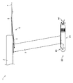
図13は、水上乗り物1の進行状態の一例が示された側面図である。定常状態である図1の状態から図13に示されるように、水上浮遊部2と水面7との距離が所定の距離よりも大となった場合には、水面センサ4は自重によって下方へ回動する。一方、図示による説明は省略するが、定常状態である図1の状態から、水上浮遊部2と水面7との距離が所定の距離よりも小となった場合には、水面センサ4は上方へ回動する。船尾水中翼44は、水面センサ4の回動に応じ、水上浮遊部2と水面7との距離を所定の距離に保つように支柱3に対して揺動する。
FIG. 13 is a side view showing an example of the progress state of the water vehicle 1. As shown in FIG. 13 from the steady state of FIG. 1, when the distance between the floating portion 2 on the water and the water surface 7 becomes larger than a predetermined distance, the water surface sensor 4 rotates downward due to its own weight. Move. On the other hand, although the description by illustration is omitted, when the distance between the floating portion 2 on the water and the water surface 7 becomes smaller than a predetermined distance from the state of FIG. 1 which is a steady state, the water surface sensor 4 moves upward. Rotate. The stern hydrofoil 44 swings with respect to the support column 3 so as to keep the distance between the floating portion 2 on the water and the water surface 7 at a predetermined distance in response to the rotation of the water surface sensor 4.
図14は、水上乗り物1の停止状態の一例が示された側面図である。水上乗り物1が停止状態では、水面センサ4は、図14に示されるように、浮力によって上方へ回動した状態となる。
FIG. 14 is a side view showing an example of the stopped state of the water vehicle 1. When the water vehicle 1 is stopped, the water surface sensor 4 is in a state of being rotated upward by buoyancy as shown in FIG.
リンク機構93は、水面センサ4と船尾水中翼44とを連動連結させる構成であれば良く、上述の構成に限定されるものではない。リンク機構93は、支柱3の外部に配設されても構わない。しかしながら、抗力の低減、保護等の観点から、リンク機構93は、支柱3の内部に配設されることが好ましい。
The link mechanism 93 may be configured as long as the water level sensor 4 and the stern hydrofoil 44 are interlocked and connected, and is not limited to the above configuration. The link mechanism 93 may be arranged outside the support column 3. However, from the viewpoint of reducing drag, protection, etc., the link mechanism 93 is preferably arranged inside the support column 3.
次に、水上乗り物1の制御系統について詳述する。図15は、水上乗り物1の制御系統の要部ブロック図である。図15おいて、電力の供給は破線で示されている。水上乗り物1は、水上浮遊部2に内蔵されるバッテリ10と、制御部11と、水上浮遊部2に取り付けられる操作具12とを更に備える。
Next, the control system of the water vehicle 1 will be described in detail. FIG. 15 is a block diagram of a main part of the control system of the water vehicle 1. In FIG. 15, the power supply is indicated by a broken line. The water vehicle 1 further includes a battery 10 built in the water floating unit 2, a control unit 11, and an operating tool 12 attached to the water floating unit 2.
制御部11は、水中推進装置20の制御部26、及び操作具12と電気的に接続される。また、制御部11は、水上浮遊部2に内蔵される図示せぬコンバータを介してバッテリ10に接続され、所定の電圧の直流電力がバッテリ10から供給される。制御部11は、種々の設定値及び操作具12からの入力信号を読み込み、この入力信号に基づいて水中推進装置20の制御部26へ制御信号を出力するように構成されている。
The control unit 11 is electrically connected to the control unit 26 of the underwater propulsion device 20 and the operating tool 12. Further, the control unit 11 is connected to the battery 10 via a converter (not shown) built in the floating unit 2 on the water, and DC power of a predetermined voltage is supplied from the battery 10. The control unit 11 is configured to read various set values and input signals from the operating tool 12 and output the control signal to the control unit 26 of the underwater propulsion device 20 based on the input signals.
制御部11としては、水中推進装置20の制御部26と同様に、演算処理及び制御処理を行うCPU(Central Processing Unit)、データが格納される主記憶装置、タイマ、入力回路、出力回路等の含まれた制御盤が例示される。ROM(Read Only Memory)、EEPROM(Electrically Erasable Programmable Read Only Memory)に例示される主記憶装置には、制御プログラム、各種データが格納されている。なお、制御部11の構成は特に限定されるものではなく、例えば、複数の制御盤から構成されても構わない。
Similar to the control unit 26 of the underwater propulsion device 20, the control unit 11 includes a CPU (Central Processing Unit) that performs arithmetic processing and control processing, a main storage device that stores data, a timer, an input circuit, an output circuit, and the like. The included control panel is illustrated. A control program and various data are stored in a main storage device exemplified by a ROM (Read Only Memory) and an EEPROM (Electrically Erasable Programmable Read Only Memory). The configuration of the control unit 11 is not particularly limited, and may be composed of, for example, a plurality of control panels.
制御部11が操作具12からの入力信号に基づいて水中推進装置20の制御部26へ制御信号を出力し、水中推進装置20の制御部26がこの制御信号に基づいてインバータ25へ制御信号を出力する。そして、インバータ25が入力される制御信号に基づいてモータ22へ供給する交流電力の周波数を変更することで、モータ22の回転数が変更され、水上乗り物1の進行速度が変更される。
The control unit 11 outputs a control signal to the control unit 26 of the underwater propulsion device 20 based on the input signal from the operating tool 12, and the control unit 26 of the underwater propulsion device 20 outputs a control signal to the inverter 25 based on this control signal. Output. Then, by changing the frequency of the AC power supplied to the motor 22 based on the control signal input by the inverter 25, the rotation speed of the motor 22 is changed and the traveling speed of the water vehicle 1 is changed.
ここで、水上浮遊部2の制御部11と水中推進装置20の制御部26は、相互通信ができるように構成されても構わない。制御部11と制御部26との通信は、シリアル通信であっても良く、パラレル通信であっても良い。しかしながら、抗力を減少させる観点において、制御部11と制御部26との通信は、シリアル通信であることが好ましい。シリアル通信とすることで、制御部11と制御部26とを接続する通信線を1本とすることができる。これにより、支柱3の内部を通る通信線の数が減って支柱3を細くすることができるため、抗力が減少された水上乗り物1の進行ができる。
Here, the control unit 11 of the floating unit 2 on the water and the control unit 26 of the underwater propulsion device 20 may be configured to enable mutual communication. The communication between the control unit 11 and the control unit 26 may be serial communication or parallel communication. However, from the viewpoint of reducing drag, the communication between the control unit 11 and the control unit 26 is preferably serial communication. By using serial communication, one communication line can be used to connect the control unit 11 and the control unit 26. As a result, the number of communication lines passing through the inside of the support column 3 is reduced, and the support column 3 can be made thinner, so that the water vehicle 1 with reduced drag can proceed.
水中推進装置20は、上述の構成に限定されるものではない。例えば、水中推進装置20は、制御部26を備えない構成であっても良い。このような構成の場合には、水中推進装置20は、水上浮遊部2に内蔵される制御部11からインバータ25へ制御信号が出力される構成とする。
The underwater propulsion device 20 is not limited to the above configuration. For example, the underwater propulsion device 20 may be configured not to include the control unit 26. In the case of such a configuration, the underwater propulsion device 20 is configured to output a control signal from the control unit 11 built in the water floating unit 2 to the inverter 25.
水中推進装置20は、水上乗り物1の進行速度を測定するための圧力センサ、モータ22やインバータ25の温度を測定するための温度センサ、水上乗り物1の傾き等を測定するための加速度センサ等を備える構成であっても良い。これらの各種センサは制御部26に電気的に接続される。この場合、制御部26は、圧力センサの検出値に基づいて水上乗り物1の進行速度を算出したり、温度センサの検出値に基づいてモータ22やインバータ25の温度を算出したり、あるいは加速度センサの検出値に基づいて水上乗り物1の傾き等を算出したりするように構成される。
The underwater propulsion device 20 includes a pressure sensor for measuring the traveling speed of the water vehicle 1, a temperature sensor for measuring the temperature of the motor 22 and the inverter 25, an acceleration sensor for measuring the inclination of the water vehicle 1, and the like. It may be provided. These various sensors are electrically connected to the control unit 26. In this case, the control unit 26 calculates the traveling speed of the water vehicle 1 based on the detection value of the pressure sensor, calculates the temperature of the motor 22 or the inverter 25 based on the detection value of the temperature sensor, or the acceleration sensor. It is configured to calculate the inclination and the like of the water vehicle 1 based on the detected value of.
水中推進装置20が各種センサを備える場合には、制御部11によって制御される表示装置を水上浮遊部2に配設することが好ましい。表示装置は、制御部26によって算出された速度、温度、傾き等を表示する。表示装置には、バッテリ10の電力量、進行可能な距離等を表示させても良い。表示装置としては、特に限定されるものではなく、防水構造とされた液晶モニタ等を用いることができる。このような構成にすることで、使用者は水上乗り物1の進行状態を把握することができ、使い勝手が良い。
When the underwater propulsion device 20 includes various sensors, it is preferable to dispose the display device controlled by the control unit 11 in the water floating unit 2. The display device displays the speed, temperature, inclination, etc. calculated by the control unit 26. The display device may display the electric energy of the battery 10, the distance that can be traveled, and the like. The display device is not particularly limited, and a liquid crystal monitor or the like having a waterproof structure can be used. With such a configuration, the user can grasp the progress state of the water vehicle 1, which is convenient.
制御部26が各種センサの検出値に基づいてモータ22を制御するように構成することも可能となる。例えば、水上乗り物1の速度が所定の速度以上とならいようにするモータ22の制御等が可能となる。更に、水中推進装置20は、船尾水中翼44を能動的に揺動させる駆動機構を備えるとともに、制御部26が各種センサの検出に基づいてこの駆動機構を制御する構成とされても良い。このような構成にすることで、水上乗り物1の姿勢制御を行うことも可能となる。
It is also possible to configure the control unit 26 to control the motor 22 based on the detection values of various sensors. For example, it is possible to control the motor 22 so that the speed of the water vehicle 1 does not exceed a predetermined speed. Further, the underwater propulsion device 20 may be provided with a drive mechanism for actively swinging the stern hydrofoil 44, and the control unit 26 may be configured to control the drive mechanism based on the detection of various sensors. With such a configuration, it is possible to control the attitude of the water vehicle 1.
制御部26に替わって制御部11が各種の値を算出する構成にしても良い。加速度センサは、水上浮遊部2に配設されても構わない。また、水上浮遊部2に測位衛星からの電波を受信する受信装置を配設し、GNSS(Global Navigation Satellite System)を用いて進行速度を算出するように構成されても良い。
Instead of the control unit 26, the control unit 11 may be configured to calculate various values. The acceleration sensor may be arranged on the floating portion 2 on the water. Further, a receiving device for receiving radio waves from the positioning satellite may be provided in the floating portion 2 on the water, and the traveling speed may be calculated using GNSS (Global Navigation Satellite System).
水中推進装置20の船首水中翼43は、例えば、胴部32や船尾部34に取り付けられても構わない。水中推進装置20は、船首水中翼43を備えなくても良い。船首水中翼43は、支柱3等に備えられていてもよい。
The bow hydrofoil 43 of the underwater propulsion device 20 may be attached to, for example, the fuselage portion 32 or the stern portion 34. The underwater propulsion device 20 does not have to include the bow hydrofoil 43. The bow hydrofoil 43 may be provided on the support column 3 or the like.
水中推進装置20は、船尾水中翼44が本体部21に固定される構成であっても良い。船尾水中翼44は、噴流口30の近傍以外の場所に配置されても構わない。水中推進装置20は、船尾水中翼44を備えなくても良い。船尾水中翼44は、支柱3等に備えられていてもよい。
The underwater propulsion device 20 may have a configuration in which the stern hydrofoil 44 is fixed to the main body 21. The stern hydrofoil 44 may be arranged at a location other than the vicinity of the jet port 30. The underwater propulsion device 20 does not have to include the stern hydrofoil 44. The stern hydrofoil 44 may be provided on the support column 3 or the like.
また、水中推進装置20の本体部21は、上述の構成に限定されるものではない。本体部21は、例えば、船首部31と胴部32とが一体的に構成されても構わない。しかしながら、生産性の観点から、上述のように、船首部31と、胴部32と、船尾部34とが別体であることが好ましい。
Further, the main body 21 of the underwater propulsion device 20 is not limited to the above-mentioned configuration. In the main body 21, for example, the bow 31 and the body 32 may be integrally formed. However, from the viewpoint of productivity, it is preferable that the bow portion 31, the fuselage portion 32, and the stern portion 34 are separate bodies as described above.
以上、本実施形態の一実施形態について説明したが、本開示に係る水中推進装置は、上記実施形態に限定されるものではなく、発明の趣旨を逸脱しない範囲において種々の変更が可能である。
Although one embodiment of the present embodiment has been described above, the underwater propulsion device according to the present disclosure is not limited to the above embodiment, and various modifications can be made without departing from the spirit of the invention.