JP6871230B2 - Electrical junction box - Google Patents
Electrical junction box Download PDFInfo
- Publication number
- JP6871230B2 JP6871230B2 JP2018247801A JP2018247801A JP6871230B2 JP 6871230 B2 JP6871230 B2 JP 6871230B2 JP 2018247801 A JP2018247801 A JP 2018247801A JP 2018247801 A JP2018247801 A JP 2018247801A JP 6871230 B2 JP6871230 B2 JP 6871230B2
- Authority
- JP
- Japan
- Prior art keywords
- case
- cover
- boss
- component mounting
- component
- Prior art date
- Legal status (The legal status is an assumption and is not a legal conclusion. Google has not performed a legal analysis and makes no representation as to the accuracy of the status listed.)
- Active
Links
- 230000002093 peripheral effect Effects 0.000 claims description 17
- 238000012986 modification Methods 0.000 description 14
- 230000004048 modification Effects 0.000 description 14
- 210000000078 claw Anatomy 0.000 description 13
- 238000003780 insertion Methods 0.000 description 7
- 230000037431 insertion Effects 0.000 description 7
- 238000005452 bending Methods 0.000 description 3
- 229920003002 synthetic resin Polymers 0.000 description 2
- 239000000057 synthetic resin Substances 0.000 description 2
- 230000000694 effects Effects 0.000 description 1
- 239000000463 material Substances 0.000 description 1
- 230000000717 retained effect Effects 0.000 description 1
Images


Classifications
-
- H—ELECTRICITY
- H01—ELECTRIC ELEMENTS
- H01R—ELECTRICALLY-CONDUCTIVE CONNECTIONS; STRUCTURAL ASSOCIATIONS OF A PLURALITY OF MUTUALLY-INSULATED ELECTRICAL CONNECTING ELEMENTS; COUPLING DEVICES; CURRENT COLLECTORS
- H01R9/00—Structural associations of a plurality of mutually-insulated electrical connecting elements, e.g. terminal strips or terminal blocks; Terminals or binding posts mounted upon a base or in a case; Bases therefor
- H01R9/16—Fastening of connecting parts to base or case; Insulating connecting parts from base or case
-
- H—ELECTRICITY
- H02—GENERATION; CONVERSION OR DISTRIBUTION OF ELECTRIC POWER
- H02G—INSTALLATION OF ELECTRIC CABLES OR LINES, OR OF COMBINED OPTICAL AND ELECTRIC CABLES OR LINES
- H02G3/00—Installations of electric cables or lines or protective tubing therefor in or on buildings, equivalent structures or vehicles
- H02G3/02—Details
- H02G3/08—Distribution boxes; Connection or junction boxes
- H02G3/086—Assembled boxes
-
- H—ELECTRICITY
- H01—ELECTRIC ELEMENTS
- H01R—ELECTRICALLY-CONDUCTIVE CONNECTIONS; STRUCTURAL ASSOCIATIONS OF A PLURALITY OF MUTUALLY-INSULATED ELECTRICAL CONNECTING ELEMENTS; COUPLING DEVICES; CURRENT COLLECTORS
- H01R13/00—Details of coupling devices of the kinds covered by groups H01R12/70 or H01R24/00 - H01R33/00
- H01R13/62—Means for facilitating engagement or disengagement of coupling parts or for holding them in engagement
- H01R13/627—Snap or like fastening
- H01R13/6271—Latching means integral with the housing
-
- H—ELECTRICITY
- H01—ELECTRIC ELEMENTS
- H01R—ELECTRICALLY-CONDUCTIVE CONNECTIONS; STRUCTURAL ASSOCIATIONS OF A PLURALITY OF MUTUALLY-INSULATED ELECTRICAL CONNECTING ELEMENTS; COUPLING DEVICES; CURRENT COLLECTORS
- H01R13/00—Details of coupling devices of the kinds covered by groups H01R12/70 or H01R24/00 - H01R33/00
- H01R13/73—Means for mounting coupling parts to apparatus or structures, e.g. to a wall
-
- H—ELECTRICITY
- H02—GENERATION; CONVERSION OR DISTRIBUTION OF ELECTRIC POWER
- H02G—INSTALLATION OF ELECTRIC CABLES OR LINES, OR OF COMBINED OPTICAL AND ELECTRIC CABLES OR LINES
- H02G3/00—Installations of electric cables or lines or protective tubing therefor in or on buildings, equivalent structures or vehicles
- H02G3/02—Details
- H02G3/08—Distribution boxes; Connection or junction boxes
- H02G3/16—Distribution boxes; Connection or junction boxes structurally associated with support for line-connecting terminals within the box
Description
本発明は、電気接続箱に関する。 The present invention relates to an electrical junction box.
ケースの上部にカバー(他方のケース)が被せられて組み付けられる電気接続箱として、ケースに設けられた位置決めボスを、カバーの外面上に突出する筒体の位置決め凹部に嵌め入れて位置決めするものがある(例えば、特許文献1参照)。 As an electrical connection box that can be assembled by covering the upper part of the case with a cover (the other case), a positioning boss provided on the case is fitted into a positioning recess of a cylinder protruding on the outer surface of the cover for positioning. (See, for example, Patent Document 1).
ところで、上記の電気接続箱は、互いに嵌合するボスと位置決め凹部とが両端に設けられている。このため、カバーにおける部品が搭載される領域では、カバーの上面板が十分に支持されず、カバーへ部品を搭載する際にかかる荷重によって上面板に撓みが生じるおそれがある。すると、カバーに搭載した部品の端子と電気接続箱内の端子接続部との接続が不安定となり、信頼性が低下するおそれがある。 By the way, the above-mentioned electric junction box is provided with bosses and positioning recesses that are fitted to each other at both ends. Therefore, in the region where the parts are mounted on the cover, the upper surface plate of the cover is not sufficiently supported, and the upper surface plate may be bent due to the load applied when the parts are mounted on the cover. Then, the connection between the terminal of the component mounted on the cover and the terminal connection portion in the electric junction box becomes unstable, and the reliability may be lowered.
本発明は、上述した事情に鑑みてなされたものであり、その目的は、搭載する部品の端子を端子接続部へ安定的に接続することが可能な信頼性の高い電気接続箱を提供することにある。 The present invention has been made in view of the above circumstances, and an object of the present invention is to provide a highly reliable electrical junction box capable of stably connecting the terminals of mounted components to the terminal connection portion. It is in.
前述した目的を達成するために、本発明に係る電気接続箱は、下記(1)〜(3)を特徴としている。
(1) 端子接続部を備えた底面板を有するケースと、
前記ケースの上部に被せられて組付けられる上面板を有するカバーと、
前記カバーの前記上面板に設けられ、前記カバーの上方から端子を有する部品が組付けられる複数の部品搭載部と、
を備え、
前記部品搭載部に組付けられる前記部品の前記端子が前記ケースの前記端子接続部に接続される電気接続箱であって、
前記ケースまたは前記カバーに、前記ケースの前記底面板と前記カバーの前記上面板との間隔を維持させる少なくとも一つのボスを備え、
一つの前記ボスは、平面視で、前記ボスの範囲の一部が、互いに離れて位置する2つの前記部品搭載部のうち一方の前記部品搭載部の範囲の一部と重複し、且つ、前記ボスの範囲の前記一部と異なる一部が、前記2つの前記部品搭載部のうち他方の前記部品搭載部の範囲の一部と重複するように、配置されている
ことを特徴とする電気接続箱。
(2) 前記部品搭載部は、組付けられる前記部品の周囲を囲う周壁部を有する
ことを特徴とする(1)に記載の電気接続箱。
(3) 前記ボスは、前記ケースの前記底面板に立設され、
前記ケースの前記底面板の裏面には、前記ボスに対応する位置に、前記ケースが載置される治具に設けられた位置決めピンが挿し込まれる位置決め穴が形成されている
ことを特徴とする(1)または(2)に記載の電気接続箱。
In order to achieve the above-mentioned object, the electric junction box according to the present invention is characterized by the following (1) to (3).
(1) A case having a bottom plate with a terminal connection and
A cover having a top plate that is put over the upper part of the case and assembled.
A plurality of component mounting portions provided on the top plate of the cover and to which components having terminals are assembled from above the cover.
With
An electrical junction box in which the terminal of the component assembled to the component mounting portion is connected to the terminal connection portion of the case.
The case or the cover is provided with at least one boss that maintains a distance between the bottom plate of the case and the top plate of the cover.
In a plan view, a part of the range of the boss overlaps with a part of the range of the component mounting portion of one of the two component mounting portions located apart from each other, and the boss An electrical connection characterized in that a part different from the part of the range of the boss is arranged so as to overlap a part of the range of the other part mounting part of the two parts mounting parts. box.
(2 ) The electrical junction box according to (1), wherein the component mounting portion has a peripheral wall portion that surrounds the component to be assembled.
( 3 ) The boss is erected on the bottom plate of the case.
A positioning hole for inserting a positioning pin provided in a jig on which the case is placed is formed on the back surface of the bottom plate of the case at a position corresponding to the boss. The electrical junction box according to (1) or (2).
上記(1)の構成の電気接続箱によれば、ケースの底面板とカバーの上面板との間隔を維持させるボスを、平面視で複数の部品搭載部の外周を囲う部品搭載領域に配置させている。これにより、部品搭載部に部品を組付ける際の荷重をボスによって確実に受け止めさせることができ、部品の組付け時の荷重によるカバー及びケースの撓みなどの変形を良好に抑制できる。
したがって、ケースの端子接続部に対して部品の端子を円滑かつ予め設定した挿入量で安定的に挿し込むことができ、接続信頼性を高めることができる。また、カバー及びケースの変形が抑制されることで、カバーとケースとを係止する係止部分における外れを抑えることができ、カバーとケースとの組付け状態を確実に維持させることができる。
更に、上記(1)の構成の電気接続箱によれば、平面視で部品搭載領域内の部品搭載部の範囲にボスが配置されているので、部品搭載部に部品を搭載する際の荷重を部品の直下でより効率的に受け止めることができる。これにより、カバー及びケースの変形抑制効果をより高めることができる。
上記(2)の構成の電気接続箱によれば、部品搭載部に搭載した部品の周囲を周壁部によって良好に保持させることができる。しかも、カバーの撓みが抑制されるので、カバーの上面板の変形に伴って周壁部が傾いて部品の外周面を押圧するような不具合も抑制できる。
上記(3)の構成の電気接続箱によれば、位置決め穴に治具の位置決めピンを挿し込むことで、ケースを治具上に位置決めすることができる。これにより、ケースに対する端子接続部やカバーの組付け作業及び部品搭載部への部品の搭載作業等を円滑に行うことができる。しかも、ボスに対応する位置に位置決め穴が設けられているので、ボスを中抜きして位置決め穴を形成することができ、別個の位置決め穴をケースに設けることによるコストアップ及びスペースの占有を抑制できる。また、ケースにカバーを被せる構造であることからケースの外周面を位置決めピン等に突き当てて位置決めすることができない場合であっても、ケースを容易に位置決めすることができる。
According to the electrical connection box having the configuration of (1) above, the boss that maintains the distance between the bottom plate of the case and the top plate of the cover is arranged in the component mounting area that surrounds the outer periphery of the plurality of component mounting portions in a plan view. ing. As a result, the load when assembling the component to the component mounting portion can be reliably received by the boss, and deformation such as bending of the cover and the case due to the load when assembling the component can be satisfactorily suppressed.
Therefore, the terminals of the component can be smoothly and stably inserted into the terminal connection portion of the case with a preset insertion amount, and the connection reliability can be improved. Further, by suppressing the deformation of the cover and the case, it is possible to suppress the disengagement of the locking portion that locks the cover and the case, and it is possible to reliably maintain the assembled state of the cover and the case.
Further, according to the electric junction box having the configuration of ( 1 ) above, since the boss is arranged in the range of the component mounting portion in the component mounting area in a plan view, the load when the component is mounted on the component mounting portion can be applied. It can be received more efficiently directly under the parts. Thereby, the deformation suppressing effect of the cover and the case can be further enhanced.
According to the electrical connection box having the configuration of ( 2 ) above, the peripheral wall portion can satisfactorily hold the periphery of the component mounted on the component mounting portion. Moreover, since the bending of the cover is suppressed, it is possible to suppress a problem that the peripheral wall portion is tilted and presses the outer peripheral surface of the component due to the deformation of the upper surface plate of the cover.
According to the electrical connection box having the configuration of ( 3 ) above, the case can be positioned on the jig by inserting the positioning pin of the jig into the positioning hole. As a result, it is possible to smoothly perform the work of assembling the terminal connection portion and the cover to the case and the work of mounting the component on the component mounting portion. Moreover, since the positioning hole is provided at the position corresponding to the boss, the boss can be hollowed out to form the positioning hole, and the cost increase and space occupancy due to the provision of the separate positioning hole in the case are suppressed. it can. Further, since the case is covered with a cover, the case can be easily positioned even when the outer peripheral surface of the case cannot be abutted against a positioning pin or the like for positioning.
本発明によれば、搭載する部品の端子を端子接続部へ安定的に接続することが可能な信頼性の高い電気接続箱を提供できる。 According to the present invention, it is possible to provide a highly reliable electrical junction box capable of stably connecting the terminals of mounted components to the terminal connection portion.
以上、本発明について簡潔に説明した。更に、以下に説明される発明を実施するための形態(以下、「実施形態」という。)を添付の図面を参照して通読することにより、本発明の詳細は更に明確化されるであろう。 The present invention has been briefly described above. Further, the details of the present invention will be further clarified by reading through the embodiments described below (hereinafter referred to as "embodiments") with reference to the accompanying drawings. ..
以下、本発明に係る実施の形態の例を、図面を参照して説明する。
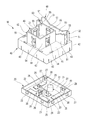
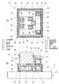
図1は、本実施形態に係る電気接続箱の斜視図である。図2は、本実施形態に係る電気接続箱及び部品の斜視図である。図3は、本実施形態に係る電気接続箱の分解斜視図である。図4は、本実施形態に係る電気接続箱の下方から視た分解斜視図である。図5は、電気接続箱を示す図であって、図5(a)は平面図、図5(b)は側面図である。図6は、電気接続箱の内部構造を示す図であって、図6(a)は図5(b)におけるB−B断面図、図6(b)は図5(a)におけるA−A断面図である。
Hereinafter, examples of embodiments according to the present invention will be described with reference to the drawings.
FIG. 1 is a perspective view of an electrical connection box according to the present embodiment. FIG. 2 is a perspective view of the electrical junction box and parts according to the present embodiment. FIG. 3 is an exploded perspective view of the electrical connection box according to the present embodiment. FIG. 4 is an exploded perspective view of the electrical junction box according to the present embodiment as viewed from below. 5A and 5B are views showing an electrical junction box, FIG. 5A is a plan view, and FIG. 5B is a side view. 6A and 6B are views showing the internal structure of the electrical junction box, FIG. 6A is a sectional view taken along line BB in FIG. 5B, and FIG. 6B is AA in FIG. 5A. It is a cross-sectional view.
図1〜図5に示すように、本実施形態に係る電気接続箱10は、ケース20と、カバー40とを備えている。電気接続箱10は、ケース20に対して、その上方側からカバー40を組付けることで構成される。
As shown in FIGS. 1 to 5, the
ケース20は、絶縁性の合成樹脂により一体成形されている。ケース20は、底面板21と、外壁部22とを有している。底面板21は、平面視矩形状の板状に形成されている。外壁部22は、底面板21の各辺の縁部から上方へ延在されており、底面板21に一体に形成されている。外壁部22には、外面側に、複数の係止爪23が形成されている。ケース20には、底面板21の上面に、複数のバスバー25が設けられている。これらのバスバー25には、音叉状の端子接続部26が形成されている。端子接続部26は、一対の挟持片27を有している。
The
ケース20は、ボス30を備えている。ボス30は、底面板21に一体に形成されており、カバー40が装着される上方側へ突設されている。ボス30は、平面視円形状に形成されており、上方へ向かって僅かに縮径されている。また、ボス30は、その上端部に、ボス30の突設方向に直交する平面からなる当接面31を有している。また、ケース20は、その底面板21の裏面に、位置決め穴32を有している。この位置決め穴32は、ボス30に対応する位置に形成されている。この位置決め穴32は、ボス30を中抜きすることで形成されている。なお、ボス30は、平面視円形状に限らず、平面視角形状等の他の形状であってもよい。
The
ケース20の上部に装着されるカバー40は、絶縁性の合成樹脂により一体成形されている。カバー40は、上面板41と、側面板42とを有している。上面板41は、平面視矩形状の板状に形成されている。側面板42は、上面板41の各辺の縁部から下方へ延在されており、上面板41に一体に形成されている。側面板42には、複数の係止片43が形成されており、これらの係止片43には、その内面側に、係止凹部44が形成されている。
The
カバー40は、その上面板41に、複数(本例では二つ)の部品搭載部45,46を備えている。一方の部品搭載部45は、平面視略正方形状に形成され、他方の部品搭載部46は、平面視略長方形状に形成されている。これらの部品搭載部45,46は上面板41の上面から上方へ立設された四つの側板部51を有する周壁部52を備えており、この周壁部52内が部品嵌合凹部53とされている。部品搭載部45,46の部品嵌合凹部53の底面部分には、端子挿入孔54(部品搭載部45の端子挿入孔54のみ図示)が形成されている。
The
一方の部品搭載部45の周壁部52には、各側板部51に、部品嵌合凹部53側へ突出する係止爪55が形成されている。また、他方の部品搭載部46の周壁部52には、短辺側の側板部51に、部品嵌合凹部53側へ突出する係止爪55が形成されている。
On the
部品搭載部45,46には、それぞれ部品P1,P2が組付けられる。これらの部品P1,P2は、例えば、リレー、ヒューズあるいは抵抗器などの電気部品であり、それぞれ下面側に端子60が突出されている。
Parts P1 and P2 are assembled to the
部品P1は、略立方体形状に形成されており、部品搭載部45の部品嵌合凹部53に対して端子60を下方へ向けて嵌合されることで、部品搭載部45に組付けられる。そして、部品搭載部45に部品P1を組付けることで、部品P1の端子60が、端子挿入孔54に挿し込まれて上面板41の裏面側へ突出される。この部品P1の側面には、互いに反対側へ突出する一対の爪部62が形成されている。この部品P1は、部品搭載部45の部品嵌合凹部53に嵌合されることで、部品P1の爪部62が係止爪55に係止される。これにより、部品P1が部品搭載部45に組付けられた状態に維持される。
The component P1 is formed in a substantially cubic shape, and is assembled to the
部品P2は、略直方体形状に形成されており、部品搭載部46の部品嵌合凹部53に対して端子60を下方へ向けて嵌合されることで、部品搭載部46に組付けられる。そして、部品搭載部46に部品P2を組付けることで、部品P2の端子60が、端子挿入孔54に挿し込まれて上面板41の裏面側へ突出される。この部品P2は、部品搭載部46の部品嵌合凹部53に嵌合されることで、その両端における上縁が係止爪55に係止される。これにより、部品P2が部品搭載部46に組付けられた状態に維持される。
The component P2 is formed in a substantially rectangular parallelepiped shape, and is assembled to the
カバー40は、ケース20に対して、その上方側から被せられて装着され、カバー40の側面板42がケース20の外壁部22の外面側に配置される。そして、このカバー40をケース20に装着することで、側面板42の係止片43の係止凹部44にケース20の外壁部22の係止爪23が入り込んで係止する。これにより、ケース20にカバー40が装着された状態に維持される。
The
この状態で、図6(a)に示すように、ボス30は、平面視で、部品搭載部45,46の間に配置される。ここで、平面視で部品搭載部45,46の外周を囲う領域を部品搭載領域PAとしたときに、ボス30は、この部品搭載領域PAに配置される。そして、ケース20にカバー40を装着すると、図6(b)に示すように、ケース20に形成されたボス30の当接面31がカバー40の上面板41の裏面に当接する。これにより、ケース20の底面板21とカバー40の上面板41との間隔が、ボス30によって維持される。
In this state, as shown in FIG. 6A, the
次に、電気接続箱10を組み立てて部品P1,P2を搭載させる場合について説明する。
Next, a case where the
ケース20を治具70の載置面71に載置させる。このとき、治具70の載置面71に立設された位置決めピン72を、ケース20の底面板21の裏面に形成された位置決め穴32に挿し込む(図6(b)参照)。これにより、ケース20が治具70の載置面71上に位置決めされた状態で保持される。
The
ケース20に対してバスバー25を組付ける。このとき、ケース20が治具70の載置面71上に位置決めされて保持されているので、バスバー25を容易にかつ円滑に組付けることができる。
Assemble the
バスバー25を組付けたケース20に対してカバー40を組付ける。具体的には、ケース20に対して、その上方側からカバー40を被せる。これにより、カバー40の側面板42をケース20の外壁部22の外面側に配置させ、側面板42の係止片43の係止凹部44にケース20の外壁部22の係止爪23を係止させてケース20にカバー40を固定させる。
The
次に、カバー40の部品搭載部45,46に、それぞれ部品P1,P2を装着する。具体的には、部品搭載部45,46の部品嵌合凹部53に対して、端子60を下方へ向けた部品P1,P2を押し込んで嵌合させる。すると、各部品P1,P2の端子60が端子挿入孔54へ挿し込まれて上面板41の裏面側へ突出され、ケース20のバスバー25に形成された端子接続部26の挟持片27の間に挿し込まれる。これにより、各部品P1,P2の端子60とバスバー25の端子接続部26とが電気的に接続される。また、この状態で、部品P1は、係止爪55によって爪部62が係止され、部品搭載部45に組付けられた状態に維持され、部品P2は、係止爪55によって両端における上縁が係止され、部品搭載部46に組付けられた状態に維持される。
Next, the components P1 and P2 are mounted on the
このとき、カバー40の上面板41には、部品P1,P2の押し込み力からなる大きな荷重が付与されるが、この荷重は、ケース20のボス30によって受け止められる。
At this time, a large load consisting of the pushing force of the parts P1 and P2 is applied to the
このように、本実施形態に係る電気接続箱10によれば、ケース20の底面板21とカバー40の上面板41との間隔を維持させるボス30を、平面視で複数の部品搭載部45,46の外周を囲う部品搭載領域PAに配置させている。これにより、部品搭載部45,46に部品P1,P2を組付ける際の荷重をボス30によって確実に受け止めさせることができ、部品P1,P2の組付け時の荷重によるカバー40及びケース20の撓みなどの変形を良好に抑制できる。
As described above, according to the
したがって、ケース20の端子接続部26に対して部品P1,P2の端子60を円滑かつ予め設定した挿入量で安定的に挿し込むことができ、接続信頼性を高めることができる。また、カバー40及びケース20の変形が抑制されることで、カバー40とケース20とを係止する係止爪23と係止片43との係止部分における外れを抑えることができ、カバー40とケース20との組付け状態を確実に維持させることができる。
Therefore, the
また、部品搭載部45,46は、組付けられる部品P1,P2の周囲を囲う周壁部52を有するので、部品搭載部45,46に搭載した部品P1,P2の周囲を周壁部52によって良好に保持させることができる。しかも、カバー40の撓みが抑制されるので、カバー40の上面板41の変形に伴って周壁部52が傾いて部品P1,P2の外周面を押圧するような不具合も抑制できる。
Further, since the
また、電気接続箱10は、ケース20の底面板21にボス30が立設され、ケース20の底面板21の裏面におけるボス30に対応する位置に位置決め穴32が形成されている。したがって、位置決め穴32に治具70の位置決めピン72を挿し込むことで、ケース20を治具70の載置面71上に位置決めすることができる。これにより、ケース20に対する端子接続部26を有するバスバー25やカバー40の組付け作業及び部品搭載部45,46への部品P1,P2の搭載作業等を円滑に行うことができる。しかも、ボス30に対応する位置に位置決め穴32が設けられているので、ボス30を中抜きして位置決め穴32を形成することができ、別個の位置決め穴32をケース20に設けることによるコストアップ及びスペースの占有を抑制できる。また、ケース20にカバー40を被せる構造であることからケース20の外周面を位置決めピン等に突き当てて位置決めすることができない場合であっても、ケース20を容易に位置決めすることができる。
Further, in the
次に、変形例に係る電気接続箱について説明する。
(変形例1)
図7は、変形例1に係る電気接続箱の内部構造を示す図であって、図7(a)は図5(b)におけるB−B断面図、図7(b)は図5(a)におけるA−A断面図である。
Next, the electric junction box according to the modified example will be described.
(Modification example 1)
7A and 7B are views showing the internal structure of the electrical junction box according to the first modification, FIG. 7A is a sectional view taken along line BB in FIG. 5B, and FIG. 7B is FIG. 5A. ) Is a sectional view taken along the line AA.
図7(a)及び図7(b)に示すように、変形例1に係る電気接続箱10Aでは、複数の部品P1,P2と同数のボス30を有している。これらのボス30は、それぞれの部品P1.P2が搭載される部品搭載部45,46に対応してケース20に設けられている。そして、これらのボス30は、平面視において、部品搭載領域PA内における部品搭載部45,46の範囲に配置されている。
As shown in FIGS. 7 (a) and 7 (b), the
この変形例1では、平面視で部品搭載領域PA内の部品搭載部45,46の範囲にボス30が配置されているので、部品搭載部45,46に部品P1,P2を組付ける際に、その荷重がボス30によって部品P1,P2の直下で受け止められる。また、二つのボス30の位置決め穴32に治具70の位置決めピン72を挿し込んで位置決めすることで、治具70の載置面71へ高精度に位置決めすることができるとともに、ケース20を回り止めすることができる。これにより、電気接続箱10Aの組立作業をさらに円滑に行うことができる。
In this modification 1, since the
(変形例2)
図8は、変形例2に係る電気接続箱の斜視図である。図9は、変形例2に係る電気接続箱を示す図であって、図9(a)は平面図、図9(b)は側面図である。図10は、変形例2に係る電気接続箱の内部構造を示す図であって、図10(a)は図9(b)におけるD−D断面図、図10(b)は図9(a)におけるC−C断面図である。
(Modification 2)
FIG. 8 is a perspective view of the electrical connection box according to the second modification. 9A and 9B are views showing an electrical connection box according to the second modification, FIG. 9A is a plan view, and FIG. 9B is a side view. 10A and 10B are views showing the internal structure of the electrical junction box according to the second modification, FIG. 10A is a sectional view taken along line DD in FIG. 9B, and FIG. 10B is FIG. 9A. ) Is a sectional view taken along line CC.
図8、図9(a)及び図9(b)に示すように、変形例2に係る電気接続箱10Bは、平面視で細長形状に形成されている。この電気接続箱10Bでは、カバー40に平面視略正方形状の二つの部品搭載部45が間隔をあけて設けられている。この電気接続箱10Bでは、それぞれの部品搭載部45に対応するボス30がケース20に設けられている。これらのボス30は、平面視において、部品搭載領域PA内におけるそれぞれの部品搭載部45の範囲に配置されている。
As shown in FIGS. 8, 9 (a) and 9 (b), the
この変形例2の場合も、平面視で部品搭載領域PA内の部品搭載部45の範囲にボス30が配置されているので、それぞれの部品搭載部45に部品P1を組付ける際に、その荷重がボス30によって部品P1の直下で受け止められる。また、二つのボス30の位置決め穴32に治具70の位置決めピン72を挿し込んで位置決めすることで、治具70の載置面71へ高精度に位置決めすることができるとともに、ケース20を回り止めすることができる。これにより、電気接続箱10Aの組立作業をさらに円滑に行うことができる。
Also in the case of this modification 2, since the
尚、本発明は、上述した実施形態に限定されるものではなく、適宜、変形、改良、等が可能である。その他、上述した実施形態における各構成要素の材質、形状、寸法、数、配置箇所、等は本発明を達成できるものであれば任意であり、限定されない。 The present invention is not limited to the above-described embodiment, and can be appropriately modified, improved, and the like. In addition, the material, shape, size, number, arrangement location, etc. of each component in the above-described embodiment are arbitrary and are not limited as long as the present invention can be achieved.
例えば、上記実施形態では、ケース20の底面板21にカバー40側へ突出するボス30を設けたが、カバー40の上面板41にケース20側へ突出するボスを設けてケース20の底面板21とカバー40の上面板41との間隔を維持させる構造としてもよい。
For example, in the above embodiment, the
ここで、上述した本発明に係る電気接続箱の実施形態の特徴をそれぞれ以下[1]〜[4]に簡潔に纏めて列記する。
[1] 端子接続部(26)を備えた底面板(21)を有するケース(20)と、
前記ケース(20)の上部に被せられて組付けられる上面板(41)を有するカバー(40)と、
前記カバー(40)の前記上面板(41)に設けられ、前記カバー(40)の上方から端子(60)を有する部品(P1,P2)が組付けられる複数の部品搭載部(45,46)と、
を備え、
前記部品搭載部(45,46)に組付けられる前記部品(P1,P2)の前記端子(60)が前記ケース(20)の前記端子接続部(26)に接続される電気接続箱(10)であって、
前記ケース(20)または前記カバー(40)に、前記ケース(20)の前記底面板(21)と前記カバー(40)の前記上面板(41)との間隔を維持させる少なくとも一つのボス(30)を備え、
前記ボス(30)は、平面視で複数の前記部品搭載部(45,46)の外周を囲う部品搭載領域(PA)に配置されている
ことを特徴とする電気接続箱。
[2] 前記ボス(30)は、平面視で前記部品搭載部(45,46)の範囲に配置されている
ことを特徴とする[1]に記載の電気接続箱。
[3] 前記部品搭載部(45,46)は、組付けられる前記部品(P1,P2)の周囲を囲う周壁部(52)を有する
ことを特徴とする[1]または[2]に記載の電気接続箱。
[4] 前記ボス(30)は、前記ケース(20)の前記底面板(21)に立設され、
前記ケース(20)の前記底面板(21)の裏面には、前記ボス(30)に対応する位置に、前記ケース(20)が載置される治具(70)に設けられた位置決めピン(72)が挿し込まれる位置決め穴(32)が形成されている
ことを特徴とする[1]から[3]のいずれか一つに記載の電気接続箱。
Here, the features of the above-described embodiments of the electrical junction box according to the present invention are briefly summarized and listed below [1] to [4], respectively.
[1] A case (20) having a bottom plate (21) provided with a terminal connection portion (26), and a case (20).
A cover (40) having a top plate (41) to be assembled over the case (20), and a cover (40).
A plurality of component mounting portions (45, 46) provided on the top plate (41) of the cover (40) and to which components (P1, P2) having terminals (60) are assembled from above the cover (40). When,
With
An electrical junction box (10) in which the terminal (60) of the component (P1, P2) assembled to the component mounting portion (45, 46) is connected to the terminal connection portion (26) of the case (20). And
At least one boss (30) that causes the case (20) or the cover (40) to maintain a distance between the bottom plate (21) of the case (20) and the top plate (41) of the cover (40). )
The boss (30) is an electrical connection box characterized in that the boss (30) is arranged in a component mounting area (PA) surrounding the outer periphery of the plurality of component mounting portions (45, 46) in a plan view.
[2] The electrical connection box according to [1], wherein the boss (30) is arranged within the range of the component mounting portions (45, 46) in a plan view.
[3] The component mounting portion (45, 46) according to [1] or [2], wherein the component mounting portion (45, 46) has a peripheral wall portion (52) surrounding the components (P1, P2) to be assembled. Electrical junction box.
[4] The boss (30) is erected on the bottom plate (21) of the case (20).
On the back surface of the bottom plate (21) of the case (20), a positioning pin (70) provided on a jig (70) on which the case (20) is placed is provided at a position corresponding to the boss (30). The electrical connection box according to any one of [1] to [3], wherein a positioning hole (32) into which the 72) is inserted is formed.
10,10A,10B:電気接続箱
20:ケース
21:底面板
26:端子接続部
30:ボス
32:位置決め穴
40:カバー
41:上面板
45,46:部品搭載部
52:周壁部
60:端子
P1,P2:部品
PA:部品搭載領域
10, 10A, 10B: Electrical connection box 20: Case 21: Bottom plate 26: Terminal connection part 30: Boss 32: Positioning hole 40: Cover 41:
Claims (3)
前記ケースの上部に被せられて組付けられる上面板を有するカバーと、
前記カバーの前記上面板に設けられ、前記カバーの上方から端子を有する部品が組付けられる複数の部品搭載部と、
を備え、
前記部品搭載部に組付けられる前記部品の前記端子が前記ケースの前記端子接続部に接続される電気接続箱であって、
前記ケースまたは前記カバーに、前記ケースの前記底面板と前記カバーの前記上面板との間隔を維持させる少なくとも一つのボスを備え、
一つの前記ボスは、平面視で、前記ボスの範囲の一部が、互いに離れて位置する2つの前記部品搭載部のうち一方の前記部品搭載部の範囲の一部と重複し、且つ、前記ボスの範囲の前記一部と異なる一部が、前記2つの前記部品搭載部のうち他方の前記部品搭載部の範囲の一部と重複するように、配置されている
ことを特徴とする電気接続箱。 A case with a bottom plate with terminal connections and
A cover having a top plate that is put over the upper part of the case and assembled.
A plurality of component mounting portions provided on the top plate of the cover and to which components having terminals are assembled from above the cover.
With
An electrical junction box in which the terminal of the component assembled to the component mounting portion is connected to the terminal connection portion of the case.
The case or the cover is provided with at least one boss that maintains a distance between the bottom plate of the case and the top plate of the cover.
In a plan view, a part of the range of the boss overlaps with a part of the range of the component mounting portion of one of the two component mounting portions located apart from each other, and the boss An electrical connection characterized in that a part different from the part of the range of the boss is arranged so as to overlap a part of the range of the other part mounting part of the two parts mounting parts. box.
ことを特徴とする請求項1に記載の電気接続箱。 The electrical connection box according to claim 1, wherein the component mounting portion has a peripheral wall portion that surrounds the component to be assembled.
前記ケースの前記底面板の裏面には、前記ボスに対応する位置に、前記ケースが載置される治具に設けられた位置決めピンが挿し込まれる位置決め穴が形成されている
ことを特徴とする請求項1または請求項2に記載の電気接続箱。 The boss is erected on the bottom plate of the case and
The back surface of the bottom plate of the case is characterized in that a positioning hole into which a positioning pin provided in a jig on which the case is placed is inserted is formed at a position corresponding to the boss. The electrical junction box according to claim 1 or 2.
Priority Applications (4)
| Application Number | Priority Date | Filing Date | Title |
|---|---|---|---|
| JP2018247801A JP6871230B2 (en) | 2018-12-28 | 2018-12-28 | Electrical junction box |
| EP19215970.5A EP3675298B1 (en) | 2018-12-28 | 2019-12-13 | Electrical connection box |
| US16/716,425 US10819048B2 (en) | 2018-12-28 | 2019-12-16 | Electrical connection box |
| CN201911364678.7A CN111384696B (en) | 2018-12-28 | 2019-12-26 | Electric connection box |
Applications Claiming Priority (1)
| Application Number | Priority Date | Filing Date | Title |
|---|---|---|---|
| JP2018247801A JP6871230B2 (en) | 2018-12-28 | 2018-12-28 | Electrical junction box |
Publications (2)
| Publication Number | Publication Date |
|---|---|
| JP2020108306A JP2020108306A (en) | 2020-07-09 |
| JP6871230B2 true JP6871230B2 (en) | 2021-05-12 |
Family
ID=69061045
Family Applications (1)
| Application Number | Title | Priority Date | Filing Date |
|---|---|---|---|
| JP2018247801A Active JP6871230B2 (en) | 2018-12-28 | 2018-12-28 | Electrical junction box |
Country Status (4)
| Country | Link |
|---|---|
| US (1) | US10819048B2 (en) |
| EP (1) | EP3675298B1 (en) |
| JP (1) | JP6871230B2 (en) |
| CN (1) | CN111384696B (en) |
Family Cites Families (38)
| Publication number | Priority date | Publication date | Assignee | Title |
|---|---|---|---|---|
| JP2778856B2 (en) * | 1991-07-10 | 1998-07-23 | 住友電装株式会社 | Small junction box |
| JPH1032914A (en) * | 1996-07-15 | 1998-02-03 | Yazaki Corp | Elexctical connection box |
| WO1999053585A1 (en) * | 1998-04-09 | 1999-10-21 | The Furukawa Electric Co., Ltd. | Terminal box |
| JPH11332057A (en) * | 1998-05-14 | 1999-11-30 | Yazaki Corp | Electrical junction box |
| US6008982A (en) * | 1998-05-20 | 1999-12-28 | General Motors Corporation | Low profile electrical distribution center and method of making a bus subassembly therefor |
| JP3334618B2 (en) * | 1998-06-16 | 2002-10-15 | 住友電装株式会社 | Electrical junction box |
| US6354846B1 (en) * | 1998-09-17 | 2002-03-12 | The Furukawa Electric Co., Ltd. | Electrical connection box |
| JP3673422B2 (en) * | 1999-03-12 | 2005-07-20 | 株式会社オートネットワーク技術研究所 | Branch connection box |
| TW486848B (en) * | 1999-08-18 | 2002-05-11 | Yazaki Corp | Wire harness circuit configuration method and wire harness |
| JP3473526B2 (en) * | 1999-11-18 | 2003-12-08 | 住友電装株式会社 | Electrical junction box with vertical busbar |
| JP2001314015A (en) * | 2000-04-27 | 2001-11-09 | Sumitomo Wiring Syst Ltd | Electric junction box with tentative retainer of connector |
| JP3576085B2 (en) * | 2000-09-13 | 2004-10-13 | 株式会社東芝 | Electronics |
| JP2002125307A (en) * | 2000-10-16 | 2002-04-26 | Sumitomo Wiring Syst Ltd | Electrical connection box |
| US6561822B2 (en) * | 2001-01-31 | 2003-05-13 | Sumitomo Wiring Systems, Ltd. | Electrical junction box cover assembly |
| JP2003009347A (en) * | 2001-06-20 | 2003-01-10 | Sumitomo Wiring Syst Ltd | Electrical junction box |
| JP2003032840A (en) * | 2001-07-23 | 2003-01-31 | Fujikura Ltd | Electrical connection box |
| JP3954915B2 (en) * | 2002-05-29 | 2007-08-08 | 矢崎総業株式会社 | Electrical junction box and manufacturing method thereof |
| US6926541B2 (en) * | 2002-08-30 | 2005-08-09 | Yazaki Corporation | Mounting structure of electric junction box |
| JP4064766B2 (en) * | 2002-08-30 | 2008-03-19 | 矢崎総業株式会社 | Electrical junction box |
| US7375981B2 (en) * | 2005-03-14 | 2008-05-20 | Vansco Electronics Lp | Electric power distribution and control apparatus |
| JP2007288930A (en) * | 2006-04-18 | 2007-11-01 | Auto Network Gijutsu Kenkyusho:Kk | Electrical connection box |
| US7591653B2 (en) * | 2006-09-08 | 2009-09-22 | Aees, Inc. | Modular power distribution center |
| JP4885693B2 (en) * | 2006-12-05 | 2012-02-29 | 株式会社オートネットワーク技術研究所 | Electrical junction box |
| JP5122868B2 (en) * | 2007-05-28 | 2013-01-16 | 矢崎総業株式会社 | Electrical junction box |
| US7955133B2 (en) * | 2008-04-23 | 2011-06-07 | Littelfuse, Inc. | Flexible power distribution module |
| JP5173596B2 (en) * | 2008-05-27 | 2013-04-03 | 株式会社オートネットワーク技術研究所 | Electrical junction box |
| JP5200857B2 (en) * | 2008-10-28 | 2013-06-05 | 住友電装株式会社 | Electrical junction box |
| KR101023885B1 (en) * | 2008-11-27 | 2011-03-22 | 현대자동차주식회사 | Junction box for vehicle |
| JP5535567B2 (en) * | 2009-10-01 | 2014-07-02 | 矢崎総業株式会社 | Manufacturing method of electrical junction box, electrical junction box, and power supply device provided with the electrical junction box |
| JP2012070503A (en) * | 2010-09-22 | 2012-04-05 | Sumitomo Wiring Syst Ltd | Electric connection box |
| JP5772471B2 (en) * | 2011-10-07 | 2015-09-02 | 住友電装株式会社 | Electrical junction box |
| JP5794938B2 (en) * | 2012-03-14 | 2015-10-14 | 古河電気工業株式会社 | High voltage electrical junction box |
| JP5929560B2 (en) * | 2012-06-29 | 2016-06-08 | 株式会社豊田自動織機 | Electronics |
| EP3089296B1 (en) * | 2014-06-19 | 2018-02-28 | AutoNetworks Technologies, Ltd. | Electrical junction box and connector housing |
| JP6009604B1 (en) * | 2015-03-30 | 2016-10-19 | 住友電装株式会社 | Electrical junction box |
| CN205040128U (en) * | 2015-08-28 | 2016-02-17 | 上海与德通讯技术有限公司 | Electronic device |
| JP6404258B2 (en) * | 2016-04-26 | 2018-10-10 | 矢崎総業株式会社 | Electrical junction box and wire harness |
| JP6627683B2 (en) | 2016-07-29 | 2020-01-08 | 住友電装株式会社 | Electrical equipment |
-
2018
- 2018-12-28 JP JP2018247801A patent/JP6871230B2/en active Active
-
2019
- 2019-12-13 EP EP19215970.5A patent/EP3675298B1/en active Active
- 2019-12-16 US US16/716,425 patent/US10819048B2/en active Active
- 2019-12-26 CN CN201911364678.7A patent/CN111384696B/en active Active
Also Published As
| Publication number | Publication date |
|---|---|
| CN111384696A (en) | 2020-07-07 |
| JP2020108306A (en) | 2020-07-09 |
| EP3675298A1 (en) | 2020-07-01 |
| US10819048B2 (en) | 2020-10-27 |
| CN111384696B (en) | 2021-09-10 |
| EP3675298B1 (en) | 2023-03-01 |
| US20200212606A1 (en) | 2020-07-02 |
Similar Documents
| Publication | Publication Date | Title |
|---|---|---|
| JP5513232B2 (en) | Electronic components | |
| CN110582896B (en) | Connector for substrate | |
| US20150163943A1 (en) | Electronic component assembly, connection structure between electronic component assembly and terminal fitting, and electrical connection box having electronic component assembly | |
| US6870097B2 (en) | Electrical junction box | |
| JP6138560B2 (en) | Electronic component assembly structure and electrical junction box | |
| WO2015041329A1 (en) | Fuse unit attachment structure | |
| US20170250504A1 (en) | Joint connector | |
| JP2010110058A (en) | Electric connection box | |
| US20190067923A1 (en) | Electrical connection box | |
| US8672712B2 (en) | Shield and circuit board module having the same | |
| JP5990333B2 (en) | Connection structure between electronic parts and terminal fittings | |
| CN112072351B (en) | Electronic component unit | |
| JP6871230B2 (en) | Electrical junction box | |
| CN109564812B (en) | Coil assembly, circuit structure, and electrical junction box | |
| JP6622753B2 (en) | Substrate holding structure | |
| US11139135B2 (en) | Attachment structure between cover and housing, and fusible link unit | |
| JP6122737B2 (en) | Electrical junction box and its packing structure | |
| JP5746500B2 (en) | Bus bar and electrical junction box provided with the same | |
| JP6807369B2 (en) | Electrical junction box | |
| JP7383442B2 (en) | electrical junction box | |
| JP6039300B2 (en) | fuse | |
| JP4697797B2 (en) | Fuse mounting structure | |
| JP4817391B2 (en) | Pin jack | |
| JP6432741B2 (en) | Electrical junction box | |
| JP6643889B2 (en) | Fusible link unit |
Legal Events
| Date | Code | Title | Description |
|---|---|---|---|
| A621 | Written request for application examination |
Free format text: JAPANESE INTERMEDIATE CODE: A621 Effective date: 20200219 |
|
| A977 | Report on retrieval |
Free format text: JAPANESE INTERMEDIATE CODE: A971007 Effective date: 20201228 |
|
| A131 | Notification of reasons for refusal |
Free format text: JAPANESE INTERMEDIATE CODE: A131 Effective date: 20210119 |
|
| A521 | Request for written amendment filed |
Free format text: JAPANESE INTERMEDIATE CODE: A523 Effective date: 20210303 |
|
| TRDD | Decision of grant or rejection written | ||
| A01 | Written decision to grant a patent or to grant a registration (utility model) |
Free format text: JAPANESE INTERMEDIATE CODE: A01 Effective date: 20210406 |
|
| A61 | First payment of annual fees (during grant procedure) |
Free format text: JAPANESE INTERMEDIATE CODE: A61 Effective date: 20210415 |
|
| R150 | Certificate of patent or registration of utility model |
Ref document number: 6871230 Country of ref document: JP Free format text: JAPANESE INTERMEDIATE CODE: R150 |
|
| S531 | Written request for registration of change of domicile |
Free format text: JAPANESE INTERMEDIATE CODE: R313531 |
|
| R350 | Written notification of registration of transfer |
Free format text: JAPANESE INTERMEDIATE CODE: R350 |
|
| R250 | Receipt of annual fees |
Free format text: JAPANESE INTERMEDIATE CODE: R250 |