JP6869748B2 - Pressure changer for breast implants - Google Patents
Pressure changer for breast implants Download PDFInfo
- Publication number
- JP6869748B2 JP6869748B2 JP2017034500A JP2017034500A JP6869748B2 JP 6869748 B2 JP6869748 B2 JP 6869748B2 JP 2017034500 A JP2017034500 A JP 2017034500A JP 2017034500 A JP2017034500 A JP 2017034500A JP 6869748 B2 JP6869748 B2 JP 6869748B2
- Authority
- JP
- Japan
- Prior art keywords
- bag
- spindle
- fluid
- enclosure
- motor
- Prior art date
- Legal status (The legal status is an assumption and is not a legal conclusion. Google has not performed a legal analysis and makes no representation as to the accuracy of the status listed.)
- Active
Links
Images


Classifications
-
- A—HUMAN NECESSITIES
- A61—MEDICAL OR VETERINARY SCIENCE; HYGIENE
- A61F—FILTERS IMPLANTABLE INTO BLOOD VESSELS; PROSTHESES; DEVICES PROVIDING PATENCY TO, OR PREVENTING COLLAPSING OF, TUBULAR STRUCTURES OF THE BODY, e.g. STENTS; ORTHOPAEDIC, NURSING OR CONTRACEPTIVE DEVICES; FOMENTATION; TREATMENT OR PROTECTION OF EYES OR EARS; BANDAGES, DRESSINGS OR ABSORBENT PADS; FIRST-AID KITS
- A61F2/00—Filters implantable into blood vessels; Prostheses, i.e. artificial substitutes or replacements for parts of the body; Appliances for connecting them with the body; Devices providing patency to, or preventing collapsing of, tubular structures of the body, e.g. stents
- A61F2/02—Prostheses implantable into the body
- A61F2/12—Mammary prostheses and implants
-
- A—HUMAN NECESSITIES
- A61—MEDICAL OR VETERINARY SCIENCE; HYGIENE
- A61M—DEVICES FOR INTRODUCING MEDIA INTO, OR ONTO, THE BODY; DEVICES FOR TRANSDUCING BODY MEDIA OR FOR TAKING MEDIA FROM THE BODY; DEVICES FOR PRODUCING OR ENDING SLEEP OR STUPOR
- A61M5/00—Devices for bringing media into the body in a subcutaneous, intra-vascular or intramuscular way; Accessories therefor, e.g. filling or cleaning devices, arm-rests
- A61M5/14—Infusion devices, e.g. infusing by gravity; Blood infusion; Accessories therefor
- A61M5/142—Pressure infusion, e.g. using pumps
-
- A—HUMAN NECESSITIES
- A61—MEDICAL OR VETERINARY SCIENCE; HYGIENE
- A61M—DEVICES FOR INTRODUCING MEDIA INTO, OR ONTO, THE BODY; DEVICES FOR TRANSDUCING BODY MEDIA OR FOR TAKING MEDIA FROM THE BODY; DEVICES FOR PRODUCING OR ENDING SLEEP OR STUPOR
- A61M5/00—Devices for bringing media into the body in a subcutaneous, intra-vascular or intramuscular way; Accessories therefor, e.g. filling or cleaning devices, arm-rests
- A61M5/14—Infusion devices, e.g. infusing by gravity; Blood infusion; Accessories therefor
- A61M5/168—Means for controlling media flow to the body or for metering media to the body, e.g. drip meters, counters ; Monitoring media flow to the body
- A61M5/16804—Flow controllers
-
- A—HUMAN NECESSITIES
- A61—MEDICAL OR VETERINARY SCIENCE; HYGIENE
- A61F—FILTERS IMPLANTABLE INTO BLOOD VESSELS; PROSTHESES; DEVICES PROVIDING PATENCY TO, OR PREVENTING COLLAPSING OF, TUBULAR STRUCTURES OF THE BODY, e.g. STENTS; ORTHOPAEDIC, NURSING OR CONTRACEPTIVE DEVICES; FOMENTATION; TREATMENT OR PROTECTION OF EYES OR EARS; BANDAGES, DRESSINGS OR ABSORBENT PADS; FIRST-AID KITS
- A61F2/00—Filters implantable into blood vessels; Prostheses, i.e. artificial substitutes or replacements for parts of the body; Appliances for connecting them with the body; Devices providing patency to, or preventing collapsing of, tubular structures of the body, e.g. stents
- A61F2/02—Prostheses implantable into the body
- A61F2/48—Operating or control means, e.g. from outside the body, control of sphincters
- A61F2/484—Fluid means, i.e. hydraulic or pneumatic
-
- A—HUMAN NECESSITIES
- A61—MEDICAL OR VETERINARY SCIENCE; HYGIENE
- A61F—FILTERS IMPLANTABLE INTO BLOOD VESSELS; PROSTHESES; DEVICES PROVIDING PATENCY TO, OR PREVENTING COLLAPSING OF, TUBULAR STRUCTURES OF THE BODY, e.g. STENTS; ORTHOPAEDIC, NURSING OR CONTRACEPTIVE DEVICES; FOMENTATION; TREATMENT OR PROTECTION OF EYES OR EARS; BANDAGES, DRESSINGS OR ABSORBENT PADS; FIRST-AID KITS
- A61F2250/00—Special features of prostheses classified in groups A61F2/00 - A61F2/26 or A61F2/82 or A61F9/00 or A61F11/00 or subgroups thereof
- A61F2250/0003—Special features of prostheses classified in groups A61F2/00 - A61F2/26 or A61F2/82 or A61F9/00 or A61F11/00 or subgroups thereof having an inflatable pocket filled with fluid, e.g. liquid or gas
-
- A—HUMAN NECESSITIES
- A61—MEDICAL OR VETERINARY SCIENCE; HYGIENE
- A61F—FILTERS IMPLANTABLE INTO BLOOD VESSELS; PROSTHESES; DEVICES PROVIDING PATENCY TO, OR PREVENTING COLLAPSING OF, TUBULAR STRUCTURES OF THE BODY, e.g. STENTS; ORTHOPAEDIC, NURSING OR CONTRACEPTIVE DEVICES; FOMENTATION; TREATMENT OR PROTECTION OF EYES OR EARS; BANDAGES, DRESSINGS OR ABSORBENT PADS; FIRST-AID KITS
- A61F2250/00—Special features of prostheses classified in groups A61F2/00 - A61F2/26 or A61F2/82 or A61F9/00 or A61F11/00 or subgroups thereof
- A61F2250/0004—Special features of prostheses classified in groups A61F2/00 - A61F2/26 or A61F2/82 or A61F9/00 or A61F11/00 or subgroups thereof adjustable
- A61F2250/0013—Special features of prostheses classified in groups A61F2/00 - A61F2/26 or A61F2/82 or A61F9/00 or A61F11/00 or subgroups thereof adjustable for adjusting fluid pressure
Description
(関連出願の相互参照)
本出願は、2016年2月29日に出願された米国仮出願第62/301,180号の利益を主張する。同仮出願は、参照により本明細書に組み込まれる。
(Cross-reference of related applications)
This application claims the interests of US Provisional Application Nos. 62 / 301,180 filed on February 29, 2016. The provisional application is incorporated herein by reference.
(発明の分野)
本発明は、一般的に、乳房切除術、特に乳房切除術後に行われる処置に関する。
(Field of invention)
The present invention generally relates to mastectomy, particularly procedures performed after mastectomy.
乳房切除術後に用いられ得る、当該技術分野において周知の装置が数多くある。 There are many well-known devices in the art that can be used after mastectomy.
Konekeらによる米国特許第3,852,833号(この開示は参照によって本明細書に組み込まれる)は、底部を覆って延びる第1内側カバー部分を備える半剛性の平坦状底部分を含む乳房プロテーゼについて記載している。 U.S. Pat. No. 3,852,833 by Koneke et al. (This disclosure is incorporated herein by reference) is a breast prosthesis that includes a semi-rigid, flat bottom portion with a first inner cover portion that extends over the bottom. Is described.
Cohenによる米国特許第4,433,440号(この開示は参照によって本明細書に組み込まれる)は、それぞれが自己密閉式弁を有している、内側及び外側可撓性容器を含む乳房プロテーゼについて記載している。弁は、それぞれの容器が個別に流体で充満され得るように配置される。 U.S. Pat. No. 4,433,440 by Cohen (this disclosure is incorporated herein by reference) describes a breast prosthesis containing inner and outer flexible containers, each with a self-sealing valve. It is described. The valves are arranged so that each container can be individually filled with fluid.
Kronowitzによる米国特許第8,080,057号(この開示は参照によって本明細書に組み込まれる)は、乳房に挿入されてもよく、また乳房皮膚エンベロープの形状を保存するために膨張させてもよいプロテーゼについて記載している。プロテーゼは、ベース、及びベースに連結されたバルーンを含んでもよく、バルーンは、乳房皮膚エンベロープの形状を保存するために膨張されてもよい。 U.S. Pat. No. 8,080,057 by Kronowitz (this disclosure is incorporated herein by reference) may be inserted into the breast or inflated to preserve the shape of the breast skin envelope. Describes the prosthesis. The prosthesis may include a base and a balloon attached to the base, which may be inflated to preserve the shape of the breast skin envelope.
Jonesらによる米国特許第8,394,118号(この開示は参照によって本明細書に組み込まれる)は、圧縮ガス貯蔵器を完全に包囲している拡張可能チャンバを備える植込型組織拡張器を備える組織拡張システムについて記載しており、拡張可能チャンバは、予め形成された乳房形状を備える非弾性チャンバであるとされる。 US Pat. No. 8,394,118 by Jones et al. (This disclosure is incorporated herein by reference) provides an implantable tissue expander with an expandable chamber that completely encloses a compressed gas reservoir. The tissue expansion system provided is described, and the expandable chamber is said to be an inelastic chamber with a preformed breast shape.
Falsettiによる米国特許出願第2005/0284215号(この開示は参照によって本明細書に組み込まれる)は、乳房インプラントの容量を術前に推定する装置について記載しており、ブラジャーのような衣類のカップ内に置かれた1つ又はそれ以上の嚢を膨張させるために、空気、水又は他の物質の量が用いられる。 US Patent Application No. 2005/0284215 by Falsetti (this disclosure is incorporated herein by reference) describes a device for preoperatively estimating the volume of a breast implant, in a cup of clothing such as a brassiere. An amount of air, water or other substance is used to inflate one or more sac placed in.
本特許出願中に参照によって組み込まれる文献は、いずれかの用語がこれらの援用文献において本明細書に明確に又は暗示的になされる定義と矛盾する形で定義されている場合には本明細書中の定義のみが考慮されるべきである点を除いて、本出願の一部とみなされるものとする。 References incorporated by reference in the present patent application are herein defined in a manner that contradicts the definitions made expressly or implied herein in any of these supporting documents. It shall be considered part of this application, except that only the definitions in it should be considered.
本発明の実施形態は、
エンクロージャと、
エンクロージャ内に置かれた流体密封バッグと、
流体密封バッグに接続された流体密封弁と、
チューブであって、流体密封バッグに流体密封弁を介して接続された第1端、及びインプラントを受ける患者に適応した乳房インプラント内のバルーンに接続された第2端を有する、チューブと、
スピンドルであって、エンクロージャ内に置かれ、流体密封バッグに接続され、かつ、流体密封バッグをスピンドルに巻き付けるように、又はスピンドルから流体密封バッグを展開するように、インプラントを受ける患者の制御下で回転し、それによってバルーン、チューブ、及び流体密封バッグ内に収容された流体を、それらの間で移送するように構成された、スピンドルと、を備える装置を提供する。
Embodiments of the present invention
Enclosure and
A fluid-sealed bag placed inside the enclosure,
With a fluid seal valve connected to the fluid seal bag,
A tube having a first end connected to a fluid seal bag via a fluid seal valve and a second end connected to a balloon within a breast implant adapted for the patient receiving the implant.
Under the control of the patient receiving the implant, which is the spindle, placed in the enclosure, connected to the fluid seal bag, and to wrap the fluid seal bag around the spindle or to deploy the fluid seal bag from the spindle. Provided is a device comprising a spindle, which is configured to rotate and thereby transfer fluid contained in a balloon, tube, and fluid sealing bag between them.
開示された実施形態において、装置は、エンクロージャ内に、スピンドルを回転させるようにスピンドルに接続されたモータを含む。モータ及びスピンドルは、スピンドルが回転する間、エンクロージャ内の固定位置に留まるように構成されてもよい。あるいは、装置は、エンクロージャ内にトラックを含み、モータ及びスピンドルは、スピンドルが回転する間、トラックに沿って摺動するように構成されている。 In a disclosed embodiment, the device comprises, within an enclosure, a motor connected to the spindle to rotate the spindle. The motor and spindle may be configured to remain in a fixed position within the enclosure while the spindle rotates. Alternatively, the device includes a track within the enclosure, and the motor and spindle are configured to slide along the track while the spindle rotates.
更に開示された実施形態では、装置は、流体密封バッグに接続されて、その中の圧力を測定する圧力センサを含む。 In a further disclosed embodiment, the device comprises a pressure sensor connected to a fluid sealed bag to measure the pressure therein.
更に開示された実施形態では、装置は、スピンドルを操作するように構成されたエンクロージャ内のコントローラ、及びエンクロージャから離れて、インプラントを受ける患者の制御下に置かれて、コントローラと無線で通信するように構成された、更なるコントローラを含む。 In a further disclosed embodiment, the device is placed under the control of a controller in an enclosure configured to operate a spindle, and a patient receiving an implant away from the enclosure to communicate wirelessly with the controller. Includes additional controllers configured in.
別の実施形態では、流体は液体からなる。あるいは、流体は気体からなる。 In another embodiment, the fluid consists of a liquid. Alternatively, the fluid consists of a gas.
本発明の一実施形態により、次の工程を含む方法が更に提供され、本方法は、
エンクロージャを設けることと、
エンクロージャ内に流体密封バッグを置くことと、
流体密封弁を流体密封バッグに接続することと、
チューブの第1端を、流体密封バッグに流体密封弁を介して接続し、チューブの第2端を、インプラントを受ける患者に適応した乳房インプラント内のバルーンに接続することと、
エンクロージャ内に置かれたスピンドルを流体密封バッグに接続し、流体密封バッグをスピンドルに巻き付けるように、又はスピンドルから流体密封バッグを展開するように、インプラントを受ける患者の制御下で回転し、それによってバルーン、チューブ、及び流体密封バッグ内に収容された流体を、それらの間で移送するようにスピンドルを構成することと、を含む。
An embodiment of the present invention further provides a method comprising the following steps.
Providing an enclosure and
Putting a fluid-sealed bag inside the enclosure,
Connecting the fluid seal valve to the fluid seal bag and
Connecting the first end of the tube to the fluid seal bag via a fluid seal valve and connecting the second end of the tube to a balloon in the breast implant adapted for the patient receiving the implant.
The spindle placed in the enclosure is connected to the fluid-sealed bag and rotated under the control of the patient receiving the implant so that the fluid-sealed bag is wrapped around the spindle or unfolded from the spindle. Includes configuring the spindle to transfer fluid contained in balloons, tubes, and fluid sealing bags between them.
以下の本開示の実施形態の詳細な説明を図面と併せ読むことで本開示のより完全な理解が得られるであろう。 A more complete understanding of the present disclosure may be obtained by reading the following detailed description of the embodiments of the present disclosure in conjunction with the drawings.
概観
乳房切除術後に、ポケットを作るのに用いられる仮インプラントを乳房に挿入してもよい。ポケットを作るために、乳房の外部の弁を備えるバルーンは、仮インプラントに組み込まれてもよく、一般的には100mL程度である生理食塩水のそれぞれ容量が、バルーンに周期的に注入されてもよい。注入間隔は、通常2〜3週間程度であり、それぞれの注入は、一般的に医師の手術を受ける必要がある。更に、多量の流体を比較的急激に注入することは、不快であり、又は更には幾分痛みを伴う場合がある。
Overview After mastectomy, a temporary implant used to create a pocket may be inserted into the breast. A balloon with a valve on the outside of the breast to create a pocket may be incorporated into a temporary implant, even if each volume of saline, typically around 100 mL, is periodically infused into the balloon. Good. The injection interval is usually about 2 to 3 weeks, and each injection generally requires surgery by a doctor. Moreover, injecting large amounts of fluid relatively rapidly can be unpleasant or even somewhat painful.
これらの問題を克服するために、本発明の一実施形態は、エンクロージャを提供し、流体密封バッグがエンクロージャ内に置かれる。チューブの第1端は、流体密封バッグに、そのバッグに繋がる流体密封弁を介して接続される。チューブの第2端は、典型的には別の流体密封弁を介して、インプラントを受ける患者に適応した乳房インプラント内のバルーンに接続される。 To overcome these problems, one embodiment of the invention provides an enclosure in which a fluid seal bag is placed within the enclosure. The first end of the tube is connected to the fluid seal bag via a fluid seal valve connected to the bag. The second end of the tube is typically connected via a separate fluid seal valve to a balloon within the breast implant adapted for the patient receiving the implant.
スピンドルは、エンクロージャ内に置かれ、流体密封バッグに接続される。スピンドルは、インプラントを受ける患者の制御下にあり、流体密封バッグをスピンドル上で回転させるか、又はスピンドルから流体密封バッグを展開するように構成される。巻き付け及び展開によって、バルーン、チューブ、及び流体密閉バッグ内に収容される流体は、これら3つの要素間で移送される。 The spindle is placed inside the enclosure and connected to a fluid sealed bag. The spindle is under the control of the patient receiving the implant and is configured to rotate the fluid seal bag on the spindle or deploy the fluid seal bag from the spindle. By wrapping and unfolding, the balloon, tubing, and fluid contained within the fluid seal bag are transferred between these three elements.
巻き付け及び展開はインプラントを受ける患者の制御下にあるため、インプラントを受ける患者は、スケジュールに合わせて、バルーンへの流体注入(又はバルーンからの流体除去)の時間を選択可能である。更に、本発明の実施形態を用いることで、上述した周期的注入よりも一層快適であることが明らかとなった。 Since the wrapping and unfolding is under the control of the patient receiving the implant, the patient receiving the implant can choose the time of fluid infusion (or fluid removal from the balloon) into the balloon according to the schedule. Furthermore, it has become clear that by using the embodiment of the present invention, it is more comfortable than the periodic injection described above.
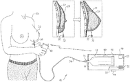
ここで図1を参照すると、同図は、本発明の実施形態による、乳房インプラント圧力チェンジャアセンブリ10の使用を示す概略図である。アセンブリ10は、アセンブリ内に流体で満たされた流体密封バッグ12を含み、このバッグは流体密封弁16で終端するチューブ14に連結される。一般的に、バッグを満たす流体は生理食塩水を含むが、幾つかの実施形態では、流体は空気を含んでもよい。アセンブリ10のユーザ20は、本明細書ではインプラントを受ける患者20とも呼ばれ、乳房切除術後に乳房22に仮インプラント24を埋め込まれている。インプラントはバルーンを含み、本明細書ではバルーン24とも呼ばれる。バルーン24は、流体密封弁32で終端するチューブ30に連結される。弁32及びチューブ30の少なくとも一部は、乳房22の外部にあり、そのため通常は比較的目立たないように設計される。
With reference to FIG. 1, the figure is a schematic diagram showing the use of the breast implant
連結チューブ34は、弁16と弁32との間を接続する。両方の弁が開放するとき、バルーン24、チューブ30、34及び14、並びにバッグ12は、密閉システム40を形成する。以下により詳細に記述するように、ユーザ20は、バッグ12の容量を変えることができ、容量の変化はシステム40内の圧力の変化をもたらす。システム40内の圧力の変化によって、バルーン24の圧力には対応する変化が形成され、次にバルーンの容量の変化をもたらす。バッグ12の容量の変化は、通常、ユーザがバッグ容量を減らすことを含み、バルーンの容量を増加させる。場合によって、ユーザ20は、例えば過剰圧力に対抗するために、バッグ12の容量を増加さることを所望してもよい。したがって、アセンブリ10は、ユーザがバッグ12の容量を増減できるように構成される。
The connecting
幾つかの実施形態では、アセンブリ10は、バッグ12の容量を変えるため、すなわち、バッグの容量を増加させるため、又はバッグの容量を減らすために、インプラントを受ける患者20が用いるスイッチ44を含む。代替的に、又は追加的に、インプラントを受ける患者20は、例えば、アセンブリ10と無線で通信するシステムコントローラ48、典型的にはスマートフォン内のアプリケーションを操作することで、遠隔システムを用いてバッグ12の容量を変えてもよい。無線通信は、一般的に、標準プロトコール、及びブルートゥース低エネルギー(BLE)のような技術を用いる。
In some embodiments, the
DCモータ50は、スピンドル56に連結され、モータが作動されるとき、スピンドル56の周りにバッグ12が巻き付き又は展開する。モータ50は、バッテリ52を電源とし、モータとバッテリはいずれもアセンブリ10内にある。圧力センサ60は、バッグ12に接続され、バッグ内の流体の圧力を測定する。また、アセンブリ10は、圧力センサ及びDCモータと通信して、バッグの巻き付け又は展開の操作を制御するアセンブリコントローラ62を含む。上述のように無線遠隔システムがアセンブリ10を操作する場合、アセンブリコントローラ62はまた、コントローラ48と無線で通信するように構成される。
The
図2は、本発明の実施形態による、部分的に分解された形態のセンブリ10の概略図である。アセンブリ10は、アセンブリベース72上に嵌合するカバー70を含み、ベースはアセンブリの操作要素を保持する。バッグ12は図2に示され、チューブ14に接続する。DCモータ50が稼働されると、歯車54を介してスピンドル56を回転させ、その結果、バッグがスピンドルに巻き付くか展開する。モータ50、歯車54、及びスピンドル56は、ベース72内に固定される。図は、展開構成にあるバッグ12を備えるアセンブリ10を示す。バッグはスピンドルに巻き付くとき、チューブ14をアセンブリの中に引き込む。バッグがスピンドルから展開するとき、通常大気圧よりも大きいバッグ内圧力は、バッグを膨張状態に維持し、バッグがアセンブリ10内を移動するのを拘束して、チューブ14をアセンブリから出す。(接続弁16は、図2には示されない。)バッテリ52及びプロセッサ62は、アセンブリベース72内に取り付けられるが、図では見られない。圧力センサ60はバッグ12に付けられるが、これも図では見られない。
FIG. 2 is a schematic view of a partially disassembled form of
図3A及び図3Bは、本発明の別の実施形態による、アセンブリベース72及びアセンブリ80の操作要素の概略図である。以下に述べる違いとは別に、アセンブリ80の操作はアセンブリ10(図1及び図2)の操作と概ね同様であり、アセンブリ10及びアセンブリ80の両方において同じ参照番号で示される要素は、構造及び動作において概ね同様である。簡略化のために、カバー70は図3A及び図3Bでは示されない。
3A and 3B are schematic views of the operating elements of the
アセンブリ10とは対照的に、アセンブリ80において、モータ50、歯車54、及びスピンドル56は、サブアセンブリ82の中に取り付けられ、サブアセンブリ82は、通常トラック86を設けることによって(そのトラック86に沿ってサブアセンブリが摺動する)、ベース72内を単一ユニットとして移動するように拘束される。図3Aは、スピンドル56に巻き付けられていないときのバッグ12を示す。図3Bは、スピンドル56に部分的に巻き付けられたときのバッグ12を示す。アセンブリ10に関して、アセンブリ80では、バッグの巻き付け又は展開は、モータ50の回転により制御される。しかしながら、サブアセンブリ82は移動できるため、バッグの巻き付きによって、サブアセンブリは図3Bの矢印84で示される方向に移動する。バッグの展開によって、サブアセンブリは矢印の方向とは反対の方向に移動する。矢印の方向とは反対の方向へのサブアセンブリの移動は、バッグ12内の流体の圧力によって支援される。チューブ14がアセンブリに出入りするアセンブリ10とは対照的に、アセンブリ80では、チューブ14は実質的に固定されて移動しない。
In
バッグ12の展開及び巻き付きの両方の間、チューブ14及び34の長さのため、並びにチューブが通常狭いために、システム40内の均圧化に通常遅延が生じる。この遅延及び一般的な安全性に対する懸念を考慮するため、アセンブリコントローラ62は一般的に、センサ60によって測定される圧力が、1010mbarのような予め設定された安全値に達するか、又は超える場合に、モータ50の動作を停止するように構成されている。モータの突発的作動と、その結果として生じるバッグ12の断続的な巻き付き又は展開を防止するため、コントローラ62は、一般的に、予め設定された圧力安全値に達したことによってモータが一旦停止すると、モータ50を再起動する前に時間遅延を提供するようにも構成されている。
During both unfolding and wrapping of the
図4は、本発明の実施形態による、圧力対時間の概略的グラフである。グラフは、インプラントを受ける患者20がバッグ12をスピンドル56に巻き付けるためにアセンブリ10又はアセンブリ80を操作する際に、センサ60によって測定された圧力の変化を示す。バッグをスピンドルに巻き付けると、システム40内、特にまずバッグ12内の圧力が増加する。したがって、初期期間T1の間、センサ60によって測定された圧力は、1010mbarの予め設定された安全値に達するまで増加し、その時点でコントローラ62はモータ50を停止させ、その結果、バッグ12はスピンドル56に巻き付かない(又はロールオフしない)。本明細書において期間T2と仮定された、予め設定された遅延期間中、システム40内は均圧化され、この期間中、モータ50は停止したままとなる。予め設定された遅延期間の終わりに、インプラントを受ける患者20がアセンブリ10又は80を作動させてバッグ12をスピンドル56に巻き付け続けていると想定すると、コントローラ62はバッグをスピンドルに更に巻き付けるためにモータ50を再起動し、その結果、期間T3の間、センサ60によって測定される圧力は、圧力安全値に達するまで再度増加し、そこでコントローラはモータを停止させる。
FIG. 4 is a schematic graph of pressure vs. time according to an embodiment of the present invention. The graph shows the change in pressure measured by the
インプラントを受ける患者20は、例えば上述の過剰圧力を軽減するために、バッグ12をスピンドル56から展開するように、アセンブリ10又はアセンブリ80を作動してもよい。この場合、モータ50による展開は、圧力が閉システム40の全体に実質的に均等なままとなるように、通常、十分ゆっくりであるように構成されている。
The patient 20 receiving the implant may actuate the
上記に述べた実施形態は一例として記載されたものであり、本発明は上記に具体的に示し、説明したものに限定されない点は理解されよう。むしろ、本発明の範囲は、上記されている種々の特徴の組み合わせ及び部分的組み合わせと、前述の説明を読むことに基づいて当業者が想起するであろう、先行技術に開示されていない変形例及び修飾との両方を含む。 It will be appreciated that the embodiments described above have been described as an example and the present invention is not limited to those specifically shown and described above. Rather, the scope of the invention is a combination and partial combination of the various features described above and variations not disclosed in the prior art that one of ordinary skill in the art would recall based on reading the above description. And with modifications.
〔実施の態様〕
(1) 装置であって、
エンクロージャと、
前記エンクロージャ内に置かれた流体密封バッグと、
前記流体密封バッグに接続された流体密封弁と、
チューブであって、前記流体密封バッグに前記流体密封弁を介して接続された第1端、及びインプラントを受ける患者に適応した乳房インプラント内のバルーンに接続された第2端を有する、チューブと、
スピンドルであって、前記エンクロージャ内に置かれ、前記流体密封バッグに接続され、かつ、前記流体密封バッグを前記スピンドルに巻き付けるように、又は前記スピンドルから前記流体密封バッグを展開するように、前記インプラントを受ける患者の制御下で回転し、それによって前記バルーン、前記チューブ、及び前記流体密封バッグ内に収容された流体を、それらの間で移送するように構成された、スピンドルと、
を備える、装置。
(2) 前記エンクロージャ内に、前記スピンドルを回転させるように前記スピンドルに接続されたモータを備える、実施態様1に記載の装置。
(3) 前記モータ及び前記スピンドルは、前記スピンドルが回転する間、前記エンクロージャ内の固定位置に留まるように構成されている、実施態様2に記載の装置。
(4) 前記エンクロージャ内にトラックを備え、前記モータ及び前記スピンドルは、前記スピンドルが回転する間、該トラックに沿って摺動するように構成されている、実施態様2に記載の装置。
(5) 前記流体密封バッグに接続されて、その中の圧力を測定する圧力センサを備える、実施態様1に記載の装置。
[Implementation mode]
(1) It is a device
Enclosure and
A fluid-sealed bag placed in the enclosure,
A fluid sealing valve connected to the fluid sealing bag and
A tube having a first end connected to the fluid seal bag via the fluid seal valve and a second end connected to a balloon in a breast implant adapted for the patient receiving the implant.
The implant, which is a spindle, placed in the enclosure, connected to the fluid seal bag, and to wrap the fluid seal bag around the spindle, or to deploy the fluid seal bag from the spindle. A spindle configured to rotate under the control of the receiving patient, thereby transferring the fluid contained in the balloon, the tube, and the fluid sealing bag between them.
A device that comprises.
(2) The apparatus according to the first embodiment, wherein the enclosure includes a motor connected to the spindle so as to rotate the spindle.
(3) The device according to embodiment 2, wherein the motor and the spindle are configured to remain in a fixed position in the enclosure while the spindle rotates.
(4) The device according to embodiment 2, wherein a track is provided in the enclosure, and the motor and the spindle are configured to slide along the track while the spindle rotates.
(5) The device according to the first embodiment, comprising a pressure sensor connected to the fluid sealing bag and measuring the pressure in the bag.
(6) 前記スピンドルを操作するように構成された前記エンクロージャ内のコントローラを備え、前記エンクロージャから離れて、前記インプラントを受ける患者の制御下に置かれて、前記コントローラと無線で通信するように構成された、更なるコントローラを更に備える、実施態様1に記載の装置。
(7) 前記流体が液体を含む、実施態様1に記載の装置。
(8) 前記流体が気体を含む、実施態様1に記載の装置。
(9) 方法であって、
エンクロージャを設けることと、
前記エンクロージャ内に流体密封バッグを置くことと、
流体密封弁を前記流体密封バッグに接続することと、
チューブの第1端を、前記流体密封バッグに前記流体密封弁を介して接続し、前記チューブの第2端を、インプラントを受ける患者に適応した乳房インプラント内のバルーンに接続することと、
前記エンクロージャ内に置かれたスピンドルを前記流体密封バッグに接続し、前記流体密封バッグを前記スピンドルに巻き付けるように、又は前記スピンドルから前記流体密封バッグを展開するように、前記インプラントを受ける患者の制御下で回転し、それによって前記バルーン、前記チューブ、及び前記流体密封バッグ内に収容された流体を、それらの間で移送するように前記スピンドルを構成することと、
を含む、方法。
(10) 前記スピンドルを回転させるように、モータを前記エンクロージャ内で前記スピンドルに接続することを含む、実施態様9に記載の方法。
(6) A controller in the enclosure configured to operate the spindle is provided, separated from the enclosure, placed under the control of the patient receiving the implant, and configured to communicate wirelessly with the controller. The device according to embodiment 1, further comprising an additional controller.
(7) The apparatus according to the first embodiment, wherein the fluid contains a liquid.
(8) The apparatus according to the first embodiment, wherein the fluid contains a gas.
(9) It is a method
Providing an enclosure and
Placing a fluid-sealed bag inside the enclosure
Connecting the fluid seal valve to the fluid seal bag and
Connecting the first end of the tube to the fluid sealing bag via the fluid sealing valve and connecting the second end of the tube to a balloon in a breast implant adapted to the patient receiving the implant.
Control of a patient receiving the implant to connect a spindle placed in the enclosure to the fluid seal bag and wrap the fluid seal bag around the spindle or to deploy the fluid seal bag from the spindle. To configure the spindle to rotate under and thereby transfer the fluid contained in the balloon, the tube, and the fluid sealing bag between them.
Including methods.
(10) The method of embodiment 9, wherein the motor is connected to the spindle in the enclosure so as to rotate the spindle.
(11) 前記モータ及び前記スピンドルは、前記スピンドルが回転する間、前記エンクロージャ内の固定位置に留まるように構成されている、実施態様10に記載の方法。
(12) 前記エンクロージャ内にトラックを設けることを含み、前記モータ及び前記スピンドルは、前記スピンドルが回転する間、該トラックに沿って摺動するように構成されている、実施態様10に記載の方法。
(13) 圧力センサを前記流体密封バッグに接続して、その中の圧力を測定することを含む、実施態様9に記載の方法。
(14) 前記エンクロージャ内でコントローラを用いて前記スピンドルを操作することを含み、前記エンクロージャから離れて、前記インプラントを受ける患者の制御下に、前記コントローラと無線で通信するように構成されている更なるコントローラを置くことを更に含む、実施態様9に記載の方法。
(15) 前記流体が液体を含む、実施態様9に記載の方法。
(11) The method according to
(12) The method of
(13) The method according to embodiment 9, wherein a pressure sensor is connected to the fluid sealing bag and the pressure in the bag is measured.
(14) Further configured to include operating the spindle with a controller within the enclosure and wirelessly communicating with the controller under the control of a patient receiving the implant away from the enclosure. 9. The method of embodiment 9, further comprising placing a controller.
(15) The method according to embodiment 9, wherein the fluid contains a liquid.
(16) 前記流体が気体を含む、実施態様9に記載の方法。 (16) The method according to embodiment 9, wherein the fluid contains a gas.
Claims (7)
エンクロージャと、
前記エンクロージャ内に置かれた流体密封バッグと、
前記流体密封バッグに接続された圧力センサと、
前記流体密封バッグに接続された流体密封弁と、
チューブであって、前記流体密封バッグに前記流体密封弁を介して接続された第1端、及び乳房インプラント内のバルーンに接続された第2端を有する、チューブと、
スピンドルであって、前記エンクロージャ内に置かれ、前記流体密封バッグに接続され、かつ、前記流体密封バッグを前記スピンドルに巻き付けるように、又は前記スピンドルから前記流体密封バッグを展開するように、それによって前記バルーン、前記チューブ、及び前記流体密封バッグ内に収容された流体を、それらの間で移送するように構成された、スピンドルと、
前記スピンドルに連結されたモータと、
設定された圧力安全値に達したときに前記モータを停止させるために前記圧力センサから信号を受信することに応答して前記モータを制御するためのコントローラと、
を備える、装置。 It ’s a device,
Enclosure and
A fluid-sealed bag placed in the enclosure,
With the pressure sensor connected to the fluid sealing bag,
A fluid sealing valve connected to the fluid sealing bag and
A tube, having said fluid tight first end connected through the fluid-tight valve in the bag, a second end connected to the balloon及Breasts tufts within the implant, the tube,
A spindle, placed in the enclosure, connected to the fluid-tight bag, and the fluid-tight bag to wrap the spindle, or to deploy the fluid seal bag from the spindle, Re their A spindle configured to transfer the fluid contained in the balloon, the tube, and the fluid sealing bag between them.
The motor connected to the spindle and
A controller for controlling the motor in response to receiving a signal from the pressure sensor to stop the motor when a set pressure safety value is reached.
A device that comprises.
Applications Claiming Priority (2)
| Application Number | Priority Date | Filing Date | Title |
|---|---|---|---|
| US201662301180P | 2016-02-29 | 2016-02-29 | |
| US62/301,180 | 2016-02-29 |
Publications (2)
| Publication Number | Publication Date |
|---|---|
| JP2017153957A JP2017153957A (en) | 2017-09-07 |
| JP6869748B2 true JP6869748B2 (en) | 2021-05-12 |
Family
ID=58212932
Family Applications (1)
| Application Number | Title | Priority Date | Filing Date |
|---|---|---|---|
| JP2017034500A Active JP6869748B2 (en) | 2016-02-29 | 2017-02-27 | Pressure changer for breast implants |
Country Status (8)
| Country | Link |
|---|---|
| US (2) | US10548712B2 (en) |
| EP (1) | EP3210570A1 (en) |
| JP (1) | JP6869748B2 (en) |
| CN (1) | CN107126300A (en) |
| AU (1) | AU2017201186B2 (en) |
| CA (1) | CA2958373A1 (en) |
| IL (1) | IL250645B (en) |
| MA (1) | MA42140A (en) |
Families Citing this family (7)
| Publication number | Priority date | Publication date | Assignee | Title |
|---|---|---|---|---|
| US10548712B2 (en) * | 2016-02-29 | 2020-02-04 | Biosense Webster (Israel) Ltd. | Pressure changer for a breast implant |
| GB2560503B (en) * | 2017-03-07 | 2019-12-11 | Gc Aesthetics Mfg Ltd | Packaging |
| GB201705707D0 (en) | 2017-04-10 | 2017-05-24 | Gc Aesthetics (Manufacturing) Ltd | Implant |
| US10751165B2 (en) | 2017-12-12 | 2020-08-25 | Mentor Worldwide Llc | Adjustable implant |
| US10751163B2 (en) | 2017-09-01 | 2020-08-25 | Mentor Worldwide Llc | Adjustable implant |
| CN109717993B (en) * | 2018-12-13 | 2021-02-05 | 云南省第一人民医院 | Rehabilitation auxiliary device after mammary gland surgery |
| CN112472413B (en) * | 2019-09-11 | 2023-06-16 | 微创视神医疗科技(上海)有限公司 | Active perfusion system for ultrasonic emulsification |
Family Cites Families (90)
| Publication number | Priority date | Publication date | Assignee | Title |
|---|---|---|---|---|
| US146805A (en) | 1874-01-27 | Improvement in breast-pads | ||
| US1091063A (en) | 1910-04-29 | 1914-03-24 | Thomas C Hutchinson | Tube-holder. |
| US1263798A (en) | 1916-12-01 | 1918-04-23 | Henry J Otto | Device for deflating tire-tubes. |
| DE2224963C3 (en) | 1972-05-23 | 1975-03-27 | Otto Thaemert, Textil Und Kunststoff Gmbh & Co Kg, 3006 Grossburgwedel | Breast prosthesis |
| US3919724A (en) * | 1974-06-07 | 1975-11-18 | Medical Eng Corp | Implantable prosthesis having a self-sealing valve |
| US3934274A (en) * | 1974-10-29 | 1976-01-27 | Hartley Jr John H | Deflatable mammary augmentation prosthesis |
| US4433440A (en) | 1979-02-26 | 1984-02-28 | Cohen I Kelman | Prosthesis formed by inner and outer inflatable containers |
| US4643733A (en) | 1983-04-04 | 1987-02-17 | Hilton Becker | Permanent reconstruction implant and method of performing human tissue expansion |
| US4624671A (en) * | 1984-06-25 | 1986-11-25 | Kress Donald W | Method of sizing and implanting breast prosthesis |
| US4615704A (en) | 1984-11-26 | 1986-10-07 | Dow Corning Corporation | Shape retention tissue expander and method of using |
| US4944749A (en) | 1985-01-23 | 1990-07-31 | Hilton Becker | Implant and inflating construction |
| US4773908A (en) | 1986-12-18 | 1988-09-27 | Hilton Becker | Filling tube and seal construction for inflatable implant |
| US4775379A (en) | 1986-12-30 | 1988-10-04 | Mentor Corporation | Self-sealing valve for fluid fillable article |
| US4790309A (en) | 1987-04-10 | 1988-12-13 | Hilton Becker | Tissue expander stent |
| IT215259Z2 (en) * | 1988-08-08 | 1990-09-11 | Marianna Calogero | EXPANDABLE PROSTHESIS FOR CORRECTIONS OF MYOPYSTROPHIES. |
| US4969899A (en) * | 1989-03-08 | 1990-11-13 | Cox-Uphoff International | Inflatable implant |
| US4938760A (en) | 1989-03-29 | 1990-07-03 | American Medical Systems, Inc. | Female suspension procedure |
| US5019101A (en) | 1989-05-31 | 1991-05-28 | Purkait Bobby K | Self-sealing valve for implantable device |
| US5181907A (en) | 1990-03-20 | 1993-01-26 | Hilton Becker | Cannula and method for liposuction |
| US5723006A (en) | 1991-02-22 | 1998-03-03 | Ledergerber; Walter J. | Breast implant introducer |
| US5219360A (en) * | 1991-05-10 | 1993-06-15 | Fortis Research Corporation | Mammary prosthesis fill and method of making same |
| US5549672A (en) * | 1991-12-26 | 1996-08-27 | Mentor Corporation | Method and apparatus for filling mammary prostheses and tissue expanders |
| GB9316403D0 (en) | 1993-08-06 | 1993-09-22 | Daton Lovett Andrew | Apparatus for varying the quantity of contents in a receptacle |
| US5882353A (en) * | 1994-04-11 | 1999-03-16 | Pmt Corporation | Mechanical tissue expander |
| US5630843A (en) * | 1994-06-30 | 1997-05-20 | Rosenberg; Paul H. | Double chamber tissue expander |
| US5507808A (en) | 1994-10-26 | 1996-04-16 | Becker; Hilton | Filling tube and seal construction |
| US6113569A (en) | 1995-12-21 | 2000-09-05 | Very Inventive Physicians | Reciprocating liposuction device |
| US5776159A (en) * | 1996-10-03 | 1998-07-07 | General Surgical Innovations, Inc. | Combination dissector and expander |
| US5845813A (en) * | 1997-06-20 | 1998-12-08 | Werner; Barry J. | Toothpaste dispenser |
| US6296150B1 (en) | 1999-02-25 | 2001-10-02 | Barry Farris | Medicinal dosing apparatus and method |
| DE19923183A1 (en) | 1999-05-21 | 2000-11-23 | Schlegel Ramona | Tube squeezer, especially for tubes containing medical products or foodstuffs, comprises two rollers, at least one of which is driven, which grip end of tube and squeeze it |
| US6183514B1 (en) | 1999-08-16 | 2001-02-06 | Hilton Becker | Self positioning breast prosthesis |
| US6540702B1 (en) | 2000-11-01 | 2003-04-01 | Maria Sarango | Breast compressing device |
| US6755861B2 (en) | 2001-10-16 | 2004-06-29 | Granit Medical Innovation, Inc. | Device for providing a portion of an organism with a desired shape |
| AU2004235622A1 (en) | 2003-12-17 | 2005-07-07 | Ethicon Endo-Surgery, Inc. | Mechanically adjustable gastric band |
| US20050284215A1 (en) | 2004-06-28 | 2005-12-29 | Falsetti Andrew E | Method and apparatus for preoperative estimation of breast implant volume |
| US20060100578A1 (en) | 2004-09-13 | 2006-05-11 | Tandem Medical, Inc. | Medication delivery apparatus and methods for intravenous infusions |
| US20080275569A1 (en) * | 2004-09-16 | 2008-11-06 | Evera Medical, Inc | Tissue Augmentation Device |
| AU2005286840B2 (en) | 2004-09-21 | 2012-01-12 | Shalon Ventures, Inc. | Tissue expansion devices |
| US7762982B1 (en) * | 2004-12-27 | 2010-07-27 | Darshan Shah | Breast implant fill device |
| US7587367B2 (en) | 2004-12-31 | 2009-09-08 | Ebay Inc. | Method and system to provide feedback data within a distributed e-commerce system |
| US20060161196A1 (en) * | 2005-01-18 | 2006-07-20 | Widgerow Alan D | Methods of and apparatus for use in medical treatment |
| US7081136B1 (en) | 2005-04-18 | 2006-07-25 | Techno Investments Llc | Adjustable gel filled mammary prosthesis and method |
| US8080057B2 (en) * | 2005-08-09 | 2011-12-20 | Steven J. Kronowitz | Methods and devices for breast reconstruction |
| US7615074B2 (en) * | 2005-08-25 | 2009-11-10 | Carvallo Edward | Method and apparatus for reconstructive surgery |
| US7798954B2 (en) | 2006-01-04 | 2010-09-21 | Allergan, Inc. | Hydraulic gastric band with collapsible reservoir |
| US20070276478A1 (en) | 2006-05-12 | 2007-11-29 | Micardia Corporation | Intraoperative and post-operative adjustment of an annuloplasty ring |
| GB0619181D0 (en) | 2006-09-29 | 2006-11-08 | Dyson Technology Ltd | Surface treating appliance |
| WO2008064173A2 (en) | 2006-11-17 | 2008-05-29 | B. Braun Medical Inc. | Antimicrobial silicone rubber injection port valves |
| KR101533855B1 (en) | 2007-05-07 | 2015-07-06 | 마렉 스지만스키 | Liquid dispensing apparatus |
| US9439745B2 (en) | 2007-10-11 | 2016-09-13 | Peter Forsell | Method for controlling flow of intestinal contents in a patient's intestines |
| CN101965164B (en) * | 2008-01-31 | 2014-12-24 | 米卢克斯控股股份有限公司 | Breast implantation material system |
| US8377128B2 (en) * | 2008-04-28 | 2013-02-19 | Allergan, Inc. | Flush patch for elastomeric implant shell |
| US7927375B2 (en) | 2008-09-12 | 2011-04-19 | Doty Keith L | Dynamic six-degrees-of-freedom intervertebral spinal disc prosthesis |
| WO2010042493A1 (en) | 2008-10-06 | 2010-04-15 | Allergan, Inc. | Mechanical gastric band with cushions |
| WO2010051506A1 (en) | 2008-10-31 | 2010-05-06 | Alure Medical, Inc. | Minimally invasive tissue support system and method with a superior tissue support and an inferior anchor |
| EP2367503A1 (en) * | 2008-11-25 | 2011-09-28 | AttenueX Technologies, Inc. | Implant with high vapor pressure medium |
| BRPI0805495A2 (en) | 2008-12-19 | 2010-09-08 | Miranda Jose Maria De | silicone implant with expandable and / or interactive compartments, whether or not lined with ricinus communis polyurethane foam and / or hydroxyapatite, with tabs or cords |
| US20100204792A1 (en) | 2009-02-11 | 2010-08-12 | Greco Richard J | Permanently Adjustable Silicone Implant |
| US8353956B2 (en) | 2009-02-17 | 2013-01-15 | Valtech Cardio, Ltd. | Actively-engageable movement-restriction mechanism for use with an annuloplasty structure |
| WO2010096449A2 (en) * | 2009-02-17 | 2010-08-26 | Pharmanova, Inc. | Implantable drug delivery devices |
| US8226724B2 (en) | 2009-06-18 | 2012-07-24 | Doty Keith L | Intervertebral spinal disc prosthesis |
| EP2453839B1 (en) | 2009-07-17 | 2014-03-12 | Kirk Promotion LTD. | Breast implant system |
| US20110106249A1 (en) | 2009-09-02 | 2011-05-05 | Hilton Becker | Self supporting and forming breast implant and method for forming and supporting an implant in a human body |
| US8197542B2 (en) | 2009-09-02 | 2012-06-12 | Hilton Becker | Self supporting implant in a human body and method for making the same without capsular contracture |
| US8202317B2 (en) | 2009-09-02 | 2012-06-19 | Hilton Becker | Self supporting and forming breast implant and method for forming and supporting an implant in a human body |
| ES2556806T3 (en) | 2009-12-18 | 2016-01-20 | Airxpanders, Inc. | Tissue expanders |
| US8454690B2 (en) * | 2009-12-22 | 2013-06-04 | William T. MCCLELLAN | Systems and methods for tissue expansion with fluid delivery and drainage system |
| US8349007B2 (en) * | 2009-12-29 | 2013-01-08 | Mentor Worldwide Llc | Breast implants having drug-eluting reservoirs and methods therefor |
| US20130245758A1 (en) * | 2010-02-05 | 2013-09-19 | Allergan, Inc. | Inflatable prostheses and methods of making same |
| ES2536055T3 (en) | 2010-03-15 | 2015-05-20 | Apollo Endosurgery, Inc. | Bariatric device and weight loss method |
| US8852276B2 (en) * | 2011-07-05 | 2014-10-07 | Lipovera, Llc | Cosmetic surgery sizer |
| US9265921B2 (en) | 2011-08-22 | 2016-02-23 | Marz Medical, Inc. | Method and system for in situ tissue expansion |
| CN104066465A (en) * | 2011-12-02 | 2014-09-24 | 赫基梅德有限公司 | A mobile infusion device |
| GB2502881B (en) | 2012-04-23 | 2016-03-16 | E Vision Smart Optics Inc | Systems, devices, and/or methods for managing implantable devices |
| US20130341353A1 (en) | 2012-06-20 | 2013-12-26 | Charles Harris | Battery operated toothpaste dispenser |
| KR101234768B1 (en) | 2012-07-27 | 2013-02-19 | 문일 | Erection assistance device |
| US20140100656A1 (en) * | 2012-10-04 | 2014-04-10 | Innovative Biologics LLC | Restorative post-lumpectomy implant device |
| US8821574B2 (en) * | 2012-12-05 | 2014-09-02 | Mentor Worldwide Llc | Valve assemblies for expandable implants and tissue expanders |
| EP3954286A1 (en) | 2013-02-21 | 2022-02-16 | Airxpanders, Inc. | Implantable tissue expanders |
| CA3107228A1 (en) | 2013-03-15 | 2014-09-18 | Implantica Patent Ltd. | Operable implant comprising an electrical motor and a gear system |
| US9744260B2 (en) * | 2013-04-12 | 2017-08-29 | Phi Nguyen | Timing controlled in-situ cross-linking of halyuronic acid during injection |
| US10226242B2 (en) | 2013-07-31 | 2019-03-12 | Nuvasive Specialized Orthopedics, Inc. | Noninvasively adjustable suture anchors |
| WO2015058051A1 (en) * | 2013-10-18 | 2015-04-23 | Mcclellan William T | Tissue expander improvements |
| AU2015204868B2 (en) * | 2014-01-07 | 2019-05-16 | Potrero Medical, Inc. | Systems, devices and methods for draining and analyzing bodily fluids |
| US20160000546A1 (en) | 2014-07-03 | 2016-01-07 | Elwha Llc | Devices, methods, and systems related to expandable implants |
| WO2016028585A1 (en) | 2014-08-18 | 2016-02-25 | St. Jude Medical, Cardiology Division, Inc. | Sensors for prosthetic heart devices |
| EP3120927A1 (en) * | 2015-07-24 | 2017-01-25 | Centre National De La Recherche Scientifique | Entangled fluidic device |
| US20180279889A1 (en) * | 2015-10-08 | 2018-10-04 | Charmcare Co., Ltd. | Wrist-worn blood pressure monitor |
| US10548712B2 (en) * | 2016-02-29 | 2020-02-04 | Biosense Webster (Israel) Ltd. | Pressure changer for a breast implant |
-
2017
- 2017-02-14 US US15/432,585 patent/US10548712B2/en not_active Expired - Fee Related
- 2017-02-16 IL IL250645A patent/IL250645B/en active IP Right Grant
- 2017-02-17 CA CA2958373A patent/CA2958373A1/en active Pending
- 2017-02-22 AU AU2017201186A patent/AU2017201186B2/en active Active
- 2017-02-27 JP JP2017034500A patent/JP6869748B2/en active Active
- 2017-02-28 EP EP17158382.6A patent/EP3210570A1/en not_active Withdrawn
- 2017-02-28 CN CN201710116233.1A patent/CN107126300A/en active Pending
- 2017-02-28 MA MA042140A patent/MA42140A/en unknown
-
2020
- 2020-02-04 US US16/781,170 patent/US11234808B2/en active Active
Also Published As
| Publication number | Publication date |
|---|---|
| AU2017201186B2 (en) | 2021-04-01 |
| IL250645A0 (en) | 2017-03-30 |
| CN107126300A (en) | 2017-09-05 |
| CA2958373A1 (en) | 2017-08-29 |
| EP3210570A1 (en) | 2017-08-30 |
| IL250645B (en) | 2020-06-30 |
| AU2017201186A1 (en) | 2017-09-14 |
| US20200170784A1 (en) | 2020-06-04 |
| US10548712B2 (en) | 2020-02-04 |
| US11234808B2 (en) | 2022-02-01 |
| US20170245980A1 (en) | 2017-08-31 |
| JP2017153957A (en) | 2017-09-07 |
| MA42140A (en) | 2018-03-28 |
Similar Documents
| Publication | Publication Date | Title |
|---|---|---|
| JP6869748B2 (en) | Pressure changer for breast implants | |
| ES2547448T3 (en) | Tissue expansion devices | |
| US6579301B1 (en) | Intragastric balloon device adapted to be repeatedly varied in volume without external assistance | |
| ES2624618T3 (en) | Tissue expander | |
| US20050065592A1 (en) | System and method of aneurism monitoring and treatment | |
| EP3284504A3 (en) | Intragastric device | |
| JP2010510838A (en) | Wound treatment device | |
| EP2533733B1 (en) | Remotely adjustable gastric banding system | |
| GB2378392A (en) | Wound irrigation/suction device | |
| US8852276B2 (en) | Cosmetic surgery sizer | |
| RU2013126242A (en) | INFLATABLE CONTROLLED CYLINDER FOR LIFTING FABRIC INSIDE THE BODY | |
| JP2017513687A (en) | Magnetically actuated arteriovenous access valve system and related method | |
| ES2555654T3 (en) | Artificial urinary sphincter system | |
| CA2909891A1 (en) | Integrated balloon catheter inflation system | |
| JP2006110193A (en) | Introduction apparatus into patient, and production method therefor | |
| US20200197590A1 (en) | Implantable fluid extraction system | |
| CN202263281U (en) | Double-press-fitting sac type drainage catheter holder | |
| EP3845255A1 (en) | Cardiac pumping assistance device | |
| ES2758301T3 (en) | Apparatus to control biomechanical adaptation between the ventricle and the aorta | |
| CN209475354U (en) | A kind of oesophageal dilator | |
| CN112912037A (en) | Method for adapting the user-side volume of a breast prosthesis | |
| JP2019528122A5 (en) | ||
| CN215425386U (en) | Adjustable medical bandage | |
| CN111328273B (en) | Occlusion cuff and implantable occlusion system including such cuff | |
| KR20160033481A (en) | Assistant Device for A Breast Surgery |
Legal Events
| Date | Code | Title | Description |
|---|---|---|---|
| A621 | Written request for application examination |
Free format text: JAPANESE INTERMEDIATE CODE: A621 Effective date: 20191127 |
|
| A977 | Report on retrieval |
Free format text: JAPANESE INTERMEDIATE CODE: A971007 Effective date: 20201014 |
|
| A131 | Notification of reasons for refusal |
Free format text: JAPANESE INTERMEDIATE CODE: A131 Effective date: 20201110 |
|
| A521 | Request for written amendment filed |
Free format text: JAPANESE INTERMEDIATE CODE: A523 Effective date: 20210204 |
|
| TRDD | Decision of grant or rejection written | ||
| A01 | Written decision to grant a patent or to grant a registration (utility model) |
Free format text: JAPANESE INTERMEDIATE CODE: A01 Effective date: 20210406 |
|
| A61 | First payment of annual fees (during grant procedure) |
Free format text: JAPANESE INTERMEDIATE CODE: A61 Effective date: 20210414 |
|
| R150 | Certificate of patent or registration of utility model |
Ref document number: 6869748 Country of ref document: JP Free format text: JAPANESE INTERMEDIATE CODE: R150 |