JP6868924B1 - Multi-directional auger bit - Google Patents
Multi-directional auger bit Download PDFInfo
- Publication number
- JP6868924B1 JP6868924B1 JP2020172348A JP2020172348A JP6868924B1 JP 6868924 B1 JP6868924 B1 JP 6868924B1 JP 2020172348 A JP2020172348 A JP 2020172348A JP 2020172348 A JP2020172348 A JP 2020172348A JP 6868924 B1 JP6868924 B1 JP 6868924B1
- Authority
- JP
- Japan
- Prior art keywords
- auger
- excavation
- tip
- directional
- inclined portion
- Prior art date
- Legal status (The legal status is an assumption and is not a legal conclusion. Google has not performed a legal analysis and makes no representation as to the accuracy of the status listed.)
- Active
Links
- 238000009412 basement excavation Methods 0.000 abstract description 89
- 238000010586 diagram Methods 0.000 abstract description 4
- 239000000463 material Substances 0.000 description 18
- 230000000694 effects Effects 0.000 description 8
- 229910000831 Steel Inorganic materials 0.000 description 7
- 239000010959 steel Substances 0.000 description 7
- 238000010276 construction Methods 0.000 description 6
- 239000002689 soil Substances 0.000 description 5
- 235000019589 hardness Nutrition 0.000 description 4
- 229910001149 41xx steel Inorganic materials 0.000 description 3
- 101001131990 Homo sapiens Peroxidasin homolog Proteins 0.000 description 3
- 102100034601 Peroxidasin homolog Human genes 0.000 description 3
- 238000000034 method Methods 0.000 description 3
- 239000002023 wood Substances 0.000 description 3
- 230000002093 peripheral effect Effects 0.000 description 2
- 238000005553 drilling Methods 0.000 description 1
- 238000005516 engineering process Methods 0.000 description 1
- 238000005493 welding type Methods 0.000 description 1
Images


Classifications
-
- E—FIXED CONSTRUCTIONS
- E21—EARTH OR ROCK DRILLING; MINING
- E21B—EARTH OR ROCK DRILLING; OBTAINING OIL, GAS, WATER, SOLUBLE OR MELTABLE MATERIALS OR A SLURRY OF MINERALS FROM WELLS
- E21B10/00—Drill bits
- E21B10/46—Drill bits characterised by wear resisting parts, e.g. diamond inserts
- E21B10/58—Chisel-type inserts
-
- E—FIXED CONSTRUCTIONS
- E21—EARTH OR ROCK DRILLING; MINING
- E21B—EARTH OR ROCK DRILLING; OBTAINING OIL, GAS, WATER, SOLUBLE OR MELTABLE MATERIALS OR A SLURRY OF MINERALS FROM WELLS
- E21B10/00—Drill bits
- E21B10/44—Bits with helical conveying portion, e.g. screw type bits; Augers with leading portion or with detachable parts
-
- E—FIXED CONSTRUCTIONS
- E21—EARTH OR ROCK DRILLING; MINING
- E21B—EARTH OR ROCK DRILLING; OBTAINING OIL, GAS, WATER, SOLUBLE OR MELTABLE MATERIALS OR A SLURRY OF MINERALS FROM WELLS
- E21B10/00—Drill bits
- E21B10/46—Drill bits characterised by wear resisting parts, e.g. diamond inserts
-
- E—FIXED CONSTRUCTIONS
- E21—EARTH OR ROCK DRILLING; MINING
- E21B—EARTH OR ROCK DRILLING; OBTAINING OIL, GAS, WATER, SOLUBLE OR MELTABLE MATERIALS OR A SLURRY OF MINERALS FROM WELLS
- E21B10/00—Drill bits
- E21B10/62—Drill bits characterised by parts, e.g. cutting elements, which are detachable or adjustable
Landscapes
- Engineering & Computer Science (AREA)
- Life Sciences & Earth Sciences (AREA)
- Geology (AREA)
- Mining & Mineral Resources (AREA)
- Mechanical Engineering (AREA)
- Physics & Mathematics (AREA)
- Environmental & Geological Engineering (AREA)
- Fluid Mechanics (AREA)
- General Life Sciences & Earth Sciences (AREA)
- Geochemistry & Mineralogy (AREA)
- Earth Drilling (AREA)
Abstract
【課題】掘削面に対して、掘削方向と孔壁方向、又は掘削方向と杭芯方向、もしくは、その全ての方向の同時掘削を行う多方向オーガービットを提供する。【解決手段】オーガーヘッドに装着される多方向オーガービット1であって、オーガーヘッドの軸方向に先端が突出した基部2と、基部と連続した脚部3,4とを備え、基部は、脚部と連続した平面部2aと、平面部から前記オーガーヘッドの軸方向、先端側に向けて傾斜した第1傾斜部2b乃至2dと、第1傾斜部から連続した左右の側面部2fと、第1傾斜部から前記オーガーヘッドの軸方向、脚部側に向けて傾斜した第2傾斜部2gとからなり、第1傾斜部、側面部、及び第2傾斜部には、第1の超硬チップが配設されており、左右の側面部の一方から第1傾斜部にわたり、第2の超硬チップが、左右の側面部に垂直な方向に突出するように配設されている多方向オーガービット1である。【選択図】図1PROBLEM TO BE SOLVED: To provide a multi-directional auger bit which simultaneously excavates an excavation surface in an excavation direction and a hole wall direction, an excavation direction and a pile core direction, or all directions thereof. SOLUTION: The multi-directional auger bit 1 mounted on an auger head includes a base 2 having a tip protruding in the axial direction of the auger head, and legs 3 and 4 continuous with the base, and the base is a leg. A flat surface portion 2a continuous with the portion, first inclined portions 2b to 2d inclined from the flat surface portion toward the tip side in the axial direction of the auger head, left and right side surface portions 2f continuous from the first inclined portion, and a first portion. It is composed of a second inclined portion 2g inclined from the first inclined portion toward the axial direction of the auger head and the leg side, and the first inclined portion, the side surface portion, and the second inclined portion have a first super hard tip. Is arranged, and a second super hard tip is arranged so as to project in a direction perpendicular to the left and right side surface portions from one of the left and right side surface portions to the first inclined portion. It is 1. [Selection diagram] Fig. 1
Description
本発明は、掘削面に対して複数方向の同時掘削を行う多方向オーガービットに関する。 The present invention relates to a multi-directional auger bit that simultaneously excavates a drilling surface in a plurality of directions.
従来、例えば、杭打機を用いた既成杭工法は、オーガーヘッドが駆動機構に接続されており、地面に建造物の基礎穴や連続地中壁体の造成穴等を掘削するものであり、オーガーヘッドの先端に設けられるオーガービットには、掘削の為の刃部が設けられている。これは、鋼管中堀工法などについても略同様である。 Conventionally, for example, in the ready-made pile construction method using a pile driver, an auger head is connected to a drive mechanism, and a foundation hole of a building, a construction hole of a continuous underground wall body, etc. are excavated in the ground. The auger bit provided at the tip of the auger head is provided with a blade for excavation. This is almost the same for the steel pipe Nakabori method.
ここで、例えば、特許文献1では、掘削刃が中央チップ及び両脇のサイドチップからなるもので、掘削頭部には、肉盛りが施された着脱式アースオーガービットが開示されている。この着脱式アースオーガービットにおいて、中央チップは、サイドチップに対して湾曲状態で突出する楔状刃を構成している。掘削刃として、掘削作用に応じて刃先部分が脱落して新しい刃先部分を再生していく自生刃機能を有するものが適用され、掘削刃は、刃部材本体に超硬合金から棒状チップが埋め込まれるものである。
Here, for example, in
しかしながら、特許文献1では、着脱構造を改善した着脱式アースオーガービット及びアースオーガを単に開示しているにすぎない。
However,
そして、オーガーヘッド用のオーガービットについて、ケーシングの外板又は内板、もしくは外板及び内板両側に取付け、掘削面に対して、掘削方向と孔壁方向、または、掘削方向と杭芯方向、もしくは、その全ての方向の同時掘削を行うものは従来存在しない。同様に、掘削翼の外側に取付け、掘削面に対して、掘削方向と孔壁方向の両方向の同時掘削を行うものは従来存在しない。 Then, the auger bit for the auger head is attached to the outer plate or inner plate of the casing, or both the outer plate and the inner plate, and with respect to the excavation surface, the excavation direction and the hole wall direction, or the excavation direction and the pile core direction, Or, there is no conventional one that performs simultaneous excavation in all the directions. Similarly, there is no conventional one that is attached to the outside of the excavation blade and simultaneously excavates the excavation surface in both the excavation direction and the hole wall direction.
本発明は、このような課題に鑑みてなされたものであり、その目的とするところは、掘削面に対して、掘削方向と孔壁方向、又は掘削方向と杭芯方向、もしくは、その全ての方向の同時掘削を行う技術を提供することにある。 The present invention has been made in view of such a problem, and an object of the present invention is the excavation direction and the hole wall direction, the excavation direction and the pile core direction, or all of them with respect to the excavation surface. The purpose is to provide technology for simultaneous excavation in directions.
上記課題を解決するために、本発明の一つの態様に係るオーガービットは、オーガーヘッドに装着されるオーガービットであって、前記オーガーヘッドの軸方向に先端が突出した基部と、前記基部と連続した脚部と、を備え、前記基部は、前記脚部と連続した平面部と、前記平面部から前記オーガーヘッドの軸方向、前記先端側に向けて傾斜した第1傾斜部と、前記第1傾斜部から連続した左右の側面部と、前記第1傾斜部から前記オーガーヘッドの軸方向、前記脚部側に向けて傾斜した第2傾斜部とからなり、前記第1傾斜部、前記側面部、及び前記第2傾斜部には、第1の超硬チップが配設されており、前記左右の側面部の一方から前記第1傾斜部にわたり、第2の超硬チップが、前記左右の側面部に垂直な方向に突出するように配設されている。 In order to solve the above problems, the auger bit according to one aspect of the present invention is an auger bit mounted on the auger head, and has a base portion whose tip protrudes in the axial direction of the auger head and is continuous with the base portion. The base portion includes a flat portion continuous with the leg portion, a first inclined portion inclined from the flat portion in the axial direction of the auger head, and the first inclined portion toward the tip side. It is composed of left and right side surface portions that are continuous from the inclined portion, and a second inclined portion that is inclined from the first inclined portion to the axial direction of the auger head and toward the leg portion side, and the first inclined portion and the side surface portion. A first super hard tip is disposed on the second inclined portion, and the second super hard tip extends from one of the left and right side surface portions to the first inclined portion, and the second super hard tip is formed on the left and right side surfaces. It is arranged so as to project in the direction perpendicular to the portion.
この態様において、前記第2の超硬チップとして、複数の超硬チップが所定間隔を隔てて、前記オーガーヘッドの軸方向に平行に配設されてもよい。 In state like this, as the second carbide inserts, a plurality of carbide inserts is at a predetermined distance, may be disposed in parallel with the axial direction of the auger head.
本発明によれば、掘削面に対して、掘削方向と孔壁方向、又は掘削方向と杭芯方向、もしくは、その全ての方向の同時掘削を行う技術を提供することができる。 According to the present invention, it is possible to provide a technique for simultaneously excavating an excavated surface in the excavation direction and the hole wall direction, the excavation direction and the pile core direction, or all the directions thereof.
以下、図面を参照しつつ、本発明の第1乃至第3実施形態に係る多方向オーガービットの構成及び作用を詳述する。 Hereinafter, the configuration and operation of the multi-directional auger bit according to the first to third embodiments of the present invention will be described in detail with reference to the drawings.
本発明の第1乃至第3の実施形態に係る多方向オーガービットは、ケーシングの外板または内板、もしくは外板及び内板両側に取付け、掘削面に対して掘削方向と孔壁方向、または掘削方向と杭芯方向、もしくは、その全ての方向の同時掘削を行うことを特徴とするものである。また、同オーガービットは、掘削翼の外側に取付け、掘削面に対して掘削方向と孔壁方向の両方向の同時掘削を行うことを特徴とするものである。 The multi-directional auger bit according to the first to third embodiments of the present invention is attached to the outer plate or inner plate of the casing, or both the outer plate and the inner plate, and is attached to the excavation surface in the excavation direction and the hole wall direction, or. It is characterized in that simultaneous excavation is performed in the excavation direction and the pile core direction, or in all directions thereof. Further, the auger bit is attached to the outside of the excavation blade and is characterized in that the excavation surface is simultaneously excavated in both the excavation direction and the hole wall direction.
上記作用を実現するために、多方向オーガービットは、掘削方向と孔壁方向、または掘削方向と杭芯方向にそれぞれ超硬チップが装着されている。掘削方向、孔壁方向、杭芯方向に装着される超硬チップの大きさ、形状、取付角度、及び個数は、掘削対象に合わせて適宜変更可能である。また、超硬チップの硬さは、掘削方向、孔壁方向、杭芯方向、それぞれ掘削対象に合わせて選択可能である。このほか、多方向オーガービットの取付方式は、脱着式(第1及び第2実施形態)、溶接式(第3実施形態)のいずれでもよい。以下、第1乃至第3実施形態について詳述する。 In order to realize the above operation, the multi-directional auger bit is equipped with carbide chips in the excavation direction and the hole wall direction, or in the excavation direction and the pile core direction, respectively. The size, shape, mounting angle, and number of cemented carbide tips mounted in the excavation direction, the hole wall direction, and the pile core direction can be appropriately changed according to the excavation target. Further, the hardness of the cemented carbide tip can be selected in the excavation direction, the hole wall direction, and the pile core direction, respectively, according to the excavation target. In addition, the mounting method of the multi-directional auger bit may be either a removable type (first and second embodiments) or a welding type (third embodiment). Hereinafter, the first to third embodiments will be described in detail.
<第1実施形態> <First Embodiment>
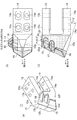
図1には、本発明の第1実施形態に係る多方向オーガービットの構成を示し説明する。より詳細には、図1(a)は、同オーガービットの斜視図、図1(b)は平面図、図1(c)は側面図である。尚、図1(a)では各部の構成を明確に示すために、硬質肉盛の図示を省略している。 FIG. 1 shows and describes a configuration of a multi-directional auger bit according to the first embodiment of the present invention. More specifically, FIG. 1A is a perspective view of the auger bit, FIG. 1B is a plan view, and FIG. 1C is a side view. In addition, in FIG. 1A, the illustration of the hard overlay is omitted in order to clearly show the structure of each part.
これらの図に示されるように、多方向オーガービット1は、基部2と当該基部2から延びた2本の脚部3、4で構成されている。第1実施形態では、基部2側を、オーガービット1の先端とも称し、脚部3、4側を、オーガーヘッドへの装着側又はオーガービット1の後端とも称する。また、先端が向いている方向が掘削方向であり、当該掘削方向に垂直な方向が孔壁方向又は杭芯方向となる。
As shown in these figures, the
ここで、杭芯方向とは、基礎工事に使用する既成杭、場所打ち杭、鋼管杭等のあらゆる杭工事における「杭の中心」であり、種々の杭の引抜き工事、障害物撤去工事等に使用するケーシング及び掘削翼の中心部を意味する。一方、孔壁方向とは、基礎工事に使用する既成杭、場所打ち杭、鋼管杭等のあらゆる杭工事における杭の外周側及び、種々の杭の引抜き工事、障害物撤去工事に使用するケーシング及び掘削翼の外周側、すなわち、地盤もしくは障害物を掘削して構築した地中孔の孔壁を意味する。 Here, the pile core direction is the "center of the pile" in all pile works such as ready-made piles, cast-in-place piles, and steel pipe piles used for foundation work, and is used for pulling out various piles, removing obstacles, etc. Means the center of the casing and excavation blades used. On the other hand, the hole wall direction refers to the outer peripheral side of piles in all pile works such as ready-made piles, cast-in-place piles, steel pipe piles used for foundation work, and casings used for pulling out various piles and removing obstacles. It means the outer peripheral side of the excavation blade, that is, the hole wall of the underground hole constructed by excavating the ground or an obstacle.
基部2は、オーガーヘッドの軸方向、多方向オーガービット1の先端側に向けて頂部が突出した所謂山型形状となっている。より具体的には、多方向オーガービット1の基部2の平面部2aは、脚部3、4の平面と平行となっており、基部2の平面部2aには、オーガーヘッドの軸方向、先端側に向けて傾斜した3つの傾斜部2b、2c、2dが連続している。
The
この例では、傾斜部2bは、オーガーヘッドの軸方向、先端側から見て左端が側面部2eと連続しており、傾斜部2dは、オーガーヘッドの軸方向、先端側から見て右端が側面部2fと連続している。
In this example, the
基部2の傾斜部2b、2c、2dは、オーガーヘッドの軸方向、先端側から見て横方向に、つまりオーガーヘッドの周方向に、この順で連続している。第1実施形態例では、傾斜部2bは、傾斜部2cに対してオーガーヘッドの周方向に向けて傾斜しており、傾斜部2dは、傾斜部2cに対してオーガーヘッドの周方向(傾斜部2bの傾斜方向とは逆方向)に向けて傾斜している。
The
基部2の傾斜部2b、2c、2dの下端は、傾斜部2gに連続している。基部2の傾斜部2gは、基部2の平面部2aと平行な平面に対して17.5度で、オーガーヘッドの軸方向、多方向オーガービット1の後端側、つまりオーガービット1のオーガーヘッドへの装着側に向けて傾斜している。基部2には、硬質肉盛7が配設されている。
The lower ends of the
脚部3、4は、所定間隔を隔てて、平行に、且つ側面から見た様子がコの字状となるように、基部2からオーガーヘッドの軸方向、後端側に向けて延びている。この脚部3、4には、オーガーヘッドに多方向オーガービット1をボルト等で装着するための、各4つの孔部3a、4aが設けられている。
The
多方向オーガービット1の基部2の傾斜部2b、2c、2dには、その下部において、第1の超硬チップ5が配設されている。第1の超硬チップ5によれば、当り面外側の摩耗を防できる。さらに、多方向オーガービット1の基部2の傾斜部2dから側面部2fにわたり、第2の超硬チップ6が設けられている。第2の超硬チップ6は、所謂山型形状であって、その頂部が孔壁方向または杭芯方向に向いている。ここで、孔壁方向、杭芯方向とは、掘削方向に垂直な方向である。したがって、多方向オーガービット1をケーシングの外板に配置した場合には、第2の超硬チップ6は孔壁方向を向き、内板に配置した場合には、第2の超硬チップ6は杭芯方向を向くことになる。この第1及び第2の超硬チップ5、6の材種及び硬度は、掘削対象の地盤又は障害に応じて自由に組み合わせ可能としている。
A first cemented
ここで、各部の材質について言及すると、基部2、脚部3、4の母材は、SCM440(クロモリ鋼)等を採用することができる。そして、第1及び第2の超硬チップ5、6としては、JIS使用分類記号でいうE3(材質名MG30)、E4(材質名MG40)、E5(材質名MG50)、E6(材質名MG60)等やCIS規格のG4(CIS材種記号VC−40)、G5(CIS材種記号VC−50)等を採用することができる。但し、これには限定されないことは勿論である。
Here, referring to the material of each part, SCM440 (chromoly steel) or the like can be adopted as the base material of the
以上説明したように、本発明の第1実施形態に係る多方向オーガービットによれば、掘削面に対して、掘削方向と孔壁方向、または掘削方向と杭芯方向、もしくは、その全ての方向の同時掘削を行うことが可能となる。 As described above, according to the multi-directional auger bit according to the first embodiment of the present invention, the excavation direction and the hole wall direction, the excavation direction and the pile core direction, or all directions thereof with respect to the excavation surface. It is possible to perform simultaneous excavation.
<第2実施形態> <Second Embodiment>
図2には、本発明の第2実施形態に係る多方向オーガービットの構成を示し説明する。より詳細には、図2(a)は、同オーガービットの斜視図、図2(b)は平面図、図2(c)は側面図である。尚、図2(a)では各部の構成を明確に示すために、硬質肉盛の図示を省略している。 FIG. 2 shows and describes a configuration of a multi-directional auger bit according to a second embodiment of the present invention. More specifically, FIG. 2A is a perspective view of the auger bit, FIG. 2B is a plan view, and FIG. 2C is a side view. In addition, in FIG. 2A, the illustration of the hard overlay is omitted in order to clearly show the structure of each part.
これらの図に示されるように、多方向オーガービット11は、基部12と当該基部12から延びた2本の脚部13、14で構成されている。第2実施形態では、基部12側を、多方向オーガービット11の先端とも称し、脚部13、14側を、オーガーヘッドへの装着側又は多方向オーガービット11の後端とも称する。また、先端が向いている方向が掘削方向であり、当該掘削方向に垂直な方向が孔壁方向又は杭芯方向となる。
As shown in these figures, the
基部12は、オーガーヘッドの軸方向、多方向オーガービット11の先端側に向けて頂部が突出した所謂山型形状となっている。より具体的には、多方向オーガービット11の基部12の平面部12aは、脚部13、14の平面と平行となっており、基部12の平面部12aには、オーガーヘッドの軸方向、先端側に向けて傾斜した3つの傾斜部12b、12c、12dが連続している。
The
この例では、傾斜部12bは、オーガーヘッドの軸方向、先端側から見て左端が側面部12eと連続しており、傾斜部12dは、オーガーヘッドの軸方向、先端側から見て右端が側面部12fと連続している。
In this example, the
基部12の傾斜部12b、12c、12dは、オーガーヘッドの軸方向、先端側から見て横方向に、つまりオーガーヘッドの周方向に、この順で連続している。第2実施形態では、傾斜部12bは、傾斜部12cに対してオーガーヘッドの周方向に向けて傾斜しており、傾斜部12dは、傾斜部12cに対してオーガーヘッドの周方向(傾斜部12bの傾斜方向とは逆方向)に向けて傾斜している。
The
基部12の傾斜部12b、12c、12dの下端は、傾斜部12gに連続している。基部12の傾斜部12gは、基部12の平面部12aと平行な平面に対して17.5度でオーガーヘッドの軸方向、オーガービット1の後端側、つまり多方向オーガービット11のオーガーヘッドへの装着側に向けて傾斜している。基部12には、硬質肉盛18が配設されている。
The lower ends of the
脚部13、14は、所定間隔を隔てて、平行に、且つ側面から見た様子がコの字状となるように、基部12からオーガーヘッドの軸方向、後端側に向けて延びている。この脚部13、14には、オーガーヘッドに多方向オーガービット11をボルト等で装着するための、各4つの孔部13a、14aが設けられている。
The
多方向オーガービット11の基部12の傾斜部12b、12c、12dには、その下部において、第1の超硬チップ15が配設されている。第1の超硬チップ15によれば、当り面外側の摩耗を防できる。さらに、多方向オーガービット11の基部12の傾斜部12dから側面部12fにわたり、2つの第2の超硬チップ16、17が、オーガーヘッドの軸方向、後端側に向けて所定間隔をあけて平行に設けられている。第2の超硬チップ16、17は、所謂山型形状であって、その頂部が孔壁方向または杭芯方向に向いている。ここで、孔壁方向、杭芯方向とは、掘削方向に垂直な方向である。したがって、多方向オーガービット11をケーシングの外板に配置した場合には、第2の超硬チップ16、17は孔壁方向を向くことになり、内板に配置した場合には、第2の超硬チップ16、17は杭芯方向を向くことになる。第1及び第2の超硬チップ15、16、17の材種及び硬度は、掘削対象の地盤又は障害に応じて自由に組み合わせ可能としている。
A first cemented
ここで、各部の材質について言及すると、基部12、脚部13、14の母材は、SCM440(クロモリ鋼)等を採用することができる。そして、第1及び第2の超硬チップ15、16、17としては、JIS使用分類記号でいうE3(材質名MG30)、E4(材質名MG40)、E5(材質名MG50)、E6(材質名MG60)等やCIS規格のG4(CIS材種記号VC−40)、G5(CIS材種記号VC−50)等を採用することができる。但し、これには限定されない。
Here, referring to the material of each part, SCM440 (chromoly steel) or the like can be adopted as the base material of the
以上説明したように、本発明の第2実施形態に係るオーガービットによれば、掘削面に対して、掘削方向と孔壁方向、または掘削方向と杭芯方向、もしくは、その全ての方向の同時掘削を行うことが可能となる。 As described above, according to the auger bit according to the second embodiment of the present invention, the excavation direction and the hole wall direction, the excavation direction and the pile core direction, or all the directions at the same time with respect to the excavation surface. It becomes possible to excavate.
<第3実施形態> <Third Embodiment>
図3には、本発明の第3実施形態に係る多方向オーガービットの構成を示し説明する。より詳細には、図3(a)は、同多方向オーガービットの斜視図、図3(b)は平面図、図3(c)は側面図である。尚、図3(a)では各部の構成を明確に示すために、硬質肉盛の図示を省略している。 FIG. 3 shows and describes a configuration of a multi-directional auger bit according to a third embodiment of the present invention. More specifically, FIG. 3A is a perspective view of the multi-directional auger bit, FIG. 3B is a plan view, and FIG. 3C is a side view. In addition, in FIG. 3A, the illustration of the hard overlay is omitted in order to clearly show the structure of each part.
これらの図に示されるように、多方向オーガービット21は、基部22と当該基部22から延びた脚部(溶接部ともいう)23で構成されている。第1実施形態では、基部22側をオーガービット21の先端とも称し、溶接部23側を、オーガーヘッドへの装着側又はオーガービット21の後端とも称する。また、先端が向いている方向が掘削方向であり、当該掘削方向に垂直な方向が孔壁方向又は杭芯方向となる。
As shown in these figures, the
基部22は、オーガーヘッドの軸方向、多方向オーガービット21の先端側に向けて頂部が突出した所謂山型形状となっている。より具体的には、多方向オーガービット21の基部22の平面部22aは、脚部23の平面と平行となっており、基部22の平面部22aには、オーガーヘッドの軸方向、先端側に向けて傾斜した3つの傾斜部22b、22c、22dが連続している。
The
この例では、傾斜部22bは、オーガーヘッドの軸方向、先端側から見て左端が側面部22eと連続しており、傾斜部22dは、オーガーヘッドの軸方向、先端側から見て右端が側面部22fと連続している。
In this example, the
基部22の傾斜部22b、22c、22dは、オーガーヘッドの軸方向、先端側から見て横方向に、つまりオーガーヘッドの周方向に、この順で連続している。第3実施形態では、傾斜部22bは、傾斜部22cに対してオーガーヘッドの周方向に向けて傾斜しており、傾斜部22dは、傾斜部22cに対してオーガーヘッドの周方向(傾斜部22bの傾斜方向とは逆方向)に向けて傾斜している。
The
基部22の傾斜部22b、22c、22dの下端は、傾斜部22gに連続している。基部22の傾斜部22gは、基部22の平面部22aと平行な平面に対して15度で、オーガーヘッドの軸方向、オーガービット21の後端側、つまりオーガービット21のオーガーヘッドへの装着側に向けて傾斜している。基部22には、硬質肉盛27が配設されている。基部22より後端方向に延出している脚部23は、オーガービット1をオーガーヘッドに固定する際に、溶接される部分である。
The lower ends of the
多方向オーガービット21の基部22の傾斜部22b、22c、22dには、その下部において、第1の超硬チップ25が配設されている。第1の超硬チップ25によれば、当り面外側の摩耗を防できる。さらに、多方向オーガービット21の基部22の傾斜部22dから側面部22fにわたり、第2の超硬チップ26が設けられている。第2の超硬チップ26は、所謂山型形状であって、その頂部が孔壁方向または杭芯方向に向いている。ここで、孔壁方向、杭芯方向とは、掘削方向に垂直な方向である。したがって、多方向オーガービット21をケーシングの外板に配置した場合には、第2の超硬チップ26は孔壁方向を向き、内板に配置した場合には、第2の超硬チップ26は杭芯方向を向くことになる。第1及び第2の超硬チップ25、26の材種及び硬度は、掘削対象の地盤又は障害に応じて自由に組み合わせ可能としている。
A first cemented
ここで、各部の材質について言及すると、基部22、脚部23の母材としては、SCM440(クロモリ鋼)等を採用することができる。第1及び第2の超硬チップ25、26としては、JIS使用分類記号でいうE3(材質名MG30)、E4(材質名MG40)、E5(材質名MG50)、E6(材質名MG60)等やCIS規格のG4(CIS材種記号VC−40)、G5(CIS材種記号VC−50)等を採用することができる。但し、これには限定されないことは勿論である。
Here, referring to the material of each part, SCM440 (chromoly steel) or the like can be adopted as the base material of the
以上説明したように、本発明の第3実施形態に係る多方向オーガービットによれば、掘削面に対して、掘削方向と孔壁方向、または掘削方向と杭芯方向、もしくは、その全ての方向の同時掘削を行うことが可能となる。 As described above, according to the multi-directional auger bit according to the third embodiment of the present invention, the excavation direction and the hole wall direction, the excavation direction and the pile core direction, or all directions thereof with respect to the excavation surface. It is possible to perform simultaneous excavation.
次に、図4には、本発明の第1及び第2の多方向オーガービットのケーシングへの取付けの様子を示し、その効果を詳細に説明する。より詳細には、図4(a)は、取付けの様子を示す斜視図、図4(b)は取付けの様子を示す平面図、図4(c)は取付けの様子を示す側面図である。 Next, FIG. 4 shows how the first and second multi-directional auger bits of the present invention are attached to the casing, and the effects thereof will be described in detail. More specifically, FIG. 4 (a) is a perspective view showing the state of mounting, FIG. 4 (b) is a plan view showing the state of mounting, and FIG. 4 (c) is a side view showing the state of mounting.
これらの図に示されるように、多方向オーガービットをケーシングの外板に取付けて使用する場合には、掘削方向に装着した第1の超硬チップが掘削方向を掘削しながら、孔壁方向側に装着した第2の超硬チップが、孔壁側からの土圧と摩擦を緩和すると同時に、杭径のサイズアップを行う。尚、杭径のサイズアップは、孔壁方向に装着する第2の超硬チップのサイズを任意に変更することで可能である。 As shown in these figures, when the multi-directional auger bit is attached to the outer plate of the casing and used, the first carbide tip mounted in the excavation direction excavates the excavation direction and the hole wall direction side. The second cemented carbide tip attached to the hole alleviates the earth pressure and friction from the hole wall side, and at the same time, increases the size of the pile diameter. The size of the pile diameter can be increased by arbitrarily changing the size of the second cemented carbide tip mounted in the hole wall direction.
そして、孔壁方向側に装着した第2の超硬チップが、掘削方向に装着した第1の超硬チップが掘削した掘削土を、掘削面から上方へと掻き上げる補助をすることにより、ケーシングの先端に掛かる土圧と摩擦を緩和し、掘削効率を上げる。 Then, the second cemented carbide tip mounted on the hole wall direction side assists the excavated soil excavated by the first cemented carbide tip mounted in the excavation direction to be scraped upward from the excavated surface, thereby causing the casing. It relieves the earth pressure and friction applied to the tip of the excavation and improves excavation efficiency.
さらに、孔壁方向側に装着した第2の超硬チップが孔壁を掘削する際、回転方向側にネジ込み効果を与え、掘削力が増す。 Further, when the second cemented carbide tip mounted on the hole wall direction side excavates the hole wall, it gives a screwing effect on the rotation direction side, and the excavation force is increased.
また、障害撤去掘削においては、掘削方向に装着した第2の超硬チップが掘削した更に外側を、孔壁方向に装着した第2の超硬チップが掘削することにより、より幅の広い掘削幅が確保できる為、当該多方向オーガービットの取付けのみでサイズアップした障害撤去掘削が可能となる。 Further, in the obstacle removal excavation, a wider excavation width is obtained by excavating the outer side of the excavation by the second cemented carbide chip mounted in the excavation direction by the second cemented carbide chip mounted in the hole wall direction. Therefore, it is possible to remove obstacles and excavate the size by simply installing the multi-directional auger bit.
そして、孔壁方向に装着する第2の超硬チップの数量に変化を付けることにより、掘削経路(パス)が均一になるので、杭径のサイズアップ効果もしくは、障害撤去径のサイズアップ効果が上がる。例えば、同図の例では、孔壁方向に装着する第2の超硬チップが1個の多方向オーガービット1と2個の多方向オーガービット11を交互に取付けている。
Then, by changing the number of the second cemented carbide chips to be mounted in the hole wall direction, the excavation path (path) becomes uniform, so that the effect of increasing the size of the pile diameter or the effect of increasing the size of the obstacle removal diameter can be obtained. Go up. For example, in the example of the figure, the second cemented carbide tip mounted in the hole wall direction alternately mounts one
さらに、孔壁方向側に第2の超硬チップを装着することにより、ケーシングの外側に掛かる負荷が低減される為、ケーシング自体の耐久性が上がる。 Further, by mounting the second cemented carbide tip on the hole wall direction side, the load applied to the outside of the casing is reduced, so that the durability of the casing itself is improved.
一方、ケーシングの内板にオーガービットを取付けて使用する場合には、掘削方向に装着した第1の超硬チップが掘削方向を掘削しながら、杭芯方向側に装着した第2の超硬チップが、杭芯側からの土圧と摩擦を緩和する。 On the other hand, when the auger bit is attached to the inner plate of the casing and used, the first carbide tip attached in the excavation direction excavates the excavation direction and the second carbide tip attached to the pile core direction side. However, the earth pressure and friction from the pile core side are alleviated.
そして、杭芯方向側に装着した第2の超硬チップが、掘削方向側に装着した第1の超硬チップが掘削した掘削土を掘削面から上方へと掻き上げる補助をすることにより、ケーシングの先端に掛かる土圧と摩擦を緩和し、掘削効率を上げると同時に、ケーシングの内側の掘削土の取出し効率が上がる。 Then, the second superhard tip mounted on the pile core direction side assists the excavated soil excavated by the first superhard tip mounted on the excavation direction side to be scraped upward from the excavated surface, thereby causing the casing. The earth pressure and friction applied to the tip of the sill are alleviated to improve the excavation efficiency, and at the same time, the efficiency of excavated soil inside the casing is increased.
さらに、杭芯方向側に装着した第2の超硬チップがケーシングの内側を掘削する際、回転方向側にネジ込み効果を与え、掘削力が増す。 Further, when the second cemented carbide tip mounted on the pile core direction side excavates the inside of the casing, it gives a screwing effect on the rotation direction side, and the excavation force is increased.
また、障害撤去掘削においては、掘削方向に装着した第1の超硬チップが掘削した更に内側を、杭芯方向に装着した第2の超硬チップが掘削することにより、より幅の広い掘削幅が確保できる為、当該オーガービットの取付けのみで、ケーシングの内側の障害物のサイズダウンが可能となり、ケーシングの内側の障害物の取出し効率が上がる。尚、障害物のサイズダウンは、杭芯方向に装着する第2の超硬チップのサイズを任意に変更することで可能である。 Further, in the obstacle removal excavation, a wider excavation width is obtained by excavating the inside of the excavation by the first cemented carbide chip mounted in the excavation direction by the second cemented carbide tip mounted in the pile core direction. Therefore, the size of the obstacle inside the casing can be reduced only by attaching the auger bit, and the efficiency of taking out the obstacle inside the casing is improved. The size of the obstacle can be reduced by arbitrarily changing the size of the second cemented carbide tip mounted in the direction of the pile core.
そして、杭芯方向に装着する第2の超硬チップの数量に変化を付けることにより、掘削経路(パス)が均一になるので、掘削土及び障害物の取出し効果が更に向上する。例えば同図の例では、杭芯方向に装着するチップが1個の多方向オーガービット1と2個の多方向オーガービット11を交互に取付けている。
Then, by changing the number of the second cemented carbide chips to be mounted in the pile core direction, the excavation path (path) becomes uniform, so that the effect of removing the excavated soil and obstacles is further improved. For example, in the example of the figure, one
さらに、杭芯方向側に第2の超硬チップを装着することにより、ケーシングの内側に掛かる負荷が低減される為、ケーシング自体の耐久性が上がる。 Further, by mounting the second cemented carbide tip on the pile core direction side, the load applied to the inside of the casing is reduced, so that the durability of the casing itself is improved.
次に、図5には、本発明の第1及び第2の多方向オーガービットのスクリュー形状のオーガーヘッド(掘削翼ともいう)の外側への取付けの様子を示し、その効果を説明する。尚、図5(a)は多方向オーガービットのオーガーヘッドへの取付けの様子を示す側面図であり、図5(b)は多方向オーガービットのオーガーヘッドへの取付けの様子を示す平面図である。 Next, FIG. 5 shows how the first and second multi-directional auger bits of the present invention are attached to the outside of the screw-shaped auger head (also referred to as an excavation blade), and the effect thereof will be described. 5 (a) is a side view showing how the multi-directional auger bit is attached to the auger head, and FIG. 5 (b) is a plan view showing how the multi-directional auger bit is attached to the auger head. is there.
これらの図に示されるように、多方向オーガービットを掘削翼の外側に取付けて使用する場合には、掘削方向に装着した第1の超硬チップが掘削方向を掘削しながら、孔壁方向側に装着した第2の超硬チップが、孔壁側からの土圧と摩擦を緩和すると同時に、杭径のサイズアップを行う。尚、杭径のサイズアップは、孔壁方向に装着する第2のチップのサイズを任意に変更することで可能である。 As shown in these figures, when the multi-directional auger bit is attached to the outside of the excavation blade and used, the first carbide tip mounted in the excavation direction excavates the excavation direction and the hole wall direction side. The second carbide tip attached to the hole alleviates the earth pressure and friction from the hole wall side, and at the same time, increases the size of the pile diameter. The size of the pile diameter can be increased by arbitrarily changing the size of the second tip to be mounted in the hole wall direction.
そして、孔壁方向側に装着した第2の超硬チップが孔壁を掘削する際、回転方向側に更にネジ込み効果を与える為、掘削方向に対する食い込み力が増し、掘削効率が上がる。 Then, when the second cemented carbide tip mounted on the hole wall direction side excavates the hole wall, the screwing effect is further given to the rotation direction side, so that the biting force in the excavation direction is increased and the excavation efficiency is improved.
さらに、掘削方向と孔壁方向の両方に装着した第1及び第2のチップが同時に掘削を行うことにより、掘削翼のスパイラルに掻き上げられる掘削土量が増し、掘削効率が向上する。そして、孔壁方向側に第2の超硬チップを装着することにより、掘削翼に掛かる負荷が低減される為、掘削翼自体の耐久性が上がる。 Further, by simultaneously excavating the first and second tips mounted in both the excavation direction and the hole wall direction, the amount of excavated soil scraped up by the spiral of the excavation blade is increased, and the excavation efficiency is improved. By mounting the second cemented carbide tip on the hole wall direction side, the load applied to the excavation blade is reduced, so that the durability of the excavation blade itself is improved.
以上、本発明の第1乃至第3実施形態について説明したが、本発明はこれに限定されることなくその趣旨を逸脱しない範囲で種々の改良・変更が可能である。 Although the first to third embodiments of the present invention have been described above, the present invention is not limited to this, and various improvements and changes can be made without departing from the spirit of the present invention.
例えば、本実施形態に係るケーシングオーガ用の多方向オーガービットは、例えば、既成杭工法や鋼管中堀工法等を用いた工事に用いることができ、これら工事の際に、超硬チップの欠け、滑落、及び摩耗が従来に比べて少なくなる。
尚、本発明には、以下の態様も含まれる。
すなわち、オーガーヘッドに装着される多方向オーガービットであって、前記オーガーヘッドの軸方向に先端が突出した基部を備え、前記基部の先端に、掘削方向に突出した第1の超硬チップと、孔壁又は杭芯方向に突出した第2の超硬チップを配設置した多方向オーガービット、である。
For example, the multi-directional auger bit for the casing auger according to the present embodiment can be used for construction using, for example, a prefabricated pile construction method, a steel pipe middle moat construction method, or the like, and during these constructions, the cemented carbide tip is chipped or slips off. , And wear is less than before.
The present invention also includes the following aspects.
That is, a multi-directional auger bit mounted on the auger head, the first cemented carbide tip having a base portion having a tip protruding in the axial direction of the auger head and protruding in the excavation direction at the tip of the base portion. A multi-directional auger bit in which a second cemented carbide chip protruding in the hole wall or pile core direction is arranged and installed.
1…多方向オーガービット、2…基部、2a…平面部、2b,2c,2d…傾斜部、2e,2f…側面部、2g…傾斜部、3…脚部、3a…孔部、4…脚部、4a…孔部、5…超硬チップ、6…超硬チップ、7…硬質肉盛、11…多方向オーガービット、12…基部、12a…平面部、12b,12c,12d…傾斜部、12e,12f…側面部、12g…傾斜部、13…脚部、13a…孔部、14…脚部、14a…孔部、15…超硬チップ、17…超硬チップ、18…硬質肉盛、21…多方向オーガービット、22…基部、22a…平面部、22b,22c,22d…傾斜部、22e,22f…側面部、22g…傾斜部、23…脚部、25…超硬チップ、26…超硬チップ、27…硬質肉盛。 1 ... Multi-directional auger bit, 2 ... Base, 2a ... Flat part, 2b, 2c, 2d ... Inclined part, 2e, 2f ... Side part, 2g ... Inclined part, 3 ... Leg part, 3a ... Hole part, 4 ... Leg Part, 4a ... Hole, 5 ... Carbide tip, 6 ... Carbide tip, 7 ... Hard overlay, 11 ... Multi-directional auger bit, 12 ... Base, 12a ... Flat part, 12b, 12c, 12d ... Inclined part, 12e, 12f ... Side surface, 12g ... Inclined, 13 ... Leg, 13a ... Hole, 14 ... Leg, 14a ... Hole, 15 ... Carbide tip, 17 ... Carbide tip, 18 ... Hard overlay, 21 ... Multi-directional auger bit, 22 ... Base, 22a ... Flat surface, 22b, 22c, 22d ... Inclined portion, 22e, 22f ... Side surface, 22g ... Inclined portion, 23 ... Leg, 25 ... Carbide tip, 26 ... Carbide tip, 27 ... Hard overlay.
Claims (2)
前記オーガーヘッドの軸方向に先端が突出した基部と、
前記基部と連続した脚部と、を備え、
前記基部は、前記脚部と連続した平面部と、前記平面部から前記オーガーヘッドの軸方向、前記先端側に向けて傾斜した第1傾斜部と、前記第1傾斜部から連続した左右の側面部と、前記第1傾斜部から前記オーガーヘッドの軸方向、前記脚部側に向けて傾斜した第2傾斜部とからなり、
前記第1傾斜部、前記側面部、及び前記第2傾斜部には、第1の超硬チップが配設されており、前記左右の側面部の一方から前記第1傾斜部にわたり、第2の超硬チップが、前記左右の側面部に垂直な方向に突出するように配設されている
多方向オーガービット。 It is a multi-directional auger bit attached to the auger head.
A base whose tip protrudes in the axial direction of the auger head, and
The base is provided with continuous legs.
The base portion includes a flat surface portion continuous with the leg portion, a first inclined portion inclined from the flat surface portion in the axial direction of the auger head and toward the tip end side, and left and right side surfaces continuous from the first inclined portion. It is composed of a portion and a second inclined portion that is inclined from the first inclined portion toward the axial direction of the auger head and the leg side.
A first cemented carbide tip is disposed on the first inclined portion, the side surface portion, and the second inclined portion, and the second inclined portion extends from one of the left and right side surface portions to the first inclined portion. A multi-directional auger bit in which a carbide tip is arranged so as to project in a direction perpendicular to the left and right side surface portions.
請求項1に記載の多方向オーガービット。 The multi-directional auger bit according to claim 1 , wherein as the second cemented carbide tip, a plurality of cemented carbide tips are arranged in parallel with the axial direction of the auger head at predetermined intervals.
Priority Applications (7)
| Application Number | Priority Date | Filing Date | Title |
|---|---|---|---|
| JP2020172348A JP6868924B1 (en) | 2020-10-13 | 2020-10-13 | Multi-directional auger bit |
| JP2021063909A JP2022064272A (en) | 2020-10-13 | 2021-04-05 | Multi-directional auger bit |
| PCT/JP2021/036552 WO2022080161A1 (en) | 2020-10-13 | 2021-10-04 | Multidirectional auger bit |
| CN202180040862.5A CN115698461A (en) | 2020-10-13 | 2021-10-04 | Multidirectional drill block |
| EP21879901.3A EP4230836A1 (en) | 2020-10-13 | 2021-10-04 | Multidirectional auger bit |
| KR1020227044167A KR20230011400A (en) | 2020-10-13 | 2021-10-04 | multi-directional auger bit |
| US17/993,407 US20230091613A1 (en) | 2020-10-13 | 2022-11-23 | Multidirectional auger bit |
Applications Claiming Priority (1)
| Application Number | Priority Date | Filing Date | Title |
|---|---|---|---|
| JP2020172348A JP6868924B1 (en) | 2020-10-13 | 2020-10-13 | Multi-directional auger bit |
Related Child Applications (1)
| Application Number | Title | Priority Date | Filing Date |
|---|---|---|---|
| JP2021063909A Division JP2022064272A (en) | 2020-10-13 | 2021-04-05 | Multi-directional auger bit |
Publications (2)
| Publication Number | Publication Date |
|---|---|
| JP6868924B1 true JP6868924B1 (en) | 2021-05-12 |
| JP2022063934A JP2022063934A (en) | 2022-04-25 |
Family
ID=75801803
Family Applications (2)
| Application Number | Title | Priority Date | Filing Date |
|---|---|---|---|
| JP2020172348A Active JP6868924B1 (en) | 2020-10-13 | 2020-10-13 | Multi-directional auger bit |
| JP2021063909A Pending JP2022064272A (en) | 2020-10-13 | 2021-04-05 | Multi-directional auger bit |
Family Applications After (1)
| Application Number | Title | Priority Date | Filing Date |
|---|---|---|---|
| JP2021063909A Pending JP2022064272A (en) | 2020-10-13 | 2021-04-05 | Multi-directional auger bit |
Country Status (6)
| Country | Link |
|---|---|
| US (1) | US20230091613A1 (en) |
| EP (1) | EP4230836A1 (en) |
| JP (2) | JP6868924B1 (en) |
| KR (1) | KR20230011400A (en) |
| CN (1) | CN115698461A (en) |
| WO (1) | WO2022080161A1 (en) |
Families Citing this family (1)
| Publication number | Priority date | Publication date | Assignee | Title |
|---|---|---|---|---|
| JP7181661B1 (en) * | 2022-09-12 | 2022-12-01 | 金属工具株式会社 | twin bit |
Family Cites Families (8)
| Publication number | Priority date | Publication date | Assignee | Title |
|---|---|---|---|---|
| JPS6129831Y2 (en) * | 1980-11-29 | 1986-09-02 | ||
| JPH0169893U (en) * | 1987-10-22 | 1989-05-09 | ||
| JP3135097B2 (en) * | 1993-07-06 | 2001-02-13 | 日本タングステン株式会社 | Impact member with carbide tip |
| JP4635375B2 (en) * | 2001-05-21 | 2011-02-23 | 株式会社タンガロイ | Detachable earth auger bit and earth auger |
| JP3085847U (en) * | 2001-11-06 | 2002-05-24 | 有限会社エヌテイマテックス | Drill bit |
| JP3924679B2 (en) * | 2002-08-30 | 2007-06-06 | 日本ハードメタル株式会社 | Drilling bit |
| US10077607B2 (en) * | 2015-02-10 | 2018-09-18 | Belltec Industries, Inc. | Drill head borer |
| JP6601897B1 (en) * | 2019-04-08 | 2019-11-06 | 金属工具株式会社 | Casing protection bit |
-
2020
- 2020-10-13 JP JP2020172348A patent/JP6868924B1/en active Active
-
2021
- 2021-04-05 JP JP2021063909A patent/JP2022064272A/en active Pending
- 2021-10-04 KR KR1020227044167A patent/KR20230011400A/en unknown
- 2021-10-04 EP EP21879901.3A patent/EP4230836A1/en active Pending
- 2021-10-04 CN CN202180040862.5A patent/CN115698461A/en active Pending
- 2021-10-04 WO PCT/JP2021/036552 patent/WO2022080161A1/en unknown
-
2022
- 2022-11-23 US US17/993,407 patent/US20230091613A1/en active Pending
Also Published As
| Publication number | Publication date |
|---|---|
| JP2022063934A (en) | 2022-04-25 |
| WO2022080161A1 (en) | 2022-04-21 |
| KR20230011400A (en) | 2023-01-20 |
| JP2022064272A (en) | 2022-04-25 |
| EP4230836A1 (en) | 2023-08-23 |
| CN115698461A (en) | 2023-02-03 |
| US20230091613A1 (en) | 2023-03-23 |
Similar Documents
| Publication | Publication Date | Title |
|---|---|---|
| WO2020004294A1 (en) | Cutter bit | |
| CN113767199B (en) | Steel pipe protective drill bit | |
| JP6868924B1 (en) | Multi-directional auger bit | |
| JP2000160989A (en) | Cutter bit for shield machine and shield machine | |
| JP3428430B2 (en) | Casing cutter and casing cutter bit | |
| JP7445304B2 (en) | casing bit | |
| JP3332842B2 (en) | Drilling cutters and drilling disc cutters | |
| JP3542924B2 (en) | Drill bit | |
| JP2021179082A (en) | Cutting tip and cutting bit | |
| JPS635553B2 (en) | ||
| JP2006188873A (en) | Excavating equipment | |
| JP2592165B2 (en) | Drilling blade for civil excavator | |
| WO2024057916A1 (en) | Twin bit | |
| JP2002054390A (en) | Excavator cutter bit | |
| JP3229233B2 (en) | Bit for drilling continuous wall | |
| JP3542923B2 (en) | Drill bit | |
| JP2017133328A (en) | Cutter bit | |
| JP3924679B2 (en) | Drilling bit | |
| JPH09287375A (en) | Bit for excavation and excavator | |
| JP2520117Y2 (en) | Blade structure of the top pipe for casing method | |
| JP2007255048A (en) | Cutter head | |
| JP2013047425A (en) | Roller cutter and shield type natural-ground excavator | |
| JP3331170B2 (en) | Drilling cutters and drilling disc cutters | |
| JP2002081287A (en) | Composite bit | |
| JPH0415825Y2 (en) |
Legal Events
| Date | Code | Title | Description |
|---|---|---|---|
| A621 | Written request for application examination |
Free format text: JAPANESE INTERMEDIATE CODE: A621 Effective date: 20201014 |
|
| A871 | Explanation of circumstances concerning accelerated examination |
Free format text: JAPANESE INTERMEDIATE CODE: A871 Effective date: 20201014 |
|
| A975 | Report on accelerated examination |
Free format text: JAPANESE INTERMEDIATE CODE: A971005 Effective date: 20201022 |
|
| A131 | Notification of reasons for refusal |
Free format text: JAPANESE INTERMEDIATE CODE: A131 Effective date: 20201208 |
|
| A521 | Request for written amendment filed |
Free format text: JAPANESE INTERMEDIATE CODE: A523 Effective date: 20210128 |
|
| TRDD | Decision of grant or rejection written | ||
| A01 | Written decision to grant a patent or to grant a registration (utility model) |
Free format text: JAPANESE INTERMEDIATE CODE: A01 Effective date: 20210316 |
|
| A61 | First payment of annual fees (during grant procedure) |
Free format text: JAPANESE INTERMEDIATE CODE: A61 Effective date: 20210406 |
|
| R150 | Certificate of patent or registration of utility model |
Ref document number: 6868924 Country of ref document: JP Free format text: JAPANESE INTERMEDIATE CODE: R150 |
|
| S531 | Written request for registration of change of domicile |
Free format text: JAPANESE INTERMEDIATE CODE: R313531 |
|
| R350 | Written notification of registration of transfer |
Free format text: JAPANESE INTERMEDIATE CODE: R350 |