JP6868898B2 - Web take-up device - Google Patents
Web take-up device Download PDFInfo
- Publication number
- JP6868898B2 JP6868898B2 JP2017099279A JP2017099279A JP6868898B2 JP 6868898 B2 JP6868898 B2 JP 6868898B2 JP 2017099279 A JP2017099279 A JP 2017099279A JP 2017099279 A JP2017099279 A JP 2017099279A JP 6868898 B2 JP6868898 B2 JP 6868898B2
- Authority
- JP
- Japan
- Prior art keywords
- web
- winding core
- winding
- new
- roller
- Prior art date
- Legal status (The legal status is an assumption and is not a legal conclusion. Google has not performed a legal analysis and makes no representation as to the accuracy of the status listed.)
- Active
Links
Images


Landscapes
- Details Of Cutting Devices (AREA)
- Replacement Of Web Rolls (AREA)
Description
本発明は、印刷機や塗工機などの製造ラインに組み込まれ、巻芯を交互に切り替えながら長尺のウエブを連続して巻き取る巻取装置に関する。 The present invention relates to a winding device that is incorporated in a production line such as a printing machine or a coating machine and continuously winds a long web while alternately switching winding cores.
このような巻取装置では、巻芯の切替時に、自動的にウエブを切断してその切断端を巻芯に巻き付ける必要があるため、粘着テープを外周面に備えた巻芯(テープ付き巻芯)が一般に使用されている。 In such a winding device, when switching the winding core, it is necessary to automatically cut the web and wind the cut end around the winding core. Therefore, the winding core provided with the adhesive tape on the outer peripheral surface (the winding core with tape). ) Is commonly used.
例えば、特許文献1には、テープ付き巻芯に押えローラでウエブを押し付けて、走行するウエブを挟持し、その挟持位置の下流側の位置で、カッター刃を回動させることにより、表面を突き切るようにウエブを切断することで、その切断端を巻芯に巻き付ける巻取装置が開示されている。
For example, in
その巻取装置では、ウエブを切断する際、切断端の先端部分はテープ付き巻芯から浮き上がるが、その浮いた先端部分を、シワを発生させることなくテープ付き巻芯に巻き取れるように、カッター刃の周速度をテープ付き巻芯の表面の周速度よりも速く設定するとともに、切断端の先端部分を刷毛でテープ付き巻芯に押し付けるようにしている。それにより、100m/分程度の比較的速い巻取速度で、安定した切り替えを実現している。 In the winding device, when cutting the web, the tip of the cut end rises from the taped core, but the cutter so that the floating tip can be wound around the taped core without causing wrinkles. The peripheral speed of the blade is set faster than the peripheral speed of the surface of the winding core with tape, and the tip of the cut end is pressed against the winding core with tape with a brush. As a result, stable switching is realized at a relatively high winding speed of about 100 m / min.
しかし、テープ付き巻芯は、表面が粘着するため、扱い辛い。そのため、粘着テープの無い、テープレスの巻芯(以下、単に巻芯ともいう)が使用できる巻取装置が要望されており、これまでも様々な巻取装置が提案されている。 However, the winding core with tape is difficult to handle because the surface is sticky. Therefore, there is a demand for a winding device that can use a tapeless winding core (hereinafter, also simply referred to as a winding core) without an adhesive tape, and various winding devices have been proposed so far.
例えば、特許文献2には、粘着の代わりに静電気を利用してウエブを巻芯に巻き付ける巻取装置が提案されている。その巻取装置では、特許文献1の巻取装置と同様に、巻芯と押付ローラとで走行するウエブを挟持し、カッター刃でウエブを切断してその切断端を巻芯に巻き付けているが、その際、静電気を発生させる非接触の帯電用電極を用いて、巻芯やウエブを帯電し、静電気の吸着によってウエブを巻芯に付着させている。
For example, Patent Document 2 proposes a winding device that winds a web around a winding core by using static electricity instead of adhesive. Similar to the winding device of
印刷機等のライン速度は益々高速になってきており、それに伴って、巻取装置も、高速走行するウエブを安定して巻き取ることが必要になってきている。例えば、従来であれば、20m/分程度の速度で走行するウエブを巻き取ることができればよかったのが、近年では、200m/分以上で高速走行するウエブを安定して巻き取ることが求められるようになってきている。 The line speed of printing machines and the like is becoming higher and higher, and along with this, it is becoming necessary for the take-up device to stably wind the web traveling at high speed. For example, in the past, it would have been good if a web traveling at a speed of about 20 m / min could be wound up, but in recent years, it has been required to stably wind up a web traveling at a high speed of 200 m / min or more. Is becoming.
特に、印刷機等の製造ラインは、200m/分程度のライン速度に設定されている場合が多い。従って、200m/分程度でウエブを安定して巻き取ることができれば、巻き取り時にライン速度を低下させずに連続して製造できるようになるため、生産性を大幅に向上させることができる。 In particular, production lines such as printing machines are often set to a line speed of about 200 m / min. Therefore, if the web can be stably wound at about 200 m / min, continuous production can be performed without lowering the line speed at the time of winding, so that the productivity can be significantly improved.
そのため、本出願人は、テープレスの巻芯を用いて、200m/分を超える巻取速度で、安定した切り替えが実現できる巻取装置を開発している。 Therefore, the applicant has developed a winding device that can realize stable switching at a winding speed exceeding 200 m / min by using a tapeless winding core.
そのような状況の下、本発明者らが、静電気の利用を検討したところ、特許文献2のように、静電気付与装置でウエブ等を帯電させるだけでは、高速での巻取速度の実現は困難であったのに対し、除電装置を特定の配置とすることで、200m/分を超える、高速での巻取速度が実現可能であることを見出した。 Under such circumstances, when the present inventors examined the use of static electricity, it is difficult to realize a high-speed winding speed only by charging the web or the like with a static electricity applying device as in Patent Document 2. On the other hand, it was found that a high-speed winding speed exceeding 200 m / min can be realized by arranging the static eliminator in a specific arrangement.
そこで本発明の目的は、高速の巻取速度であっても、テープレスの巻芯を用いて安定した切り替えが実現できるウエブ巻取装置を提供することにある。 Therefore, an object of the present invention is to provide a web winding device capable of realizing stable switching by using a tapeless winding core even at a high winding speed.
本発明は、巻芯を交互に切り替えながらウエブを連続してロール状に巻き取る巻取装置に関する。 The present invention relates to a winding device that continuously winds a web in a roll shape while alternately switching winding cores.
前記巻取装置は、
前記巻芯を個別に装着して回転制御する一対の軸支部を有し、前記ウエブの巻き取りが行われる巻取位置と、前記巻芯の入れ替えが行われる待機位置とに、前記巻芯の位置を交換するターレット、
切り替え時に、前記巻取位置に位置する巻取前の前記巻芯である新巻芯の近傍に進出することにより、前記待機位置に位置する前記巻芯に巻き取られて走行する前記ウエブを、前記新巻芯とで挟持するニップローラ、
前記ニップローラと前記新巻芯とが前記ウエブを挟持する挟持位置から下流側に離れた位置で前記ウエブを切断するカッター、
前記新巻芯の近傍で静電気を発生させる静電気付与装置、
前記新巻芯の近傍で静電気を除去する除電装置、
を備える。
The take-up device is
The winding core has a pair of shaft support portions for individually mounting the winding core to control rotation, and the winding core is set at a winding position where the web is wound and a standby position where the winding core is replaced. Turrets to swap positions,
At the time of switching, the web, which is wound around the winding core located at the standby position and travels by advancing to the vicinity of the new winding core which is the winding core before winding located at the winding position, is moved. Nip roller sandwiched between the new winding core,
A cutter that cuts the web at a position downstream from the holding position where the nip roller and the new winding core sandwich the web.
An static electricity applying device that generates static electricity in the vicinity of the new winding core.
A static eliminator that removes static electricity near the new winding core,
To be equipped.
そして、前記除電装置が、前記新巻芯に前記ウエブが接した位置の出口側に配置されている。 Then, the static elimination device is arranged on the outlet side at a position where the web is in contact with the new winding core.
すなわち、このウエブ巻取装置によれば、除電装置が、ウエブが新巻芯に巻き取られることによって新巻芯にウエブが接触している位置の出口側(走行方向の下流側)に配置されている。本発明者らが様々な検討を行った結果、詳細なメカニズムは不明であるが、そのような特定の位置に除電装置を配置することで、ウエブWや新巻芯Cnを効率よく帯電させることができ、強い吸着力が得られることが判明した。そして、そのようにすることで、テープレスの巻芯でも、200m/分を超える高速の巻取速度で安定した切り替えが実現できるようになる。 That is, according to this web winding device, the static eliminator is arranged on the outlet side (downstream side in the traveling direction) at the position where the web is in contact with the new winding core due to the web being wound around the new winding core. ing. As a result of various studies by the present inventors, the detailed mechanism is unknown, but by arranging the static eliminator at such a specific position, the web W and the new winding core Cn can be efficiently charged. It was found that a strong adsorption force can be obtained. By doing so, even with a tapeless winding core, stable switching can be realized at a high winding speed exceeding 200 m / min.
特に、前記カッターは、基端部が回動可能に支持された回動腕と、前記回動腕の先端部に取り付けられて、当該回動腕が回動することによって前記ウエブの表面を突き切る切刃と、前記回動腕の先端部に取り付けられて、前記切刃で切断された前記ウエブの端部に接触して前記新巻芯に押し付ける弾性変形可能な押付装置と、を有し、前記押付装置が、導電性を有することによって前記除電装置を兼ねるようにするとよい。 In particular, the cutter is attached to a rotating arm whose base end portion is rotatably supported and a tip portion of the rotating arm, and the rotating arm rotates to thrust the surface of the web. It has a cutting edge for cutting and an elastically deformable pressing device attached to the tip of the rotating arm and in contact with the end of the web cut by the cutting edge and pressed against the new winding core. It is preferable that the pressing device also serves as the static eliminator by having conductivity.
そうした場合、押付装置によるウエブの押し付け作用と、切断速度の制御による作用と、静電気による吸着作用との組み合わせにより、高速な巻取速度での安定した切り替えが実現できる。 In such a case, stable switching at a high winding speed can be realized by combining the action of pressing the web by the pressing device, the action of controlling the cutting speed, and the action of adsorption by static electricity.
この場合、前記押付装置は、金属製のブラシ体からなるようにするのが好ましい。 In this case, it is preferable that the pressing device is made of a metal brush body.
そうすれば、既存の装置の構成を僅かに変更するだけで、除電装置(押付装置)が得られるので、本発明のウエブ巻取装置を安価で実現できる。 Then, since the static elimination device (pressing device) can be obtained by slightly changing the configuration of the existing device, the web winding device of the present invention can be realized at low cost.
本発明のウエブ巻取装置によれば、高速の巻取速度であっても、テープレスの巻芯を用いて安定した切り替えができるようになる。 According to the web winding device of the present invention, stable switching can be performed by using a tapeless winding core even at a high winding speed.
以下、本発明の実施形態を図面に基づいて詳細に説明する。ただし、以下の説明は、本質的に例示に過ぎず、本発明、その適用物あるいはその用途を制限するものではない。 Hereinafter, embodiments of the present invention will be described in detail with reference to the drawings. However, the following description is essentially merely an example and does not limit the present invention, its application or its use.
(静電気付与装置と除電装置の組み合わせ)
本発明者らが、検討したところ、静電気付与装置を巻芯(テープレス)の近傍に配置し、その巻芯CにウエブWを巻き取る際に、静電気を発生させても、200m/分の巻取速度はもちろんのこと、50〜100m/分の巻取速度でもウエブWを安定して巻き取ることができなかった。
(Combination of static electricity applying device and static eliminator)
As a result of examination by the present inventors, even if static electricity is generated when the static electricity applying device is arranged in the vicinity of the winding core (tapeless) and the web W is wound around the winding core C, 200 m / min. Not only the winding speed but also the winding speed of 50 to 100 m / min could not stably wind the web W.
その主たる原因は、ウエブWや巻芯Cの表面に伴って移動する空気層が、ウエブWや巻芯Cの帯電を阻害していることにあると推定された。 It is presumed that the main cause is that the air layer that moves along with the surface of the web W and the winding core C inhibits the charging of the web W and the winding core C.
すなわち、静電気付与装置はウエブWには非接触であるため、静電気付与装置が発生するイオンは、空気中を移動し、ウエブWや巻芯Cの表面に作用することでウエブWや巻芯Cが帯電する。走行するウエブWや回転する巻芯Cの場合、周辺から空気を巻き込みながら、ウエブWや巻芯Cとともにその表面上の空気層も移動する。そのため、巻芯CやウエブWの表面の近くで放電しても、流動する空気層によってイオンの移動が阻まれてしまい、ウエブWや巻芯Cが十分に帯電できないことが原因と推定された。 That is, since the static electricity applying device is not in contact with the web W, the ions generated by the static electricity applying device move in the air and act on the surfaces of the web W and the winding core C to act on the web W and the winding core C. Is charged. In the case of the traveling web W and the rotating winding core C, the air layer on the surface of the web W and the winding core C moves together with the web W and the winding core C while entraining air from the periphery. Therefore, even if the electric discharge is performed near the surface of the winding core C or the web W, the movement of ions is hindered by the flowing air layer, and it is presumed that the cause is that the web W or the winding core C cannot be sufficiently charged. ..
特に、巻取速度が速くなると、ウエブWや巻芯Cの表面上の空気層の流動も大きくなるため、更に帯電が困難になる。電圧を高めてイオン量を増加することも考えられるが、電圧を高めるとスパークが発生するため、印加できる電圧には上限があり、また、スパークが発生し得る電圧まで高めても、満足のいく吸着力は得られなかった。 In particular, as the winding speed increases, the flow of the air layer on the surfaces of the web W and the winding core C also increases, which makes charging more difficult. It is possible to increase the amount of ions by increasing the voltage, but since sparks occur when the voltage is increased, there is an upper limit to the voltage that can be applied, and even if the voltage is increased to the voltage at which sparks can occur, it is satisfactory. No adsorption power was obtained.
それに対し、本発明者らは、除電装置を、巻芯CにウエブWが接した位置の出口側という、特定の位置に配置することで、200m/分を超える巻取速度が実現可能であることを見出した。 On the other hand, the present inventors can realize a winding speed exceeding 200 m / min by arranging the static eliminator at a specific position, that is, the outlet side at the position where the web W is in contact with the winding core C. I found that.
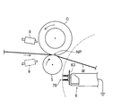
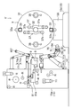
図1に、その具体的な構成例を示す。図示の構成例では、新しい巻芯C(テープレス)にウエブWを巻き取る際には、その巻芯Cにニップローラ5で押し付けることにより、走行するウエブWを挟持する。その挟持位置NPの下流側の位置で、巻芯Cの表面の周速度よりも速い周速度でカッター6の切刃63を回動させ、表面を突き切るようにしてウエブWを切断する。そうして、その切断端の先端部分をブラシ体70(押付装置の一例)で巻芯Cに押し付け、その切断端の先端部分を巻芯Cに巻き付ける。
FIG. 1 shows a specific configuration example thereof. In the illustrated configuration example, when the web W is wound around the new winding core C (tapeless), the traveling web W is sandwiched by pressing the web W against the winding core C with the
静電気を発生させる静電気付与装置9は、挟持位置NPの入口側の近傍(少なくとも静電気付与装置9による作用が巻芯C及びウエブWに及ぶ位置)に配置する。この構成例では、挟持位置NPが、巻芯CにウエブWが接する位置に相当する。挟持位置NPの近傍であれば、静電気付与装置9の位置は、実線で示すようにその上側でもよいし、仮想線で示すようにその下側であってもよい。
The static
このように静電気付与装置9を配置した場合、静電気付与装置9が発生するイオンは、ウエブW及び巻芯Cの双方の表面上の空気層の流れに乗って挟持位置NPに運ばれる。そこで密着するウエブWと巻芯Cの双方に挟み込まれるため、直接これらに作用させ易い。従って、空気層による阻害を緩和でき、ウエブW及び巻芯Cを効率的に帯電させることができるので、良好な吸着力が得られる。
When the static
特に、静電気付与装置9は、挟持位置NPに近づけるのが好ましい。具体的には、巻芯Cの回転軸が延びる方向から見て、巻芯Cの回転方向を挟持位置NPから90度戻った位置での巻芯Cの表面に対する接線とウエブWと巻芯Cの表面とで区画される、横断面V字状の隙間で放電されるように、静電気付与装置9を設置するのが好ましい。そうすれば、挟持位置NPに真っ直ぐ向かうウエブWの表面の空気層の流れと、挟持位置NPに巻き込まれる巻芯Cの表面の空気層の流れとにより、挟持位置NPによりいっそう効率よくイオンを送り込むことができる。
In particular, the static
静電気を除去する除電装置は、挟持位置NPの出口側の近傍に配置する。図示の構成例では、ブラシ体70が除電装置を兼ねている。
The static eliminator for removing static electricity is arranged near the outlet side of the pinching position NP. In the illustrated configuration example, the
すなわち、ブラシ体70は、導電性(電気を通し易い性質)を有する細い針状ないし繊維状の部材を束ねて構成されている。ブラシ体70の素材としては、金属繊維やカーボン繊維、アモルファス繊維等が利用できる。ブラシ体70は、その機能上、適度な弾性も必要なことから、特に金属繊維が好ましい。ブラシ体70は、その支持部材を通じてアース(接地)されている。
That is, the
ウエブWの巻き取り時には、切刃63及びブラシ体70が、ウエブWの下方から上方に変位し、挟持位置NPの出口側を横断する。その過程で、ブラシ体70が挟持位置NPの出口側の近傍を通過する。ブラシ体70は、空隙率が高く、空気の抵抗を受け難い。そのため、ブラシ体70が挟持位置NPの出口側の近傍の空間を通過する際には、その空間の空気層が大きく乱れないので、効率的に除電できる。
At the time of winding the web W, the
アースされた針状の導電体の先端が、帯電物と対向すると、その間の空間に電界が形成されることが知られている。従って、このようなブラシ体70を、挟持位置NPを介在させた状態で、静電気付与装置9と対向させることで、これらの間に強い電界が形成される。それにより、静電気付与装置9で発生したイオンは、挟持位置NPに誘導され、ウエブWや巻芯を効率よく帯電及び除電することができ、これらを円滑かつ速やかに吸着させることができるものと考えられる。
It is known that when the tip of a grounded needle-shaped conductor faces a charged object, an electric field is formed in the space between them. Therefore, when such a
ブラシ体70の変位に伴って電界も巻芯の側に偏るため、よりいっそうウエブWを巻芯に円滑かつ速やかに吸着させることができる。
Since the electric field is also biased toward the winding core as the
ウエブWは、カッター6によって切断されると、その切断端の先端部分が直ちに、ブラシ体70によって巻芯Cに押し付けられる。従って、静電気による吸着作用とともにブラシ体70の機械的作用により、安定してウエブWを巻芯Cに巻き付けることができる。ブラシ体70は、ウエブWの切断端の先端部分に接触し、これを巻芯Cに押し付けるので、巻芯Cに巻き付けられたウエブWの表面部分の不要な静電気は、速やかに除去される。
When the web W is cut by the
このように、静電気付与装置9及び除電装置70を配置とすることで、200m/分を超える巻取速度が実現可能となる(詳細は後述)。
By arranging the static
(ウエブ巻取装置)
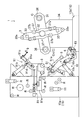
図2に、本実施形態のウエブ巻取装置1を示す。このウエブ巻取装置1は、ロール状の原反から、例えば、PETやOP、CP等、合成樹脂製のウエブWを連続的に巻き出しながら、そのウエブWに印刷や塗工を行って、再度、ロール状に巻き取っていく、いわゆるロールツーロール方式の印刷機や塗工機の製造ライン(図示せず)の最終工程に使用される。ウエブ巻取装置1は、製造ラインを止めることなく、巻芯Cを自動的に交互に切り替えながら、連続してウエブWをロール状に巻き取るように構成されている。
(Web winding device)
FIG. 2 shows the
特に、本実施形態の製造ラインは、食品向けのウエブを対象としており、そのライン速度(製造過程でウエブWを搬送する速度)は、200m/分前後に設定されている。 In particular, the production line of the present embodiment is intended for a web for food, and the line speed (the speed at which the web W is conveyed in the production process) is set to around 200 m / min.
このウエブ巻取装置1は、外周面に粘着テープの無い、長さ1〜2m程度の円筒形状をした厚紙製の巻芯Cが使用できるように構成されている。すなわち、このウエブ巻取装置1では、一般的なテープレスの巻芯Cがそのまま使用できる。特に、このウエブ巻取装置1の場合、直径が6インチ以下の比較的小径な巻芯Cが使用可能であり、そのような小径の巻芯Cに対し、100m/分以上の高速で走行するウエブWを、安定して切り替えできるように工夫されている。
The
ウエブ巻取装置1には、ターレット3、ニップローラ5、カッター6、ニアローラ8、静電気付与装置9、ダンサローラ11、各種ガイドローラRなどが備えられていて、これら装置が、フレーム15aやベース15bなどからなる支持体15に組み付けられている。ニップローラ5等はアーチ形状のフレーム15aに設置されていて、そのフレーム15aに隣接するように、ベース15bの上にターレット3が設置されている。なお、ターレット3やニップローラ5等、回動する各装置の中心軸は、互いに平行に配置されていて、ウエブWの走行方向と直交する方向(軸方向)に延びている。
The
ターレット3は、一対の支持プレート31,31、主軸32、一対の軸支部36,36、一対の主軸受部34,34、一対の補助ローラ33a,33aなどで構成されている(2軸ターレット方式)。各支持プレート31は、十字状の同一部材からなり、軸方向に離れて互いに対向している。主軸32は、これら支持プレート31の中心を貫通した状態でこれら支持プレート31に固定されている。
The
両支持プレート31,31の間には一対の横リブ33,33が架設されている。主軸32の両端は、ベース15bに設置された一対の主軸受部34,34によって回転自在に支持されており、一方の主軸受部34には、ターレット3を制御可能に回転させる駆動モータ(図示せず)が連結されている。各横リブ33の外周側には、支持プレート31の中心に対して対称状に、巻芯Cの切り替え時に使用される補助ローラ33aが、回転自在な状態で設置されている。
A pair of
一対の軸支部36,36は、これら一対の補助ローラ33a,33aと直交するように、支持プレート31の中心から離れた位置に対称状に配置されている。各軸支部36は、両支持プレート31,31の対向面に対向して配置された一対の突軸を有しており、これら一対の突軸に、巻芯Cの両端部が着脱可能に装着される。各軸支部36の突軸の一方には巻取モータが連結されており、軸支部36に装着される巻芯Cは、回転制御可能となっている(中心駆動巻取方式)。
The pair of
ターレット3は、ウエブWの巻き取りが行われる巻取位置と、巻芯Cの入れ替えが行われる待機位置とに、両軸支部36,36に装着された巻芯Cの位置が交換されるように回転制御される。図2において、フレーム15aに近い左側の軸支部36のある位置が巻取位置であり、右側の軸支部36のある位置が待機位置である。
In the
主軸32の周囲には、一対の軸支部36,36に対応した一対の補助アーム構造体37,37が点対称状に設置されている。各補助アーム構造体37は、各支持プレート31の近傍に配置された2つの補助アーム37aを有し、両補助アーム37a,37aの一端の間には、ウエブWの巻き取り時に使用されるタッチローラ37bが回転自在に軸支されている。各補助アーム構造体37は、各補助アーム37aの他端側に位置する軸部を中心に揺動し、巻取位置に位置する巻芯CにウエブWを巻き取って形成されるロールの外周面に、所定の荷重でタッチローラ37bが接するように、制御可能に構成されている。
A pair of
ニップローラ5は、フレーム15aに設置されたローラ支持体51(第2支持部材)に取り付けられている。ローラ支持体51は、軸方向に離れて対向するとともに、一方の端部がフレーム15aに回動自在に軸支された一対のローラ支持アーム51a,51aと、これらローラ支持アーム51aを揺動させるシリンダ51bと、を有している。ニップローラ5は、これらローラ支持アーム51a,51aの他方の端部に回転自在に軸支されている。
The
ローラ支持アーム51aが揺動することにより、ニップローラ5は、巻取位置に位置する巻取前の巻芯C(新巻芯Cn)の近傍に進出し、新巻芯Cnの下部にその表面を押し付ける切替位置と、新巻芯Cnから下方に大きく離れて位置する非切替位置と、に切替制御可能に構成されている。ニップローラ5が切替位置に位置することにより、待機位置に位置する巻芯Cに巻き取られて走行するウエブWは、ニップローラ5の外周面と新巻芯Cnの外周面とで挟持される。このウエブ巻取装置1では、この挟持位置が新巻芯CnにウエブWが接する位置となっている(挟持位置NPともいう)。
When the
カッター6は、切断補助ローラ61とともに、フレーム15aに設置されたカッター支持体62に設置されている。カッター支持体62は、軸方向に離れて対向するとともに、上側の端部が巻取位置よりも下方でフレーム15aに回動自在に軸支された一対のカッター支持アーム62a,62aと、これらカッター支持アーム62a,62aを揺動させるシリンダ62bと、を有している。
The
各カッター支持アーム62aは、ターレット3の側に向かって下端部がJ字状に屈曲した形状を有し、これらカッター支持アーム62aの下端部の突端間に、カッター6と切断補助ローラ61とが取り付けられている。両カッター支持アーム62a,62aが揺動することにより、カッター6及び補助ローラ33aは、新巻芯Cnの側に進出する切替位置と、新巻芯Cnから下方に大きく離れて位置する非切替位置と、に切替制御可能に構成されている。
Each
図3に詳しく示すように、カッター6は、切刃63、一対の回動腕64,64などで構成されている。各回動腕64の基端部は、各カッター支持アーム62aに回動可能に支持されており、各回動腕64の先端部に、横長な切刃63が架け渡すように取り付けられている。切刃63は、これら回動腕64が、跳ね上げられるように揺動することにより、挟持位置NPから下流側に離れた位置を通って、ウエブWの表面を突き切ってウエブWを切断するように構成されている。
As shown in detail in FIG. 3, the
カッター6は、両カッター支持アーム62a,62aの間に収容されており、切断時に回動腕64が揺動するように制御される。切刃63で切断されて浮き上がるウエブWの端部を新巻芯Cnに適切に巻き付けるため、回動腕64の揺動速度は、切刃63が、新巻芯Cnの表面の周速度よりも速い周速度でウエブWを切断するように設定されている。
The
切刃63の外周側には、切刃63に沿って2列に延びる一対のブラシ体70,70(押付装置の一例)が取り付けられている。これらブラシ体70は、切刃63が新巻芯Cnの側方を通過する際に、新巻芯Cnの表面に接触し、切刃63で切断されたウエブWの端部を新巻芯Cnに押し付けるように構成されている。
A pair of
本実施形態のブラシ体70は、除電装置を兼ねており、導電性に優れた金属製の素材で構成されている。
The
具体的には、ブラシ体70は、ステンレス製の針状ないし繊維状の細い部材(ブラシ要素)を束ねて構成されている。ブラシ体70は、ウエブWを傷つけることなく、新巻芯Cnに安定して押し付けるために、適度に撓んで変形する弾性が必要である。そのため、ブラシ要素の線径(横断面の外径)は5〜25μmの範囲で設定するのが好ましく、その長さは10〜40mmの範囲で設定するのが好ましい。
Specifically, the
ステンレス製のブラシ要素であれば、そのような範囲で設定することで、従来の刷毛や樹脂製のブラシ体と同等以上の押し付け性能が得られる。また、ステンレスであれば、錆が発生しないので、異物混入が防止でき、食品向けの用途に好適である。なお、ブラシ要素の先端側は基端側に比べて細くするのが好ましく、また、ブラシ要素の最先端は、丸めて球面状にするのが好ましい。 If it is a stainless steel brush element, by setting it in such a range, pressing performance equal to or higher than that of a conventional brush or resin brush body can be obtained. Further, if stainless steel is used, rust does not occur, so that foreign matter can be prevented from being mixed in, which is suitable for use in foods. The tip end side of the brush element is preferably thinner than the base end side, and the tip end side of the brush element is preferably rounded to have a spherical shape.
図4に詳しく示すように、静電気付与装置9は、フレーム15aに設置されたバー支持体91(第1支持部材)に設置されている。バー支持体91は、軸方向に離れて位置するフレーム15aの両側壁に設けられた一対のスイング板91a,91aと、これらスイング板91a,91aを揺動させるシリンダ91bと、各スイング板91aの先端部の間に架設され、スイング板91aから突出可能なスライド部91cと、そのスライド部91cをスライドさせるサブシリンダ91dと、を有している。静電気付与装置9は、スライド部91cに、金属導体であるブラケット93を介して取り付けられている。
As shown in detail in FIG. 4, the static
静電気付与装置9は、軸方向に延びる横長なバー本体9aと、バー本体9aに等間隔で横並びに配置された複数の放電針9bと、を有している。これら放電針9bは、直流高電圧発生装置94に接続されており、例えば、10〜30kVの正又は負の電圧が印加できるように構成されている。この静電気付与装置9では、負の電圧が放電針9bに印加されるようになっており、放電針9bの周辺にマイナスのイオンが発生する。
The static
切り替え時には、巻取位置から離れた待機位置からスイング板91aが揺動し、その先端部が巻取位置の近傍に進出した後、スライド部91cが突出する。それにより、静電気付与装置9は、ウエブWや新巻芯Cnに接触すること無く挟持位置NPに接近し、適切な位置に配置される。具体的には、静電気付与装置9は、放電針9bが挟持位置NPの方に向くように、新巻芯Cnの近傍に変位し、挟持位置NPの入口側であって、ウエブWに対して新巻芯Cnが位置する側に配置される。
At the time of switching, the
図2に示すように、ニアローラ8は、フレーム15aに設置されたスライド機構81に設置されている。スライド機構81は、軸方向に離れて位置するフレーム15aの両側壁に設けられた一対のスライダー81a,81aを有している。両スライダー81a,81aは、巻取位置と略同じ高さを略水平にスライドし、その突端部がターレット3の側に向かって進退するように構成されている。両スライダー81a,81aの突端部の間に、ニアローラ8と、ニアローラ8を補助するサポートローラ81bとが回転自在に軸支されている。ニアローラ8は、サポートローラ81bよりもターレット3の側に配置されている。
As shown in FIG. 2, the
両スライダー81aは、巻き取り時にはロールに対して、ニアローラ8が一定の隙間を保持するように制御される。切り替え時には、両スライダー81aは後退し、ニアローラ8が新巻芯Cnから離れて位置するように制御される。
Both
各種ガイドローラR及びダンサローラ11は、ウエブWが巻き掛けられて、その走行方向を所定の方向に誘導するようにフレーム15aの側壁間に回転自在に軸支されている。ダンサローラ11は、ウエブWの走行距離を一時的に増減できるように、フレーム15aに変位可能な状態で支持されている。
The various guide rollers R and the
<ウエブ巻取装置の動作>
図5に、巻き取り時におけるウエブ巻取装置1の状態の一例を示す。巻き取り時には、ニップローラ5、カッター6、静電気付与装置9は、巻取位置から離れた非切替位置に待機している。各軸支部36には、直径が6インチの巻芯Cが装着されており、巻取位置に位置する巻芯Cに、各種ガイドローラR、ダンサローラ11、サポートローラ81b、ニアローラ8に誘導されて、150m/分以上の高速で走行するウエブWが巻き取られている。ロールの直径が所定の大きさになるまで、連続してウエブWの巻き取りが行われる。
<Operation of web take-up device>
FIG. 5 shows an example of the state of the
巻き取り時には、ウエブWの張力やタッチローラ37bの荷重は適正に調整される。また、ニアローラ8は、直径が次第に大きくなるロールとの間に一定の隙間を保持するように後退する。ニアローラ8とロールとの間を、ウエブWの走行距離の短い一定の隙間に保つことで、ウエブWの長手方向に発生する縦シワ(トラフ)を抑制することが可能になり、空気の巻き込み量を減少させることができる。これらの結果、直径の小さい巻芯Cに高速で巻き取っても、シワやスリップなどのウエブWの巻き取り時に発生する不具合を効果的に抑制することができる。
At the time of winding, the tension of the web W and the load of the
そうして、ロールの直径が所定の大きさになると、切り替え処理が行われる。具体的には、補助アーム構造体37の一方が揺動制御されることにより、ロールに接していたタッチローラ37bが離脱する。そして、ターレット3が回転し(図5において半時計回り)、両軸支部36,36の位置が交換される。それにより、図6に示すように、待機位置に有った巻取前の巻芯Cは巻取位置に移動し、次にウエブWを巻き取る新巻芯Cnが構成される。巻取位置に有ったロールは待機位置に移動し、走行するウエブWは、一方の補助ローラ33aに巻き掛けられてV字状に誘導され、継続して待機位置で巻き取られる。なお、切り替え時の新巻芯Cnは、走行するウエブWに対して適切な速度で回転するように制御される。
Then, when the diameter of the roll reaches a predetermined size, the switching process is performed. Specifically, by controlling the swing of one of the
続いて、図7に示すように、スイング板91aが揺動して、その先端部が巻取位置の近傍に進出した後、スライド部91cが突出し、静電気付与装置9は、適切な位置に配置される。
Subsequently, as shown in FIG. 7, after the
そうして、ローラ支持アーム51a及びカッター支持アーム62aが揺動されることにより、ニップローラ5及びカッター6が、巻取位置の近傍に進出する。それにより、ウエブWは、切断補助ローラ61によって支持された状態で、ニップローラ5が新巻芯Cnの下部に押し付けられ、新巻芯Cnとニップローラ5とで挟持される。新巻芯Cnとニップローラ5とでウエブWが挟持された状態になると、軸支部36の回転制御の主体は、待機位置に位置する軸支部36から、巻取位置に位置する軸支部36に切り替わる。
Then, the
新巻芯Cnとニップローラ5とによるウエブWの挟持動作に連動して放電針9bに電圧が印加され、放電が行われる。それにより、放電針9bの周囲で静電気が発生し、ウエブWと新巻芯Cnの双方が帯電する。
A voltage is applied to the
また、新巻芯Cnとニップローラ5とによるウエブWの挟持動作に連動してウエブWがカッター6で切断される。具体的には、回動腕64が揺動し、切刃63が新巻芯Cnの表面の周速度よりも速い周速度で跳ね上げられることによって、ウエブWが切断される。ニップローラ5には、粘着テープが無い。従って、切断前に予め新巻芯Cnにニップさせておくことが可能になり、切断時の衝撃でウエブWにシワが発生するのを効果的に防止できる。
Further, the web W is cut by the
その際、ブラシ体70は、挟持位置NPの出口側を横断し、挟持位置NPの出口側の近傍を通過する。それにより、静電気付与装置9との間に強い電界が形成され、ウエブWの切断端の先端部分や新巻芯Cnが、効率よく帯電及び除電されるので、強い吸着力が得られる。その結果、高速処理であっても、ウエブWの切断端の先端部分を円滑に新巻芯Cnの側に誘導することができる。
At that time, the
更に、新巻芯Cnから浮き上がっている切断端の先端部分は、ブラシ体70によって新巻芯Cnに押し付けられる。従って、シワ等の不具合を生じることなく、ウエブWを安定して新巻芯Cnに巻き付けることができる。ウエブWと新巻芯Cnとの間には、静電気の吸着力が作用しているので、粘着テープが無くても、剥がれることなく、確りと新巻芯Cnに巻き付けることができる。ブラシ体70がウエブWに接触するので、ウエブWの表面の、不要な静電気は速やかに除去することができる。
Further, the tip portion of the cut end raised from the new winding core Cn is pressed against the new winding core Cn by the
また、切断時には、図示しないアキュームレーター装置の作動により、新巻芯Cnより上流側を走行するウエブWの走行距離が増大するように設定してもよい。そうすれば、新巻芯Cnを通過するウエブWの走行速度が一時的に低下し、より適切にウエブWを切断できるようにすることができる。 Further, at the time of cutting, the mileage of the web W traveling on the upstream side of the new winding core Cn may be increased by operating an accumulator device (not shown). Then, the traveling speed of the web W passing through the new winding core Cn is temporarily reduced, and the web W can be cut more appropriately.
ウエブWが切断されて新巻芯CnにウエブWが巻き付けられると、ニップローラ5は、新巻芯Cnから離れ、放電針9bへの電圧の印加は停止される。その後、ニップローラ5、カッター6、静電気付与装置9は、非切替位置に移動し、対応する補助アーム37a構造体37が揺動制御されることにより、新巻芯Cnに巻き取られて形成されるロールの外周面にタッチローラ37bが接触する。
When the web W is cut and the web W is wound around the new winding core Cn, the
ニアローラ8は、ロールに対して一定の隙間を保持するように進出し、その後、その一定の隙間を保持しながら、徐々に後退するように制御される。ウエブWは、タッチローラ37bの荷重や巻取張力を変化させながら新巻芯Cnに巻取られていき、ロールの直径が所定の大きさになれば、待機位置に装着された新たな巻芯Cと切り替えられる。
The
<別の実施形態>
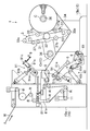
図8及び図9に、他のウエブ巻取装置1’に適用した例を示す。このウエブ巻取装置1’には、ターレット3、巻付ローラ104、ニップローラ5、カッター6、カウンタローラ107、ニアローラ8、静電気付与装置9、ブラシ体70(除電装置の一例)、ダンサローラ11、各種ガイドローラRなどが備えられている。このウエブ巻取装置1’の基本的構造は、上述した実施形態のウエブ巻取装置1と同じであるため、同じ機能の部材には同じ符号を用いてその説明は省略する。
<Another Embodiment>
8 and 9 show an example of application to another web winding device 1'. The web winding device 1'includes a
ターレット3の各支持プレート31は、円板状の同一部材からなり、副軸受部135で支持された状態で回転するように構成されている。
Each
巻付ローラ104、ニップローラ5、カッター6は、フレーム15aに設置されたウエブ押上機構141に設置されている。ウエブ押上機構141は、軸方向に離れて対向するとともに、上側の端部が巻取位置よりも下方でフレーム15aに回動自在に軸支された一対の押上アーム141a,141aと、これら押上アーム141a,141aを揺動させる押上シリンダ141bと、を有している。
The winding
各押上アーム141aは、ターレット3の側に向かって下端部がJ字状に屈曲した形状を有し、これら押上アーム141a,141aの下端部の突端間に、巻付ローラ104が回転自在に軸支されている。両押上アーム141a,141aが揺動することにより、巻付ローラ104は、新巻芯Cnの近傍に進出する切替位置と、新巻芯Cnから下方に大きく離れて位置する非切替位置と、に切替制御可能に構成されている。
Each push-up
ニップローラ5は、巻付ローラ104に隣接した位置に回転自在に軸支されており、カッター6は、ニップローラ5の近傍に配置されている。
The
カウンタローラ107は、フレーム15aに設置されたローラ変位機構171に設置されている。ローラ変位機構171は、軸方向に離れて対向するとともに、下端部が巻取位置よりも上方でフレーム15aに回動自在に軸支された一対の支持アーム171a,171aと、これら支持アーム171a,171aを揺動させることによってターレット3の側に押し下げる押下シリンダ171bとを有している。カウンタローラ107は、両支持アーム171a,171aの上端部の突端間に回転自在に軸支されている。両支持アーム171a,171aが揺動することにより、カウンタローラ107は、新巻芯Cnの上部に押し付けられる切替位置と、新巻芯Cnから上方に大きく離れて位置する非切替位置と、に切替制御可能に構成されている。
The
静電気付与装置9は、ニアローラ8とともにスライド機構81に設置されている。静電気付与装置9は、ニアローラ8の上側に位置するように、両スライダー81aの突端部の間に架設されている。
The static
ブラシ体70は、ニップローラ5とカッター6との間に配置されている。ブラシ体70は、押上アーム141a等を通じてアースされている。
The
<ウエブ巻取装置の動作>
図8に示すように、巻き取り時の巻付ローラ104及びカウンタローラ107は、いずれも非切替位置に位置している。そうして、ロールの直径が所定の大きさになると、切り替え処理が行われる。まず、ターレット3が回転し、巻取位置に有ったロールは待機位置に移動し、走行するウエブWは継続して待機位置で巻き取られる。
<Operation of web take-up device>
As shown in FIG. 8, both the winding
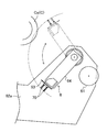
図9に示すように、ニアローラ8は、走行するウエブWに対して新巻芯Cnの上流側の近傍に進出した状態となる。巻付ローラ104は、押上アーム141aが揺動されることにより、切替位置に移動し、走行するウエブWに対して新巻芯Cnの下流側の近傍に進出した状態となる。そうすることにより、待機位置に位置する巻芯Cに巻き取られて高速で走行するウエブWのうち、新巻芯Cnの下流側の近傍部位が巻付ローラ104によって押し上げられ、新巻芯Cnの下側の部分にウエブWが巻き付けられた状態となる。
As shown in FIG. 9, the
すなわち、ニアローラ8と巻付ローラ104とにより、新巻芯Cnの略半分の範囲にウエブWが巻き付けられた状態となり、高速で走行するウエブWであっても、テープレスの巻芯Cに過度な負荷を与えずに巻き付けることができる。ニアローラ8は新巻芯Cnの近傍に位置しているため、ニアローラ8から新巻芯Cnに向かうウエブWの走行経路が新巻芯Cnに近接し、空気の巻き込みが抑制される。それにより、高速で走行するウエブWでも安定して新巻芯Cnに巻き付けが行える。
That is, the
この時、静電気付与装置9は、放電針9bを下方に向けた状態で、ニアローラ8と新巻芯Cnとの間の隙間を走行するウエブWの直ぐ上側に位置している。すなわち、静電気付与装置9は、新巻芯Cがウエブを最初に受け入れて接する位置の入口側に配置され、新巻芯CnとウエブWとの間の横断面V字状の隙間に放電するようになっている。
At this time, the static
巻付ローラ104が切替位置に位置している時には、ニップローラ5は、新巻芯Cnに巻き付いているウエブWの下流側の部位(ウエブWが新巻芯Cnから離れる直前の部位)と隙間を隔てて位置している。従って、ニップローラ5とカッター6との間に配置されているブラシ体70は、新巻芯CnにウエブWが接した位置の出口側に配置された状態となっている。
When the winding
ニップローラ5は、所定のタイミングで新巻芯Cnの側に進出し、新巻芯Cnに巻き付いているウエブWの下流側の部位を新巻芯Cnに押し付けるように設定されている。その時、新巻芯Cnの偏心を防ぐために、ニップローラ5の押し付け動作に連動して、カウンタローラ107が、切替位置に移動して新巻芯Cnの上部に押し付けられる。そうすることにより、新巻芯Cnの偏心を効果的に抑制することができる。ニップローラ5がウエブWを新巻芯Cnに押し付けるタイミングに連動して、静電気付与装置9で静電気が発生される。
The
ニップローラ5で押し付けられているウエブWがカッター6で切断される。このウエブ巻取装置1’のカッター6は、切刃161、空圧で駆動するロッドレスシリンダ162(アクチュエータの一例)などで構成されている。ロッドレスシリンダ162は、押上アーム141aの下端部の突端間に架設されている。切刃161は、ロッドレスシリンダ162のスライドブロックに固定されていて、切断時には、新巻芯Cnに沿ってスライドするように設定されている。
The web W pressed by the
切刃161は、新巻芯Cnから離れていくウエブWに新巻芯Cnの近傍で接触し、一方の側縁から切り裂くようにしてウエブWを切断する。それにより、ウエブWの切断端が新巻芯Cnに向かって付勢され、静電気の吸引作用と合わさって、ウエブWの切断端が新巻芯Cnに瞬時に巻き付くようになっている。
The
ブラシ体70は、新巻芯CnにウエブWが接した位置の出口側に配置された状態となっているため、ウエブWの表面の不要な静電気を除去させることができ、ニップローラ5を通過した後のウエブWにシワ等が発生するのを防止できる。しかも、切断された部分から順次新巻芯Cnに巻き付いていくので、幅方向に発生するシワ等が防止され、安定してウエブWの切断端を新巻芯Cnに巻き付けることができる。
Since the
<検証結果>
実施形態のウエブ巻取装置1(第1の巻取装置)及び別の実施形態のウエブ巻取装置1’(第2の巻取装置)の各々において、切り替え試験を行い、高速の巻取速度で安定した切り替えができるか否かを確認した。
<Verification result>
A switching test was performed on each of the web winding device 1 (first winding device) of the embodiment and the web winding device 1'(second winding device) of another embodiment, and a high-speed winding speed was performed. It was confirmed whether stable switching was possible with.
切り替え試験では、材質や厚み、構成が異なるウエブWを用い、外径が6インチの巻芯Cに対し、100N/mの切断張力で切り替え処理を行った。その結果、テープ付き巻芯を用いた場合と同等のレベルで安定したウエブWの切り換えが確認できた巻取速度を図10に示す。 In the switching test, a web W having a different material, thickness, and composition was used, and a winding core C having an outer diameter of 6 inches was subjected to a switching process with a cutting tension of 100 N / m. As a result, FIG. 10 shows the winding speed at which stable web W switching was confirmed at the same level as when the winding core with tape was used.
第1及び第2の巻取装置のいずれにおいても、200m/分以上の巻取速度で安定した切り替えが可能であった。 In both the first and second winding devices, stable switching was possible at a winding speed of 200 m / min or more.
巻芯の外径が小さくなるほど、外周面の周回速度が遅くなり、巻き取り条件としては有利である。従って、外径が6インチ以下の巻芯であれば、200m/分の巻取速度で安定した巻取が可能になる。 The smaller the outer diameter of the winding core, the slower the orbiting speed of the outer peripheral surface, which is advantageous as a winding condition. Therefore, if the winding core has an outer diameter of 6 inches or less, stable winding is possible at a winding speed of 200 m / min.
従って、実施形態の巻取装置を適用した製造ラインに、外径が6インチ以下の巻芯を用いれば、ライン速度を落とさずに、扱い易いテープレスの巻芯の切り替えが可能になるので、生産性を大幅に向上させることができる。 Therefore, if a winding core having an outer diameter of 6 inches or less is used in the production line to which the winding device of the embodiment is applied, it is possible to easily switch the tapeless winding core without reducing the line speed. Productivity can be greatly improved.
1、1’ ウエブ巻取装置
3 ターレット
5 ニップローラ
6 カッター
8 ニアローラ
9 静電気付与装置
70 ブラシ体(押付装置、除電装置)
C 巻芯
Cn 新巻芯
W ウエブ
NP 挟持位置
1,
C winding core Cn new winding core W web NP holding position
Claims (2)
前記巻芯を個別に装着して回転制御する一対の軸支部を有し、前記ウエブの巻き取りが行われる巻取位置と、前記巻芯の入れ替えが行われる待機位置とに、前記巻芯の位置を交換するターレットと、
切り替え時に、前記巻取位置に位置する巻取前の前記巻芯である新巻芯の近傍に進出することにより、前記待機位置に位置する前記巻芯に巻き取られて走行する前記ウエブを、前記新巻芯とで挟持するニップローラと、
前記ニップローラと前記新巻芯とが前記ウエブを挟持する挟持位置から下流側に離れた位置で前記ウエブを切断するカッターと、
前記新巻芯の近傍で静電気を発生させる静電気付与装置と、
前記新巻芯の近傍で静電気を除去する除電装置と、
を備え、
前記除電装置は、前記新巻芯に前記ウエブが接した位置の出口側に配置され、
前記カッターは、
基端部が回動可能に支持された回動腕と、
前記回動腕の先端部に取り付けられて、当該回動腕が回動することによって前記ウエブの表面を突き切る切刃と、
前記回動腕の先端部に取り付けられて、前記切刃で切断された前記ウエブの端部に接触して前記新巻芯に押し付ける弾性変形可能な押付装置と、
を有し、
前記押付装置が、導電性を有することによって前記除電装置を兼ねているウエブ巻取装置。 It is a winding device that continuously winds the web in a roll shape while switching the winding core alternately.
The winding core has a pair of shaft support portions for individually mounting the winding core to control rotation, and the winding core is set at a winding position where the web is wound and a standby position where the winding core is replaced. With a turret that exchanges positions,
At the time of switching, the web, which is wound around the winding core located at the standby position and travels by advancing to the vicinity of the new winding core which is the winding core before winding located at the winding position, is moved. The nip roller sandwiched between the new winding core and
A cutter that cuts the web at a position downstream from the holding position where the nip roller and the new winding core sandwich the web.
An static electricity applying device that generates static electricity in the vicinity of the new winding core,
A static eliminator that removes static electricity near the new winding core,
With
The static eliminator is arranged on the outlet side at a position where the web is in contact with the new winding core .
The cutter
With a rotating arm whose base end is rotatably supported,
A cutting edge that is attached to the tip of the rotating arm and cuts through the surface of the web by rotating the rotating arm.
An elastically deformable pressing device attached to the tip of the rotating arm, which comes into contact with the end of the web cut by the cutting edge and presses against the new winding core.
Have,
A web winding device in which the pressing device also serves as the static eliminator because it has conductivity.
前記押付装置が、金属製のブラシ体からなるウエブ巻取装置。 In the web winding device according to claim 1.
The pressing device is a web winding device made of a metal brush body.
Priority Applications (1)
| Application Number | Priority Date | Filing Date | Title |
|---|---|---|---|
| JP2017099279A JP6868898B2 (en) | 2017-05-18 | 2017-05-18 | Web take-up device |
Applications Claiming Priority (1)
| Application Number | Priority Date | Filing Date | Title |
|---|---|---|---|
| JP2017099279A JP6868898B2 (en) | 2017-05-18 | 2017-05-18 | Web take-up device |
Publications (2)
| Publication Number | Publication Date |
|---|---|
| JP2018193194A JP2018193194A (en) | 2018-12-06 |
| JP6868898B2 true JP6868898B2 (en) | 2021-05-12 |
Family
ID=64571461
Family Applications (1)
| Application Number | Title | Priority Date | Filing Date |
|---|---|---|---|
| JP2017099279A Active JP6868898B2 (en) | 2017-05-18 | 2017-05-18 | Web take-up device |
Country Status (1)
| Country | Link |
|---|---|
| JP (1) | JP6868898B2 (en) |
Families Citing this family (3)
| Publication number | Priority date | Publication date | Assignee | Title |
|---|---|---|---|---|
| JP7609401B2 (en) | 2020-10-13 | 2025-01-07 | 富士機械工業株式会社 | Web Winding Device |
| CN114873329B (en) * | 2022-04-29 | 2024-07-12 | 苏州捷力新能源材料有限公司 | Winding method and device for ultraviolet light curing high heat-resistant diaphragm |
| CN116945279A (en) * | 2023-06-05 | 2023-10-27 | 江苏沃峰新材料有限公司 | A continuously rolled buffer foam forming process and device |
Family Cites Families (4)
| Publication number | Priority date | Publication date | Assignee | Title |
|---|---|---|---|---|
| JPH01317942A (en) * | 1988-06-20 | 1989-12-22 | Asahi Chem Ind Co Ltd | Rolling up method for film |
| JP3327727B2 (en) * | 1995-04-10 | 2002-09-24 | 富士機械工業株式会社 | Sheet cutting equipment |
| JP2009132507A (en) * | 2007-11-30 | 2009-06-18 | Toray Ind Inc | Charge applying roll, sheet roll body of electric insulating sheet and manufacturing method of electric insulating sheet |
| JP6532790B2 (en) * | 2015-09-07 | 2019-06-19 | 富士機械工業株式会社 | Winding device |
-
2017
- 2017-05-18 JP JP2017099279A patent/JP6868898B2/en active Active
Also Published As
| Publication number | Publication date |
|---|---|
| JP2018193194A (en) | 2018-12-06 |
Similar Documents
| Publication | Publication Date | Title |
|---|---|---|
| KR890003939B1 (en) | Automatic cutting winding device of film strip shape | |
| JP6868898B2 (en) | Web take-up device | |
| JP6532790B2 (en) | Winding device | |
| JP2014156305A (en) | Winding device | |
| JP6754181B2 (en) | Web take-up device | |
| JP5589242B2 (en) | Coating device | |
| CN112722971A (en) | Film splitter | |
| JP7173519B2 (en) | Sheet take-up device | |
| KR20160077251A (en) | Apparatus and method for preventing wrinkles of paper | |
| JP2015048173A (en) | Web take-up device and method | |
| CN203529533U (en) | Single-shaft re-reeling machine | |
| EP1520814B1 (en) | Apparatus for controlling the speed of logs on output from a rewinding machine | |
| JP2017114581A (en) | Sheet winding device | |
| JP6235111B2 (en) | Winding device | |
| CN114380096A (en) | Production of coating white board is with measuring cutting device | |
| JP7609401B2 (en) | Web Winding Device | |
| TW409081B (en) | Rotor coiler | |
| CN110854447A (en) | Square battery cell winding method and device | |
| JP2009220991A (en) | Roll paper rewinding device | |
| JP7638599B2 (en) | Web winding device | |
| CN219507219U (en) | Unreeling machine | |
| CN220942628U (en) | Wrinkle removing device for battery lugs | |
| CN221662200U (en) | Film rolling and slitting device and electroplating system | |
| CN220222938U (en) | A sorting device for non-woven fabric processing | |
| CN220811233U (en) | Rewinding machine for gummed paper |
Legal Events
| Date | Code | Title | Description |
|---|---|---|---|
| A621 | Written request for application examination |
Free format text: JAPANESE INTERMEDIATE CODE: A621 Effective date: 20200323 |
|
| A977 | Report on retrieval |
Free format text: JAPANESE INTERMEDIATE CODE: A971007 Effective date: 20210107 |
|
| A131 | Notification of reasons for refusal |
Free format text: JAPANESE INTERMEDIATE CODE: A131 Effective date: 20210112 |
|
| A521 | Request for written amendment filed |
Free format text: JAPANESE INTERMEDIATE CODE: A523 Effective date: 20210225 |
|
| TRDD | Decision of grant or rejection written | ||
| A01 | Written decision to grant a patent or to grant a registration (utility model) |
Free format text: JAPANESE INTERMEDIATE CODE: A01 Effective date: 20210323 |
|
| A61 | First payment of annual fees (during grant procedure) |
Free format text: JAPANESE INTERMEDIATE CODE: A61 Effective date: 20210406 |
|
| R150 | Certificate of patent or registration of utility model |
Ref document number: 6868898 Country of ref document: JP Free format text: JAPANESE INTERMEDIATE CODE: R150 |
|
| R250 | Receipt of annual fees |
Free format text: JAPANESE INTERMEDIATE CODE: R250 |