JP6867882B2 - Humidifier - Google Patents
Humidifier Download PDFInfo
- Publication number
- JP6867882B2 JP6867882B2 JP2017107785A JP2017107785A JP6867882B2 JP 6867882 B2 JP6867882 B2 JP 6867882B2 JP 2017107785 A JP2017107785 A JP 2017107785A JP 2017107785 A JP2017107785 A JP 2017107785A JP 6867882 B2 JP6867882 B2 JP 6867882B2
- Authority
- JP
- Japan
- Prior art keywords
- water storage
- storage tank
- water
- air
- fixing member
- Prior art date
- Legal status (The legal status is an assumption and is not a legal conclusion. Google has not performed a legal analysis and makes no representation as to the accuracy of the status listed.)
- Active
Links
- XLYOFNOQVPJJNP-UHFFFAOYSA-N water Substances O XLYOFNOQVPJJNP-UHFFFAOYSA-N 0.000 claims description 177
- 238000000926 separation method Methods 0.000 claims description 17
- 239000000853 adhesive Substances 0.000 claims description 4
- 230000001070 adhesive effect Effects 0.000 claims description 4
- 238000011144 upstream manufacturing Methods 0.000 claims description 3
- 239000003595 mist Substances 0.000 description 26
- 238000004140 cleaning Methods 0.000 description 13
- 238000001816 cooling Methods 0.000 description 2
- 238000005260 corrosion Methods 0.000 description 2
- 230000007797 corrosion Effects 0.000 description 2
- 238000010586 diagram Methods 0.000 description 2
- 238000010438 heat treatment Methods 0.000 description 2
- 230000002093 peripheral effect Effects 0.000 description 2
- RYGMFSIKBFXOCR-UHFFFAOYSA-N Copper Chemical compound [Cu] RYGMFSIKBFXOCR-UHFFFAOYSA-N 0.000 description 1
- BZHJMEDXRYGGRV-UHFFFAOYSA-N Vinyl chloride Chemical compound ClC=C BZHJMEDXRYGGRV-UHFFFAOYSA-N 0.000 description 1
- 238000004061 bleaching Methods 0.000 description 1
- 238000007664 blowing Methods 0.000 description 1
- 229910052802 copper Inorganic materials 0.000 description 1
- 239000010949 copper Substances 0.000 description 1
- 230000001186 cumulative effect Effects 0.000 description 1
- 238000001514 detection method Methods 0.000 description 1
- 238000001035 drying Methods 0.000 description 1
- 238000010981 drying operation Methods 0.000 description 1
- 239000000428 dust Substances 0.000 description 1
- 230000000694 effects Effects 0.000 description 1
- 238000011010 flushing procedure Methods 0.000 description 1
- 238000009434 installation Methods 0.000 description 1
- 229910052751 metal Inorganic materials 0.000 description 1
- 239000002184 metal Substances 0.000 description 1
- 150000002739 metals Chemical class 0.000 description 1
- 238000000034 method Methods 0.000 description 1
- 238000012986 modification Methods 0.000 description 1
- 230000004048 modification Effects 0.000 description 1
- 239000002245 particle Substances 0.000 description 1
- 238000004080 punching Methods 0.000 description 1
- 230000001954 sterilising effect Effects 0.000 description 1
- 238000004659 sterilization and disinfection Methods 0.000 description 1
- 239000008400 supply water Substances 0.000 description 1
Images


Description
この発明は、加湿空気を室内へ供給する加湿装置に関するものである。 The present invention relates to a humidifying device that supplies humidified air into a room.
従来、この種のものでは、貯水タンク内の水から加湿空気を発生させ、送風ファンにより器具本体内に取り込んだ空気を貯水タンクを通過させ加湿空気を室内に送風する加湿装置があり、貯水タンクの上部に室外から吸い込んだ空気を流通させる空気流通路が載置され、送風ファンが駆動することで室外から器具本体内へ乾燥空気を吸い込み、空気流通路を介して貯水タンク内へ乾燥空気を流入させ、加湿手段空気発生手段により乾燥空気に水分を含ませて発生した加湿空気を送風口から室内へ送風することで、室内の加湿を可能としていた。(例えば、特許文献1) Conventionally, in this type, there is a humidifying device that generates humidified air from the water in the water storage tank, passes the air taken into the main body of the appliance by a blower fan, passes through the water storage tank, and blows the humidified air into the room. An air flow passage that circulates the air sucked from the outside is placed on the upper part of the room, and by driving the blower fan, the dry air is sucked from the outside into the main body of the appliance, and the dry air is sent into the water storage tank through the air flow passage. It was possible to humidify the room by inflowing and blowing the humidified air generated by adding moisture to the dry air by the humidifying means air generating means from the air outlet to the room. (For example, Patent Document 1)
しかし、この従来のものでは、水に含まれるカルキや空気中の塵埃等の影響で貯水タンクの近傍は汚れが溜まりやすく定期的に清掃作業を実施する必要があり、清掃作業は、器具本体前面のパネルを取り外してから空気流通路を貯水タンクから取り外し、貯水タンクの上部が開口された状態にして実施していたが、貯水タンクの上部に載置された空気流通路を固定する固定部材が貯水タンクに溶接されていたことで、清掃作業を実施しようとしても固定部材を取り外すことができず、固定部材と貯水タンクとの間については清掃が実施できなかったため、固定部材と貯水タンクとの間に残留する水分によって貯水タンクの構成部材が腐食し、腐食が進行すると貯水タンクに穴が空いて加湿空気が漏れてしまい、室内に送風される加湿空気量が減少して加湿効率が低下するおそれがあったことから、改善の余地があった。 However, with this conventional product, dirt tends to accumulate in the vicinity of the water storage tank due to the effects of bleaching contained in water and dust in the air, and it is necessary to perform cleaning work on a regular basis. After removing the panel, the air flow passage was removed from the water storage tank, and the upper part of the water storage tank was opened. Since it was welded to the water storage tank, the fixing member could not be removed even when cleaning work was performed, and cleaning could not be performed between the fixing member and the water storage tank. The components of the water storage tank are corroded by the water remaining between them, and as the corrosion progresses, a hole is created in the water storage tank and the humidified air leaks, reducing the amount of humidified air blown into the room and reducing the humidification efficiency. There was room for improvement because there was a risk.
上記課題を解決するために、本発明の請求項1では、器具本体と、当該器具本体内にあり水を貯水する貯水タンクと、当該貯水タンクに載置され空気が流通する空気流通路と、前記貯水タンク内の水から加湿空気を発生させる加湿空気発生手段と、前記器具本体に形成された吸気口から吸い込んだ空気を前記空気流通路を介して前記貯水室内を通過させ加湿空気を送風口から送風する送風ファンと、を備え、
前記空気流通路を載置場所に固定する固定部材が前記貯水タンクに固定されている取り付け金具に着脱手段を介して設けられており、
前記空気流通路は、前記貯水タンクの上流側に載置され前記器具本体から吸い込んだ乾燥空気が通過する風洞と、前記貯水タンクの下流側に載置され前記貯水タンク内で発生した加湿空気が通過する気水分離ケースと、で構成され、
前記固定部材には、前記風洞、及び前記気水分離ケースを前記貯水タンクの載置場所へ案内するよう、前記風洞、及び前記気水分離ケースの後端に形成された突出部が嵌まり込む切り欠きが設けられていることを特徴としている。
In order to solve the above-mentioned problems, in
A fixing member for fixing the air flow passage to the mounting place is provided on the mounting bracket fixed to the water storage tank via an attachment / detachment means .
The air flow passage includes a wind tunnel that is placed on the upstream side of the water storage tank and through which dry air sucked from the instrument body passes, and humidified air that is placed on the downstream side of the water storage tank and generated in the water storage tank. Consists of a passing air-water separation case,
A protrusion formed at the rear end of the wind tunnel and the brackish water separation case is fitted into the fixing member so as to guide the wind tunnel and the brackish water separation case to a place where the water storage tank is placed. It is characterized by having a notch.
この発明によれば、空気流通路を載置場所に固定する固定部材が貯水タンクに固定されている取り付け金具に着脱手段を介して設けられているので、清掃作業を実施するとき固定部材を取り外して貯水タンクに残留する水分を確実に拭き取れるため、貯水タンクの腐食を防止して加湿空気が漏れることを防止し、室内に送風される加湿空気量が減少して加湿効率が低下する事態を未然に防止することができる。 According to the present invention, since the fixing member for fixing the air flow passage to the mounting place is provided on the mounting bracket fixed to the water storage tank via the attachment / detachment means, the fixing member is removed when the cleaning work is performed. Since the water remaining in the water storage tank can be wiped off reliably, the corrosion of the water storage tank is prevented, the humidified air is prevented from leaking, and the amount of humidified air blown into the room is reduced, resulting in a decrease in humidification efficiency. It can be prevented in advance.
次に、この発明の一実施形態におけるミスト発生装置を図に基づいて説明する。
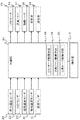
1は器具本体、2は器具本体1上部に形成され複数のルーバー3が設置された送風口、4は器具本体1の正面上部を構成する上面パネル、5は器具本体1の正面下部を構成する下面パネル、6は複数のスイッチが備えられ各種操作指令を行う操作部、7は図示しないブレーカーを隠すブレーカーカバーである。
Next, the mist generator according to the embodiment of the present invention will be described with reference to the drawings.
1 is an instrument body, 2 is an air outlet formed on the upper part of the
8は器具本体1内の略中段高さ位置にあって所定量の水を貯水する貯水タンクであり、この貯水タンク8内には、水に下端を水没させ駆動軸9に軸支された筒状の回転体10が備えられている。
前記回転体10は、中空逆円錐形で上方に向かって円周が徐々に拡大するものであり、駆動軸9に接続され回転体10を回転駆動させるミストモータ11を駆動させ、回転体10が回転することによる回転の遠心力で貯水タンク8の水を汲み上げ、回転体10の外壁および内壁を伝わせて水を押し上げて、回転体10の外壁を伝わせて押し上げた水を周囲に飛散させると共に、回転体10の内壁を伝わせて押し上げた水を回転体10の上端に形成された複数の図示しない飛散口から外周方向へ飛散させる。
The rotating
12は回転体10の上部外周に所定間隔を離間させて位置し、回転体10と共に回転する円筒状の多孔体で、該多孔体12には、その全周壁に多数のスリットや金網やパンチングメタル等から成る衝突体としての多孔部13が設置されており、前記回転体10、前記ミストモータ11及び前記多孔部13で加湿空気発生手段が構成されている。
前記加湿空気発生手段を構成するミストモータ11を駆動させ、回転体10を回転させたことで発生する遠心力で貯水タンク8内の水を汲み上げると共に空気を飛散させ、多孔部13を通過した水滴が破砕されることで、水を微細化して粒径がナノメートル(nm)サイズのミストが多量に生成される。
The
14は下面パネル5内に設置され所定の回転数で駆動することで乾燥空気を吸引して器具本体1の上部方向へ送風する送風ファン、15は貯水タンク8の上部に載置され内部にミストモータ11が載置されており開口16から流入した空気を貯水タンク8内まで流通させる空気流通路としての風洞、17は貯水タンク8と送風口2との間にあり貯水タンク8内で発生したミストを含む加湿空気を送風口2へ送る空気流通路としての気水分離ケース、18は該気水分離ケース17の途中に設置され加湿空気に含まれる大径水滴を捕集する板状のバッフル板であり、前記送風ファン14が所定の回転数で駆動すると、器具本体1の底面に形成された吸気口19から吸い込んだ乾燥空気を器具本体1の上部方向へ送風され、貯水タンク8の上流側に形成された吸入経路20内を送風ファン14によって送風された乾燥空気が流通し、開口16から風洞15内へ流入した乾燥空気が貯水タンク8内へ流入すると加湿空気発生手段により発生したミストを含む加湿空気となって気水分離ケース17内を上昇して、気水分離ケース17内に設置されたバッフル板18により大径水滴が捕集されることで微細な水滴を含む加湿空気のみが送風口2から室内へ送風される。
14 is a blower fan installed in the
21は貯水タンク8内に設置され貯水を加熱する加熱ヒータであり、貯水タンク8の外壁に設置され貯水温度を検知する貯水温度センサ22で検知される温度が所定温度となるよう、ON/OFF状態が適宜切り替えられる。
23は貯水タンク8内に設置されフロートが上下することで水位を検知する水位センサであり、貯水タンク8内の水位が低下して下限水位以下になったらOFF信号を出力し、水位が上昇して上限水位以上になったらON信号を出力し、更に水位が上昇して貯水タンク8内が満水となったら満水信号を出力する。
24は貯水タンク8の側面に一端が接続され貯水タンク8内に市水を給水する給水管であり、当該給水管24の配管途中には、電磁弁を開閉して貯水タンク8内への給水を制御する給水弁25と、給水圧を所定値まで減圧する減圧弁26とが備えられている。
27は貯水タンク8底部に一端が接続され貯水タンク8内の水を器具本体1外部に排水する硬質塩化ビニル管で構成された排水管であり、当該排水管27の配管途中には、電磁弁を開閉して貯水タンク8内水の排水を制御する排水弁28が備えれている。
29は送風口2の壁面に設置され送風口2から室内へ向けて送風される加湿空気の温度を検知する送風温度センサ、30は送風ファン14の近傍に設置され器具本体1の下部にある銅製の網が設置された吸気口19へ吸い込まれる乾燥空気の雰囲気温度を検知する吸気温度センサ、31は前記吸気温度センサ30の近傍に設置され器具本体1が設置された室内の相対湿度を検知する湿度センサであり、各センサで検知された温度や相対湿度に基づいて、ミストモータ11や送風ファン14の回転数を変化させ、加熱ヒータ21のON/OFF状態を切り替える。
32は各センサで検知された検知値や操作部6上に備えられた各スイッチでの設定内容に基づき運転内容や弁の開閉を制御するマイコンで構成された制御部であり、ミストモータ11を所定の回転数で駆動させるミストモータ制御手段33と、送風ファン14を所定の回転数で駆動させる送風ファン制御手段34と、加熱ヒータ21のON/OFF状態を切り替えて貯水タンク8内の水温を制御する加熱ヒータ制御手段35とが備えられている。
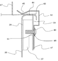
36は貯水タンク8を構成するタンク壁面、37は当該タンク壁面36に設置された取り付け金具であり、当該取り付け金具37は、両端でタンク壁面36に溶接された接合面38と、当該接合面38から折り曲げられタンク壁面36と略平行な位置に形成された取り付け面39とで構成され、前記取り付け面39には着脱手段としてのネジ40が螺着可能な取り付け金具側ネジ穴41が複数形成されている。
42は空気流通路としての風洞15及び気水分離ケース17を貯水タンク8上部の載置する場所に固定する固定部材であり、当該固定部材42は、貯水タンク8の上部に載置される風洞15及び気水分離ケース17の端面43を貯水タンク8の上部を構成するフランジ面44方向へ押さえつけて固定するバネ部45と、当該バネ部45に形成され風洞15及び気水分離ケース17を貯水タンク8へ載置するときに組み付け位置を案内する切り欠き46と、取り付け金具37へ固定部材42を取り付けるときに取り付け面39と接着する接着面47と、当該接着面47に複数形成されネジ40が螺着可能な固定部材側ネジ穴48とで構成されており、取り付け金具側ネジ穴41と固定部材側ネジ穴48とを貫通してネジ40が螺着することで、固定部材42が取り付け金具37に取り付けられる。
次に、この一実施形態での運転開始から終了までの動作について図5のフローチャートに基づいて説明する。
まず、操作部6の図示しない運転スイッチが操作されたら、制御部32は、排水弁28を開弁して貯水タンク8内の水を排水し、水位センサ23でOFF信号が検知されたら給水弁25を開弁して貯水タンク8内を水で洗い流すクリーニング動作を行い、所定時間経過したら排水弁28を閉弁することで給水弁25から流入する水を貯水タンク8内に供給し、水位センサ23でON信号が検知されたら、所定量の水が貯水タンク8内に供給されたとして給水弁25を閉弁する洗浄モードを行う(ステップS101)。
Next, the operation from the start to the end of the operation in this one embodiment will be described with reference to the flowchart of FIG.
First, when an operation switch (not shown) of the operation unit 6 is operated, the
ステップS101の洗浄モードが終了したら、制御部32は、貯水温度センサ22で検知される貯水温度が室温と同値になるまで加熱ヒータ制御手段35で加熱ヒータ21をON状態にして、ミストモータ11及び送風ファン14が所定の回転数となるようミストモータ制御手段33及び送風ファン制御手段34で制御する立ち上げ動作を実行する立ち上げモードを行う(ステップS102)。
When the cleaning mode in step S101 is completed, the
ステップS102の立ち上げモードが終了したら、制御部32は、図示しない加湿スイッチ及び風量スイッチで設定された加湿レベルと風量レベルとに基づいて、ミストモータ11と送風ファン14とが所定の回転数で駆動するようミストモータ制御手段33と送風ファン制御手段34とで回転数を制御し、加熱ヒータ21のON/OFF状態を加熱ヒータ制御手段35で切り替えて制御して、加湿レベルと風量レベルとに合わせた所定の温度範囲内にするミスト運転を実行する通常運転モードを行う(ステップS103)。
When the start-up mode of step S102 is completed, the
また、制御部32は、前記ミスト運転中に貯水タンク8の水位が下限水位以下となって水位センサ23がOFF信号を出力したと判断したら、給水弁25を開弁して貯水タンク8内への給水を開始し、貯水タンク8の水位が上限水位に達して水位センサ23がON信号を出力したと判断したら、給水弁25を閉弁して貯水タンク8内への給水を停止することで、常時ミスト運転が実施可能な水位を保持することができる。
Further, when the
また、制御部32は、前記通常運転モードが開始されたら時間カウントを開始し、カウントした時間が所定の運転時間を経過したと判断したら後述する水入れ替え動作を開始して、所定の水入れ替え時間である10分間が経過したと判断したら、水入れ替え動作を終了させ、ミスト運転を再開する。
Further, the
ステップS103の通常運転モードが開始されてから経過した時間が16時間となったか、または通常運転モード中に運転スイッチが操作されミスト運転終了の指示があったと判断したら、制御部32は、ミストモータ11を停止させてから排水弁28を開弁して貯水タンク8内の水を排水し、所定時間経過したら給水弁25を開弁して貯水タンク8内を洗浄してから排水弁28を閉弁して貯水タンク8内に所定量だけ貯水する洗浄運転を行い、その後、加熱ヒータ21をON状態にして水を65℃前後に加熱し除菌を行う除菌運転を10分間実施し、10分経過後に貯水タンク8内を冷却する冷却運転を実行し、貯水温度が60℃未満になったら排水弁28を開弁して排水するクリーニングモードを行う(ステップS104)。
When it is determined that the time elapsed from the start of the normal operation mode in step S103 is 16 hours, or that the operation switch is operated during the normal operation mode and an instruction to end the mist operation is given, the
ステップS104のクリーニングモードが終了したら、制御部32は、乾燥モード(ステップS105)に移行し、送風ファン14が所定の回転数(例えば、800rpm)で駆動するよう送風ファン制御手段34で制御し、所定時間(例えば3時間)だけ送風ファン14を駆動させ続ける乾燥運転を実施して、3時間経過したと判断したら、送風ファン14を停止させて運転を終了する。
When the cleaning mode of step S104 is completed, the
次に、この一実施形態での貯水タンク8周辺の清掃方法について説明する。
実施したミスト運転の積算時間が所定時間以上になったことや、器具本体1の設置から経過した期間が所定期間以上となった等の条件を満たし、貯水タンク8近傍の清掃を実施する時期になったとき、作業者は、上面パネル4を取り外して器具本体1内部を開放し、ドライバーを使用してネジ40を取り外すことで固定部材42を取り付け金具37から取り外し、風洞15及び気水分離ケース17を貯水タンク8上部から取り外して貯水タンク8上部が開口した状態にする。
Next, a cleaning method around the
At the time when the vicinity of the
そして、貯水タンク8上部が開口した状態となったら、貯水タンク8の上部を構成するフランジ面44の拭き掃除が可能となることから、フランジ面44に水が残留することでタンク壁面36やフランジ面44が腐食して隙間が形成され、ミスト運転時に加湿空気が隙間から漏れることで室内の送風される加湿空気量が減少し、ミスト運転の加湿効率が低下することを未然に防止することができる。
Then, when the upper part of the
以上のように、貯水タンク8のタンク壁面36に空気流通路としての風洞15及び気水分離ケース17の載置場所を固定する固定部材42を取り付け金具37にネジ40で着脱可能となるよう設置したことで、貯水タンク8近傍の清掃作業を実施するとき、固定部材42を取り外して貯水タンク8のフランジ面44の拭き掃除が可能となるため、水分がフランジ面44に残留することを確実に防止することができ、残留した水によりタンク壁面36やフランジ面44が腐食して隙間が形成し、ミスト運転時に加湿空気が隙間から漏れて室内の加湿効率が低下する事態を未然に防止することができる。
As described above, the fixing
また、固定部材42の接着面47を取り付け金具37の取り付け面39にネジ40で螺着させるという、シンプルな着脱手段で固定部材42の着脱を可能としたので、固定部材42及び取り付け金具37について複雑な加工を要することがなく、コストの増大を防止することができる。
Further, since the fixing
なお、本実施形態では着脱手段をネジ40とし、当該ネジ40により固定部材42を取り付け金具37から着脱可能とした内容で説明したが、これに限らず貯水タンク8から固定部材42を着脱可能とした構成であればよく、例えば、タンク壁面36に固定部材42の位置決めを可能とする突起を形成し、当該突起に係止される係止部を固定部材42に形成することで、貯水タンク8近傍の清掃の実施時にタンク壁面36の突起から固定部材42を取り外すことで、フランジ面44の清掃を可能とした内容であってもよい。
In the present embodiment, the attachment / detachment means is a
また、本実施形態で用いたその他の構成は一例として提示したものであり、発明の範囲を限定することは意図しておらず、その他の様々な形態で実施されることが可能であり、発明の要旨を逸脱しない範囲において、種々の省略、置き換え、変更を行うことができる。これら実施形態やその変形は、発明の範囲や要旨に含まれると共に、特許請求の範囲に記載された発明とその均等の範囲に含まれる。 Further, the other configurations used in the present embodiment are presented as an example, and are not intended to limit the scope of the invention, and can be implemented in various other embodiments. Various omissions, replacements, and changes can be made without departing from the gist of. These embodiments and modifications thereof are included in the scope and gist of the invention, and are also included in the scope of the invention described in the claims and the equivalent scope thereof.
1 器具本体
2 送風口
8 貯水タンク
10 回転体(加湿空気発生手段)
11 ミストモータ(加湿空気発生手段)
13 多孔部(加湿空気発生手段)
14 送風ファン
15 風洞(空気流通路)
17 気水分離ケース(空気流通路)
19 吸気口
37 取り付け金具
40 ネジ(着脱手段)
42 固定部材
1
11 Mist motor (humidified air generating means)
13 Perforated part (humidified air generating means)
14
17 Brackish water separation case (air flow passage)
19
42 Fixing member
Claims (3)
前記空気流通路を載置場所に固定する固定部材が前記貯水タンクに固定されている取り付け金具に着脱手段を介して設けられており、
前記空気流通路は、前記貯水タンクの上流側に載置され前記器具本体から吸い込んだ乾燥空気が通過する風洞と、前記貯水タンクの下流側に載置され前記貯水タンク内で発生した加湿空気が通過する気水分離ケースと、で構成され、
前記固定部材には、前記風洞、及び前記気水分離ケースを前記貯水タンクの載置場所へ案内するよう、前記風洞、及び前記気水分離ケースの後端に形成された突出部が嵌まり込む切り欠きが設けられていることを特徴とする加湿装置。 An instrument body, a water storage tank inside the instrument body that stores water, an air flow passage that is placed in the water storage tank and through which air flows, and a humidified air generating means that generates humidified air from the water in the water storage tank. And a blower fan that allows air sucked from the intake port formed in the instrument body to pass through the water storage chamber through the air flow passage and blows humidified air from the blower port.
A fixing member for fixing the air flow passage to the mounting place is provided on the mounting bracket fixed to the water storage tank via an attachment / detachment means .
The air flow passage includes a wind tunnel that is placed on the upstream side of the water storage tank and through which dry air sucked from the instrument body passes, and humidified air that is placed on the downstream side of the water storage tank and generated in the water storage tank. Consists of a passing air-water separation case,
A protrusion formed at the rear end of the wind tunnel and the brackish water separation case is fitted into the fixing member so as to guide the wind tunnel and the brackish water separation case to a place where the water storage tank is placed. A humidifying device characterized by being provided with a notch.
前記固定部材は、前記取り付け面と接着する接着面を有し、
前記着脱手段はネジで構成され、
前記取り付け面と前記接着面とを前記ネジで螺着することで、前記固定部材が前記取り付け金具に取り付けられることを特徴とする請求項1に記載の加湿装置。 The mounting bracket has a joint surface having both ends joined to the tank wall surface of the water storage tank, and a mounting surface between the joint surfaces and located substantially parallel to and separated from the tank wall surface.
The fixing member has an adhesive surface that adheres to the mounting surface.
The attachment / detachment means is composed of screws.
The humidifying device according to claim 1 , wherein the fixing member is attached to the mounting bracket by screwing the mounting surface and the adhesive surface with the screw.
Priority Applications (1)
| Application Number | Priority Date | Filing Date | Title |
|---|---|---|---|
| JP2017107785A JP6867882B2 (en) | 2017-05-31 | 2017-05-31 | Humidifier |
Applications Claiming Priority (1)
| Application Number | Priority Date | Filing Date | Title |
|---|---|---|---|
| JP2017107785A JP6867882B2 (en) | 2017-05-31 | 2017-05-31 | Humidifier |
Publications (3)
| Publication Number | Publication Date |
|---|---|
| JP2018204818A JP2018204818A (en) | 2018-12-27 |
| JP2018204818A5 JP2018204818A5 (en) | 2019-11-28 |
| JP6867882B2 true JP6867882B2 (en) | 2021-05-12 |
Family
ID=64955403
Family Applications (1)
| Application Number | Title | Priority Date | Filing Date |
|---|---|---|---|
| JP2017107785A Active JP6867882B2 (en) | 2017-05-31 | 2017-05-31 | Humidifier |
Country Status (1)
| Country | Link |
|---|---|
| JP (1) | JP6867882B2 (en) |
Families Citing this family (4)
| Publication number | Priority date | Publication date | Assignee | Title |
|---|---|---|---|---|
| JP7173922B2 (en) * | 2019-05-13 | 2022-11-16 | 株式会社コロナ | humidifier |
| CN113757858A (en) * | 2021-08-26 | 2021-12-07 | 湖南红橡室内气候技术有限公司 | Water circulating device of humidifying equipment |
| CN113757864A (en) * | 2021-08-30 | 2021-12-07 | 湖南红橡室内气候技术有限公司 | Fresh air humidifying device |
| CN114046580B (en) * | 2021-11-15 | 2023-06-23 | 贵州火焰山电器股份有限公司 | Humidifier based on intelligent home system |
Family Cites Families (4)
| Publication number | Priority date | Publication date | Assignee | Title |
|---|---|---|---|---|
| CN101639250B (en) * | 2008-08-01 | 2012-10-10 | 日立空调·家用电器株式会社 | Air purifier and condenser |
| JP6282935B2 (en) * | 2014-05-23 | 2018-02-21 | 株式会社コロナ | Mist generator |
| JP6346102B2 (en) * | 2015-02-10 | 2018-06-20 | 株式会社コロナ | Mist generator |
| JP6475602B2 (en) * | 2015-11-13 | 2019-02-27 | 株式会社コロナ | Humidifier |
-
2017
- 2017-05-31 JP JP2017107785A patent/JP6867882B2/en active Active
Also Published As
| Publication number | Publication date |
|---|---|
| JP2018204818A (en) | 2018-12-27 |
Similar Documents
| Publication | Publication Date | Title |
|---|---|---|
| JP6867882B2 (en) | Humidifier | |
| JP6591936B2 (en) | Humidifier | |
| JP6603599B2 (en) | Humidifier | |
| JP7074696B2 (en) | Humidified air generator | |
| JP2017116164A (en) | Humidifier | |
| JP6467330B2 (en) | Humidifier | |
| JP6806595B2 (en) | Mist generator | |
| JP6817909B2 (en) | Humidifier | |
| JP6475602B2 (en) | Humidifier | |
| JP6470638B2 (en) | Humidifier | |
| JP6925291B2 (en) | Humidifier | |
| JP6657000B2 (en) | Mist generator | |
| JP7040958B2 (en) | Humidifier | |
| JP6849539B2 (en) | Mist generator | |
| JP7163226B2 (en) | humidifier | |
| JP7424956B2 (en) | humidifier | |
| JP7157007B2 (en) | humidifier | |
| JP6510955B2 (en) | Humidifier | |
| JP7173922B2 (en) | humidifier | |
| JP7437257B2 (en) | humidifier | |
| JP6998426B2 (en) | Mist generator | |
| JP6826931B2 (en) | Humidifier lid locking mechanism | |
| JP7421458B2 (en) | humidifier | |
| JP2022089210A (en) | Humidifier | |
| JP7045965B2 (en) | Mist generator |
Legal Events
| Date | Code | Title | Description |
|---|---|---|---|
| A521 | Request for written amendment filed |
Free format text: JAPANESE INTERMEDIATE CODE: A523 Effective date: 20191016 |
|
| A621 | Written request for application examination |
Free format text: JAPANESE INTERMEDIATE CODE: A621 Effective date: 20191016 |
|
| A131 | Notification of reasons for refusal |
Free format text: JAPANESE INTERMEDIATE CODE: A131 Effective date: 20201006 |
|
| A521 | Request for written amendment filed |
Free format text: JAPANESE INTERMEDIATE CODE: A523 Effective date: 20201113 |
|
| TRDD | Decision of grant or rejection written | ||
| A01 | Written decision to grant a patent or to grant a registration (utility model) |
Free format text: JAPANESE INTERMEDIATE CODE: A01 Effective date: 20210406 |
|
| A61 | First payment of annual fees (during grant procedure) |
Free format text: JAPANESE INTERMEDIATE CODE: A61 Effective date: 20210409 |
|
| R150 | Certificate of patent or registration of utility model |
Ref document number: 6867882 Country of ref document: JP Free format text: JAPANESE INTERMEDIATE CODE: R150 |
|
| R250 | Receipt of annual fees |
Free format text: JAPANESE INTERMEDIATE CODE: R250 |