JP6867342B2 - Control device layout structure for saddle-type vehicles - Google Patents
Control device layout structure for saddle-type vehicles Download PDFInfo
- Publication number
- JP6867342B2 JP6867342B2 JP2018163638A JP2018163638A JP6867342B2 JP 6867342 B2 JP6867342 B2 JP 6867342B2 JP 2018163638 A JP2018163638 A JP 2018163638A JP 2018163638 A JP2018163638 A JP 2018163638A JP 6867342 B2 JP6867342 B2 JP 6867342B2
- Authority
- JP
- Japan
- Prior art keywords
- control device
- intake passage
- connecting member
- throttle
- insertion hole
- Prior art date
- Legal status (The legal status is an assumption and is not a legal conclusion. Google has not performed a legal analysis and makes no representation as to the accuracy of the status listed.)
- Active
Links
Images


Description
本発明は、鞍乗型車両の制御装置配置構造に関する。 The present invention relates to a control device arrangement structure for a saddle-mounted vehicle.
従来、スロットルボディの車体上壁面に、エンジンの点火タイミングや燃料噴射タイミング等を制御する制御ユニット(ECU)を配設した構造が知られている(例えば、特許文献1参照)。特許文献1では、ECUがスロットルボディに一体的に設けられている。 Conventionally, there is known a structure in which a control unit (ECU) for controlling engine ignition timing, fuel injection timing, and the like is arranged on the upper wall surface of the throttle body (see, for example, Patent Document 1). In Patent Document 1, the ECU is integrally provided on the throttle body.
しかしながら、ECUをスロットルボディに一体的に設けると、スロットルボディ周りのスペースが必要となる。 However, if the ECU is integrally provided on the throttle body, a space around the throttle body is required.
そこで本発明は、鞍乗型車両の制御装置配置構造において、スロットルボディ周辺のスペースを維持しながら、エンジン系部品につながるハーネスを短くすることを目的とする。 Therefore, an object of the present invention is to shorten the harness connected to the engine system parts while maintaining the space around the throttle body in the control device arrangement structure of the saddle-mounted vehicle.
上記課題の解決手段として、請求項1に記載した発明は、内燃機関(30)の燃焼室に空気を導くための吸気通路(41)に設けられ、前記内燃機関(30)の近傍で空気量を調整するためのスロットルボディ(40)と、外気を浄化するエアクリーナ(50)と、前記スロットルボディ(40)と前記エアクリーナ(50)とを接続する接続部材(60)と、前記内燃機関(30)の制御を行う制御装置(70)と、を備え、前記制御装置(70)は、前記接続部材(60)に支持され、前記接続部材(60)は、前記制御装置(70)を差し込み可能な差込孔部(64)を有する保持部(62)を備え、前記差込孔部(64)は、貫通孔で形成されていることを特徴とする。
請求項2に記載した発明は、前記スロットルボディ(40)の左側面には、スロットルバルブ開度センサ及び吸気圧センサを含むセンサユニット(46)が設けられ、前記センサユニット(46)は、前記スロットルボディ(40)を挟んで車両右側方のマフラ(17)に接続される排気管とは反対側に配置されていることを特徴とする。
請求項3に記載した発明は、前記接続部材(60)は、空気が流通する吸気路部(61)と、前記吸気路部(61)と一体に形成され、前記吸気路部(61)から側方に延出し、前記制御装置(70)を保持する保持部(62)と、を備えることを特徴とする。
請求項4に記載した発明は、前記接続部材(60)は、弾性部材で形成されていることを特徴とする。
請求項5に記載した発明は、前記接続部材(60)は、空気が流通する吸気路部(61)と、前記制御装置(70)を差し込み可能な差込孔部(64)を有する保持部(62)と、前記吸気路部(61)と前記保持部(62)とを接続する接続部(63)と、を備え、前記差込孔部(64)への前記制御装置(70)の差込方向から見て、前記接続部(63)は、前記制御装置(70)の断面の長辺部(70L)と対向することを特徴とする。
請求項6に記載した発明は、前記接続部材(60)は、空気が流通する吸気路部(61)と、前記制御装置(70)を差し込み可能な差込孔部(64)を有する保持部(62)と、を備え、前記差込孔部(64)は、前記吸気路部(61)に沿うように設けられていることを特徴とする。
請求項7に記載した発明は、前記スロットルボディ(40)に軸支されたスロットルバルブ(43)と、前記スロットルバルブ(43)に接続されたスロットルドラム(44)と、前記スロットルドラム(44)を牽引するように配置され、前記スロットルバルブ(43)の開閉量を調整するワイヤ(45)と、を更に備え、前記接続部材(60)は、前記制御装置(70)を保持する保持部(62)を備え、車両上面視で、前記保持部(62)は、前記吸気通路(41)を挟んで前記スロットルドラム(44)と反対側に配置されていることを特徴とする。
As a means for solving the above problems, the invention according to claim 1 is provided in an intake passage (41) for guiding air to a combustion chamber of an internal combustion engine (30), and an amount of air is provided in the vicinity of the internal combustion engine (30). A throttle body (40) for adjusting the throttle body (40), an air cleaner (50) for purifying the outside air, a connecting member (60) for connecting the throttle body (40) and the air cleaner (50), and an internal combustion engine (30). ), The control device (70) is supported by the connecting member (60), and the connecting member (60) can be inserted into the control device (70). A holding portion (62) having an insertion hole portion (64) is provided, and the insertion hole portion (64) is formed of a through hole .
In the invention described in
In the invention according to
The invention according to claim 4 is characterized in that the connecting member (60) is made of an elastic member.
According to the fifth aspect of the present invention, the connecting member (60) is a holding portion having an intake passage portion (61) through which air flows and an insertion hole portion (64) into which the control device (70) can be inserted. (62), a connecting portion (63) for connecting the intake passage portion (61) and the holding portion (62), and the control device (70) to the insertion hole portion (64). The connecting portion (63) faces the long side portion (70L) of the cross section of the control device (70) when viewed from the insertion direction.
According to the sixth aspect of the present invention, the connecting member (60) is a holding portion having an intake passage portion (61) through which air flows and an insertion hole portion (64) into which the control device (70) can be inserted. (62), and the insertion hole portion (64) is provided along the intake passage portion (61) .
The invention according to claim 7 is a throttle valve (43) pivotally supported by the throttle body (40), a throttle drum (44) connected to the throttle valve (43), and the throttle drum (44). The connecting member (60) further includes a wire (45) that is arranged to pull the throttle valve (43) and adjusts the opening / closing amount of the throttle valve (43), and the connecting member (60) holds a holding portion (70) that holds the control device (70). 62) is provided, and the holding portion (62) is arranged on the opposite side of the throttle drum (44) with the intake passage (41) interposed therebetween, when viewed from the top of the vehicle.
請求項1、2に記載した発明によれば、制御装置が接続部材に支持されていることで、制御装置をスロットルボディに設ける場合に対して、スロットルボディ周辺のスペースを維持することができる。加えて、制御装置がスロットルボディとエアクリーナとの間に配置されるため、スロットルボディおよび内燃機関との距離が近くなり、スロットルボディ等のエンジン系部品につながるハーネスを短くすることができる。したがって、スロットルボディ周辺のスペースを維持しながら、エンジン系部品につながるハーネスを短くすることができる。加えて、接続部材周りのデッドスペースを活用するため、制御装置をスロットルボディに一体的に設ける構成と比較して、スペース効率を高めることができる。加えて、吸気通路の近傍に制御装置が配置されるため、吸気の作用により制御装置を冷却することができる。加えて、接続部材は、制御装置を差し込み可能な差込孔部を有する保持部を備え、差込孔部は、貫通孔で形成されていることで、以下の効果を奏する。差込孔部が凹部で形成されている場合と比較して、制御装置の中心部を保持しやすいため、制御装置を安定して保持することができる。
請求項3に記載した発明によれば、接続部材は、空気が流通する吸気路部と、吸気路部と一体に形成され、吸気路部から側方に延出し、制御装置を保持する保持部と、を備えることで、以下の効果を奏する。吸気路部と保持部とが一体に形成されるため、吸気路部と保持部とを別個独立に設けた場合と比較して、部品点数を削減することができる。
請求項4に記載した発明によれば、接続部材が弾性部材で形成されていることで、制御装置に伝わる振動を抑制することができる。
請求項5に記載した発明によれば、接続部材は、空気が流通する吸気路部と、制御装置を差し込み可能な差込孔部を有する保持部と、吸気路部と保持部とを接続する接続部と、を備え、差込孔部への制御装置の差込方向から見て、接続部は、制御装置の断面の長辺部と対向することで、以下の効果を奏する。差込孔部への制御装置の差込方向から見て、接続部が制御装置の断面の短辺部と対向する場合と比較して、制御装置に伝わる振動をより効果的に抑えることができる。
請求項6に記載した発明によれば、接続部材は、空気が流通する吸気路部と、制御装置を差し込み可能な差込孔部を有する保持部と、を備え、差込孔部は、吸気路部に沿うように設けられていることで、以下の効果を奏する。差込孔部が吸気路部に交差するように設けられている場合と比較して、エンジン系部品につながるハーネスをより一層短くすることができる。
請求項7に記載した発明によれば、スロットルボディに軸支されたスロットルバルブと、スロットルボディに接続されたスロットルドラムと、スロットルドラムを牽引するように配置され、スロットルバルブの開閉量を調整するワイヤと、を更に備え、接続部材は、制御装置を保持する保持部を備え、車両上面視で、保持部は、吸気通路を挟んでスロットルドラムと反対側に配置されていることで、以下の効果を奏する。保持部がスロットルドラムと同じ側に配置された場合と比較して、エンジン系部品につながるハーネスが干渉しないように配置しやすい。
According to the inventions of
According to the invention described in
According to the fourth aspect of the present invention, since the connecting member is made of an elastic member, vibration transmitted to the control device can be suppressed.
According to the invention described in claim 5, the connecting member connects the intake passage portion through which air flows, the holding portion having the insertion hole portion into which the control device can be inserted, and the intake passage portion and the holding portion. A connecting portion is provided, and when viewed from the insertion direction of the control device into the insertion hole portion, the connecting portion faces the long side portion of the cross section of the control device, thereby achieving the following effects. When viewed from the insertion direction of the control device into the insertion hole, the vibration transmitted to the control device can be suppressed more effectively than when the connection portion faces the short side of the cross section of the control device. ..
According to the invention described in
According to the invention described in claim 7 , the throttle valve pivotally supported by the throttle body, the throttle drum connected to the throttle body, and the throttle drum are arranged so as to be towed, and the opening / closing amount of the throttle valve is adjusted. The wire is further provided, the connecting member is provided with a holding portion for holding the control device, and the holding portion is arranged on the opposite side of the throttle drum across the intake passage in the vehicle top view. It works. Compared to the case where the holding portion is arranged on the same side as the throttle drum, it is easier to arrange it so that the harness connected to the engine system parts does not interfere with each other.
以下、本発明の実施形態について図面を参照して説明する。なお、以下の説明における前後左右等の向きは、特に記載が無ければ以下に説明する車両における向きと同一とする。また以下の説明に用いる図中適所には、車両前方を示す矢印FR、車両左方を示す矢印LH、及び車両上方を示す矢印UPが示されている。 Hereinafter, embodiments of the present invention will be described with reference to the drawings. Unless otherwise specified, the orientations of the front, rear, left, and right directions in the following description are the same as those in the vehicle described below. Further, an arrow FR indicating the front of the vehicle, an arrow LH indicating the left side of the vehicle, and an arrow UP indicating the upper part of the vehicle are shown at appropriate positions in the drawings used in the following description.
<車両全体>
図1は、鞍乗型車両の一例として、ユニットスイング式の自動二輪車1を示す。図1を参照し、自動二輪車1は、前輪3と、後輪4と、を備える。前輪3は、ハンドル2によって操向される。後輪4は、動力源を含むパワーユニット10(スイングユニット)によって駆動される。以下、自動二輪車を単に「車両」ともいうことがある。自動二輪車1は、シート8に着座した乗員が足を載せるステップフロア9を有する。実施形態の自動二輪車1は、スクータ型の車両である。
<Whole vehicle>
FIG. 1 shows a unit swing type motorcycle 1 as an example of a saddle-mounted vehicle. With reference to FIG. 1, the motorcycle 1 includes a
ハンドル2及び前輪3を含むステアリング系部品は、車体フレーム11の前端のヘッドパイプ12に操向可能に支持されている。車体フレーム11の外周は車体カバー20で覆われている。図1において、符号6はフロントフォーク、符号7はリアクッションをそれぞれ示す。
The steering system parts including the
車体フレーム11は、複数種の鋼材を溶接等により一体に接合して形成されている。車体フレーム11は、ヘッドパイプ12と、メインフレーム13と、ロアフレーム14と、シートフレーム15と、を備える。
The body frame 11 is formed by integrally joining a plurality of types of steel materials by welding or the like. The vehicle body frame 11 includes a
ヘッドパイプ12は、車両の前部に配置されている。側面視で、ヘッドパイプ12は、ヘッドパイプ12の上端が後方に位置し、かつ、ヘッドパイプ12の下端が前方に位置するように傾斜している。ヘッドパイプ12は、車体フレーム11の前端部に位置している。
The
メインフレーム13は、ヘッドパイプ12の上下中央位置に接続されている。メインフレーム13は、ヘッドパイプ12から斜め後下方へ延びている。
The
ロアフレーム14は、左右一対設けられている。ロアフレーム14は、ヘッドパイプ12の下端部に接続されている。ロアフレーム14は、第一延在部14a、第二延在部14bおよび第三延在部14cを備える。第一延在部14a、第二延在部14bおよび第三延在部14cは、同一の部材で一体に形成されている。第一延在部14aは、メインフレーム13よりも急傾斜でヘッドパイプ12から斜め後下方へ延びている。第二延在部14bは、第一延在部14aの下端から後方へ向けて略水平に延びている。第三延在部14cは、第二延在部14bの後端から後上方へ延びている。
A pair of left and right
シートフレーム15は、左右一対設けられている。シートフレーム15は、ロアフレーム14の第一延在部14aの下部から斜め後上方へ延びている。
図示はしないが、左右ロアフレーム14および左右シートフレーム15の適所には、各フレームの車幅方向間をわたすように車幅方向に延びるクロスメンバが設けられている。
A pair of left and right seat frames 15 are provided. The
Although not shown, cross members extending in the vehicle width direction are provided at appropriate positions on the left and right
ハンドル2とシート8との間には、乗員が車両を跨ぐための跨ぎ部18が設けられている。ステップフロア9は、跨ぎ部18の左右両側に設けられている。左右ステップフロア9の間には、上方に凸の膨出形状をなして前後に延びるセンタートンネル19が設けられている。
A
車体カバー20は、フロントセンターカバー21、フロントサイドカバー22、レッグシールド23、フロントインナーカバー24、フロアフロントカバー25、フロアサイドカバー26、センターアッパーカバー27、センターサイドカバー28およびリアサイドカバー29を備える。例えば、車体カバー20は、樹脂製である。
The
フロントセンターカバー21は、車両前部の車幅方向中央に配置される。フロントセンターカバー21は、ヘッドパイプ周りを前方から覆っている。
フロントサイドカバー22は、フロントセンターカバー21の側方に左右一対設けられている。フロントサイドカバー22は、ヘッドパイプ周りを前外側方から覆っている。
レッグシールド23は、乗員の脚部と対向する位置に左右一対設けられている。
The
A pair of left and right front side covers 22 are provided on the side of the
A pair of left and right leg shields 23 are provided at positions facing the legs of the occupant.
フロントインナーカバー24は、ヘッドパイプ周りを後方から覆っている。フロントインナーカバー24は、センタートンネル19の前部及び左右レッグシールド23を形成している。
フロアフロントカバー25は、フロントサイドカバー22の後下方に連なるように左右一対設けられている。
フロアサイドカバー26は、フロアフロントカバー25の下部後方に連なるように左右一対設けられている。
The front
A pair of left and right floor front covers 25 are provided so as to be connected to the rear lower side of the
A pair of left and right floor side covers 26 are provided so as to be connected to the lower rear part of the
センターアッパーカバー27は、フロントインナーカバー24の下部後方に連なっている。センターアッパーカバー27は、センタートンネル19の後部上面を形成している。
センターサイドカバー28は、フロントインナーカバー24の下部後方に連なっている。センターサイドカバー28は、センタートンネル19の後部側面を形成するように左右一対設けられている。
リアサイドカバー29は、センターアッパーカバー27およびセンターサイドカバー28の後方に連なるように左右一対設けられている。リアサイドカバー29は、車体後部を側方から覆っている。
The center
The center side cover 28 is connected to the lower rear part of the front
A pair of left and right rear side covers 29 are provided so as to be connected to the rear of the center
パワーユニット10は、内燃機関であるエンジン30と、エンジン30の左側部から後方へ延びて後輪を支持するアーム部31と、を一体に備える。エンジン30は、クランクケース32と、クランクケース32の前端部から略前方(具体的には水平面に対してやや前上方)に突出するシリンダ33と、を備える。アーム部31は、クランクケース32の左側部から後方へ延出する伝動ケース34を備える。伝動ケース34の内部には、エンジン30の出力を後輪4に伝達する不図示の変速機が収容されている。図中符号35は、パワーユニット10の下部に支持されたセンタースタンドを示す。
The
パワーユニット10の前下部は、リンク部材36を介して、車体フレーム11の後下部に上下揺動可能に支持されている。パワーユニット10の後端部(伝動ケース34の後端部)とシートフレーム15の後端部との間には、パワーユニット10の揺動を減衰するリアクッション7が掛け渡されている。図1において符号17は、車両の右側方に配置されたマフラを示す。
The front lower portion of the
<制御装置配置構造39>
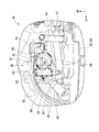
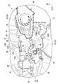
車両後部には、エンジン30(内燃機関)の制御装置であるECU70(Engine Control Unit)を備える制御装置配置構造39が設けられている。図2に示すように、制御装置配置構造39は、スロットルボディ40、エアクリーナ50(図3参照)、接続部材60およびECU70を備える。図2においては、ECU70の断面ハッチを省略している。図3において、符号57はブリーザホースを示す。
<Control
A control
<スロットルボディ40>
図3に示すように、スロットルボディ40は、エンジン30(図4参照)の燃焼室に空気を導くための吸気通路41に設けられている。図4に示すように、スロットルボディ40は、エンジン30の近傍で空気量を調整するために設けられている。側面視で、スロットルボディ40は、略前方に突出するシリンダ33の上方に配置されている。側面視で、スロットルボディ40は、シートフレーム15(図1参照)の下方に配置されている。図中符号58はホースを係合するためのホースクランプ、符号59はホースクランプ58を支持するブラケットをそれぞれ示す。
<Throttle
As shown in FIG. 3, the
スロットルボディ40は、略円形断面の吸気通路41が内部に形成された直方体柱状を有する。スロットルボディ40の前端部は、インレットパイプ42を介してシリンダヘッドの後部の吸気ポート(不図示)に接続されている。スロットルボディ40の後端部は、接続部材60の前端部に接続されている。図示はしないが、シリンダヘッドの前部の排気ポートには、排気管の一端が接続されている。排気管の他端は、マフラ17(図1参照)に接続されている。
The
図3に示すように、スロットルボディ40の内部には、吸気通路41を開閉するスロットルバルブ43が設けられている。スロットルバルブ43は、スロットルボディ40に回転可能に軸支されている。例えば、スロットルバルブ43は、バタフライバルブである。スロットルバルブ43には、スロットルドラム44が接続されている。スロットルドラム44は、スロットルグリップ(不図示)の回転操作に応じて、スロットルバルブ43を回転させる。
As shown in FIG. 3, a
ワイヤ45は、スロットルドラム44を牽引するように配置されている。上面視で、ワイヤ45は、スロットルドラム44から後方に延出した後、接続部材60の上方を通って左後方へ延出し、その後、前方へ湾曲して延びている。ワイヤ45は、一対のスロットルケーブルである。スロットルドラム44には、ワイヤ45の一端が接続されている。ワイヤ45の他端は、スロットルグリップに接続されている。ワイヤ45がスロットルドラム44を牽引することにより、スロットルバルブ43の開閉量が調整される。
The
スロットルボディ40では、スロットルグリップの回転操作に応じて一対のスロットルケーブルのうちの一方が引っ張られるとともに、他方が繰り出されることにより、スロットルドラム44が回転する。これにより、スロットルボディ40は、スロットルグリップの回転操作に応じて、スロットルバルブ43の開閉量を調整して、エアクリーナ50から接続部材60を通して供給される吸気の吸気量を制御する。
In the
スロットルボディ40の左側面には、スロットルバルブ開度センサおよびPbセンサ(吸気圧センサ)などを含むセンサユニット46が設けられている。図中符号47はセンサユニット46に接続されたセンサハーネス、符号48はセンサハーネス47のカプラをそれぞれ示す。なお、センサユニット46には、IACV(アイドルエアコントロールバルブ)のユニットおよびその駆動センサなどがさらに含まれていてもよい。
A
<エアクリーナ50>
図1に示すように、エアクリーナ50は、パワーユニット10におけるアーム部31の上部に支持されている。エアクリーナ50は、パワーユニット10と一体に揺動する。エアクリーナ50は、エアクリーナケース51内に不図示のエレメントを収容する。
<Air cleaner 50>
As shown in FIG. 1, the
図3に示すように、エアクリーナケース51は、車幅方向内側部を形成する内ケース体52と、車幅方向外側部を形成する外ケース体53と、を備える。内ケース体52は、車幅方向内方に膨出する膨出部54を備える。図4に示すように、膨出部54には、前後方向に貫通する接続口55が形成されている。膨出部54の接続口55には、接続部材60の一部(後部)が挿入されている。
As shown in FIG. 3, the
図示はしないが、エアクリーナ50は、吸気ダクトから導入される空気中の塵埃等を捕集するエレメントを備える。エアクリーナ50は、エレメントを挟んでクリーンサイドとダーティサイドとに区画されている。
Although not shown, the
ここで、外気を浄化するエアクリーナ50の作用について説明する。エアクリーナ50においては、先ず、吸気ダクト(不図示)から導入された外気(空気)がダーティサイドに供給される。ダーティサイドに供給された空気は、エレメントを介して浄化される。浄化された空気は、クリーンサイドに供給される。そして、クリーンサイドから接続部材60、スロットルボディ40、インレットパイプ42を通して、浄化された空気がエンジン30に供給される。
Here, the action of the
<ECU70>
ECU70は、各種センサからの信号に基づいて、エンジン30の点火時期、燃料噴射タイミング、アイドル回転数、排ガス還元量などを制御する。図5に示すように、ECU70は、電子回路部品を搭載した回路基板71が、外部機器との間で着脱可能な電気的制御を行うためのカードエッジ端子74を備えた構造を有する。
<
The
ECU70は、回路基板71と、回路基板71に実装された電子回路部品(不図示)と、電子回路部品を覆い回路基板71と電子回路部品とを一体化する封止部材72と、を備える。回路基板71には、封止部材72から前方にはみ出した基板端部領域73が設けられている。
The
基板端部領域73には、電気信号を伝える接合部として機能するカードエッジ端子74が設けられている。カードエッジ端子74は、コネクタ80と着脱可能な電気的接続を行う。例えば、封止部材72は、樹脂材料などの絶縁材料により形成されている。
A
図4の側面視で、ECU70は、矩形形状を有している。以下、ECU70の各辺のうち、前側の辺を「前辺」、後側の辺を「後辺」、上側の辺を「上辺」、下側の辺を「下辺」ともいう。後面視で(図2の断面視で)、ECU70は、上下方向に長手を有する矩形形状をなしている。図中符号70LはECU70の断面の長辺部、符号70Tは短辺部をそれぞれ示す。
In the side view of FIG. 4, the
図5に示すように、ECU70は、電気信号を伝えるカードエッジ端子74(接合部)を備える。カードエッジ端子74は、コネクタ80(カードエッジコネクタ)に接続される。カードエッジ端子74は、ECU70の前辺に配置されている。カードエッジ端子74とコネクタ80との接続方向Vc(車両前後方向)から見て、ECU70の外周は、コネクタ80の外周よりも内側に配置されている。
As shown in FIG. 5, the
コネクタ80は、カードエッジ端子74に接続されることにより、ECU70と外部機器とを電気的に接続する。コネクタ80は、カードエッジ端子74に接続可能な接続端子81と、接続端子81を保持する胴体部82と、胴体部82から延出しECU70の外周部(封止部材72の外周部)が嵌め込まれる外周枠部83と、を備える。外周枠部83の上下壁部は、ECU70の上辺および下辺に沿ってそれぞれ延在している。図中符号84はスロットルボディ40(図4参照)とECU70とを接続するハーネスを示す。ハーネス84は、ECU70の前端部から前方に延出している。
The
<接続部材60>
図4に示すように、ECU70は、スロットルボディ40とエアクリーナ50との間の空間69に配置されている。ECU70は、接続部材60に支持されている。接続部材60は、スロットルボディ40とエアクリーナ50とを接続するコネクティングチューブである。接続部材60は、パワーユニット10の上方を前後方向に延在している。接続部材60は、ゴム等の弾性部材で形成されている。
<Connecting
As shown in FIG. 4, the
接続部材60は、空気が流通する吸気路部61と、ECU70を保持する保持部62と、吸気路部61と保持部62とを接続する接続部63(図2参照)と、を備える。
吸気路部61は、前後方向に延在する円管状をなしている。
The connecting
The
図2に示すように、保持部62は、吸気路部61および接続部63と同一の部材で一体に形成されている。保持部62は、吸気路部61から左側方に延出している。保持部62は、ゴムのグリップ力でECU70を保持している。図3の上面視で、保持部62は、吸気通路41を挟んでスロットルドラム44と反対側に配置されている。保持部62は、吸気通路41の右側方のスロットルドラム44とは反対側(吸気通路41の左側方)に配置されている。
接続部63は、ECU70の中央部と重なるように配置されていてもよい。これにより、振動に強くECU70を保持することができる。
As shown in FIG. 2, the holding
The connecting
図4に示すように、保持部62は、ECU70の前後中央部を保持している。側面視で、保持部62は、吸気路部61の上下幅内(外形内)に収まるように配置されている。
As shown in FIG. 4, the holding
図2に示すように、保持部62は、ECU70を差し込み可能な差込孔部64を有する。差込孔部64は、吸気路部61に沿うように設けられている。差込孔部64は、前後方向に開口する貫通孔で形成されている。差込孔部64の延在方向は、吸気路部61の延在方向と略平行である。後面視で、保持部62は、上下方向に長手を有する矩形枠状をなしている。
As shown in FIG. 2, the holding
接続部63は、吸気路部61と保持部62とを一体に接続する部分である。差込孔部64へのECU70の差込方向から見て(図2の後面視で)、接続部63は、ECU70の断面の長辺部70Lと対向している。
The connecting
以上説明したように、上記実施形態の制御装置配置構造39は、エンジン30の燃焼室に空気を導くための吸気通路41に設けられ、エンジン30の近傍で空気量を調整するためのスロットルボディ40と、外気を浄化するエアクリーナ50と、スロットルボディ40とエアクリーナ50とを接続する接続部材60と、エンジン30の制御を行うECU70と、を備え、ECU70は、接続部材60に支持されている。
この構成によれば、ECU70が接続部材60に支持されていることで、ECU70をスロットルボディ40に設ける場合に対して、スロットルボディ40周辺のスペースを維持することができる。加えて、ECU70がスロットルボディ40とエアクリーナ50との間に配置されるため、スロットルボディ40およびエンジン30との距離が近くなり、スロットルボディ40等のエンジン系部品につながるハーネス84を短くすることができる。したがって、スロットルボディ40周辺のスペースを維持しながら、エンジン系部品につながるハーネス84を短くすることができる。加えて、接続部材60周りのデッドスペースを活用するため、ECU70をスロットルボディ40に一体的に設ける構成と比較して、スペース効率を高めることができる。加えて、吸気通路41の近傍にECU70が配置されるため、吸気の作用によりECU70を冷却することができる。
As described above, the control
According to this configuration, since the
上記実施形態では、接続部材60は、空気が流通する吸気路部61と、吸気路部61と一体に形成され、吸気路部61から左側方に延出し、ECU70を保持する保持部62と、を備えることで、以下の効果を奏する。吸気路部61と保持部62とが一体に形成されるため、吸気路部61と保持部62とを別個独立に設けた場合と比較して、部品点数を削減することができる。
In the above embodiment, the connecting
上記実施形態では、接続部材60が弾性部材で形成されていることで、ECU70に伝わる振動を抑制することができる。
In the above embodiment, since the connecting
上記実施形態では、接続部材60は、空気が流通する吸気路部61と、ECU70を差し込み可能な差込孔部64を有する保持部62と、吸気路部61と保持部62とを接続する接続部63と、を備え、差込孔部64へのECU70の差込方向から見て、接続部63は、ECU70の断面の長辺部70Lと対向することで、以下の効果を奏する。差込孔部64へのECU70の差込方向から見て、接続部63がECU70の断面の短辺部70Tと対向する場合と比較して、ECU70に伝わる振動をより効果的に抑えることができる。
In the above embodiment, the connecting
上記実施形態では、差込孔部64は、吸気路部61に沿うように設けられていることで、以下の効果を奏する。差込孔部64が吸気路部61に交差するように設けられている場合と比較して、エンジン系部品につながるハーネス84をより一層短くすることができる。
In the above embodiment, the
上記実施形態では、差込孔部64は、貫通孔で形成されていることで、以下の効果を奏する。差込孔部64が凹部で形成されている場合と比較して、ECU70の中心部を保持しやすいため、ECU70を安定して保持することができる。
In the above embodiment, the
上記実施形態では、スロットルボディ40に軸支されたスロットルバルブ43と、スロットルボディ40に接続されたスロットルドラム44と、スロットルドラム44を牽引するように配置され、スロットルバルブ43の開閉量を調整するワイヤ45と、を更に備え、車両上面視で、保持部62は、吸気通路41を挟んでスロットルドラム44と反対側に配置されていることで、以下の効果を奏する。保持部62がスロットルドラム44と同じ側に配置された場合と比較して、エンジン系部品につながるハーネス84が干渉しないように配置しやすい。
In the above embodiment, the
<変形例>
上記実施形態では、保持部62が吸気路部61から左側方に延出している例を挙げて説明したが、これに限らない。例えば、図6に示すように、保持部が吸気路部61から左側方以外の外方に延出していてもよい。図6において、符号162Aは吸気路部61から上方に延出する保持部、符号162Bは吸気路部61から下方に延出する保持部、符号162Cは吸気路部61から右側方に延出する保持部、符号170A〜170Cは各保持部162A〜162Cに保持されているECUをそれぞれ示す。
<Modification example>
In the above embodiment, the case where the holding
上記実施形態では、保持部62が吸気路部61と同一の部材で一体に形成されている例を挙げて説明したが、これに限らない。例えば、保持部62は、吸気路部61と異なる部材で形成されていてもよい。例えば、保持部62は、吸気路部61とは別個独立に形成されていてもよい。
In the above embodiment, an example in which the holding
上記実施形態では、接続部材60が弾性部材で形成されている例を挙げて説明したが、これに限らない。例えば、接続部材60は、ゴム以外の可撓性部材で形成されていてもよい。例えば、接続部材60は、金属などの剛体で形成されていてもよい。
In the above embodiment, an example in which the connecting
上記実施形態では、ECU70が保持部62(ゴム)のグリップ力で保持されている例を挙げて説明したが、これに限らない。例えば、ECU70は、ブラケット等の支持部材とボルト等の締結部材とにより保持されていてもよい。
In the above embodiment, the example in which the
上記実施形態では、差込孔部64へのECU70の差込方向から見て、接続部63は、ECU70の断面の長辺部70Lと対向する例を挙げて説明したが、これに限らない。例えば、差込孔部64へのECU70の差込方向から見て、接続部63は、ECU70の断面の短辺部70Tと対向していてもよい。
In the above embodiment, the
上記実施形態では、差込孔部64は、貫通孔で形成されている例を挙げて説明したが、これに限らない。例えば、差込孔部64は、凹部で形成されていてもよい。
In the above embodiment, the
上記実施形態では、車両上面視で、保持部62は、吸気通路41を挟んでスロットルドラム44と反対側に配置されている例を挙げて説明したが、これに限らない。例えば、保持部62は、スロットルドラム44と同じ側に配置されていてもよい。
In the above embodiment, the holding
上記実施形態では、制御装置がECU70である例を挙げて説明したが、これに限らない。例えば、制御装置は、パワーコントロールユニット(PCU)であってもよいし、ボルテージコントロールユニット(VCU)であってもよい。制御装置は、要求仕様に応じてECU70以外のものを採用してもよい。
In the above embodiment, an example in which the control device is the
上記実施形態では、制御装置配置構造39をスクータ型車両に適用した例を挙げて説明したが、これに限らない。例えば、制御装置配置構造39をモータサイクル等のスクータ型車両以外の車両に適用してもよい。
In the above embodiment, an example in which the control
なお、本発明は上記実施形態に限られるものではなく、例えば、前記鞍乗型車両には、運転者が車体を跨いで乗車する車両全般が含まれ、自動二輪車(原動機付自転車及びスクータ型車両を含む)のみならず、三輪(前一輪かつ後二輪の他に、前二輪かつ後一輪の車両も含む)の車両も含まれる。また、本発明は、自動二輪車のみならず、自動車等の四輪の車両にも適用可能である。
そして、上記実施形態における構成は本発明の一例であり、実施形態の構成要素を周知の構成要素に置き換える等、本発明の要旨を逸脱しない範囲で種々の変更が可能である。
The present invention is not limited to the above embodiment. For example, the saddle-mounted vehicle includes all vehicles in which a driver rides across a vehicle body, and is a motorcycle (motorized bicycle and scooter-type vehicle). (Including), but also three-wheeled vehicles (including front two-wheeled and rear one-wheeled vehicles in addition to front one-wheeled and rear two-wheeled vehicles). Further, the present invention can be applied not only to motorcycles but also to four-wheeled vehicles such as automobiles.
The configuration in the above embodiment is an example of the present invention, and various modifications can be made without departing from the gist of the present invention, such as replacing the constituent elements of the embodiment with well-known constituent elements.
1 自動二輪車(鞍乗型車両)
30 エンジン(内燃機関)
39 制御装置配置構造
40 スロットルボディ
41 吸気通路
43 スロットルバルブ
44 スロットルドラム
45 ワイヤ
50 エアクリーナ
60 接続部材
61 吸気路部
62,162A〜162C 保持部
63 接続部
64 差込孔部
70,170A〜170C ECU(制御装置)
70L 長辺部
1 Motorcycle (saddle-type vehicle)
30 engine (internal combustion engine)
39 Control
70L long side
Claims (7)
外気を浄化するエアクリーナ(50)と、
前記スロットルボディ(40)と前記エアクリーナ(50)とを接続する接続部材(60)と、
前記内燃機関(30)の制御を行う制御装置(70)と、を備え、
前記制御装置(70)は、前記接続部材(60)に支持され、
前記接続部材(60)は、前記制御装置(70)を差し込み可能な差込孔部(64)を有する保持部(62)を備え、
前記差込孔部(64)は、貫通孔で形成されていることを特徴とする鞍乗型車両の制御装置配置構造。 A throttle body (40) provided in an intake passage (41) for guiding air to the combustion chamber of the internal combustion engine (30) and adjusting the amount of air in the vicinity of the internal combustion engine (30).
An air cleaner (50) that purifies the outside air,
A connecting member (60) that connects the throttle body (40) and the air cleaner (50),
A control device (70) for controlling the internal combustion engine (30) is provided.
The control device (70) is supported by the connecting member (60) and is supported by the connecting member (60) .
The connecting member (60) includes a holding portion (62) having an insertion hole portion (64) into which the control device (70) can be inserted.
The insertion hole portion (64) is a control device arrangement structure for a saddle-mounted vehicle, characterized in that the insertion hole portion (64) is formed of a through hole.
前記センサユニット(46)は、前記スロットルボディ(40)を挟んで車両右側方のマフラ(17)に接続される排気管とは反対側に配置されていることを特徴とする請求項1に記載の鞍乗型車両の制御装置配置構造。 A sensor unit (46) including a throttle valve opening sensor and an intake pressure sensor is provided on the left side surface of the throttle body (40).
The first aspect of claim 1, wherein the sensor unit (46) is arranged on the side opposite to the exhaust pipe connected to the muffler (17) on the right side of the vehicle with the throttle body (40) interposed therebetween. Control device layout structure for saddle-mounted vehicles.
空気が流通する吸気路部(61)と、
前記吸気路部(61)と一体に形成され、前記吸気路部(61)から側方に延出し、前記制御装置(70)を保持する保持部(62)と、を備えることを特徴とする請求項1または2に記載の鞍乗型車両の制御装置配置構造。 The connecting member (60) is
The intake passage (61) through which air flows and
It is characterized by including a holding portion (62) formed integrally with the intake passage portion (61), extending laterally from the intake passage portion (61), and holding the control device (70). The control device arrangement structure for a saddle-mounted vehicle according to claim 1 or 2.
空気が流通する吸気路部(61)と、
前記制御装置(70)を差し込み可能な差込孔部(64)を有する保持部(62)と、
前記吸気路部(61)と前記保持部(62)とを接続する接続部(63)と、を備え、
前記差込孔部(64)への前記制御装置(70)の差込方向から見て、前記接続部(63)は、前記制御装置(70)の断面の長辺部(70L)と対向することを特徴とする請求項1から4のいずれか一項に記載の鞍乗型車両の制御装置配置構造。 The connecting member (60) is
The intake passage (61) through which air flows and
A holding portion (62) having an insertion hole portion (64) into which the control device (70) can be inserted, and a holding portion (62).
A connecting portion (63) for connecting the intake passage portion (61) and the holding portion (62) is provided.
The connection portion (63) faces the long side portion (70L) of the cross section of the control device (70) when viewed from the insertion direction of the control device (70) into the insertion hole portion (64). The control device arrangement structure for a saddle-mounted vehicle according to any one of claims 1 to 4, wherein the control device is arranged.
空気が流通する吸気路部(61)と、
前記制御装置(70)を差し込み可能な差込孔部(64)を有する保持部(62)と、を備え、
前記差込孔部(64)は、前記吸気路部(61)に沿うように設けられていることを特徴とする請求項1から5のいずれか一項に記載の鞍乗型車両の制御装置配置構造。 The connecting member (60) is
The intake passage (61) through which air flows and
A holding portion (62) having an insertion hole portion (64) into which the control device (70) can be inserted is provided.
The control device for a saddle-type vehicle according to any one of claims 1 to 5, wherein the insertion hole portion (64) is provided along the intake passage portion (61). Arrangement structure.
前記スロットルバルブ(43)に接続されたスロットルドラム(44)と、
前記スロットルドラム(44)を牽引するように配置され、前記スロットルバルブ(43)の開閉量を調整するワイヤ(45)と、を更に備え、
前記接続部材(60)は、前記制御装置(70)を保持する保持部(62)を備え、
車両上面視で、前記保持部(62)は、前記吸気通路(41)を挟んで前記スロットルドラム(44)と反対側に配置されていることを特徴とする請求項1から6のいずれか一項に記載の鞍乗型車両の制御装置配置構造。 A throttle valve (43) pivotally supported by the throttle body (40) and
A throttle drum (44) connected to the throttle valve (43) and
A wire (45) arranged to pull the throttle drum (44) and adjusting the opening / closing amount of the throttle valve (43) is further provided.
The connecting member (60) includes a holding portion (62) for holding the control device (70).
Any one of claims 1 to 6 , wherein the holding portion (62) is arranged on the side opposite to the throttle drum (44) with the intake passage (41) interposed therebetween in a vehicle top view. The control device arrangement structure of the saddle-type vehicle described in the section.
Priority Applications (1)
| Application Number | Priority Date | Filing Date | Title |
|---|---|---|---|
| JP2018163638A JP6867342B2 (en) | 2018-08-31 | 2018-08-31 | Control device layout structure for saddle-type vehicles |
Applications Claiming Priority (1)
| Application Number | Priority Date | Filing Date | Title |
|---|---|---|---|
| JP2018163638A JP6867342B2 (en) | 2018-08-31 | 2018-08-31 | Control device layout structure for saddle-type vehicles |
Publications (2)
| Publication Number | Publication Date |
|---|---|
| JP2020032980A JP2020032980A (en) | 2020-03-05 |
| JP6867342B2 true JP6867342B2 (en) | 2021-04-28 |
Family
ID=69666899
Family Applications (1)
| Application Number | Title | Priority Date | Filing Date |
|---|---|---|---|
| JP2018163638A Active JP6867342B2 (en) | 2018-08-31 | 2018-08-31 | Control device layout structure for saddle-type vehicles |
Country Status (1)
| Country | Link |
|---|---|
| JP (1) | JP6867342B2 (en) |
Family Cites Families (6)
| Publication number | Priority date | Publication date | Assignee | Title |
|---|---|---|---|---|
| JP3846580B2 (en) * | 2002-09-04 | 2006-11-15 | 株式会社デンソー | Intake module |
| JP2011000912A (en) * | 2009-06-16 | 2011-01-06 | Suzuki Motor Corp | Electrical component mounting structure for motorcycle |
| JP5349430B2 (en) * | 2010-08-31 | 2013-11-20 | 本田技研工業株式会社 | Throttle device |
| JP6189165B2 (en) * | 2013-10-02 | 2017-08-30 | 川崎重工業株式会社 | Motorcycle |
| JP2015112948A (en) * | 2013-12-10 | 2015-06-22 | 川崎重工業株式会社 | Motorcycle |
| JP5911538B2 (en) * | 2014-08-27 | 2016-04-27 | 本田技研工業株式会社 | Vehicle intake system |
-
2018
- 2018-08-31 JP JP2018163638A patent/JP6867342B2/en active Active
Also Published As
| Publication number | Publication date |
|---|---|
| JP2020032980A (en) | 2020-03-05 |
Similar Documents
| Publication | Publication Date | Title |
|---|---|---|
| JP5301374B2 (en) | Motorcycle | |
| JP6980641B2 (en) | Saddle-type vehicle | |
| US9140222B2 (en) | Intake passage structure for vehicle | |
| JP5728352B2 (en) | Saddle riding | |
| JP5546897B2 (en) | Intake air temperature sensor arrangement structure for motorcycles | |
| JP5816715B2 (en) | Saddle riding | |
| JP2014177928A (en) | Saddle-riding type vehicle | |
| US10233875B2 (en) | Saddle-ridden vehicle | |
| JP5764025B2 (en) | Saddle riding | |
| JP5865323B2 (en) | Saddle riding | |
| JP5292512B2 (en) | Arrangement structure of intake system of saddle-ride type vehicle | |
| WO2014034000A1 (en) | Saddled vehicle | |
| JP7082561B2 (en) | Intake structure of saddle-riding vehicle | |
| JP7038035B2 (en) | Intake structure of saddle-riding vehicle | |
| JP6952867B2 (en) | Control unit layout structure for saddle-mounted vehicles | |
| JP6867342B2 (en) | Control device layout structure for saddle-type vehicles | |
| CN112351935B (en) | Oxygen sensor arrangement structure of motorcycle | |
| JP6670788B2 (en) | Body structure of saddle type vehicle | |
| WO2021065733A1 (en) | Air cleaner structure of saddle-ride type vehicle | |
| JP5597054B2 (en) | Saddle riding vehicle | |
| JP5380337B2 (en) | Wiring structure to throttle body in small vehicle | |
| JP6782363B2 (en) | Engine exhaust purification device | |
| JP5150441B2 (en) | Motorcycle | |
| TW200415042A (en) | Small-sized vehicle | |
| JP2012077707A (en) | Accelerator position sensor arrangement structure for vehicle |
Legal Events
| Date | Code | Title | Description |
|---|---|---|---|
| A621 | Written request for application examination |
Free format text: JAPANESE INTERMEDIATE CODE: A621 Effective date: 20190327 |
|
| A131 | Notification of reasons for refusal |
Free format text: JAPANESE INTERMEDIATE CODE: A131 Effective date: 20200428 |
|
| A521 | Written amendment |
Free format text: JAPANESE INTERMEDIATE CODE: A523 Effective date: 20200618 |
|
| A131 | Notification of reasons for refusal |
Free format text: JAPANESE INTERMEDIATE CODE: A131 Effective date: 20201124 |
|
| A521 | Written amendment |
Free format text: JAPANESE INTERMEDIATE CODE: A523 Effective date: 20210108 |
|
| TRDD | Decision of grant or rejection written | ||
| A01 | Written decision to grant a patent or to grant a registration (utility model) |
Free format text: JAPANESE INTERMEDIATE CODE: A01 Effective date: 20210323 |
|
| A61 | First payment of annual fees (during grant procedure) |
Free format text: JAPANESE INTERMEDIATE CODE: A61 Effective date: 20210408 |
|
| R150 | Certificate of patent or registration of utility model |
Ref document number: 6867342 Country of ref document: JP Free format text: JAPANESE INTERMEDIATE CODE: R150 |