JP6867218B2 - Body tissue position measuring device and radiotherapy device, and body tissue position measuring method - Google Patents
Body tissue position measuring device and radiotherapy device, and body tissue position measuring method Download PDFInfo
- Publication number
- JP6867218B2 JP6867218B2 JP2017083389A JP2017083389A JP6867218B2 JP 6867218 B2 JP6867218 B2 JP 6867218B2 JP 2017083389 A JP2017083389 A JP 2017083389A JP 2017083389 A JP2017083389 A JP 2017083389A JP 6867218 B2 JP6867218 B2 JP 6867218B2
- Authority
- JP
- Japan
- Prior art keywords
- ultrasonic
- patient
- ultrasonic image
- tissue
- image
- Prior art date
- Legal status (The legal status is an assumption and is not a legal conclusion. Google has not performed a legal analysis and makes no representation as to the accuracy of the status listed.)
- Active
Links
Images


Classifications
-
- A—HUMAN NECESSITIES
- A61—MEDICAL OR VETERINARY SCIENCE; HYGIENE
- A61B—DIAGNOSIS; SURGERY; IDENTIFICATION
- A61B8/00—Diagnosis using ultrasonic, sonic or infrasonic waves
- A61B8/13—Tomography
- A61B8/14—Echo-tomography
-
- A—HUMAN NECESSITIES
- A61—MEDICAL OR VETERINARY SCIENCE; HYGIENE
- A61N—ELECTROTHERAPY; MAGNETOTHERAPY; RADIATION THERAPY; ULTRASOUND THERAPY
- A61N5/00—Radiation therapy
- A61N5/10—X-ray therapy; Gamma-ray therapy; Particle-irradiation therapy
Description
本発明は、超音波で患者体内の特定の組織位置を測定する体内組織位置測定装置および放射線治療装置、ならびに体内組織位置測定方法に関する。 The present invention relates to an in-vivo tissue position measuring device and a radiotherapy device for measuring a specific tissue position in a patient's body by ultrasonic waves, and an in-body tissue position measuring method.
体内組織の位置を測定する方法が、特許文献1や特許文献2に記載されている。 A method for measuring the position of a body tissue is described in Patent Document 1 and Patent Document 2.
特許文献1には、装置自体の大型化や過度の複雑化を特に招来することなく、患者の呼吸や拍動もしくは体動などに起因する治療対象部位の挙動を検知して精度の高い放射線照射を行うことができる非侵襲性で且つ安全性の高い放射線治療装置等を提供することを目的として、治療計画用CТ画像の撮像時に治療計画用の超音波画像を同時撮像しておき、治療時には、リアルタイムに撮像した治療用超音波画像と上記治療計画用超音波画像とを比較して両超音波画像の相関値が所定値以上であるか否かを判定し、この相関値が所定値以上のときにのみ、治療対象部位に対する放射線照射が行われるように、放射線照射手段を制御することが記載されている。 Patent Document 1 describes highly accurate irradiation by detecting the behavior of the treatment target site caused by the patient's breathing, beating, or body movement without causing the device itself to become large or excessively complicated. For the purpose of providing a non-invasive and highly safe radiotherapy device, etc., which can perform the above-mentioned treatment, an ultrasonic image for the treatment plan is simultaneously imaged at the time of capturing the CТ image for the treatment plan, and an ultrasonic image for the treatment plan is simultaneously imaged at the time of the treatment. , The therapeutic ultrasonic image captured in real time is compared with the above-mentioned therapeutic planning ultrasonic image to determine whether or not the correlation value of both ultrasonic images is equal to or higher than a predetermined value, and this correlation value is equal to or higher than the predetermined value. It is described that the irradiation means is controlled so that the irradiation target site is irradiated only at the time of.
特許文献2には、組織位置に関する適切な情報を出力する超音波医療システムを提供することを目的として、超音波診断装置はホストコントローラへエコーデータを出力し、組織座標演算部は3次元探触子を原点とする腫瘍の座標情報を演算し、探触子座標演算部は基準位置であるX線照射装置を原点とする3次元探触子の座標情報を演算し、総合組織座標演算部は、3次元探触子を原点とする腫瘍の座標情報、およびX線照射装置を原点とする3次元探触子の座標情報に基づいて、X線照射装置を原点とする腫瘍の座標情報を演算し、X線照射装置に出力することが記載されている。 In Patent Document 2, for the purpose of providing an ultrasonic medical system that outputs appropriate information regarding the tissue position, the ultrasonic diagnostic apparatus outputs echo data to the host controller, and the tissue coordinate calculation unit performs a three-dimensional probe. The coordinate information of the tumor with the child as the origin is calculated, the probe coordinate calculation unit calculates the coordinate information of the three-dimensional probe with the X-ray irradiation device as the reference position as the origin, and the comprehensive tissue coordinate calculation unit calculates the coordinate information of the three-dimensional probe. 3. Calculate the coordinate information of the tumor with the X-ray irradiation device as the origin based on the coordinate information of the tumor with the 3D probe as the origin and the coordinate information of the 3D probe with the X-ray irradiation device as the origin. It is described that the coordinates are output to the X-ray irradiation device.
がんの主な治療方法として外科手術、化学療法、放射線療法の3つがある。 There are three main treatments for cancer: surgery, chemotherapy, and radiation therapy.
このうち、放射線療法は、高線量の放射線を患者の治療対象部位である体内組織に照射することでがん細胞を死滅させる治療方法であり、治療部位に放射線を集中して作用させることができ、副作用が比較的軽い方法である。 Of these, radiation therapy is a treatment method that kills cancer cells by irradiating a patient's internal tissue, which is the treatment target site, with a high dose of radiation, and the radiation can be concentrated on the treatment site. , A method with relatively mild side effects.
放射線療法を効率的に実施するためには、放射線が集中して照射される領域と治療対象であるがん腫瘍の存在する領域が精度良く一致していることが重要である。 In order to carry out radiation therapy efficiently, it is important that the area where the radiation is concentrated and the area where the cancer tumor to be treated exists are exactly the same.
従来の放射線治療装置では、事前に取得したCT(Computed Tomography)画像などの情報から治療対象部位である体内組織の位置を特定し、それに基づいて治療計画を立てる。その後、患者を放射線治療装置の治療台に固定し、照射方向、強度等の放射線の特性を制御することで患者の治療対象部位である体内組織に放射線を照射して治療している。 In the conventional radiotherapy apparatus, the position of the internal tissue which is the treatment target site is specified from the information such as the CT (Computed Tomography) image acquired in advance, and the treatment plan is made based on the position. After that, the patient is fixed on the treatment table of the radiotherapy device, and the internal tissue, which is the treatment target site of the patient, is irradiated and treated by controlling the radiation characteristics such as the irradiation direction and intensity.
しかし、放射線照射中に患者自身の呼吸などに起因して、患者の治療対象部位が事前に計画した放射線照射位置から動くことが、精度良く治療することの課題となっていた。 However, it has been a problem for accurate treatment that the treatment target site of the patient moves from the irradiation position planned in advance due to the patient's own respiration during irradiation.
この課題に対して、あらかじめ患者の体内に金などでできたマーカーを埋め込んでおき、このマーカーをX線透過像で撮像して追跡することによって治療対象部位の動きを検知し、事前の治療計画や照射時の放射線制御に利用することで、精度良く治療する方法が確立されている。 To solve this problem, a marker made of gold or the like is embedded in the patient's body in advance, and the movement of the treatment target site is detected by imaging and tracking this marker with an X-ray transmission image to detect the movement of the treatment target site and plan the treatment in advance. A method of accurate treatment has been established by using it for radiation control during irradiation.
一方、治療中のX線照射による被ばく量を抑えることができ、かつ呼吸などの患者の動きに対応できるような、侵襲性の低い体内組織位置測定装置の実現が更なる低被ばく量化のために望まれている。侵襲性の低い方法の一つとして、超音波画像を用いる方法がある。 On the other hand, in order to further reduce the exposure dose, the realization of a less invasive internal tissue position measuring device that can suppress the exposure dose due to X-ray irradiation during treatment and can respond to the movement of the patient such as breathing. It is desired. As one of the less invasive methods, there is a method using an ultrasonic image.
特許文献1では、マーカーとX線に代わり、事前に取得したCT像と同時相に取得した超音波画像と、治療中に取得した超音波画像との相関値が高いタイミングで放射線を照射する放射線治療装置について記載がある。 In Patent Document 1, instead of markers and X-rays, radiation that irradiates radiation at a timing when the correlation value between the ultrasonic image acquired in the same phase as the CT image acquired in advance and the ultrasonic image acquired during treatment is high. There is a description about the treatment device.
特許文献1記載の放射線治療装置は、事前に取得するCT像と同時相に取得した治療計画用超音波画像と、治療中に取得した治療用超音波画像を利用して放射線を照射するように制御することで、低侵襲で治療ができるようにしている。しかし、治療超音波画像と相関値の高い治療計画用超音波画像が得られるタイミングで放射線を照射するものであって、治療中の体内組織位置を超音波画像から特定しているわけではないことから、実際の治療対象部位と位置の誤差が生じる恐れがある、との問題がある。 The radiotherapy apparatus described in Patent Document 1 irradiates radiation using a treatment planning ultrasonic image acquired at the same time as a CT image acquired in advance and a therapeutic ultrasonic image acquired during treatment. By controlling it, it is possible to treat with minimal invasiveness. However, the radiation is irradiated at the timing when the ultrasonic image for treatment planning with a high correlation value with the treatment ultrasonic image is obtained, and the position of the internal tissue during treatment is not specified from the ultrasonic image. Therefore, there is a problem that there is a possibility that an error may occur between the actual treatment target site and the position.
特許文献2記載の超音波医療システムは、3次元超音波探触子を用いて得られた3次元超音波像を用いて患者体内の腫瘍の座標を特定し、X線照射装置に座標情報を出力するようにしている。しかし、超音波波形の収録やデータ処理に時間を要し、システムが複雑化する、との問題がある。 The ultrasonic medical system described in Patent Document 2 identifies the coordinates of a tumor in a patient using a three-dimensional ultrasonic image obtained by using a three-dimensional ultrasonic probe, and outputs the coordinate information to an X-ray irradiation device. I am trying to output. However, there is a problem that it takes time to record ultrasonic waveforms and process data, which complicates the system.
また、特許文献2の(0024)段落には、3次元超音波探触子に代えて、2次元超音波探触子を用いて2次元走査面内のみへ送受波を行ってもよい旨の記載がある。しかしながら、腫瘍を含む対象組織は超音波画像の断面内だけでなく、断面から外れる方向にも動くため、3次元超音波探触子に代えて2次元超音波探触子を用いるだけでは、実際の腫瘍位置と測定位置に誤差が生じる恐れがある、との問題がある。 Further, paragraph (0024) of Patent Document 2 states that a two-dimensional ultrasonic probe may be used instead of the three-dimensional ultrasonic probe to transmit and receive waves only within the two-dimensional scanning plane. There is a description. However, since the target tissue containing the tumor moves not only in the cross section of the ultrasonic image but also in the direction deviating from the cross section, it is actually possible to use a two-dimensional ultrasonic probe instead of the three-dimensional ultrasonic probe. There is a problem that there may be an error between the tumor position and the measurement position.
本発明は、上記課題に鑑みなされたものであって、侵襲性の低い超音波を用いて、システムを複雑にすることなく、正確かつリアルタイムに体内組織位置を測定することが可能な体内組織位置測定装置および放射線治療装置、ならびに体内組織位置測定方法を提供することを目的とする。 The present invention has been made in view of the above problems, and it is possible to accurately and in real time measure the position of internal tissue using less invasive ultrasonic waves without complicating the system. It is an object of the present invention to provide a measuring device, a radiotherapy device, and a method for measuring the position of a tissue in the body.
本発明は、上記課題を解決する手段を複数含んでいるが、その一例を挙げるならば、超音波によって患者体内の組織の位置を測定する体内組織位置測定装置であって、呼吸と同期した患者の3D情報を取得する呼吸同期3D情報取得部と、前記呼吸同期3D情報取得部によって取得した前記3D情報を保存する患者3D情報保存部と、前記患者3D情報保存部に保存された前記患者3D情報を用いて超音波伝搬モデルを作成する超音波伝搬モデル作成部と、前記超音波伝搬モデル作成部において作成された前記超音波伝搬モデル内での超音波の伝搬をシミュレーションして疑似超音波画像を計算する超音波画像シミュレーション部と、前記超音波画像シミュレーション部で計算された前記疑似超音波画像を前記患者3D情報と対応づけて保存するデータベースと、前記患者の体内に向けて超音波を送信し、前記患者の体内から戻る超音波を受信する超音波送受信部と、前記超音波送受信部で受信した超音波から実超音波画像を構成する超音波画像構成部と、前記患者の呼吸状態を測定する呼吸状態計測部と、前記呼吸状態計測部で測定した呼吸状態に基づいて、前記超音波画像構成部で構成された前記実超音波画像と前記データベースに記憶された疑似超音波画像とを比較して、前記患者の体内の組織位置を算出する体内組織位置算出部と、を備えたことを特徴とする。 The present invention includes a plurality of means for solving the above problems. For example, an internal tissue position measuring device for measuring the position of a tissue in a patient's body by ultrasonic waves, and a patient synchronized with breathing. A respiratory synchronous 3D information acquisition unit that acquires the 3D information of the above, a patient 3D information storage unit that stores the 3D information acquired by the respiratory synchronization 3D information acquisition unit, and the patient 3D stored in the patient 3D information storage unit. Pseudo-ultrasonic image by simulating the propagation of ultrasonic waves in the ultrasonic propagation model created by the ultrasonic propagation model creation unit and the ultrasonic propagation model creation unit that creates an ultrasonic propagation model using information. An ultrasonic image simulation unit that calculates the above, a database that stores the pseudo-ultrasonic image calculated by the ultrasonic image simulation unit in association with the patient 3D information, and transmission of ultrasonic waves toward the patient's body. Then, the ultrasonic transmission / reception unit that receives the ultrasonic waves returning from the body of the patient, the ultrasonic image composition unit that constitutes the actual ultrasonic image from the ultrasonic waves received by the ultrasonic transmission / reception unit, and the respiratory state of the patient. The respiratory state measuring unit to be measured, the actual ultrasonic image composed of the ultrasonic image constituent unit, and the pseudo ultrasonic image stored in the database based on the respiratory state measured by the respiratory state measuring unit. In comparison, the body tissue position calculation unit for calculating the tissue position in the body of the patient is provided.
本発明によれば、侵襲性の低い超音波を用いて、システムを複雑にすることなく、正確かつリアルタイムに患者体内の体内組織位置を測定することができる。 According to the present invention, it is possible to measure the position of internal tissues in a patient accurately and in real time by using ultrasonic waves with low invasiveness without complicating the system.
以下に本発明の体内組織位置測定装置および放射線治療装置、ならびに体内組織位置測定方法の実施例を、図面を用いて説明する。 Hereinafter, examples of the body tissue position measuring device and the radiotherapy device of the present invention and the body tissue position measuring method will be described with reference to the drawings.
<第1の実施例>
本発明の体内組織位置測定装置および体内組織位置測定方法の第1の実施例を、図1乃至図8を用いて説明する。なお、図1乃至図8で共通する部分については同一の符号を付している。
<First Example>
A first embodiment of the body tissue position measuring device and the body tissue position measuring method of the present invention will be described with reference to FIGS. 1 to 8. The parts common to FIGS. 1 to 8 are designated by the same reference numerals.
図1は本実施例による体内組織位置測定装置の構成の概念図、図2は患者体内の体内組織位置の変化の様子を示す模式図、図3Aおよび図3Bは患者体内の体内組織位置の変化による超音波断面画像の変化を示す模式図、図4は本実施例により生成される超音波伝搬モデルを示す概念図、図5Aおよび図5Bは実超音波画像と患者3D情報の比較による体内組織位置測定方法を示す概念図、図6は本実施例によるデータベース構築方法を示すフローチャート、図7は本実施例による体内組織位置測定方法を示すフローチャート、図8は本実施例による実超音波画像と疑似超音波画像との比較方法を示すフローチャートである。 FIG. 1 is a conceptual diagram of the configuration of the internal tissue position measuring device according to the present embodiment, FIG. 2 is a schematic diagram showing a change in the internal tissue position in the patient, and FIGS. 3A and 3B are changes in the internal tissue position in the patient. FIG. 4 is a schematic diagram showing the change of the ultrasonic cross-sectional image according to the above, FIG. 4 is a conceptual diagram showing the ultrasonic propagation model generated by this embodiment, and FIGS. 5A and 5B are internal tissues by comparing the actual ultrasonic image and the patient 3D information. A conceptual diagram showing a position measurement method, FIG. 6 is a flowchart showing a database construction method according to this embodiment, FIG. 7 is a flowchart showing a body tissue position measurement method according to this embodiment, and FIG. 8 is an actual ultrasonic image according to this embodiment. It is a flowchart which shows the comparison method with the pseudo ultrasonic image.
まず、図1乃至図5Bを用いて本実施例における体内組織位置測定装置の構成と役割を説明する。 First, the configuration and role of the internal tissue position measuring device in this embodiment will be described with reference to FIGS. 1 to 5B.
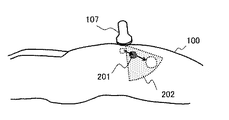
図1において、体内組織位置測定装置は、寝台500に固定して寝かされた患者100の三次元体内組織位置を超音波によって測定する装置であり、主に、呼吸同期3D情報取得部101、患者3D情報保存部102、超音波伝搬モデル作成部103、体内組織位置変更部(入力デバイス)104、超音波画像シミュレーション部105、データベース106、超音波探触子107、超音波送受信部108、超音波画像構成部109、呼吸状態計測部110、体内組織位置算出部111、体内組織位置出力部112から構成される。
In FIG. 1, the body tissue position measuring device is a device that measures the three-dimensional body tissue position of a
体内組織位置測定装置では、患者100は、ロボットアーム等の固定治具107aによりその位置が固定された超音波探触子107がその体表に押し付けられるように設置された状態で寝台500に固定される。
In the body tissue position measuring device, the
超音波探触子107は超音波送受信部108から電気信号を受け取って、超音波を励振し、患者100の体内に送信する。また、患者100の体内から反射、散乱などによって戻ってくる超音波を受け取って電気信号に変換し、超音波送受信部108に送信する。超音波送受信部108は超音波探触子107から受け取った電気信号を増幅処理し、超音波画像構成部109へ送る。
The
一般に、超音波探触子107内部には超音波素子が一列に並んで配置されており、それぞれの励振タイミングを超音波送受信部108で制御することで、超音波のフォーカス位置などが走査可能となっている。
Generally, ultrasonic elements are arranged in a row inside the
超音波画像構成部109は、超音波送受信部108で受信した反射、散乱などによる超音波受信信号を合成することで、超音波走査範囲の超音波画像を取得する。
The ultrasonic
ここで、図2に患者体内の体内組織位置の変化の様子を模式図で示す。超音波走査断面202に測定対象とする腫瘍201の中心が存在する時は、取得した超音波画像内から体内組織位置を容易に算出することができる。しかし、図2に示したように患者100の呼吸に伴って腫瘍201の位置が変化する場合、必ずしも超音波走査断面202と腫瘍201の中心が一致するわけではなく、一致しないことが多い。
Here, FIG. 2 is a schematic diagram showing a state of change in the position of internal tissues in the patient's body. When the center of the
図3Aおよび図3Bに患者の体内組織位置の変化による超音波断面画像の変化を模式図で示す。 3A and 3B are schematic views showing changes in the ultrasonic cross-sectional image due to changes in the position of tissue in the patient's body.
超音波走査断面202と腫瘍201の中心が一致する場合は、図3Aに示すような、実超音波画像301A内に臓器302Aおよび腫瘍303Aの像が描画される。
When the ultrasonic
一方、超音波走査断面202と腫瘍201の中心が一致しない場合は、図3Bに示すような、実超音波画像301B内に臓器302Bおよび腫瘍303Bの像が描画される。
On the other hand, when the ultrasonic
ここで、図3Aに示す腫瘍303Aの像と図3Bに示す腫瘍303Bの像は、同一の体内組織である腫瘍201を描画したものであるが、実超音波画像の臓器302A,302B内における相対位置やサイズが異なって描画されている。このような実超音波画像301Aと実超音波画像301Bとからのみでは、二次元画像の中で体内組織位置を推定することしかできず、三次元の体内組織位置を算出することは困難であるか、その精度が十分でない恐れがある。
Here, the image of the
そこで、本発明では、予め呼吸と同期した患者100の3D情報を取得、保存しておき、上述の3D情報を用いて様々な対象体内組織位置に対応する超音波画像をシミュレーションにより作成しておく。さらに、このシミュレーションにより得られた超音波画像と上述した3D情報における対象体内組織位置を対応付けてデータベースに保存しておく。その上で、超音波を用いて患者体内を撮像して体内組織位置を算出する際に、上述したデータベースを参照し、測定で得られた超音波画像とシミュレーションで得られた超音波画像とを比較することで、対応する体内組織位置を見出すこととする。以下、シミュレーションによって超音波画像を作成するための構成とその動作について説明する。
Therefore, in the present invention, the 3D information of the
図1において、呼吸同期3D情報取得部101は、例えば、呼吸に同期したタイミングで、少なくとも位置算出の対象とする体内組織を含むCT像を撮像する。呼吸位相ごとの複数のタイミングでCT像を撮像することで、呼吸位相ごとの患者100の体内組織位置およびその他の組織に関する情報を3D情報で取得する。この時、超音波探触子107がCT像のアーチファクトを作ることがある。このような場合は、3D情報取得の際に、超音波探触子107に代えて、超音波探触子107による体表の押し付けを模擬するための、アーチファクトが少ないダミー探触子を固定治具107aで保持し、その状態でCT像を取得することが望ましい。
In FIG. 1, the respiration-synchronized 3D
呼吸同期3D情報取得部101によって取得した情報は患者3D情報保存部102に送られ、患者3D情報保存部102にて保存される。
The information acquired by the respiratory synchronization 3D
超音波伝搬モデル作成部103は、図4に示すように、患者3D情報保存部102に保存されている患者100の3D情報に合わせて適当な小領域(メッシュ)に分割された患者体内の超音波伝搬モデル401を作成する。
As shown in FIG. 4, the ultrasonic propagation
例えば、超音波伝搬モデル作成部103では、後述する体内組織位置変更部104等を用いたオペレータによる各小領域の密度と音速の値または音響インピーダンスなどの超音波伝搬を計算するために必要な物理量の組合せの設定の入力を受けて超音波伝搬モデル401を作成する。オペレータは、患者3D情報から脂肪、筋肉、血管、骨、臓器などを判別し、組織の種類に応じて各小領域に物理量を設定する。例えば、脂肪中の音速は約1450m/s、血液・筋肉・臓器中の音速は約1530〜1630m/s、骨中の音速は約2700〜4100m/sであることが知られており、患者100の状態に合わせて適当な値を設定する。また、CT画像の輝度に応じて脂肪、筋肉、血管、骨、臓器などを超音波伝搬モデル作成部103において自動で判別し、組織の種類に応じて各省領域に物理量を設定することで設定を自動化することができる。
For example, in the ultrasonic propagation
また、超音波伝搬モデル作成部103は、実際に超音波探触子107を設置する位置とその超音波の発信方向の情報に基づいて、3Dモデルのうちどの断面の超音波画像を得るかを決定する。
Further, the ultrasonic propagation
体内組織位置変更部104は、超音波伝搬モデル作成部103で作成された超音波伝搬モデルに対して、測定対象とする体内組織や、または、その他の脂肪、筋肉、血管、骨、臓器などの位置をオペレータ等が任意に指示変更するための機器である。例えば、コンピュータの画面上に表示された超音波伝搬モデルにおいて、マウスなどの操作やテキストデータなどの入力手段を用いることができる。
The body
超音波画像シミュレーション部105は、超音波伝搬解析などの手段を用いて、超音波伝搬モデル作成部103において作成されたり、体内組織位置変更部104で変更・修正された超音波伝搬モデル内において、指定された超音波探触子位置から患者体内に入射される超音波の伝搬経路を解析し、患者体内での超音波の反射、散乱などをシミュレーションし、疑似的な超音波画像(疑似超音波画像)を計算する。伝搬解析には、有限要素法や差分法、レイトレーシングによる手法が一般には知られており、一定の精度が保証されるのであれば、どのような手法でも用いることができ、本発明を限定するものではない。
The ultrasonic
データベース106は、超音波画像シミュレーション部105にて得られた疑似超音波画像を、体内組織位置変更部104で指定した体内組織位置および呼吸同期3D情報取得部101で取得した際の患者呼吸位相の情報と対応付けた状態で保存する。
The
呼吸状態計測部110は、患者100の呼吸状態を計測する機器,装置である。呼吸状態計測部110としては、例えば、レーザ距離計を用いた患者100の体表の動きのモニタリングや患者の呼気の計測などにより呼吸位相を同定する機器、装置がある。呼吸状態計測部110としては、この他様々な方式を採用することができ、したがって、ここで示した例は、本発明を限定するものではない。
The respiratory
体内組織位置算出部111は、データベース106、超音波画像構成部109、呼吸状態計測部110を参照して、呼吸状態計測部110で測定した呼吸状態に基づいて、超音波画像構成部109でリアルタイムに取得した実超音波画像とデータベース106に記憶されたシミュレーションで得られた疑似超音波画像とを比較し、患者100の体内の組織位置を算出する。以下、比較方法の一例について図5Aおよび図5を用いて説明する。
The body tissue
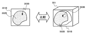
本実施例の体内組織位置測定装置では、上述のように、データベース106にはある呼吸位相での患者3D情報501とその呼吸位相における疑似超音波画像501A,501B,…が記憶されており、超音波測定の際に得られる実超音波画像と比較可能な疑似超音波画像が患者3D情報の特定の断面におけるシミュレーションにより得られている。
In the body tissue position measuring device of this embodiment, as described above, the
そこで、超音波走査断面と体内組織の中心とが一致する場合は、図5Aに示すように、データベース106に記憶された、超音波走査断面と体内組織の中心とが一致する場合における疑似超音波画像501Aをデータベース106から呼び出し、疑似超音波画像501A内に描写された臓器502Aおよび腫瘍503Aを、実超音波画像301A内に描写された臓器302Aおよび腫瘍303Aと比較し、一致すると判定されるときはその実超音波画像301Aの情報を用いて患者100の体内の組織位置を算出する。
Therefore, when the ultrasonic scanning cross section and the center of the internal organ match, as shown in FIG. 5A, the pseudo-ultrasonic wave stored in the
これに対し、超音波走査断面と体内組織の中心とが一致しない場合は、図5Bに示すように、呼吸状態計測部110で測定したその時の呼吸位相の情報に基づいて、データベース106に記憶された、超音波走査断面と体内組織の中心とが一致しない場合における疑似超音波画像501Bをデータベース106から呼び出し、疑似超音波画像501B内に描写された臓器502Bおよび腫瘍503Bを、実超音波画像301B内に描写された臓器302Bおよび腫瘍303Bと比較し、一致すると判定されるときはその実超音波画像301Bの情報を用いて患者100の体内の組織位置を算出する。
On the other hand, when the ultrasonic scanning cross section and the center of the internal tissue do not match, as shown in FIG. 5B, it is stored in the
ここで、体内組織位置算出部111における疑似超音波画像と実超音波画像との比較に際しては、例えば、画像処理などにより、測定対象とする体内組織の断面像内における体内組織の形状、サイズ、位置などの複数のパラメータを抽出してその差異を定量的に比較することができる。例えば、両者の差異を誤差として計算し、計算した誤差を予め適当に定めた閾値と比較し、閾値よりも小さいときに一致すると判定し、誤差が閾値以上の時は一致しないと判定することができる。両者が一致しないと判定された場合には、あらかじめデータベース106に保存しておいた別の体内組織位置が指定され、シミュレーションされて得られた超音波断面画像を参照し、再度比較を実行し、一致するデータを検索する。
Here, when comparing the pseudo-ultrasonic image and the actual ultrasonic image in the internal tissue
また、体内組織位置算出部111における比較では、例えば、画像同士の相関係数を計算し、予め適当に定めた閾値が相関係数を越える場合に両者が一致すると判定し、相関係数が閾値以下の場合には一致しないと判定することができる。
Further, in the comparison in the internal tissue
ここで、体内組織位置算出部111におけるシミュレーションと実超音波断面像の比較に際して、疑似超音波画像と実超音波断面像で得られる画素サイズや画素形状が異なることが想定される。例えば、体内組織の断面像内における形状、サイズ、位置などは、画素サイズが大きく異なると、比較が難しくなるか、その比較の精度を十分に担保することが困難となる恐れがある。また、相関係数を計算するためには、両者の画素サイズと画素形状がある程度の水準で一致している必要がある。
Here, when comparing the simulation and the actual ultrasonic cross-sectional image in the internal tissue
そこで、体内組織位置算出部111では、最初に疑似超音波画像と実超音波画像の解像度を比較し、疑似超音波画像と実超音波画像のどちらか一方の画像に関して画素データを内挿することで両者の画像の解像度を一致させておくことが好適である。画素の内挿の方法は、最近傍補間、双一次補間、双三次補間などが一般に知られており、目標とする位置算出精度に応じて適切な方法を選択することができる。内挿処理を行う画像はどちらの画像でも良いが、解像度の低い方の画像を解像度の高い画像に合わせることが望ましい。
Therefore, the internal tissue
一致するデータが発見できた場合は、体内組織位置算出部111は、対応する体内組織位置の情報を体内組織位置出力部112に対して出力する。出力方法は、例えば、モニタ上に基準座標からの相対位置を数値で表示させる、発見した超音波断面画像シミュレーション結果に対応する患者3D情報をモニタ上に表示させる、あるいは、適当にエンコードされた電気信号として有線あるいは無線で送信するなどの方法がある。この他、出力方法は、算出した体内組織位置の利用目的に応じて様々な方式を採用することができ、したがって、ここで示した例は、本発明を限定するものではない。
When the matching data is found, the internal tissue
上述の超音波伝搬モデル作成部103、超音波画像シミュレーション部105、超音波送受信部108、超音波画像構成部109、体内組織位置算出部111の各部はコンピュータやFPGA(Field−Programmable Gate Array)などにプログラムを読み込ませて計算を実行させることで実現できる。
Each part of the above-mentioned ultrasonic propagation
患者3D情報保存部102やデータベース106は、揮発性メモリや不揮発性メモリ、ハードディスク、外部記憶装置などの各種記憶媒体を用いて構成することができる。
The patient 3D
次に、図6乃至図8を用いて、上述の体内組織位置測定装置を好適に用いた本実施例の体内組織位置測定方法について説明する。 Next, with reference to FIGS. 6 to 8, the method for measuring the position of the internal tissue of the present embodiment, which preferably uses the above-mentioned internal tissue position measuring device, will be described.
最初に、図6を用いて本実施例の体内組織位置測定方法のうち、超音波伝搬モデルの作成方法について説明する。 First, among the methods for measuring the position of internal tissues in this example, a method for creating an ultrasonic propagation model will be described with reference to FIG.
図6において、まず、処理を開始する(ステップS101)。なお、本ステップでは、患者100は既に寝台500に固定されているものとする。また、固定治具107aによる超音波探触子107、あるいはアーチファクトを低減したダミー探触子の患者100への実超音波画像取得時を模擬した押し付け、呼吸同期3D情報取得部101などによる患者100の呼吸状態の測定の準備についても完了しているものとする。
In FIG. 6, first, the process is started (step S101). In this step, it is assumed that the
次いで、呼吸同期3D情報取得部101により、患者100の呼吸位相ごとの3D情報を収集・保存する(ステップS102)。以下では、3D情報としてCT像を用いた場合を例として、フローを説明する。
Next, the respiratory-synchronized 3D
次いで、超音波伝搬モデル作成部103により、超音波伝搬モデルを作成する(ステップS103)。
Next, the ultrasonic wave propagation
次いで、ステップS103にて作成した超音波伝搬モデルにおいて、超音波の起点となる超音波探触子107の位置,向きと測定対象とする体内組織位置を指定する(ステップS104)。
Next, in the ultrasonic propagation model created in step S103, the position and orientation of the
次いで、ステップS103で作成した超音波伝搬モデルに対して、ステップS104で指定した超音波探触子107の位置,向きと体内組織位置を含む領域において超音波伝搬解析を実施し、シミュレーション画像(疑似超音波画像)を作成する(ステップS105)。
Next, the ultrasonic propagation model created in step S103 is subjected to ultrasonic propagation analysis in a region including the position, orientation and internal tissue position of the
次いで、ステップS105で作成した疑似超音波画像を、ステップS104で指定した体内組織位置と組みにしてデータベース106に保存する(ステップS106)。 Next, the pseudo-ultrasonic image created in step S105 is combined with the internal tissue position specified in step S104 and stored in the database 106 (step S106).
次いで、十分な量の疑似超音波画像がデータベース106に保存されたか否かを判定する(ステップS107)。 Then, it is determined whether or not a sufficient amount of pseudo-ultrasound images are stored in the database 106 (step S107).
本実施例の体内組織位置測定方法においては、データベース106に保存された疑似超音波画像の数は最終的な体内組織位置算出精度に影響を与える。具体的には、体内組織位置の算出精度は、ステップS104で指定した体内組織位置の疑似超音波画像間の差分程度の誤差になる。そこで、ステップS107の判定では、算出される最終的な体内組織位置算出の精度が目的に対して十分かどうかを判定することによって十分な量の疑似超音波画像がデータベース106に保存されたか否かを判定することができる。
In the method for measuring the position of internal tissue in the present embodiment, the number of pseudo-ultrasonic images stored in the
データベース106に保存された疑似超音波画像の保存量が不十分であると判定されたときは処理をステップS104に戻し、別のパターンでシミュレーションおよび疑似超音波画像の作成処理を実施する。疑似超音波画像が十分に保存されていると判定されたときはステップS108に処理を進める。
When it is determined that the amount of the pseudo-ultrasonic image stored in the
なお、疑似超音波画像の間については、補間等によって超音波伝搬解析以外の手段で疑似超音波画像を作成するなどして、精度を担保することもできる。 It should be noted that the accuracy can be ensured between the pseudo-ultrasonic images by creating a pseudo-ultrasonic image by means other than the ultrasonic propagation analysis by interpolation or the like.
次いで、必要な呼吸位相のパターンで患者3D情報が得られているかどうかを判定する(ステップS108)。上述のステップS107における説明と同様で、最終的な体内組織位置算出精度に応じて判定の基準とする必要な呼吸位相のパターン数を決定する。データベース106に保存されたシミュレーションパターン数が不十分であると判定されたときはステップS102に処理を戻し、別の患者3D情報を用いてシミュレーションを実施する。パターン数が十分であると判定されたときはステップS109に処理を進め、超音波伝搬モデルの作成処理を終了する。
Next, it is determined whether or not the patient 3D information is obtained with the required respiratory phase pattern (step S108). Similar to the above description in step S107, the number of patterns of the required respiratory phase to be used as a criterion for determination is determined according to the final accuracy of calculating the position of the internal tissue. When it is determined that the number of simulation patterns stored in the
なお、本実施例では複数の呼吸状態と体内組織位置のパターンを収集する例を示したが、十分な精度が確保できるならば、患者の息止め状態の計測結果のみを使用しても良い。また、人体を均一な密度・音速の物質として簡易的にモデル化しても良い。 In this example, a plurality of patterns of respiratory state and body tissue position are collected, but if sufficient accuracy can be ensured, only the measurement result of the patient's breath-holding state may be used. Further, the human body may be simply modeled as a substance having a uniform density and sound velocity.
次に、図7および図8を用いて、上述の体内組織位置測定装置を好適に用いた体内組織位置測定方法のうち、体内組織位置算出部111における体内組織位置の算出方法について説明する。
Next, among the methods for measuring the position of internal tissue using the above-mentioned internal tissue position measuring device, the method for calculating the position of internal tissue in the internal tissue
まず、処理を開始する(ステップS201)。ここでは、ステップS101と同様に、患者100は既に寝台500に固定されており、また固定治具107aによる超音波探触子107の押し付けや、呼吸状態計測部110による患者100の呼吸状態の測定の準備についても完了しているものとする。
First, the process is started (step S201). Here, as in step S101, the
次いで、超音波探触子107による患者100の体内に向けた超音波の送信や、超音波送受信部108による患者体内から反射、散乱した超音波の信号を収集する(ステップS202)。
Next, the
次いで、超音波画像構成部109によって、収集した超音波信号を用いて実超音波画像を構成する(ステップS203)。
Next, the ultrasonic
次いで、呼吸状態計測部110を用いて患者100の呼吸状態を計測する(ステップS204)。
Next, the respiratory state of the
ここで、実超音波画像を構成するためのステップS202,S203と呼吸状態を計測するステップS204は同時に実施しても良いし、その順番を入れ替えて実施しても良い。 Here, steps S202 and S203 for constructing an actual ultrasonic image and step S204 for measuring the respiratory state may be performed at the same time, or the order may be changed.
次に、データベース106を参照し、データベース106に保存された疑似超音波画像を読み出す(ステップS205)。本ステップにおける疑似超音波画像の選択にあたっては、ステップS204で計測した患者の呼吸状態を用いて、同じ呼吸状態で取得した3D情報から生成した疑似超音波画像、近似する呼吸状態で取得した3D情報から生成した疑似超音波画像、または近似する呼吸状態で取得した3D情報から補間によって生成した疑似超音波画像から適宜選択する。
Next, the pseudo-ultrasound image stored in the
次いで、ステップS203で構成した実超音波画像をステップS205で選択した疑似超音波画像と比較し、一致する疑似超音波画像を検索する(ステップS206)。 Next, the actual ultrasonic image configured in step S203 is compared with the pseudo-ultrasonic image selected in step S205, and a matching pseudo-ultrasonic image is searched for (step S206).
次いで、ステップS206における検索が成功したか否かを判定する(ステップS207)。検索が成功したと判定された場合は、ステップS208Aに処理を進めて、疑似超音波画像に対応する体内組織位置をデータベース106から読み出し、体内組織位置出力部112に出力する(ステップS208A)。これに対し、ステップS207にて検索が失敗と判定された場合は、体内組織位置出力部112にエラー信号を出力する(ステップS208B)。
Next, it is determined whether or not the search in step S206 was successful (step S207). If it is determined that the search is successful, the process proceeds to step S208A, the internal tissue position corresponding to the pseudo-ultrasonic image is read from the
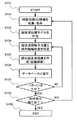
図8は上述のステップS206における実超音波画像と疑似超音波画像との検索方法の詳細を示すフローチャートである。 FIG. 8 is a flowchart showing the details of the search method between the actual ultrasonic image and the pseudo ultrasonic image in step S206 described above.
まず、処理を開始する(ステップS301)。 First, the process is started (step S301).
次いで、実超音波画像から体内組織の形状、サイズ、位置を抽出する(ステップS302)。 Next, the shape, size, and position of the internal tissue are extracted from the actual ultrasonic image (step S302).
続いて、疑似超音波画像から体内組織の形状、サイズ、位置を抽出する(ステップS303)。 Subsequently, the shape, size, and position of the internal tissue are extracted from the pseudo-ultrasound image (step S303).
次いで、ステップS302およびステップS303で抽出した体内組織の形状、サイズ、位置から差異を誤差として計算する(ステップS304)。例えば、それぞれ値の差の二乗和などを誤差として用いることができる。このステップS304では、更に、誤差をあらかじめ設定した閾値と比較し、一致か不一致かを判定する。 Next, the difference is calculated as an error from the shape, size, and position of the body tissue extracted in steps S302 and S303 (step S304). For example, the sum of squares of the differences between the values can be used as an error. In this step S304, the error is further compared with a preset threshold value to determine whether the error is a match or a mismatch.
ステップS304において誤差が閾値以下であると判定された場合は一致したとみなし、ステップS306に処理を進めて、疑似超音波画像を体内組織位置出力部112出力した後、処理を終了する(ステップS307)。
If it is determined in step S304 that the error is equal to or less than the threshold value, it is considered that they match, the process proceeds to step S306, the pseudo-ultrasonic image is output to the internal tissue
これに対し、ステップS304において誤差が閾値より大きいと判定された場合は一致しないとみなし、ステップS302に処理を戻し、異なる疑似超音波画像と実超音波画像との比較を実行する。 On the other hand, if it is determined in step S304 that the error is larger than the threshold value, it is considered that they do not match, the process is returned to step S302, and a comparison between a different pseudo-ultrasonic image and an actual ultrasonic image is executed.
なお、ステップS206における実超音波画像と疑似超音波画像との検索方法は図8に示す手順に限られず、例えば、実超音波画像と疑似超音波画像の相関係数を計算し、予め適当に定めた閾値が相関係数を越える場合に両者が一致すると判定し、相関係数が閾値以下の場合には一致しないと判定する方法とすることができる。 The method of searching the real ultrasonic image and the pseudo ultrasonic image in step S206 is not limited to the procedure shown in FIG. 8, and for example, the correlation coefficient between the real ultrasonic image and the pseudo ultrasonic image is calculated and appropriately prepared in advance. If the predetermined threshold exceeds the correlation coefficient, it is determined that the two match, and if the correlation coefficient is less than the threshold, it is determined that they do not match.
また、疑似超音波画像と実超音波断面像で得られる画素サイズや画素形状が異なるか否かを判定し、いずれか一方の画素データを内挿することにより、実超音波画像と疑似超音波画像との解像度を一致させることができる。 In addition, it is determined whether or not the pixel size and pixel shape obtained from the pseudo-ultrasonic image and the real ultrasonic cross-sectional image are different, and by interpolating one of the pixel data, the real ultrasonic image and the pseudo-ultrasonic wave are obtained. The resolution can be matched with the image.
このようにして得られた疑似超音波画像を用いて、上述のステップS208にて対応する患者3D情報から患者100内の組織位置に関する3D位置を出力することができる。 Using the pseudo-ultrasonic image thus obtained, it is possible to output the 3D position regarding the tissue position in the patient 100 from the corresponding patient 3D information in step S208 described above.
次に、本実施例の効果について説明する。 Next, the effect of this embodiment will be described.
上述した本発明の第1の実施例の体内組織位置測定装置は、呼吸と同期した患者100の3D情報を取得する呼吸同期3D情報取得部101と、呼吸同期3D情報取得部101によって取得した3D情報を保存する患者3D情報保存部102と、患者3D情報保存部102に保存された患者3D情報を用いて超音波伝搬モデルを作成する超音波伝搬モデル作成部103と、超音波伝搬モデル作成部103において作成された超音波伝搬モデル内での超音波の伝搬をシミュレーションして疑似超音波画像を計算する超音波画像シミュレーション部105と、超音波画像シミュレーション部105で計算された疑似超音波画像を患者3D情報と対応づけて保存するデータベース106と、患者100の体内に向けて超音波を送信し、患者100の体内から戻る超音波を受信する超音波探触子107および超音波送受信部108と、超音波探触子107および超音波送受信部108で受信した超音波から実超音波画像を構成する超音波画像構成部109と、患者100の呼吸状態を測定する呼吸状態計測部110と、呼吸状態計測部110で測定した呼吸状態に基づいて、超音波画像構成部109で構成された実超音波画像とデータベース106に記憶された疑似超音波画像とを比較して、患者100の体内の組織位置を算出する体内組織位置算出部111と、を備えたものである。
The internal tissue position measuring device of the first embodiment of the present invention described above is a respiratory-synchronized 3D
これによって、侵襲性の低い超音波を用いた患者100の体内の組織の位置をリアルタイムで正確に測定することができ、3次元超音波探触子等を用いる場合などのようにシステムを複雑にすることなく、正確かつリアルタイムに患者体内の体内組織位置を測定することができる。
As a result, the position of the tissue in the body of the
また、超音波伝搬モデル作成部103で作成した超音波伝搬モデル内の体内組織の位置を変え、変えた超音波伝搬モデルに基づいてシミュレーションさせるための入力デバイスとして体内組織位置変更部104を更に備えたため、治療計画時に拾いきれなかった細かな情報を設定することができ、より精度の高い超音波伝搬モデルを設定することができることから、より正確な体内組織位置の測定が可能となる。
Further, the body tissue
更に、体内組織位置算出部111は、実超音波画像と疑似超音波画像のそれぞれの画像内における体内組織の形状、サイズ、および位置を画像処理により抽出し、形状、サイズ、位置の差異を誤差として計算して、計算した誤差を予め設定された閾値と比較して患者100の体内の組織位置を算出することで、実超音波画像と疑似超音波画像との比較を高精度に実行することができ、更に正確な体内組織位置の測定を行うことができる。
Further, the internal tissue
また、体内組織位置算出部111は、実超音波画像と疑似超音波画像との相関係数を計算し、計算した相関係数と予め設定された閾値とを比較することで患者100の体内の組織位置を算出することによっても、実超音波画像と疑似超音波画像との比較を高精度に実行することができ、更に正確な体内組織位置の測定を行うことができる。
Further, the internal tissue
更に、体内組織位置算出部111は、実超音波画像と疑似超音波画像との解像度を、いずれか一方の画素データを内挿により一致させることで、より精度の高い実超音波画像と疑似超音波画像との比較が可能となり、更に正確な体内組織位置の測定が可能となる。
Further, the internal tissue
<第2の実施例>
本発明の第2の実施例の放射線治療装置を図9を用いて説明する。図9は本発明の第2の実施例である放射線照射装置の構成概念を示す図である。第1の実施例と同じ構成には同一の符号を示し、説明は省略する。以下の実施例においても同様とする。
<Second Example>
The radiotherapy apparatus of the second embodiment of the present invention will be described with reference to FIG. FIG. 9 is a diagram showing a configuration concept of a radiation irradiation device according to a second embodiment of the present invention. The same reference numerals are shown in the same configurations as in the first embodiment, and the description thereof will be omitted. The same applies to the following examples.
図9に示すように、本実施例の放射線治療装置は、対象とする体内組織位置を特定して、標的に対して放射線を照射する装置であって、第1の実施例の体内組織位置測定装置に加えて、更に、放射線を標的に対して照射する放射線照射部(照射装置)901と放射線制御部902を備えている。
As shown in FIG. 9, the radiation therapy device of the present embodiment is a device that identifies the position of the target body tissue and irradiates the target with radiation, and measures the position of the body tissue of the first example. In addition to the device, it further includes a radiation irradiation unit (irradiation device) 901 and a
放射線制御部902は体内組織位置算出部111によって算出された体内組織位置を信号として受け取り、放射線照射部901を制御することにより患者100に照射されるX線や粒子線などの放射線903の照射位置を制御する。これにより、治療計画で計画した治療対象部位の領域に集中して放射線を照射するよう構成されている。
The
本実施例の放射線治療装置では、患者100の呼吸状態を呼吸状態計測部110等によりモニタリングすることで呼吸位相を特定して、適切な超音波伝搬モデルを選択して疑似超音波画像を構成する。これにより、治療対象部位が目的の座標領域を通過する適切なタイミングを特定して、放射線の照射を高精度で開始したり停止したりすることができる。
In the radiotherapy apparatus of this embodiment, the respiratory state of the
また、適切なフレームレートで体内組織位置算出を繰り返し実行することで治療対象部位の動きに応じた放射線903の制御を実施することができる。
In addition, the
本発明の第2の実施例の放射線治療装置のように、実施例1の体内組織位置測定装置と、放射線を標的に対して照射する放射線照射部901と、体内組織位置測定装置を用いて測定した体内組織位置に基づいて放射線照射部901における放射線照射位置を制御する放射線制御部902と、を備えたことにより、治療中の体内組織の位置の特定に由来するX線照射による被ばく量を低減することができ、かつ呼吸などの患者の動きに対応した精度の高い放射線治療を実施することができる。
Measurement using the body tissue position measuring device of Example 1, the
<第3の実施例>
本発明の第3の実施例の体内組織位置測定装置および放射線治療装置、ならびに体内組織位置測定方法を図10を用いて説明する。図10は、本実施例の体内組織位置測定装置における超音波断面画像の概念図である。
<Third Example>
The body tissue position measuring device and the radiotherapy device of the third embodiment of the present invention, and the body tissue position measuring method will be described with reference to FIG. FIG. 10 is a conceptual diagram of an ultrasonic cross-sectional image of the internal tissue position measuring device of this embodiment.
本実施例では、第1の実施例における体内組織位置測定装置において、患者100の体内に埋め込むための超音波を強く反射する超音波反射体1001を更に備えているものである。
In this embodiment, the internal tissue position measuring device according to the first embodiment further includes an
更に、体内組織位置を測定する際には、患者100の体内に超音波反射体1001を埋め込み、超音波反射体1001を測定対象の体内組織の位置を示す指標として、この超音波反射体1001の位置を算出することで患者100の体内の組織位置を算出するものである。
Further, when measuring the position of the internal tissue, the
一般的に、生体組織は軟組織であり、超音波の減衰が大きいうえ、体内組織間の音響インピーダンス差が小さいために超音波反射が起こりにくいことが知られている。このため、位置算出の対象としている体内組織からの十分な反射信号が得られず、鮮明な実超音波画像が得られない場合がある。 In general, it is known that living tissue is a soft tissue, and ultrasonic reflection is unlikely to occur because the attenuation of ultrasonic waves is large and the difference in acoustic impedance between body tissues is small. Therefore, a sufficient reflected signal from the internal tissue for which the position is calculated may not be obtained, and a clear actual ultrasonic image may not be obtained.
そこで、本実施例では、超音波伝搬モデル作成前である作成呼吸同期3D情報を取得する段階で、あらかじめ生体組織と音響インピーダンスが大きく異なる超音波反射体1001を患者100の体内、特に注目する治療対象部位などの体内組織の近傍に埋め込んでおく。これにより、より鮮明な実超音波画像が得られるようにする。
Therefore, in this embodiment, at the stage of acquiring the created respiratory synchronization 3D information before the creation of the ultrasonic propagation model, the
その上で、超音波反射体1001の映り込んだ超音波伝搬モデル401Aを作成するとともに、埋め込んだ超音波反射体1001と位置を算出したい体内組織の間の相対座標をあらかじめ算出しておく。また、実超音波画像と疑似超音波画像との比較の際に超音波反射体1001の形状、サイズ、位置等の誤差を計算したり、相関係数の計算の際に超音波反射体1001を用いたりする。
Then, the
本実施例では、注目する体内組織の位置を算出する際に、超音波反射体1001の絶対座標にあらかじめ算出しておいた相対座標を加える。
In this embodiment, when calculating the position of the body tissue of interest, the relative coordinates calculated in advance are added to the absolute coordinates of the
本発明の第3の実施例の体内組織位置測定装置においても、前述した第1の実施例の体内組織位置測定装置とほぼ同様な効果が得られる。 The body tissue position measuring device of the third embodiment of the present invention also has almost the same effect as the body tissue position measuring device of the first embodiment described above.
また、患者100の体内に埋め込む超音波反射体1001を更に備え、体内組織位置算出部111は、疑似超音波画像および実超音波画像に映る超音波反射体1001を用いて患者100の体内の組織位置を算出ことにより、実超音波画像と疑似超音波画像との比較をより高い精度で行うことができ、更に正確な体内組織位置の測定を行うことができる。
Further, an
<その他>
なお、本発明は、上記の実施例に限定されるものではなく、様々な変形例が含まれる。上記の実施例は本発明を分かりやすく説明するために詳細に説明したものであり、必ずしも説明した全ての構成を備えるものに限定されるものではない。また、ある実施例の構成の一部を他の実施例の構成に置き換えることも可能であり、また、ある実施例の構成に他の実施例の構成を加えることも可能である。また、各実施例の構成の一部について、他の構成の追加・削除・置換をすることも可能である。
<Others>
The present invention is not limited to the above examples, and includes various modifications. The above-mentioned examples have been described in detail in order to explain the present invention in an easy-to-understand manner, and are not necessarily limited to those having all the described configurations. It is also possible to replace a part of the configuration of one embodiment with the configuration of another embodiment, and it is also possible to add the configuration of another embodiment to the configuration of one embodiment. It is also possible to add / delete / replace a part of the configuration of each embodiment with another configuration.
100…患者
101…呼吸同期3D情報取得部
102…患者3D情報保存部
103…超音波伝搬モデル作成部
104…体内組織位置変更部
105…超音波画像シミュレーション部
106…データベース
107…超音波探触子
108…超音波送受信部
109…超音波画像構成部
110…呼吸状態計測部
111…体内組織位置算出部
112…体内組織位置出力部
201…腫瘍
202…超音波走査断面
301A,301B…ある呼吸位相での実超音波画像
302A,302B…実超音波画像中に描画された臓器
303A,303B…実超音波画像中に描画された腫瘍
401,401A…超音波伝搬モデル
501…患者3D情報
501A,501B…ある呼吸位相での疑似超音波画像
502A,502B…患者3D情報中に描画された臓器
503A,503B…患者3D情報中に描画された測定対象の腫瘍
901…放射線照射部
902…放射線制御部
903…放射線
1001…超音波反射体
100 ...
Claims (11)
呼吸と同期した患者の3D情報を取得する呼吸同期3D情報取得部と、
前記呼吸同期3D情報取得部によって取得した前記3D情報を保存する患者3D情報保存部と、
前記患者3D情報保存部に保存された前記患者3D情報を用いて超音波伝搬モデルを作成する超音波伝搬モデル作成部と、
前記超音波伝搬モデル作成部において作成された前記超音波伝搬モデル内での超音波の伝搬をシミュレーションして疑似超音波画像を計算する超音波画像シミュレーション部と、
前記超音波画像シミュレーション部で計算された前記疑似超音波画像を前記患者3D情報と対応づけて保存するデータベースと、
前記患者の体内に向けて超音波を送信し、前記患者の体内から戻る超音波を受信する超音波送受信部と、
前記超音波送受信部で受信した超音波から実超音波画像を構成する超音波画像構成部と、
前記患者の呼吸状態を測定する呼吸状態計測部と、
前記呼吸状態計測部で測定した呼吸状態に基づいて、前記超音波画像構成部で構成された前記実超音波画像と前記データベースに記憶された疑似超音波画像とを比較して、前記患者の体内の組織位置を算出する体内組織位置算出部と、を備えた
ことを特徴とする体内組織位置測定装置。 It is an internal tissue position measuring device that measures the position of tissue in the patient's body by ultrasonic waves.
Respiratory-synchronized 3D information acquisition unit that acquires 3D information of the patient synchronized with respiration,
A patient 3D information storage unit that stores the 3D information acquired by the respiratory synchronization 3D information acquisition unit, and a patient 3D information storage unit.
An ultrasonic propagation model creation unit that creates an ultrasonic propagation model using the patient 3D information stored in the patient 3D information storage unit, and an ultrasonic propagation model creation unit.
An ultrasonic image simulation unit that calculates a pseudo-ultrasonic image by simulating the propagation of ultrasonic waves in the ultrasonic propagation model created by the ultrasonic propagation model creation unit.
A database that stores the pseudo-ultrasonic image calculated by the ultrasonic image simulation unit in association with the patient 3D information, and a database.
An ultrasonic transmitter / receiver that transmits ultrasonic waves toward the patient's body and receives ultrasonic waves returning from the patient's body.
An ultrasonic image component that composes an actual ultrasonic image from the ultrasonic waves received by the ultrasonic transmitter / receiver, and an ultrasonic image component.
A respiratory condition measuring unit that measures the respiratory condition of the patient,
Based on the respiratory condition measured by the respiratory condition measuring unit, the actual ultrasonic image composed of the ultrasonic image constituent unit and the pseudo ultrasonic image stored in the database are compared with each other in the patient's body. An internal tissue position measuring device characterized by having an internal tissue position calculating unit for calculating the tissue position of the body.
前記超音波伝搬モデル作成部で作成した前記超音波伝搬モデル内の体内組織の位置を変え、変えた超音波伝搬モデルに基づいてシミュレーションさせるための入力デバイスを更に備えた
ことを特徴とする体内組織位置測定装置。 In the body tissue position measuring device according to claim 1,
An internal tissue characterized by being further provided with an input device for changing the position of the internal tissue in the ultrasonic propagation model created by the ultrasonic propagation model creation unit and performing a simulation based on the changed ultrasonic propagation model. Position measuring device.
前記体内組織位置算出部は、前記実超音波画像と前記疑似超音波画像のそれぞれの画像内における体内組織の形状、サイズ、および位置を画像処理により抽出し、前記形状、サイズ、位置の差異を誤差として計算して、計算した前記誤差を予め設定された閾値と比較することで、前記患者の体内の組織位置を算出する
ことを特徴とする体内組織位置測定装置。 In the body tissue position measuring device according to claim 1,
The internal tissue position calculation unit extracts the shape, size, and position of the internal tissue in each image of the actual ultrasonic image and the pseudo-ultrasonic image by image processing, and obtains the difference in the shape, size, and position. An internal tissue position measuring device for calculating the tissue position in the body of the patient by calculating as an error and comparing the calculated error with a preset threshold value.
前記体内組織位置算出部は、前記実超音波画像と疑似超音波画像との相関係数を計算し、計算した前記相関係数と予め設定された閾値とを比較することで前記患者の体内の組織位置を算出する
ことを特徴とする体内組織位置測定装置。 In the body tissue position measuring device according to claim 1,
The internal tissue position calculation unit calculates the correlation coefficient between the actual ultrasonic image and the pseudo-ultrasonic image, and compares the calculated correlation coefficient with a preset threshold value in the patient's body. An in-body tissue position measuring device characterized by calculating the tissue position.
前記体内組織位置算出部は、前記実超音波画像と疑似超音波画像との解像度を、いずれか一方の画素データを内挿することにより一致させる
ことを特徴とする体内組織位置測定装置。 In the body tissue position measuring device according to claim 1,
The internal tissue position calculation unit is an internal tissue position measuring device, characterized in that the resolutions of the actual ultrasonic image and the pseudo ultrasonic image are matched by interpolating pixel data of either one.
前記患者の体内に埋め込む超音波反射体を更に備え、
前記体内組織位置算出部は、前記疑似超音波画像および前記実超音波画像に映る前記超音波反射体を用いて前記患者の体内の組織位置を算出する
ことを特徴とする体内組織位置測定装置。 In the body tissue position measuring device according to claim 1,
Further equipped with an ultrasonic reflector to be embedded in the patient's body,
The internal tissue position calculation unit is an internal tissue position measuring device that calculates the tissue position in the patient's body by using the pseudo-ultrasonic image and the ultrasonic reflector reflected in the actual ultrasonic image.
請求項1に記載の体内組織位置測定装置と、
前記放射線を前記標的に対して照射する照射装置と、
前記体内組織位置測定装置を用いて測定した体内組織位置に基づいて前記照射装置における放射線照射位置を制御する放射線制御部と、を備えた
ことを特徴とする放射線治療装置。 A radiotherapy device that identifies the location of target body tissue and irradiates the target with radiation.
The body tissue position measuring device according to claim 1,
An irradiation device that irradiates the target with the radiation,
A radiotherapy apparatus including a radiation control unit that controls an irradiation position in the irradiation apparatus based on the position of the internal tissue measured by the internal tissue position measuring apparatus.
呼吸と同期した患者の3D情報を取得するステップと、
取得した前記3D情報を用いて超音波伝搬モデルを作成するステップと、
作成した前記超音波伝搬モデル内での超音波の伝搬をシミュレーションして疑似超音波画像を作成するステップと、
作成した前記疑似超音波画像を前記患者3D情報と対応付けてデータベースに保存するステップと、
前記患者の体内に向けて超音波を送信するとともに前記患者の体内から戻る超音波を受信し、受信した超音波から実超音波画像を構成するステップと、
前記患者の呼吸状態を測定するステップと、
測定した前記患者の呼吸状態に基づいて、前記実超音波画像と前記疑似超音波画像とを比較して、前記患者の体内の組織位置を算出するステップと、を有する
ことを特徴とする体内組織位置測定方法。 It is a method of measuring the position of internal tissue in the patient's body by ultrasonic waves.
Steps to acquire 3D information of the patient synchronized with breathing,
Steps to create an ultrasonic propagation model using the acquired 3D information,
Steps to create a pseudo-ultrasonic image by simulating the propagation of ultrasonic waves in the created ultrasonic propagation model, and
A step of associating the created pseudo-ultrasonic image with the patient 3D information and saving it in a database, and
A step of transmitting ultrasonic waves toward the patient's body, receiving ultrasonic waves returning from the patient's body, and constructing an actual ultrasonic image from the received ultrasonic waves.
The step of measuring the respiratory condition of the patient and
A body tissue characterized by having a step of comparing the actual ultrasonic image and the pseudo-ultrasonic image based on the measured respiratory state of the patient and calculating the tissue position in the body of the patient. Position measurement method.
前記体内組織位置を算出するステップは、
画像処理により、前記実超音波画像と前記疑似超音波画像のそれぞれの画像内における体内組織の形状、サイズ、および位置を画像処理により抽出するステップと、
前記形状、サイズ、および位置の差異を誤差として計算するステップと、
前記誤差を予め設定された閾値と比較することで前記実超音波画像と前記疑似超音波画像とが一致するか否かを判定するステップと、を有する
ことを特徴とする体内組織位置測定方法。 In the method for measuring the position of body tissue according to claim 8,
The step of calculating the position of the tissue in the body is
A step of extracting the shape, size, and position of internal tissues in each image of the real ultrasonic image and the pseudo ultrasonic image by image processing, and a step of extracting the position by image processing.
The step of calculating the difference in shape, size, and position as an error, and
A method for measuring the position of an internal tissue, which comprises a step of determining whether or not the actual ultrasonic image and the pseudo-ultrasonic image match by comparing the error with a preset threshold value.
前記体内組織位置を算出するステップは、
前記実超音波画像と疑似超音波画像との相関係数を計算するステップと、
前記相関係数を予め設定された閾値と比較することで前記実超音波画像と前記疑似超音波画像とが一致するか否かを判定するステップと、を有する
ことを特徴とする体内組織位置測定方法。 In the method for measuring the position of body tissue according to claim 8,
The step of calculating the position of the tissue in the body is
The step of calculating the correlation coefficient between the real ultrasonic image and the pseudo ultrasonic image, and
Body tissue position measurement characterized by having a step of determining whether or not the actual ultrasonic image and the pseudo-ultrasonic image match by comparing the correlation coefficient with a preset threshold value. Method.
前記体内組織位置を算出するステップは、
前記実超音波画像と疑似超音波画像との解像度を、いずれか一方の画素データを内挿することにより一致させるステップ、を更に有する
ことを特徴とする体内組織位置測定方法。 In the method for measuring the position of body tissue according to claim 8,
The step of calculating the position of the tissue in the body is
A method for measuring the position of internal tissue, which further comprises a step of matching the resolutions of the real ultrasonic image and the pseudo ultrasonic image by interpolating the pixel data of either one.
Priority Applications (2)
| Application Number | Priority Date | Filing Date | Title |
|---|---|---|---|
| JP2017083389A JP6867218B2 (en) | 2017-04-20 | 2017-04-20 | Body tissue position measuring device and radiotherapy device, and body tissue position measuring method |
| PCT/JP2018/008404 WO2018193731A1 (en) | 2017-04-20 | 2018-03-05 | Body tissue position measurement device, radiation therapy device, and body tissue position measurement method |
Applications Claiming Priority (1)
| Application Number | Priority Date | Filing Date | Title |
|---|---|---|---|
| JP2017083389A JP6867218B2 (en) | 2017-04-20 | 2017-04-20 | Body tissue position measuring device and radiotherapy device, and body tissue position measuring method |
Publications (3)
| Publication Number | Publication Date |
|---|---|
| JP2018175688A JP2018175688A (en) | 2018-11-15 |
| JP2018175688A5 JP2018175688A5 (en) | 2020-04-09 |
| JP6867218B2 true JP6867218B2 (en) | 2021-04-28 |
Family
ID=63857106
Family Applications (1)
| Application Number | Title | Priority Date | Filing Date |
|---|---|---|---|
| JP2017083389A Active JP6867218B2 (en) | 2017-04-20 | 2017-04-20 | Body tissue position measuring device and radiotherapy device, and body tissue position measuring method |
Country Status (2)
| Country | Link |
|---|---|
| JP (1) | JP6867218B2 (en) |
| WO (1) | WO2018193731A1 (en) |
Families Citing this family (2)
| Publication number | Priority date | Publication date | Assignee | Title |
|---|---|---|---|---|
| KR20200132144A (en) * | 2019-05-15 | 2020-11-25 | 삼성메디슨 주식회사 | Ultrasound diagnostic apparatus and method for operating the same |
| JP7433927B2 (en) * | 2020-01-22 | 2024-02-20 | キヤノンメディカルシステムズ株式会社 | Radiation therapy planning device |
Family Cites Families (4)
| Publication number | Priority date | Publication date | Assignee | Title |
|---|---|---|---|---|
| JP2003117010A (en) * | 2001-08-09 | 2003-04-22 | Mitsubishi Electric Corp | Radiotherapy device, program and computer-readable recording medium recording program |
| JP2004000499A (en) * | 2002-03-27 | 2004-01-08 | Aloka Co Ltd | Ultrasonic medical system |
| US7177386B2 (en) * | 2004-03-15 | 2007-02-13 | Varian Medical Systems Technologies, Inc. | Breathing synchronized computed tomography image acquisition |
| WO2013183651A1 (en) * | 2012-06-05 | 2013-12-12 | 株式会社東芝 | Ultrasound diagnostic device and image processing device |
-
2017
- 2017-04-20 JP JP2017083389A patent/JP6867218B2/en active Active
-
2018
- 2018-03-05 WO PCT/JP2018/008404 patent/WO2018193731A1/en active Application Filing
Also Published As
| Publication number | Publication date |
|---|---|
| WO2018193731A1 (en) | 2018-10-25 |
| JP2018175688A (en) | 2018-11-15 |
Similar Documents
| Publication | Publication Date | Title |
|---|---|---|
| JP6987040B2 (en) | Methods and devices for determining motor relationships | |
| CN104244818B (en) | Reference-based motion tracking during non-invasive therapy | |
| US20180228471A1 (en) | Method and apparatus for analyzing elastography of tissue using ultrasound waves | |
| WO2011021410A1 (en) | Radiation treatment system | |
| JP2006515187A5 (en) | ||
| JP2006515187A (en) | Apparatus and method for tracking an internal target site without using an embedded fiducial | |
| US10500418B2 (en) | System and method for patient-specific motion management for treatment | |
| KR20140126815A (en) | Method, apparatus and system for tracing deformation of organ in respiration cycle | |
| US20140018676A1 (en) | Method of generating temperature map showing temperature change at predetermined part of organ by irradiating ultrasound wave on moving organs, and ultrasound system using the same | |
| CN106456253B (en) | From the automatic multi-modal ultrasound registration of reconstruction | |
| US20130346050A1 (en) | Method and apparatus for determining focus of high-intensity focused ultrasound | |
| KR20130054003A (en) | Method and apparatus for making plan of ultrasonic irradiation based on anatomical features | |
| JP5495886B2 (en) | Patient positioning system | |
| KR20140100648A (en) | Method, apparatus and system for generating model representing deformation of shape and location of organ in respiration cycle | |
| JP7072471B2 (en) | A position measuring device, a treatment system equipped with the position measuring device, and a position measuring method. | |
| JP6867218B2 (en) | Body tissue position measuring device and radiotherapy device, and body tissue position measuring method | |
| JP5177943B2 (en) | Treatment system | |
| KR101717728B1 (en) | System, method and program for manufacturing the patient-specific moving phantom | |
| JP6450165B2 (en) | Charged particle beam apparatus, charged particle beam irradiation position specifying apparatus, and charged particle beam irradiation position specifying method | |
| JP2001190587A (en) | Ultrasonic medical treatment device | |
| JP6925137B2 (en) | Body tissue position measuring device | |
| KR20190082161A (en) | Operating apparatus for generating energy according to skin characteristics | |
| Owen et al. | The detectability and localization accuracy of implanted fiducial markers determined on in-room computerized tomography (CT) and electronic portal images (EPI) | |
| CN116437866A (en) | Method, apparatus and system for generating an image based on calculated robot arm position | |
| KR20140021109A (en) | Method and system to trace trajectory of lesion in a moving organ using ultrasound |
Legal Events
| Date | Code | Title | Description |
|---|---|---|---|
| A521 | Written amendment |
Free format text: JAPANESE INTERMEDIATE CODE: A523 Effective date: 20200221 |
|
| A621 | Written request for application examination |
Free format text: JAPANESE INTERMEDIATE CODE: A621 Effective date: 20200221 |
|
| A131 | Notification of reasons for refusal |
Free format text: JAPANESE INTERMEDIATE CODE: A131 Effective date: 20201117 |
|
| A521 | Written amendment |
Free format text: JAPANESE INTERMEDIATE CODE: A523 Effective date: 20201216 |
|
| TRDD | Decision of grant or rejection written | ||
| A01 | Written decision to grant a patent or to grant a registration (utility model) |
Free format text: JAPANESE INTERMEDIATE CODE: A01 Effective date: 20210323 |
|
| A61 | First payment of annual fees (during grant procedure) |
Free format text: JAPANESE INTERMEDIATE CODE: A61 Effective date: 20210408 |
|
| R150 | Certificate of patent or registration of utility model |
Ref document number: 6867218 Country of ref document: JP Free format text: JAPANESE INTERMEDIATE CODE: R150 |